Empire HW350 El manual del propietario
- Categoría
- Calentadores espaciales
- Tipo
- El manual del propietario

37411-0-0616 Page 1
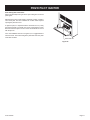
INSTALLATION INSTRUCTIONS
AND
OWNER'S MANUAL
GRAVITY VENTED
SINGLE WALL FURNACE
MODEL
HW250GW0XX1(N,P)-3
HW350GW0XX1(N,P)-3
Installer: Leave this manual with the appliance.
Consumer: Retain this manual for futurereference.
WARNING: If not installed, operated and maintained
in accordance with the manufacturer's instructions,
this product could expose you to substances in fuel
or from fuel combustion which can cause death or
serious illness.
vapors and liquids in the vicinity of this or any
other appliance.
— WHAT TO DO IF YOU SMELL GAS
any phone in your building.
neighbor’s phone. Follow the gas supplier’s
instructions.
— Installation and service must be performed by a
-
plier.
WARNING: If the information in these instructions
result causing property damage, personal injury
or loss of life.
Reverso en español

37411-0-0616Page 2
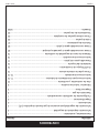
Tools and Materials ................................................................................................. 3
Important Safety Information ................................................................................... 4
Safety Information for Users of LP Gas .................................................................. 5
Introduction ............................................................................................................. 6
.......................................................................................................... 6
......................................................................... 7
Gas Supply .............................................................................................................. 8
Clearances .............................................................................................................. 9
Location - All Models ................................................................................................9
Ventilation and Combustion Air ............................................................................. 10
Rough-In Instructions ....................................................................................... 11-12
Finishing Instructions ....................................................................................... 13-14
Removing the Outer Casing .................................................................................. 15
ON/OFF Device Location ...................................................................................... 16
Bracket Installation ............................................................................................... 16
Piezo Pilot Ignitor ................................................................................................. 17
Lighting Instructions ............................................................................................. 18
Vent Safety Shutoff System ................................................................................. 19
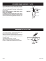
Proper Main Burner Flame .....................................................................................20
Proper Pilot Flame .................................................................................................20
Troubleshooting ......................................................................................................21
Parts List ................................................................................................................22
How To Order Repair Parts ....................................................................................22
Parts View ..............................................................................................................23
Warranty Information .............................................................................................. 24
SECTION PAGE
TABLE OF CONTENTS

37411-0-0616 Page 3
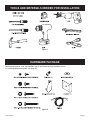
Figure 2
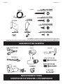
Replacement screws, nuts, and washers can be purchased at most hardware stores.
For ordering replacement parts see page 22.
HARDWARE PACKAGE
Figure 1
TOOLS AND MATERIALS NEEDED FOR INSTALLATION

37411-0-0616Page 4
Due to high temperatures the appliance should be
draperies.
of high surface temperatures and should stay away
to avoid burns or clothing ignition.
they are in the same room as the appliance.
placed on or near the appliance.
an appliance must be replaced prior to operating
the appliance.
Installation and repair should be done by a
QUALIFIED SERVICE PERSON. The appliance
should be inspected before use and at least annually
cleaning may be required due to excessive lint from
carpeting, bedding materials, etc. It is imperative
that control compartments, burners and circulating
air passageways of the appliance be kept clean.
put anything around the furnace that will
keep the appliance area clear and free from
vapors and liquids.
examine venting system periodically and replace
damaged parts.
make a periodic visual check of pilot and burners.
Clean and replace damaged parts.
use this heater if any part has been under
to inspect the heater and to replace any part of the
control system and any gas control which has been
under water.
THIS IS A HEATING APPLIANCE
DO NOT OPERATE THIS APPLIANCE WITHOUT OUTER CASING INSTALLED.
IMPORTANT SAFETY INFORMATION

37411-0-0616 Page 5
Your local LP-Gas
Dealer can give you a "Scratch and Sniff" pamphlet. Use it to
your LP-Gas has a weak or abnormal odor, call your LP-Gas
Dealer.
or make adjustments to appliances on the LP-Gas system. If
prior to and while lighting pilot lights or performing service or
making adjustments.
smell that can cover up the LP-Gas odor. Do not try to light
pilot lights, perform service, or make adjustments in an area
where the conditions are such that you may not detect the
odor if there has been a leak of LP-Gas.
new cylinders and tanks, is possible. Therefore, people should
be particularly alert and careful when new tanks or cylinders
are placed in service. Odor fade can occur in new tanks, or
out of service for a time may develop internal rust which will
a periodic sniff test of the gas is advisable. If you have any
question about the gas odor, call your LP-gas dealer. A
periodic sniff test of the LP-gas is a good safety measure
under any condition.
think you should, assume you have a leak. Then take the same
immediate action recommended above for the occasion when
you do detect the odorized LP-Gas.
-
der no vapor pressure), turn the tank valve off immediately.
If the container valve is left on, the container may draw in
occurs, some new internal rusting could occur. If the valve is
left open, then treat the container as a new tank. Always be
sure your container is under vapor pressure by turning it off
at the container before it goes completely empty or having it
SOME POINTS TO REMEMBER
Some people cannot smell well. Some people cannot smell the
can smell the odorant in propane. Smoking can decrease your
ability to smell. Being around an odor for a time can affect your
sensitivity or ability to detect that odor. Sometimes other odors in
the area mask the gas odor. People may not smell the gas odor
or their minds are on something else. Thinking about smelling a
gas odor can make it easier to smell.
The odorant in LP-gas is colorless, and it can fade under
some circumstances.
occur if there is rust inside the storage tank or in iron gas pipes.
The odorant in escaped gas can adsorb or absorb onto or into
walls, masonry and other materials and fabrics in a room. That will
take some of the odorant out of the gas, reducing its odor intensity.
LP-Gas may stratify in a closed area, and the odor intensity could
vary at different levels. Since it is heavier than air, there may be
more odor at lower levels. Always be sensitive to the slightest gas
odor. If you detect any odor, treat it as a serious leak. Immediately
go into action as instructed earlier.
NO ODOR DETECTED - ODOR FADE
phone. Do not do anything that could ignite the gas.
that IMMEDIATELY.
as basements. When you have reason to suspect a gas leak,
keep out of basements and other low areas. Stay out until
continue to smell gas, do not turn on the gas again. Do not
re-enter the building, vehicle, trailer, or area.
Finally,
gas. Have them air out the area before you return. Properly
trained LP-Gas service people should repair the leak, then
check and relight the gas appliance for you.
If a gas leak happens, you should be able to smell the gas because of the odorant put in the LP-Gas.
That's your signal to go into immediate action!
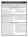
SAFETY INFORMATION FOR USERS OF LP-GAS
LP-GAS WARNING ODOR
and explosions. In its natural state, propane is odorless and
colorless. You may not know all the following safety precautions
which can protect both you and your family from an accident.
Read them carefully now, then review them point by point
with the members of your household. Someday when there
may not be a minute to lose, everyone's safety will depend
on knowing exactly what to do. If, after reading the following
information, you feel you still need more information, please
contact your gas supplier.

37411-0-0616Page 6
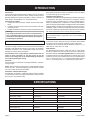
Introduction
Building Department regarding regulations, codes or ordinances
which apply to the installation of a vented wall furnace.
Instructions to Installer
1. Installer must leave instruction manual with owner after instal-
lation.
-
plied with furnace.
3. Installer should show owner how to start and operate furnace.
Warning:
Any change to this furnace or its control can be dangerous.
This is a heating appliance and any panel, door or guard
removed for servicing an appliance must be replaced prior
to operating the appliance.
General Information
Standard / CSA Standard Z21.86 and CSA 2.32 by the Canadian
Standards Association, as a Vented Wall Furnace and must be
installed according to these instructions.
Any alteration of the original design, installed other than as
shown in these instructions or use with a type of gas not
shown on the rating plate is the responsibility of the person
and company making the change.
Important
All correspondence should refer to complete Model No., Serial No.
and type of gas.
Notice:
smoke will occur. To prevent triggering of smoke alarms, ventilate
the room in which the furnace is installed.
Installation in Residential Garages
so that all burners and burner ignition devices are located not less
to physical damage by a moving vehicle.
person or through a representative is engaged in and is responsible for
State of Massachusetts: The installation must be made
Massachusetts.
The installation must conform to local codes or, in the absence of
local codes, with the National Fuel Gas Code ANSI Z223.1/NFPA
54* Natural Gas and Propane Installation Code, CSA B149.1.
*Available from the American National Standards Institute, Inc., 11
West 42nd St., New York, N.Y. 10036.
High Altitudes
feet above sea level. Canadian High Altitudes for locations having
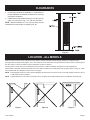
SPECIFICATIONS
Model HW250GW Series HW350GW Series
Width
Gas Inlet Pipe 1/2" 1/2"
Vent Pipe Type B Oval
Accessories
HWGWTB2 HWGWTB2
HWGWTR HWGWTR
HWGWTW2 HWGWTW2
Attention: When the HWGWTW2-1, Out-of-the-Wall kit is used the HWGWTR-1, Rear Register kit cannot be used.
INTRODUCTION
To conserve Gas: Turn off pilot when heater is not in use.

37411-0-0616 Page 7
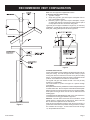
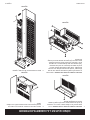
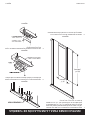
Note:
4" Oval (all parts purchase locally)
1. Type B-1 oval pipe
pair of ceiling plate spacers.
Type B-W gas vent pipe is available for single story or multi-story
installations. Type B-W gas vent pipe is to be used with the Listed
Figure 4
Insulated Vent Enclosure
have poor venting. The cold vent pipe will have a delay in proper
venting and cause the wall furnace to shut "off" by the vent safety
products an insulated vent enclosure is recommended.
clearance to combustibles.
Use metal thimble to protect vent pipe as it passes through
combustibles.
Baseplate Gasket is factory installed on header. Baseplate attaches
to header with screws. B-vent snaps into and is attached to baseplate.
Stud space around gas vents must be free of obstructions and
building paper.
Uninsulated Single-Wall Metal Pipe shall not be used outdoors in
Attention: The main burner uses room air for combustion. As the
Dust and lint accumulation inside the main burner will result in a
-
tion chamber and vent pipe. To clean main burner refer to Page
13, "Proper Main Burner Flame."
Figure 3
RECOMMENDED VENT CONFIGURATION

37411-0-0616Page 8
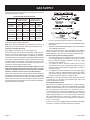
Recommended Gas Pipe Diameter
Pipe Length Schedule 40 Pipe
Inside Diameter
Tubing, Type L
Outside Diameter
Nat. L.P. Nat. L.P.
0-10 feet
0-3 meters
1/2”
12.7 mm
3/8”
9.5 mm
1/2”
12.7 mm
3/8”
9.5 mm
10-40 feet
4-12 meters
1/2”
12.7 mm
1/2”
12.7 mm
5/8”
15.9 mm
1/2”
12.7 mm
40-100 feet
13-30 meters
1/2”
12.7 mm
1/2”
12.7 mm
3/4”
19 mm
1/2”
12.7 mm
100-150 feet
31-46 meters
3/4”
19 mm
1/2”
12.7 mm
7/8”
22.2 mm
3/4”
19 mm
Note:
codes allow copper tubing or galvanized.
Note: Since some municipalities have additional local codes, it is
always best to consult your local authority and installation code.
Installing a New Main Gas Cock
Each appliance should have its own manual gas cock.
A manual main gas cock should be located in the vicinity of the unit.
contact your local authorized installer for installation or relocation.
Compounds used on threaded joints of gas piping shall be resistant
checked for leaks by the installer. This should be done with a soap
be disconnected from piping at inlet of control valve and pipe
capped or plugged for pressure test. Never pressure test with
A gas valve and ground joint union should be installed in the gas
the National Fuel Gas Code that a drip line be installed near the gas
inlet. This should consist of a vertical length of pipe tee connected
into the gas line that is capped on the bottom in which condensation
and foreign particles may collect.
Figure 5
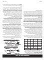
The use of the following gas connectors is recommended:
— ANS Z21.24 Appliance Connectors of Corrugated Metal Tubing
and Fittings
Than All-Metal Construction
The above connectors may be used if acceptable by the authority
Pressure Testing of the Gas Supply System
N.P.T. plugged tapping, accessible for test gauge connection,
must be placed immediately upstream of the gas supply
connection to the appliance.
2. The appliance and its individual shutoff valve must be
disconnected from the gas supply piping system during any
3. The appliance must be isolated from the gas supply piping
system by closing its individual manual shutoff valve during
any pressure testing of the gas supply piping system at test
Attention!
result in a hazardous condition.
Checking Manifold Pressure
Both Propane and Natural gas valves have a built-in pressure
regulator in the gas valve. Natural gas models will have a manifold
with the inlet pressure to the valve from a minimum of 4.5" w.c.
with the inlet pressure to the valve from a minimum of 11.0" w.c.
connection, is located on the outlet side of the gas control.
GAS SUPPLY

37411-0-0616 Page 9
S
the outer casing, or where circulation could be retarded by furniture or cabinets.
Do not install in a closet, alcove or small hallway where the furnace could be isolated by closing doors to the heated space.
When location is selected, check the walls, attic and roof to make sure there are no obstructions such as pipes, electric wiring, etc., which
would interfere with the installation of the furnace or vent pipe.
NOTE:
in wall before furnace is installed.
NOTE: If Optional Blower is to be used, hard wiring must be completed for the optional blower prior to installation of header plate.
Figure 6
Figure 7 Figure 8 Figure 9
CLEARANCES
1. In selecting a location for installation, it is necessary to
and proper installation.
NOTE:
maintained from top surface of carpeting, tile, etc.
LOCATION - ALL MODELS

37411-0-0616Page 10
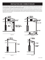
Wall furnaces shall be installed in a location in which the facilities for ventilation permit satisfactory combustion of gas and proper venting
for combustion and ventilation must be obtained directly from outdoors or from such spaces that freely communicate with the outdoors.
2
) per 2,000 BTU
Figure 10
Figure 12
Figure 11
Figure 13
VENTILATION AND COMBUSTION AIR

37411-0-0616 Page 11
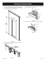
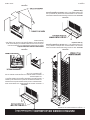
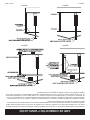
66 1/4”
(1683mm)
14 ½”
(368mm)
Figure 14
Figure 15
with sheet metal screws at each end.
HEADER ASSEMBLY
BASE PLATE
GASKET
Figure 16
BASE PLATE
OVAL PIPE
Figure 17
ROUGH-IN INSTRUCTIONS

37411-0-0616Page 12
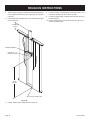
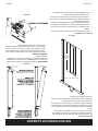
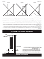
stud which will center the vent collar in the wall.
the wall opening.
screws provided or nails.
5. Attach enough vent pipe so that when installed in wall opening
6. Insert header plate with attached 4" oval, double wall vent pipe
into wall opening.
HEADER
ASSEMBLY
BOTTOM OF
NAILING FLANGE
TOPOF FLOOR PLATE
62 3/8”
(1584mm)
6” MINIMUM
(152mm)
Figure 18
7. Position header plate at height shown in Figure 18.
ROUGH-IN INSTRUCTIONS

37411-0-0616 Page 13
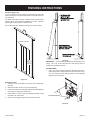
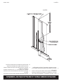
Plastering (Figure 19)
into wall space.
Use wood strips nailed to inside of studs and top of bottom plate.
These must be removed before installation of furnace. Lath and
plaster against top projection of Header Plate.
HEADER ASSEMBLY
66 1/4”
(1683mm)
WALL
OPENING
Figure 19
Installing Furnace
1. Clear the recess of all debris, and remove any wood plaster-
grounds.
4. Swing bottom of furnace into wall opening with back of legs
Figure 20
IMPORTANT — Avoid securing too tightly and disturbing the inner
casing. Do not try to force furnace into a wall opening which is
OUTER CASING
1. Align 1 3/4" slot on casing bracket with bottom screw hole on
tighten screws at this time.
CASING BRACKET
Figure 21
FINISHING INSTRUCTIONS

37411-0-0616Page 14
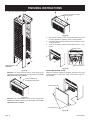
ATTACH HERE IF BLOWER
IS INSTALLED
Figure 24
3. Align clearance holes on outer casing bottom with screw holes
on casing brackets by adjusting slots on casing brackets.
4. Complete tightening casing bracket screws from Step 1 to inner
casing at this time.
screws.
CASING
BRACKET
SCREW HOLES
Figure 25
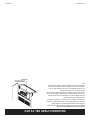
INSTALLING CONTROL DOOR
Attach two washers supplied in hardware package to pivot pins
located at bottom of control door. Install control door to outer cas-
ing assembly.
NYLON WASHER
CASING DOOR
Figure 26
FINISHING INSTRUCTIONS
2. Place outer casing onto header.
CASING
FRONT
ASSEMBL
Y
Figure 22
Attention: Use center clearance hole on outer casing top for
when
optional blower is not installed.
ATTACH HERE IF NO
BLOWER IS INSTALLED
Figure 23
Attention: Use outside clearance holes on outer casing top for
when
optional blower is installed.

37411-0-0616 Page 15
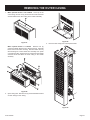
Figure 29
3. Remove outer casing from unit and place aside.
Figure 30
1. When optional blower is not installed. At the top of the
slot that attaches the outer casing to the header assembly.
Figure 27
When optional blower is installed.
screws that attach blower front to blower housing. Separate
blower front from blower housing. Remove blower front by
disconnecting fan control switch wire assembly from power
clearance slots that attach the outer casing to the header
assembly.
Figure 28
of outer casing to inner casing.
REMOVING THE OUTER CASING

37411-0-0616Page 16
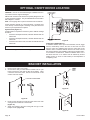
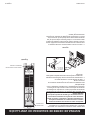
OPTIONAL ON/OFF DEVICE LOCATION
1. Remove outer casing from heater.
2. Choose which side you would like the bracket to be on your
heater. Choose the side with the best air circulation. Using
a hammer and center punch, remove the knockouts on the
chosen side of the heater.
OUTER CASING SIDE
Figure 32
3. Route the wire through the center knockout hole in the outer
casing and the center hole in the bracket.
(Figure 33)
Phillips screws. (Figure 34)
Figure 33
Figure 34
BRACKET INSTALLATION
CAUTION — D
any location where it might be damaged.
Millivolt wall mounted on/off devices are specially designed for use
on self-generating systems. They should never be used on line or
low voltage A.C. circuits.
Note:
System Check (Figure 31)
should be:
heater OFF.
heater ON.
heater ON.
To conserve Gas: Turn off pilot when heater is not in use.
Connect wires to gas valve as shown in Figure 31.
Figure 31
Installing the ON/OFF Device
switch,or thermostat), remove the wire nut from the two wires
from the valve. Run additional wire from the valve wires to the
ON/OFF device. Install the ON/OFF device in the same room as
the furnace following the installation instructions supplied with it.
In the absence of instructions, install the ON/OFF device 4 to 5
an adjoining room.
TO ON/OFF
DEVICE

37411-0-0616 Page 17
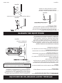
PIEZO PILOT IGNITOR
Piezo is located adjacent to gas valve. Open casing door to access
piezo ignitor.
Depressing the piezo ignitor button completely causes a spark to
opening the pilot hole cover.
from the thermopile. The spark must occur at the point the burner
with the pilot on.
On a new installation with air in the gas line, it is suggested that a
match be used. The match will light the pilot faster than the piezo
under this condition.
PIEZO IGNITOR
Figure 35

37411-0-0616Page 18
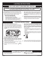
LIGHTING INSTRUCTIONS
FOR YOUR SAFETY READ BEFORE LIGHTING
LIGHTING INSTRUCTIONS
TO TURN OFF GAS TO APPLIANCE
A. This appliance has a pilot which must be lighted by hand.
When lighting the pilot, follow these instructions exactly.
B. BEFORE LIGHTING smell all around the appliance area
WHAT TO DO IF YOU SMELL GAS
do not use any phone in your building.
phone. Follow the gas supplier’s instructions.
department.
C. Use only your hand to push in or turn the gas control
knob. Never use tools. If the knob will not push in or
or explosion.
D. Do not use this appliance if any part has been under water.
the appliance and to replace any part of the control system
and any gas control which has been under water.
1. STOP! Read the safety information above.
2. Turn off all electric power to the appliance (if applicable).
3. Push in gas control knob slightly and turn clockwise
to “OFF”. NOTE: Knob cannot be turned from
“PILOT” to “OFF” unless knob is pushed in slightly. Do
not force.
GAS CONTROL KNOB SHOWN IN "OFF" POSITION
4. Wait ten (10) minutes to clear out any gas. Then smell
Follow “B” in the safety information above. If you don’t
smell gas, go to the next step.
5. Find pilot - follow metal tube from gas control. The pilot
is mounted on front of main burner.
6. Turn gas control knob counterclockwise to
“PILOT.”
7. Push and hold control knob in and repeatedly push the
ignitor button until pilot is lit (or use match to light.).
Continue to hold the control knob in for about one (1)
minute after the pilot is lit. Release knob and it will pop
back up. Pilot should remain lit. If it goes out, repeat
steps 4 through 8.
-
supplier.
control knob to “OFF” and call your service technician
or gas supplier.
8. Turn gas control knob counterclockwise to “ON.”
9. Turn on all electric power to the appliance (if applicable).
1. Turn off all electric power (if applicable) to appliance if
service is to be performed.
2. Push in gas control knob slightly and turn clockwise
to “OFF.” Do not force
WARNING:
result causing property damage, personal injury or loss of life.

37411-0-0616 Page 19
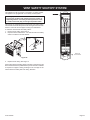
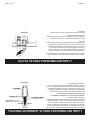
This appliance must be properly connected to a venting system.
Warning: Operation of this wall furnace when not connected
to a properly installed and maintained venting system or
tampering with the vent safety shutoff system can result
in carbon monoxide (CO) poisoning and possible death.
To reset the manual reset vent safety switch:
1. Remove outer casing. See Page 15.
2. Depress manual reset button. The manual reset vent safety
switch is located on the draft diverter.
LIMIT RESET
BUTTON
Figure 36
3. Replace outer casing. See Page 14.
If the manual reset vent safety switch continues to "shut off" the gas
to inspect for improper venting, blockage in the vent pipe or the
manual reset vent safety switch for being defective.
Figure 37
VENT SAFETY SHUTOFF SYSTEM
WIRES FOR
ON/OFF DEVICE

37411-0-0616Page 20
Figure 42
PROPER PILOT FLAME
control valve and turn the adjustment screw clockwise to reduce
control valve opening.
Figure 43
times per season.
Agency, or the Gas Supplier.
To clean burner ports, disconnect the gas supply to the valve. Remove
the burner assembly from the combustion chamber. Remove pilot
burner from main burner and then remove the main burner. Force
water into the ports and blow dry with vacuum cleaner air, or low
pressure compressed air.
PROPER MAIN BURNER FLAME

37411-0-0616 Page 21
Agency, or the Gas Supplier.
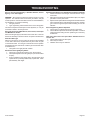
GENERAL
control operation. If the furnace fails to function on initial installation,
it is advisable to re-check the following:
1. Inlet gas pressure.
2. Type of gas being used and that shown on the rating plate.
The Service Department at Empire Comfort Systems, Inc. may be
contacted to assist in servicing furnace.
Disconnect the gas supply at the inlet to the control valve. Remove
the burner assembly to which the above components are attached.
Pilot Does Not Light
PILOT position
and depress the gas control knob. Hold the gas control knob down
to bleed the line;
1. Use lighter rod to light pilot with a match.
If Pilot Does Not Light By Any Means
1. Check gas control knob for being in the "Pilot" position.
to open).
or pilot burner is probably restricted by a spider web. Clean
pilot assembly and relight.
If Pilot Does Not Remain "On" After Releasing Gas Control Knob
1. Follow instructions and hold gas control knob down longer
and harder.
3. Replace thermopile if millivolt reading is less than 300 millivolts
when wall thermostat or remote bulb is turned OFF. Replace
gas control if magnet dropout millivolt reading is over 100
millivolts.
Pilot Outage During Normal Operation
1. Check input by manifold pressure gauge or gas meter.
2. Check millivolt output when furnace is in operation. If millivolt
output decreases during furnace operation gas control may
be defective.
Main Gas Valve Does Not Open When ON/OFF Device Is
Turned "On"
1. Check millivolt output of thermopile.
2. Wires may be broken.
3. ON/OFF device may be defective.
TROUBLESHOOTING

37411-0-0616Page 22
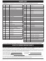
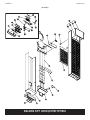
USE ONLY MANUFACTURER'S REPLACEMENT PARTS. USE OF ANY OTHER PARTS COULD CAUSE INJURY OR DEATH.
Parts can be ordered only through your service person or dealer. For best results, the service person or dealer should
order parts through the distributor. Parts can be shipped directly to the service person/dealer.
not
the following appropriate illustration and list. Be sure to give all this information.
Furnace Model Number
Part Description
Furnace Serial Number Part Number
Do not order bolts, screws, washers or nuts. They are standard hardware items and can be purchased at any local hard-
HOW TO ORDER REPAIR PARTS
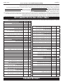
No. Part No. Description
1 WFA-115
2 23792 HEADER ASSEMBLY
3 GWT-182 INNER CASING ASSEMBLY
4 23849 DIVERTER ASSEMBLY - HW250GW
4 23782 DIVERTER ASSEMBLY - HW350GW
5 R-3239 VENT SAFETY SWITCH - HW250GW
5 R-3045 VENT SAFETY SWITCH - HW350GW
6 R-3038-A ECO LEAD ASSEMBLY
7 GWT-020 FRONT SHIELD
8 GWT-077 HEAT SHIELD
9 26463 EXCHANGER ASSEMBLY - HW250GW
9 26464 EXCHANGER ASSEMBLY - HW350GW
10 GWT-070
HW250GW
10 GWT-073
HW350GW
11 R-5245 GAS VALVE - NAT
11 R-5246 GAS VALVE - LPG
12 R-3031
13 P-88-65 BURNER ORIFICE - HW250GW LPG
13 P-88-55 BURNER ORIFICE - HW250GW NAT
13 P-88-65 BURNER ORIFICE - HW350GW LP G
13 P-88-54 BURNER ORIFICE - HW350GW NAT
14 GWT-169 AIR SHUTTER REAR - HW250GW LPG
14 GWT-012 AIR SHUTTER REAR - HW350GW LPG
15 GWT-054 AIR SHUTTER BOTTOM - HW250GW LPG
No. Part No. Description
15 GWT-049 AIR SHUTTER BOTTOM - HW350GW LPG
16 GWT-168 AIR SHUTTER FRONT - HW250GW LPG
16 GWT-011 AIR SHUTTER FRONT - HW350GW LPG
17 GWT-010 BURNER COMPARTMENT FRONT -
HW250GW
17 GWT-008 BURNER COMPARTMENT FRONT -
HW350GW
18 DV-064 COVER PLATE
19 R-3034 PILOT - NAT
19 R-3035 PILOT - LPG
20 GWT-021
21 R-1054 THERMOPILE
22 GWT-186
23 23795
24 R-3763
25 23789 CASING DOOR ASSEMBLY
26 R-885 NYLON WASHER
27 23906 VALVE SHIELD
28 R-2708 PIEZO IGNITOR
29 R-3039 ELECTRODE ASSEMBLY
30 GWT-022
31 23908 CASING ASSEMBLY COMPLETE
32 29011 EXCHANGER TUBE SUPPORT
N/S R-1081 PILOT ORIFICE
N/S R-1089 PILOT ORIFICE
N/S GWT-121 PILOT TUBING - HW250GW
N/S GWT-076 PILOT TUBING - HW350GW
N/S 23887
N/S 23919
Empire Comfort Systems, Inc. - Belleville, Illinois
PARTS LIST
ATTENTION: When ordering parts, it is very important that part number and description of part coincide.

37411-0-0616 Page 23
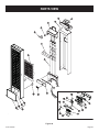
PARTS VIEW
32
10
11
12
13
14
15
16
19
20
21
27
28
29
30
2
17
22
6
3
4
5
7
8
9
1
23
24
25
26
31
18
Figure 44

37411-0-0616Page 24
HOUSEWARMER is a registered trademark of
Empire Comfort Systems Inc.
Manufactured by:
Empire Comfort Systems Inc.
Belleville, IL
Limited Ten-Year Warranty
material within ten years from the date of purchase, Empire will repair or, at Empire’s
option, replace the defective chamber.
Limited One-Year Warranty
Should any part fail because of defective workmanship or material within one year
from the date of purchase, Empire will repair or, at Empire’s option, replace the
defective part.
Duties Of The Owner
furnished with the appliance and local codes.
Ready access to the appliance for service is the responsibility of the owner.
Travel, diagnostic cost, service labor, labor to repair the defective appliance, and freight charges on warranty parts to and
from the factory will be the responsibility of the owner.
A bill of sale, cancelled check, or payment record should be kept to verify purchase date and establish warranty period.
What is Not Covered
-
use, or improper installation of this heating appliance.
This warranty does not cover claims which do not involve defective workmanship or materials.
How To Get Service
-
port Group, Empire Comfort Systems, Inc.) Provide the Customer Service Representative with the model number, serial
WARRANTY INFORMATION
PLACE OWNER’S IDENTIFICATION LABEL
HERE
-
FICACIÓN DEL PROPIETARIO
Garantía Limitada De 10 Años
Obligación Del Dueño
Acceso claro para darle servicio al aparato es responsabilidad del dueño.
establecer period de garantía.
Qué No Está Cubierto
Como Obtener Servicio
-

37411-0-0616 Página 24
HOUSEWARMER is a registered trademark of
Empire Comfort Systems Inc.
Manufactured by:
Empire Comfort Systems Inc.
Belleville, IL
Limited Ten-Year Warranty
of purchase, Empire will repair or, at Empire’s option, replace the defective chamber.
Limited One-Year Warranty
Should any part fail because of defective workmanship or material within one year from the date of purchase, Empire will
repair or, at Empire’s option, replace the defective part.
Duties Of The Owner
furnished with the appliance and local codes.
Ready access to the appliance for service is the responsibility of the owner.
Travel, diagnostic cost, service labor, labor to repair the defective appliance, and freight charges on warranty parts to and
from the factory will be the responsibility of the owner.
A bill of sale, cancelled check, or payment record should be kept to verify purchase date and establish warranty period.
What is Not Covered
-
use, or improper installation of this heating appliance.
This warranty does not cover claims which do not involve defective workmanship or materials.
How To Get Service
-
port Group, Empire Comfort Systems, Inc.) Provide the Customer Service Representative with the model number, serial
GARANTIA
Garantía Limitada De 10 Años
Obligación Del Dueño
Acceso claro para darle servicio al aparato es responsabilidad del dueño.
establecer period de garantía.
Qué No Está Cubierto
Como Obtener Servicio
-

37411-0-0616 Página 23
VISUALIZACIÓN DE LAS PARTES
Figura 44
32
10
11
12
13
14
15
16
19
20
21
27
28
29
30
2
17
22
6
3
4
5
7
8
9
1
23
24
25
26
31
18

37411-0-0616 Página 22
ATENCIÓN:
Las partes pueden pedirse sólotécnico o comerciante
técnico/comerciante.
Todas las partes enumeradas en la lista de partes tienen un número de parte. Cuando pida las partes, primero obtenga el número de modelo de la
no
Número de modelo del calefactor
Número de serie del calefactor Número de la parte
LISTA DE PARTES
CÓMO PEDIR PARTES DE REEMPLAZO
Nro. Parte Nro.
1 WFA-115 JUNTA DEL CABEZAL
2 23792 MONTAJE DEL CABEZAL
3 GWT-182 MONTAJE DE LA CUBIERTA INTERIOR
4 23849 MONTAJE DEL DESVIADOR -HW250GW
4 23782 MONTAJE DEL DESVIADOR -HW350GW
5 R-3239 INTERRUPTOR DE SEGURIDAD DE
VENTILACIÓN - HW250GW
5 R-3045 INTERRUPTOR DE SEGURIDAD DE
VENTILACIÓN - HW350GW
6 R-3038-A MONTAJE DE PLOMO ECO
7 GWT-020 PANTALLA FRONTAL
8 GWT-077 PANTALLA TÉRMICA
9 26463 MONTAJE DEL INTERCAMBIADOR -
HW250GW
9 26464 MONTAJE DEL INTERCAMBIADOR -
HW350GW
10 GWT-070 -
HW250GW
10 GWT-073 -
HW350GW
11 R-5245 VÁLVULA DE GAS - GAS NATURAL
11 R-5246 VÁLVULA DE GAS - GAS LP
12 R-3031
13 P-88-65
13 P-88-55
13 P-88-65
13 P-88-54
14 GWT-169 PARTE TRASERA DEL CIERRE DE AIRE -
HW250GW GAS LP
14 GWT-012 PARTE TRASERA DEL CIERRE DE AIRE -
HW350GW GAS LP
Nro. Parte Nro
15 GWT-054 PARTE INFERIOR DEL CIERRE DE AIRE -
HW250GW GAS LP
15 GWT-049 PARTE INFERIOR DEL CIERRE DE AIRE -
HW350GW GAS LP
16 GWT-168 PARTE FRONTAL DEL CIERRE DE AIRE -
HW250GW GAS LP
16 GWT-011 PARTE FRONTAL DEL CIERRE DE AIRE -
HW350GW GAS LP
17 GWT-010 FRENTE DEL COMPARTIMIENTO DEL
17 GWT-008 FRENTE DEL COMPARTIMIENTO DEL
18 DV-064 PLACA DE LA CUBIERTA
19 R-3034 PILOTO - GAS NATURAL
19 R-3035 PILOTO - GAS LP
20 GWT-021 SOPORTE DEL PILOTO
21 r-1054 TERMOPILA
22 GWT-186 SOPORTE DE LA CUBIERTA
23 23795 MONTAJE FRONTAL DE LA CUBIERTA
24 R-3763
25 23789 MONTAJE DE LA PUERTA DE LA CUBIERTA
26 R-885
27 23906 PROTECTOR DE VÁLVULA
28 R-2708 ENCENDIDO PIEZO
29 R-3039 MONTAJE DEL ELECTRODO
30 GWT-022 SOPORTE DEL DISPOSITIVO PIEZO
31 23908 MONTAJE DE LA CUBIERTA COMPLETO
32 29011 SOPORTE PARA EL TUBO DEL INTERCAMBIA-
DOR
N/S R-1081 ORIFICIO DEL PILOTO
N/S R-1089 ORIFICIO DEL PILOTO
N/S GWT-121
N/S GWT-076
N/S 23887
N/S 23919 SOPORTE
Empire Comfort Systems, Inc. Belleville, Illinois

GENERAL
-
valores.
Puede comunicarse con el departamento de servicios de Empire
del calefactor.
Desconecte el suministro de gas en la entrada a la válvula de
componentes anteriores.
El piloto no se enciende
Con aire en la línea de gas, como cuando el calefactor se instala
por primera vez o cuando estuvo “APAGADO” durante todo el
para encenderse en los primeros intentos. Gire la perilla de con-
de gas. Mantenga presionada la perilla de control de gas para
purgar la línea.
1. Use una varilla de encendido para encender el piloto con un
Si el piloto no se enciende de ninguna forma
del reloj).
por telas de araña. Limpie el montaje del piloto y vuelva a
encenderlo.
Si el piloto no permanece “encendido” después de abrir la
perilla de control de gas
1. Siga las instrucciones y mantenga presionada la perilla de
control de gas con más fuerza y durante más tiempo.
del piloto.
3. Cambie la termopila si la lectura de milivatios es inferior a los
300 milivatios cuando el termostato de pared o la bombilla
la lectura de milivatios baja del imán es superior a los 100
milivatios.
Corte del piloto durante el funcionamiento normal
colector o del medidor de gas.
funcionando. Si la cantidad de milivatios disminuye durante
gas tenga algún defecto.
SOLUCIÓN DE PROBLEMAS
37411-0-0616 Página 21

La llama correcta debe ser una llama interior azul y corta con una
un ajuste de aire primario. La llama será la adecuada si se usan
al menos 2 veces por persona.
-
Figura 42
LLAMA RECOMENDADA PARA EL QUEMADOR PRINCIPAL
-
mopila. La llama rodeará a la termopila justo debajo de su punta.
tornillo de la cubierta del piloto en la válvula de control y gire
los tornillos de ajuste en el sentido de las agujas de reloj para
reducir la llama. Vuelva a colocar el tornillo de la cubierta del
piloto para eliminar escapes de gas en esa abertura de la válvula
de control.
LLAMA RECOMENDADA PARA EL PILOTO
Figura 43
37411-0-0616 Página 20

Este artefacto debe conectarse correctamente a un sistema de
Advertencia: Hacer funcionar este calefactor de pared
cuando no está conectado a un sistema de ventilación
correctamente instalado y mantenido o cuando se altere el
sistema de cierre de seguro de ventilación puede provo-
car una intoxicación con dióxido de carbono (CO2) y una
probable muerte.
salida obstruida.
de energía.
Figura 40
-
manual tiene algún defecto.
SISTEMA DE CIERRE DE SEGURIDAD DE VENTILACIÓN
CABELS PARA EL DISPOSITIVO
DE
ENCENDIDO YAPAGADO
VENTILACIÓN
DE
SEGURIDAD
Figura 41
LÍMITE DEL
BOTÓN DE
REPOSICIÓN
37411-0-0616 Página 19

A. Este artefacto tiene un piloto que debe encenderse
manualmente. Cuando encienda el piloto, siga
exactamente estas instrucciones.
B. ANTES DE ENCENDERLO huela toda el área alrededor
del artefacto para detectar pérdidas de gas. Asegúrese
de oler cerca del suelo porque algunos gases son más
pesados que el aire y se pueden ubicar en el piso.
QUÉ HACER SI HUELE GAS
teléfono de la vivienda
el teléfono de un vecino. Siga las instrucciones del
proveedor de gas.
llame a los bomberos.
C. Use únicamente la mano para presionar o girar la perilla de
control de gas. No use nunca herramientas. Si no puede
girar la perilla con la mano, no intente repararla, llame a
podría producir un incendio o explosión.
D. No use este artefacto si alguna parte ha estado bajo el
que revise el artefacto y reemplace la parte del sistema
de control y el control de gas que ha estado bajo el agua.
1. ¡Deténgase! Lea la información de seguridad mencionada
anteriormente.
2. Desconecte el artefacto de la energía eléctrica.
3. Presione suavemente la perilla de control de gas y gire
en el sentido de las agujas del reloj
hacia la
posición de “OFF” (Apagado).
NOTA: La perilla no puede pasar de “PILOT” (Piloto) a "OFF”
(Apagado) a menos que se presione suavemente la perilla.
huela para detectar gas, incluso cerca del piso. Si huele
a gas, ¡DETÉNGASE! Siga el paso “B” en la información
de seguridad mencionada anteriormente. Si no huele
gas, siga con el próximo paso.
5. Ubique el piloto. Siga el tubo de metal del control de gas.
El piloto está montado en el frente del quemador principal.
6. Gire la perilla de control de gas en el sentido contrario a
las agujas del reloj, hacia la posición de “PILOT”
(Piloto).
7. Presione y mantenga presionada la
perilla de control y presione reitera-
damente el botón de encendido hasta
que se encienda el piloto (o use un
fósforo para encenderlo). Mantenga
presionada la perilla de control du-
rante aproximadamente un (1) minuto después de que
se encienda el piloto. Suelte la perilla. Ésta volverá a su
posición inicial. El piloto deberá seguir encendido. Si
se apaga, repita los pasos 4 a 8.
-
o al proveedor de gas.
intentos, cierre la perilla de control de gas y llame a su
técnico o proveedor de gas.
8. Gire la perilla de control de gas en el sentido contrario a
las agujas del reloj,
hacia la posición de “ON”
(Encendido).
9. Conecte el artefacto a la energía eléctrica (si
corresponde).
INSTRUCCIONES DE ENCENDIDO
ADVERTENCIA: Si no respeta rigurosamente la información que aparece en estas
instrucciones, se podría originar un incendio o una explosión que
provoque daño a la propiedad, lesiones personales o muerte.
INSTRUCCIONES DE ENCENDIDO
PARA CERRAR EL GAS DEL ARTEFACTO
1. Desconecte el artefacto de la energía eléctrica (si
corresponde) si se va a efectuar una reparación.
2. Presione suavemente la perilla de control de gas y gírela
en el sentido de las agujas del reloj, hacia la
PARA SU SEGURIDAD LEA ANTES DE ENCENDER
37411-0-0616 Página 18

ENCENDIDO PIEZO DEL PILOTO
El dispositivo piezo está ubicado junto a la válvula de gas. Abra
la puerta de la cubierta para acceder al encendido piezo.
-
estará al rojo vivo con el piloto encendido.
-
-
-
trico.
Figura 39
37411-0-0616 Página 17

OPCIONAL ON/OFF DISPOSITIVO DE UBICACIÓN
ADVERTENCIA:
Nunca deben ser usados en circuitos de CA de bajo voltaje o
voltaje de línea.
Nota:
milivatios.
Un funcionamiento adecuado depende de una buena llama del
piloto. La llama debe cubrir la parte superior de la termopila.
debido a la presencia de arañas.
Revisión del sistema
Se necesita un medidor de milivoltios para revisar el sistema. Las
lecturas de milivoltios deberían ser las siguientes:
con el calentador APAGADO.
con el calentador ENCENDIDO.
el calentador ENCENDIDO.
Instalación del dispositivo de encendido y apagado
interruptor de pared, un control remoto, un interruptor de palanca
o un termostato), retire la tuerca para cables de los dos cables
de la válvula. Pase un cable adicional desde los cables de la
válvula hacia el dispositivo de encendido y apagado. Instale
contigua.
Para conservar gas: Apagar el piloto cuando el calenton
no se ocupe.
Conecte los cables a la válvula de gas como se muestra en la
Figura 31.
AL DISPOSITIVO DE
ENCENDIDO YAPAGADO
Figura 31
INSTALACIÓN DEL SOPORTE
elegido del calefactor.
Figura 32
Figura 33
Figura 34
37411-0-0616 Página 16

interior.
Figura 29
Figura 30
1. Cuando el soplador opcional no está instalado. En la
Figura 27
Cuando el soplador opcional está instalado.
del soplador. Separe el frente del soplador de la carcasa
grupo de cables del interruptor de control del ventilador
del cabezal.
Figura 28
CÓMO QUITAR LA CUBIERTA EXTERIOR
37411-0-0616 Página 15

Figura 24
3.
la cubierta al ajustar las ranuras en los soportes de la cubierta.
4. Ahora ajuste los tornillos del soporte de la cubierta del paso 1
a la cubierta interior.
Figura 25
PUERTA DE CONTROL DE INSTALACIÓN
-
rios en los pernos de montaje ubicados en la parte inferior de la
puerta de control. Instale la puerta de control en el montaje de la
Figura 26
INSTRUCCIONES DE ACABADO (continuación)
Figura 22
Atención:
cuando el soplador opcional
no está instalado.
Figura 23
Atención:
cuando el soplador opcional
está instalado.
37411-0-0616 Página 14

Revoque (Figura 19)
pared.
Use tablas de madera clavadas a la parte interna de los mon-
-
gan hacia el espacio del calefactor.
Figura 19
Instalación del calefactor
madera.
2. Pare el calefactor en el piso frente a la abertura en la pared
3. Inserte la salida del calefactor en una abertura rectangular en
la placa del cabezal y levante cuidadosamente el calefactor
en la pared con la parte posterior de las patas al mismo nivel
5. Fije las patas de apoyo del calefactor a la placa del piso.
INSTRUCCIONES DE ACABADO
Figura 20
IMPORTANTE:
-
CUBIERTA EXTERIOR
1. Alinee la ranura de 1 3/4” de los soportes de la cubierta con el
los tornillos por completo en este momento.
Figura 21
MONTAJEDEL CABEZAL
66 1/4”
(1683mm)
ABERTURA
DE LA
PARED
37411-0-0616 Página 13

Figura 18.
10. Clave la placa del cabezal a los montantes de la pared.
6. Inserte en la abertura de la pared la placa del cabezal con el
Figura 18
INSTRUCCIONES PARA LA INSTALACIÓN DE TUBERÍAS
37411-0-0616 Página 12

Figura 14
calefactor) de acuerdo con las instrucciones del fabricante.
66 1/4”
(1683mm)
14 ½”
(368mm)
Figura 15
Figura 16
mm) a la placa de apoyo.
Figura 17
INSTRUCCIONES PARA LA INSTALACIÓN DE TUBERÍAS
37411-0-0616 Página 11

-
-
-
-
tes, una cerca de la parte superior del recinto y una cerca de la parte inferior; cada abertura deberá tener un área libre no menor a una
AIRE DE COMBUSTIÓN Y VENTILACIÓN
Figura 12
Figura 11 Figura 13
Figura 10
37411-0-0616 Página 10

libres para tener un acceso adecuado para poder hacer el
NOTA:
baldosas, etc.
ESPACIOS LIBRES
UBICACIÓN: TODOS LOS MODELOS
Figura 6
Figura 7 Figura 8 Figura 9
adyacentes.
muebles o armarios.
calefaccionado.
NOTA:
NOTA:
placa del cabezal.
37411-0-0616 Página 9

SUMINISTRO DE GAS
Nota:
locales permiten tuberías de cobre o galvanizadas.
Nota:
adicionales, siempre es mejor consultar con la autoridad local y
Instalación de una nueva llave principal de gas
Cada artefacto debe tener su propia llave de gas manual.
Debe haber una llave de gas manual cerca de la unidad. Si no
Nunca use una llama expuesta para buscar escapes. Para re-
de los tubos en la entrada de la válvula de control y el tubo
debe estar tapado o bloqueado. Nunca realice el control de
sufrirá daños!
Debe instalarse una válvula de gas y un empalme de puesta a
tierra en la línea de gas contra la corriente del control de gas
-
entrada de gas. Dicha línea debe constar de una salida de tubo
Figura 5
Se recomienda el uso de los siguientes conectores de gas:
— Conectores de artefacto ANS Z21.24 de tuberías y accesorios
de metal corrugado
-
Control de presión del sistema de suministro de gas
2. El artefacto y la válvula de cierre individual deben estar
desconectados del sistema de tubos del suministro de gas
3. El artefacto debe aislarse del sistema de tubos del suministro
de gas cerrando la válvula de cierre manual individual durante
¡Atención! Si uno de los procedimientos produce presiones
Control de la presión del colecto
Las válvulas de gas propano y natural poseen un regulador
incorporado en la válvula de gas. Los modelos de gas natural
-
kPa).
En el lado de la salida del control de gas hay una toma de 1/8”
prueba.
Diámetro recomendado para el tubo de gas
Longitud del
tubo
Tubo Schedule 40
Diámetro interno
Tubería, tipo L
Nat. L.P. Nat. L.P.
0-10 pies
0-3 metros
1/2”
12.7 mm
3/8”
9.5 mm
1/2”
12.7 mm
3/8”
9.5 mm
10-40 pies
4-12 metros
1/2”
12.7 mm
1/2”
12.7 mm
5/8”
15.9 mm
1/2”
12.7 mm
40-100 pies
13-30 metros
1/2”
12.7 mm
1/2”
12.7 mm
3/4”
19 mm
1/2”
12.7 mm
100-150 pies
31-46 metros
3/4”
19 mm
1/2”
12.7 mm
7/8”
22.2 mm
3/4”
19 mm
37411-0-0616 Página 8

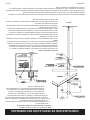
Nota:
Ovalo de 4” (todas las partes se compran localmente)
1. Tubo ovalado tipo B-1
y un par de espaciadores para la placa de techo.
de apoyo, un par de espaciadores para la placa del techo del primer piso
y un par de espaciadores cortafuego en cada nivel sucesivo del techo.
Para las instalaciones en uno o múltiples pisos, se encuentra
los espaciadores para la placa de techo y los espaciadores corta-
CONFIGURACIÓN DE VENTILACIÓN RECOMENDADA
Figura 3
Figura 4
Recinto de ventilación aislado
aislado.
La junta de la placa de apoyo viene instalada de fábrica en el cabezal. La placa de
El espacio para los montantes alrededor de las ventilaciones de gas no debe presentar
Atención:
37411-0-0616 Página 7

Introducción
-
Instrucciones para el instalador
1. El instalador debe dejar el manual de instrucciones en manos
la tarjeta de garantía provista con el calefactor.
el calefactor.
Advertencia:
a sus controles puede ser peligrosa. Éste es un artefac-
to de calefacción y cualquier panel, puerta o dispositivo
de protección que se extraiga para reparar un artefacto
debe colocarse en su lugar antes de ponerlo en funcio-
namiento.
Para conservar gas: Apagar el piloto cuando el calenton
no se ocupe.
Información general
Estándar)/CSA Standard Z21.86 y CSA 2.32 de la Canadian
acuerdo con estas instrucciones.
Cualquier alteración del diseño original, instalación del
artefacto de forma diferente a estas instrucciones o uso con
un tipo de gas distinto del que se muestra en la placa de
valores será responsabilidad de la persona o empresa que
lo haga.
Importante
Toda la correspondencia debe hacer referencia al tipo de gas,
nro. de serie y nro. de modelo completo.
Aviso: Durante el encendido inicial de este artefacto, la pintura
instalado el calefactor.
Instalación en cocheras domésticas
-
-
-
cia en dichas tareas, conocer todas las precauciones necesarias
Estado de Massachusetts:
un instalador de gas o fontanero registrado en el estado de
Massachusetts.
en su ausencia, según el Código Nacional de Gas Combustible
ANSI Z223.1/NFPA 54* el Código de Instalación de Gas Natural
y Propano, CSA B149.1.
*Disponible en el American National Standards Institute (Instituto
Nacional Americano de Estándares), Inc., 11 West 42nd St., New
York, N.Y. 10036.
Altitudes elevadas
los índices de entrada deben disminuirse al 4 por ciento por cada
Altitudes elevadas en
Canadá
INTRODUCCIÓN
ESPECIFICACIONES
Modelo Serie HW250GW Serie HW350GW
Ancho
Tubo de entrada de gas 1/2" 1/2"
Accesorios
Juego del soplador HWGWTB2 HWGWTB2
Juego de registro trasero HWGWTR HWGWTR
Juego fuera de la pared HWGWTW2 HWGWTW2
Atención: Cuando se usa el juego HWGWTW2-1, fuera de la pared, el juego de registro trasero HWGWTR-1 no se
puede usar.
37411-0-0616 Página 6

Algunas personas no tienen un buen sentido del olfato. No
pueden percibir el olor del producto químico colocado en
odorante colocada en el propano. El tabaco puede perjudicar
prolongados puede afectar su habilidad para detectar el
odorante. A veces otros olores en el área ocultan el olor del gas.
Las personas pueden no percibir el olor del gas o pueden no
estar atentos al mismo. Si se predispone a percibir el olor del
gas, puede olerlo más fácilmente.
La sustancia odorante en el gas LP es incolora y puede
perder intensidad en algunas circunstancias. Por ejemplo,
si se produce un escape subterráneo, el desplazamiento del
almacenamiento o en los tubos de hierro de gas.
Las paredes, la mampostería y otros materiales y telas en la
odorante del gas y reduce su intensidad.
-
sidad del olor podría variar en diferentes niveles. Al ser más
detecta algún olor, actúe como si fuera un escape grave. Tome
provocar incendios o explosiones. En su estado natural, el
todas las precauciones de seguridad que se mencionan a
continuación, las cuales lo protegen a usted y a su familia
de un accidente. Léalas ahora con detenimiento, luego
repáselas en detalle con los miembros de su hogar. En
una situación donde no se puede perder ni un minuto, la
seguridad de todos dependerá de conocer exactamente
lo que se debe hacer. Si, después de leer la siguiente
información, considera que necesita más detalles,
comuníquese con su proveedor de gas.
o área. Hágalo INMEDIATAMENTE.
los cilindros.
Por último, -
capacitada en gas LP debe reparar el escape, luego revisar
y volver a encender el artefacto a gas.
OLOR IMPERCEPTIBLE. PÉRDIDA DE INTENSIDAD DEL OLOR.
OLOR DE ADVERTENCIA DE GAS LP
En caso de un escape de gas, debería oler el gas debido a la sustancia odorante colocada en el gas LP.
¡Ésa es la señal para que actúe de inmediato!
INFORMACIÓN DE SEGURIDAD PARA USUARIOS DE GAS
LICUADO DE PETRÓLEO (LP)
ALGUNOS PUNTOS PARA RECORDAR
Aprenda a reconocer el olor del gas LP. Su comerciante
local de gas LP puede entregarle un folleto “raspar y oler”.
con su comerciante de gas LP.
-
ciones o ajustes en los artefactos del sistema de gas LP. Si
está capacitado, piense concientemente en el olor del gas LP
antes de encender el piloto o realizar reparaciones o ajustes
y mientras lo realiza.
y esto puede ocultar el olor del gas LP. No intente encender
el piloto ni realizar reparaciones o ajustes en un área donde
produce un escape de gas LP.
viejos reutilizados, si se los llena y se los deja asentados
demasiado tiempo antes de ser rellenados. Los cilindros y
del olor del gas. Si tiene alguna duda sobre el olor del gas,
comuníquese con su comerciante de gas LP. Una prueba
periódica del olor del gas LP es una medida de seguridad
anteriormente cuando se detecta un escape de gas LP gracias
a la sustancia odorante.
-
no se cierra la válvula del contenedor, puede ingresar aire a
37411-0-0616 Página 5

Debido a las altas temperaturas, el artefacto debe ubicarse
alejado de las áreas de circulación y de muebles y cortinas.
y deben mantenerse alejados de las mismas para prevenir
quemaduras o daños en las prendas de vestir.
cuando se encuentran en la misma habitación que el
artefacto.
seguridad que se haya extraído para reparar el artefacto
debe colocarse en su lugar antes de hacer funcionar el
aparato.
control.
debido a una cantidad excesiva de pelusas provenientes
del alfombrado, la ropa de cama, etc. Es sumamente
importante mantener limpios los compartimientos de
control, quemadores y conductos de circulación de aire
del artefacto.
No coloque ningún elemento alrededor del calefactor que
Mantenga el área del artefacto alejada de material
combustible, gasolina y otros líquidos y vapores
Revise el sistema de ventilación periódicamente y
reemplace las partes dañadas.
quemadores. Limpie y reemplace las partes dañadas.
No use este calefactor si alguna parte ha estado bajo el
que revise el calefactor y reemplace la parte del sistema
de control y el control de gas que ha estado bajo el agua.
chimenea de otro artefacto que quema combustible sólido.
ESTE PRODUCTO ES UN ARTEFACTO DE CALEFACCIÓN.
NO OPERE ESTE ARTEFACTO SIN ANTES HABER INSTALADO LA CUBIERTA EXTERIOR.
INFORMACIÓN IMPORTANTE DE SEGURIDAD
37411-0-0616 Página 4

HERRAMIENTAS Y MATERIALES NECESARIOS
PARA LA INSTALACIÓN
PAQUETE DE ACCESORIOS
Los tornillos, las tuercas y las arandelas de repuesto pueden adquirirse en la mayoría de las ferret-
Figura 1
Figura 2
37411-0-0616 Página 3

CONTENIDOS
SECCIÓN PÁGINA
Herramientas y materiales ...................................................................................... 3
...................................................................... 4
.............. 5
............................................................................................................. 6
..................................................................................................... 6
............................................................ 7
Suministro de gas ................................................................................................... 8
Espacios libres ........................................................................................................ 9
..................................................................................9
........................................................................... 10
................................................... 11-12
Instrucciones de acabado ................................................................................ 13-14
............................................................................ 15
.............................................................................. 16
.......................................................................................... 16
Encendido piezo del piloto .................................................................................... 17
Instrucciones de encendido .................................................................................. 18
..................................................... 19
...................................................20
Llama recomendada para el piloto .........................................................................20
...........................................................................................21
Lista de partes ........................................................................................................22
....................................................................22
..................................................................................... 23
Garantia .............................................................................................................2424
37411-0-0616 Página 2

Flip for English
Página 1
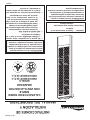
INSTRUCCIONES DE
INSTALACIÓN Y
MANUAL DEL PROPIETARIO
ADVERTENCIA: Si no se instala, se opera y
se mantiene conforme a las instrucciones del
fabricante, este producto podría exponerlo
a sustancias derivadas de la combustión de
combustibles lo cual podría causarle la muerte
o enfermedades graves.
CALEFACTOR DE PARED
SIMPLE
CON VENTILACIÓN POR
GRAVEDAD
MODELO
HW250GW0XX1(N,P)-3
HW350GW0XX1(N,P)-3
Instalador: Conserve este manual con el
artefacto.
Consumidor: Guarde este manual para
referencia futura.
— No guarde ni use gasolina u otros vapores
cualquier otro artefacto.
— QUÉ HACER SI HUELE GAS
utilice ningún teléfono de la vivienda.
gas desde el teléfono de un vecino. Siga
las instrucciones del proveedor de gas.
-
eedor de gas, llame a los bomberos.
— Una agencia de servicios, un instalador cali-
la instalación y el servicio.
ADVERTENCIA: Si no se respeta rigurosa-
mente la información que aparece en estas
instrucciones, se podría originar un incendio
o una explosión, lo cual ocasionaría daños
materiales, lesiones personales o la muerte.
-
 1
1
-
 2
2
-
 3
3
-
 4
4
-
 5
5
-
 6
6
-
 7
7
-
 8
8
-
 9
9
-
 10
10
-
 11
11
-
 12
12
-
 13
13
-
 14
14
-
 15
15
-
 16
16
-
 17
17
-
 18
18
-
 19
19
-
 20
20
-
 21
21
-
 22
22
-
 23
23
-
 24
24
-
 25
25
-
 26
26
-
 27
27
-
 28
28
-
 29
29
-
 30
30
-
 31
31
-
 32
32
-
 33
33
-
 34
34
-
 35
35
-
 36
36
-
 37
37
-
 38
38
-
 39
39
-
 40
40
-
 41
41
-
 42
42
-
 43
43
-
 44
44
-
 45
45
-
 46
46
-
 47
47
-
 48
48


Empire HW350 El manual del propietario
- Categoría
- Calentadores espaciales
- Tipo
- El manual del propietario
en otros idiomas
- English: Empire HW350 Owner's manual
Artículos relacionados
-
Empire Heating Systems DV25/35 El manual del propietario
-
Empire Comfort Systems MV 120 El manual del propietario
-
-
Empire DV-35-4SG Installation Instructions And Owner's Manual
-
Empire Products GWT-35-2 RB Manual de usuario
-
Empire Heating Systems DV210/215 El manual del propietario
-
Empire Heating Systems Gravity Wall Furnace (GWT50W) El manual del propietario
-
Otros documentos
-
-
-
-
-
-
Cozy 90N30A El manual del propietario
-
MTD Genuine Factory Parts 490-100-M115 Información del Producto
-
Mars DGAA077BDTD-CY Manual de usuario
-
Pentair 476000 Guía de instalación
-
Pentair ETi 400 Guía de instalación