Malaguti F18 WARRIOR Electric System Troubleshooting
- Categoría
- Probadores de redes de cable
- Tipo
- Electric System Troubleshooting

MALAGUTI F18MALAGUTI F18
MALAGUTI F18MALAGUTI F18
MALAGUTI F18
IDENTIFICAZIONE GUASTI IMPIANTO ELETTRICOIDENTIFICAZIONE GUASTI IMPIANTO ELETTRICO
IDENTIFICAZIONE GUASTI IMPIANTO ELETTRICOIDENTIFICAZIONE GUASTI IMPIANTO ELETTRICO
IDENTIFICAZIONE GUASTI IMPIANTO ELETTRICO
FEHLERSUCHE IM ELEKTRISCHEN SYSTEMFEHLERSUCHE IM ELEKTRISCHEN SYSTEM
FEHLERSUCHE IM ELEKTRISCHEN SYSTEMFEHLERSUCHE IM ELEKTRISCHEN SYSTEM
FEHLERSUCHE IM ELEKTRISCHEN SYSTEM
ELECTRIC SYSTEM TROUBLESHOOTINGELECTRIC SYSTEM TROUBLESHOOTING
ELECTRIC SYSTEM TROUBLESHOOTINGELECTRIC SYSTEM TROUBLESHOOTING
ELECTRIC SYSTEM TROUBLESHOOTING
IDENTIFICATION DES PANNES DANS L’INSTALLATION ELECTRIQUEIDENTIFICATION DES PANNES DANS L’INSTALLATION ELECTRIQUE
IDENTIFICATION DES PANNES DANS L’INSTALLATION ELECTRIQUEIDENTIFICATION DES PANNES DANS L’INSTALLATION ELECTRIQUE
IDENTIFICATION DES PANNES DANS L’INSTALLATION ELECTRIQUE
IDENTIFICACION AVERIAS INSTALACION ELECTRICAIDENTIFICACION AVERIAS INSTALACION ELECTRICA
IDENTIFICACION AVERIAS INSTALACION ELECTRICAIDENTIFICACION AVERIAS INSTALACION ELECTRICA
IDENTIFICACION AVERIAS INSTALACION ELECTRICA

1 11/00
••
••
• La ditta
Malaguti Malaguti
Malaguti Malaguti
Malaguti si riserva il diritto di apportare modifiche di ogni natura ai propri motoveicoli, in qualunque
momento, senza l’obbligo di tempestivo preavviso.
•
Riproduzioni Riproduzioni
Riproduzioni Riproduzioni
Riproduzioni o divulgazioni, anche parziali, degli argomenti e delle illustrazioni riportati nei Manuali oggetto della
presente pubblicazione sono
assolutamente vietateassolutamente vietate
assolutamente vietateassolutamente vietate
assolutamente vietate. Ogni diritto è riservato alla ditta
MalagutiMalaguti
MalagutiMalaguti
Malaguti, alla quale si
dovrà richiedere autorizzazione (scritta) specificando la utilizzazione delle eventuali riproduzioni.
GBGB
GBGB
GB
FF
FF
F
DD
DD
D
MALAGUTI - 40068 S. Lazzaro di Savena (Bologna)MALAGUTI - 40068 S. Lazzaro di Savena (Bologna)
MALAGUTI - 40068 S. Lazzaro di Savena (Bologna)MALAGUTI - 40068 S. Lazzaro di Savena (Bologna)
MALAGUTI - 40068 S. Lazzaro di Savena (Bologna)
Via Emilia Levante, 498 - Tel. 051/6255106 - Fax 051/6255160Via Emilia Levante, 498 - Tel. 051/6255106 - Fax 051/6255160
Via Emilia Levante, 498 - Tel. 051/6255106 - Fax 051/6255160Via Emilia Levante, 498 - Tel. 051/6255106 - Fax 051/6255160
Via Emilia Levante, 498 - Tel. 051/6255106 - Fax 051/6255160
EE
EE
E
Eurograph - Studio Baravelli - BO
• Die Firma
Malaguti Malaguti
Malaguti Malaguti
Malaguti behält sich das Recht vor, jederzeit und ohne Vorankündigung Änderungen aller Art an ihren
Krafträdern durchzuführen.
• Die vollständige oder auszugsweise
ReproduktionReproduktion
ReproduktionReproduktion
Reproduktion dieses Handbuchs einschließlich der Abbildungen in irgendeiner Form
ohne schriftliche Genehmigung ist
untersagtuntersagt
untersagtuntersagt
untersagt. Alle Rechte sind der Firma
Malaguti Malaguti
Malaguti Malaguti
Malaguti vorbehalten, bei der für eine eventuelle
Reproduktion unter Angabe spezifischer Verwendungszwecke um (schriftliche) Genehmigung ersucht werden muß.
••
••
•
MalagutiMalaguti
MalagutiMalaguti
Malaguti reserves the right to make any and all changes to its vehicles as it deems fit and opportune at any time
without prior notice.
• All rights reserved. No part of this publication, whether text or illustrations,
may be reproducedmay be reproduced
may be reproducedmay be reproduced
may be reproduced or circulated
without the prior written permission from
MalagutiMalaguti
MalagutiMalaguti
Malaguti. Reasons must be given for any request for permission thereto.
• La société
MalagutiMalaguti
MalagutiMalaguti
Malaguti se réserve le droit d’apporter des modifications à ses motocycles, de quelque nature que ce
soit, à tout moment, sans notification préalable.
• Toute
reproduction reproduction
reproduction reproduction
reproduction ou divulgation, même partielle, des sujets et des illustrations figurant dans les manuels
faisant l’objet de cette publication est
formellement interditeformellement interdite
formellement interditeformellement interdite
formellement interdite. Tous droits réservés à la société
MalagutiMalaguti
MalagutiMalaguti
Malaguti, à
laquelle il est nécessaire de demander l’autorisation (écrite) en précisant l’utilisation des reproductions éventuelles.
• La Empresa
MalagutiMalaguti
MalagutiMalaguti
Malaguti, se reserva el derecho de aportar modificaciones de cualquier naturaleza, a sus propios
vehículos a motor, en cualquier momento, sin la obligación de aviso tempestivo.
•
Está terminantemente prohibido reproducirEstá terminantemente prohibido reproducir
Está terminantemente prohibido reproducirEstá terminantemente prohibido reproducir
Está terminantemente prohibido reproducir o divulgar aunque sea parcialmente, los argumentos y las
ilustraciones que se indican en los manuales objeto de la presente publicación. Todos los derechos están reservados
a la Empresa
MalagutiMalaguti
MalagutiMalaguti
Malaguti a la que se tendrá que solicitar la autorización (por escrito) especificando la utilización de
las eventuales reproducciones.
PRIMA EDIZIONE : 11/00PRIMA EDIZIONE : 11/00
PRIMA EDIZIONE : 11/00PRIMA EDIZIONE : 11/00
PRIMA EDIZIONE : 11/00
ERSTAUFLAGE: 11/00ERSTAUFLAGE: 11/00
ERSTAUFLAGE: 11/00ERSTAUFLAGE: 11/00
ERSTAUFLAGE: 11/00
FIRST EDITION: 11/00FIRST EDITION: 11/00
FIRST EDITION: 11/00FIRST EDITION: 11/00
FIRST EDITION: 11/00
PREMIERE EDITION: 11/00PREMIERE EDITION: 11/00
PREMIERE EDITION: 11/00PREMIERE EDITION: 11/00
PREMIERE EDITION: 11/00
PRIMERA EDICIÓN: 11/00PRIMERA EDICIÓN: 11/00
PRIMERA EDICIÓN: 11/00PRIMERA EDICIÓN: 11/00
PRIMERA EDICIÓN: 11/00

2 11/00
INTRODUCTIONINTRODUCTION
INTRODUCTIONINTRODUCTION
INTRODUCTION
• The present publication describes all necessary steps
for the troubleshooting concerning the electric system
(of the models indicated on the front page) and of the
possible service operations, which are necessary for
their solution. It supplies the trade technicians
(authorized customer service centres) with the
necessary information for operating in compliance with
the modern concepts of “good practice” and “work
safety”.
• Further information can be derived from the “Cycle”
workshop manual - from the Engine workshop manual
- from the Spare Part catalogue.
• All described operations foresee the necessary skill
and experience by the technicians.
• The steps for the removal of body parts and of electric
and mechanical components, to allow the access to
wiring or electric components to service, can be taken
from the Cycle Workshop Manual.
• We recommend to follow with care the information given
in this publication.
• For any further information you may need, refer to the
Customer service department or to the Malaguti
Technical Department.
AVANT-PROPOSAVANT-PROPOS
AVANT-PROPOSAVANT-PROPOS
AVANT-PROPOS
••
••
• Cette publication contient toutes les procédures
nécessaires pour
déterminer les pannes dedéterminer les pannes de
déterminer les pannes dedéterminer les pannes de
déterminer les pannes de
l’installation électriquel’installation électrique
l’installation électriquel’installation électrique
l’installation électrique (des modèles indiqués sur la
couverture) et pour intervenir afin de les éliminer, en
fournissant aux
techniciens du secteurtechniciens du secteur
techniciens du secteurtechniciens du secteur
techniciens du secteur (Centres
d’Assistance Autorisés), les informations les plus
importantes pour opérer en parfaite harmonie avec les
concepts modernes de “
bonnebonne
bonnebonne
bonne technique” et de “sécurité
sur les lieux de travail”.
• L’opérateur pourra trouver d’autres informations sur le
Manuel d’atelier “cycliste”Manuel d’atelier “cycliste”
Manuel d’atelier “cycliste”Manuel d’atelier “cycliste”
Manuel d’atelier “cycliste” - le
Manuel d’atelier duManuel d’atelier du
Manuel d’atelier duManuel d’atelier du
Manuel d’atelier du
moteurmoteur
moteurmoteur
moteur - le
Catalogue des pièces de rechange.Catalogue des pièces de rechange.
Catalogue des pièces de rechange.Catalogue des pièces de rechange.
Catalogue des pièces de rechange.
• Toutes les interventions décrites supposent une
compétence et un acquis des techniciens chargés de les
exécuter.
• Les procédures pour enlever les parties de la
carrosserie et les éléments électro/mécaniques, pour
permettre l’accès aux différents câblages ou
composants électriques, sur lesquels il faudra
intervenir, figurent dans le Manuel d’atelier cycliste.
• Nous conseillons se suivre scrupuleusement les
indications figurant dans ce fascicule.
• Pour de plus amples informations, s’adresser au
Service d’Assistance ou au Bureau Technique
MalagutiMalaguti
MalagutiMalaguti
Malaguti.
PREMESSAPREMESSA
PREMESSAPREMESSA
PREMESSA
••
••
• La presente pubblicazione, contempla tutte le procedure necessarie all’
individuazione di guasti all’impianto elet-individuazione di guasti all’impianto elet-
individuazione di guasti all’impianto elet-individuazione di guasti all’impianto elet-
individuazione di guasti all’impianto elet-
tricotrico
tricotrico
trico (dei modelli evidenziati in copertina) e degli interventi possibili, per la loro risoluzione, fornendo ai
tecnici deltecnici del
tecnici deltecnici del
tecnici del
settoresettore
settoresettore
settore (Centri di Assistenza Autorizzata), le principali informazioni per operare in perfetta armonia con i moderni
concetti di “
buonabuona
buonabuona
buona tecnica” e “sicurezza sul lavoro”.
• Altre eventuali informazioni, possono essere dedotte dal
Manuale officina della “ciclistica”Manuale officina della “ciclistica”
Manuale officina della “ciclistica”Manuale officina della “ciclistica”
Manuale officina della “ciclistica” - dal
Manuale officinaManuale officina
Manuale officinaManuale officina
Manuale officina
del motoredel motore
del motoredel motore
del motore - dal
Catalogo ricambiCatalogo ricambi
Catalogo ricambiCatalogo ricambi
Catalogo ricambi.
• Tutti gli interventi descritti, prevedono competenza ed esperienza da parte dei tecnici preposti.
• Le procedure per la rimozione di parti della carrozzeria e particolari elettro/meccanici, per consentire l’accesso ai vari
cablaggi o componenti elettrici, sui quali si dovrà intervenire, sono deducibili dal Manuale officina ciclistica.
• È consigliabile attenersi scrupolosamente a quanto riportato nel presente fascicolo.
• Per qualsiasi ulteriore informazione, interpellare il Reparto Assistenza o l’Ufficio Tecnico della
MalagutiMalaguti
MalagutiMalaguti
Malaguti.
VORWORTVORWORT
VORWORTVORWORT
VORWORT
• Diese Unterlage beschreibt die zur
Fehlersuche imFehlersuche im
Fehlersuche imFehlersuche im
Fehlersuche im
elektrischen Systemelektrischen System
elektrischen Systemelektrischen System
elektrischen System notwendigen Schritte (für die auf
dem Deckblatt angegebenen Modelle), die möglichen
Eingriffe, und auch die Lösung der Probleme. Sie
versorgt die Fachtechniker (anerkannte Kundendienste)
mit den wichtigsten Informationen, in Übereinstimmung
mit den modernsten Normen des
Stands der TechnikStands der Technik
Stands der TechnikStands der Technik
Stands der Technik
und der “Arbeitssicherheit”.
• Dem
Fahrwerk-Werkstatthandbuch, Fahrwerk-Werkstatthandbuch,
Fahrwerk-Werkstatthandbuch, Fahrwerk-Werkstatthandbuch,
Fahrwerk-Werkstatthandbuch, dem
Werkstatthandbuch des Motors Werkstatthandbuch des Motors
Werkstatthandbuch des Motors Werkstatthandbuch des Motors
Werkstatthandbuch des Motors und dem
ErsatzteilkatalogErsatzteilkatalog
ErsatzteilkatalogErsatzteilkatalog
Ersatzteilkatalog können weitere Informationen
entnommen werden.
• Die beschriebenen Eingriffe sehen die notwendige
Fähigkeit und Erfahrung seitens der Techniker vor.
• Die Schritte zur Entfernung der Karosseriebauteile und der
elektrischen und mechanischen Bauteile, um die
Verdrahtungen oder die elektrischen Bauteile zugänglich zu
machen, können aus dem Fahrwerk-Werkstatthandbuch
entnommen werden.
• Die Angaben dieser Unterlage sollen mit Sorgfalt
berücksichtigt werden.
• Für weitere Klärungen steht der Kundendienst oder die
Technische Abteilung der Fa.
MalagutiMalaguti
MalagutiMalaguti
Malaguti immer gerne
zur Verfügung.
PRELIMINARESPRELIMINARES
PRELIMINARESPRELIMINARES
PRELIMINARES
• Este manual contiene todos los procedimientos
necesarios para
individuar las averías en la individuar las averías en la
individuar las averías en la individuar las averías en la
individuar las averías en la
instalación eléctricainstalación eléctrica
instalación eléctricainstalación eléctrica
instalación eléctrica (de los modelos que aparecen
en la tapa) y de las intervenciones posibles, para
resolverlas, proporcionando a los
técnicos del sector técnicos del sector
técnicos del sector técnicos del sector
técnicos del sector
(Centros de Asistencia Autorizada), las principales
informaciones para obrar en perfecta armonía con los
conceptos modernos de “
buena buena
buena buena
buena técnica” y “seguridad
en el trabajo”.
• Otras informaciones, pueden deducirse del
Manual Manual
Manual Manual
Manual
taller de la “ciclística”taller de la “ciclística”
taller de la “ciclística”taller de la “ciclística”
taller de la “ciclística” - del
Manual taller del motorManual taller del motor
Manual taller del motorManual taller del motor
Manual taller del motor
- del
Catálogo recambios. Catálogo recambios.
Catálogo recambios. Catálogo recambios.
Catálogo recambios.
••
••
• Todas las operaciones descritas están dirigidas a
técnicos competentes y expertos.
••
••
• Los procedeimientos para la remoción de partes de la
carrocería y particulares electro/mecánicos, para
consentir el acceso a los diferentes cableos o
componentes eléctricos, sobre los que se deberá
intervenir, pueden encontrarse en el Manual taller
ciclística.
••
••
• Se aconseja atenerse escrupulosamente a lo descrito
en este manual.
• Para cualquier otro tipo de información, dirigirse al
Departamento Asistencia o a la Oficina Técnica de la
Malaguti.Malaguti.
Malaguti.Malaguti.
Malaguti.

3 11/00
AGGIORNAMENTO DELLA PUBBLICAZIONEAGGIORNAMENTO DELLA PUBBLICAZIONE
AGGIORNAMENTO DELLA PUBBLICAZIONEAGGIORNAMENTO DELLA PUBBLICAZIONE
AGGIORNAMENTO DELLA PUBBLICAZIONE
•
Gli Gli
Gli Gli
Gli aggiornamenti verranno da noi spediti (
in un ragionevole lasso di tempo
), prevedendo l’invio di una nuova
versione CD che sostituirà quella già in Vs. possesso.
•
L’indice L’indice
L’indice L’indice
L’indice verrà aggiornato nel caso in cui le modifiche e le variazioni alle pagine interne risultino tali da non garantire
più una razionale consultazione della pubblicazione.
••
••
•
IMPORTANTE! IMPORTANTE!
IMPORTANTE! IMPORTANTE!
IMPORTANTE! Il manuale per l’identificazione guasti impianto elettrico deve essere considerato un vero e proprio
strumento di lavoro strumento di lavoro
strumento di lavoro strumento di lavoro
strumento di lavoro e può mantenere il suo “
valore
” nel tempo, soltanto se mantenuto costantemente aggiornato.
AKTUALISIERUNGDERVERÖFFENTLICHUNGAKTUALISIERUNGDERVERÖFFENTLICHUNG
AKTUALISIERUNGDERVERÖFFENTLICHUNGAKTUALISIERUNGDERVERÖFFENTLICHUNG
AKTUALISIERUNGDERVERÖFFENTLICHUNG
•
Die AktualisierungDie Aktualisierung
Die AktualisierungDie Aktualisierung
Die Aktualisierung werden von uns (innerhalb
sinnvoller Zeitabstände) geschickt. Jede neue Cd-Rom
wird die schon in Ihren Handen ersetzen.
•
Das Inhaltsverzeichnis Das Inhaltsverzeichnis
Das Inhaltsverzeichnis Das Inhaltsverzeichnis
Das Inhaltsverzeichnis wird dann aktualisiert, wenn
die Modifizierungen sowie die Änderungen der
Innenseiten dergestalt sind, daß eine sinnvolle
Benutzung des Handbuchs nicht mehr gewährleistet
ist.
•
WICHTIG! WICHTIG!
WICHTIG! WICHTIG!
WICHTIG! Das Handbuch für die Fehlersuche im
elektrischen System ist als echtes
Arbeitsmittel Arbeitsmittel
Arbeitsmittel Arbeitsmittel
Arbeitsmittel zu
betrachten und kann seinen “Wert” auf Dauer nur dann
bewahren, wenn es regelmäßig aktualisiert wird.
PUBLICATION UPDATESPUBLICATION UPDATES
PUBLICATION UPDATESPUBLICATION UPDATES
PUBLICATION UPDATES
• The
up-datesup-dates
up-datesup-dates
up-dates will be sent by us (
in due course). Every
Cd- Rom you will receive, will supersede the one already
in your hands.
• The
table of contentstable of contents
table of contentstable of contents
table of contents will be duly updated in case of
the insertion of new pages causing difficulty in the
rational consultation of the manual.
••
••
•
IMPORTANT!IMPORTANT!
IMPORTANT!IMPORTANT!
IMPORTANT! The manual for the electric system
troubleshooting is to be considered as an essential
work instrumentwork instrument
work instrumentwork instrument
work instrument to be properly kept up-to-date so as
to maintain its
“validity”
over time.
MISE A JOUR DE LA PUBLICATIONMISE A JOUR DE LA PUBLICATION
MISE A JOUR DE LA PUBLICATIONMISE A JOUR DE LA PUBLICATION
MISE A JOUR DE LA PUBLICATION
••
••
•
Les mises à jourLes mises à jour
Les mises à jourLes mises à jour
Les mises à jour seront expédiées par notre société
(
dans un laps de temps raisonnable
). Chaque Cd-Rom
qui sera envoyé, remplacera ceux dans vos mains.
••
••
•
Le sommaire Le sommaire
Le sommaire Le sommaire
Le sommaire sera mis à jour si les modifications et
les variations apportées aux pages internes sont telles
qu’elles ne garantissent plus une bonne consultation
de la publication.
••
••
•
IMPORTANT! IMPORTANT!
IMPORTANT! IMPORTANT!
IMPORTANT! Le manuel pour l’identification des pannes
électriques doit être considéré comme un
outil de outil de
outil de outil de
outil de
travail travail
travail travail
travail proprement dit et ne peut garder sa
“valeur
”
dans le temps que par une mise à jour constante.
ACTUALIZACION DEL MANUALACTUALIZACION DEL MANUAL
ACTUALIZACION DEL MANUALACTUALIZACION DEL MANUAL
ACTUALIZACION DEL MANUAL
••
••
•
Las puestas al díaLas puestas al día
Las puestas al díaLas puestas al día
Las puestas al día serán enviadas (en un periodo
de tiempo razonable). Cada nuevo Cd-Rom va a
reemplazar lo que ya tienen.
••
••
•
El índiceEl índice
El índiceEl índice
El índice se pondrá al día en el caso de que las
modificaciones y las variaciones de las páginas
interiores sean tales que ya no garanticen una racional
consulta del manual.
••
••
•
¡IMPORTANTE! ¡IMPORTANTE!
¡IMPORTANTE! ¡IMPORTANTE!
¡IMPORTANTE! El manual para la identificación
averías instalación eléctrica se tiene que considerar
como un verdadero e importante
instrumento deinstrumento de
instrumento deinstrumento de
instrumento de
trabajotrabajo
trabajotrabajo
trabajo y puede mantener su “valor” en el tiempo, sólo
si se mantiene constantemente actualizado.

4 11/00
X Modello del motoveicolo Modell des K-Rades Motor-bike model Modèle du motocycle Modelo del vehículo a motor
W N° di pagina Seite Nr. Page No. N° de la page Nº de la página
Z Data di edizione Datum der Auflage Date of issue Date d’édition Fecha de edición
CONFIGURAZIONECONFIGURAZIONE
CONFIGURAZIONECONFIGURAZIONE
CONFIGURAZIONE
DELLE PAGINEDELLE PAGINE
DELLE PAGINEDELLE PAGINE
DELLE PAGINE
Nota: Nota:
Nota: Nota:
Nota: nel caso non figuri alcuna indicazione (al posto della casella ), significa che le informazioni contenute
nella pagina si riferiscono a tutti i motori della gamma, di ogni singolo Costruttore.
PAGINE MODIFICATEPAGINE MODIFICATE
PAGINE MODIFICATEPAGINE MODIFICATE
PAGINE MODIFICATE
• La pagina che ha subito modifiche porterà lo stesso numero della pagina di precedente edizione,
seguito da una
M M
M M
M e, nella casella inerente, la
nuova data nuova data
nuova data nuova data
nuova data di edizione.
• Nelle pagine modificate è possibile l’implementazione di figure; in questo caso la figura (o le figure) aggiunta
porterà il numero della figura precedente seguito da una lettera.
PAGINE AGGIUNTIVEPAGINE AGGIUNTIVE
PAGINE AGGIUNTIVEPAGINE AGGIUNTIVE
PAGINE AGGIUNTIVE
• Eventuali pagine aggiuntive porteranno l’ultimo numero della loro sezione d’appartenenza,
seguito da una
A A
A A
A e la
nuova datanuova data
nuova datanuova data
nuova data di edizione.
GESTALTUNGGESTALTUNG
GESTALTUNGGESTALTUNG
GESTALTUNG
DER SEITENDER SEITEN
DER SEITENDER SEITEN
DER SEITEN
PAGEPAGE
PAGEPAGE
PAGE
LAYOUTLAYOUT
LAYOUTLAYOUT
LAYOUT
CONFIGURATIONCONFIGURATION
CONFIGURATIONCONFIGURATION
CONFIGURATION
DES PAGESDES PAGES
DES PAGESDES PAGES
DES PAGES
CONFIGURACIÓNCONFIGURACIÓN
CONFIGURACIÓNCONFIGURACIÓN
CONFIGURACIÓN
DE LAS PÁGINASDE LAS PÁGINAS
DE LAS PÁGINASDE LAS PÁGINAS
DE LAS PÁGINAS
XX
XX
X
NOTES FORNOTES FOR
NOTES FORNOTES FOR
NOTES FOR
EASYEASY
EASYEASY
EASY
CONSULTATIONCONSULTATION
CONSULTATIONCONSULTATION
CONSULTATION
NOTASNOTAS
NOTASNOTAS
NOTAS
DEDE
DEDE
DE
CONSULTACONSULTA
CONSULTACONSULTA
CONSULTA
NOTES POURNOTES POUR
NOTES POURNOTES POUR
NOTES POUR
LALA
LALA
LA
CONSULTATIONCONSULTATION
CONSULTATIONCONSULTATION
CONSULTATION
NOTENOTE
NOTENOTE
NOTE
DIDI
DIDI
DI
CONSULTAZIONECONSULTAZIONE
CONSULTAZIONECONSULTAZIONE
CONSULTAZIONE
HINWEISEHINWEISE
HINWEISEHINWEISE
HINWEISE
ZUMZUM
ZUMZUM
ZUM
NACHSCHLAGENNACHSCHLAGEN
NACHSCHLAGENNACHSCHLAGEN
NACHSCHLAGEN
WW
WW
W
ZZ
ZZ
Z
XX
XX
X

5 11/00
NoteNote
NoteNote
Note: s’il n’y a aucune mention (à la place de la
case ), c’est que les informations contenues dans la
page concernent tous les moteurs de la gamme, pour
chaque fabricant.
PAGES MODIFIEESPAGES MODIFIEES
PAGES MODIFIEESPAGES MODIFIEES
PAGES MODIFIEES
• La page qui a subi des modifications portera le même
numéro que la page de la précédente édition, suivi d’un
MM
MM
M et, dans la case correspondante, la
nouvelle datenouvelle date
nouvelle datenouvelle date
nouvelle date
d’édition.
• Dans les pages modifiées, il est possible de réaliser les
figures; dans ce cas, la figure (ou les figures) ajoutée (s)
portera (porteront) le numéro de la figure précédente suivi
d’une lettre.
PAGES ADDITIONNELLESPAGES ADDITIONNELLES
PAGES ADDITIONNELLESPAGES ADDITIONNELLES
PAGES ADDITIONNELLES
• Les éventuelles pages additionnelles porteront le dernier
numéro de leur section d’appartenance, suivi d’un
AA
AA
A et
la
nouvelle datenouvelle date
nouvelle datenouvelle date
nouvelle date d’édition.
NotaNota
NotaNota
Nota: si no se indica ninguna indicación (en el lugar de
lacasilla ), significa que las informaciones contenidas
en la página se refieren a todos los motores de la gama,
para cada uno de los Fabricantes.
PÁGINAS MODIFICADASPÁGINAS MODIFICADAS
PÁGINAS MODIFICADASPÁGINAS MODIFICADAS
PÁGINAS MODIFICADAS
• La página que ha sido modificada, tendrá el mismo
número de la página de la precedente edición, seguida
de una
MM
MM
M y en la casilla inherente, la
nueva fechanueva fecha
nueva fechanueva fecha
nueva fecha de
edición.
• En las páginas modificadas es posible una
implementación de las figuras, en este caso la figura
(o las figuras) agregada, tendrá el número de la figura
anterior seguido por una letra.
PÁGINAS AGREGADASPÁGINAS AGREGADAS
PÁGINAS AGREGADASPÁGINAS AGREGADAS
PÁGINAS AGREGADAS
• Eventuales páginas que se agreguen, tendrán el último
número de su sección a la que pertenecen, seguido
de una
AA
AA
A y la,
nueva fechanueva fecha
nueva fechanueva fecha
nueva fecha de edición.
Hinweis: Hinweis:
Hinweis: Hinweis:
Hinweis: Falls keinerlei Angabe gemacht wurde (an der
Stelle des Kästchens ), bedeutet dies, daß sich die
auf der Seite enthaltenen Informationen auf alle Motoren
der Produktpalette des jeweiligen Herstellers beziehen
.
IGEÄNDERTE SEITENIGEÄNDERTE SEITEN
IGEÄNDERTE SEITENIGEÄNDERTE SEITEN
IGEÄNDERTE SEITEN
• Diejenige Seite, welche Änderungen unterzogen wurde,
wird mit derselben Seitennummer wie die Seite der
vorhergehenden Ausgabe, gefolgt vom Buchstaben
MM
MM
M,
versehen. Im Kästchen betreffend die Auflage wird
hingegen deren
neues Datum neues Datum
neues Datum neues Datum
neues Datum eingetragen.
• In den neuen Seiten können auch Abbildungen eingefügt
werden. In diesem Fall wird die neue Abbildung mit der
Nummer der alten Abbildung, gefolgt von einem
Buchstaben, versehen.
ZUSATZSEITENZUSATZSEITEN
ZUSATZSEITENZUSATZSEITEN
ZUSATZSEITEN
• Eventuell hinzugefügte Seiten erhalten die letzte
Nummer ihres Zugehörigkeitsabschnittes, gefolgt vom
Buchstaben
A A
A A
A und dem
neuen Datum neuen Datum
neuen Datum neuen Datum
neuen Datum der Auflage.
Note: Note:
Note: Note:
Note: When no indication is reported in the box marked
by an , the information in the page refers to all the
models of the full range of engines of each
manufacturer
.
MODIFIED PAGESMODIFIED PAGES
MODIFIED PAGESMODIFIED PAGES
MODIFIED PAGES
• Modified pages shall bear the same number as those
in the previous edition /pre-modified ones/ followed by
the letter
MM
MM
M, with the
date of issuedate of issue
date of issuedate of issue
date of issue appearing in the
appropriate box.
• Any modified illustrations shall bear the same numbers
as the pre-modified ones followed by a letter.
ADDITIONAL PAGESADDITIONAL PAGES
ADDITIONAL PAGESADDITIONAL PAGES
ADDITIONAL PAGES
• Any additional pages shall bear the last number of the
section to which they belong followed by the letter
AA
AA
A
together with the
date ofdate of
date ofdate of
date of
issueissue
issueissue
issue.
XX
XX
X
XX
XX
X
XX
XX
X
XX
XX
X

6 11/00
Prima di ogni intervento Prima di ogni intervento
Prima di ogni intervento Prima di ogni intervento
Prima di ogni intervento accertarsi della perfetta stabilità del motoveicolo.
La ruota anteriore deve risultare ancorata, preferibilmente, sull’attrezzatura (A) solidale alla pedana di solle-
vamento.
AA
AA
A
Vor jedem Eingriff Vor jedem Eingriff
Vor jedem Eingriff Vor jedem Eingriff
Vor jedem Eingriff die perfekte Standsicherheit des Kraftrades sicherstellen.
Das Vorderrad muß verankert sein. Zu diesem Zwecke sollte möglichst das fest mit der Hebeplattform
verbundene Werkzeug (A) verwendet werden.
Before any servicing,Before any servicing,
Before any servicing,Before any servicing,
Before any servicing, make sure that the motor-bike is perfectly stable.
The front wheel should preferably be anchored to the equipment (A) integral with the lifting board.
Avant toute interventionAvant toute intervention
Avant toute interventionAvant toute intervention
Avant toute intervention, s’assurer que le motocycle est parfaitement stable.
La roue avant doit être ancrée, de préférence, sur l’outillage (A) solidaire du tapis d’élévation.
Antes de cada intervención,Antes de cada intervención,
Antes de cada intervención,Antes de cada intervención,
Antes de cada intervención, cerciorarse que el vehículo a motor esté perfectamente estable.
La rueda delantera debe anclarse, de preferencia, en la herramienta (A) solidaria al estribo de elevación.

7 11/00
Il motore non si
Der Motor läuft
The engine does
Le moteur ne
El motor
avvia o si avvia
nicht an oder er
not start or it
démarre pas ou
no arranca
8
con difficoltà.
läuft mit
starts with
démarre avec
o arranca
Schwierigkeit an.
difficulty.
difficulté.
con dificultad.
Il motore si avvia
Der Motor läuft
The engine starts
Le moteur ne
El motor arranca
solo con la leva
nur mit Kitck-
only with the kitck-
démarre
solo con la palanca
14
kick-starter.
starter-hebel an.
starter lever.
qu’avec la pédale
kick-starter.
de kick.
Il motore
Der Motor hält nicht
The engine does
Le moteur
El motor
18
non si arresta.
an.
not stop.
ne s’éteint pas.
no se detiene.
La batteria
Die Batterie kann
The battery does
La batterie
La batería
non si ricarica.
nicht nachgeladen
not charge.
ne se recharge pas.
no se recarga. 20
werden.
Sensore livello
Sensor
Fuel level
Capteur niveau
Detector nivel
carburante
Kraftstoffstand
sensor
carburant
carburante
26
Indicatore
Temperaturanzeiger
The temperature
Indicateur
Indicador
temperatura
(auf dem
indicator (on the
température
temperatura
(sul cruscotto)
Instrumentenbrett)
dashboard) does
(sur le tableau de
(en el salpicadero)
32
non funziona
funktioniert nicht
not work
bord) ne marche pas
no funciona
Motorino
Der motor
The motor of the
Le moteur du rotor
Motor ventilador
ventola radiatore
Kühlerlüfterrads
radiator fan does
de ventilation radia-
radiador no 34
non funziona
funktioniert nicht
not work
teur ne marche pas
funciona
Avvisatore
Das Horn
The horn does
L’avertisseur
Claxon
acustico
funktioniert
not work.
ne marche pas.
no funciona. 36
non funziona.
nicht.
Indicatori
Die
The turn
Les clignotants
Indicadores
di direzione
Richtungsanzeiger
indicators do nor
ne clignotent pas.
de dirección 40
non lampeggiano.
blinken nicht.
blink. no centellean.
Luce stop
Die Bremsleuchte
The stop light
Le stop
Luz stop
46
non si accende.
funktioniert nicht.
does not function.
ne s’allume pas.
no se enciende.
Controllo
Prüfung des
Check of the light
Contrôle
Control
48
sistema luci
Lichtsystems
system
système feux
sistema luces
INDICEINDICE
INDICEINDICE
INDICE
INHALTINHALT
INHALTINHALT
INHALT
CONTENTSCONTENTS
CONTENTSCONTENTS
CONTENTS
SOMMAIRESOMMAIRE
SOMMAIRESOMMAIRE
SOMMAIRE
ÍNDICEÍNDICE
ÍNDICEÍNDICE
ÍNDICE
PP
PP
P
F18 - 125F18 - 125
F18 - 125F18 - 125
F18 - 125
cc / 150cc Hcc / 150cc H
cc / 150cc Hcc / 150cc H
cc / 150cc H
22
22
2
0 0
0 0
0

8 11/00
F. 1
F. 2
IL MOTORE NON SI AVVIA O SI AVVIA CONIL MOTORE NON SI AVVIA O SI AVVIA CON
IL MOTORE NON SI AVVIA O SI AVVIA CONIL MOTORE NON SI AVVIA O SI AVVIA CON
IL MOTORE NON SI AVVIA O SI AVVIA CON
DIFFICOLTÀDIFFICOLTÀ
DIFFICOLTÀDIFFICOLTÀ
DIFFICOLTÀ
• Avviare il motore senza intervenire sulla manopo-
la dell’acceleratore.
• Regolare il minimo a circa
1.400 giri/1’.1.400 giri/1’.
1.400 giri/1’.1.400 giri/1’.
1.400 giri/1’.
• Regolare la vite aria carburatore svitandola di
1½ giro ± ¼.1½ giro ± ¼.
1½ giro ± ¼.1½ giro ± ¼.
1½ giro ± ¼.
VERIFICA STARTERVERIFICA STARTER
VERIFICA STARTERVERIFICA STARTER
VERIFICA STARTER
ELETTRICO AUTOMATICOELETTRICO AUTOMATICO
ELETTRICO AUTOMATICOELETTRICO AUTOMATICO
ELETTRICO AUTOMATICO
a) Verificare l’alimentazione, col-
legando il
tester (AC 20V) tester (AC 20V)
tester (AC 20V) tester (AC 20V)
tester (AC 20V) al
connettore del cablaggio (F. 1).
- Avviare il motore a circa
5.000 giri/1’.5.000 giri/1’.
5.000 giri/1’.5.000 giri/1’.
5.000 giri/1’.
- Terminale (+) → tester
terminale
giallo/verdegiallo/verde
giallo/verdegiallo/verde
giallo/verde.
- Terminale (-) → tester
terminale
neronero
neronero
nero.
- La tensione deve risultare:
12 Volt.12 Volt.
12 Volt.12 Volt.
12 Volt.
- Fuori specifica:
cavo
giallo/giallo/
giallo/giallo/
giallo/
verdeverde
verdeverde
verde o cavo
neronero
neronero
nero interrotto.
-
Verifica cavo nero (mas-Verifica cavo nero (mas-
Verifica cavo nero (mas-Verifica cavo nero (mas-
Verifica cavo nero (mas-
sa):sa):
sa):sa):
sa): collegare
tester tester
tester tester
tester
((
((
(
Ω Ω
Ω Ω
Ω
x 1)x 1)
x 1)x 1)
x 1) al connettore del ca-
blaggio come segue (F. 2):
- Terminale (+) → tester
terminale
nero nero
nero nero
nero.
- Terminale (-) → tester
a massa telaio.
- Non c’è continuità:
cavo
neronero
neronero
nero interrotto. Riparare cre-
ando un ponte con un cavet-
to tra connettore e massa te-
laio.
- C’è continuità:
cavo
giallo/ giallo/
giallo/ giallo/
giallo/
verdeverde
verdeverde
verde interrotto riparare cre-
ando un ponte con un cavet-
to tra cavo
giallo/verdegiallo/verde
giallo/verdegiallo/verde
giallo/verde in-
serito nel connettore dello
starter e uno dei cavi verdi
(uno qualsiasi) inserito nel
connettore del volano (vedi
schema elettrico).
- Come da specifica:
prose-
guire la ricerca.
F. 3
b)
Verificare l’avanzamentoVerificare l’avanzamento
Verificare l’avanzamentoVerificare l’avanzamento
Verificare l’avanzamento
dell’ago dell’ago
dell’ago dell’ago
dell’ago (F. 3):
- collegare ad una batteria
(
12V12V
12V12V
12V) i cavetti dello starter
e verificare nel tempo il va-
riare dell’altezza del piston-
cino; nel caso non subisse
variazioni nell’arco di circa
5 minuti, sostituire lo star-
ter.
~ mm 4~ mm 4
~ mm 4~ mm 4
~ mm 4
F18 - 125F18 - 125
F18 - 125F18 - 125
F18 - 125
cc / 150cccc / 150cc
cc / 150cccc / 150cc
cc / 150cc
DER MOTORDER MOTOR
DER MOTORDER MOTOR
DER MOTOR
LÄUFT NICHT AN ODER ERLÄUFT NICHT AN ODER ER
LÄUFT NICHT AN ODER ERLÄUFT NICHT AN ODER ER
LÄUFT NICHT AN ODER ER
LÄUFT MIT SCHWIERIGKEIT ANLÄUFT MIT SCHWIERIGKEIT AN
LÄUFT MIT SCHWIERIGKEIT ANLÄUFT MIT SCHWIERIGKEIT AN
LÄUFT MIT SCHWIERIGKEIT AN
• Den Motor in Betrieb setzen ohne den Gasgriff zu
betätigen.
• Den Leerlauf zu
1.400 Upm 1.400 Upm
1.400 Upm 1.400 Upm
1.400 Upm regulieren.
• Die Schraube Vergaser-Luft um
1½ Drehungen ± ¼ 1½ Drehungen ± ¼
1½ Drehungen ± ¼ 1½ Drehungen ± ¼
1½ Drehungen ± ¼
losschrauben.
PRÜFUNG DES AUTOMATISCHENPRÜFUNG DES AUTOMATISCHEN
PRÜFUNG DES AUTOMATISCHENPRÜFUNG DES AUTOMATISCHEN
PRÜFUNG DES AUTOMATISCHEN
ELEKTR.STARTERSELEKTR.STARTERS
ELEKTR.STARTERSELEKTR.STARTERS
ELEKTR.STARTERS
a) Die elektrische Versorgung
überprüfen. Das
VielfachmessgerätVielfachmessgerät
VielfachmessgerätVielfachmessgerät
Vielfachmessgerät
(AC 20V) (AC 20V)
(AC 20V) (AC 20V)
(AC 20V) an den
Verdrahtungsverbinder
(Abb. 1) anschliessen.
- Den Motor mit ca.
5.000 UpM5.000 UpM
5.000 UpM5.000 UpM
5.000 UpM
anlaufen.
- Endverschluss Vielfachmessgerät (+)
→
gelbergelber
gelbergelber
gelber
/grünen/grünen
/grünen/grünen
/grünen Endverschluss.
- Endverschluss Vielfachmessgerät (-)
→
schwarzerschwarzer
schwarzerschwarzer
schwarzer Endverschluss
- Spannung soll
12 Volt 12 Volt
12 Volt 12 Volt
12 Volt sein.
- Außerhalb Spezifikation:
gelbesgelbes
gelbesgelbes
gelbes
//
//
/
grünes Kabelgrünes Kabel
grünes Kabelgrünes Kabel
grünes Kabel oder
schwarzesschwarzes
schwarzesschwarzes
schwarzes
Kabel unterbrochen.
-
Prüfung des schwarzen KabelsPrüfung des schwarzen Kabels
Prüfung des schwarzen KabelsPrüfung des schwarzen Kabels
Prüfung des schwarzen Kabels
(Erde):(Erde):
(Erde):(Erde):
(Erde):
das Vielfachmessgerätdas Vielfachmessgerät
das Vielfachmessgerätdas Vielfachmessgerät
das Vielfachmessgerät
((
((
(
Ω Ω
Ω Ω
Ω
x 1)x 1)
x 1)x 1)
x 1) an den
Verdrahtungsverbinder wie folgt
anschliessen (Abb. 2):
- Endverschluss Vielfachmessgerät
(+) →
schwarzerschwarzer
schwarzerschwarzer
schwarzer Endverschluss
- Endverschluss Vielfachmessgerät
(-) → am Fahrgestell geerdet.
- Keiner Stromdurchgang:
schwarzesschwarzes
schwarzesschwarzes
schwarzes Kabel unterbrochen.
Durch Überbrückung mit einem
Kabel zwischen Verbinder und
Fahrgestellerde instandsetzen.
- Stromdurchgang:
gelbes/grünesgelbes/grünes
gelbes/grünesgelbes/grünes
gelbes/grünes
Kabel unterbrochen. Durch
Überbrückung mit einem Kabel
zwischen dem
gelben/grünemgelben/grünem
gelben/grünemgelben/grünem
gelben/grünem
Kabel, das am Starterverbinder
angeschlossen ist, und einem der
grünen Kabeln (irgendeinem), das
am Schwungradverbinder
angeschlossen ist (siehe
Schaltplan) .
- Innerhalb Spezifikation:
weitersuchen.
b)
Die Nadelbewegung prüfenDie Nadelbewegung prüfen
Die Nadelbewegung prüfenDie Nadelbewegung prüfen
Die Nadelbewegung prüfen
(Abb. 3):
- Die Kabel des Starters an
eine Batterie (
12V12V
12V12V
12V)
anschliessen und die
Änderung der Kolbenhöhe
prüfen; sind keine
Änderungen in 5 Minuten
nicht festgestellt werden,
den Starter ersetzen.

9 11/00
EL MOTOR NO ARRANCA OEL MOTOR NO ARRANCA O
EL MOTOR NO ARRANCA OEL MOTOR NO ARRANCA O
EL MOTOR NO ARRANCA O
ARRANCA CONARRANCA CON
ARRANCA CONARRANCA CON
ARRANCA CON
DIFICULTADDIFICULTAD
DIFICULTADDIFICULTAD
DIFICULTAD
• Arrancar el motor sin
tocar la manecilla de gases.
• Regular el mínimo a
1.4001.400
1.4001.400
1.400
revoluciones/1’ más o menos.revoluciones/1’ más o menos.
revoluciones/1’ más o menos.revoluciones/1’ más o menos.
revoluciones/1’ más o menos.
• Regular el tornillo aire carburador
destornillándolo
1½ vuelta ± ¼.1½ vuelta ± ¼.
1½ vuelta ± ¼.1½ vuelta ± ¼.
1½ vuelta ± ¼.
F18 - 125F18 - 125
F18 - 125F18 - 125
F18 - 125
cc / 150cccc / 150cc
cc / 150cccc / 150cc
cc / 150cc
b)
Controlar el avance de la agujaControlar el avance de la aguja
Controlar el avance de la agujaControlar el avance de la aguja
Controlar el avance de la aguja
(F. 3):
- conectar a una batería (
12V12V
12V12V
12V) los
cablecitos del estárter y controlar
durante un tiempo como varía la
altura del pistón; si tras, más o
menos, cinco minutos no
hubiesen variaciones, sustituir el
estárter.
CONTROL ESTARTERCONTROL ESTARTER
CONTROL ESTARTERCONTROL ESTARTER
CONTROL ESTARTER
ELECTRICO AUTOMATICOELECTRICO AUTOMATICO
ELECTRICO AUTOMATICOELECTRICO AUTOMATICO
ELECTRICO AUTOMATICO
a) Controlar la alimentación,
conectando el
tester (AC 20V) tester (AC 20V)
tester (AC 20V) tester (AC 20V)
tester (AC 20V) al
conector del cableo (F. 1).
- Arrancar el motor a
5.0005.000
5.0005.000
5.000
revoluciones/1’ más o menos.revoluciones/1’ más o menos.
revoluciones/1’ más o menos.revoluciones/1’ más o menos.
revoluciones/1’ más o menos.
- Terminal (+) → tester terminal
amarilloamarillo
amarilloamarillo
amarillo
/verde/verde
/verde/verde
/verde
-
Terminal (-) → tester
terminal
negro. negro.
negro. negro.
negro.
-
La tensión debe ser :
12 Volt. 12 Volt.
12 Volt. 12 Volt.
12 Volt.
- Valores diferentes a los
especificados:
cable
amarillo/amarillo/
amarillo/amarillo/
amarillo/
verdeverde
verdeverde
verde o cable
negronegro
negronegro
negro interrumpido.
-
Control cable negro (masa):Control cable negro (masa):
Control cable negro (masa):Control cable negro (masa):
Control cable negro (masa):
conectar
tester ( tester (
tester ( tester (
tester (
Ω Ω
Ω Ω
Ω
x 1) x 1)
x 1) x 1)
x 1) al
conector del cableo de la
siguiente manera (F. 2):
- Terminal (+) → tester terminal
negronegro
negronegro
negro
- Terminal (-) → tester en masa
chasís.
- No hay continuidad:
cable
negro negro
negro negro
negro
interrumpido reparar haciendo un
puente con un cable entre
conector y masa chasís.
- Hay continuidad:
cable
amarillo/ amarillo/
amarillo/ amarillo/
amarillo/
verdeverde
verdeverde
verde
interrumpido reparar
haciendo un puente con un cable
entre cable
amarillo/amarillo/
amarillo/amarillo/
amarillo/
verdeverde
verdeverde
verde
conectado al conector del estárter
y uno de los cables verdes (uno
cualquiera) conectado al conector
del volante (ver esquema eléctrico).
- Valores iguales a los especifi-
cados:
continuar la búsqueda.
LE MOTEUR NE DEMARRELE MOTEUR NE DEMARRE
LE MOTEUR NE DEMARRELE MOTEUR NE DEMARRE
LE MOTEUR NE DEMARRE
PAS OU DEMARRE AVECPAS OU DEMARRE AVEC
PAS OU DEMARRE AVECPAS OU DEMARRE AVEC
PAS OU DEMARRE AVEC
DIFFICULTEDIFFICULTE
DIFFICULTEDIFFICULTE
DIFFICULTE
• Démarrer le moteur sans
actionner la poignée de
l’accélérateur.
• Régler le ralenti à environ
1.4001.400
1.4001.400
1.400
tours/mn.tours/mn.
tours/mn.tours/mn.
tours/mn.
• Régler l’arrivée d’air au carburateur en
dévissant la vis de
1½ tour ± ¼.1½ tour ± ¼.
1½ tour ± ¼.1½ tour ± ¼.
1½ tour ± ¼.
CONTROLE DU DEMARREURCONTROLE DU DEMARREUR
CONTROLE DU DEMARREURCONTROLE DU DEMARREUR
CONTROLE DU DEMARREUR
ELECTRIQUE AUTOMATIQUEELECTRIQUE AUTOMATIQUE
ELECTRIQUE AUTOMATIQUEELECTRIQUE AUTOMATIQUE
ELECTRIQUE AUTOMATIQUE
a) Vérifier l’alimentation, en reliant le
testeur (C.A. 20V) testeur (C.A. 20V)
testeur (C.A. 20V) testeur (C.A. 20V)
testeur (C.A. 20V) au connecteur
du câblage (F. 1).
- Faire tourner le moteur à
environ
5 000 tours/mn.5 000 tours/mn.
5 000 tours/mn.5 000 tours/mn.
5 000 tours/mn.
- Borne (+) → testeur
cossecosse
cossecosse
cosse
jaune/vertjaune/vert
jaune/vertjaune/vert
jaune/vert
- Borne (-) → testeur
cosse noirecosse noire
cosse noirecosse noire
cosse noire.
- La tension doit être de
12 Volts. 12 Volts.
12 Volts. 12 Volts.
12 Volts.
- Non conforme aux indications :
câble
jaune/vertjaune/vert
jaune/vertjaune/vert
jaune/vert ou câble
noirnoir
noirnoir
noir
interrompu.
-
Contrôle câble noir (masse) :Contrôle câble noir (masse) :
Contrôle câble noir (masse) :Contrôle câble noir (masse) :
Contrôle câble noir (masse) :
connecter
testeur ( testeur (
testeur ( testeur (
testeur (
Ω Ω
Ω Ω
Ω
x 1)x 1)
x 1)x 1)
x 1) au
connecteur du câblage comme
suit (F. 2) :
- Borne (+) → testeur cosse
noirenoire
noirenoire
noire.
- Borne (-) → testeur à masse
châssis.
- Pas de continuité : câble
noir noir
noir noir
noir
interrompu - réparer en créant un
pontet à l’aide d’un petit câble entre
connecteur et masse châssis.
- Continuité : câble
jaune/vert jaune/vert
jaune/vert jaune/vert
jaune/vert
interrompu - réparer en créant un
pontet à l’aide d’un petit câble entre
câble
jaune/vertjaune/vert
jaune/vertjaune/vert
jaune/vert introduit dans le
connecteur du démarreur et un des
câbles verts (quel qu’il soit)
introduit dans le connecteur du
volant (voir schéma électrique).
- Conforme aux indications :
poursuivre la recherche.
b)
Contrôler l’avance de l’aiguilleContrôler l’avance de l’aiguille
Contrôler l’avance de l’aiguilleContrôler l’avance de l’aiguille
Contrôler l’avance de l’aiguille
(F. 3) :
- connecter à une batterie (
12V12V
12V12V
12V) les
petits câbles du démarreur et con-
trôler en un temps donné, la
variation de la hauteur du piston ;
s’il n’y a aucune variation dans
les 5 minutes, changer le
démarreur.
THE ENGINE DOES NOTTHE ENGINE DOES NOT
THE ENGINE DOES NOTTHE ENGINE DOES NOT
THE ENGINE DOES NOT
START OR IT STARTS WITHSTART OR IT STARTS WITH
START OR IT STARTS WITHSTART OR IT STARTS WITH
START OR IT STARTS WITH
DIFFICULTYDIFFICULTY
DIFFICULTYDIFFICULTY
DIFFICULTY
• Start the engine without using
the gas handle.
• Adjust the idling speed at about
1,400 rpm.1,400 rpm.
1,400 rpm.1,400 rpm.
1,400 rpm.
• Adjust the carburettor air screw by
unscrewing it of
1½ turn ± ¼.1½ turn ± ¼.
1½ turn ± ¼.1½ turn ± ¼.
1½ turn ± ¼.
CHECK OF THE AUTOMATICCHECK OF THE AUTOMATIC
CHECK OF THE AUTOMATICCHECK OF THE AUTOMATIC
CHECK OF THE AUTOMATIC
ELECTRIC STARTERELECTRIC STARTER
ELECTRIC STARTERELECTRIC STARTER
ELECTRIC STARTER
a) Check the supply by connecting the
tester (AC 20V) tester (AC 20V)
tester (AC 20V) tester (AC 20V)
tester (AC 20V) to the wiring
connector (F. 1).
- Start the engine at about
5,0005,000
5,0005,000
5,000
rpm.rpm.
rpm.rpm.
rpm.
- Tester terminal (+) →
yellow/yellow/
yellow/yellow/
yellow/
greengreen
greengreen
green terminal
- Tester terminal (-) →
blackblack
blackblack
black
terminal
- Voltage must be:
12 Volt. 12 Volt.
12 Volt. 12 Volt.
12 Volt.
- Out of specification:
yellow/yellow/
yellow/yellow/
yellow/
green cablegreen cable
green cablegreen cable
green cable or
blackblack
blackblack
black cable is
broken.
-
Check of the black cableCheck of the black cable
Check of the black cableCheck of the black cable
Check of the black cable
(earth):(earth):
(earth):(earth):
(earth): connect the
tester tester
tester tester
tester
((
((
(
Ω Ω
Ω Ω
Ω
x 1)x 1)
x 1)x 1)
x 1) to the wiring connector
as follows (F. 2):
- Tester terminal (+) →
blackblack
blackblack
black
terminal
- Tester terminal (-) → grounded to
frame.
- No continuity:
black black
black black
black cable is
broken: repair bridging connector
and frame earth by means of a
cable.
- Continuity:
yellow/greenyellow/green
yellow/greenyellow/green
yellow/green cable is
broken: repair creating a bridge
between the yellow/green cable,
which is fitted into the starter
connector, and one of the green
cables (whichever of them),
which is fitted into the flywheel
connector (see electric diagram).
- According to the specification:
continue searching.
b)
Check the needle progressCheck the needle progress
Check the needle progressCheck the needle progress
Check the needle progress
(F. 3):
- connect the starter cables to a
battery (
12V12V
12V12V
12V) and check the
changes in the pin height; if no
changes are noted within 5
minutes, replace the starter.

10 11/00
F. 4
c)
Verifica volano magneteVerifica volano magnete
Verifica volano magneteVerifica volano magnete
Verifica volano magnete
- A motore freddo, scollegare
il connettore del cavo
rosso/rosso/
rosso/rosso/
rosso/
neronero
neronero
nero del volano e collegare
il tester in
OHMOHM
OHMOHM
OHM (F. 4).
- Terminale (+) tester →
terminale
rosso/nerorosso/nero
rosso/nerorosso/nero
rosso/nero.
- Terminale (-) tester →
a massa telaio.
- Il valore riscontrato deve
essere compreso tra
i i
i i
i
50 e i 360 50 e i 360
50 e i 360 50 e i 360
50 e i 360
ΩΩ
ΩΩ
Ω.
2)
Resistenza avvolgimentoResistenza avvolgimento
Resistenza avvolgimentoResistenza avvolgimento
Resistenza avvolgimento
secondariosecondario
secondariosecondario
secondario
da 3,4 a 4,6 Kda 3,4 a 4,6 K
da 3,4 a 4,6 Kda 3,4 a 4,6 K
da 3,4 a 4,6 K
ΩΩ
ΩΩ
Ω
senza cappuccio candela
(F. 7).
F18 - 125F18 - 125
F18 - 125F18 - 125
F18 - 125
cc / 150cccc / 150cc
cc / 150cccc / 150cc
cc / 150cc
d)
Verifica bobina accensione:Verifica bobina accensione:
Verifica bobina accensione:Verifica bobina accensione:
Verifica bobina accensione:
1)
Resistenza avvolgimentoResistenza avvolgimento
Resistenza avvolgimentoResistenza avvolgimento
Resistenza avvolgimento
primarioprimario
primarioprimario
primario
da 0,16 a 1,0 da 0,16 a 1,0
da 0,16 a 1,0 da 0,16 a 1,0
da 0,16 a 1,0
ΩΩ
ΩΩ
Ω
(F. 6).
F. 6
Ω Ω
Ω Ω
Ω
x 1x 1
x 1x 1
x 1
F. 7
F. 5
- Scollegare il connettore a
due vie e collegare il tester
in OHM (F. 5).
- Terminale (+) tester → ter-
minale
giallo/blugiallo/blu
giallo/blugiallo/blu
giallo/blu.
- Terminale (-) tester → termi-
nale
bianco/verde.bianco/verde.
bianco/verde.bianco/verde.
bianco/verde.
- Il valore riscontrato deve es-
sere compreso tra i
50 e i50 e i
50 e i50 e i
50 e i
170 170
170 170
170
Ω Ω
Ω Ω
Ω (PICK-UP).
- Valori fuori specifica: sosti-
tuire il volano magnete.
11
11
1
22
22
2
massamassa
massamassa
massa
Ω Ω
Ω Ω
Ω
x 1Kx 1K
x 1Kx 1K
x 1K
c)
Prüfung desPrüfung des
Prüfung desPrüfung des
Prüfung des
SchwungmagnetzündersSchwungmagnetzünders
SchwungmagnetzündersSchwungmagnetzünders
Schwungmagnetzünders
- Beim kalten Motor, den roten/
schwarzen Kabelverbinder des
Schwungmagnetzünders
ausschalten und das
Vielfachmessgerät in
OHMOHM
OHMOHM
OHM (Abb. 4)
anschliessen.
- Endverschluss Vielfachmessgerät (+)
→
roter/schwarzerroter/schwarzer
roter/schwarzerroter/schwarzer
roter/schwarzer
EndverschlussEndverschluss
EndverschlussEndverschluss
Endverschluss
- Endverschluss Vielfachmessgerät
(-) → am Fahrgestell geerdet.
- Der festgestellte Wert soll zwischen
5050
5050
50
und und
und und
und
360 360
360 360
360
ΩΩ
ΩΩ
Ω liegen.
2)
Widerstand derWiderstand der
Widerstand derWiderstand der
Widerstand der
Sekundärwicklung vonSekundärwicklung von
Sekundärwicklung vonSekundärwicklung von
Sekundärwicklung von
3,4 bis 4,6 K3,4 bis 4,6 K
3,4 bis 4,6 K3,4 bis 4,6 K
3,4 bis 4,6 K
ΩΩ
ΩΩ
Ω.
ohneohne
ohneohne
ohne
ZündkerzenkappeZündkerzenkappe
ZündkerzenkappeZündkerzenkappe
Zündkerzenkappe
(Abb. 7).
- Den Zwei-Weg-Verbinder
ausschalten und das
Vielfachmessgerät in OHM
(Abb.5) anschliessen.
- Endverschluss
Vielfachmessgerät (+) →
gelber/blauer gelber/blauer
gelber/blauer gelber/blauer
gelber/blauer Endverschluss
- Endverschluss
Vielfachmessgerät (+) →
weißer/grüner weißer/grüner
weißer/grüner weißer/grüner
weißer/grüner Endverschluss
- Der gemessene Wert soll
zwischen
50 und 170 50 und 170
50 und 170 50 und 170
50 und 170
ΩΩ
ΩΩ
Ω
(PICK-UP) liegen.
- Ausserhalb Spezifikation: den
Schwungmagnetzünder
ersetzem.
d)
Prüfung der Zündungsspule:Prüfung der Zündungsspule:
Prüfung der Zündungsspule:Prüfung der Zündungsspule:
Prüfung der Zündungsspule:
1)
Widerstand derWiderstand der
Widerstand derWiderstand der
Widerstand der
Primärwicklung, vonPrimärwicklung, von
Primärwicklung, vonPrimärwicklung, von
Primärwicklung, von
0,16 bis 1,0 0,16 bis 1,0
0,16 bis 1,0 0,16 bis 1,0
0,16 bis 1,0
ΩΩ
ΩΩ
Ω. (Abb. 6).

11 11/00
c)
Control volante magnéticoControl volante magnético
Control volante magnéticoControl volante magnético
Control volante magnético
- Con el motor frío, desconectgar
el conector del cable
rojo/negrorojo/negro
rojo/negrorojo/negro
rojo/negro
del volante y conectar el tester
en
OHMOHM
OHMOHM
OHM (F. 4).
- Terminal (+) tester → terminal
rojo/negrorojo/negro
rojo/negrorojo/negro
rojo/negro
- Terminal (-) tester → en masa
chasís.
- El valor que resulte debe estar com-
prendido entre
los 50 y los 360 los 50 y los 360
los 50 y los 360 los 50 y los 360
los 50 y los 360
ΩΩ
ΩΩ
Ω.
2)
Resistencia devanado secun-Resistencia devanado secun-
Resistencia devanado secun-Resistencia devanado secun-
Resistencia devanado secun-
dario de 3,4 a 4,6 Kdario de 3,4 a 4,6 K
dario de 3,4 a 4,6 Kdario de 3,4 a 4,6 K
dario de 3,4 a 4,6 K
ΩΩ
ΩΩ
Ω sin cape-
ruza bujía (F. 7).
d)
Control bobina encendido:Control bobina encendido:
Control bobina encendido:Control bobina encendido:
Control bobina encendido:
1)
Resistencia devanado primarioResistencia devanado primario
Resistencia devanado primarioResistencia devanado primario
Resistencia devanado primario
de 0,16 a 1,0 de 0,16 a 1,0
de 0,16 a 1,0 de 0,16 a 1,0
de 0,16 a 1,0
ΩΩ
ΩΩ
Ω (F. 6).
F18 - 125F18 - 125
F18 - 125F18 - 125
F18 - 125
cc / 150cccc / 150cc
cc / 150cccc / 150cc
cc / 150cc
c)
Contrôle volant magnétoContrôle volant magnéto
Contrôle volant magnétoContrôle volant magnéto
Contrôle volant magnéto
- Quand le moteur est froid, décon-
necter le connecteur du câble
rouge/noirrouge/noir
rouge/noirrouge/noir
rouge/noir du volant et connec-
ter le testeur en
OHMOHM
OHMOHM
OHM (F. 4).
- Borne (+) testeur → cosse
rouge/noirerouge/noire
rouge/noirerouge/noire
rouge/noire
- Borne (-) testeur → à masse
châssis.
- La valeur trouvée doit être
comprise entre
50 et 360 50 et 360
50 et 360 50 et 360
50 et 360
ΩΩ
ΩΩ
Ω..
2)
Résistance bobinage secondai-Résistance bobinage secondai-
Résistance bobinage secondai-Résistance bobinage secondai-
Résistance bobinage secondai-
rere
rere
re
entre 3,4 et 4,6 kentre 3,4 et 4,6 k
entre 3,4 et 4,6 kentre 3,4 et 4,6 k
entre 3,4 et 4,6 k
ΩΩ
ΩΩ
Ω sans
capuchons de bougie (F. 7).
d)
Contrôle bobine allumage :Contrôle bobine allumage :
Contrôle bobine allumage :Contrôle bobine allumage :
Contrôle bobine allumage :
1)
Résistance bobinage primaireRésistance bobinage primaire
Résistance bobinage primaireRésistance bobinage primaire
Résistance bobinage primaire
entre 0,16 et 1,0 entre 0,16 et 1,0
entre 0,16 et 1,0 entre 0,16 et 1,0
entre 0,16 et 1,0
ΩΩ
ΩΩ
Ω (F. 6).
- Déconnecter le connecteur à
deux voies et connecter le testeur
en OHM (F. 5).
- Borne (+) testeur
→
cosse
jaune/bleue.jaune/bleue.
jaune/bleue.jaune/bleue.
jaune/bleue.
- Borne (-) testeur
→
cosse
blanche/verte.blanche/verte.
blanche/verte.blanche/verte.
blanche/verte.
- La valeur trouvée doit être
comprise entre
50 et 17050 et 170
50 et 17050 et 170
50 et 170
WW
WW
W
(PICK-UP).
- Valeurs non conformes aux
indications: changer le volant
magnéto.
c)
Check of the magneto flywheelCheck of the magneto flywheel
Check of the magneto flywheelCheck of the magneto flywheel
Check of the magneto flywheel
- With cold engine, disconnect the
red/black cable connector of the
flywheel and connect the tester
in
OHMOHM
OHMOHM
OHM (F. 4).
- Tester terminal (+) →
red/blackred/black
red/blackred/black
red/black
terminal
- Tester terminal (-) → grounded to
frame.
- The resulting value must be within
50 and 36050 and 360
50 and 36050 and 360
50 and 360
Ω.Ω.
Ω.Ω.
Ω.
2)
Secondary winding resistanceSecondary winding resistance
Secondary winding resistanceSecondary winding resistance
Secondary winding resistance
from 3.4 to 4,6 Kfrom 3.4 to 4,6 K
from 3.4 to 4,6 Kfrom 3.4 to 4,6 K
from 3.4 to 4,6 K
ΩΩ
ΩΩ
Ω
without without
without without
without
spark plug capspark plug cap
spark plug capspark plug cap
spark plug cap (F. 7).
- Disconnect the two-way con-
nector and connect the tester in
OHMOHM
OHMOHM
OHM (F. 5).
- Tester terminal (+) →
yellow/yellow/
yellow/yellow/
yellow/
blueblue
blueblue
blue terminal
- Tester terminal (-) →
white/gre-white/gre-
white/gre-white/gre-
white/gre-
enen
enen
en terminal
- The resulting value must be within
50 and 170 50 and 170
50 and 170 50 and 170
50 and 170 (PICK-UP).
- Out of specification: replace the
magneto flywheel.
d)
Ignition coil check:Ignition coil check:
Ignition coil check:Ignition coil check:
Ignition coil check:
1)
Primary winding resistancePrimary winding resistance
Primary winding resistancePrimary winding resistance
Primary winding resistance
from 0.16 to 1.0 from 0.16 to 1.0
from 0.16 to 1.0 from 0.16 to 1.0
from 0.16 to 1.0
ΩΩ
ΩΩ
Ω (F. 6).
- Desconectar el conector de dos
vías y conectar el tester en OHM
(F. 5).
- Terminal (+) tester → terminal
amarillo/azulamarillo/azul
amarillo/azulamarillo/azul
amarillo/azul.
- Terminal (-) tester → terminal
blanco/verdeblanco/verde
blanco/verdeblanco/verde
blanco/verde.
- El valor que resulte debe estar
comprendido entre los
50 y los 17050 y los 170
50 y los 17050 y los 170
50 y los 170
(PICK-UP).
- Valores diferentes a los
especificados: sustituir el volante
magnético.

12 11/00
F. 8
3)
Resistenza avvolgimento se-Resistenza avvolgimento se-
Resistenza avvolgimento se-Resistenza avvolgimento se-
Resistenza avvolgimento se-
condariocondario
condariocondario
condario
da da
da da
da
7,67,6
7,67,6
7,6
a a
a a
a
99
99
9
,6 K,6 K
,6 K,6 K
,6 K
ΩΩ
ΩΩ
Ω con
cappuccio candela (F. 8).
F18 - 125F18 - 125
F18 - 125F18 - 125
F18 - 125
cc / 150cccc / 150cc
cc / 150cccc / 150cc
cc / 150cc
e)
Verifica centralina elettronicaVerifica centralina elettronica
Verifica centralina elettronicaVerifica centralina elettronica
Verifica centralina elettronica
Poichè all’interno della centralina “CDI” vi sono diodi, con-
densatori e altri componenti elettronici, si consiglia di
effettuare il controllo con lo strumento DSE (DUCATI),
utilizzando l’adattatore (
cod. 01729500cod. 01729500
cod. 01729500cod. 01729500
cod. 01729500).
33
33
3
3)
Widerstand derWiderstand der
Widerstand derWiderstand der
Widerstand der
sekundären Wicklung vonsekundären Wicklung von
sekundären Wicklung vonsekundären Wicklung von
sekundären Wicklung von
7,6 bis 9,6 KÙ7,6 bis 9,6 KÙ
7,6 bis 9,6 KÙ7,6 bis 9,6 KÙ
7,6 bis 9,6 KÙ mit
Zündkerzenkappe (Abb. 8).
e)
Prüfung der elektronischen SteuereinheitPrüfung der elektronischen Steuereinheit
Prüfung der elektronischen SteuereinheitPrüfung der elektronischen Steuereinheit
Prüfung der elektronischen Steuereinheit
Da in der Steuereinheit „CDI“ LED-Dioden,
Kondensatoren und weitere elektronische Bestandteile
vorhanden sind, empfehlen wir die Prüfung mit dem DSE
Instrument (DUCATI) durchzuführen und das
Anpassungsgerät (
Code 01729500Code 01729500
Code 01729500Code 01729500
Code 01729500) zu verwenden.

13 11/00
F18 - 125F18 - 125
F18 - 125F18 - 125
F18 - 125
cc / 150cccc / 150cc
cc / 150cccc / 150cc
cc / 150cc
3)
Résistance secondaire de 7,6 àRésistance secondaire de 7,6 à
Résistance secondaire de 7,6 àRésistance secondaire de 7,6 à
Résistance secondaire de 7,6 à
9,6 K9,6 K
9,6 K9,6 K
9,6 K
ΩΩ
ΩΩ
Ω
avec capuchon bougie
(F. 8).
e)
Contrôle centraleContrôle centrale
Contrôle centraleContrôle centrale
Contrôle centrale
électroniqueélectronique
électroniqueélectronique
électronique
De nombreux diodes, condensa-
teurs et autrescomposants électro-
niques étant présents à l’intérieur
de la centrale “CDI”, il convient d’ef-
fectuer le contrôle avec l’instrument
DSE (DUCATI), au moyen de
l’adaptateur (
code 01729500code 01729500
code 01729500code 01729500
code 01729500).
3)
Secondary winding resistanceSecondary winding resistance
Secondary winding resistanceSecondary winding resistance
Secondary winding resistance
from 7.6 to 9.6 KÙfrom 7.6 to 9.6 KÙ
from 7.6 to 9.6 KÙfrom 7.6 to 9.6 KÙ
from 7.6 to 9.6 KÙ with spark plug
cap (F. 8).
e)
Check of the electronicCheck of the electronic
Check of the electronicCheck of the electronic
Check of the electronic
control unitcontrol unit
control unitcontrol unit
control unit
Since the “CDI” electronic control
unit contains diodes, capacitors
and further electronic components,
we recommend the use of the
(DUCATI) DSE instrument, with the
adapter (
cod. 01729500cod. 01729500
cod. 01729500cod. 01729500
cod. 01729500), to carry
out the check.
3)
Resistencia devanado secunda-Resistencia devanado secunda-
Resistencia devanado secunda-Resistencia devanado secunda-
Resistencia devanado secunda-
rio de 7,6 a 9,6 Krio de 7,6 a 9,6 K
rio de 7,6 a 9,6 Krio de 7,6 a 9,6 K
rio de 7,6 a 9,6 K
ΩΩ
ΩΩ
Ω
con caperuza
bujía (F. 8).
e)
Control centralControl central
Control centralControl central
Control central
electrónicaelectrónica
electrónicaelectrónica
electrónica
Ya que al interno de la central “CDI”
hay diodos, condensadores y otros
componentes electrónicos, se acon-
seja efectuar el control con el instru-
mento DSE (DUCATI), utilizando el
adaptador (
cod. 01729500cod. 01729500
cod. 01729500cod. 01729500
cod. 01729500).

14 11/00
F. 9
IL MOTORE SI AVVIA SOLO CON LA LEVAIL MOTORE SI AVVIA SOLO CON LA LEVA
IL MOTORE SI AVVIA SOLO CON LA LEVAIL MOTORE SI AVVIA SOLO CON LA LEVA
IL MOTORE SI AVVIA SOLO CON LA LEVA
KICK-STARTERKICK-STARTER
KICK-STARTERKICK-STARTER
KICK-STARTER
a)
Verificare la carica della batteria.Verificare la carica della batteria.
Verificare la carica della batteria.Verificare la carica della batteria.
Verificare la carica della batteria.
- La tensione deve essere non inferiore a
12,5 V.12,5 V.
12,5 V.12,5 V.
12,5 V.
- Densità elettrolita:
1,269 gr/cm1,269 gr/cm
1,269 gr/cm1,269 gr/cm
1,269 gr/cm
33
33
3
a 20°C. a 20°C.
a 20°C. a 20°C.
a 20°C.
1) Controllare il livello ed eventualmente ripristinarlo con
acqua distillata.
2) Controllare che non vi siano tracce di solfatazione.
3) Eventualmente sostituire la batteria.
F. 10
b)
Verifica motorino di avvia-Verifica motorino di avvia-
Verifica motorino di avvia-Verifica motorino di avvia-
Verifica motorino di avvia-
mento (F. 9).mento (F. 9).
mento (F. 9).mento (F. 9).
mento (F. 9).
- Collegare direttamente il ca-
vetto (+) della batteria alla
linguetta del motorino d’av-
viamento ed il cavetto (-) a
massa sul telaio.
-
Il motorino avviamento non
funziona:
sostituirlo.
-
Funziona:
proseguire la ricer-
ca.
c)
Verifica interruttore starterVerifica interruttore starter
Verifica interruttore starterVerifica interruttore starter
Verifica interruttore starter
(F. 10).(F. 10).
(F. 10).(F. 10).
(F. 10).
- Smontare il coprimanubrio
superiore.
- Scollegare il connettore a 6
vie del commutatore destro
e collegare il
tester (tester (
tester (tester (
tester (
Ω Ω
Ω Ω
Ω
x 1).x 1).
x 1).x 1).
x 1).
- Terminale (+) tester → cavo
bianco/rossobianco/rosso
bianco/rossobianco/rosso
bianco/rosso.
- Terminale (-) tester → cavo
neronero
neronero
nero.
- Premere il pulsante “Start”.
- Non c’è continuità:
sostitui-
re il commutatore destro.
- C’è continuità:
proseguire la
ricerca.
F18 - 125F18 - 125
F18 - 125F18 - 125
F18 - 125
cc / 150cccc / 150cc
cc / 150cccc / 150cc
cc / 150cc
DER MOTOR LÄUFT NUR MITDER MOTOR LÄUFT NUR MIT
DER MOTOR LÄUFT NUR MITDER MOTOR LÄUFT NUR MIT
DER MOTOR LÄUFT NUR MIT
KICK-STARTER-HEBEL ANKICK-STARTER-HEBEL AN
KICK-STARTER-HEBEL ANKICK-STARTER-HEBEL AN
KICK-STARTER-HEBEL AN
a)
Die Batterieladung prüfen.Die Batterieladung prüfen.
Die Batterieladung prüfen.Die Batterieladung prüfen.
Die Batterieladung prüfen.
- Spannung soll
12,5 V 12,5 V
12,5 V 12,5 V
12,5 V nicht unterschreiten.
- Elektrolytendichte:
1,269 gr/cm1,269 gr/cm
1,269 gr/cm1,269 gr/cm
1,269 gr/cm
33
33
3
bei 20°C. bei 20°C.
bei 20°C. bei 20°C.
bei 20°C.
1) Das Niveau prüfen und evtl. mit destilliertem Wasser
nachfüllen.
2) Prüfen, ob Sulfatationspuren vorhanden sind.
3) Wenn nötig, die Batterie ersetzen.
b)
Prüfung des AnlassersPrüfung des Anlassers
Prüfung des AnlassersPrüfung des Anlassers
Prüfung des Anlassers
(Abb. 9).(Abb. 9).
(Abb. 9).(Abb. 9).
(Abb. 9).
- Das Kabel (+) der Batterie
direkt an die Lasche des
Anlassers anschliessen
und das Kabel (-) an
Fahrgestell erden.
- Der Anlasser funktioniert
nicht: ersetzen.
- Der Anlasser funktioniert:
weitersuchen.
c)
Prüfung des StarterschaltersPrüfung des Starterschalters
Prüfung des StarterschaltersPrüfung des Starterschalters
Prüfung des Starterschalters
(Abb. 10).(Abb. 10).
(Abb. 10).(Abb. 10).
(Abb. 10).
- Den oberen Lenkerdeckel
entfernen.
- Den 6-Weg-Verbinder des
rechten Umschalters
ausschalten und das
Vielfachmessgerät (Vielfachmessgerät (
Vielfachmessgerät (Vielfachmessgerät (
Vielfachmessgerät (
Ω Ω
Ω Ω
Ω
x 1)x 1)
x 1)x 1)
x 1)
anschliessen
- Endverschluss
Vielfachmessgerät (+) →
weißes/rotes weißes/rotes
weißes/rotes weißes/rotes
weißes/rotes Kabel
- Endverschluss
Vielfachmessgerät (-) →
schwarzes schwarzes
schwarzes schwarzes
schwarzes Kabel
- Die Taste “Start”drücken.
- Keiner Stromdurchgang: den
rechten Umschalter ersetzen.
- Stromdurchgang:
weitersuchen.

15 11/00
F18 - 125F18 - 125
F18 - 125F18 - 125
F18 - 125
cc / 150cccc / 150cc
cc / 150cccc / 150cc
cc / 150cc
EL MOTOR ARRANCAEL MOTOR ARRANCA
EL MOTOR ARRANCAEL MOTOR ARRANCA
EL MOTOR ARRANCA
SOLO CON LA PALANCASOLO CON LA PALANCA
SOLO CON LA PALANCASOLO CON LA PALANCA
SOLO CON LA PALANCA
KICK-STARTERKICK-STARTER
KICK-STARTERKICK-STARTER
KICK-STARTER
a)
Controlar la carga de la batería.Controlar la carga de la batería.
Controlar la carga de la batería.Controlar la carga de la batería.
Controlar la carga de la batería.
- La tensión no debe ser inferior a
12,5 V.12,5 V.
12,5 V.12,5 V.
12,5 V.
- Densidad electrólita:
1,269 gr/cm1,269 gr/cm
1,269 gr/cm1,269 gr/cm
1,269 gr/cm
33
33
3
a 20°C.a 20°C.
a 20°C.a 20°C.
a 20°C.
1) Controlar el nivel y eventualmente
restablecerlo con agua destilada.
2) Controlar que no hayan residuos
de sulfatación.
3) Eventualmente sustituir la
batería.
c)
Control interruptor estárterControl interruptor estárter
Control interruptor estárterControl interruptor estárter
Control interruptor estárter
(F. 10).(F. 10).
(F. 10).(F. 10).
(F. 10).
- Desmontar el cubremanillar
superior.
- Desconectar el conector de 6 vías
del conmutador derecho y
conectar el
tester (tester (
tester (tester (
tester (
Ω Ω
Ω Ω
Ω
x 1).x 1).
x 1).x 1).
x 1).
- Terminal (+) tester → cable
blanco/rojoblanco/rojo
blanco/rojoblanco/rojo
blanco/rojo.
- Terminal (-) tester → cable
negronegro
negronegro
negro.
- Apretar el botón “Start”.
- No hay continuidad:
sustituir el
conmutador derecho.
- Hay continuidad:
continuar la
búsqueda.
b)
Control motor de arranqueControl motor de arranque
Control motor de arranqueControl motor de arranque
Control motor de arranque
(F. 9).(F. 9).
(F. 9).(F. 9).
(F. 9).
- Conectar directamente el cable
(+) de la batería a la lengüeta del
motor de arranque y el cable (-)
en masa sobre el chasís.
-
El motor de arranque no funciona:
sustituirlo.
-
Funciona:
continuar la búsqueda.
THE ENGINE STARTSTHE ENGINE STARTS
THE ENGINE STARTSTHE ENGINE STARTS
THE ENGINE STARTS
ONLY WITH THE KICK-ONLY WITH THE KICK-
ONLY WITH THE KICK-ONLY WITH THE KICK-
ONLY WITH THE KICK-
STARTER LEVERSTARTER LEVER
STARTER LEVERSTARTER LEVER
STARTER LEVER
a)
Check the battery chargeCheck the battery charge
Check the battery chargeCheck the battery charge
Check the battery charge
..
..
.
- Voltage must not be below
12.5 V.12.5 V.
12.5 V.12.5 V.
12.5 V.
- Electrolyte density:
1.269 gr/cm1.269 gr/cm
1.269 gr/cm1.269 gr/cm
1.269 gr/cm
33
33
3
with 20°C.with 20°C.
with 20°C.with 20°C.
with 20°C.
1) Check the level and if necessary
fill it with distilled water.
2) Check if sulphation marks are
present.
3) If necessary, replace the battery.
b)
Starting motor checkStarting motor check
Starting motor checkStarting motor check
Starting motor check
(F. 9).(F. 9).
(F. 9).(F. 9).
(F. 9).
- Connect the battery cable (+)
directly to the starting motor key
and the cable (-) grounded to
frame.
-
The starting motor does not run:
replace it.
-
The starting motor runs:
continue
searching.
c)
Starter switch checkStarter switch check
Starter switch checkStarter switch check
Starter switch check
(F. 10).(F. 10).
(F. 10).(F. 10).
(F. 10).
- Remove the upper handlebar
cover.
- Disconnect the 6-way connector
of the right change-over switch
and connect the
tester (tester (
tester (tester (
tester (
Ω Ω
Ω Ω
Ω
x 1).x 1).
x 1).x 1).
x 1).
- Tester terminal (+) →
white/redwhite/red
white/redwhite/red
white/red
cable.
- Tester terminal (-) →
blackblack
blackblack
black cable.
- Press the “Start” switch.
- No continuity:
replace the right
change-over switch.
- Continuity:
continue searching.
LE MOTEUR NE DEMARRELE MOTEUR NE DEMARRE
LE MOTEUR NE DEMARRELE MOTEUR NE DEMARRE
LE MOTEUR NE DEMARRE
QU’AVEC LA PEDALE DEQU’AVEC LA PEDALE DE
QU’AVEC LA PEDALE DEQU’AVEC LA PEDALE DE
QU’AVEC LA PEDALE DE
KICKKICK
KICKKICK
KICK
a)
Contrôler la charge de la batterie.Contrôler la charge de la batterie.
Contrôler la charge de la batterie.Contrôler la charge de la batterie.
Contrôler la charge de la batterie.
- La tension doit être au minimum
de
12,5 V.12,5 V.
12,5 V.12,5 V.
12,5 V.
- Densité électrolyte :
1,269 g/cm1,269 g/cm
1,269 g/cm1,269 g/cm
1,269 g/cm
33
33
3
à 20°C.à 20°C.
à 20°C.à 20°C.
à 20°C.
1) Contrôler le niveau et éventuelle-
ment remettre à niveau en
ajoutant de l’eau distillée.
2) Contrôler s’il y a traces de
sulfatation.
3) Eventuellement changer la
batterie.
b)
Contrôle démarreurContrôle démarreur
Contrôle démarreurContrôle démarreur
Contrôle démarreur
(F. 9).(F. 9).
(F. 9).(F. 9).
(F. 9).
- Connecter directement le petit
câble (+) de la batterie à la lan-
guette du démarreur et le petit
câble (-) à masse sur le châssis.
- Le démarreur ne marche pas : le
changer.
- Le démarreur marche : poursui-
vre la recherche.
c)
Contrôle interrupteur démarreurContrôle interrupteur démarreur
Contrôle interrupteur démarreurContrôle interrupteur démarreur
Contrôle interrupteur démarreur
(F. 10).(F. 10).
(F. 10).(F. 10).
(F. 10).
- Démonter le couvre-guidon
supérieur.
- Déconnecter le connecteur à 6
voies du commutateur droit et
connecter le testeur
( (
( (
(
Ω Ω
Ω Ω
Ω
x 1).x 1).
x 1).x 1).
x 1).
- Borne (+) testeur → câble
blanc/blanc/
blanc/blanc/
blanc/
rougerouge
rougerouge
rouge.
- Borne (-) testeur → câble
noirnoir
noirnoir
noir.
- Appuyer sur la touche “Départ”.
- Pas de continuité : changer le
commutateur droit.
- Continuité : poursuivre la
recherche.

16 11/00
F. 11
d)
Verifica relais di avviamento (F. 11).Verifica relais di avviamento (F. 11).
Verifica relais di avviamento (F. 11).Verifica relais di avviamento (F. 11).
Verifica relais di avviamento (F. 11).
1) Verificare che il connettore
giallo/rossogiallo/rosso
giallo/rossogiallo/rosso
giallo/rosso e
verde/gial-verde/gial-
verde/gial-verde/gial-
verde/gial-
lolo
lolo
lo del relais siano inseriti correttamente nei corrispetti-
vi connettori del cablaggio (terminale bianco/rosso e ter-
minale rosso) (vedi schema elettrico).
2) Portare direttamente il cavo (+) della batteria al polo
del relais dove è inserito il
cavo verde/giallocavo verde/giallo
cavo verde/giallocavo verde/giallo
cavo verde/giallo; il
cavo (-) della batteria al polo del relais dove è inserito il
cavo bicolore
giallo/rossogiallo/rosso
giallo/rossogiallo/rosso
giallo/rosso.
- Il relais non funziona:
sostituirlo.
- Il relais funziona:
proseguire la ricerca.
3) Controllare la continuità
(tester (tester
(tester (tester
(tester
ΩΩ
ΩΩ
Ω
x 1)x 1)
x 1)x 1)
x 1) del cavo
blublu
blublu
blu tra
relaisrelais
relaisrelais
relais →
batteriabatteria
batteriabatteria
batteria e
relais relais
relais relais
relais →
motorino di avvia-motorino di avvia-
motorino di avvia-motorino di avvia-
motorino di avvia-
mento.mento.
mento.mento.
mento.
- Non c’è continuità:
riparare il cavo interrotto (vedi
schema elettrico).
- C’è continuità:
proseguire la ricerca.
4)
Controllare la continuitàControllare la continuità
Controllare la continuitàControllare la continuità
Controllare la continuità
(tester (tester
(tester (tester
(tester
ΩΩ
ΩΩ
Ω
x 1) x 1)
x 1) x 1)
x 1)
del cavo ros-del cavo ros-
del cavo ros-del cavo ros-
del cavo ros-
soso
soso
so tra il terminale inserito negli interruttori stop e termi-
nale inserito nel relais di avviamento; e continuità del
cavo
bianco/rossobianco/rosso
bianco/rossobianco/rosso
bianco/rosso tra il terminale inserito nel relais e
terminale inserito nel connettore a 6 vie del commuta-
tore destro (vedi schema elettrico). In caso di disconti-
nuità, seguire il percorso dei cavi cercando l’interruzio-
ne e riparare (vedi schema elettrico).
Nota: se il motorino di avviamento gira “lento” con bat-Nota: se il motorino di avviamento gira “lento” con bat-
Nota: se il motorino di avviamento gira “lento” con bat-Nota: se il motorino di avviamento gira “lento” con bat-
Nota: se il motorino di avviamento gira “lento” con bat-
teria carica, verificare il corretto serraggio e posizioneteria carica, verificare il corretto serraggio e posizione
teria carica, verificare il corretto serraggio e posizioneteria carica, verificare il corretto serraggio e posizione
teria carica, verificare il corretto serraggio e posizione
dede
dede
de
ii
ii
i
cav cav
cav cav
cav
ii
ii
i
di massa, situat di massa, situat
di massa, situat di massa, situat
di massa, situat
ii
ii
i
sul lato sul lato
sul lato sul lato
sul lato
dede
dede
de
stro del stro del
stro del stro del
stro del
veicoloveicolo
veicoloveicolo
veicolo
sotto la pedana poggiapiedi, e fissati al motorino disotto la pedana poggiapiedi, e fissati al motorino di
sotto la pedana poggiapiedi, e fissati al motorino disotto la pedana poggiapiedi, e fissati al motorino di
sotto la pedana poggiapiedi, e fissati al motorino di
avviamento.avviamento.
avviamento.avviamento.
avviamento.
11
11
1
33
33
3
22
22
2
F18 - 125F18 - 125
F18 - 125F18 - 125
F18 - 125
cc / 150cccc / 150cc
cc / 150cccc / 150cc
cc / 150cc
d)
Prüfung des Anlassrelais (Abb. 11).Prüfung des Anlassrelais (Abb. 11).
Prüfung des Anlassrelais (Abb. 11).Prüfung des Anlassrelais (Abb. 11).
Prüfung des Anlassrelais (Abb. 11).
1) Überprüfen, ob der
gelbe/rotegelbe/rote
gelbe/rotegelbe/rote
gelbe/rote und der
grüne/gelbegrüne/gelbe
grüne/gelbegrüne/gelbe
grüne/gelbe Re-
laisverbinder ordnungsgemäß in den dazugehörigen Ver-
drahtungsverbindern angeschlossen sind (weißer/roter
Endverschluß und roter Endverschluß) (siehe Schaltplan)
2) Das Kabel (+) der Batterie direkt an den Relaispol
anschliessen, wo das
grüne/gelbe Kabelgrüne/gelbe Kabel
grüne/gelbe Kabelgrüne/gelbe Kabel
grüne/gelbe Kabel
angeschlossen ist; das Kabel (-) der Batterie an den
Relaispol anschliessen, wo das zweifarbige
gelbe/rotegelbe/rote
gelbe/rotegelbe/rote
gelbe/rote
Kabel angeschlossen ist.
- Das Relais funktioniert nicht: ersetzen.
- Das Relais funktioniert: weitersuchen.
3) Den Stromdurchgang
(Vielfachmessgerät (Vielfachmessgerät
(Vielfachmessgerät (Vielfachmessgerät
(Vielfachmessgerät
ΩΩ
ΩΩ
Ω
x 1) x 1)
x 1) x 1)
x 1) des
blauenblauen
blauenblauen
blauen Kabels zwischen
RelaisRelais
RelaisRelais
Relais →
Batterie Batterie
Batterie Batterie
Batterie und
Relais Relais
Relais Relais
Relais
→
Anlasser Anlasser
Anlasser Anlasser
Anlasser prüfen
- Keiner Stromdurchgang: das unterbrochene Kabel
instandsetzen (siehe Schaltplan).
- Stromdurchgang: weitersuchen.
4)
Den Stromdurchgang (Vielfachmessgerät Den Stromdurchgang (Vielfachmessgerät
Den Stromdurchgang (Vielfachmessgerät Den Stromdurchgang (Vielfachmessgerät
Den Stromdurchgang (Vielfachmessgerät
ΩΩ
ΩΩ
Ω
x 1) x 1)
x 1) x 1)
x 1)
desdes
desdes
des
roten Kabels roten Kabels
roten Kabels roten Kabels
roten Kabels zwischen dem Endverschluss, der an den
Stopschalter angeschlossen ist, und dem Endverschluss,
der an dem Anlassrelais angeschlossen ist, prüfen; den
Stromdurchgang des
weißen/rotenweißen/roten
weißen/rotenweißen/roten
weißen/roten Kabels zwischen
dem Endverschluss, der an dem Relais angeschlossen
ist, und dem Endverschluss, der an dem 6-Weg-Verbinder
des rechten Umschalters angeschlossen ist, prüfen (siehe
Schaltplan). Ist keiner Stromdurchgang festgestellt, die
Kabelstrecke prüfen und die Unterbrechung auffinden.
Instandsetzen (siehe Schaltplan).
Anmerkung: dreht der Anlasser “langsam” mitAnmerkung: dreht der Anlasser “langsam” mit
Anmerkung: dreht der Anlasser “langsam” mitAnmerkung: dreht der Anlasser “langsam” mit
Anmerkung: dreht der Anlasser “langsam” mit
geladener Batterie, das Anziehen und die Stellung dergeladener Batterie, das Anziehen und die Stellung der
geladener Batterie, das Anziehen und die Stellung dergeladener Batterie, das Anziehen und die Stellung der
geladener Batterie, das Anziehen und die Stellung der
Erdungskabel prüfen, die sich an der rechten Seite desErdungskabel prüfen, die sich an der rechten Seite des
Erdungskabel prüfen, die sich an der rechten Seite desErdungskabel prüfen, die sich an der rechten Seite des
Erdungskabel prüfen, die sich an der rechten Seite des
Fahrzeugs unter dem Fussraster befinden und die amFahrzeugs unter dem Fussraster befinden und die am
Fahrzeugs unter dem Fussraster befinden und die amFahrzeugs unter dem Fussraster befinden und die am
Fahrzeugs unter dem Fussraster befinden und die am
Anlasser angeschlossen sind.Anlasser angeschlossen sind.
Anlasser angeschlossen sind.Anlasser angeschlossen sind.
Anlasser angeschlossen sind.

17 11/00
F18 - 125F18 - 125
F18 - 125F18 - 125
F18 - 125
cc / 150cccc / 150cc
cc / 150cccc / 150cc
cc / 150cc
d)
Control relé de arranqueControl relé de arranque
Control relé de arranqueControl relé de arranque
Control relé de arranque
(F. 11).(F. 11).
(F. 11).(F. 11).
(F. 11).
1) Controlar que el conector
amaril-amaril-
amaril-amaril-
amaril-
lo/rojolo/rojo
lo/rojolo/rojo
lo/rojo y
verde/amarilloverde/amarillo
verde/amarilloverde/amarillo
verde/amarillo del relé
estén conectados correctamente a
los respectivos conectores del ca-
bleo (terminal blanco/rojo y termi-
nal rojo) (ver esquema eléctrico).
2) Llevar directamente el cable (+) de
la batería al polo del relé al que está
conectado el
cable cable
cable cable
cable
verde/verde/
verde/verde/
verde/
amarilloamarillo
amarilloamarillo
amarillo; el cable (-) de la batería
al polo del relé al que está
conectado el cable bicolor
amarilloamarillo
amarilloamarillo
amarillo
/rojo/rojo
/rojo/rojo
/rojo.
- El relé no funciona: sustituirlo
.
- El relé funciona:
continuar la
búsqueda.
3) Controlar la continuidad
(tester(tester
(tester(tester
(tester
ΩΩ
ΩΩ
Ω
x 1) x 1)
x 1) x 1)
x 1) del cable
azulazul
azulazul
azul entre
relérelé
relérelé
relé →
bateríabatería
bateríabatería
batería y
relé relé
relé relé
relé →
motor demotor de
motor demotor de
motor de
arranque.arranque.
arranque.arranque.
arranque.
- No hay continuidad:
reparar el
cable interrumpido (ver esquema
eléctrico).
- Hay continuidad:
continuar la
búsqueda.
4)
Controlar la continuidadControlar la continuidad
Controlar la continuidadControlar la continuidad
Controlar la continuidad
(tester(tester
(tester(tester
(tester
ΩΩ
ΩΩ
Ω
x 1) x 1)
x 1) x 1)
x 1)
del cable rojodel cable rojo
del cable rojodel cable rojo
del cable rojo entre el
terminal conectado a los
interruptores stop y terminal
conectado al relé de arranque; y
continuidad del cable
blanco/rojoblanco/rojo
blanco/rojoblanco/rojo
blanco/rojo
entre el terminal conectado al relé
y terminal conectado al conector de
6 vías del conmutador derecho (ver
esquema eléctrico). En caso de
discontinuidad, seguir el recorrido
de los cables buscando la
interrupción y reparar (ver esquema
eléctrico).
Nota: si el motor de arranque giraNota: si el motor de arranque gira
Nota: si el motor de arranque giraNota: si el motor de arranque gira
Nota: si el motor de arranque gira
“lento” con batería cargada,“lento” con batería cargada,
“lento” con batería cargada,“lento” con batería cargada,
“lento” con batería cargada,
controlar que la sujeción seacontrolar que la sujeción sea
controlar que la sujeción seacontrolar que la sujeción sea
controlar que la sujeción sea
correcta y la posición de los cablescorrecta y la posición de los cables
correcta y la posición de los cablescorrecta y la posición de los cables
correcta y la posición de los cables
de masa con el motor, situados ende masa con el motor, situados en
de masa con el motor, situados ende masa con el motor, situados en
de masa con el motor, situados en
el lado izquierdo del cárter puestael lado izquierdo del cárter puesta
el lado izquierdo del cárter puestael lado izquierdo del cárter puesta
el lado izquierdo del cárter puesta
en marcha.en marcha.
en marcha.en marcha.
en marcha.
d)
Contrôle relais de démarrageContrôle relais de démarrage
Contrôle relais de démarrageContrôle relais de démarrage
Contrôle relais de démarrage
(F. 11).(F. 11).
(F. 11).(F. 11).
(F. 11).
1) Contrôler si les connecteurs j
aune/aune/
aune/aune/
aune/
rougerouge
rougerouge
rouge et
vert/jaunevert/jaune
vert/jaunevert/jaune
vert/jaune du relais sont
introduits correctement dans les
connecteurs correspondantsdu câ-
blage (cosse blanche/rouge et cos-
se rouge) (voir schéma électrique).
2) Mettre directement le câble (+) de
la batterie au pôle du relais où le
câble vert/jaune câble vert/jaune
câble vert/jaune câble vert/jaune
câble vert/jaune est introduit
; le
câble (-) de la batterie au pôle du
relais où le câble bicolore
jaune/jaune/
jaune/jaune/
jaune/
rougerouge
rougerouge
rouge est introduit.
- Le relais ne marche pas :
changer.
- Le relais marche : poursuivre la
recherche.
3) Contrôler la continuité
(testeur(testeur
(testeur(testeur
(testeur
ΩΩ
ΩΩ
Ω
x 1) x 1)
x 1) x 1)
x 1) du câble
bleubleu
bleubleu
bleu entre
relaisrelais
relaisrelais
relais →
batteriebatterie
batteriebatterie
batterie et
relais relais
relais relais
relais →
démarreur.démarreur.
démarreur.démarreur.
démarreur.
- Pas de continuité : réparer le
câble interrompu (voir schéma
électrique).
- Continuité : poursuivre la
recherche.
4)
Contrôler la continuitéContrôler la continuité
Contrôler la continuitéContrôler la continuité
Contrôler la continuité
(testeur(testeur
(testeur(testeur
(testeur
ΩΩ
ΩΩ
Ω
x 1)x 1)
x 1)x 1)
x 1)
du câble rougedu câble rouge
du câble rougedu câble rouge
du câble rouge entre la
cosse introduite dans les
interrupteurs stop et la cosse
introduite dans le relais de
démarrage ; et contrôler la continuité
du câble
blanc/rougeblanc/rouge
blanc/rougeblanc/rouge
blanc/rouge entre la cosse
introduite dans le relais et la cosse
introduite dans le connecteur à 6
voies du commutateur droit (voir
schéma électrique). En cas de
discontinuité, suivre le parcours des
câbles en cherchant l’interruption et
réparer (voir schéma électrique).
Note : si le démarreur tourneNote : si le démarreur tourne
Note : si le démarreur tourneNote : si le démarreur tourne
Note : si le démarreur tourne
“lentement” avec batterie chargée,“lentement” avec batterie chargée,
“lentement” avec batterie chargée,“lentement” avec batterie chargée,
“lentement” avec batterie chargée,
contrôler si les câbles de masse,contrôler si les câbles de masse,
contrôler si les câbles de masse,contrôler si les câbles de masse,
contrôler si les câbles de masse,
situés sur le côté droit du véhiculesitués sur le côté droit du véhicule
situés sur le côté droit du véhiculesitués sur le côté droit du véhicule
situés sur le côté droit du véhicule
sous le tapis du repose-pieds, etsous le tapis du repose-pieds, et
sous le tapis du repose-pieds, etsous le tapis du repose-pieds, et
sous le tapis du repose-pieds, et
fixés au démarreur, sont bien serrésfixés au démarreur, sont bien serrés
fixés au démarreur, sont bien serrésfixés au démarreur, sont bien serrés
fixés au démarreur, sont bien serrés
et bien positionnés.et bien positionnés.
et bien positionnés.et bien positionnés.
et bien positionnés.
d)
Starting relay checkStarting relay check
Starting relay checkStarting relay check
Starting relay check
(F. 11).(F. 11).
(F. 11).(F. 11).
(F. 11).
1) Check if the
yellow/redyellow/red
yellow/redyellow/red
yellow/red and the
green/yellowgreen/yellow
green/yellowgreen/yellow
green/yellow relay connector are
fitted in their wiring connectors
(white/red cable terminal and red
cable terminal) (see electric
diagram).
2) Connect the battery cable (+)
directly to the relay pole where the
green/yellow cable green/yellow cable
green/yellow cable green/yellow cable
green/yellow cable is fitted; the
battery cable (-) to the relay pole
where the
two-colour yello/redtwo-colour yello/red
two-colour yello/redtwo-colour yello/red
two-colour yello/red
cable is fitted.
- The relay does not operate:
replace it.
- The relay operates:
continue
searching.
3) Check the continuity
(tester (tester
(tester (tester
(tester
ΩΩ
ΩΩ
Ω
x 1) x 1)
x 1) x 1)
x 1)
of the
blueblue
blueblue
blue cable between
relayrelay
relayrelay
relay →
batterybattery
batterybattery
battery and
relay relay
relay relay
relay →
startingstarting
startingstarting
starting
motor.motor.
motor.motor.
motor.
- No continuity:
repair the broken
cable (see electric diagram).
- Continuity:
continue
searching.
4)
Check the continuityCheck the continuity
Check the continuityCheck the continuity
Check the continuity
(tester(tester
(tester(tester
(tester
ΩΩ
ΩΩ
Ω
x 1) x 1)
x 1) x 1)
x 1)
of the red cableof the red cable
of the red cableof the red cable
of the red cable between
the terminal, which is fitted into the
stop switches, and the terminal,
which is fitted into the starting relay;
check the continuity of the
white/white/
white/white/
white/
redred
redred
red cable between the terminal,
which is fitted into the relay, and the
terminal, which is fitted into the 6-
way connector of the right change-
over switch (see electric diagram).
In case no continuity is found, follow
the cable route looking for the break
and repair (see electric diagram).
Note: if the starting motor runsNote: if the starting motor runs
Note: if the starting motor runsNote: if the starting motor runs
Note: if the starting motor runs
“slow” with charged battery, check“slow” with charged battery, check
“slow” with charged battery, check“slow” with charged battery, check
“slow” with charged battery, check
the correct tightening and positionthe correct tightening and position
the correct tightening and positionthe correct tightening and position
the correct tightening and position
of the earth cables, which areof the earth cables, which are
of the earth cables, which areof the earth cables, which are
of the earth cables, which are
positioned on the right of the vehiclepositioned on the right of the vehicle
positioned on the right of the vehiclepositioned on the right of the vehicle
positioned on the right of the vehicle
foot rest and which are fitted to thefoot rest and which are fitted to the
foot rest and which are fitted to thefoot rest and which are fitted to the
foot rest and which are fitted to the
starting motor.starting motor.
starting motor.starting motor.
starting motor.

18 11/00
IL MOTORE NON SI ARRESTAIL MOTORE NON SI ARRESTA
IL MOTORE NON SI ARRESTAIL MOTORE NON SI ARRESTA
IL MOTORE NON SI ARRESTA
Smontare lo scudo anteriore, seguire il percorso del cavet-
to bianco/nero (1) in uscita dal commutatore chiave fino al
fastom, quindi staccare la connessione e appoggiare il
cavetto proveniente dal cablaggio al telaio (massa) (F. 12).
A)
Se il motore si arresta:Se il motore si arresta:
Se il motore si arresta:Se il motore si arresta:
Se il motore si arresta:
--
--
-
Verificare commutatore a chiave (F. 13).Verificare commutatore a chiave (F. 13).
Verificare commutatore a chiave (F. 13).Verificare commutatore a chiave (F. 13).
Verificare commutatore a chiave (F. 13).
Scollegare il connettore a 4 vie del commutatore chiave
e collegare il tester in OHM.
- Terminale (+) tester → terminale
neronero
neronero
nero.
- Terminale (-) tester → terminale
bianco nerobianco nero
bianco nerobianco nero
bianco nero.
- Porre la chiave in “OFF”.
- Non c’è continuità:
sostituire il commutatore chiave.
- C’è continuità:
proseguire la ricerca.
--
--
-
Verificare la massa (cavo nero) Verificare la massa (cavo nero)
Verificare la massa (cavo nero) Verificare la massa (cavo nero)
Verificare la massa (cavo nero) del connettore a 4
vie del cablaggio che va inserito nel connettore del
commutatore chiave (tester in OHM).
- Terminale (+) tester → terminale
neronero
neronero
nero.
- Terminale (-) tester → a massa telaio.
- Non c’è continuità:
cavetto nero interrotto - riparare
creando un ponte con un cavetto tra terminale nero e
un punto a massa del telaio.
B)
Se il motore non si arresta:Se il motore non si arresta:
Se il motore non si arresta:Se il motore non si arresta:
Se il motore non si arresta:
- Verificare la giusta connessione del cavetto
bianco/bianco/
bianco/bianco/
bianco/
neronero
neronero
nero alla centralina elettronica (vedi schema elettrico).
- Se il tutto risulta regolare, il cavetto
bianco/nerobianco/nero
bianco/nerobianco/nero
bianco/nero è
interrotto. Tagliare la guaina che protegge il cablaggio
e seguire il percorso del cavo fino al punto di rottura.
Quindi riparare e isolare con cura.
F18 - 125F18 - 125
F18 - 125F18 - 125
F18 - 125
cc / 150cccc / 150cc
cc / 150cccc / 150cc
cc / 150cc
DER MOTOR HÄLT NICHT ANDER MOTOR HÄLT NICHT AN
DER MOTOR HÄLT NICHT ANDER MOTOR HÄLT NICHT AN
DER MOTOR HÄLT NICHT AN
Das Vorderschild abnehmen, das aus dem Schlüsselum-
schalter herauskommende weiße/schwarze Kabel (1) bis
zum Faston folgen, dann die Verbindung ausschalten und
das aus der Verdrahtung (Erde) herauskommende Kabel
an das Fahrgestell anliegen (Abb. 12).
A)
Der Motor hält an:Der Motor hält an:
Der Motor hält an:Der Motor hält an:
Der Motor hält an:
-
Den Schlüsselumschalter prüfen (Abb. 13).Den Schlüsselumschalter prüfen (Abb. 13).
Den Schlüsselumschalter prüfen (Abb. 13).Den Schlüsselumschalter prüfen (Abb. 13).
Den Schlüsselumschalter prüfen (Abb. 13).
Den 4-Weg-Umschalterverbinder ausschalten und das
Vielfachmessgerät in OHM anschliessen.
- Endverschluss Vielfachmessgerät (+) →
schwarzerschwarzer
schwarzerschwarzer
schwarzer
Endverschlus.
- Endverschluss Vielfachmessgerät (-) →
weißer/weißer/
weißer/weißer/
weißer/
schwarzerschwarzer
schwarzerschwarzer
schwarzer Endverschluss.
- Den Schlüssel auf “OFF” stellen.
- Keiner Stromdurchgang: den Schlüsselumschalter
ersetzen.
- Stromdurchgang: weitersuchen.
- Die Erdung (schwarzes Kabel)
des 4-Weg-Verbindersdes 4-Weg-Verbinders
des 4-Weg-Verbindersdes 4-Weg-Verbinders
des 4-Weg-Verbinders
der Verdrahtung der Verdrahtung
der Verdrahtung der Verdrahtung
der Verdrahtung prüfen
, der an den Verbinder des, der an den Verbinder des
, der an den Verbinder des, der an den Verbinder des
, der an den Verbinder des
Schlüsselumschalters (Vielfachmessgerät in OHM)Schlüsselumschalters (Vielfachmessgerät in OHM)
Schlüsselumschalters (Vielfachmessgerät in OHM)Schlüsselumschalters (Vielfachmessgerät in OHM)
Schlüsselumschalters (Vielfachmessgerät in OHM)
angeschlossen werden soll.angeschlossen werden soll.
angeschlossen werden soll.angeschlossen werden soll.
angeschlossen werden soll.
--
--
-
Endverschluss Vielfachmessgerät (+) Endverschluss Vielfachmessgerät (+)
Endverschluss Vielfachmessgerät (+) Endverschluss Vielfachmessgerät (+)
Endverschluss Vielfachmessgerät (+) →
schwarzer
Endverschluss
..
..
.
- Endverschluss Vielfachmessgerät (-) → am Fahrgestell
geerdet.
- Keiner Stromdurchgang: schwarzes Kabel unterbrochen
– durch eine Brücke mit einem Kabel zwischen dem
schwarzem Endverschluss und einer Fahrgestell-
Erdung instandsetzen.
B)
Der Motor hält nicht an:Der Motor hält nicht an:
Der Motor hält nicht an:Der Motor hält nicht an:
Der Motor hält nicht an:
- Die korrekte Verbindung des
weißen/schwarzenweißen/schwarzen
weißen/schwarzenweißen/schwarzen
weißen/schwarzen Kabels
zur elektronischen Steuereinheit prüfen (siehe Schaltplan).
- Ist alles in Ordnung, ist das
weiße/schwarzeweiße/schwarze
weiße/schwarzeweiße/schwarze
weiße/schwarze Kabel
unterbrochen. Den Mantel, der die Verdrahtung schützt,
schneiden und das Kabel bis zum Unterbrechungsstelle
folgen. Dann ersetzen und sorgfältig isolieren.
F. 13F. 12
11
11
1

19 11/00
F18 - 125F18 - 125
F18 - 125F18 - 125
F18 - 125
cc / 150cccc / 150cc
cc / 150cccc / 150cc
cc / 150cc
EL MOTOR NO SEEL MOTOR NO SE
EL MOTOR NO SEEL MOTOR NO SE
EL MOTOR NO SE
DETIENEDETIENE
DETIENEDETIENE
DETIENE
Desmontar el escudo delantero, seguir
el recorrido del cablecito blanco/ne-
gro (1) en salida del conmutador llave
hasta el fastom, luego cortar la co-
nexión y apoyar el cablecito provenien-
te del cableo al chasís (masa) (F.12)
A)
Si el motor se detiene:Si el motor se detiene:
Si el motor se detiene:Si el motor se detiene:
Si el motor se detiene:
--
--
-
Controlar conmutador a llaveControlar conmutador a llave
Controlar conmutador a llaveControlar conmutador a llave
Controlar conmutador a llave
(F.13).(F.13).
(F.13).(F.13).
(F.13).
Desconectar el conector de 4 vías
del conmutador llave y conectar
el tester en OHM.
- Terminal (+) tester → terminal
negro.negro.
negro.negro.
negro.
- Terminal (-) tester → terminal
blanco/negro.blanco/negro.
blanco/negro.blanco/negro.
blanco/negro.
- Situar la llave en “OFF”.
-
No hay continuidad:
sustituir el
conmutador llave.
-
Hay continuidad:
continuar la
búsqueda.
-
Controlar la masa (cableControlar la masa (cable
Controlar la masa (cableControlar la masa (cable
Controlar la masa (cable
negro)negro)
negro)negro)
negro) del conector de 4 vías del
cableo que va conectado al co-
nector del conmutador llave (te-
ster en OHM).
- Terminal (+) tester →terminal
negronegro
negronegro
negro.
- Terminal (-) tester →en masa
chasís.
-
No hay continuidad:
cablecito ne-
gro interrumpido - reparar hacien-
do un puente con un cablecito
entre terminal negro y un puento
en masa del chasís.
B)
Si el motor no se detiene:Si el motor no se detiene:
Si el motor no se detiene:Si el motor no se detiene:
Si el motor no se detiene:
- Controlar que la conexión del ca-
blecito
blanco/negroblanco/negro
blanco/negroblanco/negro
blanco/negro a la cen-
tral electrónica (ver esquema elé-
ctrico) sea correcta.
- Si todo es correcto, el cablecito
blanco/negroblanco/negro
blanco/negroblanco/negro
blanco/negro está interrumpido.
Cortar la vaina que protege el
cableo y seguir el recorrido del
cable hasta el punto de ruptura.
Entonces reparar y aislar con
cuidado.
THE ENGINE DOES NOTTHE ENGINE DOES NOT
THE ENGINE DOES NOTTHE ENGINE DOES NOT
THE ENGINE DOES NOT
STOPSTOP
STOPSTOP
STOP
Remove the front shield, follow the
route of the white/black (1) cable
coming out of the key commutator up
to the faston. Then disconnect and rest
the cable coming from the wiring to
the frame (earth) (F. 12).
A)
The motor stops:The motor stops:
The motor stops:The motor stops:
The motor stops:
--
--
-
Check the key commutatorCheck the key commutator
Check the key commutatorCheck the key commutator
Check the key commutator
(F. 13).(F. 13).
(F. 13).(F. 13).
(F. 13).
Disconnect the 4-way-connector
of the key commutator and
connect the tester in OHM.
- Tester terminal (+) →
blackblack
blackblack
black
terminal.
- Tester terminal (-) →
white/white/
white/white/
white/
blackblack
blackblack
black terminal.
- Place the key on “OFF”.
-
No continuity:
replace the key
commutator.
-
Continuity:
continue searching.
-
Check the ground (black cable)Check the ground (black cable)
Check the ground (black cable)Check the ground (black cable)
Check the ground (black cable)
of the 4-way wiring connector,
which must be connected to the
connector of the key commutator
(tester in OHM).
- Tester terminal (+) →
black black
black black
black
terminal.
- Tester terminal (-) → grounded
to frame.
-
No continuity:
black cable broken
- repair by means of a bridge with
a cable between the black terminal
and a ground point of the frame.
B)
The motor does not stop:The motor does not stop:
The motor does not stop:The motor does not stop:
The motor does not stop:
- Check the correct connection of
the
white/blackwhite/black
white/blackwhite/black
white/black cable to the
electronic control unit (see
electric diagram).
- If everything is regular, the
white/blackwhite/black
white/blackwhite/black
white/black cable is broken. Cut
the sheath protecting the wiring
and follow the cable route up to
the breakage point. Then repair
and insulate carefully.
LE MOTEUR NE S’ARRETELE MOTEUR NE S’ARRETE
LE MOTEUR NE S’ARRETELE MOTEUR NE S’ARRETE
LE MOTEUR NE S’ARRETE
PASPAS
PASPAS
PAS
Démonter le tablier avant, suivre le
parcours du câble blanc/noir (1) à la
sortie du démarreur à clef jusqu’au
fastom, puis déconnecter et poser le
câble venant du câblage au châssis
(masse) (F. 12).
A
) Si le moteur s’arrête :) Si le moteur s’arrête :
) Si le moteur s’arrête :) Si le moteur s’arrête :
) Si le moteur s’arrête :
- contrôler le démarreur à clef- contrôler le démarreur à clef
- contrôler le démarreur à clef- contrôler le démarreur à clef
- contrôler le démarreur à clef
(F. 13).(F. 13).
(F. 13).(F. 13).
(F. 13).
Déconnecter le connecteur à 4
voies du démarreur à clef et
connecter le testeur en OHM.
- Borne (+) testeur → cosse
noirenoire
noirenoire
noire
- Borne (-) testeur → cosse
blanche/noireblanche/noire
blanche/noireblanche/noire
blanche/noire.
- Tourner la clef sur “OFF”.
- Pas de continuité : changer le
démarreur à clef.
- Continuité : poursuivre la
recherche.
-
Contrôler la masse (câble noir)Contrôler la masse (câble noir)
Contrôler la masse (câble noir)Contrôler la masse (câble noir)
Contrôler la masse (câble noir)
du connecteur à 4 voies du
câblage qui doit entrer dans le
connecteur du démarreur à clef
(testeur en OHM).
- Borne (+) testeur → cosse
noirenoire
noirenoire
noire
- Borne (-) testeur → à masse
châssis.
- Pas de continuité : câble noir
interrompu - réparer en créant un
pontet à l’aide d’un câble entre la
cosse noire et un point à masse
du châssis.
B)
Si le moteur ne s’arrête pas :Si le moteur ne s’arrête pas :
Si le moteur ne s’arrête pas :Si le moteur ne s’arrête pas :
Si le moteur ne s’arrête pas :
- Vérifier la bonne connexion du
câble
blanc/noirblanc/noir
blanc/noirblanc/noir
blanc/noir à la centrale
électronique (voir schéma
électrique).
- Si tout est régulier, le câble
blanc/noir blanc/noir
blanc/noir blanc/noir
blanc/noir est interrompu.
Couper la gaine qui protège le
câblage et suivre le parcours du
câble jusqu’au point de rupture.
Puis réparer et isoler avec soin.

20 11/00
F18 - 125F18 - 125
F18 - 125F18 - 125
F18 - 125
cc / 150cccc / 150cc
cc / 150cccc / 150cc
cc / 150cc
LA BATTERIALA BATTERIA
LA BATTERIALA BATTERIA
LA BATTERIA
NON SI RICARICANON SI RICARICA
NON SI RICARICANON SI RICARICA
NON SI RICARICA
FUSIBILEFUSIBILE
FUSIBILEFUSIBILE
FUSIBILE
• Verificare la continuità usando
tester (tester (
tester (tester (
tester (
ΩΩ
ΩΩ
Ω
x 1): x 1):
x 1): x 1):
x 1):
-
Non c’è continuità
: sostituire il fusibile
(15 Ah)(15 Ah)
(15 Ah)(15 Ah)
(15 Ah)
-
C’è continuità
: proseguire la ricerca.
BATTERIABATTERIA
BATTERIABATTERIA
BATTERIA
• Verificare la condizione di carica della batteria, misuran-
do la tensione a circuito aperto (cioè quando il morsetto
positivo è scollegato).
• Collegare un voltmetro ai morsetti della batteria, il valore
riscontrato deve raggiungere almeno i
12,8 volt12,8 volt
12,8 volt12,8 volt
12,8 volt. Se la
tensione è inferiore, procedere alla ricarica. Tempo di ri-
carica massimo
20 ore20 ore
20 ore20 ore
20 ore.
• Controllare la tensione a circuito aperto dopo aver la-
sciato la batteria inutilizzata per almeno
30 minuti30 minuti
30 minuti30 minuti
30 minuti dopo
la carica.
- 12,8 volt = carica completa
- 12,5 volt = è necessaria la ricarica
- 12,0 volt = sostituire la batteria
DIE BATTERIE KANN NICHTDIE BATTERIE KANN NICHT
DIE BATTERIE KANN NICHTDIE BATTERIE KANN NICHT
DIE BATTERIE KANN NICHT
NACHGELADEN WERDENNACHGELADEN WERDEN
NACHGELADEN WERDENNACHGELADEN WERDEN
NACHGELADEN WERDEN
SICHERUNGSICHERUNG
SICHERUNGSICHERUNG
SICHERUNG
• Den Stromdurchgang mit dem
VielfachmessgerätVielfachmessgerät
VielfachmessgerätVielfachmessgerät
Vielfachmessgerät
((
((
(
Ω Ω
Ω Ω
Ω
x 1) x 1)
x 1) x 1)
x 1) prüfen
::
::
:
- Keiner Stromdurchgang: die Sicherung
(15 Ah)(15 Ah)
(15 Ah)(15 Ah)
(15 Ah)
ersetzen
- Stromdurchgang: weitersuchen
BATTERIEBATTERIE
BATTERIEBATTERIE
BATTERIE
• Die Ladung der Batterie durch das Messen der
Spannung mit geöffnetem Kreis prüfen (z.B. bei
positivem Endverschluss ausgeschlossen)
• Einen Spannungsmesser an die Endverschlüsse der
Batterie anschließen. Der Wert soll mind.
12.8 Volts12.8 Volts
12.8 Volts12.8 Volts
12.8 Volts
erreichen. Zeigt die Spannung einen niedrigeren Wert,
soll die Batterie geladen werden. Max. Ladungszeit:
20 Std.20 Std.
20 Std.20 Std.
20 Std.
• Die Spannung mit geöffnetem Kreis prüfen, nachdem
die Batterie mind.
30 Minuten 30 Minuten
30 Minuten 30 Minuten
30 Minuten nach der Ladung nicht
gearbeitet hat.
- 12.8 Volt = kplt. Ladung
- 12.5 Volt = Ladung ist erforderlich
- 12.0 Volt = die Batterie ersetzen

21 11/00
F18 - 125F18 - 125
F18 - 125F18 - 125
F18 - 125
cc / 150cccc / 150cc
cc / 150cccc / 150cc
cc / 150cc
THE BATTERY DOESTHE BATTERY DOES
THE BATTERY DOESTHE BATTERY DOES
THE BATTERY DOES
NOT CHARGENOT CHARGE
NOT CHARGENOT CHARGE
NOT CHARGE
FUSEFUSE
FUSEFUSE
FUSE
• Check the continuity by means of
the
tester (tester (
tester (tester (
tester (
ΩΩ
ΩΩ
Ω
x 1 x 1
x 1 x 1
x 1
):):
):):
):
-
No continuity:
replace the fuse
(15 Ah)(15 Ah)
(15 Ah)(15 Ah)
(15 Ah)
-
Continuity:
continue searching.
BATTERYBATTERY
BATTERYBATTERY
BATTERY
• Check the battery charge condition
by measuring voltage with open
circuit (i.e. when the positive terminal
is disconnected)
• Connect a voltmeter to the battery
terminals.
The value must reach at least
12.8 Volts12.8 Volts
12.8 Volts12.8 Volts
12.8 Volts.
If the voltage is lower, recharge.
Max. charge time:
20 hours.20 hours.
20 hours.20 hours.
20 hours.
• Check the voltage with open circuit
after having left the battery
inoperative for at least
30 minutes30 minutes
30 minutes30 minutes
30 minutes
after the charge operation.
- 12.8 volts = complete charge
- 12.5 volts = recharge is necessary
- 12.0 volts = replace the battery
LA BATERIA NO SELA BATERIA NO SE
LA BATERIA NO SELA BATERIA NO SE
LA BATERIA NO SE
RECARGARECARGA
RECARGARECARGA
RECARGA
FUSIBLEFUSIBLE
FUSIBLEFUSIBLE
FUSIBLE
• Comprobar la continuidad usando
tester (tester (
tester (tester (
tester (
ΩΩ
ΩΩ
Ω
x 1): x 1):
x 1): x 1):
x 1):
-
No hay continuidad:
sustituir el
fusible
(15 Ah)(15 Ah)
(15 Ah)(15 Ah)
(15 Ah)
-
Hay continuidad:
continuar la
búsqueda.
BATERIABATERIA
BATERIABATERIA
BATERIA
• Comprobar si la batería está
cargada, midiendo la tensión en
circuito abierto (es decir cuando el
borne positivo está desconectado).
• Conectar un voltímetro a los bornes
de la batería, el valor que resulte
debe alcanzar al menos los
12,8 volt.12,8 volt.
12,8 volt.12,8 volt.
12,8 volt. Si la tensión es inferior,
cargar la batería. Tiempo de recarga
máximo
20 horas. 20 horas.
20 horas. 20 horas.
20 horas.
• Controlar la tensión en circuito
abierto después de haber dejado la
batería inutilizada durante al menos
30 minutos30 minutos
30 minutos30 minutos
30 minutos después de la carga.
- 12,8 volt = carga completa
- 12,5 volt = es necesaria la recarga
- 12,0 volt = sustituir la batería
LA BATTERIE NE SELA BATTERIE NE SE
LA BATTERIE NE SELA BATTERIE NE SE
LA BATTERIE NE SE
RECHARGE PASRECHARGE PAS
RECHARGE PASRECHARGE PAS
RECHARGE PAS
FUSIBLEFUSIBLE
FUSIBLEFUSIBLE
FUSIBLE
• Vérifier la continuité à l’aide du
testeur (testeur (
testeur (testeur (
testeur (
ΩΩ
ΩΩ
Ω
x 1) x 1)
x 1) x 1)
x 1):
- Pas de continuité : changer le
fusible
(15 Ah) (15 Ah)
(15 Ah) (15 Ah)
(15 Ah)
- Continuité : poursuivre la
recherche.
BATTERIEBATTERIE
BATTERIEBATTERIE
BATTERIE
• Vérifier la condition de charge de la
batterie, en mesurant la tension
quand le circuit est ouvert (c’est-à-
dire quand le plot positif est
déconnecté).
• Brancher un voltmètre aux bornes
de la batterie, la valeur trouvée doit
atteindre au moins
12,8 volt12,8 volt
12,8 volt12,8 volt
12,8 volt. Si la
tension est inférieure, procéder à la
recharge. Temps de recharge
maximum
20 heures20 heures
20 heures20 heures
20 heures.
• Contrôler la tension avec circuit
ouvert après avoir laissé la batterie
inutilisée pendant au moins
30 minutes30 minutes
30 minutes30 minutes
30 minutes après l’avoir chargée.
- 12,8 volt = charge complète
- 12,5 volt = recharge nécessaire
- 12,0 volt = changer la batterie

22 11/00
A)A)
A)A)
A)
Controllo tensione di caricaControllo tensione di carica
Controllo tensione di caricaControllo tensione di carica
Controllo tensione di carica
(usare una batteria carica)(usare una batteria carica)
(usare una batteria carica)(usare una batteria carica)
(usare una batteria carica)
• Collegare il
tester (DC 20V)tester (DC 20V)
tester (DC 20V)tester (DC 20V)
tester (DC 20V) alla batteria (F. 14):
- Terminale (+) tester: polo (+) batteria
- Terminale (-) tester: polo (-) batteria
• Misurare prima la tensione a motore spento.
• Collegare un contagiri al cavo candela.
• Avviare il motore a circa 5000 giri/min.
• La tensione di carica è data dalla tensione ricavata a
motore acceso, meno la tensione ricavata a motore spen-
to.
• La tolleranza della tensione di carica, può variare da
0,2 volt0,2 volt
0,2 volt0,2 volt
0,2 volt a
2,5 volt2,5 volt
2,5 volt2,5 volt
2,5 volt (es.: tensione a motore spento =
12,712,7
12,712,7
12,7
voltvolt
voltvolt
volt – tensione a motore acceso =
13 volt 13 volt
13 volt 13 volt
13 volt →
13 volt13 volt
13 volt13 volt
13 volt -
12,7 volt12,7 volt
12,7 volt12,7 volt
12,7 volt =
0,3 volt0,3 volt
0,3 volt0,3 volt
0,3 volt).
-
Fuori specifica
: proseguire la ricerca.
B)B)
B)B)
B)
Controllo resistenza bobina di ricaricaControllo resistenza bobina di ricarica
Controllo resistenza bobina di ricaricaControllo resistenza bobina di ricarica
Controllo resistenza bobina di ricarica
• Rimuovere il connettore a tre vie (cavi
gialligialli
gialligialli
gialli) del volano
magnete, e collegare il
tester (tester (
tester (tester (
tester (
Ω Ω
Ω Ω
Ω
x 1) x 1)
x 1) x 1)
x 1) (F. 15):
- Terminale (+) tester: cavo
giallo.giallo.
giallo.giallo.
giallo.
- Terminale (-) tester: cavo
giallogiallo
giallogiallo
giallo,
intercambiandoli. intercambiandoli.
intercambiandoli. intercambiandoli.
intercambiandoli.
- Resistenza bobina statore:
da 0,6 da 0,6
da 0,6 da 0,6
da 0,6
Ω Ω
Ω Ω
Ω
a 1,6 a 1,6
a 1,6 a 1,6
a 1,6
Ω Ω
Ω Ω
Ω
..
..
.
-
Fuori specifica
: sostituire statore.
-
Come da specifica
: sostituire il regolatore.
A)A)
A)A)
A)
Prüfung der Ladungsspannung (eine geladenePrüfung der Ladungsspannung (eine geladene
Prüfung der Ladungsspannung (eine geladenePrüfung der Ladungsspannung (eine geladene
Prüfung der Ladungsspannung (eine geladene
Batterie verwenden)Batterie verwenden)
Batterie verwenden)Batterie verwenden)
Batterie verwenden)
• Das
Vielfachmessgerät (DC 20V) Vielfachmessgerät (DC 20V)
Vielfachmessgerät (DC 20V) Vielfachmessgerät (DC 20V)
Vielfachmessgerät (DC 20V) an die Batterie
anschließen (Abb. 14):
- Endverschluss Vielfachmessgerät (+): Batteriepol (+)
- Endverschluss Vielfachmessgerät (-): Batteriepol (-)
• Zuerst die Spannung beim abgeschalteten Motor
messen.
• Einen Drehzahlmesser an das Zündkerzenkabel
anschließen.
• Den Motor mit ca. 5000 Upm in Betrieb setzen.
• Die Ladungsspannung ist die Differenz zwischen der
Spannung, die beim eingeschalteten Motor erreicht
wird und der Spannung, die beim ausgeschalteten
Motor erreicht wird.
• Die Toleranz der Ladungsspannung kann von
0.2 Volts0.2 Volts
0.2 Volts0.2 Volts
0.2 Volts
bis
2.5 Volts2.5 Volts
2.5 Volts2.5 Volts
2.5 Volts ändern (z.B. Spannung beim
ausgeschalteten Motor =
12.7 Volts 12.7 Volts
12.7 Volts 12.7 Volts
12.7 Volts – Spannung beim
eingeschalteten Motor =
13 Volts13 Volts
13 Volts13 Volts
13 Volts
→
13 Volts – 12.713 Volts – 12.7
13 Volts – 12.713 Volts – 12.7
13 Volts – 12.7
Volts = 0.3 VoltsVolts = 0.3 Volts
Volts = 0.3 VoltsVolts = 0.3 Volts
Volts = 0.3 Volts)
- Außerhalb Spezifikation: weitersuchen.
B)B)
B)B)
B)
Prüfung des LadungsspulenwiderstandsPrüfung des Ladungsspulenwiderstands
Prüfung des LadungsspulenwiderstandsPrüfung des Ladungsspulenwiderstands
Prüfung des Ladungsspulenwiderstands
• Den Drei-Weg-Verbinder (
gelbe gelbe
gelbe gelbe
gelbe Kabel) von dem
Schwungmagnetzünder entfernen und das
Vielfachmessgerät (Vielfachmessgerät (
Vielfachmessgerät (Vielfachmessgerät (
Vielfachmessgerät (
ΩΩ
ΩΩ
Ω
x 1) x 1)
x 1) x 1)
x 1) (Abb. 15) anschließen:
- Endverschluss Vielfachmessgerät (+):
gelbes gelbes
gelbes gelbes
gelbes Kabel.
- Endverschluss Vielfachmessgerät (-):
gelbes gelbes
gelbes gelbes
gelbes Kabel
und
austauschen.austauschen.
austauschen.austauschen.
austauschen.
- Statorspulenwiderstand:
von 0.6 von 0.6
von 0.6 von 0.6
von 0.6
ΩΩ
ΩΩ
Ω
bis 1,6 bis 1,6
bis 1,6 bis 1,6
bis 1,6
Ω.Ω.
Ω.Ω.
Ω.
- Außerhalb Spezifikation: den Stator ersetzen.
- Innerhalb der Spezifikation: den Regler ersetzen.
F. 14 F. 15
F18 - 125F18 - 125
F18 - 125F18 - 125
F18 - 125
cc / 150cccc / 150cc
cc / 150cccc / 150cc
cc / 150cc

23 11/00
A)A)
A)A)
A)
Check of the charge voltage (useCheck of the charge voltage (use
Check of the charge voltage (useCheck of the charge voltage (use
Check of the charge voltage (use
a charged battery)a charged battery)
a charged battery)a charged battery)
a charged battery)
• Connect the
tester (DC 20V) tester (DC 20V)
tester (DC 20V) tester (DC 20V)
tester (DC 20V) to the
battery (F.14):
- Tester terminal (+): battery pole
(+)
- Tester terminal (-): battery pole
(-)
• At first measure the voltage with
switched off engine.
• Connect a revolution counter to
the spark plug cable.
• Start the engine at about 5000 rpm.
• The charge voltage is the result of
the voltage obtained with switched
on engine less the voltage
obtained with switched off engine.
• The tolerance of the charge
voltage can vary from
0.2 volts 0.2 volts
0.2 volts 0.2 volts
0.2 volts to
2.5 volts2.5 volts
2.5 volts2.5 volts
2.5 volts (i.e. voltage with
switched off engine =
12.7 volts 12.7 volts
12.7 volts 12.7 volts
12.7 volts -
voltage with switched on
engine =
13 volts 13 volts
13 volts 13 volts
13 volts →
13 volts -13 volts -
13 volts -13 volts -
13 volts -
12.7 volts = 0.3 volts12.7 volts = 0.3 volts
12.7 volts = 0.3 volts12.7 volts = 0.3 volts
12.7 volts = 0.3 volts)
-
Out of specification
: continue
searching.
B)B)
B)B)
B)
Check of the loading coilCheck of the loading coil
Check of the loading coilCheck of the loading coil
Check of the loading coil
resistanceresistance
resistanceresistance
resistance
• Remove the three-way connector
(
yellow yellow
yellow yellow
yellow cables) from the magneto
flywheel and connect the
testertester
testertester
tester
((
((
(
ΩΩ
ΩΩ
Ω
x 1) x 1)
x 1) x 1)
x 1) (F. 15):
- Tester terminal (+):
yellowyellow
yellowyellow
yellow
cable
- Tester terminal (-):
yellowyellow
yellowyellow
yellow
cable and
interchange theminterchange them
interchange theminterchange them
interchange them
- Stator coil resistance:
from 0.6 from 0.6
from 0.6 from 0.6
from 0.6
ΩΩ
ΩΩ
Ω
to 1.6 to 1.6
to 1.6 to 1.6
to 1.6
Ω.Ω.
Ω.Ω.
Ω.
-
Out of specification
: replace the
stator.
-
According to the specification
:
replace the regulator.
A)A)
A)A)
A)
Control tensión de carga (usarControl tensión de carga (usar
Control tensión de carga (usarControl tensión de carga (usar
Control tensión de carga (usar
una batería cargada)una batería cargada)
una batería cargada)una batería cargada)
una batería cargada)
• Conectar el
tester (DC 20V) tester (DC 20V)
tester (DC 20V) tester (DC 20V)
tester (DC 20V) a la
batería (F. 14):
- Terminal (+) tester: polo (+)
batería
- Terminal (-) tester: polo (-)
batería
• Medir primero la tensión con el motor
apagado.
• Conectar un cuentarrevoluciones al
cable bujía.
• Arrancar el motor a unas 5000
revoluciones/min.
• La tensión de carga viene dada por
la tensión obtenida con el motor
encendido, menos la tensión
obtenida con el motor apagado.
• La tolerancia de la tensión de carga,
puede variar de
0,2 volt 0,2 volt
0,2 volt 0,2 volt
0,2 volt a
2,5 volt 2,5 volt
2,5 volt 2,5 volt
2,5 volt
(ej.: tensión con motor apagado =
12,7 volt12,7 volt
12,7 volt12,7 volt
12,7 volt - tensión con motor
encendido =
13 volt 13 volt
13 volt 13 volt
13 volt
→ →
→ →
→
13 volt -13 volt -
13 volt -13 volt -
13 volt -
12,7 volt = 0,3 volt12,7 volt = 0,3 volt
12,7 volt = 0,3 volt12,7 volt = 0,3 volt
12,7 volt = 0,3 volt).
-
Valores no dentro de los especi-
ficados
: continuar la búsqueda.
B)B)
B)B)
B)
Control resistencia bobina deControl resistencia bobina de
Control resistencia bobina deControl resistencia bobina de
Control resistencia bobina de
recargarecarga
recargarecarga
recarga
• Quitar el conector de dos vías
(cables
amarillosamarillos
amarillosamarillos
amarillos) del volante
magneto, y conectar el
tester tester
tester tester
tester
((
((
(
ΩΩ
ΩΩ
Ω
x 1) x 1)
x 1) x 1)
x 1) (F. 15):
- Terminal (+) tester: cable
amarilloamarillo
amarilloamarillo
amarillo
- Terminal (-) tester: cable
amarilloamarillo
amarilloamarillo
amarillo
blanco, intercambiándolosblanco, intercambiándolos
blanco, intercambiándolosblanco, intercambiándolos
blanco, intercambiándolos
- Resistencia bobina estator:
da 0,6 da 0,6
da 0,6 da 0,6
da 0,6
ΩΩ
ΩΩ
Ω
a 1,6 a 1,6
a 1,6 a 1,6
a 1,6
Ω.Ω.
Ω.Ω.
Ω.
-
Valores no dentro de los
especificados
: sustituir estator.
-
Valores dentro de los especifi-
cados
: sustituir el regulador.
F18 - 125F18 - 125
F18 - 125F18 - 125
F18 - 125
cc / 150cccc / 150cc
cc / 150cccc / 150cc
cc / 150cc
A)A)
A)A)
A)
Contrôle tension de chargeContrôle tension de charge
Contrôle tension de chargeContrôle tension de charge
Contrôle tension de charge
(utiliser une batterie chargée)(utiliser une batterie chargée)
(utiliser une batterie chargée)(utiliser une batterie chargée)
(utiliser une batterie chargée)
• Brancher le testeur
(CC 20V) (CC 20V)
(CC 20V) (CC 20V)
(CC 20V) à la
batterie (F. 14):
- Borne (+) testeur : pôle (+)
batterie
- Borne (-) testeur : pôle (-)
batterie
• Mesurer d’abord la tension quand le
moteur est à l’arrêt.
• Brancher un compte-tours au câble
bougie.
• Démarrer le moteur à environ 5000
tours/mn.
• La tension de charge provient de la
tension obtenue par le moteur en
marche, moins la tension obtenue
quand le moteur est à l’arrêt.
• La tolérance de la tension de
charge, peut varier de
0,2 volt0,2 volt
0,2 volt0,2 volt
0,2 volt à
2,5 volt2,5 volt
2,5 volt2,5 volt
2,5 volt (ex. : tension quand le
moteur est à l’arrêt =
12,7 volt12,7 volt
12,7 volt12,7 volt
12,7 volt -
tension quand le moteur est en
marche =
13 volt 13 volt
13 volt 13 volt
13 volt →
13 volt13 volt
13 volt13 volt
13 volt -
12,712,7
12,712,7
12,7
voltvolt
voltvolt
volt =
0,3 volt0,3 volt
0,3 volt0,3 volt
0,3 volt).
- Non conforme aux indications :
poursuivre la recherche.
B)B)
B)B)
B)
Contrôle résistance self deContrôle résistance self de
Contrôle résistance self deContrôle résistance self de
Contrôle résistance self de
chargecharge
chargecharge
charge
• Enlever le connecteur à trois
voies (câbles
jaunesjaunes
jaunesjaunes
jaunes) du volant
magnéto, et brancher le
testeurtesteur
testeurtesteur
testeur
((
((
(
ΩΩ
ΩΩ
Ω
x 1) x 1)
x 1) x 1)
x 1) (F. 15) :
- Borne (+) testeur : câble
jaunejaune
jaunejaune
jaune
- Borne (-) testeur : câble
jaune en les interchangeantjaune en les interchangeant
jaune en les interchangeantjaune en les interchangeant
jaune en les interchangeant
- Résistance bobine stator :
de 0,6 de 0,6
de 0,6 de 0,6
de 0,6
Ω Ω
Ω Ω
Ω
à 1,6 à 1,6
à 1,6 à 1,6
à 1,6
Ω.Ω.
Ω.Ω.
Ω.
- Non conforme aux indications :
changer stator.
- Conforme aux indications :
changer le régulateur.

24 11/00
F. 16
F18 - 125F18 - 125
F18 - 125F18 - 125
F18 - 125
cc / 150cccc / 150cc
cc / 150cccc / 150cc
cc / 150cc
COMMUTATORE CHIAVE IN “ON” QUADRO = 0COMMUTATORE CHIAVE IN “ON” QUADRO = 0
COMMUTATORE CHIAVE IN “ON” QUADRO = 0COMMUTATORE CHIAVE IN “ON” QUADRO = 0
COMMUTATORE CHIAVE IN “ON” QUADRO = 0
A)A)
A)A)
A)
Verifica del fusibile 10AHVerifica del fusibile 10AH
Verifica del fusibile 10AHVerifica del fusibile 10AH
Verifica del fusibile 10AH
• Collegare il tester in OHM.
-
Non c’è continuità
: sostituire il fusibile.
-
C’è continuità
: proseguire la ricerca.
B)B)
B)B)
B)
Verificare commutatore a chiave (F. 16)Verificare commutatore a chiave (F. 16)
Verificare commutatore a chiave (F. 16)Verificare commutatore a chiave (F. 16)
Verificare commutatore a chiave (F. 16)
• Scollegare il connettore a 4 vie del commutatore (verifi-
care l’ordine dei cavi).
• Collegare tester (
Ω Ω
Ω Ω
Ω
x 1) x 1)
x 1) x 1)
x 1) al connettore:
- Terminale (+) tester: terminale cavo
rosso.rosso.
rosso.rosso.
rosso.
- Terminale (-) tester: terminale cavo
marrone.marrone.
marrone.marrone.
marrone.
- Ruotare la chiave del commutatore su “ON”.
-
Non c’è continuità
: sostituire commutatori chiave.
-
C’è continuità
: proseguire la ricerca.
C)C)
C)C)
C)
Verificare la continuità del cavo blu/rosso (correnteVerificare la continuità del cavo blu/rosso (corrente
Verificare la continuità del cavo blu/rosso (correnteVerificare la continuità del cavo blu/rosso (corrente
Verificare la continuità del cavo blu/rosso (corrente
continua in entrata)continua in entrata)
continua in entrata)continua in entrata)
continua in entrata)
• Collegare tester in OHM:
- Terminale (+) tester: terminale cavo
blu/rossoblu/rosso
blu/rossoblu/rosso
blu/rosso
(connettore 4 vie)(connettore 4 vie)
(connettore 4 vie)(connettore 4 vie)
(connettore 4 vie)
- Terminale (-) tester: terminale cavo
blu/rosso blu/rosso
blu/rosso blu/rosso
blu/rosso inserito
nel portafusibile di 10AH.
-
Non c’è continuità
: cavo
blu/rossoblu/rosso
blu/rossoblu/rosso
blu/rosso interrotto riparare
(vedi schema elettrico).
-
C’è continuità
: cavo
blublu
blublu
blu interrotto (corrente continua in
uscita) riparare (vedi schema elettrico).
SCHLÜSSELUMSCHALTER AUF “ON” TAFEL = 0SCHLÜSSELUMSCHALTER AUF “ON” TAFEL = 0
SCHLÜSSELUMSCHALTER AUF “ON” TAFEL = 0SCHLÜSSELUMSCHALTER AUF “ON” TAFEL = 0
SCHLÜSSELUMSCHALTER AUF “ON” TAFEL = 0
A)A)
A)A)
A)
Prüfung der Sicherung 10AHPrüfung der Sicherung 10AH
Prüfung der Sicherung 10AHPrüfung der Sicherung 10AH
Prüfung der Sicherung 10AH
• Das Vielfachmessgerät in OHM anschliessen.
- Keiner Stromdurchgang: die Sicherung ersetzen.
- Stromdurchgang: weitersuchen.
B)B)
B)B)
B)
Prüfung des Schlüsselumschalters (Abb. 16)Prüfung des Schlüsselumschalters (Abb. 16)
Prüfung des Schlüsselumschalters (Abb. 16)Prüfung des Schlüsselumschalters (Abb. 16)
Prüfung des Schlüsselumschalters (Abb. 16)
• Den 4-Weg-Verbinder des Schlüsselumschalters
ausschalten (die Reihenfolge der Kabel prüfen).
••
••
• Das Vielfachmessgerät (
Ω Ω
Ω Ω
Ω
x 1x 1
x 1x 1
x 1) an den Verbinder
anschliessen:
- Endverschluss Vielfachmessgerät (+):
roterroter
roterroter
roter
Kabelendverschluss.
- Endverschluss Vielfachmessgerät (-):
braunerbrauner
braunerbrauner
brauner
Kabelendverschluss.
- Den Schlüssel des Umschalters auf “ON” stellen.
- Keiner Stromdurchgang: den Schlüsselumschalter
ersetzen.
- Stromdurchgang: weitersuchen.
C)C)
C)C)
C)
Den Stromdurchgang des blauen/roten KabelsDen Stromdurchgang des blauen/roten Kabels
Den Stromdurchgang des blauen/roten KabelsDen Stromdurchgang des blauen/roten Kabels
Den Stromdurchgang des blauen/roten Kabels
prüfen (Gleichstrom am Eingang)prüfen (Gleichstrom am Eingang)
prüfen (Gleichstrom am Eingang)prüfen (Gleichstrom am Eingang)
prüfen (Gleichstrom am Eingang)
• Das Vielfachmessgerät in OHM anschliessen:
- Endverschluss Vielfachmessgerät (+):
blauer/roterblauer/roter
blauer/roterblauer/roter
blauer/roter
Kabelendverschluss (
4-Weg-Verbinder4-Weg-Verbinder
4-Weg-Verbinder4-Weg-Verbinder
4-Weg-Verbinder)
- Endverschluss Vielfachmessgerät (-):blauer/roter
Kabelendverschluss am Sicherungshalter 10 AH
angeschlossen.
- Keiner Stromdurchgang:
blaues/rotesblaues/rotes
blaues/rotesblaues/rotes
blaues/rotes Kabel
unterbrochen. Ersetzen (siehe Schaltplan).
- Stromdurchgang:
blaues blaues
blaues blaues
blaues Kabel unterbrochen
(Gleichstrom am Ausgang). Ersetzen (siehe
Schaltplan).

25 11/00
F18 - 125F18 - 125
F18 - 125F18 - 125
F18 - 125
cc / 150cccc / 150cc
cc / 150cccc / 150cc
cc / 150cc
DEMARREUR A CLEF SUR “ON”DEMARREUR A CLEF SUR “ON”
DEMARREUR A CLEF SUR “ON”DEMARREUR A CLEF SUR “ON”
DEMARREUR A CLEF SUR “ON”
TABLEAUX = 0 TABLEAUX = 0
TABLEAUX = 0 TABLEAUX = 0
TABLEAUX = 0
A)A)
A)A)
A)
Contrôle du fusible 10 AHContrôle du fusible 10 AH
Contrôle du fusible 10 AHContrôle du fusible 10 AH
Contrôle du fusible 10 AH
• Connecter le testeur en OHM
- Pas de continuité : changer le
fusible.
- Continuité : poursuivre la
recherche.
B)B)
B)B)
B)
Contrôler le démarreur à clefContrôler le démarreur à clef
Contrôler le démarreur à clefContrôler le démarreur à clef
Contrôler le démarreur à clef
(F.16)(F.16)
(F.16)(F.16)
(F.16)
• Déconnecter le connecteur à 4
voies du démarreur (vérifier l’ordre
des câbles).
• Connecter le testeur (
ΩΩ
ΩΩ
Ω
x 1x 1
x 1x 1
x 1) au
connecteur:
- Borne (+) testeur : cosse câble
rougerouge
rougerouge
rouge.
- Borne (-) testeur : cosse câble
marronmarron
marronmarron
marron.
- Tourner la clef du démarreur sur
“ON”.
- Pas de continuité : changer le
démarreur à clef.
- Continuité : poursuivre la
recherche.
C)C)
C)C)
C)
Contrôler la continuité du câbleContrôler la continuité du câble
Contrôler la continuité du câbleContrôler la continuité du câble
Contrôler la continuité du câble
bleu/rouge (courant continu enbleu/rouge (courant continu en
bleu/rouge (courant continu enbleu/rouge (courant continu en
bleu/rouge (courant continu en
entrée)entrée)
entrée)entrée)
entrée)
• Connecter le testeur en OHM :
- Borne (+) testeur : cosse câble
bleu/rougebleu/rouge
bleu/rougebleu/rouge
bleu/rouge
(connecteur à 4 voies)(connecteur à 4 voies)
(connecteur à 4 voies)(connecteur à 4 voies)
(connecteur à 4 voies).
- Borne (-) testeur : cosse câble
bleu/rougebleu/rouge
bleu/rougebleu/rouge
bleu/rouge introduit dans le
porte-fusible de 10 AH.
- Pas de continuité : câble
bleu/bleu/
bleu/bleu/
bleu/
rouge rouge
rouge rouge
rouge interrompu - réparer (voir
schéma électrique).
- Continuité : câble
bleubleu
bleubleu
bleu interrompu
(courant continu en sortie) réparer
(voir schéma électrique).
KEY COMMUTATOR ONKEY COMMUTATOR ON
KEY COMMUTATOR ONKEY COMMUTATOR ON
KEY COMMUTATOR ON
“ON” PANEL = 0“ON” PANEL = 0
“ON” PANEL = 0“ON” PANEL = 0
“ON” PANEL = 0
A)A)
A)A)
A)
Check the 10AH fuseCheck the 10AH fuse
Check the 10AH fuseCheck the 10AH fuse
Check the 10AH fuse
• Connect the tester in OHM.
-
No continuity:
replace the fuse.
-
Continuity:
continue searching.
B)B)
B)B)
B)
Check the key commutatorCheck the key commutator
Check the key commutatorCheck the key commutator
Check the key commutator
(F. 16)(F. 16)
(F. 16)(F. 16)
(F. 16)
• Disconnect the 4-way-connector of
the commutator (check the cable
sequence).
• Connect the tester (
Ω Ω
Ω Ω
Ω
x 1x 1
x 1x 1
x 1) to the
connector:
- Tester terminal (+):
redred
redred
red cable
terminal.
- Tester terminal (-):
brownbrown
brownbrown
brown cable
terminal.
- Turn the commutator key on “ON”.
- No continuity:
replace the key
commutator.
- Continuity:
continue searching.
C)C)
C)C)
C)
Check the continuity of the blue/Check the continuity of the blue/
Check the continuity of the blue/Check the continuity of the blue/
Check the continuity of the blue/
red cable (direct current onred cable (direct current on
red cable (direct current onred cable (direct current on
red cable (direct current on
input)input)
input)input)
input)
• Connect the tester in OHM:
- Tester terminal (+):
blue/red blue/red
blue/red blue/red
blue/red cable
terminal (
4-way connector4-way connector
4-way connector4-way connector
4-way connector)
- Tester terminal (-):
blue/redblue/red
blue/redblue/red
blue/red cable
terminal connected to the fuse
holder 10AH.
- No continuity
:
blue/redblue/red
blue/redblue/red
blue/red cable
broken. Repair (see electric
diagram).
- Continuity:
blue blue
blue blue
blue cable broken
(direct current on output). Repair
(see electric diagram).
CONMUTADOR LLAVE EN “ON”CONMUTADOR LLAVE EN “ON”
CONMUTADOR LLAVE EN “ON”CONMUTADOR LLAVE EN “ON”
CONMUTADOR LLAVE EN “ON”
CUADRO = 0CUADRO = 0
CUADRO = 0CUADRO = 0
CUADRO = 0
A)A)
A)A)
A)
Control del fusible 10AHControl del fusible 10AH
Control del fusible 10AHControl del fusible 10AH
Control del fusible 10AH
• Conectar el tester en OHM.
-
No hay continuidad:
sustituir el
fusible.
-
Hay continuidad:
continuar la
búsqueda.
B)B)
B)B)
B)
Controlar conmutador a llaveControlar conmutador a llave
Controlar conmutador a llaveControlar conmutador a llave
Controlar conmutador a llave
(F.16)(F.16)
(F.16)(F.16)
(F.16)
• Desconectar el conector de 4 vías
del conmutador (comprobar el or-
den de los cables).
• Conectar tester (
ΩΩ
ΩΩ
Ω
x 1x 1
x 1x 1
x 1) al conector:
- Terminal (+) tester: terminal
cable
rojorojo
rojorojo
rojo.
- Terminal (-) tester: terminal cable
marrónmarrón
marrónmarrón
marrón.
- Girar la llave del conmutador
hasta “ON”.
-
No hay continuidad
: sustituir
conmutadores llave.
-
Hay continuidad
: continuar la
búsqueda.
C)C)
C)C)
C)
Controlar la continuidad delControlar la continuidad del
Controlar la continuidad delControlar la continuidad del
Controlar la continuidad del
cable azul/rojo (corriente conti-cable azul/rojo (corriente conti-
cable azul/rojo (corriente conti-cable azul/rojo (corriente conti-
cable azul/rojo (corriente conti-
nua en entrada)nua en entrada)
nua en entrada)nua en entrada)
nua en entrada)
• Conectar tester en OHM:
- Terminal (+) tester: terminal
cable
azul/rojo (conector 4 vías)azul/rojo (conector 4 vías)
azul/rojo (conector 4 vías)azul/rojo (conector 4 vías)
azul/rojo (conector 4 vías)
- Terminal (-) tester: terminal cable
azul/rojoazul/rojo
azul/rojoazul/rojo
azul/rojo conectado al portafu-
sible de 10AH.
-
No hay continuidad
: cable
azul/azul/
azul/azul/
azul/
rojorojo
rojorojo
rojo interrumpido reparar (ver
esquema eléctrico).
-
Hay continuidad
: cable
azulazul
azulazul
azul in-
terrumpido (corriente continua en
salida) reparar (ver esquema
eléctrico).

26 11/00
F18 - 125F18 - 125
F18 - 125F18 - 125
F18 - 125
cc / 150cccc / 150cc
cc / 150cccc / 150cc
cc / 150cc
SENSORE LIVELLOSENSORE LIVELLO
SENSORE LIVELLOSENSORE LIVELLO
SENSORE LIVELLO
CARBURANTECARBURANTE
CARBURANTECARBURANTE
CARBURANTE
• Il sensore livello carburante è montato nella parte ante-
riore del serbatoio. È accessibile rimuovendo il vano ca-
sco.
• Questo sensore ha una doppia funzione: trasmettere il
segnale di livello carburante all’indicatore del cruscotto,
ed accendere la spia riserva.
INDICATORE BENZINA NON TRASMETTEINDICATORE BENZINA NON TRASMETTE
INDICATORE BENZINA NON TRASMETTEINDICATORE BENZINA NON TRASMETTE
INDICATORE BENZINA NON TRASMETTE
A)A)
A)A)
A)
Verifica sonda carburanteVerifica sonda carburante
Verifica sonda carburanteVerifica sonda carburante
Verifica sonda carburante
• Scollegare il connettore sonda carburante (F. 17) e
creare un ponte tra il cavo
grigiogrigio
grigiogrigio
grigio ed il cavo
neronero
neronero
nero:
-
Lancetta indicatore su 4/4
: sostituire la sonda
-
Lancetta indicatore non si sposta
: proseguire la ricerca.
B)B)
B)B)
B)
Verificare la continuità del cavo nero Verificare la continuità del cavo nero
Verificare la continuità del cavo nero Verificare la continuità del cavo nero
Verificare la continuità del cavo nero del connettore
3 vie del cablaggio.
Collegare il tester OHM:
- Terminale (+) tester: terminale cavo
nero.nero.
nero.nero.
nero.
- Terminale (-) tester: a massa telaio.
-
Non c’è continuità
: cavo nero interrotto, riparare crean-
do un ponte con un cavetto tra terminale cavo nero ed
un punto a massa del telaio.
-
C’è continuità
: proseguire la ricerca.
C)C)
C)C)
C)
Verificare la continuità del cavo grigio:Verificare la continuità del cavo grigio:
Verificare la continuità del cavo grigio:Verificare la continuità del cavo grigio:
Verificare la continuità del cavo grigio:
Collegare il tester OHM:
- Terminale (+) tester: terminale cavo
grigio grigio
grigio grigio
grigio connettore
3 vie cablaggio
..
..
.
- Terminale (-) tester: terminale cavo
grigio grigio
grigio grigio
grigio connettore
6 vie cruscotto.
-
Non c’è continuità
: cavo grigio interrotto. Trovare inter-
ruzione e riparare (vedi schema elettrico).
-
C’è continuità
: proseguire la ricerca.
SENSORSENSOR
SENSORSENSOR
SENSOR
KRAFTSTOFFSTANDKRAFTSTOFFSTAND
KRAFTSTOFFSTANDKRAFTSTOFFSTAND
KRAFTSTOFFSTAND
• Der Sensor für den Kraftstoffstand befindet sich an der
Vorderseite des Tanks. Um den Sensor zu erreichen, soll
den Helmraum entfernt werden.
• Dieser Sensor weist eine doppelte Funktion auf: er sendet
das Kraftstoffsignal an den Zeiger auf dem Instrumentbrett
und leuchtet die Reservelampe auf.
DER KRAFTSTOFFANZEIGER SENDET KEIN SIGNALDER KRAFTSTOFFANZEIGER SENDET KEIN SIGNAL
DER KRAFTSTOFFANZEIGER SENDET KEIN SIGNALDER KRAFTSTOFFANZEIGER SENDET KEIN SIGNAL
DER KRAFTSTOFFANZEIGER SENDET KEIN SIGNAL
A)A)
A)A)
A)
Prüfung des KraftstoffsensorsPrüfung des Kraftstoffsensors
Prüfung des KraftstoffsensorsPrüfung des Kraftstoffsensors
Prüfung des Kraftstoffsensors
• Den Kraftstoffsensorverbinder entfernen (Abb. 17) und
den
grauengrauen
grauengrauen
grauen Kabel und den
schwarzenschwarzen
schwarzenschwarzen
schwarzen Kabel brücken:
- Anzeiger auf 4/4: den Sensor ersetzen
- Der Anzeiger bewegt sich nicht: weitersuchen.
B)B)
B)B)
B)
Den Stromdurchgang des schwarzen KabelsDen Stromdurchgang des schwarzen Kabels
Den Stromdurchgang des schwarzen KabelsDen Stromdurchgang des schwarzen Kabels
Den Stromdurchgang des schwarzen Kabels des 3-
Weg-Verbinders der Verdrahtung
prüfen
..
..
.
Das Vielfachmessgerät OHM anschliessen:
- Endverschluss Vielfachmessgerät (+):
schwarzerschwarzer
schwarzerschwarzer
schwarzer
Kabelendverschluss.
- Endverschluss Vielfachmessgerät (-): am Fahrgestell geerdet.
- Keiner Stromdurchgang: schwarzes Kabel
unterbrochen. Durch eine Brücke mit einem Kabel
zwischen schwarzem Kabelendverschluss und einer
Fahrgestellerdung instandsetzen.
- Stromdurchgang: weitersuchen.
C)C)
C)C)
C)
Den Stromdurchgang des grauen Kabels prüfen:Den Stromdurchgang des grauen Kabels prüfen:
Den Stromdurchgang des grauen Kabels prüfen:Den Stromdurchgang des grauen Kabels prüfen:
Den Stromdurchgang des grauen Kabels prüfen:
Das Vielfachmessgerät OHM anschliessen:
- Endverschluss Vielfachmessgerät (+):
grauergrauer
grauergrauer
grauer
Kabelendverschluss 3-Weg-Verdrahtungsverbinder.
- Endverschluss Vielfachmessgerät (-):
grauergrauer
grauergrauer
grauer
Kabelendverschluss 6-Weg-Instrumentenbrettverbinder.
- Keiner Stromdurchgang: graues Kabel unterbrochen. Die
Unterbrechung auffinden und instandsetzen (siehe Schaltplan).
- Stromdurchgang: weitersuchen.
F. 17

27 11/00
F18 - 125F18 - 125
F18 - 125F18 - 125
F18 - 125
cc / 150cccc / 150cc
cc / 150cccc / 150cc
cc / 150cc
FUEL LEVERFUEL LEVER
FUEL LEVERFUEL LEVER
FUEL LEVER
SENSORSENSOR
SENSORSENSOR
SENSOR
• The fuel level sensor is placed on
the tank front side. To access it,
remove the helmet compartment.
• This sensor has two functions: it
transmits the fuel level signal to the
dashboard indicator and it turns on
the low fuel warning light.
THE FUEL INDICATOR DOES NOTTHE FUEL INDICATOR DOES NOT
THE FUEL INDICATOR DOES NOTTHE FUEL INDICATOR DOES NOT
THE FUEL INDICATOR DOES NOT
TRANSMITTRANSMIT
TRANSMITTRANSMIT
TRANSMIT
A)A)
A)A)
A)
Check of the fuel feelerCheck of the fuel feeler
Check of the fuel feelerCheck of the fuel feeler
Check of the fuel feeler
• Disconnect the fuel feeler connector
(F. 17) and make a bridge between
the
greygrey
greygrey
grey cable and the
blackblack
blackblack
black
cable:
-
Pointer to 4/4
: replace the
feeler
-
The pointer does not move
:
continue searching.
B)
Check the continuity of the blackCheck the continuity of the black
Check the continuity of the blackCheck the continuity of the black
Check the continuity of the black
cablecable
cablecable
cable of the 3-way wiring connector
- Connect the tester OHM:
- Tester terminal (+):
blackblack
blackblack
black cable
terminal.
- Tester terminal (-): grounded to
frame.
-
No continuity:
black cable broken.
Repair by means of a bridge with
a cable between the black cable
terminal and a grounded point of
the frame.
-
Continuity
: continue searching.
C)C)
C)C)
C)
Check the continuity of the greyCheck the continuity of the grey
Check the continuity of the greyCheck the continuity of the grey
Check the continuity of the grey
cable:cable:
cable:cable:
cable:
Connect the tester OHM:
- Tester terminal (+):
greygrey
greygrey
grey cable
terminal 3-way wiring connector.
- Tester terminal (-):
greygrey
greygrey
grey cable
terminal 6-way dashboard
connector.
-
No continuity
: grey cable broken.
Find the break and repair (see
electric diagram).
-
Continuity
: continue searching.
CAPTEUR NIVEAUCAPTEUR NIVEAU
CAPTEUR NIVEAUCAPTEUR NIVEAU
CAPTEUR NIVEAU
CARBURANTCARBURANT
CARBURANTCARBURANT
CARBURANT
• Le capteur du niveau de carburant
est monté à l’avant du réservoir. Il
est accessible en enlevant le coffre
à casque.
• Ce capteur a une double fonction :
transmettre le signal de niveau de
carburant à l’indicateur du tableau
de bord, et allumer le voyant de
réserve.
JAUGE ESSENCE NEJAUGE ESSENCE NE
JAUGE ESSENCE NEJAUGE ESSENCE NE
JAUGE ESSENCE NE
TRANSMET PASTRANSMET PAS
TRANSMET PASTRANSMET PAS
TRANSMET PAS
A)A)
A)A)
A)
Contrôle de la sonde du carburantContrôle de la sonde du carburant
Contrôle de la sonde du carburantContrôle de la sonde du carburant
Contrôle de la sonde du carburant
• Débrancher le connecteur de la
sonde du carburant (F. 17) et créer
un pont entre le câble
grisgris
grisgris
gris et le câble
noir :noir :
noir :noir :
noir :
- l’aiguille de la jauge est sur 4/4 :
changer la sonde
- l’aiguille de la jauge ne se dépla-
ce pas : poursuivre la recherche.
DETECTOR NIVELDETECTOR NIVEL
DETECTOR NIVELDETECTOR NIVEL
DETECTOR NIVEL
CARBURANTECARBURANTE
CARBURANTECARBURANTE
CARBURANTE
• El detector nivel carburante está
montado en la parte anterior del
depósito. Se accede a él
desplazando el espacio casco.
• Este detector tiene una doble
función: transmitir la señal de nivel
carburante al indicador del
salpicadero, y encender la luz
reserva.
INDICADOR GASOLINAINDICADOR GASOLINA
INDICADOR GASOLINAINDICADOR GASOLINA
INDICADOR GASOLINA
NO TRANSMITENO TRANSMITE
NO TRANSMITENO TRANSMITE
NO TRANSMITE
A)A)
A)A)
A)
Comprobar sonda carburanteComprobar sonda carburante
Comprobar sonda carburanteComprobar sonda carburante
Comprobar sonda carburante
• Desconectar el conector sonda
carburante (F. 17) y hacer un puente
entre el cable
gris gris
gris gris
gris y el cable
negronegro
negronegro
negro:
-
Anguja indicadora en 4/4
: susti-
tuir la sonda
-
Aguja indicadora no se mueve
:
continuar la búsqueda.
B)B)
B)B)
B)
Contrôler la continuité du câbleContrôler la continuité du câble
Contrôler la continuité du câbleContrôler la continuité du câble
Contrôler la continuité du câble
noir noir
noir noir
noir du connecteur à 3 voies du
câblage.
Connecter le testeur OHM :
- Borne (+) testeur : cosse câble
noir.noir.
noir.noir.
noir.
- Borne (-) testeur : à masse
châssis.
- Pas de continuité : câble noir
interrompu, réparer en créant un
pontet à l’aide d’un autre câble
entre la cosse noire et un point à
masse du châssis.
- Continuité : poursuivre la
recherche.
C) Contrôler la continuité du câbleC) Contrôler la continuité du câble
C) Contrôler la continuité du câbleC) Contrôler la continuité du câble
C) Contrôler la continuité du câble
gris :gris :
gris :gris :
gris :
Connecter le testeur OHM :
- Borne (+) testeur : cosse câble
gris gris
gris gris
gris connecteur à 3 voies.
- Borne (-) testeur : cosse câble
grisgris
grisgris
gris
connecteur à 6 voies tableau de
bord.
- Pas de continuité : câble
grisgris
grisgris
gris
interrompu. trouver l’interruption et
réparer
- Continuité : poursuivre la recher-
che (voir schéma électrique).
- Continuité : poursuivre la recher-
che.
B)
Controlar la continuidad delControlar la continuidad del
Controlar la continuidad delControlar la continuidad del
Controlar la continuidad del
cable negrocable negro
cable negrocable negro
cable negro del conector 3 vías
del cableo.
Conectar el tester OHM:
- Terminal (+) tester. Terminal
cable
negronegro
negronegro
negro.
- Terminal (-) tester: en masa
chasís.
-
No hay continuidad
: cable negro
interrumpido, reparar haciendo un
puente con un cable entre termi-
nal cable negro y un punto en
masa del chasís.
-
Hay continuidad
: continuar la
búsqueda.
C)C)
C)C)
C)
Controlar la continuidad delControlar la continuidad del
Controlar la continuidad delControlar la continuidad del
Controlar la continuidad del
cable gris:cable gris:
cable gris:cable gris:
cable gris:
Conectar el tester OHM:
- Terminal (+) tester: terminal
cable
grisgris
grisgris
gris conector 3 vías cableo.
- Terminal (-) tester: terminal
cable
grisgris
grisgris
gris conector 6 vías salpi-
cadero.
-
No hay continuidad
: cable gris in-
terrumpido: Encontrar inter-
rupción y reparar (ver esquema
eléctrico).
-
Hay continuidad
: continuar la
búsqueda.

28 11/00
F18 - 125F18 - 125
F18 - 125F18 - 125
F18 - 125
cc / 150cccc / 150cc
cc / 150cccc / 150cc
cc / 150cc
D)D)
D)D)
D)
Verifica indicatore cruscottoVerifica indicatore cruscotto
Verifica indicatore cruscottoVerifica indicatore cruscotto
Verifica indicatore cruscotto
• Portare la tensione, tramite due cavetti, direttamente al
connettore a sei vie del cruscotto (F. 18):
- Cavo (+) batteria: terminale cavo
blublu
blublu
blu
- Cavo (-) batteria: terminale cavo
grigiogrigio
grigiogrigio
grigio
-
Lancetta indicatore non si sposta
: sostituire il cruscot-
to completo.
D)D)
D)D)
D)
Prüfung des InstrumentenbrettanzeigersPrüfung des Instrumentenbrettanzeigers
Prüfung des InstrumentenbrettanzeigersPrüfung des Instrumentenbrettanzeigers
Prüfung des Instrumentenbrettanzeigers
• Mit zwei Kabeln, den Sechs-Weg-Verbinder des
Instrumentenbretts direkt mit Spannung versorgen (Abb. 18):
- Kabel Batterie (+):
blauerblauer
blauerblauer
blauer Kabelendverschluss
- Kabel Batterie (-):
grauer grauer
grauer grauer
grauer Kabelendverschluss
- Der Anzeiger bewegt sich nicht: das ganze
Instrumentenbrett ersetzen.
F. 18

29 11/00
F18 - 125F18 - 125
F18 - 125F18 - 125
F18 - 125
cc / 150cccc / 150cc
cc / 150cccc / 150cc
cc / 150cc
D)D)
D)D)
D)
Comprobar indicadorComprobar indicador
Comprobar indicadorComprobar indicador
Comprobar indicador
salpicaderosalpicadero
salpicaderosalpicadero
salpicadero
• Llevar la tensión, a través de los
dos cables, directamente al
conector de seis vías del
salpicadero (F. 18):
- Cable (+) batería: terminal cable
azulazul
azulazul
azul
- Cable (-) batería: terminal cable
grisgris
grisgris
gris
-
Aguja indicadora no se mueve
:
sustituir el salpicadero completo.
D)D)
D)D)
D)
Check of the dashboardCheck of the dashboard
Check of the dashboardCheck of the dashboard
Check of the dashboard
indicatorindicator
indicatorindicator
indicator
• By means of two cables, supply
voltage directly to the six-way
connector of the dashboard
(F. 18):
- Battery cable (+):
blueblue
blueblue
blue cable
terminal
- Battery cable (-):
grey grey
grey grey
grey cable
terminal
-
The pointer does not move
:
replace the whole dashboard.
D)D)
D)D)
D)
Contrôle jauge tableauContrôle jauge tableau
Contrôle jauge tableauContrôle jauge tableau
Contrôle jauge tableau
de bordde bord
de bordde bord
de bord
• Amener la tension, au moyen de
deux fils, directement au
connecteur à six voies du tableau
de bord (F. 18) :
- Câble (+) batterie : cosse câble
bleubleu
bleubleu
bleu
- Câble (-) batterie : cosse câble
grisgris
grisgris
gris
- Aiguille jauge immobile : chan-
ger tout le tableau de bord.

30 11/00
F18 - 125F18 - 125
F18 - 125F18 - 125
F18 - 125
cc / 150cccc / 150cc
cc / 150cccc / 150cc
cc / 150cc
VERIFICA SPIA RISERVA BENZINAVERIFICA SPIA RISERVA BENZINA
VERIFICA SPIA RISERVA BENZINAVERIFICA SPIA RISERVA BENZINA
VERIFICA SPIA RISERVA BENZINA
• Scollegare il connettore sonda benzina (F. 19) e creare
un ponte con un cavetto tra il cavo
grigio/rossogrigio/rosso
grigio/rossogrigio/rosso
grigio/rosso ed il
cavo nerocavo nero
cavo nerocavo nero
cavo nero.
-
Spia accesa
: sostituire la sonda benzina.
-
La spia non si accende
: proseguire la ricerca.
• Verificare la continuità del cavo
grigio/rossogrigio/rosso
grigio/rossogrigio/rosso
grigio/rosso
(tester (tester
(tester (tester
(tester
Ω Ω
Ω Ω
Ω
x 1)x 1)
x 1)x 1)
x 1) tra il terminale inserito nel connettore della
sonda ed il terminale inserito nel connettore a sei vie del
cruscotto:
-
C’è continuità
: lampadina fulminata → sostituire
(12V x 1,2 W)(12V x 1,2 W)
(12V x 1,2 W)(12V x 1,2 W)
(12V x 1,2 W)
-
Non c’è continuità
: individuare l’interruzione del cavo
grigio/rossogrigio/rosso
grigio/rossogrigio/rosso
grigio/rosso e riparare (F. 20).
PRÜFUNG DER RESERVELAMPEPRÜFUNG DER RESERVELAMPE
PRÜFUNG DER RESERVELAMPEPRÜFUNG DER RESERVELAMPE
PRÜFUNG DER RESERVELAMPE
• Den Sensorverbinder ausschalten (Abb. 19) und mit einem
Kabel den
grauen/roten grauen/roten
grauen/roten grauen/roten
grauen/roten Kabel und den
schwarzen schwarzen
schwarzen schwarzen
schwarzen Kabel
brücken.
- Die Lampe leuchtet auf: den Kraftstoffsensor erset-
zen
- Die Lampe leuchtet nicht auf: weitersuchen.
• Den Stromdurchgang des
grauen/roten grauen/roten
grauen/roten grauen/roten
grauen/roten Kabels
(Vielfachmessgerät (Vielfachmessgerät
(Vielfachmessgerät (Vielfachmessgerät
(Vielfachmessgerät
ΩΩ
ΩΩ
Ω
x 1) x 1)
x 1) x 1)
x 1) zwischen dem
Endverschluss, der an den Sensorverbinder
angeschlossen ist, und dem Endverschluss, der an den
Sechs-Weg-Verbinder des Instrumentenbretts
angeschlossen ist, prüfen:
- Stromdurchgang: die Lampe ist durchgebrannt
→
ersetzen
(12V x 1.2 W)(12V x 1.2 W)
(12V x 1.2 W)(12V x 1.2 W)
(12V x 1.2 W)
- Keiner Stromdurchgang: die Unterbrechung im
grauen/grauen/
grauen/grauen/
grauen/
roten roten
roten roten
roten Kabel auffinden und instandsetzen (Abb. 20).
F. 20
F. 19

31 11/00
F18 - 125F18 - 125
F18 - 125F18 - 125
F18 - 125
cc / 150cccc / 150cc
cc / 150cccc / 150cc
cc / 150cc
CHECK OF THE LOW FUELCHECK OF THE LOW FUEL
CHECK OF THE LOW FUELCHECK OF THE LOW FUEL
CHECK OF THE LOW FUEL
WARNING LIGHTWARNING LIGHT
WARNING LIGHTWARNING LIGHT
WARNING LIGHT
• Disconnect the fuel feeler connector
(F. 19) and create a bridge with a
cable between the
grey/red grey/red
grey/red grey/red
grey/red cable
and the
black black
black black
black cable.
-
The light is on:
replace the fuel
feeler
-
The light does not light on:
continue searching.
• Check the continuity between the
grey/red grey/red
grey/red grey/red
grey/red cable
(tester (tester
(tester (tester
(tester
ΩΩ
ΩΩ
Ω
x 1) x 1)
x 1) x 1)
x 1)
between the terminal, which is fitted
into the feeler connector, and the
terminal, which is fitted into the six-
way connector of the dashboard:
-
Continuity:
the lamp is burnt out
→ replace
(12V x 1.2 W)(12V x 1.2 W)
(12V x 1.2 W)(12V x 1.2 W)
(12V x 1.2 W)
-
No continuity:
locate the break in
the
grey/red grey/red
grey/red grey/red
grey/red cable and repair
(F. 20).
CONTROL INDICADOR RESERVACONTROL INDICADOR RESERVA
CONTROL INDICADOR RESERVACONTROL INDICADOR RESERVA
CONTROL INDICADOR RESERVA
GASOLINAGASOLINA
GASOLINAGASOLINA
GASOLINA
• Desconectar el conector sonda
gasolina (F. 19) y hacer un puente
con un cable entre el cable
gris/rojogris/rojo
gris/rojogris/rojo
gris/rojo
y el cable
negro.negro.
negro.negro.
negro.
-
Luz encendida:
sustituir la
sonda gasolina.
-
La luz no se enciende:
continuar la búsqueda.
• Controlar la continuidad del cable
gris/rojo (tester gris/rojo (tester
gris/rojo (tester gris/rojo (tester
gris/rojo (tester
ΩΩ
ΩΩ
Ω
x 1) x 1)
x 1) x 1)
x 1) entre el
terminal conectaro en el conector
de seis vias del salpicadero:
-
Hay continuidad:
bombilla fundi-
da → sustituir
(12V x 1,2 W)(12V x 1,2 W)
(12V x 1,2 W)(12V x 1,2 W)
(12V x 1,2 W)
-
No hay continuidad:
individuar la
interrupcion del cable
gris/rojogris/rojo
gris/rojogris/rojo
gris/rojo
y reparar (F. 20).
CONTROLE TEMOIN RESERVECONTROLE TEMOIN RESERVE
CONTROLE TEMOIN RESERVECONTROLE TEMOIN RESERVE
CONTROLE TEMOIN RESERVE
ESSENCEESSENCE
ESSENCEESSENCE
ESSENCE
• Débrancher le connecteur sonde
essence (F. 19) et créer un pont
avec un fil entre le câble
gris/gris/
gris/gris/
gris/
rougerouge
rougerouge
rouge et le câble
noir noir
noir noir
noir.
- Témoin allumé : changer la
sonde essence.
- Témoin éteint : poursuivre la
recherche.
• Vérifier la continuité du câble
gris/rouge (testeur gris/rouge (testeur
gris/rouge (testeur gris/rouge (testeur
gris/rouge (testeur
ΩΩ
ΩΩ
Ω
x 1) x 1)
x 1) x 1)
x 1) entre la
cosse introduite dans le connecteur
de la sonde et la cosse introduite
dans le connecteur à six voies du
tableau de bord :
- Continuité : ampoule sautée →
changer
(12V x 1,2 W)(12V x 1,2 W)
(12V x 1,2 W)(12V x 1,2 W)
(12V x 1,2 W)
- Pas de continuité : trouver l’inter-
ruption du câble
gris/rougegris/rouge
gris/rougegris/rouge
gris/rouge et
réparer (F. 20).

32 11/00
F18 - 125F18 - 125
F18 - 125F18 - 125
F18 - 125
cc / 150cccc / 150cc
cc / 150cccc / 150cc
cc / 150cc
INDICATORE TEMPERATURAINDICATORE TEMPERATURA
INDICATORE TEMPERATURAINDICATORE TEMPERATURA
INDICATORE TEMPERATURA
(sul cruscotto(sul cruscotto
(sul cruscotto(sul cruscotto
(sul cruscotto
) NON FUNZIONA) NON FUNZIONA
) NON FUNZIONA) NON FUNZIONA
) NON FUNZIONA
A)A)
A)A)
A)
Verifica sensore temperaturaVerifica sensore temperatura
Verifica sensore temperaturaVerifica sensore temperatura
Verifica sensore temperatura
• Posto sulla parte termica del motore, accessibile rimuo-
vendo il vano casco.
• Scollegare il terminale cavo
rosso/nerorosso/nero
rosso/nerorosso/nero
rosso/nero dal sensore, ed
inserirlo a massa (F. 21):
-
Lancetta indicatore a fondo scala
: sensore temperatu-
ra, da sostituire
-
Lancetta indicatore non si sposta
: proseguire la ricerca.
B)B)
B)B)
B)
Verifica indicatore temperatura cruscottoVerifica indicatore temperatura cruscotto
Verifica indicatore temperatura cruscottoVerifica indicatore temperatura cruscotto
Verifica indicatore temperatura cruscotto
• Portare tensione, tramite due cavetti, direttamente al con-
nettore a sei vie del cruscotto, verificando che i cavi
siano correttamente inseriti (F. 22):
- Cavo (+) batteria: terminale cavo
blublu
blublu
blu
- Cavo (-) batteria: terminale cavo
rosso/nerorosso/nero
rosso/nerorosso/nero
rosso/nero
-
Lancetta indicatore non si sposta
: sostituire il cruscot-
to completo
-
Lancetta indicatore a fondo scala
: proseguire la
ricerca.
C)C)
C)C)
C)
Verifica continuità del cavo rosso/neroVerifica continuità del cavo rosso/nero
Verifica continuità del cavo rosso/neroVerifica continuità del cavo rosso/nero
Verifica continuità del cavo rosso/nero
• Controllare la continuità con il
tester (tester (
tester (tester (
tester (
ΩΩ
ΩΩ
Ω
x 1) x 1)
x 1) x 1)
x 1) tra termina-
le inserito nel sensore e terminale inserito nel connettore
a sei vie del cruscotto. Individuare interruzione e riparare
(vedi schema elettrico).
F. 21 F. 22
DER TEMPERATURANZEIGER DER TEMPERATURANZEIGER
DER TEMPERATURANZEIGER DER TEMPERATURANZEIGER
DER TEMPERATURANZEIGER
(auf dem(auf dem
(auf dem(auf dem
(auf dem
Instrumentenbrett)Instrumentenbrett)
Instrumentenbrett)Instrumentenbrett)
Instrumentenbrett)
FUNKTIONIERT NICHT FUNKTIONIERT NICHT
FUNKTIONIERT NICHT FUNKTIONIERT NICHT
FUNKTIONIERT NICHT
A)A)
A)A)
A)
Prüfung des TemperaturfühlersPrüfung des Temperaturfühlers
Prüfung des TemperaturfühlersPrüfung des Temperaturfühlers
Prüfung des Temperaturfühlers
• Der Temperaturfühler ist auf der thermischen Seite des
Motors installiert und ist nach der Entfernung des
Helmraums zugänglich.
• Den
roten/schwarzen roten/schwarzen
roten/schwarzen roten/schwarzen
roten/schwarzen Kabelendverschluss vom Fühler
ausschalten und erden (Abb. 21).
- Anzeiger zu Endwert: den Temperaturfühler ersetzen
- Der Anzeiger bewegt sich nicht: weitersuchen.
B)B)
B)B)
B)
Prüfung des Temperaturanzeigers im InstrumentenbrettPrüfung des Temperaturanzeigers im Instrumentenbrett
Prüfung des Temperaturanzeigers im InstrumentenbrettPrüfung des Temperaturanzeigers im Instrumentenbrett
Prüfung des Temperaturanzeigers im Instrumentenbrett
• Durch zwei Kabel Spannung an den Sechs-Weg-Verbinder
des Instrumentenbretts direkt versorgen und prüfen, ob
die Kabel ordnungsmäßig eingesetzt sind (Abb. 22):
- Kabel Batterie (+):
blauer blauer
blauer blauer
blauer Kabelendverschluss
- Kabel Batterie (-):
roter/schwarzer roter/schwarzer
roter/schwarzer roter/schwarzer
roter/schwarzer Kabelendverschluss
- Der Anzeiger bewegt sich nicht: das ganze Instrumen-
tenbrett ersetzen
- Anzeiger zu Endwert: weitersuchen
C)C)
C)C)
C)
Prüfung des Stromdurchgangs im roten/schwarzen KabelPrüfung des Stromdurchgangs im roten/schwarzen Kabel
Prüfung des Stromdurchgangs im roten/schwarzen KabelPrüfung des Stromdurchgangs im roten/schwarzen Kabel
Prüfung des Stromdurchgangs im roten/schwarzen Kabel
• Den Stromdurchgang mit dem
VielfachmessgerätVielfachmessgerät
VielfachmessgerätVielfachmessgerät
Vielfachmessgerät
((
((
(
ΩΩ
ΩΩ
Ω
x 1) x 1)
x 1) x 1)
x 1) zwischen dem Endverschluss, der an den Fühler
angeschlossen ist, und dem Endverschluss, der an den
Sechs-Weg-Verbinder des Instrumentenbretts
angeschlossen ist, prüfen. Die Unterbrechung auffinden
und instandsetzen (siehe Schaltplan).

33 11/00
F18 - 125F18 - 125
F18 - 125F18 - 125
F18 - 125
cc / 150cccc / 150cc
cc / 150cccc / 150cc
cc / 150cc
THE TEMPERATURE INDI-THE TEMPERATURE INDI-
THE TEMPERATURE INDI-THE TEMPERATURE INDI-
THE TEMPERATURE INDI-
CATOR CATOR
CATOR CATOR
CATOR
(on the dashboard)(on the dashboard)
(on the dashboard)(on the dashboard)
(on the dashboard)
DOES NOT WORKDOES NOT WORK
DOES NOT WORKDOES NOT WORK
DOES NOT WORK
A)A)
A)A)
A)
Check the temperature sensorCheck the temperature sensor
Check the temperature sensorCheck the temperature sensor
Check the temperature sensor
• The temperature sensor is located
on the thermal part of the engine and
it can be accessed by removing the
helmet compartment.
• Disconnect the
red/black red/black
red/black red/black
red/black cable
terminal from the sensor and earth
it (F. 21):
-
Pointer at the end of the scale:
replace the temperature sensor
-
The pointer does not move:
con-
tinue searching.
B)B)
B)B)
B)
Check the dashboard temperatu-Check the dashboard temperatu-
Check the dashboard temperatu-Check the dashboard temperatu-
Check the dashboard temperatu-
re indicatorre indicator
re indicatorre indicator
re indicator
• By means of two cables supply
voltage directly to the six-way
connector of the dashboard and
make sure that the cables are
correctly fitted (F. 22):
- Battery cable (+):
blue blue
blue blue
blue cable
terminal
- Battery cable (-):
red/blackred/black
red/blackred/black
red/black
cable terminal
-
The pointer does not move:
replace the whole dashboard
-
Pointer at the end of the scale:
continue searching.
C)C)
C)C)
C)
Check the continuity of the red/Check the continuity of the red/
Check the continuity of the red/Check the continuity of the red/
Check the continuity of the red/
black cableblack cable
black cableblack cable
black cable
• Check the continuity by means of
the
tester (tester (
tester (tester (
tester (
ΩΩ
ΩΩ
Ω
x 1) x 1)
x 1) x 1)
x 1) between the
terminal, which is fitted in the sensor,
and the terminal, which is fitted in
the six-way connector of the
dashboard. Locate the break and
repair (see electric diagram).
INDICADOR TEMPERATURAINDICADOR TEMPERATURA
INDICADOR TEMPERATURAINDICADOR TEMPERATURA
INDICADOR TEMPERATURA
(en el salpicadero)(en el salpicadero)
(en el salpicadero)(en el salpicadero)
(en el salpicadero)
NO NO
NO NO
NO
FUNCIONAFUNCIONA
FUNCIONAFUNCIONA
FUNCIONA
A)A)
A)A)
A)
Control detector temperaturaControl detector temperatura
Control detector temperaturaControl detector temperatura
Control detector temperatura
• Situado en la parte térmica del
motor, se llega a él desplazando el
espacio casco.
• Desconectar el terminal cable
rojo/rojo/
rojo/rojo/
rojo/
negronegro
negronegro
negro del detector, y conectarlo en
masa (F. 21):
-
Aguja indicadora en fondo
escala:
sustituir detector tem-
peratura
-
Aguja indicadora no se mueve:
continuar la búsqueda.
B)B)
B)B)
B)
Control indicador temperaturaControl indicador temperatura
Control indicador temperaturaControl indicador temperatura
Control indicador temperatura
salpicaderosalpicadero
salpicaderosalpicadero
salpicadero
• Llevar tensión, con dos cables,
directamente al conector de seis
vías del salpicadero, controlando que
los cables estén conectados
correctamente (F. 22):
- Cable (+) batería: terminal cable
azulazul
azulazul
azul
- Cable (-) batería: terminal cable
rojo/negrorojo/negro
rojo/negrorojo/negro
rojo/negro
-
Aguja indicadora no se mueve:
sustituir todo el salpicadero
-
Luz indicadora en el fondo de la
escala:
continuar la búsqueda.
C)C)
C)C)
C)
Control continuidad del cableControl continuidad del cable
Control continuidad del cableControl continuidad del cable
Control continuidad del cable
rojo/negrorojo/negro
rojo/negrorojo/negro
rojo/negro
• Controlar la continuidad con el
testertester
testertester
tester
((
((
(
ΩΩ
ΩΩ
Ω
x 1) x 1)
x 1) x 1)
x 1) entre terminal conectado en
el detector y terminal conectado en
el conector de seis vías del
salpicadero. Individuar interrupción
y reparar (ver esquema eléctrico).
INDICATEUR DE TEMPERA-INDICATEUR DE TEMPERA-
INDICATEUR DE TEMPERA-INDICATEUR DE TEMPERA-
INDICATEUR DE TEMPERA-
TURE (TURE (
TURE (TURE (
TURE (
sur le tableau desur le tableau de
sur le tableau desur le tableau de
sur le tableau de
bord) bord)
bord) bord)
bord)
NE MARCHE PASNE MARCHE PAS
NE MARCHE PASNE MARCHE PAS
NE MARCHE PAS
A)A)
A)A)
A)
Contrôle capteur températureContrôle capteur température
Contrôle capteur températureContrôle capteur température
Contrôle capteur température
• Le capteur se trouve sur la partie
thermique du moteur, accessible
en enlevant le coffre à casque.
• Débrancher la cosse du câble
rouge/noirrouge/noir
rouge/noirrouge/noir
rouge/noir du capteur, et
l’introduire à masse (F. 21) :
- Aiguille de l’indicateur en bas de
l’échelle : capteur température à
changer
- Aiguille de l’indicateur immobile :
poursuivre la recherche.
B)B)
B)B)
B)
Contrôle de l’indicateur deContrôle de l’indicateur de
Contrôle de l’indicateur deContrôle de l’indicateur de
Contrôle de l’indicateur de
température tableau de bordtempérature tableau de bord
température tableau de bordtempérature tableau de bord
température tableau de bord
• Amener la tension, au moyen de
deux fils, directement au connecteur
à six voies du tableau de bord, en
regardant si les câbles sont introduits
correctement (F. 22) :
- Câble (+) batterie : cosse câble
bleubleu
bleubleu
bleu
- Câble (-) batterie : cosse câble
rouge/noirrouge/noir
rouge/noirrouge/noir
rouge/noir
- Aiguille de l’indicateur immobile :
changer tout le tableau de bord
- Aiguille de l’indicateur en bas de
l’échelle : poursuivre la recherche.
C)C)
C)C)
C)
Contrôle continuité du câbleContrôle continuité du câble
Contrôle continuité du câbleContrôle continuité du câble
Contrôle continuité du câble
rouge/noirrouge/noir
rouge/noirrouge/noir
rouge/noir
• Contrôler la continuité à l’aide du
testeur (testeur (
testeur (testeur (
testeur (
ΩΩ
ΩΩ
Ω
x 1) x 1)
x 1) x 1)
x 1) entre la cosse
introduite dans le capteur et la
cosse introduite dans le
connecteur à six voies du tableau
de bord. Trouver l’interruption et
réparer (voir schéma électrique).

34 11/00
F18 - 125F18 - 125
F18 - 125F18 - 125
F18 - 125
cc / 150cccc / 150cc
cc / 150cccc / 150cc
cc / 150cc
MOTORINO VENTOLAMOTORINO VENTOLA
MOTORINO VENTOLAMOTORINO VENTOLA
MOTORINO VENTOLA
RADIATORE NONRADIATORE NON
RADIATORE NONRADIATORE NON
RADIATORE NON
FUNZIONAFUNZIONA
FUNZIONAFUNZIONA
FUNZIONA
A)A)
A)A)
A)
Verifica motorino ventolaVerifica motorino ventola
Verifica motorino ventolaVerifica motorino ventola
Verifica motorino ventola
• Scollegare il connettore della
ventola e portare tensione diret-
tamente tramite due cavetti
(F. 23):
- Morsetto (+) batteria: termina-
le cavo
rosso.rosso.
rosso.rosso.
rosso.
- Morsetto (-) batteria: termina-
le cavo
nero.nero.
nero.nero.
nero.
-
Motorino ventola non gira
: so-
stituire il motorino.
-
Motorino ventola gira
: prose-
guire la ricerca.
F. 23
F. 24
DER MOTOR DESDER MOTOR DES
DER MOTOR DESDER MOTOR DES
DER MOTOR DES
KÜHLERLÜFTERRADSKÜHLERLÜFTERRADS
KÜHLERLÜFTERRADSKÜHLERLÜFTERRADS
KÜHLERLÜFTERRADS
FUNKTIONIERT NICHTFUNKTIONIERT NICHT
FUNKTIONIERT NICHTFUNKTIONIERT NICHT
FUNKTIONIERT NICHT
A) Prüfung des Lüftermotors
• Den Lüfterverbinder ausschalten
und Spannung mittels zwei
Kabeln direkt versorgen
(Abb. 23):
- Klemme (+) Batterie:
roterroter
roterroter
roter
Kabelendverschluss.
- Klemme (-) Batterie:
schwarzer schwarzer
schwarzer schwarzer
schwarzer
Kabelendverschluss.
- Der Lüftermotor läuft nicht: den
Motor ersetzen.
- Der Lüftermotor läuft:
weitersuchen.
DD
DD
D
))
))
)
VerificaVerifica
VerificaVerifica
Verifica
rere
rere
re
la continuità del cavo giallo (tester OHM)la continuità del cavo giallo (tester OHM)
la continuità del cavo giallo (tester OHM)la continuità del cavo giallo (tester OHM)
la continuità del cavo giallo (tester OHM)
tra il terminale inserito nell’interruttore termico e il termi-
nale inserito nel connettore a due vie della ventola.
-
C’è continuità
: manca la massa al cavo nero del connet-
tore a due vie della ventola. Riparare creando un ponte
con un cavetto tra terminale nero e un punto a massa
del telaio.
D)D)
D)D)
D)
Den Stromdurchgang des gelben KabelsDen Stromdurchgang des gelben Kabels
Den Stromdurchgang des gelben KabelsDen Stromdurchgang des gelben Kabels
Den Stromdurchgang des gelben Kabels
(Vielfachmessgerät OHM) (Vielfachmessgerät OHM)
(Vielfachmessgerät OHM) (Vielfachmessgerät OHM)
(Vielfachmessgerät OHM) zwischen dem
Endverschluss, der am Thermoschalter angeschlossen
ist und dem Endverschluss, der am 2-Weg-
Lüfterverbinder angeschlossen ist, prüfen.
- Stromdurchgang: Keine Erdung im schwarzen Kabel
des 2-Weg-Lüfterverbinders. Durch eine Brücke mit
einem Kabel zwischen dem schwarzem Endverschluss
und einer Fahrgestellerdung instandsetzen.
B)B)
B)B)
B)
Die Spannung an LüftermotorDie Spannung an Lüftermotor
Die Spannung an LüftermotorDie Spannung an Lüftermotor
Die Spannung an Lüftermotor
prüfenprüfen
prüfenprüfen
prüfen
••
••
•
Beide Endverschlüsse aus demBeide Endverschlüsse aus dem
Beide Endverschlüsse aus demBeide Endverschlüsse aus dem
Beide Endverschlüsse aus dem
Thermoschalter ausschaltenThermoschalter ausschalten
Thermoschalter ausschaltenThermoschalter ausschalten
Thermoschalter ausschalten
((
((
(blaues und gelbes Kabel
).).
).).
).
• Beide Kabel durch ein Kabel brüc-
ken (Abb. 24).
• Den Umschalterschlüssel auf
“ON” stellen:
- Der Lüftermotor läuft: den
Thermoschalter ersetzen.
- Der Lüftermotor läuft nicht:
weitersuchen.
C)C)
C)C)
C)
Den Stromdurchgang desDen Stromdurchgang des
Den Stromdurchgang desDen Stromdurchgang des
Den Stromdurchgang des
blauen Kabels (Vielfachmessge-blauen Kabels (Vielfachmessge-
blauen Kabels (Vielfachmessge-blauen Kabels (Vielfachmessge-
blauen Kabels (Vielfachmessge-
rät) rät)
rät) rät)
rät) zwischen dem Endverschluss,
der am Sicherungshalter 10AH an-
geschlossen ist und dem Endver-
schluss, der am Thermoschalter
angeschlossen ist, prüfen.
- Stromdurchgang: weitersuchen.
B)B)
B)B)
B)
Verifica la tensione al moto-Verifica la tensione al moto-
Verifica la tensione al moto-Verifica la tensione al moto-
Verifica la tensione al moto-
rino ventolarino ventola
rino ventolarino ventola
rino ventola
• Scollegare i due terminali dall’in-
terruttore termico (
cavo blu ecavo blu e
cavo blu ecavo blu e
cavo blu e
cavo giallocavo giallo
cavo giallocavo giallo
cavo giallo).
• Creare un ponte con un cavetto
tra i due cavi (F. 24).
• Posizionare la chiave del com-
mutatore su “ON”:
-
Motorino ventola gira
: sostitu-
ire l’interruttore termico.
-
Motorino ventola non gira
: pro-
seguire la ricerca.
CC
CC
C
))
))
)
VerificaVerifica
VerificaVerifica
Verifica
rere
rere
re
la continuità della continuità del
la continuità della continuità del
la continuità del
cavo blu (tester OHM)cavo blu (tester OHM)
cavo blu (tester OHM)cavo blu (tester OHM)
cavo blu (tester OHM) tra il
terminale inserito nel portafusi-
bile di 10 AH e il terminale in-
serito nell’interruttore termico.
-
C’è continuità
: proseguire la
ricerca.

35 11/00
F18 - 125F18 - 125
F18 - 125F18 - 125
F18 - 125
cc / 150cccc / 150cc
cc / 150cccc / 150cc
cc / 150cc
THE MOTOR OF THETHE MOTOR OF THE
THE MOTOR OF THETHE MOTOR OF THE
THE MOTOR OF THE
RADIATOR FAN DOES NOTRADIATOR FAN DOES NOT
RADIATOR FAN DOES NOTRADIATOR FAN DOES NOT
RADIATOR FAN DOES NOT
WORKWORK
WORKWORK
WORK
A)A)
A)A)
A)
Check of the fan motorCheck of the fan motor
Check of the fan motorCheck of the fan motor
Check of the fan motor
• Disconnect the fan connector and
supply voltage directly by means
of two cables (F. 23):
- Battery terminal (+):
red red
red red
red cable
terminal.
- Battery terminal (-):
blackblack
blackblack
black cable
terminal.
-
The fan motor does not run
:
replace the motor.
-
The fan motor runs
: continue
searching.
LE MOTEUR DU ROTOR DELE MOTEUR DU ROTOR DE
LE MOTEUR DU ROTOR DELE MOTEUR DU ROTOR DE
LE MOTEUR DU ROTOR DE
VENTILATION RADIATEURVENTILATION RADIATEUR
VENTILATION RADIATEURVENTILATION RADIATEUR
VENTILATION RADIATEUR
NE MARCHE PASNE MARCHE PAS
NE MARCHE PASNE MARCHE PAS
NE MARCHE PAS
A) Contrôle du moteur du rotor deA) Contrôle du moteur du rotor de
A) Contrôle du moteur du rotor deA) Contrôle du moteur du rotor de
A) Contrôle du moteur du rotor de
ventilationventilation
ventilationventilation
ventilation
• Déconnecter le connecteur du rotor
de ventilation et amener la tension
directement par l’intermédiaire de
deux câbles (F. 23) :
- Borne (+) batterie : cosse câble
rouge.rouge.
rouge.rouge.
rouge.
- Borne (-) batterie : cosse câble
noirnoir
noirnoir
noir.
- Le moteur du rotor de ventilation
ne tourne pas : changer le moteur
du rotor.
- Le moteur du rotor de ventilation
tourne : poursuivre la recherche.
B)B)
B)B)
B)
Contrôle de la tension au moteurContrôle de la tension au moteur
Contrôle de la tension au moteurContrôle de la tension au moteur
Contrôle de la tension au moteur
du rotor de ventilationdu rotor de ventilation
du rotor de ventilationdu rotor de ventilation
du rotor de ventilation
• Déconnecter les deux cosses de
l’interrupteur thermique (
câble bleucâble bleu
câble bleucâble bleu
câble bleu
et câble jauneet câble jaune
et câble jauneet câble jaune
et câble jaune).
• Créer un pontet au moyen d’un
câbleau entre les deux câbles (F. 24).
• Tourner la clef du démarreur sur “ON” :
- Le moteur du rotor de ventilation
tourne : changer l’interrupteur
thermique.
- Le moteur du rotor de ventilation
ne tourne pas : poursuivre la
recherche.
C) Contrôler la continuité du câbleC) Contrôler la continuité du câble
C) Contrôler la continuité du câbleC) Contrôler la continuité du câble
C) Contrôler la continuité du câble
bleu (testeur OHM)bleu (testeur OHM)
bleu (testeur OHM)bleu (testeur OHM)
bleu (testeur OHM) entre la cosse
introduite dans le porte-fusible de
10 AH et la cosse introduite dans
l’interrupteur thermique.
- Continuité: poursuivre la
recherche.
D) Contrôler la continuité du câbleD) Contrôler la continuité du câble
D) Contrôler la continuité du câbleD) Contrôler la continuité du câble
D) Contrôler la continuité du câble
jaune (testeur OHM)jaune (testeur OHM)
jaune (testeur OHM)jaune (testeur OHM)
jaune (testeur OHM) entre la cosse
introduite dans l’interrupteur
thermique et la cosse introduite
dans le connecteur à deux voies
du rotor de ventilation.
- Continuité : absence de masse au
câble noir du connecteur à deux
voies du rotor de ventilation.
Réparer en créant un pontet au
moyen d’un cableau entre la cosse
noire et un point à masse du
châssis.
B)B)
B)B)
B)
Check of the voltage to the fanCheck of the voltage to the fan
Check of the voltage to the fanCheck of the voltage to the fan
Check of the voltage to the fan
motormotor
motormotor
motor
• Disconnect both terminals from the
thermal switch (
blue and yellowblue and yellow
blue and yellowblue and yellow
blue and yellow
cablecable
cablecable
cable).
• Create a bridge with a cable between
both cables (F. 24).
• Turn the commutator key on “ON”:
- The fan motor runs:
replace the
thermal switch.
- The fan motor does not run:
continue searching.
C)C)
C)C)
C)
Check the continuity of the blueCheck the continuity of the blue
Check the continuity of the blueCheck the continuity of the blue
Check the continuity of the blue
cable (tester OHM) cable (tester OHM)
cable (tester OHM) cable (tester OHM)
cable (tester OHM) between the
terminal, which is connected to the
fuse holder 10 AH and the terminal
which is connected to the thermal
switch.
- Continuity:
continue searching.
D)D)
D)D)
D)
Check the continuity of the yel-Check the continuity of the yel-
Check the continuity of the yel-Check the continuity of the yel-
Check the continuity of the yel-
low cable (tester OHM) low cable (tester OHM)
low cable (tester OHM) low cable (tester OHM)
low cable (tester OHM) between
the terminal, which is connected to
the thermal switch and the termi-
nal, which is connected to the 2-
way fan connector.
-
Continuity
: no ground in the black
cable of the 2-way fan connector.
Repair by means of a bridge with
a cable between the black terminal
and a grounded point in the frame.
B)B)
B)B)
B)
Controlar la tensión al motorControlar la tensión al motor
Controlar la tensión al motorControlar la tensión al motor
Controlar la tensión al motor
ventiladorventilador
ventiladorventilador
ventilador
• Desconectar los dos terminales del
interuptor térmico (
cable azul ycable azul y
cable azul ycable azul y
cable azul y
cable amarillocable amarillo
cable amarillocable amarillo
cable amarillo).
• Hacer un puente con un cable entre
los dos cables (F. 24).
• Situar la llave del conmutador en
“ON”:
-
Motor ventilador no gira
: sustituir
el interruptor térmico.
-
Motor ventilador gira
: continuar la
búsqueda.
C)C)
C)C)
C)
Controlar la continuidad delControlar la continuidad del
Controlar la continuidad delControlar la continuidad del
Controlar la continuidad del
cable azul (tester OHM)cable azul (tester OHM)
cable azul (tester OHM)cable azul (tester OHM)
cable azul (tester OHM) entre el
terminal conectado al portafusible
de 10 AH y el terminal conectado
al interruptor térmico.
-
Hay continuidad
: continuar la
búsqueda.
D)D)
D)D)
D)
Controlar la continuidad delControlar la continuidad del
Controlar la continuidad delControlar la continuidad del
Controlar la continuidad del
cable amarillo (tester OHM)cable amarillo (tester OHM)
cable amarillo (tester OHM)cable amarillo (tester OHM)
cable amarillo (tester OHM)
entre el terminal conectado al
interruptor térmico y el terminal
conectado al conector de dos vías
del ventilador.
-
Hay continuidad
: falta la masa al
cable negro del conector de dos
vías del ventilador. Reparar
haciendo un puente con un cable
entre terminal negro y un punto en
masa del chasís.
MOTOR VENTILADORMOTOR VENTILADOR
MOTOR VENTILADORMOTOR VENTILADOR
MOTOR VENTILADOR
RADIADOR NORADIADOR NO
RADIADOR NORADIADOR NO
RADIADOR NO
FUNCIONAFUNCIONA
FUNCIONAFUNCIONA
FUNCIONA
A)A)
A)A)
A)
Control motor ventiladorControl motor ventilador
Control motor ventiladorControl motor ventilador
Control motor ventilador
• Desconectar el conector del
ventilador y llevar la tensión
directamente a través de dos
cables (F. 23):
- Borne (+) batería: terminal cable
rojorojo
rojorojo
rojo.
- Borne (-) batería: terminal ceble
negronegro
negronegro
negro.
-
Motor ventilador no gira
: sustituir
el motor.
-
Motor ventilador gira
: continuar la
búsqueda.

36 11/00
F18 - 125F18 - 125
F18 - 125F18 - 125
F18 - 125
cc / 150cccc / 150cc
cc / 150cccc / 150cc
cc / 150cc
AVVISATORE ACUSTICO NON FUNZIONAAVVISATORE ACUSTICO NON FUNZIONA
AVVISATORE ACUSTICO NON FUNZIONAAVVISATORE ACUSTICO NON FUNZIONA
AVVISATORE ACUSTICO NON FUNZIONA
CONTROLLO INTERRUTTORE (HORN)CONTROLLO INTERRUTTORE (HORN)
CONTROLLO INTERRUTTORE (HORN)CONTROLLO INTERRUTTORE (HORN)
CONTROLLO INTERRUTTORE (HORN)
• Scollegare il connettore a nove vie del commutatore si-
nistro (smontare il coprimanubrio).
• Verificare la continuità
(tester (tester
(tester (tester
(tester
ΩΩ
ΩΩ
Ω
x 1) x 1)
x 1) x 1)
x 1) (F. 25)
::
::
:
- Terminale (+) tester: terminale cavo
arancionearancione
arancionearancione
arancione
- Terminale (-) tester: terminale cavo
neronero
neronero
nero
• Premere il pulsante “HORN”:
-
Non c’è continuità
: sostituire il commutatore sinistro
-
C’è continuità
: proseguire la ricerca.
DAS HORN FUNKTIONIERT NICHTDAS HORN FUNKTIONIERT NICHT
DAS HORN FUNKTIONIERT NICHTDAS HORN FUNKTIONIERT NICHT
DAS HORN FUNKTIONIERT NICHT
PRÜFUNG DES SCHALTERS (HORN)PRÜFUNG DES SCHALTERS (HORN)
PRÜFUNG DES SCHALTERS (HORN)PRÜFUNG DES SCHALTERS (HORN)
PRÜFUNG DES SCHALTERS (HORN)
• Den Sechs-Weg-Verbinder des linken Umschalters ausschalten (den Lenkerdeckel entfernen)
• Den Stromdurchgang
(Vielfachmessgerät (Vielfachmessgerät
(Vielfachmessgerät (Vielfachmessgerät
(Vielfachmessgerät
ΩΩ
ΩΩ
Ω
x 1) x 1)
x 1) x 1)
x 1) (Abb. 25) prüfen:
- Endverschluss Vielfachmessgerät (+):
orangenfarbigerorangenfarbiger
orangenfarbigerorangenfarbiger
orangenfarbiger Kabelendverschluss
- Endverschluss Vielfachmessgerät (-):
schwarzerschwarzer
schwarzerschwarzer
schwarzer Kabelendverschluss
• Die Taste “HORN” drücken:
- Keiner Stromdurchgang: den linken Umschalter ersetzen
- Stromdurchgang: weitersuchen.
F. 25

37 11/00
F18 - 125F18 - 125
F18 - 125F18 - 125
F18 - 125
cc / 150cccc / 150cc
cc / 150cccc / 150cc
cc / 150cc
THE HORN DOES NOT WORKTHE HORN DOES NOT WORK
THE HORN DOES NOT WORKTHE HORN DOES NOT WORK
THE HORN DOES NOT WORK
CHECK OF THE SWITCH HORN)CHECK OF THE SWITCH HORN)
CHECK OF THE SWITCH HORN)CHECK OF THE SWITCH HORN)
CHECK OF THE SWITCH HORN)
• Disconnect the nine-way connector of the left change-over switch (remove the handlebar cover)
• Check the continuity
(tester (tester
(tester (tester
(tester
ΩΩ
ΩΩ
Ω
x 1) x 1)
x 1) x 1)
x 1) (F. 25):
- Tester terminal (+):
orangeorange
orangeorange
orange cable terminal
- Tester terminal (-):
blackblack
blackblack
black cable terminal
• Press the push button “HORN”:
-
No continuity
: replace the left change-over switch
-
Continuity
: continue searching.
CLAXON NO FUNCIONACLAXON NO FUNCIONA
CLAXON NO FUNCIONACLAXON NO FUNCIONA
CLAXON NO FUNCIONA
CONTROL INTERRUPTOR (HORN)CONTROL INTERRUPTOR (HORN)
CONTROL INTERRUPTOR (HORN)CONTROL INTERRUPTOR (HORN)
CONTROL INTERRUPTOR (HORN)
• Desconectar el conector de nueve vías del conmutador izquierdo (desmontar el cubremanillar).
• Controlar la continuidad
(tester (tester
(tester (tester
(tester
ΩΩ
ΩΩ
Ω
x 1) x 1)
x 1) x 1)
x 1) (F. 25):
- Terminal (+) tester: terminal cable
naranjanaranja
naranjanaranja
naranja
- Terminal (-) tester: terminal cable
negronegro
negronegro
negro
• Apretar el botón “HORN”:
-
No hay continuidad
: sustituir el conmutador izquierdo
-
Hay continuidad
: continuar la búsqueda.
L’AVERTISSEUR NE MARCHE PASL’AVERTISSEUR NE MARCHE PAS
L’AVERTISSEUR NE MARCHE PASL’AVERTISSEUR NE MARCHE PAS
L’AVERTISSEUR NE MARCHE PAS
CONTRÔLE INTERRUPTEUR (HORN)CONTRÔLE INTERRUPTEUR (HORN)
CONTRÔLE INTERRUPTEUR (HORN)CONTRÔLE INTERRUPTEUR (HORN)
CONTRÔLE INTERRUPTEUR (HORN)
• Débrancher le connecteur à neuf voies du commutateur gauche (démonter le protège-guidon).
• Vérifier la continuité
(testeur (testeur
(testeur (testeur
(testeur
ΩΩ
ΩΩ
Ω
x 1) x 1)
x 1) x 1)
x 1) (F. 25) :
- Borne (+) testeur : cosse câble
orangeorange
orangeorange
orange
- Borne (-) testeur : cosse câble
noirnoir
noirnoir
noir
• Appuyer sur la touche “HORN” :
- Pas de continuité : changer le commutateur gauche
- Continuité : poursuivre la recherche.

38 11/00
F18 - 125F18 - 125
F18 - 125F18 - 125
F18 - 125
cc / 150cccc / 150cc
cc / 150cccc / 150cc
cc / 150cc
F. 26/a
CONTROLLO TENSIONE TERMINALI AVVISATORECONTROLLO TENSIONE TERMINALI AVVISATORE
CONTROLLO TENSIONE TERMINALI AVVISATORECONTROLLO TENSIONE TERMINALI AVVISATORE
CONTROLLO TENSIONE TERMINALI AVVISATORE
ACUSTICOACUSTICO
ACUSTICOACUSTICO
ACUSTICO
• Scollegare i terminali dall’avvisatore acustico, e verifica-
re la tensione
(tester DC 20V) (tester DC 20V)
(tester DC 20V) (tester DC 20V)
(tester DC 20V) (F. 26/a)
::
::
:
- Terminale (+) tester: terminale cavo
blublu
blublu
blu
- Terminale (-) tester: terminale cavo
arancionearancione
arancionearancione
arancione
- Chiave commutatore su “ON”.
• Premere il pulsante “HORN”:
-
Tensione 12 volt
: sostituire l’avvisatore
-
Manca tensione
: proseguire la ricerca.
Verificare la tensione al cavo bluVerificare la tensione al cavo blu
Verificare la tensione al cavo bluVerificare la tensione al cavo blu
Verificare la tensione al cavo blu
- Collegare il tester (DC 20V) (F. 26/b).
- Terminale (+) tester: terminale cavo
blublu
blublu
blu
- Terminale (-) tester: a massa telaio.
- Porre la chiave in “ON”.
- La tensione riscontrata deve essere di 12 Volt.
- Tensione = 0 cavo blu interrotto. Riparare (vedi sche-
ma elettrico).
- Tensione 12 Volt: cavo arancione interrotto tra il termi-
nale inserito nell’avvisatore e terminale inserito nel
connettore a nove vie del commutatore sinistro.
Riparare (vedi schema elettrico).
PRÜFUNG DER SPANNUNG AN DIEPRÜFUNG DER SPANNUNG AN DIE
PRÜFUNG DER SPANNUNG AN DIEPRÜFUNG DER SPANNUNG AN DIE
PRÜFUNG DER SPANNUNG AN DIE
HORN-ENDVERSCHLÜSSEHORN-ENDVERSCHLÜSSE
HORN-ENDVERSCHLÜSSEHORN-ENDVERSCHLÜSSE
HORN-ENDVERSCHLÜSSE
• Die Endverschlüsse aus dem Horn ausschalten und die
Spannung
(Vielfachmessgerät DC 20V)(Vielfachmessgerät DC 20V)
(Vielfachmessgerät DC 20V)(Vielfachmessgerät DC 20V)
(Vielfachmessgerät DC 20V) (Abb. 26/a) prüfen:
- Endverschluss Vielfachmessgerät (+):
blauerblauer
blauerblauer
blauer
Kabelendverschluss
- Endverschluss Vielfachmessgerät (-):
orangenfarbigerorangenfarbiger
orangenfarbigerorangenfarbiger
orangenfarbiger Kabelendverschluss
- Umschalterschlüssel auf “ON”.
• Die Taste “HORN” drücken:
- Spannung 12 Volts: das Horn ersetzen
- Keine Spannung: : weitersuchen
Die Spannung am blauen Kabel prüfenDie Spannung am blauen Kabel prüfen
Die Spannung am blauen Kabel prüfenDie Spannung am blauen Kabel prüfen
Die Spannung am blauen Kabel prüfen
- Das Vielfachmessgerät anschliessen (DC 20V)
(Abb. 26/b).
- Endverschluss Vielfachmessgerät (+):
blauerblauer
blauerblauer
blauer
Kabelendverschluss
- Endverschluss Vielfachmessgerät (-): am Fahrgestell
geerdet.
- Den Schlüssel auf “ON” stellen.
- Die festgesetzte Spannung soll 12 Volt sein.
- Spannung = 0 blaues Kabel unterbrochen.
Instandsetzen (siehe Schaltplan).
- Spannung 12 Volt: oranges Kabel unterbrochen
zwischen dem Endverschluss, der am Horn
angeschlossen ist, und dem Endverschluss, der am
9-Weg-Verbinder des linken Umschalters
angeschlossen ist.
Instandsetzen (siehe Schaltplan).
F. 26/b

39 11/00
F18 - 125F18 - 125
F18 - 125F18 - 125
F18 - 125
cc / 150cccc / 150cc
cc / 150cccc / 150cc
cc / 150cc
CHECK OF THE VOLTAGE TO THECHECK OF THE VOLTAGE TO THE
CHECK OF THE VOLTAGE TO THECHECK OF THE VOLTAGE TO THE
CHECK OF THE VOLTAGE TO THE
HORN TERMINALSHORN TERMINALS
HORN TERMINALSHORN TERMINALS
HORN TERMINALS
• Disconnect the terminals from the
horn and check the voltage
(tester(tester
(tester(tester
(tester
DC 20V) DC 20V)
DC 20V) DC 20V)
DC 20V) (F. 26/a):
- Tester terminal (+):
blueblue
blueblue
blue cable
terminal
- Tester terminal (-):
orangeorange
orangeorange
orange cable
terminal
- Change-over switch key on “ON”
• Press the push button “HORN”:
-
Voltage 12 Volts:
replace the
horn
-
No voltage
: continue searching.
Check the voltage to the blue cableCheck the voltage to the blue cable
Check the voltage to the blue cableCheck the voltage to the blue cable
Check the voltage to the blue cable
- Connect the tester (DC 20V)
(F. 26/b).
- Tester terminal (+):
blue blue
blue blue
blue cable
terminal
- Tester terminal (-): grounded to
frame.
- Turn the key on “ON”.
- Voltage must be 12 Volt.
- Voltage = 0 blue cable broken.
Repair (see electric diagram).
- Voltage 12 Volt: orange cable
broken between the terminal, which
is connected to the horn and the
terminal, which is connected to the
9-way connector of the left
commutator.
Repair (see electric diagram).
CONTROL TENSION TERMINALESCONTROL TENSION TERMINALES
CONTROL TENSION TERMINALESCONTROL TENSION TERMINALES
CONTROL TENSION TERMINALES
CLAXONCLAXON
CLAXONCLAXON
CLAXON
• Desconectar los terminales del
claxon, y controlar la tensión
(tester (tester
(tester (tester
(tester
DC 20V)DC 20V)
DC 20V)DC 20V)
DC 20V) (F. 26/a):
- Terminal (+) tester: terminal cable
azulazul
azulazul
azul
- Terminal (-) tester: terminal cable
naranjanaranja
naranjanaranja
naranja
- Llave conmutador en “ON”
• Apretar el botón “HORN”:
-
Tensión 12 volt
: sustituir el claxon
-
Falta tensión
: continuar la
búsqueda.
Controlar la tensión al cable azulControlar la tensión al cable azul
Controlar la tensión al cable azulControlar la tensión al cable azul
Controlar la tensión al cable azul
- Conectar el tester (DC 20V)
(F. 26/b).
- Terminal (+) tester: terminal cable
azulazul
azulazul
azul.
- Terminal (-) tester: en masa chasís.
- Situar la llave en “ON”.
- La tensión que resulte debe ser
de12 Volt.
- Tensión = 0 cable azul
interrumpido. Reparar (ver
esquema eléctrico).
- Tensión 12 Volt: cable naranja
interrumpido entre el terminal
conectado al claxon y terminal
conectado al conector de nueve
vías del conmutador izquierdo.
Reparar (ver esquema eléctrico).
CONTRÔLE TENSION COSSESCONTRÔLE TENSION COSSES
CONTRÔLE TENSION COSSESCONTRÔLE TENSION COSSES
CONTRÔLE TENSION COSSES
AVERTISSEURAVERTISSEUR
AVERTISSEURAVERTISSEUR
AVERTISSEUR
• Débrancher les cosses de
l’avertisseur, et contrôler la tension
(testeur CC 20V)(testeur CC 20V)
(testeur CC 20V)(testeur CC 20V)
(testeur CC 20V) (F. 26/a) :
- Borne (+) testeur : cosse câble
bleubleu
bleubleu
bleu
- Borne (-) testeur : cosse câble
orangeorange
orangeorange
orange
- Clef commutateur sur “ON”
• Appuyer sur la touche “HORN” :
- Tension 12 volts : changer
l’avertisseur
- Absence de tension : poursuivre
la recherche.
Contrôle de la tension au câble bleuContrôle de la tension au câble bleu
Contrôle de la tension au câble bleuContrôle de la tension au câble bleu
Contrôle de la tension au câble bleu
- Connecter le testeur (CC 20V)
(F. 26/b).
- Borne (+) testeur : cosse câble
bleubleu
bleubleu
bleu
- Borne (-) testeur : à la masse sur
châssis.
- Tourner la clef sur “ON”.
- La tension trouvée doit être de 12
Volts.
- Tension = 0 câble bleu interrompu.
Réparer (voir schéma électrique).
- Tension 12 Volts : câble orange
interrompu entre la cosse
introduite dans l’avertisseur et la
cosse introduite dans le
connecteur à neuf voies du
commutateur gauche.
Réparer (voir schéma électrique).

40 11/00
F18 - 125F18 - 125
F18 - 125F18 - 125
F18 - 125
cc / 150cccc / 150cc
cc / 150cccc / 150cc
cc / 150cc
INDICATORI DI DIREZIONE NONINDICATORI DI DIREZIONE NON
INDICATORI DI DIREZIONE NONINDICATORI DI DIREZIONE NON
INDICATORI DI DIREZIONE NON
LAMPEGGIANOLAMPEGGIANO
LAMPEGGIANOLAMPEGGIANO
LAMPEGGIANO
• Verificare lo stato della lampada e del portalampada.
CONTROLLO INTERRUTTORE INDICATORECONTROLLO INTERRUTTORE INDICATORE
CONTROLLO INTERRUTTORE INDICATORECONTROLLO INTERRUTTORE INDICATORE
CONTROLLO INTERRUTTORE INDICATORE
DI DIREZIONEDI DIREZIONE
DI DIREZIONEDI DIREZIONE
DI DIREZIONE
• Scollegare il connettore a 9 vie, del commutatore sini-
stro
(tester (tester
(tester (tester
(tester
ΩΩ
ΩΩ
Ω
x 1) x 1)
x 1) x 1)
x 1) (F. 27)
::
::
:
• Portare il pulsante interruttore su freccia sinistra:
- Terminale (+) tester: terminale cavo
marronemarrone
marronemarrone
marrone
- Terminale (-) tester: terminale cavo
violaviola
violaviola
viola
• Portare il pulsante interruttore su freccia destra:
- Terminale (+) tester: terminale cavo
marronemarrone
marronemarrone
marrone
- Terminale (-) tester: terminale cavo
verdeverde
verdeverde
verde
• In entrambi i casi, deve esserci continuità:
-
Non c’è continuità
: sostituire il commutatore
-
C’è continuità
: proseguire la ricerca.
DIE RICHTUNGSANZEIGER BLINKEN NICHTDIE RICHTUNGSANZEIGER BLINKEN NICHT
DIE RICHTUNGSANZEIGER BLINKEN NICHTDIE RICHTUNGSANZEIGER BLINKEN NICHT
DIE RICHTUNGSANZEIGER BLINKEN NICHT
• Den Zustand der Lampe und der Lampenfassung prüfen.
PRÜFUNG DES RICHTUNGSANZEIGER-SCHALTERSPRÜFUNG DES RICHTUNGSANZEIGER-SCHALTERS
PRÜFUNG DES RICHTUNGSANZEIGER-SCHALTERSPRÜFUNG DES RICHTUNGSANZEIGER-SCHALTERS
PRÜFUNG DES RICHTUNGSANZEIGER-SCHALTERS
• Den 9-Weg-Verbinder des linken Umschalters
(Vielfachmessgerät (Vielfachmessgerät
(Vielfachmessgerät (Vielfachmessgerät
(Vielfachmessgerät
ΩΩ
ΩΩ
Ω
x 1) x 1)
x 1) x 1)
x 1) (Abb. 27) ausschalten:
• Die Schaltertaste auf linken Richtungsanzeiger drehen:
- Endverschluss Vielfachmessgerät (+):
braunerbrauner
braunerbrauner
brauner Kabelendverschluss
- Endverschluss Vielfachmessgerät (-):
violettervioletter
violettervioletter
violetter Kabelendverschluss
• Die Schaltertaste auf rechten Richtungsanzeiger drehen:
- Endverschluss Vielfachmessgerät (+):
braunerbrauner
braunerbrauner
brauner Kabelendverschluss
- Endverschluss Vielfachmessgerät (-):
grünergrüner
grünergrüner
grüner Kabelendverschluss
• Durchgang soll in beiden Fällen festgestellt sein:
- Keiner Stromdurchgang: den Umschalter ersetzen
- Stromdurchgang: weitersuchen.
F. 27

41 11/00
F18 - 125F18 - 125
F18 - 125F18 - 125
F18 - 125
cc / 150cccc / 150cc
cc / 150cccc / 150cc
cc / 150cc
THE TURN INDICATORS DO NOT BLINKTHE TURN INDICATORS DO NOT BLINK
THE TURN INDICATORS DO NOT BLINKTHE TURN INDICATORS DO NOT BLINK
THE TURN INDICATORS DO NOT BLINK
• Check the lamp and the lamp holder conditions.
CHECK OF THE TURN INDICATOR SWITCHCHECK OF THE TURN INDICATOR SWITCH
CHECK OF THE TURN INDICATOR SWITCHCHECK OF THE TURN INDICATOR SWITCH
CHECK OF THE TURN INDICATOR SWITCH
• Disconnect the 9-way connector of the left change-over switch
(tester (tester
(tester (tester
(tester
ΩΩ
ΩΩ
Ω
x 1) x 1)
x 1) x 1)
x 1) (F. 27):
• Turn the switch push button on left indicator:
- Tester terminal (+):
brownbrown
brownbrown
brown cable terminal
- Tester terminal (-):
violetviolet
violetviolet
violet cable terminal
• Turn the switch push button on right indicator:
- Tester terminal (+):
brown brown
brown brown
brown cable terminal
- Tester terminal (-):
green green
green green
green cable terminal
• In both cases continuity has to be detected:
-
No continuity
: replace the change-over switch
-
Continuity
: continue searching.
INDICADORES DE DIRECCION NO CENTELLEANINDICADORES DE DIRECCION NO CENTELLEAN
INDICADORES DE DIRECCION NO CENTELLEANINDICADORES DE DIRECCION NO CENTELLEAN
INDICADORES DE DIRECCION NO CENTELLEAN
• Controlar el estado de la lámpara y del portalámparas.
CONTROL INTERRUPTOR INDICADOR DE DIRECCIONCONTROL INTERRUPTOR INDICADOR DE DIRECCION
CONTROL INTERRUPTOR INDICADOR DE DIRECCIONCONTROL INTERRUPTOR INDICADOR DE DIRECCION
CONTROL INTERRUPTOR INDICADOR DE DIRECCION
• Desconectar el conector de nueve vías, del conmutador izquierdo
(tester (tester
(tester (tester
(tester
ΩΩ
ΩΩ
Ω
x 1) x 1)
x 1) x 1)
x 1) (F. 27):
• Situar el pulsador interruptor en la flecha izquierda:
- Terminal (+) tester: terminal cable
marrónmarrón
marrónmarrón
marrón
- Terminal (-) tester: terminal cable
violetavioleta
violetavioleta
violeta
• Situar el pulsador interruptor en la flecha derecha:
- Terminal (+) tester: terminal cable
marrón marrón
marrón marrón
marrón
- Terminal (-) tester: terminal cable
verdeverde
verdeverde
verde
• En ambos casos, debe haber continuidad:
-
No hay continuidad
: sustituir el conmutador
-
Hay continuidad
: continuar la búsqueda.
LES CLIGNOTANTS NE CLIGNOTENT PASLES CLIGNOTANTS NE CLIGNOTENT PAS
LES CLIGNOTANTS NE CLIGNOTENT PASLES CLIGNOTANTS NE CLIGNOTENT PAS
LES CLIGNOTANTS NE CLIGNOTENT PAS
• Contrôler l’état de l’ampoule et de la douille.
CONTRÔLE INTERRUPTEUR CLIGNOTANTCONTRÔLE INTERRUPTEUR CLIGNOTANT
CONTRÔLE INTERRUPTEUR CLIGNOTANTCONTRÔLE INTERRUPTEUR CLIGNOTANT
CONTRÔLE INTERRUPTEUR CLIGNOTANT
• Débrancher le connecteur à neuf voies, du commutateur gauche
(testeur (testeur
(testeur (testeur
(testeur
ΩΩ
ΩΩ
Ω
x 1) x 1)
x 1) x 1)
x 1) (F. 27) :
• Mettre la touche interrupteur sur la flèche gauche :
- Borne (+) testeur : cosse câble
marronmarron
marronmarron
marron
- Borne (-) testeur : cosse câble
violetviolet
violetviolet
violet
• Mettre la touche interrupteur sur la flèche droite :
- Borne (+) testeur : cosse câble
marronmarron
marronmarron
marron
- Borne (-) testeur : cosse câble
vertvert
vertvert
vert
• Dans les deux cas, il doit y avoir continuité :
- Pas de continuité : changer le commutateur
- Continuité : poursuivre la recherche.

42 11/00
F18 - 125F18 - 125
F18 - 125F18 - 125
F18 - 125
cc / 150cccc / 150cc
cc / 150cccc / 150cc
cc / 150cc
F. 28
F. 29
VERIFICA TENSIONE ALL’IN-VERIFICA TENSIONE ALL’IN-
VERIFICA TENSIONE ALL’IN-VERIFICA TENSIONE ALL’IN-
VERIFICA TENSIONE ALL’IN-
TERMITTENZA (F. 28)TERMITTENZA (F. 28)
TERMITTENZA (F. 28)TERMITTENZA (F. 28)
TERMITTENZA (F. 28)
• Scollegare il connettore dall’in-
termittenza.
• Verificare la tensione
(tester DC 20V):(tester DC 20V):
(tester DC 20V):(tester DC 20V):
(tester DC 20V):
- Terminale (+) tester: termina-
le cavo
blublu
blublu
blu
- Terminale (-) tester: a massa
sul telaio
- Chiave commutatore su “ON”:
-
Tensione = 0
: il circuito tra
commutatore chiave e con-
nettore intermittenza, è difet-
toso. Riparare il cavo
blu.blu.
blu.blu.
blu.
-
Tensione 12 volt
: proseguire
la ricerca.
•
Verificare la continuità del cavo marrone/neroVerificare la continuità del cavo marrone/nero
Verificare la continuità del cavo marrone/neroVerificare la continuità del cavo marrone/nero
Verificare la continuità del cavo marrone/nero
(F. 29) tra terminale inserito nel connettore dell’intermit-
tenza e terminale inserito nel connettore a nove vie del
commutatore sinistro:
-
C’è continuità
: sostituire l’intermittenza
-
Non c’è continuità
: cavo
marrone /neromarrone /nero
marrone /neromarrone /nero
marrone /nero interrotto.
Riparare (vedi schema elettrico).
PRÜFUNG DER SPANNUNG ANPRÜFUNG DER SPANNUNG AN
PRÜFUNG DER SPANNUNG ANPRÜFUNG DER SPANNUNG AN
PRÜFUNG DER SPANNUNG AN
DIE AUSSETZUNG (ADIE AUSSETZUNG (A
DIE AUSSETZUNG (ADIE AUSSETZUNG (A
DIE AUSSETZUNG (A
bbbb
bbbb
bb
. 28). 28)
. 28). 28)
. 28)
• Den Aussetzungsverbinder
ausschalten.
• Die Spannung prüfen
(Vielfachmessgerät DC 20V):(Vielfachmessgerät DC 20V):
(Vielfachmessgerät DC 20V):(Vielfachmessgerät DC 20V):
(Vielfachmessgerät DC 20V):
- Endverschluss
Vielfachmessgerät (+):
blauerblauer
blauerblauer
blauer
Kabelendverschluss
- Endverschluss
Vielfachmessgerät (-): in
Fahrgestell geerdet
- Umschalterschlüssel auf “ON”:
- Spannung = 0: der Kreis
zwischen Schlüsselumschalter
und Aussetzungsverbinder ist
defekt. Das
blaueblaue
blaueblaue
blaue Kabel
instandsetzen.
- Spannung 12 Volts:
weitersuchen.
•
Den Stromdurchgang des braunen/schwarzen KabelsDen Stromdurchgang des braunen/schwarzen Kabels
Den Stromdurchgang des braunen/schwarzen KabelsDen Stromdurchgang des braunen/schwarzen Kabels
Den Stromdurchgang des braunen/schwarzen Kabels
(Abb. 29) zwischen dem Endverschluss, der an den
Aussetzungsverbinder angeschlossen ist, und dem
Endverschluss, der an den Neun-Weg-Verbinder des
linken Umschalters angeschlossen ist, prüfen:
- Stromdurchgang: die Aussetzung ersetzen
- Keiner Stromdurchgang: das
braune/schwarzebraune/schwarze
braune/schwarzebraune/schwarze
braune/schwarze Kabel
ist unterbrochen. Instandsetzen (siehe Schaltplan).

43 11/00
F18 - 125F18 - 125
F18 - 125F18 - 125
F18 - 125
cc / 150cccc / 150cc
cc / 150cccc / 150cc
cc / 150cc
CHECK OF THE VOLTAGE TO THECHECK OF THE VOLTAGE TO THE
CHECK OF THE VOLTAGE TO THECHECK OF THE VOLTAGE TO THE
CHECK OF THE VOLTAGE TO THE
INTERMITTENCE (F. 28)INTERMITTENCE (F. 28)
INTERMITTENCE (F. 28)INTERMITTENCE (F. 28)
INTERMITTENCE (F. 28)
• Disconnect the intermittence
connector.
• Check the voltage
(tester DC 20V):(tester DC 20V):
(tester DC 20V):(tester DC 20V):
(tester DC 20V):
- Tester terminal (+):
blueblue
blueblue
blue cable
terminal
- Tester terminal (-): grounded to
frame
- Change-over switch key on “ON”:
-
Voltage
= 0: the circuit between
key change-over switch and
intermittence connector is
defective. Repair
blueblue
blueblue
blue cable.
-
Voltage 12 Volts
: continue
searching.
••
••
•
Check the continuity of the brown/Check the continuity of the brown/
Check the continuity of the brown/Check the continuity of the brown/
Check the continuity of the brown/
black black
black black
black cable (F. 29) between the
terminal, which is fitted into the
intermittence connector, and the
terminal, which is fitted into the nine-
way connector of the left change-
over switch:
-
Continuity
: replace the
intermittence.
-
No continuity
: the
brown/blackbrown/black
brown/blackbrown/black
brown/black
cable is broken. Repair (see
electric diagram).
CONTROL TENSION A LACONTROL TENSION A LA
CONTROL TENSION A LACONTROL TENSION A LA
CONTROL TENSION A LA
INTERMITENCIA (F. 28)INTERMITENCIA (F. 28)
INTERMITENCIA (F. 28)INTERMITENCIA (F. 28)
INTERMITENCIA (F. 28)
• Desconectar el conector de la
intermitencia.
• Controlar la tensión
(tester DC 20V):(tester DC 20V):
(tester DC 20V):(tester DC 20V):
(tester DC 20V):
- Terminal (+) tester: terminal cable
azulazul
azulazul
azul
- Terminal (-) tester: en masa sobre
el chasís
- Llave conmutador en “ON”:
-
Tensión
= 0: el circuito entre
conmutador llave y conector
intermitencia , es defectuoso.
Reparar el cable
azul.azul.
azul.azul.
azul.
-
Tensión 12 volt
: continuar la
búsqueda.
••
••
•
Controlar la continuidad delControlar la continuidad del
Controlar la continuidad delControlar la continuidad del
Controlar la continuidad del
cable marrón/negrocable marrón/negro
cable marrón/negrocable marrón/negro
cable marrón/negro (F. 29) entre
terminal conectado en el conector
de la intermitencia y terminal
conectado en el conector de nueve
vías del conmutador izquierdo:
-
Hay continuidad
: sustituir la
intermitencia.
-
No hay continuidad
: cable
marrón/negro marrón/negro
marrón/negro marrón/negro
marrón/negro interrumpido.
Reparar (ver esquema eléctrico).
CONTROLE TENSION A L’ALLU-CONTROLE TENSION A L’ALLU-
CONTROLE TENSION A L’ALLU-CONTROLE TENSION A L’ALLU-
CONTROLE TENSION A L’ALLU-
MAGE INTERMITTENT (F. 28)MAGE INTERMITTENT (F. 28)
MAGE INTERMITTENT (F. 28)MAGE INTERMITTENT (F. 28)
MAGE INTERMITTENT (F. 28)
• Débrancher le connecteur de
l’allumage intermittent.
• Contrôler la tension
(testeur CC 20V) :(testeur CC 20V) :
(testeur CC 20V) :(testeur CC 20V) :
(testeur CC 20V) :
- Borne (+) testeur : cosse câble
bleubleu
bleubleu
bleu
- Borne (-) testeur : à masse sur le
châssis
- Clef démarreur sur “ON” :
- Tension = 0 : le circuit entre
démarreur à clef et connecteur
d’allumage intermittent, est
défectueux. Réparer le câble
bleu. bleu.
bleu. bleu.
bleu.
- Tension 12 volts : poursuivre la
recherche.
••
••
•
Vérifier la continuité du câbleVérifier la continuité du câble
Vérifier la continuité du câbleVérifier la continuité du câble
Vérifier la continuité du câble
marron/noir marron/noir
marron/noir marron/noir
marron/noir (F. 29) entre la cosse
introduite dans le connecteur de
l’allumage intermittent et la cosse
introduite dans le connecteur à neuf
voies du commutateur gauche :
- Continuité : changer l’allumage
intermittent.
- Pas de continuité : câble
marron /marron /
marron /marron /
marron /
noirnoir
noirnoir
noir interrompu. Réparer (voir
schéma électrique).

44 11/00
F18 - 125F18 - 125
F18 - 125F18 - 125
F18 - 125
cc / 150cccc / 150cc
cc / 150cccc / 150cc
cc / 150cc
F. 30
F. 31
VERIFICA TENSIONE ALVERIFICA TENSIONE AL
VERIFICA TENSIONE ALVERIFICA TENSIONE AL
VERIFICA TENSIONE AL
CONNETTORE PORTALAMPADACONNETTORE PORTALAMPADA
CONNETTORE PORTALAMPADACONNETTORE PORTALAMPADA
CONNETTORE PORTALAMPADA
INDICATORI DI DIREZIONEINDICATORI DI DIREZIONE
INDICATORI DI DIREZIONEINDICATORI DI DIREZIONE
INDICATORI DI DIREZIONE
A)A)
A)A)
A)
Controllo indicatore destroControllo indicatore destro
Controllo indicatore destroControllo indicatore destro
Controllo indicatore destro
(F. 30)(F. 30)
(F. 30)(F. 30)
(F. 30)
• Scollegare il terminale del por-
talampada destro e collegare il
testertester
testertester
tester
(DC 20V):(DC 20V):
(DC 20V):(DC 20V):
(DC 20V):
- Terminale (+) tester: termina-
le cavo
verdeverde
verdeverde
verde
- Terminale (-) tester: terminale
cavo
neronero
neronero
nero
• Chiave commutatore su “ON”
• Portare l’interruttore su freccia
destra:
-
Tensione 12 volt
: come da
specifica
-
Fuori specifica
: il circuito tra
interruttore indicatori di dire-
zione ed il connettore del por-
talampada è difettoso → ripa-
rare (vedi schema elettrico).
B)B)
B)B)
B)
Controllo indicatore sinistroControllo indicatore sinistro
Controllo indicatore sinistroControllo indicatore sinistro
Controllo indicatore sinistro
(F. 31)(F. 31)
(F. 31)(F. 31)
(F. 31)
• Scollegare il terminale del por-
talampada sinistro e collegare
il
tester (DC 20V):tester (DC 20V):
tester (DC 20V):tester (DC 20V):
tester (DC 20V):
- Terminale (+) tester: termina-
le cavo
violaviola
violaviola
viola
- Terminale (-) tester: terminale
cavo
neronero
neronero
nero
• Chiave commutatore su “ON”
• Portare l’interruttore su freccia
sinistra:
-
Tensione 12 volt
: come da
specifica
-
Fuori specifica
: il circuito tra
interruttore indicatori di dire-
zione ed il connettore del por-
talampada è difettoso → ripa-
rare (vedi schema elettrico).
PRÜFUNG DER SPANNUNGPRÜFUNG DER SPANNUNG
PRÜFUNG DER SPANNUNGPRÜFUNG DER SPANNUNG
PRÜFUNG DER SPANNUNG
AN DEN LAMPENFASSUNG-AN DEN LAMPENFASSUNG-
AN DEN LAMPENFASSUNG-AN DEN LAMPENFASSUNG-
AN DEN LAMPENFASSUNG-
SVERBINDER DERSVERBINDER DER
SVERBINDER DERSVERBINDER DER
SVERBINDER DER
RICHTUNGSANZEIGERRICHTUNGSANZEIGER
RICHTUNGSANZEIGERRICHTUNGSANZEIGER
RICHTUNGSANZEIGER
A)A)
A)A)
A)
Prüfung des rechtenPrüfung des rechten
Prüfung des rechtenPrüfung des rechten
Prüfung des rechten
Richtungsanzeigers (Abb. 30)Richtungsanzeigers (Abb. 30)
Richtungsanzeigers (Abb. 30)Richtungsanzeigers (Abb. 30)
Richtungsanzeigers (Abb. 30)
• Den Endverschluss der rechten
Lampenfassung ausschalten und
ein
VielfachmessgerätVielfachmessgerät
VielfachmessgerätVielfachmessgerät
Vielfachmessgerät
(DC 20V)(DC 20V)
(DC 20V)(DC 20V)
(DC 20V) anschließen:
- Endverschluss
Vielfachmessgerät (+):
grünergrüner
grünergrüner
grüner Kabelendverschluss
- Endverschluss
Vielfachmessgerät (-):
schwarzerschwarzer
schwarzerschwarzer
schwarzer
Kabelendverschluss
• Umschalterschlüssel auf “ON”
• Den Schalter auf rechten
Richtungsanzeiger stellen:
- Spannung 12 Volts: gemäß
Spezifikation
- Außerhalb Spezifikation: der
Kreis zwischen dem
Richtungsanzeigerschalter
und dem
Lampenfassungsverbinder
ist defekt → instandsetzen
(siehe Schaltplan).
B)B)
B)B)
B)
Prüfung des linken Richtun-Prüfung des linken Richtun-
Prüfung des linken Richtun-Prüfung des linken Richtun-
Prüfung des linken Richtun-
gsanzeigers (Abb. 31)gsanzeigers (Abb. 31)
gsanzeigers (Abb. 31)gsanzeigers (Abb. 31)
gsanzeigers (Abb. 31)
• Den Endverschluss der linken
Lampenfassung ausschalten
und das
VielfachmessgerätVielfachmessgerät
VielfachmessgerätVielfachmessgerät
Vielfachmessgerät
(DC 20V)(DC 20V)
(DC 20V)(DC 20V)
(DC 20V) anschließen:
- Endverschluss
Vielfachmessgerät (+):
violettervioletter
violettervioletter
violetter
Kabelendverschluss
- Endverschluss
Vielfachmessgerät (-):
schwarzerschwarzer
schwarzerschwarzer
schwarzer
Kabelendverschluss
• Umschalterschlüssel auf “ON”
• Den Schalter auf linken
Richtungsanzeiger stellen:
- Spannung 12 Volts: gemäß
Spezifikation
- Außerhalb Spezifikation: der
Kreis zwischen dem
Richtungsanzeigerschalter
und dem
Lampenfassungsverbinder
ist defekt
→
instandsetzen
(siehe Schaltplan).

45 11/00
F18 - 125F18 - 125
F18 - 125F18 - 125
F18 - 125
cc / 150cccc / 150cc
cc / 150cccc / 150cc
cc / 150cc
CONTROL TENSION ALCONTROL TENSION AL
CONTROL TENSION ALCONTROL TENSION AL
CONTROL TENSION AL
CONECTOR PORTALAMPARACONECTOR PORTALAMPARA
CONECTOR PORTALAMPARACONECTOR PORTALAMPARA
CONECTOR PORTALAMPARA
INDICADORES DE DIRECCIONINDICADORES DE DIRECCION
INDICADORES DE DIRECCIONINDICADORES DE DIRECCION
INDICADORES DE DIRECCION
A)A)
A)A)
A)
Control indicador derechoControl indicador derecho
Control indicador derechoControl indicador derecho
Control indicador derecho
(F. 30)(F. 30)
(F. 30)(F. 30)
(F. 30)
• Desconectar el terminal del
portalámpara derecho y conectar el
tester (DC 20V):tester (DC 20V):
tester (DC 20V):tester (DC 20V):
tester (DC 20V):
- Terminal (+) tester: terminal cable
verdeverde
verdeverde
verde
- Terminal (-) tester: terminal cable
negronegro
negronegro
negro
• Llave conmutador en “ON”
• Situar el interruptor en la flecha
derecha:
-
Tensión 12 volt
: como en los
valores especificados
-
Fuera de los valores especificados
:
el circuito entre interruptor
indicadores de dirección y el
conector del portalámpara es
defectuoso → reparar (ver
esquema eléctrico).
B)B)
B)B)
B)
Control indicador izquierdoControl indicador izquierdo
Control indicador izquierdoControl indicador izquierdo
Control indicador izquierdo
(F. 31)(F. 31)
(F. 31)(F. 31)
(F. 31)
• Desconectar el terminal del
portalámpara izquierdo y conectar
el
tester (DC 20V):tester (DC 20V):
tester (DC 20V):tester (DC 20V):
tester (DC 20V):
- Terminal (+) tester: terminal cable
violetavioleta
violetavioleta
violeta
- Terminal (-) tester: terminal cable
negronegro
negronegro
negro
• Llave conmutador en “ON”
• Situar el interruptor en la flecha
izquierda:
-
Tensión 12 volt
: como en los
valores especificados
-
Fuera de los valores especificados
el circuito entre interruptor
indicadores de dirección y el
conector del portalámpara es
defectuoso → reparar (ver
esquema eléctrico).
CHECK OF THE VOLTAGE TO THECHECK OF THE VOLTAGE TO THE
CHECK OF THE VOLTAGE TO THECHECK OF THE VOLTAGE TO THE
CHECK OF THE VOLTAGE TO THE
TURN INDICATOR LAMPTURN INDICATOR LAMP
TURN INDICATOR LAMPTURN INDICATOR LAMP
TURN INDICATOR LAMP
HOLDER CONNECTORHOLDER CONNECTOR
HOLDER CONNECTORHOLDER CONNECTOR
HOLDER CONNECTOR
A)A)
A)A)
A)
Check of the right indicatorCheck of the right indicator
Check of the right indicatorCheck of the right indicator
Check of the right indicator
(F. 30)(F. 30)
(F. 30)(F. 30)
(F. 30)
••
••
• Disconnect the right lamp holder
terminal and connect the
tester (DCtester (DC
tester (DCtester (DC
tester (DC
20V):20V):
20V):20V):
20V):
- Tester terminal (+):
greengreen
greengreen
green cable
terminal
- Tester terminal (-):
blackblack
blackblack
black cable
terminal
• Change-over switch key on “ON”
• Position the switch on right indicator:
-
Voltage 12 Volts
: according to the
specification
-
Out of specification
: the circuit
between the turn indicator switch
and the lamp holder connector is
defective → repair (see electric
diagram).
B)B)
B)B)
B)
Check of the left indicatorCheck of the left indicator
Check of the left indicatorCheck of the left indicator
Check of the left indicator
(F. 31)(F. 31)
(F. 31)(F. 31)
(F. 31)
• Disconnect the terminal of the left
lamp holder and connect the
tester tester
tester tester
tester
(DC 20V):(DC 20V):
(DC 20V):(DC 20V):
(DC 20V):
- Tester terminal (+):
violetviolet
violetviolet
violet cable
terminal
- Tester terminal (-):
blackblack
blackblack
black cable
terminal
• Change-over switch key on “ON”
• Position the switch on left
indicator:
-
Voltage 12 Volts
: according to the
specification
-
Out of specification
: the circuit
between the turn indicator switch
and the lamp holder connector is
defective → repair (see electric
diagram).
CONTROLE TENSION AUCONTROLE TENSION AU
CONTROLE TENSION AUCONTROLE TENSION AU
CONTROLE TENSION AU
CONNECTEUR DOUILLECONNECTEUR DOUILLE
CONNECTEUR DOUILLECONNECTEUR DOUILLE
CONNECTEUR DOUILLE
CLIGNOTANTSCLIGNOTANTS
CLIGNOTANTSCLIGNOTANTS
CLIGNOTANTS
A)A)
A)A)
A)
Contrôle clignotant droitContrôle clignotant droit
Contrôle clignotant droitContrôle clignotant droit
Contrôle clignotant droit
(F. 30)(F. 30)
(F. 30)(F. 30)
(F. 30)
• Débrancher la cosse de la douille
droite et brancher le
testeur testeur
testeur testeur
testeur
(CC 20V) :(CC 20V) :
(CC 20V) :(CC 20V) :
(CC 20V) :
- Borne (+) testeur : cosse câble
vertvert
vertvert
vert
- Borne (-) testeur : cosse câble
noirnoir
noirnoir
noir
• Clef démarreur sur “ON”
• Mettre l’interrupteur sur la flèche
droite :
- Tension 12 volts : conforme aux
indications
- Non conforme aux indications : le
circuit entre l’interrupteur des
clignotants et le connecteur de la
douille est défectueux → réparer
(voir schéma électrique).
B)B)
B)B)
B)
Contrôle clignotant gaucheContrôle clignotant gauche
Contrôle clignotant gaucheContrôle clignotant gauche
Contrôle clignotant gauche
(F. 31)(F. 31)
(F. 31)(F. 31)
(F. 31)
• Débrancher la cosse de la douille
gauche et brancher le
testeur testeur
testeur testeur
testeur
(CC 20V) :(CC 20V) :
(CC 20V) :(CC 20V) :
(CC 20V) :
- Borne (+) testeur : cosse câble
violetviolet
violetviolet
violet
- Borne (-) testeur : cosse câble
noirnoir
noirnoir
noir
• Clef démarreur sur “ON”
• Mettre l’interrupteur sur la flèche
gauche :
- Tension 12 volts : conforme aux
indications
- Non conforme aux indications : le
circuit entre l’interrupteur des
clignotants et le connecteur de la
douille est défectueux
→
réparer
(voir schéma électrique).

46 11/00
F18 - 125F18 - 125
F18 - 125F18 - 125
F18 - 125
cc / 150cccc / 150cc
cc / 150cccc / 150cc
cc / 150cc
LUCE STOP NONLUCE STOP NON
LUCE STOP NONLUCE STOP NON
LUCE STOP NON
SI ACCENDESI ACCENDE
SI ACCENDESI ACCENDE
SI ACCENDE
a)
Verificare la lampada e ilVerificare la lampada e il
Verificare la lampada e ilVerificare la lampada e il
Verificare la lampada e il
portalportal
portalportal
portal
ampamp
ampamp
amp
ada.ada.
ada.ada.
ada.
b)
Verifica dell’interruttore Stop.Verifica dell’interruttore Stop.
Verifica dell’interruttore Stop.Verifica dell’interruttore Stop.
Verifica dell’interruttore Stop.
F. 32
• Scollegare i terminali
rossorosso
rossorosso
rosso e
blublu
blublu
blu.
• Controllare la continuità con il
tester (tester (
tester (tester (
tester (
ΩΩ
ΩΩ
Ω
x 1) x 1)
x 1) x 1)
x 1) (F. 32)
..
..
.
• Azionare una delle due leve del
freno:
- Terminale (+) tester: termina-
le
blublu
blublu
blu
- Terminale (-) tester: terminale
rossorosso
rossorosso
rosso
-
Non c’è continuità
: sostituire
l’interruttore “stop”
• Den
rotenroten
rotenroten
roten und den
blauenblauen
blauenblauen
blauen
Endverschluss ausschalten.
• Den Stromdurchgang mit dem
Vielfachmessgerät (Vielfachmessgerät (
Vielfachmessgerät (Vielfachmessgerät (
Vielfachmessgerät (
ΩΩ
ΩΩ
Ω
x 1) x 1)
x 1) x 1)
x 1)
(Abb. 32) prüfen.
• Einen der beiden Bremsenhebel
betätigen:
- Endverschluss
Vielfachmessgerät (+):
blauerblauer
blauerblauer
blauer
Endverschluss
- Endverschluss
Vielfachmessgerät (-):
roter roter
roter roter
roter
Endverschluss
c)
Verificare la tensione ai connettori delVerificare la tensione ai connettori del
Verificare la tensione ai connettori delVerificare la tensione ai connettori del
Verificare la tensione ai connettori del
portalampadaportalampada
portalampadaportalampada
portalampada
• Collegare il tester (DC 20V) (F. 33) al portalampada.
- Terminale (+) tester → terminale cavo
rossorosso
rossorosso
rosso.
- Terminale (-) tester → terminale cavo
neronero
neronero
nero.
- Chiave commutatore in “ON”.
- Azionare la leva del freno (dx o sx).
- La tensione riscontrata deve essere di
12 volt12 volt
12 volt12 volt
12 volt.
- Fuori specifica: cavo
neronero
neronero
nero (massa) o cavo
rossorosso
rossorosso
rosso
interrotto.
Riparare (vedi schema elettrico).
F. 33
-
C’è continuità
: proseguire la ricerca.
• Verificare la continuità del cavo
blublu
blublu
blu e del cavo
rossorosso
rossorosso
rosso -
se interrotti riparare (vedi schema elettrico).
- Keiner Stromdurchgang: den “Stop”-Schalter ersetzen
- Stromdurchgang: weitersuchen
• Den Stromdurchgang des
blauen blauen
blauen blauen
blauen und des
roten roten
roten roten
roten Kabels
prüfen - sind Unterbrechungen vorhanden, instandsetzen
(siehe Schaltplan).
DIE BREMSLEUCHTEDIE BREMSLEUCHTE
DIE BREMSLEUCHTEDIE BREMSLEUCHTE
DIE BREMSLEUCHTE
LEUCHTET NICHT AUFLEUCHTET NICHT AUF
LEUCHTET NICHT AUFLEUCHTET NICHT AUF
LEUCHTET NICHT AUF
a)
Die Lampe und die Lampen-Die Lampe und die Lampen-
Die Lampe und die Lampen-Die Lampe und die Lampen-
Die Lampe und die Lampen-
fassung prüfen.fassung prüfen.
fassung prüfen.fassung prüfen.
fassung prüfen.
b)
Den Stop-Schalter prüfen.Den Stop-Schalter prüfen.
Den Stop-Schalter prüfen.Den Stop-Schalter prüfen.
Den Stop-Schalter prüfen.
c)
Die Spannung an den LampenfassungsverbindernDie Spannung an den Lampenfassungsverbindern
Die Spannung an den LampenfassungsverbindernDie Spannung an den Lampenfassungsverbindern
Die Spannung an den Lampenfassungsverbindern
prüfenprüfen
prüfenprüfen
prüfen
• Das Vielfachmessgerät (DC 20V) (Abb. 33) an die Lam-
penfassung anschliessen.
- Endverschluss Vielfachmessgerät (+) → roter
Kabelendverschluss.
- Endverschluss Vielfachmessgerät (-) → schwarzer
Kabelendverschluss.
- Umschalterschlüssel auf “ON”.
- Den Bremsenhebel betätigen (rechts oder links).
- Die festgesetzte Spannung soll
12 volt 12 volt
12 volt 12 volt
12 volt sein.
- Außerhalb Spezifikation:
schwarzesschwarzes
schwarzesschwarzes
schwarzes Kabel (Erdung)
oder
rotesrotes
rotesrotes
rotes Kabel unterbrochen.
Instandsetzen (siehe Schaltplan).

47 11/00
F18 - 125F18 - 125
F18 - 125F18 - 125
F18 - 125
cc / 150cccc / 150cc
cc / 150cccc / 150cc
cc / 150cc
• Disconnect the
redred
redred
red and
blueblue
blueblue
blue
terminals.
• Check the continuity by means of
the
tester (tester (
tester (tester (
tester (
ΩΩ
ΩΩ
Ω
x 1) x 1)
x 1) x 1)
x 1) (F. 32).
• Operate one of the two brake
levers:
- Tester terminal (+):
blue blue
blue blue
blue terminal
- Tester terminal (-):
red red
red red
red terminal
-
No continuity
: replace the “stop”
switch.
-
Continuity
: continue searching.
• Check the continuity of the
blue blue
blue blue
blue and
of the
red red
red red
red cable - if the continuity is
broken, repair (see electric diagram).
• Débrancher les cosses
rougerouge
rougerouge
rouge et
bleuebleue
bleuebleue
bleue.
• Contrôler la continuité à l’aide du
testeur (testeur (
testeur (testeur (
testeur (
ΩΩ
ΩΩ
Ω
x 1) x 1)
x 1) x 1)
x 1) (F. 32)
..
..
.
• Serrer l’une des deux poignées de
frein :
- Borne (+) testeur : cosse
bleuebleue
bleuebleue
bleue
- Borne (-) testeur : cosse
rougerouge
rougerouge
rouge
- Pas de continuité : changer
l’interrupteur “stop”
- Continuité : poursuivre la
recherche.
• Vérifier la continuité du câble
bleubleu
bleubleu
bleu
et du câble
rougerouge
rougerouge
rouge - s’ils sont
interrompus, réparer (voir schéma
électrique).
• Desconectar los terminales
rojorojo
rojorojo
rojo y
azulazul
azulazul
azul.
• Controlar la continuidad con el
testertester
testertester
tester
((
((
(
ΩΩ
ΩΩ
Ω
x 1) x 1)
x 1) x 1)
x 1) (F. 32).
• Accionar una de las dos palancas
del freno:
- Terminal (+) tester: terminal
azulazul
azulazul
azul
- Terminal (-) tester: terminal
rojo rojo
rojo rojo
rojo
-
No hay continuidad
: sustituir el
interruptor “stop”
-
Hay continuidad
: continuar la
búsqueda.
• Comprobar la continuidad del cable
azulazul
azulazul
azul y del cable
rojorojo
rojorojo
rojo - si interrumpi-
dos reparar (ver esquema eléctrico).
c)
Contrôler la tension aux con-Contrôler la tension aux con-
Contrôler la tension aux con-Contrôler la tension aux con-
Contrôler la tension aux con-
necteur de la douillenecteur de la douille
necteur de la douillenecteur de la douille
necteur de la douille
• Connecter le testeur (CC 20V) (F. 33)
à la douille.
- Borne (+) testeur → cosse câble
rougerouge
rougerouge
rouge.
- Borne (-) testeur → cosse câble
noir.noir.
noir.noir.
noir.
- Clef démarreur sur “ON”.
- Actionner la poignée du frein
(droit ou gauche).
- La tension trouvée doit être de
12 volts.12 volts.
12 volts.12 volts.
12 volts.
- Non conforme aux indications :
câble
noir noir
noir noir
noir (masse) ou câble
rougerouge
rougerouge
rouge interrompu.
Réparer (voir schéma électrique).
LES STOP NELES STOP NE
LES STOP NELES STOP NE
LES STOP NE
S’ALLUMENT PASS’ALLUMENT PAS
S’ALLUMENT PASS’ALLUMENT PAS
S’ALLUMENT PAS
a)
Contrôler l’ampoule et la douille. Contrôler l’ampoule et la douille.
Contrôler l’ampoule et la douille. Contrôler l’ampoule et la douille.
Contrôler l’ampoule et la douille.
b)
Contrôler l’interrupteur des Stop. Contrôler l’interrupteur des Stop.
Contrôler l’interrupteur des Stop. Contrôler l’interrupteur des Stop.
Contrôler l’interrupteur des Stop.
c)c)
c)c)
c)
Check voltage to the lampCheck voltage to the lamp
Check voltage to the lampCheck voltage to the lamp
Check voltage to the lamp
holder connectorsholder connectors
holder connectorsholder connectors
holder connectors
• Connect the tester (DC 20V) (F. 33)
to the lamp holder.
- Tester terminal (+) →
redred
redred
red cable
terminal.
- Tester terminal (-) →
blackblack
blackblack
black cable
terminal.
- Commutator key on “ON”.
- Actuate the brake lever (right or
left).
- Voltage must be
12 volt.12 volt.
12 volt.12 volt.
12 volt.
- Out of specification:
blackblack
blackblack
black cable
(ground) or
red red
red red
red cable broken.
Repair (see electric diagram).
THE STOP LIGHT DOESTHE STOP LIGHT DOES
THE STOP LIGHT DOESTHE STOP LIGHT DOES
THE STOP LIGHT DOES
NOT LIGHT ONNOT LIGHT ON
NOT LIGHT ONNOT LIGHT ON
NOT LIGHT ON
a)
Check lamp and lamp holder.Check lamp and lamp holder.
Check lamp and lamp holder.Check lamp and lamp holder.
Check lamp and lamp holder.
b)
Check the Stop switch.Check the Stop switch.
Check the Stop switch.Check the Stop switch.
Check the Stop switch.
c)c)
c)c)
c)
Controlar la tensión a losControlar la tensión a los
Controlar la tensión a losControlar la tensión a los
Controlar la tensión a los
conectores del portalámparaconectores del portalámpara
conectores del portalámparaconectores del portalámpara
conectores del portalámpara
• Conectar el tester (DC 20V) (F. 33)
al portalámpara.
- Terminal (+) tester → terminal
cable
rojorojo
rojorojo
rojo.
- Terminal (-) tester → terminal cable
negronegro
negronegro
negro.
- Llave conmutador en “ON”.
- Accionar la palanca del freno
(derecho o izquierdo).
- La tensión que resulte debe der
de
12 volt12 volt
12 volt12 volt
12 volt.
-
Valores diferentes a los
especificados
: cable
negronegro
negronegro
negro
(masa) o cable
rojorojo
rojorojo
rojo interrumpido.
Reparar (ver esquema eléctrico).
LUZ STOP NO SELUZ STOP NO SE
LUZ STOP NO SELUZ STOP NO SE
LUZ STOP NO SE
ENCIENDEENCIENDE
ENCIENDEENCIENDE
ENCIENDE
a)
Controlar la lámpara y elControlar la lámpara y el
Controlar la lámpara y elControlar la lámpara y el
Controlar la lámpara y el
portalámpara.portalámpara.
portalámpara.portalámpara.
portalámpara.
b)
Control del interruptor StopControl del interruptor Stop
Control del interruptor StopControl del interruptor Stop
Control del interruptor Stop.

48 11/00
F. 34
CONTROLLO SISTEMA LUCICONTROLLO SISTEMA LUCI
CONTROLLO SISTEMA LUCICONTROLLO SISTEMA LUCI
CONTROLLO SISTEMA LUCI
LUCE ABBAGLIANTE E SPIA ABBAGLIANTE NON SILUCE ABBAGLIANTE E SPIA ABBAGLIANTE NON SI
LUCE ABBAGLIANTE E SPIA ABBAGLIANTE NON SILUCE ABBAGLIANTE E SPIA ABBAGLIANTE NON SI
LUCE ABBAGLIANTE E SPIA ABBAGLIANTE NON SI
ACCENDONO (F. 34)ACCENDONO (F. 34)
ACCENDONO (F. 34)ACCENDONO (F. 34)
ACCENDONO (F. 34)
A) Controllare la lampada ed il portalampada.
B) Verificare la tensione
(tester DC 20V)(tester DC 20V)
(tester DC 20V)(tester DC 20V)
(tester DC 20V) al connettore del
faro e della spia.
FAROFARO
FAROFARO
FARO
- Terminale (+) tester: terminale cavo
bianco/nerobianco/nero
bianco/nerobianco/nero
bianco/nero
- Terminale (-) tester: terminale cavo
neronero
neronero
nero
• Chiave commutatore su “ON”
• Disporre l’interruttore luci su “ON” ( )
• Disporre il commutatore luci su abbagliante ( ):
- La tensione deve risultare di
12 volt12 volt
12 volt12 volt
12 volt.
-
Fuori specifica
: verificare il funzionamento del com-
mutatore destro e del commutatore sinistro, se funzio-
nanti, il circuito tra il connettore del commutatore sini-
stro ed il connettore inserito nel cablaggio del faro è
difettoso. Riparare (vedi schema elettrico).
-
Come da specifica
: il circuito è efficiente. Cablaggio
faro difettoso → riparare o sostituire.
PRÜFUNG DES LICHTSYSTEMSPRÜFUNG DES LICHTSYSTEMS
PRÜFUNG DES LICHTSYSTEMSPRÜFUNG DES LICHTSYSTEMS
PRÜFUNG DES LICHTSYSTEMS
FERNLICHT UND FERNLICHTLAMPE LEUCHTEN NICHT AUF (AFERNLICHT UND FERNLICHTLAMPE LEUCHTEN NICHT AUF (A
FERNLICHT UND FERNLICHTLAMPE LEUCHTEN NICHT AUF (AFERNLICHT UND FERNLICHTLAMPE LEUCHTEN NICHT AUF (A
FERNLICHT UND FERNLICHTLAMPE LEUCHTEN NICHT AUF (A
bbbb
bbbb
bb
. 34). 34)
. 34). 34)
. 34)
A) Die Lampe und die Lampenfassung prüfen.
B) Die Spannung
(Vielfachmessgerät DC 20V)(Vielfachmessgerät DC 20V)
(Vielfachmessgerät DC 20V)(Vielfachmessgerät DC 20V)
(Vielfachmessgerät DC 20V) am Verbinder des Fernscheinwerfers und der Lampe prüfen.
FERNSCHEINWERFERFERNSCHEINWERFER
FERNSCHEINWERFERFERNSCHEINWERFER
FERNSCHEINWERFER
- Endverschluss Vielfachmessgerät (+):
weißer/schwarzerweißer/schwarzer
weißer/schwarzerweißer/schwarzer
weißer/schwarzer Kabelendverschluss
- Endverschluss Vielfachmessgerät (-):
schwarzer schwarzer
schwarzer schwarzer
schwarzer Kabelendverschluss
• Umschalterschlüssel auf “ON”
• Den Lichtschalter auf “ON” stellen ( )
• Den Lichtumschalter auf Fernlicht stellen ( ):
- Spannung soll
12 Volts12 Volts
12 Volts12 Volts
12 Volts sein.
- Außerhalb Spezifikation: die Funktion des rechten und des linken Umschalters prüfen. Funktionieren sie
ordnungsmäßig, bedeutet dass der Kreis zwischen dem linken Umschalterverbinder und dem Verbinder, der an die
Fernscheinwerfer-Verdrahtung angeschlossen ist, defekt ist. Instandsetzen (siehe Schaltplan).
- Innerhalb Spezifikation: der Kreis ist leistungsfähig. Fehlerhafte Fernscheinwerfer-Verdrahtung → instandsetzen
oder ersetzen.
F18 - 125F18 - 125
F18 - 125F18 - 125
F18 - 125
cc / 150cccc / 150cc
cc / 150cccc / 150cc
cc / 150cc

49 11/00
CHECK OF THE LIGHTING SYSTEMCHECK OF THE LIGHTING SYSTEM
CHECK OF THE LIGHTING SYSTEMCHECK OF THE LIGHTING SYSTEM
CHECK OF THE LIGHTING SYSTEM
THE DRIVING BEAM AND THE DRIVING BEAM PILOT LIGHT DO NOT LIGHT ON (F. 34)THE DRIVING BEAM AND THE DRIVING BEAM PILOT LIGHT DO NOT LIGHT ON (F. 34)
THE DRIVING BEAM AND THE DRIVING BEAM PILOT LIGHT DO NOT LIGHT ON (F. 34)THE DRIVING BEAM AND THE DRIVING BEAM PILOT LIGHT DO NOT LIGHT ON (F. 34)
THE DRIVING BEAM AND THE DRIVING BEAM PILOT LIGHT DO NOT LIGHT ON (F. 34)
A) Check the lamp and the lamp holder.
B) Check the voltage
(tester DC 20V)(tester DC 20V)
(tester DC 20V)(tester DC 20V)
(tester DC 20V) to the connector of the headlight and of the pilot light.
HEADLIGHTHEADLIGHT
HEADLIGHTHEADLIGHT
HEADLIGHT
- Tester terminal (+):
white/blackwhite/black
white/blackwhite/black
white/black cable terminal
- Tester terminal (-):
black black
black black
black cable terminal
• Change-over switch key on “ON”
• Position the light switch on “ON” ( )
• Position the light change-over switch on driving beam ( ):
- Voltage must be
12 Volts12 Volts
12 Volts12 Volts
12 Volts.
-
Out of specification:
check the operation of the right and of the left change-over switch. If they operate correctly, it
means that the circuit between the left change-over switch connector and the connector fitted into the headlight
wiring is defective. Repair (see electric diagram).
-
According to the specification:
the circuit is efficient. Defective headlight wiring
→
repair or replace.
CONTROL SISTEMA LUCESCONTROL SISTEMA LUCES
CONTROL SISTEMA LUCESCONTROL SISTEMA LUCES
CONTROL SISTEMA LUCES
LUZ DESLUMBRANTE Y LUZ INDICADORA DESLUMBRANTE NO SE ENCIENDEN (F. 34)LUZ DESLUMBRANTE Y LUZ INDICADORA DESLUMBRANTE NO SE ENCIENDEN (F. 34)
LUZ DESLUMBRANTE Y LUZ INDICADORA DESLUMBRANTE NO SE ENCIENDEN (F. 34)LUZ DESLUMBRANTE Y LUZ INDICADORA DESLUMBRANTE NO SE ENCIENDEN (F. 34)
LUZ DESLUMBRANTE Y LUZ INDICADORA DESLUMBRANTE NO SE ENCIENDEN (F. 34)
A) Controlar la lámpara y el portalámpara.
B) Controlar la tensión
(tester DC 20V) (tester DC 20V)
(tester DC 20V) (tester DC 20V)
(tester DC 20V) al conector del faro y de la luz indicadora.
FAROFARO
FAROFARO
FARO
- Terminal (+) tester: terminal cable
blanco/negro blanco/negro
blanco/negro blanco/negro
blanco/negro
- Terminal (-) tester: terminal cable
negronegro
negronegro
negro
• Llave conmutador en “ON”
• Situar el interruptor luces en “ON” ( )
• Situar el conmutador luces en deslumbrante ( ):
- La tensión debe ser de
12 volt 12 volt
12 volt 12 volt
12 volt.
-
Fuera del valor especificado:
controlar el funcionamiento del conmutador derecho y del conmutador izquierdo, si
funcionan, el cirucito entre el conector del conmutador izquierdo y el conector conectado al cableo del faro es
defectuoso. Reparar (ver esquema eléctrico).
-
Como el valor especificado:
el circuito funciona. Cableo faro defectuoso → reparar o sustituir.
F18 - 125F18 - 125
F18 - 125F18 - 125
F18 - 125
cc / 150cccc / 150cc
cc / 150cccc / 150cc
cc / 150cc
CONTROLE SYSTÈME FEUXCONTROLE SYSTÈME FEUX
CONTROLE SYSTÈME FEUXCONTROLE SYSTÈME FEUX
CONTROLE SYSTÈME FEUX
LE PHARE DE ROUTE ET LA LAMPE TEMOIN PHARE DE ROUTE NE S’ALLUMENT PAS (F. 34)LE PHARE DE ROUTE ET LA LAMPE TEMOIN PHARE DE ROUTE NE S’ALLUMENT PAS (F. 34)
LE PHARE DE ROUTE ET LA LAMPE TEMOIN PHARE DE ROUTE NE S’ALLUMENT PAS (F. 34)LE PHARE DE ROUTE ET LA LAMPE TEMOIN PHARE DE ROUTE NE S’ALLUMENT PAS (F. 34)
LE PHARE DE ROUTE ET LA LAMPE TEMOIN PHARE DE ROUTE NE S’ALLUMENT PAS (F. 34)
A) Contrôler l’ampoule et la douille.
B) Contrôler la tension
(testeur CC 20V)(testeur CC 20V)
(testeur CC 20V)(testeur CC 20V)
(testeur CC 20V) au connecteur du phare et de la lampe témoin.
PHAREPHARE
PHAREPHARE
PHARE
- Borne (+) testeur : cosse câble
blanc/noirblanc/noir
blanc/noirblanc/noir
blanc/noir
- Borne (-) testeur : cosse câble
noirnoir
noirnoir
noir
• Clef démarreur sur “ON”
• Mettre l’interrupteur feux sur “ON” ( )
• Mettre le commutateur feux sur phare de route ( ):
- La tension doit être de
12 volts12 volts
12 volts12 volts
12 volts.
- Non conforme aux indications : contrôler le fonctionnement du commutateur droit et du commutateur gauche ; s’ils
marchent, le circuit entre le connecteur du commutateur gauche et le connecteur introduit dans le câblage du phare
est défectueux. Réparer (voir schéma électrique).
- Conforme aux indications : le circuit est en état de marche. Câblage phare défectueux → réparer ou changer.

50 11/00
F18 - 125F18 - 125
F18 - 125F18 - 125
F18 - 125
cc / 150cccc / 150cc
cc / 150cccc / 150cc
cc / 150cc
F. 35
SPIA ABBAGLIANTE (F. 35)SPIA ABBAGLIANTE (F. 35)
SPIA ABBAGLIANTE (F. 35)SPIA ABBAGLIANTE (F. 35)
SPIA ABBAGLIANTE (F. 35)
- Terminale (+) tester: terminale cavo
bianco/nerobianco/nero
bianco/nerobianco/nero
bianco/nero
- Terminale (-) tester: terminale cavo
neronero
neronero
nero
• Chiave commutatore su “ON”
• Disporre il commutatore luci su ( )
• Disporre il commutatore sinistro su abbagliante ( ):
- La tensione deve risultare di
12 volt.12 volt.
12 volt.12 volt.
12 volt.
-
Fuori specifica
: il circuito tra il connettore a quattro vie
inserito nel cruscotto, ed il connettore del commutato-
re sinistro è difettoso. Individuare l’interruzione tra cavo
bianco/nero bianco/nero
bianco/nero bianco/nero
bianco/nero e riparare.
-
Come da specifica
: il circuito è efficiente, controllare il
portalampadina e lo stampato della pista cruscotto, nel
caso sostituire.
FERNLICHTLAMPE (FERNLICHTLAMPE (
FERNLICHTLAMPE (FERNLICHTLAMPE (
FERNLICHTLAMPE (
Abb. Abb.
Abb. Abb.
Abb.
35)35)
35)35)
35)
- Endverschluss Vielfachmessgerät (+):
weißer/schwarzerweißer/schwarzer
weißer/schwarzerweißer/schwarzer
weißer/schwarzer Kabelendverschluss
- Endverschluss Vielfachmessgerät (-):
schwarzerschwarzer
schwarzerschwarzer
schwarzer Kabelendverschluss
• Umschalterschlüssel auf “ON”
• Den Lichtumschalter auf ( ) stellen
• Den Umschalter auf Fernlicht ( ) stellen
- Spannung soll
12 Volts12 Volts
12 Volts12 Volts
12 Volts sein.
- Außerhalb Spezifikation: der Kreis zwischen dem Vier-Weg-Verbinder, der an das Instrumentenbrett angeschlossen
ist, und dem linken Umschalterverbinder ist defekt. Die Unterbrechung zwischen
weißem/schwarzemweißem/schwarzem
weißem/schwarzemweißem/schwarzem
weißem/schwarzem Kabel auffinden
und instandsetzen.
- Innerhalb der Spezifikation: der Kreis ist leistungsfähig. Die Lampenfassung und die gedruckte Schaltung des
Instrumentenbretts prüfen. Falls notwendig, ersetzen.

51 11/00
F18 - 125F18 - 125
F18 - 125F18 - 125
F18 - 125
cc / 150cccc / 150cc
cc / 150cccc / 150cc
cc / 150cc
DRIVING BEAM PILOT LIGHT (F. 35)DRIVING BEAM PILOT LIGHT (F. 35)
DRIVING BEAM PILOT LIGHT (F. 35)DRIVING BEAM PILOT LIGHT (F. 35)
DRIVING BEAM PILOT LIGHT (F. 35)
- Tester terminal (+):
white/black white/black
white/black white/black
white/black cable terminal
- Tester terminal (-):
black black
black black
black cable terminal
• Change-over switch key on “ON”
• Position the light change-over switch on ( )
• Position the left change-over switch on driving beam ( ):
- Voltage must be
12 Volts. 12 Volts.
12 Volts. 12 Volts.
12 Volts.
-
Out of specification:
the circuit between the four-way connector, which is fitted into the dashboard, and the left
change-over switch connector is defective. Locate the break between
white/blackwhite/black
white/blackwhite/black
white/black cable and repair.
-
According to the specification:
the circuit is efficient. Check the lamp holder and the dashboard printed circuit. If
necessary, replace.
LUZ INDICADORA DESLUMBRANTE (F. 35)LUZ INDICADORA DESLUMBRANTE (F. 35)
LUZ INDICADORA DESLUMBRANTE (F. 35)LUZ INDICADORA DESLUMBRANTE (F. 35)
LUZ INDICADORA DESLUMBRANTE (F. 35)
- Terminal (+) tester: terminal cable
blanco/negroblanco/negro
blanco/negroblanco/negro
blanco/negro
- Terminal (-) tester: terminal cable
negro negro
negro negro
negro
• Llave conmutador en “ON”
• Situar el conmutador luces en ( )
• Situar el conmutador izquierdo en deslumbrante ( ):
- La tensión debe ser de
12 volt 12 volt
12 volt 12 volt
12 volt.
-
Fuera del valor especificado:
el circuito entre el conector de cuatro vías conectado en el salpicadero, y el conector
del conmutador izquierdo es defectuoso. Individuar la interrupción entre cable
blanco/negroblanco/negro
blanco/negroblanco/negro
blanco/negro y reparar..
-
Como el valor especificado:
el circuito funciona, controlar el portalámpara y salpicadero, si es necesario sustituir.
LAMPE TEMOIN PHARE DE ROUTE (F. 35)LAMPE TEMOIN PHARE DE ROUTE (F. 35)
LAMPE TEMOIN PHARE DE ROUTE (F. 35)LAMPE TEMOIN PHARE DE ROUTE (F. 35)
LAMPE TEMOIN PHARE DE ROUTE (F. 35)
- Borne (+) testeur : cosse câble
blanc/noir blanc/noir
blanc/noir blanc/noir
blanc/noir
- Borne (-) testeur : cosse câble
noir noir
noir noir
noir
• Clef démarreur sur “ON”
• Mettre le commutateur feux sur ( )
• Mettre le commutateur gauche sur le phare de route ( ):
- La tension doit être de
12 volts.12 volts.
12 volts.12 volts.
12 volts.
- Non conforme aux indications : le circuit entre le connecteur à quatre voies introduit dans le tableau de bord, et le
connecteur du commutateur gauche est défectueux. Trouver l’interruption entre câble
blanc/noir blanc/noir
blanc/noir blanc/noir
blanc/noir et réparer.
- Conforme aux indications : le circuit est en état de marche, contrôler la douille et la piste de circuit imprimé du
tableau de bord, si besoin est, changer.

52 11/00
F18 - 125F18 - 125
F18 - 125F18 - 125
F18 - 125
cc / 150cccc / 150cc
cc / 150cccc / 150cc
cc / 150cc
F. 36
LUCE ANABBAGLIANTE E SPIA ANABBAGLIANTELUCE ANABBAGLIANTE E SPIA ANABBAGLIANTE
LUCE ANABBAGLIANTE E SPIA ANABBAGLIANTELUCE ANABBAGLIANTE E SPIA ANABBAGLIANTE
LUCE ANABBAGLIANTE E SPIA ANABBAGLIANTE
NON SI ACCENDONONON SI ACCENDONO
NON SI ACCENDONONON SI ACCENDONO
NON SI ACCENDONO
A) Controllare la lampada ed il portalampada.
B) Verificare la tensione
(tester DC 20V)(tester DC 20V)
(tester DC 20V)(tester DC 20V)
(tester DC 20V) al connettore del
faro e della spia.
FARO (F. 36)FARO (F. 36)
FARO (F. 36)FARO (F. 36)
FARO (F. 36)
- Terminale (+) tester: terminale cavo
bianco/blubianco/blu
bianco/blubianco/blu
bianco/blu
- Terminale (-) tester: terminale cavo
neronero
neronero
nero
• Chiave commutatore su “ON”
• Disporre l’interruttore luci su “ON” ( )
• Disporre il commutatore luci su anabbagliante ( ):
- La tensione deve risultare di
12 volt12 volt
12 volt12 volt
12 volt.
-
Fuori specifica
: verificare il funzionamento del com-
mutatore destro e del commutatore sinistro, se funzio-
nanti, il circuito tra il connettore del commutatore sini-
stro ed il connettore inserito nel cablaggio del faro è
difettoso. Riparare (vedi schema elettrico).
-
Come da specifica
: il circuito è efficiente. Cablaggio
faro difettoso → riparare o sostituire.
ABBLENDLICHT UND ABBLENDLICHTLAMPE LEUCHTEN NICHT AUFABBLENDLICHT UND ABBLENDLICHTLAMPE LEUCHTEN NICHT AUF
ABBLENDLICHT UND ABBLENDLICHTLAMPE LEUCHTEN NICHT AUFABBLENDLICHT UND ABBLENDLICHTLAMPE LEUCHTEN NICHT AUF
ABBLENDLICHT UND ABBLENDLICHTLAMPE LEUCHTEN NICHT AUF
A) Die Lampe und die Lampenfassung prüfen.
B) Die Spannung
(Vielfachmessgerät DC 20V)(Vielfachmessgerät DC 20V)
(Vielfachmessgerät DC 20V)(Vielfachmessgerät DC 20V)
(Vielfachmessgerät DC 20V) am Verbinder des Fernscheinwerfers und der Lampe prüfen.
FERNSCHEINWERFER (AFERNSCHEINWERFER (A
FERNSCHEINWERFER (AFERNSCHEINWERFER (A
FERNSCHEINWERFER (A
bbbb
bbbb
bb
. 36). 36)
. 36). 36)
. 36)
- Endverschluss Vielfachmessgerät (+):
weißer/blauerweißer/blauer
weißer/blauerweißer/blauer
weißer/blauer Kabelendverschluss
- Endverschluss Vielfachmessgerät (-):
schwarzer schwarzer
schwarzer schwarzer
schwarzer Kabelendverschluss
• Umschalterschlüssel auf “ON”
• Den Lichtschalter auf “ON” ( ) stellen
• Den Lichtumschalter auf Abblendlicht ( ) stellen.
- Spannung soll
12 Volts 12 Volts
12 Volts 12 Volts
12 Volts sein.
- Außerhalb Spezifikation: die Funktion des rechten und linken Umschalters prüfen. Funktionieren sie ordnungsgemäß,
bedeutet dass der Kreis zwischen dem linken Umschalterverbinder und dem Verbinder, der an die Fernscheinwerfer-
Verdrahtung angeschlossen ist, defekt ist. Instandsetzen (siehe Schaltplan).
- Innerhalb der Spezifikation: der Kreis ist leistungsfähig. Fehlerhafte Fernscheinwerfer
→
Verdrahtung instandsetzen
oder ersetzen.

53 11/00
F18 - 125F18 - 125
F18 - 125F18 - 125
F18 - 125
cc / 150cccc / 150cc
cc / 150cccc / 150cc
cc / 150cc
LUZ ANTIDESLUMBRANTE Y LUZ INDICADORA ANTIDESLUMBRANTE NO SE ENCIENDENLUZ ANTIDESLUMBRANTE Y LUZ INDICADORA ANTIDESLUMBRANTE NO SE ENCIENDEN
LUZ ANTIDESLUMBRANTE Y LUZ INDICADORA ANTIDESLUMBRANTE NO SE ENCIENDENLUZ ANTIDESLUMBRANTE Y LUZ INDICADORA ANTIDESLUMBRANTE NO SE ENCIENDEN
LUZ ANTIDESLUMBRANTE Y LUZ INDICADORA ANTIDESLUMBRANTE NO SE ENCIENDEN
A) Conrolar la lámpara y el portalámpara.
B) Controlar la tensión
(tester DC 20V)(tester DC 20V)
(tester DC 20V)(tester DC 20V)
(tester DC 20V) al conector del faro y de la luz indicadora.
FARO (F. 36)FARO (F. 36)
FARO (F. 36)FARO (F. 36)
FARO (F. 36)
- Terminal (+) tester: terminal cable
blanco/azulblanco/azul
blanco/azulblanco/azul
blanco/azul
- Terminal (-) tester: terminal cable
negronegro
negronegro
negro
• Llave conmutador en “ON”
• Situar el interruptor luces en “ON” ( )
• Situar el conmutador luces en antideslumbrante ( ):
- La tensión debe ser de
12 volt. 12 volt.
12 volt. 12 volt.
12 volt.
-
Fuera del valor especificado:
controlar el funcionamiento del conmutador derecho y del conmutador izquierdo, si
funcionan, el circuito entre el conector del conmutador izquierdo y el conector conectado en el cableo del faro es
defectuoso. Reparar (ver esquema eléctrico).
-
Como el valor especificado:
el circuito funciona. Cableo faro defectuoso → reparar o sustituir.
LES CODES ET LA LAMPE TEMOIN DES CODES NE S’ALLUMENT PASLES CODES ET LA LAMPE TEMOIN DES CODES NE S’ALLUMENT PAS
LES CODES ET LA LAMPE TEMOIN DES CODES NE S’ALLUMENT PASLES CODES ET LA LAMPE TEMOIN DES CODES NE S’ALLUMENT PAS
LES CODES ET LA LAMPE TEMOIN DES CODES NE S’ALLUMENT PAS
A) Contrôler l’ampoule et la douille.
B) Contrôler la tension
(testeur CC 20V) (testeur CC 20V)
(testeur CC 20V) (testeur CC 20V)
(testeur CC 20V) au connecteur du phare et de la lampe témoin.
PHAREPHARE
PHAREPHARE
PHARE
(F. 36)(F. 36)
(F. 36)(F. 36)
(F. 36)
- Borne (+) testeur : cosse câble
blanc/bleu blanc/bleu
blanc/bleu blanc/bleu
blanc/bleu
- Borne (-) testeur : cosse câble
noirnoir
noirnoir
noir
• Clef démarreur sur “ON”
• Mettre l’interrupteur feux sur “ON” ( )
• Mettre le commutateur feux sur codes ( ):
- La tension doit être de
12 volts.12 volts.
12 volts.12 volts.
12 volts.
- Non conforme aux indications : contrôler le fonctionnement du commutateur droit et du commutateur gauche ; s’ils
marchent, le circuit entre le connecteur du commutateur gauche et le connecteur introduit dans le câblage du phare
est défectueux. Réparer (voir schéma électrique).
- Conforme aux indications : le circuit est en état de marche. Câblage phare défectueux → réparer ou changer.
TRAFFIC BEAM AND TRAFFIC BEAM PILOT LIGHT DO NOT LIGHT ONTRAFFIC BEAM AND TRAFFIC BEAM PILOT LIGHT DO NOT LIGHT ON
TRAFFIC BEAM AND TRAFFIC BEAM PILOT LIGHT DO NOT LIGHT ONTRAFFIC BEAM AND TRAFFIC BEAM PILOT LIGHT DO NOT LIGHT ON
TRAFFIC BEAM AND TRAFFIC BEAM PILOT LIGHT DO NOT LIGHT ON
A) Check the lamp and the lamp holder.
B) Check the voltage
(tester DC 20V) (tester DC 20V)
(tester DC 20V) (tester DC 20V)
(tester DC 20V) to the connector of the headlight and of the pilot light.
HEADLIGHT (F. 36)HEADLIGHT (F. 36)
HEADLIGHT (F. 36)HEADLIGHT (F. 36)
HEADLIGHT (F. 36)
- Tester terminal (+):
white/blue white/blue
white/blue white/blue
white/blue cable terminal
- Tester terminal (-):
blackblack
blackblack
black cable terminal
• Change-over switch key on “ON”
• Position the light switch on “ON” ( )
• Position the light change-over switch on traffic beam ( ):
- Voltage must be
12 Volts.12 Volts.
12 Volts.12 Volts.
12 Volts.
-
Out of specification:
check the operation of the right and of the left change-over switch. If they operate correctly, it
means that the circuit between the left change-over switch connector and the connector fitted into the headlight
wiring is defective. Repair (see electric diagram).
-
According to the specification:
the circuit is efficient. Defective headlight wiring → repair or replace.

54 11/00
SPIA ANABBAGLIANTESPIA ANABBAGLIANTE
SPIA ANABBAGLIANTESPIA ANABBAGLIANTE
SPIA ANABBAGLIANTE
- Terminale (+) tester: terminale cavo
bianco/blubianco/blu
bianco/blubianco/blu
bianco/blu
- Terminale (-) tester: terminale cavo
neronero
neronero
nero
• Chiave commutatore su “ON”
• Disporre il commutatore luci su ( )
• Disporre il commutatore sinistro su anabbagliante ( ):
- La tensione deve risultare di
12 volt.12 volt.
12 volt.12 volt.
12 volt.
-
Fuori specifica
: il circuito tra il connettore a quattro vie
inserito nel cruscotto, ed il connettore del commutato-
re sinistro è difettoso. Individuare l’interruzione del cavo
bianco/azzurrobianco/azzurro
bianco/azzurrobianco/azzurro
bianco/azzurro e riparare.
-
Come da specifica
: il circuito è efficiente, controllare il
portalampadina e lo stampato della pista cruscotto, nel
caso sostituire (F. 37).
F. 37
F18 - 125F18 - 125
F18 - 125F18 - 125
F18 - 125
cc / 150cccc / 150cc
cc / 150cccc / 150cc
cc / 150cc
ABBLENDLICHTLAMPEABBLENDLICHTLAMPE
ABBLENDLICHTLAMPEABBLENDLICHTLAMPE
ABBLENDLICHTLAMPE
- Endverschluss Vielfachmessgerät (+):
weißer/blauerweißer/blauer
weißer/blauerweißer/blauer
weißer/blauer Kabelendverschluss
- Endverschluss Vielfachmessgerät (-):
schwarzer schwarzer
schwarzer schwarzer
schwarzer Kabelendverschluss
• Umschalterschlüssel auf “ON”
• Den Lichtumschalter auf ( ) stellen.
• Den linken Umschalter auf Abblendlicht ( ) stellen.
- Spannung soll
12 Volts12 Volts
12 Volts12 Volts
12 Volts sein.
- Außerhalb Spezifikation: der Kreis zwischen dem Vier-Weg-Verbinder, der an das Instrumentenbrett angeschlossen
ist, und dem Umschalterverbinder, ist defekt. Die Unterbrechung zwischen
weißem/azurblauem weißem/azurblauem
weißem/azurblauem weißem/azurblauem
weißem/azurblauem Kabel auffinden
und instandsetzen.
- Innerhalb der Spezifikation: der Kreis ist leistungsfähig. Die Lampenfassung und die gedruckte Schaltung des
Instrumentenbretts prüfen. Falls notwendig, ersetzen (Abb. 37).

55 11/00
LUZ INDICADORA ANTIDESLUMBRANTELUZ INDICADORA ANTIDESLUMBRANTE
LUZ INDICADORA ANTIDESLUMBRANTELUZ INDICADORA ANTIDESLUMBRANTE
LUZ INDICADORA ANTIDESLUMBRANTE
- Terminal (+) tester: terminal cable
blanco/azulblanco/azul
blanco/azulblanco/azul
blanco/azul
- Terminal (-) tester: terminal cable
negronegro
negronegro
negro
• Llave conmutador en “ON”
• Situar el conmutador luces en ( )
• Situar el conmutador izquierdo en antideslumbrante ( ):
- La tensión debe ser de
12 volt.12 volt.
12 volt.12 volt.
12 volt.
-
Fuera del valor especificado:
el circuito entre el conector de cuatro vías conectado en el salpicadero, y el conector
del conmutador izquierdo es defectuoso. Inidviduar la interrupción del cable
blanco/azulblanco/azul
blanco/azulblanco/azul
blanco/azul y reparar.
-
Como el valor especificado:
el circuito funciona, controlar el portalámpara y el salpicadero, si es necesario, sustituir
(F. 37).
F18 - 125F18 - 125
F18 - 125F18 - 125
F18 - 125
cc / 150cccc / 150cc
cc / 150cccc / 150cc
cc / 150cc
LAMPE TEMOIN CODESLAMPE TEMOIN CODES
LAMPE TEMOIN CODESLAMPE TEMOIN CODES
LAMPE TEMOIN CODES
- Borne (+) testeur : cosse câble
blanc/bleublanc/bleu
blanc/bleublanc/bleu
blanc/bleu
- Borne (-) testeur : cosse câble
noir noir
noir noir
noir
• Clef démarreur sur “ON”
• Mettre le commutateur feux sur ( )
• Mettre le commutateur gauche sur codes ( ):
- La tension doit être de
12 volts.12 volts.
12 volts.12 volts.
12 volts.
- Non conforme aux indications : le circuit entre le connecteur à quatre voies introduit dans le tableau de bord, et le
connecteur du commutateur gauche est défectueux. Trouver l’interruption du câble
blanc/bleu clair blanc/bleu clair
blanc/bleu clair blanc/bleu clair
blanc/bleu clair et réparer.
- Conforme aux indications : le circuit est en état de marche, contrôler la douille et la piste de circuit imprimé du
tableau de bord ; si besoin est, changer (F. 37).
TRAFFIC BEAM PILOT LIGHTTRAFFIC BEAM PILOT LIGHT
TRAFFIC BEAM PILOT LIGHTTRAFFIC BEAM PILOT LIGHT
TRAFFIC BEAM PILOT LIGHT
- Tester terminal (+):
white/bluewhite/blue
white/bluewhite/blue
white/blue cable terminal
- Tester terminal (-):
black black
black black
black cable terminal
• Change-over switch key on “ON”
• Position the light change-over switch on ( )
• Position the left change-over switch on traffic beam ( ):
- Voltage must be
12 Volts.12 Volts.
12 Volts.12 Volts.
12 Volts.
-
Out of specification:
the circuit between the four-way connector, which is fitted into the dashboard, and the left
change-over switch connector is defective. Locate the break between
white/light bluewhite/light blue
white/light bluewhite/light blue
white/light blue cable and repair.
-
According to the specification:
the circuit is efficient. Check the lamp holder and the dashboard printed circuit. If
necessary, replace (F. 37).

56 11/00
F18 - 125F18 - 125
F18 - 125F18 - 125
F18 - 125
cc / 150cccc / 150cc
cc / 150cccc / 150cc
cc / 150cc
ILLUMINAZIONE CRUSCOTTOILLUMINAZIONE CRUSCOTTO
ILLUMINAZIONE CRUSCOTTOILLUMINAZIONE CRUSCOTTO
ILLUMINAZIONE CRUSCOTTO
NON FUNZIONANON FUNZIONA
NON FUNZIONANON FUNZIONA
NON FUNZIONA
A)A)
A)A)
A)
Verifica commutatore destro (F. 38)Verifica commutatore destro (F. 38)
Verifica commutatore destro (F. 38)Verifica commutatore destro (F. 38)
Verifica commutatore destro (F. 38)
Se oltre alla luce cruscotto non funziona neppu-Se oltre alla luce cruscotto non funziona neppu-
Se oltre alla luce cruscotto non funziona neppu-Se oltre alla luce cruscotto non funziona neppu-
Se oltre alla luce cruscotto non funziona neppu-
re la luce del fanale posteriore, verificare il com-re la luce del fanale posteriore, verificare il com-
re la luce del fanale posteriore, verificare il com-re la luce del fanale posteriore, verificare il com-
re la luce del fanale posteriore, verificare il com-
mutatore destro.mutatore destro.
mutatore destro.mutatore destro.
mutatore destro.
• Scollegare il connettore del commutatore destro e verifi-
care la continuità
(tester (tester
(tester (tester
(tester
ΩΩ
ΩΩ
Ω
x 1) x 1)
x 1) x 1)
x 1)
- Terminale (+) tester: terminale cavo
giallogiallo
giallogiallo
giallo
- Terminale (-) tester: terminale cavo
rosarosa
rosarosa
rosa
• Interruttore luci in posizione ( )
-
Non c’è continuità
: sostituire il commutatore destro
-
C’è continuità
: proseguire la ricerca.
F. 38
DIE BELEUCHTUNG DES INSTRUMENTENBRETTSDIE BELEUCHTUNG DES INSTRUMENTENBRETTS
DIE BELEUCHTUNG DES INSTRUMENTENBRETTSDIE BELEUCHTUNG DES INSTRUMENTENBRETTS
DIE BELEUCHTUNG DES INSTRUMENTENBRETTS
FUNKTIONIERT NICHTFUNKTIONIERT NICHT
FUNKTIONIERT NICHTFUNKTIONIERT NICHT
FUNKTIONIERT NICHT
A)A)
A)A)
A)
Prüfung des rechten Umschalters (Abb. 38)Prüfung des rechten Umschalters (Abb. 38)
Prüfung des rechten Umschalters (Abb. 38)Prüfung des rechten Umschalters (Abb. 38)
Prüfung des rechten Umschalters (Abb. 38)
Falls, außer der Instrumentenbrettbeleuchtung,Falls, außer der Instrumentenbrettbeleuchtung,
Falls, außer der Instrumentenbrettbeleuchtung,Falls, außer der Instrumentenbrettbeleuchtung,
Falls, außer der Instrumentenbrettbeleuchtung,
auch das hintere Licht nicht funktioniert, denauch das hintere Licht nicht funktioniert, den
auch das hintere Licht nicht funktioniert, denauch das hintere Licht nicht funktioniert, den
auch das hintere Licht nicht funktioniert, den
rechten Umschalter prüfen.rechten Umschalter prüfen.
rechten Umschalter prüfen.rechten Umschalter prüfen.
rechten Umschalter prüfen.
• Den Verbinder des rechten Umschalters ausschalten und den
Stromdurchgang
(Vielfachmessgerät (Vielfachmessgerät
(Vielfachmessgerät (Vielfachmessgerät
(Vielfachmessgerät
ΩΩ
ΩΩ
Ω
x 1) x 1)
x 1) x 1)
x 1) prüfen.
- Endverschluss Vielfachmessgerät (+):
gelbergelber
gelbergelber
gelber
Kabelendverschluss
- Endverschluss Vielfachmessgerät (-):
rosaroterrosaroter
rosaroterrosaroter
rosaroter
Kabelendverschluss
• Lichtschalter auf (
) stellen.
- Keiner Stromdurchgang: den rechten Umschalter ersetzen
- Stromdurchgang: weitersuchen.

57 11/00
F18 - 125F18 - 125
F18 - 125F18 - 125
F18 - 125
cc / 150cccc / 150cc
cc / 150cccc / 150cc
cc / 150cc
ILUMINACION SALPICADERO NOILUMINACION SALPICADERO NO
ILUMINACION SALPICADERO NOILUMINACION SALPICADERO NO
ILUMINACION SALPICADERO NO
FUNCIONAFUNCIONA
FUNCIONAFUNCIONA
FUNCIONA
A)A)
A)A)
A)
Control conmutador derechoControl conmutador derecho
Control conmutador derechoControl conmutador derecho
Control conmutador derecho
(F. 38)(F. 38)
(F. 38)(F. 38)
(F. 38)
Si además de la luzSi además de la luz
Si además de la luzSi además de la luz
Si además de la luz
salpicadero no funcionasalpicadero no funciona
salpicadero no funcionasalpicadero no funciona
salpicadero no funciona
tampoco la luz del faro trasero,tampoco la luz del faro trasero,
tampoco la luz del faro trasero,tampoco la luz del faro trasero,
tampoco la luz del faro trasero,
controlar el conmutador derechocontrolar el conmutador derecho
controlar el conmutador derechocontrolar el conmutador derecho
controlar el conmutador derecho
• Desconectar el conector del
conmutador derecho y controlar la
continuidad
(tester (tester
(tester (tester
(tester
ΩΩ
ΩΩ
Ω
x 1) x 1)
x 1) x 1)
x 1)
- Terminal (+) tester: terminal
cable
amarilloamarillo
amarilloamarillo
amarillo
- Terminal (-) tester: terminal
cable
rosarosa
rosarosa
rosa
• Interruptores luces en posición
( ).
-
No hay continuidad:
sustituir el
conmutador derecho
-
Hay continuidad:
continuar la
búsqueda.
L’ECLAIRAGE DU TABLEAU DEL’ECLAIRAGE DU TABLEAU DE
L’ECLAIRAGE DU TABLEAU DEL’ECLAIRAGE DU TABLEAU DE
L’ECLAIRAGE DU TABLEAU DE
BORD NE MARCHE PASBORD NE MARCHE PAS
BORD NE MARCHE PASBORD NE MARCHE PAS
BORD NE MARCHE PAS
A)A)
A)A)
A)
Contrôle du commutateur droitContrôle du commutateur droit
Contrôle du commutateur droitContrôle du commutateur droit
Contrôle du commutateur droit
(F. 38)(F. 38)
(F. 38)(F. 38)
(F. 38)
Si en plus de la lumière duSi en plus de la lumière du
Si en plus de la lumière duSi en plus de la lumière du
Si en plus de la lumière du
tableau de bord, la lumière dutableau de bord, la lumière du
tableau de bord, la lumière dutableau de bord, la lumière du
tableau de bord, la lumière du
feu arrière non plus ne marche pas,feu arrière non plus ne marche pas,
feu arrière non plus ne marche pas,feu arrière non plus ne marche pas,
feu arrière non plus ne marche pas,
vérifier le commutateur droit.vérifier le commutateur droit.
vérifier le commutateur droit.vérifier le commutateur droit.
vérifier le commutateur droit.
• Débrancher le connecteur du
commutateur droit et vérifier la
continuité
(testeur (testeur
(testeur (testeur
(testeur
ΩΩ
ΩΩ
Ω
x 1) x 1)
x 1) x 1)
x 1)
- Borne (+) testeur : cosse câble
jaunejaune
jaunejaune
jaune
- Borne (-) testeur : cosse câble
roserose
roserose
rose
• Interrupteur feux de position
( ).
- Pas de continuité : changer le
commutateur droit
- Continuité : poursuivre la
recherche.
THE DASHBOARD LIGHTINGTHE DASHBOARD LIGHTING
THE DASHBOARD LIGHTINGTHE DASHBOARD LIGHTING
THE DASHBOARD LIGHTING
DOES NOT WORKDOES NOT WORK
DOES NOT WORKDOES NOT WORK
DOES NOT WORK
A)A)
A)A)
A)
Right commutator checkRight commutator check
Right commutator checkRight commutator check
Right commutator check
(F. 38)(F. 38)
(F. 38)(F. 38)
(F. 38)
If, besides the dashboardIf, besides the dashboard
If, besides the dashboardIf, besides the dashboard
If, besides the dashboard
light, also the rear headlightlight, also the rear headlight
light, also the rear headlightlight, also the rear headlight
light, also the rear headlight
light does not work, check the rightlight does not work, check the right
light does not work, check the rightlight does not work, check the right
light does not work, check the right
change-over switch.change-over switch.
change-over switch.change-over switch.
change-over switch.
• Disconnect the connector of the right
change-over switch and check the
continuity
(tester (tester
(tester (tester
(tester
ΩΩ
ΩΩ
Ω
x 1) x 1)
x 1) x 1)
x 1)
- Tester terminal (+):
yellow yellow
yellow yellow
yellow cable
terminal
- Tester terminal (-):
pink pink
pink pink
pink cable
terminal
• Light switch positioned on (
).
-
No continuity:
replace the right
change-over switch
-
Continuity:
continue searching.

58 11/00
F18 - 125F18 - 125
F18 - 125F18 - 125
F18 - 125
cc / 150cccc / 150cc
cc / 150cccc / 150cc
cc / 150cc
B)B)
B)B)
B)
Verifica tensione al connettore a 6 vie del cruscottoVerifica tensione al connettore a 6 vie del cruscotto
Verifica tensione al connettore a 6 vie del cruscottoVerifica tensione al connettore a 6 vie del cruscotto
Verifica tensione al connettore a 6 vie del cruscotto
(tester DC 20V)(tester DC 20V)
(tester DC 20V)(tester DC 20V)
(tester DC 20V)
- Terminale (+) tester: terminale cavo
rosa (F. 39)rosa (F. 39)
rosa (F. 39)rosa (F. 39)
rosa (F. 39)
- Terminale (-) tester: terminale cavo
neronero
neronero
nero
• Chiave commutatore su “ON”.
• Interruttore luci commutatore destro in posizione
o
• La tensione deve risultare
12 volt.12 volt.
12 volt.12 volt.
12 volt.
-
Come da specifica
: verificare lo stato delle lampade e
dei portalampada. Se sono in buono stato, sostituire il
cruscotto.
-
Fuori specifica
: proseguire la ricerca.
C)C)
C)C)
C)
Verifica continuità del cavo rosaVerifica continuità del cavo rosa
Verifica continuità del cavo rosaVerifica continuità del cavo rosa
Verifica continuità del cavo rosa
• Collegare il
tester (tester (
tester (tester (
tester (
ΩΩ
ΩΩ
Ω
x 1) x 1)
x 1) x 1)
x 1) tra terminale inserito nel con-
nettore del cruscotto e terminale inserito nel connettore
del commutatore destro. Individuare interruzione e ripa-
rare.
F. 39
B)B)
B)B)
B)
Prüfung der Spannung am 6-Weg-Verbinder des In-Prüfung der Spannung am 6-Weg-Verbinder des In-
Prüfung der Spannung am 6-Weg-Verbinder des In-Prüfung der Spannung am 6-Weg-Verbinder des In-
Prüfung der Spannung am 6-Weg-Verbinder des In-
strumentenbretts (Vielfachmessgerät DC 20V)strumentenbretts (Vielfachmessgerät DC 20V)
strumentenbretts (Vielfachmessgerät DC 20V)strumentenbretts (Vielfachmessgerät DC 20V)
strumentenbretts (Vielfachmessgerät DC 20V)
- Endverschluss Vielfachmessgerät (+):
rosaroterrosaroter
rosaroterrosaroter
rosaroter
Kabelendverschluss
(Abb. 39)(Abb. 39)
(Abb. 39)(Abb. 39)
(Abb. 39)
- Endverschluss Vielfachmessgerät (-):
schwarzerschwarzer
schwarzerschwarzer
schwarzer
Kabelendverschluss
• Umschalterschlüssel auf “ON”
• Lichtschalter des rechten Umschalters auf oder
stellen
• Spannung soll
12 Volts 12 Volts
12 Volts 12 Volts
12 Volts sein.
- Innerhalb der Spezifikation: den Zustand der Lampe
und der Lampenfassung prüfen. Sind sie im guten
Zustand, das Instrumentenbrett ersetzen.
- Außerhalb Spezifikation: weitersuchen
C)C)
C)C)
C)
Prüfung des Stromdurchgangs des rosaroten KabelsPrüfung des Stromdurchgangs des rosaroten Kabels
Prüfung des Stromdurchgangs des rosaroten KabelsPrüfung des Stromdurchgangs des rosaroten Kabels
Prüfung des Stromdurchgangs des rosaroten Kabels
• Das
Vielfachmessgerät ( Vielfachmessgerät (
Vielfachmessgerät ( Vielfachmessgerät (
Vielfachmessgerät (
ΩΩ
ΩΩ
Ω
x 1) x 1)
x 1) x 1)
x 1) zwischen dem
Endverschluss, der an den Instrumentenbrettverbinder
angeschlossen ist, und dem Endverschluss, der an den
rechten Umschalterverbinder angeschlossen ist,
anschließen. Die Unterbrechung auffinden und
instandsetzen.

59 11/00
F18 - 125F18 - 125
F18 - 125F18 - 125
F18 - 125
cc / 150cccc / 150cc
cc / 150cccc / 150cc
cc / 150cc
B)B)
B)B)
B)
Check of the voltage to the 6-wayCheck of the voltage to the 6-way
Check of the voltage to the 6-wayCheck of the voltage to the 6-way
Check of the voltage to the 6-way
connector of the dashboard (te-connector of the dashboard (te-
connector of the dashboard (te-connector of the dashboard (te-
connector of the dashboard (te-
ster DC 20V)ster DC 20V)
ster DC 20V)ster DC 20V)
ster DC 20V)
- Tester terminal (+):
pinkpink
pinkpink
pink cable
terminal
(F. 39)(F. 39)
(F. 39)(F. 39)
(F. 39)
- Tester terminal (-):
black black
black black
black cable
terminal
• Change-over switch key on “ON”
• Light switch of the right change-over
switch positioned on or
• Voltage must be
12 Volts12 Volts
12 Volts12 Volts
12 Volts.
-
According to the specification:
check the lamp and lamp holder
conditions. If they are in good
conditions, replace the dashboard.
-
Out of specification:
continue
searching.
C)C)
C)C)
C)
Check of the pink cableCheck of the pink cable
Check of the pink cableCheck of the pink cable
Check of the pink cable
continuitycontinuity
continuitycontinuity
continuity
• Connect the
tester ( tester (
tester ( tester (
tester (
ΩΩ
ΩΩ
Ω
x 1) x 1)
x 1) x 1)
x 1) between
the terminal, which is fitted into the
dashboard connector, and the
terminal, which is fitted into the right
change-over switch connector.
Locate the break and repair.
B)B)
B)B)
B)
Control tensión al conector deControl tensión al conector de
Control tensión al conector deControl tensión al conector de
Control tensión al conector de
seis vías del salpicadero (testerseis vías del salpicadero (tester
seis vías del salpicadero (testerseis vías del salpicadero (tester
seis vías del salpicadero (tester
DC 20V)DC 20V)
DC 20V)DC 20V)
DC 20V)
- Terminal (+) tester: terminal cable
rosa (F. 39)rosa (F. 39)
rosa (F. 39)rosa (F. 39)
rosa (F. 39)
- Terminal (-) tester: terminal cable
negronegro
negronegro
negro
• Llave conmutador en “ON”.
• Interruptor luces conmutador
derecho en posición o
• La tensión debe ser de
12 volt.12 volt.
12 volt.12 volt.
12 volt.
-
Como el valor especificado:
controlar el estado de la lámpara
y de los portalámpara. Si están en
buen estado, sustituir el
salpicadero.
-
Fuera del valor especificado:
continuar la búsqueda.
C)C)
C)C)
C)
Control continuidad del cableControl continuidad del cable
Control continuidad del cableControl continuidad del cable
Control continuidad del cable
rosarosa
rosarosa
rosa
• Conectar el
tester ( tester (
tester ( tester (
tester (
ΩΩ
ΩΩ
Ω
x 1) x 1)
x 1) x 1)
x 1) entre
terminal conectado en el conector
del salpicadero y terminal conectado
en el conector del conmutador
derecho. Individuar interrupción y
reparar.
B)B)
B)B)
B)
Contrôle tension au connecteurContrôle tension au connecteur
Contrôle tension au connecteurContrôle tension au connecteur
Contrôle tension au connecteur
à six voies du tableau de bordà six voies du tableau de bord
à six voies du tableau de bordà six voies du tableau de bord
à six voies du tableau de bord
(testeur CC 20V)(testeur CC 20V)
(testeur CC 20V)(testeur CC 20V)
(testeur CC 20V)
- Borne (+) testeur : cosse câble
rose (F. 39)rose (F. 39)
rose (F. 39)rose (F. 39)
rose (F. 39)
- Borne (-) testeur : cosse câble
noirnoir
noirnoir
noir
• Clef démarreur sur “ON”.
• Interrupteur feux commutateur droit
en position ou
• La tension doit être de
12 volts.12 volts.
12 volts.12 volts.
12 volts.
- Conforme aux indications :
contrôler l’état de l’ampoule et des
douilles. Si elles sont en bon état,
changer le tableau de bord.
- Non conforme aux indications :
poursuivre la recherche.
C)C)
C)C)
C)
Contrôle de la continuité duContrôle de la continuité du
Contrôle de la continuité duContrôle de la continuité du
Contrôle de la continuité du
câble rosecâble rose
câble rosecâble rose
câble rose
• Brancher le
testeur ( testeur (
testeur ( testeur (
testeur (
ΩΩ
ΩΩ
Ω
x 1) x 1)
x 1) x 1)
x 1) entre la
cosse introduite dans le connecteur
du tableau de bord et la cosse
introduite dans le connecteur du
commutateur droit. Trouver
l’interruption et réparer.

60 11/00
F18 - 125F18 - 125
F18 - 125F18 - 125
F18 - 125
cc / 150cccc / 150cc
cc / 150cccc / 150cc
cc / 150cc
F. 40 F. 41
LUCE FANALE POSTERIORE NON SI ACCENDELUCE FANALE POSTERIORE NON SI ACCENDE
LUCE FANALE POSTERIORE NON SI ACCENDELUCE FANALE POSTERIORE NON SI ACCENDE
LUCE FANALE POSTERIORE NON SI ACCENDE
A)A)
A)A)
A)
Controllare la lampada ed il portalampada.Controllare la lampada ed il portalampada.
Controllare la lampada ed il portalampada.Controllare la lampada ed il portalampada.
Controllare la lampada ed il portalampada.
B)B)
B)B)
B)
Verificare la tensione (tester DC 20V) al connettoreVerificare la tensione (tester DC 20V) al connettore
Verificare la tensione (tester DC 20V) al connettoreVerificare la tensione (tester DC 20V) al connettore
Verificare la tensione (tester DC 20V) al connettore
del cablaggio posterioredel cablaggio posteriore
del cablaggio posterioredel cablaggio posteriore
del cablaggio posteriore
(F. 40)(F. 40)
(F. 40)(F. 40)
(F. 40)
- Terminale (+) tester: terminale cavo
rosarosa
rosarosa
rosa
- Terminale (-) tester: terminale cavo
neronero
neronero
nero
• Chiave commutatore su “ON”.
• Portare l’interruttore luci destro su
• La tensione deve risultare
12 volt12 volt
12 volt12 volt
12 volt.
-
Come da specifica
: il circuito del cablaggio principale
è efficiente. Cablaggio fanale posteriore difettoso
→ sostituire o riparare.
-
Fuori specifica
: proseguire la ricerca.
C)C)
C)C)
C)
Verifica interruttore luci del commutatore destroVerifica interruttore luci del commutatore destro
Verifica interruttore luci del commutatore destroVerifica interruttore luci del commutatore destro
Verifica interruttore luci del commutatore destro
• Vedi pag. 56 (“Illuminazione cruscotto” punto “A”)
-
Non c’è continuità
: sostituire il commutatore destro
-
C’è continuità
: proseguire la ricerca.
D)D)
D)D)
D)
Verifica continuità del cavo rosaVerifica continuità del cavo rosa
Verifica continuità del cavo rosaVerifica continuità del cavo rosa
Verifica continuità del cavo rosa
(F. 41)(F. 41)
(F. 41)(F. 41)
(F. 41)
• Collegare il
tester (tester (
tester (tester (
tester (
ΩΩ
ΩΩ
Ω
x 1) x 1)
x 1) x 1)
x 1) tra terminale inserito nel con-
nettore del cablaggio fanale posteriore, terminale inseri-
to nel connettore del cruscotto e terminale inserito nel
connettore del commutatore destro. Individuare interru-
zione, consultando lo schema elettrico, e riparare.
DAS LICHT DER HINTERLEUCHTE LEUCHTET NICHT AUFDAS LICHT DER HINTERLEUCHTE LEUCHTET NICHT AUF
DAS LICHT DER HINTERLEUCHTE LEUCHTET NICHT AUFDAS LICHT DER HINTERLEUCHTE LEUCHTET NICHT AUF
DAS LICHT DER HINTERLEUCHTE LEUCHTET NICHT AUF
A)A)
A)A)
A)
Die Lampe und die Lampenfassung prüfenDie Lampe und die Lampenfassung prüfen
Die Lampe und die Lampenfassung prüfenDie Lampe und die Lampenfassung prüfen
Die Lampe und die Lampenfassung prüfen
B)B)
B)B)
B)
Die Spannung (Vielfachmessgerät DC 20V) am hin-Die Spannung (Vielfachmessgerät DC 20V) am hin-
Die Spannung (Vielfachmessgerät DC 20V) am hin-Die Spannung (Vielfachmessgerät DC 20V) am hin-
Die Spannung (Vielfachmessgerät DC 20V) am hin-
teren Verdrahtungsverbinder prüfen (Abb. 40)teren Verdrahtungsverbinder prüfen (Abb. 40)
teren Verdrahtungsverbinder prüfen (Abb. 40)teren Verdrahtungsverbinder prüfen (Abb. 40)
teren Verdrahtungsverbinder prüfen (Abb. 40)
- Endverschluss Vielfachmessgerät (+):
rosaroterrosaroter
rosaroterrosaroter
rosaroter
Kabelendverschluss
- Endverschluss Vielfachmessgerät (-):
schwarzerschwarzer
schwarzerschwarzer
schwarzer
Kabelendverschluss
• Umschalterschlüssel auf “ON”
• Den rechten Lichtschalter auf stellen
• Spannung soll
12 Volts12 Volts
12 Volts12 Volts
12 Volts sein.
- Innerhalb der Spezifikation: der Kreis der
Hauptverdrahtung ist leistungsfähig. Die Verdrahtung der
Hinterleuchte ist defekt
→
ersetzen oder instandsetzen.
- Außerhalb Spezifikation: weitersuchen.
C)C)
C)C)
C)
Prüfung des Lichtschalters des rechten UmschaltersPrüfung des Lichtschalters des rechten Umschalters
Prüfung des Lichtschalters des rechten UmschaltersPrüfung des Lichtschalters des rechten Umschalters
Prüfung des Lichtschalters des rechten Umschalters
• Siehe Seite 56 (Beleuchtung des Instrumentenbretts
“Punkt A”)
- Keiner Stromdurchgang: den rechten Umschalter ersetzen
- Stromdurchgang: weitersuchen.
D)D)
D)D)
D)
Prüfung des Stromdurchgangs des rosaroten KabelsPrüfung des Stromdurchgangs des rosaroten Kabels
Prüfung des Stromdurchgangs des rosaroten KabelsPrüfung des Stromdurchgangs des rosaroten Kabels
Prüfung des Stromdurchgangs des rosaroten Kabels
(Abb. 41)(Abb. 41)
(Abb. 41)(Abb. 41)
(Abb. 41)
• Das
Vielfachmessgerät (Vielfachmessgerät (
Vielfachmessgerät (Vielfachmessgerät (
Vielfachmessgerät (
ΩΩ
ΩΩ
Ω
x 1) x 1)
x 1) x 1)
x 1) zwischen dem
Endverschluss, der an dem Verbinder der
Hinterleuchteverdrahtung angeschlossen ist, und dem
Endverschluss, der an den Instrumentenbrettverbinder
angeschlossen ist und dem Endverschluss, der an dem
rechten Umschalterverbinder angeschlossen ist,
anschließen. Die Unterbrechung auffinden, den
Schaltplan prüfen und instandsetzen.

61 11/00
F18 - 125F18 - 125
F18 - 125F18 - 125
F18 - 125
cc / 150cccc / 150cc
cc / 150cccc / 150cc
cc / 150cc
LUZ FARO POSTERIOR NO SELUZ FARO POSTERIOR NO SE
LUZ FARO POSTERIOR NO SELUZ FARO POSTERIOR NO SE
LUZ FARO POSTERIOR NO SE
ENCIENDEENCIENDE
ENCIENDEENCIENDE
ENCIENDE
A)A)
A)A)
A)
Controlar la lámpara y elControlar la lámpara y el
Controlar la lámpara y elControlar la lámpara y el
Controlar la lámpara y el
portalámpara (F. 40)portalámpara (F. 40)
portalámpara (F. 40)portalámpara (F. 40)
portalámpara (F. 40)
B)B)
B)B)
B)
Controlar la tensión (tester DCControlar la tensión (tester DC
Controlar la tensión (tester DCControlar la tensión (tester DC
Controlar la tensión (tester DC
20V) al conector del cableo20V) al conector del cableo
20V) al conector del cableo20V) al conector del cableo
20V) al conector del cableo
posterior.posterior.
posterior.posterior.
posterior.
- Terminal (+) tester: terminal cable
rosarosa
rosarosa
rosa
- Terminal (-) tester: terminal cable
negronegro
negronegro
negro
• Llave conmutador en “ON”.
• Situar el interruptor luces derecho
en .
• La tensión debe ser de
12 volt.12 volt.
12 volt.12 volt.
12 volt.
-
Como valor especificado:
el
circuito del cableo principal
funciona. Cableo faro trasero
defectuoso → sustituir o
reparar.
-
Fuera del valor especificado:
continuar la búsqueda.
C)C)
C)C)
C)
Control interruptor luces del con-Control interruptor luces del con-
Control interruptor luces del con-Control interruptor luces del con-
Control interruptor luces del con-
mutador derechomutador derecho
mutador derechomutador derecho
mutador derecho
• Ver pág 56 (“Iluminación salpicade-
ro” punto “A”)
-
No hay continuidad
: sustituir el
conmutador derecho
-
Hay continuidad
: continuar la
búsqueda.
D)D)
D)D)
D)
Control continuidad del cableControl continuidad del cable
Control continuidad del cableControl continuidad del cable
Control continuidad del cable
rosarosa
rosarosa
rosa
(F. 41)(F. 41)
(F. 41)(F. 41)
(F. 41)
• Conectar el
tester (tester (
tester (tester (
tester (
ΩΩ
ΩΩ
Ω
x 1) x 1)
x 1) x 1)
x 1) entre
terminal conectado en el conector
del cableo faro trasero, terminal
conectado en el conector del
salpicadero y terminal conecta-do en
el conector del conmutador derecho
(F. 55). Individuar inter-rupción,
consultando el esquema eléctrico,
y reparar.
LA LUMIERE DU FEU ARRIÈRELA LUMIERE DU FEU ARRIÈRE
LA LUMIERE DU FEU ARRIÈRELA LUMIERE DU FEU ARRIÈRE
LA LUMIERE DU FEU ARRIÈRE
NE S’ALLUME PASNE S’ALLUME PAS
NE S’ALLUME PASNE S’ALLUME PAS
NE S’ALLUME PAS
A)A)
A)A)
A)
Contrôler l’ampoule et laContrôler l’ampoule et la
Contrôler l’ampoule et laContrôler l’ampoule et la
Contrôler l’ampoule et la
douille (F. 40)douille (F. 40)
douille (F. 40)douille (F. 40)
douille (F. 40)
B)B)
B)B)
B)
Contrôler la tension (testeur CCContrôler la tension (testeur CC
Contrôler la tension (testeur CCContrôler la tension (testeur CC
Contrôler la tension (testeur CC
20V) au connecteur du câblage20V) au connecteur du câblage
20V) au connecteur du câblage20V) au connecteur du câblage
20V) au connecteur du câblage
arrièrearrière
arrièrearrière
arrière
- Borne (+) testeur : cosse câble
roserose
roserose
rose
- Borne (-) testeur : cosse câble
noirnoir
noirnoir
noir
• Clef démarreur sur “ON”.
• Mettre l’interrupteur du feux droit sur
.
• La tension droit être de
12 volts. 12 volts.
12 volts. 12 volts.
12 volts.
- Conforme aux indications : le circuit
du câblage principal est en bon état
de marche. Le câblage du feu
arrière est défectueux → changer
ou réparer.
- Non conforme aux indications :
poursuivre la recherche.
C)C)
C)C)
C)
Contrôle de l’interrupteur desContrôle de l’interrupteur des
Contrôle de l’interrupteur desContrôle de l’interrupteur des
Contrôle de l’interrupteur des
feux du commutateur droitfeux du commutateur droit
feux du commutateur droitfeux du commutateur droit
feux du commutateur droit
• Voir page 56 (“Eclairage tableau de
bord” point “A”)
- Pas de continuité : changer le
commutateur droit
- Continuité : poursuivre la
recherche.
D)D)
D)D)
D)
Contrôle de la continuité duContrôle de la continuité du
Contrôle de la continuité duContrôle de la continuité du
Contrôle de la continuité du
câble rosecâble rose
câble rosecâble rose
câble rose
(F. 41)(F. 41)
(F. 41)(F. 41)
(F. 41)
• Brancher le
testeur (testeur (
testeur (testeur (
testeur (
ΩΩ
ΩΩ
Ω
x 1) x 1)
x 1) x 1)
x 1) entre la
cosse introduite dans le connecteur
du câblage du feu arrière, la cosse
introduite dans le connecteur du
tableau de bord et la cosse introduite
dans le connecteur du commutateur
droit. Trouver l’interruption, en
consultant le schéma électrique, et
réparer.
THE LIGHT OF THE REARTHE LIGHT OF THE REAR
THE LIGHT OF THE REARTHE LIGHT OF THE REAR
THE LIGHT OF THE REAR
HEADLIGHT DOES NOT LIGHT ONHEADLIGHT DOES NOT LIGHT ON
HEADLIGHT DOES NOT LIGHT ONHEADLIGHT DOES NOT LIGHT ON
HEADLIGHT DOES NOT LIGHT ON
A)A)
A)A)
A)
Check the lamp and the lampCheck the lamp and the lamp
Check the lamp and the lampCheck the lamp and the lamp
Check the lamp and the lamp
holder (F. 40)holder (F. 40)
holder (F. 40)holder (F. 40)
holder (F. 40)
B)B)
B)B)
B)
Check the voltage (tester DCCheck the voltage (tester DC
Check the voltage (tester DCCheck the voltage (tester DC
Check the voltage (tester DC
20V) to the rear wiring20V) to the rear wiring
20V) to the rear wiring20V) to the rear wiring
20V) to the rear wiring
connectorconnector
connectorconnector
connector
- Tester terminal (+):
pink pink
pink pink
pink cable
terminal
- Tester terminal (-):
blackblack
blackblack
black cable
terminal
• Change-over switch key on “ON”
• Position the right light switch on
.
• Voltage must be
12 Volts. 12 Volts.
12 Volts. 12 Volts.
12 Volts.
-
According to the specification:
the
circuit of the main wiring is
efficient. The rear headlight
wiring is defective → replace or
repair.
-
Out of specification:
continue
searching.
C)C)
C)C)
C)
Check of the light switch of theCheck of the light switch of the
Check of the light switch of theCheck of the light switch of the
Check of the light switch of the
right change-over switchright change-over switch
right change-over switchright change-over switch
right change-over switch
• See page 56 (dashboard lighting
“point A”)
-
No continuity
: replace the right
change-over switch
-
Continuity
: continue
searching.
D)D)
D)D)
D)
Check of the pink cableCheck of the pink cable
Check of the pink cableCheck of the pink cable
Check of the pink cable
continuitycontinuity
continuitycontinuity
continuity
(F. 41)(F. 41)
(F. 41)(F. 41)
(F. 41)
• Connect the
tester ( tester (
tester ( tester (
tester (
ΩΩ
ΩΩ
Ω
x 1) x 1)
x 1) x 1)
x 1) between
the terminal, which is fitted into the
connector of the rear headlight
wiring, the terminal, which is fitted
into the dashboard connector and the
terminal, which is fitted into the right
change-over switch connector
(F. 55). Locate the break, check the
electric diagram and repair.

62 11/00
NOTES NOTES
NOTES NOTES
NOTES
................................................................................................................................................................................................................................................
................................................................................................................................................................................................................................................
................................................................................................................................................................................................................................................
................................................................................................................................................................................................................................................
................................................................................................................................................................................................................................................
................................................................................................................................................................................................................................................
................................................................................................................................................................................................................................................
................................................................................................................................................................................................................................................
................................................................................................................................................................................................................................................
................................................................................................................................................................................................................................................
................................................................................................................................................................................................................................................
................................................................................................................................................................................................................................................
................................................................................................................................................................................................................................................
................................................................................................................................................................................................................................................
................................................................................................................................................................................................................................................
................................................................................................................................................................................................................................................
................................................................................................................................................................................................................................................
................................................................................................................................................................................................................................................
................................................................................................................................................................................................................................................
................................................................................................................................................................................................................................................
................................................................................................................................................................................................................................................
................................................................................................................................................................................................................................................
................................................................................................................................................................................................................................................
................................................................................................................................................................................................................................................
................................................................................................................................................................................................................................................
................................................................................................................................................................................................................................................
................................................................................................................................................................................................................................................
................................................................................................................................................................................................................................................
................................................................................................................................................................................................................................................
................................................................................................................................................................................................................................................
................................................................................................................................................................................................................................................
................................................................................................................................................................................................................................................
Transcripción de documentos
MALAGUTI F18 IDENTIFICAZIONE GUASTI IMPIANTO ELETTRICO FEHLERSUCHE IM ELEKTRISCHEN SYSTEM ELECTRIC SYSTEM TROUBLESHOOTING IDENTIFICATION DES PANNES DANS L’INSTALLATION ELECTRIQUE IDENTIFICACION AVERIAS INSTALACION ELECTRICA • La ditta Malaguti si riserva il diritto di apportare modifiche di ogni natura ai propri motoveicoli, in qualunque momento, senza l’obbligo di tempestivo preavviso. • Riproduzioni o divulgazioni, anche parziali, degli argomenti e delle illustrazioni riportati nei Manuali oggetto della presente pubblicazione sono assolutamente vietate vietate. Ogni diritto è riservato alla ditta Malaguti Malaguti, alla quale si dovrà richiedere autorizzazione (scritta) specificando la utilizzazione delle eventuali riproduzioni. PRIMA EDIZIONE : 11/00 D • Die Firma Malaguti behält sich das Recht vor, jederzeit und ohne Vorankündigung Änderungen aller Art an ihren Krafträdern durchzuführen. • Die vollständige oder auszugsweise Reproduktion dieses Handbuchs einschließlich der Abbildungen in irgendeiner Form ohne schriftliche Genehmigung ist untersagt untersagt. Alle Rechte sind der Firma Malaguti vorbehalten, bei der für eine eventuelle Reproduktion unter Angabe spezifischer Verwendungszwecke um (schriftliche) Genehmigung ersucht werden muß. ERSTAUFLAGE: 11/00 GB • Malaguti reserves the right to make any and all changes to its vehicles as it deems fit and opportune at any time without prior notice. • All rights reserved. No part of this publication, whether text or illustrations, may be reproduced or circulated without the prior written permission from Malaguti Malaguti. Reasons must be given for any request for permission thereto. FIRST EDITION: 11/00 F • La société Malaguti se réserve le droit d’apporter des modifications à ses motocycles, de quelque nature que ce soit, à tout moment, sans notification préalable. • Toute reproduction ou divulgation, même partielle, des sujets et des illustrations figurant dans les manuels faisant l’objet de cette publication est formellement interdite interdite. Tous droits réservés à la société Malaguti Malaguti, à laquelle il est nécessaire de demander l’autorisation (écrite) en précisant l’utilisation des reproductions éventuelles. PREMIERE EDITION: 11/00 E • La Empresa Malaguti Malaguti, se reserva el derecho de aportar modificaciones de cualquier naturaleza, a sus propios vehículos a motor, en cualquier momento, sin la obligación de aviso tempestivo. • Está terminantemente prohibido reproducir o divulgar aunque sea parcialmente, los argumentos y las ilustraciones que se indican en los manuales objeto de la presente publicación. Todos los derechos están reservados a la Empresa Malaguti a la que se tendrá que solicitar la autorización (por escrito) especificando la utilización de las eventuales reproducciones. Eurograph - Studio Baravelli - BO PRIMERA EDICIÓN: 11/00 MALAGUTI - 40068 S. Lazzaro di Savena (Bologna) Via Emilia Levante, 498 - Tel. 051/6255106 - Fax 051/6255160 1 11/00 PREMESSA individuazione di guasti all’impianto elet• La presente pubblicazione, contempla tutte le procedure necessarie all’individuazione • • • • • trico (dei modelli evidenziati in copertina) e degli interventi possibili, per la loro risoluzione, fornendo ai tecnici del settore (Centri di Assistenza Autorizzata), le principali informazioni per operare in perfetta armonia con i moderni buona tecnica” e “sicurezza sul lavoro”. concetti di “buona Altre eventuali informazioni, possono essere dedotte dal Manuale officina della “ciclistica” - dal Manuale officina del motore - dal Catalogo ricambi ricambi. Tutti gli interventi descritti, prevedono competenza ed esperienza da parte dei tecnici preposti. Le procedure per la rimozione di parti della carrozzeria e particolari elettro/meccanici, per consentire l’accesso ai vari cablaggi o componenti elettrici, sui quali si dovrà intervenire, sono deducibili dal Manuale officina ciclistica. È consigliabile attenersi scrupolosamente a quanto riportato nel presente fascicolo. Per qualsiasi ulteriore informazione, interpellare il Reparto Assistenza o l’Ufficio Tecnico della Malaguti Malaguti. VORWORT INTRODUCTION • Diese Unterlage beschreibt die zur Fehlersuche im elektrischen System notwendigen Schritte (für die auf dem Deckblatt angegebenen Modelle), die möglichen Eingriffe, und auch die Lösung der Probleme. Sie versorgt die Fachtechniker (anerkannte Kundendienste) mit den wichtigsten Informationen, in Übereinstimmung mit den modernsten Normen des Stands der Technik und der “Arbeitssicherheit”. Fahrwerk-Werkstatthandbuch, • Dem dem Werkstatthandbuch des Motors und dem Ersatzteilkatalog können weitere Informationen entnommen werden. • Die beschriebenen Eingriffe sehen die notwendige Fähigkeit und Erfahrung seitens der Techniker vor. • Die Schritte zur Entfernung der Karosseriebauteile und der elektrischen und mechanischen Bauteile, um die Verdrahtungen oder die elektrischen Bauteile zugänglich zu machen, können aus dem Fahrwerk-Werkstatthandbuch entnommen werden. • Die Angaben dieser Unterlage sollen mit Sorgfalt berücksichtigt werden. • Für weitere Klärungen steht der Kundendienst oder die Technische Abteilung der Fa. Malaguti immer gerne zur Verfügung. • The present publication describes all necessary steps for the troubleshooting concerning the electric system (of the models indicated on the front page) and of the possible service operations, which are necessary for their solution. It supplies the trade technicians (authorized customer service centres) with the necessary information for operating in compliance with the modern concepts of “good practice” and “work safety”. • Further information can be derived from the “Cycle” workshop manual - from the Engine workshop manual - from the Spare Part catalogue. • All described operations foresee the necessary skill and experience by the technicians. • The steps for the removal of body parts and of electric and mechanical components, to allow the access to wiring or electric components to service, can be taken from the Cycle Workshop Manual. • We recommend to follow with care the information given in this publication. • For any further information you may need, refer to the Customer service department or to the Malaguti Technical Department. AVANT-PROPOS PRELIMINARES • Cette publication contient toutes les procédures nécessaires pour déterminer les pannes de l’installation électrique (des modèles indiqués sur la couverture) et pour intervenir afin de les éliminer, en fournissant aux techniciens du secteur (Centres d’Assistance Autorisés), les informations les plus importantes pour opérer en parfaite harmonie avec les bonne technique” et de “sécurité concepts modernes de “bonne sur les lieux de travail”. • L’opérateur pourra trouver d’autres informations sur le Manuel d’atelier “cycliste” - le Manuel d’atelier du moteur - le Catalogue des pièces de rechange. • Toutes les interventions décrites supposent une compétence et un acquis des techniciens chargés de les exécuter. • Les procédures pour enlever les parties de la carrosserie et les éléments électro/mécaniques, pour permettre l’accès aux différents câblages ou composants électriques, sur lesquels il faudra intervenir, figurent dans le Manuel d’atelier cycliste. • Nous conseillons se suivre scrupuleusement les indications figurant dans ce fascicule. • Pour de plus amples informations, s’adresser au Service d’Assistance ou au Bureau Technique Malaguti Malaguti. • Este manual contiene todos los procedimientos necesarios para individuar las averías en la instalación eléctrica (de los modelos que aparecen en la tapa) y de las intervenciones posibles, para resolverlas, proporcionando a los técnicos del sector (Centros de Asistencia Autorizada), las principales informaciones para obrar en perfecta armonía con los buena técnica” y “seguridad conceptos modernos de “buena en el trabajo”. • Otras informaciones, pueden deducirse del Manual taller de la “ciclística” - del Manual taller del motor - del Catálogo recambios. • Todas las operaciones descritas están dirigidas a técnicos competentes y expertos. • Los procedeimientos para la remoción de partes de la carrocería y particulares electro/mecánicos, para consentir el acceso a los diferentes cableos o componentes eléctricos, sobre los que se deberá intervenir, pueden encontrarse en el Manual taller ciclística. • Se aconseja atenerse escrupulosamente a lo descrito en este manual. • Para cualquier otro tipo de información, dirigirse al Departamento Asistencia o a la Oficina Técnica de la Malaguti. 2 11/00 AGGIORNAMENTO DELLA PUBBLICAZIONE • Gli aggiornamenti verranno da noi spediti (in un ragionevole lasso di tempo), prevedendo l’invio di una nuova versione CD che sostituirà quella già in Vs. possesso. • L’indice verrà aggiornato nel caso in cui le modifiche e le variazioni alle pagine interne risultino tali da non garantire più una razionale consultazione della pubblicazione. • IMPORTANTE! Il manuale per l’identificazione guasti impianto elettrico deve essere considerato un vero e proprio strumento di lavoro e può mantenere il suo “valore” nel tempo, soltanto se mantenuto costantemente aggiornato. AKTUALISIERUNGDERVERÖFFENTLICHUNG PUBLICATION UPDATES • Die Aktualisierung werden von uns (innerhalb sinnvoller Zeitabstände) geschickt. Jede neue Cd-Rom wird die schon in Ihren Handen ersetzen. • The up-dates will be sent by us (in due course). Every Cd- Rom you will receive, will supersede the one already in your hands. • Das Inhaltsverzeichnis wird dann aktualisiert, wenn die Modifizierungen sowie die Änderungen der Innenseiten dergestalt sind, daß eine sinnvolle Benutzung des Handbuchs nicht mehr gewährleistet ist. • The table of contents will be duly updated in case of the insertion of new pages causing difficulty in the rational consultation of the manual. • WICHTIG! Das Handbuch für die Fehlersuche im elektrischen System ist als echtes Arbeitsmittel zu betrachten und kann seinen “Wert” auf Dauer nur dann bewahren, wenn es regelmäßig aktualisiert wird. • IMPORTANT! The manual for the electric system troubleshooting is to be considered as an essential work instrument to be properly kept up-to-date so as to maintain its “validity” over time. MISE A JOUR DE LA PUBLICATION ACTUALIZACION DEL MANUAL • Les mises à jour seront expédiées par notre société (dans un laps de temps raisonnable). Chaque Cd-Rom qui sera envoyé, remplacera ceux dans vos mains. • Las puestas al día serán enviadas (en un periodo de tiempo razonable). Cada nuevo Cd-Rom va a reemplazar lo que ya tienen. • Le sommaire sera mis à jour si les modifications et les variations apportées aux pages internes sont telles qu’elles ne garantissent plus une bonne consultation de la publication. • El índice se pondrá al día en el caso de que las modificaciones y las variaciones de las páginas interiores sean tales que ya no garanticen una racional consulta del manual. • IMPORTANT! Le manuel pour l’identification des pannes électriques doit être considéré comme un outil de travail proprement dit et ne peut garder sa “valeur” dans le temps que par une mise à jour constante. • ¡IMPORTANTE! El manual para la identificación averías instalación eléctrica se tiene que considerar como un verdadero e importante instrumento de trabajo y puede mantener su “valor” en el tiempo, sólo si se mantiene constantemente actualizado. 3 11/00 NOTE DI CONSULTAZIONE CONFIGURAZIONE DELLE PAGINE NOTES FOR HINWEISE EASY ZUM NACHSCHLAGEN CONSULTATION GESTALTUNG DER SEITEN PAGE LAYOUT NOTES POUR LA CONSULTATION CONFIGURATION DES PAGES NOTAS DE CONSULTA CONFIGURACIÓN DE LAS PÁGINAS X Modello del motoveicolo Modell des K-Rades Motor-bike Modèle du motocycle Modelo del vehículo a motor W N° di pagina Seite Nr. Page No. N° de la page Nº de la página Z Data di edizione Datum der Auflage Date of issue Date d’édition Fecha de edición model X Z W Nota: nel caso non figuri alcuna indicazione (al posto della casella X ), significa che le informazioni contenute nella pagina si riferiscono a tutti i motori della gamma, di ogni singolo Costruttore. PAGINE MODIFICATE • La pagina che ha subito modifiche porterà lo stesso numero della pagina di precedente edizione, seguito da una M e, nella casella inerente, la nuova data di edizione. • Nelle pagine modificate è possibile l’implementazione di figure; in questo caso la figura (o le figure) aggiunta porterà il numero della figura precedente seguito da una lettera. PAGINE AGGIUNTIVE • Eventuali pagine aggiuntive porteranno l’ultimo numero della loro sezione d’appartenenza, seguito da una A e la nuova data di edizione. 4 11/00 Hinweis: Falls keinerlei Angabe gemacht wurde (an der Stelle des Kästchens X ), bedeutet dies, daß sich die auf der Seite enthaltenen Informationen auf alle Motoren der Produktpalette des jeweiligen Herstellers beziehen. Note: When no indication is reported in the box marked by an X , the information in the page refers to all the models of the full range of engines of each manufacturer. IGEÄNDERTE SEITEN • Diejenige Seite, welche Änderungen unterzogen wurde, wird mit derselben Seitennummer wie die Seite der vorhergehenden Ausgabe, gefolgt vom Buchstaben M, versehen. Im Kästchen betreffend die Auflage wird hingegen deren neues Datum eingetragen. • In den neuen Seiten können auch Abbildungen eingefügt werden. In diesem Fall wird die neue Abbildung mit der Nummer der alten Abbildung, gefolgt von einem Buchstaben, versehen. MODIFIED PAGES • Modified pages shall bear the same number as those in the previous edition /pre-modified ones/ followed by the letter M, with the date of issue appearing in the appropriate box. ZUSATZSEITEN • Eventuell hinzugefügte Seiten erhalten die letzte Nummer ihres Zugehörigkeitsabschnittes, gefolgt vom Buchstaben A und dem neuen Datum der Auflage. ADDITIONAL PAGES • Any additional pages shall bear the last number of the section to which they belong followed by the letter A together with the date of issue issue. Note Note: s’il n’y a aucune mention (à la place de la case X ), c’est que les informations contenues dans la page concernent tous les moteurs de la gamme, pour chaque fabricant. Nota Nota: si no se indica ninguna indicación (en el lugar de lacasilla X ), significa que las informaciones contenidas en la página se refieren a todos los motores de la gama, para cada uno de los Fabricantes. PAGES MODIFIEES • La page qui a subi des modifications portera le même numéro que la page de la précédente édition, suivi d’un M et, dans la case correspondante, la nouvelle date d’édition. • Dans les pages modifiées, il est possible de réaliser les figures; dans ce cas, la figure (ou les figures) ajoutée (s) portera (porteront) le numéro de la figure précédente suivi d’une lettre. PÁGINAS MODIFICADAS • La página que ha sido modificada, tendrá el mismo número de la página de la precedente edición, seguida de una M y en la casilla inherente, la nueva fecha de edición. • En las páginas modificadas es posible una implementación de las figuras, en este caso la figura (o las figuras) agregada, tendrá el número de la figura anterior seguido por una letra. PAGES ADDITIONNELLES • Les éventuelles pages additionnelles porteront le dernier numéro de leur section d’appartenance, suivi d’un A et la nouvelle date d’édition. PÁGINAS AGREGADAS • Eventuales páginas que se agreguen, tendrán el último número de su sección a la que pertenecen, seguido de una A y la, nueva fecha de edición. 5 • Any modified illustrations shall bear the same numbers as the pre-modified ones followed by a letter. 11/00 Prima di ogni intervento accertarsi della perfetta stabilità del motoveicolo. La ruota anteriore deve risultare ancorata, preferibilmente, sull’attrezzatura (A) solidale alla pedana di sollevamento. Vor jedem Eingriff die perfekte Standsicherheit des Kraftrades sicherstellen. Das Vorderrad muß verankert sein. Zu diesem Zwecke sollte möglichst das fest mit der Hebeplattform verbundene Werkzeug (A) verwendet werden. Before any servicing, make sure that the motor-bike is perfectly stable. The front wheel should preferably be anchored to the equipment (A) integral with the lifting board. Avant toute intervention intervention, s’assurer que le motocycle est parfaitement stable. La roue avant doit être ancrée, de préférence, sur l’outillage (A) solidaire du tapis d’élévation. Antes de cada intervención, cerciorarse que el vehículo a motor esté perfectamente estable. La rueda delantera debe anclarse, de preferencia, en la herramienta (A) solidaria al estribo de elevación. A 6 11/00 F18 - 125 cc / 150cc H2 0 125cc INDICE INHALT CONTENTS SOMMAIRE ÍNDICE P 8 Il motore non si avvia o si avvia con difficoltà. Der Motor läuft nicht an oder er läuft mit Schwierigkeit an. The engine does not start or it starts with difficulty. Le moteur ne démarre pas ou démarre avec difficulté. El motor no arranca o arranca con dificultad. Il motore si avvia solo con la leva kick-starter. Der Motor läuft nur mit Kitckstarter-hebel an. The engine starts only with the kitckstarter lever. Le moteur ne démarre qu’avec la pédale de kick. El motor arranca solo con la palanca kick-starter. Il motore non si arresta. Der Motor hält nicht The engine does an. not stop. Le moteur ne s’éteint pas. El motor no se detiene. La batteria non si ricarica. Die Batterie kann nicht nachgeladen werden. The battery does not charge. La batterie La batería ne se recharge pas. no se recarga. Sensore livello carburante Sensor Kraftstoffstand Fuel level sensor Capteur niveau carburant Detector nivel carburante 26 Indicatore temperatura (sul cruscotto) non funziona Temperaturanzeiger (auf dem Instrumentenbrett) funktioniert nicht The temperature indicator (on the dashboard) does not work Indicateur température (sur le tableau de bord) ne marche pas Indicador temperatura (en el salpicadero) no funciona 32 Motorino ventola radiatore non funziona Der motor Kühlerlüfterrads funktioniert nicht The motor of the radiator fan does not work Le moteur du rotor Motor ventilador de ventilation radia- radiador no teur ne marche pas funciona Avvisatore acustico non funziona. Das Horn funktioniert nicht. The horn does not work. L’avertisseur ne marche pas. Claxon no funciona. Indicatori di direzione non lampeggiano. Die Richtungsanzeiger blinken nicht. The turn indicators do nor blink. Les clignotants ne clignotent pas. Indicadores de dirección no centellean. 40 Luce stop non si accende. Die Bremsleuchte funktioniert nicht. The stop light does not function. Le stop ne s’allume pas. Luz stop no se enciende. 46 Controllo sistema luci Prüfung des Lichtsystems Check of the light system Contrôle système feux Control sistema luces 48 7 11/00 14 18 20 34 36 F18 - 125 cc / 150cc 125cc IL MOTORE NON SI AVVIA O SI AVVIA CON DIFFICOLTÀ DER MOTOR LÄUFT NICHT AN ODER ER LÄUFT MIT SCHWIERIGKEIT AN • Avviare il motore senza intervenire sulla manopola dell’acceleratore. • Regolare il minimo a circa 1.400 giri/1’. • Regolare la vite aria carburatore svitandola di 1½ giro ± ¼. VERIFICA STARTER ELETTRICO AUTOMATICO a) Verificare l’alimentazione, collegando il tester (AC 20V) al connettore del cablaggio (F. 1). - Avviare il motore a circa 5.000 giri/1’. - Terminale (+) → tester terminale giallo/verde giallo/verde. - Terminale (-) → tester terminale nero nero. - La tensione deve risultare: 12 Volt. - Fuori specifica: cavo giallo/ F. 1 verde o cavo nero interrotto. • Den Motor in Betrieb setzen ohne den Gasgriff zu betätigen. • Den Leerlauf zu 1.400 Upm regulieren. • Die Schraube Vergaser-Luft um 1½ Drehungen ± ¼ losschrauben. PRÜFUNG DES AUTOMATISCHEN ELEKTR.STARTERS - Verifica cavo nero (massa): collegare tester (Ω x 1) al connettore del cablaggio come segue (F. 2): - Terminale (+) → tester terminale nero nero. - Terminale (-) → tester a massa telaio. - Non c’è continuità: cavo nero interrotto. Riparare creando un ponte con un cavetto tra connettore e massa telaio. - C’è continuità: cavo giallo/ verde interrotto riparare creando un ponte con un cavetto tra cavo giallo/verde inserito nel connettore dello starter e uno dei cavi verdi (uno qualsiasi) inserito nel connettore del volano (vedi schema elettrico). - Come da specifica: proseguire la ricerca. a) Die elektrische Versorgung überprüfen. Das Vielfachmessgerät (AC 20V) an den Verdrahtungsverbinder (Abb. 1) anschliessen. - Den Motor mit ca. 5.000 UpM anlaufen. - Endverschluss Vielfachmessgerät (+) /grünen Endverschluss. → gelber gelber/grünen - Endverschluss Vielfachmessgerät (-) → schwarzer Endverschluss - Spannung soll 12 Volt sein. - Außerhalb Spezifikation: gelbes gelbes// grünes Kabel oder schwarzes Kabel unterbrochen. - Prüfung des schwarzen Kabels (Erde): das Vielfachmessgerät (Ω x 1) an den Verdrahtungsverbinder wie folgt anschliessen (Abb. 2): - Endverschluss Vielfachmessgerät (+) → schwarzer Endverschluss - Endverschluss Vielfachmessgerät (-) → am Fahrgestell geerdet. - Keiner Stromdurchgang: schwarzes Kabel unterbrochen. Durch Überbrückung mit einem Kabel zwischen Verbinder und Fahrgestellerde instandsetzen. - Stromdurchgang: gelbes/grünes Kabel unterbrochen. Durch Überbrückung mit einem Kabel zwischen dem gelben/grünem Kabel, das am Starterverbinder angeschlossen ist, und einem der grünen Kabeln (irgendeinem), das am Schwungradverbinder angeschlossen ist (siehe Schaltplan) . - Innerhalb Spezifikation: weitersuchen. F. 2 b) Die Nadelbewegung prüfen (Abb. 3): - Die Kabel des Starters an 12V eine Batterie (12V 12V) anschliessen und die Änderung der Kolbenhöhe prüfen; sind keine Änderungen in 5 Minuten nicht festgestellt werden, den Starter ersetzen. m4 ~m b) Verificare l’avanzamento dell’ago (F. 3): - collegare ad una batteria 12V (12V 12V) i cavetti dello starter e verificare nel tempo il variare dell’altezza del pistoncino; nel caso non subisse variazioni nell’arco di circa 5 minuti, sostituire lo starter. F. 3 8 11/00 F18 - 125 cc / 150cc 125cc THE ENGINE DOES NOT START OR IT STARTS WITH DIFFICULTY LE MOTEUR NE DEMARRE PAS OU DEMARRE AVEC DIFFICULTE EL MOTOR NO ARRANCA O ARRANCA CON DIFICULTAD • Start the engine without using the gas handle. • Adjust the idling speed at about 1,400 rpm. • Adjust the carburettor air screw by unscrewing it of 1½ turn ± ¼. • Démarrer le moteur sans actionner la poignée de l’accélérateur. • Régler le ralenti à environ 1.400 tours/mn. • Régler l’arrivée d’air au carburateur en dévissant la vis de 1½ tour ± ¼. • Arrancar el motor sin tocar la manecilla de gases. • Regular el mínimo a 1.400 revoluciones/1’ más o menos. • Regular el tornillo aire carburador destornillándolo 1½ vuelta ± ¼. CHECK OF THE AUTOMATIC ELECTRIC STARTER a) Check the supply by connecting the tester (AC 20V) to the wiring connector (F. 1). - Start the engine at about 5,000 rpm. - Tester terminal (+) → yellow/ green terminal - Tester terminal (-) → black terminal - Voltage must be: 12 Volt. - Out of specification: yellow/ green cable or black cable is broken. - Check of the black cable (earth): connect the tester (Ω x 1) to the wiring connector as follows (F. 2): - Tester terminal (+) → black terminal - Tester terminal (-) → grounded to frame. - No continuity: black cable is broken: repair bridging connector and frame earth by means of a cable. - Continuity: yellow/green cable is broken: repair creating a bridge between the yellow/green cable, which is fitted into the starter connector, and one of the green cables (whichever of them), which is fitted into the flywheel connector (see electric diagram). - According to the specification: continue searching. CONTROLE DU DEMARREUR ELECTRIQUE AUTOMATIQUE a) Vérifier l’alimentation, en reliant le testeur (C.A. 20V) au connecteur du câblage (F. 1). - Faire tourner le moteur à environ 5 000 tours/mn. - Borne (+) → testeur cosse jaune/vert - Borne (-) → testeur cosse noire noire. - La tension doit être de 12 Volts. - Non conforme aux indications : câble jaune/vert ou câble noir interrompu. CONTROL ESTARTER ELECTRICO AUTOMATICO a) Controlar la alimentación, conectando el tester (AC 20V) al conector del cableo (F. 1). - Arrancar el motor a 5.000 revoluciones/1’ más o menos. - Terminal (+) → tester terminal amarillo /verde amarillo/verde - Terminal (-) → tester terminal negro. - La tensión debe ser : 12 Volt. - Valores diferentes a los especificados: cable amarillo/ verde o cable negro interrumpido. - Contrôle câble noir (masse) : Ω x 1) au connecter testeur ((Ω connecteur du câblage comme suit (F. 2) : - Borne (+) → testeur cosse noire noire. - Borne (-) → testeur à masse châssis. - Pas de continuité : câble noir interrompu - réparer en créant un pontet à l’aide d’un petit câble entre connecteur et masse châssis. - Continuité : câble jaune/vert interrompu - réparer en créant un pontet à l’aide d’un petit câble entre câble jaune/vert introduit dans le connecteur du démarreur et un des câbles verts (quel qu’il soit) introduit dans le connecteur du volant (voir schéma électrique). - Conforme aux indications : poursuivre la recherche. - Control cable negro (masa): Ω x 1) al conectar tester ((Ω conector del cableo de la siguiente manera (F. 2): - Terminal (+) → tester terminal negro - Terminal (-) → tester en masa chasís. - No hay continuidad: cable negro interrumpido reparar haciendo un puente con un cable entre conector y masa chasís. - Hay continuidad: cable amarillo/ verde interrumpido reparar haciendo un puente con un cable verde entre cable amarillo/ amarillo/verde conectado al conector del estárter y uno de los cables verdes (uno cualquiera) conectado al conector del volante (ver esquema eléctrico). - Valores iguales a los especificados: continuar la búsqueda. b) Check the needle progress (F. 3): - connect the starter cables to a 12V battery (12V 12V) and check the changes in the pin height; if no changes are noted within 5 minutes, replace the starter. b) Contrôler l’avance de l’aiguille (F. 3) : 12V - connecter à une batterie (12V 12V) les petits câbles du démarreur et contrôler en un temps donné, la variation de la hauteur du piston ; s’il n’y a aucune variation dans les 5 minutes, changer le démarreur. b) Controlar el avance de la aguja (F. 3): 12V - conectar a una batería (12V 12V) los cablecitos del estárter y controlar durante un tiempo como varía la altura del pistón; si tras, más o menos, cinco minutos no hubiesen variaciones, sustituir el estárter. 9 11/00 F18 - 125 cc / 150cc 125cc c) Verifica volano magnete - A motore freddo, scollegare il connettore del cavo rosso/ nero del volano e collegare il tester in OHM (F. 4). - Terminale (+) tester → terminale rosso/nero rosso/nero. - Terminale (-) tester → a massa telaio. - Il valore riscontrato deve essere compreso tra i 50 e i 360 Ω. massa F. 4 c) Prüfung des Schwungmagnetzünders - Beim kalten Motor, den roten/ schwarzen Kabelverbinder des Schwungmagnetzünders ausschalten und das Vielfachmessgerät in OHM (Abb. 4) anschliessen. - Endverschluss Vielfachmessgerät (+) → roter/schwarzer Endverschluss - Endverschluss Vielfachmessgerät (-) → am Fahrgestell geerdet. - Der festgestellte Wert soll zwischen 50 und 360 Ω liegen. - Scollegare il connettore a due vie e collegare il tester in OHM (F. 5). - Terminale (+) tester → terminale giallo/blu giallo/blu. - Terminale (-) tester → terminale bianco/verde. - Il valore riscontrato deve essere compreso tra i 50 e i 170 Ω (PICK-UP). - Valori fuori specifica: sostituire il volano magnete. - Den Zwei-Weg-Verbinder ausschalten und das Vielfachmessgerät in OHM (Abb.5) anschliessen. - Endverschluss Vielfachmessgerät (+) → gelber/blauer Endverschluss - Endverschluss Vielfachmessgerät (+) → weißer/grüner Endverschluss - Der gemessene Wert soll zwischen 50 und 170 Ω (PICK-UP) liegen. - Ausserhalb Spezifikation: den Schwungmagnetzünder ersetzem. F. 5 d) Verifica bobina accensione: 1) d) Prüfung der Zündungsspule: 1 Resistenza avvolgimento primario da 0,16 a 1,0 Ω (F. 6). 1) Widerstand der Primärwicklung, von 0,16 bis 1,0 Ω. (Abb. 6). 2) Widerstand der Sekundärwicklung von 3,4 bis 4,6 K Ω. ohne KΩ Zündkerzenkappe (Abb. 7). Ωx1 F. 6 2) Resistenza avvolgimento secondario da 3,4 a 4,6 K Ω KΩ senza cappuccio candela (F. 7). 2 Ω x 1K F. 7 10 11/00 F18 - 125 cc / 150cc 125cc c) Check of the magneto flywheel - With cold engine, disconnect the red/black cable connector of the flywheel and connect the tester in OHM (F. 4). - Tester terminal (+) → red/black terminal - Tester terminal (-) → grounded to frame. - The resulting value must be within 50 and 360 Ω. c) Contrôle volant magnéto - Quand le moteur est froid, déconnecter le connecteur du câble rouge/noir du volant et connecter le testeur en OHM (F. 4). - Borne (+) testeur → cosse rouge/noire - Borne (-) testeur → à masse châssis. - La valeur trouvée doit être comprise entre 50 et 360 Ω.. c) Control volante magnético - Con el motor frío, desconectgar el conector del cable rojo/negro del volante y conectar el tester en OHM (F. 4). - Terminal (+) tester → terminal rojo/negro - Terminal (-) tester → en masa chasís. - El valor que resulte debe estar comprendido entre los 50 y los 360 Ω. - Disconnect the two-way connector and connect the tester in OHM (F. 5). - Tester terminal (+) → yellow/ blue terminal - Tester terminal (-) → white/green terminal - The resulting value must be within 50 and 170 (PICK-UP). - Out of specification: replace the magneto flywheel. - Déconnecter le connecteur à deux voies et connecter le testeur en OHM (F. 5). - Borne (+) testeur → cosse jaune/bleue. - Borne (-) testeur → cosse blanche/verte. - La valeur trouvée doit être comprise entre 50 et 170 W (PICK-UP). - Valeurs non conformes aux indications: changer le volant magnéto. - Desconectar el conector de dos vías y conectar el tester en OHM (F. 5). - Terminal (+) tester → terminal amarillo/azul amarillo/azul. - Terminal (-) tester → terminal blanco/verde blanco/verde. - El valor que resulte debe estar comprendido entre los 50 y los 170 (PICK-UP). - Valores diferentes a los especificados: sustituir el volante magnético. d) Ignition coil check: d) Contrôle bobine allumage : d) Control bobina encendido: 1) Primary winding resistance from 0.16 to 1.0 Ω (F. 6). 1) Résistance bobinage primaire entre 0,16 et 1,0 Ω (F. 6). 1) Resistencia devanado primario de 0,16 a 1,0 Ω (F. 6). 2) Secondary winding resistance from 3.4 to 4,6 K Ω without KΩ spark plug cap (F. 7). 2) Résistance bobinage secondaire entre 3,4 et 4,6 kkΩ Ω sans capuchons de bougie (F. 7). 2) Resistencia devanado secundario de 3,4 a 4,6 K Ω sin capeKΩ ruza bujía (F. 7). 11 11/00 F18 - 125 cc / 150cc 125cc 3) Resistenza avvolgimento secondario da 7,6 a 9,6 K Ω con KΩ cappuccio candela (F. 8). 3) Widerstand der sekundären Wicklung von 7,6 bis 9,6 KÙ mit Zündkerzenkappe (Abb. 8). 3 F. 8 e) Verifica centralina elettronica Poichè all’interno della centralina “CDI” vi sono diodi, condensatori e altri componenti elettronici, si consiglia di effettuare il controllo con lo strumento DSE (DUCATI), cod. 01729500 utilizzando l’adattatore (cod. 01729500). 12 e) Prüfung der elektronischen Steuereinheit Da in der Steuereinheit „CDI“ LED-Dioden, Kondensatoren und weitere elektronische Bestandteile vorhanden sind, empfehlen wir die Prüfung mit dem DSE Instrument (DUCATI) durchzuführen und das Code 01729500 Anpassungsgerät (Code 01729500) zu verwenden. 11/00 F18 - 125 cc / 150cc 125cc 3) Secondary winding resistance from 7.6 to 9.6 KÙ with spark plug cap (F. 8). 3) Résistance secondaire de 7,6 à 9,6 K Ω avec capuchon bougie KΩ (F. 8). 3) Resistencia devanado secundario de 7,6 a 9,6 K Ω con caperuza KΩ bujía (F. 8). e) Check of the electronic control unit Since the “CDI” electronic control unit contains diodes, capacitors and further electronic components, we recommend the use of the (DUCATI) DSE instrument, with the cod. 01729500 adapter (cod. 01729500), to carry out the check. e) Contrôle centrale électronique De nombreux diodes, condensateurs et autrescomposants électroniques étant présents à l’intérieur de la centrale “CDI”, il convient d’effectuer le contrôle avec l’instrument DSE (DUCATI), au moyen de code 01729500 l’adaptateur (code 01729500). e) Control central electrónica Ya que al interno de la central “CDI” hay diodos, condensadores y otros componentes electrónicos, se aconseja efectuar el control con el instrumento DSE (DUCATI), utilizando el cod. 01729500 adaptador (cod. 01729500). 13 11/00 F18 - 125 cc / 150cc 125cc IL MOTORE SI AVVIA SOLO CON LA LEVA KICK-STARTER DER MOTOR LÄUFT NUR MIT KICK-STARTER-HEBEL AN a) Verificare la carica della batteria. a) Die Batterieladung prüfen. - La tensione deve essere non inferiore a 12,5 V. - Densità elettrolita: 1,269 gr/cm3 a 20°C. 1) Controllare il livello ed eventualmente ripristinarlo con acqua distillata. 2) Controllare che non vi siano tracce di solfatazione. 3) Eventualmente sostituire la batteria. - Spannung soll 12,5 V nicht unterschreiten. - Elektrolytendichte: 1,269 gr/cm3 bei 20°C. 1) Das Niveau prüfen und evtl. mit destilliertem Wasser nachfüllen. 2) Prüfen, ob Sulfatationspuren vorhanden sind. 3) Wenn nötig, die Batterie ersetzen. b) Prüfung des Anlassers (Abb. 9). - Das Kabel (+) der Batterie direkt an die Lasche des Anlassers anschliessen und das Kabel (-) an Fahrgestell erden. - Der Anlasser funktioniert nicht: ersetzen. - Der Anlasser funktioniert: weitersuchen. b) Verifica motorino di avviamento (F. 9). - Collegare direttamente il cavetto (+) della batteria alla linguetta del motorino d’avviamento ed il cavetto (-) a massa sul telaio. - Il motorino avviamento non funziona: sostituirlo. - Funziona: proseguire la ricerca. F. 9 c) Prüfung des Starterschalters (Abb. 10). - Den oberen Lenkerdeckel entfernen. - Den 6-Weg-Verbinder des rechten Umschalters ausschalten und das Vielfachmessgerät ((Ω Ω x 1) anschliessen - Endverschluss Vielfachmessgerät (+) → weißes/rotes Kabel - Endverschluss Vielfachmessgerät (-) → schwarzes Kabel - Die Taste “Start”drücken. - Keiner Stromdurchgang: den rechten Umschalter ersetzen. - Stromdurchgang: weitersuchen. c) Verifica interruttore starter (F. 10). - Smontare il coprimanubrio superiore. - Scollegare il connettore a 6 vie del commutatore destro Ω x 1). e collegare il tester ((Ω - Terminale (+) tester → cavo bianco/rosso bianco/rosso. - Terminale (-) tester → cavo nero nero. - Premere il pulsante “Start”. - Non c’è continuità: sostituire il commutatore destro. - C’è continuità: proseguire la ricerca. F. 10 14 11/00 F18 - 125 cc / 150cc 125cc THE ENGINE STARTS ONLY WITH THE KICKSTARTER LEVER LE MOTEUR NE DEMARRE QU’AVEC LA PEDALE DE KICK EL MOTOR ARRANCA SOLO CON LA PALANCA KICK-STARTER a) Check the battery charge charge.. a) Contrôler la charge de la batterie. a) Controlar la carga de la batería. - Voltage must not be below 12.5 V. - Electrolyte density: 1.269 gr/cm3 with 20°C. 1) Check the level and if necessary fill it with distilled water. - La tension doit être au minimum de 12,5 V. - Densité électrolyte : 1,269 g/cm3 à 20°C. 1) Contrôler le niveau et éventuellement remettre à niveau en ajoutant de l’eau distillée. 2) Contrôler s’il y a traces de sulfatation. 3) Eventuellement changer la batterie. - La tensión no debe ser inferior a 12,5 V. - Densidad electrólita: 1,269 gr/cm3 a 20°C. 1) Controlar el nivel y eventualmente restablecerlo con agua destilada. b) Contrôle démarreur (F. 9). b) Control motor de arranque (F. 9). 2) Check if sulphation marks are present. 3) If necessary, replace the battery. b) Starting motor check (F. 9). - Connect the battery cable (+) directly to the starting motor key and the cable (-) grounded to frame. - The starting motor does not run: replace it. - The starting motor runs: continue searching. c) Starter switch check (F. 10). - Remove the upper handlebar cover. - Disconnect the 6-way connector of the right change-over switch Ω x 1). and connect the tester ((Ω - Tester terminal (+) → white/red cable. - Tester terminal (-) → black cable. - Press the “Start” switch. - No continuity: replace the right change-over switch. - Continuity: continue searching. - Connecter directement le petit câble (+) de la batterie à la languette du démarreur et le petit câble (-) à masse sur le châssis. - Le démarreur ne marche pas : le changer. - Le démarreur marche : poursuivre la recherche. c) Contrôle interrupteur démarreur (F. 10). - Démonter le couvre-guidon supérieur. - Déconnecter le connecteur à 6 voies du commutateur droit et connecter le testeur ((Ω Ω x 1). - Borne (+) testeur → câble blanc/ rouge rouge. - Borne (-) testeur → câble noir noir. - Appuyer sur la touche “Départ”. - Pas de continuité : changer le commutateur droit. - Continuité : poursuivre la recherche. 15 11/00 2) Controlar que no hayan residuos de sulfatación. 3) Eventualmente sustituir la batería. - Conectar directamente el cable (+) de la batería a la lengüeta del motor de arranque y el cable (-) en masa sobre el chasís. - El motor de arranque no funciona: sustituirlo. - Funciona: continuar la búsqueda. c) Control interruptor estárter (F. 10). - Desmontar el cubremanillar superior. - Desconectar el conector de 6 vías del conmutador derecho y Ω x 1). conectar el tester ((Ω - Terminal (+) tester → cable blanco/rojo blanco/rojo. - Terminal (-) tester → cable negro negro. - Apretar el botón “Start”. - No hay continuidad: sustituir el conmutador derecho. - Hay continuidad: continuar la búsqueda. F18 - 125 cc / 150cc 125cc d) Verifica relais di avviamento (F. 11). d) Prüfung des Anlassrelais (Abb. 11). 1) Verificare che il connettore giallo/rosso e verde/giallo del relais siano inseriti correttamente nei corrispettivi connettori del cablaggio (terminale bianco/rosso e terminale rosso) (vedi schema elettrico). 1) Überprüfen, ob der gelbe/rote und der grüne/gelbe Relaisverbinder ordnungsgemäß in den dazugehörigen Verdrahtungsverbindern angeschlossen sind (weißer/roter Endverschluß und roter Endverschluß) (siehe Schaltplan) 2) Portare direttamente il cavo (+) della batteria al polo del relais dove è inserito il cavo verde/giallo verde/giallo; il cavo (-) della batteria al polo del relais dove è inserito il cavo bicolore giallo/rosso giallo/rosso. - Il relais non funziona: sostituirlo. - Il relais funziona: proseguire la ricerca. 2) Das Kabel (+) der Batterie direkt an den Relaispol anschliessen, wo das grüne/gelbe Kabel angeschlossen ist; das Kabel (-) der Batterie an den Relaispol anschliessen, wo das zweifarbige gelbe/rote Kabel angeschlossen ist. - Das Relais funktioniert nicht: ersetzen. - Das Relais funktioniert: weitersuchen. 3) Controllare la continuità (tester Ω x 1) del cavo blu tra relais → batteria e relais → motorino di avviamento. - Non c’è continuità: riparare il cavo interrotto (vedi schema elettrico). - C’è continuità: proseguire la ricerca. 3) Den Stromdurchgang (Vielfachmessgerät Ω x 1) des blauen Kabels zwischen Relais → Batterie und Relais → Anlasser prüfen - Keiner Stromdurchgang: das unterbrochene Kabel instandsetzen (siehe Schaltplan). - Stromdurchgang: weitersuchen. 4) Controllare la continuità (tester Ω x 1) del cavo rosso tra il terminale inserito negli interruttori stop e terminale inserito nel relais di avviamento; e continuità del cavo bianco/rosso tra il terminale inserito nel relais e terminale inserito nel connettore a 6 vie del commutatore destro (vedi schema elettrico). In caso di discontinuità, seguire il percorso dei cavi cercando l’interruzione e riparare (vedi schema elettrico). 4) Den Stromdurchgang (Vielfachmessgerät Ω x 1) des roten Kabels zwischen dem Endverschluss, der an den Stopschalter angeschlossen ist, und dem Endverschluss, der an dem Anlassrelais angeschlossen ist, prüfen; den Stromdurchgang des weißen/roten Kabels zwischen dem Endverschluss, der an dem Relais angeschlossen ist, und dem Endverschluss, der an dem 6-Weg-Verbinder des rechten Umschalters angeschlossen ist, prüfen (siehe Schaltplan). Ist keiner Stromdurchgang festgestellt, die Kabelstrecke prüfen und die Unterbrechung auffinden. Instandsetzen (siehe Schaltplan). Nota: se il motorino di avviamento gira “lento” con batteria carica, verificare il corretto serraggio e posizione de stro del veicolo deii cav cavii di massa, situat situatii sul lato de destro sotto la pedana poggiapiedi, e fissati al motorino di avviamento. Anmerkung: dreht der Anlasser “langsam” mit geladener Batterie, das Anziehen und die Stellung der Erdungskabel prüfen, die sich an der rechten Seite des Fahrzeugs unter dem Fussraster befinden und die am Anlasser angeschlossen sind. 3 1 2 F. 11 16 11/00 F18 - 125 cc / 150cc 125cc d) Starting relay check (F. 11). d) Contrôle relais de démarrage (F. 11). d) Control relé de arranque (F. 11). 1) Check if the yellow/red and the green/yellow relay connector are fitted in their wiring connectors (white/red cable terminal and red cable terminal) (see electric diagram). 1) Contrôler si les connecteurs jaune/ aune/ rouge et vert/jaune du relais sont introduits correctement dans les connecteurs correspondantsdu câblage (cosse blanche/rouge et cosse rouge) (voir schéma électrique). 1) Controlar que el conector amarillo/rojo y verde/amarillo del relé estén conectados correctamente a los respectivos conectores del cableo (terminal blanco/rojo y terminal rojo) (ver esquema eléctrico). 2) Connect the battery cable (+) directly to the relay pole where the green/yellow cable is fitted; the battery cable (-) to the relay pole where the two-colour yello/red cable is fitted. - The relay does not operate: replace it. - The relay operates: continue searching. 2) Mettre directement le câble (+) de la batterie au pôle du relais où le câble vert/jaune est introduit ; le câble (-) de la batterie au pôle du relais où le câble bicolore jaune/ rouge est introduit. - Le relais ne marche pas : changer. - Le relais marche : poursuivre la recherche. 2) Llevar directamente el cable (+) de la batería al polo del relé al que está conectado el cable verde/ amarillo amarillo; el cable (-) de la batería al polo del relé al que está conectado el cable bicolor amarillo /rojo amarillo/rojo /rojo. - El relé no funciona: sustituirlo. - El relé funciona: continuar la búsqueda. 3) Check the continuity (tester Ω x 1) of the blue cable between relay → battery and relay → starting motor. - No continuity: repair the broken cable (see electric diagram). - Continuity: continue searching. 3) Contrôler la continuité (testeur Ω x 1) du câble bleu entre relais → batterie et relais → démarreur. - Pas de continuité : réparer le câble interrompu (voir schéma électrique). - Continuité : poursuivre la recherche. 3) Controlar la continuidad (tester Ω x 1) del cable azul entre relé → batería y relé → motor de arranque. - No hay continuidad: reparar el cable interrumpido (ver esquema eléctrico). - Hay continuidad: continuar la búsqueda. 4) Check the continuity (tester Ω x 1) of the red cable between the terminal, which is fitted into the stop switches, and the terminal, which is fitted into the starting relay; check the continuity of the white/ red cable between the terminal, which is fitted into the relay, and the terminal, which is fitted into the 6way connector of the right changeover switch (see electric diagram). In case no continuity is found, follow the cable route looking for the break and repair (see electric diagram). 4) Contrôler la continuité (testeur Ω x 1) du câble rouge entre la cosse introduite dans les interrupteurs stop et la cosse introduite dans le relais de démarrage ; et contrôler la continuité du câble blanc/rouge entre la cosse introduite dans le relais et la cosse introduite dans le connecteur à 6 voies du commutateur droit (voir schéma électrique). En cas de discontinuité, suivre le parcours des câbles en cherchant l’interruption et réparer (voir schéma électrique). 4) Controlar la continuidad (tester Ω x 1) del cable rojo entre el terminal conectado a los interruptores stop y terminal conectado al relé de arranque; y continuidad del cable blanco/rojo entre el terminal conectado al relé y terminal conectado al conector de 6 vías del conmutador derecho (ver esquema eléctrico). En caso de discontinuidad, seguir el recorrido de los cables buscando la interrupción y reparar (ver esquema eléctrico). Note: if the starting motor runs “slow” with charged battery, check the correct tightening and position of the earth cables, which are positioned on the right of the vehicle foot rest and which are fitted to the starting motor. Note : si le démarreur tourne “lentement” avec batterie chargée, contrôler si les câbles de masse, situés sur le côté droit du véhicule sous le tapis du repose-pieds, et fixés au démarreur, sont bien serrés et bien positionnés. Nota: si el motor de arranque gira “lento” con batería cargada, controlar que la sujeción sea correcta y la posición de los cables de masa con el motor, situados en el lado izquierdo del cárter puesta en marcha. 17 11/00 F18 - 125 cc / 150cc 125cc IL MOTORE NON SI ARRESTA DER MOTOR HÄLT NICHT AN Smontare lo scudo anteriore, seguire il percorso del cavetto bianco/nero (1) in uscita dal commutatore chiave fino al fastom, quindi staccare la connessione e appoggiare il cavetto proveniente dal cablaggio al telaio (massa) (F. 12). Das Vorderschild abnehmen, das aus dem Schlüsselumschalter herauskommende weiße/schwarze Kabel (1) bis zum Faston folgen, dann die Verbindung ausschalten und das aus der Verdrahtung (Erde) herauskommende Kabel an das Fahrgestell anliegen (Abb. 12). A) Se il motore si arresta: - Verificare commutatore a chiave (F. 13). Scollegare il connettore a 4 vie del commutatore chiave e collegare il tester in OHM. - Terminale (+) tester → terminale nero nero. - Terminale (-) tester → terminale bianco nero nero. - Porre la chiave in “OFF”. - Non c’è continuità: sostituire il commutatore chiave. - C’è continuità: proseguire la ricerca. A) Der Motor hält an: - Den Schlüsselumschalter prüfen (Abb. 13). Den 4-Weg-Umschalterverbinder ausschalten und das Vielfachmessgerät in OHM anschliessen. - Endverschluss Vielfachmessgerät (+) → schwarzer Endverschlus. - Endverschluss Vielfachmessgerät (-) → weißer/ schwarzer Endverschluss. - Den Schlüssel auf “OFF” stellen. - Keiner Stromdurchgang: den Schlüsselumschalter ersetzen. - Stromdurchgang: weitersuchen. - Verificare la massa (cavo nero) del connettore a 4 vie del cablaggio che va inserito nel connettore del commutatore chiave (tester in OHM). - Terminale (+) tester → terminale nero nero. - Terminale (-) tester → a massa telaio. - Non c’è continuità: cavetto nero interrotto - riparare creando un ponte con un cavetto tra terminale nero e un punto a massa del telaio. - Die Erdung (schwarzes Kabel) des 4-Weg-Verbinders der Verdrahtung prüfen,, der an den Verbinder des Schlüsselumschalters (Vielfachmessgerät in OHM) angeschlossen werden soll. - Endverschluss Vielfachmessgerät (+) → schwarzer Endverschluss.. - Endverschluss Vielfachmessgerät (-) → am Fahrgestell geerdet. - Keiner Stromdurchgang: schwarzes Kabel unterbrochen – durch eine Brücke mit einem Kabel zwischen dem schwarzem Endverschluss und einer FahrgestellErdung instandsetzen. B) Se il motore non si arresta: - Verificare la giusta connessione del cavetto bianco/ nero alla centralina elettronica (vedi schema elettrico). - Se il tutto risulta regolare, il cavetto bianco/nero è interrotto. Tagliare la guaina che protegge il cablaggio e seguire il percorso del cavo fino al punto di rottura. Quindi riparare e isolare con cura. B) Der Motor hält nicht an: - Die korrekte Verbindung des weißen/schwarzen Kabels zur elektronischen Steuereinheit prüfen (siehe Schaltplan). - Ist alles in Ordnung, ist das weiße/schwarze Kabel unterbrochen. Den Mantel, der die Verdrahtung schützt, schneiden und das Kabel bis zum Unterbrechungsstelle folgen. Dann ersetzen und sorgfältig isolieren. 1 F. 12 F. 13 18 11/00 F18 - 125 cc / 150cc 125cc THE ENGINE DOES NOT STOP LE MOTEUR NE S’ARRETE PAS EL MOTOR NO SE DETIENE Remove the front shield, follow the route of the white/black (1) cable coming out of the key commutator up to the faston. Then disconnect and rest the cable coming from the wiring to the frame (earth) (F. 12). Démonter le tablier avant, suivre le parcours du câble blanc/noir (1) à la sortie du démarreur à clef jusqu’au fastom, puis déconnecter et poser le câble venant du câblage au châssis (masse) (F. 12). Desmontar el escudo delantero, seguir el recorrido del cablecito blanco/negro (1) en salida del conmutador llave hasta el fastom, luego cortar la conexión y apoyar el cablecito proveniente del cableo al chasís (masa) (F.12) A) The motor stops: - Check the key commutator (F. 13). Disconnect the 4-way-connector of the key commutator and connect the tester in OHM. - Tester terminal (+) → black terminal. - Tester terminal (-) → white/ black terminal. - Place the key on “OFF”. - No continuity: replace the key commutator. - Continuity: continue searching. A)) Si le moteur s’arrête : - contrôler le démarreur à clef (F. 13). Déconnecter le connecteur à 4 voies du démarreur à clef et connecter le testeur en OHM. - Borne (+) testeur → cosse noire - Borne (-) testeur → cosse blanche/noire blanche/noire. - Tourner la clef sur “OFF”. - Pas de continuité : changer le démarreur à clef. - Continuité : poursuivre la recherche. A) Si el motor se detiene: - Controlar conmutador a llave (F.13). Desconectar el conector de 4 vías del conmutador llave y conectar el tester en OHM. - Terminal (+) tester → terminal negro. - Terminal (-) tester → terminal blanco/negro. - Situar la llave en “OFF”. - No hay continuidad: sustituir el conmutador llave. - Hay continuidad: continuar la búsqueda. - Check the ground (black cable) of the 4-way wiring connector, which must be connected to the connector of the key commutator (tester in OHM). - Tester terminal (+) → black terminal. - Tester terminal (-) → grounded to frame. - No continuity: black cable broken - repair by means of a bridge with a cable between the black terminal and a ground point of the frame. - Contrôler la masse (câble noir) du connecteur à 4 voies du câblage qui doit entrer dans le connecteur du démarreur à clef (testeur en OHM). - Borne (+) testeur → cosse noire - Borne (-) testeur → à masse châssis. - Pas de continuité : câble noir interrompu - réparer en créant un pontet à l’aide d’un câble entre la cosse noire et un point à masse du châssis. - Controlar la masa (cable negro) del conector de 4 vías del cableo que va conectado al conector del conmutador llave (tester en OHM). - Terminal (+) tester →terminal negro negro. - Terminal (-) tester →en masa chasís. - No hay continuidad: cablecito negro interrumpido - reparar haciendo un puente con un cablecito entre terminal negro y un puento en masa del chasís. B) The motor does not stop: - Check the correct connection of the white/black cable to the electronic control unit (see electric diagram). - If everything is regular, the white/black cable is broken. Cut the sheath protecting the wiring and follow the cable route up to the breakage point. Then repair and insulate carefully. B) Si le moteur ne s’arrête pas : - Vérifier la bonne connexion du câble blanc/noir à la centrale électronique (voir schéma électrique). - Si tout est régulier, le câble blanc/noir est interrompu. Couper la gaine qui protège le câblage et suivre le parcours du câble jusqu’au point de rupture. Puis réparer et isoler avec soin. B) Si el motor no se detiene: - Controlar que la conexión del cablecito blanco/negro a la central electrónica (ver esquema eléctrico) sea correcta. - Si todo es correcto, el cablecito blanco/negro está interrumpido. Cortar la vaina que protege el cableo y seguir el recorrido del cable hasta el punto de ruptura. Entonces reparar y aislar con cuidado. 19 11/00 F18 - 125 cc / 150cc 125cc LA BATTERIA NON SI RICARICA DIE BATTERIE KANN NICHT NACHGELADEN WERDEN FUSIBILE Ω x 1): • Verificare la continuità usando tester ((Ω - Non c’è continuità: sostituire il fusibile (15 Ah) - C’è continuità: proseguire la ricerca. SICHERUNG • Den Stromdurchgang mit dem Vielfachmessgerät (Ω x 1) prüfen:: - Keiner Stromdurchgang: die Sicherung (15 Ah) ersetzen - Stromdurchgang: weitersuchen BATTERIA • Verificare la condizione di carica della batteria, misurando la tensione a circuito aperto (cioè quando il morsetto positivo è scollegato). • Collegare un voltmetro ai morsetti della batteria, il valore riscontrato deve raggiungere almeno i 12,8 volt volt. Se la tensione è inferiore, procedere alla ricarica. Tempo di ricarica massimo 20 ore ore. • Controllare la tensione a circuito aperto dopo aver lasciato la batteria inutilizzata per almeno 30 minuti dopo la carica. - 12,8 volt = carica completa - 12,5 volt = è necessaria la ricarica - 12,0 volt = sostituire la batteria BATTERIE • Die Ladung der Batterie durch das Messen der Spannung mit geöffnetem Kreis prüfen (z.B. bei positivem Endverschluss ausgeschlossen) • Einen Spannungsmesser an die Endverschlüsse der Batterie anschließen. Der Wert soll mind. 12.8 Volts erreichen. Zeigt die Spannung einen niedrigeren Wert, soll die Batterie geladen werden. Max. Ladungszeit: 20 Std. • Die Spannung mit geöffnetem Kreis prüfen, nachdem die Batterie mind. 30 Minuten nach der Ladung nicht gearbeitet hat. - 12.8 Volt = kplt. Ladung - 12.5 Volt = Ladung ist erforderlich - 12.0 Volt = die Batterie ersetzen 20 11/00 F18 - 125 cc / 150cc 125cc THE BATTERY DOES NOT CHARGE LA BATTERIE NE SE RECHARGE PAS LA BATERIA NO SE RECARGA FUSE • Check the continuity by means of Ωx1 ): the tester ((Ω 1): - No continuity: replace the fuse (15 Ah) - Continuity: continue searching. FUSIBLE • Vérifier la continuité à l’aide du testeur ((Ω Ω x 1) 1): - Pas de continuité : changer le fusible (15 Ah) - Continuité : poursuivre la recherche. FUSIBLE • Comprobar la continuidad usando tester ((Ω Ω x 1): - No hay continuidad: sustituir el fusible (15 Ah) - Hay continuidad: continuar la búsqueda. BATTERY • Check the battery charge condition by measuring voltage with open circuit (i.e. when the positive terminal is disconnected) • Connect a voltmeter to the battery terminals. The value must reach at least 12.8 Volts Volts. If the voltage is lower, recharge. Max. charge time: 20 hours. BATTERIE • Vérifier la condition de charge de la batterie, en mesurant la tension quand le circuit est ouvert (c’est-àdire quand le plot positif est déconnecté). • Brancher un voltmètre aux bornes de la batterie, la valeur trouvée doit atteindre au moins 12,8 volt volt. Si la tension est inférieure, procéder à la recharge. Temps de recharge maximum 20 heures heures. • Contrôler la tension avec circuit ouvert après avoir laissé la batterie inutilisée pendant au moins 30 minutes après l’avoir chargée. - 12,8 volt = charge complète - 12,5 volt = recharge nécessaire - 12,0 volt = changer la batterie BATERIA • Comprobar si la batería está cargada, midiendo la tensión en circuito abierto (es decir cuando el borne positivo está desconectado). • Conectar un voltímetro a los bornes de la batería, el valor que resulte debe alcanzar al menos los 12,8 volt. Si la tensión es inferior, cargar la batería. Tiempo de recarga máximo 20 horas. • Controlar la tensión en circuito abierto después de haber dejado la batería inutilizada durante al menos 30 minutos después de la carga. - 12,8 volt = carga completa - 12,5 volt = es necesaria la recarga - 12,0 volt = sustituir la batería • Check the voltage with open circuit after having left the battery inoperative for at least 30 minutes after the charge operation. - 12.8 volts = complete charge - 12.5 volts = recharge is necessary - 12.0 volts = replace the battery 21 11/00 F18 - 125 cc / 150cc 125cc A) Controllo tensione di carica (usare una batteria carica) • Collegare il tester (DC 20V) alla batteria (F. 14): - Terminale (+) tester: polo (+) batteria - Terminale (-) tester: polo (-) batteria • Misurare prima la tensione a motore spento. • Collegare un contagiri al cavo candela. • Avviare il motore a circa 5000 giri/min. • La tensione di carica è data dalla tensione ricavata a motore acceso, meno la tensione ricavata a motore spento. • La tolleranza della tensione di carica, può variare da 0,2 volt a 2,5 volt (es.: tensione a motore spento = 12,7 volt – tensione a motore acceso = 13 volt → 13 volt 12,7 volt = 0,3 volt volt). - Fuori specifica: proseguire la ricerca. A) Prüfung der Ladungsspannung (eine geladene Batterie verwenden) • Das Vielfachmessgerät (DC 20V) an die Batterie anschließen (Abb. 14): - Endverschluss Vielfachmessgerät (+): Batteriepol (+) - Endverschluss Vielfachmessgerät (-): Batteriepol (-) • Zuerst die Spannung beim abgeschalteten Motor messen. • Einen Drehzahlmesser an das Zündkerzenkabel anschließen. • Den Motor mit ca. 5000 Upm in Betrieb setzen. • Die Ladungsspannung ist die Differenz zwischen der Spannung, die beim eingeschalteten Motor erreicht wird und der Spannung, die beim ausgeschalteten Motor erreicht wird. • Die Toleranz der Ladungsspannung kann von 0.2 Volts bis 2.5 Volts ändern (z.B. Spannung beim ausgeschalteten Motor = 12.7 Volts – Spannung beim eingeschalteten Motor = 13 Volts → 13 Volts – 12.7 Volts = 0.3 Volts Volts) - Außerhalb Spezifikation: weitersuchen. B) Controllo resistenza bobina di ricarica • Rimuovere il connettore a tre vie (cavi gialli gialli) del volano Ω x 1) (F. 15): magnete, e collegare il tester ((Ω - Terminale (+) tester: cavo giallo. - Terminale (-) tester: cavo giallo giallo, intercambiandoli. - Resistenza bobina statore: da 0,6 Ω a 1,6 Ω . - Fuori specifica: sostituire statore. - Come da specifica: sostituire il regolatore. B) Prüfung des Ladungsspulenwiderstands • Den Drei-Weg-Verbinder (gelbe gelbe Kabel) von dem Schwungmagnetzünder entfernen und das Vielfachmessgerät ((Ω Ω x 1) (Abb. 15) anschließen: - Endverschluss Vielfachmessgerät (+): gelbes Kabel. - Endverschluss Vielfachmessgerät (-): gelbes Kabel und austauschen. - Statorspulenwiderstand: von 0.6 Ω bis 1,6 Ω. - Außerhalb Spezifikation: den Stator ersetzen. - Innerhalb der Spezifikation: den Regler ersetzen. F. 14 F. 15 22 11/00 F18 - 125 cc / 150cc 125cc A) Check of the charge voltage (use a charged battery) • Connect the tester (DC 20V) to the battery (F.14): - Tester terminal (+): battery pole (+) - Tester terminal (-): battery pole (-) • At first measure the voltage with switched off engine. • Connect a revolution counter to the spark plug cable. • Start the engine at about 5000 rpm. • The charge voltage is the result of the voltage obtained with switched on engine less the voltage obtained with switched off engine. • The tolerance of the charge voltage can vary from 0.2 volts to 2.5 volts (i.e. voltage with switched off engine = 12.7 volts voltage with switched on engine = 13 volts → 13 volts 12.7 volts = 0.3 volts volts) - Out of specification: continue searching. A) Contrôle tension de charge (utiliser une batterie chargée) • Brancher le testeur (CC 20V) à la batterie (F. 14): - Borne (+) testeur : pôle (+) batterie - Borne (-) testeur : pôle (-) batterie • Mesurer d’abord la tension quand le moteur est à l’arrêt. • Brancher un compte-tours au câble bougie. • Démarrer le moteur à environ 5000 tours/mn. • La tension de charge provient de la tension obtenue par le moteur en marche, moins la tension obtenue quand le moteur est à l’arrêt. • La tolérance de la tension de charge, peut varier de 0,2 volt à 2,5 volt (ex. : tension quand le moteur est à l’arrêt = 12,7 volt tension quand le moteur est en marche = 13 volt → 13 volt - 12,7 volt = 0,3 volt volt). - Non conforme aux indications : poursuivre la recherche. A) Control tensión de carga (usar una batería cargada) • Conectar el tester (DC 20V) a la batería (F. 14): - Terminal (+) tester: polo (+) batería - Terminal (-) tester: polo (-) batería • Medir primero la tensión con el motor apagado. • Conectar un cuentarrevoluciones al cable bujía. • Arrancar el motor a unas 5000 revoluciones/min. • La tensión de carga viene dada por la tensión obtenida con el motor encendido, menos la tensión obtenida con el motor apagado. • La tolerancia de la tensión de carga, puede variar de 0,2 volt a 2,5 volt (ej.: tensión con motor apagado = 12,7 volt - tensión con motor encendido = 13 volt → 13 volt 12,7 volt = 0,3 volt volt). - Valores no dentro de los especificados: continuar la búsqueda. B) Check of the loading coil resistance • Remove the three-way connector yellow cables) from the magneto (yellow flywheel and connect the tester (Ω x 1) (F. 15): - Tester terminal (+): yellow cable - Tester terminal (-): yellow cable and interchange them - Stator coil resistance: from 0.6 Ω to 1.6 Ω. - Out of specification: replace the stator. - According to the specification: replace the regulator. B) Contrôle résistance self de charge • Enlever le connecteur à trois voies (câbles jaunes jaunes) du volant magnéto, et brancher le testeur (Ω x 1) (F. 15) : - Borne (+) testeur : câble jaune - Borne (-) testeur : câble jaune en les interchangeant - Résistance bobine stator : de 0,6 Ω à 1,6 Ω. - Non conforme aux indications : changer stator. - Conforme aux indications : changer le régulateur. B) Control resistencia bobina de recarga • Quitar el conector de dos vías (cables amarillos amarillos) del volante magneto, y conectar el tester (Ω x 1) (F. 15): - Terminal (+) tester: cable amarillo - Terminal (-) tester: cable amarillo blanco, intercambiándolos - Resistencia bobina estator: da 0,6 Ω a 1,6 Ω. - Valores no dentro de los especificados: sustituir estator. - Valores dentro de los especificados: sustituir el regulador. 23 11/00 F18 - 125 cc / 150cc 125cc COMMUTATORE CHIAVE IN “ON” QUADRO = 0 A) Verifica del fusibile 10AH • Collegare il tester in OHM. - Non c’è continuità: sostituire il fusibile. - C’è continuità: proseguire la ricerca. SCHLÜSSELUMSCHALTER AUF “ON” TAFEL = 0 A) Prüfung der Sicherung 10AH • Das Vielfachmessgerät in OHM anschliessen. - Keiner Stromdurchgang: die Sicherung ersetzen. - Stromdurchgang: weitersuchen. B) Verificare commutatore a chiave (F. 16) • Scollegare il connettore a 4 vie del commutatore (verificare l’ordine dei cavi). Ω x 1) al connettore: • Collegare tester (Ω - Terminale (+) tester: terminale cavo rosso. - Terminale (-) tester: terminale cavo marrone. - Ruotare la chiave del commutatore su “ON”. - Non c’è continuità: sostituire commutatori chiave. - C’è continuità: proseguire la ricerca. B) Prüfung des Schlüsselumschalters (Abb. 16) • Den 4-Weg-Verbinder des Schlüsselumschalters ausschalten (die Reihenfolge der Kabel prüfen). • Das Vielfachmessgerät (Ω Ω x 1 1) an den Verbinder anschliessen: - Endverschluss Vielfachmessgerät (+): roter Kabelendverschluss. - Endverschluss Vielfachmessgerät (-): brauner Kabelendverschluss. - Den Schlüssel des Umschalters auf “ON” stellen. - Keiner Stromdurchgang: den Schlüsselumschalter ersetzen. - Stromdurchgang: weitersuchen. C) Verificare la continuità del cavo blu/rosso (corrente continua in entrata) • Collegare tester in OHM: - Terminale (+) tester: terminale cavo blu/rosso (connettore 4 vie) - Terminale (-) tester: terminale cavo blu/rosso inserito nel portafusibile di 10AH. - Non c’è continuità: cavo blu/rosso interrotto riparare (vedi schema elettrico). - C’è continuità: cavo blu interrotto (corrente continua in uscita) riparare (vedi schema elettrico). C) Den Stromdurchgang des blauen/roten Kabels prüfen (Gleichstrom am Eingang) • Das Vielfachmessgerät in OHM anschliessen: - Endverschluss Vielfachmessgerät (+): blauer/roter 4-Weg-Verbinder Kabelendverschluss (4-Weg-Verbinder 4-Weg-Verbinder) - Endverschluss Vielfachmessgerät (-):blauer/roter Kabelendverschluss am Sicherungshalter 10 AH angeschlossen. - Keiner Stromdurchgang: blaues/rotes Kabel unterbrochen. Ersetzen (siehe Schaltplan). - Stromdurchgang: blaues Kabel unterbrochen (Gleichstrom am Ausgang). Ersetzen (siehe Schaltplan). F. 16 24 11/00 F18 - 125 cc / 150cc 125cc KEY COMMUTATOR ON “ON” PANEL = 0 A) Check the 10AH fuse • Connect the tester in OHM. - No continuity: replace the fuse. - Continuity: continue searching. DEMARREUR A CLEF SUR “ON” TABLEAUX = 0 A) Contrôle du fusible 10 AH • Connecter le testeur en OHM - Pas de continuité : changer le fusible. - Continuité : poursuivre la recherche. CONMUTADOR LLAVE EN “ON” CUADRO = 0 A) Control del fusible 10AH • Conectar el tester en OHM. - No hay continuidad: sustituir el fusible. - Hay continuidad: continuar la búsqueda. B) Check the key commutator (F. 16) • Disconnect the 4-way-connector of the commutator (check the cable sequence). Ωx 1 • Connect the tester (Ω 1) to the connector: - Tester terminal (+): red cable terminal. - Tester terminal (-): brown cable terminal. - Turn the commutator key on “ON”. - No continuity: replace the key commutator. - Continuity: continue searching. B) Contrôler le démarreur à clef (F.16) • Déconnecter le connecteur à 4 voies du démarreur (vérifier l’ordre des câbles). • Connecter le testeur (Ω 1) au Ωx1 connecteur: - Borne (+) testeur : cosse câble rouge rouge. - Borne (-) testeur : cosse câble marron marron. - Tourner la clef du démarreur sur “ON”. - Pas de continuité : changer le démarreur à clef. - Continuité : poursuivre la recherche. B) Controlar conmutador a llave (F.16) • Desconectar el conector de 4 vías del conmutador (comprobar el orden de los cables). Ωx1 • Conectar tester (Ω 1) al conector: - Terminal (+) tester: terminal cable rojo rojo. - Terminal (-) tester: terminal cable marrón marrón. - Girar la llave del conmutador hasta “ON”. - No hay continuidad : sustituir conmutadores llave. - Hay continuidad: continuar la búsqueda. C) Check the continuity of the blue/ red cable (direct current on input) • Connect the tester in OHM: - Tester terminal (+): blue/red cable 4-way connector terminal (4-way connector) - Tester terminal (-): blue/red cable terminal connected to the fuse holder 10AH. - No continuity : blue/red cable broken. Repair (see electric diagram). - Continuity: blue cable broken (direct current on output). Repair (see electric diagram). C) Contrôler la continuité du câble bleu/rouge (courant continu en entrée) • Connecter le testeur en OHM : - Borne (+) testeur : cosse câble bleu/rouge (connecteur à 4 voies) voies). - Borne (-) testeur : cosse câble bleu/rouge introduit dans le porte-fusible de 10 AH. - Pas de continuité : câble bleu/ rouge interrompu - réparer (voir schéma électrique). - Continuité : câble bleu interrompu (courant continu en sortie) réparer (voir schéma électrique). C) Controlar la continuidad del cable azul/rojo (corriente continua en entrada) • Conectar tester en OHM: - Terminal (+) tester: terminal cable azul/rojo (conector 4 vías) - Terminal (-) tester: terminal cable azul/rojo conectado al portafusible de 10AH. - No hay continuidad: cable azul/ rojo interrumpido reparar (ver esquema eléctrico). - Hay continuidad: cable azul interrumpido (corriente continua en salida) reparar (ver esquema eléctrico). 25 11/00 F18 - 125 cc / 150cc 125cc SENSORE LIVELLO CARBURANTE SENSOR KRAFTSTOFFSTAND • Il sensore livello carburante è montato nella parte anteriore del serbatoio. È accessibile rimuovendo il vano casco. • Questo sensore ha una doppia funzione: trasmettere il segnale di livello carburante all’indicatore del cruscotto, ed accendere la spia riserva. • Der Sensor für den Kraftstoffstand befindet sich an der Vorderseite des Tanks. Um den Sensor zu erreichen, soll den Helmraum entfernt werden. • Dieser Sensor weist eine doppelte Funktion auf: er sendet das Kraftstoffsignal an den Zeiger auf dem Instrumentbrett und leuchtet die Reservelampe auf. INDICATORE BENZINA NON TRASMETTE A) Verifica sonda carburante • Scollegare il connettore sonda carburante (F. 17) e creare un ponte tra il cavo grigio ed il cavo nero nero: - Lancetta indicatore su 4/4: sostituire la sonda - Lancetta indicatore non si sposta: proseguire la ricerca. DER KRAFTSTOFFANZEIGER SENDET KEIN SIGNAL A) Prüfung des Kraftstoffsensors • Den Kraftstoffsensorverbinder entfernen (Abb. 17) und den grauen Kabel und den schwarzen Kabel brücken: - Anzeiger auf 4/4: den Sensor ersetzen - Der Anzeiger bewegt sich nicht: weitersuchen. B) Verificare la continuità del cavo nero del connettore 3 vie del cablaggio. Collegare il tester OHM: - Terminale (+) tester: terminale cavo nero. - Terminale (-) tester: a massa telaio. - Non c’è continuità: cavo nero interrotto, riparare creando un ponte con un cavetto tra terminale cavo nero ed un punto a massa del telaio. - C’è continuità: proseguire la ricerca. B) Den Stromdurchgang des schwarzen Kabels des 3Weg-Verbinders der Verdrahtung prüfen.. Das Vielfachmessgerät OHM anschliessen: - Endverschluss Vielfachmessgerät (+): schwarzer Kabelendverschluss. - Endverschluss Vielfachmessgerät (-): am Fahrgestell geerdet. - Keiner Stromdurchgang: schwarzes Kabel unterbrochen. Durch eine Brücke mit einem Kabel zwischen schwarzem Kabelendverschluss und einer Fahrgestellerdung instandsetzen. - Stromdurchgang: weitersuchen. C) Verificare la continuità del cavo grigio: Collegare il tester OHM: - Terminale (+) tester: terminale cavo grigio connettore 3 vie cablaggio.. - Terminale (-) tester: terminale cavo grigio connettore 6 vie cruscotto. - Non c’è continuità: cavo grigio interrotto. Trovare interruzione e riparare (vedi schema elettrico). - C’è continuità: proseguire la ricerca. C) Den Stromdurchgang des grauen Kabels prüfen: Das Vielfachmessgerät OHM anschliessen: - Endverschluss Vielfachmessgerät (+): grauer Kabelendverschluss 3-Weg-Verdrahtungsverbinder. - Endverschluss Vielfachmessgerät (-): grauer Kabelendverschluss 6-Weg-Instrumentenbrettverbinder. - Keiner Stromdurchgang: graues Kabel unterbrochen. Die Unterbrechung auffinden und instandsetzen (siehe Schaltplan). - Stromdurchgang: weitersuchen. F. 17 26 11/00 F18 - 125 cc / 150cc 125cc FUEL LEVER SENSOR CAPTEUR NIVEAU CARBURANT DETECTOR NIVEL CARBURANTE • The fuel level sensor is placed on the tank front side. To access it, remove the helmet compartment. • This sensor has two functions: it transmits the fuel level signal to the dashboard indicator and it turns on the low fuel warning light. • Le capteur du niveau de carburant est monté à l’avant du réservoir. Il est accessible en enlevant le coffre à casque. • Ce capteur a une double fonction : transmettre le signal de niveau de carburant à l’indicateur du tableau de bord, et allumer le voyant de réserve. • El detector nivel carburante está montado en la parte anterior del depósito. Se accede a él desplazando el espacio casco. • Este detector tiene una doble función: transmitir la señal de nivel carburante al indicador del salpicadero, y encender la luz reserva. THE FUEL INDICATOR DOES NOT TRANSMIT A) Check of the fuel feeler • Disconnect the fuel feeler connector (F. 17) and make a bridge between the grey cable and the black cable: - Pointer to 4/4 : replace the feeler - The pointer does not move : continue searching. JAUGE ESSENCE NE TRANSMET PAS A) Contrôle de la sonde du carburant • Débrancher le connecteur de la sonde du carburant (F. 17) et créer un pont entre le câble gris et le câble noir : - l’aiguille de la jauge est sur 4/4 : changer la sonde - l’aiguille de la jauge ne se déplace pas : poursuivre la recherche. INDICADOR GASOLINA NO TRANSMITE A) Comprobar sonda carburante • Desconectar el conector sonda carburante (F. 17) y hacer un puente entre el cable gris y el cable negro negro: - Anguja indicadora en 4/4: sustituir la sonda - Aguja indicadora no se mueve: continuar la búsqueda. B) Check the continuity of the black cable of the 3-way wiring connector - Connect the tester OHM: - Tester terminal (+): black cable terminal. - Tester terminal (-): grounded to frame. - No continuity: black cable broken. Repair by means of a bridge with a cable between the black cable terminal and a grounded point of the frame. - Continuity: continue searching. B) Contrôler la continuité du câble noir du connecteur à 3 voies du câblage. Connecter le testeur OHM : - Borne (+) testeur : cosse câble noir. - Borne (-) testeur : à masse châssis. - Pas de continuité : câble noir interrompu, réparer en créant un pontet à l’aide d’un autre câble entre la cosse noire et un point à masse du châssis. - Continuité : poursuivre la recherche. B) Controlar la continuidad del cable negro del conector 3 vías del cableo. Conectar el tester OHM: - Terminal (+) tester. Terminal cable negro negro. - Terminal (-) tester: en masa chasís. - No hay continuidad: cable negro interrumpido, reparar haciendo un puente con un cable entre terminal cable negro y un punto en masa del chasís. - Hay continuidad: continuar la búsqueda. C) Check the continuity of the grey cable: Connect the tester OHM: - Tester terminal (+): grey cable terminal 3-way wiring connector. - Tester terminal (-): grey cable terminal 6-way dashboard connector. - No continuity: grey cable broken. Find the break and repair (see electric diagram). - Continuity: continue searching. C) Contrôler la continuité du câble gris : Connecter le testeur OHM : - Borne (+) testeur : cosse câble gris connecteur à 3 voies. - Borne (-) testeur : cosse câble gris connecteur à 6 voies tableau de bord. - Pas de continuité : câble gris interrompu. trouver l’interruption et réparer - Continuité : poursuivre la recherche (voir schéma électrique). - Continuité : poursuivre la recherche. C) Controlar la continuidad del cable gris: Conectar el tester OHM: - Terminal (+) tester: terminal cable gris conector 3 vías cableo. - Terminal (-) tester: terminal cable gris conector 6 vías salpicadero. - No hay continuidad: cable gris interrumpido: Encontrar interrupción y reparar (ver esquema eléctrico). - Hay continuidad: continuar la búsqueda. 27 11/00 F18 - 125 cc / 150cc 125cc D) Verifica indicatore cruscotto • Portare la tensione, tramite due cavetti, direttamente al connettore a sei vie del cruscotto (F. 18): - Cavo (+) batteria: terminale cavo blu - Cavo (-) batteria: terminale cavo grigio - Lancetta indicatore non si sposta: sostituire il cruscotto completo. D) Prüfung des Instrumentenbrettanzeigers • Mit zwei Kabeln, den Sechs-Weg-Verbinder des Instrumentenbretts direkt mit Spannung versorgen (Abb. 18): - Kabel Batterie (+): blauer Kabelendverschluss - Kabel Batterie (-): grauer Kabelendverschluss - Der Anzeiger bewegt sich nicht: das ganze Instrumentenbrett ersetzen. F. 18 28 11/00 F18 - 125 cc / 150cc 125cc D) Check of the dashboard indicator • By means of two cables, supply voltage directly to the six-way connector of the dashboard (F. 18): - Battery cable (+): blue cable terminal - Battery cable (-): grey cable terminal - The pointer does not move: replace the whole dashboard. D) Contrôle jauge tableau de bord • Amener la tension, au moyen de deux fils, directement au connecteur à six voies du tableau de bord (F. 18) : - Câble (+) batterie : cosse câble bleu - Câble (-) batterie : cosse câble gris - Aiguille jauge immobile : changer tout le tableau de bord. 29 11/00 D) Comprobar indicador salpicadero • Llevar la tensión, a través de los dos cables, directamente al conector de seis vías del salpicadero (F. 18): - Cable (+) batería: terminal cable azul - Cable (-) batería: terminal cable gris - Aguja indicadora no se mueve: sustituir el salpicadero completo. F18 - 125 cc / 150cc 125cc VERIFICA SPIA RISERVA BENZINA • Scollegare il connettore sonda benzina (F. 19) e creare un ponte con un cavetto tra il cavo grigio/rosso ed il cavo nero nero. - Spia accesa: sostituire la sonda benzina. - La spia non si accende: proseguire la ricerca. PRÜFUNG DER RESERVELAMPE • Den Sensorverbinder ausschalten (Abb. 19) und mit einem Kabel den grauen/roten Kabel und den schwarzen Kabel brücken. - Die Lampe leuchtet auf: den Kraftstoffsensor ersetzen - Die Lampe leuchtet nicht auf: weitersuchen. • Verificare la continuità del cavo grigio/rosso (tester Ω x 1) tra il terminale inserito nel connettore della sonda ed il terminale inserito nel connettore a sei vie del cruscotto: - C’è continuità : lampadina fulminata → sostituire (12V x 1,2 W) - Non c’è continuità: individuare l’interruzione del cavo grigio/rosso e riparare (F. 20). • Den Stromdurchgang des grauen/roten Kabels (Vielfachmessgerät Ω x 1) zwischen dem Endverschluss, der an den Sensorverbinder angeschlossen ist, und dem Endverschluss, der an den Sechs-Weg-Verbinder des Instrumentenbretts angeschlossen ist, prüfen: - Stromdurchgang: die Lampe ist durchgebrannt → ersetzen (12V x 1.2 W) - Keiner Stromdurchgang: die Unterbrechung im grauen/ roten Kabel auffinden und instandsetzen (Abb. 20). F. 19 F. 20 30 11/00 F18 - 125 cc / 150cc 125cc CHECK OF THE LOW FUEL WARNING LIGHT • Disconnect the fuel feeler connector (F. 19) and create a bridge with a cable between the grey/red cable and the black cable. - The light is on: replace the fuel feeler - The light does not light on: continue searching. CONTROLE TEMOIN RESERVE ESSENCE • Débrancher le connecteur sonde essence (F. 19) et créer un pont avec un fil entre le câble gris/ rouge et le câble noir noir. - Témoin allumé : changer la sonde essence. - Témoin éteint : poursuivre la recherche. CONTROL INDICADOR RESERVA GASOLINA • Desconectar el conector sonda gasolina (F. 19) y hacer un puente con un cable entre el cable gris/rojo y el cable negro. - Luz encendida: sustituir la sonda gasolina. - La luz no se enciende: continuar la búsqueda. • Check the continuity between the grey/red cable (tester Ω x 1) between the terminal, which is fitted into the feeler connector, and the terminal, which is fitted into the sixway connector of the dashboard: - Continuity: the lamp is burnt out → replace (12V x 1.2 W) - No continuity: locate the break in the grey/red cable and repair (F. 20). • Vérifier la continuité du câble gris/rouge (testeur Ω x 1) entre la cosse introduite dans le connecteur de la sonde et la cosse introduite dans le connecteur à six voies du tableau de bord : - Continuité : ampoule sautée → changer (12V x 1,2 W) - Pas de continuité : trouver l’interruption du câble gris/rouge et réparer (F. 20). • Controlar la continuidad del cable gris/rojo (tester Ω x 1) entre el terminal conectaro en el conector de seis vias del salpicadero: - Hay continuidad: bombilla fundida → sustituir (12V x 1,2 W) - No hay continuidad: individuar la interrupcion del cable gris/rojo y reparar (F. 20). 31 11/00 F18 - 125 cc / 150cc 125cc INDICATORE TEMPERATURA (sul cruscotto cruscotto)) NON FUNZIONA DER TEMPERATURANZEIGER (auf dem Instrumentenbrett) FUNKTIONIERT NICHT A) Verifica sensore temperatura • Posto sulla parte termica del motore, accessibile rimuovendo il vano casco. • Scollegare il terminale cavo rosso/nero dal sensore, ed inserirlo a massa (F. 21): - Lancetta indicatore a fondo scala: sensore temperatura, da sostituire - Lancetta indicatore non si sposta: proseguire la ricerca. A) Prüfung des Temperaturfühlers • Der Temperaturfühler ist auf der thermischen Seite des Motors installiert und ist nach der Entfernung des Helmraums zugänglich. • Den roten/schwarzen Kabelendverschluss vom Fühler ausschalten und erden (Abb. 21). - Anzeiger zu Endwert: den Temperaturfühler ersetzen - Der Anzeiger bewegt sich nicht: weitersuchen. B) Verifica indicatore temperatura cruscotto • Portare tensione, tramite due cavetti, direttamente al connettore a sei vie del cruscotto, verificando che i cavi siano correttamente inseriti (F. 22): - Cavo (+) batteria: terminale cavo blu - Cavo (-) batteria: terminale cavo rosso/nero - Lancetta indicatore non si sposta: sostituire il cruscotto completo - Lancetta indicatore a fondo scala: proseguire la ricerca. B) Prüfung des Temperaturanzeigers im Instrumentenbrett • Durch zwei Kabel Spannung an den Sechs-Weg-Verbinder des Instrumentenbretts direkt versorgen und prüfen, ob die Kabel ordnungsmäßig eingesetzt sind (Abb. 22): - Kabel Batterie (+): blauer Kabelendverschluss - Kabel Batterie (-): roter/schwarzer Kabelendverschluss - Der Anzeiger bewegt sich nicht: das ganze Instrumentenbrett ersetzen - Anzeiger zu Endwert: weitersuchen C) Verifica continuità del cavo rosso/nero Ω x 1) tra termina• Controllare la continuità con il tester ((Ω le inserito nel sensore e terminale inserito nel connettore a sei vie del cruscotto. Individuare interruzione e riparare (vedi schema elettrico). C) Prüfung des Stromdurchgangs im roten/schwarzen Kabel • Den Stromdurchgang mit dem Vielfachmessgerät (Ω x 1) zwischen dem Endverschluss, der an den Fühler angeschlossen ist, und dem Endverschluss, der an den Sechs-Weg-Verbinder des Instrumentenbretts angeschlossen ist, prüfen. Die Unterbrechung auffinden und instandsetzen (siehe Schaltplan). F. 21 F. 22 32 11/00 F18 - 125 cc / 150cc 125cc THE TEMPERATURE INDICATOR (on the dashboard) DOES NOT WORK INDICATEUR DE TEMPERATURE ((sur sur le tableau de bord) NE MARCHE PAS INDICADOR TEMPERATURA (en el salpicadero) NO FUNCIONA A) Check the temperature sensor • The temperature sensor is located on the thermal part of the engine and it can be accessed by removing the helmet compartment. • Disconnect the red/black cable terminal from the sensor and earth it (F. 21): - Pointer at the end of the scale: replace the temperature sensor - The pointer does not move: continue searching. A) Contrôle capteur température • Le capteur se trouve sur la partie thermique du moteur, accessible en enlevant le coffre à casque. • Débrancher la cosse du câble rouge/noir du capteur, et l’introduire à masse (F. 21) : - Aiguille de l’indicateur en bas de l’échelle : capteur température à changer - Aiguille de l’indicateur immobile : poursuivre la recherche. A) Control detector temperatura • Situado en la parte térmica del motor, se llega a él desplazando el espacio casco. • Desconectar el terminal cable rojo/ negro del detector, y conectarlo en masa (F. 21): - Aguja indicadora en fondo escala: sustituir detector temperatura - Aguja indicadora no se mueve: continuar la búsqueda. B) Check the dashboard temperature indicator • By means of two cables supply voltage directly to the six-way connector of the dashboard and make sure that the cables are correctly fitted (F. 22): - Battery cable (+): blue cable terminal - Battery cable (-): red/black cable terminal - The pointer does not move: replace the whole dashboard - Pointer at the end of the scale: continue searching. B) Contrôle de l’indicateur de température tableau de bord • Amener la tension, au moyen de deux fils, directement au connecteur à six voies du tableau de bord, en regardant si les câbles sont introduits correctement (F. 22) : - Câble (+) batterie : cosse câble bleu - Câble (-) batterie : cosse câble rouge/noir - Aiguille de l’indicateur immobile : changer tout le tableau de bord - Aiguille de l’indicateur en bas de l’échelle : poursuivre la recherche. B) Control indicador temperatura salpicadero • Llevar tensión, con dos cables, directamente al conector de seis vías del salpicadero, controlando que los cables estén conectados correctamente (F. 22): - Cable (+) batería: terminal cable azul - Cable (-) batería: terminal cable rojo/negro - Aguja indicadora no se mueve: sustituir todo el salpicadero - Luz indicadora en el fondo de la escala: continuar la búsqueda. C) Check the continuity of the red/ black cable • Check the continuity by means of Ω x 1) between the the tester ((Ω terminal, which is fitted in the sensor, and the terminal, which is fitted in the six-way connector of the dashboard. Locate the break and repair (see electric diagram). C) Contrôle continuité du câble rouge/noir • Contrôler la continuité à l’aide du testeur ((Ω Ω x 1) entre la cosse introduite dans le capteur et la cosse introduite dans le connecteur à six voies du tableau de bord. Trouver l’interruption et réparer (voir schéma électrique). C) Control continuidad del cable rojo/negro • Controlar la continuidad con el tester (Ω x 1) entre terminal conectado en el detector y terminal conectado en el conector de seis vías del salpicadero. Individuar interrupción y reparar (ver esquema eléctrico). 33 11/00 F18 - 125 cc / 150cc 125cc MOTORINO VENTOLA RADIATORE NON FUNZIONA DER MOTOR DES KÜHLERLÜFTERRADS FUNKTIONIERT NICHT A) Verifica motorino ventola • Scollegare il connettore della ventola e portare tensione direttamente tramite due cavetti (F. 23): - Morsetto (+) batteria: terminale cavo rosso. - Morsetto (-) batteria: terminale cavo nero. - Motorino ventola non gira: sostituire il motorino. - Motorino ventola gira: proseguire la ricerca. A) Prüfung des Lüftermotors • Den Lüfterverbinder ausschalten und Spannung mittels zwei Kabeln direkt versorgen (Abb. 23): - Klemme (+) Batterie: roter Kabelendverschluss. - Klemme (-) Batterie: schwarzer Kabelendverschluss. - Der Lüftermotor läuft nicht: den Motor ersetzen. - Der Lüftermotor läuft: weitersuchen. F. 23 B) Verifica la tensione al motorino ventola • Scollegare i due terminali dall’incavo blu e terruttore termico (cavo cavo giallo giallo). • Creare un ponte con un cavetto tra i due cavi (F. 24). • Posizionare la chiave del commutatore su “ON”: - Motorino ventola gira: sostituire l’interruttore termico. - Motorino ventola non gira: proseguire la ricerca. B) Die Spannung an Lüftermotor prüfen • Beide Endverschlüsse aus dem Thermoschalter ausschalten (blaues und gelbes Kabel). ). • Beide Kabel durch ein Kabel brücken (Abb. 24). • Den Umschalterschlüssel auf “ON” stellen: - Der Lüftermotor läuft: den Thermoschalter ersetzen. - Der Lüftermotor läuft nicht: weitersuchen. re la continuità del Verificare C) Verifica cavo blu (tester OHM) tra il terminale inserito nel portafusibile di 10 AH e il terminale inserito nell’interruttore termico. - C’è continuità: proseguire la ricerca. C) Den Stromdurchgang des blauen Kabels (Vielfachmessgerät) zwischen dem Endverschluss, der am Sicherungshalter 10AH angeschlossen ist und dem Endverschluss, der am Thermoschalter angeschlossen ist, prüfen. - Stromdurchgang: weitersuchen. F. 24 D) Verifica re la continuità del cavo giallo (tester OHM) Verificare tra il terminale inserito nell’interruttore termico e il terminale inserito nel connettore a due vie della ventola. - C’è continuità: manca la massa al cavo nero del connettore a due vie della ventola. Riparare creando un ponte con un cavetto tra terminale nero e un punto a massa del telaio. 34 D) Den Stromdurchgang des gelben Kabels (Vielfachmessgerät OHM) zwischen dem Endverschluss, der am Thermoschalter angeschlossen ist und dem Endverschluss, der am 2-WegLüfterverbinder angeschlossen ist, prüfen. - Stromdurchgang: Keine Erdung im schwarzen Kabel des 2-Weg-Lüfterverbinders. Durch eine Brücke mit einem Kabel zwischen dem schwarzem Endverschluss und einer Fahrgestellerdung instandsetzen. 11/00 F18 - 125 cc / 150cc 125cc THE MOTOR OF THE RADIATOR FAN DOES NOT WORK LE MOTEUR DU ROTOR DE VENTILATION RADIATEUR NE MARCHE PAS MOTOR VENTILADOR RADIADOR NO FUNCIONA A) Check of the fan motor • Disconnect the fan connector and supply voltage directly by means of two cables (F. 23): - Battery terminal (+): red cable terminal. - Battery terminal (-): black cable terminal. - The fan motor does not run : replace the motor. - The fan motor runs : continue searching. A) Contrôle du moteur du rotor de ventilation • Déconnecter le connecteur du rotor de ventilation et amener la tension directement par l’intermédiaire de deux câbles (F. 23) : - Borne (+) batterie : cosse câble rouge. - Borne (-) batterie : cosse câble noir noir. - Le moteur du rotor de ventilation ne tourne pas : changer le moteur du rotor. - Le moteur du rotor de ventilation tourne : poursuivre la recherche. A) Control motor ventilador • Desconectar el conector del ventilador y llevar la tensión directamente a través de dos cables (F. 23): - Borne (+) batería: terminal cable rojo rojo. - Borne (-) batería: terminal ceble negro negro. - Motor ventilador no gira: sustituir el motor. - Motor ventilador gira: continuar la búsqueda. B) Check of the voltage to the fan motor • Disconnect both terminals from the blue and yellow thermal switch (blue cable cable). • Create a bridge with a cable between both cables (F. 24). • Turn the commutator key on “ON”: - The fan motor runs: replace the thermal switch. - The fan motor does not run: continue searching. B) Contrôle de la tension au moteur du rotor de ventilation • Déconnecter les deux cosses de câble bleu l’interrupteur thermique (câble et câble jaune jaune). • Créer un pontet au moyen d’un câbleau entre les deux câbles (F. 24). • Tourner la clef du démarreur sur “ON” : - Le moteur du rotor de ventilation tourne : changer l’interrupteur thermique. - Le moteur du rotor de ventilation ne tourne pas : poursuivre la recherche. B) Controlar la tensión al motor ventilador • Desconectar los dos terminales del cable azul y interuptor térmico (cable cable amarillo amarillo). • Hacer un puente con un cable entre los dos cables (F. 24). • Situar la llave del conmutador en “ON”: - Motor ventilador no gira: sustituir el interruptor térmico. - Motor ventilador gira: continuar la búsqueda. C) Check the continuity of the blue cable (tester OHM) between the terminal, which is connected to the fuse holder 10 AH and the terminal which is connected to the thermal switch. - Continuity: continue searching. C) Contrôler la continuité du câble bleu (testeur OHM) entre la cosse introduite dans le porte-fusible de 10 AH et la cosse introduite dans l’interrupteur thermique. - Continuité: poursuivre la recherche. C) Controlar la continuidad del cable azul (tester OHM) entre el terminal conectado al portafusible de 10 AH y el terminal conectado al interruptor térmico. - Hay continuidad : continuar la búsqueda. D) Check the continuity of the yellow cable (tester OHM) between the terminal, which is connected to the thermal switch and the terminal, which is connected to the 2way fan connector. - Continuity: no ground in the black cable of the 2-way fan connector. Repair by means of a bridge with a cable between the black terminal and a grounded point in the frame. D) Contrôler la continuité du câble jaune (testeur OHM) entre la cosse introduite dans l’interrupteur thermique et la cosse introduite dans le connecteur à deux voies du rotor de ventilation. - Continuité : absence de masse au câble noir du connecteur à deux voies du rotor de ventilation. Réparer en créant un pontet au moyen d’un cableau entre la cosse noire et un point à masse du châssis. D) Controlar la continuidad del cable amarillo (tester OHM) entre el terminal conectado al interruptor térmico y el terminal conectado al conector de dos vías del ventilador. - Hay continuidad : falta la masa al cable negro del conector de dos vías del ventilador. Reparar haciendo un puente con un cable entre terminal negro y un punto en masa del chasís. 35 11/00 F18 - 125 cc / 150cc 125cc AVVISATORE ACUSTICO NON FUNZIONA CONTROLLO INTERRUTTORE (HORN) • Scollegare il connettore a nove vie del commutatore sinistro (smontare il coprimanubrio). • Verificare la continuità (tester Ω x 1) (F. 25):: - Terminale (+) tester: terminale cavo arancione - Terminale (-) tester: terminale cavo nero • Premere il pulsante “HORN”: - Non c’è continuità: sostituire il commutatore sinistro - C’è continuità: proseguire la ricerca. F. 25 DAS HORN FUNKTIONIERT NICHT PRÜFUNG DES SCHALTERS (HORN) • Den Sechs-Weg-Verbinder des linken Umschalters ausschalten (den Lenkerdeckel entfernen) • Den Stromdurchgang (Vielfachmessgerät Ω x 1) (Abb. 25) prüfen: - Endverschluss Vielfachmessgerät (+): orangenfarbiger Kabelendverschluss - Endverschluss Vielfachmessgerät (-): schwarzer Kabelendverschluss • Die Taste “HORN” drücken: - Keiner Stromdurchgang: den linken Umschalter ersetzen - Stromdurchgang: weitersuchen. 36 11/00 F18 - 125 cc / 150cc 125cc THE HORN DOES NOT WORK CHECK OF THE SWITCH HORN) • Disconnect the nine-way connector of the left change-over switch (remove the handlebar cover) • Check the continuity (tester Ω x 1) (F. 25): - Tester terminal (+): orange cable terminal - Tester terminal (-): black cable terminal • Press the push button “HORN”: - No continuity: replace the left change-over switch - Continuity: continue searching. L’AVERTISSEUR NE MARCHE PAS CONTRÔLE INTERRUPTEUR (HORN) • Débrancher le connecteur à neuf voies du commutateur gauche (démonter le protège-guidon). • Vérifier la continuité (testeur Ω x 1) (F. 25) : - Borne (+) testeur : cosse câble orange - Borne (-) testeur : cosse câble noir • Appuyer sur la touche “HORN” : - Pas de continuité : changer le commutateur gauche - Continuité : poursuivre la recherche. CLAXON NO FUNCIONA CONTROL INTERRUPTOR (HORN) • Desconectar el conector de nueve vías del conmutador izquierdo (desmontar el cubremanillar). • Controlar la continuidad (tester Ω x 1) (F. 25): - Terminal (+) tester: terminal cable naranja - Terminal (-) tester: terminal cable negro • Apretar el botón “HORN”: - No hay continuidad : sustituir el conmutador izquierdo - Hay continuidad: continuar la búsqueda. 37 11/00 F18 - 125 cc / 150cc 125cc CONTROLLO TENSIONE TERMINALI AVVISATORE ACUSTICO • Scollegare i terminali dall’avvisatore acustico, e verificare la tensione (tester DC 20V) (F. 26/a):: - Terminale (+) tester: terminale cavo blu - Terminale (-) tester: terminale cavo arancione - Chiave commutatore su “ON”. PRÜFUNG DER SPANNUNG AN DIE HORN-ENDVERSCHLÜSSE • Die Endverschlüsse aus dem Horn ausschalten und die Spannung (Vielfachmessgerät DC 20V) (Abb. 26/a) prüfen: - Endverschluss Vielfachmessgerät (+): blauer Kabelendverschluss - Endverschluss Vielfachmessgerät (-): orangenfarbiger Kabelendverschluss - Umschalterschlüssel auf “ON”. • Premere il pulsante “HORN”: - Tensione 12 volt: sostituire l’avvisatore - Manca tensione: proseguire la ricerca. • Die Taste “HORN” drücken: - Spannung 12 Volts: das Horn ersetzen - Keine Spannung: : weitersuchen Verificare la tensione al cavo blu - Collegare il tester (DC 20V) (F. 26/b). - Terminale (+) tester: terminale cavo blu - Terminale (-) tester: a massa telaio. - Porre la chiave in “ON”. - La tensione riscontrata deve essere di 12 Volt. - Tensione = 0 cavo blu interrotto. Riparare (vedi schema elettrico). - Tensione 12 Volt: cavo arancione interrotto tra il terminale inserito nell’avvisatore e terminale inserito nel connettore a nove vie del commutatore sinistro. Riparare (vedi schema elettrico). F. 26/a Die Spannung am blauen Kabel prüfen - Das Vielfachmessgerät anschliessen (DC 20V) (Abb. 26/b). - Endverschluss Vielfachmessgerät (+): blauer Kabelendverschluss - Endverschluss Vielfachmessgerät (-): am Fahrgestell geerdet. - Den Schlüssel auf “ON” stellen. - Die festgesetzte Spannung soll 12 Volt sein. - Spannung = 0 blaues Kabel unterbrochen. Instandsetzen (siehe Schaltplan). - Spannung 12 Volt: oranges Kabel unterbrochen zwischen dem Endverschluss, der am Horn angeschlossen ist, und dem Endverschluss, der am 9-Weg-Verbinder des linken Umschalters angeschlossen ist. Instandsetzen (siehe Schaltplan). F. 26/b 38 11/00 F18 - 125 cc / 150cc 125cc CHECK OF THE VOLTAGE TO THE HORN TERMINALS • Disconnect the terminals from the horn and check the voltage (tester DC 20V) (F. 26/a): - Tester terminal (+): blue cable terminal - Tester terminal (-): orange cable terminal - Change-over switch key on “ON” CONTRÔLE TENSION COSSES AVERTISSEUR • Débrancher les cosses de l’avertisseur, et contrôler la tension (testeur CC 20V) (F. 26/a) : - Borne (+) testeur : cosse câble bleu - Borne (-) testeur : cosse câble orange - Clef commutateur sur “ON” CONTROL TENSION TERMINALES CLAXON • Desconectar los terminales del claxon, y controlar la tensión (tester DC 20V) (F. 26/a): - Terminal (+) tester: terminal cable azul - Terminal (-) tester: terminal cable naranja - Llave conmutador en “ON” • Press the push button “HORN”: - Voltage 12 Volts: replace the horn - No voltage: continue searching. • Appuyer sur la touche “HORN” : - Tension 12 volts : changer l’avertisseur - Absence de tension : poursuivre la recherche. • Apretar el botón “HORN”: - Tensión 12 volt: sustituir el claxon - Falta tensión : continuar la búsqueda. Check the voltage to the blue cable - Connect the tester (DC 20V) (F. 26/b). - Tester terminal (+): blue cable terminal - Tester terminal (-): grounded to frame. - Turn the key on “ON”. - Voltage must be 12 Volt. - Voltage = 0 blue cable broken. Repair (see electric diagram). - Voltage 12 Volt: orange cable broken between the terminal, which is connected to the horn and the terminal, which is connected to the 9-way connector of the left commutator. Repair (see electric diagram). Contrôle de la tension au câble bleu - Connecter le testeur (CC 20V) (F. 26/b). - Borne (+) testeur : cosse câble bleu - Borne (-) testeur : à la masse sur châssis. - Tourner la clef sur “ON”. - La tension trouvée doit être de 12 Volts. - Tension = 0 câble bleu interrompu. Réparer (voir schéma électrique). - Tension 12 Volts : câble orange interrompu entre la cosse introduite dans l’avertisseur et la cosse introduite dans le connecteur à neuf voies du commutateur gauche. Réparer (voir schéma électrique). Controlar la tensión al cable azul - Conectar el tester (DC 20V) (F. 26/b). - Terminal (+) tester: terminal cable azul azul. - Terminal (-) tester: en masa chasís. - Situar la llave en “ON”. - La tensión que resulte debe ser de12 Volt. - Tensión = 0 cable azul interrumpido. Reparar (ver esquema eléctrico). - Tensión 12 Volt: cable naranja interrumpido entre el terminal conectado al claxon y terminal conectado al conector de nueve vías del conmutador izquierdo. Reparar (ver esquema eléctrico). 39 11/00 F18 - 125 cc / 150cc 125cc INDICATORI DI DIREZIONE NON LAMPEGGIANO • Verificare lo stato della lampada e del portalampada. CONTROLLO INTERRUTTORE INDICATORE DI DIREZIONE • Scollegare il connettore a 9 vie, del commutatore sinistro (tester Ω x 1) (F. 27):: • Portare il pulsante interruttore su freccia sinistra: - Terminale (+) tester: terminale cavo marrone - Terminale (-) tester: terminale cavo viola • Portare il pulsante interruttore su freccia destra: - Terminale (+) tester: terminale cavo marrone - Terminale (-) tester: terminale cavo verde • In entrambi i casi, deve esserci continuità: - Non c’è continuità: sostituire il commutatore - C’è continuità: proseguire la ricerca. F. 27 DIE RICHTUNGSANZEIGER BLINKEN NICHT • Den Zustand der Lampe und der Lampenfassung prüfen. PRÜFUNG DES RICHTUNGSANZEIGER-SCHALTERS • Den 9-Weg-Verbinder des linken Umschalters (Vielfachmessgerät Ω x 1) (Abb. 27) ausschalten: • Die Schaltertaste auf linken Richtungsanzeiger drehen: - Endverschluss Vielfachmessgerät (+): brauner Kabelendverschluss - Endverschluss Vielfachmessgerät (-): violetter Kabelendverschluss • Die Schaltertaste auf rechten Richtungsanzeiger drehen: - Endverschluss Vielfachmessgerät (+): brauner Kabelendverschluss - Endverschluss Vielfachmessgerät (-): grüner Kabelendverschluss • Durchgang soll in beiden Fällen festgestellt sein: - Keiner Stromdurchgang: den Umschalter ersetzen - Stromdurchgang: weitersuchen. 40 11/00 F18 - 125 cc / 150cc 125cc THE TURN INDICATORS DO NOT BLINK • Check the lamp and the lamp holder conditions. CHECK OF THE TURN INDICATOR SWITCH • Disconnect the 9-way connector of the left change-over switch (tester Ω x 1) (F. 27): • Turn the switch push button on left indicator: - Tester terminal (+): brown cable terminal - Tester terminal (-): violet cable terminal • Turn the switch push button on right indicator: - Tester terminal (+): brown cable terminal - Tester terminal (-): green cable terminal • In both cases continuity has to be detected: - No continuity: replace the change-over switch - Continuity: continue searching. LES CLIGNOTANTS NE CLIGNOTENT PAS • Contrôler l’état de l’ampoule et de la douille. CONTRÔLE INTERRUPTEUR CLIGNOTANT • Débrancher le connecteur à neuf voies, du commutateur gauche (testeur Ω x 1) (F. 27) : • Mettre la touche interrupteur sur la flèche gauche : - Borne (+) testeur : cosse câble marron - Borne (-) testeur : cosse câble violet • Mettre la touche interrupteur sur la flèche droite : - Borne (+) testeur : cosse câble marron - Borne (-) testeur : cosse câble vert • Dans les deux cas, il doit y avoir continuité : - Pas de continuité : changer le commutateur - Continuité : poursuivre la recherche. INDICADORES DE DIRECCION NO CENTELLEAN • Controlar el estado de la lámpara y del portalámparas. CONTROL INTERRUPTOR INDICADOR DE DIRECCION • Desconectar el conector de nueve vías, del conmutador izquierdo (tester Ω x 1) (F. 27): • Situar el pulsador interruptor en la flecha izquierda: - Terminal (+) tester: terminal cable marrón - Terminal (-) tester: terminal cable violeta • Situar el pulsador interruptor en la flecha derecha: - Terminal (+) tester: terminal cable marrón - Terminal (-) tester: terminal cable verde • En ambos casos, debe haber continuidad: - No hay continuidad: sustituir el conmutador - Hay continuidad: continuar la búsqueda. 41 11/00 F18 - 125 cc / 150cc 125cc VERIFICA TENSIONE ALL’INTERMITTENZA (F. 28) • Scollegare il connettore dall’intermittenza. • Verificare la tensione (tester DC 20V): - Terminale (+) tester: terminale cavo blu - Terminale (-) tester: a massa sul telaio - Chiave commutatore su “ON”: - Tensione = 0: il circuito tra commutatore chiave e connettore intermittenza, è difettoso. Riparare il cavo blu. - Tensione 12 volt: proseguire la ricerca. PRÜFUNG DER SPANNUNG AN bb (Abb bb.. 28) DIE AUSSETZUNG (A • Den Aussetzungsverbinder ausschalten. • Die Spannung prüfen (Vielfachmessgerät DC 20V): - Endverschluss Vielfachmessgerät (+): blauer Kabelendverschluss - Endverschluss Vielfachmessgerät (-): in Fahrgestell geerdet - Umschalterschlüssel auf “ON”: - Spannung = 0: der Kreis zwischen Schlüsselumschalter und Aussetzungsverbinder ist defekt. Das blaue Kabel instandsetzen. - Spannung 12 Volts: weitersuchen. F. 28 • Verificare la continuità del cavo marrone/nero (F. 29) tra terminale inserito nel connettore dell’intermittenza e terminale inserito nel connettore a nove vie del commutatore sinistro: - C’è continuità: sostituire l’intermittenza - Non c’è continuità: cavo marrone /nero interrotto. Riparare (vedi schema elettrico). • Den Stromdurchgang des braunen/schwarzen Kabels (Abb. 29) zwischen dem Endverschluss, der an den Aussetzungsverbinder angeschlossen ist, und dem Endverschluss, der an den Neun-Weg-Verbinder des linken Umschalters angeschlossen ist, prüfen: - Stromdurchgang: die Aussetzung ersetzen - Keiner Stromdurchgang: das braune/schwarze Kabel ist unterbrochen. Instandsetzen (siehe Schaltplan). F. 29 42 11/00 F18 - 125 cc / 150cc 125cc CHECK OF THE VOLTAGE TO THE INTERMITTENCE (F. 28) • Disconnect the intermittence connector. • Check the voltage (tester DC 20V): - Tester terminal (+): blue cable terminal - Tester terminal (-): grounded to frame - Change-over switch key on “ON”: - Voltage = 0: the circuit between key change-over switch and intermittence connector is defective. Repair blue cable. - Voltage 12 Volts : continue searching. CONTROLE TENSION A L’ALLUMAGE INTERMITTENT (F. 28) • Débrancher le connecteur de l’allumage intermittent. • Contrôler la tension (testeur CC 20V) : - Borne (+) testeur : cosse câble bleu - Borne (-) testeur : à masse sur le châssis - Clef démarreur sur “ON” : - Tension = 0 : le circuit entre démarreur à clef et connecteur d’allumage intermittent, est défectueux. Réparer le câble bleu. - Tension 12 volts : poursuivre la recherche. CONTROL TENSION A LA INTERMITENCIA (F. 28) • Desconectar el conector de la intermitencia. • Controlar la tensión (tester DC 20V): - Terminal (+) tester: terminal cable azul - Terminal (-) tester: en masa sobre el chasís - Llave conmutador en “ON”: - Tensión = 0: el circuito entre conmutador llave y conector intermitencia , es defectuoso. Reparar el cable azul. - Tensión 12 volt : continuar la búsqueda. • Check the continuity of the brown/ black cable (F. 29) between the terminal, which is fitted into the intermittence connector, and the terminal, which is fitted into the nineway connector of the left changeover switch: - Continuity: replace the intermittence. - No continuity: the brown/black cable is broken. Repair (see electric diagram). • Vérifier la continuité du câble marron/noir (F. 29) entre la cosse introduite dans le connecteur de l’allumage intermittent et la cosse introduite dans le connecteur à neuf voies du commutateur gauche : - Continuité : changer l’allumage intermittent. - Pas de continuité : câble marron / noir interrompu. Réparer (voir schéma électrique). • Controlar la continuidad del cable marrón/negro (F. 29) entre terminal conectado en el conector de la intermitencia y terminal conectado en el conector de nueve vías del conmutador izquierdo: - Hay continuidad : sustituir la intermitencia. - No hay continuidad : cable marrón/negro interrumpido. Reparar (ver esquema eléctrico). 43 11/00 F18 - 125 cc / 150cc 125cc PRÜFUNG DER SPANNUNG AN DEN LAMPENFASSUNGSVERBINDER DER RICHTUNGSANZEIGER A) Prüfung des rechten Richtungsanzeigers (Abb. 30) • Den Endverschluss der rechten Lampenfassung ausschalten und Vielfachmessgerät ein (DC 20V) anschließen: - Endverschluss Vielfachmessgerät (+): grüner Kabelendverschluss - Endverschluss Vielfachmessgerät (-): schwarzer Kabelendverschluss • Umschalterschlüssel auf “ON” • Den Schalter auf rechten Richtungsanzeiger stellen: - Spannung 12 Volts: gemäß Spezifikation - Außerhalb Spezifikation: der Kreis zwischen dem Richtungsanzeigerschalter und dem Lampenfassungsverbinder ist defekt → instandsetzen (siehe Schaltplan). VERIFICA TENSIONE AL CONNETTORE PORTALAMPADA INDICATORI DI DIREZIONE A) Controllo indicatore destro (F. 30) • Scollegare il terminale del portalampada destro e collegare il tester (DC 20V): - Terminale (+) tester: terminale cavo verde - Terminale (-) tester: terminale cavo nero • Chiave commutatore su “ON” • Portare l’interruttore su freccia destra: - Tensione 12 volt: come da specifica - Fuori specifica: il circuito tra interruttore indicatori di direzione ed il connettore del portalampada è difettoso → riparare (vedi schema elettrico). F. 30 B) Prüfung des linken Richtungsanzeigers (Abb. 31) • Den Endverschluss der linken Lampenfassung ausschalten und das Vielfachmessgerät (DC 20V) anschließen: - Endverschluss Vielfachmessgerät (+): violetter Kabelendverschluss - Endverschluss Vielfachmessgerät (-): schwarzer Kabelendverschluss • Umschalterschlüssel auf “ON” • Den Schalter auf linken Richtungsanzeiger stellen: - Spannung 12 Volts: gemäß Spezifikation - Außerhalb Spezifikation: der Kreis zwischen dem Richtungsanzeigerschalter und dem Lampenfassungsverbinder ist defekt → instandsetzen (siehe Schaltplan). B) Controllo indicatore sinistro (F. 31) • Scollegare il terminale del portalampada sinistro e collegare il tester (DC 20V): - Terminale (+) tester: terminale cavo viola - Terminale (-) tester: terminale cavo nero • Chiave commutatore su “ON” • Portare l’interruttore su freccia sinistra: - Tensione 12 volt: come da specifica - Fuori specifica: il circuito tra interruttore indicatori di direzione ed il connettore del portalampada è difettoso → riparare (vedi schema elettrico). F. 31 44 11/00 F18 - 125 cc / 150cc 125cc CHECK OF THE VOLTAGE TO THE TURN INDICATOR LAMP HOLDER CONNECTOR A) Check of the right indicator (F. 30) • Disconnect the right lamp holder terminal and connect the tester (DC 20V): - Tester terminal (+): green cable terminal - Tester terminal (-): black cable terminal • Change-over switch key on “ON” • Position the switch on right indicator: - Voltage 12 Volts: according to the specification - Out of specification: the circuit between the turn indicator switch and the lamp holder connector is defective → repair (see electric diagram). CONTROLE TENSION AU CONNECTEUR DOUILLE CLIGNOTANTS A) Contrôle clignotant droit (F. 30) • Débrancher la cosse de la douille droite et brancher le testeur (CC 20V) : - Borne (+) testeur : cosse câble vert - Borne (-) testeur : cosse câble noir • Clef démarreur sur “ON” • Mettre l’interrupteur sur la flèche droite : - Tension 12 volts : conforme aux indications - Non conforme aux indications : le circuit entre l’interrupteur des clignotants et le connecteur de la douille est défectueux → réparer (voir schéma électrique). CONTROL TENSION AL CONECTOR PORTALAMPARA INDICADORES DE DIRECCION A) Control indicador derecho (F. 30) • Desconectar el terminal del portalámpara derecho y conectar el tester (DC 20V): - Terminal (+) tester: terminal cable verde - Terminal (-) tester: terminal cable negro • Llave conmutador en “ON” • Situar el interruptor en la flecha derecha: - Tensión 12 volt : como en los valores especificados - Fuera de los valores especificados: el circuito entre interruptor indicadores de dirección y el conector del portalámpara es defectuoso → reparar (ver esquema eléctrico). B) Check of the left indicator (F. 31) • Disconnect the terminal of the left lamp holder and connect the tester (DC 20V): - Tester terminal (+): violet cable terminal - Tester terminal (-): black cable terminal • Change-over switch key on “ON” • Position the switch on left indicator: - Voltage 12 Volts: according to the specification - Out of specification: the circuit between the turn indicator switch and the lamp holder connector is defective → repair (see electric diagram). B) Contrôle clignotant gauche (F. 31) • Débrancher la cosse de la douille gauche et brancher le testeur (CC 20V) : - Borne (+) testeur : cosse câble violet - Borne (-) testeur : cosse câble noir • Clef démarreur sur “ON” • Mettre l’interrupteur sur la flèche gauche : - Tension 12 volts : conforme aux indications - Non conforme aux indications : le circuit entre l’interrupteur des clignotants et le connecteur de la douille est défectueux → réparer (voir schéma électrique). B) Control indicador izquierdo (F. 31) • Desconectar el terminal del portalámpara izquierdo y conectar el tester (DC 20V): - Terminal (+) tester: terminal cable violeta - Terminal (-) tester: terminal cable negro • Llave conmutador en “ON” • Situar el interruptor en la flecha izquierda: - Tensión 12 volt: como en los valores especificados - Fuera de los valores especificados el circuito entre interruptor indicadores de dirección y el conector del portalámpara es defectuoso → reparar (ver esquema eléctrico). 45 11/00 F18 - 125 cc / 150cc 125cc LUCE STOP NON SI ACCENDE DIE BREMSLEUCHTE LEUCHTET NICHT AUF a) Verificare la lampada e il portalampada. b) Verifica dell’interruttore Stop. a) Die Lampe und die Lampenfassung prüfen. b) Den Stop-Schalter prüfen. • Scollegare i terminali rosso e blu blu. • Controllare la continuità con il tester ((Ω Ω x 1) (F. 32).. • Azionare una delle due leve del freno: - Terminale (+) tester: terminale blu - Terminale (-) tester: terminale rosso - Non c’è continuità: sostituire l’interruttore “stop” F. 32 - C’è continuità: proseguire la ricerca. • Verificare la continuità del cavo blu e del cavo rosso se interrotti riparare (vedi schema elettrico). c) Verificare la tensione ai connettori del portalampada • Collegare il tester (DC 20V) (F. 33) al portalampada. - Terminale (+) tester → terminale cavo rosso rosso. - Terminale (-) tester → terminale cavo nero nero. - Chiave commutatore in “ON”. - Azionare la leva del freno (dx o sx). - La tensione riscontrata deve essere di 12 volt volt. - Fuori specifica: cavo nero (massa) o cavo rosso interrotto. Riparare (vedi schema elettrico). • Den roten und den blauen Endverschluss ausschalten. • Den Stromdurchgang mit dem Vielfachmessgerät ((Ω Ω x 1) (Abb. 32) prüfen. • Einen der beiden Bremsenhebel betätigen: - Endverschluss Vielfachmessgerät (+): blauer Endverschluss - Endverschluss Vielfachmessgerät (-): roter Endverschluss - Keiner Stromdurchgang: den “Stop”-Schalter ersetzen - Stromdurchgang: weitersuchen • Den Stromdurchgang des blauen und des roten Kabels prüfen - sind Unterbrechungen vorhanden, instandsetzen (siehe Schaltplan). c) Die Spannung an den Lampenfassungsverbindern prüfen • Das Vielfachmessgerät (DC 20V) (Abb. 33) an die Lampenfassung anschliessen. - Endverschluss Vielfachmessgerät (+) → roter Kabelendverschluss. - Endverschluss Vielfachmessgerät (-) → schwarzer Kabelendverschluss. - Umschalterschlüssel auf “ON”. - Den Bremsenhebel betätigen (rechts oder links). - Die festgesetzte Spannung soll 12 volt sein. - Außerhalb Spezifikation: schwarzes Kabel (Erdung) oder rotes Kabel unterbrochen. Instandsetzen (siehe Schaltplan). F. 33 46 11/00 F18 - 125 cc / 150cc 125cc THE STOP LIGHT DOES NOT LIGHT ON LES STOP NE S’ALLUMENT PAS LUZ STOP NO SE ENCIENDE a) Check lamp and lamp holder. b) Check the Stop switch. a) Contrôler l’ampoule et la douille. b) Contrôler l’interrupteur des Stop. a) Controlar la lámpara y el portalámpara. b) Control del interruptor Stop Stop. • Disconnect the red and blue terminals. • Check the continuity by means of Ω x 1) (F. 32). the tester ((Ω • Operate one of the two brake levers: - Tester terminal (+): blue terminal - Tester terminal (-): red terminal - No continuity: replace the “stop” switch. - Continuity: continue searching. • Check the continuity of the blue and of the red cable - if the continuity is broken, repair (see electric diagram). • Débrancher les cosses rouge et bleue bleue. • Contrôler la continuité à l’aide du testeur ((Ω Ω x 1) (F. 32).. • Serrer l’une des deux poignées de frein : - Borne (+) testeur : cosse bleue - Borne (-) testeur : cosse rouge - Pas de continuité : changer l’interrupteur “stop” - Continuité : poursuivre la recherche. • Vérifier la continuité du câble bleu et du câble rouge - s’ils sont interrompus, réparer (voir schéma électrique). • Desconectar los terminales rojo y azul azul. • Controlar la continuidad con el tester (Ω x 1) (F. 32). • Accionar una de las dos palancas del freno: - Terminal (+) tester: terminal azul - Terminal (-) tester: terminal rojo - No hay continuidad: sustituir el interruptor “stop” - Hay continuidad: continuar la búsqueda. • Comprobar la continuidad del cable azul y del cable rojo - si interrumpidos reparar (ver esquema eléctrico). c) Check voltage to the lamp holder connectors • Connect the tester (DC 20V) (F. 33) to the lamp holder. - Tester terminal (+) → red cable terminal. - Tester terminal (-) → black cable terminal. - Commutator key on “ON”. - Actuate the brake lever (right or left). - Voltage must be 12 volt. - Out of specification: black cable (ground) or red cable broken. Repair (see electric diagram). c) Contrôler la tension aux connecteur de la douille • Connecter le testeur (CC 20V) (F. 33) à la douille. - Borne (+) testeur → cosse câble rouge. rouge - Borne (-) testeur → cosse câble noir. - Clef démarreur sur “ON”. - Actionner la poignée du frein (droit ou gauche). - La tension trouvée doit être de 12 volts. - Non conforme aux indications : câble noir (masse) ou câble rouge interrompu. Réparer (voir schéma électrique). c) Controlar la tensión a los conectores del portalámpara • Conectar el tester (DC 20V) (F. 33) al portalámpara. - Terminal (+) tester → terminal cable rojo rojo. - Terminal (-) tester → terminal cable negro negro. - Llave conmutador en “ON”. - Accionar la palanca del freno (derecho o izquierdo). - La tensión que resulte debe der de 12 volt volt. - Valores diferentes a los especificados : cable negro (masa) o cable rojo interrumpido. Reparar (ver esquema eléctrico). 47 11/00 F18 - 125 cc / 150cc 125cc CONTROLLO SISTEMA LUCI LUCE ABBAGLIANTE E SPIA ABBAGLIANTE NON SI ACCENDONO (F. 34) A) Controllare la lampada ed il portalampada. B) Verificare la tensione (tester DC 20V) al connettore del faro e della spia. FARO - Terminale (+) tester: terminale cavo bianco/nero - Terminale (-) tester: terminale cavo nero • Chiave commutatore su “ON” • Disporre l’interruttore luci su “ON” ( ) ): • Disporre il commutatore luci su abbagliante ( - La tensione deve risultare di 12 volt volt. - Fuori specifica: verificare il funzionamento del commutatore destro e del commutatore sinistro, se funzionanti, il circuito tra il connettore del commutatore sinistro ed il connettore inserito nel cablaggio del faro è difettoso. Riparare (vedi schema elettrico). - Come da specifica: il circuito è efficiente. Cablaggio faro difettoso → riparare o sostituire. F. 34 PRÜFUNG DES LICHTSYSTEMS FERNLICHT UND FERNLICHTLAMPE LEUCHTEN NICHT AUF (A bb (Abb bb.. 34) A) Die Lampe und die Lampenfassung prüfen. B) Die Spannung (Vielfachmessgerät DC 20V) am Verbinder des Fernscheinwerfers und der Lampe prüfen. FERNSCHEINWERFER - Endverschluss Vielfachmessgerät (+): weißer/schwarzer Kabelendverschluss - Endverschluss Vielfachmessgerät (-): schwarzer Kabelendverschluss • Umschalterschlüssel auf “ON” • Den Lichtschalter auf “ON” stellen ( ) • Den Lichtumschalter auf Fernlicht stellen ( ): - Spannung soll 12 Volts sein. - Außerhalb Spezifikation: die Funktion des rechten und des linken Umschalters prüfen. Funktionieren sie ordnungsmäßig, bedeutet dass der Kreis zwischen dem linken Umschalterverbinder und dem Verbinder, der an die Fernscheinwerfer-Verdrahtung angeschlossen ist, defekt ist. Instandsetzen (siehe Schaltplan). - Innerhalb Spezifikation: der Kreis ist leistungsfähig. Fehlerhafte Fernscheinwerfer-Verdrahtung → instandsetzen oder ersetzen. 48 11/00 F18 - 125 cc / 150cc 125cc CHECK OF THE LIGHTING SYSTEM THE DRIVING BEAM AND THE DRIVING BEAM PILOT LIGHT DO NOT LIGHT ON (F. 34) A) Check the lamp and the lamp holder. B) Check the voltage (tester DC 20V) to the connector of the headlight and of the pilot light. HEADLIGHT - Tester terminal (+): white/black cable terminal - Tester terminal (-): black cable terminal • Change-over switch key on “ON” • Position the light switch on “ON” ( ) ): • Position the light change-over switch on driving beam ( - Voltage must be 12 Volts Volts. - Out of specification: check the operation of the right and of the left change-over switch. If they operate correctly, it means that the circuit between the left change-over switch connector and the connector fitted into the headlight wiring is defective. Repair (see electric diagram). - According to the specification: the circuit is efficient. Defective headlight wiring → repair or replace. CONTROLE SYSTÈME FEUX LE PHARE DE ROUTE ET LA LAMPE TEMOIN PHARE DE ROUTE NE S’ALLUMENT PAS (F. 34) A) Contrôler l’ampoule et la douille. B) Contrôler la tension (testeur CC 20V) au connecteur du phare et de la lampe témoin. PHARE - Borne (+) testeur : cosse câble blanc/noir - Borne (-) testeur : cosse câble noir • Clef démarreur sur “ON” • Mettre l’interrupteur feux sur “ON” ( ) ): • Mettre le commutateur feux sur phare de route ( - La tension doit être de 12 volts volts. - Non conforme aux indications : contrôler le fonctionnement du commutateur droit et du commutateur gauche ; s’ils marchent, le circuit entre le connecteur du commutateur gauche et le connecteur introduit dans le câblage du phare est défectueux. Réparer (voir schéma électrique). - Conforme aux indications : le circuit est en état de marche. Câblage phare défectueux → réparer ou changer. CONTROL SISTEMA LUCES LUZ DESLUMBRANTE Y LUZ INDICADORA DESLUMBRANTE NO SE ENCIENDEN (F. 34) A) Controlar la lámpara y el portalámpara. B) Controlar la tensión (tester DC 20V) al conector del faro y de la luz indicadora. FARO - Terminal (+) tester: terminal cable blanco/negro - Terminal (-) tester: terminal cable negro • Llave conmutador en “ON” • Situar el interruptor luces en “ON” ( ) • Situar el conmutador luces en deslumbrante ( ): - La tensión debe ser de 12 volt volt. - Fuera del valor especificado: controlar el funcionamiento del conmutador derecho y del conmutador izquierdo, si funcionan, el cirucito entre el conector del conmutador izquierdo y el conector conectado al cableo del faro es defectuoso. Reparar (ver esquema eléctrico). - Como el valor especificado: el circuito funciona. Cableo faro defectuoso → reparar o sustituir. 49 11/00 F18 - 125 cc / 150cc 125cc SPIA ABBAGLIANTE (F. 35) - Terminale (+) tester: terminale cavo bianco/nero - Terminale (-) tester: terminale cavo nero • Chiave commutatore su “ON” • Disporre il commutatore luci su ( ) • Disporre il commutatore sinistro su abbagliante ( ): - La tensione deve risultare di 12 volt. - Fuori specifica: il circuito tra il connettore a quattro vie inserito nel cruscotto, ed il connettore del commutatore sinistro è difettoso. Individuare l’interruzione tra cavo bianco/nero e riparare. - Come da specifica: il circuito è efficiente, controllare il portalampadina e lo stampato della pista cruscotto, nel caso sostituire. F. 35 FERNLICHTLAMPE ((Abb. Abb. 35) - Endverschluss Vielfachmessgerät (+): weißer/schwarzer Kabelendverschluss - Endverschluss Vielfachmessgerät (-): schwarzer Kabelendverschluss • Umschalterschlüssel auf “ON” • Den Lichtumschalter auf ( ) stellen • Den Umschalter auf Fernlicht ( ) stellen - Spannung soll 12 Volts sein. - Außerhalb Spezifikation: der Kreis zwischen dem Vier-Weg-Verbinder, der an das Instrumentenbrett angeschlossen ist, und dem linken Umschalterverbinder ist defekt. Die Unterbrechung zwischen weißem/schwarzem Kabel auffinden und instandsetzen. - Innerhalb der Spezifikation: der Kreis ist leistungsfähig. Die Lampenfassung und die gedruckte Schaltung des Instrumentenbretts prüfen. Falls notwendig, ersetzen. 50 11/00 F18 - 125 cc / 150cc 125cc DRIVING BEAM PILOT LIGHT (F. 35) - Tester terminal (+): white/black cable terminal - Tester terminal (-): black cable terminal • Change-over switch key on “ON” • Position the light change-over switch on ( ) • Position the left change-over switch on driving beam ( ): - Voltage must be 12 Volts. - Out of specification: the circuit between the four-way connector, which is fitted into the dashboard, and the left change-over switch connector is defective. Locate the break between white/black cable and repair. - According to the specification: the circuit is efficient. Check the lamp holder and the dashboard printed circuit. If necessary, replace. LAMPE TEMOIN PHARE DE ROUTE (F. 35) - Borne (+) testeur : cosse câble blanc/noir - Borne (-) testeur : cosse câble noir • Clef démarreur sur “ON” • Mettre le commutateur feux sur ( ) • Mettre le commutateur gauche sur le phare de route ( ): - La tension doit être de 12 volts. - Non conforme aux indications : le circuit entre le connecteur à quatre voies introduit dans le tableau de bord, et le connecteur du commutateur gauche est défectueux. Trouver l’interruption entre câble blanc/noir et réparer. - Conforme aux indications : le circuit est en état de marche, contrôler la douille et la piste de circuit imprimé du tableau de bord, si besoin est, changer. LUZ INDICADORA DESLUMBRANTE (F. 35) - Terminal (+) tester: terminal cable blanco/negro - Terminal (-) tester: terminal cable negro • Llave conmutador en “ON” ) • Situar el conmutador luces en ( • Situar el conmutador izquierdo en deslumbrante ( ): - La tensión debe ser de 12 volt volt. - Fuera del valor especificado: el circuito entre el conector de cuatro vías conectado en el salpicadero, y el conector del conmutador izquierdo es defectuoso. Individuar la interrupción entre cable blanco/negro y reparar.. - Como el valor especificado: el circuito funciona, controlar el portalámpara y salpicadero, si es necesario sustituir. 51 11/00 F18 - 125 cc / 150cc 125cc LUCE ANABBAGLIANTE E SPIA ANABBAGLIANTE NON SI ACCENDONO A) Controllare la lampada ed il portalampada. B) Verificare la tensione (tester DC 20V) al connettore del faro e della spia. FARO (F. 36) - Terminale (+) tester: terminale cavo bianco/blu - Terminale (-) tester: terminale cavo nero • Chiave commutatore su “ON” ) • Disporre l’interruttore luci su “ON” ( • Disporre il commutatore luci su anabbagliante ( ): - La tensione deve risultare di 12 volt volt. - Fuori specifica: verificare il funzionamento del commutatore destro e del commutatore sinistro, se funzionanti, il circuito tra il connettore del commutatore sinistro ed il connettore inserito nel cablaggio del faro è difettoso. Riparare (vedi schema elettrico). - Come da specifica: il circuito è efficiente. Cablaggio faro difettoso → riparare o sostituire. F. 36 ABBLENDLICHT UND ABBLENDLICHTLAMPE LEUCHTEN NICHT AUF A) Die Lampe und die Lampenfassung prüfen. B) Die Spannung (Vielfachmessgerät DC 20V) am Verbinder des Fernscheinwerfers und der Lampe prüfen. FERNSCHEINWERFER (A (Abb bb.. 36) bb - Endverschluss Vielfachmessgerät (+): weißer/blauer Kabelendverschluss - Endverschluss Vielfachmessgerät (-): schwarzer Kabelendverschluss • Umschalterschlüssel auf “ON” • Den Lichtschalter auf “ON” ( ) stellen • Den Lichtumschalter auf Abblendlicht ( ) stellen. - Spannung soll 12 Volts sein. - Außerhalb Spezifikation: die Funktion des rechten und linken Umschalters prüfen. Funktionieren sie ordnungsgemäß, bedeutet dass der Kreis zwischen dem linken Umschalterverbinder und dem Verbinder, der an die FernscheinwerferVerdrahtung angeschlossen ist, defekt ist. Instandsetzen (siehe Schaltplan). - Innerhalb der Spezifikation: der Kreis ist leistungsfähig. Fehlerhafte Fernscheinwerfer → Verdrahtung instandsetzen oder ersetzen. 52 11/00 F18 - 125 cc / 150cc 125cc TRAFFIC BEAM AND TRAFFIC BEAM PILOT LIGHT DO NOT LIGHT ON A) Check the lamp and the lamp holder. B) Check the voltage (tester DC 20V) to the connector of the headlight and of the pilot light. HEADLIGHT (F. 36) - Tester terminal (+): white/blue cable terminal - Tester terminal (-): black cable terminal • Change-over switch key on “ON” • Position the light switch on “ON” ( ) • Position the light change-over switch on traffic beam ( ): - Voltage must be 12 Volts. - Out of specification: check the operation of the right and of the left change-over switch. If they operate correctly, it means that the circuit between the left change-over switch connector and the connector fitted into the headlight wiring is defective. Repair (see electric diagram). - According to the specification: the circuit is efficient. Defective headlight wiring → repair or replace. LES CODES ET LA LAMPE TEMOIN DES CODES NE S’ALLUMENT PAS A) Contrôler l’ampoule et la douille. B) Contrôler la tension (testeur CC 20V) au connecteur du phare et de la lampe témoin. PHARE (F. 36) - Borne (+) testeur : cosse câble blanc/bleu - Borne (-) testeur : cosse câble noir • Clef démarreur sur “ON” • Mettre l’interrupteur feux sur “ON” ( ) • Mettre le commutateur feux sur codes ( ): - La tension doit être de 12 volts. - Non conforme aux indications : contrôler le fonctionnement du commutateur droit et du commutateur gauche ; s’ils marchent, le circuit entre le connecteur du commutateur gauche et le connecteur introduit dans le câblage du phare est défectueux. Réparer (voir schéma électrique). - Conforme aux indications : le circuit est en état de marche. Câblage phare défectueux → réparer ou changer. LUZ ANTIDESLUMBRANTE Y LUZ INDICADORA ANTIDESLUMBRANTE NO SE ENCIENDEN A) Conrolar la lámpara y el portalámpara. B) Controlar la tensión (tester DC 20V) al conector del faro y de la luz indicadora. FARO (F. 36) - Terminal (+) tester: terminal cable blanco/azul - Terminal (-) tester: terminal cable negro • Llave conmutador en “ON” • Situar el interruptor luces en “ON” ( ) • Situar el conmutador luces en antideslumbrante ( ): - La tensión debe ser de 12 volt. - Fuera del valor especificado: controlar el funcionamiento del conmutador derecho y del conmutador izquierdo, si funcionan, el circuito entre el conector del conmutador izquierdo y el conector conectado en el cableo del faro es defectuoso. Reparar (ver esquema eléctrico). - Como el valor especificado: el circuito funciona. Cableo faro defectuoso → reparar o sustituir. 53 11/00 F18 - 125 cc / 150cc 125cc SPIA ANABBAGLIANTE - Terminale (+) tester: terminale cavo bianco/blu - Terminale (-) tester: terminale cavo nero • Chiave commutatore su “ON” • Disporre il commutatore luci su ( ) • Disporre il commutatore sinistro su anabbagliante ( ): - La tensione deve risultare di 12 volt. - Fuori specifica: il circuito tra il connettore a quattro vie inserito nel cruscotto, ed il connettore del commutatore sinistro è difettoso. Individuare l’interruzione del cavo bianco/azzurro e riparare. - Come da specifica: il circuito è efficiente, controllare il portalampadina e lo stampato della pista cruscotto, nel caso sostituire (F. 37). F. 37 ABBLENDLICHTLAMPE - Endverschluss Vielfachmessgerät (+): weißer/blauer Kabelendverschluss - Endverschluss Vielfachmessgerät (-): schwarzer Kabelendverschluss • Umschalterschlüssel auf “ON” • Den Lichtumschalter auf ( ) stellen. • Den linken Umschalter auf Abblendlicht ( ) stellen. - Spannung soll 12 Volts sein. - Außerhalb Spezifikation: der Kreis zwischen dem Vier-Weg-Verbinder, der an das Instrumentenbrett angeschlossen ist, und dem Umschalterverbinder, ist defekt. Die Unterbrechung zwischen weißem/azurblauem Kabel auffinden und instandsetzen. - Innerhalb der Spezifikation: der Kreis ist leistungsfähig. Die Lampenfassung und die gedruckte Schaltung des Instrumentenbretts prüfen. Falls notwendig, ersetzen (Abb. 37). 54 11/00 F18 - 125 cc / 150cc 125cc TRAFFIC BEAM PILOT LIGHT - Tester terminal (+): white/blue cable terminal - Tester terminal (-): black cable terminal • Change-over switch key on “ON” • Position the light change-over switch on ( ) • Position the left change-over switch on traffic beam ( ): - Voltage must be 12 Volts. - Out of specification: the circuit between the four-way connector, which is fitted into the dashboard, and the left change-over switch connector is defective. Locate the break between white/light blue cable and repair. - According to the specification: the circuit is efficient. Check the lamp holder and the dashboard printed circuit. If necessary, replace (F. 37). LAMPE TEMOIN CODES - Borne (+) testeur : cosse câble blanc/bleu - Borne (-) testeur : cosse câble noir • Clef démarreur sur “ON” • Mettre le commutateur feux sur ( ) • Mettre le commutateur gauche sur codes ( ): - La tension doit être de 12 volts. - Non conforme aux indications : le circuit entre le connecteur à quatre voies introduit dans le tableau de bord, et le connecteur du commutateur gauche est défectueux. Trouver l’interruption du câble blanc/bleu clair et réparer. - Conforme aux indications : le circuit est en état de marche, contrôler la douille et la piste de circuit imprimé du tableau de bord ; si besoin est, changer (F. 37). LUZ INDICADORA ANTIDESLUMBRANTE - Terminal (+) tester: terminal cable blanco/azul - Terminal (-) tester: terminal cable negro • Llave conmutador en “ON” • Situar el conmutador luces en ( ) • Situar el conmutador izquierdo en antideslumbrante ( ): - La tensión debe ser de 12 volt. - Fuera del valor especificado: el circuito entre el conector de cuatro vías conectado en el salpicadero, y el conector del conmutador izquierdo es defectuoso. Inidviduar la interrupción del cable blanco/azul y reparar. - Como el valor especificado: el circuito funciona, controlar el portalámpara y el salpicadero, si es necesario, sustituir (F. 37). 55 11/00 F18 - 125 cc / 150cc 125cc ILLUMINAZIONE CRUSCOTTO NON FUNZIONA A) Verifica commutatore destro (F. 38) DIE BELEUCHTUNG DES INSTRUMENTENBRETTS FUNKTIONIERT NICHT A) Prüfung des rechten Umschalters (Abb. 38) Se oltre alla luce cruscotto non funziona neppure la luce del fanale posteriore, verificare il commutatore destro. Falls, außer der Instrumentenbrettbeleuchtung, auch das hintere Licht nicht funktioniert, den rechten Umschalter prüfen. • Scollegare il connettore del commutatore destro e verificare la continuità (tester Ω x 1) - Terminale (+) tester: terminale cavo giallo - Terminale (-) tester: terminale cavo rosa • Interruttore luci in posizione ( ) - Non c’è continuità: sostituire il commutatore destro - C’è continuità: proseguire la ricerca. • Den Verbinder des rechten Umschalters ausschalten und den Stromdurchgang (Vielfachmessgerät Ω x 1) prüfen. - Endverschluss Vielfachmessgerät (+): gelber Kabelendverschluss - Endverschluss Vielfachmessgerät (-): rosaroter Kabelendverschluss • Lichtschalter auf ( ) stellen. - Keiner Stromdurchgang: den rechten Umschalter ersetzen - Stromdurchgang: weitersuchen. F. 38 56 11/00 F18 - 125 cc / 150cc 125cc THE DASHBOARD LIGHTING DOES NOT WORK A) Right commutator check (F. 38) L’ECLAIRAGE DU TABLEAU DE BORD NE MARCHE PAS A) Contrôle du commutateur droit (F. 38) ILUMINACION SALPICADERO NO FUNCIONA A) Control conmutador derecho (F. 38) If, besides the dashboard light, also the rear headlight light does not work, check the right change-over switch. Si en plus de la lumière du tableau de bord, la lumière du feu arrière non plus ne marche pas, vérifier le commutateur droit. Si además de la luz salpicadero no funciona tampoco la luz del faro trasero, controlar el conmutador derecho • Disconnect the connector of the right change-over switch and check the continuity (tester Ω x 1) - Tester terminal (+): yellow cable terminal - Tester terminal (-): pink cable terminal • Light switch positioned on ( ). - No continuity: replace the right change-over switch - Continuity: continue searching. • Débrancher le connecteur du commutateur droit et vérifier la continuité (testeur Ω x 1) - Borne (+) testeur : cosse câble jaune - Borne (-) testeur : cosse câble rose • Interrupteur feux de position ( ). - Pas de continuité : changer le commutateur droit - Continuité : poursuivre la recherche. • Desconectar el conector del conmutador derecho y controlar la continuidad (tester Ω x 1) - Terminal (+) tester: terminal cable amarillo - Terminal (-) tester: terminal cable rosa • Interruptores luces en posición ( ). - No hay continuidad: sustituir el conmutador derecho - Hay continuidad: continuar la búsqueda. 57 11/00 F18 - 125 cc / 150cc 125cc B) Verifica tensione al connettore a 6 vie del cruscotto (tester DC 20V) - Terminale (+) tester: terminale cavo rosa (F. 39) - Terminale (-) tester: terminale cavo nero • Chiave commutatore su “ON”. • Interruttore luci commutatore destro in posizione o • La tensione deve risultare 12 volt. - Come da specifica: verificare lo stato delle lampade e dei portalampada. Se sono in buono stato, sostituire il cruscotto. - Fuori specifica: proseguire la ricerca. B) Prüfung der Spannung am 6-Weg-Verbinder des Instrumentenbretts (Vielfachmessgerät DC 20V) - Endverschluss Vielfachmessgerät (+): rosaroter Kabelendverschluss (Abb. 39) - Endverschluss Vielfachmessgerät (-): schwarzer Kabelendverschluss • Umschalterschlüssel auf “ON” • Lichtschalter des rechten Umschalters auf oder stellen • Spannung soll 12 Volts sein. - Innerhalb der Spezifikation: den Zustand der Lampe und der Lampenfassung prüfen. Sind sie im guten Zustand, das Instrumentenbrett ersetzen. - Außerhalb Spezifikation: weitersuchen C) Verifica continuità del cavo rosa Ω x 1) tra terminale inserito nel con• Collegare il tester ((Ω nettore del cruscotto e terminale inserito nel connettore del commutatore destro. Individuare interruzione e riparare. C) Prüfung des Stromdurchgangs des rosaroten Kabels • Das Vielfachmessgerät ( Ω x 1) zwischen dem Endverschluss, der an den Instrumentenbrettverbinder angeschlossen ist, und dem Endverschluss, der an den rechten Umschalterverbinder angeschlossen ist, anschließen. Die Unterbrechung auffinden und instandsetzen. F. 39 58 11/00 F18 - 125 cc / 150cc 125cc B) Check of the voltage to the 6-way connector of the dashboard (tester DC 20V) - Tester terminal (+): pink cable terminal (F. 39) - Tester terminal (-): black cable terminal • Change-over switch key on “ON” • Light switch of the right change-over switch positioned on or • Voltage must be 12 Volts Volts. - According to the specification: check the lamp and lamp holder conditions. If they are in good conditions, replace the dashboard. - Out of specification: continue searching. B) Contrôle tension au connecteur à six voies du tableau de bord (testeur CC 20V) - Borne (+) testeur : cosse câble rose (F. 39) - Borne (-) testeur : cosse câble noir • Clef démarreur sur “ON”. • Interrupteur feux commutateur droit en position ou • La tension doit être de 12 volts. - Conforme aux indications : contrôler l’état de l’ampoule et des douilles. Si elles sont en bon état, changer le tableau de bord. - Non conforme aux indications : poursuivre la recherche. B) Control tensión al conector de seis vías del salpicadero (tester DC 20V) - Terminal (+) tester: terminal cable rosa (F. 39) - Terminal (-) tester: terminal cable negro • Llave conmutador en “ON”. • Interruptor luces conmutador derecho en posición o • La tensión debe ser de 12 volt. - Como el valor especificado: controlar el estado de la lámpara y de los portalámpara. Si están en buen estado, sustituir el salpicadero. - Fuera del valor especificado: continuar la búsqueda. C) Check of the pink cable continuity Ω x 1) between • Connect the tester ((Ω the terminal, which is fitted into the dashboard connector, and the terminal, which is fitted into the right change-over switch connector. Locate the break and repair. C) Contrôle de la continuité du câble rose Ω x 1) entre la • Brancher le testeur ((Ω cosse introduite dans le connecteur du tableau de bord et la cosse introduite dans le connecteur du commutateur droit. Trouver l’interruption et réparer. C) Control continuidad del cable rosa Ω x 1) entre • Conectar el tester ((Ω terminal conectado en el conector del salpicadero y terminal conectado en el conector del conmutador derecho. Individuar interrupción y reparar. 59 11/00 F18 - 125 cc / 150cc 125cc LUCE FANALE POSTERIORE NON SI ACCENDE A) Controllare la lampada ed il portalampada. B) Verificare la tensione (tester DC 20V) al connettore del cablaggio posteriore (F. 40) - Terminale (+) tester: terminale cavo rosa - Terminale (-) tester: terminale cavo nero • Chiave commutatore su “ON”. • Portare l’interruttore luci destro su • La tensione deve risultare 12 volt volt. - Come da specifica: il circuito del cablaggio principale è efficiente. Cablaggio fanale posteriore difettoso → sostituire o riparare. - Fuori specifica: proseguire la ricerca. DAS LICHT DER HINTERLEUCHTE LEUCHTET NICHT AUF A) Die Lampe und die Lampenfassung prüfen B) Die Spannung (Vielfachmessgerät DC 20V) am hinteren Verdrahtungsverbinder prüfen (Abb. 40) - Endverschluss Vielfachmessgerät (+): rosaroter Kabelendverschluss - Endverschluss Vielfachmessgerät (-): schwarzer Kabelendverschluss • Umschalterschlüssel auf “ON” • Den rechten Lichtschalter auf stellen • Spannung soll 12 Volts sein. - Innerhalb der Spezifikation: der Kreis der Hauptverdrahtung ist leistungsfähig. Die Verdrahtung der Hinterleuchte ist defekt → ersetzen oder instandsetzen. - Außerhalb Spezifikation: weitersuchen. C) Verifica interruttore luci del commutatore destro • Vedi pag. 56 (“Illuminazione cruscotto” punto “A”) - Non c’è continuità: sostituire il commutatore destro - C’è continuità: proseguire la ricerca. C) Prüfung des Lichtschalters des rechten Umschalters • Siehe Seite 56 (Beleuchtung des Instrumentenbretts “Punkt A”) - Keiner Stromdurchgang: den rechten Umschalter ersetzen - Stromdurchgang: weitersuchen. D) Verifica continuità del cavo rosa (F. 41) Ω x 1) tra terminale inserito nel con• Collegare il tester ((Ω nettore del cablaggio fanale posteriore, terminale inserito nel connettore del cruscotto e terminale inserito nel connettore del commutatore destro. Individuare interruzione, consultando lo schema elettrico, e riparare. D) Prüfung des Stromdurchgangs des rosaroten Kabels (Abb. 41) • Das Vielfachmessgerät ( Ω x 1) zwischen dem Endverschluss, der an dem Verbinder der Hinterleuchteverdrahtung angeschlossen ist, und dem Endverschluss, der an den Instrumentenbrettverbinder angeschlossen ist und dem Endverschluss, der an dem rechten Umschalterverbinder angeschlossen ist, anschließen. Die Unterbrechung auffinden, den Schaltplan prüfen und instandsetzen. F. 40 F. 41 60 11/00 F18 - 125 cc / 150cc 125cc THE LIGHT OF THE REAR HEADLIGHT DOES NOT LIGHT ON A) Check the lamp and the lamp holder (F. 40) LA LUMIERE DU FEU ARRIÈRE NE S’ALLUME PAS A) Contrôler l’ampoule et la douille (F. 40) LUZ FARO POSTERIOR NO SE ENCIENDE A) Controlar la lámpara y el portalámpara (F. 40) B) Check the voltage (tester DC 20V) to the rear wiring connector - Tester terminal (+): pink cable terminal - Tester terminal (-): black cable terminal • Change-over switch key on “ON” • Position the right light switch on . • Voltage must be 12 Volts. - According to the specification: the circuit of the main wiring is efficient. The rear headlight wiring is defective → replace or repair. - Out of specification: continue searching. B) Contrôler la tension (testeur CC 20V) au connecteur du câblage arrière - Borne (+) testeur : cosse câble rose - Borne (-) testeur : cosse câble noir • Clef démarreur sur “ON”. • Mettre l’interrupteur du feux droit sur . • La tension droit être de 12 volts. - Conforme aux indications : le circuit du câblage principal est en bon état de marche. Le câblage du feu arrière est défectueux → changer ou réparer. - Non conforme aux indications : poursuivre la recherche. B) Controlar la tensión (tester DC 20V) al conector del cableo posterior. - Terminal (+) tester: terminal cable rosa - Terminal (-) tester: terminal cable negro • Llave conmutador en “ON”. • Situar el interruptor luces derecho en . • La tensión debe ser de 12 volt. - Como valor especificado: el circuito del cableo principal funciona. Cableo faro trasero defectuoso → sustituir o reparar. - Fuera del valor especificado: continuar la búsqueda. C) Check of the light switch of the right change-over switch • See page 56 (dashboard lighting “point A”) - No continuity: replace the right change-over switch - Continuity: continue searching. C) Contrôle de l’interrupteur des feux du commutateur droit • Voir page 56 (“Eclairage tableau de bord” point “A”) - Pas de continuité : changer le commutateur droit - Continuité : poursuivre la recherche. C) Control interruptor luces del conmutador derecho • Ver pág 56 (“Iluminación salpicadero” punto “A”) - No hay continuidad: sustituir el conmutador derecho - Hay continuidad : continuar la búsqueda. D) Check of the pink cable continuity (F. 41) Ω x 1) between • Connect the tester ((Ω the terminal, which is fitted into the connector of the rear headlight wiring, the terminal, which is fitted into the dashboard connector and the terminal, which is fitted into the right change-over switch connector (F. 55). Locate the break, check the electric diagram and repair. D) Contrôle de la continuité du câble rose (F. 41) Ω x 1) entre la • Brancher le testeur ((Ω cosse introduite dans le connecteur du câblage du feu arrière, la cosse introduite dans le connecteur du tableau de bord et la cosse introduite dans le connecteur du commutateur droit. Trouver l’interruption, en consultant le schéma électrique, et réparer. D) Control continuidad del cable rosa (F. 41) Ω x 1) entre • Conectar el tester ((Ω terminal conectado en el conector del cableo faro trasero, terminal conectado en el conector del salpicadero y terminal conecta-do en el conector del conmutador derecho (F. 55). Individuar inter-rupción, consultando el esquema eléctrico, y reparar. 61 11/00 NOTES ................................................................................................................................................................................................................................................ ................................................................................................................................................................................................................................................ ................................................................................................................................................................................................................................................ ................................................................................................................................................................................................................................................ ................................................................................................................................................................................................................................................ ................................................................................................................................................................................................................................................ ................................................................................................................................................................................................................................................ ................................................................................................................................................................................................................................................ ................................................................................................................................................................................................................................................ ................................................................................................................................................................................................................................................ ................................................................................................................................................................................................................................................ ................................................................................................................................................................................................................................................ ................................................................................................................................................................................................................................................ ................................................................................................................................................................................................................................................ ................................................................................................................................................................................................................................................ ................................................................................................................................................................................................................................................ ................................................................................................................................................................................................................................................ ................................................................................................................................................................................................................................................ ................................................................................................................................................................................................................................................ ................................................................................................................................................................................................................................................ ................................................................................................................................................................................................................................................ ................................................................................................................................................................................................................................................ ................................................................................................................................................................................................................................................ ................................................................................................................................................................................................................................................ ................................................................................................................................................................................................................................................ ................................................................................................................................................................................................................................................ ................................................................................................................................................................................................................................................ ................................................................................................................................................................................................................................................ ................................................................................................................................................................................................................................................ ................................................................................................................................................................................................................................................ ................................................................................................................................................................................................................................................ ................................................................................................................................................................................................................................................ 62 11/00-
 1
1
-
 2
2
-
 3
3
-
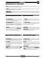 4
4
-
 5
5
-
 6
6
-
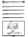 7
7
-
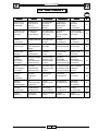 8
8
-
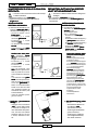 9
9
-
 10
10
-
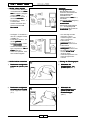 11
11
-
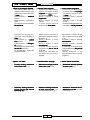 12
12
-
 13
13
-
 14
14
-
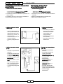 15
15
-
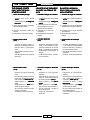 16
16
-
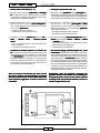 17
17
-
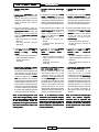 18
18
-
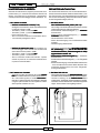 19
19
-
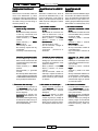 20
20
-
 21
21
-
 22
22
-
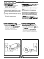 23
23
-
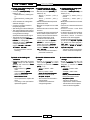 24
24
-
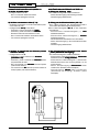 25
25
-
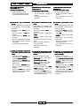 26
26
-
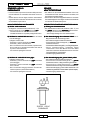 27
27
-
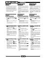 28
28
-
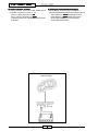 29
29
-
 30
30
-
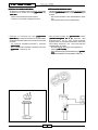 31
31
-
 32
32
-
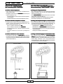 33
33
-
 34
34
-
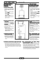 35
35
-
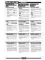 36
36
-
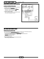 37
37
-
 38
38
-
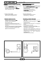 39
39
-
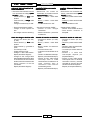 40
40
-
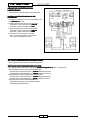 41
41
-
 42
42
-
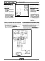 43
43
-
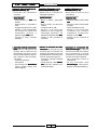 44
44
-
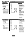 45
45
-
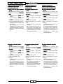 46
46
-
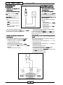 47
47
-
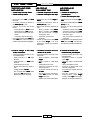 48
48
-
 49
49
-
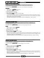 50
50
-
 51
51
-
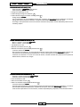 52
52
-
 53
53
-
 54
54
-
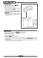 55
55
-
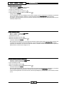 56
56
-
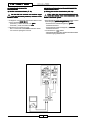 57
57
-
 58
58
-
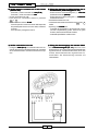 59
59
-
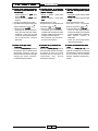 60
60
-
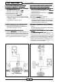 61
61
-
 62
62
-
 63
63


Malaguti F18 WARRIOR Electric System Troubleshooting
- Categoría
- Probadores de redes de cable
- Tipo
- Electric System Troubleshooting
en otros idiomas
- français: Malaguti F18 WARRIOR
- italiano: Malaguti F18 WARRIOR
- English: Malaguti F18 WARRIOR
- Deutsch: Malaguti F18 WARRIOR
Artículos relacionados
-
Malaguti F18 WARRIOR Manual de usuario
-
-
-
-
-
Malaguti MADISON 180-200 Manual de usuario
-
-
-
-