9
-
Courtesy Light.
A light that illuminates
the manoeuvring zone; after an open-
ing command, the light remains on for
a fixed time of 5 minutes and 30 sec-
onds (E-EX), see page 15;
-"
Operator present" function:
Gate
operates only when the pushbutton is
held down (the radio remote control
system is deactivated);
-
Pre-flashing
for 5 seconds, while the
door is opening and closing;
-
Master function
; the panel assumes
all the command functions when two
paired motors are used (see page 24);
-
Slave function
; this panel is exclu-
sively controlled by the “MASTER” (see
page 24);
-
Enabling
functions of partial stop or
re-closure during opening, normally-
closed contact (2-CX), select one of the
two functions by setting dip (see
selection of functions);
-
Type of command:
-open-close-reverse by button and
transmitter;
-open-stop-close-stop by button and
transmitter;
-open only by transmitter.
Adjustments
- Automatic closure time;
- Partial opening time.
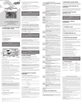
The power supply to the circuit should
be connected to terminals R, S and T,
and is protected by a 8A fuse on the
main power line. The ZT4 control panel
is factory set for 380V power supply. If
the power supply is 220V, it is
necessary to move the jumper which
short-circuit terminals «380» and
«COM» so that it short-circuits
terminals «220» and «COM» (see
pag.7). The Control systems are
powered by low voltage and protected
with a 2A fuse. The total power
consumption of 24 V accessories must
not exceed 20W.
Fixed operating time of 150 seconds.
Safety
Photocells can be connected to obtain:
-
Re-opening
during the closing cycle
(2-C1);
-
Re-closing
during the opening cycle
(2-CX, see dip 8-9);
-
Partial stop
, shutdown of moving gate,
with activation of an automatic closing
cycle (2-CX, see dip 8-9);
-
Total stop
(1-2), shutdown of gate
movement without automatic closing; a
pushbutton or radio remote control
must be actuated to resume movement;
N.B
: If an NC safety contact (2-C1, 2-
CX, 1-2) is opened, the LED will flash to
indicate this fact;
safety devices (for example, the
photocells);
-
Obstacle presence detection.
When
the motor is stopped (gate is closed,
open or half-open after an emercency
stop command), the transmitter and the
control pushbutton will be deactivated
if an obstacle is detected by one of the
safety devices (for example, the
photocells);
-
Safety test function.
The control unit
will now check the safety system every
time an opening or closing command
is given (see pag.14).
Accessories which can be
connected
-Cycle lamp or courtesy light (60 Watt,
see pag.15);
Other functions
-
Automatic closing:
The automatic
closing timer is automatically activated
at the end of the opening cycle. The
preset, adjustable automatic closing
time is automatically interrupted by the
activation of any safety system, and is
deactivated after a STOP command or
in case of power failure;
-
Partial opening.
Opening of the gate
to allow for foot traffic; activated by
connecting to terminals 2-3P and
adjusted with the AP-PARZ. trimmer.
With this function, the automatic closing
can vary in the following way:
1) Dip 12 set to ON: after a partial open-
ing, the time for automatic closing func-
tions independently of the adjustment
of the TCA trimmer and of the position
of Dip 1; it is set at 8 seconds.
2) Dip 12 set to OFF: after a partial
opening, the time for automatic clos-
ing is adjustable only if Dip 1 is set to
ON.
-
Cycle lamp.
The lamp which lights the
manoeuvring zone: it remains lit from
the moment the doors begin to open
until they are completely closed
(including the time required for the
automatic closure). In case automatic
closure is not enabled, the lamp
remains lit only during movement (E-
EX), see p.15;
DESCRIPTION ZT4 CONTROL PANEL
ENGLISH
Important! Disconnect the unit
from the main power lines before
carrying out any operation inside the
unit.