Key Automation 580BOXLED Manual de usuario
- Tipo
- Manual de usuario

Istruzioni ed avvertenze per l’installazione e l’uso
Instructions and warnings for installation and use
Instrucciones y advertencias para su instalación y uso
Anleitungen und Hinweise zu Installation und Einsatz
Instruções e advertências para a instalação e utilização
Instructions et avertissements pour l’installation et l’usage
Management
System
ISO 9001:2008
www.tuv.com
ID 9105043769
Centrale per il controllo di luci a LED
Control unit for LED lights
Logique de commande pour le contrôle des lampes à LED
Central para el control de las luces por LED
Steuerung zur Kontrolle der LED-Lichter
Unidade para controlo de luzes a LED
Centralka do sterowania oświetleniem diodami LED
BOXLED

I
1 - AVVERTENZE PER LA SICUREZZA
Per la sicurezza delle persone è importante rispettare queste istru-
zioni e conservarle per utilizzi futuri.
Leggere attentamente le istruzioni prima di eseguire l’installazione.
La progettazione e la fabbricazione dei dispositivi che compongo-
no il prodotto e le informazioni contenute nel presente manuale ri-
spettano le normative vigenti sulla sicurezza. Ciò nonostante un’in-
stallazione e una programmazione errata possono causare gravi
ferite alle persone che eseguono il lavoro e a quelle che useranno
l’impianto. Per questo motivo, durante l’installazione, è importante
seguire attentamente tutte le istruzioni riportate in questo manuale.
2 - INTRODUZIONE AL PRODOTTO
La centrale di comando BOXLED, insieme al sensore notte QUADRO, per-
mette l’accensione e lo spegnimento automatico delle luci da giardino a led
Key Automation.
BOXLED aziona automaticamente durante le ore notturne no a 20 luci led
(FIG.1), BOXLED XL no a 64 luci led (FIG.2).
Il sistema (Night Light System) accende o spegne le luci dopo 15 minuti dal
superamento della soglia impostata.
Con la centrale è possibile regolare l’intensità della luce di ciascuna uscita
su 5 livelli di intensità mantenendo premuto il tasto del trasmettitore o degli
ingressi a pulsante associati. L’intensità della luce impostata verrà memo-
rizzata anche per le successive accensioni.
CODICE DESCRIZIONE
BOXLED Centrale per controllo luci a led Key Automation, no a 20 luci
BOXLEDXL Centrale per controllo luci a led Key Automation, no a 64 luci
CARATTERISTICHE
ELETTRICHE BOXLED BOXLED XL
alimentazione Vac 90 ~ 260 50-60 Hz 90 ~ 260 50-60 Hz
potenza max W 25 100
potenza stand-by W <0,5 <0,5
carico massimo
uscite 24
Vdc
25W MAX
1=20W (MAX 40W)
2=20W
3=20W
4= 20W (MAX 40W)
80W MAX TOTALI
5 luci da 18 led per
ognuna delle 4 uscite
20 luci da 18 led per
1 uscita
16 luci da 18 led per
ognuna delle 4 uscite
32 luci da 18 led per
uscite 1 e 4
CARATTERISTICHE
GENERICHE BOXLED BOXLED XL
grado di protezione IP 54 54
dimensioni (L - P - H) mm 160 - 90 - 200 222 - 110 - 275
temperatura di
esercizio °C -20 + 55 -20 + 55
N° max trasmettitori
memorizzabili 30 trasmettitori 30 trasmettitori
SPECIFICHE TECNICHE CAVI ELETTRICI
Utilizzare CAVO DUE POLI di adeguata sezione per ogni singola uscita,
tutti i comuni devono arrivare ed essere uniti all’interno della centrale
3 - VERIFICHE PRELIMINARI
Prima di installare il prodotto vericare e controllare i seguenti
punti:
• Posizionare il sensore notte QUADRO in una zona prevalente-
mente soleggiata
• Fissare BOXLED in posizione riparata e non esposta diretta-
mente alla luce solare
• Utilizzare collegamenti elettrici adeguati alle correnti richieste
• Vericare che l’alimentazione rispetti i valori delle caratteristi-
che tecniche.
4 - INSTALLAZIONE DEL PRODOTTO
COLLEGAMENTI ELETTRICI
• Progettare e disegnare l’impianto sulla pianta del proprio giardino (Fig.3),
avendo cura di vericare preventivamente il numero massimo di luci per
ogni zona e la lunghezza massima e conseguente sezione di ogni cavo.
Fare attenzione al numero di massimo di luci collegabili.
ATTENZIONE !
ATTENZIONE !
SEZIONE CAVO PER SINGOLA USCITA (U1)
LUNGHEZZA
[M]
NUMERO LUCI
1 - 5 6 -10 11 - 20 21 - 32
10 2X0,75
H05RNF 2X0,75
H05RNF 2X0,75
H05RNF 2X0,75
H05RNF
15 2X0,75
H05RNF 2X0,75
H05RNF 2X0,75
H05RNF
2X1
H05RNF
H07RNF
25 2X0,75
H05RNF 2X0,75
H05RNF
2X1
H05RNF
H07RNF
2X1,5
H07RNF
50 2X0,75
H05RNF
2X1
H05RNF
H07RNF
2X1,5
H07RNF 2X1,5
H07RNF
75 2X0,75
H05RNF
2X1
H05RNF
H07RNF
2X2,5
H07RNF 2X2,5
H07RNF
100 2X1
H05RNF
H07RNF
2X1,5
H07RNF 2X2,5
H07RNF 2X2,5
H07RNF
BOXLED BOXLED XL
TABELLA 2
Luci Max totali Luci Max mod. TONDA
BOXLED 20 (25W) 4 TOTALI
BOXLEDXL 64 (80W) 5X2 CANALI (10 TOTALI)
ESEMPIO LUCI MASSIME PER USCITA
1234
BOXLED 20 0 0 0
BOXLEDXL 32 0 0 32
ESEMPIO LUCI MASSIME CON LAMPADA TONDA
1234
BOXLED 4 (TONDA) 3 3 2
BOXLEDXL 5 (TONDA) 17 17 5 (TONDA)
Il numero di luci corrisponde al numero di strisce led da 18 led cia-
scuna all’interno di ogni lampada e NON corrisponde necessaria-
mente al numero di lampade (seguire TABELLA 1 e Fig.4)
TABELLA 1
STIKDW, STIKDB, STIKDD, STIKUW, STIKUB, STIKUD,
STIKMW, STIKMB, STIKMD, STIKFW, STIKFB, STIKFD,
STIKVW, STIKVB, STIKVD 1 LUCE
STIKTW, STIKTB, STIKTD 2 LUCI
TONDA* 3 LUCI
ST60, ST100 4 LUCI
*Il livello di luce non è regolabile (sempre 100%)
• Una volta conteggiato il numero totale di luci vericare se il modello di
BOXLED scelto sia adeguato seguendo TABELLA 2
• Posizionare la centrale in una zona che possa essere sempre a vista dal-
la posizione in cui si desidera azionare il trasmettitore radio. Tutti i colle-
gamenti dalla centrale alle luci sono in bassissima tensione di sicurezza
(Fig.5).
• Posizionare il sensore notte in prossimità della centrale in zona soleggia-
ta, collegarlo tra COM e SEN (Fig. 1 e 6). Il collegamento è in bassissima
tensione di sicurezza.
• Collegare le luci in parallelo all’uscita desiderata tra COM e 1, tra COM e
2, tra COM e 3, tra COM e 4 (Fig. 1). Fare attenzione al numero massimo
di luci collegabili ad ogni uscita (Tab.2). Per la giunzione dei cavi si può
utilizzare il connettore preisolato autospellante opzionale 3MJ (sezione max
1,5 mm²) (Fig. 7).
• Collegare gli eventuali pulsanti di tipo “monostabile” in bassissima tensio-
ne agli ingressi dedicati tra COM e INP1, tra COM e INP2, tra COM e INP3
o tra COM e INP4 (Fig. 1). Ogni pulsante controlla la relativa zona. Man-
tenendo il pulsante premuto viene regolata l’intensità della relativa zona.
• Collegare la spina di alimentazione (Fig.8). L’alimentazione della centrale
può variare fra 90 – 260 Vac. Se non fosse possibile utilizzare la spina di
alimentazione in dotazione chiamare un elettricista professionista per il col-
legamento alla rete elettrica;
NON manomettere la spina di alimentazione e NON collegare
l’alimentazione di rete se non si è un elettricista professionista!
Per ognuno dei cavi collegati alla centrale deve essere utilizzato
un pressacavo di dimensioni appropriate. Inoltre per impedire
l’ingresso di condensa, acqua o roditori, l’entrata cavi deve esse-
re adeguatamente sigillata utilizzando specici gel o materiali per
la protezione di vie cavi.
• Procedere alla programmazione della centrale nel paragrafo successivo
ATTENZIONE !
ATTENZIONE !

I
FASE DESCRIZIONE ESEMPIO
1
Premere e rilasciare il pulsante RADIO per
un numero di volte uguale all’uscita che si
vuole attivare:
1 volta per l’uscita 1,
2 volte per l’uscita 2,
3 volte per l’uscita 3,
4 volte per l’uscita 4,
5 volte per l’uscita PREIMPOSTATA (tasto
1= uscita 1, tasto 2 = uscita 2, tasto 3 =
uscita 3, tasto 4 = uscita 4)
+ +
+
2Il LED D2 eettua un numero di lampeggi
corrispondente all’uscita selezionata inter-
vallati da una pausa di 1 secondo
+ 1s + 1s
3
Entro 10 secondi premere per almeno 2 se-
condi il tasto del radiocomando che si vuole
memorizzare
2s
4Se la memorizzazione è andata a buon ne
il LED D2 emetterà un lampeggio lungo 3s
5Per memorizzare un altro radiocomando
sulla stessa uscita ripetere il punto 3
Nota
Dopo 7 secondi di inattività la centrale esce
automaticamente dalla fase di programma-
zione
CANCELLAZIONE SINGOLO TRASMETTITORE
FASE DESCRIZIONE ESEMPIO
1
Premere il pulsante RADIO no a quando si
accende il LED (circa 3 secondi). Rilasciare
il tasto
(>3s) ->
2
Entro 10 secondi premere un tasto del
radiocomando che si vuole cancellare no
a quando il LED D2 si spegne. Rilasciare il
tasto del radiocomando
->
3Dopo circa 1 secondo dal rilascio del tasto il
LED D2 comincia a lampeggiare 0,5s 0,5s
4Confermare la cancellazione premendo il
pulsante RADIO
5Se la cancelllazione è andata a buon ne il
LED D2 emetterà 1 lampeggio lungo 3s
Nota Dopo 7 secondi di inattività la centrale esce
automaticamente dalla fase di cancellazione
CANCELLAZIONE TOTALE CODICI RADIO
FASE DESCRIZIONE ESEMPIO
1
Premere e mantenere premuto il pulsante
RADIO no a quando si accende il LED D2
(circa 2 secondi) e poi si spegne (circa 2
secondi). Rilasciare il tasto
(>3s) -> (>3s) ->
2Dopo circa 1 secondo dal rilascio del tasto il
LED D2 inizia a lampeggiare (+1s) +
3
Per la cancellazione di tutta la memoria
premere il tasto RADIO in corrispondenza
del terzo lampeggio
4Se la cancelllazione è andata a buon ne il
LED D2 emetterà 1 lampeggio lungo 3s
RESET CENTRALE
PARAMETRI DI DEFAULT VALORI DEFAULT
INTENSITÀ LED CANALE 1
INTENSITÀ LED CANALE 2
INTENSITÀ LED CANALE 3
INTENSITÀ LED CANALE 4
1 - 6
1 - 6
1 - 6
1 - 6
3
3
3
3
OUTPUT 1 SENSORE LUCE ATTIVO
OUTPUT 2 SENSORE LUCE ATTIVO
OUTPUT 3 SENSORE LUCE ATTIVO
OUTPUT 4 SENSORE LUCE ATTIVO
1 - 2
1 - 2
1 - 2
1 - 2
2
2
2
2
LIVELLO LUCE AMBIENTE 1-3 2
PROGRAMMAZIONE CON DISPLAY ESTERNO OPZIONALE DYL
Oltre che con i pulsanti a bordo della centrale, il sistema può essere
programmato anche con il display esterno opzionale DYL. Alcune funzioni
avanzate possono essere programmate solo tramite DYL (Fig.9-IT)
REGOLAZIONE INTENSITÁ LUCE LED/FUNZIONE TONDA
Questa programmazione consente di regolare l’intensità della luce dei led
durante la notte.
Dopo aver memorizzato un trasmettitore a 4 canali sarà possibile regolare
l’intensità di ogni uscita associata mantenendo premuto il tasto del trasmet-
titore. Rilasciato il tasto l’intensità della luce impostata verrà memorizzata
anche per le successive accensioni
FASE DESCRIZIONE ESEMPIO
1
Premere e rilasciare il pulsante MENU per
un numero di volte uguale all’uscita che si
vuole attivare:
1 volta per l’uscita 1,
2 volte per l’uscita 2,
3 volte per l’uscita 3,
4 volte per l’uscita 4
+ + +
2Il LED D1 eettua un numero di lampeggi
corrispondente all’uscita selezionata inter-
vallati da una pausa di 1 secondo
+ + +
3Premere e mantenere premuto il pulsante
MENU per più di 3 secondi >3s
4Il led rimane spento
5Rilasciare il pulsante MENU
6
Il led inizierà ad eseguire dei lampeggi lenti.
Premere il pulsante MENU in corrisponden-
za del livello desiderato
1° lampeggio:livello 1 (bassa luminosità)
2° lampeggio:livello 2
3° lampeggio:livello 3 (default di fabbrica)
4° lampeggio:livello 4
5° lampeggio:livello 5 (alta luminosità)
6° lampeggio funzione TONDA:
ATTENZIONE in questa modalità non è
possibile impostare il livello di luce
+ + +
+ +
7Dopo aver premuto il pulsante MENU, Il LED
D1 eseguirà 4 lampeggi veloci
x4
REGOLAZIONE LIVELLO LUCE AMBIENTE
Questa programmazione consente di regolare l’intervento del sensore luce
in base al livello di luce ambientale
FASE DESCRIZIONE ESEMPIO
1Premere cinque volte il pulsante MENU x5
2Il LED D1 esegue cinque lampeggi veloci
seguiti da una pausa x5
3Premere e mantenere premuto il pulsante
MENU per più di 3 secondi >3s
4Il led rimane spento
5Rilasciare il pulsante MENU
6
Il led inizierà ad eseguire 3 lampeggi lenti.
Premere il pulsante MENU in corrisponden-
za del livello desiderato
1° lampeggio:livello 1(attivazione con bassa
luminosità ambientale)
2° lampeggio:livello 2 (attivazione con media
luminosità ambientale - default di fabbrica)
3° lampeggio:livello 3 (attivazione con alta
luminosità ambientale)
+ +
7Dopo aver premuto il pulsante MENU, Il LED
D1 eseguirà 4 lampeggi veloci x4
PROGRAMMAZIONE DELLE 4 USCITE (1, 2, 3, 4) TRAMITE DYL
Tramite il display programmatore esterno DYL è possibile escludere ogni
singola uscita dal funzionamento con sensore notte QUADRO.
Impostando il valore a 1 il sensore viene escluso e l’attivazione dell’uscita
avverrà solamente tramite trasmettitore oppure tramite pulsante via lo.
Impostando il valore a 2 (default) l’attivazione dell’uscita avverrà tramite
sensore notte QUADRO. In questo caso è possibile cambiare lo stato
dell’uscita tramite trasmettitore o pulsante ma il giorno successivo il senso-
re ritornerà ad attivare l’uscita in modo automatico.
PROGRAMMAZIONE TRASMETTITORI
ATTENZIONE: quando BOXLED viene alimentato il LED D2 emetterà dei
lampeggi che corrispondono alla tipologia di codica radio impostata:
1 lampeggio lungo=nessuna codica radio impostata
2 lampeggi=FIX CODE
3 lampeggi=ROLLING CODE
FASE DESCRIZIONE ESEMPIO
1
Premere e mantenere premuto il pulsante
MENU no a quando si accende il LED D1
(circa 3 secondi) e poi si spegne (circa 3
secondi). Rilasciare il tasto
(>3s) -> (>3s) ->
2Dopo circa 1 secondo dal rilascio il LED D1
inizia a lampeggiare (1s) + (1s) +
3
Per il reset e reimpostazione valori di fabbri-
ca premere il tasto MENU in corrispondenza
del terzo lampeggio
4Se il reset è andato a buon ne il LED D1
eseguirà 4 lampeggi veloci x4

I
MESSAGGI DI ERRORE
2 lampeggi veloci LED D1 + pausa = SOVRACCARICO USCITA 1
3 lampeggi veloci LED D1 + pausa = SOVRACCARICO USCITA 2
4 lampeggi veloci LED D1 + pausa = SOVRACCARICO USCITA 3
5 lampeggi veloci LED D1 + pausa = SOVRACCARICO USCITA 4
6 lampeggi veloci LED D1 + pausa = ECCESSIVA TEMPERATURA
L’errore si resetta disalimentando la centrale.
5 - COLLAUDO E MESSA IN SERVIZIO
L’impianto può essere messo in servizio dopo il collaudo di un tecnico qua-
licato che deve eettuare le prove richieste dalla normativa di riferimento
in funzione dei rischi presenti, vericando il rispetto di quanto previsto dalle
normative dell’applicazione.
ESCLUSIONE FUNZIONAMENTO CREPUSCOLARE SULL’USCITA
Tramite questa programmazione è possibile escludere il funzionamento
crepuscolare sull’uscita desiderata. All’esclusione del crepuscolare l’uscita
funzionerà solamente tramite comando radio oppure tramite l’ingresso della
scheda.
FASE DESCRIZIONE ESEMPIO
1
Premere e rilasciare il pulsante MENU per
un numero di volte specico relativo all’usci-
ta sulla quale si vuole disattivare il funziona-
mento con crepuscolare:
6 volte uscita 1,
7 volte uscita 2,
8 volte uscita 3,
9 volte uscita 4,
+ + +
2Il LED D1 eettua un numero di lampeggi
corrispondente al numero di pressioni ese-
guite intervallati da una pausa di 1 secondo
+ + +
3Premere e mantenere premuto il pulsante
MENU per più di 3 secondi >3s
4Il led rimane spento
5Rilasciare il pulsante MENU
6
Il led inizierà ad eseguire 2 lampeggi lenti.
Premere il pulsante MENU in corrisponden-
za del livello desiderato
1° lampeggio crepuscolare disattivato
2° lampeggio crepuscolare attivato
+
7 Dopo aver premuto il pulsante MENU, Il LED
D1 eseguirà 4 lampeggi veloci x4
ESCLUSIONE FUNZIONAMENTO CREPUSCOLARE TEMPORANEO
SU DI UN’USCITA
Per escludere temporaneamente il funzionamento del sensore crepuscola-
re su di una uscita mantenere premuto l’ingresso corrispondente all’uscita
da escludere per più di 35 secondi.
A questo punto l’uscita verrà spenta per tutto il tempo in cui l’ingresso sarà
attivo. Alla disattivazione dell’ingresso sarà ripristinato il normale funziona-
mento.

EN
1 - SAFETY WARNINGS
To ensure personal safety it is important to follow these instructions
and keep them for future reference.
Read the instructions carefully before proceeding with installation.
The design and manufacture of the devices making up the product
and the information in this manual are compliant with current safe-
ty standards. However, incorrect installation or programming may
cause serious injury to those working on or using the system. Com-
pliance with the instructions provided here when installing the pro-
duct is therefore extremely important.
2 - INTRODUCING THE PRODUCT
In combination with the QUADRO light sensor, BOXLED control unit is
able to switch the Key Automation LED garden lights on and o automati-
cally.
BOXLED is able to operate up to 20 LED lights automatically during the
hours of darkness (FIG.1), BOXLED XL up to 64 LED lights (FIG.2).
The Night Light System turns the lights on or o 15 minutes after the set
threshold is exceeded.
The control unit enables the user to dim the led light of each output to 5
dierent brightness settings, by simply pressing and holding the transmit-
ter button or associated button inputs. The set led light brightness will be
memorised for subsequent activations
CODE DESCRIPTION
BOXLED Key Automation led light control unit, up to 20 lights
BOXLEDXL Key Automation led light control unit, up to 64 lights
ELECTRICAL DATA BOXLED BOXLED XL
power supply Vac 90 ~ 260 50-60 Hz 90 ~ 260 50-60 Hz
max power W25 100
power stand-by W<0,5 <0,5
maximum output load 24Vdc
25W MAX
1=20W (MAX 40W)
2=20W
3=20W
4= 20W (MAX
40W)
80W MAX TOTAL
five 18-led lights
for each of the 4
outputs /
twenty 18-led lights
for 1 output
sixteen 18-led
lights for each of
the 4 outputs /
thirty-two 18-led
lights for outputs
1, 4
GENERIC DATA BOXLED BOXLED XL
protection degree IP 54 54
dimensions (L - D - H) mm 160 - 90 - 200 222 - 110 - 275
operating temperature °C -20 + 55 -20 + 55
max. number of transmitters
storage 30 transmitters 30 transmitters
ELECTRIC CABLE TECHNICAL SPECIFICATIONS
Use a TWO-WIRE CABLE of suitable gauge for every single output; all the
common wires must arrive and be interconnected inside the control unit.
3 - PRELIMINARY CHECKS
Before installing the product, perform the following checks and in-
spections:
• Position the QUADRO night-light sensor in a sunny area
• Fix the BOXLED in a sheltered location not exposed to direct
sunlight
• Use electrical connections suitable for the currents required
• Check that the power supply conforms to the values in the techni-
cal specications
4 - INSTALLING THE PRODUCT
ELECTRIC CONNECTIONS
• Plan and design the system on the plan of your garden (Fig.3), taking
care to check the maximum number of lights for each zone and the
maximum length and consequent gauge of each cable in advance. Do not
exceed the maximum number of connectible lights.
The number of lights refers to the number of strips of 18 LEDs each
inside each lamp and does NOT necessarily correspond to the
number of lamps (refer to TABLE 1 and Fig.4)
TABLE 1
STIKDW, STIKDB, STIKDD, STIKUW, STIKUB, STIKUD,
STIKMW, STIKMB, STIKMD, STIKFW, STIKFB, STIKFD,
STIKVW, STIKVB, STIKVD 1 LIGHT
STIKTW, STIKTB, STIKTD 2 LIGHTS
TONDA* 3 LIGHTS
ST60, ST100 4 LIGHTS
*Light intensity is not adjustable (always 100%)
• After counting the total number of lights verify if the model of BOXLED
chosen is correct referring to TABLE 2
BOXLED BOXLED XL
• Place the control unit in a zone which is always visible from the position
where you intend to operate the radio transmitter. All connections from the
control unit to the lights are in safety extra-low voltage (Fig.5).
• Place the light sensor close to the control unit in a sunny position; con-
nect it between COM and SEN (Fig. 1 and 6). The connection is at safety
extra-low voltage.
• Parallel-connect the lights to the chosen output between COM and 1,
between COM and 2, between COM and 3 or between COM and 4 (Fig.
1). Do not exceed the maximum number of connectible lights for each
output (Tab.2). Cables can be joined together using the optional self-strip-
ping, pre-insulated connector 3MJ (max gauge1.5 mm²) (Fig. 7).
• Connect any extra-low voltage “hold-to-run” buttons to the specic inputs
between COM and INP1, between COM and INP2, between COM and
INP3 or between COM and INP4 (Fig. 1). Every button controls the relative
zone. Holding the button down dims the lights in the relative zone.
• Connect the power supply plug (Fig.8). The control unit power supply is
at voltage 90 – 260 Vac. If it is not possible to use the power supply plug
provided, have the mains connection made by a qualied electrician.
DO NOT tamper with the power supply plug and DO NOT connect
the mains power supply unless you are a qualied electrician!
For each of the cables connected to the control unit, an appro-
priately sized cable gland must be used. Furthermore, to prevent
condensation, water inltration or rodents entry, the entrance
must be sealed using specic gels.
• Program the control unit as described in the next point
CAUTION !
CAUTION !
CAUTION !
CAUTION !
CABLE GAUGE FOR SINGLE OUTPUTS (U1)
LENGTH [M] NUMBER OF LIGHTS
1 - 5 6 -10 11 - 20 21 - 32
10 2X0,75
H05RNF 2X0,75
H05RNF 2X0,75
H05RNF 2X0,75
H05RNF
15 2X0,75
H05RNF 2X0,75
H05RNF 2X0,75
H05RNF
2X1
H05RNF
H07RNF
25 2X0,75
H05RNF 2X0,75
H05RNF
2X1
H05RNF
H07RNF
2X1,5
H07RNF
50 2X0,75
H05RNF
2X1
H05RNF
H07RNF
2X1,5
H07RNF 2X1,5
H07RNF
75 2X0,75
H05RNF
2X1
H05RNF
H07RNF
2X2,5
H07RNF 2X2,5
H07RNF
100 2X1
H05RNF
H07RNF
2X1,5
H07RNF 2X2,5
H07RNF 2X2,5
H07RNF
TABLE 2
Max. total lights Max. lights mod. TONDA
BOXLED 20 (25W) 4 TOTALS
BOXLEDXL 64 (80W) 5X2 CHANNEL (10
TOTALS)
EXAMPLE OF MAXIMUM LIGHTS PER OUTPUT
1234
BOXLED 20 0 0 0
BOXLEDXL 32 0 0 32
EXAMPLE OF MAXIMUM LIGHTS WITH TONDA LIGHT
1234
BOXLED 4 (TONDA) 3 3 2
BOXLEDXL 5 (TONDA) 17 17 5 (TONDA)

EN
PROGRAMMING WITH OPTIONAL DYL EXTERNAL DISPLAY
Apart from with the buttons on the control unit, the system can also be
programmed with the optional DYL external display. Some advanced fun-
ctions can only be programmed using the DYL (Fig.9-EN)
ADJUST LED BRIGHTNESS/TONDA FUNCTION
This setting enables adjustment of the led intensity during night-time
hours.
After memorising a 4-channel transmitter, the brightness of each asso-
ciated output can be adjusted as required by pressing and holding the
transmitter button. On release of the button, the light brightness will also
be memorised for subsequent activations
PH. DESCRIPTION EXAMPLE
1
Press and release the MENU button a
number of times equal to the number of the
output to be activated:
once for output 1,
twice for output 2,
three times for output 3,
four times for output 4
+ + +
2The D1 LED will ash a number of times
equal to the number of the output selected,
with 1 second pauses between ashes + + +
3Press and hold the button MENU for more
than 3 seconds >3s
4 The led remains o
5Release button MENU
6
The led emits some slow ashes.
Press the MENU button corresponding to
the required brightness
1st ash: level 1 (low brightness)
2nd ash: level 2
3rd ash: level 3 (factory setting)
4th ash: level 4
5th ash: level 5 (high brightness)
6th ash TONDA function:
ATTENTION in this mode you cannot adjust
light intensity
+ + +
+ +
7After pushing MENU botton, the led emits 4
quick ashes x4
AMBIENT LIGHT LEVEL ADJUSTMENT
This setting enables adjustment of the light sensor activation on the basis
of ambient light.
PH. DESCRIPTION EXAMPLE
1Press the button MENU ve times x5
2LED D1 emits ve quick ashes followed by
a pause x5
3Press and hold the button MENU for more
than 3 seconds >3s
4 The led remains o
5Release button MENU
6
The led emits 3 slow ashes.
Press the MENU button corresponding to
the required brightness
1st ash: level 1(activation with low ambient
light)
2nd ash: level 2 (activation with medium
ambient light - factory setting)
3rd ash: level 3 (activation with high am-
bient light)
+ +
7After pushing MENU botton, the led emits 4
quick ashes x4
PROGRAMMING THE 4 OUTPUTS (1, 2, 3 AND 4) WITH DYL
Operation of each single output with the QUADRO light sensor can be
disabled using the DYL external programmer display.
When the value is set as 1, the sensor is disabled and the output will only
be activated using the transmitter or the button connected by wire.
When the value is set as 2 (default), the output will be activated by the
QUADRO light sensor. In this case, the status of the output can be changed
using the transmitter or button, but the next day automatic control of the
output by the sensor will be restored.
TRANSMITTER PROGRAMMING
CAUTION: when BOXLED is powered, LED D2 will ash a set number of
times corresponding to the type of radio code set:
1 long ash = no radio code set
2 ashes = FIXED CODE
3 ashes = ROLLING CODE
PH. DESCRIPTION EXAMPLE
1
Press and release RADIO button a number
of times equal to the number of the output to
be activated:
once for output 1,
twice for output 2,
three times for output 3,
four times for output 4
ve times for output PRESET (button 1 = ou-
tput 1, button 2 = output 2, button 3 = output
3, button 4 = output 4)
+ +
+
2The LED D2 will ash a number of times
equal to the number of the output selected,
with 1 second pauses between ashes + 1s + 1s
3
Press the key of the remote control to be
memorised within 10 seconds, holding it
down for at least 2 seconds 2s
4If the memorisation has been successful, the
LED D2 will give one long ash 3s
5To memorise another remote control on the
same output, repeat point 3
N.B.
If no commands are given for 7 seconds,
the control board automatically quits the
programming mode
CANCELLATION OF A SINGLE TRANSMITTER
PH. DESCRIPTION EXAMPLE
1
Press the RADIO button on the receiver
until the LED lights up (about 3 seconds).
Release the key (>3s) ->
2
Press the key of the remote control to be de-
leted within 10 seconds, holding it down until
the LED D2 goes out. Release the remote
control key
->
3About 1 second after the key is released, the
LED D2 on the receiver starts to ash 0,5s 0,5s
4Conrm the deletion by pressing the RADIO
button
5If the deletion has been successful, the LED
D2 will give one long ash 3s
N.B.
If no commands are given for 7 seconds, the
control board automatically quits the deletion
mode
COMPLETE CANCELLATION OF RADIO CODES
PH. DESCRIPTION EXAMPLE
1
Press the button RADIO and hold it down
until the LED D2 lights up (about 2 secon-
ds) and then goes out (about 2 seconds).
Release the key
(>3s) -> (>3s) ->
2About 1 second after the key is released, the
LED D2 starts to ash (+1s) +
3To clear the entire memory, press the RA-
DIO button on the third ash
4If the deletion has been successful, the LED
D2 will give one long ash 3s
RESET CONTROL UNIT
DEFAULT PARAMETERS VALUES DEFAULT
CHANNEL 1 LIGHT INTENSITY
CHANNEL 2 LIGHT INTENSITY
CHANNEL 3 LIGHT INTENSITY
CHANNEL 4 LIGHT INTENSITY
1 - 6
1 - 6
1 - 6
1 - 6
3
3
3
3
OUTPUT 1 LIGHT SENSOR
OUTPUT 2 LIGHT SENSOR
OUTPUT 3 LIGHT SENSOR
OUTPUT 4 LIGHT SENSOR
1 - 2
1 - 2
1 - 2
1 - 2
2
2
2
2
AMBIENT LIGHT LEVEL 1-3 2
PH. DESCRIPTION EXAMPLE
1
Press the MENU button and hold it down
until the LED D1 lights up (about 3 secon-
ds) and then goes out (about 3 seconds).
Release the key
(>3s) -> (>3s) ->
2About 1 second after the key is released, the
LED D1 starts to ash (1s) + (1s) +
3To reset and restore the factory settings,
press the MENU button on the third ash
4If the deletion has been successful, the LED
D1 will give four quick ashes x4

EXCLUSION TWILIGHT FUNCTION ON AN OUTPUT
With this programming you can exclude twilight function on the desired ou-
tput. Excluding the twilight function, the output will only work via radio con-
trol or via the input on the control unit.
PH. DESCRIPTION EXAMPLE
1
Press and release the MENU button for a
specic number of times of the output that
you want to turn o twilight function:
6 times output 1,
7 times output 2,
8 times output 3,
9 times output 4,
+ + +
2
The D1 LED performs a number of ashes
corresponding to the number of presses car-
ried out with a pause of 1 second between
ashes.
+ + +
3Press and hold the MENU button for more
than 3 seconds >3s
4 The LED remains OFF
5Release the MENU button
6
The LED will start emitting 2 slow ashes.
Press the MENU button during the ash of
the desired function
1st ash twilight function OFF
2nd ash twilight function ON
+
7After pushing MENU botton, The D1 LED
will perform 4 fast ashes x4
TEMPORARY EXCLUSION TWILIGHT FUNCTION OF AN OUTPUT
To temporarily exclude twilight sensor function on an output, activate the
input corresponding to the output to be excluded for more than 35 seconds.
At this point, the output will be switched o as long as the input is active.
Once the input is no longer activated the output will resume normal opera-
tion.
EN
ERROR MESSAGES
2 rapid ashes on led D1+ PAUSE = overload on output 1
3 rapid ashes on led D1+ PAUSE = overload on output 2
4 rapid ashes on led D1+ PAUSE = overload on output 3
5 rapid ashes on led D1+ PAUSE = overload on output 4
6 quick ashes of LED D1 + pause = OVERHEATING
To reset the error, disconnect the power supply to the control unit.
5 - TESTING AND COMMISSIONING
The system may be put into operation after testing by a qualied technician,
who must perform the tests required by the relevant standards in relation
to the risks present, to check that the installation complies with the relevant
regulatory requirements.

FR
1 - CONSIGNES DE SÉCURITÉ
Pour la sécurité des personnes, il est important de respecter ces
instructions et de les conserver pour pouvoir les consulter ultérieu-
rement.
Lire attentivement les instructions avant d’eectuer l’installation.
La conception et la fabrication des dispositifs qui composent le
produit et les informations contenues dans ce guide respectent les
normes de sécurité en vigueur. Néanmoins, une installation et une
programmation erronées peuvent causer de graves blessures aux
personnes qui exécutent le travail et à celles qui utiliseront l’instal-
lation. C’est pourquoi il est important, durant l’installation, de suivre
scrupuleusement toutes les instructions fournies dans ce guide.
2 - PRÉSENTATION DU PRODUIT
La logique de commande BOXLED, avec le capteur crépusculaire QUA-
DRO, permet d’allumer et d’éteindre automatiquement les lampes de jardin
à LED Key Automation.
BOXLED actionne automatiquement, durant les heures nocturnes, jusqu’à
20 lampes à LED (g. 1), BOXLED XL jusqu’à 64 lampes à LED (g. 2).
Le système (Night Light System) allume ou éteint les lumières au bout de 15
minutes une fois le seuil paramétré dépassé.
Avec la logique de commande BOXLED, il est possible de régler l’intensité
lumineuse des LED de chaque sortie sur 5 niveaux d’intensité grâce à une
pression continue sur la touche de l’émetteur ou des entrées à bouton as-
sociées. L’intensité de la lampe à LED paramétrée sera mémorisée pour les
allumages suivants.
CODE DESCRIPTION
BOXLED Logique de commande pour le contrôle des lampes à LED
Key Automation, jusqu’à 20 lampes
BOXLEDXL Logique de commande pour le contrôle des lampes à LED
Key Automation, jusqu’à 64 lampes
CARACTÉRISTIQUES
ÉLECTRIQUES BOXLED BOXLED XL
alimentation Vac 90 ~ 260 50-60 Hz 90 ~ 260 50-60 Hz
W25 100
W<0,5 <0,5
charge maximale des
sorties 24
Vdc
25W MAX
1=20W (MAX 40W)
2=20W
3=20W
4= 20W (MAX 40W)
80W MAX TOTAUX
5 lumières de 18
LED pour chacune
des 4 sorties / 20
lumières de 18 LED
pour 1 sortie
16 lumières de 18 LED
pour chacune des 4
sorties / 32 lumières
de 18 LED pour sor-
ties 1, 4
PROPIEDADES GENÉRICAS BOXLED BOXLED XL
degré de protection IP 54 54
dimensions (L - P - H) mm 160 - 90 - 200 222 - 110 - 275
température de fonctionnement °C -20 + 55 -20 + 55
N° maximum telecommandes
stockable 30
telecommandes 30
telecommandes
SPÉCIFICATIONS TECHNIQUES DES CÂBLES ÉLECTRIQUES
Utiliser UN CÂBLE À DEUX PÔLES ayant une section adéquate pour cha-
que sortie ; tous les câbles communs doivent pouvoir être réunis à l’intérieur
de la logique de commande.
3 - VÉRIFICATIONS PRÉALABLES
Avant d’installer le produit, vérier et contrôler les points suivants:
• Positionner le capteur nuit QUADRO dans une zone généralement
ensoleillée
• Fixer BOXLED dans une position abritée qui ne soit pas directe-
ment exposée à la lumière du soleil
• Utiliser des câblages électriques adaptés aux courants nécessaires
• Vérier que l’alimentation est conforme aux valeurs des caractéri-
stiques techniques
4 - INSTALLATION DU PRODUIT
BRANCHEMENTS ÉLECTRIQUES
• Concevoir et dessiner l’installation selon le plan de son jardin (g. 3),
en vériant bien au préalable le nombre maximal de lampes pour chaque
zone ainsi que la longueur maximale et donc la section de chaque câble.
Faire attention au nombre maximal de lampes raccordables.
Le nombre de lampes correspond au nombre de bandes de LED de
18 LED chacune à l’intérieur de chaque éclairage mais PAS NÉCES-
SAIREMENT au nombre d’éclairages (suivre le tableau 1 et la g. 4)
TABLEAU 1
STIKDW, STIKDB, STIKDD, STIKUW, STIKUB, STIKUD,
STIKMW, STIKMB, STIKMD, STIKFW, STIKFB, STIKFD,
STIKVW, STIKVB, STIKVD 1 LAMPE
TONDA* 3 LAMPES
STIKTW, STIKTB, STIKTD 2 LAMPES
ST60, ST100 4 LAMPES
*L’intensité de la lumière n’est pas réglable (toujours 100%)
• Une fois calculé le nombre total de lampes, vérier si le modèle BOXLED
choisi est adéquat selon les informations fournies dans le TABLEAU 2.
ATTENTION !
ATTENTION !
ATTENTION !
puissance maximale
puissance stand-by
SECTION DU CÂBLE POUR CHAQUE SORTIE (U1)
LONGUEUR
[M]
NOMBRE DE LAMPES
1 - 5 6 -10 11 - 20 21 - 32
10 2X0,75
H05RNF 2X0,75
H05RNF 2X0,75
H05RNF 2X0,75
H05RNF
15 2X0,75
H05RNF 2X0,75
H05RNF 2X0,75
H05RNF
2X1
H05RNF
H07RNF
25 2X0,75
H05RNF 2X0,75
H05RNF
2X1
H05RNF
H07RNF
2X1,5
H07RNF
50 2X0,75
H05RNF
2X1
H05RNF
H07RNF
2X1,5
H07RNF 2X1,5
H07RNF
75 2X0,75
H05RNF
2X1
H05RNF
H07RNF
2X2,5
H07RNF 2X2,5
H07RNF
100 2X1
H05RNF
H07RNF
2X1,5
H07RNF 2X2,5
H07RNF 2X2,5
H07RNF
TABLEAU 2
Lampes max. totales Lampes max. totales
mod. TONDA
BOXLED 20 (25W) 4 TOTALES
BOXLEDXL 64 (80W) 5X2 CANAUX
(10 TOTALES)
EXEMPLE DE NOMBRE MAXIMAL DE LAMPES PAR SORTIE
1234
BOXLED 20 0 0 0
BOXLEDXL 32 0 0 32
EXEMPLE DE NOMBRE MAXIMAL AVEC LUMIÈRE TONDA
1234
BOXLED 4 (TONDA) 3 3 2
BOXLEDXL 5 (TONDA) 17 17 5 (TONDA)
• Positionner la logique de commande dans une zone où elles sera
toujours à portée de vue depuis la position d’actionnement de l’émetteur
radio. Tous les raccordements de la logique de commande aux lampes
sont en très basse tension de sécurité (g. 5).
• Positionner le capteur crépusculaire à proximité de la logique de com-
mande, dans une zone ensoleillée, et le raccorder entre COM et SEN (g.
1 et 6). Le branchement est en très basse tension de sécurité.
• Raccorder les lampes en parallèle dans la sortie voulue entre COM et
1, COM et 2, COM et 3 ou COM et 4 (g. 1). Faire attention au nombre
maximal de lampes raccordables dans chaque sortie (tableau 2). Pour
la jonction des câbles, il est possible d’utiliser le connecteur pré-isolé
autodénudant en option 3MJ (section max. 1,5 mm²) (g. 7).
• Raccorder d’éventuels boutons de type « monostable » en très basse
tension aux entrées dédiées entre COM et INP1, COM et INP2, COM et
INP3 ou COM et INP4 (g. 1). Chaque bouton contrôle la zone correspon-
dante. La pression continue sur le bouton permet de varier l’intensité des
lampes de la zone correspondante.
• Raccorder la che d’alimentation (g. 8). La logique de commande est
alimentée en tension 90 – 260 Vca. S’il n’est pas possible d’utiliser la che
d’alimentation fournie, appeler un électricien professionnel pour le raccor-
dement de l’alimentation du secteur ;
NE PAS modier la che d’alimentation et NE PAS raccorder
l’alimentation du secteur: toujours s’adresser à un électricien
professionnel!
Pour chacun des câbles connectés à la centrale de commande il
faut utiliser un presse-étoupe de taille appropriée.
En outre, pour empêcher la pénétration de condensat, d’eau ou
de rongeurs, l’entrée de câble doit être correctement scellée en
utilisant des gels ou des matériaux spéciques.
• Eectuer la programmation de la logique de commande décrite au para-
graphe suivant
BOXLED BOXLED XL
ATTENTION !

FR
PROGRAMMATION AVEC ÉCRAN EXTÉRIEUR EN OPTION DYL
Le système peut être programmé non seulement avec les boutons
présents sur la logique de commande mais aussi avec l’écran extérieur en
option DYL. Certaines fonctions avancées ne peuvent être programmées
que grâce au DYL (g. 9-FR).
RÉGLAGE DE L’INTENSITÉ DE LA LUMIÈRE LED/FONCTION TONDA
Cette programmation permet de régler l’intensité des LED durant la nuit.
Une fois un émetteur à 4 canaux mémorisé, il sera possible de régler l’inten-
sité de chaque sortie associée grâce à une pression continue sur la touche
de l’émetteur.
Une fois la touche relâchée, l’intensité de la lumière réglée sera également
mémorisée pour les allumages suivants.
PH. DESCRIPTION EXEMPLE
1
Presser puis relâcher la touche MENU le
nombre de fois correspondant au numéro de
la sortie que l’on veut activer:
1 fois pour la sortie 1,
2 fois pour la sortie 2,
3 fois pour la sortie 3,
4 fois pour la sortie 4
+ + +
2
La LED D1 clignote le nombre de fois cor-
respondant au numéro de la sortie sélec-
tionnée avec une pause d’une seconde entre
chaque clignotement
+ + +
3Presser le bouton MENU et le garder en-
foncé pendant plus de 3 secondes >3s
4La LED reste éteinte
5Relâcher le bouton MENU
6
La LED commencera à eectuer des clignote-
ments lents.
Presser le bouton MENU en correspondance
du niveau souhaité
1er clignotement: niveau 1 (faible luminosité)
2e clignotement: niveau 2
3e clignotement: niveau 3 (réglage par défaut)
4e clignotement: niveau 4
5e clignotement: niveau 5 (forte luminosité)
6e clignotement fonction TONDA :
ATTENTION dans ce mode, il n’est pas
possible de régler l’intensité de la lumière
+ + +
+ +
7Après avoir appuyé sur le bouton MENU, la
LED D1 eectuera 4 clignotements rapides x4
RÉGLAGE DU NIVEAU DE LA LUMIÈRE AMBIANTE
Cette programmation permet de régler l’intervention du capteur de lumière
en fonction de la lumière ambiante
PH. DESCRIPTION EXEMPLE
1Presser cinq fois le bouton MENU x5
2La LED D1 eectue cinq clignotements rapi-
des suivis d’une pause x5
3Presser le bouton MENU et le garder en-
foncé pendant plus de 3 secondes >3s
4La LED reste éteinte
5Relâcher le bouton MENU
6
La LED commencera à eectuer 3 clignote-
ments lents.
Presser le bouton MENU en correspondance
du niveau souhaité
1er clignotement: niveau 1 (activation avec
faible lumière ambiante)
2e clignotement: niveau 2 (activation avec lu-
mière ambiante moyenne - règlement usine)
3e clignotement: niveau 3 (activation avec
forte lumière ambiante)
+ +
7Après avoir appuyé sur le bouton MENU, la
LED D1 eectuera 4 clignotements rapides x4
PROGRAMMATION DES 4 SORTIES (1, 2, 3, 4) GRÂCE AU DYL
L’écran extérieur de programmation DYL permet d’exclure séparément
chaque sortie du fonctionnement avec le capteur crépusculaire QUADRO.
Le réglage de la valeur sur 1 exclut le capteur : l’activation de la sortie
s’eectuera donc uniquement au moyen d’un émetteur ou d’un bouton par
câble.
Le réglage de la valeur sur 2 (par défaut) sélectionne l’activation de la sortie
grâce au capteur crépusculaire QUADRO. Dans ce cas, il est possible de
changer l’état de la sortie grâce à un émetteur ou un bouton mais, le jour
suivant, le capteur réactivera automatiquement la sortie.
PROGRAMMATION ÉMETTEURS
ATTENTION: quand BOXLED est mise sous tension, la LED D2 émet des
clignotements qui correspondent au type de codage radio paramétré:
1 clignotement long=aucun codage radio paramétré
2 clignotements=CODE FIXE
3 clignotements=CODE TOURNANT
PH. DESCRIPTION EXEMPLE
1
Presser puis relâcher la touche RADIO le
nombre de fois correspondant au numéro de
la sortie que l’on veut activer:
1 fois pour la sortie 1,
2 fois pour la sortie 2,
3 fois pour la sortie 3,
4 fois pour la sortie 4,
5 fois pour la sortie PRÉDÉFINIE (bouton
1 = sortie 1, bouton 2 = sortie 2, bouton 3 =
sortie 3, bouton 4 = sortie 4)
+ +
+
2
La LED D2 clignote le nombre de fois cor-
respondant au numéro de la sortie sélec-
tionnée avec une pause d’une seconde entre
chaque clignotement
+ 1s + 1s
3
Dans les 10 secondes qui suivent, presser
pendant au moins 2 secondes la touche de
la radiocommande que l’on veut mémoriser 2s
4Si la mémorisation a été correctement eec-
tuée, le LED D2 émettra un clignotement long 3s
5Pour mémoriser une autre radiocommande
sur la même sortie, répéter le point 3
Rem.
Au bout de 7 secondes d’inactivité, la logique
de commande sort automatiquement de la
phase de programmation
EFFACEMENT D’UN ÉMETTEUR
PH. DESCRIPTION EXEMPLE
1
Presser la touche RADIO jusqu’à ce que la
LED s’allume (3 secondes environ). Relâcher
la touche
(>3s) ->
2
Dans les 10 secondes qui suivent, presser
une touche de la radiocommande que l’on
veut eacer jusqu’à ce que la LED D2 s’étei-
gne. Relâcher la touche de la radiocommande
->
3Environ une seconde après que la touche a été
relâchée, la LED D2 commence à clignoter 0,5s 0,5s
4Conrmer l’eacement en pressant la touche
RADIO
5Si l’eacement a été correctement eectué, le
LED D2 émettra 1 clignotement long 3s
Rem.
Au bout de 7 secondes d’inactivité, la logique
de commande sort automatiquement de la
phase d’eacement
EFFACEMENT TOTAL DES CODES RADIO
PH. DESCRIPTION EXEMPLE
1
Presser sans le relâcher la touche RADIO
jusqu’à ce que la LED D2 s’allume (2 se-
condes environ) puis s’éteigne (2 secondes
environ). Relâcher la touche
(>3s) -> (>3s) ->
2Environ une seconde après que la touche
a été relâchée, la LED D2 commence à
clignoter
(+1s) +
3Pour eacer toute la mémoire, presser la
touche RADIO au troisième clignotement
4Si l’eacement a été correctement eectué,
le LED D2 émettra 1 clignotement long 3s
RÉINITIALISATION LOGIQUE DE COMMANDE
PARAMÈTRES PAR DÉFAUT VALEURS PAR DÉFAUT
INTENSITE LUMIERE CANAL 1
INTENSITE LUMIERE CANAL 2
INTENSITE LUMIERE CANAL 3
INTENSITE LUMIERE CANAL 4
1 - 6
1 - 6
1 - 6
1 - 6
3
3
3
3
OUTPUT 1 CAPTEUR LUMIERE
OUTPUT 2 CAPTEUR LUMIERE
OUTPUT 3 CAPTEUR LUMIERE
OUTPUT 4 CAPTEUR LUMIERE
1 - 2
1 - 2
1 - 2
1 - 2
2
2
2
2
NIVEAU LUMIÈRE AMBIANTE 1-3 2
PH. DESCRIPTION EXEMPLE
1
Presser sans le relâcher la touche MENU
jusqu’à ce que la LED D1 s’allume (3 se-
condes environ) puis s’éteigne (3 secondes
environ). Relâcher la touche
(>3s) -> (>3s) ->
2Environ une seconde après que la touche a été
relâchée, la LED D1 commence à clignoter (1s) + (1s) +
3
Pour la réinitialisation et le réglage des
valeurs d’usine, presser la touche MENU au
troisième clignotement
4Si la réinitialisation a été correctement eectué,
le LED D1 émettra 4 clignotements rapides x4

FR
MESSAGES D’ERREUR
2 clignotements rapides LED D1 + PAUSE = surcharge sortie 1
3 clignotements rapides LED D1 + PAUSE = surcharge sortie 2
4 clignotements rapides LED D1 + PAUSE = surcharge sortie 3
5 clignotements rapides LED D1 + PAUSE = surcharge sortie 4
6 clignotements rapides LED D1 + pause = TEMPÉRATURE TROP
ÉLEVÉE
L’erreur est réinitialisée en mettant la logique de commande hors tension.
5 - RÉCEPTION ET MISE EN SERVICE
L’installation peut être mise en service après l’essai de réception coné à
un technicien qualié, qui doit eectuer les essais prescrits par la norme de
référence en fonction des risques présents et s’assurer que l’installation est
conforme aux dispositions des normes.
EXCLUSION FONCTIONNEMENT CREPUSCULAIRE SUR LA SORTIE
Avec cette programmation, vous pouvez exclure le fonctionnement crépu-
sculaire sur la sortie désirée.
Après l’exclusion du crépusculaire, la sortie ne fonctionnera que par la com-
mande radio ou par l’entrée de la carte.
PH. DESCRIPTION EXEMPLE
1
Appuyez et relâchez le bouton MENU un
nombre de fois correspondant à la sortie
sur laquelle vous souhaitez désactiver le
fonctionnement crépusculaire :
6 fois la sortie 1,
7 fois la sortie 2,
8 fois la sortie 3,
9 fois la sortie 4
+ + +
2
La LED D1 eectue un nombre de cli-
gnotements correspondant au nombre de
pressions eectuées interrompues par une
pause d’une seconde
+ + +
3Maintenez le bouton MENU enfoncé pen-
dant plus de 3 secondes >3s
4 La LED reste éteinte
5Relâchez le bouton MENU
6
La LED commencera à clignoter 2 fois
lentement.
Appuyez sur le bouton MENU au niveau
souhaité
1er clignotement capteur nuit activé
2ème clignotement capteur nuit désactivé
+
7Après avoir appuyé sur le bouton MENU, la
LED D1 eectuera 4 clignotements rapides x4
EXCLUSION FONCTIONNEMENT CREPUSCULAIRE TEMPORAIRE
SUR UNE SORTIE
Pour exclure temporairement le fonctionnement du capteur crépusculaire
sur une sortie, maintenez enfoncée l’entrée correspondant à la sortie à
exclure pendant plus de 35 secondes.
À ce stade, la sortie sera désactivée tant que l’entrée est active. Lorsque
l’entrée sera désactivée, le fonctionnement normal sera rétabli.

ES
1 - AVVERTENZE PER LA SICUREZZA
Para la seguridad de las personas es importante respetar estas
instrucciones y conservarlas para futuros consultaciones.
Lea detenidamente las instrucciones antes de realizar la instala-
ción. El diseño y la fabricación de los dispositivos que compo-
nen el producto y las informaciones contenidas en este manual
respetan las normativas vigentes sobre la seguridad. No obstan-
te esto, una instalación y una programación incorrectas pueden
provocar graves heridas a las personas que realizan el trabajo y
a aquellas que utilizarán el sistema. Por dicho motivo, durante la
instalación es importante respetar escrupulosamente todas las
instrucciones mencionadas en este manual.
2 - INTRODUCCIÓN AL PRODUCTO
La central de mando BOXLED, junto con el sensor noche QUADRO, per-
mite el encendido y apagado automático de las luces de jardín de LED Key
Automation.
BOXLED acciona automáticamente durante la noche hasta 20 luces de
LED (FIG.1), BOXLED XL hasta 64 luces de LED (FIG.2).
El sistema (Night Light System) enciende o apaga las luces después de
15 minutos de superar el umbral congurado. Con la central BOXLED se
puede regular la intensidad de la luz por LED de cada una de las salidas en
5 niveles de intensidad, manteniendo presionado el pulsador del transmisor
o las entradas de pulsador asociadas. La intensidad de la luz del LED regu-
lada queda memorizada inclusive para los siguientes encendidos.
CÓDIGO DESCRIPCIÓN
BOXLED Central para el control de las luces por LED Key Automation,
hasta 20 luces
BOXLEDXL Central para el control de las luces por LED Key Automation,
hasta 64 luces
PROPIEDADES
ELECTRICAS BOXLED BOXLED XL
alimentación Vac 90 ~ 260 50-60 Hz 90 ~ 260 50-60 Hz
W25 100
W<0,5 <0,5
capacidad
máxima de las
salidas
24Vdc
25W MAX
1=20W (MAX 40W)
2=20W
3=20W
4= 20W (MAX 40W)
80W MAX TOTALES
5 luces de 18 LED
en cada una de las
4 salidas / 20 luces
de 18 LED en 1
salida
16 luces de 18 LED
en cada una de las
4 salidas / 32 luces
de 18 LED en salidas
1, 4
PROPIEDADES GENÉRICAS BOXLED BOXLED XL
grados de protección IP 54 54
dimensiones (L - P - A) mm 160 - 90 - 200 222 - 110 - 275
temperatura de servicio °C -20 + 55 -20 + 55
N° máx. de transmisores memori-
zables 30 emisores 30 emisores
ESPECIFICACIONES TÉCNICAS DE LOS CABLES ELÉCTRICOS
Utilice un CABLE DE DOS POLOS de sección adecuada por cada salida,
todos los comunes deben llegar y estar conectados al interior de la central
3 - CONTROLES PRELIMINARES
Antes de instalar el producto, compruebe y controle los siguien-
tes puntos:
• Sitúe el sensor noche QUADRO preferentemente en una zona
soleada
• Fije BOXLED en un lugar seguro y protegido contra la luz direc-
ta del sol
• Utilice conexiones eléctricas adecuadas para las corrientes
requeridas
• Compruebe que la alimentación respete los valores de las ca-
racterísticas técnicas
4 - INSTALACIÓN DEL PRODUCTO
CONEXIONES ELÉCTRICAS
• Proyecte y diseñe el sistema en el plano de su jardín (Fig.3), comproban-
do previamente el número máximo de luces para cada zona y la longitud
máxima y la consiguiente sección de cada cable. Tenga cuidado con el
número máximo de luces que se pueden conectar.
El número de luces corresponde al número de tiras de LED de 18
LED cada una en el interior de cada lámpara y NO corresponde ne-
cesariamente al número de lámparas (observe la TABLA 1 y la Fig.4)
TABLA 1
STIKDW, STIKDB, STIKDD, STIKUW, STIKUB, STIKUD,
STIKMW, STIKMB, STIKMD, STIKFW, STIKFB, STIKFD,
STIKVW, STIKVB, STIKVD 1 LUZ
STIKTW, STIKTB, STIKTD 2 LUCES
TONDA* 3 LUCES
ST60, ST100 4 LUCES
*El nivel de luz no es regulable (siempre 100%)
• Tras haber contado el número total de luces, compruebe si el modelo de
BOXLED elegido sea adecuado observando la TABLA 2
• Coloque la central en una zona que siempre esté a la vista desde la po-
sición en que se desea accionar el transmisor radio. Todas las conexiones
desde la central a las luces son a muy baja tensión de seguridad (Fig.5).
• Coloque el sensor noche en proximidad de la central en una zona solea-
da, conéctelo entre COM y SEN (Figs. 1 y 6). La conexión es a muy baja
tensión de seguridad.
• Conecte las luces en paralelo a la salida deseada entre COM y 1, entre
COM y 2, entre COM y 3, entre COM y 4 (Fig. 1). Tenga cuidado con el
número máximo de luces que se pueden conectar a cada salida (Tab.2).
Para unir los cables se puede utilizar el conector preaislado autopelante
opcional 3MJ (sección máx. 1,5 mm²) (Fig. 7).
• Conecte los pulsadores tipo “monoestable” a muy baja tensión a las
entradas dedicadas entre COM y INP1, entre COM y INP2, entre COM y
INP3 o entre COM y INP4 (Fig. 1). Cada pulsador controla la zona respec-
tiva. Manteniendo presionado el pulsador se puede regular la intensidad
de las luces en la zona respectiva.
• Conecte la clavija de alimentación (Fig.8). La alimentación de la central
tiene una tensión de 90 – 260 Vca. Si no fuera posible utilizar la clavija de
alimentación suministrada, contacte con un electricista profesional para la
conexión de la alimentación de red;
¡NO manipule la clavija de alimentación NI conecte la alimenta-
ción de red si usted no fuera un electricista profesional!
Para cada cable conectado a la central devé ser utilitzado un ja-
cable de dimensiones apropiadas. Además para impedir el ingre-
so de condensación, agua o roedores, la entrada de los cables
debe estar adecuadamente sellada utilizando siliconas especí-
cas o materiales para proteger los cables.
• Proceda con la programación de la central descrita en el siguiente
apartado
ATENCIÓN !
ATENCIÓN !
ATENCIÓN !
ATENCIÓN !
potencia máxima
potencia stand-by
SECCIÓN DEL CABLE PARA CADA SALIDA (U1)
LONGITUD
[M]
NÚMERO DE LUCES
1 - 5 6 -10 11 - 20 21 - 32
10 2X0,75
H05RNF 2X0,75
H05RNF 2X0,75
H05RNF 2X0,75
H05RNF
15 2X0,75
H05RNF 2X0,75
H05RNF 2X0,75
H05RNF
2X1
H05RNF
H07RNF
25 2X0,75
H05RNF 2X0,75
H05RNF
2X1
H05RNF
H07RNF
2X1,5
H07RNF
50 2X0,75
H05RNF
2X1
H05RNF
H07RNF
2X1,5
H07RNF 2X1,5
H07RNF
75 2X0,75
H05RNF
2X1
H05RNF
H07RNF
2X2,5
H07RNF 2X2,5
H07RNF
100 2X1
H05RNF
H07RNF
2X1,5
H07RNF 2X2,5
H07RNF 2X2,5
H07RNF
BOXLED BOXLED XL
TABLA 2
Luces máx. totales Luces máx. totales mod.
TONDA
BOXLED 20 (25W) 4 TOTALES
BOXLEDXL 64 (80W) 5X2 CANALES
(10 TOTALES)
EJEMPLO DE LUCES MÁXIMAS POR SALIDA
1234
BOXLED 20 0 0 0
BOXLEDXL 32 0 0 32
EJEMPLO DE LUCES MÁXIMAS CON LUZ TONDA
1234
BOXLED 4 (TONDA) 3 3 2
BOXLEDXL 5 (TONDA) 17 17 5 (TONDA)

ES
PROGRAMACIÓN MEDIANTE LA PANTALLA EXTERIOR
OPCIONAL DYL
El sistema se puede programar con los pulsadores de la central y con la
pantalla exterior opcional DYL. Algunas funciones avanzadas se pueden
programar solo con DYL (Fig.9-ES)
REGULACIÓN DE INTENSIDAD DE LA LUZ LED/FUNCION TONDA
Por medio de esta programación es posible regular la intensidad de los led
durante la noche.
Tras haber memorizado un transmisor de 4 canales, es posible regular la
intensidad de cada salida asociada manteniendo presionado el pulsador
del transmisor. Al soltar el pulsador, la intensidad de la luz regulada quedará
memorizada para los siguientes encendidos.
FASE DESCRIPCIÓN EJEMPLO
1
Presione y suelte el pulsador MENU durante
un número de veces equivalente a la salida
que se desea activar:
1 vez para la salida 1,
2 veces para la salida 2,
3 veces para la salida 3,
4 veces para la salida 4
+ + +
2El LED D1 realiza un número de destellos
correspondiente a la salida seleccionada,
con un intervalo de pausa de 1 segundo
+ + +
3Pulse y mantenga apretado el pulsador
MENU durante más de 3 segundos >3s
4 El led queda apagado
5Suelte el pulsador MENU
6
El led empezará a hacer unos destellos lentos
Presione el pulsador MENU en el nivel que
le interesa
1° destello:nivel 1 (luminosidad baja)
2° destello:nivel 2
3° destello:nivel 3 (predeterminado de fábrica)
4° destello:nivel 4
5° destello:nivel 5 (luminosidad alta)
6° destello funcion TONDA:
ATENCIÓN en esta modalidad no es posible
ajustar el nivel de luz
+ + +
+ +
7Después de presionar el botón MENU, el
LED D1 destellará 4 veces de manera rápida x4
REGULACIÓN DEL NIVEL DE LUZ AMBIENTAL
Por medio de esta programación es posible regular la activación del sensor
luz según las luz del entorno
FASE DESCRIPCIÓN EJEMPLO
1Pulse cincos veces el pulsador MENU x5
2El LED D1 hace cincos destellos rápidos
seguidos por una pausa x5
3Pulse y mantenga apretado el pulsador
MENU durante más de 3 segundos >3s
4 El led queda apagado
5Suelte el pulsador MENU
6
El led empezará a hacer 3 destellos lentos
Presione el pulsador MENU en el nivel que
le interesa
1° destello:nivel 1 (activación con luminosidad
ambiental baja)
2° destello:nivel 2 (activación con luminosidad
ambiental media – predeterminado de fábrica)
3° destello:nivel 3 (activación con luminosidad
ambiental alta)
+ +
7Después de presionar el botón MENU, El
led destellará 4 veces de manera rápida x4
PROGRAMACIÓN DE LAS 4 SALIDAS (1, 2, 3, 4) MEDIANTE DYL
Con la pantalla de programación exterior DYL se puede desactivar cada
una de las salidas del funcionamiento con sensor noche QUADRO.
Al congurar el valor en 1, el sensor queda desactivado y la salida se acti-
vará únicamente mediante el transmisor o con el pulsador vía cable.
Al congurar el valor en 2 (por defecto), la salida se activará mediante el
sensor noche QUADRO. En este caso es posible cambiar el estado de la
salida mediante el transmisor o pulsador, pero el día siguiente el sensor
volverá a activar la salida de manera automática.
PROGRAMACIÓN DE TRANSMISORES
ATENCIÓN: cuando se alimenta la BOXLED, el LED D2 se encenderá de
manera intermitente de acuerdo con el tipo de codicación radio congu-
rada:
1 destello prolongado = ninguna codicación radio congurada
2 destellos = FIX CODE
3 destellos = ROLLING CODE
FASE DESCRIPCIÓN EJEMPLO
1
Presione y suelte el pulsador RADIO du-
rante un número de veces equivalente a la
salida que se desea activar:
1 vez para la salida 1,
2 veces para la salida 2,
3 veces para la salida 3,
4 veces para la salida 4,
5 veces para la salida PRECONFIGURA-
DO (bóton 1 = salida 1, bóton 2 = salida 2,
bóton 3 = salida 3, bóton 4 = salida 4)
+ +
+
2El LED D2 realiza un número de destellos
correspondiente a la salida seleccionada,
con un intervalo de pausa de 1 segundo
+ 1s + 1s
3
Antes de 10 segundos presione durante
2 segundos como mínimo el pulsador del
radiomando que se desea memorizar 2s
4Si la memorización ha sido correcta, el LED
D2 emitirá un destello prolongado 3s
5Para memorizar otro radiomando en la
misma salida, repita el punto 3
Nota
Transcurridos 7 segundos de inactividad, la
central sale automáticamente de la fase de
programación
BORRADO DE UN TRANSMISOR
FASE DESCRIPCIÓN EJEMPLO
1
Presione el pulsador RADIO hasta que
se encienda el LED (3 segundos aprox.).
Suelte el pulsador
(>3s) ->
2
Presione antes de 10 segundos un pulsador
del radiomando que se desea cancelar
hasta que se apague el LED D2. Suelte el
pulsador del radiomando
->
3
Transcurrido 1 segundo después de haber
soltado el pulsador, el LED D2 comenzará a
destellar
0,5s 0,5s
4Conrme la cancelación presionando el
pulsador RADIO
5Si la cancelación ha sido correcta, el LED
D2 emitirá 1 destello prolongado 3s
Nota
Transcurridos 7 segundos de inactividad, la
central sale automáticamente de la fase de
cancelación
BORRADO TOTAL DE CÓDIGOS RADIO
FASE DESCRIPCIÓN EJEMPLO
1
Presione y mantenga presionado el pulsador
RADIO hasta que se encienda el LED D2
(2 segundos aprox.) y luego se apague (2
segundos aprox.). Suelte el pulsador
(>3s) -> (>3s) ->
2Transcurrido 1 segundo después de haber
soltado el pulsador, el LED D2 comenzará a
destellar
(+1s) +
3Para borrar toda la memoria, presione el
pulsador RADIO en el tercer destello
4Si la cancelación ha sido correcta, el LED
D2 emitirá 1 destello prolongado 3s
RESTABLECER CENTRAL
PARÁMETROS POR DEFECTO VALORES POR DEFECTO
INTENSIDAD LUCES CANAL 1
INTENSIDAD LUCES CANAL 2
INTENSIDAD LUCES CANAL 3
INTENSIDAD LUCES CANAL 4
1 - 6
1 - 6
1 - 6
1 - 6
3
3
3
3
OUTPUT 1 SENSOR LUCES
OUTPUT 2 SENSOR LUCES
OUTPUT 3 SENSOR LUCES
OUTPUT 4 SENSOR LUCES
1 - 2
1 - 2
1 - 2
1 - 2
2
2
2
2
NIVEL LUZ AMBIENTE 1-3 2
FASE DESCRIPCIÓN EJEMPLO
1
Presione y mantenga presionado el pulsador
MENU ìhasta que se encienda el LED D1
(3 segundos aprox.) y luego se apague (3
segundos aprox.). Suelte el pulsador
(>3s) -> (>3s) ->
2Transcurrido 1 segundo después de haber
soltado el pulsador, el LED D1comenzará a
destellar
(1s) + (1s) +
3
Para reajustar y volver a congurar los valo-
res de fábrica, presione el pulsador MENU
durante el tercer destello
4Si la restablecer ha sido correcta, el LED D1
emitirá 4 veces de manera rápida x4

EXCLUSIÓN FUNCIONAMIENTO CREPUSCULAR EN LA SALIDA
A través de esta programación es posible excluir el funcionamiento crepu-
scular en la salidad deseada.
A la exclusión del crepuscular la salida funcionará solamente a través del
emisor o ingreso de la placa.
FASE DESCRIPCIÓN EJEMPLO
1
Pulsar y soltar el botón MENU por un núme-
ro de veces especíco relativo a la salida
que se quiera desactivar el funcionamiento
con crepuscular:
6 veces salida 1,
7 veces salida 2,
8 veces salida 3,
9 veces salida 4,
+ + +
2El LED D1 efectúa un número de destellos
correspondiente al número de presiones se-
guidas a intervalos de pausa de 1 segundo
+ + +
3Pulsar y mantener pulsado el botón MENU
por más de 3 segundos >3s
4El led permanece apagado
5Soltar el botón MENU
6
El led iniciará a efectuar 2 destellos lentos.
Pulsar el botón MENU en correspondencia
del nivel deseado
1º destello crepuscular desactivado
2º destello crepuscular activado
+
7Después de presionar el botón MENU, El
LED D1 efectuará 4 destellos rápidos x4
EXCLUSIÓN FUNCIONAMIENTO CREPUSCULAR TEMPORIZADO EN
UNA SALIDA
Para excluir temporalmente el funcionamiento del sensor crepuscular de
una salida mantener pulsado el ingreso correspondiente a la salida a exclu-
ir por más de 35 segundos.
En este punto la salida vendrá desactivada para todo el tiempo en el que
el ingreso será activo. A la desactivación del ingreso será re-ajustado el
funcionamiento normal.
ES
MENSAJES DE ERROR
2 destellos rápidos LED D1+ pausa=SOBRECARGA SALIDA 1
3 destellos rápidos LED D1+ pausa=SOBRECARGA SALIDA 2
4 destellos rápidos LED D1+ pausa=SOBRECARGA SALIDA 3
5 destellos rápidos LED D1+ pausa=SOBRECARGA SALIDA 4
6 destellos rápidos LED D1 + pausa = TEMPERATURA EXCESIVA
El error se pone a cero cuando se desactiva la central.
5 - ENSAYO Y PUESTA EN SERVICIO
El sistema puede ponerse en servicio después del ensayo realizado por un
técnico calicado que debe realizar las pruebas requeridas por la Norma-
tiva de referencia en función de los riesgos presentes, comprobando la
conformidad de las normativas de la aplicación

DE
1 - SICHERHEITSHINWEISE
Für die Sicherheit von Personen ist es wichtig, diese Anleitung zu
beachten und für zukünftige Nutzungen aufzubewahren.
Vor Durchführung der Installation lesen Sie die Anleitung bitte
aufmerksam durch. Die Konstruktion und die Herstellung der Vor-
richtungen, aus denen das Produkt sich zusammensetzt, und die
in diesem Handbuch enthaltenen Informationen entsprechen den
geltenden Sicherheitsvorschriften. Dennoch können eine falsche
Installation und eine falsche Programmierung schwerwiegende Ver-
letzungen bei Personen verursachen, die die Arbeit ausführen und
bei denen, die die Anlage benutzen werden. Aus diesem Grund ist
es wichtig, während der Installation aufmerksam alle Anweisungen
in diesem Handbuch zu beachten.
2 - EINFÜHRUNG IN DAS PRODUKT
Die Steuerung BOXLED ermöglicht zusammen mit dem Nachtsensor QUA-
DRO die automatische Ein- und Ausschaltung der LED-Gartenlichter von
Key Automation.
BOXLED betätigt während der Nachtstunden automatisch bis zu 20 Led-
Lichter (ABB.1), BOXLED XL bis zu 64 Led-Lichter (ABB.2).
15 Minuten nachdem die eingestellte Zeitschwelle überschritten wurde,
schaltet das System (Night Light System) die Lichter ein oder aus.
Mit der BOXLED-Steuerung ist die Stärke der LED-Lichter eines jeden
Ausganges in 5 Lichtstärken dimmbar; dazu ist die Taste des Senders oder
der zugeordneten Tastereingänge gedrückt zu halten. Die eingestellte LED-
Lichtstärke wird auch für die nächsten Einschaltungen gespeichert.
CODE BESCHREIBUNG
BOXLED Steuerung zur Kontrolle der LED-Lichter von Key Automa-
tion, bis 20 Lichter
BOXLEDXL Steuerung zur Kontrolle der LED-Lichter von Key Automa-
tion, bis 64 Lichter
EIGENSCHAFTEN BOXLED BOXLED XL
Speisung Vac 90 ~ 260 50-60 Hz 90 ~ 260 50-60 Hz
Max. Leistung W25 100
Standby-Leistung W <0,5 <0,5
Max. Belastung der
Ausgänge 24
Vdc
25W MAX
1=20W (MAX 40W)
2=20W
3=20W
4= 20W (MAX 40W)
80W MAX INSGESAMT
5 Lichter mit je 18
Leds für jeden der
4 Ausgänge
20 Lichter mit je 18
Leds für 1 Ausgang
16 Lichter mit je 18
Leds für jeden der 4
Ausgänge
32 Lichter mit je 18
Leds für die Ausgänge
1 und 4
ALLGEMEINE EIGENSCHAFTEN BOXLED BOXLED XL
Schutzgrad IP 54 54
Abmessungen (B – T – H) mm 160 - 90 - 200 222 - 110 - 275
Betriebstemperatur °C -20 + 55 -20 + 55
Max. speicherbare Sender 30 Sender 30 Sender
TECHNISCHE SPEZIFIKATIONEN FÜR ELEKTRISCHE KABEL
Ein ZWEIPOLIGES KABEL mit geeignetem Querschnitt für jeden einzel-
nen Ausgang verwenden, alle gemeinsamen Kabel müssen schließlich im
Innern der Steuerung vereint sein.
3 - VORABPRÜFUNGEN
Prüfen und kontrollieren Sie die folgenden Punkte, bevor Sie mit der
Installation beginnen:
• Den Nachtsensor QUADRO an einer vorwiegend sonnenbestrahl-
ten Stelle positionieren
• BOXLED ist an einer geschützten und keiner direkten Sonnenbe-
strahlung ausgesetzten
Position zu befestigen
• Elektrische Anschlüsse verwenden, die für die geforderten Ströme
geeignet sind
• Prüfen, ob die Versorgung den Werten der technischen Merkmale
entspricht
4 - PRODUKTINSTALLATION
ELEKTRISCHE ANSCHLÜSSE
• Das Anlagenprojekt entwickeln und in das Layout des eigenen Gartens
einzeichnen (Abb.3); dabei zuvor die Höchstzahl der Lichter in jeder Zone,
sowie die Höchstlänge und den Querschnitt jedes Kabels prüfen. Die
Höchstmenge der anschließbaren Lichter beachten!
Die Anzahl der Lichter entspricht der Anzahl Led-Streifen mit je 18
Leds im Innern jeder Lampe, NICHT aber notwendigerweise der An-
zahl der Lampen (TABELLE 1 und Abb.4 befolgen).
TABELLE 1
STIKDW, STIKDB, STIKDD, STIKUW, STIKUB, STIKUD,
STIKMW, STIKMB, STIKMD, STIKFW, STIKFB, STIKFD,
STIKVW, STIKVB, STIKVD 1 LICHT
STIKTW, STIKTB, STIKTD 2 LICHTER
TONDA* 3 LICHTER
ST60, ST100 4 LICHTER
*Die Lichtintensität ist nicht einstellbar (stets 100%)
• Nachdem die Gesamtmenge der Lichter gezählt wurde, ist zu prüfen
ob das gewählte Modell von BOXLED korrekt ist, anbei die TABELLE 2
befolgen.
ACHTUNG !
ACHTUNG !
ACHTUNG !
ACHTUNG !
KABELQUERSCHNITT FÜR EINZELNEN AUSGANG (U1)
LÄNGE [M] ANZAHL LICHTER
1 - 5 6 -10 11 - 20 21 - 32
10 2X0,75
H05RNF 2X0,75
H05RNF 2X0,75
H05RNF 2X0,75
H05RNF
15 2X0,75
H05RNF 2X0,75
H05RNF 2X0,75
H05RNF
2X1
H05RNF
H07RNF
25 2X0,75
H05RNF 2X0,75
H05RNF
2X1
H05RNF
H07RNF
2X1,5
H07RNF
50 2X0,75
H05RNF
2X1
H05RNF
H07RNF
2X1,5
H07RNF 2X1,5
H07RNF
75 2X0,75
H05RNF
2X1
H05RNF
H07RNF
2X2,5
H07RNF 2X2,5
H07RNF
100 2X1
H05RNF
H07RNF
2X1,5
H07RNF 2X2,5
H07RNF 2X2,5
H07RNF
TABELLE 2
Max. Lichter, insgesamt Max. Lichter, insgesamt
mod. TONDA
BOXLED 20 (25W) 4 INSGESAMT
BOXLEDXL 64 (80W) 5X2 KANAL
(10 INSGESAMT)
BEISPIEL MAX. LICHTER PRO AUSGANG
1234
BOXLED 20 0 0 0
BOXLEDXL 32 0 0 32
BEISPIEL MAX. LICHTER MIT TONDA LICHT
1234
BOXLED 4 (TONDA) 3 3 2
BOXLEDXL 5 (TONDA) 17 17 5 (TONDA)
BOXLED BOXLED XL
• Die Steuerung in eine Zone positionieren, die von der Stelle, an der man
den Funksender betätigen möchte, immer sichtbar ist. Alle Anschlüsse von
der Steuerung bis zu den Lichtern sind in Schutzkleinspannung (Abb.5).
• Den Nachtsensor in der Nähe der Steuerung an eine sonnige Zone posi-
tionieren und den Anschluss zwischen COM und SEN fertigen (Abb. 1 und
6). Der Anschluss ist in Schutzkleinspannung.
• Die Lichter im gewünschten Ausgang zwischen COM und 1, zwischen
COM und 2, zwischen COM und 3, zwischen COM und 4 parallelschal-
ten (Abb. 1). Die Höchstzahl der anschließbaren Lichter pro Ausgang
beachten (Tab.2). Zur Verbindung der Kabel kann wahlweise der voriso-
lierte selbstschälende Verbinder 3MJ (max. Querschnitt 1,5 mm²) verwen-
det werden (Abb. 7).
• Die eventuellen monostabilen Taster in Schutzniederspannung an
die spezischen Eingänge zwischen COM und INP1, zwischen COM
und INP2, zwischen COM und INP3 oder zwischen COM und INP4
anschließen (Abb. 1). Jeder Taster kontrolliert die entsprechende Zone.
Wenn der Druck auf den Taster bewahrt wird, werden die Lichter der
entsprechenden Zone gedimmt.
• Den Anschlussstecker anschließen (Abb.8). Die Steuerung wird mit
Spannung 90 – 260 Vac versorgt. Falls es nicht möglich sein sollte, den
beigestellten Anschlussstecker zu verwenden, ist ein Berufselektriker mit
dem Anschluss an das Stromversorgungsnetz zu beauftragen;
Den Anschlussstecker NICHT verstellen und das Stromversor-
gungsnetz NICHT anschließen, wenn Sie kein Berufselektriker
sind!
Für jedes Kabel, das an die Steuereinheit angeschlossen wird,
muss eine entsprechend dimensionierte Kabelverschraubung
verwendet werden. Um Kondensation, Eindringen von Wasser
oder Eindringen von Nagetieren zu verhindern, muss der Ein-
gang mit speziellen Gelen versiegelt werden.
• Auf die Programmierung der Steuerung gemäß Beschreibung im folgen-
den Absatz übergehen.

PROGRAMMIERUNG MIT EXTERNEM DISPLAY DYL (OPTION)
Zusätzlich zu den Knöpfen auf der Steuerung steht für die Program-
mierung des Systems wahlweise auch das externe Display DYL zur
Verfügung. Einige fortgeschrittene Funktionen können nur mittels DYL
programmiert werden (Abb. 9-DE).
EINSTELLUNG DER LED-LICHTSTÄRKE/TONDA-FUNKTION
Mit dieser Programmierung ist die Stärke der Leds in den Nachtstunden
einstellbar.
Nach erfolgter Speicherung eines 4-Kanal-Senders ist die Stärke jedes zu-
geordneten Ausgangs regelbar, indem die Sendertaste gedrückt zu halten
ist. Nach Loslassen der Taste wird die eingestellte Lichtstärke auch für die
nächsten Einschaltungen gespeichert.
PH. BESCHREIBUNG BEISPIEL
1
Die Taste so oft betätigen und loslassen, wie
es der Nummer des Ausgangs entspricht,
der aktiviert werden soll:
1 mal für Ausgang 1,
2 mal für Ausgang 2,
3 mal für Ausgang 3,
4 mal für Ausgang 4
+ + +
2Die LED D1 blinkt mit der Anzahl, die dem
gewählten Ausgang entspricht, unterbrochen
von einer Pause von 1 Sekunde + + +
3Auf den Taster MENU drücken und länger
als 3 Sekunden gedrückt halten >3s
4Die Led bleibt ausgeschaltet
5Den Taster MENU loslassen
6
Die LED sendet einige langsame Blitze.
Bei Erreichen der gewünschten Helligkeit
auf den Taster MENU drücken
1. Blinken: Stufe 1 (niedrige Helligkeit)
2. Blinken: Stufe 2
3. Blinken: Stufe 3 (werkseitige Einstellung)
4. Blinken: Stufe 4
5. Blinken: Stufe 5 (hohe Helligkeit)
6. Blinken TONDA-funktion:
ACHTUNG in diesem Modus können Sie die
Lichtintensität nicht einstellen
+ + +
+ +
7Nach der Taste MENU drücken, die LED D1
wird viermal schnell blinken x4
EINSTELLUNG DER UMGEBUNGSBELEUCHTUNG
Mit dieser Programmierung ist das Ansprechen des Lichtsensors je nach
Umwelthelligkeit einstellbar
PH. BESCHREIBUNG BEISPIEL
1Fünfmal auf den Taster MENU drücken x5
2Die LED D1 blinkt fünfmal schnell mit da-
rauolgender Pause x5
3Auf den Taster MENU drücken und länger
als 3 Sekunden gedrückt halten >3s
4Die Led bleibt ausgeschaltet
5Den Taster MENU loslassen
6
Die Led beginnt dreimal langsam zu blinken.
Bei Erreichen der gewünschten Helligkeit
auf den Taster MENU drücken
1. Blinken: Stufe 1 (Aktivierung bei niedriger
Umwelthelligkeit)
2. Blinken: Stufe 2 (Aktivierung bei mittlerer
Umwelthelligkeit – werkseitige Defaultein-
stellung)
3. Blinken: Stufe 3 (Aktivierung bei hoher
Umwelthelligkeit)
+ +
7Nach der Taste MENU drücken, die LED D1
wird viermal schnell blinken x4
PROGRAMMIERUNG DER 4 AUSGÄNGE (1, 2, 3, 4) MIT DYL
Mit dem externen Programmierungsdisplay DYL können alle einzelnen
Ausgänge vom Betrieb mit Nachtsensor QUADRO ausgeschaltet werden.
Bei Einstellung auf „1“ wird der Sensor ausgeschaltet und die Aktivierung
des Ausganges erfolgt nur durch den Sender oder den per Kabel angesch-
lossenen Taster.
Bei Einstellung auf „2“ (Default) wird der Ausgang durch den Nachtsensor
QUADRO aktiviert. In diesem Fall besteht die Möglichkeit, den Zustand
des Ausganges mit dem Sender oder Taster zu ändern, am nächsten Tag
aktiviert der Sensor den Ausgang jedoch wieder automatisch.
PROGRAMMIERUNG DER SENDER
ACHTUNG: Wenn die BOXLED gespeist wird, blinkt di LED D2 in einer
Weise, die der Art der eingestellten Funkcodierung entspricht:
1-maliges langes Blinken=keine Funkcodierung eingestellt
2-maliges Blinken=FIX CODE
3-maliges Blinken=ROLLING CODE
PH. BESCHREIBUNG BEISPIEL
1
Die Taste RADIO so oft betätigen und lo-
slassen, wie es der Nummer des Ausgangs
entspricht, der aktiviert werden soll:
1 mal für Ausgang 1,
2 mal für Ausgang 2,
3 mal für Ausgang 3,
4 mal für Ausgang 4,
5 mal für Ausgang VOREINGESTELLT
(Taste 1 = Ausgang 1, Taste 2 = Ausgang 2,
Taste 3 = Ausgang 3, Taste 4 = Ausgang 4)
+ +
+
2Die LED D2 blinkt mit der Anzahl, die dem
gewählten Ausgang entspricht, unterbrochen
von einer Pause von 1 Sekunde + 1s + 1s
3
Innerhalb von 10 Sekunden mindestens 2
Sekunden lang die Taste der Funksteuerung
betätigen, die gespeichert werden soll
2s
4War die Speicherung erfolgreich, meldet der
LED D2 dies durch 1 langes Blinken 3s
5
Für die Speicherung einer weiteren Funk-
steuerung auf den selben Ausgang ist Punkt
3 zu wiederholen
Hinweis Wird innerhalb von 7 Sekunden keine Taste
betätigt, verlässt der Steuerung automatisch
die Programmierphase
PROGRAMMIERUNG DER SENDER
PH. BESCHREIBUNG BEISPIEL
1
Die Taste RADIO so oft betätigen, bis die
LED aueuchtet (ca. 3 Sekunden). Die Taste
loslassen
(>3s) ->
2
Innerhalb von 10 Sekunden die Taste der
Funksteuerung, die gelöscht werden soll, so
lange betätigen, bis die LED D2 erlischt. Die
Taste der Funksteuerung loslassen
->
3Ca. 1 Sekunde nach dem Loslassen der
Taste beginnt die LED D2 zu blinken 0,5s 0,5s
4Das Löschen durch Betätigen der Taste
RADIO quittieren
5War die Speicherung erfolgreich, meldet der
LED D2 dies durch 1 langes Blinken 3s
Nota
Wird innerhalb von 7 Sekunden keine Taste
betätigt, verlässt der Steuerung automatisch
die Programmierphase
LÖSCHUNG ALLER FUNKCODES
PH. BESCHREIBUNG BEISPIEL
1
Die Taste des MENU drücken und gedrückt
halten, bis die LED (ca. 3 Sekunden) au-
euchtet und dann erlischt (ca. 3 Sekunden).
Die Taste loslassen
(>3s) -> (>3s) ->
2Ca. 1 Sekunde nach dem Loslassen der
Taste beginnt die LED D2 zu blinken (+1s) +
3Zur Löschung des gesamten Speichers beim
dritten Blinken auf die RADIO drücken
4War das Löschen erfolgreich, meldet der
LED D2 dies durch 1 langes Blinken 3s
RESET STEUERUNG
DEFAULT-PARAMETER WERTE DEFAULT
LICHTINTENSITAT KANAL 1
LICHTINTENSITAT KANAL 2
LICHTINTENSITAT KANAL 3
LICHTINTENSITAT KANAL 4
1 - 6
1 - 6
1 - 6
1 - 6
3
3
3
3
OUTPUT 1 DAEMMERUNGSSENSOR
OUTPUT 2 DAEMMERUNGSSENSOR
OUTPUT 3 DAEMMERUNGSSENSOR
OUTPUT 4 DAEMMERUNGSSENSOR
1 - 2
1 - 2
1 - 2
1 - 2
2
2
2
2
UMGEBUNGSLICHTNIVEAU 1-3 2
PH. BESCHREIBUNG BEISPIEL
1
Die Taste MENU drücken und gedrückt
halten, bis die LED D1 (ca. 3 Sekunden) au-
euchtet und dann erlischt (ca. 3 Sekunden).
Die Taste loslassen
(>3s) -> (>3s) ->
2Ca. 1 Sekunde nach dem Loslassen der
Taste beginnt die LED D1 zu blinken (1s) + (1s) +
3
Für das Reset und Zurücksetzen auf die
Werkseinstellungen, beim dritten Blinken auf
MENU drücken
4War das Reset erfolgreich, meldet LED D1
wird viermal schnell blinken x4

FEHLERMELDUNGEN
2-maliges schnelles Blinken LED D1+ Pause=ÜBERLAST AUSGANG 1
3-maliges schnelles Blinken LED D1 + Pause=ÜBERLAST AUSGANG 2
4-maliges schnelles Blinken LED D1 + Pause=ÜBERLAST AUSGANG 3
5-maliges schnelles Blinken LED D1 + Pause=ÜBERLAST AUSGANG 4
6-maliges schnelles Blinken LED D1 + PAUSE = ZU HOHE TEMPERATUR
Die Fehlerrückstellung erfolgt durch Abschaltung der Stromversorgung von
der Steuerung.
5 - PRÜFUNG UND INBETRIEBNAHME
Die Anlage kann nach erfolgter Prüfung durch einen ausgebildeten Techni-
ker in Betrieb genommen werden. Dieser muss die von der einschlägigen
Vorschrift verlangten Tests hinsichtlich der vorhandenen Risiken durchfüh-
ren und prüfen, ob alle Vorgaben der Vorschriften für die Anwendungen
beachtet wurden
AUSSCHLUSS-TWILIGHT-FUNKTION AN EINEM AUSGANG
Mit dieser Programmierung können Sie die Dämmerungsfunktion am
gewünschten Ausgang ausschließen. Ohne die Dämmerungsfunktion
funktioniert der Ausgang nur per Funk oder über den Eingang der Steue-
rung.
PH. BESCHREIBUNG BEISPIEL
1
Drücken Sie die MENU-Taste für eine
bestimmte Anzahl der Ausgänge, für die
Sie die Dämmerungsfunktion ausschalten
möchten, und lassen Sie sie los:
6 mal Ausgabe 1,
7 mal Ausgabe 2,
8 mal Ausgabe 3,
9 mal Ausgabe 4
+ + +
2
Die D1-LED führt eine Anzahl von Blinksi-
gnalen aus, die der Anzahl der durchgeführ-
ten Pressen mit einer Pause von 1 Sekunde
zwischen den Blitzen entspricht
+ + +
3Halten Sie die MENU-Taste länger als 3
Sekunden gedrückt >3s
4Die LED bleibt AUS
5Lassen Sie die MENU-Taste los
6
Die LED beginnt 2 langsame Blinksignale zu
senden.
Drücken Sie während des Blitzes der
gewünschten Funktion die Taste MENU
1 Blitz-Dämmerungsfunktion AUS
2 Blitz-Dämmerungsfunktion EIN
+
7Nach der Taste MENU drücken, die LED D1
führt 4 schnelle Blitze aus x4
TEMPORÄRE AUSSCHLUSS-TWILIGHT-FUNKTION EINER AUSGABE
Um die Dämmerungssensorfunktion an einem Ausgang vorübergehend
auszuschließen, aktivieren Sie den Eingang, der dem auszuschließenden
Ausgang entspricht, für mehr als 35 Sekunden.
An diesem Punkt wird der Ausgang ausgeschaltet, solange der Eingang
aktiv ist. Sobald der Eingang nicht mehr aktiviert ist, geht die Ausgabe
wieder in den Normalbetrieb über.
DE

PT
1 - AVISOS SOBRE A SEGURANÇA
Para a segurança das pessoas é importante respeitar estas in-
struções e conservá-las para utilizações futuras.
Ler com atenção as instruções antes de instalar.
O projeto e o fabrico dos dispositivos que compõem o produto e as
informações presentes neste manual respeitam as normas vigentes
sobre segurança. Porém, a instalação ou a programação inadequa-
da podem causar feridas graves às pessoas que fazem o trabalho e
às que utilizarão o sistema. Por este motivo, durante a instalação, é
importante seguir com atenção todasas instruções deste manual.
2 - DESCRIÇÃO DO PRODUTO
A unidade de comando BOXLED, juntamente com o sensor noturno QUA-
DRO, permite ligar e desligar automaticamente as luzes a led Key Automa-
tion do jardim.
A BOXLED acende automaticamente, durante as horas noturnas, até 20
luzes a led (FIG.1), a BOXLED XL até 64 luzes a led (FIG.2).
O sistema (Night Light System) acende ou apaga as luzes 15 minutos após
superado o limiar programado.
Com a unidade BOXLED é possível regular a intensidade da luz a led de
cada saída em 5 níveis de intensidade, mantendo premida a tecla do emis-
sor ou das respetivas entradas de botão. A intensidade da luz a led progra-
mada será memorizada também para as ligações sucessivas.
CÓDIGO DESCRIÇÃO
BOXLED Unidade para controlo de luzes a led Key Automation, até 20
luzes
BOXLEDXL Unidade para controlo de luzes a led Key Automation, até 64
luzes
CARACTERÍSTI-
CAS BOXLED BOXLED XL
alimentação Vac 90 ~ 260 50-60 Hz 90 ~ 260 50-60 Hz
potência máx. W25 100
potência stand-by W<0,5 <0,5
carga máxima às
saídas 24
Vdc
25W MAX
1=20W (MÁX. 40W)
2=20W
3=20W
4=20W (MÁX. 40W)
80W MÁX. TOTAIS
luzes de 18 leds
para cada uma das 4
saídas
20 luzes de 18 leds
para 1 saída
16 luzes de 18 leds
para cada uma das 4
saídas
32 luzes de 18 leds
para saídas 1 e 4
CARACTERÍSTICAS
GENÉRICAS BOXLED BOXLED XL
grau de proteção IP 54 54
Dimensões
(compr. - prof. - alt.) mm 160 - 90 - 200 222 - 110 - 275
temperatura de
exercício °C -20 + 55 -20 + 55
N.º máx. emissores
memorizáveis 30 emissores 30 emissores
ESPECIFICAÇÕES TÉCNICAS DOS CABOS ELÉTRICOS
Utilizar CABO BIPOLAR de secção adequada para cada saída, todos os
comuns devem chegar e ser unidos dentro da unidade.
3 - CONTROLOS PRELIMINARES
Antes de instalar o produto, vericar e controlar os pontos indica-
dos a seguir:
• Posicionar o sensor noturno QUADRO numa zona bem ensolarada
• Fixar a BOXLED em posição protegida e não exposta diretamente
à luz solar
• Utilizar ligações elétricas adequadas às correntes necessárias
• Vericar se a alimentação respeita os valores das características
técnicas
4 - INSTALAÇÃO DO PRODUTO
LIGAÇÕES ELÉTRICAS
• Projete e desenhe a instalação segundo a planta do seu jardim (Fig. 3),
tendo o cuidado de vericar antes o número máximo de luzes para cada
zona e o comprimento máximo e respetiva secção de cada cabo. Preste
atenção ao número máximo de luzes que podem ser ligadas.
O número de luzes corresponde ao número de tiras de led de 18
leds cada dentro de cada lâmpada e NÃO corresponde necessaria-
mente ao número de lâmpadas (seguir o QUADRO 1 e Fig. 4)
QUADRO 1
STIKDW, STIKDB, STIKDD, STIKUW, STIKUB, STIKUD,
STIKMW, STIKMB, STIKMD, STIKFW, STIKFB, STIKFD,
STIKVW, STIKVB, STIKVD 1 LUZ
STIKTW, STIKTB, STIKTD 2 LUZES
TONDA* 3 LUZES
ST60, ST100 4 LUZES
*A intensidade da luz não é ajustável (sempre 100%)
• Uma vez denido o número total de luzes, vericar se o modelo de
BOXLED escolhido está correto referente a QUADRO 2
ATENÇÃO !
ATENÇÃO !
ATENÇÃO !
ATENÇÃO !
SECÇÃO DO CABO PARA CADA SAÍDA (U1)
COMPRIMEN-
TO [M]
NÚMERO DE LUZES
1 - 5 6 -10 11 - 20 21 - 32
10 2X0,75
H05RNF 2X0,75
H05RNF 2X0,75
H05RNF 2X0,75
H05RNF
15 2X0,75
H05RNF 2X0,75
H05RNF 2X0,75
H05RNF
2X1
H05RNF
H07RNF
25 2X0,75
H05RNF 2X0,75
H05RNF
2X1
H05RNF
H07RNF
2X1,5
H07RNF
50 2X0,75
H05RNF
2X1
H05RNF
H07RNF
2X1,5
H07RNF 2X1,5
H07RNF
75 2X0,75
H05RNF
2X1
H05RNF
H07RNF
2X2,5
H07RNF 2X2,5
H07RNF
100 2X1
H05RNF
H07RNF
2X1,5
H07RNF 2X2,5
H07RNF 2X2,5
H07RNF
BOXLED BOXLED XL
QUADRO 2
N.º de luzes total máx. N.º de luzes total máx.
mod. TONDA
BOXLED 20 (25W) 4 TOTAL
BOXLEDXL 64 (80W) 5X2 CANAL
(10 TOTAL)
EXEMPLO DE N.º DE LUZES MÁXIMO POR SAÍDA
1234
BOXLED 20 0 0 0
BOXLEDXL 32 0 0 32
EXEMPLO DE N.º DE LUZES MÁXIMO COM LUZ TONDA
1234
BOXLED 4 (TONDA) 3 3 2
BOXLEDXL 5 (TONDA) 17 17 5 (TONDA)
• Posicione a unidade numa zona que possa car sempre visível da po-
sição em que se deseja acionar o emissor de rádio. Todas as ligações da
unidade às luzes são de baixíssima tensão de segurança (Fig. 5).
• Posicione o sensor noturno nas proximidades da unidade em zona en-
solarada, ligue-o entre COM e SEN (Fig. 1 e 6). A ligação é de baixíssima
tensão de segurança.
• Ligue as luzes em paralelo na saída desejada entre COM e 1, entre COM
e 2, entre COM e 3, entre COM e 4 (Fig. 1). Preste atenção ao número
máximo de luzes que podem ser ligadas em cada saída (Quadro 2). Para
unir os cabos, pode utilizar-se o conector pré-isolado instantâneo 3MJ
(secção máx. 1,5 mm²) (Fig. 7).
• Ligue eventuais botões de tipo “monoestável” de baixíssima tensão às
respetivas entradas entre COM e INP1, entre COM e INP2, entre COM e
INP3 ou entre COM e INP4 (Fig. 1). Cada botão controla a respetiva zona.
Mantendo o botão premido, são reguladas as luzes da respetiva zona.
• Ligue a cha de alimentação (g. 8). A tensão de alimentação da unidade
é 90 - 260 Vac. Se não for possível utilizar a cha de alimentação fornecida
de série, contacte um eletricista prossional para ligar a alimentação da
rede.
NÃO modique a cha de alimentação e NÃO ligue a alimentação
da rede se não for um eletricista prossional!
Para cada um dos cabos conectados à unidade de controle, um
bucim de tamanho apropriado deve ser usado. Além disso, para
impedir a condensação, a inltração de água ou a entrada de roe-
dores, a entrada deve ser selada usando géis especícos.
• Faça a programação da unidade consoante o parágrafo seguinte.

PT
PROGRAMAÇÃO COM DISPLAY EXTERNO OPCIONAL DYL
Além dos botões presentes na unidade, o sistema também pode ser
programado por meio do display externo opcional DYL. Algumas funções
avançadas podem ser programadas apenas por meio do DYL (Fig. 9-PT).
REGULAÇÃO DA INTENSIDADE DA LUZ LED/FUNCIONALIDADE TONDA
Através desta programação é possível regular a intensidade dos LEDs du-
rante a noite.
Após memorizar um emissor de 4 canais, será possível regular a intensida-
de de cada saída associada mantendo premida a tecla do emissor. Depois
de soltar a tecla, a intensidade da luz será memorizada também para as
ligações sucessivas.
FASE DESCRIÇÃO EXEMPLO
1
Premir e libertar o botão MENU um número
de vezes igual ao número da saída que se
deseja ativar:
1 vez para a saída 1,
2 vezes para a saída 2,
3 vezes para a saída 3,
4 vezes para a saída 4
+ + +
2O LED D1 emite um número de sinais intemi-
tentes correspondente à saída selecionada
com intervalos de 1 segundo
+ + +
3Premir e manter premido o botão MENU
durante mais de 3 segu >3s
4O LED permanece apagado
5Soltar o botão MENU
6
O LED apresentará alguns intermitências lentas.
Premir o botão MENU correspondente ao
nível desejado
1ª intermitência: nível 1 (baixa luminosidade)
2ª intermitência: nível 2
3ª intermitência:nível 3 (pré-congurado de
fábrica)
4ª intermitência:nível 4
5ª intermitência:nível 5 (alta luminosidade)
6ª intermitência funcionalidade TONDA:
ATENÇÃO Neste modo não é possível
ajustar a intensidade da luz
+ + +
+ +
7Depois de apertar o botão MENU, o LED D1
apresentará 4 intermitências rápidas x4
REGULAÇÃO DO NÍVEL DA LUZ AMBIENTE
Através desta programação é possível regular a atuação do sensor de luz
com base na luz ambiente
FASE DESCRIÇÃO EXEMPLO
1Premir cinco vezes o botão MENU x5
2O LED D1 apresenta cinco intermitências
rápidas seguidas de uma pausa x5
3Premir e manter premido o botão MENU du-
rante mais de 3 segundos >3s
4O LED permanece apagado
5Soltar o botão MENU
6
O LED apresentará 3 intermitências lentas.
Premir o botão MENU correspondente ao
nível desejado
1ª intermitência: nível 1 (ativação com lumi-
nosidade ambiente baixa)
2ª intermitência: nível 2 (ativação com lumi-
nosidade ambiente média - pré-congurado
de fábrica)
3ª intermitência: nível 3 (ativação com lumi-
nosidade ambiente alta)
+ +
7Depois de apertar o botão MENU, o LED D1
apresentará 4 intermitências rápidas x4
PROGRAMAÇÃO DAS 4 SAÍDAS (1, 2, 3, 4) POR MEIO DO DYL
Por meio do display do programador externo DYL, é possível excluir cada
uma das saídas do funcionamento com sensor noturno QUADRO.
Congurando o valor 1, o sensor é excluído e a saída será ativada apenas
por meio do emissor ou por meio do botão via cabo.
Congurando o valor 2 (predenido), a ativação da saída será feita por
meio do sensor noturno QUADRO. Neste caso é possível trocar o estado
da saída por meio do emissor ou botão, mas no dia seguinte o sensor
voltará a ativar a saída de modo automático.
PROGRAMAÇÃO DOS EMISSORES
ATENÇÃO: quando a BOXLED for alimentada, o LED D2 acenderá de forma
intermitente indicando o tipo de codicação rádio programada:
1 intermitência longa = nenhuma codicação rádio programada
2 intermitências = FIX CODE
3 intermitências = ROLLING CODE
FASE DESCRIÇÃO EXEMPLO
1
Premir e libertar o botão RADIO um número
de vezes igual ao número da saída que se
deseja ativar:
1 vez para a saída 1,
2 vezes para a saída 2,
3 vezes para a saída 3,
4 vezes para a saída 4,
5 vezes para a saída 5 PRÉ-CONFIGU-
RADA (tecla 1 = saída 1, tecla 2 = saída 2,
tecla 3 = saída 3, tecla 4 = saída 4)
+ +
+
2O LED D2 no recetor emite um número de
sinais intemitentes correspondente à saída
selecionada com intervalos de 1 segundo
+ 1s + 1s
3
Dentro de 10 segundos, premir durante pelo
menos 2 segundos a tecla do radiocomando
que se deseja memorizar 2s
4Se a memorização for concluída, o LED D2
emitirá um sinal intermitente longo 3s
5Para memorizar um outro radiocomando na
mesma saída, repetir o ponto 3
Obs.
Depois de 7 segundos de inatividade o uni-
dade sai automaticamente da fase de pro-
gramação
ELIMINAÇÃO DE UM EMISSOR
FASE DESCRIÇÃO EXEMPLO
1Premir a tecla RADIO até quando se acender
o LED (cerca de 3 segundos). Libertar a tecla (>3s) ->
2
Dentro de 10 segundos premir uma tecla do
radiocomando que se deseja eliminar até
quando o LED D2 se apagar. Libertar a tecla
do radiocomando
->
3Cerca de 1 segundo após libertar a tecla, o
LED D2 ca intermitente 0,5s 0,5s
4Conrmar a eliminação premindo o botão
RADIO
5Se a eliminação for concluída, o LED D2 emi-
tirá 1 sinal intermitente longo 3s
Obs. Depois de 7 segundos de inatividade o unidade
sai automaticamente da fase de eliminação
ELIMINAÇÃO DE UM EMISSOR
FASE DESCRIÇÃO EXEMPLO
1
Premir e manter premido o botão RADIO até
quando se acender o LED D2 (cerca de 2
segundos) e depois se apagar (cerca de 2
segundos). Libertar a tecla
(>3s) -> (>3s) ->
2Cerca de 1 segundo após libertar a tecla, o
LED D2 ca intermitente (+1s) +
3Para eliminar toda a memória, premir a tecla
RADIO na altura do terceiro sinal intermitente
4Se a eliminação for concluída, o LED D2 emi-
tirá 1 sinal intermitente longo 3s
RESET UNIDADE
PARÂMETROS PADRÃO VALORES PADRÃO
CANAL 1 INTENSIDADE DE LUZ
CANAL 2 INTENSIDADE DE LUZ
CANAL 3 INTENSIDADE DE LUZ
CANAL 4 INTENSIDADE DE LUZ
1 - 6
1 - 6
1 - 6
1 - 6
3
3
3
3
OUTPUT 1 SENSOR DE LUZ
OUTPUT 2 SENSOR DE LUZ
OUTPUT 3 SENSOR DE LUZ
OUTPUT 4 SENSOR DE LUZ
1 - 2
1 - 2
1 - 2
1 - 2
2
2
2
2
NÍVEL DE LUZ AMBIENTE 1-3 2
FASE DESCRIÇÃO EXEMPLO
1
Premir e manter premido o botão MENU até
quando se acender o LED D1 (cerca de 3
segundos) e depois se apagar (cerca de 3
segundos). Libertar a tecla
(>3s) -> (>3s) ->
2Cerca de 1 segundo após libertar a tecla, o
LED D1 ca intermitente (1s) + (1s) +
3
Para o reset e reconguração dos valores de
fábrica, premir a tecla MENU durante a ter-
ceira intermitência
4Se a reset for concluída, o LED D1 emitirá 4
intermitências rápidas x4

EXCLUSÃO FUNCIONAMENTO CREPUSCULAR NA SAÍDA
Através desta programação é possível excluir o funcionamento crepuscular
na saída desejada.
Com a exclusão do crepuscular, a saída só funcionará através do emissor
ou do ingresso da placa.
FASE DESCRIÇÃO EXEMPLO
1
Pressionar e soltar o botão MENU por um
número de vezes especíco relativo à saída
que se queira desativar o funcionamento
com crepuscular.
6 vezes saída 1,
7 vezes saída 2,
8 vezes, saída 3,
9 vezes saída 4,
+ + +
2El LED D1 efetua um número de piscadelas
correspondente em número de preções se-
guidas a intervalos de pausa de 1 segundo
+ + +
3Pressione e mantenha pressionado o botão
MENU, por mais de 3 segundos >3s
4O led permanece apagado
5Soltar o botão MENU
6
O led iniciará 2 piscadelas lentas.
Pulsar o botão MENU correspondente ao
nível desejado
1º Piscadela, crepuscular desativado
2º Piscadelas crepuscular ativado
+
7Depois de apertar o botão MENU, o LED D1
fará 4 piscadelas rápidas x4
EXCLUSÃO DO FUNCIONAMENTO CREPUSCULAR TEMPORIZADO
NA SAÍDA
Para excluir temporariamente o funcionamento do sensor crepuscular de
uma saída, manter pulsado a entrada correspondente á saída a excluir por
más de 35 segundos.
Assim a saída será desativada até que seja novamente ativada. A desati-
vação da saída será reajustado o funcionamento normal
PT
MENSAGENS DE ERRO
2 intermitências rápidas LED D1+ pausa=SOBRECARGA À SAÍDA 1
3 intermitências rápidas LED D1+ pausa=SOBRECARGA À SAÍDA 2
4 intermitências rápidas LED D1+ pausa=SOBRECARGA À SAÍDA 3
5 intermitências rápidas LED D1+ pausa=SOBRECARGA À SAÍDA 4
6 intermitências rápidas LED D1 + pausa = TEMPERATURA EXCESSIVA
O erro é reconhecido desligando a alimentação da unidade.
5 - COLLAUDO E MESSA IN SERVIZIO
O sistema pode ser colocado em serviço após o ensaio feito por um técnico
qualicado
que deve realizar os testes previstos pela norma de referência de acordo
com os riscos
presentes, vericando que sejam respeitadas as normas aplicáveis

PL
1 - UWAGI DOTYCZĄCE BEZPIECZEŃSTWA
Aby zapewnić bezpieczeństwo osób należy stosować się do ni-
niejszej instrukcji i zachować ją do użytku w przyszłości.
Przed przystąpieniem do instalacji zapoznać się uważnie z
treścią instrukcji. Procesy projektowania i produkcji urządzeń
wchodzących w skład produktu, jak też informacje zawarte w
niniejszej instrukcji, spełniają wymogi obowiązujących przepisów
bezpieczeństwa. Pomimo tego nieprawidłowa instalacja oraz błędne
programowanie mogą spowodować poważne obrażenia osób
wykonujących pracę lub eksploatujących instalację. Dlatego też
podczas instalacji należy rygorystycznie stosować się do wszelkich
zaleceń podanych w niniejszej instrukcji
2 - INFORMACJE OGÓLNE DOTYCZĄCE PRODUKTU
Centralka sterująca BOXLED, w połączeniu z czujnikiem zmierzchu QUA-
DRO, zarządza automatycznym włączaniem i wyłączaniem diodowego
oświetlenia ogrodu Key Automation.
BOXLED automatycznie uruchamia po zmierzchu do 20 diodowych
punktów świetlnych (RYS. 1), BOXLED XL do 64 diodowych punktów
świetlnych (RYS. 2).System (Night Light System) włącza i wyłącza
oświetlenie po upływie 15 minut od przekroczeniu ustawionego progu.
Za pomocą centralki BOXLED można regulować w zakresie 5 poziomów
natężenie światła diod LED, na każdym z wyjść, poprzez naciśnięcie i
przytrzymanie przycisku nadajnika, lub na wejściach przypisanych do
przycisku. Ustawione natężenie światła zostanie zapisane na użytek
kolejnych cykli włączania.
KOD OPIS
BOXLED Centralka do sterowania oświetleniem diodami LED Key
Automation, do 20 światła
BOXLEDXL Centralka do sterowania oświetleniem diodami LED Key
Automation, do 64 światła
PARAMETRY
ELEKTRYCZNE BOXLED BOXLED XL
zasilanie Vac 90 ~ 260 50-60 Hz 90 ~ 260 50-60 Hz
moc maksymalna W25 100
moc w trybie czuwania W<0,5 <0,5
maksymalne
obciążenie wyjść 24
Vdc
25W MAX
1 = 20 W (MAKS 40 W)
2 = 20 W
3 = 20 W
4 = 20 W (MAKS 40 W)
80 W MAKS ŁĄCZNA
LICZBA
5 punktów
świetlnych z 18
diodami dla każdego
z 4 wyjść
16 punktów świetlnych
z 18 diodami dla
każdego z 4 wyjść
PARAMETRY
OGÓLNE BOXLED BOXLED XL
stopień ochrony IP 54 54
wymiary (DŁ. – GŁ. – WYS.) mm 160 - 90 - 200 222 - 110 - 275
temperatura pracy °C -20 + 55 -20 + 55
Maks. liczba nadajników
do zaprogramowania 30 nadajników 30 nadajników
PARAMETRY TECHNICZNE PRZEWODÓW ELEKTRYCZNYCH
Dla każdego wyjścia użyć PRZEWODU DWUŻYŁOWEGO o odpowiednim
przekroju. Wszystkie przewody wspólne należy doprowadzić i połączyć
wewnątrz centralki.
3 - KONTROLE WSTĘPNE
Przed zainstalowaniem produktu wykonać następujące kontrole i
zalecenia:
• Umieścić czujnik zmierzchowy QUADRO w miejscu dobrze
oświetlonym światłem naturalnym
• Umocować BOXLED we wskazanym położeniu, osłoniętym przed
bezpośrednim działaniem promieni słonecznych
• Używać podłączeń elektrycznych dostosowanych do wymaganych
wartości prądu
• Sprawdzić, czy zasilanie posiada wartości określone w parame-
trach technicznych
4 - INSTALACJA PRODUKTU
PODŁĄCZENIA ELEKTRYCZNE
• Zaprojektować instalację i rozrysować ją na planie danego ogrodu (rys.
3). Należy wcześniej sprawdzić maksymalną liczbę punktów świetlnych dla
każdej strefy oraz ustalić maksymalną długość i wynikający z niej przekrój
każdego z przewodów. Zwracać uwagę na maksymalną liczbę możliwych
do podłączenia punktów świetlnych.
Liczba punktów świetlnych odpowiada liczbie taśm diodowych,
z 18 diodami każda, wewnątrz każdej z lamp i NIEKONIECZNIE
odpowiada liczbie lamp (patrz TABELI 1 i rys. 4).
TABELI 1
STIKDW, STIKDB, STIKDD, STIKUW, STIKUB, STIKUD,
STIKMW, STIKMB, STIKMD, STIKFW, STIKFB, STIKFD,
STIKVW, STIKVB, STIKVD 1 ŚWIATŁO
STIKTW, STIKTB, STIKTD 2 ŚWIATŁA
TONDA* 3 ŚWIATŁA
ST60, ST100 4 ŚWIATŁA
*Intensywność światła nie podlega ustawieniu (zawsze 100%)
Po obliczeniu całkowitej liczby punktów świetlnych sprawdzić czy model
BOXLED wybrany jest właściwy w odniesieniu do TABELI 2.
UWAGA !
UWAGA !
UWAGA !
UWAGA !
PRZEKRÓJ PRZEWODU DLA POJEDYNCZEGO WYJŚCIA (U1)
DŁUGOŚĆ
[M]
LICZBA PUNKTÓW ŚWIETLNYCH
1 - 5 6 -10 11 - 20 21 - 32
10 2X0,75
H05RNF 2X0,75
H05RNF 2X0,75
H05RNF 2X0,75
H05RNF
15 2X0,75
H05RNF 2X0,75
H05RNF 2X0,75
H05RNF
2X1
H05RNF
H07RNF
25 2X0,75
H05RNF 2X0,75
H05RNF
2X1
H05RNF
H07RNF
2X1,5
H07RNF
50 2X0,75
H05RNF
2X1
H05RNF
H07RNF
2X1,5
H07RNF 2X1,5
H07RNF
75 2X0,75
H05RNF
2X1
H05RNF
H07RNF
2X2,5
H07RNF 2X2,5
H07RNF
100 2X1
H05RNF
H07RNF
2X1,5
H07RNF 2X2,5
H07RNF 2X2,5
H07RNF
BOXLED BOXLED XL
TABELI 2
Maks. łączna liczba
punktów świetlnych Max. Numero totale di
punti luce mod. TONDA
BOXLED 20 (25W) 4 ŁĄCZNY
BOXLEDXL 64 (80W) 5X2 KANAŁ
(10 ŁĄCZNY)
PRZYKŁAD MAKSYMALNEJ LICZBY PUNKTÓW ŚWIETLNYCH
DLA WYJŚCIA
U1 U2 U3 U4
BOXLED 20 0 0 0
BOXLEDXL 32 0 0 32
PRZYKŁAD MAKSYMALNEJ LICZBY PUNKTÓW ŚWIETLNYCH ZE
ŚWIATŁEM TONDA
U1 U2 U3 U4
BOXLED 4 (TONDA) 3 3 2
BOXLEDXL 5 (TONDA) 17 17 5 (TONDA)
• Centralkę umieścić w stree, która będzie zawsze widoczna z miejsca,
w którym uruchamiany będzie nadajnik radiowy. Wszystkie podłączenia
od centralki do punktów świetlnych znajdują się pod bardzo małym
bezpiecznym napięciem (rys. 5).
• Umieścić czujnik zmierzchu w pobliżu centralki, w nasłonecznionym
miejscu. Czujnik podłączyć pomiędzy COM i SEN (rys. 1 i 6) Podłączenie
znajduje się pod bardzo małym bezpiecznym napięciem.
• Podłączyć równolegle punkty świetlne na wybranym wyjściu pomiędzy
COM i 1, pomiędzy COM i 2, pomiędzy COM i 3, pomiędzy COM i 4 (rys.
1). Zwracać uwagę na maksymalną liczbę punktów świetlnych, możliwych
do podłączenia na każdym z wyjść (tab. 2). Do podłączenia przewodów
można użyć w opcji izolowanego łącznika z kurczliwą osłoną 3MJ (maksy-
malny przekrój 1,5 mm²) (rys. 7).
• Podłączyć ewentualne przełączniki przyciskowe jednostabilne pod
bardzo małym napięciem na odpowiednich wejściach pomiędzy COM i
INP1, pomiędzy COM i INP2, pomiędzy COM i INP3 lub pomiędzy COM
i INP4 (rys. 1). Każdy z przycisków kontroluje odpowiednią strefę. Po
naciśnięciu i przytrzymaniu przycisku zostaną przyciemnione punkty
świetlne w danej stree.
• Podłączyć wtyczkę zasilania (rys. 8). Zasilanie centralki znajduje się pod
napięciem 90 – 260 Vac. W przypadku braku możliwości wykorzystania
wtyczki zasilającej pozostającej na wyposażeniu, zwrócić się do profesjo-
nalnego elektryka w celu wykonania podłączenia do zasilania sieciowego
NIE dokonywać ingerencji w obrębie wtyczki zasilającej i NIE
wykonywać samodzielnie podłączenia do zasilania sieciowego,
bez pomocy profesjonalnego elektryka!
Dla każdego z kabli podłączonych do jednostki sterującej
należy zastosować odpowiedni dławik kablowy o odpowiedniej
wielkości. Ponadto, by uniknąć skraplania, inltracji wody lub
dostępu gryzoni, wpis musi być zaplombowany specjalnymi
żelami.
• Rozpocząć programowanie centralki, zgodnie z procedurą podaną w
kolejnym paragrae.

PL
PROGRAMOWANIE ZA POMOCĄ ZEWNĘTRZNEGO EKRANU DYL W OPCJI
System można programować za pomocą przycisków w obrębie centrali
oraz zewnętrznego ekranu DYL w opcji. Niektóre zaawansowane funkcje
można zaprogramować wyłącznie za pomocą DYL (rys. 9-PL).
REGULACJA NATĘŻENIA OŚWIETLENIA LED/FUNKCJA TONDA
Za pomocą opisanego programowania można wyregulować natężenie
światła lamp LED w nocy.
Po zaprogramowaniu nadajnika 4-kanałowego można regulować
natężenie światła na każdym przypisanym wyjściu, poprzez naciśnięcie
i przytrzymanie przycisku nadajnika. Po zwolnieniu przycisku natężenie
światła zostanie zapisane na użytek kolejnych cykli włączania.
FAZA OPIS PRZYKŁAD
1
Wcisnąć i zwolnić przycisk MENU taką
liczbę razy, która równa jest numerowi
wyjścia wybranego do aktywacji:
1 raz dla wyjścia 1,
2 razy dla wyjścia 2,
3 razy dla wyjścia 3,
4 razy dla wyjścia 4
+ + +
2
Znajdująca się dioda LED D1 błyska taką
liczbę razy, jaka odpowiada numerowi
wybranego wyjścia; błyski przedzielane są
pauzą trwającą 1 s
+ + +
3Przytrzymać wciśnięty przycisk MENU przez
co najmniej 3 sekundy >3s
4 Lampa LED pozostanie wyłączona
5Zwolnić przycisk MENU
6
Dioda LED emituje wolne błyski.
Wcisnąć przycisk MENU odpowiadający
wybranemu poziomowi
1. mignięcie: poziom 1 (małe natężenie światła)
2. mignięcie: poziom 2
3. mignięcie: poziom 3 (ustawienie fabryczne)
4. mignięcie: poziom 4
5. mignięcie: poziom 5 (duże natężenie światła)
6. mignięcie funkcja TONDA:
UWAGA: w tym trybie nie ma możliwości usta-
wienia intensywności światła.
+ + +
+ +
7Po naciśnięciu klawisza MENU, lampa LED
D1 mignie szybko 4 razy x4
REGULACJA POZIOMU ŚWIATŁA OTOCZENIA
Za pomocą opisanego programowania można regulować zadziałanie
czujnika światła w zależności od oświetlenia otoczenia
FAZA OPIS PRZYKŁAD
1Nacisnąć pięć razy przycisk MENU x5
2Lampa LED D1 mignie szybko pięć razy i
przejdzie w stan pauzy x5
3Przytrzymać wciśnięty przycisk MENU przez
co najmniej 3 sekundy >3s
4 Lampa LED pozostanie wyłączona
5Zwolnić przycisk MENU
6
Lampa LED mignie powoli 3 razy.
Wcisnąć przycisk MENU odpowiadający
wybranemu poziomowi
1. mignięcie: poziom 1 (aktywacja przy
małym natężeniu światła w otoczeniu)
2. mignięcie: poziom 2 (aktywacja przy
średnim natężeniu światła w otoczeniu –
ustawienie fabryczne)
3. mignięcie: poziom 3 (aktywacja przy
dużym natężeniu światła w otoczeniu)
+ +
7Po naciśnięciu klawisza MENU, lampa LED
D1 mignie szybko 4 razy x4
PROGRAMOWANIE 4 WYJŚĆ (1, 2, 3, 4) ZA POMOCĄ DYL
Za pomocą zewnętrznego ekranu programowania DYL można wyłączać
poszczególne wyjścia z działania z czujnikiem zmierzchu QUADRO.
Po ustawieniu wartości 1 czujnik zostaje wyłączony. Aktywacja wyjścia
odbywa się wyłącznie za pomocą nadajnika lub przycisku podłączonego
przewodem.
Po ustawieniu wartości 2 (domyślnej), aktywacja wyjścia odbywa się za
pomocą czujnika zmierzchu QUADRO. W takim przypadku można zmienić
stan wyjścia za pomocą nadajnika lub przycisku, ale kolejnego dnia czujnik
ponownie będzie aktywował wyjście w sposób automatyczny.
PROGRAMOWANIE NADAJNIKÓW
UWAGA: gdy do BOXLED zostanie doprowadzone zasilanie, dioda LED D2
wykona cykl mignięć, zgodnie z rodzajem ustawionego kodu radia:
1 długie mignięcie = brak ustawienia kodu radia
2 mignięcia = FIX CODE
3 mignięcia = ROLLING CODE
FAZA OPIS PRZYKŁAD
1
Wcisnąć i zwolnić przycisk RADIO odbiorni-
ka taką liczbę razy, która równa jest nume-
rowi wyjścia wybranego do aktywacji:
1 raz dla wyjścia 1,
2 razy dla wyjścia 2,
3 razy dla wyjścia 3,
4 razy dla wyjścia 4,
5 razy dla wyjścia WSTĘPNE (przycisk 1 =
wyjścia 1, przycisk 2 = wyjścia 2, przycisk 3
= wyjścia 3, przycisk 4 = wyjścia 4)
+ +
+
2
Znajdująca się dioda LED D2 błyska taką
liczbę razy, jaka odpowiada numerowi
wybranego wyjścia; błyski przedzielane są
pauzą trwającą 1 s
+ 1s + 1s
3
W ciągu 10 sekund należy wcisnąć i
przytrzymać przez co najmniej 2 sekundy
przycisk pilota, który chcemy wprowadzić do
pamięci
2s
4Jeżeli wprowadzanie pilota do pamięci
zakończyło się powodzeniem, LED D2 poja-
wi się jeden długi błysk 3s
5
W celu wprowadzenia do pamięci innego
pilota na tym samym wyjściu, powtórzyć
czynności z punktu 3
Uwag. Po 7 sekundach centralka kończy auto-
matycznie fazę programowania
KASOWANIE POJEDYNCZEGO NADAJNIKA
FAZA OPIS PRZYKŁAD
1
Wcisnąć i przytrzymać przycisk RADIO do
momentu zaświecenia się diody LED (ok. 3
sekundy). Zwolnić przycisk (>3s) ->
2
W ciągu 10 sekund wcisnąć przycisk pilota,
który ma zostać skasowany, i przytrzymać
aż do momentu zgaśnięcia diody LED D2.
Zwolnić przycisk pilota
->
3Po upływie ok. 1 sekundy od zwolnienia
przycisku, dioda LED D2 zaczyna migać 0,5s 0,5s
4Zatwierdzić kasowanie poprzez wciśnięcie
RADIO
5
Jeżeli kasowanie pilota zakończyło się
powodzeniem, LED D2 pojawi się 1 długie
mignięcie 3s
Uwag. Po 7 sekundach centralka kończy auto-
matycznie fazę programowania
KASOWANIE ZUPEŁNE KODÓW RADIOWYCH
FAZA OPIS PRZYKŁAD
1
Wcisnąć i przytrzymać przycisk RADIO do
momentu zaświecenia się diody LED D2
(ok. 2 sekundy) a potem jej zgaśnięcia (ok. 2
sekundy). Zwolnić przycisk
(>3s) -> (>3s) ->
2Po upływie ok. 1 sekundy od zwolnienia
przycisku, dioda LED D2 zaczyna migać (+1s) +
3
W celu całkowitego wykasowania pamięci
nacisnąć przycisk RADIO trakcie trzeciego
mignięcia kontrolki
4Jeżeli kasowanie/reset pilota zakończyło się
powodzeniem, LED D2 pojawi się 1 długie
mignięcie 3s
RESET CENTRALKI
PARAMETRY DOMYŚLNE WARTOŚCI USTAWIENIA
DOMYŚLNE
KANAŁ 1 INTENSYWNOŚĆ ŚWIATŁA
KANAŁ 2 INTENSYWNOŚĆ ŚWIATŁA
KANAŁ 3 INTENSYWNOŚĆ ŚWIATŁA
KANAŁ 4 INTENSYWNOŚĆ ŚWIATŁA
1 - 6
1 - 6
1 - 6
1 - 6
3
3
3
3
OUTPUT 1 CZUJNIK ŚWIATŁA
OUTPUT 2 CZUJNIK ŚWIATŁA
OUTPUT 3 CZUJNIK ŚWIATŁA
OUTPUT 4 CZUJNIK ŚWIATŁA
1 - 2
1 - 2
1 - 2
1 - 2
2
2
2
2
OŚWIETLENIE ŚWIATŁA 1-3 2
FAZA OPIS PRZYKŁAD
1
Wcisnąć i przytrzymać przycisk MENU do
momentu zaświecenia się diody LED D1
(ok. 3 sekundy) a potem jej zgaśnięcia (ok. 3
sekundy). Zwolnić przycisk
(>3s) -> (>3s) ->
2Po upływie ok. 1 sekundy od zwolnienia
przycisku, dioda LED D1 zaczyna migać (1s) + (1s) +
3
Aby wykonać reset i przywrócić ustawie-
nia fabryczne, nacisnąć przycisk MENU w
trakcie trzeciego mignięcia
4Jeżeli reset pilota zakończyło się powodze-
niem, LED D1 mignie szybko 4 razy x4

WYŁĄCZENIE FUNKCJI ZMIERZCHOWEJ NA WYJŚCIU
Dzięki temu programowi można wyłączyć funkcję zmierzchową na
żądanym wyjściu. Wyłączenie funkcji zmierzchowej powoduje, że wyjście
będzie pracować tylko przez sterowanie radiowe lub przez wejście centrali
sterującej.
FAZA OPIS PRZYKŁAD
1
Naciśnij i zwolnij przycisk MENU określoną
liczbę razy odpowiadającą wyjściu,
dla którego chcemy wyłączyć funkcję
zmierzchową:
6 razy wyjście 1,
7 razy wyjście 2,
8 razy wyjście 3,
9 razy wyjście 4,
+ + +
2Dioda LED D1 mignięciami sygnalizuje
liczbę wykonanych wciśnięć z pauzą 1
sekundy pomiędzy błyskami + + +
3Naciśnij i przytrzymaj przycisk MENU przez
ponad 3 sekundy >3s
4 Dioda LED pozostaje wyłączona
5Zwolnij przycisk MENU
6
Dioda LED mignie powoli 2 razy.
Naciśnij przycisk MENU podczas wskazania
żądanej funkcji
Pierwszy błysk - funkcja zmierzchowa
będzie wyłączona;
Drugi błysk - funkcja zmierzchowa będzie
włączona.
+
7Po naciśnięciu klawisza MENU, dioda D1
LED mignie szybko 4 razy x4
TYMCZASOWE WYŁĄCZENIE FUNKCJI ZMIERZCHOWEJ NA
WYJŚCIU
Aby tymczasowo wyłączyć funkcję czujnika zmierzchowego na wyjściu,
należy uaktywnić wejście odpowiadające wyjściu, które ma zostać
wyłączone na dłużej niż 35 sekund.
W tym momencie wyjście zostanie wyłączone tak długo, jak wejście jest
aktywne. Gdy wejście nie jest już aktywne, wyjście wznowi normalną pracę.
PL
KOMUNIKATY O BŁĘDZIE
2 szybkie mignięcia diody LED D1+ pauza=PRZECIĄŻENIE WYJŚCIA 1
3 szybkie mignięcia diody LED D1+ pauza=PRZECIĄŻENIE WYJŚCIA 2
4 szybkie mignięcia diody LED D1+ pauza=PRZECIĄŻENIE WYJŚCIA 3
5 szybkich mignięć diody LED D1+ pauza=PRZECIĄŻENIE WYJŚCIA 4
6 szybkich mignięć diody LED D1 + pauza = ZBYT WYSOKA TEMPERA-
TURA. Błąd można zresetować poprzez odłączenie zasilania od centralki.
5 - ODBIÓR TECHNICZNY ORAZ ODDANIE DO UŻYTKOWANIA
Instalacja może zostać oddana do użytkowania po przeprowadzeniu przez
wykwalikowanego technika odbioru technicznego. Technik zobowiązany
jest do wykonania testów wymaganych przepisami wskazanymi w
zależności od istniejących zagrożeń oraz do sprawdzenia, czy instalacja
spełnia wymogi określone w mających zastosowanie uregulowaniach.

Fig 1 - BOXLED

Fig 2 - BOXLED XL

Fig 3
Fig 4
Fig 5
Fig 6
ZONE 1
ZONE2
ZONE 3
ZONE 4
18 LEDS
90-260 Vac

Fig 7
Fig 8
Fig 9 - IT
90-260 Vac
KEY
AUTOMATION
OPZIONI
DISPLAY
BOXLED
▲ ▼
SELEZIONA
LINGUA
ENGLISH
DEUTSCH
ESPANOL
FRANCAIS
ITALIANO
SETTAGGIO
PARAMETRI
DIAGNOSTICA
▲ ▼
INTENSITÁ LUCE CANALE 1
INTENSITÁ LUCE CANALE 2
INTENSITÁ LUCE CANALE 3
INTENSITÁ LUCE CANALE 4
LIVELLO SENSORE LUCE
OUTPUT 1 SENSORE LUCE ATTIVO
OUTPUT 2 SENSORE LUCE ATTIVO
OUTPUT 3 SENSORE LUCE ATTIVO
OUTPUT 4 SENSORE LUCE ATTIVO
DEFAULT
TEMPO LAVORO USCITA 1
TEMPO LAVORO USCITA 2
TEMPO LAVORO USCITA 3
TEMPO LAVORO USCITA 4
TEMPO TOTALE DI FUNZIONAMENTO
VERSIONE SOFTWARE
3MJ !
24V
3MJ

KEY
AUTOMATION
DISPLAY
OPTIONS
BOXLED
▲ ▼
SELECT
LANGUAGE
ENGLISH
DEUTSCH
ESPANOL
FRANCAIS
ITALIANO
PARAMETER
SETTINGS
DIAGNOSTIC
▲ ▼
CHANNEL 1 LIGHT INTENSITY
CHANNEL 2 LIGHT INTENSITY
CHANNEL 3 LIGHT INTENSITY
CHANNEL 4 LIGHT INTENSITY
LIGHT SENSOR LEVEL
OUTPUT 1 LIGHT SENSOR
OUTPUT 2 LIGHT SENSOR
OUTPUT 3 LIGHT SENSOR
OUTPUT 4 LIGHT SENSOR
DEFAULT
WORK TIME 1
WORK TIME 2
WORK TIME 3
WORK TIME 4
TOTAL WORK TIME
SOFTWARE VERSION
KEY
AUTOMATION
OPTIONS
AFFICHEUR
BOXLED
▲ ▼
SELECTIONNER
LA LANGUE
ENGLISH
DEUTSCH
ESPANOL
FRANCAIS
ITALIANO
PARAMÈTRES
DIAGNOSTIC
▲ ▼
INTENSITE LUMIERE CANAL 1
INTENSITE LUMIERE CANAL 2
INTENSITE LUMIERE CANAL 3
INTENSITE LUMIERE CANAL 4
NIVEAU CAPTEUR LUMIERE
OUTPUT 1 CAPTEUR LUMIERE
OUTPUT 2 CAPTEUR LUMIERE
OUTPUT 3 CAPTEUR LUMIERE
OUTPUT 4 CAPTEUR LUMIERE
DEFAULT
TEMPS DE TRAVAIL SORTIE 1
TEMPS DE TRAVAIL SORTIE 2
TEMPS DE TRAVAIL SORTIE 3
TEMPS DE TRAVAIL SORTIE 4
TEMPS DE TRAVAIL TOTAL
VERSION DU LOGICIEL
Fig 9 - EN
Fig 9 - FR

KEY
AUTOMATION
OPCIONES
PANTALLA
BOXLED
▲ ▼
SELECCIÓN
IDIOMA
ENGLISH
DEUTSCH
ESPANOL
FRANCAIS
ITALIANO
AJUSTE
AVANZADOS
DIAGNÓSIS
▲ ▼
INTENSIDAD LUCES CANAL 1
INTENSIDAD LUCES CANAL 2
INTENSIDAD LUCES CANAL 3
INTENSIDAD LUCES CANAL 4
NIVEL SENSOR LUCES
OUTPUT 1 SENSOR LUCES
OUTPUT 2 SENSOR LUCES
OUTPUT 3 SENSOR LUCES
OUTPUT 4 SENSOR LUCES
DEFAULT
TIEMPO DE TRABAJO SALIDA 1
TIEMPO DE TRABAJO SALIDA 2
TIEMPO DE TRABAJO SALIDA 3
TIEMPO DE TRABAJO SALIDA 4
TIEMPO TODAL DE FUNCIONAMIENTO
VERSIÓN SOFTWARE
Fig 9 - ES
Fig 9 - DE
KEY
AUTOMATION
DISPLAY
OPTIONEN
BOXLED
▲ ▼
SPRACHE
AUSWAEHLEN
ENGLISH
DEUTSCH
ESPANOL
FRANCAIS
ITALIANO
PARAMETER
SETZEN
DIAGNOSE
▲ ▼
LICHTINTENSITAT KANAL 1
LICHTINTENSITAT KANAL 2
LICHTINTENSITAT KANAL 3
LICHTINTENSITAT KANAL 4
DÄMMERUNGSSENSOR INTENSITÄT
OUTPUT 1 DAEMMERUNGSSENSOR
OUTPUT 2 DAEMMERUNGSSENSOR
OUTPUT 3 DAEMMERUNGSSENSOR
OUTPUT 4 DAEMMERUNGSSENSOR
DEFAULT
ARFBEITSZEIT AUSGANG 1
ARFBEITSZEIT AUSGANG 2
ARFBEITSZEIT AUSGANG 3
ARFBEITSZEIT AUSGANG 4
GESAMTEN ARBEITSZEIT
SOFTWARE VERSION

NOTE

NOTE

DICHIARAZIONE DI INCORPORAZIONE DI QUASI-MACCHINA
DECLARATION OF INCORPORATION OF PARTLY COMPLETED MACHINERY
Key Automation S.r.l.
Via A. Volta, 30 Capitale sociale 154.000,00 i.v.
30020 Noventa di Piave (VE) Reg. Imprese di Venezia 03627650264
P.IVA 03627650264 C.F. 03627650264 REA VE 326953
info@keyautomation.it www.keyautomation.it
Il sottoscritto Nicola Michelin, Amministratore Delegato dell’azienda
The undersigned Nicola Michelin, General Manager of the company
Key Automation srl, Via Alessandro Volta, 30 - 30020 Noventa di Piave (VE) – ITALIA
dichiara che il prodotto tipo:
declares that the product type:
BOXLED
Centrale di controllo luci 24V per il giardino con radio integrata
Control unit for garden lights with built-in radio receiver
Models:
Models:
BOXLED, BOXLEDXL
E’ conforme a quanto previsto dalle seguenti direttive comunitarie:
Is in conformity with the following community (EC) regulaons:
Direttiva macchine / Machinery Direcve 2006/42/EC
Direttiva compatibilità elettromagnetica / EMC Direcve 2014/30/EU
Direttiva bassa tensione / Low voltage Direcve 2014/35/EU
Direttiva radiofrequenza / RED Direcve 2009/125/EC
Direttiva ErP / ErP Direcve 2009/125/EC
Direttiva RoHS / RoHS Direcve 2011/65/UE
Secondo quanto previsto dalle seguenti norme armonizzate:
In accordance with the following harmonized standards regulaons:
ETSI EN 301489-3 V1.6.1, ETSI EN 301489-1 V1.9.2
ETSI EN 300220-2 V2.4.1
EN 61347-1:2015, EN 61347-1:2015
EN 61000-3-2:2014, EN 61000-3-3:2013
EN 61000-6-1:2009, EN 61000-6-3:2007 + A1:2011
EN 62493:2010
EN 55015:2013 + A1
EB 60598-1:2015
Dichiara che la documentazione tecnica pertinente al prodotto è stata redatta conformemente a quanto previsto dalla
direttiva 2006/42/CE Allegato VII parte B e verrà fornita a fronte di una richiesta adeguatamente motivata dalle
autorità nazionali.
Dichiara altresì che non è consentita la messa in servizio del prodotto finchè la macchina, in cui il prodotto è
incorporato, non sia stata dichiarata conforme alla direttiva 2006/42/CE.
Noventa di Piave (VE), 03/04/17
Amministratore Delegato
General Manager
Nicola Michelin
He also declares that is not allowed to use the above menoned product unl the machine, in which this product is incorpora-
ted, has been idenfied and declared in conformity with the regulaon 2006/42/EC.
Declares that the technical documentaon is compiled in accordance with the direcve 2006/42/EC Annex VII part B and will
be transmied in response to a reasoned request by the naonal authories.
DECLARATION OF CONFORMITY

Key Automation S.r.l.
Via Meucci - 30027 San Donà di Piave (VE)
T. +39 0421.307.456 - F. +39 0421.656.98
[email protected] - www.keyautomation.it
Instruction version
580BOXLED REV.04
-
 1
1
-
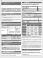 2
2
-
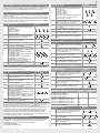 3
3
-
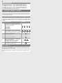 4
4
-
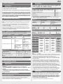 5
5
-
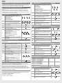 6
6
-
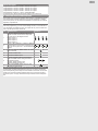 7
7
-
 8
8
-
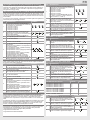 9
9
-
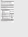 10
10
-
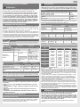 11
11
-
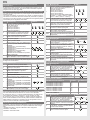 12
12
-
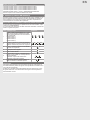 13
13
-
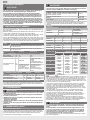 14
14
-
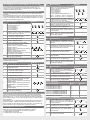 15
15
-
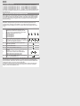 16
16
-
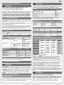 17
17
-
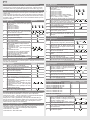 18
18
-
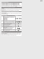 19
19
-
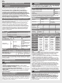 20
20
-
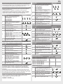 21
21
-
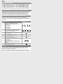 22
22
-
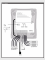 23
23
-
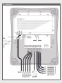 24
24
-
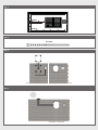 25
25
-
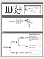 26
26
-
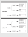 27
27
-
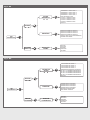 28
28
-
 29
29
-
 30
30
-
 31
31
-
 32
32


Key Automation 580BOXLED Manual de usuario
- Tipo
- Manual de usuario
en otros idiomas
- français: Key Automation 580BOXLED Manuel utilisateur
- italiano: Key Automation 580BOXLED Manuale utente
- Deutsch: Key Automation 580BOXLED Benutzerhandbuch
- português: Key Automation 580BOXLED Manual do usuário
- polski: Key Automation 580BOXLED Instrukcja obsługi
Artículos relacionados
-
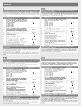 Key Automation 580LED Manual de usuario
-
 Key Automation 580RX4K Manual de usuario
-
 Key Automation 580RX4Z Manual de usuario
-
 Key Automation 580VIP1 Manual de usuario
-
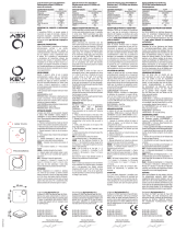 Key Automation 580TO2MP Manual de usuario
-
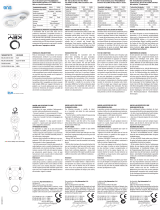 Key Automation 580ISSUB8 Manual de usuario
-
 Key Automation 580ISSUBF Manual de usuario
-
 Key Automation 580HALO Manual de usuario
-
 Key Automation 580IS14A Manual de usuario


Otros documentos
-
Telcoma SUN POWER El manual del propietario
-
Key Gates RX2H Guía del usuario
-
Elvox 682F/RC Installer's Manual
-
-
-
V2 V2 WES-ADI El manual del propietario
-
-
Ferrari 612 Scaglietti El manual del propietario