Interfaccia per controllo luci a led
Interface for led light control
Interface pour le contrôle des lumières à DEL
Interfaz de control para luces por led
Schnittstelle für Led-Lichter-Kontrolle
Interface para controlo de luzes a led
Interfejs do kontroli lamp LED
VIP1
Istruzioni ed avvertenze per l’installazione e l’uso
Instructions and warnings for installation and use
Instrucciones y advertencias para su instalación y uso
Anleitungen und Hinweise zu Installation und Einsatz
Instruções e advertências para a instalação e utilização
Instructions et avertissements pour l’installation et l’usage
Management
System
ISO 9001:2008
www.tuv.com
ID 9105043769

F1
T2.5A
250V
SBS
STOP
NEG
NEG
PH1
COM
LED
COM
BATTERY
FLASH
+24V
RECEIVER
FLAT/STIK/VERTICAL
MAX 5x
CPU
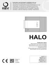
VIPER LED VIP1
QUADRO
BROWN
WHITE
BROWN
WHITE
LED
+ 24 Vdc
NEG
COM
LED
SEN
LED V
L1
S1
F1
T2.5A
250V
SBS
STOP
NEG
NEG
PH1
COM
LED
COM
BATTERY
FLASH
+24V
RECEIVER
FLAT/STIK/VERTICAL
MAX 4x
CPU
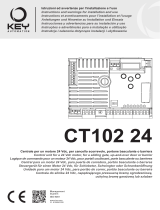
VIPER LED VIP1
ECLIPSE
BROWN
WHITE
LED
+ 24 Vdc
NEG
COM
LED
SEN
LED V
L1
S1
COM
LED FLASH SEN

NEG
COM
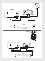
EG1/EG2
VIP1
QUADRO
BROWN
WHITE
BROWN
WHITE
LED
24 Vdc
CONTROL UNIT
+ 24 Vdc
NEG
COM
LED
SEN
LED V
L1
S1

IT
1 - AVVERTENZE PER LA SICUREZZA
ATTENZIONE – per la sicurezza delle persone è importante rispettare queste istru-
zioni e conservarle per utilizzi futuri.
Leggere attentamente le istruzioni prima di eseguire l’installazione. La progettazione e la
fabbricazione dei dispositivi che compongono il prodotto e le informazioni contenute nel
presente manuale rispettano le normative vigenti sulla sicurezza. Ciò nonostante un’in-
stallazione e una programmazione errata possono causare gravi ferite alle persone che
eseguono il lavoro e a quelle che useranno l’impianto. Per questo motivo, durante l’instal-
lazione, è importante seguire attentamente tutte le istruzioni riportate in questo manuale.
2 - INTRODUZIONE AL PRODOTTO
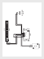
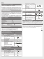
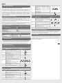
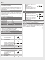
L’interfaccia VIP1, insieme al sensore notte QUADRO e alle centrali dei motori per porte
da garage Key Automation, permette il controllo automatico di ulteriori luci a led all’ester-
no o all’interno della porta da garage.
L’interfaccia VIP1 viene alimentata dalla centrale presente nel motore da garage e tra-
mite il sensore crepuscolare QUADRO aziona automaticamente durante le ore notturne
no a 5 luci a led Key Automation.
Il sistema Night Light System accende o spegne le luci dopo 15 minuti dal superamento
della soglia impostata. Questo avviene per evitare false accensioni o spegnimenti dovuti
a fonti di luci esterne quali i fari delle automobili.
CODICE DESCRIZIONE
VIP1 interfaccia per controllo luci a led
CARATTERISTICHE TECNICHE VIP1
alimentazione 24 ÷ 32 Vdc
potenza massima led 10 W
grado di protezione IP30
temperatura di esercizio -20+55 °C
dimensioni (L-P-H) 85-40-25
SPECIFICHE TECNICHE CAVI ELETTRICI
collegamento cavo limite massimo consentito
quadro 1 x cavo 2 x 0,5 mm210 m
led 1 x cavo 2 x 0,75 mm220 m
viper led / vip1 1 x cavo 3 x 0,75 mm25 m
3 - VERIFICHE PRELIMINARI
ATTENZIONE – prima di installare il prodotto vericare e controllare i seguenti punti:
• Posizionare il sensore notte QUADRO in una zona prevalentemente soleggiata
• Posizionare VIP1 in posizione riparata all’interno dell’abitazione
• Utilizzare collegamenti elettrici adeguati alle correnti richieste
• Vericare che l’alimentazione rispetti i valori delle caratteristiche tecniche
4 - INSTALLAZIONE DEL PRODOTTO
REGOLAZIONE INTENSITÁ LUCE LED
Tramite questa programmazione è possibile regolare l’intensità dei led durante la notte
FASE DESCRIZIONE ESEMPIO
1Premere una volta il pulsante S1 x 1
2Il LED “L1” esegue un lampeggio veloce se-
guito da una pausa x 1
3Premere e mantenere premuto il pulsante S1
per più di 3 secondi > 3sec
4Il led rimane spento
5Rilasciare il pulsante S1
6
Il led inizierà ad eseguire 5 lampeggi lenti.
1° lampeggio:livello 1 (bassa luminosità)
2° lampeggio:livello 2
3° lampeggio:livello 3 (default di fabbrica)
4° lampeggio:livello 4
5° lampeggio:livello 5 (alta luminosità)
+ + + +
7Premere il pulsante in corrispondenza del li-
vello desiderato
8Il led eseguirà 5 lampeggi veloci x 5
REGOLAZIONE LIVELLO LUCE AMBIENTE
Tramite questa programmazione è possibile regolare l’intervento del sensore luce in
base all a luce ambientale
FASE DESCRIZIONE ESEMPIO
1Premere due volte il pulsante S1 x 2
2Il LED “L1” esegue due lampeggi veloci se-
guiti da una pausa x 2
3Premere e mantenere premuto il pulsante S1
per più di 3 secondi > 3sec
4Il led rimane spento
5Rilasciare il pulsante S1
6
Il led inizierà ad eseguire 3 lampeggi lenti.
1° lampeggio:livello 1(attivazione con bassa
luminosità ambientale - default di fabbrica)
2° lampeggio:livello 2 (attivazione con media
luminosità ambientale)
3° lampeggio:livello 3 (attivazione con alta
luminosità ambientale)
+ +
7Premere il pulsante in corrispondenza del li-
vello desiderato
8Il led eseguirà 5 lampeggi veloci x 5
RESET VIP1
FASE DESCRIZIONE ESEMPIO
1
Premere e mantenere premuto il pulsante della
ricevente no a quando si accende il LED (circa
3 secondi) e poi si spegne (circa 3 secondi).
Rilasciare il tasto.
(>3s)-> (>3s)->
2Dopo circa 1 secondo dal rilascio del tasto il LED
sulla ricevente inizia a lampeggiare. (1s)+ (1s)+
3
Per il reset e reimpostazione valori di fabbri-
ca premere il tasto della ricevente in corri-
spondenza del terzo lampeggio
4Se il reset è andato a buon ne la ricevente
emetterà 1 lampeggio lungo
5 - COLLAUDO E MESSA IN SERVIZIO
L’impianto può essere messo in servizio dopo il collaudo di un tecnico qualicato che
deve eettuare le prove richieste dalla normativa di riferimento in funzione dei rischi pre-
senti, vericando il rispetto di quanto previsto dalle normative dell’applicazione
6 - SMATILMENTO
Componenti dell’imballo (cartone, plastica, ecc.), debitamente separati, devono essere
conferiti negli appositi cassonetti. I componenti del dispositivo come schede elettroni-
che, parti metalliche, batterie, ecc., vanno separati e dierenziati. Per le modalità di
smaltimento devono essere applicate le regole vigenti nel luogo d’installazione.
NON DISPERDERE NELL’AMBIENTE!

EN
1 - SAFETY WARNINGS
CAUTION – to ensure personal safety it is important to follow these instructions
and keep them for future reference.
Read the instructions carefully before proceeding with installation. The design and ma-
nufacture of the devices making up the product and the information in this manual are
compliant with current safety standards. However, incorrect installation or programming
may cause serious injury to those working on or using the system. Compliance with the
instructions provided here when installing the product is therefore extremely important.
2 - INTRODUCING THE PRODUCT
The VIP1 interface, together with the QUADRO night-time sensor and the control units of
the motors for Key Automation garage doors, enables the automatic control of additional
led lights outside and inside the garage door.
The VIP1 interface is powered by the control unit in the garage door motor, while the
QUADRO dusk sensor automatically activates up to 5 Key Automation led lights during
the night-time house.
The Night Light System switches the lights on or o 15 minutes after the set threshold
is exceeded. This delay is to prevent false switch-on or switch-o due to external light
sources such as car headlights.
CODE DESCRIPTION
VIP1 interface for led light control
TECHNICAL SPECIFICATIONS VIP1
power supply 24 ÷ 32 Vdc
maximum led power 10 W
protection rating IP30
operating temperature -20+55 °C
dimensions (L-D-H) 85-40-25
ELECTRIC CABLE TECHNICAL SPECIFICATIONS
connection cable maximum permitted limit
quadro 1 x cable 2 x 0,5 mm210 m
led 1 x cable 2 x 0,75 mm220 m
viper led / vip1 1 x cable 3 x 0,75 mm25 m
3 - PRELIMINARY CHECKS
WARNING - before installing the product, perform the following checks and inspections:
• Position the QUADRO night-time sensor in a sunny area
• Position VIP1 in a sheltered are in the building
• Use electrical connections suitable for the currents required
• Check that the power supply conforms to the values in the technical specications
4 - INSTALLING THE PRODUCT
ADJUST LED BRIGHTNESS
This setting enables adjustment of the led intensity during night-time hours
PH. DESCRIPTION EXAMPLE
1Press the button S1 once x 1
2Led “L1” ashes briey followed by a pause x 1
3Press and hold the button S1 for more than
3 seconds > 3sec
4The led remains o
5Release button S1
6
The led emits 5 slow ashes
1st ash: level 1 (low brightness)
2nd ash: level 2
3rd ash: level 3 (factory setting)
4th ash: level 4
5th ash: level 5 (high brightness)
+ + + +
7Press the button corresponding to the requi-
red brightness
8The led emits 5 quick ashes x 5
ADJUST AMBIENT LIGHT LEVEL
This setting enables adjustment of the light sensor activation on the basis of ambient
light
PH. DESCRIPTION EXAMPLE
1Press the button S1 twice x 2
2Led “L1” emits two quick ashes followed by
a pause x 2
3Press and hold the button S1 for more than
3 seconds > 3sec
4The led remains o
5Release button S1
6
The led emits 3 slow ashes
1st ash: level 1(activation with low ambient
light - factory setting)
2nd ash: level 2 (activation with medium
ambient light)
3rd ash: level 3 (activation with high ambient
light)
+ +
7Press the button corresponding to the requi-
red brightness
8The led emits 5 quick ashes x 5
RESET VIP1
PH. DESCRIPTION EXAMPLE
1
Press the button on the receiver and hold it
down until the LED lights up (about 3 seconds)
and then goes out (about 3 seconds). Release
the key
(>3s)-> (>3s)->
2About 1 second after the key is released, the
LED on the receiver starts to ash (1s)+ (1s)+
3To reset and restore the factory settings,
press the receiver button on the third ash
4If the reset has been successful, the receiver
will give one long ash
5 - TESTING AND COMMISSIONING
The system may be put into operation after testing by a qualied technician, who must
perform the tests required by the relevant standards in relation to the risks present, to
check that the installation complies with the relevant regulatory requirements.
6 - DISPOSAL
Packaging components (cardboard, plastic, etc.), duly separated, must be placed in the
appropriate bins. Device components such as electronic boards, metal parts, batteries,
etc. must be separated and dierentiated. For the methods of disposal, the rules in force
in the place of installation must be applied. DO NOT DISPOSE IN THE ENVIRONMENT!

FR
1 - CONSIGNES DE SÉCURITÉ
ATTENTION – pour la sécurité des personnes, il est important de respecter ces
instructions et de les conserver pour pouvoir les consulter ultérieurement.
Lire attentivement les instructions avant d’eectuer l’installation. La conception et la fa-
brication des dispositifs qui composent le produit et les informations contenues dans ce
guide respectent les normes de sécurité en vigueur. Néanmoins, une installation et une
programmation erronées peuvent causer de graves blessures aux personnes qui exécu-
tent le travail et à celles qui utiliseront l’installation. C’est pourquoi il est important, durant
l’installation, de suivre scrupuleusement toutes les instructions fournies dans ce guide.
2 - PRÉSENTATION DU PRODUIT
L’interface VIP1, avec le capteur nuit QUADRO et les logiques de commande des mo-
teurs pour portes de garage Key Automation, permet de contrôler automatiquement
d’autres lumières à DEL à l’extérieur ou à l’intérieur de la porte de garage.
L’interface VIP1 est alimentée par la logique de commande qui se trouve dans le moteur
de garage et par le capteur crépusculaire QUADRO elle actionne automatiquement du-
rant les heures nocturnes jusqu’à 5 lumières à DEL Key Automation.
Le système Night Light System allume ou éteint les éclairages 15 minutes après le
dépassement du seuil programmé. Cela an d’éviter les extinctions ou les allumages
inutiles déclenchés par des sources de lumières extérieures comme les phares des
voitures.
CODE DESCRIPTION
VIP1 interface pour le contrôle des lumières à DEL
CARACTÉR. TECHNIQUES VIP1
alimentation 24 ÷ 32 Vdc
puissance maximale de la DEL 10 W
indice de protection IP30
température de service -20+55 °C
dimensions (L-P-H) 85-40-25
SPÉCIFICATIONS TECHNIQUES DES CÂBLES ÉLECTRIQUES
branchement câble limite maximum consentie
quadro 1 x câble 2 x 0,5 mm210 m
led 1 x câble 2 x 0,75 mm220 m
viper led / vip1 1 x câble 3 x 0,75 mm25 m
3 - VÉRIFICATIONS PRÉALABLES
ATTENTION – avant d’installer le produit, vérier et contrôler les points suivants:
• Positionner le capteur nuit QUADRO dans une zone généralement ensoleillée
• Positionner VIP1 à l’abri dans l’habitation
• Utiliser des câblages électriques adaptés aux courants nécessaires
• Vérier que l’alimentation est conforme aux valeurs des caractéristiques techniques
4 - INSTALLATION DU PRODUIT
RÉGLAGE DE L’INTENSITÉ DE LA LUMIÈRE DEL
Cette programmation permet de régler l’intensité des DEL durant la nuit
PH. DESCRIPTION EXEMPLE
1Presser une fois la touche S1 x 1
2La DEL « L1 » eectue un clignotement
rapide suivi d’une pause x 1
3Presser le bouton S et le garder enfoncé
pendant plus de 3 secondes > 3sec
4La DEL reste éteinte
5Relâcher le bouton S1
6
La DEL commencera à effectuer 5 clignotements lents
1er clignotement : niveau 1 (faible luminosité)
2e clignotement : niveau 2
3e clignotement : niveau 3 (réglage par défaut)
4e clignotement : niveau 4
5e clignotement : niveau 5 (forte luminosité)
+ + + +
7Presser le bouton en correspondance du ni-
veau souhaité
8La DEL eectuera 5 clignotements rapides x 5
RÉGLAGE DU NIVEAU DE LA LUMIÈRE AMBIANTE
Cette programmation permet de régler l’intervention du capteur de lumière en fonction
de la lumière ambiante
PH. DESCRIPTION EXEMPLE
1Presser deux fois le bouton S1 x 2
2La DEL « L1 » eectue deux clignotements
rapides suivis d’une pause x 2
3Presser le bouton S et le garder enfoncé pen-
dant plus de 3 secondes > 3sec
4La DEL reste éteinte
5Relâcher le bouton S1
6
La DEL commencera à eectuer 3 clignote-
ments lents
1er clignotement : niveau 1 (activation avec
faible lumière ambiante - règlement usine)
2e clignotement : niveau 2 (activation avec
lumière ambiante moyenne)
3e clignotement : niveau 3 (activation avec
forte lumière ambiante)
+ +
7Presser le bouton en correspondance du
niveau souhaité
8La DEL eectuera 5 clignotements rapides x 5
RÉINITIALISATION VIP1
PH. DESCRIPTION EXEMPLE
1
Presser sans le relâcher la touche du récepteur
jusqu’à ce que la DEL s’allume (3 secondes
environ) puis s’éteigne (3 secondes environ).
Relâcher la touche
(>3s)-> (>3s)->
2
Environ une seconde après que la touche a
été relâchée, la DEL présente sur le récepteur
commence à clignoter
(1s)+ (1s)+
3
Pour la réinitialisation et le réglage des va-
leurs d’usine, presser la touche du récepteur
au troisième clignotement
4Si la réinitialisation a été correctement eec-
tué, le récepteur émettra 1 clignotement long
5 - RÉCEPTION ET MISE EN SERVICE
L’installation peut être mise en service après l’essai de réception coné à un technicien
qualié, qui doit eectuer les essais prescrits par la norme de référence en fonction des
risques présents et s’assurer que l’installation est conforme aux dispositions des normes
6 - ÉLIMINATION
Les composants de l’emballage (carton, plastique, etc.), dûment séparés, doivent être
placés dans les bacs appropriés. Les composants de l’appareil tels que les cartes élec-
troniques, les pièces métalliques, les batteries, etc. doivent être séparés et diérenciés.
Pour les modalités d’élimination, les règles en vigueur sur le lieu d’installation doivent
être appliquées. NE PAS JETER DANS L’ENVIRONNEMENT!

ES
1 - ADVERTENCIAS PARA LA SEGURIDAD
ATENCIÓN – para la seguridad de las personas es importante respetar estas in-
strucciones y conservarlas para futuros consultaciones.
Lea detenidamente las instrucciones antes de realizar la instalación. El diseño y la fabricación
de los dispositivos que componen el producto y las informaciones contenidas en este ma-
nual respetan las normativas vigentes sobre la seguridad. No obstante esto, una instalación
y una programación incorrectas pueden provocar graves heridas a las personas que realizan
el trabajo y a aquellas que utilizarán el sistema. Por dicho motivo, durante la instalación es
importante respetar escrupulosamente todas las instrucciones mencionadas en este manual.
2 - INTRODUCCIÓN AL PRODUCTO
La interfaz VIP1, junto con el sensor noche QUADRO y las centrales de los motores
para puertas de garaje Key Automation, permiten el control automático de otras luces
por led en el exterior o en el interior de la puerta de garaje.
La interfaz VIP1 es alimentada por la central instalada en el motor de garaje y mediante
el sensor crepuscular QUADRO acciona automáticamente durante la noche hasta 5
luces por led de Key Automation.
El sistema Night Light System enciende o apaga las luces después de 15 minutos de
superar el umbral congurado, con la nalidad de evitar falsos encendidos o falsos apa-
gados debidos a las fuentes de luces exteriores tales como los faros de automóviles.
CÓDIGO DESCRIPCIÓN
VIP1 Interfaz de control para luces por led
CARACTERÍST. TÉCNICAS VIP1
alimentación 24 ÷ 32 Vdc
potencia máxima led 10 W
grado de protección IP30
temperatura de servicio -20+55 °C
medidas (L-P-H) 85-40-25
ESPECIFICACIONES TÉCNICAS DE LOS CABLES ELÉCTRICOS
conexión cable límite máximo admitido
quadro 1 x cable 2 x 0,5 mm210 m
led 1 x cable 2 x 0,75 mm220 m
viper led / vip1 1 x cable 3 x 0,75 mm25 m
3 - CONTROLES PRELIMINARES
ATENCIÓN – antes de instalar el producto, compruebe y controle los siguientes puntos:
• Sitúe el sensor noche QUADRO preferentemente en una zona soleada
• Sitúe el VIP1 en una posición protegida dentro de la habitación
• Utilice conexiones eléctricas adecuadas para las corrientes requeridas
• Compruebe que la alimentación respete los valores de las características técnicas
4 - INSTALACIÓN DEL PRODUCTO
REGULACIÓN DE INTENSIDAD DE LA LUZ LED
Por medio de esta programación es posible regular la intensidad de los led durante la noche
FASE DESCRIPCIÓN EJEMPLO
1Pulse una vez el pulsador S1 x 1
2El LED “L1” hace un destello rápido seguido
por una pausa x 1
3Pulse y mantenga apretado el pulsador S1
durante más de 3 segundos > 3sec
4El led queda apagado
5Suelte el pulsador S1
6
El led empezará a hacer 5 destellos lentos
1° destello:nivel 1 (luminosidad baja)
2° destello:nivel 2
3° destello:nivel 3 (predeterminado de fábrica)
4° destello:nivel 4
5° destello:nivel 5 (luminosidad alta)
+ + + +
7Presione el pulsador en el nivel que le interesa
8El led destellará 5 veces de manera rápida x 5
REGULACIÓN DEL NIVEL DE LUZ AMBIENTAL
Por medio de esta programación es posible regular la activación del sensor luz según
las luz del entorno
FASE DESCRIPCIÓN EJEMPLO
1Pulse dos veces el pulsador S1 x 2
2El LED “L1” hace dos destellos rápidos se-
guidos por una pausa x 2
3Pulse y mantenga apretado el pulsador S1
durante más de 3 segundos > 3sec
4El led queda apagado
5Suelte el pulsador S1
6
El led empezará a hacer 3 destellos lentos
1° destello:nivel 1 (activación con lumino-
sidad ambiental baja – predeterminado de
fábrica)
2° destello:nivel 2 (activación con luminosidad
ambiental media )
3° destello:nivel 3 (activación con luminosi-
dad ambiental alta)
+ +
7Presione el pulsador en el nivel que le inte-
resa
8El led destellará 5 veces de manera rápida x 5
RESTABLECER VIP1
FASE DESCRIPCIÓN EJEMPLO
1
Presione y mantenga presionado el pulsador
del receptor hasta que se encienda el LED (3
segundos aprox.) y luego se apague (3 segun-
dos aprox.). Suelte el pulsador
(>3s)-> (>3s)->
2
Transcurrido 1 segundo después de haber
soltado el pulsador, el LED del receptor co-
menzará a destellar
(1s)+ (1s)+
3
Para reajustar y volver a congurar los va-
lores de fábrica, presione el pulsador del re-
ceptor durante el tercer destello
4Si la restablecer ha sido correcta, el receptor
emitirá 1 destello prolongado
5 - ENSAYO Y PUESTA EN SERVICIO
El sistema puede ponerse en servicio después del ensayo realizado por un técnico
calicado que debe realizar las pruebas requeridas por la Normativa de referencia en
función de los riesgos presentes, comprobando la conformidad de las normativas de la
aplicación
6 - ELIMINACIÓN
Los componentes del embalaje (cartón, plástico, etc.), debidamente separados, se de-
positarán en los contenedores correspondientes. Los componentes del dispositivo como
placas electrónicas, partes metálicas, baterías, etc. deben estar separados y diferencia-
dos. Para los métodos de eliminación, se deben aplicar las normas vigentes en el lugar
de instalación. ¡NO DESECHE EN EL MEDIO AMBIENTE!

DE
1 - SICHERHEITSHINWEISE
ACHTUNG – für die Sicherheit von Personen ist es wichtig, diese Anleitung
zu beachten und für zukünftige Nutzungen aufzubewahren.
Vor Durchführung der Installation lesen Sie die Anleitung bitte aufmerksam durch. Die
Konstruktion und die Herstellung der Vorrichtungen, aus denen das Produkt sich zu-
sammensetzt, und die in diesem Handbuch enthaltenen Informationen entsprechen den
geltenden Sicherheitsvorschriften. Dennoch können eine falsche Installation und eine
falsche Programmierung schwerwiegende Verletzungen bei Personen verursachen,
die die Arbeit ausführen und bei denen, die die Anlage benutzen werden. Aus diesem
Grund ist es wichtig, während der Installation aufmerksam alle Anweisungen in diesem
Handbuch zu beachten.
2 - EINFÜHRUNG IN DAS PRODUKT
Die Schnittstelle VIP1 erlaubt zusammen mit dem Nachtsensor QUADRO und den
Steuerungen der Garagentorantriebe Key Automation eine automatische Kontrolle
zusätzlicher externer und interner Led-Lichter des Garagentors.
Die Schnittstelle VIP1 wird von der im Garagentorantrieb vorhandenen Steuerung ge-
speist und betätigt in den Nachtstunden mit dem Dämmerungssensor QUADRO auto-
matisch bis zu 5 Led-Lichter Key Automation.
Das Night Light System schaltet die Lichter 15 Minuten nach Überschreiten des einge-
stellten Schwellwertes ein bzw. aus.Hierdurch wird ein irrtümliches Ein- bzw. Ausschal-
ten aufgrund von externen Lichtquellen wie Autoscheinwerfern verhindert.
CODE BESCHREIBUNG
VIP1 Schnittstelle für Led-Lichter-Kontrolle
TECHNISCHE MERKMALE VIP1
Speisung 24 ÷ 32 Vdc
Max. Led-Leistung 10 W
Schutzgrad IP30
Betriebstemperatur -20+55 °C
Abmessungen (B-T-H) 85-40-25
TECHNISCHE SPEZIFIKATIONEN FÜR ELEKTRISCHE KABEL
Anschluss Kabel Zulässige Höchstlänge
quadro 1 x Kabel 2 x 0,5 mm210 m
led 1 x Kabel 2 x 0,75 mm220 m
viper led / vip1 1 x Kabel 3 x 0,75 mm25 m
3 - VORABPRÜFUNGEN
ACHTUNG – Prüfen und kontrollieren Sie die folgenden Punkte, bevor Sie mit der Installation beginnen:
• Den Nachtsensor QUADRO an einer vorwiegend sonnenbestrahlten Stelle positionieren
• Die Schnittstelle VIP1 an einer geschützten Stelle im Innern der Wohnung positionieren
• Elektrische Anschlüsse verwenden, die für die geforderten Ströme geeignet sind
• Prüfen, ob die Versorgung den Werten der technischen Merkmale entspricht
4 -
PRODUKTINSTALLATION
EINSTELLUNG DER LED-LICHTSTÄRKE
Mit dieser Programmierung ist die Stärke der Leds in den Nachtstunden einstellbar
PH. BESCHREIBUNG BEISPIEL
1Einmal auf den Taster S1 drücken x 1
2Die LED “L1” blinkt einmal schnell mit darauf-
folgender Pause x 1
3Auf den Taster S1 drücken und länger als 3
Sekunden gedrückt halten > 3sec
4Die Led bleibt ausgeschaltet
5Den Taster S1 loslassen
6
Die Led beginnt fünfmal langsam zu blinken
1. Blinken: Stufe 1 (niedrige Helligkeit)
2. Blinken: Stufe 2
3. Blinken: Stufe 3 (werkseitige Einstellung)
4. Blinken: Stufe 4
5. Blinken: Stufe 5 (hohe Helligkeit)
+ + + +
7Bei Erreichen der gewünschten Helligkeit auf
den Taster drücken
8Die Led wird fünfmal schnell blinken x 5
EINSTELLUNG DER UMGEBUNGSBELEUCHTUNG
Mit dieser Programmierung ist das Ansprechen des Lichtsensors je nach
Umwelthelligkeit einstellbar
PH. BESCHREIBUNG BEISPIEL
1Zweimal auf den Taster S1 drücken x 2
2Die LED “L1” blinkt zweimal schnell mit da-
rauolgender Pause x 2
3Auf den Taster S1 drücken und länger als 3
Sekunden gedrückt halten > 3sec
4Die Led bleibt ausgeschaltet
5Den Taster S1 loslassen
6
Die Led beginnt dreimal langsam zu blinken
1. Blinken: Stufe 1 (Aktivierung bei niedriger
Umwelthelligkeit – werkseitige Defaultein-
stellung)
2. Blinken: Stufe 2 (Aktivierung bei mittlerer
Umwelthelligkeit)
3. Blinken: Stufe 3 (Aktivierung bei hoher
Umwelthelligkeit)
+ +
7Bei Erreichen der gewünschten Helligkeit auf
den Taster drücken
8Die Led wird fünfmal schnell blinken x 5
RESET VIP1
PH. BESCHREIBUNG BEISPIEL
1
Die Taste des Empfängers drücken und ge-
drückt halten, bis die LED (ca. 3 Sekunden)
aueuchtet und dann erlischt ( ca. 3 Sekun-
den). Die Taste loslassen
(>3s)-> (>3s)->
2
Ca. 1 Sekunde nach dem Loslassen der Ta-
ste beginnt die LED am Empfänger zu blin-
ken
(1s)+ (1s)+
3
Für das Reset und Zurücksetzen auf die Wer-
kseinstellungen, beim dritten Blinken auf die
Empfängertaste drücken
4War das Reset erfolgreich, meldet der
Empfänger dies durch 1 langes Blinken
5 - PRÜFUNG UND INBETRIEBNAHME
Die Anlage kann nach erfolgter Prüfung durch einen ausgebildeten Techniker in Betrieb
genommen werden. Dieser muss die von der einschlägigen Vorschrift verlangten Tests
hinsichtlich der vorhandenen Risiken durchführen und prüfen, ob alle Vorgaben der
Vorschriften für die Anwendungen beachtet wurden
6 - ENTSORGUNG
Verpackungsbestandteile (Karton, Kunststo etc.) sind ordnungsgemäß getrennt in die
entsprechenden Behälter zu entsorgen. Gerätekomponenten wie Elektronikplatinen,
Metallteile, Batterien etc. müssen getrennt und unterschieden werden. Für die Entsor-
gungswege sind die am Aufstellungsort geltenden Vorschriften anzuwenden. NICHT IN
DER UMWELT ENTSORGEN!

PT
1 - AVISOS SOBRE A SEGURANÇA
ATENÇÃO – para a segurança das pessoas é importante respeitar estas instruções
e conservá-las para utilizações futuras.
Ler com atenção as instruções antes de instalar. O projeto e o fabrico dos dispositivos
que compõem o produto e as informações presentes neste manual respeitam as normas
vigentes sobre segurança. Porém, a instalação ou a programação inadequada podem
causar feridas graves às pessoas que fazem o trabalho e às que utilizarão o sistema.
Por este motivo, durante a instalação, é importante seguir com atenção todasas in-
struções deste manual.
2 - DESCRIÇÃO DO PRODUTO
A interface VIP1, em conjunto com o sensor noite QUADRO e com as unidades dos
motores para portões de garagem Key Automation, permite o controlo automático de
outras luzes a led no exterior ou no interior da porta da garagem.
A interface VIP1 é alimentada pela unidade presente no motor de garagem e através do
sensor crepuscular QUADRO aciona automaticamente, durante as horas noturnas, até
5 luzes a led Key Automation.
O sistema Night Light System acende ou apaga as luzes 15 minutos após superado o
limiar congurado. Isso para evitar erros ao acender ou apagar causados por fontes de
luzes externas tais como os faróis dos automóveis.
CÓDIGO DESCRIÇÃO
VIP1 interface para controlo de luzes a led
CARACTERÍSTICAS TÉCNICAS VIP1
alimentação 24 ÷ 32 Vdc
potência máxima do led 10 W
grau de proteção IP30
temperatura de utilização: -20+55 °C
dimensões (compr. - prof. - alt.) 85-40-25
ESPECIFICAÇÕES TÉCNICAS DOS CABOS ELÉTRICOS
Ligação cabo limite máximo permitido
quadro 1 x cabo 2 x 0,5 mm210 m
led 1 x cabo 2 x 0,75 mm220 m
viper led / vip1 1 x cabo 3 x 0,75 mm25 m
3 - CONTROLOS PRELIMINARES
ATENÇÃO – antes de instalar o produto, vericar e controlar os pontos indicados a seguir:
• Posicionar o sensor noturno QUADRO numa zona bem ensolarada
• Colocar a VIP1 numa posição protegida dentro da residência
• Utilizar ligações elétricas adequadas às correntes necessárias
• Vericar se a alimentação respeita os valores das características técnicas
4 - INSTALAÇÃO DO PRODUTO
REGULAÇÃO DA INTENSIDADE DA LUZ LED
Através desta programação é possível regular a intensidade dos LEDs durante a noite
FASE DESCRIÇÃO EXEMPLO
1Premir uma vez o botão S1 x 1
2O LED “L1” apresenta uma intermitência
rápida seguida de uma pausa x 1
3Premir e manter premido o botão S1 durante
mais de 3 segundos > 3sec
4O LED permanece apagado
5Soltar o botão S1
6
O LED apresentará 5 intermitências lentas
1ª intermitência: nível 1 (baixa luminosidade)
2ª intermitência: nível 2
3ª intermitência:nível 3 (pré-congurado de fábrica)
4ª intermitência:nível 4
5ª intermitência:nível 5 (alta luminosidade)
+ + + +
7Premir o botão correspondente ao nível de-
sejado
8O LED apresentará 5 intermitências rápidas x 5
REGULAÇÃO DO NÍVEL DA LUZ AMBIENTE
Através desta programação é possível regular a atuação do sensor de luz com base
na luz ambiente
FASE DESCRIÇÃO EXEMPLO
1Premir duas vezes o botão S1 x 2
2O LED “L1” apresenta duas intermitências
rápidas seguidas de uma pausa x 2
3Premir e manter premido o botão S1 durante
mais de 3 segundos > 3sec
4O LED permanece apagado
5Soltar o botão S1
6
O LED apresentará 3 intermitências lentas
1ª intermitência: nível 1 (ativação com lumi-
nosidade ambiente baixa - pré-congurado
de fábrica)
2ª intermitência: nível 2 (ativação com lumi-
nosidade ambiente média )
3ª intermitência: nível 3 (ativação com lumi-
nosidade ambiente alta)
+ +
7Premir o botão correspondente ao nível de-
sejado
8O LED apresentará 5 intermitências rápidas x 5
RESET VIP1
FASE DESCRIÇÃO EXEMPLO
1
Premir e manter premido o botão do recetor
até quando se acender o LED (cerca de 3
segundos) e depois se apagar (cerca de 3
segundos). Libertar a tecla
(>3s)-> (>3s)->
2Cerca de 1 segundo após libertar a tecla, o
LED no recetor ca intermitente (1s)+ (1s)+
3
Para o reset e reconguração dos valores de
fábrica, premir a tecla do recetor durante a
terceira intermitência
4Se a reset for concluída, o recetor emitirá 1
sinal intermitente longo
5 - ENSAIO E COLOCAÇÃO EM SERVIÇO
O sistema pode ser colocado em serviço após o ensaio feito por um técnico qualicado
que deve realizar os testes previstos pela norma de referência de acordo com os riscos
presentes, vericando que sejam respeitadas as normas aplicáveis
6 - DESCARTE
Os componentes da embalagem (papelão, plástico, etc.), devidamente separados, de-
vem ser colocados nas lixeiras apropriadas. Os componentes do dispositivo, como pla-
cas eletrônicas, partes metálicas, baterias, etc., devem ser separados e diferenciados.
Para os métodos de eliminação, devem ser aplicadas as regras em vigor no local de
instalação. NÃO DESCARTE NO MEIO AMBIENTE!

PL
1 - UWAGI DOTYCZĄCE BEZPIECZEŃSTWA
UWAGA – aby zapewnić bezpieczeństwo osób należy stosować się do niniejszej
instrukcji i zachować ją do użytku w przyszłości.
Przed przystąpieniem do instalacji zapoznać się uważnie z treścią instrukcji. Procesy projekto-
wania i produkcji urządzeń wchodzących w skład produktu, jak też informacje zawarte w ni-
niejszej instrukcji, spełniają wymogi obowiązujących przepisów bezpieczeństwa. Pomimo tego
nieprawidłowa instalacja oraz błędne programowanie mogą spowodować poważne obrażenia
osób wykonujących pracę lub eksploatujących instalację. Dlatego też podczas instalacji należy
rygorystycznie stosować się do wszelkich zaleceń podanych w niniejszej instrukcji
2 - INFORMACJE OGÓLNE DOTYCZĄCE PRODUKTU
Interfejs VIP1, razem z czujnikiem zmierzchowym QUADRO oraz z centralkami silników
bram garażowych Key Automation, pozwala na automatyczną kontrolę dodatkowych
lamp LED na zewnątrz oraz wewnątrz garażu.
Interfejs VIP1 zasilany jest przez centralkę znajdującą się w silniku bramy garażowej. Za
pośrednictwem czujnika zmierzchowego QUADRO uruchamia automatycznie w czasie
nocnym do 5 lamp LED Key Automation.
System Night Light System włącza lub wyłącza oświetlenie po 15 minutach od przekroc-
zenia ustawionego progu.Powyższe pozwala zapobiec fałszywym włączeniom lub
wyłączeniom, spowodowanym źródłami oświetlenia zewnętrznego, takimi jak reektory
samochodów.
KOD OPIS
VIP1 interfejs do kontroli lamp LED
DANE TECHNICZNE VIP1
zasilanie 24 ÷ 32 Vdc
maksymalna moc lamp LED 10 W
stopień ochrony IP30
temperatura pracy -20+55 °C
wymiary (D-S-W) 85-40-25
PARAMETRY TECHNICZNE PRZEWODÓW ELEKTRYCZNYCH
Podłączenie Przewód elektryczny Dozwolony limit maksymalny
quadro 1 x przewód 2 x 0,5 mm210 m
led 1 x przewód 2 x 0,75 mm220 m
viper led / vip1 1 x przewód 3 x 0,75 mm25 m
3 - KONTROLE WSTĘPNE
UWAGA – przed zainstalowaniem produktu wykonać następujące kontrole i zalecenia:
• Umieścić czujnik zmierzchowy QUADRO w miejscu dobrze oświetlonym światłem naturalnym
• Umieścić VIP1 w osłoniętym miejscu wewnątrz mieszkania
• Używać podłączeń elektrycznych dostosowanych do wymaganych wartości prądu
• Sprawdzić, czy zasilanie posiada wartości określone w parametrach technicznych
4 - INSTALACJA PRODUKTU
REGULACJA NATĘŻENIA OŚWIETLENIA LED
Za pomocą opisanego programowania można wyregulować natężenie światła lamp LED w nocy
FAZA OPIS PRZYKŁAD
1Nacisnąć jeden raz przycisk S1 x 1
2LED „L1” mignie szybko jeden raz i przejdzie
w stan pauzy x 1
3Przytrzymać wciśnięty przycisk S1 przez co
najmniej 3 sekundy > 3sec
4Lampa LED pozostanie wyłączona
5Zwolnić przycisk S1
6
Lampa LED mignie powoli 5 razy
1. mignięcie: poziom 1 (małe natężenie światła)
2. mignięcie: poziom 2
3. mignięcie: poziom 3 (ustawienie fabryczne)
4. mignięcie: poziom 4
5. mignięcie: poziom 5 (duże natężenie światła)
+ + + +
7Wcisnąć przycisk odpowiadający wybranemu
poziomowi
8Lampa LED mignie szybko 5 razy x 5
REGULACJA POZIOMU ŚWIATŁA OTOCZENIA
Za pomocą opisanego programowania można regulować zadziałanie czujnika światła
w zależności od oświetlenia otoczenia
FAZA OPIS PRZYKŁAD
1Nacisnąć dwa razy przycisk S1 x 2
2Lampa LED „L1” mignie szybko dwa razy i
przejdzie w stan pauzy x 2
3Przytrzymać wciśnięty przycisk S1 przez co
najmniej 3 sekundy > 3sec
4Lampa LED pozostanie wyłączona
5Zwolnić przycisk S1
6
Lampa LED mignie powoli 3 razy
1. mignięcie: poziom 1 (aktywacja przy
małym natężeniu światła w otoczeniu – usta-
wienie fabryczne)
2. mignięcie: poziom 2 (aktywacja przy
średnim natężeniu światła w otoczeniu)
3. mignięcie: poziom 3 (aktywacja przy
dużym natężeniu światła w otoczeniu)
+ +
7Wcisnąć przycisk odpowiadający wybrane-
mu poziomowi
8Lampa LED mignie szybko 5 razy x 5
RESET VIP1
FAZA OPIS PRZYKŁAD
1
Wcisnąć i przytrzymać przycisk odbiorni-
ka do momentu zaświecenia się diody LED
(ok. 3 sekundy) a potem jej zgaśnięcia (ok. 3
sekundy). Zwolnić przycisk
(>3s)-> (>3s)->
2
Po upływie ok. 1 sekundy od zwolnienia
przycisku, dioda LED na odbiorniku zaczyna
migać
(1s)+ (1s)+
3
Aby wykonać reset i przywrócić ustawienia
fabryczne, nacisnąć przycisk na odbiorniku w
trakcie trzeciego mignięcia
4
Jeżeli reset pilota zakończyło się powodze-
niem, na odbiorniku pojawi się 1 długie
mignięcie
5 - ODBIÓR TECHNICZNY ORAZ ODDANIE DO UŻYTKOWANIA
Instalacja może zostać oddana do użytkowania po przeprowadzeniu przez wykwaliko-
wanego technika odbioru technicznego. Technik zobowiązany jest do wykonania testów
wymaganych przepisami wskazanymi w zależności od istniejących zagrożeń oraz do
sprawdzenia, czy instalacja spełnia wymogi określone w mających zastosowanie ure-
gulowaniach.
6 - USUWANIE
Elementy opakowania (karton, plastik itp.), należycie oddzielone, należy umieścić w
odpowiednich pojemnikach. Elementy urządzenia, takie jak płytki elektroniczne, części
metalowe, baterie itp. muszą być odseparowane i zróżnicowane. W przypadku metod
utylizacji należy stosować przepisy obowiązujące w miejscu instalacji. NIE WYRZUCAĆ
DO ŚRODOWISKA!

Key Automation S.r.l.
Via A. Meucci, 23 - 30027 San Donà di Piave (VE)
T. +39 0421.307.456
[email protected] - www.keyautomation.com
Instruction version
580VIP1 REV.02
-
 1
1
-
 2
2
-
 3
3
-
 4
4
-
 5
5
-
 6
6
-
 7
7
-
 8
8
-
 9
9
-
 10
10
-
 11
11


en otros idiomas
- français: Key Automation 580VIP1 Manuel utilisateur
- italiano: Key Automation 580VIP1 Manuale utente
- Deutsch: Key Automation 580VIP1 Benutzerhandbuch
- português: Key Automation 580VIP1 Manual do usuário
- polski: Key Automation 580VIP1 Instrukcja obsługi