SICK IN4000 Standard Safety Switch Instrucciones de operación
- Tipo
- Instrucciones de operación


Operating Instructions
IN4000 Standard
2 © SICK AG • Germany • All rights reserved 8010934/ZWG9/2018-07-26
Subject to change without notice
Inhalt/Contents
Inhalt/Contents
de Seite 3–56
en Page 57-108
es Página 109–164
fr Page 165–216
it Pagina 217-270
This document is protected by the law of copyright,
whereby all rights established therein remain with the
company SICK AG. Reproduction of this document or
parts of this document is only permissible within the
limits of the legal determination of Copyright Law.
Alteration or abridgement of the document is not
permitted without the explicit written approval of the
company SICK AG.

Betriebsanleitung
IN4000 Standard
8010934/ZWG9/2018-07-26 © SICK AG • Deutschland • Alle Rechte vorbehalten 3
Irrtümer und Änderungen vorbehalten
Inhalt
de
Inhalt
1 Zu diesem Dokument ..........................................5
1.1 Funktion dieses Dokuments ......................5
1.2 Zielgruppe....................................................5
1.3 Informationstiefe.........................................6
1.4 Geltungsbereich ..........................................6
1.5 Verwendete Symbole ..................................7
2 Zur Sicherheit.......................................................8
2.1 Befähigte Personen ....................................8
2.2 Verwendungsbereiche der
Sicherheitsschalter .....................................9
2.3 Bestimmungsgemäße Verwendung ........10
2.4 Vorhersehbare Fehlanwendung...............10
2.5 Allgemeine Sicherheitshinweise und
Schutzmaßnahmen ..................................11
3 Produktbeschreibung ....................................... 13
3.1 Sicherheitsschalter der Typenreihe
IN4000 Standard......................................13
3.2 Merkmale und Funktionsprinzip..............14
3.3 Freigabezone und sicherer
Ausschaltabstand .....................................15
3.4 LED-Anzeigen.............................................18
3.4.1 Anzeigen im Betriebsmodus ....................19
3.4.2 Anzeigen im Justagemodus .....................20
3.5 Signalverhalten .........................................23
3.6 Reaktionszeiten des
Sicherheitsschalters .................................25
3.7 Manipulationsschutz ................................26
4 Montage............................................................. 27
4.1 Montage des Sicherheitsschalters
IN40-D0101K............................................27
4.2 Montage der Sicherheitsschalter
IN40-D03.. und IN40-D0202K ................31

Betriebsanleitung
IN4000 Standard
4 © SICK AG • Deutschland • Alle Rechte vorbehalten 8010934/ZWG9/2018-07-26
Irrtümer und Änderungen vorbehalten
Inhalt
de
5 Anschluss und Justage ..................................... 35
5.1 Elektrischer Anschluss .............................35
5.2 Reihenschaltung von induktiven
Sicherheitsschaltern ................................36
5.3 Justage ......................................................37
6 Inbetriebnahme und Betrieb ............................ 38
6.1 Prüfungen vor der
Erstinbetriebnahme..................................38
6.1.1 Start-Funktion überprüfen .......................38
6.2 Wiederkehrende technische
Prüfungen..................................................39
6.2.1 Tägliche Prüfung .......................................39
6.2.2 Prüfungen durch eine befähigte
Person........................................................39
6.3 Verhalten im Fehlerfall............................. 40
7 Fehlerdiagnose.................................................. 41
7.1 Sicherheit ..................................................41
7.2 Fehlerbehebung........................................42
7.3 Sicherer Zustand im Fehlerfall ................43
8 Wartung und Entsorgung ................................. 44
9 Technische Daten.............................................. 45
9.1 Datenblatt .................................................45
9.2 Anschlussbelegung...................................49
9.3 Maßbilder ..................................................50
10 Bestelldaten ...................................................... 52
10.1 Geräte........................................................52
10.2 Zubehör .....................................................52
11 Anhang ............................................................... 53
11.1 Konformität mit EU-Richtlinien ................53
11.2 Tabellenverzeichnis..................................54
11.3 Abbildungsverzeichnis .............................55

Betriebsanleitung Kapitel 1
IN4000 Standard
8010934/ZWG9/2018-07-26 © SICK AG • Deutschland • Alle Rechte vorbehalten 5
Irrtümer und Änderungen vorbehalten
Zu diesem Dokument
de
1 Zu diesem Dokument
Bitte lesen Sie dieses Kapitel sorgfältig, bevor Sie mit
der Dokumentation und dem IN4000 Standard arbei-
ten.
1.1 Funktion dieses Dokuments
Diese Betriebsanleitung leitet das technische Personal
des Maschinenherstellers bzw. Maschinenbetreibers
zur sicheren Montage, Parametrierung, Elektro-
installation, Inbetriebnahme sowie zum Betrieb und zur
Prüfung des induktiven Sicherheitsschalters IN4000
Standard an.
Diese Betriebsanleitung leitet nicht zur Bedienung der
Maschine an, in die der Sicherheitsschalter integriert
ist oder wird. Informationen hierzu enthält die Betriebs-
anleitung der Maschine.
1.2 Zielgruppe
Diese Betriebsanleitung richtet sich an die Planer,
Entwickler und Betreiber von Anlagen, welche durch
einen oder mehrere induktive Sicherheitsschalter
IN4000 Standard abgesichert werden sollen. Sie rich-
tet sich auch an Personen, die den IN4000 Standard in
eine Maschine integrieren, erstmals in Betrieb nehmen
oder prüfen.

Kapitel 1 Betriebsanleitung
IN4000 Standard
6 © SICK AG • Deutschland • Alle Rechte vorbehalten 8010934/ZWG9/2018-07-26
Irrtümer und Änderungen vorbehalten
Zu diesem Dokument
de
1.3 Informationstiefe
Diese Betriebsanleitung enthält Informationen über
den induktiven Sicherheitsschalter IN4000 Standard
zu folgenden Themen:
• Montage,
• Elektroinstallation,
• Hardware-Inbetriebnahme,
• Fehlerdiagnose und Fehlerbehebung,
• Artikelnummern,
• Konformität und Zulassung.
Darüber hinaus sind bei Planung und Einsatz von SICK-
Schutzeinrichtungen wie dem IN4000 Standard
technische Fachkenntnisse notwendig, die nicht in
diesem Dokument vermittelt werden.
Grundsätzlich sind die behördlichen und gesetzlichen
Vorschriften beim Betrieb des induktiven Sicherheits-
schalters IN4000 Standard einzuhalten.
Allgemeine Informationen zum Thema Sicherheits-
technik enthält der Leitfaden „Sichere Maschinen“.
Nutzen Sie auch die Homepage im Internet unter:
www.sick.com
Dort finden Sie:
• Beispielapplikationen,
• eine Liste häufiger Fragen zum IN4000 Standard.
1.4 Geltungsbereich
Diese Betriebsanleitung ist eine Original-Betriebs-
anleitung.
Diese Betriebsanleitung ist gültig für den induktiven
Sicherheitsschalter IN4000 Standard.
Hinweis

Betriebsanleitung Kapitel 1
IN4000 Standard
8010934/ZWG9/2018-07-26 © SICK AG • Deutschland • Alle Rechte vorbehalten 7
Irrtümer und Änderungen vorbehalten
Zu diesem Dokument
de
1.5 Verwendete Symbole
Empfehlungen geben Ihnen Entscheidungshilfe hin-
sichtlich der Anwendung einer Funktion oder tech-
nischen Maßnahme.
Hinweise informieren Sie über Besonderheiten des
Geräts.
LED-Symbole beschreiben den Zustand einer Diagnose-
LED. Beispiele:
Ν Die LED leuchtet konstant.
∏ Die LED blinkt.
ν Die LED ist aus.
Handlungsanweisungen sind durch einen Pfeil gekenn-
zeichnet. Lesen und befolgen Sie Handlungs-
anweisungen sorgfältig.
Warnhinweis!
Ein Warnhinweis weist Sie auf konkrete oder potenti-
elle Gefahren hin. Dies soll Sie vor Unfällen bewahren.
⋅ Lesen und befolgen Sie Warnhinweise sorgfältig!
Der Begriff „Gefahr bringender Zustand“
In den Abbildungen in diesem Dokument wird der
Gefahr bringende Zustand (Normbegriff) der Maschine
stets als Bewegung eines Maschinenteiles dargestellt.
In der Praxis kann es verschiedene Gefahr bringende
Zustände geben:
• Maschinenbewegungen,
• Strom führende Teile,
• sichtbare oder unsichtbare Strahlung,
• eine Kombination mehrerer Gefahren.
Empfehlung
Hinweis
Ν, ∏, ν
= Handeln
Sie …
ACHTUNG

Kapitel 2 Betriebsanleitung
IN4000 Standard
8 © SICK AG • Deutschland • Alle Rechte vorbehalten 8010934/ZWG9/2018-07-26
Irrtümer und Änderungen vorbehalten
Zur Sicherheit
de
2 Zur Sicherheit
Dieses Kapitel dient Ihrer Sicherheit und der Sicherheit
der Anlagenbenutzer.
⋅ Bitte lesen Sie dieses Kapitel sorgfältig, bevor Sie
mit den induktiven Sicherheitsschaltern der Typen-
reihe IN4000 Standard oder der durch diese Sicher-
heitsschalter in Verbindung mit den entsprechenden
Schutzeinrichtungen geschützten Maschine
arbeiten.
Für Verwendung/Einbau der Sicherheitsschalter der
Typenreihe IN4000 Standard sowie für Inbetriebnahme
und wiederkehrende technische Überprüfungen gelten
die nationalen und internationalen Rechtsvorschriften,
insbesondere
• die Maschinenrichtlinie,
• die EMV-Richtlinie,
• die Arbeitsmittelbenutzungsrichtlinie,
• die Sicherheitsvorschriften sowie
• die Unfallverhütungsvorschriften/Sicherheitsregeln.
2.1 Befähigte Personen
Die Sicherheitsschalter der Typenreihe IN4000
Standard dürfen nur von befähigten Personen montiert
und in Betrieb genommen werden. Befähigt ist, wer
• über eine geeignete technische Ausbildung verfügt
und
• vom Maschinenbetreiber in der Bedienung und den
gültigen Sicherheitsrichtlinien unterwiesen wurde
und
• Zugriff auf diese Betriebsanleitung hat.

Betriebsanleitung Kapitel 2
IN4000 Standard
8010934/ZWG9/2018-07-26 © SICK AG • Deutschland • Alle Rechte vorbehalten 9
Irrtümer und Änderungen vorbehalten
Zur Sicherheit
de
2.2 Verwendungsbereiche der
Sicherheitsschalter
Die Sicherheitsschalter der Typenreihe IN4000
Standard sind induktive Sicherheits-Näherungs-
schalter, die berührungslos durch Metall betätigt
werden. Der sichere Zustand ist der stromlose Zustand.
Mit den Sicherheitsschaltern der Typenreihe IN4000
Standard und der entsprechenden Maschinen- oder
Anlagensteuerung können z. B. beweglich trennende
Schutzeinrichtungen so abgesichert werden, dass
• der Gefahr bringende Zustand der Maschine oder
Anlage nur dann eingeschaltet werden kann, wenn
die Schutzeinrichtungen geschlossen sind.
• ein Stopp-Befehl ausgelöst wird, wenn eine Schutz-
einrichtung bei laufender Maschine geöffnet wird.
Für die Steuerung bedeutet dies, dass
• Einschaltbefehle, die Gefahr bringende Zustände
hervorrufen, erst dann wirksam werden dürfen,
wenn die Schutzeinrichtungen in Schutzstellung
sind,
und
• Gefahr bringende Zustände beendet sein müssen,
bevor die Schutzstellung aufgehoben ist.
Vor dem Einsatz der Sicherheitsschalter ist eine Risiko-
beurteilung an der Maschine durchzuführen.
Zur bestimmungsgemäßen Verwendung gehört auch
das Einhalten der einschlägigen Anforderungen für den
Einbau und den Betrieb.
Die Sicherheitsschalter müssen regelmäßig einer
technischen Überprüfung entsprechend Abschnitt 6.2
unterzogen werden.

Kapitel 2 Betriebsanleitung
IN4000 Standard
10 © SICK AG • Deutschland • Alle Rechte vorbehalten 8010934/ZWG9/2018-07-26
Irrtümer und Änderungen vorbehalten
Zur Sicherheit
de
2.3 Bestimmungsgemäße Verwendung
Die Sicherheitsschalter der Typenreihe IN4000
Standard dürfen nur im Sinne von Abschnitt 2.2 „Ver-
wendungsbereiche der Sicherheitsschalter“ verwendet
werden. Die Sicherheitsschalter dürfen nur von befä-
higten Personen installiert und nur an der Maschine
verwendet werden, an der sie gemäß dieser Betriebs-
anleitung von einer befähigten Person installiert und
erstmalig in Betrieb genommen wurden.
Der Sicherheitsschalter darf zu jeder Zeit nur innerhalb
der Grenzen der vorgeschriebenen und angegebenen
technischen Daten und Betriebsbedingungen
verwendet werden.
Bei jeder anderen Verwendung sowie bei Veränderun-
gen an den Geräten – auch im Rahmen von Montage
und Installation – verfällt jeglicher Gewährleistungs-
anspruch gegenüber der SICK AG.
2.4 Vorhersehbare Fehlanwendung
Der Sicherheitsschalter ist unter anderem für nach-
folgende Verwendungen nicht geeignet:
• In der Umgebung von chemischen und biologischen
Medien (fest, flüssig, gasförmig)
• In Umgebungen mit erhöhter ionisierender Strahlung

Betriebsanleitung Kapitel 2
IN4000 Standard
8010934/ZWG9/2018-07-26 © SICK AG • Deutschland • Alle Rechte vorbehalten 11
Irrtümer und Änderungen vorbehalten
Zur Sicherheit
de
2.5 Allgemeine Sicherheitshinweise
und Schutzmaßnahmen
Das Sicherheitssystem, das aus einem oder mehreren
Sicherheitsschaltern der Typenreihe IN4000 Standard
und der Sicherheits-Steuerung, z. B. Flexi Classic oder
Flexi Soft besteht, erfüllt eine Personenschutz-Funk-
tion. Alternativ zur Sicherheits-Steuerung können die
Sicherheitsschalter auch an eine sichere SPS ange-
schlossen werden. Unsachgemäßer Einbau oder
Manipulationen können zu schweren Verletzungen von
Personen führen.
Der Sicherheitsschalter IN4000 Standard erfüllt
folgende Sicherheitsanforderungen:
• SIL3 gemäß IEC 61 508,
• SILCL3 gemäß EN 62 061,
• Performance Level e gemäß EN ISO 13 849-1
(applikationsabhängig).
Änderungshinweis
• Für Geräte bis KW24 2018 gilt:
PFH
D
1,33 × 10
–9
/Kategorie 4 (EN ISO 13 849-1)
• Für Geräte ab KW25 2018 gilt:
PFH
D
1,0 × 10
–8
/Kategorie 3 (EN ISO 13 849-1)
⋅ Prüfen Sie, ob das Gerät den gewünschten Sicher-
heitsanforderungen der Applikation entspricht.

Kapitel 2 Betriebsanleitung
IN4000 Standard
12 © SICK AG • Deutschland • Alle Rechte vorbehalten 8010934/ZWG9/2018-07-26
Irrtümer und Änderungen vorbehalten
Zur Sicherheit
de
Hinweis zur Klassifizierung des Geräts gemäß
EN 60 947-5-2:
• Der Sicherheitsschalter IN40-D0101K entspricht
abhängig von der Einbauart der Klassifizierung
I1C40SP2M bzw. I2C40SP2M.
• Der Sicherheitsschalter IN40-D0303K entspricht der
Klassifizierung I2A18SP2M.
• Der Sicherheitsschalter IN40-D0202K entspricht der
Klassifizierung I2A30SP2M.
• Der Sicherheitsschalter IN40-D0304K entspricht der
Klassifizierung I1A18SP2M.
Sicherheitsschalter dürfen nicht umgangen, wegge-
dreht, entfernt oder auf andere Weise unwirksam
gemacht werden. Ihre Kontakte dürfen nicht über-
brückt werden.
Bitte beachten Sie die Einbaumaßnahmen gemäß
EN ISO 14 119.
Beschädigte Geräte müssen ausgetauscht werden.
ACHTUNG

Betriebsanleitung Kapitel 3
IN4000 Standard
8010934/ZWG9/2018-07-26 © SICK AG • Deutschland • Alle Rechte vorbehalten 13
Irrtümer und Änderungen vorbehalten
Produktbeschreibung
de
3 Produktbeschreibung
3.1 Sicherheitsschalter der Typenreihe
IN4000 Standard
Die Sicherheitsschalter der Typenreihe IN4000
Standard arbeiten nach dem gleichen Funktionsprinzip,
unterscheiden sich aber in der Bauform, Einbauart,
Ansprechbereichen und Klassifizierung.
Der Sicherheitsschalter IN40-D0101K verfügt über ein
quaderförmiges Gehäuse mit ausrichtbarer aktiver
Sensorfläche. Er kann, ausgenommen in Stahl, auch
bündig oder einseitig bündig eingebaut werden.
Die Sicherheitsschalter IN40-D0303K und IN40-
D0202K sind in einem zylindrischen Gehäuse unterge-
bracht und nicht für den bündigen oder einseitig bündigen
Einbau geeignet.
Der Sicherheitsschalter IN40-D0304K ist in einem
zylindrischen Gehäuse untergebracht und ist für den
bündigen Einbau geeignet.

Kapitel 3 Betriebsanleitung
IN4000 Standard
14 © SICK AG • Deutschland • Alle Rechte vorbehalten 8010934/ZWG9/2018-07-26
Irrtümer und Änderungen vorbehalten
Produktbeschreibung
de
3.2 Merkmale und Funktionsprinzip
Die Sicherheitsschalter der Typenreihe IN4000
Standard werden typischerweise für eine sichere
Positionserkennung eingesetzt, wie dies z. B. bei der
Überwachung einer beweglichen Schutzeinrichtung der
Fall ist. Der Sensor detektiert die An- bzw. Abwesenheit
von Metall. Um den Anforderungen gegen einfache
Manipulation nachzukommen, wird der Schaltbereich
des Sensors zeitlich und räumlich überwacht.
Mittels LEDs kann der Status direkt am Sensor bzw. an
der Schutzeinrichtung abgelesen werden. Fehler, wie
beispielsweise Spulenbruch, Kurzschluss und
Leitungsbruch, werden durch die Selbstüberwachung
des Sensors erkannt.
Der Sicherheitsschalter kann direkt an eine sichere
SPS oder an eine SICK-Sicherheits-Steuerung, z. B.
Flexi Classic oder Flexi Soft angeschlossen werden.
Sicherheitsschalter der Serie IN4000 Standard können
kaskadiert werden (siehe Abschnitt 5.2 „Reihen-
schaltung von induktiven Sicherheitsschaltern“ auf
Seite 36).
Informationen zum Anschluss sind auch der Betriebs-
anleitung der verwendeten Sicherheits-Steuerung (z. B.
Flexi Classic oder Flexi Soft) zu entnehmen.

Betriebsanleitung Kapitel 3
IN4000 Standard
8010934/ZWG9/2018-07-26 © SICK AG • Deutschland • Alle Rechte vorbehalten 15
Irrtümer und Änderungen vorbehalten
Produktbeschreibung
de
3.3 Freigabezone und sicherer
Ausschaltabstand
Der Ausgang des Sicherheitsschalters wird nur bei
einer Bedämpfung innerhalb der Freigabezone frei-
gegeben. Außerhalb der Freigabezone, also auch im
Nahbereich, bleibt der Ausgang ausgeschaltet.
Nach einer Bedämpfung im Nahbereich muss entweder
die Versorgungsspannung unterbrochen oder das
Bedämpfungselement für mehr als 2 s in den sicheren
Ausschaltabstand gebracht werden, bevor wieder die
Freigabe erfolgen kann.
Die Freigabezone ist abhängig vom Typ des Sicher-
heitsschalters und von Material und Form des Be-
dämpfungselements. Die Verwendung anderer Be-
dämpfungselemente (Material, Form) ergibt eine
andere Freigabezone.
Typischerweise wird bei einer Umgebungstemperatur
von 20 °C bei nicht bündigem Einbau des Sicherheits-
schalters mit einer Normplatte gemäß EN 60 947-5-2
(45 × 45 × 1 mm
3
für IN40-D0101K und
IN40-D0202K bzw. 24 × 24 × 1 mm
3
für IN40-D03..)
Abb. 1: Schema-
tische Abbildung
der Zonen der
Sicherheits-
schalter IN4000
Standard (am
Beispiel
IN40-D0101K)
Nahbereich
Sensor
Freigabezone
gesicherter
Ausschaltabstand
Distanz
Bedämpfungsobjekt
(Metall)

Kapitel 3 Betriebsanleitung
IN4000 Standard
16 © SICK AG • Deutschland • Alle Rechte vorbehalten 8010934/ZWG9/2018-07-26
Irrtümer und Änderungen vorbehalten
Produktbeschreibung
de
mit verschiedenen Materialien folgende Freigabezone
erreicht:
IN40-D0101K
Material Freigabezone
Untere
Grenze
Obere
Grenze
Sicherer
Ausschalt-
abstand
Stahl FE360 ≥ 10,0 mm ≤ 15,0 mm
Edelstahl
1.4302 (V2A)
7,5 mm 13,2 mm
AlMg 3G22 2,0 mm 5,8 mm
Al 99 % 1,4 mm 5,0 mm
CuZn 37 2,3 mm 6,2 mm
Cu 0,8 mm 4,3 mm
30 mm
IN40-D0202K
(zylindrisch M30)
Material Freigabezone
Untere
Grenze
Obere
Grenze
Sicherer
Ausschalt-
abstand
Stahl FE360 ≥ 6,0 mm ≤ 12,0 mm
Edelstahl
1.4302 (V2A)
3,7 mm 8,4 mm
AlMg 3G22 1,0 mm 4,7 mm
CuZn 37 1,2 mm 5,1 mm
30 mm
Tab. 1: Freigabe-
zone und sicherer
Ausschaltabstand
IN40-D0101K
Tab. 2: Freigabe-
zone und sicherer
Ausschaltabstand
IN40-D0202K

Betriebsanleitung Kapitel 3
IN4000 Standard
8010934/ZWG9/2018-07-26 © SICK AG • Deutschland • Alle Rechte vorbehalten 17
Irrtümer und Änderungen vorbehalten
Produktbeschreibung
de
IN40-D0303K
(zylindrisch M18)
Material Freigabezone
Untere
Grenze
Obere
Grenze
Sicherer
Ausschalt-
abstand
Stahl FE360 ≥ 3,0 mm ≤ 6,0 mm
Edelstahl
1.4302 (V2A)
1,7 mm 4,3 mm
AlMg 3G22 0,5 mm 2,2 mm
CuZn 37 0,5 mm 2,5 mm
15 mm
IN40-D0304K
(zylindrisch M18)
Material Freigabezone
Untere
Grenze
Obere
Grenze
Sicherer
Ausschalt-
abstand
Stahl FE360 ≥ 1,0 mm ≤ 4,0 mm
Edelstahl
1.4302 (V2A)
0,4 mm 2,7 mm
AlMg 3G22 0 mm 1,4 mm
CuZn 37 0 mm 1,5 mm
Cu 0 mm 0,8 mm
10 mm
Tab. 3: Freigabe-
zone und sicherer
Ausschaltabstand
IN40-D0303K
Tab. 4: Freigabe-
zone und sicherer
Ausschaltabstand
IN40-D0304K

Kapitel 3 Betriebsanleitung
IN4000 Standard
18 © SICK AG • Deutschland • Alle Rechte vorbehalten 8010934/ZWG9/2018-07-26
Irrtümer und Änderungen vorbehalten
Produktbeschreibung
de
3.4 LED-Anzeigen
Die Sicherheitsschalter besitzen zwei LEDs, die den
Status der Versorgungsspannung und den Betriebs-
zustand anzeigen.
Abb. 2: LED-
Anzeigen für
Spannungs-
versorgung und
Betriebszustand
LED Power,
grün
LED Signal,
gelb
LED Power,
grün
LED Signal,
gelb
LED Power,
grün
LED Signal,
gelb

Betriebsanleitung Kapitel 3
IN4000 Standard
8010934/ZWG9/2018-07-26 © SICK AG • Deutschland • Alle Rechte vorbehalten 19
Irrtümer und Änderungen vorbehalten
Produktbeschreibung
de
3.4.1 Anzeigen im Betriebsmodus
Die gelbe Signal-LED leuchtet je nach Dauer der vor-
hergehenden Entdämpfung sofort oder zeitverzögert,
wenn ein Bedämpfungsobjekt in die Freigabezone
gelangt.
Unabhängig vom Verhalten der gelben LED schaltet der
Ausgang in jedem Fall mit den normalen Reaktions-
zeiten (siehe Abschnitt 3.6) ohne zusätzliche
Verzögerung.
• Wenn sich das Bedämpfungselement bei Einschal-
ten der Versorgungsspannung im Freigabebereich
(vgl. je nach Sensortyp Tab. 1, Tab. 2 oder Tab. 3)
befindet, schaltet die gelbe Signal-LED mit einer
Zeitverzögerung von 5 s.
• War das Bedämpfungselement länger als 2 s im
sicheren Ausschaltabstand (vgl. je nach Sensortyp
Tab. 1, Tab. 2 oder Tab. 3) vom Sensor entfernt und
wird dann wieder in die Freigabezone gebracht,
schaltet die gelbe Signal-LED mit einer Verzögerung
von 3 s.
• War das Bedämpfungselement kürzer als 2 s im
sicheren Ausschaltabstand (vgl. je nach Sensortyp
Tab. 1, Tab. 2 oder Tab. 3) vom Sensor entfernt und
wird dann wieder in die Freigabezone gebracht,
schaltet die gelbe Signal-LED ohne Zeitverzögerung.
• Wird das Bedämpfungselement in den sicheren
Ausschaltabstand (vgl. je nach Sensortyp Tab. 1,
Tab. 2 oder Tab. 3) vom Sensor gebracht, schaltet
die gelbe Signal-LED ohne Verzögerung ab.
• Wird das Bedämpfungselement in den Nahbereich
(vgl. je nach Sensortyp Tab. 1, Tab. 2 oder Tab. 3)
gebracht, schaltet die gelbe Signal-LED mit einer
Verzögerung von 2 s ab.
Hinweis

Kapitel 3 Betriebsanleitung
IN4000 Standard
20 © SICK AG • Deutschland • Alle Rechte vorbehalten 8010934/ZWG9/2018-07-26
Irrtümer und Änderungen vorbehalten
Produktbeschreibung
de
3.4.2 Anzeigen im Justagemodus
Im Justagemodus (vgl. Abschnitt 5.3)
• blinkt die gelbe Signal-LED, wenn sich das Bedämp-
fungselement außerhalb der Freigabezone befindet,
• erlischt die gelbe Signal-LED, wenn sich das
Bedämpfungselement innerhalb der Freigabezone
oder im sicheren Ausschaltbereich befindet.
Im Justagemodus bleibt der Ausgang im sicheren
Zustand.
Hinweis

Betriebsanleitung Kapitel 3
IN4000 Standard
8010934/ZWG9/2018-07-26 © SICK AG • Deutschland • Alle Rechte vorbehalten 21
Irrtümer und Änderungen vorbehalten
Produktbeschreibung
de
Anzeige Bedeutung Sensorsignale
ν Gelb
ν Grün
Keine
Versorgungsspannung
ν Gelb
∏ Grün
Unterspannung
ν Gelb
∏∏
Grün
Überspannung
ν Gelb
Ν Grün
Ausgang ausgeschal-
tet (sicherer Zustand);
Bedämpfungsele-
ment außerhalb der
Freigabezone
(Betriebsmodus) oder
Bedämpfungsele-
ment innerhalb der
Freigabezone
(Justagemodus)
Ν Gelb
Ν Grün
Ausgang geschaltet;
Bedämpfungs-
element innerhalb der
Freigabezone
(Betriebsmodus)
∏ Gelb
Ν Grün
Ausgang ausge-
schaltet (sicherer
Zustand);
Bedämpfungs-
element außerhalb
der Freigabezone
(Justagemodus)

Kapitel 3 Betriebsanleitung
IN4000 Standard
22 © SICK AG • Deutschland • Alle Rechte vorbehalten 8010934/ZWG9/2018-07-26
Irrtümer und Änderungen vorbehalten
Produktbeschreibung
de
Anzeige Bedeutung Sensorsignale
∏ Gelb
ν Grün
Fehler. Zur Fehler-
behebung
• Entdämpfung/Be-
dämpfung durch-
führen
• Versorgungsspannung
aus- und wieder
einschalten
• Gerät austauschen
• Verdrahtung/
Anschlüsse prüfen
und in ordnungs-
gemäßen Zustand
versetzen
• Folgeelektronik
(Sicherheits-
Steuerung oder
SPS) prüfen und in
ordnungsgemäßen
Zustand versetzen
Bedeutung der Symbole:
Ν Die LED leuchtet konstant.
∏ Die LED blinkt.
∏ ∏ Die LED blinkt schnell.
ν Die LED ist aus.

Betriebsanleitung Kapitel 3
IN4000 Standard
8010934/ZWG9/2018-07-26 © SICK AG • Deutschland • Alle Rechte vorbehalten 23
Irrtümer und Änderungen vorbehalten
Produktbeschreibung
de
3.5 Signalverhalten
Der Sicherheitsschalter muss an seinem Eingang TE
mit einem Taktsignal betrieben werden, das die folgen-
den Bedingungen erfüllt (vgl. Abb. 3):
Die elektrischen Eingangskenndaten sind kompatibel
zu den Ausgangskenndaten gemäß EN 61 131-2
(Nennstrom 0,1 A und Nennspannung 24 V):
Logisch „1“ ≥ 11 V, < 30 V Eingangsstrom 3 mA
Logisch „0“ ≤ 5V Reststrom 1 mA
Zulässige
Testimpulsdauer
1,0 ms
Ist das Bedämpfungselement in der Freigabezone und
liegt kein Sensorfehler vor, wird das Takteingangs-
signal mit der Verzögerungszeit td verzögert an den
Ausgang weitergereicht. Die Ausgangskenndaten sind
kompatibel zu den Kenndaten des Eingangs gemäß
EN 61 131-2 Typ 1 oder 2:
Abb. 3: Takt-
betrieb der
Sicherheits-
schalter IN4000
Standard
Tab. 5: Eingangs-
kenndaten der
Sicherheits-
schalter IN4000
Standard
Taktausgang (A)
Takteingang (TE)
T1
≥ 50 ms
T2
≥ 50 ms
T
= 100…500 ms
Td
= 1,0…1,5 ms

Kapitel 3 Betriebsanleitung
IN4000 Standard
24 © SICK AG • Deutschland • Alle Rechte vorbehalten 8010934/ZWG9/2018-07-26
Irrtümer und Änderungen vorbehalten
Produktbeschreibung
de
Logisch „1“ ≥ 15 V
≥ 11 V
2 … 15 mA
15 … 30 mA
Ausgangsimpedanz typ.
27 Ohm
Logisch „0“ ≤ 5V Reststrom 0 mA
Pull-down-Strom typ.:
IN40-D0101K: 50 mA
IN40-D03..: 30 mA
IN40-D0202K: 30 mA
Ist das Bedämpfungselement außerhalb der Freigabe-
zone, wird der Ausgang abgeschaltet (Logisch „0“;
sicherer Zustand).
Eine Abweichung vom Zeitschema, u. a. dauernd
Logisch „1“, stellt einen Fehler dar.
Querschlüsse werden vom Sicherheitsschalter er-
kannt und führen zu einer Fehlermeldung (dauernd
Logisch „1“). Der Pull-down-Strom des Taktgebers
darf 30 mA nicht überschreiten, da der Sicherheits-
schalter diesen Strom nicht mehr verarbeiten kann.
Eine Fehlermeldung ist dann nicht mehr möglich.
Tab. 6: Ausgangs-
kenndaten der
Sicherheits-
schalter IN4000
Standard
ACHTUNG

Betriebsanleitung Kapitel 3
IN4000 Standard
8010934/ZWG9/2018-07-26 © SICK AG • Deutschland • Alle Rechte vorbehalten 25
Irrtümer und Änderungen vorbehalten
Produktbeschreibung
de
3.6 Reaktionszeiten des
Sicherheitsschalters
Reaktionszeit auf Sicherheits-
anforderung (Entfernen aus der
Freigabezone)
≤ T2 + 20 ms
1)
Reaktionszeit bei Annäherung in
Nahbereichzone (nicht sicher-
heitsrelevante Zone)
2)
≤ T
Reaktionszeit bei Annäherung in
die Freigabezone (Freigabezeit)
Typ. 100 ms
≤ 200 ms
3)
Signalverzögerung bei Kaska-
dierung von Sensoren (je Sensor)
≤ 2 ms
Bereitschaftsverzögerungszeit bei
Anlegen TE (je Sensor)
Typ. 40 ms
max. 100 ms
Fehlerreaktionszeit bei
sicherheitsrelevanten Fehlern
4)
≤ T
Zulässige Verweildauer im
Nahbereich
Ca. 2 s
Verzögerungszeit zur Aktivierung
des Justagemodus
5)
Ca. 5 s
Verweilzeit im entdämpften
Zustand (≥ 30 mm) zur Rückkehr
in den Betriebsmodus
Ca. 2 s
1)
In dieser Zeit wird der Ausgang ausgeschaltet (Logisch „0“).
2)
Siehe Abb. 3.
3)
Ab diesem Zeitpunkt wird das Takteingangssignal zeitver-
zögert an den Ausgang weitergereicht.
4)
Siehe Abb. 3.
5)
Siehe Abschnitt 5.3.
Tab. 7: Reaktions-
zeiten der
Sicherheits-
schalter IN4000
Standard

Kapitel 3 Betriebsanleitung
IN4000 Standard
26 © SICK AG • Deutschland • Alle Rechte vorbehalten 8010934/ZWG9/2018-07-26
Irrtümer und Änderungen vorbehalten
Produktbeschreibung
de
3.7 Manipulationsschutz
Die induktiven Sicherheitsschalter reagieren auf
metallische Gegenstände, z. B. den Rahmen einer
Sicherheitstür. Andere metallische Gegenstände, die
die Sicherheitsfunktion nicht auslösen sollen, dürfen
keinesfalls auf die aktive Fläche der Sicher-
heitsschalter gelangen. Deshalb müssen geeignete
Maßnahmen getroffen werden, die das verhindern.
Der Sicherheitsschalter ist durch das folgende Schalt-
verhalten gegen einfaches Umgehen gesichert:
• Durch langsame Annäherung eines metallischen
Gegenstands in die Freigabezone wird der Ausgang
unverzüglich angesteuert, aber durch die Signal-LED
erst mit einer Zeitverzögerung von ca. 3 s angezeigt.
Dadurch befindet sich der Gegenstand in der Regel
in der Nahbereichzone, bevor die Signal-LED
leuchtet. Die technischen Vorschriften hinsichtlich
des Wiederanlaufs der Anlage sind zu beachten.
• Bleibt dieser Gegenstand länger als ca. 2 s in der
Nahbereichzone, wird der Ausgang komplett ge-
sperrt und bei einer Bedämpfung in der Freigabe-
zone nicht mehr freigegeben. Bleibt der Gegenstand
länger als ca. 5 s in der Nahbereichzone, wird der
Justagemodus aktiviert (siehe Abschnitt 5.3).
Die Entsperrung der Freigabezone kann erfolgen
entweder
• durch Entdämpfen (> 30 mm) für eine Zeit von mehr
als 2 s
oder
• durch eine Spannungsunterbrechung (siehe
Abschnitt 5.3).
ACHTUNG

Betriebsanleitung Kapitel 4
IN4000 Standard
8010934/ZWG9/2018-07-26 © SICK AG • Deutschland • Alle Rechte vorbehalten 27
Irrtümer und Änderungen vorbehalten
Montage
de
4 Montage
Das Sicherheitssystem IN4000 Standard darf nur von
autorisiertem Fachpersonal montiert werden.
Den Montageort und die Montageposition des Sicher-
heitsschalters so auswählen, dass
• der Sicherheitsschalter für Bedienpersonal bei
geöffneter Schutzeinrichtung schwer zugänglich ist,
• Kontrolle und Austausch des Sicherheitsschalters
möglich ist.
Eine Umgehung des induktiven Sicherheitsschalters
auf einfache Weise oder eine unbeabsichtigte Betäti-
gung muss gemäß EN ISO 14 119 durch geeignete
Einbaumaßnahmen verhindert werden.
Beschädigung des Sicherheitsschalters durch
mechanische Belastung
Verlust der Sicherheitsfunktion
⋅ Sicherheitsschalter vor mechanischer Belastung wie
Schlägen oder permanentem Anpressdruck
schützen, z. B. durch zusätzlichen Anschlag.
4.1 Montage des Sicherheitsschalters
IN40-D0101K
Der Sicherheitsschalter IN40-D0101K darf in Stahl
nicht bündig montiert werden.
• Der Einbau des Sicherheitsschalters IN40-D0101K
in Kupfer, Aluminium und Messing darf bündig oder
ACHTUNG
ACHTUNG
GEFAHR
ACHTUNG

Kapitel 4 Betriebsanleitung
IN4000 Standard
28 © SICK AG • Deutschland • Alle Rechte vorbehalten 8010934/ZWG9/2018-07-26
Irrtümer und Änderungen vorbehalten
Montage
de
nicht bündig erfolgen; daraus ergibt sich die Klassifi-
zierung I1C40SP2 gemäß EN 60 947-5-2.
• Der Einbau des Sicherheitsschalters IN40-D0101K
in Stahl darf nicht bündig erfolgen; daraus ergibt sich
die Klassifizierung I2C40SP2 gemäß EN 60 947-5-2.
• Gesicherten Ausschaltabstand und Freigabezone
beachten (vgl. Tab. 1).
• Die in Abb. 4 genannten Mindestabstände für be-
nachbarte und gegenüberliegende Sensoren und die
Mindestabstände zu feststehenden Anlagenteilen
und Wänden müssen eingehalten werden.
Winkel Kanal
Abb. 4: Mindest-
abstände bei der
Montage des
Sicherheits-
schalters
IN40-D0101K

Betriebsanleitung Kapitel 4
IN4000 Standard
8010934/ZWG9/2018-07-26 © SICK AG • Deutschland • Alle Rechte vorbehalten 29
Irrtümer und Änderungen vorbehalten
Montage
de
• Der Sicherheitsschalter IN40-D0101K muss so mon-
tiert werden, dass die aktive Fläche des Sensors
zum beweglichen Teil der Schutzeinrichtung (Tür
o. ä.) orientiert ist. Die aktive Fläche kann bei Bedarf
ausgerichtet werden.
Der Sicherheitsschalter wird vormontiert auf einem
Haltewinkel ausgeliefert. Zur Ausrichtung der aktiven
Fläche des Sensors muss der Haltewinkel nicht
demontiert werden.
Die aktive Fläche des Sicherheitsschalters so ausrich-
ten, dass sie nach der Montage zum beweglichen Teil
der Schutzeinrichtung (Tür o. ä.) orientiert ist; dazu falls
nötig
• die Innensechskantschraube am Sensorhalter
öffnen und den Sensor vom Halter abziehen
(vgl. Abb. 5 a–b),
• die beiden Schrauben an der unteren Ecke des Sen-
sorgehäuses lösen und die aktive Sensor-Fläche in
die richtige Position drehen (vgl. Abb. 5 c–d),
• Sensorgehäuse wieder verschrauben und den
Sensor wieder am Sensorhalter montieren
(vgl. Abb. 5 e–f).

Kapitel 4 Betriebsanleitung
IN4000 Standard
30 © SICK AG • Deutschland • Alle Rechte vorbehalten 8010934/ZWG9/2018-07-26
Irrtümer und Änderungen vorbehalten
Montage
de
• Sicherheitsschalter mithilfe des Haltewinkels mög-
lichst unlösbar am ausgewählten Montageort und in
der gewählten Position befestigen. Unlösbare
Schrauben mit 1,0 Nm anziehen.
Abb. 5: Ausrich-
tung der aktiven
Sensorfläche des
Sicherheits-
schalters
IN40-D0101K
a b
dc
e f

Betriebsanleitung Kapitel 4
IN4000 Standard
8010934/ZWG9/2018-07-26 © SICK AG • Deutschland • Alle Rechte vorbehalten 31
Irrtümer und Änderungen vorbehalten
Montage
de
4.2 Montage der Sicherheitsschalter
IN40-D03.. und IN40-D0202K
Die Sicherheitsschalter IN40-D0303K und
IN40-D0202K dürfen nicht bündig montiert werden.
• Der Einbau des Sicherheitsschalters IN40-D0303K
darf nicht bündig erfolgen; daraus ergibt sich die
Klassifizierung I2A18SP2M gemäß EN 60 947-5-2.
• Der Einbau des Sicherheitsschalters IN40-D0202K
darf nicht bündig erfolgen; daraus ergibt sich die
Klassifizierung I2A30SP2M gemäß EN 60 947-5-2.
• Der Einbau des Sicherheitsschalters IN40-D0304K
darf bündig erfolgen; daraus ergibt sich die Klassi-
fizierung I1A18SP2M gemäß EN 60 947-5-2.
• Gesicherten Ausschaltabstand und Freigabezone
beachten (vgl. Tab. 2, Tab. 3 bzw. Tab. 4).
• Die in Abb. 6, Abb. 7 bzw. Abb. 8 genannten Min-
destabstände für benachbarte und gegenüber-
liegende Sensoren und die Mindestabstände zu
feststehenden Anlagenteilen und Wänden müssen
eingehalten werden.
ACHTUNG

Kapitel 4 Betriebsanleitung
IN4000 Standard
32 © SICK AG • Deutschland • Alle Rechte vorbehalten 8010934/ZWG9/2018-07-26
Irrtümer und Änderungen vorbehalten
Montage
de
Abb. 6: Mindest-
abstände bei der
Montage des
Sicherheits-
schalters
IN40-D0303K

Betriebsanleitung Kapitel 4
IN4000 Standard
8010934/ZWG9/2018-07-26 © SICK AG • Deutschland • Alle Rechte vorbehalten 33
Irrtümer und Änderungen vorbehalten
Montage
de
Abb. 7: Mindest-
abstände bei der
Montage des
Sicherheits-
schalters
IN40-D0202K

Kapitel 4 Betriebsanleitung
IN4000 Standard
34 © SICK AG • Deutschland • Alle Rechte vorbehalten 8010934/ZWG9/2018-07-26
Irrtümer und Änderungen vorbehalten
Montage
de
• Sicherheitsschalter mithilfe der Montagemuttern
möglichst unlösbar am ausgewählten Montageort
und in der gewählten Position befestigen.
Abb. 8: Mindest-
abstände bei der
Montage des
Sicherheits-
schalters
IN40-D0304K

Betriebsanleitung Kapitel 5
IN4000 Standard
8010934/ZWG9/2018-07-26 © SICK AG • Deutschland • Alle Rechte vorbehalten 35
Irrtümer und Änderungen vorbehalten
Anschluss und Justage
de
5 Anschluss und Justage
5.1 Elektrischer Anschluss
Die Versorgungsspannung (L+…L–) ist zwischen Pin 1
und Pin 3 des Steckers anzuschließen. Die Nenn-
spannung beträgt 24 V DC. Diese Spannung darf ent-
sprechend EN 61 131-2 zwischen 19,2 V und 30 V bei
5 % Restwelligkeit schwanken.
Die Versorgungsspannung muss SELV gemäß
EN 60 950-1 entsprechen.
Für den Einsatz und die Verwendung gemäß den Anfor-
derungen von cULus muss die Versorgungsspannung
von einem sekundär abgesicherten Transformator
bereitgestellt werden. Es ist ein sicheres industrielles
Netzteil mit Überspannungsschutz zu verwenden. Im
Fehlerfall dürfen 60 V DC nicht überschritten werden.
Für quaderförmige Sensoren gilt:
Überstromschutz
Leitungsdurchmesser
Steuerstromkreis
Maximale Belastung der
Schutzeinrichtung
AWG (mm²) Ampere
26 (0,13) 1
24 (0,20) 2
22 (0,32) 3
20 (0,52) 5
18 (0,82) 7
16 (1,3) 10
ACHTUNG

Kapitel 5 Betriebsanleitung
IN4000 Standard
36 © SICK AG • Deutschland • Alle Rechte vorbehalten 8010934/ZWG9/2018-07-26
Irrtümer und Änderungen vorbehalten
Anschluss und Justage
de
Für zylindrische Sensoren gilt:
a) entweder max. 5 A für Spannungen von 0 … 20 Vrms
(0 … 28,3 Vp)
b) oder 100/Vp für Spannungen von 20 … 30 Vrms
(28,3 … 42,4 Vp).
5.2 Reihenschaltung von induktiven
Sicherheitsschaltern
Es können 2 bis 10 induktive Sicherheitsschalter in
Reihe geschaltet werden. Hierzu können Y-Verteiler
IN40-A2121N verwendet werden (siehe Abschnitt 10.2
„Zubehör“ auf Seite 52).
Abb. 9: Reihen-
schaltung von
induktiven Sicher-
heitsschaltern
safety controller

Betriebsanleitung Kapitel 5
IN4000 Standard
8010934/ZWG9/2018-07-26 © SICK AG • Deutschland • Alle Rechte vorbehalten 37
Irrtümer und Änderungen vorbehalten
Anschluss und Justage
de
5.3 Justage
Um eine geeignete Montageposition zu ermitteln, kann
der Sensor in einen Justagemodus gebracht werden.
• Metallischen Gegenstand für etwa 5 s in den Nah-
bereich (vgl. Abb. 1 und je nach Sensortyp Tab. 1, 2
oder 3) des Sensors halten; wenn die gelbe Signal-
LED blinkt, ist der Sensor im Justagemodus.
Im Justagemodus bleibt der Ausgang im sicheren
Zustand.
• Zur Ermittlung der Freigabezone Bedämpfungs-
element vor dem Sensor bewegen; die gelbe Signal-
LED geht aus, wenn sich das Bedämpfungselement
in der Freigabezone befindet.
• Sensor und Bedämpfungselement in der gefunden-
en Position fest montieren.
• Justagemodus durch Spannungsunterbrechung oder
Entdämpfen des Sensors für mehr als 2 s wieder
ausschalten.
Hinweis

Kapitel 6 Betriebsanleitung
IN4000 Standard
38 © SICK AG • Deutschland • Alle Rechte vorbehalten 8010934/ZWG9/2018-07-26
Irrtümer und Änderungen vorbehalten
Inbetriebnahme und Betrieb
de
6 Inbetriebnahme und Betrieb
Vor der Erstinbetriebnahme muss eine befähigte
Person die Sicherheitsfunktionen der Maschine oder
Anlage vollständig prüfen und dokumentieren.
Nach jeder Änderung und nach Wartungs- und
Reparaturarbeiten muss die gesamte Schutzeinrich-
tung von einer befähigten Person auf ihre Wirksam-
keit geprüft werden.
6.1 Prüfungen vor der
Erstinbetriebnahme
• Einhaltung der Bedingungen gemäß Kapitel 4
überprüfen.
• Elektrische Funktionsprüfung des Sensors zusam-
men mit einer Sicherheits-Steuerung oder einer
sicheren SPS vornehmen.
6.1.1 Start-Funktion überprüfen
Die Überprüfung muss für jede Schutzeinrichtung
gesondert erfolgen.
⋅ Maschine oder Anlage ausschalten,
⋅ Schutzeinrichtung öffnen.
Maschine oder Anlage starten; bei korrekter Sicher-
heitsfunktion der Schutzeinrichtung darf die Maschine
oder Anlage nicht anlaufen.
ACHTUNG

Betriebsanleitung Kapitel 6
IN4000 Standard
8010934/ZWG9/2018-07-26 © SICK AG • Deutschland • Alle Rechte vorbehalten 39
Irrtümer und Änderungen vorbehalten
Inbetriebnahme und Betrieb
de
Wenn die Maschine oder Anlage dennoch startet,
Einhaltung der Montagebedingungen und korrekte
Ausführung aller elektrischen Anschlüsse erneut
prüfen und Funktionsfähigkeit des Sicherheits-
systems herstellen.
6.2 Wiederkehrende technische
Prüfungen
Wartungsarbeiten sind nicht erforderlich. Um eine ein-
wandfreie und dauerhafte Funktion zu gewährleisten,
sind regelmäßige Kontrollen erforderlich.
6.2.1 Tägliche Prüfung
Täglich oder vor Schichtbeginn muss das Bedienper-
sonal das Sicherheitssystem IN4000 Standard prüfen
auf
• einwandfreie Funktion,
• erkennbare Manipulation.
6.2.2 Prüfungen durch eine befähigte Person
Die Prüfung durch eine befähigte Person muss regel-
mäßig entsprechend den national gültigen Vorschriften
innerhalb der darin geforderten Fristen durchgeführt
werden. Dies dient der Aufdeckung von Veränderungen
an der Maschine oder von Manipulationen an der
Schutzeinrichtung nach der Erstinbetriebnahme.
ACHTUNG

Kapitel 6 Betriebsanleitung
IN4000 Standard
40 © SICK AG • Deutschland • Alle Rechte vorbehalten 8010934/ZWG9/2018-07-26
Irrtümer und Änderungen vorbehalten
Inbetriebnahme und Betrieb
de
6.3 Verhalten im Fehlerfall
Kein Betrieb bei unklarem Fehlverhalten!
⋅ Setzen Sie die Maschine außer Betrieb, wenn Sie
den Fehler nicht eindeutig zuordnen können und
nicht sicher beheben können.
⋅ Versuchen Sie nicht, den Sicherheitsschalter IN4000
Standard zu reparieren.
⋅ Ersetzen Sie defekte Geräte vor der Wieder-
inbetriebnahme der Maschine.
Verhalten bei behebbaren Fehlern:
⋅ Falls behebbare Fehler auftreten (siehe Abschnitt
3.4.2 „Anzeigen im Justagemodus“ auf Seite 20),
beheben Sie diese Fehler unverzüglich.
SICK-Support
Wenn Sie einen Fehler nicht mithilfe der Informationen
in diesem Kapitel beheben können, dann setzen Sie
sich bitte mit Ihrer zuständigen SICK-Niederlassung in
Verbindung (siehe die Rückseite dieser Betriebs-
anleitung).
ACHTUNG
ACHTUNG

Betriebsanleitung Kapitel 7
IN4000 Standard
8010934/ZWG9/2018-07-26 © SICK AG • Deutschland • Alle Rechte vorbehalten 41
Irrtümer und Änderungen vorbehalten
Fehlerdiagnose
de
7 Fehlerdiagnose
Dieses Kapitel beschreibt, wie Sie Fehler erkennen und
beheben können, die die Funktion des Sicherheits-
schalters IN4000 Standard stören.
7.1 Sicherheit
Gefahr der Unwirksamkeit der Schutzeinrichtung
Zu schützende Personen und Körperteile werden bei
Nichtbeachtung nicht erkannt.
⋅ Setzen Sie die Maschine bei unklarem Verhalten
sofort außer Betrieb.
⋅ Setzen Sie die Maschine im Fehlerfall sofort außer
Betrieb, wenn Sie den Fehler nicht eindeutig
zuordnen können oder nicht sicher beheben können.
⋅ Sichern Sie die Maschine gegen unbeabsichtigtes
Einschalten.
Gefahr durch unerwarteten Anlauf der Maschine
⋅ Sichern Sie die Maschine gegen unbeabsichtigtes
Einschalten.
⋅ Wenn Sie einen Fehler nicht mithilfe der Informatio-
nen in diesem Kapitel beheben können, dann setzen
Sie sich mit Ihrer zuständigen SICK-Niederlassung in
Verbindung.
Im Fehlerfall wird die Art des Fehlers über die LED-
Anzeige am Sender oder am Empfänger angezeigt.
ACHTUNG
Hinweis

Kapitel 7 Betriebsanleitung
IN4000 Standard
42 © SICK AG • Deutschland • Alle Rechte vorbehalten 8010934/ZWG9/2018-07-26
Irrtümer und Änderungen vorbehalten
Fehlerdiagnose
de
7.2 Fehlerbehebung
Problem Mögliche Ursache So beheben Sie den
Fehler
Keine LED-
Anzeige
Keine Versorgungs-
spannung
⋅ Schalten Sie die
Spannungs-
versorgung ein.
• LED
„Power“
blinkt
nicht.
• Sensor
schaltet
nicht.
• Unterspannung
• Überspannung
⋅ Prüfen Sie die
Versorgungs-
spannung (siehe
9.1 „Datenblatt“
auf Seite 45).
• LED
„Power“
ist aus.
• LED
„Signal“
blinkt.
Interner oder
externer Fehler
⋅ Entdämpfung und
Bedämpfung
durchführen
⋅ Schalten Sie die
Spannungs-
versorgung aus
und wieder ein
⋅ Prüfen Sie die
Anschlüsse und
deren Verdrahtung
⋅ Beheben Sie
mögliche Quer-
schlüsse.
⋅ Prüfen Sie die
verbundenen
Komponenten,
z. B. die SPS.
⋅ Tauschen Sie das
Gerät aus.
Tab. 8: Fehler-
behebung beim
IN4000 Standard
(LED-Anzeigen
siehe 3.4 auf
Seite 18)

Betriebsanleitung Kapitel 7
IN4000 Standard
8010934/ZWG9/2018-07-26 © SICK AG • Deutschland • Alle Rechte vorbehalten 43
Irrtümer und Änderungen vorbehalten
Fehlerdiagnose
de
7.3 Sicherer Zustand im Fehlerfall
Beim Auftreten eines Fehlers, der zum Verlust der
Sicherheitsfunktion führt, nimmt der Sicherheits-
schalter einen definierten, sicheren Zustand ein. In
diesem Zustand verbleibt der Sicherheitsschalter, bis
der Fehler bzw. die Ursache des Fehlers behoben ist
(siehe 9.1 „Datenblatt“ auf Seite 45).
Fehler, die zum Verlust der Sicherheitsfunktion führen,
können z. B. sein:
• Sicherheitsrelevante, interne Fehler
• Ungültige Eingangssignalbedingungen
• Verlust der Versorgungsspannung
• Verlust der zugesicherten Detektionsfähigkeit

Kapitel 8 Betriebsanleitung
IN4000 Standard
44 © SICK AG • Deutschland • Alle Rechte vorbehalten 8010934/ZWG9/2018-07-26
Irrtümer und Änderungen vorbehalten
Wartung und Entsorgung
de
8 Wartung und Entsorgung
Wartung
Bei sachgemäßem Betrieb sind keine Maßnahmen für
Wartung und Instandhaltung notwendig.
Das Gerät darf nur vom Hersteller repariert werden.
Entsorgung
Die Entsorgung unbrauchbarer oder irreparabler
Geräte sollte immer gemäß den jeweils gültigen landes-
spezifischen Abfallbeseitigungsvorschriften erfolgen
(z. B. Europäischer Abfallschlüssel 16 02 14).
Gerne sind wir Ihnen bei der Entsorgung dieser Geräte
behilflich. Sprechen Sie uns an.
Hinweis

Betriebsanleitung Kapitel 9
IN4000 Standard
8010934/ZWG9/2018-07-26 © SICK AG • Deutschland • Alle Rechte vorbehalten 45
Irrtümer und Änderungen vorbehalten
Technische Daten
de
9 Technische Daten
9.1 Datenblatt
WertParameter
Minimal Typisch Maximal
Sicherheits-
Integritätslevel
6)
SIL3 (IEC 61 508)
SIL-Anspruchs-
grenze
6)
SILCL3 (EN 62 061)
Kategorie Kategorie 3 (EN ISO 13 849-1)
Performance Level PL e (EN ISO 13 849-1)
PFH
D
(40 °C) 1,0 × 10
–8
Bauart Bauart 3 (EN ISO 14 119)
Codierungsstufe des
Betätigers
Uncodiert (EN ISO 14 119)
Gehäusewerkstoff
IN40-D0101K
IN40-D0303K
IN40-D0202K
IN40-D0304K
PPE, Zinkdruckguss
PBT, V4A
PEEK, V4A
PBT, Messing spezialbeschichtet
Schlagfestigkeit
gemäß EN 60 439-6
IN40-D0101K
IN40-D03..
IN40-D0202K
IK06
IK04
IK04
6)
Für detaillierte Informationen zur Sicherheitsauslegung Ihrer
Maschine/Anlage setzen Sie sich bitte mit Ihrer zuständigen
SICK-Niederlassung in Verbindung.
Tab. 9: Datenblatt
IN4000 Standard

Kapitel 9 Betriebsanleitung
IN4000 Standard
46 © SICK AG • Deutschland • Alle Rechte vorbehalten 8010934/ZWG9/2018-07-26
Irrtümer und Änderungen vorbehalten
Technische Daten
de
WertParameter
Minimal Typisch Maximal
Schutzart gemäß
IEC 60 529
IN40-D0101K
IN40-D03..
IN40-D0202K
IP67
IP68/IP69K
IP68/IP69K
Schutzklasse III
Umgebungsbedingungen
Einsatzort Klasse C gemäß EN 60 654-1
Wettergeschützter Einsatzort
Temperatur-
änderungsrate
0,5 K/min
Ionisierende
Strahlung
Nicht zulässig
T
M
(Gebrauchsdauer) EN ISO 13 849-1; abhängig von
Umgebungsbedingungen: siehe
folgende Zeilen
Betriebstemperatur
T
M
= 10 Jahre
IN40-D0101K
IN40-D0202K
IN40-D0303K
IN40-D0304K
T
M
= 20 Jahre
IN40-DO...
–25 °C
0 °C
–25 °C
–25 °C
+10 °C
+70 °C
+70 °C
+70 °C
+70 °C
+40 °C
Relative Feuchte
T
M
= 10 Jahre
T
M
= 20 Jahre
5 %
5 %
95 %
70 %
Absolute Luftfeuchte 1 g/m³ 25 g/m³

Betriebsanleitung Kapitel 9
IN4000 Standard
8010934/ZWG9/2018-07-26 © SICK AG • Deutschland • Alle Rechte vorbehalten 47
Irrtümer und Änderungen vorbehalten
Technische Daten
de
WertParameter
Minimal Typisch Maximal
Luftdruck 80 kPa 106 kPa
Sonnenstrahlung 500 W/m²
Kondensation Ja
Regen, Schnee,
Hagel
Ja
Eisbildung Ja
Salznebel Nein
Einsatzbereich
Betriebsart Dauerbetrieb (wartungsfrei)
Elektrische Daten
Betriebsspannung 24 V DC (19,2 … 30 V DC)
7)
Bemessungs-
isolationsspannung
30 V
Kurzschlussschutz Getaktet
Stromaufnahme < 15 mA
EMV/Schwingfestig-
keit/Schockfestigkeit
EN 60 947-5-3
7)
Sicherheits-Steuerung, z. B. Flexi Classic oder Flexi Soft,
oder SPS.

Kapitel 9 Betriebsanleitung
IN4000 Standard
48 © SICK AG • Deutschland • Alle Rechte vorbehalten 8010934/ZWG9/2018-07-26
Irrtümer und Änderungen vorbehalten
Technische Daten
de
WertParameter
Minimal Typisch Maximal
Betriebsdaten
Ansprechbereich/
Freigabezone
IN40-D0101K
IN40-D0303K
IN40-D0202K
IN40-D0304K
10 mm
3 mm
6 mm
1 mm
15 mm
6 mm
12 mm
4 mm
Sicherer
Ausschaltabstand
IN40-D0101K
IN40-D0303K
IN40-D0202K
IN40-D0304K
30 mm
15 mm
30 mm
10 mm
Reaktionszeit auf
Sicherheits-
anforderung
Freigabe
< 20 ms
< 200 ms, typ. 100 ms

Betriebsanleitung Kapitel 9
IN4000 Standard
8010934/ZWG9/2018-07-26 © SICK AG • Deutschland • Alle Rechte vorbehalten 49
Irrtümer und Änderungen vorbehalten
Technische Daten
de
9.2 Anschlussbelegung
Pin Aderfarbe Funktion
1 BN (braun) L+ (24 V)
2
WH (weiß)
Takteingang TE
3
BU (blau)
L– (GND)
4
BK (schwarz)
Ausgang A
Abb. 10: Pin-
Belegung und
Anschlussschema
Tab. 10: Pin-
Belegung der
Sicherheits-
schalter IN4000
Standard

Kapitel 9 Betriebsanleitung
IN4000 Standard
50 © SICK AG • Deutschland • Alle Rechte vorbehalten 8010934/ZWG9/2018-07-26
Irrtümer und Änderungen vorbehalten
Technische Daten
de
9.3 Maßbilder
Abb. 11: Maßbild
Sicherheits-
schalter
IN40-D0101K
(mm)
Abb. 12: Maßbild
Sicherheits-
schalter
IN40-D0303K
(mm)

Betriebsanleitung Kapitel 9
IN4000 Standard
8010934/ZWG9/2018-07-26 © SICK AG • Deutschland • Alle Rechte vorbehalten 51
Irrtümer und Änderungen vorbehalten
Technische Daten
de
Abb. 13: Maßbild
Sicherheits-
schalter
IN40-D0202K
(mm)
Abb. 14: Maßbild
Sicherheits-
schalter
IN40-D0304K
(mm)

Kapitel 10 Betriebsanleitung
IN4000 Standard
52 © SICK AG • Deutschland • Alle Rechte vorbehalten 8010934/ZWG9/2018-07-26
Irrtümer und Änderungen vorbehalten
Bestelldaten
de
10 Bestelldaten
10.1 Geräte
Beschreibung Typ Artikel-
nummer
Sicherheitsschalter in
kubischer Bauform
IN40-D0101K 6027389
Sicherheitsschalter in
zylindrischer Bauform
M30
IN40-D0202K 6027392
Sicherheitsschalter in
zylindrischer Bauform
M18
IN40-D0303K 6027391
Sicherheitsschalter in
zylindrischer Bauform
M18 und bündiger
Einbau
IN40-D0304K 6037684
10.2 Zubehör
Beschreibung Typ Artikel-
nummer
Y-Verteiler zur
Reihenschaltung
IN40-A2121N 5315025
Anschlussleitung
5 m, Stecker gerade
YF2A14-
050VB3XLEAX
2096235
Anschlussleitung
10 m, Stecker gerade
YF2A14-
100VB3XLEAX
2096236
Anschlussleitung
15 m, Stecker gerade
YF2A14-
150VB3XLEAX
2096237
Anschlussleitung
20 m, Stecker gerade
YF2A14-
200VB3XLEAX
2096238

Betriebsanleitung Kapitel 11
IN4000 Standard
8010934/ZWG9/2018-07-26 © SICK AG • Deutschland • Alle Rechte vorbehalten 53
Irrtümer und Änderungen vorbehalten
Anhang
de
11 Anhang
11.1 Konformität mit EU-Richtlinien
IN4000 Standard, Sicherheitsschalter
SICK AG, Erwin-Sick-Straße 1, D-79183 Waldkirch
Sie finden die EU-Konformitätserklärung und die
aktuelle Betriebsanleitung, indem Sie auf
www.sick.com im Suchfeld die Artikelnummer eingeben
(Artikelnummer: siehe Typenschildeintrag im Feld
„Ident. no.“).
Direktlink zur EU-Konformitätserklärung:
www.sick.com/9094633
Der Unterzeichner, der den Hersteller vertritt, erklärt
hiermit, dass das Produkt in Übereinstimmung mit den
Bestimmungen der nachstehenden EU-Richtlinie(n)
(einschließlich aller zutreffenden Änderungen) ist, und
dass die in der EU-Konformitätserklärung angegebenen
Normen und/oder technischen Spezifikationen
zugrunde gelegt sind.
• MACHINERY DIRECTIVE 2006/42/EC
• EMC DIRECTIVE 2014/30/EU
• ROHS DIRECTIVE 2011/65/EU
Waldkirch: 2017-07-22
ppa. Walter Reithofer
Vice President R&D
(GBC Industrial Safety)
authorized for technical
documentation
ppa. Birgit Knobloch
Vice President Operations
(GBC Industrial Safety)

Kapitel 11 Betriebsanleitung
IN4000 Standard
54 © SICK AG • Deutschland • Alle Rechte vorbehalten 8010934/ZWG9/2018-07-26
Irrtümer und Änderungen vorbehalten
Anhang
de
11.2 Tabellenverzeichnis
Tab. 1: Freigabezone und sicherer
Ausschaltabstand IN40-D0101K ................16
Tab. 2: Freigabezone und sicherer
Ausschaltabstand IN40-D0202K ................16
Tab. 3: Freigabezone und sicherer
Ausschaltabstand IN40-D0303K ................17
Tab. 4: Freigabezone und sicherer
Ausschaltabstand IN40-D0304K ................17
Tab. 5: Eingangskenndaten der
Sicherheitsschalter IN4000 Standard ........23
Tab. 6: Ausgangskenndaten der
Sicherheitsschalter IN4000 Standard ........24
Tab. 7: Reaktionszeiten der Sicherheitsschalter
IN4000 Standard..........................................25
Tab. 8: Fehlerbehebung beim IN4000 Standard.... 42
Tab. 9: Technische Daten .........................................45
Tab. 10: Pin-Belegung der Sicherheitsschalter
IN4000 Standard..........................................49

Betriebsanleitung Kapitel 11
IN4000 Standard
8010934/ZWG9/2018-07-26 © SICK AG • Deutschland • Alle Rechte vorbehalten 55
Irrtümer und Änderungen vorbehalten
Anhang
de
11.3 Abbildungsverzeichnis
Abb. 1: Schematische Abbildung der Zonen der
Sicherheitsschalter IN4000 Standard
(am Beispiel IN40-D0101K).........................15
Abb. 2: LED-Anzeigen für Spannungsversorgung
und Betriebszustand.....................................18
Abb. 3: Taktbetrieb der Sicherheitsschalter
IN4000 Standard ..........................................23
Abb. 4: Mindestabstände bei der Montage des
Sicherheitsschalters IN40-D0101K ............28
Abb. 5: Ausrichtung der aktiven Sensorfläche
des Sicherheitsschalters IN40-D0101K .....30
Abb. 6: Mindestabstände bei der Montage des
Sicherheitsschalters IN40-D0303K ............32
Abb. 7: Mindestabstände bei der Montage des
Sicherheitsschalters IN40-D0202K ............33
Abb. 8: Mindestabstände bei der Montage des
Sicherheitsschalters IN40-D0304K ............34
Abb. 9: Reihenschaltung von induktiven
Sicherheitsschaltern .....................................36
Abb. 10: Pin-Belegung und Anschlussschema...........49
Abb. 11: Maßbild Sicherheitsschalter
IN40-D0101K (mm) ......................................50
Abb. 12: Maßbild Sicherheitsschalter
IN40-D0303K (mm) ......................................50
Abb. 13: Maßbild Sicherheitsschalter
IN40-D0202K (mm) ......................................51
Abb. 14: Maßbild Sicherheitsschalter
IN40-D0304K (mm) ......................................51

Kapitel 11 Betriebsanleitung
IN4000 Standard
56 © SICK AG • Deutschland • Alle Rechte vorbehalten 8010934/ZWG9/2018-07-26
Irrtümer und Änderungen vorbehalten
Anhang
de

Operating Instructions
IN4000 Standard
8010934/ZWG9/2018-07-26 © SICK AG • Germany • All rights reserved 57
Subject to change without notice
Contents
en
Contents
1 About this document ........................................ 59
1.1 Function of this document .......................59
1.2 Target group ..............................................59
1.3 Depth of information ................................60
1.4 Scope .........................................................60
1.5 Symbols used ............................................61
2 On safety............................................................ 62
2.1 Specialist personnel .................................62
2.2 Applications of the safety switches .........63
2.3 Correct use ................................................63
2.4 Foreseeable misuse..................................64
2.5 General safety notes and protective
measures ...................................................64
3 Product description .......................................... 66
3.1 IN4000 Standard series safety
switches .....................................................66
3.2 Features and principle of operation ........66
3.3 Enable zone and safe switch off
distance .....................................................67
3.4 LED displays ..............................................70
3.4.1 Indications in the operating mode...........71
3.4.2 Indications in the adjustment mode .......72
3.5 Signal behaviour .......................................75
3.6 Response times of the safety switch.......77
3.7 Protection against tampering...................78
4 Mounting ........................................................... 79
4.1 Mounting the IN40-D0101K safety
switch .........................................................79
4.2 Mounting the IN40-D03.. and
IN40-D0202K safety switches.................83

Operating Instructions
IN4000 Standard
58 © SICK AG • Germany • All rights reserved 8010934/ZWG9/2018-07-26
Subject to change without notice
Contents
en
5 Connection and adjustment............................. 87
5.1 Electrical connection ................................87
5.2 Series circuit of the inductive safety
switches.....................................................88
5.3 Adjustment ................................................ 89
6 Commissioning and operation ......................... 90
6.1 Tests before the initial
commissioning .......................................... 90
6.1.1 Checking start function ............................90
6.2 Periodic technical checks ........................91
6.2.1 Daily check ................................................91
6.2.2 Inspections by a qualified person ...........91
6.3 In the event of faults or errors.................92
7 Fault diagnosis .................................................. 93
7.1 Safety.........................................................93
7.2 Troubleshooting ........................................94
7.3 Safe state in case of an error ..................95
8 Maintenance and disposal ............................... 96
9 Technical specifications................................... 97
9.1 Data sheet.................................................97
9.2 Pin assignment .......................................101
9.3 Dimensional drawings............................102
10 Ordering information.......................................104
10.1 Devices ....................................................104
10.2 Accessories .............................................104
11 Appendix ..........................................................105
11.1 Compliance with EU directives ..............105
11.2 List of tables............................................105
11.3 List of illustrations ..................................107

Operating Instructions Chapter 1
IN4000 Standard
8010934/ZWG9/2018-07-26 © SICK AG • Germany • All rights reserved 59
Subject to change without notice
About this document
en
1 About this document
Please read this chapter carefully before working with
these operating instructions and the IN4000 Standard.
1.1 Function of this document
These operating instructions provide the machine
manufacturer’s or machine operator’s technical per-
sonnel instructions on the safe mounting, configura-
tion, electrical installation, commissioning, and on the
operation and test of the inductive safety switch
IN4000 Standard.
These operating instructions do not provide instruc-
tions for operating machines on which the non-con-tact
safety switch is, or will be, integrated. Information on
this is to be found in the appropriate operating
instructions of the machine.
1.2 Target group
These operating instructions are addressed to plan-
ning engineers, developers and the operators of plant
and systems which are to be protected by one or more
inductive safety switches IN4000 Standard. It also
addresses people who integrate the IN4000 Standard
into a machine, initialize its use, or who are in charge
of servicing and testing the unit.

Chapter 1 Operating Instructions
IN4000 Standard
60 © SICK AG • Germany • All rights reserved 8010934/ZWG9/2018-07-26
Subject to change without notice
About this document
en
1.3 Depth of information
These operating instructions contain information on
the inductive safety switch IN4000 Standard on the
following subjects:
• mounting,
• electrical installation,
• hardware commissioning,
• fault, error diagnosis and troubleshooting,
• part numbers,
• conformity and approval.
The planning and use of protective devices such as the
IN4000 Standard also require specific technical skills
that are not detailed in this document.
When operating the inductive safety switch IN4000
Standard the national, local and statutory rules and
regulations must be observed.
General information on the subject of safety technology
is given in the guidelines “Safe Machinery”.
We also refer you to the SICK homepage in the Internet
at: www.sick.com
Here you will find information on:
• sample applications,
• a list of frequently asked questions regarding the
IN4000 Standard.
1.4 Scope
These operating instructions are original operating
instructions.
These operating instruction apply to the inductive
safety switch IN4000 Standard.
Note

Operating Instructions Chapter 1
IN4000 Standard
8010934/ZWG9/2018-07-26 © SICK AG • Germany • All rights reserved 61
Subject to change without notice
About this document
en
1.5 Symbols used
Recommendations are designed to give you some
assistance in your decision-making process with
respect to a certain function or a technical measure.
Refer to notes for special features of the device.
LED symbols describe the status of a diagnostics LED.
Examples:
O The LED is illuminated constantly.
Ö The LED is flashing.
o The LED is off.
Instructions for actions to be taken are shown by an
arrow. Carefully read and follow the instructions for
action.
Warning!
A warning notice indicates an actual or potential risk or
health hazard. They are designed to help you to
prevent accidents.
⋅ Always read warnings attentively and follow instruc-
tions carefully!
The term “dangerous state”
The “dangerous state” (standard term) of the machine
is always shown in the drawings and diagrams of this
document as the movement of a machine part. In
practical operation, there may be a number of different
dangerous states:
• machine movements,
• electrical conductors,
• visible or invisible radiation,
• a combination of several hazards.
Recommen-
dation
Note
O, Ö, o
> Take
action ...
a
WARNING

Chapter 2 Operating Instructions
IN4000 Standard
62 © SICK AG • Germany • All rights reserved 8010934/ZWG9/2018-07-26
Subject to change without notice
On safety
en
2 On safety
This chapter deals with your own safety and the safety
of the equipment operators.
⋅ Please read this chapter carefully before working
with the IN4000 Standard series inductive safety
switches or with the machine protected by these
safety switches in conjunction with the related
protective devices.
The national/international rules and regulations apply
to the commissioning, use and periodic technical
inspections of the IN4000 Standard series safety
switches, in particular
• the machinery directive,
• EMC directive,
• Work Equipment Directive,
• the safety regulations
as well as
• the work safety regulations/safety rules.
2.1 Specialist personnel
The IN4000 Standard series safety switch are only
allowed to be mounted and placed in operation by
specialist personnel. Specialist personnel are defined
as persons who
• have undergone the appropriate technical training
and
• who have been instructed by the responsible machi-
ne operator in the operation of the machine and the
current valid safety guidelines
and
• who have access to these operating instructions.

Operating Instructions Chapter 2
IN4000 Standard
8010934/ZWG9/2018-07-26 © SICK AG • Germany • All rights reserved 63
Subject to change without notice
On safety
en
2.2 Applications of the safety switches
The IN4000 Standard series safety switches are
inductive safety proximity switches that are actuated by
metal. The safe state is the isolated state.
Using the IN4000 Standard series safety switches and
the related machine or plant controller, e.g., movable
physical guards can be protected such that
• the dangerous state of the machine or system can
only be switched on when the guards are closed.
• a stop command is triggered if a guard is opened
with the machine running.
For the control this means that
• switch-on commands that produce dangerous states
are only allowed to become effective when the
protective devices are in the protective position,
and
• dangerous states must be terminated before the
protective position is left.
Prior to the use of the safety switches, a risk assess-
ment must be performed on the machine.
Correct use includes observance of the applicable
requirements on installation and operation.
The safety switches must be regularly subjected to a
technical inspection as per section 6.2.
2.3 Correct use
The IN4000 Standard series safety switches must be
used only as defined in chapter 2.2 “Applications of the
safety switches”. The safety switches are only allowed
to be installed by qualified safety personnel and are
only allowed to be used on the machine on which they
have been installed and commissioned by qualified
safety personnel as per these operating instructions.

Chapter 2 Operating Instructions
IN4000 Standard
64 © SICK AG • Germany • All rights reserved 8010934/ZWG9/2018-07-26
Subject to change without notice
On safety
en
The safety switch must only be used within the limits of
the prescribed and specified technical data and
operating conditions at all times.
All warranty claims against SICK AG are forfeited in the
case of any other use, or alterations being made to
devices, even as part of their mounting or installation.
2.4 Foreseeable misuse
Among others, the safety switch is not suitable for the
following applications:
• in an environment with chemical or biological media
(solid, liquid, gaseous)
• in environments with enhanced ionizing radiation
2.5 General safety notes and protective
measures
The safety system, which comprises one or more safety
switches of the IN4000 Standard series and the, e.g.
Flexi Classic or Flexi Soft safety controller, provides a
personnel protection function. As an alternative to the
safety controller, the safety switches can also be
connected to a safe PLC. Incorrect installation or
manipulation can result in serious injuries.
The IN4000 Standard safety switch complies with the
following safety requirements:
• SIL3 as per IEC 61 508,
• SILCL3 as per EN 62 061,
• Performance Level e as per EN ISO 13 849-1
(application-dependent).

Operating Instructions Chapter 2
IN4000 Standard
8010934/ZWG9/2018-07-26 © SICK AG • Germany • All rights reserved 65
Subject to change without notice
On safety
en
Change notice
• For devices up to CW24 2018 the following
applies:
PFH
D
1.33 × 10
–9
/category 4 (EN ISO 13 849-1)
• For devices from CW25 2018 the following
applies:
PFH
D
1.0 × 10
–8
/category 3 (EN ISO 13 849-1)
⋅ Check whether the device complies with the
necessary safety requirements for the application.
Note on the classification of the device in compliance
with EN 60 947-5-2:
• The IN40-D0101K safety switch complies with the
classification I1C40SP2M or I2C40SP2M depending
on the installation.
• The IN40-D0303K safety switch complies with the
classification I2A18SP2M.
• The IN40-D0202K safety switch complies with the
classification I2A30SP2M.
• The IN40-D0304K safety switch complies with the
classification I1A18SP2M.
Safety switches are not allowed to be bypassed,
turned away, removed or made ineffective in any
other manner. Their contacts must not be bridged.
Please observe the installation features as per
EN ISO 14 119.
Damaged devices must be replaced.
a
WARNING

Chapter 3 Operating Instructions
IN4000 Standard
66 © SICK AG • Germany • All rights reserved 8010934/ZWG9/2018-07-26
Subject to change without notice
Product description
en
3 Product description
3.1 IN4000 Standard series safety
switches
The IN4000 Standard series safety switches all use the
same principle of operation, but differ in design,
installation, response range and classification.
The IN40-D0101K safety switch has a square housing
with a sensing face that can be aligned. The sensor can
also be installed flush or flush on one side, except in
steel.
The IN40-D0303K and IN40-D0202K safety switches
are fitted in a cylindrical housing and are not suitable
for flush installation or installation flush on one side.
The IN40-D0304K safety switch is manufactured in a
cylindrical housing and is suitable for flush installation.
3.2 Features and principle of operation
The IN4000 Standard series safety switches are typi-
cally used for safe position detection, as is the case,
e.g., when monitoring a movable guard. The sensor
detects the presence or absence of metal. To address
requirements to prevent simple tampering, the
switching range of the sensor is monitored spatially
and over time.
Using LEDs the status can be read directly on the
sensor or the protective device. Errors, for example a
coil break, short-circuit or cable break are detected by
the sensor's self-monitoring.
The safety switch can be connected directly to a safe
PLC or a SICK safety controller, e.g. Flexi Classic or
Flexi Soft.

Operating Instructions Chapter 3
IN4000 Standard
8010934/ZWG9/2018-07-26 © SICK AG • Germany • All rights reserved 67
Subject to change without notice
Product description
en
IN4000 Standard series safety switches can be cas-
caded (see section 5.2 “Series circuit of the inductive
safety switches” on page 88).
Information on the connection is also to be found in the
operating instructions for the safety controller used
(e.g. Flexi Classic or Flexi Soft).
3.3 Enable zone and safe switch off
distance
The output of the safety switch is only enabled on
activation within the enable zone. Outside the enable
zone, that is also in the near range, the output remains
switched off.
After activation in the near range, either the power
supply must be interrupted or the actuating element
must be placed at the safe switch off distance for more
than 2 s before enable is possible again.
The enable zone is dependent on the type of safety
switch and the material and shape of the actuating
element. The use of different actuating elements
(material, shape) will result in different enable zones.
Fig. 1: Schematic
illustration of the
zones of the
IN4000 Standard
safety switches
(based on the
example of the
IN40-D0101K)
Near range
Sensor
Enable zone
Safe switch off distance
Distance
Actuating object
(metal)

Chapter 3 Operating Instructions
IN4000 Standard
68 © SICK AG • Germany • All rights reserved 8010934/ZWG9/2018-07-26
Subject to change without notice
Product description
en
At an ambient temperature of 20 °C, with the safety
switch surface mounted, with a standard plate in
compliance with EN 60 947-5-2 (45 × 45 × 1 mm
3
for
IN40-D0101K and IN40-D0202K or 24 × 24 × 1 mm
3
for IN40-D03..) the following enable zone is typically
achieved with different materials:
IN40-D0101K
Material Enable zone
Lower limit Upper limit
Safe
switch off
distance
Steel FE360 ≥ 10.0 mm ≤ 15.0 mm
Stainless
steel 1.4302
(V2A)
7.5 mm 13.2 mm
AlMg 3G22 2.0 mm 5.8 mm
Al 99 % 1.4 mm 5.0 mm
CuZn 37 2.3 mm 6.2 mm
Cu 0.8 mm 4.3 mm
30 mm
IN40-D0202K
(cylindrical M30)
Material Enable zone
Lower limit Upper limit
Safe
switch off
distance
Steel FE360 ≥ 6.0 mm ≤ 12.0 mm
Stainless
steel 1.4302
(V2A)
3.7 mm 8.4 mm
AlMg 3G22 1.0 mm 4.7 mm
CuZn 37 1.2 mm 5.1 mm
30 mm
Tab. 1: Enable
zone and safe
switch off distance
IN40-D0101K
Tab. 2: Enable
zone and safe
switch off distance
IN40-D0202K

Operating Instructions Chapter 3
IN4000 Standard
8010934/ZWG9/2018-07-26 © SICK AG • Germany • All rights reserved 69
Subject to change without notice
Product description
en
IN40-D0303K
(cylindrical M18)
Material Enable zone
Lower limit Upper limit
Safe switch
off distance
Steel FE360 ≥ 3.0 mm ≤ 6.0 mm
Stainless
steel 1.4302
(V2A)
1.7 mm 4.3 mm
AlMg 3G22 0.5 mm 2.2 mm
CuZn 37 0.5 mm 2.5 mm
15 mm
IN40-D0304K
(cylindrical M18)
Material Enable zone
Lower limit Upper limit
Safe switch
off distance
Steel FE360 ≤1.0 mm ≥ 4.0 mm
Stainless
steel 1.4302
(V2A)
0.4 mm 2.7 mm
AlMg 3G22 0 mm 1.4 mm
CuZn 37 0 mm 1.5 mm
Cu 0 mm 0.8 mm
10 mm
Tab. 3: Enable
zone and safe
switch off distance
IN40-D0303K
Tab. 4: Enable
zone and safe
switch off distance
IN40-D0304K

Chapter 3 Operating Instructions
IN4000 Standard
70 © SICK AG • Germany • All rights reserved 8010934/ZWG9/2018-07-26
Subject to change without notice
Product description
en
3.4 LED displays
The safety switches have two LEDs that indicate the
status of the supply voltage and the operational status.
Fig. 2: LED
indications for
voltage supply and
operational status
LED Power,
green
LED Signal,
yellow
LED Power,
green
LED Signal,
yellow
LED Power,
green
LED Signal,
yellow

Operating Instructions Chapter 3
IN4000 Standard
8010934/ZWG9/2018-07-26 © SICK AG • Germany • All rights reserved 71
Subject to change without notice
Product description
en
3.4.1 Indications in the operating mode
When an actuating object enters the enable zone, the
yellow signal LED illuminates either immediately or with
a time delay depending on the duration of the prior
removal of activation.
The output always switches with normal response
times (see section 3.6) without an additional delay,
independent of the behaviour of the yellow LED.
• If the actuating element is in the enable area (cf.
depending on sensor type Tab. 1, Tab. 2 or Tab. 3)
when the supply voltage is switched on, the yellow
signal LED switches with a time delay of 5 s.
• If the actuating element was at the safe switch off
distance (cf. depending on sensor type Tab. 1, Tab. 2
or Tab. 3) from the sensor for more than 2 s and is
then brought back into the enable zone, the yellow
signal LED switches with a time delay of 3 s.
• If the actuating element was at the safe switch off
distance (cf. depending on sensor type Tab. 1, Tab. 2
or Tab. 3) from the sensor for less than 2 s and is
then brought back into the enable zone, the yellow
signal LED switches without a time delay.
• If the actuating element is placed at the safe switch
off distance (cf. depending on sensor type Tab. 1,
Tab. 2 or Tab. 3) from the sensor, the yellow signal
LED extinguishes without a delay.
• If the actuating element is placed in the near range
(cf. depending on the sensor type Tab. 1, Tab. 2 or
Tab. 3), the yellow signal LED extinguishes with a
delay of 2 s.
Note

Chapter 3 Operating Instructions
IN4000 Standard
72 © SICK AG • Germany • All rights reserved 8010934/ZWG9/2018-07-26
Subject to change without notice
Product description
en
3.4.2 Indications in the adjustment mode
In the adjustment mode (see section 5.3)
• the yellow signal LED flashes when the actuating
element is outside the enable zone
• the yellow signal LED extinguishes when the
actuating element is within the enable zone or in the
safe switch off range
The output remains in the safe state in the adjustment
mode.
Note

Operating Instructions Chapter 3
IN4000 Standard
8010934/ZWG9/2018-07-26 © SICK AG • Germany • All rights reserved 73
Subject to change without notice
Product description
en
Display Meaning Sensor signals
o Yellow
o Green
No supply voltage
o Yellow
Ö Green
Undervoltage
o Yellow
ÖÖ
Green
Overvoltage
o Yellow
O Green
Output switched off
(safe state); Actuating
element outside the
enable zone
(operating mode) or
Actuating element
inside the enable
zone (adjustment
mode)
O Yellow
O Green
Output switched;
Actuating element
inside the enable
zone (operating
mode)
Ö Yellow
O Green
Output switched off
(safe state); Actuating
element outside the
enable zone
(adjustment mode)

Chapter 3 Operating Instructions
IN4000 Standard
74 © SICK AG • Germany • All rights reserved 8010934/ZWG9/2018-07-26
Subject to change without notice
Product description
en
Display Meaning Sensor signals
Ö Yellow
o Green
Error. To rectify errors
• Remove activation/
activate
• Switch the supply
voltage off and
back on again
• Replace device
• Check wiring/
connections and
repair as necessary
• Check electronics in
subsequent devices
(safety controller or
PLC) and repair as
necessary
Meaning of the symbols:
O The LED is illuminated constantly.
Ö The LED is flashing.
Ö Ö The LED is flashing quickly.
o The LED is off.

Operating Instructions Chapter 3
IN4000 Standard
8010934/ZWG9/2018-07-26 © SICK AG • Germany • All rights reserved 75
Subject to change without notice
Product description
en
3.5 Signal behaviour
At the TE input on the safety switch there must be a test
signal that meets the following conditions (cf. Fig. 3):
The electrical input parameters are compatible with the
output parameters in compliance with EN 61 131-2
(nominal current 0.1 A and nominal voltage 24 V):
Logical “1” ≥ 11 V, < 30 V Input current 3 mA
Logical “0” ≤ 5V Residual current
1 mA
Permissible test
pulse duration
1.0 ms
If the actuating element is in the enable zone and there
is no sensor error, the test input signal is forwarded to
the output with the time delayed. The output
parameters are compatible with the parameters for the
input in compliance with EN 61 131-2 type 1 or 2:
Fig. 3: Test mode
on the IN4000
Standard safety
switches
Tab. 5: Electrical
input parameters
for the IN4000
Standard safety
switches
PSDI ouput (A)
PSDI input (TE)
T1
≥ 50 ms
T2
≥ 50 ms
T
= 100…500 ms
Td
= 1.0…1.5 ms

Chapter 3 Operating Instructions
IN4000 Standard
76 © SICK AG • Germany • All rights reserved 8010934/ZWG9/2018-07-26
Subject to change without notice
Product description
en
Logical “1” ≥ 15 V
≥ 11 V
2 … 15 mA
15 … 30 mA
Output impedance typ.
27 Ohm
Logical “0” ≤ 5V Residual current 0 mA
Pull-down current typ.:
IN40-D0101K: 50 mA
IN40-D03 ..: 30 mA
IN40-D0202K: 30 mA
If the actuating element is outside the enable zone, the
output is switched off (Logical “0”; safe state).
Different timing behaviour, including continuous
Logical “1” is indicative of an error.
Cross-circuits are detected by the safety switch and
result in an error message (continuous Logical “1”).
The pull-down current for the source of the PSDI must
not exceed 30 mA, as the safety switch cannot
process this current. It is then not possible to provide
an error message.
Tab. 6: Electrical
output parameters
for the IN4000
Standard
safety switches
a
WARNING

Operating Instructions Chapter 3
IN4000 Standard
8010934/ZWG9/2018-07-26 © SICK AG • Germany • All rights reserved 77
Subject to change without notice
Product description
en
3.6 Response times of the safety switch
Response time on safety request
(removal from the enable zone)
≤ T2 + 20 ms
1)
Response time on approach to
the near range zone (non-safety-
relevant zone)
2)
≤ T
Response time on approach to
the enable zone (enable time)
Typ. 100 ms
≤ 200 ms
3)
Signal delay on cascading
sensors (per sensor)
≤ 2 ms
Ready delay time on applying TE
(per sensor)
Typ. 40 ms
Max. 100 ms
Error response time on safety-
relevant errors
4)
≤ T
Permissible duration in the near
range
Approx. 2 s
Delay time for the activation of
the adjustment mode
5)
Approx. 5 s
Dwell time in the state with
activation removed (≥ 30 mm) for
the return to the operating mode
Approx. 2 s
1)
During this time the output is switched off (Logical “0”).
2)
See Fig. 3.
3)
From this point in time the PSDI input signal is forwarded to
the output with a time delay.
4)
See Fig. 3.
5)
See section 5.3.
Tab. 7: Response
times of the
IN4000 Standard
safety switches

Chapter 3 Operating Instructions
IN4000 Standard
78 © SICK AG • Germany • All rights reserved 8010934/ZWG9/2018-07-26
Subject to change without notice
Product description
en
3.7 Protection against tampering
The inductive safety switches react to metal objects,
e.g. the frame of a safety door. Other metal objects
that are not to trigger the safety function must never
reach the sensing face of the safety switches.
Suitable measures must be taken to prevent this
situation arising.
The safety switch is protected against simple bypassing
with the following switching behaviour:
• The output is operated without delay on the slow
approach of a metal object to the enable zone,
however this situation is only indicated by the signal
LED with a time delay of approx. 3 s. As a result the
object is in general in the near range zone before the
signal LED illuminates. The technical regulations in
relation to restarting the system are to be observed.
• If this object remains in the near range zone for
longer than approx. 2 s, the output is completely
inhibited and no longer enabled on the presence of
activation in the enable zone. If the object remains
in the near range zone for longer than approx. 5 s,
the adjustment mode is activated (see section 5.3).
The enable zone inhibit can be lifted either
• by removing the activation (> 30 mm) for a period of
more than 2 s
or
• by interrupting the power supply (see section 5.3)
a
WARNING

Operating Instructions Chapter 4
IN4000 Standard
8010934/ZWG9/2018-07-26 © SICK AG • Germany • All rights reserved 79
Subject to change without notice
Mounting
en
4 Mounting
The IN4000 Standard safety system is only allowed to
be fitted by authorized specialist personnel.
Select the mounting location and the mounting position
of the safety switch such that
• the safety switch is difficult for operators to access
when the protective device is open,
• it must be possible to check and replace the safety
switch
Bypassing the inductive safety switch by simple
means or unintentional actuation must be prevented
by appropriate installation features as per
EN ISO 14 119.
Damage to the safety switch due to mechanical
loads
Loss of the safety function
⋅ Protect safety switch against mechanical loads such
as impacts or continuous contact pressure, e.g. by
using an additional stop.
4.1 Mounting the IN40-D0101K safety
switch
The IN40-D0101K safety switch is not allowed to be
mounted flush in steel.
a
WARNING
a
WARNING
a
DANGER
a
WARNING

Chapter 4 Operating Instructions
IN4000 Standard
80 © SICK AG • Germany • All rights reserved 8010934/ZWG9/2018-07-26
Subject to change without notice
Mounting
en
• The IN40-D0101K safety switch can be installed in
copper, aluminium and brass either flush or surface
mounted; this type of mounting results in the catego-
rization I1C40SP2 as per EN 60 947-5-2.
• The IN40-D0101K safety switch is not allowed to
be mounted flush in steel; this type of mounting
results in the categorization I2C40SP2 as per
EN 60 947-5-2.
• Pay attention to safe switch off distance and enable
zone (cf. Tab. 1).
• The minimum distances stated in Fig. 4 for neigh-
bouring sensors, sensors mounted opposite and the
minimum distances to fixed parts of the plant and
walls must be observed.
Angle Channel
Fig. 4: Minimum
distances on
mounting the
IN40-D0101K
safety switch

Operating Instructions Chapter 4
IN4000 Standard
8010934/ZWG9/2018-07-26 © SICK AG • Germany • All rights reserved 81
Subject to change without notice
Mounting
en
• The IN40-D0101K safety switch must be mounted
such that the sensing face is orientated towards the
moving part of the guard (door or similar). The
sensing face can be aligned if required.
The safety switch is supplied pre-assembled on a
mounting bracket. It is not necessary to dismantle the
mounting bracket to align the sensing face on the
sensor.
Align the sensing face on the safety switch such that it
is orientated towards the moving part of the guard
(door or similar); for this purpose if necessary
• undo the hex socket head screw on the sensor
bracket and pull the sensor off the bracket (cf. Fig. 5
a-b),
• undo the two screws on the bottom corner of the
sensor housing and rotate the sensing face on the
sensor to the correct position (cf. Fig. 5 c-d),
• refit sensor housing and refit the sensor to the
sensor bracket (cf. Fig. 5 e-f).

Chapter 4 Operating Instructions
IN4000 Standard
82 © SICK AG • Germany • All rights reserved 8010934/ZWG9/2018-07-26
Subject to change without notice
Mounting
en
• Fasten safety switch with the aid of a mounting
bracket at the selected mounting location, if possible
so that it cannot be detached, and fasten in the
selected position. Tighten self-locking screws to
1.0 Nm.
Fig. 5: Alignment
of the sensing
face on the
IN40-D0101K
safety switch
a b
dc
e f

Operating Instructions Chapter 4
IN4000 Standard
8010934/ZWG9/2018-07-26 © SICK AG • Germany • All rights reserved 83
Subject to change without notice
Mounting
en
4.2 Mounting the IN40-D03.. and
IN40-D0202K safety switches
The IN40-D0303K and IN40-D0202K safety switches
are not allowed to be mounted flush.
• The IN40-D0303K safety switch is not allowed to be
mounted flush; this type of mounting results in the
categorization I2A18SP2M as per EN 60 947-5-2.
• The IN40-D0202K safety switch is not allowed to be
mounted flush; this type of mounting results in the
categorization I2A30SP2M as per EN 60 947-5-2.
• Flush installation is allowable using IN40-D0304K
safety switch: this type of mounting results in the
classification I2A18SP2M as per EN 60 947-5-2.
• Pay attention to safe switch off distance and enable
zone (cf. Tab. 2, Tab. 3 and Tab. 4).
• The minimum distances stated in Fig. 6, Fig. 7 and
Fig. 8 for neighbouring sensors, sensors mounted
opposite and the minimum distances to fixed parts
of the plant and walls must be observed.
a
WARNING

Chapter 4 Operating Instructions
IN4000 Standard
84 © SICK AG • Germany • All rights reserved 8010934/ZWG9/2018-07-26
Subject to change without notice
Mounting
en
Fig. 6: Minimum
distances on
mounting the
IN40-D0303K
safety switch

Operating Instructions Chapter 4
IN4000 Standard
8010934/ZWG9/2018-07-26 © SICK AG • Germany • All rights reserved 85
Subject to change without notice
Mounting
en
Fig. 7: Minimum
distances on
mounting the
IN40-D0202K
safety switch

Chapter 4 Operating Instructions
IN4000 Standard
86 © SICK AG • Germany • All rights reserved 8010934/ZWG9/2018-07-26
Subject to change without notice
Mounting
en
• Fasten safety switch with the aid of the mounting
nuts at the selected mounting location, if possible so
that it cannot be detached, and fasten in the
selected position.
Fig. 8: Minimum
distances on
mounting the
IN40-D0304K
safety switch

Operating Instructions Chapter 5
IN4000 Standard
8010934/ZWG9/2018-07-26 © SICK AG • Germany • All rights reserved 87
Subject to change without notice
Connection and adjustment
en
5 Connection and adjustment
5.1 Electrical connection
The supply voltage (L+…L–) is to be connected
between Pin 1 and Pin 3 on the plug. The nominal
voltage is 24 V DC. This voltage is allowed, as per
EN 61 131-2, to fluctuate between 19.2 V and 30 V
with 5 % residual ripple.
The supply voltage must comply with SELV as per
EN 60 950-1.
For application and usage as per the requirements of
cULus, the supply voltage must be provided by a trans-
former with protected secondary. A safe industrial
power supply unit with overcurrent protection is to be
used. In case of error 60 V DC may not be exceeded.
The following applies to cuboid sensors:
Overcurrent protection
Cable diameter control
circuit
Maximum load of the
protective device
AWG (mm²) Ampere
26 (0.13) 1
24 (0.20) 2
22 (0.32) 3
20 (0.52) 5
18 (0.82) 7
16 (1.3) 10
a
WARNING

Chapter 5 Operating Instructions
IN4000 Standard
88 © SICK AG • Germany • All rights reserved 8010934/ZWG9/2018-07-26
Subject to change without notice
Connection and adjustment
en
The following applies to cylindrical sensors:
a) either max. 5 A for voltages from 0 … 20 Vrms
(0 … 28.3 Vp)
b) or 100/Vp for voltages from 20 … 30 Vrms
(28.3 … 42.4 Vp).
5.2 Series circuit of the inductive safety
switches
2 to 10 inductive safety switches can be connected in
series. Y-distributions IN40-A2121N can be used for
this purpose (see section 10.2 “Accessories” on
page 104).
Fig. 9: Series
circuit of the
inductive safety
switches
safety controller

Operating Instructions Chapter 5
IN4000 Standard
8010934/ZWG9/2018-07-26 © SICK AG • Germany • All rights reserved 89
Subject to change without notice
Connection and adjustment
en
5.3 Adjustment
To determine a suitable mounting position, the sensor
can be placed in an adjustment mode.
• Hold metal object in the near range (cf. Fig. 1 and,
depending on the sensor type, Tab. 1, Tab. 2 or
Tab. 3) of the sensor for around 5 s; the sensor is
in the adjustment mode when the yellow signal LED
flashes.
The output remains in the safe state in the adjustment
mode.
• To identify the enable zone, move the actuating
element in front of the sensor; the yellow signal LED
extinguishes when the actuating element is in the
enable zone.
• Mount sensor and actuating element in the position
found.
• Switch off adjustment mode by interrupting the
power supply or removing the activation for more
than 2 s.
Note

Chapter 6 Operating Instructions
IN4000 Standard
90 © SICK AG • Germany • All rights reserved 8010934/ZWG9/2018-07-26
Subject to change without notice
Commissioning and
operation
en
6 Commissioning and operation
Prior to initial commissioning, the machine or system
safety functions must be fully checked by specialist
personnel and also documented.
After every change and after maintenance and repair
work, the entire protective device must be checked
for effectiveness by specialist personnel.
6.1 Tests before the initial
commissioning
• Check observance of the conditions as per
chapter 4.
• Perform electrical function test on the sensor
together with a safety controller or a safe PLC.
6.1.1 Checking start function
The check must be performed separately for each pro-
tective device.
⋅ Deactivate the machine or the system.
⋅ Open the protective device.
Start the machine or system; if the safety function of
the protective device is correct, the machine or system
must not start.
If, nevertheless, the machine or system starts, again
check compliance with mounting conditions, the
correctness of all electrical connections and correct
the function of the safety system.
a
WARNING
a
WARNING

Operating Instructions Chapter 6
IN4000 Standard
8010934/ZWG9/2018-07-26 © SICK AG • Germany • All rights reserved 91
Subject to change without notice
Commissioning and
operation
en
6.2 Periodic technical checks
Maintenance work is not necessary. To ensure correct
function over the long term, regular checks are
necessary.
6.2.1 Daily check
Daily, or prior to starting a shift, the operators must
check the IN4000 Standard safety system for
• correct function
• visible signs of tampering
6.2.2 Inspections by a qualified person
The check by specialist personnel must be performed
regularly as per the applicable national regulations
within the intervals defined. This procedure ensures
that any changes on the machine or manipulations of
the protective device after the initial commissioning are
detected.

Chapter 6 Operating Instructions
IN4000 Standard
92 © SICK AG • Germany • All rights reserved 8010934/ZWG9/2018-07-26
Subject to change without notice
Commissioning and
operation
en
6.3 In the event of faults or errors
Cease operation if the cause of the malfunction has
not been clearly identified!
⋅ Stop the machine if you cannot clearly identify or
allocate the error and if you cannot safely rectify the
malfunction.
⋅ Do not attempt to repair the IN4000 Standard safety
switch.
⋅ Replace faulty devices prior to placing the machine
back in operation.
Behavior in case of recoverable errors:
⋅ In the case that recoverable errors occur (see
section 3.4.2 “Indications in the adjustment mode”
on page 72), rectify this error without delay.
SICK support
If you cannot rectify an error with the help of the
information provided in this chapter, please contact
your local SICK subsidiary (see on the rear of these
operating instructions).
a
WARNING
a
WARNING

Operating Instructions Chapter 7
IN4000 Standard
8010934/ZWG9/2018-07-26 © SICK AG • Germany • All rights reserved 93
Subject to change without notice
Fault diagnosis
en
7 Fault diagnosis
This chapter describes how you can identify and detect
errors that are interfering with the function of the
IN4000 Standard safety switch.
7.1 Safety
Hazard due to lack of effectiveness of the protective
device
The persons and parts of the body to be protected
will not be detected on failure to observe.
⋅ Immediately shut down the machine in case of
unclear behavior.
⋅ In case of error stop the machine immediately if you
cannot clearly identify or allocate the error or if you
cannot safely rectify the malfunction.
⋅ Secure machine against unintentional switching on.
Hazard due to unexpected starting of the machine
⋅ Secure machine against unintentional switching on.
⋅ If you cannot rectify an error with the help of the
information provided in this chapter, please contact
your local SICK representative.
In case of an error the type of error is indicated via the
LED display on the sender or on the receiver.
a
WARNING
Note

Chapter 7 Operating Instructions
IN4000 Standard
94 © SICK AG • Germany • All rights reserved 8010934/ZWG9/2018-07-26
Subject to change without notice
Fault diagnosis
en
7.2 Troubleshooting
Problem Possible cause Rectification of the
error
No LED
indication
No supply voltage ⋅ Switch the voltage
supply on.
• Power
LED does
not flash.
• Sensor
does not
switch.
• Undervoltage
• Overvoltage
⋅ Check supply
voltage (see 9.1
“Data sheet” on
page 97).
• Power
LED is
off.
• Signal
LED
flashes.
Internal or
external fault
⋅ Undamp/damp
⋅ Switch the voltage
supply off and
back on again.
⋅ Test the
connections and
their wiring.
⋅ Rectify possible
cross-circuits.
⋅ Test the
components
connected, e.g.
the PLC.
⋅ Replace the
device.
Tab. 8: Trouble-
shooting for the
IN4000 Standard
(LED indicators
see 3.4 on
page 70)

Operating Instructions Chapter 7
IN4000 Standard
8010934/ZWG9/2018-07-26 © SICK AG • Germany • All rights reserved 95
Subject to change without notice
Fault diagnosis
en
7.3 Safe state in case of an error
On the occurrence of an error that results in the loss of
the safety function, the safety switch adopts a defined,
safe state. The safety switch remains in this state until
the error or the cause of the error has been rectified
(see 9.1 “Data sheet” on page 97).
Errors that can result in the loss of the safety function,
can be e.g.:
• safety-related internal errors
• invalid input signal conditions
• supply voltage loss
• loss of the assured detection capability

Chapter 8 Operating Instructions
IN4000 Standard
96 © SICK AG • Germany • All rights reserved 8010934/ZWG9/2018-07-26
Subject to change without notice
Maintenance and disposal
en
8 Maintenance and disposal
Maintenance
In case of proper operation, no maintenance or
servicing measures are required.
The device is only allowed to be repaired by the
manufacturer.
Disposal
Unusable or irreparable devices should always be
disposed as per the applicable national regulations on
waste disposal (e.g. European waste code 16 02 14).
We would be pleased to be of assistance to you on the
disposal of these devices. Contact us.
Note

Operating Instructions Chapter 9
IN4000 Standard
8010934/ZWG9/2018-07-26 © SICK AG • Germany • All rights reserved 97
Subject to change without notice
Technical specifications
en
9 Technical specifications
9.1 Data sheet
ValueParameter
Minimum Typical Maximum
Safety integrity
level
6)
SIL3 (IEC 61 508)
SIL claim limit
6)
SILCL3 (EN 62 061)
Category Category 3
Performance Level PL e (EN ISO 13 849-1)
PFH
D
(40 °C) 1.0 × 10
–8
Type Type 3 (EN ISO 14 119)
Actuator coding
level
Uncoded (EN ISO 14 119)
Housing material
IN40-D0101K
IN40-D0303K
IN40-D0202K
IN40-D0304K
PPE, zinc-die cast
PBT, V4A
PEEK, V4A
PBT, specially coated brass
Impact resistance
as per EN 60 439-6
IN40-D0101K
IN40-D03..
IN40-D0202K
IK06
IK04
IK04
6)
For detailed information on the safety design of your
machine or system, please contact your local SICK
representative.
Tab. 9: Data sheet
IN4000 Standard

Chapter 9 Operating Instructions
IN4000 Standard
98 © SICK AG • Germany • All rights reserved 8010934/ZWG9/2018-07-26
Subject to change without notice
Technical specifications
en
ValueParameter
Minimum Typical Maximum
Enclosure rating
according to
IEC 60 529
IN40-D0101K
IN40-D03..
IN40-D0202K
IP67
IP68/IP69K
IP68/IP69K
Protection class III
Ambient conditions
Application location Class C in accordance with
EN 60 654-1
Application location protected from
the weather
Rate of temperature
change
0.5 K/min
Ionizing radiation Not permitted
T
M
(mission time) EN ISO 13 849-1; depending on
environmental conditions: see
following lines
Operating
temperature
T
M
= 10 years
IN40-D0101K
IN40-D0202K
IN40-D0303K
IN40-D0304K
T
M
= 20 years
IN40-DO...
–25 °C
0 °C
–25 °C
–25 °C
+10 °C
+70 °C
+70 °C
+70 °C
+70 °C
+40 °C

Operating Instructions Chapter 9
IN4000 Standard
8010934/ZWG9/2018-07-26 © SICK AG • Germany • All rights reserved 99
Subject to change without notice
Technical specifications
en
ValueParameter
Minimum Typical Maximum
Relative humidity
T
M
= 10 years
T
M
= 20 years
5 %
5 %
95 %
70 %
Absolute
atmospheric
humidity
1 g/m³ 25 g/m³
Air pressure 80 kPa 106 kPa
Sunlight 500 W/m²
Condensation Yes
Rain, snow, hail Yes
Formation of ice Yes
Salt mist No
Application
Operating mode Continuous operation
(maintenance-free)
Electrical data
Operating voltage 24 V DC (19.2 … 30 V DC)
7)
Rated insulation
voltage
30 V
Short-circuit
protection
Pulsed
Power consumption < 15 mA
EMC/vibration
resistance/shock
resistance
EN 60 947-5-3
7)
E.g. Flexi Classic or Flexi Soft safety controller or PLC.

Chapter 9 Operating Instructions
IN4000 Standard
100 © SICK AG • Germany • All rights reserved 8010934/ZWG9/2018-07-26
Subject to change without notice
Technical specifications
en
ValueParameter
Minimum Typical Maximum
Operating data
Response range/
Enable zone
IN40-D0101K
IN40-D0303K
IN40-D0202K
IN40-D0304K
10 mm
3 mm
6 mm
1 mm
15 mm
6 mm
12 mm
4 mm
Safe switch off
distance
IN40-D0101K
IN40-D0303K
IN40-D0202K
IN40-D0304K
30 mm
15 mm
30 mm
10 mm
Response time to
Safety request
Enable
< 20 ms
< 200 ms, typ. 100 ms

Operating Instructions Chapter 9
IN4000 Standard
8010934/ZWG9/2018-07-26 © SICK AG • Germany • All rights reserved 101
Subject to change without notice
Technical specifications
en
9.2 Pin assignment
Pin Wire color Function
1 BN (brown) L+ (24 V)
2 WH (white) PSDI input TE
3 BU (blue) L– (GND)
4 BK (black) Output A
Fig. 10: Pin
assignments and
connection
example
Tab. 10: Pin
assignment of the
IN4000 Standard
safety switches

Chapter 9 Operating Instructions
IN4000 Standard
102 © SICK AG • Germany • All rights reserved 8010934/ZWG9/2018-07-26
Subject to change without notice
Technical specifications
en
9.3 Dimensional drawings
Fig. 11: Dimen-
sional drawing
IN40-D0101K
safety switch
(mm)

Operating Instructions Chapter 9
IN4000 Standard
8010934/ZWG9/2018-07-26 © SICK AG • Germany • All rights reserved 103
Subject to change without notice
Technical specifications
en
Fig. 12: Dimen-
sional drawing
IN40-D0303K
safety switch
(mm)
Fig. 13: Dimen-
sional drawing
IN40-D0202K
safety switch
(mm)
Fig. 14: Dimen-
sional drawing
IN40-D0304K
safety switch
(mm)

Chapter 10 Operating Instructions
IN4000 Standard
104 © SICK AG • Germany • All rights reserved 8010934/ZWG9/2018-07-26
Subject to change without notice
Ordering information
en
10 Ordering information
10.1 Devices
Description Type Part
number
Safety switch in cuboid
shape
IN40-D0101K 6027389
Safety switch in
cylindrical shape M30
IN40-D0202K 6027392
Safety switch in
cylindrical shape M18
IN40-D0303K 6027391
Safety switch in
cylindrical shape M18
and flush installation
IN40-D0304K 6037684
10.2 Accessories
Description Type Part
number
Y-piece for series circuit IN40-A2121N 5315025
Connecting cable
5 m, straight plug
YF2A14-050VB3XLEAX 2096235
Connecting cable
10 m, straight plug
YF2A14-100VB3XLEAX 2096236
Connecting cable
15 m, straight plug
YF2A14-150VB3XLEAX 2096237
Connecting cable
20 m, straight plug
YF2A14-200VB3XLEAX 2096238

Operating Instructions Chapter 11
IN4000 Standard
8010934/ZWG9/2018-07-26 © SICK AG • Germany • All rights reserved 105
Subject to change without notice
Appendix
en
11 Appendix
11.1 Compliance with EU directives
IN4000 Standard, Sicherheitsschalter
SICK AG, Erwin-Sick-Straße 1, D-79183 Waldkirch
You can call up the EU declaration of conformity and
the current operating instructions by entering the part
number in the search field at www.sick.com (part
number: see the type label entry in the “Ident. no.”
field).
Direct link to EU declaration of conformity:
www.sick.com/9094633
The undersigned, representing the manufacturer, here-
with declares that the product is in conformity with the
provisions of the following EU directive(s) (including all
applicable amendments), and that the standards
and/or technical specifications stated in the EU decla-
ration of conformity have been used as a basis for this.
• MACHINERY DIRECTIVE 2006/42/EC
• EMC DIRECTIVE 2014/30/EU
• ROHS DIRECTIVE 2011/65/EU
Waldkirch: 2017-07-22
ppa. Walter Reithofer
Vice President R&D
(GBC Industrial Safety)
authorized for technical
documentation
ppa. Birgit Knobloch
Vice President Operations
(GBC Industrial Safety)

Chapter 11 Operating Instructions
IN4000 Standard
106 © SICK AG • Germany • All rights reserved 8010934/ZWG9/2018-07-26
Subject to change without notice
Appendix
en
11.2 List of tables
Tab. 1: Enable zone and safe switch off
distance IN40-D0101K ................................68
Tab. 2: Enable zone and safe switch off
distance IN40-D0202K ................................68
Tab. 3: Enable zone and safe switch off
distance IN40-D0303K ................................69
Tab. 4: Enable zone and safe switch off
distance IN40-D0304K ................................69
Tab. 5: Electrical input parameters for the
IN4000 Standard safety switches...............75
Tab. 6: Electrical output parameters for the
IN4000 Standard safety switches...............76
Tab. 7: Response times of the IN4000
Standard safety switches .............................77
Tab. 8: Troubleshooting for the IN4000
Standard ........................................................ 94
Tab. 9: Data sheet IN4000 Standard ......................97
Tab. 10: Pin assignment of the IN4000 Standard
safety switches............................................101

Operating Instructions Chapter 11
IN4000 Standard
8010934/ZWG9/2018-07-26 © SICK AG • Germany • All rights reserved 107
Subject to change without notice
Appendix
en
11.3 List of illustrations
Fig. 1: Schematic illustration of the zones of
the IN4000 Standard safety switches
(based on the example of the
IN40-D0101K) ...............................................67
Fig. 2: LED indications for voltage supply and
operational status .........................................70
Fig. 3: Test mode on the IN4000 Standard
safety switches ..............................................75
Fig. 4: Minimum distances on mounting the
IN40-D0101K safety switch .........................80
Fig. 5: Alignment of the sensing face on the
IN40-D0101K safety switch .........................82
Fig. 6: Minimum distances on mounting the
IN40-D0303K safety switch .........................84
Fig. 7: Minimum distances on mounting the
IN40-D0202K safety switch .........................85
Fig. 8: Minimum distances on mounting the
IN40-D0304K safety switch .........................86
Fig. 9: Series circuit of the inductive safety
switches .........................................................88
Fig. 10: Pin assignments and connection
example....................................................... 101
Fig. 11: Dimensional drawing IN40-D0101K
safety switch (mm) ..................................... 102
Fig. 12: Dimensional drawing IN40-D0303K
safety switch (mm) ..................................... 103
Fig. 13: Dimensional drawing IN40-D0202K
safety switch (mm) ..................................... 103
Fig. 14: Dimensional drawing IN40-D0304K
safety switch (mm) ..................................... 103

Chapter 11 Operating Instructions
IN4000 Standard
108 © SICK AG • Germany • All rights reserved 8010934/ZWG9/2018-07-26
Subject to change without notice
Appendix
en

Instrucciones de servicio
IN4000 Standard
8010934/ZWG9/2018-07-26 © SICK AG • Alemania • Reservados todos los derechos 109
Sujeto a cambio sin previo aviso
Contenido
es
Contenido
1 Respecto a este documento .......................... 111
1.1 Función de este documento ................. 111
1.2 Destinatarios de este documento ........ 111
1.3 Alcance de las informaciones............... 112
1.4 Ámbito de validez................................... 113
1.5 Símbolos utilizados................................ 113
2 Respecto a la seguridad ................................ 115
2.1 Persona cualificada ............................... 116
2.2 Ámbitos de aplicación de los
interruptores de seguridad ................... 116
2.3 Utilización conforme al fin previsto ...... 117
2.4 Mal uso previsible .................................. 118
2.5 Indicaciones de seguridad y
medidas de protección generales ........ 118
3 Descripción del producto ............................... 120
3.1 Interruptores de seguridad de la
serie IN4000 Standard.......................... 120
3.2 Características y principio de
funcionamiento ...................................... 121
3.3 Zona de habilitación y distancia de
desconexión segura............................... 122
3.4 LEDs indicadores ................................... 125
3.4.1 Indicaciones en el modo de
funcionamiento ...................................... 126
3.4.2 Indicaciones en el modo de ajuste....... 127
3.5 Comportamiento de las señales........... 130
3.6 Tiempos de reacción del interruptor
de seguridad........................................... 132
3.7 Protección contra manipulaciones....... 133
4 Montaje............................................................ 134
4.1 Montaje del interruptor de seguridad
IN40-D0101K......................................... 135
4.2 Montaje de los interruptores de se-
guridad IN40-D03.. y IN40-D0202K...... 138

Instrucciones de servicio
IN4000 Standard
110 © SICK AG • Alemania • Reservados todos los derechos 8010934/ZWG9/2018-07-26
Sujeto a cambio sin previo aviso
Contenido
es
5 Conexión y ajuste............................................142
5.1 Conexión eléctrica ..................................142
5.2 Conexión en serie de los
interruptores de seguridad
inductivos ................................................143
5.3 Ajuste.......................................................144
6 Puesta en servicio y funcionamiento ............145
6.1 Comprobaciones antes de la
primera puesta en servicio ....................145
6.1.1 Comprobar la función de arranque.......145
6.2 Comprobaciones técnicas
periódicas................................................146
6.2.1 Comprobación diaria ..............................146
6.2.2 Comprobaciones a cargo de una
persona capacitada................................146
6.3 Cómo actuar en caso de producirse
un fallo.....................................................147
7 Diagnóstico de fallos ......................................148
7.1 Seguridad ................................................148
7.2 Eliminación de fallos ..............................149
7.3 Estado seguro en caso de error ............150
8 Mantenimiento y eliminación de residuos ...151
9 Datos técnicos.................................................152
9.1 Hoja de datos..........................................152
9.2 Conexión eléctrica ..................................156
9.3 Croquis de dimensiones ........................157
10 Datos para el pedido.......................................159
10.1 Equipos....................................................159
10.2 Accesorios ...............................................160
11 Apéndice ..........................................................161
11.1 Conformidad con las directivas
de la UE ...................................................161
11.2 Índice de tablas ......................................161
11.3 Índice de figuras e ilustraciones ...........163

Instrucciones de servicio Capítulo 1
IN4000 Standard
8010934/ZWG9/2018-07-26 © SICK AG • Alemania • Reservados todos los derechos 111
Sujeto a cambio sin previo aviso
Respecto a este documento
es
1 Respecto a este documento
Por favor, lea atentamente este capítulo antes de
trabajar con las presentes instrucciones de servicio y el
IN4000 Standard.
1.1 Función de este documento
Estas instrucciones de servicio sirven de guía al
personal técnico del fabricante de la máquina o al
explotador de la máquina para lograr el montaje, la
parametrización, la instalación eléctrica y la puesta en
servicio seguros del interruptor de seguridad inductivo
IN4000 Standard, así como para operar con él y
comprobarlo.
Estas instrucciones de servicio no sirven de guía para
el manejo de la máquina donde se integre el interrup-
tor de seguridad. Las informaciones a este respecto
están contenidas en las instrucciones de servicio de la
máquina.
1.2 Destinatarios de este documento
Estas instrucciones de servicio van dirigidas a los
proyectistas, constructores y explotadores de aquellas
instalaciones que hayan de ser protegidas por uno o
varios interruptores de seguridad inductivos IN4000
Standard. También van dirigidas a aquellas personas
que inte-gren el IN4000 Standard en una máquina, o
que pongan ésta en servicio por primera vez o lleven a
cabo su mantenimiento.

Capítulo 1 Instrucciones de servicio
IN4000 Standard
112 © SICK AG • Alemania • Reservados todos los derechos 8010934/ZWG9/2018-07-26
Sujeto a cambio sin previo aviso
Respecto a este documento
es
1.3 Alcance de las informaciones
Estas instrucciones de servicio contienen informacio-
nes sobre el interruptor de seguridad inductivo IN4000
Standard acerca de los siguientes temas:
• montaje,
• instalación eléctrica,
• puesta en servicio del hardware,
• diagnóstico y eliminación de fallos,
• números de los artículos,
• conformidad y homologación.
Aparte de estas informaciones, para la planificación y
la utilización de dispositivos de protección SICK como
el IN4000 Standard se requieren conocimientos téc-
nicos especializados que no están incluidos en el
presente documento.
Como base general, en todo lo relativo al funciona-
miento del interruptor de seguridad inductivo IN4000
Standard se deberán cumplir las normas prescritas por
las autoridades y por la legislación vigente.
La guía práctica “Máquinas seguras” contiene infor-
maciones generales sobre el tema de la tecnología de
seguridad.
Consulte asimismo la página web de SICK en la
siguiente dirección de Internet: www.sick.com
Allí encontrará:
• ejemplos de aplicaciones,
• una lista con las cuestiones más frecuentes acerca
del IN4000 Standard.
Indicación

Instrucciones de servicio Capítulo 1
IN4000 Standard
8010934/ZWG9/2018-07-26 © SICK AG • Alemania • Reservados todos los derechos 113
Sujeto a cambio sin previo aviso
Respecto a este documento
es
1.4 Ámbito de validez
Estas instrucciones de servicio son una traducción de
las instrucciones de servicio originales.
Estas instrucciones de servicio tienen validez para el
interruptor de seguridad inductivo IN4000 Standard.
1.5 Símbolos utilizados
Las recomendaciones le ayudarán a la hora de tomar
decisiones relativas a la aplicación de una función o de
medidas técnicas.
Las indicaciones proporcionan información sobre par-
ticularidades del equipo.
Los símbolos de los LED describen el estado de un LED
de diagnóstico.
O El LED luce constantemente.
Ö El LED luce intermitentemente.
o El LED está apagado.
Las instrucciones sobre acciones concretas que debe
realizar el usuario están señaladas con una flecha. Lea
detenidamente y cumpla con esmero las instruc-ciones
sobre las acciones a realizar.
¡Indicación de aviso!
Una indicación de aviso le advierte sobre peligros con-
cretos o potenciales. Estas indicaciones tienen como
finalidad protegerle de posibles accidentes.
⋅ ¡Lea detenidamente y cumpla estrictamente las indi-
caciones de aviso!
Recomen-
dación
Indicación
O, Ö, o
> Haga
esto …
a
ATENCIÓN

Capítulo 1 Instrucciones de servicio
IN4000 Standard
114 © SICK AG • Alemania • Reservados todos los derechos 8010934/ZWG9/2018-07-26
Sujeto a cambio sin previo aviso
Respecto a este documento
es
El término “estado peligroso”
En las ilustraciones de este documento, el “estado
peligroso” (término normalizado) de la máquina se
representa siempre como movimiento de una parte de
la máquina. En la práctica se pueden dar distin-tos
estados peligrosos:
• movimientos de la máquina,
• piezas conductoras de electricidad,
• radiación visible o invisible,
• una combinación de varios peligros.

Instrucciones de servicio Capítulo 2
IN4000 Standard
8010934/ZWG9/2018-07-26 © SICK AG • Alemania • Reservados todos los derechos 115
Sujeto a cambio sin previo aviso
Respecto a la seguridad
es
2 Respecto a la seguridad
Este capítulo sirve para su propia seguridad y la de los
operadores de la instalación.
⋅ Lea detenidamente este capítulo antes de trabajar
con los interruptores inductivos de seguridad de la
serie IN4000 Standard o con la máquina protegida
con estos interruptores y los respectivos dispositivos
de protección.
Para el montaje y la utilización de los interruptores de
seguridad de la serie de modelos IN4000 Standard, así
como para la puesta en servicio y las verificaciones
técnicas periódicas rigen las normas legales
nacionales/internacionales, particularmente
• la directiva sobre maquinaria,
• la directiva CEM,
• la directiva de utilización por parte de los trabaja-
dores de equipos de trabajo,
• las normas de seguridad
• las prescripciones sobre prevención de accidentes y
las normas de seguridad.

Capítulo 2 Instrucciones de servicio
IN4000 Standard
116 © SICK AG • Alemania • Reservados todos los derechos 8010934/ZWG9/2018-07-26
Sujeto a cambio sin previo aviso
Respecto a la seguridad
es
2.1 Persona cualificada
Los interruptores de seguridad de la serie IN4000
Standard sólo deben ser montados y puestos en
funcionamiento por personas cualificadas. Personas
cualificadas son aquellas que
• tiene una formación técnica apropiada
y
• ha sido formado e informado por el explotador de la
máquina acerca del uso y de las directivas vigentes
de seguridad
y
• tiene acceso a estas instrucciones de servicio.
2.2 Ámbitos de aplicación de los
interruptores de seguridad
Los interruptores de seguridad de la serie IN4000
Standard son detectores de proximidad inductivos de
seguridad, accionados electrosensitivamente por me-
tales. El estado seguro es el estado sin corriente.
Con los interruptores de seguridad de la serie IN4000
Standard y el correspondiente sistema de control de la
máquina o instalación se protegen, entre otros,
equipos de protección separadores móviles de tal
forma que
• la máquina o instalación sólo puede ser conectada
en un estado peligroso cuando los equipos de pro-
tección están cerrados.
• se activa una orden de parada cuando se abre un
equipo de protección siempre que la máquina este
en marcha.
En lo que respecta al sistema de control, esto significa
que
• los comandos que originen estados peligrosos no

Instrucciones de servicio Capítulo 2
IN4000 Standard
8010934/ZWG9/2018-07-26 © SICK AG • Alemania • Reservados todos los derechos 117
Sujeto a cambio sin previo aviso
Respecto a la seguridad
es
podrán ser efectivos hasta que los equipos de
protección estén en la posición de protección,
y
• los estados peligrosos deberán haber terminado
antes de que se anule la posición de protección.
Antes de utilizar los interruptores de seguridad hay que
evaluar los riesgos en la máquina.
La utilización conforme al fin previsto conlleva además
el cumplimiento de los requerimientos pertinentes
para el montaje y el funcionamiento.
Los interruptores de seguridad deben ser sometidos
con regularidad a una verificación técnica de acuerdo
con el apartado 6.2.
2.3 Utilización conforme al fin previsto
Los interruptores de seguridad de la serie IN4000
Standard sólo deben ser utilizados en el sentido del
apartado 2.2 “Ámbitos de aplicación de los interrupto-
res de seguridad”. Los interruptores de seguridad
deben ser instalados únicamente por personas cuali-
ficadas y utilizados únicamente en la máquina en la
que hayan sido instalados y puestos en servicio por
primera vez a cargo de una persona cualificada y con-
forme a estas instrucciones de servicio.
El interruptor de seguridad únicamente puede
utilizarse dentro de los límites establecidos por los
datos técnicos y las condiciones de servicio prescritos
y estipulados.
En caso de utilizar el equipo con cualquier otro fin, o de
efectuar cualquier modificación del equipos -incluidas
aquellas modificaciones que estén relacionadas con el
montaje y la instalación- quedará anulado todo
derecho de garantía frente a SICK AG.

Capítulo 2 Instrucciones de servicio
IN4000 Standard
118 © SICK AG • Alemania • Reservados todos los derechos 8010934/ZWG9/2018-07-26
Sujeto a cambio sin previo aviso
Respecto a la seguridad
es
2.4 Mal uso previsible
Entre otros, el interruptor de seguridad no puede
utilizarse para los siguientes usos:
• en el entorno de medios químicos y biológicos
(sólidos, líquidos, gaseosos)
• en entornos con radiación ionizante elevada
2.5 Indicaciones de seguridad y
medidas de protección generales
El sistema de seguridad, formado por uno o varios
interruptores de seguridad de la serie IN4000
Standard y el controlador de seguridad (p. ej. Flexi
Classic o Flexi Soft) cumple una función de protección
de las personas. En lugar del controlador de seguridad
también se puede conectar los interruptores de segu-
ridad a un PLC de seguridad. El montaje o las manipu-
laciones indebidas pueden causar graves lesiones a
las personas.
El interruptor de seguridad IN4000 Standard cumple
los siguientes requerimientos de seguridad:
• SIL3 según IEC 61 508,
• SILCL3 según EN 62 061,
• performance level e según EN ISO 13 849-1
(dependiendo de la aplicación).
Notificación de modificación
• Para los equipos hasta la semana 24 2018 rige:
PFH
D
1,33 × 10
–9
/categoría 4 (EN ISO 13 849-1)
• Para los equipos a partir de la semana 25 2018
rige:
PFH
D
1,0 × 10
–8
/categoría 3 (EN ISO 13 849-1)
⋅ Compruebe si el equipo cumple los requisitos de
seguridad deseados de la aplicación.

Instrucciones de servicio Capítulo 2
IN4000 Standard
8010934/ZWG9/2018-07-26 © SICK AG • Alemania • Reservados todos los derechos 119
Sujeto a cambio sin previo aviso
Respecto a la seguridad
es
Indicación sobre la clasificación del equipo según
EN 60 947-5-2, respectivamente:
• El interruptor de seguridad IN40-D0101K
corresponde a la clasificación I1C40SP2M o
I2C40SP2M, dependiendo del tipo de montaje.
• El sensor de seguridad IN40-D0303K corresponde a
la clasificación I2A18SP2M.
• El sensor de seguridad IN40-D0202K corresponde a
la clasificación I2A30SP2M.
• El sensor de seguridad IN40-D0304K corresponde a
la clasificación I1A18SP2M.
Los interruptores de seguridad no deben ser omiti-
dos, apartados, retirados ni anulados de ninguna otra
manera. No se debe puentear sus contactos.
Observe las medidas de montaje según
EN ISO 14 119.
Debe sustituirse todo equipo que se haya
deteriorado.
a
ATENCIÓN

Capítulo 3 Instrucciones de servicio
IN4000 Standard
120 © SICK AG • Alemania • Reservados todos los derechos 8010934/ZWG9/2018-07-26
Sujeto a cambio sin previo aviso
Descripción del producto
es
3 Descripción del producto
3.1 Interruptores de seguridad de la
serie IN4000 Standard
Los interruptores de seguridad de la serie IN4000
Standard operan siguiendo el mismo principio de
funcionamiento, pero se distinguen en su forma
constructiva, tipo de montaje, rangos de respuesta y
clasificación.
El interruptor de seguridad IN40-D0101K tiene una
caja paralelepípeda con un área detectora activa
orientable. También puede montarse completamente
rasante, o rasante por un lado, excepto en acero.
Los interruptores de seguridad IN40-D0303K e
IN40-D0202K están alojados en una caja cilíndrica, no
siendo apropiados para montarlos completamente
rasantes ni rasantes por un lado.
El interruptor de seguridad IN40-D0304K está alojado
en una caja cilíndrica y es apropiado para el montaje
rasante.

Instrucciones de servicio Capítulo 3
IN4000 Standard
8010934/ZWG9/2018-07-26 © SICK AG • Alemania • Reservados todos los derechos 121
Sujeto a cambio sin previo aviso
Descripción del producto
es
3.2 Características y principio de
funcionamiento
La aplicación característica de los interruptores de
seguridad de la serie IN4000 Standard es su uso para
detectar posiciones con seguridad, tal y como ocurre,
por ejemplo, al vigilar un equipo de protección móvil. El
sensor detecta la presencia o la ausencia de metal.
Para satisfacer los requerimientos contra manipula-
ciones fáciles se controla espacial y temporalmente el
rango de maniobra del sensor.
Por medio de LEDs indicadores se puede ver el estado
directamente en el sensor o en el equipo de protecci-
ón. La autovigilancia del sensor detecta fallos tales
como la rotura de bobinas, cortocircuitos o rotura de
hilos.
El interruptor de seguridad puede conectarse direc-
tamente a un PLC de seguridad o al controlador de
seguridad SICK, p. ej. Flexi Classic o Flexi Soft.
Los interruptores de seguridad de la serie IN4000
Standard se pueden conectar en cascada (ver apar-
tado 5.2 “Conexión en serie de los interruptores de
seguridad inductivos” en la página 143).
Consultar también las informaciones sobre la conexión
en las instrucciones de servicio del controlador de
seguridad que se emplee (p. ej. Flexi Classic o
Flexi Soft).

Capítulo 3 Instrucciones de servicio
IN4000 Standard
122 © SICK AG • Alemania • Reservados todos los derechos 8010934/ZWG9/2018-07-26
Sujeto a cambio sin previo aviso
Descripción del producto
es
3.3 Zona de habilitación y distancia de
desconexión segura
La salida del interruptor de seguridad sólo se habilita
cuando se produce una amortiguación dentro de la
zona de habilitación. La salida permanece desconec-
tada fuera de la zona de habilitación, es decir, también
en la zona próxima.
Cuando se ha dado una actuación en la zona próxima,
para que se pueda volver a producir la habilitación se
debe interrumpir la tensión de alimentación o colocar
el elemento actuador durante más de 2 s a la distancia
de desconexión segura.
La zona de habilitación varía en función del modelo del
interruptor de seguridad y del material y la forma del
elemento amortiguador. Si se usan elementos actuado-
res diferentes (material, forma), la zona de habilitación
también será distinta.
Lo característico es que, con una temperatura
ambiental de 20 °C y un montaje no rasante del sen-
sor de seguridad con una placa normalizada según
EN 60 947-5-2 (45 × 45 × 1 mm
3
para IN40-D0101K e
IN40-D0202K o 24 × 24 × 1 mm
3
para IN40-D03..)
con diferentes materiales, las zonas de habilitación
resultantes sean las siguientes:
Fig. 1: Esquema
de las zonas de
los interruptores
de seguridad
IN4000 Standard
(en el ejemplo
IN40-D0101K)
Zona próxima
Sensor
Zona de habilitación
Distancia de desconexión
segura
Distancia
Objeto actuador
(metal)

Instrucciones de servicio Capítulo 3
IN4000 Standard
8010934/ZWG9/2018-07-26 © SICK AG • Alemania • Reservados todos los derechos 123
Sujeto a cambio sin previo aviso
Descripción del producto
es
IN40-D0101K
Material Zona de habilitación
Límite
inferior
Límite
superior
Distancia de
desconexión
segura
Acero FE360 ≥ 10,0 mm ≤ 15,0 mm
Acero inox.
1.4302 (V2A)
7,5 mm 13,2 mm
AlMg 3G22 2,0 mm 5,8 mm
Al 99 % 1,4 mm 5,0 mm
CuZn 37 2,3 mm 6,2 mm
Cu 0,8 mm 4,3 mm
30 mm
IN40-D0202K
(cilíndrico M30)
Material Zona de habilitación
Límite
inferior
Límite
superior
Distancia de
desconexión
segura
Acero FE360 ≥ 6,0 mm ≤ 12,0 mm
Acero inox.
1.4302 (V2A)
3,7 mm 8,4 mm
AlMg 3G22 1,0 mm 4,7 mm
CuZn 37 1,2 mm 5,1 mm
30 mm
Tab. 1: Zona de
habilitación y
distancia de
desconexión
segura
IN40-D0101K
Tab. 2: Zona de
habilitación y
distancia de
desconexión
segura
IN40-D0202K

Capítulo 3 Instrucciones de servicio
IN4000 Standard
124 © SICK AG • Alemania • Reservados todos los derechos 8010934/ZWG9/2018-07-26
Sujeto a cambio sin previo aviso
Descripción del producto
es
IN40-D0303K
(cilíndrico M18)
Material Zona de habilitación
Límite
inferior
Límite
superior
Distancia de
desconexión
segura
Acero FE360 ≥ 3,0 mm ≤ 6,0 mm
Acero inox.
1.4302 (V2A)
1,7 mm 4,3 mm
AlMg 3G22 0,5 mm 2,2 mm
CuZn 37 0,5 mm 2,5 mm
15 mm
IN40-D0304K
(cilíndrico M18)
Material Zona de habilitación
Límite
inferior
Límite
superior
Distancia de
desconexión
segura
Acero FE360 ≤ 1,0 mm ≥ 4,0 mm
Acero inox.
1.4302 (V2A)
0,4 mm 2,7 mm
AlMg 3G22 0 mm 1,4 mm
CuZn 37 0 mm 1,5 mm
Cu 0 mm 0,8 mm
10 mm
Tab. 3: Zona de
habilitación y
distancia de
desconexión
segura
IN40-D0303K
Tab. 4: Zona de
habilitación y
distancia de
desconexión
segura
IN40-D0304K

Instrucciones de servicio Capítulo 3
IN4000 Standard
8010934/ZWG9/2018-07-26 © SICK AG • Alemania • Reservados todos los derechos 125
Sujeto a cambio sin previo aviso
Descripción del producto
es
3.4 LEDs indicadores
Los interruptores de seguridad tienen dos LEDs, que
indican el estado de la tensión de alimentación y el
estado operativo.
Fig. 2: LEDs
indicadores de la
alimentación y el
modo de
funcionamiento
LED Power,
verde
LED Signal,
amarillo
LED Power,
verde
LED Signal,
amarillo
LED Power,
verde
LED Signal,
amarillo

Capítulo 3 Instrucciones de servicio
IN4000 Standard
126 © SICK AG • Alemania • Reservados todos los derechos 8010934/ZWG9/2018-07-26
Sujeto a cambio sin previo aviso
Descripción del producto
es
3.4.1 Indicaciones en el modo de funcionamiento
Dependiendo de cuánto dure la desactivación prece-
dente, cuando un objeto actuador entra en la zona de
habilitación el LED de señalización amarillo se
iluminará inmediatamente o con retardo.
Independientemente del comportamiento del LED
amarillo, la salida actúa en todos los casos con los
tiempos de reacción normales (ver aptdo.3.6) sin
retardo adicional.
• Si, al conectar la tensión de alimentación, el
elemento amortiguador está dentro de la zona de
habilitación (comp. Tab. 1, Tab. 2 o Tab. 3, según el
tipo de sensor), el LED de señalización amarillo
conmutará con un retardo de 5 s.
• Si el elemento actuador ha estado alejado del sen-
sor durante más de 2 s dentro de la distancia de
desconexión segura (comp. Tab. 1, Tab. 2 o Tab. 3,
según el tipo de sensor), y luego vuelve a colocarse
en la zona de habilitación, el LED de señalización
amarillo se activará con un retardo de 3 s.
• Si el elemento actuador ha estado alejado del sen-
sor durante menos de 2 s dentro de la distancia de
desconexión segura (comp. Tab. 1, Tab. 2 o Tab. 3,
según el tipo de sensor), y luego vuelve a colocarse
en la zona de habilitación, el LED de señalización
amarillo se activará sin retardo.
• Si se aleja el elemento actuador del sensor lleván-
dolo a la distancia de desconexión segura (comp.
Tab. 1, Tab. 2 o Tab. 3, según el tipo de sensor), el
LED de señalización amarillo se desactivará sin
retardo.
• Si se lleva el elemento actuadora la zona próxima
(comp. Tab. 1, Tab. 2 o Tab. 3, según el tipo de sen-
sor), el LED de señalización amarillo se desactivará
con un retardo de 2 s.
Indicación

Instrucciones de servicio Capítulo 3
IN4000 Standard
8010934/ZWG9/2018-07-26 © SICK AG • Alemania • Reservados todos los derechos 127
Sujeto a cambio sin previo aviso
Descripción del producto
es
3.4.2 Indicaciones en el modo de ajuste
En el modo de ajuste (ver apartado 5.3)
• el LED de señalización amarillo parpadea cuando el
elemento actuador está fuera de la zona de
habilitación,
• el LED de señalización amarillo se apaga cuando el
elemento actuador está dentro de la zona de
habilitación o en la zona de desconexión segura,
En el modo de ajuste la salida permanece en el estado
seguro.
Indicación

Capítulo 3 Instrucciones de servicio
IN4000 Standard
128 © SICK AG • Alemania • Reservados todos los derechos 8010934/ZWG9/2018-07-26
Sujeto a cambio sin previo aviso
Descripción del producto
es
Indicación Significado Señales del sensor
o Amarillo
o Verde
No hay tensión de
alimentación
o Amarillo
Ö Verde
Subtensión
o Amarillo
ÖÖ Verde
Sobretensión
o Amarillo
O Verde
Salida desconecta-
da (estado seguro);
Elemento actuador
fuera de la zona de
habilitación (modo
operativo) o
elemento actuador
dentro de la zona de
habilitación (modo
de ajuste)
O Amarillo
O Verde
Salida conectada;
Elemento actuador
dentro de la zona de
habilitación (modo
operativo)
Ö Amarillo
O Verde
Salida desconecta-
da (estado seguro);
Elemento actuador
fuera de la zona de
habilitación (modo
de ajuste)

Instrucciones de servicio Capítulo 3
IN4000 Standard
8010934/ZWG9/2018-07-26 © SICK AG • Alemania • Reservados todos los derechos 129
Sujeto a cambio sin previo aviso
Descripción del producto
es
Indicación Significado Señales del sensor
Ö Amarillo
o Verde
Error. Para subsana-
ción de errores
• Desactivar/activar
• Desconectar la
tensión de
alimentación y
volver a conectarla
• Sustituir equipo
• Comprobar cable-
ado/conexiones y
poner en el estado
debido
• Comprobar la elec-
trónica siguiente
(controlador de
seguridad o PLC) y
poner en el estado
debido
Significado de los símbolos:
O El LED brilla permanentemente.
Ö El LED brilla intermitentemente.
Ö Ö El LED parpadea rápido.
o El LED está apagado.

Capítulo 3 Instrucciones de servicio
IN4000 Standard
130 © SICK AG • Alemania • Reservados todos los derechos 8010934/ZWG9/2018-07-26
Sujeto a cambio sin previo aviso
Descripción del producto
es
3.5 Comportamiento de las señales
El interruptor de seguridad tiene que actuar en su
entrada TE con una señal de pulsos que cumpla las
siguientes condiciones (comp. Fig. 3):
Los datos característicos eléctricos de la entrada son
compatibles con los datos característicos de la salida
según EN 61 131-2 (intensidad nominal 0,1 A y tensión
nominal 24 V):
“1” lógico ≥ 11 V, < 30 V Corriente de entrada
3 mA
“0” lógico ≤ 5V Intensidad residual
1 mA
Duración
admisible del
pulso de test
1,0 ms
Fig. 3: Funcio-
namiento por
pulsos de los
interruptores de
seguridad IN4000
Standard
Tab. 5: Datos
característicos de
la entrada de los
interruptores de
seguridad IN4000
Standard
Salida de
pulsos (A)
Entrada de
pulsos (TE)
T1
≥ 50 ms
T2
≥ 50 ms
T
= 100…500 ms
Td
= 1,0…1,5 ms

Instrucciones de servicio Capítulo 3
IN4000 Standard
8010934/ZWG9/2018-07-26 © SICK AG • Alemania • Reservados todos los derechos 131
Sujeto a cambio sin previo aviso
Descripción del producto
es
Si el elemento actuador está en la zona de habilitación
y no hay fallos en el sensor, la señal de entrada de
pulsos se transmite retardada a la salida con el tiempo
de retardo td. Los datos característicos de la salida son
compatibles con los datos característicos de la entrada
según EN 61 131-2 tipo 1 ó 2:
“1” lógico ≥ 15 V
≥ 11 V
2 … 15 mA
15 … 30 mA
Impedancia de salida
típ. 27 Ohm
“0” lógico ≤ 5V Intensidad residual
0 mA
Intensidad pull-down
típ.:
IN40-D0101K: 50 mA
IN40-D03..: 30 mA
IN40-D0202K: 30 mA
Si el elemento actuador está fuera de la zona de
habilitación, se desconecta la salida (“0” lógico; estado
seguro).
Una divergencia respecto del esquema de tiempo, p. ej.
un “1” lógico permanente, representa un error.
Los cortocircuitos entre las salidas son detectados
por el interruptor de seguridad y provocan un men-
saje de error (“1” lógico permanente). La intensidad
pull-down del generador de pulsos no debe exceder
de 30 mA, porque el interruptor de seguridad no
puede procesar tales intensidades. En tales casos no
se emitiría el mensaje de error.
Tab. 6: Datos
característicos de
la salida de los
interruptores de
seguridad IN4000
Standard
a
ATENCIÓN

Capítulo 3 Instrucciones de servicio
IN4000 Standard
132 © SICK AG • Alemania • Reservados todos los derechos 8010934/ZWG9/2018-07-26
Sujeto a cambio sin previo aviso
Descripción del producto
es
3.6 Tiempos de reacción del interruptor
de seguridad
Tiempo de reacción a un requerimiento
de seguridad (alejar de la zona de
habilitación)
≤ T2 + 20 ms
1)
Tiempo de reacción con aproximación a
la zona próxima (zona no relevante para
la seguridad)
2)
≤ T
Tiempo de reacción en la aproximación
a la zona de habilitación (tiempo de
habilitación)
Típico 100 ms
≤ 200 ms
3)
Retardo de señal con sensores
conectados en cascada (por sensor)
≤ 2 ms
Retardo de operatividad al aplicar TE
(por sensor)
Típico 40 ms
Máx. 100 ms
Tiempo de reacción a errores relevantes
para la seguridad
4)
≤ T
Tiempo admisible de permanencia en
la zona próxima
Aprox. 2 s
Tiempo de retardo para activar el modo
de ajuste
5)
Aprox. 5 s
Tiempo de permanencia en el estado
desamortiguado (≥ 30 mm) para
retornar al modo operativo
Aprox. 2 s
1)
En este tiempo se desconecta la salida (“0” lógico).
2)
Ver Fig. 3.
3)
A partir de ese instante la señal de entrada de pulsos se
transmite retardada a la salida.
4)
Ver Fig. 3.
5)
Ver apartado 5.3.
Tab. 7: Tiempos
de reacción del
interruptor de
seguridad IN4000
Standard

Instrucciones de servicio Capítulo 3
IN4000 Standard
8010934/ZWG9/2018-07-26 © SICK AG • Alemania • Reservados todos los derechos 133
Sujeto a cambio sin previo aviso
Descripción del producto
es
3.7 Protección contra manipulaciones
Los interruptores de seguridad inductivos reaccionan
a objetos metálicos, p. ej. al bastidor de una puerta
de seguridad. En ningún caso deben llegar a la
superficie activa de los interruptores de seguridad
otros objetos metálicos que no vayan a activar la
función de seguridad. Por esta razón, deben apli-
carse medidas apropiadas para impedirlo.
El interruptor de seguridad está protegido contra la
manipulación fácil por el siguiente comportamiento de
conmutación:
• Al acercarse lentamente un objeto metálico a la
zona de habilitación, la salida se excita
inmediatamente, pero el LED de señalización lo
indica con un retardo de aprox. 3 s. De esta forma,
el objeto está generalmente dentro de la zona
próxima antes de que luzca el LED de señalización.
Deben observarse las normas técnicas sobre el
rearme de la instalación.
• Si ese objeto permanece más de aprox. 2 s dentro
de la zona próxima, la salida será bloqueada
completamente y no se volverá a habilitar cuando
haya otro actuador en la zona de habilitación. Si el
objeto permanece más de 5 s en la zona próxima se
activará el modo de ajuste (ver apartado 5.3).
La zona de habilitación se puede desbloquear
• por retirando el actuador (> 30 mm) durante más de
2 s
o
• por una interrupción de la tensión (ver apartado 5.3)
a
ATENCIÓN

Capítulo 4 Instrucciones de servicio
IN4000 Standard
134 © SICK AG • Alemania • Reservados todos los derechos 8010934/ZWG9/2018-07-26
Sujeto a cambio sin previo aviso
Montaje
es
4 Montaje
El sistema de seguridad IN4000 Standard debe ser
montado únicamente por personal especializado y
autorizado.
Elegir un lugar y una posición de montaje para el inter-
ruptor de seguridad de tal modo que
• el personal operador no pueda tener acceso
fácilmente al interruptor de seguridad estando
abierto el equipo de protección,
• sea posible controlar y sustituir el interruptor de
seguridad.
Aplicando medidas de montaje apropiadas según
EN ISO 14 119 debe impedirse una fácil omisión del
interruptor de seguridad inductivo y su accionamien-
to involuntario.
Daño del interruptor de seguridad por carga
mecánica
Pérdida de la función de seguridad
⋅ Proteger el interruptor de seguridad contra una
carga mecánica como golpes o una presión de
apriete permanente, p. ej., mediante un tope
adicional.
a
ATENCIÓN
a
ATENCIÓN
a
PELIGRO

Instrucciones de servicio Capítulo 4
IN4000 Standard
8010934/ZWG9/2018-07-26 © SICK AG • Alemania • Reservados todos los derechos 135
Sujeto a cambio sin previo aviso
Montaje
es
4.1 Montaje del interruptor de
seguridad IN40-D0101K
El interruptor de seguridad IN40-D0101K no debe
montarse en acero completamente rasante.
• El montaje del interruptor de seguridad
IN40-D0101K puede ser rasante o no rasante en
cobre, aluminio y latón; de ello resulta la clasifica-
ción I1C40SP2 según EN 60 947-5-2.
• El interruptor de seguridad IN40-D0101K no debe
montarse en acero completamente rasante; de
ello resulta la clasificación I2C40SP2 según
EN 60 947-5-2.
• Tener presente la distancia de desconexión segura y
la zona de habilitación (comp. Tab. 1).
• Deben respetarse las distancias mínimas citadas en
Fig. 4 para sensores próximos y colocados enfrente,
así como las distancias mínimas a las partes fijas de
la instalación y a las paredes.
a
ATENCIÓN
Fig. 4: Distancias
mínimas al montar
el interruptor de
seguridad
IN40-D0101K

Capítulo 4 Instrucciones de servicio
IN4000 Standard
136 © SICK AG • Alemania • Reservados todos los derechos 8010934/ZWG9/2018-07-26
Sujeto a cambio sin previo aviso
Montaje
es
Ángulo Canal
• El interruptor de seguridad IN40-D0101K se debe
montar de tal forma que el área activa del sensor
esté orientada hacia la parte móvil del equipo de
protección (puerta o similares). El área activa se
puede alinear cuando sea necesario.
El interrutor de seguridad se suministra premontado en
una escuadra de montaje. Para alinear el área activa
del sensor no hace falta desmontar la escuadra de
fijación.
Alinear el área activa del interruptor de seguridad de
tal forma que tras el montaje quede orientada hacia la
parte móvil del equipo de protección (puerta o simila-
res); para hacerlo, si fuera necesario
• aflojar el tornillo Allen de la fijación del sensor y reti-
rarlo de la fijación (comp. Fig. 5 a–b),
• soltar los dos tornillos en la esquina inferior de la
caja del sensor, y girar el área activa del sensor a la
posición correcta (comp. Fig. 5 c–d),
• volver a atornillar la caja del sensor y montar el sen-
sor en su fijación (comp. Fig. 5 e–f).

Instrucciones de servicio Capítulo 4
IN4000 Standard
8010934/ZWG9/2018-07-26 © SICK AG • Alemania • Reservados todos los derechos 137
Sujeto a cambio sin previo aviso
Montaje
es
• Fijar el interruptor de seguridad con ayuda de la
escuadra de fijación en el lugar y la posición de
montaje elegidas, de tal forma que no pueda
soltarse. Apretar con un par de 1,0 Nm los tornillos
no desmontables.
Fig. 5: Alineación
del área activa
detectora del
interruptor de
seguridad
IN40-D0101K
a b
dc
e f

Capítulo 4 Instrucciones de servicio
IN4000 Standard
138 © SICK AG • Alemania • Reservados todos los derechos 8010934/ZWG9/2018-07-26
Sujeto a cambio sin previo aviso
Montaje
es
4.2 Montaje de los interruptores de
seguridad IN40-D03.. y
IN40-D0202K
Los interruptores de seguridad IN40-D0303K y
IN40-D0202K no deben montarse completamente
rasantes.
• El interruptor de seguridad IN40-D0303K no debe
montarse completamente rasante; de ello resulta la
clasificación I2A18SP2M según EN 60 947-5-2.
• El interruptor de seguridad IN40-D0202K no debe
montarse completamente rasante; de ello resulta la
clasificación I2A30SP2M según EN 60 947-5-2.
• El montaje del interruptor de seguridad
IN40-D0304K puede ser rasante; de ello resulta la
clasificación I2A18SP2M según EN 60 947-5-2.
• Tener presente la distancia de desconexión segura y
la zona de habilitación (comp. Tab. 2, Tab. 3 o
Tab. 4).
• Deben respetarse las distancias mínimas citadas en
Fig. 6, Fig. 7 o en Fig. 8 respectivamente, para los
sensores próximos y colocados enfrente, así como
las distancias mínimas a las partes fijas de la
instalación y a las paredes.
a
ATENCIÓN

Instrucciones de servicio Capítulo 4
IN4000 Standard
8010934/ZWG9/2018-07-26 © SICK AG • Alemania • Reservados todos los derechos 139
Sujeto a cambio sin previo aviso
Montaje
es
Fig. 6: Distancias
mínimas al montar
el interruptor de
seguridad
IN40-D0303K

Capítulo 4 Instrucciones de servicio
IN4000 Standard
140 © SICK AG • Alemania • Reservados todos los derechos 8010934/ZWG9/2018-07-26
Sujeto a cambio sin previo aviso
Montaje
es
Fig. 7: Distancias
mínimas al montar
el interruptor de
seguridad
IN40-D0202K

Instrucciones de servicio Capítulo 4
IN4000 Standard
8010934/ZWG9/2018-07-26 © SICK AG • Alemania • Reservados todos los derechos 141
Sujeto a cambio sin previo aviso
Montaje
es
• Fijar el interruptor de seguridad con ayuda de las
tuercas de montaje en el lugar y la posición de
montaje elegidas, de tal forma que no pueda
soltarse.
Fig. 8: Distancias
mínimas al montar
el interruptor de
seguridad
IN40-D0304K

Capítulo 5 Instrucciones de servicio
IN4000 Standard
142 © SICK AG • Alemania • Reservados todos los derechos 8010934/ZWG9/2018-07-26
Sujeto a cambio sin previo aviso
Conexión y ajuste
es
5 Conexión y ajuste
5.1 Conexión eléctrica
La tensión de alimentación (L+ … L–) debe conectarse
entre Pin 1 y Pin 3 del conector macho. La tensión
nominal es de 24 V c.c. Esta tensión puede oscilar en-
tre 19,2 V y 30 V con un 5 % de ondulación residual,
conforme a EN 61 131-2.
La tensión de alimentación debe corresponder a
SELV según EN 60 950-1.
Para el empleo y la aplicación según los requerimien-
tos de cULus, la tensión de alimentación debe ser
proporcionada por un transformador secundario pro-
tegido. Debe utilizarse una fuente de alimentación
industrial de seguridad con protección contra sobre-
tensiones. En caso de fallo no se deben sobrepasar
los 60 V c.c.
Para sensores paralelepípedos rige:
Protección contra sobrecorrientes
Diámetro del cable del
circuito de corriente de
control
Máxima carga del dispositivo
de protección
AWG (mm²) Ampere
26 (0,13) 1
24 (0,20) 2
22 (0,32) 3
20 (0,52) 5
18 (0,82) 7
16 (1,3) 10
a
ATENCIÓN

Instrucciones de servicio Capítulo 5
IN4000 Standard
8010934/ZWG9/2018-07-26 © SICK AG • Alemania • Reservados todos los derechos 143
Sujeto a cambio sin previo aviso
Conexión y ajuste
es
Para sensores cilíndricos rige:
a) o bien máx. 5 A para tensiones de 0 … 20 Vrms
(0 … 28,3 Vp)
b) o 100/Vp para tensiones de 20 … 30 Vrms
(28,3 … 42,4 Vp).
5.2 Conexión en serie de los inter-
ruptores de seguridad inductivos
Pueden conectarse en serie de 2 a 10 interruptores de
seguridad inductivos. Para ello pueden utilizarse
distribuidores en Y IN40-A2121N (ver apartado 10.2
“Accesorios” en la página 160).
Fig. 9: Conexión
en serie de los
interruptores de
seguridad
inductivos
safety controller

Capítulo 5 Instrucciones de servicio
IN4000 Standard
144 © SICK AG • Alemania • Reservados todos los derechos 8010934/ZWG9/2018-07-26
Sujeto a cambio sin previo aviso
Conexión y ajuste
es
5.3 Ajuste
El sensor se puede poner en el modo de ajuste para
determinar su posición de montaje apropiada.
• Colocar objetos metálicos durante aprox. 5 s en la
zona próxima del sensor (comp. Fig. 1 y las tablas 1,
2 ó 3, según el tipo de sensor); cuando el LED de
señalización parpadea, el sensor está en el modo de
ajuste.
En el modo de ajuste la salida permanece en el estado
seguro.
• Para determinar la zona de habilitación, mover el
elemento actuador delante del sensor; el LED de
señalización amarillo se apaga cuando el elemento
actuador está dentro de la zona de habilitación.
• Montar el sensor y el elemento actuador en la posi-
ción localizada.
• Desconectar el modo de ajuste interrumpiendo la
tensión o retirando el actuador del sensor durante
más de 2 s.
Indicación

Instrucciones de servicio Capítulo 6
IN4000 Standard
8010934/ZWG9/2018-07-26 © SICK AG • Alemania • Reservados todos los derechos 145
Sujeto a cambio sin previo aviso
Puesta en servicio y
funcionamiento
es
6 Puesta en servicio y funcionamiento
Antes de realizar la primera puesta en servicio, una
persona capacitada debe comprobar y documentar
todas las funciones de seguridad de la máquina o
instalación.
Después de realizar cualquier modificación o trabajo
de mantenimiento o reparación, una persona capaci-
tada debe comprobar la eficacia del equipo de
protección completo.
6.1 Comprobaciones antes de la
primera puesta en servicio
• Comprobar que se cumplen las condiciones expues-
tas en el capítulo 4.
• Comprobar el funcionamiento eléctrico del sensor
junto con un controlador de seguridad o un PLC de
seguridad.
6.1.1 Comprobar la función de arranque
Se debe comprobar cada equipo de protección por
separado.
⋅ Desconectar la máquina o instalación,
⋅ Abrir el equipo de protección.
Arrancar la máquina o instalación; si la función de
seguridad del equipo de protección es correcta, la
máquina o instalación no deben ponerse en marcha.
a
ATENCIÓN

Capítulo 6 Instrucciones de servicio
IN4000 Standard
146 © SICK AG • Alemania • Reservados todos los derechos 8010934/ZWG9/2018-07-26
Sujeto a cambio sin previo aviso
Puesta en servicio y
funcionamiento
es
En el caso de que la máquina o instalación arran-
quen, comprobar de nuevo que se cumplen las
condiciones de montaje y que las conexiones eléc-
tricas son correctas, y establecer la capacidad
funcional apropiada del sistema de seguridad.
6.2 Comprobaciones técnicas
periódicas
No se requieren trabajos de mantenimiento. Para
garantizar un funcionamiento impecable y duradero se
deben efectuar controles regularmente.
6.2.1 Comprobación diaria
Todos los días, o al comenzar cada turno, el operador
debe comprobar el sistema de seguridad IN4000
Standard en cuanto se refiere a su
• funcionamiento impecable,
• manipulación reconocible.
6.2.2 Comprobaciones a cargo de una persona
capacitada
La comprobación a cargo de un especialista debe
realizarse con regularidad conforme a las normas
nacionales vigentes y dentro de los plazos que ellas
prescriban. Con ello se podrán detectar las modifica-
ciones que haya sufrido la máquina y las manipula-
ciones que se hayan efectuado en el equipo de
protección desde el momento de ponerla en servicio
por primera vez.
a
ATENCIÓN

Instrucciones de servicio Capítulo 6
IN4000 Standard
8010934/ZWG9/2018-07-26 © SICK AG • Alemania • Reservados todos los derechos 147
Sujeto a cambio sin previo aviso
Puesta en servicio y
funcionamiento
es
6.3 Cómo actuar en caso de producirse
un fallo
¡No mantener la máquina en funcionamiento cuando
haya un fallo de origen desconocido!
⋅ Parar la máquina siempre que se presente un fallo
que no pueda ser determinado claramente y no
pueda ser eliminado con seguridad.
⋅ No intente reparar el interruptor de seguridad
IN4000 Standard.
⋅ Sustituya los equipos averiados antes de volver a
poner la máquina en servicio.
Comportamiento en caso de errores subsanables:
⋅ Si se producen errores subsanables (ver apartado
3.4.2 “Indicaciones en el modo de ajuste” en la
página 127), subsane esos errores sin demora.
Asistencia técnica SICK
En caso de que no pueda subsanar un fallo con la
ayuda de las informaciones incluidas en este capítulo,
póngase en contacto con la sucursal de SICK respon-
sable de su zona (ver al dorso de estas instrucciones
de servicio).
a
ATENCIÓN
a
ATENCIÓN

Capítulo 7 Instrucciones de servicio
IN4000 Standard
148 © SICK AG • Alemania • Reservados todos los derechos 8010934/ZWG9/2018-07-26
Sujeto a cambio sin previo aviso
Diagnóstico de fallos
es
7 Diagnóstico de fallos
En este capítulo explicaremos cómo detectar y subsa-
nar errores que perturban el funcionamiento del inter-
ruptor de seguridad IN4000 Standard.
7.1 Seguridad
Peligro de ineficacia del dispositivo de protección
En caso de inobservancia no se detectarán las
personas y miembros corporales a proteger.
⋅ Pare inmediatamente la máquina en caso de que se
dé un comportamiento poco claro.
⋅ Pare la máquina inmediatamente siempre que se
presente un fallo que usted no pueda determinar
claramente o no pueda subsanarlo con seguridad.
⋅ Asegure la máquina para que no pueda conectarse
involuntariamente.
Peligro por arranque inesperado de la máquina
⋅ Asegure la máquina para que no pueda conectarse
involuntariamente.
⋅ En caso de que no pueda subsanar un fallo con la
ayuda de las informaciones incluidas en este capí-
tulo, póngase en contacto con la filial SICK respon-
sable de su zona.
En caso de fallo, el tipo del fallo será indicado por los
LED del emisor o del receptor.
a
ATENCIÓN
Indicación

Instrucciones de servicio Capítulo 7
IN4000 Standard
8010934/ZWG9/2018-07-26 © SICK AG • Alemania • Reservados todos los derechos 149
Sujeto a cambio sin previo aviso
Diagnóstico de fallos
es
7.2 Eliminación de fallos
Problema Causa posible Modo de eliminar el
fallo
Sin indica-
ción LED
No hay tensión de
alimentación
⋅ Conecte la ali-
mentación de
tensión.
• El LED
“Power”
no parpa-
dea.
• El sensor
no con-
muta.
• Subtensión
• Sobretensión
⋅ Compruebe la
tensión de ali-
mentación
(ver 9.1 “Hoja de
datos” en la
página 152).
• El LED
“Power”
está
apagado.
• El LED de
“Signal”
parpadea.
Error interno o
externo
⋅ Efectuar amorti-
guamiento/des-
amortiguamiento
⋅ Desconectar la
alimentación de
servicio y volver a
conectarla.
⋅ Compruebe las
conexiones y su
cableado.
⋅ Elimine las posi-
bles derivaciones.
⋅ Compruebe los
componentes
enlazados, p. ej. el
PLC.
⋅ Sustituya el
equipo.
Tab. 8: Elimina-
ción de fallos en el
IN4000 Standard
(LEDs indicadores
ver 3.4 en la
página 125)

Capítulo 7 Instrucciones de servicio
IN4000 Standard
150 © SICK AG • Alemania • Reservados todos los derechos 8010934/ZWG9/2018-07-26
Sujeto a cambio sin previo aviso
Diagnóstico de fallos
es
7.3 Estado seguro en caso de error
Cuando se produce un error que causa la pérdida de la
función de seguridad, el interruptor de seguridad
adopta un estado definido, seguro. El interruptor de
seguridad permanece en ese estado hasta que se ha
subsanado el error o la causa del error, respectiva-
mente (ver 9.1 “Hoja de datos” en la página 152).
Errores que causan la pérdida de la función de seguri-
dad pueden ser, p. ej.:
• errores internos relevantes para la seguridad
• condiciones de señal de entrada no válidas
• pérdida de la tensión de alimentación
• pérdida de la capacidad de detección garantizada

Instrucciones de servicio Capítulo 8
IN4000 Standard
8010934/ZWG9/2018-07-26 © SICK AG • Alemania • Reservados todos los derechos 151
Sujeto a cambio sin previo aviso
Mantenimiento y
eliminación de residuos
es
8 Mantenimiento y eliminación de
residuos
Mantenimiento
Si el funcionamiento es correcto no se requiere aplicar
medidas de mantenimiento o reparación.
El equipo solo debe ser reparado por el fabricante.
Eliminación de residuos
Los equipos inutilizables o irreparables deben ser eli-
minados siempre conforme a las normas de elimina-
ción de residuos vigentes en el país respectivo (p. ej.
clave de la lista europea de residuos 16 02 14).
Nosotros le ayudaremos de buen grado a eliminar
estos equipos. Hable con nosotros.
Indicación

Capítulo 9 Instrucciones de servicio
IN4000 Standard
152 © SICK AG • Alemania • Reservados todos los derechos 8010934/ZWG9/2018-07-26
Sujeto a cambio sin previo aviso
Datos técnicos
es
9 Datos técnicos
9.1 Hoja de datos
ValorParámetro
Mínimo Típico Máximo
Nivel de integridad
de seguridad
6)
SIL3 (IEC 61 508)
Límite de respuesta
SIL
6)
SILCL3 (EN 62 061)
Categoría Categoría 3 (EN ISO 13 849-1)
Performance level PL e (EN ISO 13 849-1)
PFH
D
(40 °C) 1,0 × 10
–8
Diseño Diseño 3 (EN ISO 14 119)
Nivel de codificación
del accionador
Sin codificación (EN ISO 14 119)
Material de la
carcasa
IN40-D0101K
IN40-D0303K
IN40-D0202K
IN40-D0304K
PPE, fundición inyectada de cinc
PBT, V4A
PEEK, V4A
PBT, latón con revestimiento especial
Resistencia a los
golpes según
EN 60 439-6
IN40-D0101K
IN40-D03..
IN40-D0202K
IK06
IK04
IK04
6)
Para obtener informaciones detalladas sobre el diseño de
seguridad de su máquina/instalación, póngase en contacto
con la filial SICK competente en su zona.
Tab. 9: Hoja de
datos IN4000
Standard

Instrucciones de servicio Capítulo 9
IN4000 Standard
8010934/ZWG9/2018-07-26 © SICK AG • Alemania • Reservados todos los derechos 153
Sujeto a cambio sin previo aviso
Datos técnicos
es
ValorParámetro
Mínimo Típico Máximo
Grado de protección
según IEC 60 529
IN40-D0101K
IN40-D03..
IN40-D0202K
IP67
IP68/IP69K
IP68/IP69K
Clase de protección III
Condiciones ambientales
Lugar de utilización Clase C según EN 60 654-1
Lugar de empleo protegido contra la
intemperie
Velocidad de cambio
de temperatura
0,5 K/min
Radiación ionizante No permitido
T
M
(tiempo de uso) EN ISO 13 849-1; depende de las
condiciones ambientales: véanse las
siguientes líneas
Temperatura de
servicio, T
M
= 10 años
IN40-D0101K
IN40-D0202K
IN40-D0303K
IN40-D0304K
T
M
= 20 años
IN40-DO...
–25 °C
0 °C
–25 °C
–25 °C
+10 °C
+70 °C
+70 °C
+70 °C
+70 °C
+40 °C
Humedad relativa
T
M
= 10 años
T
M
= 20 años
5 %
5 %
95 %
70 %

Capítulo 9 Instrucciones de servicio
IN4000 Standard
154 © SICK AG • Alemania • Reservados todos los derechos 8010934/ZWG9/2018-07-26
Sujeto a cambio sin previo aviso
Datos técnicos
es
ValorParámetro
Mínimo Típico Máximo
Humedad absoluta
del aire
1 g/m³ 25 g/m³
Presión del aire 80 kPa 106 kPa
Radiación solar 500 W/m²
Condensación Sí
Lluvia, nieve, granizo Sí
Formación de hielo Sí
Niebla salina No
Aplicación
Modo de operación Operación permanente
(sin mantenimiento)
Datos eléctricos
Tensión de servicio 24 V c.c. (19,2 … 30 V c.c.)
7)
Tensión de
aislamiento asignada
30 V
Protección contra
cortocircuitos
Por pulsos
Consumo de
corriente
; 15 mA
CEM/resistencia a
vibraciones/resisten-
cia contra choques
EN 60 947-5-3
7)
Controlador de seguridad, p. ej. Flexi Classic o Flexi Soft, o
PLC.

Instrucciones de servicio Capítulo 9
IN4000 Standard
8010934/ZWG9/2018-07-26 © SICK AG • Alemania • Reservados todos los derechos 155
Sujeto a cambio sin previo aviso
Datos técnicos
es
ValorParámetro
Mínimo Típico Máximo
Datos operacionales
Zona de respuesta/
Zona de habilitación
IN40-D0101K
IN40-D0303K
IN40-D0202K
IN40-D0304K
10 mm
3 mm
6 mm
1 mm
15 mm
6 mm
12 mm
4 mm
Distancia de
desconexión segura
IN40-D0101K
IN40-D0303K
IN40-D0202K
IN40-D0304K
30 mm
15 mm
30 mm
10 mm
Tiempo de reacción a
Requerimiento de
seguridad
Habilitación
< 20 ms
< 200 ms, típico 100 ms

Capítulo 9 Instrucciones de servicio
IN4000 Standard
156 © SICK AG • Alemania • Reservados todos los derechos 8010934/ZWG9/2018-07-26
Sujeto a cambio sin previo aviso
Datos técnicos
es
9.2 Conexión eléctrica
Pin Color del hilo Función
1 BN (marrón) L+ (24 V)
2 WH (blanco) Entrada de pulsos TE
3 BU (azul) L– (GND)
4 BK (negro) Salida A
Fig. 10: Asigna-
ción de pines y
esquema de
conexiones
Tab. 10:
Asignación de
pines de los
interruptores de
seguridad IN4000
Standard

Instrucciones de servicio Capítulo 9
IN4000 Standard
8010934/ZWG9/2018-07-26 © SICK AG • Alemania • Reservados todos los derechos 157
Sujeto a cambio sin previo aviso
Datos técnicos
es
9.3 Croquis de dimensiones
Fig. 11: Croquis de
dimensiones del
interruptor de
seguridad
IN40-D0101K
(mm)

Capítulo 9 Instrucciones de servicio
IN4000 Standard
158 © SICK AG • Alemania • Reservados todos los derechos 8010934/ZWG9/2018-07-26
Sujeto a cambio sin previo aviso
Datos técnicos
es
Fig. 12: Croquis de
dimensiones del
interruptor de
seguridad
IN40-D0303K
(mm)
Fig. 13: Croquis de
dimensiones del
interruptor de
seguridad
IN40-D0202K
(mm)
Fig. 14: Croquis de
dimensiones del
interruptor de
seguridad
IN40-D0304K
(mm)

Instrucciones de servicio Capítulo 10
IN4000 Standard
8010934/ZWG9/2018-07-26 © SICK AG • Alemania • Reservados todos los derechos 159
Sujeto a cambio sin previo aviso
Datos para el pedido
es
10 Datos para el pedido
10.1 Equipos
Descripción Tipo Número de
referencia
del
artículo
Interruptor de
seguridad con forma
cúbica
IN40-D0101K 6027389
Interruptor de
seguridad con forma
cilíndrica M30
IN40-D0202K 6027392
Interruptor de
seguridad con forma
cilíndrica M18
IN40-D0303K 6027391
Interruptor de
seguridad con forma
cilíndrica M18 y
montaje rasante
IN40-D0304K 6037684

Capítulo 10 Instrucciones de servicio
IN4000 Standard
160 © SICK AG • Alemania • Reservados todos los derechos 8010934/ZWG9/2018-07-26
Sujeto a cambio sin previo aviso
Datos para el pedido
es
10.2 Accesorios
Descripción Tipo Número de
referencia
del
artículo
Distribuidor en Y para
la conexión en serie
IN40-A2121N 5315025
Cable de conexión
5 m, conector recto
YF2A14-050VB3XLEAX 2096235
Cable de conexión
10 m, conector recto
YF2A14-100VB3XLEAX 2096236
Cable de conexión
15 m, conector recto
YF2A14-150VB3XLEAX 2096237
Cable de conexión
20 m, conector recto
YF2A14-200VB3XLEAX 2096238

Instrucciones de servicio Capítulo 11
IN4000 Standard
8010934/ZWG9/2018-07-26 © SICK AG • Alemania • Reservados todos los derechos 161
Sujeto a cambio sin previo aviso
Apéndice
es
11 Apéndice
11.1 Conformidad con las directivas
de la UE
IN4000 Standard, Sicherheitsschalter
SICK AG, Erwin-Sick-Straße 1, D-79183 Waldkirch
La declaración de conformidad de la UE y el manual de
instrucciones actual en la página web www.sick.com
introduciendo el número de referencia (Número de
referencia: véase el punto “Ident. no.” de la placa de
características).
Enlace directo a la declaración de conformidad de la
UE: www.sick.com/9094633
El abajo firmante, en representación del fabricante,
declara que el producto es conforme con las disposi-
ciones de las siguientes directiva(s) de la UE (incluidas
todas las modificaciones aplicables) y que las respec-
tivas normas o especificaciones técnicas indicadas en
la declaración de conformidad de la UE se han utili-
zado como base.
• MACHINERY DIRECTIVE 2006/42/EC
• EMC DIRECTIVE 2014/30/EU
• ROHS DIRECTIVE 2011/65/EU
Waldkirch: 2017-07-22
ppa. Walter Reithofer
Vice President R&D
(GBC Industrial Safety)
authorized for technical
documentation
ppa. Birgit Knobloch
Vice President Operations
(GBC Industrial Safety)

Capítulo 11 Instrucciones de servicio
IN4000 Standard
162 © SICK AG • Alemania • Reservados todos los derechos 8010934/ZWG9/2018-07-26
Sujeto a cambio sin previo aviso
Apéndice
es
11.2 Índice de tablas
Tab. 1: Zona de habilitación y distancia de
desconexión segura IN40-D0101K...........123
Tab. 2: Zona de habilitación y distancia de
desconexión segura IN40-D0202K...........123
Tab. 3: Zona de habilitación y distancia de
desconexión segura IN40-D0303K...........124
Tab. 4: Zona de habilitación y distancia de
desconexión segura IN40-D0304K...........124
Tab. 5: Datos característicos de la entrada de
los interruptores de seguridad IN4000
Standard ......................................................130
Tab. 6: Datos característicos de la salida de los
interruptores de seguridad IN4000
Standard ......................................................131
Tab. 7: Tiempos de reacción del interruptor de
seguridad IN4000 Standard......................132
Tab. 8: Eliminación de fallos en el IN4000
Standard ......................................................149
Tab. 9: Hoja de datos IN4000 Standard ...............152
Tab. 10: Asignación de pines de los interruptores
de seguridad IN4000 Standard.................156

Instrucciones de servicio Capítulo 11
IN4000 Standard
8010934/ZWG9/2018-07-26 © SICK AG • Alemania • Reservados todos los derechos 163
Sujeto a cambio sin previo aviso
Apéndice
es
11.3 Índice de figuras e ilustraciones
Fig. 1: Esquema de las zonas de los
interruptores de seguridad IN4000
Standard (en el ejemplo IN40-D0101K) .. 122
Fig. 2: LEDs indicadores de la alimentación y el
modo de funcionamiento .......................... 125
Fig. 3: Funcionamiento por pulsos de los
interruptores de seguridad IN4000
Standard ..................................................... 130
Fig. 4: Distancias mínimas al montar el
interruptor de seguridad IN40-D0101K... 135
Fig. 5: Alineación del área activa detectora del
interruptor de seguridad IN40-D0101K... 137
Fig. 6: Distancias mínimas al montar el
interruptor de seguridad IN40-D0303K... 139
Fig. 7: Distancias mínimas al montar el
interruptor de seguridad IN40-D0202K... 140
Fig. 8: Distancias mínimas al montar el
interruptor de seguridad IN40-D0304K... 141
Fig. 9: Conexión en serie de los interruptores
de seguridad inductivos............................. 143
Fig. 10: Asignación de pines y esquema de
conexiones.................................................. 156
Fig. 11: Croquis de dimensiones del interruptor
de seguridad IN40-D0101K (mm)............ 157
Fig. 12: Croquis de dimensiones del interruptor
de seguridad IN40-D0303K (mm)............ 158
Fig. 13: Croquis de dimensiones del interruptor
de seguridad IN40-D0202K (mm)............ 158
Fig. 14: Croquis de dimensiones del interruptor
de seguridad IN40-D0304K (mm)............ 158

Capítulo 11 Instrucciones de servicio
IN4000 Standard
164 © SICK AG • Alemania • Reservados todos los derechos 8010934/ZWG9/2018-07-26
Sujeto a cambio sin previo aviso
Apéndice
es

Notice d’instructions
IN4000 Standard
8010934/ZWG9/2018-07-26 © SICK AG • Allemagne • Tous droits réservés 165
Sujet à modification sans préavis
Sommaire
fr
Sommaire
1 A propos de ce manuel ................................... 167
1.1 But de ce manuel................................... 167
1.2 À qui cette notice s’adresse-t-elle ? ..... 167
1.3 Étendue des informations fournies ...... 168
1.4 Disponibilité des fonctions.................... 168
1.5 Symboles utilisés ................................... 169
2 La sécurité....................................................... 170
2.1 Personnel qualifié .................................. 171
2.2 Domaines d’utilisation des
interrupteurs de sécurité....................... 171
2.3 Conformité d’utilisation ......................... 172
2.4 Mauvais usage prévisible...................... 173
2.5 Consignes de sécurité et mesures
de protection d’ordre général ............... 173
3 Description du produit.................................... 175
3.1 Interrupteurs de sécurité de la série
IN4000 Standard................................... 175
3.2 Caractéristiques et principe de
fonctionnement...................................... 176
3.3 Zone de sécurité et distance de
commutation garantie ........................... 177
3.4 LED d’état............................................... 180
3.4.1 Indications en mode de
fonctionnement normal......................... 181
3.4.2 Indications en mode réglage................. 182
3.5 Signaux d’entré/sortie........................... 184
3.6 Temps de réponse de l’interrupteur
de sécurité.............................................. 186
3.7 Protection contre les manipulations .... 187
4 Montage........................................................... 188
4.1 Montage de l’interrupteur de
sécurité IN40-D0101K........................... 189
4.2 Montage des interrupteurs de
sécurité IN40-D03.. et IN40-D0202K.... 192

Notice d’instructions
IN4000 Standard
166 © SICK AG • Allemagne • Tous droits réservés 8010934/ZWG9/2018-07-26
Sujet à modification sans préavis
Sommaire
fr
5 Raccordement électrique et réglage ............196
5.1 Raccordement électrique ......................196
5.2 Câblage en série des interrupteurs
de sécurité inductifs...............................197
5.3 Réglage....................................................198
6 Mise en service et utilisation.........................199
6.1 Tests et essais préalables à la
première mise en service ......................199
6.1.1 Contrôle du fonctionnement au
démarrage...............................................199
6.2 Contrôles techniques périodiques ........200
6.2.1 Contrôle quotidien..................................200
6.2.2 Contrôles effectués par un
technicien qualifié ..................................200
6.3 Comportement en cas de
défaillance...............................................201
7 Diagnostics des défauts .................................202
7.1 Sécurité ...................................................202
7.2 Élimination des défauts .........................203
7.3 État de sécurité en cas de
défaillance...............................................204
8 Maintenance et élimination...........................205
9 Caractéristiques techniques..........................206
9.1 Fiche de spécifications ..........................206
9.2 Brochage des connexions......................210
9.3 Schémas cotés .......................................211
10 Références.......................................................213
10.1 Appareils..................................................213
10.2 Accessoires .............................................213
11 Annexe .............................................................214
11.1 Conformité aux directives UE ................214
11.2 Répertoire des tableaux.........................214
11.3 Répertoire des figures............................215

Notice d’instructions Chapitre 1
IN4000 Standard
8010934/ZWG9/2018-07-26 © SICK AG • Allemagne • Tous droits réservés 167
Sujet à modification sans préavis
A propos de ce manuel
fr
1 A propos de ce manuel
Prière de lire ce chapitre avec attention avant de
commencer à travailler avec cette notice d’instructions
et le IN4000 Standard.
1.1 But de ce manuel
Cette notice d’instructions guide en toute sécurité le
technicien du fabricant ou, le cas échéant, de l’exploi-
tant de la machine tout au long du montage, de la
configuration, de l’installation électrique, de la mise en
service ainsi que l’exploitation et le contrôle de
l’interrupteur de sécurité inductif IN4000 Standard.
Cette notice d’instructions n’a pas pour but de fournir
des informations et instructions quant à la commande
de la machine dans laquelle l’interrupteur de sécurité
est ou doit être intégré. C’est la notice d’instructions de
la machine qui s’y applique.
1.2 À qui cette notice s’adresse-t-elle ?
Cette notice d’instructions est destinée aux concep-
teurs, développeurs et exploitants d’installations dont
la sécurité doit être assurée par un ou plusieurs inter-
rupteurs de sécurité inductifs IN4000 Standard. Elle
s’adresse également aux personnes qui intègrent le
IN4000 Standard Direct dans une machine ou qui
effectuent une première mise en service ou une
maintenance.

Chapitre 1 Notice d’instructions
IN4000 Standard
168 © SICK AG • Allemagne • Tous droits réservés 8010934/ZWG9/2018-07-26
Sujet à modification sans préavis
A propos de ce manuel
fr
1.3 Étendue des informations fournies
Cette notice d’instructions concerne l’interrupteur de
sécurité inductif IN4000 Standard et aborde les sujets
suivants :
• le montage,
• l’installation électrique,
• la mise en service matérielle,
• le diagnostic et la correction des défauts,
• références,
• les conformités et homologations.
Pour mener à bien le projet d’implantation et l’utilisa-
tion d’équipements de protection SICK comme le
IN4000 Standard, il est nécessaire de posséder des
connaissances techniques spécifiques qui ne sont pas
l’objet de ce document.
Pour utiliser l’interrupteur de sécurité inductif IN4000
Standard, l’exploitant doit également se conformer aux
prescriptions réglementaires et légales.
Vous trouverez des informations générales sur la sé-
curité dans le Guide « Sécurité des machines ».
Consulter également le site Internet SICK à l’adresse :
www.sick.com
Il comporte :
• des exemples d’application,
• une liste des questions les plus fréquemment
posées sur le IN4000 Standard.
1.4 Disponibilité des fonctions
Cette notice d’instructions est une traduction de la
notice d’instructions d’origine.
Cette notice d’instructions est valable pour l’interrup-
teur de sécurité inductif IN4000 Standard.
Remarque

Notice d’instructions Chapitre 1
IN4000 Standard
8010934/ZWG9/2018-07-26 © SICK AG • Allemagne • Tous droits réservés 169
Sujet à modification sans préavis
A propos de ce manuel
fr
1.5 Symboles utilisés
Une recommandation oriente la décision concernant
l’utilisation d’une fonction ou la mise en œuvre d’une
mesure technique.
Une remarque informe sur des particularités de
l’appareil.
Les symboles LED indiquent l’état d’une LED de
diagnostic.
Exemples :
O La LED est constamment allumée.
Ö La LED clignote.
o La LED est éteinte.
Les conseils de manipulation sont repérés par une flèche.
Les conseils de manipulation mis en évidence de cette
manière doivent être lus et suivis scrupuleusement.
Avertissement !
Les avertissements servent à signaler un risque po-
tentiel ou existant. Un avertissement est destiné à la
protection contre les accidents.
⋅ Ils doivent être lus et suivis scrupuleusement !
Notion de « situation dangereuse »
Dans les figures de ce document, une situation dange-
reuse (selon la norme) de la machine est toujours
symbolisée par un mouvement d’une partie de la
machine. Dans la pratique, plusieurs cas de « situa-
tions dangereuses » peuvent se présenter :
• mouvements de la machine,
• conducteurs sous tension,
• rayonnement visible ou invisible,
• association de plusieurs risques.
Recomman-
dation
Remarque
O, Ö, o
> Mode
opératoire ...
a
ATTENTION

Chapitre 2 Notice d’instructions
IN4000 Standard
170 © SICK AG • Allemagne • Tous droits réservés 8010934/ZWG9/2018-07-26
Sujet à modification sans préavis
La sécurité
fr
2 La sécurité
Ce chapitre est essentiel pour la sécurité tant des
installateurs que des opérateurs que du propriétaire de
l’installation.
⋅ Lire ce chapitre avec attention avant de commencer
à travailler avec les interrupteurs de sécurité induc-
tifs de la série IN4000 Standard ou sur les machines
protégées par ces interrupteurs de sécurité via les
protecteurs correspondants.
Pour le montage et l’exploitation ainsi que pour la mise
en service et le contrôle technique périodique des
interrupteurs de sécurité de la série IN4000 Standard,
il faut impérativement appliquer les prescriptions
légales nationales et internationales et en particulier
• la directive machine,
• la directive Compatibilité Électromagnétique dite
« CEM »,
• la directive d’utilisation des installations,
• les prescriptions de sécurité
ainsi que
• les prescriptions de prévention des accidents et les
règlements de sécurité.

Notice d’instructions Chapitre 2
IN4000 Standard
8010934/ZWG9/2018-07-26 © SICK AG • Allemagne • Tous droits réservés 171
Sujet à modification sans préavis
La sécurité
fr
2.1 Personnel qualifié
Seul le personnel qualifié est habilité à monter et
mettre en service les interrupteurs de sécurité de la
série IN4000 Standard. Sont qualifiées les personnes
qui :
• ont reçu la formation technique appropriée
et
• ont été formées par l’exploitant à l’utilisation de
l’équipement et aux directives de sécurité en vigueur
applicables
et
• ont accès à cette notice d’instructions.
2.2 Domaines d’utilisation des
interrupteurs de sécurité
Les interrupteurs de sécurité de la série IN4000
Standard sont des détecteurs de proximité inductifs de
sécurité, actionnés sans contact par des pièces
métalliques. L’état dit de sécurité est celui pour lequel
aucun courant ne passe.
Avec les interrupteurs de sécurité de la série IN4000
Standardet la commande de la machine ou de l’in-
stallation correspondante, des protecteurs mobiles
peuvent être sécurisés de sorte que
• la situation dangereuse de la machine ou de
l’installation ne peut apparaître que lorsque les
protecteurs sont fermés.
• une commande d’arrêt est émise si un protecteur
est ouvert alors que que la machine est en
fonctionnement.

Chapitre 2 Notice d’instructions
IN4000 Standard
172 © SICK AG • Allemagne • Tous droits réservés 8010934/ZWG9/2018-07-26
Sujet à modification sans préavis
La sécurité
fr
Pour la commande de la machine cela signifie que :
• tous les protecteurs doivent être en position fermée
pour qu’une commande de démarrage entraînant
l’apparition de la situation dangereuse puisse être
exécutée,
et
• la situation dangereuse doit avoir cessé avant que le
protecteur ne puisse être ouvert.
Avant toute mise en œuvre des interrupteurs de sé-
curité, il est indispensable d’effectuer une estimation
des risques présentés par la machine.
Pour que l’utilisation soit conforme aux dispositions
légales, il faut aussi satisfaire aux exigences en vigueur
concernant le montage et l’exploitation.
Les interrupteurs de sécurité doivent faire l’objet d’un
contrôle technique régulier conformément au para-
graphe 6.2.
2.3 Conformité d’utilisation
Les interrupteurs de sécurité de la série IN4000
Standard ne peuvent s’utiliser qu’au sens de la section
2.2 « Domaines d’utilisation des interrupteurs de
sécurité ». Les interrupteurs de sécurité ne peuvent en
particulier être mis en œuvre que par un personnel
qualifié et seulement sur la machine sur laquelle ils ont
été installés et mis en service initialement par un per-
sonnel qualifié et selon les prescriptions de cette
notice d’instructions.
Utiliser l’interrupteur de sécurité uniquement dans les
limites des caractéristiques techniques et des
conditions d’exploitation prescrites et indiquées.
Pour toute autre utilisation, aussi bien que pour les
modifications, y compris concernant le montage et
l’installation, la responsabilité de la société SICK AG ne
saurait être invoquée.

Notice d’instructions Chapitre 2
IN4000 Standard
8010934/ZWG9/2018-07-26 © SICK AG • Allemagne • Tous droits réservés 173
Sujet à modification sans préavis
La sécurité
fr
2.4 Mauvais usage prévisible
L’interrupteur de sécurité ne convient pas aux usages
suivants (entre autres) :
• environnement de milieux chimiques et biologiques
(solides, liquides, gazeuses)
• environnements à fort rayonnement ionisant
2.5 Consignes de sécurité et mesures
de protection d’ordre général
Le système de sécurité composé d’un ou plusieurs
interrupteurs de sécurité de la série IN4000 Standard
et d’un système de commande de sécurité (par ex.
Flexi Classic ou Flexi Soft) remplit une fonction de
protection des personnes. Il est également possible
d’utiliser un automate programmable à tolérance de
panne (APS) comme système de commande de sécu-
rité. Un montage non professionnel ou des manipula-
tions intentionnelles font courir un risque de blessure
corporelle grave au personnel.
L’interrupteur de sécurité IN4000 Standard est con-
forme aux exigences de sécurité suivantes :
• SIL3 selon CEI 61 508,
• SILCL3 selon EN 62 061,
• Performance Level e selon EN ISO 13 849-1 (dépend
de l’application).
Notice de modification
• Pour les appareils jusqu’à KW24 2018 :
PFH
D
1,33 × 10
–9
/catégorie 4 (EN ISO 13 849-1)
• Pour les appareils à partir de KW25 2018 :
PFH
D
1,0 × 10
–8
/catégorie 3 (EN ISO 13 849-1)
⋅ Veuillez vérifier que l’appareil satisfait aux exigences
relatives à la sécurité requises pour l’application.

Chapitre 2 Notice d’instructions
IN4000 Standard
174 © SICK AG • Allemagne • Tous droits réservés 8010934/ZWG9/2018-07-26
Sujet à modification sans préavis
La sécurité
fr
Indications sur la classification des appareils selon
EN 60 947-5-2 :
• Selon le type de montage, l’interrupteur de sécurité
IN40-D0101K est conforme à la classification
I1C40SP2M ou I2C40SP2M.
• L’interrupteur de sécurité IN40-D0303K est
conforme à la classification I2A18SP2M.
• L’interrupteur de sécurité IN40-D0202K est
conforme à la classification I2A30SP2M.
• L’interrupteur de sécurité IN40-D0304K est
conforme à la classification I1A18SP2M.
Il est interdit de manipuler, tourner, démonter ou
neutraliser de quelque manière que ce soit les
interrupteurs de sécurité. Il est interdit de court-
circuiter les contacts.
Observer les mesures d’implantation de la norme
EN ISO 14 119.
Les appareils endommagés doivent être remplacés.
a
ATTENTION

Notice d’instructions Chapitre 3
IN4000 Standard
8010934/ZWG9/2018-07-26 © SICK AG • Allemagne • Tous droits réservés 175
Sujet à modification sans préavis
Description du produit
fr
3 Description du produit
3.1 Interrupteurs de sécurité de la série
IN4000 Standard
Les interrupteurs de sécurité de la série IN4000
Standard travaillent selon le même principe de base,
mais se distinguent par la forme de leur boîtier, le
mode de montage, les plages de fonctionnement et la
classification.
L’interrupteur de sécurité IN40-D0101K est enfermé
dans un boîtier parallélépipédique, et la surface active
du capteur est orientable. Il peut être monté encastré
ou à plat, sauf dans l’acier.
Les interrupteurs de sécurité IN40-D0303K et IN40-
D0202K sont montés dans un boîtier cylindrique et ne
sont pas conçus pour être montés encastrés ni à plat.
Le boîtier de l’interrupteur de sécurité IN40-D0304K
est cylindrique et prévu pour un montage encastré.

Chapitre 3 Notice d’instructions
IN4000 Standard
176 © SICK AG • Allemagne • Tous droits réservés 8010934/ZWG9/2018-07-26
Sujet à modification sans préavis
Description du produit
fr
3.2 Caractéristiques et principe de
fonctionnement
Dans une application type, les interrupteurs de sécurité
de la série IN4000 Standard sont utilisés pour une
détection de position sûre comme c’est obligatoire
pour la surveillance d’un protecteur séparable. Le cap-
teur détecte la présence (ou l’absence) d’un métal. Afin
de se conformer aux exigences de la protection contre
les manipulations simples, la plage de commutation du
capteur est soumise à une surveillance temporelle et
spatiale.
Grâce à des LED, il est possible de lire l’état du capteur ou
équipement de protection directement sur ce dernier. Les
défauts, comme la coupure de l’enroulement, un court-
circuit ou une coupure du câblage sont détectées
automatiquement par le capteur.
L’interrupteur de sécurité peut être raccordé directe-
ment sur un automate programmable à tolérance de
panne (APS) ou un système de commande de sécurité
SICK, par ex. Flexi Classic ou Flexi Soft.
Les interrupteurs de sécurité de la série IN4000
Standard peuvent être câblés en cascade (voir la
section 5.2 « Câblage en série des interrupteurs de
sécurité inductifs », page 197).
Pour plus d’informations sur le raccordement, consul-
ter aussi la notice d’instructions du système de com-
mande de sécurité utilisé (par ex. Flexi Classic ou
Flexi Soft).

Notice d’instructions Chapitre 3
IN4000 Standard
8010934/ZWG9/2018-07-26 © SICK AG • Allemagne • Tous droits réservés 177
Sujet à modification sans préavis
Description du produit
fr
3.3 Zone de sécurité et distance de
commutation garantie
La sortie de l’interrupteur de sécurité n’est activée que
si l’amortissement (du circuit électronique de dé-
tection) se produit à l’intérieur de la zone de sécurité.
En dehors de la zone de sécurité, y compris dans la
zone proche, la sortie du capteur reste coupée.
Si la charge inductive arrive dans la zone proche, il est
nécessaire soit de couper la tension d’alimentation,
soit de placer la charge inductive pendant plus de 2 s
dans la zone de sécurité avant que la sortie ne soit
coupée.
La zone de sécurité dépend du type d’interrupteur de
sécurité ainsi que du matériau et de la forme des
éléments amortisseurs. L’utilisation d’une charge
inductive différente (matériau, forme) modifie la zone
de sécurité.
Avec une température ambiante de 20 °C et pour un
montage en saillie de l’interrupteur de sécurité au
moyen d’une plaque normalisée selon EN 60 947-5-2
(45 × 45 × 1 mm
3
pour IN40-D0101K et
IN40-D0202K ou 24 × 24 × 1 mm
3
pour IN40D03..)
différents matériaux donnent des zones de sécurités
types indiquées ci-dessous :
Fig. 1 : Représen-
tation schéma-
tique des zones de
l’interrupteur de
sécurité IN4000
Standard (ici, le
IN40-D0101K)
Zone de sécurité
« protecteur fermé »
Zone proche
Capteur
Distance garantie de passage
à l'état protecteur « ouvert »
Distance
Objet amortissant le circuit
(charge inductive métallique)

Chapitre 3 Notice d’instructions
IN4000 Standard
178 © SICK AG • Allemagne • Tous droits réservés 8010934/ZWG9/2018-07-26
Sujet à modification sans préavis
Description du produit
fr
IN40-D0101K
Matériau Zone de sécurité
« protecteur fermé »
Limite
inférieure
Limite
supérieure
Distance
garantie de
passage à
l’état
protecteur
« ouvert »
Acier FE360 ≥ 10,0 mm ≤ 15,0 mm
Acier inox
1.4302 (V2A)
7,5 mm 13,2 mm
AlMg 3G22 2,0 mm 5,8 mm
Al 99 % 1,4 mm 5,0 mm
CuZn 37 2,3 mm 6,2 mm
Cu 0,8 mm 4,3 mm
30 mm
IN40-D0202K
(cylindrique M30)
Matériau Zone de sécurité
« protecteur fermé »
Limite
inférieure
Limite
supérieure
Distance
garantie de
passage à
l’état
protecteur
« ouvert »
Acier FE360 ≥ 6,0 mm ≤ 12,0 mm
Acier inox
1.4302 (V2A)
3,7 mm 8,4 mm
AlMg 3G22 1,0 mm 4,7 mm
CuZn 37 1,2 mm 5,1 mm
30 mm
Tab. 1 : Zone de
sécurité et
distance de
commutation
garantie
IN40-D0101K
Tab. 2 : Zone de
sécurité et
distance de
commutation
garantie
IN40-D0202K

Notice d’instructions Chapitre 3
IN4000 Standard
8010934/ZWG9/2018-07-26 © SICK AG • Allemagne • Tous droits réservés 179
Sujet à modification sans préavis
Description du produit
fr
IN40-D0303K
(cylindrique M18)
Matériau Zone de sécurité
« protecteur fermé »
Limite
inférieure
Limite
supérieure
Distance
garantie de
passage à
l’état
protecteur
« ouvert »
Acier FE360 ≥ 3,0 mm ≤ 6,0 mm
Acier inox
1.4302 (V2A)
1,7 mm 4,3 mm
AlMg 3G22 0,5 mm 2,2 mm
CuZn 37 0,5 mm 2,5 mm
15 mm
IN40-D0304K
(cylindrique M18)
Matériau Zone de sécurité
« protecteur fermé »
Limite
inférieure
Limite
supérieure
Distance
garantie de
passage à
l’état
protecteur
« ouvert »
Acier FE360 ≤ 1,0 mm ≥ 4,0 mm
Acier inox
1.4302 (V2A)
0,4 mm 2,7 mm
AlMg 3G22 0 mm 1,4 mm
CuZn 37 0 mm 1,5 mm
Cu 0 mm 0,8 mm
10 mm
Tab. 3 : Zone de
sécurité et
distance de
commutation
garantie
IN40-D0303K
Tab. 4 : Zone de
sécurité et
distance de
commutation
garantie
IN40-D0304K

Chapitre 3 Notice d’instructions
IN4000 Standard
180 © SICK AG • Allemagne • Tous droits réservés 8010934/ZWG9/2018-07-26
Sujet à modification sans préavis
Description du produit
fr
3.4 LED d’état
Les interrupteurs de sécurité possèdent 2 LED qui
signalent l’état de la tension d’alimentation et l’état de
fonctionnement.
Fig. 2 : LED de
signalisation de
l’état de
d’alimentation et
de l’état de
fonctionnement
LED Power,
vert
LED Signal,
jaune
LED Power,
vert
LED Signal,
jaune
LED Power,
vert
LED Signal,
jaune

Notice d’instructions Chapitre 3
IN4000 Standard
8010934/ZWG9/2018-07-26 © SICK AG • Allemagne • Tous droits réservés 181
Sujet à modification sans préavis
Description du produit
fr
3.4.1 Indications en mode de fonctionnement
normal
La LED d’état jaune s’allume selon la durée de la dis-
parition de l’amortissement soit immédiatement, soit
après une temporisation lorsqu’une charge inductive
se trouve dans la zone de sécurité.
Indépendamment du comportement de la LED jaune,
la sortie commute systématiquement avec le temps de
réponse normal c.-à-d. sans temporisation (voir la
section 3.6).
• Si au moment de la mise sous tension d’alimentation,
l’élément amortisseur se trouve dans la zone
d’autorisation (se référer selon le type de capteur
aux tableaux Tab. 1, Tab. 2 ou Tab. 3), la LED de
signalisation jaune commute avec un retard de 5 s.
• Si la charge inductive s’est trouvée plus de 2 s au-
delà de la distance de commutation garantie (voir
selon le type de capteur Tab. 1, Tab. 2 ou Tab. 3)
puis est ramenée dans la zone de sécurité, la LED
d’état jaune s’allume après une temporisation de
3 s.
• Si la charge inductive s’est trouvée moins de 2 s au-
delà de la distance de commutation garantie (voir
selon le type de capteur Tab. 1, Tab. 2 ou Tab. 3)
puis est ramenée dans la zone de sécurité, la LED
d’état jaune s’éteint sans temporisation.
• Si la charge inductive s’éloigne au-delà de la distan-
ce de commutation garantie (voir selon le type de
capteur Tab. 1, Tab. 2 ou Tab. 3), la LED d’état jaune
s’éteint sans temporisation.
• Si la charge inductive parvient dans la zone proche
(voir selon le type de capteur Tab. 1, Tab. 2 ou
Tab. 3), la LED d’état jaune s’éteint après une tem-
porisation de 2 s.
Remarque

Chapitre 3 Notice d’instructions
IN4000 Standard
182 © SICK AG • Allemagne • Tous droits réservés 8010934/ZWG9/2018-07-26
Sujet à modification sans préavis
Description du produit
fr
3.4.2 Indications en mode réglage
En mode réglage (voir la section 5.3)
• la LED d’état jaune clignote lorsque la charge
inductive se trouve en dehors de la zone de sécurité,
• la LED d’état jaune s’éteint, lorsque la charge
inductive se trouve dans la zone de sécurité ou en-
deçà de la distance de commutation garantie.
En mode réglage, la sortie reste coupée (état de
sécurité).
Indicateur Interprétation Signaux du capteur
o Jaune
o Vert
Pas de tension
d’alimentation
o Jaune
Ö Vert
Tension d’alimentation
trop faible
o Jaune
ÖÖ
Vert
Tension d’alimentation
trop forte
o Jaune
O Vert
Sortie désactivée (état
dit de sécurité) ; Charge
inductive hors de la
zone de sécurité (mode
normal de fonctionne-
ment) ou charge induc-
tive dans la zone de
sécurité (mode réglage)
O Jaune
O Vert
Sortie activée (fermée) ;
Charge inductive dans
la zone de sécurité
(mode normal de
fonctionnement)
Remarque

Notice d’instructions Chapitre 3
IN4000 Standard
8010934/ZWG9/2018-07-26 © SICK AG • Allemagne • Tous droits réservés 183
Sujet à modification sans préavis
Description du produit
fr
Indicateur Interprétation Signaux du capteur
Ö Jaune
O Vert
Sortie désactivée (état
dit de sécurité) ; Charge
inductive hors de la
zone de sécurité (mode
réglage)
Ö Jaune
o Vert
Défaut. Pour corriger le
défaut
• Éloigner puis
rapprocher la charge
inductive
• Couper puis rétablir la
tension d’alimentation
• Remplacer l’appareil
• Vérifier le câblage/les
connexions ; le cas
échant, corriger le
défaut
• Contrôler l’électro-
nique en aval (sys-
tème de commande
de sécurité ou APS) et
remettre en état le cas
échéant
Interprétation des icônes :
O La LED est constamment allumée.
Ö La LED clignote.
Ö Ö La LED clignote rapidement.
o La LED est éteinte.

Chapitre 3 Notice d’instructions
IN4000 Standard
184 © SICK AG • Allemagne • Tous droits réservés 8010934/ZWG9/2018-07-26
Sujet à modification sans préavis
Description du produit
fr
3.5 Signaux d’entré/sortie
L’interrupteur de sécurité doit être piloté à son entrée
TE par une horloge de synchronisation répondant aux
caractéristiques mentionnées à la (comp. Fig. 3) :
Les caractéristriques électriques d’entrée sont com-
patibles avec les caractéristiques de sortie selon
EN 61 131-2 (courant nominal 0,1 A et tension
nominale 24 V) :
Logique « 1 » ≥ 11 V, < 30 V Courant d’entrée
3 mA
Logique « 0 » ≤ 5V Courant résiduel
1 mA
Largeur
admissible
d’impulsion de
test
1,0 ms
Fig. 3 : Fonction-
nement
synchronisé de
l’interrupteur de
sécurité IN4000
Standard
Tab. 5 : Caractér-
istiques d’entrée
des interrupteurs
de sécurité
IN4000 Standard
Sortie
cyclique (A)
Entrée
synchro (TE)
T1
≥ 50 ms
T2
≥ 50 ms
T
= 100…500 ms
Td
= 1,0…1,5 ms

Notice d’instructions Chapitre 3
IN4000 Standard
8010934/ZWG9/2018-07-26 © SICK AG • Allemagne • Tous droits réservés 185
Sujet à modification sans préavis
Description du produit
fr
Si la charge inductive se trouve dans la zone de sécu-
rité et qu’il n’y a pas de défaut capteur, le signal de
l’entrée synchro. est retransmis sur la sortie avec une
temporisation td. Les caractéristriques électriques de
sortie sont compatibles avec les caractéristiques
d’entrée de type 1 ou 2 selon EN 61 131-2 :
Logique « 1 » ≥ 15 V
≥ 11 V
2 … 15 mA
15 … 30 mA
Impédance de sortie
type : 27 Ohm
Logique « 0 » ≤ 5V Courant résiduel 0 mA
Courant de rappel type :
IN40-D0101K : 50 mA
IN40-D03.. : 30 mA
IN40-D0202K : 30 mA
Si la charge inductive est en dehors de la zone de
sécurité, la sortie est désactivée (coupée) (« 0 »
logique ; état de sécurité).
Un écart par rapport au diagramme de temps, entre
autres un « 1 » logique permanent déclenche la signali-
sation d’un défaut.
Les courts-circuits entre conducteurs sont détectés
par l’interrupteur de sécurité et entraînent le
signalement d’une défaillance (sortie logique « 1 »
permanente). Le courant délivré par le générateur
d’horloge ne doit pas dépasser 30 mA car l’interrup-
teur de sécurité ne saurait travailler un courant plus
élevé. Il est alors impossible de signaler le défaut.
Tab. 6 : Caractér-
istiques des
sorties des
interrupteurs de
sécurité IN4000
Standard
a
ATTENTION

Chapitre 3 Notice d’instructions
IN4000 Standard
186 © SICK AG • Allemagne • Tous droits réservés 8010934/ZWG9/2018-07-26
Sujet à modification sans préavis
Description du produit
fr
3.6 Temps de réponse de l’interrupteur
de sécurité
Temps de réponse pour le passage
en mode sécurité (quand la charge
inductive quitte la zone de sécurité)
≤ T2 + 20 ms
1)
Temps de réponse au passage dans
la zone proche (zone ne jouant pas
sur la sécurité)
2)
≤ T
Le temps de réponse quand la
charge inductive arrive dans la zone
de sécurité (temps de fermeture de
la sortie)
Typ. 100 ms
≤ 200 ms
3)
Temporisation du signal avec
capteurs en cascade (par capteur)
≤ 2 ms
Délai de disponibilité à l’activation
de l’entrée test TE (par capteur)
Typ. 40 ms
Maxi. 100 ms
Temps de réponse à un défaut
mettant la sécurité en péril
4)
≤ T
Durée maximale admissible de
présence dans la zone proche
Env. 2 s
Temporisation à l’activation du
mode réglage
5)
Env. 5 s
Durée de l’état non amorti (≥ 30
mm) pour revenir au mode normal
de fonctionnement
Env. 2 s
1)
C'est le temps nécessaire pour couper la sortie (logique
« 0 »).
2)
Voir Fig. 3.
3)
À partir de cet instant, l'entrée de synchronisation est
transmise à la sortie avec une temporisation.
4)
Voir Fig. 3.
5)
Voir section 5.3.
Tab. 7 : Temps de
réponse de
l’interrupteur de
sécurité IN4000
Standard

Notice d’instructions Chapitre 3
IN4000 Standard
8010934/ZWG9/2018-07-26 © SICK AG • Allemagne • Tous droits réservés 187
Sujet à modification sans préavis
Description du produit
fr
3.7 Protection contre les manipulations
Les interrupteurs de sécurité inductifs réagissent aux
objets métalliques, par ex. le cadre d’une porte de
sécurité. D’autres objets métalliques susceptibles de
déclencher par erreur la fonction de sécurité, ne
doivent en aucun cas toucher la surface active de
l’interrupteur de sécurité. C’est pourquoi des
mesures appropriées doivent être prises pour
empêcher que cela se produise.
L’interrupteur de sécurité est protégé contre les
manipulations simples par le comportement suivant :
• En approchant lentement un objet métallique de la
zone de sécurité, la sortie est coupée immédiate-
ment mais la LED de signalisation ne l’indique qu’au
bout d’une temporisation d’environ 3 s. De ce fait,
l’objet se trouve en général dans la zone proche
avant que la LED d’état n’ait pu s’allumer. Il faut
respecter les prescriptions techniques concernant le
redémarrage de l’installation.
• Si l’objet reste plus de 2 s environ dans la zone
proche, la sortie est bloquée totalement même si
une charge inductive se trouve ensuite dans la zone
de sécurité. Si l’objet reste plus de 5 s environ dans
la zone proche, le capteur passe en mode réglage
(voir la section 5.3).
Pour débloquer le système dans la zone de sécurité il
faut soit :
• éloigner la charge inductive (> 30 mm) pendant une
durée supérieure à 2 s
ou
• couper l’alimentation du capteur (voir la section 5.3)
a
ATTENTION

Chapitre 4 Notice d’instructions
IN4000 Standard
188 © SICK AG • Allemagne • Tous droits réservés 8010934/ZWG9/2018-07-26
Sujet à modification sans préavis
Montage
fr
4 Montage
Seuls des professionnels autorisés sont habilités à
monter le système de sécurité IN4000 Standard.
Choisir le site et la position de montage de l’interrup-
teur de sécurité de sorte que :
• l’interrupteur de sécurité soit difficilement access-
ible au personnel de service lorsque le protecteur
est ouvert ;
• le contrôle et l’échange des interrupteurs de sécurité
soient possibles.
La norme EN ISO 14 119 impose de mettre en place
des mesures d’implantation appropriées afin d’em-
pêcher toute neutralisation aisée ou tout actionne-
ment involontaire de l’interrupteur de sécurité
inductif.
Endommagement de l’interrupteur de sécurité par
sollicitation mécanique
Perte de la fonction de sécurité
⋅ Protéger l’interrupteur de sécurité des sollicitations
mécaniques telles que les chocs ou d’une pression
appliquée en permanence, par exemple par une
butée supplémentaire.
a
ATTENTION
a
ATTENTION
a
DANGER

Notice d’instructions Chapitre 4
IN4000 Standard
8010934/ZWG9/2018-07-26 © SICK AG • Allemagne • Tous droits réservés 189
Sujet à modification sans préavis
Montage
fr
4.1 Montage de l’interrupteur de
sécurité IN40-D0101K
Dans l’acier, l’interrupteur de sécurité IN40-D0101K
ne doit pas être monté encastré.
• Dans le cuivre, l’aluminium ou le laiton, l’interrup-
teur de sécurité IN40-D0101K peut être monté
encastré ou non ; la classification I1C40SP2 selon
EN 60 947-5-2 s’applique ici.
• Dans l’acier, l’interrupteur de sécurité IN40-D0101K
ne doit pas être monté encastré ; la classification
I2C40SP2 selon EN 60 947-5-2 s’applique ici.
• Respecter la zone de sécurité et la distance de com-
mutation garantie (comp. Tab. 1).
• Les distances minimales des capteurs voisins ou
placés en face ainsi que les distances minimales
des parties fixes de l’installation indiquées Fig. 4
doivent être respectées.
a
ATTENTION
Fig. 4 : Distances
minimales pour le
montage de
l’interrupteur de
sécurité
IN40-D0101K

Chapitre 4 Notice d’instructions
IN4000 Standard
190 © SICK AG • Allemagne • Tous droits réservés 8010934/ZWG9/2018-07-26
Sujet à modification sans préavis
Montage
fr
Angle Voie
• L’interrupteur de sécurité IN40-D0101K doit être
monté de sorte que la face active du capteur soit
orientée en direction de la partie mobile du protec-
teur (porte ou autre). En cas de besoin, on peut
orienter les surfaces actives.
L’interrupteur de sécurité est livré prémonté sur une
équerre de fixation. Pour l’alignement de la surface
active du capteur, il n’est pas nécessaire de démonter
l’équerre de fixation.
Orienter la surface active de l’interrupteur de sécurité
de sorte qu’après montage, elle soit en direction de la
partie mobile du protecteur (porte ou autre) ; pour y
parvenir, au besoin
• dévisser la vis 6 pans creuse du support du capteur
et séparer ces derniers (comp. Fig. 5 a–b),
• desserrer les deux vis situées au-dessous de l’arrête
inférieure du boîtier du capteur et tourner le capteur
jusqu’à ce que la surface soit dans la bonne position
(comp. Fig. 5 c–d),
• revisser le boîtier du capteur et remonter le capteur
sur le support (comp. Fig. 5 e–f).

Notice d’instructions Chapitre 4
IN4000 Standard
8010934/ZWG9/2018-07-26 © SICK AG • Allemagne • Tous droits réservés 191
Sujet à modification sans préavis
Montage
fr
• Fixer l’interrupteur de sécurité à l’endroit voulu et
dans la position choisie au moyen de l’équerre de
fixation, si possible de façon irréversible. Serrer les
vis inviolables au couple de 1,0 Nm.
Fig. 5 : Orientation
de la partie active
du capteur de
l’interrupteur de
sécurité
IN40-D0101K
a b
dc
e f

Chapitre 4 Notice d’instructions
IN4000 Standard
192 © SICK AG • Allemagne • Tous droits réservés 8010934/ZWG9/2018-07-26
Sujet à modification sans préavis
Montage
fr
4.2 Montage des interrupteurs de
sécurité IN40-D03.. et
IN40-D0202K
Les interrupteurs de sécurité IN40-D0303K et
IN40-D0202K ne doivent pas être montés encastrés.
• L’interrupteur de sécurité IN40-D0303K ne doit pas
être monté encastré ; la classification I2A18SP2M
selon EN 60 947-5-2 s’applique ici.
• L’interrupteur de sécurité IN40-D0202K ne doit pas
être monté encastré ; la classification I2A30SP2M
selon EN 60 947-5-2 s’applique ici.
• L’interrupteur de sécurité IN40-D0304K peut être
monté encastré ; cela correspond à une conformité
à la classification I2A18SP2M selon EN 60 947-5-2.
• Respecter la zone de sécurité et la distance de com-
mutation garantie (voir Tab. 2, Tab. 3 ou Tab. 4).
• Les distances minimales des capteurs voisins ou
placés en face ainsi que les distances minimales
des parties fixes de l’installation indiquées Fig. 6,
Fig. 7 ou Fig. 8 doivent être respectées.
a
ATTENTION

Notice d’instructions Chapitre 4
IN4000 Standard
8010934/ZWG9/2018-07-26 © SICK AG • Allemagne • Tous droits réservés 193
Sujet à modification sans préavis
Montage
fr
Fig. 6 : Distances
minimales pour le
montage de
l’interrupteur de
sécurité
IN40-D0303K

Chapitre 4 Notice d’instructions
IN4000 Standard
194 © SICK AG • Allemagne • Tous droits réservés 8010934/ZWG9/2018-07-26
Sujet à modification sans préavis
Montage
fr
Fig. 7 : Distances
minimales pour le
montage de
l’interrupteur de
sécurité
IN40-D0202K

Notice d’instructions Chapitre 4
IN4000 Standard
8010934/ZWG9/2018-07-26 © SICK AG • Allemagne • Tous droits réservés 195
Sujet à modification sans préavis
Montage
fr
• Fixer l’interrupteur de sécurité à l’endroit voulu et
dans la position choisie au moyen des écrous de
fixation, si possible de façon irréversible.
Fig. 8 : Distances
minimales pour le
montage de
l’interrupteur de
sécurité
IN40-D0304K

Chapitre 5 Notice d’instructions
IN4000 Standard
196 © SICK AG • Allemagne • Tous droits réservés 8010934/ZWG9/2018-07-26
Sujet à modification sans préavis
Raccordement électrique et
réglage
fr
5 Raccordement électrique et réglage
5.1 Raccordement électrique
La tension d’alimentation (L+...L–) doit être appliquée
entre les broches Pin 1 et Pin 3 du connecteur. La
tension nominale d’alimentation est de 24 V CC. Cette
tension peut selon EN 61 131-2 varier entre 19,2 V et
30 V avec une ondulation résiduelle de 5 % maximum.
La tension d’alimentation doit répondre aux
exigences TBTS (SELV) selon EN 60 950-1.
Pour la mise en œuvre et l’utilisation selon les exigen-
ces de cULus, la tension d’alimentation doit provenir
du secondaire protégé d’un transformateur. Il faut uti-
liser une alimentation secteur industrielle de sécurité
protégée contre les surtensions. En cas de défaillance,
la tension ne doit pas dépasser 60 V CC.
Valable pour les capteurs parallélépipédiques :
Protection contre les surintensités
Diamètre des
conducteurs du circuit
de commande
Charge maximale de
l’équipement de protection
AWG (mm²) Ampere
26 (0,13) 1
24 (0,20) 2
22 (0,32) 3
20 (0,52) 5
18 (0,82) 7
16 (1,3) 10
a
ATTENTION

Notice d’instructions Chapitre 5
IN4000 Standard
8010934/ZWG9/2018-07-26 © SICK AG • Allemagne • Tous droits réservés 197
Sujet à modification sans préavis
Raccordement électrique et
réglage
fr
Valable pour les capteurs cylindriques :
a) soit 5 A max., pour des tensions de 0 … 20 Vrms
(0 … 28,3 Vp)
b) ou 100/Vp pour des tensions de 20 … 30 Vrms
(28,3 … 42,4 Vp).
5.2 Câblage en série des interrupteurs
de sécurité inductifs
Il est possible de monter en série de 2 à 10 interrup-
teurs de sécurité inductifs. Utiliser pour cela des
répartiteurs en Y IN40-A2121N (voir la section 10.2
« Accessoires », page 213).
Fig. 9 : Câblage
en série des
interrupteurs de
sécurité inductifs
safety controller

Chapitre 5 Notice d’instructions
IN4000 Standard
198 © SICK AG • Allemagne • Tous droits réservés 8010934/ZWG9/2018-07-26
Sujet à modification sans préavis
Raccordement électrique et
réglage
fr
5.3 Réglage
Pour déterminer une position de montage, il est pos-
sible de mettre le capteur en mode réglage.
• Maintenir un objet métallique pendant environ 5 s
dans la zone proche du capteur (voir Fig. 1 et selon
le type de capteur voir Tab. 1, 2 ou 3) ; lorsque la
LED d’état jaune clignote, le capteur est en mode
réglage.
En mode réglage, la sortie reste coupée (état de
sécurité).
• Pour déterminer la zone de sécurité, déplacer la
charge inductive devant le capteur ; la LED d’état
s’éteint lorsque la charge inductive parvient dans la
zone de sécurité.
• Fixer respectivement le capteur et la charge
inductive dans la position ainsi déterminée.
• Sortir du mode réglage en coupant l’alimentation ou
en éloignant la charge inductive du capteur pendant
une durée supérieure à 2 s.
Remarque

Notice d’instructions Chapitre 6
IN4000 Standard
8010934/ZWG9/2018-07-26 © SICK AG • Allemagne • Tous droits réservés 199
Sujet à modification sans préavis
Mise en service et
utilisation
fr
6 Mise en service et utilisation
Avant la première mise en service, un technicien
qualifié doit procéder à une vérification complète des
fonctions de sécurité de la machine ou de l’ins-
tallation et documenter le contrôle et les résultats.
Un technicien qualifié doit vérifier le parfait fonc-
tionnement de l’ensemble de l’équipement de pro-
tection après chaque modification ainsi qu’après une
maintenance ou une réparation.
6.1 Tests et essais préalables à la
première mise en service
• Vérifier que les conditions stipulées au chapitre 4
sont bien respectées.
• Effectuer la vérification du fonctionnement élec-
trique du capteur avec un système de commande de
sécurité ou un APS de sécurité.
6.1.1 Contrôle du fonctionnement au démarrage
La vérification doit concerner chaque équipement de
protection individuellement.
⋅ Arrêter la machine ou l’installation,
⋅ Ouvrir le protecteur.
Démarrer la machine ou l’installation ; si l’équipement
de protection fonctionne correctement, la machine ou
l’installation ne doit pas démarrer.
a
ATTENTION

Chapitre 6 Notice d’instructions
IN4000 Standard
200 © SICK AG • Allemagne • Tous droits réservés 8010934/ZWG9/2018-07-26
Sujet à modification sans préavis
Mise en service et
utilisation
fr
Si la machine ou l’installation démarre tout de
même, contrôler à nouveau le montage et chaque
connexion individuelle. Rétablir le fonctionnement
correct du système de sécurité.
6.2 Contrôles techniques périodiques
Aucune maintenance n’est nécessaire. Pour s’assurer
que le fonctionnement dure le plus longtemps possible
sans problème, il convient de contrôler régulièrement
le système.
6.2.1 Contrôle quotidien
L’opérateur doit vérifier le système de sécurité IN4000
Standard quotidiennement (ou à chaque prise de
service) en contrôlant que
• le système fonctionne parfaitement,
• il n’y a pas eu de tentative de manipulation.
6.2.2 Contrôles effectués par un technicien
qualifié
Un technicien compétent doit effectuer un contrôle
périodique en observant les prescriptions nationales
applicables en particulier concernant l’intervalle de
vérification. Ces tests servent à détecter des modifi-
cations ou des manipulations de l’équipement de
protection intervenues postérieurement à la mise en
service.
a
ATTENTION

Notice d’instructions Chapitre 6
IN4000 Standard
8010934/ZWG9/2018-07-26 © SICK AG • Allemagne • Tous droits réservés 201
Sujet à modification sans préavis
Mise en service et
utilisation
fr
6.3 Comportement en cas de
défaillance
Ne jamais travailler avec un système dont la sécurité
pourrait être mise en doute !
⋅ Mettre la machine hors service si la défaillance ne
peut pas être identifiée ni éliminée avec certitude.
⋅ Ne pas tenter de réparer l’interrupteur de sécurité
IN4000 Standard.
⋅ Remplacer les appareils défectueux avant la remise
en service de la machine.
Conduite à tenir pour les défaillances réversibles :
⋅ Si des défaillances réversibles se produisent (voir
la section 3.4.2 « Indications en mode réglage »,
page 182), corriger la défaillance immédiatement.
Support de SICK
Si une défaillance survient et que les informations
contenues dans ce chapitre ne permettent pas de
l’éliminer, prendre contact avec l’agence la plus proche
de SICK (voir au dos de la présente notice
d’instructions).
a
ATTENTION
a
ATTENTION

Chapitre 7 Notice d’instructions
IN4000 Standard
202 © SICK AG • Allemagne • Tous droits réservés 8010934/ZWG9/2018-07-26
Sujet à modification sans préavis
Diagnostics des défauts
fr
7 Diagnostics des défauts
Ce chapitre décrit le diagnostic et l’élimination des
défauts perturbant le fonctionnement de l’interrupteur
de sécurité IN4000 Standard.
7.1 Sécurité
Risque lié au non fonctionnement d’un protecteur
Les personnes et parties de corps humain à protéger
ne le seront pas en cas de dysfonctionnement.
⋅ En cas de comportement inhabituel ou inexpliqué de
la machine, la mettre immédiatement hors service.
⋅ En cas de défaillance, mettre la machine hors ser-
vice si la cause du défaut ne peut pas être identifiée,
ni le défaut éliminé avec certitude.
⋅ S’assurer que la machine ne peut être mise en
marche involontairement.
Risque lié à un redémarrage involontaire de la
machine
⋅ S’assurer que la machine ne peut être mise en
marche involontairement.
⋅ Si une défaillance survient et que les informations
contenues dans ce chapitre ne permettent pas de
l’éliminer, prendre contact avec l’agence la plus
proche de SICK.
En cas de défaillance, son type est signalé par les
témoins LED de l’émetteur ou du récepteur.
a
ATTENTION
Remarque

Notice d’instructions Chapitre 7
IN4000 Standard
8010934/ZWG9/2018-07-26 © SICK AG • Allemagne • Tous droits réservés 203
Sujet à modification sans préavis
Diagnostics des défauts
fr
7.2 Élimination des défauts
Problème Cause possible Action corrective
Aucune
indication LED
Pas de tension
d’alimentation
⋅ Mettre
l’alimentation
sous tension.
• LED « Power »
ne clignote
pas.
• Le capteur ne
commute pas.
• Sous-tension
• Surtension
⋅ Contrôler la ten-
sion d’alimenta-
tion (voir 9.1
« Fiche de
spécifications »,
page 206).
• La LED
« Power » est
éteinte.
• La LED
« Signal »
clignote.
Défaut interne ou
externe
⋅ Désamortissem
ent / amortisse-
ment
⋅ Couper puis
remettre
l’alimentation
de l’appareil.
⋅ Contrôler les
raccordements
et leur câblage.
⋅ Éliminer les
éventuels
courts-circuits
internes.
⋅ Contrôler les
organes raccor-
dés, par ex.
l’API.
⋅ Échangez
l’appareil.
Tab. 8 : Élimina-
tion des défauts
de l’IN4000
Standard
(indications LED
voir 3.4,
page 180)

Chapitre 7 Notice d’instructions
IN4000 Standard
204 © SICK AG • Allemagne • Tous droits réservés 8010934/ZWG9/2018-07-26
Sujet à modification sans préavis
Diagnostics des défauts
fr
7.3 État de sécurité en cas de
défaillance
Si un défaut conduisant à la perte de la fonction de
sécurité survient, l’interrupteur de sécurité passe dans
un état de sécurité bien défini. L’interrupteur de sécu-
rité reste dans cet état jusqu’à la disparition de la
cause du défaut (voir 9.1 « Fiche de spécifications »,
page 206).
Les défauts conduisant à la perte de la fonction de
sécurité peuvent par exemple être :
• défaillance interne d’un organe de sécurité ;
• configuration de signaux d’entrée non valable ;
• perte de la tension d’alimentation ;
• perte de la capacité de détection de sécurité.

Notice d’instructions Chapitre 8
IN4000 Standard
8010934/ZWG9/2018-07-26 © SICK AG • Allemagne • Tous droits réservés 205
Sujet à modification sans préavis
Maintenance et élimination
fr
8 Maintenance et élimination
Maintenance
Dans le cadre d’une utilisation conforme, aucune
maintenance ni aucun entretien ne sont à prévoir.
Seul le fabricant est autorisé à réparer l’appareil.
Élimination
L’élimination des appareils mis au rebut ou irrépara-
bles doit toujours être effectuée dans le respect des
prescriptions concernant l’élimination des déchets
(par ex. Code européen des déchets 16 02 14).
Nous sommes à votre disposition pour vous informer
sur la mise au rebut de ce produit. Contactez nous.
Remarque

Chapitre 9 Notice d’instructions
IN4000 Standard
206 © SICK AG • Allemagne • Tous droits réservés 8010934/ZWG9/2018-07-26
Sujet à modification sans préavis
Caractéristiques techniques
fr
9 Caractéristiques techniques
9.1 Fiche de spécifications
ValeurParamètre
Minimum Typique Maximum
Niveau d'intégrité de
la sécurité
6)
SIL3 (CEI 61 508)
Limite d’exigence
SIL
6)
SILCL3 (EN 62 061)
Catégorie Catégorie 3 (EN ISO 13 849-1)
Performance Level PL e (EN ISO 13 849-1)
PFH
D
(40 °C) 1,0 × 10
–8
Type Type 3 (EN ISO 14 119)
Degré de codage de
l’actionneur
Non codé (EN ISO 14 119)
Matériau du boîtier
IN40-D0101K
IN40-D0303K
IN40-D0202K
IN40-D0304K
PPE, fonte de zinc moulée sous
pression
PBT, V4A
PEEK, V4A
PBT, laiton, revêtement spécial
Résistance aux chocs
selon EN 60 439-6
IN40-D0101K
IN40-D03..
IN40-D0202K
IK06
IK04
IK04
6)
Pour obtenir des informations détaillées sur la conception
de sécurité de la machine/installation, prendre contact avec
l’agence SICK la plus proche.
Tab. 9 : Fiche de
spécifications
IN4000 Standard

Notice d’instructions Chapitre 9
IN4000 Standard
8010934/ZWG9/2018-07-26 © SICK AG • Allemagne • Tous droits réservés 207
Sujet à modification sans préavis
Caractéristiques techniques
fr
ValeurParamètre
Minimum Typique Maximum
Indice de protection
selon CEI 60 529
IN40-D0101K
IN40-D03..
IN40-D0202K
IP67
IP68/IP69K
IP68/IP69K
Classe de protection III
Conditions ambiantes
Site d’utilisation Classe C selon EN 60 654-1
Lieu d’utilisation protégé contre les
intempéries
Taux de variation de
température
0,5 K/min
Rayonnement
ionisant
Non autorisé
T
M
(longévité) EN ISO 13 849-1 ; dépend des
conditions ambiantes : voir les lignes
suivantes
Température de
fonctionnement
T
M
= 10 ans
IN40-D0101K
IN40-D0202K
IN40-D0303K
IN40-D0304K
T
M
= 20 ans
IN40-DO...
–25 °C
0 °C
–25 °C
–25 °C
+10 °C
+70 °C
+70 °C
+70 °C
+70 °C
+40 °C

Chapitre 9 Notice d’instructions
IN4000 Standard
208 © SICK AG • Allemagne • Tous droits réservés 8010934/ZWG9/2018-07-26
Sujet à modification sans préavis
Caractéristiques techniques
fr
ValeurParamètre
Minimum Typique Maximum
Humidité relative
T
M
= 10 Jahre
T
M
= 20 Jahre
5 %
5 %
95 %
70 %
Humidité absolue 1 g/m³ 25 g/m³
Pression
atmosphérique
80 kPa 106 kPa
Éclairement solaire 500 W/m²
Condensation Oui
Pluie, neige, grêle Oui
Formation de glace Oui
Pulvérisations salées Non
Domaine d’utilisation
Mode de
fonctionnement
Fonctionnement continu
(sans maintenance)
Caract. électriques
Tension
d’alimentation
24 V CC (19,2 … 30 V CC)
7)
Tension d’isolement 30 V
Protection contre les
courts-circuits
Impulsions de test
Puissance
consommée
; 15 mA
CEM/immunité aux
vibrations/immunité
aux chocs
EN 60 947-5-3
7)
Système de commande de sécurité, p. ex. Flexi Classic ou
Flexi Soft, ou APS.

Notice d’instructions Chapitre 9
IN4000 Standard
8010934/ZWG9/2018-07-26 © SICK AG • Allemagne • Tous droits réservés 209
Sujet à modification sans préavis
Caractéristiques techniques
fr
ValeurParamètre
Minimum Typique Maximum
Caractéristiques de fonctionnement
Plage de
fonctionnement/
Zone de sécurité
« protecteur fermé »
IN40-D0101K
IN40-D0303K
IN40-D0202K
IN40-D0304K
10 mm
3 mm
6 mm
1 mm
15 mm
6 mm
12 mm
4 mm
Distance garantie de
passage à l’état
protecteur « ouvert »
IN40-D0101K
IN40-D0303K
IN40-D0202K
IN40-D0304K
30 mm
15 mm
30 mm
10 mm
Temps de réponse à
l’apparition d’un
signal ou défaut de
sécurité
la disparition du
signal ou défaut de
sécurité
< 20 ms
< 200 ms, typ. 100 ms

Chapitre 9 Notice d’instructions
IN4000 Standard
210 © SICK AG • Allemagne • Tous droits réservés 8010934/ZWG9/2018-07-26
Sujet à modification sans préavis
Caractéristiques techniques
fr
9.2 Brochage des connexions
Broche Couleur du
conducteur
Fonction
1
BN (marron)
L+ (24 V)
2
WH (blanc)
Entrée synchro TE
3
BU (bleu)
L– (GND)
4
BK (noir)
Sortie A
Fig. 10 : Schéma
de brochage et de
raccordement
Tab. 10 : Brochage
de l’interrupteur
de sécurité
IN4000 Standard

Notice d’instructions Chapitre 9
IN4000 Standard
8010934/ZWG9/2018-07-26 © SICK AG • Allemagne • Tous droits réservés 211
Sujet à modification sans préavis
Caractéristiques techniques
fr
9.3 Schémas cotés
Fig. 11 : Schéma
coté de l’inter-
rupteur de sécurité
IN40-D0101K
(mm)

Chapitre 9 Notice d’instructions
IN4000 Standard
212 © SICK AG • Allemagne • Tous droits réservés 8010934/ZWG9/2018-07-26
Sujet à modification sans préavis
Caractéristiques techniques
fr
Fig. 12 : Schéma
coté de l’inter-
rupteur de sécurité
IN40-D0303K
(mm)
Fig. 13 : Schéma
coté de l’inter-
rupteur de sécurité
IN40-D0202K
(mm)
Fig. 14 : Schéma
coté de l’inter-
rupteur de sécurité
IN40-D0304K
(mm)

Notice d’instructions Chapitre 10
IN4000 Standard
8010934/ZWG9/2018-07-26 © SICK AG • Allemagne • Tous droits réservés 213
Sujet à modification sans préavis
Références
fr
10 Références
10.1 Appareils
Description Type Référence
Interrupteur de sécu-
rité en boîtier cubique
IN40-D0101K 6027389
Interrupteur de
sécurité en boîtier
cylindrique M30
IN40-D0202K 6027392
Interrupteur de
sécurité en boîtier
cylindrique M18
IN40-D0303K 6027391
Interrupteur de
sécurité en boîtier
cylindrique M18 et
montage encastré
IN40-D0304K 6037684
10.2 Accessoires
Description Type Référence
Répartiteur en Y pour
le câblage en série
IN40-A2121N 5315025
Câble de
raccordement 5 m,
connecteur mâle droit
YF2A14-050VB3XLEAX 2096235
Câble de
raccordement 10 m,
connecteur mâle droit
YF2A14-100VB3XLEAX 2096236
Câble de
raccordement 15 m,
connecteur mâle droit
YF2A14-150VB3XLEAX 2096237
Câble de
raccordement 20 m,
connecteur mâle droit
YF2A14-200VB3XLEAX 2096238

Chapitre 11 Notice d’instructions
IN4000 Standard
214 © SICK AG • Allemagne • Tous droits réservés 8010934/ZWG9/2018-07-26
Sujet à modification sans préavis
Annexe
fr
11 Annexe
11.1 Conformité aux directives UE
IN4000 Standard, Sicherheitsschalter
SICK AG, Erwin-Sick-Straße 1, D-79183 Waldkirch
Pour trouver la déclaration de conformité UE et la
notice d’instruction actuelle, taper le numéro d’article
dans le champ de recherche de notre site internet
www.sick.com (numéro d’article : voir numéro de
plaque signalétique dans le champ « Ident. no. »).
Lien direct vers la déclaration de conformité UE :
www.sick.com/9094633
Le soussigné, représentant le constructeur, déclare par
la présente que le produit est conforme aux exigences
de la (des) directive(s) de l’UE suivantes (y compris
tous les amendements applicables) et que les normes
et/ou spécifications techniques dans la déclaration de
conformité UE ont servi de base.
• MACHINERY DIRECTIVE 2006/42/EC
• EMC DIRECTIVE 2014/30/EU
• ROHS DIRECTIVE 2011/65/EU
Waldkirch: 2017-07-22
ppa. Walter Reithofer
Vice President R&D
(GBC Industrial Safety)
authorized for technical
documentation
ppa. Birgit Knobloch
Vice President Operations
(GBC Industrial Safety)

Notice d’instructions Chapitre 11
IN4000 Standard
8010934/ZWG9/2018-07-26 © SICK AG • Allemagne • Tous droits réservés 215
Sujet à modification sans préavis
Annexe
fr
11.2 Répertoire des tableaux
Tab. 1 : Zone de sécurité et distance de
commutation garantie IN40-D0101K ......178
Tab. 2 : Zone de sécurité et distance de
commutation garantie IN40-D0202K ......178
Tab. 3 : Zone de sécurité et distance de
commutation garantie IN40-D0303K ......179
Tab. 4 : Zone de sécurité et distance de
commutation garantie IN40-D0304K ......179
Tab. 5 : Caractéristiques d’entrée des
interrupteurs de sécurité IN4000
Standard ..................................................... 184
Tab. 6 : Caractéristiques des sorties des
interrupteurs de sécurité IN4000
Standard ..................................................... 185
Tab. 7 : Temps de réponse de l’interrupteur de
sécurité IN4000 Standard......................... 186
Tab. 8 : Élimination des défauts de l’IN4000
Standard ..................................................... 203
Tab. 9 : Fiche de spécifications IN4000
Standard ..................................................... 206
Tab. 10 : Brochage de l’interrupteur de sécurité
IN4000 Standard ....................................... 210
11.3 Répertoire des figures
Fig. 1 : Représentation schématique des zones
de l’interrupteur de sécurité IN4000
Standard (ici, le IN40-D0101K) ................ 177
Fig. 2 : LED de signalisation de l’état de
d’alimentation et de l’état de
fonctionnement .......................................... 180
Fig. 3 : Fonctionnement synchronisé de
l’interrupteur de sécurité IN4000
Standard ..................................................... 184

Chapitre 11 Notice d’instructions
IN4000 Standard
216 © SICK AG • Allemagne • Tous droits réservés 8010934/ZWG9/2018-07-26
Sujet à modification sans préavis
Annexe
fr
Fig. 4 : Distances minimales pour le montage
de l’interrupteur de sécurité
IN40-D0101K..............................................189
Fig. 5 : Orientation de la partie active du
capteur de l’interrupteur de sécurité
IN40-D0101K..............................................191
Fig. 6 : Distances minimales pour le montage
de l’interrupteur de sécurité
IN40-D0303K..............................................193
Fig. 7 : Distances minimales pour le montage
de l’interrupteur de sécurité
IN40-D0202K..............................................194
Fig. 8 : Distances minimales pour le montage
de l’interrupteur de sécurité
IN40-D0304K..............................................195
Fig. 9 : Câblage en série des interrupteurs de
sécurité inductifs ........................................197
Fig. 10 : Schéma de brochage et de
raccordement..............................................210
Fig. 11 : Schéma coté de l’interrupteur de
sécurité IN40-D0101K (mm) .....................211
Fig. 12 : Schéma coté de l’interrupteur de
sécurité IN40-D0303K (mm) .....................212
Fig. 13 : Schéma coté de l’interrupteur de
sécurité IN40-D0202K (mm) .....................212
Fig. 14 : Schéma coté de l’interrupteur de
sécurité IN40-D0304K (mm) .....................212

Istruzioni d’uso
IN4000 Standard
8010934/ZWG9/2018-07-26 © SICK AG • Germania • Tutti i diritti riservati 217
Contenuti soggetti a modifiche senza preavviso
Indice
it
Indice
1 A proposito di questo documento ................. 219
1.1 Funzione di questo documento ............ 219
1.2 Destinatari .............................................. 219
1.3 Informazioni d’uso ................................. 220
1.4 Campo di applicazione .......................... 220
1.5 Simboli utilizzati ..................................... 221
2 Sulla sicurezza ................................................ 222
2.1 Personale qualificato............................. 222
2.2 Campi d’impiego degli interruttori di
sicurezza................................................. 223
2.3 Uso in conformità alla normativa.......... 224
2.4 Uso improprio prevedibile ..................... 224
2.5 Note di sicurezza generali e misure
di protezione........................................... 225
3 Descrizione del prodotto ................................ 227
3.1 Interruttori di sicurezza della serie
IN4000 Standard................................... 227
3.2 Caratteristiche e principio di
funzionamento ....................................... 227
3.3 Zona di attivazione e distanza di
disattivazione sicura.............................. 228
3.4 Visualizzazioni LED ................................ 232
3.4.1 Visualizzazioni in modalità operativa..... 233
3.4.2 Visualizzazioni in modalità di
registrazione........................................... 234
3.5 Tipologia di segnalazione ...................... 237
3.6 Tempi di reazione dell’interruttore
di sicurezza............................................. 239
3.7 Protezione dalle manipolazioni............. 240
4 Montaggio e installazione ............................. 241
4.1 Montaggio dell’interruttore di
sicurezza IN40-D0101K........................ 242
4.2 Montaggio degli interruttori di sicu-
rezza IN40-D03.. e IN40-D0202K ........ 245

Istruzioni d’uso
IN4000 Standard
218 © SICK AG • Germania • Tutti i diritti riservati 8010934/ZWG9/2018-07-26
Contenuti soggetti a modifiche senza preavviso
Indice
it
5 Connessione e registrazione..........................249
5.1 Connessione elettrica ............................249
5.2 Commutazione in serie degli
interruttori di sicurezza induttivi............250
5.3 Registrazione ..........................................251
6 Messa in servizio e funzionamento ...............252
6.1 Verifiche preventive alla prima
messa in servizio ....................................252
6.1.1 Verificare la funzione di avvio................252
6.2 Verifiche tecniche periodiche ................253
6.2.1 Verifica giornaliera..................................253
6.2.2 Verifiche di una persona abilitata .........253
6.3 Comportamento in caso di
anomalia..................................................254
7 Diagnostica delle anomalie ...........................255
7.1 Sicurezza .................................................255
7.2 Eliminazione di anomalie.......................256
7.3 Stato sicuro in caso di errore ................257
8 Manutenzione e smaltimento ........................258
9 Dati tecnici ......................................................259
9.1 Scheda tecnica .......................................259
9.2 Assegnazione delle connessioni ...........263
9.3 Disegni quotati........................................264
10 Dati di ordinazione ..........................................267
10.1 Dispositivi................................................267
10.2 Accessori .................................................267
11 Apendice ..........................................................268
11.1 Conformità alle direttive UE...................268
11.2 Indice delle tabelle .................................268
11.3 Indice delle figure ...................................270

Istruzioni d’uso Capitolo 1
IN4000 Standard
8010934/ZWG9/2018-07-26 © SICK AG • Germania • Tutti i diritti riservati 219
Contenuti soggetti a modifiche senza preavviso
A proposito di questo
documento
it
1 A proposito di questo documento
Leggere attentamente il presente capitolo prima di
iniziare ad applicare le presenti istruzioni d’uso e di
cominciare a lavorare con il IN4000 Standard.
1.1 Funzione di questo documento
Queste istruzioni d’uso forniscono al personale tecnico
del produttore o del gestore della macchina le istru-
zioni necessarie per un sicuro montaggio, la
parametrizzazione, l’installazione elettrica, la messa in
servizio e per il funzionamento e la verifica dell’inter-
ruttore di sicurezza induttivo IN4000 Standard
Queste istruzioni d’uso non servono per il comando
della macchina a cui è stato o verrà integrato l’inter-
ruttore di sicurezza. Le informazioni a riguardo sono
contenute nel manuale istruzioni d’uso della macchina.
1.2 Destinatari
Queste istruzioni d’uso sono dirette ai progettisti, cos-
truttori e responsabili della sicurezza di impianti da
rendere sicuri con uno o vari interruttori di sicurezza
induttivi IN4000 Standard. Sono dirette anche alle
persone che provvedono ad integrare il IN4000
Standard in una macchina, che lo mettono in funzione
o provvedono alla sua manutenzione per la prima volta.

Capitolo 1 Istruzioni d’uso
IN4000 Standard
220 © SICK AG • Germania • Tutti i diritti riservati 8010934/ZWG9/2018-07-26
Contenuti soggetti a modifiche senza preavviso
A proposito di questo
documento
it
1.3 Informazioni d’uso
Le presenti istruzioni per l’uso contengono informazioni
sui seguenti argomenti dell’interruttore di sicurezza
induttivo IN4000 Standard:
• montaggio,
• installazione elettrica,
• messa in servizio dell’hardware,
• diagnostica ed eliminazione delle anomalie,
• codici numerici,
• conformità e omologazione.
La progettazione e l’impiego di dispositivi di protezione
SICK come il IN4000 Standard richiedono inoltre parti-
colari conoscenze tecniche, non fornite dal presente
documento.
Vanno fondamentalmente rispettate le prescrizioni di
autorità e di legge durante il funzionamento dell’inter-
ruttore di sicurezza induttivo IN4000 Standard.
Per informazioni generali sull’argomento della tecnica
di sicurezza consultare le nostre linee guida per la
“Sicurezza macchine”.
Utilizzate anche la home page della SICK in internet
sotto: www.sick.com
Vi trovate:
• esempi di applicazioni,
• una lista delle domande frequenti sul IN4000
Standard.
1.4 Campo di applicazione
Le presenti istruzioni per l’uso sono la traduzione delle
istruzioni per l’uso originali.
Le presenti istruzioni d’uso valgono per l’interruttore di
sicurezza induttivo IN4000 Standard.
Nota

Istruzioni d’uso Capitolo 1
IN4000 Standard
8010934/ZWG9/2018-07-26 © SICK AG • Germania • Tutti i diritti riservati 221
Contenuti soggetti a modifiche senza preavviso
A proposito di questo
documento
it
1.5 Simboli utilizzati
Le raccomandazioni aiutano a prendere una decisione
inerente l’applicazione di una funzione o di un
provvedimento tecnico.
Le note informano su particolarità del dispositivo.
I simboli LED descrivono lo stato di un LED di
diagnostica.
Esempi:
O Il LED è illuminato costantemente.
Ö Il LED lampeggia.
o Il LED è spento.
Le istruzioni su come agire sono contrassegnate da
una freccia. Leggete e seguite attentamente le
istruzioni su come agire.
Avvertenza!
Un’avvertenza vi indica dei pericoli concreti o poten-
ziali. Esse hanno il compito di difendervi dagli incidenti.
⋅ Leggete e seguite attentamente le avvertenze!
Il termine “stato pericoloso”
Nelle figure di questo documento lo “stato pericoloso”
(termine di norma) della macchina è continuamente
rappresentato come movimento di un componente
della macchina. Nella pratica sono possibili vari stati
pericolosi:
• movimenti di macchina,
• componenti a carica elettrica,
• radiazione visibile o invisibile,
• una combinazione di vari pericoli.
Raccoman-
dazione
Nota
O, Ö, o
> Agite …
a
ATTENZIONE

Capitolo 2 Istruzioni d’uso
IN4000 Standard
222 © SICK AG • Germania • Tutti i diritti riservati 8010934/ZWG9/2018-07-26
Contenuti soggetti a modifiche senza preavviso
Sulla sicurezza
it
2 Sulla sicurezza
Questo capitolo serve alla vostra sicurezza e a quella
degli operatori dell’impianto.
⋅ Vi preghiamo di leggere attentamente il presente
capitolo prima di lavorare con gli interruttori induttivi
di sicurezza della serie IN4000 Standard o con la
macchina protetta da questi interruttori in abbina-
mento ai relativi dispositivi di protezione.
Per l’installazione e l’uso degli interruttori di sicurezza
della serie IN4000 Standard, nonché per la messa in
servizio e le ripetute verifiche tecniche, sono valide le
normative nazionali ed internazionali, ed in particolare
• la Direttiva Macchine,
• la Direttiva EMC,
• la Direttiva sugli operatori di attrezzature di lavoro,
• le prescrizioni di sicurezza
nonché
• le prescrizioni antinfortunistiche/le regole di
sicurezza.
2.1 Personale qualificato
Direct devono essere montati e messi in funzione
esclusivamente da persone competenti.Gli interruttori
di sicurezza della serie IN4000 Standard. Viene consi-
derato qualificato chi
• dispone di un’adeguata formazione tecnica
e
• è stato istruito dal responsabile della sicurezza
macchine nell’uso e nelle direttive di sicurezza
vigenti
e
• accede alle istruzioni d’uso.

Istruzioni d’uso Capitolo 2
IN4000 Standard
8010934/ZWG9/2018-07-26 © SICK AG • Germania • Tutti i diritti riservati 223
Contenuti soggetti a modifiche senza preavviso
Sulla sicurezza
it
2.2 Campi d’impiego degli interruttori di
sicurezza
Gli interruttori di sicurezza della serie IN4000 Standard
sono degli interruttori di prossimità induttivi ed
elettrosensibili azionati tramite metallo. Lo stato sicuro
è quello privo di corrente.
Con gli interruttori di sicurezza della serie IN4000
Standard e il relativo comando della macchina o
dell’impianto è possibile p. es. proteggere dei ripari
mobili affinché
• lo stato pericoloso della macchina o dell’impianto
sia attivabile esclusivamente quando i dispositivi di
protezione sono chiusi.
• venga attivato un comando di arresto se un dispo-
sitivo di protezione viene aperto mentre la macchina
è in funzione.
Per il controllo questo significa che
• i comandi di accensione che causano degli stati
pericolosi devono essere attivi esclusivamente
quando i dispositivi di protezione sono in posizione
di protezione,
e
• la posizione di protezione non deve essere abban-
donata prima che siano terminati gli stati pericolosi.
Prima di impiegare gli interruttori di sicurezza va
effettuata una valutazione dei rischi che la macchina
comporta.
Per un uso in conformità alla normativa è necessario
anche che siano rispettati i requisiti richiesti per
l’installazione e l’uso.
Gli interruttori di sicurezza vanno sottoposti regolar-
mente a una verifica tecnica come indicato nella
sezione 6.2.

Capitolo 2 Istruzioni d’uso
IN4000 Standard
224 © SICK AG • Germania • Tutti i diritti riservati 8010934/ZWG9/2018-07-26
Contenuti soggetti a modifiche senza preavviso
Sulla sicurezza
it
2.3 Uso in conformità alla normativa
Gli interruttori di sicurezza della serie IN4000 Standard
vanno utilizzati esclusivamente ai sensi della sezione
2.2 “Campi d’impiego degli interruttori di sicurezza”. Gli
interruttori di sicurezza vanno installati esclusivamente
da persone competenti e utilizzati esclusivamente sulla
macchina in cui essi sono stati installati e messi in
funzione la prima volta da una persona competente
secondo le presenti istruzioni per l’uso.
L’interruttore di sicurezza può essere usato solo entro i
limiti della scheda tecnica e delle condizioni di
funzionamento prescritte e indicate.
Se i dispositivi vengono usati per altri scopi o vengono
modificati – anche in fase di montaggio o di installa-
zione – decade ogni diritto di garanzia nei confronti
della SICK AG.
2.4 Uso improprio prevedibile
L’interruttore di sicurezza non è idoneo, fra l’altro, per i
seguenti impieghi:
• in ambienti con sostanze chimiche o biologiche
(solide, liquide, gassose)
• in ambienti con elevate radiazioni ionizzanti

Istruzioni d’uso Capitolo 2
IN4000 Standard
8010934/ZWG9/2018-07-26 © SICK AG • Germania • Tutti i diritti riservati 225
Contenuti soggetti a modifiche senza preavviso
Sulla sicurezza
it
2.5 Note di sicurezza generali e misure
di protezione
Il sistema di sicurezza, composto da uno o più inter-
ruttori di sicurezza della serie IN4000 Standard e del
controllore di sicurezza, come ad es. la Flexi Classic o
la Flexi Soft, adempie una funzione di protezione delle
persone. In alternativa al controllore di sicurezza è
possibile allacciare gli interruttori di sicurezza anche ad
un PLC di sicurezza. Un montaggio non appropriato o
eventuali manipolazioni possono causare gravi lesioni
alle persone.
L’interruttore di sicurezza IN4000 Standard risponde ai
seguenti requisiti di sicurezza:
• SIL3 in conformità a IEC 61 508,
• SILCL3 in conformità a EN 62 061,
• performance level e secondo EN ISO 13 849-1
(a seconda dell’applicazione).

Capitolo 2 Istruzioni d’uso
IN4000 Standard
226 © SICK AG • Germania • Tutti i diritti riservati 8010934/ZWG9/2018-07-26
Contenuti soggetti a modifiche senza preavviso
Sulla sicurezza
it
Nota di modifica
• Per dispositivi fino a KW24 2018 vale:
PFH
D
1,33 × 10
–9
/categoria 4 (EN ISO 13 849-1)
• Per dispositivi a partire da KW25 2018 vale:
PFH
D
1,0 × 10
–8
/categoria 3 (EN ISO 13 849-1)
⋅ Verificare che il dispositivo corrisponda ai requisiti di
sicurezza desiderati per l’applicazione.
Nota sulla classificazione del dispositivo secondo
EN 60 947-5-2:
• A seconda del tipo di montaggio, l’interruttore di
sicurezza IN40-D0101K corrisponde alla classifica-
zione 1C40SP2M, ovvero I2C40SP2M.
• Il sensore di sicurezza IN40-D0303K corrisponde
alla classificazione I2A18SP2M.
• Il sensore di sicurezza IN40-D0202K corrisponde
alla classificazione I2A30SP2M.
• Il sensore di sicurezza IN40-D0304K corrisponde
alla classificazione I1A18SP2M.
Gli interruttori di sicurezza non devono essere
esclusi, ruotati in posizione non efficace, eliminati o
resi inefficaci in altro modo. I contatti non devono
essere ponticellati.
Si prega di osservare le misure di montaggio ai sensi
della EN ISO 14 119.
I dispositivi danneggiati vanno sostituiti.
a
ATTENZIONE

Istruzioni d’uso Capitolo 3
IN4000 Standard
8010934/ZWG9/2018-07-26 © SICK AG • Germania • Tutti i diritti riservati 227
Contenuti soggetti a modifiche senza preavviso
Descrizione del prodotto
it
3 Descrizione del prodotto
3.1 Interruttori di sicurezza della serie
IN4000 Standard
Gli interruttori di sicurezza della serie IN4000 Standard
agiscono secondo lo stesso principio di funzionamento
ma si distinguono per la loro forma, la tipologia di
montaggio, le aree di risposta e la classificazione.
L’interruttore di sicurezza IN40-D0101K è dotato di un
contenitore parallelepipedo con superficie sensoriale
attiva orientabile. Può essere montato con aderenza
totale o unilaterale, tranne che sull’acciaio.
Gli interruttori di sicurezza IN40-D0303K e
IN40-D0202K sono alloggiati in un contenitore
cilindrico e non si prestano al montaggio aderente
totale o unilaterale.
L’interruttore di sicurezza IN40-D0304K è alloggiato in
un involucro cilindrico e adatto al montaggio aderente.
3.2 Caratteristiche e principio di
funzionamento
Gli interruttori di sicurezza delle serie IN4000 Standard
Direct sono impiegati tipicamente per rilevare con
sicurezza i posizionamenti, come p. es. nei casi di
sorveglianza di un dispositivo di protezione mobile.
l’assenza oppure la presenza di metallo. Per
rispondere ai requisiti che impediscono le semplici
manipolazioni avviene una sorveglianza spaziotempo-
rale dell’area di commutazione del sensore.

Capitolo 3 Istruzioni d’uso
IN4000 Standard
228 © SICK AG • Germania • Tutti i diritti riservati 8010934/ZWG9/2018-07-26
Contenuti soggetti a modifiche senza preavviso
Descrizione del prodotto
it
Dei LED consentono la lettura dello stato direttamente
sul sensore oppure sul dispositivo di protezione. Gli
errori dovuti ad esempio a corto circuiti, bobine e linee
interrotte vengono riconosciute dalla funzione di
autosorveglianza del sensore.
L’interruttore di sicurezza può essere allacciato
direttamente a un PLC di sicurezza o a un controllore di
sicurezza SICK, come p. es. alla Flexi Classic o alla Flexi
Soft.
Gli interruttori di sicurezza della serie IN4000 Standard
possono essere utilizzati in cascata (vedere sezione
5.2 “Commutazione in serie degli interruttori di
sicurezza induttivi” a pagina 250).
Per le informazioni sulla connessione consultate anche
le istruzioni per l’uso del controllore di sicurezza
impiegato (p. es. la Flexi Classic o la Flexi Soft).
3.3 Zona di attivazione e distanza di
disattivazione sicura
Fig. 1: rappre-
sentazione
schematica delle
aree degli
interruttori di
sicurezza IN4000
Standard
(esempio
IN40-D0101K)
area
adiacente
sensore
zona di
attivazione
distanza di disattivazione
controllata
distanza
oggetto attuatore
(metallo)

Istruzioni d’uso Capitolo 3
IN4000 Standard
8010934/ZWG9/2018-07-26 © SICK AG • Germania • Tutti i diritti riservati 229
Contenuti soggetti a modifiche senza preavviso
Descrizione del prodotto
it
L’uscita dell’interruttore di sicurezza viene abilitata
soltanto nel caso di un’attenuazione all’interno della
zona di attivazione. In caso di rilevamento fuori dalla
zona di attivazione, e quindi anche nella zona
adiacente, l’uscita rimarrà disattivata.
Dopo il verificarsi di un rilevamento nella zona adia-
cente è necessario interrompere la tensione di alimen-
tazione o trasferire l’attuatore per minimo 2 s nella
zona di disattivazione prima che sia dato nuovamente
il via libera.
Le dimensioni della zona di attivazione dipendono dal
tipo di interruttore di sicurezza e dal materiale e dalla
forma dell’elemento attenuatore. L’impiego di attuatori
differenti (materiale, forma) comporta una zona di
attivazione differente.
Un interruttore di sicurezza montato in modo non
aderente, applicato ad una temperatura ambiente di
20 °C con una piastra standard conforme a
EN 60 947-5-2 (45 × 45 × 1 mm
3
per l’IN40-D0101K e
per l’IN40-D0202K, ovvero 24 × 24 × 1 mm
3
per
l’IN40-D03..) raggiunge con i vari materiali la zona di
attivazione seguente:

Capitolo 3 Istruzioni d’uso
IN4000 Standard
230 © SICK AG • Germania • Tutti i diritti riservati 8010934/ZWG9/2018-07-26
Contenuti soggetti a modifiche senza preavviso
Descrizione del prodotto
it
IN40-D0101K
Materiale Zona di attivazione
Limite
inferiore
Limite
superiore
Distanza di
disatti-
vazione
sicura
Acciaio
FE360
≥ 10,0 mm ≤ 15,0 mm
Acciaio inox
1.4302 (V2A)
7,5 mm 13,2 mm
AlMg 3G22 2,0 mm 5,8 mm
Al 99 % 1,4 mm 5,0 mm
CuZn 37 2,3 mm 6,2 mm
Cu 0,8 mm 4,3 mm
30 mm
IN40-D0202K
(cilindrico M30)
Materiale Zona di attivazione
Limite
inferiore
Limite
superiore
Distanza di
disatti-
vazione
sicura
Acciaio
FE360
≥ 6,0 mm ≤ 12,0 mm
Acciaio inox
1.4302 (V2A)
3,7 mm 8,4 mm
AlMg 3G22 1,0 mm 4,7 mm
CuZn 37 1,2 mm 5,1 mm
30 mm
Tab. 1: zona di
attivazione e
distanza di
disattivazione
sicura
IN40-D0101K
Tab. 2: zona di
attivazione e
distanza di
disattivazione
sicura
IN40-D0101K

Istruzioni d’uso Capitolo 3
IN4000 Standard
8010934/ZWG9/2018-07-26 © SICK AG • Germania • Tutti i diritti riservati 231
Contenuti soggetti a modifiche senza preavviso
Descrizione del prodotto
it
IN40-D0303K
(cilindrico M18)
Materiale Zona di attivazione
Limite
inferiore
Limite
superiore
Distanza di
disatti-
vazione
sicura
Acciaio
FE360
≥ 3,0 mm ≤ 6,0 mm
Acciaio inox
1.4302 (V2A)
1,7 mm 4,3 mm
AlMg 3G22 0,5 mm 2,2 mm
CuZn 37 0,5 mm 2,5 mm
15 mm
IN40-D0304K
(cilindrico M18)
Materiale Zona di attivazione
Limite
inferiore
Limite
superiore
Distanza di
disatti-
vazione
sicura
Acciaio
FE360
≤ 3,0 mm ≥ 4,0 mm
Acciaio inox
1.4302 (V2A)
0,4 mm 2,7 mm
AlMg 3G22 0 mm 1,4 mm
CuZn 37 0 mm 1,5 mm
Cu 0 mm 0,8 mm
10 mm
Tab. 3: zona di
attivazione e
distanza di
disattivazione
sicura
IN40-D0303K
Tab. 4: zona di
attivazione e
distanza di
disattivazione
sicura
IN40-D0304K

Capitolo 3 Istruzioni d’uso
IN4000 Standard
232 © SICK AG • Germania • Tutti i diritti riservati 8010934/ZWG9/2018-07-26
Contenuti soggetti a modifiche senza preavviso
Descrizione del prodotto
it
3.4 Visualizzazioni LED
Gli interruttori di sicurezza sono dotati di due LED che
indicano lo stato di tensione di alimentazione e lo stato
di funzionamento.
Fig. 2: visualizza-
zioni LED per
l’alimentazione e
lo stato di
funzionamento
LED Power,
verde
LED Signal,
giallo
LED Power,
verde
LED Signal,
giallo
LED Power,
verde
LED Signal,
giallo

Istruzioni d’uso Capitolo 3
IN4000 Standard
8010934/ZWG9/2018-07-26 © SICK AG • Germania • Tutti i diritti riservati 233
Contenuti soggetti a modifiche senza preavviso
Descrizione del prodotto
it
3.4.1 Visualizzazioni in modalità operativa
Dopo che un oggetto attuatore raggiunge la zona di
attivazione il LED di segnalazione giallo si illuminerà
subito o con ritardo, a seconda di quanto è durata la
disattivazione precedente.
Indipendentemente dal comportamento del LED giallo
l’uscita commuterà in ogni caso entro i tempi di
reazione normali (vedere sezione 3.6) senza alcun
ulteriore ritardo.
• Se nel momento in cui si accende l’alimentazione
della tensione l’attuatore si trova nella zona di atti-
vazione (cfr. a seconda del tipo di sensore Tab. 1,
Tab. 2 o Tab. 3), il LED di segnalazione giallo
commuterà con un ritardo di 5 s.
• Se l’attuatore è rimasto ad una distanza di disatti-
vazione sicura dal sensore (cfr. a seconda del tipo di
sensore Tab. 1, Tab. 2 o Tab. 3) per più di 2 s, ed è
stato poi reinserito nella zona di attivazione, il LED di
segnalazione giallo commuterà con un ritardo di 3 s.
• Se l’attuatore è rimasto ad una distanza di disatti-
vazione sicura per meno di 2 s (cfr. a seconda del
tipo di sensore Tab. 1, Tab. 2 o Tab. 3) ed è stato poi
reinserito nella zona di attivazione, il LED di
segnalazione commuterà senza ritardo.
• Se l’elemento attuatore si trova ad una distanza di
disattivazione sicura dal sensore (cfr. a seconda del
tipo di sensore Tab. 1, Tab. 2 o Tab. 3), il LED di
segnalazione giallo commuterà senza ritardo.
• Se l’elemento attuatore viene portato nell’area
adiacente (cfr. a seconda del tipo di sensore Tab. 1,
Tab. 2 o Tab. 3), il LED di segnalazione giallo com-
muta con un ritardo di 2 s.
Nota

Capitolo 3 Istruzioni d’uso
IN4000 Standard
234 © SICK AG • Germania • Tutti i diritti riservati 8010934/ZWG9/2018-07-26
Contenuti soggetti a modifiche senza preavviso
Descrizione del prodotto
it
3.4.2 Visualizzazioni in modalità di registrazione
Nella modalità di registrazione (vedere sezione 5.3)
• il LED di segnalazione giallo lampeggia quando
l’elemento attuatore si trova fuori dalla zona di
attivazione,
• il LED di segnalazione giallo si spegne quando
l’elemento attuatore si trova all’interno della zona di
attivazione o nell’area di disattivazione sicura.
Nella modalità di registrazione l’uscita rimane nello
stato sicuro.
Nota

Istruzioni d’uso Capitolo 3
IN4000 Standard
8010934/ZWG9/2018-07-26 © SICK AG • Germania • Tutti i diritti riservati 235
Contenuti soggetti a modifiche senza preavviso
Descrizione del prodotto
it
Visualizza-
zione
Significato Segnali emessi dal
sensore
o Giallo
o Verde
Non c’è tensione di
alimentazione
o Giallo
Ö Verde
Sottotensione
o Giallo
ÖÖ
Verde
Sovratensione
o Giallo
O Verde
Uscita disattivata
(stato sicuro);
elemento attuatore
fuori dalla zona di
attivazione (modalità
operativa) oppure
elemento attuatore
nella zona di attiva-
zione (modalità di
registrazione)
O Giallo
O Verde
Uscita commutata;
elemento attuatore
nella zona di attiva-
zione (modalità
operativa)
Ö Giallo
O Verde
Uscita disattivata
(stato sicuro);
elemento attuatore
fuori dalla zona di
attivazione (modalità
di registrazione)

Capitolo 3 Istruzioni d’uso
IN4000 Standard
236 © SICK AG • Germania • Tutti i diritti riservati 8010934/ZWG9/2018-07-26
Contenuti soggetti a modifiche senza preavviso
Descrizione del prodotto
it
Visualizza-
zione
Significato Segnali emessi dal
sensore
Ö Giallo
o Verde
Errore. Per eliminare
l’errore
• eseguire il processo
di disattivazione/
attivazione
• Spegnere e
riaccendere la
tensione di
alimentazione
• sostituire il
dispositivo
• controllare il
cablaggio/le
connessioni e
eventualmente
correggerli
• controllare i
componenti
elettronici correlati
(controllore di
sicurezza o PLC) e
eventualmente
correggerli
Significato dei simboli:
O Il LED è illuminato costantemente.
Ö Il LED lampeggia.
Ö Ö Il LED lampeggia velocemente.
o Il LED è spento.

Istruzioni d’uso Capitolo 3
IN4000 Standard
8010934/ZWG9/2018-07-26 © SICK AG • Germania • Tutti i diritti riservati 237
Contenuti soggetti a modifiche senza preavviso
Descrizione del prodotto
it
3.5 Tipologia di segnalazione
L’ingresso TE dell’interruttore di sicurezza deve essere
azionato da un segnale a cadenza che risponde ai
seguenti requisiti (cfr. Fig. 3):
I dati caratteristici di ingresso sono compatibili con i
dati caratteristici di uscita secondo EN 61 131-2
(corrente nominale di 0,1 A e tensione nominale di
24 V):
Logica “1” ≥ 11 V, < 30 V Corrente d’ingresso
3 mA
Logica “0” ≤ 5V Corrente residua
1 mA
Durata degli
impulsi di test
1,0 ms
Fig. 3: funziona-
mento a cadenza
degli interruttori di
sicurezza IN4000
Standard
Tab. 5: dati
caratteristici di
ingresso degli
interruttori di
sicurezza IN4000
Standard
uscita
cadenza (A)
ingresso
cadenza (TE)
T1
≥ 50 ms
T2
≥ 50 ms
T
= 100…500 ms
Td
= 1,0…1,5 ms

Capitolo 3 Istruzioni d’uso
IN4000 Standard
238 © SICK AG • Germania • Tutti i diritti riservati 8010934/ZWG9/2018-07-26
Contenuti soggetti a modifiche senza preavviso
Descrizione del prodotto
it
Se l’elemento attuatore si trova nella zona di attiva-
zione senza che sussista nessun errore il segnale a
cadenza di ingresso verrà trasferito all’uscita con il
tempo di ritardo td. I dati caratteristici di uscita sono
compatibili con i dati caratteristici dell’ingresso
secondo EN 61 131-2 del tipo 1 o 2:
Logica “1” ≥ 15 V
≥ 11 V
2 … 15 mA
15 … 30 mA
Impedenza di uscita tip.
27 ohm
Logica “0” ≤ 5V Corrente residua 0 mA
corrente pull-down tip.:
IN40-D0101K: 50 mA
IN40-D03..: 30 mA
IN40-D0202K: 30 mA
Se l’elemento attuatore è fuori dalla zona di attivazione
viene spenta l’uscita (in posizione logica “0”; stato
sicuro).
Una divergenza dallo schema temporale, tra cui quella
della posizione logica “1” costante, rappresenta un
errore.
I corti trasversali vengono riconosciuti dall’interrut-
tore di sicurezza e portano a una segnalazione di
errore (costantemente in posizione logica “1”). La
corrente di pull-down dell’encoder non deve superare
i 30 mA poiché l’interruttore di sicurezza non
sarebbe più in grado di elaborare questa corrente. In
questo caso la segnalazione di un errore non è più
possibile.
Tab. 6: dati
caratteristici di
uscita degli
interruttori di
sicurezza IN4000
Standard
a
ATTENZIONE

Istruzioni d’uso Capitolo 3
IN4000 Standard
8010934/ZWG9/2018-07-26 © SICK AG • Germania • Tutti i diritti riservati 239
Contenuti soggetti a modifiche senza preavviso
Descrizione del prodotto
it
3.6 Tempi di reazione dell’interruttore
di sicurezza
Tempo di reazione a requisito di
sicurezza (eliminazione dalla zona di
attivazione)
≤ T2 + 20 ms
1)
Tempo di reazione all’avvicinarsi alla
zona adiacente (zona non vitale per la
sicurezza)
2)
≤ T
Tempo di reazione all’avvicinarsi alla
zona di attivazione (tempo di
attivazione)
Tip. 100 ms
≤ 200 ms
3)
Ritardo del segnale nei collegamenti di
sensori a cascata (per ogni sensore)
≤ 2 ms
Tempo di ritardo per raggiungere la
disponibilità collegando TE (per ogni
sensore)
Tip. 40 ms
Max. 100 ms
Tempo di reazione agli errori in caso di
errori vitali per la sicurezza
4)
≤ T
Tempo di sosta permessa nell’area
adiacente
Circa 2 s
Tempo di ritardo necessario per attivare
la modalità di registrazione
5)
Circa 5 s
Tempo di sosta nello stato disattivato
(≥ 30 mm) per tornare alla modalità
operativa
Circa 2 s
1)
In questo tempo viene disattivata l’uscita (logica “0”).
2)
Vedere Fig. 3.
3)
Da questo momento in poi il segnale di ingresso a cadenza
verrà trasmesso all’uscita con un tempo ritardato.
4)
Vedere Fig. 3.
5)
Vedere sezione 5.3.
Tab. 7: tempi di
reazione dell’inter-
ruttore di
sicurezza IN4000
Standard

Capitolo 3 Istruzioni d’uso
IN4000 Standard
240 © SICK AG • Germania • Tutti i diritti riservati 8010934/ZWG9/2018-07-26
Contenuti soggetti a modifiche senza preavviso
Descrizione del prodotto
it
3.7 Protezione dalle manipolazioni
Gli interruttori di sicurezza induttivi reagiscono agli
oggetti metallici, p. es. al telaio di una porta di si-
curezza. Tutti gli altri oggetti metallici non destinati
a far scattare la funzione di sicurezza non devono
raggiungere in nessun caso la superficie attiva degli
interruttori di sicurezza. Vanno quindi prese delle
misure idonee che lo impediscano.
L’interruttore di sicurezza è protetto contro i semplici
schivamenti grazie al seguente comportamento di
commutazione:
• l’uscita riceve direttamente un comando quando un
oggetto metallico si avvicina lentamente alla zona di
attivazione, ma il LED di segnalazione lo visualizza
solo dopo un tempo di ritardo di 3 s. In linea di
massima questo consente all’oggetto di essere nella
zona adiacente prima ancora che il LED di segna-
lazione si illumini. Vanno osservate le prescrizioni
tecniche per il riavvio dell’impianto.
• se tale oggetto rimane nella zona adiacente più di
2 s l’uscita verrà bloccata completamente e non
verrà più resa agibile in caso di un’attenuazione
nella zona di attivazione. Se l’oggetto rimane nella
zona adiacente più di 5 s verrà attivata la modalità
di registrazione (vedere sezione 5.3).
La zona di attivazione può essere sbloccata
• grazie ad una disattivazione (> 30 mm) che superi
2 s
oppure
• grazie all’interruzione della tensione (vedere
sezione 5.3).
a
ATTENZIONE

Istruzioni d’uso Capitolo 4
IN4000 Standard
8010934/ZWG9/2018-07-26 © SICK AG • Germania • Tutti i diritti riservati 241
Contenuti soggetti a modifiche senza preavviso
Montaggio e installazione
it
4 Montaggio e installazione
Il sistema di sicurezza IN4000 Standard deve essere
montato esclusivamente da personale tecnico
autorizzato.
Scegliere il luogo e la posizione di montaggio dell’in-
terruttore di sicurezza in modo che
• l’interruttore di sicurezza risulti difficilmente raggi-
ungibile per gli operatori della macchina quando il
dispositivo di protezione è aperto,
• siano possibili il controllo e la sostituzione dell’inter-
ruttore di sicurezza.
Impedire con apposite misure di montaggio conformi
alla EN ISO 14 119, che l’interruttore di sicurezza
induttivo possa essere bypassato facilmente, o azio-
nato involontariamente.
Danneggiamento dell’interruttore di sicurezza a
causa di sollecitazione meccanica
Perdita della funzione di sicurezza
⋅ Proteggere gli interruttori di sicurezza da
sollecitazioni meccaniche come colpi o pressione di
contatto permanente, p. es. tramite un finecorsa
supplementare.
a
ATTENZIONE
a
ATTENZIONE
a
PERICOLO

Capitolo 4 Istruzioni d’uso
IN4000 Standard
242 © SICK AG • Germania • Tutti i diritti riservati 8010934/ZWG9/2018-07-26
Contenuti soggetti a modifiche senza preavviso
Montaggio e installazione
it
4.1 Montaggio dell’interruttore di
sicurezza IN40-D0101K
Il montaggio dell’interruttore di sicurezza
IN40-D0101K nell’acciaio non deve essere a filo.
• Il montaggio dell’interruttore di sicurezza IN40-D0101K
in elementi di rame, alluminio e ottone può essere
eseguito sia con che senza aderenza; comportando la
classificazione I1C40SP2 secondo EN 60 947-5-2.
• Il montaggio dell’interruttore di sicurezza
IN40-D0101 nell’acciaio non deve essere a filo;
comportando così la classificazione I2C40SP2
secondo EN 60 947-5-2.
• Fate attenzione alla distanza di disattivazione sicura e
alla zona di attivazione (cfr. Tab. 1).
• Vanno rispettate le distanze minime per i sensori
adiacenti e disposti uno di fronte all’altro, e le dis-
tanze minime da parti fisse dell’impianto e da pareti
che sono riportate nella Fig. 4.
a
ATTENZIONE
Fig. 4: distanze
minime per il
montaggio
dell’interruttore di
sicurezza
IN40-D0101K

Istruzioni d’uso Capitolo 4
IN4000 Standard
8010934/ZWG9/2018-07-26 © SICK AG • Germania • Tutti i diritti riservati 243
Contenuti soggetti a modifiche senza preavviso
Montaggio e installazione
it
angolo canale
• L’interruttore di sicurezza IN40-D0101K deve essere
montato in modo che la superficie attiva del sensore
sia orientata verso il componente mobile del
dispositivo di protezione (sportello o simile). Se
necessario, la superficie attiva potrà essere
orientata.
L’interruttore di sicurezza viene fornito già premontato
su una squadretta di fissaggio. Per allineare la super-
ficie attiva del sensore non è necessario smontare la
squadretta di fissaggio.
Allineare la superficie attiva dell’interruttore di sicu-
rezza in modo che dopo il montaggio sia orientata
verso la parte mobile del dispositivo di protezione
(sportello o simile); se risultasse necessario,
• allentare la vite esagonale interna del supporto del
sensore e sfilare il sensore dal supporto (cfr. Fig. 5 a-
b),
• svitare le due viti nell’angolo inferiore del conteni-
tore del sensore e girare la superficie attiva del
sensore nella posizione giusta (cfr. Fig. 5 c-d),
• riavvitare il contenitore del sensore e rimontare il
sensore sull’apposito supporto (cfr. Fig. 5 e-f).

Capitolo 4 Istruzioni d’uso
IN4000 Standard
244 © SICK AG • Germania • Tutti i diritti riservati 8010934/ZWG9/2018-07-26
Contenuti soggetti a modifiche senza preavviso
Montaggio e installazione
it
• Fissare l’interruttore di sicurezza al punto e alla
posizione di fissaggio scelti aiutandosi con la
squadretta di supporto e fissandolo possibilmente in
modo irremovibile. Serrate le viti a fissaggio
permanente con 1,0 Nm.
Fig. 5: allinea-
mento della
superficie attiva
del sensore
dell’interruttore di
sicurezza
IN40-D0101K
a b
dc
e f

Istruzioni d’uso Capitolo 4
IN4000 Standard
8010934/ZWG9/2018-07-26 © SICK AG • Germania • Tutti i diritti riservati 245
Contenuti soggetti a modifiche senza preavviso
Montaggio e installazione
it
4.2 Montaggio degli interruttori di
sicurezza IN40-D03.. e
IN40-D0202K
Il montaggion degli interruttori di sicurezza
IN40-D0303K e IN40-D0202K non deve essere a filo.
• Il montaggio dell’interruttore di sicurezza
IN40-D0303K non deve essere a filo; comportando
la classificazione I2A18SP2M secondo
EN 60 947-5-2.
• Il montaggio dell’interruttore di sicurezza
IN40-D0202K non deve essere a filo;
comportando la classificazione I2A30SP2M secondo
EN 60 947-5-2.
• Il montaggio dell’interruttore di sicurezza IN40-D0304K
può essere aderente; comportando così la classifi-
cazione I2A18SP2M in conformità a EN 60 947-5-2.
• Fate attenzione alla distanza di disattivazione sicura
e alla zona di attivazione (cfr. Tab. 2, Tab. 3 oppure
Tab. 4).
• Vanno rispettate le distanze minime per i sensori
adiacenti e disposti uno di fronte all’altro, e le
distanze minime da parti fisse dell’impianto e da
pareti che sono riportate nella Fig. 6, Fig. 7 oppure
Fig. 8.
a
ATTENZIONE

Capitolo 4 Istruzioni d’uso
IN4000 Standard
246 © SICK AG • Germania • Tutti i diritti riservati 8010934/ZWG9/2018-07-26
Contenuti soggetti a modifiche senza preavviso
Montaggio e installazione
it
Fig. 6: distanze
minime per il
montaggio
dell’interruttore di
sicurezza
IN40-D0303K

Istruzioni d’uso Capitolo 4
IN4000 Standard
8010934/ZWG9/2018-07-26 © SICK AG • Germania • Tutti i diritti riservati 247
Contenuti soggetti a modifiche senza preavviso
Montaggio e installazione
it
Fig. 7: distanze
minime per il
montaggio
dell’interruttore di
sicurezza
IN40-D0202K

Capitolo 4 Istruzioni d’uso
IN4000 Standard
248 © SICK AG • Germania • Tutti i diritti riservati 8010934/ZWG9/2018-07-26
Contenuti soggetti a modifiche senza preavviso
Montaggio e installazione
it
• Fissare l’interruttore di sicurezza al punto e alla
posizione di montaggio scelti aiutandosi con i dadi di
montaggio e fissandolo nel modo più irremovibile
possibile.
Fig. 8: distanze
minime per il
montaggio
dell’interruttore di
sicurezza
IN40-D0304K

Istruzioni d’uso Capitolo 5
IN4000 Standard
8010934/ZWG9/2018-07-26 © SICK AG • Germania • Tutti i diritti riservati 249
Contenuti soggetti a modifiche senza preavviso
Connessione e registrazione
it
5 Connessione e registrazione
5.1 Connessione elettrica
La tensione di alimentazione (L+...L–) va allacciata tra
il Pin 1 e il Pin 3 della spina. La tensione nominale è di
24 V cc. Questa tensione può variare secondo
EN 61 131-2 dai 19,2 V ai 30 V con un’ondulazione
residua del 5 %.
La tensione di alimentazione deve corrispondere alla
SELV conformemente alla EN 60 950-1.
Per l’impiego e l’utilizzo in conformità ai requisiti cULus
è necessario che la tensione di alimentazione sia
messa a disposizione da un trasformatore dotato di
protezione secondaria. Va impiegato un alimentatore
industriale sicuro con protezione di sovratensione. In
caso di errore non andranno superati i 60 V cc.
Per i sensori parallelepipedi vale:
Protezione contro la sovracorrente
Diametro dei cavi del
circuito di comando
Sollecitazione massima del
dispositivo di protezione
AWG (mm²) Ampere
26 (0,13) 1
24 (0,20) 2
22 (0,32) 3
20 (0,52) 5
18 (0,82) 7
16 (1,3) 10
a
ATTENZIONE

Capitolo 5 Istruzioni d’uso
IN4000 Standard
250 © SICK AG • Germania • Tutti i diritti riservati 8010934/ZWG9/2018-07-26
Contenuti soggetti a modifiche senza preavviso
Connessione e registrazione
it
Per i sensori cilindrici vale:
a) max. 5 A per tensioni da 0 a 20 Vrms (0 a 28,3 Vp)
b) oppure 100/Vp per tensioni da 20 a 30 Vrms
(28,3 a 42,4 Vp).
5.2 Commutazione in serie degli
interruttori di sicurezza induttivi
È possibile commutare in serie dai 2 ai 10 interruttori
di sicurezza induttivi utilizzando i distributori a Y
IN40-A2121N (vedi sezione 10.2 “Accessori” a
pagina 267).
Fig. 9: commu-
tazione in serie
degli interruttori di
sicurezza induttivi
safety controller

Istruzioni d’uso Capitolo 5
IN4000 Standard
8010934/ZWG9/2018-07-26 © SICK AG • Germania • Tutti i diritti riservati 251
Contenuti soggetti a modifiche senza preavviso
Connessione e registrazione
it
5.3 Registrazione
Per rilevare una posizione di montaggio adatta si potrà
portare il sensore alla modalità di registrazione.
• Lasciate un oggetto metallico nella zona adiacente
del sensore (cfr. la Fig. 1 e a seconda del tipo di
sensore Tab. 1, Tab. 2 o Tab. 3) per circa 5 s; il
sensore ha raggiunto la modalità di registrazione
quando il LED di segnalazione giallo lampeggia.
Nella modalità di registrazione l’uscita rimane nello
stato sicuro.
• Per rilevare la zona di attivazione muovere l’attuato-
re davanti al sensore; il LED di segna-lazione giallo si
spegne quando l’attuatore si trova nella zona di
attivazione.
• Fissare il sensore e l’attuatore nella posizione trova-
ta.
• Disattivare la modalità di registrazione interrompendo
la tensione o disattivando il sensore per più di 2 s.
Nota

Capitolo 6 Istruzioni d’uso
IN4000 Standard
252 © SICK AG • Germania • Tutti i diritti riservati 8010934/ZWG9/2018-07-26
Contenuti soggetti a modifiche senza preavviso
Messa in servizio e
funzionamento
it
6 Messa in servizio e funzionamento
La prima messa in servizio deve avvenire solo dopo
che la funzioni di sicurezza della macchina o
impianto sono state interamente controllate e
documentate da una persona abilitata.
Una persona abilitata deve verificare l’efficacia
dell’intero dispositivo di protezione dopo l’esecuzione
di qualsiasi tipo di modifica o di lavoro di
manutenzione e riparazione.
6.1 Verifiche preventive alla prima
messa in servizio
• Controllare che i requisiti secondo il capitolo 4 siano
rispettati.
• Eseguire la prova di funzionamento del sensore con
un controllore di sicurezza o un PLC di sicurezza.
6.1.1 Verificare la funzione di avvio
Va eseguita una verifica separata per ogni dispositivo
di protezione.
⋅ Spegnere la macchina o l’impianto,
⋅ Aprire il dispositivo di protezione.
Avviare la macchina o l’impianto; se la funzione di si-
curezza del dispositivo di protezione lavora corretta-
mente la macchina o l’impianto non devono avviarsi.
a
ATTENZIONE

Istruzioni d’uso Capitolo 6
IN4000 Standard
8010934/ZWG9/2018-07-26 © SICK AG • Germania • Tutti i diritti riservati 253
Contenuti soggetti a modifiche senza preavviso
Messa in servizio e
funzionamento
it
Se la macchina o l’impianto dovessero invece avvi-
arsi, verificare nuovamente che i requisiti di mon-
taggio e l’esecuzione di tutti i collegamenti elettrici
siano rispettati e che il sistema di sicurezza sia in
grado di funzionare.
6.2 Verifiche tecniche periodiche
Non è necessaria nessuna operazione di manuten-
zione. Per garantire una funzione a regola d’arte e
duratura è necessario effettuare regolarmente dei
controlli.
6.2.1 Verifica giornaliera
Gli operatori della macchina devono verificare quoti-
dianamente o prima di iniziare il proprio turno lavora-
tivo che il sistema di sicurezza IN4000 Standard
• funzioni a regola d’arte,
• non mostri nessuna manipolazione.
6.2.2 Verifiche di una persona abilitata
La verifica da parte di una persona qualificata deve
essere effettuata regolarmente in conformità alle
prescrizioni nazionali valide e entro i termini richiesti
da esse. Questo serve a scoprire modifiche della
macchina o manipolazioni sul dispositivo di protezione
dopo la prima messa in servizio.
a
ATTENZIONE

Capitolo 6 Istruzioni d’uso
IN4000 Standard
254 © SICK AG • Germania • Tutti i diritti riservati 8010934/ZWG9/2018-07-26
Contenuti soggetti a modifiche senza preavviso
Messa in servizio e
funzionamento
it
6.3 Comportamento in caso di anomalia
Interrompere il funzionamento se la causa del
malfunzionamento non è stata chiaramente
identificata!
⋅ Disattivare la macchina se non si riesce ad attribuire
l’anomalia ad una causa in modo univoco e se non
si sa come eliminarla definitivamente.
⋅ Non tentare di riparare l’interruttore di sicurezza
IN4000 Standard.
⋅ Prima di rimettere in funzione la macchina sostituire
i dispositivi difettosi.
Comportamento nel caso di errori eliminabili:
⋅ In presenza di errori eliminabili (vedere sezione
3.4.2 “Visualizzazioni in modalità di registrazione”
a pagina 234) eliminare immediatamente l’errore.
Supporto SICK
Se non riuscite ad eliminare un’anomalia con l’aiuto
delle informazioni del capitolo presente, vi preghiamo
di contattare la vostra sede SICK di riferimento (vedere
il retro delle presenti istruzioni d’uso).
a
ATTENZIONE
a
ATTENZIONE

Istruzioni d’uso Capitolo 7
IN4000 Standard
8010934/ZWG9/2018-07-26 © SICK AG • Germania • Tutti i diritti riservati 255
Contenuti soggetti a modifiche senza preavviso
Diagnostica delle anomalie
it
7 Diagnostica delle anomalie
Il capitolo presente descrive come riconoscere ed
eliminare le anomalie che compromettono il funziona-
mento dell’interruttore di sicurezza IN4000 Standard.
7.1 Sicurezza
Pericolo di inefficacia del dispositivo di protezione
In caso di inosservanza non vengono riconosciute le
persone o le parti del corpo da proteggere.
⋅ Disattivare immediatamente la macchina se un com-
portamento risultasse poco chiaro.
⋅ Se in presenza di un errore risultasse impossibile
attribuirlo in modo univoco o eliminarlo con certezza,
disattivare immediatamente la macchina.
⋅ Proteggere la macchina da accensioni involontarie.
Pericolo a causa di un avvio inaspettato della
macchina
⋅ Proteggere la macchina da accensioni involontarie.
⋅ Se non riuscite ad eliminare un’anomalia con l’aiuto
delle informazioni del capitolo presente, vi preghia-
mo di contattare la vostra sede SICK di riferimento.
In presenza di un errore, la sua tipologia sarà indicata
dalla visualizzazione LED dell’emettitore o del
ricevitore.
a
ATTENZIONE
Nota

Capitolo 7 Istruzioni d’uso
IN4000 Standard
256 © SICK AG • Germania • Tutti i diritti riservati 8010934/ZWG9/2018-07-26
Contenuti soggetti a modifiche senza preavviso
Diagnostica delle anomalie
it
7.2 Eliminazione di anomalie
Problema Causa possibile Come eliminare
l’errore
Nessuna
visualizzazione
LED
Non c’è tensione di
alimentazione
⋅ Accendete
l’alimentazione di
tensione.
• Il LED
“Power”
non lam-
peggia.
• Il sensore
non com-
muta.
• Sottotensione
• Sovratensione
⋅ Verificare la
tensione di
alimentazione
(vedi 9.1 “Scheda
tecnica” a
pagina 259).
• LED
“Power” è
spento.
• LED
“Signal”
lampeggia.
Anomalia interna o
esterna
⋅ Allontanare/
Avvicinare il target
⋅ Spegnete e
riaccendete
l’alimentazione
elettrica.
⋅ Verificare le
connessioni e il
loro cablaggio.
⋅ Eliminare gli
eventuali corti
trasversali.
⋅ Verificare i compo-
nent collegati,
p. es. il PLC.
⋅ Sostituite il
dispositivo.
Tab. 8: eliminazio-
ne delle anomalie
nell’IN4000
Standard
(indicatori LED
vedere 3.4 a
pagina 232)

Istruzioni d’uso Capitolo 7
IN4000 Standard
8010934/ZWG9/2018-07-26 © SICK AG • Germania • Tutti i diritti riservati 257
Contenuti soggetti a modifiche senza preavviso
Diagnostica delle anomalie
it
7.3 Stato sicuro in caso di errore
In presenza di un errore che inibisce la funzione di
sicurezza, l’interruttore di sicurezza passa a uno stato
definito, sicuro. L’interruttore di sicurezza rimane in
questo stato finché l’errore, ovvero la causa dell’errore,
non saranno rimossi (vedi 9.1 “Scheda tecnica” a
pagina 259).
Errori che inibiscono la funzione di sicurezza possono
essere p. es.:
• errori interni che compromettono la sicurezza
• condizioni di segnale di ingresso non valide
• perdita della tensione di alimentazione
• perdita della capacità di rilevamento

Capitolo 8 Istruzioni d’uso
IN4000 Standard
258 © SICK AG • Germania • Tutti i diritti riservati 8010934/ZWG9/2018-07-26
Contenuti soggetti a modifiche senza preavviso
Manutenzione e
smaltimento
it
8 Manutenzione e smaltimento
Manutenzione
Un funzionamento appropriato non richiede alcuna
misura di manutenzione.
La riparazione del dispositivo è consentita soltanto al
produttore.
Smaltimento
Lo smaltimento dei dispositivi inutilizzabili o irreparabili
dovrebbe avvenire sempre in conformità alle prescrizio-
ni nazionali vigenti in materia di smaltimento dei rifiuti
(p. es. Codice Europeo Rifiuti 16 02 14).
Vi supportiamo volentieri nello smaltimento dei dispo-
sitivi. Contattateci.
Nota

Istruzioni d’uso Capitolo 9
IN4000 Standard
8010934/ZWG9/2018-07-26 © SICK AG • Germania • Tutti i diritti riservati 259
Contenuti soggetti a modifiche senza preavviso
Dati tecnici
it
9 Dati tecnici
9.1 Scheda tecnica
ValoreParametro
Minimo Tipico Massimo
Livello di integrità di
sicurezza
6)
SIL3 (IEC 61 508)
Limite SIL
dichiarato
6)
SILCL3 (EN 62 061)
Categoria Categoria 3 (EN ISO 13 849-1)
Performance level PL e (EN ISO 13 849-1)
PFH
D
(40 °C) 1,0 × 10
–8
Tipo di struttura Tipo di struttura 3 (EN ISO 14 119)
Livello di codifica
dell’attuatore
Non codificato (EN ISO 14 119)
Materiale del
contenitore
IN40-D0101K
IN40-D0303K
IN40-D0202K
IN40-D0304K
PPE, pressofusione di zinco
PBT, V4A
PEEK, V4A
PBT, ottone con rivestimento speciale
Resistenza agli urti
conforme a
EN 60 439-6
IN40-D0101K
IN40-D03..
IN40-D0202K
IK06
IK04
IK04
6)
Per informazioni più dettagliate sull’impostazione di
sicurezza della vostra macchina, o del vostro impianto,
preghiamo di contattare la vostra sede SICK di riferimento.
Tab. 9: scheda
tecnica IN4000
Standard

Capitolo 9 Istruzioni d’uso
IN4000 Standard
260 © SICK AG • Germania • Tutti i diritti riservati 8010934/ZWG9/2018-07-26
Contenuti soggetti a modifiche senza preavviso
Dati tecnici
it
ValoreParametro
Minimo Tipico Massimo
Tipo di protezione
conforme a
IEC 60 529
IN40-D0101K
IN40-D03..
IN40-D0202K
IP67
IP68/IP69K
IP68/IP69K
Classe di protezione III
Condizioni ambientali
Luogo operativo Classe C conforme a EN 60 654-1
Luogo d’impiego protetto dalle
intemperie
Tasso di variazione
temperatura
0,5 K/min
Radiazione ionizzante Non è permessa
T
M
(durata di utilizzo) EN ISO 13 849-1; dipende delle
condizioni ambientali: vedi le righe
successive
Temperatura di
funzionamento
T
M
= 10 anni
IN40-D0101K
IN40-D0202K
IN40-D0303K
IN40-D0304K
T
M
= 20 anni
IN40-DO...
–25 °C
0 °C
–25 °C
–25 °C
+10 °C
+70 °C
+70 °C
+70 °C
+70 °C
+40 °C

Istruzioni d’uso Capitolo 9
IN4000 Standard
8010934/ZWG9/2018-07-26 © SICK AG • Germania • Tutti i diritti riservati 261
Contenuti soggetti a modifiche senza preavviso
Dati tecnici
it
ValoreParametro
Minimo Tipico Massimo
Umidità relativa
T
M
= 10 anni
T
M
= 20 anni
5 %
5 %
95 %
70 %
Umidità assoluta 1 g/m³ 25 g/m³
Pressione
atmosferica
80 kPa 106 kPa
Irradiazione solare 500 W/m²
Condensazione Sì
Pioggia, neve,
grandine
Sì
Formazione di
ghiaccio
Sì
Nebbia salina No
Impiego
Modo operativo Funzionamento continuo
(senza manutenzione)
Dati elettrici
Tensione di esercizio 24 V cc (19,2 … 30 V cc)
7)
Tensione di
isolamento nominale
30 V
Protezione contro
corto circuiti
Temporizzata
Assorbimento di
corrente
< 15 mA
EMC/resistenza alle
vibrazioni/resistenza
agli urti
EN 60 947-5-3
7)
Controllore di sicurezza, p. es. Flexi Classic o Flexi Soft, o
PLC.

Capitolo 9 Istruzioni d’uso
IN4000 Standard
262 © SICK AG • Germania • Tutti i diritti riservati 8010934/ZWG9/2018-07-26
Contenuti soggetti a modifiche senza preavviso
Dati tecnici
it
ValoreParametro
Minimo Tipico Massimo
Dati di esercizio
Area di risposta/
Zona di attivazione
IN40-D0101K
IN40-D0303K
IN40-D0202K
IN40-D0304K
10 mm
3 mm
6 mm
1 mm
15 mm
6 mm
12 mm
4 mm
Distanza di
disattivazione sicura
IN40-D0101K
IN40-D0303K
IN40-D0202K
IN40-D0304K
30 mm
15 mm
30 mm
10 mm
Tempo di reazione
al requisito di
sicurezza
all’attivazione
< 20 ms
< 200 ms, tip. 100 ms

Istruzioni d’uso Capitolo 9
IN4000 Standard
8010934/ZWG9/2018-07-26 © SICK AG • Germania • Tutti i diritti riservati 263
Contenuti soggetti a modifiche senza preavviso
Dati tecnici
it
9.2 Assegnazione delle connessioni
Pin Colore filo Funzione
1
BN (marrone)
L+ (24 V)
2
WH (bianco)
Ingresso cadenza TE
3
BU (blu)
L– (GND)
4
BK (nero)
Uscita A
Fig. 10: assegna-
zione dei pin e
schema degli
allacciamenti
Tab. 10: assegna-
zione dei pin degli
interruttori di
sicurezza IN4000
Standard

Capitolo 9 Istruzioni d’uso
IN4000 Standard
264 © SICK AG • Germania • Tutti i diritti riservati 8010934/ZWG9/2018-07-26
Contenuti soggetti a modifiche senza preavviso
Dati tecnici
it
9.3 Disegni quotati
Fig. 11: disegno
quotato dell’inter-
ruttore di
sicurezza
IN40-D0101K
(mm)

Istruzioni d’uso Capitolo 9
IN4000 Standard
8010934/ZWG9/2018-07-26 © SICK AG • Germania • Tutti i diritti riservati 265
Contenuti soggetti a modifiche senza preavviso
Dati tecnici
it
Fig. 12: disegno
quotato dell’inter-
ruttore di
sicurezza
IN40-D0303K
(mm)
Fig. 13: disegno
quotato dell’inter-
ruttore di
sicurezza
IN40-D0202K
(mm)

Capitolo 9 Istruzioni d’uso
IN4000 Standard
266 © SICK AG • Germania • Tutti i diritti riservati 8010934/ZWG9/2018-07-26
Contenuti soggetti a modifiche senza preavviso
Dati tecnici
it
Fig. 14: disegno
quotato dell’inter-
ruttore di
sicurezza
IN40-D0304K
(mm)

Istruzioni d’uso Capitolo 10
IN4000 Standard
8010934/ZWG9/2018-07-26 © SICK AG • Germania • Tutti i diritti riservati 267
Contenuti soggetti a modifiche senza preavviso
Dati di ordinazione
it
10 Dati di ordinazione
10.1 Dispositivi
Descrizione Tipo Codice
numerico
Interruttore di sicurezza
a forma cubica
IN40-D0101K 6027389
Interruttore di sicurezza
a forma cilindrica M30
IN40-D0202K 6027392
Interruttore di sicurezza
a forma cilindrica M18
IN40-D0303K 6027391
Interruttore di sicurezza
a forma cilindrica M18
e con montaggio
aderente
IN40-D0304K 6037684
10.2 Accessori
Descrizione Tipo Codice
numerico
Distributore a Y per la
commutazione in serie
IN40-A2121N 5315025
Cavo di allacciamento
5 m, spina diritta
YF2A14-050VB3XLEAX 2096235
Cavo di allacciamento
10 m, spina diritta
YF2A14-100VB3XLEAX 2096236
Cavo di allacciamento
15 m, spina diritta
YF2A14-150VB3XLEAX 2096237
Cavo di allacciamento
20 m, spina diritta
YF2A14-200VB3XLEAX 2096238

Capitolo 11 Istruzioni d’uso
IN4000 Standard
268 © SICK AG • Germania • Tutti i diritti riservati 8010934/ZWG9/2018-07-26
Contenuti soggetti a modifiche senza preavviso
Apendice
it
11 Apendice
11.1 Conformità alle direttive UE
IN4000 Standard, Sicherheitsschalter
SICK AG, Erwin-Sick-Straße 1, D-79183 Waldkirch
La dichiarazione di conformità UE e le istruzioni aggior-
nate per l’uso sono reperibili nel sito web
www.sick.com immettendo il numero articolo nel
campo di ricerca (per il numero articolo: vedere la
dicitura della targhetta di tipo nel campo “Ident. no.”).
Link diretto sulla Dichiarazione di conformità UE:
www.sick.com/9094633
Il sottoscritto, in qualità di rappresentante del costrut-
tore, dichiara con la presente che il prodotto è con-
forme alle disposizioni della/e seguente/i direttiva/e
UE (comprese tutte le modifiche applicabili) e che si
basa sulle norme e/o specifiche tecniche indicate nella
Dichiarazione di conformità UE.
• MACHINERY DIRECTIVE 2006/42/EC
• EMC DIRECTIVE 2014/30/EU
• ROHS DIRECTIVE 2011/65/EU
Waldkirch: 2017-07-22
ppa. Walter Reithofer
Vice President R&D
(GBC Industrial Safety)
authorized for technical
documentation
ppa. Birgit Knobloch
Vice President Operations
(GBC Industrial Safety)

Istruzioni d’uso Capitolo 11
IN4000 Standard
8010934/ZWG9/2018-07-26 © SICK AG • Germania • Tutti i diritti riservati 269
Contenuti soggetti a modifiche senza preavviso
Apendice
it
11.2 Indice delle tabelle
Tab. 1: zona di attivazione e distanza di
disattivazione sicura IN40-D0101K ......... 230
Tab. 2: zona di attivazione e distanza di
disattivazione sicura IN40-D0101K ......... 230
Tab. 3: zona di attivazione e distanza di
disattivazione sicura IN40-D0303K ......... 231
Tab. 4: zona di attivazione e distanza di
disattivazione sicura IN40-D0304K ......... 231
Tab. 5: dati caratteristici di ingresso degli
interruttori di sicurezza IN4000
Standard ..................................................... 237
Tab. 6: dati caratteristici di uscita degli
interruttori di sicurezza IN4000
Standard ..................................................... 238
Tab. 7: tempi di reazione dell’interruttore di
sicurezza IN4000 Standard ...................... 239
Tab. 8: eliminazione delle anomalie
nell’IN4000 Standard ................................ 256
Tab. 9: scheda tecnica IN4000 Standard............. 259
Tab. 10: assegnazione dei pin degli interruttori di
sicurezza IN4000 Standard ...................... 263

Capitolo 11 Istruzioni d’uso
IN4000 Standard
270 © SICK AG • Germania • Tutti i diritti riservati 8010934/ZWG9/2018-07-26
Contenuti soggetti a modifiche senza preavviso
Apendice
it
11.3 Indice delle figure
Fig. 1: rappresentazione schematica delle aree
degli interruttori di sicurezza IN4000
Standard (esempio IN40-D0101K) ...........228
Fig. 2: visualizzazioni LED per l’alimentazione e
lo stato di funzionamento ..........................232
Fig. 3: funzionamento a cadenza degli inter-
ruttori di sicurezza IN4000 Standard .......237
Fig. 4: distanze minime per il montaggio
dell’interruttore di sicurezza
IN40-D0101K..............................................242
Fig. 5: allineamento della superficie attiva del
sensore dell’interruttore di sicurezza
IN40-D0101K..............................................244
Fig. 6: distanze minime per il montaggio
dell’interruttore di sicurezza IN40-D0303K .246
Fig. 7: distanze minime per il montaggio
dell’interruttore di sicurezza IN40-D0202K .247
Fig. 8: distanze minime per il montaggio
dell’interruttore di sicurezza IN40-D0304K .248
Fig. 9: commutazione in serie degli interruttori
di sicurezza induttivi ...................................250
Fig. 10: assegnazione dei pin e schema degli
allacciamenti ...............................................263
Fig. 11: disegno quotato dell’interruttore di
sicurezza IN40-D0101K (mm)...................264
Fig. 12: disegno quotato dell’interruttore di
sicurezza IN40-D0303K (mm)...................265
Fig. 13: disegno quotato dell’interruttore di
sicurezza IN40-D0202K (mm)...................265
Fig. 14: disegno quotato dell’interruttore di
sicurezza IN40-D0304K (mm)...................266

Operating Instructions
IN4000 Standard
8010934/ZWG9/2018-07-26 © SICK AG • Germany • All rights reserved 271
Subject to change without notice
Notizen/Notes
Notizen/Notes

Australia
Phone +61 (3) 9457 0600
1800 33 48 02 – tollfree
Austria
Phone +43 (0) 2236 62288-0
Belgium/Luxembourg
Phone +32 (0) 2 466 55 66
Brazil
Phone +55 11 3215-4900
Canada
Phone +1 905.771.1444
Czech Republic
Phone +420 2 57 91 18 50
Chile
Phone +56 (2) 2274 7430
China
Phone +86 20 2882 3600
Denmark
Phone +45 45 82 64 00
Finland
Phone +358-9-25 15 800
France
Phone +33 1 64 62 35 00
Germany
Phone +49 (0) 2 11 53 01
Hong Kong
Phone +852 2153 6300
Hungary
Phone +36 1 371 2680
India
Phone +91-22-6119 8900
Israel
Phone +972-4-6881000
Italy
Phone +39 02 27 43 41
Japan
Phone +81 3 5309 2112
Malaysia
Phone +603-8080 7425
Mexico
Phone +52 (472) 748 9451
Netherlands
Phone +31 (0) 30 229 25 44
New Zealand
Phone +64 9 415 0459
0800 222 278 – tollfree
Norway
Phone +47 67 81 50 00
Poland
Phone +48 22 539 41 00
Romania
Phone +40 356-17 11 20
Russia
Phone +7 495 283 09 90
Singapore
Phone +65 6744 3732
Slovakia
Phone +421 482 901 201
Slovenia
Phone +386 591 78849
South Africa
Phone +27 (0)11 472 3733
South Korea
Phone +82 2 786 6321
Spain
Phone +34 93 480 31 00
Sweden
Phone +46 10 110 10 00
Switzerland
Phone +41 41 619 29 39
Taiwan
Phone +886-2-2375-6288
Thailand
Phone +66 2 645 0009
Turkey
Phone +90 (216) 528 50 00
United Arab Emirates
Phone +971 (0) 4 88 65 878
United Kingdom
Phone +44 (0)17278 31121
USA
Phone +1 800.325.7425
Vietnam
Phone +65 6744 3732
Detailed addresses and further locations
at www.sick.com
8010934/ZWG9/2018-07-26 ∙ REIPA/XX (2018-08) ∙ A6 sw int48
SICK AG | Waldkirch | Germany | www.sick.com
80272221 / 00 08 / 2018
-
 1
1
-
 2
2
-
 3
3
-
 4
4
-
 5
5
-
 6
6
-
 7
7
-
 8
8
-
 9
9
-
 10
10
-
 11
11
-
 12
12
-
 13
13
-
 14
14
-
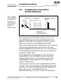 15
15
-
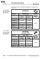 16
16
-
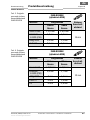 17
17
-
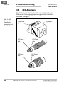 18
18
-
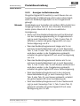 19
19
-
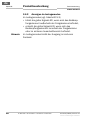 20
20
-
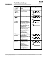 21
21
-
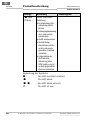 22
22
-
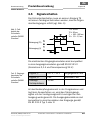 23
23
-
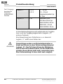 24
24
-
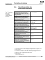 25
25
-
 26
26
-
 27
27
-
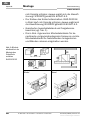 28
28
-
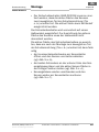 29
29
-
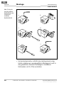 30
30
-
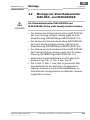 31
31
-
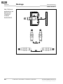 32
32
-
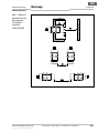 33
33
-
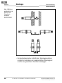 34
34
-
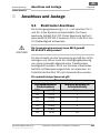 35
35
-
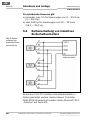 36
36
-
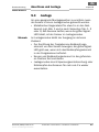 37
37
-
 38
38
-
 39
39
-
 40
40
-
 41
41
-
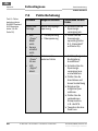 42
42
-
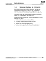 43
43
-
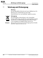 44
44
-
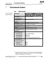 45
45
-
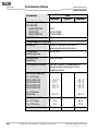 46
46
-
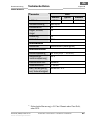 47
47
-
 48
48
-
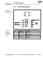 49
49
-
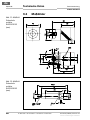 50
50
-
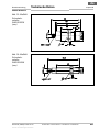 51
51
-
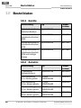 52
52
-
 53
53
-
 54
54
-
 55
55
-
 56
56
-
 57
57
-
 58
58
-
 59
59
-
 60
60
-
 61
61
-
 62
62
-
 63
63
-
 64
64
-
 65
65
-
 66
66
-
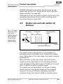 67
67
-
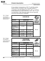 68
68
-
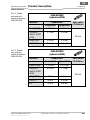 69
69
-
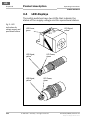 70
70
-
 71
71
-
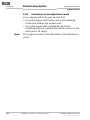 72
72
-
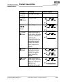 73
73
-
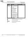 74
74
-
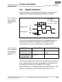 75
75
-
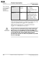 76
76
-
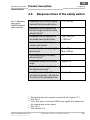 77
77
-
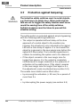 78
78
-
 79
79
-
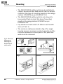 80
80
-
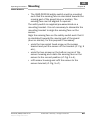 81
81
-
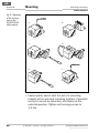 82
82
-
 83
83
-
 84
84
-
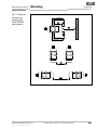 85
85
-
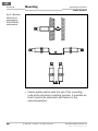 86
86
-
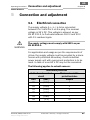 87
87
-
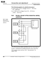 88
88
-
 89
89
-
 90
90
-
 91
91
-
 92
92
-
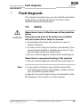 93
93
-
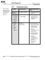 94
94
-
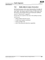 95
95
-
 96
96
-
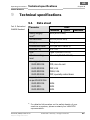 97
97
-
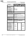 98
98
-
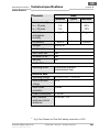 99
99
-
 100
100
-
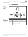 101
101
-
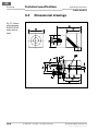 102
102
-
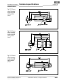 103
103
-
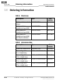 104
104
-
 105
105
-
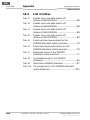 106
106
-
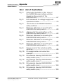 107
107
-
 108
108
-
 109
109
-
 110
110
-
 111
111
-
 112
112
-
 113
113
-
 114
114
-
 115
115
-
 116
116
-
 117
117
-
 118
118
-
 119
119
-
 120
120
-
 121
121
-
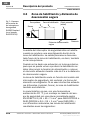 122
122
-
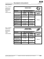 123
123
-
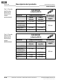 124
124
-
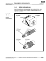 125
125
-
 126
126
-
 127
127
-
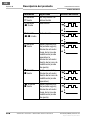 128
128
-
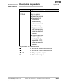 129
129
-
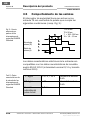 130
130
-
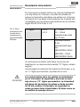 131
131
-
 132
132
-
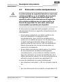 133
133
-
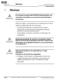 134
134
-
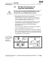 135
135
-
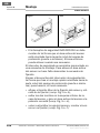 136
136
-
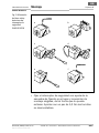 137
137
-
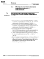 138
138
-
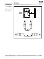 139
139
-
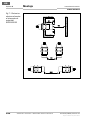 140
140
-
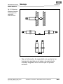 141
141
-
 142
142
-
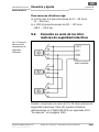 143
143
-
 144
144
-
 145
145
-
 146
146
-
 147
147
-
 148
148
-
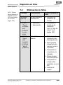 149
149
-
 150
150
-
 151
151
-
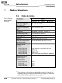 152
152
-
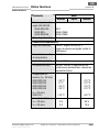 153
153
-
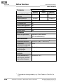 154
154
-
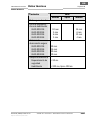 155
155
-
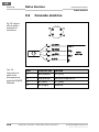 156
156
-
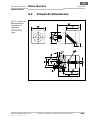 157
157
-
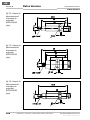 158
158
-
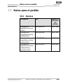 159
159
-
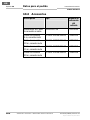 160
160
-
 161
161
-
 162
162
-
 163
163
-
 164
164
-
 165
165
-
 166
166
-
 167
167
-
 168
168
-
 169
169
-
 170
170
-
 171
171
-
 172
172
-
 173
173
-
 174
174
-
 175
175
-
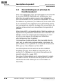 176
176
-
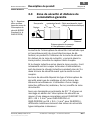 177
177
-
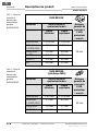 178
178
-
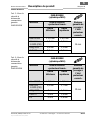 179
179
-
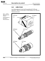 180
180
-
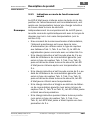 181
181
-
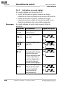 182
182
-
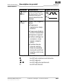 183
183
-
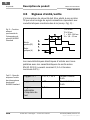 184
184
-
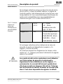 185
185
-
 186
186
-
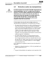 187
187
-
 188
188
-
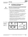 189
189
-
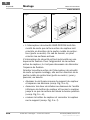 190
190
-
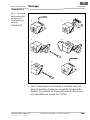 191
191
-
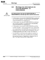 192
192
-
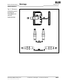 193
193
-
 194
194
-
 195
195
-
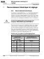 196
196
-
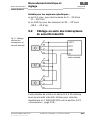 197
197
-
 198
198
-
 199
199
-
 200
200
-
 201
201
-
 202
202
-
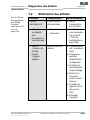 203
203
-
 204
204
-
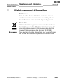 205
205
-
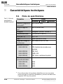 206
206
-
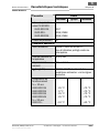 207
207
-
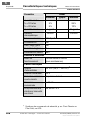 208
208
-
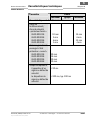 209
209
-
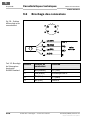 210
210
-
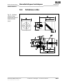 211
211
-
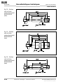 212
212
-
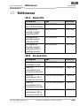 213
213
-
 214
214
-
 215
215
-
 216
216
-
 217
217
-
 218
218
-
 219
219
-
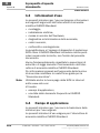 220
220
-
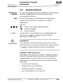 221
221
-
 222
222
-
 223
223
-
 224
224
-
 225
225
-
 226
226
-
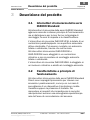 227
227
-
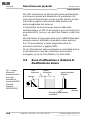 228
228
-
 229
229
-
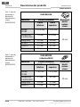 230
230
-
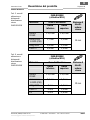 231
231
-
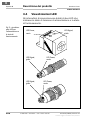 232
232
-
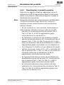 233
233
-
 234
234
-
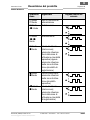 235
235
-
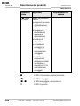 236
236
-
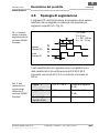 237
237
-
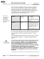 238
238
-
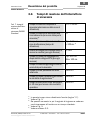 239
239
-
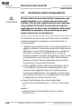 240
240
-
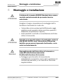 241
241
-
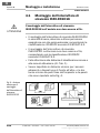 242
242
-
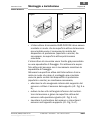 243
243
-
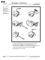 244
244
-
 245
245
-
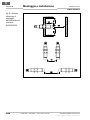 246
246
-
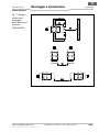 247
247
-
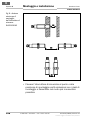 248
248
-
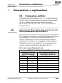 249
249
-
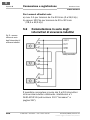 250
250
-
 251
251
-
 252
252
-
 253
253
-
 254
254
-
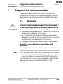 255
255
-
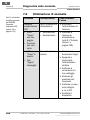 256
256
-
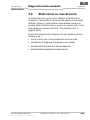 257
257
-
 258
258
-
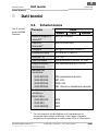 259
259
-
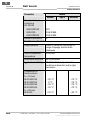 260
260
-
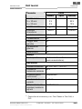 261
261
-
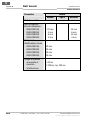 262
262
-
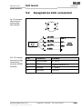 263
263
-
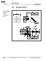 264
264
-
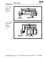 265
265
-
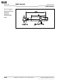 266
266
-
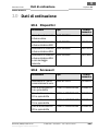 267
267
-
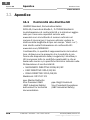 268
268
-
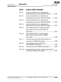 269
269
-
 270
270
-
 271
271
-
 272
272


SICK IN4000 Standard Safety Switch Instrucciones de operación
- Tipo
- Instrucciones de operación
en otros idiomas
Artículos relacionados
-
SICK IN3000 Direct Safety Switch Instrucciones de operación
-
-
-
-
-
-
-
-
-