
OPERATOR’S MANUAL
MANUAL DE OPERACIÓN
Roller
Rodillo
RD11V
0151722 001
0301
0151722

BELGIEBELGIE
BELGIEBELGIE
BELGIE
1730 ASSE-MOLLEM1730 ASSE-MOLLEM
1730 ASSE-MOLLEM1730 ASSE-MOLLEM
1730 ASSE-MOLLEM ASSESTEENWEG 17
Tel. (32) 02-4528509+07Tel. (32) 02-4528509+07
Tel. (32) 02-4528509+07Tel. (32) 02-4528509+07
Tel. (32) 02-4528509+07
4040 Herstal 4 Avenue
9800 Deinze Kortrijkse Steenweg 400 Tel. (09)-386 8529
6041 Gosselies-Charleroi Route Nationale Cinq Tel. 071-372450
ÇESKÁ
REPUBLIKA REPUBLIKA
REPUBLIKA REPUBLIKA
REPUBLIKA
19402 PRAHA 9-HLOUBETIN KOLBENOVA 259
Tel. (0042) 2 862165Tel. (0042) 2 862165
Tel. (0042) 2 862165Tel. (0042) 2 862165
Tel. (0042) 2 862165
DANMARKDANMARK
DANMARKDANMARK
DANMARK
2690 KARLSLUNDE RØRGANGEN 6
Tel. 46 15 36 00Tel. 46 15 36 00
Tel. 46 15 36 00Tel. 46 15 36 00
Tel. 46 15 36 00
8200 Arhus N Randersvej 346 Tel. 86-231777
5250 Odense SV Holkebjergvej 56A Tel. 66-172170
ESPAÑAESPAÑA
ESPAÑAESPAÑA
ESPAÑA
28850 TORREJON DE ARDOZ (MADRID) POLIGONO INDUSTRIAL LAS MONJAS
Tel. (34) 91-6757525 / 85Tel. (34) 91-6757525 / 85
Tel. (34) 91-6757525 / 85Tel. (34) 91-6757525 / 85
Tel. (34) 91-6757525 / 85
CALLE PRIMAVERA 11
08780 PALLEJA (Barcelona) PRAT DE LA RIBA, 184 Tel. (93)-6632273
41700 Dos Hermanas (Sevilla) Poligono Industrial La Palmera Tel. (95)-4691129
Nave 14 Tel. (95)-4691129
46133 Meliana (Valencia) Calle Salvador Giner, 6 Tel. (96)-1492102
15890 Santiago de Compostela (La Coruña) Poligono Industrial el Tambre, Via Pasteur, 47a Tel. (981) 573366 / 67
SUOMISUOMI
SUOMISUOMI
SUOMI
FIN 04250 KERAVA Peltomäenkatu 7
Tel. (358) 9-274 4740Tel. (358) 9-274 4740
Tel. (358) 9-274 4740Tel. (358) 9-274 4740
Tel. (358) 9-274 4740
FRANCEFRANCE
FRANCEFRANCE
FRANCE
77170 BRIE COMTE ROBERT 335, RUE GLORIETTE—ZAC DU TUBOEUF
Tel. (33) 1-60623000Tel. (33) 1-60623000
Tel. (33) 1-60623000Tel. (33) 1-60623000
Tel. (33) 1-60623000
Aix en Provence 13540 Puyricard Tel. 4 42630526
Arras 62217 Beaurains Tel. 3 21235361
Bordeaux 33700 Merignac Tel. 5 56343346
Bourges 18390 St. Germain du Puy Tel. 2 48652015
Lyon 69740 Genas Tel. 4 78401384
Nancy 54180 Heillecourt Tel. 3 83565801
Rennes 35510 Cesson Sevigne Tel. 2 99321522
Toulouse 31270 Cugnaux Tel. 5 61075250
Kehl 77694 Kehl-Goldscheuer Tel. (0590) 9321
HUNGARIAHUNGARIA
HUNGARIAHUNGARIA
HUNGARIA
1106 BUDAPEST Kada u. 137
Tel. (36) 1-260 8668Tel. (36) 1-260 8668
Tel. (36) 1-260 8668Tel. (36) 1-260 8668
Tel. (36) 1-260 8668
IRELANDIRELAND
IRELANDIRELAND
IRELAND
DUBLIN 13 127A. BALDOYLE INDUSTRIAL ESTATE
Tel. (00353) 01-8320218Tel. (00353) 01-8320218
Tel. (00353) 01-8320218Tel. (00353) 01-8320218
Tel. (00353) 01-8320218
ITALIAITALIA
ITALIAITALIA
ITALIA
40016 SAN GIORGIO DI PIANO (Bologna) Via Due Agosto, 1980, Strage di Bologna, 3
Tel. 39.05.665.566 - 665.1574Tel. 39.05.665.566 - 665.1574
Tel. 39.05.665.566 - 665.1574Tel. 39.05.665.566 - 665.1574
Tel. 39.05.665.566 - 665.1574
00125 ACILIA (Roma) Viale Enrico Ortolani, 262 Tel. 39 . 06 . 5219246
20041 Agrate Brianza (Mi) Via Archimede, 31 Tel. 39. 039.699 0136
NEDERLANDNEDERLAND
NEDERLANDNEDERLAND
NEDERLAND
3821 BJ AMERSFOORT COBOLWEG 1
Tel. 033 - 450 40 45Tel. 033 - 450 40 45
Tel. 033 - 450 40 45Tel. 033 - 450 40 45
Tel. 033 - 450 40 45
2984 BL Ridderker Glasblazerstraat 7 Tel. 0180 - 41 70 56
7418 EZ Deventer Arnbergstraat 9 Tel. 0570 - 63 00 87
5684 PS Best De Dintel 37 Tel. 0499 - 33 04 33
1704 RT Heerhugowaard Einsteinstraat 4d Tel. 072 - 574 20 78
9411 XN Beilen De Hanekampen 19 Tel. 0593 - 52 31 24
NORGENORGE
NORGENORGE
NORGE
1481 HAGAN TYRIVN. 7
Tel. (47) 0 6707-2330Tel. (47) 0 6707-2330
Tel. (47) 0 6707-2330Tel. (47) 0 6707-2330
Tel. (47) 0 6707-2330
POLSKAPOLSKA
POLSKAPOLSKA
POLSKA
05-850 O•ARÓW MAZOWIECKI UL. KONOTOPSKA 4
Tel. (48) 22 722 20 59Tel. (48) 22 722 20 59
Tel. (48) 22 722 20 59Tel. (48) 22 722 20 59
Tel. (48) 22 722 20 59
62-081 Wysogotowo k. Poznania ul. Kamienna 1 Tel. (061) 814-3797
PORTUGALPORTUGAL
PORTUGALPORTUGAL
PORTUGAL
2785-S. Domingos De Rana Urbanização Industrial de Trajouce, Lote 1
Tel. (351) 21 4443561 / 87Tel. (351) 21 4443561 / 87
Tel. (351) 21 4443561 / 87Tel. (351) 21 4443561 / 87
Tel. (351) 21 4443561 / 87
4785-S. Romao do Coronado Lg. do Soeiro, Apartado 2 Tel. (351) 22 982 7992 / 93
SVERIGESVERIGE
SVERIGESVERIGE
SVERIGE
24734 SÖDRA SANDBY SKATTEBERGAVÄGEN 13
Tel. (46) 046-57870Tel. (46) 046-57870
Tel. (46) 046-57870Tel. (46) 046-57870
Tel. (46) 046-57870
16170 Bromma Karlsbodavägen 17E Tel. 08-282860
41749 Göteborg Knipplekullen 3A Tel. 031-551362
SCHWEIZSCHWEIZ
SCHWEIZSCHWEIZ
SCHWEIZ
8305 Dietlikon Bahnhofstrasse 3
Tel. (41) 1-8353939Tel. (41) 1-8353939
Tel. (41) 1-8353939Tel. (41) 1-8353939
Tel. (41) 1-8353939
TURKIYETURKIYE
TURKIYETURKIYE
TURKIYE
81120 K. Bakkalköy-ISTANBUL Karaman Çiftligi Cad. No: 55
Tel. (90) 216 573 0621Tel. (90) 216 573 0621
Tel. (90) 216 573 0621Tel. (90) 216 573 0621
Tel. (90) 216 573 0621
35350 Üçkuyular-Izmir Mithatpasa Cad. No. 1189 Tel. (90) 232 259 8944
Ostim 06370 Ankara Alinteri Bulvari No. 210 Tel. (90) 312 385 6438/6439

RD11V
i
This manual provides information and procedures to safely operate and maintain this WACKER model. For your
own safety and protection from injury, carefully read, understand and observe the safety instructions described
in this manual. THE INFORMATION CONTAINED IN THIS MANUAL WAS BASED ON MACHINES IN PRODUCTION
AT THE TIME OF PUBLICATION. WACKER CORPORATION RESERVES THE RIGHT TO CHANGE ANY PORTION
OF THIS INFORMATION WITHOUT NOTICE.
Este manual contiene información y procedimientos que son necesarios para operar y mantener esta máquina
WACKER. Para su propia seguridad y protección, lea por favor este manual cuidadosamente y observe todas las
instrucciones de seguridad descritas en este manual. LA INFORMACION CONTENIDA POR ESTE MANUAL FUE
BASADA EN LAS MAQUINAS FABRICADAS AL TIEMPO DE SU PUBLICACION. WACKER RESERVA EL
DERECHO DE CAMBIAR CUALQUIER PORCION DE ESTE MANUAL SIN AVISO PREVIO.
This manual is divided into the sections listed below:
Este manual está compuesto por las siguientes secciones:
Operation
(English)
Maintenance
Operación
(Español)
Mantenimiento
1A
2A
1C
2C
Item Number / Número de referencia:
0007694
Engine exhaust, some of its constituents, and certain vehicle
components contain or emit chemicals known to the State of
California to cause cancer and birth defects or other
reproductive harm.
!
WARNING
1040SD71

RD11V
ii
Serial Number
Número de Serie
My machine’s numbers are / Los números de mi máquina son:
Revision
Nivel de revisión
Item Number
Número de referencia
Model number
Modelo
Rev. Serial Number
MENOMONEE FALLS, WI USA 53051
hpkWlbs
dB(A)
Model
kg
MADE
IN USA
Item Number
88291
RD11VRD11V
RD11VRD11V
RD11V
00076940007694
00076940007694
0007694 101101
101101
101
50101015010101
50101015010101
5010101
Nameplate / Placa de Identificación
A nameplate listing the Model Number, Item Number, Revision, and Serial Number is attached to each unit. Please
record the information found on this plate so it will be available should the nameplate become lost or damaged. When
ordering parts or requesting service information, you will always be asked to specify the model, item number,
revision number, and serial number of the unit.
Una placa de identificación con el modelo, número de referencia, nivel de revisión y número de serie ha sido añadida
en cada máquina. Favor de anotar los datos en la placa en caso de que la placa de identificación sea destruida o
perdida. En todos los pedidos para repuestos necesita siempre el modelo, el número de referencia, el nivel de
revisión y el número de serie de la máquina en cuestión.
1031SD50

RD11V
iii
PATENT PENDING
111545
This machine may be covered by one or more of the following patents:
Puede ser que las patentes a continuación sean válidas para esta máquina:
111891
OF THESE U.S. PATENTS:
4643611; 4555238; 5564375; 5586630; 4419048
WACKER MACHINES PROTECTED BY ONE OR MORE

RD11V
iv
Keep this manual or a copy of it with the machine. If you lose this manual or need an
additional copy, please contact WACKER Corporation. This machine is built with user
safety in mind, however, it can present hazards if improperly operated and serviced.
Follow operating instructions carefully! If you have questions about operating or
servicing this equipment, please contact WACKER Corporation.
Mantenga este manual o una copia de el con la máquina. Si se pierde o si Ud. desea un
ejemplar adicional, favor comunicarse con WACKER. Esta máquina fue fabricada con la
seguridad del usuario en mente; sin embargo, situaciones peligrosas pueden presentarse
si la máquina es utilizada o mantención es dada inapropiadamente. Siga las instrucciones
de operación cuidadosamente. Si Ud. tiene preguntas acerca de la operación o mantención
de este equipo, favor de comunicarse con WACKER CORPORATION.

RD11V
Operation
Table of Contents
1A
1A-1
1.1 Safety Information ..................................................................................... 1A-2
1.2 Application ................................................................................................ 1A-2
1.3 Laws Pertaining to Spark Arresters........................................................... 1A-2
1.4 Operating Safety ....................................................................................... 1A-3
1.5 Service Safety........................................................................................... 1A-4
1.6 Operator Safety while using Internal Combustion Engines........................ 1A-5
1.7 Dimensions ............................................................................................... 1A-6
1.8 Technical Data .......................................................................................... 1A-7
1.9 Label Location........................................................................................... 1A-8
1.10 Warning & Informational Labels .............................................................. 1A-10
1.11 Operating Labels..................................................................................... 1A-13
1.12 Operation & Service Locations................................................................ 1A-14
1.13 Vibration.................................................................................................. 1A-16
1.14 Watering System .................................................................................... 1A-16
1.15 Articulation Joint Lockarm ....................................................................... 1A-17
1.16 Adding Ballast To Rear Drum ................................................................. 1A-17
1.17 Roll Over Protection Structure (ROPS) ................................................... 1A-18
1.18 Operation on Slopes ............................................................................... 1A-19
1.19 Before Starting ........................................................................................ 1A-20
1.20 Starting ................................................................................................... 1A-20
1.21 Direction and Speed ............................................................................... 1A-21
1.22 Braking Machine ..................................................................................... 1A-21
1.23 Stopping/Parking..................................................................................... 1A-21
1.24 Hood Prop Bar ........................................................................................ 1A-22
1.25 Hour Meter/Tachometer .......................................................................... 1A-22

1A-2
1A OPERATION RD11V
1.3 Laws Pertaining to Spark Arresters
Notice: Some states require that in certain locations, spark arresters be used on internal combustion engines. A spark
arrester is a device designed to prevent the discharge of sparks or flames from the engine exhaust. It is often required
when operating equipment on forested land to reduce the risk of fires. Consult the engine distributor or local authorities
and make sure you comply with regulations regarding spark arresters.
1.2 Application
This machine is designed as a lightweight roller to be used in the compaction of sublayers and finish layers of asphalt
on roads, driveways, parking lots, and other types of asphalt-covered surfaces. Do not use this machine for any other
purpose.
1.1 Safety Information
This manual contains DANGER, WARNING, CAUTION, and NOTE callouts which must be followed to reduce the
possibility of personal injury, damage to the equipment, or improper service.
CAUTION: Used without the safety alert symbol,
CAUTION indicates a potentially hazardous situation
which, if not avoided, may result in property damage.
Note:
Contains additional information
important to a procedure.
This is the safety alert symbol. It is used to alert you to potential
personal injury hazards. Obey all safety messages that follow
this symbol to avoid possible injury or death.
DANGER indicates an imminently hazardous
situation which, if not avoided, will result in
death or serious injury.
CAUTION indicates a potentially hazardous
situation which, if not avoided, may result in
minor or moderate injury.
WARNING indicates a potentially hazardous
situation which, if not avoided, could result in
death or serious injury.
!
WARNING
!
CAUTION
!
!
DANGER

1A-3
RD11V OPERATION 1A
1.4 Operating Safety
Familiarity and proper training are required for the safe operation of mechanical equipment! Equipment operated
improperly or by untrained personnel can be dangerous! Read the operating instructions in both this manual and the
engine manual and familiarize yourself with the location and proper use of all controls. Inexperienced operators should
receive instruction from someone familiar with the equipment before being allowed to operate the machine.
ALWAYS disengage and stow locking bar for the
articulated joint before operating machine. The ma-
chine cannot be steered when the locking bar is
engaged.
ALWAYS check that all controls are functioning prop-
erly immediately after start-up! DO NOT operate ma-
chine unless all controls operate correctly.
ALWAYS remain aware of changing positions and
movement of other equipment and personnel on the
jobsite.
ALWAYS remain seated at all times while operating
machine.
ALWAYS remain aware of changing surface condi-
tions and use extra care when operating over uneven
ground, on hills, or over soft or coarse material. The
machine could shift or slide unexpectedly.
ALWAYS use caution when operating near the edges
of pits, trenches or platforms. Check to be sure ground
surface is stable enough to support the weight of the
machine and there is no danger of the roller sliding,
falling or tipping.
ALWAYS wear protective clothing when operating
equipment. For instance, goggles or safety glasses
will protect eyes from damage caused by flying debris.
ALWAYS keep hands, feet, and loose clothing away
from moving parts of equipment.
ALWAYS read, understand, and follow procedures in
Operator’s Manual before attempting to operate equip-
ment.
ALWAYS store equipment properly when it is not
being used. Equipment should be stored in a clean,
dry location out of the reach of children.
ALWAYS operate machine with all safety devices
and guards in place and in working order.
NEVER allow improperly trained people to operate
this equipment. People operating this equipment must
be familiar with the potential risks and hazards asso-
ciated with it.
NEVER touch engine or muffler while machine is
operating or immediately after it has been turned off.
These areas get hot and may cause burns.
NEVER use accessories or attachments which are
not recommended by WACKER for this equipment.
Damage to equipment and/or injury to user may
result.
NEVER leave machine running unattended.
NEVER operate a defective unit in need of service or
repair.
NEVER operate with fuel cap loose or missing.
WARNING
!

1A-4
1A OPERATION RD11V
1.5 Service Safety
Poorly maintained equipment can become a safety hazard! In order for the equipment to operate safely and properly
over a long period of time, periodic maintenance and occasional repairs are necessary.
DO NOT attempt to clean or service machine while
it is running. Rotating parts can cause severe injury.
DO NOT crank a flooded engine with the spark plug
removed on gasoline-powered engines. Fuel trapped
in the cylinder will squirt out the spark plug opening.
DO NOT test for spark on gasoline-powered engines,
if engine is flooded or the smell of gasoline is present.
A stray spark could ignite fumes.
DO NOT use gasoline or other types of fuels or
flammable solvents to clean parts, especially in en-
closed areas. Fumes from fuels and solvents can
accumulate and become explosive.
DO NOT modify the equipment without express writ-
ten approval of the manufacturer.
ALWAYS keep area around muffler free of debris
such as leaves, paper, cartons, etc. A hot muffler
could ignite them, starting a fire.
ALWAYS replace worn or damaged components
with spare parts designed and recommended by
WACKER for servicing this machine.
ALWAYS remove or disconnect spark plug on
machines equipped with gasoline engines, before
servicing, to avoid accidental start-up.
ALWAYS keep machine clean and labels legible.
Replace all missing and hard-to-read labels. Labels
provide important operating instructions and warn
of dangers and hazards.
ALWAYS check and tighten all external fasteners
at regular intervals.
WARNING
!

1A-5
RD11V OPERATION 1A
DO NOT run machine indoors or in an enclosed
area unless adequate ventilation, through such
items as exhaust fans or hoses, is provided. Ex-
haust gas from the engine contains poisonous
carbon monoxide gas; exposure to carbon monox-
ide can cause loss of consciousness and may lead
to death.
ALWAYS refill fuel tank in well-ventilated area.
ALWAYS replace fuel tank cap after refueling.
ALWAYS keep area around hot exhaust pipes free
of debris to reduce the chance of an accidental fire.
DO NOT smoke while operating machine.
DO NOT smoke when refueling engine.
DO NOT refuel hot or running engine.
DO NOT refuel engine near open flame.
DO NOT spill fuel when refueling engine.
DO NOT operate near open flames.
1.6 Operator Safety while using Internal Combustion Engines
Internal combustion engines present special hazards during operation and fueling! Failure to follow the safety guidelines
described below could result in severe injury or death.
WARNING
!

1A-6
1A OPERATION RD11V
1.7 Dimensions
C
F
F
E
E
D
A
G
B
1025SD75
ABCDEFG
60 87 83 44 22 35 40
1530 2210 2100 1127 560 900 1025
inches / mm
E

1A-7
RD11V OPERATION 1A
Engine
1.8 Technical Data
Roller
Engine Make
Engine Model
Power Hp (kW)
Displacement in
3
(cm
3
)
Spark Plug
Electrode Gap in. (mm)
Starter type / V
Alternator Amp
Air Cleaner type
Operating Speed rpm
Valve Clearance (cold)intake in. (mm)
exhaust
Battery V / Size
Fuel type
Fuel Capacity gal. (l)
Fuel Consumption gal. (l)/hr.
Briggs & Stratton
Champion RC12YC
0.030 (0.76)
Electric / 12
20
Dual Element
3200
0.004–0.006 (0.10–0.16)
0.004–0.006 (0.10–0.16)
12 / 22NF
Lead-free Regular
6.3 (24)
1.2 (4.6)
2040 (925)
82 x 41 x 60 (2080 x 1040 x 1530)
35.4 (900)
18.4 / 8.1 (470 / 205)
40 (151)
9.2 (2.8)
0–414
(0–126)
1
27% (12
°
)
3900 (65)
Dry Weight lb.(kg)
Overall Size l x w x h in. (mm)
Drum Width in. (mm)
Curb Clearance right/left in. (mm)
Water Tank Capacity gal. (l)
Outside Turning Radius ft. (m)
Forward / Reverse Speed
1
ft. (m) / min.
Gradeability
Vibration Frequency vpm (Hz)
1
Maximum values for forward and reverse speeds are based on the machine traveling on a firm, level surface and engine at full throttle.
Lubrication
Engine Crankcase
Hydraulic System
Exciter
Rear Drum Drive Bearing
Articulated Joint
Front Drum Drive Bearings
Type
SAE 10W30
SG, SF, or SE rated
Premium grade,
Anti-wear hydraulic fluid
10W30
Shell Alvania No. 2 Grease
(1 grease fitting)
Shell Alvania No. 2 Grease
(4 grease fittings)
Sealed Bearings—No lubrication required
Quantity
3.5 pts. (1.6 liters)
5.7 U.S. gal. (21.6 liters)
2-3 shots with hand-held
grease gun
Wheel Bearing Grease Filmite EMB
*Vanguard 303447 **Vanguard 350447
16 (11.9) 18 (13.4)
29.3 (480) 34.7 (570)
* Revisions 110 & Lower. **Revisions 111 & Higher.

1A-8
1A OPERATION RD11V
CAUTION
PRECAUTION
PRECAUCION
VORSICHT
AVOID CRUSHING AREA
WARNING
EVITE ZONA DE APRIETE
QUETSCH-ZONE VERMEIDEN
EVITER ZONE DE RACCORDEMENT A PINCE
ADVERTENCIA
WARNUNG
AVERTISSEMENT
1.9 Label Location
STOP
DANGER
DANGER
GEFAHR
PELIGRO
STOP
DANGER
GEFAHR
PELIGRO
DANGER
MAX
3.39 Nm
MAX
30 lb-in
115682
(Under Hood)
1041SD29
(Inside Door)

1A-9
RD11V OPERATION 1A
1 0 0
READ AND UNDERSTAND THE SUPPLIED OPERATOR'S MANUAL BEFORE
OPERATING THIS MACHINE. FAILURE TO DO SO INCREASES THE
RISK OF INJURY TO YOURSELF OR OTHERS.
VOR INBETRIEBNAHME DIESES GERÄTES BEIGEFÜGTE BETRIEBSVOR-
SCHRIFT LESEN UND VERSTEHEN. NICHTBEFOLGUNG ERHÖHT DAS
RISIKO ZU EIGENER VERLETZUNG ODER ANDERER.
LEA Y ENTIENDA EL MANUAL DE OPERACION PROVISTO CON EL
EQUIPO ANTES DE QUE OPERE ESTE EQUIPO. DE NO HACERSE
ASI, PODRIA AUMENTAR EL RIESGO DE DAÑOS PERSONALES Y
A OTRAS PERSONAS.
LIRE ET COMPRENDRE LA NOTICE D'EMPLOI FOURNIE AVEC LA
MACHINE AVANT DE LA METTRE EN SERVICE. A DEFAUT, VOUS
AUGMENTERIEZ LE RISQUE DE VOUS EXPOSER ET LES AUTRES A
DES BLESSURES.
WARNING
WARNUNG
ADVERTENCIA
AVERTISSEMENT
116859
WARNING
WARNUNG
ADVERTENCIA
AVERTISSEMENT
PRECAUTION
PRECAUCION
VORSICHT
CAUTION
1.9 Label Location (cont.)
1041SD30
A D V E R T E N C I A
A V E R T I S S E M E N T
W A R N U N G
W A R N I N G
W A R N U N G
W A R N I N G
A D V E R T E N C I A
A V E R T I S S E M E N T

1A-10
1A OPERATION RD11V
1.10 Warning & Informational Labels
This WACKER machine uses international pictorial labels where needed. These labels are described below:
Label Meaning Label Meaning
WARNING!
Pinch point
Tie-down point
(one of two)
Hydraulic oil reservoir
level (on rear wall of front
section,outside engine
compartment)
Hydraulic oil reservoir fill
(on fill cap)
Hydraulic oil drain
CAUTION
Lift point
(one of four)
111418b
111760a
111760b
110176-5
112216
WARNING!
Hot surface
117039
111418-2
110745-2
AVOID CRUSHING AREA
WARNING
EVITE ZONA DE APRIETE
QUETSCH-ZONE VERMEIDEN
EVITER ZONE DE RACCORDEMENT A PINCE
ADVERTENCIA
WARNUNG
AVERTISSEMENT
WARNING
WARNUNG
ADVERTENCIA
AVERTISSEMENT
CAUTION
PRECAUTION
PRECAUCION
VORSICHT
PRECAUTION
PRECAUCION
VORSICHT
CAUTION
CAUTION!
Read and understand the supplied operator's
manual before operating this machine. Failure
to do so increases the risk of injury to yourself
or others.

1A-11
RD11V OPERATION 1A
Label Meaning
110200
117034
114473-4
118362
1 0 0
Grease points:
Inspect and lubricate every 100 hours
of operation.
114965
WARNING!
Always wear seat belt when operating roller.
A D V E R T E N C I A
A V E R T I S S E M E N T
W A R N U N G
W A R N I N G
STOP
DANGER
DANGER
GEFAHR
PELIGRO
1.10 Warning & Informational Labels (Continued)
This WACKER machine uses international pictorial labels where needed. These labels are described below:
STOP
DANGER
GEFAHR
PELIGRO
DANGER
W A R N U N G
W A R N I N G
A D V E R T E N C I A
A V E R T I S S E M E N T
DANGER!
Engines emit carbon monoxide; operate only
in well ventilated area.
Read the operator's manual.
No sparks, flames or burning objects near
machine. Shut off engine before refueling.
WARNING!
To prevent hearing loss, wear hearing protec-
tion when operating this machine.
DANGER!
Before fueling, stop the engine.
No sparks, flames or burning objects near
machine.

1A-12
1A OPERATION RD11V
1.10 Warning & Informational Labels (Continued)
This WACKER machine uses international pictorial labels where needed. These labels are described below:
113823
113824
Gas level Water level
115682
Torque battery
hold down nuts
to 30 in.lbs.
(3.39 Nm) max.
MAX
3.39 Nm
MAX
30 lb-in
115682
READ AND UNDERSTAND THE SUPPLIED OPERATOR'S MANUAL BEFORE
OPERATING THIS MACHINE. FAILURE TO DO SO INCREASES THE
RISK OF INJURY TO YOURSELF OR OTHERS.
VOR INBETRIEBNAHME DIESES GERÄTES BEIGEFÜGTE BETRIEBSVOR-
SCHRIFT LESEN UND VERSTEHEN. NICHTBEFOLGUNG ERHÖHT DAS
RISIKO ZU EIGENER VERLETZUNG ODER ANDERER.
LEA Y ENTIENDA EL MANUAL DE OPERACION PROVISTO CON EL
EQUIPO ANTES DE QUE OPERE ESTE EQUIPO. DE NO HACERSE
ASI, PODRIA AUMENTAR EL RIESGO DE DAÑOS PERSONALES Y
A OTRAS PERSONAS.
LIRE ET COMPRENDRE LA NOTICE D'EMPLOI FOURNIE AVEC LA
MACHINE AVANT DE LA METTRE EN SERVICE. A DEFAUT, VOUS
AUGMENTERIEZ LE RISQUE DE VOUS EXPOSER ET LES AUTRES A
DES BLESSURES.
WARNING
WARNUNG
ADVERTENCIA
AVERTISSEMENT
116859
116859-1
Label Meaning Label Meaning

1A-13
RD11V OPERATION 1A
1.11 Operating Labels
Variable speed throttle:
High engine speed
Low engine speed
Variable choke:
Fully closed
Fully open
Label Meaning Label Meaning
Variable direction control:
Forward
Neutral
Reverse
Vibration control:
Press to turn vibration on
Press to turn vibration off
Key switch, engine start:
Off
On
Start
Water control valve:
Fully open
Fully closed
This WACKER machine uses international pictorial labels where needed. These labels are described below:
111780 111780
111945
111945
89712112123
G3000064

1A-14
1A OPERATION RD11V
1.12 Operation & Service Locations
40
20
26
8
24
34
33
14
40
42
43
30
47
9
11
21
18
40
2
24
39
40
37
9
29
3
23
13
47
48
49
49
49
49
37
35
35
35
36
37
37
50
50
51
51
4
22
G3000063
52
52
45

1A-15
RD11V OPERATION 1A
G3000062
7
25
10
31
32
16
28
1
6
44
19
15
Engine Compartment
1022SD70
Ref. Description
1. Air Cleaner (Vanguard shown)
2. Articulated Joint
3. Water Level Sight Gauge
4. Parking Brake Lever
5. Choke Lever
6. Coupling - Engine
7. Dipstick
8. Drain Plug - Hydraulic Tank
9. Drive Motor
10. Drive Pump
11. Engine Hood
12. Engine Throttle Control
13. Vibration Control Button
14. Exciter Motor
15. Exciter/Steering Pump
16. Filter - Return Line
17. Filter - Suction Line
18. Forward / Reverse Control
19. Forward / Reverse Control Cable
20. Front Drum - Vibratory
21. Fuel Tank Access Door
22. Fuel Filter (under floor panel)
23. Grease Fitting - Rear Drum
24. Grease Fittings - Articulated Joint (4 places)
25. Hydraulic Tank Fill Port
26. Identification Plate
27. Ignition Switch
28. Steering/Exciter Manifold
29. Water Tank
30. Lockarm
31. Drive Manifold Assembly (Valve Block)
32. Oil Filter - Engine
33. Rear Drum Fill/Drain Plug
34. Rear Drum - Static
35. Scraper Bar (4 places)
36. Sightglass - Hydraulic Tank
37. Sprinkler Tube (4)
38. Steering Wheel
39. Steering Cylinder
40. Tiedown (2 places)
41. Towing Valve
42. Water System Control - Front Drum
43. Water System Control - Rear Drum
44. Battery
45. Hour Meter / Tachometer
46. Suction Line
47. Grease Fitting - Exciter (2 places)
48. Fuel Level Sight Gauge
49. Lifting Eye (4 places)
50. Step (2)
51. ROPS
52. Safety Belt
53. Exciter Indicator Light
17
46
Ref. Description
41
12
38
5
27
53

1A-16
1A OPERATION RD11V
1022SD76
1.13 Vibration
Vibration is turned “ON” or “OFF” by a push button (a)
located in the uppermost portion of the Forward/Reverse
Control. Push the button to turn vibration on; push it again
to turn it off. Vibration can be turned on while operating in
either forward or reverse and will remain on until it is
switched off.
CAUTION: If machine has been turned off with the
vibration on, the vibration will come on as soon as
machine is restarted. Therefore, for easier starting and to
keep surface finish smooth, be ready to switch vibration
off should it come on while cranking engine.
Note:
Vibration will remain on even when the forward/
reverse control is in neutral. When operating on asphalt,
to keep surface finish smooth, turn vibration off before
stopping roller.
1.14 Watering System
The watering system is controlled by two valves, one for
each drum. The valve handles (b) are located to the right
of the operator. Rotate the valve handles to control the
amount of water being applied to the drum.
FRONT DRUM
REAR DRUM
(Shown in the fully
OPEN position)
(Shown in the fully
CLOSED position)
b
a
1022SD74
a

1A-17
RD11V OPERATION 1A
c
d
1.15 Articulation Joint Lockarm
A lockarm (c), located above the articulated joint, is
provided to secure the front and rear halves of the roller
together. Once secured, the lockarm prevents the two
halves from swinging together.
To set lockarm, release it from its holder and swing it out
from its stored position. Place the forward end of the arm
into the hole provided in the front frame of the machine.
Secure it in this position using the large hairpin cotter
(d)
provided.
1022SD77
1.16 Adding Ballast To Rear Drum
The rear drum can be filled with ballast to provide
additional weight. Add ballast through plug opening (e).
Drum Capacity: 30.2 gal. (114 liters)
Added Weight (water ballast): 250 lbs. (113 Kg)
If water is used as ballast, add antifreeze or drain drum
after use, in areas where temperatures are below freez-
ing.
1022SD78
e
To avoid being pinched by machine halves, set the
lockarm before lifting the machine for transport or
repairs!
WARNING
!

1A-18
1A OPERATION RD11V
1.17 Roll Over Protection Structure (ROPS)
Do not use the machine without the ROPS in place.
The ROPS is designed to protect the operator in a
rollover accident.
1025SD74
Always wear the safety belt provided when
operating the roller.
a
b
c
The machine is fitted with a Roll Over Protection Struc-
ture (ROPS). The machine is normally delivered to the
customer with the ROPS folded forward to facilitate
transport.
Before using the machine, position the ROPS in the fully
upright position as follows:
• Support the ROPS (a) using a crane and suitable
rigging capable of supporting 105 lbs. (48 kg.), or
two individuals capable of supporting the ROPS.
• Loosen the screws (c) (one on each side) without
removing them.
• Raise the ROPS to the upright position.
• Insert the screws into the holes (b) and torque all
screws to 88 ft.lbs. (120 Nm).
• Remove the rigging from the ROPS.
CAUTION: Do not use the ROPS to lift the machine.
Each month, check that the screws holding the ROPS in
place are tight. Check that the ROPS frame is not rusty,
cracked, broken or damaged in any way.
If the frame has been removed from the machine, it must
be reinstalled before the machine is used. When rein-
stalling a safety frame, use the original nuts and bolts.
Keep the safety frame upright when working with the
roller, and use the safety belt provided.
To remove the ROPS:
• Support the ROPS with a crane and rigging with
sufficient capacity to support 105 lbs. (48 Kg).
• Remove all the screws securing the ROPS to the
machine.
• Lift the ROPS from the machine and place it on the
ground.
CAUTION: Do not use the ROPS to lift the machine.
WARNING
!
WARNING
!

1A-19
RD11V OPERATION 1A
NEVER operate machine on side slopes. The
machine may roll over, even on stable ground.
1.18 Operation on Slopes
When operating on slopes or hills special care must be
taken to reduce the risk of personal injury or damage to
the equipment. Always operate the machine up and
down hills rather than from side to side. For safe
operation and for protection of the engine, continuous
duty use should be restricted to front/rear slopes of 17°
(30% grade) or less.
17°
30%
SIDE SLOPE OPERATION IS NOT PERMITTED
1024SD29
1024SD56
MAXIMUM RECOMMENDED FRONT/REAR SLOPE
WARNING
!

1A-20
1A OPERATION RD11V
f
1.20 Starting
1. If the engine is cold, place the choke lever in the
closed position (b
2
). If the engine is warm, place the
choke control in the open position (b
1
).
2. Set the forward/reverse control in the neutral
position (e
2
).
Note:
The roller will not start unless the forward/reverse
control is in neutral.
3. Check that the parking brake is set (d).
4. Turn the ignition switch (f) to start the engine. If exciter
indicator light (g) is on, turn vibration off.
CAUTION: Do not crank the engine starter for more than
15 seconds at one time. Longer cranking cycles could
lead to starter damage.
5. Gradually place the choke lever to the open position
(b
1
) as the engine warms up. Allow the engine to
warm up for a few minutes before operating the roller.
a
1
d
c
1022SD97
b
2
b
1
e
2
e
3
e
1
a
2
1.19 Before Starting
Before starting the machine check the following:
• Engine oil level
• Hydraulic fluid level
• Condition of fuel lines
• Condition of air cleaner
• Operation of the brake system
• Fuel level
• Water level
• Safety belt
• Scraper bars are clean and properly adjusted
Note:
All fluid levels should be checked with the machine
on a level surface.
Ensure that regular maintenance has been carried out.
Ensure that the driver's platform is clean.
Always use the steps and handrails when climbing on
and off the machine.
g

1A-21
RD11V OPERATION 1A
1.23 Stopping/Parking
1. Turn vibration off.
2. Close both watering valves.
3. Return engine throttle to idle (a
1
) by pressing the
throttle switch ( ) and allow engine to cool down.
4. Stop engine by turning ignition switch to “OFF”.
5. Set parking brake.To set the brake (d), pull the brake
lever up until brake pad engages drum. To release,
lower lever. Always set parking brake before leaving
machine.
The parking brake is connected to the brake pads and
can be adjusted by turning the knob (c) on the end of
the handle. See Section 2.20
Parking Brake Adjust-
ment.
Note:
The parking brake engages the rear drum only.
CAUTION: Avoid parking roller on a hill or incline. If roller
must be parked on a hill, block drums in addition to setting
brake to prevent roller from moving.
1.22 Braking Machine
The machine will brake automatically when the control
lever is returned to neutral. If machine continues to drift,
shift the control lever slightly in the opposite direction to
stop movement and then return lever to neutral. If it will
not remain stationary in neutral, adjust per Section 2.19,
Adjusting the Drive Control Cable.
Note:
Do not stop the machine using the parking brake!
The parking brake is not intended to be used to stop the
machine.
1.21 Direction and Speed
The forward/reverse lever controls both the direction and
speed of the roller. Use the control lever, rather than the
throttle, to control the speed of the machine while com-
pacting.
Daily, before operating, check the machine for “drift”
(movement with the forward/reverse control in the NEU-
TRAL position) and adjust per Section 2.19,
Adjusting the
Drive Control Cable,
as necessary.
Speed is controlled by the amount the lever is moved in
the direction of travel—forward (e
1
) or reverse (e
3
).
During operation, to run the machine at full throttle (a
2
),
quickly press the throttle switch ( ). This ensures
maximum travel speeds and will produce the best com-
paction results. Operating the machine at slower engine
speeds will reduce compaction, slow down machine
functions, and damage hydraulic components.

1A-22
1A OPERATION RD11V
1.24 Hood Prop Bar
The hood prop bar (a) is designed to prevent the hood
from shutting inadvertently while maintenance is being
performed in the engine compartment. To close the
hood, release the prop by lifting up on the bottom of the
bar, then lower the hood.
1024SD20
a
1.25 Hour Meter/Tachometer
The hour meter/tachometer (b) is located on the steering
collumn. When the engine is running, it acts as a
tachometer. When the engine is shut down, it records the
actual running time of the engine. Use the hour meter
when planning scheduled maintenance.
G3000061
0000
b

RD11V
Maintenance
Table of Contents
2A
2A-1
2.1 Engine Maintenance .................................................................................. 2A-2
2.2 Maintenance Schedules ............................................................................ 2A-2
2.3 Fuel Filter - all models ............................................................................... 2A-3
2.4 Engine Oil Drain - all models ..................................................................... 2A-3
2.5 Engine Oil-Vanguard .................................................................................. 2A-4
2.6 Oil Filter-Vanguard ..................................................................................... 2A-4
2.7 Spark Plug-Vanguard ................................................................................. 2A-5
2.8 Air Cleaner-Vanguard ................................................................................. 2A-5
2.9 Carburetor Adjustment-Vanguard ............................................................... 2A-6
2.10 Articulated Joint ......................................................................................... 2A-6
2.11 Rear Drum ................................................................................................. 2A-6
2.12 Exciter Lubrication..................................................................................... 2A-6
2.13 Scraper Bars ............................................................................................. 2A-7
2.14 Hydraulic System Cleanliness ................................................................... 2A-7
2.15 Hydraulic Oil Requirements ....................................................................... 2A-7
2.16 Hydraulic Oil Level ..................................................................................... 2A-8
2.17 Suction Filter (Exciter Pump Inlet) ............................................................. 2A-8
2.18 Changing Hydraulic Oil & Filter .................................................................. 2A-8
2.19 Bleeding the Hydraulic System.................................................................. 2A-9
2.20 Adjusting the Drive Control Cable ............................................................... 2A-9
2.21 Parking Brake Adjustment ....................................................................... 2A-10
2.22 Towing ..................................................................................................... 2A-10
2.23 Lifting Machine ........................................................................................ 2A-11
2.24 Transporting Machine .............................................................................. 2A-11
2.25 Storage ................................................................................................... 2A-11
2.26 Hydraulic Schematic ............................................................................... 2A-12
2.27 Hydraulic Diagram ................................................................................... 2A-13
2.28 Electrical Schematic ............................................................................... 2A-14
2.29 General Troubleshooting .......................................................................... 2A-15

2A-2
2A MAINTENANCE RD11V
Periodically:
1. Check operation of parking brake, making sure it engages; adjust per Section 2.21
Parking Brake Adjustment
,
as necessary. Replace pads if they become worn beyond their limits.
2. Check for leaks around hydraulic hoses and connections.
3. Clean engine exterior, cooling fins, and blower housing.
4. Check electrical wiring and connections.
5. Check operation of neutral safety switch.
New Machines:
1. Change engine oil per engine schedule.
2. Replace hydraulic system return line filter after first month or 100 hours of operation.
All machines
1. Increase air cleaner / filter inspections and cleaning under dusty conditions.
2.1 Engine Maintenance
An engine Operator’s Manual was supplied with the machine at the time of its shipment from the factory. The
manual provides detailed operation and maintenance procedures for the engine. Additional copies of this manual
are available from the engine manufacturer.
2.2 Maintenance Schedules
-eludehcSecnanetniaM
sledomllA
yliaD
erofeb
esu
yrevE
rohtnom
sruoh001
6yrevE
roshtnom
sruoh006
yrevE
roraey
sruoh0021
diulfciluardyhfolevelkcehC
•
tniojdetalucitraesaerG
•
gniraebevirdmurdraeresaerG
•
gniraebreticxeesaerG
•
retlifenilnrutermetsysciluardyhegnahC
•
srabreparcstsujdadnakcehC
•
slanimretyrettabnaelC
•
secnaraelcevlavenignekcehC
•
liociluardyhegnahC
•

2A-3
RD11V MAINTENANCE 2A
-eludehcSecnanetniaM
senignEdraugnaV
yrevE
sruoh8
yliadro
retfA
tsrif
sruoh8
52yrevE
rosruoh
nosaes
05yrevE
rosruoh
nosaes
001yrevE
rosruoh
nosaes
ylraeY
lioenignefolevelkcehC
•
lioenigneegnahC
••
retliflioenigneecalpeR
••
renaelc-erprenaelcriaecivreS
•
egdirtracrenaelcriaecivreS
•
metsysgniloocnaelC
•
gulpkrapsecalpeR
•
secnaraelcevlavkcehC
•
retlifleufenil-niecalpeR
•
2.3 Fuel Filter - all models
Replace the in-line fuel filter (a) once a year. Check fuel
lines and fittings daily for cracks or leaks. Replace as
needed.
a
1022SD99
The fuel filter is located under the floor panel of the
operating platform.
Gasoline is extremely flammable! Turn engine
off and allow engine to cool before replacing fuel
filter.
WARNING
!
1025SD98
2.4 Engine Oil Drain - all models
The engine oil drain (b) has been routed to the outside of
the front half of the RD-11. This is to make draining easier
and to help keep the engine compartment clean.
b

2A-4
2A MAINTENANCE RD11V
FULL ADD
2.5 Engine Oil-Vanguard
Drain oil while engine is still warm. To drain oil:
1. Remove filler cap (a), drain screw. Drain oil into a
suitable container.
Note:
In the interests of environmental protection, place
plastic sheeting and a container under the machine to
collect the liquid which drains off. Dispose of this liquid
properly.
2. Re-insert the drain screw and tighten the screw se-
curely.
3. Fill the engine with the recommended oil to the upper
limit mark (b) on the dipstick. See Section 1.8
Technical Data
for correct oil and amount. DO NOT
overfill.
Dispose of used oil in an appropriate manner — consult
local recycling center.
Note:
Change the oil every 25 hours when operating
under heavy load or in high temperatures.
1022SD81
2.6 Oil Filter-Vanguard
Replace oil filter every 100 hours of operation.
To change oil filter:
Drain engine oil and replace with fresh oil before
removing used oil filter. Remove used filter, and before
installing new filter, lightly oil filter gasket with fresh,
clean engine oil. Screw filter on by hand until gasket (c)
makes contact, then tighten an additional 1/2 to 3/4 turn.
Start and run engine to check for leaks. Stop engine.
Recheck oil level and add oil if required.
1023SD01
c
a
b
Danger of burns! Care must be taken when drain-
ing hot engine oil. Hot oil can burn!
WARNING
!

2A-5
RD11V MAINTENANCE 2A
2.7 Spark Plug-Vanguard
Clean or replace spark plug as needed to ensure proper
operation.
To service spark plug:
1. Remove spark plug and inspect it.
2. Replace plug if the insulator is cracked or chipped.
Clean spark plug electrodes with a wire brush.
3. Set gap to 0.030" (0.75 mm).
4. Tighten spark plug securely.
CAUTION: A loose spark plug can become very hot
and may cause engine damage.
0.030 in.
(0.75 mm)
1006SD37
2.8 Air Cleaner-Vanguard
To service air cleaner:
1. Remove cover (g), knob (h), and retaining plate (i).
2. Remove foam precleaner (k) from filter cartridge (j).
3. Wash precleaner in liquid detergent and water.
Squeeze dry in a clean cloth. Saturate precleaner in
engine oil, squeeze out excess oil. Replace precleaner
if it is damaged or heavily soiled.
4. To clean cartridge, remove and tap lightly on a flat
surface. Replace cartridge if it is damaged or heavily
soiled.
Note:
Do not use petroleum solvents to clean precleaner
or cartridge. Petroleum type solvents will damage them.
Do not use pressurized air to clean cartridge. Pressur-
ized air can also damage the cartridge.
g
i
k
j
h
1016SD34
Champion RC12YC
The muffler and cylinder block become very hot
during operation and remain hot for a while after
stopping the engine.
WARNING
!

2A-6
2A MAINTENANCE RD11V
2.9 Carburetor Adjustment-
Vanguard
Note:
Air cleaner must be in place and engine warm
when making adjustments to carburetor. To adjust:
1. With engine running, place throttle in SLOW position
and rotate carburetor throttle lever against the idle
speed screw (a) and hold it there.
2. Turn the idle speed screw to obtain 1300 to 1500 rpm.
3. While still holding the throttle lever against the idle
speed screw, turn the idle mixture valve
(b) midway
between limits.
4. Readjust the idle speed to 1750 rpm and release
carburetor throttle lever. Engine should accelerate
smoothly when throttle is opened. If it does not,
readjust idle mixture valve slightly counterclockwise.
a
b
1016SD35
2.10 Articulated Joint
The articulated joint is equipped with five grease fittings
(c) for lubrication. Use Shell Alvania No. 2 or an
equivalent general purpose grease.
1022SD78
c
2.12 Exciter Lubrication
The exciter is grease lubricated. There are two grease
fittings (e), one on each side of the machine, located
behind the front drum supports. Use wheel bearing
grease Filmite EMB or equivalent.
2.11 Rear Drum
The rear drum drive bearing is equipped with a grease
fitting (d) located at the center of the drum behind the
right rear drum support. Use Shell Alvania No. 2 or an
equivalent general purpose grease.
c
d
1022SD90
e

2A-7
RD11V MAINTENANCE 2A
2.14 Hydraulic System Cleanliness
Keeping the hydraulic oil clean is a vital factor affecting
the service life of hydraulic components. Oil in hydraulic
systems is used not only to transfer power, but also to
lubricate the hydraulic components used in the system.
Keeping the hydraulic system clean will help avoid costly
downtime and repairs.
Major sources of hydraulic system contamination
include:
1. Particles of dirt introduced when the hydraulic system
is opened for maintenance or repair.
2. Contaminants generated by the mechanical compo-
nents of the system during operation.
3. Improper storage and handling of hydraulic oil.
4. Use of the wrong type of hydraulic oil.
5. Leakage in lines and fittings.
To minimize hydraulic oil contamination:
CLEAN hydraulic connections before opening lines.
When adding oil, clean hydraulic tank filler cap and
surrounding area before removing.
AVOID opening pumps, motors, or hose connections
unless absolutely necessary.
PLUG or cap all open hydraulic connections while servic-
ing system.
CLEAN and cover the containers, funnels, and spouts
used to store and transfer hydraulic oil.
CHANGE hydraulic filters and oils at the recommended
service intervals.
2.15 Hydraulic Oil Requirements
WACKER recommends the use of a good petroleum-
based, anti-wear hydraulic oil in the hydraulic system of
this equipment. Good anti-wear hydraulic oils contain
special additives to reduce oxidation, prevent foaming,
and they provide for good water separation.
When selecting hydraulic oil for your machine, be sure to
specify anti-wear properties. Most hydraulic oil suppliers
will provide assistance in finding the correct hydraulic oil
for your machine.
Avoid mixing different brands and grades of hydraulic
oils.
Most hydraulic oils are available in different viscosities.
The SAE number for an oil is used strictly to identify
viscosity—it does not indicate the type of oil (engine,
hydraulic, gear, etc.).
When selecting a hydraulic oil be sure it matches the
specified SAE viscosity rating and is intended to be used
as a hydraulic oil. See Section 1.8
Technical Data -
Lubrication.
2.13 Scraper Bars
Scraper bars, located in front of and behind each drum,
are used to prevent dirt and asphalt from sticking to and
accumulating on the drum surface. These bars must be
adjusted periodically as they wear.
To adjust the scraper bar (f), loosen the bolts (g)
connecting the scraper bars to the shockmounts (h) on
both sides of the drum. Using a 3/8" (9 mm) drive ratchet
extension in socket (j), rotate assembly away from the
drum until the bolts are observed to have rotated approxi-
mately1/4" (6 mm) in slots, then tighten the bolts. Check
that the scraper bar has a slight deflection where it
contacts the drum, and readjust as necessary.
Note:
A large deflection of the scraper bar indicates
excessive pre-loading of the rubber shockmounts, which
will result in premature scraper wear.
1022SD93
f
h
g
j

2A-8
2A MAINTENANCE RD11V
2.16 Hydraulic Oil Level
A hydraulic oil level sightglass (a) is located near the
bottom left side of the machine below the engine com-
partment.
Check that the hydraulic oil level is visible in the sightglass.
If it is not, add oil through the filler port
(b) inside the
engine compartment. Use only clean hydraulic oil.
Thoroughly clean top of filler cap before removing it from
the tank. Care should be taken to prevent smaller dirt
particles from entering the system.
If hydraulic oil continually needs to be added, inspect
hoses and connections for possible leaks.
2.18 Changing Hydraulic Oil & Filter
All oils eventually shear or thin out with use, reducing
their lubricating ability. In addition, heat, oxidation, and
contamination may cause the formation of sludge, gum,
or varnish in the system. For these reasons, it is impor-
tant to change the hydraulic oil at specified intervals. See
Section 2.2
Maintenance Schedule
.
1. Remove filler cap (b) from top of hydraulic tank.
2. Remove drain plug (d) and allow hydraulic fluid to
drain.
Note:
In the interests of environmental protection, place
plastic sheeting and a container under the machine to
collect the liquid which drains off. Dispose of this liquid
properly.
3. Unscrew the return line filter (e) and replace filter
cartridge.
4. Install drain plug.
5. Fill hydraulic tank through filler port with clean hydrau-
lic fluid.
6. Bleed hydraulic system as described in Section 2.19.
b
e
d
a
c
2.17 Suction Filter (Exciter Pump Inlet)
A hydraulic filter (c) is located in the hydraulic tank. This
filter will not normally require service and does not need
to be replaced when changing the hydraulic oil.
1022SD91

2A-9
RD11V MAINTENANCE 2A
2.19 Bleeding the Hydraulic System
1. Fill the hydraulic system with clean hydraulic oil until
it is visible in the sightglass. Do not re-use used
hydraulic oil.
2. Disconnect the line (f) from drive pump. Fill pump
case with hydraulic oil through the open connection.
Reconnect the line.
3. Disconnect spark plug wires to prevent engine from
starting and crank engine 5 – 10 seconds. This will
allow oil to fill inlet lines.
4. Reconnect spark plug wires and place forward/
reverse control lever in NEUTRAL. Start engine and
run machine at idle for 3 – 4 minutes.
5. With engine still running at idle, move control slowly
back and forth from forward to reverse for a short time
to bleed air trapped in drive circuit.
6. Gradually increase engine speed to full throttle and
operate all controls to bleed remaining air from hy-
draulic lines.
7. Check hydraulic oil level and add oil as required.
Note:
If drive pump chatters or operation is noisy, turn
machine off and check for air leaks in the inlet line of the
charge pump.
1022SD92
f
g
h
j
k
2.20 Adjusting the Drive Control Cable
If the RD-11 tends to “drift” in either direction when the
forward/reverse control is in neutral, the drive control
cable must be adjusted.
Check the adjustment with the machine on a hard level
surface, the engine running, and the forward/reverse
control in NEUTRAL. The pump control lever (g) should
be centered. If the machine does not remain stationary,
loosen the jam nuts (h) and move the turnbuckle (j) as
needed until movement stops.
If adjusting the turnbuckle does not acheive the desired
results, a gross adjustment can be made at nut
(k) and
then fine-tuned as described above.

2A-10
2A MAINTENANCE RD11V
2.22 Towing
The drive circuit is equipped with a towing valve to allow
oil to bypass the drive motors and let the roller freewheel
for towing.
The towing valve should be used in emergency cases
where the machine has become bogged down in loose
or muddy soil, or cannot be driven due to an engine or
hydraulic system failure.
To open bypass, shut engine off and loosen jam nut (b)
one full turn counterclockwise. Then turn valve (c) one
full turn counterclockwise.
When resuming machine operation, make sure by-pass
is closed tightly. Turn valve (c) clockwise until fully
seated. Then secure valve with jamnut (b). If valve is
not closed completely, the drive system may not
respond or may perform sluggishly
CAUTION: Do not tow the roller long distances or at
speeds greater than 2–3 mph. Damage to the drive
motors may occur.
With the tow valve open, the drive circuit has no
braking action and the machine will roll freely.
Close valve immediately after towing operation
is complete to prevent machine from rolling unex-
pectedly.
1022SD94
CLOSE
OPEN
c
b
WARNING
!
2.21 Parking Brake Adjustment
The parking brake is located on the rear drive motor drum
support, and is used to prevent the roller from moving
when it is turned off.
Adjust brake for proper holding force as follows:
1. Unscrew brake lever knob (a) until brake can be
applied with moderate force (approx. 30 lbs.).
2. Start roller on level ground and try to travel forward
and reverse with brake applied. If roller drives
through brake, stop machine, tighten lever knob one
turn and repeat process.
3. When machine no longer moves with brake set, stop
machine, turn knob one more turn and brake is
properly set.
a
G3000066

2A-11
RD11V MAINTENANCE 2A
2.25 Storage
If unit is to be stored for more than 30 days:
1. Drain fuel tank and water tank. Also drain rear
drum, if ballast was added.
2. Open water valves and drain water from sprinkling
system.
3. Change engine oil.
4. Remove spark plugs and pour approximately 1
ounce (3 ml) of SAE 30W oil into each engine
cylinder through spark plug opening.
5. Install spark plugs. Leave ignition wires discon-
nected to prevent engine from starting. Crank
engine for one or two seconds to distribute oil
inside engine cylinders. Connect ignition wires.
2.24 Transporting Machine
When transporting the machine place blocks in front
of and behind each drum and use the front and rear tie-
down lugs (j) provided to securely fasten the machine
to the trailer (2 places).
CAUTION: Never use articulation joint or steps to tie
down the machine, as severe damage can result.
To avoid being pinched by machine halves, set the
lockarm before lifting the machine for transport or
repairs!
1024SD26
j
j
i
h
i
2.23 Lifting Machine
Lock front and rear machine halves together using the
lockarm
(h) at the articulation joint, per Section 1.15
Articulation Joint Lockarm.
Place slings or chains
through each lifting eye (i) on the machine (4 places).
Use four slings or chains with a minimum length of 6 feet
(2 meters) on each leg connected to a central lifting
device, OR two slings or chains with a minimum length
of 12 feet (4 meters), one connecting the front lifting
eyes and one connecting the rear lifting eyes, then
brought together over the crane hook. Ensure that all
lifting devices have sufficient weight-bearing capacity.
6. Clean entire roller and engine compartment.
7. Remove dirt from cooling fins on engine cylinders
and on blower housing
8. Set lockarm to secure roller halves together.
9. Cover entire machine and place in a dry, protected
area.
10. Remove battery from machine and charge it peri-
odically.
1024SD28
1024SD27
j
WARNING
!

2A-12
2A MAINTENANCE RD11V
2.26 Hydraulic Schematic
2
1
3
P
T
P
T
6
12
L
R
3
10 MICRON
G1
G2
G3
14.5 PSI
(0.1 mPa)
2
7
8
10
11
13
14
15
16
17
174 PSI
(1.2 mPa)
18
2900 PSI
(20 mPa)
19
1022SD63
9
25 PSI (0.17 mPa)
1
2000 PSI (13.8 mPa)
Ref Description
1 Exciter Relief Valve
2 Manifold
3 Exciter Control Valve
4 Exciter Motor
5 Steering Cylinder
6 Steering Valve
7 Rear Drive Motor
8 Front Drive Motor
9 Filter Bypass
10 Return Line Filter Assembly
11 Suction Filter
12 Pump Assembly
13 Towing Valve
14 Charge Pump
15 Drive Pump
16 Exciter Pump
17 Charge Pressure Relief Valve
18 Internal Drive Pump Relief Valves
19 Steering Relief Valve
20 Backpressure Valve
Ref Description
4
5
20
650 - 725 PSI (4.5 - 5 mPa)

2A-13
RD11V MAINTENANCE 2A
2.27 Hydraulic Diagram
1040SD76
7
8
2
12
5
6
20
3
4
10
11

2A-14
2A MAINTENANCE RD11V
2.28 Electrical Schematic
1. 20 Amp fuse
2. Battery
3. Key switch
4. 30 Amp fuse
5. Throttle solenoid
6. Starter
7. Magneto kill
8. Alternator
9. Anti-backfire
Ref. Description
Ref. Description
10. Engine
11. Exciter manifold
12. Vibration switch
13. Forward/reverse control
14. Neutral safety switch
15. Backup alarm (optional)
16. Throttle Switch
17. 12VDC Relay
18. Starter Solenoid

2A-15
RD11V MAINTENANCE 2A
2.29 General Troubleshooting
/MELBORP
MOTPMYS
YDEMER/NOSAER
SEODENIGNE
TRATSTON
.1.ytpmeknatleuF
.2.leuffoepytgnorW
.3
htiwllifdnaretlifleufegnahc,knatniarD.leufdlO
.leufhserf
.4.demirptonmetsysleuF
.5.retlifecalpeR.deggulprodetcirtserretlifleuF
.6.daedyrettaB.dedorrocroesoolsnoitcennocyrettaB
.7.deggulptnemelerenaelcriA
.8.evitcefedrotomretratS
.9.evitareponienignenosdionelosleuF
01.evitareponiyalerretratS
.11.nekorbroesoolsnoitcennoclacirtcelE
.21.evitcefedhctiwsyeK
SPOTSENIGNE
FLESTIYB
.1.ytpmeknatleuF
.2.deggulpretlifleuF
.3.esoolronekorbsenilleuF
.4.krapsoN
NOITARBIVON
.1.noitcennocrooprohctiwsevitcefeD
.2
rodegamadevlavnoitarbivnodioneloS
.detcennocsid
.3.degamadylbmessareticxE
.4.nekorbrodegamadgnilpuocrotomreticxE
.5.degamadrotomreticxE
.6.degamadpmupreticxE
LEVARTON
ro
NIYLNOLEVART
NOITCERIDENO
.1.revellortnocnoderaehsniP
.2.nekorbroesoolelbaclortnoC
.3.degamadrotomevirD
.4.degamadpmupevirD
.5.sevlavroevlavfeilerevitcefeD
GNIREETSON
.1.degamadrednilycgnireetS
.2.degamadtinugnireetS
.3.degamadrokcutsevlavfeilergnireetS
.4.degagnemrakcoltniojnoitalucitrA

2A-16
2A MAINTENANCE RD11V
Notes:

RD11V
Operación
1C
1C-1
1.1 Información Sobre la Seguridad ................................................................ 1C-2
1.2 Aplicaciones.............................................................................................. 1C-2
1.3 Leyes referentes a supresores de chispas................................................ 1C-2
1.4 Seguridad en la operación ........................................................................ 1C-3
1.5 Seguridad en el mantenimiento................................................................. 1C-4
1.6 Seguridad para el operador del motor ....................................................... 1C-5
1.7 Dimensiones ............................................................................................. 1C-6
1.8 Datos técnicos .......................................................................................... 1C-7
1.9 Ubicación de las Calomanías.................................................................... 1C-8
1.10 Etiquetas de información y advertencia .................................................. 1C-10
1.11 Etiquetas referentes a la operación......................................................... 1C-13
1.12 Ubicación puntos de operación y servicio ............................................... 1C-14
1.13 Vibración ................................................................................................. 1C-16
1.14 Sistema de riego ..................................................................................... 1C-16
1.15 Barra de fijación de la unión articulada ................................................... 1C-17
1.16 Agregado de lastre al tambor trasero ...................................................... 1C-17
1.17 Estructura antivuelco (ROPS) ................................................................. 1C-18
1.18 Operación en pendientes ........................................................................ 1C-19
1.19 Antes del arranque.................................................................................. 1C-20
1.20 El arranque ............................................................................................. 1C-20
1.21 Dirección de marcha y velocidad de avance ........................................... 1C-21
1.22 Detención de la máquina ........................................................................ 1C-21
1.23 Detención / estacionamiento ................................................................... 1C-21
1.24 Barra de fijación para el capot ................................................................ 1C-22
1.25 Reloj cuentahoras / tacómetro ................................................................ 1C-22
Indice

1C-2
1C OPERACIÓN RD11V
1.3 Leyes referentes a supresores de chispas
Nota: Algunos Estados requieren en ciertas zonas el uso de supresores de chispas para motores de combustión
interna. Un supresor de chispas es un dispositivo diseñado para inhibir la descarga de chispas o llamaradas de los
caños de escape. El supresor es exigido muchas veces para reducir el peligro de incendios al trabajarse con el equipo
en zonas forestales. Consulte con el distribuidor o con las autoridades locales para asegurarse de cumplir con las
reglamentaciones respecto al supresor de chispas.
1.2 Aplicaciones
La presente máquina ha sido diseñada como un rodillo de peso liviano para ser utilizado en la compactación de sub-
bases y capas de terminación de asfalto en caminos, accesos a cocheras, parques de estacionamiento y otros tipos
de superficies asfálticas. No utilice esta máquina para ningún otro propósito.
1.1 Información Sobre la Seguridad
Este manual contiene notas de PELIGRO, ADVERTENCIA, PRECAUCION, Y NOTA las cuales precisan ser
seguidos para reducir la posibilidad de lesión personal, daño a los equipos, o servicio incorrecto.
PRECAUCION empleado sin el símbolo de alerta, indica
una situación potencialmente peligrosa que a no ser que
se evite, puede resultar en daños a la propiedad.
Este es el símbolo de alerta de seguridad. Se emplea para
avisarle de peligros potenciales de lesión personal. Obedezca
todos los avisos de seguridad que siguen este símbolo para
evitar posibles daños personales o muerte.
PELIGRO indica situaciones inminentes de
riesgo que a no ser que se eviten, resultarán en
la muerte o serios daños personales.
PRECAUCION indica situaciones inminentes de
riesgo que a no ser que se eviten pueden resultar
en daños personales de grado menor o moderado.
ADVERTENCIA indica situaciones inminentes de
riesgo que a no ser que se eviten, pueden
resultar en la muerte o serios daños personales.
Nota:
Contiene información adicional importante
para un procedimiento.
PELIGRO
!
ADVERTENCIA
!
PRECAUCION
!
!

1C-3
RD11V OPERACIÓN 1C
1.4 Seguridad en la operación
¡Para la operación segura de equipos mecánicos es necesario estar familiarizado con la máquina y correctamente
entrenado! ¡Equipos utilizados en forma incorrecta o por personal no entrenado pueden resultar peligrosos! Lea las
instrucciones de operación en este manual como también en el del motor para poder familiarizarse con la ubicación
y el uso correcto de los controles de mando. Personal inexperto deberá ser entrenado por una persona familiarizada
con el equipo antes de que se le permita operar esta máquina.
SIEMPRE desacople y guarde la barra de fijación de la
unión articulada antes de operar la máquina. La
máquina no podrá ser guiada con la barra de fijación
acoplada.
SIEMPRE verifique - ni bien arrancada la máquina - que
todos los mandos de control funcionen correctamente.
NUNCA opere la máquina a menos que todos los
mandos funcionen correctamente.
SIEMPRE esté informado sobre el movimiento y las
posiciones de los demás equipos y el personal presente
en la obra.
SIEMPRE permanezca sentado en la máquina al operar
la misma.
SIEMPRE esté informado sobre las condiciones
cambiantes de las superficies y aplique extremo
cuidado al trabajar sobre superficies irregulares, en
pendientes o también sobre materiales blandos o
gruesos. La máquina podría cambiar de posición o
deslizarse inesperadamente.
SIEMPRE sea cauteloso al trabajar a los costados de
pozos, zanjas o plataformas. Verifique que la
estabilidad del suelo sea tal como para soportar el
peso de la máquina y que no haya peligro de un
resbalamiento, una caída o un vuelco del rodillo.
SIEMPRE use ropa de protección al trabajar con
equipos. Antiparras o anteojos de seguridad, por
ejemplo, protegerán a los ojos contra piedras u otros
objetos que pudieran volar por el aire.
SIEMPRE mantenga alejados manos, pies y ropa suelta
de partes móviles de la máquina.
SIEMPRE lea, entienda y siga las instrucciones dadas
en el Manual del Operario antes de tratar de operar un
equipo.
SIEMPRE almacene el equipo en forma correcta
cuando este se encuentra fuera de uso. El equipo
deberá ser almacenado en un lugar limpio, seco y
fuera del alcance de los niños.
SIEMPRE opere la máquina sólo si todos los
dispositivos de seguridad están en su lugar y si
funcionan correctamente.
NUNCA permita que personas incorrectamente
entrenadas trabajen con el equipo. El personal que
opera esta máquina deberá estar familiarizado con
los posibles riesgos y peligros inherentes a la misma.
NUNCA toque el motor o el caño de escape mientras
la máquina se encuentre en marcha o inmediatamente
después de que haya sido detenida. Estas áreas
toman altas temperaturas y podrán causar serias
quemaduras.
NUNCA utilice accesorios o agregados que no hayan
sido recomendados para este equipo por la WACKER,
ya que podrían llegar a causar daños al equipo y/o
lesiones al usuario.
NUNCA deje sin atender el equipo mientras que este
se encuentre en marcha.
NUNCA trabaje con una unidad defectuosa o con una
unidad que requiera mantenimiento o reparaciones.
NUNCA trabaje sin la tapa de combustible o estando
la misma suelta.
ADVERTENCIA
!

1C-4
1C OPERACIÓN RD11V
1.5 Seguridad en el mantenimiento
¡Equipos de mantenimiento pobre pueden convertirse en un riesgo para la seguridad! Para que el equipo pueda ser
operado correctamente y con seguridad por largos períodos de tiempo son necesarios mantenimientos periódicos y
reparaciones aisladas.
NUNCA trate de limpiar o efectuar trabajos de
mantenimiento en la máquina mientras que la misma
se encuentre en marcha. Los elementos en rotación
pueden causar lesiones severas.
NUNCA trate de hacer arrancar un motor de gasolina
ahogado después de haber removido la bujía. El
combustible atrapado en el cilindro saldrá a chorros
por la abertura de la bujía.
NUNCA pruebe verificar la presencia de chispas en
un motor de gasolina ahogado o si hubiera olor a
gasolina. Una chispa podría conducir a la explosión
de los gases del combustible.
NUNCA limpie piezas con gasolina u otros tipos de
combustible o solventes inflamables, especialmente
en áreas cerradas, ya que los gases provenientes de
los combustibles o solventes pueden llegar a
acumularse y volverse explosivos.
NUNCA modifique el equipo sin el consentimiento
expreso y escrito del fabricante.
SIEMPRE mantenga el área alrededor del caño de
escape libre de desechos tales como hojas, papeles,
cartones, etc. Un caño de escape caliente puede
encender estos materiales y causar un incendio.
SIEMPRE reemplace componentes gastados o
dañados por repuestos designados y recomendados
por la WACKER para el servicio de esta máquina.
SIEMPRE saque o desconecte la bujía antes de
efectuar trabajos de mantenimiento en motores
equipados con motores de gasolina para evitar así
arranques accidentales.
SIEMPRE mantenga limpia la máquina y legibles
las etiquetas autoadhesivas. Reemplace etiquetas
ilegibles o faltantes. Las etiquetas dan importantes
informaciones respecto a la operación y advierten
sobre peligros y riegos.
SIEMPRE controle y ajuste regularmente todas las
atornilladuras exteriores.
ADVERTENCIA
!

1C-5
RD11V OPERACIÓN 1C
1.6 Seguridad para el operador del motor
¡Motores de combustión interna presentan riesgos especiales durante el funcionamiento y el llenado de combustible!
La falta de atención para con las reglas aquí enunciadas pueden resultar en lesiones severas o en una muerte.
ventiladores o mangueras de escape. Los gases
de escape de un motor contienen gas de monóxido
de carbono, que es venenoso. El aspirar monóxido
de carbono puede conducir a una pérdida de
conocimiento y a la muerte.
SIEMPRE llene el tanque de combustible en zonas
bien ventiladas.
SIEMPRE reponga la tapa del tanque después de
llenar el tanque con combustible.
SIEMPRE mantenga la zona alrededor de caños
de escape libre de todo tipo de residuos o desechos
para reducir la posibilidad de un fuego accidental.
NUNCA fume al operar la máquina.
NUNCA fume al llenar de combustible el motor.
NUNCA llene combustible con el motor caliente o en
marcha.
NUNCA llene combustible cerca de un fuego abierto.
NUNCA deje volcar combustible al reabastecer el
motor.
NUNCA opere cerca de fuegos abiertos.
NUNCA deje marchar el motor en recintos cerrados
o en áreas de poca ventilación a menos que exista
una ventilación apropiada, tales como por ej.
ADVERTENCIA
!

1C-6
1C OPERACIÓN RD11V
1.7 Dimensiones
C
F
F
E
E
D
A
G
B
1025SD75
pulgadas / mm
E
ABCDEFG
60 87 83 44 22 35 40
1530 2210 2100 1127 560 900 1025

1C-7
RD11V OPERACIÓN 1C
1.8 Datos técnicos
1
Los valores máximos de avance y retroceso se basan en una máquina marchando sobre una superficie firme y plana
y con el motor a pleno número de revoluciones.
Lubricantes
Cárter del motor
Sistema hidráulico
Excitador
Rodamiento accionamiento
trasero
Unión articulada
Rodamiento accionamiento
delantero
Tipo
SAE 10W30
SG, SF o SE de calidad
Líquido hidráulico anti-desgaste
de alta calidad 10W30
Grasa Shell Alvania N° 2
(1 niple de engrase)
Grasa Shell Alvania N° 2
(4 niples de engrase)
Rodamientos sellados - no requieren lubricación
Cantidad
1,6 litros
21,6 litros
2–3 bombeadas con
grasera de mano
Grasa Filmite EMB para rodamientos de ruedas
2040 (925)
82 x 41 x 60 (2080 x 1040 x 1530)
35,4 (900)
18,4 / 8,1 (470 / 205)
40 (151)
9,2 (2,8)
0–414
(0–126)
1
27% (12
°
)
3900 (65)
Rodillo
Peso en vacío lb. (kg)
Medidas generales l x a x h in. (mm)
Ancho del tambor in. (mm)
Altura vertical libre der./izq. in. (mm)
Contenido tanque de agua gal. (l)
Radio de giro exterior ft. (m)
Velocidad de avance/retroceso
1
ft. (m) /min.
Capacidad de ascenso
Frecuencia de vibración vpm (Hz)
Motor
Briggs & Stratton
Champion RC12YC
0,030 (0,76)
Eléctrico / 12
20
Doble elemento filtrante
3200
0,004–0,006 (0,10–0,16)
0,004–0,006 (0,10–0,16)
12 / 22NF
Regular, sin plomo
6,3 (24)
1,2 (4,6)
Fabricante
Modelo
Potencia HP (kW)
Cilindrada in
3
(cm
3
)
Bujía
Luz de electrodos bujía
in. (mm)
Arranque tipo / V
Alternador Amperio
Filtro de aire tipo
Número de rev. rpm
Luz de válvulas (en frío) admisiónin. (mm)
escape
Batería V / tamaño
Combustible tipo
Contenido tanque de combustible gal. (l)
Consumo de combustible gal. (l)/hr.
*Vanguard 303447 **Vanguard 350447
16 (11,9) 18 (13.4)
29,3 (480) 34.7 (570)
* Revisiones 110 & Más bajo. **Revisiones 111 & Más alto.

1C-8
1C OPERACIÓN RD11V
1.9 Ubicación de las Calomanías
CAUTION
PRECAUTION
PRECAUCION
VORSICHT
AVOID CRUSHING AREA
WARNING
EVITE ZONA DE APRIETE
QUETSCH-ZONE VERMEIDEN
EVITER ZONE DE RACCORDEMENT A PINCE
ADVERTENCIA
WARNUNG
AVERTISSEMENT
STOP
DANGER
DANGER
GEFAHR
PELIGRO
STOP
DANGER
GEFAHR
PELIGRO
DANGER
MAX
3.39 Nm
MAX
30 lb-in
115682
(Under Hood)
1041SD29
(Inside Door)

1C-9
RD11V OPERACIÓN 1C
1.9 Ubicación de las Calomanías (a continuación)
1 0 0
READ AND UNDERSTAND THE SUPPLIED OPERATOR'S MANUAL BEFORE
OPERATING THIS MACHINE. FAILURE TO DO SO INCREASES THE
RISK OF INJURY TO YOURSELF OR OTHERS.
VOR INBETRIEBNAHME DIESES GERÄTES BEIGEFÜGTE BETRIEBSVOR-
SCHRIFT LESEN UND VERSTEHEN. NICHTBEFOLGUNG ERHÖHT DAS
RISIKO ZU EIGENER VERLETZUNG ODER ANDERER.
LEA Y ENTIENDA EL MANUAL DE OPERACION PROVISTO CON EL
EQUIPO ANTES DE QUE OPERE ESTE EQUIPO. DE NO HACERSE
ASI, PODRIA AUMENTAR EL RIESGO DE DAÑOS PERSONALES Y
A OTRAS PERSONAS.
LIRE ET COMPRENDRE LA NOTICE D'EMPLOI FOURNIE AVEC LA
MACHINE AVANT DE LA METTRE EN SERVICE. A DEFAUT, VOUS
AUGMENTERIEZ LE RISQUE DE VOUS EXPOSER ET LES AUTRES A
DES BLESSURES.
WARNING
WARNUNG
ADVERTENCIA
AVERTISSEMENT
116859
WARNING
WARNUNG
ADVERTENCIA
AVERTISSEMENT
PRECAUTION
PRECAUCION
VORSICHT
CAUTION
1041SD30
A D V E R T E N C I A
A V E R T I S S E M E N T
W A R N U N G
W A R N I N G
W A R N U N G
W A R N I N G
A D V E R T E N C I A
A V E R T I S S E M E N T

1C-10
1C OPERACIÓN RD11V
1.10 Etiquetas de información y advertencia
Calcomania Significado Calcomania Significado
Para esta máquina WACKER se han utilizado donde sea necesario etiquetas con pictogramas internacionales. Las
etiquetas se describen a continuación:
¡ADVERTENCIA!
Punto de apriete
¡PRECAUCION!
Punto de izaje
(uno de cuatro)
111418b
111760a
111760b
110176-5
112216
¡ADVERTENCIA!
Superficie caliente.
117039
111418-2
110745-2
AVOID CRUSHING AREA
WARNING
EVITE ZONA DE APRIETE
QUETSCH-ZONE VERMEIDEN
EVITER ZONE DE RACCORDEMENT A PINCE
ADVERTENCIA
WARNUNG
AVERTISSEMENT
WARNING
WARNUNG
ADVERTENCIA
AVERTISSEMENT
CAUTION
PRECAUTION
PRECAUCION
VORSICHT
PRECAUTION
PRECAUCION
VORSICHT
CAUTION
¡PRECAUCION!
Lea y entienda el manual de operacion
provisto con el equipo antes de que opere
este equipõ. De no hacerse asi podría
aumentar el riesgo de daños personales y a
otras personas.
Punto de fijación
(uno de dos)
Nivel tanque líquido
hidráulico
(en pared trasera de parte
frontal, fuera del
compartimento del motor)
Desagote líquido
hidráulico
Boca de llenado para
líquido hidráulico
(en la tapa de llenado)

1C-11
RD11V OPERACIÓN 1C
110200
117034
114473-4
118362
1 0 0
114965
¡ADVERTENCIA!
Utilice siempre el cinturón de seguridad al
trabajar con el rodillo.
A D V E R T E N C I A
A V E R T I S S E M E N T
W A R N U N G
W A R N I N G
STOP
DANGER
DANGER
GEFAHR
PELIGRO
STOP
DANGER
GEFAHR
PELIGRO
DANGER
W A R N U N G
W A R N I N G
A D V E R T E N C I A
A V E R T I S S E M E N T
¡PELIGRO!
Motores despiden monóxido de carbono.
Opere solamente en áreas bien ventiladas.
Lea el manual del operario para
instrucciones.
Evite chispas, llamas u objetos encendidos
cerca de la máquina. Antes de llenar tanque,
apague el motor.
¡ADVERTENCIA!
Proteja los oídos.
¡PELIGRO!
Antes de llenar el tanque, apague el
motor. Evite chispas, llamas u objetos
encendidos cerca de la máquina.
Puntos de engrase:
Inspeccione y engrase
cada 100 horas de
operación
1.10 Etiquetas de información y advertencia (a continuación)
Calcomania Significado
Para esta máquina WACKER se han utilizado donde sea necesario etiquetas con pictogramas internacionales. Las
etiquetas se describen a continuación:

1C-12
1C OPERACIÓN RD11V
Nivel de
combustible
Torque las tuercas
de retención de la
batería a 30 in.lbs.
(3,39 Nm) max.
Nivel de agua
113823
113824
115682
MAX
3.39 Nm
MAX
30 lb-in
115682
READ AND UNDERSTAND THE SUPPLIED OPERATOR'S MANUAL BEFORE
OPERATING THIS MACHINE. FAILURE TO DO SO INCREASES THE
RISK OF INJURY TO YOURSELF OR OTHERS.
VOR INBETRIEBNAHME DIESES GERÄTES BEIGEFÜGTE BETRIEBSVOR-
SCHRIFT LESEN UND VERSTEHEN. NICHTBEFOLGUNG ERHÖHT DAS
RISIKO ZU EIGENER VERLETZUNG ODER ANDERER.
LEA Y ENTIENDA EL MANUAL DE OPERACION PROVISTO CON EL
EQUIPO ANTES DE QUE OPERE ESTE EQUIPO. DE NO HACERSE
ASI, PODRIA AUMENTAR EL RIESGO DE DAÑOS PERSONALES Y
A OTRAS PERSONAS.
LIRE ET COMPRENDRE LA NOTICE D'EMPLOI FOURNIE AVEC LA
MACHINE AVANT DE LA METTRE EN SERVICE. A DEFAUT, VOUS
AUGMENTERIEZ LE RISQUE DE VOUS EXPOSER ET LES AUTRES A
DES BLESSURES.
WARNING
WARNUNG
ADVERTENCIA
AVERTISSEMENT
116859
116859-1
1.10 Etiquetas de información y advertencia (a continuación)
Calcomania Significado Calcomania Significado
Para esta máquina WACKER se han utilizado donde sea necesario etiquetas con pictogramas internacionales. Las
etiquetas se describen a continuación:

1C-13
RD11V OPERACIÓN 1C
1.11 Etiquetas referentes a la operación
Acelerador de velocidad
variable:
Alto n° de revoluciones
del motor
Bajo n° de revoluciones
del motor
Cebador variable:
Completamente cerrado
Completamente abierto
Control de dirección variable:
Avance
Neutro
Retroceso
Control de vibración:
Apretar para prender
vibración
Apretar para apagar
vibración
Interruptor a llave:
No
Si
Arranque
Válvula de control para agua:
Completamente abierto
Completamente cerrado
111780 111780
111945
111945
89712112123
Para esta máquina WACKER se han utilizado donde sea necesario etiquetas con pictogramas internacionales. Las
etiquetas se describen a continuación:
Calcomania Significado Calcomania Significado
G3000064

1C-14
1C OPERACIÓN RD11V
1.12 Ubicación puntos de operación y servicio
40
20
26
8
24
34
33
14
40
42
43
30
47
9
11
21
18
40
2
24
39
40
37
9
29
3
23
13
47
48
49
49
49
49
37
35
35
35
36
37
37
50
50
51
51
4
22
G3000063
52
52
45

1C-15
RD11V OPERACIÓN 1C
1022SD70
Compartimento del motor
Réf. Descripción
1. Filtro de aire (se muestra “Vanguard”)
2. Unión articulada
3. Mirilla para nivel de agua
4. Palanca freno de estacionamiento
5. Palanca del cebador
6. Acoplamiento del motor
7. Varilla de aceite
8. Tapón de drenaje tanque hidráulico
9. Motor de accionamiento
10. Bomba de accionamiento
11. Capot del motor
12. Control acelerador del motor
13. Botón control de vibración
14. Motor del excitador
15. Bomba del excitador/conducción
16. Línea de retorno del filtro
17. Línea de succión del filtro
18. Control marcha de avance/retroceso
19. Cable del control marcha de avance/retroceso
20. Tambor vibratorio delantero
21. Puerta acceso tanque de combustible
22. Filtro de combustible (debajo de la plancha
metálica del piso)
23. Niple de engrase tambor trasero
24. Niples de engrase unión articulada (4 puntos)
25. Boca de llenado del tanque hidráulico
26. Placa de identificación
27. Interruptor de arranque
28. Bloque de mando de conducción/excitador
29. Tanque de agua
30. Barra de fijación
31. Conjunto bloque de accionamiento
(bloque de válvulas)
32. Filtro de aceite del motor
33. Boca de llenado/vaciado tambor trasero
34. Tambor trasero estático
35. Barra raspadora (en 4 sitios)
36. Mirilla del tanque hidráulico
37. Tubo de rociado (4)
38. Volante
39. Cilindro de conducción
40. Punto de fijación (2 sitios)
41. Válvula de remolque
42. Sistema de control rociado tambor delantero
43. Sistema de control rociado tambor trasero
44. Batería
45. Cuentahoras / tacómetro
46. Línea de succión
47. Niple de engrase excitador (2 sitios)
48. Mirilla nivel de combustible
49. Punto de izaje (4 sitios)
50. Peldaño (2)
51. ROPS
52. Cinturón de seguridad
53. Luz de indicadora de encendido
Réf. Descripción
7
25
10
31
32
16
28
1
6
44
19
15
17
46
41
45
G3000062
12
38
5
27
53

1C-16
1C OPERACIÓN RD11V
1022SD74
a
1.13 Vibración
La vibración podrá ser “conectada” (ON) o “desconectada”
(OFF) por medio del botón pulsador
(a) ubicado en la
parte más alta del control de mando para la marcha de
avance/retroceso. Pulse el botón para conectar la
vibración; pulse nuevamente para desconectar la misma.
La vibración podrá ser conectada al operar en marcha de
avance o de retroceso; quedará conectada hasta ser
apagada.
PRECAUCION: Si el motor de la máquina ha sido
detenido estando conectada la vibración, la misma volverá
apenas se vuelva a arrancar la máquina. Por ello esté
preparado a desconectar la vibración en el momento de
arranque del motor, permitiendo así un arranque más
suave y una superficie lisa y plana.
Nota:
La vibración quedará conectada aún estando la
palanca de avance/retroceso en la posición neutral.
Recomendamos desconecte la vibración antes de detener
a la máquina al trabajar sobre asfalto para poder mantener
de esta forma una superficie lisa y llana.
1.14 Sistema de riego
El sistema de riego podrá ser controlado por medio de
dos válvulas, una por tambor. Las palancas de las
válvulas (b) están ubicadas a la derecha del operador.
Gire las palancas de las válvulas para controlar el
volumen de agua para cada tambor.
1022SD76
Tambor delantero
Tambor trasero
(Vista en posición
totalmente
ABIERTA)
(Vista en posición
totalmente
CERRADA)
b
a

1C-17
RD11V OPERACIÓN 1C
c
d
1022SD77
1022SD78
e
1.15 Barra de fijación de la unión articulada
¡Para evitar ser apretado entre las mitades del
rodillo, una ambas partes por medio de la barra de
fijación antes de transportar la máquina o efectuar
reparaciones en la misma!
La barra de fijación (c), ubicada por encima de la unión
articulada, ha sido diseñada para unir rígidamente la
parte delantera con la parte trasera del rodillo. La barra
de fijación impide movimientos laterales de las dos
mitades una vez unidas por la misma.
Retire la barra de fijación de su punto de fijación y luego
gírela hacia afuera para fijar ambas mitades del rodillo.
Coloque la parte delantera de la barra dentro de la
abertura correspondiente en la mitad delantera de la
máquina. Asegure la barra con la chaveta partida (d)
suministrada.
1.16 Agregado de lastre al tambor trasero
El tambor trasero podrá ser llenado de lastre para brindar
peso adicional. Agregue el lastre por la abertura (e).
Contenido del tambor - 30,2 gal. (114 litros)
Peso adicional (lastrado con agua): 250 lbs. (113 kg)
Agregue un anticongelante al agua de lastre o vacíe el
tambor después del uso en zonas donde las temperaturas
bajan por debajo del punto de congelación.
ADVERTENCIA
!

1C-18
1C OPERACIÓN RD11V
1025SD74
a
b
c
1.17 Estructura antivuelco (ROPS)
La máquina ha sido equipada con una estructura
antivuelco (ROPS). Normalmente la máquina será
entregada al cliente con la estructura plegada hacia
adelante para facilitar el transporte de la máquina.
Tal como se describe a continuación y antes de comenzar
las tareas con el rodillo se deberá proceder a ubicar la
estructura ROPS en posición vertical:
• Sostenga la estructura ROPS (a) con un guinche y
una eslinga apropiada capaz de soportar 105 lbs.
(48 kg.) o con la ayuda de dos personas capaces
de mantener la estructura ROPS en posición.
• Suelte pero no quite los tornillos (c) (uno de cada
lado).
• Levante la estructura hasta la posición vertical.
• Introduzca los tornillos en las perforaciones (b)
y luego ajuste todos los tornillos a 88 ft.lbs.
(120 Nm).
• Quite la eslinga de la estructura ROPS.
PRECAUCION: No utilice la estructura ROPS para
levantar la máquina.
Controle al menos una vez por mes el correcto ajuste de
los tornillos que mantienen a la estructura ROPS en su
lugar. Verifique que la estructura no esté oxidada, rajada
o dañada de forma alguna.
Si se hubiera quitado la estructura ROPS la misma
deberá ser reinstalada antes de volver a utilizar la
máquina. Utilice solamente los tornillos y las tuercas
originales para fijar la estructura ROPS.
Mantenga siempre la estructura en posición vertical al
trabajar con la máquina y no deje de utilizar el cinturón de
seguridad.
Para quitar la estructura ROPS:
• Sostenga la estructura ROPS con un guinche y
una eslinga apropiada capaz de soportar 105 lbs.
(48 kg).
• Suelte todos los tornillos de fijación de la
estructura.
• Levante la estructura para luego colocarla sobre el
suelo.
PRECAUCION: No utilice la estructura ROPS para
levantar la máquina.
No utilice el rodillo si la estructura ROPS no se
encuentra en su lugar. La estructura ROPS ha sido
diseñada para la protección del operario en el caso
de un vuelco del rodillo.
Utilice siempre el cinturón de seguridad cuando esté
trabajando con el rodillo.
ADVERTENCIA
!
ADVERTENCIA
!

1C-19
RD11V OPERACIÓN 1C
1.18 Operación en pendientes
Ponga especial cuidado al trabajar en superficies
inclinadas o en pendientes para reducir a un mínimo el
riesgo de lesiones personales o daños al equipo. Siempre
trabaje hacia arriba y abajo en la pendiente en lugar de
a lo largo de la misma. Para una operación segura y para
la protección del motor recomendamos que trabajos
llevados a cabo en forma continua sean restringidos a
pendientes de 17° / 30 %) o menos en marcha adelante/
atrás.
NUNCA trabaje a lo largo de pendientes. La
máquina podría volcar en dirección cuesta abajo
aún en suelos estables.
1024SD29
1024SD56
NO ESTÁ PERMITIDO EL TRABAJO A LO LARGO DE LA PENDIENTE
MÁXIMA PENDIENTE LONGITUDINAL RECOMENDADA
17°
30%
ADVERTENCIA
!

1C-20
1C OPERACIÓN RD11V
1.19 Antes del arranque
Antes de arrancar la máquina rogamos verifique lo
siguiente:
• Nivel de aceite del motor
• Nivel del líquido hidráulico
• Estado de las líneas de combustible
• Estado del filtro de aire
• Funcionamiento del sistema de frenos
• Nivel de combustible
• Nivel del agua
• Cinturón de seguridad
• El estado de limpieza y el ajuste de las barras
raspadoras
Nota:
Los niveles de todos los líquidos deberán ser
controlados estando la máquina parada en una superficie
nivelada y perfectamente horizontal.
Asegúrese que se haya llevado a cabo un mantenimiento
regular.
Asegúrese del estado de limpieza de la plataforma para
el operario.
Utilice siempre los escalones y los pasamanos para
subir o bajar de la máquina.
f
a
1
a
2
d
c
1022SD97
b
2
b
1
e
2
e
3
e
1
a
3
1.20 El arranque
1. Si el motor estuviera frío coloque el cebador en la
posición cerrada (b
2
). Al estar caliente el motor
verifique que el cebador esté en la posición
abierta (b
1
).
2. Ubique la palanca de control de marcha de avance/
retroceso en la posición neutra (punto muerto) (e
2
).
Nota:
El rodillo no arrancará a menos que la palanca de
avance/retroceso esté ubicada en la posición neutra.
3. Verifique que el freno de estacionamiento esté colocado
(d).
4. Gire el interruptor de encendido (f) para arrancar el
motor. Si la luz indicadora del excitador (g) está
encendida, apague la vibración.
PRECAUCIÓN: No accione el arranque (starter) por
más de 15 segundos seguidos. Períodos largos de arranque
podrían conducir a daños en el starter.
5. Empuje la palanca del cebador gradualmente hacia la
posición abierta (b
1
) mientras que se va calentando el
motor. Permita que el motor tome temperatura unos
minutos antes de comenzar a trabajar con el rodillo.

1C-21
RD11V OPERACIÓN 1C
1.22 Detención de la máquina
La máquina se detendrá automáticamente al ser llevada
la palanca de control a la posición neutral (punto muerto).
Mueva la palanca de control un poco en la dirección
opuesta para parar la marcha y luego vuelva la palanca
a la posición neutral si la máquina continuara
desplazándose. Si la máquina continúa desplazándose
al estar en punto muerto, proceda a ajustar el cable de
acuerdo a lo indicado en la Sección 2.19,
Ajuste del cable
de control del accionamiento de marcha.
Nota:
No detenga la máquina con el freno de
estacionamiento! El freno de estacionamiento no ha sido
diseñado para detener la marcha de la máquina.
1.21 Dirección de marcha y velocidad
de avance
La palanca de control de marcha de avance/retroceso
controla tanto la dirección como también la velocidad de
marcha del rodillo. Utilice preferentemente la palanca de
control, y no el acelerador, para controlar la velocidad de
marcha durante la compactación.
Verifique diariamente, y antes de ponerse a trabajar, que
la máquina no se desplace al estar ubicada la palanca de
control de marcha en la posición NEUTRA (punto muerto).
Caso contrario se deberá ajustar el cable de acuerdo a lo
indicado en la Sección 2.19,
Ajuste del cable de control
del accionamiento de marcha.
La velocidad podrá ser controlada por medio de la posición
de la palanca en la dirección de marcha - avance (e
1
) o
retroceso (e
3
).
Durante la operación, para hacer funcionar la máquina
a plena velocidad (a
2
), presione rápidamente el interruptor
del acelerador ( ). Esto asegura las máximas
velocidades de desplazamiento y producirá los mejores
resultados de compactación. Si se opera la máquina a
menores velocidades del motor, se reducirá la
compactación, las funciones de la máquina serán más
lentas, y se dañarán los componentes hidráulicos.
1.23 Detención / estacionamiento
1. Desconecte la vibración.
2. Cierre ambas válvulas de agua.
3. Haga que el motor vuelva a la aceleración
en vacío
(a
1
) presionando el interruptor del acelerador
( ) y deje que el motor se enfríe.
4. Gire la llave de encendido a la posición “OFF” para
detener el motor.
5. Aplique el freno de estacionamiento. Para aplicar el
freno
(d) tire la palanca hacia arriba hasta que los
frenos estén aplicados. Baje la palanca para soltar los
frenos. Aplique siempre los frenos antes de alejarse de
la máquina.
El freno de estacionamiento está conectado con las
zapatas de freno; el mismo podrá ser ajustado si se
hace girar el botón (c) en la punta de la palanca.
Ajuste o reemplace las zapatas de freno según
las indicaciones en la sección 2.20
Ajuste del freno
de estacionamiento
si el freno se desgasta más allá
del limite de engrane de la palanca.
Nota:
El freno de estacionamiento solo es aplicado en
el tambor trasero.
PRECAUCIÓN: Evite estacionar el rodillo en una
pendiente o cuesta. Si fuera necesario estacionar el
rodillo en una cuesta y para evitar que el rodillo se mueva,
además de aplicar los frenos, trabe los tambores.

1C-22
1C OPERACIÓN RD11V
1024SD20
a
1.24 Barra de fijación para el capot
La barra de fijación (a) ha sido diseñada para evitar que
el capot cierre sin querer durante trabajos de
mantenimiento dentro del compartimento del motor.
Levante la parte inferior de la barra de fijación para poder
volver a bajar el capot.
G3000061
0000
b
1.25 Reloj cuentahoras / tacómetro
El reloj cuentahoras/tacómetro (b) está ubicado debajo
del capot en la pared trasera del compartimento de motor.
Funciona como tacómetro cuando el motor está en
marcha e indica las horas de marcha reales del motor
cuando el mismo está detenido. Haga uso del cuentahoras
al programar el mantenimiento del rodillo.

RD11V
Mantanimiento
2C
Indice
2C-1
2.1 Mantenimiento del motor ........................................................................... 2C-2
2.2 Programa de mantenimiento ...................................................................... 2C-2
2.3 Filtro de combustible - todos los modelos ................................................. 2C-3
2.4 Drenaje del aceite del motor - todos los modelos ...................................... 2C-3
2.5 Lubricación del motor - Vanguard .............................................................. 2C-4
2.6 Filtro de aceite - Vanguard......................................................................... 2C-4
2.7 Bujía de encendido - Vanguard .................................................................. 2C-5
2.8 Filtro de aire - Vanguard ............................................................................ 2C-5
2.9 Ajuste del carburador - Vanguard............................................................... 2C-6
2.10 Unión articulada ......................................................................................... 2C-6
2.11 Tambor trasero .......................................................................................... 2C-6
2.12 Lubricación del excitador ........................................................................... 2C-6
2.13 Barras raspadoras ..................................................................................... 2C-7
2.14 Estado de limpieza del sistema hidráulico ................................................. 2C-7
2.15 Requisitos del sistema hidráulico .............................................................. 2C-7
2.16 Nivel del líquido hidráulico .......................................................................... 2C-8
2.17 Filtro de succión (Admisión de la bomba del excitador) ............................. 2C-8
2.18 Cambio del líquido hidráulico y del filtro ..................................................... 2C-8
2.19 Purgado del sistema hidráulico .................................................................. 2C-9
2.20 Ajuste del cable de control del accionamiento de marcha.......................... 2C-9
2.21 Ajuste del freno de estacionamiento ........................................................ 2C-10
2.22 Remolque del rodillo ................................................................................ 2C-10
2.23 Izaje de la máquina ................................................................................. 2C-11
2.24 Transporte de la máquina ........................................................................ 2C-11
2.25 Almacenamiento...................................................................................... 2C-11
2.26 Esquema hidráulico ................................................................................. 2C-12
2.27 Diagrama de hidráulico ............................................................................ 2C-13
2.28 Esquema eléctrico................................................................................... 2C-14
2.29 Diagnóstico general de fallas ................................................................... 2C-15

2C-2
2C MANTENIMIENTO RD11V
Periódicamente:
1. Verifique el correcto funcionamiento y la aplicación del freno de estacionamiento; ajuste según sea necesario el
freno de acuerdo a la Sección 2.24
Ajuste del freno de estacionamiento
. Reponga las zapatas si estas estuvieran
desgastadas más allá de lo permisible.
2. Verifique que no haya pérdidas alrededor de las mangueras hidráulicas y las uniones.
3. Limpie el exterior del motor, las aletas de refrigeración y la caja del ventilador.
4. Controle los cables eléctricos y sus conexiones.
5. Controle el correcto funcionamiento del interruptor de seguridad neutral.
Máquinas nuevas:
1. Cambie el aceite del motor de acuerdo al programa de mantenimiento.
2. Reemplace el filtro de la línea de retorno del sistema hidráulico después del primer mes o 100 horas de
funcionamiento.
Todas las máquinas:
1. Aumente el ritmo de inspecciones y limpieza del sistema del filtro de aire al trabajar bajo condiciones polvorientas.
2.2 Programa de mantenimiento
2.1 Mantenimiento del motor
En el momento de ser despachada de fábrica se incluyó con esta máquina un manual sobre el motor. El manual
especifica en detalle procedimientos de operación y mantenimiento para el motor. El fabricante del motor tiene a
disposición copias adicionales de este manual.
-otneiminetnamedamargorP
ollidoR
etnemairaiD
edsetna
rasu
semadaC
001o
saroh
6adaC
osesem
saroh006
oñaadaC
0021o
saroh
ociluárdihodiuqílledlevinleelortnoC
•
adalucitranóinualesargnE
•
ledotneimadorleesargnE
oresartrobmatledotneimanoicca
•
rodaticxeledotneimadorleesargnE
•
ledonroteredaenílortlifeibmaC
ociluárdihametsis
•
sarodapsarsarrabsaletsujayelortnoC
•
aíretabaledselanimretsoleipmiL
•
saluvlávedzulalelortnoC
•
ociluárdihodiuqílleeibmaC
•

2C-3
RD11V MANTENIMIENTO
2C
-otneiminetnamedamargorP
draugnaVserotoM
8adaC
osaroh
etnemairaid
séupseD
saled
saremirp
saroh8
52adaC
osaroh
nóicatse
oñaled
05adaC
osaroh
nóicatse
oñaled
001adaC
osaroh
nóicatse
oñaled
-launA
etnem
rotomledetiecaedlevinralortnoC
•
rotomledetiecaraibmaC
••
rotomledetiecaedortlifraibmaC
••
eriaedortliferpotneiminetnaM
•
eriaedetnartlifotnemeleotneiminetnaM
•
nóicaregirferedametsisraipmiL
•
odidnecneedaíjubrazalpmeeR
•
saluvlávedzulralortnoC
•
elbitsubmocedortlifrazalpmeeR
•
2.3 Filtro de combustible - todos los modelos
Gasolina es extremadamente inflamable. Detenga
el motor y permita que el mismo se enfríe antes de
reemplazar una línea de combustible.
El filtro de combustible se encuentra ubicado por debajo
de la plancha metálica del piso de la plataforma del
operario.
a
1022SD99
1025SD98
b
2.4 Drenaje del aceite del motor -
todos los modelos
Reemplace el filtro de combustible (a) una vez por año.
Controle diariamente las líneas de combustible y sus
uniones para verificar la falta de rajaduras o pérdidas.
Reemplace si fuera necesario.
La apertura para el drenado de aceite (b) ha sido ubicado
en la parte exterior de la mitad delantera del rodillo RD11.
Con ello se facilita el drenaje y se logra mantener limpio
al compartmiento de motor.
ADVERTENCIA
!

2C-4
2C MANTENIMIENTO RD11V
2.5 Lubricación del motor - Vanguard
2.6 Filtro de aceite - Vanguard
Reemplace el filtro de aceite cada 100 horas de
funcionamiento.
Para cambiar el filtro:
Drene y reponga con aceite de motor nuevo antes de
quitar el filtro usado. Quite el filtro usado y luego unte
levemente la junta del filtro nuevo con aceite de motor
fresco y limpio antes de instalar el filtro nuevo. Atornille
el filtro a mano hasta que la junta (c) haga contacto;
luego ajuste el filtro otra ½ a ¾ de vuelta. Arranque el
motor para verificar que no haya pérdidas de aceite.
Detenga el motor. Vuelva a controlar el nivel de aceite
del motor y agregue aceite si fuera necesario.
Drene el aceite mientras que el motor aún esté caliente.
Para drenar el aceite:
1. Quite el tapón de llenado (a) y el tornillo de drenaje.
Vacíe el aceite en un recipiente adecuado.
Nota:
Por el bién de la protección ambiental, coloque un
plástico y un recipiente por debajo de la máquina para
recoger el líquido drenándose. Disponga del líquido de
acuerdo con las leyes y reglamentos válidos.
2. Vuelva a colocar y ajuste correctamente el tornillo de
drenaje.
3. Llene el motor hasta llegar a la marca superior (b) de
la varilla con el aceite recomendado. Vea Sección 1.8
Datos Técnicos
para determinar la cantidad correcta
de aceite. EVITE sobrellenar.
Deshágase del aceite en forma correcta - consulte con
el centro de reciclado local.
Nota:
Cambie el aceite cada 25 horas al efectuar trabajos
pesados o bajo condiciones de temperaturas altas.
FULL ADD
1022SD81
1023SD01
c
a
b

2C-5
RD11V MANTENIMIENTO
2C
2.7 Bujía de encendido - Vanguard
Limpie o reemplace la bujía de encendido cuando sea necesario
para garantizar un buen funcionamiento del motor.
0,030 in.
(0,75 mm)
1006SD37
Champion RC12YC
Para efectuar trabajos de mantenimiento en la bujía:
1. Remueva e inspeccione la bujía.
2. Reemplace la bujía si el material aislante presenta rajaduras
o está dañado. Limpie los electrodos con un cepillo de
alambre.
3. Ajuste la luz de los electrodos en 0,030“ (0,75 mm).
4. Vuelva a colocar y ajuste correctamente la bujía.
PRECAUCION: Una bujía suelta puede recalentarse y
conducir a daños en el motor.
Tanto el silenciador como también el bloque de motor
toman temperaturas muy altas durante el
funcionamiento y también permanecen calientes por
un cierto tiempo una vez apagado el motor.
g
i
k
j
h
1016SD34
ADVERTENCIA
!
2.8 Filtro de aire - Vanguard
Para efectuar el mantenimiento del filtro de aire:
1. Quite la tapa
(g), la perilla (h) y la placa de retención (i).
2. Quite el prefiltro de espuma
(k) del elemento filtrante de filtro
(j).
3. Lave el prefiltro en detergente líquido y agua. Exprima el
prefiltro dentro de una tela limpia hasta que esté seco. Sature
el prefiltro con aceite fresco de motor y luego exprima el
aceite en exceso. Reemplace el prefiltro si este estuviera
dañado o demasiado sucio.
4. Para limpiar el elemento filtrante quite el mismo y luego dé
con el mismo suaves golpes sobre una superficie plana.
Reemplace el elemento filtrante si el mismo estuviera dañado
o demasiado sucio.
Nota:
No utilice solventes derivados del petróleo para limpiar el
elemento filtrante. Este tipo de solventes podrá dañar el elemento.
No use aire comprimido para limpiar el elemento filtrante. Este
también podrá dañar el elemento.

2C-6
2C MANTENIMIENTO RD11V
2.12 Lubricación del excitador
El excitador deberá ser lubricado con grasa. Los niples
de engrase (e) han sido montados de ambos lados de
la máquina y detrás de los soportes delanteros del
tambor. Para engrasar utilice grasa para rodamientos de
ruedas Filmite EMB o equivalente.
2.10 Unión articulada
La unión articulada ha sido equipada con cinco niples de
engrase (c). Use grasa Shell Alvania N° 2 o una grasa
de uso general equivalente.
2.11 Tambor trasero
El rodamiento del accionamiento del tambor trasero ha
sido equipado con un niple de engrase (d) ubicado en el
centro del tambor y por detrás del soporte de tambor
derecho trasero. Use grasa Shell Alvania N° 2 o una
grasa de uso general equivalente.
1022SD78
c
c
d
1022SD90
e
2.9 Ajuste del carburador - Vanguard
Nota:
El filtro de aire deberá estar colocado y el motor
en estado caliente para poder efectuar ajustes en el
carburador. Para ajustar:
1. Coloque el acelerador en posición de bajo número de
revoluciones (SLOW) y luego gire la palanca del
acelerador en el carburador en dirección al tornillo de
marcha ralentí (a) y manténgala en esa posición.
2. Gire el tornillo de marcha ralentí hasta obtener 1300
a 1500 r.p.m.
3. Siga manteniendo la palanca de acelerador apretada
contra el tornillo de marcha ralentí; gire la válvula de
mezcla ralentí (b) a la posición de medio camino
entre los limites.
4. Vuelva a ajustar el motor a 1750 r.p.m. y suelte luego
la palanca del acelerador del carburador. El motor
deberá acelerar sin problemas al abrir el acelerador.
Si este no fuera el caso, vuelva a ajustar la válvula
de mezcla ralentí levemente en dirección opuesta a
las agujas del reloj.
a
b
1016SD35

2C-7
RD11V MANTENIMIENTO
2C
2.14 Estado de limpieza del sistema
hidráulico
El estado de limpieza del sistema hidráulico es un factor
vital que influye en la duración de los componentes
hidráulicos. El líquido en un sistema hidráulico no sólo
transmite fuerzas sino que también lubrica los
componentes hidráulicos empleados en el sistema. El
mantener limpio el sistema hidráulico evitarár costosos
períodos de inactividad y reparaciones.
Fuentes de contaminación del sistema hidráulico incluyen:
1. Partículas de suciedad introducidas dentro del sistema
hidráulico encontrándose este abierto para trabajos
de mantenimiento o reparaciones.
2. Contaminaciones generadas por los componentes
mecánicos del sistema durante el funcionamiento.
3. Almacenamiento y manejo no adecuado del líquido
hidráulico.
4. Uso de líquido hidráulico no apropiado.
5. Pérdidas en las líneas y en las conexiones.
Para reducir a un mínimo la contaminación
recomendamos:
LIMPIAR las conexiones hidráulicas antes de abrir las
líneas. Limpie también el tapón de llenado y la zona
alrededor de la boca de llenado antes de agregar líquido
hidráulico.
EVITAR abrir bombas, motores o conexiones de líneas
a menos que esto sea absolutamente indispensable.
TAPAR todas las conexiones hidráulicas abiertas du-
rante trabajos de mantenimiento del sistema.
LIMPIAR y tape los recipientes, embudos y otros
elementos utilizados para el almacenamiento y la
transferencia de líquidos hidráulicos.
CAMBIAR los filtros y los líquidos hidráulicos dentro de
los intervalos recomendados.
2.15 Requisitos del sistema
hidráulico
WACKER recomienda el uso de un buen líquido hidráulico
derivado del petróleo y del tipo anti-desgaste para el
sistema hidráulico de este equipo. Los líquidos hidráulicos
anti-desgaste buenos contienen aditivos especiales para
reducir la oxidación, evitar la formación de espuma y
tienen además buenas propiedades para la separación
del agua.
Preste atención a las propiedades anti-desgaste del
líquido hidráulico durante su selección. La mayoría de
los proveedores de líquidos hidráulicos le asistirán
gustosamente en la búsqueda del líquido apropiado para
su máquina.
Evite mezclar líquidos hidráulicos de diferentes tipos y
marcas.
La mayoría de los líquidos hidráulicos pueden ser
adquiridos con diferentes grados de viscosidad.
El número de SAE de un aceite o líquido hidráulico sólo
identifica la viscosidad - no indica sin embargo el tipo de
aceite o líquido (motor, hidráulico, cajas de engranajes,
etc.).
Asegúrese que el aceite por Ud. seleccionado tenga la
viscosidad SAE especificada y que sea específico para
uso como líquido hidráulico. Vea también Sección 1.11
Datos Técnicos - Lubricación
.
2.13 Barras raspadoras
Las barras raspadoras, ubicadas delante y detrás de cada tambor, evitan que se pegue y acumule suciedad o asfalto
en la superficie de los tambores. Las barras (f) deberán ser ajustadas periódicamente para compensar su desgaste.
1022SD93
f
h
g
j
Suelte los pernos (g) que conectan las barras raspadoras
a los topes de caucho-metal (h) de cada lado del tambor
para ajustar las mismas. Coloque una extensión para
llave trinquete (de carraca) de 3/8“ (9 mm) dentro de la
abertura (j) y luego gire el conjunto de forma de alejarlo
del tambor hasta observar que los pernos hayan girado
dentro de las ranuras aprox. ¼“ (6 mm); luego vuelva a
ajustar los pernos. Verifique que las barras raspadoras
tengan una leve desviación en la zona de contacto con
el tambor y vuelva a ajustarlas si fuese necesario.
Nota:
Una desviación grande de las barras raspadoras
indica un pretensado excesivo de los topes de caucho-
metal, lo que resultará en un desgaste prematuro de las
barras raspadoras.

2C-8
2C MANTENIMIENTO RD11V
2.16 Nivel del líquido hidráulico
Para el control del nivel de líquido hidráulico se ha
incorporado a la máquina una mirilla
(a) ubicada cerca
de la parte inferior izquierda de la máquina por debajo
del compartimento de motor.
Verifique que el líquido hidráulico sea visible por la
mirilla. Agregue líquido hidráulico por la boca de llenado
(b) dentro del compartimento del motor si este no fuera
el caso. Sólo utilice líquido hidráulico limpio.
Limpie a fondo la tapa de llenado antes de quitar la
misma del tanque. Tenga cuidado de evitar que pequeñas
partículas de suciedad contaminen el sistema.
Inspeccione las líneas y las conexiones hidráulicas si
resulta necesario agregar repetidamente líquido
hidráulico.
2.18 Cambio del líquido hidráulico y
del filtro
Con el uso todos los aceites y líquidos hidráulicos van
perdiendo su viscosidad y con ello, sus propiedades
lubricantes. Adicionalmente es posible que se formen
sedimentos, sustancias resinosas o barnices en el
sistema debido a factores tales como el calor, la oxidación
y una posible contaminación. Por las razones recién
mencionadas es importante cambiar el líquido hidráulico
dentro de los intervalos especificados. Vea Sección 2.2
Programa de mantenimiento.
1. Quite el tapón de llenado (b) de la parte superior del
tanque de líquido hidráulico.
2. Quite el tapón de drenaje (d) y deje drenar el líquido.
Nota:
Por el bién de la protección ambiental, coloque un
plástico y un recipiente por debajo de la máquina para
recoger el líquido drenándose. Disponga del líquido de
acuerdo con las leyes y reglamentos válidos.
3. Destornille el filtro de la línea de retorno (e) y
reemplace el cartucho filtrante.
4. Vuelva a colocar el tapón de drenaje.
5. Llene con líquido hidráulico limpio el tanque por la
boca de llenado.
6. Purgue el sistema hidráulico tal como descripto en la
Sección 2.23.
2.17 Filtro de succión (Admisión de la
bomba del excitador)
Se ha incorporado un filtro hidráulico (c) dentro del
tanque de líquido hidráulico. Por lo general este filtro no
requiere ningún tipo de mantenimiento ni tampoco deberá
ser recambiado al cambiar el líquido hidráulico.
b
e
d
a
c
1022SD91

2C-9
RD11V MANTENIMIENTO
2C
2.19 Purgado del sistema hidráulico
1. Llene el sistema hidráulico con líquido hidráulico
limpio hasta que el mismo sea visible a través de la
mirilla. Evite utilizar líquidos hidráulicos usados.
2. Quite el tapón
(f) o desconecte la línea de drenaje (g)
del cuerpo de la bomba de accionamiento. Llene el
cuerpo de la bomba a través de la abertura con líquido
hidráulico. Vuelva a cerrar la abertura.
3. Desconecte los cables de las bujías de encendido
para evitar que el motor pueda arrancar y luego
accione el starter durante unos 5 a 10 segundos. Esto
permitirá que el líquido hidráulico llene las líneas de
admisión.
4. Vuelva a conectar los cables de bujías y coloque la
palanca de marcha de avance/retroceso en la posición
NEUTRA (punto muerto). Arranque el motor y deje
que marche en ralentí durante 3 a 4 minutos.
5. Manteniendo el motor en marcha ralentí, mueva
varias veces la palanca de avance y retroceso
lentamente hacia adelante y atrás por un corto período
de tiempo para purgar de esta forma el aire restante
en las líneas hidráulicas.
6. Aumente gradualmente el n° de revoluciones del
motor hasta llegar a pleno acelerador y luego accione
todos los controles para purgar de esta forma el resto
del aire en las líneas hidráulicas.
1022SD92
f
g
h
j
k
2.20 Ajuste del cable de control del
accionamiento de marcha
Se deberá proceder a ajustar el cable de control del
accionamiento de marcha si, estando la palanca de
control en posición NEUTRA (punto muerto), el rodillo
RD11 tendiera a desplazarse en una dirección u otra.
Para poder verificar el ajuste la máquina deberá estar
ubicada en una superficie dura, plana y horizontal, el
motor en marcha y la palanca de control de marcha de
avance/retroceso en posición NEUTRA (punto muerto).
La palanca de control (g) de la bomba deberá estar
centrada. Si la máquina no queda inmóvil, suelte las
contratuercas (h) y luego gire el mango tensor (de
regulación) (j) en la dirección que sea necesaria para
detener el movimiento de la máquina.
Si al girar el mango tensor no se lograra el resultado
deseado se deberá proceder a efectuar un ajuste grueso
en la tuerca (k) y luego un ajuste fino tal como recién
descripto.
7. Controle el nivel del líquido hidráulico y agregue
líquido si fuese necesario.
Nota:
Detenga el motor si la bomba de accionamiento
traquetea o si la operación resulta ruidosa; luego controle
para ver si hay pérdidas de aire en la línea de entrada de
la bomba de carga.

2C-10
2C MANTENIMIENTO RD11V
2.22 Remolque del rodillo
El circuito de accionamiento ha sido provisto con una
válvula de remolque para permitir que el líquido hidráulico
evite tener que pasar por los motores de accionamiento;
de esta forma el rodillo podrá rodar libremente durante el
remolque.
La válvula de remolque sólo deberá ser utilizada en
casos de emergencia, tales como cuando la máquina ha
quedado atascada en materiales sueltos o barrosos, o
también, si el rodillo no pudiera marchar debido a fallas
mecánicas en el motor o sistema hidráulico.
Para abrir el bypass se deberá detener el motor y luego
girar la contratuerca (b) una vuelta completa en dirección
opuesta a las agujas del reloj. Luego se deberá proceder
a girar la válvula (c) una vuelta completa también en
sentido antihorario.
Asegúrese que el bypass haya sido firmemente cerrado
antes de volver a comenzar las tareas. Gire la válvula
(c) en sentido de las agujas del reloj hasta que la misma
asiente completamente. Luego fije la válvula con la
contratuerca (b). Es posible que el sistema de
accionamiento no reaccione o trabaje con lentitud si la
válvula no ha sido completamente cerrada.
1022SD94
CERRADA
ABIERTA
c
b
El circuito de accionamiento no podrá actuar
como freno y el rodillo podrá rodar libremente si la
válvula de remolque quedara abierta. Cierre la
válvula inmediatamente después de la operación
de remolque para evitar que el rodillo se ponga en
marcha en forma inesperada.
PRECAUCION: Para evitar posibles daños al motor
recomendamos no remolcar el rodillo por grandes
distancias ni a una velocidad mayor de 2 - 3 millas/hora
(3 - 5 km/h).
ADVERTENCIA
!
2.21 Ajuste del freno de estacionamiento
a
G3000066
El freno de estacionamiento está situado en el soporte del
tambor del motor de traslación trasero, y se utiliza para
evitar que el rodillo se mueva cuando esté apagado.
Ajuste el freno para que tenga la fuerza de contención de
la siguiente manera:
1. Desatornille la perilla de la palanca de freno
(a) hasta
que se pueda aplicar el freno con una fuerza moderada
de aprox. 30 lbs. (13,6 kg).
2. Arranque el rodillo en una superficie nivelada y trate de
desplazarse hacia adelante y hacia atrás con el freno
activado. Si el rodillo avanza a pesar de estar activado
el freno, detenga la máquina, apriete la perilla de la
palanca una vuelta y repita el procedimiento.
3. Cuando la máquina no se pueda mover con el freno
activado, detenga la máquina, gire la perilla una vuelta
más y el freno quedará fijado correctamente.

2C-11
RD11V MANTENIMIENTO
2C
1024SD26
j
j
i
h
i
1024SD28
1024SD27
j
2.24 Transporte de la máquina
Coloque bloques o cuñas delante y detrás de cada
tambor durante el transporte del rodillo. Utilice también
los dos puntos de fijación (j) delanteros y traseros para
amarrar firmemente la máquina al equipo de remolque.
PRECAUCIÒN: Nunca utilice otra cosa que las orejas
de amarre designadas para amarrar la máquina, ya que
eso podría causar severos daños a la máquina.
2.23 Izaje de la máquina
Trabe la parte delantera y trasera de la máquina por
medio de la barra de fijación
(h) en la unión articulada,
según lo indicado en la Sección 1.15
Barra de fijación de
la unión articulada.
Coloque eslingas o cadenas en cada
uno de los 4 puntos de izaje (i) de la máquina. Utilice para
ello 4 eslingas o cadenas de un largo mínimo de 6 pies
(2 m) por parte y unidas en un punto central, o
alternativamente, 2 eslingas o cadenas de un largo
mínimo de 12 pies (4 m) conectados un juego a los
puntos de izaje delanteros y el otro juego a los puntos
de izaje traseros y colgados juntos en el gancho de la
grúa. Asegúrese que los dispositivos de elevación o
izaje tengan una capacidad de carga suficientemente
alta para el rodillo.
Fije ambas mitades del rodillo por medio de la barra
de fijación para evitar ser apretado durante un
transporte o una reparación de la máquina.
2.25 Almacenamiento
Si la unidad debiera ser estacionada por más de 30 días:
1. Vacíe los tanques de combustible y agua.
También vacíe el tambor trasero si este estuviera
cargado con lastre.
2. Abra las válvulas de agua y vacíe el agua del
sistema de riego.
3. Cambie el aceite del motor.
4. Quite las bujías de encendido y vierta aprox. 1
onza (3 ml) de aceite SAE 30W dentro de cada
cilindro a través de las aberturas para las bujías.
5. Vuelva a colocar las bujías. Deje desconectados
los cables de encendido para evitar que el motor
pueda arrancar. Haga girar el motor durante uno a
dos segundos para distribuir uniformemente el
aceite dentro de los cilindros. Luego vuelva a
conectar los cables de encendido.
6. Limpie el rodillo entero y el compartimento del
motor.
7. Remueva suciedad de las aletas de refrigeración
de los cilindros del motor y de la caja del ventilador.
8. Coloque el brazo de fijación para inmovilizar las
dos mitades del rodillo.
9. Cubra la máquina y colóquela en un lugar seco y
protegido.
10. Remueva la batería de la máquina. No olvide de
cargarla regularmente.
ADVERTENCIA
!

2C-12
2C MANTENIMIENTO RD11V
2.26 Esquema hidráulico
1022SD63
Ref Descripción
1. Válvula de sobrecarga del excitador
2. Múltiple
3. Válvula de control del excitador
4. Motor del excitador
5. Cilindro de dirección
6. Válvula de dirección
7. Motor de accionamiento trasero
8. Motor de accionamiento delantero
9. Filtro bypass
10. Conjunto filtro línea de retorno
Ref Descripción
11. Filtro de succión
12. Conjunto de bomba
13. Válvula de remolque
14. Bomba de carga
15. Bomba de accionamiento
16. Bomba del excitador
17. Válvula de sobrecarga
18. Válvulas de sobrecarga internas bomba de
accionamiento
19. Válvula de sobrecarga de la dirección
20. Válvula de retención
2
1
3
P
T
P
T
6
12
L
R
3
10 MICRON
G1
G2
G3
14.5 PSI
(0,1 mPa)
2
7
8
10
11
13
14
15
16
17
174 PSI
(1,2 mPa)
18
2900 PSI
(20 mPa)
19
9
25 PSI (0,17 mPa)
1
2000 PSI (13,8 mPa)
4
5
20
650 - 725 PSI (4,5 - 5 mPa)

2C-13
RD11V MANTENIMIENTO
2C
1040SD76
7
8
2
12
5
6
20
3
4
10
11
2.27 Diagrama de hidráulico

2C-14
2C MANTENIMIENTO RD11V
2.28 Esquema eléctrico
1. Fusible 20 Amp.
2. Batería
3. Interruptor para llave de encendido
4. Fusible 15 Amp.
5. Solenoide del regulador
6. Arranque (starter)
7. Desconexión magneto
8. Alternador
9. Sistema anti-detonaciones
Ref. Descripción
Ref. Descripción
10. Motor
11. Múltiple de excitador
12. Interruptor de vibración
13. Control avance / retroceso
14. Interruptor de seguridad neutro (punto muerto)
15. Alarma de retroceso (accesorio opcional)
16. Acelerador
17. 12VDC Relais
18. Solenoide del arranque

2C-15
RD11V MANTENIMIENTO
2C
2.29 Diagnóstico general de fallas
AMELBORPOIDEMER/ASUAC
ONROTOMLE
ACNARRA
.1
.oícavelbitsubmocedeuqnaT
.2
.odacoviuqeelbitsubmocedopiT
.3
ranellyelbitsubmocedortlifraibmac,euqnatranerD.ojeivelbitsubmoC
.ocserfelbitsubmocnoc
.4
.rabecniselbitsubmocedametsiS
.5
.ortlifrazalpmeeR.odapatoodignirtserelbitsubmocedortliF
.6
.adagracsedaíretaB.sadíorrocosajolfaíretabaledsenoixenoC
.7
.odapateriaedortliF
.8
.osoutcefed)retrats(euqnarraedrotoM
.9
.setnareponirotomleneelbitsubmocedsedionelossaluvláV
.01
.etnareponieuqnarraedéleR
.11
.satorosatleussacirtcélesenoixenoC
.21
.osoutcefedeuqnarraedrotpurretnI
ESROTOMLE
OLOSARAP
.1
.oícavelbitsubmocedeuqnaT
.2
.odapatelbitsubmocedortliF
.3
.satleusosatorelbitsubmocedsaeníL
.4
.apsihcedatlaF
YAHON
NOICARBIV
.1
.alamnóixenocoosoutcefedrotpurretnI
.2
.osoutcefedoodañadnóicarbivedaluvlávalneedioneloS
.3
.odañadrodaticxeledotnujnoC
.4
.otorooda142adrodaticxeledrotomledotneimalpocA
.5
.odañadrodaticxeledrotoM
.6
.adañadrodaticxeledabmoB
YAHON
OTNEIMAZALPSED
OTNEIMAZALPSED
ALOSANUNE
NÒICCERID
.1
.lortnocedacnalapalneotorrodasaP
.2
.otorootleuslortnocedelbaC
.3
.odañadotneimanoiccaedrotoM
.4
.adañadotneimanoiccaedabmoB
.5
.sasoutcefedagracerbosedsaluvlávoaluvláV
EDATLAF
NOICCERID
.1
.odañadnóicceridaledordniliC
.2
.adañadnóicceridaleddadinU
.3
.adañadoadacsatanóicceridaledagracerbosedaluvláV
.4
.nóicajifedozarblenocadazilivomniodisahadalucitranóinuaL

2C-16
2C MANTENIMIENTO RD11V
Notes:

DEUTSCHLANDDEUTSCHLAND
DEUTSCHLANDDEUTSCHLAND
DEUTSCHLAND
80809 MÜNCHEN PREUSSENSTR. 41
Tel.Tel.
Tel.Tel.
Tel.
089/35 40 21089/35 40 21
089/35 40 21089/35 40 21
089/35 40 21
Fax 089/35 40 23 90
85757 Karlsfeld (WLZ) Tel. 018131-59780
21109 Hamburg Fax 040/75 73 90 Tel. 040/75 15 66
24145 Kiel Fax 0431/71 46 25 Tel. 0431/71 15 25
23566 Lübeck Fax 0451/62 56 15 Tel. 0451/62 56 19
28307 Bremen-Mahndorf Fax 0421/48 15 36 Tel. 0421/48 15 01
26789 Leer-Bingum Fax 0491/6 25 39 Tel. 0491/6 72 20
30165 Hannover Fax 0511/3 52 49 69 Tel. 0511/3 52 40 61
38112 Braunschweig Fax 0531/31 29 24 Tel. 0531/31 21 80
37574 Einbeck Fax 05561/7 10 89 Tel. 05561/40 59
34233 Fuldatal Fax 0561/81 10 58 Tel. 0561/81 10 59
40721 Hilden Fax 02103/4 69 31 Tel. 02103/3 10 48
41065 Mönchengladbach Fax 02161/4 25 44 Tel. 02161/48 11 41
46485 Wesel Fax 0281/5 16 37 Tel. 0281/8 98 79
45326 Essen Fax 0201/32 13 02 Tel. 0201/31 17 93
48291 Telgte Fax 02504/71 47 Tel. 02504/26 68
49565 Bramsche Fax 05461/49 22 Tel. 05461/6 21 21
44319 Dortmund Fax 0231/21 82 27 Tel. 0231/21 82 26
33659 Bielefeld Fax 0521/40 31 14 Tel. 0521/4 07 77
52355 Düren Fax 02421/6 21 22 Tel. 02421/6 30 51
53842 Troisdorf Fax 02241/4 65 75 Tel. 02241/4 40 31
56218 Mülheim-Kärlich Fax 0261/2 65 55 Tel. 0261/2 65 10
57080 Siegen Fax 0271/31 10 49 Tel. 0271/31 50 55
60388 Frankfurt Fax 069/41 71 89 Tel. 069/42 40 80
35398 Gießen Fax 0641/2 98 19 Tel. 0641/2 22 69
55129 Mainz-Hechtsheim Fax 06131/50 79 80 Tel. 06131/59 20 70
66119 Saarbrücken Fax 0681/85 15 30 Tel. 0681/85 20 11
67133 Maxdorf Fax 06237/50 08 Tel. 06237/72 00
74172 Neckarsulm-Obereisesheim Fax 07132/4 36 19 Tel. 07132/4 36 18
71254 Ditzingen Fax 07156/1 82 04 Tel. 07156/60 54
72336 Balingen-Frommern Fax 07433/3 76 86 Tel. 07433/47 53
76327 Pfinztal Fax 0721/46 86 60 Tel. 0721/46 04 67
77746 Schutterwald Fax 0781/5 97 13 Tel. 0781/5 23 43
78315 Radolfzell Fax 07732/5 65 08 Tel. 07732/5 64 85
79112 Freiburg-Opfingen Fax 07664/5 97 76 Tel. 07664/10 14
89155 Erbach Fax 07305/86 10 Tel. 07305/61 22
88353 Kißlegg-Zaisenhofen Fax 07563/85 73 Tel. 07563/82 76
85716 Unterschleißheim Fax 089/3 17 13 07 Tel. 089/3 10 60 31
85077 Manching Fax 08459/76 02 Tel. 08459/69 97
82538 Geretsried Fax 08171/3 14 09 Tel. 08171/3 12 68
83064 Raubling Fax 08035/39 79 Tel. 08035/22 22
94491 Hengersberg Fax 09901/32 13 Tel. 09901/21 99
93128 Regenstauf Fax 09402/33 66 Tel. 09402/45 01
90765 Fürth-Stadeln Fax 0911/76 34 90 Tel. 0911/76 40 24
95326 Kulmbach Fax 09221/8 44 87 Tel. 09221/26 20
97080 Würzburg Fax 0931/9 81 58 Tel. 0931/9 17 08
63741 Aschaffenburg Fax 06021/8 36 17 Tel. 06021/8 36 16
86167 Augsburg Fax 0821/70 78 58 Tel. 0821/70 22 07
13627 Berlin Fax 030/349 919-12 Tel. 030/349 919-0
13627 Berlin-Nord (Land-Brandenburg) Fax 030/344 13 52 Tel. 030/344 30 47
14974 Genshagen (Berlin-Süd) Fax 03378/81 06 23 Tel. 03378/81 06 21
19061 Schwerin/Görrîes Fax 0385/660 513 Tel. 0385/650 55
01097 Dresden Fax 0351/803 60 91 Tel. 0351/8036090
04430 Blenltz/OT Dölzlg (Leipzig) Fax 034205/5 89 83 Tel. 034205/58982
99428 Nohra (Erfurt) Fax 03643/82 58 28 Tel. 03643/825826
09247 Röhrsdorf (Chemnitz) Fax 03722/50 24 85 Tel. 03722/502 484
39167 Irxleben (Magdeburg) Fax 039204/6 64 78 Tel. 039204/56 78
17033 Neubrandenburg Fax 0395/369 00 41 Tel. 0395/3690040
UNITED KINGDOMUNITED KINGDOM
UNITED KINGDOMUNITED KINGDOM
UNITED KINGDOM
LONDON LEA ROAD
Tel. (44)(01992) 707200Tel. (44)(01992) 707200
Tel. (44)(01992) 707200Tel. (44)(01992) 707200
Tel. (44)(01992) 707200
WALTHAM CROSS, HERTS EN9 1AW
Washington Washington/Tyne N37 1LH Tel. (0191) 4 16 63 92
Warrington Winwick Quay, Warrington WA2 8RE Tel. (01925) 57 39 55
Worksop Worksop S81 7BE Tel. (01909) 48 45 06
Redditch Washford, Redditch B98 0DQ Tel. (01527) 2 45 56
Pontypool Pontypool, Gwent NP4 6PD Tel. (01495) 75 05 95
Ashford Ashford, Kent TN23 2NF Tel. (01233) 64 52 27
Exeter Clyst, Honiton, Exeter EX5 2LG Tel. (01392) 6 97 71
Hungerford Hungerford R617 OYX Tel. (01488) 68 14 28
Lanarks Bellshill, Lanarks ML4 3NN Tel. (01698) 84 58 15
ÖSTERREICHÖSTERREICH
ÖSTERREICHÖSTERREICH
ÖSTERREICH
1110 WIEN SCHEMMERLSTR.82
Tel. (43) 01-7671515Tel. (43) 01-7671515
Tel. (43) 01-7671515Tel. (43) 01-7671515
Tel. (43) 01-7671515
4050 Traun Wiener Bundesstr. 147 Tel. 07229-73739
9020 Klagenfurt Wiegelegasse 18 Tel. 0463-262716
8054 Graz-Strassgang Kärntner Str. 512 Tel. 0316-281690
6122 Fritzens Innstr. 11 Tel. 05224-51351
5300 Hallwang b. Sbg. Wiener Bundesstr. 17 Tel. 0662-661741
3106 St. Pölten Hnilickastr. 9 Tel. 02742-73170

Wacker Corporation - P. O. Box 9007 - Menomonee Falls, WI 53052-9007 - Tel.: (262)-255-0500 - Fax: (262)-255-0550
Wacker-Werke GmbH & Co. KG - Preußenstraße 41 - 80809 München - Tel.: +49-(0)89-354 02-0 - Fax: +49-(0)89-35 402-390
UNITED STATESUNITED STATES
UNITED STATESUNITED STATES
UNITED STATES
CORPORATE OFFICE
MENOMONEE FALLS, WI 53052 N92 W15000 ANTHONY AVE.
Tel. (262) 255-0500Tel. (262) 255-0500
Tel. (262) 255-0500Tel. (262) 255-0500
Tel. (262) 255-0500
CANADACANADA
CANADACANADA
CANADA
MISSISSAUGA, ONT. L5T 2N6 160 ADMIRAL BLVD.
Tel. (905) 795-1661Tel. (905) 795-1661
Tel. (905) 795-1661Tel. (905) 795-1661
Tel. (905) 795-1661
Calgary, Alta. T2H 2H9 #11, 6115-4 St. S.E. Tel. (403) 255-3336
St. Laurent, Quebec H4R 2C1 3526 Rue Ashby Tel. (514) 337-1708
MEXICOMEXICO
MEXICOMEXICO
MEXICO
MEXICO CITY 2A. CERRADA NORTE 147 NO. 20
Tel. (52) 5-353-15-03Tel. (52) 5-353-15-03
Tel. (52) 5-353-15-03Tel. (52) 5-353-15-03
Tel. (52) 5-353-15-03
COL. SAN MIGUEL AMANTLA 02700 Mexico D.F.
Monterrey, Nuevo León Calle Nardo #970, Col. Cementos, C. P. 64520 Tel. (52-8) 331-12-85
Guadalajara, Jalisco Avenida del Obrero 1239, Sector Libertad Tel. 51-51-87
C. P. 37530 Leon, Guanajuato Privada Manzanares #103, Fracc.San Isidro de Jerez Tel. (47) 11-34-35
C. P. 91700 Veracruz, Ver. Miguel Alemán N
o
. 1001B, Col. Centro Tel. (29) 35-10-44
ARGENTINAARGENTINA
ARGENTINAARGENTINA
ARGENTINA Colectora Oeste de Ruta Panamerica
Tel. 5411-4-748-6800Tel. 5411-4-748-6800
Tel. 5411-4-748-6800Tel. 5411-4-748-6800
Tel. 5411-4-748-6800
BUENOS AIRES 1611 Km 28.5 Don Torcuato
BRASILBRASIL
BRASILBRASIL
BRASIL Avda. Arquimedes 1070
Tel. 5511-4582-4333Tel. 5511-4582-4333
Tel. 5511-4582-4333Tel. 5511-4582-4333
Tel. 5511-4582-4333
SÃO PAULO Unidade Autonoma No. 6
Jundiai, São Paulo
CHILECHILE
CHILECHILE
CHILE
SANTIAGO El Rosal 5000, Huechuraba, Casilla 130 - Correo 30
Tel. (56) 2-7400014Tel. (56) 2-7400014
Tel. (56) 2-7400014Tel. (56) 2-7400014
Tel. (56) 2-7400014
Antofagasta Orella 975 Tel. (56) 55-227250
Temuco Balmaceda 298 Tel. (56) 45-214425
AUSTRALIAAUSTRALIA
AUSTRALIAAUSTRALIA
AUSTRALIA
CLAYTON, VIC. 3169 PO Box 1315 RMDC
Tel . (61) 03-95474033Tel . (61) 03-95474033
Tel . (61) 03-95474033Tel . (61) 03-95474033
Tel . (61) 03-95474033
Norwood, S.A. 5067 45 Beulah Road Tel. 08-3622331
Woodridge, QLD 4114 Unit 2, 6-8 Pendrey Court Tel. 07-32089577
Osborne Park, W.A. 6017 Unit P, 69-73 Hector Street Tel. 09-4452911
Auburn, N.S.W. 2144 14 Vore Street Tel. 02-7480366
JAPANJAPAN
JAPANJAPAN
JAPAN
OHTA-KU, TOYKO 144 2-CHOME 18-1, MINAMI-KAMATA
Tel. (81) 03-37329281/5Tel. (81) 03-37329281/5
Tel. (81) 03-37329281/5Tel. (81) 03-37329281/5
Tel. (81) 03-37329281/5
Hirano-ku, Osaka-shi Miyake Nishi, 4-Chome Tel. 0723 30-0571
Sendai-shi Tachimachi 1-7-21 Tel. 022 284-8032
Fukuoka-shi Sannoh 1-7-1, Hakata-ku Tel. 092 451-1083
MALAYSIAMALAYSIA
MALAYSIAMALAYSIA
MALAYSIA
46150 PETALING JAYA 5. JALAN PJS 11/22
Tel. (03) 7364770Tel. (03) 7364770
Tel. (03) 7364770Tel. (03) 7364770
Tel. (03) 7364770
Selangor Darul Ehsan Bandar Sunway
NEW ZEALANDNEW ZEALAND
NEW ZEALANDNEW ZEALAND
NEW ZEALAND 4A Ponui Place
WIRI-AUCKLAND Mt. Wellington, Auckland
Tel. (64) (9) 270 3784Tel. (64) (9) 270 3784
Tel. (64) (9) 270 3784Tel. (64) (9) 270 3784
Tel. (64) (9) 270 3784
SINGAPORESINGAPORE
SINGAPORESINGAPORE
SINGAPORE
JURONG TOWN SINGAPORE 2263 NO. 23, Tuas Ave. 18
Tel. (65) 861-0446Tel. (65) 861-0446
Tel. (65) 861-0446Tel. (65) 861-0446
Tel. (65) 861-0446
THAILANDTHAILAND
THAILANDTHAILAND
THAILAND 22/197 Pattanakarn Rd.
Tel. (66) 2-319-9363/65Tel. (66) 2-319-9363/65
Tel. (66) 2-319-9363/65Tel. (66) 2-319-9363/65
Tel. (66) 2-319-9363/65
BANGKOK 10250 Soi Mooban Panya
SOUTH AFRICASOUTH AFRICA
SOUTH AFRICASOUTH AFRICA
SOUTH AFRICA 1031 KATROL AVE., ROBERTVILLE X10
Tel. H/O Jhb(011) 672-0847Tel. H/O Jhb(011) 672-0847
Tel. H/O Jhb(011) 672-0847Tel. H/O Jhb(011) 672-0847
Tel. H/O Jhb(011) 672-0847
JOHANNESBURG Roodepoort / P.O. Box 2163, Florida 1710, Gauteng.
Durban 10 Kinsman Rd. P.O. Box 420, New Germany 3620 Tel. Dbn(031) 702-3337
Capetown Cor. Beatrix & Carel, Marincowitz St.
P.O. Box 398, Brackenfell 7560 Tel. Cpt(021) 981-2197
CHINACHINA
CHINACHINA
CHINA Unit 611-612, 6/F Sunley Centre
Tel. (852) 24068613Tel. (852) 24068613
Tel. (852) 24068613Tel. (852) 24068613
Tel. (852) 24068613
HONG KONG 9 Wing Yin Street
Kwai Chung, New Territories
Printed in U.S.A.
0101
-
 1
1
-
 2
2
-
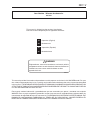 3
3
-
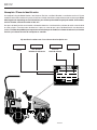 4
4
-
 5
5
-
 6
6
-
 7
7
-
 8
8
-
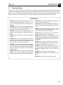 9
9
-
 10
10
-
 11
11
-
 12
12
-
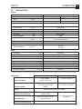 13
13
-
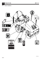 14
14
-
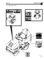 15
15
-
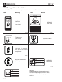 16
16
-
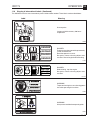 17
17
-
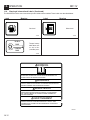 18
18
-
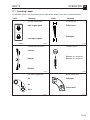 19
19
-
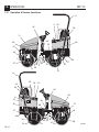 20
20
-
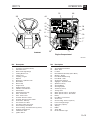 21
21
-
 22
22
-
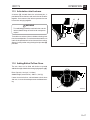 23
23
-
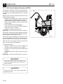 24
24
-
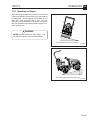 25
25
-
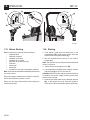 26
26
-
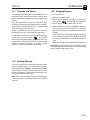 27
27
-
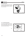 28
28
-
 29
29
-
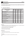 30
30
-
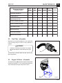 31
31
-
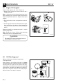 32
32
-
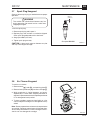 33
33
-
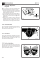 34
34
-
 35
35
-
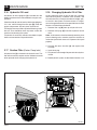 36
36
-
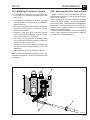 37
37
-
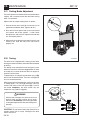 38
38
-
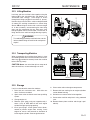 39
39
-
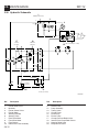 40
40
-
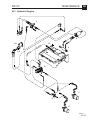 41
41
-
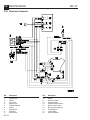 42
42
-
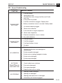 43
43
-
 44
44
-
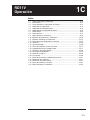 45
45
-
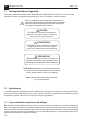 46
46
-
 47
47
-
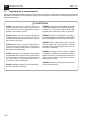 48
48
-
 49
49
-
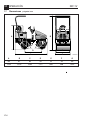 50
50
-
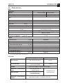 51
51
-
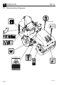 52
52
-
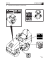 53
53
-
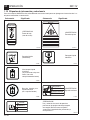 54
54
-
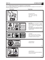 55
55
-
 56
56
-
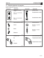 57
57
-
 58
58
-
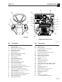 59
59
-
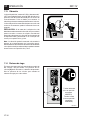 60
60
-
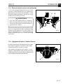 61
61
-
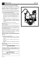 62
62
-
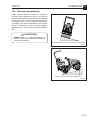 63
63
-
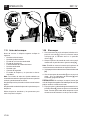 64
64
-
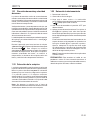 65
65
-
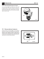 66
66
-
 67
67
-
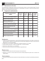 68
68
-
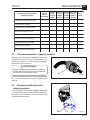 69
69
-
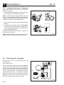 70
70
-
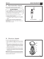 71
71
-
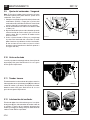 72
72
-
 73
73
-
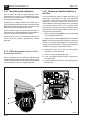 74
74
-
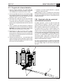 75
75
-
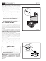 76
76
-
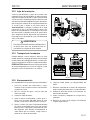 77
77
-
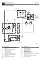 78
78
-
 79
79
-
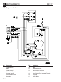 80
80
-
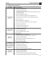 81
81
-
 82
82
-
 83
83
-
 84
84


en otros idiomas
- English: Wacker Neuson RD11V User manual
Artículos relacionados
-
Wacker Neuson RD11A Manual de usuario
-
-
-
Wacker Neuson RT820 Manual de usuario
-
-
-
-
-
Wacker Neuson DS720 Manual de usuario
-
Wacker Neuson G70 Manual de usuario