CARLO GAVAZZI PC50CNT20R Manual de usuario
- Tipo
- Manual de usuario

Excess gain Green LED
Yellow LED
Comments
Target present
≤ 0.7 ON OFF Supply OK
>
0.7 < 1.0 OFF OFF Alignment help
> 1.0 < 1.5 OFF ON Output function OK
> 1.5 ON ON Stable function
CARLO GAVAZZI INDUSTRI A/S
Over Hadstenvej 40, DK-8370 Hadsten
Phone/Telefon: +45 89 60 61 00
Fax: +45 86 98 25 22
www.gavazzi-automation.com
Certified in accordance with ISO 9001
Gerätehersteller mit dem ISO 9001/EN 29 001 Zertifikat
Une société qualifiée selon ISO 9001
Certificado de acuerdo con ISO 9001
Conformità alle norme ISO 9001
Kvalificeret i overensstemmelse med ISO 9001
MAN PC50 MUL rev.12-10.2009
Photoelectric Switch
Fotoelektrische Sensoren Einweg-Lichtschranken /
Cellule Photoélectrique réflexe / Fotocélulas /
F
otocellula a riflessione / Fotoelektrisk reflektor-reflekterende
PC50
User Manual
Bedienungsanleitung / Manuel Utilisateur / Manual del
Usuario / Manuale d'istruzione / Brugervejledning
15-029-67
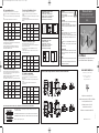
Dimensions, Abmessungen, Dimensions, Dimensiones, Dimensioni, Dimensioner
11.3
29
Ø5
35.2
35.2
50
50
21
21.4
24.85
15
19
41.4
24.85
21
1
o
9
19
21.15
R2.3
Ø4.45
R2.3
14.5
35.2
35.2
50
50
21
21.4
24.85
15
19
41.4
24.85
21
1
o
9
19
21.15
R2.3
Ø4.45
R2.3
11.3
29
11.3
29
11.3
29
Wiring diagrams - transistor output
S
chaltbild - Transistorausgang
S
chéma de câblage - Sortie Transistorisée
D
iagrama de conexiones - Salida de Transistor
C
ollegamenti Eletrici - Uscita a transistor
Forbindelsesdiagram - Transistorudgang
+
-
1 BN
4 BK
2 WH
3 BU
BU
BN
GY
BK
WH
12-240 VDC
24 - 240 VAC
3 A/240 VAC
3 A/30 VDC
μ
+
-
1 BN
3 BU
L
N
BN
BU
Wiring diagrams - relay output
Schaltbild - Relaisausgang
Schéma de câblage - Sortie relais
Diagrama de conexiones - Salida de relé
Collegamenti Eletrici - Uscita a relè
Forbindelsesdiagram - Relæudgang
EmitterPNPNPN
Please notice!
The PC 50 photoelectric sensors are not designed for
personal safety applications.
Clean only with a soft damp cloth. Do not use deter-
gents or alcohol.
Bitte beachten!
D
ie Lichtschranken vom Typ PC 50 sind nicht für eine Anwendung
a
ls Sicherheitslichtschranke ausgelegt.
D
ie Reinigung darf nur mit einem feuchten, weichen Tuch
vorgenommen werden. Keine Reinigungsmittel oder Alkohol ver-
wenden.
Attention!
Les cellules photoélectriques PC 50 ne sont pas conçues pour
des applications de sécurité de personnes.
Nettoyer les cellules avec un chiffon doux humide à l’exclusion de
tout autre produit. Ne jamais utiliser de détergents ou d’alcool.
¡Nota!
Las fotocélulas PC 50 no están diseñadas para aplicaciones de
seguridad.
Limpie únicamente con un trapo suave y húmedo. No utilice
detergentes ni alcohol.
Notizia importante!
Per applicazioni antinfortunistiche utilizzare dispositivi omologati.
Per pulire usare soltanto un panno soffice inumidito. Non usare
detergenti o alcool.
Bemærk!
PC 50-fotocellerne er ikke beregnet til sikring af personlig sikker-
hed.
Må kun rengøres med en blød og fugtig klud. Der må ikke anven-
des rengøringsmidler eller alkohol.
Excess gain
Time
150%
100%
70%
Green LED ON
Yellow LED ON
Signal Stability / Signalstabilität / Stabilité du Signal / Estabilidad de la Señal / Stabilità del segnale / Signalstabilitet
GB - Signal stability indication
The stability indication gives an indication of the level of received light.
T
he purpose of this feature is to facilitate adjustment as well as to have a dirt
alarm.
For the sensor to operate in a stable condition the green LED must be steadily
O
N.
F
or the green LED to be steadily ON, please see the table below.
D - Anzeige der Signalstabilität
Die Stabilitätsanzeige dient als Einstellungshilfe und als Schmutzalarm, indem
e
s die empfangene Lichtmenge anzeigt.
Für stabilen Sensorbetrieb muss die grüne LED permanent aufleuchten.
Die grüne LED leuchtet permanent auf, wenn eine der in untenstehender
Tabelle angeführten Zustände erreicht ist.
F - Indication de stabilité du signal
L’indication de stabilité fournit une information du niveau de lumière reçue.
Cette fonctionnalité a pour but à la fois de simplifier le réglage et de fournir
une alarme du niveau d’encrassement.
La stabilité des conditions de fonctionnement du détecteur est matérialisée
par la LED verte qui doit être allumée en fixe.
Pour que la LED verte reste allumée en fixe, se reporter au tableau ci-dessous.
E - Indicación de Estabilidad de la Señal
La indicación de estabilidad indica el nivel de luz recibida.
E
l objetivo de este sistema es facilitar el ajuste y tener una alarma de
suciedad.
El LED verde debe estar constantemente encendido para que el sensor pueda
o
perar en condiciones estables.
C
onsulte la siguiente tabla para más información sobre las condiciones del
LED verde.
I - Indicazione di stabilità del segnale
L'indicazione di stabilità indica il livello di luce ricevuta.
L
o scopo di tale funzione è di facilitare la regolazione nonché di disporre di un
allarme per accumulo di sporcizia.
Perché il sensore funzioni in condizioni stabili il LED verde deve essere
costantemente acceso.
Consultare la tabella sottostante per le condizioni che fanno sì che il LED
verde sia costantemente acceso.
DK - Indikation a signalstabilitet
Stabilitetsindikationen angiver mængden af modtaget lys.
Formålet med denne funktion er at gøre justering lettere samt at have en
alarm for snavs.
Hvis aftasteren kører i stabil tilstand, skal den grønne lysdiode være tændt
konstant.
For at sikre, at den grønne lysdiode er konstant tændt, henvises til
tabellen herunder.
≤ 0.7 EIN AUS Betriebsspannung OK
> 0.7 < 1.0 AUS AUS Abgleichhilfe
> 1.0 < 1.5 AUS EIN Ausgangsfunktion OK
> 1.5 EIN EIN Stabile Funktion
Funktions-
reserve
Grün LED
Gelb LED
Reflektor erfasst
Bemerkungen
Emitter
≤ 0.7 Active Désactivée Alimentation OK
> 0.7 < 1.0 Désactivée Désactivée Aide d’alignement
> 1.0 < 1.5 Désactivée Active Fonction de sortie OK
> 1.5 Active Active Fonction stable
Excédent
de gain
LED Verte
LED Jaune
Cible présente
Commentaires
≤ 0.7 ON OFF Alimentación OK
>
0.7 < 1.0 OFF OFF Ayuda de alineación
> 1.0 < 1.5 OFF ON Función de salida OK
> 1.5 ON ON Función estable
Sobreganancia
LED Verde
L
ED Amarillo
R
eferencia presente
Comentarios
≤ 0.7 ON OFF Alimentazione OK
> 0.7 < 1.0 OFF OFF Guida per allineamento
> 1.0 < 1.5 OFF ON Funzioni di uscita OK
> 1.5 ON ON Funzione stabile
Guadagno del
circuito ricevitore
LED Verde
LED Giallo
Riferimento presente
Note
≤ 0.7 Tændt Slukket Strømforsyning OK
> 0.7 < 1.0 Slukket Slukket Hjælp til justering
> 1.0 < 1.5 Slukket Tændt Udgangsfunktion OK
> 1.5 Tændt Tændt Stabil funktion
Overskridelse af
forstærkning
Grøn lysdiode
Gul lysdiode
Emne til stede
Kommentarer
Excess gain / Funktions-reserve / Excédent de gain / Sobreganancia / Guadagno del circuito ricevitore /
Overskridelse af forstærkning
Green LED ON / Grün LED EIN / LED Verte Active / LED Verde ON / LED Verde ON / Grøn lysdiode tændt
Yellow LED ON / Gelb LED EIN / LED Jaune Active / LED Amarillo ON / LED Giallo ON / Gul lysdiode tændt
Time / Zeit / Temps / Tiempo / Tempo / Tid
15-029-67 PC50 MUL.qxp:15-029-67 PC50 MUL 02/10/09 12:00 Page 1

Distance
NPN/PNP
D
istance
N
PN/PNP
Distance
NPN/PNP
ON
OFF
ON
OFF
OFF
ON
Target
Target/object
Target
Emitter
Emitter
Object
Object
Object
Object
Object
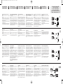
Retro-reflective and polarised Retro-reflective
sensor:
M
ount the reflector and the sensor in the required
positions.
Turn the distance potentiometer clockwise to maxi-
m
um. Adjust the sensor horizontally and vertically until
the yellow and the green LEDs go ON to ensure that
the beam hits the reflector.
T
urn the distance potentiometer counter clockwise
until both LEDs go OFF.
For correct adjustment turn the distance potentiome-
t
er clockwise until both LEDs are steadily ON again.
Diffuse-reflective:
Mount the sensor in the required position pointing at
the target.
Turn the distance potentiometer counter clockwise to
minimum.
Turn the distance potentiometer clockwise until the
yellow LED and green LEDs go ON.
Diffuse-reflective with background suppression:
Mount the sensor at the required distance from the
background.
Turn the “Tune” potmeter counter clockwise to mini-
mum. Turn the “Dist” potmeter clockwise from mini-
mum until the yellow LED goes on. Then turn counter
clockwise until the yellow LED turns off. Turn the
“Tune” potmeter clockwise until the yellow LED goes
on and then again counter clockwise until the yellow
LED turns off. The background is now suppressed.
The “Tune” adjustment potentiometer is facilitating
adjustment when target & background are close
together.
Through-beam sensor:
Mount the emitter and the receiver in the required
positions.
Turn the distance potentiometer on the receiver clock-
wise to maximum.
Move the receiver (and the emitter, if necessary) hori-
zontally and vertically until the yellow and the green
LEDs go ON and fix the sensors.
Turn the distance potentiometer counter-clockwise
until both LEDs go OFF.
For correct adjustment turn the distance potentiome-
ter clockwise until both LEDs are steadily ON.
Reflexions-Lichtschranke (mit Polarisationsfilter):
Den Reflektor und die Lichtschranke in der gewünsch-
t
en Position montieren.
Das “Distance”-Potentiometer in die Maximalposition
drehen.
D
ie Lichtschranke vertikal und horizontal bewegen, bis
die gelbe und die grüne LED´s aufleuchten. Damit wird
sichergestellt, dass der Lichtstrahl den Reflektor trifft.
D
as “Distance”-Potentiometer entgegen dem
Uhrzeigersinn drehen, bis beide LED´s erlöschen.
Zur korrekten Einstellung muss das “Distance”-
P
otentiometer im Uhrzeigersinn gedreht werden, bis
beide LED´s konstant aufleuchten.
Reflexions-Lichttaster
Den Lichttaster in der gewünschten Position montie-
ren.
Das “Distance”-Potentiometer in die Minimalposition
drehen.
Das “Distance”-Potentiometer im Uhrzeigersinn dre-
hen, bis die gelbe und die grüne LED´s aufleuchtet.
Reflexions-Lichtschalter mit
Hintergrundausblendung
Den Sensor in dem gewünschten Abstand von dem
Hintergrund montieren.
Das ”TUNE” Potentiometer entgegen dem
Uhrzeigersinn auf Minimum drehen. Das ”DIST”
Abstandspotentiometer im Uhrzeigersinn von
Minimum hinweg drehen, bis die gelbe LED leuchtet.
Dann entgegen dem Uhrzeigersinn drehen, bis die
gelbe LED erlischt. Das ”TUNE” Abstandspotentio-
meter im Uhrzeigersinn drehen, bis die gelbe LED
leuchtet, und dann wieder entgegen dem
Uhrzeigersinn drehen, bis die gelbe LED erlischt. Der
Hintergrund kann jetzt detektiert werden.
Das Tune Abstandspotentiometer erleichtert die
Einstellung, wenn der Hintergrund und das Objekt nah
beieinander sind.
Einweg-Lichtschranke:
Den Sender und den Empfänger in den gewünschten
Positionen montieren.
Das “Distance”-Potentiometer des Empfängers in die
Maximalposition drehen.
Die Lichtschranken vertikal und horizontal bewegen,
bis die gelbe und die grüne LED´s aufleuchten. Damit
sind die Lichtschranken korrekt installiert.
Das “Distance”-Potentiometer gegen dem
Uhrzeigersinn drehen, bis beide LED´s erlöschen.
Zur korrekten Einstellung muss das “Distance”-
Potentiometer im Uhrzeigersinn gedreht werden, bis
beide LED´s kontinuierlich aufleuchtet.
Cellule réflexe et réflexe polarisée
Installer le réflecteur et le capteur aux positions
r
equises.
Régler le potentiomètre de distance au maximum en le
tournant dans le sens horaire. Ajuster le capteur
h
orizontalement et verticalement jusqu'à ce que les
LED jaune et verte s’allument afin de s'assurer que le
faisceau lumineux vienne frapper le réflecteur.
R
égler le potentiomètre de distance au minimum en le
tournant dans le sens anti horaire jusqu'à ce que les
deux LED s’éteignent, puis pour obtenir un réglage
c
orrect, tourner le potentiomètre de distance dans le
sens horaire jusqu'à ce que les deux LED restent
allumées en fixe.
Cellule à réflexion directe:
Installer le capteur dans la position en le faisant pointer
sur la cible.
Régler le potentiomètre de distance au minimum en le
tournant dans le sens horaire.
Tourner le potentiomètre de distance dans le sens
anti horaire jusqu'à ce que les LED jaune et verte
s’allument.
Réflexion directe avec suppression d’arrière plan
Installer le détecteur dans la position derrière par rap-
port à l’arrière plan.
Tourner le potentiomètre « Tune » dans le sens des
aiguilles d’une montre jusqu’au minimum.
Tourner le potentiomètre « Dist » du minimum vers le
maximum jusqu’à l’allumage de la Led jaune.
Tourner le potentiomètre « Tune » jusqu’à l’allumage
de la Led jaune puis jusqu’à l’extinction.
L’arrière n’est désormais plus détecté.
Le potentiometre “Tune” permet un ajustement précis
quand l’objet à détecter est trés proche de l’arrière
plan.
Cellule barrage:
Installer l’émetteur et le récepteur aux positions
requises.
Sur le récepteur, amener le potentiomètre de distance
au maximum en le tournant dans le sens horaire.
Décaler le récepteur (et au besoin l'émetteur,) dans les
plans horizontaux et verticaux jusqu'à ce que les LED
jaune et verte s’allument, puis immobiliser les
capteurs.
Tourner le potentiomètre de distance dans le sens anti
horaire jusqu'à ce que les deux LED s’éteignent, puis
pour obtenir un réglage correct, tourner le
potentiomètre de distance dans le sens horaire
jusqu'à ce que les deux LED restent allumées en fixe.
Fotocélulas de reflexión sobre espejo y fotocélulas
de reflexión sobre espejo polarizadas:
M
onte el espejo y la fotocélula en las posiciones
requeridas.
Gire el potenciómetro de distancia en sentido horario
h
asta llegar al máximo. Ajuste la fotocélula horizontal
y verticalmente hasta que se enciendan los LED ama-
rillo y verde para asegurar que el rayo apunte hacia el
e
spejo.
Gire el potenciómetro de distancia en sentido antiho-
rario hasta que se apaguen los dos LED.
P
ara obtener el ajuste correcto, gire el potenciómetro
de distancia en sentido horario hasta que los dos LED
permanezcan constantemente encendidos.
Reflexión directa:
Monte la fotocélula en la posición requerida apuntan-
do hacia el objeto.
Gire el potenciómetro de distancia en sentido antiho-
rario hasta llegar al mínimo.
Gire el potenciómetro de distancia en sentido horario
hasta que se enciendan el LED amarillo y los LED ver-
des.
Reflexión directa con supresión de fondo:
Instale el sensor en la posición correcta de trabajo.
Gire el potenciómetro “Tune” en sentido antihorario
hasta el mínimo. Gire el potenciómetro “Dist” en sen-
tido horario desde el mínimo hasta que el LED amari-
llo se ilumine. Después gire en sentido antihorario
hasta que el LED amarillo se apague. Gire el potenció-
metro “Tune” en sentido horario hasta que el LED
amarillo se ilumine y entonces gire en sentido antiho-
rario hasta que el LED amarillo se apague. El fondo
está ahora ignorado.
El potenciómetro de ajuste "Tune" facilita el ajuste
cuando el objeto y el fondo están próximos entre si.
Fotocélula de barrera:
Monte el emisor y el receptor en las posiciones reque-
ridas.
Gire el potenciómetro de distancia del receptor en
sentido horario hasta llegar al máximo.
Mueva el receptor (y, de ser necesario, el emisor) hori-
zontal y verticalmente hasta que se encienda el LED
amarillo y los dos LED verdes y luego fije las fotocélulas.
Gire el potenciómetro de distancia en sentido antiho-
rario hasta que se apaguen los LED.
Para obtener el ajuste correcto, gire el potenciómetro
de distancia en sentido horario hasta que los LED
permanezcan constantemente encendidos.
Sensore a riflessione e sensore a riflessione pola-
rizzata:
M
ontare il catarifrangente ed il sensore nella posizione
desiderata.
Ruotare il potenziometro di regolazione della distanza
i
n senso orario sul massimo. Per assicurarsi che il rag-
gio luminoso raggiunga il catarifrangente, regolare il
sensore orizzontalmente e verticalmente finché i LED
g
iallo e verde non risultano entrambi accesi.
Ruotare il potenziometro di distanza in senso antiora-
rio finché entrambi i LED non si spengono.
P
er una regolazione corretta, girare il potenziometro di
distanza in senso orario finché entrambi i LED non
sono di nuovo costantemente accesi.
Sensori a riflessione diretta:
Montare il sensore nella posizione desiderata, puntato
verso l’oggetto di riferimento.
Ruotare il potenziometro di regolazione della distanza
in senso antiorario sul minimo.
Ruotare il potenziometro di distanza in senso orario
finché i LED giallo e verde non si accendono.
Riflessione diretta con soppressione di sfondo:
Montare il sensore nella posizione di lavoro. Girare il
potenziometro "tune" in senso antiorario al minimo.
Girare il potenziometro "Dist" in senso orario al minimo
finche il LED giallo non si accende. Girare in senso
antiorario fin che il LED giallo si spegne. Girare il
potenziometro "tune" in senso orario finche LED giallo
non si accende e subito dopo in senso antiorario
finche il LED giallo si spegne. Ora la regolazione della
soppressione è terminata.
Il potenziometro "tune" facilita' la programmazione nel
caso in cui la distanza tra l'oggetto da rilevare e lo
sfondo e' ridotta
Sensore a barriera:
Montare l’emettitore ed il ricevitore nella posizione
desiderata.
Ruotare il potenziometro di regolazione della distanza
del ricevitore in senso orario sul massimo.
Muovere orizzontalmente e verticalmente il ricevitore
(e l’emettitore, se necessario) finché i LED giallo e
verde non si accendono. Fissare i sensori.
Ruotare il potenziometro di distanza in senso antiora-
rio finché entrambi i LED non si spengono.
Per una regolazione corretta, girare il potenziometro di
distanza in senso orario finché entrambi i LED non
rimangono costantemente accesi.
Retro-reflektiv og polariseret, retro-reflektiv
fotoaftaster:
M
onter refleksbrikken og fotoaftasteren i de ønskede
positioner.
Drej afstandspotentiometeret med uret til maximum.
J
uster aftasteren horisontalt og vertikalt indtil den gule
og den grønne lysdiode lyser; således sikres, at lys-
strålen rammer refleksbrikken.
A
fstandspotentiometeret drejes mod minimum indtil
begge lysdioder slukker.
Derefter drejes mod maximum indtil begge lysdioder
l
yser konstant.
Objektaftaster:
Placer aftasteren og objektet i de ønskede positioner.
Drej afstandspotentiometeret mod uret til minimum.
Drej afstandspotentiometeret med uret (mod maxi-
mum) indtil den gule og den grønne lysdiode lyser.
Objektaftaster med baggrundsudblænding:
Placer aftasteren i den ønskede afstand fra baggrun-
den.
Drej ”TUNE” afstandspotentiometeret mod uret til
minimum. Drej ”DIST” afstandspotentiometeret med
uret fra minimum indtil den gule lysdiode lyser.
Derefter drejes mod uret indtil den gule lysdiode sluk-
ker. Drej ”TUNE” afstandspotentiometeret med uret
indtil den gule lysdiode lyser for derefter at dreje mod
uret indtil den gule lysdiode slukker. Baggrunden er nu
detekteret.
“Tune” justerings potentiometeret gør justeringen let-
tere når emne og baggrund er tæt på hinanden.
Fotoaftaster med separat sender og modtager:
Monter senderen og modtageren i de ønskede positio-
ner.
Drej afstandspotentiometeret på modtageren til maxi-
mum.
Bevæg modtageren (og evt. senderen) horisontalt og
vertikalt indtil den gule og den grønne lysdiode lyser.
Fastgør modtager og sender.
Afstandspotentiometeret drejes mod minimum (mod
uret) indtil begge lysdioder slukker.
Drej afstandspotentiometeret mod maximum indtil
begge lysdioder lyser konstant.
Optical alignment and
sensitivity adjustment
Einstellung der optischen
Achse und der Empfindlichkeit
Réglage de l’alignement
optique et de la sensibilité
Alineación óptica y ajuste
de sensibilidad
Allineamento ottico e
regolazione della sensibilità
Optisk indstilling og
følsomhedsjustering
Detection - Make switching (NO)
E
rfassung – Schließkontakt (NO)
Détection – Commutation travail (NO)
D
etección – Detección con luz (NA)
Rilevamento- Attivazione per impulso di luce (NA)
Aftastning – sluttefunktion (normalt åben – NO)
GB D F E I DK
DIST
NPN/PNP
TUNE
ON
OFF
Target/object
Background
15-029-67 PC50 MUL.qxp:15-029-67 PC50 MUL 02/10/09 12:00 Page 2
Transcripción de documentos
02/10/09 12:00 Page 1 GB - Signal stability indication E - Indicación de Estabilidad de la Señal The stability indication gives an indication of the level of received light. The purpose of this feature is to facilitate adjustment as well as to have a dirt alarm. For the sensor to operate in a stable condition the green LED must be steadily ON. For the green LED to be steadily ON, please see the table below. La indicación de estabilidad indica el nivel de luz recibida. El objetivo de este sistema es facilitar el ajuste y tener una alarma de suciedad. El LED verde debe estar constantemente encendido para que el sensor pueda operar en condiciones estables. Consulte la siguiente tabla para más información sobre las condiciones del LED verde. Green LED Yellow LED Target present ≤ 0.7 ON OFF Supply OK > 0.7 < 1.0 OFF OFF Alignment help > 1.0 < 1.5 OFF ON Output function OK > 1.5 ON ON Stable function Excess gain Comments D - Anzeige der Signalstabilität Die Stabilitätsanzeige dient als Einstellungshilfe und als Schmutzalarm, indem es die empfangene Lichtmenge anzeigt. Für stabilen Sensorbetrieb muss die grüne LED permanent aufleuchten. Die grüne LED leuchtet permanent auf, wenn eine der in untenstehender Tabelle angeführten Zustände erreicht ist. Funktionsreserve ≤ 0.7 Grün LED Gelb LED Reflektor erfasst EIN AUS AUS Bemerkungen Betriebsspannung OK > 0.7 < 1.0 AUS Abgleichhilfe > 1.0 < 1.5 AUS EIN Ausgangsfunktion OK > 1.5 EIN EIN Stabile Funktion F - Indication de stabilité du signal L’indication de stabilité fournit une information du niveau de lumière reçue. Cette fonctionnalité a pour but à la fois de simplifier le réglage et de fournir une alarme du niveau d’encrassement. La stabilité des conditions de fonctionnement du détecteur est matérialisée par la LED verte qui doit être allumée en fixe. Pour que la LED verte reste allumée en fixe, se reporter au tableau ci-dessous. Excédent de gain LED Verte LED Jaune Cible présente Commentaires Sobreganancia LED Verde Wiring diagrams - transistor output Please notice! Schaltbild - Transistorausgang Schéma de câblage - Sortie Transistorisée Diagrama de conexiones - Salida de Transistor Collegamenti Eletrici - Uscita a transistor Forbindelsesdiagram - Transistorudgang The PC 50 photoelectric sensors are not designed for personal safety applications. Clean only with a soft damp cloth. Do not use detergents or alcohol. LED Amarillo Referencia presente Comentarios Active > 0.7 < 1.0 > 1.0 < 1.5 > 1.5 Désactivée Désactivée Désactivée Alimentation OK Aide d’alignement 1 BN ≤ 0.7 ON OFF Alimentación OK > 0.7 < 1.0 OFF OFF Ayuda de alineación 4 BK > 1.0 < 1.5 OFF ON Función de salida OK > 1.5 ON ON Función estable 3 BU NPN L'indicazione di stabilità indica il livello di luce ricevuta. Lo scopo di tale funzione è di facilitare la regolazione nonché di disporre di un allarme per accumulo di sporcizia. Perché il sensore funzioni in condizioni stabili il LED verde deve essere costantemente acceso. Consultare la tabella sottostante per le condizioni che fanno sì che il LED verde sia costantemente acceso. PNP ¡Nota! Las fotocélulas PC 50 no están diseñadas para aplicaciones de seguridad. Limpie únicamente con un trapo suave y húmedo. No utilice detergentes ni alcohol. Notizia importante! BN 12-240 VDC 24 - 240 VAC BN Per applicazioni antinfortunistiche utilizzare dispositivi omologati. Per pulire usare soltanto un panno soffice inumidito. Non usare detergenti o alcool. L GY LED Giallo Riferimento presente Note BK μ ≤ 0.7 ON OFF Alimentazione OK > 0.7 < 1.0 OFF OFF Guida per allineamento > 1.0 < 1.5 OFF ON Funzioni di uscita OK > 1.5 ON ON Funzione stabile WH 3 A/30 VDC 3 A/240 VAC BU Bemærk! N PC 50-fotocellerne er ikke beregnet til sikring af personlig sikkerhed. Må kun rengøres med en blød og fugtig klud. Der må ikke anvendes rengøringsmidler eller alkohol. Emitter Stabilitetsindikationen angiver mængden af modtaget lys. Formålet med denne funktion er at gøre justering lettere samt at have en alarm for snavs. Hvis aftasteren kører i stabil tilstand, skal den grønne lysdiode være tændt konstant. For at sikre, at den grønne lysdiode er konstant tændt, henvises til tabellen herunder. R2.3 1 50 Gul lysdiode Emne til stede Désactivée Active Fonction de sortie OK Active Active Fonction stable > 0.7 < 1.0 Slukket Slukket Hjælp til justering > 1.0 < 1.5 Slukket Tændt Udgangsfunktion OK > 1.5 Tændt Tændt Stabil funktion Tændt Slukket Strømforsyning OK 9 19 Ø4.45 21 24.85 35.2 15 Ø5 R2.3 21.4 Certified in accordance with ISO 9001 Gerätehersteller mit dem ISO 9001/EN 29 001 Zertifikat 24.85 50 21 R2.3 Signal Stability / Signalstabilität / Stabilité du Signal / Estabilidad de la Señal / Stabilità del segnale / Signalstabilitet 21.15 35.2 50 Une société qualifiée selon ISO 9001 19 41.4 19 Green LED ON / Grün LED EIN / LED Verte Active / LED Verde ON / LED Verde ON / Grøn lysdiode tændt Yellow LED ON / Gelb LED EIN / LED Jaune Active / LED Amarillo ON / LED Giallo ON / Gul lysdiode tændt 35.2 14.5 11.3 Certificado de acuerdo con ISO 9001 Conformità alle norme ISO 9001 Ø4.45 21 24.85 150% 70% 29 29 11.3 9 Excess gain / Funktions-reserve / Excédent de gain / Sobreganancia / Guadagno del circuito ricevitore / Overskridelse af forstærkning 100% 11.3 11.3 1o Excess gain 29 29 o 19 41.4 Kommentarer ≤ 0.7 Phone/Telefon: +45 89 60 61 00 Fax: +45 86 98 25 22 www.gavazzi-automation.com 21 21.15 Bedienungsanleitung / Manuel Utilisateur / Manual del Usuario / Manuale d'istruzione / Brugervejledning Over Hadstenvej 40, DK-8370 Hadsten 24.85 50 User Manual CARLO GAVAZZI INDUSTRI A/S Dimensions, Abmessungen, Dimensions, Dimensiones, Dimensioni, Dimensioner DK - Indikation a signalstabilitet Overskridelse af Grøn lysdiode forstærkning Les cellules photoélectriques PC 50 ne sont pas conçues pour des applications de sécurité de personnes. Nettoyer les cellules avec un chiffon doux humide à l’exclusion de tout autre produit. Ne jamais utiliser de détergents ou d’alcool. Emitter Schaltbild - Relaisausgang Schéma de câblage - Sortie relais Diagrama de conexiones - Salida de relé Collegamenti Eletrici - Uscita a relè Forbindelsesdiagram - Relæudgang BU LED Verde - Wiring diagrams - relay output I - Indicazione di stabilità del segnale Guadagno del circuito ricevitore Attention! 3 BU - PC50 Die Lichtschranken vom Typ PC 50 sind nicht für eine Anwendung als Sicherheitslichtschranke ausgelegt. Die Reinigung darf nur mit einem feuchten, weichen Tuch vorgenommen werden. Keine Reinigungsmittel oder Alkohol verwenden. + 2 WH 35.2 ≤ 0.7 Bitte beachten! + 1 BN Photoelectric Switch Fotoelektrische Sensoren Einweg-Lichtschranken / Cellule Photoélectrique réflexe / Fotocélulas / Fotocellula a riflessione / Fotoelektrisk reflektor-reflekterende 15 Kvalificeret i overensstemmelse med ISO 9001 R2.3 21.4 Time Green LED ON Yellow LED ON Time / Zeit / Temps / Tiempo / Tempo / Tid MAN PC50 MUL rev.12-10.2009 15-029-67 15-029-67 PC50 MUL.qxp:15-029-67 PC50 MUL D Réglage de l’alignement optique et de la sensibilité F Reflexions-Lichtschranke (mit Polarisationsfilter): Den Reflektor und die Lichtschranke in der gewünschten Position montieren. Das “Distance”-Potentiometer in die Maximalposition drehen. Die Lichtschranke vertikal und horizontal bewegen, bis die gelbe und die grüne LED´s aufleuchten. Damit wird sichergestellt, dass der Lichtstrahl den Reflektor trifft. Das “Distance”-Potentiometer entgegen dem Uhrzeigersinn drehen, bis beide LED´s erlöschen. Zur korrekten Einstellung muss das “Distance”Potentiometer im Uhrzeigersinn gedreht werden, bis beide LED´s konstant aufleuchten. Cellule réflexe et réflexe polarisée Installer le réflecteur et le capteur aux positions requises. Régler le potentiomètre de distance au maximum en le tournant dans le sens horaire. Ajuster le capteur horizontalement et verticalement jusqu'à ce que les LED jaune et verte s’allument afin de s'assurer que le faisceau lumineux vienne frapper le réflecteur. Régler le potentiomètre de distance au minimum en le tournant dans le sens anti horaire jusqu'à ce que les deux LED s’éteignent, puis pour obtenir un réglage correct, tourner le potentiomètre de distance dans le sens horaire jusqu'à ce que les deux LED restent allumées en fixe. Reflexions-Lichttaster Den Lichttaster in der gewünschten Position montieren. Das “Distance”-Potentiometer in die Minimalposition drehen. Das “Distance”-Potentiometer im Uhrzeigersinn drehen, bis die gelbe und die grüne LED´s aufleuchtet. Cellule à réflexion directe: Installer le capteur dans la position en le faisant pointer sur la cible. Régler le potentiomètre de distance au minimum en le tournant dans le sens horaire. Tourner le potentiomètre de distance dans le sens anti horaire jusqu'à ce que les LED jaune et verte s’allument. Alineación óptica y ajuste de sensibilidad E Allineamento ottico e regolazione della sensibilità I Optisk indstilling og følsomhedsjustering DK Fotocélulas de reflexión sobre espejo y fotocélulas de reflexión sobre espejo polarizadas: Monte el espejo y la fotocélula en las posiciones requeridas. Gire el potenciómetro de distancia en sentido horario hasta llegar al máximo. Ajuste la fotocélula horizontal y verticalmente hasta que se enciendan los LED amarillo y verde para asegurar que el rayo apunte hacia el espejo. Gire el potenciómetro de distancia en sentido antihorario hasta que se apaguen los dos LED. Para obtener el ajuste correcto, gire el potenciómetro de distancia en sentido horario hasta que los dos LED permanezcan constantemente encendidos. Sensore a riflessione e sensore a riflessione polarizzata: Montare il catarifrangente ed il sensore nella posizione desiderata. Ruotare il potenziometro di regolazione della distanza in senso orario sul massimo. Per assicurarsi che il raggio luminoso raggiunga il catarifrangente, regolare il sensore orizzontalmente e verticalmente finché i LED giallo e verde non risultano entrambi accesi. Ruotare il potenziometro di distanza in senso antiorario finché entrambi i LED non si spengono. Per una regolazione corretta, girare il potenziometro di distanza in senso orario finché entrambi i LED non sono di nuovo costantemente accesi. Retro-reflektiv og polariseret, retro-reflektiv fotoaftaster: Monter refleksbrikken og fotoaftasteren i de ønskede positioner. Drej afstandspotentiometeret med uret til maximum. Juster aftasteren horisontalt og vertikalt indtil den gule og den grønne lysdiode lyser; således sikres, at lysstrålen rammer refleksbrikken. Afstandspotentiometeret drejes mod minimum indtil begge lysdioder slukker. Derefter drejes mod maximum indtil begge lysdioder lyser konstant. Reflexión directa: Monte la fotocélula en la posición requerida apuntando hacia el objeto. Gire el potenciómetro de distancia en sentido antihorario hasta llegar al mínimo. Gire el potenciómetro de distancia en sentido horario hasta que se enciendan el LED amarillo y los LED verdes. Sensori a riflessione diretta: Montare il sensore nella posizione desiderata, puntato verso l’oggetto di riferimento. Ruotare il potenziometro di regolazione della distanza in senso antiorario sul minimo. Ruotare il potenziometro di distanza in senso orario finché i LED giallo e verde non si accendono. Objektaftaster: Placer aftasteren og objektet i de ønskede positioner. Drej afstandspotentiometeret mod uret til minimum. Drej afstandspotentiometeret med uret (mod maximum) indtil den gule og den grønne lysdiode lyser. Detection - Make switching (NO) Erfassung – Schließkontakt (NO) Détection – Commutation travail (NO) Detección – Detección con luz (NA) Rilevamento- Attivazione per impulso di luce (NA) Aftastning – sluttefunktion (normalt åben – NO) NPN/PNP Distance OFF ON NPN/PNP Distance ON OFF Einweg-Lichtschranke: Den Sender und den Empfänger in den gewünschten Positionen montieren. Das “Distance”-Potentiometer des Empfängers in die Maximalposition drehen. Die Lichtschranken vertikal und horizontal bewegen, bis die gelbe und die grüne LED´s aufleuchten. Damit sind die Lichtschranken korrekt installiert. Das “Distance”-Potentiometer gegen dem Uhrzeigersinn drehen, bis beide LED´s erlöschen. Zur korrekten Einstellung muss das “Distance”Potentiometer im Uhrzeigersinn gedreht werden, bis beide LED´s kontinuierlich aufleuchtet. Cellule barrage: Installer l’émetteur et le récepteur aux positions requises. Sur le récepteur, amener le potentiomètre de distance au maximum en le tournant dans le sens horaire. Décaler le récepteur (et au besoin l'émetteur,) dans les plans horizontaux et verticaux jusqu'à ce que les LED jaune et verte s’allument, puis immobiliser les capteurs. Tourner le potentiomètre de distance dans le sens anti horaire jusqu'à ce que les deux LED s’éteignent, puis pour obtenir un réglage correct, tourner le potentiomètre de distance dans le sens horaire jusqu'à ce que les deux LED restent allumées en fixe. Reflexión directa con supresión de fondo: Instale el sensor en la posición correcta de trabajo. Gire el potenciómetro “Tune” en sentido antihorario hasta el mínimo. Gire el potenciómetro “Dist” en sentido horario desde el mínimo hasta que el LED amarillo se ilumine. Después gire en sentido antihorario hasta que el LED amarillo se apague. Gire el potenciómetro “Tune” en sentido horario hasta que el LED amarillo se ilumine y entonces gire en sentido antihorario hasta que el LED amarillo se apague. El fondo está ahora ignorado. El potenciómetro de ajuste "Tune" facilita el ajuste cuando el objeto y el fondo están próximos entre si. Riflessione diretta con soppressione di sfondo: Montare il sensore nella posizione di lavoro. Girare il potenziometro "tune" in senso antiorario al minimo. Girare il potenziometro "Dist" in senso orario al minimo finche il LED giallo non si accende. Girare in senso antiorario fin che il LED giallo si spegne. Girare il potenziometro "tune" in senso orario finche LED giallo non si accende e subito dopo in senso antiorario finche il LED giallo si spegne. Ora la regolazione della soppressione è terminata. Il potenziometro "tune" facilita' la programmazione nel caso in cui la distanza tra l'oggetto da rilevare e lo sfondo e' ridotta Objektaftaster med baggrundsudblænding: Placer aftasteren i den ønskede afstand fra baggrunden. Drej ”TUNE” afstandspotentiometeret mod uret til minimum. Drej ”DIST” afstandspotentiometeret med uret fra minimum indtil den gule lysdiode lyser. Derefter drejes mod uret indtil den gule lysdiode slukker. Drej ”TUNE” afstandspotentiometeret med uret indtil den gule lysdiode lyser for derefter at dreje mod uret indtil den gule lysdiode slukker. Baggrunden er nu detekteret. “Tune” justerings potentiometeret gør justeringen lettere når emne og baggrund er tæt på hinanden. NPN/PNP TUNE DIST Target/object Réflexion directe avec suppression d’arrière plan Installer le détecteur dans la position derrière par rapport à l’arrière plan. Tourner le potentiomètre « Tune » dans le sens des aiguilles d’une montre jusqu’au minimum. Tourner le potentiomètre « Dist » du minimum vers le maximum jusqu’à l’allumage de la Led jaune. Tourner le potentiomètre « Tune » jusqu’à l’allumage de la Led jaune puis jusqu’à l’extinction. L’arrière n’est désormais plus détecté. Le potentiometre “Tune” permet un ajustement précis quand l’objet à détecter est trés proche de l’arrière plan. ON OFF Fotoaftaster med separat sender og modtager: Monter senderen og modtageren i de ønskede positioner. Drej afstandspotentiometeret på modtageren til maximum. Bevæg modtageren (og evt. senderen) horisontalt og vertikalt indtil den gule og den grønne lysdiode lyser. Fastgør modtager og sender. Afstandspotentiometeret drejes mod minimum (mod uret) indtil begge lysdioder slukker. Drej afstandspotentiometeret mod maximum indtil begge lysdioder lyser konstant. Distance Emitter ON Object Sensore a barriera: Montare l’emettitore ed il ricevitore nella posizione desiderata. Ruotare il potenziometro di regolazione della distanza del ricevitore in senso orario sul massimo. Muovere orizzontalmente e verticalmente il ricevitore (e l’emettitore, se necessario) finché i LED giallo e verde non si accendono. Fissare i sensori. Ruotare il potenziometro di distanza in senso antiorario finché entrambi i LED non si spengono. Per una regolazione corretta, girare il potenziometro di distanza in senso orario finché entrambi i LED non rimangono costantemente accesi. Object Fotocélula de barrera: Monte el emisor y el receptor en las posiciones requeridas. Gire el potenciómetro de distancia del receptor en sentido horario hasta llegar al máximo. Mueva el receptor (y, de ser necesario, el emisor) horizontal y verticalmente hasta que se encienda el LED amarillo y los dos LED verdes y luego fije las fotocélulas. Gire el potenciómetro de distancia en sentido antihorario hasta que se apaguen los LED. Para obtener el ajuste correcto, gire el potenciómetro de distancia en sentido horario hasta que los LED permanezcan constantemente encendidos. Object Through-beam sensor: Mount the emitter and the receiver in the required positions. Turn the distance potentiometer on the receiver clockwise to maximum. Move the receiver (and the emitter, if necessary) horizontally and vertically until the yellow and the green LEDs go ON and fix the sensors. Turn the distance potentiometer counter-clockwise until both LEDs go OFF. For correct adjustment turn the distance potentiometer clockwise until both LEDs are steadily ON. Reflexions-Lichtschalter mit Hintergrundausblendung Den Sensor in dem gewünschten Abstand von dem Hintergrund montieren. Das ”TUNE” Potentiometer entgegen dem Uhrzeigersinn auf Minimum drehen. Das ”DIST” Abstandspotentiometer im Uhrzeigersinn von Minimum hinweg drehen, bis die gelbe LED leuchtet. Dann entgegen dem Uhrzeigersinn drehen, bis die gelbe LED erlischt. Das ”TUNE” Abstandspotentiometer im Uhrzeigersinn drehen, bis die gelbe LED leuchtet, und dann wieder entgegen dem Uhrzeigersinn drehen, bis die gelbe LED erlischt. Der Hintergrund kann jetzt detektiert werden. Das Tune Abstandspotentiometer erleichtert die Einstellung, wenn der Hintergrund und das Objekt nah beieinander sind. Target Diffuse-reflective with background suppression: Mount the sensor at the required distance from the background. Turn the “Tune” potmeter counter clockwise to minimum. Turn the “Dist” potmeter clockwise from minimum until the yellow LED goes on. Then turn counter clockwise until the yellow LED turns off. Turn the “Tune” potmeter clockwise until the yellow LED goes on and then again counter clockwise until the yellow LED turns off. The background is now suppressed. The “Tune” adjustment potentiometer is facilitating adjustment when target & background are close together. Emitter OFF NPN/PNP Background Diffuse-reflective: Mount the sensor in the required position pointing at the target. Turn the distance potentiometer counter clockwise to minimum. Turn the distance potentiometer clockwise until the yellow LED and green LEDs go ON. Einstellung der optischen Achse und der Empfindlichkeit Target Retro-reflective and polarised Retro-reflective sensor: Mount the reflector and the sensor in the required positions. Turn the distance potentiometer clockwise to maximum. Adjust the sensor horizontally and vertically until the yellow and the green LEDs go ON to ensure that the beam hits the reflector. Turn the distance potentiometer counter clockwise until both LEDs go OFF. For correct adjustment turn the distance potentiometer clockwise until both LEDs are steadily ON again. Page 2 Target/object GB 12:00 Object Optical alignment and sensitivity adjustment 02/10/09 Object 15-029-67 PC50 MUL.qxp:15-029-67 PC50 MUL-
 1
1
-
 2
2


CARLO GAVAZZI PC50CNT20R Manual de usuario
- Tipo
- Manual de usuario
en otros idiomas
- français: CARLO GAVAZZI PC50CNT20R Manuel utilisateur
- italiano: CARLO GAVAZZI PC50CNT20R Manuale utente
- English: CARLO GAVAZZI PC50CNT20R User manual
- Deutsch: CARLO GAVAZZI PC50CNT20R Benutzerhandbuch
- dansk: CARLO GAVAZZI PC50CNT20R Brugermanual
Artículos relacionados
Otros documentos
-
 ALGE-Timing RLS1n Guía del usuario
-
Schneider Electric RM35JA32MT Instrucciones de operación
-
SICK SureSense - HTF18 Hybrid photoelectric sensors Instrucciones de operación
-
-
-
-
SICK WT34 Compact photoelectric sensors Instrucciones de operación
-
-
Vetus Interface warningsystem EP46844-EP46845-EP46846-EP46847-EP46848-EP412326 Guía de instalación
