CARLO GAVAZZI CA30CAF16PCTA Manual de usuario
- Tipo
- Manual de usuario

Capacitive Level Sensors
Näherungsschalter Kapazitiv / Détecteurs de niveau capacitifs / Sensores de Nivel
Capacitivos / Sensori di livello capacitivi / Kapacitive level sensorer /
电容物位传感器
Transistor Output
Transistor-Ausgang / Sortie transistor / Salida de Transistor/
Uscita a transistor / Transistorudgang / 晶体管输出
CA18-CA30CAN/CAF....
User Manual
Bedienungsanleitung / Manuel de l’utilisateur / Manual del Usuario /
Manuale d’istruzione / Brugerhåndbog / 用户手册
TRIPLESHIELD
TM
Rated operational voltage (U
e
)
Nenn-Betriebsspannung / Tension de fonctionnement nominale / Tensión de alimentación /
Tensione di alimentazione / Nominelt spændingsområde / 额定工作电压
Ripple included
Einschl. Restwelligkeit / ondulation inclue / ondulación incluida / ripple incluso / inkl. ripple / 含纹波
10 - 40 VDC (10 - 40 VCC)
No load supply current (I
o
)
Leeraufstrom / Courant d’alimentation à vide / Consume de corriente sin carga / Corrente di ali-
mentazione / Tomgangsstrøm / 空载电流
≤ 12 mA
Ripple
Restwelligkeit / Ondulation / Ondulación / Ripple / Ripple / 纹波 : ≤ 10%
Rated operational current (I
e
)
Nenn-Betriebsstrom / Courant de fonctionnement nominal / Intensidad de salida /
Corrente di carico / Max. strøm / 额定工作电流
≤ 200 mA
Output
Ausgang / Sortie / Salida / Uscita / Udgang / 输出
Transistor, NPN, NO and NC ; PNP, NO and/or NC
Transistor, NPN, Schließer und Öffner ; PNP, Schließer und/oder Öffner
Transistor, NPN, NO et NF ; PNP, NO et/ou NF
Transistor, NPN, norm. abierto y cerrado ; PNP, norm. abierto y/o cerrado
Transistor, NPN, NA e NC ; PNP, NA e/o NC
Transistor, NPN, NO og NC : PNP, NO og/eller NC
晶体管,NPN,NO 和 NC;PNP,NO 和/或 NC
Protection
Schutz / Protection / Protección / Protezione / Beskyttelse / 防护措施
Short-circuit, reverse polarity, transients
Verpolung, Kurzschluss und Transienten / Court-circuit, inversion de polarité, transitoires /
Cortocircuitos, inversión de polaridad, transitorios / Corto circuito, inversione di polarità,
transitori / Kortslutning, omvendt polaritet, transient / 短路、反 极性、瞬态
Rated operating distance
(S
n
)
Nenn-Schaltabstand / Distance nominale de fonctionnement / Distancia nominal de detección /
Distanza di attivazione nominale / Nominel tasteafstand / 额定工作距离
CA18CAN..... 3 - 12 mm
CA18CAF..... 2 - 8 mm
CA30CAN..... 4 - 25 mm
CA30CAF..... 2 - 16 mm
Operating temperature
Umgebungstemperatur, Betrieb / Température de fonctionnement /
Temperatura ambiente, trabajo / Temperatura di funzionamento / Omgivelsestemperatur, drift / 工作温度
-30° --> +85°C (-22° --> +185°F)
Storage temperature
Umgebungstemperatur, Lager / Température de stockage /
Temperatura ambiente, almacenamiento /
Temperatura di immagazzinaggio / Omgivelsestemperatur, lager / 存储温度
-40° --> +85°C (-40° --> +185°F)
Degree of protection
Schutzart / Indice de protection / Grado de protección / Grado di protezione / Tæthedsgrad / 防
护等级 最低
IP67, IP68, IP69K
Tightening torque
Anzugsdrehmoment / force de serrage / Par de apriete / Coppia di serragio /
Tilspændingsmoment / 拧紧扭矩
CA18 ≤ 2.6 Nm
CA30 ≤ 7.5 Nm
UL
Enclosure Type Ratings for indoor use: 1, 2, 5 and 12.
Enclosure Type Ratings for indoor and outdoor use: 4, 4X, 6 and 6P.
Sensors with M1 in item number are rated Outdoor.
Sensors without M1 in item number are rated Indoor.
Für Inneneinsatz ausgelegte Gehäusetypen: 1, 2, 5 und 12.
Für Innen- und Außeneinsatz ausgelegte Gehäusetypen: 4, 4X, 6 und 6P.
Sensoren mit „M1“ in der Bezeichnung sind für den Außeneinsatz ausgelegt.
Sensoren ohne „M1“ in der Bezeichnung sind für den Inneneinsatz ausgelegt.
Caractéristiques du type de boîtier pour utilisation en intérieur : 1, 2, 5 et 12.
Caractéristiques du type de boîtier pour utilisation en extérieur : 4, 4X, 6 et 6P.
Les détecteurs dont le code produit porte la référence M1 sont conçus pour
utilisation en extérieur.
Les détecteurs dont le code produit exclut la référence M1 sont conçus pour
utilisation en intérieur.
Clasificaciones de tipo de carcasa para el uso en interiores: 1, 2, 5 y 12.
Clasificaciones de tipo de carcasa para el uso en exteriores: 4, 4X, 6 y 6P.
Los sensores con M1 en el número de elemento están indicados para exteriores.
Los sensores sin M1 en el número de elemento están indicados para interiores.
Gradi di protezione della custodia per uso interno: 1, 2, 5 e 12.
Gradi di protezione della custodia per uso interno ed esterno: 4, 4X, 6 e 6P.
I sensori con M1 nel numero articolo sono classificati per uso esterno.
I sensori senza M1 nel numero articolo sono classificati per uso interno.
Klassifiicering af sensorhus til indendørs brug: 1, 2, 5 og 12.
Klassifiicering af sensorhus til indendørs og udendørs brug: 4, 4X, 6 og 6P.
Sensorer med M1 i typenummeret er godkendt til udendørs brug.
Sensorer uden M1 i typenummeret er godkendt til indendørs brug.
室内应用的规定机柜型号:1、2、5 和 12。
室内及室外应用的规定机柜型号:4、4X、6 和 6P。
产品编号中有 M1 的传感器是规定的室外传感器。
产品编号中没有 M1 的传感器是规定的室内传感器。
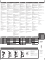
Specifications / Technische Daten / Caractéristiques Techniques / Especificaciones / Caratteristiche Tecniche / Specifikationer / 产品规格
Detection Stability / Erkennungsstabilität / stabilité de la détection / Estabilidad de Detección / Rilevamento di stabilità / Detektionstabilitet / 检测稳定性
Target influence / Einwirkung des Ziels / Influence de la cible / Influencia del objetivo / Influsso dell’obiettivo /
Påvirkning fra emnet / 目标感应
Stable ON / Stabil EIN / Stable activée / Stable ON / Stabile ON / Stabil ON / 稳定开启
Output ON / Ausgang EIN / Sortie activée / Salida ON / Uscita ON / Udgang aktiveret / 输出开启
Output OFF / Ausgang AUS / Sortie désactivée / Salida OFF / Uscita OFF / Udgang deaktiveret / 输出关闭
Stable OFF / Stabil AUS / Stable désactivée / Stable OFF / Stabile OFF / Stabil OFF / 稳定关闭
Green LED / Grün LED / LED Vert / LED Verde / LED Verde / Grøn LED / 绿色 LED
Yellow LED / Gelb LED / LED Jaune / LED Amarillo / LED Giallo / Gul LED / 黄色 LED
Dust alarm / Staubalarm / Alarme poussière / Alarma de polvo / Allarme polvere / Støvalarm / 粉尘警报
Time / Zeit / Temps / Tiempo / Tempo / Tid / 時間
Sensitivity adjustment / Einstellbare Empfindlichkeit / Ajustement de la sensibilité / Ajuste de la sensibilidad /
Regolazione della sensibilita / Justering af følsomhed / 目标感应
Dust alarm NC
>1 sec. >1 sec. >1 sec.
>2 sec.
Dust alarm NO
>1 sec. >1 sec. >1 sec.
>2 sec.
Output NC
Output NO
Yellow LED ON
Green LED ON
Stable OFF
Output OFF
Output ON
Stable ON
Time
Target influence
DIST.
OUTPUT
STABLE
Yellow LED
Sensitivity
adjustment
Green LED
Mounting / Montage / Montage / Montaje / Montaggio / Montering / 安装
Flush mounting
Non-flush mounting
Flush mounting / Bündig einbaubar / Montage noyable / Montaje empotrable / Totalmente scher-
mato / Planmontage / 齐平安装
Non-flush mounting / Nicht-bündigen Einbau / Montage non noyable / Montaje no empotrado /
Parzialmente schermato / Ikke planmonteret / 非齐平安装
ENGLISH
Relief of cable strain
Protection of the sensing face
Switch mounted on mobile carrier
To avoid interference from inductive
voltage/ current peaks, separate
the prox. switch power cables from
any other power cables, e.g. motor,
contactor or solenoid cables
The cable should not be
pulled
A proximity switch should not
serve as mechanical stop
Any repetitive flexing of the cable should
be avoided
Schutz vor Überdehnung des
Kabels
Schutz der Sensorfläche des
Schalters
Mobiler Näherungsschalter
Um Störungen durch induktive
Spannungs-/Stromspitzen zu
vermeiden, Kabel der
Näherungsschalter getrennt
von anderen stromführenden
Kabeln für z.B. Motoren und
Leistungsschalter halten
Nicht am Kabel ziehen Näherungsschalter nicht als
mechanischen Anschlag
verwenden
Wiederholtes Biegen des Kabels vermeiden
Tension des câbles
Protection de la face de détection
du détecteur
Détecteur monté sur support mobile
Pour éviter les interférences issues
des pics de tension et/ou des courants
inductifs, veiller à toujours faire cheminer
séparément les câbles d’alimentation
des détecteurs de proximité et les
câbles d’alimentation des moteurs,
contacts ou solénoïdes
Eviter toute contrainte en
traction du câble
Ne jamais utiliser un détecteur
de proximité en tant que butée
mécanique
Eviter toute répétition de courbure dans le
cheminement du câble
Alivio de la tensión del cable
Protección de la cara de
detección
Conector montado sobre portadora móvil
Para evitar interferencias de tensión
inductiva/ picos de intensidad se
deben separar los cables del sensor
del resto de los cables de alimentación
tales como cables de motor,
contactores o solenoides
No se debe tirar del cable Un sensor de proximidad nunca
debe funcionar como tope
mecánico
Evitar doblar el cable repetidas veces
Aflastning af kabel
Beskyttelse af følerens tasteflade
Aftaster monteret på bevægeligt underlag
For at undgå støjindflydelse fra
induktive strøm-/spændingsspidser
skal aftasterkablet adskilles fra andre
kraftkabler, f.eks. fra motorer, trans-
formatorer og magnetventiler
Der bør ikke trækkes i kablet
En aftaster bør ikke anvendes
som mekanisk stop
Gentagne bøjninger af kablet bør undgås
Posizione del cavo
Protezione della parte sensibile
del sensore
Sensore installato su pedana mobile
Al fine di evitare interferenze di
tipo elettrico, separare i cavi di
alimentazione del sensore di pros-
simità dai cavi di potenza
Il cavo non deve essere teso
I sensori di prossimità non devono
essere usati per bloccaggi
meccanici
Evitare qualsiasi flessione ripetuta del cavo
Installation Hints / Installationshinweise / Conseils d’Installation / Normas de Instalación / Consigli per l’Installazione / Installationsråd og -vink / 安装提示
DEUTSCHFRANÇAISESPAÑOLITALIANO
DANSK
中國
线缆应力消除
感应面保护
安装在移动载体上的开关
为了避免受感应电压/峰值电流的干
扰,请将接近开关电源线缆与所有其
他电源线缆分开,例如电机、接触器
或螺线管的线缆
不能拉动线缆 接近开关不能用作机械式止动装置 避免反复弯曲线缆
DIST.
OUTPUT STABLE
Yellow LED
Sensitivity
adjustment
Green LED
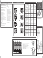
Dimensions / Abmessungen / Dimensions / Dimensiones /
Dimensioni / Dimensioner / 尺寸图
85
M18 x 1.0 x 55
70
15
M12 x 1.0
LED
CA18CAF....M1
CA18CAF....
86
M18 x 1.0 x 55
70
15
LED
CA18CAN....
86
M18 x 1.0 x 47
70
8 15
LED
CA18CAN....M1
85
M18 x 1.0 x 47
70
8 15
M12 x 1.0
LED
CA30CAF....
81
M30 x 1.5 x 59.5
LED
61
CA30CAF....M1
74
M30 x 1.5 x 59.5
LED
M12 x 1.0
61
CA30CAN....
81
M30 x 1.5 x 45.5
14,5
LED
61
CA30CAN....M1
74
M30 x 1.5 x 45.5
14,5
LED
M12 x 1.0
61
CA18
CA30
CA18
CA30

Capacitive sensors have a unique ability to detect almost all materials, in either liquid
or solid form. Capa ci tive sensors can detect metallic as well as non-metallic objects;
how ever, their traditional use is for non-metallic materials such as:
• Plastic Industry: resins, regrinds or moulded products.
• Chemical Industry: cleansers, fertilisers, liquid soaps, corrosives and petroche-
micals.
• Wood Industry: saw dust, paper products, door and window frames.
• Ceramic & Glass Industry: raw material, clay or finished product, bottles.
• Packaging Industry: package inspection for level or contents, dry goods, fruits
and vegetables, dairy products.
Materials are detected due to their dielectric constant. The bigger the size of an object,
the higher the density of material, the better or easier it is to detect the object. The
nominal sensing di stan ce for a capacitive sensor refers to a grounded me tal plate
(ST37). For addi tional information regarding di elec tric ratings of materials please refer
to Technical Information Capacitive Proximity Sensors.
Safety Instructions
Before installing the sensor, please read the installation manual carefully to ensure the
sensor is suitable for your application and installation.
Improper use or installation may result in unintended malfunction of the sensor.
We recommend that the sensor is installed by qualified personnel in order to ensure
correct installation such as electrical connection, sensing distance adjustment, oper-
ation and maintenance.
Mounting the Sensor
Flush or non-flush sensors require an empty safety distance to surrounding materials
or adjacent sensors.
A non-flush sensor requires an increased empty safety distance to material that can
influence the performance of the proximity sensor. See “Mounting”.
Electrical Connection
The sensor must be connected to a power supply that complies with national and
international regulations.
The sensor must be connected according to the connection diagram.
Adjustment
Adjustment at the target:
1) Place the target in front of the sensor.
2) Turn the potentiometer clockwise until both the yellow and the green LED light
steadily.
3) You have now reached a Stable ON level
Elimination of the background:
1) Place the sensor in the application with no target in front of the sensor.
2) Turn the potentiometer clockwise until the yellow LED lights, and then counter
clockwise until the yellow LED is off and the green LED lights steadily.
3) You have now reached a Stable OFF level
Maintenance, Repair and Disposal
Keep the sensor surface clean to ensure optimal sensing conditions.
The sensor cannot be repaired as it is fully potted.
After use, please dispose of the unit in an environmentally friendly manner in accor-
dance with national regulations.
Description and Installation GB
Kapazitive Näherungsschalter eignen sich zum Erfassen von Materialien in fester oder
flüssiger Form. Dazu gehören alle Metalle und nicht-metallischen Stoffe.
Einsatz-möglichkeiten ergeben sich in:
• Spritzgießmaschinen, z..B. Kleber, Granulat aus Kunststoff.
• Chemische Industrie, z.B. Wasseraufbereitung, Säure, Lauge, Lösungsmittel.
• Holzindustrie, z.B. Holz, Sägespäne, Papier.
• Keramik- und Glasindustrie, z.B. Quarzsand, Flaschenerfassung
• Verpackungsindustrie, z.B. Verpackungen, Füllmengenerfassung, Futtermittel,
Molkereierzeugnisse, Früchte und Gemüse
Die Erfassung von Materialien durch kapazitive Näherungsschalter hängt von der
Dichte und den elektrischen Eigenschaften des Objektes ab. Der angegebene
Schaltabstand für kapazitive Näherungsschalter bezieht sich auf eine genormte
Messplatte aus Stahl (ST37).
Sicherheitshinweise
Lesen Sie vor der Installation des Sensors das Installationshandbuch aufmerksam
durch, um sicherzustellen, dass der Sensor für die Anwendung und die Installation
geeignet ist.
Unsachgemäße Verwendung oder Installation kann zu unerwünschten Fehlfunktionen
des Sensors führen.
Wir empfehlen, den Sensor durch qualifiziertes Fachpersonal installieren zu lassen,
um die korrekte Ausführung der Installation im Hinblick auf elektrischen Anschluss,
Einstellung des Messabstands, Betrieb und Wartung sicherzustellen.
Sensor einbauen
Unterputz- und Aufputzsensoren benötigen einen freien Sicherheitsabstand zu umge-
benden Materialien und benachbarten Sensoren.
Bei Aufputzsensoren ist ein größerer Sicherheitsabstand zu Materialien erforderlich,
welche die Leistung des Näherungssensors beeinträchtigen können. Siehe „Einbau“.
Elektrischer Anschluss
Der Sensor muss mit einer Stromversorgung verbunden werden, welche den nationa-
len und internationalen Normen entspricht.
Der Sensor muss gemäß der Anschlussbelegung angeschlossen werden.
Einstellung
Einstellung auf das Ziel:
1) Platzieren Sie das Ziel vor dem Sensor.
2) Drehen Sie das Potenziometer im Uhrzeigersinn, bis sowohl die gelbe als auch die
grüne LED dauerhaft leuchten.
3) Sie haben die Einstellung für den stabilen EIN-Zustand erreicht.
Eliminierung des Hintergrunds:
1) Platzieren Sie den Sensor an der Anwendungsposition. Es darf sich kein Ziel vor
dem Sensor befinden.
2) Drehen Sie das Potenziometer im Uhrzeigersinn, bis die gelbe LED aufleuchtet,
und dann entgegen dem Uhrzeigersinn, bis die gelbe LED erlischt und die grüne LED
dauerhaft leuchtet.
3) Sie haben die Einstellung für den stabilen AUS-Zustand erreicht.
Wartung, Reparatur und Entsorgung
Halten Sie die Sensoroberfläche sauber, um optimale Erkennungsbedingungen zu
gewährleisten.
Der Sensor kann nicht repariert werden, da er vollständig vergossen ist.
Führen Sie den Sensor nach Gebrauch einer umweltfreundlichen Entsorgung zu, die
den nationalen Vorschriften entspricht.
Beschreibung und Installation D
Les détecteurs capacitifs disposent de la faculté exclusive de détecter pratiquement
tous les matériaux dans leur forme solide ou liquide.
Les détecteurs capacitifs sont capables de détecter à la fois les objets métalliques et
non métalliques. Cependant, leur usage est traditionnellement réservé aux matériaux
non métalliques, comme suit:
• Industrie des matières plastiques : Résines, produits moulus ou moulés.
• Industrie chimique : Produits de nettoyage, fertilisants, savons liquides, produits
corrosifs et pétro-chimiques
• Industrie du bois : Sciures, produits de l’industrie du papier, châssis de portes et
de fenêtres.
• Industrie de la céramique et du verre : Matières premières, argile ou produits
finis, bouteilles
• Vérification de contenus ou de niveaux dans l’industrie : de l’emballage et du
conditionnement de marchandises sèches, fruits et légumes, produits laitiers.
Les matériaux sont détectés grâce à
leur constance diélectrique. Plus l’objet est de
grande taille, plus la densité du matériau est grande et plus cet objet pourra être
détecté aisément. La distance de détection nominale d’un détecteur capacitif est
étalonnée à partir d’une plaque en acier doux ST37 mise à la masse. Pour plus
amples détails sur les caractéristiques diélectriques des matérielles, se reporter au
Informations Techniques des Détecteurs de Proximité Capacitifs.
Instructions de sécurité
Avant d’installer le détecteur, lire attentivement le manuel d’installation et constater
assurer que le détecteur correspond à vos application et installation.
Une utilisation ou une installation impropres peuvent conduire à des résultats inatten-
dus du capteur en fonctionnement.
Nous vous recommandons de faire installer votre capteur par un personnel qualifié,
garantie de la qualité des connexions électriques, du réglage de la distance de détec-
tion, du fonctionnement et de la maintenance.
Montage du détecteur
Le montage des détecteurs noyables ou non noyables, exige une distance de sécurité
vide autour des équipements ou détecteurs adjacents.
Un capteur non noyable exige une plus grande distance de sécurité vide par rapport
aux équipements susceptibles d’affecter la performance du détecteur de proximité.
Voir la section « Montage »
Raccordement électrique
Connecter impérativement le détecteur à une alimentation conforme aux réglementa-
tions nationales et internationales.
Le détecteur doit être connecté conformément au Diagramme de raccordement.
Réglage
Réglage par rapport à la cible :
1) Positionner la cible en face du détecteur.
2) Tourner le potentiomètre dans le sens horaire jusqu’à ce que les LED jaune et
verte s’allument en fixe.
3) À ce stade, le détecteur est stable et réglé en position travail (ON)
Suppression de l’arrière-plan :
1) Positionner le détecteur dans l’application en omettant la cible en face du détec-
teur.
2) Tourner le potentiomètre dans le sens horaire jusqu’à ce que la LED jaune s’al-
lume, puis dans le sens anti horaire jusqu’à ce que la LED jaune s’éteigne et que
la LED verte s’allume en fixe.
3) À ce stade, le détecteur est stable et réglé en position repos (OFF)
Maintenance, réparation et mise au rebut
Maintenir impérativement la surface du détecteur propre afin de garantir des condi-
tions de détection optimales.
Conçu par encapsulation globale, le détecteur ne peut être réparé.
Après utilisation, rebuter le détecteur en respectant l’environnement, selon les régle-
mentations nationales.
Description et Installation F
Los sensores capacitivos pueden detectar casi todos los materiales, en estado líquido
o sólido. Permiten detectar objetos metálicos y no metálicos, sin embargo, se utilizan
normalmente con materiales no metálicos en:
• Industria del plástico: Resinas, virutas o productos moldeados.
• Industria química: Detergentes, fertilizantes, jabones líquidos, productos corrosi-
vos y petroquímicos.
• Industria maderera: Serrín, papel, marcos de puertas y ventanas.
• Industria del vidrio y cerámica: Materias primas, arcilla o productos acabados,
botellas.
• Industria del embalaje: Inspección del embalaje: nivel, contenido, sustancias
secas, frutas y verduras, productos lácteos.
Los materiales se detectan por su constante dieléctrica. Cuanto mayor es el objeto,
mayor es su densidad y mejor se detecta. La distancia de detección de un sensor
capacitivo hace referencia a una placa metálica con toma de tierra (ST37). Para obte-
ner más información acerca de las clasificaciones dieléctricas de los materiales, véase
la Información técnica sobre sensores de proximidad capacitivos.
Instrucciones de seguridad
Antes de instalar el sensor, lea con atención el manual de instalación a fin de asegu-
rarse de que el sensor es adecuado para su aplicación y su instalación.
Un uso o una instalación indebidos pueden dar lugar a averías involuntarias del sensor.
Se recomienda que el sensor sea instalado por personal cualificado con el fin de
garantizar la instalación correcta, así como la conexión eléctrica, el ajuste de la dis-
tancia de detección, el funcionamiento y el mantenimiento.
Montaje del sensor
Los sensores empotrados o no empotrados precisan una distancia de seguridad libre
respecto a los materiales del entorno o los sensores adyacentes.
Un sensor no empotrado precisa una distancia de seguridad libre más amplia respec-
to a cualquier material que pueda afectar al rendimiento del sensor de proximidad.
Véase “Montaje”.
Conexión eléctrica
El sensor debe conectarse a una toma eléctrica conforme a los reglamentos nacio-
nales e internacionales.
El sensor debe conectarse de conformidad con el diagrama de conexión.
Ajuste
Ajuste en el objetivo:
1) Coloque el objetivo delante del sensor.
2) Gire el potenciómetro en el sentido de las agujas del reloj hasta que los LED de
color amarillo y verde se iluminen ininterrumpidamente.
3) Ha alcanzado el nivel Stable ON
Eliminación del fondo:
1) Coloque el sensor en la aplicación sin que el objetivo esté delante del sensor.
2) Gire el potenciómetro en el sentido de las agujas del reloj hasta que se ilumine el
LED amarillo y, a continuación, gírelo en el sentido contrario a las agujas del reloj
hasta que el LED amarillo se apague y el LED verde se ilumine ininterrumpidamente.
3) Ha alcanzado el nivel Stable OFF
Mantenimiento, reparaciones y eliminación
Mantenga limpia la superficie del sensor a fin de garantizar unas condiciones de
detección óptimas.
El sensor no se puede reparar y está completamente sellado.
Tras el uso, deseche la unidad de forma respetuosa con el medio ambiente y de con-
formidad con los reglamentos nacionales.
Descripción e Instalación E
I sensori capacitivi sono concepiti per rilevare tutti i tipi di materiale metallico e non
metallico, liquido o solido. Normalmente sono usati per rilevare materiali non metallici
nei seguenti settori:
• Industria della plastica: resine, materiali triturati o plasmati.
• Industria chimica: detergenti, fertilizzanti, saponi liquidi, prodotti corrosivi e
petrolchimici.
• Industria del legno: segatura, prodotti cartacei, intelaiature di porte e finestre.
• Industria della ceramica e del vetro: materiali grezzi, prodotti finiti, bottiglie.
• Industria dell’imballaggio: controllo degli imballaggi secondo livelli e contenuto,
cereali, frutta e verdura, prodotti caseari.
I materiali vengono rilevati grazie alla loro costante dielettrica. La facilità di
individuazione dell’oggetto cresce con l’aumentare delle sue dimensioni o della
densità del materiale. La distanza di attivazione nominale di un sensore capacitivo
viene considerata in relazione ad una piastra di metallo (ST37) collegata a terra. Per
maggiori delucidazioni riguardo alla classificazione dielettrica dei materiali consultare
le Informazioni tecniche dei sensori di prossimità capacitivi.
Istruzioni per la sicurezza
Prima di installare il sensore, leggere attentamente il manuale d’installazione per
accertarsi che il sensore sia adatto per l’applicazione e l’installazione.
L’uso improprio o l’installazione non eseguita correttamente può provocare il malfun-
zionamento involontario del sensore.
Raccomandiamo che il sensore venga installato da personale qualificato al fine di
garantire una corretta installazione, quali allacciamento elettrico, regolazione della
distanza di rilevamento, funzionamento e manutenzione.
Montaggio del sensore
I sensori a filo o sporgenti richiedono una distanza di sicurezza dai materiali circostanti
o dai sensori adiacenti.
Un sensore sporgente richiede una maggiore distanza di sicurezza dal materiale che
può influire sulle prestazioni del sensore di prossimità. Vedere “Montaggio”.
Allacciamento elettrico
Il sensore deve essere collegato ad un alimentatore conforme alle normative nazionali
e internazionali.
Il sensore deve essere collegato secondo l’apposito schema.
Regolazione
Regolazione dall’obiettivo:
1) Posizionare l’obiettivo davanti al sensore.
2) Ruotare il potenziometro in senso orario fino a quando sia la luce LED verde e gialla
si accendono stabilmente.
3) E’ stato raggiunto un livello Stable ON
Eliminazione dello sfondo:
1) Posizionare il sensore nell’applicazione senza obiettivo davanti al sensore.
2) Ruotare il potenziometro in senso orario fino a quando le luci LED gialle, e poi in
senso antiorario fino a quando il LED giallo è spento e il LED verde rimane acceso
stabilmente.
3) E’ stato raggiunto un livello Stable OFF
Manutenzione, riparazione e smaltimento
Mantenere pulita la superficie del sensore per garantire delle condizioni ottimali di
rilevamento.
Il sensore non può essere riparato in quanto è completamente incapsulato.
Dopo l’uso, si prega di smaltire l’apparecchio a tutela dell’ambiente in conformità alle
normative nazionali.
Descrizione e installazione I
Kapacitive sensorer har den enestående egenskab, at de kan aftaste praktisk talt alle
materialer, enten i flydende eller fast form. Kapacitive af tastere kan aftaste metalliske
såvel som ikke-metalliske objekter, men den traditionelle anvendelse er til ikke-metalliske
materialer, f.eks. inden for:
• Plastindustri: Harpiks, genformalede materialer eller støbte produkter m.v.
• Kemisk industri: Rensemidler, gødning, flydende sæbe, ætsende og petrokemiske
stoffer m.v.
• Træindustri:
Savsmuld, papirprodukter, dør- og vinduesrammer
m.v.
• Keramik- og glasindustri:
Råmaterialer, ler eller færdige produkter, flasker
m.v.
•
Emballageindustri:
Kontrol af niveau eller indhold i emballage, tørstoffer, frugter og
grøntsager, mejeriprodukter
m.v.
Materialerne aftastes efter deres dielektriske konstant. Jo større genstand og massefyl-
de, des bedre og nemmere aftastning af genstanden. Den nominelle tasteafstand for en
kapacitiv sensor måles i forhold til en jordforbundet metalplade (ST37). Yderligere oplys-
ninger vedrørende dielektrisk klassificering af materialer findes i ”Technical Information
Capacitive Proximity Sensors”.
Sikkerhedsinstruktioner
Læs installationsvejledningen omhyggeligt før sensoren monteres for at sikre at den
egner sig til den aktuelle installation.
Forkert anvendelse eller montering kan resultere i utilsigtede fejl i sensorfunktionen.
Vi anbefaler at føleren er monteret af uddannet personale for at sikre korrekt instal-
lation, fx når det drejer sig om tilslutning af strøm, justering af tasteafstand, drift og
vedligeholdelse.
Montering af sensoren
Plan- og ikke-planmonterede sensorer skal have en vis sikkerhedsafstand til
omgivende materialer eller andre sensorer placeret tæt på.
En ikke-planmonteret sensor skal have en endnu større sikkerhedsafstand til materi-
aler der kan påvirke dens ydeevne. Se “Montering”
Eltilslutning
Sensoren skal tilsluttes en strømforsyning der overholder nationale og internationale
regler.
Sensoren skal tilsluttes ifølge forbindelsesdiagrammet.
Justering
Justering efter emnet:
1) Placer emnet foran sensoren.
2) Drej potentiometeret med uret indtil både den gule og den grønne LED lyser kon-
stant.
3) Sensoren er nu i stabil ON-tilstand.
Undertrykkelse af baggrund:
1) Placér sensoren i applikationen uden noget emne foran.
2) Drej potentiometeret med uret indtil den gule LED lyser, og derefter mod uret ind-
til den gule LED slukkes og den grønne LED lyser konstant.
3) Sensoren er nu i stabil OFF-tilstand.
Vedligeholdelse, reparation og bortskaffelse
Hold sensorens overflade ren for at sikre optimale forhold for aftastningen.
Sensoren er helstøbt og kan derfor ikke repareres.
Efter brug bortskaffes enheden på en miljøvenlig måde i overensstemmelse med de
enkelte landes regulativer.
Beskrivelse og Installation DK
Green LED Yellow LED
ON OFF
The power is on and the sensor is in a stable OFF
state.
OFF OFF The output is OFF, and the Target is not detected
OFF ON The output ON, and the Target is detected
ON ON
The output is ON and the sensor is in a Stable
ON state.
LED indication
Grüne LED Gelbe LED
EIN AUS
Die Stromversorgung ist hergestellt, und der Sen-
sor befindet sich in einem stabilen AUS-Zustand.
AUS AUS
Der Ausgang ist deaktiviert (AUS), und es wird
kein Ziel erkannt.
AUS EIN
Der Ausgang ist aktiviert (EIN), und das Ziel wird
erkannt.
EIN EIN
Der Ausgang ist aktiviert (EIN), und der Sensor
befindet sich in einem stabilen EIN-Zustand.
LED-Anzeige
LED verte LED jaune
ON OFF L’alimentation est active et le détecteur est stable
en position REPOS.
OFF OFF La sortie est désactivée (OFF) et la cible n’est pas
détectée.
OFF ON La sortie est activée (ON) et la cible est détectée.
ON ON La sortie est activée (ON) et le détecteur est stable
en position TRAVAIL.
LED d’indication
LED verde LED amarillo
ON OFF La alimentación está conectada y el sensor está
en el estado Stable OFF
OFF OFF La salida está desactivada (OFF) y no es posible
detectar el objetivo
OFF ON La salida está activada (ON) y se detecta el
objetivo
ON ON La salida está activada (ON) y el sensor está en el
estado Stable ON
Indicación LED
LED verde LED giallo
ON OFF L’apparecchio è acceso e il sensore è in uno stato
Stable OFF
OFF OFF L’uscita è OFF, e l’obiettivo non viene rilevato
OFF ON L’uscita ON e l’obiettivo viene rilevato
ON ON L’uscita è ON e il sensore è in stato Stable ON
Indicazione a LED
Grøn LED Gul LED
Tændt Slukket Strøm er tilsluttet og sensoren er i stabil OFF-til-
stand
Slukket Slukket Udgangen er OFF (slukket) og emnet er ikke
registreret
Slukket Tændt Udgangen er ON (tændt) og emnet er registreret
Tændt Tændt Udgangen er ON (tændt) og sensoren er i stabil
ON-tilstand
Lysdiodeindikering
Wiring Diagram / Schaltbild / Schéma de Câblage / Diagrama de Conexiones / Collegamenti elettrici / Forbindelsesdiagram / 布线图
NPN
BN
BK
WH
BU
10 - 40 VDC
200 mA
PNP
BN
BK
WH
BU
10 - 40 VDC
200 mA
PNP Dust- or Temperature alarm on NC
BN
BK
WH (DU/TA)
BU
10 - 40 VDC
200 mA
PNP Dust- or Temperature alarm on NO
10 - 40 VDC
200 mA
BN
BK
WH (DU/TA)
BU
Colour code / Farbcode / Code couleur / Código de color / Codice colore / Farvekode / 色码
BN: Brown / Braun / Marron / Marrón / Marrone / Brun / 褐色
BK: Black / Schwarz / Noir / Negro / Nero / Sort / 黑色
WH: White / Weiss / Blanc / Blanco / Bianco / Hvid / 白色
BU: Blue / Blau / Bleu / Azul / Blu / Blå / 蓝色
Dust or temperature alarm on NC/NO / Staub- oder Temperaturalarm am Öffner/Schließer (NC/NO)
/ Alarme poussière ou température sur sortie NF/NO / Alarma de polvo o temperatura en NC/NA /
Allarme polvere o temperatura su NC/NO / Støv- eller temperaturalarm på NC/NO-udgangen /
粉尘或温度警报 NC/NO
电容式传感器具有独特的能力,它能够检测液态或 固态的几乎所有材料。电容式传感
器还可以检测金属和非金属物体;但是,它们通常用于检测非金属材料,如:
* 塑料行业:树脂、再生材料或模制品。
* 化工行业:清洁剂、肥料、液体肥皂、腐蚀剂和石油化学产品。
* 木材行业:木屑、纸制品、门框和窗框。
* 陶瓷与玻璃行业:原材料、粘土或成品、瓶子。
* 包装行业:针对干货、蔬果、乳制品进行等级或内容物方面的包装检验。
根据材料的介电常数检测材料。物体越大,材料密度越高,物体检测起来越容易。电容
式传感器的标称感应距离指的是与接地金属板 (ST37) 之间的距离。有关材料的介电额
定值的其他信息,请参阅“电容式接近传感器技术信息”。
安全说明
在安装传感器之前,请仔细阅读安装手册,确保传感器适合于您的应用及安装环境。
使用或安装的方式不当可能导致传感器出现意外的故障。
我们建议由符合资格的人员来安装传感器,确保安装方式正确无误,这包括电气连接、
传感距离调整、操作以及维护等。
安装传感器
齐平式或非齐平式传感器需要与周边的材料或邻近传感器之间保持空安全距离。
非齐平式传感器需要与那些可能影响接近式传感器性能的材料之间保持更大的空安全距
离。请参阅“安装”。
电器连接
传感器必须连接到符合国内以及国际法规的电源上。
必须根据连接图来连接传感器。
调整
目标的调整:
1) 将目标放在传感器正面。
2) 顺时针旋转电位计,直到黄色和绿色 LED 同时长亮。
3) 您现在已达到稳定的开启状态
消除背景噪声:
1) 将传感器置于正面没有目标的应用环境中。
2) 顺时针旋转电位计,直到黄色 LED 亮起,然后逆时针旋转电位计,直到黄色 LED 关
闭而绿色 LED 长亮。
3) 您现在已达到稳定的关闭状态
维护、维修和弃置
保持传感器表面清洁,确保获得最佳感应条件。
传感器完全密封,因此无法维修。
使用后,请按照国家法规以环保的方式处置本设备。
说明与安装 CN
绿色LED 黄色LED
ON OFF
电源开启,并且传感器处于稳定的关闭状态
OFF OFF
输出关闭,未检测到目标
OFF ON
输出打开,检测到目标
ON ON
输出开启,并且传感器处于稳定的开启状态
LED指示
CARLO GAVAZZI
www.gavazziautomation.com
Certified in accordance with ISO 9001
Gerätehersteller mit dem ISO 9001/EN 29 001 Zertifikat
Une société qualifiée selon ISO 9001
Empresa que cumple con ISO 9001
Certificato in conformità con l’IS0 9001
Kvalificeret i overensstemmelse med ISO 9001
按照 ISO 9001认证标准
MAN CA18-CA30CAxxx MUL rev. 01 - 01.2015
15-029-624
1
4
3
2
Colour code
1 Brown
2 White
3 Blue
4 Black
Transcripción de documentos
/ Abmessungen / Dimensions / Dimensiones / Dimensioni / Dimensioner / 尺寸图 Protection Schutz / Protection / Protección / Protezione / Beskyttelse / 防护措施 Short-circuit, reverse polarity, transients Verpolung, Kurzschluss und Transienten / Court-circuit, inversion de polarité, transitoires / Cortocircuitos, inversión de polaridad, transitorios / Corto circuito, inversione di polarità, transitori / Kortslutning, omvendt polaritet, transient / 短路、反 极性、瞬态 Rated operating distance (Sn) Nenn-Schaltabstand / Distance nominale de fonctionnement / Distancia nominal de detección / Distanza di attivazione nominale / Nominel tasteafstand / 额定工作距离 CA18CAN..... 3 - 12 mm CA18CAF..... 2 - 8 mm 4 - 25 mm 2 - 16 mm Operating temperature Umgebungstemperatur, Betrieb / Température de fonctionnement / Temperatura ambiente, trabajo / Temperatura di funzionamento / Omgivelsestemperatur, drift / 工作温度 -30° --> +85°C (-22° --> +185°F) CA18CAF.... 81 ≤ 7.5 Nm 70 LED LED Für Inneneinsatz ausgelegte Gehäusetypen: 1, 2, 5 und 12. Für Innen- und Außeneinsatz ausgelegte Gehäusetypen: 4, 4X, 6 und 6P. Sensoren mit „M1“ in der Bezeichnung sind für den Außeneinsatz ausgelegt. Sensoren ohne „M1“ in der Bezeichnung sind für den Inneneinsatz ausgelegt. Caractéristiques du type de boîtier pour utilisation en intérieur : 1, 2, 5 et 12. Caractéristiques du type de boîtier pour utilisation en extérieur : 4, 4X, 6 et 6P. Les détecteurs dont le code produit porte la référence M1 sont conçus pour utilisation en extérieur. Les détecteurs dont le code produit exclut la référence M1 sont conçus pour utilisation en intérieur. M18 x 1.0 x 55 CA30CAF....M1 M30 x 1.5 x 59.5 15 CA18CAF....M1 74 85 61 70 Clasificaciones de tipo de carcasa para el uso en interiores: 1, 2, 5 y 12. Clasificaciones de tipo de carcasa para el uso en exteriores: 4, 4X, 6 y 6P. Los sensores con M1 en el número de elemento están indicados para exteriores. Los sensores sin M1 en el número de elemento están indicados para interiores. LED Gradi di protezione della custodia per uso interno: 1, 2, 5 e 12. Gradi di protezione della custodia per uso interno ed esterno: 4, 4X, 6 e 6P. I sensori con M1 nel numero articolo sono classificati per uso esterno. I sensori senza M1 nel numero articolo sono classificati per uso interno. Klassifiicering af sensorhus til indendørs brug: 1, 2, 5 og 12. Klassifiicering af sensorhus til indendørs og udendørs brug: 4, 4X, 6 og 6P. Sensorer med M1 i typenummeret er godkendt til udendørs brug. Sensorer uden M1 i typenummeret er godkendt til indendørs brug. CA18-CA30CAN/CAF.... 86 61 UL Enclosure Type Ratings for indoor use: 1, 2, 5 and 12. Enclosure Type Ratings for indoor and outdoor use: 4, 4X, 6 and 6P. Sensors with M1 in item number are rated Outdoor. Sensors without M1 in item number are rated Indoor. LED M12 x 1.0 M18 x 1.0 x 55 M12 x 1.0 15 M30 x 1.5 x 59.5 CA30CAN.... CA18CAN.... 81 86 61 室内应用的规定机柜型号:1、2、5 和 12。 室内及室外应用的规定机柜型号:4、4X、6 和 6P。 产品编号中有 M1 的传感器是规定的室外传感器。 产品编号中没有 M1 的传感器是规定的室内传感器。 70 LED LED Storage temperature Umgebungstemperatur, Lager / Température de stockage / Temperatura ambiente, almacenamiento / Temperatura di immagazzinaggio / Omgivelsestemperatur, lager / 存储温度 -40° --> +85°C (-40° --> +185°F) 14,5 CA30CAN....M1 8 M30 x 1.5 x 45.5 M18 x 1.0 x 47 15 CA18CAN....M1 74 85 61 70 LED LED M12 x 1.0 14,5 8 M18 x 1.0 x 47 M30 x 1.5 x 45.5 Detection Stability / 15 ENGLISH Output Ausgang / Sortie / Salida / Uscita / Udgang / 输出 Transistor, NPN, NO and NC ; PNP, NO and/or NC Transistor, NPN, Schließer und Öffner ; PNP, Schließer und/oder Öffner Transistor, NPN, NO et NF ; PNP, NO et/ou NF Transistor, NPN, norm. abierto y cerrado ; PNP, norm. abierto y/o cerrado Transistor, NPN, NA e NC ; PNP, NA e/o NC Transistor, NPN, NO og NC : PNP, NO og/eller NC 晶体管,NPN,NO 和 NC;PNP,NO 和/或 NC CA30CAF.... Transistor Output Transistor-Ausgang / Sortie transistor / Salida de Transistor/ Uscita a transistor / Transistorudgang / 晶体管输出 To avoid interference from inductive voltage/ current peaks, separate the prox. switch power cables from any other power cables, e.g. motor, contactor or solenoid cables DEUTSCH Rated operational current (Ie) Nenn-Betriebsstrom / Courant de fonctionnement nominal / Intensidad de salida / Corrente di carico / Max. strøm / 额定工作电流 ≤ 200 mA CA18 Um Störungen durch induktive Spannungs-/Stromspitzen zu vermeiden, Kabel der Näherungsschalter getrennt von anderen stromführenden Kabeln für z.B. Motoren und Leistungsschalter halten FRANÇAIS Ripple Restwelligkeit / Ondulation / Ondulación / Ripple / Ripple / 纹波 : ≤ 10% CA30 CA30 Pour éviter les interférences issues des pics de tension et/ou des courants inductifs, veiller à toujours faire cheminer séparément les câbles d’alimentation des détecteurs de proximité et les câbles d’alimentation des moteurs, contacts ou solénoïdes ESPAÑOL No load supply current (Io) Leeraufstrom / Courant d’alimentation à vide / Consume de corriente sin carga / Corrente di alimentazione / Tomgangsstrøm / 空载电流 ≤ 12 mA Tightening torque Anzugsdrehmoment / force de serrage / Par de apriete / Coppia di serragio / Tilspændingsmoment / 拧紧扭矩 CA18 ≤ 2.6 Nm Capacitive Level Sensors Näherungsschalter Kapazitiv / Détecteurs de niveau capacitifs / Sensores de Nivel Capacitivos / Sensori di livello capacitivi / Kapacitive level sensorer / 电容物位传感器 Para evitar interferencias de tensión inductiva/ picos de intensidad se deben separar los cables del sensor del resto de los cables de alimentación tales como cables de motor, contactores o solenoides ITALIANO Ripple included Einschl. Restwelligkeit / ondulation inclue / ondulación incluida / ripple incluso / inkl. ripple / 含纹波 10 - 40 VDC (10 - 40 VCC) Degree of protection Schutzart / Indice de protection / Grado de protección / Grado di protezione / Tæthedsgrad / 防 护等级 最低 IP67, IP68, IP69K Installation Hints / Installationshinweise / Conseils d’Installation / Normas de Instalación / Consigli per l’Installazione / Installationsråd og -vink / 安装提示 Al fine di evitare interferenze di tipo elettrico, separare i cavi di alimentazione del sensore di prossimità dai cavi di potenza DANSK Rated operational voltage (Ue) Nenn-Betriebsspannung / Tension de fonctionnement nominale / Tensión de alimentación / Tensione di alimentazione / Nominelt spændingsområde / 额定工作电压 CA30CAN..... CA30CAF..... Dimensions / Technische Daten / Caractéristiques Techniques / Especificaciones / Caratteristiche Tecniche / Specifikationer / 产品规格 For at undgå støjindflydelse fra induktive strøm-/spændingsspidser skal aftasterkablet adskilles fra andre kraftkabler, f.eks. fra motorer, transformatorer og magnetventiler 中國 Specifications 为了避免受感应电压/峰值电流的干 扰,请将接近开关电源线缆与所有其 他电源线缆分开,例如电机、接触器 或螺线管的线缆 M12 x 1.0 Relief of cable strain Protection of the sensing face Switch mounted on mobile carrier The cable should not be pulled A proximity switch should not serve as mechanical stop Any repetitive flexing of the cable should be avoided Schutz vor Überdehnung des Kabels Schutz der Sensorfläche des Schalters Mobiler Näherungsschalter Nicht am Kabel ziehen Näherungsschalter nicht als mechanischen Anschlag verwenden Wiederholtes Biegen des Kabels vermeiden Tension des câbles Protection de la face de détection du détecteur Détecteur monté sur support mobile Eviter toute contrainte en traction du câble Ne jamais utiliser un détecteur de proximité en tant que butée mécanique Eviter toute répétition de courbure dans le cheminement du câble Alivio de la tensión del cable Protección de la cara de detección Conector montado sobre portadora móvil No se debe tirar del cable Un sensor de proximidad nunca debe funcionar como tope mecánico Evitar doblar el cable repetidas veces Posizione del cavo Protezione della parte sensibile del sensore Sensore installato su pedana mobile Il cavo non deve essere teso I sensori di prossimità non devono essere usati per bloccaggi meccanici Evitare qualsiasi flessione ripetuta del cavo Aflastning af kabel Beskyttelse af følerens tasteflade Aftaster monteret på bevægeligt underlag Der bør ikke trækkes i kablet En aftaster bør ikke anvendes som mekanisk stop Gentagne bøjninger af kablet bør undgås 线缆应力消除 感应面保护 安装在移动载体上的开关 不能拉动线缆 接近开关不能用作机械式止动装置 避免反复弯曲线缆 TM T SH LE P RI D IEL User Manual Bedienungsanleitung / Manuel de l’utilisateur / Manual del Usuario / Manuale d’istruzione / Brugerhåndbog / 用户手册 Mounting / Montage / Montage / Montaje / Montaggio / Montering / 安装 Flush mounting Erkennungsstabilität / stabilité de la détection / Estabilidad de Detección / Rilevamento di stabilità / Detektionstabilitet / 检测稳定性 STABLE CA18 Target influence Sensitivity adjustment Non-flush mounting DIST. Stable ON Yellow OUTPUT Green LED LED Output ON Output OFF Stable OFF Time Target influence / Einwirkung des Ziels / Influence de la cible / Influencia del objetivo / Influsso dell’obiettivo / Påvirkning fra emnet / 目标感应 Stable ON / Stabil EIN / Stable activée / Stable ON / Stabile ON / Stabil ON / 稳定开启 Output ON / Ausgang EIN / Sortie activée / Salida ON / Uscita ON / Udgang aktiveret / 输出开启 Output OFF / Ausgang AUS / Sortie désactivée / Salida OFF / Uscita OFF / Udgang deaktiveret / 输出关闭 Stable OFF / Stabil AUS / Stable désactivée / Stable OFF / Stabile OFF / Stabil OFF / 稳定关闭 Green LED / Grün LED / LED Vert / LED Verde / LED Verde / Grøn LED / 绿色 LED Yellow LED / Gelb LED / LED Jaune / LED Amarillo / LED Giallo / Gul LED / 黄色 LED Dust alarm / Staubalarm / Alarme poussière / Alarma de polvo / Allarme polvere / Støvalarm / 粉尘警报 Time / Zeit / Temps / Tiempo / Tempo / Tid / 時間 Sensitivity adjustment / Einstellbare Empfindlichkeit / Ajustement de la sensibilité / Ajuste de la sensibilidad / Regolazione della sensibilita / Justering af følsomhed / 目标感应 CA30 Sensitivity adjustment Green LED Green LED ON Yellow LED Yellow LED ON DIST. Output NO Output NC OUTPUT Dust alarm NO >1 sec. >1 sec. >1 sec. >2 sec. Dust alarm NC >1 sec. >1 sec. >1 sec. >2 sec. STABLE Flush mounting / Bündig einbaubar / Montage noyable / Montaje empotrable / Totalmente schermato / Planmontage / 齐平安装 Non-flush mounting / Nicht-bündigen Einbau / Montage non noyable / Montaje no empotrado / Parzialmente schermato / Ikke planmonteret / 非齐平安装 Description and Installation GB Capacitive sensors have a unique ability to detect almost all materials, in either liquid or solid form. Capacitive sensors can detect metallic as well as non-metallic objects; however, their traditional use is for non-metallic materials such as: • Plastic Industry: resins, regrinds or moulded products. • Chemical Industry: cleansers, fertilisers, liquid soaps, corrosives and petroche micals. • Wood Industry: saw dust, paper products, door and window frames. • Ceramic & Glass Industry: raw material, clay or finished product, bottles. • Packaging Industry: package inspection for level or contents, dry goods, fruits and vegetables, dairy products. Materials are detected due to their dielectric constant. The bigger the size of an object, the higher the density of material, the better or easier it is to detect the object. The nominal sensing distance for a capacitive sensor refers to a grounded metal plate (ST37). For additional information regarding dielectric ratings of materials please refer to Technical Information Capacitive Proximity Sensors. Beschreibung und Installation D Kapazitive Näherungsschalter eignen sich zum Erfassen von Materialien in fester oder flüssiger Form. Dazu gehören alle Metalle und nicht-metallischen Stoffe. Einsatz-möglichkeiten ergeben sich in: • Spritzgießmaschinen, z..B. Kleber, Granulat aus Kunststoff. • Chemische Industrie, z.B. Wasseraufbereitung, Säure, Lauge, Lösungsmittel. • Holzindustrie, z.B. Holz, Sägespäne, Papier. • Keramik- und Glasindustrie, z.B. Quarzsand, Flaschenerfassung • Verpackungsindustrie, z.B. Verpackungen, Füllmengenerfassung, Futtermittel, Molkereierzeugnisse, Früchte und Gemüse Die Erfassung von Materialien durch kapazitive Näherungsschalter hängt von der Dichte und den elektrischen Eigenschaften des Objektes ab. Der angegebene Schaltabstand für kapazitive Näherungsschalter bezieht sich auf eine genormte Messplatte aus Stahl (ST37). Safety Instructions Before installing the sensor, please read the installation manual carefully to ensure the sensor is suitable for your application and installation. Improper use or installation may result in unintended malfunction of the sensor. We recommend that the sensor is installed by qualified personnel in order to ensure correct installation such as electrical connection, sensing distance adjustment, operation and maintenance. Sicherheitshinweise Lesen Sie vor der Installation des Sensors das Installationshandbuch aufmerksam durch, um sicherzustellen, dass der Sensor für die Anwendung und die Installation geeignet ist. Unsachgemäße Verwendung oder Installation kann zu unerwünschten Fehlfunktionen des Sensors führen. Wir empfehlen, den Sensor durch qualifiziertes Fachpersonal installieren zu lassen, um die korrekte Ausführung der Installation im Hinblick auf elektrischen Anschluss, Einstellung des Messabstands, Betrieb und Wartung sicherzustellen. Mounting the Sensor Flush or non-flush sensors require an empty safety distance to surrounding materials or adjacent sensors. A non-flush sensor requires an increased empty safety distance to material that can influence the performance of the proximity sensor. See “Mounting”. Sensor einbauen Unterputz- und Aufputzsensoren benötigen einen freien Sicherheitsabstand zu umgebenden Materialien und benachbarten Sensoren. Bei Aufputzsensoren ist ein größerer Sicherheitsabstand zu Materialien erforderlich, welche die Leistung des Näherungssensors beeinträchtigen können. Siehe „Einbau“. Electrical Connection The sensor must be connected to a power supply that complies with national and international regulations. The sensor must be connected according to the connection diagram. Elektrischer Anschluss Der Sensor muss mit einer Stromversorgung verbunden werden, welche den nationalen und internationalen Normen entspricht. Der Sensor muss gemäß der Anschlussbelegung angeschlossen werden. Adjustment Adjustment at the target: 1) Place the target in front of the sensor. 2) Turn the potentiometer clockwise until both the yellow and the green LED light steadily. 3) You have now reached a Stable ON level Einstellung Einstellung auf das Ziel: 1) Platzieren Sie das Ziel vor dem Sensor. 2) Drehen Sie das Potenziometer im Uhrzeigersinn, bis sowohl die gelbe als auch die grüne LED dauerhaft leuchten. 3) Sie haben die Einstellung für den stabilen EIN-Zustand erreicht. Elimination of the background: 1) Place the sensor in the application with no target in front of the sensor. 2) Turn the potentiometer clockwise until the yellow LED lights, and then counter clockwise until the yellow LED is off and the green LED lights steadily. 3) You have now reached a Stable OFF level Eliminierung des Hintergrunds: 1) Platzieren Sie den Sensor an der Anwendungsposition. Es darf sich kein Ziel vor dem Sensor befinden. 2) Drehen Sie das Potenziometer im Uhrzeigersinn, bis die gelbe LED aufleuchtet, und dann entgegen dem Uhrzeigersinn, bis die gelbe LED erlischt und die grüne LED dauerhaft leuchtet. 3) Sie haben die Einstellung für den stabilen AUS-Zustand erreicht. Maintenance, Repair and Disposal Keep the sensor surface clean to ensure optimal sensing conditions. The sensor cannot be repaired as it is fully potted. After use, please dispose of the unit in an environmentally friendly manner in accordance with national regulations. Wartung, Reparatur und Entsorgung Halten Sie die Sensoroberfläche sauber, um optimale Erkennungsbedingungen zu gewährleisten. Der Sensor kann nicht repariert werden, da er vollständig vergossen ist. Führen Sie den Sensor nach Gebrauch einer umweltfreundlichen Entsorgung zu, die den nationalen Vorschriften entspricht. Description et Installation F Les détecteurs capacitifs disposent de la faculté exclusive de détecter pratiquement tous les matériaux dans leur forme solide ou liquide. Les détecteurs capacitifs sont capables de détecter à la fois les objets métalliques et non métalliques. Cependant, leur usage est traditionnellement réservé aux matériaux non métalliques, comme suit: • Industrie des matières plastiques : Résines, produits moulus ou moulés. • Industrie chimique : Produits de nettoyage, fertilisants, savons liquides, produits corrosifs et pétro-chimiques • Industrie du bois : Sciures, produits de l’industrie du papier, châssis de portes et de fenêtres. • Industrie de la céramique et du verre : Matières premières, argile ou produits finis, bouteilles • Vérification de contenus ou de niveaux dans l’industrie : de l’emballage et du conditionnement de marchandises sèches, fruits et légumes, produits laitiers. Les matériaux sont détectés grâce à leur constance diélectrique. Plus l’objet est de grande taille, plus la densité du matériau est grande et plus cet objet pourra être détecté aisément. La distance de détection nominale d’un détecteur capacitif est étalonnée à partir d’une plaque en acier doux ST37 mise à la masse. Pour plus amples détails sur les caractéristiques diélectriques des matérielles, se reporter au Informations Techniques des Détecteurs de Proximité Capacitifs. Instructions de sécurité Avant d’installer le détecteur, lire attentivement le manuel d’installation et constater assurer que le détecteur correspond à vos application et installation. Une utilisation ou une installation impropres peuvent conduire à des résultats inattendus du capteur en fonctionnement. Nous vous recommandons de faire installer votre capteur par un personnel qualifié, garantie de la qualité des connexions électriques, du réglage de la distance de détection, du fonctionnement et de la maintenance. Montage du détecteur Le montage des détecteurs noyables ou non noyables, exige une distance de sécurité vide autour des équipements ou détecteurs adjacents. Un capteur non noyable exige une plus grande distance de sécurité vide par rapport aux équipements susceptibles d’affecter la performance du détecteur de proximité. Voir la section « Montage » Raccordement électrique Connecter impérativement le détecteur à une alimentation conforme aux réglementations nationales et internationales. Le détecteur doit être connecté conformément au Diagramme de raccordement. Réglage Réglage par rapport à la cible : 1) Positionner la cible en face du détecteur. 2) Tourner le potentiomètre dans le sens horaire jusqu’à ce que les LED jaune et verte s’allument en fixe. 3) À ce stade, le détecteur est stable et réglé en position travail (ON) Suppression de l’arrière-plan : 1) Positionner le détecteur dans l’application en omettant la cible en face du détecteur. 2) Tourner le potentiomètre dans le sens horaire jusqu’à ce que la LED jaune s’allume, puis dans le sens anti horaire jusqu’à ce que la LED jaune s’éteigne et que la LED verte s’allume en fixe. 3) À ce stade, le détecteur est stable et réglé en position repos (OFF) Descripción e Instalación E Descrizione e installazione I Beskrivelse og Installation DK • Plastindustri: Harpiks, genformalede materialer eller støbte produkter m.v. • Kemisk industri: Rensemidler, gødning, flydende sæbe, ætsende og petrokemiske stoffer m.v. • Træindustri: Savsmuld, papirprodukter, dør- og vinduesrammer m.v. • Keramik- og glasindustri: Råmaterialer, ler eller færdige produkter, flasker m.v. • Emballageindustri: Kontrol af niveau eller indhold i emballage, tørstoffer, frugter og grøntsager, mejeriprodukter m.v. Materialerne aftastes efter deres dielektriske konstant. Jo større genstand og massefylde, des bedre og nemmere aftastning af genstanden. Den nominelle tasteafstand for en kapacitiv sensor måles i forhold til en jordforbundet metalplade (ST37). Yderligere oplysninger vedrørende dielektrisk klassificering af materialer findes i ”Technical Information Capacitive Proximity Sensors”. 安全说明 在安装传感器之前,请仔细阅读安装手册,确保传感器适合于您的应用及安装环境。 使用或安装的方式不当可能导致传感器出现意外的故障。 我们建议由符合资格的人员来安装传感器,确保安装方式正确无误,这包括电气连接、 传感距离调整、操作以及维护等。 Instrucciones de seguridad Antes de instalar el sensor, lea con atención el manual de instalación a fin de asegurarse de que el sensor es adecuado para su aplicación y su instalación. Un uso o una instalación indebidos pueden dar lugar a averías involuntarias del sensor. Se recomienda que el sensor sea instalado por personal cualificado con el fin de garantizar la instalación correcta, así como la conexión eléctrica, el ajuste de la distancia de detección, el funcionamiento y el mantenimiento. Istruzioni per la sicurezza Prima di installare il sensore, leggere attentamente il manuale d’installazione per accertarsi che il sensore sia adatto per l’applicazione e l’installazione. L’uso improprio o l’installazione non eseguita correttamente può provocare il malfunzionamento involontario del sensore. Raccomandiamo che il sensore venga installato da personale qualificato al fine di garantire una corretta installazione, quali allacciamento elettrico, regolazione della distanza di rilevamento, funzionamento e manutenzione. Sikkerhedsinstruktioner Læs installationsvejledningen omhyggeligt før sensoren monteres for at sikre at den egner sig til den aktuelle installation. Forkert anvendelse eller montering kan resultere i utilsigtede fejl i sensorfunktionen. Vi anbefaler at føleren er monteret af uddannet personale for at sikre korrekt installation, fx når det drejer sig om tilslutning af strøm, justering af tasteafstand, drift og vedligeholdelse. 安装传感器 齐平式或非齐平式传感器需要与周边的材料或邻近传感器之间保持空安全距离。 非齐平式传感器需要与那些可能影响接近式传感器性能的材料之间保持更大的空安全距 离。请参阅“安装”。 Montaggio del sensore I sensori a filo o sporgenti richiedono una distanza di sicurezza dai materiali circostanti o dai sensori adiacenti. Un sensore sporgente richiede una maggiore distanza di sicurezza dal materiale che può influire sulle prestazioni del sensore di prossimità. Vedere “Montaggio”. Montering af sensoren Plan- og ikke-planmonterede sensorer skal have en vis sikkerhedsafstand til omgivende materialer eller andre sensorer placeret tæt på. En ikke-planmonteret sensor skal have en endnu større sikkerhedsafstand til materialer der kan påvirke dens ydeevne. Se “Montering” Conexión eléctrica El sensor debe conectarse a una toma eléctrica conforme a los reglamentos nacionales e internacionales. El sensor debe conectarse de conformidad con el diagrama de conexión. Allacciamento elettrico Il sensore deve essere collegato ad un alimentatore conforme alle normative nazionali e internazionali. Il sensore deve essere collegato secondo l’apposito schema. Eltilslutning Sensoren skal tilsluttes en strømforsyning der overholder nationale og internationale regler. Sensoren skal tilsluttes ifølge forbindelsesdiagrammet. Ajuste Ajuste en el objetivo: 1) Coloque el objetivo delante del sensor. 2) Gire el potenciómetro en el sentido de las agujas del reloj hasta que los LED de color amarillo y verde se iluminen ininterrumpidamente. 3) Ha alcanzado el nivel Stable ON Regolazione Regolazione dall’obiettivo: 1) Posizionare l’obiettivo davanti al sensore. 2) Ruotare il potenziometro in senso orario fino a quando sia la luce LED verde e gialla si accendono stabilmente. 3) E’ stato raggiunto un livello Stable ON Justering Justering efter emnet: 1) Placer emnet foran sensoren. 2) Drej potentiometeret med uret indtil både den gule og den grønne LED lyser konstant. 3) Sensoren er nu i stabil ON-tilstand. Eliminación del fondo: 1) Coloque el sensor en la aplicación sin que el objetivo esté delante del sensor. 2) Gire el potenciómetro en el sentido de las agujas del reloj hasta que se ilumine el LED amarillo y, a continuación, gírelo en el sentido contrario a las agujas del reloj hasta que el LED amarillo se apague y el LED verde se ilumine ininterrumpidamente. 3) Ha alcanzado el nivel Stable OFF Eliminazione dello sfondo: 1) Posizionare il sensore nell’applicazione senza obiettivo davanti al sensore. 2) Ruotare il potenziometro in senso orario fino a quando le luci LED gialle, e poi in senso antiorario fino a quando il LED giallo è spento e il LED verde rimane acceso stabilmente. 3) E’ stato raggiunto un livello Stable OFF Undertrykkelse af baggrund: 1) Placér sensoren i applikationen uden noget emne foran. 2) Drej potentiometeret med uret indtil den gule LED lyser, og derefter mod uret indtil den gule LED slukkes og den grønne LED lyser konstant. 3) Sensoren er nu i stabil OFF-tilstand. Mantenimiento, reparaciones y eliminación Mantenga limpia la superficie del sensor a fin de garantizar unas condiciones de detección óptimas. El sensor no se puede reparar y está completamente sellado. Tras el uso, deseche la unidad de forma respetuosa con el medio ambiente y de conformidad con los reglamentos nacionales. Manutenzione, riparazione e smaltimento Mantenere pulita la superficie del sensore per garantire delle condizioni ottimali di rilevamento. Il sensore non può essere riparato in quanto è completamente incapsulato. Dopo l’uso, si prega di smaltire l’apparecchio a tutela dell’ambiente in conformità alle normative nazionali. Green LED LED-Anzeige Yellow LED Grüne LED ON OFF The power is on and the sensor is in a stable OFF state. OFF OFF The output is OFF, and the Target is not detected OFF ON The output ON, and the Target is detected ON ON The output is ON and the sensor is in a Stable ON state. LED d’indication Gelbe LED 调整 目标的调整: 1) 将目标放在传感器正面。 2) 顺时针旋转电位计,直到黄色和绿色 LED 同时长亮。 3) 您现在已达到稳定的开启状态 消除背景噪声: 1) 将传感器置于正面没有目标的应用环境中。 2) 顺时针旋转电位计,直到黄色 LED 亮起,然后逆时针旋转电位计,直到黄色 LED 关 闭而绿色 LED 长亮。 3) 您现在已达到稳定的关闭状态 维护、维修和弃置 保持传感器表面清洁,确保获得最佳感应条件。 传感器完全密封,因此无法维修。 使用后,请按照国家法规以环保的方式处置本设备。 绿色 LED Indicación LED Indicazione a LED Lysdiodeindikering LED verte LED jaune LED verde LED amarillo LED verde LED giallo Grøn LED Gul LED ON OFF L’alimentation est active et le détecteur est stable en position REPOS. ON OFF La alimentación está conectada y el sensor está en el estado Stable OFF ON OFF L’apparecchio è acceso e il sensore è in uno stato Stable OFF Tændt Slukket Strøm er tilsluttet og sensoren er i stabil OFF-tilstand OFF La sortie est désactivée (OFF) et la cible n’est pas détectée. OFF OFF La salida está desactivada (OFF) y no es posible detectar el objetivo OFF OFF L’uscita è OFF, e l’obiettivo non viene rilevato Slukket Slukket OFF ON L’uscita ON e l’obiettivo viene rilevato Udgangen er OFF (slukket) og emnet er ikke registreret ON ON L’uscita è ON e il sensore è in stato Stable ON Slukket Tændt Udgangen er ON (tændt) og emnet er registreret Tændt Tændt Udgangen er ON (tændt) og sensoren er i stabil ON-tilstand EIN AUS AUS AUS Der Ausgang ist deaktiviert (AUS), und es wird kein Ziel erkannt. OFF EIN Der Ausgang ist aktiviert (EIN), und das Ziel wird erkannt. OFF ON La sortie est activée (ON) et la cible est détectée. OFF ON ON ON EIN Der Ausgang ist aktiviert (EIN), und der Sensor befindet sich in einem stabilen EIN-Zustand. La sortie est activée (ON) et le détecteur est stable en position TRAVAIL. La salida está activada (ON) y se detecta el objetivo ON ON La salida está activada (ON) y el sensor está en el estado Stable ON EIN 电器连接 传感器必须连接到符合国内以及国际法规的电源上。 必须根据连接图来连接传感器。 LED 指示 Die Stromversorgung ist hergestellt, und der Sensor befindet sich in einem stabilen AUS-Zustand. AUS 电容式传感器具有独特的能力,它能够检测液态或 固态的几乎所有材料。电容式传感 器还可以检测金属和非金属物体;但是,它们通常用于检测非金属材料,如: * 塑料行业:树脂、再生材料或模制品。 * 化工行业:清洁剂、肥料、液体肥皂、腐蚀剂和石油化学产品。 * 木材行业:木屑、纸制品、门框和窗框。 * 陶瓷与玻璃行业:原材料、粘土或成品、瓶子。 * 包装行业:针对干货、蔬果、乳制品进行等级或内容物方面的包装检验。 根据材料的介电常数检测材料。物体越大,材料密度越高,物体检测起来越容易。电容 式传感器的标称感应距离指的是与接地金属板 (ST37) 之间的距离。有关材料的介电额 定值的其他信息,请参阅“电容式接近传感器技术信息”。 Vedligeholdelse, reparation og bortskaffelse Hold sensorens overflade ren for at sikre optimale forhold for aftastningen. Sensoren er helstøbt og kan derfor ikke repareres. Efter brug bortskaffes enheden på en miljøvenlig måde i overensstemmelse med de enkelte landes regulativer. Maintenance, réparation et mise au rebut Maintenir impérativement la surface du détecteur propre afin de garantir des conditions de détection optimales. Conçu par encapsulation globale, le détecteur ne peut être réparé. Après utilisation, rebuter le détecteur en respectant l’environnement, selon les réglementations nationales. LED indication CN I sensori capacitivi sono concepiti per rilevare tutti i tipi di materiale metallico e non metallico, liquido o solido. Normalmente sono usati per rilevare materiali non metallici nei seguenti settori: • Industria della plastica: resine, materiali triturati o plasmati. • Industria chimica: detergenti, fertilizzanti, saponi liquidi, prodotti corrosivi e petrolchimici. • Industria del legno: segatura, prodotti cartacei, intelaiature di porte e finestre. • Industria della ceramica e del vetro: materiali grezzi, prodotti finiti, bottiglie. • Industria dell’imballaggio: controllo degli imballaggi secondo livelli e contenuto, cereali, frutta e verdura, prodotti caseari. I materiali vengono rilevati grazie alla loro costante dielettrica. La facilità di individuazione dell’oggetto cresce con l’aumentare delle sue dimensioni o della densità del materiale. La distanza di attivazione nominale di un sensore capacitivo viene considerata in relazione ad una piastra di metallo (ST37) collegata a terra. Per maggiori delucidazioni riguardo alla classificazione dielettrica dei materiali consultare le Informazioni tecniche dei sensori di prossimità capacitivi. Montaje del sensor Los sensores empotrados o no empotrados precisan una distancia de seguridad libre respecto a los materiales del entorno o los sensores adyacentes. Un sensor no empotrado precisa una distancia de seguridad libre más amplia respecto a cualquier material que pueda afectar al rendimiento del sensor de proximidad. Véase “Montaje”. Kapacitive sensorer har den enestående egenskab, at de kan aftaste praktisk talt alle materialer, enten i flydende eller fast form. Kapacitive aftastere kan aftaste metalliske såvel som ikke-metalliske objekter, men den traditionelle anvendelse er til ikke-metalliske materialer, f.eks. inden for: 说明与安装 Los sensores capacitivos pueden detectar casi todos los materiales, en estado líquido o sólido. Permiten detectar objetos metálicos y no metálicos, sin embargo, se utilizan normalmente con materiales no metálicos en: • Industria del plástico: Resinas, virutas o productos moldeados. • Industria química: Detergentes, fertilizantes, jabones líquidos, productos corrosivos y petroquímicos. • Industria maderera: Serrín, papel, marcos de puertas y ventanas. • Industria del vidrio y cerámica: Materias primas, arcilla o productos acabados, botellas. • Industria del embalaje: Inspección del embalaje: nivel, contenido, sustancias secas, frutas y verduras, productos lácteos. Los materiales se detectan por su constante dieléctrica. Cuanto mayor es el objeto, mayor es su densidad y mejor se detecta. La distancia de detección de un sensor capacitivo hace referencia a una placa metálica con toma de tierra (ST37). Para obtener más información acerca de las clasificaciones dieléctricas de los materiales, véase la Información técnica sobre sensores de proximidad capacitivos. 黄色 LED ON OFF 电源开启,并且传感器处于稳定的关闭状态 OFF OFF 输出关闭,未检测到目标 OFF ON 输出打开,检测到目标 ON ON 输出开启,并且传感器处于稳定的开启状态 CARLO GAVAZZI www.gavazziautomation.com Wiring Diagram / Schaltbild / Schéma de Câblage / Diagrama de Conexiones / Collegamenti elettrici / Forbindelsesdiagram / 布线图 PNP BN WH BK BU PNP Dust- or Temperature alarm on NC BN BN BK 10 - 40 VDC 200 mA WH BU PNP Dust- or Temperature alarm on NO 10 - 40 VDC 200 mA BK WH (DU/TA) BU 1 BN 10 - 40 VDC 200 mA BK WH (DU/TA) BU 10 - 40 VDC 200 mA Colour code 4 2 3 1 2 3 4 Brown White Blue Black Colour code / Farbcode / Code couleur / Código de color / Codice colore / Farvekode / 色码 BN: Brown / Braun / Marron / Marrón / Marrone / Brun / 褐色 BK: Black / Schwarz / Noir / Negro / Nero / Sort / 黑色 WH: White / Weiss / Blanc / Blanco / Bianco / Hvid / 白色 BU: Blue / Blau / Bleu / Azul / Blu / Blå / 蓝色 Dust or temperature alarm on NC/NO / Staub- oder Temperaturalarm am Öffner/Schließer (NC/NO) / Alarme poussière ou température sur sortie NF/NO / Alarma de polvo o temperatura en NC/NA / Allarme polvere o temperatura su NC/NO / Støv- eller temperaturalarm på NC/NO-udgangen / 粉尘或温度警报 NC/NO Certified in accordance with ISO 9001 Gerätehersteller mit dem ISO 9001/EN 29 001 Zertifikat Une société qualifiée selon ISO 9001 Empresa que cumple con ISO 9001 Certificato in conformità con l’IS0 9001 Kvalificeret i overensstemmelse med ISO 9001 按照 ISO 9001认证标准 15-029-624 NPN MAN CA18-CA30CAxxx MUL rev. 01 - 01.2015-
 1
1
-
 2
2


CARLO GAVAZZI CA30CAF16PCTA Manual de usuario
- Tipo
- Manual de usuario
En otros idiomas
Documentos relacionados
-
CARLO GAVAZZI CA12CLC08BPM1RT Manual de usuario
-
CARLO GAVAZZI CA18CLL12BPM1 Manual de usuario
-
-
-
-
CARLO GAVAZZI CA18FAN12BPM1IO Manual de usuario
-
CARLO GAVAZZI PC50CNT20R El manual del propietario
-
-
CARLO GAVAZZI UA18CAD22PKTI Manual de usuario
-