Titan 1200GXC El manual del propietario
- Categoría
- Rociador de pintura
- Tipo
- El manual del propietario

0200 © 2000 Titan Tool Inc. All rights reserved. Form No. 313-1466
REV A
Printed in the U. S. A.
Do not use this equipment before reading this manual!
1200GXC Airless Sprayer
Owner’s Manual
For professional use only
NOTE: This manual contains important warnings
and instructions. Please read and retain for
reference.
Model Numbers:
High Rider Complete 783-2000
High Rider Bare 783-2001
NOTE: This manual contains important warnings
and instructions. Please read and retain for
reference.

2©Titan Tool Inc. All rights reserved.
PISTON SEAL LUBRICANT
Specially formulated to prevent materi-
als from adhering to the piston rod,
which becomes abrasive to the upper
seals. Piston Lube will break down
any material that may accumulate in
the wet cup and keep it from drying.
8 oz individual ..........................700-925
1 qt individual...........................700-926
8 oz, case of 12 .......................700-911
1 qt, case of 12.......................700-912
AIRLESS HOSE
I.D.x Length Part #
1/4” x 50’ .......................316-505
3/8" x 50' .......................690-375-50
3/16" x 15' ......................550-221
HIGH PRESSURE SWIVELS
Pressure Rated at 5000 psi
Gun-to-Hose
1/4” NPS (F) x 1/4” NPS (M).........500-428
Hose-to-Hose
1/4” NPS (M) x 1/4” NPS(M) ........500-424
FITTINGS
Description
Part #
1/4" x 1/4" Hose Coupling............490-012
1/4" x 3/8" Hose Coupling............490-016
3/8" x 3/8" Hose Coupling............490-014
T-Fittings 1/4" x 1/4".....................490-036
4 Gun Manifold.............................500-056
Tip Filter Retainer ........................520-046
1/4" Mx1/4"F Swivel Union...........490-005
1/4" Mx3/8"F Swivel Union...........490-032
Retaining Nut Adapter..................490-007
High Pressure Fl. Gauge .............730-394
Parts Lists and Repair Information...15-25
Frame Assembly..............................15
Siphon Assembly (optional).............15
Main Assembly ..........................16–17
Replacement Labels........................17
Engine Assembly.............................18
Important Facts................................18
Maintenance..........................................19
Service/Replacement of Clutch
Assembly .........................................19
Gear Box Assembly.........................20
Replacing the Clutch Rotor..............21
ON/OFF Switch................................21
Gear Repair/Service ........................21
Electrical Schematic ........................21
Filter Block Assembly ......................22
Pressure Switch Replacement ........23
Replacement of the Bypass Valve ..23
Filter Replacement...........................23
Fluid Section Assembly ...................24
Pump Repair....................................25
Equipment Job History.........................26
Limited Warranty..................................28
Table of Contents
Accessories ............................................2
General Repair & Service Notes............3
Maintenance/Service Record .................4
Warnings ................................................5
Aviso (En Español).................................6
Attention (En Français) ..........................7
Notice: Fire or Explosion Hazards ...8–10
Startup Procedure ................................11
Spraying ...............................................12
Cleaning Procedure..............................13
Flushing Specifications.........................14
Airless Tip Selection.............................13
Troubleshooting..............................13–14
Airless Gun .......................................13
Spray Pattern....................................13
Airless Pump.....................................14
Accessories
LIQUID SHIELD
Cleans and protects spray systems
against rust, corrosion and premature
wear.
Case of 12 (1 quart bottles).....700-888
1 quart......................................700-889
U.S. Patents: 3,936,002; 4,220,286;
4,457,472; 4,508,268; 4,494,697;
4,500,119; 4,626,004; 4,611,758;
4,744,571; 4,728,213; 4,768,932;
4,755,638; 4,768,929; 4,840,543;
4,908,538; 5,074,467; 5,425,506
WARNING: The Engine Exhaust
from this product contains chemicals
known to the State of California to
cause cancer, birth defects, or other
reproductive harm.

© Titan Tool Inc. All rights reserved. 3
General Repair & Service Notes
WARNING: Before proceeding, follow the Pressure
Relief Procedure outlined in the “Warning” section of
this manual. Additionally, follow all other warnings to
reduce the risk of an injection injury, injury from mov-
ing parts, or electric shock. Always unplug the sprayer
before servicing!
The following tools are needed when repairing this sprayer:
Phillips Screwdriver 3/8"Allen Wrench
Needle Nose Pliers 5/16" Allen Wrench
Adjustable Wrench 1/4" Allen Wrench
Rubber Mallet 3/16" Allen Wrench
Flat-blade Screwdriver 1/8" Allen Wrench
1/2" Open End Wrench
1. Before repairing any part of the sprayer, read the
instructions carefully, including all warnings.
2. When disconnecting wires, use needle nose pliers to
separate mating connectors.
CAUTION: Never pull on a wire to disconnect it. Pulling
on a wire could loosen the connector from the wire.
3. Test your repair before regular operation of the sprayer
to be sure that the problem is corrected. If the sprayer
does not operate properly, review the repair procedure
to determine if everything was done correctly. Refer to
the Troubleshooting Charts to help identify other
possible problems.
4. Make certain that the service area is well ventilated in
case solvents are used during cleaning. Always wear
protective eyewear while servicing. Additional
protective equipment may be required depending on
the type of cleaning solvent. Always contact the
supplier of solvents for recommendations.
5. If you have any further questions concerning your
TITAN Airless Sprayer, call TITAN:
Customer Service Department ..............1-800-526-5362
Fax ........................................................1-800-528-4826
Outside the U.S. Call.............................1-201-405-7520
Outside the U.S. Fax ............................1-201-405-7449
Canada .................................................1-800-565-8665
Fax........................................................ 1-905-856-8496
Electrical
Box
Bypass
Valve
Return
Hose
Outlet
Fitting
Gas Tank
Hose Rack
Pressure
Control Knob
Paint Filter
Gear Box
Siphon Down
Tube
Engine
Pail Hook
Add piston
seal lubricant
(P.S.L.) here
Fluid Section
Figure 2
Figure 1
Figure 3

4©Titan Tool Inc. All rights reserved.
MODEL # SERIAL # DATE PURCHASED COMPANY NAME
Titan Tool is in the business of designing and manufacturing spray systems and accessories that make today’s Painting Professional
become more efficient and profitable. We feel that if you accurately track the maintenance of your equipment on this chart it will
improve the performance of this valuable tool to help you get the most out of your investment.
The chart is easy to follow and to use. The Maintenance Schedule allows for the recording of all your service work and will help you
make sure your unit is always running at peak performance.
Make sure to fill in the boxes at the top of this record with the model number, serial number, date purchased and your company
name. This information will be needed to validate your warranty.
Maintenance Schedule
Check Piston Seal Lubricant Level WEEKLY.
Gas Engine Models
Change engine oil
every 50 hours
Date Date
Date
Date
Date
Date
Date
Date Date
Date
Service Record
Service Performed
Date Service Center
Cost of Repair
Months in Service
Service Performed
Date Service Center
Cost of Repair
Months in Service
Service Performed
Date Service Center
Cost of Repair
Months in Service
Service Performed
Date Service Center
Cost of Repair
Months in Service
Service Performed
Date Service Center
Cost of Repair
Months in Service
Warranty
Repair
❏ Yes
❏ No
Warranty
Repair
❏ Yes
❏ No
Warranty
Repair
❏ Yes
❏ No
Warranty
Repair
❏ Yes
❏ No
Warranty
Repair
❏ Yes
❏ No
Service Performed
Date Service Center
Cost of Repair
Months in Service
Warranty
Repair
❏ Yes
❏ No
Service Performed
Date Service Center
Cost of Repair
Months in Service
Warranty
Repair
❏ Yes
❏ No
May Be Copied For Field Use

© Titan Tool Inc. All rights reserved. 5
An airless spray gun requires that fluid be introduced to it at very
high pressure. Fluids under high pressure, from spray or leaks,
can penetrate the skin and inject substantial quantities of toxic fluid
into the body. If not promptly and properly treated, the injury can
cause tissue death or gangrene and may result in serious,
permanent disability or amputation of the wounded part. Therefore,
extreme caution must be exercised when using any airless spray
equipment. IF YOU ARE INJECTED, SEE A PHYSICIAN
IMMEDIATELY! DO NOT TREAT AS A SIMPLE CUT!
NOTE TO PHYSICIAN: Injection into the skin is a serious,
traumatic injury. It is important to treat the injury surgically
as soon as possible. Do not delay treatment to research
toxicity. Toxicity is a concern with some exotic coatings
injected directly into the bloodstream. Consultation with a
plastic surgeon or a reconstructive hand surgeon may be
advised.
1. Handle the spray gun carefully. Keep clear of the nozzle.
NEVER point the gun at yourself or anyone else. NEVER
permit any part of your body to come in contact with the fluid
stream of either the gun or any hose leak. ALWAYS keep the
gun trigger safety lever in a locked position when not spraying.
ALWAYS use a tip safety guard.
2. NEVER attempt to force the flow of fluid backward through
the gun with your finger, hand or hand-held object against
the gun nozzle. THIS IS NOT AN AIR SPRAY GUN.
3. NEVER attempt to remove tip, disassemble or repair
equipment without first doing the following:
4. Before flushing system, always remove spray tip and adjust
fluid pressure to lowest possible setting.
5. Tighten all fluid connections before each use. NEVER
exceed 3200 psi with this unit. Make sure that all accessory
hoses, connections, swivels and so forth can withstand the
high pressures which develop. NEVER exceed the pressure
rating of any component in the system.
6. The paint hose can develop leaks from wear, kinking, abuse,
etc. A leak is capable of injecting fluid into the skin, therefore
the paint hose should be inspected before each use.
NEVER attempt to plug a hose with any part of your body,
adhesive tape or any other makeshift device. Do not
attempt to repair a spray hose. Instead, replace it with a
new grounded hose. Use only with hoses that have spring
guards. NEVER use less than 50' of hose with this unit.
7. Be sure that the airless equipment being used and the object
being sprayed are properly grounded to prevent static discharge
or sparks which could cause fire or explosion. Warning:
ALWAYS hold the gun against metal container when flushing
system with tip removed, to prevent static discharge. CAUTION:
To reduce the risk of electrical shock, do not expose to rain.
Store indoors.
8. ALWAYS keep the working area around the pump well
ventilated. Additionally, the pump itself should be a minimum
of 25' (7.5m) from the spray area. If these instructions are not
followed, there is the possibility of fire or explosion with certain
materials. ALWAYS follow the coating or solvent
manufacturer's safety precautions and warnings. Never spray
flammable material near open flames, pilot lights or any source
of ignition.
9. ALWAYS wear spray masks and protective eyewear while
spraying. Additional personal protective equipment may be
required depending on the type of material being sprayed and
conditions of ventilation. Always contact supplier of material
being sprayed for recommendation.
10. Keep all extension poles clear of electrical wires.
11. NEVER alter or modify any part of this equipment; doing so
could cause it to malfunction.
12. NEVER leave equipment unattended. Keep away from
children or anyone not familiar with the operation of airless
equipment.
PRESSURE RELEASE PROCEDURE
A. Set trigger lock in the locked
position.
B. Shut off pump.
C. Release fluid pressure from
entire system and trigger gun.
D. Reset trigger lock in the
locked position.
DO NOT USE EQUIPMENT BEFORE READING THIS SECTION
WARNING
HIGH PRESSURE SPRAY
CAN CAUSE SERIOUS INJURY
Maximum Working Pressure 3200 psi, 221 bar

6©Titan Tool Inc. All rights reserved.
Una pistola rociadora sin aire requiere que se le introduzca
líquido a presión muy alta. Los líquidos bajo presión alta, de la
rociadura o de las fugas, pueden penetrar en la piel e inyectar
en el cuerpo cantidades considerables de líquido tóxico. Si no
se atiende rápida y apropiadamente, la lesión puede causar
muerte del tejido o gangrena, y puede resultar en incapacidad
seria y permanente o en la amputación de la parte lesionada.
Por lo tanto, hay que emplear precauciones estrictas al usar
cualquier equipo de rociadura sin aire. SI USTED HA ESTADO
EXPUESTO A LA PENETRACION DE TOXICOS POR
INYECCION, CONSULTE INMEDIATAMENTE AL MEDICO. ¡NO
TRATE LA HERIDA COMO SI FUERA UNA MERA
CORTADURA!
NOTA PARA EL MEDICO: La penetración de tóxicos en la piel
es una herida seria y traumática. Es importante tratar la
herida quirúrgicamente lo más pronto posible. No demore el
tratamiento para investigar la toxicidad. La toxicidad es
asunto serio cuando se trata de la penetración de ciertos
revestimientos tóxicos en la corriente sanguínea. Puede que
sea necesaria la consulta con un cirujano plástico o un
cirujano especialista en la reconstrucción de la mano.
1. Maneje la pistola de rociadura con cuidado. Manténgase
alejado de la boquilla. JAMAS apunte la pistola hacia usted
u otra persona. NUNCA permita que parte alguna de su
cuerpo se ponga en contacto con el chorro de líquido de la
pistola o de alguna fuga de la manguera. SIEMPRE
mantenga trabado el seguro de la pistola mientras no esté
rociando. SIEMPRE utilice el protector de seguridad de la
boquilla.
2. JAMAS intente forzar el flujo del líquido por la pistola hacia
atrás con el dedo, la mano o un objeto sostenido con la
mano contra la boquilla de la pistola, ya que NO SE TRATA
DE UNA PISTOLA DE ROCIADURA DE AIRE.
3. JAMAS intente quitar la boquilla ni desarmar o reparar el
equipo sin haber cumplido antes con los pasos siguientes:
4. Antes de lavar el sistema, siempre quite la boquilla de
rociadura y ajuste la presión del líquido al valor más bajo
posible.
5. Ajuste todas las conexiones antes de cada uso. JAMAS
supere 3200 libras por pulgada cuadrada con esta unidad.
Asegúrese de que todas las mangueras, conexiones,
articulaciones giratorias y demás elementos accesorios
estén en condiciones de tolerar las altas presiones que se
presentan. JAMAS exceda la clasificación de presión de
cualquier componente del sistema.
6. ADVERTENCIA: La manguera de pintura puede presentar
fugas como resultado del desgaste, retorcimiento, abuso,
etc. Las fugas pueden inyectar líquido a través de la piel,
por lo que la manguera de pintura debe ser inspeccionada
antes de cada uso. JAMAS intente obturar la manguera con
una parte de su cuerpo o con tela adhesiva o cualquier otro
elemento improvisado. No intente reparar una manguera de
rociadura; en cambio reemplácela con una manguera nueva
conectada a tierra. Utilice solamente mangueras con
protector de resorte.
7. Asegúrese de que el equipo sin aire que esté empleando y el
objeto que se intenta rociar estén correctamente conectados a
tierra para evitar descargas estáticas o chispas que podrían
ocasionar incendio o explosión. ADVERTENCIA: Sostenga
SIEMPRE la pistola contra el receptáculo de metal al limpiar el
sistema con la boquilla desprendida, para evitar la descarga
estática. ADVERTENCIA: Para reducir riesgo de descarga
eléctrica, no exponer a la lluvia.
8. SIEMPRE mantenga el lugar de trabajo alrededor de la bomba
bien ventilado. Además, la bomba en sí debe estar ubicada a
no menos de 7,6 m de la operación de rociadura. Si no se
observan estas instrucciones, existe el riesgo de incendio o
explosión con ciertos materiales. SIEMPRE observe las
precauciones y advertencias de los fabricantes sobre
revestimientos y solventes. Nunca rocíe material inflamable
cerca de llamas expuestas, llamas piloto o cualquier fuente de
ignición.
9. SIEMPRE use máscaras apropiadas y anteojos de protección
durante la operación de rociadura. Según el tipo de material
que se está rociando y las condiciones de ventilación puede
ser necesario usar equipo personal protector adicional.
Siempre comuníquese con el proveedor del material para
conseguir recomendaciones.
10. Mantenga todas las varas de extensión fuera del alcance de
cables eléctricos.
11. JAMAS altere o modifique parte alguna de este equipo, ya
que ello puede causar deficiencias de funcionamiento.
12. JAMAS deje al equipo solo. Manténgalo fuera del alcance
de los niños o de cualquier persona no familiarizada con la
operación de equipo sin aire.JAMAS use una manguera de
menos de 15,2 m con esta unidad. Almacenar bajo techo.
PROCEDIMIENTO DE
DESCOMPRESION
A. Coloque el seguro de la pistola
en posición trabada.
B. Apague la bomba.
C. Descargue la presión del líquido
de todo el sistema y de la pistola.
D. Vuelva a trabar el seguro.
NO USE EL EQUIPO ANTES DE LEER ESTA SECCION
ADVERTENCIA
LA ROCIADURA A PRESION ALTA
PUEDE CAUSAR LESION GRAVE.
Presión de Trabajo Máxima 3200 libras por pulgada cuadrada (psi), 221 bar

© Titan Tool Inc. All rights reserved. 7
Le liquide introduit dans un pistolet pulvérisateur sans air doit l’être
à pression extrêmement élevée. Les liquides à haute pression, en
provenance du pulvérisateur ou d’une fuite quelconque, sont
capables de pénétrer la peau et d’injecter d’importantes quantités
de liquide toxique dans l’organisme. Si elle n’est pas traitée
promptement et avec toute l’attention voulue, la lésion causée de
la sorte peut provoquer la nécrose des tissus ou la gangrène et
donner lieu à de sérieux handicaps permanents, voire à
l’amputation du membre atteint. Une prudence extrême s’impose
donc lors de l’utilisation de matériel de pulvérisation sans air. EN
CAS D’INJECTION, CONSULTEZ UN MEDECIN
IMMEDIATEMENT. NE TRAITEZ PAS LA BLESSURE COMME
S’IL S’AGISSAIT D’UNE SIMPLE COUPURE!
REMARQUE A L’INTENTION DU MEDECIN: Une injection
pénétrant la peau constitue une lésion traumatique grave qu’il
est important de traiter chirurgicalement aussitôt que
possible. Ne perdez pas de temps à rechercher la toxicité de
l’injection. Il s’agit là d’un risque à envisager en cas
d’injection directe dans le circuit sanguin de certains
revêtements exotiques. La consultation d’un chirurgien
plasticien ou d’un spécialiste de la chirurgie reconstructive de
la main peut être conseillée.
1. Maniez le pistolet avec soin. Maintenez-vous à l’écart de la
buse. N’en dirigez JAMAIS la buse vers aucune partie de votre
corps ou vers aucune autre personne. Ne laissez JAMAIS
aucune partie de votre corps entrer en contact avec le flux de
liquide s’échappant du pistolet ou d’une fuite quelconque au
niveau du flexible. Verrouillez TOUJOURS le levier de sûreté
de la détente lorsque vous n’êtes pas occupé à pulvériser.
Veillez à TOUJOURS utiliser un dispositif de sûreté à la buse
du pistolet.
2. N’essayez JAMAIS de refouler le flux de liquide dans le pistolet
au moyen de votre doigt, de votre main ou d’un objet maintenu
contre la buse du pistolet. CET APPAREIL N’EST PAS UN
PISTOLET PULVERISATEUR A AIR. N’utilisez aucune pièce de
matériel sans air avec une pompe non équipée d’une soupape de
surpression.
3. N’essayez JAMAIS d’enlever la buse, de démonter ou de
réparer l’appareil avant d’avoir accompli la procédure
suivante :
4. Avant de procéder au rinçage du système, enlevez toujours
la buse de pulvérisation et réglez la pression au niveau le
plus faible possible.
5. Serrez bien tous les raccords du système hydrodynamique
avant chaque emploi. Ne dépassez JAMAIS, avec cet appareil,
une pression de 3200 psi. Assurez-vous que tous les flexibles
accessoires, raccords, articulations, etc. sont bien capables de
résister aux hautes pressions prévues. Ne dépassez JAMAIS la
capacité de pression nominale d’aucun composant du système.
DANGER : Afin de réduire tout risque d’électrocution,
n’exposez pas à la pluie.
6. Des fuites risquent de se produire le long du flexible de peinture
sous l’effet de l’usure, des torsions, des rudes traitements, etc.
auxquels il est éventuellement soumis. Les injections de liquide
dans la peau sont possibles par la voie de telles fuites. Il est donc
important d’inspecter le flexible avant chaque usage. N’essayez
JAMAIS d’obturer une fuite à l’aide de votre doigt ou de tout autre
membre de votre corps, de ruban adhésif ou de tout autre moyen
de fortune. N’essayez pas non plus de réparer un flexible de
pulvérisation ; remplacez-le plutôt par un nouveau flexible mis à la
terre. Veillez à n’utiliser que les flexibles munis de dispositifs de
sécurité à ressort. N’utilisez JAMAIS moins de 15,2 m de flexible
avec cet appareil.
7. Assurez-vous que le matériel sans air utilisé et que l’objet à
peindre sont adéquatement mis à la terre, de façon à éviter
toute décharge d’électricité statique ou toute étincelle
susceptible de provoquer un incendie ou une explosion.
ATTENTION : Tenez TOUJOURS le pistolet contre un récipient
en métal lors du rinçage du système, après en avoir ôté la
buse. Ne vaporisez JAMAIS de substances inflammables à
proximité de flammes nues, lampes témoin ni d’aucune source
d’allumage. Rangez à l’intérieur.
8. Le moteur électrique de cet appareil n’est pas protégé contre
les explosions. Il est donc essentiel d’assurer une bonne
ventilation de la zone de travail et des alentours de la pompe. Il
est également important de maintenir la pompe à une distance
minimale de 7,6 m de la zone de pulvérisation. Certains
matériaux présentent, à défaut de suivre ces consignes, un
risque d’incendie ou d’explosion. Suivez TOUJOURS les
précautions et avertissements du fabricant de chaque solvant
ou revêtement utilisé.
9. Portez TOUJOURS un masque et des lunettes de protection lors
de vos travaux de pulvérisation. D’autres articles de protection
personnelle peuvent être nécessaires suivant le type de produit
pulvérisé et les conditions d’aération. Demandez toujours ses
recommandations à votre fournisseur.
10.Maintenez toutes les tiges de rallonge à distance des fils
électriques.
11.N´altérez ou ne modifiez JAMAIS une partie quelconque de cet
appareil, ce qui pourrait causer des défaillances.
12.Ne laissez JAMAIS le matériel sans surveillance. Gardez-le
hors de portée des enfants et de toute personne
inexpérimentée quant à l’usage de matériel sans air.
PROCEDURE DE DELESTAGE
DE PRESSION
A. Verrouillez la sûreté de la détente.
B. Arrêtez la pompe.
C. Délestez la pression dans tout le
système et appuyez sur la détente
du pistolet.
D. Reverrouillez la sûreté de la
détente.
NE PAS UTILISER LE MATERIEL AVANT D’AVOIR LU CETTE SECTION
ATTENTION!
LES PULVERISATEURS A HAUTE PRESSION PEUVENT
PROVOQUER DE SERIEUSES LESIONS
Pression de travail maximale: 3200 psi — 221 bar

8©Titan Tool Inc. All rights reserved.
FIRE OR EXPLOSION HAZARD
Static electricity is created by the high velocity of fluid through the pump, hose and tip. If every part of the spray element
is not properly grounded, sparking may occur and the system may become hazardous. Sparking may also occur when
plugging in or unplugging a power supply cord, or starting a gas engine. Sparks can ignite fumes from solvents or the
fluids being sprayed. Always plug the sprayer into an outlet at least 25' (7,5) away from the spray area.
WARNING: Always flush the unit into a separate metal container with the spray tip removed and the gun held
firmly against the side of the container to assure proper grounding and prevent static discharge which could
cause serious bodily injury.
If you experience any static sparking or slight shock while using this equipment, stop spraying immediately. Check the
entire system for proper grounding. Do not use the system again until the problem has been corrected.
ELECTRIC MOTOR
The electric motors used by TITAN are not explosion proof. Therefore, it is essential to keep the working area
around the pump well ventilated. Additionally, the pump itself should be a minimum of 25' (7,5) from the spray
area.
WARNING: Always keep pump outside of any enclosed spray area. Never clean the exterior of the pump with
any flammable solvents.
GAS ENGINE (Where Applicable)
Always keep pump outside of any enclosed spray area. Keep area around pump well ventilated. Keep all sol-
vents away from engine exhaust. (Never fill the fuel tank while the engine is running or hot. Fuel spilled on a
hot surface can ignite and cause a fire.) Always attach ground wire located on rear of engine to a grounded
object, i.e. water pipe. NOTE: Refer to engine owner's manual for additional safety and service information.
FLUID SECTION—SOLVENTS
Halogenated Hydrocarbon solvents can cause an explosion when used with aluminum or galvanized components in a
closed (pressurizable) fluid system (pumps, heaters, filters, valves, spray guns, tanks, etc.). The explosion could cause
serious injury, death and/or substantial property damage. Cleaning agents, coatings, paints, etc. may contain
Halogenated Hydrocarbon solvents. Titan Tool Inc. spray equipment includes aluminum or galvanized components
and will be affected by Halogenated Hydrocarbon solvents. DO NOT USE HALOGENATED HYDROCARBONS IN
TITAN EQUIPMENT.
EXPLANATION OF THE HAZARD
There are three key elements to the Halogenated Hydrocarbon (HHC) solvent hazard. These elements are:
1. The presence of HHC solvents.
2. Aluminum or galvanized parts.
3. Equipment capable of withstanding pressure.
When all three elements are present, the result can be an extremely violent explosion. The reaction can be sustained
with very little aluminum or galvanized metal: any amount of aluminum is too much. The reaction is unpredictable.
Prior use of an HHC solvent without incident (corrosion or explosion) does NOT mean that such use is safe.
PELIGRO DE INCENDIO O EXPLOSIÓN
La alta velocidad del líquido a través de la bomba, manguera y la boquilla produce electricidad estática. Si algún com-
ponente del equipo de rociadura no está conectado a tierra correctamente pueden producirse chispas y el sistema se
vuelve peligroso. También pueden producirse chispas al enchufar o desenchufar cables eléctricos o al poner en fun-
cionamiento un motor a gasolina. Las chispas pueden encender los vapores provenientes de los solventes o de los
líquidos rociados. Siempre conecte el rociador a un enchufe ubicado a no menos de 7,5m de distancia de la zona de
rociadura.
ADVERTENCIA: Lavar siempre la unidad en un recipiente metálico separado, habiendo quitado la boca del roci-
ador y teniendo la pistola firmemente contra el lado del recipiente para asegurar una puesta a tierra correcta y
evitar la descarga estática que podría causar lesión corporal grave.
Si ocurren chispas de electricidad estática o si sufre un shock eléctrico ligero mientras usa el equipo, deje de rociar de
immediato. Verifique que el sistema en su totalidad esté conectado a tierra correctamente. No vuelva a usar el sistema
hasta que el problema haya sido resuelto.
MOTOR ELÉCTRICO:
Los motores eléctricos utilizados por TITAN no son a prueba de explosión. Por lo tanto, es esencial mantener
el área de trabajo alrededor de la bomba bien ventilada. Además, la bomba misma debe estar a una distancia
minima de 7,5m del area de rociadura.
ADVERTENCIA: Mantener siempre la bomba afuera de cualquier área de rociadura cerrada. Nunca limpie el
exterior de la bomba con solventes inflamables.

© Titan Tool Inc. All rights reserved. 9
MOTOR A GASOLINA: (Si fuera aplicable)
Siempre mantenga la bomba afuera de cualquier zona de rociadura cerrada. Mantenga el área alrededor de la
bomba bien ventilada. Mantenga todos los solventes lejos del escape del motor. (Nunca liene el tanque de
combustible cuando el motor esté funcionando o caliente. El combustible derramado sobre una superficie
caliente puede encenderse y producir un incendio). El cable a tierra que está ubicado en la parte de atrás del
motor debe estar siempre adherido a un objeto conectado a tierra, por ejemplo, una cañería de agua. NOTA:
Vea el manual de uso del motor para información adicional sobre seguridad y mantenimiento.
SECCION FLUIDO—SOLVENTES
Los solventes a base de hidrocarburos halogenados pueden provocar explosión cuando se usan con componentes gal-
vanizados o de aluminio en un sistema líquido cerrado (sujeto a presión) (bombas, calefactores, filtros, válvulas, pistolas
de rociadura, tanques, etc.) La explosión podría causar lesiones serias e inclusive la muerte, así como daños materi-
ales de consideración. Los líquidos de limpieza, revestimientos, pinturas, etc. pueden contener solventes a base de
hidrocarburos halogenados. El equipo de rociadura ofrecido por Titan Tool Inc. tiene componentes galvanizados o de
aluminio y será afectado por solventes a base de hidrocarburos halogenados. NO USE HIDROCARBUROS HALOGE-
NADOS EN EL EQUIPO TITAN.
EXPLICACION DEL RIESGO
Hay tres elementos fundamentales que condicionan el riesgo de los hidrocarburos halogenados, a saber:
1. Presencia de solventes de hidrocarburos halogenados.
2. Componentes galvanizados o de aluminio.
3. Equipo capaz de tolerar presión.
Cuando todos estos elementos están presentes, el resultado puede ser una explosión sumamente violenta. La reacción
puede tener lugar aun cuando la cantidad de aluminio o metal galvanizado sea muy pequeña: cualquier cantidad de alu-
minio es excesiva. La reacción no puede predecirse. El hecho de que un solvente a base de hidrocarburos halogena-
dos haya sido usado anteriormente sin accidentes (corrosión o explosión) NO significa que dicho uso no es peligroso.
DANGER!
RISQUE D'INCENDIE OU D'EXPLOSION
La vitesse du liquide à travers la pompe le flexible et la buse produit de l'électricité statique. Si tous les éléments du
matériel de pulvérisation ne sont pas mis à la terre de manière adéquate, ils risquent de favoriser la production d'étincelles
et de rendre le système dangereux. Des étincelles peuvent également se produire lors de branchement ou débranchement
d'un cordon d’alimentation électrique ou lors de la mise en marche d'un moteur au gaz. De telles étincelles sont suscepti-
bles d'enflammer les vapeurs des solvants ou les liquides pulvérisés. Veillez donc toujours à brancher le pulvérisateur
dans une prise située à au moins 7,5m du pulvérisateur et de la zone de travail.
MISE EN GARDE: Toujours rincer l’appareil dans un récipient métallique distinct après avoir enlevé le bec de pul-
vérisation et en tenant fermement le pistolet contre le côté du récipient afin d’assurer une mise à la terre appro-
priée et de prévenir une décharge statique susceptible de causer des blessures graves.
Si vous remarquez la formation d'étincelles sous l'effet de la présence d'électricité statique ou que vous ressentez une
légère décharge électrique en cours d'utilisation du matériel, arrêtez immédiatement la pulvérisation. Assurez-vous que
tous les éléments du système sont bien mis à la terre. Ne remettez pas le système en marche avant d'avoir résolu le prob-
lème.
MOTEUR ÉLECTRIQUE
Les moteurs électriques utilisés par TITAN ne sont pas protégés contre les explosions. Il est donc essentiel d'as-
surer une bonne ventilation de la zone de travail et des environs de la pompe. Il est également important de main-
tenir la pompe à une distance minimale de 7,5m de la zone de pulvérisation.
ATTENTION: N'introduisez jamais la pompe dans une zone de pulvérisation fermée. Ne nettoyez jamais nettoyer
l'extérieur de la pompe à l'aide de solvants inflammables.
MOTEUR AU GAZ (le cas échéant)
N'introduisez jamais la pompe dans une zone de pulvérisation fermée. Veillez à ce que les environs de la pompe
soient toujours bien aérés. Ne placez aucun solvant à proximité du système d'échappement du moteur. (Ne rem-
plissez jamais le réservoir à carburant lorsque le moteur tourne ou s'il est chaud. Renversé sur une surface
chaude, le gaz pourrait s'enflammer et provoquer un incendie.) Veillez à toujours bien raccorder le fil de terre
situé à l'arrière du moteur à un objet mis à la terre (par exemple, une conduite d'eau). REMARQUE: Pour plus de
détails sur les mesures de sécurité et d'entretien pertinentes, consultez le manuel fourni avec le moteur.
SECTION HYDRODYNAMIQUE—SOLVANTS
Les solvants à hydrocarbure halogéné sont explosifs en présence de pièces galvanisées ou en aluminium dans un sys-
tème hydrodynamique fermé (pressurisable) (pompes, radiateurs, filtres, soupapes, pistolets pulvérisateurs, réservoirs, etc.)
L'explosion provoquée pourrait donner lieu à des lésions corporelles graves ou même mortelles et/ou à de sérieux dégâts
matériels. Certains produits d'entretien, revêtements, peintures et autres liquides contiennent des solvants à hydrocarbure
halogéné. Les appareils pulvérisateurs de la Titan Tool Inc. comportent des pièces en aluminium et des composants gal-
vanisés sensibles aux solvants à hydrocarbure halogéné. N’EMPLOYER PAS D’HYDROCARBURES HALOGÉNÉS
DANS LE MATÉRIEL TITAN.

10 © Titan Tool Inc. All rights reserved.
EXPLICATION DU RISQUE
Le danger que présentent les solvants à hydrocarbure halogéné se caractérise par trois éléments clés:
1. La présence de solvants à hydrocarbure halogéné
2. La présence de pièces en aluminium ou galvanisées
3. Un matériel capable de supporter des pressions élevées
La combinaison de ces trois éléments peut donner lieu à une explosion extrêmement violente. La réaction peut se produire
en présence d'une quantité minime d'aluminium ou de métal galvanisé. En fait, la moindre trace d'aluminium en constitue
déjà trop.
La réaction est imprévisible. Toute utilisation antérieure de solvant à hydrocarbure halogéné n'ayant donné lieu à
aucun incident (corrosion ou explosion) NE CONSTITUE NULLEMENT un signe de sécurité.
HALOGENATED SOLVENTS
DEFINITION -- Any hydrocarbon solvent containing any of the elements as listed below:
Consult your material supplier to determine whether your solvent or coating contains Halogenated Hydrocarbon Solvents.
SOLVENTES HALOGENADOS
DEFINICION -- Cualquier solvente a base de hidrocarburos que contenga cualquiera de estos elementos:
EJEMPLOS (lista parcial):
Consulte la información suministrada por su proveedor de materiales para determinar si un solvente o revestimiento
contiene solventes de Hidrocarburos Halogenados.
SOLVANTS HALOGÉNÉS
DÉFINITION -- Tout solvant à hydrocarbure contenant l'un des éléments suivants:
EXEMPLES (liste incomplete):
Pour déterminer si vos solvants ou revêtements contiennent des solvants a hydrocarbure halogéné, consultez votre
fournisseur.
Fluorine (F) "-fluor-" Chlorine (CI) "-chloro-"
Bromine (Br) "-bromo-" Iodine (I) "-Iodo-"
EXAMPLES
(not all-inclusive):
FLUOROCARBON SOLVENTS:
Dichlorofluoromethane
Trichlorofluoromethane
BROMINATED SOLVENTS:
Ethylene dibromide
Methylene chlorobromide
Methyl bromine
IODINATED SOLVENTS:
N-butyl iodide
Methyl iodide
Ethyl iodide
Propyl iodide
CHLORINATED SOLVENTS:
Carbon tetrachloride
Chloroform
Ethylene dichloride
METHYLENE CHLORIDE or
DICHLOROMOETHANE
Monochlorobenzene
Orthodichlorobenzene
Perchloroethylene
TRICHLOROETHANE
Trichloroethylene
Monochlorotoluene

© Titan Tool Inc. All rights reserved. 11
Startup Procedure
WARNING: High pressure device, thoroughly read and understand the warning section located in the owner's manual and
the label on the sprayer.
IMPORTANT: Whenever starting or cleaning this sprayer, always reduce engine or motor speed. Additionally, never operate
this sprayer for more than 10 seconds without fluid, this can cause unnecessary wear to the packings.
Do not operate dry.
Step 1: Before you plug in the power cord to the electrical outlet or start the gas engine, do the following:
A. Tighten suction and return hoses, then install a minimum of 50' (15,2 m) of nylon airless spray hose and airless
gun. Do not install tip yet, or remove if installed.
WARNING: If you are supplying your own hoses and spray gun, be sure they are electrically grounded and rated for at least
3200 psi (221 bar) working pressure, and that the gun has a tip guard. This is to reduce the risk of serious bodily injury
caused by static sparking and fluid injection or over-pressurization, causing a component rupture.
B. Preset pressure control by turning the pressure control knob counterclockwise to lowest setting.
C. Place on-off switch in the off position.
D. Be sure to fill the Wet Cup with 1 tablespoon of Piston Seal Lubricant.
Step 2: ELECTRIC MOTOR
A. Check electrical service. Be sure it is 120V 15 amp minimum and that outlet is properly grounded.
B. Plug electrical cord into a grounded outlet that is at least 25' (7.5 m) from the spray area. Make certain that all
extension cords are a three wire, 12 gauge minimum cord with a grounded plug. Never remove third
prong or use an adaptor. Never exceed 150' (45 m) of extension cord.
C. If a secondary hose and gun is not installed be sure the plug is secure.
D. Place the suction tube into container containing mineral spirits.
GAS ENGINE
A. Check the engine oil level. For instructions refer to the engine manual
supplied.
B. Fill the gas tank. Be sure the engine is cool. Refueling a hot engine
could cause a fire. Close the black fuel shut off lever located under the
air cleaner. Use unleaded high quality gasoline.
C. If a secondary hose and gun is not installed, be sure the plug is secure.
D. Place the suction tube into container containing mineral spirits.
E. Open the fuel shut off lever by pushing it in the direction of the arrow.
F. Move the throttle lever away from fuel tank.
G. Close the engine choke lever, located beneath the air cleaner.
H. Turn the engine switch on. Turn pressure relief prime valve down to
prime position.
I. Pull the starter rope. Holding the frame with one hand, pull the rope
rapidly and firmly. Continue to hold the rope as you let it return. Pull
and return rope until engine starts.
Step 3: Flush oil out of new paint pump: Oil is used by the factory for testing and protection. It is necessary to flush out with
mineral spirits before you begin to spray.
A. Pour 1/2 gallon mineral spirits into a metal container and insert syphon and return tube.
B. Turn pressure relief prime valve down to prime position and turn unit on. Increase pressure slightly. Let solvent
cycle for approximately 30 seconds. Then tilt syphon tube above container and let the sprayer pump itself dry.
Then turn unit off. If you are going to use water based paints, repeat procedure using water.
Step 4: Prepare the paint according to manufacturer's recommendations. Remove any skin that may have formed and stir.
Strain the paint through a fine nylon mesh bag to remove particles that could clog spray tip.
Step 5: Place syphon and return tubes into paint container. Turn pressure relief priming knob, located on side of pump,
down for priming.
Step 6: Turn sprayer on and turn up pressure slightly. Let circulate on prime until no bubbles filter up through the paint.
Step 7: Hold gun firmly against a metal container, disengage trigger lock and trigger gun against side of container. Then,
while gun is triggered, turn the pressure relief valve to the spray position. Keep the gun triggered until all the air is
forced out of the system and the paint flows freely. Release the trigger and engage gun safety lock; set gun down
while unit pressurizes.
Step 8: Check for leaks. If any leaks occur, follow the proper pressure relief procedure before tightening.
Step 9: Turn off sprayer and relieve pressure by turning pressure relief prime knob to prime.
Step 10: With gun trigger lock engaged, install tip and guard as instructed in separate tip or gun manual.
Step 11: Turn sprayer on and rotate the pressure relief prime valve to the spray position.
Step 12: Test on cardboard to check spray pattern. Adjust pressure just until the spray from gun is completely atomized.

12 © Titan Tool Inc. All rights reserved.
Spraying
WARNING: POSSIBLE INJECTION HAZARD. Do not
spray without the tip guard in place. Never trigger the
gun unless the tip is in either the spray or the unclog
position. Always engage the gun trigger lock before
removing, replacing, or cleaning tip.
Spraying Technique
The following techniques, if followed, will assure professional
painting results.
Hold the gun perpendicular to the surface and always at
equal distance from the surface. Depending on the type of
material, surface, or desired spray pattern, the gun should be
held at a distance of 12 to 14 inches (30 to 35 cm).
Move the gun either across or up and down the surface at a
steady rate. Moving the gun at a consistent speed conserves
material and provides even coverage. The correct spraying
speed allows a full, wet coat of paint to be applied without runs
or sags.
Holding the gun closer to the surface deposits more paint on
the surface and produces a narrower spray pattern. Holding
the gun farther from the surface produces a thinner coat and
wider spray pattern. If runs, sags, or excessive paint occur,
change to a spray tip with a smaller orifice. If there is an
insufficient amount of paint on the surface or you desire to
spray faster, a larger orifice tip should be selected.
Maintain uniform spray stroke action. Spray alternately from
left to right and right to left. Begin movement of the gun
before the trigger is pulled.
Avoid arcing or holding the gun at an angle. This will result in
an uneven finish and excessive overspray.
Proper lapping (overlap of spray pattern) is essential to an
even finish. Lap each stroke. If you are spraying
horizontally, aim at the bottom edge of the preceding stroke,
so as to lap the previous pattern by 50%.
Too Thick
Offspray
Arcing Gun at angle
start
stroke
release
trigger
pull
trigger
end
stroke
For corners and edges,
split the center of the
spray pattern on the
corner or edge and spray
vertically so that both
adjoining sections receive
approximately even
amounts of paint.
If conditions are windy, angle
the spray pattern into the wind
to minimize drifting. Work from
ground to roof. Do not attempt
to spray if wind is excessive.
When spraying with a shield,
hold it firmly against the surface. Angle the spray gun slightly
away from the shield and toward the surface. This will prevent
paint from being forced underneath.
Shrubs next to houses should be tied back and covered with
a canvas cloth. The cloth should be removed as soon as
possible. Titan gun extensions are extremely helpful in these
situations.
Nearby objects such as automobiles, outdoor furniture, etc.
should be moved or covered whenever in the vicinity of a
spray job. Be careful of any other surrounding objects that
could be damaged by overspray.
Practice
1. Be sure that the paint hose is free of kinks and clear of
objects with sharp cutting edges.
2. Turn the pressure control knob counterclockwise to its to
its lowest setting.
3. Turn the PRIME/SPRAY valve up to its SPRAY position.
4. Turn the pressure control knob clockwise to its highest
setting. The paint hose should stiffen as paint begins to
flow through it.
5. Unlock the gun trigger lock.
6. Trigger the spray gun to bleed air out of the hose.
7. When paint reaches the spray tip, spray a test area to
check the spray pattern.
8. Use the lowest pressure
setting necessary to get a
good spray pattern. If the
pressure is set too high, the
spray pattern will be too light.
If the pressure is set too low,
tailing will appear or the paint
will spatter out in gobs rather
than in a fine spray.
Good spray pattern
Paint tailing pattern
Overlap edges
1st
pass
2nd
pass
3rd
pass
4th
pass
5th
pass

© Titan Tool Inc. All rights reserved. 13
Cleaning Procedure
WARNING: High pressure device --
Follow all safety warnings located on
sprayer and in the owner's manual.
Always clean using low pressure,
with the spray tip removed. Always
flush into a separate metal container
away from the sprayer. Never clean
the exterior of the pump while the
pump is plugged in or operating.
Pressure Relief Procedure
1. Engage trigger safety lock on gun.
2. Turn off pump and release fluid
pressure by turning the pressure relief
prime valve located on the side of
pump down.
Low Pressure Cleaning
Procedure
1. Remove tip and let soak clean, in a
small container of solvents or water.
Adjust fluid pressure to lowest
possible setting.
2. Turn the pump on. Tilt syphon tube
above paint container, allowing the
sprayer to pump itself dry through the
return tube.
3. Have available a container of hot
soapy water if spraying latex (or
suitable solvent for oil base paints).
Do not clean with mineral spirits if
using latex paint as this will make
jelly.
4. Place syphon tube into container with
hot soapy water or solvents. Let
circulate for 2-3 minutes, then turn
unit off.
5. To save paint still in spray hose, turn
prime valve up to spray position, then
carefully trigger gun into and against
side of metal paint container. Be
careful of splashing. When cleaning
solution appears, shut off gun and
place gun in a separate metal
container. Repeat process if spraying
with two guns.
6. Trigger gun and let cleaning solution
circulate for approximately 2-3
minutes, then turn unit off.
7. Turn prime valve down and remove
suction tube from cleaning container.
Turn unit on and allow sprayer to
pump dry.
8. Take a clean container of water or
solvent and, using low pressure,
pump through system until clear. If
cleaning with water, pump a small
amount of mineral spirits or TITAN
LS-10 solution through pump. This
will protect against corrosion.
9. Take suction tube out of container
and let sprayer run itself dry.
10. Check filter on pump and gun. Clean
or replace.
11. Remove spray tip from solvent, clean
with a soft bristle brush and store in a
dry place.
Cause
1. Inadequate fluid delivery
2. Fluid not atomizing
3. Insufficient velocity
4. Material too cohesive
5. Tip worn past pump capacity
1. Worn tip
2. Tip may be chipped
1. Plugged, worn or chipped tip
1. Leak in suction tube
2. Not enough hose
3. Tip too large or worn
Problem
Tails
Heavy centered
pattern
Distorted pattern
Pattern expanding
and contracting
(Surge)
Solution
1. ncrease pressure
2. Change to smaller
tip
3. Clean gun & pump
filters
4. Reduce viscosity
5. Replace
1. Replace
2. Replace
1. Clean or replace
1. Tighten
2. Use a minimum of
50' (15m) of 1/4"
high pressure hose
3. Replace with a
new or smaller tip
Troubleshooting Spray Patterns
Solution
1. Inspect connections
for air leaks
2. Disassemble and
clean
3. Inspect and adjust
4. Inspect and replace
1. Replace
2. Adjust
3. Clean
1. Check fluid supply
2. Clean
3. Replace
Cause
1. Air in system
2. Dirty gun
3. Needle assembly out of
adjustment
4. Broken or chipped seat
1. Worn or broken needle &
seat
2. Needle assembly out of
adjustment
3. Dirty gun
1. No paint
2. Plugged filter or tip
3. Broken needle in gun
Problem
Spitting gun
Gun will not shut off
Gun does not spray
Troubleshooting Airless Gun
Tips are selected by the orifice size and fan width. The proper selection is
determined by the fan width required for a specific job and by the orifice size
that will supply the desired amount of fluid and accomplish proper atomization.
For light viscosity fluids, smaller orifice tips generally are desired. For heavier
viscosity materials, larger orifice tips are preferred. Please refer to the chart
below.
Note: Do not exceed the pump's recommended tip size.
The following chart indicates the most common sizes and the appropriate
materials to be sprayed.
.011 - .013 Lacquers & Stains 100 Mesh Filter
.015 - .019 Oil & Latex 50 Mesh Filter
.021 - .026 Heavy Bodied Latex & Blockfillers 5 Mesh Filter
Fan widths measuring 8" to 12" (20 to 30 centimeters) are most preferred
because they offer more control while spraying and are less likely to plug.
Airless Tip Selection

14 © Titan Tool Inc. All rights reserved.
Flushing
Specifications
1. New Sprayer: Oil is used by the
factory for testing and protection.
It is necessary to flush unit before
spraying.
a. If spraying water-base paint,
flush with mineral spirits
followed by water.
b. If spraying oil-base paint, flush
with mineral spirits only.
2. Changing from water-base to oil
base: Flush with water, then
mineral spirits.
3. Changing from oil-base to
water-base: Flush with mineral
spirits, then water.
4. Changing colors: Flush with a
compatible solvent such as water
or mineral spirits.
5. Storage: To assure proper
performance and long life, always
clean the sprayer thoroughly
before storing.
A. Water-Base Paint: Flush with
water, then mineral spirits and
leave the pump, gun and hose
filled with mineral spirits. Shut off
and unplug the sprayer and turn
pressure relief prime valve to
prime to relieve pressure. Return
prime valve to spray position.
B. Oil-Base Paint: Flush with mineral
spirits. Shut off and unplug the
sprayer, turn the pressure relief
prime valve to prime to relieve
pressure and leave open. Return
prime valve to spray position.
*During storage the power cord
must be coiled around cord holder
to avoid damage.
6. Start-Up After Storage:
a. Water-Base Paint: Flush out
mineral spirits with water.
b. Oil-Base Paint: Flush out the
mineral spirits with the material
to be sprayed.
Always dispose of mineral spirits in a
proper way.
Problem
Electric motor won't run
Gas engine won't start
(where applicable)
Pump won’t prime
Insufficient material flow
Pump will not maintain
pressure
Not enough pressure
Excessive surge at
spray gun
Paint leaks into oil cup
Cause
1. Unit unplugged or circuit
fuse blown
2. Pressure setting too low
3. Brushes on motor are worn
4. Electric motor burned out
5. Switch defective
6. Fuse in pump blown
1. Engine switch not on
2. Engine oil level low
3. Out of gas
4. Spark plug cable
disconnected or bad plug
1. Air leak in syphon hose.
2. Insufficient pressure
3. Clutch worn or damaged
(Gas models)
1. No paint
2. Syphon strainer clogged
3. Pump/gun filter clogged
4. Pump will not prime,
material too heavy
5. Engine not tuned properly
(Gas)
6. Worn clutch (Gas models)
1. Air leak in system
2. Air leak in syphon tube
3. Inlet valve not seating
4. Worn packings
5. Dirty or worn ball valves
6. Worn valve seats
7. Worn prime valve
1. Pressure setting too low
2. Plugged filters
3. Spray tip too big or worn
4. Engine or motor rpm too
low (Gas)
1. Wrong type of hose
2. Spray tip too big or worn
3. Excessive pressure
1. Worn out packings
Solution
1. Check
2. Increase
3. Replace
4. Replace
5. Replace
6. Replace
1. Turn on
2. Try starting engine. If light
on rear glows, add oil
3. Fill
4. Connect or replace
1. Check syphon tube o-
ring and/or let paint
circulate in prime
position
2. Increase pressure
3. Replace
1. Check supply
2. Clean
3. Clean & replace
4. Thin material
5. Tune engine
6. Service
1. Tighten connections
2. Tighten, check for leaks
3. Service or clean
4. Replace
5. Clean or replace
6. Reverse
7. Replace
1. Increase
2. Clean or replace
3. Change or replace
4. Increase throttle
1. Replace with a minimum
50' grounded nylon braid
high pressure hose
2. Change or replace
3. Decrease pressure and
engine speed
1. Replace
Troubleshooting Airless Pump

© Titan Tool Inc. All rights reserved. 15
Frame Assembly
Item
Part # Description Quantity
1 590-502 Handle.................................................1
2 590-508 Roll pin ................................................2
3 590-507 Snap button.........................................2
4 590-504 Sleeve .................................................2
5 590-506 Washer................................................2
6 856-921 Screw ..................................................4
7 856-002 Washer................................................4
8 590-503 Axle .....................................................1
9 449-120 Spacer.................................................1
10 781-030 Frame..................................................1
11 783-007 Pump support......................................1
12 756-154 Screw ..................................................4
13 756-094 Lock washer ........................................4
14 756-090 Washer................................................4
15 570-010 Cotter key............................................2
16 870-004 Washer................................................2
17 670-109 Wheel ..................................................2
18 449-145 Spacer.................................................1
1
2
11
3
6
7
8
9
10
4
5
12
13
14
16
17
18
15
Siphon Assembly (optional)
Item Part # Description Quantity
1 103-111 Return tube, 5 gal/55 gal. ................1
2 710-196 O-ring...............................................1
3 710-081 Adapter ............................................1
4 757-068 Siphon tube (includes item 2)..........1
5 757-079 Siphon hose, 5 gal...........................1
710-219 Siphon hose, 55 gal.(optional)
6 710-046 Inlet screen ......................................1
1
2
3
4
5
6

16 © Titan Tool Inc. All rights reserved.
Main Assembly
Figure 5
When transporting a unit with a gas engine, make
sure the fuel is shut off.
WARNING

© Titan Tool Inc. All rights reserved. 17
Replacement Labels
Part #
Description Quantity
313-1462 Gas Tank ................................................................1
783-080 Front Cover Label.................................................1
313-191 “Warning” label (English)....................................1
313-201 "Warning/Attention" Label (French)..................1

18 © Titan Tool Inc. All rights reserved.
Item Part # Description Quantity
1 730-165 Ground wire.........................................1
2 730-162 Gasket .................................................1
3 730-161 Engine bearing ....................................1
4 730-160 Engine seal..........................................1
5 730-158 Dip stick...............................................1
6 763-524 Screw ..................................................6
7 763-556 Engine mount (includes items 3 and 4).1
8 730-184 Electrical Connector ............................1
9 783-239 Engine assembly .................................1
(includes items 1–8 and 16)
10 763-520 Spline ..................................................1
11 763-550 Bushing (includes item 12)..................1
12 763-566 Screw ..................................................2
13 763-565 Spline assembly
(includes items 10–12) ........................1
14 763-521 Clutch plate ........................................1
15 763-567 Clutch assembly .................................1
(includes items 10–14) ........................1
16 700-722 Terminal .............................................1
17 764-018 Plug .....................................................1
Engine Assembly
Figure 6
Important Facts Concerning this
Unit
WARNING: When transporting a unit with a gas engine,
make the fuel is shut off.
This unit contains a clutch that engages when the unit is
pumping. The pump’s pressure control device engages and
disengages the clutch to control pressure. To prevent
unnecessary wear to the clutch it is advisable to adjust your
engine speed and pressure setting so as to limit the amount of
times the clutch engages and disengages. This can be
accomplished as follows:
Example:
Operating two guns with .017 tips. To reduce clutch wear,
reduce engine speed by adjusting the throttle to a low or
medium setting and increase pressure only until heavy ends of
spray pattern have been eliminated.
Example:
Operating two guns with .021 or .025 tips. Increase engine
speed to a high setting and increase pressure until heavy ends
of spray pattern have been eliminated.
Example:
Spraying light-bodied materials at low pressure. To reduce
surging at the gun and to decrease clutch wear, reduce engine
speed to idle and reduce pressure until desired spray pattern is
achieved.

© Titan Tool Inc. All rights reserved. 19
Maintenance
WARNING: Before proceeding, follow the Pressure Relief
Procedure outlined on Page 5. Additionally, follow all
other warnings to reduce the risk of an injection injury,
injury from moving parts or electric shock.
CAUTION: For detailed engine maintenance and
specifications, refer to the separate engine manual
supplied.
Routine Maintenance
Daily: Check and fill the gas tank. After the first 20 hours of
operation: Drain the oil and refill with clean oil.
Daily: Check the engine oil level and fill as necessary.
Weekly: Remove the cover of the air filter and clean the
element. Replace the element if necessary. If operating in an
unusually dusty environment, check the filter daily and replace
if necessary.
Replacement elements can be purchased from your local
TITAN Dealer.
Weekly: Check the level of the Piston Seal Lubricant (PSL)
in the displacement pump packing cup. Fill it if necessary.
Keeping PSL in the cup helps lubricate the packings and
piston
After each 50 hours of operation: Change the engine oil.
Spark Plug: Use only a (NKG) BP6ES plug. Gap the plug to
0.025 - 0.030 in. (0.7 - 0.8 mm). Be sure to use a spark plug
wrench when installing and removing the plug.
Service/Replacement of Clutch
Assembly
WARNING: Before proceeding, follow the Pressure Relief
Procedure outlined on Page 5. Additionally, follow all
other warnings to reduce the risk of an injection injury,
injury from moving parts or electric shock.
1. Remove four screws #30 located on page 20.
2. Slide Pump and Gear Box Assembly away from the
Engine.
3. Using an 1/8” hex wrench, remove 2 screws (#12) on
Busing (#11). Thread one of the screws back into the
third threaded hole on the Bushing. As the Bushing
loosens, slide the Clutch and Spline off the Engine Shaft.
4. When re-installing, make sure that the clutch plate (#14)
is set back 5/16” from the front of the Spline (#10).
5. Once the Clutch Plate (#14) has been placed on the
Spline (#10), make sure that the top of the Spline (#10) is
even with the front of the Engine Mount (#7). This can
be done by laying a straight edge across the Engine
Mount and holding the Spline against it while tightening
the Screws (#13). Make sure the Clutch surface is clean
and free of oil or grease.
6. When replacing the Clutch Plate, you must also replace
the Spline and Clutch Rotor. This will allow even wear on
the new clutch parts.
NOTE: All service work on the Engine must be done
by a Honda Authorized Service Center. To
locate one in your area, call Titan Customer
Service at 1-800-526-5362.
NOTE: See below for instructions and drawings
outlining this procedure.
763-520

20
55
47
26
56
19
21
22
23
25
24
53
54
48
49
50
27
51
29
57
45
44
39
40
46
52
30
28
31
32
33
34
36
37
38
37
35
20 © Titan Tool Inc. All rights reserved.
Item
Part # Description Quantity
19 763-551 Washer ............................................3
20 763-517 Screws .............................................3
21 763-522 Clutch Rotor.....................................1
22 763-553 Field .................................................1
23 763-510 Retaining Ring .................................1
24 763-561 Rubber Grommet .............................1
25 763-519 Drive Shaft & Pinion ........................1
26 700-159 Pressure control knob......................1
27 700-884 Screw...............................................1
28 783-031 Motor housing ..................................1
29 763-525 Screw...............................................4
30 763-526 Screw...............................................4
31 700-680 Thrust Washer .................................1
32 761-221 Thrust Bearing .................................1
33 763-534 Crankshaft Housing .........................1
34 761-114 Screw...............................................6
35 783-080 Front Cover......................................1
36 700-653 Screw...............................................4
Gear Box Assembly
Item
Part # Description Quantity
37 761-116 Thrust Ball........................................2
38 763-508 Output Pinion Gear..........................1
39 700-197 Pressure transducer assembly ........1
40 700-191 In-line Fuse..................................... 1
44 700-158 Potentiometer ..................................1
45 730-146 5 AMP Fuse.................................... 1
46 700-164 Pressure control board .......................1
47 700-176 Seal..................................................1
48 700-645 Rubber Boot ................................... 1
49 700-775 On /Off Plate................................... 1
50 700-646 Toggle Switch ................................. 1
51 730-127 Screw.............................................. 1
52 763-552 Washer ............................................4
53 730-390 Connector ........................................1
54 730-151 Connector ........................................1
55 700-148 Potentiometer mount ..........................1
56 700-175 Cap ..................................................1
57 700-139 Screw...............................................4
Figure 7

© Titan Tool Inc. All rights reserved. 21
Replacing the Clutch Rotor
WARNING: Before proceeding, follow the Pressure Relief
Procedure outlined on Page 5. Additionally, follow all
other warnings to reduce the risk of an injection injury,
injury from moving parts or electric shock.
1. Remove four screws (#30).
2. Slide the Pump and Gear Box Assembly away from the
Engine.
3. Using a 3/16” hex wrench, remove three screws (#20).
4. Thread one to the screws into the fourth threaded hole.
This will push the Clutch Rotor (#21) away from the
Drive Shaft and Pinion (#25).
5. To remove the Field Coil (#22), use the following steps:
a. Remove four screws (#29).
b. Remove Pressure Control Board and screws (#46 &
#57).
c. Disconnect the two thin black wires located on the
Pressure Control Board (#46).
d. Carefully slide the Coil away from the Motor Housing
(#28).
e. Reverse steps a – d to reassemble.
6. To remove the Drive Shaft and Pinion (#25), follow steps
1 – 4 above, then proceed with the following:
a. Remove the Retaining Ring (#23).
b. Slide the Drive Shaft and Pinion (#25) away from the
Motor Housing (#28).
On/Off Switch Replacement
WARNING: Before proceeding, follow the Pressure Relief
Procedure outlined on Page 5. Additionally, follow all
other warnings to reduce the risk of an injection injury,
injury from moving parts or electric shock.
1. Remove Pressure Control Board and screws (#46 &
#57).
2. Disconnect the two black wires from the ON/OFF Switch
(50).
3. Remove the rubber boot and plate (#48 & #49) with a
wrench.
4. Remove the ON/OFF Switch (62).
5. Install a new Switch and reattach plate and rubber boot.
Tighten securely.
6. Reconnect the two black wires to the new ON/OFF
Switch.
7. Reinstall Pressure Control Board and screws, with
warning label facing out.
Gear Repair/Service
WARNING: Before proceeding, follow the Pressure Relief
Procedure outlined on Page 5. Additionally, follow all
other warnings to reduce the risk of an injection injury,
injury from moving parts or electric shock.
1. Remove the Front Cover (#35).
2. Loosen the Retaining Nut on Hose Assembly (#300 on
pg. 24).
3. Remove the four screws (#303 on pg. 24) and pull off the
Slider Housing and the Fluid Section located on page 24.
4. Remove six screws (#34).
5. Remove the Crankshaft Housing (#33) by lightly tapping
on each corner with a plastic mallet.
6. Remove the Output Pinion Gear (#38).
7. Examine Washers (#31) and Bearing (#32). Replace if
worn.
8. Before reassembling check the following:
a. If installing a new gear, make sure that ample grease
is applied to gears and bearings.
b. Check that the Thrust Balls (#37) are in place.
c. Check that the Thrust Washer and Bearing (#31 and
#32) are in place.
Electrical Schematic
TRANSDUCER
700-197
POTENTIOMETER
700-158
PRESSURE
CONTROL
BOARD
700-164
SWITCH
CLUTCH
MOTOR
CLUTCH
CLUTCH
SWITCH
J6J7
WHITE
J3
J2
J5
J4
ELECTRICAL CONTROL ASSEMBLY
GAS UNIT
ELECTRICAL
CONNECTOR
NOTE: Because of the amount of grease used in
the Bearings where Thrust Balls are
located, they will generally stay in place.
DO NOT ATTEMPT TO REMOVE.

22 © Titan Tool Inc. All rights reserved.
28
29
1
23
2
25
24
26
27
22
21
20
19
18
17
16
15
14
12
13
11
10
9
8
7
6
5
5
3
4
Filter Block Assembly
Item Part # Description Quantity
1 783-036 Hose (high pressure)..........................1
2 781-002 Filter block ..........................................1
3 781-005 Fitting..................................................1
4 920-927 Filter body...........................................1
5 227-027 Pipe plug ............................................2
6 812-003 Fitting..................................................1
7 227-033 Pipe plug ............................................1
8 920-070 Gasket, PTFE (thin)...........................1
9 920-006 Gasket, PTFE (thick) .........................1
10 920-004 Filter element, 50 mesh......................1
920-001 Filter element, 5 mesh (optional)
920-005 Filter element, 100 mesh (optional)
11 920-917 Filter cap.............................................1
12 700-697 Bypass valve handle ..........................1
13 700-759 Dowel pin............................................1
14 700-252 Bypass cam base ...............................1
15 700-248 Bypass valve retainer .........................1
16 700-244 Spring .................................................1
Item
Part # Description Quantity
17 700-250 Bypass valve stem .............................1
18 700-721 O-Ring ................................................1
700-897 O-Ring, PTFE (optional)
19 700-246 Bypass housing
(includes items 20 and 21) .................1
20 222-012 O-Ring ................................................1
21 221-012 O-Ring ................................................1
22 700-537 Gasket ................................................1
23 700-258 Bypass valve assembly ......................1
24 783-041 Screw..................................................2
25 761-256 Lock washer .......................................2
26 702-239 Bypass hose.......................................1
27 730-334 Clip (to down tube) .............................1
28 700-881 Gasket ................................................1
29 761-057 O-Ring ................................................1
700-890 Bypass o-ring tool (not shown)...........1
Figure 12

© Titan Tool Inc. All rights reserved. 23
Pressure Switch Replacement
WARNING: Before proceeding, follow the Pressure Relief
Procedure outlined on Page 5. Additionally, follow all
other warnings to reduce the risk of an injection injury,
injury from moving parts or electric shock.
1. Remove old pressure switch. Be sure all loose parts are
removed from the electrical box.
2. Install the transducer assembly (#39, pg. 20) with o-rings
in place. Then press the assembly securely into the filter
block. It is recommended that you replace the
polyethylene gasket that is between the pump and the
Filter Block.
3. Reattach the Filter Block by guiding the Transducer Wires
through the bottom hole of the electrical box. Reinstall the
two original bolts that mount the Filter Block to the Pump.
Be sure to tighten them evenly.
5. When installing the plastic potentiometer mount (#55, pg.
20), from the top of the electrical box, be sure the stop
(raised portion of the mount) is closest to the opening of
the electrical box. Square up the mount to the opening.
Use a rubber mallet to press the mount onto the pump,
making it flush. Loctite is supplied for mounting.
6. Put the potentiometer shaft (#44, pg. 20), through the upper
hole in the electrical box, from the inside. The wires on the
potentiometer should come out of the box. Turn the
potentiometer, clockwise or counter clockwise until it finds
the locating hole and stops turning. Install the seal tight nut
(#47. pg. 20), onto the shaft of the potentiometer. Use
needle nose pliers to start the nut, and with a 1/2” socket
1/4” drive, tighten to a torque of 4 inch-lbs.
7. Turn the Potentiometer shaft clockwise until it stops.
8. Loosen nut on pressure control knob (#26, pg. 20), and
install onto shaft of the potentiometer with the pointer
pointing away from the opening of the electrical box.
9. Hand tighten the nut onto the potentiometer knob and
turn the knob clockwise until it hits the stop. With a 5/16”
socket, tighten the nut onto the knob to 2 inch-lbs. Install
the plastic potentiometer cap (#56, pg. 20), onto the top
of the knob.
Service/Replacement of the
Bypass Valve
WARNING: Before proceeding, follow the Pressure Relief
Procedure outlined on page 5. Additionally, follow all
other warnings to reduce the risk of an injection injury,
injury from moving parts or electric shock.
1. Remove the Pin (#13) from Bypass Valve Handle (#12).
2. Remove Handle (#12) and Bypass Cam (#14).
3. Using a wrench, loosen Bypass Housing (#19) and
unscrew. Inspect O-Rings (#20 & #21).
4. Unscrew Bypass Valve Retainer (#15) and remove
Bypass Valve Stem (#17).
5. Inspect ball on end of Stem (#17) and seat, located in the
Bypass Housing (#19). Clean or replace if damaged.
Inspect O-Ring #18.
6. When reinstalling, screw completed assembly into Filter
Block except for items #14, #13 and #12. Tighten securely
with wrench. Make sure that both washers are in place.
7. Install Bypass Cam (#14) over Bypass Retainer (#15),
lubricate with grease. Line up Cam (#14) with Filter Block
(#2).
8. Using Pin, line up Stem (#17) with hole on Handle (#12).
Secure Handle with Pin (#13).
IMPORTANT: If Handle (#12) rotates 360°, check Pin on
Cam (#14).
Service / Replacement of Filters
WARNING: Before proceeding, follow the Pressure Relief
Procedure outlined on page 5. Additionally, follow all
other warnings to reduce the risk of an injection injury,
injury from moving parts or electric shock.
Pump Filter
1. Unscrew Filter Cap (#11).
2. Remove Filter Element (#10) from Filter Body (#4). Clean
or replace.
3. Clean or replace O-rings and Gaskets.
4. Clean the inside of Filter Body (#4). Remove the bottom
drain plug to flush.
5. Reinstall components and thread Filter Cap (#11) onto
Filter Body (#4) until it is secure.
Gun Filter
1. Move the gun trigger lock to the unlocked position.
2. Loosen and remove the handle from the gun body.
3. Turning clockwise, unscrew the filter from the gun body.
4. Turning counterclockwise, screw the new or cleaned filter
into the gun body.
5. Make sure the handle seal is in position and thread the
handle into the gun body until secure.
6. Move the gun trigger lock to the locked position.
NOTE: For more detail, part number information, and
assembly drawings at larger scale, please see
the LX -80 Professional Airless Gun Owner's
Manual (#313-012).
Gun Body
Handle Seal
Filter
Handle
NOTE: Left-handed threads require turning the filter
clockwise to remove. If the filter breaks off in
the pump block, use a small wood screw to
remove.
NOTE: The filter element filters from the inside out.
Make sure to clean the inside of the element
thoroughly.
NOTE: Do not over-tighten the nut on the potentiometer.

24 © Titan Tool Inc. All rights reserved.
Item Part # Description Quantity
300 783-036 Hose assembly....................................1
301 761-062 Crank slide and Connecting Rod ........1
302 781-236 Slider housing .....................................1
303 761-115 Screw ..................................................4
304 761-034 Upper mount .......................................1
305 761-149 Screw ..................................................1
306 761-148 Screw ..................................................4
307 761-162 Splash guard.......................................1
308 761-077 Upper guide.........................................1
309 761-136 Upper seal...........................................1
310 490-006 Connector............................................1
311 761-118 Upper housing.....................................1
312 761-138 Lower seal ..........................................2
313 761-117 Piston Rod...........................................1
314 761-111 Seal .....................................................1
315 761-078 Upper cage..........................................1
316 761-144 Upper ball............................................1
317 761-079 Seat ....................................................1
318 761-057 O-Ring.................................................1
319 761-073 Retainer...............................................1
320 761-103 O-Ring.................................................1
321 761-064 Lower housing.....................................1
322 761-076 Seal .....................................................1
323 761-075 Lower cage..........................................1
309
Fluid Section Assembly
Figure 10
Item
Part # Description Quantity
324 761-145 Lower ball............................................1
325 761-080 Lower seat...........................................1
326 761-058 O-Ring.................................................1
327 761-123 Foot Valve Housing..............................1
328 761-153 Down tube...........................................1
329 710-046 Inlet screen..........................................1
340 761-033 Pail hook .............................................1
341 710-033 Screw ..................................................2
342 761-171 Safety plate .........................................1
343 730-260 Screw ..................................................2
761-204 Fluid Section Complete
(excludes items 300, 301, 302,
303, 306, and 328–343)
761-175 Repacking Kit
(Includes items 309, 312, 314, 316,
318, 320, 322, 324, 326)
761-202 Packing tool
761-273 Piston guide tool

© Titan Tool Inc. All rights reserved. 25
Fluid Section Assembly
Procedures
Pump Section Repair and Service
WARNING: Before proceeding, follow the Pressure Relief
Procedure outlined on Page 5. Additionally, follow all other
warnings to reduce the risk of an injection injury, injury
from moving parts or electric shock. Always unplug the
sprayer before servicing!
Seat Service and Repair
The design of the fluid section allows access to the inlet and
outlet balls and seat without completely disassembling the fluid
section. It is possible that the balls may not seat properly
because of debris stuck in the inlet or outlet seat. Follow the
instructions below for access to those areas.
1. Place a wrench on Foot Valve #327 and unthread.
2. Clean out all debris. Examine Ball and Seat. If damaged,
replace. Continue if necessary or re-install.
3. Place a wrench on the Lower Pump Housing (#321) and
unthread.
4. Place a wrench on the Retainer (#319) and unthread.
5. Clean out all debris. Examine Ball and Seat. If damaged,
replace.
6. Reassemble and test unit. Should unit not perform
properly, consult the Troubleshooting Guides in this manual
or continue with the Packing Replacement instructions
below.
Packing Replacement
1. Stop the sprayer at the bottom of its stroke and remove
Safety Plate (#342). Turn off and/or unplug the sprayer.
2. Using a 3/8” hex wrench, remove four Screws (#306)
3. Using a 3/4” hex wrench, loosen and remove the retaining
nut on Hose Assembly (#300) from Connector (#310).
4. Place a screwdriver between Upper Mount (#304) and
Slider Housing (#302) and lightly pry downward.
5. Pull fluid section forward.
6. Place Foot Valve Housing (#327) in a vise and use a
wrench on Lower Housing (#321) to unthread.
7. Remove Seal (#322) from inside Lower Housing (#321).
8. Remove Lower Cage (#323) from Foot Valve Housing
(#327).
9. Remove Ball (#324) and examine.
10. Remove Seat (#325). If damaged, use the other side or
replace.
11. Remove Seal (#326).
12. Place the Lower Housing (#321) in a vise and use a wrench
on Upper Housing (#311) to unthread.
13. Remove Seal (#320) from the outside of Lower Housing
(#321).
14. Place Upper Housing (#311) in a vise and use wrench on
Upper Guide (#308) to unthread.
15. Using a plastic mallet, tap Piston (#313) out of the bottom of
Upper Housing (#311).
16. Place Piston (#313) in the slots of Slider (#301), which is
still mounted on the unit. This will hold the piston in place
when removing Retainer (#319).
CAUTION: Never use a wrench on the piston itself. This
could cause damage to the piston and cause leakage.
17. Remove Upper Seal (#314) from inside of Piston Rod
(#313).
18. Remove Upper Cage (#315) from Retainer (#319).
19. Remove Upper Ball (#316) and examine.
20. Remove Seat (#317). If damaged, use the other side or
replace.
21. Remove Seal (#318) from Retainer (#319).
22. Remove Upper Packing (#309) from Upper Housing (#311).
23. Remove both Lower Packings (#312) from inside Upper
Housing (#311)
WARNING: Always insert Packings with the raised side
facing into the Upper Housing.
24. Assemble in reverse order.
25. Align flats on Piston (#313) so that it is perpendicular to
Upper Mount (#304).
26. Reattach the four screws (#306) to Upper Mount (#304).
27. Reattach the retaining nut on Hose Assembly (#300) to
Connector (#310).
NOTE: Make sure to fill Upper Guide (#308) one-third
(1/3) full with piston seal lubricant.
NOTE: Repacking Kit P/N 761-175 is available. For
best results use all parts supplied in this kit.

26 © Titan Tool Inc. All rights reserved.
Job Name Foreman's Name Type of Coating
Date Begun Site Gallons Sprayed
Tips Used Date Completed
QuantitySizes
Job Name Foreman's Name Type of Coating
Date Begun Site Gallons Sprayed
Tips Used Date Completed
QuantitySizes
Job Name Foreman's Name Type of Coating
Date Begun Site Gallons Sprayed
Tips Used Date Completed
QuantitySizes
Job Name Foreman's Name Type of Coating
Date Begun Site Gallons Sprayed
Tips Used Date Completed
QuantitySizes
Job Name Foreman's Name Type of Coating
Date Begun Site Gallons Sprayed
Tips Used Date Completed
QuantitySizes
Job Name Foreman's Name Type of Coating
Date Begun Site Gallons Sprayed
Tips Used Date Completed
QuantitySizes
Job Name Foreman's Name Type of Coating
Date Begun Site Gallons Sprayed
Tips Used Date Completed
QuantitySizes
Job Name Foreman's Name Type of Coating
Date Begun Site Gallons Sprayed
Tips Used Date Completed
QuantitySizes
Job Name Foreman's Name Type of Coating
Date Begun Site Gallons Sprayed
Tips Used Date Completed
QuantitySizes
Job Name Foreman's Name Type of Coating
Date Begun Site Gallons Sprayed
Tips Used Date Completed
QuantitySizes
Job Name Foreman's Name Type of Coating
Date Begun Site Gallons Sprayed
Tips Used Date Completed
QuantitySizes
Job Name Foreman's Name Type of Coating
Date Begun Site Gallons Sprayed
Tips Used Date Completed
QuantitySizes
In order to help you track the superior performance of your Titan Sprayer we recommend you keep this log for your records. We feel you may find it
useful for gauging on-site performance, invoicing or overtime and your estimator's reference.
Equipment Job History
MODEL # SERIAL # DATE PURCHASED COMPANY NAME

© Titan Tool Inc. All rights reserved. 27
Notes

National Sales & Service
1-800-526-5362
Fax 1-800-528-4826
556 Commerce Street
Franklin Lakes, NJ 07417
Canadian Branch
1-800-565-8665
Fax 1-905-856-8496
200 Trowers Road, Unit 7B
Woodbridge, L4L 5Z8
International
1-201-405-7520
Fax 1-201-405-7449
556 Commerce Street
Franklin Lakes, NJ 07417 USA
28 © Titan Tool Inc. All rights reserved.
Titan Tool, Inc., (“Titan”) warrants that at the time of delivery to the original purchaser for use (“End User”), the equipment covered by
this warranty is free from defects in material and workmanship. Titan’s obligation under this warranty is limited to replacing or
repairing without charge those parts which, to Titan’s reasonable satisfaction, are shown to be defective within twelve (12) months
with the exception of defects in the parts of the drive train/gear box or pressure control assembly which will be repaired or replaced
for twenty four (24) months after sale to the End User. This warranty applies only when the unit is installed and operated in
accordance with the recommendations and instructions of Titan.
This warranty does not apply in the case of damage or wear caused by abrasion, corrosion or misuse, negligence, accident, faulty
installation, substitution of non-Titan component parts, or tampering with the unit in a manner to impair normal operation.
Defective parts are to be returned to an authorized Titan sales/service outlet. All transportation charges, including return to the
factory, if necessary, are to be borne and prepaid by the End User. Repaired or replaced equipment will be returned to the End User
transportation prepaid.
THERE IS NO OTHER EXPRESS WARRANTY. TITAN HEREBY DISCLAIMS ANY AND ALL IMPLIED WARRANTIES INCLUDING,
BUT NOT LIMITED TO, THOSE OF MERCHANTABILITY AND FITNESS FOR A PARTICULAR PURPOSE, TO THE EXTENT
PERMITTED BY LAW. THE DURATION OF ANY IMPLIED WARRANTIES WHICH CANNOT BE DISCLAIMED IS LIMITED TO THE
TIME PERIOD SPECIFIED IN THE EXPRESS WARRANTY. IN NO CASE SHALL TITAN LIABILITY EXCEED THE AMOUNT OF
THE PURCHASE PRICE. LIABILITY FOR CONSEQUENTIAL, INCIDENTAL OR SPECIAL DAMAGES UNDER ANY AND ALL
WARRANTIES IS EXCLUDED TO THE EXTENT PERMITTED BY LAW.
TITAN MAKES NO WARRANTY AND DISCLAIMS ALL IMPLIED WARRANTIES OF MERCHANTABILITY AND FITNESS FOR A
PARTICULAR PURPOSE WITH RESPECT TO ACCESSORIES, EQUIPMENT, MATERIALS OR COMPONENTS SOLD BUT NOT
MANUFACTURED BY TITAN. THOSE ITEMS SOLD, BUT NOT MANUFACTURED BY TITAN (SUCH AS GAS ENGINES,
SWITCHES, HOSES, ETC.) ARE SUBJECT TO THE WARRANTY, IF ANY, OF THEIR MANUFACTURER. TITAN WILL PROVIDE
THE PURCHASER WITH REASONABLE ASSISTANCE IN MAKING ANY CLAIM FOR BREACH OF THESE WARRANTIES.
Limited Warranty
-
 1
1
-
 2
2
-
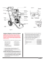 3
3
-
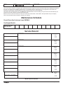 4
4
-
 5
5
-
 6
6
-
 7
7
-
 8
8
-
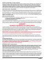 9
9
-
 10
10
-
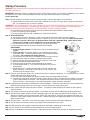 11
11
-
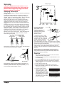 12
12
-
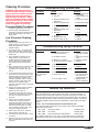 13
13
-
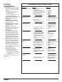 14
14
-
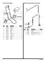 15
15
-
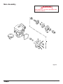 16
16
-
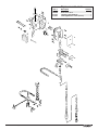 17
17
-
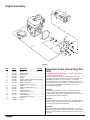 18
18
-
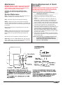 19
19
-
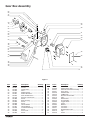 20
20
-
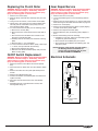 21
21
-
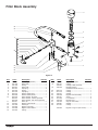 22
22
-
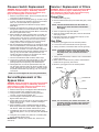 23
23
-
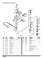 24
24
-
 25
25
-
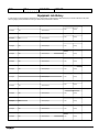 26
26
-
 27
27
-
 28
28


Titan 1200GXC El manual del propietario
- Categoría
- Rociador de pintura
- Tipo
- El manual del propietario
en otros idiomas
- français: Titan 1200GXC Le manuel du propriétaire
- English: Titan 1200GXC Owner's manual
Artículos relacionados
-
Titan Epic 660HPX El manual del propietario
-
-
-
-
-
Titan GPX85 El manual del propietario
-
-
-
-
Titan PowrTwin™ 6900 XLT El manual del propietario