
1
24811740/26-01-2015
TABELLE
RIASSUNTIVE
TABLES
SUMMARIZING
ÜBERSICHTS-
TABELLEN
TABLEAU
DE RESUME
CUADROS
RESUMEN
TABELAS
RESUMIDAS
OH/A.01
Per poter gestire in modo semplice e chiaro tutte le
funzioni associate ai relè, si raccomanda di riportare le
stesse nelle due tabelle allegate.
Le tabelle inoltre aiutano la verifica e il controllo delle
procedure effettuate.
La configurazione del sistema prevede la compila-
zione di 2 tabelle Tabella posizione relè e ingressi
e Tabella associazione ingressi e funzioni.
Nella prima si devono inserire secondo la posizione di
programmazione, tutti (vedere nelle istruzioni di cia-
scun dispositivo, il capitolo Installazione del modulo
nel sistema, N. modulo=numero di lampeggi LED) i
dispositivi, ad eccezione del modulo OH/T.01, OH/Z.02
e OH/A.01 (Tipo modulo), OH-GSM.
Inserire nell’apposito campo la descrizione dell’ubica-
zione del modulo e l’ID associato.
Successivamente si numerano i relè e gli ingressi pre-
senti secondo il tipo di dispositivo usato:
OH/6I: 6 ingressi
OH/RI: 1 uscita relè e 3 ingressi
OH/RP: 1 uscita relè
OH/2RP: 2 uscite relè
OH/MA: 2 uscite relè
OH/3RPI: 3 uscite relè e 3 ingressi
OH/R.01: 4 uscite relè e 4 ingressi.
NH-DIM: 1 uscita relè.
Riportare nelle 2 colonne preposte le apparecchiature
collegate ai singoli relè e ingressi.
Completare la tabella inserendo nelle due colonne
“Cablatura” il nome attribuito al cablaggio relativo.
(Es.: l’ottavo ingresso posto al secondo piano potrà
chiamarsi “2 Ing 8” e il 4 relè del secondo piano potrà
chiamarsi “2U4”.
A questo punto nella Tabella associazione ingressi e
funzioni riportare l’elenco dei relè precedentemente
numerati nella prima tabella per l’associazione di un
massimo di 7 ingressi di comando.
L’ottavo ingresso associato ad ogni relè è asssegna-
bile solo a ingressi virtuali come ad esempio Scenari
o Timer.
Riempire cioè sequenzialmente le prime due colonne
con nome cablatura associata al relè e descrizione.
Per ogni relè riempire le colonne degli ingressi asso-
ciati attraverso il nome cablatura e selezionare la
modalità di attivazione del relè barrando o la colon-
na CC (contatto chiuso) o la colonna CA (contatto
aperto).
Per ciascun ingresso di comando specificato si pos-
sono associare una delle 6 funzioni disponibili (Passo
Passo, ON, OFF, Diretto, ecc.).
Nota: In caso di sostituzione delle apparecchia-
ture, si perdono tutte o parte delle programma-
zioni effettuate all’atto dell’installazione.
FUNZIONE DEGLI INGRESSI
Le funzioni possono venire attivate dalla chiusura o
apertura di un contatto sull’ingresso programmato
tramite la selezione Cnt chiuso o Cnt aperto oppure
dagli eventi timer (timers 1…16) o scenari (ENTRA,
ESCI, NOTTE) sul modulo OH/T.01.
1 - Tipi di ingressi di comando
•Ingressi (ingresso per contatto dei moduli OH/R.01,
OH/6I, ecc.).
•Timers (personalizzazioni da utente).
•Scenari (ENTRA, ESCI, NOTTE).
•Ingressi Termost. (ingressi dei moduli di zona OH/
Z.02).
Si possono utilizzare fino a 8 ingressi per singolo relè.
ATTENZIONE. Non è consentito collegare ai relè
del modulo OH/3RPI e OH/R.01 carichi a 230 V
insieme a carichi a bassa tensione (12-24 V).
2 - Tipi di funzioni associate
all’ ingresso di comando
a) Passo Passo
Il relè viene alternativamente attivato e disattivato
da successive azioni sugli ingressi di comando (es.
pulsante).
b) ON
Il relè, se disattivo, viene attivato dagli ingressi di
comando (es. comando scenario ETRA).
c) OFF
Il relè, se attivo, viene disattivato dagli ingressi di
comando (es. comando scenario ESCI).
d) Diretto
L’attivazione del relè segue lo stato degli ingresso di
comando (es. interruttore).
e) Impulso
L’attivazione del relè avviene per il tempo program-
mato (durata da 00 min 00 s a 59 min 59 s).
È possibile ritardare l’attivazione del relè (ritardo da 00
min 00 s a 59 min 59 s), (es. luce scale temporizzato).
f) Abilitazione
L’attivazione del relè, conseguente alle varie condi-
zioni degli altri ingressi di comando, viene abilitata o
disabilitata dagli ingressi di comando cui è associata
questa funzione (es. crepuscolare).

OH/T. 01
OH/Z.02
OH/6I
C
I1
I2
I3
I4
I5
I6
OH/RP
1
LA
CN1
LA
OH/RI
C
I1
I2
I3
LA
1
OH/R.01
M3
M4
LA
C
I1
I2
I3
I4
NO
NC
C
NO
NC
C
NO
NC
C
NO
NC
C
1
2
3
4
4
3
21
LA
C
I1
C
NA
L
C
NA
LC
NA
N
LA
C
OH/MA
OH/3RPI
C
NA
C
NA
C
NA
2
3
1
5
6
LA
C
I1
I2
I3
LA
LA
OH/A.01
M1
M2
M3
BK
2
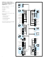
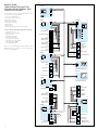
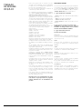
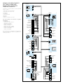
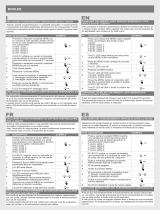
ESEMPIO DI COMPILAZIONE
DELLE TABELLE PER UN IMPIANTO
CON GESTIONE TERMICA E
DOMOTICA
L’impianto con gestione termica e domotica rappre-
sentato in fig. 1 comprende:
• Riscaldamento zona bagno
• Riscaldamento zona soggiorno
• Luce giardino 1
• Luce giardino 2
• Luce ingresso
• Irrigazione 1
• Irrigazione 2
• Controllo tapparella soggiorno.
Per questo impianto sono necessarie le seguenti
apparecchiature:
• 1 terminale OH/T.01
• 1 termostato di zona OH/Z.02
• 1 alimentatore OH/A.01
• 1 modulo ingressi OH/6I
• 1 modulo relè OH/RI
• 1 modulo di potenza OH/RP
• 1 modulo automazioni OH/MA
• 1 modulo relè OH/3RPI.
• 1 modulo relè OH/R.01.
Con le due tabelle completate (vedi esempio allegato
a pagina 3 e 4) si potrà procedere alla programmazio-
ne del sistema dal terminale OH/T.01.
Pulsante
luce ingresso
Pulsante luce gia-
rdino 1 e 2
Pulsante
irrigazione 1
Pulsante
irrigazione 2
Sensore
crepuscolare
Sensore
pioggia
Sensore
vento
Luce
giardino 1
Luce
ingresso
Tapparella
soggiorno
Elettrovalvola
zona bagno
Elettrovalvola
zona soggiorno
Pulsante
luce ingresso
Pulsante luce gia-
rdino 1 e 2
Zona bagno
Zona soggiorno
Pulsante
luce ingresso
Scenario
ENTRA
Scenario
ESCI
Luce
giardino 2
Pulsante tapparella
soggiorno sù
Pulsante tapparella
soggiorno giù
Pulsante tapparella
soggiorno sù
Pulsante tapparella
soggiorno giù
Pulsante stop
Elettrovalvola
irrigazione 2
Elettrovalvola
irrigazione 1
1
1Ing8
1Ing7
1Ing6
1Ing5
1Ing4
1Ing3
1Ing11
1Ing10
1Ing9
1U3
1U4
1U5
1U6
1U2
1U1
1Ing2
1Ing1
1Ing12
1Ing13
1Ing14
1U9
1U8
1U7

3
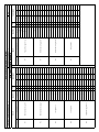
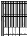
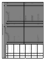
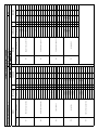
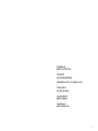
TABELLA POSIZIONE RELÈ E INGRESSI
LOCAZIONE (piano,appartamento, …): SPAZIO (cucina,salotto, …): Pag.
ELENCO MODULI
N° SIGLA ID e luogo di installazione INGRESSI RELE'
N° Descizione Cablatura N° Descrizione Cablatura
1
OH/R.01
26343160200
Scatola di derivazione salotto
1 Pulsante luce giardino 1 e 2 1 Ing 1 1 Elettrovalvola zona soggiorno 1U1
2 Pulsante luce ingresso 1 Ing 2 2 Elettrovalvola zona bagno 1U2
3 3
4 4
2
OH/6I
26883160200
Scatola di derivazione salotto
5 Pulsante irrigazione 2 1 Ing 3
6 Pulsante irrigazione 1 1 Ing 4
7 Pulsante tapparella su 1 Ing 5
8 Pulsante tapparella giù 1 Ing 6
9 Pulsante luce giardino 1 e 2 1 Ing 7
10 Pulsante luce ingresso 1 Ing 8
3
OH/RI
027AF01F0100
Scatola di derivazione giardino
11 Sensore vento 1 Ing 9 5 Luce giardino 1 1U3
12 Sensore pioggia 1 Ing 10
13 Sensore crepuscolare 1 Ing 11
4
OH/RP
02F4F01F0100
Dietro scatola 503 lato ingresso
6 Luce ingresso 1U4
5
OH/MA
029AF01F0100
Scatola di derivazione salotto
7 Tapparella soggiorno su 1U5
8 Tapparella soggiorno giù 1U6
6
OH/3RPI
0234F01F0100
Scatola di derivazione ingresso
14 Pulsante luce ingresso 1 Ing 12 9 Elettrovalvola irrigazione 1 1U7
15 Scenario ENTRA 1 Ing 13 10 Elettrovalvola irrigazione 2 1U8
16 Scenario ESCI 1 Ing 14 11 Luce giardino 2 1U9

4
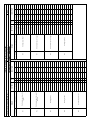
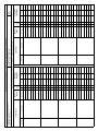
TABELLA ASSOCIAZIONE INGRESSI E FUNZIONI
LOCAZIONE (piano,appartamento, …): SPAZIO (cucina,salotto, …): Pag.
ELENCO RELÈ/FUNZIONAMENTO
RELÈ INGRESSI Attivo
con FUNZIONE RELÈ INGRESSI Attivo
con FUNZIONE
N° Cablatura Descrizione N° Cablatura CC CA Funzione Ritardo Durata N° Cablatura Descrizione N° Cablatura CC CA Funzione Ritardo Durata
1U1 Elettrovalvola zona giorno 1U6 Tapparella soggiorno giù
1 Ing 6 x IMP 30s
1 Ing 9 x IMP 30s
1 Ing 10 x IMP 30s
1 Ing 14 x IMP 30s
1U2 Elettrovalvola zona bagno 1U7 Elettrovalvola irrigazione 1
1 Ing 4 x PP
1U3 Luce giardino 1
1 Ing 1 x PP
1U8 Elettrovalvola irrigazione 2
1 Ing 3 PP
1 Ing 7 x PP
1 Ing 11 x AB
1 Ing 14 x IMP 30s
1U4 Luce ingresso
1 Ing 2 x PP
1U9 Luce giardino 2
1 Ing 1 x PP
1 Ing 8 x PP 1 Ing 7 x PP
1 Ing 12 x PP 1 Ing 11 x AB
1 Ing 13 x ON
1 Ing 14 x OFF
1U5 Tapparella soggiorno su
1 Ing 5 x IMP 30s
1 Ing 13 x IMP 30s

5

6
TABLES
SUMMARIZING
OH/A.01
For simple and clear management of all functions
associated with the relays, they should be shown in
the two tables provided.
The tables also aid in checking and verifying the pro-
cedures carried out.
System configuration requires the completion of 2
tables Position of inputs and relays table and Input
and function matching table.
In the first, you must insert according to the program-
ming position, all (see in the instructions for each
device the chapter Installation of the module in the
system, No. module=number of LED flashes) the
devices, except for module OH/T.01, OH/Z.02 and
OH/A.01 (module type), OH-GSM.
Insert in the appropriate field the description of the
location of the module and the associated ID.
Afterwards, the relays and inputs are numbered based
on the type of device used:
OH/6I: 6 inputs
OH/RI: 1 relay output and 3 inputs
OH/RP: 1 relay output
OH/2RP: 2 relay outputs
OH/MA: 2 relay outputs
OH/3RPI: 3 relay outputs and 3 inputs
OH/R.01: 4 relay outputs and 4 inputs
NH-DIM: 1 relay output.
Insert in the 2 provided columns the units connected
to the single relays and inputs.
Complete the table by inserting in the two columns
labelled “wiring” the name assigned to the relative
wiring.
(Example: The eighth input located on the second
floor may be called “2 Ing 8” and relay 4 on the second
floor may be called “2U4”).
Complete the table by inserting in the provided
columns the units connected to the single relays and
inputs.
At this point, in the Inputs and functions matching
table, insert the list of relays previously numbered
in the first table for the matching of up to 7 control
inputs.
The eighth input associated with each relay can be
assigned only to virtual inputs, for example Scenarios
or Timer.
I.e., fill in the first two columns sequentially with the
name of the wiring assigned to the relay and the
description.
For each relay, fill in the columns of the inputs associ-
ated via the wiring name and select the method of
activation of the relay may marking out either the
column CC (closed contact) or the column CA (open
contact).
For each specified control input, you can match one
of the six available functions (Step by step, ON, OFF,
dDirect, etc.).
Note: if equipment is replaced, all or part of the
programming carried out during installation will
be lost.
INPUT FUNCTION
The functions can be activated by the opening or clos-
ing of a contact on the programmed input by select-
ing Cnt closed or Cnt open or by the timer events
(timers 1…16) or scenarios (ENTER, EXIT, NIGHT) on
the module OH/T.01.
1 - Types of control inputs
• Inputs (input for contact of modules OH/R.01,
OH/6I, etc.).
• Timers (user customisations).
• Scenarios (ENTER, EXIT, NIGHT).
• Thermostat Inputs (inputs of zone modules OH/
Z.02).
Up to 8 inputs can be used for each single relay.
WARNING. It is prohibited to connect 230 V loads
together with low voltage loads (12-24 V) to the
relays module OH/3RPI and OH/R.01.
2 - Types of functions matched
to the control input
a) Step by step
The relay is alternately activated and deactivated by
successive actions on the control inputs (e.g. button).
b) ON
The relay, if inactive, is activated by the control inputs
(e.g. ETRA scenario command).
c) OFF
The relay, if active, is deactivated by the control inputs
(e.g. EXIT scenario command).
d) Direct
The activation of the relay follows the status of the
control input (e.g. switch).
e) Impulse
Relay activation occurs for a programmed time (dura-
tion from 00 min 00 s to 59 min 59 s).
It is possible to delay the activation of the relay (delay
from 00 min 00 s to 59 min 59 s), (e.g. timed stairway
lights).
f) Enable
The activation of the relay, as a result of the various
conditions of the other control inputs, is activated or
de-activated by the control inputs to which this func-
tion is matched (e.g. twilight).

OH/T. 01
OH/Z.02
OH/6I
C
I1
I2
I3
I4
I5
I6
OH/RP
1
LA
CN1
LA
OH/RI
C
I1
I2
I3
LA
1
OH/R.01
M3
M4
LA
C
I1
I2
I3
I4
NO
NC
C
NO
NC
C
NO
NC
C
NO
NC
C
1
2
3
4
4
3
21
LA
C
I1
C
NA
L
C
NA
LC
NA
N
LA
C
OH/MA
OH/3RPI
C
NA
C
NA
C
NA
2
3
1
5
6
LA
C
I1
I2
I3
LA
LA
OH/A.01
M1
M2
M3
BK
1
1Ing8
1Ing7
1Ing6
1Ing5
1Ing4
1Ing3
1Ing11
1Ing10
1Ing9
1U3
1U4
1U5
1U6
1U2
1U1
1Ing2
1Ing1
1Ing12
1Ing13
1Ing14
1U9
1U8
1U7
77
EXAMPLE OF HOW TO FILL OUT
THE TABLES FOR A HEATING
MANAGEMENT AND HOME
AUTOMATION SYSTEM
The system with heating and home automation man-
agement shown in figure 1 includes:
• Bathroom area heating
• Living room area heating
• Garden light 1
• Garden light 2
• Entry light
• Irrigation 1
• Irrigation 2
• Living room blinds control.
The following equipment is required for this sys-
tem:
• 1 terminal OH/T.01
• 1 zone thermostat OH/Z.02
• 1 power supplier OH/A.01
• 1 input module OH/6I
• 1 relay module OH/RI
• 1 power module OH/RP
• 1 automation module OH/MA
• 1 relay module OH/3RPI.
• 1 relay module OH/R.01.
With the tables completed (see example enclosed
on pages 7 and 8) you will be able to proceed with
system programming by the OH/T.01.
Entry light
push button
Garden light 1-2
push button
Living room
blind down
Living room
blind up
Irrigation 1
push button
Irrigation 2
push button
Twilight
sensor
Rain
sensor
Wind
sensor
Garden
light 1
Entry
light
Living room
blind
Bathroom zone
solenoid valve
Living room zone
solenoid valve
Entry light
push button
Garden light 1-2
push button
Bathroom zone
Living room zone
Entry light
push button
ENTER
scenario
EXIT
scenario
Garden
light 2
Irrigation 2
solenoid valve
Irrigation 1
solenoid valve
Living room
blind down
Stop
push button
Living room
blind up

8
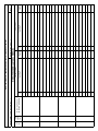
RELAY AND INPUT POSITION TABLE
LOCATION (floor, flat, …): SPACE (kitchen, living room, …): Page
LIST OF MODULES
No. CODE ID and place of installation INPUTS RELAY
No. Description Wiring No. Description Cablatura
1
OH/R.01
26343160200
Living room junction box
1 Light garden button 1 and 2 1 Ing 1 1 Living room zone solenoid valve 1U1
2 Entry light push button 1 Ing 2 2 Bathroom zone solenoid valve 1U2
3 3
4 4
2
OH/6I
26883160200
Living room junction box
5 Irrigation button 2 1 Ing 3
6 Irrigation button 1 1 Ing 4
7 Blind up button 1 Ing 5
8 Blind down button 1 Ing 6
9 Light garden button 1 and 2 1 Ing 7
10 Entry light push button 1 Ing 8
3
OH/RI
027AF01F0100
Garden junction box
11 Wind sensor 1 Ing 9 5 Garden light 1 1U3
12 Rain sensor 1 Ing 10
13 Twilight sensor 1 Ing 11
4
OH/RP
02F4F01F0100
Behind box 503 entry side
6 Entry light 1U4
5
OH/MA
029AF01F0100
Living room junction box
7 Living room blind up 1U5
8 Living room blind down 1U6
6
OH/3RPI
0234F01F0100
Entry junction box
14 Entry light push button 1 Ing 12 9 Irrigation solenoid valve 1 1U7
15 ENTER scenario 1 Ing 13 10 Irrigation solenoid valve 2 1U8
16 EXIT scenario 1 Ing 14 11 Garden light 2 1U9

9
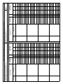
INPUT AND FUNCTIONS MATCHING TABLE
LOCATION (floor, flat, …): SPACE (kitchen, living room, …): Page
LIST OF RELAYS/FUNCTION
RELAY INPUTS Active
with FUNCTION RELAY INPUTS Active
with FUNCTION
Wiring no. Description Wiring no. CC CA Function Delay Duration Wiring no. Description Wiring no. CC CA Function Delay Duration
1U1 Day zone solenoid valve 1U6 Living room blind down
1 Ing 6 x IMP 30s
1 Ing 9 x IMP 30s
1 Ing 10 x IMP 30s
1 Ing 14 x IMP 30s
1U2 Bathroom zone solenoid valve 1U7 Irrigation solenoid valve 1
1 Ing 4 x SS
1U3 Garden light 1
1 Ing 1 x SS
1U8 Irrigation solenoid valve 2
1 Ing 3 SS
1 Ing 7 x SS
1 Ing 11 x EN
1 Ing 14 x IMP 30s
1U4 Entry light
1 Ing 2 x SS
1U9 Garden light 2
1 Ing 1 x SS
1 Ing 8 x SS 1 Ing 7 x SS
1 Ing 12 x SS 1 Ing 11 x EN
1 Ing 13 x ON
1 Ing 14 x OFF
1U5 Living room blind up
1 Ing 5 x IMP 30s
1 Ing 13 x IMP 30s

10
ÜBERSICHTS-
TABELLEN
OH/A.01
Zur einfachen und klaren Steuerung der den Relais
zugeordneten Funktionen sind diese stets in die zwei
beiliegenden Tabellen einzutragen.
Außerdem sind die Tabellen eine Hilfe bei der Prüfung
und Kontrolle der ausgeführten Vorgänge.
Die Systemkonfiguration sieht die Aufstellung 2er
Tabellen vor Tabelle Position Relais und Eingänge
und Tabelle Zuordnung Eingänge und Funktionen.
In die erste müssen entsprechend der
Programmierposition, alle (siehe Anleitungen für
jede Vorrichtung im Kapitel Systemeinbau des
Moduls, Modulnr.=Nummer der blinkenden LED)
Vorrichtungen mit Ausnahme der Module OH/T.01,
OH/Z.02 und OH/A.01 (Modultyp) eingetragen wer-
den, OH-GSM.
In das Beschreibungsfeld die Unterbringung und und
die damit verknüpfte ID eintragen.
Anschließend sind die Relais und Eingänge zu num-
merieren, die je nach verwendeter Vorrichtung vor-
liegen:
OH/6I: 6 Eingänge
OH/RI: 1 Relaisausgang und 3 Eingänge
OH/RP: 1 Relaisausgang
OH/2RP: 2 Relaisausgänge
OH/MA: 2 Relaisausgänge
OH/3RPI: 3 Relaisausgänge und 3 Eingänge
OH/R.01: 4 Relaisausgänge und 4 Eingänge.
NH-DIM: 1 Relaisaustritt
In die 2 Tabellenspalten die Geräte eintragen, die an
die einzelnen Relais und Eingänge angeschlossen
wurden.
Die Tabelle durch Eintragen der Bezeichnung der
betreffenden Verkabelung in die zwei Spalten
“Verkabelung” ergänzen.
(Beisp.: der achte Eingang im zweiten Stockwerk
kann “2 Ing 8” genannt werden und das Relais 4 des
zweiten Stockwerks könnte mit “2U4” bezeichnet
werden).
In die 2 Tabellenspalten die Geräte einfügen, die an
die einzelnen Relais und Eingänge angeschlossen
wurden.
Nun in die Tabelle Zuordnung Eingänge und
Funktionen die Liste der in der ersten Tabelle zuvor
nummerierten Relais für die Zuordnung von maximal
7 Steuereingängen eingeben.
Der an jedes Relais angeschlossene achte Eingang
kann nur virtuellen Eingängen wie Szenarien oder
Timern zugeordnet werden.
Die ersten zwei Spalten nacheinander mit der
Bezeichnung der Verkabelung, die mit dem Relais und
der Beschreibung verknüpft ist, ausfüllen.
Die Spalten der verknüpften Eingänge für jedes Relais
mit der Bezeichnung der Verkabelung ausfüllen und
den Aktivierungsmodus des Relais durch Ankreuzen
entweder der Spalte CC (geschlossener Kontakt) oder
der Spalte CA (offener Kontakt) bestimmen.
Jedem angeführten Steuereingang können eine der 6
verfügbaren Funktionen (Schrittweise, ON, OFF, Direkt,
usw.) zugeordnet werden.
Vermerk: Bei einem Auswechseln der Geräte
gehen alle bei der Installation vorgenommenen
Programmierungen oder ein Teil davon verlo-
ren.
FUNKTION DER EINGÄNGE
Die Funktionen sind über die Schließung oder
Öffnung eines Kontakts am programmierten Eingang
anhand der Auswahl Knt geschlossen oder Knt
offen, der Ereigniszeitschalter (Zeitschalter 1…16)
oder Szenarien (EINWÄRTS, AUSWÄRTS, NACHT) am
Modul OH/T.01 aktivierbar.
1 - Art von Steuereingängen
• Eingänge (Eingang für den Kontakt der Module
OH/R.01, OH/6I usw.).
• Zeitschalter (benutzerspezifische Gestaltung).
• Szenarien (EINWÄRTS, AUSWÄRTS, NACHT).
• Thermostateingänge (Eingänge der Zonenmodule
OH/Z.02).
Je Einzelrelais können bis zu 8 Eingängen verwendet
werden.
ACHTUNG. An die Relais des Moduls OH/3RPI und
OH/R.01 sind Lasten zu 230 V nicht zusammen mit
Niederspannungslasten (12-24 V) anschließbar.
2 - Art der dem Steuereingang
zugeordneten Funktionen
a) Schrittweise
Das Relais wird durch darauf folgende Einwirkungen
an den Steuereingängen abwechselnd aktiviert und
deaktiviert (Beisp. Taste).
b) ON
Das eventuell deaktivierte Relais wird durch die
Steuereingänge aktiviert (Beisp. Befehl Szene
EINTRETEN).
c) OFF
Das eventuell aktivierte Relais wird durch die
Steuereingänge deaktiviert Beisp. Befehl Szene
VERLASSEN).
d) Direkt
Die Relaisaktivierung ist vom Status der Steuereingänge
abhängig (z.B. Schalter).
e) Impulsweise
Die Relaisaktivierung erfolgt in der programmierten
Zeit (Dauer von 00 min 00 s bis 59 min 59 s), (Beisp.
zeitgeschaltetes Treppenlicht).
Die Relaisaktivierung kann verzögert werden
(Verzögerung von 00 min 00 s bis 59 min 59 s).
f) Aktivierung
Die sich aus den unterschiedlichen Bedingungen der
anderen Steuereingänge ergebende Relaisaktivierung
wird über die Steuereingänge, die dieser Funktion
zugeordnet wurden, aktiviert oder deaktiviert (Beisp.
Dämmerung).

OH/T. 01
OH/Z.02
OH/6I
C
I1
I2
I3
I4
I5
I6
OH/RP
1
LA
CN1
LA
OH/RI
C
I1
I2
I3
LA
1
OH/R.01
M3
M4
LA
C
I1
I2
I3
I4
NO
NC
C
NO
NC
C
NO
NC
C
NO
NC
C
1
2
3
4
4
3
21
LA
C
I1
C
NA
L
C
NA
LC
NA
N
LA
C
OH/MA
OH/3RPI
C
NA
C
NA
C
NA
2
3
1
5
6
LA
C
I1
I2
I3
LA
LA
OH/A.01
M1
M2
M3
BK
1
1Ing8
1Ing7
1Ing6
1Ing5
1Ing4
1Ing3
1Ing11
1Ing10
1Ing9
1U3
1U4
1U5
1U6
1U2
1U1
1Ing2
1Ing1
1Ing12
1Ing13
1Ing14
1U9
1U8
1U7
1111
BEISPIEL EINER
TABELLENAUFSTELLUNG FÜR
EINE ANLAGE MIT WÄRME- UND
DOMOTIKSTEUERUNG
Die in der Abb. 1 gezeigte Anlage mit thermischer und
domotischer Steuerung umfasst:
• Heizung des Badbereiches
• Heizung des Wohnbereiches
• Gartenbeleuchtung 1
• Gartenbeleuchtung 2
• Eingangsbeleuchtung
• Bewässerung 1
• Bewässerung 2
• Steuerung des Rollladens im Wohnzimmer.
Für diese Anlage sind folgende Geräte notwendig:
• 1 Anschluss OH/T.01
• 1 Raumthermostat OH/Z.02
• 1 Speiser OH/A.01
• 1 Eintrittsmodul OH/6I
• 1 Schutzmodul OH/RI
• 1 Leistungsmodul OH/RP
• 1 Automationsmodul OH/MA
• 1 Schutzmodul OH/3RPI.
• 1 Schutzmodul OH/R.01.
Nach der Vervollständigung beider Tabellen (siehe
Beispiel auf Seite 11 und 12) ist nun das System über
OH/T.01 programmierbar.
Elektroventil
Bewässerung 1
Taste
Eingangslichter
Taste Gartenlichter
1-2
Taste
Wohnzimmer-
rollladen unten
Taste
Bewässerung 1
Taste
Bewässerung 2
Dämmerungs-
sensor
Regensensor
Windsensor
Gartenlichter 1
Eingangslichter
Rollladen
Wohnzimmer
Elektroventil
Badezimmer-
bereich
Elektroventil
Wohnzimmer-
bereich
Taste
Eingangslichter
Taste Gartenlichter
1-2
Badezimmerbereich
Wohnzimmerbereich
Taste
Eingangslichter
Szenarium
EINWÄRTS
Szenarium
AUSWÄRTS
Gartenlichter 2
Taste
Wohnzimmer-
rollladen oben
Elektroventil
Bewässerung 2
Taste Stopp
Taste
Wohnzimmer-
rollladen unten
Taste
Wohnzimmer-
rollladen oben

12
TABELLE POSITION RELAIS UND EINGÄNGE
UNTERBRINGUNG (Stockwerk,Wohnung, …): BEREICH (Küche,Wohnzimmer, …): Seite
MODULVERZEICHNIS
Nr. ZEI-
CHEN ID und Installationsort EINGÄNGE RELAIS
Nr. Beschreibung Verkabelung Nr. Beschreibung Verkabelung
1
OH/R.01
26343160200
Abzweigkasten Wohnzimmer
1 Taste Gartenbeleuchtung 1 und 2 1 Ing 1 1 Magnetventil Wohnzimmerbereich 1U1
2 Taste Eingangsbeleuchtung 1 Ing 2 2 Magnetventil Badezimmerbereich 1U2
3 3
4 4
2
OH/6I
26883160200
Abzweigkasten Wohnzimmer
5 Taste Bewässerung 2 1 Ing 3
6 Taste Bewässerung 1 1 Ing 4
7 Taste Wohnzimmerrollladen oben 1 Ing 5
8 Taste Wohnzimmerrollladen unten 1 Ing 6
9 Taste Gartenbeleuchtung 1 und 2 1 Ing 7
10 Taste Eingangsbeleuchtung 1 Ing 8
3
OH/RI
027AF01F0100
Abzweigkasten Garten
11 Windsensor 1 Ing 9 5 Gartenbeleuchtung 1 1U3
12 Regensensor 1 Ing 10
13 Dämmerungssensor 1 Ing 11
4
OH/RP
02F4F01F0100
Hinter Kasten 503 eingangsseitig
6 Eingangsbeleuchtung 1U4
5
OH/MA
029AF01F0100
Abzweigkasten Wohnzimmer
7 Rollladen Wohnzimmer oben 1U5
8 Rollladen Wohnzimmer unten 1U6
6
OH/3RPI
0234F01F0100
Abzweigkasten Eingang
14 Taste Eingangsbeleuchtung 1 Ing 12 9 Magnetventil Bewässerung 1 1U7
15 Szenarium EINTRITT 1 Ing 13 10 Magnetventil Bewässerung 2 1U8
16 Szenarium AUSTRITT 1 Ing 14 11 Gartenbeleuchtung 2 1U9

13
TABELLE ZUORDNUNG EINGÄNGE UND FUNKTIONEN
UNTERBRINGUNG (Stockwerk,Wohnung, …): BEREICH (Küche,Wohnzimmer, …): Seite
VERZEICHNIS RELAIS/FUNKTION
RELAIS EINGÄNGE Aktiv
bei FUNKTION RELAIS EINGÄNGE Aktiv
bei FUNKTION
Nr. Verkabelung Beschreibung: Nr. Verkabelung CC CA Funktion Verzö-
gerung Dauer Nr. Verkabelung Beschreibung: Nr. Verkabelung CC CA Funktion Verzö-
gerung Dauer
1U1 Magnetventil Wohnbereich 1U6 Rollladen Wohnzimmer unten
1 Ing 6 x IMP. 30s
1 Ing 9 x IMP. 30s
1 Ing 10 x IMP. 30s
1 Ing 14 x IMP. 30s
1U2 Magnetventil
Badezimmerbereich 1U7 Magnetventil Bewässerung 1
1 Ing 4 x SCHRITT.
1U3 Gartenbeleuchtung 1
1 Ing 1 x SCHRITT.
1U8 Magnetventil Bewässerung 2
1 Ing 3 SCHRITT.
1 Ing 7 x SCHRITT.
1 Ing 11 x AKTIVIER.
1 Ing 14 x IMP. 30s
1U4 Eingangsbeleuchtung
1 Ing 2 x SCHRITT.
1U9 Gartenbeleuchtung 2
1 Ing 1 x SCHRITT.
1 Ing 8 x SCHRITT. 1 Ing 7 x SCHRITT.
1 Ing 12 x SCHRITT. 1 Ing 11 x AKTIVIER.
1 Ing 13 x ON
1 Ing 14 x OFF
1U5 Rollladen Wohnzimmer oben
1 Ing 5 x IMP. 30s
1 Ing 13 x IMP. 30s

14
TABLEAU
DE RESUME
OH/A.01
Pour pouvoir gérer toutes les fonctions associées
aux relais le plus clairement et le plus simplement
possible, nous vous recommandons de reporter ces
fonctions sur les deux tableaux joints.
En outre, les tableaux permettent de vérifier et de
contrôler les procédures effectuées.
La configuration du système prévoit la compilation
de 2 tableaux Tableau position relais et entrées et
Tableau association entrées et fonctions.
Pour le premier, il faut insérer selon la position de pro-
grammation, tous (voir dans les instructions de cha-
que dispositif, le chapitre Installation du module dans
le système, N. module=nombres de clignotements
LED) les dispositifs, excepté les modules OH/T.01, OH/
Z.02 et OH/A.01 (Type module), OH-GSM.
Insérer dans le champ prévu à cet effet la description
de l’emplacement du module et l’ID associé.
Ensuite, il faut numéroter les relais et les entrées pré-
sents en fonction du type de dispositif utilisé:
OH/6I: 6 entrées
OH/RI: 1 sortie relais et 3 entrées
OH/RP: 1 sortie relais
OH/2RP: 2 sorties relais
OH/MA: 2 sorties relais
OH/3RPI: 3 sorties relais et 3 entrées
OH/R.01: 4 sorties relais et 4 entrées
NH-DIM : 1 sortie du relais.
Reporter les appareils reliés à chaque relais et à chaque
entrée dans les deux colonnes prévues à cet effet.
Compléter le tableau en insérant dans les deux colon-
nes “Câblage” le nom attribué au câblage correspon-
dant.
(Ex.: la huitième entrée située au deuxième étage
pourra s’appeler “2 Ing 8” et le 4 relais du deuxième
étage pourra s’appeler “2U4”).
Compléter le tableau en reportant les appareils reliés à
chaque relais et à chaque entrée dans les deux colon-
nes prévues à cet effet.
A partir de ce moment, dans le Tableau associa-
tion entrées et fonctions reporter la liste des relais
numérotés précédemment dans le premier tableau
pour l’association pour un maximum de 7 entrées de
commande.
La huitième entrée associée à chaque relais ne peut
être attribuée qu’à des entrées virtuelles comme par
exemple Scénarios ou Timer.
Remplir donc en séquence les deux premières colon-
nes avec le nom du câblage associé au relais et la
description.
Pour chaque relais remplir les colonnes des entrées
associées moyennant le nom du câblage et sélec-
tionner la modalité d’activation du relais en barrant
soit la colonne CF (contact fermé) soit la colonne CO
(contact ouvert).
Pour chaque entrée de commande spécifiée, il est
possible d’associer l’une des 6 fonctions disponibles
(Pas à pas, ON, OFF, Direct, etc.).
Remarque: En cas de remplacement des appa-
reils, toutes ou presque toutes les program-
mations effectuées lors de l’installation sont
perdues.
FONCTION DES ENTREES
Les fonctions peuvent être activées par la fermeture
ou l’ouverture d’un contact sur l’entrée programmée
en sélectionnant Cnt fermé ou Cnt ouvert ou bien
par les actions timer (timers 1…16) ou situations
(ENTRER, SORTIR, NUIT) sur le module OH/T.01.
1 - Types d’entrées de commande
• Entrées (entrées par contact des modules OH/R.01,
OH/6I, etc.).
• Timers (personnalisé par utilisateur).
• Situations (ENTRER, SORTIR, NUIT).
• Entrées Thermost. (entrées des modules de zone
OH/Z.02).
8 entrées peuvent être utilisées pour chaque relais.
ATTENTION. Il est interdit de relier des charges à
230 V avec des charges à basse tension (12-24 V)
aux relais module OH/3RPI et OH/R.01.
2 - Types de fonctions associées
à l’entrée de commande
a) Pas à pas
Le relais est activé et désactivé alternativement par
des actions successives sur les entrées de commande
(ex. bouton-poussoir).
b) ON
Lorsque le relais est désactivé, il sera activé par
les entrées de commande (ex. commande situation
ENTRER).
c) OFF
Si le relais est actif, il sera désactivé par les entrées de
commande (ex. commande situation SORTIR).
d) Direct
L’activation du relais suit l’état des entrées de com-
mande (par ex. interrupteur).
e) Impulsion
Le relais est activé pendant le temps programmé
(durée de 00 min 00 s à 59 min 59 s).
Il est possible de retarder l’activation du relais (retard
de 00 min 00 s à 59 min 59 s), (ex. minuterie).
f) Habilitation
L’activation du relais, suite aux différentes conditions
des autres entrées de commande, est habilitée ou
déshabilitée par les entrées de commande auxquelles
cette fonction est associée (ex. crépusculaire).

OH/T. 01
OH/Z.02
OH/6I
C
I1
I2
I3
I4
I5
I6
OH/RP
1
LA
CN1
LA
OH/RI
C
I1
I2
I3
LA
1
OH/R.01
M3
M4
LA
C
I1
I2
I3
I4
NO
NC
C
NO
NC
C
NO
NC
C
NO
NC
C
1
2
3
4
4
3
21
LA
C
I1
C
NA
L
C
NA
LC
NA
N
LA
C
OH/MA
OH/3RPI
C
NA
C
NA
C
NA
2
3
1
5
6
LA
C
I1
I2
I3
LA
LA
OH/A.01
M1
M2
M3
BK
1
1Ing8
1Ing7
1Ing6
1Ing5
1Ing4
1Ing3
1Ing11
1Ing10
1Ing9
1U3
1U4
1U5
1U6
1U2
1U1
1Ing2
1Ing1
1Ing12
1Ing13
1Ing14
1U9
1U8
1U7
1515
EXEMPLE DE COMPILATION
DES TABLEAUX POUR UNE
INSTALLATION AVEC
GESTION THERMIQUE
ET DOMOTIQUE
L’installation avec gestion thermique et domotique
représentée à la fig. 1 comprend:
• Chauffage zone bain
• Chauffage zone séjour
• Éclairage jardin 1
• Éclairage jardin 2
• Éclairage entrée
• Irrigation 1
• Irrigation 2
• Contrôle volet séjour.
Pour cette instalaltion sont nécessaires les suivants
appareils:
• 1 terminal OH/T.01
• 1 thermostat de zone OH/Z.02
• 1 alimentateur OH/A.01
• 1 module entrées OH/6I
• 1 module relais OH/RI
• 1 module de puissance OH/RP
• 1 module automatismes OH/MA
• 1 module relais OH/3RPI.
• 1 module relais OH/R.01.
Lorsque les 2 tableaux sont complétés (voir exemple
joint page 15 et 16), nous pouvons procéder à la pro-
grammation du système depuis l’OH/T.01.
Touche éclairage
entrée
Touche éclairage
jardin 1-2
Touche volet
séjour fermé
Touche volet
séjour ouvert
Touche
irrigation 1
Touche
irrigation 2
Senseur
crépusculaire
Senseur
pluie
Senseur
vent
Eclairage
jardin 1
Eclairage entrée
Volet
séjour
Electrovanne
zone salle
de bains
Electrovanne
zone séjour
Touche
éclairage entrée
Touche éclairage
jardin 1-2
Zone salle de bains
Zone séjour
Touche
éclairage entrée
Situation
ENTRER
Situation
SORTIR
Eclairage
jardin 2
Electrovanne
irrigation 2
Electrovanne
irrigation 1
Touche volet
séjour fermé
Touche
arrêt
Touche volet
séjour ouvert

16
TABLEAU POSITION RELAIS ET ENTREES
EMPLACEMENT (étage, appartement, …) : ESPACE (cuisine, salon, …) : Page
LISTE DES MODULES
N° SIGLE ID et lieu d’installation ENTRÉES RELAIS
N° Description Câblage N° Description Câblage
1
OH/R.01
26343160200
Boîte de dérivation pour salon
1 Touches pour éclairage jardin 1 et 2 1 Ing 1 1 Électrovanne pour zone de séjour 1U1
2 Touche pour éclairage entrée 1 Ing 2 2 Électrovanne pour zone salle de bains 1U2
3 3
4 4
2
OH/6I
26883160200
Boîte de dérivation pour salon
5 Touche pour arrosage 2 1 Ing 3
6 Touche pour arrosage 1 1 Ing 4
7 Touche pour volet ouvert 1 Ing 5
8 Touche pour volet fermé 1 Ing 6
9 Touches pour éclairage jardin 1 et 2 1 Ing 7
10 Touche pour éclairage entrée 1 Ing 8
3
OH/RI
027AF01F0100
Boîte de dérivation pour jardin
11 Senseur pour vent 1 Ing 9 5 Éclairage pour jardin 1 1U3
12 Senseur pour pluie 1 Ing 10
13 Senseur crépusculaire 1 Ing 11
4
OH/RP
02F4F01F0100
Arrière de la boîte 503 côté entrée
6 Éclairage pour entrée 1U4
5
OH/MA
029AF01F0100
Boîte de dérivation pour salon
7 Volet du séjour ouvert 1U5
8 Volet du séjour fermé 1U6
6
OH/3RPI
0234F01F0100
Boîte de dérivation pour entrée
14 Touche pour éclairage entrée 1 Ing 12 9 Électrovanne pour arrosage 1 1U7
15 Scénario ENTRER 1 Ing 13 10 Électrovanne pour arrosage 2 1U8
16 Scénario SORTIR 1 Ing 14 11 Éclairage jardin 2 1U9

17
TABLEAU ASSOCIATION ENTRÉES ET FONCTIONS
EMPLACEMENT (étage, appartement, …) : ESPACE (cuisine, salon, …) : Page
LISTE DES RELAIS/FONCTIONNEMENT
RELAIS ENTRÉES Actif
avec FONCTION RELAIS ENTRÉES Actif
avec FONCTION
N° Câblage Description N° Câblage CF CO Fonction Retard Durée N° Câblage Description N° Câblage CF CO Fonction Retard Durée
1U1 Électrovanne pour zone de
séjour 1U6 Volet du séjour fermé
1 Ing 6 x IMP 30s
1 Ing 9 x IMP 30s
1 Ing 10 x IMP 30s
1 Ing 14 x IMP 30s
1U2 Électrovanne pour la zone salle
de bains 1U7 Électrovanne pour arrosage 1
1 Ing 4 x PP
1U3 Éclairage jardin 1
1 Ing 1 x PP
1U8 Électrovanne pour arrosage 2
1 Ing 3 PP
1 Ing 7 x PP
1 Ing 11 x HAB
1 Ing 14 x IMP 30s
1U4 Éclairage entrée
1 Ing 2 x PP
1U9 Éclairage jardin 2
1 Ing 1 x PP
1 Ing 8 x PP 1 Ing 7 x PP
1 Ing 12 x PP 1 Ing 11 x HAB
1 Ing 13 x ON
1 Ing 14 x OFF
1U5 Volet du séjour ouvert
1 Ing 5 x IMP 30s
1 Ing 13 x IMP 30s

18
CUADROS
RESUMEN
OH/A.01
Para poder gestionar de forma simple y clara todas las
funciones asociadas a los relés, se recomienda apun-
tarlas en los dos cuadros adjuntos.
Además, los cuadros ayudan a comprobar y controlar
los procedimientos llevados a cabo.
La configuración del sistema prevé la compilación de
2 cuadros Cuadro posición relé y entradas y Cuadro
asociación entradas y funciones.
En el primero se deben introducir, según la posición
de programación, (ver las instrucciones de cada uno
de los dispositivos, en el capítulo de instalación del
módulo en el sistema, Núm. módulo=número de
parpadeos del LED) todos los dispositivos, excepto los
módulos OH/T.01, OH/Z.02 y OH/A.01 (tipo módulo),
OH-GSM.
Introduzca en el campo correspondiente la descrip-
ción de la ubicación del módulo y el ID asociado.
A continuación se enumeran los relés y las entra-
das presentes dependiendo del tipo de dispositivo
empleado:
OH/6I: 6 entradas
OH/RI: 1 salida relé y 3 entradas
OH/RP: 1 salida relé
OH/2RP: 2 salidas relé
OH/MA: 2 salidas relé
OH/3RPI: 3 salidas relé y 3 entradas
OH/R.01: 4 salidas relé y 4 entradas
NH-DIM: 1 salida de relé.
Indique en las dos columnas los aparatos conectados
a cada relé y entrada.
Complete el cuadro introduciendo en las dos colum-
nas “Cableado” el nombre asignado al cableado
correspondiente.
(Ej.: la octava entrada situada en el segundo piso
podrá llamarse “2 Ing 8” y el 4º relé del segundo piso
podrá llamarse “2U4”).
Rellene el cuadro apuntando en las dos columnas los
aparatos conectados a cada relé y entrada.
En este punto, en el Cuadro asociación entradas y
funciones, apunte la lista de los relés anteriormente
enumerados en el primer cuadro para la asociación de
un máximo de 7 entradas de comando.
La octava entrada asociada a cada relé solo puede
asignarse a entradas virtuales, como por ejemplo
Eventos o Temporizador.
Así pues, rellene sucesivamente las dos primeras
columnas con el nombre del cableado asociado al relé
y su descripción.
Para cada relé, rellene las columnas de las entradas
asociadas mediante el nombre del cableado y selec-
cione la modalidad de activación del relé marcando
o bien la columna CC (contacto cerrado) o bien la
columna CA (contacto abierto).
Para cada entrada de comando, es posible asociar una
de las 6 funciones disponibles (Paso a paso, ON, OFF,
Directo, etc.).
Nota: en caso de sustitución de los aparatos, se
pierden todas las programaciones efectuadas
durante la instalación, o parte de ellas.
FUNCIÓN DE LAS ENTRADAS
Puede activar las funciones abriendo o cerrando un
contacto en la entrada programada, seleccionando
Cnt cerrado o Cnt abierto, o bien tras actuaciones
del temporizador (temporizadores 1…16) o eventos
(ENTRA, SAL, NOCHE) en el módulo OH/T.01.
1 - Tipos de entrada de comandos
•Entradas (entradas para contacto de los módulos
OH/R.01, OH/6I, etc.).
•Temporizadores (personalizaciones de usuario).
•Evento (ENTRA, SAL, NOCHE).
•Entradas Termost. (entrada de los módulos de zona
OH/Z.02).
Es posible utilizar hasta 8 entradas por cada relé.
ATENCIÓN. No está permitido conectar a los relés
del módulo OH/3RPI y OH/R.01 de carga de 230 V
junto a cargas de baja tensión (12-24 V).
2 - Tipos de funciones asociadas
a la entrada de mando
a) Paso a paso
Se activa y desactiva el relé, de forma alterna, tras
distintas acciones en las entradas de comando (ej.
botón).
b) ON
El relé, si está desactivado, se activa tras las entradas
de comando (ej. control evento ENTRAR).
c) OFF
El relé, si está activo, se desactiva tras las entradas de
comando (ej. control evento SALIR).
d) Directo
La activación del relé depende del estado de la entra-
da de comando (ej.: interruptor).
e) Impulso
La activación del relé tiene lugar durante un tiempo
programado (duración: desde 00 min 00 s a 59 min
59 s).
Es posible atrasar la activación del relé (atraso desde
00 min 00 s a 59 min 59 s), (ej. luz de las escaleras
temporizada).
f) Habilitación
La activación del relé, consecuencia de las distintas
condiciones de las otras entradas de comando, se
habilita o deshabilita por las entradas de comando a
los que se asocia esta función (ej. crepuscular).

OH/T. 01
OH/Z.02
OH/6I
C
I1
I2
I3
I4
I5
I6
OH/RP
1
LA
CN1
LA
OH/RI
C
I1
I2
I3
LA
1
OH/R.01
M3
M4
LA
C
I1
I2
I3
I4
NO
NC
C
NO
NC
C
NO
NC
C
NO
NC
C
1
2
3
4
4
3
21
LA
C
I1
C
NA
L
C
NA
LC
NA
N
LA
C
OH/MA
OH/3RPI
C
NA
C
NA
C
NA
2
3
1
5
6
LA
C
I1
I2
I3
LA
LA
OH/A.01
M1
M2
M3
BK
1
1Ing8
1Ing7
1Ing6
1Ing5
1Ing4
1Ing3
1Ing11
1Ing10
1Ing9
1U3
1U4
1U5
1U6
1U2
1U1
1Ing2
1Ing1
1Ing12
1Ing13
1Ing14
1U9
1U8
1U7
1919
EJEMPLO DE COMPILACIÓN
DE LOS CUADROS PARA UN
EQUIPO CON GESTIÓN TÉRMICA Y
DOMÓTICA
El equipo de gestión térmica y domótica que se mues-
tra en fig. 1 comprende:
• Calefacción zona baño
• Calefacción zona sala de estar
• Luz jardín 1
• Luz jardín 2
• Luz entrada
• Regado 1
• Regado 2
• Control persiana sala de estar.
Para este equipo, son necesarios los siguientes
aparatos:
• 1 terminal OH/T.01
• 1 termostato de zona OH/Z.02
• 1 alimentador OH/A.01
• 1 módulo entradas OH/6I
• 1 módulo relés OH/RI
• 1 módulo de potencia OH/RP
• 1 módulo mecanismos automáticos OH/MA
• 1 módulo relés OH/3RPI.
• 1 módulo relés OH/R.01.
Con los dos cuadros completados (véase ejemplo en
las páginas 19 y 20) será posible proceder a la progra-
mación del sistema desde el OH/T.01.
Botón luz
entrada
Botón luz
jardín 1-2
Botón bajar
persiana
sala de estar
Botón
regado 1
Botón
regado 2
Sensor
crepúsculo
Sensor
lluvia
Sensor
viento
Luz
jardín 1
Luz
entrada
Persiana sala
de estar
Electroválvula zona
baño
Electroválvula
zona sala
de estar
Botón luz
entrada
Botón
luz jardín 1-2
Zona baño
Zona sala de estar
Botón luz
entrada
Evento
ENTRA
Evento
SAL
Luz
jardín 2
Botón subir
persiana
sala de estar
Electroválvula
regado 2
Electroválvula
regado 1
Botón bajar
persiana
sala de estar
Botón
detención
Botón subir
persiana
sala de estar

20
CUADRO POSICIÓN RELÉS Y ENTRADAS
UBICACIÓN (piso,apartamento, …): ESPACIO (cocina,salón, …): Pág.
LISTA DE MÓDULOS
N° SIGLA ID y lugar de instalación ENTRADAS RELÉS
N° Descripción Cableado N° Descripción Cableado
1
OH/R.01
26343160200
Caja de derivación salón
1 Botón luz de jardín 1 y 2 1 Ing 1 1 Electroválvula zona sala de estar 1U1
2 Botón luz entrada 1 Ing 2 2 Electroválvula zona baño 1U2
3 3
4 4
2
OH/6I
26883160200
Caja de derivación salón
5 Botón irrigación 2 1 Ing 3
6 Botón irrigación 1 1 Ing 4
7 Botón subir persiana 1 Ing 5
8 Botón bajar persiana 1 Ing 6
9 Botón luz de jardín 1 y 2 1 Ing 7
10 Botón luz entrada 1 Ing 8
3
OH/RI
027AF01F0100
Caja de derivación jardín
11 Sensor viento 1 Ing 9 5 Luz de jardín 1 1U3
12 Sensor lluvia 1 Ing 10
13 Sensor crepúsculo 1 Ing 11
4
OH/RP
02F4F01F0100
Detrás caja 503 lado entrada
6 Luz entrada 1U4
5
OH/MA
029AF01F0100
Caja de derivación salón
7 Subir persiana sala de estar 1U5
8 Bajar persiana sala de estar 1U6
6
OH/3RPI
0234F01F0100
Caja de derivación entrada
14 Botón luz entrada 1 Ing 12 9 Electroválvula irrigación 1 1U7
15 Evento ENTRAR 1 Ing 13 10 Electroválvula irrigación 2 1U8
16 Evento SALIR 1 Ing 14 11 Luz de jardín 2 1U9

21
CUADRO ASOCIACIÓN ENTRADAS Y FUNCIONES
UBICACIÓN (piso,apartamento, …): ESPACIO (cocina,salón, …): Pág.
LISTA DE RELÉS/FUNCIONAMIENTO
RELÉS ENTRADAS Activo
con FUNCIÓN RELÉS ENTRADAS Activo
con FUNCIÓN
N° Cableado Descripción N° Cableado CC CA Función Retraso Dura-
ción N° Cableado Descripción N° Cableado CC CA Función Retraso Dura-
ción
1U1 Electroválvula zona de día 1U6 Bajar persiana sala de estar
1 Ing 6 x IMP 30s
1 Ing 9 x IMP 30s
1 Ing 10 x IMP 30s
1 Ing 14 x IMP 30s
1U2 Electroválvula zona baño 1U7 Electroválvula irrigación 1
1 Ing 4 x PP
1U3 Luz de jardín 1
1 Ing 1 x PP
1U8 Electroválvula irrigación 2
1 Ing 3 PP
1 Ing 7 x PP
1 Ing 11 x HAB
1 Ing 14 x IMP 30s
1U4 Luz entrada
1 Ing 2 x PP
1U9 Luz de jardín 2
1 Ing 1 x PP
1 Ing 8 x PP 1 Ing 7 x PP
1 Ing 12 x PP 1 Ing 11 x HAB
1 Ing 13 x ON
1 Ing 14 x OFF
1U5 Subir persiana sala de estar
1 Ing 5 x IMP 30s
1 Ing 13 x IMP 30s

22
TABELAS
RESUMIDAS
OH/A.01
Para poder gerenciar de modo simples e claro todas
as funções associadas aos relés, recomenda-se para
copiar as mesmas nas duas tabelas anexas.
A tabela também ajuda a verificação e o controlo dos
procedimentos efectuados.
A configuração do sistema prevê o preenchimento de
2 tabelas Tabela posição relés e entradas e Tabela
associação entradas e funções.
Na primeira devem ser introduzidos todos, conforme
a posição de programação (veja nas instruções de
cada dispositivo, o capítulo Instalação do módulo
no sistema, N. módulo = número de lampejos LED)
os dispositivos, com excepção do módulo OH/T.01,
OH/Z.02 e OH/A.01 (Tipo módulo), OH-GSM.
Introduzir no campo específico a descrição da
localização do módulo e o ID associado.
Sucessivamente numeram-se os relés e as entradas
presentes segundo o tipo de dispositivo usado:
OH/6I: 6 entradas
OH/RI: 1 saída relés e 3 entradas
OH/RP: 1 saída relés
OH/2RP: 2 saídas relés
OH/MA: 2 saídas relés
OH/3RPI: 3 saídas relés e 3 entradas
OH/R.01: 4 saídas relés e 4 entradas.
NH-DIM: 1 saída do relé.
Copiar nas 2 colunas apropriadas as aparelhagens
ligadas a cada relé e a cada entrada.
Completar a tabela introduzindo nas duas colunas
“Fiação” o nome atribuído à fiação relativa.
(Ex.: a oitava entrada situada no segundo andar pode-
rá denominar-se “2 Ing 8” e o 4 relé do segundo andar
poderá denominar-se “2U4”).
Complete a tabela copiando nas 2 colunas específicas
as aparelhagens ligadas a cada relé e entradas.
A esta altura na Tabela associação entradas e funções
copie a lista dos relés numerados anteriormente na
primeira tabela para a associação de no máximo 7
entradas de comando.
A oitava entrada associada a cada relé pode ser atri-
buída somente a entradas virtuais, como por exemplo
Cenários ou Timer.
Preencher,portanto, em sequência as primeiras duas
colunas com o nome da fiação associada ao relé e
descrição.
Para cada relé preencher as colunas das entradas
associadas através do nome da fiação e seleccionar a
modalidade de activação do relé barrando ou a colu-
na CC (contacto fechado) ou a coluna CA (contacto
aberto).
Para cada entrada de comando especificado podem
ser associadas uma das 6 funções disponíveis (Passo a
passo, ON, OFF, Direto, etc.).
Nota: No caso de substituição das aparelhagens,
perdem-se todas ou parte das programações
efectuadas no acto da instalação.
FUNÇÃO DAS ENTRADAS
As funções podem ser ativadas mediante o
fechamento ou abertura de um contato na entrada
programado através da seleção Cnt fechado ou Cnt
aberto ou pelos eventos timer (timers 1…16) ou
cenários (ENTRA, SAI, NOITE) no módulo OH/T.01.
1 - Tipos de entradas de comando
•Entradas (entrada para contado dos módulos, OH/
R.01, OH/6I, etc.).
•Timers (personalizações pelo usuário).
•Cenários (ENTRA, SAI, NOITE).
•Entradas Termost. (entradas dos módulos de área
OH/Z.02).
Podem ser utilizadas até 8 entradas para cada relé.
ATENÇÃO. Não é permitido ligar aos relés do
módulo OH/3RPI e OH/R.01 cargas a 230 V junto
com cargas de baixa tensão (12-24 V).
2 - Tipos de funções associadas
na entrada de comando
a) Passo a Passo
O relé é alternadamente ativado e desativado por
ações seguidas nas entradas de comando (ex. botão).
b) ON
O relé, se estiver desativo, é ativado pelas entradas de
comando (ex. comando cenário ETRA).
c) OFF
O relé, se estiver desativo, é desativado pelas entradas
de comando (ex. comando cenário SAIR).
d) Direto
A ativação do relé segue o estado das entradas de
comando (ex. interruptor).
e) Impulso
A ativação do relé é efetuada pelo tempo programado
(duração de 00 min 00 s até 59 min 59 s).
É possível retardar a ativação do relé (retardo de 00 min
00 s até 59 min 59 s), (ex. luz escadas temporizado).
f) Habilitação
A ativação do relé, conseqüente às várias condições
das outras entradas de comando, é habilitada ou
desabilitada pelas entradas de comando às quais esta
função é associada (ex. crepuscular).

OH/T. 01
OH/Z.02
OH/6I
C
I1
I2
I3
I4
I5
I6
OH/RP
1
LA
CN1
LA
OH/RI
C
I1
I2
I3
LA
1
OH/R.01
M3
M4
LA
C
I1
I2
I3
I4
NO
NC
C
NO
NC
C
NO
NC
C
NO
NC
C
1
2
3
4
4
3
21
LA
C
I1
C
NA
L
C
NA
LC
NA
N
LA
C
OH/MA
OH/3RPI
C
NA
C
NA
C
NA
2
3
1
5
6
LA
C
I1
I2
I3
LA
LA
OH/A.01
M1
M2
M3
BK
1
1Ing8
1Ing7
1Ing6
1Ing5
1Ing4
1Ing3
1Ing11
1Ing10
1Ing9
1U3
1U4
1U5
1U6
1U2
1U1
1Ing2
1Ing1
1Ing12
1Ing13
1Ing14
1U9
1U8
1U7
23
EXEMPLO DE PREENCHIMENTO
DAS TABELAS PARA UMA
INSTALAÇÃO COM GESTÃO
TÉRMICA E DOMÓTICA
A instalação com gestão térmica e domótica ilustrada
na fig. 1 contém:
• Aquecimento área sala de banho
• Aquecimento área sala de estar
• Luz jardim 1
• Luz jardim 2
• Luz hall de entrada
• Irrigação 1
• Irrigação 2
• Controlo veneziana sala de estar.
Para esta instalação são necessárias as seguintes
aparelhagens:
• 1 terminal OH/T.01
• 1 termóstato de área OH/Z.02
• 1 alimentador OH/A.01
• 1 módulo entradas OH/6I
• 1 módulo relé OH/RI
• 1 módulo de potência OH/RP
• 1 módulo automações OH/MA
• 1 módulo relé OH/3RPI.
• 1 módulo relé OH/R.01.
Com as duas tabelas completadas (ver exemplo anexo
à pág. 23 e 24) pode-se efetuar a programação do
sistema pelo OH/T.01.
Botão luz
de entrada
Botão luz
do jardim 1-2
Botão persiana
sala abaixada
Botão persiana
sala levantada
Botão
irrigacão 1
Botão
irrigacão 2
Sensor
crepuscular
Sensor
chuva
Sensor
vento
Luz
jardim1
Luz
entrada
Persiana
sala
Eletroválvula
área banheiro
Eletroválvula
área sala
Botão luz de
entrada
Botão luz
do jardim 1-2
Área banheiro
Área sala
Botão luz de
entrada
Cenário
ENTRA
Cenário
SAI
Luz
jardim2
Eletroválvula
irrigacão 2
Eletroválvula
irrigacão 1
Botão persiana
sala abaixada
Botão
stop
Botão persiana
sala levantada

24
TABELA POSIÇÃO RELÉS E ENTRADAS
LOCALIZAÇÃO (andar,apartamento, …): ESPAÇO (cozinha,sala, …): Pág.
LISTA DE MÓDULOS
N° SIGLA ID e lugar de instalação ENTRADAS RELÉS
N° Descrição Fiação N° Descrição Fiação
1
OH/R.01
26343160200
Caixa de passagem da sala
1 Botão luz jardim 1 e 2 1 Ing 1 1 Electroválvula zona sala 1U1
2 Botão luz de entrada 1 Ing 2 2 Electroválvula zona cada de banho 1U2
3 3
4 4
2
OH/6I
26883160200
Caixa de passagem da sala
5 Botão rega 2 1 Ing 3
6 Botão rega 1 1 Ing 4
7 Botão persiana levantada 1 Ing 5
8 Botão persiana abaixada 1 Ing 6
9 Botão luz jardim 1 e 2 1 Ing 7
10 Botão luz de entrada 1 Ing 8
3
OH/RI
027AF01F0100
Caixa de passagem do jardim
11 Sensor vento 1 Ing 9 5 Luz jardim 1 1U3
12 Sensor chuva 1 Ing 10
13 Sensor crepuscular 1 Ing 11
4
OH/RP
02F4F01F0100
Parte traseira caixa 503 lado entrada
6 Luz entrada 1U4
5
OH/MA
029AF01F0100
Caixa de passagem da sala
7 Persiana sala levantada 1U5
8 Persiana sala abaixada 1U6
6
OH/3RPI
0234F01F0100
Caixa de passagem da entrada
14 Botão luz de entrada 1 Ing 12 9 Electroválvula rega 1 1U7
15 Cenário ENTRAR 1 Ing 13 10 Electroválvula rega 2 1U8
16 Cenário SAIR 1 Ing 14 11 Luz jardim 2 1U9

25
TABELA ASSOCIAÇÃO ENTRADAS E FUNÇÕES
LOCALIZAÇÃO (andar,apartamento, …): ESPAÇO (cozinha,sala, …): Pág.
LISTA RELÉ/FUNCIONAMENTO
RELÉS ENTRADAS Activa
com FUNÇÃO RELÉS ENTRADAS Activa
com FUNÇÃO
N° Fiação Descrição N° Fiação CC CA Função Atraso Duração N° Fiação Descrição N° Fiação CC CA Função Atraso Duração
1U1 Electroválvula zona dia 1U6 Persiana sala abaixada
1 Ing 6 x IMP 30s
1 Ing 9 x IMP 30s
1 Ing 10 x IMP 30s
1 Ing 14 x IMP 30s
1U2 Electroválvula zona casa
de banho 1U7 Electroválvula rega 1
1 Ing 4 x PP
1U3 Luz jardim 1
1 Ing 1 x PP
1U8 Electroválvula rega 2
1 Ing 3 PP
1 Ing 7 x PP
1 Ing 11 x HAB
1 Ing 14 x IMP 30s
1U4 Luz entrada
1 Ing 2 x PP
1U9 Luz jardim 2
1 Ing 1 x PP
1 Ing 8 x PP 1 Ing 7 x PP
1 Ing 12 x PP 1 Ing 11 x HAB
1 Ing 13 x ON
1 Ing 14 x OFF
1U5 Persiana sala levantada
1 Ing 5 x IMP 30s
1 Ing 13 x IMP 30s

26

27
TABELLE
RIASSUNTIVE
TABLES
SUMMARIZING
ÜBERSICHTS-TABELLEN
TABLEAU
DE RESUME
CUADROS
RESUMEN
TABELAS
RESUMIDAS

28
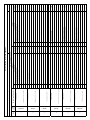
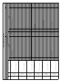
TABELLA POSIZIONE RELÈ E INGRESSI/RELAY AND INPUT POSITION TABLE
LOCAZIONE (piano,appartamento, …):
LOCATION (floor, flat, …):
SPAZIO (cucina,salotto, …):
SPACE (kitchen, living room, …):
Pag.
Page
ELENCO MODULI/LIST OF MODULES
N°
No.
SIGLA
CODE
ID e luogo di installazione
ID and place of installation
INGRESSI - INPUTS RELE' - RELAY
N°
No.
Descizione
Description
Cablatura
Wiring
N°
No.
Descizione
Description
Cablatura
Wiring

29
TABELLA ASSOCIAZIONE INGRESSI E FUNZIONI/INPUT AND FUNCTIONS MATCHING TABLE
LOCAZIONE (piano,appartamento, …):
LOCATION (floor, flat, …):
SPAZIO (cucina,salotto, …):
SPACE (kitchen, living room, …):
Pag.
Page
ELENCO RELÈ/FUNZIONAMENTO-LIST OF RELAYS/FUNCTION
RELÈ-RELAY INGRESSI
INPUTS
Attivo
con
Active
with
FUNZIONE
FUNZIONE RELÈ-RELAY INGRESSI
INPUTS
Attivo
con
Active
with
FUNZIONE
FUNZIONE
N° Cablatura
Wiring no.
Descrizione
Description
N° Cablatura
Wiring no. CC CA Funzione
Function
Ritardo
Delay
Durata
Duration
N° Cablatura
Wiring no.
Descrizione
Description
N° Cablatura
Wiring no. CC CA Funzione
Function
Ritardo
Delay
Durata
Duration

30
TABELLE POSITION RELAIS UND EINGÄNGE/TABLEAU POSITION RELAIS ET ENTREES
UNTERBRINGUNG (Stockwerk,Wohnung, …):
EMPLACEMENT (étage, appartement, …):
BEREICH (Küche,Wohnzimmer, …):
ESPACE (cuisine, salon, …) :
Seite
Page
MODULVERZEICHNIS/LISTE DES MODULES
Nr.
N°
ZEI-
CHEN
SIGLE
ID und Installationsort
ID et lieu d’installation
EINGÄNGE -ENTRÉES RELAIS - RELAIS
Nr.
N°
Beschreibung
Description
Verkabelung
Câblage
Nr.
N°
Beschreibung
Description
Verkabelung
Câblage

31
TABELLE ZUORDNUNG EINGÄNGE UND FUNKTIONEN/TABLEAU ASSOCIATION ENTRÉES ET FONCTIONS
UNTERBRINGUNG (Stockwerk,Wohnung, …):
EMPLACEMENT (étage, appartement, …) :
BEREICH (Küche,Wohnzimmer, …):
ESPACE (cuisine, salon, …):
Seite
Page
VERZEICHNIS RELAIS/FUNKTION-LISTE DES RELAIS/FONCTIONNEMENT
RELAIS-RELAIS EINGÄNGE
ENTRÉES
Aktiv
bei
Actif
avec
FUNKTION
FONCTION RELAIS-RELAIS EINGÄNGE
ENTRÉES
Aktiv
bei
Actif
avec
FUNKTION
FONCTION
Nr. Verkabelung
N° Câblage
Beschreibung
Description
Nr. Verkabelung
N° Câblage
CC
CF
CA
CO
Funktion
Fonction
Verzö-
gerung
Retard
Dauer
Durée
Nr. Verkabelung
N° Câblage
Beschreibung
Description
Nr. Verkabelung
N° Cablatura
CC
CF
CA
CO
Funktion
Fonction
Verzö-
gerung
Retard
Dauer
Durée

32
CUADRO POSICIÓN RELÉS Y ENTRADAS/TABELA POSIÇÃO RELÉS E ENTRADAS
UBICACIÓN (piso,apartamento, …):
LOCALIZAÇÃO (andar,apartamento, …):
ESPACIO (cocina,salón, …):
ESPAÇO (cozinha,sala, …):
Pág.
Pág.
LISTA DE MÓDULOS/LISTA DE MÓDULOS
N°
N°
SIGLA
SIGLA
ID y lugar de instalación
ID e lugar de instalação
ENTRADAS - ENTRADAS RELÉS - RELÉS
N°
N°
Descripción
Descrição
Cableado
Fiação
N°
N°
Descripción
Descrição
Cableado
Fiação

33
CUADRO ASOCIACIÓN ENTRADAS Y FUNCIONES/TABELA ASSOCIAÇÃO ENTRADAS E FUNÇÕES
UBICACIÓN (piso,apartamento, …):
LOCALIZAÇÃO (andar,apartamento, …):
ESPACIO (cocina,salón, …):
ESPAÇO (cozinha,sala, …):
Pág.
Pág.
LISTA DE RELÉS/FUNCIONAMIENTO-LISTA RELÉ/FUNCIONAMENTO
RELÉS-RELÉS ENTRADAS
ENTRADAS
Activo
con
Activa
com
FUNCIÓN
FUNÇÃO RELÉS-RELÉS ENTRADAS
ENTRADAS
Activo
con
Activa
com
FUNCIÓN
FUNÇÃO
N° Cableado
N° Fiação
Descripción
Descrição
N° Cableado
N° Fiação
CC
CF
CA
CO
Función
Função
Retraso
Atraso
Duración
Duração
N° Cableado
N° Fiação
Descripción
Descrição
N° Cableado
N° Cablatura
CC
CF
CA
CO
Función
Função
Retraso
Atraso
Duración
Duração

34

35

36
-
 1
1
-
 2
2
-
 3
3
-
 4
4
-
 5
5
-
 6
6
-
 7
7
-
 8
8
-
 9
9
-
 10
10
-
 11
11
-
 12
12
-
 13
13
-
 14
14
-
 15
15
-
 16
16
-
 17
17
-
 18
18
-
 19
19
-
 20
20
-
 21
21
-
 22
22
-
 23
23
-
 24
24
-
 25
25
-
 26
26
-
 27
27
-
 28
28
-
 29
29
-
 30
30
-
 31
31
-
 32
32
-
 33
33
-
 34
34
-
 35
35
-
 36
36


En otros idiomas
- italiano: CAME OH/A.01 Guida d'installazione
- português: CAME OH/A.01 Guia de instalação
Documentos relacionados
Otros documentos
-
 Key Automation 580LED Manual de usuario
-
claber 1" M. RF programmable solenoid valve Manual de usuario
-
-
Mitsubishi α Series El manual del propietario
-
Elvox ECG3 Instrucciones de operación
-
Toro TEMPUS Series Controller Manual de usuario
-
Gossen MetraWatt SINEAX V604s Instrucciones de operación
-
Rain Bird ESP-Modular El manual del propietario
-
CARLO GAVAZZI UDM 40 Manual de usuario
-
Mitsumi electronic FX2N Manual de usuario
