Quality Craft MM624-32AACO Instrucciones de operación
- Categoría
- Calentadores espaciales
- Tipo
- Instrucciones de operación

1
Model: MM624-32AACO
ELECTRIC FIREPLACE
HEATER
IMPORTANT:
PLEASE NOTE: WHEN YOU OPEN THE CARTON CAREFULLY CHECK THE UNIT
AND MAKE SURE THERE IS NO DAMAGE. IF YOU HAVE ANY PROBLEMS WITH
ASSEMBLING THE UNIT, WITH HOW THE VARIOUS FUNCTIONS WORK OR WITH
DAMAGE OR MISSING PARTS PLEASE CALL 1-800-459-4409 (9:00 AM -
5:00 PM EST) IMMEDIATELY FOR SERVICE.
NOTE: DO NOT RETURN UNIT TO THE STORE BEFORE CALLING THE TOLL FREE NUMBER.
DO NOT DISPOSE OF YOUR CARTONS UNTIL YOU ARE COMPLETELY SATISFIED WITH
YOUR NEW FIREPLACE HEATER.
NOTE: Light bulbs may become loose during shipping. If the flame effect is dim or does
not work, please check that light bulb or bulbs are finger tight in socket. See instructions
for replacing bulb or bulbs.
NOTE: The electric fireplace heater may emit a slight harmless odor when first turned
on. This is caused by activating the internal heater components for the first time and
should not occur again.
INSTRUCTION MANUAL
ATTENTION:
1) Find a location for the electric fireplace heater that is protected from direct sunlight.
2) Do not plug the unit into the power outlet before reading all instructions.
IMPORTANT SAFETY INSTRUCTIONS
WHEN USING ELECTRICAL APPLIANCES, BASIC PRECAUTIONS SHOULD ALWAYS
BE FOLLOWED TO REDUCE THE RISK OF FIRE, ELECTRIC SHOCK, AND INJURY
TO PERSONS, INCLUDING THE FOLLOWING:
1) Read all instructions before using this electric fireplace heater.
2) This electric fireplace heater is hot when in use. To avoid burns, do not let
bare skin touch hot surfaces. The grill directly in front of the heater outlet
becomes hot during heater operation. Keep combustible materials, such
as furniture, pillows, bedding, papers, clothes, and curtains at least 3 feet
(0.9 m) away from the front of the unit and keep them away from the sides
and rear.
3) Extreme caution is necessary when any heater is used by, or near, children or
individuals with disabilities and whenever the fireplace is left operating
and unattended.
4) Always unplug the electric fireplace heater when not in use.
5) Do not operate any electric fireplace heater with a damaged cord or plug or
after the heater malfunctions, has been dropped or damaged in any manner.
6) Do not use outdoors.
7) This electric fireplace heater is not intended for use in bathrooms, laundry
areas and similar indoor locations. Never place heater where it may fall into a
bathtub or other water container.
8) Do not run cord under carpeting. Do not cover cord with throw rugs, runners,
or similar coverings. Arrange cord away from traffic area and where it will
not be tripped over.
9) To disconnect the electric fireplace heater, turn controls to off, then remove
plug from outlet.
10) Connect to properly grounded outlets only.
11) Do not insert or allow foreign objects to enter any ventilation or exhaust
opening as this may cause an electric shock or fire, or damage the heater.
12) To prevent a possible fire, do not block air intakes or exhaust in any manner.
Do not use on soft surfaces, like a bed, where openings may become blocked.
13) A heater has hot and arcing or sparking parts inside. Do not use it in areas
where gasoline, paint, or flammable liquids are used or stored.
14) Use this electric fireplace heater only as described in this manual. Any other
use not recommended by the manufacturer may cause fire, electric shock, or
injury to persons.
15) Avoid the use of an extension cord because the extension cord may overheat
and cause a risk of fire. However, if you have to use an extension cord, the
cord shall be No. 14 AWG minimum size and rated not less than 1875 watts.
16) Caution: Do not plug this product into a receptacle controlled by a wall switch
or dimmer.
17) When storing or transporting the unit and cord, keep in a dry place, free from
excessive vibration and store so as to avoid damage.
SAVE THESE INSTRUCTIONS
FOR FUTURE USE.
CAUTION:
IF YOU USE THIS HEATER IN CONJUNCTION WITH A THERMAL CONTROL, A
PROGRAM CONTROLLER, A TIMER OR ANY OTHER DEVICE THAT SWITCHES THE
HEATER ON AUTOMATICALLY, REMEMBER TO OBSERVE ALL SAFETY WARNINGS
AT ALL TIMES. THE FIREPLACE HEATER HAS SAFETY OVERHEAT PROTECTION. IF
THE OVERHEAT PROTECTION TRIPS, SWITCH OFF ALL SWITCH BUTTONS AND WAIT
APPROXIMATELY 5 -10 MINUTES. IT SHOULD RESET AUTOMATICALLY ONCE THE
UNIT COOLS DOWN.
WARNING:
PROCEDURES AND TECHNIQUES IF NOT CAREFULLY FOLLOWED WILL RESULT
IN DAMAGE TO THE EQUIPMENT AND WILL EXPOSE THE USER TO THE RISK OF
SERIOUS INJURY, ILLNESS OR DEATH.
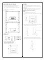
THIS ELECTRIC FIREPLACE HEATER IS FOR USE ON 120 VOLTS. THE CORD HAS
A PLUG AS SHOWN AT A IN ILLUSTRATION BELOW. AN ADAPTER AS SHOWN AT
C IS AVAILABLE FOR CONNECTING THREE-BLADE GROUNDING-TYPE PLUGS TO
TWO-SLOT RECEPTACLES. THE GREEN GROUNDING PLUG EXTENDING FROM THE
ADAPTER MUST BE CONNECTED TO A PERMANENT GROUND SUCH AS A PROPERLY
GROUNDED OUTLET BOX. THE ADAPTER SHOULD NOT BE USED IF A THREE-SLOT
GROUNDED RECEPTACLE IS AVAILABLE.
A 15 AMP CIRCUIT IS REQUIRED TO OPERATE THIS HEATER. IF THE BREAKER
TRIPS WHEN THE HEATER IS USED THEN YOU MAY NEED TO MOVE THE HEATER
TO ANOTHER LOCATION OR UNPLUG OTHER APPLIANCES THAT ARE ON THE SAME
CIRCUIT. IF YOU REQUIRE AN EXTENSION CORD USE ONE THAT IS RATED AT 1875
WATTS.

2
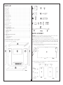
PARTS LIST
Fireplace insert...................................................................................................... 1
A) Top panel ........................................................................................................ 1
B) Base panel ...................................................................................................... 1
C) Side panels ..................................................................................................... 2
D) Front panels .................................................................................................... 2
E) Upper front panel ............................................................................................. 1
F) Lower front panel ............................................................................................. 1
S) Connectors ...................................................................................................... 2
T) Short KD screws .............................................................................................. 3
U) Mounting clips ................................................................................................. 3
V) Mounting brackets ........................................................................................... 2
W) KD screws ..................................................................................................... 55
X) Plastic connectors ......................................................................................... 15
Y) SELF REPAIR SET
Touch-up repair paint (bottle) ........................................................................... 1
L shape bracket ............................................................................................... 2
Screws for L shape .......................................................................................... 8
Plastic connector ............................................................................................. 1
KD screws ....................................................................................................... 3
KD nuts ........................................................................................................... 3
Z) WALL ANCHOR SAFETY CABLE
Wall anchor ..................................................................................................... 1
Screw for wall anchor ...................................................................................... 1
Screw for mantel ............................................................................................. 1
Safety cable .................................................................................................... 1
THIS FIREPLACE MANTEL REQUIRES 1 - 2 PEOPLE TO ASSEMBLE
AND NORMALLY TAKES 45 MINUTES - 1 HOUR TO COMPLETE.
TOOL REQUIRED: PHILLIPS HEAD SCREWDRIVER
BACK
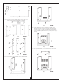
MANTEL ASSEMBLY
CAUTION: Place a piece of cardboard or protective sheet on the floor in order to avoid
scratching the decorative surface of your mantel during assembly.
Please DO NOT fully tighten the KD screws until all panels are assembled.
NOTE: Each plastic connector is pre-assembled (pre-drilled) on the specific panels with
2 screws. If the KD screw(s) do not fit during assembly, loosen the 2 (pre-drilled) screws
to adjust the plastic connector until the KD screws are able to be installed. Tighten all KD
screws once all panels are assembled.
Step 1: Attach 2 connectors [S] to upper front panel [E] with 4 KD screws [W] (2 KD
screws for each side). See Fig. A.
Fig. A BACK
Step 2: Attach all plastic connectors [X] to panels C, D and E as shown in Fig. B (2 KD
screws for each plastic connector).
Fig. B BACK

3
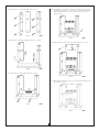
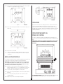
Step 3: Attach panels C to panels D with 6 KD screws. See Fig. C.
Fig. C BACK
Step 4: Attach panels C and D to panel B with 4 KD screws. See Fig. D.
Fig. D BACK
Step 5: Attach panel F to panels D with 2 KD screws. See Fig. E.
Fig. E BACK
Step 6: Carefully place the insert into the unit opening. The front of the insert should
be flush with front of the mantel. Once the insert is in place, attach 2 mounting
brackets [V] with 2 KD screws onto the bottom of insert (1 screw for each
bracket). See Fig. F.
Fig. F BACK
Step 7: Attach panel E to the unit as shown in Fig. G with 2 KD screws. See Fig. G.
Fig. G BACK
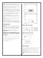
Step 8: Attach 3 mounting clips [U] onto the top of insert and lock in place with 3 short
KD screws [T]. See Fig. H.
Fig. H BACK

4
Step 9: Attach top panel [A] to the unit as shown in Fig. I with 5 KD screws.
Fig. I BACK
Step 10: Tighten all KD screws.
Step 11: Carefully move the assembled unit to the desired location.
The fireplace mantel should not be positioned in area exposed to
direct sunlight.
WALL ANCHOR SAFETY CABLE
The use of wall anchor safety cable is highly recommended in order to reduce the
risk of the fireplace being tipped over accidentally.
WARNING: This cable may reduce possible risk of injury if the fireplace is
improperly handled, but is not a substitute for proper adult supervision.
Children should not be left unattended near any heater.
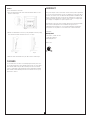
Step 1: Drill a 5/16 in (8 mm) hole in the wall. Insert the plastic wall anchor into the
hole and gently tap until the flange on the anchor is against the wall surface.
Step 2: Position the back edge of the mantel close to the wall.
Step 3: Attach the safety cable to the mantel using the screw for mantel. See Fig. J.
Step 4: Use the screw for wall to attach the other end of safety cable to the wall.
Step 5: Make sure all screws are tight.
Fig. J BACK
OPERATION
After reading complete instructions, confirm all controls on fireplace are in the OFF
position. Plug the fireplace into a 15 AMP / 120 Volt outlet. If the cord does not
reach, you may use an extension cord rated for a minimum of 1875 WATTS. Once
the fireplace insert has been properly connected to a grounded electrical outlet, it is
ready to operate.
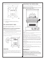
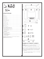
OPERATION BY THE CONTROL PANEL
The controls are located behind the grill below the glass and can be accessed by
pulling the grill from the top, forward and down.
WARNING: DO NOT TOUCH. HOT SURFACE AT CENTRE OF GRILL. HOLD LEFT OR
RIGHT SIDE OF THE GRILL WHEN PULLING OUT.
O/I: Press this button for main power function and flame effect. See below for other
control switches.
750W: For low heat function – Press this switch while the ON/OFF switch is in the ON
position for low heat. The indicator light will turn on.
1500W: For high heat function – Press this switch while the 0/I switch and 750 switch
are in the ON position for high heat. The indicator light will turn on.
Temperature Control: To adjust the temperature to your individual requirements,
turn the temperature control dial to the right (clockwise) to increase the desired
temperature and to the left for lower temperature. This temperature control dial can
only be used while the 0/I switch and 750W / 1500W switches are in the ON position.
When the heater reaches the desired temperature, the heater and 750W / 1500W
indicator light will turn off but the fan will continue to operate. Adjust this knob to
restart the heater.
Dimmer Control Knob: Turn the dimmer dial clockwise or counter clockwise to get
the desired flame intensity. The dimmer switch can only be used when the 0/I switch is
in the ON position.
Note: When the 0/I switch is turned off, all other heater functions will stop even though
the switches may be in the on position.
Note: In order to shut down the heater safely, it is recommended to turn the
temperature control knob to lowest setting and allow the heater to cool down before
press the 0/ I switch to off position.
MAINTENANCE
MAINTENANCE: Disconnect power and unplug the power cord before
attempting any maintenance or cleaning to reduce the risk of fire, electric
shock or damage to persons. The bulbs in your unit can become extremely hot.
Allow at least 10 minutes between turning off the unit and removing the light
bulbs to avoid the accidental burning of the skin.
RISK OF FIRE: Do not exceed the recommended bulb wattage.

5
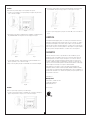
REPLACING THE LIGHT BULBS
Step 1: Remove 4 screws on the back of fireplace and open the rear cover.
Step 2: You will find 1x40W type B-10 bulbs under the log-set bed.
Step 3: Loosen and remove the burnt out bulb and replace with new bulb.
Step 4: Close the rear cover. Secure the 4 screws.
Step 5: Plug in the unit.
REPAIR SET
TOUCH-UP REPAIR PAINT
Paint directly on the mantel unit if necessary.
REPAIRS
If any problems are found with the original parts during mantel assembly, such as
the panels cannot be installed with the plastic connector, try to solve by one of the
following methods:
Tools required: Electric drill, drill bits 3/4 inches (10 mm) or 1/16 inches (2 mm),
pencil, hammer, Phillips screwdriver, safety goggles and gloves (if necessary).
WARNING: Wear goggles before you start drilling.
OPTION 1:
Use the spare KD nuts, KD screws and plastic connector.
1. Place the plastic connector on the mantel unit and mark the drill-holes as shown in
Fig. A.
Fig. A
2. Drill the holes with diameter 3/4 inches (10 mm) and depth 3/4 inches
(10 mm) on
the mantel. Each plastic connector needs 3 holes. See Fig. B.
Fig. B Fig. C
3. Gently install the KD nuts into the drilled-holes with hammer as shown in Fig. C.
4. Attach the plastic connector and lock in place with KD screws as shown in Fig. D.
Fig. D

6
OPTION 2:
Use the small L-brackets and screws.
1. Place the small L-bracket to the unit as shown and mark the drill-holes on the
mantel as shown in Fig. E.
Fig. E
2. Drill the holes with diameter 1/16 inches (2 mm) and depth 5/16 inches (8 mm)
on the mantel. Each small L-bracket needs 4 holes. See Fig. F.
Fig. F Fig. G
3. Attach the small L-bracket and lock in place with screws as shown in Fig. G.
CLEANING
To clean unit first turn off controls on unit and unplug the unit from power source.
To clean glass display panel; remove dust with clean dry cloth or to remove finger
prints and other marks clean glass with clean damp cloth. Do not use abrasive
cleaners or spray liquids on glass display panel surface. Metal and metal painted
parts should be cleaned with damp cloth. Do not use abrasive cleaners or spray
liquids on these surfaces.
WARRANTY
Every electric fireplace heater is tested before it leaves the factory and it is guaranteed
for one year. If the unit should fail to operate correctly within one year from the date of
purchase, call customer service at 1-800-459-4409 (9:00 AM - 5:00 PM EST). We
will, at our discretion either repair or replace the unit. It will have to be returned to us
freight prepaid and we will return the repaired or replaced unit to you freight prepaid.
The company’s sole obligation is to repair or replace the unit.
This warranty is void if in the opinion of Quality Craft the unit has been tampered with,
altered, misused, damaged, abused or used with the wrong power source.
Light bulbs and remote batteries are not covered by this warranty. The warranty is
for homeowner use only and does not cover units used in commercial situations.
Imported by
Quality Craft
Laval, Quebec, Canada H7S 2G7
1-800-459-4409 (EST)
www.qualitycraft.com
Made in China

1
Modelo: MM624-32AACO
CHIMENEA
ELÉCTRICA
IMPORTANTE:
DESPUÉS DE ABRIR LA CAJA, VERIFIQUE MUY BIEN EL APARATO Y ASEGÚRESE
DE QUE NO ESTÉ DAÑADO. SI TUVIERA PROBLEMAS ENSAMBLANDO EL APARATO,
LAS DIVERSAS FUNCIONES DEL MISMO, O SI FALTARAN PIEZAS Y HUBIERA
DAÑOS INTERNOS, SÍRVASE LLAMAR DE INMEDIATO AL SERVICIO AL CLIENTE,
MARCANDO EL 1-800-459-4409 (ENTRE LAS 9 Y 17 HORAS, HORA NORMAL DEL
ESTE).
NOTA: NO DEVUELVA EL APARATO A LA TIENDA DONDE LO COMPRÓ ANTES DE
HABER LLAMADO AL NÚMERO SIN CARGO MENCIONADO. NO DESECHE LOS
EMBALAJES HASTA QUE QUEDE PLENAMENTE SATISFECHO CON SU NUEVA
ESTUFA ELÉCTRICA.
NOTA: Las bombillas pueden aflojarse durante el transporte. Si el efecto de llama es débil o
no funciona, sírvase cerciorarse de que las bombillas estén bien ajustadas en la base. Para
cambiar las bombillas, vea las instrucciones.
NOTA: El calentador de la chimenea eléctrica puede emitir un olor inocuo suave apenas
se lo enciende. Esto se produce porque los componentes del calentador interno se
activan por primera vez y no debería ocurrir nuevamente.
MANUAL DE INSTRUCCIONES
IMPORTANTE:
1) Encuentre un lugar para instalar la estufa eléctrica donde esté protegida de la luz solar
directa.
2) Antes de enchufar la estufa eléctrica en el tomacorriente, lea todas las instrucciones.
INSTRUCCIONES IMPORTANTES DE
SEGURIDAD
AL USAR APARATOS ELÉCTRICOS, SE DEBEN TOMAR SIEMPRE CIERTAS
PRECUACIONES BÁSICAS COMO LAS SIGUIENTES, PARA REDUCIR EL RIESGO
DE INCENDIO, DESCARGA ELÉCTRICA Y LESIONES PERSONALES:
1) Lea todas las instrucciones antes de usar esta estufa.
2) Esta estufa se calienta cuando se usa. Para evitar quemaduras, no toque
las superficies calientes con la piel desnuda. Mantenga materiales
combustibles, como muebles, almohadas, ropa de cama, papeles, ropa y
cortinas a un mínimo de 3 pies (0,9 m) de la parte delantera de la estufa y
manténgalos alejados también de los costados y de la parte trasera.
3) Es necesario tomar precauciones extremas cuando se usa un aparato
como éste cerca de niños o minusválidos o cuando el aparato se deja en
funcionamiento sin supervisión.
4) Desenchufe siempre la estufa cuando no se use.
5) No haga funcionar ninguna estufa que tenga un cordón o enchufe dañado o
después de que haya funcionado mal, se haya caído o dañado.
6) No utilice la estufa al aire libre.
7) Esta estufa no ha sido concebida para usar en cuartos de baño, lavaderos y
áreas interiores similares. Nunca coloque la estufa donde se pueda caer a la
bañera u otro lugar donde se acumule el agua.
8) No pase el cordón por debajo de la alfombra. No cubra el cordón con
alfombras pequeñas, alfombrillas de pasillo o cubiertas similares. Ponga el
cordón lejos del área de tráfico y donde no sea posible tropezar con él.
9) Para desconectar la estufa, gire los controles a “apagado” y luego saque el
enchufe del tomacorriente.
10) Enchufe únicamente en un tomacorriente con conexión a tierra.
11) No inserte ni permita que entre ningún objeto en ninguna abertura de
ventilación o de salida de aire, ya que puede producir un choque eléctrico, un
incendio o dañar el aparato.
12) Para impedir que se produzca un incendio, no bloquee las tomas o escapes de
aire. No ponga la estufa sobre superficies blandas, como una cama, donde las
aberturas pueden bloquearse.
13) Una estufa tiene piezas que se calientan y que hacen arco o producen chispas
en el interior. No lo utilice en áreas donde se use o se guarde gasolina, pintura
o líquidos inflamables.
14) Utilice esta estufa conforme a lo que se indica en este manual. Cualquier otro
uso no recomendado por el fabricante puede producir incendios, descargas
eléctricas o lesiones personales.
15) Evite el uso de un cable de extensión ya que este se puede calentar y causar
un riesgo de fuego. Sin embargo, si requiere de un cable de extensión, este
deberá ser del No. 14 AWG y con capacidad para no menos de 1875 vatios.
16) Precaución: No enchufar la chimenea eléctrica en un tomacorriente
controlado por un interruptor de pared o un regulador de intensidad.
17) Cuando guarde o transporte el aparato y el cordón, manténgalos en un lugar
seco, libre de excesiva vibración y guárdelos bien para que no se dañen.
GUARDE ESTA INFORMACIÓN PARA
CONSULTARLA EN EL FUTURO.
PRECAUCIÓN :
SI USA ESTA ESTUFA CON UN CONTROL TÉRMICO, UN CONTROLADOR DE
PROGRAMA, UN TEMPORIZADOR O CUALQUIER OTRO DISPOSITIVO QUE ENCIENDA
LA ESTUFA AUTOMÁTICAMENTE, SIEMPRE DEBERÁ TOMAR TODAS LAS MEDIDAS
DE SEGURIDAD. LA ESTUFA ELÉCTRICA ESTÁ EQUIPADA CON UN PROTECTOR
CONTRA EL SOBRECALENTAMIENTO. SI EL DISPOSITIVO DE PROTECCIÓN SALTA,
DESENCHUFE EL CABLE DE ALIMENTACIÓN DEL TOMACORRIENTE. DICHO
DISPOSITIVO DEBERÍA REPOSICIONARSE AUTOMÁTICAMENTE DESPUÉS DE UNOS
5 MINUTOS.
PRECAUCIÓN :
SI NO SE SIGUEN ATENTAMENTE LOS PROCEDIMIENTOS Y TÉCNICAS INDICADOS,
SE DAÑARÁ EL EQUIPO; EL USUARIO QUEDARÁ EXPUESTO AL RIESGO DE SUFRIR
LESIONES O DOLENCIAS GRAVES O FATALES.
ESTA CHIMENEA ELÉCTRICA DEBE UTILIZARSE CON 120 VOLTIOS. COMO SE
OBSERVA EN LA FIGURA A, EL CABLE POSEE UN ENCHUFE. HAY UN ADAPTADOR
DISPONIBLE, COMO SE OBSERVA EN LA FIGURA C, PARA CONECTAR ENCHUFES
DE TRES CLAVIJAS CON CONEXIÓN A TIERRA A TOMACORRIENTES DE DOS
ESPIGAS. EL ENCHUFE CON CONEXIÓN A TIERRA VERDE DEL ADAPTADOR
DEBE CONECTARSE A UN CONTACTO A TIERRA PERMANENTE, POR EJEMPLO,
UN TOMACORRIENTE DE CONEXIÓN A TIERRA. EL ADAPTADOR NO DEBERÍA
UTILIZARSE SI HAY UN TOMACORRIENTE DE TRES ESPIGAS DISPONIBLE.
PARA HACER FUNCIONAR ESTE CALENTADOR SE REQUIERE UN CIRCUITO DE 15
AMPERIOS. SI EL INTERRUPTOR SE DESCONECTA AL USAR EL CALENTADOR, ES
POSIBLE QUE DEBA MOVERLO A OTRO SITIO O DESENCHUFAR OTROS APARATOS
QUE ESTÉN CONECTADOS AL MISMO CIRCUITO. SI REQUIERE UN CABLE DE
EXTENSIÓN, ÉSTE DEBERÁ ESTAR CLASIFICADO PARA 1875 VATIOS.

2
LISTADO DE PIEZAS
Chimenea.............................................................................................................. 1
A) Panel superior ................................................................................................. 1
B) Panel inferior ................................................................................................... 1
C) Paneles laterales ............................................................................................. 2
D) Panel delantero................................................................................................ 2
E) Panel delantero superior .................................................................................. 1
F) Panel delantero inferior .................................................................................... 1
S) Conectores ...................................................................................................... 2
T) Tornillos cortos KD ........................................................................................... 3
U) Broche de sujeción .......................................................................................... 3
V) Soportes de montaje ........................................................................................ 2
W) Tornillos KD ................................................................................................... 55
X) Conectores plásticos ...................................................................................... 15
Y) JUEGO PARA AUTORREPARACIONES
Pintura para efectuar retoques (botella) ............................................................ 1
Soporte en forma de “L” ................................................................................... 2
Tornillos para el soporte en forma de “L” .......................................................... 8
Connector de plástico ...................................................................................... 1
Tornillos KD ..................................................................................................... 3
Tuercas KD ...................................................................................................... 3
Z) ANCLAJE PARA PAREDLE
Anclaje para pared .......................................................................................... 1
Tornillo del anclaje para pared ......................................................................... 1
Tornillo para el gabinete .................................................................................. 1
Cable de seguridad ......................................................................................... 1
ES NECESARIO QUE 1 O 2 PERSONAS REALICEN EL MONTAJE DE ESTA REPISA DE CHIMENEA QUE
GENERALMENTE TOMA 45 MINUTOS O 1 HORA.
HERRAMIENTA REQUERIDA: DESTORNILLADOR PHILLIPS
TRASERO
ENSAMBLE DE LA REPISA Y EL INSERTO
ADVERTENCIA: Cerciórese de que los controles del INSERTO de la chimenea estén en la
posición de APAGADO (OFF) y que el INSERTO NO esté enchufado.
NO ajuste al máximo los tornillos KD hasta que se hayan montado todos los paneles.
NOTA: Cada conector plástico está preinstalado (perforado previamente) en los paneles
específicos con 2 tornillos. Si, durante la instalación, los tornillos KD no encajan, afloje
los 2 tornillos (perforados previamente) para ajustar el conector plástico hasta que
puedan instalarse los tornillos KD. Una vez que todos los paneles estén instalados, ajuste
todos los tornillos KD.
Paso 1: Sujete 2 conectores [S] al panel delantero superior [E] con 4 tornillos KD [W]
(2 tornillos KD en cada lado). Vea la fig. A.

3
Fig. A TRASERO
Paso 2: Sujete todos los conectores plásticos [X] a los paneles C, D y E, como se
muestra en la fig. B (2 tornillos KD para cada conector plástico).
Fig. B TRASERO
Paso 3: Sujete los paneles C a los paneles D con 6 tornillos KD. Vea la fig. C.
Fig. C TRASERO
Paso 4: Sujete los paneles C y D a el panel B con 4 tornillos KD. Vea la fig. D.
Fig. D TRASERO
Paso 5: Sujete el panel F a los paneles D con 2 tornillos KD. Vea la fig. E.
Fig. E TRASERO
Paso 6: Coloque cuidadosamente el inserto en la abertura de la unidad. La parte
delantera del inserto debe estar nivelada con la parte delantera de la repisa.
Una vez que el inserto esté colocado en su lugar, sujete 2 soportes de montaje
[V] con 2 tornillos KD a la parte inferior del inserto (1 tornillo para cada soporte).
Vea la fig. F.
Fig. F TRASERO
Paso 7: Sujete el panel E a la unidad, como se muestra en la fig. G, con 2 tornillos KD.
Vea la fig. G.
Fig. G TRASERO

4
Paso 8: Sujete 3 ganchos de montaje [U] a la parte superior del inserto y asegúrelos
en el lugar con 3 tornillos KD cortos [T]. Vea la fig. H.
Fig. H TRASERO
Paso 9: Sujete el panel superior [A] a la unidad, como se muestra en la fig. I, con 5
tornillos KD.
Fig. I TRASERO
Paso 10: Ajuste todos los tornillos KD.
Paso 11: Mueva con cuidado toda la unidad ensamblada a la ubicación deseada.
La repisa de la chimenea no deberá ponerse en un área con exposición
directa al sol.
ANCLAJE PARA PAREDLE
Se recomienda especialmente usar un cable de seguridad del anclaje para pared con
el n de reducir el riesgo de que la chimenea se caiga accidentalmente.
PRECAUCIÓN: Este cable puede reducir el posible riesgo de sufrir lesiones
sino se manipula la chimenea correctamente, pero no es el sustituto de la
correspondiente supervisión de un adulto. No se debe dejar que los niños
permanezcan cerca de la chimenea sin supervisión.
Paso 1: Haga un ori cio de 5/16” (8 mm) en la pared. Introduzca el anclaje de
plásticopara pared dentro del ori cio y, con suavidad, déle unos golpecitos
hasta que el reborde del anclaje quede contra la supercie de la pared.
Paso 2: Coloque el borde posterior del gabinete cerca de la pared.
Paso 3: Sujete el cable de seguridad al gabinete usando el tornillo para el gabinete.
Vea la fig. J.
Paso 4: Use el tornillo para la pared para sujetar el otro extremo del cable de
seguridad a la pared.
Paso 5: Asegúrese de que todos los tornillos queden ajustados.
Fig. J TRASERO
OPERACIÓN
Después de leer las instrucciones, verifique que todos los controles de la chimenea
estén a la posición APAGADO. Enchufe la chimenea a un tomacorriente de 15
amperios/120 voltios. Si el cable no alcanza, puede utilizar un alargador clasificado
para 1875 vatios como mínimo. Una vez que el alargador de la chimenea se encuentra
conectado adecuadamente a un tomacorriente con conexión a tierra, el calentador
está listo para funcionar.
OPERACIÓN MEDIANTE EL
PANEL DE CONTROL
Los controles están ubicados detrás de la parrilla debajo del cristal delantero y se
puede acceder a ellos tirando de la parrilla hacia arriba, y luego hacia adelante y hacia
abajo.
ADVERTENCIA: NO TOQUE. LA SUPERFICIE DEL CENTRO DE LA REJILLA ESTÁ
CALIENTE. AGARRE EL LADO IZQUIERDO O DERECHO DE LA REJILLA PARA
EXTRAERLA.
O/I (ENCENDIDO/APAGADO): oprima este botón para encender el aparato y crear
el efecto de llamas. Vea la descripción de los otros controles más abajo.

5
750W: Para obtener la función de bajo nivel de calor: presione este interruptor
mientras el interruptor de encendido o apagado (ON/OFF) está en la posición de
encendido a fin de lograr un bajo nivel de calor. La luz indicadora se encenderá.
1500W: Para obtener la función de alto nivel de calor: presione este interruptor
mientras los interruptores ON/OFF y 750W están en la posición de encendido a fin
de lograr un alto nivel de calor. La luz indicadora se encenderá.
Control de temperatura: Para ajustar la temperatura según lo requiera, gire el dial
de control de temperatura hacia la derecha (en el sentido de las agujas del reloj)
para aumentar la temperatura hasta el nivel deseado, y hacia la izquierda, para
disminuirla. Este dial de control de temperatura puede usarse únicamente mientras
los interruptores ON/OFF, 750W y 1500W están en la posición de encendido (ON).
Cuando el calefactor alcanza la temperatura deseada, el calefactor y la luz
indicadora de 750W/1500W se apagarán, pero el ventilador seguirá funcionando
con flujo de aire. Regule esta perilla para volver a encender el calefactor.
Perilla de control del regulador: Gire el dial del regulador en sentido horario
o contrahorario para obtener la intensidad de llama deseada. El interruptor del
regulador solo puede ser utilizado cuando el regulador O/I esté en la posición de
encendido (ON).
NOTA: Cuando el interruptor O/I o el de reposo están apagados, todas las demás
funciones del calefactor se interrumpirán aunque los interruptores estén en la
posición de encendido (ON).
NOTA: Para apagar el calentador de una manera segura, se recomienda colocar
la perilla de control de temperatura en la posición más baja y dejar que el
calentador se enfríe antes de presionar el botón O/I (ENCENDIDO/APAGADO).
MANTENIMIENTO
PRECAUCIÓN: Desconecte la energía eléctrica y desenchufe el cable de
alimentación eléctrica antes de hacer el mantenimiento o de limpiar, para disminuir
el riesgo de incendio, descarga eléctrica o lesiones físicas. Las bombillas de la
unidad se pueden calentar en forma excesiva. Para quitar las bombillas, espere
al menos 10 minutos después de apagar la unidad para evitar una quemadura
accidental.
RIESGO DE INCENDIO: NO EXCEDA EL VATAJE DE LA BOMBILLA
RECOMENDADO.
REEMPLAZO DE LAS BOMBILLAS DE LUZ
DEL EFECTO DE LLAMA Y EL CONJUNTO
DE LEÑOS
Paso 1: Quite 4 tornillos de la parte trasera de la chimenea y abra la cubierta
trasera.
Paso 2: Encontrará una bombilla de 40 vatios tipo B-10 debajo de la base de los leños.
Paso 3: Afloje y quite la bombilla quemada, y reemplácela con una nueva.
Paso 4: Cierre la cubierta trasera. Fije los 4 tornillos.
Paso 5: Enchufe la unidad.
PINTURA PARA RETOQUES
PEINTURE POUR RETOUCHE
En caso de ser necesario, pinte directamente sobre la repisa.
REPARACIONESS
En el caso de que surjan problemas con las piezas originales durante el montaje de
la repisa, por ejemplo, que los paneles no puedan instalarse con el conector plástico,
intente solucionar el problema mediante uno de los siguientes métodos.
Herramientas necesarias: Taladro eléctrico, brocas para taladro de 10 mm (3/4 in)
o de 2 mm (1/16 in), lápiz, martillo carpintero, destornilladores tipo Philips, guantes y
gafas de seguridad (si es necesario).
ADVERTENCIA: Tenga sus gafas y guantes puestos antes de comenzar a
taladrar.

6
OPCIÓN 1:
Utilice las tuercas y tornillos KD, y el conector plástico de repuesto.
1. Coloque el conector plástico en la repisa y marque los agujeros de perforación,
como se muestra en la fig. A.
Fig. A
2. En la repisa, perfore agujeros de 10 mm (3/4 in) de diámetro y de 10 mm (3/4 in)
de profundidad. Cada conector plástico necesita 3 agujeros. Ver fig. B.
Fig. B Fig. C
3. Con un martillo carpintero, empuje suavemente las tuercas KD dentro de los
agujeros perforados, como se muestra en la fig. C.
4. Sujete el conector plástico y asegure con tornillos KD, como se muestra en la fig. D.
Fig. D
OPCIÓN 2:
Utilice los soportes largos pequeños y los tornillos largos.
1. Coloque el soporte largo pequeño en la unidad, como se muestra, y marque los
agujeros de perforación en la repisa, como se muestra en la fig. E.
Fig. E
2. En la repisa, perfore agujeros de 2 mm (1/16 in) de diámetro y de 8 mm (5/16 in)
de profundidad. Cada soporte largo pequeño necesita 4 agujeros. Ver fig. F.
Fig. F Fig. G
3. Sujete el soporte largo pequeño y asegure con tornillos KD, como se muestra en la
fig. G.
LIMPIEZA
Para limpiar la unidad, apague primero los controles y desenchúfela de la fuente de
alimentación. Para limpiar el panel de vidrio, quite el polvo con un paño seco y limpio.
Para quitar huellas digitales u otras marcas, limpie el vidrio con un paño húmedo y
limpio. No utilice productos de limpieza abrasivos o rociadores sobre la superficie del
panel de vidrio. Las partes de metal o pintadas se deben limpiar con un paño húmedo.
No utilice productos de limpieza abrasivos o rociadores sobre estas superficies.
GARANTÍA
Todas las chimeneas eléctricas se prueban antes de salir de la fábrica y poseen
garantía por un año. Si la unidad no funciona como corresponde dentro del año de
garantía a partir de la fecha de compra, comuníquese con el servicio de atención
al cliente al 1-800- 459-4409 (hora del Este). Nuestra empresa, a su discreción,
reparará o cambiará la unidad. La unidad deberá ser devuelta con el flete pago y la
empresa le devolverá la unidad reparada o una unidad nueva, también con flete pago.
La única obligación de la empresa es reparar o cambiar la unidad.
Esta garantía carece de validez si, a criterio de Quality Craft, la unidad ha sido
manipulada, alterada, usada de manera inapropiada, dañada, maltratada o utilizada
con una fuente de energía inadecuada. Esta garantía tampoco cubre las bombillas. La
garantía cubre únicamente el uso doméstico del aparato y no aquellos aparatos que se
usen para fines comerciales.
Importado por
Quality Craft
Laval, Quebec, Canada H7S 2G7
1-800-459-4409 (EST)
www.qualitycraft.com
Hecho en China
-
 1
1
-
 2
2
-
 3
3
-
 4
4
-
 5
5
-
 6
6
-
 7
7
-
 8
8
-
 9
9
-
 10
10
-
 11
11
-
 12
12


Quality Craft MM624-32AACO Instrucciones de operación
- Categoría
- Calentadores espaciales
- Tipo
- Instrucciones de operación
en otros idiomas
Artículos relacionados


Otros documentos
-
Twin-Star International 23WM9083-PM92 Manual de usuario
-
-
Classic Flame 80649 Manual de usuario
-
-
Home Decorators Collection MTVSC2513SCH Manual de usuario
-
NAPOLEON NEFP24HT-HD El manual del propietario
-
Muskoka Gold MFB33WSC Guía del usuario
-
-
Philips 12972NGSDLB1 Product Datasheet