
INSTRUCTION MANUAL
MODE D’EMPLOI
BEDIENUNGSANLEITUNG
MANUAL DE INSTRUCCIONES
Инструкция по монтажу
Manuale di istruzioni per l’uso
AF 550

81 mm
Serratura
Lock
Schloss
Serrure
Cerradura
Замок
Leva di sblocco
Unlocking handle
Enthemmungsstange
Poignee deblocage
Manipulo de
desbloqueio
Ключ разблокировки
Pulsante
Pusher
Pulsgeber
Bouton
Pulsador
Кнопка
46 mm
147 mm
Fig. 1 Fig. 2

Fori di fissaggio
Holes for fixing box
Gehausebefestigungslocher
Trou fixation boite
Agujeros fijaciòn caja
Отверстия для крепления
Entrata cavo freno
Brake input cable
Bremskabeleingang
Entree cable frein
Entrada cable freno
Вход тормозного
кабеля
Entrata cavo elettrico
Input electric wire
Kabeleingang
Entree electrique
Entrada cable electrico
Вход электрического
кабеля
Fig. 3

a b
Fig. 4
Morsetto cavo freno
Pin
Druckbolzen
Serre cable
Prisionero
Терминал тормозного кабеля
Cavo del freno
Brake wire
Bremsloskabel
Cable frein
Cable freno
Тормозный кабель

Fig. 5
Fig. 6
MOVIMENTAZIONE SERRANDE
SHUTTERS MOVEMENT
MOUVEMENT VOLET
ROULANTE
MOVIMIENTO PERSIANAS
ROLLTOR-HANDHABUNG
ДВИЖЕНИЕ ЖАЛЮЗИ
(AUTOMATION FRAME)
MOVIMENTAZIONE CANCELLI
GATES MOVEMENT
MOUVEMENT PORTE
MOVIMIENTO PUERTA
TOR-HANDHABUNG
ДВИЖЕНИЕ ВОРОТ
(AUTOMATION GATE)
4
3
2
1
N
L
P P
PED
GND
STOP
8K2
ELS+
24V
5W
L6
L7
ANT
GND
L5
L4
L2
L3
SEL
SET
LIV.
6
7
8
9
10
11
12
13
14
15
16
17
18
SLOWING FORCE SENS
DS1
ELS-
ANT+
LED
PED
PP

1
Leggere attentamente prima di iniziare e rispettare le istruzioni riportate nel manuale. Conservare il presente
manuale per l’utilizzo.
Il presente manuale di installazione è rivolto esclusivamente a personale professionalmente competente. L’installazione, i
collegamenti elettrici e le regolazioni devono essere effettuati nell’osservanza della Buona Tecnica e in ottemperanza alle
norme vigenti. Leggere attentamente le istruzioni prima di iniziare l’installazione del prodotto. Una errata installazione
può essere fonte di pericolo. I materiali dell’imballaggio (plastica, polistirolo, ecc.) non vanno dispersi nell’ambiente e
non devono essere lasciati alla portata dei bambini in quanto potenziali fonti di pericolo. Prima di iniziare l’installazione
verificare l’integrità del prodotto.
1. INFORMAZIONI GENERALI
2. ISTRUZIONI DI MONTAGGIO
1. INFORMAZIONI GENERALI pag. 1
2. ISTRUZIONI DI MONTAGGIO pag. 1
3. COLLEGAMENTI ELETTRICI pag. 2
4. CONNESSIONE DELLA GUAINA E CAVO DI SBLOCCO FRENO pag. 3
5. MOVIMENTAZIONE SERRANDE (AUTOMATION FRAME) pag. 3
6. MOVIMENTAZIONE CANCELLI (AUTOMATION GATE) pag. 3
7. GARANZIA pag. 4
8. DICHIARAZIONE DI CONFORMITÁ CE pag. 5
INDICE

ITALIANO
2
IMPORTANTE! Per attrezzature connesse in modo permanente dovrà essere aggiunto al cablaggio un dispositivo di
connessione di facile accesso. Collegare alla presa a terra.
Togliere dalla sede il pulsante svitando le due viti di fermo.
Collegare un cavo di rete da 230 V (linea di fase, L) al contatto centrale del pulsante (1 ). (Fig. 5)
Effettuare la connessione del cavo n.2 e n.3 provenienti dal motoriduttore ai due contatti esterni del pulsante (vedi
schema elettrico del motoriduttore per rispettare i sensi di rotazione della puleggia) (Fig. 5).
Collegare il cavo di presa a terra inserendolo nell’alloggiamento posto dietro all’interruttore e fissarlo con vite e
una rondella dentellata. (Fig. 2)
Collegare un cavo di rete da 230 V (linea di neutro, N) direttamente al cavo comune (4) proveniente dal motoriduttore.
(Fig. 5).
Porre di nuovo il pulsante nella sua sede.
In caso di impianto con centralina elettronica collegare il contatto del pulsante ai morsetti stabiliti sulla stessa. In
questo caso nessuna alimentazione elettrica dovrà mai pervenire al pulsante stesso. (Fig. 6)
3. COLLEGAMENTI ELETTRICI
Se il cavo di alimentazione è danneggiato, esso deve essere sostituito dal costruttore o dal suo servizio di assistenza
tecnica o comunque da una persona con qualifica similare, in modo da prevenire ogni rischio.
Non installare il prodotto in ambiente e atmosfera esplosivi: presenza di gas o fumi infiammabili costituiscono un grave
pericolo per la sicurezza.
Sulla parete scelta per l’installazione, eseguire i due fori relativi ai passaggi del cavo di alimentazione elettrica e
freno in corrispondenza di quelli esistenti sul dorso del blindino (Fig. 3).
Nella parte posteriore della scatola in alluminio, in corrispondenza del foro del cavo del freno, è stata creata
appositamente una sede di diametro mm 10 che eventualmente può contenere un tubo (guida) protettore della
guaina, fra la parte esterna e il luogo d'installazione del motoriduttore per permettere una facile introduzione ed
estrazione della stessa.
Eseguire i tre fori di fissaggio per avvitare la scatola alla parete (Fig. 3).

3
Introdurre nella sua sede la guaina e inserire il cavo metallico nel foro della leva.
Posizionare ora la leva nella sede stabilita.
Applicare su detto cavo la vite d'arresto accostandolo alla leva e serrandolo con chiave da mm. 8 (Fig. 4).
Agire sul tensore posto sul fondo del freno del motoriduttore e porre in tiro la guaina.
Tirare la leva e verificare che il motoriduttore venga sbloccato movimentando a mano la serranda. In caso di
necessità, agire di nuovo sul tensore o sulla vite d’arresto, fino ad ottenere che le funzioni di sblocco e di blocco
avvengano sempre correttamente.
4. CONNESSIONE DELLA GUAINA E CAVO DI
SBLOCCO FRENO
UOMO PRESENTE
• Interruttore I sempre premuto: chiusura della serranda (Fig. 4)
• Interruttore II sempre premuto: apertura della serranda
MODALITÀ PASSO-PASSO
• Interruttore I (ingresso PP): premendo 1, 2 o 3 volte si ha rispettivamente l’apertura, l’arresto e la chiusura del
cancello. (Fig.2 - Fig.6)
• Interruttore II (ingresso PED): premendo 1, 2 o 3 volte si ha rispettivamente l’apertura, l’arresto e la chiusura di
una sola anta per il passaggio pedonale.
MODALITÀ AUTOMATICO
• Interruttore I (ingresso PP): premendo 1 o 2 volte si ha rispettivamente l’apertura e la chiusura del cancello.
• Interruttore II (ingresso PED): premendo 1 o 2 volte si ha rispettivamente l’apertura e la chiusura di una sola
anta per il passaggio pedonale. (Fig.2 - Fig.6)
5. MOVIMENTAZIONE SERRANDE (AUTOMATION FRAME)
6. MOVIMENTAZIONE CANCELLI (AUTOMATION GATE)

ITALIANO
4
UOMO PRESENTE
• Interruttore I (ingresso PP): premendo (e mantenendo premuto) si comanda il movimento del cancello. Al
rilascio il cancello si arresta.
• Interruttore II (ingresso PED): premendo (e mantenendo premuto) si comanda il movimento di una sola anta per
il passaggio pedonale. Al rilascio il cancello si arresta.
NOTA: le modalità di funzionamento PASSO-PASSO, AUTOMATICA e UOMO-PRESENTE sono configurabili nelle
centraline di controllo Automation Gate
7. GARANZIA
a) La presente garanzia nei rapporti commerciali o in caso di vendita di beni per uso professionale è limitata
alla riparazione o sostituzione del pezzo del Prodotto riconosciuto da FRATELLI COMUNELLO SPA quale difettoso
mediante Prodotti rigenerati equivalenti (di seguito “Garanzia Convenzionale”), non risulta compresa nella garanzia
il costo necessario per le attività di riparazione e sostituzione del materiale (a titolo esemplificativo costi di
manodopera, noleggio materiali, etc).
b) E’ esclusa l’applicazione della disciplina dettata dagli articoli 1490-1495 del Codice Civile.
c) FRATELLI COMUNELLO SPA garantisce il funzionamento dei Prodotti nei limiti indicati al superiore punto
sub a). Salvo diverso accordo, la validità della Garanzia Convenzionale è di 36 (trentasei) mesi dalla data di
produzione, rilevabile sui Prodotti. La Garanzia risulterà efficace e vincolante per COMUNELLO solo se il prodotto
verrà correttamente montato e manutentato in conformità alle regole di installazione e di sicurezza indicate nella
documentazione fornita da COMUNELLO o comunque rinvenibile sul sito http://www.comunello.com/it/corporate/
condizioni-generali/
d) La garanzia non comprende: avarie o danni causati dal trasporto; avarie o danni causati da vizi dell’impianto
elettrico presente presso l’acquirente il prodotto e/o da trascuratezza, negligenza, inadeguatezza, uso anomalo
di tale impianto; avarie o danni dovuti a manomissioni poste in essere da parte di personale non autorizzato o
conseguenti allo scorretto uso/installazione (a questo proposito, si consiglia una manutenzione del sistema
almeno ogni sei mesi) o all’impiego di pezzi di ricambio non originali; difetti causati da agenti chimici e/o fenomeni
atmosferici. La garanzia non comprende il costo per materiale di consumo, in ogni caso COMUNELLO matura il
credito per l’intervento eseguito presso il cliente, laddove quest’ultimo si riveli inutile poiché non risultava operante
la garanzia o perché il cliente aveva utilizzato il prodotto COMUNELLO in modo negligente, imprudente od imperito,
tale per cui il corretto utilizzo del prodotto avrebbe potuto evitare l’installazione.
e) Termini attuativi: salvo diverso accordo, il diritto alla Garanzia Convenzionale si esercita esibendo copia del
documento di acquisto (fattura fiscale) a COMUNELLO. Il Cliente deve denunciare il difetto a COMUNELLO entro il
termine di decadenza di 30 (trenta) giorni dalla scoperta.
L’azione deve essere esercitata entro il termine di prescrizione di 6 (sei) mesi dalla scoperta. I pezzi dei Prodotti per
i quali viene richiesta l’attivazione della Garanzia Convenzionale devono essere spediti dal Cliente presso FRATELLI
COMUNELLO SPA, Via Cassola 64, 36027 Rosà (VI) Italia.

5
f) Il Cliente non potrà richiedere il risarcimento di danni indiretti, mancati profitti, perdita di produzione ed in ogni
caso non potrà pretendere a titolo di risarcimento somme superiori al valore dei componenti o dei Prodotti forniti.
Tutte le spese per il trasporto dei Prodotti da riparare o riparati, anche se coperti dalla Garanzia Convenzionale,
sono a carico del Cliente.
g) Nessun intervento esterno effettuato dal personale tecnico di COMUNELLO è coperto dalla Garanzia
Convenzionale.
h) Modifiche specifiche delle condizioni della Garanzia Convenzionale qui descritte possono essere definite dalle
parti nei propri contratti commerciali.
i) In caso di controversia legale di qualsiasi natura è applicabile il diritto italiano ed è competente il Foro di Vicenza.

ITALIANO
6
8. DICHIARAZIONE DI CONFORMITÀ CE
Il fabbricante Fratelli Comunello S.p.A. con sede in Via Cassola 64, 36027 Rosà (VI), Italia
Dichiara che l’apparecchiatura descritta in appresso
Descrizione: Blindino con interruttore di comando per serrande motorizzate
Modello: AF550
è conforme alle disposizioni legislative che traspongono le seguenti direttive:
2014/35/EU (Direttiva LVD)
2011/65/EU (Direttiva RoHS)
e che sono state applicate tutte le norme e/o specifiche tecniche di seguito indicate:
EN61058-1 :2017
EN61058-2-1 :2011
ed emendamenti successivi
Rosà, 15/05/2018
Luca Comunello
Legale rappresentante della FRATELLI COMUNELLO S.p.A.

1
INDEX
1. GENERAL INFORMATION pag. 1
2. INSTALLATION pag. 1
3. ELECTRICAL CONNECTION pag. 2
4. SHEATH CONNECTION AND BRAKE RELEASE CABLE pag. 3
5. SHUTTERS MOVEMENT (AUTOMATION FRAME) pag. 3
6. GATES MOVEMENT (AUTOMATION GATE) pag. 3
7. GUARANTEE pag. 4
8. DECLARATION OF CONFORMITY pag. 5
Please read carefully and follow the instructions detailed in this manual. Keep the manual for use and future
maintenance.
This installation manual is written exclusively for competent professional personnel.
The installation, electrical connections and adjustments must be carried out conforming to good practice and according
to the regulations in force. Incorrect installation can cause a potential hazard. The packing materials (plastic,
polystyrene, etc.) must not be allowed to pollute the environment, but must be disposed of correctly, and must not be
left within the reach of children since they can cause possible hazards. Before starting installation, check the product
is complete and undamaged.
1. GENERAL INFORMATION
2. INSTALLATION

2
ENGLISH
IMPORTANT! For permanently connected equipment, an easily accessible connection device must be fitted to the
cabling. Connect to Earth.
Remove the button from the base by unscrewing the two retaining screws.
Connect a 230V mains cable (electric phase, L) to the central contact of the button (1 ). (Fig. 5)
Connect cables 2 and 3 from the motor gear to the two outer contacts of the button (see electrical diagram of the
motor gear to ensure correct rotation
direction of the pulley) (Fig. 5).
Connect the cable to Earth by inserting into the housing at the rear of the switch and fix with a toothed washer and
screw. (Fig. 2)
Connect a 230 V mains cable (neutral phase, N) directly to the common cable (4) coming from the motor gear. (Fig.
5).
Replace the button in its housing.
For units with a central electrical control unit, connect the button contact to the terminals on the control unit. In this
case, no electrical power must go to the button itself. (Fig. 6)
3. ELECTRICAL CONNECTION
If the power cable is damaged, it must be replaced by the manufacturer or his technical support or a similarly qualified
person in order to avoid any risks.
Do not install the product in an explosive environment or atmosphere: the presence of flammable gas or fumes is a
serious health and safety hazard.
On the wall chosen for installation, make two holes for passing the electrical power and brake cables on the back
of the shutter locking lever (Fig. 3).
At the rear of the aluminium box, in correspondence with the brake cable hole, there is a specifically created 10
mm diameter housing that can house a protective (guide) tube of the sheath, between the outer part and where the
motor gearing is installed in order to allow for ease of fitting and removal.
Make three fixing holes to screw the box to the wall (Fig. 3).

3
Insert the sheath into its housing and insert the metal cable into the lever hole.
Place the lever in its pre-established housing.
Apply the locking setscrew to the cable, lining it up to the lever and secured with an M4 allen key (Fig. 4).
Adjust the tensor on the bottom of the motor gear brake and pull the sheath taught.
Pull the lever and check that the motor gear is released by moving the shutter by hand. If necessary, use the tensor
or the stop screw so that the release and lock functions always work correctly.
4. SHEATH CONNECTION AND BRAKE RELEASE
CABLE
MAN PRESENT
• Switch I pressed and held: shutter close (Fig. 4)
• Switch II pressed and held: shutter open
STEP-BY-STEP MODE
• Switch I (PP entrance): pressing once, twice or three times controls respectively the opening, stopping and
closing of the gate. (Fig.2 - Fig.6)
• Switch II (PED entrance): pressing once, twice or three times controls respectively the opening, stopping and
closing of one of the pedestrian gates.
AUTOMATIC MODE
• Switch I (PP entrance): pressing once or twice controls respectively the opening and closing of the gate.
• Switch II (PED entrance): pressing once or twice controls respectively the opening and closing of one of the
pedestrian gates. (Fig.2 - Fig.6)
5. SHUTTERS MOVEMENT (AUTOMATION FRAME)
6. GATES MOVEMENT (AUTOMATION GATE)

4
ENGLISH
MAN PRESENT
• Switch I (PP entrance): pressing (and holding) controls gate movement. Releasing the switch stops the gate.
• Switch II (PED entrance): pressing (and holding) controls the movement of one of the pedestrian gates. Releasing
the switch stops the gate.
NB: the OPEN-STOP-CLOSE, AUTHOMATIC and MAN'S SWITCH modes of operation shall be configurable in Gate
Automation control units
7. GUARANTEE
a) In business relationships or in case of products sold for professional use, this warranty is limited to the repair
or replacement of product parts that FRATELLI COMUNELLO SPA acknowledges as defective, through equivalent
re-manufactured Products (the "Conventional Warranty"); the warranty does not include the costs necessary for
repairing or replacing the material (e.g. labour costs, rental of equipment etc).
b) The provisions contained in articles 1490 to 1495 of the Italian Civil Code shall not apply.
c) FRATELLI COMUNELLO SPA warrants the proper operation of the products within the limits indicated in a) above.
Unless otherwise agreed, the validity of the Conventional Warranty is 36 (thirty-six) months from the production
date, which can be found on the products. The Warranty shall be effective and binding on COMUNELLO only if the
product has been correctly installed and maintained in accordance with the installation and safety rules set out in
the documentation provided by COMUNELLO or otherwise available on the website http://www.comunello.com/
corporate/ general_conditions_sales/
d) The warranty does not cover: failures or damage caused by transport; failures or damage caused by defects in
the electrical system of the buyer and/or by carelessness, negligence, inadequate or abnormal use of such system;
failure or damage due to tampering carried out by unauthorized personnel or due to incorrect use / installation
(in this regard, system maintenance at least every six months is recommended) or the use of non-original spare
parts; defects caused by chemical agents and/or atmospheric phenomena. The warranty does not cover the cost
of consumables; in any event, COMUNELLO shall be entitled to a consideration for the work performed at the
Customer, where such work proves useless as the warranty did not apply or because the customer had used the
Comunello product in a negligent, reckless or incompetent manner, such that the proper use of the product could
have avoided the work.
e) Implementation terms: unless otherwise agreed, the right to the Conventional Warranty is exercised by showing
a copy of the purchase document (invoice) to COMUNELLO. Any defect must be notified to COMUNELLO within the
time limit of thirty (30) days from detection of the defect.
The action must be exercised within the limitation period of 6 (six) months from detection of the defect. The Product
parts for which the Customer requests application of the Conventional Warranty must be returned by the Customer
to FRATELLI COMUNELLO SPA, Via Cassola 64, 36027 Rosà (VI) Italy.

5
f) The Customer cannot claim compensation for indirect damage, loss of profits, loss of production and in any case
it cannot claim compensation for an amount that exceeds the value of the supplied components or products. All
transport costs for Products that have been repaired or to be repaired, although covered by the Conventional
Warranty, shall be charged to the Customer.
g) No external work carried out by Comunello technical staff is covered by the Conventional Warranty.
h) Specific amendments to the Conventional Warranty conditions described herein can be defined by the parties in
their commercial contracts.
i) The Court of Vicenza (Italy) shall be the place of jurisdiction for any dispute which will be settled according to
the Italian laws.

6
ENGLISH
8. DECLARATION OF CONFORMITY
The company Fratelli Comunello S.p.A. based in Via Cassola 64, 36027 Rosà (VI) Italy
Declares that the equipment described below
Description: Shutter locking lever
Model: AF550
is in compliance with the provisions set down in the following directives:
2014/35/EU (LVD Directive)
2011/65/EU (RoHS Directive)
and that all the rules and/or technical specifications shown below have been applied:
EN61058-1 :2017
EN61058-2-1 :2011
and the following amendments
Rosà, 15/05/2018
Luca Comunello
FRATELLI COMUNELLO S.p.A. Legal Representative

1
SOMMAIRE
1. INFORMATIONS GÉNÉRALES pag. 1
2. INSTALLATION pag. 1
3. BRANCHEMENTS ÉLECTRIQUES pag. 2
4. BRANCHEMENT DE LA GAINE ET CÂBLE DE DÉBLOCAGE DU FREIN pag. 3
5. MOUVEMENT VOLET ROULANTE (AUTOMATION FRAME) pag. 3
6. MOUVEMENT PORTE (AUTOMATION GATE) pag. 3
7. GARANTIE pag. 4
8. DECLARATION DE CONFORMITE pag. 5
Lire attentivement et respecter les instructions fournies dans cette notice. Conserver cette notice afin de pouvoir la
consulter lors des utilisations et opérations d'entretien futures.
Cette notice d’installation s’adresse uniquement à un personnel professionnellement compétent.
L’installation, les branchements électriques et les réglages doivent être réalisés conformément aux règles de l’art et
en respectant les normes en vigueur. Toute erreur d’installation peut être source de danger. Ne pas jeter les matériaux
d’emballage (plastique, polystyrène, etc.) dans la nature et ne pas les laisser à la portée des enfants car ils représentent
une source de danger potentiel. Avant de procéder à l’installation, vérifier l’intégrité du produit.
1. INFORMATIONS GÉNÉRALES
2. INSTALLATION

2
FRANÇAIS
IMPORTANT ! Pour les équipements branchés de façon permanente, il faudra ajouter au câblage un dispositif de
connexion facilement accessible. Brancher à la
prise de terre.
Retirer le bouton de son siège en dévissant les deux vis de fixation.
Relier un câble de réseau de 230 V (Phase electrique, L) au contact central du bouton (1). (Fig. 5)
Effectuer la connexion du câble n.2 et n.3 provenant du motoréducteur aux deux contacts externes du bouton (voir
schéma électrique du motoréducteur pour respecter les sens de rotation de la poulie) (Fig. 5).
Brancher le câble de prise à terre en l’introduisant dans le logement situé derrière l’interrupteur et le fixer avec
une vis et une rondelle dentée. (Fig. 2)
Brancher un câble de réseau de 130 V (Phase neutre, N) directement au câble commun (4) provenant du
motoréducteur. (Fig. 5).
Placer de nouveau le bouton dans son liège.
En présence d’une installation avec centrale électronique, brancher le contact du bouton aux bornes de la centrale.
Dans ce cas, aucune alimentation électrique ne devra jamais parvenir au bouton. (Fig. 6)
3. BRANCHEMENTS ÉLECTRIQUES
Si le câble d’alimentation est endommagé, il doit être remplacé par le fabricant ou son support technique ou encore une
personne qualifiée afin d’éviter tout risque.
Ne pas installer le produit dans une atmosphère ou un environnement explosifs: la présence de gaz ou de fumées
inflammables constituent un grave risque pour la sécurité.
Sur la paroi choisie pour l’installation, effectuer les deux trous pour les passages du câble d’alimentation électrique
et du frein en correspondance de ceux existant sur le dos du levier de déblocage (Fig. 3).
Sur la partie arrière de la boîte en aluminium, en correspondance du trou du câble du frein, un siège a été créé
d’un diamètre de 10 mm qui peut éventuellement contenir un tube (guide) de protection de la gaine, entre la partie
externe et le lieu d’installation du motoréducteur pour permettre une introduction et extraction facile de la gaine.
Effectuer les trois trous de fixation pour visser la boîte à la paroi (Fig. 3).

3
Introduire la gaine dans son siège et introduire le câble métallique dans le trou du levier.
Positionner alors le levier dans le siège établi.
Appliquer sur ce câble l’écrou de blocage en le rapprochant du levier et en le serrant avec la clé M4 (Fig. 4).
Agir sur le tendeur placé au fond du frein du motoréducteur et tirer la gaine.
Tirer le levier et vérifier que le motoréducteur soit débloqué en déplaçant manuellement le volet. Si besoin, agir
de nouveau sur le tendeur et sur la vis d’arrêt, jusqu’à ce que les fonctions de déblocage et de blocage se fassent
toujours correctement.
4. BRANCHEMENT DE LA GAINE ET CÂBLE DE
DÉBLOCAGE DU FREIN
HOMME PRÉSENT
• Interrupteur I toujours appuyé : fermeture du volet (Fig. 4)
• Interrupteur II toujours appuyé : ouverture du volet
MODALITÉ PAS-PAS
• Interrupteur I (entrée PP) : en appuyant 1, 2 ou 3 fois sur cet interrupteur, on obtient respectivement l’ouverture,
l’arrêt et la fermeture de la grille. (Fig.2 - Fig.6)
• Interrupteur II (entrée PED): en appuyant 1, 2 ou 3 fois sur cet interrupteur, on obtient respectivement
l’ouverture, l’arrêt et la fermeture d’une seule porte pour le passage piéton.
MODALITÉ AUTOMATIQUE
• Interrupteur I (entrée PP) : en appuyant 1 ou 2 fois sur cet interrupteur, on obtient respectivement l’ouverture
et la fermeture de la grille.
• Interrupteur II (entrée PED) : en appuyant 1 ou 2 fois sur cet interrupteur, on obtient respectivement l’ouverture
et la fermeture d’une seule porte pour le passage piéton. (Fig.2 - Fig.6)
5. MOUVEMENT VOLET ROULANTE (AUTOMATION FRAME)
6. MOUVEMENT PORTE (AUTOMATION GATE)

4
FRANÇAIS
HOMME PRÉSENT
• Interrupteur I (entrée PP) : en appuyant sur cet interrupteur (et en le maintenant appuyé) o commande le
mouvement de la grille. Quand on relâche l’interrupteur, la grille s’arrête.
• Interrupteur II (entrée PED) : en appuyant sur cet interrupteur (et en le maintenant appuyé) o commande le
mouvement d’une seule porte pour le passage piéton. Quand on relâche l’interrupteur, la grille s’arrête. II
NB: les modalités de fonctionnement OUVRE-STOP-FERME, AUTOMATIQUE et HOMME MORT peuvent être
configurées dans les cates Gate Automation
7. GARANTIE
a) Dans le cadre des rapports commerciaux, ou en cas de vente de biens à usage professionnel, la présente
garantie se limitera à la réparation ou au remplacement du composant du Produit jugé défectueux par FRATELLI
COMUNELLO SPA par des Produits régénérés équivalents (ci-après «Garantie conventionnelle»), et ne couvrira
pas les frais de réparation et de remplacement du matériel (comme, à titre indicatif uniquement, frais de main-
d'œuvre, location matériel, etc).
b) L'application des dispositions des art. 1490-1495 du Code Civil est exclue.
c) FRATELLI COMUNELLO SPA garantit le fonctionnement des Produits dans les limites indiquées au point sub a).
Sauf accord contraire, la Garantie conventionnelle est valable durant 36 (trente-six) mois à compter de la date de
production indiquée sur les Produits. La Garantie sera uniquement efficace et contraignante pour COMUNELLO
si le produit a été correctement monté et soumis à un entretien conforme aux règles d'installation et de sécurité
indiquées dans le document remis par COMUNELLO et pouvant être consulté sur le site http://www.comunello.
com/corporate/general_ conditions_sales/
d) La garantie ne comprend pas: des pannes ou des dommages causes par le transport; des pannes ou des dommages
causés par des défauts de l’installation électrique chez l’acheteur et/ou par des omissions, des négligences, des
inadéquations, l’utilisation inappropriée de cette installation; des pannes ou des dommages dus à des effractions
de la part de personnel non autorisé ou causées par l’utilisation/installation incorrectes (à ce propos, on suggère
un entretien su system tous les six mois au moins) ou à l’emploi de pièces rechange non originales; des défauts
causes par des agents chimiques ou par des phénomènes atmosphériques. La garantie ne couvre pas le coût des
consommables et, en tout état de cause, COMUNELLO facturera les interventions effectuées auprès du client si ces
dernières ont été inutiles du fait d'une non-applicabilité de la garantie ou si le client a utilisé le produit COMUNELLO
en faisant preuve de négligence, d'imprudence ou d'incompétence et qu'une utilisation correcte du produit aurait
pu éviter ladite intervention.
e) Conditions d'application: sauf accord contraire, le droit à la Garantie conventionnelle sera exercé sur présentation
d'une copie de la preuve d'achat (facture) à COMUNELLO. Le Client devra signaler le défaut à COMUNELLO dans un
délai de 30 (trente) jours à compter de sa découverte.

5
L’intervention devra être exercée dans un délai de 6 (six) mois à compter de la découverture dudit défaut. Les
composants des Produits pour lesquels il est demandé de faire jouer la Garantie conventionnelle devront être
expédiés par le Client à FRATELLI COMUNELLO SPA, Via Cassola 64, 36027 Rosà (VI) Italie.
f) Le Client ne pourra demander aucun dédommagement pour dommages indirects, manque à gagner ou perte de
production, et ne pourra, en tout état de cause, demander un dédommagement d'un montant supérieur à la valeur
des composants ou des Produits fournis. Tous les frais d'expédition des Produits devant être ou ayant été réparés, y
compris si la réparation a été effectuée au titre de la Garantie conventionnelle, seront à la charge du Client.
g) Aucune intervention externe effectuée par le personnel technique de COMUNELLO ne sera couverte par la
Garantie conventionnelle.
h) Les parties peuvent modifier les conditions de la Garantie conventionnelle décrites dans leurs propres contrats
commerciaux.
i) En cas de litige, de quelque type que ce soit, la législation italienne sera appliquée et le Tribunal de Vicence sera
compétent en la matière.

6
FRANÇAIS
8. DECLARATION DE CONFORMITE
Le fabriquant Fratelli Comunello S.p.A. ayant son siège social à Via Cassola 64, 36027 Rosà (VI) Italie
Déclare que l’appareil décrit ci-dessous
Description: Levier de déblocage
Modèle: AF550
est conforme aux dispositiones légales transposant les directives suivantes:
2014/35/EU (LVD Directive)
2011/65/EU (RoHS Directive)
et qui ont été soumis toutes les norms et /ou spécifications techniques ci-après indiquées:
EN61058-1 :2017
EN61058-2-1 :2011
et amendements ultérieurs
Rosà, 15/05/2018
Luca Comunello
Représentant légal de la société FRATELLI COMUNELLO S.p.A.

1
INHALTSVERZEICHNIS
1. ALLGEMEINE INFORMATIONEN abb. 1
2. INSTALLATION abb. 1
3. EELEKTRISCHE VERBINDUNG abb. 2
4. KABELMANTELANSCHLUSS UND BREMSENAUSLÖSEKABEL abb. 3
5. ROLLTOR-HANDHABUNG (AUTOMATION FRAME) abb. 3
6. TOR-HANDHABUNG (AUTOMATION GATE) abb. 3
7. GARANTIE abb. 4
8. KONFORMITÄTSERKLÄRUNG abb. 5
Dieses Handbuch aufmerksam durchlesen und die darin enthaltenen Anweisungen beachten. Es für zukünftige
Benutzung und Wartung aufzubewahren.
Dieses Montagehandbuch wendet sich ausschließlich an kompetentes Fachpersonal.
Die Montage, die elektrischen Anschlüsse und die Einstellung müssen fachgerecht und in Übereinstimmung der geltenden
Richtlinien ausgeführt werden. Eine unsachgemäße Montage kann eine Gefahrenquelle darstellen. Das Verpackungsmaterial
(Kunststoff, Polystyrol usw.) darf weder die Umwelt belasten, noch darf es in Kinderhände gelangen; es ist eine potentielle
Gefahrenquelle.
Wenn das Speisekabel beschädigt ist, soll es von dem Konstrukteur, von seiner technischen Dienstleistung bzw. von
Fachleuten ersetzt werden, um alle Gefahren vermeiden zu können. Vor dem Beginn der Montage ist die Unversehrtheit
1. ALLGEMEINE INFORMATIONEN
2. INSTALLATION

2
DEUTSCH
WICHTIG! Bei fest angeschlossenen Geräten ist dem Kabelbaum eine leicht zugängliche Anschlussvorrichtung
beizufügen. An die Erdungssteckdose anschließen.
Entfernen Sie den Knopf von seinem Sitz, indem Sie die beiden Stellschrauben herausdrehen.
Schließen Sie ein 230 V-Netzkabel (Phasenleitung, L) an den Mittelkontakt des Knopfes (1) an. (Abb. 5)
Die vom Getriebemotor kommende Kabel Nr.2 und Nr,3 an die beiden externen Kontakte des Knopfes anschließen
(siehe elektrisches Schema des Getriebemotors, um die Drehrichtung der Riemenscheibe zu beachten) (Abb. 5).
Schließen Sie das Erdungskabel durch Einstecken in das Gehäuse hinter dem Schalter an und sichern Sie es mit
einer Schraube und einer Fächerscheibe. (Abb. 2)
Schließen Sie ein 230 V-Netzkabel (Nullleitung, N) direkt an das vom Getriebemotor kommende gemeinsame Kabel
(4) an. (Abb. 5).
Setzen Sie den Knopf wieder ein.
Bei Systemen mit elektronischer Steuerung den Kontakt des Knopfes mit den darauf befindlichen Klemmen
verbinden. In diesem Fall darf keine Spannungsversorgung den Knopf selbst erreichen. (Abb. 6)
3. ELEKTRISCHE VERBINDUNG
des Geräts zu überprüfen. Das Gerät nicht in Umgebungen montieren, deren Atmosphäre explosionsgefährdet ist: das
Vorhandensein von Gas oder brennbaren Dämpfen ist ein schweres Sicherheitsrisiko.
Vor der Montage der Motorisierung sind alle strukturellen Veränderungen vorzunehmen, um Sicherheits- und Schutzzonen
zu schaffen bzw. alle quetschgefährdeten, abschergefährdeten, leitenden sowie alle anderen allgemein gefährlichen Bereiche
zu sichern.
Bohren Sie an der für die Montage gewählten Wand die beiden Löcher in Bezug auf die Durchgänge der
Stromversorgungs- und Bremskabel entsprechend derjenigen auf der Rückseite des Bremslüfthebel für
motorisierte Rollläden (Abb. 3).
Im hinteren Teil des Aluminiumgehäuses wurde entsprechend der Bohrung des Bremsseils ein Sitz mit einem
Durchmesser von 10 mm geschaffen, der zwischen dem Außenteil und dem Einbauort des Getriebemotors ein
Rohr (Führung) zum Schutz des Kabelmantels enthalten kann, um dessen einfaches Einführen und Herausziehen
zu ermöglichen.
Bohren Sie die drei Befestigungslöcher, um das Gehäuse an der Wand zu befestigen (Abb. 3).

3
Setzen Sie das Kabelmantel in seinen Sitz ein und führen Sie das Metallkabel in die Bohrung des Hebels ein.
Positionieren Sie nun den Hebel an seinem Platz.
Setzen Sie die Stellschraube auf dieses Kabel, legen Sie es neben den Hebel und ziehen Sie es mit einem M4-
Inbusschlüssel fest (Abb. 4).
Wirken Sie durch die Spannvorrichtung an der Unterseite der Getriebemotorbremse und ziehen Sie den
Kabelmantel.
Ziehen Sie den Hebel und prüfen Sie, ob der Getriebemotor entriegelt ist, indem Sie den Dämpfer von Hand
bewegen. Gegebenenfalls erneut auf die Spannvorrichtung oder die Stellschraube einwirken, bis die Entriegelungs-
und Verriegelungsfunktionen immer korrekt sind.
4. KABELMANTELANSCHLUSS UND
BREMSENAUSLÖSEKABEL
PERSON ANWESEND
• Schalter I immer gedrückt: Klappe schließen (Abb. 4)
• Schalter II immer gedrückt: Klappe öffnen
SCHRITTWEISE MODUS
• Schalter I (PP-Eingang): 1, 2 oder 3 mal drücken öffnet, stoppt bzw. schließt das Tor. (Abb.2 - Abb.6)
• Schalter II (PED-Eingang): 1, 2 oder 3 mal drücken öffnet, stoppt und schließt jeweils eine einzelne Tür für den
Fußgängerdurchgang.
AUTOMATISCHES MODUS
• Schalter I (PP-Eingang): 1 oder 2 mal drücken öffnet bzw. schließt das Tor.
• Schalter II (PED-Eingang): 1 oder 2 mal drücken öffnet und schließt jeweils eine einzelne Tür für den
Fußgängerdurchgang. (Abb.2 - Abb.6)
5. ROLLTOR-HANDHABUNG (AUTOMATION FRAME)
6. TOR-HANDHABUNG (AUTOMATION GATE)

4
DEUTSCH
7. GARANTIE
a) Diese Garantie beschränkt sich im Rahmen der Geschäftsbeziehungen oder im Falle des Verkaufs von Gütern
für den professionellen Gebrauch auf die Reparatur oder Auswechslung des von der Firma FRATELLI COMUNELLO
SPA als fehlerhaft anerkannten Produktbestandteiles durch gleichwertige regenerierte Produkte (im Folgenden
„Konventionalgarantie“); nicht in der Garantie enthalten sind die anfallenden Kosten für die Reparatur- und
Auswechslungsarbeiten des Materials (beispielsweise Lohnkosten, Materialmietkosten, usw.).
b) Die Anwendung der Regelung laut Artikel 1490-1495 des ital. Zivilgesetzbuches wird ausgeschlossen.
c) FRATELLI COMUNELLO SPA garantiert die Funktionsfähigkeit der Produkte im Rahmen der im oberen Punkt a)
angegebenen Grenzen. Sofern nicht anders vereinbart, beträgt die Gültigkeitsdauer der Konventionalgarantie 36
(sechsunddreißig) Monate ab dem auf den Produkten stehenden Produktionsdatum. Die Garantie ist für COMUNELLO
nur dann wirksam und bindend, wenn das Produkt korrekt montiert und gewartet wird, in Entsprechung der
Installations- und Sicherheitsregeln, die in der von COMUNELLO gelieferten Dokumentation aufgeführt bzw. auf der
Website http://www.comunello.com/ corporate/general_conditions_sales/ zu finden sind.
d) Von der Garantie ausgeschlossen sind: Störungen oder Schäden, die vom Transport verursacht werden;
Störungen oder Schäden, die von Mängeln an der elektrischen Anlage beim Käufer des Produktes verursacht
werden und/oder durch Verwahrlosung, Nachlässigkeit, Unangemessenheit, anomalem Gebrauch dieser Anlage;
Störungen oder Schäden durch Verstellungen, die von unbefugtem Personal ausgeführt werden oder die sich
aus einer unkorrekten Benutzung/Installation ergeben (diesbezüglich wird mindestens alle sechs Monate eine
Systemwartung empfohlen), oder durch den Einsatz nicht originaler Ersatzteile; Fehler, die von chemischen
Mitteln und/oder Witterungserscheinungen verursacht werden. Die Garantie umfasst keine Kosten für
Verbrauchsmaterialien und der Firma COMUNELLO ist in jedem Fall die Bezahlung für den Eingriff beim Kunden
zu leisten, wenn sich dieser wegen nicht rechtsgültiger Garantie als zwecklos erweist, oder wenn der Kunde das
COMUNELLO-Produkt in nachlässiger, unvorsichtiger oder ungeschickter Weise verwendet hat, d.h. wenn eine
korrekte Benutzung des Produktes die Installation hätte vermeiden können.
e) Ausführungsbedingungen: Sofern nicht anders vereinbart, ist zur Erhebung des Anspruchs auf die
Konventionalgarantie eine Kopie des Kaufdokuments (Steuerrechnung) bei COMUNELLO vorzulegen. Der Kunde
PERSON ANWESEND
• Schalter I (PP-Eingang): Durch Drücken (und Gedrückthalten) ist es möglich, die Bewegung des Tores zu
steuern. Beim Loslassen stoppt das Tor.
• Schalter II (PED-Eingang): Durch Drücken (und Gedrückthalten) ist es möglich, die Bewegung von nur einer Tür
für den Fußgängerdurchgang zu steuern. Beim Loslassen stoppt das Tor.
ANMERKUNG : Die Betriebsarten STEP-BY-STEP, AUTOMATIC und MAN-PRESENT können in den Automation
Gate-Steuergeräten konfiguriert werden

5
muss der Firma COMUNELLO den Fehler innerhalb einer Frist von 30 (dreißig) Tagen nach seiner Feststellung
melden. Der Garantieanspruch ist innerhalb der Verjährungsfrist von 6 (sechs) Monaten ab seiner Feststellung
zu erheben. Die Produktbestandteile, für die eine Aktivierung der Konventionalgarantie gefordert wird, sind vom
Kunden an folgende Adresse zu senden: FRATELLI COMUNELLO SPA, Via Cassola 64, 36027 Rosà (Vicenza) Italien.
f) Der Kunde hat keinen Anspruch auf Entschädigung für indirekte Schäden, Gewinneinbußen, sowie
Produktionsverluste und kann in jedem Fall als Entschädigung keine höheren Beträge verlangen als den Wert der
gelieferten Komponenten oder Produkte. Der Kunde übernimmt, auch bei Deckung durch die Konventionalgarantie,
alle Kosten für den Transport der zu reparierenden oder reparierten Produkte.
g) Kein vom technischen Personal der Firma COMUNELLO betriebsextern ausgeführte Eingriff wird von der
Konventionalgarantie gedeckt.
h) Änderungen an den hier beschriebenen spezifischen Bedingungen der Konventionalgarantie können von den
Vertragspartnern in ihren Handelsverträgen definiert werden.
i) Im Falle von Rechtsstreiten irgendwelcher Art ist das italienische Recht anzuwenden und der Gerichtsstand ist
Vicenza.

6
DEUTSCH
8. KONFORMITÄTSERKLÄRUNG
Der Hersteller Fratelli Comunello S.p.A. mit Sitz in Via Cassola 64, 36027 Rosà (VI) Italien
Erklärt, dass die anbei beschriebene Ausrüstung
Beschreibung: Bremslüfthebel für motorisierte Rollläden
Modell: AF550
den Gesetzesbestimmungen entspricht, die folgende Richtlinien umsetzen:
2014/35/EU (LVD Richtlinie)
2011/65/EU (RoHS Richtlinie)
und dass alle folgenden Normen und/oder technischen Spezifikationen angewendet wurden:
EN61058-1 :2017
EN61058-2-1 :2011
sowie ihre nachträglichen Änderungen
Rosà, 15/05/2018
Luca Comunello
Rechtsvertreter der Firma FRATELLI COMUNELLO S.p.A.

1
ÍNDICE
1. INFORMACIÓN GENERAL pag. 1
2. INSTALACIÓN pag. 1
3. CONEXIONES ELÉCTRICAS pag. 2
4. CONEXIÓN DE LA FUNDA Y CABLE DE DESBLOQUEO FRENO pag. 3
5. MOVIMIENTO PERSIANAS (AUTOMATION FRAME) pag. 3
6. MOVIMIENTO PUERTA (AUTOMATION GATE) pag. 3
7. GARANTÍA pag. 4
8. CONFORMIDAD A LAS NORMATIVAS pag. 5
Lea atentamente y respete las instrucciones incluidas en el manual. Conserve este manual para la utilización y el
mantenimiento futuros.
Este manual de instalación se dirige exclusivamente a personal profesionalmente competente.
La instalación, las conexiones eléctricas y las regulaciones deben ser efectuadas respetando las normas técnicas y la
normativa vigente. Lea atentamente las instrucciones antes de comenzar la instalación del producto. Una instalación
equivocada puede ser fuente de peligros. Los materiales del embalaje (plástico, poliestireno, etc.) no se deben echar en el
medio ambiente y no deben dejarse al alcance de los niños ya que son potenciales fuentes de peligro. Antes de comenzar la
instalación compruebe la integridad del producto.
1. INFORMACIÓN GENERAL
2. INSTALACIÓN

2
ESPAÑOL
¡IMPORTANTE! Para equipos conectados de modo permanente deberá ser añadido al cableado un dispositivo de
conexión de fácil acceso. Conectar a la toma de tierra.
Quitar de la sede el botón desenroscando los dos tornillos de freno.
Conectar un cable de red de 230 V (Fase eléctrica, L) al contacto central del botón (1 ). (Fig. 5)
Efectuar la conexión del cable n.2 y n.3 provenientes del motoreductor a los dos contactos externos del botón (ver
esquema eléctrico del motoreductor para respetar los sentidos de rotación de la polea) (Fig. 5).
Conectar el cable de toma de tierra introduciéndolo en el lugar colocado detrás del interruptor y fijarlo con tornillo
y una arandela denticulada. (Fig. 2)
Conectar un cable de red de 230 V (Fase neutra, N) directamente al cable común (4) proveniente del motoreductor.
(Fig. 5).
Colocar de nuevo el botón en su lugar.
En caso de instalación con centralita electrónica conectar el contacto del botón a los terminales establecidos en la
misma. En este caso ninguna alimentación eléctrica deberá nunca llegar al botón mismo. (Fig. 6)
3. CONEXIONES ELÉCTRICAS
Si el cable de alimentación está dañado, debe ser reemplazado por el fabricante o su servicio de asistencia técnica o por
personal cualificado con el fin de prevenir cualquier riesgo.
No instale el producto en ambientes y atmósferas explosivos: la presencia de gases o humos inflamables constituyen un
grave peligro para la seguridad.
En la pared escogida para la instalación, realizar los dos agujeros relativos para los pasos del cable de alimentación
eléctrica y freno a nivel de los existentes en el dorso delblindino (Fig. 3).
En la parte posterior de la caja en aluminio, a nivel del agujero del cable del freno, ha sido creada expresamente una
sede de 10 mm de diámetro que eventualmente puede contener un tubo (guía) protector de la funda, entre la parte
externa y el lugar de instalación del motoreductor para permitir una fácil introducción y extracción de la misma.
Realizar los tres agujeros de fijación para atornillar la caja a la pared (Fig. 3).

3
Introducir en su lugar la funda y conectar el cable metálico en el agujero de la leva.
Colocar ahora la leva en el lugar establecido.
Aplicar en dicho cable el grano de parada acercándolo a la leva y apretándolo con llave de cadena M4 (Fig. 4).
Actuar en el tensor colocado en el fondo del freno del motoreductor y poner en tiro la funda.
Halar la leva y verificar que el motoreductor sea desbloqueado movilizando a mano la compuerta. En caso de
necesidad, actuar de nuevo en el tensor o en el tornillo de parada, hasta obtener que las funciones de desbloqueo
y bloqueo se realicen correctamente.
4. CONEXIÓN DE LA FUNDA Y CABLE DE
DESBLOQUEO FRENO
HOMBRE PRESENTE
• Interruptor I siempre presionado: cierre de la compuerta (Fig. 4)
• Interruptor II siempre presionado: apertura de la compuerta
MODALIDAD PASO-PASO
• Interruptor I (ingreso PP): presionando 1, 2 o 3 veces se tiene respectivamente la apertura, la parada y el cierre
de la puerta. (Fig.2 - Fig.6)
• Interruptor II (ingreso PED): presionando 1, 2 o 3 veces se tiene respectivamente la apertura, la parada y el
cierre de una sola puerta para el paso peatonal.
MODALIDAD AUTOMÁTICO
• Interruptor I (ingreso PP): presionando 1 o 2 veces se tiene respectivamente la apertura y el cierre de la puerta.
• Interruptor II (ingreso PED): presionando 1 o 2 veces se tiene respectivamente la apertura y el cierre de una sola
puerta para el paso peatonal. (Fig.2 - Fig.6)
5. MOVIMIENTO PERSIANAS (AUTOMATION FRAME)
6. MOVIMIENTO PUERTA (AUTOMATION GATE)

4
ESPAÑOL
HOMBRE PRESENTE
• Interruptor I (ingreso PP): presionando (y manteniendo presionado) se ordena el movimiento de la puerta. Al
soltarlo la puerta se detiene.
• Interruptor II (ingreso PED): presionando (y manteniendo presionado) se ordena el movimiento de una sola
puerta para el paso peatonal. Al soltarlo la puerta se detiene.
NB: les modalidades ABRE-STOP-CIERRE, AUTOMÁTICA y HOMBRE MUERTO pueden ser configuradas en las
tarjetas de control Gate Automation
7. GARANTÍA
a) Esta garantía, en lo que se refiere a las relaciones comerciales o en caso de venta de bienes para uso
profesional, se limita a la reparación o sustitución de la pieza del Producto reconocida por FRATELLI COMUNELLO
SPA como defectuosa por Productos regenerados equivalentes (en adelante, “Garantía convencional”); la
garantía no cubre los gastos de reparación y sustitución del material (por ejemplo, los gastos de mano de obra,
alquiler de materiales, etc.).
b) Queda excluida la aplicación de las disposiciones establecidas en los artículos 1490-1495 del Código Civil
italiano.
c) FRATELLI COMUNELLO SPA garantiza el funcionamiento de los Productos dentro de los límites indicados en
el apartado a) anterior. Salvo acuerdo en contrario, la validez de la Garantía convencional es de 36 (treinta y
seis) meses a partir de la fecha de fabricación indicada en los Productos. La garantía será válida y vinculante
para COMUNELLO sólo si el producto es montado correctamente y mantenido de conformidad con las normas
de instalación y de seguridad indicadas en la documentación suministrada por COMUNELLO o consultable en la
página internet http://www.comunello. com/corporate/general_conditions_sales/
d) La garantía no incluye: averías o daños causados por el transporte; averías o daños causados por defectos
en la instalación eléctrica del comprador del producto y/o por descuido, negligencia, uso inadecuado y anormal
de dicha instalación; averías o daños causados por manipulaciones realizadas por personal no autorizado o
como resultado de un uso o instalación incorrectos (a tal propósito se recomienda realizar un mantenimiento
del sistema al menos cada seis meses) o por el uso de piezas de repuesto no originales; defectos provocados
por agentes químicos y/o fenómenos atmosféricos. La garantía no incluye el precio de los consumibles; de todas
maneras, COMUNELLO tendrá derecho a cargar en cuenta los gastos por la intervención realizada en el domicilio
del cliente, cuando esta resulte inútil porque no es válida la garantía o porque el cliente ha utilizado el producto
COMUNELLO de manera negligente, imprudente o inadecuada, siendo que el uso correcto del producto hubiera
evitado la intervención.
e) Condiciones de aplicación: salvo acuerdo en contrario, el derecho a la Garantía convencional se ejerce
presentando una copia del documento de compra (factura) a COMUNELLO. El Cliente debe comunicar el defecto a
COMUNELLO dentro del plazo de 30 (treinta) días a partir de la fecha del descubrimiento.

5
La acción debe ejercerse dentro del límite de prescripción de 6 (seis) meses a partir de la fecha del
descubrimiento. Las piezas de los Productos para las que se requiere la activación de la Garantía convencional
deben ser enviadas por el Cliente a FRATELLI COMUNELLO SPA, Via Cassola 64, 36027 Rosà (VI) Italia.
f) El cliente no podrá solicitar ningún tipo de indemnización por daños indirectos, pérdida de beneficios, pérdida
de producción ni tampoco podrá exigir en concepto de indemnización importes superiores al valor de los
componentes o de los Productos suministrados. Todos los gastos de transporte de los Productos a reparar o
reparados, aunque estén amparados por la Garantía convencional, quedan a cargo del Cliente.
g) Ninguna intervención externa realizada por el personal técnico de COMUNELLO está cubierta por la Garantía
convencional.
h) Las modificaciones específicas de las condiciones de la Garantía convencional aquí descritas pueden ser
definidas por las partes en los respectivos contratos comerciales.
i) En caso de controversia legal de cualquier tipo, será aplicable sólo la ley italiana y será competente el Tribunal
de Vicenza.

6
ESPAÑOL
8. CONFORMIDAD A LAS NORMATIVAS
El fabricante Fratelli Comunello S.p.A. con sede a Via Cassola 64, 36027 Rosà (VI) Italia
Declara que el automatismo en lo sucesivo descrito
Descripción: Blindino
Modelo: AF550
es conforme a las disposiciones legales que transponen las seguientes directivas:
2014/35/EU (Directiva LVD)
2011/65/EU (Directiva RoHS)
y que han sido aplicadas todas las normas y /o especificaciones técnicas en lo sucesivo indicadas:
EN61058-1 :2017
EN61058-2-1 :2011
y enmiendas posteriores
Rosà, 15/05/2018
Luca Comunello
Representante Legal de FRATELLI COMUNELLO S.p.A.

1
Перед началом работ внимательно прочитайте, выполняйте и храните инструкцию по эксплуатации. Храните
настоящее руководство для будущих консультаций.
1. ОБЩИЕ ДАННЫЕ
СОДЕРЖАНИЕ
1. ОБЩИЕ ДАННЫЕ Рис. 1
2. УСТАНОВКА Рис. 1
3. ЭЛЕКТРИЧЕСКИЕ СОЕДИНЕНИЯ Рис. 2
4. ПОДКЛЮЧЕНИЕ ОПЛЕТКИ И КАБЕЛЯ РАЗБЛОКИРОВКИ ТОРМОЗА Рис. 3
5. ДВИЖЕНИЕ ЖАЛЮЗИ (AUTOMATION FRAME) Рис. 3
6. ДВИЖЕНИЕ ВОРОТ (AUTOMATION GATE) Рис. 3
7. ГАРАНТИЯ Рис. 4
8. СООТВЕТСТВИЕ ДИРЕКТИВЕ Рис. 5
Настоящая инструкция предназначена для квалифицированных и профессиональных специалистов.
Монтаж, подключение и настройка оборудования должны осуществляться в соответствии с принятыми
нормами и действующими положениями. Некорректный монтаж представляет собой потенциальную опасность.
Упаковочные материалы (пластмасса, полистирол и прочие) должны утилизироваться таким образом, чтобы
не загрязнять окружающую среду. Следует исключить доступ к ним детям, так как данные материалы могут
представлять опасность их здоровью. Перед началом установки проверьте комплектность и целостность
2. УСТАНОВКА

2
ВАЖНО! Для приспособлений с постоянным подключением необходимо к общей проводке добавить
соединительное устройство простоты доступа. Подсоединить к разъему заземления.
Вытащить кнопку со своего места, для этого раскрутить два стопорных винта.
Подключить сетевой кабель 230 В (электрическая фаза, L) к центральному контакту кнопки (1 ). (рис. 5)
Выполнить подключение кабеля 2 и 3 от редукторного двигателя к двум внешним контактам кнопки (см.
электрическую схему редукторного двигателя, чтобы следовать направлению вращения шкива, рис. 5).
Подключить кабель заземления, для этого завести его в гнездо за выключателем и закрепить его винтом и
зубчатой шайбой. (рис. 2)
Подключить сетевой кабель 230 B (электрическая фаза, L) непосредственно к общему кабелю (4) от
редукторного двигателя. (рис. 5).
Установить кнопку на свое место.
Если сеть имеет электронный блок, подключить контакт кнопки к зажимам, установленным на блоке. В этом
случае к кнопке не должно поступать никакого электрического питания. (рис. 6)
3. ЭЛЕКТРИЧЕСКИЕ СОЕДИНЕНИЯ
изделия. Не устанавливайте изделие там, где существует взрывоопасная среда: наличие газов и испарений
является серьёзной угрозой для здоровья и безопасности человека.
На предназначенной для установки стене выполнить два отверстия для прохода кабеля электрического
питания и тормоза, которые соответствуют существующим сзади рычага разблокировки (рис. 3).
На задней стороне алюминиевой коробки поблизости от отверстия кабеля тормоза было специально создано
гнездо диаметром 10 мм, в котором может находиться труба (направляющая) защиты оплетки между внешней
стороной и местом установки редукторного двигателя. Это гарантирует простоту вставки и извлечения
направляющей.
Выполнить три отверстия крепления, чтобы прикрутить коробку на стену (рис. 3).

3
Завести на свое место оплетку и завести металлический кабель в отверстие рычага.
Поместить рычаг в установленное место.
Установить на кабель стопорный винт, подвести его к рычагу и затянуть шестигранным ключом М4 (рис. 4).
С помощью натяжителя на днище тормоза редукторного двигателя натянуть оплетку.
Потянуть рычаг и убедиться, что редукторный двигатель разблокируется от ручного смещения заслонки.
В случае необходимости с помощью натяжителя или стопорного винта добиться того, чтобы функции
разблокирования и блокировки выполнялись правильно.
4. ПОДКЛЮЧЕНИЕ ОПЛЕТКИ И КАБЕЛЯ
РАЗБЛОКИРОВКИ ТОРМОЗА
ПРИСУТСТВИЕ ЧЕЛОВЕКА
• Выключатель I всегда нажат: закрытие заслонки (рис. 2)
• Выключатель II всегда нажат: открытие заслонки
РЕЖИМ ПОШАГОВЫЙ
• Выключатель I (вход PP): после нажатия 1, 2 или 3 раза соответственно открывается, останавливается и
закрывается калитка. (рис.2 и рис.6)
• Выключатель II (вход PED): после нажатия 1, 2 или 3 раза соответственно открывается, останавливается и
закрывается только одна створка для пешеходного прохода.
АВТОМАТИЧЕСКИЙ РЕЖИМ
• Выключатель I (вход PP): после нажатия 1 или 2 раза соответственно открывается и закрывается калитка.
• Выключатель II (вход PED): после нажатия 1 или 2 раза соответственно открывается и закрывается только
одна створка для пешеходного прохода. (рис.2 и рис.6)
5. ДВИЖЕНИЕ ЖАЛЮЗИ (AUTOMATION FRAME)
6. ДВИЖЕНИЕ ВОРОТ (AUTOMATION GATE)

4
РРРРРРР
ПРИСУТСТВИЕ ЧЕЛОВЕКА
• Выключатель I (вход PP): после нажатия и удержания в нажатом положении отдается команда движения
калитки. Если выключатель отпустить, калитка останавливается.
• Выключатель II (вход PED): после нажатия и удержания в нажатом положении отдается команда движения
только одной створки для пешеходного прохода. Если выключатель отпустить, калитка останавливается.
Примечание: режимы работы ОТКРЫТЬ-СТОП-ЗАКРЫТЬ, АВТОМАТИЧЕСКИЙ и КНОПКA МЕРТВЕЦА могут
быть конфигурируемы в блоках управления Gate Automation
7. ГАРАНТИЯ
a) Настоящая гарантия, используемая в коммерческих отношениях или в случае продажи товаров для
профессионального использования, ограничивается ремонтом или заменой части изделия, признанного
FRATELLI COMUNELLO SPA имеющим дефекты, посредством предоставления эквивалентных восстановленных
изделий (далее по тексту «Принятая гарантия»), при этом в гарантию не входят затраты на ремонт и замену
материалов (например, затраты на оплату труда, аренду материалов и т. д.).
b) Исключается применение положений статей 1490-1495 Гражданского кодекса Италии.
c) FRATELLI COMUNELLO SPA гарантирует функционирование изделий в пределах, указанных в приведенном
выше подпункте a). Если не существуют другие договоренности, срок действия Принятой гарантии составляет
36 (тридцать-шесть) месяца с даты производства, которая указана на самом изделии. Гарантия является
действительной и обязательной для COMUNELLO только в том случае, если изделие было правильно
монтировано и выполняется техобслуживание в соответствии с правилами установки и безопасности,
указанными в документации, предоставленной COMUNELLO или представленной на сайте http://www.
comunello.com/corporate/general_conditions_sales/
d) Гарантия не действует в следующих случаях: гарантия не покрывает любые повреждения изделий,
произошедшие при транспортировке или вследствие неисправности электроустановки у покупателя,
человеческой халатности и небрежности, нарушения правила эксплуатации электроустановки,
несанкционированной разборки, ремонта или модификации, неправильного использования (мы советуем
проводить техническое обслуживание 1 раз в 6 месяцев), использования неоригинальных запчастей;
воздействия атмосферных явлений или химических веществ. Гарантия не включает в себя стоимость расходных
материалов, в любом случае COMUNELLO приобретает право на кредит за операции, выполняемые у заказчика,
в том случае, если операция оказывается бесполезной, поскольку не подпадает под действие гарантии или
потому что клиент использовал изделие COMUNELLO небрежно, неосмотрительно или не имея надлежащего
опыта, в связи с чем правильное использование продукта могло позволить избежать установку.
e) Условия вступления в действие: если не согласовано иначе, право на Принятую гарантию осуществляется
путем предоставления копии документа, удостоверяющего покупку (счет-налоговая квитанция), COMUNELLO.

5
Заказчик должен заявить о наличии дефекта COMUNELLO в течение 30 (тридцати) дней после его обнаружения.
Данное действие должно осуществляться в течение 6 (шести) месяцев с момента обнаружения. Части изделий,
для которых требуется применение Принятой гарантии, должны быть отправлены Заказчиком по адресу:
FRATELLI COMUNELLO SPA, Via Cassola 64, 36027 Rosà (VI) Italia.
f) Заказчик не может требовать компенсации за косвенный ущерб, упущенную прибыль, потери производства
и, в любом случае, не может требовать компенсации, превышающей стоимость поставляемых компонентов
или изделий. Все расходы по транспортировке изделий, подлежащих ремонту или отремонтированных, хотя и
покрываются Принятой гарантией, оплачиваются Заказчиком.
g) Принятая гарантия не распространяется на внешнее вмешательство технического персонала COMUNELLO.
h) Особые изменения условий Принятой гарантии, описанных здесь, могут определяться сторонами в
соответствующих коммерческих договорах.
i) В случае возникновения юридического спора любого рода применяется итальянское законодательство, и
является компетентным судебный округ г. Виченцы.

6
8. СООТВЕТСТВИЕ ДИРЕКТИВЕ
Производитель Fratelli Comunello S.p.A. с юридическим адресом: Via Cassola 64, 36027 Rosà (VI) Италия
Заявляет, что описанное здесь оборудование
Описание: Рычага разблокировки
Модель: AF550
соответствует законодательным положениям, передающим содержание следующих директив:
2014/35/EU (Директива LVD)
2011/65/EU (Директива RoHS)
и что были применены все нормы и/или технические спецификации, перечисленные далее:
EN61058-1 :2017
EN61058-2-1 :2011
и последующие дополнения
г. Rosà, 15/05/2018
Luca Comunello
Официальный представитель фирмы FRATELLI COMUNELLO S.p.A.

Notes

Notes

91300349 - Rev.00 - 29/05/2018
FRATELLI COMUNELLO S.P.A.
AUTOMATION DIVISION
Via Cassola, 64 - C.P. 79
36027 Rosà, Vicenza, Italy
Tel. +39 0424 585111 Fax +39 0424 533417
[email protected] www.comunello.com
LIFE MADE EASY
Fratelli Comunello S.p.A.
Company with certied Quality Management System
UNI EN ISO 9001:2015
Transcripción de documentos
Manuale di istruzioni per l’uso AF 550 INSTRUCTION MANUAL MODE D’EMPLOI BEDIENUNGSANLEITUNG MANUAL DE INSTRUCCIONES Инструкция по монтажу Fig. 1 Fig. 2 Pulsante Pusher Pulsgeber Bouton Pulsador Кнопка 147 mm 81 mm Leva di sblocco Unlocking handle Enthemmungsstange Poignee deblocage Manipulo de desbloqueio Ключ разблокировки 46 mm Serratura Lock Schloss Serrure Cerradura Замок Fig. 3 Entrata cavo elettrico Input electric wire Kabeleingang Entree electrique Entrada cable electrico Вход электрического кабеля Fori di fissaggio Holes for fixing box Gehausebefestigungslocher Trou fixation boite Agujeros fijaciòn caja Отверстия для крепления Entrata cavo freno Brake input cable Bremskabeleingang Entree cable frein Entrada cable freno Вход тормозного кабеля Fig. 4 Morsetto cavo freno Pin Druckbolzen Serre cable Prisionero Терминал тормозного кабеля a Cavo del freno Brake wire Bremsloskabel Cable frein Cable freno Тормозный кабель b Fig. 5 4 N L MOVIMENTAZIONE SERRANDE SHUTTERS MOVEMENT MOUVEMENT VOLET ROULANTE MOVIMIENTO PERSIANAS ROLLTOR-HANDHABUNG ДВИЖЕНИЕ ЖАЛЮЗИ 1 2 3 (AUTOMATION FRAME) Fig. 6 L2 DS1 L3 STOP 8K2 L4 L5 MOVIMENTAZIONE CANCELLI GATES MOVEMENT MOUVEMENT PORTE MOVIMIENTO PUERTA TOR-HANDHABUNG ДВИЖЕНИЕ ВОРОТ L6 L7 LIV. GND PED PP ELS+ ELS- 24V 5W GND LED (AUTOMATION GATE) SEL SET ANT ANT+ SLOWING FORCE SENS 6 7 8 9 10 11 12 13 14 15 16 17 18 PED PP INDICE 1. INFORMAZIONI GENERALI pag. 1 2. ISTRUZIONI DI MONTAGGIO pag. 1 3. COLLEGAMENTI ELETTRICI pag. 2 4. CONNESSIONE DELLA GUAINA E CAVO DI SBLOCCO FRENO pag. 3 5. MOVIMENTAZIONE SERRANDE (AUTOMATION FRAME) pag. 3 6. MOVIMENTAZIONE CANCELLI (AUTOMATION GATE) pag. 3 7. GARANZIA pag. 4 8. DICHIARAZIONE DI CONFORMITÁ CE pag. 5 1. INFORMAZIONI GENERALI Leggere attentamente prima di iniziare e rispettare le istruzioni riportate nel manuale. Conservare il presente manuale per l’utilizzo. 2. ISTRUZIONI DI MONTAGGIO Il presente manuale di installazione è rivolto esclusivamente a personale professionalmente competente. L’installazione, i collegamenti elettrici e le regolazioni devono essere effettuati nell’osservanza della Buona Tecnica e in ottemperanza alle norme vigenti. Leggere attentamente le istruzioni prima di iniziare l’installazione del prodotto. Una errata installazione può essere fonte di pericolo. I materiali dell’imballaggio (plastica, polistirolo, ecc.) non vanno dispersi nell’ambiente e non devono essere lasciati alla portata dei bambini in quanto potenziali fonti di pericolo. Prima di iniziare l’installazione verificare l’integrità del prodotto. 1 Sulla parete scelta per l’installazione, eseguire i due fori relativi ai passaggi del cavo di alimentazione elettrica e freno in corrispondenza di quelli esistenti sul dorso del blindino (Fig. 3). Nella parte posteriore della scatola in alluminio, in corrispondenza del foro del cavo del freno, è stata creata appositamente una sede di diametro mm 10 che eventualmente può contenere un tubo (guida) protettore della guaina, fra la parte esterna e il luogo d'installazione del motoriduttore per permettere una facile introduzione ed estrazione della stessa. Eseguire i tre fori di fissaggio per avvitare la scatola alla parete (Fig. 3). 3. COLLEGAMENTI ELETTRICI IMPORTANTE! Per attrezzature connesse in modo permanente dovrà essere aggiunto al cablaggio un dispositivo di connessione di facile accesso. Collegare alla presa a terra. Togliere dalla sede il pulsante svitando le due viti di fermo. Collegare un cavo di rete da 230 V (linea di fase, L) al contatto centrale del pulsante (1 ). (Fig. 5) Effettuare la connessione del cavo n.2 e n.3 provenienti dal motoriduttore ai due contatti esterni del pulsante (vedi schema elettrico del motoriduttore per rispettare i sensi di rotazione della puleggia) (Fig. 5). Collegare il cavo di presa a terra inserendolo nell’alloggiamento posto dietro all’interruttore e fissarlo con vite e una rondella dentellata. (Fig. 2) Collegare un cavo di rete da 230 V (linea di neutro, N) direttamente al cavo comune (4) proveniente dal motoriduttore. (Fig. 5). Porre di nuovo il pulsante nella sua sede. In caso di impianto con centralina elettronica collegare il contatto del pulsante ai morsetti stabiliti sulla stessa. In questo caso nessuna alimentazione elettrica dovrà mai pervenire al pulsante stesso. (Fig. 6) 2 ITALIANO Se il cavo di alimentazione è danneggiato, esso deve essere sostituito dal costruttore o dal suo servizio di assistenza tecnica o comunque da una persona con qualifica similare, in modo da prevenire ogni rischio. Non installare il prodotto in ambiente e atmosfera esplosivi: presenza di gas o fumi infiammabili costituiscono un grave pericolo per la sicurezza. 4. CONNESSIONE DELLA GUAINA E CAVO DI SBLOCCO FRENO Introdurre nella sua sede la guaina e inserire il cavo metallico nel foro della leva. Posizionare ora la leva nella sede stabilita. Applicare su detto cavo la vite d'arresto accostandolo alla leva e serrandolo con chiave da mm. 8 (Fig. 4). Agire sul tensore posto sul fondo del freno del motoriduttore e porre in tiro la guaina. Tirare la leva e verificare che il motoriduttore venga sbloccato movimentando a mano la serranda. In caso di necessità, agire di nuovo sul tensore o sulla vite d’arresto, fino ad ottenere che le funzioni di sblocco e di blocco avvengano sempre correttamente. 5. MOVIMENTAZIONE SERRANDE (AUTOMATION FRAME) UOMO PRESENTE •• Interruttore I sempre premuto: chiusura della serranda (Fig. 4) •• Interruttore II sempre premuto: apertura della serranda 6. MOVIMENTAZIONE CANCELLI (AUTOMATION GATE) MODALITÀ PASSO-PASSO •• Interruttore I (ingresso PP): premendo 1, 2 o 3 volte si ha rispettivamente l’apertura, l’arresto e la chiusura del cancello. (Fig.2 - Fig.6) •• Interruttore II (ingresso PED): premendo 1, 2 o 3 volte si ha rispettivamente l’apertura, l’arresto e la chiusura di una sola anta per il passaggio pedonale. MODALITÀ AUTOMATICO •• Interruttore I (ingresso PP): premendo 1 o 2 volte si ha rispettivamente l’apertura e la chiusura del cancello. •• Interruttore II (ingresso PED): premendo 1 o 2 volte si ha rispettivamente l’apertura e la chiusura di una sola anta per il passaggio pedonale. (Fig.2 - Fig.6) 3 NOTA: le modalità di funzionamento PASSO-PASSO, AUTOMATICA e UOMO-PRESENTE sono configurabili nelle centraline di controllo Automation Gate 7. GARANZIA a) La presente garanzia nei rapporti commerciali o in caso di vendita di beni per uso professionale è limitata alla riparazione o sostituzione del pezzo del Prodotto riconosciuto da FRATELLI COMUNELLO SPA quale difettoso mediante Prodotti rigenerati equivalenti (di seguito “Garanzia Convenzionale”), non risulta compresa nella garanzia il costo necessario per le attività di riparazione e sostituzione del materiale (a titolo esemplificativo costi di manodopera, noleggio materiali, etc). b) E’ esclusa l’applicazione della disciplina dettata dagli articoli 1490-1495 del Codice Civile. c) FRATELLI COMUNELLO SPA garantisce il funzionamento dei Prodotti nei limiti indicati al superiore punto sub a). Salvo diverso accordo, la validità della Garanzia Convenzionale è di 36 (trentasei) mesi dalla data di produzione, rilevabile sui Prodotti. La Garanzia risulterà efficace e vincolante per COMUNELLO solo se il prodotto verrà correttamente montato e manutentato in conformità alle regole di installazione e di sicurezza indicate nella documentazione fornita da COMUNELLO o comunque rinvenibile sul sito http://www.comunello.com/it/corporate/ condizioni-generali/ d) La garanzia non comprende: avarie o danni causati dal trasporto; avarie o danni causati da vizi dell’impianto elettrico presente presso l’acquirente il prodotto e/o da trascuratezza, negligenza, inadeguatezza, uso anomalo di tale impianto; avarie o danni dovuti a manomissioni poste in essere da parte di personale non autorizzato o conseguenti allo scorretto uso/installazione (a questo proposito, si consiglia una manutenzione del sistema almeno ogni sei mesi) o all’impiego di pezzi di ricambio non originali; difetti causati da agenti chimici e/o fenomeni atmosferici. La garanzia non comprende il costo per materiale di consumo, in ogni caso COMUNELLO matura il credito per l’intervento eseguito presso il cliente, laddove quest’ultimo si riveli inutile poiché non risultava operante la garanzia o perché il cliente aveva utilizzato il prodotto COMUNELLO in modo negligente, imprudente od imperito, tale per cui il corretto utilizzo del prodotto avrebbe potuto evitare l’installazione. e) Termini attuativi: salvo diverso accordo, il diritto alla Garanzia Convenzionale si esercita esibendo copia del documento di acquisto (fattura fiscale) a COMUNELLO. Il Cliente deve denunciare il difetto a COMUNELLO entro il termine di decadenza di 30 (trenta) giorni dalla scoperta. L’azione deve essere esercitata entro il termine di prescrizione di 6 (sei) mesi dalla scoperta. I pezzi dei Prodotti per i quali viene richiesta l’attivazione della Garanzia Convenzionale devono essere spediti dal Cliente presso FRATELLI COMUNELLO SPA, Via Cassola 64, 36027 Rosà (VI) Italia. 4 ITALIANO UOMO PRESENTE •• Interruttore I (ingresso PP): premendo (e mantenendo premuto) si comanda il movimento del cancello. Al rilascio il cancello si arresta. •• Interruttore II (ingresso PED): premendo (e mantenendo premuto) si comanda il movimento di una sola anta per il passaggio pedonale. Al rilascio il cancello si arresta. f) Il Cliente non potrà richiedere il risarcimento di danni indiretti, mancati profitti, perdita di produzione ed in ogni caso non potrà pretendere a titolo di risarcimento somme superiori al valore dei componenti o dei Prodotti forniti. Tutte le spese per il trasporto dei Prodotti da riparare o riparati, anche se coperti dalla Garanzia Convenzionale, sono a carico del Cliente. g) Nessun intervento esterno effettuato dal personale tecnico di COMUNELLO è coperto dalla Garanzia Convenzionale. h) Modifiche specifiche delle condizioni della Garanzia Convenzionale qui descritte possono essere definite dalle parti nei propri contratti commerciali. i) In caso di controversia legale di qualsiasi natura è applicabile il diritto italiano ed è competente il Foro di Vicenza. 5 ITALIANO 8. DICHIARAZIONE DI CONFORMITÀ CE Il fabbricante Fratelli Comunello S.p.A. con sede in Via Cassola 64, 36027 Rosà (VI), Italia Dichiara che l’apparecchiatura descritta in appresso Descrizione: Blindino con interruttore di comando per serrande motorizzate Modello: AF550 è conforme alle disposizioni legislative che traspongono le seguenti direttive: 2014/35/EU (Direttiva LVD) 2011/65/EU (Direttiva RoHS) e che sono state applicate tutte le norme e/o specifiche tecniche di seguito indicate: EN61058-1 :2017 EN61058-2-1 :2011 ed emendamenti successivi Rosà, 15/05/2018 Luca Comunello Legale rappresentante della FRATELLI COMUNELLO S.p.A. 6 INDEX 1. GENERAL INFORMATION pag. 1 2. INSTALLATION pag. 1 3. ELECTRICAL CONNECTION pag. 2 4. SHEATH CONNECTION AND BRAKE RELEASE CABLE pag. 3 5. SHUTTERS MOVEMENT (AUTOMATION FRAME) pag. 3 6. GATES MOVEMENT (AUTOMATION GATE) pag. 3 7. GUARANTEE pag. 4 8. DECLARATION OF CONFORMITY pag. 5 1. GENERAL INFORMATION Please read carefully and follow the instructions detailed in this manual. Keep the manual for use and future maintenance. 2. INSTALLATION This installation manual is written exclusively for competent professional personnel. The installation, electrical connections and adjustments must be carried out conforming to good practice and according to the regulations in force. Incorrect installation can cause a potential hazard. The packing materials (plastic, polystyrene, etc.) must not be allowed to pollute the environment, but must be disposed of correctly, and must not be left within the reach of children since they can cause possible hazards. Before starting installation, check the product is complete and undamaged. 1 On the wall chosen for installation, make two holes for passing the electrical power and brake cables on the back of the shutter locking lever (Fig. 3). At the rear of the aluminium box, in correspondence with the brake cable hole, there is a specifically created 10 mm diameter housing that can house a protective (guide) tube of the sheath, between the outer part and where the motor gearing is installed in order to allow for ease of fitting and removal. Make three fixing holes to screw the box to the wall (Fig. 3). 3. ELECTRICAL CONNECTION IMPORTANT! For permanently connected equipment, an easily accessible connection device must be fitted to the cabling. Connect to Earth. Remove the button from the base by unscrewing the two retaining screws. Connect a 230V mains cable (electric phase, L) to the central contact of the button (1 ). (Fig. 5) Connect cables 2 and 3 from the motor gear to the two outer contacts of the button (see electrical diagram of the motor gear to ensure correct rotation direction of the pulley) (Fig. 5). Connect the cable to Earth by inserting into the housing at the rear of the switch and fix with a toothed washer and screw. (Fig. 2) Connect a 230 V mains cable (neutral phase, N) directly to the common cable (4) coming from the motor gear. (Fig. 5). Replace the button in its housing. For units with a central electrical control unit, connect the button contact to the terminals on the control unit. In this case, no electrical power must go to the button itself. (Fig. 6) 2 ENGLISH If the power cable is damaged, it must be replaced by the manufacturer or his technical support or a similarly qualified person in order to avoid any risks. Do not install the product in an explosive environment or atmosphere: the presence of flammable gas or fumes is a serious health and safety hazard. 4. SHEATH CONNECTION AND BRAKE RELEASE CABLE Insert the sheath into its housing and insert the metal cable into the lever hole. Place the lever in its pre-established housing. Apply the locking setscrew to the cable, lining it up to the lever and secured with an M4 allen key (Fig. 4). Adjust the tensor on the bottom of the motor gear brake and pull the sheath taught. Pull the lever and check that the motor gear is released by moving the shutter by hand. If necessary, use the tensor or the stop screw so that the release and lock functions always work correctly. 5. SHUTTERS MOVEMENT (AUTOMATION FRAME) MAN PRESENT •• Switch I pressed and held: shutter close (Fig. 4) •• Switch II pressed and held: shutter open 6. GATES MOVEMENT (AUTOMATION GATE) STEP-BY-STEP MODE •• Switch I (PP entrance): pressing once, twice or three times controls respectively the opening, stopping and closing of the gate. (Fig.2 - Fig.6) •• Switch II (PED entrance): pressing once, twice or three times controls respectively the opening, stopping and closing of one of the pedestrian gates. AUTOMATIC MODE •• Switch I (PP entrance): pressing once or twice controls respectively the opening and closing of the gate. •• Switch II (PED entrance): pressing once or twice controls respectively the opening and closing of one of the pedestrian gates. (Fig.2 - Fig.6) 3 NB: the OPEN-STOP-CLOSE, AUTHOMATIC and MAN'S SWITCH modes of operation shall be configurable in Gate Automation control units 7. GUARANTEE a) In business relationships or in case of products sold for professional use, this warranty is limited to the repair or replacement of product parts that FRATELLI COMUNELLO SPA acknowledges as defective, through equivalent re-manufactured Products (the "Conventional Warranty"); the warranty does not include the costs necessary for repairing or replacing the material (e.g. labour costs, rental of equipment etc). b) The provisions contained in articles 1490 to 1495 of the Italian Civil Code shall not apply. c) FRATELLI COMUNELLO SPA warrants the proper operation of the products within the limits indicated in a) above. Unless otherwise agreed, the validity of the Conventional Warranty is 36 (thirty-six) months from the production date, which can be found on the products. The Warranty shall be effective and binding on COMUNELLO only if the product has been correctly installed and maintained in accordance with the installation and safety rules set out in the documentation provided by COMUNELLO or otherwise available on the website http://www.comunello.com/ corporate/ general_conditions_sales/ d) The warranty does not cover: failures or damage caused by transport; failures or damage caused by defects in the electrical system of the buyer and/or by carelessness, negligence, inadequate or abnormal use of such system; failure or damage due to tampering carried out by unauthorized personnel or due to incorrect use / installation (in this regard, system maintenance at least every six months is recommended) or the use of non-original spare parts; defects caused by chemical agents and/or atmospheric phenomena. The warranty does not cover the cost of consumables; in any event, COMUNELLO shall be entitled to a consideration for the work performed at the Customer, where such work proves useless as the warranty did not apply or because the customer had used the Comunello product in a negligent, reckless or incompetent manner, such that the proper use of the product could have avoided the work. e) Implementation terms: unless otherwise agreed, the right to the Conventional Warranty is exercised by showing a copy of the purchase document (invoice) to COMUNELLO. Any defect must be notified to COMUNELLO within the time limit of thirty (30) days from detection of the defect. The action must be exercised within the limitation period of 6 (six) months from detection of the defect. The Product parts for which the Customer requests application of the Conventional Warranty must be returned by the Customer to FRATELLI COMUNELLO SPA, Via Cassola 64, 36027 Rosà (VI) Italy. 4 ENGLISH MAN PRESENT •• Switch I (PP entrance): pressing (and holding) controls gate movement. Releasing the switch stops the gate. •• Switch II (PED entrance): pressing (and holding) controls the movement of one of the pedestrian gates. Releasing the switch stops the gate. f) The Customer cannot claim compensation for indirect damage, loss of profits, loss of production and in any case it cannot claim compensation for an amount that exceeds the value of the supplied components or products. All transport costs for Products that have been repaired or to be repaired, although covered by the Conventional Warranty, shall be charged to the Customer. g) No external work carried out by Comunello technical staff is covered by the Conventional Warranty. h) Specific amendments to the Conventional Warranty conditions described herein can be defined by the parties in their commercial contracts. i) The Court of Vicenza (Italy) shall be the place of jurisdiction for any dispute which will be settled according to the Italian laws. 5 8. DECLARATION OF CONFORMITY ENGLISH The company Fratelli Comunello S.p.A. based in Via Cassola 64, 36027 Rosà (VI) Italy Declares that the equipment described below Description: Shutter locking lever Model: AF550 is in compliance with the provisions set down in the following directives: 2014/35/EU (LVD Directive) 2011/65/EU (RoHS Directive) and that all the rules and/or technical specifications shown below have been applied: EN61058-1 :2017 EN61058-2-1 :2011 and the following amendments Rosà, 15/05/2018 Luca Comunello FRATELLI COMUNELLO S.p.A. Legal Representative 6 SOMMAIRE 1. INFORMATIONS GÉNÉRALES pag. 1 2. INSTALLATION pag. 1 3. BRANCHEMENTS ÉLECTRIQUES pag. 2 4. BRANCHEMENT DE LA GAINE ET CÂBLE DE DÉBLOCAGE DU FREIN pag. 3 5. MOUVEMENT VOLET ROULANTE (AUTOMATION FRAME) pag. 3 6. MOUVEMENT PORTE (AUTOMATION GATE) pag. 3 7. GARANTIE pag. 4 8. DECLARATION DE CONFORMITE pag. 5 1. INFORMATIONS GÉNÉRALES Lire attentivement et respecter les instructions fournies dans cette notice. Conserver cette notice afin de pouvoir la consulter lors des utilisations et opérations d'entretien futures. 2. INSTALLATION Cette notice d’installation s’adresse uniquement à un personnel professionnellement compétent. L’installation, les branchements électriques et les réglages doivent être réalisés conformément aux règles de l’art et en respectant les normes en vigueur. Toute erreur d’installation peut être source de danger. Ne pas jeter les matériaux d’emballage (plastique, polystyrène, etc.) dans la nature et ne pas les laisser à la portée des enfants car ils représentent une source de danger potentiel. Avant de procéder à l’installation, vérifier l’intégrité du produit. 1 Si le câble d’alimentation est endommagé, il doit être remplacé par le fabricant ou son support technique ou encore une personne qualifiée afin d’éviter tout risque. Ne pas installer le produit dans une atmosphère ou un environnement explosifs: la présence de gaz ou de fumées inflammables constituent un grave risque pour la sécurité. Sur la paroi choisie pour l’installation, effectuer les deux trous pour les passages du câble d’alimentation électrique et du frein en correspondance de ceux existant sur le dos du levier de déblocage (Fig. 3). Sur la partie arrière de la boîte en aluminium, en correspondance du trou du câble du frein, un siège a été créé d’un diamètre de 10 mm qui peut éventuellement contenir un tube (guide) de protection de la gaine, entre la partie externe et le lieu d’installation du motoréducteur pour permettre une introduction et extraction facile de la gaine. FRANÇAIS Effectuer les trois trous de fixation pour visser la boîte à la paroi (Fig. 3). 3. BRANCHEMENTS ÉLECTRIQUES IMPORTANT ! Pour les équipements branchés de façon permanente, il faudra ajouter au câblage un dispositif de connexion facilement accessible. Brancher à la prise de terre. Retirer le bouton de son siège en dévissant les deux vis de fixation. Relier un câble de réseau de 230 V (Phase electrique, L) au contact central du bouton (1). (Fig. 5) Effectuer la connexion du câble n.2 et n.3 provenant du motoréducteur aux deux contacts externes du bouton (voir schéma électrique du motoréducteur pour respecter les sens de rotation de la poulie) (Fig. 5). Brancher le câble de prise à terre en l’introduisant dans le logement situé derrière l’interrupteur et le fixer avec une vis et une rondelle dentée. (Fig. 2) Brancher un câble de réseau de 130 V (Phase neutre, N) directement au câble commun (4) provenant du motoréducteur. (Fig. 5). Placer de nouveau le bouton dans son liège. En présence d’une installation avec centrale électronique, brancher le contact du bouton aux bornes de la centrale. Dans ce cas, aucune alimentation électrique ne devra jamais parvenir au bouton. (Fig. 6) 2 4. BRANCHEMENT DE LA GAINE ET CÂBLE DE DÉBLOCAGE DU FREIN Introduire la gaine dans son siège et introduire le câble métallique dans le trou du levier. Positionner alors le levier dans le siège établi. Appliquer sur ce câble l’écrou de blocage en le rapprochant du levier et en le serrant avec la clé M4 (Fig. 4). Agir sur le tendeur placé au fond du frein du motoréducteur et tirer la gaine. Tirer le levier et vérifier que le motoréducteur soit débloqué en déplaçant manuellement le volet. Si besoin, agir de nouveau sur le tendeur et sur la vis d’arrêt, jusqu’à ce que les fonctions de déblocage et de blocage se fassent toujours correctement. 5. MOUVEMENT VOLET ROULANTE (AUTOMATION FRAME) HOMME PRÉSENT •• Interrupteur I toujours appuyé : fermeture du volet (Fig. 4) •• Interrupteur II toujours appuyé : ouverture du volet 6. MOUVEMENT PORTE (AUTOMATION GATE) MODALITÉ PAS-PAS •• Interrupteur I (entrée PP) : en appuyant 1, 2 ou 3 fois sur cet interrupteur, on obtient respectivement l’ouverture, l’arrêt et la fermeture de la grille. (Fig.2 - Fig.6) •• Interrupteur II (entrée PED): en appuyant 1, 2 ou 3 fois sur cet interrupteur, on obtient respectivement l’ouverture, l’arrêt et la fermeture d’une seule porte pour le passage piéton. MODALITÉ AUTOMATIQUE •• Interrupteur I (entrée PP) : en appuyant 1 ou 2 fois sur cet interrupteur, on obtient respectivement l’ouverture et la fermeture de la grille. •• Interrupteur II (entrée PED) : en appuyant 1 ou 2 fois sur cet interrupteur, on obtient respectivement l’ouverture et la fermeture d’une seule porte pour le passage piéton. (Fig.2 - Fig.6) 3 HOMME PRÉSENT •• Interrupteur I (entrée PP) : en appuyant sur cet interrupteur (et en le maintenant appuyé) o commande le mouvement de la grille. Quand on relâche l’interrupteur, la grille s’arrête. •• Interrupteur II (entrée PED) : en appuyant sur cet interrupteur (et en le maintenant appuyé) o commande le mouvement d’une seule porte pour le passage piéton. Quand on relâche l’interrupteur, la grille s’arrête. II 7. GARANTIE a) Dans le cadre des rapports commerciaux, ou en cas de vente de biens à usage professionnel, la présente garantie se limitera à la réparation ou au remplacement du composant du Produit jugé défectueux par FRATELLI COMUNELLO SPA par des Produits régénérés équivalents (ci-après « Garantie conventionnelle »), et ne couvrira pas les frais de réparation et de remplacement du matériel (comme, à titre indicatif uniquement, frais de maind'œuvre, location matériel, etc). b) L'application des dispositions des art. 1490-1495 du Code Civil est exclue. c) FRATELLI COMUNELLO SPA garantit le fonctionnement des Produits dans les limites indiquées au point sub a). Sauf accord contraire, la Garantie conventionnelle est valable durant 36 (trente-six) mois à compter de la date de production indiquée sur les Produits. La Garantie sera uniquement efficace et contraignante pour COMUNELLO si le produit a été correctement monté et soumis à un entretien conforme aux règles d'installation et de sécurité indiquées dans le document remis par COMUNELLO et pouvant être consulté sur le site http://www.comunello. com/corporate/general_ conditions_sales/ d) La garantie ne comprend pas: des pannes ou des dommages causes par le transport; des pannes ou des dommages causés par des défauts de l’installation électrique chez l’acheteur et/ou par des omissions, des négligences, des inadéquations, l’utilisation inappropriée de cette installation; des pannes ou des dommages dus à des effractions de la part de personnel non autorisé ou causées par l’utilisation/installation incorrectes (à ce propos, on suggère un entretien su system tous les six mois au moins) ou à l’emploi de pièces rechange non originales; des défauts causes par des agents chimiques ou par des phénomènes atmosphériques. La garantie ne couvre pas le coût des consommables et, en tout état de cause, COMUNELLO facturera les interventions effectuées auprès du client si ces dernières ont été inutiles du fait d'une non-applicabilité de la garantie ou si le client a utilisé le produit COMUNELLO en faisant preuve de négligence, d'imprudence ou d'incompétence et qu'une utilisation correcte du produit aurait pu éviter ladite intervention. e) Conditions d'application : sauf accord contraire, le droit à la Garantie conventionnelle sera exercé sur présentation d'une copie de la preuve d'achat (facture) à COMUNELLO. Le Client devra signaler le défaut à COMUNELLO dans un délai de 30 (trente) jours à compter de sa découverte. 4 FRANÇAIS NB: les modalités de fonctionnement OUVRE-STOP-FERME, AUTOMATIQUE et HOMME MORT peuvent être configurées dans les cates Gate Automation L’intervention devra être exercée dans un délai de 6 (six) mois à compter de la découverture dudit défaut. Les composants des Produits pour lesquels il est demandé de faire jouer la Garantie conventionnelle devront être expédiés par le Client à FRATELLI COMUNELLO SPA, Via Cassola 64, 36027 Rosà (VI) Italie. f) Le Client ne pourra demander aucun dédommagement pour dommages indirects, manque à gagner ou perte de production, et ne pourra, en tout état de cause, demander un dédommagement d'un montant supérieur à la valeur des composants ou des Produits fournis. Tous les frais d'expédition des Produits devant être ou ayant été réparés, y compris si la réparation a été effectuée au titre de la Garantie conventionnelle, seront à la charge du Client. g) Aucune intervention externe effectuée par le personnel technique de COMUNELLO ne sera couverte par la Garantie conventionnelle. h) Les parties peuvent modifier les conditions de la Garantie conventionnelle décrites dans leurs propres contrats commerciaux. i) En cas de litige, de quelque type que ce soit, la législation italienne sera appliquée et le Tribunal de Vicence sera compétent en la matière. 5 8. DECLARATION DE CONFORMITE Le fabriquant Fratelli Comunello S.p.A. ayant son siège social à Via Cassola 64, 36027 Rosà (VI) Italie Déclare que l’appareil décrit ci-dessous Description: Levier de déblocage Modèle: AF550 est conforme aux dispositiones légales transposant les directives suivantes: FRANÇAIS 2014/35/EU (LVD Directive) 2011/65/EU (RoHS Directive) et qui ont été soumis toutes les norms et /ou spécifications techniques ci-après indiquées: EN61058-1 :2017 EN61058-2-1 :2011 et amendements ultérieurs Rosà, 15/05/2018 Luca Comunello Représentant légal de la société FRATELLI COMUNELLO S.p.A. 6 INHALTSVERZEICHNIS 1. ALLGEMEINE INFORMATIONEN abb. 1 2. INSTALLATION abb. 1 3. EELEKTRISCHE VERBINDUNG abb. 2 4. KABELMANTELANSCHLUSS UND BREMSENAUSLÖSEKABEL abb. 3 5. ROLLTOR-HANDHABUNG (AUTOMATION FRAME) abb. 3 6. TOR-HANDHABUNG (AUTOMATION GATE) abb. 3 7. GARANTIE abb. 4 8. KONFORMITÄTSERKLÄRUNG abb. 5 1. ALLGEMEINE INFORMATIONEN Dieses Handbuch aufmerksam durchlesen und die darin enthaltenen Anweisungen beachten. Es für zukünftige Benutzung und Wartung aufzubewahren. 2. INSTALLATION Dieses Montagehandbuch wendet sich ausschließlich an kompetentes Fachpersonal. Die Montage, die elektrischen Anschlüsse und die Einstellung müssen fachgerecht und in Übereinstimmung der geltenden Richtlinien ausgeführt werden. Eine unsachgemäße Montage kann eine Gefahrenquelle darstellen. Das Verpackungsmaterial (Kunststoff, Polystyrol usw.) darf weder die Umwelt belasten, noch darf es in Kinderhände gelangen; es ist eine potentielle Gefahrenquelle. Wenn das Speisekabel beschädigt ist, soll es von dem Konstrukteur, von seiner technischen Dienstleistung bzw. von Fachleuten ersetzt werden, um alle Gefahren vermeiden zu können. Vor dem Beginn der Montage ist die Unversehrtheit 1 des Geräts zu überprüfen. Das Gerät nicht in Umgebungen montieren, deren Atmosphäre explosionsgefährdet ist: das Vorhandensein von Gas oder brennbaren Dämpfen ist ein schweres Sicherheitsrisiko. Vor der Montage der Motorisierung sind alle strukturellen Veränderungen vorzunehmen, um Sicherheits- und Schutzzonen zu schaffen bzw. alle quetschgefährdeten, abschergefährdeten, leitenden sowie alle anderen allgemein gefährlichen Bereiche zu sichern. Bohren Sie an der für die Montage gewählten Wand die beiden Löcher in Bezug auf die Durchgänge der Stromversorgungs- und Bremskabel entsprechend derjenigen auf der Rückseite des Bremslüfthebel für motorisierte Rollläden (Abb. 3). Im hinteren Teil des Aluminiumgehäuses wurde entsprechend der Bohrung des Bremsseils ein Sitz mit einem Durchmesser von 10 mm geschaffen, der zwischen dem Außenteil und dem Einbauort des Getriebemotors ein Rohr (Führung) zum Schutz des Kabelmantels enthalten kann, um dessen einfaches Einführen und Herausziehen zu ermöglichen. Bohren Sie die drei Befestigungslöcher, um das Gehäuse an der Wand zu befestigen (Abb. 3). WICHTIG! Bei fest angeschlossenen Geräten ist dem Kabelbaum eine leicht zugängliche Anschlussvorrichtung beizufügen. An die Erdungssteckdose anschließen. Entfernen Sie den Knopf von seinem Sitz, indem Sie die beiden Stellschrauben herausdrehen. Schließen Sie ein 230 V-Netzkabel (Phasenleitung, L) an den Mittelkontakt des Knopfes (1) an. (Abb. 5) Die vom Getriebemotor kommende Kabel Nr.2 und Nr,3 an die beiden externen Kontakte des Knopfes anschließen (siehe elektrisches Schema des Getriebemotors, um die Drehrichtung der Riemenscheibe zu beachten) (Abb. 5). Schließen Sie das Erdungskabel durch Einstecken in das Gehäuse hinter dem Schalter an und sichern Sie es mit einer Schraube und einer Fächerscheibe. (Abb. 2) Schließen Sie ein 230 V-Netzkabel (Nullleitung, N) direkt an das vom Getriebemotor kommende gemeinsame Kabel (4) an. (Abb. 5). Setzen Sie den Knopf wieder ein. Bei Systemen mit elektronischer Steuerung den Kontakt des Knopfes mit den darauf befindlichen Klemmen verbinden. In diesem Fall darf keine Spannungsversorgung den Knopf selbst erreichen. (Abb. 6) 2 DEUTSCH 3. ELEKTRISCHE VERBINDUNG 4. KABELMANTELANSCHLUSS UND BREMSENAUSLÖSEKABEL Setzen Sie das Kabelmantel in seinen Sitz ein und führen Sie das Metallkabel in die Bohrung des Hebels ein. Positionieren Sie nun den Hebel an seinem Platz. Setzen Sie die Stellschraube auf dieses Kabel, legen Sie es neben den Hebel und ziehen Sie es mit einem M4Inbusschlüssel fest (Abb. 4). Wirken Sie durch die Spannvorrichtung an der Unterseite der Getriebemotorbremse und ziehen Sie den Kabelmantel. Ziehen Sie den Hebel und prüfen Sie, ob der Getriebemotor entriegelt ist, indem Sie den Dämpfer von Hand bewegen. Gegebenenfalls erneut auf die Spannvorrichtung oder die Stellschraube einwirken, bis die Entriegelungsund Verriegelungsfunktionen immer korrekt sind. 5. ROLLTOR-HANDHABUNG (AUTOMATION FRAME) PERSON ANWESEND •• Schalter I immer gedrückt: Klappe schließen (Abb. 4) •• Schalter II immer gedrückt: Klappe öffnen 6. TOR-HANDHABUNG (AUTOMATION GATE) SCHRITTWEISE MODUS •• Schalter I (PP-Eingang): 1, 2 oder 3 mal drücken öffnet, stoppt bzw. schließt das Tor. (Abb.2 - Abb.6) •• Schalter II (PED-Eingang): 1, 2 oder 3 mal drücken öffnet, stoppt und schließt jeweils eine einzelne Tür für den Fußgängerdurchgang. AUTOMATISCHES MODUS •• Schalter I (PP-Eingang): 1 oder 2 mal drücken öffnet bzw. schließt das Tor. •• Schalter II (PED-Eingang): 1 oder 2 mal drücken öffnet und schließt jeweils eine einzelne Tür für den Fußgängerdurchgang. (Abb.2 - Abb.6) 3 PERSON ANWESEND •• Schalter I (PP-Eingang): Durch Drücken (und Gedrückthalten) ist es möglich, die Bewegung des Tores zu steuern. Beim Loslassen stoppt das Tor. •• Schalter II (PED-Eingang): Durch Drücken (und Gedrückthalten) ist es möglich, die Bewegung von nur einer Tür für den Fußgängerdurchgang zu steuern. Beim Loslassen stoppt das Tor. ANMERKUNG : Die Betriebsarten STEP-BY-STEP, AUTOMATIC und MAN-PRESENT können in den Automation Gate-Steuergeräten konfiguriert werden 7. GARANTIE b) Die Anwendung der Regelung laut Artikel 1490-1495 des ital. Zivilgesetzbuches wird ausgeschlossen. c) FRATELLI COMUNELLO SPA garantiert die Funktionsfähigkeit der Produkte im Rahmen der im oberen Punkt a) angegebenen Grenzen. Sofern nicht anders vereinbart, beträgt die Gültigkeitsdauer der Konventionalgarantie 36 (sechsunddreißig) Monate ab dem auf den Produkten stehenden Produktionsdatum. Die Garantie ist für COMUNELLO nur dann wirksam und bindend, wenn das Produkt korrekt montiert und gewartet wird, in Entsprechung der Installations- und Sicherheitsregeln, die in der von COMUNELLO gelieferten Dokumentation aufgeführt bzw. auf der Website http://www.comunello.com/ corporate/general_conditions_sales/ zu finden sind. d) Von der Garantie ausgeschlossen sind: Störungen oder Schäden, die vom Transport verursacht werden; Störungen oder Schäden, die von Mängeln an der elektrischen Anlage beim Käufer des Produktes verursacht werden und/oder durch Verwahrlosung, Nachlässigkeit, Unangemessenheit, anomalem Gebrauch dieser Anlage; Störungen oder Schäden durch Verstellungen, die von unbefugtem Personal ausgeführt werden oder die sich aus einer unkorrekten Benutzung/Installation ergeben (diesbezüglich wird mindestens alle sechs Monate eine Systemwartung empfohlen), oder durch den Einsatz nicht originaler Ersatzteile; Fehler, die von chemischen Mitteln und/oder Witterungserscheinungen verursacht werden. Die Garantie umfasst keine Kosten für Verbrauchsmaterialien und der Firma COMUNELLO ist in jedem Fall die Bezahlung für den Eingriff beim Kunden zu leisten, wenn sich dieser wegen nicht rechtsgültiger Garantie als zwecklos erweist, oder wenn der Kunde das COMUNELLO-Produkt in nachlässiger, unvorsichtiger oder ungeschickter Weise verwendet hat, d.h. wenn eine korrekte Benutzung des Produktes die Installation hätte vermeiden können. e) Ausführungsbedingungen: Sofern nicht anders vereinbart, ist zur Erhebung des Anspruchs auf die Konventionalgarantie eine Kopie des Kaufdokuments (Steuerrechnung) bei COMUNELLO vorzulegen. Der Kunde 4 DEUTSCH a) Diese Garantie beschränkt sich im Rahmen der Geschäftsbeziehungen oder im Falle des Verkaufs von Gütern für den professionellen Gebrauch auf die Reparatur oder Auswechslung des von der Firma FRATELLI COMUNELLO SPA als fehlerhaft anerkannten Produktbestandteiles durch gleichwertige regenerierte Produkte (im Folgenden „Konventionalgarantie“); nicht in der Garantie enthalten sind die anfallenden Kosten für die Reparatur- und Auswechslungsarbeiten des Materials (beispielsweise Lohnkosten, Materialmietkosten, usw.). muss der Firma COMUNELLO den Fehler innerhalb einer Frist von 30 (dreißig) Tagen nach seiner Feststellung melden. Der Garantieanspruch ist innerhalb der Verjährungsfrist von 6 (sechs) Monaten ab seiner Feststellung zu erheben. Die Produktbestandteile, für die eine Aktivierung der Konventionalgarantie gefordert wird, sind vom Kunden an folgende Adresse zu senden: FRATELLI COMUNELLO SPA, Via Cassola 64, 36027 Rosà (Vicenza) Italien. f) Der Kunde hat keinen Anspruch auf Entschädigung für indirekte Schäden, Gewinneinbußen, sowie Produktionsverluste und kann in jedem Fall als Entschädigung keine höheren Beträge verlangen als den Wert der gelieferten Komponenten oder Produkte. Der Kunde übernimmt, auch bei Deckung durch die Konventionalgarantie, alle Kosten für den Transport der zu reparierenden oder reparierten Produkte. g) Kein vom technischen Personal der Firma COMUNELLO betriebsextern ausgeführte Eingriff wird von der Konventionalgarantie gedeckt. h) Änderungen an den hier beschriebenen spezifischen Bedingungen der Konventionalgarantie können von den Vertragspartnern in ihren Handelsverträgen definiert werden. i) Im Falle von Rechtsstreiten irgendwelcher Art ist das italienische Recht anzuwenden und der Gerichtsstand ist Vicenza. 5 8. KONFORMITÄTSERKLÄRUNG Der Hersteller Fratelli Comunello S.p.A. mit Sitz in Via Cassola 64, 36027 Rosà (VI) Italien Erklärt, dass die anbei beschriebene Ausrüstung Beschreibung: Bremslüfthebel für motorisierte Rollläden Modell: AF550 den Gesetzesbestimmungen entspricht, die folgende Richtlinien umsetzen: 2014/35/EU (LVD Richtlinie) 2011/65/EU (RoHS Richtlinie) und dass alle folgenden Normen und/oder technischen Spezifikationen angewendet wurden: DEUTSCH EN61058-1 :2017 EN61058-2-1 :2011 sowie ihre nachträglichen Änderungen Rosà, 15/05/2018 Luca Comunello Rechtsvertreter der Firma FRATELLI COMUNELLO S.p.A. 6 ÍNDICE 1. INFORMACIÓN GENERAL pag. 1 2. INSTALACIÓN pag. 1 3. CONEXIONES ELÉCTRICAS pag. 2 4. CONEXIÓN DE LA FUNDA Y CABLE DE DESBLOQUEO FRENO pag. 3 5. MOVIMIENTO PERSIANAS (AUTOMATION FRAME) pag. 3 6. MOVIMIENTO PUERTA (AUTOMATION GATE) pag. 3 7. GARANTÍA pag. 4 8. CONFORMIDAD A LAS NORMATIVAS pag. 5 1. INFORMACIÓN GENERAL Lea atentamente y respete las instrucciones incluidas en el manual. Conserve este manual para la utilización y el mantenimiento futuros. 2. INSTALACIÓN Este manual de instalación se dirige exclusivamente a personal profesionalmente competente. La instalación, las conexiones eléctricas y las regulaciones deben ser efectuadas respetando las normas técnicas y la normativa vigente. Lea atentamente las instrucciones antes de comenzar la instalación del producto. Una instalación equivocada puede ser fuente de peligros. Los materiales del embalaje (plástico, poliestireno, etc.) no se deben echar en el medio ambiente y no deben dejarse al alcance de los niños ya que son potenciales fuentes de peligro. Antes de comenzar la instalación compruebe la integridad del producto. 1 Si el cable de alimentación está dañado, debe ser reemplazado por el fabricante o su servicio de asistencia técnica o por personal cualificado con el fin de prevenir cualquier riesgo. No instale el producto en ambientes y atmósferas explosivos: la presencia de gases o humos inflamables constituyen un grave peligro para la seguridad. En la pared escogida para la instalación, realizar los dos agujeros relativos para los pasos del cable de alimentación eléctrica y freno a nivel de los existentes en el dorso delblindino (Fig. 3). En la parte posterior de la caja en aluminio, a nivel del agujero del cable del freno, ha sido creada expresamente una sede de 10 mm de diámetro que eventualmente puede contener un tubo (guía) protector de la funda, entre la parte externa y el lugar de instalación del motoreductor para permitir una fácil introducción y extracción de la misma. Realizar los tres agujeros de fijación para atornillar la caja a la pared (Fig. 3). 3. CONEXIONES ELÉCTRICAS ¡IMPORTANTE! Para equipos conectados de modo permanente deberá ser añadido al cableado un dispositivo de conexión de fácil acceso. Conectar a la toma de tierra. Quitar de la sede el botón desenroscando los dos tornillos de freno. Efectuar la conexión del cable n.2 y n.3 provenientes del motoreductor a los dos contactos externos del botón (ver esquema eléctrico del motoreductor para respetar los sentidos de rotación de la polea) (Fig. 5). Conectar el cable de toma de tierra introduciéndolo en el lugar colocado detrás del interruptor y fijarlo con tornillo y una arandela denticulada. (Fig. 2) Conectar un cable de red de 230 V (Fase neutra, N) directamente al cable común (4) proveniente del motoreductor. (Fig. 5). Colocar de nuevo el botón en su lugar. En caso de instalación con centralita electrónica conectar el contacto del botón a los terminales establecidos en la misma. En este caso ninguna alimentación eléctrica deberá nunca llegar al botón mismo. (Fig. 6) 2 ESPAÑOL Conectar un cable de red de 230 V (Fase eléctrica, L) al contacto central del botón (1 ). (Fig. 5) 4. CONEXIÓN DE LA FUNDA Y CABLE DE DESBLOQUEO FRENO Introducir en su lugar la funda y conectar el cable metálico en el agujero de la leva. Colocar ahora la leva en el lugar establecido. Aplicar en dicho cable el grano de parada acercándolo a la leva y apretándolo con llave de cadena M4 (Fig. 4). Actuar en el tensor colocado en el fondo del freno del motoreductor y poner en tiro la funda. Halar la leva y verificar que el motoreductor sea desbloqueado movilizando a mano la compuerta. En caso de necesidad, actuar de nuevo en el tensor o en el tornillo de parada, hasta obtener que las funciones de desbloqueo y bloqueo se realicen correctamente. 5. MOVIMIENTO PERSIANAS (AUTOMATION FRAME) HOMBRE PRESENTE •• Interruptor I siempre presionado: cierre de la compuerta (Fig. 4) •• Interruptor II siempre presionado: apertura de la compuerta 6. MOVIMIENTO PUERTA (AUTOMATION GATE) MODALIDAD PASO-PASO •• Interruptor I (ingreso PP): presionando 1, 2 o 3 veces se tiene respectivamente la apertura, la parada y el cierre de la puerta. (Fig.2 - Fig.6) •• Interruptor II (ingreso PED): presionando 1, 2 o 3 veces se tiene respectivamente la apertura, la parada y el cierre de una sola puerta para el paso peatonal. MODALIDAD AUTOMÁTICO •• Interruptor I (ingreso PP): presionando 1 o 2 veces se tiene respectivamente la apertura y el cierre de la puerta. •• Interruptor II (ingreso PED): presionando 1 o 2 veces se tiene respectivamente la apertura y el cierre de una sola puerta para el paso peatonal. (Fig.2 - Fig.6) 3 HOMBRE PRESENTE •• Interruptor I (ingreso PP): presionando (y manteniendo presionado) se ordena el movimiento de la puerta. Al soltarlo la puerta se detiene. •• Interruptor II (ingreso PED): presionando (y manteniendo presionado) se ordena el movimiento de una sola puerta para el paso peatonal. Al soltarlo la puerta se detiene. NB: les modalidades ABRE-STOP-CIERRE, AUTOMÁTICA y HOMBRE MUERTO pueden ser configuradas en las tarjetas de control Gate Automation 7. GARANTÍA a) Esta garantía, en lo que se refiere a las relaciones comerciales o en caso de venta de bienes para uso profesional, se limita a la reparación o sustitución de la pieza del Producto reconocida por FRATELLI COMUNELLO SPA como defectuosa por Productos regenerados equivalentes (en adelante, “Garantía convencional”); la garantía no cubre los gastos de reparación y sustitución del material (por ejemplo, los gastos de mano de obra, alquiler de materiales, etc.). b) Queda excluida la aplicación de las disposiciones establecidas en los artículos 1490-1495 del Código Civil italiano. d) La garantía no incluye: averías o daños causados por el transporte; averías o daños causados por defectos en la instalación eléctrica del comprador del producto y/o por descuido, negligencia, uso inadecuado y anormal de dicha instalación; averías o daños causados por manipulaciones realizadas por personal no autorizado o como resultado de un uso o instalación incorrectos (a tal propósito se recomienda realizar un mantenimiento del sistema al menos cada seis meses) o por el uso de piezas de repuesto no originales; defectos provocados por agentes químicos y/o fenómenos atmosféricos. La garantía no incluye el precio de los consumibles; de todas maneras, COMUNELLO tendrá derecho a cargar en cuenta los gastos por la intervención realizada en el domicilio del cliente, cuando esta resulte inútil porque no es válida la garantía o porque el cliente ha utilizado el producto COMUNELLO de manera negligente, imprudente o inadecuada, siendo que el uso correcto del producto hubiera evitado la intervención. e) Condiciones de aplicación: salvo acuerdo en contrario, el derecho a la Garantía convencional se ejerce presentando una copia del documento de compra (factura) a COMUNELLO. El Cliente debe comunicar el defecto a COMUNELLO dentro del plazo de 30 (treinta) días a partir de la fecha del descubrimiento. 4 ESPAÑOL c) FRATELLI COMUNELLO SPA garantiza el funcionamiento de los Productos dentro de los límites indicados en el apartado a) anterior. Salvo acuerdo en contrario, la validez de la Garantía convencional es de 36 (treinta y seis) meses a partir de la fecha de fabricación indicada en los Productos. La garantía será válida y vinculante para COMUNELLO sólo si el producto es montado correctamente y mantenido de conformidad con las normas de instalación y de seguridad indicadas en la documentación suministrada por COMUNELLO o consultable en la página internet http://www.comunello. com/corporate/general_conditions_sales/ La acción debe ejercerse dentro del límite de prescripción de 6 (seis) meses a partir de la fecha del descubrimiento. Las piezas de los Productos para las que se requiere la activación de la Garantía convencional deben ser enviadas por el Cliente a FRATELLI COMUNELLO SPA, Via Cassola 64, 36027 Rosà (VI) Italia. f) El cliente no podrá solicitar ningún tipo de indemnización por daños indirectos, pérdida de beneficios, pérdida de producción ni tampoco podrá exigir en concepto de indemnización importes superiores al valor de los componentes o de los Productos suministrados. Todos los gastos de transporte de los Productos a reparar o reparados, aunque estén amparados por la Garantía convencional, quedan a cargo del Cliente. g) Ninguna intervención externa realizada por el personal técnico de COMUNELLO está cubierta por la Garantía convencional. h) Las modificaciones específicas de las condiciones de la Garantía convencional aquí descritas pueden ser definidas por las partes en los respectivos contratos comerciales. i) En caso de controversia legal de cualquier tipo, será aplicable sólo la ley italiana y será competente el Tribunal de Vicenza. 5 8. CONFORMIDAD A LAS NORMATIVAS El fabricante Fratelli Comunello S.p.A. con sede a Via Cassola 64, 36027 Rosà (VI) Italia Declara que el automatismo en lo sucesivo descrito Descripción: Blindino Modelo: AF550 es conforme a las disposiciones legales que transponen las seguientes directivas: 2014/35/EU (Directiva LVD) 2011/65/EU (Directiva RoHS) y que han sido aplicadas todas las normas y /o especificaciones técnicas en lo sucesivo indicadas: EN61058-1 :2017 EN61058-2-1 :2011 y enmiendas posteriores Rosà, 15/05/2018 ESPAÑOL Luca Comunello Representante Legal de FRATELLI COMUNELLO S.p.A. 6 СОДЕРЖАНИЕ 1. ОБЩИЕ ДАННЫЕ Рис. 1 2. УСТАНОВКА Рис. 1 3. ЭЛЕКТРИЧЕСКИЕ СОЕДИНЕНИЯ Рис. 2 4. ПОДКЛЮЧЕНИЕ ОПЛЕТКИ И КАБЕЛЯ РАЗБЛОКИРОВКИ ТОРМОЗА Рис. 3 5. ДВИЖЕНИЕ ЖАЛЮЗИ (AUTOMATION FRAME) Рис. 3 6. ДВИЖЕНИЕ ВОРОТ (AUTOMATION GATE) Рис. 3 7. ГАРАНТИЯ Рис. 4 8. СООТВЕТСТВИЕ ДИРЕКТИВЕ Рис. 5 1. ОБЩИЕ ДАННЫЕ Перед началом работ внимательно прочитайте, выполняйте и храните инструкцию по эксплуатации. Храните настоящее руководство для будущих консультаций. 2. УСТАНОВКА Настоящая инструкция предназначена для квалифицированных и профессиональных специалистов. Монтаж, подключение и настройка оборудования должны осуществляться в соответствии с принятыми нормами и действующими положениями. Некорректный монтаж представляет собой потенциальную опасность. Упаковочные материалы (пластмасса, полистирол и прочие) должны утилизироваться таким образом, чтобы не загрязнять окружающую среду. Следует исключить доступ к ним детям, так как данные материалы могут представлять опасность их здоровью. Перед началом установки проверьте комплектность и целостность 1 изделия. Не устанавливайте изделие там, где существует взрывоопасная среда: наличие газов и испарений является серьёзной угрозой для здоровья и безопасности человека. На предназначенной для установки стене выполнить два отверстия для прохода кабеля электрического питания и тормоза, которые соответствуют существующим сзади рычага разблокировки (рис. 3). На задней стороне алюминиевой коробки поблизости от отверстия кабеля тормоза было специально создано гнездо диаметром 10 мм, в котором может находиться труба (направляющая) защиты оплетки между внешней стороной и местом установки редукторного двигателя. Это гарантирует простоту вставки и извлечения направляющей. Выполнить три отверстия крепления, чтобы прикрутить коробку на стену (рис. 3). 3. ЭЛЕКТРИЧЕСКИЕ СОЕДИНЕНИЯ ВАЖНО! Для приспособлений с постоянным подключением необходимо к общей проводке добавить соединительное устройство простоты доступа. Подсоединить к разъему заземления. Вытащить кнопку со своего места, для этого раскрутить два стопорных винта. Подключить сетевой кабель 230 В (электрическая фаза, L) к центральному контакту кнопки (1 ). (рис. 5) Выполнить подключение кабеля 2 и 3 от редукторного двигателя к двум внешним контактам кнопки (см. электрическую схему редукторного двигателя, чтобы следовать направлению вращения шкива, рис. 5). Подключить кабель заземления, для этого завести его в гнездо за выключателем и закрепить его винтом и зубчатой шайбой. (рис. 2) Подключить сетевой кабель 230 B (электрическая фаза, L) непосредственно к общему кабелю (4) от редукторного двигателя. (рис. 5). Установить кнопку на свое место. Если сеть имеет электронный блок, подключить контакт кнопки к зажимам, установленным на блоке. В этом случае к кнопке не должно поступать никакого электрического питания. (рис. 6) 2 4. ПОДКЛЮЧЕНИЕ ОПЛЕТКИ И КАБЕЛЯ РАЗБЛОКИРОВКИ ТОРМОЗА Завести на свое место оплетку и завести металлический кабель в отверстие рычага. Поместить рычаг в установленное место. Установить на кабель стопорный винт, подвести его к рычагу и затянуть шестигранным ключом М4 (рис. 4). С помощью натяжителя на днище тормоза редукторного двигателя натянуть оплетку. Потянуть рычаг и убедиться, что редукторный двигатель разблокируется от ручного смещения заслонки. В случае необходимости с помощью натяжителя или стопорного винта добиться того, чтобы функции разблокирования и блокировки выполнялись правильно. 5. ДВИЖЕНИЕ ЖАЛЮЗИ (AUTOMATION FRAME) ПРИСУТСТВИЕ ЧЕЛОВЕКА •• Выключатель I всегда нажат: закрытие заслонки (рис. 2) •• Выключатель II всегда нажат: открытие заслонки 6. ДВИЖЕНИЕ ВОРОТ (AUTOMATION GATE) РЕЖИМ ПОШАГОВЫЙ •• Выключатель I (вход PP): после нажатия 1, 2 или 3 раза соответственно открывается, останавливается и закрывается калитка. (рис.2 и рис.6) •• Выключатель II (вход PED): после нажатия 1, 2 или 3 раза соответственно открывается, останавливается и закрывается только одна створка для пешеходного прохода. АВТОМАТИЧЕСКИЙ РЕЖИМ •• Выключатель I (вход PP): после нажатия 1 или 2 раза соответственно открывается и закрывается калитка. •• Выключатель II (вход PED): после нажатия 1 или 2 раза соответственно открывается и закрывается только одна створка для пешеходного прохода. (рис.2 и рис.6) 3 ПРИСУТСТВИЕ ЧЕЛОВЕКА •• Выключатель I (вход PP): после нажатия и удержания в нажатом положении отдается команда движения калитки. Если выключатель отпустить, калитка останавливается. •• Выключатель II (вход PED): после нажатия и удержания в нажатом положении отдается команда движения только одной створки для пешеходного прохода. Если выключатель отпустить, калитка останавливается. Примечание: режимы работы ОТКРЫТЬ-СТОП-ЗАКРЫТЬ, АВТОМАТИЧЕСКИЙ и КНОПКA МЕРТВЕЦА могут быть конфигурируемы в блоках управления Gate Automation 7. ГАРАНТИЯ a) Настоящая гарантия, используемая в коммерческих отношениях или в случае продажи товаров для профессионального использования, ограничивается ремонтом или заменой части изделия, признанного FRATELLI COMUNELLO SPA имеющим дефекты, посредством предоставления эквивалентных восстановленных изделий (далее по тексту «Принятая гарантия»), при этом в гарантию не входят затраты на ремонт и замену материалов (например, затраты на оплату труда, аренду материалов и т. д.). b) Исключается применение положений статей 1490-1495 Гражданского кодекса Италии. d) Гарантия не действует в следующих случаях: гарантия не покрывает любые повреждения изделий, произошедшие при транспортировке или вследствие неисправности электроустановки у покупателя, человеческой халатности и небрежности, нарушения правила эксплуатации электроустановки, несанкционированной разборки, ремонта или модификации, неправильного использования (мы советуем проводить техническое обслуживание 1 раз в 6 месяцев), использования неоригинальных запчастей; воздействия атмосферных явлений или химических веществ. Гарантия не включает в себя стоимость расходных материалов, в любом случае COMUNELLO приобретает право на кредит за операции, выполняемые у заказчика, в том случае, если операция оказывается бесполезной, поскольку не подпадает под действие гарантии или потому что клиент использовал изделие COMUNELLO небрежно, неосмотрительно или не имея надлежащего опыта, в связи с чем правильное использование продукта могло позволить избежать установку. e) Условия вступления в действие: если не согласовано иначе, право на Принятую гарантию осуществляется путем предоставления копии документа, удостоверяющего покупку (счет-налоговая квитанция), COMUNELLO. 4 РУССКИЙ c) FRATELLI COMUNELLO SPA гарантирует функционирование изделий в пределах, указанных в приведенном выше подпункте a). Если не существуют другие договоренности, срок действия Принятой гарантии составляет 36 (тридцать-шесть) месяца с даты производства, которая указана на самом изделии. Гарантия является действительной и обязательной для COMUNELLO только в том случае, если изделие было правильно монтировано и выполняется техобслуживание в соответствии с правилами установки и безопасности, указанными в документации, предоставленной COMUNELLO или представленной на сайте http://www. comunello.com/corporate/general_conditions_sales/ Заказчик должен заявить о наличии дефекта COMUNELLO в течение 30 (тридцати) дней после его обнаружения. Данное действие должно осуществляться в течение 6 (шести) месяцев с момента обнаружения. Части изделий, для которых требуется применение Принятой гарантии, должны быть отправлены Заказчиком по адресу: FRATELLI COMUNELLO SPA, Via Cassola 64, 36027 Rosà (VI) Italia. f) Заказчик не может требовать компенсации за косвенный ущерб, упущенную прибыль, потери производства и, в любом случае, не может требовать компенсации, превышающей стоимость поставляемых компонентов или изделий. Все расходы по транспортировке изделий, подлежащих ремонту или отремонтированных, хотя и покрываются Принятой гарантией, оплачиваются Заказчиком. g) Принятая гарантия не распространяется на внешнее вмешательство технического персонала COMUNELLO. h) Особые изменения условий Принятой гарантии, описанных здесь, могут определяться сторонами в соответствующих коммерческих договорах. i) В случае возникновения юридического спора любого рода применяется итальянское законодательство, и является компетентным судебный округ г. Виченцы. 5 8. СООТВЕТСТВИЕ ДИРЕКТИВЕ Производитель Fratelli Comunello S.p.A. с юридическим адресом: Via Cassola 64, 36027 Rosà (VI) Италия Заявляет, что описанное здесь оборудование Описание: Рычага разблокировки Модель: AF550 соответствует законодательным положениям, передающим содержание следующих директив: 2014/35/EU (Директива LVD) 2011/65/EU (Директива RoHS) и что были применены все нормы и/или технические спецификации, перечисленные далее: EN61058-1 :2017 EN61058-2-1 :2011 и последующие дополнения г. Rosà, 15/05/2018 Luca Comunello Официальный представитель фирмы FRATELLI COMUNELLO S.p.A. 6 Notes Notes FRATELLI COMUNELLO S.P.A. AUTOMATION DIVISION Via Cassola, 64 - C.P. 79 36027 Rosà, Vicenza, Italy Tel. +39 0424 585111 Fax +39 0424 533417 [email protected] www.comunello.com Fratelli Comunello S.p.A. Company with certified Quality Management System UNI EN ISO 9001:2015 91300349 - Rev.00 - 29/05/2018 LIFE MADE EASY-
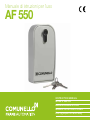 1
1
-
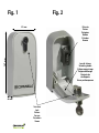 2
2
-
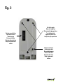 3
3
-
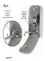 4
4
-
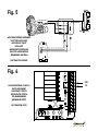 5
5
-
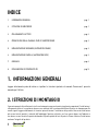 6
6
-
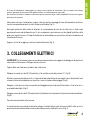 7
7
-
 8
8
-
 9
9
-
 10
10
-
 11
11
-
 12
12
-
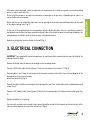 13
13
-
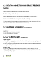 14
14
-
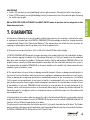 15
15
-
 16
16
-
 17
17
-
 18
18
-
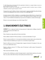 19
19
-
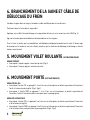 20
20
-
 21
21
-
 22
22
-
 23
23
-
 24
24
-
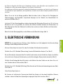 25
25
-
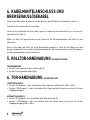 26
26
-
 27
27
-
 28
28
-
 29
29
-
 30
30
-
 31
31
-
 32
32
-
 33
33
-
 34
34
-
 35
35
-
 36
36
-
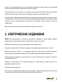 37
37
-
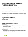 38
38
-
 39
39
-
 40
40
-
 41
41
-
 42
42
-
 43
43
-
 44
44


en otros idiomas
- français: Comunello AF 550 Manuel utilisateur
- italiano: Comunello AF 550 Manuale utente
- English: Comunello AF 550 User manual
- Deutsch: Comunello AF 550 Benutzerhandbuch
- русский: Comunello AF 550 Руководство пользователя
Artículos relacionados
Otros documentos
-
Key Gates Sharp Guía del usuario
-
Telcoma T21 and T31 El manual del propietario
-
Genius TRIGON02 TRIGONK Instrucciones de operación
-
-
Marantec Comfort SU700M El manual del propietario
-
-
Vimar ELVOX EDP4 Guía de instalación
-
Elvox ES series Manual de usuario
-
Tau speed El manual del propietario
-