Pelonis FS45-3ER El manual del propietario
- Categoría
- Ventiladores domésticos
- Tipo
- El manual del propietario

READ AND SAVE THESE INSTRUCTIONS
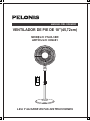
OWNER’S MANUAL
18'' STAND FAN
MODEL: FS45-3ER
ITEM: 809481
145x210mm /YDX/2017.10.10

1
Read Rules for Safe Operation and Instructions carefully.
CAUTION
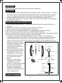
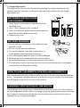
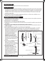
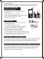
Chassis
Bent anchor bolt
Blade
Front grille
Plastic nut
Motor shaft
Clutch knob
Motor housing
Rear grille
Case
Thumb
screw
Internal
pole
Touch
switch
Tighten
Spinner
Loosen
Fasten
Height
adjustment
ring
Extension
pole
1. This appliance has a polarized plug (one blade is wider than the other). To reduce
the risk of electric shock, this plug is intended to fit in a polarized outlet only one
way. If plug does not fit fully in the outlet, reverse the plug. If it still does not fit,
contact a qualified electrician. Do not attempt to defeat this safely feature.
2. To reduce the risk of fire or electric shock, do not use this fan with any solid state
speed control device.
1. Never insert fingers, pencils, or any other object through the grille when fan is
running.
2. Disconnect fan when moving from one location to another.
3. Disconnect fan when removing grilles for cleaning.
4. Be sure fan is on a stable surface when operating to avoid overturning.
5. Do not use fan in window. Rain may create electrical hazard.
6. Ensure that the fan is switched off from the supply mains before removing the grille.
The rules for safe cord and plug operations are as follows:
1. This product employs overload protection (fuse). A blown fuse indicates an
overload or short-circuit situation. If the fuse blows, unplug the product from the
outlet. Replace the fuse as per the user servicing instructions (follow product
marking for proper fuse rating) and check the products. If the replacement fuse
blows, a short-circuit may
be present and the product
should be discarded or
returned to an authorized
service facility for
examination and/or repair.
2. Do not operate any fan with
a damaged cord or plug.
Discard fan or return to an
authorized service facility
for examination and/or
repair.
3. Do not run cord under
carpeting. Do not cover
cord with throw rugs,
runners, or similar coverings.
Do not route cord under
furniture or appliances.
Arrange cord away from
traffic area and where it will
not be tripped over.
WARNING
RULES FOR SAFE OPERATION
PARTS DIAGRAM

2
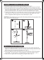
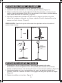
1. Unscrew the bent anchor boltfrom the Extension Pole. (Fig.1)
2. Insert the extension pole into the chassis and tighten the bent anchor bolt (Fig.2)
3. From the extension pole, loosen the height adjustment ring and adjust the internal
pole to the desired height. (Note: If you can’t find the internal pole, might have fallen
inside the extension pole. You can pull it out from the extension pole.) (Fig.3)
4. To attach the head unit to the internal pole, loosen the thumb screw on the bottom
of the head unit. Place the head unit on the internal pole and tighten the thumb
screw in alignment with the groove on the internal pole. (Fig.4)
CAUTION: Height adjustment ring must be fully fastened before the assembly of the
motor section to the internal pole.
ASSEMBLY OF CHASSIS & COLUMN UNIT
Annular groove
Mounting hole
Thumb screw
Fig.3
L
o
o
seen
F
ig.4
Fig
.
1
Fig.2
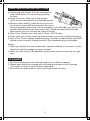
GRILLE & FAN BLADE ASSEMBLY
1. Unscrew the spinner clockwise to remove it from the motor shaft. Unscrew the
plastic nut counterclockwise to remove it from the motor housing. Secure the rear
grille to the motor housing with the plastic nut. (Fig. 5)
2. Insert the blade into shaft, and make sure the rotor shaft pin is fitted into groove
on the blade. Turn the spinner counterclockwise to secure the blade. (Fig. 6)
3. Fasten the front grille and the rear grille by the grille clips. (Fig. 7)

3
OPERATING INSTRUCTIONS
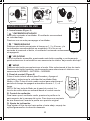
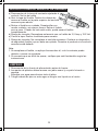
Fig.8
Fig.9
II. Control Panel (Fig.9)
To make the fan oscillate, press the clutch knob located on the
top of the motor housing. To get the directional airflow, pull the
clutch knob up to its initial position.
III. Oscillation Control
To adjust the air flow upward or downward, push the grilles
lightly to the desired direction.
IV. Tilt Adjustment
“ ” ON/OFF KEY
The key is for switching on the fan. The fan will be started at low
speed. Press the key again, it will be switched off.
“ ” TIMER KEY
When this key is touched repeatedly, the time to be set 1,
2 and 4 hours and the correspond pilot lamp will light. If the
lamp don’t light after you touched the key, the fan will run
continuously.
“ ” SPEED KEY
After the fan has started, this key serves as a speed selector in the sequence from
“low-medium-high-low” when this key being touched repeated or continuously.
“ ” MODE KEY
Press this key to select mode. This key is a selector key for wind type. The wind
type changes in the sequence from NORMAL---NATURAL---NORMAL wind when
this key being touched repeatedly or kept in.
I. Remote Controller (Fig.8)
Clip
Fig.5 Fig.6 Fig.7
Press the lower center button to Start and Stop fan and to
select Low, Medium or High fan speed. Press the middle center
button to select 1, 2 or 4 hour automatic shutoff time period
of operation.
NOTE: There is no Mode key on the control panel. Mode
function must be activated from the remote control.

4
1. Press down on the battery compartment cover
and slide it out.
2. Use 2 "AAA" batteries (Not Included)
3. Insert the batteries, making sure that the positive
terminals are facing the proper way.
4. Replace the cover.
BATTERIES INSTRUCTIONS
(not included)
1. Do not dispose of batteries in fire, batteries may
explode or leak.
2. Do not mix old and new batteries.
3. Do not mix alkaline, standard (carbon-zinc) or
rechargeable (nickel-cadmium) batteries.
4. Non-rechargeable batteries are not to be recharged.
5. Batteries are to be inserted with the correct polarity.
6. Exhausted batteries are to be removed from the product.
7. The batteries must be removed from the remote controller before it is scrapped
and that they are disposed of safely.
BATTERY WARNING
The windings of the motor have a thermal-fuse that burns out and the fan switches
off and temperature of the motor is no longer going up so that plastic parts of the fan
don’t subject to deformation so far so to be burned by the overheat if the motor is
overheat for any unexpected reason.
OVERHEAT PROTECTION OF THE MOTOR
Point the remote controller at the receptor on body of the fan and press the desired
button. The remote controller will work at distances of up to roughly 16.40 feet and
at a 30 degree angle from the front of the receiver.
HOW TO USE THE REMOTE CONTROLLER CORRECTLY
The height of the fan can be adjusted by loosening the height adjustment ring,
carefully carefully raising or lowering the fan and firmly re-tightening the height
adjustment ring.
V. Height Adjustment

5
a) Grasp plug and remove from the receptacle or
other outlet device. Do not unplug by pulling
on cord.
b) Open fuse cover. Slide open fuse access
cover on top of attachment plug towards blades.
c) Remove fuse carefully. Insert the tip of your tool
into fuse slot (close with the terminal), then prize
the fuse gradually and slowly, but not overexert. If you feel tight, you can try it at
several times and prize the fuse little by little. When one side of the fuse has
been prized, then you can get the fuse out entirely.
d) Risk of fire. Replace fuse only with 2.5 Amp, 125 Volt fuse.
e) Close fuse cover. Slide closed the fuse access cover on top of attachment plug.
f) Risk of fire. Do not replace attachment plug. Contains a safety device (fuse) that
should not be removed. Discard product if the attachment plug is damaged.
Notice:
1. When you replace the fuse, please don’t operate suddenly or overexert, or else
the product will be damage or cause accident.
2. When you feel it hard to be operated, please make sure you have got the right
way.
USER SERVICING INSTRUCTIONS
CLEANING
1. Be sure to unplug from the electrical supply source before cleaning.
2. Plastic parts should be cleaned with mild soap and a damp cloth or sponge.
Thoroughly to remove soap film with clean water.
3. Be sure not to make water or other liquid enter inside of motor.

6
For questions or comments,please write to:
Midea America Corporation
Customer Care Center
Email us at: [email protected]
1-866-646-4332
fan
11411 NW 107th Street,
Suite 12 Miami, FL 33178

7
ONE (1) YEAR LIMITED WARRANTY
Please read all instructions before attempting to use this product.
In the event of malfunctions or failure of your Fan, simply deliver or send the Fan,
postage prepaid along with PROOF OF PURCHASE, within the warranty period of one (1)
year, to Midea America Corporation. Midea America Corporation reserves the right to
inspect the claimed defective part or parts to determine if the defect or malfunction
complaint is covered by this warranty. Midea America Corporation shall, within sixty(60)days
after receipt of the product, at its option, repair and/or replace the defective part or parts free
of charge. This warranty shall only cover defect arising from normal usage. Midea America
Corporation assumes no responsibility whatsoever if the Fan should fail during the warranty
period by reason of:
Misuse, negligence, physical damage or accidents.
Lack of maintenance (see instructions for proper maintenance).
Repair by any unauthorized party during the warranty period.
Damage caused by connection to an improper input voltage (see specification
label on your Fan).
Midea America Corporation makes no further warranties or representations, express or
implied except those contained herein. No representative or dealer is authorized to assume
any other liability regarding the Fan. The duration of the implied warranty granted under
State law, including warranties of merchantability and fitness for particular purpose are
limited in duration should the duration of the express warranty grant it hereunder. Midea
America Corporation shall in no event be liable for direct, indirect, special or consequential
damages.
Some states do not allow limitations on how long an implied warranty lasts, and/or the above
limitations or exclusion may not apply to you. This warranty gives you specific legal rights
and you may have other rights which vary from state to state.
Midea America Corporation warrants as limited herein to the original purchaser of retail
thateach new Fan, shall be free of defects in material and workmanship for aperiod of
one (1) year from the date of original purchase. This one (1) year warranty is limited to
the Motor and Electric Element.

LEA Y GUARDE ESTAS INSTRUCCIONES
MANUAL DEL USUARIO
VENTILADOR DE PIE DE 18"(45,72cm)
MODELO: FS45-3ER
ARTÍCULO: 809481

8
Lea las normas de seguridad y las instrucciones atentamente.
PRECAUCIÓN
Chasis
Perno de anclaje
Aspas
Rejilla frontal
Tuerca plástica
Eje del motor
Perilla de embrague
Carcasa del
motor
Rejilla posterior
Carcasa
Tornillo
moleteado
Tubo interno
Interruptor
Ajustar
Girador
Aflojar
Ajustar
Anillo de
ajuste de
altura
Tubo de extensión
1. Este aparato tiene un enchufe polarizado (una pata es más ancha que la otra). Para reducir
el riesgo de descarga eléctrica, el enchufe está diseñado para encajar en un tomacorriente
polarizado de una sola manera. Si el enchufe no encaja por completo en el tomacorriente,
inviértalo. Si aún así no encaja, llame a un electricista calificado. No trate de violar esta
medida de seguridad.
2. Para reducir el riesgo de incendio o descarga eléctrica, no utilice este ventilador con un
dispositivo de control de velocidad sólido.
1. No introduzca los dedos, lápices, u cualquier otro objeto a través de las rejillas mientras el
ventilador esté en funcionamiento.
2. Desconectar si va a desplazarlo.
3. Desconectar si va a quitar las rejillas para limpiar.
4. Asegúrese de que el ventilador esté colocado sobre una superficie estable, para evitar que
se vuelque.
5. No utilizar en una ventana. La lluvia representa un peligro eléctrico.
6. Asegúrese de que el ventilador esté desconectado de la fuente de alimentación antes de
quitar las rejillas.
Las normas para operar el cable y el enchufe son las siguientes:
1. Este producto está equipado con una protección contra sobrecarga (fusible). Un fusible
quemado indica que hubo una sobrecarga o un cortocircuito. Si el fusible se quema,
desconecte el aparato de la toma de corriente. Reemplace el fusible de acuerdo a las
instrucciones al usuario (ver el
marcado de producto para el
valor nominal de fusible
apropiado) Si el fusible de
reemplazo se quema, puede
haber un cortocircuito y el
producto debe ser desechado
o llevado a un centro de servicio
autorizado para examinar y/o
reparar.
2. No operar un ventilador con un
cable o enchufe dañado.
Deseche el aparato o llévelo a
un centro de servicio autorizado
para examinar y/o reparar.
3. No pase el cable de
alimentación por debajo de
alfombras. No cubra el cable
con tapetes, alfombras o
similares. No tienda el cable
debajo de muebles u otros
electrodomésticos. Coloque el
cable lejos de áreas de tráfico y
donde no pueda provocar
tropiezos.
ADVERTENCIA
NORMAS DE SEGURIDAD
DIAGRAMA DE LAS PARTES

9
1. Aflojar el perno de anclaje del tubo de extensión (Figura 1).
2. Insertar el tubo de extensión en el cahsis y ajustar el perno (Figura 2).
3. Aflojar el anillo de ajuste de altura desde el tubo de extensión y colocar el tubo
interno a la altura deseada (Nota: Si no encuentra el tubo interno, puede haberse
caído dentro del tubo de extensión) (Figura 3)
4. Para fijar la cabeza del ventilador al tubo interior, afloje el tornillo en la parte
inferior de la cabeza, colóquela en el lugar y ajuste el tornillo alinéandolo con la
ranura en el tubo interior. (Figura 4)
PRECAUCIÓN: El anillo de ajuste debe estar bien ajustado antes de instalar el
motor al tubo interior.
MONTAJE DEL CHASIS Y LA COLUMNA
Aflojar
Ranura
Tornillo
Anillo
Figura 1 Figura 2
Figura 3 Figura 4
MONTAJE DE LAS ASPAS Y REJILLAS
1. Destornillar el centro giratorio hacia la derecha para sacarlo del motor.
Destornillar la tuerca de plástico hacia la izquierda para sacarla de la carcasa.
Ajustar la rejilla posterior a la carcasa del motor con la tuerca de plástico. (Figura 5)
2. Insertar las aspas en el eje, asegurándose de que el eje giratorio quede bien
ajustado. Girar en el sentido contrario a las agujas del reloj para ajustar las aspas.
(Figura 6)
3. Sujetar las rejillas con los clips. (Figura 7)

10
INSTRUCCIONES DE USO
Figura 8
Figura 9
II. Panel de control (Figura 9)
III. Control de oscilación
Para hacer que el ventilador oscile, presione la perilla en la
parte superior de la carcasa del motor. Para tener una corriente
de aire direccional, levante la perilla a su posición original.
IV. Ajuste de inclinación
Para ajustar el flujo de aire hacia arriba o hacia abajo, empuje las
rejillas ligeramente a la dirección deseada.
“ ” ENCENDIDO/APAGADO
Este botón enciende el ventilador. El ventilador se encenderá
en velocidad baja.
Presione una vez más para apagar el ventilador.
“ ” TEMPORIZADOR
Presione este botón para ajustar el tiempo en 1, 2 y 4 horas, y la
luz indicadora correspondiente se encenderá. Si la luz no se
enciende al presionar el botón, el ventilador funcionará continuamente
sin apagarse.
“ ” VELOCIDAD
Con el ventilador encendido, presionando este botón repetida o continuamente
puede seleccionar la velocidad en una secuencia de niveles "bajo-medio-alto-bajo".
“ ” MODO
Presione este botón para seleccionar el modo. Esto seleccionará el tipo de viento.
Presione este botón repetida o continuamente para seleccionar el viento en una
secuencia de NORMAL---NATURAL---NORMAL.
I. Control remoto (Figura 8)
Figura 5 Figura 6 Figura 7
Centro
giratorio
Centro
giratorio
Ajustar
Ajustar
Ranura
Aspas
Clip
Pin de
sujeción
Aflojar
Tuerca plástica
Pulse el botón inferior central para Encender y Apagar el
ventilador y seleccionar la velocidad del ventilador Baja,
Media, o Alta. Pulse el botón medio central para seleccionar el
período de tiempo de apagado automático durante 1, 2, o 4
horas.
NOTA: No hay tecla de Modo en el panel de control. La
función de modo debe ser activada desde el control remoto.

V. Ajuste de altura
La altura puede ajustarse aflojando el anillo de ajuste de altura, levantando o
bajando el ventilador con cuidado y volviendo a ajustar el anillo firmemente.
11
1. Presione la tapa del compartimento de pilas
para retirarlo.
2. Utilice 2 pilas "AAA" (no incluidas).
3. Inserte las pilas asegurándose de que los extremos
positivos estén hacia el lado correcto.
4. Vuelva a colocar la tapa.
INSTRUCCIONES PARA
PILAS (no incluidas)
1. No deseche las pilas en fuego, ya que pueden
explotar o tener fugas.
2. No combine pilas viejas y nuevas.
3. No combine pilas alcalinas y estándar (línea de
carbono) y pilas recargables (níquel-cadmio).
4. No intente recargar pilas no recargables.
5. Inserte las pilas con la polaridad correcta.
6. Las pilas agotadas deben ser removidas del producto.
7. Quitar las pilas del control remoto antes de desecharlo
y asegúrese de eliminarlas de forma segura.
ADVERTENCIA
Los bobinados del motor poseen un fusible térmico que se quema para apagar el
motor y que la temperatura del ventilador no siga subiendo, para evitar que las
partes plásticas no se deformen o se quemen en caso de que el motor se
sobrecaliente por alguna razón imprevista.
PROTECCIÓN CONTRA SOBRECALENTAMIENTO DEL MOTOR
Apunte el control remoto al receptor en el cuerpo del ventilador y presione el botón
de la función deseada. El control remoto funcionará a distancias de hasta 16.40
pies y en ángulos de hasta 30 grados desde la parte delantera del receptor.
CÓMO USAR EL CONTROL REMOTO
Control remoto
Batería
Cubierta de
la batería

12
a) Desconectar de la toma de corriente sujetando el
enchufe. No tire del cable.
b) Abrir la tapa del fusible. Deslice la cubierta de
acceso al fusible en la parte superior del enchufe
accesorio para abrirla.
c) Retirar el fusible con cuidado. Desatornillar con
mucho cuidado y sin ejercer fuerza. Retire el fusible
poco a poco. Cuando un lado esté suelto, podrá sacar el fusible
completamente.
d) Riesgo de incendio. Reemplazar solamente con un fusible de 2,5 Amp y 125 Volt.
e) Cerrar la tapa. Deslice la cubierta para cerrarla.
f) Riesgo de incendio. No reemplace el enchufe accesorio. Contiene un dispositivo
de seguridad (fusible) que no debe ser quitado. Deseche el producto si el enchufe
accesorio está dañado.
Nota:
1. Al reemplazar el fusible, no aplique fuerza sobre él, o de lo contrario puede
dañarlo o causar un accidente.
2. Si encuentra que es difícil de operar, verifique que esté haciéndolo según las
instrucciones.
INSTRUCCIONES DE SERVICIO DE USUARIO
LIMPIEZA
1. Desconectar de la fuente de alimentación antes de limpiar.
2. Las partes de plástico deben lavarse con jabón suave y un paño húmedo o
esponja.
Enjuagar con agua para eliminar todo el jabón.
3. Tenga cuidado de que no entre agua ni ningún otro líquido en el motor.

13
SERVICIO Y SOPORTE
En caso de reclamos de garantía o si se necesita servicio para este ventilador, por favor,
póngase en contacto con nosotros a los siguientes números:
Gratis: 1-866-646-4332
Envíenos un mensaje de correo electrónico a:
Para preguntas o comentarios, por favor escriba a:
Midea America Corporation
Customer Care Center
Para su registro, engrape su recibo de compra a este manual y registre lo siguiente:
FECHA DE COMPRA: ________________________________
_
______________
_
LUGAR DE COMPRA: ________________________________
_
______________
_
(ENGRAPE EL RECIBO DE VENTA AQUÍ)
NOTA: SE REQUIERE UNA PRUEBA DE
COMPRA PARA TODOS LOS RECLAMOS
DE GARANTÍA
IMPRESO EN CHINA
11411 NW 107th Street,
Suite 12 Miami, FL 33178

14
GARANTÍA LIMITADA DE UN (1) AÑOS
Por favor lea todas las instrucciones antes de intentar utilizar este producto.
Mal uso, negligencia, daño físico o accidentes.
Falta de mantenimiento (vea las instrucciones de mantenimiento adecuado).
Reparación por alguna parte no autorizada durante el período de garantía.
Daños causados por conexión a un voltaje inapropiado (vea la etiqueta de
especificación en su Ventilador).
Midea America Corporation no ot orga más garantías o representaciones, expresas o implícitas
excepto las que se mencionan aquí. Ningún representante o vendedor está autorizado a asumir
cualquier otra responsabilidad relacionada con el Calefactor con ventilador. La duración de la
garantía implícita otorgada bajo las leyes del Estado, incluyendo garantías de comercialización y
aptitud para un propósito en particular están limitadas en duración si l
a duración de la garantía
expresa lo otorgara a continuación.Midea America Corporation no será en ningún caso responsable
por daños directos, indirectos, especiales o consecuenciales.
Algunos estados no permiten limitaciones sobre la duración de una garantía implícita, y/o las
limitaciones o exclusiones anteriores pueden no aplicarse a usted. Esta garantía le ofrece
derechos legales específicos y usted puede tener otros derechos, que varían de estado a
estado.
●
●
●
●
●
Midea America Corporation ntiza de forma limitada, como se explicita aquí, al comprador original
que cada Ventilador nuevo estará libre de defectos de materiales o mano de obra por el período
de un (1) años desde la fecha de la compra original. Esta garantía de un (1) años está limitada a
los motor,y elementos de calefacción.
En caso de mal funcionamiento o avería de su Ventilador simplemente lleve o envíe el
valentador, con un envío prepago junto con una PRUEBA DE COMPRA, dentro del período de la
garantía de un (1) años, a Midea America Corporation. Midea America Corporation se reserva el
derecho de inspeccionar la parte o partes supuestamente defectuosas para determinar si el
reclamo por defecto o mal funcionamiento está cubierto por esta garantía. Dentro de los sesenta
(60) días de recibido el producto, Midea America Corporation , a su elección, reparará y/o
reemplazará la parte o partes defectuosas sin cargo alguno. Esta garantía sólo cubrirá defectos que
surjan de una utilización normal. Midea America Corporation no asume ninguna responsabilidad si el
Calefacotr con Ventilador se averiara durante el período de la garantía debido a:
-
 1
1
-
 2
2
-
 3
3
-
 4
4
-
 5
5
-
 6
6
-
 7
7
-
 8
8
-
 9
9
-
 10
10
-
 11
11
-
 12
12
-
 13
13
-
 14
14
-
 15
15
-
 16
16


Pelonis FS45-3ER El manual del propietario
- Categoría
- Ventiladores domésticos
- Tipo
- El manual del propietario
en otros idiomas
- English: Pelonis FS45-3ER Owner's manual
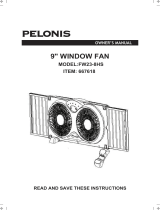
Artículos relacionados
-
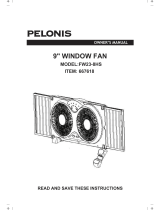 Pelonis FW23-8HS El manual del propietario
-
 Utilitech FW23-8HS El manual del propietario
-
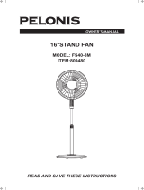 Pelonis FS40-8M El manual del propietario
-
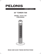 Pelonis FZ10-17JR El manual del propietario
-
 Pelonis FS45-9L El manual del propietario
-
 Utilitech FS45-9L El manual del propietario
-
 Utilitech 809486 El manual del propietario
-
 Pelonis FZ10-19JR Manual de usuario
-
Easy@Home NF15-17P Manual de usuario


Otros documentos
-
 Utilitech FB50-17H Instrucciones de operación
-
Kenmore 35182 El manual del propietario
-
-
 Utilitech FB50-16HB Guía del usuario
-
Toshiba F-AXW50(BK)US Manual de usuario
-
 Continental Electric CE27616 Manual de usuario
-
-
 Continental Electric CE27616 Manual de usuario
-
Svan SVVE16P4 El manual del propietario
-
 Star Max STFFS45-3DF El manual del propietario


