Pelonis FS45-9L El manual del propietario
- Categoría
- Ventiladores domésticos
- Tipo
- El manual del propietario

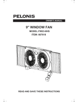
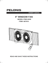
OWNER’S MANUAL
18" OUTDOOR MISTING FAN
MODEL: FS45-9L
ITEM: 758415
READ AND SAVE THESE INSTRUCTIONS

1. Fan should be used under rated voltage.
2. Connect power after the fan is fully assembled.
3. Never insert fingers, pencils, or any other object through the guard when fan is running.
4. Unplug from outlet when: not in use, when moving fan from one location to another, before putting on or
taking off parts, and before cleaning.
5. Disconnect fan when removing grilles for cleaning.
6. Be sure fan is on a stable surface when operating to avoid overturning.
7. Do not operate any fan with a damaged cord or plug. Discard fan or return to an authorized service facility
for examination and/or repair .
8. Do not run cord under carpeting. Do not cover cord with throw rugs, runners,or similar coverings. do not
route cord under furniture or appliances. Arrange cord away from traffic area and where it will not be
tripped over.
9. Press the TEST button (then RESET button) every month to assure proper operation.
RULES FOR SAFETY OPERATION
Read Rules for Safe Operation and Instructions Carefully.
CAUTION
1. To reduce the risk of fire or electric shock, do not use this fan with any solid state speed control device.
2. This product must be grounded. If it should malfunction or break down, grounding provides a path of least
resistance for electric current to reduce the risk of electric shock. This product is equipped with a cord
having an equipment-grounding conductor and a grounding plug. Plug into an appropriate outlet that is
properly installed and grounded in accordance with all local codes and ordinances.
3. This fan is provided with a ground fault circuit interrupter (GFCI) built into the power supply cord. This device
provides additional protection from the risk of electric shock. Should replacement of the plug or cord
become necessary, use only identical replacement parts that include GFCI protection.
4. Do not leave the fan running unattended.
5. This product employs overload protection (fuse). A blown fuse indicates an overload or short-circuit situation.
If the fuse blows, unplug the product from the outlet. Replace the fuse as per the user servicing instructions
(follow product marking for proper fuse rating) and check the product. If the replacement fuse blows, a
short-circuit may be present and the product should be discarded or returned to an authorized service facility
for examination and/or repair.
6. Risk of fire. Do not replace attachment plug. Contains a safety device (fuse,) that should not be removed.
Discard product if the attachment plug is damaged.
WARNING
1
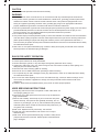
USER SERVICING INSTRUCTIONS
a) Grasp plug and remove from the receptacle or other outlet device. Do
not unplug by pulling on cord.
b) Open fuse cover. Slide open fuse access cover on top of attachment
plug towards blades.
c) Remove fuse carefully. Insert the tip of your tool into fuse slot (close
with the terminal), then prize the fuse gradually and slowly, but not
overexert. If you feel tight, you can try it at several times and prize the
fuse little by little. When one side of the fuse has been prized, then you
can get the fuse out entirely.
d) Risk of fire. Replace fuse only with 5 Amp, 125 Volt fuse.
e) Close fuse cover. Slide closed the fuse access cover on top of
attachment plug.
f ) Risk of fire. Do not replace attachment plug. Contains a safety device
(fuse) that should not be removed. Discard product if the attachment
plug is damaged.

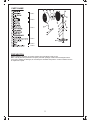
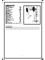
PREPARATION
Before beginning assembly of product, Please have screwdriver ready to use.
Make sure all parts are presentand Compare parts with package contents list and diagram above.
If any part is missing or damaged, do not attempt to assemble the product. Contact customer service
for replacement parts.
2
PARTS NAME
Part 5
Part 6
Part 1
Part 2
Part 3
Part 4
A
B
C
D
F
G
E
I
H
J
U
T
S
R
Q
L
M
P
O
K
N

3
B D E F
CA
Fig. 2 Fig. 3
Fasten
O
N
P
T
U
Fig. 1
Fig. 4
J
L
N
M
Q
O
OPERATING INSTRUCTION
1. Place the fan on a level surface. Plug the grounding type attachment plug into a standard 120V AC
3-Prong wall outlet.
2. Attach the Valve(S) onto a standard outdoor hose. Turn your water on at the spigot and use the lever on the
Valve(S) to turn water on and off.
3. To turn oscillation mode on, push the Clutch Knob (G). Pull the Clutch Knob (G) up to turn oscillation off.
4. To adjust the air flow upward or downward, simply tilt the fan head with hand and move to desired angle.
5. Control speed by pushing the desired button :
0 - OFF, 1 - low, 2 - medium, 3 - high
6. The height of the fan can be adjusted by loosening the height adjustment Knob (O) and carefully adjusting the
Internal Pole(N). the fan and retightening Height adjustment Knob(O). Always ensure the waterproof Cover(L)
covers the Height adjustable Knob(O) after adjusting the Internal Pole(N).
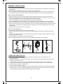
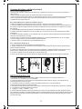
ASSEMBLY INSTRUCTIONS
Step 1. Fan Base Assembly (Fig. 1)
1. Unscrew the Screw (U) from the external Pole (P) and attach the external Pole (P) to the Base (T) by tightening
the Screw(U).
2. Remove the height adjustment Knob (O) by unscrewing it counterclockwise.
3. Use your finger to pull out the internal Pole(N), slide height adjustment Knob (O) over internal Pole (N). Fasten
it to external Pole (P) by turning the knob while holding the pole. Make sure the Knob (O) is tightly fastened.
Step 2. Fan Head Assembly (Fig. 2)
1. Remove the blade Cap (B) by turning clockwise. Remove the plastic Nut (D) by turning counter clockwise.
2. Position the rear Grille(E) over the motor Shaft(F), make certain the handle is at the top and the one notch in the
rear of rear Grille(E) cover fit over the three prong on the motor Housing(H).
3. Secure rear Grille(E) by turning the plastic Nut(D) clockwise a
nd tightening firmly.
4. Slide the fan Blade(C), with the hollow interior of the blade facing toward rear Grille(E), onto motor Shaft(F).
5. Secure Fan Blade(C) onto motor Shaft(F) by turning the blade Cap (B)counterclockwise until it firmly in place.
6. Loosen the bolt on the bottom of the Front Grille(A) and mount the Front Grille(A) with the logo right side up to the
Rear Grille ( E) by snapping both tog
ether firmly.Ensure all snaps around the Front Grille(A) are secure on the
Rear Grille (E).
7. Tighten the bolt on the bottom of the Front Grille(A).
Step 3. Final Assembly (Fig. 4)
1. Loosen the thumb Screw (J) by turning it counter clockwise.
2. Always keep the water proof Cover(L) match with the height adjustable Knob (O)when adjusting the internal
Pole(N).
3. Insert internal Pole(N) into the neck joint
and tighten by turning thumb Screw(J) clockwise. Make sure it is tight
enough to support the fan head.
4.Attach the Misting Line Holder(M) onto the Internal Pole(N).
5.Secure the Misting Line(Q) to the clip under the Front Grille(A) and the Misting Line Holder(M).

4
CLEANING
1. Be sure to unplug the power cord from the outlet before cleaning.
2. Plastic parts should be cleaned with mild soap and damp cloth or sponge. Thoroughly remove soap film with
clean water.
3. Be sure not to get water or other liquid enter the inside of the motor.
TROUBLESHOOTING
1. Problem
Misting features sputters or does not mist at all.
Solution
● Ensure your outside water faucet is turned all the way on.
● Check the fan's valve lever and make sure it set open.
● Check water hose for kinks or buckles.
● The valves on the fan may be clogged. Follow the instructions in the "Misting nozzles Maintenance" section
above.
2. Problem
Fan will not run.
Solution
● Ensure the fan is plugged in.
● Check the GFCI on the fan's plug. If the window is black the GFCI has been tripped and needs to be reset.
● Press the "RESET" button on the plug. If the GFCI window is orange then the circuit is active and does not
need to be reset.
3. Problem
Fan will not oscillate.
Solution
● Ensure the oscillation knob on the fan is pressed in.
4. Problem
GFCI continues to activate.
Solution
● Try using a different power outlet.
MAINTENANCE INSTRUCTION
The fan requires little maintenance. Do not try to fix it by yourself. Refer it to qualified service personnel if
service is needed.
1. Before cleaning and assembling, do not plug the pins into the socket.
2. To ensure adequate air circulation to the motor. Keep vents at the rear of the motor housing from dust, fluff
and etc. A vacuum cleaner can not be used to clean these vents before unplug. Do not disassemble the
fan remove fluff.
3. Please wipe the exterior parts with a soft cloth soaking a mild detergent.
Do not use any abrasive detergent or solvents to avoid scratching the sufrace.
Do not use of the following as a cleaner: gasoline, thinner, bending.
4. Do not allow water or any other liquid into the motor housing or interior parts.
Misting Nozzle Maintenance:
1. To clean the misting nozzles, use a pair of needles nose pliers to twist each nozzle counterclockwise.
2. Once removed, soak the nozzles in white vinegar for 2 hours.
3. Rinse each nozzle with water and place back into the front fan grill.
4. Twist clockwise until secure. DO NOT over tighten.
GFCI OPERATION
The GFCI in the power supply cord of this fan has 2 buttons "TEST" and "RESET". If you wish to see if the GFCI
circuit is functioning properly press the "TEST" button. The fan will immediately shut off as if the GFCI has been
activated and the window between the button will change to black. This lets you know the GFCI circuit has been
activated. Press the "RESET" button and the fan can be turned on again and the window between the buttons
will show orange. This indicates the GFCI circuit has not been activated and the fan should operate normally.

5
For questions or comments,please write to:
Midea America Corporation
Customer Care Center
Email us at: [email protected]
1-866-646-4332
fan
11411 NW 107th Street,
Suite 12 Miami, FL 33178

6
ONE (1) YEAR LIMITED WARRANTY
Please read all instructions before attempting to use this product.
In the event of malfunctions or failure of your Fan, simply deliver or send the Fan,
postage prepaid along with PROOF OF PURCHASE, within the warranty period of one (1)
year, to Midea America Corporation. Midea America Corporation reserves the right to
inspect the claimed defective part or parts to determine if the defect or malfunction
complaint is covered by this warranty. Midea America Corporation shall, within sixty(60)days
after receipt of the product, at its option, repair and/or replace the defective part or parts free
of charge. This warranty shall only cover defect arising from normal usage. Midea America
Corporation assumes no responsibility whatsoever if the Fan should fail during the warranty
period by reason of:
Misuse, negligence, physical damage or accidents.
Lack of maintenance (see instructions for proper maintenance).
Repair by any unauthorized party during the warranty period.
Damage caused by connection to an improper input voltage (see specification
label on your Fan).
Midea America Corporation makes no further warranties or representations, express or
implied except those contained herein. No representative or dealer is authorized to assume
any other liability regarding the Fan. The duration of the implied warranty granted under
State law, including warranties of merchantability and fitness for particular purpose are
limited in duration should the duration of the express warranty grant it hereunder. Midea
America Corporation shall in no event be liable for direct, indirect, special or consequential
damages.
Some states do not allow limitations on how long an implied warranty lasts, and/or the above
limitations or exclusion may not apply to you. This warranty gives you specific legal rights
and you may have other rights which vary from state to state.
Midea America Corporation warrants as limited herein to the original purchaser of retail
thateach new Fan, shall be free of defects in material and workmanship for aperiod of
one (1) year from the date of original purchase. This one (1) year warranty is limited to
the Motor and Electric Element.

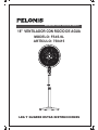
MANUAL DEL PROPIETARIO
18" VENTILADOR CON ROCÍO DE AGUA
MODELO: FS45-9L
ARTÍCULO: 758415
LEA Y GUARDE ESTAS INSTRUCCIONES

INSTRUCCIÓN DE SERVICIO DE PROPIETARIO
a) Tome el enchufe y retírelo de la toma o el dispositivo de salida de otros.
No desenchufe la máquina tirando del cordón.
b) Abra la tapa del fusible. Deslice abriendo la tapa de fusibles de acceso
en la parte superior del enchufe hacia las paletas de ventilador.
c) Retire el fusible con cuidado. Presione el fusible del otro lado o de
vuelta la caja de fusible para quitar el fusible.
d) Riesgo de incendio. Reemplace el fusible únicamente con 5 amperios,
125 voltios fusible.
e) Cierre la tapa de fusibles. Deslize cerrando la tapa de fusibles de
acceso en la parte superior del enchufe.
f) Riesgo de incendio. No sustituya enchufe. Contiene un dispositivo de
seguridad (fusible) que no se debe quitar. Deseche producto si el
enchufe está dañado.
1.Debe utilizar el ventilador debajo del voltaje nominal.
2.Se conecta a la fuente eléctrica después de montar bien el ventilador.
3. Nunca inserte sus dedos, lápices o cualquier otro objeto en el compartimiento cuando el ventilador torre esta
funcionando. Desconéctelo cuando vaya a moverlo de un lugar a otro.
4. Desenchufe desde el tomacorriente cuando: no utilizar el ventilador, moverlo d
esde un sitio a otro, montar o
desmontar las piezas de repuestos o limpiarlo.
5. Desconecte el ventilador al limpiar.
6. Asegúrese que el ventilador esta en una superficie estable cuando funciona.
7. NO opere ningún ventilador con un cordón o enchufe dañado. Deseche o devuelva el ventilador a un centro
de servicio autorizado para su revisión y/o reparación.
8. NO arrastre el cordón por debajo de la alfombra. N
o cubra el cordón con alfombras, tapetes o cubiertas
similares. No encamine el cordón debajo de los muebles o electrodomésticos. Arregle el cordón lejos de zonas de
tráfico y donde no se tropiece con ellos.
REGLAS DE OPERACION SEGURA
Lea las reglas de seguridad operacional y las instrucciones con cuidado.
CAUCIÓN
ADVERTENCIA
7
1. Para reducir el riesgo de incendio o choque eléctrico, NO use este ventilador con ningún dispositivo de estado
sólido para control de velocidad.
2. El producto debe conectarse a tierra. Si se funciona mal o se daña, la conexión a tierra se proporciona una ruta
de menor resistencia para la corriente eléctrica para reducir el riesgo del choque eléctrico. Se equipa con un cable
con un conductor de c
onexión a tierra y un enchufe de conexión a tierra. Debe enchufarlo en un tomacorriente
adecuado y conectarse a tierra de acuerdo a todos los códigos y decretos locales.
3. Este ventilador posee un interruptor de circuito con descarga a tierra (GFCI) integrado en el cable de
alimentación. Este dispositivo proporciona protección adicional contra el riesgo de descarga eléctrica. En caso de
que sea necesario reemplazar el enchufe o el cable, utilice únicamente piezas de repuesto idénticas que incluyan
protección GFCI.
4. No deje el ventilador en funcionamiento sin vigilancia.
5. Este producto está equipado con protección contra sobrecargas (fusible). Un fusible quemado indica que hubo
una sobrecarga o un cortocircuito. Si el fusible se funde, desconecte el aparato de la toma de corriente.
Reemplazar el fusible de acuerdo a las instrucciones de uso (ver el marcado de producto para el valor de fusible) y
revisar el producto. Si el fusible de reemplazo se funde, puede haber un cortocircuito y el producto debe ser
desechado o llevado a un centro de servicio autorizado para examinar y/o reparar.
6. Riesgo de incendio. No reemplace el enchufe accesorio. Éste contiene un dispositivo de seguridad (fusible) que
no debe ser retirado. Deseche el producto si el enchufe accesorio está dañado.
9. Presione el botón TEST (y luego el botón RESET) cada mes para asegurar un funcionamiento adecuado.

PREPARACIÓN
Antes de comenzar a ensamblar el producto, asegúrese de tener todas las piezas. Compare las piezas con la lista
del contenido del paquete y el diagrama anterior. No intente ensamblar el producto si falta alguna pieza o si éstas
están dañadas. Póngase en contacto con el Departamento de Servicio al Cliente para obtener piezas de repuesto.
8
NOMBRE DE PARTES
Parte 1
Parte 2
Parte 3
Parte 4
Parte 5
Parte 6
A
B
C
D
F
G
E
I
H
J
U
T
S
R
Q
L
M
P
O
K
N

9
Conexion de la base y del barral principal
INSTRUCCIONES DE USO
1. Coloque el ventilador sobre una superficie nivelada. Insertar el enchufe con conexión a tierra en un
tomacorriente de 3 entradas de 120 V CA estándar.
2. Conecte la Válvula (S) en una manguera de salida estándar. Abra el agua en el grifo y use la palanca en la
Válvula (S) para abrir o cortar el agua.
3. Para activar el modo de oscilación, presione la Perilla de oscilación (H). Tire de la Perilla de
oscilación (H) hacia arriba para cesar la oscilación.
4. Para ajustar el flujo del aire hacia arriba o hacia abajo, empuje suavemente las guardas en la dirección deseada.
5. La velocidad es controlada oprimiendo las teclas.
0 – Apagado, 1 – Baja, 2 – Media, 3 – Alta
6. Ajuste la altura del ventilador agarrando firmemente el Poste interno (N), aflojando la Perilla de ajuste de altura
(O) y ajustando el ventilador a la altura deseada. Apriete la Perilla de ajuste de altura (O) girándola en sentido horario.
Siempre asegúrese de que la Cubierta impermeable (L) cubra la Perilla de ajuste de altura (O) después de ajustar
el Poste interno (M).
Paso 2 Ensamblaje de la cabeza del ventilador (Fig. 2)
1.Retire la tapa(B) de la cuchilla girando hacia la derecha. Deseche el manguito de plástico(D).
2. Coloque el Rejilla posterior(E) sobre el eje del motor(F), asegúrese que la manija está en la parte superior y la
única muesca está en la parte trasera de la cubierta de rejilla posterior (E), ajuste las tres clavijas en la carcasa
del motor(H).
3. Asegure Rejilla posterior(E) de plástico en sentido(D) horario y apretar firmemente.
4. Deslice la pala del ventilador(C) en el eje del motor con el hueco interior de la hoja orientados hacia rejilla
posterior(E),.
5. Asegure el Aspa del ventilador (C) en el Eje del motor (F) girando la Tapa de aspa (B) en sentido antihorario
hasta que esté firmemente en su lugar.
6. Afloje el perno en l
a parte inferior de la Rejilla delantera (A) y monte la Rejilla delantera (A) con el logotipo
vertical a la Rejilla posterior (E) presionándolas juntas firmemente.
7. Apriete el perno en la parte inferior de la Rejilla delantera (A).
Paso 3 Ensamblaje Final (Fig. 4)
1. Afloje el Tornillo de mano (J) girándolo en sentido antihorario.
2. Siempre asegúrese de que la Cubierta impermeable (M) cubra la Perilla de aju
ste de altura (O) después de
ajustar el Poste interno (M).
3. Inserte el Poste interno (N) en la unión de cuello del Alojamiento y apriete girando el Tornillo de mano (J) en
sentido horario. Asegúrese de que está suficientemente apretado para oportar el motor del ventilador.
4. Conecte el Soporte de tubo de niebla (M) en el Poste interno (N).
5 Fije el Tubo de niebla (Q) al gancho debajo de la Rejilla
delantera (A) y del Soporte de tubo de niebla (M).
Paso 1 Fan de la Asamblea (Fig.1).
1.Desenrosque el tornillo dedo (u) del polo externo (P) y adjuntar el polo externo (P) a la base (T) apretando el
dedo screw (u).
2.Retire la perilla de ajuste de altura (o) desenroscandola en sentido antihorario.
3.Use su dedo para sacar el polo interior (n), Slide perilla de ajuste de altura (o) mas polo interior (n).Sujetar A polo
externo (P) girando la perilla mientras sostiene el poste.Asegúrese de que el mando (o) es fuertemente
montaje final. abrochados Antes del
B D E F
CA
Fig. 2 Fig. 3
Fasten
O
N
P
T
U
Fig. 1
Fig. 4
J
L
N
M
Q
O

El ventilador no necesita mucho mantenimiento. No intente repararlo usted mismo.
Contacte a un centro de reparación calificado si es necesario.
1. No lo enchufe antes de limpiarlo o ensamblarlo.
2. Asegúrese de que el motor tenga suficiente ventilación. Mantenga limpios los respiraderos del motor en la
parte trasera de la carcasa. No use una aspiradora para limpiar éstos sin primero desconectar el ventilador.
No desarme el ventilador para limpiarlo.
3. Use un paño suave y detergente no abrasivo para limpiar el exterior. No use solventes o
productos abrasivos
que pudieran rayar la superficie. No use gasolina o quitapinturas para limpiar el ventilador.
4. Asegúrese de que no entre agua u otros líquidos en el motor o en las partes interiores.
Mantenimiento de boquillas de niebla:
1. Para limpiar las boquillas de niebla, use un par de alicates de punta de aguja para doblar cada boquilla
en sentido antihorario.
2. Después de retiradas, sumerja las boquillas en vinagre blanco por 2 horas.
3. Enjuague cada boquilla con agua y colóquelas nuevamente en la rejilla delantera del ventilador.
4. Gire en sentido horario para asegurarla. NO apriete
demasiado.
INSTRUCCIÓNES DE MANTENIMIENTO
OPERACIÓN DEL GFCI
1. Asegúrese de que el cable de poder este desconectado del tomacorriente antes de limpiar.
2. Las partes plásticas deben ser limpiadas con una paño húmedo o esponja con detergente suave.
Luego remueva la capa de detergente con agua limpia.
3. Asegúrese que ninguna parte adentro del motor sea tocada por agua u otro liquido.
LIMPIANDO
1.Problema
La función de niebla es muy irregular o no hace niebla en absoluto.
Solución
● Asegúrese de que la llave de agua exterior esté totalmente abierta.
● Verifique que la palanca de la válvula del ventilador esté abierta.
● Revise que la manguera de agua no se haya estrangulado o deformado.
● Las válvulas en el ventilador pueden estar obstruidas. Siga las instrucciones en la sección “Mantenimiento
de boquillas de niebla” de esta manual.
2. Problema
El ventilador no funciona.
Solución
● Asegúrese de que el ventilador esté conectado.
● Verifique el GFCI en el
enchufe del ventilador. Si la ventana está negra, el GFCI ha disparado y debe ser
repuesto.Presione el botón “Reset” en el enchufe. Si la ventana del GFCI es naranja, el circuito está activo y
no necesita ser repuesto.
3.Problema
El ventilador no oscila.
Solución
● Asegúrese de que la perilla de oscilación en el ventilador esté presionada.
4.Problema
El GFCI sigue activándose.
Solución
● Pruebe otra vez usando otra toma de corriente.
LOCALIZACIÓN DE FALLAS
10
El GFCI en el cable de alimentación de este ventilador tiene 2 botones: "TEST" y "RESET". Si desea verificar que
el circuito GFCI esté funcionando correctamente, presione el botón "TEST". El ventilador se apagará de inmediato,
como si se hubiera activado el GFCI, y la ventana entre los botones se volverá negra. Esto indica que el circuito
GFCI se ha activado. Presione el botón "RESET" y el ventilador puede volver a encenderse. La ventana entre los
botones será naranja. Esto indica que el circuito GFCI no ha sido activado y que el ventilador debe funcionar
normalmente.

11
SERVICIO Y SOPORTE
En caso de reclamos de garantía o si se necesita servicio para este ventilador, por favor,
póngase en contacto con nosotros a los siguientes números:
Gratis: 1-866-646-4332
Envíenos un mensaje de correo electrónico a:
Para preguntas o comentarios, por favor escriba a:
Midea America Corporation
Customer Care Center
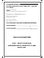
Para su registro, engrape su recibo de compra a este manual y registre lo siguiente:
FECHA DE COMPRA: ________________________________
_
______________
_
LUGAR DE COMPRA: ________________________________
_
______________
_
(ENGRAPE EL RECIBO DE VENTA AQUÍ)
NOTA: SE REQUIERE UNA PRUEBA DE
COMPRA PARA TODOS LOS RECLAMOS
DE GARANTÍA
IMPRESO EN CHINA
11411 NW 107th Street,
Suite 12 Miami, FL 33178

12
GARANTÍA LIMITADA DE UN (1) AÑOS
Por favor lea todas las instrucciones antes de intentar utilizar este producto.
Mal uso, negligencia, daño físico o accidentes.
Falta de mantenimiento (vea las instrucciones de mantenimiento adecuado).
Reparación por alguna parte no autorizada durante el período de garantía.
Daños causados por conexión a un voltaje inapropiado (vea la etiqueta de
especificación en su Ventilador).
Midea America Corporation no ot orga más garantías o representaciones, expresas o implícitas
excepto las que se mencionan aquí. Ningún representante o vendedor está autorizado a asumir
cualquier otra responsabilidad relacionada con el Calefactor con ventilador. La duración de la
garantía implícita otorgada bajo las leyes del Estado, incluyendo garantías de comercialización y
aptitud para un propósito en particular están limitadas en duración si l
a duración de la garantía
expresa lo otorgara a continuación.Midea America Corporation no será en ningún caso responsable
por daños directos, indirectos, especiales o consecuenciales.
Algunos estados no permiten limitaciones sobre la duración de una garantía implícita, y/o las
limitaciones o exclusiones anteriores pueden no aplicarse a usted. Esta garantía le ofrece
derechos legales específicos y usted puede tener otros derechos, que varían de estado a
estado.
●
●
●
●
●
Midea America Corporation ntiza de forma limitada, como se explicita aquí, al comprador original
que cada Ventilador nuevo estará libre de defectos de materiales o mano de obra por el período
de un (1) años desde la fecha de la compra original. Esta garantía de un (1) años está limitada a
los motor,y elementos de calefacción.
En caso de mal funcionamiento o avería de su Ventilador simplemente lleve o envíe el
valentador, con un envío prepago junto con una PRUEBA DE COMPRA, dentro del período de la
garantía de un (1) años, a Midea America Corporation. Midea America Corporation se reserva el
derecho de inspeccionar la parte o partes supuestamente defectuosas para determinar si el
reclamo por defecto o mal funcionamiento está cubierto por esta garantía. Dentro de los sesenta
(60) días de recibido el producto, Midea America Corporation , a su elección, reparará y/o
reemplazará la parte o partes defectuosas sin cargo alguno. Esta garantía sólo cubrirá defectos que
surjan de una utilización normal. Midea America Corporation no asume ninguna responsabilidad si el
Calefacotr con Ventilador se averiara durante el período de la garantía debido a:
-
 1
1
-
 2
2
-
 3
3
-
 4
4
-
 5
5
-
 6
6
-
 7
7
-
 8
8
-
 9
9
-
 10
10
-
 11
11
-
 12
12
-
 13
13
-
 14
14


Pelonis FS45-9L El manual del propietario
- Categoría
- Ventiladores domésticos
- Tipo
- El manual del propietario
en otros idiomas
- English: Pelonis FS45-9L Owner's manual
Artículos relacionados

Otros documentos
-
 Utilitech FB50-17H Instrucciones de operación
-
Sytech SYVLS18IBL El manual del propietario
-
 Cozy Breeze FS45-A1Z Guía de instalación
-
 Utilitech FB50-16H Instrucciones de operación
-
 Utilitech FB50-16HB Guía del usuario
-
 Continental Electric CE27616 Manual de usuario
-
Kenmore 35182 El manual del propietario
-
Toshiba F-AXW50(BK)US Manual de usuario
-
-


