Ega Master 51259 El manual del propietario
- Categoría
- Multimetros
- Tipo
- El manual del propietario

MULTÍMETRO DIGITAL PARA AUTOMÓVILES
AUTOMOTIVE DIGITAL MULTIMETER
MANUAL DE INSTRUCCIONES
OPERATING INSTRUCTIONS
ESPAÑOL ............................... 2
ENGLISH .............................. 26
GARANTIA/GUARANTEE ..... 51
COD. 51259

2
CONTENIDO
Información general .............................................................................................. 3
Reglas para una operación segura .......................................................................... 4
Guía para un seguro servicio del automóvil ........................................................... 5
Símbolos eléctricos internacionales ....................................................................... 6
La estructura del medidor ...................................................................................... 7
Interruptor rotatorio ............................................................................................... 7
Funciones de los botones ...................................................................................... 8
Símbolos de la pantalla.......................................................................................... 8
Operación de medida ............................................................................................ 9
A. DC prueba de voltaje ........................................................................................ 9
B. AV prueba de voltaje ....................................................................................... 10
C. DC prueba de corriente ................................................................................... 11
D. Prueba de resistencia ...................................................................................... 12
E. Prueba de diodo .............................................................................................. 13
F. Prueba de continuidad ..................................................................................... 14
G. Medida de la batería de 12V ........................................................................... 14
H. Medida de la temperatura ............................................................................... 15
I. Medida de frecuencia ....................................................................................... 16
J. Medición del ciclo de servicio .......................................................................... 17
K. Prueba de parada momentánea (Dwell) .......................................................... 18
L. Tacómetro (velocidad de rotación) prueba “RPMX10” ..................................... 19
M. Operación del modo HOLD ........................................................................... 19
Especicacionesgenerales ................................................................................... 20
Especicacionesexactas ...................................................................................... 20
A. Voltaje DC ...................................................................................................... 20
B. Voltaje AC....................................................................................................... 21
C. Corriente DC .................................................................................................. 21
D. Resistencia ...................................................................................................... 21
E. Diodo ....................................................................................................... 21
F. Prueba de continuidad ..................................................................................... 22
G. Batería 12V ..................................................................................................... 22
H. Temperatura ................................................................................................... 22
I. Frecuencia ....................................................................................................... 22
ESPAÑOL

3
J. Ciclo de trabajo .................................................................................................... 23
K. Prueba Dwell ...................................................................................................... 23
L. Prueba de tach ( Velocidad de rotación) ............................................................. 23
Mantenimiento ........................................................................................................ 23
A. Servicios generales .............................................................................................. 24
B . Sustitución de los fusibles .................................................................................. 24
C. Sustitución de la batería ...................................................................................... 25
INFORMACIÓN GENERAL
Este manual de instrucciones contiene información sobre la seguridad y las precauciones
a tener en cuenta a la hora de utilizar este medidor. Por favor, lea la información relevante
cuidadosamente y observe todas las notas y advertencias con atención.
Advertencia!
Para evitar descargas eléctricas o lesiones personales, lea cuidadosamente las “Información de
seguridad” y “Reglas para la operación segura” antes de utilizar el medidor.
El multímetro digital para automóviles modelo COD. 51259 (de aquí en adelante será
identicadocomo“elmedidor”)conpantallade1999conteos,unmedidorderangomanualde
3-1/2dígitos.PoseeundiseñoúnicoconpantallaLCDextragrande,pantallaconconexiónde
prueba, protección contra sobrecarga y diseño único. Por esta razón, surge como un medidor
eléctrico con un rendimiento altamente destacado para una operación más segura que otros
medidores. Además del DWELL, el tacómetro y la retención de datos “HOLD”, el medidor puede
ser utilizado para medir el voltaje AC, el voltaje DC, corriente DC, resistencia, temperatura, batería,
ciclo de trabajo, frecuencia, diodo y continuidad.
DESEMBALAJE
Abra la caja empaquetada y saque el medidor. Compruebe los siguientes elementos
cuidadosamente para comprobar si falta algo o se aprecia algún cambio:
Item Descripción Cantidad
1 Manual de instrucciones 1 pieza
2 Cable de prueba 1 par
3Prueba de temperatura en el punto de
contacto 1 pieza
4 funda 1 pieza
5 Batería de 9V/NEDA 1604, 6F22 ó 0066P) 1 pieza
En caso de encontrar alguna falta o daño, por favor póngase en contacto con su distribuidor
inmediatamente.

4
INFORMACIÓN DE SEGURIDAD
Este medidor cumple con las normas ICE61010: en grado de contaminación 2, categoría de
sobretensión (CAT. II 1000V,CAT.III 600V) y doble aislamiento.
CAT II: nivel local, electrodomésticos, EQUIPO PORTATIL etc., con menores sobretensiones
transitorias que CAT. IV
CAT.III:Niveldedistribución.Instalaciónja,conmenoressobretensionesqueCAT.IV
Useestemedidorsolocomoseespecicaenelmanual,sinolaprotecciónqueproporcionael
medidor puede verse reducida.
Los símbolos eléctricos internacionales usados en el medidor y en éste manual de instrucciones
estánexplicadosenlapágina6.
REGLAS PARA UNA OPERACIÓN SEGURA
Advertencia!
Para evitar descargas eléctricas o lesiones personales, y para evitar posibles daños al medidor
o al equipo a prueba, se adhieren las siguientes reglas:
• Antes de usar el medidor inspeccione la caja. No use el medidor si está dañado o si la
carcasa(o parte de la carcasa) esta movida. Busque grietas o plástico perdido. Preste atención al
aislamiento alrededor de los conectores.
• Inspeccioneloscablesporsielaislamientoestádañadooelmetalexpuesto.Chequearla
continuidadenlaconexióndeprueba.Encasodequehayadaños,reemplaceloscablesdañados
soloporunmodeloidénticoodelasmismasespecicacioneseléctricasantesdeusarelmedidor.
• Cuandoestéusandolaconexióndeprueba,mantengasusdedosdetrásdelasprotecciones
• No aplicar más voltaje del nominal, indicado en el medidor, entre los terminales o entre
cualquier terminal y la toma de tierra.
• Paraevitarlastimarse,nuncaintentemeterunatensiónecazdemayorde60VenDCo30
V en AC.
• Usar los terminales apropiados, función y rango para sus mediciones.
• El interruptor rotatorio debería posicionarse en la posición adecuada y no debe efectuarse
ninguna conversión de rango cuando se está efectuando la medida para prevenir daños en el
medidor.
• Desconecte la alimentación del circuito y descargue todos los capacitores de alta tensión
antes de la prueba de resistencia, continuidad y diodos.
• Antes de medir la corriente, probar si el fusible está bien. Antes de conectar el medidor en
serie, desconecte la energía del circuito.
• Sielvalordelacorrienteasermedidoesdesconocido,utiliceelvalormáximode
medición y reduzca el rango paso a paso hasta que la lectura sea satisfactoria.
• Reemplace la batería tan pronto como el indicador de la batería lo indique. Con la
batería baja, el medidor podría producir lecturas que pueden conducir a descargas eléctricas y
lesiones personales.
• Alrepararelmedidor,usesoloelmismomodelooidénticasespecicacionesparalas
partes reemplazadas.
• El circuito interno del medidor no debe ser alterado para evitar daños en el medidor y
ningún accidente.

5
• Paralimpiarlasuperciedelmedidor,utiliceunpañosuaveyundetergentesuave.No
utiliceabrasivosdisolventesparaevitarquelasuperciedelmedidorsufradaños
• Apague el medidor cuando no esté en uso y retire la batería cuando no se vaya a utilizar
durante un largo periodo de tiempo.
• Revise constantemente el estado de la batería cuando haya sido usado durante un tiempo ya
que podrían aparecer fugas. Remplace la batería tan pronto como aparezcan fugas, puede dañar el
medidor.
• No utilice ni guarde el medidor en un ambiente de alta temperatura o humedad, ambientes
explosivos,inamablesocamposmagnéticosfuertes.Lafundicióndelmedidorpuededeteriorarse
si se humedece.
• El medidor es adecuado para su uso en interiores.
GUÍA PARA UN SEGURO SERVICIO DEL AUTOMÓVIL
Advertencia!
Como se instalan airbags en algunos automóviles, debe prestar atención a las advertencias
queseespecicanenelmanualdeserviciodelautomóvilcuandoestétrabajandoalrededorde
los componentes y los cables de los airbags, puesto que en cualquier descuido podría abrirse
un airbag y causar daños personales. Notar que el airbag se mantendrá abierto durante algunos
minutos hasta que se cierre el bloqueo(o incluso cuando se desconecte la batería automotriz) el
cual es conducido por una reserva de energía especial.
Para prevenir un accidente que cause cualquier daño personal o cualquier daño al automóvil o
a cualquiera de sus medidores, por favor lea las guías de seguridad que se aparecen a continuación
y pruebe el procedimiento con seriedad:
• Levar gafas de protección las cuales cumplan con los requerimientos de seguridad
• Manejar el automóvil en un lugar bien ventilado, para prevenir la inhalación de cualquier
toxicoogasesdeescape.
• Mantener tus propias herramientas e instrumentos de prueba lejos de todos los componentes
de calefacción del aparato en operación.
• Asegurar que el automóvil haya parado (transición automática) o ponerlo en punto muerto
(transición manual) y estar seguro de que esté el freno echado y las ruedas bloqueadas.
• No poner ninguna herramienta en la batería del automóvil la cual causará un cortocircuito
en los electrodos y puede llevar a daños personales o daños de la batería o de la herramienta.
• Fumar o encender una llama cerca del automóvil está prohibido
• Prestar atención a la bobina de encendido, una ignición del cable o una bujía porque estos
componentes están prohibidos con altos voltajes cuando el automóvil esta en operación.
• Al conectar o desconectar un componente electrónico, cerrar el interruptor de encendido.
• Prestar atención en las advertencias, notas y procedimientos en servicio del fabricante.
Esposiblecomprobarlaexactitudylaplenituddelainformación,delacualnoasumimos
responsabilidades.

6
A. El manual de instrucciones ha sido creado a partir de la información en servicio.
1. Contactar con los distribuidores locales de los componentes de automoción.
2. Contactar con los minoristas de los componentes de automoción.
3. Consulteenlasbibliotecaslocalesparaconsultarlaedicióndecualquierlibroande
proveerle a usted con la última información.
B. Antes del diagnóstico de cualquier problema abrir la tapa del aparato para hacer una
inspección visual. Encontrará la causa de muchos de los problemas para solventarlos
1. ¿Ha llevado a arreglar el coche hace poco? ¿Ha tenido el mismo problema varias veces en el
mismo lugar?
2. No intente encontrar algún cortocircuito. Revise las mangueras y los cables donde es poco
probable encontrar donde se ubican otros problemas.
3. Revise cualquier problema con el depurador de agua o el sistema de tubos.
4. Revise cualquier daño de cualquier sensor o el engranaje de transmisión.
5. Revise el cable de encendido: cualquier de cualquier terminal, grieta en cualquier bujía, o
rotura de la protección del cable de encendido.
6. Revise todo las mangueras de vacío: cualquier línea recta, encogimiento, curva grieta,
fractura o daño.
7. Reviseloscables:cualquierconexiónconbordesenarista,conexionesdesupercies
calientes (como el colector de escape), encogimiento, quemaduras o arañazos en las protecciones
oconexionesenlínearecta.
8. Reviselasconexionesdeloscircuitos:corrosiónenlospines,curvas,daños,posicióndelas
conexionesinapropiadaodañosenelcabledelelectrodo.
SÍMBOLOS ELÉCTRICOS INTERNACIONALES
AC (Corriente Alterna)
DC (Corriente Continua)
Toma a tierra
Con doble aislamiento
Estado de la batería
Fusible
Advertencia. Consulte el manual de
instrucciones
Conforme a las normas de la Unión Europea

7
LA ESTRUCTURA DEL MEDIDOR (VER FIGURA 1)
(gura1)
1. Pantalla LCD
2. Botón para guardar los datos
3. Interruptor rotatorio
4. Terminales de entrada
5. Botón de encendido
INTERRUPTOR ROTATORIO
A continuación se indica la tabla para obtener la información sobre las funciones de la ruleta.
Posición de la ruleta Función
Medición del voltaje DC
Medición del voltaje AC
ΩMedida de la resistencia
Prueba de diodos
Pruebadecontinuidad,UnidadΩ
Medida de la corriente DC
12V Medida de la batería
ºC Medida de la temperatura, Unidad ºC
kHz Medida de la frecuencia, Unidad: kilohercio
Duty% Medida del ciclo en servicio
Prueba del DWELL, Unidad: grados
Prueba de tacómetro (lectura en pantalla X 10) Unidad: rmp

8
FUNCIONES DE LOS BOTONES
A continuación se indica la tabla para obtener información sobre las funciones de los botones.
Botón Operación realizada
Gire el encendido y apagado.
HOLD
Pulse HOLD una vez que este en el modo hold
Presione HOLD de nuevo para salir del modo hold y se mostrará el
valor actual.
En el modo Hold, aparecerá.
SÍMBOLOS DE LA PANTALLA (VER FIGURA 2)
(gura2)
1
La batería esta baja.
Advertencia: Para evitar lecturas falsas
las cuales podrían llevar a un electroshock
o daños personales, remplace la batería
tan pronto como el indicador de la batería
aparezca.
2Indica lectura negativa
3 Prueba de diodo
4 Prueba de continuidad
5Retención de datos esta activo
6
Conecte los cables de prueba
Indicadordepruebadeconexiónentre
diferentes terminales.

9
PRUEBA BÁSICA DE MEDIDOR
A. DC PRUEBA DE VOLTAJE (VER FIGURA 3)
(gura3)
Advertencia!
Para evitar daños personales al medidor por un electroshock, por favor no intente medir
voltajes mayores de 1000V aunque la lectura podría ser obtenida.
Por favor tenga cuidado especialmente cuando se midan voltajes altos para evitar un
electroshock.
Los rango de voltaje DC son: 200mV,2V,20V, 200V y 1000V
Para medir voltaje DC conectar el medidor como sigue:
1. Introduzca el cable de prueba rojo en el terminal V y el cable de prueba negro en el
terminal COM
2. Posicione la ruleta en la posición de medida apropiada en .
3. Conecteloscablesdepruebaentrelosextremosdelobjetomedido.
El valor medido aparece en la pantalla.
Nota
• Sielvalordelvoltajeasermedidoesdesconocidouselaposicióndemedidamáxima
(1000V) y reduzca el rango paso a paso hasta que la lectura satisfactoria sea obtenida.
• Un “1” en la pantalla LCD indica que el rango seleccionado está sobrecargado, es necesario
seleccionar un rango mayor para obtener una lectura correcta.
• Encadarango,elmedidortieneunaentradadeimpedanciaaproximadade10MΩ.Este
efecto de carga puede causar errores en las medidas en circuitos con impedancias altas. Si la
impedanciadelcircuitoesmenoroigualque10kΩ,elerroresdespreciable(0,1omenor).
• CuandolamedidadelvoltajeDChasidocompletado,desconectarlaconexiónentrelos
cables de prueba y el circuito sometido a prueba.

10
B. AV PRUEBA DE VOLTAJE (VER FIGURA 4)
(gura4)
Advertencia!
Para evitar daños personales al medidor por un electroshock, por favor no intente medir
voltajes mayores de 1000V aunque la lectura podría ser obtenida.
Por favor tenga cuidado especialmente cuando se midan voltajes altos para evitar un
electroshock.
Los rangos de voltaje de AC son: 200V y 750V.
Para medir voltaje de AC, conectar el medidor como sigue:
1. Introduzca el cable de prueba rojo en el terminal V y el cable de prueba negro en el
terminal COM.
2. Posicione la ruleta en la posición de medida apropiada en .
3. Conecteloscablesdepruebaentrelosextremosdelobjetomedido.
El valor medido aparece en la pantalla. Es el valor efectivo de la onda sinusoide (respuesta de
valor medio).
Nota
• Sielvalordevoltajeasermedidoesdesconocidouselaposicióndemedidamáxima
(1000V) y reduzca el rango paso a paso hasta obtener una medida satisfactoria.
• Un “1” en la pantalla LCD indica que el rango seleccionado está sobrecargado, es necesario
seleccionar un rango mayor para obtener una lectura correcta.
• Encadarango,elmedidortieneunaentradadeimpedanciaaproximadade10MΩ.Este
efecto de carga puede causar errores en las medidas en circuitos con impedancias altas. Si la
impedanciadelcircuitoesmenoroigualque10kΩ,elerroresdespreciable(0,1omenor).
• CuandolamedidadelvoltajeAChasidocompletado,desconectelaconexiónentrelos
cables de prueba y el circuito sometido a prueba.

11
C. DC PRUEBA DE CORRIENTE (VER FIGURA 5)
(gura5)
Advertencia!
Antes de conectar el medidor en serie con el circuito probado, desconecte dicho circuito.
Si se quema el fusible durante la medida, el medidor podría dañarse o el operador podría
resultar herido. Usar los terminales, la función y el rango apropiados para la medida. Cuando
los cables de prueba son conectados a los terminales de corriente, No ponerlos en paralelo con
ningún circuito, si no se quemará el fusible o el medidor resultará dañado.
The current ranges are: 200mA and 10A.
Los rangos de corriente son: 200mA y 10ª
Para medir la corriente DC, conecte el medidor como sigue:
1. Inserte el cable rojo de prueba al o al terminal A y el cable negro de prueba al
terminal COM.
2. Set the rotary switch to an appropriate measurement position in .
3. Connect the test leads in serial to the object being measured.
The measured value shows on the display.
Nota
• Sielvalordelacorrienteasermedidoesdesconocido,uselaposicióndemedidamáximo
(10A) y el terminal 10A, y reduzca el rango paso a paso hasta que una lectura satisfactoria sea
obtenida.
• CuandolamedidadelacorrienteDChasidocompletada,desconectelaconexiónentrelos
cables de prueba y el circuito sometido a prueba
• Cuando se midan 5A ~ 10A: Para mediciones continuas de ≤10 segundos e intervalos
mayores de tiempo entre 2 medidas mayores de 15 minutos.

12
D. PRUEBA DE RESISTENCIA (VER FIGURA 6)
(gura6)
Advertencia!
Para evitar daños al medidor u otro aparato bajo prueba, desconecte la energía del circuito y
descargue todos los condensadores de alto voltaje antes de realizar la medición de resistencia
Para evitar daños personales, nunca intente introducir un voltaje efectivo de más de 60V en
DC o 30V en AC.
LosrangosderesistenciaDCson:200Ω,2kΩ,20k,200kΩ,2MΩy20MΩ
Para medir la resistencia DC conectar el medidor como sigue:
1. IntroduzcaelcabledepruebarojoenelterminalΩyelcabledepruebanegroenel
terminal COM.
2. PosicionelaruletaenlaposicióndemedidaapropiadaenrangoΩ
3. Conecteloscablesdepruebaentrelosextremosdelobjetomedido.
El valor medido aparece en la pantalla.
Nota
• Loscablesdepruebapuedenaumentarelerrorentre0,1Ωy0,2Ωalamedidadela
resistencia.Paraobtenerlecturasconprecisiónconbajasresistencias,esteeselrangode200Ω,
cortocircuite la entrada de los terminales de antemano y anote la lectura obtenida (esta lectura es
llamada X). (X) es la resistencia adicional de los cables de prueba.
Entonces use la ecuación:
Valor de la resistencia medida (Y)-(X)= Precisión de la lectura de la resistencia.
• Cuandolalecturadelaresistenciaes≥0.5Ωencondicióndecortocircuito,porfavorrevise
queloscablesdepruebanosehayanaojadouotrasrazones.
• Pararesistenciasaltas(>1MΩ),esnormalquetardevariossegundosenobtenerlecturas
estables, y es mejor elegir cables de prueba más cortos.
• Cuando no haya entradas, por ejemplo en condiciones de circuito abierto, la pantalla del
medidor mostrará “1”
• Cuandolamedidadelaresistenciahayasidocompletada.Desconectelaconexiónentrelos
cables de prueba y el circuito sometido a prueba.

13
E. PRUEBA DE DIODO (VER FIGURA 7)
(gura7)
Advertencia!
Para evitar posibles daños en el medidor y el dispositivo sometido a prueba, desconecte la
energía del circuito y descargue todos los condensadores de alto voltaje antes de realizar la
medición de resistencia
Para evitar daños personales, nunca intente introducir un voltaje efectivo de más de 60V
en DC o 30V en AC.
Use la prueba de diodos para revisar los diodos, transistores y otros dispositivos
semiconductores. La prueba de diodo envía una corriente a través de la unión semiconductora,
entonces mide la caída de tensión a través de la unión. Una buena unión de silicio cae entre 0,5V
y 0.8V.
Para probar el diodo fuera de un circuito, conecte el medidor como sigue:
1. Introduzca el cable de prueba rojo en el terminal y el cable negro de prueba en el
terminal COM.
2. Coloque la ruleta en .
3. Para las lecturas de caída de tensión en cualquiera de los componentes semiconductores,
coloque el cable rojo de prueba en el ánodo del componente y coloque el cable de prueba negro
en el cátodo del componente. La polaridad del cable rojo de prueba es “+” mientras que el negro
es “-“
El valor medido aparece en la pantalla.
Nota
• En un circuito, un buen diodo debería todavía producir una caída de tensión en la lectura
entre 0.5 y 0.8V; sin embargo, la caída en la tensión invertida puede variar dependiendo de la
resistencia de otros caminos entre la punta del medidor.
• Conecte los cables de prueba a los terminales apropiados como se dijo anteriormente para
evitar errores en la pantalla
• El voltaje del circuito abierto esta alrededor de 2.7V cuando se prueba el diodo
• En la pantalla LCD aparecerá un “1”indicandoqueelcircuitoestáabiertooconexiónde
polaridad errónea.
• Cuandolapruebadeldiodohasidocompletada,desconectelaconexiónentreloscablesde
prueba y el circuito sometido a prueba.

14
F. PRUEBA DE CONTINUIDAD (VER FIGURA 7)
Advertencia!
Para evitar posibles daños en el medidor y el dispositivo sometido a prueba, desconecte la
energía del circuito y descargue todos los condensadores de alto voltaje antes de realizar la
medición de resistencia.
Para evitar daños personales, nunca intente introducir un voltaje efectivo de más de 60V en
DC o 30V en AC.
Para hacer la prueba de continuidad, conecte el medidor como se indica a continuación:
1. Introduzca el cable de prueba rojo en el terminal y el cable negro de prueba en el
terminal COM.
2. Coloque la ruleta en .
3. Conecte los cables de prueba entre el objeto a ser medido.
• Eltimbrenosuenacuandoelvalordelaresistenciaes>100Ω.Elcircuitoestadesconectado
• Eltimbresuenacontinuamentecuandolaresistenciavale≤10Ω.Elcircuitoestáenbuenas
condiciones
• Eltimbrepodríaonopodríasonarcuandoelvalordelaresistenciaestáentre10Ωy100Ω
4. Elvalormáscercanodelcircuitoprobadosemuestraenlapantalla,lasunidadessonΩ.
Nota
• Elvoltajedelcircuitoabiertoesaproximadamente3V
• Cuandoeltestdecontinuidadhasidocompletado,desconectarlaconexiónentreloscables
de prueba y el circuito sometido a prueba.
G. MEDIDA DE LA BATERÍA DE 12V (VER FIGURA 8)
(gura8)
Advertencia!
Para evitar daños personales, nunca intente introducir un voltaje efectivo de más de 60V en
DC o 30V en AC.
Para probar la batería, proceder como sigue:

15
1. Inserte el cable rojo de prueba en el terminal y el cable de prueba negro en el
terminal COM.
2. Coloque al ruleta en 12V.
3. ConecteLoscablesdepruebaentrelosextremosdelobjetoasermedido.Elcablede
prueba rojo al positivo y cable de prueba negro a la polaridad negativa.
4. El valor medido aparecerá en la pantalla en unidades de V.
Nota
• El medidor solo es aplicable a medidas menores de 20V batería fuera de servicio. Para
medir la batería en servicio, es necesario aumentar la carga de trabajo y la carga integrada del
medidor
• Laresistenciadecargaquehasidointegradaenelmedidores120Ω/2WElvalormedido
que aparece en la pantalla es el valor de la batería cargada
• Cuandolapruebadelabateríahasidocompletada,desconectelaconexiónentreelcable
de prueba y el circuito sometido a prueba.
H. MEDIDA DE LA TEMPERATURA (VER FIGURA 9)
(gura9)
Advertencia!
Para evitar daños personales, nunca intente introducir un voltaje efectivo de más de 60V en
DC o 30V en AC.
Para medir la temperatura, conecte el medidor como se indica:
1. Inserte el cable de prueba rojo en el terminal y el cable de prueba negro en el
terminal COM
2. Coloque la ruleta en ºC
3. Coloquelapruebadelatemperaturaenelinterioroenelexteriordelobjetoquevaaser
medido
4. El valor medido se muestra en la pantalla, la unidad es ºC.

16
Nota
• Por favor elija la prueba de temperatura correcta. El cable de prueba de temperatura
incluido solo puede medir por encima de 250 ºC. Necesitará seleccionar otro cable de
temperatura para cualquier medición mayor a 250 ºC
• El medidor muestra un “1” cuando no hay señal de entrada
• El medidor muestra el valor de temperatura interna más cercana cuando los terminales de
entrada con cortados.
• Cuandolapruebadetemperaturahasidocompletada,desconectelaconexiónentrela
prueba de temperatura y el circuitos sometido aprueba.
I. MEDIDA DE FRECUENCIA (VER FIGURA 10)
(gura10)
Advertencia!
Para evitar daños personales, nunca intente introducir un voltaje efectivo de más de 60V en
DC o 30V en AC.
Para medir la frecuencia conectar el medidor como se indica:
1. Inserte el cable de prueba rojo en el terminal Hz y el cable de prueba negro en el terminal
COM.
2. Coloque la ruleta en 2kHz.
3. Coloquelapruebadelatemperaturaenelinterioroenelexteriordelobjetoquevaaser
medido
4. El valor medido se muestra en la pantalla, la unidad es kHz.
Nota
• Este método de medida es aplicable a entradas de alcance menores de <30Vrms. Cuando
laentradatieneunalcance≥30Vrms,elcircuitodeproteccióndeentradapodríamoverse,porlo
que no se obtendrá ninguna lectura.
• Cuandolapruebadefrecuenciasehayacompletado,desconectelaconexiónentrela
prueba de temperatura y el circuito sometido a prueba.

17
J. MEDICIÓN DEL CICLO DE SERVICIO CYLE (VER FIGURA 11)
(gura11)
Advertencia!
Para evitar daños personales, nunca intente introducir un voltaje efectivo de más de 60V en
DC o 30V en AC.
Para medir el ciclo de servicio, conecte el medidor como sigue
5. Inserte el cable de prueba rojo en el terminal Hz y el cable de prueba negro en el terminal
COM.
6. Coloque la ruleta en DUTY%.
7. ColoqueLoscablesdepruebaentrelosextremosdelobjetoquevanasermedidos
8. El valor medido se muestra en la pantalla, la unidad es%.
Nota
• Este método de medida es aplicable a entradas de alcance menores de <30Vrms. Cuando la
entradatieneunalcance≥30Vrms,elcircuitodeproteccióndeentradapodríamoverseporloque
no se obtendrá ninguna lectura.
• Cuandolapruebadefrecuenciasehayacompletado,desconectarlaconexiónentrela
prueba de temperatura y el circuito sometido a prueba.

18
K. PRUEBA DE PARADA MOMENTÁNEA (DWELL) (VER LA FIGURA 12)
(gura12)
En el pasado era muy importante revisar la parada momentánea del interruptor de freno del
sistema de ignición. La prueba de parada momentánea hace referencia a la duración cuando el
interruptor de corte se mantiene parado cuando la leva se mueve. Ahora como los automóviles
se encienden electrónicamente, no se tarda mucho en ajustar el DWELL. Además la prueba del
DWELLpuedeserempleadaparaprobarelsolenoidemezcladocontrolado(mixedcontrolled
solenoid)
(Por ejemplo, GM carburador de retroalimentación)
1. Coloque la ruleta en DWELL.
2. ComoseindicaenlosterminalesdeconexióndelLCD,introducirelcabledepruebarojo
en el terminal y en cable de prueba negro en el terminal COM. Conectar los terminales como
se muestra.
• Si el interruptor de corte del sistema de ignición es revisado conecte el cable de prueba
rojo al terminal negativo primario del cable de encendido. (Referirse el manual de servicio del
automóvilparalaposiciónespecíca)
• Si la retroalimentación del carburador GM es probado, conecte el cable rojo al terminal de
tierra o al ordenador de a bordo del solenoide (Consulte con el manual de servicio del automóvil
paralaposiciónespecíca)
• Si el DWELL de un equipo arbitrario de ON/OFF es revisado, conecte el cable de prueba
rojoalterminaldelequipo,jadoconuninterruptorON/OFF.
3. Conecte el cable de prueba negro a una buena toma de tierra del automóvil
4. Lea el arranque del dwell del automóvil probado directamente de la pantalla

19
L. ENGINE TACH (ROTATION SPEED) TESTING “RPMX10” (SEE FIGURE 13)
(gura13)
ElRPMsereerealafrecuenciaderotaciónporminutodelejeprincipaldelaparato.
1. Ponga la ruleta en RPMx10.
2. Comoseindicaenlosterminalesdeconexión,introduzcaelcabledepruebarojoenel
terminal y el cable de prueba negro en el terminal COM. Seleccionar un número apropiado de
cilindros. Conectar los terminales que se van a probar como se muestra.
• Si se emplea en el automóvil un sistema de encendido DIS sin cuadro de distribución,
conecte el cable de prueba rojo a la línea de señal del tacómetro (TACH), (el cual está conectado
al modulo DIS del ordenador del aparato). consulte el manual de servicio del automóvil para una
posiciónespecíca
• Si se emplea en el automóvil un sistema de encendido con un cuadro de distribución,
conecte el cable rojo de prueba al terminal negativo primario del cable de ignición.
3. Conecte el cable de prueba negro a un buen terminal de puesta a tierra del automóvil
4. Al encender el aparato o durante la operación, pruebe la velocidad de rotación del aparato
y lea el valor mostrado en la pantalla. La velocidad de rotación del automóvil que va a ser probado
debería ser igual al valor mostrado por 10. Por ejemplo, la velocidad de rotación del aparato del
automóvildeberíaserde2000RMP(200x10)sielvalormostradoes200yelmedidorestajoen
la entalla 6CYL (6 cilindros).
M. OPERACIÓN DEL MODO HOLD
El modo Hold es aplicable a todas las funciones de medida:
• Presione HOLD para entrar en el modo Hold
• Presione de nuevo el modo HOLD para salir del modo Hold
• En el modo Hold, aparece en pantalla.

20
ESPECIFICACIONES GENERALES
-Máximovoltajeentrecualquierterminalytierra:Referidoadiferentesrangosdevoltajede
protección de entrada..
- Protección de fusible del terminal :315mA,250V,tiporápido,Ø5x20mm.
- Velocidad de medición;: actualizaciones 2-3 veces/segundo.
- Resolución: 1999.
- Temperatura:
Operación: 0ºC ~40ºC (32ºF~104ºF).
Almacenamiento: -10ºC ~50ºC (14ºF~122ºF).
- Humedad relativa:
≤75%@0ºCpordebajode30ºC;
≤50%@30ºCa40ºC.
- Altitud: Operación : 2000m; almacenaje: 10000m.
- Tipo de batería: Una pieza de 9V (NEDA1604 ó 6F22 ó 006P).
-Compatibilidadelectromagnética:Enunradiode1V/m,exactitudglobal:exactitudespecíca
del5%derango;enunradiodemásde1V/mnohayunaexactitudespecicada.
- Cuando hay batería baja: visualizado .
- Lectura negativa: visualizado .
- Sobrecarga: visualizado 1.
- Equipado con una pantalla llena de iconos.
- Rango manual.
- Polaridad: visualización automática.
-Dimensiones(HxWxL):179x88x39mm.
- Peso: 380g. (Incluida la batería y la funda)
- Seguridad/Conformidades: IEC61010: CAT. II 1000V, CAT. III 600V sobretensión y doble
protección estándar.
-Certicación:
ESPECIFICACIONES EXACTAS
Precisión: ±(a% Lectura + Dígitos), Garantía por un año
Temperatura de operación: 18ºC a 28ºC
Humedad relativa: No más de 75% RH.
A. Voltaje DC
Rango Resolución Precisión Protección frente a
sobrecargas
200mV 0.1 mV
±(0.5%+2)
230VAC
2V 1 mV
1000 VDC o 750
VAC continua
20V 10 mV
200V 100 mV
1000V 1 mV ±(0.8%+2)
Observación:Impedanciadeentrada:alrededorde10MΩ.

21
B. Voltaje AC
Rango Resolución Precisión Protección frente a
sobrecargas
200V 100mV ±(0.8%+5) 1000VDC o 750
VAC continua
750V 1V
Observaciones:
• Introduzcaimpedancia:Alrededorde10MΩ
• Respuesta de frecuencia: 40Hz ~400Hz
• Muestra un valor efectivo del valor de onda sinusoidal (respuesta de valor medio).
C. Corriente DC
Rango Resolución Precisión Protección frente a
sobrecargas
200mA 0.1 mA ±(0.8%+5)
Fusible 315mA,
250V, tipo rápido,
Ø5x20mm
10A 10 mA ±(1.2%+5)
Fusible 10mA,
250V, tipo rápido,
Ø5x20mm
Observación:
-Paramedidascontinuas≤10segundoseintervalosdetiempoentre2medidasmayoresa15
minutos.
D. Resistencia
Rango Resolución Precisión Protección frente a
sobrecargas
200Ω 0.1Ω
±(0.8%+5) 600Vp
2kΩ 1Ω
20kΩ 10Ω
200kΩ 100Ω
2MΩ 1kΩ
20MΩ 10kΩ ±(1.5%+5)
E. Diodo
Rango Resolución Protección frente a
sobrecargas
1mV 600Vp
Observaciones:
• Abrirelcircuitodevoltajeaproximadamentea2.7V
• El voltaje normal de la unión de silicio PN es de alrededor de 500mV a 800Mv.

22
F. Prueba de continuidad
Rango Resolución Protección frente a
sobrecargas
1Ω 600Vp
Observaciones:
• Abrirelcircuitodevoltajeaproximadamentea2.7V
• Eltimbrenosuenacuandoelvalordelaresistenciaes>100Ω.Elcircuitoesta
desconectado.
• Eltimbresuenacontinuamentecuandoelvalordelaresistenciaes≤10Ω.Elcircuitoestáen
buenas condiciones
• Eltimbrepodríaonopodríasonarcuandoelvalordelaresistenciaestáentre10Ω~100Ω.
G. Batería 12V
Rango Resolución Precisión Protección frente a
sobrecargas
20V 10mV ±(3%+5)
Fusible 315mA,
250V, tipo rápido,
Ø5x20mm
Observación:
• Elmedidortieneintegradounaresistenciadecargade120Ω/2W,elvalormedidoquese
muestra en la pantalla es el valor de la batería cargada.
H. Temperatura
Rango Resolución Exactitud
-40ºC ~ 1000ºC 1ºC
-40ºC ~ 0ºC: ±(3%+9)
0ºC ~ 400ºC: ±(1%+7)
400ºC ~ 1000ºC: ±(2%+10)
Observación:
• Laproteccióndesobrecarga:Fusiblede315mA,250V,tiporápidoØ5x20mm.
I. Frecuencia
Rango Resolución Exactitud
2kHz 1Hz ±(2%+5)
Observación:
• Protección sobrecarga: 600Vp
• Alcance de entrada (señal de automóvil): 10V en forma de impulso; ancho de banda
≥0.5mS
• Extensióndeentrada(señalnormal):≥100mV;cuando≤1000Hz:≥200mV.

23
J. Ciclo de trabajo
Rango Resolución Exactitud
1%~90%
0.1%
Señal de automóvil(alcance de
entrada≥10V):(4%+5)
10%~90%
Señal normal (alcance de
entrada≥500mV:solo
referencia
K. Prueba Dwell
Rango Resolución Precisión Protección frente a
sobrecargas
4CYL
0.1º ±(3%+5) 600 Vp6CYL
8CYL
Observación:
• Alcancedeentrada:≥10venformadeimpulso;anchodebanda≥0.5mS.
L. PRUEBA DE TACH ( VELOCIDAD DE ROTACIÓN)
Rango Resolución Precisión Protección frente a
sobrecargas
4CYL
10 RPM ±(3%+5) 600 Vp6CYL
8CYL
Observaciones:
• Alcancedeentrada:≥10venformadeimpulso;anchodebanda≥0.5mS
• Tachmáximo:10000RPM,Tach=lecturamostradax10.
MANTENIMIENTO
Esta sección proporciona la información básica de mantenimiento, incluyendo el mantenimiento
de la batería e instrucciones para la sustitución del fusible.
Advertencia!
Nointenterepararodarservicioalmedidoramenosqueestecualicadoparahacerlo.

24
A. SERVICIOS GENERALES
• Limpie periódicamente la carcasa con un paño húmedo y detergente. No utilice productos
abrasivos o disolventes.
• Para limpiar los terminales utilice una barra de algodón con detergente, ya que la suciedad
o la humedad en los terminales puede afectar a las lecturas.
• Apague el medidor cuando no esté en uso y saque la batería cuando no lo utilice durante
un largo periodo de tiempo.
• No utilice ni guarde el medidor en ambientes húmedos, de temperaturas elevadas,
inamables,explosivosofuertescamposmagnéticos.
B. SUSTITUCIÓN DE LOS FUSIBLES (VER FIGURA 14)
(gura14)
Advertencia!
Para evitar descargas eléctricas o lesiones o daños al medidor, utilice los fusibles especicados
SÓLO de acuerdo con el siguiente procedimiento.
Para cambiar el fusible del medidor:
1. Apagueelmedidoryquitetodaslasconexionesdelosterminales.
2. Quite la funda del medidor
3. Quite los tres tornillos de la parte inferior de la carcasa
4. Retireelfusible,aojándolosuavementeysáquelodesusoporte.
5. InstaleSÓLOfusiblesyespecicacionesadecuadascomosemarca,yasegúresedequeel
fusile esta correctamente colocado en su compartimento
Fusible1:10A,250V,tiporápido,Ø5x20mm
Fusible2:315mA,250V,tiporápido,Ø5x20mm
6. Vuelva a juntar la parte superior de la tapa con la parte inferior y reinstale los 3 tornillos y la
funda.
La sustitución del fusible se realiza raramente. La quema de un fusible es el resultado de un mal
funcionamiento.

25
C. SUSTITUCIÓN DE LA BATERÍA (VER FIGURA15)
(gura15)
Advertencia!
Para evitar falsas lecturas, lo cual puede llevar un posible electroshock o a posibles daños
personales, sustituya la batería tan pronto como el indicador de la batería aparezca .
Para reemplazar la batería del medidor:
1. Desconecteelmedidoryretiretodaslasconexionesdelosterminales
2. Saque el medidor de la funda
3. Quite el tornillo de compartimento de la batería y abra el compartimento d la batería
4. Saque la batería y sustitúyala por una nueva de 9V (NEDA1604, 6F22 O 006P).
5. Vuelva a colocar el compartimento de la batería la parte inferior de la carcasa y reinstale el
tornillo y la funda.
NOTAS
IMPORTANTE!
El fabricante no se responsabiliza de los daños o mal funcionamiento del aparato, en caso de
que no se use correctamente o se haya utilizado para trabajos para los que no esté diseñado.
De acuerdo con la Directiva de Residuos de Aparatos Eléctricos y Electrónicos (RAEE),
estos deben ser recogidos y dispuestos por separado. Si usted tiene que tirar, por favor, no use
la basura habitual. Por favor, póngase en contacto con su distribuidor para el reciclaje de forma
gratuita.
GARANTIA
Esta garantía no cubre aquellas piezas que por su uso normal tienen un desgaste.
Nota: para obtener la validez de la garantía, es absolutamente imprescindible que complete y
remita al fabricante el documento de “CERTIFICADO DE GARANTIA”, dentro de los siete dias a
partir de la fecha de compra.

26
TABLE OF CONTENTS
Safety Information ............................................................................................... 27
Rules For Safe Operation ..................................................................................... 28
Automotive Servicing Safety Guide ...................................................................... 29
International Electrical Symbols ........................................................................... 30
The Meter Structure ............................................................................................. 31
Rotary Switch ...................................................................................................... 31
Functional Buttons ............................................................................................... 32
Display Symbols .................................................................................................. 32
Measurement Operation ...................................................................................... 33
A. DC Voltage Testing ......................................................................................... 33
B. AV Voltage Testing .......................................................................................... 34
C. DC Current Testing ......................................................................................... 35
D. Resistance Testing ........................................................................................... 36
E. Diode Testing .................................................................................................. 37
F. Continuity Testing ........................................................................................... 38
G. 12V Battery Measurement ............................................................................... 38
H. Temperature Measurement ............................................................................. 39
I. Frequency Measurement .................................................................................. 40
J. Measuring Duty Cycle ...................................................................................... 41
K. Dwell Testing .................................................................................................. 42
L.EngineTach(RotationSpeed)Testing“RPMx10” ............................................. 43
M. Operation of Hold Mode ................................................................................ 43
GeneralSpecications ......................................................................................... 44
AccurateSpecications ........................................................................................ 44
A. DC Voltage ..................................................................................................... 45
B. AC Voltage ...................................................................................................... 45
C. DC Current ..................................................................................................... 45
D. Resistance ....................................................................................................... 45
E. Diode ....................................................................................................... 45
F. Continuity Testing ........................................................................................... 46
G. 12V Battery..................................................................................................... 46
H. Temperature ................................................................................................... 46
I. Frequency ....................................................................................................... 46
ENGLISH

27
J. Duty Cycle ....................................................................................................... 47
K. Dwell Testing .................................................................................................. 47
L. Tach (Rotation Speed) Testing .......................................................................... 47
Maintenance ....................................................................................................... 47
A. General Services ............................................................................................. 48
B . Replacing the Fuses ......................................................................................... 48
C. Replacing the Battery ...................................................................................... 49
OVERVIEW
This Operating Manual covers information on safety and cautions. Please read the relevant
information carefully and observe all the Warnings and Notes strictly.
Warning!
To avoid electric shock or personal injury, read the “Safety Information” and “Rules for Safe
Operation” carefully before using the Meter.
Automotive Digital Multimeter COD. 51259 (hereafter referred to as “the Meter”) is a 1999
counts,3-1/2digitsmanualrangingmeter.SpottingauniquedesignwithanextralargeLCD
display, Connect Test Leads display, full overload protection and unique outlook design. For this
reason, it emerges as an electric meter with more outstanding performance for safer operation than
other meters. In addition to the Dwell, Tach and Data Hold feature, the Meter can be used to test
the AC voltage, DC voltage, DC current, resistance, temperature, battery, duty cycle, frequency,
diode and continuity.
UNPACKING INSPECTION
Open the package case and take out the Meter. Check the following items carefully to see any
missing or damaged part:
Item Description Qty
1 English Operating Manual 1 piece
2 Test Lead 1 pair
3 Point Contact Temperature Probe 1 piece
4 Holster 1 piece
5 9V Battery (NEDA 1604, 6F22 or 006P) 1 piece
Intheeventyoundanymissingordamage,pleasecontactyourdealerimmediately.
SAFETY INFORMATION
This Meter complies with standards IEC61010: in pollution degree 2, overvoltage category (CAT.
II 1000V, CAT. III 600V) and double insulation.
CAT.II: Local level, appliance, PORTABLE EQUIPMENT etc., with smaller transient overvoltages
than CAT. III .

28
CAT.III:Distributionlevel,xedinstallation,withsmallertransientovervoltagesthanCAT.IV.
UsetheMeteronlyasspeciedinthisoperatingmanual,otherwisetheprotectionprovidedby
the Meter may be impaired.
InternationalelectricalsymbolsusedontheMeterandinthisOperatingManualareexplained
on page 6.
RULES FOR SAFE OPERATION
Warning!
To avoid possible electric shock or personal injury, and to avoid possible damage to the Meter
or to the equipment under test, adhere to the following rules:
- Before using the Meter inspect the case. Do not use the Meter if it is damaged or the case
(or part of the case) is removed. Look for cracks or missing plastic. Pay attention to the insulation
around the connectors.
-Inspectthetestleadsfordamagedinsulationorexposedmetal.Checkthetestleadsfor
continuity.Replacedamagedtestleadswithidenticalmodelnumberorelectricalspecications
before using the Meter.
-Whenusingthetestleads,keepyourngersbehindthengerguards.
- Do not apply more than the rated voltage, as marked on the Meter, between the terminals or
between any terminal and grounding.
- To avoid harm to yourselves, never attempt to input an effective voltage over 60V in DC or
30V in AC.
- Use the proper terminals, function, and range for your measurements.
- The rotary switch should be placed in the right position and no any changeover of range shall
be made during measurement is conducted to prevent damage of the Meter.
- Disconnect circuit power and discharge all highvoltage capacitors before testing, resistance,
diodes or continuity.
- Before measuring current, check the fuse is ok.
- Before connecting the Meter in serial to the tested in-circuit, disconnect in-circuit power.
-Ifthevalueofcurrenttobemeasuredisunknown,usethemaximummeasurementposition,
and reduce the range step by step until a satisfactory reading is obtained.
- Replace the battery as soon as the battery indicator appears. With a low battery, the Meter
might produce false readings that can lead to electric show and personal injury.
- When servicing the Meter, use only the same model number or identical electrical
specicationsreplacementparts.
- The internal circuit of the Meter shall not be altered at will to avoid damage of the Meter and
any accident.
- Soft cloth and mild detergent should be used to clean the surface of the Meter when servicing.
No abrasive and solvent should be used to prevent the surface of the Meter from corrosion, damage
and accident.
- Turn off the Meter when it is not in use and take out the battery when not using for a long time.
- Constantly check the battery as it may leak when it has been using for some time, replace the
battery as soon as leaking appears. A leaking battery will damage the Meter.
-DonotuseorstoretheMeterinanenvironmentofhightemperature,humidity,explosive,

29
inammableandstrongmagneticeld.TheperformanceoftheMetermaydeteriorateafter
dampened.
- The Meter is suitable for indoor use.
AUTOMOTIVE SERVICING SAFETY GUIDE
Warning!
As some automobiles are installed with safety air bags, you must pay attention to the cautions
in the automotive servicing manual when you are working around the components and wiring of
the air bags, or any carelessness will open an air bag, resulting in some personal injury. Note that
the air bag will also be opened for a few minutes after the ignition lock is closed (or even when the
automotive battery is cut off), which is driven by the special energy reserve.
To prevent an accident from causing any personal injury or any damage to an automobile or any
of its meters, please read the following safety guidelines and testing procedure in earnest:
- Wear protective eyeglasses which meet safety requirements.
-Operatetheautomobileinawell-ventilatedplacesoastopreventtheinhalationofanytoxic
tail gas.
- Keep your own tools and testing instruments far from all the heater components of the
operating engine.
- Ensure that the automobile has stopped (automatic transmission) or put into neutral gear
(manual transmission) and be sure that it is equipped with brakes and the wheels have been locked.
- Do not place any tool on the automotive battery which will cause a short circuit of the
electrodes and in turn lead to any personal injury or damage to a tool or battery.
- Smoking or striking a light near the automobile is prohibited.
- Pay attention to ignition coil, an ignition lead or a spark plug socket because these components
are provided with high voltages when the automobile is operating.
- To connect or cut off an electronic component, close the ignition lock.
- Pay attention to the automotive producer’s cautions, notes and servicing procedures.
Alltheinformation,explanationsanddetaileddescriptionsintheoperationmanualhave
originated from the industrial information recently published.
It is impossible to prove the accuracy and completeness of the information, of which we shall
not be responsible for the assumption.
A. The data of the automotive servicing manual have originated from the automotive servicing
information.
1. Contact the local distributors of automotive components.
2. Contact the local retailers of automotive components.
3. Contact the local libraries to look up any book for the proofreading of your automotive
servicing manual so as to provide you with the latest information.
B. Before the diagnosis of any trouble, open the engine hood to make a thorough visual
inspection.

30
You will nd the causes for many of your problems to be solved, which will save you a lot of
time.
1. Has the automobile recently been serviced? Has the same problem sometimes occurred
where the trouble lies?
2.Donottrytondanyshortcut.Checkthehosesandleadswhereitisprobablyverydifcult
tondoutwhereanytroublelies.
3.Checkanytroublewiththeairpurierorpipelinesystem.
4. Check any damage to any sensor or the driving gear.
5. Check the ignition lead: any breakage of any terminal, crack on any spark plug or breakage at
the insulation of the ignition lead.
6. Check all the vacuum hoses: any right line, shrinkage, bend, crack, fracture or damage.
7.Checktheleads:anyconnectionofsharpedges,connectionofhotsurfaces(suchasexhaust
manifold), shrinkage, burn or scratch at the insulation or right line connection.
8. Check circuit connections: any pin corrosion, bend or damage, inappropriate connection
position or damaged electrode lead.
INTERNATIONAL ELECTRICAL SYMBOLS
AC (Alternating Current).
DC (Direct Current)
Grounding.
Double Insulated.
DeciencyofBuilt-InBattery.
Fuse.
Warning. Refer to the Operating Manual.
Conforms to Standards of European Union.

31
THE METER STRUCTURE (SEE FIGURE 1)
(gure1)
1. LCD display
2. Data Hold button
3. Rotary Switch
4. Input Terminals
5. Power button
ROTARY SWITCH
Below table indicated for information about the rotary switch positions.
Rotary
Switch
Position
Function
DC Voltage Measurement.
AC Voltage Measurement.
ΩResistance Measurement.
Diode Test.
ContinuityTest,Unit:Ω
DC Current Measurement.
12V Battery Measurement
ºC Temperature Measurement, Unit: ºC
kHz Frequency Measurement, Unit: Kilohertz
Duty% Duty Cycle Measurement
Automotive ignition dwell testing, Unit: degree
Automotiveenginetachtesting(DisplayedReadingx10),Unit:rpm

32
FUNCTIONAL BUTTONS
Below table indicated for information about the functional button operations.
Button Operation Performed
Turn the power on and off.
HOLD
Press HOLD once to enter hold mode.
PressHOLDagaintoexitholdmodeand
the present value is shown.
In Hold mode, is displayed
DISPLAY SYMBOLS (SEE FIGURE 2)
(gure2)
1
The battery is low.
Warning!: To avoid false readings, which
could lead to possible electric shock or
personal injury, replace the
battery as soon as the battery indicator appears.
2Indicates negative reading.
3 Test of diode.
4 Continuity test.
5Date hold is active.
6
Connect test leads
Indicator of connecting test leads into different
input terminals.

33
MEASUREMENT OPERATION
A. DC VOLTAGE TESTING (SEE FIGURE 3)
(gure3)
Warning!
To avoid harms to you or damages to the Meter from electric shock, please do not attempt to
measure voltages higher than 1000Vp although readings may be obtained.
Please take extra care when measuring high voltages to avoid electric shock.
The DC voltage ranges are: 200mV, 2V, 20V, 200V and 1000V.
To measure DC voltage, connect the Meter as follows:
1. Insert the red test lead into the V terminal and the black test lead into the COM terminal.
2. Set the rotary switch to an appropriate measurement position in .
3. Connect the test leads across with the object being measured.
The measured value shows on the display.
Note
-Ifthevalueofvoltagetobemeasuredisunknown,usethemaximummeasurementposition
(1000V) and reduce the range step by step until a satisfactory reading is obtained.
- The LCD displays “1”indicatingtheexistingselectedrangeisoverloaded,itisrequiredto
select a higher range in order to obtain a correct reading.
-Ineachrange,theMeterhasaninputimpedanceofapprox.10MΩ.Thisloadingeffectcan
cause measurement errors in high impedance circuits. If the circuit impedance is less than or equal
to10kΩ,theerrorisnegligible(0.1%orless).
- When DC voltage measurement has been completed, disconnect the connection between the
testing leads and the circuit under test.

34
B. AC VOLTAGE TESTING (SEE FIGURE 4)
(gure4)
Warning!
To avoid harms to you or damages to the Meter from electric shock, please do not attempt to
measure voltages higher than 1000Vp although readings may be obtained.
Please take extra care when measuring high voltages to avoid electric shock.
The AC voltage ranges are: 200V and 750V.
To measure AC voltage, connect the Meter as follows:
1. Insert the red test lead into the V terminal and the black test lead into the COM terminal.
2. Set the rotary switch to an appropriate measurement position in .
3. Connect the test leads across with the object beingmeasured.The measured value shows on
the display. It is theeffective value of sine wave (mean value response).
Note
-Ifthevalueofvoltagetobemeasuredisunknown,usethemaximummeasurementposition
(1000V) andreduce the range step by step until a satisfactoryreading is obtained.
- The LCD displays “1”indicatingtheexistingselectedrangeisoverloaded,itisrequiredtoselect
a higherrange in order to obtain a correct reading.
-Ineachrange,theMeterhasaninputimpedanceofapprox.10MΩ.Thisloadingeffectcan
causemeasurement errors in high impedance circuits. If thecircuit impedance is less than or equal
to10kΩ,theerrorisnegligible(0.1%orless).
- When AC voltage measurement has been completed,disconnect the connection between the
testing leadsand the circuit under test.

35
C. DC CURRENT TESTING (SEE FIGURE 5)
(gure5)
Warning!
Before connecting the Meter in serial to the tested in-circuit, disconnect in-circuit power.
If the fuse burns out during measurement, the Meter may be damaged or the operator himself
may be hurt. Use proper terminals, function, and range for the measurement. When the testing
leads are connected to the current terminals, do not parallel them across any circuit otherwise it
will burn the fuse or damage to the Meter.
The current ranges are: 200mA and 10A.
To measure DC current, connect the Meter as follows:
1. Insert the red test lead into the terminal and the black test lead into the COM
terminal.
2. Set the rotary switch to an appropriate measurement position in .
3. Connect the test leads in serial to the object being measured.
The measured value shows on the display.
Note
-Ifthevalueofcurrenttobemeasuredisunknown,usethemaximummeasurementposition
(10A) and 10A terminal, and reduce the range step by step until a satisfactory reading is obtained.
- When DC current measurement has been completed, disconnect the connection between the
testing leads and the circuit under test.
-Whenmeasuring5A~10A:forcontinuousmeasurement≤10secondsandintervaltime
between 2 measurement greater than 15 minutes.

36
D. RESISTANCE TESTING (SEE FIGURE 6)
(gure6)
Warning!
To avoid damages to the Meter or to the devicesunder test, disconnect circuit power and
dischargeall the high-voltage capacitors before measuring resistance.
To avoid harm to yourselves, never attempt to inputan effective voltage over 60V in DC or
30V in AC.
Theresistancerangesare:200Ω,2kΩ,20kΩ,200kΩ,2MΩand20MΩ.
To measure resistance, connect the Meter as follows:
1. Insert the red test lead into the Ω terminal and theblack test lead into the COM terminal.
2. Set the rotary switch to an appropriate measurementposition in Ω range.
3. Connect the test leads across with the object beingmeasured. The measured value shows on
the display.
Note
-Thetestleadscanadd0.1Ωto0.2Ωoferrortotheresistancemeasurement.Toobtainprecision
readingsinlow-resistance,thatistherangeof200Ω,short-circuittheinputterminalsbeforehand
and record thereading obtained (called this reading as X). (X) is theadditional resistance from the
test lead.Then use the equation:
measured resistance value (Y) – (X) = precisionreadings of resistance.
-Whentheresistancereading≥0.5Ωintheshort-circuitcondition,pleasecheckforloosetest
leads or other reasons.
-Forhighresistance(>1MΩ),itisnormaltakingseveralsecondstoobtainastablereading,andit
is better tochoose shorter test lead.
-Whenthereisnoinput,forexampleinopencircuitcondition,theMeterdisplays“1”.
- When resistance measurement has been completed,disconnect the connection between the
testing leads and the circuit under test.

37
E. DIODE TESTING (SEE FIGURE 7)
(gure7)
Warning!
To avoid possible damage to the Meter and to the device under test, disconnect circuit power
and discharge all high-voltage capacitors before testing diodes and continuity.
To avoid harm to yourselves, never attempt to input an effective voltage over 60V in DC or
30V in AC.
Use the diode test to check diodes, transistors, and other semiconductor devices. The diode test
sends a current through the semiconductor junction, then measures the voltage drop across the
junction. A good silicon junction drops between 0.5V and 0.8V.
To test a diode out of a circuit, connect the Meter as follows:
1. Insert the red test lead into the terminal and theblack test lead into the COM terminal.
2. Set the rotary switch to .
3. For forward voltage drop readings on any semiconductor component, place the red test lead
on the component’s anode and place the black test lead on the component’s cathode. The polarity
of red test lead is “+” while black test lead is “-“.
The measured value shows on the display.
Note
- In a circuit, a good diode should still produce a forward voltage drop reading of 0.5V to 0.8V;
however, the reverse voltage drop reading can vary depending on the resistance of other pathways
between the probe tips.
- Connect the test leads to the proper terminals as said above to avoid error display.
- The open-circuit voltage is around 2.7V when testing diode.
- The LCD will display “1” indicating open-circuit or wrong polarity connection.
- When diode testing has been completed, disconnect the connection between the testing leads
and the circuit under test.

38
F. CONTINUITY TESTING (SEE FIGURE 7)
Warning!
To avoid possible damage to the Meter and to the device under test, disconnect circuit power
and discharge all high-voltage capacitors before testing diodes and continuity.
To avoid harm to yourselves, never attempt to input an effective voltage over 60V in DC or
30V in AC.
To test for continuity, connect the Meter as below:
1. Insert the red test lead into the terminal and the black test lead into the COM terminal.
2. Set the rotary switch to .
3. Connect the test leads across with the object being measured.
-Thebuzzerdoesnotsoundwhentheresistancevalueis>100Ω.
-Thebuzzersoundscontinuouslywhentheresistancevalueis≤10Ω.Thecircuitisingood
condition.
-Thebuzzermayormaynotsoundwhentheresistancevalueisbetween10Ω~100Ω.
4.Thenearestvalueofthetestedcircuitshowonthedisplay,theunitisΩ.
Note
-Open-circuitvoltageisapprox.3V.
- When continuity testing has been completed, disconnect the connection between the testing
leads and the circuit under test.
G. 12V BATTERY MEASUREMENT (SEE FIGURE 8)
(gure8)
Warning!
To avoid harm to yourselves, never attempt to input
an effective voltage over 60V in DC or 30V in AC.
To test the battery, proceed as follows:
1. Insert the red test lead into the terminal andthe black test lead into the COM
terminal.

39
2. Set the rotary switch to 12V.
3. Connect the test leads across with the object beingmeasured. Red test lead to the positive
polarity andblack test lead to the negative polarity.
4. The measured value shows on the display, the unit is V.
Note
- The Meter is only applicable to measure less than 20V non-working battery. To measure the
working battery, it is necessary to add up the working loading and the Meter built-in loading.
-TheMeterhasabuilt-in120Ω/2Wloadedresistance,themeasuredvalueshownonthedisplay
is the value of the loaded battery.
- When battery testing has been completed, disconnect the connection between the testing lead
and the circuit under test.
H. TEMPERATURE MEASUREMENT (SEE FIGURE 9)
(gure9)
Warning!
To avoid harm to yourselves, never attempt to input
an effective voltage over 60V in DC or 30V in AC.
The temperature measurement range is -40ºC ~ 1000ºC.
To measure temperature, connect the Meter as below:
1. Insert the red test lead into the terminal and the black test lead into the COM
terminal.
2. Set the rotary switch to ºC.
3. Place the temperature probe on the outside or internal of the object being measured.
4. The measured value shows on the display, the unit is ºC.
Note
- Please choose a correct temperature probe. The included temperature probe can only measure
up to 250ºC. You need to select another temperature probe for any measurement higher than
250ºC.
- The Meter display “1” when there is no signal input.
- The Meter display its internal nearest temperature value when the two input terminals are
shorted.
- When temperature testing has been completed, disconnect the connection between the
temperature probe and the circuit under test.

40
I. FREQUENCY MEASUREMENT (SEE FIGURE 10)
(gure10)
Warning!
To avoid harm to yourselves, never attempt to inputan effective voltage over 60V in DC or
30V in AC.
The measurement range is 2kHz.
To measure frequency, connect the Meter as follows:
1. Insert the red test lead into the Hz terminal and theblack test lead into the COM terminal.
2. Set the rotary switch to 2kHz.
3. Connect the test leads across with the object being measured.
4. The measured value shows on the display, the unit is kHz.
Note
- This measurement method is applicable to input scope<30Vrms. When the input scope
≥30Vrms,theinputprotectioncircuitmaymovewhichcausecannotgetanyreading.
- When frequency testing has been completed,disconnect the connection between the
temperature probe and the circuit under test.

41
J. MEASURING DUTY CYLE (SEE FIGURE 11)
(gure11)
Warning!
To avoid harm to yourselves, never attempt to input an effective voltage over 60V in DC or
30V in AC.
To measure duty cycle, connect the Meter as follows:
1. Insert the red test lead into the Hz terminal and the black test lead into the COM terminal.
2. Set the rotary switch to Duty%.
3. Connect the test leads across with the object being measured.
4. The measured value shows on the display, the unit is %.
Note
- This measurement method is applicable to input scope <30Vrms. When the input scope
≥30Vrms,theinputprotectioncircuitmaymovewhichcausecannotgetanyreading.
- When duty cycle testing has been completed, disconnect the connection between the
temperature probe and the circuit under test.

42
K. DWELL TESTING (SEE FIGURE 12)
(gure12)
It was very important in the past to test the dwell of the cut-off switch of an ignition system. The
dwell testing means the duration when the cut-off switch remains off when the cam is turning. Now
as an automobile is ignited electronically, it is no longer necessary to adjust the dwell. In addition,
thedwelltestingcanalsobeusedtotestamixed-controlledsolenoid.
1. Set the rotary switch to DWELL.
2. As prompted at the LCD connect terminal, insert the red test lead into the terminal and
the black test lead into the COM terminal. Connect the ends to be tested as illustrated.
- If the cut-off switch of an ignition system is tested, connect the red test lead probe to the
primarynegativeendoftheignitioncoil.(Refertotheautomotiveservicingmanualforthespecic
position.)
- If the GM feedback carburetor is tested, connect the red probe to the ground terminal or the
computerdriveofthesolenoid.(Refertotheautomotiveservicingmanualforthespecicposition.)
- If the dwell of an arbitrary ON/OFF equipment is tested, connect the red probe to the end of
theequipment,xedwithanON/OFFswitch.
3. Connect the black test lead probe to the good ground terminal of the automobile.
4. Read the ignition dwell of the tested automobile directly from the display.

43
L. ENGINE TACH (ROTATION SPEED) TESTING “RPMX10” (SEE FIGURE 13)
(gure13)
The RPM means the rotating frequency of the main shaft of the engine per minute.
1. Set the rotary switch to RPMx10.
2. As prompted at the LCD connect terminal, insert the red test lead into the terminal and
the black one into the COM terminal. Select an appropriate number of cylinders. Connect the ends
to be tested as illustrated.
- If a DIS ignition system without any distributor board is used in the automobile, connect the
red test lead probe to the TACH (tachometer) signal line (which is connected to the computer
DISmoduleoftheautomotiveengine).Refertotheautomotiveservicingmanualforthespecic
position.
- If an ignition system with a distributor board is used in the automobile, connect the red test
lead probe to the primary negative end of the ignition coil. (Refer to the automotive servicing
manualforthespecicposition.)
3. Connect the black test lead probe to the good ground terminal of the automobile.
4. Upon the start of the engine or during its operation, test the rotation speed of the engine and
read the displayed value from the display. The actual rotation speed of the automobile to be tested
shouldbeequaltothedisplayedvaluemultipliedby10.Forexample,theactualrotationspeedof
theengineoftheautomobileshouldbe2000RPM(200x10)ifthedisplayedvalueis200andthe
meter is set at the 6CYL (6 cylinders) notch.
M. OPERATION OF HOLD MODE
The Hold mode is applicable to all measurement functions:
- Press HOLD to enter Hold mode.
-PressHOLDagaintoexitHoldmode.
- In Hold mode, is displayed.

44
GENERAL SPECIFICATIONS
-MaximumVoltagebetweenanyTerminalsandgrounding:Refertodifferentrangeinput
protection voltage.
- Fuse Protection of terminal:315mA,250V,fasttype,Ø5x20mm.
- FuseProtectionofAterminal:10A,250V,fasttype,Ø5x20mm.
- Measurement Speed: Updates 2-3 times /second.
-MaximumDisplay:1999.
- Temperature:
Operating: 0ºC ~40ºC (32ºF~104ºF).
Storage: -10ºC ~50ºC (14ºF~122ºF).
- Relative Humidity:
≤75%@0ºCtobelow30ºC;
≤50%@30ºCto40ºC.
- Altitude: Operating : 2000m; Storage: 10000m.
- Battery Type: One piece of 9V (NEDA1604 or 6F22 or 006P).
-ElectromagneticCompatibility:Inaradioeldof1V/m,OverallAccuracy=Specied
Accuracy+5%ofRange;inaradioeldofmorethan1V/m,noassignedaccuracyisspecied.
-BatteryDeciency:Display .
- Negative reading: Display .
- Overloading: Display 1.
- Equipped with full icons display.
- Manual ranging.
- Polarity: Automatically display.
-Dimensions(HxWxL):179x88x39mm.
- Weight: 380g. (including holster and battery)
- Safety/Compliances: IEC61010: CAT. II 1000V, CAT. III 600V overvoltage and double
insulation standard.
-Certication:
ACCURATE SPECIFICATIONS
Accuracy: ±(a% Reading + Digits), guarantee for 1 year.
Operating Temperature: 18ºC to 28ºC.
Relative Humidity: No more than 75% RH.
A. DC Voltage
Range Resolution Accuracy Overload
Protection
200mV 0.1 mV
±(0.5%+2)
230VAC
2V 1 mV
1000 VDC or 750
VAC continuous
20V 10 mV
200V 100 mV
1000V 1 V ±(0.8%+2)

45
Remark:Inputimpedance:Around10MΩ.
B. AC Voltage
Range Resolution Accuracy Overload
Protection
200V 100mV ±(0.8%+5) 1000 VDC or 750
VAC continuous
750V 1V
Remark:
-Inputimpedance:Around10MΩ.
- Frequency response: 40Hz ~ 400Hz
- Displays effective value of sine wave (mean value response)
C. DC Current
Range Resolution Accuracy Overload
Protection
200mA 0.1 mA ±(0.8%+5) Fuse 315mA, 250V,
fasttype,Ø5x20mm
10A 10 mA ±(1.2%+5) Fuse 10A, 250V,
fasttype,Ø5x20mm
Remark:
- When measuring 5 to 10A:
Forcontinuousmeasurement≤10secondsandinterval
time between 2 measurement greater than 15 minutes.
D. Resistance
Range Resolution Accuracy Overload
Protection
200Ω 0.1Ω
±(0.8%+5) 600Vp
2kΩ 1Ω
20kΩ 10Ω
200kΩ 100Ω
2MΩ 1kΩ
20MΩ 10kΩ ±(1.5%+5)
E. Diode
Range Resolution Overload
Protection
1mV 600Vp

46
Remark:
-Opencircuitvoltageapproximate2.7V.
- The silicon PN junction normal voltage is about 500 mV to 800 mV.
F. Continuity Testing
Range Resolution Overload
Protection
1Ω 600Vp
Remark:
-Opencircuitvoltageapproximate2.7V.
-Thebuzzerdoesnotsoundwhentheresistancevalueis>100Ω.Thecircuitisdisconnected.
-Thebuzzersoundscontinuouslywhentheresistancevalueis≤10Ω.Thecircuitisingood
condition.
-Thebuzzermayormaynotsoundwhentheresistancevalueisbetween10Ω~100Ω.
G. 12V Battery
Range Resolution Accuracy Overload
Protection
20V 10mV ±(3%+5)
Fuse 315mA,
250V, fast type,
Ø5x20mm
Remark:
-TheMeterhasabuilt-in120Ω/2Wloadedresistance,themeasuredvalueshownonthedisplay
is the value of the loaded battery.
H. Temperature
Range Resolution Accuracy
-40ºC ~ 1000ºC 1ºC
-40ºC ~ 0ºC: ±(3%+9)
0ºC ~ 400ºC: ±(1%+7)
400ºC ~ 1000ºC: ±(2%+10)
Remark:
OverloadProtection:Fuse315mA,250V,fasttype,Ø5x20mm.
I. Frequency
Range Resolution Accuracy
2kHz 1Hz ±(2%+5)
Remark:
- Overload Protection: 600Vp.

47
-InputScope(Automobilesignal):≥10Vinforwardimpulse;Bandwidth≥0.5mS
-InputScope(Normalsignal):≥100mV;when≥100Hz:≥200mV.
J. Duty Cycle
Range Resolution Accuracy
1%~90%
0.1%
Automobile signal (input scope
≥10V):(4%+5)
10%~90% Normal signal (input scope
≥500mV):referenceonly.
K. Dwell Testing
Range Resolution Accuracy Overload
Protection
4CYL
0.1º ±(3%+5) 600 Vp6CYL
8CYL
Remark:
-InputScope:≥10Vinforwardimpulse;Bandwidth≥0.5mS
L. TACH (ROTATION SPEED) TESTING
Range Resolution Accuracy Overload
Protection
4CYL
10 RPM ±(3%+5) 600 Vp6CYL
8CYL
Remark:
-InputScope:≥10Vinforwardimpulse;Bandwidth≥0.5mS
-MaximumTach:10000RPM,Tach=DisplayedReadingx10.
MAINTENANCE
This section provides basic maintenance information including battery and fuse replacement
instruction.
Warning!
DonotattempttorepairorserviceyourMeterunlessyouarequaliedtodosoandhavethe
relevant calibration, performance test, and service information.

48
To avoid electrical shock or damage to the Meter, do not get water inside the case.
A. GENERAL SERVICE
- Periodically wipe the case with a damp cloth and mild detergent. Do not use abrasives or
solvents.
- To clean the terminals with cotton bar with detergent, as dirt or moisture in the terminals can
affect readings.
- Turn the Meter off when it is not in use and take out the battery when not using for a long time.
-DonotstoretheMeterinaplaceofhumidity,hightemperature,explosive,inammableand
strongmagneticeld.
B. REPLACING THE FUSES (SEE FIGURE 14)
(gure14)
Warning!
To avoid electrical shock or arc blast, or personalinjury or damage to the Meter, use specied
fuses ONLY in accordance with the following procedure.
To replace the Meter’s fuse:
1. Turn the Meter off and remove all connections fromthe terminals.
2. Remove the holster from the Meter.
3. Remove the 3 screws from the case bottom, and separate the case top from the case bottom.
4. Remove the fuse by gently prying one end loose, thentake out the fuse from its bracket.
5.InstallONLYreplacementfuseswiththeidenticaltypeandspecicationasfollowsandmake
surethefuseisxedrmlyinthebracket.
Fuse1:10A,250V,fasttype,Ø5x20mm.
Fuse2:315mA,250V,fasttype,Ø5x20mm.
6. Rejoin the case bottom and case top, and reinstall the3 screws and holster.
Replacement of the fuses is seldom required. Burningof a fuse always results from improper
operation.

49
C. REPLACING THE BATTERY (SEE FIGURE 15)
(gure15)
Warning!
To avoid false readings, which could lead to possible electric shock or personal injury, replace
the battery as soon as the battery indicator appears.
To replace the Meter’s battery:
1. Turn the Meter power off and remove all connections from the terminals.
2. Take the Meter out from the holster.
3. Remove the screw from the battery compartment and open the battery compartment.
4. Take out the battery and replace with a new 9V battery (NEDA1604, 6F22 or 006P).
5. Rejoin the battery compartment and the case bottom, and reinstall the screw and the holster.
NOTES
IMPORTANT!
The maker will not take responsibility for damage or malfunction as a result of the device being
incorrectly used or, applied for a purpose for whith it was not intended.
According to Waste Electrical and Electronic Equipment directive (WEEE), these ones must
be collected and arranged separately. If you have to throw them out, please, do not use the usual
rubbish. Please, contact your distributor for free recycling.
GUARANTEE
The maker guarantees to the device owner 12 months against any manufacture defect.
This guarantee do not cover the parts wich are consumables.
Note: to apply the guarantee its necesary to send the “GUARANTEE CERTIFICATE” duly lled
within one week after purchased the machine to the maker.

50


-
 1
1
-
 2
2
-
 3
3
-
 4
4
-
 5
5
-
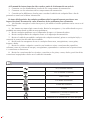 6
6
-
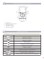 7
7
-
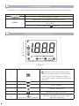 8
8
-
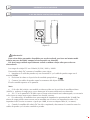 9
9
-
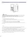 10
10
-
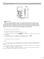 11
11
-
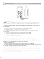 12
12
-
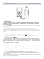 13
13
-
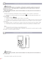 14
14
-
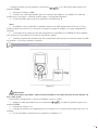 15
15
-
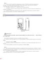 16
16
-
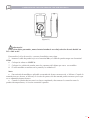 17
17
-
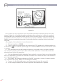 18
18
-
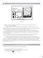 19
19
-
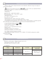 20
20
-
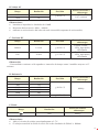 21
21
-
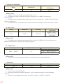 22
22
-
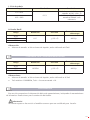 23
23
-
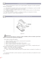 24
24
-
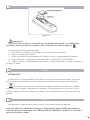 25
25
-
 26
26
-
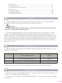 27
27
-
 28
28
-
 29
29
-
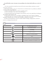 30
30
-
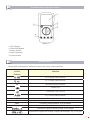 31
31
-
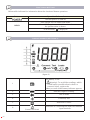 32
32
-
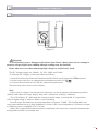 33
33
-
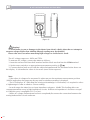 34
34
-
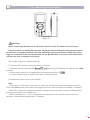 35
35
-
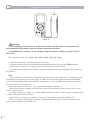 36
36
-
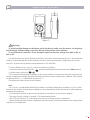 37
37
-
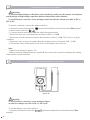 38
38
-
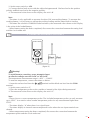 39
39
-
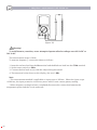 40
40
-
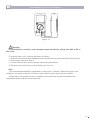 41
41
-
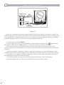 42
42
-
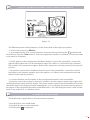 43
43
-
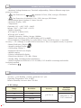 44
44
-
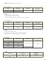 45
45
-
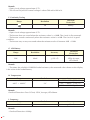 46
46
-
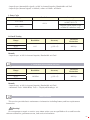 47
47
-
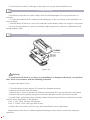 48
48
-
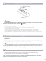 49
49
-
 50
50
-
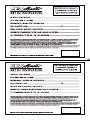 51
51
-
 52
52
-
 53
53
-
 54
54


Ega Master 51259 El manual del propietario
- Categoría
- Multimetros
- Tipo
- El manual del propietario
en otros idiomas
- English: Ega Master 51259 Owner's manual
Artículos relacionados
Otros documentos
-
KNOVA KN 8056 El manual del propietario
-
Extech Instruments MA435T Manual de usuario
-
Extech Instruments MA610 Manual de usuario
-
-
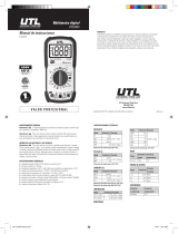 UTL UTLDM1 El manual del propietario
-
UEi Test Instruments DM391 Manual de usuario
-
UNI-T UT191T Manual de usuario
-
-
-
