Weller C-WXP200 El manual del propietario
- Categoría
- Soldadores
- Tipo
- El manual del propietario

WXP 200
Betriebsanleitung - Operating Instructions - Manual de uso - Mode d'emploi - Istruzioni per lùso -
Manual do utilizador


WX 200 – Operating Instructions I
The data specified above only serves
to describe the product. No statements
concerning a certain condition or suitability for
a certain application can be derived from our
information. The given information does not
release the user from the obligation of own
judgement and verification. It must be
remembered that our products are subject to a
natural process of wear and aging.
© This document, as well as the data,
specifications and other information set forth
in it, are the exclusive property of Cooper
Tools GmbH. Without their consent it may not
be reproduced or given to third parties.
Subject to modifications.
Printed in Germany.
10.2010
Deutsch
DE
English
EN
Español
ES
Français
FR
Italiano
IT
Português
PT

WR 3M II

EN FR IT ES PT NL SV DK FI GR TR CZ PL HU SK SL EE LV LT DE
WXP 200
Betriebsanleitung

WXP 200
WXP 200
Geräteübersicht
1. Reinigungseinsatz 5. Grif
f
2. Lötspitze 6. Temperaturbeständige antistatische Silikonleitung
3. Spitzenhalte
r
7. Veriegelbarer Anschlußstecke
r
4. LED Statusanzeige
WDH 31
WXP 200

WXP 200 3-8
DE EN FR IT ES PT NL SV DK FI GR TR CZ PL HU SK SL EE LV LT
Inhaltsverzeichnis
1Zu dieser Anleitung .................................................................... 3
2Zu Ihrer Sicherheit ..................................................................... 3
3Lieferumfang .............................................................................. 5
4Gerätebeschreibung .................................................................. 5
5Inbetriebnahme des Gerätes ..................................................... 6
6Wechsel der WXP 120 Lötspitzen ............................................. 7
7Zubehör ..................................................................................... 8
8Entsorgung ................................................................................ 8
9Garantie ..................................................................................... 8
1 Zu dieser Anleitung
Wir danken Ihnen für das mit dem Kauf des Weller Lötkolbens
WXP 2000 erwiesene Vertrauen. Bei der Fertigung wurden strengste
Qualitätsanforderungen zugrunde gelegt, die eine einwandfreie
Funktion des Gerätes sicherstellen.
Diese Anleitung enthält wichtige Informationen, um den Lötkolben
WXP 200 sicher und sachgerecht in Betrieb zu nehmen, zu
bedienen, zu warten und einfache Störungen selbst zu beseitigen.
Z Lesen Sie diese Anleitung und die beiliegenden
Sicherheitshinweise vor Inbetriebnahme des Lötkolbens
WXP 200 durch.
Z Bewahren Sie diese Anleitung so auf, dass sie für alle Benutzer
zugänglich ist.
1.1 Einzuhaltende Richtlinien
Der Weller Lötkolben WXP 200 entspricht der EG-
Konformitätserklärung gemäß den grundlegenden
Sicherheitsanforderungen der Richtlinien 2004/108/EG und
2006/95/EG.
1.2 Geltende Unterlagen
− Betriebsanleitung für Ihre Versorgungseinheit
− Betriebsanleitungen für WXP 200
− Beiliegendes Heft zur Sicherheit
2 Zu Ihrer Sicherheit
− Der Lötkolben WXP 200 wurde nach dem neuesten Stand der
Technik und anerkannten Sicherheitsregeln und -bestimmungen
entsprechend hergestellt.
− Bei Nichtbeachtung der beiliegenden Sicherheitsinformationen
und aufgeführten Warnhinweise besteht jedoch die Gefahr von
Personen- und Sachschäden.

4-8 WXP 200
− Geben Sie den WXP 200 Lötkolben nur zusammen mit dieser
Betriebsanleitung weiter.
− Der Hersteller ist nicht haftbar für Schäden, die aus einer
unsachgemäßen Verwendung des Werkzeugs oder unerlaubten
Veränderungen am Gerät entstehen.
2.1 Beachten Sie bitte Folgendes:
Allgemeine
Hinweise
− Legen Sie den Lötkolben WXP 200 immer in die vorgesehene
Sicherheitsablage.
− Entfernen Sie alle entzündbaren Objekte aus der Nähe des
heißen Lötwerkzeugs.
− Tragen Sie bei der Arbeit mit WXP 200 entsprechende
Schutzkleidung.
− Lassen Sie den heißen WXP 200 nie unbeaufsichtigt.
− Führen Sie keine Arbeiten an unter Spannung stehenden Teilen
aus.
− Antistatische Kunststoffe sind zur Verhinderung von statischen
Ladungen mit leitenden Füllstoffen versehen. Dadurch sind auch
die Isoliereigenschaften des Kunststoffes vermindert.
Führen Sie keine Arbeiten an unter Spannung stehenden Teilen
aus.
− Tragen Sie bei Löt- oder Entlötanwendungen immer einen
Augenschutz.
− Lesen und beachten Sie die Betriebsanleitung der jeweiligen
verwendeten Weller WX Versorgungseinheit
Umgang mit
Löt-/
Entlöt-
spitzen
− Legen Sie heiße Löt- oder Entlötspitzen weder auf die
A
rbeitsfläche oder auf Kunststoffflächen noch lassen Sie sie dort
zurück.
− Benetzen Sie beim ersten Aufheizen des Kolbens die verzinnten
Löt-/Entlötspitzen mit Lot, wodurch lagerbedingte Oxidschichten
oder Unreinheiten von den Löt- bzw. Entlötspitzen entfernt
werden.
− Vergewissern Sie sich, dass bei Arbeitsunterbrechungen
zwischen Löten und Entlöten sowie vor der Lagerung des
Gerätes die Löt-/Entlötspitzen gut benetzt sind.
− Verwenden Sie keine aggressiven Flussmittel.
− Immer darauf achten, dass die Löt-/Entlötspitzen
ordnungsgemäß sitzen.
− Wählen Sie die möglichst geringste Arbeitstemperatur.
− Wählen Sie die möglichst größte Löt-/Entlötspitzenform für die
Anwendung: ca. so groß wie das Lötpad.
− Benetzen Sie die Löt-/Entlötspitzen gut, um effiziente
Wärmeübertragung zwischen Löt-/Entlötspitzen und Lötpunkt zu
gewährleisten.
− Schalten Sie das System ab, wenn Sie das Löt-/Entlötwerkzeug
über längere Zeit nicht verwenden möchten.
− Benetzen Sie die Spitzen vor Ablegen des Löt-/Entlötwerkzeugs
in der Sicherheitsablage.
− Geben Sie das Lot direkt auf die Lötstelle, nicht auf die Löt-/
Entlötspitzen.
− Wenden Sie auf die Löt-/Entlötspitzen keine übermäßige Kraft
an.

WXP 200 5-8
DE EN FR IT ES PT NL SV DK FI GR TR CZ PL HU SK SL EE LV LT
− Immer darauf achten, dass der Lötkolben ordnungsgemäß in der
Sicherheitsablage liegt.
2.2 Bestimmungsgemäßer Gebrauch
Verwenden Sie den WXP 200 Lötkolben ausschließlich für den in
der Betriebsanleitung bezüglich Lösen, Verstauung und Ablage von
elektronischen Bauteilen angegebenen Zweck unter den hier
beschriebenen Bedingungen. Der bestimmungsgemäße Gebrauch
des Lötkolbens WXP 200 beinhaltet auch, dass
− Sie diese Anleitung beachten,
− Sie alle weiteren Begleitunterlagen beachten,
− Sie die nationalen Unfallverhütungsvorschriften am Einsatzort
beachten.
Der Hersteller übernimmt keine Haftung für Schäden, die aus
unsachgemäßem, nicht dem in der Betriebsanleitung beschriebenen
Gebrauch oder unerlaubten Änderungen am Gerät resultieren.
3 Lieferumfang
WXP 200 verpackt T0052920599:
− WXP 200 Lötkolben, T0052920599
− Einmaulschlüssel SW 17 T0058741753
− XHT D Meißelspitze 5 X 1,2 mm T0054480199
− Betriebsanleitung WXP 200
− Heft Sicherheitshinweise
Zusätzlich beim WXP 200 Lötset T0052920699:
− WDH 31 Sicherheitsablage T0051515898
− Steckverbinder für Fußplatte T0058703153
− Betriebsanleitung WDC 2
4 Gerätebeschreibung
4.1 Lötkolben WXP 200
Der WXP 200 Lötkolben zeichnet sich durch ein schnelles und
präzises Erreichen der Lötspitzentemperatur aus. Aufgrund seines
besonders leistungsfähigen 200 W Heizelementes wird ein
ausgezeichnetes dynamisches Verhalten erreicht. Zusammen mit
der schlanken Bauform und der kurzen Distanz vom Griff zur
Lötspitze findet dieser Lötkolben universellen Einsatz von extrem
feinen Lötarbeiten, bis hin zu solchen mit erhöhtem Wärmebedarf.
Auf Grund einer zusätzlichen optimierten Sensorposition ist dieser
Lötkolben besonders für Lötarbeiten mit erhöhter Wärmezufuhr
geeignet. Der WXP 200 ist mit einer Nutzungserkennung
ausgestattet und kann bei Nichtgebrauch automatisch in
Standbybetrieb bzw. Aus geschaltet werden. Durch die LED
Statusanzeige wird der jeweilige Betriebszustand angezeigt. Das
Einstellen der Standbytemperatur sowie die Schaltzeiten entnehmen
Sie bitte der Betriebsanleitung der jeweils verwendeten WX
Versorgungseinheit.

6-8 WXP 200
Hinweis Der Lötkolben WXP 200 von Weller darf nur mit den
Weller WX Versorgungseinheiten betrieben werden.
4.2 Technische Daten
Temperaturbereich 100°C - 450°C (212°F - 850°F)
Werkzeugkabel Silikonkautschuk, hitzebeständig
Heizelement Integriertes Heizdrahtelement
Temperatursenso
r
Platinsenso
r
Heizleistung 200 W
Spannung (Heizung) 24 V
Aufheizzeit (ca.) 19s (50°C auf 380°C)
(120°F auf 660°F)
Anschluss 6 poliger St. verpolungssicher mit
Verriegelung
Gewicht 94 g incl. Spitze ohne Kabel
Spitzentyp
Versorgungseinheit
XHT-Baureihe
Weller WX Stationen
5 Inbetriebnahme des Gerätes
WARNUNG!
Verbrennungsgefahr
Die Lötspitzen vom Lötkolben werden beim
Löt-/Entlötvorgang sehr heiß.
Bei Berührung der Spitzen besteht Verbrennungsgefahr.
Z Berühren Sie nicht die heißen Lötspitzen und halten Sie
entzündbare Objekte fern.
1. Den Lötkolben WXP 200 vorsichtig auspacken.
2. Den Lötkolben in der Sicherheitsablage WDH 31 ablegen.
3. Den Anschlussstecker (7) an der Versorgungseinheit
anschließen und durch Drehen im Uhrzeigersinn verriegeln.
4. Überprüfen Sie, ob die Netzspannung mit der Spannungsangabe
auf dem Typenschild der WX Versorgungseinheit übereinstimmt.
5. Die Versorgungseinheit einschalten und die gewünschte
Temperatur einstellen.
6. Hat das Werkzeug die gewünschte Temperatur erreicht, leuchtet
die LED Status Anzeige (4) dauernd. Die Lötspitze mit Lot
benetzen.

WXP 200 7-8
DE EN FR IT ES PT NL SV DK FI GR TR CZ PL HU SK SL EE LV LT
6 Wechsel der WXP 200 Lötspitzen
WARNUNG!
Verbrennungsgefahr
Die Lötspitze wird bei Löt- und Entlötvorgängen sehr heiß.
Bei Berührung der Lötspitze besteht Verbrennungsgefahr.
Z Das Lötwerkzeug muss in ausgeschaltetem Zustand
mindestens 3 Minuten in der Sicherheitsablage (WDH 31)
verbleiben, bis die Lötspitze abgekühlt ist. LED Status
Anzeige (4) muss Aus sein. Lötspitzen dürfen nur gewechselt
werden, wenn sie kalt sind.
Auswechseln einer verbrauchten Spitze
1. Lötwerkzeug in die Sicherheitsablage WDH 31 legen.
2. Netzschalter der Versorgungseinheit ausschalten.
3. Drei Minuten warten, bis die Lötspitze abgekühlt ist.
4. Lötkolben mit der Spitze leicht nach unten halten.
Lötkolben am hinteren Griffteil (5) fest halten und
Spitzenhalter (3) mit Linksdrehung abschrauben
Spitzenhalter (3) nach vorne abziehen
Lötspitze (2) befindet sich nun lose im Spitzenhalter (3)
Hinweis Die Lötspitze / Messspitze nicht auf dem Reinigungsschwamm oder
Kunststoffoberflächen ablegen bzw. abkühlen. Bei der Verwendung
von mehreren Lötspitzentypen, wird empfohlen die Lötspitze (2) und
den Spitzenhalter (3) zusammen in dem Wechselsystem zu
verwenden (siehe 3 Bild oben).
Die Wärmeübertragungsflächen von Lötspitze und Heizkörper
sauber halten. Das Heizelement darf nicht mit Lötzinn in Berührung
kommen.
Einsetzen einer neuen Lötspitze
5. Lötspitze mit der Spitze nach vorne in Spitzenhalter einlegen.
Spitzenhalter zusammen mit der Lötspitze über das Heizelement
schieben und mit Rechtsdrehung festdrehen.
Mit geringem Drehmoment anziehen da sonst der Konus des
Heizelementes beschädigt wird!
6. Netzschalter der Versorgungseinheit einschalten und die
gewünschte Temperatur einstellen.

8-8 WXP 200
7 Zubehör
7.1 XHT Lötspitzen für den Lötkolben WXP 200
Siehe Tabelle XHT Lötspitzen für Lötkolben WXP 200 am Ende
dieser Anleitung und auf www.weller.eu
7.2 Ersatzteile und Zubehör für WXP 200
Bestell-Nr. Beschreibung
T0052920599 WXP 200 Lötkolben
T0051515898 Sicherheitsablage WDH 31
T0051384199 Spiralwolle für Reinigungseinsatz für WDC 2
T0058741753 Einmaulschlüssel SW17
8 Entsorgung
Entsorgen Sie ausgetauschte Geräteteile, Filter oder alte Geräte
gemäß den Vorschriften Ihres Landes.
9 Garantie
Die Mängelansprüche des Käufers verjähren nach einem Jahr ab
Ablieferung an ihn. Dies gilt nicht für Rückgriffsansprüche des
Käufers nach §§ 478, 479 BGB.
Aus einer von uns abgegebenen Garantie haften wir nur bei
Ansprüchen, wenn die Beschaffenheits- oder Haltbarkeitsgarantie
von uns schriftlich und unter Verwendung des Begriffs „Garantie“
abgegeben worden ist.
Technische Änderungen vorbehalten!
Die aktualisierten Betriebsanleitungen finden Sie unter
www.weller.eu.

EN
FR IT ES PT NL SV DK FI GR TR CZ PL HU SK SL EE LV LT DE
WXP 200
Operating Instructions

WXP 200
WXP 200
Hardware Overview
1. Cleaning element 5. Handle
2. Soldering tip 6. Heat-resistant antistatic silicon cable
3. Tip handle 7. Lockable connector plug
4. LED status indicato
r
WDH 31
WXP 200

WXP 200 3-8
DE EN FR IT ES PT NL SV DK FI GR TR CZ PL HU SK SL EE LV LT
Table of Contents
1About these instructions ............................................................ 3
2For your safety ........................................................................... 3
3Included in delivery .................................................................... 5
4Device description ..................................................................... 5
5Commissioning the device ......................................................... 6
6Replacing the WXP 200 soldering tips ...................................... 6
7Accessories ............................................................................... 7
8Disposal ..................................................................................... 7
9Warranty .................................................................................... 8
1 About these instructions
Thank you for the confidence you have shown in buying the Weller
WXP 200 soldering iron. The device has been manufactured in
accordance with the most rigorous quality standards, which ensure
that it operates perfectly.
These instructions contain important information which will help you
to start up, operate and service the WXP 200 soldering iron safely
and correctly as well as to eliminate simple faults or malfunctions
yourselves.
Z Read these instructions and the accompanying safety information
carefully before starting up the device and starting work with the
WXP 200 soldering iron.
Z Keep these instructions in a safe place and so that they are
easily accessible to all users.
1.1 Directives taken into consideration
The Weller WXP 200 soldering iron conforms to the specifications of
the EC Declaration of Conformity as defined by Directives
2004/108/EC and 2006/95/EC.
1.2 Applicable documents
− Operating instructions for your supply unit
− Operating instructions for WXP 200
− Safety information booklet accompanying these instructions
2 For your safety
− The WXP 200 soldering iron has been manufactured in
accordance with the current state of the art and recognised safety
rules and regulations. There is nevertheless the risk of personal
injury and damage to property if you fail to observe the safety
information set out in the accompanying booklet and the warnings
given in these instructions.

4-8 WXP 200
− Always pass on the WXP 200 soldering iron to third parties
together with these operating instructions.
− The manufacturer accepts no liability for improper use of the tool
or for unauthorised modifications.
2.1 Please observe the following guidelines:
General
information
− Always place the WXP 200 soldering iron in the intended safety
rest.
− Remove all inflammable articles from around the hot soldering
iron.
− Always wear suitable protective clothing when using the
WXP 200.
− Never leave a hot WXP 200 unattended.
− Do not work on electrically live parts.
− Antistatic plastics are provided with conductive fillers to prevent
the build-up of static charge. This also reduces the insulating
properties of the plastic.
Do not work on electrically live parts.
− Always wear eye protection when working with soldering and
desoldering applications.
− Read and follow the operating instructions for the Weller WX
supply unit.
Handling
soldering/
desoldering
tips
− Do not place or leave hot soldering/desoldering tips on the
worktop or on plastic surfaces.
− Wet the tinned soldering/desoldering tips with solder once they
have heated up in order to remove oxide layers that form during
storage or contamination from the soldering/desoldering tips.
− Ensure the soldering/desoldering tips are well wetted during
intervals between soldering and desoldering and prior to storage
of the device.
− Do not use aggressive fluxing agents.
− Always make sure that the soldering/desoldering tips are
properly seated.
− Select the lowest possible working temperature.
− Select the largest possible soldering/desoldering tip shape for
the application (roughly as large as the soldering pad).
− Wet the soldering/desoldering tips well to ensure efficient heat
transfer between the soldering/desoldering tips and the soldering
spot.
− Switch off the system if you do not intend to use the
soldering/desoldering tool for prolonged periods.
− Wet the tips before placing the soldering/desoldering tool in the
safety rest.
− Apply the solder directly at the soldering point, not on the
soldering/desoldering tips.
− Do not apply excessive force to the soldering/desoldering tips.
−
A
lways make sure that the soldering iron is placed properly in the
safety rest.

WXP 200 5-8
DE EN FR IT ES PT NL SV DK FI GR TR CZ PL HU SK SL EE LV LT
2.2 Intended use
Use the WXP 200 soldering iron exclusively for the purpose
indicated in the operating instructions of releasing, accommodating
and depositing electronic components under the conditions specified
herein. Intended use of the WXP 200 soldering iron also includes the
requirement that you
− adhere to these instructions,
− observe all other accompanying documents,
− comply with national accident prevention guidelines applicable at
the place of use.
The manufacturer accepts no liability for any damage resulting from
failure to use the device in compliance with these operating
instructions or unauthorised modifications to the device.
3 Included in delivery
WXP 200 (packed) T0052920599:
− Soldering iron WXP 200, T0052920599
− 17 mm open end wrench T0058741753
− XHT D chisel 5 X 1.2 mm T0054480199
− Operating instructions of WXP 200
− Safety information booklet
Also included in WXP 200 soldering set T0052920699:
− WDH 31 safety rest T0051515898
− Sole plate connector T0058703153
− Operating instructions of WDC 2
4 Device description
4.1 Soldering iron WXP 200
The WXP 200 soldering iron is characterised by fast and precise
achievement of the soldering tip temperature. A highly powerful
200 W heater element provides excellent dynamic performance.
With its additional optimised sensor position, this soldering iron is
ideal for soldering applications requiring high heat.
Thanks to its slim-line design and the extremely short distance from
the handle to the tip, this soldering iron can be used for general
purposes from precision soldering to high-temperature soldering.
The WXP 200 is equipped with a usage detector and can be
automatically switched to standby mode or switched off when not in
use. The operating status is indicated by the status indicator LED.
For directions for setting the standby temperature and the switching
times, please refer to the operating instructions of the WX supply
unit in use.
Note The WXP 200 soldering iron by Weller may only be operated
together with Weller WX supply units.

6-8 WXP 200
4.2 Technical data
Temperature range 100°C - 450°C (212°F - 850°F)
Tool cable Silicone rubber, heat resistant
Heating element Integrated heating wire element
Temperature senso
r
Platinum senso
r
Heating output 200 W
Voltage (heater) 24 V
Heat-up time (approx.) 19s (50°C to 380°C)
(120°F to 660°F)
Connection 6 pin connector, polarity protected with lock
Weight 94 g incl. cordless tip
Tip type
Supply unit
XHT series
Weller WX stations
5 Commissioning the device
WARNING!
Risk of burns
The soldering tips of soldering irons become very hot during
soldering and desoldering processes.
There is a risk of burns from touching the tips.
Z Do not touch the hot soldering tips and keep them away from
inflammable objects.
1. Carefully unpack the WXP 200 soldering iron.
2. Place the soldering iron into safety rest WDH 31.
3. Insert the connecting plug (7) into the power supply socket and
lock it by turning it clockwise.
4. Check to make sure that the mains voltage matches the voltage
specified on the rating plate of the WX supply unit.
5. Switch on the supply unit and set the required temperature.
6. If the tool has not reached the required temperature, the status
indicator LED (4) will be lit continuously. Wet the soldering tip
with solder.
6 Replacing the WXP 200 soldering tips
WARNING!
Risk of burns
The soldering tip becomes hot during soldering and desoldering
processes.
There is a risk of burns from touching the soldering tip.
Z The soldering tool must be switched off and stand at least
3 min. in the safety rest (WDH 31) until the soldering tip has
cooled off. The status indicator LED (4) must be OFF. Only
replace the soldering tips when they are cold.

WXP 200 7-8
DE EN FR IT ES PT NL SV DK FI GR TR CZ PL HU SK SL EE LV LT
Replacing a used tip
1. Place the soldering tool in the WDH 31 safety rest.
2. Switch off the power switch of the supply unit.
3. Wait five minutes until the soldering tip has cooled down.
4. Hold the soldering iron with the tip facing slightly downwards.
Hold the soldering iron by the rear handle (5) and unscrew the tip
receptacle (3) using the supplied 17 mm open end wrench
Pull off the soldering tip (2) forwards
The soldering tip is now resting loosely in the tip receptacle (3)
Note Do not place or leave the hot soldering tip or probe tip on the
cleaning sponge or on plastic surfaces. When using multiple types
of soldering tip, it is recommended that the soldering tip (2) and tip
receptacle (3) be used together in the changing system (see figure
above).
Keep the heat transfer surfaces of the soldering tip and heating
element clean. The heating element must not come into contact with
soldering tin.
Inserting a new soldering tip
5. Place the soldering tip into the tip receptacle with the tip facing
forwards. Push the tip receptacle together with the soldering tip
over the heating element and screw the soldering tip securely
into place using a 17 mm open end wrench.
Tighten to a low torque, as otherwise you might damage the
tapered part of the heating element.
6. Switch on the power switch of the supply unit and set the
temperature to the required level.
7 Accessories
7.1 XHT soldering tips for the WXP 200 soldering
iron
See the table XHT soldering tips for WXP 200 soldering iron in the
section in the back and at www.weller.eu
7.2 Replacement parts and accessories for
WXP 200
Order no. Description
T0052920599 WXP 200 soldering iron
T0051515898 WDH 31 safety rest
T0051384199 Metal wool for cleaning element for WDC 2
T0058741753 17 mm open end wrench
8 Disposal
Dispose of replaced equipment parts, filters or old devices in
accordance with the rules and regulations applicable in your country.

8-8 WXP 200
9 Warranty
Claims by the buyer for physical defects are time-barred after a
period of one year from delivery to the buyer. This does not apply to
claims by the buyer for indemnification in accordance with §§ 478,
479 BGB (German Federal Law Gazette).
We shall only be liable for claims arising from a warranty furnished
by us if the quality or durability warranty has been furnished by use
in writing and using the term "Warranty“.
In addition, for the USA and Canada:
Cooper Tools warrants to the original purchaser and any subsequent
owner (“Buyer”) that Weller soldering and desoldering products will
be free from defects in material and workmanship for a period of one
year from date of purchase, provided that no warranty is made with
respect to products which have been altered, subjected to abuse or
improperly used, installed or repaired. Use of non-Cooper Tools
components will void this warranty if a non-Cooper Tools component
is defective (or is the source of the defect). Cooper Tools will repair
or replace products found to be defective not caused by a part,
component or accessory manufactured by another company, during
the warranty period. Contact Cooper Tools with dated proof of
purchase and return to Apex Tool Group, LLC., 14600 York Rd. Suit
A, Sparks, MD 21152. All costs of transportation and reinstallation
shall be borne by the Buyer.
IN NO EVENT SHALL COOPER TOOLS BE LIABLE FOR
INCIDENTAL OR CONSEQUENTIAL DAMAGES. COOPER TOOLS
LIABILITY FOR ANY CLAIMS ARISING OUT OF THIS WARRANTY
SHALL NOT EXCEED THE PURCHASE PRICE OF THE
PRODUCT.
THE PERIOD OF ALL IMPLIED WARRANTIES APPLICABLE TO
THIS PRODUCT INCLUDING ANY IMPLIED WARRANTY OF
MERCHANTABILITY OR FITNESS, OR FITNESS FOR A
PARTICULAR PURPOSE IS LIMITED TO 12 MONTHS FROM THE
DATE OF PURCHASE BY THE USER.
Some states do not allow the exclusion or limitation of incidental or
consequential damages, so the above limitation or exclusion may
not apply to you. Some states do not allow limitation on how long an
implied warranty lasts, so the above limitation may not apply to you.
This warranty gives you specific legal rights, and you may also have
other rights, which vary from state to state.
Subject to technical alterations and amendments!
Updated operating instructions are available for download at
www.weller.eu.

EN
ES
IT ES PT NL SV DK FI GR TR CZ PL HU SK SL EE LV LT DE
WXP 200
Manual de uso

WXP 200
WXP 200
Componentes principales del aparato
1. Limpiado
r
5. Mango
2. Punta de soldadura 6. Cable de silicona antiestático y termorresistente
3. Empuñadura de la punta 7. Clavija de conexión con mecanismo de bloqueo
4. LED de estado
WDH 31
WXP 200

WXP 200 3-8
DE EN ES IT ES PT NL SV DK FI GR TR CZ PL HU SK SL EE LV LT
Índice
1Acerca de estas instrucciones ................................................... 3
2Acerca de la seguridad .............................................................. 3
3Piezas suministradas ................................................................. 5
4Descripción del aparato ............................................................. 5
5Puesta en servicio del aparato .................................................. 6
6Cambio de las puntas de soldadura WXP 200 ......................... 7
7Accesorios ................................................................................. 8
8Eliminación de residuos ............................................................. 8
9Garantía ..................................................................................... 8
1 Acerca de estas instrucciones
Le agradecemos la confianza depositada en nosotros al comprar el
lápiz de soldadura WXP 200 de Weller. La fabricación de este
aparato está sometida a los más rigurosos controles de calidad para
garantizar un perfecto funcionamiento del mismo.
Este manual de uso contiene información importante para poder
poner en marcha y manejar de forma segura y adecuada el lápiz de
soldadura WXP 200, así como para realizar tareas de
mantenimiento e incluso reparar pequeñas averías.
Z Lea atentamente estas instrucciones de uso y las indicaciones
de seguridad adjuntas antes de poner en funcionamiento el lápiz
de soldadura WXP 200.
Z Mantenga este manual de uso en un lugar al que puedan
acceder todos los usuarios del aparato.
1.1 Directivas que tener en cuenta
El lápiz de soldadura WXP 200 de Weller dispone de la Declaración
de Conformidad CE que certifica el cumplimiento de los requisitos
básicos de seguridad contemplados en las Directivas 2004/108/CE y
2006/95/CE.
1.2 Documentos aplicables
− Manual de instrucciones para la unidad de alimentación
− Manual de uso para el WXP 200
− Folleto adjunto sobre seguridad
2 Acerca de la seguridad
− El lápiz de soldadura WXP 200 ha sido fabricado conforme a los
últimos avances tecnológicos y las normativas y disposiciones de
seguridad reconocidas. No obstante, existe riesgo de daños
personales y daños a la propiedad si se hace caso omiso a la
información de seguridad establecida en el folleto adjunto que
acompaña a este manual de instrucciones y a las advertencias
mencionadas al respecto.

4-8 WXP 200
− Entregue siempre el lápiz de soldadura WXP 200 a terceros junto
con este manual de uso.
− El fabricante no asumirá ningún daño resultante del uso indebido
de la herramienta ni de modificaciones no autorizadas.
2.1 Tener en cuenta lo siguiente:
Indicaciones
generales
− Colocar siempre el lápiz de soldadura WXP 200 en el soporte de
seguridad previsto a tal efecto.
− Retirar todos los objetos inflamables de las proximidades de la
herramienta de soldadura.
− Llevar siempre una indumentaria protectora adecuada al utilizar
el WXP 200.
− Mantener siempre vigilado el WXP 200 caliente.
− No trabajar en piezas sometidas a tensión.
− Los materiales plásticos antiestáticos contienen sustancias de
relleno conductoras para impedir que se puedan producir cargas
estáticas. De esta forma también quedan mermadas las
propiedades aislantes del material plástico.
No trabajar en piezas sometidas a tensión.
− Llevar siempre protección ocular al trabajar con aplicaciones de
soldadura y desoldadura.
− Leer y respetar las indicaciones recogidas en el manual de uso
de la unidad de alimentación Weller WX
Manejo de las
puntas de
soldadura /
desoldadura
− No colocar ni dejar las puntas de soldadura/desoldadura
calientes sobre la esponja limpiadora ni sobre superficies de
plástico.
− Recubrir las puntas de soldadura/desoldadura estañadas al
calentar el soldador por primera vez, así se eliminarán todas las
películas de óxido o impurezas de las puntas de
soldadura/desoldadura que se hayan acumulado durante el
almacenamiento.
− Durante las interrupciones de la soldadura/desoldadura y antes
de almacenar la herramienta, asegurarse de que las puntas de
soldadura/desoldadura estén bien recubiertas.
− No utilizar fundentes agresivos.
− Asegurarse siempre de que las puntas de
soldadura/desoldadura estén colocadas correctamente.
− Seleccionar una temperatura de trabajo lo más baja posible.
− Seleccionar unas puntas de soldadura/desoldadura lo más
largas posibles para la aplicación: aprox. de la longitud de la
placa de soldar.
− Recubrir bien las puntas de soldadura/desoldadura para
asegurarse una transferencia de calor eficiente entre las puntas
de soldadura/desoldadura y el punto de soldadura.
− Desconectar el sistema si no está previsto utilizar la herramienta
de soldadura/desoldadura durante largos periodos de tiempo.
− Recubrir las puntas antes de colocar la herramienta de
soldadura/desoldadura en el soporte de seguridad.
− Soldar directamente en el punto de soldadura, no en las puntas
de soldadura/desoldadura.
− No someter las puntas de soldadura/desoldadura a fuerzas
físicas.

WXP 200 5-8
DE EN ES IT ES PT NL SV DK FI GR TR CZ PL HU SK SL EE LV LT
− Asegurarse siempre de que el lápiz de soldadura está colocado
correctamente en el soporte de seguridad.
2.2 Uso reglamentario
Emplear el lápiz de soldadura WXP 200 exclusivamente para el
propósito indicado en el manual de uso en lo referente a la
liberación, alojamiento y fijación de componentes electrónicos bajo
las condiciones especificadas aquí. Dentro del uso previsto para el
lápiz de soldadura WXP 200 también se incluye lo siguiente:
− Seguir las instrucciones de este manual.
− Seguir las instrucciones de todos los documentos que acompañan
al aparato.
− Cumplir las normas de prevención de accidentes laborales
vigentes en el país de uso.
El fabricante no asumirá ningún daño resultante del uso incorrecto
de este aparato en cumplimiento con el presente manual de
instrucciones o de las modificaciones no autorizadas en el aparato.
3 Piezas suministradas
WXP 200 embalado T0052920599:
− Lápiz de soldadura WXP 200, T0052920599
− Llave fija del nº 17 T0058741753
− Punta de cincel XHT D de 5 X 1,2 mm T0054480199
− Manual de uso para WXP 200
− Folleto de normas de seguridad
Elementos adicionales para el juego de
soldadura WXP 200 T0052920699:
− Soporte de seguridad WDH 31 T0051515898
− Acoplamiento para la base T0058703153
− Manual de uso para WDC 2
4 Descripción del aparato
4.1 Lápiz de soldadura WXP 200
El lápiz de soldadura WXP 200 se distingue por su rapidez y
precisión para alcanzar la temperatura deseada. La extraordinaria
potencia (200 W) de su elemento calefactor le proporciona un
comportamiento dinámico excelente.
Este soldador es especialmente idóneo para los trabajos de
soldadura con elevada disipación térmica gracias a un
posicionamiento optimizado del sensor.
Su reducido diseño y la corta distancia entre el mango y la punta
permiten utilizar este lápiz de soldar de forma universal, desde los
trabajos más precisos hasta aquellos que requieran mayor
temperatura. El WXP 200 está equipado con un sistema de
detección de uso que desconecta automáticamente el aparato —o lo
pone en modo de inactividad— cuando no se está utilizando. El LED
de estado señala el estado de funcionamiento del aparato.

6-8 WXP 200
La información relativa al ajuste de temperatura para el modo de
inactividad, así como de los tiempos de desconexión, aparece
recogida en el manual de uso de la unidad de alimentación WX.
Nota El lápiz de soldadura WXP 200 de Weller debe utilizarse
únicamente con las unidades de alimentación Weller WX.
4.2 Datos técnicos
Rango de temperatura 100 °C – 450 °C (212 °F – 850 °F)
Cable de la
herramienta
Caucho de silicona, resistente al fuego
Elemento calefacto
r
A
lambre de calefacción integrado
Sensor de
temperatura
Sensor de platino
Potencia de
calentamiento
200 W
Tensión de
calentamiento
24 V
Tiempo de
calentamiento
(aprox.) 19 s (50 °C a 380 °C)
(120 °F a 660 °F)
Conector Conector de 6 polos con protección
contra polaridad inversa y mecanismo de
bloqueo
Peso de la
herramienta
94 g incluida punta sin cable
Tipo de punta
Unidad de
alimentación
Serie XHT
Estaciones Weller WX
5 Puesta en servicio del aparato
¡ADVERTENCIA!
Riesgo de quemaduras
Las puntas del lápiz de soldadura alcanzan temperaturas muy
elevadas durante los trabajos de soldadura/desoldadura.
Existe riesgo de quemaduras al tocar las puntas de
soldadura/desoldadura.
Z No toque las puntas de soldadura calientes y manténgalas
siempre alejadas de objetos inflamables.
1. Desembalar con cuidado el lápiz de soldadura WXP 200.
2. Colocar el lápiz de soldadura en el soporte de seguridad
WDH 31.
3. Insertar la clavija de conexión (7) en la unidad de alimentación
corriente y bloquearla girándola en sentido horario.
4. Comprobar si la tensión de la red coincide con los datos de la
placa de identificación de la unidad de alimentación WX.
5. Encender la unidad de alimentación y ajustar la temperatura
deseada.

WXP 200 7-8
DE EN ES IT ES PT NL SV DK FI GR TR CZ PL HU SK SL EE LV LT
6. Una vez que la herramienta ha alcanzado la temperatura
deseada, el LED de estado (4) se ilumina de forma permanente.
Estañar la punta de soldadura.
6 Cambio de las puntas de soldadura
WXP 200
¡ADVERTENCIA!
Riesgo de quemaduras
La punta de soldadura alcanza temperaturas muy elevadas
durante la soldadura y desoldadura.
Existe riesgo de quemaduras al tocar la punta de soldadura .
Z La herramienta de soldadura debe permanecer desconectada
en el soporte de seguridad (WDH 31) por lo menos durante
3 min. para que la punta de soldadura se enfríe. El LED de
estado (4) debe estar apagado. Las puntas de soldadura solo
se deben cambiar cuando estén frías.
Cambio de una punta de soldar usada
1. Colocar el soldador en el soporte de seguridad WDH 31.
2. Desconectar el interruptor principal de la unidad de alimentación.
3. Esperar cinco minutos hasta que se enfríe la punta de soldar.
4. Mantener el soldador con la punta mirando ligeramente hacia
abajo.
Mantener el soldador sujetado por la parte posterior del mando
(5) y desenroscar el
portapuntas (3) con la llave fija adjunta del nº 17
Retirar el portapuntas (3) tirando de él hacia delante
Ahora la punta de soldar (2) estará suelta en el portapuntas (3)
Nota No colocar ni dejar enfriar la punta de soldar (o medir) sobre la
esponja de limpieza o superficies de plástico. Si se trabaja con
distintos tipos de puntas de soldadura, se recomienda utilizar la
punta de soldadura (2) y el portapuntas (3) juntos para que los
cambios resulten más rápidos (ver 3 figuras superiores).
Mantener siempre limpias las superficies de transmisión térmica de
las puntas de soldadura y el cuerpo calefactor. El elemento
calefactor no debe entrar en contacto con el estaño para soldar.
Colocación de una nueva punta de soldar
5. Introducir en el portapuntas una punta de soldar nueva con la
punta mirando hacia delante. Colocar el portapuntas con la punta
de soldar pasándolo por la resistencia y apretarlo con la llave fija
del nº 17.
¡Apretar ligeramente puesto que de lo contrario podría dañar el
cono de la resistencia!
6. Conectar el interruptor principal de la unidad de alimentación y
ajustar la temperatura deseada.

8-8 WXP 200
7 Accesorios
7.1 Puntas de soldadura XHT para el lápiz de
soldadura WXP 200
Ver la tabla de puntas de soldadura XHT para lápiz de soldadura
WXP 200 al final de este manual y en www.weller.eu
7.2 Piezas de repuesto y accesorios para el
WXP200
N.º pedido Descripción
T0052920599 Lápiz de soldadura WXP 200
T0051515898 Soporte de seguridad WDH 31
T0051384199 Lana de acero para útil limpiador WDC 2
T0058741753 Llave fija del nº 17
8 Eliminación de residuos
Eliminar las piezas sustituidas del equipo, filtros u otros aparatos
antiguos según las normas y regulaciones aplicables en el país
correspondiente.
9 Garantía
Las reclamaciones por parte del comprador en cuanto a defectos
físicos se limitan a un periodo de un año a partir de la fecha de
entrega al comprador. Solo válido para los derechos del comprador
según el art. §§ 478, 479 BGB (código civil alemán).
Nosotros asumiremos solo aquellas reclamaciones relacionadas con
la garantía que hemos concedido, siempre y cuando la garantía de
calidad y durabilidad haya sido concedida de forma escrita y con
mención expresa del término "Garantía“.
¡Reservado el derecho a realizar modificaciones técnicas!
Encontrará los manuales de instrucciones actualizados en
www.weller.eu.

EN FR FR ES PT NL SV DK FI GR TR CZ PL HU SK SL EE LV LT DE
WXP 200
Mode d'emploi

WXP 200
WXP 200
Vue d'ensemble de l'appareil
1. Bloc de nettoyage 5. Poignée
2. Panne de soudage 6. Cordon antistatique en silicone résistant à la
chaleu
r
3. Poignée du fer à soude
r
7. Connecteur verrouillable
4. Témoin LED
WDH 31
WXP 200

WXP 200 3-8
DE EN FR IT FR PT NL SV DK FI GR TR CZ PL HU SK SL EE LV LT
Sommaire
1À propos de ces instructions ...................................................... 3
2Pour votre sécurité ..................................................................... 3
3Fourniture .................................................................................. 5
4Description de l'outil ................................................................... 5
5Mise en service de l'outil ............................................................ 6
6Remplacement des pannes WXP 200 ....................................... 7
7Accessoires ............................................................................... 8
8Mise au rebut ............................................................................. 8
9Garantie ..................................................................................... 8
1 À propos de ces instructions
Nous vous remercions de la confiance que vous nous avez
accordée avec l'achat du fer à souder Weller WXP 200. Sa
fabrication a fait l'objet d'exigences les plus strictes en termes de
qualité, ce qui garantit un fonctionnement irréprochable de l'appareil.
Cette notice contient des informations importantes qui vous
permettront de mettre en service le fer à souder WXP 200 en toute
sécurité et dans les règles de l'art, de l'utiliser, de l'entretenir et de
remédier par vous-mêmes aux dérangements les plus simples.
Z Lisez intégralement cette notice et les consignes de sécurité
jointes avant de mettre en service le fer à souder WXP 200.
Z Conservez le présent mode d'emploi de telle manière qu'il soit
accessible à tous les utilisateurs.
1.1 Directives prises en considération
Le fer à souder Weller WXP 200 correspond à la déclaration de
conformité européenne conformément aux exigences de sécurité
des directives 2004/108/CE et 2006/95/CE.
1.2 Documents applicables
− Instructions de service pour votre station
− Notices d'utilisation pour WXP 200
− Livret des consignes de sécurité
2 Pour votre sécurité
− Le fer à souder WXP 200 a été fabriqué en tenant compte des
connaissances techniques les plus récentes et conformément aux
règles et dispositions de sécurité reconnues. Il existe cependant
un risque de dommages corporels et de dégâts matériels si vous
n'observez pas les consignes de sécurité figurant dans le manuel
joint, accompagnant les présentes instructions de service, ainsi
que les mises en garde y figurant.

4-8 WXP 200
− Ne remettez le fer à souder WXP 200 à un tiers qu'avec cette
notice d'utilisation.
− Le fabricant n'est pas responsable quant aux dommages résultant
d'un usage inapproprié de l'outil ou de modifications non
autorisées.
2.1 Veuillez observer les points suivants:
Instructions
générales
− Placez toujours le fer à souder WXP 200 dans le support de
sécurité prévu à cet effet.
− Éloignez tous les objets inflammables se trouvant à proximité de
l'outil de soudage chaud.
− Portez des vêtements de protection appropriés pour travailler
avec le WXP 200.
− Ne laissez jamais le WXP 200 chaud sans surveillance.
− N'effectuez aucune opération sur des composants sous tension.
− Les matières plastiques antistatiques comportent des agents de
remplissage conducteurs pour éviter les charges statiques. De
ce fait, les propriétés isolantes de la matière plastique sont
également amoindries.
N'effectuez aucune opération sur des composants sous tension.
− Portez toujours une protection oculaire en travaillant avec des
applications de soudage ou de dessoudage.
− Lisez et respectez la notice d'utilisation de l'unité d'alimentation
Weller WX utilisée
Maniement
des
pannes de
soudage /
dessoudage
− Ne placez ou ne laissez pas les pannes de soudage/dessoudage
chaudes sur la surface de travail ou sur des surfaces en matière
plastique.
− Étamez les pannes de soudage / dessoudage avec de la
soudure lorsque vous utiliser le fer pour la première fois; ceci
aura pour effet d'éliminer les films d'oxyde ou les impuretés des
pannes de soudage / dessoudage, qui se sont accumulés
pendant le stockage.
− Pendant les pauses entre les soudages / dessoudages et avant
de stocker l'outil, assurez-vous que les pannes de soudage /
dessoudage sont correctement étamées.
− N'utilisez aucun fondant agressif.
− Assurez-vous toujours que les pannes de soudage / dessoudage
sont correctement engagées dans leur logement.
− Sélectionnez la température de travail la plus faible possible.
− Sélectionnez la forme de panne de soudage/dessoudage la plus
grande possible pour l'application : env. aussi grande que la
pastille à souder.
− Étamez suffisamment les pannes de soudage / dessoudage afin
d'assurer un transfert de chaleur efficace entre les pannes de
soudage / dessoudage et le point à souder.
− Eteignez le système lorsque vous ne souhaitez pas utiliser l'outil
de soudage/dessoudage durant une période prolongée.
− Etamez les pannes avant de placer l'outil de
soudage/dessoudage dans le support de sécurité.
− Déposez le métal d'apport directement sur le point de soudage,
pas sur les pannes de soudage/ dessoudage.

WXP 200 5-8
DE EN FR FR ES PT NL SV DK FI GR TR CZ PL HU SK SL EE LV LT
− Ne soumettez pas les pannes de soudage / dessoudage à des
forces physiques.
− Toujours faire attention à ce que le fer à souder repose
correctement dans le support de sécurité.
2.2 Utilisation conforme aux prescriptions
Utilisez le fer à souder WXP 200 exclusivement dans le but indiqué
dans la notice d'utilisation concernant le dessoudage, le rangement
et le retrait de composants électroniques dans les conditions
présentement décrites. L'utilisation conforme du fer à souder
WXP 200 inclut également les points suivants:
− Lisez et respectez les présentes instructions,
− Lisez et respectez les documents d'accompagnement
additionnels,
− Observez les prescriptions nationales en matière de prévention
des accidents en vigueur sur le lieu d'utilisation de l'appareil.
Le fabricant décline toute responsabilité quant aux dommages
résultant d'une utilisation non conforme avec les présentes
instructions de service ou en cas de modifications non autorisées de
l'appareil.
3 Fourniture
WXP 200 emballé T0052920599:
− Fer à souder WXP 200, T0052920599
− Clé à fourche de 17 T0058741753
− Panne marteau XHT D; 5 X 1,2 mm T0054480199
− Notice d'utilisation WXP 200
− Livret des consignes de sécurité
En plus avec le kit de soudage WXP 200 T0052920699:
− Support de sécurité WDH 31 T0051515898
− Connecteur pour pédale T0058703153
− Notice d'utilisation WDC 2
4 Description de l'outil
4.1 Fer à souder WXP 200
Le fer à souder WXP 200 se distingue par une montée rapide et
précise de la température de la panne. Son élément de chauffe très
puissant (200 W) permet d'obtenir un excellent comportement
dynamique.
En raison d'une position supplémentaire optimisée pour le capteur,
ce fer à souder convient particulièrement aux travaux de soudage
requérant un apport calorifique plus important.
Grâce à sa forme mince et à la courte distance entre la poignée et la
panne, ce fer à souder convient à une utilisation universelle allant du
soudage extrêmement fin au soudage intensif nécessitant un apport
de chaleur important. Equipé d'un système de détection d'utilisation,
le WXP 200 peut se mettre automatiquement en veille ou se couper
s'il n'est pas utilisé.

6-8 WXP 200
Le témoin à LED signale chaque état de fonctionnement. Pour le
réglage de la température de veille ainsi que des temps
d'enclenchement, veuillez vous reporter à la notice d'utilisation de
l'unité d'alimentation WX correspondante.
Remarque Le fer à souder WXP 200 de Weller ne doit être utilisé qu'avec les
unités d'alimentation Weller WX.
4.2 Caractéristiques techniques
Plage de température 100 °C - 450 °C (212 °F - 850 °F)
Cordon Caoutchouc de silicone, résistant aux
brûlures
Elément de chauffe Filament de chauffe intégré
Capteur de
température
Capteur platine
Puissance calorifique 200 W
Tension de chauffage 24 V
Temps de montée en
température
(env.) 19 s (de 50 °C à 380 °C)
(de 120 °F à 660 °F)
Connecteur 6 contacts, protection contre l'inversion
de polarité avec verrouillage
Poids total 94 g avec panne sans câble
Type de panne
Unité d'alimentation
Série XHT
Stations Weller WX
5 Mise en service de l'outil
AVERTISSEMENT !
Risque de brûlures
Les pannes du fer à souder deviennent
très chaudes pendant le soudage/dessoudage.
En touchant les pannes de soudage / dessoudage, vous risquez
de vous brûler.
Z Ne touchez pas les pannes très chaudes et éloignez les objets
inflammables.
1. Déballer le fer à souder WXP 200 avec précaution.
2. Placer le fer à souder dans le support de sécurité WDH 31.
3. Brancher le connecteur (7) sur l'unité d'alimentation et le
verrouiller en le tournant dans le sens des aiguilles d'une montre.
4. Vérifiez si la tension du secteur correspond à la tension indiquée
sur la plaque signalétique de l'unité d'alimentation WX.
5. Enclencher l'unité d'alimentation et régler la température
souhaitée.
6. Le témoin LED (4) s'allume en continu dès que l'outil a atteint la
température souhaitée. Etamer la panne avec le métal d'apport.

WXP 200 7-8
DE EN FR FR ES PT NL SV DK FI GR TR CZ PL HU SK SL EE LV LT
6 Remplacement des pannes WXP 200
AVERTISSEMENT !
Risque de brûlures
La panne devient très chaude pendant le soudage et
dessoudage.
En touchant les pannes de soudage / dessoudage, vous risquez
de vous brûler.
Z L'outil de soudage doit rester éteint pendant au moins
3 minutes dans le support de sécurité (WDH 31) jusqu'à ce
que la panne soit refroidie. Le témoin LED (4) doit être éteint.
Ne remplacez les pannes du fer à souder que lorsqu’elles
sont froides.
Remplacement d'une panne usagée
1. Placer l'outil de soudage dans le support de sécurité WDH 31.
2. Couper l'interrupteur de l'unité d'alimentation.
3. Attendre cinq minutes le refroidissement de la panne.
4. Tenir le fer à souder avec la panne légèrement inclinée vers le
bas.
Retenir le fer à souder par la poignée arrière (5) et
dévisser le support de panne (3) avec la clé à fourche de 17
fournie.
Retirer le support de panne (3) par l'avant.
La panne (2) n'est maintenant plus fixée à l'intérieur du support
de panne (3)
Remarque Ne pas poser ou laisser refroidir la panne de soudage / la pointe de
mesure sur la mousse de nettoyage ou sur les surfaces plastiques.
Si vous utilisez plusieurs types de panne, nous recommandons
d'utiliser la panne (2) et le support de panne (3) ensemble dans le
système de remplacement (voir 3 figure du haut).
Maintenir propres les surfaces de transfert thermique de la panne et
du corps de chauffe. L'élément de chauffe ne doit pas entrer en
contact avec l'étain.
Mise en place d'une nouvelle panne
5. Insérer la panne dans le support de panne avec la pointe en
avant. Engager le support de panne avec la panne par dessus
l'élément de chauffe puis la visser avec la clé de 17.
Serrer à un couple modéré, car sinon le cône de l'élément de
chauffe sera endommagé !
6. Mettre en circuit l'interrupteur de l'unité d'alimentation et régler la
température souhaitée.

8-8 WXP 200
7 Accessoires
7.1 Pannes XHT pour fer à souder WXP 200
Voir tableau des pannes XHT pour fer à souder WXP 200 à la fin de
cette notice et sur le site www.weller.eu
7.2 Pièces de rechange et accessoires pour
WXP 200
N° de
commande
Description
T0052920599 Fer à souder WXP 200
T0051515898 Support de sécurité WDH 31
T0051384199 Laine spirale pour bloc de nettoyage pour
WDC 2
T0058741753 Clé à fourche de 17
8 Mise au rebut
Éliminez les pièces d'équipement et filtres remplacés, ainsi que les
appareils usagés conformément aux réglementations et
prescriptions applicables dans votre pays.
9 Garantie
Les réclamations de l'acheteur concernant des défauts physiques
sont forclos après une période d'un an à compter de la livraison à
l'acheteur. Ceci ne s'applique pas aux réclamations par l'acheteur
concernant le dédommagement selon §§ 478, 479 BGB (Loi
fédérale allemande).
Nous engageons uniquement notre responsabilité dans le cas de
réclamations découlant d'une garantie fournie par nous, dans la
mesure où la garantie de qualité ou de durabilité a été fournie par
nous par écrit et en utilisant le terme de "Garantie".
Technische wijzigingen voorbehouden!
Veuillez consulter les modes d'emploi actualisés sous
www.weller.eu.

EN FR IT
IT
PT NL SV DK FI GR TR CZ PL HU SK SL EE LV LT DE
WXP 200
Istruzioni per l'uso

WXP 200
WXP 200
Panoramica dell'apparecchio
1. Inserto di pulizia 5. Impugnatura
2. Punta di saldatura 6. Cavo in silicone antistatico termostabile
3. Impugnatura 7. Connettore bloccabile
4. Indicatore di stato a LED
WDH 31
WXP 200

WXP 200 3-8
DE EN FR IT IT PT NL SV DK FI GR TR CZ PL HU SK SL EE LV LT
Indice
1Nota alle presenti istruzioni ........................................................ 3
2Informazioni sulla sicurezza ....................................................... 3
3Dotazione ................................................................................... 5
4Descrizione del dispositivo ........................................................ 5
5Messa in funzione del dispositivo .............................................. 6
6Sostituzione delle punte di saldatura del WXP 200 ................... 7
7Accessori ................................................................................... 7
8Smaltimento ............................................................................... 8
9Garanzia .................................................................................... 8
1 Nota alle presenti istruzioni
La ringraziamo per la fiducia accordataci con l'acquisto del saldatore
Weller WXP 200. Durante la produzione sono stati rispettati i più
severi requisiti di qualità per assicurare un perfetto funzionamento
dell'apparecchio.
Le presenti istruzioni per l'uso contengono importanti informazioni
che permettono di mettere in funzione, utilizzare, eseguire la
manutenzione in modo sicuro e conforme sul saldatore WXP 200,
nonché di eliminare autonomamente semplici anomalie.
Z Leggere attentamente le presenti istruzioni e le istruzioni di
sicurezza allegate prima della messa in funzione del saldatore
WXP 200.
Z Conservare le presenti istruzioni in modo che siano accessibili a
tutti gli utenti.
1.1 Direttive prese in considerazione
Il saldatore Weller WXP 200 corrisponde alla dichiarazione di
conformità CE secondo i requisiti di sicurezza fondamentali delle
direttive 2004/108/CE e 2006/95/CE.
1.2 Documenti applicabili
− Istruzioni per l'uso dell'alimentatore
− Istruzioni per l'uso per WXP 200
− Opuscolo di accompagnamento sulla sicurezza
2 Informazioni sulla sicurezza
− Il saldatore WXP 200 è stato realizzato secondo lo stato della
tecnica e le regole e le disposizioni sulla sicurezza note più
recenti. Esiste tuttavia il rischio di lesioni personali e di danni
materiali in caso di mancata osservanza delle informazioni sulla
sicurezza riportate nell'opuscolo allegato alle presenti istruzioni
per l'uso e delle avvertenze in esso contenute.

4-8 WXP 200
− Le presenti istruzioni per l'uso devono sempre essere consegnate
a terzi unitamente al saldatore WXP 200.
− Il produttore non si assume alcuna responsabilità per i danni
risultanti da un uso scorretto dell'utensile o da modifiche non
autorizzate
2.1 Avvertenze:
Istruzioni
Generali
− Posizionare il saldatore a stilo WXP 200 sempre nell'apposito
supporto di sicurezza.
− Allontanare tutti gli oggetti infiammabili presenti nelle vicinanze
dell'utensile di saldatura caldo.
− Indossare sempre indumenti protettivi adatti durante l'utilizzo di
WXP 200.
− Non lasciare mai il WXP 200 incustodito.
− Non effettuare lavori su elementi sotto tensione.
− Le plastiche antistatiche vengono fornite per impedire cariche
statiche con sostanze di riempimento conduttrici. In questo modo
vengono ridotte anche le caratteristiche di isolamento della
plastica.
Non effettuare lavori su elementi sotto tensione.
− Indossare sempre una protezione per gli occhi durante le
operazioni di saldatura e dissaldatura.
− Leggere e rispettare le istruzioni per l'uso dell'unità di
alimentazione Weller WX di volta in volta utilizzata
Impiego
delle
punte di
saldatura /
dissaldatura
− Non posizionare né lasciare le punte di saldatura/dissaldatura
calde sulla superficie di lavoro o su superfici plastiche.
− Rivestire le punte di saldatura/dissaldatura stagnate con la lega
per saldatura quando si scalda il ferro per la prima volta, in modo
da eliminare eventuali pellicole di ossido o impurità che possono
essersi accumulate sulle stesse durante il magazzinaggio.
− Durante le pause tra le operazioni di saldatura/dissaldatura e
prima di riporre l'utensile, assicurarsi che le punte di
saldatura/dissaldatura siano ricoperte correttamente.
− Non utilizzare flussanti aggressivi.
− Assicurarsi sempre che le punte di saldatura/dissaldatura siano
posizionate correttamente.
− Selezionare la temperatura di esercizio più bassa consentita.
− Selezionare la forma delle punte di saldatura/dissaldatura più
grande possibile per l'applicazione, all'incirca grande quanto il
pad di saldatura.
− Rivestire le punte di saldatura/dissaldatura a sufficienza per
garantire una trasmissione di calore efficace tra le stesse e il
punto di saldatura.
− Spegnere il sistema se non si prevede di utilizzare l'utensile di
saldatura/dissaldatura per un lungo periodo.
− Rivestire le punte prima di posizionare l'utensile di
saldatura/dissaldatura sul supporto di sicurezza.
− Applicare la lega per saldatura direttamente sul punto da
saldare, non sulla punta saldante / dissaldante.
− Non sottoporre le punte di saldatura/dissaldatura a forze fisiche.

WXP 200 5-8
DE EN FR IT IT PT NL SV DK FI GR TR CZ PL HU SK SL EE LV LT
−
A
ssicurarsi sempre che il saldatore sia posizionato correttamente
sul supporto di sicurezza.
2.2 Utilizzo conforme
Utilizzare il saldatore a stilo WXP 200 esclusivamente allo scopo
indicato nelle istruzioni per l'uso per il rilascio, l'alloggiamento e il
fissaggio di componenti dei chip secondo le condizioni ivi
specificate. L'uso previsto del saldatore a stilo WXP 200 comprende
inoltre che
− vengano osservate le presenti istruzioni,
− vengano rispettate tutte le ulteriori documentazioni
accompagnatorie,
− vengano rispettate le normative antinfortunistiche nazionali sul
luogo di impiego.
Il produttore non si assume alcuna responsabilità per i danni
risultanti da una mancata osservanza delle presenti istruzioni per
l'uso durante l'utilizzo del dispositivo o da modifiche non autorizzate
allo stesso.
3 Dotazione
WXP 200 confezionato T0052920599:
− Saldatore a stilo WXP 200, T0052920599
− Chiave fissa semplice, apertura 17 T0058741753
− Punta a scalpello XHT D 5 X 1,2 mm T0054480199
− Istruzioni per l'uso WXP 200
− Fascicolo avvertenze per la sicurezza
Inoltre nel set di saldatura WXP 200 T0052920699:
− Supporto di sicurezza WDH 31 T0051515898
− Connettore a innesto per piastra di base T0058703153
− Istruzioni per l'uso WDC 2
4 Descrizione del dispositivo
4.1 Saldatore a stilo WXP 200
Il saldatoio WXP 200 si distingue per il raggiungimento rapido e
preciso della temperatura di brasatura. Il comportamento risulta
molto dinamico grazie al suo elemento di riscaldamento
particolarmente potente da 200 W.
Grazie ad un'ulteriore posizione ottimizzata del sensore, questo
saldatore è particolarmente adatto a lavori di saldatura dall'elevato
afflusso di calore.
Il WXP 200 è dotato di un riconoscimento di utilizzo e in caso di
mancato impiego può essere posizionato automaticamente in
stand-by o spento. Con l'indicatore di stato a LED viene indicata la
condizione di funzionamento di volta in volta attiva. La regolazione
della temperatura di standby e il tempo di accensione sono contenuti
nelle istruzioni per l'uso dell'unità di alimentazione WX di volta in
volta utilizzata.

6-8 WXP 200
Avvertenza Il saldatore a stilo WXP 200 della Weller può essere fatto
funzionare solo con le unità di alimentazione Weller WX.
4.2 Specifiche tecniche
Range di temperatura 100°C - 450°C (212°F - 850°F)
Cavo di alimentazione
dell'utensile
Gomma siliconica, ignifuga
Elemento di
riscaldamento
Elemento a filo caldo integrato
Sensore di
temperatura
Sensore di platino
Potenza di
riscaldamento
200 W
Tensione di
riscaldamento
24 V
Tempo di
riscaldamento
(ca.) 19s (50°C a 380°C) (120°F a 660°F)
Connettore connettore a 6 poli protetto da inversione
dei poli con bloccaggio
Peso 94 g incl. punte senza cavo
Tipo di punta
Unità di alimentazione
Serie XHT
Stazioni Weller WX
5 Messa in funzione del dispositivo
AVVISO!
Rischio di ustioni
Durante la saldatura/dissaldatura le punte del saldatore a stilo
diventano molto calde.
Esiste quindi il rischio di ustioni in caso di contatto con le punte di
saldatura/dissaldatura.
Z Non toccare le punte calde e tenere a distanza gli oggetti
infiammabili.
1. Togliere delicatamente dall'imballaggio il saldatore a stilo
WXP 200.
2. Posizionare il saldatore a stilo nel supporto di sicurezza WDH 31.
3. Inserire il connettore (7) nella presa di alimentazione e bloccarlo
ruotandolo in senso orario.
4. Verificare se la tensione di rete coincide con i dati di tensione
sulla targhetta dell'unità di alimentazione WX.
5. Accendere l'unità di alimentazione e regolare la temperatura
desiderata.
6. Se l'utensile ha raggiunto la temperatura desiderata si accende
l'indicatore di stato a LED (4). Stagnare la punta con la lega per
saldatura.

WXP 200 7-8
DE EN FR IT IT PT NL SV DK FI GR TR CZ PL HU SK SL EE LV LT
6 Sostituzione delle punte di saldatura del
WXP 200
AVVISO!
Rischio di ustioni
La punta di saldatura si scalda durante le operazioni di saldatura
e dissaldatura.
Esiste quindi il rischio di ustioni in caso di contatto con la punta di
saldatura.
Z L'utensile di saldatura deve rimanere spento per almeno
3 min. sul supporto di sicurezza (WDH 31) prima che la punta
si raffreddi. L'indicatore di stato a LED (4) deve essere spento.
Le punte di saldatura devono essere cambiate solo se sono
fredde.
Sostituzione di una punta usata
1. Sistemare l'utensile di saldatura nel supporto di sicurezza
WDH 31.
2. Disinserire l'interruttore di rete dell'unità di alimentazione.
3. Attendere 5 minuti per lasciar raffreddare la punta saldante.
4. Mantenere il saldatore con la punta leggermente orientata verso
il basso.
Trattenere il saldatore sulla parte inferiore dell'impugnatura (5)
e svitare il portapunta (3) con la chiave fissa semplice di apertura
17 compresa in dotazione
Estrarre il portapunta (3) verso l'alto
La punta saldante (2) si troverà ora, non fissata, all'interno del
portapunta (3)
Avvertenza Non posizionare né fare raffreddare le punte di saldatura / punte di
misura sulla spugnetta di pulizia o su superfici plastiche. Se si
impiegano più tipi di punte di saldatura, si raccomanda di utilizzare
le punte di saldatura (2) e il portapunta (3) insieme nel sistema di
sostituzione (vedere la figura 3 sopra).
Mantenere pulite le superfici di trasferimento del calore di punte di
saldatura e corpo di riscaldamento. L'elemento di riscaldamento non
deve entrare in contatto con lo stagno.
Inserimento di una nuova punta saldante
5. Inserire la punta saldante nel portapunta con la parte superiore
rivolta verso l'alto. Spingere il portapunta, insieme con la punta
saldante, oltre l'elemento riscaldante ed avvitare saldamente con
la chiave fissa semplice di apertura 17.
Serrare a coppia ridotta; in caso contrario, il cono dell'elemento
riscaldante verrebbe danneggiato.
6. Inserire l'interruttore di rete dell'unità di alimentazione ed
impostare la temperatura desiderata.

8-8 WXP 200
7 Accessori
7.1 Punte di saldatura XHT per il saldatore a stilo
WXP 200
Consultare la tabella relativa alle punte di saldatura XHT per il
saldatore a stilo WXP 200 riportata nella parte finale delle presenti
istruzioni e all'indirizzo www.weller.eu
7.2 Pezzi di ricambio e accessori per WXP 200
Numero
d'ordine
Descrizione
T0052920599 Saldatore a stilo WXP 200
T0051515898 Supporto di sicurezza WDH 31
T0051384199 Lana metallica a spirale per inserto di pulizia
per WDC 2
T0058741753 Chiave fissa semplice, apertura 17
8 Smaltimento
I pezzi di ricambio sostituiti, i filtri o i dispositivi vecchi devono essere
smaltiti in conformità con le norme e i regolamenti applicabili nel
paese di residenza.
9 Garanzia
Eventuali reclami da parte dell'acquirente per difetti fisici sono
irricevibili per scadenza dei termini dopo un periodo di un anno dalla
consegna, Tale condizione non si applica ai diritti di recesso
dell'acquirente secondo §§ 478, 479 BGB.
Il produttore si ritiene responsabile solamente dei reclami avanzati in
base ad una garanzia fornita dallo stesso se la garanzia di qualità o
durata è stata concessa per iscritto e utilizzando il termine
"Garanzia".
Salvo variazioni tecniche!
Attenersi alle istruzioni per l'uso aggiornate, disponibili all'indirizzo
www.weller.eu.

EN FR IT
ES
PT
NL SV DK FI GR TR CZ PL HU SK SL EE LV LT DE
WXP 200
Manual de instruções

WXP 200
WXP 200
Perspectiva geral da ferramenta
1. Kit de limpeza 5. Manga
2. Ponta de soldar 6. Cabo de silicone antiestático resistente a altas
temperaturas
3. Encaixe para pontas 7. Ficha/tomada com t
r
avamento
4. Indicação de estado (LED)
WDH 31
WXP 200

WXP 200 3-8
DE EN FR IT ES PT NL SV DK FI GR TR CZ PL HU SK SL EE LV LT
Índice
1Sobre estas instruções .............................................................. 3
2Para sua segurança ................................................................... 3
3Fornecimento ............................................................................. 5
4Descrição do dispositivo ............................................................ 5
5Preparar a ferramenta para o funcionamento ............................ 6
6Mudar as pontas de soldar WXP 200 ........................................ 7
7Acessórios ................................................................................. 7
8Eliminação ................................................................................. 8
9Garantia ..................................................................................... 8
1 Sobre estas instruções
Agradecemos a sua confiança na nossa empresa, demonstrada
pela aquisição do ferro de soldar tipo lápis Weller WXP 200. O
fabrico baseou-se nas mais rigorosas exigências de qualidade,
estando assim assegurado um funcionamento correcto da
ferramenta.
O presente manual contém informações importantes para a
colocação em serviço, operação, manutenção e eliminação de
falhas simples do ferro de soldar tipo lápis WXP 200 de maneira
segura e correcta.
Z Leia, de modo completo, o presente manual e as indicações de
segurança anexas antes da colocação em funcionamento do
ferro de soldar tipo lápis WXP 200.
Z Guarde este manual de modo a estar acessível para todos os
utilizadores.
1.1 Directivas tomadas em consideração
O ferro de soldar tipo lápis WXP 200 da Weller corresponde à
declaração de conformidade CE em aplicação dos requisitos de
segurança de base das Directivas 2004/108/CE e 2006/95/CE.
1.2 Documentos aplicáveis
− Instruções de funcionamento para a sua unidade de alimentação
− Manual de instruções para WXP 200
− Brochura incluída sobre segurança
2 Para sua segurança
− O ferro de soldar tipo lápis WXP 200 foi fabricado segundo as
melhores técnicas disponíveis e as regulamentações e regras de
segurança reconhecidas. Há, no entanto, risco de ferimentos e de
danos materiais se não respeitar a informação de segurança
apresentada na brochura incluída que acompanha estas
instruções de funcionamento e os avisos aqui apresentados.

4-8 WXP 200
− Entregue sempre o ferro de soldar tipo lápis WXP 200 a terceiros
juntamente com este manual de instruções.
− O fabricante não será responsável pelos danos causados pela má
utilização da ferramenta ou por alterações não autorizadas
2.1 Por favor, respeite o seguinte:
Advertências
gerais
− Pouse sempre o ferro de soldar tipo lápis WXP 200 no descanso
de segurança para esse fim.
− Retire todos os objectos inflamáveis das proximidades da
ferramenta de soldar quente.
− Use sempre vestuário de protecção quando utilizar o WXP 200.
− Nunca deixe o WXP 200 quente sem vigilância.
− Não execute tarefas em componentes sob tensão.
− Para evitar cargas estáticas, os materiais sintéticos antiestáticos
estão equipados com materiais de enchimento condutores.
Desta forma serão reduzidas também as características
isolantes do material sintético.
Não execute tarefas em componentes sob tensão.
− Use sempre protecção ocular quando estiver a executar
aplicações de soldadura ou de dessoldadura.
− Leia e respeite o manual de instruções da respectiva unidade de
alimentação Weller WX utilizada.
Manuseamento
de pontas de
soldar /
dessoldar
− Não pouse ou deixe as pontas de soldar/dessoldar quentes
sobre a superfície de trabalho ou sobre superfícies plásticas.
− Cubra as pontas de soldar/dessoldar revestidas a estanho com
solda quando aquecer o ferro pela primeira vez, porque isto
removerá quaisquer películas de óxido ou impurezas das pontas
de soldar/dessoldar que se tenham acumulado durante o
armazenamento.
− Durante os intervalos entre soldaduras/dessoldaduras e antes
de armazenar a ferramenta, certifique-se de que as pontas de
soldar/dessoldar estão bem revestidas.
− Não utilize agentes fundentes agressivos.
− Certifique-se sempre de que as pontas de soldar/dessoldar
estão bem colocadas.
− Seleccione a temperatura de trabalho mais baixa possível.
− Seleccione as pontas de soldar/dessoldar maiores possíveis
para a aplicação: aprox. tão grandes como a almofada de solda.
− Revista bem as pontas de soldar/dessoldar para assegurar uma
transferência de calor eficiente entre as pontas de
soldar/dessoldar e o ponto de soldadura.
− Desligue o sistema se não pretende utilizar a ferramenta de
soldar/dessoldar durante períodos mais alargados.
− Cubra as pontas com solda antes de colocar a ferramenta de
soldar/dessoldar no descanso de segurança.
− Aplique a solda directamente na junção, e não nas pontas de
soldar/dessoldar.
− Não submeta as pontas de soldar/dessoldar a força excessiva.
− Certifique-se sempre de que o ferro de soldar tipo lápis está bem
colocado no descanso de segurança.

WXP 200 5-8
DE EN FR IT ES PT NL SV DK FI GR TR CZ PL HU SK SL EE LV LT
2.2 Utilização adequada
Utilize o ferro de soldar tipo lápis WXP 200 exclusivamente para o
fim indicado no manual de instruções para soltar, instalar e fixar
componentes electrónicos nas condições aqui especificadas. A
utilização adequada do ferro de soldar tipo lápis WXP 200 também
pressupõe que
− lê e respeita estas instruções,
− lê e respeita todos os documentos adicionais incluídos,
− respeita as regulamentações nacionais de prevenção de
acidentes aplicáveis no local onde o dispositivo é utilizado.
O fabricante não aceita qualquer responsabilidade por danos
resultantes da não utilização da ferramenta segundo estas
instruções de funcionamento ou de modificações não autorizadas
feitas à ferramenta.
3 Fornecimento
WXP 200 embalado T0052920599:
− Ferro de soldar tipo lápis WXP 200 T0052920599
− Chave de uma boca SW 17 T0058741753
− Ponta de cinzel XHT D 5 X 1,2 mm T0054480199
− Manual de instruções WXP 200
− Caderno de indicações de segurança
Adicionalmente com o conjunto de
soldar WXP 200 T0052920599:
− Descanso de segurança WDH 31 T0051515898
− Conector de ficha para placa de base T0058703153
− Manual de instruções WDC 2
4 Descrição do dispositivo
4.1 Ferro de soldar tipo lápis WXP 200
O ferro de soldar WXP 200 prima pelo estabelecimento rápido e
preciso da temperatura da ponta de soldar. Graças ao seu elemento
de aquecimento de 200 W especialmente eficiente consegue-se um
comportamento dinâmico excelente. Combinando a forma
construtiva esguia e a curta distância entre a pega e a ponta de
soldar, este ferro de soldar pode ser utilizado universalmente, desde
trabalhos de soldar extremamente finos até tarefas com
necessidades de calor acrescidas. Graças a uma posição adicional
optimizada do sensor, este ferro de soldar é especialmente
adequado para trabalhos de soldar com elevado fornecimento de
calor. O WXP 200 possui um detector de utilização, podendo ser
comutado automaticamente para modo de
standby
ou desligado em
caso de não utilização. A indicação de estado (LED) indica em cada
momento o respectivo estado de funcionamento. Consulte o manual
de instruções da respectiva unidade de alimentação WX utilizada
para saber como regular a temperatura de
standby
bem como os
tempos de comutação.

6-8 WXP 200
Nota O ferro de soldar tipo lápis WXP 200 da Weller só deve ser
utilizado em conjunto com as unidades de alimentação Weller WX.
4.2 Dados técnicos
Gama de
temperaturas
100 °C - 450 °C (212 °F - 850 °F)
Fio da ferramenta Borracha de silicone, resistente a
queimaduras
Elemento de
aquecimento
Fio de aquecimento integrado
Sensor da
temperatura
Sensor de platina
Saída de aquecimento 200 W
Tensão de
aquecimento
24 V
Tempo de
aquecimento
(aprox.) 19 s (dos 50 °C aos 380 °C)
(dos 120 °F aos 660 °F)
Ficha 6 pinos, à prova de inversão de
polaridades com travamento
Peso total 94 g incluindo ponta sem cabo
Tipo de ponta
Unidade de
alimentação
Série XHT
Estações WX da Weller
5 Preparar a ferramenta para o
funcionamento
AVISO!
Risco de queimaduras
As pontas de soldar do ferro de soldar aquecem durante a
soldadura/dessoldadura.
Há risco de queimadura se tocar nas pontas de soldar/dessoldar.
Z Não toque nas pontas de soldar quentes e mantenha objectos
inflamáveis afastados.
1. Retirar o ferro de soldar tipo lápis WXP 200 cuidadosamente da
embalagem.
2. Pousar o ferro de soldar no descanso de segurança WDH 31.
3. Inserir a ficha de ligação (7) na tomada da unidade de
alimentação e bloqueá-la rodando-a no sentido dos ponteiros do
relógio.
4. Verificar se a tensão de rede corresponde à tensão indicada na
placa de características da fonte de alimentação WX.
5. Ligar a unidade de alimentação e regular a temperatura
pretendida.
6. Quando a ferramenta tiver atingido a temperatura desejada, a
indicação de estado (LED) (4) acende permanentemente. Cobrir
a ponta de soldar com solda.

WXP 200 7-8
DE EN FR IT ES PT NL SV DK FI GR TR CZ PL HU SK SL EE LV LT
6 Mudar as pontas de soldar WXP 200
AVISO!
Risco de queimaduras
A ponta de soldar aquece durante a soldadura e dessoldadura.
Há risco de queimadura se tocar na ponta de soldar.
Z A ferramenta de soldar desligada tem de estar, pelo menos,
3 min. no descanso de segurança da ferramenta (WDH 31)
antes de a ponta de soldar estar fria. A indicação de estado
(LED) (4) tem de estar desligada. As pontas de soldar só
podem ser mudadas quando estiverem frias.
Substituição de uma ponta gasta
1. Pousar a ferramenta de soldas no descanso de segurança WDH
31.
2. Desligar o interruptor de rede da unidade de alimentação.
3. Aguardar cinco minutos, até que a ponta de soldar tenha
arrefecido.
4. Segurar o ferro de soldar com a ponta ligeiramente virada para
baixo.
Segurar o ferro de soldar pela parte da manga traseira (5) e
desenroscar o suporte das pontas (3) com a chave de uma boca
SW 17 fornecida
Retirar o suporte das pontas (3) para a frente
Agora, a ponta de soldar (2) está solta no suporte das pontas (3)
Nota Não pousar ou arrefecer a ponta de soldar/ponta de medição sobre
a esponja para limpeza ou superfícies de material sintético. Se
forem utilizados vários tipos de pontas de soldar, recomenda-se
que a ponta de soldar (2) e o encaixe para pontas (3) sejam
utilizados em conjunto com o sistema de substituição
(ver figura 3 acima).
Manter limpas as superfícies de transmissão de calor da ponta de
soldar e do elemento de aquecimento. O elemento de aquecimento
não pode entrar em contacto com solda de estanho.
Instalação de uma nova ponta de solda
5. Inserir a ponta de soldar no suporte das pontas, com a ponta
virada para a frente. Empurrar o suporte das pontas juntamente
com a ponta de soldar sobre o elemento de aquecimento e
apertar com a chave de uma boca SW 17.
Apertar com um binário baixo, pois, caso contrário, o cone do
elemento de aquecimento fica danificado!
6. Ligar o interruptor de rede da unidade de alimentação e regular a
temperatura pretendida.

8-8 WXP 200
7 Acessórios
7.1 Pontas de soldar XHT para o ferro de soldar
tipo lápis WXP 200
Consulte a tabela de pontas de soldar XHT para ferros de soldar
tipo lápis WXP 200 na secção final deste manual e em
www.weller.eu
7.2 Peças de substituição e acessórios WXP 200
Encomenda n.º Descrição
T0052920599 Fe
r
ro de soldar tipo lápis WXP 200
T0051515898 Descanso de segurança WDH 31
T0051384199 Lã espiral para kit de limpeza para WDC 2
T0058741753 Chave de uma boca SW17
8 Eliminação
Elimine as peças da ferramenta substituídas, filtros e ferramentas
antigas de acordo com as regras e regulamentações aplicáveis no
seu país.
9 Garantia
Reclamações por parte do comprador resultantes de defeitos físicos
estão limitados a um período de um ano após a entrega ao
comprador. Isto não se aplica aos direitos de recurso do comprador
segundo os artigos 478, 479 do código civil alemão.
Só seremos responsáveis por reclamações resultantes de uma
garantia fornecida por nós se a garantia de qualidade ou de
durabilidade tiver sido fornecida por nós por escrito e usar o termo
"Garantia“.
Reservado o direito a alterações técnicas!
Consulte os manuais de instruções actualizados em www.weller.eu.

Soldering Tips
XHT- Spitzen für WXP 200
Soldering Tips for WXP 200
Bestell-Nr. Modell Beschreibung. Breite A Dicke B Länge C
Order-No Model Description Width A Length B Length C
T005 44 801 99 XHT D Meisselform 5,0 mm 1,2 mm 48 mm
Chisel tip
T005 44 802 99 XHT E Meisselform 7,6 mm 1,5 mm 48 mm
Chisel tip
T005 44 803 99 XHT Messspitze
Measuring tip

WXP 200 Exploded Drawing
DE EN FR IT ES PT NL SV DK FI GR TR CZ PL HU SK SL EE LV LT

GERMANY
Cooper Tools GmbH
A company of Apex Tool
Group, LLC.
Carl-Benz-Str. 2
74354 Besigheim
Phone: +49 (0) 7143 580-0
Fax: +49 (0) 7143 580-108
GREAT BRITAIN
Cooper Tools
A company of Apex Tool
Group, LLC.
A Division of Cooper (GB) Ltd.
4th Floor Pennine House
Washington, Tyne & Wear
NE37 1LY
Phone: +44 (0191) 419 7700
Fax: +44 (0191) 417 9421
FRANCE
Cooper Tools S.A.S.
A company of Apex Tool
Group, LLC.
25 Rue Maurice Chevalier BP 46
77832 Ozoir-la-Ferrière Cedex
Phone: +33 (01) 60.18.55.40
Fax: +33 (01) 64.40.33.05
ITALY
Cooper Italia S.r.I.
A company of Apex Tool
Group, LLC.
Viale Europa 80
20090 Cusago (MI)
Phone: +39 (02) 9033101
Fax: +39 (02) 90394231
SWITZERLAND
Erem Sàrl
A company of Apex Tool
Group, LLC.
Rue de la Roselière 12
1400 Yverdon-les-Bains
Phone: +41 (024) 426 12 06
Fax: +41 (024) 425 09 77
A
USTRALIA
Cooper Tools
A company of Apex Tool
Group, LLC.
P.O. Box 366
519 Nurigong Street
Albury, N. S. W. 2640
Phone: +61 (2) 6058-0300
Fax: +61 (2) 6021-7403
CANADA
Cooper Hand Tools
A company of Apex Tool
Group, LLC.
164 Innisfil
Barrie Ontario
Canada L4N 3E7
Phone: +1 (705) 728 5564
Fax: +1 (705) 728 3406
CHINA
Cooper Hand Tools
A company of Apex Tool
Group, LLC.
18th Floor, Yu An Building
738 Dongfang Road
Pudong, Shanghai
200122 China
Phone: +86 (21) 5111-8300
Fax: +86 (21) 5111-8446
USA
Cooper Tools
A company of Apex Tool
Group, LLC.
P.O. Box 728
Apex, NC 27502-0728
North-East
Phone: +1 (919) 362-7540
Fax: +1 (800) 854-5137
West Coast (South-West)
Phone: +1 (919) 362-1709
Fax: +1 (800) 846-7312
All other USA inquires
Fax: +1 (800) 423-6175
South
Phone: +1 (919) 362-7541
Fax: +1 (800) 854-5139
Midwest
Phone: +1 (919) 362-7542
Fax: +1 (800) 854-5138
www.weller.eu
www.apextoolgroup.eu
Weller® is a registered Trademark and registered Design of Apex Tool Group, LLC.
© 2010, Apex Tool Group, LLC.
T005 57 228 00 / 10.2010
-
 1
1
-
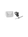 2
2
-
 3
3
-
 4
4
-
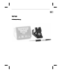 5
5
-
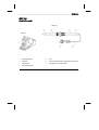 6
6
-
 7
7
-
 8
8
-
 9
9
-
 10
10
-
 11
11
-
 12
12
-
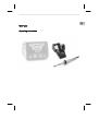 13
13
-
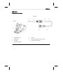 14
14
-
 15
15
-
 16
16
-
 17
17
-
 18
18
-
 19
19
-
 20
20
-
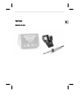 21
21
-
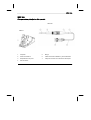 22
22
-
 23
23
-
 24
24
-
 25
25
-
 26
26
-
 27
27
-
 28
28
-
 29
29
-
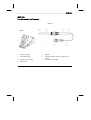 30
30
-
 31
31
-
 32
32
-
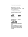 33
33
-
 34
34
-
 35
35
-
 36
36
-
 37
37
-
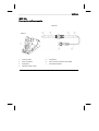 38
38
-
 39
39
-
 40
40
-
 41
41
-
 42
42
-
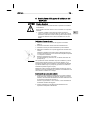 43
43
-
 44
44
-
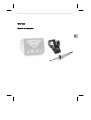 45
45
-
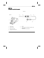 46
46
-
 47
47
-
 48
48
-
 49
49
-
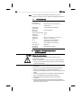 50
50
-
 51
51
-
 52
52
-
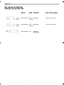 53
53
-
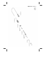 54
54
-
 55
55


Weller C-WXP200 El manual del propietario
- Categoría
- Soldadores
- Tipo
- El manual del propietario
en otros idiomas
- français: Weller C-WXP200 Le manuel du propriétaire
- italiano: Weller C-WXP200 Manuale del proprietario
- Deutsch: Weller C-WXP200 Bedienungsanleitung
- português: Weller C-WXP200 Manual do proprietário
Artículos relacionados
-
Weller WXP 120 Operating Instructions Manual
-
Weller WXD 2 Operating Instructions Manual
-
Weller WXMT Operating Instructions Manual
-
Weller WXMP Set Instrucciones de operación
-
Weller WX2 Operating Instructions Manual
-
Weller WXR 3 Translation Of The Original Instructions
-
-
-
-