Wood Column Installation Instructions
Instrucciones para instalar columnas de madera
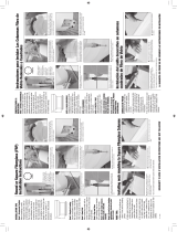
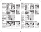
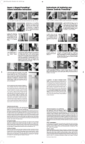
1. Measure the total distance from
the bottom of the beam to the platform,
minus the combined heights of the cap
and the base.
1. Mida la distancia total del la parte inferior
de la viga a la plataforma, menos la altura
combinada de la tapa y de la base.
2. An easy way to accomplish this is
to stack the cap and the base on the
platform, then measure from the top of
the cap to the beam.
2. Una manera fácil de lograrlo es apilar
la tapa y la base sobre la plataforma, y
después medir desde la parte superior de
la tapa a la viga.
3. Measuring from the neck ring and using
the saw kerf line, trim ³⁄₈" to ¹⁄₄" from the
top of the column to provide a square end
from which to measure.
3. Midiendo desde la argolla del cuello y
utilizando la línea del corte de la sierra,
recorte ³⁄₈" a ¹⁄₄" desde la parte superior
de la columna para proveer un cuadrado
desde el cual se pueda medir.
4. Use a rasp to level off the cuts so the
weight will be evenly distributed across
the surface of the column.
4. Utilice una escofi na para nivelar los
cortes para que el peso sea distribuido
uniformemente a través de la superfi cie
de la columna.
5. Measure from the newly trimmed top of
the shaft to the proper length and make a
series of marks around the column shaft.
5. Mida de la nueva medida de la parte
superior del eje a la longitud apropiada y
haga una serie de marcas alrededor del
eje de la columna.
6. Using a piece of cardboard as a guide,
draw a line all the way around the shaft.
6. Utilizando un pedazo de cartulina como
guía, dibuje una línea alrededor de toda
la columna.
7. Use a fi ne-tooth saw to cut the column.
Cut through the wall and roll the column
to accurately follow the line.
7. Utilice una sierra de diente fi no para
cortar la columna. Corte a través la
pared y ruede la columna para seguir
exactamente la línea.
8. Using a non-fi brous, solid-drying
asphaltum-type roof coating, paint the
inside of the shaft from the bottom up, as
far as you can reach.
8. Usando una capa de pintura para
azotea, sin fi bras, de sequedad sólida,
de tipo asfalto, pinte el interior del eje
de arriba para abajo, hasta donde usted
pueda alcanzar.
9. Paint the bottom cut end of the shaft
with an oil-base or acrylic-latex outdoor
wood primer and two topcoats of paint.
9. Pinte el extremo inferior del eje con una
capa preparatoria exterior base de aceite
o acrílica y látex, y dos capas de pintura.
10. Paint the top cut end of the shaft with
an oil-base or acrylic-latex outdoor wood
primer and two topcoats of paint.
10. Pinte la parte superior del eje con una
capa preparatoria exterior base de aceite
o acrílica y látex, y dos capas de pintura.
11. Using a jack and post, jack up the
beam only enough to remove the existing
post, no more than ¹⁄₄".
11. Usando un gato y un poste,
levante la viga con el gato lo sufi ciente
como para quitar el poste existente, no
más que ¹⁄₄".
12. Determine the top centerline and mark
it on the beam.
12. Determine la línea central superior
y márquela en la viga.
13. Hang a plumb bob from
the top centerline to determine the
bottom centerline.
13. Cuelgue un plomo vertical de la línea
central superior para determinar la línea
central inferior.
14. Mark the bottom centerline point.
14. Marque el punto inferior de la
línea central.
15. Using a square, draw a centerline
perpendicular to the outside edge
of the platform.
15. Utilizando una escuadra, dibuje una
línea central perpendicular al borde
exterior de la plataforma.
16. Draw a centerline parallel to the
outside edge.
16. Dibuje una línea central paralela
al borde exterior.
17. Mark the centerline on all four sides of
the base to assist with alignment.
17. Marque la línea central en los
cuatro lados de la base para asistir con
la alineación.
18. Center the base on the centerlines on
the platform and draw an outline where
the base will sit.
18. Centre la base en las líneas centrales
en la plataforma y dibuje un trazado
donde la base se sentará.
19. Mark the location of anchor pins in the
corners of the base outline–¹⁄₂" from either
side. Mark for two pins in diagonally
opposite corners.
19. Marque el lugar de los pernos de
ancla en las esquinas del trazado–¹⁄₂"
de cualquier lado. Marque para dos
pernos situado diagonalmente en
esquinas opuestas.
20. Drill pilot holes for the anchor pins.
20. Taladre agujeros guía para los pernos
de anclar.
2
1. Place the anchor pins in the platform
pilot holes.
21. Coloque los pernos de anclar en los
agujeros guía de la plataforma.
22. Center the base on the bottom of the
shaft. Use a couple of fi nishing nails to
temporarily hold it in place.
22. Centre la base en la parte inferior
del eje. Utilice un par de clavos para
mantenerlo en lugar temporalmente.
23. Drill pilot holes through the remaining
two holes in the base.
23. Taladre agujeros guía a través de los
dos agujeros restantes en la base.
24. Using the pilot holes, attach the base
with two 2¹⁄₂" corrosion resistant drywall
screws. Remove the nails, drill pilot holes,
and install two more screws.
24. Utilizando los agujeros guía, una
la base con dos tornillos resistentes a
la corrosión de 2¹⁄₂". Quite los clavos,
perfore los agujeros guía e instale dos
tornillos adicionales.
25. Position the shaft-base assembly over
the two anchor pins.
25. Coloque el montaje de la base del eje
sobre los dos pernos de anclar.
26. Use 2" fi nishing nails to secure the cap
in place on the beam.
26. Utilice clavos sin cabeza de 2" para
asegurar la tapa en su lugar en la viga.
27. Drill four countersunk pilot holes
through the edge of the wider portion of
the top of the shaft into the cap.
27. Taladre cuatro agujeros guía
abocardados a través del borde de la
porción más ancha de la parte superior
del eje en la tapa.
28. Drive four 2¹⁄₂" corrosion-resistant
drywall screws at an angle through
the wider portion of the shaft top into
the cap.
28. Ajuste 4 tornillos de 2¹⁄₂" para
tablarroca resistentes a la corrosión en
un ángulo a través de la porción más ancha
de la parte superior del eje en la tapa.
29. Seal the seam where the shaft meets
the cap and base with 30-year, paintable
siliconized caulk.
29. Selle la línea de la junta donde el
eje se encuentra con la tapa y la base con
sello de calafetear de silicon de 30 años.
30. Fill countersunk holes with an outdoor
wood putty.
30. Llene los agujeros abocardados
con un resanador para el exterior.
Before exposure to weather, wood
parts must be painted with two coats
of high-quality OIL-BASE or ACRYLIC-
LATEX primer and two topcoats of
paint to maintain warranty coverage.
Antes de exponerlas a la intemperie,
las piezas de madera se deben pintar
con dos capas de pintura base de
alta calidad de BASE DE ACEITE
o ACRILICA Y LATEX, y dos capas de
pintura para mantener la cobertura de
la garantía.
1
20
21
26
27
28
29
30
22
23
24
25
19
18
17
16
2
3
4
5
6
7
8
9
10
15
14
13
12
11
TCT185 ©2006 Turncraft. All right reserved. TW-V1660066160 All other trademarks mentioned herein are the property of their respective owners.
Wood Column Installation Instructions
Instrucciones para instalar columnas de madera
PAINT BEFORE
INSTALLATION!
www.turncraft.com -- (541) 826-2911
-
 1
1
Turncraft 2508 Guía de instalación
- Tipo
- Guía de instalación
en otros idiomas
- English: Turncraft 2508 Installation guide
Artículos relacionados
Otros documentos
-
 HB&G 120970 Guía de instalación
-
 HB&G 701598 Guía de instalación
-
 HB&G 120999 Instrucciones de operación
-
Craftsman 139.53920DM El manual del propietario
-
Craftsman 139.53930DM El manual del propietario
-
Craftsman 139.53904D El manual del propietario
-
 HB&G 316693 Instrucciones de operación
-
Chamberlain C870 Instrucciones de operación
-
Chamberlain 311 Manual de usuario
-
Craftsman 139.53905DM El manual del propietario


