
AV SURROUND RECEIVER
AVR-3802
OPERATING INSTRUCTIONS
BEDIENUNGSANLEITUNG
MODE D’EMPLOI
ISTRUZIONI PER L’USO
INSTRUCCIONES DE OPERACION
GEBRUIKSAANWIJZING
BRUKSANVISNING
ON / STANDBY
¢
OFF£
AVR-3802
PRECISION AUDIO COMPONENT / AV SURROUND RECEIVER
OUTPUT
SIGNAL
DETECT
SURROUND
BACK CH
TUNING
PRESET
REC /
MULTI
6.1 / 7.1
SURROUND
SOURCE
ON / STANDBY
REMOTE
SENSOR
FUNCTION
SURROUND
SPEAKER
A
B
AUTO
PCM
DTS
SIGNAL
DIGITAL
INPUT
VOLUME LEVEL
MASTER VOLUME
SURROUND
MODE
SURROUND
PARAMETER
TONE
CONTROL
SELECT CH VOL
DIMMER
STATUS TONE DEFEAT
VIDEO SELECT
INPUT
EXT. IN
ANALOG
AUTO PCM DTS
PHONES
1
2
3
456
789
+10
0
TV/
VCR
OFF
TV
CD
CDR/MD/ TAPE RECEIVER
VCR DBS/CABLE
SKIP
SKIP
ENTER
MEMORY
VOLUME
CHANNEL
+
-
+
-
VDP DVD
POWER
REMOTE CONTROL UNIT
RC-884
ON /
SOURCE
TUNER
VDP
VCR-1 VCR-2/ V.AUX
DVD
TV/DBS
CDR/TAPE
PHONO
CD
SURROUND
PTY RTRDS
INPUT
OUTPUT
TEST
TONE
SPEAKER
6.1 / 7.1
SURROUND
5CH / 7CH
ANALOG
EXT.INMODE
CALL 2
BACKLIGHT
CALL 1
STEREO
STEREO
DOLBY/DTS
SURROUND
DSP
SIMU.
DISPLAY
SYSTEM CALL
DIRECT
RETURN
SETUP
MENU
SHIFT
SURR.
PARA.
OSD
A/B
MUTING
BAND MODE
TUNING
TUNING
FOR ENGLISH READERS PAGE 112 ~ PAGE 142
FÜR DEUTSCHE LESER SEITE 143 ~ SEITE 182
POUR LES LECTEURS FRANCAIS PAGE 183 ~ PAGE 122
PER IL LETTORE ITALIANO PAGINA 123 ~ PAGINA 162
PARA LECTORES DE ESPAÑOL PAGINA 163 ~ PAGINA 202
VOOR NEDERLANDSTALIGE LEZERS PAGINA 203 ~ PAGINA 242
FOR SVENSKA LÄSARE SIDA 243 ~ SIDA 282

2
CAUTION
RISK OF ELECTRIC SHOCK
DO NOT OPEN
CAUTION: TO REDUCE THE RISK OF ELECTRIC SHOCK, DO
NOT REMOVE COVER (OR BACK). NO USER
SERVICEABLE PARTS INSIDE. REFER SERVICING
TO QUALIFIED SERVICE PERSONNEL.
The lightning flash with arrowhead symbol, within an equilateral triangle,
is intended to alert the user to the presence of uninsulated “dangerous
voltage” within the product’s enclosure that may be of sufficient
magnitude to constitute a risk of electric shock to persons.
The exclamation point within an equilateral triangle is intended to alert the
user to the presence of important operating and maintenance (servicing)
instructions in the literature accompanying the appliance.
WARNING: TO REDUCE THE RISK OF FIRE OR ELECTRIC SHOCK, DO
NOT EXPOSE THIS APPLIANCE TO RAIN OR MOISTURE.
• DECLARATION OF CONFORMITY
We declare under our sole responsibility that this
product, to which this declaration relates, is in conformity
with the following standards:
EN60065, EN55013, EN55020, EN61000-3-2 and
EN61000-3-3.
Following the provisions of 73/23/EEC, 89/336/EEC and
93/68/EEC Directive.
• ÜBEREINSTIMMUNGSERKLÄRUNG
Wir erklären unter unserer Verantwortung, daß dieses
Produkt, auf das sich diese Erklärung bezieht, den
folgenden Standards entspricht:
EN60065, EN55013, EN55020, EN61000-3-2 und
EN61000-3-3.
Entspricht den Verordnungen der Direktive 73/23/EEC,
89/336/EEC und 93/68/EEC.
• DECLARATION DE CONFORMITE
Nous déclarons sous notre seule responsabilité que
l’appareil, auquel se réfère cette déclaration, est
conforme aux standards suivants:
EN60065, EN55013, EN55020, EN61000-3-2 et
EN61000-3-3.
D’après les dispositions de la Directive 73/23/EEC,
89/336/EEC et 93/68/EEC.
• DICHIARAZIONE DI CONFORMITÀ
Dichiariamo con piena responsabilità che questo
prodotto, al quale la nostra dichiarazione si riferisce, è
conforme alle seguenti normative:
EN60065, EN55013, EN55020, EN61000-3-2 e EN61000-
3-3.
In conformità con le condizioni delle direttive 73/23/EEC,
89/336/EEC e 93/68/EEC.
QUESTO PRODOTTO E’ CONFORME
AL D.M. 28/08/95 N. 548
• DECLARACIÓN DE CONFORMIDAD
Declaramos bajo nuestra exclusiva responsabilidad que
este producto al que hace referencia esta declaración,
está conforme con los siguientes estándares:
EN60065, EN55013, EN55020, EN61000-3-2 y EN61000-
3-3.
Siguiendo las provisiones de las Directivas 73/23/EEC,
89/336/EEC y 93/68/EEC.
• EENVORMIGHEIDSVERKLARING
Wij verklaren uitsluitend op onze verantwoordelijkheid
dat dit produkt, waarop deze verklaring betrekking heeft,
in overeenstemming is met de volgende normen:
EN60065, EN55013, EN55020, EN61000-3-2 en
EN61000-3-3.
Volgens de bepalingen van de Richtlijnen 73/23/EEC,
89/336/EEC en 93/68/EEC.
• ÖVERENSSTÄMMELSESINTYG
Härmed intygas helt på eget ansvar att denna produkt,
vilken detta intyg avser, uppfyller följande standarder:
EN60065, EN55013, EN55020, EN61000-3-2 och
EN61000-3-3.
Enligt stadgarna i direktiv 73/23/EEC, 89/336/EEC och
93/68/EEC.
NOTE ON USE / HINWEISE ZUM GEBRAUCH /
OBSERVATIONS RELATIVES A L’UTILISATION / NOTE SULL’USO
NOTAS SOBRE EL USO / ALVORENS TE GEBRUIKEN / OBSERVERA
• Avoid high temperatures.
Allow for sufficient heat dispersion when
installed on a rack.
• Vermeiden Sie hohe Temperaturen.
Beachten Sie, daß eine ausreichend
Luftzirkulation gewährleistet wird, wenn das
Gerät auf ein Regal gestellt wird.
• Eviter des températures élevées
Tenir compte d’une dispersion de chaleur
suffisante lors de l’installation sur une
étagère.
• Evitate di esporre l’unità a temperature alte.
Assicuratevi che ci sia un’adeguata
dispersione del calore quando installate
l’unità in un mobile per componenti audio.
• Evite altas temperaturas
Permite la suficiente dispersión del calor
cuando está instalado en la consola.
• Vermijd hoge temperaturen.
Zorg voor een degelijk hitteafvoer indien het
apparaat op een rek wordt geplaatst.
• Undvik höga temperaturer.
Se till att det finns möjlighet till god
värmeavledning vid montering i ett rack.
• Keep the set free from moisture, water, and
dust.
• Halten Sie das Gerät von Feuchtigkeit,
Wasser und Staub fern.
• Protéger l’appareil contre l’humidité, l’eau et
lapoussière.
• Tenete l’unità lontana dall’umidità, dall’acqua
e dalla polvere.
• Mantenga el equipo libre de humedad, agua
y polvo.
• Laat geen vochtigheid, water of stof in het
apparaat binnendringen.
• Utsätt inte apparaten för fukt, vatten och
damm.
• Do not let foreign objects in the set.
• Keine fremden Gegenstände in das Gerät
kommen lassen.
• Ne pas laisser des objets étrangers dans
l’appareil.
• E’ importante che nessun oggetto è inserito
all’interno dell’unità.
• No deje objetos extraños dentro del equipo.
• Laat geen vreemde voorwerpen in dit
apparaat vallen.
• Se till att främmande föremål inte tränger in i
apparaten.
• Handle the power cord carefully.
Hold the plug when unplugging the cord.
• Gehen Sie vorsichtig mit dem Netzkabel um.
Halten Sie das Kabel am Stecker, wenn Sie
den Stecker herausziehen.
• Manipuler le cordon d’alimentation avec
précaution.
Tenir la prise lors du débranchement du
cordon.
• Manneggiate il filo di alimentazione con cura.
Agite per la spina quando scollegate il cavo
dalla presa.
• Maneje el cordón de energía con cuidado.
Sostenga el enchufe cuando desconecte el
cordón de energía.
• Hanteer het netsnoer voorzichtig.
Houd het snoer bij de stekker vast wanneer
deze moet worden aan- of losgekoppeld.
• Hantera nätkabeln varsamt.
Håll i kabeln när den kopplas från el-uttaget.
• Unplug the power cord when not using the
set for long periods of time.
• Wenn das Gerät eine längere Zeit nicht
verwendet werden soll, trennen Sie das
Netzkabel vom Netzstecker.
• Débrancher le cordon d’alimentation lorsque
l’appareil n’est pas utilisé pendant de
longues périodes.
• Disinnestate il filo di alimentazione quando
avete l’intenzione di non usare il filo di
alimentazione per un lungo periodo di tempo.
• Desconecte el cordón de energía cuando no
utilice el equipo por mucho tiempo.
• Neem altijd het netsnoer uit het stopkontakt
wanneer het apparaat gedurende een lange
periode niet wordt gebruikt.
• Koppla ur nätkabeln om apparaten inte
kommer att användas i lång tid.
• Do not let insecticides, benzene, and thinner
come in contact with the set.
• Lassen Sie das Gerät nicht mit Insektiziden,
Benzin oder Verdünnungsmitteln in
Berührung kommen.
• Ne pas mettre en contact des insecticides,
du benzène et un diluant avec l’appareil.
• Assicuratevvi che l’unità non venga in
contatto con insetticidi, benzolo o solventi.
• No permita el contacto de insecticidas,
gasolina y diluyentes con el equipo.
• Laat geen insektenverdelgende middelen,
benzine of verfverdunner met dit apparaat in
kontakt komen.
• Se till att inte insektsmedel på spraybruk,
bensen och thinner kommer i kontakt med
apparatens hölje.
• Never disassemble or modify the set in any
way.
• Versuchen Sie niemals das Gerät
auseinander zu nehmen oder auf jegliche Art
zu verändern.
• Ne jamais démonter ou modifier l’appareil
d’une manière ou d’une autre.
• Non smontate mai, nè modificate l’unità in
nessun modo.
• Nunca desarme o modifique el equipo de
ninguna manera.
• Nooit dit apparaat demonteren of op andere
wijze modifiëren.
• Ta inte isär apparaten och försök inte bygga
om den.
• Do not obstruct the ventilation holes.
• Die Belüftungsöffnungen dürfen nicht
verdeckt werden.
• Ne pas obstruer les trous d’aération.
• Non coprite i fori di ventilazione.
• No obstruya los orificios de ventilación.
• De ventilatieopeningen mogen niet worden
beblokkeerd.
• Täpp inte till ventilationsöppningarna.
* (For sets with ventilation holes)
ENGLISH DEUTSCH FRANCAIS ITALIANO ESPAÑOL NEDERLANDS SVENSKA

3
ENGLISH
2 We greatly appreciate your purchase of the AVR-3802.
2 To be sure you take maximum advantage of all the features the AVR-3802 has to offer, read these
instructions carefully and use the set properly. Be sure to keep this manual for future reference,
should any questions or problems arise.
“SERIAL NO.
PLEASE RECORD UNIT SERIAL NUMBER ATTACHED TO THE REAR OF THE
CABINET FOR FUTURE REFERENCE”
2 INTRODUCTION
Thank you for choosing the DENON AVR-3802 Digital Surround A / V receiver. This remarkable component has
been engineered to provide superb surround sound listening with home theater sources such as DVD, as well as
providing outstanding high fidelity reproduction of your favorite music sources.
As this product is provided with an immense array of features, we recommend that before you begin hookup and
operation that you review the contents of this manual before proceeding.
TABLE OF CONTENTS
z
Before Using........................................................3
x
Cautions on Installation........................................3
c
Cautions on Handling...........................................3
v
Features...............................................................4
b
Connections.....................................................4~8
n
Part Names and Functions ..............................8, 9
m
Setting up the system...................................9~16
,
Remote Control Unit ...................................16~22
.
Operation.....................................................22~26
⁄0
Surround......................................................27~29
⁄1
DSP Surround Simulation............................30~32
⁄2
Listening to the Radio .................................33~35
⁄3
Last Function Memory.......................................36
⁄4
Initialization of the Microprocessor....................36
⁄5
Troubleshooting ...........................................36, 37
⁄6
Additional Information .................................37~41
⁄7
Specifications.....................................................42
2
ACCESSORIES
Check that the following parts are included in addition to the main unit:
ertyu
q Operating instructions........................................1
w Service station list..............................................1
e Remote control unit (RC-884) ............................1
r R6P/AA batteries................................................3
t AM loop antenna................................................1
y FM indoor antenna.............................................1
u FM antenna adaptor...........................................1
1
BEFORE USING
Pay attention to the following before using this
unit:
• Moving the set
To prevent short circuits or damaged wires in the
connection cords, always unplug the power cord
and disconnect the connection cords between all
other audio components when moving the set.
• Before turning the power switch on
Check once again that all connections are proper
and that there are not problems with the connection
cords. Always set the power switch to the standby
position before connecting and disconnecting
connection cords.
• Store this instructions in a safe place.
After reading, store this instructions along with the
warranty in a safe place.
• Note that the illustrations in this instructions
may differ from the actual set for explanation
purposes.
Noise or disturbance of the picture may be generated
if this unit or any other electronic equipment using
microprocessors is used near a tuner or TV.
If this happens, take the following steps:
• Install this unit as far as possible from the tuner or
TV.
• Set the antenna wires from the tuner or TV away
from this unit’s power cord and input/output
connection cords.
• Noise or disturbance tends to occur particularly
when using indoor antennas or 300 Ω/ohms feeder
wires. We recommend using outdoor antennas
and 75 Ω/ohms coaxial cables.
For heat dispersal, leave at least 10 cm of space
between the top, back and sides of this unit
and the wall or other components.
B
10 cm or more
wall
10 cm or more
2
CAUTIONS ON INSTALLATION
• Switching the input function when input jacks
are not connected
A clicking noise may be produced if the input
function is switched when nothing is connected to
the input jacks. If this happens, either turn down the
MASTER VOLUME control or connect components
to the input jacks.
• Muting of PRE OUT jacks, HEADPHONE jacks
and SPEAKER terminals
The PRE OUT jacks, HEADPHONE jacks and
SPEAKER terminals include a muting circuit.
Because of this, the output signals are greatly
reduced for several seconds after the power switch
is turned on or input function, surround mode or any
other-set-up is changed. If the volume is turned up
during this time, the output will be very high after
the muting circuit stops functioning. Always wait
until the muting circuit turns off before adjusting the
volume.
• Whenever the power switch is in the
£ OFF
state, the apparatus is still connected on AC line
voltage.
Please be sure to unplug the cord when you
leave home for, say, a vacation.
3
CAUTIONS ON HANDLING

4
ENGLISH
4
FEATURES
1. Digital Surround Sound Decoding
Featuring 32 bit high speed DSP, operating entirely
in digital domain, surround sound from digital
sources such as DVD, LD, DTV and satellite are
faithfully re-created.
2. Dolby Pro Logic II decoder
Dolby Pro Logic II is a new format for playing
multichannel audio signals that offers
improvements over conventional Dolby Pro Logic.
It can be used to decode not only sources
recorded in Dolby Surround but also regular stereo
sources into five channels (front left/right, center
and surround left/right). In addition, various
parameters can be set according to the type of
source and the contents, so you can adjust the
sound field with greater precision.
3. Dolby Digital
Using advanced digital processing algorithms,
Dolby Digital provides up to 5.1 channels of wide-
range, high fidelity surround sound. Dolby Digital
is the default digital audio delivery system for
North American DVD and DTV.
4. DTS (Digital Theater Systems)
DTS provides up to 5.1 channels of wide-range,
high fidelity surround sound, from sources such as
laser disc, DVD and specially-encoded music
discs.
5. DTS-ES Extended Surround and DTS Neo:6
The AVR-3802 is compatible with DTS-ES Extended
Surround, a new multi-channel format developed by
Digital Theater Systems Inc.
The AVR-3802 is also compatible with DTS Neo:6, a
surround mode allowing 6.1-channel playback of
regular stereo sources.
6. Wide screen mode for a 7.1-channel sound
even with
5.1-channel sources
DENON has developed a wide screen mode with
a new design which recreates the effects of the
multi surround speakers in movie theaters. The
result is 7.1-channel sound taking full advantage of
surround back speakers, even with Dolby Pro
Logic or Dolby Digital/DTS 5.1-channel signals.
7. 24 bit D/A Conversion
All six channels, including the five main channels
and the low frequency effects (LFE) channel
benefit from reference, for optimum high fidelity
reproduction of music and movie soundtracks.
8. Dual Surround Speaker Mode
Provides for the first time the ability to optimize
surround sound reproduction using two different
types of surround sound speakers as well as two
different surround speaker positions:
(1) Movie Surround
Motion picture soundtracks use the surround
channel(s) to provide the ambient elements of
the acoustic environment they want the
audience to realize. This is best accomplished
by the use of specially-designed surround
speakers that offer a wide diffusion pattern
(bipolar dispersion) or by using surround
speakers that provide broad dispersion with a
minimum of on-axis localization (dipolar
dispersion). Side wall mounting (closer to the
ceiling) of the surround speakers provides the
greatest envelopment, minimizing localization
of direct sound from the speakers.
(2) Music Surround
With full range discrete surround channels, as
well as three discrete full range front channels,
digital formats such as Dolby and DTS offer
thrilling surround sound music listening.
Producers of multi-channel discrete digital
music recordings almost always favor the use
of direct radiating (monopolar) surround
speakers, placed in the rear corners of the
room, since that is how they configure their
studios during the mixing/creation process.
The DENON AVR-3802 provides the ability to
connect two different sets of surround
speakers, and place them in the appropriate
locations in your AV theater room, so that you
can enjoy both movie soundtracks and music
listening, with optimum results and no
compromise.
9. Component Video Switching
In addition to composite video and “S” video
switching, the AVR-3802 provides 2 sets of
component video (Y, P
B/CB, PR/CR) inputs for the
DVD and TV/DBS inputs, and one set of
component video outputs to the television, for
superior picture quality.
10. Video Select Function
Allow you to watch one source (visual) while
listening to another source (audio).
11. Future Sound Format Upgrade Capability via
Eight Channel Inputs & Outputs
For future multi-channel audio format(s), the AVR-
3802 is provided with 7.1 channel (seven main
channels, plus one low frequency effects channel)
inputs, along with a full set of 7.1 channel pre-amp
outputs, controlled by the 8 channel master
volume control. This assures future upgrade
possibilities for any future multi-channel sound
format.
• Do not plug in the AC cord until all connections
have been completed.
• Be sure to connect the left and right channels
properly (left with left, right with right).
• Insert the plugs securely. Incomplete connections
will result in the generation of noise.
• Use the AC OUTLET for audio equipment only.
Do not use them for hair driers, etc.
• Note that binding pin plug cords together with AC
cords or placing them near a power transformer
will result in generating hum or other noise.
• Noise or humming may be generated if a
connected audio equipment is used independently
without turning the power of this unit on. If this
happens, turn on the power of the this unit
.
Connecting the audio components
5
CONNECTIONS
R
L
R
L
R
INPUT OUTPUT
LRL
R
OUTPUT
L
R
L
INPUT
OPTICAL COAXIAL
OUTPUT
OPTICAL
L
R
L
R
L
R
L
R
OUTPUT
DIGITAL AUDIODIGITAL AUDIO
DIGITAL AUDIODIGITAL AUDIO
B
B
CD player
Connecting a CD player
Connect the CD player’s
analog output jacks
(ANALOG OUTPUT) to this
unit’s CD jacks using pin
plug cords.
Connecting a turntable
Connect the turntable’s output cord to the
AVR-3802’s PHONO jacks, the L (left) plug to
the L jack, the R (right) plug to the right jack.
NOTES:
• This unit cannot be used with MC
cartridges directly. Use a separate head
amplifier or step-up transformer.
• If humming or other noise is generated
when the ground wire is connected,
disconnect the ground wire.
Turntable
(MM cartridge)
Ground
wire
Use these jacks if you wish to connect external power
amplifier(s) to increase the power of the front, center,
surround and surround back sound channels, or for
connection to powered loudspeakers.
To use Surround back with one speaker, connect the
speaker to SURR. BACK L CH.
MD recorder, CD recorder or other component
equipped with digital input/output jacks
CD player or other component equipped
with digital output jacks
Connecting the DIGITAL jacks
Use these for connections to audio equipment with digital output. Refer to
page 14 for instructions on setting this terminal.
Connecting a tape deck
Connections for recording:
Connect the tape deck’s recording input jacks (LINE IN or REC) to this unit’s
tape recording (CDR/TAPE OUT) jacks using pin plug cords.
Connections for playback:
Connect the tape deck’s playback output jacks (LINE OUT or PB) to this
unit’s tape playback (CDR/TAPE IN) jacks using pin plug cords.
CD recorder or Tape deck
• When making connections, also refer to the operating instructions of the other components.
The power to this outlet is turned on and off when the power is switched between on and standby from the
remote control unit or power switch.
NOTES:
• Use 75 Ω/ohms cable pin cords for coaxial connections.
• Use optical cables for optical connections, removing the cap before
connecting.
Power supply cord
AC 230V, 50Hz
Connecting the AC OUTLET
AC OUTLET
• SWITCHED
(total capacity – 100 W)
The power to this outlet is turned on and off in conjunction with the
POWER operation switch on the main unit, and when the power is
switched between on and standby from the remote control unit.
No power is supplied from this outlet when this unit’s power is at
standby. Never connect equipment whose total capacity is above 100
W.
NOTE:
Only use the AC OUTLET for audio equipment. Never use them for
hair driers, TVs or other electrical appliances.
Route the connection cords, etc., in
such a way that they do not
obstruct the ventilation holes.
NOTE:
If humming noise is generated
by a tape deck, etc., move the
tape deck away.
Connecting the pre-out jacks

5
ENGLISH
Connecting video components
• To connect the video signal, connect using a 75 Ω/ohms video signal cable cord. Using an improper cable can
result in a drop in video quality.
• When making connections, also refer to the operating instructions of the other components.
IN
VIDEO
R
L
ROUTIN
AUDIO
VIDEO
OUT IN
LRL
R
L
R
L
R OUT IN
AUDIO
VIDEO
OUT IN
LRL
R
L
R
L
R OUT
VIDEO
OUT
L
AUDIO
L
R
R OUT
VIDEO
OUT
L
AUDIO
L
R
R
L
R
L
R
L
R
L
RL
B
B
TV or DBS tuner
DVD player or video disc player (VDP), etc.
Monitor TV
Connecting a TV/DBS tuner
TV/DBS
• Connect the TV’s or DBS tuner’s video output jack (VIDEO OUTPUT)
to the (yellow) TV/DBS IN jack using a 75 Ω/ohms video
coaxial pin plug cord.
• Connect the TV’s or DBS tuner’s audio output jacks (AUDIO OUTPUT)
to the TV/DBS IN jacks using pin plug cords.
AUDIO
VIDEO
Connecting a DVD player or a video disc player (VDP)
MONITOR OUT
• Connect the TV’s video
input jack (VIDEO
INPUT) to the
MONITOR OUT jack
using a 75 Ω/ohms
video coaxial pin plug
cord.
VIDEO
Note on connecting the digital input
jacks
• Only audio signals are input to the
digital input jacks. For details, see page
4.
Video deck 2
Video deck 1
• There are two sets of video deck (VCR) jacks, so two video decks can be connected for simultaneous recording or video copying.
Video input/output connections:
• Connect the video deck’s video output jack (VIDEO OUT) to the (yellow) VCR-1 IN jack, and the video deck’s video input jack (VIDEO IN) to the
(yellow) VCR-1 OUT jack using 75 Ω/ohms video coaxial pin plug cords.
Connecting the audio output jacks
• Connect the video deck’s audio output jacks (AUDIO OUT) to the VCR-1 IN jacks, and the video deck’s audio input jacks (AUDIO IN) to the
VCR-1 OUT jacks using pin plug cords.
Connect the second video deck to the VCR-2/V.AUX jacks in the same way.
AUDIOAUDIO
VIDEO
VIDEO
Connecting a video decks
DVD
• Connect the DVD player’s video output jack (VIDEO OUTPUT) to the
(yellow) DVD IN jack using a 75 Ω/ohms video coaxial pin plug cord.
• Connect the DVD player’s analog audio output jacks (ANALOG AUDIO OUTPUT)
to the DVD IN jacks using pin plug cords.
• VDP player can be connected to the VDP jacks in the same way.
• It is also possible to connect a video disc player, DVD player, video camcorder,
game machine, etc., to the VCR-2/V.AUX jacks.
AUDIO
VIDEO
IN
S-VIDEO
OUT
S-VIDEO
OUT
S-VIDEO
OUT IN
S-VIDEO
OUT IN
S-VIDEO
B
B
DVD player or video disc player (VDP)
Monitor TV
Video deck 2
Video deck 1
TV or satellite broadcast tuner
Connecting a DVD player or a video disc player (VDP)
Connecting a monitor TV
Connecting the video decks
Connecting a TV/DBS tuner
DVD
• Connect the DVD player’s S-Video output jack to the S-
VIDEO DVD IN jack using an S-Video connection cord.
• A VDP can be connected to the VDP jacks in the same way.
• It is also possible to connect a video disc player, DVD player,
video camcorder, game machine, etc., to the VCR-2/V.AUX
jacks.
MONITOR OUT
• Connect the TV’s S video input (S-VIDEO INPUT) to the
MONITOR OUT jack using a S jack connection cord.
S-VIDEO
• Connect the TV’s or DBS tuner’s S video output jack (S-
VIDEO OUTPUT) to the TV/DBS IN jack using an
S jack connection cord.
S-VIDEO
• Connect the video deck’s S output jack (S-OUT) to the
VCR-1 IN jack and the video deck’s S input jack (S-IN) to the
VCR-1 OUT jack using S jack connection cords.
• Connect the video deck’s S output jack (S-OUT) to the
VCR-2/V.AUX IN jack and the video deck’s S input jack (S-IN) to
the VCR-2/V.AUX OUT jack using S jack connection
cords.
S-VIDEO
S-VIDEO
S-VIDEO
S-VIDEO
Connecting a video component equipped with S-Video jacks
• When making connections, also refer to the operating instructions of the other components.
• A note on the S input jacks
The input selectors for the S inputs and pin jack inputs work in conjunction with each other.
• Precaution when using S-jacks
This unit’s S-jacks (input and output) and video pin jacks (input and output) have independent circuit structures,
so that video signals input from the S-jacks are only output from the S-jack outputs and video signals input
from the pin jacks are only output from the pin jack outputs.
When connecting this unit with equipment that is equipped with S-jacks, keep the above point in mind and
make connections according to the equipment’s instruction manuals.
Connecting a monitor
TV

6
ENGLISH
Connecting the antenna terminals
DIRECTION OF
BROADCASTING
STATION
75 Ω/ohms
COAXIAL
CABLE
FM ANTENNA
300 Ω/ohms
FEEDER
CABLE
FM INDOOR
ANTENNA
(Supplied)
300 Ω/ohms
AM LOOP
ANTENNA
(Supplied)
AM OUTDOOR
ANTENNA
GROUND
FM ANTENNA
ADAPTER
(Supplied)
• An F-type FM antenna cable plug can be connected directly.
• If the FM antenna cable’s plug is not of the F-type, connect using the included antenna adapter.
14mm
9mm
14mm
19mm
5mm
5mm
5C-2V3C-2V
1
4
2
3
AM loop antenna assembly FM antenna adopter assembly
Connect to the AM
antenna terminals.
Remove the vinyl tie
and take out the
connection line.
Bend in the reverse
direction.
a. With the
antenna on
top any
stable
surface.
b. With the
antenna
attached to
a wall.
Mount
Installation hole Mount on wall, etc.
75 Ω/ohms COAXIAL CABLE
Open the cover
ANTENNA ADAPTER
REMOVE
CLAMP
CLAMP
CLAMP
PULL
PULL
SHUT
Connection of AM antennas
1. Push the
lever.
2. Insert the
conductor.
3. Return the
lever.
Notes:
• Do not connect two FM antennas
simultaneously.
• Even if an external AM antenna is used, do
not disconnect the AM loop antenna.
• Make sure AM loop antenna lead terminals
do not touch metal parts of the panel.
Y CRCB
VIDEO OUT
Y
CR CB
COMPONENT
VIDEO IN
COMPONENT
B
DVD player
Monitor TV
Connecting a DVD player
Connecting a monitor TV
DVD IN jacks
• Connect the DVD player’s color difference (component)
video output jacks (COMPONENT VIDEO OUTPUT) to the
COMPONENT DVD IN jack using 75 Ω/ohms coaxial video
pin-plug cords.
• In the same way, another video source with component
video outputs such as a TV/DBS tuner, etc., can be connected
to the TV/DBS color difference (component) video jacks.
MONITOR OUT jack
• Connect the TV’s color difference (component)
video input jacks (COMPONENT VIDEO INPUT)
to the COMPONENT MONITOR OUT jack using
75 Ω/ohms coaxial video pin-plug cords.
• The color difference input jacks may be indicated differently on some
TVs, monitors or video components (“CR, CB and Y”, “R-Y, B-Y and Y”,
“Pr, Pb and Y”, etc.). For details, carefully read the operating instructions
included with the TV or other component.
Connecting a Video Component Equipped with Color Difference (Component
- Y, P
R
/C
R
, P
B
/C
B
) Video Jacks (DVD Player)
• When making connections, also refer to the operating instructions of the other components.
• The signals input to the color difference (component) video jacks are not output from the VIDEO output jack
(yellow) or the S-Video output jack. In addition, the video signals input to the VIDEO input (yellow) and S-Video
input jacks are not output to the color difference (component) video jacks.
• The AVR-3802’s on-screen display signals are not output from the color difference (component) video output
jacks (MONITOR OUT).
• Some video sources with component video outputs are labeled Y, C
B, CR, or Y, P
b, Pr, or Y, R-Y, B-Y. These
terms all refer to component video color difference output.

7
ENGLISH
L
R
L
R
RL
Decoder with 8- or 6-channel
analog output
Front
Surround back
Surround
Subwoofer
Center
For instructions on playback using the external input (EXT. IN) jacks, see page 24.
Connecting the external input (EXT. IN) jacks
• These jacks are for inputting multi-channel audio signals from an outboard decoder, or a component with a
different type of multi-channel decoder, such as a DVD Audio player, or a multi-channel SACD player, or other
future multi-channel sound format decoder.
• When making connections, also refer to the operating instructions of the other components.
R
L
B
Another room
Integrated pre-main amplifier or power amplifier
For instructions on operations using the MULTI ZONE jacks, see pages 25, 26.
Connecting the MULTI ZONE jacks
• If another pre-main (integrated) amplifier or power amplifier is connected, the multi-source jacks can be used
to play a different program source in another room at the same time.
Speaker Impedance
• Speakers with an impedance of from 6 to 16
Ω/ohms can be connected for use as front and
center speakers.
• Speakers with an impedance of 6 to 16 Ω/ohms
can be connected for use as surround and surround
back speakers.
• Be careful when using two pairs of surround
speakers (A + B) at the same time, since use of
speakers with an impedance of less than 8 Ω/ohms
will lead to damage.
• The protector circuit may be activated if the set is
played for long periods of time at high volumes
when speakers with an impedance lower than the
specified impedance are connected.
NOTE:
NEVER touch the speaker terminals when the
power is on.
Doing so could result in electric shocks.
Connecting the speaker cords
1. Loosen by turning
counterclockwise.
2. Insert the cord. 3. Tighten by turning
clockwise.
Speaker system connections
• Connect the speaker terminals with the speakers
making sure that like polarities are matched ( <
with < , > with > ). Mismatching of polarities will
result in weak central sound, unclear orientation of
the various instruments, and the sense of direction
of the stereo being impaired.
• When making connections, take care that none of
the individual conductors of the speaker cord come
in contact with adjacent terminals, with other
speaker cord conductors, or with the rear panel.
Protector circuit
• This unit is equipped with a high-speed protection circuit. The purpose of this circuit is to protect the
speakers under circumstances such as when the output of the power amplifier is inadvertently short-
circuited and a large current flows, when the temperature surrounding the unit becomes unusually high, or
when the unit is used at high output over a long period which results in an extreme temperature rise.
When the protection circuit is activated, the speaker output is cut off and the power supply indicator LED
flashes. Should this occur, please follow these steps: be sure to switch off the power of this unit, check
whether there are any faults with the wiring of the speaker cables or input cables, and wait for the unit to
cool down if it is very hot. Improve the ventilation condition around the unit and switch the power back on.
If the protection circuit is activated again even though there are no problems with the wiring or the
ventilation around the unit, switch off the power and contact a DENON service center.
Note on speaker impedance
• The protector circuit may be activated if the set is played for long periods of time at high volumes when
speakers with an impedance lower than the specified impedance (for example speakers with an
impedance of lower than 4 Ω/ohms) are connected. If the protector circuit is activated, the speaker output
is cut off. Turn off the set’s power, wait for the set to cool down, improve the ventilation around the set,
then turn the power back on.

8
ENGLISH
Connections
• When making connections, also refer to the operating instructions of the other components.
(
L
) (
R
)
(
L
) (
R
) (
L
) (
R
)
(
L
) (
R
)
Connection jack for
subwoofer with built-in
amplifier (super woofer),
etc.
SURROUND SPEAKER
SYSTEMS (A)
CENTER SPEAKER
SYSTEM
FRONT SPEAKER
SYSTEMS
• Precautions when
connecting speakers
If a speaker is placed near
a TV or video monitor, the
colors on the screen may
be disturbed by the
speaker’s magnetism. If
this should happen, move
the speaker away to a
position where it does not
have this effect.
SURROUND SPEAKER
SYSTEMS (B)
SURROUND BACK/MULTI ZONE
SPEAKER SYSTEMS
NOTES:
• To use Surround back with one
speaker, connect the speaker to
SURR. BACK L CH.
• The settings must be changed to
use this speaker for MULTI
ZONE.
See page 10.
AVR-3802
PRECISION AUDIO COMPONENT / AV SURROUND RECEIVER
OUTPUT
SIGNAL
DETECT
SURROUND
BACK CH
TUNING
PRESET
REC /
MULTI
6.1 / 7.1
SURROUND
SOURCE
ON / STANDBY
REMOTE
SENSOR
FUNCTION
SURROUND
SPEAKER
A
B
AUTO
PCM
DTS
SIGNAL
DIGITAL
INPUT
VOLUME LEVEL
MASTER VOLUME
SURROUND
MODE
SURROUND
PARAMETER
TONE
CONTROL
SELECT CH VOL
DIMMER
STATUS TONE DEFEAT
VIDEO SELECT
INPUT
EXT. IN
ANALOG
AUTO PCM DTS
PHONES
ON / STANDBY
OFF
£
¢
!8
!9@0@1@2@3@4@5@6@7@8@9
q w ter y u i o
!0 !1 !2 !3 !4 !5 !6 !7
Front Panel
6
PART NAMES AND FUNCTIONS
• For details on the functions of these parts, refer to the pages given in parentheses ( ).
q
Power operation switch .................................(22)
w
Headphones jack (PHONES) ..........................(24)
e
6.1/7.1 SURROUND button............................(29)
r
Surround speaker system indicators
(SURROUND SPEAKER A/B)
t
AUTO button ..................................................(23)
y
PCM button....................................................(23)
u
DTS button .....................................................(23)
i
ANALOG button .............................................(23)
o
EXT. IN button ................................................(23)
!0
VIDEO SELECT button ...................................(25)
!1
DIMMER button.............................................(25)
!2
STATUS button ...............................................(25)
!3
TONE DEFEAT button ....................................(24)
!4
SURROUND MODE button............................(23)
!5
SURROUND PARAMETER button .................(28)
!6
SELECT knob..................................................(23)
!7
TONE CONTROL button ................................(24)
!8
CH VOL button...............................................(27)
!9
MASTER VOLUME control ............................(23)
@0
Master volume indicator (VOLUME LEVEL) ..(23)
@1
Display
@2
INPUT mode indicators ..................................(23)
@3
SIGNAL indicators ..........................................(23)
@4
Remote control sensor
(REMOTE SENSOR).......................................(16)
@5
Power indicator ..............................................(22)
@6
FUNCTION knob.............................................(23)
@7
TUNING PRESET button ................................(34)
@8
SOURCE selector button ...............................(23)
@9
REC/MULTI button .........................................(25)

9
ENGLISH
1
2
3
456
789
+10
0
TV/
VCR
OFF
TV
CD
CDR/MD/TAPE RECEIVER
VCR DBS/CABLE
SKIP
SKIP
ENTER
MEMORY
VOLUME
CHANNEL
+
-
+
-
VDP DVD
POWER
REMOTE CONTROL UNIT
RC-884
ON /
SOURCE
TUNER
VDP
VCR-1
RDS PTY RT
VCR-2/V.AUX
DVD
TV/DBS
CDR/TAPE
PHONO
CD
SURROUND
INPUT
OUTPUT
TEST
TONE
SPEAKER
6.1 / 7.1
SURROUND
5CH / 7CH
ANALOG
EXT.INMODE
CALL 2
BACKLIGHT
CALL 1
STEREO
STEREO
DOLBY/DTS
SURROUND
DSP
SIMU.
DISPLAY
SYSTEM CALL
DIRECT
RETURN
SETUP
MENU
SHIFT
SURR.
PARA.
OSD
A/B
MUTING
BAND MODE
TUNING
TUNING
Remote control unit
• For details on the functions of these parts, refer to the pages given in parentheses ( ).
SYSTEM CALL buttons................(19)
Input mode selector buttons .......(23)
Surround mode buttons...............(30)
TEST TONE / RDS button ............(27)
Speaker selector / PTY button .....(30)
System buttons............................(33)
ENTER/system button .................(10)
Tuner system/
system button..............................(10)
System setup/
system button..............................(10)
DISPLAY/SURR. PARA
button...........................................(28)
Master volume control
buttons.........................................(23)
Mode selector buttons ................(17)
Power button ...............................(22)
MENU/OSD button ......................(25)
RETURN/MEMORY/system
button...........................................(33)
MUTING button ...........................(24)
Input source selector
buttons.........................................(23)
OUTPUT / RT button....................(24)
BACKLIGHT button
Remote control signal
transmitter ...................................(16)
SKIP
SKIP
ENTER
MEMORY
VOLUME
CHANNEL
+
-
+
-
TUNER
PH
O
N
O
CD
DISPLAY
RETURN
SETUP
MENU
SHIFT
SURR.
PARA.
OSD
A/B
MUTING
BAND MODE
TUNING
TUNING
7
SETTING UP THE SYSTEM
• Once all connections with other AV components have been completed as described in “CONNECTIONS”
(see pages 4 to 8), make the various settings described below on the monitor screen using the AVR-3802’s
on-screen display function.
These settings are required to set up the listening room’s AV system centered around the AVR-3802.
• Use the following buttons to set up the system:
SYSTEM SETUP button
Press this to display the system setup menu.
ENTER button
Press this to switch the display.
Also use this button to complete the setting.
CURSOR buttons
F and G: Use these to move the cursors (F and G) to
the left and right on the screen.
D and H: Use these to move the cursors (D and H) to
the up and down on the screen.
• System setup items and default values (set upon shipment from the factory)
System setup Default settings
w
e
t
y
i
Speaker
Configuration
(Surround
Speaker
Setting)
(Subwoofer
mode)
SB CH Auto
Flag Detect
Channel Level
Digital In
Assignment
On Screen
Display
Input the combination of speakers in your system and their
corresponding sizes (SMALL for regular speakers, LARGE for
full-size, full-range) to automatically set the composition of the
signals output from the speakers and the frequency response.
Use this function when using multiple surround
speaker combinations for more ideal surround
sound. Once the combinations of surround
speakers to be used for the different surround
modes are preset, the surround speakers are
selected automatically according to the surround
mode.
This selects the subwoofer speaker for playing deep bass
signals.
Set the method of playing the surround backchannel for digital
signals.
This adjusts the volume of the signals output from the speakers
and subwoofer for the different channels in order to obtain
optimum effects.
This assigns the digital input jacks for the different
input sources.
This sets whether or not to display the on-screen display that
appears on the monitor screen when the controls on the remote
control unit or main unit are operated.
Surround
mode
Surround
speaker
Input
source
Digital
Inputs
Front Sp.
Large
Center Sp. Surround Sp. A /BSub Woofer
Small SmallYes
DOLBY/
DTS
SURROUND
5CH/7CH
STEREO
DSP
SIMULATION
EXT. IN
——
AAAA——
LFE
Front L & R Center Surround L & RSub Woofer
3.6 m (12 ft) 3.6 m (12 ft) 3.0 m (10 ft)3.6 m (12 ft)
Front L
Front R Center
Surround
R
Surround
Back R
Subwoofer
0 dB 0 dB 0 dB 0 dB 0 dB 0 dB
CD DVD TV/DBS
CDR
/TAPE
VDP —
COAXIAL
OPTICAL
1
OPTICAL
2
OPTICAL
3
OFF —
On Screen Display = ON
Surround Back Sp.
Small / 2spkrs
DTS-ES / 6.1 Source Auto Flag Detect Mode = OFF
r
Delay Time
This parameter is for optimizing the timing with which the
audio signals are produced from the speakers and subwoofer
according to the listening position.
SBL & SBR
3.0 m (10 ft)
u
This sets the output level for the multi output jacks. 0 dB
Surround
Back L
0 dB
Surround
L
0 dB
Multi vol. Level
VCR-2
OFF
VCR-1
OFF
Power AMP
Assignment
Set this to switch the surround back channel’s power amplifier
for use for multi-zone.
Surround Back
q
A1 ~ A8 87.5 / 89.1 / 98.1 / 108.0 / 90.1 / 90.1 / 90.1 / 90.1 MHz
B1 ~ B8 522 / 603 / 999 / 1404 / 1611 kHz, 90.1 / 90.1 MHz
C1 ~ C8 90.1 MHz
D1 ~ D8 90.1 MHz
E1 ~ E8 90.1 MHz
o
Auto Tuner
Preset
FM stations are received automatically and stored in the
memory.
Crossover
Frequency
Set the frequency (Hz) below which the bass sound of the
various speakers is to be output from the subwoofer.
80 Hz

10
ENGLISH
NOTES:
• The on-screen display signals are not output from the color difference (component) video signal
(MONITOR OUT) jacks.
• The on-screen display signals are output with priority to the S-VIDEO MONITOR OUT jack during playback
of a video component. For example, if the TV monitor is connected to both the AVR-3802’s S-Video and
video monitor output jacks and signals are input to the AVR-3802 from a video source (VDP, etc.) connected
to both the S-Video and video input jacks, the on-screen display signals are output with priority to the S-
Video monitor output. If you wish to output the signals to the video monitor output jack, do not connect a
cord to the S-VIDEO MONITOR OUT jack. (For details, see page 16.)
• The AVR-3802’s on-screen display function is designed for use with high resolution monitor TVs, so it may
be difficult to read small characters on TVs with small screens or low resolutions.
• The setup menu is not displayed when “HEADPHONE ONLY” is selected.
• Speaker system layout
Basic system layout
• The following is an example of the basic layout for a system consisting of eight speaker systems and a
television monitor:
With the AVR-3802 it is also possible to use the surround speaker selector function to choose the best layout for
a variety of sources and surround modes.
Subwoofer Center speaker system
Surround speaker systems
Surround back speaker systems
Front speaker systems
Set these at the sides of the TV or
screen with their front surfaces as flush
with the front of the screen as possible.
• Surround speaker selector function
This function makes it possible to achieve the optimum sound fields for different sources by switching
between two systems of surround speakers (A and B).
AA
BB
AA
BB
SB SB SB SB
Using A only Using B only
SB: SURROUND BACK SPEAKER
Before setting up the system
2
Display the System Setup Menu.
SETUP
1
Check that all the connections are correct, then turn on the main unit’s power.
Setting the power amplifier assignment
Make this setting to switch the power amplifier for the surround back channel to Multi.
1
At the System Setup Menu, select “Power Amp
Assignment” and press the ENTER button.
BAND MODE
TUNING
TUNING
ENTER
SHIFT
2
Select “Surround Back” to use
as the surround back channel,
“Multi” to use as multi zone
out.
BAND MODE
TUNING
TUNING
When “Surround Back” is selected When “Multi” is selected
3
Enter the setting.
The System Setup Menu reappears.
ENTER
SHIFT
• The composition of the signals output from the different channels and the frequency response are adjusted
automatically according to the combination of speakers actually being used.
Setting the type of speakers
1
At the System Setup Menu select “Speaker Configuration”.
BAND MODE
TUNING
TUNING

11
ENGLISH
2
Switch to the speaker configuration screen.
ENTER
SHIFT
Center Sp.
Front Sp.
Subwoofer
Surround Sp. A
Surround back Sp.
Surround Sp. B
NOTE:
• Select “Large” or “Small” not according to the actual size of the speaker but according to the speaker’s
capacity for playing low frequency (bass sound below frequency set for the Crossover Frequency mode and
below) signals. If you do not know, try comparing the sound at both settings (setting the volume to a level
low enough so as not to damage the speakers) to determine the proper setting.
3
Set whether or not speakers
are connected and, if so, their
size parameters.
• To select the speaker
BAND MODE
TUNING
TUNING
• To select the parameter
BAND MODE
TUNING
TUNING
4
Press the ENTER button to finalize the settong.
ENTER
SHIFT
• Parameters
Large.................Select this when using speakers that have sufficient performance for reproducing bass
sound below the frequency set for the Crossover Frequency mode.
Small.................Select this when using speakers that do not have sufficient performance for reproducing
bass sound below the frequency set for the Crossover Frequency mode. When this is set,
bass sound with a frequency below the frequency set for the Crossover Frequency mode
is sent to the subwoofer.
When this setting is selected, low frequencies of below the frequency set for the Crossover
Frequency mode are assigned to the subwoofer.
None……..........Select this when no speakers are installed.
Yes/No…...........Select “Yes” when a subwoofer is installed, “No” when a subwoofer is not installed.
2spkrs/1spkr .....Set the number of speakers to be used for the surround back channel.
If the subwoofer has sufficient low frequency playback capacity, good sound can be achieved even when
“Small” is set for the front, center and surround speakers.
For the majority of speaker system configurations, using the Small setting for all five main speakers and
Subwoofer On with a connected subwoofer will yield the best results.
This screen is displayed when using both surround speakers A and B.
• At this screen preset the surround speakers to be used in the different surround modes.
Selecting the surround speakers for the different surround modes
1
When either “Large” or “Small” has been set for both
speakers A and B on the System Setup Menu (when using
both A and B surround speakers), the surround speaker
setting screen appears.
Select the surround speakers to be used in the different
surround modes.
• To select the surround mode
BAND MODE
TUNING
TUNING
• To select the surround speaker
A: When using surround speakers A
B: When using surround speakers B
A+B: When using both surround speakers A and B
BAND MODE
TUNING
TUNING
Speaker type setting when using both surround speakers A and B
If “Small” is set for either surround speakers A or B, the output is the same as when “Small” is set for both
A and B.
2
Enter the setting.
When “Front” is set to “Large” and “Subwoofer” is set to “Yes”, the set switches to the
subwoofer mode.
ENTER
SHIFT
Setting the Crossover Frequency and Subwoofer mode
1
Select the “Crossover Frequency” mode.
BAND MODE
TUNING
TUNING
3
Enter the setting.
The System Setup Menu reappears.
ENTER
SHIFT
This screen is displayed when using a subwoofer.
• Set the crossover frequency and subwoofer mode according to the speaker system being used.
Select the Frequency.
BAND MODE
TUNING
TUNING
2
Select the “Subwoofer Mode”.
BAND MODE
TUNING
TUNING
Select the setting.
BAND MODE
TUNING
TUNING

12
ENGLISH
NOTES:
— Assignment of low frequency signal range —
• The only signals produced from the subwoofer channel are LFE signals (during playback of Dolby Digital or
DTS signals) and the low frequency signal range of channels set to “Small” in the setup menu. The low
frequency signal range of channels set to “Large” are produced from those channels.
— Crossover Frequency —
• When “Subwoofer” is set to “Yes” at the “Speaker Configuration Setting”, set the frequency (Hz) below
which the bass sound of the various speakers is to be output from the subwoofer (the crossover
frequency).
• For speakers set to “Small”, sound with a frequency below the crossover frequency is cut, and the cut bass
sound is output from the subwoofer instead.
NOTE: For ordinary speaker systems, we recommend setting the crossover frequency to 80 Hz. When
using small speakers, however, setting the crossover frequency to a high frequency may improve
frequency response for frequencies near the crossover frequency.
— Subwoofer mode —
• The subwoofer mode setting is only valid when “Large” is set for the front speakers and “Ye s” is set for
the subwoofer in the “Speaker Configuration” settings (see page 10).
• When the “LFE+MAIN” playback mode is selected, the low frequency signal range of channels set to
“Large” are produced simultaneously from those channels and the subwoofer channel.
In this playback mode, the low frequency range expand more uniformly through the room, but depending
on the size and shape of the room, interference may result in a decrease of the actual volume of the low
frequency range.
• Selection of the “LFE ” play mode will play the low frequency signal range of the channel selected with
“Large” from that channel only. Therefore, the low frequency signal range that are played from the
subwoofer channel are only the low frequency signal range of LFE (only during Dolby Digital or DTS signal
playback) and the channel specified as “Small” in the setup menu.
• Select the play mode that provides bass reproduction with body.
• When the subwoofer is set to “Ye s”, bass sound is output from the subwoofer regardless of the subwoofer
mode setting in surround modes other than Dolby/DTS.
Set the operation for the digital signals when playing in the 6.1 SURROUND and DTS-ES surround modes.
Setting the SB CH Auto Flag Detect
1
At the System Setup Menu select “SB CH
Auto Flag Deterct” and press the ENTER
button.
BAND MODE
TUNING
TUNING
ENTER
SHIFT
Setting
q Auto Flag Detect Mode (AFDM)
ON: This function only works for sources containing DTS-ES or 6.1-channel surround identification signals.
When this function is used, sources that have been recorded in 6.1-channel surround or DTS-ES are
automatically played in the 6.1-channel surround mode using the surround back speaker(s). (Refer to
w for the method of playback of the surround back speaker in this case.)
OFF: Set this mode if you wish to play normal 5.1-channel sources or sources not containing the
identification signals described below in the 6.1-channel mode.
NOTES:
• The “SB CH Auto Flag Detect” setting screen is displayed when the surround back speaker is set to
“Large” or “Small” at “Speaker Configuration”.
• The surround back speakers can also be turned on and off using the “6.1/7.1 Surround” surround
parameter. (See page 29.)
2
Select the desired setting.
We recommend setting this
to “OFF”.
When set to “ON”, the
operation for software for
which no identification
signals are recorded is set.
BAND MODE
TUNING
TUNING
3
Enter the setting.
The System Setup Menu reappears.
ENTER
SHIFT
• Input the distance between the listening position and the different speakers to set the delay time for the
surround mode.
• The delay time can be set separately for surround speakers A and B.
Setting the delay time
Preparations:
Measure the distances between the listening position and the speakers
(L1 to L5 on the diagram at the right).
L1: Distance between center speaker and listening position
L2: Distance between front speakers and listening position
L3: Distance between surround speakers and listening position
L4: Distance between surround back speakers and listening position
L5: Distance between subwoofer and listening position
L1
L2
L5
L3
L4
Center FRFL
Subwoofer
SL
Listening position
SR
SBRSBL
1
At the System Setup Menu select “Delay Time”.
BAND MODE
TUNING
TUNING
w Non-Flag Source SBch Output
MTRX ON: Sources are played using the surround back speaker(s). The surround back channel is played
with digital matrix processing.
NON-MTRX: Sources are played using the surround back speaker(s). The same signals as those of the
surround channel are output from the surround back speaker(s).
OFF: Sources are played without using the surround back speaker(s).
2
Switch to the Delay Time screen.
ENTER
SHIFT
Example: When “Meters” is selected
3
Select the desired unit, meters or feet.
Select (darken) the desired units, “Meters” or “Feet”.
BAND MODE
TUNING
TUNING

13
ENGLISH
4
Once “Meter” or “Feet” is selected in Step 3,
the Delay Time screen appears automatically.
5
Select the speaker to be set.
BAND MODE
TUNING
TUNING
Example: When the distance is set to
3.6 m for the center speaker
6
Set the distance between the
center speaker and listening
position.
The distance changes in units
of 0.1 meters (1 foot) each
time the button is pressed.
Select the value closest to the
measured distance.
BAND MODE
TUNING
TUNING
If “Yes” is selected for “Default”, the settings are
automatically reset to the default values.
Please note that the difference of distance for every speaker
should be 4.5 m (15 ft) or less. If you set an invalid distance,
a CAUTION notice, such as screen right will appear. In this
case, please relocate the blinking speaker(s) so that its
distance is no larger than the value shown in highlighted line.
7
Enter the setting.
The System Setup Menu reappears.
The AVR-3802 automatically sets the optimum surround delay time for the listening room.
ENTER
SHIFT
NOTES:
• If the distance unit is changed after the delay time is set, the settings are reset to the factory default values
(see page 9).
• Use this setting to adjust so that the playback level between the different channels is equal.
• From the listening position, listen to the test tones produced from the speakers to adjust the level.
• The level can also be adjusted directly from the remote control unit. (For details, see page 27.)
• When using both surround speakers A and B, their playback levels can be adjusted separately.
Setting the channel level
1
At the System Setup Menu select “Channel Level”.
BAND MODE
TUNING
TUNING
2
Switch to the Channel Level screen.
ENTER
SHIFT
3
Select “Test Tone Mode”.
BAND MODE
TUNING
TUNING
Example: When the “Auto” mode is selected
4
Select the mode.
Select “Auto” or “Manual”.
• Auto:
Adjust the level while listening to the test tones produced
automatically from the different speakers.
• Manual:
Select the speaker from which you want to produce the
test tone to adjust the level.
BAND MODE
TUNING
TUNING
5
Select “Surr. Sp.”, then select the surround speaker(s) from which
you want to produce the test tone (A, B or A+B).
• Surr. Sp.: A
Adjusts the balance of the playback level between the channels
when using surround speaker A.
• Surr. Sp.: B
Adjusts the balance of the playback level between the channels
when using surround speaker B.
• Surr. Sp.: A+B
Adjusts the balance of the playback level between the channels
when using surround speakers A and B at the same time.
The “Surr. Sp.” can only be selected when both surround
speakers A and B have been selected at the “Speaker
Configuration” (when both A and B have been set to “Large” or
“Small”).
BAND MODE
TUNING
TUNING
BAND MODE
TUNING
TUNING
6
Select “Test Tone Start”.
BAND MODE
TUNING
TUNING

14
ENGLISH
Use the CURSOR buttons to adjust all the speakers to the
same volume.
The volume can be adjusted between –12 dB and +12 dB in
units of 1 dB.
Example: When the volume is set to
–12 dB while the test tone
is being produced from the
subwoofer
FL C FR SR SBR SBL SL SW
SB
1spkr
2spkrs
When the surround back speaker setting is set to
“1spkr” for “Speaker Configuration”, this is set to “SB”.
7
Select “Ye s”.
BAND MODE
TUNING
TUNING
8
a. If the “Auto” mode is selected:
Test tones are automatically emitted from the different
speakers.
The test tones are emitted from the different speakers in
the following order, at 4-second intervals the first time and
second time around, 2-second intervals the third time
around and on:
BAND MODE
TUNING
TUNING
Flashing
Example: When the volume is set to
–12 dB while the
subwoofer is selected
b. When the “Manual” mode is selected
Use the CURSOR left and right to select the speaker for
which you want to output test tones, then use the
CURSOR up and down to adjust so that the volume of the
test tones from the various speakers is the same.
Flashing
BAND MODE
TUNING
TUNING
9
After the above settings are completed, press the ENTER button.
The “Channel Level” screen reappears.
ENTER
SHIFT
BAND MODE
TUNING
TUNING
To cancel the settings, select “Level Clear” and “Yes ” on the “Channel Level” screen, then make the
settings again.
The level of each channel should be adjusted to 75 dB (C-weighted, slow meter mode) on a sound level meter
at the listening position.
If a sound level meter is not available adjust the channels by ear so the sound levels are the same. Because
adjusting the subwoofer level test tone by ear is difficult, use a well known music selection and adjust for natural
balance.
NOTE: When adjusting the level of an active subwoofer system, you may also need to adjust the subwoofer’s
own volume control.
When you adjust the channel levels while in the SYSTEM SETUP CHANNEL LEVEL mode, the channel
level adjustments made will affect ALL surround modes. Consider this mode a Master Channel Level
adjustment mode.
After you have completed the SYSTEM SETUP CHANNEL LEVEL adjustments, you can then activate the
individual surround modes and adjust channel levels that will be remembered for each of those modes.
Then, whenever you activate a particular surround sound mode, your preferred channel level adjustments
for just that mode will be recalled. Check the instructions for adjusting channel levels within each
surround mode on page 27.
You can adjust the channel levels for each of the following surround modes: DIRECT, STEREO, 5/7 CH
STEREO, DOLBY/DTS SURROUND, WIDE SCREEN, ROCK ARENA, JAZZ CLUB, VIDEO GAME, MONO
MOVIE, and MATRIX.
When using either surround speakers A or B, or when using surround speakers A and B at the same time,
be sure to adjust the balance of playback levels between each channel for the various selections of “A
or B” and “A and B”.
• This setting assigns the digital input jacks of the AVR-3802 for the different input sources.
Setting the Digital In Assignment
1
At the System Setup Menu select “Digital In Assignment”.
BAND MODE
TUNING
TUNING
2
Switch to the Digital In Assignment screen.
ENTER
SHIFT
3
Select the digital input jack to be assigned to the input source.
• To select the input source
• To select the digital input jack
Select “OFF” for input sources for which no digital input jacks are used.
If “Yes” is selected for “Default”, the settings are automatically reset
to the default values.
BAND MODE
TUNING
TUNING
BAND MODE
TUNING
TUNING
NOTES:
• The OPTICAL 3 jacks on the AVR-3802’s rear panel are equipped with an optical digital output jack for
recording digital signals on a CD recorder, MD recorder or other digital recorder. Use this for digital recording
between a digital audio source (stereo - 2 channel) and a digital audio recorder.
• Do not connect the output of the component connected to the OPTICAL 3 OUT jack on the AVR-3802’s rear
panel to any jack other than the OPTICAL 3 IN jack.
•“PHONO” and “TUNER” cannot be selected on the Digital In Assignment screen.
4
Enter the setting.
The System Setup Menu reappears.
ENTER
SHIFT

15
ENGLISH
Set the multi pre-out output level adjustment.
Setting the multi vol. level
1
At the “System Setup Menu” screen, select
“Multi Vol. Level” and press the ENTER
button.
BAND MODE
TUNING
TUNING
2
Select the desired settimg.
0 dB, -40 dB:
The output level is fixed at the set level and the volume can
no longer be adjusted.
Variable:
The level can be adjusted freely using the buttons on the
remote control unit.
BAND MODE
TUNING
TUNING
3
Enter the setting.
The “System Setup Menu” reappears.
ENTER
SHIFT
ENTER
SHIFT
• Use this to turn the on-screen display (messages other than the menu screens) on or off.
Setting the on-screen display (OSD)
1
At the System Setup Menu select “On Screen Display”.
BAND MODE
TUNING
TUNING
2
Switch to the On Screen Display screen.
ENTER
SHIFT
3
Select “ON” or “OFF”.
BAND MODE
TUNING
TUNING
4
Enter the setting.
The System Setup Menu reappears.
ENTER
SHIFT
Use this to automatically search for FM broadcasts and store up to 40 stations at preset channels A1 to 8, B1 to
8, C1 to 8, D1 to 8 and E1 to 8.
NOTE:
• If an FM station cannot be preset automatically due to poor reception, use the “Manual tuning” operation to
tune in the station, then preset it using the manual “Preset memory” operation.
Auto tuner preset
1
Use the CURSOR buttons to specify “Auto Tuner Presets”
from the “System Setup Menu” screen.
BAND MODE
TUNING
TUNING
2
Press the ENTER button.
The “Auto Preset Memory” screen appears.
ENTER
SHIFT
3
Use the CURSOR button to select “Yes”.
“Search” flashes on the screen and searching begins.
“Completed” appears once searching is completed.
The display automatically switches to screen.
BAND MODE
TUNING
TUNING
This completes system setup. Once these settings are made, there is no need to change them unless
different AV components are connected or the speakers are repositioned.

16
ENGLISH
This button can be pressed at any time during the system setup process to complete the process.
After completing system setup
1
At the System Setup Menu, press the SYSTEM SETUP button.
The changed settings are entered and the on-screen display turns off.
SETUP
• On-screen display signals
1
2
3
4
Signals input to the AVR-3802 On-screen display signal output
VIDEO signal input
jack (yellow)
S-video signal
input jack
VIDEO MONITOR OUT video
signal output jack (yellow)
S-video MONITOR OUT video
signal output jack
E
C
C
E
E
E
C
C
C
C
E
E
C
E
C
C
(
C
: Signal
E
:
No signal)(
C
: On-screen signals output
E
:
On-screen signals not output)
NOTES:
• The on-screen display signals are not output from the color difference (component) video signal
MONITOR OUT jacks.
• For 4 above, the on-screen display signals are output to the VIDEO MONITOR OUT video signal output
jack (yellow) if the monitor TV is not connected to the S-video MONITOR OUT video signal output jack.
B
• Point the remote control unit at the remote sensor
on the main unit as shown on the diagram.
• The remote control unit can be used from a straight
distance of approximately 7 meters from the main
unit, but this distance will be shorter if there are
obstacles in the way or if the remote control unit is
not pointed directly at the remote sensor.
• The remote control unit can be operated at a
horizontal angle of up to 30 degrees with respect to
the remote sensor.
NOTES:
• It may be difficult to operate the remote control
unit if the remote sensor is exposed to direct
sunlight or strong artificial light.
• Do not press buttons on the main unit and remote
control unit simultaneously. Doing so may result in
malfunction.
• Neon signs or other devices emitting pulse-type
noise nearby may result in malfunction, so keep
the set as far away from such devices as possible.
Approx. 7 m
30°
30°
Using the remote control unit
8
REMOTE CONTROL UNIT
• The included remote control unit (RC-884) can be used to operate not only the AVR-3802 but other remote
control compatible DENON components as well. In addition, the memory contains the control signals for
other remote control units, so it can be used to operate non-Denon remote control compatible products.
Inserting the batteries
q Remove the remote control unit’s rear cover.
w Set three R6P/AA batteries in the battery
compartment in the indicated direction.
e Put the rear cover back on.
Notes on Batteries
• Use R6P/AA batteries in the remote control unit.
• The batteries should be replaced with new ones
approximately once a year, though this depends on
the frequency of usage.
• Even if less than a year has passed, replace the
batteries with new ones if the set does not operate
even when the remote control unit is operated
nearby the set. (The included battery is only for
verifying operation. Replace it with a new battery as
soon as possible.)
• When inserting the batteries, be sure to do so in the
proper direction, following the “≈” and “√” marks
in the battery compartment.
• To prevent damage or leakage of battery fluid:
• Do not use a new battery together with an old
one.
• Do not use two different types of batteries.
• Do not short-circuit, disassemble, heat or
dispose of batteries in flames.
• Remove the batteries from the remote control unit
when you do not plan to use it for an extended
period of time.
• If the battery fluid should leak, carefully wipe the
fluid off the inside of the battery compartment and
insert new batteries.
• When replacing the batteries, have the new
batteries ready and insert them as quickly as
possible.

17
ENGLISH
1
2
3
456
789
+10
0
TV/
VCR
OFF
TV
CD
CDR/MD/ TAPE RECEIVER
VCR DBS/ CABLE
SKIP
SKIP
ENTER
MEMORY
VOLUME
CHANNEL
+
-
+
-
VDP DVD
POWER
REMOTE CONTROL UNIT
RC-884
ON /
SOURCE
TUNER
VDP
VCR-1
RDS PTY RT
VCR-2/ V.AUX
DVD
TV/DBS
CDR/TAPE
PHONO
CD
DISPLAY
RETURN
SETUP
MENU
SHIFT
SURR.
PARA.
OSD
A/B
MUTING
BAND MODE
TUNING
TUNING
1
Operating DENON audio components
1
Use the mode selector buttons to select the component you want
to operate.
The mode switches between “AMP”, “TUNER” and “MULTI”
each time the RECEIVER button is pressed, between “CDR”,
“MD” and “TAPE” each time the CDR/MD/TAPE button is
pressed, between “DBS” and “CABLE” each time the
DBS/CABLE button is pressed, and between “DVD” and “DVD
SETUP” each time the DVD button is pressed, and between
“VCR” and “VCR2” eachtime the VCR button is pressed.
2
Operate the audio component.
• For details, refer to the component’s operating instructions.
It may not be possible to operate some models.
1. CD player (CD) system buttons 2. Tape deck (TAPE) system buttons
1
2
3
456
789
+10
0
TV/
VCR
SKIP
SKIP
ENTER
MEMORY
VOLUME
CHANNEL
+
-
+
-
TUNER
VDP
VCR-1 VCR-2/V.AUX
DVD
TV/DBS
CDR/TAPE
PHONO
CD
RETURN
SETUP
SHIFT
A/B
MUTING
BAND MODE
TUNING
TUNING
1
2
3
SKIP
SKIP
ENTER
MEMORY
VOLUME
CHANNEL
+
-
+
-
TUNER
C/
PHONO
CD
RETURN
SETUP
SHIFT
A/B
MUTING
BAND MODE
TUNING
TUNING
6, 7 : Manual search (forward and reverse)
2 :Stop
1 : Play
8, 9 : Auto search (to beginning of track)
3 : Pause
SKIP +, – : (for CD changers only)
0~9, +10 : 10 key
6 : Rewind
7 : Fast forward
2 :Stop
1 : Forward play
3 : Pause
8 : Reverse play
A/B : Switch between sides A and B
3. MD recorder (MD), CD recorder (CDR) system
buttons
1
2
3
456
789
+10
0
TV/
VCR
SKIP
SKIP
ENTER
MEMORY
VOLUME
CHANNEL
+
-
+
-
TUNER
VDP
VCR-1 VCR-2/V.AUX
DVD
TV/DBS
CDR/TAPE
PHONO
CD
RETURN
SETUP
SHIFT
A/B
MUTING
BAND MODE
TUNING
TUNING
6, 7 : Manual search (forward and reverse)
2 :Stop
1 : Play
8, 9 : Auto search (to beginning of track)
3 : Pause
0~9, +10 : 10 key
4. Tuner system buttons
89
+10
0
SKIP
ENTER
MEMORY
VOLUME
CHANNEL
+
+
VCR-1
PTY RT
VCR-2/ V.AUX
TV/DBS
OUTPUT
SPEAKER
RETURN
SETUP
A/B
BAND MODE
TUNING
TUNING
7
TV/
VCR
RDS
TEST
TONE
1
2
3
456
SKIP
-
-
TUNER
VDP DVDCDR/TAPE
PHONO
CD
SHIFT
MUTING
TUNING D, H : Tuning up/down
BAND : Switch between AM and FM bands
MODE : Switch between AUTO and MONO
MEMORY : Preset memory
SHIFT : Switch preset channel range
CHANNEL +, – : Preset channel up/down
1~8 : 10 key
RDS : RDS search
PTY : PTY search
RT : Radio Text
By using the preset memory, the included remote control unit can be used to control other makes of video
equipment. Note that this is not possible for some models, however. In such cases, use the learning function
(see page 19) to store the remote control signals in the remote control unit’s memory.
See page 20 for instructions on resetting the data stored in the preset memory.
Preset memory
1
Press the power ON/SOURCE button and the
OFF button at the same time.
•“SET UP” appears on the remote control
unit’s display.
OFF
ON /
SOURCE
2
Press the ENTER button.
ENTER
SHIFT
3
Use the D and H cursor buttons to display
“ENTER CODE” on the remote control unit,
then press the ENTER button.
The remote control unit’s display switches
as follows each time the D and H cursor
buttons are pressed.
ENTER CODE
CODE NO
LEARN
SYS CALL
RESET
AUTO SEARCH
BAND MODE
TUNING
TUNING
ENTER
SHIFT
4
After “SEL MODE” is displayed, the last
selected mode is set. Use the D and H cursor
buttons to display the component whose codes
you want to store in the memory, then press
the ENTER button.
BAND MODE
TUNING
TUNING
ENTER
SHIFT
The display switches as shown below each
time the D and H cursor buttons are
pressed.
TV CD MD TAPE VCR
DVD VDP CABLE DBS VCR2
NOTES:
• The signals for the pressed buttons are emitted while setting the preset memory. To avoid accidental
operation, cover the remote control unit’s transmitting window while setting the preset memory.
• Depending on the model and year of manufacture, this function cannot be used for some models, even if
they are of makes listed on the included list of preset codes.
• Some manufacturers use more than one type of remote control code. Refer to the included list of preset
codes to change the number and check.
5
Referring to the included List
of Preset Codes, use the
number buttons to input the
preset code (a 4-digit
number) for the manufacturer
of the component whose
signals you want to store in
the memory.
1
2
3
456
789
0
6
“OK” is displayed when the signals are
registered and the mode is terminated.
7
To store the codes of another component in the
memory, repeat steps 1 to 6.
1
2
3
456
789
+10
0
TV/
VCR
OFF
TV
CD
CDR/MD/ TAPE RECEIVER
VCR DBS/ CABLE
SKIP
SKIP
ENTER
MEMORY
VOLUME
CHANNEL
+
-
+
-
VDP DVD
POWER
REMOTE CONTROL UNIT
RC-884
ON /
SOURCE
TUNER
VDP
VCR-1
RDS PTY RT
VCR-2/ V.AUX
DVD
TV/DBS
CDR/TAPE
PHONO
CD
SURROUND
INPUT
OUTPUT
TEST
TONE
SPEAKER
6.1 / 7.1
SURROUND
5CH / 7CH
ANALOG
EXT.INMODE
CALL 2
BACKLIGHT
CALL 1
STEREO
STEREO
DOLBY/DTS
SURROUND
DSP
SIMU.
DISPLAY
SYSTEM CALL
DIRECT
RETURN
SETUP
MENU
SHIFT
SURR.
PARA.
OSD
A/B
MUTING
BAND MODE
TUNING
TUNING
1
5
3, 4
2, 3, 4

18
ENGLISH
Checking the preset memory settings
1
Press the power ON/SOURCE button and the
OFF button at the same time.
•“SET UP” appears on the remote control
unit’s display.
OFF
ON /
SOURCE
2
Press the ENTER button.
ENTER
SHIFT
3
Use the D and H cursor buttons to display
“CODE NO” on the remote control unit, then
press the ENTER button.
BAND MODE
TUNING
TUNING
ENTER
SHIFT
4
Press the D and H cursor
buttons to display the registered
preset memory on the remote
control unit’s display and check.
BAND MODE
TUNING
TUNING
5
Press the ENTER button to
terminate.
ENTER
SHIFT
Operating a component stored in the preset memory
1
Press the mode selector button for the
component you want to operate.
TV
CD
CDR/MD/ TAPE RECEIVER
VCR DBS/CABLE VDP DVD
1
2
3
456
789
+10
0
TV/
VCR
OFF
TV
CD
CDR/MD/ TAPE RECEIVER
VCR DBS/ CABLE
SKIP
SKIP
ENTER
MEMORY
VOLUME
CHANNEL
+
-
+
-
VDP DVD
POWER
REMOTE CONTROL UNIT
RC-884
ON /
SOURCE
TUNER
VDP
VCR-1
RDS PTY RT
VCR-2/ V.AUX
DVD
TV/DBS
CDR/TAPE
PHONO
CD
SURROUND
INPUT
OUTPUT
TEST
TONE
SPEAKER
6.1 / 7.1
SURROUND
5CH / 7CH
ANALOG
EXT.INMODE
CALL 2
BACKLIGHT
CALL 1
STEREO
STEREO
DOLBY/DTS
SURROUND
DSP
SIMU.
DISPLAY
SYSTEM CALL
DIRECT
RETURN
SETUP
MENU
SHIFT
SURR.
PARA.
OSD
A/B
MUTING
BAND MODE
TUNING
TUNING
1
NOTE:
• For the DVD player remote control buttons,
function names may differ depending on the
make. Compare with the remote control
operation of the various components.
The preset codes are as follows upon shipment from the factory and after resetting:
TV, VCR......................................................................HITACHI
CD, MD, TAPE, CDR, VDP, DVD, DVD SETUP .........DENON
DBS ...........................................................................GENERAL INSTRUMENT
CABLE .......................................................................JERROLD
2
Operate the component.
• For details, refer to the component’s operating instructions.
Some models cannot be operated with this remote control unit.
1
2
3
456
789
+10
0
TV/
VCR
OFF
TV
CD
CDR/MD/ TAPE RECEIVER
VCR DBS/CABLE
SKIP
SKIP
ENTER
MEMORY
VOLUME
CHANNEL
+
-
+
-
VDP DVD
POWER
REMOTE CONTROL UNIT
RC-884
ON /
SOURCE
TUNER
VDP
VCR-1
RDS PTY RT
VCR-2/ V.AUX
DVD
TV/DBS
CDR/TAPE
PHONO
CD
SURROUND
INPUT
OUTPUT
TEST
TONE
SPEAKER
6.1 / 7.1
SURROUND
5CH / 7CH
ANALOG
EXT.INMODE
CALL 2
BACKLIGHT
CALL 1
STEREO
STEREO
DOLBY/DTS
SURROUND
DSP
SIMU.
DISPLAY
SYSTEM CALL
DIRECT
RETURN
SETUP
MENU
SHIFT
SURR.
PARA.
OSD
A/B
MUTING
BAND MODE
TUNING
TUNING
1. Digital video disc player
(DVD, DVD SETUP) system
buttons
POWER : Power on/standby
(ON/SOURCE)
6,7 : Manual search
(forward and reverse)
2 :Stop
1 : Play
8,9 : Auto search
(to beginning of track)
3 : Pause
0 ~ 9, +10 : 10 key
skip +, – : Disc skip
(for DVD changer only)
DISPLAY : Display
MENU : Menu
RETURN : Return
SETUP : Setup
2. Video disc player (VDP)
system buttons
POWER : Power on/standby
(ON/SOURCE)
6,7 : Manual search
(forward and reverse)
2 :Stop
1 : Play
8,9 : Auto search (cue)
3 : Pause
0~9, +10 : 10 key
1
2
3
456
789
+10
0
TV/
VCR
OFF
TV
CD
CDR/MD/ TAPE RECEIVER
VCR DBS/CABLE
SKIP
SKIP
ENTER
MEMORY
VOLUME
CHANNEL
+
-
+
-
VDP DVD
POWER
REMOTE CONTROL UNIT
RC-884
ON /
SOURCE
TUNER
VDP
VCR-1
RDS PTY RT
VCR-2/ V.AUX
DVD
TV/DBS
CDR/TAPE
PHONO
CD
SURROUND
INPUT
OUTPUT
TEST
TONE
SPEAKER
6.1 / 7.1
SURROUND
5CH / 7CH
ANALOG
EXT.INMODE
CALL 2
BACKLIGHT
CALL 1
STEREO
STEREO
DOLBY/DTS
SURROUND
DSP
SIMU.
DISPLAY
SYSTEM CALL
DIRECT
RETURN
SETUP
MENU
SHIFT
SURR.
PARA.
OSD
A/B
MUTING
BAND MODE
TUNING
TUNING
3. Video deck (VCR/VCR-2)
system buttons
POWER : Power on/standby
(ON/SOURCE)
6,7 : Manual search
(forward and reverse)
2 :Stop
1 : Play
3 : Pause
Channel +, – : Channels
1
2
3
456
789
+10
0
TV/
VCR
OFF
TV
CD
CDR/MD/ TAPE RECEIVER
VCR DBS/CABLE
SKIP
SKIP
ENTER
MEMORY
VOLUME
CHANNEL
+
-
+
-
VDP DVD
POWER
REMOTE CONTROL UNIT
RC-884
ON /
SOURCE
TUNER
VDP
VCR-1
RDS PTY RT
VCR-2/ V.AUX
DVD
TV/DBS
CDR/TAPE
PHONO
CD
SURROUND
INPUT
OUTPUT
TEST
TONE
SPEAKER
6.1 / 7.1
SURROUND
5CH / 7CH
ANALOG
EXT.INMODE
CALL 2
BACKLIGHT
CALL 1
STEREO
STEREO
DOLBY/DTS
SURROUND
DSP
SIMU.
DISPLAY
SYSTEM CALL
DIRECT
RETURN
SETUP
MENU
SHIFT
SURR.
PARA.
OSD
A/B
MUTING
BAND MODE
TUNING
TUNING
4. Monitor TV (TV), digital
broadcast satellite (DBS)
tuner and cable (CABLE)
system buttons
POWER : Power on/standby
(ON/SOURCE)
SETUP : Setup
RETURN : Menu
D, H, F, G : Cursor up, down,
left and right
ENTER : Enter
CHANNEL : Switch channels
+, –
0~9, +10 : Channels
TV/VCR : Switch between TV
and video player
1
2
3
456
789
+10
0
TV/
VCR
OFF
TV
CD
CDR/MD/ TAPE RECEIVER
VCR DBS/CABLE
SKIP
SKIP
ENTER
MEMORY
VOLUME
CHANNEL
+
-
+
-
VDP DVD
POWER
REMOTE CONTROL UNIT
RC-884
ON /
SOURCE
TUNER
VDP
VCR-1
RDS PTY RT
VCR-2/ V.AUX
DVD
TV/DBS
CDR/TAPE
PHONO
CD
SURROUND
INPUT
OUTPUT
TEST
TONE
SPEAKER
6.1 / 7.1
SURROUND
5CH / 7CH
ANALOG
EXT.INMODE
CALL 2
BACKLIGHT
CALL 1
STEREO
STEREO
DOLBY/DTS
SURROUND
DSP
SIMU.
DISPLAY
SYSTEM CALL
DIRECT
RETURN
SETUP
MENU
SHIFT
SURR.
PARA.
OSD
A/B
MUTING
BAND MODE
TUNING
TUNING

19
ENGLISH
If your AV component is not a Denon product or if it cannot be operated using the preset memory, it can be
controlled with the included remote control unit by storing its remote control signals in the remote control unit.
Learning function
1
Press the power ON/SOURCE button and the
OFF button simultaneously.
•“SET UP” appears on the remote control
unit’s display.
OFF
ON /
SOURCE
2
Press the ENTER button.
ENTER
SHIFT
3
Use the D and H cursor buttons to display
“LEARN” on the remote control unit’s display,
then press the ENTER button.
•“SEL MODE” is displayed.
1
2
3
456
789
+10
0
TV/
VCR
OFF
TV
CD
CDR/MD/ TAPE RECEIVER
VCR DBS/ CABLE
SKIP
SKIP
ENTER
MEMORY
VOLUME
CHANNEL
+
-
+
-
VDP DVD
POWER
REMOTE CONTROL UNIT
RC-884
ON /
SOURCE
TUNER
VDP
VCR-1
RDS PTY RT
VCR-2/ V.AUX
DVD
TV/DBS
CDR/TAPE
PHONO
CD
SURROUND
INPUT
OUTPUT
TEST
TONE
SPEAKER
6.1 / 7.1
SURROUND
5CH / 7CH
ANALOG
EXT.INMODE
CALL 2
BACKLIGHT
CALL 1
STEREO
STEREO
DOLBY/DTS
SURROUND
DSP
SIMU.
DISPLAY
SYSTEM CALL
DIRECT
RETURN
SETUP
MENU
SHIFT
SURR.
PARA.
OSD
A/B
MUTING
BAND MODE
TUNING
TUNING
1, 5, 8
3, 4
2, 3, 4
BAND MODE
TUNING
TUNING
ENTER
SHIFT
4
Use the D and H cursor buttons to select the
mode for the button to be “learned”, then press
the ENTER button.
•“SELECT KEY” is displayed.
BAND MODE
TUNING
TUNING
ENTER
SHIFT
5
Press the button to be “learned” while
“SELECT KEY” is displayed. “NOW LEARN”
appears.
•“NOT VALID” is displayed if a button that
cannot be “learned” is pressed.
• To cancel, press the power ON/SOURCE
button and the OFF button simultaneously.
OFF
ON /
SOURCE
6
Point the remote control units directly at each
other and press and hold in the button on the
other remote control unit which you want to
“learn”.
Other remote
control unit
7
“COMPLETE” appears on the remote control
unit’s display and learning is completed.
•“SELECT KEY” is displayed. Other keys can
be “learned” by repeating steps 5 to 7.
8
To cancel the learning mode, press the power
ON/SOURCE button and the OFF button
simultaneously again.
Registering is not possible in the receiver
mode.
OFF
ON /
SOURCE
The included remote control unit is equipped with a system call function allowing a series of remote control
signals to be transmitted by pressing a single button.
This function can be used for example to turn on the amplifier’s power, select the input source, turn on the
monitor TV’s power, turn on the source component’s power and set the source to the play mode, all at the touch
of a button.
System call
1
Press the power ON/SOURCE button and the
OFF button at the same time. “SET UP”
appears on the remote control unit’s display.
OFF
ON /
SOURCE
2
Press the ENTER button.
ENTER
SHIFT
3
Use the D and H cursor buttons to display “SYS
CALL” on the remote control unit, then press
the ENTER button.
• Display “SYS MODE” on the remote control
unit’s display.
1
2
3
456
789
+10
0
TV/
VCR
OFF
TV
CD
CDR/MD/ TAPE RECEIVER
VCR DBS/ CABLE
SKIP
SKIP
ENTER
MEMORY
VOLUME
CHANNEL
+
-
+
-
VDP DVD
POWER
REMOTE CONTROL UNIT
RC-884
ON /
SOURCE
TUNER
VDP
VCR-1
RDS PTY RT
VCR-2/ V.AUX
DVD
TV/DBS
CDR/TAPE
PHONO
CD
SURROUND
INPUT
OUTPUT
TEST
TONE
SPEAKER
6.1 / 7.1
SURROUND
5CH / 7CH
ANALOG
EXT.INMODE
CALL 2
BACKLIGHT
CALL 1
STEREO
STEREO
DOLBY/DTS
SURROUND
DSP
SIMU.
DISPLAY
SYSTEM CALL
DIRECT
RETURN
SETUP
MENU
SHIFT
SURR.
PARA.
OSD
A/B
MUTING
BAND MODE
TUNING
TUNING
1
7
3, 4, 5
2, 3, 5, 6, 8
BAND MODE
TUNING
TUNING
ENTER
SHIFT
(1) System call buttons
The buttons that can be used for the system call
function are shown on the diagram at the right.
System call signals can be stored at different
buttons according to the mode. System call
signals can be stored at a maximum of 6 buttons
other than the CALL 1 and CALL 2 buttons.
29 successive operations can be set at each of
these buttons.
(2) Storing system call signals
4
When “SYS MODE” is displayed, the remote
control unit’s display switches as shown below
each time the D and H cursor buttons are
pressed.
BAND MODE
TUNING
TUNING
SYS MODE SYS CALL 1
SYS CALL 2
When “SYS CALL 1” or “SYS CALL 2” is
selected, the signals are stored at the SYSTEM
CALL 1 and CALL 2 buttons (green), regardless
of the mode. When the enter button is pressed,
the button registering mode (step 6) is set.
To register at other buttons, select “SYS
MODE” then press the enter button.
• After “SEL MODE” is displayed on the
remote control unit’s display, the mode last
set is displayed.
1
2
3
456
789
+10
0
TV/
VCR
OFF
TV
CD
CDR/MD/ TAPE RECEIVER
VCR DBS/CABLE
SKIP
SKIP
ENTER
MEMORY
VOLUME
CHANNEL
+
-
+
-
VDP DVD
POWER
REMOTE CONTROL UNIT
RC-884
ON /
SOURCE
TUNER
VDP
VCR-1
RDS PTY RT
VCR-2/ V.AUX
DVD
TV/DBS
CDR/TAPE
PHONO
CD
SURROUND
INPUT
OUTPUT
TEST
TONE
SPEAKER
6.1 / 7.1
SURROUND
5CH / 7CH
ANALOG
EXT.INMODE
CALL 2
BACKLIGHT
CALL 1
STEREO
STEREO
DOLBY/DTS
SURROUND
DSP
SIMU.
DISPLAY
SYSTEM CALL
DIRECT
RETURN
SETUP
MENU
SHIFT
SURR.
PARA.
OSD
A/B
MUTING
BAND MODE
TUNING
TUNING

20
ENGLISH
5
Use the D and H cursor buttons to select the
mode for the button at which the system call
signals are to be registered, then press the
ENTER button.
BAND MODE
TUNING
TUNING
ENTER
SHIFT
6
“SELECT KEY” is displayed. Press
the button at which the system call
signals are to be registered, then
press the ENTER button.
•“ENTER KEYS” is displayed, then
the mode display appears.
ENTER
SHIFT
7
q Press the mode selector button according to
the button with the remote control signals to
be registered.
TV
CD
CDR/MD/ TAPE RECEIVER
VCR DBS/CABLE VDP DVD
w Press the buttons with the remote control
signals to be registered one at a time.
8
Press the ENTER button.
•“COMPLETE” appears on the
remote control unit’s display and
registration is completed.
ENTER
SHIFT
NOTES:
• The remote control signals of the buttons pressed while registering the system call signals are emitted, so
be careful not to operate the components accidentally (cover the remote sensors, for example).
• If you exceed the number of signals that can be registered, “FULL” appears on the remote control unit’s
display and only the number of signals that can be registered are registered (up to 29 operations).
1
Press the button at which the system call signals have been stored.
• The stored signals are transmitted successively.
(3) Using the system call function
Resetting
1
Press the power ON/SOURCE button and the
OFF button at the same time.
•“SET UP” appears on the remote control
unit’s display.
OFF
ON /
SOURCE
2
Press the ENTER button.
ENTER
SHIFT
3
Use the D and H cursor buttons to display
“RESET” on the remote control unit, then press
the ENTER button.
BAND MODE
TUNING
TUNING
ENTER
SHIFT
(1) Resetting the system call buttons
1
2
3
456
789
+10
0
TV/
VCR
OFF
TV
CD
CDR/MD/ TAPE RECEIVER
VCR DBS/ CABLE
SKIP
SKIP
ENTER
MEMORY
VOLUME
CHANNEL
+
-
+
-
VDP DVD
POWER
REMOTE CONTROL UNIT
RC-884
ON /
SOURCE
TUNER
VDP
VCR-1
RDS PTY RT
VCR-2/ V.AUX
DVD
TV/DBS
CDR/TAPE
PHONO
CD
SURROUND
INPUT
OUTPUT
TEST
TONE
SPEAKER
6.1 / 7.1
SURROUND
5CH / 7CH
ANALOG
EXT.INMODE
CALL 2
BACKLIGHT
CALL 1
STEREO
STEREO
DOLBY/DTS
SURROUND
DSP
SIMU.
DISPLAY
SYSTEM CALL
DIRECT
RETURN
SETUP
MENU
SHIFT
SURR.
PARA.
OSD
A/B
MUTING
BAND MODE
TUNING
TUNING
1
3, 4, 5
2, 3, 4, 5, 6
4
Use the D and H cursor buttons to display
“RESET SYS” on the remote control unit, then
press the ENTER button.
•“SYS SEL” appears on the remote control
unit’s display.
BAND MODE
TUNING
TUNING
ENTER
SHIFT
5
Press the D and H cursor buttons
to select the system call setting
to be reset.
q To reset CALL 1 or CALL 2, select “SYS
CALL 1” or SYS CALL 2”, then press the
ENTER button.
w To reset system call settings registered at
other buttons, select “SYS MODE”, press
the ENTER button, press the mode button at
which the button is registered, then press
the ENTER button again.
6
“CONFIRM” is displayed. To reset the setting,
press the ENTER button while “CONFIRM” is
displayed.
•“SYS SEL” appears on the remote control
unit’s display.
ENTER
SHIFT
The remote control unit’s display switches
as shown below each time the D and H
cursor buttons are pressed.
RESET PRE RESET LRN
RESET ALL RESET SYS
BAND MODE
TUNING
TUNING
The remote control unit’s display switches
as shown below each time the D and H
cursor buttons are pressed.
SYS MODE SYS CALL 1
SYS CALL 2
ENTER
SHIFT
ENTER
SHIFT
1
Press the power ON/SOURCE button and the
OFF button at the same time.
•“SET UP” appears on the remote control
unit’s display.
OFF
ON /
SOURCE
2
Press the ENTER button.
ENTER
SHIFT
3
Use the D and H cursor buttons to display
“RESET” on the remote control unit, then press
the ENTER button.
BAND MODE
TUNING
TUNING
ENTER
SHIFT
(2) Resetting the preset memory
1
2
3
456
789
+10
0
TV/
VCR
OFF
TV
CD
CDR/MD/ TAPE RECEIVER
VCR DBS/ CABLE
SKIP
SKIP
ENTER
MEMORY
VOLUME
CHANNEL
+
-
+
-
VDP DVD
POWER
REMOTE CONTROL UNIT
RC-884
ON /
SOURCE
TUNER
VDP
VCR-1
RDS PTY RT
VCR-2/ V.AUX
DVD
TV/DBS
CDR/TAPE
PHONO
CD
SURROUND
INPUT
OUTPUT
TEST
TONE
SPEAKER
6.1 / 7.1
SURROUND
5CH / 7CH
ANALOG
EXT.INMODE
CALL 2
BACKLIGHT
CALL 1
STEREO
STEREO
DOLBY/DTS
SURROUND
DSP
SIMU.
DISPLAY
SYSTEM CALL
DIRECT
RETURN
SETUP
MENU
SHIFT
SURR.
PARA.
OSD
A/B
MUTING
BAND MODE
TUNING
TUNING
1
3, 4, 5
2, 3, 4, 6, 7

21
ENGLISH
4
Use the D and H cursor buttons to display
“RESET PRE” on the remote control unit, then
press the ENTER button.
• After “SEL PRE” is displayed on the remote
control unit’s display, the registered preset
memory is displayed on the remote control
unit’s display.
BAND MODE
TUNING
TUNING
ENTER
SHIFT
5
Use the D and H cursor buttons
to select the code to be reset.
When the mode you want to reset is shown on
the remote control unit’s display, press the
ENTER button to reset the preset memory.
7
“CONFIRM” is displayed. To reset the preset
memory, press the ENTER button while
“CONFIRM” is displayed.
•“COMPLETE” appears on the remote control
unit’s display.
ENTER
SHIFT
BAND MODE
TUNING
TUNING
ENTER
SHIFT
6
1
Press the power ON/SOURCE button and the
OFF button at the same time.
•“SET UP” appears on the remote control
unit’s display.
OFF
ON /
SOURCE
2
Press the ENTER button.
ENTER
SHIFT
3
Use the D and H cursor buttons to display
“RESET” on the remote control unit’s display,
then press the ENTER button.
•“RESET PRE” is displayed.
BAND MODE
TUNING
TUNING
ENTER
SHIFT
(3) Resetting “learned” buttons
1
2
3
456
789
+10
0
TV/
VCR
OFF
TV
CD
CDR/MD/ TAPE RECEIVER
VCR DBS/ CABLE
SKIP
SKIP
ENTER
MEMORY
VOLUME
CHANNEL
+
-
+
-
VDP DVD
POWER
REMOTE CONTROL UNIT
RC-884
ON /
SOURCE
TUNER
VDP
VCR-1
RDS PTY RT
VCR-2/ V.AUX
DVD
TV/DBS
CDR/TAPE
PHONO
CD
SURROUND
INPUT
OUTPUT
TEST
TONE
SPEAKER
6.1 / 7.1
SURROUND
5CH / 7CH
ANALOG
EXT.INMODE
CALL 2
BACKLIGHT
CALL 1
STEREO
STEREO
DOLBY/DTS
SURROUND
DSP
SIMU.
DISPLAY
SYSTEM CALL
DIRECT
RETURN
SETUP
MENU
SHIFT
SURR.
PARA.
OSD
A/B
MUTING
BAND MODE
TUNING
TUNING
1
3, 4, 5
2, 3, 4, 5, 6
4
Use the D and H cursor buttons to display
“RESET LRN” on the remote control unit’s
display, then press the ENTER button.
•“SEL MODE” is displayed, then “TV”
appears.
BAND MODE
TUNING
TUNING
ENTER
SHIFT
5
Use the D and H cursor buttons to select the
mode of the button to be reset, then press the
ENTER button.
BAND MODE
TUNING
TUNING
ENTER
SHIFT
“CONFIRM” is displayed. To reset
the “learned” button for the
selected mode, press the ENTER
button while “CONFIRM” is
displayed.
ENTER
SHIFT
6
1
Press the power ON/SOURCE button and the
OFF button at the same time. “SET UP”
appears on the remote control unit’s display.
OFF
ON /
SOURCE
2
Press the ENTER button.
ENTER
SHIFT
3
Use the D and H cursor buttons to display
“RESET” on the remote control unit, then press
the ENTER button.
BAND MODE
TUNING
TUNING
ENTER
SHIFT
(4) All reset function
1
2
3
456
789
+10
0
TV/
VCR
OFF
TV
CD
CDR/MD/ TAPE RECEIVER
VCR DBS/ CABLE
SKIP
SKIP
ENTER
MEMORY
VOLUME
CHANNEL
+
-
+
-
VDP DVD
POWER
REMOTE CONTROL UNIT
RC-884
ON /
SOURCE
TUNER
VDP
VCR-1
RDS PTY RT
VCR-2/ V.AUX
DVD
TV/DBS
CDR/TAPE
PHONO
CD
SURROUND
INPUT
OUTPUT
TEST
TONE
SPEAKER
6.1 / 7.1
SURROUND
5CH / 7CH
ANALOG
EXT.INMODE
CALL 2
BACKLIGHT
CALL 1
STEREO
STEREO
DOLBY/DTS
SURROUND
DSP
SIMU.
DISPLAY
SYSTEM CALL
DIRECT
RETURN
SETUP
MENU
SHIFT
SURR.
PARA.
OSD
A/B
MUTING
BAND MODE
TUNING
TUNING
1
3, 4
2, 3, 4, 5
4
Use the D and H cursor buttons to display
“RESET ALL” on the remote control unit, then
press the ENTER button.
BAND MODE
TUNING
TUNING
ENTER
SHIFT
“CONFIRM” is displayed. To reset, press the
ENTER button while “CONFIRM” is displayed.
•“BUSY” is displayed during the resetting
operation, and “COMPLETE” is displayed
once resetting is completed.
ENTER
SHIFT
5
• This function is for resetting all the settings to the
factory defaults.

22
ENGLISH
• The set is equipped with a function for searching for the registration number if you do not know the preset
code (a 4-digit number) when setting the preset memory.
Auto search function
2
Press the power ON/SOURCE button and the
OFF button simultaneously.
•“SET UP” appears on the remote control
unit’s display.
OFF
ON /
SOURCE
3
Press the ENTER button.
ENTER
SHIFT
4
Use the D and H cursor buttons to display
“AUTOSEARCH” on the remote control unit,
then press the ENTER button.
1
2
3
456
789
+10
0
TV/
VCR
OFF
TV
CD
CDR/MD/ TAPE RECEIVER
VCR DBS/ CABLE
SKIP
SKIP
ENTER
MEMORY
VOLUME
CHANNEL
+
-
+
-
VDP DVD
POWER
REMOTE CONTROL UNIT
RC-884
ON /
SOURCE
TUNER
VDP
VCR-1
RDS PTY RT
VCR-2/ V.AUX
DVD
TV/DBS
CDR/TAPE
PHONO
CD
SURROUND
INPUT
OUTPUT
TEST
TONE
SPEAKER
6.1 / 7.1
SURROUND
5CH / 7CH
ANALOG
EXT.INMODE
CALL 2
BACKLIGHT
CALL 1
STEREO
STEREO
DOLBY/DTS
SURROUND
DSP
SIMU.
DISPLAY
SYSTEM CALL
DIRECT
RETURN
SETUP
MENU
SHIFT
SURR.
PARA.
OSD
A/B
MUTING
BAND MODE
TUNING
TUNING
2
6
4, 5
3, 4, 5, 7
BAND MODE
TUNING
TUNING
ENTER
SHIFT
1
For TV, DBS or CABLE components, turn on the
component’s power. For CD, MD, TAPE, DVD,
VCR and VDP component’s, turn on the
component’s power and load a disc or tape.
5
Use the D and H cursor buttons to display the
mode of the component to be searched for on
the remote control unit’s display, then press the
ENTER button.
• The registration codes are transmitted in
order.
BAND MODE
TUNING
TUNING
ENTER
SHIFT
6
When the component operates,
press the POWER OFF button.
• The mode and the registered
number appear on the remote
control unit’s display.
The channel switches on the TV, DBS or CABLE
device and playback stops on a CD, MD, tape,
DVD, VCR or VDP player.
OFF
7
Press the ENTER button.
•“COMPLETE” is displayed on the
remote control unit’s display and the
selected code is preset.
ENTER
SHIFT
If you press the power OFF button late at step 6,
press the D and H cursor button once to move to
the next code or back to the previous code one
step at a time.
D button: Next code
H button: Previous code
Auto search resumes when you move ahead from
the code at which you stopped.
9
OPERATION
B
3
OFF
TV
CD
CDR/MD/ TAPE RECEIVER
VCR DBS/CABLE VDP DVD
POWER
REMOTE CONTROL UNIT
RC-884
ON /
SOURCE
DISPLAY
MENU
2
3
Before operating
1
Refer to “CONNECTIONS” (pages 4 to 8) and
check that all connections are correct.
2
Select “AMP” using the RECEIVER button.
(only when operating with the remote control
unit)
ON / STANDBY
OFF
£
¢
ON /
SOURCE
ON/STANDBY
Lights
(Main unit) (Remote control unit)
• ¢ ON/STANDBY
The power turns on and “ON/STANDBY”
indicator is light.
Several seconds are required from the time
the power operation switch is set to the “¢
ON/STANDBY” position until sound is output.
This is due to the built-in muting circuit that
prevents noise when the power switch is
turned on and off.
Set the power operation switch to this
position to turn the power on and off from the
included remote control unit (RC-884).
• £ OFF
The power turns off and “ON/STANDBY”
indicator is off.
In this position, the power cannot be turned
on and off from the remote control unit (RC-
884).
3
Turn on the power.
Press the POWER operation switch (button).
RECEIVER
(Remote control unit)

23
ENGLISH
B
115
2 3
Playing the input source
1
2
3
456
789
+10
0
TV/
VCR
SKIP
SKIP
ENTER
VOLUME
CHANNEL
+
-
+
-
TUNER
VDP
VCR-1
RDS PTY RT
VCR-2/ V.AUX
DVD
TV/DBS
CDR/TAPE
PHONO
CD
SURROUND
INPUT
OUTPUT
TEST
TONE
SPEAKER
6.1 / 7.1
SURROUND
5CH / 7CH
ANALOG
EXT.INMODE
CALL 2
BACKLIGHT
CALL 1
STEREO
STEREO
DOLBY/DTS
SURROUND
DSP
SIMU.
SYSTEM CALL
DIRECT
SHIFT
MUTING
BAND MODE
TUNING
1
2
3
4
1
Select the input source to be played.
Example: CD
To select the input source
when REC MULTI OUT or
TUNING PRESET is selected,
press the SOURCE button
then operate the input function
selector.
SOURCE
FUNCTION
3
CD
(Main unit) (Remote control unit)
AUTO PCM DTS
• Selecting the external input (EXT. IN) mode
Press the EXT. IN (on the EXT. IN button on
the remote control unit) to switch the external
input.
EXT.IN
EXT.IN
(Main unit) (Remote control unit)
• Selecting the AUTO, PCM and DTS modes
The mode switches as shown below each
time the INPUT MODE button is pressed.
MODE
(Remote control unit)
Input mode selection function
Different input modes can be selected for the different
input sources. The selected input modes for the separate
input sources are stored in the memory.
q AUTO (auto mode)
In this mode, the types of signals being input to the
digital and analog input jacks for the selected input
source are detected and the program in the AVR-
3802’s surround decoder is selected automatically
upon playback. This mode can be selected for all input
sources other than PHONO and TUNER.
The presence or absence of digital signals is detected,
the signals input to the digital input jacks are identified
and decoding and playback are performed
automatically in DTS, Dolby Digital or PCM (2 channel
stereo) format. If no digital signal is being input, the
analog input jacks are selected.
Use this mode to play Dolby Digital signals.
w PCM (exclusive PCM signal playback mode)
Decoding and playback are only performed when PCM
signals are being input.
Note that noise may be generated when using this
mode to play signals other than PCM signals.
e DTS (exclusive DTS signal playback mode)
Decoding and playback are only performed when DTS
signals are being input.
r ANALOG (exclusive analog audio signal playback
mode)
The signals input to the analog input jacks are decoded
and played.
t EXT. IN (external decoder input jack selection mode)
The signals being input to the external decoder input
jacks are played without passing through the surround
circuitry.
NOTE:
• Note that noise will be output when CDs or LDs
recorded in DTS format are played in the “PCM”
(exclusive PCM signal playback) or “ANALOG”
(exclusive PCM signal playback) mode. Select the
AUTO or DTS mode when playing signals recorded in
DTS from a laser disc player or CD player.
Note on playing a source encorded with DTS
• Noise may be generated at the beginning of
playback and while searching during DTS
playback in the AUTO mode. If so, play in the
DTS mode.
(Main unit)
2
Select the input mode.
• Selecting the analog mode
Press the ANALOG button to switch to the
analog input.
ANALOG
ANALOG
(Main unit) (Remote control unit)
• Selecting the AUTO mode
Press the AUTO button to switch to the auto
mode.
AUTO
(Main unit)
• Selecting the PCM mode
Press the PCM button to switch to the PCM
signal input.
PCM
(Main unit)
• Selecting the DTS mode
Press the DTS button to switch to the DTS
signal input.
DTS
(Main unit)
3
Select the play mode.
Example: Stereo
SURROUND
MODE
STEREO
(Main unit) (Remote control unit)
The volume can be adjusted within the range of
–70 to 0 to 18 dB, in steps of 1 dB. However, when
the channel level is set as described on page 13 or
page 27, if the volume for any channel is set at +1
dB or greater, the volume cannot be adjusted up to
18 dB. (In this case the maximum volume
adjustment range is “18 dB — (Maximum value of
channel level)”.)
Input mode when playing DTS sources
• Noise will be output if DTS-compatible CDs or LDs
are played in the “ANALOG” or “PCM” mode.
When playing DTS-compatible sources, be sure to
connect the source component to the digital input
jacks (OPTICAL/COAXIAL) and set the input mode to
“DTS”.
4
Start playback on the selected component.
• For operating instructions, refer to the
component’s manual.
5
Adjust the volume.
MASTER VOLUME
VOLUME
+
-
(Main unit) (Remote control unit)
The volume level is
displayed on the
master volume level
display.
SELECT
To select the surround mode
while adjusting the surround
parameters, channel volume or
tone control, press the
surround mode button then
operate the selector.
SURROUND
MODE
(Main unit)
Input mode display
ANALOGDIGITAL
DIGITAL
DIGITAL
ANALOG
AUTO
INPUT
PCM DTS
AUTO
INPUT
PCM DTS
AUTO
INPUT
PCM DTS
AUTO
INPUT
PCM DTS
• In the AUTO mode
• In the DIGITAL PCM mode
• In the DIGITAL DTS mode
• In the ANALOG mode
One of these lights, depending on
the input signal.
Input signal display
SIGNAL
DIGITAL
DIGITAL
DIGITAL
SIGNAL
SIGNAL
• DOLBY DIGITAL
• DTS
• PCM
The indicator lights when digital signals
are being input properly. If the indicator
does not light, check whether the digital input
component setup (page 14) and connections are
correct and whether the component’s power is
turned on.
DIGITAL
DIGITAL
NOTE:
• The indicator will light when playing
CD-ROMs containing data other than audio
signals, but no sound will be heard.
DIGITAL

24
ENGLISH
B
231
BASS TREBLE
[1] Adjusting the sound quality (TONE)
The tone control function will not work in the Direct mode.
After starting playback
1
The tone switches as follows each time the
TONE CONTROL button is pressed.
TONE
CONTROL
(Main unit)
2
With the name of the volume to
be adjusted selected, turn the
SELECT knob to adjust the level.
SELECT
(Main unit)
• To increase the bass or treble: Turn the control
clockwise. (The bass or treble sound can be
increased to up to +12 dB in steps of 2 dB.)
• To decrease the bass or treble: Turn the
control clockwise. (The bass or treble sound
can be decreased to up to –12 dB in steps of
2 dB.)
B
1
+10
0
TV/
VCR
RDS PTY RT
SURROUND
OUTPUT
TEST
TONE
SPEAKER
5CH / 7CH
STEREO
DOLBY/DTS
SURROUND
DSP
SIMU.
2
[2] Listening over headphones
2
Press the OUTPUT button to play the sound
over the headphones only.
OUTPUT
1
Use this to turn off the audio
output temporarily.
Press the MUTING button.
Cancelling MUTING
mode.
Press the MUTING button again.
MUTING
(Remote control unit)
• The output to the speaker and pre-out jacks is
turned off and no sound is produced from the
speakers.
1
Connect the headphones to
the PHONES jack of the front
panel.
1
PHONES
NOTE:
To prevent hearing loss, do not raise the volume level
excessively when using headphones.
Caution: Switching off the power of the unit and
the unit will cancel the settings.
[3] Turning the sound off temporarily (MUTING)
1
2
3
SKIP
SKIP
ENTER
+
-
+
-
TUNER
PHONO
CD
SHIFT
MUTING
TUNING
1
Playback using the external input (EXT. IN) jacks
• When the input mode is set to the external input
(EXT. IN), the play mode (DIRECT, STEREO,
DOLBY/DTS SURROUND, 5/7CH STEREO, WIDE
SCREEN or DSP SIMULATION) cannot be set.
NOTES:
• In play modes other than the external input
mode, the signals connected to these jacks
cannot be played. In addition, signals cannot be
output from channels not connected to the input
jacks.
• The external input mode can be set for any input
source. To watch video while listening to sound,
select the input source to which the video signal
is connected, then set this mode.
1
Set the external input (EXT. IN) mode.
Press the EXT. IN to switch the external input.
Once this is selected, the input signals
connected to the FL (front left), FR (front right),
C (center), SL (surround left), SR (surround
right), SBL (surround back left) and SBR
(surround back right) channels of the EXT. IN
jacks are output directly to the front (left and
right), center, surround (left and right) and
surround back (left and right) speaker systems
as well as the pre-out jacks without passing
through the surround circuitry.
In addition, the signal input to the SW
(subwoofer) jack is output to the PRE OUT
SUBWOOFER jack.
EXT.IN
(Main unit)
EXT.IN
(Remote control unit)
2
Cancelling the external input mode
To cancel the external input (EXT. IN) setting,
press the input mode (AUTO, PCM, DTS) or
ANALOG button to switch to the desired input
mode. (See page 23.)
ANALOG
DTS
AUTO
PCM
(Main unit)
ANALOG
MODE
(Remote control unit)
INPUT
6.1 / 7.1
SURROUND
ANALOG
EXT.INMODE
CALL 2
BACKLIGHT
CALL 1
STEREO
SYSTEM CALL
DIRECT
1
2
B
21
3
If you do not want the bass and treble to be
adjusted, turn on the tone defeat mode.
TONE DEFEAT
(Main unit)
The signals do not pass
through the bass and treble
adjustment circuits, providing
higher quality sound.

25
ENGLISH
1
Simulcast playback
Use this switch to monitor a video source other
than the audio source.
Press the VIDEO SELECT
button repeatedly until the
desired source appears on
the display.
Cancelling simulcast playback.
• Select “SOURCE” using the VIDEO
SELECT button.
• Switch the program source to the
component connected to the video input.
VIDEO SELECT
(Main unit)
[5]
Checking the currently playing program source, etc.
VCR DBS/CABLE
MEMORY
VDP DVD
DISPLAY
RETURN
SETUP
MENU
SURR.
PARA.
OSD
A/B
BAND MODE
TUNING
1
1
Using the dimmer function
• Use this to change the brightness of
the display.
The display brightness changes in
four steps (bright, medium, dim and
off) by pressing the remote control
unit’s DIMMER button repeatedly.
The brightness changes in 3 steps each time the
button is pressed, and finally the display turns off.
1
On screen display
• Each time an operation is
performed, a description of
that operation appears on
the display connected to the
unit’s VIDEO MONITOR OUT
jack.
Also, the unit’s operating status can be
checked during playback by pressing the
remote control unit’s OSD button.
Such information as the position of the input
selector and the surround parameter settings
is output in sequence.
Front panel display
• Descriptions of the unit’s
operations are also displayed
on the front panel display.
In addition, the display can
be switched to check the
unit’s operating status while
playing a source by pressing
the STATUS button.
OSD
(Remote control unit)
STATUS
(Main unit)
DIMMER
(Main unit)
B
1
[4]
Combining the currently playing sound with the desired image
B
22,4
1
[1] Playing one source while recording another (REC OUT mode)
Multi-source recording/playback
1
Press the REC/MULTI button.
REC /
MULTI
(Main unit)
Display
NOTES:
• Recording sources other than digital inputs
selected in the REC OUT mode are also output to
the multi source audio output jacks.
• Digital signals are not output from the REC
SOURCE or audio output jacks.
2
With “RECOUT SOURCE”
displayed, turn the FUNCTION
knob to select the source you
wish to record.
• The “REC” indicator and the
indicator of the selected
source light.
FUNCTION
(Main unit)
3
Set the recording mode.
• For operating instructions, refer to the manual
of the component on which you want to
record.
4
To cancel, turn the function
knob and select “SOURCE”.
• When “SOURCE” is selected,
the “REC” indicator turns off.
FUNCTION
(Main unit)
VCR -1 -2 TAPE
PHONO CD TUNER DVD VDP TV / DBS
2
REC
RECOUT SOURCE
[2] Outputting a program source to an amplifier, etc., in a different room (MULTI mode)
1
Press the REC/MULTI button.
The display switches as follows
each time the button is pressed.
REC /
MULTI
(Main unit)
Display
NOTES:
• The signals of the source selected in the MULTI
mode are also output from the VCR-1, VCR-
2/V.AUX and CDR/TAPE recording output
terminals.
• Digital signals are not output from the multi
source audio output jacks.
2
With “M-SOURCE SOURCE”
displayed, turn the FUNCTION
knob and select the source you
wish to output.
• The “MULTI” indicator and
the indicator of the selected
source light.
FUNCTION
(Main unit)
3
Start playing the source to be output.
• For operating instructions, refer to the
manuals of the respective components.
VCR -1 -2 TAPE
PHONO CD TUNER DVD VDP TV / DBS
2
MULTI
M-SOURCE SOURCE
B
22,4
1
4
To cancel, turn the function
knob and select “SOURCE”.
• When “SOURCE” is selected,
the “MULTI” indicator turns
off.
FUNCTION
(Main unit)

26
ENGLISH
[3] Remote control unit operations during multi-source playback (selecting the input source)
This operation is possible when Multi mode is selected.
This operation is not possible in the REC OUT mode.
1
Select “MULTI” using the
RECEIVER button.
RECEIVER
(Remote Control unit)
2
Press the input
source button.
The multi source
switches directly.
1
2
3
456
789
TV
CD
CDR/MD/ TAPE RECEIVER
VCR DBS/CABLE
SKIP
SKIP
ENTER
MEMORY
VOLUME
CHANNEL
+
-
+
-
VDP DVD
TUNER
VDP
VCR-1 VCR-2 /V.AUX
DVD
TV/DBS
CDR/TAPE
PHONO
CD
DISPLAY
RETURN
SETUP
MENU
SHIFT
SURR.
PARA.
OSD
A/B
MUTING
BAND MODE
TUNING
TUNING
1
2
3
CD
(Remote Control unit)
Example: CD
[4] Remote control unit operation during multi-source playback (adjusting the volume level)
1
Select “MULTI” using the
RECEIVER button.
RECEIVER
(Remote Control unit)
2
Use the VOLUME buttons to
adjust the volume level.
NOTE:
MULTI VOLUME functions
when “Variable” is selected
for SYSTEM SETUP MENU
“Multi Vol. Level”.
(See page 15.)
TV
CD
CDR/MD/ TAPE RECEIVER
VCR DBS/CABLE
SKIP
SKIP
ENTER
MEMORY
VOLUME
CHANNEL
+
-
+
-
VDP DVD
TUNER
PHONO
CD
DISPLAY
RETURN
SETUP
MENU
SHIFT
SURR.
PARA.
OSD
A/B
MUTING
BAND MODE
TUNING
TUNING
1
2
VOLUME
+
-
(Remote Control unit)
MULTI ZONE MUSIC ENTERTAINMENT SYSTEM
• When the outputs of the MULTI ZONE PRE OUT terminals are wired and connected to integrated amplifiers
installed in other rooms, different sources can be played in rooms other than the main room in which this unit
and the playback devices are installed. (Refer to ANOTHER ROOM on the diagram below.)
• MULTI ZONE SPEAKER OUT can be used when “Multi” is selected at System Setup Menu “Power Amp
Assignment”. In this case, Surround Back Speaker OUT cannot be used for MAIN ROOM. (See page 10.)
Multi-source and multi-zone playback
NOTE:
• For the AUDIO output, use high quality pin-plug cords and wire in such a way that there is no humming
or noise.
2 MULTI ZONE MUSIC ENTERTAINMENT SYSTEM (When using PREOUT)
AVR-3802
B
ANOTHER ROOM MAIN ROOM
INTEGRATED AMPLIFIER
MULTI SOURCE AUDIO signal cable
SPEAKER cable
*
Refer to CONNECTIONS on pages 4 to 8.
2 MULTI ZONE MUSIC ENTERTAINMENT SYSTEM (When using SPEAKER OUT)
AVR-3802
B
ANOTHER ROOM MAIN ROOM
MULTI SOURCE SPEAKER cable
SPEAKER cable
*
Refer to CONNECTIONS on pages 4 to 8.

27
ENGLISH
10
SURROUND
Before playing with the surround function
• Before playing with the surround function, be sure to use the test tones to adjust the playback level from the
different speakers. This adjustment can be performed with the system setup (see page 13) or from the remote
control unit, as described below.
• Adjusting with the remote control unit using the test tones is only possible in the “Auto” mode and only
effective in the DOLBY/DTS SURROUND modes. The adjusted levels for the different modes are automatically
stored in the memory.
1
2
3
456
789
+10
0
TV/
VCR
SKIP
SKIP
ENTER
MEMORY
VOLUME
CHANNEL
+
-
+
-
TUNER
VDP
VCR-1
RDS PTY RT
VCR-2/ V.AUX
DVD
TV/DBS
CDR/TAPE
PHONO
CD
OUTPUT
TEST
TONE
SPEAKER
RETURN
SETUP
SHIFT
A/B
MUTING
BAND MODE
TUNING
TUNING
2
1, 3
1
Press the TEST TONE button.
TEST
TONE
• After adjusting using the test tones, adjust the channel levels either according to the playback sources or to
suit your tastes, as described below.
FL C FR SR SBR SBL
SLSW
FADER
1
Select the speaker whose level you want to
adjust.
CH VOL
(Main unit)
2
SKIP
SKIP
ENTER
MEMORY
VOLUME
CHANNEL
+
-
+
-
TUNER
PHONO
CD
RETURN
SETUP
SHIFT
A/B
MUTING
BAND MODE
TUNING
TUNING
2
1
B
12
The channel whose channel level is adjusted
lowest can be faded to –12 dB using the fader
function.
If the channel levels are adjusted separately after
adjusting the fader, the fader adjustment values
are cleared, so adjust the fader again.
Fader function
• This function makes it possible to lower the volume of the front channels (FL, C and FR) or the rear channels
(SL, SR, SBL and SBR) together. Use it for example to adjust the balance of the sound from the different
positions when playing multi-channel music sources.
1
Select “FADER”.
This is only displayed when setting the fader control.
SKIP
SKIP
ENTER
MEMORY
VOLUME
CHANNEL
+
-
+
-
TUNER
PHONO
CD
RETURN
SETUP
SHIFT
A/B
MUTING
BAND MODE
TUNING
TUNING
2
1
B
12
(Remote control unit)
2
Test tones are output from
the different speakers. Use
the channel volume adjust
buttons to adjust so that the
volume of the test tones is
the same for all the speakers.
BAND MODE
TUNING
TUNING
(Remote control unit)
3
After completing the
adjustment, press the TEST
TONE button again.
TEST
TONE
(Remote control unit)
ENTER
SHIFT
(Remote control unit)
The channel switches as shown below each
time the button is pressed.
Adjust the level of the selected speaker.
SELECT
(Main unit)
BAND MODE
TUNING
TUNING
(Remote control unit)
When the surround back speaker setting is set
to “1spkr” for “Speaker Configuration”, this is
set to “SB”.
NOTES:
• The adjustment range for the different channels
is +12 dB to –12 dB.
• When using the DIRECT mode, the sound from
the subwoofer can be cut by lowering the SW
(subwoofer) setting one step from –12 dB
(setting it to “OFF”).
FL C FR SR SBR SBL
SLSW
FADER
CH VOL
(Main unit)
ENTER
SHIFT
(Remote control unit)
The channel switches in the order shown
below each time this button is pressed.
2
Press the D button to reduce the volume of the
front channels, the H button to reduce the
volume of the rear channels.
SELECT
(Main unit)
BAND MODE
TUNING
TUNING
(Remote control unit)
The fader function does not affect the SW
channel.
Dolby Surround Pro Logic
II
mode
1
Select the Dolby Surround Pro Logic II mode.
• The Dolby Pro Logic indicator lights.
SURROUND
MODE
DOLBY/DTS
SURROUND
Light
(Main unit) (Remote control unit)
2
Play a program source with the mark.
• For operating instructions, refer to the manuals of the
respective components.
B
1 3, 5 1, 4, 6
SELECT
1
2
3
456
789
+10
0
TV/
VCR
TV
CD
CDR/MD/ TAPE RECEIVER
VCR DBS/CABLE
SKIP
SKIP
ENTER
MEMORY
VOLUME
CHANNEL
+
-
+
-
VDP DVD
TUNER
VDP
VCR-1 VCR-2 /V.AUX
DVD
TV/DBS
CDR/TAPE
PHONO
CD
SURROUND
PTY RTRDS
INPUT
OUTPUT
TEST
TONE
SPEAKER
6.1 / 7.1
SURROUND
5CH / 7CH
ANALOG
EXT.INMODE
STEREO
STEREO
DOLBY/DTS
SURROUND
DSP
SIMU.
DISPLAY
SYSTEM CALL
DIRECT
RETURN
SETUP
MENU
SHIFT
SURR.
PARA.
OSD
A/B
MUTING
BAND MODE
TUNING
TUNING
1
4, 5, 6
3
Display

28
ENGLISH
NOTE:
• There are four Dolby Surround Pro Logic modes
(NORMAL, PHANTOM, WIDE and 3 STEREO).
The AVR-3802 sets the mode automatically
according to the types of speakers set during the
system setup process (page 10).
3
Set the surround parameter mode.
SURROUND
PARAMETER
(Main unit)
SURR.
PARA.
(Remote control unit)
MODE CINEMA
Display
The on-screen display differs according to whether the operation is performed from the main unit or
the remote control unit.
4
Select the play mode.
SELECT
(Main unit)
BAND MODE
TUNING
TUNING
(Remote control unit)
Display
MODE CINEMA MODE MUSIC MODE PRO LOGIC
5
Select the various parameters. (See “Surround parameters q” for a description of the various parameters.)
SURROUND
PARAMETER
(Main unit)
BAND MODE
TUNING
TUNING
(Remote control unit)
MODE PRO LOGIC
CINEMA EQ
MODE CINEMA
CINEMA EQ
MODE MUSIC
PANORAMA
DIMENSION
CENTER WIDTH
When set with the on-screen display using
the remote control unit while in the MUSIC
mode, set the “” mark to “OPTION
0
”
using the D and H cursor buttons, then press
the F cursor button.
Press the ENTER button to return to the
previous screen.
6
Set the various surround parameters.
SELECT
(Main unit)
BAND MODE
TUNING
TUNING
(Remote control unit)
7
When the surround parameters are set using
the buttons on the main unit, stop operating
buttons after completing the settings. The
settings are automatically finalized and the
normal display reappears after several seconds.
When the settings are made using the buttons
on the remote control unit, press the SURR.
PARA. button to finish.
Surround parameters q
Pro Logic II Mode:
The Cinema mode is for use with stereo television shows and all programs encoded in Dolby Surround.
The Music mode is recommended as the standard mode for autosound music systems (no video), and is
optional for A/V systems.
The Pro Logic mode offers the same robust surround processing as original Pro Logic in case the source
contents is not of optimum quality.
Select one of the modes (“Cinema”, “Music” or “Pro Logic”).
Panorama Control:
This mode extends the front stereo image to include the surround speakers for an exciting “wraparound”
effect with side wall imaging.
Select “OFF” or “ON”.
Dimension Control:
This control gradually adjust the soundfield either towards the front or towards the rear.
The control can be set in 7 steps from o to 6.
Center Width Control:
This control adjust the center image so it may be heard only from the center speaker; only from the left/right
speakers as a phontom image; or from all three front speakers to varying degrees.
The control can be set in 8 steps from 0 to 7.
B
13
2 4,51 2,63
1
2
3
456
789
+10
0
TV/
VCR
OFF
TV
CD
CDR/MD/ TAPE RECEIVER
VCR DBS/CABLE
SKIP
SKIP
ENTER
MEMORY
VOLUME
CHANNEL
+
-
+
-
VDP DVD
POWER
REMOTE CONTROL UNIT
RC-884
ON /
SOURCE
TUNER
VDP
VCR-1 VCR-2 /V.AUX
DVD
TV/DBS
CDR/TAPE
PHONO
CD
SURROUND
PTYRDS RT
INPUT
OUTPUT
TEST
TONE
SPEAKER
6.1 / 7.1
SURROUND
5CH / 7CH
ANALOG
EXT.INMODE
CALL 2
BACKLIGHT
CALL 1
STEREO
STEREO
DOLBY/DTS
SURROUND
DSP
SIMU.
DISPLAY
SYSTEM CALL
DIRECT
RETURN
SETUP
MENU
SHIFT
SURR.
PARA.
OSD
A/B
MUTING
BAND MODE
TUNING
TUNING
5, 6
4
2
3
1
1
Dolby Digital mode (only with digital input) and DTS Surround mode
(only with digital input)
Playback with digital input
1
Select the input source.
q Select an input source set to digital
(COAXIAL/OPTICAL) (see page 14).
FUNCTION
5
VDP
(Main unit) (Remote control unit)
w Set the input mode to “AUTO” or “DTS”.
AUTO
DTS
MODE
(Main unit) (Remote control unit)
2
Select the Dolby/DTS
Surround mode.
DOLBY/DTS
SURROUND
(Remote control unit)
When performing this operation from the main
unit’s panel, press the SURROUND MODE
button, then turn the SELECT knob and select
Dolby Pro logic or DTS NEO:6.
SURROUND
MODE
SELECT
(Main unit) (Remote control unit)

29
ENGLISH
3
Play a program source with the , mark.
4
Display the surround parameter menu.
DIGITAL
• The DTS indicator lights when
playing DTS sources.
Light
SIGNAL
DETECT
• The SIGNAL DETECT indictor lights
when playing DTS-ES/6.1-channel
surround sources containing the
identification signal.
• The Dolby Digital indicator lights
when playing Dolby Digital sources.
Light
Light
Operate the 6.1/7.1 Surround button to switch
Surround Back CH ON/OFF.
When the SIGNAL DETECT indictor is lit, we
recommend turning the surround back channel
using the 6.1/7.1 Surround button on the
remote control unit and main unit during
playback.
SURROUND
BACK CH
OUTPUT
• Lights when the 6.1/7.1 Surround
mode is on
.
6.1 / 7.1
SURROUND
6.1 / 7.1
SURROUND
(Main unit) (Remote control unit)
Light
SURROUND
PARAMETER
(Main unit)
SURR.
PARA.
(Remote control unit)
5
Select the various parameters.
SURROUND
PARAMETER
(Main unit)
BAND MODE
TUNING
TUNING
(Remote control unit)
6
Adjust the parameter settings.
SELECT
(Main unit)
BAND MODE
TUNING
TUNING
(Remote control unit)
NOTE: When “Default” is selected and the F cursor button is pressed, “CINEMA EQ.” and “D.COMP.” are
automatically turned off, “LFE” is reset, and the tone is set to the default value.
NOTE: The display on the screen differs depending on whether you are performing the operation from
the main unit or the remote control unit.
2 Dialogue Normalization
The dialogue normalization function is activated automatically when playing Dolby Digital program sources.
Dialogue normalization is a basic function of Dolby Digital which automatically normalizes the dialog level
(standard level) of the signals which are recorded at different levels for different program sources, such as DVD,
DTV and other future formats that will use Dolby Digital.
These contents can be verified with the STATUS button.
The number indicates the normalization level when the currently playing
program is normalized to the standard level.
OFFSET - 4dB
Surround parameters w
CINEMA EQ. (Cinema Equalizer):
The Cinema EQ function gently decreases the level of the extreme high frequencies, compensating for
overly-bright sounding motion picture soundtracks. Select this function if the sound from the front speakers
is too bright.
This function only works in the Dolby Pro Logic, Dolby Digital, DTS Surround and WIDE SCREEN modes. (The
same contents are set for all operating modes.)
D.COMP. (Dynamic Range Compression):
Motion picture soundtracks have tremendous dynamic range (the contrast between very soft and very loud
sounds). For listening late at night, or whenever the maximum sound level is lower than usual, the Dynamic
Range Compression allows you to hear all of the sounds in the soundtrack (but with reduced dynamic range).
(This only works when playing program sources recorded in Dolby Digital or DTS.) Select one of the four
parameters (“OFF”, “LOW”, “MID” (middle) or “HI” (high)). Set to OFF for normal listening.
LFE (Low Frequency Effect):
This sets the level of the LFE (Low Frequency Effect) sounds included in the source when playing program
sources recorded in Dolby Digital or DTS.
If the sound produced from the subwoofer sounds distorted due to the LFE signals when playing Dolby Digital
or DTS sources when the peak limiter is turned off with the subwoofer peak limit level setting (system setup
menu), adjust the level as necessary.
Program source and adjustment range:
1. Dolby Digital: –10 dB to 0 dB
2. DTS Surround: –10 dB to 0 dB
When DTS encoded movie software is played, it is recommended that the LFE LEVEL be set to
0 dB for correct DTS playback.
When DTS encoded music software is played, it is recommended that the LFE LEVEL be set to
–10 dB for correct DTS playback.
TONE:
This adjusts the tone control. (See “Surround parameters e” on page 32.)
AFDM (Auto Flag Detect Mode):
Turns the auto flag detect mode on and off.
For 5-channel Dolby Digital/DTS sources:
The surround back channel play mode can be selected when the AFDM (Auto Flag Detect Mode) is set to
“OFF”. The parameters that can be selected are the same as the “Non-Flag Source SBch Output”
settings.
When the AFDM (Auto Flag Detect Mode) is set to “ON”, the setting selected at “Non-Flag Source SBch
Output” are displayed. (See page 12.)
If you wish to change the setting, set the AFDM (Auto Flag Detect Mode) to “OFF”.
SB CH OUT (6.1/7.1 Surround):
(1) Dolby Digital/DTS source
“OFF” ......................Playback is conducted without using the surround back speaker.
“NON MTRX”..........Playback is conducted using the surround back speaker.
The same signals those of the surround channels are output from the surround back
channels.
“MTRX ON”.............Playback is conducted using the surround back speaker.
Surround back chnnel is reproduced using digital matrix processing.
(2) Other source
“OFF” ......................Playback is conducted without using the surround back speaker.
“ON”........................Playback is conducted using the surround back speaker.
NOTE: This operation can be performed directly using the “6.1/7.1 Surround” button on the main unit’s panel.

30
ENGLISH
1
2
3
4
5
6
7
VIDEO GAME
ROCK ARENA
JAZZ CLUB
MONO MOVIE
(NOTE 1)
MATRIX
WIDE SCREEN
5CH/7CH STEREO
Use this to enjoy video game sources.
Use this mode to achieve the feeling of a live concert in an arena with reflected sounds coming
from all directions.
This mode creates the sound field of a live house with a low ceiling and hard walls. This mode
gives jazz a very vivid realism.
Select this when watching monaural movies for a greater sense of expansion.
Select this to emphasize the sense of expansion for music sources recorded in stereo. Signals
consisting of the difference component of the input signals (the component that provides the
sense of expansion) processed for delay are output from the surround channel.
Select this to achieve an atmosphere like that of a movie theater with a large screen. In this
mode, all signal sources are played in the 7.1-channel mode, including Dolby Pro Logic and Dolby
Digital 5.1-channel sources. Effects simulating the multi surround speakers of movie theaters are
added to the surround channels.
In this mode, the signals of the front left channel are output from the left surround channel, the
signals of the front right channel are output from the right surround channel, and the same (in-
phase) component of the left and right channels is output from the center channel. This mode
provides all speaker surround sound, but without directional steering effects, and works with any
stereo program source.
Depending on the program source being played, the effect may not be very noticeable.
In this case, try other surround modes, without worrying about their names, to create a sound field suited
to your tastes.
NOTE 1: When playing sources recorded in monaural, the sound will be one-sided if signals are only input to
one channel (left or right), so input signals to both channels. If you have a source component with only
one audio output (monophonic camcorder, etc.) obtain a “Y” adaptor cable to split the mono output
to two outputs, and connect to the L and R inputs.
NOTE:
Only the DIRECT and 5CH/7CH STEREO modes can be used when playing PCM signals with a sampling
frequency of 96 kHz (such as from DVD-Video discs that contain 24 bit, 96 kHz audio). If such signals are
input during playback in one of the other surround modes, the mode automatically switches to DIRECT.
11
DSP SURROUND SIMULATION
Surround modes and their features
• The AVR-3802 is equipped with a high performance DSP (Digital Signal Processor) which uses digital signal
processing to synthetically recreate the sound field. One of seven preset surround modes can be selected
according to the program source and the parameters can be adjusted according to the conditions in the
listening room to achieve a more realistic, powerful sound. These surround modes can also be used for
program sources not recorded in Dolby Surround Pro Logic or Dolby Digital.
Personal Memory Plus
This set is equipped with a personal memorize function that automatically memorizes the surround modes
and input modes selected for the input different sources. When the input source is switched, the modes set
for that source last time it was used are automatically recalled.
The surround parameters, tone control settings and playback level balance for the different output
channels are memorized for each surround mode.
SURROUND
6.1 / 7.1
SURROUND
5CH / 7CH
STEREO
STEREO
DOLBY/DTS
SURROUND
DSP
SIMU.
DIRECT
(Remote control unit)
The surround mode switches in the following
order each time the DSP SIMULATION button
is pressed:
WIDE SCREEN MONO MOVIE ROCK ARENA
JAZZ CLUBVIDEO GAME
MATRIX
DSP surround simulation
1
Select the surround mode for the input channel.
1
2
3
456
789
+10
0
TV/
VCR
CS/C
SKIP
SKIP
ENTER
MEMORY
VOLUME
CHANNEL
+
-
+
-
TUNER
VDP
VCR-1
RDS PTY RT
VCR-2/ V.AUX
DVD
TV/DBS
CDR/TAPE
PHONO
CD
SURROUND
OUTPUT
TEST
TONE
SPEAKER
6.1 / 7.1
SURROUND
5CH / 7CH
STEREO
STEREO
DOLBY/DTS
SURROUND
DSP
SIMU.
DISPLAY
DIRECT
RETURN
SETUP
MENU
SHIFT
SURR.
PARA.
OSD
A/B
MUTING
BAND MODE
TUNING
TUNING
3
2, 4
1
2
Display the surround parameter screen on the monitor.
The screen for the selected surround mode appears.
SURR.
PARA.
(Remote control unit)
3
Set the parameters.
BAND MODE
TUNING
TUNING
BAND MODE
TUNING
TUNING
(Remote control unit)
4
To end the setting mode, press the surround parameter button again.
NOTES:
• The surround speaker setting can also be changed with the SPEAKER button on the remote control unit.
• When “Default” is selected and the F courser button is pressed, “CINEMA EQ.” and “D.COMP.” are
automatically turned off, “ROOM SIZE” is set to “medium”, “EFFECT LEVEL” to “10”, “DELAY TIME” to
“30ms” and “LFE” to “0 dB”.
• The “ROOM SIZE” expresses the expansion effect for the different surround modes in terms of the size
of the sound field, not the actual size of the listening room.
• To operate the surround mode and surround parameters from the remote control unit.
SURR.
PARA.
(Remote control unit)

31
ENGLISH
Tone control setting
• Use the tone control setting to adjust the bass and treble as desired.
• To operate the tone control from the remote control unit.
1
Display the surround parameter
screen on the monitor.
The screen for the selected
surround mode appears.
“TONE” cannot be selected
in the Direct mode.
SURR.
PARA.
1
2
3
456
789
+10
0
TV/
VCR
OFF
TV
CD
CDR/MD/ TAPE RECEIVER
VCR DBS/CABLE
SKIP
SKIP
ENTER
MEMORY
VOLUME
CHANNEL
+
-
+
-
VDP DVD
POWER
REMOTE CONTROL UNIT
RC-884
ON /
SOURCE
TUNER
VDP
VCR-1
RDS PTY RT
VCR-2/ V.AUX
DVD
TV/DBS
CDR/TAPE
PHONO
CD
DISPLAY
RETURN
SETUP
MENU
SHIFT
SURR.
PARA.
OSD
A/B
MUTING
BAND MODE
TUNING
TUNING
4
1, 6
3, 5
(Remote control unit)
2
Select “TONE”.
BAND MODE
TUNING
TUNING
(Remote control unit)
3
Switch to the Tone Control
screen.
ENTER
SHIFT
(Remote control unit)
4
5
Enter the setting.
The surround menu screen re-appears.
ENTER
SHIFT
(Remote control unit)
6
To end the setting mode, press the surround parameter button again.
SURR.
PARA.
(Remote control unit)
SELECT
(Main unit)
1
Turn the SELECT knob to select the surround
mode.
B
1 2 1,3
2
Press the SURROUND PARAMETER button.
Press and hold in the surround parameter button to select the parameter you want to
set.
• The parameters which can be set differ for the different surround modes. (Refer to
“Surround Modes and Parameters” on page 32.
SURROUND
PARAMETER
(Main unit)
3
Display the parameter you want to adjust, then turn the SELECT knob to set it.
NOTE:
• When playing PCM digital signals or analog signals in the DOLBY PRO LOGIC, DTS NEO:6 modes and the
input signal switches to a digital signal encoded in Dolby Digital, the Dolby surround mode switches
automatically. When the input signal switches to a DTS signal, the mode automatically switches to DTS
surround.
• Operating the surround mode and surround parameters from the main unit‘s panel.
• When turned clockwise
• When turned counterclockwise
DIRECT STEREO DOLBY PRO LOGIC II DTS NEO:6 5/7CH STEREO
MONO MOVIEROCK ARENAJAZZ CLUBVIDEO GAMEMATRIX
DIRECT STEREO DOLBY PRO LOGIC
II DTS NEO:6 5/7CH STEREO
WIDE SCREEN
WIDE SCREEN
MONO MOVIEROCK ARENAJAZZ CLUBVIDEO GAMEMATRIX
To select the surround mode while adjusting the surround parameters, channel volume or tone control,
press the surround mode button then operate the selector.
SURROUND
MODE
(Main unit)
BAND MODE
TUNING
TUNING
(Remote control unit)
To select Bass or Treble.
BAND MODE
TUNING
TUNING
(Remote control unit)
To set the level.
1
The tone switches as follows each time the TONE CONTROL button is pressed.
• To operate the tone control from the main unit.
TONE
CONTROL
(Main unit)
1
TREBLE
0
BASS
2
With the name of the volume to be adjusted selected, turn the SELECT knob to adjust
the level.
• To increase the bass or treble:
Turn the control clockwise. (The bass or treble sound can be increased to up to +12 dB in
steps of 2 dB.)
• To decrease the bass or treble:
Turn the control clockwise. (The bass or treble sound can be decreased up to –12 dB in
steps of 2 dB.)
SELECT
(Main unit)

*
32
ENGLISH
Surround parameters e
MODE: (DTS NEO:6)
• Cinema
This mode is optimum for playing movies. Decoding is performed with emphasis on separation
performance to achieve the same atmosphere with 2-channel sources as with 6.1-channel sources.
This mode is effective for playing sources recorded in conventional surround formats as well, because the
in-phase component is assigned mainly to the center channel (C) and the reversed phase component to
the surround (SL, SR and SB channels).
• Music
This mode is suited mainly for playing music. The front channel (FL and FR) signals bypass the decoder
and are played directly so there is no loss of sound quality, and the effect of the surround signals output
from the center (C) and surround (SL, SR and SB) channels add a natural sense of expansion to the sound
field.
ROOM SIZE:
This sets the size of the sound field.
There are five settings: “small”, “med.s” (medium-small), “medium”, “med.l” (medium-large) and “large”.
“small” recreates a small sound field, “large” a large sound field.
EFFECT LEVEL:
This sets the strength of the surround effect.
The level can be set in 15 steps from 1 to 15. Lower the level if the sound seems distorted.
DELAY TIME:
In the matrix mode only, the delay time can be set within the range of 0 to 300 ms.
TONE CONTROL:
This can be set individually for the separate surround modes other than Direct.
However, the same contents are set for DOLBY/DTS modes.
2 Surround modes and parameters
Channel output
When
playing
Dolby
Digital
Signals
DIRECT
STEREO
EXTERNAL INPUT
DOLBY PRO LOGIC II
DTS NEO:6
DOLBY DIGITAL
(6.1 SURROUND)
DTS SURROUND
(DTS ES MTRX 6.1)
5/7CH STEREO
WIDE SCREEN
ROCK ARENA
JAZZ CLUB
VIDEO GAME
MONO MOVIE
MATRIX
C
C
C
C
C
C
C
C
C
C
C
C
C
C
Mode Front L/R
E
E
B
B
B
B
B
B
B
B
B
B
B
B
CENTER
E
E
B
B
B
B
B
B
B
B
B
B
B
B
SURROUND
L/R
B
B
B
B
B
B
B
B
B
B
B
B
B
B
SUB-
WOOFER
E
E
B
B
B
B
B
B
B
B
B
B
B
B
SURROUND
BACK L/R
C
C
E
C
E
C
E
C
C
C
C
C
C
C
When
playing
DTS
signals
C
C
E
E
E
E
C
C
C
C
C
C
C
C
When
playing
PCM
signals
C
C
E
C
C
E
E
C
C
C
C
C
C
C
When
playing
ANALOG
signals
C
C
C
C
C
E
E
C
C
C
C
C
C
C
C: Signal
E: No signal
B: Turned on or off by speaker configuration setting
C: Able
E: Unable
* Only for 2 ch contents
Parameter (default values are shown in parentheses)
SURROUND PARAMETER
TONE
CONTROL
CINEMA EQ.
ROOM SIZE
EFFECT
LEVEL
DELAY TIME
When playing
Dolby Digital
/ DTS signals
D. COMP
LFE
DIRECT
STEREO
EXTERNAL INPUT
DOLBY PRO LOGIC II
DTS NEO:6
DOLBY DIGITAL
(6.1 SURROUND)
DTS SURROUND
(DTS ES MTRX 6.1)
5/7CH STEREO
WIDE SCREEN
ROCK ARENA
JAZZ CLUB
VIDEO GAME
MONO MOVIE
MATRIX
E
C
(0dB)
C
(0dB)
C
(0dB)
C
(0dB)
C
(0dB)
C
(0dB)
C
(0dB)
C
(0dB)
C
(0dB)
C
(0dB)
C
(0dB)
C
(0dB)
C
(0dB)
E
E
E
C
(OFF)
C
(OFF)
C
(OFF)
C
(OFF)
E
C
(OFF)
E
E
E
E
E
E
E
E
E
E
E
E
E
E
C
(Medium)
C
(Medium)
C
(Medium)
C
(Medium)
E
E
E
E
E
E
E
E
E
E
C
(10)
C
(10)
C
(10)
C
(10)
E
E
E
E
E
E
E
E
E
E
E
E
E
E
C
(30msec)
C
(OFF)
C
(OFF)
E
C
(OFF)
E
C
(OFF)
C
(OFF)
C
(OFF)
C
(OFF)
C
(OFF)
C
(OFF)
C
(OFF)
C
(OFF)
C
(OFF)
C
(0dB)
C
(0dB)
E
C
(0dB)
E
C
(0dB)
C
(0dB)
C
(0dB)
C
(0dB)
C
(0dB)
C
(0dB)
C
(0dB)
C
(0dB)
C
(0dB)
Mode
MODE
E
E
E
C
(CINEMA)
C
(CINEMA)
E
E
E
E
E
E
E
E
E
EFFECT
E
E
E
E
E
E
E
E
C
(ON)
E
E
E
E
E
LEVEL
E
E
E
E
E
E
E
E
C
(10)
E
E
E
E
E
SURROUND
BACK
E
E
E
C
(
NON MTRX
)
C
(
NON MTRX
)
C
(MTRX ON)
C
(MTRX ON)
E
E
E
E
E
E
E
PANORAMA
E
E
E
C
(OFF)
E
E
E
E
E
E
E
E
E
E
DIMENSION
E
E
E
C
(3)
E
E
E
E
E
E
E
E
E
E
CENTER
WIDE
E
E
E
C
(0)
E
E
E
E
E
E
E
E
E
E
PRO LOGIC II MUSIC
MODE ONLY
C:
Adjustable
E:
Not adjustable

33
ENGLISH
12
LISTENING TO THE RADIO
Auto tuning
B
1
1
Set the input function to “TUNER”.
FUNCTION
(Main unit)
2
Press the RECEIVER button
on the remote control unit to
select “TUNER”.
RECEIVER
(Remote control unit)
3
Watching the display, press
the BAND button to select
the desired band (AM or
FM).
BAND MODE
TUNING
TUNING
1
TUNER
(Remote control unit)
(Remote control unit)
4
Press the MODE button to
set the auto tuning mode.
BAND MODE
TUNING
TUNING
(Remote control unit)
“Auto” appears on the
display.
5
Press the TUNING UP or
DOWN button.
BAND MODE
TUNING
TUNING
(Remote control unit)
Automatic searching begins,
then stops when a station is
tuned in.
If tuning does not stop at the desired station, use to
the “Manual tuning” operation.
1
2
3
456
OFF
TV
CD
CDR/MD/ TAPE RECEIVER
VCR DBS/CABLE
SKIP
SKIP
ENTER
MEMORY
VOLUME
CHANNEL
+
-
+
-
VDP DVD
POWER
REMOTE CONTROL UNIT
RC-884
ON /
SOURCE
TUNER
VDP DVDCDR/TAPE
PHONO
CD
DISPLAY
RETURN
SETUP
MENU
SHIFT
SURR.
PARA.
OSD
A/B
MUTING
BAND MODE
TUNING
TUNING
3, 4, 5
1
2
Manual tuning
1
Set the input function to “TUNER”.
FUNCTION
(Main unit)
2
Press the RECEIVER button
on the remote control unit to
select “TUNER”.
RECEIVER
(Remote control unit)
1
TUNER
(Remote control unit)
3
Watching the display, press
the BAND button to select
the desired band (AM or
FM).
BAND MODE
TUNING
TUNING
(Remote control unit)
4
Press the MODE button to
set the manual tuning mode.
Check that the display’s
“AUTO” indicator turns off.
BAND MODE
TUNING
TUNING
(Remote control unit)
5
Press the TUNING UP or
DOWN button to tune in the
desired station.
The frequency changes
continuously
when the
button is held in.
BAND MODE
TUNING
TUNING
(Remote control unit)
NOTES:
• When in the auto tuning mode on the FM band, the
“STEREO” indicator lights on the display when a
stereo broadcast is tuned in. At open frequencies,
the noise is muted and the “TUNED” and
“STEREO” indicators turn off.
• When the manual tuning mode is set, FM stereo
broadcasts are received in monaural and the
“STEREO” indicator turns off.
Preset memory
1
2
3
456
789
+10
0
TV/
VCR
OFF
TV
CD
CDR/MD/ TAPE RECEIVER
VCR DBS/CABLE
SKIP
SKIP
ENTER
MEMORY
VOLUME
CHANNEL
+
-
+
-
VDP DVD
POWER
REMOTE CONTROL UNIT
RC-884
ON /
SOURCE
TUNER
VDP
VCR-1
RDS PTY RT
VCR-2/ V.AUX
DVD
TV/DBS
CDR/TAPE
PHONO
CD
SURROUND
INPUT
OUTPUT
TEST
TONE
SPEAKER
6.1 / 7.1
SURROUND
5CH / 7CH
ANALOG
EXT.INMODE
CALL 2
BACKLIGHT
CALL 1
STEREO
STEREO
DOLBY/DTS
SURROUND
DSP
SIMU.
DISPLAY
SYSTEM CALL
DIRECT
RETURN
SETUP
MENU
SHIFT
SURR.
PARA.
OSD
A/B
MUTING
BAND MODE
TUNING
TUNING
4
2. 5
3
1
Use the “Auto tuning” or “Manual tuning”
operation to tune in the station to be preset in
the memory.
2
Press the MEMORY button.
MEMORY
RETURN
A/B
(Remote control unit)
3
Press the SHIFT button and
select the desired memory
block (A to E).
ENTER
SHIFT
(Remote control unit)
5
Press the MEMORY button
again to store the station in
the preset memory.
MEMORY
RETURN
A/B
(Remote control unit)
To preset other channels, repeat steps 2 to 5.
A total of 40 broadcast stations can be preset
— 8 stations (channels 1 to 8) in each of blocks
A to E.
Checking the preset stations
1
Press the OSD button repeatedly until the “Tuner Preset Stations” screen
appears on the on screen display.
OSD
(Remote control unit)
• The preset broadcast stations can be checked on the on screen display.
VCR DBS/CABLE
MEMORY
VOLUME
CHANNEL
VDP DVD
DISPLAY
RETURN
SETUP
MENU
SURR.
PARA.
OSD
A/B
BAND MODE
TUNING
1
4
Press the CHANNEL + (UP)
or – (DOWN) button to select
the desired preset channel (1
to 8).
SKIP
SKIP
CHANNEL
+
-
(Remote control unit)

34
ENGLISH
Recalling preset stations
OFF
TV
CD
CDR/MD/ TAPE RECEIVER
VCR DBS/CABLE
SKIP
SKIP
ENTER
MEMORY
VOLUME
CHANNEL
+
-
+
-
VDP DVD
POWER
REMOTE CONTROL UNIT
RC-884
ON /
SOURCE
TUNER
PHONO
CD
DISPLAY
RETURN
SETUP
MENU
SHIFT
SURR.
PARA.
OSD
A/B
MUTING
BAND MODE
TUNING
TUNING
2
1
• To call out preset stations from the remote control unit.
1
Watching the display, press
the SHIFT button to select
the preset memory block.
ENTER
SHIFT
(Remote control unit)
2
Watching the display, press
the CHANNEL + or – button
to select the desired preset
channel.
SKIP
SKIP
CHANNEL
+
-
(Remote control unit)
B
21
• Calling out preset stations from the main unit‘s panel.
1
Press the TUNING PRESET
button.
TUNING
PRESET
(Main unit)
2
Turn the FUNCTION knob
and select the desired
station.
FUNCTION
(Main unit)
RDS (Radio Data System)
RDS (works only on the FM band) is a broadcasting service which allows station to send additional information
along with the regular radio program signal.
The following three types of RDS information can be received on this unit:
2 Program Type (PTY)
PTY identifies the type of RDS program.
The program types and their displays are as follows:
NEWS
AFFAIRS
INFO
SPORT
EDUCATE
ROCK M
EASY M
LIGHT M
CLASSICS
OTHER M
PHONE IN
TRAVEL
LEISURE
JAZZ
COUNTRY
DRAMA
CULTURE
SCIENCE
VARIED
POP M
WEATHER
FINANCE
CHILDREN
SOCIAL
RELIGION
NATION M
OLDIES
FOLK M
DOCUMENT
News
Current Affairs
Information
Sports
Education
Rock Music
Easy Listening
Music
Light Classical
Serious
Classical
Other Music
Phone In
Travel
Leisure
Jazz Music
Country Music
2 Traffic Program (TP)
TP identifies programs that carry traffic announcements.
This allows you to easily find out the latest traffic conditions in your area before you leaving home.
2 Radio Text (RT)
RT allows the RDS station to send text messages that appear on the display.
NOTE: The operations described below using the RDS, PTY and RT buttons will not function in areas in which
there are no RDS broadcasts.
Drama
Culture
Science
Varied
Pop Music
Weather
Finance
Children’s
programmes
Social Affairs
Religion
National Music
Oldies Music
Folk Music
Documentary
RDS search
Use this function to automatically tune to FM stations that provide RDS service.
1
2
3
456
789
+10
0
TV/
VCR
OFF
TV
CD
CDR/MD/ TAPE RECEIVER
VCR DBS/CABLE
SKIP
SKIP
ENTER
MEMORY
VOLUME
CHANNEL
+
-
+
-
VDP DVD
POWER
REMOTE CONTROL UNIT
RC-884
ON /
SOURCE
TUNER
VDP
VCR-1
RDS PTY RT
VCR-2/ V.AUX
DVD
TV/DBS
CDR/TAPE
PHONO
CD
SURROUND
INPUT
OUTPUT
TEST
TONE
SPEAKER
6.1 / 7.1
SURROUND
5CH / 7CH
ANALOG
EXT.INMODE
CALL 2
BACKLIGHT
CALL 1
STEREO
STEREO
DOLBY/DTS
SURROUND
DSP
SIMU.
DISPLAY
SYSTEM CALL
DIRECT
RETURN
SETUP
MENU
SHIFT
SURR.
PARA.
OSD
A/B
MUTING
BAND MODE
TUNING
TUNING
4
1
3
2
1
Set the input function to
“TUNER”.
1
TUNER
(Remote control unit)
4
Press the CHANNEL + (UP)
or – (DOWN) button to
automatically begin the RDS
search operation.
SKIP
SKIP
CHANNEL
+
-
(Remote control unit)
2
Press the RECEIVER button
on the remote control unit to
select “TUNER”.
RECEIVER
(Remote control unit)
3
Press the RDS button until
“RDS SEARCH” appears on
the display.
TEST
TONE
RDS
(Remote control unit)
If no RDS stations is found with above
operation, all the reception band are searched.
5
When a broadcast station is found, that station's
name appears on the display.
6
To continue searching, repeat step 4.
If no other RDS station is found when all the
frequencies are searched, “NO RDS” is
displayed.

35
ENGLISH
PTY search
Use this function to find RDS stations broadcasting a designated program type (PTY).
For a description of each program type, refer to “Program Type (PTY)”.
1
2
3
456
789
+10
0
TV/
VCR
OFF
TV
CD
CDR/MD/ TAPE RECEIVER
VCR DBS/CABLE
SKIP
SKIP
ENTER
MEMORY
VOLUME
CHANNEL
+
-
+
-
VDP DVD
POWER
REMOTE CONTROL UNIT
RC-884
ON /
SOURCE
TUNER
VDP
VCR-1
RDS PTY RT
VCR-2/ V.AUX
DVD
TV/DBS
CDR/TAPE
PHONO
CD
SURROUND
INPUT
OUTPUT
TEST
TONE
SPEAKER
6.1 / 7.1
SURROUND
5CH / 7CH
ANALOG
EXT.INMODE
CALL 2
BACKLIGHT
CALL 1
STEREO
STEREO
DOLBY/DTS
SURROUND
DSP
SIMU.
DISPLAY
SYSTEM CALL
DIRECT
RETURN
SETUP
MENU
SHIFT
SURR.
PARA.
OSD
A/B
MUTING
BAND MODE
TUNING
TUNING
5
1
3
2
4
1
Set the input function to
“TUNER”.
1
TUNER
(Remote control unit)
5
Press the CHANNEL + (UP)
or – (DOWN) button to
automatically begin the PTY
search operation.
SKIP
SKIP
CHANNEL
+
-
(Remote control unit)
2
Press the RECEIVER button
on the remote control unit to
select “TUNER”.
RECEIVER
(Remote control unit)
3
Press the RDS button until
“PTY SEARCH” appears on
the display.
TEST
TONE
RDS
(Remote control unit)
If there is no station broadcasting the
designated program type with above operation,
all the reception bands are searched.
6
The station name is displayed on the display
after searching stops.
7
To continue searching, repeat step 5.
If no other station broadcasting the designated
program type is found when all the frequencies
are searched, “NO PROGRAMME” is
displayed.
4
Watching the display, press
the PTY button to call out the
desired program type.
SPEAKER
PTY
(Remote control unit)
TP search
Use this function to find RDS stations broadcasting traffic program (TP stations).
1
2
3
456
789
+10
0
TV/
VCR
OFF
TV
CD
CDR/MD/ TAPE RECEIVER
VCR DBS/CABLE
SKIP
SKIP
ENTER
MEMORY
VOLUME
CHANNEL
+
-
+
-
VDP DVD
POWER
REMOTE CONTROL UNIT
RC-884
ON /
SOURCE
TUNER
VDP
VCR-1
RDS PTY RT
VCR-2/ V.AUX
DVD
TV/DBS
CDR/TAPE
PHONO
CD
SURROUND
INPUT
OUTPUT
TEST
TONE
SPEAKER
6.1 / 7.1
SURROUND
5CH / 7CH
ANALOG
EXT.INMODE
CALL 2
BACKLIGHT
CALL 1
STEREO
STEREO
DOLBY/DTS
SURROUND
DSP
SIMU.
DISPLAY
SYSTEM CALL
DIRECT
RETURN
SETUP
MENU
SHIFT
SURR.
PARA.
OSD
A/B
MUTING
BAND MODE
TUNING
TUNING
4
1
3
2
1
Set the input function to
“TUNER”.
1
TUNER
(Remote control unit)
4
Press the CHANNEL + (UP)
or – (DOWN) button TP
search begins.
SKIP
SKIP
CHANNEL
+
-
(Remote control unit)
2
Press the RECEIVER button
on the remote control unit to
select “TUNER”.
RECEIVER
(Remote control unit)
3
Press the RDS button until
“TP SEARCH” appears on
the display.
TEST
TONE
RDS
(Remote control unit)
If no TP station is found with above operation,
all the reception bands are searched.
5
The station name is displayed on the display
after searching stops.
6
To continue searching, repeat step 4.
If no other TP station is found when all the
frequencies are searched, “NO PROGRAMME”
is displayed.
RT (Radio Text)
“RT” appears on the display when radio text data is
received.
When the RT button is pressed while receiving an RDS
broadcast station, the text data broadcast from the
station is displayed. To turn the display off, press the
RT button again. If no text data is being broadcast,
“NO TEXT DATA” is displayed.
+10
0
TV/
VCR
RDS PTY RT
SURROUND
OUTPUT
TEST
TONE
SPEAKER
6.1 / 7.1
SURROUND
5CH / 7CH
STEREO
STEREO
DOLBY/DTS
SURROUND
DSP
SIMU.
DIRECT
‘‘RT’’

36
ENGLISH
NOTES:
• If step 3 does not work, start over from step 1.
• If the microprocessor has been reset, all the
button settings are reset to the default values
(the values set upon shipment from the factory).
B
1, 2 2
13
LAST FUNCTION MEMORY
• This unit is equipped with a last function memory which stores the input and output setting conditions as they
were immediately before the power is switched off.
This function eliminates the need to perform complicated resettings when the power is switched on.
• The unit is also equipped with a back-up memory. This function provides approximately one week of memory
storage when the main unit’s power switch is off and with the power cord disconnected.
14
INITIALIZATION OF THE MICROPROCESSOR
When the indication of the display is not normal or when the operation of the unit does not shows the reasonable
result, the initialization of the microprocessor is required by the following procedure.
1
Switch off the unit using the main unit’s power
operation switch.
2
Hold the following AUTO button and PCM
button, and turn the main unit’s power
operation switch on.
3
Check that the entire display is flashing with an
interval of about 1 second, and release your
fingers from the 2 buttons and the
microprocessor will be initialized
.
15
TROUBLESHOOTING
If a problem should arise,first check the following.
1. Are the connections correct ?
2. Have you operated the receiver according to the Operating Instructions ?
3. Are the speakers, turntable and other components operating property ?
If this unit is not operating properly, check the items listed in the table below. Should the problem persist, there
may be a malfunction.
Disconnect the power immediately and contact your store of purchase.
Symptom Cause Measures Page
DISPLAY not lit and sound not
produced when power switch set
to on.
• Power cord not plugged in
securely.
•
Check the insertion of the power
cord plug.
• Turn the power on with the remote
control unit after turning the
POWER switch on.
4
22
DISPLAY lit but sound not
produced.
•
Speaker cords not securely connected.
•
Improper position of the audio
function button.
•
Volume control set to minimum.
•
MUTING is on.
•
Digital signals not input Digital input
selected.
•
Connect securely.
•
Set to a suitable position.
•
Turn volume up to suitable level.
•
Switch off MUTING.
•
Input digital signals or select input
jacks to which digital signals are
being input.
8
23
23
24
23
DISPLAY not lit and power
indicator is flashing rapidly.
•
Speaker terminals are short-
circuited.
•
Block the ventilation holes of the
set.
•
The unit is operating at continuous
high power conditions and/or
inadequate ventilation.
•
Switch power off, connect speakers
properly, then switch power back
on.
•
Turn off the set’s power, then
ventilate it well to cool it down.
Once the set is cooled down, turn
the power back on.
•
Turn off the set’s power, then
ventilate it well to cool it down.
Once the set is cooled down, turn
the power back on.
8
3, 7
3, 7
Sound produced only from one
channel.
•
Incomplete connection of speaker
cords.
•
Incomplete connection of
input/output cords.
•
Connect securely.
•
Connect securely.
8
4 ~ 8
Positions of instruments
reversed during stereo
playback.
•
Reverse connections of left and
right speakers or left and right
input/output cords.
•
Check left and right connections. 8
The on screen display is not
displayed.
•
“On screen display” is set to off on
the system setup menu screen.
•
Set “on screen display” on the
system setup menu screen to on.
15
Humming noise produced when
record is playing.
•
Ground wire of turntable not
connected properly.
•
Incomplete PHONO jack
connection.
•
TV or radio transmission antenna
nearby.
•
Connect securely.
• Connect securely.
• Contact your store of purchase.
4
4
—
Howling noise produced when
volume is high.
•
Turntable and speaker systems too
close together.
•
Floor is unstable and vibrates easily.
•
Separate as much as possible.
•
Use cushions to absorb speaker
vibrations transmitted by floor. If
turntable is not equipped with
insulators, use audio insulators
(commonly available).
—
—
Sound is distorted.
•
Stylus pressure too weak.
•
Dust or dirt on stylus.
•
Cartridge defective.
•
Apply proper stylus pressure.
•
Check stylus.
•
Replace cartridge.
—
—
—
Common problems when listening to the CD, records, tapes and FM broadcasts, etc.
Volume is weak.
•
MC cartridge being used.
•
Replace with MM cartridge or use a
head amplifier or step-up
transformer.
4
When playing records

37
ENGLISH
FL C
SW
FR
FL C
SW
FR
SL SR
SB
SL SR
SB
Multiple surround speakers
Movie theater sound field
Listening room sound field
In this case it is important to achieve the same
sense of expansion as in a movie theater with
the surround channels.
To do so, in some cases the number of
surround speakers is increased (to four or
eight) or speakers with bipolar or dipolar
properties are used.
• Other types of audio These signals are designed to recreate a 360° sound field using three to five
speakers.
In this case the speakers should surround the listener from all sides to
create a uniform sound field from 360°. Ideally the surround speakers
should function as “point” sound sources in the same way as the front
speakers.
FL C
SW
FR
SL SR
These two types of sources thus have different properties, and different speaker settings, particularly for the
surround speakers, are required in order to achieve the ideal sound.
The AVR-3802’s surround speaker selection function makes it possible to change the settings according to the
combination of surround speakers being used and the surrounding environment in order to achieve the ideal
surround sound for all sources. This means that you can connect a pair of bipolar or dipolar surround speakers
(mounted on either side of the prime listening position), as well as a separate pair of direct radiating
(monopolar) speakers placed at the rear corners of the listening room.
SL: Surround L channel
SR: Surround R channel
SB: Surround back channel
16
ADDITIONAL INFORMATION
Optimum surround sound for different sources
There are currently various types of multi-channel signals (signals or formats with more than two channels).
2 Types of multi-channel signals
Dolby Digital, Dolby Pro Logic, DTS, high definition 3-1 signals (Japan MUSE Hi-Vision audio), DVD-Audio,
SACD (Super Audio CD), MPEG multi-channel audio, etc.
“Source” here does not refer to the type of signal (format) but the recorded content. Sources can be divided
into two major categories.
Types of sources
• Movie audio Signals created to be played in movie theaters. In general sound is recorded to be played in
movie theaters equipped with multiple surround speakers, regardless of the format (Dolby
Digital, DTS, etc.).
Symptom Cause Measures Page
Remote control unit
This unit does not operate
properly when remote control
unit is used.
•
Batteries dead.
•
Remote control unit too far from this
unit.
•
Obstacle between this unit and
remote control unit.
•
Different button is being pressed.
•
< and > ends of battery inserted in
reverse.
•
Replace with new batteries.
•
Move closer.
•
Remove obstacle.
•
Press the proper button.
•
Insert batteries properly.
16
16
16
—
16
(For 6.1-channel system)
Surround back speakers
A 6.1-channel system is a conventional 5.1-channel system to which the “surround back” (SB) channel has been
added. This makes it easy to achieve sound positioned directly behind the listener, something that was
previously difficult with sources designed for conventional multi surround speakers. In addition, the acoustic
image extending between the sides and the rear is narrowed, thus greatly improving the expression of the
surround signals for sounds moving from the sides to the back and from the front to the point directly behind the
listening position.
FL C
SW
FR FL C
SW
FR
SR chSL ch
SL ch SR ch
SB ch
Change of positioning and acoustic image
with 5.1-channel systems
With this set, speaker(s) for 1 or 2 channels are required to achieve a 6.1-channel system (DTS-ES, etc.). Adding
these speakers, however, increases the surround effect not only with sources recorded in 6.1 channels but also
with conventional 2- to 5.1-channel sources. The WIDE SCREEN mode is a mode for achieving surround sound
with up to 7.1 channels using surround back speakers, for sources recorded in conventional Dolby Surround as
well as Dolby Digital 5.1-channel and DTS Surround 5.1-channel sources. Furthermore, all the Denon original
surround modes (see page 30) are compatible with 7.1-channel playback, so you can enjoy 7.1-channel sound
with any signal source.
Movement of acoustic image from SR to SL
Change of positioning and acoustic image
with 6.1-channel systems
Movement of acoustic image from SR to SB to SL
2 Number of surround back speakers
Though the surround back channel only consists of 1 channel of playback signals for 6.1-channel sources
(DTS-ES, etc.), we recommend using two speakers. When using speakers with dipolar characteristics in
particular, it is essential to use two speakers.
Using two speakers results in a smoother blend with the sound of the surround channels and better sound
positioning of the surround back channel when listening from a position other than the center.
2 Placement of the surround left and right channels when using surround back speakers
Using surround back speakers greatly improves the positioning of the sound at the rear. Because of this, the
surround left and right channels play an important role in achieving a smooth transition of the acoustic image
from the front to the back. As shown on the diagram above, in a movie theater the surround signals are also
produced from diagonally in front of the listeners, creating an acoustic image as if the sound were floating in
space.
To achieve these effects, we recommend placing the speakers for the surround left and right channels slightly
more towards the front than with conventional surround systems. Doing so sometimes increases the
surround effect when playing conventional 5.1-channel sources in the 6.1 surround or DTS-ES Matrix 6.1
mode. Check the surround effects of the various modes before selecting the surround mode.

38
ENGLISH
• Set the front speakers, center speaker
and subwoofer in the same positions as
in example (1).
• It is best to place the surround speakers
directly at the side or slightly to the front
of the viewing position, and 60 to 90 cm
above the ears.
• Same as surround back speaker
installation method (1).
Using dipolar speakers for the surround back speakers as well is more
effective.
• Connect the surround speakers to the surround speaker A jacks on the AVR-
3802 and set all settings on the setup menu to “A”. (This is the factory
default setting. For details, see page 9.)
• The signals from the surround channels reflect off the walls as shown on the
diagram at the left, creating an enveloping and realistic surround sound
presentation.
For multi-channel music sources however, the use of bipolar or dipolar
speakers mounted at the sides of the listening position may not be
satifactory in order to create a coherent 360 degree surround sound field.
Connect another pair of direct radiating speakers as described in example (3)
and place them at the rear corners of the room facing towards the prime
listening position.
• Set the front speakers with their front
surfaces as flush with the TV or monitor
screen as possible. Set the center
speaker between the front left and right
speakers and no further from the listening
position than the front speakers.
• Consult the owner’s manual for your
subwoofer for advice on placing the
subwoofer within the listening room.
• If the surround speakers are direct-radiating (monopolar) then place them
slightly behind and at an angle to the listening position and parallel to the
walls at a position 60 to 90 centimeters (2 to 3 feet) above ear level at the
prime listening position.
• When using two surround back speakers, place them at the back facing the
front at a narrower distance than the front left and right speakers. When
using one surround back speaker, place it at the rear center facing the front
at a slightly higher position (0 to 20 cm) than the surround speakers.
• We recommend installing the surround back speaker(s) at a slightly
downward facing angle. This effectively prevents the surround back
channel signals from reflecting off the monitor or screen at the front center,
resulting in interference and making the sense of movement from the front
to the back less sharp.
• Connect the surround speakers to the surround speaker A jacks on the AVR-
3802 and set all settings on the setup menu to “A”. (This is the factory
default setting. For details, see page 9.)
(2) Setting for primarily watching movies using diffusion type speakers for the surround speakers
For the greatest sense of surround sound envelopment, diffuse radiation speakers such as bipolar
types, or dipolar types, provide a wider dispersion than is possible to obtain from a direct radiating
speaker (monopolar). Place these speakers at either side of the prime listening position, mounted above
ear level.
Subwoofer
Surround speaker
Front speaker
60 to 90 cm
Surround back speakers
60°
Front speakers
45°
Monitor
Center speaker
As seen from above
As seen from above
As seen from the side
Path of the surround sound from the
speakers to the listening position
Surround
speakers
Surround back speakers
60°
Surround
speakers
Surround back
speaker
Point slightly
downwards
Speaker setting examples
Here we describe a number of speaker settings for different purposes. Use these examples as guides to set up
your system according to the type of speakers used and the main usage purpose.
1. DTS-ES compatible system (using surround back speakers)
(1) Basic setting for primarily watching movies
This is recommended when mainly playing movies and using regular single way or 2-way speakers for
the surround speakers.
Surround speaker
Surround back
speaker
Point slightly
downwards
Front speaker
60 to 90 cm
As seen from the side
• Set the front speakers with their front surfaces
as flush with the TV or monitor screen as
possible. Set the center speaker between the
front left and right speakers and no further from
the listening position than the front speakers.
• Consult the owner’s manual for your
subwoofer for advice on placing the subwoofer
within the listening room.
• If the surround speakers are direct-radiating
(monopolar) then place them slightly behind
and at an angle to the listening position and parallel to the walls at a position
60 to 90 centimeters above ear level at the prime listening position.
• Connect the surround speakers to the surround speaker A jacks on the AVR-
3802 and set all settings on the setup menu to “A”. (This is the factory
default setting. For details, see page 9.)
• Set the front speakers slightly wider apart than the setup for watching
movies only and point them toward the listening position in order assure
clear positioning of the sound.
• Set the center speaker in the same positions as in example (1).
• Set surround speakers A for watching movies in the positions described in
example (1) or (2), depending on the types of speakers used.
• Set surround speakers B for playing multi-channel music at the same height
as the front speakers and slightly at an angle to the rear of the listening
position, and point them toward the listening position.
• Connect the surround speakers for watching movies to the surround
speaker A jacks on the AVR-3802, the
surround speakers for playing multi-
channel music to the surround speaker B
jacks. Set the surround speaker selection
on the setup menu. (For instructions, see
page 10.)
(3) When using different surround speakers for movies and music
To achieve more effective surround sound for both movies and music, use different sets of surround
speakers and different surround modes for the two types of sources.
60 to 90 cm
Front speaker
Surround speakers A
Surround
speakers B
Surround speakers B
120°
45° ~ 60°
Subwoofer
Monitor
Center speaker
Front speakers
As seen from above
As seen from the side
Surround back
speaker
Surround
speakers A
Surround back
speakers (A)
2. When not using surround back speakers
Subwoofer
Surround speaker
Front speaker
60 to 90 cm
Surround speakers
120°
Front speakers
45°
Monitor
Center speaker
As seen from above
As seen from the side
Point slightly
downwards

39
ENGLISH
2 Dolby Digital and Dolby Pro Logic
Comparison of home surround
systems
No. recorded channels (elements)
No. playback channels
Playback channels (max.)
Audio processing
High frequency playback limit of
surround channel
Dolby Digital
5.1 ch
5.1 ch
L, R, C, SL, SR, SW
Digital discrete processing Dolby Digital (AC-3)
encoding/decoding
20 kHz
Dolby Pro Logic
2 ch
4 ch
L, R, C, S (SW - recommended)
Analog matrix processing Dolby
Surround
7 kHz
2 Dolby Digital compatible media and playback methods
Marks indicating Dolby Digital compatibility: and .
The following are general examples. Also refer to the player’s operating instructions.
Media
LD (VDP)
DVD
Others
(satellite broadcasts, CATV, etc.)
Dolby Digital output jacks
Coaxial Dolby Digital RF output jack
1
Optical or coaxial digital output
(same as for PCM) 2
Optical or coaxial digital output
(same as for PCM)
Playback method (reference page)
Set the input mode to “AUTO”.
(Page 23)
Set the input mode to “AUTO”.
(Page 23)
Set the input mode to “AUTO”.
(Page 23)
1 Please use a commercially available adapter when connecting the Dolby Digital RF (AC-3RF) output jack
of the LD player to the digital input jack.
Please refer to the instruction manual of the adapter when making connection.
2 Some DVD digital outputs have the function of switching the Dolby Digital signal output method
between “bit stream” and “(convert to) PCM”. When playing in Dolby Digital surround on the AVR-
3802, switch the DVD player’s output mode to “bit stream”. In some cases players are equipped with
both “bit stream + PCM” and “PCM only” digital outputs. In this case connect the “bit stream + PCM”
jacks to the AVR-3802.
Surround
The AVR-3802 is equipped with a digital signal processing circuit that lets you play program sources in the
surround mode to achieve the same sense of presence as in a movie theater.
Dolby Surround
(1) Dolby Digital (Dolby Surround AC-3)
Dolby Digital is the multi-channel digital signal format developed by Dolby Laboratories.
Dolby Digital consists of up to “5.1” channels - front left, front right, center, surround left, surround right,
and an additional channel exclusively reserved for additional deep bass sound effects (the Low Frequency
Effects – LFE – channel, also called the “.1” channel, containing bass frequencies of up to 120 Hz).
Unlike the analog Dolby Pro Logic format, Dolby Digital’s main channels can all contain full range sound
information, from the lowest bass, up to the highest frequencies – 22 kHz. The signals within each channel
are distinct from the others, allowing pinpoint sound imaging, and Dolby Digital offers tremendous dynamic
range from the most powerful sound effects to the quietest, softest sounds, free from noise and distortion.
Manufactured under license from Dolby Laboratories.
“Dolby”, “Pro Logic” and the double-D symbol are trademarks of Dolby Laboratories.
Confidential unpublished works, ©1992-1999 Dolby Laboratories. All rights reserved.
(2) Dolby Pro Logic
II
• Dolby Pro-Logic II is a new multi-channel playback format developed by Dolby Laboratories using
feedback logic steering technology and offering improvements over conventional Dolby Pro Logic circuits.
• Dolby Pro Logic
II can be used to decode not only sources recorded in Dolby Surround ( ) but also
regular stereo sources into five channels (front left, front right, center, surround left and surround right) to
achieve surround sound.
• Whereas with conventional Dolby Pro Logic the surround channel playback frequency band was limited,
Dolby Pro Logic
II offers a wider band range (20 Hz to 20 kHz or greater). In addition, the surround
channels were monaural (the surround left and right channels were the same) with previous Dolby Pro
Logic, but Dolby Pro Logic
II they are played as stereo signals.
• Various parameters can be set according to the type of source and the contents, so it is possible to
achieve optimum decoding (see page 27).
Sources recorded in Dolby Surround
These are sources in which three or more channels of surround have been recorded as two channels of
signals using Dolby Surround encoding technology.
Dolby Surround is used for the sound tracks of movies recorded on DVDs, LDs and video cassettes to
be played on stereo VCRs, as well as for the stereo broadcast signals of FM radio, TV, satellite broadcasts
and cable TV.
Decoding these signals with Dolby Pro Logic makes it possible to achieve multi-channel surround
playback. The signals can also be played on ordinary stereo equipment, in which case they provide
normal stereo sound.
There are two types of DVD Dolby surround recording signals.
q 2-channel PCM stereo signals
w 2-channel Dolby Digital signals
When either of these signals is input to the AVR-3802, the surround mode is automatically set to Dolby
Pro Logic
II when the “DOLBY/DTS SURROUND” mode is selected.
2 Sources recorded in Dolby Surround are indicated with the logo mark shown below.
Dolby Surround support mark:

40
ENGLISH
Media
CD
LD (VDP)
DVD
Dolby Digital output jacks
Optical or coaxial digital output
(same as for PCM) 2
Optical or coaxial digital output
(same as for PCM) 2
Optical or coaxial digital output
(same as for PCM) 3
Playback method (reference page)
Set the input mode to “AUTO” or “DTS” (page 23). Never set
the mode to “ANALOG” or “PCM”. 1
Set the input mode to “AUTO” or “DTS” (page 23). Never set
the mode to “ANALOG” or “PCM”. 1
Set the input mode to “AUTO” or “DTS” (page 23).
DTS Digital Surround
Digital Theater Surround (also called simply DTS) is a multi-channel digital signal format developed by Digital
Theater Systems.
DTS offers the same “5.1” playback channels as Dolby Digital (front left, front right and center, surround left and
surround right) as well as the stereo 2-channel mode. The signals for the different channels are fully independent,
eliminating the risk of deterioration of sound quality due to interference between signals, crosstalk, etc.
DTS features a relatively higher bit rate as compared to Dolby Digital (1234 kbps for CDs and LDs, 1536 kbps for
DVDs) so it operates with a relatively low compression rate. Because of this the amount of data is great, and
when DTS playback is used in movie theaters, a separate CD-ROM synchronized with the film is played.
With LDs and DVDs, there is of course no need for an extra disc; the pictures and sound can be recorded
simultaneously on the same disc, so the discs can be handled in the same way as discs with other formats.
There are also music CDs recorded in DTS. These CDs include 5.1-channel surround signals (compared to two
channels on current CDs). They do not include picture data, but they offer surround playback on CD players that
are equipped with digital outputs (PCM type digital output required).
DTS surround track playback offers the same intricate, grand sound as in a movie theater, right in your own
listening room.
2 DTS compatible media and playback methods
Marks indicating DTS compatibility: and .
The following are general examples. Also refer to the player’s operating instructions.
1 DTS signals are recorded in the same way on CDs and LDs as PCM signals. Because of this, the un-
decoded DTS signals are output as random “hissy” noise from the CD or LD player’s analog outputs. If
this noise is played with the amplifier set at a very high volume, it may possibly cause damage to the
speakers. To avoid this, be sure to switch the input mode to “AUTO” or “DTS” before playing CDs or LDs
recorded in DTS. Also, never switch the input mode to “ANALOG” or “PCM” during playback. The same
holds true when playing CDs or LDs on a DVD player or LD/DVD compatible player. For DVDs, the DTS
signals are recorded in a special way so this problem does not occur.
2 The signals provided at the digital outputs of a CD or LD player may undergo some sort of internal signal
processing (output level adjustment, sampling frequency conversion, etc.). In this case the DTS-encoded
signals may be processed erroneously, in which case they cannot be decoded by the AVR-3802, or may
only produce noise. Before playing DTS signals for the first time, turn down the master volume to a low
level, start playing the DTS disc, then check whether the DTS indicator on the AVR-3802 (see page 29)
lights before turning up the master volume.
3 A DVD player with DTS-compatible digital output is required to play DTS DVDs. A DTS Digital Output logo
is featured on the front panel of compatible DVD players. Recent DENON DVD player models feature DTS-
compatible digital output – consult the player’s owner’s manual for information on configuring the digital
output for DTS playback of DTS-encoded DVDs.
Manufactured under license from Digital Theater Systems, Inc. US Pat. No. 5,451,942, 5,956,674, 5,974,380,
5,978,762 and other world-wide patents issued and pending.
“DTS”,”DTS-ES Extended Surround” and “Neo:6” are trademarks of Digital Theater Systems, Inc. ©1996,
2000 Digital Theater Systems, Inc. All Rights Reserved.
DTS-ES Extended Surround
TM
DTS-ES Extended Surround is a new multi-channel digital signal format developed by Digital Theater Systems
Inc. While offering high compatibility with the conventional DTS Digital Surround format, DTS-ES Extended
Surround greatly improves the 360-degree surround impression and space expression thanks to further expanded
surround signals. This format has been used professionally in movie theaters since 1999.
In addition to the 5.1 surround channels (FL, FR, C, SL, SR and LFE), DTS-ES Extended Surround also offers the
SB (Surround Back, sometimes also referred to as “surround center”) channel for surround playback with a total
of 6.1 channels. DTS-ES Extended Surround includes two signal formats with different surround signal recording
methods, as described below.
2 DTS-ES
TM
Discrete 6.1
DTS-ESTM Discrete 6.1 is the newest recording format. With it, all 6.1 channels (including the SB channel)
are recorded independently using a digital discrete system. The main feature of this format is that because
the SL, SR and SB channels are fully independent, the sound can be designed with total freedom and it is
possible to achieve a sense that the acoustic images are moving about freely among the background sounds
surrounding the listener from 360 degrees.
Though maximum performance is achieved when sound tracks recorded with this system are played using
a DTS-ES decoder, when played with a conventional DTS decoder the SB channel signals are automatically
down-mixed to the SL and SR channels, so none of the signal components are lost.
2 DTS-ES
TM
Matrix 6.1
With this format, the additional SB channel signals undergo matrix encoding and are input to the SL and SR
channels beforehand. Upon playback they are decoded to the SL, SR and SB channels. The performance
of the encoder used at the time of recording can be fully matched using a high precision digital matrix
decoder developed by DTS, thereby achieving surround sound more faithful to the producer’s sound design
aims than with conventional 5.1- or 6.1-channel systems.
In addition, the bit stream format is 100% compatible with conventional DTS signals, so the effect of the
Matrix 6.1 format can be achieved even with 5.1-channel signal sources. Of course it is also possible to play
DTS-ES Matrix 6.1 encoded sources with a DTS 5.1-channel decoder.
When DTS-ES Discrete 6.1 or Matrix 6.1 encoded sources are decoded with a DTS-ES decoder, the format
is automatically detected upon decoding and the optimum playing mode is selected. However, some Matrix
6.1 sources may be detected as having a 5.1-channel format, so the DTS-ES Matrix 6.1 mode must be set
manually to play these sources.
(For instructions on selecting the surround mode, see page 30.)
The DTS-ES decoder includes another function, the DTS Neo:6 surround mode for 6.1-channel playback of
digital PCM and analog signal sources.
2 DTS Neo:6
TM
surround
This mode applies conventional 2-channel signals to the high precision digital matrix decoder used for DTS-
ES Matrix 6.1 to achieve 6.1-channel surround playback. High precision input signal detection and matrix
processing enable full band reproduction (frequency response of 20 Hz to 20 kHz or greater) for all 6.1
channels, and separation between the different channels is improved to the same level as that of a digital
discrete system.
DTS Neo:6 surround includes two modes for selecting the optimum decoding for the signal source.
• DTS Neo:6 Cinema
This mode is optimum for playing movies. Decoding is performed with emphasis on separation
performance to achieve the same atmosphere with 2-channel sources as with 6.1-channel sources.
This mode is effective for playing sources recorded in conventional surround formats as well, because the
in-phase component is assigned mainly to the center channel (C) and the reversed phase component to
the surround (SL, SR and SB channels).
• DTS Neo:6 Music
This mode is suited mainly for playing music. The front channel (FL and FR) signals bypass the decoder
and are played directly so there is no loss of sound quality, and the effect of the surround signals output
from the center (C) and surround (SL, SR and SB) channels add a natural sense of expansion to the sound
field.

41
ENGLISH
System setup items and default values (set upon shipment from the factory) Surround modes and parameters
System setup Default settings
w
e
t
y
i
Speaker
Configuration
(Surround
Speaker
Setting)
(Subwoofer
mode)
SB CH Auto
Flag Detect
Channel Level
Digital In
Assignment
On Screen
Display
Input the combination of speakers in your system and their
corresponding sizes (SMALL for regular speakers, LARGE for
full-size, full-range) to automatically set the composition of the
signals output from the speakers and the frequency response.
Use this function when using multiple surround
speaker combinations for more ideal surround
sound. Once the combinations of surround
speakers to be used for the different surround
modes are preset, the surround speakers are
selected automatically according to the surround
mode.
This selects the subwoofer speaker for playing deep bass
signals.
Set the method of playing the surround backchannel for digital
signals.
This adjusts the volume of the signals output from the speakers
and subwoofer for the different channels in order to obtain
optimum effects.
This assigns the digital input jacks for the different
input sources.
This sets whether or not to display the on-screen display that
appears on the monitor screen when the controls on the remote
control unit or main unit are operated.
Surround
mode
Surround
speaker
Input
source
Digital
Inputs
Front Sp.
Large
Center Sp. Surround Sp. A /BSub Woofer
Small SmallYes
DOLBY/
DTS
SURROUND
5CH/7CH
STEREO
DSP
SIMULATION
EXT. IN
——
AAAA——
LFE
Front L & R Center Surround L & RSub Woofer
3.6 m (12 ft) 3.6 m (12 ft) 3.0 m (10 ft)3.6 m (12 ft)
Front L
Front R Center
Surround
R
Surround
Back R
Subwoofer
0 dB 0 dB 0 dB 0 dB 0 dB 0 dB
CD DVD TV/DBS
CDR
/TAPE
VDP —
COAXIAL
OPTICAL
1
OPTICAL
2
OPTICAL
3
OFF —
On Screen Display = ON
Surround Back Sp.
Small / 2spkrs
DTS-ES / 6.1 Source Auto Flag Detect Mode = OFF
r
Delay Time
This parameter is for optimizing the timing with which the
audio signals are produced from the speakers and subwoofer
according to the listening position.
SBL & SBR
3.0 m (10 ft)
u
This sets the output level for the multi output jacks. 0 dB
Surround
Back L
0 dB
Surround
L
0 dB
Multi vol. Level
VCR-2
OFF
VCR-1
OFF
Power AMP
Assignment
Set this to switch the surround back channel’s power amplifier
for use for multi-zone.
Surround Back
q
A1 ~ A8 87.5 / 89.1 / 98.1 / 108.0 / 90.1 / 90.1 / 90.1 / 90.1 MHz
B1 ~ B8 522 / 603 / 999 / 1404 / 1611 kHz, 90.1 / 90.1 MHz
C1 ~ C8 90.1 MHz
D1 ~ D8 90.1 MHz
E1 ~ E8 90.1 MHz
o
Auto Tuner
Preset
FM stations are received automatically and stored in the
memory.
Crossover
Frequency
Set the frequency (Hz) below which the bass sound of the
various speakers is to be output from the subwoofer.
80 Hz
*
Channel output
When
playing
Dolby
Digital
Signals
DIRECT
STEREO
EXTERNAL INPUT
DOLBY PRO LOGIC II
DTS NEO:6
DOLBY DIGITAL
(6.1 SURROUND)
DTS SURROUND
(DTS ES MTRX 6.1)
5/7CH STEREO
WIDE SCREEN
ROCK ARENA
JAZZ CLUB
VIDEO GAME
MONO MOVIE
MATRIX
C
C
C
C
C
C
C
C
C
C
C
C
C
C
Mode Front L/R
E
E
B
B
B
B
B
B
B
B
B
B
B
B
CENTER
E
E
B
B
B
B
B
B
B
B
B
B
B
B
SURROUND
L/R
B
B
B
B
B
B
B
B
B
B
B
B
B
B
SUB-
WOOFER
E
E
B
B
B
B
B
B
B
B
B
B
B
B
SURROUND
BACK L/R
C
C
E
C
E
C
E
C
C
C
C
C
C
C
When
playing
DTS
signals
C
C
E
E
E
E
C
C
C
C
C
C
C
C
When
playing
PCM
signals
C
C
E
C
C
E
E
C
C
C
C
C
C
C
When
playing
ANALOG
signals
C
C
C
C
C
E
E
C
C
C
C
C
C
C
C: Signal
E: No signal
B: Turned on or off by speaker configuration setting
C: Able
E: Unable
* Only for 2 ch contents
Parameter (default values are shown in parentheses)
SURROUND PARAMETER
TONE
CONTROL
CINEMA EQ.
ROOM SIZE
EFFECT
LEVEL
DELAY TIME
When playing
Dolby Digital
/ DTS signals
D. COMP
LFE
DIRECT
STEREO
EXTERNAL INPUT
DOLBY PRO LOGIC II
DTS NEO:6
DOLBY DIGITAL
(6.1 SURROUND)
DTS SURROUND
(DTS ES MTRX 6.1)
5/7CH STEREO
WIDE SCREEN
ROCK ARENA
JAZZ CLUB
VIDEO GAME
MONO MOVIE
MATRIX
E
C
(0dB)
C
(0dB)
C
(0dB)
C
(0dB)
C
(0dB)
C
(0dB)
C
(0dB)
C
(0dB)
C
(0dB)
C
(0dB)
C
(0dB)
C
(0dB)
C
(0dB)
E
E
E
C
(OFF)
C
(OFF)
C
(OFF)
C
(OFF)
E
C
(OFF)
E
E
E
E
E
E
E
E
E
E
E
E
E
E
C
(Medium)
C
(Medium)
C
(Medium)
C
(Medium)
E
E
E
E
E
E
E
E
E
E
C
(10)
C
(10)
C
(10)
C
(10)
E
E
E
E
E
E
E
E
E
E
E
E
E
E
C
(30msec)
C
(OFF)
C
(OFF)
E
C
(OFF)
E
C
(OFF)
C
(OFF)
C
(OFF)
C
(OFF)
C
(OFF)
C
(OFF)
C
(OFF)
C
(OFF)
C
(OFF)
C
(0dB)
C
(0dB)
E
C
(0dB)
E
C
(0dB)
C
(0dB)
C
(0dB)
C
(0dB)
C
(0dB)
C
(0dB)
C
(0dB)
C
(0dB)
C
(0dB)
Mode
MODE
E
E
E
C
(CINEMA)
C
(CINEMA)
E
E
E
E
E
E
E
E
E
EFFECT
E
E
E
E
E
E
E
E
C
(ON)
E
E
E
E
E
LEVEL
E
E
E
E
E
E
E
E
C
(10)
E
E
E
E
E
SURROUND
BACK
E
E
E
C
(
NON MTRX
)
C
(
NON MTRX
)
C
(MTRX ON)
C
(MTRX ON)
E
E
E
E
E
E
E
PANORAMA
E
E
E
C
(OFF)
E
E
E
E
E
E
E
E
E
E
DIMENSION
E
E
E
C
(3)
E
E
E
E
E
E
E
E
E
E
CENTER
WIDE
E
E
E
C
(0)
E
E
E
E
E
E
E
E
E
E
PRO LOGIC II MUSIC
MODE ONLY
C: Adjustable
E: Not adjustable

42
ENGLISH
17
SPECIFICATIONS
2 Audio section
• Power amplifier
Rated output: Front: 105 W + 105 W (
8 Ω/ohms, 20 Hz ~ 20 kHz with 0.05% T.H.D.
)
150 W + 150 W (
6 Ω/ohms, 1 kHz with 0.7% T.H.D.
)
Center: 105 W (
8 Ω/ohms, 20 Hz ~ 20 kHz with 0.05% T.H.D.
)
150 W (
6 Ω/ohms, 1 kHz with 0.7% T.H.D.
)
Surround: 105 W + 105 W (
8 Ω/ohms, 20 Hz ~ 20 kHz with 0.05% T.H.D.
)
150 W + 150 W (
6 Ω/ohms, 1 kHz with 0.7% T.H.D.
)
Surround back: 105 W + 105 W (
8 Ω/ohms, 20 Hz ~ 20 kHz with 0.05% T.H.D.
)
150 W + 150 W (
6 Ω/ohms, 1 kHz with 0.7% T.H.D.
)
Dynamic power: 140 W x 2 ch (8 Ω/ohms)
210 W x 2 ch (4 Ω/ohms)
240 W x 2 ch (2 Ω/ohms)
Output terminals: Front, Center, Surr. Back/Multi Zone: 6 ~ 16 Ω/ohms
Surround: A or B 6 ~ 16 Ω/ohms
A + B 8 ~ 16 Ω/ohms
• Analog
Input sensitivity / input impedance: 200 mV / 47 kΩ/kohms
Frequency response: 10 Hz ~ 100 kHz: +0, –3 dB (DIRECT mode)
S/N: 102 dB (DIRECT mode)
Distortion: 0.005% (20 Hz ~ 20 kHz) (DIRECT mode)
Rated output: 1.2 V
• Digital
D/A output: Rated output — 2 V (at 0 dB playback)
Total harmonic distortion — 0.008% (1 kHz, at 0 dB)
S/N ratio — 102 dB
Dynamic range — 96 dB
Digital input: Format — Digital audio interface
• Phono equalizer (PHONO input — REC OUT)
Input sensitivity: 2.5 mV
RIAA deviation: ±1 dB (20 Hz to 20 kHz)
Signal-to-noise ratio: 74 dB (A weighting, with 5 mV input)
Rated output / Maximum output: 150 mV / 8 V
Distortion factor: 0.03% (1 kHz, 3 V)
2 Video section
• Standard video jacks
Input / output level and impedance: 1 Vp-p, 75 Ω/ohms
Frequency response: 5 Hz ~ 10 MHz — +0, –3 dB
• S-video jacks
Input / output level and impedance: Y (brightness) signal — 1 Vp-p, 75 Ω/ohms
C (color) signal — 0.286 Vp-p, 75 Ω/ohms
Frequency response: 5 Hz ~ 10 MHz — +0, –3 dB
• Color component video terminal
Input / output level and impedance: Y (brightness) signal — 1 Vp-p, 75 Ω/ohms
PB/CB (blue) signal — 0.7 Vp-p, 75 Ω/ohms
PR/CR (red) signal — 0.7Vp-p, 75 Ω/ohms
Frequency response: 5 Hz ~ 27 MHz — +0, –3 dB
2 Tuner section
[FM] (note: µV at 75 Ω/ohms, 0 dBf=1 x 10
–15
W) [AM]
Reseiving Range: 87.50 MHz ~ 108.00 MHz 522 kHz ~ 1611 kHz
Usable Sensitivity: 1.0 µV (11.2 dBf) 18 µV
50 dB Quieting Sensitivity: MONO 1.6 µV (15.3 dBf)
STEREO 23 µV (38.5 dBf)
S/N (IHF-A): MONO 80 dB
STEREO 75 dB
Total Harmonic Distortion (at 1 kHz): MONO 0.4%
STEREO 0.5%
2 General
Power supply: AC 230 V, 50 Hz
Power consumption: 400 W
2 W (Standby)
Maximum external dimensions: 434 (W) x 171 (H) x 416 (D) mm
Mass: 16.5 kg
2 Remote control unit (RC-884)
Batteries: R6P/AA Type (three batteries)
External dimensions: 61 (W) x 230 (H) x 34 (D) mm
Mass: 200 g (not including batteries)
* For purposes of improvement, specifications and design are subject to change without notice.

ESPAÑOL
163
2 Agradecemos que haya comprado el equipo AVR-3802.
2 Para obtener el máximo rendimiento de todas las prestaciones que el AVR-3802 le ofrece, lea
atentamente estas instrucciones y utilice el equipo de forma correcta. Conserve este manual para
su consulta posterior, en caso de que surgieran dudas o problemas.
“Nº DE SERIE
PARA FUTURAS CONSULTAS, ANOTE EL NÚMERO DE SERIE DEL EQUIPO, QUE
FIGURA EN LA PARTE POSTERIOR DE LA CARCASA”
2 INTRODUCCIÓN
Agradecemos que haya elegido el amplificador DENON AVR-3802 digital de sonido envolvente (digital surround)
A/V. Este notable componente ha sido diseñado para proporcionarle la escucha de un espléndido sonido de
fuentes tales como un DVD en el sistema “Home Theatre” y para obtener una reproducción de alta fidelidad
extraordinaria de su música preferida.
Puesto que este producto dispone de enormes posibilidades, le recomendamos que antes de comenzar a
instalarlo y a ponerlo en funcionamiento, lea el contenido de este manual.
INDICE
z
Antes de utilizar el aparato ..............................163
x
Precauciones en la instalación.........................163
c
Precauciones en el manejo..............................163
v
Características..................................................164
b
Conexiones..............................................164~168
n
Nombres y funciones de las piezas.........168, 169
m
Configuración del sistema.......................169~176
,
Mando a distancia ...................................176~182
.
Funcionamiento.......................................182~186
⁄0
Surround..................................................187~189
⁄1
Simulación surround DSP........................190~192
⁄2
Recepción de Radio.................................193~195
⁄3
Memoria de la última función..........................196
⁄4
Inicialización del microprocesador ...................196
⁄5
Resolución de problemas ........................196, 197
⁄6
Información adicional...............................197~201
⁄7
Especificaciones ..............................................202
2
ACCESORIOS
Compruebe que la unidad principal va acompañada de las piezas siguientes:
ertyu
q Instrucciones de funcionamiento.......................1
w Cable de CA .......................................................1
e Mando a distancia (RC-884) ...............................1
r Pilas R6P/AA ......................................................3
t Antena AM de cuadro........................................1
y Antena interior de FM........................................1
u Adaptador de antena de FM ..............................1
1
ANTES DE UTILIZAR EL APALATO
Antes de usar este equipo preste atención a las siguientes indicaciones:
• Mover el equipo
Para evitar cortocircuitos o daños en los cables de
conexión, cuando quiera mover el equipo, antes de
hacerlo desenchufe siempre el cable de
alimentación y desconecte los cables de conexión
entre todos los demás componentes de audio.
•
Antes de encender el interruptor de alimentación
Compruebe de nuevo que todas las conexiones
están correctamente hechas y que los cables no
presentan problemas. Sitúe siempre el interruptor
de alimentación en la posición de espera antes de
conectar o desconectar los cables.de conexión.
Se pueden producir ruidos o la imagen se puede
distorsionar si este equipo, o cualquier otro equipo
electrónico que utilice microprocesadores, está
situado cerca de un sintonizador o de una televisión.
Si este fuera el caso, siga los pasos que se indican a
continuación:
• Instale este equipo lo más lejos posible del
sintonizador o de la televisión.
• Coloque los cables de la antena del sintonizador o
de la televisión lejos del cable de alimentación de
este equipo y de los cables de conexión de entrada
y salida del mismo.
•
Se pueden producir ruidos o distorsiones, sobre todo
cuando se utilizan antenas de interior o cables de
alimentación de 300 Ω/ohmios. Recomendamos
que se utilicen antenas de exterior y cables
coaxiales de 75 Ω/ohmios.
Para facilitar la difusión del calor, deje, como
mínimo, una distancia de 10 cm entre la parte
superior, la parte posterior y los lados de este
equipo y la pared u otros componentes.
B
10 cm o más
Pared
10 cm o más
2
PRECAUCIONES EN LA INSTALACIÓN
• Activar la función de entrada cuando las tomas
de entrada no están conectadas
Si la función de entrada se activa cuando en las
tomas de entrada no hay nada conectado, puede
producirse un ruido de chasquido. Si ocurre esto,
gire el mando de volumen MASTER VOLUME para
bajarlo o conecte los componentes en las tomas de
entrada.
• Silenciamiento de los conectores PRE OUT,
HEADPHONE y de las terminales
Los conectores PRE OUT y HEADPHONE y los
terminales SPEAKER tienen un circuito de
silenciamiento. Por esta razón, las señales de salida
son atenuadas considerablemente durante varios
segundos cuando el interruptor de funcionamiento
de alimentación es activado o cuando se cambia de
modo de sonido envolvente o se hace cualquier otra
modificación de configuración.
3
PRECAUCIONES EN EL MANEJO
El aumentar el nivel de volumen durante este
período, resultará en un salida extremadamente alta
una vez que el circuito de silenciamiento deje de
funcionar. Por lo tanto, espere siempre a que el
circuito de silenciamiento se desactive antes de
ajustar el volumen.
• Aún cuando el interruptor de encendido esté en
la posición
£ OFF, el aparato sigue estando
conectado a la línea de CA.
Cuando vaya a ausentarse de casa durante un
tiempo, por ejemplo en vacaciones, asegúrese
de que el cable de alimentación queda
desenchufado.
• Conserve estas instrucciones en lugar seguro.
Después de leerlas, guarde estas instrucciones en
lugar seguro, junto con la garantía.
• Se advierte que las ilustraciones que figuran en
estas instrucciones pueden diferir de las del
equipo real por motivos de explicación.

ESPAÑOL
164
R
L
R
L
R
INPUT OUTPUT
LRL
R
OUTPUT
L
R
L
INPUT
OPTICAL COAXIAL
OUTPUT
OPTICAL
L
R
L
R
L
R
L
R
OUTPUT
DIGITAL AUDIODIGITAL AUDIO
DIGITAL AUDIODIGITAL AUDIO
B
B
4
CARACTERÍSTICAS
1. Decodificación de sonido digital surround
(envolvente)
Con un sistema de procesadores de alta velocidad
DSP a 32 bit, operando enteramente en campo
digital, son fielmente recreados generadores
digitales del sonido surround tales como DVD, LD,
DTV y satélite.
2. Descodificador Dolby Pro Logic
II
Dolby Pro Logic II es un nuevo formato para
reproducir señales de audio, que ofrece mejoras
frente al sistema convencional Dolby Pro Logic.
Puede utilizarse para descodificar fuentes de
audio grabadas tanto con Dolby Surround como
fuentes de audio estéreo normales en cinco
canales (delantero izquierdo/derecho, central y
surround izquierdo/derecho). Además, pueden
ajustarse varios parámetros en función del tipo de
fuente y de los contenidos, de modo que puede
ajustar el campo de sonido con mayor precisión.
3. Dolby Digital
Haciendo uso de avanzados algoritmos digitales
de proceso, Dolby Digital provee hasta 5.1 canales
de sonido surround de amplio campo y de alta
fidelidad. Dolby Digital es el sistema de entrega de
audio digital por defecto para Norte América DVD
y DTV.
4. DTS (Sistemas Digital Theater (DTS))
Los DTS proporcionan hasta 5,1 canales de sonido
envolvente de alta fidelidad y amplia extensión
procedente de fuentes como los discos láser,
DVD y discos musicales especialmente
codificados.
5. DTS-ES Extended Surround y DTS Neo:6
El AVR-3802 es compatible con DTS-ES Extended
Surround, un nuevo formato multicanal
desarrollado por Digital Theater Systems Inc.
El AVR-3802 también es compatible con DTS
Neo:6, un modo de sonido envolvente que
permite la reproducción “6,1-channel” de fuentes
estereofónicas convencionales.
6. Modo de pantalla ancha para un canal de
sonido 7,1 incluso con fuentes de canal 5,1
DENON ha desarrollado un modo de pantalla
ancha con un nuevo diseño que recrea los efectos
de los altavoces multi surround en cines.El
resultado es que el canal de sonido 7,1 toma total
ventaja de los altavoces traseros surround, incluso
con Dolby Pro Logic o Dolby Digital/DTS señales
de canal 5,1.
7. Conversión D/A de 24 bit
Los seis canales, incluyendo los cuatro canales
principales y el canal de efectos de baja frecuencia
(LFE), se benefician con los DACs Burr-Brown,
con lo cual la reproducción de música o bandas de
sonido de películas son de la máxima alta
fidelidad.
8. Modo altavoz surround dual
Este modo proporciona por primera vez la
posibilidad de mejorar la reproducción del sonido
surround o envolvente, utilizando dos tipos
distintos de altavoces de sonido envolvente, así
como dos posiciones de los altavoces.:
(1) Sonido surround de películas
Las bandas de las películas utilizan canales de
sonido envolvente para recoger los elementos
ambientales del entorno acústico que se
desea que los oyentes perciban. Esto se
consigue mejor utilizando altavoces de sonido
ambiente diseñados especialmente, que
ofrecen.
Con un modelo de amplia difusión (dispersión
bipolar) o usando altavoces de sonido
surround (o envolvente) que tienen una amplia
dispersión, consiguiéndose que la percepción
de la localización o procedencia del sonido sea
mínima (dispersión dipolar). La instalación de
los altavoces surround en la pared (cerca del
techo) hace que el sonido que emiten sea
extremadamente envolvente, minimizando la
localización de sonidos directos.
(2) Surround musical
Con canales dicretos de sonido envolvente de
extensión total, y con tres canales discretos
frontales de extensión total, los formatos
digitales como Dolby y DTS ofrecen una
impresionante audición musical ambiental. Los
productores de grabaciones de música digital
con varios canales discretos prefieren utilizar
altavoces surround (envolventes) de emisión
directa (monopolar) colocados en las esquinas
de la parte posterior de la sala, puesto que es
así como configuran sus estudios durante el
proceso de mezcla o creación.
El DENON AVR-3802 ofrece la posibilidad de
conectar dos conjuntos distintos de altavoces
envolventes y colocarlos en los lugares
adecuados en la sala de sonidos “AV theater”,
de modo que pueda usted escuchar tanto
bandas de películas como música, con un
resultado óptimo y sin problemas.
9. Cambio a Component Video
Además de poder pasar de composite video a “S”
video, el equipo AVR-3802 dispone de 2 conjuntos
de entradas de aparatos de video (Y, P
B/C
B, PR/CR)
para las entradas DVD y TV/DBS y un conjunto de
salidas de aparatos de video a televisión, para
obtener una calidad superior de imagen.
10. Función selección video
Esta función permite ver una fuente (visual)
mientras se escucha otra fuente (de audio).
11. Posibilidad de actualizar en el futuro el
formato de sonido mediante entradas y salidas
de ocho canales
Para futuros formatos de audio multicanal, el AVR-
3802 está provisto de 7,1 entradas de canales
(siete canales principales más un canal de efectos
de baja frecuencia), junto con un conjunto
completo de 7,1 salidas de canal preamplificadas,
contraladas por un mando máster de volumen de
8 canales. Esto asegura que en el futuro el
sistema se pueda actualizar con formatos de
sonido multicanal.
• No enchufe el cable de CA hasta que se hayan hecho
todas las conexiones.
• Asegúrese de conectar correctamente los canales
izquierdo y derecho (izquierdo con izquierdo, derecho con
derecho).
• Introduzca bien los enchufes. Las conexiones mal hechas
harán que se produzca ruido.
• Utilice tomas de CA para equipo de audio solamente.
No las utilice para secadores de pelo, etc.
• Advierta que si se entrelazan los cables de enchufe de
patillas con los cables de CA o se colocan cerca de un
transformador de corriente, se producirán zumbidos o
ruidos.
• Pueden producirse ruidos o zumbidos si se utilizan de
forma independiente, sin encender este equipo, equipos
de audio que estén conectados. Si ocurre esto, encienda
este equipo.
Conexión de los componentes de audio
5
CONEXIONES
Reproductor de CD
Conexión de
reproductor de CD
Conecte las tomas de
salida analógica del
reproductor de CD
(SALIDA ANALÓGICA) a
las tomas de CD de esta
unidad, utilizando para ello
los cables con enchufe de
patilla.
Conexión de un plato giradiscos
Conecte el cable de salida del plato
giradiscos a las tomas PHONO del AVR-
3802, colocando el enchufe L (izquierdo) en
la toma L y el enchufe R (derecho) en la
toma derecha.
NOTA:
• Esta unidad no puede utilizarse
directamente con cartuchos MC.
Utilice un amplificador o un
transformador.
•
Si se produjeran zumbidos o ruidos cuando
se conecte el cable de toma de tierra,
desconecte el cable de toma de tierra.
Plato giradiscos
(Cartucho MM)
Cable a
tierra
Utilice estas tomas si desea conectar uno o varios
amplificadores de potencia externos para aumentar la
potencia de los canales frontal, central y surround
posterior o de sonido envolvente, o para conectarlos a
altavoces potentes.
Para utilizar el Surround posterior con un altavoz,
conecte el altavoz a SURR. BACK L CH.
Grabador MD, grabador de CD u otro
componente equipado con terminales de
entrada/salida.
Reproductor de CD
y otros
componentes
equipados con
tomas de salida
digital.
Conexión de tomas DIGITALES
Utilice estas tomas para conexiones a equipos de audio con salida digital.
Consulte en la página 162 las instrucciones sobre el ajuste de este terminal.
Conexión de una unidad de cinta
Conexiones para realizar una grabación:
Conecte las tomas de entrada de grabación de la unidad de cinta
(LINE IN o REC) a las tomas de grabación de cinta de esta unidad
(CDR/TAPE OUT), utilizando los cables con enchufe de patillas.
Conexiones para reproducir una grabación:
Conecte las tomas de salida reproducción de la unidad de cinta (LINE
OUT o PB) a las tomas de reproducción de la cinta de esta
unidad(CDR/TAPE IN), utilizando los cables de enchufe de patillas.
Grabador CD o Magnetófono
• Al hacer las conexiones consulte también las instrucciones de los otros componentes.
La alimentación a estas salidas es conectada o desconectada cuando se hace la conexión entre ON
(encendido) y STANDBY (posición de espera).
NOTAS:
• Para las conexiones coaxiales utilice cables de patillas de 75 Ω/ohmios.
• Para las conexiones ópticas utilice cables ópticos, quitando la tapa antes
de hacer la conexión.
Cable de fuente
de alimentación
CA 230V, 50Hz
Conexión de la SALIDA DE CA
SALIDA DE CA
• CONECTADA
(Capacidad total – 100 W)
El suministro eléctrico a estas salidas se activa o desactiva en
conjunción con el interruptor POWER situado en la unidad central, y
cuando el interruptor de corriente está situado entre la situación de
encendido y la de espera en el mando a distancia.
Estas salidas no reciben corriente cuando el interruptor de este equipo
está en posición de espera. No conecte nunca equipos con capacidad
total superior a 100 W.
NOTA:
Utilice la TOMA DE SALIDA DE CA exclusivamente para equipos de
audio. No la utilice nunca para secadores de pelo, televisiones u otros
aparatos eléctricos.
Coloque los cables de conexión, etc, de
forma que no obstruyan las aberturas de
ventilación.
NOTA:
Si ruido de zumbido es
producido por un magnetófono,
etc., aleje el magnétofono.
Conexión de las tomas “pre-out”

ESPAÑOL
165
Conexión de aparatos de video
• Para conectar la señal de video utilice un cable de señal de video de 75 Ω/ohmios. El utilizar un cable no
adecuado puede empeorar la calidad del video.
• Al hacer las conexiones consulte también las instrucciones sobre los otros componentes.
IN
VIDEO
R
L
ROUTIN
AUDIO
VIDEO
OUT IN
LRL
R
L
R
L
R OUT IN
AUDIO
VIDEO
OUT IN
LRL
R
L
R
L
R OUT
VIDEO
OUT
L
AUDIO
L
R
R OUT
VIDEO
OUT
L
AUDIO
L
R
R
L
R
L
R
L
R
L
RL
B
B
Sintonizador de TV o DBS
Reproductor DVD o reproductor de discos de vídeo
(VDP), etc.
Monitor de TV
Conexión de un sintonizador de TV/DBS
TV/DBS
• Conecte la toma de salida de video del sintonizador de TV o DBS
(VIDEO OUTPUT) a la toma de entrada TV/DBS (amarilla),
utilizando un cable coaxial de enchufe de patillas para video de 75
Ω/ohmios.
• Conecte las tomas de salida de audio del sintonizador de TV o DBS
(AUDIO OUTPUT) a las tomas de entrada de de TV/DBS,
utilizando cables de enchufe de patillas.
AUDIO
AUDIO
Conexión de un reproductor DVD o un reproductor de discos de vídeo (VDP)
SALIDA DE MONITOR
• Conecte la toma de
entrada de video del
televisor (VIDEO
INPUT) en la toma de
salida del
monitor, utilizando un
cable coaxial de video
de enchufe de patillas.
VIDEO
Nota sobre la conexión de tomas de entrada
digita
• En las tomas de entrada digital sólo entran señales
de audio. Para mayor información, véase la página
164.
Unidad de video 2
Unidad de video 1
• Hay dos juegos de tomas de unidad de video (VCR), de modo que se puedan conectar dos unidades de video para la grabación simultanea o para copiar
videos.
Conexiones de entrada/salida de video:
• Conecte la toma de salida de video de la unidad de video (VIDEO OUT) a la toma (amarilla) de entrada VCR-1 IN, y la toma de entrada de video
de la unidad de video a la toma (amarilla) de salida VCR-1 OUT, utilizando cables coaxiales de video de 75 Ω/ohmios con enchufes de patillas.
Conexión de tomas de salida de audio
• Conecte la toma de salida de audio de la unidad de video (AUDIO OUT) a la toma de entrada VCR-1 IN, y la toma de entrada de audio de la unidad
de video (AUDIO OUT) a la toma de salida VCR-1 OUT, usando los cables con enchufes de patillas.
Conecte de la misma manera la segunda unidad de video a las tomas VCR-2/V.AUX.
AUDIO
AUDIO
VIDEO
VIDEO
Conexión de unidades de video
DVD
• Conecte la toma de salida de video del reproductor DVD (VIDEO OUTPUT) a la toma de
entrada (amarilla) de reproductor de DVD, utilizando un cable coaxial de enchufe
de patillas.para video de 75 Ω/ohmios.
• Conecte las tomas de salida analógica de audio del reproductor de discos de video
(ANALOG AUDIO OUTPUT) a las tomas de entrada de reproductor de DVD,
usando cables de enchufe de patillas.
• En las tomas de VDP se puede conectar un reproductor de VDP de la misma forma.
• En las tomas VCR-2/V.AUX también se puede conectar un reproductor de discos de video,
un reproductor de DVD, un “camcorder” de video, una máquina de juegos, etc.
AUDIO
VIDEO
IN
S-VIDEO
OUT
S-VIDEO
OUT
S-VIDEO
OUT IN
S-VIDEO
OUT IN
S-VIDEO
B
B
Reproductor DVD o reproductor de discos de vídeo (VDP)
Monitor de TV
Unidad de video 2
Unidad de video 1
Sintonizador de TV o de transmisión por satélite
Conexión de un reproductor DVD o un reproductor de
discos de vídeo (VDP)
Conexión de monitor de TV
Conexión de unidades de video
Conexión de sintonizador TV/DBS
DVD
• Conecte el terminal de salida S-Video del reproductor DVD
al terminal S-VIDEO DVD IN utilizando el cable de conexión
S Video.
• A las tomas VDP se puede conectar de la misma forma un
reproducor VDP.
• En las tomas VCR-2/V.AUX también se puede conectar un
reproductor de discos de video, un reproductor DVD, un
video “camcorder”, una máquina de juegos, etc.
Salida de monitor
• Conecte la entrada de vídeo S del TV (S-VIDEO INPUT) al terminal
MONITOR OUT utilizando el cable de conexión del
terminal S.
S-VIDEO
• Conecte la toma de salida del sintonizador de TV
o DBS (S-VIDEO OUTPUT) a la toma de entrada de TV/DBS,
usando un cable de conexión para toma S.
S-VIDEO
• Conecte la toma de salida S de la unidad de video (S-OUT) a la
toma de entrada VCR-1 IN y la toma de entrada S de
la unidad de video (S-IN) a la toma de salida VCR-1
OUT, utilizando cables de conexión para tomas S.
• Conecte la toma de salida S de la unidad de video (S-OUT) a la
toma de entrada VCR-2/V.AUX IN, y la toma de
entrada S de la unidad de video (S-IN) a la toma de salida
VCR-2/V.AUX OUT, utilizando cables de conexión para
tomas S.
S-VIDEO
S-VIDEO
S-VIDEO
S-VIDEO
Conexión de aparatos de video equipados con tomas S-Video
• Al hacer las conexiones consulte también las instrucciones de funcionamiento de los otros componentes.
• Nota sobre las tomas de entrada S
Los selectores de entrada de las señales S y las entradas de tomas de patilla funcionan conjuntamente unos
con otros.
• Precaución en el uso de las tomas S
Las tomas S de esta unidad (entrada y salida) y las tomas de patilla de video (entrada y salida) tienen
estructuras de circuito distintas, de modo que las entradas de señales de video procedentes de las tomas S
son exclusivamente salidas procedentes de las salidas de las tomas S y la entrada de señales de video
procedentes de las tomas de patillas son exclusivamente salidas procedentes de las salidas de las tomas de
patillas.
Al conectar esta unidad a equipos que tengan tomas S, tenga en cuenta lo anterior y haga las conexiones
siguiendo las instrucciones que se indiquen en el manual del equipo.
Conexión de monitor
de TV

ESPAÑOL
166
1
4
2
3
Conexión de los terminales de antena
DIRECCIÓN DE
ESTACIÓN
EMISORA
CABLE
COAXIAL DE
75 Ω/ohmios
ANTENA DE FM
300 Ω/ohmios
CABLE
ALIMENTADOR
ANTENA
ADAPTADORA
DE FM
(Suministrado)
300 Ω/ohmios
ANTENA AM
DE CUADRO
(Suministrado)
ANTENA EXTERIOR
DE AM
TIERRA
ANTENA
ADAPTADORA DE FM
(Suministrado)
• Una clavija del cable de la antena FM de tipo F, puede ser conectada directamente.
• En caso de que la clavija del cable de la antena FM no sea del tipo F, conectar utilizando el adaptador de antena
que va incluido.
1
4
m
m
9
m
m
1
4m
m
19
m
m
5
m
m
5
m
m
5C-2V3C-2V
Montaje de la antena AM de cuadro Montaje del adaptador de la antena FM
Conecte a los terminales
de antena AM.
Ouitar el recubrimiento
de vinilo quitar la linea
de conexión.
Doblar en la
dirección inversa
b. Con la antena
sobre cualquier
superficie
estable.
b. Con la antena
fija a la pared.
Perforación
Instalación en la pared, etc.
75 Ω/ohms COAXIAL CABLE
Abra la cubierta
ADAPTADOR DE ANTENA
RETIRE
ABRAZADERA
ABRAZADERA
TIRE
CIERRE
Conexión de antenas de AM
1. Presione la
palanca hacia
abajo.
2. Inserte el
conductor.
3. Presione la
palanca hacia
arriba.
NOTAS:
• No conecte dos antenas de FM simultáneamente.
• Aunque se use una antena exterior de AM, no
desconecte la antena AM de cuadro.
• Asegúrese de que los terminales de la antena AM
de cuadro no toquen las partes metálicas del panel.
Y CRCB
VIDEO OUT
Y
CR CB
COMPONENT
VIDEO IN
COMPONENT
B
Reproductor DVD
Monitor de TV
Conexión de reproductor DVD
Conexión de monitor de TV
Tomas de entrada DVD
• Conecte las tomas de salida de video de diferencia de
color (componente) del reproductor DVD (COMPONENT
VIDEO OUTPUT) a la toma de entrada COMPONENT
DVD IN, utilizando cables coaxiales de 75 Ω/ohmios para
video, con enchufes de patilla.
• De la misma forma se puede conectar otra fuente de
video con salidas de video de componente, como puede
ser un sintonizador TV/DBS, etc, a las tomas de video de
diferencia de color (componente) TV/DBS.
Tomas de salida (OUT) del monitor
• Conecte las tomas de entrada de video
(COMPONENT VIDEO INPUT) de diferencia de color
(componente) del televisor a la toma de salida
COMPONENT MONITOR OUT, utilizando cables
coaxiales de video de 75 Ω/ohmios, con enchufes de
patilla.
• Las tomas de entrada de diferencia de color pueden estar marcadas de
distinta forma en algunos televisores, monitores o videos (“CR, CB e Y”,
“R-Y, B-Y e Y”, “Pr, Pb e Y”, etc.). Para mayor información, lea
detenidamente las instrucciones de funcionamiento que se incluyen con
el televisor y otros componentes.
Conexión de aparatos de video equipados con tomas de video de diferencia
de color (componente - Y, P
R
/C
R
, P
B
/C
B
) (reproductor DVD)
• Al hacer las conexiones, consulte también las instrucciones de funcionamiento de los otros componentes.
• La entrada de señales en las tomas de video de diferencia de color (componente) no son salidas procedentes
de la toma de salida de VIDEO (amarilla) ni de la toma de salida S-Video. Además las señales de video que se
reciben en las tomas de entrada VIDEO (amarilla) y S-Video no son salidas de las tomas de video de diferencia
de color (componente).
• Las señales visualizadas en pantalla del AVR-3802, no son salidas procedentes de las tomas de salida de video
(MONITOR OUT) de diferencia de color (componente).
• Algunas fuentes de video que tienen salidas de video de componentes llevan la marca Y, C
B, CR, o Y, Pb, Pr,
or Y, R-Y, B-Y. Todos estos términos hacen referencia a la salida de diferencia de color de video del
componente.
ABRAZADERA
TIRE

ESPAÑOL
167
L
R
L
R
RL
Descodificador con salida
analógica para 8- o 6- canal.
Frontal
Surround posterior
Surround
Subwoofer
Central
Véanse en la página 184 las instrucciones sobre reproducción utilizando tomas de entrada externas (EXT. IN).
Conexión de las tomas de entrada exteriores (EXT. IN)
• Estos conectores son para recibir señales de audio multicanal desde un descodificador externo o desde un
componente con un tipo de descodificador multicanal distinto, como un reproductor Audio DVD o un
reproductor SACD multicanal, o para descodificadores de formato de sonido multicanal futuros.
• Al hacer la conexión, consulte las instrucciones de funcionamiento de los otros componentes.
R
L
B
Otra habitación
Amplificador integrado previo al principal o
amplificador de potencia
Para instrucciones sobre funcionamiento utilizando los terminales MULTI ZONE, ver página 185, 186.
Conexión de terminales MULTI ZONE
• Si otro amplificador previo al principal (integrado) o amplificador de potencia se conecta, los terminales multi-
fuentes se pueden utilizar para reproducir una fuente de programa diferente en otra habitación al mismo
tiempo.
Impedancia del altavoz
• Los altavoces con impedancias de 6 a 16 Ω/ohmios
pueden ir conectados para utilizarlos como
altavoces frontales y centrales.
• Los altavoces con una impedancia de 6 a
16 Ω/ohmios se pueden conectar para utilizarlos
como altavoces de sonido envolvente y de sonido
envolvente traseros.
• Tenga cuidado cuando utilice dos pares de
altavoces de sonido envolvente (surround) (A + B)
al mismo tiempo, puesto que la utilización de
altavoces con impedancias de 8 Ω/ohmios dañará
el equipo.
• Se puede activar el circuito protector si el equipo se
usa durante largos periodos de tiempo con
volumen de sonido alto y hay conectados altavoces
con impedancias inferiores a las especificadas.
NOTA:
NO TOQUE NUNCA los terminales del altavoz
cuando la corriente eléctrica esté activada.
Si lo hace podría recibir una descarga eléctrica.
Conexión de los terminales del altavoz
1. Soltar girando en
el sentido de las
agujas del reloj.
2. Inserte el cable. 3. Apretar girando en
sentido contrario a las
agujas del reloj.
Conexión del sistema de altavoces
• Conecte los terminales del altavoz en el altavoz,
verificando que las polaridades coinciden ( < con >
y < con > ). Si las polaridades no coinciden, se
producirá un sonido central débil, una orientación
confusa de los distintos instrumentos y un malo
sentido de dirección del estéreo.
• Cuando haga las conexiones, cuide que ninguno de
los conductores individuales del cable del altavoz
estén en contacto con los terminales de al lado,
con otros conductores del altavoz o con el panel
posterior.
Circuito protector
• Esta unidad está equipada con un circuito de protección de alta velocidad. El objeto de este circuito es
proteger los altavoces en circunstancias tales como cuando la salida del amplificador de potencia ha
quedado cortocircuitada de forma inadvertida y se produce un gran flujo de corriente, o cuando la
temperatura ambiente que rodea al equipo es más alta de lo normal, o cuando el equipo se utiliza con una
salida muy alta durante un tiempo largo, lo que produce un aumento grande de la temperatura.
Cuando se activa el circuito de protección, se corta la salida del altavoz y el indicador LED de alimentación
eléctrica destella. Si esto se produjera, siga estas instrucciones: desconecte el suministro eléctrico de este
aparato, compruebe si algo está mal en los cables del altavoz o en los cables de entrada y espere a que el
aparato se enfrie si estuviera muy caliente. Aumente la ventilación alrededor del aparato y vuelva a
conectar la alimentación eléctrica.
Si el circuito de protección se activara de nuevo aún cuando no detectara problemas en el cableado o en
la ventilación del aparato, desconecte la alimentación eléctrica y póngase en contacto con el servicio
técnico de DENON.
Nota sobre la impedancia de los altavoces
• El circuito protector puede activarse si el equipo está en funcionamiento durante largos periodo de tiempo
a gran volumen cuando hay conectados altavoces con impedancias inferiores a la impedancia especificada
(por ejemplo altavoces con impedancias inferiores a de 4 Ω/ohmios). Si el circuito protector se activara, la
salida del altavoz se corta. Apague el aparato, espere a que el aparato se enfrie, mejore la ventilación
alrededor del aparato y luego vuelva a encender el aparato.

ESPAÑOL
168
Conexiones
• Al hacer las conexiones consulte las instrucciones de funcionamiento de los otros aparatos.
(
L
) (
R
)
(
L
) (
R
) (
L
) (
R
)
(
L
) (
R
)
Toma de conexión del
altavoz de bajas frecuencias
(subwoofer) con
amplificador incorporado
(super woofer), etc.
SISTEMAS DE
ALTAVOCES DE SONIDO
ENVOLVENTE (A)
SISTEMA DE
ALTAVOZ CENTRAL
SISTEMAS DE
ALTAVOCES
FRONTALES
• Precauciones al conectar los altavoces
Si el altavoz se coloca cerca de un monitor de TV o de video, los colores de la pantalla pueden
verse afectados por el magnetismo del altavoz. Si ocurriera esto, separe el altavoz y colóquelo
en una posición en la que no produzca este efecto.
SISTEMAS DE
ALTAVOCES DE SONIDO
ENVOLVENTE (B)
SURROUND POSTERIOR/MULTI
ZONA SISTEMA DE ALTAVOCES
NOTAS:
• Para utilizar el Surround posterior
con un altavoz, conecte el altavoz
a SURR. BACK L CH.
• Los ajustes debe ser cambiados
para utilizar este altavoz para
MULTI ZONA.
Vea la página 170.
AVR-3802
PRECISION AUDIO COMPONENT / AV SURROUND RECEIVER
OUTPUT
SIGNAL
DETECT
SURROUND
BACK CH
TUNING
PRESET
REC /
MULTI
6.1 / 7.1
SURROUND
SOURCE
ON / STANDBY
REMOTE
SENSOR
FUNCTION
SURROUND
SPEAKER
A
B
AUTO
PCM
DTS
SIGNAL
DIGITAL
INPUT
VOLUME LEVEL
MASTER VOLUME
SURROUND
MODE
SURROUND
PARAMETER
TONE
CONTROL
SELECT CH VOL
DIMMER
STATUS TONE DEFEAT
VIDEO SELECT
INPUT
EXT. IN
ANALOG
AUTO PCM DTS
PHONES
ON / STANDBY
OFF
£
¢
!8
!9@0@1@2@3@4@5@6@7@8@9
q w ter y u i o
!0 !1 !2 !3 !4 !5 !6 !7
Panel frontal
6
NOMBRES Y FUNCIONES DE LAS PIEZAS
• Para mayor información sobre las funciones de estas piezas, consulte las páginas que se indican entre
paréntesis ( ).
q
Interruptor para operar la alimentación ........(182)
w
Toma de los auriculares (PHONES) ..............(184)
e
Botón 6.1/7.1 SURROUND .........................(189)
r
Indicadores del sistema de altavoz para sonido
difuso (SURROUND SPEAKER A/B)
t
Botón AUTO.................................................(183)
y
Botón PCM...................................................(183)
u
Botón DTS....................................................(183)
i
Botón ANALOG............................................(183)
o
Botón EXT. IN ..............................................(183)
!0
Botón VIDEO SELECT..................................(185)
!1
Botón DIMMER............................................(185)
!2
Botón STATUS..............................................(185)
!3
Botón TONE DEFEAT ...................................(184)
!4
Botón SURROUND MODE ..................................(183)
!5
Botón SURROUND PARAMETER ................(188)
!6
Botón SELECT..............................................(183)
!7
Botón TONE CONTROL ..............................(184)
!8
Botón CH VOL..............................................(187)
!9
Control MASTER VOLUME..........................(183)
@0
Indicador del volumen principal
(VOLUME LEVEL).........................................(183)
@1
Visualizar
@2
Indicadores del modo de INPUT ..................(183)
@3
Indicador SINGNAL ......................................(183)
@4
Sensor del control remoto
(REMOTE SENSOR).....................................(176)
@5
Indicador de la alimentación.........................(182)
@6
Botón FUNCTION.........................................(183)
@7
Botón TUNING/PRESET ...............................(194)
@8
Botón selector SOURCE ..............................(183)
@9
Botón selector REC/MULTI ..........................(185)

ESPAÑOL
169
1
2
3
456
789
+10
0
TV/
VCR
OFF
TV
CD
CDR/MD/TAPE RECEIVER
VCR DBS/CABLE
SKIP
SKIP
ENTER
MEMORY
VOLUME
CHANNEL
+
-
+
-
VDP DVD
POWER
REMOTE CONTROL UNIT
RC-884
ON /
SOURCE
TUNER
VDP
VCR-1
RDS PTY RT
VCR-2/V.AUX
DVD
TV/DBS
CDR/TAPE
PHONO
CD
SURROUND
INPUT
OUTPUT
TEST
TONE
SPEAKER
6.1 / 7.1
SURROUND
5CH / 7CH
ANALOG
EXT.INMODE
CALL 2
BACKLIGHT
CALL 1
STEREO
STEREO
DOLBY/DTS
SURROUND
DSP
SIMU.
DISPLAY
SYSTEM CALL
DIRECT
RETURN
SETUP
MENU
SHIFT
SURR.
PARA.
OSD
A/B
MUTING
BAND MODE
TUNING
TUNING
Mando a distancia
• Para mayor detalle sobre las funciones de estas piezas, consúltese las páginas que figuran entre paréntesis ( ).
Botón SYSTEM CALL ...............(179)
Botones del modo de selección de
entrada .......................................(183)
Botones del modo de sonido
envolvente (surround) ................(190)
Botón TEST TONE / RDS...........(187)
Botones de sistema...................(193)
Botón ENTER / de sistema ........(170)
Botón de sistema de
sintonizador/sistema ..................(170)
Botón de configuración de
sistema/sistema.........................(170)
Botón
DISPLAY/SURR. PARA...............(188)
Botones de control
de volumen ................................(183)
Botones selectores de modo.....(177)
Botón de encendido...................(182)
Botón MENU/OSD ....................(185)
Botón RETURN/MEMORY/de
sistema ......................................(193)
Botón de silenciación.................(184)
Botones selectores de fuente de
entrada .......................................(183)
Botón OUTPUT / RT .................(184)
Botón BACKLIGHT
Transmisor de señal de mando
a distancia ..................................(176)
SKIP
SKIP
ENTER
MEMORY
VOLUME
CHANNEL
+
-
+
-
TUNER
PH
O
N
O
CD
DISPLAY
RETURN
SETUP
MENU
SHIFT
SURR.
PARA.
OSD
A/B
MUTING
BAND MODE
TUNING
TUNING
7
CONFIGURACIÓN DEL SISTEMA
• Cuando estén hechas todas las conexiones con los otros componentes AV, tal como se describe en la sección
“CONEXIONES” (véanse las páginas 164 a 168) haga los ajustes que se describen a continuación en la
pantalla del monitor, utilizando la función de visualización en pantalla del AVR-3802.
Estos ajustes son necesarios para configurar el sistema AV para la sala de audición, donde el AVR-3802.
• Está situado en posición central:
Botón SYSTEM SETUP
Pulse este botón para visualizar el menú de
configuración del sistema.
Botón ENTER
Pulse este botón para cambiar lo visualizado.
Use también este botón para completar el ajuste.
Botones CURSOR
F y G: Utilices estos para mover los cursores F y G a
la izquierda y a la derecha en la pantalla.
D y H: Utilices estos para mover los cursores D y H
hacia arriba y hacia abajo en la pantalla.
• Elementos de configuración del sistema y valores por defecto (establecidos a la salida de fábrica)
Configuración del sistema Ajustes por defecto
w
e
t
y
i
Speaker
Configuration
Surround
Speaker Setting
(Subwoofer
mode)
SB CH Auto
Flag Detect
Channel Level
Digital In
Assignment
On Screen
Display
Introduzca la combinación de altavoces en el sistema y sus
tamaños correspondientes (SMALL para altavoces normales;
LARGE para altavoces grandes, de gran potencia) para establecer
automáticamente la composición de la salida de señales
procedentes de los altavoces y de la respuesta de frecuencia.
Utilice esta función cuando use varias
combinaciones de altavoces surround para obtener
un sonido envolvente ideal. Una vez efectuadas las
combinaciones de altavoces surround que se van a
usar para los distintos modos de sonido
envolvente, los altavoces surround se seleccionan
automáticamente, de acuerdo con el modo
ambiental.
Este parámetro selecciona el altavoz de frecuencias bajas
(subwoofer) para reproducir señales muy graves.
Seleccione el método de reproducción del canal de sonido
envolvente trasero para señales digitales.
Éste ajusta el volumen de la salida de señales procedentes de
los altavoces y del subwoofer para los distintos canales, a fin de
conseguir el mejor efecto.
Éste asigna las tomas de entrada digital para las
distintas fuentes de entrada.
Éste determina si se visualiza o no en pantalla la imagen que
aparece en la pantalla del monitor cuando se pulsan los mandos
del mando a distancia o de la unidad principal.
Modo
envolvente
(surround)
Altavoz de
sonido
envolvente
(surround)
Fuente de
entrada
Entradas
digitales
Front Sp.
Large
Center Sp. Surround Sp. A /BSub Woofer
Small SmallYes
DOLBY/
DTS
SURROUND
5CH/7CH
STEREO
DSP
SIMULATION
EXT. IN
——
AAAA——
LFE
Front L & R Center Surround L & RSub Woofer
3,6 m (12 ft) 3,6 m (12 ft) 3,0 m (10 ft)3,6 m (12 ft)
Front L
Front R Center
Surround
R
Surround
Back R
Subwoofer
0 dB 0 dB 0 dB 0 dB 0 dB 0 dB
CD DVD TV/DBS
CDR
/TAPE
VDP —
COAXIAL
OPTICAL
1
OPTICAL
2
OPTICAL
3
OFF —
On Screen Display = ON
Surround Back Sp.
Small / 2spkrs
DTS-ES / 6.1 Source Auto Flag Detect Mode = OFF
r
Delay Time
Este parámetro sirve para optimizar la cadencia con la que se
reproducen las señales de audio procedentes de los altavoces
y del subwoofer, de acuerdo con la posición de escucha.
SBL & SBR
3,0 m (10 ft)
u
Determina el nivel de salida para los conectores de salida multi. 0 dB
Surround
Back L
0 dB
Surround
L
0 dB
Multi vol. Level
VCR-2
OFF
VCR-1
OFF
Power AMP
Assignment
Ajuste esto para cambiar el amplificador de potencia del canal
surround posterior para utilización multi-zona.
Surround Back
q
A1 ~ A8 87,5 / 89,1 / 98,1 / 108,0 / 90,1 / 90,1 / 90,1 / 90,1 MHz
B1 ~ B8 522 / 603 / 999 / 1404 / 1611 kHz, 90,1 / 90,1 MHz
C1 ~ C8 90,1 MHz
D1 ~ D8 90,1 MHz
E1 ~ E8 90,1 MHz
o
Auto Tuner
Presets
Las emisoras FM son recibidas automáticamente y
almacenadas en la memoria.
Pantalla de visualización
/ Botones PTY...........................(190)
Crossover
Frequency
Ajuste la frecuencia (Hz) abajo a la cual el sonido de bajos de varios
altavoces será emitido del altavoz de ultragraves (subwoofer).
80 Hz

ESPAÑOL
170
NOTAS:
• Las señales de visualización de “on-screen“ no salen de los tomas del video componente de color
(MONITOR OUT).
• Las señales de visualización en pantalla son salidas prioritarias de la toma S-VIDEO MONITOR OUT
durante la reproducción en un aparato de video. Por ejemplo, si el monitor de TV está conectado a las
tomas de salida de un monitor de video y a las de S-Video del AVR-3802 y se reciben señales en el AVR-
3802 procedentes de una fuente de video (VDP, etc) conectada a las tomas de entrada de video y de S-
Video, las señales de visualización en pantalla son salidas prioritarias de la salida del monitor de S-Video.
Si desea dirigir la salida de las señales a la toma de salida del monitor de video, no conecte cables en la
toma de salida del monitor S-Video, (para mayor información, véase la página 176).
• La función de visualización en pantalla del AVR-3802 está diseñada para su uso con monitores de TV de
alta resolución, por lo que en televisiones con pantallas pequeñas de baja resolución-puede resultar dificil
leer los caracteres pequeños.
• El menú de ajuste no se visualiza cuando se están utilizando los auriculares.
• Diagrama del sistema de altavoces
Diagrama básico del sistema
• El siguiente es un ejemplo de los apuntes básicos para un sistema que consiste en sistemas de ocho
altavoces y un monitor de televisor:
Con el AVR-3802 también se puede usar la función de selección de altavoces envolventes para elegir la mejor
disposición de una serie de fuentes y modos de sonido ambiental (surround).
Altavoz de bajas frecuencias Sistema de altavoces centrales
Sistemas de altavoces envolventes
Sistemas de altavoces traseros surround
Sistemas de altavoces frontales
Sitúe estos a los lados del televisor o pantalla
con las superficies frontales los más alineadas
posible con la parte frontal de la pantalla.
• Función de selección de altavoces surround
Esta función hace que sea posible alcanzar los óptimos campos de sonido para diferentes fuentes
cambiando entre dos sistemas de altavoces surround (A y B).
AA
BB
AA
BB
SB SB SB SB
Solo A Solo B
Antes de configurar el sistema
2
Visualice el menú de configuración del sistema.
SETUP
1
Compruebe que todas las conexiones están bien hechas, luego encienda el equipo principal.
Ajuste de la asignación del amplificador de potencia
Realice este ajuste para cambiar el amplificador de potencia para el canal surround posterior a Multi.
1
En el Menú de Configuración del Sistema
seleccione “Power Amp Assignment“(Asignación
de Amp de Potencia) y pulse el botón ENTER.
BAND MODE
TUNING
TUNING
ENTER
SHIFT
2
Seleccione “Surround
Back“(Surround Posterior) para
utilizar como el canal surround
posterior, “Multi“ para utilizar
como salida multi zona.
BAND MODE
TUNING
TUNING
Cuando se selecciona
“Surround Back”
Cuando se selecciona “Multi”
3
Introduzca el ajuste.
Reaparece el menú de configuración del sistema.
ENTER
SHIFT
• La composición de la salida de señales procedentes de los distintos canales y la respuesta de frecuencia se
ajustan automáticamente, de acuerdo con la combinación de altavoces que se esté usando.
Configuración del tipo de altavoces
1
En el menú Configuración del sistema, seleccione “Speaker
Configuration” (configuración de altavoces).
BAND MODE
TUNING
TUNING
SB: ALTAVOZ TRASERO DE
SONIDO ENVOLVENTE

ESPAÑOL
171
2
Cambie a la pantalla de configuración de altavoces.
ENTER
SHIFT
Center Sp.
Front Sp.
Subwoofer
Surround Sp. A
Surround back Sp.
Surround Sp. B
NOTA:
• Seleccione “Large” o “Small”, no según el tamaño real del altavoz, sino según la capacidad del altavoz para
reproducir señales de baja frecuencia (el sonido de bajos inferior al ajuste de frecuencia para el modo de
frecuencia de transición e inferior). Si no lo sabe, trate de comparar el sonido en ambos ajustes (ajustando
el volumen a un nivel lo suficientemente bajo para que los altavoces no se dañen) para determinar el ajuste
adecuado.
3
Indique si hay altavoces
conectados o no y, en caso
afirmativo, los parámetros de
tamaño.
• Para seleccionar el altavoz
BAND MODE
TUNING
TUNING
• Para seleccionar el parámetro
BAND MODE
TUNING
TUNING
4
Pulse el botón ENTER para finalizar el ajuste.
ENTER
SHIFT
• Parámetros
Large (Grande)........Seleccione este cuando utilice altavoces que tienen el rendimiento suficiente para
reproducir sonidos bajos por debajo del ajuste de la frecuencia ajustada para el modo de
frecuencia de transición.
Small (Pequeño) ....Seleccione este cuando utilice altavoces que no tienen el rendimiento suficiente para
reproducir sonidos bajos por debajo del ajuste de la frecuencia ajustada para el modo de
frecuencia de transición. Cuando este se ajusta, el sonido bajo con una frecuencia inferior
a la frecuencia ajustada para el modo de frecuencia de transición es enviado al subwoofer
(altavoz de ultragráves).
Cuando se selecciona este ajuste, frecuencias bajas inferiores al ajuste de frecuencia para
el modo de frecuencia de transición son asignadas al subwoofer (altavoz de ultragraves).
None (Ninguno) ......Seleccione éste cuando no se hayan instalado altavoces.
Yes/No (oui/non)......Seleccione “Yes” cuando haya un altavoz de bajas frecuencias instalado, y “No” cuando
no se haya instalado un altavoz de bajas frecuencias.
2spkrs/1spkr ..........Ajuste el número de altavoces que se utilizarán para el canal surround trasero.
Si el altavoz de bajas frecuencias (subwoofer) tiene suficiente capacidad de reproducción de frecuencias
bajas, se puede conseguir un buen sonido aún cuando se haya indicado “Small” para los altavoces frontal,
central y envolvente.
En la mayoría de las configuraciones del sistema de altavoces, con el parámetro “Small” para los cinco
altavoces principales y el “Subwoofer On” cuando hay un altavoz de frecuencias bajas, se conseguirán los
mejores resultados.
Esta pantalla se visualiza cuando se utiliza tanto el altavoz de sonido envolvente A (sonido envolvente) el B.
• En esta pantalla indique los altavoces envolventes que se van a usar en los distintos modos de sonido
envolvente.
Selección de los altavoces envolventes para los distintos modos de sonido
envolvente
1
Cuando para los dos altavoces A y B se ha indicado el
parámetro “Large” o “Small” en el menú de configuración
del sistema (cuando se utilizan los dos altavoces envolventes
A y B), aparece la pantalla de ajuste de los altavoces
envolventes. Seleccione los altavoces envolventes que se
van a usar en los distintos modos de sonido envolvente.
• Seleccionar el modo de sonido envolvente
BAND MODE
TUNING
TUNING
• Seleccionar el altavoz envolvente
A: Cuando se usen los altavoces envolventes A
B: Cuando se usen los altavoces envolventes B
A+B: Cuando se usen los altavoces envolventes A y B
BAND MODE
TUNING
TUNING
Ajuste del tipo de altavoz cuando se usan los dos altavoces envolventes A y B.
Si se indica “Small” para cualquiera de los altavoces envolventes A o B, la salida es la misma que si se hubiera
indicado “Small” para los dos altavoces A y B.
2
Introduzca el ajuste.
Cuando se ajuste “Front” a “Large” y “Subwoofer” a “Yes”, ajuste los interruptores para
el modo subwoofer.
ENTER
SHIFT
Ajuste de los modos de frecuencia de transición y subwoofer
1
Seleccione el modo “Crossover Frequency”.
BAND MODE
TUNING
TUNING
3
Introduzca el ajuste.
Reaparece el menú de configuración del sistema.
ENTER
SHIFT
Esta pantalla se visualiza cuando se utiliza un altavoz de ultragraves (subwoofer).
• Ajuste los modos de frecuencia de transición y de subwoofer de acuerdo con el sistema de altavoz que se esté
utilizando.
Seleccione la frecuencia.
BAND MODE
TUNING
TUNING
2
Seleccione el modo “Subwoofer Mode”.
BAND MODE
TUNING
TUNING
Seleccione el ajuste.
BAND MODE
TUNING
TUNING

ESPAÑOL
172
NOTAS:
— Asignación del margen de señales de baja frecuencia —
• El canal del altavoz de frecuencias ultrabajas sólo produce señales LFE (durante la reproducción de señales
Dolby Digital o DTS) así como el margen de señales de baja frecuencia de canales ajustados a “Small” en
el menú de configuración. El margen de señales de baja frecuencia de canales ajustados a “Large” es
emitido desde estos canales.
— Frecuencia de transición —
• Cuando se ajusta “Subwoofer” a “Ye s” en el “Speaker Configuration Setting”, ajuste la frecuencia (Hz) bajo
la cual el sonido de bajos de varios altavoces será emitido desde el subwoofer (frecuencia de transición).
• Para los altavoces ajuste a “Small”, el sonido con una frecuencia inferior a la transición se corta, y el sonido
bajo cortado se emite entonces desde el subwoofer.
NOTA: Para sistemas del altavoces ordinarios, le recomendamos que ajuste la frecuencia de transición a 80
Hz. Cuando utilice altavoces pequeños, sin embargo, el ajuste de la frecuencia de transición en una
frecuencia alta puede mejorar la respuesta de frecuencia para aquellas frecuencias que estén cerca a
la frecuencia de transición.
— Modo de altavoz de frecuencias ultrabajas —
• El ajuste del modo de altavoz de frecuencias ultrabajas sólo es válido cuando se selecciona “Large” para
los altavoces delanteros y “Yes” para el altavoz de frecuencias ultrabajas en la sección de ajustes de
“Configuración de altavoces” (vea la página 170).
• Cuando se selecciona el modo de reproducción “LFE+MAIN”, el margen de señales de baja frecuencia de
los canales ajustados a “Large” es emitido simultáneamente desde dichos canales y desde el canal del
altavoz de frecuencias ultrabajas.
En este modo de reproducción, el margen de baja frecuencia se expande más uniformemente por la
habitación, pero dependiendo del tamaño y la forma de la habitación, las interferencias pueden causar una
disminución del volumen real del margen de baja frecuencia.
• Si selecciona el modo de reproducción “LFE”, el margen de señales de baja frecuencia del canal ajustado
a “Large” sólo será reproducido desde dicho canal. Por lo tanto, el margen de señales de baja frecuencia
reproducido desde el canal del altavoz de frecuencias ultrabajas corresponde únicamente al margen de
señales de baja frecuencia de LFE (sólo durante la reproducción de señales Dolby Digital o DTS) y del canal
especificado como “Small” en el menú de configuración. Se recomienda seleccionar
• Seleccione el modo de reproducción que permite reproducir graves consistentes.
• Cuando el subwoofer se ajusta en “Ye s“, el sonido grave sale del subwoofer sin importar el ajuste del modo
subwoofer en los modos de sonido envolvente diferentes a los del Dolby/DTS.
Al reproducir en los modos de sonido envolvente 6,1 SURROUND, y DTS-ES, seleccione el modo para señales
digitales.
Ajuste la SB CH Auto Flag Detect
1
En el Menú de Configuración del Sistema
seleccione “SB CH Auto Flag Detect
”
y pulse
el botón ENTER.
BAND MODE
TUNING
TUNING
ENTER
SHIFT
NOTAS:
• La pantalla de ajuste de la “SB CH Auto Flag Detect“ se visualiza cuando el altavoz surround posterior se
ajusta a “Large“ o “Small“ en “Speaker Configuration“.
• Los altavoces surround posteriores pueden ser activados y desactivados utilizando el parámetro surround
“6.1/7.1 Surround“. (Vea página 189.)
2
Seleccione el ajuste deseado.
Le recomendamos ajustar
esta opción a “OFF”
Cuando se ajusta a “ON”, se
selecciona el modo para
software para el cual no se
han grabado señales de
identificación.
BAND MODE
TUNING
TUNING
3
Entrer le réglage.
Le menu d’installation de système réapparaît.
ENTER
SHIFT
• Introduzca la distancia entre la posición de escucha y los distintos altavoces para ajustar el tiempo de demora
en el modo de altavoces envolventes.
• El tiempo de demora se puede introducir separadamente para los altavoces envolventes A y B.
Ajuste del tiempo de demora
Preparaciones:
Mida la distancia entre la posición de escucha y los altavoces (L1 a L5 en
el diagrama que aparece a la derecha).
L1: Distancia entre el altavoz central y la posición de escucha
L2: Distancia entre los altavoces centrales y la posición de escucha
L3: Distancia entre los altavoces envolventes y la posición de
escucha
L4: Distancia entre los altavoces traseros surround y la posición de
escucha
L5: Distancia entre el altavoz de frecuencias bajas y la posición de
escucha
L1
L2
L5
L3
L4
Center FRFL
Subwoofer
SL
Posición de
escucha
SR
SBRSBL
1
En el menú de configuración del sistema seleccione “Delay
Time” (tiempo de demora).
BAND MODE
TUNING
TUNING
Ajuste
q Modo de detección automático de flag (AFDM)
ON: Esta función solo trabaja para fuentes que contengan señales DTS-ES o señales de identificación de
sonido envolvente de 6.1 canales. Cuando se utiliza esta función, las fuentes que han sido grabadas
en sonido envolvente de 6.1 canales o DTS-ES son automáticamente reproducidas en el modo de
sonido envolvente de 6.1 canales utilizando el(los) altavoz (ces) trasero(s) de sonido
envolvente.(Remítase al ítem w para el método de reproducción del altavoz trasero de sonido
envolvente en este caso.)
OFF: Ajuste este modo si desea reproducir fuentes normales de 5.1 canales o fuentes que no contengan
las señales de identificación descritas abajo en el modo de 6.1 canales.
w Salida SBch de fuente non-flag
MTRX ON: Las fuentes son reproducidas utilizando el(los) altavoz(ces) trasero(s) de sonido envolvente.El
canal trasero de sonido envolvente se reproduce con procesamiento de matriz digital.
NON-MTRX: Las fuentes son reproducidas utilizando el(los) altavoz(ces) trasero(s) de sonido envolvente.
Las mismas señales que aquellas del canal de sonido envolvente son emitidas desde el(los)
altavoz(ces) trasero(s) de sonido envolvente.
OFF: Las fuentes se reproducen sin la utilización de el(los) altavoz(ces) trasero(s) de sonido
envolvente.
2
Cambie a la pantalla de tiempo de demora.
ENTER
SHIFT

ESPAÑOL
173
Exemple: Lorsque “Meters” (Mètres)
est sélectionné
3
Seleccione la unidad que se deseada, metros o pies.
Seleccione (oscureciéndolo) las unidades que se desean
usar, “Meters” (metros) o “Feet” (pies).
BAND MODE
TUNING
TUNING
4
Cuando se haya seleccionado “Meters”
(metros) o “Feet” (pies) en el paso 3, aparece
automáticamente la pantalla de tiempo de
demora.
5
Seleccione el altavoz que se va a configurar.
BAND MODE
TUNING
TUNING
Ejemplo: Cuando la distancia del altavoz
central se ajusta a 3,6 m
6
Indique la distancia entre el
altavoz central y la posición de
escucha.
La distancia cambia en
unidades de 0,1 metros (1 pie)
cada vez que se pulsa el botón.
Seleccione el valor más
próximo a la distancia medida.
BAND MODE
TUNING
TUNING
Si se selecciona “Yes” por “Default”, los ajustes
regresan automáticamente a los valores establecidos por
defecto.
Adviértase que la diferencia de distancia para cada altavoz
debe ser de 4,5 metros (15 pies) o menos. Si se introduce
una distancia que no es válida, aparecerá una advertencia de
PRECUACIÓN, como se ve en la pantalla de la derecha. En
tal caso, vuelva a ubicar el altavoz o altavoces que
parpadean, de modo que su distancia no sea superior al valor
que aparece en la línea resaltada.
7
Introduzca el ajuste.
Reaparece el menú de configuración del sistema.
El AVR-3802 ajusta automáticamente el tiempo de demora óptimo del altavoz envolvente
para la sala de audición.
ENTER
SHIFT
NOTA:
• Si se cambia la unidad de distancia después de introducir el tiempo de demora, los parámetros se reajustan
en los valores por defecto introducidos en fábrica (véase la página 169).
• Utilice este parámetro para hacer los ajustes precisos para que el nivel de reproducción sea igual entre los
distintos canales.
• Desde la posición de escucha, escuche los tonos de prueba procedentes de los altavoces para ajustar el nivel.
• El nivel también puede ajustarse directamente con el mando a distancia. (Para mayor información, véase la
página 187.)
• Cuando utilice los dos altavoces envolventes A y B, sus niveles de reprodución pueden ajustarse
separadamente.
Ajuste del nivel de canal
1
En el menú de configuración del sistema seleccione
“Channel Level” (nivel de canal).
BAND MODE
TUNING
TUNING
2
Cambie a la pantalla de nivel de canal.
ENTER
SHIFT
3
Seleccione “Test Tone Mode” (modo tono de prueba).
BAND MODE
TUNING
TUNING
Exemple: Lorsque le mode “Auto” est
sélectionné
4
Seleccione el modo.
Seleccione “Auto” o “Manual”.
• Auto:
Ajuste el nivel mientras escucha los tonos de prueba que
se producen automáticamente en los distintos altavoces.
• Manual:
Seleccione el altavoz del que quiera conseguir el tono de
prueba para ajustar el nivel.
BAND MODE
TUNING
TUNING
5
Seleccione “Surr. Sp” (altavoz surround) y luego seleccione el
altavoz o altavoces envolventes en los cuales quiera conseguir
el tono de prueba (a, B o A+B).
• Altavoz envolvente A:
Cuando utilice el altavoz envolvente A, ajuste el balance del nivel
de reproducción entre los canales.
• Altavoz envolvente B:
Cuando utilice el altavoz envolvente B, ajuste el balance del nivel de reproducción entre los canales.
• Altavoces envolventes A+B:
Cuando utilice los altavoces envolventes A y B al mismo tiempo, ajuste el balance del nivel de
reproducción entre los canales.
El parámetro “Surr. Sp” sólo se puede seleccionar cuando se han seleccionado los dos altavoces
envolventes A y B en el menú de configuración del sistema “Speaker Configuration” (cuando a ambos,
A y B, se les ha asignado el parámetro “Large” o “Small”).
BAND MODE
TUNING
TUNING
BAND MODE
TUNING
TUNING
6
Seleccione “Test Tone Start” (inicio de tono de prueba).
BAND MODE
TUNING
TUNING

ESPAÑOL
Utilice los botones CURSOR para ajustar todos los altavoces en el mismo volumen.
El volumen puede ajustarse entre –12 dB y +12 dB en unidades de 1 dB.
Ejemplo: Cuando el volumen se sitúa
en –12 dB, mientras el tono
de prueba se está
emitiendo en el altavoz de
frecuencias bajas
(subwoofer).
FL C FR SR SBR SBL SL SW
SB
1spkr
2spkrs
Cuando el ajuste del altavoz trasero surround se ajusta a “1spkr” para “Speaker
Configuration”, esto se ajusta a “SB”.
7
Seleccione “Ye s”.
BAND MODE
TUNING
TUNING
8
a. Si se selecciona el modo “Auto”:
Los tonos de prueba se emiten automáticamente en los
distintos altavoces.
Los tonos de prueba se emiten en los distintos altavoces
en el orden siguiente; a intervalos de 4 segundos la
primera y segunda vez y a intervalos de 2 segundos la
tercera vez en los siguientes altavoces:
BAND MODE
TUNING
TUNING
Destello
Ejemplo: Cuando el volumen se
ajusta en –12 dB mientras
se seleciona el altavoz de
frecuencias bajas
(subwoofer).
b. Si selecciona el modo “Manual“ (Manual)
Utilice el CURSOR izquierdo y derecho para seleccionar el
altavoz del cual usted desea que salgan los tonos de
prueba, luego utilice el CURSOR arriba y abajo para ajustar
de tal forma que el volumen de los tonos de prueba de
varios altavoces sea el mismo.
Destello
BAND MODE
TUNING
TUNING
9
Después de que se han terminado los ajustes anteriores, pulse el botón ENTER.
Reaparece la pantalla “Channel Level” (nivel de canal).
ENTER
SHIFT
BAND MODE
TUNING
TUNING
Para anular los ajustes, selecione “Level Clerar“ (borrar nivel) y “Yes” en la pantalla “Channel Level” (nivel
de canal), luego haga de nuevo los ajustes.
El nivel de cada canal debe ajustarse en 75 dB (C-weighted, modo medición lenta) en un medidor de nivel de
sonido en la posición de escucha.
Si no se dispone de un medidor de nivel de sonido, ajuste de oido los canales hasta conseguir los mismos
niveles de sonido. Ya que es difícil ajustar de oido el tono de prueba del nivel del subwoofer, utilice para ello una
selección de música que conozca bien y ajústelo hasta conseguir un balance natural.
NOTA: Cuando ajuste el nivel de un sistema activo de subwoofer, podría también que tener que ajustar el
control de volumen del subwoofer.
Cuando ajuste los niveles de los canales mientras esté en el modo SYSTEM SETUP CHANNEL LEVEL,
los ajustes de nivel de canal que se hayan hecho afectarán a TODOS los modos de música envolvente.
Tome este modo como modo maestro de ajuste de nivel de canal.
Una vez haya hecho los ajustes SYSTEM SETUP CHANNEL LEVEL, podrá activar los modos de sonido
envolvente individuales y ajustar los niveles de canal, que quedarán grabados para cada uno de esos
modos. Después, siempre que active un deterninado modo de sonido ambiental, la memoria recuerda
los ajustes de nivel de canal que usted prefiere en ese modo. Consulte en la página 187 las instrucciones
de ajuste de los niveles de canal en cada modo envolvente.
Usted puede ajustar los niveles de canal en cada uno de los modos de sonido envolvente siguientes:
DIRECT, STEREO, 5/7 CH STEREO, DOLBY/DTS SURROUND, WIDE SCREEN, ROCK ARENA, JAZZ
CLUB, VIDEO GAFE, MONO MOVIÓ, y MATRIZ.
Cuando utilice cualquiera de los altavoces envolventes A o B o los dos, A y B, al mismo tiempo,
asegúrese de que queda ajustado el balance de los niveles de reproducción entra cada canal para las
distintas selecciones “A o B” y “A y B.”
• Este ajuste asigna las tomas de entrada digital del AVR-3802 a las distintas fuentes de entrada.
Ajuste la Asignación de la Entrada Digital
1
Seleccione “Digital In Assignment” en el menú de
configuración del sistema.
BAND MODE
TUNING
TUNING
2
Cambie a la pantalla Digital In Assignment.
ENTER
SHIFT
3
Seleccione la toma de entrada digital que se va a asignar a la fuente de
entrada.
• Para seleccionar la fuente de entrada
• Para seleccionar la toma de entrada digital
Seleccione “OFF” para las fuentes de entrada para las cuales no se usan
tomas de entrada digital.
Si se selecciona “Yes” para “Default” (valor por defecto), los ajustes
regresan automáticamente a los valores por defecto.
BAND MODE
TUNING
TUNING
BAND MODE
TUNING
TUNING
NOTAS:
• Los conectores OPTICAL 3 del panel trasero del AVR-3802 están equipados con un conector de salida
digital óptica que permite grabar señales digitales en un grabador de CD, grabador de MD u otro grabador
digital. Use este conector para grabación digital entre una fuente de audio digital (estereofónica – 2 canales)
y un grabador de audio digital.
• No conecte la salida del aparato que esté conectado a la toma de salida OPTICAL 3 OUT situada en el panel
posterior del AVR-3802 a ninguna toma que no sea la de entrada OPTICAL 3 IN.
•“PHONO” y “TUNER” no se pueden seleccionar en la pantalla Digital In Assignment.
4
Introduzca el ajuste.
Reaparece el menú de configuración del sistema.
ENTER
SHIFT
174

175
Fijar el ajuste del nivel múltiple anterior a la salida.
Ajuste del nivel multi vol.
1
En la pantalla “System Setup Menu“( Menú
de Configuración del Sistema) seleccione
“Multi Vol. Level“(Nivel Multi Vol.) y pulse el
botón ENTER.
BAND MODE
TUNING
TUNING
2
Seleccione el ajuste deseado.
0 dB, -40 dB:
El nivel de salida queda fijo en el nivel establecido y el
volumen ya no puede ser ajustado.
Variable:
El nivel puede ajustarse libremente usando los botones del
mando a distancia.
BAND MODE
TUNING
TUNING
3
Introduzca el ajuste.
Reaparece el menú de configuración del sistema.
ENTER
SHIFT
ENTER
SHIFT
• Utilice esta facilidad para apagar o encender las visualizaciones en pantalla (mensajes que no sean pantallas
de menú).
Ajuste de la visualización en pantalla (OSD)
1
Seleccione “On Screen Display” (visualización en pantalla)
en el menú de configuración del sistema.
BAND MODE
TUNING
TUNING
2
Cambie a la pantalla On Screen Display.
ENTER
SHIFT
3
Seleccione “ON” o “OFF”.
BAND MODE
TUNING
TUNING
4
Introduzca el ajuste.
Reaparece el menú de configuración del sistema.
ENTER
SHIFT
Utilizarlo para buscar automáticamente emisoras FM y para almacenar hasta 40 emisoras en los canales
ajustados previamente A del 1 al 8, B del 1 al 8, C del 1 al 8, D del 1 al 8, E del 1 al 8.
NOTA:
• Si una emisora FM no puede ser ajustada automáticamente debido a una mala recepción, llevar a cabo la
operación descrita en el “Manual de Sintonización” (“Manual Tuning”) para sintonizar la emisora. A
continuación ajustarla siguiendo la operación descrita en el manual “memoria de preajuste” (“Preset
memory”).
Pre-ajustes del Auto Sintonizador
1
Utilizar los botones cursores para especificar “Preajustes del
Auto Sintonizador” (“Auto Tuner Presets”) de la pantalla de
“Menú de Instalación del Sistema” (“System Setup Menu”).
BAND MODE
TUNING
TUNING
2
Pulsar el botón ENTER.
Aparecerá la pantalla “Auto Pre-ajuste de Memoria” (“Auto
Preset Memory”).
ENTER
SHIFT
3
Utilizar el CURSOR para seleccionar “Yes” (“Sí”).
“Search” (“Buscar”) parpadea en la pantalla y comienza a buscar.
“Completed” (“Completado”) aparece una vez que se haya completado la búsqueda.
La visualización automáticamente se cambia a pantalla.
BAND MODE
TUNING
TUNING
Esto completa la instalación del sistema. Una vez que se hayan realizado estos ajustes, no hay necesidad de
cambiarlos a menos que diferentes componentes AV sean conectados o los altavoces sean re-posicionados.
ESPAÑOL

ESPAÑOL
176
Este botón puede pulsarse en cualquier momento durante el proceso de configuración del sistema para terminar
el proceso.
Después de haber configurado el sistema
1
Pulse el botón SYSTEM SETUP (configuración del sistema) en el menú de configuración
del sistema.
Los ajustes modificados son ingresados y la visualización de pantalla se apaga.
SETUP
• Señales visualizadas en pantalla
NOTAS:
• Las señales de visualización de pantalla no son emitidas desde la toma de señal de video MONITOR OUT
de diferencia de color (componente).
• En el punto 4 más arriba, las señales visualizadas en pantalla son salidas a la toma de salida de señales de
video VIDEO MONITOR OUT (amarilla) si el monitor de TV no está conectado a la toma de salida de señales
de video de S-video MONITOR OUT.
B
• Dirija el mando a distancia de modo que apunte
hacia el sensor remoto situado en la unidad
principal, como se indica en la ilustración.
7m, aproximadamente.
30°
30°
Utilización del mando a distancia
8
MANDO A DISTANCIA
•
El mando a distancia que se incluye (RC-884) puede utilizarse para activar las funciones no sólo del AVR-3802,
sino también de otros aparatos DENON compatibles y que también se puedan accionar con mando a distancia.
Además, la memoria contiene la señales de control para otras unidades de mando a distancia, entonces esta
puede ser utilizada para operar productos compatibles de mando a distancia que no sean Denon.
Colocación de las pilas
q Quite la cubierta trasera del mando a distancia.
w Coloque tres pilas R6P/AA, en la dirección que se
indica, en el compartimento de baterías.
e Coloque nuevamente la cubierta trasera.
Notas sobre las pilas
• Para el mando a distancia utilice pilas R6P/AA.
• Las pilas debe sustituirse por otras nuevas
aproximadamente una vez al año, aunque esto
depende de la frecuencia con que se utilicen.
• Aunque haya transcurrido menos de un año,
sustituya las pilas por otras nuevas si el equipo no
funciona aún cuando el mando a distancia se accione
cerca del aparato. (La pila suministrada es solo para
verificar el funcionamiento. Remplacela por una
nueva tan pronto sea posible.)
• Cuando introduzca las baterías, compruebe que
quedan en la dirección correcta, siguiendo las
marcas “≈” y “√” que hay en el compartimento de
las pilas.
• Para evitar daños o fugas del líquido de las pilas:
• No utilice baterías nuevas junto con otras viejas.
• No utilice dos tipos distintos de pilas.
• No cortocircuite, deshaga o caliente las pilas ni las
tire al fuego.
• Saque las pilas del mando a distancia cuando no vaya
a utilizarlo durante un largo tiempo.
• Si se produjera una fuga del líquido de las pilas,
limpie bien el interior del compartimento de las pilas
y coloque pilas nuevas.
• Al sustituir las pilas, tenga las pilas nuevas
preparadas y colóquelas lo más rápidamente posible.
1
2
3
4
Entrada de señales al AVR-3802 Salida de señales visualizadas en pantalla
Toma de entrada de
señales de video
(amarilla)
Toma de entrada de
señales
de S-video
Toma de salida de señales de
video VIDEO MONITOR OUT
(amarilla)
Toma de salida de señales de
video S-VIDEO MONITOR OUT
E
C
C
E
E
E
C
C
C
C
E
E
C
E
C
C
(
C
: señal
E
: sin señal) (
C
: Salida de señales en pantalla
E
: sin salida de señales en pantalla)
• El mando a distancia puede utilizarse a una
distancia, en línea recta, de unos 7 metros de la
unidad principal, pero esta distancia será menor si
existen obstáculos entre los dos aparatos o si el
mando a distancia no apunta directamente al
sensor remoto.
• El mando a distancia puede accionarse situándolo
en ángulo horizontal de hasta 30 grados con
respecto a sensor remoto.
NOTAS:
• Puede resultar difícil accionar el mando a distancia
si el sensor remoto está expuesto a la luz solar
directa o a una luz artificial muy fuerte.
• No pulse los botones de la unidad principal y del
mando a distancia simultáneamente. Si lo hace
puede producirse un mal funcionamiento.
• Los anuncios de neón u otros dispositivos que
emitan ruidos de tipo pulsátil y que estén situados
en las proximidades del aparato, pueden producir
un mal funcionamiento de éste, por lo que el
aparato debe estar lo más apartados que sea
posible de estos dispositivos.

ESPAÑOL
177
1
2
3
456
789
+10
0
TV/
VCR
OFF
TV
CD
CDR/MD/ TAPE RECEIVER
VCR DBS/ CABLE
SKIP
SKIP
ENTER
MEMORY
VOLUME
CHANNEL
+
-
+
-
VDP DVD
POWER
REMOTE CONTROL UNIT
RC-884
ON /
SOURCE
TUNER
VDP
VCR-1
RDS PTY RT
VCR-2/ V.AUX
DVD
TV/DBS
CDR/TAPE
PHONO
CD
SURROUND
OUTPUT
TEST
TONE
SPEAKER
5CH / 7CH
DOLBY/DTS
DSP
DISPLAY
RETURN
SETUP
MENU
SHIFT
SURR.
PARA.
OSD
A/B
MUTING
BAND MODE
TUNING
TUNING
1
Funcionamiento de los componentes de audio DENON
1
Utilice los botones selectores de modo para seleccionar el
componente que desee manejar.
El modo cambia entre “AMP“, “TUNER“ y “MULTI“ cada vez
que se pulsa el botón RECEIVER , entre “CDR“, “MD“ y
“TAPE“ cada vez que se pulsa el botón CDR/MD/TAPE, entre
“DBS“ y “CABLE“ cada vez que se pulsa el botón DBS/CABLE,
y entre “DVD“ y “DVD SETUP“ cada vez que se pulsa el botón
DVD, entre “VCR“ y “VCR2“ cada vez que se pulsa el botón
VCR.
2
Haga funcionar el componente de audio.
• Para detalles, remítase a las instrucciones de manejo del
componente.
Es posible que algunos modelos no puedan ser manejados.
1. Botones del sistema reproductor de CDs (CD) 2.
Botones del sistema de pletina de cassette (TAPE)
1
2
3
456
789
+10
0
TV/
VCR
SKIP
SKIP
ENTER
MEMORY
VOLUME
CHANNEL
+
-
+
-
TUNER
VDP
VCR-1 VCR-2/V.AUX
DVD
TV/DBS
CDR/TAPE
PHONO
CD
RETURN
SETUP
SHIFT
A/B
MUTING
BAND MODE
TUNING
TUNING
1
2
3
SKIP
SKIP
ENTER
MEMORY
VOLUME
CHANNEL
+
-
+
-
TUNER
PHONO
CD
RETURN
SETUP
SHIFT
A/B
MUTING
BAND MODE
TUNING
TUNING
6, 7 :
Búsqueda manual (hacia adelante y hacia atrás)
2 : Parada
1 : Reproducción
8, 9 :Búsqueda automática
(al comienzo de la pista)
3 : Pausa
SKIP +, – : (para cambiadores de CD solamente)
0~9, +10 : 10 tecla
6 : Rebobinado
7 : Avance rápido
2 : Parada
1 : Reproducción hacia adelante
3 : Pausa
8 : Reproducción hacia atrás
A/B : Cambia entre los lados A y B
3. Botones del sistema de grabadora de MD (MD) y
reproductor de CD (CDR)
1
2
3
456
789
+10
0
TV/
VCR
SKIP
SKIP
ENTER
MEMORY
VOLUME
CHANNEL
+
-
+
-
TUNER
VDP
VCR-1 VCR-2/V.AUX
DVD
TV/DBS
CDR/TAPE
PHONO
CD
RETURN
SETUP
SHIFT
A/B
MUTING
BAND MODE
TUNING
TUNING
6, 7 :
Búsqueda manual (hacia adelante y hacia atrás)
2 : Parada
1 : Reproducción
8, 9 :Búsqueda automática
(al comienzo de la pista)
3 : Pausa
0~9, +10 : 10 tecla
4. Botones del sistema de sintonizador
89
+10
0
SKIP
ENTER
MEMORY
VOLUME
CHANNEL
+
+
VCR-1
PTY RT
VCR-2/ V.AUX
TV/DBS
OUTPUT
SPEAKER
RETURN
SETUP
A/B
BAND MODE
TUNING
TUNING
7
TV/
VCR
RDS
TEST
TONE
1
2
3
456
SKIP
-
-
TUNER
VDP DVDCDR/TAPE
PHONO
CD
SHIFT
MUTING
TUNING D, H : Sintonización hacia adelante/hacia atrás
BAND : Cambia entre las bandas AM y FM
MODE : Cambia entre AUTO y MONO
MEMORY : Memoria de preajustes
SHIFT : Cambia la gama de canales preajustados
CHANNEL +, – :
Preajusta canales hacia adelante/hacia atrás
1~8 : 10 tecla
RDS : Buscar RDS
PTY : Buscar PTY
RT : Texto de Radio
Utilizando la memoria preajustada, la unidad de mando a distancia suministrada puede se utilizada para controlar
otras marcas de equipo de vídeo. Note que esto no es posible para algunos modelos, sin embargo, En tales
casos, utilice la función de aprendizaje ( Vea la página 179) para almacenar las señales del mando a distancia en
la memoria de la unidad de mando a distancia.
Vea la página 180 para instrucciones sobre reajuste de los datos almacenados en la memoria preajustada.
Memoria preestablecida
1
Pulse el botón ON/SOURCE y el botón OFF al
mismo tiempo.
• En la pantalla de visualización de la unidad de
mando a distancia aparecerá “SET UP”.
OFF
ON /
SOURCE
2
Pulse el botón ENTER.
ENTER
SHIFT
3
Utilice los botones de cursor D y H para
visualizar “ENTER CODE” en la unidad de
mando a distancia y luego pulse el botón ENTER.
La pantalla de visualización de la unidad de
mando a distancia cambia de la siguiente
manera cada vez que se pulsan los botones
del cursor D y H.
ENTER CODE
CODE NO
LEARN
SYS CALL
RESET
AUTO SEARCH
BAND MODE
TUNING
TUNING
ENTER
SHIFT
4
Después de que se visualiza“SEL MODE“, se
ajusta el último modo seleccionado.Utilice los
botones de cursor D y H para visualizar el
componente cuyos códigos usted quiere
almacenar en la memoria, luego pulse el botón
ENTER.
BAND MODE
TUNING
TUNING
ENTER
SHIFT
La pantalla de visualización cambia como se
muestra abajo cada vez que se pulsan los
botones del cursor D y H.
TV CD MD TAPE VCR
DVD VDP CABLE DBS VCR2
NOTAS:
• Las señales de los botones que se pulsan se
emiten mientras se configura la memoria
preestablecida. Para evitar operaciones
accidentales, tape la ventana de transmisión del
mando a distancia mientras configure la
memoria preestablecida.
• Dependiendo del modelo y del año de
fabricación, esta función no puede ser utilizada
en algunos modelos, aún si las marcas están
incluidas en la lista de códigos preajustados.
• Algunos fabricantes utilizan más de un tipo de
código de mando a distancia. Remítase a la lista
incluida de códigos preajustados para cambiar y
verificar el número.
5
Respecto a la Lista de
Códigos Preajustados
suministrada, utilice los
botones de número para
introducir el código de
preajuste (un número de 4
dígitos) para el fabricante del
componente cuyas señales
usted quiere almacenar en la
memoria.
1
2
3
456
789
0
6
“OK“(ACEPTAR) es visualizado cuando las
señales son registradas y el modo ha finalizado.
7
Para guardar los códigos de otro componente
en la memoria, repita los pasos 1 a 6.
1
2
3
456
789
+10
0
TV/
VCR
OFF
TV
CD
CDR/MD/ TAPE RECEIVER
VCR DBS/ CABLE
SKIP
SKIP
ENTER
MEMORY
VOLUME
CHANNEL
+
-
+
-
VDP DVD
POWER
REMOTE CONTROL UNIT
RC-884
ON /
SOURCE
TUNER
VDP
VCR-1
RDS PTY RT
VCR-2/ V.AUX
DVD
TV/DBS
CDR/TAPE
PHONO
CD
SURROUND
OUTPUT
TEST
TONE
SPEAKER
5CH / 7CH
STEREO
DOLBY/DTS
SURROUND
DSP
SIMU.
DISPLAY
RETURN
SETUP
MENU
SHIFT
SURR.
PARA.
OSD
A/B
MUTING
BAND MODE
TUNING
TUNING
1
5
3, 4
2, 3, 4

ESPAÑOL
178
Los códigos de preajuste a la salida de fábrica y después de un reajuste son los siguientes:
TV, VCR ..............................................................HITACHI
CD, MD, TAPE, CDR, VDP, DVD, DVD SETUP ..DENON
DBS ....................................................................GENERAL INSTRUMENT
CABLE................................................................JERROLD
Comprobación de los ajustes de la memoria de preajustes
1
Pulse el botón de alimentación ON/SOURCE y
el botón OFF al mismo tiempo.
• En la pantalla de visualización de la unidad de
mando a distancia aparecerá “SET UP”.
OFF
ON /
SOURCE
2
Pulse el botón ENTER.
ENTER
SHIFT
3
Utilice los botones de cursor D y H para
visualizar “CODE NO” en la unidad de mando a
distancia y luego pulse el botón ENTER.
BAND MODE
TUNING
TUNING
ENTER
SHIFT
4
Pulse los botones de cursor D y
H para visualizar y verificar la
memoria preajustada registrada
en la pantalla de visualización de
la unidad de mando a distancia.
BAND MODE
TUNING
TUNING
5
Pulse el botón ENTER para
terminar.
ENTER
SHIFT
Manejo del componente almacenado en la memoria de preajustes
1
Pulse el botón selector de modo para el
componente que desee manejar.
TV
CD
CDR/MD/ TAPE RECEIVER
VCR DBS/CABLE VDP DVD
1
2
3
456
789
+10
0
TV/
VCR
OFF
TV
CD
CDR/MD/ TAPE RECEIVER
VCR DBS/ CABLE
SKIP
SKIP
ENTER
MEMORY
VOLUME
CHANNEL
+
-
+
-
VDP DVD
POWER
REMOTE CONTROL UNIT
RC-884
ON /
SOURCE
TUNER
VDP
VCR-1
RDS PTY RT
VCR-2/ V.AUX
DVD
TV/DBS
CDR/TAPE
PHONO
CD
SURROUND
INPUT
OUTPUT
TEST
TONE
SPEAKER
6.1 / 7.1
SURROUND
5CH / 7CH
ANALOG
EXT.INMODE
CALL 2
BACKLIGHT
CALL 1
STEREO
STEREO
DOLBY/DTS
SURROUND
DSP
SIMU.
DISPLAY
SYSTEM CALL
DIRECT
RETURN
SETUP
MENU
SHIFT
SURR.
PARA.
OSD
A/B
MUTING
BAND MODE
TUNING
TUNING
1
NOTA:
• Para los botones del mando a distancia del
reproductor DVD, los nombres de función
pueden diferir dependiendo de la marca.
Compare con la operación del mando a distancia
de los componentes varios.
2
Ponga en marcha el aparato.
• Para mayor detalle, consulte las instrucciones de funcionamiento del aparato.
Algunos modelos no funcionan con este mando a distancia.
1
2
3
456
789
+10
0
TV/
VCR
OFF
TV
CD
CDR/MD/ TAPE RECEIVER
VCR DBS/CABLE
SKIP
SKIP
ENTER
MEMORY
VOLUME
CHANNEL
+
-
+
-
VDP DVD
POWER
REMOTE CONTROL UNIT
RC-884
ON /
SOURCE
TUNER
VDP
VCR-1
RDS PTY RT
VCR-2/ V.AUX
DVD
TV/DBS
CDR/TAPE
PHONO
CD
SURROUND
INPUT
OUTPUT
TEST
TONE
SPEAKER
6.1 / 7.1
SURROUND
5CH / 7CH
ANALOG
EXT.INMODE
CALL 2
BACKLIGHT
CALL 1
STEREO
STEREO
DOLBY/DTS
SURROUND
DSP
SIMU.
DISPLAY
SYSTEM CALL
DIRECT
RETURN
SETUP
MENU
SHIFT
SURR.
PARA.
OSD
A/B
MUTING
BAND MODE
TUNING
TUNING
1. Botones del sistema de
reproducción de discos de
vídeo digital (DVD, DVD
SETUP)
POWER : Alimentación
(ON/SOURCE) activada/en espera
6,7 :Búsqueda manual
(hacia adelante y
hacia atrás)
2 : Parada
1 : Reproducción
8,9 :Búsqueda
automática
(al comienzo
de la pista)
3 : Pausa
0 ~ 9, +10 : 10 tecla
skip +, – : Salto de disco
(sólo para el
cambiador de
DVDs)
DISPLAY : Pantalla
MENU : Menú
RETURN : Regresar
SETUP : Configuración
2. Botones del sistema de
reproductor de disco de
video (VDP)
POWER : Alimentación
(ON/SOURCE) activada/en espera
6,7 :Búsqueda manual
(hacia adelante y
hacia atrás)
2 : Parada
1 : Reproducción
8,9 :Búsqueda
automática
(al comienzo de la
pista)
3 : Pausa
0~9, +10 : 10 tecla
1
2
3
456
789
+10
0
TV/
VCR
OFF
TV
CD
CDR/MD/ TAPE RECEIVER
VCR DBS/CABLE
SKIP
SKIP
ENTER
MEMORY
VOLUME
CHANNEL
+
-
+
-
VDP DVD
POWER
REMOTE CONTROL UNIT
RC-884
ON /
SOURCE
TUNER
VDP
VCR-1
RDS PTY RT
VCR-2/ V.AUX
DVD
TV/DBS
CDR/TAPE
PHONO
CD
SURROUND
INPUT
OUTPUT
TEST
TONE
SPEAKER
6.1 / 7.1
SURROUND
5CH / 7CH
ANALOG
EXT.INMODE
CALL 2
BACKLIGHT
CALL 1
STEREO
STEREO
DOLBY/DTS
SURROUND
DSP
SIMU.
DISPLAY
SYSTEM CALL
DIRECT
RETURN
SETUP
MENU
SHIFT
SURR.
PARA.
OSD
A/B
MUTING
BAND MODE
TUNING
TUNING
3. Botones del sistema de la
unidad de video
(VCR/VCR-2)
POWER : Alimentación
(ON/SOURCE) activada/en espera
6,7 :Búsqueda manual
(hacia adelante y
hacia atrás)
2 : Parada
1 : Reproducción
3 : Pausa
Channel +, – : Canales
1
2
3
456
789
+10
0
TV/
VCR
OFF
TV
CD
CDR/MD/ TAPE RECEIVER
VCR DBS/CABLE
SKIP
SKIP
ENTER
MEMORY
VOLUME
CHANNEL
+
-
+
-
VDP DVD
POWER
REMOTE CONTROL UNIT
RC-884
ON /
SOURCE
TUNER
VDP
VCR-1
RDS PTY RT
VCR-2/ V.AUX
DVD
TV/DBS
CDR/TAPE
PHONO
CD
SURROUND
INPUT
OUTPUT
TEST
TONE
SPEAKER
6.1 / 7.1
SURROUND
5CH / 7CH
ANALOG
EXT.INMODE
CALL 2
BACKLIGHT
CALL 1
STEREO
STEREO
DOLBY/DTS
SURROUND
DSP
SIMU.
DISPLAY
SYSTEM CALL
DIRECT
RETURN
SETUP
MENU
SHIFT
SURR.
PARA.
OSD
A/B
MUTING
BAND MODE
TUNING
TUNING
4. Botones de sistemas de
monitor de TV (TV),
sintonizador de emisiones
digitales por satélite (DBS)
y cable (CABLE)
POWER : Alimentación
(ON/SOURCE) activada/en espera
SETUP : Configuración
RETURN : Menú
D, H, F, G : Cursor hacia
arriba, hacia abajo,
hacia la izquierda y
hacia la derecha
ENTER : Introducir
CHANNEL : Cambio de canales
+, –
0~9, +10 : Canales
TV/VCR : Cambia entre el
televisor y el
aparato de vídeo
1
2
3
456
789
+10
0
TV/
VCR
OFF
TV
CD
CDR/MD/ TAPE RECEIVER
VCR DBS/CABLE
SKIP
SKIP
ENTER
MEMORY
VOLUME
CHANNEL
+
-
+
-
VDP DVD
POWER
REMOTE CONTROL UNIT
RC-884
ON /
SOURCE
TUNER
VDP
VCR-1
RDS PTY RT
VCR-2/ V.AUX
DVD
TV/DBS
CDR/TAPE
PHONO
CD
SURROUND
INPUT
OUTPUT
TEST
TONE
SPEAKER
6.1 / 7.1
SURROUND
5CH / 7CH
ANALOG
EXT.INMODE
CALL 2
BACKLIGHT
CALL 1
STEREO
STEREO
DOLBY/DTS
SURROUND
DSP
SIMU.
DISPLAY
SYSTEM CALL
DIRECT
RETURN
SETUP
MENU
SHIFT
SURR.
PARA.
OSD
A/B
MUTING
BAND MODE
TUNING
TUNING

ESPAÑOL
179
Si su componente AV no es un producto Denon o si este no puede ser operado utilizando la memoria preajustada,
este puede ser controlado con la unidad de mando a distancia mediante el almacenamiento de sus señales de
mando a distancia en la unidad de mando a distancia.
Función aprendizaje
1
Pulse simultáneamente el botón de
alimentación ON/SOURCE y el botón OFF.
• Aparece “SET UP“ en la pantalla de
visualización de la unidad de mando a
distancia.
OFF
ON /
SOURCE
2
Pulse el botón ENTER.
ENTER
SHIFT
3
Utilice los botones de cursor D y H para
visualizar “LEARN“ en la pantalla de
visualización de la unidad de mando a distancia,
luego pulse el botón ENTER.
• Se visualiza “SEL MODE“.
1
2
3
456
789
+10
0
TV/
VCR
OFF
TV
CD
CDR/MD/ TAPE RECEIVER
VCR DBS/ CABLE
SKIP
SKIP
ENTER
MEMORY
VOLUME
CHANNEL
+
-
+
-
VDP DVD
POWER
REMOTE CONTROL UNIT
RC-884
ON /
SOURCE
TUNER
VDP
VCR-1
RDS PTY RT
VCR-2/ V.AUX
DVD
TV/DBS
CDR/TAPE
PHONO
CD
SURROUND
INPUT
OUTPUT
TEST
TONE
SPEAKER
6.1 / 7.1
SURROUND
5CH / 7CH
ANALOG
EXT.INMODE
CALL 2
BACKLIGHT
CALL 1
STEREO
STEREO
DOLBY/DTS
SURROUND
DSP
SIMU.
DISPLAY
SYSTEM CALL
DIRECT
RETURN
SETUP
MENU
SHIFT
SURR.
PARA.
OSD
A/B
MUTING
BAND MODE
TUNING
TUNING
1, 5, 8
3, 4
2, 3, 4
BAND MODE
TUNING
TUNING
ENTER
SHIFT
4
Utilice los botones de cursor D y H para
seleccionar el modo para el botón a ser
“asimilado“, luego pulse el botón ENTER.
• Se visualiza “SELECT KEY“.
BAND MODE
TUNING
TUNING
ENTER
SHIFT
5
Pulse el botón a ser “asimilado“ mientras se
visualice “SELECT KEY“. Aparece “NOW
LEARN“.
• Se visualiza “NOT VALID“ si se pulsa un
botón que no puede ser “asimilado“.
• Para cancelar, pulse simultáneamente el
botón de alimentación ON/SOURCE y el
botón OFF.
OFF
ON /
SOURCE
6
Apunte las unidades de mando a distancia
directamente unas a otras y mantenga pulsado
el botón en la unidad de mando a distancia de
la que quiere “ aprender“.
Otra unidad de
mando a
distancia
7
“COMPLET“ aparece en la pantalla de
visualización de la unidad de mando a distancia
y el aprendizaje se completa.
• Se visualiza “SELECT KEY“. Otras teclas
pueden ser “asimiladas“ al repetir los pasos
del 5 al 7.
8
Para cancelar el modo de aprendizaje, pulse de
nuevo simultáneamente el botón ON/SOURCE
y el botón OFF.
El registro no es posible en el modo receptor.
OFF
ON /
SOURCE
La unidad de mando a distancia está equipada con una función de llamada de sistema que permite transmitir una
serie de señales de mando a distancia al pulsar un simple botón.
Esta función puede ser utilizada por ejemplo para activar la alimentación del amplificador, seleccionar la fuente
de entrada, activar la alimentación del monitor del TV, activar la alimentación de los componentes de fuente y
ajustar la fuente al modo de reproducción, todo con el toque de un botón.
Recuperación de sistema
1
Pulse el botón de alimentación ON/SOURCE y el botón OFF al
mismo tiempo. En la pantalla de visualización de la unidad de
mando a distancia aparecerá “SET UP“.
OFF
ON /
SOURCE
2
Pulse el botón ENTER.
ENTER
SHIFT
3
Utilice los botones de cursor D y H para visualizar “SYS CALL“
en la unidad de mando a distancia y luego pulse el botón ENTER.
• Se visualiza “SYS MODE“(MODO SISTEMA) en pantalla de
visualización de la unidad de mando a distancia.
1
2
3
456
789
+10
0
TV/
VCR
OFF
TV
CD
CDR/MD/ TAPE RECEIVER
VCR DBS/ CABLE
SKIP
SKIP
ENTER
MEMORY
VOLUME
CHANNEL
+
-
+
-
VDP DVD
POWER
REMOTE CONTROL UNIT
RC-884
ON /
SOURCE
TUNER
VDP
VCR-1
RDS PTY RT
VCR-2/ V.AUX
DVD
TV/DBS
CDR/TAPE
PHONO
CD
SURROUND
INPUT
OUTPUT
TEST
TONE
SPEAKER
6.1 / 7.1
SURROUND
5CH / 7CH
ANALOG
EXT.INMODE
CALL 2
BACKLIGHT
CALL 1
STEREO
STEREO
DOLBY/DTS
SURROUND
DSP
SIMU.
DISPLAY
SYSTEM CALL
DIRECT
RETURN
SETUP
MENU
SHIFT
SURR.
PARA.
OSD
A/B
MUTING
BAND MODE
TUNING
TUNING
1
7
3, 4, 5
2, 3, 5, 6, 8
BAND MODE
TUNING
TUNING
ENTER
SHIFT
(1) Botones de recuperación de sistema
Los botones que pueden utilizarse para la función de recuperación
de sistema se indican en el diagrama de la derecha.
Las señales de llamada de sistema se pueden almacenar en
diferentes botones de acuerdo al modo.Las señales de llamada de
sistema se pueden almacenar en un máximo de 6 botones
diferentes a los botones CALL 1 y CALL 2.
Pueden ajustarse 29 operaciones sucesivas en cada uno de estos
botones.
(2) Almacenamiento de las señales de recuperación de sistema
4
Cuando se visualiza “SYS MODE“, la pantalla de visualización
de la unidad de mando a distancia cambia cada vez que se
pulsan los botones de cursor D y H como se muestra abajo.
BAND MODE
TUNING
TUNING
SYS MODE SYS CALL 1
SYS CALL 2
Cuando se selecciona “SYS CALL 1“ o “SYS CALL 2“, las
señales son almacenadas en los botones SYSTEM CALL 1 y
CALL 2 (verde), sin tener en cuenta el modo. Cuando se pulsa el
botón enter, el modo de registro de botón se ajusta (paso 6).
Para registrar otros botones, seleccione “SYS MODE“ luego
pulse el botón enter.
• Después se visualiza “SEL MODE“ en la pantalla de
visualización de la unidad de mando a distancia, el último
modo ajustado es visualizado.
1
2
3
456
789
+10
0
TV/
VCR
OFF
TV
CD
CDR/MD/ TAPE RECEIVER
VCR DBS/CABLE
SKIP
SKIP
ENTER
MEMORY
VOLUME
CHANNEL
+
-
+
-
VDP DVD
POWER
REMOTE CONTROL UNIT
RC-884
ON /
SOURCE
TUNER
VDP
VCR-1
RDS PTY RT
VCR-2/ V.AUX
DVD
TV/DBS
CDR/TAPE
PHONO
CD
SURROUND
INPUT
OUTPUT
TEST
TONE
SPEAKER
6.1 / 7.1
SURROUND
5CH / 7CH
ANALOG
EXT.INMODE
CALL 2
BACKLIGHT
CALL 1
STEREO
STEREO
DOLBY/DTS
SURROUND
DSP
SIMU.
DISPLAY
SYSTEM CALL
DIRECT
RETURN
SETUP
MENU
SHIFT
SURR.
PARA.
OSD
A/B
MUTING
BAND MODE
TUNING
TUNING

ESPAÑOL
180
5
Utilice los botones de cursor D y H para
seleccionar el modo para el botón en el cual las
señales de llamada de sistema se van a
registrar, luego pulse el botón ENTER.
BAND MODE
TUNING
TUNING
ENTER
SHIFT
6
Se visualiza “SELECT
KEY“(seleccionar tecla). Pulse el
botón en el cual las señales de
llamada de sistema van a ser
registradas, luego pulse el botón
ENTER.
• Se visualiza “ENTER
KEYS“(introducir teclas), luego
aparece la visualización de
modo.
ENTER
SHIFT
7
q Pulse el botón selector de modo de acuerdo
al botón que va a ser registrado con las
señales de mando a distancia.
TV
CD
CDR/MD/ TAPE RECEIVER
VCR DBS/CABLE VDP DVD
w Pulse los botones con las señales de mando
a distancia que se van a registrar una por
una.
8
Pulse el botón ENTER.
•“COMPLETE“(completo)
aparece en la pantalla de
visualización de la unidad de
mando a distancia y el registro
se completa.
ENTER
SHIFT
NOTAS:
• Los botones presionados durante el registro de las señales de llamada de sistema emiten señales de
mando a distancia, por esto tenga cuidado de no operar los componentes accidentalmente (cubra los
sensores a distancia, por ejemplo).
• Si usted excede el número de señales que se pueden registrar, aparece “FULL” en la pantalla de
visualización de la unidad de mando a distancia y el número de señales que se pueden registrar (hasta 29
operaciones).
1
Pulse el botón en el que se hayan almacenado las señales de recuperación de sistema.
• Las señales almacenadas serán transmitidas en sucesión.
(3) Utilización de la función de recuperación de sistema
Reajuste
1
Pulse el botón de alimentación ON/SOURCE y
el botón OFF al mismo tiempo.
• En la pantalla de visualización de la unidad de
mando a distancia aparecerá “SET UP“.
OFF
ON /
SOURCE
2
Pulse el botón ENTER.
ENTER
SHIFT
3
Utilice los botones de cursor D y H para
visualizar “RESET“ en la unidad de mando a
distancia y luego pulse el botón ENTER.
BAND MODE
TUNING
TUNING
ENTER
SHIFT
(1)
Reajuste de los botones de recuperación de sistema
1
2
3
456
789
+10
0
TV/
VCR
OFF
TV
CD
CDR/MD/ TAPE RECEIVER
VCR DBS/ CABLE
SKIP
SKIP
ENTER
MEMORY
VOLUME
CHANNEL
+
-
+
-
VDP DVD
POWER
REMOTE CONTROL UNIT
RC-884
ON /
SOURCE
TUNER
VDP
VCR-1
RDS PTY RT
VCR-2/ V.AUX
DVD
TV/DBS
CDR/TAPE
PHONO
CD
SURROUND
INPUT
OUTPUT
TEST
TONE
SPEAKER
6.1 / 7.1
SURROUND
5CH / 7CH
ANALOG
EXT.INMODE
CALL 2
BACKLIGHT
CALL 1
STEREO
STEREO
DOLBY/DTS
SURROUND
DSP
SIMU.
DISPLAY
SYSTEM CALL
DIRECT
RETURN
SETUP
MENU
SHIFT
SURR.
PARA.
OSD
A/B
MUTING
BAND MODE
TUNING
TUNING
1
3, 4, 5
2, 3, 4, 5, 6
4
Utilice los botones de cursor D y H para
visualizar “RESET SYS” en la unidad de mando
a distancia y luego pulse el botón ENTER.
• Aparece “SYS SEL“ en la pantalla de
visualización de la unidad de mando a
distancia.
BAND MODE
TUNING
TUNING
ENTER
SHIFT
5
Pulse los botones D y H para
seleccionar el ajuste de llamada
del sistema que va a ser
reajustado.
q Para reajustar CALL 1 o CALL 2, seleccione
“SYS CALL 1“ o “SYS CALL 2”, luego pulse
el botón ENTER.
w Para reajustar la configuración de llamada de
sistema en otros botones, seleccione “SYS
MODE“, pulse el botón ENTER, pulse el
botón de modo en el cual está registrado el
botón, luego pulse otra vez el botón ENTER.
6
Se visualiza “CONFIRM“.Para reajustar la
configuración, pulse el botón ENTER mientras
se visualiza “CONFIRM“.
• Aparece “SYS SEL“ en la pantalla de
visualización de la unidad de mando a
distancia.
ENTER
SHIFT
La pantalla de visualización de la unidad de
mando a distancia cambia cada vez que se
pulsan los botones de cursor D y H como se
muestra abajo.
RESET PRE RESET LRN
RESET ALL RESET SYS
BAND MODE
TUNING
TUNING
La pantalla de visualización de la unidad de
mando a distancia cambia cada vez que se
pulsan los botones de cursor D y H como se
muestra abajo.
SYS MODE SYS CALL 1
SYS CALL 2
ENTER
SHIFT
ENTER
SHIFT
1
Pulse el botón de alimentación ON/SOURCE y
el botón OFF al mismo tiempo.
• En la pantalla de visualización de la unidad de
mando a distancia aparecerá “SET UP“.
OFF
ON /
SOURCE
2
Pulse el botón ENTER.
ENTER
SHIFT
3
Utilice los botones de cursor D y H para
visualizar “RESET“ en la unidad de mando a
distancia y luego pulse el botón ENTER.
BAND MODE
TUNING
TUNING
ENTER
SHIFT
(2) Reajuste de la memoria de preajustes
1
2
3
456
789
+10
0
TV/
VCR
OFF
TV
CD
CDR/MD/ TAPE RECEIVER
VCR DBS/ CABLE
SKIP
SKIP
ENTER
MEMORY
VOLUME
CHANNEL
+
-
+
-
VDP DVD
POWER
REMOTE CONTROL UNIT
RC-884
ON /
SOURCE
TUNER
VDP
VCR-1
RDS PTY RT
VCR-2/ V.AUX
DVD
TV/DBS
CDR/TAPE
PHONO
CD
SURROUND
INPUT
OUTPUT
TEST
TONE
SPEAKER
6.1 / 7.1
SURROUND
5CH / 7CH
ANALOG
EXT.INMODE
CALL 2
BACKLIGHT
CALL 1
STEREO
STEREO
DOLBY/DTS
SURROUND
DSP
SIMU.
DISPLAY
SYSTEM CALL
DIRECT
RETURN
SETUP
MENU
SHIFT
SURR.
PARA.
OSD
A/B
MUTING
BAND MODE
TUNING
TUNING
1
3, 4, 5
2, 3, 4, 6, 7

ESPAÑOL
181
4
Utilice los botones de cursor D y H para
visualizar “RESET PRE“ en la unidad de mando
a distancia y luego pulse el botón ENTER.
• Después de que se visualiza “SEL PRE“ en la
pantalla de visualización de la unidad de
mando a distancia, la memoria preajustada
registrada se visualiza allí también.
BAND MODE
TUNING
TUNING
ENTER
SHIFT
5
Utilice los botones de cursor D y
H para seleccionar el código que
se va a reajustar.
Cuando aparezca el modo que desee reajustar
en la pantalla de visualización de la unidad de
mando a distancia, pulse el botón ENTER para
reajustar la memoria de preajustes.
7
Se visualiza “CONFIRM“. Para reajustar la
memoria preajustada, pulse el botón ENTER
mientras se visualiza “CONFIRM“.
• Aparece “COMPLETE“ en la pantalla de
visualización de la unidad de mando a
distancia.
ENTER
SHIFT
BAND MODE
TUNING
TUNING
ENTER
SHIFT
6
1
Pulse al mismo tiempo el botón de
alimentación ON/SOURCE y el botón OFF.
• Aparece “SET UP“ en la pantalla de
visualización de la unidad de mando a
distancia.
OFF
ON /
SOURCE
2
Pulse el botón ENTER.
ENTER
SHIFT
3
Utilice los botones de cursor D y H para
visualizar “RESET“ en la pantalla de
visualización de la unidad de mando a distancia,
luego pulse el botón ENTER.
• Se visualiza “RESET PRE“.
BAND MODE
TUNING
TUNING
ENTER
SHIFT
(3) Reajuste de botones “registrados“
1
2
3
456
789
+10
0
TV/
VCR
OFF
TV
CD
CDR/MD/ TAPE RECEIVER
VCR DBS/ CABLE
SKIP
SKIP
ENTER
MEMORY
VOLUME
CHANNEL
+
-
+
-
VDP DVD
POWER
REMOTE CONTROL UNIT
RC-884
ON /
SOURCE
TUNER
VDP
VCR-1
RDS PTY RT
VCR-2/ V.AUX
DVD
TV/DBS
CDR/TAPE
PHONO
CD
SURROUND
INPUT
OUTPUT
TEST
TONE
SPEAKER
6.1 / 7.1
SURROUND
5CH / 7CH
ANALOG
EXT.INMODE
CALL 2
BACKLIGHT
CALL 1
STEREO
STEREO
DOLBY/DTS
SURROUND
DSP
SIMU.
DISPLAY
SYSTEM CALL
DIRECT
RETURN
SETUP
MENU
SHIFT
SURR.
PARA.
OSD
A/B
MUTING
BAND MODE
TUNING
TUNING
1
3, 4, 5
2, 3, 4, 5, 6
4
Utilice los botones de cursor D y H para
visualizar “RESET LRN“ en la pantalla de
visualización de la unidad de mando a distancia,
luego pulse el botón ENTER.
• Se visualiza “SEL MODE“, luego aparece
“TV“.
BAND MODE
TUNING
TUNING
ENTER
SHIFT
5
Utilice los botones de cursor D y H para
seleccionar el modo del botón que va a ser
reajustado, luego pulse el botón ENTER.
BAND MODE
TUNING
TUNING
ENTER
SHIFT
Se visualiza “CONFIRM“. Para
reajustar el botón “asimilado“ para
el modo seleccionado, pulse el
botón ENTER mientras se visualiza
“CONFIRM“ .
ENTER
SHIFT
6
1
Pulse el botón de alimentación ON/SOURCE y
el botón OFF al mismo tiempo. En la pantalla de
visualización de la unidad de mando a distancia
aparecerá “SET UP”.
OFF
ON /
SOURCE
2
Pulse el botón ENTER.
ENTER
SHIFT
3
Utilice los botones de cursor D y H para
visualizar “RESET” en la unidad de mando a
distancia y luego pulse el botón ENTER.
BAND MODE
TUNING
TUNING
ENTER
SHIFT
(4) Función de reajuste total
1
2
3
456
789
+10
0
TV/
VCR
OFF
TV
CD
CDR/MD/ TAPE RECEIVER
VCR DBS/ CABLE
SKIP
SKIP
ENTER
MEMORY
VOLUME
CHANNEL
+
-
+
-
VDP DVD
POWER
REMOTE CONTROL UNIT
RC-884
ON /
SOURCE
TUNER
VDP
VCR-1
RDS PTY RT
VCR-2/ V.AUX
DVD
TV/DBS
CDR/TAPE
PHONO
CD
SURROUND
INPUT
OUTPUT
TEST
TONE
SPEAKER
6.1 / 7.1
SURROUND
5CH / 7CH
ANALOG
EXT.INMODE
CALL 2
BACKLIGHT
CALL 1
STEREO
STEREO
DOLBY/DTS
SURROUND
DSP
SIMU.
DISPLAY
SYSTEM CALL
DIRECT
RETURN
SETUP
MENU
SHIFT
SURR.
PARA.
OSD
A/B
MUTING
BAND MODE
TUNING
TUNING
1
3, 4
2, 3, 4, 5
4
Utilice los botones de cursor D y H para
visualizar “RESET ALL” en la unidad de mando
a distancia y luego pulse el botón ENTER.
BAND MODE
TUNING
TUNING
ENTER
SHIFT
Se visualiza “CONFIRM“. Para reajustar, pulse
el botón ENTER mientras se visualiza
“CONFIRM“.
• Se visualiza “BUSY“ durante la operación de
reajuste, y se visualiza “COMPLETE“ una vez
se ha completado el reajuste.
ENTER
SHIFT
5
• Esta función, se utiliza para reajustar todos los
ajustes a los valores por defecto de fábrica.

ESPAÑOL
182
• El conjunto está equipado con una función de búsqueda para el número de registro si usted no sabe el código
de preajuste (un número de 4 dígitos) cuando se configura la memoria preajustada.
Función de búsqueda automática
2
Pulse el botón de alimentación ON/SOURCE y
el botón OFF al mismo tiempo.
• En la pantalla de visualización de la unidad de
mando a distancia aparecerá “SET UP”.
OFF
ON /
SOURCE
3
Pulse el botón ENTER.
ENTER
SHIFT
4
Utilice los botones de cursor D y H para
visualizar “AUTOSEARCH” en la unidad de
mando a distancia y luego pulse el botón
ENTER.
1
2
3
456
789
+10
0
TV/
VCR
OFF
TV
CD
CDR/MD/ TAPE RECEIVER
VCR DBS/ CABLE
SKIP
SKIP
ENTER
MEMORY
VOLUME
CHANNEL
+
-
+
-
VDP DVD
POWER
REMOTE CONTROL UNIT
RC-884
ON /
SOURCE
TUNER
VDP
VCR-1
RDS PTY RT
VCR-2/ V.AUX
DVD
TV/DBS
CDR/TAPE
PHONO
CD
SURROUND
INPUT
OUTPUT
TEST
TONE
SPEAKER
6.1 / 7.1
SURROUND
5CH / 7CH
ANALOG
EXT.INMODE
CALL 2
BACKLIGHT
CALL 1
STEREO
STEREO
DOLBY/DTS
SURROUND
DSP
SIMU.
DISPLAY
SYSTEM CALL
DIRECT
RETURN
SETUP
MENU
SHIFT
SURR.
PARA.
OSD
A/B
MUTING
BAND MODE
TUNING
TUNING
2
6
4, 5
3, 4, 5, 7
BAND MODE
TUNING
TUNING
ENTER
SHIFT
1
Para los componentes de TV, DBS o de CABLE
encienda la alimentación del componente. Para
los componentes de CD, MD, TAPE, DVD, VCR
y VDP, encienda la alimentación del
componente y reproducción un disco o cinta.
5
Utilice los botones de cursor D y H para
visualizar el modo del componente a buscar en
la pantalla de visualización en la unidad de
mando a distancia y luego pulse el botón
ENTER.
• Los códigos de registro son transmitidos en
orden.
BAND MODE
TUNING
TUNING
ENTER
SHIFT
6
Cuando funcione el componente, pulse el botón
POWER OFF.
• El modo y el número registrado aparecen en la
pantalla de visualización de la unidad de
mando a distancia.
El canal cambia en el dispositivo del TV, DBS o
CABLE y la reproducción se detiene en un
reproductor de CD, MD, de cinta, DVD, VCR o
VDP.
OFF
7
Pulse el botón ENTER.
•“COMPLETE“ aparece en la pantalla de
visualización de la unidad de mando a
distancia y el código seleccionado es
preajustado.
ENTER
SHIFT
Si usted pulsa el botón de alimentación OFF tarde
en el paso 6, pulse una vez el botón de cursor D y
H para pasar al siguiente código o regresar al
código anterior, un paso a la vez.
D Botón: Código siguiente
H Botón: Código anterior
La búsqueda automática se reanuda cuando se
mueve delante del código en el cual usted se
detuvo.La búsqueda automática se reanuda
cuando se mueve delante del código en el cual
usted se detuvo.
9
FUNCIONAMIENTO
B
3
OFF
TV
CD
CDR/MD/ TAPE RECEIVER
VCR DBS/CABLE VDP DVD
POWER
REMOTE CONTROL UNIT
RC-884
ON /
SOURCE
DISPLAY
MENU
2
3
Antes de la puesta en marcha
1
Consulte la sección “CONEXIONES” (páginas
164 a 168) y verifique que todas las conexiones
están correctamente hechas.
2
Seleccione “AMP“ utilizando el botón
RECEIVER.
(sólo cuando se esté accionado el aparato con
el mando a distancia)
ON / STANDBY
OFF
£
¢
ON /
SOURCE
ON/STANDBY
Ilumina
(Unidad principal) (Mando a distancia)
• ¢ ON/STANDABY (ENCENDIDO/EN
ESPERA.)
La alimentación se activa y el indicador
“ON/STANBY” se ilumina.
Transcurren varios segundos desde el
momento en que el interruptor se sitúa en la
posición de encendido “
¢ ON/STANDBY” y
se produce la salida de sonido. Esto se debe
al circuito silenciador que el equipo lleva
incorporado y que evita el ruido que se
produce cuando el interruptor de
alimentación se apaga o enciende.
Sitúe el alimentación POWER en esta
posición para activar o desactivar la
alimentación eléctrica desde el mando a
distancia que se incluye (RC-884).
•
£ OFF (APAGADO)
La alimentación eléctrica se corta y el
indicador “ON/STANDBY” se apaga.
En esta posición, la alimentación eléctrica no
se puede activar o desactivar desde el mando
a distancia que se incluye (RC-884).
3
Encienda el aparato.
Pulse el interruptor (botón) para operar la
alimentación POWER.
RECEIVER
(Mando a distancia)

ESPAÑOL
183
B
115
2 3
Reproducción de la fuente de entrada
1
2
3
456
789
+10
0
TV/
VCR
SKIP
SKIP
ENTER
VOLUME
CHANNEL
+
-
+
-
TUNER
VDP
VCR-1
RDS PTY RT
VCR-2/ V.AUX
DVD
TV/DBS
CDR/TAPE
PHONO
CD
SURROUND
INPUT
OUTPUT
TEST
TONE
SPEAKER
6.1 / 7.1
SURROUND
5CH / 7CH
ANALOG
EXT.INMODE
CALL 2
BACKLIGHT
CALL 1
STEREO
STEREO
DOLBY/DTS
SURROUND
DSP
SIMU.
SYSTEM CALL
DIRECT
SHIFT
MUTING
BAND MODE
TUNING
1
2
3
4
1
Seleccione la fuente de entrada que se va a
reproducir.
Ejemplo: CD
Para seleccionar la fuente de
entrada cuando se selecciona
REC MULTI OUT o TUNING
PRESET, pulsar el botón
SOURCE y luego operar el
selector de la función de entrada.
SOURCE
FUNCTION
3
CD
(Unidad principal) (Mando a distancia)
AUTO PCM DTS
• Selección del modo de entrada externa
(EXT.IN)
Pulsar EXT.IN (o el botón EXT.IN en la unidad
de mando a distancia) para activar la salida
externa.
EXT.IN
EXT.IN
(Unidad principal) (Mando a distancia)
• Seleccionando los modos AUTO, PCM y DTS.
El modo cambia como se indica más abajo
cada vez que se pulsa el botón INPUT MODE
(modo de entrada).
MODE
(Mando a distancia)
Función de selección del modo de entrada
Se pueden seleccionar distintos modos de entrada para las
diferentes fuentes de entrada. Los modos de entrada
seleccionados para fuentes de entrada separadas se
almacenan en la memoria.
q AUTO (modo automático)
En este modo, se detectan los tipos de señales que
entran en las tomas de entrada digital y analógica para
la fuente de entrada seleccionada y el programa del
descodificador surround del AVR-3802 queda
automáticamente seleccionado al efecturar la
reproducción. Este modo puede seleccionarse para
todas las fuentes de entrada que no sean PHONO y
TUNER.
Se detecta la presencia o ausencia de señales digitales,
se identifica la entrada de señales en las tomas de
entrada digital y la descodificación y reproducción se
realizan automáticamente en formato DTS, Dolby Digital
o PCM (2 canales estéreo). Si no hay entrada de señales
digitales, se seleccionan las tomas de entradas
analógicas.
Utilice este modo para reproducir señales Dolby Digital.
w PCM (modo de reproducción de señales PCM
exclusivamente)
La descodificación y la reproducción se efectuan
solamente cuando se reciben señales PCM.
Observe que puede generarse ruido al utilizar este
modo para reproducir señales distintas a las señales
PCM.
e DTS (modo de reproducción de exclusiva señal DTS)
La descodificación y la reproducción se llevan a cabo
sólo cuando se introducen las señales DTS.
r ANALOG (modo de reproducción de señales analógicas
de audio exclusivamente)
La entrada de señales en las tomas de entradas
analógicas se descodifican y reproducen.
t EXT. IN (Modo de selección de tomas de entrada de
descodificador externo)
Las señales que se reciben en las tomas de entradas de
descodificadores externos se reproducen sin pasar por
la circuitería surround.
NOTA:
• Adviértase que pueden producirse ruidos cuando CDs o
LDs que han sido grabados en formato DTS se
reproducen en modo “PCM” (reproducción de señales
PCM exclusivamente) o en modo “ANALOG”
(reproducción de señales PCM exclusivamente).
Seleccionar el modo AUTO y DTS al reproducir en un
reproductor de disco láser o
Reproductor de CD
señales
grabadas en DTS.
Notas sobre la reproducción de una fuente
condificada con DTS
• Prodría producirse ruido alcomienzo de la
reproducción y al realizar la búsqueda durante la
reproducción y realizar la búsqueda durante la
reprodoucción DTS en el modo AUTO. Si
sucediera esto, reproduzca en el modo DTS.
(Unidad principal)
2
Seleccione el modo de entrada.
• Seleccionando el modo analógico.
Pulse el botón ANALOG (analógico) para
pasar a la entrada analógica.
ANALOG
ANALOG
(Unidad principal) (Mando a distancia)
• Selección del modo AUTO
Pulsar el botón AUTO para
cambiar al modo Automático
(Auto).
AUTO
(Unidad principal)
• Selección del modo PCM
Pulsar el botón PCM para
cambiar a la señal de entrada
PCM.
PCM
(Unidad principal)
• Selección del modo DTS
Pulsar el botón DTS para
cambiar a la señal de entrada
DTS.
DTS
(Unidad principal)
3
Seleccione el modo de reproducción
Ejemplo: Estéreo
SURROUND
MODE
STEREO
(Unidad principal)
(Mando a distancia)
El volumen puede ajustarse dentro del intervalo
entre –70 y 0 a 18 dB, en pasos de 1 dB. Sin
embargo, cuando el nivel de canal se ajusta como
se ha descrito en la página 161 o en la página 174,
si el volumen de cualquier canal está ajustado en
+1 dB o más, el volumen no puede ajustarse hasta
los 18 dB. (En este caso el intervalo máximo de
ajuste del volumen es “18 dB — máximo valor del
nivel de canal)”).
Modo de entrada cuando se reproducen fuentes DTS
• Se producirá ruido si se reproducen CDs o LDs
compatibles con DTS en el modo “ANALOG” o
“PCM”.
Cuando se reproducen fuentes compatibles con
DTS, cerciórese de conectar el componente fuente a
las tomas de entrada digital (OPTICA/COAXIAL) y
situe el modo de entrada en “DTS”.
4
Inicie la reproducción en el componente
seleccionado.
• Consulte las instrucciones de funcionamiento
en el manual del componente.
5
Ajuste el volumen.
MASTER VOLUME
VOLUME
+
-
(Unidad principal (Mando a distancia)
El nivel de volumen
se visualiza en la
pantalla master de
nivel de volumen.
SELECT
Para seleccionar el modo
surround mientras que se
este ajustando los parámetros
surround, volumen del canal o
control del tono, pulsar el
botón de modo surround y
luego operar el selector.
SURROUND
MODE
(Unidad principal)
Visualización del modo de entrada
ANALOGDIGITAL
DIGITAL
DIGITAL
ANALOG
AUTO
INPUT
PCM DTS
AUTO
INPUT
PCM DTS
AUTO
INPUT
PCM DTS
AUTO
INPUT
PCM DTS
• En el modo AUTO
• En el modo DIGITAL PCM
• En el modo DTS DIGITAL
• En el modo ANALÓGICO
Una de estas luces, dependiendo
de la señal de entrada.
Visualización de señales de entrada
SIGNAL
DIGITAL
DIGITAL
DIGITAL
SIGNAL
SIGNAL
• DOLBY DIGITAL
• DTS
• PCM
El indicador se ilumina cuando las
señales digitales se reciben correctamente. Si el
indicador no se ilumina, compruebe si la
configuración (página 174 y las conexiones del
componente de entrada digital son correctas y si la
alimentación eléctrica del componente está
conectada o no.
DIGITAL
DIGITAL
NOTA:
• El indicador se iluminará durante la
reproducción de CD-ROMs que contienen otro
tipo de datos (no señales de audio), pero no se
escuchará ningún sonido.
DIGITAL

ESPAÑOL
184
Reproducir utilizando las tomas de entrada exterior (EXT. IN)
• Cuando el modo de entrada es la entrada exterior
(EXT. IN) el modo de reproducción (DIRECT,
STEREO, DOLBY/DTS SURROUND, 5/7CH
STEREO, WIDE SCREEN, o DSP SIMULATION) no
puede ajustarse.
NOTAS:
• En los modos de reproducción que no sean el
modo entrada externa, las señales conectadas a
estas tomas no pueden reproducirse. Además,
no pueden salir señales de los canales que no
estén conectados a las tomas de entrada.
• El modo entrada exterior puede ajustarse para
cualquier fuente de entrada. Para ver video al
mismo tiempo que se escucha sonido,
seleccione la fuente de entrada en la que esté
conectada la señal de video y luego ajuste este
modo.
1
Posicionar el modo
de entrada exterior
(EXT.IN).
Pulsar el EXT.IN
para encender la
entrada externa.
Una vez que este se selecciona, las señales de
entrada conectadas a los canales FL(izquierdo
delantero), FR (derecho delantero), C (central),
SL (izquierdo surround), SR (derecho surround),
SBL (izquierdo posterior surround) y SBR
(derecho posterior surround) de los terminales
EXT. IN salen directamente a los sistemas de
altavoces delantero (izquierdo y derecho),
centro, surround (izquierdo y derecho) y
suround posterior (izquierdo y derecho) así
como también los terminales de salida previa
sin pasar a través del circuito surround.
Además, la señal de entrada al terminal SW
(subwoofer) sale al terminal PRE OUT
SUBWOFER.
EXT.IN
(Unidad principal)
EXT.IN
(Mando a distancia)
2
Anulación del modo de entrada exterior
Para anular el ajuste de entrada exterior (EXT.
IN), pulse el botón entrada deseada
(AUTO,PCM,DTS) o ANALOG para cambiar al
modo de entrada deseada. (Véase la página
183.)
ANALOG
DTS
AUTO
PCM
(Unidad principal)
ANALOG
MODE
(Mando a distancia)
INPUT
6.1 / 7.1
SURROUND
ANALOG
EXT.INMODE
CALL 2
BACKLIGHT
CALL 1
STEREO
SYSTEM CALL
DIRECT
1
2
B
21
B
231
BASS TREBLE
[1] Ajuste de la calidad del sonido (TONE)
La función de control del tono no funciona en el modo directo.
Después de iniciar la reproducción
1
El tono se activa de la siguiente forma cada vez
que se pulsa el botón TONE CONTROL.
TONE
CONTROL
(Unidad principal)
2
Una vez seleccionado el canal del
volumen que se desea ajustar,
girar el botón SELECT para
ajustar el nivel.
SELECT
(Unidad principal)
• Para aumentar los graves o los agudos gire el
mando hacia la derecha. (Los tonos graves o
agudos pueden aumentarse hasta +12 dB en
pasos de 2 dB.)
• Para bajar los tonos graves o agudos gire el
mando hacia la izquierda. (Los sonidos graves
o agudos pueden bajarse hasta los –12 dB en
pasos de 2 dB.)
B
1
+10
0
TV/
VCR
RDS PTY RT
SURROUND
OUTPUT
TEST
TONE
SPEAKER
5CH / 7CH
STEREO
DOLBY/DTS
SURROUND
DSP
SIMU.
2
[2] Escucha con los auriculares
2
Pulsar el botón OUTPUT para reproducir el
sonido sólo en los auriculares.
OUTPUT
• La salida al SPEAKER (altavoz) y a los tomas
PRE-OUT está desconectada y ningún sonido
es producido por los altavoces.
1
Conectar los auriculares
(HEADPHONES) al toma
PHONES en el panel frontal.
1
PHONES
NOTA:
Para evitar pérdida de audición, no suba el volumen
excesivamente cuando use los auriculares.
Advertencia: Al desconectar la alimentación de la
unidad, la unidad cancelará los
ajustes.
3
Si no quiere ajustar los sonidos graves o
agudos, active el modo “defeat tone”
(silenciador de tono).
TONE DEFEAT
(Unidad principal)
Las señales no pasan por los
circuitos de ajuste de graves
o agudos, proporcionando un
sonido de mayor calidad.

Utilización de la función del regulador
de intensidad de luz
• Utilice esta función para cambiar la
intensidad de luz de la pantalla. La
intensidad de brillo de la pantalla
cambia en cuatro pasos (brillante,
medio, débil y apagado), pulsando
repetidamente el botón DIMMER
(reductor de intensidad de luz) del
mando a distancia del equipo.
Visualización en pantalla
• Cada vez que se efectua una
operación, aparece una
descripción de la operación
en la pantalla conectada a la
toma VIDEO MONITOR OUT
del equipo.
También se puede comprobar la situación en
que está funcionando el equipo durante la
reproducción, pulsando el botón OSD del
mando a distancia de este equipo.
Aparecen sucesivamente datos sobre la
posición del selector de entrada y los ajustes
del parámetro surround (de sonido
envolvente).
Visualización en el panel frontal
• Las descripciones de las
operaciones realizadas en el
equipo también se visualizan
en el panel frontal de
visualización.
Además, pulsando el botón
STATUS se puede cambiar el dato visualizado
para comprobar en qué situación está
funcionando el equipo mientras se reproduce
una fuente.
ESPAÑOL
185
1
Utilice esta facilidad para
desactivar la salida de audio
momentáneamente.
Pulse el botón MUTING
(silenciador)
Anulación del modo
MUTING.
Pulse de nuevo el botón
MUTING.
MUTING
(Mando a distancia)
[3] Quitar el sonido momentáneamente (MUTING)
1
2
3
SKIP
SKIP
ENTER
+
-
+
-
TUNER
PHONO
CD
SHIFT
MUTING
TUNING
1
• Seleccione “SOURCE” utilizando el botón de
VIDEO SELECT (selección de video).
• Conecte la fuente de programas al
componente conectado a la entrada de video.
1
Transmisión simultánea de
imagen y sonido Utilice este
interruptor para controlar
fuentes de video que no sean
fuente de audio.
Pulse el botón VIDEO SELECT
(selección de video) repetidamente hasta que la
fuente que se desea se visualice.
Cancelación de transmisión simultánea.
VIDEO SELECT
(Mando a distancia)
[5] Comprobación de la fuente de programas que se está reproduciendo, etc.
VCR DBS/CABLE
MEMORY
VDP DVD
DISPLAY
RETURN
SETUP
MENU
SURR.
PARA.
OSD
A/B
BAND MODE
TUNING
1
1
1
OSD
(Mando a distancia)
STATUS
(Unidad principal)
DIMMER
(Unidad principal)
B
1
[4]
Combinación del sonido que se está reproduciendo con la imagen que se quiere
Reproducción y grabación de varias fuentes
B
22,4
1
[1] Reproducir una fuente mientras se graba otra fuente (modo REC OUT)
1
Pulsar el botón REC/MULTI.
REC /
MULTI
(Unidad principal)
Pantalla
NOTAS:
• Fuentes de grabación distintas a las entradas
digitales seleccionadas en el modo REC OUT
también salen a los conectores de salida del
multi fuente audio.
• Las señales digitales no salen del REC SOURCE
o conectores de salida audio.
2
Al mismo tiempo que se
visualiza “REC OUT SOURCE”
girar el botón FUNCTION para
seleccionar el generador que se
desee grabar.
• El indicador “REC” y el
indicador de la luz del
generador seleccionado.
FUNCTION
(Unidad principal)
3
Ajuste del modo de grabación.
• Para instrucciones de uso, hacer referencia al
manual del componente en el que se desea
realizar la grabación.
4
Para cancelar, gire la perilla de
función y seleccione “SOURCE“.
• Si se selecciona “SOURCE“,
el indicador “REC“ se
desactiva.
FUNCTION
(Unidad principal)
VCR -1 -2 TAPE
PHONO CD TUNER DVD VDP TV / DBS
2
REC
RECOUT SOURCE
[2]
Envio de una fuente de programas a un amplificador, etc., situado en una sala diferente (modo MULTI)
1
Pulsar el botón REC/MULTI.
El visualizador se activa de la
siguiente forma cada vez que se
pulsa el botón.
REC /
MULTI
(Unidad principal)
Pantalla
NOTAS:
• Las señales de la fuente seleccionada en el
modo MULTI salen también de los terminales de
salida de grabación VCR-1, VCR-2/V.AUX y
CDR/TAPE.
• Las señales digitales no son salidas procedentes
de las tomas de salida de audio de fuentes
múltiples.
2
Al mismo tiempo que se visualiza
“M-SOURCE SOURCE“ girar el
botón FUNCTION y seleccionar el
generador que se desee producir.
• El indicador “MULTI” y el
indicador de la luz del generador
seleccionado.
FUNCTION
(Unidad principal)
3
Comience a reproducir la fuente que va a ser
enviada fuera.
• Consulte en los manuales de los
componentes respectivos las instrucciones
de funcionamiento.
VCR -1 -2 TAPE
PHONO CD TUNER DVD VDP TV / DBS
2
MULTI
M-SOURCE SOURCE
B
22,4
1
4
Para cancelar, gire la perilla de
función y seleccione
“SOURCE“.
• Si se selecciona “SOURCE“,
el indicador “MULTI“ se
desactiva.
FUNCTION
(Unidad principal)
La intensidad del brillo cambia en tres pasos cada
vez que se pulsa el botón y finalmente la pantalla
se apaga.

ESPAÑOL
186
[3] Uso de la unidad de control remoto durante la reproducción del MULTI-SOURCE (selección del
generador salida)
Esta operación es posible cuando se selecciona el modo Múltiple.
Esta operación no es posible en el modo REC OUT.
1
Seleccione “MULTI“
utilizando el botón
RECEIVER.
RECEIVER
(Mando a distancia)
2
Pulsar el botón de entrada
de fuente.
El multi fuente se cambia
directamente.
1
2
3
456
789
TV
CD
CDR/MD/ TAPE RECEIVER
VCR DBS/CABLE
SKIP
SKIP
ENTER
MEMORY
VOLUME
CHANNEL
+
-
+
-
VDP DVD
TUNER
VDP
VCR-1 VCR-2 /V.AUX
DVD
TV/DBS
CDR/TAPE
PHONO
CD
DISPLAY
RETURN
SETUP
MENU
SHIFT
SURR.
PARA.
OSD
A/B
MUTING
BAND MODE
TUNING
TUNING
1
2
3
CD
(Mando a distancia)
Ejempio: CD
[4] Operación de la unidad de mando a distancia durante la reproducción del multi-generador (ajuste del
nivel del volumen)
1
Seleccione “MULTI“
utilizando el botón
RECEIVER.
RECEIVER
(Mando a distancia)
2
Utilizar los botones del
volumen para ajustar el nivel
del volumen.
NOTA:
MULTI VOLUME funciona
cuando se selecciona
“Variable“ para SYSTEM
SETUP MENU “Multi Vol.
Level“ .
(Vea la página 175.)
TV
CD
CDR/MD/ TAPE RECEIVER
VCR DBS/CABLE
SKIP
SKIP
ENTER
MEMORY
VOLUME
CHANNEL
+
-
+
-
VDP DVD
TUNER
PHONO
CD
DISPLAY
RETURN
SETUP
MENU
SHIFT
SURR.
PARA.
OSD
A/B
MUTING
BAND MODE
TUNING
TUNING
1
2
VOLUME
+
-
(Mando a distancia)
AVR-3802
B
SISTEMA DE ENTRETENIMIENTO MÚSICA MULTI ZONE
• Cuando las salidas de los terminales MULTI ZONE PRE OUT se conectan a los amplificadores integrados
instalados en otra habitación, diferentes generadores pueden ser reproducidos en habitaciones distintas de la
principal donde ésta unidad y los aparatos de reproducción están instalados. (Hacer referencia al ANOTHER
ROOM en el diagrama de abajo).
• MULTI ZONE SPEAKER OUT puede ser utilizado cuando se selecciona “Multi“ en el Menú de Configuración
del Sistema “Asignación de Amp de Potencia“. En este caso, no se puede utilizar la salida (OUT) del Altavoz
posterior Surround para el HABITACIÓN PRINCIPAL. (Vea la página 170.)
Reproducción de múltiples fuentes y de múltiples zonas
NOTA:
• Para la salida AUDIO, utilizar los cordones de alta calidad pin-plug y conectarlo de tal forma que no se
produzcan zumbidos o ruidos.
2 SISTEMA DE ENTRETENIMIENTO MÚSICA MULTI ZONE (Al utilizar PREOUT)
AVR-3802
B
OTRO LOCAL
HABITACIÓN PRINCIPAL
HABITACIÓN PRINCIPAL
INTEGRADO
AMPLIFICADOR
Cable de señal MULTI SOURCE AUDIO
Cable SPEAKER
*
Hacer referencia a CONNECTIONS en las
páginas del 164 al 168.
2 SISTEMA DE ENTRETENIMIENTO MÚSICA MULTI ZONE (Al utilizar SPEAKER OUT)
OTRO LOCAL
Cable de ALTAVOZ MULTIFUENTE
Cable SPEAKER
*
Hacer referencia a CONNECTIONS en las
páginas del 164 al 168.

ESPAÑOL
187
10
SURROUND
Antes de poner en marcha la función surround
• Antes de poner en marcha la función surround, utilice los tonos de prueba para ajustar el nivel de reproducción
de los distintos altavoces. Este ajuste puede hacerse con la configuración del sistema (véase la página 173) o
con el mando a distancia, como se describe a continuación.
• El ajuste con la unidad de control remoto utilizando los tonos de prueba es posible sólo en el modo “Auto” y
efectivo sólo en los modos DOLBY/DTS SURROUND. Los niveles ajustados para los distintos modos se
almacenan automáticamente en la memoria.
1
2
3
456
789
+10
0
TV/
VCR
SKIP
SKIP
ENTER
MEMORY
VOLUME
CHANNEL
+
-
+
-
TUNER
VDP
VCR-1
RDS PTY RT
VCR-2/ V.AUX
DVD
TV/DBS
CDR/TAPE
PHONO
CD
OUTPUT
TEST
TONE
SPEAKER
RETURN
SETUP
SHIFT
A/B
MUTING
BAND MODE
TUNING
TUNING
2
1, 3
1
Pulse el botón TEST TONE
(tono de prueba).
TEST
TONE
• Después de hacer los ajustes mediante los tonos de prueba, ajuste los niveles de los canales, bien según las
fuentes de reproducción o de acuerdo con sus gustos, como se indica a continuación.
FL C FR SR SBR SBL
SLSW
FADER
1
Seleccione el altavoz cuyo nivel quiera ajustar.
CH VOL
(Unidad principal)
2
SKIP
SKIP
ENTER
MEMORY
VOLUME
CHANNEL
+
-
+
-
TUNER
PHONO
CD
RETURN
SETUP
SHIFT
A/B
MUTING
BAND MODE
TUNING
TUNING
2
1
B
12
(Mando a distancia)
2
En los distintos altavoces se
producen los tonos de
prueba. Utilice los botones
de ajuste del volumen de los
canales para hacer los
ajustes precisos de modo
que el volumen de los tonos
de prueba sea el mismo para
todos los altavoces.
BAND MODE
TUNING
TUNING
(Mando a distancia)
3
Después de hacer estos
ajuste, pulse de nuevo el
botón TEST TONE.
TEST
TONE
(Mando a distancia)
ENTER
SHIFT
(Mando a distancia)
Cada vez que se pulsa el botón el canal cambia
como se indica más abajo.
Ajuste el nivel del altavoz seleccionado.
SELECT
(Unidad principal)
BAND MODE
TUNING
TUNING
(Mando a distancia)
Si la configuración del altavoz posterior
surround se ajusta a “1spkr“ para “Speaker
Configuration” esta se ajusta a “SB“.
NOTAS:
• El margen de ajuste de los diferentes canales es
de +12 dB a –12 dB.
• Cuando utilice el modo DIRECT, el sonido del
altavoz de subgraves puede cortarse bajando el
ajuste SW un paso desde –12 dB (ajustándolo a
“OFF”).
El canal cuyo volumen se haya ajustado en el valor más bajo puede disminuirse hasta –12 dB mediante la
función disminución de volumen.
Si los niveles de los canales se ajustan separadamente después de ajustar la función disminución de
volumen, los valores del ajuste de esta función se borran, por lo que deberá ajustar de nuevo la función de
disminución de volumen.
Función disminución de volumen
• Esta función permite reducir el volumen de los canales frontales (FL, C y FR) o de los canales traseros (SL,
SR, SBL y SBR) juntos. Utilice esta función para, por ejemplo, ajustar el balance del sonido procedente de las
distintas posiciones cuando reproduzca fuentes musicales multicanal.
1
Seleccione “FADER“ (disminución de volumen).
Esta pantalla se visualiza solamente cuando se ajusta el control de
disminución de volumen (fader).
SKIP
SKIP
ENTER
MEMORY
VOLUME
CHANNEL
+
-
+
-
TUNER
PHONO
CD
RETURN
SETUP
SHIFT
A/B
MUTING
BAND MODE
TUNING
TUNING
2
1
B
12
FL C FR SR SBR SBL
SLSW
FADER
CH VOL
(Unidad principal)
ENTER
SHIFT
(Mando a distancia)
Cada vez que se pulse el botón el canal cambia
en el orden indicado a continuación.
2
Pulse el botón D para reducir el volumen de los
canales frontales, y el botón H para reducir el
volumen de los canales traseros.
SELECT
(Unidad principal)
BAND MODE
TUNING
TUNING
(Mando a distancia)
La función disminución de volumen no
influye en los canales SW.
Modo Dolby Surround Pro Logic
II
1
Seleccione el modo Dolby Surround Pro Logic II.
• El indicador Dolby Pro Logic se ilumina.
SURROUND
MODE
DOLBY/DTS
SURROUND
Ilumina
(Unidad principal) (Mando a distancia)
2
Reproducir una fuente de programa con la marca
.
• Para instrucciones de uso, consulte los manuales de los
componentes respectivos.
B
1 3, 5 1, 4, 6
SELECT
1
2
3
456
789
+10
0
TV/
VCR
TV
CD
CDR/MD/ TAPE RECEIVER
VCR DBS/CABLE
SKIP
SKIP
ENTER
MEMORY
VOLUME
CHANNEL
+
-
+
-
VDP DVD
TUNER
VDP
VCR-1 VCR-2 /V.AUX
DVD
TV/DBS
CDR/TAPE
PHONO
CD
SURROUND
PTY RTRDS
INPUT
OUTPUT
TEST
TONE
SPEAKER
6.1 / 7.1
SURROUND
5CH / 7CH
ANALOG
EXT.INMODE
STEREO
STEREO
DOLBY/DTS
SURROUND
DSP
SIMU.
DISPLAY
SYSTEM CALL
DIRECT
RETURN
SETUP
MENU
SHIFT
SURR.
PARA.
OSD
A/B
MUTING
BAND MODE
TUNING
TUNING
1
4, 5, 6
3
Pantalla

ESPAÑOL
188
3
Ajuste el modo de parámetros de sonido envolvente.
SURROUND
PARAMETER
(Unidad principal)
SURR.
PARA.
(Mando a distancia)
MODE CINEMA
Pantalla
La visualización en pantalla difiere de acuerdo a si la operación se lleva a cabo desde la unidad principal
o desde la unidad de mando a distancia.
4
Seleccione el modo de reproducción.
SELECT
(Unidad principal)
BAND MODE
TUNING
TUNING
(Mando a distancia)
Pantalla
MODE CINEMA MODE MUSIC MODE PRO LOGIC
5
Seleccione varios parámetros. (Vea “Surround parameters q” para obtener una descripción de los
variados parámetros).
SURROUND
PARAMETER
(Unidad principal)
BAND MODE
TUNING
TUNING
(Mando a distancia)
MODE PRO LOGIC
CINEMA EQ
MODE CINEMA
CINEMA EQ
MODE MUSIC
PANORAMA
DIMENSION
CENTER WIDTH
Cuando ajuste la visualización en pantalla
utilizando la unidad de mando a distancia
mientras esté en el modo MUSIC, ajuste la
marca “” en ”OPTION
0
“ utilizando los
botones de cursor D y H, al pulsar el botón de
cursor F.
Pulse el botón ENTER para regresar a la
pantalla anterior.
6
Ajuste los diversos parámetros de sonido
envolvente.
SELECT
(Unidad principal)
BAND MODE
TUNING
TUNING
(Mando a distancia)
7
Cuando se ajusten los parámetros de sonido
envolvente utilizando los botones en la unidad
principal, no opere los botones hasta que se
hayan completado los ajustes. Los ajustes
finalizan automáticamente y la visualización
normal se restablece después de algunos
segundos.
Cuando los ajustes se realizan utilizando los
botones en la unidad de mando a distancia,
pulse el botón SURR. PARA. para finalizar.
Parámetros de sonido envolvente q
Modo Pro Logic II:
El modo Cinema se utiliza con programas de televisión en estéreo y con todos los programas codificados en
Dolby Surround.
El modo Music es el modo estándar recomendado para sistemas de música “autosound” (no vídeo), y es
opcional para sistemas A/V.
El modo Pro Logic ofrece el mismo procesamiento de sonido envolvente que el modo Pro Logic original
cuando se reproducen fuentes cuyo contenido no es de calidad óptima.
Seleccione uno de los modos (“Cinema”, “Music” o “Pro Logic”).
Mando Panorama:
Este modo extiende la imagen estereofónica frontal para incluir los altavoces de sonido envolvente y lograr
un poderoso efecto “envolvente” con la ayuda de las paredes laterales.
Seleccione “OFF” u “ON”.
Mando “Dimension”:
Este mando permite ajustar gradualmente el campo acústico hacia el frente o hacia atrás. Este mando puede
ajustarse en 7 pasos, de 0 a 6.
Mando “Center Width”:
Este control ajusta la imagen central de tal forma que esta puede ser escuchada solo del altavoz central; solo
de los altavoces izquierdo/derecho como una imagen fantasma; o de los tres altavoces frontales para
diversificar los grados.
Este mando puede ajustarse en 8 pasos, de 0 a 7.
NOTA:
• Existen 4 modos Dolby Surround Pro Logic
(NORMAL, PHANTOM, WIDE y 3 STEREO).
El AVR-3802 ajusta el modo automáticamente de
acuerdo con el tipo de altavoces ajustados
durante el proceso de configuración del sistema.
(página 170).
B
13
2 4,51 2,63
1
2
3
456
789
+10
0
TV/
VCR
OFF
TV
CD
CDR/MD/ TAPE RECEIVER
VCR DBS/CABLE
SKIP
SKIP
ENTER
MEMORY
VOLUME
CHANNEL
+
-
+
-
VDP DVD
POWER
REMOTE CONTROL UNIT
RC-884
ON /
SOURCE
TUNER
VDP
VCR-1 VCR-2 /V.AUX
DVD
TV/DBS
CDR/TAPE
PHONO
CD
SURROUND
PTYRDS RT
INPUT
OUTPUT
TEST
TONE
SPEAKER
6.1 / 7.1
SURROUND
5CH / 7CH
ANALOG
EXT.INMODE
CALL 2
BACKLIGHT
CALL 1
STEREO
STEREO
DOLBY/DTS
SURROUND
DSP
SIMU.
DISPLAY
SYSTEM CALL
DIRECT
RETURN
SETUP
MENU
SHIFT
SURR.
PARA.
OSD
A/B
MUTING
BAND MODE
TUNING
TUNING
5, 6
4
2
3
1
1
Modo digital Dolby (sólo con entrada digital) y modo Surround DTS
(sólo con entrada digital)
Reproducción con una entrada digital
1
Seleccione la fuente de entrada.
q Seleccione una fuente de entrada ajustada
para entrada digital (COAXIAL/OPTICAL)
(véase la página 174).
FUNCTION
5
VDP
(Unidad principal) (Mando a distancia)
w Sitúe el modo entrada en “AUTO” o
“DTS”.
AUTO
DTS
MODE
(Unidad principal) (Mando a distancia)
2
Seleccione el modo
Dolby/DTS Surround.
DOLBY/DTS
SURROUND
(Mando a distancia)
Si se lleva a cabo esta operación desde el panel
de la unidad principal, pulse el botón
SURROUND MODE (modo surround), luego
gire la perilla SELECT y seleccione Dolby Pro
logic o DTS NEO:6.
SURROUND
MODE
SELECT
(Unidad principal) (Mando a distancia)

ESPAÑOL
189
3
Reproduzca una fuente de programas con la marca , .
4
Visualizar el menú del parámetro surround.
DIGITAL
• El indicador DTS se ilumina cuando
se reproducen fuentes DTS.
S’allume
SIGNAL
DETECT
• El indicador SIGNAL DETECT se
ilumina cuando se reproducen
fuentes de sonido envolvente de 6.1
canales/ DTS-ES que contienen la
señal de identificación.
• El indicador Dolby Digital se ilumina
cuando se reproducen fuentes Dolby
Digital.
S’allume
S’allume
Operar el botón Surround 6.1/7.1 para cambiar
el canal surround posterior ON/OFF.
Si el LED SIGNAL DETECT está iluminado, le
recomendamos cambiar el canal surround
posterior utilizando el botón Surround 6.1/7.1 en
la unidad de mando a distancia y en la unidad
principal durante la reproducción.
SURROUND
BACK CH
OUTPUT
• Ilumina cuando el modo Surround
6.1/7.1 Surround está activado.
6.1 / 7.1
SURROUND
6.1 / 7.1
SURROUND
(Unidad principal) (Mando a distancia)
Ilumina
SURROUND
PARAMETER
(Unidad principal)
SURR.
PARA.
(Mando a distancia)
5
Seleccionar los diversos parámetros.
SURROUND
PARAMETER
(Unidad principal)
BAND MODE
TUNING
TUNING
(Mando a distancia)
6
Ajustar los ajustes del parámetro.
SELECT
(Unidad principal)
BAND MODE
TUNING
TUNING
(Mando a distancia)
NOTA: La visualización en pantalla difiere dependiendo de si esta llevando acabo la operación desde la
unidad principal o desde la unidad de mando a distancia.
2 Normalización de dialogo
La función de normalización de diálogo se activa automáticamente cuando se reproducen fuentes de programa
Dolby Digital. La normalización de diálogo es una función básica de Dolby Digital la cual automáticamente
normaliza el nivel de diálogo (nivel estándar) de las señales que se han grabado en niveles diferentes por
diferentes fuentes de programa, tales como DVD, DTV y otros formatos futuros que utilizarán el botón STATUS.
El número indica el nivel de normalización cuando el programa que se está
reproduciendo en ese momento se normaliza al nivel estándar.
OFFSET - 4dB
NOTA: Cuando se selecciona “Default” (valores por defecto) y se pulsa el botón F del cursor , se apagan
automáticamente “CINEMA EQ.”y “D. COMP”, “LFE” se reajusta, y el tono se ajusta en el valor por
defecto.
Parámetros surround w
CINEMA EQ. (Ecualizador Cinema):
La función ecualizador cinema disminuye suavemente el nivel de las frecuencias extremas altas, compensado
el sonido excesivamente brillante de las bandas sonoras de las películas. Seleccione esta función si el sonido
de los altavoces frontales es demasiado fuerte.
Esta función sólo se activa en los modos Dolby Pro Logic, Dolby Digital y DTS Surround y WIDE SCREEN. (Los
mismos contenidos se ajustan para todos los modos de operación.)
D.COMP. (Dynamic Range Compression):
Las bandas sonoras de las películas tienen una enorme gama dinámica (contraste entre sonidos muy suaves
y muy altos). Para escucharlas por la noche o cuando el máximo nivel del sonido es más bajo de lo habitual,
la función Dynamic Range Compression permite oir todos los sonidos de la banda sonora (pero con una gama
dinámica reducida). (Esta función solo se activa cuando se reproducen fuentes de programas grabados en
Dolby Digital o DTS). Seleccione uno de los cuatro parámetros (OFF (desactivado), LOW (bajo), MID (medio)
o HI (alto)). Elija OFF para disfrutar de una escucha normal.
LFE (efecto de baja frecuencia):
Esta función establece el nivel de los sonidos con efecto de baja frecuencia incluidos en la fuente cuando se
reproducen fuentes de programas grabados en Dolby Digital o DTS.
Si el sonido procedente de los subwoofers suena distorsionado debido a las señales de LFE cuando se
reproducen fuentes Dolby Digital o DTS y cuando el límite máximo de altos está desactivado con el ajuste de
nivel de límite máximo del subwoofer, (menú de configuración del sistema), ajuste el nivel en la medida
necesaria.
Fuente de programas e intervalo de ajustes
1. Dolby Digital: –10 dB a 0 dB
2. DTS Surround: –10 dB a 0 dB
Cuando se reproduce un software de película codificada DTS, se recomienda ajustar el LFE LEVEL
a 0 dB para una correcta reproducción DTS.
Cuando se reproduce un software de música codificada DTS, se recomienda ajustar el LFE LEVEL a
–10 dB para una correcta reproducción DTS.
TONE:
Esta opción ajusta el control del tono (véase “Parámetros surround e” en la página 192).
AFDM (Modo de detección automático de flag):
Active y desactive el modo de detección automático de flag.
Para fuentes Dolby Digital/DTS de 5 canales:
El modo de reproducción de canal trasero de sonido envolvente se puede seleccionar cuando el AFDM (Modo
de detección automático de flag) se ajusta a “OFF”. Los parámetros que se pueden seleccionar son los
mismos que para los ajustes de “Non-Flag Source SBch Output”.
Cuando el AFDM (Modo de detección automática de flag) se ajusta a “ON”, el ajuste seleccionado en “Non-
Flag Source SBch Output” se visualizará. (Vea la página 172).
Si desea cambiar el ajuste, ajuste el AFDM (Modo de detección automática flag) a “OFF”.
SB CH OUT (6.1/7.1 sonido envolvente):
(1) Fuente Dolby Digital/DTS
“OFF” ......................La reproducción se lleva a cabo sin la utilización del altavoz trasero de sonido
envolvente.
“NON MTRX”..........La reproducción se lleva a cabo sin la utilización del altavoz trasero de sonido
envolvente.
Las mismas señales que aquellas del canal de sonido envolvente son emitidas desde
los canales traseros de sonido envolvente.
“MTRX ON”.............La reproducción se lleva a cabo utilizando el altavoz trasero de sonido envolvente.
El canal trasero de sonido envolvente se reproduce utilizando el procesamiento de
matriz digital.
(2) Otras fuentes
“OFF” ......................La reproducción se lleva a cabo sin la utilización del altavoz trasero de sonido
envolvente.
“ON”........................La reproducción se lleva a cabo utilizando el altavoz trasero de sonido envolvente.
NOTA: Esta operación se puede llevar a cabo directamente utilizando el botón “6.1/7.1 Surround ” en el panel
de la unidad principal.

ESPAÑOL
190
1
2
3
4
5
6
7
VIDEO GAME
ROCK ARENA
JAZZ CLUB
MONO MOVIE
(NOTA 1)
MATRIX
WIDE SCREEN
5CH/7CH STEREO
Utilizar esto para disfrutar del generador del video juego.
Utilice este modo para tener la sensación de asistir a un concierto en directo en un escenario
donde los sonidos se reflejan y llegan de todas las direcciones.
Este modo crea el campo sonoro de una casa en vivo con techos bajos y paredes duras. Este
modo da a la música de jazz un realismo muy vívido.
Seleccione este modo cuando vea películas en monoaural, para obtener una mayor sensación de
amplitud.
Elija este modo para remarcar el sentido de expansión de las fuentes musicales grabadas en
estéreo. De los canales de sonidos graves (surround) salen señales del componente de diferencia
de las señales de entrada (el componente que crea la sensación de expansión) procesadas para
obtener una demora.
Seleccione esto para lograr una atmósfera similar a la de un cine con pantalla grande. En este
modo, todas las fuentes de señal se reproducen en el modo canal 7,1, incluyendo Dolby Pro Logic
y fuentes Dolby Digital canal 5,1. Efectos que simulan los altavoces multi surround de cines son
añadidos a los canales surround.
En este modo las señales del canal frontal izquierdo salen del canal surround izquierdo, las
señales del canal frontal derecho salen del canal surround derecho y el mismo componente (in-
phase) de los canales izquierdo y derecho es una salida procedente del canal central. Este modo
proporciona un sonido envolvente de todos los altavoces, pero sin los efectos de localización
direccional, y funciona con cualquier fuente de programas estéreo.
El efecto puede no ser muy perceptible, dependiendo de la fuente de programas que se esté reproduciendo.
En este caso, intente con otros modos surround, sin preocuparse por sus nombres, para crear un campo
sonoro que se adecue a sus gustos.
NOTA 1: Cuando se reproducen fuentes grabadas en monoaural, el sonido será unilateral si las señales
solamente entran en un canal (izquierdo o derecho), por tanto, envie las señales a los dos canales. Si
tiene usted un aparato de fuentes que sólo tiene una salida de audio (monophonic camcorder, etc),
hágase con un cable adaptador en forma de “Y“ para dividir la salida mono en dos salidas y conéctelo
a las entradas derecha e izquierda.
NOTA:
Cuando se reproducen señales PCM con una frecuencia de muestra de 96 kHz (como discos de video DVD
con un contenido de audio de 24 bit y 96 kHz), sólo se pueden usar los modos DIRECT y 5CH/7CH STEREO.
Si se reciben estas señales mientras se efectuan reproducciones en alguno de los modos surround, el modo
cambia automáticamente a DIRECT.
11
SIMULACIÓN SURROUND DSP
Los modos surround y sus características
• El AVR-3802 está equipado con un DSP (procesador de señales digitales) de gran calidad que procesa señales
digitales para recrear sintéticamente el campo sonoro. Se puede seleccionar uno de siete modos surround
preajustados, según la fuente de programas, y los parámetros pueden ajustarse de acuerdo con las
condiciones existentes en la sala de audición, para obtener un sonido poderoso y más realista. Estos modos
surround también pueden utilizarse para fuentes de programas que no están grabadas en Dolby Surround Pro
Logic o Dolby Digital.
Memoria personal Plus
Este aparato está equipado con una función de memoria personal que memoriza automáticamente los modos
de sonido envolvente y los modos de entrada seleccionados para la introducción de diferentes fuentes.
Cuando se activa la fuente de entrada, se recuperarán automáticamente los modos de tal
Los parámetros de sonido envolvente, ajustes de control de tono y balance de nivel de reproducción
modo de sonido envolvente.
SURROUND
6.1 / 7.1
SURROUND
5CH / 7CH
STEREO
STEREO
DOLBY/DTS
SURROUND
DSP
SIMU.
DIRECT
(Mando a distancia)
El modo surround cambia en el orden siguiente
cada vez que se pulsa el botón DSP
SIMULATION:
WIDE SCREEN MONO MOVIE ROCK ARENA
JAZZ CLUBVIDEO GAME
MATRIX
Simulación surround DSP
1
Seleccione el modo surround para el canal de
entrada.
1
2
3
456
789
+10
0
TV/
VCR
CS/C
SKIP
SKIP
ENTER
MEMORY
VOLUME
CHANNEL
+
-
+
-
TUNER
VDP
VCR-1
RDS PTY RT
VCR-2/ V.AUX
DVD
TV/DBS
CDR/TAPE
PHONO
CD
SURROUND
OUTPUT
TEST
TONE
SPEAKER
6.1 / 7.1
SURROUND
5CH / 7CH
STEREO
STEREO
DOLBY/DTS
SURROUND
DSP
SIMU.
DISPLAY
DIRECT
RETURN
SETUP
MENU
SHIFT
SURR.
PARA.
OSD
A/B
MUTING
BAND MODE
TUNING
TUNING
3
2, 4
1
2
Visualice la pantalla de parámetros surround en el
monitor.
Aparece la pantalla del modo surround que se ha
seleccionado.
SURR.
PARA.
(Mando a distancia)
3
Ajuste los parámetros.
BAND MODE
TUNING
TUNING
BAND MODE
TUNING
TUNING
(Mando a distancia)
4
Para finalizar el modo ajuste, pulse de nuevo el botón de parámetros surround.
NOTAS:
• Los ajustes del altavoz surround pueden ser modificados con el botón SPEAKER situado en la unidad del
mando a distancia.
• Cuando se selecciona “Default” y se pulsa el F cursor , “CINEMA EQ.” Y “D.COMP.” se desconectan
automáticamente, “ROOM SIZE” se ajusta a “medium”, “EFFECT LEVEL” a “10”, “DELAY TIME” a “30
ms” y “LFE” a “0 dB”.
• El parámetro “ROOM SIZE“ expresa el efecto expansivo de los distintos modos surround en términos de
tamaño del campo sonoro, no del tamaño real de la sala de audición.
• Cómo operar el modo surround y los parámetros surround desde la unidad de control remoto.
SURR.
PARA.
(Mando a distancia)

ESPAÑOL
191
SELECT
(Unidad principal)
1
Girar el botón SELECT para seleccionar el modo
surround.
B
1 2 1,3
2
Pulsar el botón SURROUND PARAMETER
Pulsar y mantener pulsado el botón del parámetro surround para seleccionar el
parámetro que desee ajustar.
• Los parámetros que pueden ser ajustados difieren según los diferentes modos
surround. (Remítase a “Modos surround y parámetros“ (“Modos y parámetros
surround“) en la página 192.
SURROUND
PARAMETER
(Unidad principal)
3
Visualizar el parámetro que se desee ajustar, a continuación girar el botón SELECT para ajustarlo.
NOTA:
• Al reproducir señales digitales PCM o señales análogas en los modos surround DOLBY PRO LOGIC, DTS
NEO:6 la señal de entrada cambia a señal digital codificada en Dolby Digital, el modo surround Dolby cambia
automáticamente. Cuando la señal de entrada cambia a señal DTS, el modo automáticamente cambia a
surround DTS.
• Cómo operar el modo surround y los parámetros surround desde el panel de la unidad principal.
• Cuando se gira en el sentido de las agujas del reloj
• Cuando se gira en el sentido contrario al de las agujas del reloj
DIRECT STEREO DOLBY PRO LOGIC II DTS NEO:6 5/7CH STEREO
MONO MOVIEROCK ARENAJAZZ CLUBVIDEO GAMEMATRIX
DIRECT STEREO DOLBY PRO LOGIC
II DTS NEO:6 5/7CH STEREO
WIDE SCREEN
WIDE SCREEN
MONO MOVIEROCK ARENAJAZZ CLUBVIDEO GAMEMATRIX
Para seleccionar el modo surround mientras que se está realizando el ajuste de los parámetros
surround, volumen del canal o control del tono, pulsar el botón del modo surround y luego operar el
selector.
SURROUND
MODE
(Unidad principal)
Ajuste del control de tonos
• Use el ajuste control de tonos para ajustar los sonidos graves y agudos según su deseo.
• Para operar el control del tono desde el mando a distancia.
1
Visualice en la pantalla del
monitor el parámetro surround.
Apacece la pantalla del
modo surround que se ha
seleccionado.
No se puede seleccionar
“TONE“ en el modo Direct.
SURR.
PARA.
1
2
3
456
789
+10
0
TV/
VCR
OFF
TV
CD
CDR/MD/ TAPE RECEIVER
VCR DBS/CABLE
SKIP
SKIP
ENTER
MEMORY
VOLUME
CHANNEL
+
-
+
-
VDP DVD
POWER
REMOTE CONTROL UNIT
RC-884
ON /
SOURCE
TUNER
VDP
VCR-1
RDS PTY RT
VCR-2/ V.AUX
DVD
TV/DBS
CDR/TAPE
PHONO
CD
DISPLAY
RETURN
SETUP
MENU
SHIFT
SURR.
PARA.
OSD
A/B
MUTING
BAND MODE
TUNING
TUNING
4
1, 6
3, 5
(Mando a distancia)
2
Seleccione “TONE“.
BAND MODE
TUNING
TUNING
(Mando a distancia)
(Mando a distancia)
(Mando a distancia)
(Mando a distancia)
(Mando a distancia)
3
Cambie a la pantalla de
control de tono.
ENTER
SHIFT
4
5
Introduzca el ajuste.
Reaparece la pantalla de menú surround.
ENTER
SHIFT
6
Para finalizar el modo ajuste, pulse de nuevo el botón de parámetros surround.
SURR.
PARA.
BAND MODE
TUNING
TUNING
Para seleccionar Bass o
Treble.
BAND MODE
TUNING
TUNING
(Mando a distancia)
Para ajustar el nivel.

ESPAÑOL
192
1
El tono se activa de la siguiente forma cada vez que se pulsa el botón TONE CONTROL.
• Para operar el control del tono desde la unidad principal.
TONE
CONTROL
(Unidad principal)
1
TREBLE
0
BASS
2
Una vez seleccionado el canal del volumen que se desea ajustar, girar el botón SELECT
para ajustar el nivel.
• Para aumentar los graves o los agudos gire el mando hacia la derecha :
(Los tonos graves o agudos pueden aumentarse hasta +12 dB en pasos de 2 dB.)
• Para bajar los tonos graves o agudos gire el mando hacia la izquierda :
(Los sonidos graves o agudos pueden bajarse hasta los –12 dB en pasos de 2 dB.)
SELECT
(Unidad principal)
Parámetros surround e
MODE: (DTS NEO:6)
• Cine:
Este modo es óptimo para reproducir películas. La descodificación se lleva a cabo con énfasis en la
realización de separación para alcanzar la misma atmósfera tanto con fuentes de 2 canales como con
fuentes de 6,1 canales.
Este modo es eficaz para reproducir fuentes grabadas en formatos surround convencionales tan bien,
porque el componente dentro de la fase es asignado principalmente al canal central (C) y el componente
de la fase revertida al surround (SL, SR y canales SB).
• Música
Este modo es conveniente principalmente para reproducir música. Las señales del canal delantero (FL y
FR) evitan el descodificador y son reproducidas directamente por esto no hay perdida de la calidad de
sonido, y el efecto de las señales surround que salen de los canales central (C) y surround (SL, SR y SB)
agregan una sensación natural de expansión al campo del sonido.
ROOM SIZE:
Aquí se ajusta el tamaño del campo sonoro.
Hay cinco ajustes: “small“ (pequeño), “med.s“ (medio-pequeño), “medium“ (medio) “med.l“ (medio-grande)
y “large“ (grande). El ajuste “small“ recrea un campo sonoro pequeño y “large“ un campo sonoro grande.
EFFECT LEVEL:
Aquí se ajusta la fuerza del efecto surround (sonidos graves)
El nivel puede ajustarse en 15 pasos, de 1 a 15. Reduzca el nivel si el sonido parece distorsionado.
DELAY TIME:
En el modo matrix solamente, el tiempo de demora puede ajustarse en un intervalo de 0 a 300 ms.
TONE CONTROL:
Esto se puede ajustar individualmente por los separados modos surround distintos al Direct.
Sin embargo, los mismo contenidos son ajustados para los modos DOLBY/DTS.
*
2 Modos y parámetros surround
Salida de canal
Cuando se
reproduzcan
Señales
Dolby Digital
DIRECT
STEREO
EXTERNAL INPUT
DOLBY PRO LOGIC II
DTS NEO:6
DOLBY DIGITAL
(6.1 SURROUND)
DTS SURROUND
(DTS ES MTRX 6.1)
5/7CH STEREO
WIDE SCREEN
ROCK ARENA
JAZZ CLUB
VIDEO GAME
MONO MOVIE
MATRIX
C
C
C
C
C
C
C
C
C
C
C
C
C
C
Mode Front L/R
E
E
B
B
B
B
B
B
B
B
B
B
B
B
CENTER
E
E
B
B
B
B
B
B
B
B
B
B
B
B
SURROUND
L/R
B
B
B
B
B
B
B
B
B
B
B
B
B
B
SUB-
WOOFER
E
E
B
B
B
B
B
B
B
B
B
B
B
B
SURROUND
BACK L/R
C
C
E
C
E
C
E
C
C
C
C
C
C
C
Cuando se
reproduzcan
Señales DTS
C
C
E
E
E
E
C
C
C
C
C
C
C
C
Cuando se
reproduzcan
señales
PCM
C
C
E
C
C
E
E
C
C
C
C
C
C
C
Cuando se
reproduzcan
señales
ANALOG
C
C
C
C
C
E
E
C
C
C
C
C
C
C
C: Señal
E:
Sin señal
B: Encendido o apagado mediante el ajuste de configuración
de altavoz
C: Habilitar
E:
Inhabilitar
* Sólo para material 2 ch.
Parámetro (los valores por defecto son mostrados entre paréntesis)
PARÁMETRO DE SONIDO ENVOLVENTE
TONE
CONTROL
CINEMA EQ.
ROOM SIZE
EFFECT
LEVEL
DELAY TIME
Cuando se
reproduzcan
señales Dolby
Digital/DTS
D. COMP
LFE
DIRECT
STEREO
EXTERNAL INPUT
DOLBY PRO LOGIC II
DTS NEO:6
DOLBY DIGITAL
(6.1 SURROUND)
DTS SURROUND
(DTS ES MTRX 6.1)
5/7CH STEREO
WIDE SCREEN
ROCK ARENA
JAZZ CLUB
VIDEO GAME
MONO MOVIE
MATRIX
E
C
(0dB)
C
(0dB)
C
(0dB)
C
(0dB)
C
(0dB)
C
(0dB)
C
(0dB)
C
(0dB)
C
(0dB)
C
(0dB)
C
(0dB)
C
(0dB)
C
(0dB)
E
E
E
C
(OFF)
C
(OFF)
C
(OFF)
C
(OFF)
E
C
(OFF)
E
E
E
E
E
E
E
E
E
E
E
E
E
E
C
(Medium)
C
(Medium)
C
(Medium)
C
(Medium)
E
E
E
E
E
E
E
E
E
E
C
(10)
C
(10)
C
(10)
C
(10)
E
E
E
E
E
E
E
E
E
E
E
E
E
E
C
(30msec)
C
(OFF)
C
(OFF)
E
C
(OFF)
E
C
(OFF)
C
(OFF)
C
(OFF)
C
(OFF)
C
(OFF)
C
(OFF)
C
(OFF)
C
(OFF)
C
(OFF)
C
(0dB)
C
(0dB)
E
C
(0dB)
E
C
(0dB)
C
(0dB)
C
(0dB)
C
(0dB)
C
(0dB)
C
(0dB)
C
(0dB)
C
(0dB)
C
(0dB)
Mode
MODE
E
E
E
C
(CINEMA)
C
(CINEMA)
E
E
E
E
E
E
E
E
E
EFFECT
E
E
E
E
E
E
E
E
C
(ON)
E
E
E
E
E
LEVEL
E
E
E
E
E
E
E
E
C
(10)
E
E
E
E
E
SURROUND
BACK
E
E
E
C
(
NON MTRX
)
C
(
NON MTRX
)
C
(MTRX ON)
C
(MTRX ON)
E
E
E
E
E
E
E
PANORAMA
E
E
E
C
(OFF)
E
E
E
E
E
E
E
E
E
E
DIMENSION
E
E
E
C
(3)
E
E
E
E
E
E
E
E
E
E
CENTER
WIDE
E
E
E
C
(0)
E
E
E
E
E
E
E
E
E
E
SÓLO MODO MUSIC
PRO LOGIC II
C:
Ajustable
E: No ajustable

ESPAÑOL
193
12
RECEPCIÓN DE RADIO
Sintonización automática
B
1
1
Ajuste la función de entrada a “TUNER“
FUNCTION
(Unidad principal)
2
Pulse el botón RECEIVER en
la unidad de mando a
distancia para seleccionar
“TUNER“.
RECEIVER
(Mando a distancia)
3
Observando el visualizador,
presione el botón BAND para
seleccionar la banda deseada
(AM o FM).
BAND MODE
TUNING
TUNING
1
TUNER
(Mando a distancia)
(Mando a distancia)
4
Presione el botón MODE
para ajustar el modo de
sintonización automática.
BAND MODE
TUNING
TUNING
(Mando a distancia)
“Auto“ aparece en el
visualizador.
5
Presione el botón TUNING
arriba o abajo.
BAND MODE
TUNING
TUNING
(Mando a distancia)
Comienza la búsqueda
automática, luego se
detiene cuando una estación
está sintonizada.
Si la sintonización no se detiene en la emisora
deseada, utilizar el “sintonización manual“.
1
2
3
456
OFF
TV
CD
CDR/MD/ TAPE RECEIVER
VCR DBS/CABLE
SKIP
SKIP
ENTER
MEMORY
VOLUME
CHANNEL
+
-
+
-
VDP DVD
POWER
REMOTE CONTROL UNIT
RC-884
ON /
SOURCE
TUNER
VDP DVDCDR/TAPE
PHONO
CD
DISPLAY
RETURN
SETUP
MENU
SHIFT
SURR.
PARA.
OSD
A/B
MUTING
BAND MODE
TUNING
TUNING
3, 4, 5
1
2
Sintonización manual
1
Ajuste la función de entrada a “TUNER“.
FUNCTION
(Unidad principal)
2
Pulse el botón RECEIVER en
la unidad de mando a
distancia para seleccionar
“TUNER“.
RECEIVER
(Mando a distancia)
1
TUNER
(Mando a distancia)
3
Observando el visualizador,
presione el botón BAND para
seleccionar la banda deseada
(AM o FM).
BAND MODE
TUNING
TUNING
(Mando a distancia)
4
Presione el botón MODE
para ajustar el modo de
sintonización manual.
Verifique que el indicador
“AUTO“ esté apagado.
BAND MODE
TUNING
TUNING
(Mando a distancia)
5
Presione el botón TUNING
arriba o abajo para sintonizar
la estación deseada.
La frecuencia cambia
continuamente cuando el
botón se mantiene pulsado.
BAND MODE
TUNING
TUNING
(Mando a distancia)
NOTAS:
• En el modo de sintonización automática en la banda
de FM, el indicador “STEREO“ se enciende en el
visualizador cuando una emisión estereofónica es
sintonizada. En frecuencias abiertas, el ruido es
silenciado y los indicadores “TUNED“ y “STEREO“
se apagan.
• Cuando se ajusta el modo de sintonización manual,
las emisiones estereofónicas de FM se reciben en
modo monoauricular y el indicador “STEREO“ se
apaga.
Memoria de preajuste
1
2
3
456
789
+10
0
TV/
VCR
OFF
TV
CD
CDR/MD/ TAPE RECEIVER
VCR DBS/CABLE
SKIP
SKIP
ENTER
MEMORY
VOLUME
CHANNEL
+
-
+
-
VDP DVD
POWER
REMOTE CONTROL UNIT
RC-884
ON /
SOURCE
TUNER
VDP
VCR-1
RDS PTY RT
VCR-2/ V.AUX
DVD
TV/DBS
CDR/TAPE
PHONO
CD
SURROUND
INPUT
OUTPUT
TEST
TONE
SPEAKER
6.1 / 7.1
SURROUND
5CH / 7CH
ANALOG
EXT.INMODE
CALL 2
BACKLIGHT
CALL 1
STEREO
STEREO
DOLBY/DTS
SURROUND
DSP
SIMU.
DISPLAY
SYSTEM CALL
DIRECT
RETURN
SETUP
MENU
SHIFT
SURR.
PARA.
OSD
A/B
MUTING
BAND MODE
TUNING
TUNING
4
2. 5
3
1
Use la función “Auto Tuning“ (sintonización
automática) o “Manual Tuning“ (sintonización
manual) para sintonizar la estación ajustada en
la memoria.
2
Presione el botón MEMORY.
MEMORY
RETURN
A/B
(Mando a distancia)
3
Presione el botón SHIFT y
seleccione el bloque de
memoria deseado (A a E).
ENTER
SHIFT
(Mando a distancia)
5
Presione el botón MEMORY
nuevamente para almacenar
la estación en la memoria de
preajuste.
MEMORY
RETURN
A/B
(Mando a distancia)
Para grabar otros canales, repita los pasos 2 a
5. Se pueden memorizar un total de 40
estaciones, 8 estaciones (canales 1 a 8) en cada
bloque A a E.
Comprobación de las emisoras pre-ajustadas
1
Pulsar el botón OSD repetidamente hasta que “Tuner Preset Stations“
aparezca en la pantalla del visualizador.
OSD
(Mando a distancia)
• Las pre-ajustadas emisoras se pueden comprobar en la pantalla de visualización.
VCR DBS/CABLE
MEMORY
VOLUME
CHANNEL
VDP DVD
DISPLAY
RETURN
SETUP
MENU
SURR.
PARA.
OSD
A/B
BAND MODE
TUNING
1
4
Presione el botón CHANNEL
+ (UP) o – (DOWN) para
seleccionar el canal de
preajuste deseado (1 a 8).
SKIP
SKIP
CHANNEL
+
-
(Mando a distancia)

ESPAÑOL
194
Sintonización de estaciones memorizadas
OFF
TV
CD
CDR/MD/ TAPE RECEIVER
VCR DBS/CABLE
SKIP
SKIP
ENTER
MEMORY
VOLUME
CHANNEL
+
-
+
-
VDP DVD
POWER
REMOTE CONTROL UNIT
RC-884
ON /
SOURCE
TUNER
PHONO
CD
DISPLAY
RETURN
SETUP
MENU
SHIFT
SURR.
PARA.
OSD
A/B
MUTING
BAND MODE
TUNING
TUNING
2
1
• Para llamar las estaciones preajustadas desde la unidad de mando a distancia.
1
Observando el visualizador,
presione el botón SHIFT para
seleccionar el bloque de
memoria preajustada.
ENTER
SHIFT
(Mando a distancia)
2
Observando el visualizador,
presione el botón CHANNEL
+ (UP) o – (DOWN) para
seleccionar el canal de
presintonización deseado.
SKIP
SKIP
CHANNEL
+
-
(Mando a distancia)
B
21
• Cómo llamar a las emisoras pre-ajustadas desde el panel de la unidad principal.
1
Pulsar el botón TUNING
PRESET.
TUNING
PRESET
(Unidad principal)
2
Girar el botón FUNCTION y
seleccionar la emisora
deseada.
FUNCTION
(Unidad principal)
RDS (Sistema de información radial)
RDS (sólo funciona en la banda de FM) es un servicio de transmisión que permite a la estación enviar información
adicional junto con las señales del programa radial normal.
Se puede recibir los tres tipos de información RDS siguientes en esta unidad:
2 Tipo de programa (PTY)
PTY identifica el tipo de programa RDS.
Los tipos de programa y su visualización son los siguientes:
NEWS
AFFAIRS
INFO
SPORT
EDUCATE
ROCK M
EASY M
LIGHT M
CLASSICS
OTHER M
PHONE IN
TRAVEL
LEISURE
JAZZ
COUNTRY
DRAMA
CULTURE
SCIENCE
VARIED
POP M
WEATHER
FINANCE
CHILDREN
SOCIAL
RELIGION
NATION M
OLDIES
FOLK M
DOCUMENT
Noticias
Aegocios
Información
Deportes
Educación
Música rock
Música ligera
Clásico liviano
Clásico serio
Otra música
Participación
telefónica
Viajes
Ocio
Música de Jazz
Música Country
Drama
Cultura
Ciencia
Varios
Música pop
Tiempo
Finanzas
Programas
para niños
Asuntos
sociales
Religión
Música nacional
Clásicos
Música folk
Documentales
2 Programas de tráfico (TP)
TP identifica los programas que dan anuncios del tráfico.
Esto le permite informarse rápidamente de las últimas condiciones del tráfico en su área antes que parta de
su casa.
2 Texto de radio (RT)
RT permite a las estaciones RDS enviar mensajes de texto que aparecen en el visualizador.
NOTA: Las operaciones que se describen abajo usando los botones RDS, PTY y RT no pueden efectuarse en
áreas donde no haya emisiones RDS.
Búsqueda RDS
Use esta función para sintonizar automáticamente las estaciones de FM que proporcionan servicio RDS.
1
2
3
456
789
+10
0
TV/
VCR
OFF
TV
CD
CDR/MD/ TAPE RECEIVER
VCR DBS/CABLE
SKIP
SKIP
ENTER
MEMORY
VOLUME
CHANNEL
+
-
+
-
VDP DVD
POWER
REMOTE CONTROL UNIT
RC-884
ON /
SOURCE
TUNER
VDP
VCR-1
RDS PTY RT
VCR-2/ V.AUX
DVD
TV/DBS
CDR/TAPE
PHONO
CD
SURROUND
INPUT
OUTPUT
TEST
TONE
SPEAKER
6.1 / 7.1
SURROUND
5CH / 7CH
ANALOG
EXT.INMODE
CALL 2
BACKLIGHT
CALL 1
STEREO
STEREO
DOLBY/DTS
SURROUND
DSP
SIMU.
DISPLAY
SYSTEM CALL
DIRECT
RETURN
SETUP
MENU
SHIFT
SURR.
PARA.
OSD
A/B
MUTING
BAND MODE
TUNING
TUNING
4
1
3
2
1
Ajuste la función de entrada
a “TUNER“.
1
TUNER
(Mando a distancia)
4
Presione el botón CHANNEL
+ (UP) o – (DOWN) para
comenzar automáticamente
la operación de búsqueda
RDS.
SKIP
SKIP
CHANNEL
+
-
(Mando a distancia)
3
Presione el botón RDS hasta
que aparezca “RDS
SEARCH“ en el visualizador.
TEST
TONE
RDS
(Mando a distancia)
Si no se encuentra ninguna estación RDS con la
operación anterior, la búsqueda se realiza en
todas las bandas receptoras.
5
Cuando se encuentra una estación, el nombre
de esa estación aparece en el visualizador.
6
Para continuar la búsqueda, repita el paso 4.
Si no se encuentran otras estaciones RDS en
todas las frecuencias en que se realizó la
búsqueda, se enciende “NO RDS“.
Pulse el botón RECEIVER en
la unidad de mando a
distancia para seleccionar
“TUNER“.
RECEIVER
(Mando a distancia)
2

ESPAÑOL
195
Búsqueda PTY
Use esta función para buscar las estaciones RDS que transmitan un tipo de programa designado (PTY).
Para una descripción de cada tipo de programa, ver “Tipo de programa (PTY)“.
1
2
3
456
789
+10
0
TV/
VCR
OFF
TV
CD
CDR/MD/ TAPE RECEIVER
VCR DBS/CABLE
SKIP
SKIP
ENTER
MEMORY
VOLUME
CHANNEL
+
-
+
-
VDP DVD
POWER
REMOTE CONTROL UNIT
RC-884
ON /
SOURCE
TUNER
VDP
VCR-1
RDS PTY RT
VCR-2/ V.AUX
DVD
TV/DBS
CDR/TAPE
PHONO
CD
SURROUND
INPUT
OUTPUT
TEST
TONE
SPEAKER
6.1 / 7.1
SURROUND
5CH / 7CH
ANALOG
EXT.INMODE
CALL 2
BACKLIGHT
CALL 1
STEREO
STEREO
DOLBY/DTS
SURROUND
DSP
SIMU.
DISPLAY
SYSTEM CALL
DIRECT
RETURN
SETUP
MENU
SHIFT
SURR.
PARA.
OSD
A/B
MUTING
BAND MODE
TUNING
TUNING
5
1
3
2
4
1
Ajuste la función de entrada a “TUNER“.
1
TUNER
(Mando a distancia)
5
Pulsar el botón CHANNEL +
(UP) o – (DOWN) para que la
operación de búsqueda PTY
comience automáticamente.
SKIP
SKIP
CHANNEL
+
-
(Mando a distancia)
3
Presione el botón RDS hasta
que aparezca “PTY
SEARCH“ en el visualizador.
TEST
TONE
RDS
(Mando a distancia)
4
Observando el visualizador,
presione el botón PTY para
seleccionar el tipo de
programa deseado.
(Mando a distancia)
Si no se encuentra ninguna estación que
transmita el tipo de programa con la operación
anterior, la búsqueda se realiza en todas las
bandas receptoras.
7
6
El nombre de la estación es exhibido en el
visualizador una vez que la búsqueda termina.
Para continuar la búsqueda, repita el paso 5.
Si no se encuentra ninguna otra estación que
transmita el tipo de programa designado cuando
se ha realizado la búsqueda en todas las
frecuencias, se visualiza “NO PROGRAMME“.
SPEAKER
PTY
2
Pulse el botón RECEIVER en
la unidad de mando a
distancia para seleccionar
“TUNER“.
RECEIVER
(Mando a distancia)
Búsqueda TP
Utilice esta función para encontrar estaciones RDS que emitan programas de tráfico (estaciones TP).
1
2
3
456
789
+10
0
TV/
VCR
OFF
TV
CD
CDR/MD/ TAPE RECEIVER
VCR DBS/CABLE
SKIP
SKIP
ENTER
MEMORY
VOLUME
CHANNEL
+
-
+
-
VDP DVD
POWER
REMOTE CONTROL UNIT
RC-884
ON /
SOURCE
TUNER
VDP
VCR-1
RDS PTY RT
VCR-2/ V.AUX
DVD
TV/DBS
CDR/TAPE
PHONO
CD
SURROUND
INPUT
OUTPUT
TEST
TONE
SPEAKER
6.1 / 7.1
SURROUND
5CH / 7CH
ANALOG
EXT.INMODE
CALL 2
BACKLIGHT
CALL 1
STEREO
STEREO
DOLBY/DTS
SURROUND
DSP
SIMU.
DISPLAY
SYSTEM CALL
DIRECT
RETURN
SETUP
MENU
SHIFT
SURR.
PARA.
OSD
A/B
MUTING
BAND MODE
TUNING
TUNING
4
1
3
2
1
Ajuste la función de entrada
a “TUNER“.
1
TUNER
(Mando a distancia)
4
Pulsar el botón CHANNEL +
(UP) o – (DOWN) para que la
búsqueda TP comience.
SKIP
SKIP
CHANNEL
+
-
(Mando a distancia)
2
Pulse el botón RECEIVER en
la unidad de mando a
distancia para seleccionar
“TUNER“.
RECEIVER
(Mando a distancia)
3
Presione el botón RDS hasta
que aparezca “TP SEARCH“
en el visualizador.
TEST
TONE
RDS
(Mando a distancia)
Si no se encuentra ninguna estación TP con esta
operación, la búsqueda se realiza en todas las
bandas receptoras.
5
El nombre de la estación es exhibido en el
visualizador una vez que la búsqueda termina.
6
Para continuar la búsqueda, repita el paso 4.
Si no se encuentra ninguna estación TP cuando
se ha realizado la búsqueda en todas las
frecuencias, la indicación “NO PROGRAMME“
es exhibida.
RT (Texto de radio)
“RT“ aparece en el visualizador cuando se reciben
datos de texto de radio.
Cuando se presiona el botón RT durante la recepción
de una estación RDS, los datos de texto transmitidos
desde la estación son exhibidos. Para cancelar la
visualización, presione el botón RT nuevamente. Si no
hay transmisión de datos, la indicación “NO TEXT
DATA“ es exhibida.
+10
0
TV/
VCR
RDS PTY RT
SURROUND
OUTPUT
TEST
TONE
SPEAKER
6.1 / 7.1
SURROUND
5CH / 7CH
STEREO
STEREO
DOLBY/DTS
SURROUND
DSP
SIMU.
DIRECT
‘‘RT’’

ESPAÑOL
196
NOTAS:
• Si el paso 3 no funciona, comience de nuevo
desde el paso 1.
• Si el microprocesador se ha reajustado, todos los
ajustes de los botones quedan reajustados a los
valores por defecto (los valores que se
establecieron en fábrica).
B
1, 2 2
13
MEMORIA DE LA ÚLTIMA FUNCIÓN
• Este equipo está equipado con una memoria de la última función ejecutada, que almacena las condiciones de
ajuste de entradas y salidas tal como eran inmediatamente antes de que la alimentación eléctrica se cortara.
Esta función elimina la necesidad de realizar reajustes complicados cuando la alimentación eléctrica se activa.
• Este equipo también está equipado con una memoria de “seguridad“. Esta función posibilita el almacenaje de
datos en la memoria durante una semana aproximadamente cuando la unidad principal se apaga y se
desconecta el cable de alimentación.
14
INICIARIZACIÓN DEL MICROPROCESADOR
Cuando lo que se indica en la pantalla no es normal o cuando el aparato no funciona como es razonable que lo
haga, es necesario inicializar el microprocesador, siguiendo el procedimiento que se indica a continuación.
1
Desconecte la unidad utilizando el interruptor
de la alimentación de la unidad principal.
2
Mantenga pulsados los botones AUTO y PCM,
y conecte el interruptor de operación de la
alimentación de la unidad principal.
3
Compruebe que toda la pantalla destella a
intervalos de 1 segundo y deje de pulsar los 2
botones, el microprocesador se inicializará.
15
RESOLUCIÓN DE PROBLEMAS
Si se produce algún problema, siga primero los pasos siguientes.
1. ¿Las conexiones están correctamente hechas?
2. ¿Ha utilizado el receptor de acuerdo con las instrucciones de funcionamiento?
3. ¿Funcionan correctamente los altavoces, el giradiscos y los otros aparatos o componentes?
Si este aparato no funcionara correctamente, compruebe los elementos que figuran en la tabla siguiente. Si
persistiera el problema, puede producirse un funcionamiento erróneo.
Desconecte la alimentación eléctrica inmediatamente y póngase en contacto con su proveedor.
Síntoma Causa Medidas a tomar Página
La pantalla no se enciente y
no hay sonido cuando se
enciende el aparato.
• El cable de alimentación no está bien
enchufado.
• Compruebe la colocación del cable de
alimentación.
• Encienda el aparato con el mando a
distancia después de haber encendido el
interruptor POWER.
164
182
La pantalla se enciende,
pero no hay sonido.
• Los cables de los altavoces no están bien
conectados.
• Los botones de la función de audio no están
en la posición correcta.
• El control de volumen está en el mínimo.
• La función MUTING está activada.
• Las señales digitales no introducen la
entrada digital seleccionada.
• Haga bien las conexiones.
• Póngalo en la posición correcta.
• Suba el volumen al nivel adecuado.
• Desconecte la función MUTING.
• Introduzca señales digitales o seleccione las
tomas de entrada en las que están entrando
señales digitales.
168
183
183
184
183
La pantalla no se
enciende y el indicador
de alimentación destella
con rapidez.
• Los terminales de los altavoces están
cortocircuitados.
• Están bloqueadas las aberturas de
ventilación del aparato.
• El aparato está funcionando en condiciones
contínuas de alta potencia y/o con
ventilación inadecuada.
• Apague el aparato, conecte bien los
altavoces y luego encienda el aparato.
• Apague el aparato y ventílelo para que se
enfrie.
Cuando se haya enfriado, vuelva a
encenderlo.
• Apague el aparato y ventílelo para que se
enfrie.
Cuando esté frio, enciéndalo de nuevo.
168
163, 167
163, 167
El sonido procede de un
canal solamente.
• La conexión de los cables de los altavoces
no está completamente realizada.
• La conexión de los cables de entrada/salida
no está terminada.
• Haga bien las conexiones.
• Haga bien las conexiones.
168
164~168
Las posiciones de los
instrumentos se
invierten durante la
reproducción en estéreo.
• Existe una inversión en las conexiones de
derecha e izquierda de los altavoces y de
derecha e izquierda de los cables de salida y
entrada.
• Compruebe las conexiones izquierda y
derecha.
168
No se produce
visualización en la
pantalla.
• En la pantalla de menú de configuración del
sistema la leyenda “On screen display“ está
apagada.
• Encienda la pantalla de menú de
configuración del sistema para visualizar “on
screen display“.
175
Cuando se reproduce
una grabación se
produce un ruido de
zumbido.
• El cable de toma de tierra del plato
giradiscos no está bien conectado.
• Las conexiones de la toma PHONO no están
bien hechas.
• En las proximidades hay una antena de
transmisión de radio o TV.
• Haga bien las conexiones.
• Haga bien los conexiones.
• Póngase en contacto con su proveedor.
164
164
—
Se produce un gran ruido
cuando el volumen está
alto.
• Los sistemas de altavoces y de plato
giradiscos están demasiado juntos.
• El suelo es inestable y vibra con facilidad.
• Sepárelos lo más posible.
• Utilice cojines para absorber las vibraciones
de los altavoces que se transmiten por el
suelo. Si el plato giradiscos no tiene
aisladores, utilice aisladores de radio (que se
encuentran fácilmente).
—
—
El sonido está
distorsionado.
• La presión de la aguja es demasiado débil.
• La aguja tiene polvo o está sucia.
• El cartucho es defectuoso.
• Aplique la presión correcta en la aguja.
• Compruebe la aguja.
• Sustituya el cartucho.
—
—
—
Problemas normales que surgen al escuchar CDs, discos, cintas y transmisiones de FM, etc.
El volumen es débil.
• Se está usando un cartucho MC. • Sustitúyalo por un cartucho MM o utilice un
preamplificador o un transformador de
incremento.
164
Cuando se reproduzcan grabaciones

ESPAÑOL
197
FL C
SW
FR
FL C
SW
FR
SL SR
SB
SL SR
SB
Altavoces surround múltiples
Campo sonoro tipo sala de cine
Campo sonoro de sala de audición
En este caso, resulta importante conseguir la
misma sensación de amplitud o expansión que
en las salas de cine con los canales surround.
Para conseguirlo, en algunos casos el número
de altavoces surround se aumenta (hasta
cuatro u ocho) o se utilizan altavoces con
propiedades bipolares o dipolares.
• Otros tipos de audio Estas señales están diseñadas para recrear un campo sonoro de 360°, utilizando
entre tres y cinco altavoces.
En este caso, los altavoces deben rodear al oyente desde todos los puntos
para crear un campo sonoro uniforme en 360°. De forma ideal, los
altavoces surround deben funcionar como fuentes de sonido “point“ en la
misma manera que los altavoces frontales.
FL C
SW
FR
SL SR
Estos dos tipos de fuentes tienen distintas propiedades, y son necesarios ajustes diferentes de los altavoces,
especialmente de los altavoces surround, para conseguir el sonido ideal.
La función de selección de altavoces surround del AVR-3802 posibilita el cambio de los ajustes de acuerdo con
la combinación de altavoces surround que se esté usando y con el entorno envolvente , a fin de conseguir el
sonido envolvente ideal para todas las fuentes. Esto significa que usted puede conectar un par de altavoces
surround bipolares o dipolares (montados en cualquiera de los lados de la posición de escucha), y también un
par de altavoces separados de radiación directa (monopolar) situados en los rincones de la parte posterior de
la sala de audición.
16
INFORMACIÓN ADICIONAL
Sonido surround óptimo para distintas fuentes
En la actualidad hay varios tipos de señales multicanal (señales o formatos con más de dos canales).
2 Tipos de señales multicanal
Señales Dolby Digital, Dolby Pro Logic, DTS, de alta definición 3-1 (Audio Hi-Vision MUSE de Japón) DVD-
Audio, SACD (Super audio CD), MPEG, audio multicanal, etc.
Con la palabra “fuente“ no se indica aquí el tipo de señal (formato) sino el contenido grabado. Las fuentes
pueden dividirse en dos categorías principales.
Tipos de fuentes
• Movie audio Son señales creadas para reproducirse en cines. En general, el sonido se graba para su
reproducción en salas de cine equipadas con varios altavoces surround, con independencia
del formato (Dolby Digital, DTS, etc.).
(Para sistema de– 6,1 canales)
SL: Canal surround L
SR: Canal surround R
SB: Canal trasero surround
Altavoces traseros surround
Un sistema de 6,1 canales es un sistema convencional de 5,1 canales al cual ha sido agregado el canal “surround
posterior“ (SB). Esto facilita lograr sonido colocado directamente detrás del escucha, algo que era antes difícil
con fuentes diseñadas para altavoces multi surround convencionales. Además, la imagen acústica extendiéndose
entre los lados y la parte de atrás se estrecha, mejorando así la expresión de las señales surround para sonidos
que se mueven desde los lados hacia atrás y desde delante hacia el punto directamente detrás de la posición de
escucha.
FL C
SW
FR FL C
SW
FR
SR chSL ch
SL ch SR ch
SB ch
Cambio del posicionamiento e imagen
acústica con sistemas de canal 5,1
Con este conjunto, se requiere de altavoz o altavoces para 1 o 2 canales para conseguir un sistema de 6,1
canales (DTS-ES, etc.). Agregando estos altavoces, sin embargo, el efecto surround se incrementa no solo con
fuentes grabadas en 6,1 canales sino también con fuentes convencionales de 2 a 5,1 canales. El modo WIDE
SCREEN es un modo para alcanzar sonido surround con hasta canales 7,1 utilizando altavoces traseros surround,
para fuentes grabadas en Dolby Surround convencional así como Dolby Digital canal 5,1 y fuentes DTS Surround
canal 5,1. Aún más, todos los modos de Denon original surround (vea página 190) son compatibles con la
reproducción de canal 7,1, de tal forma que puede usted disfrutar del sonido del canal 7,1 con cualquier fuente
de señal.
Movimiento de imagen acústica desde SR a SL
Cambio del posicionamiento e imagen acústica
con sistemas de canal 6,1
Movimiento de imagen acústica desde SR a SB a SL
2 Número de altavoces traseros surround
Aunque el canal surround posterior solo esta formado por 1 canal de señales de reproducción para fuentes
de 6,1 canales (DTS-ES, etc.), recomendamos utilizar dos altavoces. Cuando utilice altavoces con
características dipolares, es esencial que utilice dos altavoces.
Utilizando dos altavoces se consigue una combinación más suave con el sonido de los canales surround y
mejor posicionamiento del sonido del canal trasero surround al escuchar desde una posición distinta a la del
centro.
2 Colocación de los canales izquierdo y derecho al utilizar altavoces traseros surround
La utilización de altavoces traseros surround mejora notablemente el posicionamiento del sonido en la parte
trasera. Debido a esto, los canales izquierdo y derecho surround juegan un papel importante en conseguir una
transición suave de la imagen acústica desde delante hacia atrás. Como se muestra en el diagrama de arriba,
en un cine las señales surround se producen también diagonalmente delante de los escuchas, creando una
imagen acústica como si el sonido estuviera flotando en el espacio.
Para alcanzar estos efectos, recomendamos colocar los altavoces para los canales surround izquierdo y
derecho ligeramente más hacia el frente que con un sistema surround convencional. Al hacer esto algunas
veces incrementa el efecto surround cuando se reproducen fuentes convencionales de 5,1 canales en el
modo surround 6,1 o en el modo Matriz 6,1 DTS-ES. Verifique los efectos surround de modos varios antes
de seleccionar el modo surround.
Síntoma Causa Medidas a tomar Página
Mando a distancia
Este aparato no funciona
bien cuando se utiliza el
mando a distancia.
• Las pilas están agotadas.
• El mando a distancia está demasiado lejos
del aparato.
• Existen obstáculos entre este aparato y el
mando a distancia.
• Se está pulsando un botón distinto.
• Los polos
<
y
>
de las pilas están
colocados en posición invertida.
• Ponga baterías nuevas.
• Póngalo más cerca.
• Retire los obstáculos.
• Pulse el botón correcto.
• Ponga las pilas en la posición correcta.
176
176
176
—
176

ESPAÑOL
198
• Coloque los altavoces frontales, el central
y los subwoofer en las mismas
posiciones que se indican en el ejemplo
(1).
• Lo mejor es colocar los altavoces
surround directamente a un lado o
ligeramente hacia delante de la posición
de visión, y de 60 a 90 cm por encima de
las orejas.
• Igual que el método de instalación de altavoz trasero surround (1)
Es también más efectivo utilizar altavoces dipolares para los altavoces
traseros surround.
• Conecte los altavoces surround a las tomas A de altavoces surround del
AVR-3802 y haga todos los ajustes en “A“ en la pantalla de configuración.
(Este es el ajuste por defecto. Para mayor detalle, consulte la página 169).
• Coloque los altavoces frontales con las
caras frontales lo más alineadas posible
con la pantalla del monitor de TV. Coloque
el altavoz central entre los altavoces
frontal izquierdo y frontal derecho y no
más alejado de la posición de escucha que
los altavoces frontales.
• Consulte en el manual de instrucciones
del subwoofer las recomendaciones para
colocar el subwoofer en la sala de audición.
• Si los altavoces surround son de radiación directa (monopolares), sitúelos
ligeramente detrás y en ángulo con respecto a la posición de escucha y en
posición paralela a las paredes, a unos 60 a 90 centímetros (2 a 3 pies) por
encima de la altura del oido, con el oyente en la posición de escucha
habitual.
• Al utilizar dos altavoces traseros surround, colóquelos en la parte de atrás de
cara hacia adelante a una distancia menor que los altavoces izquierdo y
derecho. Al utilizar un altavoz trasero surround, colóquelo en la parte central
posterior de cara hacia adelante a una posición ligeramente más elevada (0
a 20 cm) que los altavoces surround.
• Recomendamos instalar el(los) altavoz(ces) a un ángulo ligeramente
inclinado hacia abajo. Esto evita efectivamente que las señales del canal
trasero surround se reflecten en el monitor o pantalla en el centro frontal,
dando como resultado una interferencia y haciendo que el sentido del
movimiento desde delante hacia atrás sea menos agudo.
• Conecte los altavoces surround a las tomas A de altavoces surround del
AVR-3802 y haga todos los ajustes en la posición “A“ en el menú de
configuración. (Estos son los ajustes por defecto. Para mayor información,
consúltese la página 169.)
(2) Ajustes para ver películas utilizando altavoces tipo difusión como altavoces surround
Para lograr la mayor sensación de sonido envolvente, con los altavoces de radiación difusa, como son
los de tipo bipolar o dipolar (THX) se consigue una dispersión más amplia que la que puede obtenerse
con altavoces de radiación directa (monopolares). Coloque estos altavoces a ambos lados de la posición
de escucha, montándolos por encima de la altura del oido.
Subwoofer
Altavoz
surround
Altavoz frontal
60 a 90 cm
Altavoces traseros surround
60°
Altavoces frontales
45°
Monitor
Altavoz central
Visto desde arriba
Visto desde arriba
Visto desde el lateral
Camino que sigue el sonido
envolvente desde los altavoces a la
posición de escucha
Altavoces
surround
Altavoces traseros surround
60°
Surround back
speaker
Apunte
ligeramente
hacia abajo
Ejemplos de ajustes de altavoces
Aquí describimos una serie de ajustes de altavoces para distintos objetivos. Use estos ejemplos como guía para
configurar su propio sistema de acuerdo con el tipo de altavoces que se están utilizando y su finalidad principal.
1. Sistema compatible DTS-ES (utilizando altavoces surround posteriores)
(1) Ajustes básicos para ver películas
Esto se recomienda principalmente al reproducir películas y al utilizar altavoces regulares de un camino
o 2 caminos para los altavoces surround.
Altavoz surround
Altavoces traseros
surround
Apunte
ligeramente
hacia abajo
Altavoz frontal
60 a 90 cm
Visto desde el lateral
Surround
speakers
• Ajuste los altavoces delanteros con sus
superficies frontales tan parejo con el TV o la
pantalla monitor como sea posible. Ajuste el
altavoz central entre los altavoces delanteros
izquierdo y derecho y no más lejos de la
posición de escucha que de los altavoces
delanteros.
• Consulte el manual del usuario de su
subwoofer en busca de consejo sobre la
colocación del subwoofer en la habitación de
escucha.
• Si los altavoces surround radian directamente (monopolar) colóquelos
ligeramente detrás y a un ángulo de la posición de escucha y paralelo a las
paredes a una posición de entre 60 a 90 centímetros por encima del nivel de
las orejas de la posición de escucha principal.
• Conecte los altavoces surround a las tomas A del altavoz surround en el
AVR-3802 y ajuste todos los ajustes en el menú de configuración a “A“.
Este es el ajuste por defecto de la fábrica. Para más detalles, vea página
169.)
• Sitúe los altavoces frontales ligeramente
más separados que cuando se colocan
para ver películas solamente y oriéntelos
hacia la posición de escucha, para que el
sonido quede claramente posicionado.
• Coloque el altavoz central en la misma
posición que se indica en el ejemplo (1)
• Para escuchar películas, coloque los
altavoces surround A en la posición del
ejemplo (1) ó (2), dependiendo de los tipos de altavoces que se usen.
• Para reproducir música multicanal, coloque los altavoces surround B a la
misma altura que los altavoces frontales y formando un poco de ángulo con
la parte posterior de la posición de escucha, dirigiéndolos hacia la posición
de escucha.
• Para ver películas, conecte los altavoces surround en las tomas de los
altavoces surround A del AVR-3802 y para reproducir música multicanal,
conecte los altavoces surround en las tomas de los altavoces surround B-
Ajuste la selección de altavoces surround en el menú de configuración.
(Véanse las instrucciones en la página 170.)
(3) Cuando se utilizan altavoces surround distintos para películas y para música
Para conseguir un sonido envolvente más efectivo tanto para películas como para música, utilice juegos
de altavoces surround distintos y modos surround distintos para los dos tipos de fuentes.
60 a 90 cm
Altavoz frontal
Altavoces
envolventes A
Altavoces
envolventes B
Altavoces surround B
120°
45° ~ 60°
Subwoofer
Monitor
Altavoz central
Altavoces frontales
Visto desde arriba
Visto desde el lateral
Altavoces traseros
surround
Surround
speakers A
Altavoces traseros
surround (A)
2. Al no utilizar altavoces traseros surround
Subwoofer
Altavoces envolventes
Altavoz frontal
60 a 90 cm
Altavoces surround
120°
Altavoces frontales
45°
Monitor
Altavoz central
Visto desde arriba
Visto desde el lateral
Apunte
ligeramente
hacia abajo
• Las señales procedentes de los canales surround se reflejan en las paredes,
como aparece en la ilustración de la izquierda, y crean una atmósfera de
sonido envolvente realista.
Sin embargo, para fuentes de música multicanal, la utilización de altavoces
bipolares o dipolares montados a los lados de la posición de escucha, puede
no resultar satisfactoria para crear un campo sonoro envolvente de 360
grados. Conecte otro par de altavoces de radiación directa, como se indica
en el ejemplo (3) y sitúelos en los rincones de la parte de atrás de la
habitación, de frente a la posición de escucha.

ESPAÑOL
199
2 Formato Dolby Digital y Dolby Pro Logic
2 Medios compatibles Dolby Digital y métodos de reproducción.
Marcas que indican compatibilidad con Dolby Digital: y .
Los siguientes son ejemplos generales. Refiérase también al manual de instrucciones de uso del reproductor.
1 Utilice un adaptador comercial disponible al conectar la salida toma del Dolby Digital RC (CA-3RF) del
reproductor LD a la salida digital toma.
Al realizar la conexión haga referencia al manual de instrucciones del adaptador.
2 Algunas salidas digitales DVD tienen la función de cambiar el método de salida de señales Dolby Digital
entre “bit stream“ y “convert to PCM“. Cuando se reproduzca una fuente en Dolby Digital surround en
el AVR-3802, cambie el modo de salida del reproductor DVD a “bit stream“. En algunos casos, los
reproductores están equipados con ambas salidas digitales “bit stream + PCM“ y “PCM solamente“.
En este caso, conecte las tomas “bit stream + PCM“ al AVR-3802.
Sonido envolvente (surround)
El AVR-3802está equipado con un circuito de procesado de señales digitales que permite programar fuentes en el modo
surround para obtener la misma sensación que si estuviera en una sala de cine.
Dolby Surround
(1) Dolby Digital (Dolby Surround AC-3)
Dolby Digital es el formato de señales digitales multicanal desarrollado por los Laboratorios Dolby.
El formato Dolby Digital consta de hasta 5,1 canales; frontal izquierdo, frontal drecho, central, surround izquierdo,
surround derecho y un canal adicional reservado exclusivamente para añadir efectos de sonidos graves profundos (el
canal de efectos de baja frecuencia, LFE, también denominado canal “,1“, que contiene frecuencias bajas de hasta
120 Hz).
A diferencia del formato analógico Dolby Pro Logic, los canales principales de Dolby Digital pueden contener todos
una gama completa de información de sonido, desde los graves más bajos hasta las frecuencias más altas, –22 kHz.
Las señales de cada canal son distintas unas de otras, lo que permite modelar un sonido preciso, y Dolby Digital ofrece
una tremenda gama dinámica que va desde los efectos sonoros más potentes a los más tranquilos y suaves, sin
ruidos ni distorsiones.
(2) Dolby Pro Logic II
• Dolby Pro Logic II es un nuevo formato de reproducción multicanal desarrollado por Dolby Laboratories
mediante el uso de tecnología de “direccionamiento lógico de realimentación” que ofrece mejoras
respecto de los circuitos Dolby Pro Logic convencionales.
• Dolby pro Logic
II puede utilizarse para descodificar no sólo fuentes grabadas con Dolby Surround ( ),
sino que también fuentes estereofónicas comunes, en cinco canales distintos (delantero izquierdo,
delantero derecho, central, sonido envolvente izquierdo y sonido envolvente derecho) para lograr el efecto
de sonido envolvente.
• En el caso del sistema Dolby Pro Logic convencional, la banda de frecuencias de reproducción del canal
de sonido envolvente estaba limitada. Dolby Pro Logic
II ofrece un margen de frecuencias más amplio (20
Hz a 20 kHz o mayor). Asimismo, los canales de sonido envolvente eran monoauriculares (los canales de
sonido envolvente izquierdo y derecho eran iguales) en el sistema Dolby Pro Logic anterior, pero en el
sistema Dolby Pro Logic
II son reproducidos como señales estereofónicas.
• Se pueden ajustar diversos parámetros de acuerdo con el tipo de fuente y su contenido, lo que permite
lograr una descodificación óptima (vea la página 187).
Fuentes grabadas con Dolby Surround
Estas son fuentes en las que se han grabado dos o más canales de sonido envolvente como dos canales
de señales utilizando la tecnología de codificación Dolby Surround.
Dolby Surround se utiliza para las pistas de sonido de películas grabadas en DVDs, LDs y videocassettes
a ser reproducidos en VCRs estereofónicos, así como para las señales de emisión estereofónicas de
radio FM, TV, emisiones vía satélite y TV por cable.
La descodificación de estas señales con Dolby Pro Logic permite lograr una reproducción de sonido
envolvente multicanal. Las señales también pueden reproducirse en equipos estereofónicos comunes,
en cuyo caso produce un sonido estereofónico normal.
Estos son dos tipos de señales de grabación de sonido envolvente DVD Dolby.
q Señales estereofónicas PCM de 2 canales
w Señales Dolby Digital de 2 canales
Cuando el AVR-3802 recibe una de estas señales, el modo de sonido envolvente se ajusta
automáticamente a Dolby Pro Logic
II si el modo “DOLBY/DTS SURROUND” está seleccionado.
2 Las fuentes grabadas con Dolby Surround se identifican por medio del logotipo que se muestra a
continuación.
Marca de compatibilidad con Dolby Surround:
Fabricado bajo licencia Dolby Laboratories.
“Dolby“, “Pro Logic“ y el símbolo “double-D“ son marcas registradas de Dolby Laboratories.
Trabajos no publicados confidenciales ©1992-1999 Dolby Laboratories. Todos los derechos reservados.
Formato Dolby Digital y Dolby Pro
Logic
Número de canales grabados
(elementos)
Número de canales de
reproducción.
Canales de reproducción (máx.)
Procesado de audio.
Límite de reproducción de alta
frecuencia del canal surround.
Dolby Digital
5,1 canales
5,1. canales.
L, R, C, SL, SR. SW
Codificación/descodificación Dolby Digital (AC-
3) de procesado digital discreto.
20 kHz
Dolby Digital Pro Logic
2 canales
4 canales
L, R, C, S, (recomendado el SW).
Sistema Dolby Surround de
procesado de matriz analógica.
7 kHz
Medios
LD (VDP)
DVD
Otros
(transmisiones por satélite, CATV, etc).
Tomas de salida Dolby Digita
Toma de salida coaxial Dolby Digital RF
1
Salida digital óptica o coaxial
(lo mismo que para PCM) 2
Salida digital óptica o coaxial
(lo mismo que para PCM)
Método de reproducción
(página de consulta)
Sitúe el modo de entrada en “AUTO“
(página 183)
Sitúe el modo de entrada en “AUTO“
(página 183)
Sitúe el modo de entrada en “AUTO“
(página 183)

ESPAÑOL
200
Formato Surround Digital DTS
El Digital Theater Surround (también denominado DTS más sencillamente), es un formato de señales digitales
multicanal desarrollado por Digital Theater Systems.
DTS ofrece los mismos 5,1 canales de reproducción que Dolby Digital (frontal izquierdo, frontal derecho y central,
surround izquierdo y surround derecho) y también el modo estéreo de 2 canales. Las señales para los distintos
canales son totalmente independientes, eliminando el riesgo de deterioro de la calidad del sonido por
interferencias entre señales, cruces, etc.
DTS representa una paso relativamente más alto frente al formato Dolby Digital (1234 kbps para CDs y LDs, 1536
para DVDs) por lo que funciona con una compresión relativamente baja. Debido a ello, la cantidad de información
es muy grande y cuando se utiliza las reproducción en DTS en salas de cine, se reproduce un CDROM
sincronizado con la película.
Por supuesto, con los LDs y DVDs no se necesitan discos extras. Las imágenes y el sonido se pueden grabar
simultáneamente en el mismo disco, de modo que los discos pueden manejarse de la misma forma que los
discos con otros formatos.
También hay CDs de música grabados en DTS. Estos CDs incluyen señales surround de 5,1 canales (frente a los
dos canales en los CDs habituales). No incluyen información de imágenes, pero ofrecen reproducción surround
en reproductores de CDs que estén equipados con salidas digitales (se necesitan salidas digitales del tipo PCM).
La reproducción de bandas de sonido surround en DTS ofrece el mismo sonido intrincado y espléndido que una
sala de cine, y esto en su propia sala de audición.
2 Medios compatibles con DTS y métodos de reproducción
Marcas que indican compatibilidad con DTS: y .
Los siguientes son ejemplos generales. Consulte también las instrucciones del reproductor.
1 Las señales DTS se graban de la misma forma en CDs y LDs como señales PCM. Debido a esto, las
señales DTS no descodificadas salen como ruido “silbante“ aleatorio procedente de las salidas analógicas
del reproductor de CDs o LDs. Si este ruido se reproduce con el amplificador en un volumen muy alto,
podría producir daños en los altavoces. Para evitarlo, compruebe que el modo de entrada está cambiado a
“AUTO“ o a “DIGITAL“ antes de reproducir CDs o LDs grabados en DTS. Tampoco cambie nunca el modo
de entrada a “ANALOG“ o “PCM“ durante la reproducción. Esto es válido también cuando se reproducen
CDs o LDs en reproductores DVD o compatibles con LD/DVD. Para los DVDs, las señales DTS se graban
de forma especial, de modo que este problema no se produce.
2 Las señales provenientes de las salidas digitales de un reproductor de CD o LD pueden sufrir algún tipo
de procesado interno de señales (ajuste de nivel de salida, conversión de frecuencia de muestreo, etc). En
este caso, las señales codificadas DTS pueden ser erróneamente procesadas, en cuyo caso no pueden ser
descodificadas por el AVR-3802 o sólo pueden producir ruido. Antes de reproducir señales DTS por primera
vez, baje el volumen master a un nivel bajo, comience a reproducir el disco DTS y compruebe si el
indicador DTS del AVR-3802 (véase la página 189) se ilumina antes de subir el volumen.
3 Se necesita un reproductor DVD con salida digital compatible con DTS para reproducir DVDs en DTS. En
el panel frontal de los reproductores DVD compatibles hay un logo DTS Digital Output. Los últimos
modelos de reproductores DVD de DENON tienen salida digital compatible con DTS. Consulte el manual
del propietario del reproductor para mayor información sobre la configuración de la salida digital para
reproducción en DTS de DVDs codificados para DTS.
Fabricado bajo licencia de Digital Theater System. Inc. US Pat. No. 5.451.942, 5.956.674, 5.974.380,
5.978.762 y otras patentes mundiales publicadas y en tramite.
“DTS“, “DTS-ES Extended Surround“ y “Neo:6“ son marcas registradas de Digital Theatre Systems, Inc. ©
1996, 2000 Digital Theater Systems, Inc. Todos los Derechos Reservados.
DTS-ES Extended Surround ™
DTS-ES Extended Surround es un nuevo formato de señales digitales multicanal desarrollado por Digital Theater
Systems Inc. Al mismo tiempo que ofrece una alta compatibilidad con el formato DTS Digital Surround
convencional, DTS-ES Extended Surround mejora significativamente la impresión de sonido envolvente de 360
grados y la expresión de espacio gracias a la expansión de las señales de sonido envolvente. Este formato ha
sido usado profesionalmente en cines desde 1999.
Además de los canales de sonido envolvente 5,1 (FL, FR, C, SL, SR y LFE), DTS-ES Extended Surround también
ofrece el canal SB (sonido envolvente trasero, a veces también llamado “sonido envolvente central“) para
reproducción de sonido envolvente con un total de 6,1 canales. DTS-ES Extended Surround incluye dos formatos
de señal que utilizan métodos distintos de grabación de señales de sonido envolvente, como se describe a
continuación.
2 DTS-ES™ Discrete 6,1
DTS-ES Discrete 6,1 es el formato de grabación más nuevo. En este formato, los 6,1 canales (incluyendo el
canal SB) se graban independientemente utilizando un sistema digital discreto. La característica principal de
este formato es que como los canales SL, SR y SB son completamente independientes, el sonido puede
modelarse con total libertad, lo que permite crear la sensación de que las imágenes acústicas se mueven
libremente entre los sonidos de fondo que rodean en 360 grados al escucha.
Aun cuando el rendimiento máximo se logra cuando las señales grabadas con este sistema son reproducidas
utilizando un descodificador DTS-ES, al ser reproducidas con un descodificador DTS convencional, las
señales del canal SB son automáticamente mezcladas de forma descendente y enviadas a los canales SL y
SR, por lo que ninguno de los componentes de las señales se pierde.
2 DTS-ES™ Matrix 6,1
Con este formato, las señales adicionales del canal SB son sometidas a codificación de matriz y son enviadas
a los canales SL y SR de forma anticipada. Al ser reproducidas, las señales son descodificadas y enviadas a
los canales SL, SR y SB. El rendimiento del codificador utilizado en el momento de la grabación puede
igualarse por completo mediante el uso de un descodificador de matriz digital de alta precisión desarrollado
por DTS, lo que permite lograr un sonido envolvente más fiel al diseño de sonido original que con fuentes
de señales de 5,1 o de 6,1 canales convencionales.
Además, el formato de flujo de bits es compatible en un 100% con las señales DTS, entonces el efecto del
formato de Matrix 6,1 puede ser alcanzazado aún con fuentes de señales de 5,1 canales. Por supuesto,
también es posible reproducir fuentes codificadas con DTS-ES Matrix 6,1 utilizando un descodificador DTS
de 5,1 canales.
Cuando las fuentes codificadas con DTS-ES Discrete 6,1 o Matrix 6,1 son descodificadas utilizando un
descodificador DTS-ES, el formato es detectado automáticamente durante la descodificación y el modo de
reproducción óptimo es seleccionado. Sin embargo, algunas fuentes Matrix 6,1 pueden ser detectadas
como si tuvieran un formato de 5,1 canales, en cuyo caso el modo DTS-ES Matrix 6,1 debe seleccionarse
manualmente para reproducir estas fuentes. (Para instrucciones sobre cómo seleccionar el modo de sonido
envolvente, vea la página 190.)
El descodificador DTS-ES incluye otra función, el modo de sonido envolvente DTS Neo:6 para reproducción
“6,1 canales“ de fuentes de señales PCM digitales y analógicas.
2 Sonido envolvente DTS Neo: 6™
Este modo aplica señales de 2 canales convencionales al descodificador de matriz digital de alta precisión
utilizado para DTS-ES Matrix 6,1 a fin de lograr reproducción de sonido envolvente de 6,1 canales. La
detección altamente precisa de señales de entrada y el procesamiento de matriz hacen posible la
reproducción de banda completa (con una respuesta de frecuencia de 20 Hz a 20 kHz o mayor) de los 6,1
canales, y la separación entre los distintos canales ha sido mejorada al mismo nivel de un sistema digital
discreto.
El sonido envolvente DTS Neo:6 incluye dos modos que permiten seleccionar la descodificación óptima para
la fuente de señales.
• DTS Neo:6 Cinema
Este modo es ideal para reproducir películas. La descodificación se realiza con énfasis en la capacidad de
separación para lograr que las fuentes de 2 canales tengan la misma atmósfera que se obtiene con
fuentes de 6,1 canales.
Este modo también es efectivo para reproducir fuentes grabadas en formatos de sonido envolvente
convencionales, puesto que el componente de la fase de entrada es asignado principalmente al canal
central (C) y el componente de la fase inversa es asignado a los canales de sonido envolvente (SL, SR y
SB).
• DTS Neo:6 Music
Este modo es especialmente apropiado para reproducir música. Las señales del canal delantero (FL y FR)
omiten el descodificador y son reproducidas directamente, por lo que no hay deterioro en la calidad de
sonido, y el efecto de las señales de sonido envolvente emitidas desde los canales central (C) y de sonido
envolvente (SL, SR y SB) añade una sensación natural de expansión al campo acústico.
Medios
CD
LD (VDP)
DVD
Tomas de salida Dolby Digital
Salida digital óptica o coaxial
(la misma que para PCM) 2
Salida digital óptica o coaxial
(la misma que para PCM) 2
Salida digital óptica o coaxial
(la misma que para PCM 3
Método de reproducción (página de consulta
Sitúe el modo entrada en “AUTO“ o “DTS“ (página 183).
Nunca sitúe el modo en “ANALOG“ o “PCM“.. 1
Sitúe el modo entrada en “AUTO“ o “DTS“ (página 183).
Nunca sitúe el modo en “ANALOG“ o “PCM“.. 1
Sitúe el modo entrada en “AUTO“ o “DTS“ (página 183).

ESPAÑOL
201
Elementos de configuración del sistema y valores por defecto
(establecidos a la salida de fábrica)
Modos y parámetros surround
Configuración del sistema Ajustes por defecto
w
e
t
y
i
Speaker
Configuration
Surround
Speaker Setting
(Subwoofer
mode)
SB CH Auto
Flag Detect
Channel Level
Digital In
Assignment
On Screen
Display
Introduzca la combinación de altavoces en el sistema y sus
tamaños correspondientes (SMALL para altavoces normales;
LARGE para altavoces grandes, de gran potencia) para establecer
automáticamente la composición de la salida de señales
procedentes de los altavoces y de la respuesta de frecuencia.
Utilice esta función cuando use varias
combinaciones de altavoces surround para obtener
un sonido envolvente ideal. Una vez efectuadas las
combinaciones de altavoces surround que se van a
usar para los distintos modos de sonido
envolvente, los altavoces surround se seleccionan
automáticamente, de acuerdo con el modo
ambiental.
Este parámetro selecciona el altavoz de frecuencias bajas
(subwoofer) para reproducir señales muy graves.
Seleccione el método de reproducción del canal de sonido
envolvente trasero para señales digitales.
Éste ajusta el volumen de la salida de señales procedentes de
los altavoces y del subwoofer para los distintos canales, a fin de
conseguir el mejor efecto.
Éste asigna las tomas de entrada digital para las
distintas fuentes de entrada.
Éste determina si se visualiza o no en pantalla la imagen que
aparece en la pantalla del monitor cuando se pulsan los mandos
del mando a distancia o de la unidad principal.
Modo
envolvente
(surround)
Altavoz de
sonido
envolvente
(surround)
Fuente de
entrada
Entradas
digitales
Front Sp.
Large
Center Sp. Surround Sp. A /BSub Woofer
Small SmallYes
DOLBY/
DTS
SURROUND
5CH/7CH
STEREO
DSP
SIMULATION
EXT. IN
——
AAAA——
LFE
Front L & R Center Surround L & RSub Woofer
3,6 m (12 ft) 3,6 m (12 ft) 3,0 m (10 ft)3,6 m (12 ft)
Front L
Front R Center
Surround
R
Surround
Back R
Subwoofer
0 dB 0 dB 0 dB 0 dB 0 dB 0 dB
CD DVD TV/DBS
CDR
/TAPE
VDP —
COAXIAL
OPTICAL
1
OPTICAL
2
OPTICAL
3
OFF —
On Screen Display = ON
Surround Back Sp.
Small / 2spkrs
DTS-ES / 6.1 Source Auto Flag Detect Mode = OFF
r
Delay Time
Este parámetro sirve para optimizar la cadencia con la que se
reproducen las señales de audio procedentes de los altavoces
y del subwoofer, de acuerdo con la posición de escucha.
SBL & SBR
3,0 m (10 ft)
u
Determina el nivel de salida para los conectores de salida multi. 0 dB
Surround
Back L
0 dB
Surround
L
0 dB
Multi vol. Level
VCR-2
OFF
VCR-1
OFF
Power AMP
Assignment
Ajuste esto para cambiar el amplificador de potencia del canal
surround posterior para utilización multi-zona.
Surround Back
q
A1 ~ A8 87,5 / 89,1 / 98,1 / 108,0 / 90,1 / 90,1 / 90,1 / 90,1 MHz
B1 ~ B8 522 / 603 / 999 / 1404 / 1611 kHz, 90,1 / 90,1 MHz
C1 ~ C8 90,1 MHz
D1 ~ D8 90,1 MHz
E1 ~ E8 90,1 MHz
o
Auto Tuner
Presets
Las emisoras FM son recibidas automáticamente y
almacenadas en la memoria.
Crossover
Frequency
Ajuste la frecuencia (Hz) abajo a la cual el sonido de bajos de varios
altavoces será emitido del altavoz de ultragraves (subwoofer).
80 Hz
*
Salida de canal
Cuando se
reproduzcan
Señales
Dolby Digital
DIRECT
STEREO
EXTERNAL INPUT
DOLBY PRO LOGIC II
DTS NEO:6
DOLBY DIGITAL
(6.1 SURROUND)
DTS SURROUND
(DTS ES MTRX 6.1)
5/7CH STEREO
WIDE SCREEN
ROCK ARENA
JAZZ CLUB
VIDEO GAME
MONO MOVIE
MATRIX
C
C
C
C
C
C
C
C
C
C
C
C
C
C
Mode Front L/R
E
E
B
B
B
B
B
B
B
B
B
B
B
B
CENTER
E
E
B
B
B
B
B
B
B
B
B
B
B
B
SURROUND
L/R
B
B
B
B
B
B
B
B
B
B
B
B
B
B
SUB-
WOOFER
E
E
B
B
B
B
B
B
B
B
B
B
B
B
SURROUND
BACK L/R
C
C
E
C
E
C
E
C
C
C
C
C
C
C
Cuando se
reproduzcan
Señales DTS
C
C
E
E
E
E
C
C
C
C
C
C
C
C
Cuando se
reproduzcan
señales
PCM
C
C
E
C
C
E
E
C
C
C
C
C
C
C
Cuando se
reproduzcan
señales
ANALOG
C
C
C
C
C
E
E
C
C
C
C
C
C
C
C: Señal
E: Sin señal
B:
Encendido o apagado mediante el ajuste de configuración
de altavoz
C: Habilitar
E: Inhabilitar
*
Sólo para material 2 ch.
Parámetro (los valores por defecto son mostrados entre paréntesis)
PARÁMETRO DE SONIDO ENVOLVENTE
TONE
CONTROL
CINEMA EQ.
ROOM SIZE
EFFECT
LEVEL
DELAY TIME
Cuando se
reproduzcan
señales Dolby
Digital/DTS
D. COMP
LFE
DIRECT
STEREO
EXTERNAL INPUT
DOLBY PRO LOGIC II
DTS NEO:6
DOLBY DIGITAL
(6.1 SURROUND)
DTS SURROUND
(DTS ES MTRX 6.1)
5/7CH STEREO
WIDE SCREEN
ROCK ARENA
JAZZ CLUB
VIDEO GAME
MONO MOVIE
MATRIX
E
C
(0dB)
C
(0dB)
C
(0dB)
C
(0dB)
C
(0dB)
C
(0dB)
C
(0dB)
C
(0dB)
C
(0dB)
C
(0dB)
C
(0dB)
C
(0dB)
C
(0dB)
E
E
E
C
(OFF)
C
(OFF)
C
(OFF)
C
(OFF)
E
C
(OFF)
E
E
E
E
E
E
E
E
E
E
E
E
E
E
C
(Medium)
C
(Medium)
C
(Medium)
C
(Medium)
E
E
E
E
E
E
E
E
E
E
C
(10)
C
(10)
C
(10)
C
(10)
E
E
E
E
E
E
E
E
E
E
E
E
E
E
C
(30msec)
C
(OFF)
C
(OFF)
E
C
(OFF)
E
C
(OFF)
C
(OFF)
C
(OFF)
C
(OFF)
C
(OFF)
C
(OFF)
C
(OFF)
C
(OFF)
C
(OFF)
C
(0dB)
C
(0dB)
E
C
(0dB)
E
C
(0dB)
C
(0dB)
C
(0dB)
C
(0dB)
C
(0dB)
C
(0dB)
C
(0dB)
C
(0dB)
C
(0dB)
Mode
MODE
E
E
E
C
(CINEMA)
C
(CINEMA)
E
E
E
E
E
E
E
E
E
EFFECT
E
E
E
E
E
E
E
E
C
(ON)
E
E
E
E
E
LEVEL
E
E
E
E
E
E
E
E
C
(10)
E
E
E
E
E
SURROUND
BACK
E
E
E
C
(
NON MTRX
)
C
(
NON MTRX
)
C
(MTRX ON)
C
(MTRX ON)
E
E
E
E
E
E
E
PANORAMA
E
E
E
C
(OFF)
E
E
E
E
E
E
E
E
E
E
DIMENSION
E
E
E
C
(3)
E
E
E
E
E
E
E
E
E
E
CENTER
WIDE
E
E
E
C
(0)
E
E
E
E
E
E
E
E
E
E
SÓLO MODO MUSIC
PRO LOGIC II
C: Ajustable
E:
No ajustable

ESPAÑOL
202
17
ESPECIFICACIONES
2 Sección de audio.
• Amplificador de potencia
Salida: Front: 105 W + 105 W (
8 Ω/ohmios, 20 Hz ~ 20 kHz con 0,05% de T.H.D.
)
150 W + 150 W (
6 Ω/ohmios, 1 kHz with 0,7% T.H.D.
)
Center: 105 W (
8 Ω/ohmios, 20 Hz ~ 20 kHz con 0,05% de T.H.D.
)
150 W (
6 Ω/ohmios, 1 kHz with 0,7% T.H.D.
)
Surround: 105 W + 105 W (
8 Ω/ohmios, 20 Hz ~ 20 kHz con 0,05% de T.H.D.
)
150 W + 150 W (
6 Ω/ohmios, 1 kHz con 0,7% T.H.D.
)
Surround back: 105 W + 105 W (
8 Ω/ohmios, 20 Hz ~ 20 kHz with 0,05% de T.H.D.
)
150 W + 150 W (
6 Ω/ohmios, 1 kHz con 0,7% de T.H.D.
)
Potencia dinámica: 140 W x 2 canales (8
Ω/ohmios
)
210 W x 2 canales (4
Ω/ohmios
)
240 W x 2 canales (2
Ω/ohmios
)
Terminales de salida: Front, Center, Surr. Back/Multi Zone: 6 ~ 16
Ω/ohmios
Surround: A o B 6 ~ 16
Ω/ohmios
A + B 8 ~ 16
Ω/ohmios
• Analógico
Sensibilidad de entrada/impedancia de entrada:
200 mV / 47 kΩ/k
ohmios
Respuesta de frecuencia 10 Hz ~ 100 kHz: +0, –3 dB (DIRECT modo)
S/N: 102 dB (DIRECT modo)
Distorsión: 0,005% (20 Hz ~ 20 kHz) (DIRECT modo)
Salida/salida máxima: 1,2 V
• Digital
Salida D/A: Potencia nominal — 2 V (a 0 dB en reproducción)
Distorsión total armónica — 0,008% (1 kHz, a 0 dB)
Relación S/R — 102 dB
Gama dinámica — 96 dB
Entrada digital: Formato — Interfaz audio digital
• Ecualizador phono (Entrada PHONO — REC OUT)
Sensibilidad de entrada: 2,5 mV
Desviación RIAA: ±1 dB (20 Hz to 20 kHz)
Indice señal -ruido: 74 dB (ponderación A, con 5 mV de entrada)
Salida/salida máxima: 150 mV / 8 V
Factor de distorsión: 0,03% (1 kHz, 3 V)
2 Sección de video
• Tomas de video estándar
Nivel de entrada/salida e impedancia: 1 Vp-p, 75 Ω/ohmios
Respuesta de frecuencia: 5 Hz ~ 10 MHz — +0, –3 dB
• Tomas de S-video
Nivel de entrada/salida e impedancia: Señal Y (luminosidad)l — 1 Vp-p, 75 Ω/ohmios
Señal C (color) — 0.286 Vp-p, 75 Ω/ohmios
Frecuencia de respuesta: 5 Hz ~ 10 MHz — +0, –3 dB
• Tomas del video componente de color
Nivel de entrada/salida e impedancia: Señal Y (luminosidad) — 1 Vp-p, 75 Ω/ohmios
Señal P
B/CB (azul) — 0,7 Vp-p, 75 Ω/ohmios
Señal P
R/CR (rojo) — 0,7Vp-p, 75 Ω/ohmios
Respuesta de frecuencia: 5 Hz ~ 27 MHz — +0, –3 dB
2 Sección de sintonizador
[FM] (nota: µV a 75 Ω/ohmios, 0 dBf=1 x 10
–
15
W) [AM]
Frecuencias de recepción: 87,50 MHz ~ 108,00 MHz 522 kHz ~ 1611 kHz
Sensibilidad útil: 1,0 µV (11,2 dBf) 18 µV
Umbral de silenciamiento a 50 dB: MONO 1,6 µV (15,3 dBf)
STEREO 23 µV (38,5 dBf)
Relación S/R: MONO 80 dB
STEREO 75 dB
Distorsión armónica total: MONO 0,4%
STEREO 0,5%
2 General
Alimentación eléctrica: CA 230 V, 50 Hz
Consumo de energía: 400 W
2 W MÁX. (espera)
Dimensiones externas máximas: 434 (ancho) x 171 (alto) x 416 (rof.) mm
Peso: 16,5 kg
2 Mando a distancia(RC-884)
Pilas: Tipo R6P/AA (3 pilas)
Dimensiones externas: 61 (ancho) x 230 (alto) x 34 (rof.) mm
Peso: 200 g (Incluyendo las pilas)
* A efectos de introducir mejoras, las características técnicas y el diseño pueden sufrir cambios sin previo aviso.
-
 1
1
-
 2
2
-
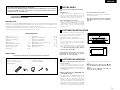 3
3
-
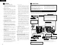 4
4
-
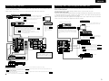 5
5
-
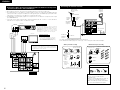 6
6
-
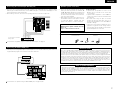 7
7
-
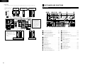 8
8
-
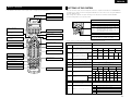 9
9
-
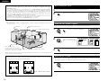 10
10
-
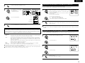 11
11
-
 12
12
-
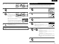 13
13
-
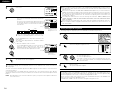 14
14
-
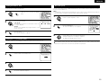 15
15
-
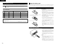 16
16
-
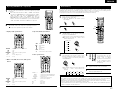 17
17
-
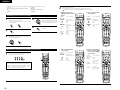 18
18
-
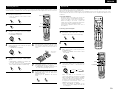 19
19
-
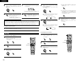 20
20
-
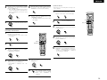 21
21
-
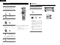 22
22
-
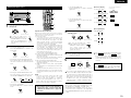 23
23
-
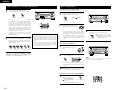 24
24
-
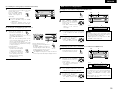 25
25
-
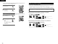 26
26
-
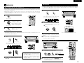 27
27
-
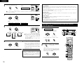 28
28
-
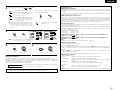 29
29
-
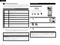 30
30
-
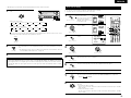 31
31
-
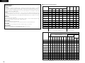 32
32
-
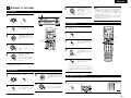 33
33
-
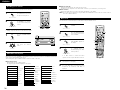 34
34
-
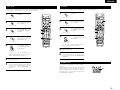 35
35
-
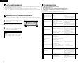 36
36
-
 37
37
-
 38
38
-
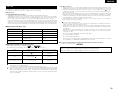 39
39
-
 40
40
-
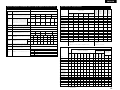 41
41
-
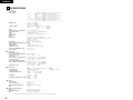 42
42
-
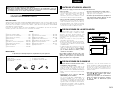 43
43
-
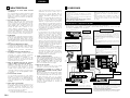 44
44
-
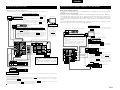 45
45
-
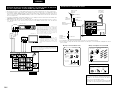 46
46
-
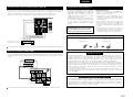 47
47
-
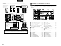 48
48
-
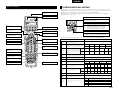 49
49
-
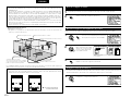 50
50
-
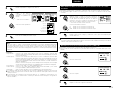 51
51
-
 52
52
-
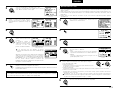 53
53
-
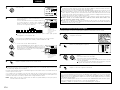 54
54
-
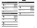 55
55
-
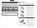 56
56
-
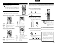 57
57
-
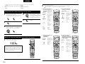 58
58
-
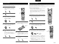 59
59
-
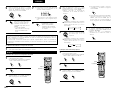 60
60
-
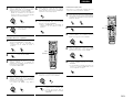 61
61
-
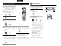 62
62
-
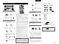 63
63
-
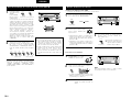 64
64
-
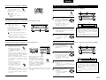 65
65
-
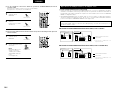 66
66
-
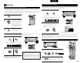 67
67
-
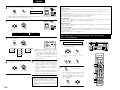 68
68
-
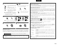 69
69
-
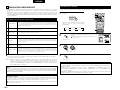 70
70
-
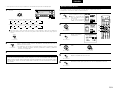 71
71
-
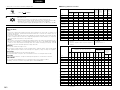 72
72
-
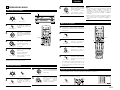 73
73
-
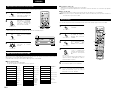 74
74
-
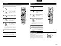 75
75
-
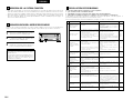 76
76
-
 77
77
-
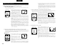 78
78
-
 79
79
-
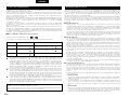 80
80
-
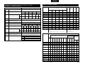 81
81
-
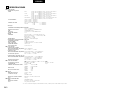 82
82


Denon 3802 Manual de usuario
- Categoría
- Receptores AV
- Tipo
- Manual de usuario
en otros idiomas
- English: Denon 3802 User manual
Artículos relacionados
-
Denon AVR-1306 Operating Instructions Manual
-
Denon AVR-2105 Operating Instructions Manual
-
Denon AVC-A11SR Operating Instructions Manual
-
Denon AVR-1804 Operating Instructions Manual
-
Denon AVR-2802 Manual de usuario
-
-
-
Denon AVR-1082 El manual del propietario
-
Denon AVR 1603 - AV Receiver Manual de usuario
-

