
Manuel d’utilisation / Manual del usuario
Owner’s manual / Instrukcja obsługi
12/24 V
Downloaded from www.cbradio.nl

Un vistazo a vuestro PRESIDENT
ANDY ASC AM/FM 12/24 V
Your PRESIDENT ANDY ASC AM/FM 12/24 V at a glance
Votre PRESIDENT ANDY ASC AM/FM
12/24 V en un coup d'œil
Twój PRESIDENT ANDY ASC AM/FM 12/24 V

3
SOMMAIRE
INSTALLATION 5
UTILISATION 7
FONCTIONS À L’ALLUMAGE DU POSTE 9
FONCTIONS AVEC LA PÉDALE D’ÉMISSION PTT 10
CARACTÉRISTIQUES TECHNIQUES 11
GUIDE DE DÉPANNAGE 11
COMMENT ÉMETTRE/RECEVOIR UN MESSAGE 11
GLOSSAIRE 12
DÉCLARATION DE CONFORMITÉ 14
CONDITIONS GÉNÉRALES DE GARANTIE 15
TABLEAUX DES FRÉQUENCES 49 ~ 51
NORMES - F 53
Français
SUMARIO
INSTALACIÓN 17
UTILIZACIÓN 19
FUNCIONES AL ENCENDER LA EMISORA 21
FUNCIONES CON LA PALANCA DE EMISIÓN PTT 22
CARACTERÍSTICAS TÉCNICAS 23
GUÍA DE PROBLEMAS 23
COMO EMITIR O RECIBIR UN MENSAJE 23
LÉXICO 24
DECLARACIÓN CE DE CONFORMIDAD 25
CONDICIONES GENERALES DE GARANTÍA 26
TABLAS DE FRECUENCIAS 49 ~ 51
NORMAS - F 53
Español
English
Polski
SUMMARY
INSTALLATION 28
HOW TO USE YOUR CB 30
FUNCTIONS TURNING ON THE UNIT 32
FUNCTIONS WITH PTT PEDAL 32
TECHNICAL CHARACTERISTICS 33
TROUBLE SHOOTING 34
HOW TO TRANSMIT OR RECEIVE A MESSAGE 34
GLOSSARY 34
DECLARATION OF CONFORMITY 36
GENERAL WARRANTY CONDITIONS 37
FREQUENCY TABLES 49 ~ 51
NORMS - F 53
SPIS TREŚCI
INSTALACJA 39
SPOSÓB OBSŁUGI CB RADIA 41
DODATKOWE FUNKCJE 43
DODATKOWE FUNKCJE Z PRZYCISKIEM PTT 44
CHARAKTERYSTYKA TECHNICZNA 44
PODSTAWOWE PROBLEMY I SPOSOBY
ICH ROZWIĄZYWANIA 45
SPOSÓB NADAWANIA I ODBIERANIA KOMUNIKATÓW
GŁOSOWYCH 45
TERMINOLOGIA 45
DEKLARACJA ZGODNOŚCI 46
ZOBOWIĄZANIA GWARANTA 47
TABELE CZĘSTOTLIWOŚCI 49 ~ 51
NORMY - F 53

4
ATTENTION !
APPAREIL MULTI-NORMES !
Avant toute utilisation, prenez garde de ne
jamais émettre sans avoir branché l’antenne
(connecteur B situé sur la face arrière de
l’appareil), ni réglé le TOS (Taux d’Ondes
Stationnaires)! Sinon, vous risquez de détruire
l’amplificateur de puissance, ce qui n’est
pas couvert par la garantie.
Voir «F» page 9 et tableau des Configu-
rations page 53.
FrançaisFrançais

5
Bienvenue dans le monde des émetteurs-récepteurs CB de la
dernière génération. Cette nouvelle gamme de postes vous fait
accéder à la communication électronique la plus performante.
Grâce à l’utilisation de technologies de pointe garantissant des
qualités sans précédent, votre PRESIDENT ANDY ASC AM/FM
12/24 V est un nouveau jalon dans la convivialité et la solution
par excellence pour le pro de la CB le plus exigeant. Pour tirer
le meilleur parti de toutes ses possibilités, nous vous conseillons
de lire attentivement ce mode d’emploi avant d’installer et
d’utiliser votre CB PRESIDENT ANDY ASC AM/FM 12/24 V.
A) INSTALLATION
1) CHOIX DE L’EMPLACEMENT, MONTAGE DU POSTE MOBILE
a) Choisissez l’emplacement le plus approprié à une utilisation simple
et pratique de votre poste mobile.
b) Veillez à ce qu’il ne gêne pas le conducteur ni les passagers du
véhicule.
c) Prévoyez le passage et la protection des différents câbles, (alimen-
tation, antenne, accessoires...) afin qu’ils ne viennent en aucun cas
perturber la conduite du véhicule.
d) Utilisez pour le montage le berceau (1) livré avec l’appareil, fixez-le
solidement à l’aide des vis auto taraudeuse (2) fournies (diamètre
de perçage 3,2 mm). Prenez garde de ne pas endommager le
système électrique du véhicule lors du perçage.
e) Lors du montage, n’oubliez pas d’insérer les rondelles de caout-
chouc (3) entre le poste et son support. Celles-ci jouent en effet
un rôle «d’amortisseur» et permettent une orientation et un serrage
en douceur du poste.
f) Choisissez un emplacement pour le support du micro et prévoyez
le passage de son cordon.
- NOTA : Votre poste mobile possédant une prise micro en façade
peut être encastré dans le tableau de bord. Dans ce cas, il est
recommandé d’y adjoindre un haut-parleur externe pour une
meilleure écoute des communications (connecteur EXT.SP situé sur
la face arrière de l’appareil : C). Renseignez-vous auprès de votre
revendeur le plus proche pour le montage sur votre appareil.
SCHÉMA GÉNÉRAL DE MONTAGE
Français

6
2) INSTALLATION DE L’ANTENNE
a) Choix de l’antenne :
- En CB, plus une antenne est grande, meilleur est son rendement.
Votre Point Conseil saura orienter votre choix.
b) Antenne mobile :
- Il faut l’installer à un endroit du véhicule où il y a un maximum de
surface métallique (plan de masse), en s’éloignant des montants
du pare-brise et de la lunette arrière.
- Dans le cas où une antenne radiotéléphone est déjà installée,
l’antenne CB doit être au-dessus de celle-ci.
- Il existe 2 types d’antennes : les préréglées et les réglables.
- Les préréglées s’utilisent de préférence avec un bon plan de masse
(pavillon de toit ou malle arrière).
- Les réglables offrent une plage d’utilisation beaucoup plus large
et permettent de tirer parti de plans de masse moins importants
(voir § 5 page 7 RÉGLAGE DU TOS).
- Pour une antenne à fixation par perçage, il est nécessaire d’avoir
un excellent contact antenne/plan de masse ; pour cela, grattez
légèrement la tôle au niveau de la vis et de l’étoile de serrage.
- Lors du passage du câble coaxial, prenez garde de ne pas le pincer
ou l’écraser (risque de rupture ou de court-circuit).
- Branchez l’antenne (B).
antennes et accessoires que nous distribuons sont spécialement
conçus pour un rendement optimal de chaque appareil de la
gamme.
3) CONNEXION DE L’ALIMENTATION
Votre PRESIDENT ANDY ASC AM/FM 12/24 V est muni d’une pro-
tection contre les inversions de polarité. Néanmoins, avant tout
branchement, vérifiez vos connexions.
Votre poste doit être alimenté par une source de courant continu
de 12 ou 24 Volts (A). À l’heure actuelle, la plupart des voitures et
des camions fonctionnent avec une mise à la masse négative. On
peut s’en assurer en vérifiant que la borne (-) de la batterie soit bien
connectée au bloc moteur ou au châssis. Dans le cas contraire,
consultez votre revendeur.
a) Assurez-vous que l’alimentation soit bien de 12 ou 24 Volts.
b) Repérez les bornes (+) et (-) de la batterie (+ = rouge, - = noir). Dans
le cas où il serait nécessaire de rallonger le cordon d’alimentation,
utilisez un câble de section équivalente ou supérieure.
c) Il est nécessaire de se connecter sur un (+) et un (-) permanents.
Nous vous conseillons donc de brancher directement le cordon
d’alimentation sur la batterie (le branchement sur le cordon de
l’autoradio ou sur d’autres parties du circuit électrique pouvant
dans certains cas favoriser la réception de signaux parasites).
d) Branchez le fil rouge (+) à la borne positive de la batterie et le fil
noir (-) à la borne négative de la batterie.
e) Branchez le cordon d’alimentation au poste.
ATTENTION : Ne jamais remplacer le fusible d’origine par un modèle
d’une valeur différente !
LOBE DE RAYONNEMENT
FrançaisFrançais
c) Antenne fixe :
- Veillez à ce qu’elle soit dégagée au maximum. En cas de fixation
sur un mât, il faudra éventuellement haubaner conformément aux
normes en vigueur (se renseigner auprès d’un professionnel). Les

7
4) OPÉRATIONS DE BASE À EFFECTUER AVANT LA PREMIÈRE
UTILISATION, SANS PASSER EN ÉMISSION (c’est-à-dire sans
appuyer sur la pédale du micro)
a) Branchez le micro,
b) Vérifiez le branchement de l’antenne,
c) Mise en marche de l’appareil : tourner le bouton du volume VOL
(1) dans le sens des aiguilles d’une montre,
d) Tournez le bouton du squelch SQ (3) au minimum (dans le sens
inverse des aiguilles d’une montre) en position M,
e) Réglez le volume à un niveau convenable,
f) Amenez le poste sur le canal 20 soit à l’aide des touches s/t de
l’appareil (2) ou des boutons UP/DN du micro (9).
5) RÉGLAGE DU TOS (Taux d’ondes stationnaires)
ATTENTION : Opération à effectuer impérativement lors de la pre-
mière utilisation de l’appareil ou lors d’un changement d’antenne.
Ce réglage doit être fait dans un endroit dégagé, à l’air libre.
* Réglage avec TOS-mètre externe (type TOS-1 PRESIDENT)
a) Branchement du Tos-mètre :
- Brancher le Tos-mètre entre le poste et l’antenne, le plus près pos-
sible du poste (utiliser pour cela un câble de (40 cm) maximum
type CA-2C PRESIDENT).
b) Réglage du Tos :
- Amener le poste sur le canal 20 en AM.
- Positionner le commutateur du Tos-mètre en position FWD (ca-
librage).
- Appuyer sur la pédale PTT (8) pour passer en émission.
- Amener l’aiguille sur l’index t à l’aide du bouton de calibrage.
- Basculer le commutateur en position REF (lecture de la valeur du
TOS). La valeur lue sur le vu-mètre doit être très proche de 1. Dans
le cas contraire, rajuster votre antenne jusqu’à obtention d’une
valeur aussi proche que possible de 1 (une valeur de TOS comprise
entre 1 et 1,8 est acceptable).
- Il est nécessaire de recalibrer le Tos-mètre, entre chaque opération
de réglage de l’antenne.
Remarque : Afin d’éviter les pertes et atténuations dans les câbles
de connexion entre la radio et ses accessoires, PRESIDENT recom-
mande une longueur de câble inférieure à 3 m.
Maintenant, votre poste est prêt à fonctionner.
B) UTILISATION
1) MARCHE/ARRÊT - VOLUME
a) Pour allumer votre poste, tourner le bouton VOL (1) dans le sens
des aiguilles d’une montre. Si la fonction KEY BEEP est activée, 4
notes sont émises à la mise en marche.
Voir le § FONCTIONS À L’ALLUMAGE DU POSTE page 9.
b) Pour augmenter le volume sonore, continuer à tourner ce bouton
dans le sens des aiguilles d’une montre.
2) SÉLECTEUR DE CANAUX : touches s/t sur l’appareil
Ces touches permettent d’effectuer une montée ou une descente
des canaux. Un bip est émis à chaque changement de canal si la
fonction KEY BEEP est activée. Voir fonction KEY BEEP page 9.
Voir aussi § 9 page 9.
3) ASC (Automatic Squelch Control) / SQUELCH
Cette fonction permet de supprimer les bruits de fond indésirables
en l’absence de communication. Le squelch ne joue ni sur le volume
sonore ni sur la puissance d’émission, mais il permet d’améliorer
considérablement le confort d’écoute.
a) ASC : SQUELCH A RÉGLAGE AUTOMATIQUE
Brevet mondial, exclusivité PRESIDENT
Tourner le bouton SQ (3) dans le sens inverse des aiguilles d’une
montre. ASC apparaît. Aucun réglage manuel répétitif et optimisa-
tion permanente entre la sensibilité et le confort d’écoute lorsque
l’ASC est actif (à fond en sens inverse des aiguilles d’une montre).
Elle est débrayable par rotation du bouton SQ (3) dans le sens des
aiguilles d’une montre. Dans ce cas le réglage du squelch redevient
manuel. ASC disparaît de l’afficheur.
Français

8
b) SQUELCH MANUEL
Tournez le bouton du squelch SQ (3) dans le sens des aiguilles d’une
montre jusqu’au point exact où tout bruit de fond disparaît. C’est un
réglage à effectuer avec précision, car mis en position maximum
dans le sens des aiguilles d’une montre, seuls les signaux les plus
forts peuvent être perçus.
4) AFFICHEUR
Il permet de visualiser l’ensemble des fonctions :
Le BARGRAPH visualise le niveau de réception et le niveau de
puissance émise.
5) EMG ~ REDÉFINITION DU CANAL D’URGENCE EMG
EMG
(pression brève)
Le canal d’urgence est automatiquement sélectionné en appuyant
sur la touche EMG (5). «EMG» apparaît dans l’afficheur.
Le canal par défaut est le canal 19, le mode d’émission (AM/FM)
varie en fonction de bande de fréquence utilisée (voir tableau
page 53).
Une nouvelle pression sur la touche EMG (5) ramène au canal
précédemment utilisé. «EMG» disparaît de l’afficheur.
REDÉFINITION DU CANAL D’URGENCE EMG (pression longue)
Le canal d’urgence peut être affecter à n’importe quel canal avec
le mode AM ou FM. Pour définir un nouveau canal d’urgence :
- Appuyer brièvement sur la touche EMG (5) pour appeler le canal
d’urgence actuel. «EMG» apparaît dans l’afficheur.
- Appuyer durant 2 secondes sur la touche EMG (5). apparaît dans
l’afficheur et «EMG» clignote.
- À l’aide des touches s/t (2) ou des boutons UP/DN (9) , choisir le
nouveau canal d’urgence.
- Appuyer sur la touche MODE(6) pour définir le mode de modulation
(AM, FM ou FM UK) utilisé avec ce nouveau canal d’urgence.
- Appuyer brièvement sur la touche EMG (5) pour valider et définir
le nouveau canal d’urgence. Un bip de validation est émis.
Remarque : redéfinir le canal d’urgence n’est possible que si le
canal d’urgence actuel est actif.
6) MODE ~ NB
MODE
(pression brève)
Ce commutateur permet de sélectionner le mode de modulation
AM ou FM. Votre mode de modulation doit correspondre à celui
de votre interlocuteur. L’afficheur indique le mode correspondant.
Modulation d’Amplitude/ AM : Communications sur terrain avec
reliefs et obstacle sur moyenne distance (mode le plus utilisé en
France).
Modulation de Fréquence/ FM : Communication rapprochée sur
terrain plat et dégagé.
En configuration U uniquement : Appuyer sur la touche MODE (6)
pour alterner entre ENG et CEPT. “UK” apparaît dans l’afficheur
lorsque la bande de fréquence ENG est sélectionné. Lorsque la
bande de fréquence CEPT est sélectionnée. “UK” disparaît de
l’afficheur (voir tableau page 49).
NB (pression longue)
Noise Blanker. Ce filtre permet de réduire les bruits de fond et
certains parasites en réception. Quand le filtre NB est actif «NB»
apparaît dans l’afficheur.
7) PRISE MICRO 6 BROCHES
Elle se situe en façade de votre appareil et facilite ainsi son inté-
gration à bord de votre véhicule.
Voir schéma de branchement en page 52.
FrançaisFrançais

9
8) PTT (Push To Talk)
Pédale d’émission, appuyer pour parler,
s’affiche. Relâcher
pour recevoir un message.
Voir FONCTIONS AVEC LA PÉDALE D’ÉMISSION PTT page 10.
9) SÉLECTEUR DE CANAUX : Boutons UP/DN sur le micro
Ces touches permettent d’effectuer une montée ou une descente
des canaux. Un bip est émis à chaque changement de canal si la
fonction KEY BEEP est activée. Voir fonction KEY BEEP page 9.
Voir aussi § 2 page 7.
C) FONCTIONS À L’ALLUMAGE DU POSTE
5 fonctions supplémentaires sont disponibles. Pour activer la fonction,
éteindre le poste, rallumer le poste en maintenant une ou deux
touches appuyées. Répéter la même opération pour désactiver
la fonction.
1) ROGER BEEP (touche s sur l’appareil ou bouton UP du micro)
Le ROGER BEEP est émis quand la pédale d’émission PTT (8) est
relâchée afin de prévenir votre interlocuteur que vous avez termi-
ner et lui laisser la parole. Historiquement, la CB étant un mode de
communication «simplex», c’est-à-dire qu’il n’est pas possible de
parler et d’écouter en même temps (comme c’est le cas pour le
téléphone par exemple), il était d’usage de dire «Roger» une fois
que l’on avait fini de parler afin de prévenir son correspondant
qu’il pouvait parler à son tour. Le mot «Roger» a été remplacé par
un bip significatif, d’où son nom “Roger Beep”.
Cette fonction peut être activer ou désactiver de la manière sui-
vante :
- Allumer l’appareil en maintenant la touche s (2a) ou le bouton UP
(9) appuyée pour activer (rb on) ou désactiver (rb oF) la fonction
ROGER BEEP.
- Quand la fonction est active «
» apparaît dans l’afficheur.
Remarque : Le ROGER BEEP est également entendu dans le haut-
parleur si la fonction KEY BEEP est activée. Si la fonction KEY BEEP
n’est pas activée, seul le correspondant peut entendre le ROGER
BEEP.
En mode PA cette fonction n’est pas autorisée.
2) KEY BEEP (touche t sur l’appareil ou bouton DN du micro)
Certaines opérations comme le changement de canal, l’appui sur
les touches, etc. sont confirmées par un bip.
Ce bip peut être activer ou désactiver de la manière suivante :
- Allumer l’appareil en maintenant la touche t (2b) le bouton DN
(9) appuyée pour activer (bP on) ou désactiver (bP oF) la fonction
KEY BEEP.
- Quand la fonction est active «BP» apparaît dans l’afficheur.
3) F - SÉLECTION DE LA BANDE DE FRÉQUENCES (touche F)
(Configuration : EU ; PL ; d ; EC ; U ; In)
Les bandes de fréquences doivent être choisies selon le pays où
vous utilisez votre appareil. N’utilisez en aucun cas une configuration
différente. Certains pays nécessitent une licence d’utilisation. Voir
tableau page 54.
Procédure :
- Allumer l’appareil en maintenant appuyée la touche F (5). La lettre
correspondant à la configuration clignote.
- Pour changer de configuration, utiliser les touches s/t (2) ou les
boutons UP/DN (9).
- Quand la configuration est choisie, appuyez 1 seconde sur la
touche F (5). La lettre correspondant à la configuration s’affichent
en continu, un bip est émis.
- À ce stade, confirmer la sélection en éteignant puis en allumant à
nouveau l’appareil.
Voir les bandes de fréquences / tableau de configurations pages
49 à 53.
4) TOT (Time Out Timer) (touche MODE)
Si la touche PTT (8) est appuyée pendant plus de 5 minutes, le canal
et commencent à clignoter et l’émission se termine.
Français

10
Un bip est émis jusqu’à ce que la touche PTT (8) soit relâchée.
Cette fonction peut être activer ou désactiver de la manière sui-
vante :
- Allumer l’appareil en maintenant la touche MODE (6) appuyée
pour activer (t on) ou désactiver (t oF) la fonction TOT.
5) COLOR (touches MODE + EMG)
Utiliser la procédure suivante pour alterner entre les trois couleurs
de l’affichage :
- Allumer l’appareil en maintenant appuyées les touches MODE (5)
et EMG (6). La couleur active clignote, (orange), (vert) ou
(bleu).
- Pour changer de couleur, utiliser les touches s/t (2) ou les boutons
UP/DN (9).
- Quand la couleur est choisie, appuyez 1 seconde sur la touche F
(5). Un bip est émis, les lettres de la couleur s’affichent en continu
durant 1 secondes.
D) FONCTIONS AVEC LA PÉDALE D’ÉMISSION PTT
3 fonctions supplémentaires sont disponibles. Pour activer la fonction,
appuyer et maintenir appuyée la pédale d’émission PTT (8) puis,
appuyer sur la touche dédiée à cette fonction. Répéter la même
opération pour désactiver la fonction.
1) TALKBACK (PTT + F)
La fonction TALKBACK peut être activée ou désactivée en suivant
la procédure suivante :
a) Appuyer et maintenir appuyée la pédale d’émission PTT (8).
b) Appuyer brièvement sur la touche F (5). Le niveau du TALKBACK
actuel clignote 3 fois indiquant que vous pouvez régler ce niveau.
Quand la fonction est active, «TALKBACK» apparaît dans l’afficheur.
Cette fonction permet d’entendre votre propre modulation dans
le haut-parleur de la CB.
2) NIVEAU DU TALKBACK (PTT + s/t sur l’appareil)
- À l’étape b), ajuster le niveau du TALKBACK à l’aide des touches
s/t (2).
- Quand la fonction est active et que «TALBACK» est affiché, appuyer
et maintenir appuyée la pédale d’émission PTT (8) puis ajuster le
niveau du TALKBACK à l’aide des touches s/t (2). 9 niveaux de
01 à 09.
Remarque : Les boutons UP/DN du microphone (9) ne permettent
pas de régler le volume du TALKBACK
3) PA (PTT + MODE)
- Appuyer et maintenir appuyée la pédale d’émission PTT (8).
- Appuyer brièvement sur la touche MODE (6) pour activer ou désac-
tiver le mode PA (Public Address). Un haut-parleur de sonorisation
extérieure peut être connecté sur le poste par une prise jack située
sur le panneau arrière PA.SP. (D).
Les messages CB reçus ou émis via le microphone seront dirigés et
amplifiés vers le haut-parleur externe du PA. Le bouton du volume
VOL (1) permet de régler le niveau de volume du PA.
Quand le mode PA est actif «PA» et le mode de modulation utilisé
(AM, FM ou FM UK) clignotent alternativement dans l’afficheur.
Quand La pédale d’émission PTT (8) est appuyée, «PA» s’affiche
à la place du canal actif. Le canal actif s’affiche à nouveau dès
que la pédale PTT (8) est relâchée.
A) ALIMENTATION (13,2 V / 26,4 V)
B) PRISE D’ANTENNE (SO-239)
C) PRISE POUR HAUT-PARLEUR EXTÉRIEUR (8 Ω, Ø 3,5 mm)
D) PRISE POUR HAUT-PARLEUR PA EXTÉRIEUR (8 Ω, Ø 3,5 mm)
FrançaisFrançais

11
E) CARACTÉRISTIQUES TECHNIQUES
1) GÉNÉRALES
- Canaux : 40
- Modes de modulation : AM/FM
- Gamme de fréquence : de 26.965 MHz à 27.405 MHz
- Impédance d’antenne : 50 ohms
- Tension d’alimentation : 13.2 V / 26.4 V
- Dimensions (en mm) : 125 (L) x 175 (P) x 45 (H)
- Poids :
~
0,9 kg
- Accessoires inclus : 1 microphone Electret et son support,
1 berceau, vis de fixation
- Filtre : ANL (Automatic Noise Limiter) intégré
2) ÉMISSION
- Tolérance de fréquence : +/- 200 Hz
- Puissance porteuse : 4 W AM / 4 W FM
- Émissions parasites : inférieure à 4 nW (- 54 dBm)
- Réponse en fréquence : 300 Hz à 3 kHz en AM/FM
- Puissance émise dans le
canal adjacent : inférieure à 20 µW
- Sensibilité du microphone : 7 mV
- Consommation maximum : 1,7 A à 13,2 V / 0,85 A à 26,4 V
- Distorsion maximum du
signal modulé : 2 %
3) RÉCEPTION
- Sensibilité max. à 20 dB sinad : 0,5 µV - 113 dBm AM / 0,35 µV - 116 dBm FM
- Réponse en fréquence : 300 Hz à 3 kHz
- Sélectivité du canal adj. : 60 dB
- Puissance audio maxi : 2,5 W
- Sensibilité du squelch : min. 0,2 µV - 120 dBm / max. 1 mV - 47 dBm
- Taux de réjection
fréquence image : 60 dB
- Taux de réjection
fréquence intermédiaire : 70 dB
- Consommation : 180 ~ 500 mA (13,2 V)
100 ~ 300 mA (26,4 V)
F) GUIDE DE DÉPANNAGE
1) VOTRE POSTE N’ÉMET PAS OU VOTRE ÉMISSION EST DE
MAUVAISE QUALITÉ
Vérifiez que :
- L’antenne soit correctement branchée et que le TOS soit bien réglé.
- Le micro soit bien branché.
- La configuration programmée soit la bonne (voir tableau page
53).
2) VOTRE POSTE NE REÇOIT PAS OU VOTRE RÉCEPTION EST DE
MAUVAISE QUALITÉ
Vérifiez que :
- Le niveau du squelch soit correctement réglé.
- La configuration programmée soit la bonne (voir tableau page
53).
- Le bouton Volume soit réglé à un niveau convenable.
- Le micro soit branché.
- L’antenne soit correctement branchée et le TOS bien réglé.
- Vous êtes bien sur le même type de modulation que votre interlo-
cuteur.
3) VOTRE POSTE NE S’ALLUME PAS
Vérifiez :
- Votre alimentation.
- Qu’il n’y ait pas d’inversion des fils au niveau de votre branchement.
- L’état du fusible.
G) COMMENT ÉMETTRE OU RECEVOIR UN MESSAGE ?
Maintenant que vous avez lu la notice, assurez-vous que votre
poste est en situation de fonctionner (antenne branchée).
Choisissez votre canal (19, 27).
Choisissez votre mode (AM, FM) qui doit être le même que celui
de votre interlocuteur.
Vous pouvez alors appuyer sur la pédale de votre micro, et lancer
Français

12
le message «Attention stations pour un essai TX» ce qui vous permet
de vérifier la clarté et la puissance de votre signal et devra entraîner
une réponse du type «Fort et clair la station».
Relâchez la pédale, et attendez une réponse. Dans le cas où vous
utilisez un canal d’appel (19, 27), et que la communication est
établie avec votre interlocuteur, il est d’usage de choisir un autre
canal disponible afin de ne pas encombrer le canal d’appel.
H) GLOSSAIRE
Au fil de l’utilisation de votre TX, vous découvrirez parfois un langage
particulier employé par certains cibistes. Afin de vous aider à mieux
le comprendre, vous trouverez ci-après dans le glossaire et le code
«Q.» un récapitulatif des termes utilisés. Toutefois, il est évident qu’un
langage clair et précis facilitera le contact entre tous les amateurs
de radiocommunication. C’est la raison pour laquelle les termes
que vous lirez ci-dessous sont donnés à titre indicatif, mais ne sont
pas à utiliser de façon formelle.
ALPHABET PHONÉTIQUE INTERNATIONAL
A Alpha H Hotel O Oscar V Victor
B Bravo I India P Papa W Whiskey
C Charlie J Juliett Q Quebec X X-ray
D Delta K Kilo R Romeo Y Yankee
E Echo L Lima S Sierra Z Zulu
F Foxtrott M Mike T Tango
G Golf N November U Uniform
LANGAGE TECHNIQUE
AM : Amplitude Modulation (modulation d’amplitude)
BLU : Bande latérale unique
BF : Basse fréquence
CB : Citizen Band (canaux banalisés)
CH : Channel (canal)
CQ : Appel général
CW : Continuous waves (morse)
DX : Liaison longue distance
DW : Dual watch (double veille)
FM : Frequency modulation (modulation de fréquence)
GMT : Greenwich Meantime (heure méridien Greenwich)
GP : Ground plane (antenne verticale)
HF : High Frequency (haute fréquence)
LSB : Low Side Band (bande latérale inférieure)
RX : Receiver (récepteur)
SSB : Single Side Band (Bande latérale unique)
SWR : Standing Waves Ratio
SWL : Short waves listening (écoute en ondes courtes)
SW : Short waves (ondes courtes)
TOS : Taux d’ondes stationnaires
TX : Transceiver. Désigne un poste émetteur-récepteur CB.
Indique aussi l’émission.
UHF : Ultra-haute fréquence
USB : Up Side Band (bande latérale supérieure)
VHF : Very high Frequency (très haute fréquence)
LANGAGE CB
ALPHA LIMA : Amplificateur linéaire
BAC : Poste CB
BASE : Station de base
BREAK : Demande de s’intercaler, s’interrompre
CANNE À PÊCHE : antenne
CHEERIO BY : Au revoir
CITY NUMBER : Code postal
COPIER : Écouter, capter, recevoir
FIXE MOBILE : Station mobile arrêtée
FB : Fine business (bon, excellent)
INFERIEURS : Canaux en-dessous des 40 canaux autorisés
(interdits en France)
MAYDAY : Appel de détresse
MIKE : Micro
MOBILE : Station mobile
NÉGATIF : Non
OM : Opérateur radio
SUCETTE : Micro
SUPÉRIEURS : Canaux au-dessus des 40 canaux autorisés
(interdits en France)
FrançaisFrançais

13
TANTE VICTORINE : Télévision
TONTON : Amplificateur de puissance
TPH : Téléphone
TVI : Interférences TV
VISU : Se voir
VX : Vieux copains
WHISKY : Watts
WX : Le temps
XYL : L’épouse de l’opérateur
YL : Opératrice radio
51 : Poignée de mains
73 : Amitiés
88 : Grosses bises
99 : Dégager la fréquence
144 : Polarisation horizontale, aller se coucher
318 : Pipi
600 ohms : le téléphone
813 : Gastro liquide (apéritif)
CODE «Q»
QRA : Emplacement de la station
QRA Familial : Domicile de la station
QRA PRO : Lieu de travail
QRB : Distance entre 2 stations
QRD : Direction
QRE : Heure d’arrivée prévue
QRG : Fréquence
QRH : Fréquence instable
QRI : Tonalité d’émission
QRJ : Me recevez-vous bien ?
QRK : Force des signaux (R1 à R5)
QRL : Je suis occupé
QRM : Parasites, brouillage
QRM DX : Parasites lointains
QRM 22 : Police
QRN : Brouillage atmosphérique (orages)
QRO : Fort, très bien, sympa
QRP : Faible, petit
Français
QRPP : Petit garçon
QRPPette : Petite fille
QRQ : Transmettez plus vite
QRR : Nom de la station
QRRR : Appel de détresse
QRS : Transmettez plus lentement
QRT : Cessez les émissions
QRU : Plus rien à dire
QRV : Je suis prêt
QRW : Avisez que j’appelle
QRX : Restez en écoute un instant
QRZ : Indicatif de la station : par qui suis-je appelé?
QSA : Force de signal (S1 à S9)
QSB : Fading, variation
QSJ : Prix, argent, valeur
QSK : Dois-je continuer la transmission ?
QSL : Carte de confirmation de contact
QSO : Contact radio
QSP : Transmettre à...
QSX : Voulez-vous écouter sur...
QSY : Dégagement de fréquence
QTH : Position de station
QTR : Heure locale
CANAUX D’APPEL
27 AM : appel général en zone urbaine
19 AM : Routiers
9 AM : Appel d’urgence

14
DÉCLARATION DE CONFORMITÉ
Nous, GROUPE PRESIDENT ELECTRONICS, Route de
Sète, BP 100 - 34540 Balaruc - FRANCE,
Déclarons, sous notre seule responsabilité que l’émetteur-ré-
cepteur de radiocommunication CB,
Marque : PRESIDENT
Modèle : ANDY ASC AM/FM 12/24 V
Fabriqué au PRC
est conforme aux exigences essentielles de la Directive
1999/5/CE (Article 3) transposées à la législation nationale,
ainsi qu’aux Normes Européennes suivantes:
EN 60950-1:2006+A11:2009+A1:2010+A12:2011+A2:2013
EN 300 433-1 V1.3.1 (2011-07)
EN 300 433-2 V1.3.1 (2011-07)
EN 301 489-1 V1.9.2 (2011-09)
EN 301 489-13 V1.2.1 (2002-08)
et est conforme à la Directive RoHS2: 2011/65/UE (08/06/2011).
Balaruc, le 05/12/2016
Jean-Gilbert MULLER
Directeur Général
FrançaisFrançais

15
CONDITIONS GÉNÉRALES DE GARANTIE
Ce poste est garanti 2 ans pièces et main d’œuvre dans son pays d’achat contre tout vice
de fabrication reconnu par notre service technique. *Le Laboratoire SAV de PRESIDENT se
réserve le droit de ne pas appliquer la garantie si une panne est provoquée par une antenne
autre que celles distribuées par la marque PRESIDENT, si la dite antenne est à l’origine
de la panne. Une extension de garantie de 3 ans est proposée systématiquement pour
l’achat et l’utilisation d’une antenne de la marque PRESIDENT, amenant la durée totale de
la garantie à 5 ans, et sur justificatif retourné sous 30 jours suivant l’achat au SAV de la
Société Groupe President Electronics, ou toute filiale étrangère.
Il est recommandé de lire attentivement les conditions ci-après et de les respecter sous
peine d’en perdre le bénéfice.
• Pour être valable, la garantie doit nous être retournée au plus tard 1 mois après l’achat.
• Détacher après l’avoir fait remplir la partie ci-contre et la retourner dûment complétée.
• Toute intervention effectuée dans le cadre de la garantie sera gratuite et les frais de
réexpédition pris en charge par notre Société.
• Une preuve d’achat doit être jointe obligatoirement avec le poste à réparer.
• Les dates inscrites sur le bon de garantie et la preuve d’achat doivent concorder.
• Ne pas procéder à l’installation de votre appareil sans avoir lu ce manuel d’instructions.
• Aucune pièce détachée ne sera envoyée ni échangée par nos services au titre de la
garantie. La garantie est valable dans le pays d’achat.
Ne sont pas couverts :
• Les dommages causés par accident , choc ou emballage insuffisant.
• Les transistors de puissance, les micros, les lampes, les fusibles et les dommages dus à
une mauvaise utilisation (antenne mal réglée, TOS trop important, inversion de polarité,
mauvaises connexions, surtension, etc.)
• La garantie ne peut être prorogée par une immobilisation de l’appareil dans nos ateliers,
ni par un changement d’un ou plusieurs composants ou pièces détachées.
• Les interventions ayant modifiées les caractéristiques d’agrément, les réparations ou
modifications effectuées par des tiers non agréés par notre Société.
Si vous constatez des défauts de fonctionnement :
• Vérifier l’alimentation de votre appareil et la qualité du fusible.
• Contrôlez les différents branchements: jacks, prise d’antenne, prise du microphone...
• Assurez-vous de la bonne position des différents réglages de votre appareil: gain micro
en position maxi, squelch au minimum, commutateur PA/CB, etc.
• En cas de non prise en charge au titre de la garantie, l’intervention et la réexpédition du
matériel seront facturés.
• Cette partie doit être conservée même après la fin de la garantie et si vous revendez votre
poste, donnez la au nouveau propriétaire pour le suivi SAV.
• En cas de dysfonctionnement réel, mettez-vous d’abord en rapport avec votre revendeur
qui décidera de la conduite à tenir.
• Dans le cas d’une intervention hors garantie, un devis sera établi avant toute réparation.
Vous venez de faire confiance à la qualité et à l’expérience de PRESIDENT et nous vous
remercions. Pour que vous soyez pleinement satisfait de votre achat, nous vous conseillons
de lire attentivement ce manuel. N’oubliez pas de nous retourner la partie droite de ce bon
de garantie, c’est très important pour vous car cela permet d’identifier votre appareil lors
de son passage éventuel dans nos ateliers. Quant au questionnaire, son objectif est de
mieux vous connaître et ainsi en répondant à vos aspirations, nous œuvrerons ensemble
pour l’avenir de la CB.
La Direction Technique
et
Le Service Qualité
Date d’achat :
Type : radio CB ANDY ASC AM/FM 12/24 V
N° de série : .............................................................
!
SANS LE CACHET DU DISTRIBUTEUR LA GARANTIE SERA NULLE
Français

16
President Electronics Ibérica S.A.U. Declara bajo su responsabilidad, que este aparato cumple con lo dispuesto en la Directiva
2014/53/UE del Parlamento Europeo y del Consejo de 16 de Abril de 2014.
¡ ATENCIÓN !
Antes de la utilización tengan cuidado de
nunca emitir sin haber previamente co-
nectado la antena (conector "B" situado
en la parte trasera de su equipo), ajustada
la ROE (Relación de Ondas Estacionarias)!
Sino, se expone a dañar el amplificador
de potencia, no cubierto por la garantía.
EQUIPO MULTI-NORMAS !
Ver la función “F” en pág. 21 y la tabla
de Configuraciones en la pág. 53.
La garantía de este artículo sólo es válida en el país de compra.
Español

17
Bienvenido al mundo de los emisores-receptores CB de últi-
ma generación. Esta nueva gama de estaciones le permite
acceder a la comunicación electrónica más competitiva.
Gracias a la utilización de tecnología punta que garantiza
una calidad sin precedentes, su PRESIDENT ANDY ASC AM/
FM 12/24 V representa un nuevo hito en la facilidad de uso y
la solución por excelencia para el usuario más exigente de
CB. Para sacar el máximo partido de todas sus posibilidades,
le aconsejamos leer atentamente estas instrucciones de uso
antes de instalar y utilizar su CB PRESIDENT ANDY ASC AM/
FM 12/24 V.
A) INSTALACIÓN
1) ELEGIR EL EMPLAZAMIENTO Y MONTAJE DEL PUESTO MÓVIL
a) Escoja el emplazamiento más apropiado para una utilización simple
y práctica de su estación móvil.
b) Procure que no moleste ni al conductor ni a los pasajeros del ve-
hículo.
c) Prevea el paso y la protección de los diferentes cables, (alimen-
tación, antena, accesorios) con el fin de que en ningún caso
perturben la conducción del vehículo.
d) Utilice para el montaje el soporte (1) entregado con el aparato,
fíjelo sólidamente con ayuda de los tornillos auto-roscantes (2)
proporcionados (diámetro de agujero de 3,2 mm). Tenga cuidado
de no dañar el sistema eléctrico del vehículo en el momento del
taladro del salpicadero.
e) En el momento del montaje, no se olvide de insertar las arandelas
de caucho (3) entre la estación y su soporte. Éstas tienen, en efec-
to, un papel “amortiguador” y permiten una orientación y presión
suaves de la estación.
f) Escoja un emplazamiento para el soporte del micro y prevea el
paso de su cable.
- NOTA: Su estación móvil que posee una toma de micro en la parte
anterior puede ser empotrada en el cuadro de mandos. En ese
caso, se recomienda añadirle un altavoz externo para una mejor
escucha de las comunicaciones (conector EXT.SP situado en la
cara posterior del aparato: C). Infórmese con su vendedor más
próximo para el montaje en su aparato.
ESQUEMA GENERAL DE MONTAJE
Español

18
2) INSTALACIÓN DE LA ANTENA
a) Elección de la antena
- En CB, cuanto más grande es una antena, mejor es su rendimiento.
Su Centro de Asesoramiento sabrá orientarle en su elección.
b) Antena móvil
- Hay que instalarla en un lugar del vehículo donde haya un máximo
de superficie metálica (plano de masa), alejándose de los mon-
tantes del parabrisas y de la luneta trasera.
- En caso de que se haya instalado una antena de radio-teléfono,
la antena CB debe estar por encima de ésta.
- Existen 2 tipos de antenas: las preajustadas y las regulables.
- Las preajustadas se utilizan preferentemente con un buen plano
de masa (en el techo o en el maletero).
- Las regulables ofrecen un campo de uso mucho más ancho y
permiten sacar partido de planos de masa menos importantes
(véase § 5 página 19 AJUSTE DE LA ROE).
- Para una antena de fijación por taladro, es necesario tener un
contacto excelente entre la antena y el plano de masa; para ello,
rasque ligeramente la chapa al nivel del tornillo y de la estrella de
presión.
- En el momento del
paso del cable coa-
xial, tenga cuidado
de no pellizcarlo ni
aplastarlo (riesgo de
rotura o cortocircuito).
- Conecte la antena (B).
3) CONEXIÓN DEL ALIMENTADOR
Su PRESIDENT ANDY ASC AM/FM 12/24 V está provista de una
protección contra las inversiones de polaridad.
Vuestra emisora debe estar alimentada por una fuente de co-
rriente continua de 12 o 24 voltios (A). En este momento, la mayor
parte de los coches y camiones funcionan con una toma de tierra
negativa, se puede asegurar verificando que el terminal (-) de la
batería esté bien conectado al bloque del motor o bastidor. En el
caso contrario, consulte con su suministrador.
Todas las operaciones de conexión siguientes, deben efectuarse
con el cable de alimentación no conectado a la emisora:
a) Asegúrense que el alimentador sea de 12 o 24 Voltios.
b) Identifique los polos (+) y (-) de la batería (+ = rojo, - = negro). En
el caso que sea necesario alargar el cable de alimentación utilice
un cable de sección equivalente o superior.
c) Es necesario conectar sobre un (+) y (-) permanentes. Les acon-
sejamos enchufar directamente el cable de alimentación en la
batería (el enchufe sobre el cable del auto-radio o sobre otras
partes del circuito electrónico podrán en ciertos casos favorecer
la recepción de las señales parásitas).
d) Conecten el hilo rojo (+) al borne positivo de la batería y el hilo
negro (-) al borne negativo de la batería.
e) Conectar el cable de alimentación a la emisora.
ATENCIÓN: ¡No reemplace jamás el fusible de origen por un modelo
de un valor diferente!
LÓBULO DE RADIACIÓN
Español
c) Antena fija
- Procure abrirla al máximo. En caso de fijación sobre un poste, habrá
que sostenerla eventualmente conforme a las normas vigentes
(infórmese con un profesional). Las antenas y los accesorios PRE-
SIDENT han sido especialmente concebidos para un rendimiento
óptimo de todos los aparatos de la gama.

19
4) OPERACIONES DE BASE QUE HAY QUE EFECTUAR ANTES
DE LA PRIMERA UTILIZACIÓN, SIN PASAR POR EMISIÓN (sin
apretar la palanca del micro)
a) Conecte el micro,
b) Verifique la conexión de la antena,
c) Puesta en marcha del aparato: gire el botón del volumen VOL (1)
en el sentido de las agujas del reloj hasta oír un “clic”,
d) Gire el botón del squelch SQ (3) al mínimo, en la posición M,
e) Ajuste el volumen (1) a un nivel conveniente,
f) Dirija la estación al canal 20 con ayuda de la teclas s/t (2) de
la estación o de los botones UP/DN (9) del micrófono.
5) AJUSTE DE LA ROE (Relación de Ondas Estacionarias)
ATENCIÓN: Esta operación debe efectuarse necesariamente en el
momento de la primera utilización del aparato o en el momento
de un cambio de antena. Este ajuste debe se realizar en un lugar
abierto, al aire libre.
* Ajustes con el medidor de ROE externo (tipo TOS-1 PRESIDENT):
a) Empalme del medidor de ROE:
- Conecte el medidor de ROE entre la estación y la antena, lo más
cerca posible de la estación (utilice para ello un cable de 40 cm
máximo tipo CA-2C PRESIDENT).
b) Ajuste de la ROE:
- Posicione la estación hacia el canal 20 en AM.
- Sitúe el conmutador del medidor de ROE en posición FWD (cali-
bración).
- Apriete la palanca PTT (8) del micro para pasar a emisión.
- Dirija la aguja al índice ▼ con ayuda del botón de calibración.
- Ponga el conmutador en posición REF (lectura del valor de la ROE). El
valor leído en el indicador debe estar muy cerca de 1. En caso contrario,
reajuste su antena hasta obtener un valor lo más cerca posible a 1 (puede
aceptarse un valor de la ROE comprendido entre 1 y 1,8).
- Es necesario recalibrar el medidor de ROE entre cada operación
de ajuste de la antena.
Observación: Con el fin de evitar las pérdidas y las atenuaciones
en los cables de conexión entre la radio y sus accesorios, PRESIDENT
recomienda una longitud de cable inferior a 3m.
Ahora, su estación está preparada para funcionar.
B) UTILIZACIÓN
1) INTERRUPTOR DE VOLUMEN
a) Para encender la emisora girar el botón VOL (1) en el sentido de
las agujas del reloj. Si la función KEY BEEP esta activa, 4 notas se
emiten cuando se enciende la emisora.
Ver § FUNCIONES AL ENCENDER LA EMISORA página 21.
b) Para aumentar el volumen girar el botón en el sentido de las agujas
del reloj.
2) SELECTOR DE CANALES: teclas s/t en la emisora
Estas teclas permiten ascender o descender de un canal. Se emite
un “Beep” sonoro en cada cambio de canal si se activa la función
KEY BEEP (Véase Función KEY BEEP página 21).
Ver también § 9 página 21.
3) ASC (Automatic Squelch Control)/SQUELCH
Permite suprimir los ruidos de fondo indeseables en la ausencia de
comunicación. El squelch no interviene ni en el volumen ni en la
posición de emisión, pero permite escuchar confortablemente.
a) ASC (AJUSTE AUTOMÁTICO DEL SQUELCH)
Patente mundial, exclusividad de PRESIDENT.
Girar el botón del squelch SQ (3) en el sentido inverso de las agujas
del reloj en la posición ASC. ASC aparece en la pantalla. En lugar
de un ajuste manual repetitivo, se produce una optimización per-
manente entre la sensibilidad y la escucha confortable cuando el
ASC está activado. Esta función es conmutable por la rotación del
botón en sentido de las agujas de un reloj, en este caso el ajuste
del squelch vuelve a ser manual. ASC desaparece de la pantalla.
Español

20
b) SQUELCH MANUAL
Girar el botón del squelch SQ (3)en el sentido de las agujas del
reloj justo hasta el punto exacto, todos los ruidos de fondo desa-
parecerán. Es un ajuste que se ha de hacer con precisión, pues
colocado en posición máxima en el sentido de las agujas del reloj,
únicamente las señales más fuertes pueden ser recibidas.
4) PANTALLA
Permite visualizar todas las funciones.
El gráfico de barras el nivel de recepción y el nivel de la potencia
emitida.
5) EMG ~ DEFINICIÓN DEL CANAL DE EMERGENCIA EMG
EMG
(presión breve)
El canal de emergencia es automáticamente seleccionado apre-
tando la tecla EMG (5). “EMG” aparece en la pantalla. El canal de
emergencia de fábrica es el canal 19, el modo de emisión (AM/FM)
depende de la banda de frecuencia utilizada (ver tabla página
53).
Apriete de nuevo la tecla EMG (5) para volver al canal activo
anterior. Desaparece «EMG» de la pantalla.
DEFINICIÓN DEL CANAL DE EMERGENCIA EMG (presión larga)
El canal de emergencia puede ser afectado a cualquier canal con
el modo AM o FM. Para definir un nuevo canal de emergencia:
- Apriete brevemente la tecla EMG (5) para llamar el canal de
emergencia actual. “EMG” aparece en la pantalla.
- Apriete durante 2 segundos la tecla EMG (5). aparece en la
pantalla y “EMG” parpadea.
- Con la teclas s/t (2) o los botones UP/DN (9), escoja el nuevo
canal de emergencia.
- Apriete la tecla MODE (6) para definir el modo de modulación
(AM, FM o FM UK) utilizado con el nuevo canal de emergencia.
- Apriete brevemente la tecla EMG (5) para validar y definir el nuevo
canal de emergencia. Un “beep” de validación es emitido.
Observación: La definición de un nuevo canal de emergencia solo
es posible si el canal de emergencia actual esta activo.
6) MODE ~ NB
MODE
(presión breve)
Apriete la tecla MODE (6) para seleccionar el modo de modulación
AM o FM. Su modalidad de trabajo debe corresponder con la de
su interlocutor. La pantalla indica el modo correspondiente.
- Modulación de Amplitud AM: Comunicación sobre terreno con
relieve y obstáculos a mediana distancia (la mas utilizada).
- Modulación de frecuencia FM: Comunicaciones cercanas en
terreno plano y despejado.
En la configuración U unicamente: Apriete la tecla MODE (6) para
alternar entre ENG y CEPT. “UK” aparece en la pantalla cuando la
banda de frecuencia ENG está seleccionada. Cuando la banda
de frecuencia CEPT está seleccionada, “UK” desaparece de la
pantalla (ver tabla página 49).
NB (presión larga)
NOISE BLANKER. Este filtros permite reducir los ruidos de fondo y
ciertos parásitos en recepción. Cuando el filtro NB esta activo,
“NB” aparece en la pantalla.
7) TOMA DE MICRÓFONO DE 6 PINS
Está situada en el panel frontal del equipo, facilitando su integración
en el tablero de su vehículo.
Ver el esquema de conexionado en la página 52.
Español

21
8) PTT (Push To Talk)
Palanca de emisión, presione la para hablar aparece en la
pantalla. Suelte la para recibir mensajes.
Ver § FUNCIONES CON LA PALANCA DE EMISIÓN PTT página 22.
9) SELECTOR DE CANALES: botones UP/DN en el micrófono
Estas teclas permiten ascender o descender de un canal. Se emite
un “Beep” sonoro en cada cambio de canal si se activa la función
KEY BEEP (Véase Función KEY BEEP página 21).
Ver también § 2 página 19.
C) FUNCIONES AL ENCENDER LA EMISORA
5 funciones suplementarias son disponibles. Para activar la función,
apagar el equipo, encender el equipo manteniendo una o dos
teclas apretadas. Repita el mismo procedimiento para desactivar
la función.
1) ROGER BEEP (tecla s de la emisora o botón UP del micrófono)
El ROGER BEEP emite un pitido cuando se suelta la palanca del
micro para dejarle la palabra a su interlocutor. Históricamente, al
ser la CB un modo de comunicación “simplex”, es decir que no es
posible hablar y escuchar al mismo tiempo (como en el caso del
teléfono por ejemplo), era usual decir “Roger” cuando se había
terminado de hablar para avisar al interlocutor que ya podía
hablar. La palabra “Roger” ha sido reemplazada por un “beep”
significativo, de ahí su nombre “Roger Beep”.
Esta función puede ser activada o desactivada con el siguiente
procedimiento:
- Encienda el equipo manteniendo apretada la tecla s (2a) o el
botón DN (9) del micrófono o para activar (rb on) o desactivar
(rb oF) la función ROGER BEEP.
- Cuando la función esta activa, “
” aparece en la pantalla.
Observación: El ROGER BEEP también se escucha en el altavoz si
la función KEY BEEP está activada. Si la función KEY BEEP no está
activada, sólo el interlocutor puede escuchar el ROGER BEEP.
En modo PA, esta función no esta autorizada.
2) KEY BEEP (tecla t de la emisora o botón DN del micrófono o)
Algunas operaciones como cambio de canales, pulsaciones en
tecla, etc. son confirmadas mediante un “beep” sonoro. Este puede
ser activado o desactivado con el siguiente procedimiento:
- Encienda el equipo manteniendo apretada la tecla t (2b) o el
botón UP (9) para activar (bP on) o desactivar (bP oF) la función
KEY BEEP.
- Cuando la función esta activa, “BP” aparece en la pantalla.
3) F - SELECCIÓN DE LA BANDA DE FRECUENCIAS (tecla F)
Deben escogerse las bandas de frecuencias según el país donde
usted usa su dispositivo. En ningún caso debe utilizarse una con-
figuración diferente al país de uso. En algunos países se necesita
una licencia para su uso (ver página 54).
Procedimiento:
- Encienda el equipo manteniendo apretada la tecla F. La letra
correspondiente a la configuración parpadea.
- Utilice las teclas s/t (2) o los botones UP/DN (9) para seleccionar
la banda de frecuencias deseada.
- Cuando haya escogido la configuración, apriete durante 1 se-
gundo la tecla F (5). La letra correspondiente a la configuración
se muestra en la pantalla, un “beep” se emite.
- A este estado, apague el equipo y vuelva a encenderlo para
validar su elección.
Ver tablas de frecuencias y tabla de configuración en las páginas
49 a 53.
Español
La utilización de la banda correcta en cada país es respon-
sabilidad del usuario.

22
4) TOT (Time out Timer) (tecla MODE)
Si la emisión dura más de 5 minutos, el canal y empiezan a
parpadear y la emisión finaliza.
La confirmación sonora de fin de emisión es audible hasta que se
deje de presionar la palanca PTT (8).
Esta función puede ser activada o desactivada con el procedi-
miento siguiente:
- Encienda el equipo manteniendo la tecla MODE apretada para
activar (t on) o desactivar (t oF).
5) COLOR (teclas MODE + EMG)
Utilice el procedimiento siguiente para alternar entre los tres colores
de la pantalla:
- Encienda el equipo manteniendo apretadas las teclas EMG (5) y
MODE (6). El color activo parpadea, (naranja),
(verde) o
(azul).
- Para cambiar el color,utilice las teclas s/t (2) o los botones UP/
DN (9).
- Cuando haya escogido el color, apriete durante 1 segundo la
tecla F (5). un “beep” se emite, las letras correspondiente al color
se muestra en la pantalla durante 1 segundo.
D) FUNCIONES CON LA PALANCA DE EMISIÓN PTT
3 funciones suplementarias son disponibles. Para activar la función,
apriete y mantenga la palanca PTT (8) y apriete la tecla dedicada
a esta función. Repita el mismo procedimiento para desactivar.
1) TALKBACK (PTT + F)
La función TALKBACK puede ser activada o desactivada con
procedimiento siguiente:
a) Apriete y mantenga la palanca PTT (8).
b) Apriete brevemente la tecla F (5). El nivel del TALKBACK actual
parpadea 3 veces indicando que se puede ajustar este nivel.
Cuando la función es activa, “TALKBACK” aparece en la pantalla.
La función TALKBACK permite escuchar su propria modulación en
el altavoz del equipo.
2) NIVEL DEL TALKBACK (PTT + s/t de la emisora)
- A la etapa b), ajuste el nivel del TALBACK con la teclas s/t de la
emisora.
- Cuando la función esta activa y que “TALBACK” se muestra en la
pantalla, apriete y mantenga la palanca PTT (8), después ajuste
el nivel del TALBACK con las teclas s/t de la emisora. 9 niveles
de 01 a 09.
Observación: los botones UP/DN (9) del micrófono no permiten
ajustar el volumen del TALKBACK.
3) PA (PTT + MODE)
- Apriete y mantenga la palanca PTT (8).
- Apriete brevemente la tecla MODE (6) para activar o desactivar
el modo PA (Public Address). Un altavoz de megafonía exterior se
puede conectar al equipo por la toma PA.SP. del panel posterior
(D).
Los mensajes CB recibidos o emitidos a través del micrófono se
amplifican y se dirigen al altavoz externo del PA. El volumen del
PA es ajustable por el botón VOL (1).
Cuando el modo PA esta activo, “PA” y el modo de modulación
(AM, FM o FM UK) parpadean alternativamente en la pantalla.
Cuando la palanca de emisión PTT (8) esta apretada, “PA” se
muestra en lugar del canal activo. Cuando se suelta la palanca
PTT (8) el canal activo vuelve a ser mostrado en la pantalla.
A) ALIMENTACIÓN (13,2 V / 26,4 V)
B) ANTENA (SO-239)
C) ALTAVOZ EXTERIOR (8 Ω, Ø 3,5 mm)
D) ALTAVOZ PA (8 Ω, Ø 3,5 mm)
Español

23
E) CARACTERÍSTICAS TÉCNICAS
1) GENERALES
- Canales : 40
- Modos de modulación : AM/FM
- Gama de frecuencias : de 26,965 MHz a 27,405 MHz
- Impedancia de la antena : 50 ohms
- Tensión de la alimentación : 13,2 V / 24,6 V
- Dimensiones (en mm) : 125 (L) x 175 (P) x 45 (A)
- Peso :
~
0,9 kg.
- Accesorios incluidos : 1 micrófono UP/DOWN y su soporte,
1 soporte de montaje y tornillos de
fijación, cable de alimentación con
fusible.
- Filtro : ANL (Automatic Noise Limiter) integrado
2) EMISIÓN
- Tolerancia de frecuencia : +/- 200 Hz
- Potencia portadora : 4 W AM / 4 W FM
- Emisiones parásitas : inferior a 4 nW (- 54 dBm)
- Respuesta en frecuencia : 300 Hz a 3 KHz en AM/FM
- Potencia emisión en el
canal adyacente : inferior a 20 µW
- Sensibilidad del micrófono : 7 mV
- Consumo máximo : 1,7 A a 13,2 V / 0,85 A a 26,4 V
- Distorsión máx. de la señal
modulada : 2 %
3) RECEPCIÓN
- Sensibilidad máx. a 20dB sinad : 0,5 µV - 113 dBm AM / 0,35 µV - 116 dBm FM
- Respuesta en frecuencia : 300 Hz a 3 KHz
- Sensibilidad del canal
adyacente : 60 dB
- Potencia audio máxima : 2,5 W
- Sensibilidad del
silenciador (squelch) : mini 0,2 µV -120 dBm
máx. 1 mV - 47 dBm
- Tasa de rechazo
frecuencia imagen : 60 dB
- Tasa de rechazo
frecuencia intermediaria : 70 dB
- Consumo : 180 ~550 (13,2 V)
100~300 mA (26,4 V)
F) GUÍA DE PROBLEMAS
1) LA EMISORA NO EMITE O VUESTRA EMISIÓN ES DE MALA
CALIDAD
- Verificar que la antena esté correctamente conectada y que la
ROE esté bien regulada.
- Verificar que el micro esté bien instalado.
- Verificar que la configuración programada sea la buena (véase
p. 53).
2) LA EMISORA NO RECIBE O VUESTRA RECEPCIÓN ES DE
MALA CALIDAD
- Verificar que el nivel del silenciador (squelch) esté correctamente
regulado.
- Verificar que la configuración programada sea la buena (véase
p. 53).
- Verificar que el botón de volumen esté regulado convenientemente.
- Verificar que el micro esté bien instalado.
- Verificar que la antena esté correctamente instalada y la ROE bien
regulada.
- Verificar si Vd. está utilizando el mismo tipo de modulación que su
interlocutor.
3) LA EMISORA NO SE ILUMINA
- Verificar el alimentador.
- Verificar que no haya una inversión en los hilos al nivel de la aco-
metida.
- Verificar el fusible.
G) ¿ COMO EMITIR O RECIBIR UN MENSAJE ?
Ahora que ha leído la nota de aviso, asegure que su emisora esté
lista para funcionar (antena conectada).
Elija el canal (19 o 27).
Español

24
Elija el modo (AM, FM) teniendo en cuenta que debe ser el mismo
que el de su interlocutor.
Puede entonces apretar sobre el pedal de su micrófono, y lanzar el
mensaje “atención estaciones, ensayo de emisora”, lo que permite
verificar la claridad y la potencia de su señal y debe provocar una
contestación de tipo: “fuerte y claro la estación”.
Suelte el pedal y espere una contestación. Si utiliza un canal de
llamada (19 o 27), y la comunicación se establece, es preciso elegir
otro canal disponible para no obstruir el canal de llamada.
H) LÉXICO
Durante la utilización de su emisora, descubrirán un lenguaje parti-
cular empleado por algunos cebeistas. Para ayudarles a entenderlo
mejor, le damos, en el léxico y el código «Q», un recapitulativo de
las palabras utilizadas. Sin embargo, es evidente que un lenguaje
claro y preciso facilitará el contacto entre los aficionados de radio-
comunicación. Por eso, las palabras mencionadas a continuación
son solo indicativas, y no deben ser utilizadas de manera formal
ALFABETO FONÉTICO INTERNACIONAL:
A Alpha H Hotel O Oscar V Victor
B Bravo I India P Papa W Whiskey
C Charlie J Juliett Q Quebec X X-ray
D Delta K Kilo R Romeo Y Yankee
E Echo L Lima S Sierra Z Zulu
F Foxtrott M Mike T Tango
G Golf N November U Uniform
TERMINOS DEL ARGOT CEBEISTA:
A.L. : Amplificador lineal
ARMONICOS : Hijos
AVE MARIA : Amplitud de modulación
BARBAS : Interferencias de canales próximos
BARRA MOVIL : Estación de movimiento
BASE : Estación fija
BIGOTADA : Reunión de aficionados
BREAK : Solicitar transmisión o entrada
BREAKER : El que interrumpe
CAJA TONTA : Televisión
CHICHARRA : Amplificador lineal
CORTINERO : Radioescucha
CRUCE DE ANTENAS : Comunicación en CB
DOS METROS HORIZONTALES : La cama
ENCENDER FILAMENTOS : Encender el equipo de CB
ESPIRAS : Edad
FOTOCOPIA : Hermano/hermana
FRECUENCIA : Megahertzios que corresponden al
canal
KAS : Pesetas expresadas generalmente en
mil
LABORO : Trabajo, ocupación
LADRILLO : Emisora de 27 MHz
LINEA DE BAJA O LINEA
DE 500 : Teléfono
MODULAR : Hablar emitiendo
O.K. : Conforme, de acuerdo
OKAPA : Conforme
P.A. : Megafonia
PASTILLA : Micrófono
P.O. BOX : Apartado de Correos
PRIMERISIMOS : Padres
PUNTITO : Lugar de reunión
PUNTOS VERDES : Guardia Civil
E. : Recibido
RX. : Receptor
SAXO : Marido, novia
SECRETARIA : Amplificador lineal
TIA VINAGRE O TIA VIRGINIA : Televisión
TRASMATA : Radioescucha
TX : Transmisor
VERTICAL : Encontrarse en persona
VIA BAJA : Teléfono
VITAMINARSE : Comer, cenar
WISKIES : Watios
Español

25
DECLARACIÓN DE CONFORMIDAD
D. Jean-Gilbert MULLER, en calidad de Director General de Groupe Pre-
sident-Electronics, con domicilio en 34540 Balaruc, Route de Sète, FRAN-
CIA, Fax: 33 04 67 48 48 49
DECLARA, bajo su responsabilidad, la conformidad del producto radiote-
léfono CB 27:
Marca : PRESIDENT
Modelo : ANDY ASC AM/FM 12/24 V
Fabricado en PRC
al que se reere esta declaración, con las series especicas de ensayos
de radio recogidos en las normas:
EN 60950-1:2006+A11:2009+A1:2010+A12:2011+A2:2013
EN 300 433-1 V1.3.1 (2011-07) / EN 300 433-2 V1.3.1 (2011-07)
EN 301 489-1 V1.9.2 (2011-09) / EN 301 489-13 V1.2.1 (2002-08)
de acuerdo con las disposiciones de la Directiva 2014/53/UE, del Par-
lamento Europeo y del Consejo de 16 de Abril de 2014; a la Directiva
73/23/CEE de seguridad eléctrica, transpuesta mediante Real Decreto
7/1988 de 8 de enero; a la Directiva 89/336/CEE de compatibilidad
electromagnética, transpuesta mediante Real Decreto 444/1994 y a la
Resolución de 18 de noviembre de 2002 de la Secretaría de Estado de
Telecomunicaciones y a la Directiva RoHS2: 2011/65/UE (08/06/2011).
Incorporando el equipo el siguiente marcado:
Balaruc, 05/12/2016
Jean-Gilbert MULLER
Director General
Español
ZAPATILLA : Amplificador lineal
33 : Saludos amisosos
51 : Abrazos
55 : Mucho éxito
73 : Saludos
88 : Besos y cariños
CÓDIGO «Q»:
QRA : Nombre de estación u operador
QRB : Distancia aproximada en línea recta entre dos estaciones
QRG : Frecuencia exacta
QRI : Tonalidad de una emisión valorada de 1 a 3
QRK : Legibilidad, comprensibilidad de una señal.
En CB, Radio valorado de 1 a 5
QRL : Estar ocupado, trabajando
QRM : Interferencia, valorado de 1 a 5
QRO : Aumentar la potencia del emisor
QRP : Disminuir la potencia del emisor
QRT : Cesar la emisión
QRV : Estar preparado, dispuesto
QRX : Cita para transmitir. En CB, «Manténgase a la Escucha»
QRY : Turno para transmitir
QRZ : Nombre de la estación que llama. En CB, «Quedar a la
escucha»
QSA : Fuerza de una señal. En CB Santiago. Valorado de 1 a 9
QSB : Variaciones de la fuerza de señal.
Desvanecimiento. Fading. Valorado de 1 a 5
QSL : Acuse de recibo. Tarjeta confirmando comunicación
QSO : Solicitar comunicación. En CB,
además, comunicación directa entre dos o más estaciones
QSP : Retransmisión a través de estación puente
QSY : Pasar a transmitir en otra frecuencia o canal
QTC : Mensaje a transmitir
QTH : Localización geográfica de la estación
QTR : Hora exacta
QUT : Localización geográfica de accidente o siniestro
NOTA: El Código Q es la fusión de las dos definiciones, como pregunta y como
respuesta, es una sola definición aceptada en CB.

26
CONDICIONES GENERALES DE GARANTÍA
De acuerdo con la Ley 23/2003 de 10 de julio y el artículo 3 de la Directiva 1999/44CE del parla-
mento Europeo y del Consejo sobre las garantías de los bienes de consumo, la garantía incluye
los siguientes derechos:
Reparación gratuita de los vicios o defectos de origen y los daños y perjuicios por ellos ocasionados.
En el supuesto de que la reparación no fuese satisfactoria i el aparato no cumpla las condiciones
de uso para el cual fue diseñado, el titular de la garantía tiene derecho a la substitución por otro de
idénticas características o a la devolución del precio pagado.
Este aparato tiene una garantía de 2 años de piezas y mano de obra. La garantía ampara la
reparación totalmente gratuita de cualquier vicio o defecto de fabricación que sea reconocido
por nuestro departamento técnico, en base a las condiciones siguientes, que aconsejamos leer
detenidamente, para así, observándolas, poder disfrutar de su cobertura.*El laboratorio del SPV
de President Electronics Ibérica S.A., se reserva el derecho de no aplicar la garantía, si una avería
ha sido provocada por una antena no distribuida por la marca PRESIDENT. Una extensión de
garantía de 3 años se aplicará sistemáticamente, por la compra y utilización de una antena de la
marca PRESIDENT, aumentando la garantía total a 5 años, y cuando el justificante sea remitido
al Servicio Postventa de PRESIDENT, dentro de los 30 días siguientes a la compra. La garantía
es valida en el país de compra.
• Para un mejor servicio recorte la parte lateral de esta tarjeta y devuélvanosla debidamente
cumplimentada hasta 30 días después de la fecha de compra.
• La prueba de compra, factura de venta, debe ser obligatoriamente adjunta al aparato cuando se
envíe para su reparación.
• Las fechas inscritas en el resguardo de garantía y la prueba de compra deben concordar.
• No instale el aparato antes de leer el Manual de Instrucciones.
• Ninguna pieza de recambio será enviada, por nuestro departamento técnico, en base a la garantía.
Esta garantía no cubre:
• Los daños causados por accidentes o golpes motivados por envoltorios defectuosos al sernos
remitido el aparato (utilice preferentemente el embalaje de origen y una protección suplementaria).
• Los daños que se produzcan por una manipulación indebida, golpes, antena mal ajustada,
ROE (relación de ondas estacionarias) excesiva o demasiado grande (mayor que 2), inversión
de polaridad de la tensión de alimentación, conexiones incorrectas, sobre tensiones, la tensión
nominal de la alimentación no puede superar la de una batería de 12V, etc.
• Las modificaciones de las Normas de Telecomunicaciones, las reparaciones y/o modificaciones
efectuadas por terceros, sin la aprobación de nuestra empresa.
Si Ud. observa defectos de funcionamiento:
• Compruebe la alimentación de su aparato y el estado del fusible.
• Controle los enchufes de los distintos conectores; tomas de antena, micrófono y alimentación.
• Verifique la posición de los distintos mandos del aparato, ganancia de micro al máximo, squelch
al mínimo, conmutador PA/CB, etc.
• En el supuesto que la intervención no esté amparada por la garantía, se facturarán las piezas, la
mano de obra y los gastos de envío.
• Conserve este resguardo de su garantía, aunque ésta haya caducado. Si Ud. vende su aparato
entregue el resguardo de su garantía al nuevo propietario a fin de facilitarle el Servicio Post Venta.
• Consulte con su vendedor quien le aconsejará y se ocupará del seguimiento de su aparato, por
intermedio nuestro si ha lugar.
• Para toda intervención, fuera de garantía, cuyo importe se juzgue elevado en relación al valor
del aparato, se hará un presupuesto previo por escrito para su eventual aceptación.
Ud. ha confiado en la experiencia y calidad de PRESIDENT y se lo agradecemos. Para que quede
totalmente satisfecho de su compra, aconsejamos leer atentamente este manual. No olvide de
devolvernos la parte derecha de su bono de garantía; es muy importante para Ud., ya que permite
una fácil identificación de su aparato durante una eventual intervención en nuestros servicios
técnicos. Respecto al cuestionario, nuestro objetivo es conocerle mejor y así, contestando a sus
aspiraciones, trabajar juntos para el porvenir de la CB.
La Dirección Técnica y el
Departamento de Calidad
Fecha de compra:
Tipo: Radio CB ANDY ASC AM/FM 12/24 V
N° de Serie: ..............................................................
!
SIN SELLO DEL DISTRIBUIDOR LA GARANTÍA NO SERÁ VALIDA
Español

27
WARNING !
MULTI-NORMS TRANSCEIVER!
Before using, be careful never to transmit without
first having connected the antenna (connection
"B" situated on the back panel of the equipment)
or without having set the SWR (Standing Wave
Ratio) ! Failure to do so may result in destruction
of the power amplifier, which is not covered by
the guarantee.
See function “F” on page 32 and the Con-
figuration table on page 53.
The guarantee of this transceiver is valid only in the country of purchase.
EnglishEnglish

28
Welcome to the world of the new generation of CB radios. The
new PRESIDENT range gives you access to top performance
CB equipment. With the use of up-to-date technology, which
guarantees unprecedented quality, your PRESIDENT ANDY ASC
AM/FM 12/24 V is a new step in personal communication and
is the surest choice for the most demanding of professional
CB radio users. To ensure that you make the most of all its ca-
pacities, we advise you to read carefully this manual before
installing and using your PRESIDENT ANDY ASC AM/FM 12/24 V.
A) INSTALLATION
1) WHERE AND HOW TO MOUNT YOUR MOBILE CB RADIO
a) You should choose the most appropriate setting from a simple and
practical point of view.
b) Your CB radio should not interfere with the driver or the passengers.
c) Remember to provide for the passing and protection of different
wires (e.g. power, antenna, accessory cabling) so that they do not
in any way interfere with the driving of the vehicle.
d) To install your equipment, use the cradle (1) and the self-tapping
screws [2] provided (drilling diameter 3.2 mm). Take care not to
damage the vehicle’s electrical system while drilling the dash board.
e) Choose where to place the microphone support and remember that
the microphone cord must stretch to the driver without interfering
with the controls of the vehicle.
f) Choose where to place the microphone support and remember that
the microphone cord must stretch to the driver without interfering
with the controls of the vehicle.
- Note: As the transceiver has a frontal microphone socket, it can be
set into the dash board. In this case, you will need to add an exter-
nal loud speaker to improve the sound quality of communications
(connector EXT.SP situated on the back panel: C). Ask your dealer
for advice on mounting your CB radio.
MOUNTING DIAGRAM
English

29
2) ANTENNA INSTALLATION
a) Choosing your antenna
- For CB radios, the longer the antenna, the better its results. Your
dealer will be able to help you with your choice of antenna.
b) Mobile antenna
- Must be fixed to the vehicle where there is a maximum of metallic
surface (ground plane), away from windscreen mountings.
- If you already have a radio-telephone antenna installed, the CB
antenna should be higher than this.
- There are two types of antenna: pre-regulated which should be
used on a good ground plane (e.g. car roof or lid of the boot), and
adjustable which offer a much larger range and can be used on
a smaller ground plane (see § 5 page 30, ADJUSTMENT OF SWR).
- For an antenna which must be fixed by drilling, you will need a
good contact between the antenna and the ground plane. To
obtain this, you should lightly scratch the surface where the screw
and tightening star are to be placed.
- Be careful not to pinch or flatten the coaxial cable (as this runs
the risk of break down and/or short-circuiting).
- Connect the an-
tenna (B).
3) POWER CONNECTION
Your PRESIDENT ANDY ASC AM/FM 12/24 V is protected against
an inversion of polarities. However, before switching it on, you are
advised to check all the connections. Your equipment must be
supplied with a continued current of 12 or 24 volts (A). Today, most
cars and lorries are negative earth. You can check this by making
sure that the negative terminal of the battery is connected either to
the engine block or to the chassis. If this is not the case, you should
consult your dealer.
a) Check that the battery is of 12 or 24 volts.
b) Locate the positive and negative terminals of the battery (+ is red
and - is black). Should it be necessary to lengthen the power cable,
you should use the same or a superior type of cable.
c) It is necessary to connect your CB to a permanent (+) and (-). We
advise you to connect the power cable directly to the battery (as
the connection of the CB cable to the wiring of the car-radio or
other parts of the electrical circuit may, in some cases, increase
the likelihood of interference).
d) Connect the red wire (+) to the positive terminal of the battery and
the black (-) wire to the negative terminal of the battery.
e) Connect the power cable to your CB radio.
WARNING: Never replace the original fuse by one of a different
value.
OUTPUT RADIUS PATTERN
EnglishEnglish
c) Fixed antenna
- A fixed antenna should be installed in a clear space as possible. If it
is fixed to a mast, it will perhaps be necessary to stay it, according
to the laws in force (you should seek professional advice). All PRES-
IDENT antennas and accessories are designed to give maximum
efficiency to each CB radio within the range.

30
4) BASIC OPERATIONS TO BE CARRIED OUT BEFORE USING YOUR
SET FOR THE FIRST TIME (without transmitting and without using
the «push-to-talk» switch on the microphone)
a) Connect the microphone,
b) Check the antenna connections,
c) Turn the set on by turning the volume knob VOL (1) clockwise,
d) Turn the squelch SQ knob (3) to minimum (M position),
e) Adjust the volume to a comfortable level,
f) Go to Channel 20 using either s/t keys (2) or the UP/DN knob (9).
5) ADJUSTMENT OF SWR (Standing wave ratio)
WARNING: This must be carried out when you use your CB radio
for the first time (and whenever you re-position your antenna). The
adjustment must be carried out in an obstacle-free area.
* Adjustment with external SWR-meter (e.g. TOS-1 PRESIDENT)
a) To connect the SWR meter :
- Connect the SWR meter between the CB radio and the antenna
as close as possible to the CB (use a maximum of 40 cm cable,
type President CA-2C).
b) To adjust the SWR meter:
- Set the CB on channel 20.
- Put the switch on the SWR-meter to position FWD (calibration).
- Press the «push-to-talk» switch on the microphone to transmit.
- Bring the index needle to t by using the calibration key.
- Change the switch to position REF (reading of the SWR level). The
reading on the Meter should be as near as possible to 1. If this is not
the case, re-adjust your antenna to obtain a reading as close as
possible to 1. (An SWR reading between 1 and 1.8 is acceptable).
- It will be necessary to re-calibrate the SWR meter after each ad-
justment of the antenna.
WARNING: In order to avoid any losses and attenuations in cables
used for connection between the radio and its accessories, PRES-
IDENT recommends to use a cable with a length inferior to 3m.
Your CB is now ready for use.
B) HOW TO USE YOUR CB
1) ON/OFF - VOLUME
a) To turn the set on, turn the VOL knob (1) clockwise.
If the KEY BEEP function is activated, 4 tones sound when you turn
the CB radio on.
See FUNCTIONS TURNING ON THE UNIT on page 32.
b) To increase the sound level, turn the same knob further clockwise.
2) CHANNEL SELECTOR: s/t keys on unit
These keys allow increasing or decreasing a channel. A «beep»
sounds each time the channel changes if the KEY BEEP function is
activated. See KEY BEEP function page 32.
See also § 9 page 31.
3) ASC (Automatic Squelch Control) / SQUELCH
Suppresses undesirable background noises when there is no com-
munication. Squelch does not affect neither sound nor transmission
power, but allows a considerable improvement in listening comfort.
a) ASC: AUTOMATIC SQUELCH CONTROL
Worldwide patent, a PRESIDENT exclusivity.
Turn the SQ knob (3) anti-clockwise into ASC position. «AS appears
on the display. No repetitive manual adjustment and a permanent
improvement between the sensitivity and the listening comfort
when ASC is active. This function can be disconnected by turning
the switch clockwise. In this case the squelch adjustment becomes
manual again. SC» disappears from the display.
b) MANUAL SQUELCH
Turn the SQ knob (3) clockwise to the exact point where all back-
ground noises disappear. This adjustment should be done with
precision as, if set to maximum (fully clockwise), only the strongest
signals will be received.
English

31
4) DISPLAY
It shows all functions:
The BARGRAPH shows the reception level and the output power
level.
5) EMG ~ EMG SETTING
EMG
(short press)
Emergency channel is automatically selected when you press EMG
Key (5). “EMG” is displayed.
The default emergency channel is channel 19 and the mode (AM/
FM) is set according the frequency range in use (see table page
53).
New short press in EMG key (5) to go back to the current channel.
“EMG” disappears.
EMG SETTING (long press)
Emergency channel can be set to any channel with mode AM or
FM. To set a new emergency channel:
- Short press on EMG key (5) to call the current emergency channel.
“EMG” appears on the display.
- Long press on EMG key (5). appears on the display and “EMG”
blinks.
- Using the s/t keys (2) or the UP/DN knobs (9), select the new
emergency channel.
- Press MODE key (6) to select the mode (AM, FM or FM UK) used with
new emergency channel.
- Short press on EMG key (5) to validate and store the new emergency
channel. A validation beep sounds.
Note: Emergency setting is not allowed if the current emergency
channel is not the active channel.
6) MODE ~ NB
MODE
(short press)
This key allows you to select the modulation mode (AM or FM).
Your modulation mode has to correspond to the one of your cor-
respondent. Corresponding mode is displayed on the LCD.
- Amplitude Modulation / AM: communication on a field with relief
and obstacles at middle distance (the most used).
- Frequency Modulation / FM: for nearby communications on a flat
open field.
In U configuration ONLY: press MODE key (6) to alternate the fre-
quency band between ENG and CEPT. “UK” appears in the display
when the ENG band is selected. “UK” disappears from the display
when CEPT is selected (see table at page 49).
NB (long press)
NOISE BLANKER. This filter allow the reduction of back ground noise,
and some reception interference. “NB” is displayed when NB filter
is active.
7) 6 PIN MICROPHONE PLUG
The plug is located on the front panel of the transceiver and makes
the setting of the equipment into the dashboard easier.
See cabling diagram page 52.
8) PTT (Push To Talk)
Transmission key, press to transmit a message, is displayed and
release to listen to an incoming communication.
See FUNCTIONS WITH PTT PEDAL on page 32.
9) CHANNEL SELECTOR: UP/DN knobs on the microphone
These keys allow increasing or decreasing a channel. A «beep»
sounds each time the channel changes if the KEY BEEP function is
activated. See KEY BEEP function page 32.
See also § 2 page 30.
EnglishEnglish

32
C) FUNCTIONS TURNING ON THE UNIT
5 more functions are available. Turn off the unit. Turn on the radio
while pressing one or two keys to set the function ON. Repeat this
action to set the function OFF.
1) ROGER BEEP (t key on the unit or UP knob on microphone)
The ROGER BEEP sounds when the PTT switch (8) of the microphone
is released in order to let your correspondent speak. Historically as
CB is a “simplex” communication mode, it is not possible to speak
and listen at the same time (as it is the case with a telephone).
Once the conversation was over, he said “Roger” in order to pre-
vent his correspondent that it was his turn to talk. The word “Roger”
has been replaced by a significant beep. That is where the name
“Roger beep” comes from.
Use the following procedure to activated or deactivated the ROGER
BEEP function:
- Turn on the power while pressing the s key (2a) or UP knob (9) to
enable (rb on) or disable (rb oF) the ROGER BEEP function.
- When function is activated, “
” appears on the display.
Note: The Roger beep also sounds in the loudspeaker if the KEY
BEEP function is active. If the KEY BEEP function is not active, only
the correspondent can hear the ROGER BEEP.
In PA mode the function is not allowed.
2) KEY BEEP (t key on the unit or DN knob on microphone)
Some operations such as changing channels, pressure on keys etc.
are confirmed by a beep tone. This beep tone can be activated
or deactivated as follows:
- Turn on the power while pressing the t key (2b) or the DN knob (2)
to enable (BP on) or disable (bP oF) the KEY BEEP function.
- When function is activated, “BP” appears on the display.
3) F - FREQUENCY BAND SELECTION (F key)
(Configuration: EU; PL; d; EC; U; In)
The frequency bands have to be chosen according to the country
of use. Don’t use any other configuration. Some countries need a
user’s licence.
See table page 54.
Proceeding:
- Turn on the power while pressing the F key (5).
The letter corresponding to the current configuration is blinking.
- In order to change the configuration, use the s/t keys (2) or the
UP/DN knobs (9) on the microphone or on the unit.
- When the configuration is selected, press the F key (5) 1 second.
The letter corresponding to the configuration are continuously
displayed and a confirmation tone beep sounds.
- At this point, confirm the selection by switching off the transceiver
and then switching it on again.
See the configurations / frequency bands table at pages 49 to 53.
4) TOT (Time Out Timer) (MODE key)
If the transmission key is longer than 5 minutes, CHANNEL and ac-
tivated or deactivated start blinking, the transmission ends.
The time-out tone will sound until the PTT pedal (8) is released.
The TOT function can be activated or deactivated as follows:
- Turn on the power while pressing the MODE key (6) to enable
(t on) or disable (t oF) the TOT function.
5) COLOR (EMG + MODE keys)
Use the following to alternate between the 3 colors:
- Turn on the power while pressing the EMG (5) and MODE (6) keys.
Current color blinks, (orange), (green) or
(bleu).
- Use the s/t keys (2) or UP/DN keys (9) to change the color.
- When the color is set, long press the F key (5). Beep sounds, the
characters of the color are displayed during 1 second.
D) FUNCTIONS WITH PTT PEDAL
3 more functions are available. To activated the function press
and hold the PTT pedal (8) and press the function key. Repeat this
process to deactivate the function.
English

33
1) TALKBACK (PTT + F)
The TALKBACK function can be activated or deactivated as follows:
a) Press and hold the PTT switch (8)
b) Short press on F key (5). Current TALKBACK level blinks 3 times al-
lowing you to adjust this level.
When function is activated, “TALKBACK” appears on the display.
This function allows to ear your own modulation with the CB speaker.
2) TALKBACK LEVEL (PTT + s/t on the unit)
- At step b) adjust the TALKBACK level using the s/t keys on the
unit.
- When the function in on and “TALKBACK” is shown on the display,
press and hold the PTT switch (8), then use the s/t keys on the
unit. 9 levels from 01 to 09.
- Note: The use of the UP/DN knobs (2) on microphone are not allowed
to adjust TALKBACK level.
3) PA (PTT + MODE)
- Press and hold the PTT switch (8)
- Short press on MODE key (6) to activated or deactivated the PA
(Public Address) mode. An external loud speaker can be connected
to your ANDY ASC AM/FM by the PA jack plug situated on the back
panel PA.SP (D). The CB message received or transmitted into the
microphone will be directed towards the external speaker and be
amplified. Adjust the PA volume with VOL key (1).
When PA mode is activated, “PA” and the used mode (AM, FM
or FM UK) blink alternatively. When PTT pedal (8) is pressed, “PA”
replace the active channel on the display. Release the PTT pedal
(8) to display again the active channel.
A) DC-POWER TERMINAL (13,2 V / 26,4 V)
B) ANTENNA CONNECTOR (SO-239)
C) EXTERNAL SPEAKER JACK (8 Ω, Ø 3,5 mm)
D) PA SPEAKER JACK (8 Ω, Ø 3,5 mm)
E) TECHNICAL CHARACTERISTICS
1) GENERAL
- Channels : 40
- Modulation modes : AM/FM
- Frequency ranges : from 26.965 MHz to 27.405 MHz
- Antenna impedance : 50 ohms
- Power supply : 13.2 V / 26.4 V
- Dimensions (in mm) : 125 (L) x 175 (H) x 45 (D)
- Weight :
~
0.9 kg
- Accessories supplied : Electret microphone with support,
mounting cradle, screws.
- Filter : ANL (Automatic Noise Limiter) built-in
2) TRANSMISSION
- Frequency allowance : +/- 200 Hz
- Carrier power : 4 W AM / 4 W FM
- Transmission interference : inferior to 4 nW (- 54 dBm)
- Audio response : 300 Hz to 3 KHz in AM/FM
- Emitted power in the adj.
channel : inferior to 20 µW
- Microphone sensitivity : 7 mV
- Maximum drain : 1.7 A at 13.2 V / 0.85 A at 26.4 V
- Modul. signal distortion : 2 %
3) RECEPTION
- Maxi. sensitivity at 20
dB sinad : 0.5 µV - 113 dBm AM / 0.35 µV - 116 dBm FM
- Frequency response : 300 Hz to 3 kHz
- Adjacent chan. selectivity : 60 dB
- Maximum audio power : 2.5 W
- Squelch sensitivity : minimum 0.2 µV - 120 dBm
maximum 1 mV - 47 dBm
- Frequency image
rejection rate : 60 dB
- Intermediate frequency
rejection rate : 70 dB
- Drain : 180 ~ 500 mA (13.2 V)
100 ~ 300 mA (24.6 V)
EnglishEnglish

34
F) TROUBLE SHOOTING
1) YOUR CB RADIO WILL NOT TRANSMIT OR YOUR
TRANSMISSION IS OF POOR QUALITY
- Check that the antenna is correctly connected and that the SWR
is properly adjusted.
- Check that the microphone is properly plugged in.
- Check that the programmed configuration is the correct one (see
table page 53).
2) YOUR CB RADIO WILL NOT RECEIVE OR RECEPTION IS POOR
- Check that the squelch level is properly adjusted.
- Check that the programmed configuration is the correct one (see
table page 53).
- Check that the volume is set to a comfortable listening level.
- Check that the microphone is properly plugged in.
- Check that the antenna is correctly connected and that the SWR
is properly adjusted.
- You are using the same modulation mode than your correspondent.
3) YOUR CB WILL NOT LIGHT UP
- Check the power supply.
- Check the connection wiring.
- Check the fuse.
G) HOW TO TRANSMIT OR RECEIVE A MESSAGE
Now that you have read the manual, make sure that your CB Radio
is ready for use (i.e. check that your antenna is connected).
Choose your channel (19, 27).
Press the «push-to-talk» switch (8) and announce your message «At-
tention stations, transmission testing» which will allow you to check
the clearness and the power of your signal. Release the switch and
wait for a reply. You should receive a reply like, «Strong and clear».
If you use a calling channel (19, 27) and you have established
communication with someone, it is common practice to choose
another available channel so as not to block the calling channel.
H) GLOSSARY
Below you will find some of the most frequently used CB radio ex-
pressions. Remember this is meant for fun and that you are by no
means obliged to use them. In an emergency, you should be as
clear as possible.
INTERNATIONAL PHONETIC ALPHABET
A Alpha H Hotel O Oscar V Victor
B Bravo I India P Papa W Whiskey
C Charlie J Juliett Q Quebec X X-ray
D Delta K Kilo R Romeo Y Yankee
E Echo L Lima S Sierra Z Zulu
F Foxtrott M Mike T Tango
G Golf N November U Uniform
TECHNICAL VOCABULARY
AM : Amplitude Modulation
CB : Citizen’s Band
CH : Channel
CW : Continuous Wave
DX : Long Distance Liaison
DW : Dual Watch
FM : Frequency Modulation
GMT : Greenwich Meantime
HF : High Frequency
LF : Low Frequency
LSB : Lower Side Band
RX : Receiver
SSB : Single Side Band
SWR : Standing Wave Ratio
SWL : Short Wave Listening
SW : Short Wave
TX : CB Transceiver
UHF : Ultra High Frequency
USB : Upper Side Band
VHF : Very High Frequency
English

35
CB LANGUAGE
Advertising : Flashing lights of police car
Back off : Slow down
Basement : Channel 1
Base station : A CB set in fixed location
Bear : Policeman
Bear bite : Speeding fine
Bear cage : Police station
Big slab : Motorway
Big 10-4 : Absolutely
Bleeding : Signal from an adjacent channel
interfering with the transmission
Blocking the channel : Pressing the PTT switch without talking
Blue boys : Police
Break : Used to ask permission to join a
conversation
Breaker : A CBer wishing to join a channel
Clean and green : Clear of police
Cleaner channel : Channel with less interference
Coming in loud and proud : Good reception
Doughnut : Tyre
Down and gone : Turning CB off
Down one : Go to a lower channel
Do you copy? : Understand?
DX : Long distance
Eighty eights : Love and kisses
Eye ball : CBers meeting together
Good buddy : Fellow CBer
Hammer : Accelerator
Handle : CBer’s nickname
Harvey wall banger : Dangerous driver
How am I hitting you? : How are you receiving me?
Keying the mike : Pressing the PTT switch without talking
Kojac with a kodak : Police radar
Land line : Telephone
Lunch box : CB set
Man with a gun : Police radar
Mayday : SOS
EnglishEnglish
Meat wagon : Ambulance
Midnight shopper : Thief
Modulation : Conversation
Negative copy : No reply
Over your shoulder : Right behind you
Part your hair : Behave yourself - police ahead
Pull your hammer back : Slow down
Rat race : Congested traffic
Rubberbander : New CBer
Sail boat fuel : Wind
Smokey dozing : Parked police car
Smokey with a camera : Police radar
Spaghetti bowl : Interchange
Stinger : Antenna
Turkey : Dumb CBer
Up one : Go up one channel
Wall to wall : All over/everywhere
What am I putting to you? : Please give me an S-meter reading

36
DECLARATION OF CONFORMITY
We, GROUPE PRESIDENT ELECTRONICS, Route de Sète,
BP 100 - 34540 Balaruc - FRANCE, declare, on our own re-
sponsibility that the CB radio-communication transceiver,
Brand: PRESIDENT
Model: ANDY ASC AM/FM 12/24 V
Made in PRC
is in conformity with the essential requirements of the Directive
1999/5/CE (Article 3) adapted to the national law, as well as
with the following European Standards:
EN 60950-1:2006+A11:2009+A1:2010+A12:2011+A2:2013
EN 300 433-1 V1.3.1 (2011-07)
EN 300 433-2 V1.3.1 (2011-07)
EN 301 489-1 V1.9.2 (2011-09)
EN 301 489-13 V1.2.1 (2002-08)
and is in conformity with Directive RoHS2: 2011/65/EU
(2011/06/08).
Balaruc, the 2016/12/05
Jean-Gilbert MULLER
General Manager
English

37
GENERAL WARRANTY CONDITIONS
This device is guaranteed 2 years parts and labour in its country of purchase against any
manufacturing defects validated by our technical department. *The After-sales Service of
PRESIDENT reserves the right not to apply the warranty if a breakdown is caused by an
antenna other than those distributed by PRESIDENT, and if said antenna is at the origin
of the breakdown. An extension of 3 years warranty is proposed systematically for the
purchase and use of a PRESIDENT antenna, bringing the total duration of the warranty to 5
years. In order to be valid, the warranty certificate must be returned within a period of 30
days after the purchase date to the After-sales Service of the company Groupe President
Electronics, or any foreign subsidiary.
It is recommended to carefully read the following conditions and to respect them under
penalty of losing their benefit.
• To be valid the warranty certificate must be returned to us at the latest 1 month after the
purchase.
• Please duly complete the warranty certificate on the right hand side of the page, detach it
(portion to be removed marked by dotted line) and send it back.
• Any repair under warranty will be free and the return delivery costs will be borne by our
company.
• A purchase proof must be necessarily included with the device to be repaired.
• The dates listed on the warranty certificate and proof of purchase must match.
• Do not proceed with the installation of the device without reading the user manual.
• No spare part will be sent nor exchanged by our services under warranty.
The warranty is only valid in the country of purchase.
Exclusions (are not covered):
• Damages caused by accident, shock or inadequate packaging.
• Power transistors, microphones, lights, fuses and the non respect of the installation and
use of specifications (including but not limited to antenna used with too high power, final
output power transistors (SWR), inversion of polarities, bad connections, overvoltage,….)
• The warranty cannot be extended due to the non-availability of the device while it is being
serviced at our technical services location, nor by a change of one or more components
or spare parts.
• Transceivers which have been modified. The warranty application is excluded in case of
modification or poor maintenance done by a third party not approved by our company.
If you note malfunctions:
• Check the power supply of your device and the quality of the fuse.
• Check that the antenna, the microphone are correctly connected.
NOT COVERED BY THE WARRANTY WITHOUT THE DEALER STAMP
!
Date of the purchase:
Type: CB Radio ANDY ASC AM/FM 12/24 V
Serial Number: ..........................................................
• Check that the squelch level is properly adjusted; the programmed configuration is the
correct one...
• In case the device is not under warranty, the repair and return of the device will be charged.
• All related documents must be preserved even after the end of the warranty period and if
you resell your device, given to the new owner for the After-sales follow-up.
• In case of real malfunction, please contact your dealer first; they will decide action to be
taken.
• In case of an intervention not covered by the warranty, an estimate will be established
before any repair.
Thank you for your trust in the PRESIDENT quality and experience. We recommend that you
read this manual carefully so that you are completely satisfied with your purchase. Do not
forget to return the detachable warranty certificate on the right hand side of this page; it is
very important for the identification of your device during a possible rendering of our services.
Technical Manager
and
Quality Manager
EnglishEnglish

38
Polski
OSTRZEŻENIE!
RADIOTELEFON PODLEGA
WYMOGOM OKREŚLONYCH
NORM!
Przed rozpoczęciem użytkowania należy podłączyć
antenę (gniazdo „B” umieszczone na tylnym panelu
urządzenia) oraz ustawić SWR (Współczynnik Fali
Stojącej)! Nie spełnienie tego wymogu może pro-
wadzić do uszkodzenia wzmacniacza mocy, co nie
jest objęte gwarancją.
Gwarancja na ten radiotelefon obowiązuje wyłącznie w kraju jego nabycia!
Patrz opis funkcji „F” na stronie 43 i Tabela -
Konguracja na stronie 53

39
Polski
Witamy w świecie nowej generacji radiotelefonów CB. Nowe modele
CB PRESIDENT dają ci możliwość użytkowania sprzętu najwyż-
szej jakości. Dzięki najnowocześniejszej technologii gwarantującej
wysoką jakość, wasz PRESIDENT ANDY ASC AM/FM 12/24 V
stanowi nowy krok w komunikacji oraz jest najlepszym wyborem
dla najbardziej wymagających profesjonalnych użytkowników CB
radia. Aby mieć pewność pełnego wykorzystania możliwości sprzętu,
przed zainstalowaniem i użytkowaniem modelu PRESIDENT ANDY
ASC AM/FM 12/24 V zalecamy dokładne przeczytanie niniejszej
Instrukcji obsługi.
A) INSTALACJA
1) GDZIE I JAK ZAMONTOWAĆ SWOJE CB RADIO
a)Należywybraćmiejscezamontowanianajbardziejdogodnezpraktycznego
punktuwidzenia.
b)RadioCBniepowinnoprzeszkadzaćkierowcyanipasażerom.
c)Przyinstalacjinależyzapewnićodpowiednieprowadzenieizabezpieczenie
przewodów(np.przewoduzasilającego,antenowego,itp.),abyprzewody
tewżadensposóbnieprzeszkadzaływprowadzeniupojazdu.
d)Abyzamontowaćurządzenie,należyużyćdotegoceludostarczonejramy
mocującej(1)iwkrętów(2)(średnicaotworów3,2mm).Przywierceniu
otworówwdescerozdzielczejzachowajostrożność,abynieuszkodzić
instalacjielektrycznejsamochodu.
e)Niezapomnijpodłożyćgumowychpodkładek(3)pomiędzyCBaramę
mocującą, gdyż zapewniają one tłumienie wstrząsów oraz ustawienie
zamocowanegourządzeniawdogodnysposób.
f)Wybierz miejsce zamontowania wieszaka mikrofonu, pamiętając przy
tym,żekabelmikrofonuniemożeprzeszkadzaćwczasieprowadzenia
pojazdu.
- UWAGA:Ponieważodbiornikwyposażonyjestwprzedniegniazdomikro-
fonowe,możebyćzamontowanywdescerozdzielczej.Wtakimprzypadku
będziekoniecznezainstalowaniezewnętrznegogłośnika,abypoprawić
jakośćodsłuchukomunikatów(gniazdoEXT.SPumieszczonenatylnym
panelu:C).ProsimyzwrócićsiędowaszegosprzedawcysprzętuCBo
wskazówkidotyczącemontażu.
Bezpiecznik

40
c) Antena bazowa
Antenabazowapowinnabyćzamontowanawtakisposób,abyniebyła
niczymprzysłonięta.Jeślimocowanajestdomasztumusispełniaćobowią-
zującewymogiprawne(należyzwrócićsięofachowąpomoc).Wszystkie
antenyiakcesoriaPRESIDENTsąprojektowanewsposóbzapewniający
jaknajlepsząwspółpracęzkażdymmodelemCBradiaznaszejoferty.
3) PODŁĄCZENIE ZASILANIA
TwójodbiornikPRESIDENTANDYASCAM/FM12/24Vjestzabezpieczo-
nyprzedodwrotnympodłączeniemzasilania.Jednakżezalecasię,aby
przedwłączeniemurządzenia, sprawdzić wszystkiepołączenia.Twoje
urządzeniemusibyćzasilaneprądemstałymonapięciu12lub24V(A).
Większośćwspółczesnychsamochodówiciężarówekmaminusnamasie.
Możeszupewnićsięotym,sprawdzającczyujemnybiegunakumulatora
jestpodłączony dobloku silnikaczydoramy/karoseriisamochodu.W
raziewątpliwości,prosimyskonsultowaćsięzesprzedawcą.
a)Sprawdźczyakumulatorjest12czy24voltowy.
b)Ustal,któryzzaciskówakumulatorajestdodatni,aktóryujemny(+jest
oznaczonynaczerwono,-naczarno).Jeślizajdziekoniecznośćprzedłu-
żeniaprzewoduzasilającego,należyużyćtakiegosamegoprzewodulub
przewoduolepszychparametrach.
c)ZasilanieCBnależypodłączyćdostałego(+)i(-).Przewódzasilający
zalecamypodłączyćbezpośredniodoakumulatora(ponieważwniektórych
przypadkachpodłączenieCBdoinstalacjiradiasamochodowegolubinnych
obwodówelektrycznychwpojeździe,możeprowadzićdozakłóceń).
d)Podłączczerwonyprzewód(+)dozaciskudodatniegoiczarnyprzewód
(-)doujemnegozaciskuakumulatora.
e)PodłączprzewódzasilającydoswojegoCBradia.
Polski
2) INSTALACJA ANTENY
a) Wybór anteny
- WprzypadkusprzętutypuCBRadio,obowiązujezasadaimdłuższaantena,
tymlepszezasięgi.Twójsprzedawcadoradziciwwyborzenajlepszejdla
ciebieanteny.
b) Antena samochodowa
- Antenasamochodowamusibyćzamocowananasamochodziewmiejscu
zapewniającymjaknajwiększykontaktzmetalowąkaroserią(płaszczyzna
masy),zdalaodsłupkówszyby.
- Jeśliposiadaszjużwsamochodzieantenędoradiotelefonu,antenaCB
powinnabyćodniejwyższa.
- Istniejądwarodzajeanten.Pierwszytyptoantenywstępniestrojonefa-
brycznie,którepowinnybyćstosowanenadobrzezmasowanejpowierzchni
(np.dachsamochodulubklapabagażnika).Drugityptoantenydostro-
jenia,któreodznaczająsięwiększymzasięgiemimogąbyćstosowane
namniejszejpowierzchniuziemienia(patrz punkt 5, USTAWIENIE SWR
str. 41).
- Wprzypadkuanten,któremusząbyćmocowanewwywierconymotwo-
rze,musiszzapewnićdobrystykpomiędzyantenąamasą.Wtymcelu
powierzchnięstyku,gdziebędziedokręcanaśrubazpodkładkątrójkątną,
należydelikatnieoczyścićzlakieru.
- Przy doprowadzeniu koncentrycznego przewodu antenowego należy
uważać,abygoniezgnieśćanidocisnąć,gdyżmożetoprowadzićdo
jegouszkodzeniatj.przecięciaoraz/lubzwarcia.
- Podłączantenę(B).
Charakterystyka promieniowania anteny

41
Polski
UWAGA:niewolnowymieniaćoryginalnegobezpiecznikanabezpiecznik
oinnejwartości.
4) PODSTAWOWE OPERACJE DO WYKONANIA PRZED
PIERWSZYM UŻYCIEM RADIOTELEFONU (przed próbą
nadawania i przed użyciem przełącznika „push-to-talk –
naciśnij, aby nadawać”)
a)Podłączmikrofon.
b)Sprawdźpodłączenieanteny.
c)Włączurządzenieprzekręcającgałkęregulacjigłośności(1)wprawo.
d)PokrętłosquelchSQ(3)-blokadaszumów-ustawnaminimum(pozycja
M).
e)Ustawgłośnośćnaodpowiednimpoziomie.
f)Zapomocąprzyciskóws/tnaurządzeniu(2)lubUP/ DNnamikrofonie
(9)przejdźnakanał20.
5) USTAWIENIE SWR (standing wave ratio - współczynnik fali
stojącej)
OSTRZEŻENIE:strojenietakiemusibyćprzeprowadzonekiedyCBradio
jestużywaneporazpierwszy(izakażdymrazemkiedyzmianieulega
pozycjaanteny).Strojenienależyprzeprowadzaćwmiejscuwolnymod
zakłócającychprzeszkód.
* Strojenie za pomocą zewnętrznego miernika SWR (np. TOS-1
PRESIDENT)
a) Podłączenie miernika SWR:
- PodłączmiernikSWRpomiędzyCBradiemiantenąmożliwienajbliżejCB
radia(używającprzewoduomaksymalnejdługości40cm,typuPresident
CA2C).
b) Ustawienie miernika SWR:
- UstawCBnakanał20naFM.
- UstawprzełącznikmiernikaSWRnapozycjęFWD.
- AbyrozpocząćnadawanienaciśnijnamikrofonieprzyciskPTT (8)„push-
-to-talk”.
- Zapomocąprzyciskudokalibracjisprowadźwskazówkęnapozycjęt.
- PrzełączprzełączniknapozycjęREF(pomiarpoziomuSWR).Odczytna
miernikupowiniendawaćwartośćmożliwiebliskąwartości1.Jeśliniejest
tomożliwe,należynanowoustawićantenę,abyuzyskiwanyodczytbył
najbliższywartości1.(OdczytSWRmiędzy1i1,8jestdopuszczalny).
- Pokażdymustawieniuantenykoniecznajestponownakalibracjamiernika
SWR.
Uwaga:Abyuniknąćstratitłumieniawprzewodachużytychdopodłączenia
radiazjegoosprzętem,PRESIDENTzalecastosowanieprzewodówo
długoścido3m.
TwojeCBradiojestgotowedopracy.
B) SPOSÓB OBSŁUGI CB RADIA
1) ON/OFF (Wł/Wył) - POZIOM GŁOŚNOŚCI
a)Abywłączyćurządzenie,obróćpokrętłoVOL(1)wprawo.Jeślifunkcja
KEY BEEP jest aktywna, po włączeniu CB radia usłyszysz 4-tonowy
dźwięk.
Patrz: DODATKOWE FUNKCJE na stronie 43.
b)Abyzwiększyćpoziomgłośności,obróćdalejwprawotymsamympo-
krętłem.
2) WYBÓR KANAŁU: przyciski s/t na urządzeniu.
Teprzyciski pozwalająwybrać kanał.Jeżeli aktywnajest funkcjaKEY
BEEPprzykażdejzmianiekanałusłychaćdźwięk.(ZobaczKEY BEEP
str.43).
Patrz również punkt 9 na stronie 43.
3) ASC (Automatic Squelch Control) / SQUELCH
Funkcjasłużydotłumienianiepożądanegoszumutławchwili,kiedynie
matransmisji.FunkcjaSquelchniemawpływuaninadźwiękaninamoc
transmisji,alepoprawiakomfortodsłuchu.
a) ASC: Automatyczna blokada szumów
Funkcja objęta światowym patentem, na wyłączność rmy PRESIDENT.
ObróćpokrętłoSQ(3)wlewoażdopozycjiASC.Nawyświetlaczupojawi
sięASC.KiedyfunkcjaASCjestaktywna,niemapotrzebyręcznejregulacji

42
Polski
imamiejscestałapoprawaczułościikomfortuodsłuchu.Funkcjęmożna
wyłączyć obracając pokrętło w prawo. Przy takim ustawieniu blokadę
szumówustawiamyręcznie.NawyświetlaczuzniknieASC.
b) Ręczna blokada szumów Squelch
ObracajpokrętłemSQ(3)wprawoażnastąpiwyciszenieszumutła.To
dostrojenienależywykonaćbardzoprecyzyjnie,ustawienienamaksimum
(pokrętło obrócone w skrajną prawą pozycję), spowoduje odbieranie
wyłącznienajsilniejszychsygnałów.
4) WYŚWIETLACZ
Nawyświetlaczusygnalizowanesąwszystkiefunkcje:
Wykressłupkowypokazujepoziomodbioruipoziommocynadawania.
5) EMG ~ USTAWIENIA EMG
EMG
(krótkie naciśnięcie)
TenprzyciskEMG (5)automatyczniewybierakanałratunkowy.Nawy-
świetlaczupojawisię„EMG”
Domyślniekanałem ratunkowym jestkanał19, modulacjaAM/FMjest
ustawiona w zależności od używanego zakresu częstotliwości (patrz:
tabela str. 53).
Ponownekrótkienaciśnięcie przyciskuEMG(5)spowodujepowrótdo
poprzedniegokanału.„EMG”znikniezwyświetlacza.
USTAWIENIA EMG (długie naciśnięcie)
JakokanałratunkowymożnaustawićdowolnykanałwmodulacjiAMlub
FM.Abyzdeniowaćnowykanałratunkowy:
- NaciśnijkrótkoprzyciskEMG(5)żebywywołaćaktualnykanałratunkowy.
Nawyświetlaczupojawisię„EMG”.
- NaciśnijiprzytrzymajprzyciskEMG(5).Nawyświetlaczupojawisię
a „EMG”zaczniemigać.
- Używającprzyciskóws/t(2)lubUP/DN(9)wybierznowykanałratun-
kowy.
- WciśnijprzyciskMODE(6)żebywybraćmodulację(AM,FMlubFM UK)
kanałuratunkowego.
- NaciśnijkrótkoprzyciskEMG(5)żebyzapisaćnowykanałratunkowy.
Dokonanezmianyzostanąpotwierdzonesygnałemdźwiękowym.
Uwaga:Ustawieniaawaryjneniesąmożliwejeżeliaktualnykanałniejest
kanałemaktywnym.
6) MODE ~ NB
MODE
(krótkie naciśnięcie)
NaciśnijprzyciskMODE(6)żebywybraćtrybmodulacjiAMlubFM.Wy-
branytrybwyświetlisięnawyświetlaczu.Twójtrybmodulacjimusibyć
zgodnyztrybemtwojegorozmówcy.
- Modulacja amplitudy / AM:komunikacjawterenie pofałdowanymiz
pewnymiprzeszkodaminadystansachośredniejodległości(najczęściej
stosowany).
- Modulacja częstotliwości / FM:dlakomunikacjiwniewielkichodległo-
ściachnapłaskiejiotwartejprzestrzeni.
Tylko U-konguracja:NaciśnijprzyciskMODE(6),abyprzełączaćsię
pomiędzyENG i CEPT.Pojawisię„UK”nawyświetlaczu,gdywybrany
jest pasmo częstotliwości ENG. Gdy CEPT pasmo częstotliwości jest
zaznaczona.„UK”znikniezwyświetlacza(patrz tabela na stronie 49).
NB (długie naciśnięcie)
NOISE BLANKER.Filtrtenredukujeszumy,iniepożądanesygnały.Gdy
ltrjestaktywny,„NB”pojawisięnawyświetlaczu.
7) WTYK MIKROFONOWY 6-PINOWY
Gniazdoumieszczonejestnaprzednimpaneluradioodbiornika,cojest
przydatneprzyinstalacjiurządzenianatablicyrozdzielczejsamochodu.
Patrz schemat okablowania na stronie 41.

43
Polski
8) PRZYCISK PTT
Przycisknadawania-naciśnijprzycisk,abynadaćkomunikatgłosowy(na
wyświetlaczupojawiasię ).Abyrozpocząćnasłuchkorespondenta
należyzwolnićprzycisk.
Sprawdź DODATKOWE FUNKCJE Z PTT na stronie 44.
9) WYBÓR KANAŁU: PRZYCISKI UP/DN NA MIKROFONIE
Teprzyciski pozwalająwybrać kanał.Jeżeli aktywnajest funkcjaKEY
BEEPprzykażdejzmianiekanałusłychaćdźwięk.(ZobaczKEY BEEP
str.43).
Patrz również punkt 2 na stronie 41.
С) DODATKOWE FUNKCJE
Dostępnychjest5dodatkowychfunkcji.Możnajeaktywować/dezaktywo-
waćwłączającurządzeniezprzytrzymanymprzyciskiemdanejfunkcji.
1) ROGER BEEP (przycisk s na urządzeniu lub UP na mikrofonie)
ROGER BEEPokreśladźwiękpozwolnieniuprzyciskuPTT(8)nami-
krofonieoznaczającyoddaniegłosurozmówcy.CBradiojestsposobem
komunikacjisimpleksowej,tzn.niemamożliwościnadawaniaiodbierania
wtymsamymczasie(jaknp.przeztelefon).Przyjęłosięmówić„Roger”
przedzwolnieniemprzyciskumikrofonu,abyuprzedzićrozmówcę,żemoże
jużnadawać.Słowo„Roger”zostałozastąpioneprzezsygnałdźwiękowy,
stądjegonazwa„ROGERBEEP”.
ŻebyaktywowaćlubdezaktywowaćfunkcjęROGER BEEP:
- Włączurządzenietrzymającprzycisks(2)lubUP(9)żebywłączyć(rb
on)lubwyłączyć(rb oF)funkcjęROGER BEEP.
- Kiedyfunkcjajestaktywnanawyświetlaczupojawiasię„
”
UWAGA:DźwiękROGER BEEPsłychaćrównieżwgłośnikujeślifunk-
cjaKEY BEEPjestaktywna.Jeżeliniejestaktywnadźwięksłyszytylko
rozmówca.
Ta funkcja nie jest dostępna w trybie PA.
2) KEY BEEP (przycisk ▼na urządzeniu lub DN na mikrofonie)
Niektóreczynnościjakzmianakanału,wciśnięcieprzyciskuitp.sąpotwier-
dzanesygnałemdźwiękowym.Sygnałdźwiękowymożebyćwłączonylub
wyłączonynastępująco:
- Włączradiowciskająct(2)lubDN(9)żebyaktywować(bP on)lub
dezaktywować(bP oF)funkcjęKEY BEEP.
- Kiedyfunkcjajestaktywnanawyświetlaczupojawiasię„BP”.
3) F - WYBÓR PASMA CZĘSTOTLIWOŚCI (przycisk F)
(Konguracja:EU;PL;d;EC;U;In)
Należywybraćpasmoodpowiedniedlakraju,wktórymCBjestużytkowa-
ne.Nieużywajinnychustawieńkonguracyjnych.Wniektórychkrajach
wymaganejestposiadanielicencji.Patrz tabela na stronie 54.
Sposób postępowania:
- WłączurządzenietrzymającwćiśniętyprzyciskF(5),nawyświetlaczu
migasymbolaktualnejkonguracji.
- Żebyzmienićkonguracjęużyjprzełącznikówzmianykanałównamikro-
fonieluburządzeniu(2lub9).
- PowybraniukonguracjiprzyciśnijprzyciskF( 5)przez1sekundę.Symbol
odpowiadającywybranejkonguracjiświeciwsposóbciągłynawyświe-
tlaczuizabrzmidźwiękpotwierdzenia.
- Wtymmomenciepotwierdźdokonaneustawieniepoprzezwyłączeniei
ponownezałączenieodbiornika.
Patrz: tabele częstotliwości str. 49 - 51.
4) TOT (Time Out Timer) (przycisk MODE)
JeśliprzyciskPTT(8)zostaniewciśniętynadłużejniż5minut,numer
kanałuoraz zacznąmigaćitransmisjazostaniezakończona.Dźwięk
time-outbędziesłychaćdopókiprzyciskPTT(8)niezostaniezwolniony.
FunkcjaTOTmożezostaćwłączonalubwyłączonanastępująco:
- WłączurządzeniewciskającprzyciskMODE(6)żebywłączyć(t on)lub
wyłączyć(t oF)funkcjęTOT.
5) COLOR (przycisk MODE + EMG)
Użyjponiższejprocedury,abyprzełączaćsiępomiędzytrzemakolorami
nawyświetlaczu:

44
Polski
- Włącz urządzenie trzymając wciśnięty przycisk MODE(6) i EMG(5).
Aktywny kolor będziemigać (Pomarańczowy), (Zielony) lub
(Niebieski).
- Abyzmienićkolor,użyjprzyciskóws/t(2)lubUP/ DN(9).
- Gdyzostaniewybranykolor,przyciśnijprzyciskFprzez1sekundęF(5).
Wybórzostaniepotwierdzonysygnałemdźwiękowym,symbolwybranego
kolorupojawisięnawyświetlaczuprzez1sekundę.
D) DODATKOWE FUNKCJE Z PRZYCISKIEM PTT
Dostępnesą3dodatkowefunkcje.Abyjeaktywowaćprzytrzymajprzy-
ciskPTT(8)iprzyciskdedykowanydodanejfunkcji.Abywyłączyćdaną
funkcję,proceduręnależypowtórzyć.
1) TALKBACK (PTT+F)
FunkcjaTALKBACKmożebyćwłączonalubwyłączonawnastępujący
sposób:
a)WciśnijiprzytrzymajprzyciskPTT(8)namikrofonie
b)NaciśnijkrótkoprzyciskF(5).Aktualnypoziomzamiga3razypozwalając
dostosowaćpoziomTALKBACK.Kiedytafunkcjajestaktywnanawy-
świetlaczupojawiasię„TALKBACK”.
TafunkcjapozwalasłuchaćwłasnejmodulacjiwgłośnikuCB.
2) POZIOM TALKBACK (PTT+▲/▼na urządzeniu)
- Wpunkcieb)ustawpoziomTALKBACKużywającs/tnaurządzeniu
(2).
- Kiedyfunkcjajestwłączonai„TALKBACK”pojawisięnawyświetlaczu
wciśnijiprzytrzymajPTT(8),następnieużyjs/t naurządzeniu.Dostęp-
nychjest9poziomówod01do09.
UWAGA: UżycieprzyciskówUP/DNnamikrofonie(9)niepozwalana
ustawieniepoziomuTALKBACK.
3) PA (PTT + MODE)
- wciśnijiprzytrzymajprzyciskPTT(8)
- wciśnijkrótkoprzyciskMODE(6)żebywłączyćlubwyłączyćtrybPA.Ze-
wnętrznygłośnikmożebyćpodłączonydotwojegourządzeniaANDYASC
AM/FMprzezgniazdoJACK PA.SPznajdującesięnatylnympanelu(D).
Komunikatodbieranylubwysłanyzapośrednictwemmikrofonuzostanie
wzmocnionydozewnętrznegogłośnika.UstawpoziomgłośnościPAprzy
pomocypokrętłaVOL(1).
KiedytrybPAjestaktywny„PA”iużywanamodulacja(AM,FMlubFM UK)
migająnaprzemiennie.PowciśnięciuprzyciskuPTT(8),„PA”zastępuje
nawyświetlaczuaktywnykanał.ZwolnijprzyciskPTT(8)żebyponownie
wyświetlićaktywnykanał.
A) ZACISK ZASILANIA DC (13,2 V / 26,4 V)
B) GNIAZDO DO PODŁĄCZENIA ANTENY (SO-239)
C) GNIAZDO ZEWNĘTRZNEGO GŁOŚNIKA TYPU JACK (8 Ω,
Ø 3,5 MM)
D) GNIAZDO GŁOŚNIKA PA TYPU JACK (8 Ω, Ø 3,5 MM)
E) CHARAKTERYSTYKA TECHNICZNA
1) OGÓLNE
-Liczbakanałów : 40
-Rodzajeemisji : AM/FM
-Zakresczęstotliwościod : 26,960do27,400MHz
-Impedencjaanteny : 50ohm
-Napięciezasilania : 13,2V/26,4V
-Wymiary : 125x175x45(mm)
-Ciężarok. : ~0,9kg
-Akcesoria : mikrofonzuchwytem,ramamocująca,
kabelzasilającyzbezpiecznikiem
-Filtry : ANL(AutomaticNoiseLimiter)
wbudowanyltr
2) NADAJNIK
-Tolerancjaczęstotliwości : +/-200Hz
-Mocnadajnika : 4WAM/4WFM
-Pasmoprzenoszeniam.cz. :300Hzdo3kHzAM/FM
-Czółośćmikrofonu : 7mV
-Pobórprądu :1,7Ado13,2V/0,85Ado26,4V
-Zniekształcenienieliniowemax : 2%

45
Polski
3) ODBIORNIK
-Czułośćprzy20dBSINAD : 0,5µV-113dbmAM
0,35µV-116dbmFM)
-Pasmoprzenoszenia : 300Hz-do3kHz
-Selektywnośćmiędzykanałowa:60dB
-Maksymalnamocwyjściowa
audio : 2,5W
-Czułośćblokadyszumów : min0,2µV-120dBm/max.1mV-47dBm
-Tłumienieczęstotliwościlepsze
niżlustrzanej : 60dB
-Odpornośćnaintermodulację : 70dB
-Pobórprądu : 180~500mA(13,2V)
100~300mA(26,4V)
F) PODSTAWOWE PROBLEMY I SPOSOBY ICH
ROZWIĄZYWANIA
1) TWOJE CB RADIO NIE NADAJE LUB NADAWANIE JEST
BARDZO ZŁEJ JAKOŚCI
- SprawdźpoprawnośćpodłączeniaantenyipoziomSWR.
- Sprawdźczymikrofonjestprawidłowopodłączony.
- Sprawdźczyzaprogramowanakonguracjajestprawidłowa (patrz str.
53).
2) CB RADIO NIE ODBIERA LUB ODBIÓR JEST BARDZO
ZŁEJ JAKOŚCI
- SprawdźczypoziomblokadyszumówSQUELCHjestwłaściwieustawiony.
- Sprawdźczyzaprogramowanakonguracjajestprawidłowa (patrz str.
53).
- Sprawdźczypoziomgłośnościjestprawidłowoustawiony.
- Sprawdźczymikrofonjestprawidłowopodłączony.
- Sprawdź poprawność podłączenia anteny oraz czy funkcja SWR jest
właściwieustawiona.
- Upewnijsię,żeużywasztegosamegotrybumodulacjicotwójrozmówca.
3) CB RADIO NIE JEST PODŚWIETLONE
- Sprawdźzasilanie.
- Sprawdźprzewodypodłączeniowe.
- Sprawdźbezpiecznik.
G) SPOSÓB NADAWANIA I ODBIERANIA KOMUNIKATÓW
GŁOSOWYCH
PozaznajomieniusięzInstrukcjąobsługiCBradia,upewnijsię,żeurzą-
dzenie jest przygotowane do pracy (np. sprawdź czy jest podłączona
antena).
Wybierzkanał(19,27).
NaciśnijprzyciskPTTsłużącydoprzełączaniananadawanieizaanon-
suj wiadomość „Uwaga stacje, testowanie nadawania”, co pozwoli ci
sprawdzićczystośćimoctwojegosygnału.Zwolnijprzyciskiodczekajna
odpowiedź.Powinieneśusłyszećprzykładowotakąodpowiedź„Sygnał
silny,słyszalnośćwyraźna”.
Jeśliwykorzystujeszkanałwywoławczy(19,27)iustanowiłeśpołączeniez
jakimśrozmówcą,przyjętąpraktykąjestzmianakanałunainnydostępny,
abynieblokowaćkanałuwywoławczego.
H) TERMINOLOGIA
Międzynarodowy alfabet fonetyczny
A Alpha H Hotel O Oscar V Victor
B Bravo I India P Papa W Whiskey
C Charlie J Juliett Q Quebec X X-ray
D Delta K Kilo R Romeo Y Yankee
E Echo L Lima S Sierra Z Zulu
F Foxtrott M Mike T Tango
G Golf N November U Uniform
Terminologia techniczna
AM : Modulacjaamplitudy
CB : Pasmo tzw. obywatelskie [pasmo częstotliwości do komunikacji
prywatnej

46
Polski
CH : Kanał
CW : Falaciągła
DX : Łącznośćnabardzodużąodległość
DW : DW(dualwatch)-funkcjaCBRadiapozwalającananasłuchiwanie
dwóchkanałównaprzemian.Jeślinaktórymścośsiępojawitoradio
pozostanienatymaktywnymkanale
FM : Modulacjaczęstotliwości
GMT : CzasuniwersalnyGreenwich
HF : Wysokaczęstotliwość
LF : Niskaczęstotliwość
LSB : WstęgadolnaSSB
RX : Odbiornik
SSB : Modulacjaamplitudowajednowstęgowa
SWR: Współczynnikfalistojącej
SWL : Nasłuchnafalachkrótkich
SW : Falekrótkie
TX : NadajnikCB
UHF : Częstotliwośćultrawysoka
USB : Wstęgagórna(przymodulacjiamplitudowejjednowstęgowej)
VHF : Bardzowysokaczęstotliwości
DEKLARACJA ZGODNOŚCI
My, GROUPE PRESIDENT ELECTRONICS, Router de Sete,
BP 100 - 34540 Balaruc - Francja, deklarujemy, na własną
odpowiedzialność, że radiotelefon CB
Marka: PRESIDENT
Model: ANDY ASC AM/FM 12/24 V
Wyprodukowany w PRC
jest zgodny z zasadniczymi wymaganiami Dyrektywy 1999/5/
CE (Artykuł 3) dostosowanej do prawa międzynarodowego
oraz poniższych Norm Europejskich:
EN 60950-1:2006+A11:2009+A1:2010+A12:2011+A2:2013
EN 300 433-1 V1.3.1 (2011-07)
EN 300 433-2 V1.3.1 (2011-07)
EN 301 489-1 V1.9.2 (2011-09)
EN 301 489-13 V1.2.1 (2002-08)
oraz jest zgodny z Dyrektywą RoHS2: 2011/65/EU
(2011/06/08)
Balaruc, 2016/12/05
Jean-Gilbert MULLER
Dyrektor Generalny

47
Polski
ZOBOWIĄZANIA GWARANTA
1. PRESIDENTELECTRONICSPOLANDSp.zo.o.zsiedzibąwCzęstochowie,ul.
Jagiellońska67/71(zwany-Gwarantem)zapewnianajwyższąjakośćisprawne
działanieswojegosprzętunabytegowhandludetalicznymlubwkażdyminnym
punkciedystrybucyjnymposiadającymautoryzacjęPRESIDENTELECTRONICS
POLANDSp.zo.o..
2. Gwarancjanasprzedanytowarkonsumpcyjnyniewyłącza,nieograniczaaninie
zawieszauprawnieńkupującegowynikającychzniezgodnościtowaruzumową.
3. Gwarancji udzielasię naokres 2lat (24 miesięcy)od datysprzedaży sprzętu,
potwierdzonejnazałączonejkarciegwarancyjnejpodpisemorazwyraźnymozna-
czeniemosobysprzedającej,jakipodmiotu,którydokonałsprzedaży(np.pieczęć
punktusprzedażyorazpieczęćimienna).
4. Nabywcomniebędącymprzedsiębiorcamiprzysługujedodatkowy3letni(36mie-
sięcy)okresgwarancyjny,oilenadajnikCB-radiobędzieużytkowanyzzakupioną
wrazznimantenąCBrmyPresident.Warunkiemwykonanianaprawygwaran-
cyjnejwdodatkowymokresiegwarancyjnymjestdołączeniedozgłoszeniadowo-
duzakupu(paragon,fakturaimienna,)antenyCBmarkiPresident.
5. Wadyujawnionewokresiegwarancjibędąbezpłatnieusuwanewterminie14dni
roboczychoddatydostarczeniawadliwegosprzętupodadresrmydokonującej
sprzedaży.WprzypadkukoniecznościusunięciawadyprzezPRESIDENTELEC-
TRONICSPOLAND Sp.z o.o.lub GROUP PRESIDENT weFrancji,okres ten
możebyćwydłużonymaksymalnieododatkowe45dniroboczych.
6. Wokresiegwarancyjnymuszkodzonysprzętzostaniebezpłatnienaprawiony,lub
wprzypadkutrzykrotnejnaprawytego samegopodzespołu-wymienionyprzez
Gwarantanatakisam,wolnyodwad.Wprzypadku,gdynaprawabądźwymia-
na urządzenia nanowe jest niemożliwa, reklamującemu przysługujeprawo do
wyboruinnegosprzętuopodobnychwalorachispecykacji.Ewentualnaróżnica
pieniężnazostanieuregulowanaprzezGwaranta,bądźprzezreklamującego,w
zależnościodkosztusprzętuwybranegoprzezreklamującegowporównaniudo
cenyreklamowanegourządzenia.
7. Okresgwarancjiulegaprzedłużeniuoczastrwanianaprawy.Jeżeliwwykonaniu
swoichobowiązkówGwarantdostarczyłuprawnionemuzamiastrzeczywadliwej
rzeczwolnąodwadalbodokonałistotnychnaprawrzeczyobjętejgwarancją,ter-
mingwarancjibiegnienanowo,odchwilidostarczeniarzeczywolnejodwadlub
zwróceniarzeczynaprawionej.JeżeliPRESIDENTELECTRONICSPOLANDSp.
zo.o.wymieniłjedynieczęśćpodzespołów,przepispowyższystosujesięodpo-
wiedniodoczęściwymienionych,którychgwarancjabiegnienanowo.
Czynności związane z uruchomieniem gwarancji
8. Naprawygwarancyjnej dokonujepunktsprzedaży, wktórymdokonano zakupu.
Dotyczytorównieżsprzedażynaodległość(internet,telefon)orazpozalokalem
(sprzedaż bezpośrednia). W większości wypadków autoryzowany sprzedawca
jestwstaniezrealizowaćwszelkieusługigwarancyjnewswoimoddziale,codo-
datkowo wpływa na szybkość i wygodę procedury gwarancyjnej. PRESIDENT
ELECTRONICSPOLANDSp.zo.o.zsiedzibąwCzęstochowiezapewniaserwis
gwarancyjnywprzypadku,gdyautoryzowanysprzedawcazaprzestałdziałalności
lubkontaktznimjestznacznieutrudniony,bądź,jeżelisprzedawcauzna,żejest
tokonieczne.Wostatnimprzypadkunastępujetozajegopośrednictwem.
9. W celu dokonania naprawy gwarancyjnej należy dostarczyć sprzęt do punktu
sprzedażywrazzważnąkartągwarancyjną(pkt.3),dowodemzakupu(faktura,
paragon)orazzpodaniemnumerufabrycznegoradia,znajdującegosięnaopa-
kowaniuoraznatablicyznamionowejradia(niedotyczyinnychproduktów).Po
wykonaniunaprawysprzętzostanieodesłanyreklamującemunakosztGwaranta.
10.Reklamujący powinien dostarczyć sprzęt odpowiednio zabezpieczony przed
uszkodzeniemwczasietransportu.Reklamującyodpowiadazazaginięciesprzę-
tuwczasiedodostarczeniadopunktusprzedaży.PunktsprzedażylubGwarant
zobowiązująsiędostarczyćnaprawionysprzętdoreklamującegoiodpowiadają
zazaginięciewczasietransportu.
Utrata uprawnień z tytułu gwarancji
1. Niniejszagwarancjaobejmujeusterkisprzętuwynikłewtrakciepoprawnejeksplo-
atacjilubspowodowanedefektamiprodukcyjnymiiniestosujesiędosystemów
mocowaniaCB-Radia,materiałóweksploatacyjnychlubinnegowyposażeniado-
datkowego.
2. Gwarancjanieobejmujewadwynikłychnaskutek:
a.Samowolnychnapraw,dokonywanychprzezużytkownikalubinnenieupoważ-
nioneosoby,przeróbeklubzmiankonstrukcyjnych,wtymusuwaniaplombza-
bezpieczającychorazmontażuizestrajaniaradiazanteną.
b.Uszkodzeń mechanicznych, termicznych, chemicznychlub celowego uszko-
dzeniasprzętu,wszczególnościpoprzezspaleniestopniakońcowegowysokiej
częstotliwościwskuteknieprofesjonalnegomontażuczyzestrojeniazanteną.
c. Nieprawidłowego przechowywania i konserwacji oraz innych uszkodzeń po-
wstałychzwinyużytkownika.
d.Obniżaniesięjakościproduktuspowodowanegonaturalnymprocesemzużycia
np.ścieraniesięzewnętrznejpowłoki,zarysowania,pęknięciaitp.
e.Uszkodzeńpowstałychwwynikunieprzestrzeganiazasadprawidłowejeksplo-
atacji,atakżeużytkowaniasprzętuniezgodniezjegoprzeznaczeniem.

48
Polski
3. Wprzypadkuutratyuprawnieńzniniejszejumowynaprawamożebyćdokonywa-
naodpłatniezawcześniejszązgodąReklamującego.
4. NiniejszagwarancjadotyczyproduktówzakupionychnaterenieRPtylkoodGwa-
ranta,któryjestwyłącznymimporterem,orazzapośrednictwemjegosiecidystry-
bucyjnej.Niedotyczyonatowarówzakupionychnainnychobszarachcelnych.W
przypadkustwierdzenia,żetowarnaruszaprzepisyprawa(wszczególności,gdy
okażesię,żejesttowarempodrobionym)podlegaonzatrzymaniuiprzekazaniu
odnośnymorganom.

49
TABLEAU DES FRÉQUENCES pour EU / EC / U (CEPT)
TABLA DE FRECUENCIAS para EU / EC / U (CEPT)
FREQUENCY TABLE for EU / EC / U (CEPT)
TABELA CZĘSTOTLIWOŚCI dla EU / EC / U (CEPT)
TABLEAU DES FRÉQUENCES pour U (ENG)
TABLA DE FRECUENCIAS para U (ENG)
FREQUENCY TABLE for U (ENG)
TABELA CZĘSTOTLIWOŚCI dla U (ENG)
N° du canal Fréquences N° du canal Fréquences
Nº Canal Frecuencia Nº Canal Frecuencia
Channel Frequency Channel Frequency
Kanał Częstotliwość Kanał Częstotliwość
1 26,965 MHz 21 27,215 MHz
2 26,975 MHz 22 27,225 MHz
3 26,985 MHz 23 27,255 MHz
4 27,005 MHz 24 27,235 MHz
5 27,015 MHz 25 27,245 MHz
6 27,025 MHz 26 27,265 MHz
7 27,035 MHz 27 27,275 MHz
8 27,055 MHz 28 27,285 MHz
9 27,065 MHz 29 27,295 MHz
10 27,075 MHz 30 27,305 MHz
11 27,085 MHz 31 27,315 MHz
12 27,105 MHz 32 27,325 MHz
13 27,115 MHz 33 27,335 MHz
14 27,125 MHz 34 27,345 MHz
15 27,135 MHz 35 27,355 MHz
16 27,155 MHz 36 27,365 MHz
17 27,165 MHz 37 27,375 MHz
18 27,175 MHz 38 27,385 MHz
19 27,185 MHz 39 27,395 MHz
20 27,205 MHz 40 27,405 MHz
N° du canal Fréquences N° du canal Fréquences
Nº Canal Frecuencia Nº Canal Frecuencia
Channel Frequency Channel Frequency
Kanał Częstotliwość Kanał Częstotliwość
1 27,60125 MHz 21 27,80125 MHz
2 27,61125 MHz 22 27,81125 MHz
3 27,62125 MHz 23 27,82125 MHz
4 27,63125 MHz 24 27,83125 MHz
5 27,64125 MHz 25 27,84125 MHz
6 27,65125 MHz 26 27,85125 MHz
7 27,66125 MHz 27 27,86125 MHz
8 27,67125 MHz 28 27,87125 MHz
9 27,68125 MHz 29 27,88125 MHz
10 27,69125 MHz 30 27,89125 MHz
11 27,70125 MHz 31 27,90125 MHz
12 27,71125 MHz 32 27,91125 MHz
13 27,72125 MHz 33 27,92125 MHz
14 27,73125 MHz 34 27,93125 MHz
15 27,74125 MHz 35 27,94125 MHz
16 27,75125 MHz 36 27,95125 MHz
17 27,76125 MHz 37 27,96125 MHz
18 27,77125 MHz 38 27,97125 MHz
19 27,78125 MHz 39 27,98125 MHz
20 27,79125 MHz 40 27,99125 MHz

50
N° du canal Fréquences N° du canal Fréquences
Nº Canal Frecuencia Nº Canal Frecuencia
Channel Frequency Channel Frequency
Kanał Częstotliwość Kanał Częstotliwość
1 26,965 MHz 21 27,215 MHz
2 26,975 MHz 22 27,225 MHz
3 26,985 MHz 23 27,255 MHz
4 27,005 MHz 24 27,235 MHz
5 27,015 MHz 25 27,245 MHz
6 27,025 MHz 26 27,265 MHz
7 27,035 MHz 27 27,275 MHz
8 27,055 MHz 28 27,285 MHz
9 27,065 MHz 29 27,295 MHz
10 27,075 MHz 30 27,305 MHz
11 27,085 MHz 31 27,315 MHz
12 27,105 MHz 32 27,325 MHz
13 27,115 MHz 33 27,335 MHz
14 27,125 MHz 34 27,345 MHz
15 27,135 MHz 35 27,355 MHz
16 27,155 MHz 36 27,365 MHz
17 27,165 MHz 37 27,375 MHz
18 27,175 MHz 38 27,385 MHz
19 27,185 MHz 39 27,395 MHz
20 27,205 MHz 40 27,405 MHz
N° du canal Fréquences N° du canal Fréquences
Nº Canal Frecuencia Nº Canal Frecuencia
Channel Frequency Channel Frequency
Kanał Częstotliwość Kanał Częstotliwość
41 26,565 MHz 61 26,765 MHz
42 26,575 MHz 62 26,775 MHz
43 26,585 MHz 63 26,785 MHz
44 26,595 MHz 64 26,795 MHz
45 26,605 MHz 65 26,805 MHz
46 26,615 MHz 66 26,815 MHz
47 26,625 MHz 67 26,825 MHz
48 26,635 MHz 68 26,835 MHz
49 26,645 MHz 69 26,845 MHz
50 26,655 MHz 70 26,855 MHz
51 26,665 MHz 71 26,865 MHz
52 26,675 MHz 72 26,875 MHz
53 26,685 MHz 73 26,885 MHz
54 26,695 MHz 74 26,895 MHz
55 26,705 MHz 75 26,905 MHz
56 26,715 MHz 76 26,915 MHz
57 26,725 MHz 77 26,925 MHz
58 26,735 MHz 78 26,935 MHz
59 26,745 MHz 79 26,945 MHz
60 26,755 MHz 80 26,955 MHz
TABLEAU DES FRÉQUENCES pour d
TABLA DE FRECUENCIAS para d
FREQUENCY TABLE for d
TABELA CZĘSTOTLIWOŚCI dla d

51
TABLEAU DES FRÉQUENCES pour PL
TABLA DE FRECUENCIAS para PL
FREQUENCY TABLE for PL
TABELA CZĘSTOTLIWOŚCI dla PL
TABLEAU DES FRÉQUENCES pour In
TABLA DE FRECUENCIAS para In
FREQUENCY TABLE for In
TABELA CZĘSTOTLIWOŚCI dla In
N° du canal Fréquences N° du canal Fréquences
Nº Canal Frecuencia Nº Canal Frecuencia
Channel Frequency Channel Frequency
Kanał Częstotliwość Kanał Częstotliwość
1 26,965 MHz 21 27,215 MHz
2 26,975 MHz 22 27,225 MHz
3 26,985 MHz 23 27,255 MHz
4 27,005 MHz 24 27,235 MHz
5 27,015 MHz 25 27,245 MHz
6 27,025 MHz 26 27,265 MHz
7 27,035 MHz 27 27,275 MHz
8 27,055 MHz
9 27,065 MHz
10 27,075 MHz
11 27,085 MHz
12 27,105 MHz
13 27,115 MHz
14 27,125 MHz
15 27,135 MHz
16 27,155 MHz
17 27,165 MHz
18 27,175 MHz
19 27,185 MHz
20 27,205 MHz
N° du canal Fréquences N° du canal Fréquences
Nº Canal Frecuencia Nº Canal Frecuencia
Channel Frequency Channel Frequency
Kanał Częstotliwość Kanał Częstotliwość
1 26,960 MHz 21 27,210 MHz
2 26,970 MHz 22 27,220 MHz
3 26,980 MHz 23 27,250 MHz
4 27,000 MHz 24 27,230 MHz
5 27,010 MHz 25 27,240 MHz
6 27,020 MHz 26 27,260 MHz
7 27,030 MHz 27 27,270 MHz
8 27,050 MHz 28 27,280 MHz
9 27,060 MHz 29 27,290 MHz
10 27,070 MHz 30 27,300 MHz
11 27,080 MHz 31 27,310 MHz
12 27,100 MHz 32 27,320 MHz
13 27,110 MHz 33 27,330 MHz
14 27,120 MHz 34 27,340 MHz
15 27,130 MHz 35 27,350 MHz
16 27,150 MHz 36 27,360 MHz
17 27,160 MHz 37 27,370 MHz
18 27,170 MHz 38 27,380 MHz
19 27,180 MHz 39 27,390 MHz
20 27,200 MHz 40 27,400 MHz

52
PRISE MICRO 6 BROCHES
CONEXIÓN DEL MICRO 6 PINS
6-PIN MICROPHONE PLUG
WTYK MIKROFONU 6-PIN
1 Modulation Modulación Modulation Modulacja
2 RX RX RX RX
3 TX - UP/DOWN TX - UP/DOWN TX - UP/DOWN TX - UP/DOWN
4 _ _ _ _
5 Masse Masa Ground Masa
6 Alimentation Alimentación Power Supply Zasilanie

53
La bande de fréquence et la puissance d’émission de votre appareil doivent correspondre à la configuration autorisée dans le pays où il est utilisé.
La banda de frecuencias y la potencia de emisión de su aparato deben corresponder a la configuración autorizada en el país donde él es utilizado.
The frequency band and the transmission power of your transceiver must correspond with the configuration authorized in the country where it is used.
Częstotliwość oraz moc nadawania Twojego radiotelefonu musi być zgodna z wymaganiami kraju, w którym jest on używany.
NORMES • F - NORMAS • F - NORMS • F - NORMY • F • NORMES • F - NORMAS • F - NORMS • F - NORMY • F
Remarque :
Dans la configuration
U
: Pour sélectionner la bande de fréquences
ENG
, appuyer plusieurs fois sur la touche F (
5
) jusqu’à ce que «UK» apparaisse dans l’afficheur. Pour sélectionner la bande de
fréquences
CEPT
, appuyer plusieurs fois sur la touche F (
5
) jusqu’à ce que «UK» disparaisse de l’afficheur
(voir tableau page 49)
.
Observación:
En la configuración
U
: Para seleccionar la banda de frecuencia
ENG
, apriete varias veces la tecla F (
5
) hasta que “UK” aparezca en la pantalla. Para seleccionar la banda de frecuencia
CEPT
,
apriete varias veces la tecla F (
5
) hasta que “UK” desaparezca de la pantalla
(véase cuadro página 49)
.
Note:
In
U
configuration: In order to select the frequency band
ENG
, press several times F key (
5
) until “UK” appears in the display. In order to select the
CEPT
frequency band, press several times F key (
5
) until
“UK” disappears from the display
(see table at page 49)
.
Uwaga:WkonfiguracjiU:WceluwybraniapasmaczęstotliwościENG,naciśnijkilkakrotnieklawiszF(5),aż„UK”pojawisięnawyświetlaczu.WceluwybraniapasmaczęstotliwościCEPT,naciśnijkilkakrotnieklawisz
F(5),aż„UK”znikniezwyświetlacza(patrz tabela na stronie 49).

54
Dernière mise à jour de ce tableau sur le site : www.president-electronics.com, rubrique «les Postes Radio-CB» puis, «La CB PRESIDENT et l’Europe».
Le rogamos encontrar la última versión de esta información en nuestro sitio web www.president-electronics.com en la página «Emisoras de radio-cb» / «PRESIDENT y la reglamentación
en Europa».
Please see updated table on website www.president-electronics.com, page «The CB radios» then «President Radio CB and Europe».
Ostatnia aktualizacja tej tabeli na stronie www.president-electronics.com, rubryka “les Postes Radio-CB” i “La CB PRESIDENT et l’Europe”.


SIEGE SOCIAL/HEAD OFFICE - FRANCE
Route de Sète - BP 100 - 34540 BALARUC
Site Internet : http://www.president-electronics.com
E-mail : [email protected]
1774/10-16 v1.01
Transcripción de documentos
Manuel d’utilisation / Manual del usuario Owner’s manual / Instrukcja obsługi Downloaded from www.cbradio.nl 12/24 V Votre PRESIDENT ANDY ASC AM/FM 12/24 V en un coup d'œil Your PRESIDENT ANDY ASC AM/FM 12/24 V at a glance Un vistazo a vuestro PRESIDENT ANDY ASC AM/FM 12/24 V Twój PRESIDENT ANDY ASC AM/FM 12/24 V SOMMAIRE is França 5 7 9 10 11 11 11 12 14 15 49 ~ 51 53 INSTALLATION UTILISATION FONCTIONS À L’ALLUMAGE DU POSTE FONCTIONS AVEC LA PÉDALE D’ÉMISSION PTT CARACTÉRISTIQUES TECHNIQUES GUIDE DE DÉPANNAGE COMMENT ÉMETTRE/RECEVOIR UN MESSAGE GLOSSAIRE DÉCLARATION DE CONFORMITÉ CONDITIONS GÉNÉRALES DE GARANTIE TABLEAUX DES FRÉQUENCES NORMES - F SUMMARY INSTALLATION HOW TO USE YOUR CB FUNCTIONS TURNING ON THE UNIT FUNCTIONS WITH PTT PEDAL TECHNICAL CHARACTERISTICS TROUBLE SHOOTING HOW TO TRANSMIT OR RECEIVE A MESSAGE GLOSSARY DECLARATION OF CONFORMITY GENERAL WARRANTY CONDITIONS FREQUENCY TABLES NORMS - F SUMARIO ol Españ 17 19 21 22 23 23 23 24 25 26 49 ~ 51 53 INSTALACIÓN UTILIZACIÓN FUNCIONES AL ENCENDER LA EMISORA FUNCIONES CON LA PALANCA DE EMISIÓN PTT CARACTERÍSTICAS TÉCNICAS GUÍA DE PROBLEMAS COMO EMITIR O RECIBIR UN MENSAJE LÉXICO DECLARACIÓN CE DE CONFORMIDAD CONDICIONES GENERALES DE GARANTÍA TABLAS DE FRECUENCIAS NORMAS - F English SPIS TREŚCI Polski INSTALACJA SPOSÓB OBSŁUGI CB RADIA DODATKOWE FUNKCJE DODATKOWE FUNKCJE Z PRZYCISKIEM PTT CHARAKTERYSTYKA TECHNICZNA PODSTAWOWE PROBLEMY I SPOSOBY ICH ROZWIĄZYWANIA SPOSÓB NADAWANIA I ODBIERANIA KOMUNIKATÓW GŁOSOWYCH TERMINOLOGIA DEKLARACJA ZGODNOŚCI ZOBOWIĄZANIA GWARANTA TABELE CZĘSTOTLIWOŚCI NORMY - F 28 30 32 32 33 34 34 34 36 37 49 ~ 51 53 3 39 41 43 44 44 45 45 45 46 47 49 ~ 51 53 Français ATTENTION ! Avant toute utilisation, prenez garde de ne jamais émettre sans avoir branché l’antenne (connecteur B situé sur la face arrière de l’appareil), ni réglé le TOS (Taux d’Ondes Stationnaires)! Sinon, vous risquez de détruire l’amplificateur de puissance, ce qui n’est pas couvert par la garantie. APPAREIL MULTI-NORMES ! Voir «F» page 9 et tableau des Configurations page 53. 4 Français Bienvenue dans le monde des émetteurs-récepteurs CB de la dernière génération. Cette nouvelle gamme de postes vous fait accéder à la communication électronique la plus performante. Grâce à l’utilisation de technologies de pointe garantissant des qualités sans précédent, votre PRESIDENT ANDY ASC AM/FM 12/24 V est un nouveau jalon dans la convivialité et la solution par excellence pour le pro de la CB le plus exigeant. Pour tirer le meilleur parti de toutes ses possibilités, nous vous conseillons de lire attentivement ce mode d’emploi avant d’installer et d’utiliser votre CB PRESIDENT ANDY ASC AM/FM 12/24 V. A) INSTALLATION 1) CHOIX DE L’EMPLACEMENT, MONTAGE DU POSTE MOBILE a) Choisissez l’emplacement le plus approprié à une utilisation simple et pratique de votre poste mobile. b) Veillez à ce qu’il ne gêne pas le conducteur ni les passagers du véhicule. c) Prévoyez le passage et la protection des différents câbles, (alimentation, antenne, accessoires...) afin qu’ils ne viennent en aucun cas perturber la conduite du véhicule. d) Utilisez pour le montage le berceau (1) livré avec l’appareil, fixez-le solidement à l’aide des vis auto taraudeuse (2) fournies (diamètre de perçage 3,2 mm). Prenez garde de ne pas endommager le système électrique du véhicule lors du perçage. e) Lors du montage, n’oubliez pas d’insérer les rondelles de caoutchouc (3) entre le poste et son support. Celles-ci jouent en effet un rôle «d’amortisseur» et permettent une orientation et un serrage en douceur du poste. f) Choisissez un emplacement pour le support du micro et prévoyez le passage de son cordon. - NOTA : Votre poste mobile possédant une prise micro en façade peut être encastré dans le tableau de bord. Dans ce cas, il est recommandé d’y adjoindre un haut-parleur externe pour une meilleure écoute des communications (connecteur EXT.SP situé sur la face arrière de l’appareil : C). Renseignez-vous auprès de votre revendeur le plus proche pour le montage sur votre appareil. SCHÉMA GÉNÉRAL DE MONTAGE 5 2) INSTALLATION DE L’ANTENNE antennes et accessoires que nous distribuons sont spécialement conçus pour un rendement optimal de chaque appareil de la gamme. a) Choix de l’antenne : Français - En CB, plus une antenne est grande, meilleur est son rendement. Votre Point Conseil saura orienter votre choix. 3) CONNEXION DE L’ALIMENTATION b) Antenne mobile : Votre PRESIDENT ANDY ASC AM/FM 12/24 V est muni d’une protection contre les inversions de polarité. Néanmoins, avant tout branchement, vérifiez vos connexions. Votre poste doit être alimenté par une source de courant continu de 12 ou 24 Volts (A). À l’heure actuelle, la plupart des voitures et des camions fonctionnent avec une mise à la masse négative. On peut s’en assurer en vérifiant que la borne (-) de la batterie soit bien connectée au bloc moteur ou au châssis. Dans le cas contraire, consultez votre revendeur. - Il faut l’installer à un endroit du véhicule où il y a un maximum de surface métallique (plan de masse), en s’éloignant des montants du pare-brise et de la lunette arrière. - Dans le cas où une antenne radiotéléphone est déjà installée, l’antenne CB doit être au-dessus de celle-ci. - Il existe 2 types d’antennes : les préréglées et les réglables. - Les préréglées s’utilisent de préférence avec un bon plan de masse (pavillon de toit ou malle arrière). - Les réglables offrent une plage d’utilisation beaucoup plus large et permettent de tirer parti de plans de masse moins importants (voir § 5 page 7 RÉGLAGE DU TOS). - Pour une antenne à fixation par perçage, il est nécessaire d’avoir un excellent contact antenne/plan de masse ; pour cela, grattez légèrement la tôle au niveau de la vis et de l’étoile de serrage. - Lors du passage du câble coaxial, prenez garde de ne pas le pincer ou l’écraser (risque de rupture ou de court-circuit). - Branchez l’antenne (B). a) Assurez-vous que l’alimentation soit bien de 12 ou 24 Volts. b) Repérez les bornes (+) et (-) de la batterie (+ = rouge, - = noir). Dans le cas où il serait nécessaire de rallonger le cordon d’alimentation, utilisez un câble de section équivalente ou supérieure. c) Il est nécessaire de se connecter sur un (+) et un (-) permanents. Nous vous conseillons donc de brancher directement le cordon d’alimentation sur la batterie (le branchement sur le cordon de l’autoradio ou sur d’autres parties du circuit électrique pouvant dans certains cas favoriser la réception de signaux parasites). d) Branchez le fil rouge (+) à la borne positive de la batterie et le fil noir (-) à la borne négative de la batterie. e) Branchez le cordon d’alimentation au poste. ATTENTION : Ne jamais remplacer le fusible d’origine par un modèle d’une valeur différente ! LOBE DE RAYONNEMENT c) Antenne fixe : - Veillez à ce qu’elle soit dégagée au maximum. En cas de fixation sur un mât, il faudra éventuellement haubaner conformément aux normes en vigueur (se renseigner auprès d’un professionnel). Les 6 4) OPÉRATIONS DE BASE À EFFECTUER AVANT LA PREMIÈRE UTILISATION, SANS PASSER EN ÉMISSION (c’est-à-dire sans appuyer sur la pédale du micro) Maintenant, votre poste est prêt à fonctionner. a) Branchez le micro, b) Vérifiez le branchement de l’antenne, c) Mise en marche de l’appareil : tourner le bouton du volume VOL (1) dans le sens des aiguilles d’une montre, d) Tournez le bouton du squelch SQ (3) au minimum (dans le sens inverse des aiguilles d’une montre) en position M, e) Réglez le volume à un niveau convenable, f) Amenez le poste sur le canal 20 soit à l’aide des touches s/t de l’appareil (2) ou des boutons UP/DN du micro (9). B) UTILISATION 1) MARCHE/ARRÊT - VOLUME a) Pour allumer votre poste, tourner le bouton VOL (1) dans le sens des aiguilles d’une montre. Si la fonction KEY BEEP est activée, 4 notes sont émises à la mise en marche. Voir le § FONCTIONS À L’ALLUMAGE DU POSTE page 9. 5) RÉGLAGE DU TOS (Taux d’ondes stationnaires) b) Pour augmenter le volume sonore, continuer à tourner ce bouton dans le sens des aiguilles d’une montre. ATTENTION : Opération à effectuer impérativement lors de la première utilisation de l’appareil ou lors d’un changement d’antenne. Ce réglage doit être fait dans un endroit dégagé, à l’air libre. 2) SÉLECTEUR DE CANAUX : touches s/t sur l’appareil * Réglage avec TOS-mètre externe (type TOS-1 PRESIDENT) Ces touches permettent d’effectuer une montée ou une descente des canaux. Un bip est émis à chaque changement de canal si la fonction KEY BEEP est activée. Voir fonction KEY BEEP page 9. a) Branchement du Tos-mètre : - Brancher le Tos-mètre entre le poste et l’antenne, le plus près possible du poste (utiliser pour cela un câble de (40 cm) maximum type CA-2C PRESIDENT). Voir aussi § 9 page 9. 3) ASC (Automatic Squelch Control) / SQUELCH b) Réglage du Tos : Cette fonction permet de supprimer les bruits de fond indésirables en l’absence de communication. Le squelch ne joue ni sur le volume sonore ni sur la puissance d’émission, mais il permet d’améliorer considérablement le confort d’écoute. - Amener le poste sur le canal 20 en AM. - Positionner le commutateur du Tos-mètre en position FWD (calibrage). - Appuyer sur la pédale PTT (8) pour passer en émission. - Amener l’aiguille sur l’index t à l’aide du bouton de calibrage. - Basculer le commutateur en position REF (lecture de la valeur du TOS). La valeur lue sur le vu-mètre doit être très proche de 1. Dans le cas contraire, rajuster votre antenne jusqu’à obtention d’une valeur aussi proche que possible de 1 (une valeur de TOS comprise entre 1 et 1,8 est acceptable). - Il est nécessaire de recalibrer le Tos-mètre, entre chaque opération de réglage de l’antenne. a) ASC : SQUELCH A RÉGLAGE AUTOMATIQUE Brevet mondial, exclusivité PRESIDENT Tourner le bouton SQ (3) dans le sens inverse des aiguilles d’une montre. ASC apparaît. Aucun réglage manuel répétitif et optimisation permanente entre la sensibilité et le confort d’écoute lorsque l’ASC est actif (à fond en sens inverse des aiguilles d’une montre). Elle est débrayable par rotation du bouton SQ (3) dans le sens des aiguilles d’une montre. Dans ce cas le réglage du squelch redevient manuel. ASC disparaît de l’afficheur. 7 Français Remarque : Afin d’éviter les pertes et atténuations dans les câbles de connexion entre la radio et ses accessoires, PRESIDENT recommande une longueur de câble inférieure à 3 m. b) SQUELCH MANUEL Français - Appuyer sur la touche MODE(6) pour définir le mode de modulation (AM, FM ou FM UK) utilisé avec ce nouveau canal d’urgence. - Appuyer brièvement sur la touche EMG (5) pour valider et définir le nouveau canal d’urgence. Un bip de validation est émis. Tournez le bouton du squelch SQ (3) dans le sens des aiguilles d’une montre jusqu’au point exact où tout bruit de fond disparaît. C’est un réglage à effectuer avec précision, car mis en position maximum dans le sens des aiguilles d’une montre, seuls les signaux les plus forts peuvent être perçus. Remarque : redéfinir le canal d’urgence n’est possible que si le canal d’urgence actuel est actif. 6) MODE ~ NB 4) AFFICHEUR MODE (pression brève) Il permet de visualiser l’ensemble des fonctions : Ce commutateur permet de sélectionner le mode de modulation AM ou FM. Votre mode de modulation doit correspondre à celui de votre interlocuteur. L’afficheur indique le mode correspondant. Modulation d’Amplitude/ AM : Communications sur terrain avec reliefs et obstacle sur moyenne distance (mode le plus utilisé en France). Modulation de Fréquence/ FM : Communication rapprochée sur terrain plat et dégagé. Le BARGRAPH visualise le niveau de réception et le niveau de puissance émise. 5) EMG ~ REDÉFINITION DU CANAL D’URGENCE EMG En configuration U uniquement : Appuyer sur la touche MODE (6) pour alterner entre ENG et CEPT. “UK” apparaît dans l’afficheur lorsque la bande de fréquence ENG est sélectionné. Lorsque la bande de fréquence CEPT est sélectionnée. “UK” disparaît de l’afficheur (voir tableau page 49). EMG (pression brève) Le canal d’urgence est automatiquement sélectionné en appuyant sur la touche EMG (5). «EMG» apparaît dans l’afficheur. Le canal par défaut est le canal 19, le mode d’émission (AM/FM) varie en fonction de bande de fréquence utilisée (voir tableau page 53). Une nouvelle pression sur la touche EMG (5) ramène au canal précédemment utilisé. «EMG» disparaît de l’afficheur. NB (pression longue) Noise Blanker. Ce filtre permet de réduire les bruits de fond et certains parasites en réception. Quand le filtre NB est actif «NB» apparaît dans l’afficheur. REDÉFINITION DU CANAL D’URGENCE EMG (pression longue) 7) PRISE MICRO 6 BROCHES Le canal d’urgence peut être affecter à n’importe quel canal avec le mode AM ou FM. Pour définir un nouveau canal d’urgence : - Appuyer brièvement sur la touche EMG (5) pour appeler le canal d’urgence actuel. «EMG» apparaît dans l’afficheur. - Appuyer durant 2 secondes sur la touche EMG (5). apparaît dans l’afficheur et «EMG» clignote. - À l’aide des touches s/t (2) ou des boutons UP/DN (9) , choisir le nouveau canal d’urgence. Elle se situe en façade de votre appareil et facilite ainsi son intégration à bord de votre véhicule. Voir schéma de branchement en page 52. 8 Pédale d’émission, appuyer pour parler, pour recevoir un message. Remarque : Le ROGER BEEP est également entendu dans le hautparleur si la fonction KEY BEEP est activée. Si la fonction KEY BEEP n’est pas activée, seul le correspondant peut entendre le ROGER BEEP. s’affiche. Relâcher Voir FONCTIONS AVEC LA PÉDALE D’ÉMISSION PTT page 10. En mode PA cette fonction n’est pas autorisée. 9) SÉLECTEUR DE CANAUX : Boutons UP/DN sur le micro 2) KEY BEEP (touche t sur l’appareil ou bouton DN du micro) Ces touches permettent d’effectuer une montée ou une descente des canaux. Un bip est émis à chaque changement de canal si la fonction KEY BEEP est activée. Voir fonction KEY BEEP page 9. Certaines opérations comme le changement de canal, l’appui sur les touches, etc. sont confirmées par un bip. Ce bip peut être activer ou désactiver de la manière suivante : - Allumer l’appareil en maintenant la touche t (2b) le bouton DN (9) appuyée pour activer (bP on) ou désactiver (bP oF) la fonction KEY BEEP. - Quand la fonction est active «BP» apparaît dans l’afficheur. Voir aussi § 2 page 7. C) FONCTIONS À L’ALLUMAGE DU POSTE 3) F - SÉLECTION DE LA BANDE DE FRÉQUENCES (touche F) 5 fonctions supplémentaires sont disponibles. Pour activer la fonction, éteindre le poste, rallumer le poste en maintenant une ou deux touches appuyées. Répéter la même opération pour désactiver la fonction. (Configuration : EU ; PL ; d ; EC ; U ; In) Les bandes de fréquences doivent être choisies selon le pays où vous utilisez votre appareil. N’utilisez en aucun cas une configuration différente. Certains pays nécessitent une licence d’utilisation. Voir tableau page 54. 1) ROGER BEEP (touche s sur l’appareil ou bouton UP du micro) Le ROGER BEEP est émis quand la pédale d’émission PTT (8) est relâchée afin de prévenir votre interlocuteur que vous avez terminer et lui laisser la parole. Historiquement, la CB étant un mode de communication «simplex», c’est-à-dire qu’il n’est pas possible de parler et d’écouter en même temps (comme c’est le cas pour le téléphone par exemple), il était d’usage de dire «Roger» une fois que l’on avait fini de parler afin de prévenir son correspondant qu’il pouvait parler à son tour. Le mot «Roger» a été remplacé par un bip significatif, d’où son nom “Roger Beep”. Procédure : - Allumer l’appareil en maintenant appuyée la touche F (5). La lettre correspondant à la configuration clignote. - Pour changer de configuration, utiliser les touches s/t (2) ou les boutons UP/DN (9). - Quand la configuration est choisie, appuyez 1 seconde sur la touche F (5). La lettre correspondant à la configuration s’affichent en continu, un bip est émis. - À ce stade, confirmer la sélection en éteignant puis en allumant à nouveau l’appareil. Cette fonction peut être activer ou désactiver de la manière suivante : - Allumer l’appareil en maintenant la touche s (2a) ou le bouton UP (9) appuyée pour activer (rb on) ou désactiver (rb oF) la fonction ROGER BEEP. - Quand la fonction est active « » apparaît dans l’afficheur. Voir les bandes de fréquences / tableau de configurations pages 49 à 53. 4) TOT (Time Out Timer) (touche MODE) Si la touche PTT (8) est appuyée pendant plus de 5 minutes, le canal et commencent à clignoter et l’émission se termine. 9 Français 8) PTT (Push To Talk) 2) NIVEAU DU TALKBACK (PTT + s/t sur l’appareil) Un bip est émis jusqu’à ce que la touche PTT (8) soit relâchée. Français Cette fonction peut être activer ou désactiver de la manière suivante : - Allumer l’appareil en maintenant la touche MODE (6) appuyée pour activer (t on) ou désactiver (t oF) la fonction TOT. - À l’étape b), ajuster le niveau du TALKBACK à l’aide des touches s/t (2). - Quand la fonction est active et que «TALBACK» est affiché, appuyer et maintenir appuyée la pédale d’émission PTT (8) puis ajuster le niveau du TALKBACK à l’aide des touches s/t (2). 9 niveaux de 01 à 09. 5) COLOR (touches MODE + EMG) Utiliser la procédure suivante pour alterner entre les trois couleurs de l’affichage : Remarque : Les boutons UP/DN du microphone (9) ne permettent pas de régler le volume du TALKBACK 3) PA (PTT + MODE) - Allumer l’appareil en maintenant appuyées les touches MODE (5) et EMG (6). La couleur active clignote, (orange), (vert) ou (bleu). - Pour changer de couleur, utiliser les touches s/t (2) ou les boutons UP/DN (9). - Quand la couleur est choisie, appuyez 1 seconde sur la touche F (5). Un bip est émis, les lettres de la couleur s’affichent en continu durant 1 secondes. - Appuyer et maintenir appuyée la pédale d’émission PTT (8). - Appuyer brièvement sur la touche MODE (6) pour activer ou désactiver le mode PA (Public Address). Un haut-parleur de sonorisation extérieure peut être connecté sur le poste par une prise jack située sur le panneau arrière PA.SP. (D). Les messages CB reçus ou émis via le microphone seront dirigés et amplifiés vers le haut-parleur externe du PA. Le bouton du volume VOL (1) permet de régler le niveau de volume du PA. Quand le mode PA est actif «PA» et le mode de modulation utilisé (AM, FM ou FM UK) clignotent alternativement dans l’afficheur. Quand La pédale d’émission PTT (8) est appuyée, «PA» s’affiche à la place du canal actif. Le canal actif s’affiche à nouveau dès que la pédale PTT (8) est relâchée. D) FONCTIONS AVEC LA PÉDALE D’ÉMISSION PTT 3 fonctions supplémentaires sont disponibles. Pour activer la fonction, appuyer et maintenir appuyée la pédale d’émission PTT (8) puis, appuyer sur la touche dédiée à cette fonction. Répéter la même opération pour désactiver la fonction. A) ALIMENTATION (13,2 V / 26,4 V) B) PRISE D’ANTENNE (SO-239) 1) TALKBACK (PTT + F) C) PRISE POUR HAUT-PARLEUR EXTÉRIEUR (8 Ω, Ø 3,5 mm) La fonction TALKBACK peut être activée ou désactivée en suivant la procédure suivante : a) Appuyer et maintenir appuyée la pédale d’émission PTT (8). b) Appuyer brièvement sur la touche F (5). Le niveau du TALKBACK actuel clignote 3 fois indiquant que vous pouvez régler ce niveau. Quand la fonction est active, «TALKBACK» apparaît dans l’afficheur. D) PRISE POUR HAUT-PARLEUR PA EXTÉRIEUR (8 Ω, Ø 3,5 mm) Cette fonction permet d’entendre votre propre modulation dans le haut-parleur de la CB. 10 F) GUIDE DE DÉPANNAGE 1) GÉNÉRALES - Canaux : - Modes de modulation : - Gamme de fréquence : - Impédance d’antenne : - Tension d’alimentation : - Dimensions (en mm) : - Poids : - Accessoires inclus : - Filtre : 1) VOTRE POSTE N’ÉMET PAS OU VOTRE ÉMISSION EST DE MAUVAISE QUALITÉ 2) ÉMISSION - Tolérance de fréquence : - Puissance porteuse : - Émissions parasites : - Réponse en fréquence : - Puissance émise dans le canal adjacent : - Sensibilité du microphone : - Consommation maximum : - Distorsion maximum du signal modulé : 3) RÉCEPTION - Sensibilité max. à 20 dB sinad: - Réponse en fréquence : - Sélectivité du canal adj. : - Puissance audio maxi : - Sensibilité du squelch : - Taux de réjection fréquence image : - Taux de réjection fréquence intermédiaire : - Consommation : 40 AM/FM de 26.965 MHz à 27.405 MHz 50 ohms 13.2 V / 26.4 V 125 (L) x 175 (P) x 45 (H) ~ 0,9 kg 1 microphone Electret et son support, 1 berceau, vis de fixation ANL (Automatic Noise Limiter) intégré Vérifiez que : - L’antenne soit correctement branchée et que le TOS soit bien réglé. - Le micro soit bien branché. - La configuration programmée soit la bonne (voir tableau page 53). 2) VOTRE POSTE NE REÇOIT PAS OU VOTRE RÉCEPTION EST DE MAUVAISE QUALITÉ Vérifiez que : - Le niveau du squelch soit correctement réglé. - La configuration programmée soit la bonne (voir tableau page 53). - Le bouton Volume soit réglé à un niveau convenable. - Le micro soit branché. - L’antenne soit correctement branchée et le TOS bien réglé. - Vous êtes bien sur le même type de modulation que votre interlocuteur. +/- 200 Hz 4 W AM / 4 W FM inférieure à 4 nW (- 54 dBm) 300 Hz à 3 kHz en AM/FM inférieure à 20 µW 7 mV 1,7 A à 13,2 V / 0,85 A à 26,4 V 3) VOTRE POSTE NE S’ALLUME PAS 2% Vérifiez : - Votre alimentation. - Qu’il n’y ait pas d’inversion des fils au niveau de votre branchement. - L’état du fusible. 0,5 µV - 113 dBm AM / 0,35 µV - 116 dBm FM 300 Hz à 3 kHz 60 dB 2,5 W min. 0,2 µV - 120 dBm / max. 1 mV - 47 dBm G) COMMENT ÉMETTRE OU RECEVOIR UN MESSAGE ? 60 dB Maintenant que vous avez lu la notice, assurez-vous que votre poste est en situation de fonctionner (antenne branchée). Choisissez votre canal (19, 27). Choisissez votre mode (AM, FM) qui doit être le même que celui de votre interlocuteur. Vous pouvez alors appuyer sur la pédale de votre micro, et lancer 70 dB 180 ~ 500 mA (13,2 V) 100 ~ 300 mA (26,4 V) 11 Français E) CARACTÉRISTIQUES TECHNIQUES Français le message «Attention stations pour un essai TX» ce qui vous permet de vérifier la clarté et la puissance de votre signal et devra entraîner une réponse du type «Fort et clair la station». Relâchez la pédale, et attendez une réponse. Dans le cas où vous utilisez un canal d’appel (19, 27), et que la communication est établie avec votre interlocuteur, il est d’usage de choisir un autre canal disponible afin de ne pas encombrer le canal d’appel. DW : FM : GMT : GP : HF : LSB : RX : SSB : SWR : SWL : SW : TOS : TX : UHF : USB : VHF : H) GLOSSAIRE Au fil de l’utilisation de votre TX, vous découvrirez parfois un langage particulier employé par certains cibistes. Afin de vous aider à mieux le comprendre, vous trouverez ci-après dans le glossaire et le code «Q.» un récapitulatif des termes utilisés. Toutefois, il est évident qu’un langage clair et précis facilitera le contact entre tous les amateurs de radiocommunication. C’est la raison pour laquelle les termes que vous lirez ci-dessous sont donnés à titre indicatif, mais ne sont pas à utiliser de façon formelle. LANGAGE CB ALPHABET PHONÉTIQUE INTERNATIONAL A B C D E F G Alpha Bravo Charlie Delta Echo Foxtrott Golf H I J K L M N Hotel India Juliett Kilo Lima Mike November O P Q R S T U Oscar Papa Quebec Romeo Sierra Tango Uniform V W X Y Z ALPHA LIMA : BAC : BASE : BREAK : CANNE À PÊCHE : CHEERIO BY : CITY NUMBER : COPIER : FIXE MOBILE : FB : INFERIEURS : MAYDAY : MIKE : MOBILE : NÉGATIF : OM : SUCETTE : SUPÉRIEURS : Victor Whiskey X-ray Yankee Zulu LANGAGE TECHNIQUE AM BLU BF CB CH CQ CW DX : : : : : : : : Dual watch (double veille) Frequency modulation (modulation de fréquence) Greenwich Meantime (heure méridien Greenwich) Ground plane (antenne verticale) High Frequency (haute fréquence) Low Side Band (bande latérale inférieure) Receiver (récepteur) Single Side Band (Bande latérale unique) Standing Waves Ratio Short waves listening (écoute en ondes courtes) Short waves (ondes courtes) Taux d’ondes stationnaires Transceiver. Désigne un poste émetteur-récepteur CB. Indique aussi l’émission. Ultra-haute fréquence Up Side Band (bande latérale supérieure) Very high Frequency (très haute fréquence) Amplitude Modulation (modulation d’amplitude) Bande latérale unique Basse fréquence Citizen Band (canaux banalisés) Channel (canal) Appel général Continuous waves (morse) Liaison longue distance 12 Amplificateur linéaire Poste CB Station de base Demande de s’intercaler, s’interrompre antenne Au revoir Code postal Écouter, capter, recevoir Station mobile arrêtée Fine business (bon, excellent) Canaux en-dessous des 40 canaux autorisés (interdits en France) Appel de détresse Micro Station mobile Non Opérateur radio Micro Canaux au-dessus des 40 canaux autorisés (interdits en France) Télévision Amplificateur de puissance Téléphone : Interférences TV Se voir : Vieux copains Watts Le temps L’épouse de l’opérateur Opératrice radio Poignée de mains Amitiés Grosses bises Dégager la fréquence Polarisation horizontale, aller se coucher Pipi le téléphone Gastro liquide (apéritif) QRPP QRPPette QRQ QRR QRRR QRS QRT QRU QRV QRW QRX QRZ QSA QSB QSJ QSK QSL QSO QSP QSX QSY QTH QTR CODE «Q» QRA QRA Familial QRA PRO QRB QRD QRE QRG QRH QRI QRJ QRK QRL QRM QRM DX QRM 22 QRN QRO QRP : : : : : : : : : : : : : : : : : : Emplacement de la station Domicile de la station Lieu de travail Distance entre 2 stations Direction Heure d’arrivée prévue Fréquence Fréquence instable Tonalité d’émission Me recevez-vous bien ? Force des signaux (R1 à R5) Je suis occupé Parasites, brouillage Parasites lointains Police Brouillage atmosphérique (orages) Fort, très bien, sympa Faible, petit : : : : : : : : : : : : : : : : : : : : : : : Petit garçon Petite fille Transmettez plus vite Nom de la station Appel de détresse Transmettez plus lentement Cessez les émissions Plus rien à dire Je suis prêt Avisez que j’appelle Restez en écoute un instant Indicatif de la station : par qui suis-je appelé? Force de signal (S1 à S9) Fading, variation Prix, argent, valeur Dois-je continuer la transmission ? Carte de confirmation de contact Contact radio Transmettre à... Voulez-vous écouter sur... Dégagement de fréquence Position de station Heure locale CANAUX D’APPEL 27 AM 19 AM 9 AM 13 : appel général en zone urbaine : Routiers : Appel d’urgence Français TANTE VICTORINE : TONTON : TPH : TVI VISU : VX WHISKY : WX : XYL : YL : 51 : 73 : 88 : 99 : 144 : 318 : 600 ohms : 813 : Français DÉCLARATION DE CONFORMITÉ Nous, GROUPE PRESIDENT ELECTRONICS, Route de Sète, BP 100 - 34540 Balaruc - FRANCE, Déclarons, sous notre seule responsabilité que l’émetteur-récepteur de radiocommunication CB, Marque : PRESIDENT Modèle : ANDY ASC AM/FM 12/24 V Fabriqué au PRC est conforme aux exigences essentielles de la Directive 1999/5/CE (Article 3) transposées à la législation nationale, ainsi qu’aux Normes Européennes suivantes: EN 60950-1:2006+A11:2009+A1:2010+A12:2011+A2:2013 EN 300 433-1 V1.3.1 (2011-07) EN 300 433-2 V1.3.1 (2011-07) EN 301 489-1 V1.9.2 (2011-09) EN 301 489-13 V1.2.1 (2002-08) et est conforme à la Directive RoHS2: 2011/65/UE (08/06/2011). Balaruc, le 05/12/2016 Jean-Gilbert MULLER Directeur Général 14 • Cette partie doit être conservée même après la fin de la garantie et si vous revendez votre poste, donnez la au nouveau propriétaire pour le suivi SAV. • En cas de dysfonctionnement réel, mettez-vous d’abord en rapport avec votre revendeur qui décidera de la conduite à tenir. • Dans le cas d’une intervention hors garantie, un devis sera établi avant toute réparation. Vous venez de faire confiance à la qualité et à l’expérience de PRESIDENT et nous vous remercions. Pour que vous soyez pleinement satisfait de votre achat, nous vous conseillons de lire attentivement ce manuel. N’oubliez pas de nous retourner la partie droite de ce bon de garantie, c’est très important pour vous car cela permet d’identifier votre appareil lors de son passage éventuel dans nos ateliers. Quant au questionnaire, son objectif est de mieux vous connaître et ainsi en répondant à vos aspirations, nous œuvrerons ensemble pour l’avenir de la CB. Ce poste est garanti 2 ans pièces et main d’œuvre dans son pays d’achat contre tout vice de fabrication reconnu par notre service technique. *Le Laboratoire SAV de PRESIDENT se réserve le droit de ne pas appliquer la garantie si une panne est provoquée par une antenne autre que celles distribuées par la marque PRESIDENT, si la dite antenne est à l’origine de la panne. Une extension de garantie de 3 ans est proposée systématiquement pour l’achat et l’utilisation d’une antenne de la marque PRESIDENT, amenant la durée totale de la garantie à 5 ans, et sur justificatif retourné sous 30 jours suivant l’achat au SAV de la Société Groupe President Electronics, ou toute filiale étrangère. Il est recommandé de lire attentivement les conditions ci-après et de les respecter sous peine d’en perdre le bénéfice. • Pour être valable, la garantie doit nous être retournée au plus tard 1 mois après l’achat. • Détacher après l’avoir fait remplir la partie ci-contre et la retourner dûment complétée. • Toute intervention effectuée dans le cadre de la garantie sera gratuite et les frais de réexpédition pris en charge par notre Société. • Une preuve d’achat doit être jointe obligatoirement avec le poste à réparer. • Les dates inscrites sur le bon de garantie et la preuve d’achat doivent concorder. • Ne pas procéder à l’installation de votre appareil sans avoir lu ce manuel d’instructions. • Aucune pièce détachée ne sera envoyée ni échangée par nos services au titre de la garantie. La garantie est valable dans le pays d’achat. La Direction Technique et Le Service Qualité Ne sont pas couverts : • Les dommages causés par accident , choc ou emballage insuffisant. • Les transistors de puissance, les micros, les lampes, les fusibles et les dommages dus à une mauvaise utilisation (antenne mal réglée, TOS trop important, inversion de polarité, mauvaises connexions, surtension, etc.) • La garantie ne peut être prorogée par une immobilisation de l’appareil dans nos ateliers, ni par un changement d’un ou plusieurs composants ou pièces détachées. • Les interventions ayant modifiées les caractéristiques d’agrément, les réparations ou modifications effectuées par des tiers non agréés par notre Société. ! Date d’achat : Type : radio CB ANDY ASC AM/FM 12/24 V N° de série :.............................................................. SANS LE CACHET DU DISTRIBUTEUR LA GARANTIE SERA NULLE Si vous constatez des défauts de fonctionnement : • Vérifier l’alimentation de votre appareil et la qualité du fusible. • Contrôlez les différents branchements: jacks, prise d’antenne, prise du microphone... • Assurez-vous de la bonne position des différents réglages de votre appareil: gain micro en position maxi, squelch au minimum, commutateur PA/CB, etc. • En cas de non prise en charge au titre de la garantie, l’intervention et la réexpédition du matériel seront facturés. 15 Français CONDITIONS GÉNÉRALES DE GARANTIE President Electronics Ibérica S.A.U. Declara bajo su responsabilidad, que este aparato cumple con lo dispuesto en la Directiva 2014/53/UE del Parlamento Europeo y del Consejo de 16 de Abril de 2014. ¡ ATENCIÓN ! Español Antes de la utilización tengan cuidado de nunca emitir sin haber previamente conectado la antena (conector "B" situado en la parte trasera de su equipo), ajustada la ROE (Relación de Ondas Estacionarias)! Sino, se expone a dañar el amplificador de potencia, no cubierto por la garantía. EQUIPO MULTI-NORMAS ! Ver la función “F” en pág. 21 y la tabla de Configuraciones en la pág. 53. La garantía de este artículo sólo es válida en el país de compra. 16 Español Bienvenido al mundo de los emisores-receptores CB de última generación. Esta nueva gama de estaciones le permite acceder a la comunicación electrónica más competitiva. Gracias a la utilización de tecnología punta que garantiza una calidad sin precedentes, su PRESIDENT ANDY ASC AM/ FM 12/24 V representa un nuevo hito en la facilidad de uso y la solución por excelencia para el usuario más exigente de CB. Para sacar el máximo partido de todas sus posibilidades, le aconsejamos leer atentamente estas instrucciones de uso antes de instalar y utilizar su CB PRESIDENT ANDY ASC AM/ FM 12/24 V. A) INSTALACIÓN 1) ELEGIR EL EMPLAZAMIENTO Y MONTAJE DEL PUESTO MÓVIL a) Escoja el emplazamiento más apropiado para una utilización simple y práctica de su estación móvil. b) Procure que no moleste ni al conductor ni a los pasajeros del vehículo. c) Prevea el paso y la protección de los diferentes cables, (alimentación, antena, accesorios) con el fin de que en ningún caso perturben la conducción del vehículo. d) Utilice para el montaje el soporte (1) entregado con el aparato, fíjelo sólidamente con ayuda de los tornillos auto-roscantes (2) proporcionados (diámetro de agujero de 3,2 mm). Tenga cuidado de no dañar el sistema eléctrico del vehículo en el momento del taladro del salpicadero. e) En el momento del montaje, no se olvide de insertar las arandelas de caucho (3) entre la estación y su soporte. Éstas tienen, en efecto, un papel “amortiguador” y permiten una orientación y presión suaves de la estación. f) Escoja un emplazamiento para el soporte del micro y prevea el paso de su cable. - NOTA: Su estación móvil que posee una toma de micro en la parte anterior puede ser empotrada en el cuadro de mandos. En ese caso, se recomienda añadirle un altavoz externo para una mejor escucha de las comunicaciones (conector EXT.SP situado en la cara posterior del aparato: C). Infórmese con su vendedor más próximo para el montaje en su aparato. ESQUEMA GENERAL DE MONTAJE 17 2) INSTALACIÓN DE LA ANTENA 3) CONEXIÓN DEL ALIMENTADOR a) Elección de la antena Su PRESIDENT ANDY ASC AM/FM 12/24 V está provista de una protección contra las inversiones de polaridad. Vuestra emisora debe estar alimentada por una fuente de corriente continua de 12 o 24 voltios (A). En este momento, la mayor parte de los coches y camiones funcionan con una toma de tierra negativa, se puede asegurar verificando que el terminal (-) de la batería esté bien conectado al bloque del motor o bastidor. En el caso contrario, consulte con su suministrador. Todas las operaciones de conexión siguientes, deben efectuarse con el cable de alimentación no conectado a la emisora: a) Asegúrense que el alimentador sea de 12 o 24 Voltios. b) Identifique los polos (+) y (-) de la batería (+ = rojo, - = negro). En el caso que sea necesario alargar el cable de alimentación utilice un cable de sección equivalente o superior. c) Es necesario conectar sobre un (+) y (-) permanentes. Les aconsejamos enchufar directamente el cable de alimentación en la batería (el enchufe sobre el cable del auto-radio o sobre otras partes del circuito electrónico podrán en ciertos casos favorecer la recepción de las señales parásitas). d) Conecten el hilo rojo (+) al borne positivo de la batería y el hilo negro (-) al borne negativo de la batería. e) Conectar el cable de alimentación a la emisora. - En CB, cuanto más grande es una antena, mejor es su rendimiento. Su Centro de Asesoramiento sabrá orientarle en su elección. b) Antena móvil Español - Hay que instalarla en un lugar del vehículo donde haya un máximo de superficie metálica (plano de masa), alejándose de los montantes del parabrisas y de la luneta trasera. - En caso de que se haya instalado una antena de radio-teléfono, la antena CB debe estar por encima de ésta. - Existen 2 tipos de antenas: las preajustadas y las regulables. - Las preajustadas se utilizan preferentemente con un buen plano de masa (en el techo o en el maletero). - Las regulables ofrecen un campo de uso mucho más ancho y permiten sacar partido de planos de masa menos importantes (véase § 5 página 19 AJUSTE DE LA ROE). - Para una antena de fijación por taladro, es necesario tener un contacto excelente entre la antena y el plano de masa; para ello, rasque ligeramente la chapa al nivel del tornillo y de la estrella de presión. - En el momento del paso del cable coaxial, tenga cuidado de no pellizcarlo ni aplastarlo (riesgo de rotura o cortocircuito). - Conecte la antena (B). ATENCIÓN: ¡No reemplace jamás el fusible de origen por un modelo de un valor diferente! LÓBULO DE RADIACIÓN c) Antena fija - Procure abrirla al máximo. En caso de fijación sobre un poste, habrá que sostenerla eventualmente conforme a las normas vigentes (infórmese con un profesional). Las antenas y los accesorios PRESIDENT han sido especialmente concebidos para un rendimiento óptimo de todos los aparatos de la gama. 18 4) OPERACIONES DE BASE QUE HAY QUE EFECTUAR ANTES DE LA PRIMERA UTILIZACIÓN, SIN PASAR POR EMISIÓN (sin apretar la palanca del micro) Observación: Con el fin de evitar las pérdidas y las atenuaciones en los cables de conexión entre la radio y sus accesorios, PRESIDENT recomienda una longitud de cable inferior a 3m. Ahora, su estación está preparada para funcionar. a) Conecte el micro, b) Verifique la conexión de la antena, c) Puesta en marcha del aparato: gire el botón del volumen VOL (1) en el sentido de las agujas del reloj hasta oír un “clic”, d) Gire el botón del squelch SQ (3) al mínimo, en la posición M, e) Ajuste el volumen (1) a un nivel conveniente, f) Dirija la estación al canal 20 con ayuda de la teclas s/t (2) de la estación o de los botones UP/DN (9) del micrófono. B) UTILIZACIÓN 1) INTERRUPTOR DE VOLUMEN 5) AJUSTE DE LA ROE (Relación de Ondas Estacionarias) Ver § FUNCIONES AL ENCENDER LA EMISORA página 21. ATENCIÓN: Esta operación debe efectuarse necesariamente en el momento de la primera utilización del aparato o en el momento de un cambio de antena. Este ajuste debe se realizar en un lugar abierto, al aire libre. b) Para aumentar el volumen girar el botón en el sentido de las agujas del reloj. * Ajustes con el medidor de ROE externo (tipo TOS-1 PRESIDENT): Estas teclas permiten ascender o descender de un canal. Se emite un “Beep” sonoro en cada cambio de canal si se activa la función KEY BEEP (Véase Función KEY BEEP página 21). 2) SELECTOR DE CANALES: teclas s/t en la emisora a) Empalme del medidor de ROE: - Conecte el medidor de ROE entre la estación y la antena, lo más cerca posible de la estación (utilice para ello un cable de 40 cm máximo tipo CA-2C PRESIDENT). Ver también § 9 página 21. 3) ASC (Automatic Squelch Control)/SQUELCH b) Ajuste de la ROE: Permite suprimir los ruidos de fondo indeseables en la ausencia de comunicación. El squelch no interviene ni en el volumen ni en la posición de emisión, pero permite escuchar confortablemente. - Posicione la estación hacia el canal 20 en AM. - Sitúe el conmutador del medidor de ROE en posición FWD (calibración). - Apriete la palanca PTT (8) del micro para pasar a emisión. - Dirija la aguja al índice ▼ con ayuda del botón de calibración. - Ponga el conmutador en posición REF (lectura del valor de la ROE). El valor leído en el indicador debe estar muy cerca de 1. En caso contrario, reajuste su antena hasta obtener un valor lo más cerca posible a 1 (puede aceptarse un valor de la ROE comprendido entre 1 y 1,8). - Es necesario recalibrar el medidor de ROE entre cada operación de ajuste de la antena. a) ASC (AJUSTE AUTOMÁTICO DEL SQUELCH) Patente mundial, exclusividad de PRESIDENT. Girar el botón del squelch SQ (3) en el sentido inverso de las agujas del reloj en la posición ASC. ASC aparece en la pantalla. En lugar de un ajuste manual repetitivo, se produce una optimización permanente entre la sensibilidad y la escucha confortable cuando el ASC está activado. Esta función es conmutable por la rotación del botón en sentido de las agujas de un reloj, en este caso el ajuste del squelch vuelve a ser manual. ASC desaparece de la pantalla. 19 Español a) Para encender la emisora girar el botón VOL (1) en el sentido de las agujas del reloj. Si la función KEY BEEP esta activa, 4 notas se emiten cuando se enciende la emisora. b) SQUELCH MANUAL - Con la teclas s/t (2) o los botones UP/DN (9), escoja el nuevo canal de emergencia. - Apriete la tecla MODE (6) para definir el modo de modulación (AM, FM o FM UK) utilizado con el nuevo canal de emergencia. - Apriete brevemente la tecla EMG (5) para validar y definir el nuevo canal de emergencia. Un “beep” de validación es emitido. Girar el botón del squelch SQ (3)en el sentido de las agujas del reloj justo hasta el punto exacto, todos los ruidos de fondo desaparecerán. Es un ajuste que se ha de hacer con precisión, pues colocado en posición máxima en el sentido de las agujas del reloj, únicamente las señales más fuertes pueden ser recibidas. Observación: La definición de un nuevo canal de emergencia solo es posible si el canal de emergencia actual esta activo. 4) PANTALLA Permite visualizar todas las funciones. 6) MODE ~ NB MODE (presión breve) Español Apriete la tecla MODE (6) para seleccionar el modo de modulación AM o FM. Su modalidad de trabajo debe corresponder con la de su interlocutor. La pantalla indica el modo correspondiente. - Modulación de Amplitud AM: Comunicación sobre terreno con relieve y obstáculos a mediana distancia (la mas utilizada). - Modulación de frecuencia FM: Comunicaciones cercanas en terreno plano y despejado. El gráfico de barras el nivel de recepción y el nivel de la potencia emitida. 5) EMG ~ DEFINICIÓN DEL CANAL DE EMERGENCIA EMG En la configuración U unicamente: Apriete la tecla MODE (6) para alternar entre ENG y CEPT. “UK” aparece en la pantalla cuando la banda de frecuencia ENG está seleccionada. Cuando la banda de frecuencia CEPT está seleccionada, “UK” desaparece de la pantalla (ver tabla página 49). EMG (presión breve) El canal de emergencia es automáticamente seleccionado apretando la tecla EMG (5). “EMG” aparece en la pantalla. El canal de emergencia de fábrica es el canal 19, el modo de emisión (AM/FM) depende de la banda de frecuencia utilizada (ver tabla página 53). Apriete de nuevo la tecla EMG (5) para volver al canal activo anterior. Desaparece «EMG» de la pantalla. NB (presión larga) NOISE BLANKER. Este filtros permite reducir los ruidos de fondo y ciertos parásitos en recepción. Cuando el filtro NB esta activo, “NB” aparece en la pantalla. 7) TOMA DE MICRÓFONO DE 6 PINS DEFINICIÓN DEL CANAL DE EMERGENCIA EMG (presión larga) Está situada en el panel frontal del equipo, facilitando su integración en el tablero de su vehículo. Ver el esquema de conexionado en la página 52. El canal de emergencia puede ser afectado a cualquier canal con el modo AM o FM. Para definir un nuevo canal de emergencia: - Apriete brevemente la tecla EMG (5) para llamar el canal de emergencia actual. “EMG” aparece en la pantalla. - Apriete durante 2 segundos la tecla EMG (5). aparece en la pantalla y “EMG” parpadea. 20 8) PTT (Push To Talk) aparece en la En modo PA, esta función no esta autorizada. Ver § FUNCIONES CON LA PALANCA DE EMISIÓN PTT página 22. 2) KEY BEEP (tecla t de la emisora o botón DN del micrófono o) 9) SELECTOR DE CANALES: botones UP/DN en el micrófono Algunas operaciones como cambio de canales, pulsaciones en tecla, etc. son confirmadas mediante un “beep” sonoro. Este puede ser activado o desactivado con el siguiente procedimiento: - Encienda el equipo manteniendo apretada la tecla t (2b) o el botón UP (9) para activar (bP on) o desactivar (bP oF) la función KEY BEEP. - Cuando la función esta activa, “BP” aparece en la pantalla. Estas teclas permiten ascender o descender de un canal. Se emite un “Beep” sonoro en cada cambio de canal si se activa la función KEY BEEP (Véase Función KEY BEEP página 21). Ver también § 2 página 19. C) FUNCIONES AL ENCENDER LA EMISORA 3) F - SELECCIÓN DE LA BANDA DE FRECUENCIAS (tecla F) 5 funciones suplementarias son disponibles. Para activar la función, apagar el equipo, encender el equipo manteniendo una o dos teclas apretadas. Repita el mismo procedimiento para desactivar la función. 1) ROGER BEEP (tecla s de la emisora o botón UP del micrófono) - El ROGER BEEP emite un pitido cuando se suelta la palanca del micro para dejarle la palabra a su interlocutor. Históricamente, al ser la CB un modo de comunicación “simplex”, es decir que no es posible hablar y escuchar al mismo tiempo (como en el caso del teléfono por ejemplo), era usual decir “Roger” cuando se había terminado de hablar para avisar al interlocutor que ya podía hablar. La palabra “Roger” ha sido reemplazada por un “beep” significativo, de ahí su nombre “Roger Beep”. - Esta función puede ser activada o desactivada con el siguiente procedimiento: - Encienda el equipo manteniendo apretada la tecla s (2a) o el botón DN (9) del micrófono o para activar (rb on) o desactivar (rb oF) la función ROGER BEEP. - Cuando la función esta activa, “ ” aparece en la pantalla. Deben escogerse las bandas de frecuencias según el país donde usted usa su dispositivo. En ningún caso debe utilizarse una configuración diferente al país de uso. En algunos países se necesita una licencia para su uso (ver página 54). Procedimiento: Encienda el equipo manteniendo apretada la tecla F. La letra correspondiente a la configuración parpadea. Utilice las teclas s/t (2) o los botones UP/DN (9) para seleccionar la banda de frecuencias deseada. Cuando haya escogido la configuración, apriete durante 1 segundo la tecla F (5). La letra correspondiente a la configuración se muestra en la pantalla, un “beep” se emite. A este estado, apague el equipo y vuelva a encenderlo para validar su elección. Ver tablas de frecuencias y tabla de configuración en las páginas 49 a 53. La utilización de la banda correcta en cada país es responsabilidad del usuario. 21 Español Palanca de emisión, presione la para hablar pantalla. Suelte la para recibir mensajes. Observación: El ROGER BEEP también se escucha en el altavoz si la función KEY BEEP está activada. Si la función KEY BEEP no está activada, sólo el interlocutor puede escuchar el ROGER BEEP. 4) TOT (Time out Timer) (tecla MODE) b) Apriete brevemente la tecla F (5). El nivel del TALKBACK actual parpadea 3 veces indicando que se puede ajustar este nivel. Cuando la función es activa, “TALKBACK” aparece en la pantalla. Si la emisión dura más de 5 minutos, el canal y empiezan a parpadear y la emisión finaliza. La confirmación sonora de fin de emisión es audible hasta que se deje de presionar la palanca PTT (8). La función TALKBACK permite escuchar su propria modulación en el altavoz del equipo. 2) NIVEL DEL TALKBACK (PTT + s/t de la emisora) Esta función puede ser activada o desactivada con el procedimiento siguiente: - A la etapa b), ajuste el nivel del TALBACK con la teclas s/t de la emisora. - Cuando la función esta activa y que “TALBACK” se muestra en la pantalla, apriete y mantenga la palanca PTT (8), después ajuste el nivel del TALBACK con las teclas s/t de la emisora. 9 niveles de 01 a 09. - Encienda el equipo manteniendo la tecla MODE apretada para activar (t on) o desactivar (t oF). 5) COLOR (teclas MODE + EMG) Español Utilice el procedimiento siguiente para alternar entre los tres colores de la pantalla: Observación: los botones UP/DN (9) del micrófono no permiten ajustar el volumen del TALKBACK. 3) PA (PTT + MODE) - Encienda el equipo manteniendo apretadas las teclas EMG (5) y MODE (6). El color activo parpadea, (naranja), (verde) o (azul). - Para cambiar el color,utilice las teclas s/t (2) o los botones UP/ DN (9). - Cuando haya escogido el color, apriete durante 1 segundo la tecla F (5). un “beep” se emite, las letras correspondiente al color se muestra en la pantalla durante 1 segundo. - Apriete y mantenga la palanca PTT (8). - Apriete brevemente la tecla MODE (6) para activar o desactivar el modo PA (Public Address). Un altavoz de megafonía exterior se puede conectar al equipo por la toma PA.SP. del panel posterior (D). Los mensajes CB recibidos o emitidos a través del micrófono se amplifican y se dirigen al altavoz externo del PA. El volumen del PA es ajustable por el botón VOL (1). Cuando el modo PA esta activo, “PA” y el modo de modulación (AM, FM o FM UK) parpadean alternativamente en la pantalla. Cuando la palanca de emisión PTT (8) esta apretada, “PA” se muestra en lugar del canal activo. Cuando se suelta la palanca PTT (8) el canal activo vuelve a ser mostrado en la pantalla. D) FUNCIONES CON LA PALANCA DE EMISIÓN PTT 3 funciones suplementarias son disponibles. Para activar la función, apriete y mantenga la palanca PTT (8) y apriete la tecla dedicada a esta función. Repita el mismo procedimiento para desactivar. 1) TALKBACK (PTT + F) A) ALIMENTACIÓN (13,2 V / 26,4 V) La función TALKBACK puede ser activada o desactivada con procedimiento siguiente: a) Apriete y mantenga la palanca PTT (8). C) ALTAVOZ EXTERIOR (8 Ω, Ø 3,5 mm) B) ANTENA (SO-239) D) ALTAVOZ PA (8 Ω, Ø 3,5 mm) 22 E) CARACTERÍSTICAS TÉCNICAS F) GUÍA DE PROBLEMAS 1) GENERALES 1) LA EMISORA NO EMITE O VUESTRA EMISIÓN ES DE MALA CALIDAD - Canales : 40 - Modos de modulación : AM/FM - Gama de frecuencias : de 26,965 MHz a 27,405 MHz - Impedancia de la antena : 50 ohms - Tensión de la alimentación : 13,2 V / 24,6 V - Dimensiones (en mm) : 125 (L) x 175 (P) x 45 (A) - Peso : ~ 0,9 kg. - Accesorios incluidos : 1 micrófono UP/DOWN y su soporte, 1 soporte de montaje y tornillos de fijación, cable de alimentación con fusible. - Filtro : ANL (Automatic Noise Limiter) integrado 2) LA EMISORA NO RECIBE O VUESTRA RECEPCIÓN ES DE MALA CALIDAD - Verificar que el nivel del silenciador (squelch) esté correctamente regulado. - Verificar que la configuración programada sea la buena (véase p. 53). - Verificar que el botón de volumen esté regulado convenientemente. - Verificar que el micro esté bien instalado. - Verificar que la antena esté correctamente instalada y la ROE bien regulada. - Verificar si Vd. está utilizando el mismo tipo de modulación que su interlocutor. 2) EMISIÓN - Tolerancia de frecuencia Potencia portadora Emisiones parásitas Respuesta en frecuencia Potencia emisión en el canal adyacente - Sensibilidad del micrófono - Consumo máximo - Distorsión máx. de la señal modulada : : : : +/- 200 Hz 4 W AM / 4 W FM inferior a 4 nW (- 54 dBm) 300 Hz a 3 KHz en AM/FM : inferior a 20 µW : 7 mV : 1,7 A a 13,2 V / 0,85 A a 26,4 V : 2% 3) LA EMISORA NO SE ILUMINA 3) RECEPCIÓN - Sensibilidad máx. a 20dB sinad : - Respuesta en frecuencia : - Sensibilidad del canal adyacente : - Potencia audio máxima : - Sensibilidad del : silenciador (squelch) - Tasa de rechazo frecuencia imagen : - Tasa de rechazo frecuencia intermediaria : - Consumo : 0,5 µV - 113 dBm AM / 0,35 µV - 116 dBm FM 300 Hz a 3 KHz 60 dB 2,5 W - Verificar el alimentador. - Verificar que no haya una inversión en los hilos al nivel de la acometida. - Verificar el fusible. mini 0,2 µV -120 dBm máx. 1 mV - 47 dBm G) ¿ COMO EMITIR O RECIBIR UN MENSAJE ? Ahora que ha leído la nota de aviso, asegure que su emisora esté lista para funcionar (antena conectada). Elija el canal (19 o 27). 60 dB 70 dB 180 ~550 (13,2 V) 100~300 mA (26,4 V) 23 Español - Verificar que la antena esté correctamente conectada y que la ROE esté bien regulada. - Verificar que el micro esté bien instalado. - Verificar que la configuración programada sea la buena (véase p. 53). Elija el modo (AM, FM) teniendo en cuenta que debe ser el mismo que el de su interlocutor. Puede entonces apretar sobre el pedal de su micrófono, y lanzar el mensaje “atención estaciones, ensayo de emisora”, lo que permite verificar la claridad y la potencia de su señal y debe provocar una contestación de tipo: “fuerte y claro la estación”. Suelte el pedal y espere una contestación. Si utiliza un canal de llamada (19 o 27), y la comunicación se establece, es preciso elegir otro canal disponible para no obstruir el canal de llamada. BREAK : Solicitar transmisión o entrada BREAKER : El que interrumpe CAJA TONTA : Televisión CHICHARRA : Amplificador lineal CORTINERO : Radioescucha CRUCE DE ANTENAS : Comunicación en CB DOS METROS HORIZONTALES : La cama ENCENDER FILAMENTOS : Encender el equipo de CB ESPIRAS : Edad FOTOCOPIA : Hermano/hermana FRECUENCIA : Megahertzios que corresponden al canal KAS : Pesetas expresadas generalmente en mil LABORO : Trabajo, ocupación LADRILLO : Emisora de 27 MHz LINEA DE BAJA O LINEA DE 500 : Teléfono MODULAR : Hablar emitiendo O.K. : Conforme, de acuerdo OKAPA : Conforme P.A. : Megafonia PASTILLA : Micrófono P.O. BOX : Apartado de Correos PRIMERISIMOS : Padres PUNTITO : Lugar de reunión PUNTOS VERDES : Guardia Civil E. : Recibido RX. : Receptor SAXO : Marido, novia SECRETARIA : Amplificador lineal TIA VINAGRE O TIA VIRGINIA : Televisión TRASMATA : Radioescucha TX : Transmisor VERTICAL : Encontrarse en persona VIA BAJA : Teléfono VITAMINARSE : Comer, cenar WISKIES : Watios H) LÉXICO Español Durante la utilización de su emisora, descubrirán un lenguaje particular empleado por algunos cebeistas. Para ayudarles a entenderlo mejor, le damos, en el léxico y el código «Q», un recapitulativo de las palabras utilizadas. Sin embargo, es evidente que un lenguaje claro y preciso facilitará el contacto entre los aficionados de radiocomunicación. Por eso, las palabras mencionadas a continuación son solo indicativas, y no deben ser utilizadas de manera formal ALFABETO FONÉTICO INTERNACIONAL: A B C D E F G Alpha Bravo Charlie Delta Echo Foxtrott Golf H I J K L M N Hotel India Juliett Kilo Lima Mike November O P Q R S T U Oscar Papa Quebec Romeo Sierra Tango Uniform V W X Y Z Victor Whiskey X-ray Yankee Zulu TERMINOS DEL ARGOT CEBEISTA: A.L. ARMONICOS AVE MARIA BARBAS BARRA MOVIL BASE BIGOTADA : : : : : : : Amplificador lineal Hijos Amplitud de modulación Interferencias de canales próximos Estación de movimiento Estación fija Reunión de aficionados 24 : : : : : : Amplificador lineal Saludos amisosos Abrazos Mucho éxito Saludos Besos y cariños DECLARACIÓN DE CONFORMIDAD D. Jean-Gilbert MULLER, en calidad de Director General de Groupe President-Electronics, con domicilio en 34540 Balaruc, Route de Sète, FRANCIA, Fax: 33 04 67 48 48 49 DECLARA, bajo su responsabilidad, la conformidad del producto radioteléfono CB 27: CÓDIGO «Q»: QRA : Nombre de estación u operador QRB : Distancia aproximada en línea recta entre dos estaciones QRG : Frecuencia exacta QRI : Tonalidad de una emisión valorada de 1 a 3 QRK : Legibilidad, comprensibilidad de una señal. En CB, Radio valorado de 1 a 5 QRL : Estar ocupado, trabajando QRM : Interferencia, valorado de 1 a 5 QRO : Aumentar la potencia del emisor QRP : Disminuir la potencia del emisor QRT : Cesar la emisión QRV : Estar preparado, dispuesto QRX : Cita para transmitir. En CB, «Manténgase a la Escucha» QRY : Turno para transmitir QRZ : Nombre de la estación que llama. En CB, «Quedar a la escucha» QSA : Fuerza de una señal. En CB Santiago. Valorado de 1 a 9 QSB : Variaciones de la fuerza de señal. Desvanecimiento. Fading. Valorado de 1 a 5 QSL : Acuse de recibo. Tarjeta confirmando comunicación QSO : Solicitar comunicación. En CB, además, comunicación directa entre dos o más estaciones QSP : Retransmisión a través de estación puente QSY : Pasar a transmitir en otra frecuencia o canal QTC : Mensaje a transmitir QTH : Localización geográfica de la estación QTR : Hora exacta QUT : Localización geográfica de accidente o siniestro NOTA: Marca : PRESIDENT Modelo : ANDY ASC AM/FM 12/24 V Fabricado en PRC al que se refiere esta declaración, con las series especificas de ensayos de radio recogidos en las normas: EN 60950-1:2006+A11:2009+A1:2010+A12:2011+A2:2013 EN 300 433-1 V1.3.1 (2011-07) / EN 300 433-2 V1.3.1 (2011-07) EN 301 489-1 V1.9.2 (2011-09) / EN 301 489-13 V1.2.1 (2002-08) de acuerdo con las disposiciones de la Directiva 2014/53/UE, del Parlamento Europeo y del Consejo de 16 de Abril de 2014; a la Directiva 73/23/CEE de seguridad eléctrica, transpuesta mediante Real Decreto 7/1988 de 8 de enero; a la Directiva 89/336/CEE de compatibilidad electromagnética, transpuesta mediante Real Decreto 444/1994 y a la Resolución de 18 de noviembre de 2002 de la Secretaría de Estado de Telecomunicaciones y a la Directiva RoHS2: 2011/65/UE (08/06/2011). Incorporando el equipo el siguiente marcado: Balaruc, 05/12/2016 Jean-Gilbert MULLER Director General El Código Q es la fusión de las dos definiciones, como pregunta y como respuesta, es una sola definición aceptada en CB. 25 Español ZAPATILLA 33 51 55 73 88 CONDICIONES GENERALES DE GARANTÍA Español • En el supuesto que la intervención no esté amparada por la garantía, se facturarán las piezas, la mano de obra y los gastos de envío. • Conserve este resguardo de su garantía, aunque ésta haya caducado. Si Ud. vende su aparato entregue el resguardo de su garantía al nuevo propietario a fin de facilitarle el Servicio Post Venta. • Consulte con su vendedor quien le aconsejará y se ocupará del seguimiento de su aparato, por intermedio nuestro si ha lugar. • Para toda intervención, fuera de garantía, cuyo importe se juzgue elevado en relación al valor del aparato, se hará un presupuesto previo por escrito para su eventual aceptación. Ud. ha confiado en la experiencia y calidad de PRESIDENT y se lo agradecemos. Para que quede totalmente satisfecho de su compra, aconsejamos leer atentamente este manual. No olvide de devolvernos la parte derecha de su bono de garantía; es muy importante para Ud., ya que permite una fácil identificación de su aparato durante una eventual intervención en nuestros servicios técnicos. Respecto al cuestionario, nuestro objetivo es conocerle mejor y así, contestando a sus aspiraciones, trabajar juntos para el porvenir de la CB. De acuerdo con la Ley 23/2003 de 10 de julio y el artículo 3 de la Directiva 1999/44CE del parlamento Europeo y del Consejo sobre las garantías de los bienes de consumo, la garantía incluye los siguientes derechos: Reparación gratuita de los vicios o defectos de origen y los daños y perjuicios por ellos ocasionados. En el supuesto de que la reparación no fuese satisfactoria i el aparato no cumpla las condiciones de uso para el cual fue diseñado, el titular de la garantía tiene derecho a la substitución por otro de idénticas características o a la devolución del precio pagado. Este aparato tiene una garantía de 2 años de piezas y mano de obra. La garantía ampara la reparación totalmente gratuita de cualquier vicio o defecto de fabricación que sea reconocido por nuestro departamento técnico, en base a las condiciones siguientes, que aconsejamos leer detenidamente, para así, observándolas, poder disfrutar de su cobertura.*El laboratorio del SPV de President Electronics Ibérica S.A., se reserva el derecho de no aplicar la garantía, si una avería ha sido provocada por una antena no distribuida por la marca PRESIDENT. Una extensión de garantía de 3 años se aplicará sistemáticamente, por la compra y utilización de una antena de la marca PRESIDENT, aumentando la garantía total a 5 años, y cuando el justificante sea remitido al Servicio Postventa de PRESIDENT, dentro de los 30 días siguientes a la compra. La garantía es valida en el país de compra. • Para un mejor servicio recorte la parte lateral de esta tarjeta y devuélvanosla debidamente cumplimentada hasta 30 días después de la fecha de compra. • La prueba de compra, factura de venta, debe ser obligatoriamente adjunta al aparato cuando se envíe para su reparación. • Las fechas inscritas en el resguardo de garantía y la prueba de compra deben concordar. • No instale el aparato antes de leer el Manual de Instrucciones. • Ninguna pieza de recambio será enviada, por nuestro departamento técnico, en base a la garantía. La Dirección Técnica y el Departamento de Calidad ! Fecha de compra: Esta garantía no cubre: • Los daños causados por accidentes o golpes motivados por envoltorios defectuosos al sernos remitido el aparato (utilice preferentemente el embalaje de origen y una protección suplementaria). • Los daños que se produzcan por una manipulación indebida, golpes, antena mal ajustada, ROE (relación de ondas estacionarias) excesiva o demasiado grande (mayor que 2), inversión de polaridad de la tensión de alimentación, conexiones incorrectas, sobre tensiones, la tensión nominal de la alimentación no puede superar la de una batería de 12V, etc. • Las modificaciones de las Normas de Telecomunicaciones, las reparaciones y/o modificaciones efectuadas por terceros, sin la aprobación de nuestra empresa. Tipo: Radio CB ANDY ASC AM/FM 12/24 V N° de Serie:............................................................... SIN SELLO DEL DISTRIBUIDOR LA GARANTÍA NO SERÁ VALIDA Si Ud. observa defectos de funcionamiento: • Compruebe la alimentación de su aparato y el estado del fusible. • Controle los enchufes de los distintos conectores; tomas de antena, micrófono y alimentación. • Verifique la posición de los distintos mandos del aparato, ganancia de micro al máximo, squelch al mínimo, conmutador PA/CB, etc. 26 WARNING ! Before using, be careful never to transmit without first having connected the antenna (connection "B" situated on the back panel of the equipment) or without having set the SWR (Standing Wave Ratio) ! Failure to do so may result in destruction of the power amplifier, which is not covered by MULTI-NORMS TRANSCEIVER! See function “F” on page 32 and the Configuration table on page 53. The guarantee of this transceiver is valid only in the country of purchase. 27 English the guarantee. Welcome to the world of the new generation of CB radios. The new PRESIDENT range gives you access to top performance CB equipment. With the use of up-to-date technology, which guarantees unprecedented quality, your PRESIDENT ANDY ASC AM/FM 12/24 V is a new step in personal communication and is the surest choice for the most demanding of professional CB radio users. To ensure that you make the most of all its capacities, we advise you to read carefully this manual before installing and using your PRESIDENT ANDY ASC AM/FM 12/24 V. A) INSTALLATION 1) WHERE AND HOW TO MOUNT YOUR MOBILE CB RADIO a) You should choose the most appropriate setting from a simple and practical point of view. b) Your CB radio should not interfere with the driver or the passengers. c) Remember to provide for the passing and protection of different wires (e.g. power, antenna, accessory cabling) so that they do not in any way interfere with the driving of the vehicle. English d) To install your equipment, use the cradle (1) and the self-tapping screws [2] provided (drilling diameter 3.2 mm). Take care not to damage the vehicle’s electrical system while drilling the dash board. e) Choose where to place the microphone support and remember that the microphone cord must stretch to the driver without interfering with the controls of the vehicle. f) Choose where to place the microphone support and remember that the microphone cord must stretch to the driver without interfering with the controls of the vehicle. - Note: As the transceiver has a frontal microphone socket, it can be set into the dash board. In this case, you will need to add an external loud speaker to improve the sound quality of communications (connector EXT.SP situated on the back panel: C). Ask your dealer for advice on mounting your CB radio. MOUNTING DIAGRAM 28 2) ANTENNA INSTALLATION 3) POWER CONNECTION a) Choosing your antenna Your PRESIDENT ANDY ASC AM/FM 12/24 V is protected against an inversion of polarities. However, before switching it on, you are advised to check all the connections. Your equipment must be supplied with a continued current of 12 or 24 volts (A). Today, most cars and lorries are negative earth. You can check this by making sure that the negative terminal of the battery is connected either to the engine block or to the chassis. If this is not the case, you should consult your dealer. - For CB radios, the longer the antenna, the better its results. Your dealer will be able to help you with your choice of antenna. b) Mobile antenna - Must be fixed to the vehicle where there is a maximum of metallic surface (ground plane), away from windscreen mountings. - If you already have a radio-telephone antenna installed, the CB antenna should be higher than this. - There are two types of antenna: pre-regulated which should be used on a good ground plane (e.g. car roof or lid of the boot), and adjustable which offer a much larger range and can be used on a smaller ground plane (see § 5 page 30, ADJUSTMENT OF SWR). - For an antenna which must be fixed by drilling, you will need a good contact between the antenna and the ground plane. To obtain this, you should lightly scratch the surface where the screw and tightening star are to be placed. - Be careful not to pinch or flatten the coaxial cable (as this runs the risk of break down and/or short-circuiting). - Connect the antenna (B). WARNING: Never replace the original fuse by one of a different value. OUTPUT RADIUS PATTERN c) Fixed antenna - A fixed antenna should be installed in a clear space as possible. If it is fixed to a mast, it will perhaps be necessary to stay it, according to the laws in force (you should seek professional advice). All PRESIDENT antennas and accessories are designed to give maximum efficiency to each CB radio within the range. 29 English a) Check that the battery is of 12 or 24 volts. b) Locate the positive and negative terminals of the battery (+ is red and - is black). Should it be necessary to lengthen the power cable, you should use the same or a superior type of cable. c) It is necessary to connect your CB to a permanent (+) and (-). We advise you to connect the power cable directly to the battery (as the connection of the CB cable to the wiring of the car-radio or other parts of the electrical circuit may, in some cases, increase the likelihood of interference). d) Connect the red wire (+) to the positive terminal of the battery and the black (-) wire to the negative terminal of the battery. e) Connect the power cable to your CB radio. 4) BASIC OPERATIONS TO BE CARRIED OUT BEFORE USING YOUR SET FOR THE FIRST TIME (without transmitting and without using the «push-to-talk» switch on the microphone) B) HOW TO USE YOUR CB a) Connect the microphone, b) Check the antenna connections, c) Turn the set on by turning the volume knob VOL (1) clockwise, d) Turn the squelch SQ knob (3) to minimum (M position), e) Adjust the volume to a comfortable level, f) Go to Channel 20 using either s/t keys (2) or the UP/DN knob (9). a) To turn the set on, turn the VOL knob (1) clockwise. If the KEY BEEP function is activated, 4 tones sound when you turn the CB radio on. 5) ADJUSTMENT OF SWR (Standing wave ratio) 2) CHANNEL SELECTOR: s/t keys on unit 1) ON/OFF - VOLUME See FUNCTIONS TURNING ON THE UNIT on page 32. b) To increase the sound level, turn the same knob further clockwise. These keys allow increasing or decreasing a channel. A «beep» sounds each time the channel changes if the KEY BEEP function is activated. See KEY BEEP function page 32. WARNING: This must be carried out when you use your CB radio for the first time (and whenever you re-position your antenna). The adjustment must be carried out in an obstacle-free area. See also § 9 page 31. * Adjustment with external SWR-meter (e.g. TOS-1 PRESIDENT) 3) ASC (Automatic Squelch Control) / SQUELCH English a) To connect the SWR meter : - Connect the SWR meter between the CB radio and the antenna as close as possible to the CB (use a maximum of 40 cm cable, type President CA-2C). b) To adjust the SWR meter: - Set the CB on channel 20. - Put the switch on the SWR-meter to position FWD (calibration). - Press the «push-to-talk» switch on the microphone to transmit. - Bring the index needle to by using the calibration key. - Change the switch to position REF (reading of the SWR level). The reading on the Meter should be as near as possible to 1. If this is not the case, re-adjust your antenna to obtain a reading as close as possible to 1. (An SWR reading between 1 and 1.8 is acceptable). - It will be necessary to re-calibrate the SWR meter after each adjustment of the antenna. Suppresses undesirable background noises when there is no communication. Squelch does not affect neither sound nor transmission power, but allows a considerable improvement in listening comfort. a) ASC: AUTOMATIC SQUELCH CONTROL Worldwide patent, a PRESIDENT exclusivity. Turn the SQ knob (3) anti-clockwise into ASC position. «AS appears on the display. No repetitive manual adjustment and a permanent improvement between the sensitivity and the listening comfort when ASC is active. This function can be disconnected by turning the switch clockwise. In this case the squelch adjustment becomes manual again. SC» disappears from the display. b) MANUAL SQUELCH Turn the SQ knob (3) clockwise to the exact point where all background noises disappear. This adjustment should be done with precision as, if set to maximum (fully clockwise), only the strongest signals will be received. WARNING: In order to avoid any losses and attenuations in cables used for connection between the radio and its accessories, PRESIDENT recommends to use a cable with a length inferior to 3m. Your CB is now ready for use. 30 4) DISPLAY 6) MODE ~ NB MODE (short press) It shows all functions: This key allows you to select the modulation mode (AM or FM). Your modulation mode has to correspond to the one of your correspondent. Corresponding mode is displayed on the LCD. - Amplitude Modulation / AM: communication on a field with relief and obstacles at middle distance (the most used). - Frequency Modulation / FM: for nearby communications on a flat open field. The BARGRAPH shows the reception level and the output power level. In U configuration ONLY: press MODE key (6) to alternate the frequency band between ENG and CEPT. “UK” appears in the display when the ENG band is selected. “UK” disappears from the display when CEPT is selected (see table at page 49). 5) EMG ~ EMG SETTING EMG (short press) Emergency channel is automatically selected when you press EMG Key (5). “EMG” is displayed. The default emergency channel is channel 19 and the mode (AM/ FM) is set according the frequency range in use (see table page 53). New short press in EMG key (5) to go back to the current channel. “EMG” disappears. NB (long press) NOISE BLANKER. This filter allow the reduction of back ground noise, and some reception interference. “NB” is displayed when NB filter is active. EMG SETTING (long press) - The plug is located on the front panel of the transceiver and makes the setting of the equipment into the dashboard easier. See cabling diagram page 52. Emergency channel can be set to any channel with mode AM or FM. To set a new emergency channel: Short press on EMG key (5) to call the current emergency channel. “EMG” appears on the display. Long press on EMG key (5). appears on the display and “EMG” blinks. Using the s/t keys (2) or the UP/DN knobs (9), select the new emergency channel. Press MODE key (6) to select the mode (AM, FM or FM UK) used with new emergency channel. Short press on EMG key (5) to validate and store the new emergency channel. A validation beep sounds. 8) PTT (Push To Talk) Transmission key, press to transmit a message, is displayed and release to listen to an incoming communication. See FUNCTIONS WITH PTT PEDAL on page 32. 9) CHANNEL SELECTOR: UP/DN knobs on the microphone These keys allow increasing or decreasing a channel. A «beep» sounds each time the channel changes if the KEY BEEP function is activated. See KEY BEEP function page 32. See also § 2 page 30. Note: Emergency setting is not allowed if the current emergency channel is not the active channel. 31 English 7) 6 PIN MICROPHONE PLUG C) FUNCTIONS TURNING ON THE UNIT user’s licence. See table page 54. 5 more functions are available. Turn off the unit. Turn on the radio while pressing one or two keys to set the function ON. Repeat this action to set the function OFF. Proceeding: - Turn on the power while pressing the F key (5). The letter corresponding to the current configuration is blinking. - In order to change the configuration, use the s/t keys (2) or the UP/DN knobs (9) on the microphone or on the unit. - When the configuration is selected, press the F key (5) 1 second. The letter corresponding to the configuration are continuously displayed and a confirmation tone beep sounds. - At this point, confirm the selection by switching off the transceiver and then switching it on again. 1) ROGER BEEP (t key on the unit or UP knob on microphone) The ROGER BEEP sounds when the PTT switch (8) of the microphone is released in order to let your correspondent speak. Historically as CB is a “simplex” communication mode, it is not possible to speak and listen at the same time (as it is the case with a telephone). Once the conversation was over, he said “Roger” in order to prevent his correspondent that it was his turn to talk. The word “Roger” has been replaced by a significant beep. That is where the name “Roger beep” comes from. See the configurations / frequency bands table at pages 49 to 53. 4) TOT (Time Out Timer) (MODE key) Use the following procedure to activated or deactivated the ROGER BEEP function: - Turn on the power while pressing the s key (2a) or UP knob (9) to enable (rb on) or disable (rb oF) the ROGER BEEP function. - When function is activated, “ ” appears on the display. If the transmission key is longer than 5 minutes, CHANNEL and activated or deactivated start blinking, the transmission ends. The time-out tone will sound until the PTT pedal (8) is released. The TOT function can be activated or deactivated as follows: - Turn on the power while pressing the MODE key (6) to enable (t on) or disable (t oF) the TOT function. English Note: The Roger beep also sounds in the loudspeaker if the KEY BEEP function is active. If the KEY BEEP function is not active, only the correspondent can hear the ROGER BEEP. 5) COLOR (EMG + MODE keys) In PA mode the function is not allowed. Use the following to alternate between the 3 colors: 2) KEY BEEP (t key on the unit or DN knob on microphone) Some operations such as changing channels, pressure on keys etc. are confirmed by a beep tone. This beep tone can be activated or deactivated as follows: - Turn on the power while pressing the t key (2b) or the DN knob (2) to enable (BP on) or disable (bP oF) the KEY BEEP function. - When function is activated, “BP” appears on the display. - Turn on the power while pressing the EMG (5) and MODE (6) keys. Current color blinks, (orange), (green) or (bleu). - Use the s/t keys (2) or UP/DN keys (9) to change the color. - When the color is set, long press the F key (5). Beep sounds, the characters of the color are displayed during 1 second. 3) F - FREQUENCY BAND SELECTION (F key) D) FUNCTIONS WITH PTT PEDAL (Configuration: EU; PL; d; EC; U; In) The frequency bands have to be chosen according to the country of use. Don’t use any other configuration. Some countries need a 3 more functions are available. To activated the function press and hold the PTT pedal (8) and press the function key. Repeat this process to deactivate the function. 32 E) TECHNICAL CHARACTERISTICS The TALKBACK function can be activated or deactivated as follows: a) Press and hold the PTT switch (8) b) Short press on F key (5). Current TALKBACK level blinks 3 times allowing you to adjust this level. When function is activated, “TALKBACK” appears on the display. This function allows to ear your own modulation with the CB speaker. 1) GENERAL - Channels : - Modulation modes : - Frequency ranges : - Antenna impedance : - Power supply : - Dimensions (in mm) : - Weight : - Accessories supplied : - Filter : 2) TALKBACK LEVEL (PTT + s/t on the unit) - At step b) adjust the TALKBACK level using the s/t keys on the unit. - When the function in on and “TALKBACK” is shown on the display, press and hold the PTT switch (8), then use the s/t keys on the unit. 9 levels from 01 to 09. 2) TRANSMISSION - Frequency allowance - Carrier power - Transmission interference - Audio response - Emitted power in the adj. channel - Microphone sensitivity - Maximum drain - Modul. signal distortion - Note: The use of the UP/DN knobs (2) on microphone are not allowed to adjust TALKBACK level. 3) PA (PTT + MODE) - Press and hold the PTT switch (8) - Short press on MODE key (6) to activated or deactivated the PA (Public Address) mode. An external loud speaker can be connected to your ANDY ASC AM/FM by the PA jack plug situated on the back panel PA.SP (D). The CB message received or transmitted into the microphone will be directed towards the external speaker and be amplified. Adjust the PA volume with VOL key (1). When PA mode is activated, “PA” and the used mode (AM, FM or FM UK) blink alternatively. When PTT pedal (8) is pressed, “PA” replace the active channel on the display. Release the PTT pedal (8) to display again the active channel. : : : : +/- 200 Hz 4 W AM / 4 W FM inferior to 4 nW (- 54 dBm) 300 Hz to 3 KHz in AM/FM : : : : inferior to 20 µW 7 mV 1.7 A at 13.2 V / 0.85 A at 26.4 V 2% 3) RECEPTION - Maxi. sensitivity at 20 dB sinad : - Frequency response : - Adjacent chan. selectivity : - Maximum audio power : - Squelch sensitivity : - Frequency image rejection rate : - Intermediate frequency rejection rate : - Drain : A) DC-POWER TERMINAL (13,2 V / 26,4 V) B) ANTENNA CONNECTOR (SO-239) C) EXTERNAL SPEAKER JACK (8 Ω, Ø 3,5 mm) D) PA SPEAKER JACK (8 Ω, Ø 3,5 mm) 33 40 AM/FM from 26.965 MHz to 27.405 MHz 50 ohms 13.2 V / 26.4 V 125 (L) x 175 (H) x 45 (D) ~ 0.9 kg Electret microphone with support, mounting cradle, screws. ANL (Automatic Noise Limiter) built-in 0.5 µV - 113 dBm AM / 0.35 µV - 116 dBm FM 300 Hz to 3 kHz 60 dB 2.5 W minimum 0.2 µV - 120 dBm maximum 1 mV - 47 dBm 60 dB 70 dB 180 ~ 500 mA (13.2 V) 100 ~ 300 mA (24.6 V) English 1) TALKBACK (PTT + F) F) TROUBLE SHOOTING H) GLOSSARY 1) YOUR CB RADIO WILL NOT TRANSMIT OR YOUR TRANSMISSION IS OF POOR QUALITY Below you will find some of the most frequently used CB radio expressions. Remember this is meant for fun and that you are by no means obliged to use them. In an emergency, you should be as clear as possible. - Check that the antenna is correctly connected and that the SWR is properly adjusted. - Check that the microphone is properly plugged in. - Check that the programmed configuration is the correct one (see table page 53). INTERNATIONAL PHONETIC ALPHABET A B C D E F G 2) YOUR CB RADIO WILL NOT RECEIVE OR RECEPTION IS POOR - Check that the squelch level is properly adjusted. - Check that the programmed configuration is the correct one (see table page 53). - Check that the volume is set to a comfortable listening level. - Check that the microphone is properly plugged in. - Check that the antenna is correctly connected and that the SWR is properly adjusted. - You are using the same modulation mode than your correspondent. Alpha Bravo Charlie Delta Echo Foxtrott Golf H I J K L M N Hotel India Juliett Kilo Lima Mike November TECHNICAL VOCABULARY AM : CB : CH : CW : DX : DW : FM : GMT : HF : LF : LSB : RX : SSB : SWR : SWL : SW : TX : UHF : USB : VHF : 3) YOUR CB WILL NOT LIGHT UP English - Check the power supply. - Check the connection wiring. - Check the fuse. G) HOW TO TRANSMIT OR RECEIVE A MESSAGE Now that you have read the manual, make sure that your CB Radio is ready for use (i.e. check that your antenna is connected). Choose your channel (19, 27). Press the «push-to-talk» switch (8) and announce your message «Attention stations, transmission testing» which will allow you to check the clearness and the power of your signal. Release the switch and wait for a reply. You should receive a reply like, «Strong and clear». If you use a calling channel (19, 27) and you have established communication with someone, it is common practice to choose another available channel so as not to block the calling channel. 34 Amplitude Modulation Citizen’s Band Channel Continuous Wave Long Distance Liaison Dual Watch Frequency Modulation Greenwich Meantime High Frequency Low Frequency Lower Side Band Receiver Single Side Band Standing Wave Ratio Short Wave Listening Short Wave CB Transceiver Ultra High Frequency Upper Side Band Very High Frequency O P Q R S T U Oscar Papa Quebec Romeo Sierra Tango Uniform V W X Y Z Victor Whiskey X-ray Yankee Zulu CB LANGUAGE Meat wagon Midnight shopper Modulation Negative copy Over your shoulder Part your hair Pull your hammer back Rat race Rubberbander Sail boat fuel Smokey dozing Smokey with a camera Spaghetti bowl Stinger Turkey Up one Wall to wall What am I putting to you? Ambulance Thief Conversation No reply Right behind you Behave yourself - police ahead Slow down Congested traffic New CBer Wind Parked police car Police radar Interchange Antenna Dumb CBer Go up one channel All over/everywhere Please give me an S-meter reading English Advertising : Flashing lights of police car Back off : Slow down Basement : Channel 1 Base station : A CB set in fixed location Bear : Policeman Bear bite : Speeding fine Bear cage : Police station Big slab : Motorway Big 10-4 : Absolutely Bleeding : Signal from an adjacent channel interfering with the transmission Blocking the channel : Pressing the PTT switch without talking Blue boys : Police Break : Used to ask permission to join a conversation Breaker : A CBer wishing to join a channel Clean and green : Clear of police Cleaner channel : Channel with less interference Coming in loud and proud : Good reception Doughnut : Tyre Down and gone : Turning CB off Down one : Go to a lower channel Do you copy? : Understand? DX : Long distance Eighty eights : Love and kisses Eye ball : CBers meeting together Good buddy : Fellow CBer Hammer : Accelerator Handle : CBer’s nickname Harvey wall banger : Dangerous driver How am I hitting you? : How are you receiving me? Keying the mike : Pressing the PTT switch without talking Kojac with a kodak : Police radar Land line : Telephone Lunch box : CB set Man with a gun : Police radar Mayday : SOS : : : : : : : : : : : : : : : : : : 35 DECLARATION OF CONFORMITY We, GROUPE PRESIDENT ELECTRONICS, Route de Sète, BP 100 - 34540 Balaruc - FRANCE, declare, on our own responsibility that the CB radio-communication transceiver, Brand: PRESIDENT Model: ANDY ASC AM/FM 12/24 V Made in PRC is in conformity with the essential requirements of the Directive 1999/5/CE (Article 3) adapted to the national law, as well as with the following European Standards: English EN 60950-1:2006+A11:2009+A1:2010+A12:2011+A2:2013 EN 300 433-1 V1.3.1 (2011-07) EN 300 433-2 V1.3.1 (2011-07) EN 301 489-1 V1.9.2 (2011-09) EN 301 489-13 V1.2.1 (2002-08) and is in conformity with Directive RoHS2: 2011/65/EU (2011/06/08). Balaruc, the 2016/12/05 Jean-Gilbert MULLER General Manager 36 GENERAL WARRANTY CONDITIONS • Check that the squelch level is properly adjusted; the programmed configuration is the correct one... • In case the device is not under warranty, the repair and return of the device will be charged. • All related documents must be preserved even after the end of the warranty period and if you resell your device, given to the new owner for the After-sales follow-up. • In case of real malfunction, please contact your dealer first; they will decide action to be taken. • In case of an intervention not covered by the warranty, an estimate will be established before any repair. Thank you for your trust in the PRESIDENT quality and experience. We recommend that you read this manual carefully so that you are completely satisfied with your purchase. Do not forget to return the detachable warranty certificate on the right hand side of this page; it is very important for the identification of your device during a possible rendering of our services. This device is guaranteed 2 years parts and labour in its country of purchase against any manufacturing defects validated by our technical department. *The After-sales Service of PRESIDENT reserves the right not to apply the warranty if a breakdown is caused by an antenna other than those distributed by PRESIDENT, and if said antenna is at the origin of the breakdown. An extension of 3 years warranty is proposed systematically for the purchase and use of a PRESIDENT antenna, bringing the total duration of the warranty to 5 years. In order to be valid, the warranty certificate must be returned within a period of 30 days after the purchase date to the After-sales Service of the company Groupe President Electronics, or any foreign subsidiary. It is recommended to carefully read the following conditions and to respect them under penalty of losing their benefit. • To be valid the warranty certificate must be returned to us at the latest 1 month after the purchase. • Please duly complete the warranty certificate on the right hand side of the page, detach it (portion to be removed marked by dotted line) and send it back. • Any repair under warranty will be free and the return delivery costs will be borne by our company. • A purchase proof must be necessarily included with the device to be repaired. • The dates listed on the warranty certificate and proof of purchase must match. • Do not proceed with the installation of the device without reading the user manual. • No spare part will be sent nor exchanged by our services under warranty. The warranty is only valid in the country of purchase. Technical Manager and Quality Manager Date of the purchase: Type: CB Radio ANDY ASC AM/FM 12/24 V Exclusions (are not covered): • Damages caused by accident, shock or inadequate packaging. • Power transistors, microphones, lights, fuses and the non respect of the installation and use of specifications (including but not limited to antenna used with too high power, final output power transistors (SWR), inversion of polarities, bad connections, overvoltage,….) • The warranty cannot be extended due to the non-availability of the device while it is being serviced at our technical services location, nor by a change of one or more components or spare parts. • Transceivers which have been modified. The warranty application is excluded in case of modification or poor maintenance done by a third party not approved by our company. Serial Number:........................................................... NOT COVERED BY THE WARRANTY WITHOUT THE DEALER STAMP If you note malfunctions: • Check the power supply of your device and the quality of the fuse. • Check that the antenna, the microphone are correctly connected. 37 English ! OSTRZEŻENIE! Przed rozpoczęciem użytkowania należy podłączyć antenę (gniazdo „B” umieszczone na tylnym panelu urządzenia) oraz ustawić SWR (Współczynnik Fali Stojącej)! Nie spełnienie tego wymogu może prowadzić do uszkodzenia wzmacniacza mocy, co nie jest objęte gwarancją. RADIOTELEFON PODLEGA WYMOGOM OKREŚLONYCH NORM! Patrz opis funkcji „F” na stronie 43 i Tabela Konfiguracja na stronie 53 Polski Gwarancja na ten radiotelefon obowiązuje wyłącznie w kraju jego nabycia! 38 Witamy w świecie nowej generacji radiotelefonów CB. Nowe modele CB PRESIDENT dają ci możliwość użytkowania sprzętu najwyższej jakości. Dzięki najnowocześniejszej technologii gwarantującej wysoką jakość, wasz PRESIDENT ANDY ASC AM/FM 12/24 V stanowi nowy krok w komunikacji oraz jest najlepszym wyborem dla najbardziej wymagających profesjonalnych użytkowników CB radia. Aby mieć pewność pełnego wykorzystania możliwości sprzętu, przed zainstalowaniem i użytkowaniem modelu PRESIDENT ANDY ASC AM/FM 12/24 V zalecamy dokładne przeczytanie niniejszej Instrukcji obsługi. A) INSTALACJA 1) GDZIE I JAK ZAMONTOWAĆ SWOJE CB RADIO a) Należy wybrać miejsce zamontowania najbardziej dogodne z praktycznego punktu widzenia. b) Radio CB nie powinno przeszkadzać kierowcy ani pasażerom. c) Przy instalacji należy zapewnić odpowiednie prowadzenie i zabezpieczenie przewodów (np. przewodu zasilającego, antenowego, itp.), aby przewody te w żaden sposób nie przeszkadzały w prowadzeniu pojazdu. Bezpiecznik - UWAGA: Ponieważ odbiornik wyposażony jest w przednie gniazdo mikrofonowe, może być zamontowany w desce rozdzielczej. W takim przypadku będzie konieczne zainstalowanie zewnętrznego głośnika, aby poprawić jakość odsłuchu komunikatów (gniazdo EXT.SP umieszczone na tylnym panelu: C). Prosimy zwrócić się do waszego sprzedawcy sprzętu CB o wskazówki dotyczące montażu. 39 Polski d) Aby zamontować urządzenie, należy użyć do tego celu dostarczonej ramy mocującej (1) i wkrętów (2) (średnica otworów 3,2 mm). Przy wierceniu otworów w desce rozdzielczej zachowaj ostrożność, aby nie uszkodzić instalacji elektrycznej samochodu. e) Nie zapomnij podłożyć gumowych podkładek (3) pomiędzy CB a ramę mocującą, gdyż zapewniają one tłumienie wstrząsów oraz ustawienie zamocowanego urządzenia w dogodny sposób. f) Wybierz miejsce zamontowania wieszaka mikrofonu, pamiętając przy tym, że kabel mikrofonu nie może przeszkadzać w czasie prowadzenia pojazdu. 2) INSTALACJA ANTENY c) Antena bazowa Antena bazowa powinna być zamontowana w taki sposób, aby nie była niczym przysłonięta. Jeśli mocowana jest do masztu musi spełniać obowiązujące wymogi prawne (należy zwrócić się o fachową pomoc). Wszystkie anteny i akcesoria PRESIDENT są projektowane w sposób zapewniający jak najlepszą współpracę z każdym modelem CB radia z naszej oferty. a) Wybór anteny - W przypadku sprzętu typu CB Radio, obowiązuje zasada im dłuższa antena, tym lepsze zasięgi. Twój sprzedawca doradzi ci w wyborze najlepszej dla ciebie anteny. b) Antena samochodowa 3) PODŁĄCZENIE ZASILANIA - Antena samochodowa musi być zamocowana na samochodzie w miejscu zapewniającym jak największy kontakt z metalową karoserią (płaszczyzna masy), z dala od słupków szyby. - Jeśli posiadasz już w samochodzie antenę do radiotelefonu, antena CB powinna być od niej wyższa. - Istnieją dwa rodzaje anten. Pierwszy typ to anteny wstępnie strojone fabrycznie, które powinny być stosowane na dobrze zmasowanej powierzchni (np. dach samochodu lub klapa bagażnika). Drugi typ to anteny do strojenia, które odznaczają się większym zasięgiem i mogą być stosowane na mniejszej powierzchni uziemienia (patrz punkt 5, USTAWIENIE SWR str. 41). - W przypadku anten, które muszą być mocowane w wywierconym otworze, musisz zapewnić dobry styk pomiędzy anteną a masą. W tym celu powierzchnię styku, gdzie będzie dokręcana śruba z podkładką trójkątną, należy delikatnie oczyścić z lakieru. - Przy doprowadzeniu koncentrycznego przewodu antenowego należy uważać, aby go nie zgnieść ani docisnąć, gdyż może to prowadzić do jego uszkodzenia tj. przecięcia oraz/lub zwarcia. - Podłącz antenę (B). Twój odbiornik PRESIDENT ANDY ASC AM/FM 12/24 V jest zabezpieczony przed odwrotnym podłączeniem zasilania. Jednakże zaleca się, aby przed włączeniem urządzenia, sprawdzić wszystkie połączenia. Twoje urządzenie musi być zasilane prądem stałym o napięciu 12 lub 24 V (A). Większość współczesnych samochodów i ciężarówek ma minus na masie. Możesz upewnić się o tym, sprawdzając czy ujemny biegun akumulatora jest podłączony do bloku silnika czy do ramy/karoserii samochodu. W razie wątpliwości, prosimy skonsultować się ze sprzedawcą. a) Sprawdź czy akumulator jest 12 czy 24 voltowy. b) Ustal, który z zacisków akumulatora jest dodatni, a który ujemny (+ jest oznaczony na czerwono, - na czarno). Jeśli zajdzie konieczność przedłużenia przewodu zasilającego, należy użyć takiego samego przewodu lub przewodu o lepszych parametrach. c) Zasilanie CB należy podłączyć do stałego (+) i (-). Przewód zasilający zalecamy podłączyć bezpośrednio do akumulatora (ponieważ w niektórych przypadkach podłączenie CB do instalacji radia samochodowego lub innych obwodów elektrycznych w pojeździe, może prowadzić do zakłóceń). d) Podłącz czerwony przewód (+) do zacisku dodatniego i czarny przewód (-) do ujemnego zacisku akumulatora. e) Podłącz przewód zasilający do swojego CB radia. Polski Charakterystyka promieniowania anteny 40 UWAGA: nie wolno wymieniać oryginalnego bezpiecznika na bezpiecznik o innej wartości. mierniku powinien dawać wartość możliwie bliską wartości 1. Jeśli nie jest to możliwe, należy na nowo ustawić antenę, aby uzyskiwany odczyt był najbliższy wartości 1. (Odczyt SWR między 1 i 1,8 jest dopuszczalny). - Po każdym ustawieniu anteny konieczna jest ponowna kalibracja miernika SWR. 4) PODSTAWOWE OPERACJE DO WYKONANIA PRZED PIERWSZYM UŻYCIEM RADIOTELEFONU (przed próbą nadawania i przed użyciem przełącznika „push-to-talk – naciśnij, aby nadawać”) Uwaga: Aby uniknąć strat i tłumienia w przewodach użytych do podłączenia radia z jego osprzętem, PRESIDENT zaleca stosowanie przewodów o długości do 3 m. a) Podłącz mikrofon. b) Sprawdź podłączenie anteny. c) Włącz urządzenie przekręcając gałkę regulacji głośności (1) w prawo. d) Pokrętło squelch SQ (3) - blokada szumów - ustaw na minimum (pozycja M). e) Ustaw głośność na odpowiednim poziomie. f) Za pomocą przycisków s/t na urządzeniu (2) lub UP/ DN na mikrofonie (9) przejdź na kanał 20. Twoje CB radio jest gotowe do pracy. B) SPOSÓB OBSŁUGI CB RADIA 1) ON/OFF (Wł/Wył) - POZIOM GŁOŚNOŚCI a) Aby włączyć urządzenie, obróć pokrętło VOL (1) w prawo. Jeśli funkcja KEY BEEP jest aktywna, po włączeniu CB radia usłyszysz 4-tonowy dźwięk. 5) USTAWIENIE SWR (standing wave ratio - współczynnik fali stojącej) Patrz: DODATKOWE FUNKCJE na stronie 43. b) Aby zwiększyć poziom głośności, obróć dalej w prawo tym samym pokrętłem. OSTRZEŻENIE: strojenie takie musi być przeprowadzone kiedy CB radio jest używane po raz pierwszy (i za każdym razem kiedy zmianie ulega pozycja anteny). Strojenie należy przeprowadzać w miejscu wolnym od zakłócających przeszkód. 2) WYBÓR KANAŁU: przyciski s/t na urządzeniu. Te przyciski pozwalają wybrać kanał. Jeżeli aktywna jest funkcja KEY BEEP przy każdej zmianie kanału słychać dźwięk. (Zobacz KEY BEEP str. 43). * Strojenie za pomocą zewnętrznego miernika SWR (np. TOS-1 PRESIDENT) a) Podłączenie miernika SWR: Patrz również punkt 9 na stronie 43. - Podłącz miernik SWR pomiędzy CB radiem i anteną możliwie najbliżej CB radia (używając przewodu o maksymalnej długości 40 cm, typu President CA 2C). Funkcja służy do tłumienia niepożądanego szumu tła w chwili, kiedy nie ma transmisji. Funkcja Squelch nie ma wpływu ani na dźwięk ani na moc transmisji, ale poprawia komfort odsłuchu. b) Ustawienie miernika SWR: - Ustaw CB na kanał 20 na FM. - Ustaw przełącznik miernika SWR na pozycję FWD. - Aby rozpocząć nadawanie naciśnij na mikrofonie przycisk PTT (8) „push-to-talk”. - Za pomocą przycisku do kalibracji sprowadź wskazówkę na pozycję t. - Przełącz przełącznik na pozycję REF (pomiar poziomu SWR). Odczyt na a) ASC: Automatyczna blokada szumów Funkcja objęta światowym patentem, na wyłączność firmy PRESIDENT. Obróć pokrętło SQ (3) w lewo aż do pozycji ASC. Na wyświetlaczu pojawi się ASC. Kiedy funkcja ASC jest aktywna, nie ma potrzeby ręcznej regulacji 41 Polski 3) ASC (Automatic Squelch Control) / SQUELCH i ma miejsce stała poprawa czułości i komfortu odsłuchu. Funkcję można wyłączyć obracając pokrętło w prawo. Przy takim ustawieniu blokadę szumów ustawiamy ręcznie. Na wyświetlaczu zniknie ASC. - Naciśnij i przytrzymaj przycisk EMG (5). Na wyświetlaczu pojawi się a „EMG” zacznie migać. - Używając przycisków s/t (2) lub UP/DN (9) wybierz nowy kanał ratunkowy. - Wciśnij przycisk MODE (6) żeby wybrać modulację (AM, FM lub FM UK) kanału ratunkowego. - Naciśnij krótko przycisk EMG (5) żeby zapisać nowy kanał ratunkowy. Dokonane zmiany zostaną potwierdzone sygnałem dźwiękowym. b) Ręczna blokada szumów Squelch Obracaj pokrętłem SQ (3) w prawo aż nastąpi wyciszenie szumu tła. To dostrojenie należy wykonać bardzo precyzyjnie, ustawienie na maksimum (pokrętło obrócone w skrajną prawą pozycję), spowoduje odbieranie wyłącznie najsilniejszych sygnałów. Uwaga: Ustawienia awaryjne nie są możliwe jeżeli aktualny kanał nie jest kanałem aktywnym. 4) WYŚWIETLACZ Na wyświetlaczu sygnalizowane są wszystkie funkcje: 6) MODE ~ NB MODE (krótkie naciśnięcie) Naciśnij przycisk MODE (6) żeby wybrać tryb modulacji AM lub FM. Wybrany tryb wyświetli się na wyświetlaczu. Twój tryb modulacji musi być zgodny z trybem twojego rozmówcy. - Modulacja amplitudy / AM: komunikacja w terenie pofałdowanym i z pewnymi przeszkodami na dystansach o średniej odległości (najczęściej stosowany). Wykres słupkowy pokazuje poziom odbioru i poziom mocy nadawania. - Modulacja częstotliwości / FM: dla komunikacji w niewielkich odległościach na płaskiej i otwartej przestrzeni. 5) EMG ~ USTAWIENIA EMG EMG (krótkie naciśnięcie) Tylko U-konfiguracja: Naciśnij przycisk MODE (6), aby przełączać się pomiędzy ENG i CEPT. Pojawi się „UK” na wyświetlaczu, gdy wybrany jest pasmo częstotliwości ENG. Gdy CEPT pasmo częstotliwości jest zaznaczona. „UK” zniknie z wyświetlacza (patrz tabela na stronie 49). Polski Ten przycisk EMG (5) automatycznie wybiera kanał ratunkowy. Na wyświetlaczu pojawi się „EMG” Domyślnie kanałem ratunkowym jest kanał 19, modulacja AM/FM jest ustawiona w zależności od używanego zakresu częstotliwości (patrz: tabela str. 53). Ponowne krótkie naciśnięcie przycisku EMG (5) spowoduje powrót do poprzedniego kanału. „EMG” zniknie z wyświetlacza. NB (długie naciśnięcie) NOISE BLANKER. Filtr ten redukuje szumy, i niepożądane sygnały. Gdy filtr jest aktywny, „NB” pojawi się na wyświetlaczu. 7) WTYK MIKROFONOWY 6-PINOWY USTAWIENIA EMG (długie naciśnięcie) Gniazdo umieszczone jest na przednim panelu radioodbiornika, co jest przydatne przy instalacji urządzenia na tablicy rozdzielczej samochodu. Jako kanał ratunkowy można ustawić dowolny kanał w modulacji AM lub FM. Aby zdefiniować nowy kanał ratunkowy: - Naciśnij krótko przycisk EMG (5) żeby wywołać aktualny kanał ratunkowy. Na wyświetlaczu pojawi się „EMG”. Patrz schemat okablowania na stronie 41. 42 8) PRZYCISK PTT 2) KEY BEEP (przycisk ▼na urządzeniu lub DN na mikrofonie) Niektóre czynności jak zmiana kanału, wciśnięcie przycisku itp. są potwierdzane sygnałem dźwiękowym. Sygnał dźwiękowy może być włączony lub wyłączony następująco: - Włącz radio wciskając t (2) lub DN (9) żeby aktywować (bP on) lub dezaktywować (bP oF) funkcję KEY BEEP. - Kiedy funkcja jest aktywna na wyświetlaczu pojawia się „BP”. Przycisk nadawania - naciśnij przycisk, aby nadać komunikat głosowy (na ). Aby rozpocząć nasłuch korespondenta wyświetlaczu pojawia się należy zwolnić przycisk. Sprawdź DODATKOWE FUNKCJE Z PTT na stronie 44. 9) WYBÓR KANAŁU: PRZYCISKI UP/DN NA MIKROFONIE 3) F - WYBÓR PASMA CZĘSTOTLIWOŚCI (przycisk F) Te przyciski pozwalają wybrać kanał. Jeżeli aktywna jest funkcja KEY BEEP przy każdej zmianie kanału słychać dźwięk. (Zobacz KEY BEEP str. 43). (Konfiguracja: EU; PL; d; EC; U; In) Należy wybrać pasmo odpowiednie dla kraju, w którym CB jest użytkowane. Nie używaj innych ustawień konfiguracyjnych. W niektórych krajach wymagane jest posiadanie licencji. Patrz tabela na stronie 54. Sposób postępowania: Patrz również punkt 2 na stronie 41. С) DODATKOWE FUNKCJE - Włącz urządzenie trzymając wćiśnięty przycisk F (5), na wyświetlaczu miga symbol aktualnej konfiguracji. - Żeby zmienić konfigurację użyj przełączników zmiany kanałów na mikrofonie lub urządzeniu (2 lub 9). - Po wybraniu konfiguracji przyciśnij przycisk F (5) przez 1 sekundę. Symbol odpowiadający wybranej konfiguracji świeci w sposób ciągły na wyświetlaczu i zabrzmi dźwięk potwierdzenia. - W tym momencie potwierdź dokonane ustawienie poprzez wyłączenie i ponowne załączenie odbiornika. Dostępnych jest 5 dodatkowych funkcji. Można je aktywować/dezaktywować włączając urządzenie z przytrzymanym przyciskiem danej funkcji. 1) ROGER BEEP (przycisk s na urządzeniu lub UP na mikrofonie) ROGER BEEP określa dźwięk po zwolnieniu przycisku PTT (8) na mikrofonie oznaczający oddanie głosu rozmówcy. CB radio jest sposobem komunikacji simpleksowej, tzn. nie ma możliwości nadawania i odbierania w tym samym czasie (jak np. przez telefon). Przyjęło się mówić „Roger” przed zwolnieniem przycisku mikrofonu, aby uprzedzić rozmówcę, że może już nadawać. Słowo „Roger” zostało zastąpione przez sygnał dźwiękowy, stąd jego nazwa „ROGER BEEP”. Patrz: tabele częstotliwości str. 49 - 51. Jeśli przycisk PTT (8) zostanie wciśnięty na dłużej niż 5 minut, numer kanału oraz zaczną migać i transmisja zostanie zakończona. Dźwięk time-out będzie słychać dopóki przycisk PTT (8) nie zostanie zwolniony. Funkcja TOT może zostać włączona lub wyłączona następująco: - Włącz urządzenie wciskając przycisk MODE (6) żeby włączyć (t on) lub wyłączyć (t oF) funkcję TOT. UWAGA: Dźwięk ROGER BEEP słychać również w głośniku jeśli funkcja KEY BEEP jest aktywna. Jeżeli nie jest aktywna dźwięk słyszy tylko rozmówca. 5) COLOR (przycisk MODE + EMG) Ta funkcja nie jest dostępna w trybie PA. Użyj poniższej procedury, aby przełączać się pomiędzy trzema kolorami na wyświetlaczu: 43 Polski 4) TOT (Time Out Timer) (przycisk MODE) Żeby aktywować lub dezaktywować funkcję ROGER BEEP: - Włącz urządzenie trzymając przycisk s (2) lub UP (9) żeby włączyć (rb on) lub wyłączyć (rb oF) funkcję ROGER BEEP. - Kiedy funkcja jest aktywna na wyświetlaczu pojawia się „ ” wnętrzny głośnik może być podłączony do twojego urządzenia ANDY ASC AM/FM przez gniazdo JACK PA.SP znajdujące się na tylnym panelu (D). Komunikat odbierany lub wysłany za pośrednictwem mikrofonu zostanie wzmocniony do zewnętrznego głośnika. Ustaw poziom głośności PA przy pomocy pokrętła VOL (1). Kiedy tryb PA jest aktywny „PA” i używana modulacja (AM, FM lub FM UK) migają naprzemiennie. Po wciśnięciu przycisku PTT (8), „PA” zastępuje na wyświetlaczu aktywny kanał. Zwolnij przycisk PTT (8) żeby ponownie wyświetlić aktywny kanał. - Włącz urządzenie trzymając wciśnięty przycisk MODE (6) i EMG (5). Aktywny kolor będzie migać (Pomarańczowy), (Zielony) lub (Niebieski). - Aby zmienić kolor, użyj przycisków s/t (2) lub UP/ DN (9). - Gdy zostanie wybrany kolor, przyciśnij przycisk F przez 1 sekundę F (5). Wybór zostanie potwierdzony sygnałem dźwiękowym, symbol wybranego koloru pojawi się na wyświetlaczu przez 1 sekundę. A) ZACISK ZASILANIA DC (13,2 V / 26,4 V) B) GNIAZDO DO PODŁĄCZENIA ANTENY (SO-239) C) GNIAZDO ZEWNĘTRZNEGO GŁOŚNIKA TYPU JACK (8 Ω, Ø 3,5 MM) D) GNIAZDO GŁOŚNIKA PA TYPU JACK (8 Ω, Ø 3,5 MM) D) DODATKOWE FUNKCJE Z PRZYCISKIEM PTT Dostępne są 3 dodatkowe funkcje. Aby je aktywować przytrzymaj przycisk PTT (8) i przycisk dedykowany do danej funkcji. Aby wyłączyć daną funkcję, procedurę należy powtórzyć. 1) TALKBACK (PTT+F) E) CHARAKTERYSTYKA TECHNICZNA Funkcja TALKBACK może być włączona lub wyłączona w następujący sposób: a) Wciśnij i przytrzymaj przycisk PTT (8) na mikrofonie b) Naciśnij krótko przycisk F (5). Aktualny poziom zamiga 3 razy pozwalając dostosować poziom TALKBACK. Kiedy ta funkcja jest aktywna na wyświetlaczu pojawia się „TALKBACK”. 1) OGÓLNE - Liczba kanałów - Rodzaje emisji - Zakres częstotliwości od - Impedencja anteny - Napięcie zasilania - Wymiary - Ciężar ok. - Akcesoria Ta funkcja pozwala słuchać własnej modulacji w głośniku CB. 2) POZIOM TALKBACK (PTT+▲/▼na urządzeniu) Polski - W punkcie b) ustaw poziom TALKBACK używając s/t na urządzeniu (2). - Kiedy funkcja jest włączona i „TALKBACK” pojawi się na wyświetlaczu wciśnij i przytrzymaj PTT (8), następnie użyj s/t na urządzeniu. Dostępnych jest 9 poziomów od 01 do 09. - Filtry 2) NADAJNIK - Tolerancja częstotliwości - Moc nadajnika - Pasmo przenoszenia m.cz. - Czółość mikrofonu - Pobór prądu - Zniekształcenie nieliniowe max UWAGA: Użycie przycisków UP/DN na mikrofonie (9) nie pozwala na ustawienie poziomu TALKBACK. 3) PA (PTT + MODE) - wciśnij i przytrzymaj przycisk PTT (8) - wciśnij krótko przycisk MODE (6) żeby włączyć lub wyłączyć tryb PA. Ze44 : : : : : : : : 40 AM / FM 26,960 do 27,400 MHz 50 ohm 13,2 V / 26,4 V 125 x 175 x 45 (mm) ~ 0,9kg mikrofon z uchwytem, rama mocująca, kabel zasilający z bezpiecznikiem : ANL (Automatic Noise Limiter) wbudowany filtr : : : : : : +/- 200 Hz 4 W AM / 4 W FM 300 Hz do 3 kHz AM/FM 7 mV 1,7 A do 13,2 V / 0,85 A do 26,4 V 2% 3) CB RADIO NIE JEST PODŚWIETLONE 3) ODBIORNIK - Czułość przy 20 dB SINAD - - Sprawdź zasilanie. - Sprawdź przewody podłączeniowe. - Sprawdź bezpiecznik. G) SPOSÓB NADAWANIA I ODBIERANIA KOMUNIKATÓW GŁOSOWYCH Po zaznajomieniu się z Instrukcją obsługi CB radia, upewnij się, że urządzenie jest przygotowane do pracy (np. sprawdź czy jest podłączona antena). Wybierz kanał (19,27). Naciśnij przycisk PTT służący do przełączania na nadawanie i zaanonsuj wiadomość „Uwaga stacje, testowanie nadawania”, co pozwoli ci sprawdzić czystość i moc twojego sygnału. Zwolnij przycisk i odczekaj na odpowiedź. Powinieneś usłyszeć przykładowo taką odpowiedź „Sygnał silny, słyszalność wyraźna”. Jeśli wykorzystujesz kanał wywoławczy (19, 27) i ustanowiłeś połączenie z jakimś rozmówcą, przyjętą praktyką jest zmiana kanału na inny dostępny, aby nie blokować kanału wywoławczego. F) PODSTAWOWE PROBLEMY I SPOSOBY ICH ROZWIĄZYWANIA 1) TWOJE CB RADIO NIE NADAJE LUB NADAWANIE JEST BARDZO ZŁEJ JAKOŚCI - Sprawdź poprawność podłączenia anteny i poziom SWR. - Sprawdź czy mikrofon jest prawidłowo podłączony. - Sprawdź czy zaprogramowana konfiguracja jest prawidłowa (patrz str. 53). H) TERMINOLOGIA Międzynarodowy alfabet fonetyczny 2) CB RADIO NIE ODBIERA LUB ODBIÓR JEST BARDZO ZŁEJ JAKOŚCI A B C D E F G - Sprawdź czy poziom blokady szumów SQUELCH jest właściwie ustawiony. - Sprawdź czy zaprogramowana konfiguracja jest prawidłowa (patrz str. 53). - Sprawdź czy poziom głośności jest prawidłowo ustawiony. - Sprawdź czy mikrofon jest prawidłowo podłączony. - Sprawdź poprawność podłączenia anteny oraz czy funkcja SWR jest właściwie ustawiona. - Upewnij się, że używasz tego samego trybu modulacji co twój rozmówca. Alpha Bravo Charlie Delta Echo Foxtrott Golf H I J K L M N Hotel India Juliett Kilo Lima Mike November O P Q R S T U Oscar Papa Quebec Romeo Sierra Tango Uniform V W X Y Z Victor Whiskey X-ray Yankee Zulu Terminologia techniczna AM CB 45 : Modulacja amplitudy : Pasmo tzw. obywatelskie [pasmo częstotliwości do komunikacji prywatnej Polski - : 0,5 µV - 113 dbm AM 0,35 µV - 116 dbm FM) Pasmo przenoszenia : 300 Hz - do 3 kHz Selektywność międzykanałowa : 60 dB Maksymalna moc wyjściowa audio : 2,5 W Czułość blokady szumów : min 0,2 µV - 120dBm / max.1 mV - 47dBm Tłumienie częstotliwości lepsze niż lustrzanej : 60 dB Odporność na intermodulację : 70 dB Pobór prądu : 180 ~ 500 mA (13,2 V) 100 ~ 300 mA (26,4 V) CH CW DX DW : : : : FM GMT HF LF LSB RX SSB SWR SWL SW TX UHF USB VHF : : : : : : : : : : : : : Kanał Fala ciągła Łączność na bardzo dużą odległość DW (dual watch) - funkcja CB Radia pozwalająca na nasłuchiwanie dwóch kanałów na przemian. Jeśli na którymś coś się pojawi to radio pozostanie na tym aktywnym kanale Modulacja częstotliwości Czas uniwersalny Greenwich Wysoka częstotliwość : Niska częstotliwość Wstęga dolna SSB Odbiornik Modulacja amplitudowa jednowstęgowa Współczynnik fali stojącej Nasłuch na falach krótkich Fale krótkie Nadajnik CB Częstotliwość ultra wysoka Wstęga górna (przy modulacji amplitudowej jednowstęgowej) Bardzo wysoka częstotliwości DEKLARACJA ZGODNOŚCI My, GROUPE PRESIDENT ELECTRONICS, Router de Sete, BP 100 - 34540 Balaruc - Francja, deklarujemy, na własną odpowiedzialność, że radiotelefon CB Marka: PRESIDENT Model: ANDY ASC AM/FM 12/24 V Wyprodukowany w PRC jest zgodny z zasadniczymi wymaganiami Dyrektywy 1999/5/ CE (Artykuł 3) dostosowanej do prawa międzynarodowego oraz poniższych Norm Europejskich: EN 60950-1:2006+A11:2009+A1:2010+A12:2011+A2:2013 EN 300 433-1 V1.3.1 (2011-07) EN 300 433-2 V1.3.1 (2011-07) EN 301 489-1 V1.9.2 (2011-09) EN 301 489-13 V1.2.1 (2002-08) oraz jest zgodny z Dyrektywą RoHS2: 2011/65/EU (2011/06/08) Balaruc, 2016/12/05 Polski Jean-Gilbert MULLER Dyrektor Generalny 46 ZOBOWIĄZANIA GWARANTA Czynności związane z uruchomieniem gwarancji 8. Naprawy gwarancyjnej dokonuje punkt sprzedaży, w którym dokonano zakupu. Dotyczy to również sprzedaży na odległość (internet, telefon) oraz poza lokalem (sprzedaż bezpośrednia). W większości wypadków autoryzowany sprzedawca jest w stanie zrealizować wszelkie usługi gwarancyjne w swoim oddziale, co dodatkowo wpływa na szybkość i wygodę procedury gwarancyjnej. PRESIDENT ELECTRONICS POLAND Sp. z o.o. z siedzibą w Częstochowie zapewnia serwis gwarancyjny w przypadku, gdy autoryzowany sprzedawca zaprzestał działalności lub kontakt z nim jest znacznie utrudniony, bądź, jeżeli sprzedawca uzna, że jest to konieczne. W ostatnim przypadku następuje to za jego pośrednictwem. 9. W celu dokonania naprawy gwarancyjnej należy dostarczyć sprzęt do punktu sprzedaży wraz z ważną kartą gwarancyjną (pkt. 3), dowodem zakupu (faktura, paragon) oraz z podaniem numeru fabrycznego radia, znajdującego się na opakowaniu oraz na tablicy znamionowej radia (nie dotyczy innych produktów). Po wykonaniu naprawy sprzęt zostanie odesłany reklamującemu na koszt Gwaranta. 10. Reklamujący powinien dostarczyć sprzęt odpowiednio zabezpieczony przed uszkodzeniem w czasie transportu. Reklamujący odpowiada za zaginięcie sprzętu w czasie do dostarczenia do punktu sprzedaży. Punkt sprzedaży lub Gwarant zobowiązują się dostarczyć naprawiony sprzęt do reklamującego i odpowiadają za zaginięcie w czasie transportu. 1. PRESIDENT ELECTRONICS POLAND Sp. z o.o. z siedzibą w Częstochowie, ul. Jagiellońska 67/71 (zwany - Gwarantem) zapewnia najwyższą jakość i sprawne działanie swojego sprzętu nabytego w handlu detalicznym lub w każdym innym punkcie dystrybucyjnym posiadającym autoryzację PRESIDENT ELECTRONICS POLAND Sp. z o.o.. 2. Gwarancja na sprzedany towar konsumpcyjny nie wyłącza, nie ogranicza ani nie zawiesza uprawnień kupującego wynikających z niezgodności towaru z umową. 3. Gwarancji udziela się na okres 2 lat (24 miesięcy) od daty sprzedaży sprzętu, potwierdzonej na załączonej karcie gwarancyjnej podpisem oraz wyraźnym oznaczeniem osoby sprzedającej, jak i podmiotu, który dokonał sprzedaży (np. pieczęć punktu sprzedaży oraz pieczęć imienna). 4. Nabywcom nie będącym przedsiębiorcami przysługuje dodatkowy 3 letni (36 miesięcy) okres gwarancyjny, o ile nadajnik CB-radio będzie użytkowany z zakupioną wraz z nim anteną CB firmy President. Warunkiem wykonania naprawy gwarancyjnej w dodatkowym okresie gwarancyjnym jest dołączenie do zgłoszenia dowodu zakupu (paragon, faktura imienna,) anteny CB marki President. 5. Wady ujawnione w okresie gwarancji będą bezpłatnie usuwane w terminie 14 dni roboczych od daty dostarczenia wadliwego sprzętu pod adres firmy dokonującej sprzedaży. W przypadku konieczności usunięcia wady przez PRESIDENT ELECTRONICS POLAND Sp. z o.o. lub GROUP PRESIDENT we Francji, okres ten może być wydłużony maksymalnie o dodatkowe 45 dni roboczych. 6. W okresie gwarancyjnym uszkodzony sprzęt zostanie bezpłatnie naprawiony, lub w przypadku trzykrotnej naprawy tego samego podzespołu - wymieniony przez Gwaranta na taki sam, wolny od wad. W przypadku, gdy naprawa bądź wymiana urządzenia na nowe jest niemożliwa, reklamującemu przysługuje prawo do wyboru innego sprzętu o podobnych walorach i specyfikacji. Ewentualna różnica pieniężna zostanie uregulowana przez Gwaranta, bądź przez reklamującego, w zależności od kosztu sprzętu wybranego przez reklamującego w porównaniu do ceny reklamowanego urządzenia. 7. Okres gwarancji ulega przedłużeniu o czas trwania naprawy. Jeżeli w wykonaniu swoich obowiązków Gwarant dostarczył uprawnionemu zamiast rzeczy wadliwej rzecz wolną od wad albo dokonał istotnych napraw rzeczy objętej gwarancją, termin gwarancji biegnie na nowo, od chwili dostarczenia rzeczy wolnej od wad lub zwrócenia rzeczy naprawionej. Jeżeli PRESIDENT ELECTRONICS POLAND Sp. z o.o. wymienił jedynie część podzespołów, przepis powyższy stosuje się odpowiednio do części wymienionych, których gwarancja biegnie na nowo. Utrata uprawnień z tytułu gwarancji 1. Niniejsza gwarancja obejmuje usterki sprzętu wynikłe w trakcie poprawnej eksploatacji lub spowodowane defektami produkcyjnymi i nie stosuje się do systemów mocowania CB-Radia, materiałów eksploatacyjnych lub innego wyposażenia dodatkowego. 2. Gwarancja nie obejmuje wad wynikłych na skutek: a. Samowolnych napraw, dokonywanych przez użytkownika lub inne nieupoważnione osoby, przeróbek lub zmian konstrukcyjnych, w tym usuwania plomb zabezpieczających oraz montażu i zestrajania radia z anteną. b. Uszkodzeń mechanicznych, termicznych, chemicznych lub celowego uszkodzenia sprzętu, w szczególności poprzez spalenie stopnia końcowego wysokiej częstotliwości w skutek nieprofesjonalnego montażu czy zestrojenia z anteną. d. Obniżanie się jakości produktu spowodowanego naturalnym procesem zużycia np. ścieranie się zewnętrznej powłoki, zarysowania, pęknięcia itp. e. Uszkodzeń powstałych w wyniku nieprzestrzegania zasad prawidłowej eksploatacji, a także użytkowania sprzętu niezgodnie z jego przeznaczeniem. 47 Polski c. Nieprawidłowego przechowywania i konserwacji oraz innych uszkodzeń powstałych z winy użytkownika. 3. W przypadku utraty uprawnień z niniejszej umowy naprawa może być dokonywana odpłatnie za wcześniejszą zgodą Reklamującego. 4. Niniejsza gwarancja dotyczy produktów zakupionych na terenie RP tylko od Gwaranta, który jest wyłącznym importerem, oraz za pośrednictwem jego sieci dystrybucyjnej. Nie dotyczy ona towarów zakupionych na innych obszarach celnych. W przypadku stwierdzenia, że towar narusza przepisy prawa (w szczególności, gdy okaże się, że jest towarem podrobionym) podlega on zatrzymaniu i przekazaniu odnośnym organom. Polski 48 TABLEAU DES FRÉQUENCES pour EU / EC / U (CEPT) TABLA DE FRECUENCIAS para EU / EC / U (CEPT) FREQUENCY TABLE for EU / EC / U (CEPT) TABELA CZĘSTOTLIWOŚCI dla EU / EC / U (CEPT) N° du canal Nº Canal Channel Kanał Fréquences Frecuencia Frequency Częstotliwość N° du canal Nº Canal Channel Kanał TABLEAU DES FRÉQUENCES pour U (ENG) TABLA DE FRECUENCIAS para U (ENG) FREQUENCY TABLE for U (ENG) TABELA CZĘSTOTLIWOŚCI dla U (ENG) Fréquences Frecuencia Frequency Częstotliwość N° du canal Nº Canal Channel Kanał Fréquences Frecuencia Frequency Częstotliwość N° du canal Nº Canal Channel Kanał Fréquences Frecuencia Frequency Częstotliwość 1 26,965 MHz 21 27,215 MHz 1 27,60125 MHz 21 27,80125 MHz 2 26,975 MHz 22 27,225 MHz 2 27,61125 MHz 22 27,81125 MHz 3 26,985 MHz 23 27,255 MHz 3 27,62125 MHz 23 27,82125 MHz 4 27,005 MHz 24 27,235 MHz 4 27,63125 MHz 24 27,83125 MHz 5 27,015 MHz 25 27,245 MHz 5 27,64125 MHz 25 27,84125 MHz 6 27,025 MHz 26 27,265 MHz 6 27,65125 MHz 26 27,85125 MHz 7 27,035 MHz 27 27,275 MHz 7 27,66125 MHz 27 27,86125 MHz 8 27,055 MHz 28 27,285 MHz 8 27,67125 MHz 28 27,87125 MHz 9 27,065 MHz 29 27,295 MHz 9 27,68125 MHz 29 27,88125 MHz 10 27,075 MHz 30 27,305 MHz 10 27,69125 MHz 30 27,89125 MHz 11 27,085 MHz 31 27,315 MHz 11 27,70125 MHz 31 27,90125 MHz 12 27,105 MHz 32 27,325 MHz 12 27,71125 MHz 32 27,91125 MHz 13 27,115 MHz 33 27,335 MHz 13 27,72125 MHz 33 27,92125 MHz 14 27,125 MHz 34 27,345 MHz 14 27,73125 MHz 34 27,93125 MHz 15 27,135 MHz 35 27,355 MHz 15 27,74125 MHz 35 27,94125 MHz 16 27,155 MHz 36 27,365 MHz 16 27,75125 MHz 36 27,95125 MHz 17 27,165 MHz 37 27,375 MHz 17 27,76125 MHz 37 27,96125 MHz 18 27,175 MHz 38 27,385 MHz 18 27,77125 MHz 38 27,97125 MHz 19 27,185 MHz 39 27,395 MHz 19 27,78125 MHz 39 27,98125 MHz 20 27,205 MHz 40 27,405 MHz 20 27,79125 MHz 40 27,99125 MHz 49 TABLEAU DES FRÉQUENCES pour d TABLA DE FRECUENCIAS para d FREQUENCY TABLE for d TABELA CZĘSTOTLIWOŚCI dla d N° du canal Nº Canal Channel Kanał Fréquences Frecuencia Frequency Częstotliwość N° du canal Nº Canal Channel Kanał Fréquences Frecuencia Frequency Częstotliwość N° du canal Nº Canal Channel Kanał Fréquences Frecuencia Frequency Częstotliwość N° du canal Nº Canal Channel Kanał Fréquences Frecuencia Frequency Częstotliwość 1 26,965 MHz 21 27,215 MHz 41 26,565 MHz 61 26,765 MHz 2 26,975 MHz 22 27,225 MHz 42 26,575 MHz 62 26,775 MHz 3 26,985 MHz 23 27,255 MHz 43 26,585 MHz 63 26,785 MHz 4 27,005 MHz 24 27,235 MHz 44 26,595 MHz 64 26,795 MHz 26,805 MHz 5 27,015 MHz 25 27,245 MHz 45 26,605 MHz 65 6 27,025 MHz 26 27,265 MHz 46 26,615 MHz 66 26,815 MHz 7 27,035 MHz 27 27,275 MHz 47 26,625 MHz 67 26,825 MHz 8 27,055 MHz 28 27,285 MHz 48 26,635 MHz 68 26,835 MHz 9 27,065 MHz 29 27,295 MHz 49 26,645 MHz 69 26,845 MHz 10 27,075 MHz 30 27,305 MHz 50 26,655 MHz 70 26,855 MHz 11 27,085 MHz 31 27,315 MHz 51 26,665 MHz 71 26,865 MHz 12 27,105 MHz 32 27,325 MHz 52 26,675 MHz 72 26,875 MHz 13 27,115 MHz 33 27,335 MHz 53 26,685 MHz 73 26,885 MHz 14 27,125 MHz 34 27,345 MHz 54 26,695 MHz 74 26,895 MHz 15 27,135 MHz 35 27,355 MHz 55 26,705 MHz 75 26,905 MHz 16 27,155 MHz 36 27,365 MHz 56 26,715 MHz 76 26,915 MHz 17 27,165 MHz 37 27,375 MHz 57 26,725 MHz 77 26,925 MHz 18 27,175 MHz 38 27,385 MHz 58 26,735 MHz 78 26,935 MHz 19 27,185 MHz 39 27,395 MHz 59 26,745 MHz 79 26,945 MHz 20 27,205 MHz 40 27,405 MHz 60 26,755 MHz 80 26,955 MHz 50 TABLEAU DES FRÉQUENCES pour PL TABLA DE FRECUENCIAS para PL FREQUENCY TABLE for PL TABELA CZĘSTOTLIWOŚCI dla PL N° du canal Nº Canal Channel Kanał Fréquences Frecuencia Frequency Częstotliwość N° du canal Nº Canal Channel Kanał TABLEAU DES FRÉQUENCES pour In TABLA DE FRECUENCIAS para In FREQUENCY TABLE for In TABELA CZĘSTOTLIWOŚCI dla In N° du canal Nº Canal Channel Kanał Fréquences Frecuencia Frequency Częstotliwość Fréquences Frecuencia Frequency Częstotliwość N° du canal Nº Canal Channel Kanał Fréquences Frecuencia Frequency Częstotliwość 1 26,960 MHz 21 27,210 MHz 1 26,965 MHz 21 27,215 MHz 2 26,970 MHz 22 27,220 MHz 2 26,975 MHz 22 27,225 MHz 3 26,980 MHz 23 27,250 MHz 3 26,985 MHz 23 27,255 MHz 4 27,000 MHz 24 27,230 MHz 4 27,005 MHz 24 27,235 MHz 27,245 MHz 5 27,010 MHz 25 27,240 MHz 5 27,015 MHz 25 6 27,020 MHz 26 27,260 MHz 6 27,025 MHz 26 27,265 MHz 7 27,030 MHz 27 27,270 MHz 7 27,035 MHz 27 27,275 MHz 8 27,050 MHz 28 27,280 MHz 8 27,055 MHz 9 27,060 MHz 29 27,290 MHz 9 27,065 MHz 10 27,070 MHz 30 27,300 MHz 10 27,075 MHz 11 27,080 MHz 31 27,310 MHz 11 27,085 MHz 12 27,100 MHz 32 27,320 MHz 12 27,105 MHz 13 27,110 MHz 33 27,330 MHz 13 27,115 MHz 14 27,120 MHz 34 27,340 MHz 14 27,125 MHz 15 27,130 MHz 35 27,350 MHz 15 27,135 MHz 16 27,150 MHz 36 27,360 MHz 16 27,155 MHz 17 27,160 MHz 37 27,370 MHz 17 27,165 MHz 18 27,170 MHz 38 27,380 MHz 18 27,175 MHz 19 27,180 MHz 39 27,390 MHz 19 27,185 MHz 20 27,200 MHz 40 27,400 MHz 20 27,205 MHz 51 PRISE MICRO 6 BROCHES CONEXIÓN DEL MICRO 6 PINS 6-PIN MICROPHONE PLUG WTYK MIKROFONU 6-PIN 1 2 3 4 5 6 Modulation RX TX - UP/DOWN _ Masse Alimentation Modulación RX TX - UP/DOWN _ Masa Alimentación Modulation RX TX - UP/DOWN _ Ground Power Supply Modulacja RX TX - UP/DOWN _ Masa Zasilanie 52 NORMES • F - NORMAS • F - NORMS • F - NORMY • F • NORMES • F - NORMAS • F - NORMS • F - NORMY • F Remarque : Dans la configuration U : Pour sélectionner la bande de fréquences ENG, appuyer plusieurs fois sur la touche F (5) jusqu’à ce que «UK» apparaisse dans l’afficheur. Pour sélectionner la bande de fréquences CEPT, appuyer plusieurs fois sur la touche F (5) jusqu’à ce que «UK» disparaisse de l’afficheur (voir tableau page 49). Observación: En la configuración U: Para seleccionar la banda de frecuencia ENG, apriete varias veces la tecla F (5) hasta que “UK” aparezca en la pantalla. Para seleccionar la banda de frecuencia CEPT, apriete varias veces la tecla F (5) hasta que “UK” desaparezca de la pantalla (véase cuadro página 49). Note: In U configuration: In order to select the frequency band ENG, press several times F key (5) until “UK” appears in the display. In order to select the CEPT frequency band, press several times F key (5) until “UK” disappears from the display (see table at page 49). Uwaga: W konfiguracji U: W celu wybrania pasma częstotliwości ENG, naciśnij kilkakrotnie klawisz F (5), aż „UK” pojawi się na wyświetlaczu. W celu wybrania pasma częstotliwości CEPT, naciśnij kilkakrotnie klawisz F (5), aż „UK” zniknie z wyświetlacza (patrz tabela na stronie 49). La bande de fréquence et la puissance d’émission de votre appareil doivent correspondre à la configuration autorisée dans le pays où il est utilisé. La banda de frecuencias y la potencia de emisión de su aparato deben corresponder a la configuración autorizada en el país donde él es utilizado. The frequency band and the transmission power of your transceiver must correspond with the configuration authorized in the country where it is used. Częstotliwość oraz moc nadawania Twojego radiotelefonu musi być zgodna z wymaganiami kraju, w którym jest on używany. 53 Dernière mise à jour de ce tableau sur le site : www.president-electronics.com, rubrique «les Postes Radio-CB» puis, «La CB PRESIDENT et l’Europe». Le rogamos encontrar la última versión de esta información en nuestro sitio web www.president-electronics.com en la página «Emisoras de radio-cb» / «PRESIDENT y la reglamentación en Europa». Please see updated table on website www.president-electronics.com, page «The CB radios» then «President Radio CB and Europe». Ostatnia aktualizacja tej tabeli na stronie www.president-electronics.com, rubryka “les Postes Radio-CB” i “La CB PRESIDENT et l’Europe”. 54 1774/10-16 v1.01 SIEGE SOCIAL/HEAD OFFICE - FRANCE Route de Sète - BP 100 - 34540 BALARUC Site Internet : http://www.president-electronics.com E-mail : [email protected]-
 1
1
-
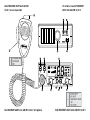 2
2
-
 3
3
-
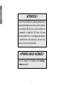 4
4
-
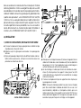 5
5
-
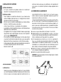 6
6
-
 7
7
-
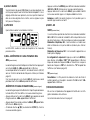 8
8
-
 9
9
-
 10
10
-
 11
11
-
 12
12
-
 13
13
-
 14
14
-
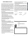 15
15
-
 16
16
-
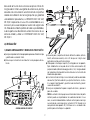 17
17
-
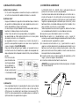 18
18
-
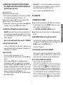 19
19
-
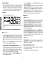 20
20
-
 21
21
-
 22
22
-
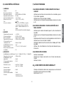 23
23
-
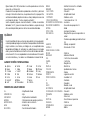 24
24
-
 25
25
-
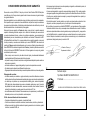 26
26
-
 27
27
-
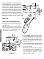 28
28
-
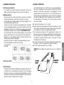 29
29
-
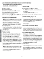 30
30
-
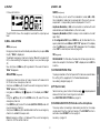 31
31
-
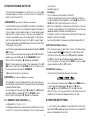 32
32
-
 33
33
-
 34
34
-
 35
35
-
 36
36
-
 37
37
-
 38
38
-
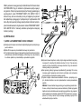 39
39
-
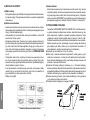 40
40
-
 41
41
-
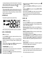 42
42
-
 43
43
-
 44
44
-
 45
45
-
 46
46
-
 47
47
-
 48
48
-
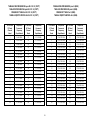 49
49
-
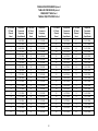 50
50
-
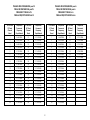 51
51
-
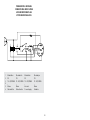 52
52
-
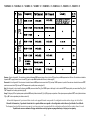 53
53
-
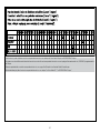 54
54
-
 55
55
-
 56
56


PRESIDENT Andy ASC El manual del propietario
- Tipo
- El manual del propietario
- Este manual también es adecuado para
en otros idiomas
- français: PRESIDENT Andy ASC Le manuel du propriétaire
- English: PRESIDENT Andy ASC Owner's manual
- polski: PRESIDENT Andy ASC Instrukcja obsługi
Artículos relacionados
-
PRESIDENT Andy USA El manual del propietario
-
-
-
-
-
-
-
-
-
PRESIDENT Ronald 10 El manual del propietario