Schneider Electric EER260LLCR Guía de instalación
- Tipo
- Guía de instalación

™
Wiser™
EER260LLCR Load Control
Control de carga EER260LLCR
Installer’s Guide / Guía de instalación
S1A90300
Rev. 01, 05/2011
Retain for future use. / Conservar para uso futuro.


ENGLISHESPAÑOL
Wiser™ Load Control Installer’s Guide
Guía de instalación del control de carga Wiser™


™
Wiser™
EER260LLCR Load Control
Installer’s Guide
S1A90300
Rev. 01, 05/2011
Retain for future use.
ENGLISH

ENGLISH

S1A90300 Wiser™ Load Control Installer’s Guide
Rev. 01, 05/2011 Contents
© 2011 Schneider Electric All Rights Reserved
3-EN
ENGLISH
HAZARD CATEGORIES AND SPECIAL SYMBOLS . . . . . . . . . . . . . . . . . . . . . . 4-EN
INTRODUCTION . . . . . . . . . . . . . . . . . . . . . . . . . . . . . . . . . . . . . . . . . . . . . . . . . . 5-EN
Product Description . . . . . . . . . . . . . . . . . . . . . . . . . . . . . . . . . . . . . . . . . . . . . 5-EN
Parts List . . . . . . . . . . . . . . . . . . . . . . . . . . . . . . . . . . . . . . . . . . . . . . . . . . . . . . 5-EN
Circuit Breakers and Current Transformers . . . . . . . . . . . . . . . . . . . . . . . . . . . 6-EN
Document Scope . . . . . . . . . . . . . . . . . . . . . . . . . . . . . . . . . . . . . . . . . . . . . . . 6-EN
Audience Definition . . . . . . . . . . . . . . . . . . . . . . . . . . . . . . . . . . . . . . . . . . . . . . 6-EN
SPECIFICATIONS . . . . . . . . . . . . . . . . . . . . . . . . . . . . . . . . . . . . . . . . . . . . . . . . . 7-EN
DIMENSIONS . . . . . . . . . . . . . . . . . . . . . . . . . . . . . . . . . . . . . . . . . . . . . . . . . . . . . 8-EN
TERMINAL DESCRIPTIONS . . . . . . . . . . . . . . . . . . . . . . . . . . . . . . . . . . . . . . . . 10-EN
INSTALLATION . . . . . . . . . . . . . . . . . . . . . . . . . . . . . . . . . . . . . . . . . . . . . . . . . . 11-EN
Safety Precautions . . . . . . . . . . . . . . . . . . . . . . . . . . . . . . . . . . . . . . . . . . . . 11-EN
Before You Install the Controller . . . . . . . . . . . . . . . . . . . . . . . . . . . . . . . . . . . 12-EN
240 V Installation . . . . . . . . . . . . . . . . . . . . . . . . . . . . . . . . . . . . . . . . . . . . . . 13-EN
120 V Installation . . . . . . . . . . . . . . . . . . . . . . . . . . . . . . . . . . . . . . . . . . . . . . 17-EN
USER INTERFACE . . . . . . . . . . . . . . . . . . . . . . . . . . . . . . . . . . . . . . . . . . . . . . . 21-EN
Setup Button . . . . . . . . . . . . . . . . . . . . . . . . . . . . . . . . . . . . . . . . . . . . . . . . . . 21-EN
Join Button . . . . . . . . . . . . . . . . . . . . . . . . . . . . . . . . . . . . . . . . . . . . . . . . . . . 21-EN
Reset Button . . . . . . . . . . . . . . . . . . . . . . . . . . . . . . . . . . . . . . . . . . . . . . . . . . 21-EN
Opt-Out Button . . . . . . . . . . . . . . . . . . . . . . . . . . . . . . . . . . . . . . . . . . . . . . . . 22-EN
LED Indications . . . . . . . . . . . . . . . . . . . . . . . . . . . . . . . . . . . . . . . . . . . . . . . . 22-EN
INITIAL CONFIGURATION OR CONFIGURATION AFTER A
FACTORY RESET . . . . . . . . . . . . . . . . . . . . . . . . . . . . . . . . . . . . . . . . . . . . . . . . 23-EN
RESET AND FACTORY RESET . . . . . . . . . . . . . . . . . . . . . . . . . . . . . . . . . . . . . 24-EN
PRODUCT SUPPORT . . . . . . . . . . . . . . . . . . . . . . . . . . . . . . . . . . . . . . . . . . . . . 25-EN
FCC RADIO FREQUENCY INTERFERENCE STATEMENT . . . . . . . . . . . . . . . 25-EN

© 2011 Schneider Electric All Rights Reserved
4-EN
Wiser™ Load Control Installer’s Guide S1A90300
Hazard Categories and Special Symbols Rev. 01, 05/2011
ENGLISH
Hazard Categories and Special Symbols
Read these instructions carefully and look at the equipment to become
familiar with the device before trying to install, operate, service or
maintain it. The following special messages may appear throughout
this bulletin or on the equipment to warn of potential hazards or to call
attention to information that clarifies or simplifies a procedure.
The addition of either symbol to a “Danger” or “Warning” safety label
indicates that an electrical hazard exists which will result in personal
injury if the instructions are not followed.
This is the safety alert symbol. It is used to alert you to potential
personal injury hazards. Obey all safety messages that follow this
symbol to avoid possible injury or death.
NOTE: Provides additional information to clarify or simplify a procedure.
DANGER
DANGER indicates an imminently hazardous situation which, if not
avoided, will result in death or serious injury.
WARNING
WARNING indicates a potentially hazardous situation which, if not
avoided, can result in death or serious injury.
CAUTION
CAUTION indicates a potentially hazardous situation which, if not
avoided, can result in minor or moderate injury.
CAUTION
CAUTION, used without the safety alert symbol, indicates a
potentially hazardous situation which, if not avoided, can result in
property damage.

© 2011 Schneider Electric All Rights Reserved
S1A90300 Wiser™ Load Control Installer’s Guide
Rev. 01, 05/2011 Introduction
5-EN
ENGLISH
Introduction
Product Description
The Wiser Load Controller is a locally or remotely-controlled load
management device for use in energy management systems. The
controller can be used as a demand response device and as a simple
metering device.
As a demand response device, the controller allows an energy
service provider to monitor energy use over a secure ZigBee
®
network and issue requests for reduced consumption. At the service
provider’s request, the controller automatically sheds the connected
electrical load. An Opt-Out feature allows users to disable load
shedding for a day or for a longer term.
As a simple metering device, the controller can measure energy
consumption of 240 V and 120 V, up to 26 kW (60 A per phase). Two
field-installable current transformers are required for 240 V
measurement and one is required for 120 V measurement.
The controller has a programmable HVAC anti-cycling feature that
provides a three minute delay before the air conditioner comes on
after a demand response event. This helps protect the compressor
from damage and energy-wasting On-Off cycling.
The controller has a timer that automatically switches the connected load
on and off at times programmed by the user. A Wiser In-Home Display,
reference EER20100, is required for programming the timer. For more
information consult the In-Home Display User’s Guide, S1B14482.
The controllers’ circuit breaker provides local disconnect operation.
The circuit breaker also provides overcurrent protection.
Parts List
The controller comes with:
• A Schneider Electric
TM
QO
TM
enclosure
• A deadfront with control electronics
• An extension cable for circuit breaker control
• Installer’s Guide S1A90300 and User’s Guide S1A90299
A Square D
TM
QOPL-ILC circuit breaker must be purchased
separately. Optional current transformer kits are required for simple
metering use. See page 6.

© 2011 Schneider Electric All Rights Reserved
Wiser™ Load Control Installer’s Guide S1A90300
Introduction Rev. 01, 05/2011
6-EN
ENGLISH
Circuit Breakers and Current Transformers
Document Scope
This manual covers installation of the Wiser Load Controller, the
Square D
TM
QOPL-ILC circuit breakers, and the optional current
transformer kits.
Audience Definition
This manual is for installers of residential power distribution
equipment. For the protection of personnel and equipment, a
qualified person must perform the procedures in this instruction
bulletin. The person must be:
• Able to read, interpret, and follow the instructions and precautions
in this instruction bulletin and the other documentation referenced.
• Able to perform installation, commissioning, and diagnostic
procedures while following the safety procedures recommended
in NFPA 70E.
• Trained on the operation and fundamentals of residential and
commercial power distribution apparatus, and familiar with the
associated hazards.
• Licensed in accordance with local electrical installation code
requirements.
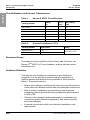
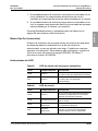
Table 1: Square D QOPL Circuit Breakers
Catalog Number
Rating
(A)
No. of
Poles
AIC Rating
(kA)
QO115PLILC 15 1 10
QO120PLILC 20 1 10
QO230PLILC 30 2 10
QO240PLILC 40 2 10
QO250PLILC 50 2 10
QO260PLILC 60 2 10
Table 2: Current Transformers (CTs)
Catalog Number Description Rating
EER260LLCCT1 1 CT
120 to 240 V, 60 A
EER260LLCCT2 2 CTs

© 2011 Schneider Electric All Rights Reserved
S1A90300 Wiser™ Load Control Installer’s Guide
Rev. 01, 05/2011 Specifications
7-EN
ENGLISH
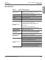
Specifications
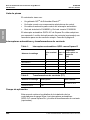
Table 3: Technical Specifications
Enclosure rating
Type 3R enclosure, 60 A, 120/240 Vac.
Accepts only 1 single-pole QOPL circuit breaker or
1 double-pole QOPL circuit breaker.
Do not install more than 1 circuit breaker in the enclosure.
Operating temperature -4 to 104 °F (-20 to 40 °C) without derating
Storage temperature -40 to 185
°F (-40 to 85 °C)
Humidity 5 to 95% noncondensing
Altitude 0 to 10,000 ft (0 to 3,048 m)
Transmission power 100 mW
Power measurement
accuracy
1
1
Power measurement specifications are applicable when an optional current
transformer kit is installed.
120 V operation:
• No power under 160 W is reported.
• Best accuracy from 160 W to 770 W is +/- 7%.
• Best accuracy from 771 W to 6.5 kW is +/- 5%.
240 V operation:
• No power under 420 W is reported.
• Best accuracy from 420 W to 1.5 kW is +/- 7%.
• Best accuracy from 1.51 kW to 13 kW is +/- 5%
Power measurement
reporting resolution
1
Minimum power resolution: 1 kW
Minimum current resolution: 0.06 A
Certifications, codes,
and standards
UL Listed per UL 498, Molded-Case Circuit Breakers,
Molded-Case Switches and Circuit-Breaker Enclosures.
Tested per UL 916, Energy Management Equipment.
RF characteristics,
within band
FCC compliance: 47CFR 15.247
(operating frequency 2.4 GHz) Part 15B
RF standard: IEEE 802.15.4: 2003
ZigBee
®
Smart Energy version 1.0
RF characteristics, out
of band
IEC 61000-4-2, 2001, Electrostatic Discharge, Level 4
EN 301 489-17, Radiated Immunity, 3 V/m
IEC 61000-4-4, 2001, EFT/Burst Immunity, Severity Level 3
IEC 61000-4-5, 2001, Surge Immunity, Severity Level 3
IEC 61000-4-6, 2003, Conducted RF Immunity, 10 V/m
IEC 61000-4-11, 2002, Voltage Dips and Interruptions
IEEE C37.90.1, 2000, EFT / Surge Relay Systems

© 2011 Schneider Electric All Rights Reserved
Wiser™ Load Control Installer’s Guide S1A90300
Dimensions Rev. 01, 05/2011
8-EN
ENGLISH
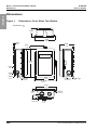
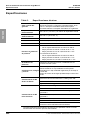
Dimensions
Figure 1: Dimensions: Front, Sides, Top, Bottom
5.53
8.78
0.70
6.40
0.31
0.30
0.953
0.5/0.75
0.75/1.0 0.062 Typ.
3.85
0.98
1.10
2.89
5.93
73.41
Dimensions: in.
mm
150.62
7.87
17.78
97.79
223
7.62
0.30
7.62
24.21
12.7/19.05
140.46
162.56
19.05/25.40 1.57
5.93
150.62
0.5/0.75
12.7/19.05
2.89
73.41
0.75/1.0
19.05/25.40
27.94
24.89

© 2011 Schneider Electric All Rights Reserved
S1A90300 Wiser™ Load Control Installer’s Guide
Rev. 01, 05/2011 Dimensions
9-EN
ENGLISH
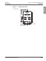
Figure 2: Dimensions: Back
1.76
7.50
1.50 1.38
Dimensions: in.
mm
190.5
44.70
0.5/0.75
12.7/19.05
0.75/1.0
19.05/25.40
38.10
35.05

© 2011 Schneider Electric All Rights Reserved
Wiser™ Load Control Installer’s Guide S1A90300
Terminal Descriptions Rev. 01, 05/2011
10-EN
ENGLISH
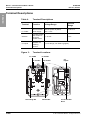
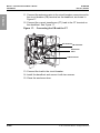
Terminal Descriptions
Table 4: Terminal Descriptions
Terminal Function Voltage Range
Current
Range
L1: PCBA
L2: PCBA
Connection
point for PCBA
power supply
120 Vac phase-to-ground/neutral;
240 Vac phase-to-phase,
-6% / +13%
15 to 60 A
CB drive
Provides voltage
and current to
the circuit
breaker motor.
+/- 24 Vdc 1.5 A
CT inputs
Provide current
feedback for
metering
function.
For CT ratings, see Table 2 (page 6).
Figure 3: Terminal Locations
Grounding Bar Neutral Bar
L1: PCBA
L1: Feeder
Circuit Breaker
Drive
CT
Inputs
L2: PCBA
L2: Feeder

© 2011 Schneider Electric All Rights Reserved
S1A90300 Wiser™ Load Control Installer’s Guide
Rev. 01, 05/2011 Installation
11-EN
ENGLISH
Installation
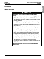
Safety Precautions
DANGER
HAZARD OF ELECTRIC SHOCK, EXPLOSION, OR ARC
FLASH
• Apply appropriate personal protective equipment (PPE) and
follow safe electrical work practices. See NFPA 70E.
• This equipment must only be installed and serviced by qualified
electrical personnel.
• Turn OFF all power supplying this equipment before working on
or inside the equipment.
• Always use a properly rated voltage sensing device to confirm
that power is off.
• Replace all devices, doors, and covers before turning on power
to this equipment.
• Petroleum-based paints, solvents, or sprays can cause plastic to
degrade. Do not allow petroleum-based paints, solvents, or
sprays to contact the nonmetallic parts of this product.
• Before starting a wiring installation or addition, consult a local
building or electrical inspector for current National Electrical
Code
®
requirements. Local codes vary, but are adopted and
enforced to promote safe electrical installations. A permit may be
needed to do electrical work, and some codes may require an
inspection of the electrical work.
• This equipment is not suitable for use in the corrosive
environments present in agricultural buildings. See NEC 547 or
CEC 2-400.
Failure to follow these instructions will result in death or
serious injury.

© 2011 Schneider Electric All Rights Reserved
Wiser™ Load Control Installer’s Guide S1A90300
Installation Rev. 01, 05/2011
12-EN
ENGLISH
Before You Install the Controller
1. Identify the target load. Examples of permissible loads:
— Resistive loads such as water heaters
— Motor loads such as pumps
— Combined loads such as HVAC
Generator loads may not be connected.
2. Select a location for mounting the controller that meets local and
national electrical code requirements.
3. The controller can function as a load disconnect. If an existing
disconnect switch is already present on the load, it can be
removed.
WARNING
IMPROPER GROUNDING
• Use Listed grounding bushings or grounding plate on the conduit
fitting.
• Connect the jumper wire from the equipment grounding terminal
to the grounding bushing or the grounding plate.
Failure to follow these instructions can result in death or
serious injury.
CAUTION
PRODUCT OVERVOLTAGE
Do not perform high-potential dielectric testing on the controller.
Damage to the control electronics may result.
Failure to follow these instructions can result in equipment
damage.

© 2011 Schneider Electric All Rights Reserved
S1A90300 Wiser™ Load Control Installer’s Guide
Rev. 01, 05/2011 Installation
13-EN
ENGLISH
240 V Installation
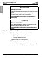
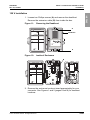
1. Loosen two Phillips screws (A) and remove the deadfront.
Remove the extension cable (B) from inside the enclosure.
2. Remove the enclosure knockout sized appropriately for your
connector. See Figures 1 and 2 (pages 8 and 9) for knockout
locations and sizes.
Figure 4: Removing the Deadfront
Figure 5: Inside of Enclosure and Back of Deadfront
A
A
WARNING / ADVERTENCIA
DANGER / PELIGRO
U
L
LISTED
Status
Event
Opt Out
NWK
Opt - Out
Join
Reset
Setup
Deadfront
WARNING / ADVERTENCIA
DANGER / PELIGRO
U
L
LISTED
B

© 2011 Schneider Electric All Rights Reserved
Wiser™ Load Control Installer’s Guide S1A90300
Installation Rev. 01, 05/2011
14-EN
ENGLISH
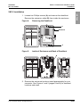
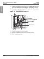
3. Mount the enclosure on the mounting surface with two screws (C).
4. Install a connector appropriate for the application (D, conduit
shown).
5. Connect the feeder grounding wire (E) to the enclosure grounding
bar and connect the neutral wire (F, if present) to the enclosure
neutral bar.
6. If the controller will be used for simple metering, install one or two
current transformers (G, ordered separately) on each feeder wire.
7. Connect the feeder wires to terminals L1 (H) and L2 (I).
Figure 6: Mounting the Enclosure
Figure 7: Installing the CTs and 240 V Feeder Wires
WARNING / ADVERTENCIA
DANGER / PELIGRO
U
L
LISTED
C
C
D
G
G
H (L1)
I (L2)
E
F

© 2011 Schneider Electric All Rights Reserved
S1A90300 Wiser™ Load Control Installer’s Guide
Rev. 01, 05/2011 Installation
15-EN
ENGLISH
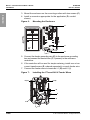
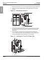
8. Install the circuit breaker (J, ordered separately).
9. For wire stress relief, hang the deadfront on the bracket (K)
provided at the right edge of the enclosure. See Figures 8 and 9.
10. Connect the wires from the deadfront:
— Connect the black wire to terminal L1 at point (L).
— Connect the blue wire to terminal L2 at point (M).
— Install a wire nut on the neutral wire (white). This wire is not
used for 240 V operation.
Figure 8: Installing the Circuit Breaker
Figure 9: Connecting the Wires from the Deadfront
1/ON
60
J
K
1/ON
60
Wire Nut
L (L1)
M (L2)
Feeder wires.
Do not connect the
deadfront wires at the
same terminal point as
the feeder wires.

© 2011 Schneider Electric All Rights Reserved
Wiser™ Load Control Installer’s Guide S1A90300
Installation Rev. 01, 05/2011
16-EN
ENGLISH
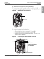
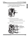
11. Connect the extension wire to the circuit breaker (CB) connector
and to the CB terminal on the deadfront, as shown in Figure 10.
12. Connect the current transformer (CT) leads to the CT terminal on
the deadfront. See Figure 10.
13. Connect the load to the circuit breaker.
14. Replace the deadfront and secure it with two screws.
15. Close the enclosure door.
Figure 10: Connecting the CB and CTs
1/ON
60
CB Connector
CT Terminal
CB Terminal
Extension Wire

© 2011 Schneider Electric All Rights Reserved
S1A90300 Wiser™ Load Control Installer’s Guide
Rev. 01, 05/2011 Installation
17-EN
ENGLISH
120 V Installation
1. Loosen two Phillips screws (A) and remove the deadfront.
Remove the extension cable (B) from inside the box.
2. Remove the enclosure knockout sized appropriately for your
connector. See Figures 1 and 2 (pages 8 and 9) for knockout
locations.
Figure 11: Removing the Deadfront
Figure 12: Inside of Enclosure
A
A
WARNING / ADVERTENCIA
DANGER / PELIGRO
U
L
LISTED
Status
Event
Opt Out
NWK
Opt - Out
Join
Reset
Setup
Deadfront
WARNING / ADVERTENCIA
DANGER / PELIGRO
U
L
LISTED
B

© 2011 Schneider Electric All Rights Reserved
Wiser™ Load Control Installer’s Guide S1A90300
Installation Rev. 01, 05/2011
18-EN
ENGLISH
3. Mount the enclosure on the mounting surface with two screws (C).
4. Install a connector appropriate for the application (D, conduit
shown).
5. Connect the feeder grounding wire (E) to the enclosure grounding
bar, and connect the neutral wire (F, if present) to the enclosure
neutral bar.
6. If the controller will be used for simple metering, install one
current transformer (G, ordered separately) on the feeder wire.
7. Connect the feeder wire to terminal L1 at point (H).
Figure 13: Mounting the Enclosure
Figure 14: Installing the CT and 120 V Feeder Wire
WARNING / ADVERTENCIA
DANGER / PELIGRO
U
L
LISTED
C
C
D
300VAC L-N
E
F
G
H

© 2011 Schneider Electric All Rights Reserved
S1A90300 Wiser™ Load Control Installer’s Guide
Rev. 01, 05/2011 Installation
19-EN
ENGLISH
8. Install the circuit breaker (J, ordered separately).
9. For wire stress relief, hang the deadfront on the bracket (K)
provided at right edge of the enclosure. See Figures 15 and 16.
10. Connect the wires from the deadfront:
— Connect the black wire to terminal L1 at point (L).
— Connect the neutral wire (white) to the neutral bar.
— Install a wire nut on the blue wire. This wire is not used for
120 V operation.
Figure 15: Installing the Circuit Breaker
Figure 16: Connecting the Wires from the Deadfront
300VAC L-N
1/ON
20
o/OFF
101kA
J
K
1/ON
20
o/OFF
101kA
300VAC L-N
Wire Nut
L
Feeder wire.
Do not connect the
deadfront wire at the
same terminal point as
the feeder wire.
Neutral

© 2011 Schneider Electric All Rights Reserved
Wiser™ Load Control Installer’s Guide S1A90300
Installation Rev. 01, 05/2011
20-EN
ENGLISH
11. Connect the extension wire to the circuit breaker connector and to
the circuit breaker (CB) terminal on the deadfront, as shown in
Figure 17.
12. Connect the current transformer (CT) lead to the CT terminal on
the deadfront. See Figure 17.
13. Connect the load to the circuit breaker.
14. Install the deadfront and secure it with two screws.
15. Close the enclosure door.
Figure 17: Connecting the CB and the CT
1/ON
20
o/OFF
101kA
Extension
Wire
CB Connector
CT Terminal
CB Terminal

© 2011 Schneider Electric All Rights Reserved
S1A90300 Wiser™ Load Control Installer’s Guide
Rev. 01, 05/2011 User Interface
21-EN
ENGLISH
User Interface
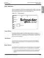
The user interface consists of four buttons and four LEDs. The Setup,
Join, and Reset buttons are just under the surface of the front panel
and can be pressed with a tool such as a paper clip.
Setup Button
The Setup button is used to configure the controller for simple
metering and HVAC anti-cycling. The Setup button is functional only
when the controller is in a hold state (see Reset Button below) and
has not joined a network.
Join Button
The Join button is used to connect the controller to the ZigBee
®
network. Once the controller is on the network, the Join button no
longer functions.
Reset Button
The Reset button is used to remove the controller from the network
and reset the control electronics. Two reset options are available.
1. A short hold reset removes the controller form the network and
resets the control electronics while preserving user-selected
options.
Figure 18: User Interface
Status
Event
Opt Out
NWK
Setup
Join
Reset
OPT - OUT

© 2011 Schneider Electric All Rights Reserved
Wiser™ Load Control Installer’s Guide S1A90300
User Interface Rev. 01, 05/2011
22-EN
ENGLISH
2. A long hold reset removes the controller from the network, returns
it to its factory default settings, and clears all user-selected
options and memory.
See Reset and Factory Reset on page 24 for more information.
Opt-Out Button
The Opt-Out button is used to opt out of demand response events
until midnight on the day the opt out is selected, or for a longer term.
It is also used to cancel an opt out. For more information, see the
Wiser™ EER260LLCR Load Control User’s Guide, document number
S1A90299.
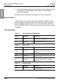
LED Indications
Table 5: Circuit Breaker Status LED
Color Behavior Meaning
Green Steady on
Circuit breaker contacts are commanded
closed (load commanded on).
Red Steady on
Circuit breaker contacts are commanded
open (load commanded off).
Table 6: Event LED
Color Behavior Meaning
Green Steady on
No demand response events are present or
scheduled. The controller is ready to accept
commands.
Green Slow blink A future demand response event is in queue.
Green Fast blink
The controller is servicing a demand
response event.
Red Fast blink
The controller is in Opt-Out mode and a
demand response event is in progress or
scheduled.
Table 7: Opt-Out LED
Color Behavior Meaning
Green Steady on
The controller will respond to demand
response events.

© 2011 Schneider Electric All Rights Reserved
S1A90300 Wiser™ Load Control Installer’s Guide
Rev. 01, 05/2011 Initial Configuration or Configuration After a Factory Reset
23-EN
ENGLISH
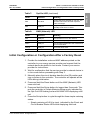
Initial Configuration or Configuration After a Factory Reset
1. Provide the installation code and MAC address printed on the
controller to your energy service provider and request that the
network device be placed in Join mode. Contact your service
provider for instructions.
2. Wait for confirmation that the service provider’s network device is
in Join mode before proceeding with Step 3.
3. Manually place the circuit breaker handle in the Off position and
turn on power to the controller. The controller will operate all the
LEDs during initialization.
4. Press and hold the Reset button until the NWK (Network) LED
turns solid red.
5. Press and hold the Setup button for longer than 5 seconds. This
puts the controller in Simple Metering Setup mode, indicated by
the Opt-Out LED flashing red and the NWK LED displaying solid
red.
6. Press the Setup button to cycle through the three simple metering
states:
— Simple metering at 240 Vac input, indicated by the Event and
Circuit Breaker Status LEDs both displaying solid red.
Red Slow blink
Opt Out has been selected for one day. The
controller will resume demand response
mode at midnight.
Red Steady on
Long-term Opt Out has been selected.
Criticality levels have no affect.
Table 8: NWK (Network) LED
Color Behavior Meaning
Red Steady on The controller is not on the network.
Red Slow blink The controller is joining the network.
Green Steady on
The controller is attached to the network and
has communication.
Orange Steady on Successful short reset.
Red Fast blink System-detected error.
Table 7: Opt-Out LED (continued)
Color Behavior Meaning

© 2011 Schneider Electric All Rights Reserved
Wiser™ Load Control Installer’s Guide S1A90300
Reset and Factory Reset Rev. 01, 05/2011
24-EN
ENGLISH
— Simple metering at 120 Vac input, indicated by the Circuit
Breaker Status LED displaying solid red. The Event LED is off
in this state.
— Simple metering disabled. The Circuit Breaker Status LED
and Event LED are off in this state. If you have not installed
current transformers, this is the only simple metering state you
may select.
7. Read this entire step before performing it. You confirm the
simple metering selection and configure HVAC anti-cycling in the
same step.
— To confirm the simple metering selection without enabling
anti-cycling, press the Opt-Out button until the Opt-Out LED
slowly flashes red. All three LEDs will then flash green three
times and the controller will return to the hold state.
— To confirm the simple metering selection with anti-cycling
enabled, press and hold the Opt-Out button until the Opt-Out
LED turns solid red. All three LEDs will flash green three times
and the controller will return to the hold state.
8. Press the Join button to join the network. The NWK (Network)
LED will slowly blink red, and then turn steady green indicating
that the controller has joined the network.
9. Request that the energy service provider send a short demand
response event. Check the status of the controller’s LEDs and the
reaction of the connected load to verify remote operation of the
controller.
10. If the controller is in Simple Metering mode, with the load running,
request that the service provider issue a read to verify remote
operation.
Reset and Factory Reset
The load controller is factory set with simple metering disabled and
anti-cycling disabled.
To reset the controller to the factory settings, press and hold the
Reset button for 30 seconds or longer until the Network (NWK) LED
turns solid red.
To reset the controller electronics while saving the user configuration,
press the Reset button until the Network (NWK) LED slowly blinks
red. The NWK LED will turn solid orange. Press Join to rejoin the
network.

© 2011 Schneider Electric All Rights Reserved
S1A90300 Wiser™ Load Control Installer’s Guide
Rev. 01, 05/2011 Product Support
25-EN
ENGLISH
Product Support
The Schneider Electric Customer Care Center (CCC) is your single
point of contact for information about the Wiser Load Controller.
Qualified personnel are available to answer your customer service
and technical support questions. Call toll free 1-888-778-2733.
FCC Radio Frequency Interference Statement
This controller has been tested and found to comply with the limits for
a Class B digital device, pursuant to Part 15 of the FCC Rules.
These limits are designed to provide reasonable protection against
harmful interference in a residential installation. This controller is an
intentional radiator. If not installed and used in accordance with the
instructions, it may cause harmful interference to radio
communications. However, there is no guarantee that interference
will not occur in a particular installation. If this controller does cause
harmful interference to radio or television reception, the user is
encouraged to try and correct the interference by one or more of the
following measures:
• Reorient or relocate the receiving antenna.
• Increase the separation between the controller and the receiver.
• Connect the receiver into an outlet on a different circuit.
• Consult the receiver dealer or an experienced radio/TV technician
for help.
Do not make changes or modifications to the controller which are not
expressly approved by Schneider Electric. Any changes or
modifications may result in the loss of authority to operate the
equipment.

© 2011 Schneider Electric All Rights Reserved
Wiser™ Load Control Installer’s Guide S1A90300
FCC Radio Frequency Interference Statement Rev. 01, 05/2011
26-EN
ENGLISH

ENGLISH

Wiser™ EER260LLCR Load Control Installer’s Guide
Instruction Bulletin
Schneider Electric USA, Inc.
8001 Knightdale Blvd.
Knightdale, NC 27545 U.S.A.
1-888-778-2733
www.schneider-electric.us
Electrical equipment should be installed, operated, serviced, and
maintained only by qualified personnel. No responsibility is
assumed by Schneider Electric for any consequences arising out of
the use of this material.
Square D
TM
,
Schneider Electric
TM
, and Wiser
TM
are trademarks or
registered trademarks of Schneider Electric. Other trademarks
used herein are the property of their respective owners.
S1A90300 Rev. 01, 05/2011 Replaces S1A90300 dated 03/2011
© 2011 Schneider Electric All Rights Reserved
TM
ENGLISH

™
Wiser™
Control de carga EER260LLCR
Guía de instalación
S1A90300
Rev. 01, 05/2011
Conservar para uso futuro.
ESPAÑOL

ESPAÑOL

S1A90300 Guía de instalación del control de carga Wiser™
Rev. 01, 05/2011 Contenido
© 2011 Schneider Electric Reservados todos los derechos
3-ES
ESPAÑOL
CATEGORÍAS DE RIESGOS Y SÍMBOLOS ESPECIALES . . . . . . . . . . . . . . . . . 4-ES
INTRODUCCIÓN . . . . . . . . . . . . . . . . . . . . . . . . . . . . . . . . . . . . . . . . . . . . . . . . . . 5-ES
Descripción del producto . . . . . . . . . . . . . . . . . . . . . . . . . . . . . . . . . . . . . . . . . 5-ES
Lista de piezas . . . . . . . . . . . . . . . . . . . . . . . . . . . . . . . . . . . . . . . . . . . . . . . . . 6-ES
Interruptores automáticos y transformadores de corriente . . . . . . . . . . . . . . . . 6-ES
Campo de aplicación . . . . . . . . . . . . . . . . . . . . . . . . . . . . . . . . . . . . . . . . . . . . 6-ES
Quiénes deben usar este manual . . . . . . . . . . . . . . . . . . . . . . . . . . . . . . . . . . . 7-ES
ESPECIFICACIONES . . . . . . . . . . . . . . . . . . . . . . . . . . . . . . . . . . . . . . . . . . . . . . 8-ES
DIMENSIONES . . . . . . . . . . . . . . . . . . . . . . . . . . . . . . . . . . . . . . . . . . . . . . . . . . . 9-ES
DESCRIPCIÓN DE LAS TERMINALES . . . . . . . . . . . . . . . . . . . . . . . . . . . . . . . 11-ES
INSTALACIÓN . . . . . . . . . . . . . . . . . . . . . . . . . . . . . . . . . . . . . . . . . . . . . . . . . . . 12-ES
Precauciones de seguridad . . . . . . . . . . . . . . . . . . . . . . . . . . . . . . . . . . . . . . 12-ES
Antes de instalar el controlador . . . . . . . . . . . . . . . . . . . . . . . . . . . . . . . . . . . 13-ES
Instalación de 240 V . . . . . . . . . . . . . . . . . . . . . . . . . . . . . . . . . . . . . . . . . . . . 14-ES
Instalación de 120 V . . . . . . . . . . . . . . . . . . . . . . . . . . . . . . . . . . . . . . . . . . . . 18-ES
INTERFAZ DEL USUARIO . . . . . . . . . . . . . . . . . . . . . . . . . . . . . . . . . . . . . . . . . 22-ES
Botón Setup (configuración) . . . . . . . . . . . . . . . . . . . . . . . . . . . . . . . . . . . . . . 22-ES
Botón Join (unión) . . . . . . . . . . . . . . . . . . . . . . . . . . . . . . . . . . . . . . . . . . . . . . 22-ES
Botón Reset (restablecimiento) . . . . . . . . . . . . . . . . . . . . . . . . . . . . . . . . . . . 22-ES
Botón Opt-Out (retracción) . . . . . . . . . . . . . . . . . . . . . . . . . . . . . . . . . . . . . . . 23-ES
Indicaciones de LED . . . . . . . . . . . . . . . . . . . . . . . . . . . . . . . . . . . . . . . . . . . . 23-ES
CONFIGURACIÓN INICIAL O CONFIGURACIÓN DESPUÉS DE UN
RESTABLECIMIENTO DE FÁBRICA . . . . . . . . . . . . . . . . . . . . . . . . . . . . . . . . . 24-ES
RESTABLECIMIENTO Y RESTABLECIMIENTO DE FÁBRICA . . . . . . . . . . . . 26-ES
ASISTENCIA TÉCNICA DEL PRODUCTO . . . . . . . . . . . . . . . . . . . . . . . . . . . . . 26-ES
DECLARACIÓN DE INTERFERENCIA A RADIOFRECUENCIA SEGÚN FCC . 26-ES

© 2011 Schneider Electric Reservados todos los derechos
4-ES
Guía de instalación del control de carga Wiser™ S1A90300
Categorías de riesgos y símbolos especiales Rev. 01, 05/2011
ESPAÑOL
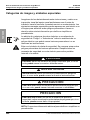
Categorías de riesgos y símbolos especiales
Asegúrese de leer detenidamente estas instrucciones y realice una
inspección visual del equipo para familiarizarse con él antes de
instalarlo, hacerlo funcionar o prestarle servicio o mantenimiento. Los
siguientes mensajes especiales pueden aparecer en este boletín o en
el equipo para advertirle sobre peligros potenciales o llamar su
atención sobre cierta información que clarifica o simplifica un
procedimiento.
La adición de cualquiera de estos símbolos a una etiqueta de
seguridad de “Peligro” o “Advertencia” indica la existencia de un
peligro eléctrico que podrá causar lesiones personales si no se
observan las instrucciones.
Este es el símbolo de alerta de seguridad. Se usa para avisar sobre
peligros potenciales de lesiones personales. Respete todos los
mensajes de seguridad con este símbolo para evitar posibles
lesiones o la muerte.
NOTA: Proporciona información adicional para clarificar o simplificar un
procedimiento.
PELIGRO
PELIGRO indica una situación de peligro inminente que, si no se
evita, podrá causar la muerte o lesiones serias.
ADVERTENCIA
ADVERTENCIA indica una situación potencialmente peligrosa
que, si no se evita, puede causar la muerte o lesiones serias.
PRECAUCIÓN
PRECAUCIÓN indica una situación potencialmente peligrosa que,
si no se evita, puede causar lesiones menores o moderadas.
PRECAUCIÓN
PRECAUCIÓN cuando se usa sin el símbolo de alerta de
seguridad, indica una situación potencialmente peligrosa que, si no
se evita, puede causar daño a la propiedad.

S1A90300 Guía de instalación del control de carga Wiser™
Rev. 01, 05/2011 Introducción
© 2011 Schneider Electric Reservados todos los derechos
5-ES
ESPAÑOL
Introducción
Descripción del producto
El controlador de carga Wiser es un dispositivo de gestión de carga
controlado local o remotamente que se emplea en sistemas de
gestión de energía. El controlador puede usarse como un dispositivo
de respuesta de demanda así como un dispositivo de medición
simple.
Como un dispositivo de respuesta de demanda, el controlador
permite a un proveedor de servicio de energía supervisar el uso de la
energía a través de una red ZigBee
®
segura y emitir solicitudes para
un consumo reducido. A solicitud del proveedor de servicio, el
controlador automáticamente desconecta la carga eléctrica
conectada. Una función de retracción (Opt-Out) permite al usuario
deshabilitar la desconexión de carga durante un día o durante un
período más largo.
Como un dispositivo de medición simple, el controlador puede medir
consumo de energía de 240 V y 120 V, hasta un máximo de 26 kW
(60 A por fase). Dos transformadores de corriente para instalar en
campo son necesarios para mediciones de 240 V y uno para
mediciones de 120 V.
El controlador tiene una función anticíclica HVAC programable que
proporciona un retardo de tres minutos antes de que arranque el aire
acondicionado seguido de un evento de respuesta de demanda. Esto
ayuda a proteger el compresor contra daños y desperdicio de
energía durante el ciclo de encendido y apagado.
El controlador tiene un temporizador que conecta y desconecta
automáticamente la carga conectada en las horas programadas por el
usuario. Una pantalla Wiser para el hogar, referencia EER20100, es
necesaria para programar el temporizador. Para obtener más
información consulte la Guía de usuario de la pantalla para el hogar,
S1B14482.
El interruptor automático del controlador proporciona desconexión
local. El interruptor automático también proporciona protección
contra sobrecorriente.

© 2011 Schneider Electric Reservados todos los derechos
6-ES
Guía de instalación del control de carga Wiser™ S1A90300
Introducción Rev. 01, 05/2011
ESPAÑOL
Lista de piezas
El controlador viene con:
• Un gabinete QO
TM
de Schneider Electric
TM
• Un frente muerto con componentes electrónicos de control
• Un cable de extensión para control del interruptor automático
• Guía de instalación S1A90300 y Guía de usuario S1A90299
El interruptor automático QOPL-ILC de Square D
TM
debe adquirirse
por separado. Los kits de tranformador de corriente (opcionales) son
necesarios para uso de medición simple. Consulte la página 6.
Interruptores automáticos y transformadores de corriente
Campo de aplicación
Este manual contiene los detalles de la instalación de los
controladores de carga Wiser, los interruptores automáticos
QOPL-ILC marca Square D
TM
y los kits de transformador de corriente
(opcionales).
Tabla 1: Interruptores automáticos QOPL marca Square D
Número de catálogo
Valor nominal
(A)
Cant. de
polos
Capacidad
interruptiva en
amperes
(kA)
QO115PLILC 15 1 10
QO120PLILC 20 1 10
QO230PLILC 30 2 10
QO240PLILC 40 2 10
QO250PLILC 50 2 10
QO260PLILC 60 2 10
Tabla 2: Transformadores de corriente (TC)
Número de catálogo Descripción Valor nominal
EER260LLCCT1 1 TC
120 a 240 V, 60 A
EER260LLCCT2 2 TC

S1A90300 Guía de instalación del control de carga Wiser™
Rev. 01, 05/2011 Introducción
© 2011 Schneider Electric Reservados todos los derechos
7-ES
ESPAÑOL
Quiénes deben usar este manual
El contenido de este manual es específico para ser usado por
aquellos encargados de la instalación del equipo de distribución
eléctrica residencial. Para la protección del personal y el equipo, una
persona calificada debe realizar los procedimientos detallados en
este boletín de instrucciones. Esta persona debe:
• ser capaz de entender, interpretar correctamente y seguir
cuidadosamente las instrucciones y precauciones delineadas en
este documento y demás documentos de referencia.
• ser capaz de realizar procedimientos de instalación, puesta en
servicio y diagnóstico mientras sigue los procedimientos de
seguridad recomendados en la norma 70E de NFPA.
• haber recibido capacitación sobre el funcionamiento y funciones
básicas de los aparatos de las redes de distribución eléctrica
residencial y comercial, así como estar familiarizado con los
riesgos relacionados.
• tener licencia de acuerdo con los requisitos de los códigos de
instalación eléctrica locales.

© 2011 Schneider Electric Reservados todos los derechos
8-ES
Guía de instalación del control de carga Wiser™ S1A90300
Especificaciones Rev. 01, 05/2011
ESPAÑOL
Especificaciones
Tabla 3: Especificaciones técnicas
Valor nominal del
gabinete
Gabinete tipo 3R, 60 A, 120/240 V~.
Acepta únicamente 1 interruptor automático QOPL de un
polo o 1 interruptor automático QOPL de dos polos.
No instale más de 1 interruptor automático en el gabinete.
Temperatura de
funcionamiento
-20 a 40 °C (-4 a 104 °F) sin reducir la capacidad nominal
Temp. de
almacenamiento
-40 a 85
°C (-40 a 185 °F)
Humedad 5 a 95% sin condensación
Altitud 0 a 3 048 m (0 a 10 000 pies)
Potencia de transmisión 100 mW
Precisión de medición
de potencia
1
1
Las especificaciones de la medición de potencia son aplicables cuando un kit de
transformador de corriente opcional está instalado.
Funcionamiento de 120 V:
• No se reporta alimentación de menos de 160 W.
• Mejor precisión de 160 W a 770 W es de +/- 7%.
• Mejor precisión de 771 W a 6,5 kW es de +/- 5%.
Funcionamiento de 240 V:
• No se reporta alimentación de menos de 420 W.
• Mejor precisión de 420 W a 1,5 kW es de +/- 7%.
• Mejor precisión de 1,51 kW a 13 kW es de +/- 5%.
Resolución de informe
de medición de
potencia
1
Resolución de potencia mínima: 1 kWResolución de
corriente mínima: 0,06 A
Certificaciones, códigos
y normas
Gabinetes para interruptores automáticos, seccionadores
desconectadores en caja moldeada e interruptores
automáticos en caja moldeada registrados por UL bajo la
norma 498.
Equipo de control de energía aprobado bajo la norma 916
de UL.
Características de RF
dentro de banda
Cumplimiento con FCC: 47CFR 15.247
(frecuencia de funcionamiento de 2,4 GHz) parte 15B
Norma de RF: IEEE 802.15.4: 2003
ZigBee
®
Smart Energy versión 1.0
Características de RF
fuera de banda
IEC 61000-4-2, descarga electrostática, nivel 4
EN 301 489-17, inmunidad radiada, 3 V/m
IEC 61000-4-4, 2001, EFT/inmunidad a ráfagas, nivel de
gravedad 3
IEC 61000-4-5, 2001, inmunidad a transitorios, nivel de
gravedad 3
IEC 61000-4-6, 2003, inmunidad a RF conducida, 10 V/m
IEC 61000-4-11, 2002, caídas e interrupciones de tensión
IEEE C37.90.1, 2000, EFT / sistemas de relevadores de
protección contra sobretensiones transitorias

S1A90300 Guía de instalación del control de carga Wiser™
Rev. 01, 05/2011 Dimensiones
© 2011 Schneider Electric Reservados todos los derechos
9-ES
ESPAÑOL
Dimensiones
Figura 1: Dimensiones: adelante, a los lados, arriba, abajo
5,53
8,78
0,70
6,40
0,31
0,30
0,953
0,5/0,75
0,75/1,0 0,062 típ.
3,85
0,98
1,10
2,89
5,93
73,41
Dimensiones: pulg
mm
150,62
7,87
17,78
97,79
223
7,62
0,30
7,62
24,21
12,7/19,05
140,46
162,56
19,05/25,40 1,57
5,93
150,62
0,5/0,75
12,7/19,05
2,89
73,41
0,75/1,0
19,05/25,40
27,94
24,89

© 2011 Schneider Electric Reservados todos los derechos
10-ES
Guía de instalación del control de carga Wiser™ S1A90300
Dimensiones Rev. 01, 05/2011
ESPAÑOL
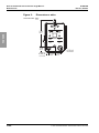
Figura 2: Dimensiones: atrás
1,76
7,50
1,50 1,38
Dimensiones: pulg
mm
190,5
44,70
0,5/0,75
12,7/19,05
0,75/1,0
19,05/25,40
38,10
35,05

S1A90300 Guía de instalación del control de carga Wiser™
Rev. 01, 05/2011 Descripción de las terminales
© 2011 Schneider Electric Reservados todos los derechos
11-ES
ESPAÑOL
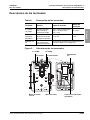
Descripción de las terminales
Tabla 4: Descripción de las terminales
Terminal Función Gama de tensión
Gama de
corriente
L1: PCBA
L2: PCBA
Punto de conexión
para la fuente de
alimentación PCBA
120 V~ fase a tierra/neutro;
240 V~ de fase a fase,
-6% / +13%
15 a 60 A
Terminal del
interruptor
automático
Proporciona tensión y
corriente al motor del
interruptor automático.
+/- 24 Vcd 1,5 A
Entradas del
TC
Proporcionan los datos
de la corriente a la
función de medición.
Para conocer los valores nominales de los TC,
consulte la tabla 2 (en la página 6).
Figura 3: Ubicaciones de las terminales
Barra de puesta
a tierra
Barra de neutro
L1: PCBA
L1: Alimen.
Terminal del interruptor
automático
Entradas del
TC
L2: PCBA
L2: Alimentador

© 2011 Schneider Electric Reservados todos los derechos
12-ES
Guía de instalación del control de carga Wiser™ S1A90300
Instalación Rev. 01, 05/2011
ESPAÑOL
Instalación
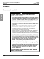
Precauciones de seguridad
PELIGRO
PELIGRO DE DESCARGA ELÉCTRICA, EXPLOSIÓN O
DESTELLO POR ARQUEO
• Utilice equipo de protección personal (EPP) apropiado y siga las
prácticas de seguridad en trabajos eléctricos establecidas por su
Compañía, consulte la norma 70E de NFPA y NOM-029-STPS.
• Solamente el personal eléctrico especializado deberá instalar y
prestar servicio de mantenimiento a este equipo.
• Desenergice el equipo antes de realizar cualquier trabajo dentro
o fuera de él.
• Siempre utilice un dispositivo detector de tensión nominal
adecuado para confirmar la desenergización del equipo.
• Vuelva a colocar todos los dispositivos, las puertas y las
cubiertas antes de energizar este equipo.
• Pintura, solventes o rocíos basados en derivados del petróleo
pueden causar la degradación del plástico. No permita que
superficies no metálicas de este producto entren en contacto con
pintura, solventes o rocíos basados en derivados del petróleo.
• Antes de realizar la instalación o adición de alambrado, consulte
con un inspector eléctrico o de la construcción local para cumplir
con los requisitos actuales del Código nacional eléctrico de EUA
(NEC
®
) o NOM-001-SEDE. Los códigos locales varían, se
aceptan y hacen cumplir para fomentar la seguridad en
instalaciones eléctricas. Es posible que necesite un permiso para
realizar el trabajo eléctrico, y en algunos casos, algunos códigos
pueden requerir una inspección del trabajo eléctrico efectuado.
• Este equipo no es adecuado para usarse en entornos corrosivos
tales como los que se encuentran en edificios de agricultura.
Consulte la norma 547 del NEC o 2-400 del CEC (código
eléctrico canadiense).
El incumplimiento de estas instrucciones podrá causar la
muerte o lesiones serias.

S1A90300 Guía de instalación del control de carga Wiser™
Rev. 01, 05/2011 Instalación
© 2011 Schneider Electric Reservados todos los derechos
13-ES
ESPAÑOL
Antes de instalar el controlador
1. Identifique la carga objetivo. Ejemplos de cargas permitidas:
— Las cargas resistivas tales como calentadores de agua
— Cargas de motor tales como bombas
— Cargas combinadas tales como los sistemas de aire
acondicionado y calefacción (HVAC)
Las cargas de generadores tal vez no puedan conectarse.
2. Seleccione una ubicación para montar el controlador, ésta debe
cumplir con los requisitos de los códigos eléctricos nacional y local.
3. El controlador puede funcionar como un desconectador de carga.
Si existe un seccionador desconectador en la carga, éste puede
ser retirado.
ADVERTENCIA
CONEXIÓN A TIERRA INCORRECTA
• Emplee pasamuros o placas de puesta a tierra aprobados para
las conexiones de tubo conduit.
• Conecte el cable de conexión en puente desde la terminal de
puesta a tierra del equipo al pasamuros o placa de puesta a
tierra.
El incumplimiento de estas instrucciones puede causar la
muerte o lesiones serias.
PRECAUCIÓN
SOBRETENSIÓN DEL PRODUCTO
No realice pruebas de rigidez dieléctrica de alto potencial en el
controlador. Es posible que se cause daño a los componentes
electrónicos de control.
El incumplimiento de estas instrucciones puede causar daño
al equipo.

© 2011 Schneider Electric Reservados todos los derechos
14-ES
Guía de instalación del control de carga Wiser™ S1A90300
Instalación Rev. 01, 05/2011
ESPAÑOL
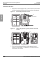
Instalación de 240 V
1. Afloje los dos tornillos Phillips (A) ) y retire el frente muerto. Retire
el cable de extensión (B) que se encuentra dentro del gabinete.
2. Retire los discos desprendibles de tamaño apropiado para el
conector. Vea las figuras 1 y 2 (páginas 9 y 10) para conocer las
ubicaciones y los tamaños.
Figura 4: Desmontaje del frente muerto
Figura 5: Interior del gabinete y parte posterior del frente
muerto
A
A
WARNING / ADVERTENCIA
DANGER / PELIGRO
U
L
LISTED
Status
Event
Opt Out
NWK
Opt - Out
Join
Reset
Setup
Frente muerto
WARNING / ADVERTENCIA
DANGER / PELIGRO
U
L
LISTED
B

S1A90300 Guía de instalación del control de carga Wiser™
Rev. 01, 05/2011 Instalación
© 2011 Schneider Electric Reservados todos los derechos
15-ES
ESPAÑOL
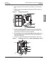
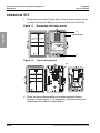
3. Monte el gabinete en la superficie de montaje con los dos tornillos
(C).
4. Instale un conector apropiado para la aplicación (D, se muestra el
tubo conduit).
5. Conecte el cable alimentador de puesta a tierra (E) a la barra de
puesta a tierra del gabinete y conecte el conductor de neutro (F, si
está presente) a la barra de neutro del gabinete.
6. Si el controlador va a ser usado para medición simple, instale uno o
dos transformadores de corriente (G, solicítelos por separado) en
cada cable alimentador.
7. Conecte los cables alimentadores a las terminales L1 (H) y L2 (I).
Figura 6: Montaje del gabinete
Figura 7: Instalación de los TC y cables alimentadores: 240 V
WARNING / ADVERTENCIA
DANGER / PELIGRO
U
L
LISTED
C
C
D
G
G
H (L1)
I (L2)
E
F

© 2011 Schneider Electric Reservados todos los derechos
16-ES
Guía de instalación del control de carga Wiser™ S1A90300
Instalación Rev. 01, 05/2011
ESPAÑOL
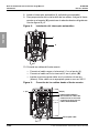
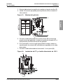
8. Instale el interruptor automático (J, solicitado por separado).
9. Para proporcionar alivio a la tensión de los cables, cuelgue el frente
muerto en el soporte (K) provisto en el reborde derecho del gabinete.
Vea las figuras 8 y 9.
10. Conecte los cables del frente muerto:
— Conecte el cable negro a la terminal L1 en el punto (L).
— Conecte el cable azul a la terminal L2 en el punto (M).
— Instale una tuerca para cable en el conductor de neutro
(blanco). Este cable no es apropiado para su uso en 240 V.
Figura 8: Instalación del interruptor automático
Figura 9: Conexión de los cables desde el frente muerto.
1/ON
60
J
K
1/ON
60
Tuerca para cable
L (L1)
M (L2)
Cables alimentadores.
No conecte los cables del
frente muerto en el mismo
punto de terminal que los
cables alimentadores.

S1A90300 Guía de instalación del control de carga Wiser™
Rev. 01, 05/2011 Instalación
© 2011 Schneider Electric Reservados todos los derechos
17-ES
ESPAÑOL
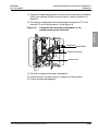
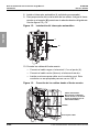
11. Conecte el cable de extensión al conector del interruptor automático
(CB) y a la terminal CB en el frente muerto, como se ilustra en la
figura 10.
12. Conecte los conductores del transformador de corriente (TC) a la
terminal TC en el frente muerto. Vea la figura 10.
13. Conecte la carga al interruptor automático.
14. Vuelva a poner el frente muerto y sujételo con dos tornillos.
15. Cierre la puerta del gabinete.
Figura 10: Conexión del interruptor automático y los
transformadores de corriente
1/ON
60
Conector CB
Terminal TC
Terminal CB
Cable de extensión

© 2011 Schneider Electric Reservados todos los derechos
18-ES
Guía de instalación del control de carga Wiser™ S1A90300
Instalación Rev. 01, 05/2011
ESPAÑOL
Instalación de 120 V
1. Afloje los dos tornillos Phillips (A) y retire el frente muerto. Retire
el cable de extensión (B) que se encuentra dentro de la caja.
2. Retire los discos desprendibles de tamaño apropiado para el
conector. Vea las figuras 1 y 2 (páginas 9 y 10) para conocer las
ubicaciones de los discos desprendibles.
Figura 11: Desmontaje del frente muerto
Figura 12: Interior del gabinete
A
A
WARNING / ADVERTENCIA
DANGER / PELIGRO
U
L
LISTED
Status
Event
Opt Out
NWK
Opt - Out
Join
Reset
Setup
Frente muerto
WARNING / ADVERTENCIA
DANGER / PELIGRO
U
L
LISTED
B

S1A90300 Guía de instalación del control de carga Wiser™
Rev. 01, 05/2011 Instalación
© 2011 Schneider Electric Reservados todos los derechos
19-ES
ESPAÑOL
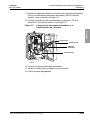
3. Monte el gabinete en la superficie de montaje con los dos tornillos (
C
).
4. Instale un conector apropiado para la aplicación (D, se muestra el
tubo conduit).
5. Conecte el cable alimentador de puesta a tierra (E) a la barra de
puesta a tierra del gabinete y conecte el conductor de neutro (F, si
está presente) a la barra de neutro del gabinete.
6. Si el controlador va a ser usado para medición simple, instale un
transformador de corriente (G, solicítado por separado) en el cable
alimentador.
7. Conecte el cable alimentador a la terminal L1 en el punto (H).
Figura 13: Montaje del gabinete
Figura 14: Instalación del TC y el cable alimentador de 120 V
WARNING / ADVERTENCIA
DANGER / PELIGRO
U
L
LISTED
C
C
D
300VAC L-N
E
F
G
H

© 2011 Schneider Electric Reservados todos los derechos
20-ES
Guía de instalación del control de carga Wiser™ S1A90300
Instalación Rev. 01, 05/2011
ESPAÑOL
8. Instale el interruptor automático (J, solicitado por separado).
9. Para proporcionar alivio a la tensión de los cables, cuelgue el frente
muerto en el soporte (K) provisto en el reborde derecho del gabinete.
Vea las figuras 15 y 16.
10. Conecte los cables del frente muerto:
— Conecte el cable negro a la terminal L1 en el punto (L).
— Conecte el cable neutro (blanco) a la barra de neutro.
— Instale una tuerca para cable en el conductor azul. Este
conductor no es apropiado para su uso en 120 V.
Figura 15: Instalación del interruptor automático
Figura 16: Conexión de los cables desde el frente muerto.
300VAC L-N
1/ON
20
o/OFF
101kA
J
K
1/ON
20
o/OFF
101kA
300VAC L-N
Tuerca para cable
L
Cable alimentador.
No conecte el cable del
frente muerto en el mismo
punto de terminal que el
cable alimentador.
Neutro

S1A90300 Guía de instalación del control de carga Wiser™
Rev. 01, 05/2011 Instalación
© 2011 Schneider Electric Reservados todos los derechos
21-ES
ESPAÑOL
11. Conecte el cable de extensión al conector del interruptor automático
(CB) y a la terminal del interruptor automático (CB) en el frente
muerto, como se ilustra en la figura 17.
12. Conecte el conductor del transformador de corriente (TC) a la
terminal TC en el frente muerto. Vea la figura 17.
13. Conecte la carga al interruptor automático.
14. Instale el frente muerto y sujételo con dos tornillos.
15. Cierre la puerta del gabinete.
Figura 17: Conexión del interruptor automático y el
transformador de corriente
1/ON
20
o/OFF
101kA
Cable de
extensión
Conector CB
Terminal TC
Terminal CB

© 2011 Schneider Electric Reservados todos los derechos
22-ES
Guía de instalación del control de carga Wiser™ S1A90300
Interfaz del usuario Rev. 01, 05/2011
ESPAÑOL
Interfaz del usuario
La interfaz del usuario consta de cuatro botones y cuatro LED. Los
botones Setup (configuración), Join (unión) y Reset
(restablecimiento) se encuentran justo debajo de la superficie del
panel frontal y pueden oprimirse con una herramienta tal como un
clip de papel.
Botón Setup (configuración)
El botón de configuración se usa para configurar el controlador para
medición simple y la función anticíclica de HVAC. El botón de
configuración funciona sólo cuando el controlador se encuentra en
estado de retención (consulte Botón Reset (restablecimiento) abajo)
y no se ha unido a una red.
Botón Join (unión)
El botón de unión se usa para conectar el controlador a la red
ZigBee
®
. Una vez que el controlador está en la red, el botón de unión
ya no funciona.
Botón Reset (restablecimiento)
El botón de restablecimiento se usa para retirar el controlador de la
red y restablecer los componentes electrónicos de control. Se
encuentran disponibles dos opciones de restablecimiento.
Figura 18: Interfaz del usuario
Status
Event
Opt Out
NWK
Setup
Join
Reset
OPT - OUT

S1A90300 Guía de instalación del control de carga Wiser™
Rev. 01, 05/2011 Interfaz del usuario
© 2011 Schneider Electric Reservados todos los derechos
23-ES
ESPAÑOL
1. Un restablecimiento de retención corta retira el controlador de la
red y restablece los componentes electrónicos de control
mientras se conservan las opciones seleccionadas por el usuario.
2. Un restablecimiento de retención larga retira el controlador de la
red, lo regresa a sus ajustes de fábrica y borra todas las opciones
seleccionadas por el usuario y la memoria.
Consulte Restablecimiento y restablecimiento de fábrica en la
página 26 para obtener más información.
Botón Opt-Out (retracción)
El botón de retracción se usa para retraer de eventos de respuesta
de demanda hasta la medianoche en el día de retracción
seleccionado, o para un período más largo. También se usa para
cancelar una retracción. Para obtener más información, consulte la
Guía de usuario del control de carga EER260LLCR Wiser™,
documento número S1A90299.
Indicaciones de LED
Tabla 5: LED de estado del interruptor automático
Color Comportamiento Descripción
Verde Continuo
A los contactos del interruptor automático se
les ordena cerrar (la carga debe conectarse)
Rojo Continuo
A los contactos del interruptor automático se
les ordena abrir (la carga debe
desconectarse)
Tabla 6: LED de evento
Color Comportamiento Descripción
Verde Continuo
No hay eventos de respuesta de demanda
presentes ni programados. El controlador
está listo para aceptar comandos.
Verde Parpadea lentamente
Un evento de respuesta de demanda futura
está en la cola.
Verde
Parpadea
rápidamente
El controlador está considerando un evento
de respuesta de demanda.
Rojo
Parpadea
rápidamente
El controlador está en el modo de retracción
(Opt-Out) y un evento de respuesta de
demanda está en curso o programado.

© 2011 Schneider Electric Reservados todos los derechos
24-ES
Guía de instalación del control de carga Wiser™ S1A90300
Configuración inicial o configuración después de un restablecimiento de fábrica Rev. 01, 05/2011
ESPAÑOL
Configuración inicial o configuración después de un
restablecimiento de fábrica
1. Proporcione el código de instalación y dirección MAC, impreso en
el controlador, a su proveedor de servicio energía eléctrica y
solicite que el dispositivo de la red sea configurado en el modo
Join (unión). Póngase en contacto con su proveedor de servicio
para obtener instrucciones.
2. Espere a que el proveedor de servicio confirme que el dispositivo de
la red se encuentre en el modo de unión antes de proceder con el
paso 3.
3. Manualmente coloque la palanca del interruptor automático en la
posición de abierto (O/OFF) y energice el controlador. El controlador
hará funcionar todos los LED durante la inicialización.
4. Presione y mantenga oprimido el botón de restablecimiento hasta
que el LED NWK (red) cambie a rojo sólido.
5. Presione y mantenga oprimido el botón Setup (configuración)
durante más de 5 segundos. Esto coloca el controlador en el modo
Tabla 7: LED de retracción (Opt-Out)
Color Comportamiento Descripción
Verde Continuo
El controlador responderá a eventos de
respuesta de demanda.
Rojo Parpadea lentamente
La retracción ha sido seleccionada durante
un día. El controlador regresará al modo de
respuesta de demanda en la medianoche.
Rojo Continuo
La retracción de tiempo largo ha sido
seleccionada. Los niveles críticos no tienen
ningún efecto.
Tabla 8: LED NWK (red)
Color Comportamiento Descripción
Rojo Continuo El controlador no está en la red.
Rojo Parpadea lentamente El controlador está uniéndose a la red.
Verde Continuo
El controlador está conectado a la red y tiene
comunicación.
Anaranjado Continuo Restablecimiento corto exitoso.
Rojo
Parpadea
rápidamente
El sistema detectó un error.

S1A90300 Guía de instalación del control de carga Wiser™
Rev. 01, 05/2011 Configuración inicial o configuración después de un restablecimiento de fábrica
© 2011 Schneider Electric Reservados todos los derechos
25-ES
ESPAÑOL
de configuración de medición simple, indicado por el LED Opt-Out
parpadeando en rojo y el LED NWK en rojo sólido.
6. Presione el botón Setup (configuración) para pasar por los tres
estados de medición simple:
— Medición simple en entrada de 240 V~, indicado por los LED
de evento y estado del interruptor automático, ambos en rojo
sólido.
— Medición simple en entrada de 120 V~, indicado por el LED
de estado del interruptor automático en rojo sólido. El LED de
evento está apagado en este estado.
— Medición simple desactivada. El LED de estado del interruptor
automático y el LED de evento están apagados en este
estado. Si no ha instalado los transformadores de corriente,
éste es el único estado de medición simple que puede
seleccionar.
7. Lea todo este paso antes de realizarlo. La selección de medición
y configuración de la función anticíclica HVAC es confirmada en el
mismo paso.
— Para confirmar la selección de medición simple sin activar la
función anticíclica, presione el botón Opt-Out hasta que el
LED Opt-Out parpadee lentamente en rojo. Todos los tres
LED parpadearán en verde tres veces y el controlador
regresará al estado de retención.
— Para confirmar la selección de medición simple con la función
anticíclica activada, presione y mantenga oprimido el botón
Opt-Out hasta que el LED Opt-Out parpadee en rojo sólido.
Todos los tres LED parpadearán en verde tres veces y el
controlador regresará al estado de retención.
8. Presione el botón Join (unión) para unirse a la red. El LED NWK
(red) parpadeará lentamente en rojo y luego, cambiará a verde
continuo con lo cual se indica que el controlador se ha unido a la red.
9. Solicite al proveedor de energía eléctrica que envíe un evento de
respuesta de demanda corta. Compruebe el estado de los LED del
controlador y la reacción de la carga conectada para verificar el
funcionamiento remoto del controlador.
10. Si el controlador se encuentra en modo de medición simple, con la
carga ejecutando, solicite al proveedor de servicio que envíe una
lectura para verificar el funcionamiento remoto.

© 2011 Schneider Electric Reservados todos los derechos
26-ES
Guía de instalación del control de carga Wiser™ S1A90300
Restablecimiento y restablecimiento de fábrica Rev. 01, 05/2011
ESPAÑOL
Restablecimiento y restablecimiento de fábrica
El controlador de carga viene configurado de fábrica con la medición
simple desactivada y la función anticíclica desactivada.
Para restablecer el controlador en las configuraciones de fábrica,
presione y mantenga oprimido el botón Reset (restablecimiento)
durante 30 segundos o más tiempo hasta que el LED NWK (red)
cambie a rojo sólido.
Para restablecer los componentes electrónicos del controlador
mientras guarda las configuraciones del usuario, presione el botón
Reset (restablecimiento) hasta que el LED NWK (red) parpadee
lentamente en rojo. El LED NWK cambiará a anaranjado sólido.
Presione el botón Join (unión) para volver a unirse a la red.
Asistencia técnica del producto
El Centro de atención al cliente de Schneider Electric es su único
punto de contacto para obtener información acerca del controlador
de carga Wiser. En este Centro se encuentra disponible personal
calificado para responderle a sus preguntas técnicas y brindarle
asistencia. Llame al 1-888-778-2733 (en EUA), y en México
al 01 (800) SCHNEIDER.
Declaración de interferencia a radiofrecuencia según FCC
El controlador ha sido probado y cumple con los límites establecidos
para los dispositivos digitales Clase B de acuerdo con la parte 15 de
las normas de la FCC (Comisión Federal de Comunicaciones de los
EUA).
La intención de estos límites es proporcionar un grado razonable de
protección contra interferencias dañinas en instalaciones
residenciales. Este controlador es un disipador intencional. Si no se
instala y usa de acuerdo con las instrucciones, éste puede causar
interferencias dañinas a las comunicaciones de radio. Sin embargo,
no se garantiza la eliminación de interferencia en una instalación en
particular. Si el controlador produce interferencia dañina en la
recepción de la radio o la televisión, se recomienda que el usuario

S1A90300 Guía de instalación del control de carga Wiser™
Rev. 01, 05/2011 Declaración de interferencia a radiofrecuencia según FCC
© 2011 Schneider Electric Reservados todos los derechos
27-ES
ESPAÑOL
intente corregir la interferencia siguiendo una o más de las siguientes
medidas:
• Vuelva a orientar o ubicar la antena de recepción.
• Aumente la separación entre el controlador y el receptor.
• Conecte el receptor a un tomacorrientes en un circuito diferente.
• Consulte con el distribuidor del receptor o un técnico
experimentado en la radio/televisión para obtener ayuda.
No realice cambios ni modificaciones al controlador que no hayan
sido expresamente aprobados por Schneider Electric. Cualquier
cambio o modificación puede resultar en la pérdida de autoridad para
operar el equipo.

© 2011 Schneider Electric Reservados todos los derechos
28-ES
Guía de instalación del control de carga Wiser™ S1A90300
Declaración de interferencia a radiofrecuencia según FCC Rev. 01, 05/2011
ESPAÑOL

ESPAÑOL

Control de carga EER260LLCR Wiser™
Guía de instalación
Importado en México por:
Schneider Electric México, S.A. de C.V.
Calz. J. Rojo Gómez 1121-A
Col. Gpe. del Moral 09300 México, D.F.
Tel. 55-5804-5000
www.schneider-electric.com.mx
Solamente el personal especializado deberá instalar, hacer
funcionar y prestar servicios de mantenimiento al equipo eléctrico.
Schneider Electric no asume responsabilidad alguna por las
consecuencias emergentes de la utilización de este material.
Square D
TM
,
Schneider Electric
TM
y Wiser
TM
son marcas comerciales
o marcas registradas de Schneider Electric. Cualquier otra marca
comercial utilizada en este documento pertenece a sus respectivos
propietarios.
S1A90300 Rev. 01, 05/2011
Sustituye al S1A90300 de fecha 03/2011.
© 2011 Schneider Electric Reservados todos los derechos
TM
ESPAÑOL


Wiser™ Load Control Installer’s Guide
Guía de instalación del control de carga Wiser™
Electrical equipment should be installed, operated,
serviced, and maintained only by qualified
personnel. No responsibility is assumed by
Schneider Electric for any consequences arising
out of the use of this material.
Solamente el personal especializado deberá instalar,
hacer funcionar y prestar servicios de mantenimiento al
equipo eléctrico. Schneider Electric no asume
responsabilidad alguna por las consecuencias
emergentes de la utilización de este material.
Square D
TM
,
Schneider Electric
TM
, and Wiser
TM
are
trademarks or registered trademarks of Schneider
Electric. Other trademarks used herein are the
property of their respective owners.
Square D
TM
,
Schneider Electric
TM
y Wiser
TM
son marcas
comerciales o marcas registradas de Schneider Electric.
Cualquier otra marca comercial utilizada en este
documento pertenece a sus respectivos propietarios.
Schneider Electric USA, Inc.
8001 Knightdale Blvd.
Knightdale, NC 27545 U.S.A.
1-888-778-2733
www.schneider-electric.us
Importado en México por:
Schneider Electric, S.A. de C.V.
Calz. J. Rojo Gómez 1121-A
Col. Gpe. del Moral 09300 México, D.F.
Tel. 55-5804-5000
www.schneider-electric.com.mx
S1A90300 Rev. 01, 05/2011
Replaces S1A90300 dated 03/2011
© 2011 Schneider Electric All Rights Reserved
S1A90300 Rev. 01, 05/2011 Sustituye al S1A90300 de
fecha 03/2011 © 2011 Schneider Electric
Reservados todos los derechos
TM
-
 1
1
-
 2
2
-
 3
3
-
 4
4
-
 5
5
-
 6
6
-
 7
7
-
 8
8
-
 9
9
-
 10
10
-
 11
11
-
 12
12
-
 13
13
-
 14
14
-
 15
15
-
 16
16
-
 17
17
-
 18
18
-
 19
19
-
 20
20
-
 21
21
-
 22
22
-
 23
23
-
 24
24
-
 25
25
-
 26
26
-
 27
27
-
 28
28
-
 29
29
-
 30
30
-
 31
31
-
 32
32
-
 33
33
-
 34
34
-
 35
35
-
 36
36
-
 37
37
-
 38
38
-
 39
39
-
 40
40
-
 41
41
-
 42
42
-
 43
43
-
 44
44
-
 45
45
-
 46
46
-
 47
47
-
 48
48
-
 49
49
-
 50
50
-
 51
51
-
 52
52
-
 53
53
-
 54
54
-
 55
55
-
 56
56
-
 57
57
-
 58
58
-
 59
59
-
 60
60
-
 61
61
-
 62
62
-
 63
63
-
 64
64


Schneider Electric EER260LLCR Guía de instalación
- Tipo
- Guía de instalación
en otros idiomas
Artículos relacionados
-
Schneider Electric EVlink Home Manual de usuario
-
-
-
Schneider Electric QO24L60NRNM Instrucciones de operación
-
-
-
-
-
-
Otros documentos
-
Schneider Electric Wiser Air Thermostat Guía de instalación
-
Schneider SQR141U1BKW Energy Monitoring Rocker Switch Manual de usuario
-
Square D D321NCP Manual de usuario
-
-
 Wiser EER56000 Guía del usuario
-
Schneider CCT595011 Manual de usuario
-
Square D DU322CP Guía de instalación
-
OutBack Power FXR / VFXR A Series El manual del propietario
-
 Square D Company QO-B120 Guía de instalación
-
Intermatic ET90115CR Guía de instalación

