Risco RP432KPP2 Installation and User Manual
- Tipo
- Installation and User Manual
Este manual también es adecuado para
El Risco RP432KPP2 es un teclado LCD cableado fácil de usar que ofrece una operación y programación sencillas de los sistemas de seguridad LightSYS (versión 5.63 y superiores) y ProSYS Plus (versión 1.2 y superiores). Cuenta con un lector de proximidad integrado opcional, lo que permite desarmar el sistema con solo acercar una tarjeta o llavero compatible. También incluye protección antimanipulación para garantizar la seguridad del sistema.
El Risco RP432KPP2 es un teclado LCD cableado fácil de usar que ofrece una operación y programación sencillas de los sistemas de seguridad LightSYS (versión 5.63 y superiores) y ProSYS Plus (versión 1.2 y superiores). Cuenta con un lector de proximidad integrado opcional, lo que permite desarmar el sistema con solo acercar una tarjeta o llavero compatible. También incluye protección antimanipulación para garantizar la seguridad del sistema.


Transcripción de documentos
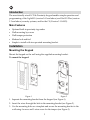
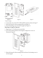
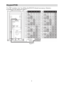
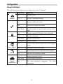
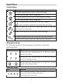
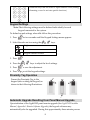
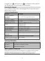
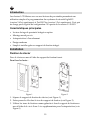
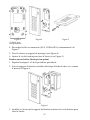
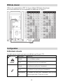
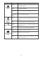
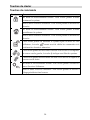
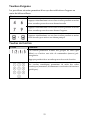
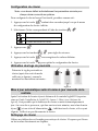
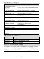
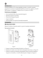
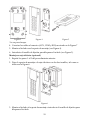
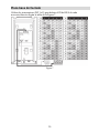
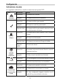
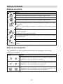
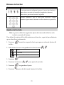
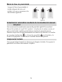
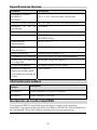
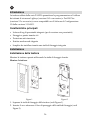
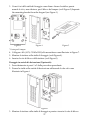
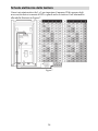
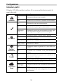
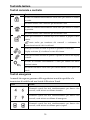
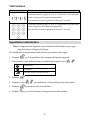
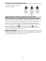
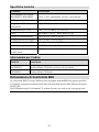
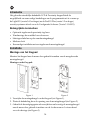
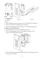
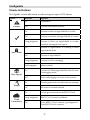
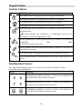
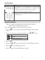
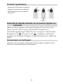
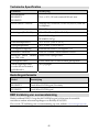
EN FR ES IT NL LCD Panda Keypad & LCD Panda Proximity Keypad Installation and User Guide Models: RP432KPP2, RP432KP02 Language Page EN 3 FR 10 ES 18 IT 26 NL 34 2 EN Introduction The user-friendly wired LCD & Proximity keypad enables simple operation and programming of the LightSYS (version 5.63 and above) and ProSYS Plus (version 1.2 and above) security systems, and for the CS (Version 3.1.0.0003). Main Features • Optional built-in proximity tag reader • Wall mounting by screws • Wall tamper protection • Modern look and feel • Simple to install with incorporated mounting bracket Installation Mounting the Keypad Mount the keypad on the wall using the supplied mounting bracket. To mount the keypad: Figure 1 Figure 2 1. Separate the mounting bracket from the keypad (see Figure 1). 2. Insert the wires through the hole in the mounting bracket (see Figure 2). 3. Use the mounting holes as a template and secure the mounting bracket to the wall using 4 screws and 1 extra screw for the tamper (see Figure 3). 3 Figure 3 Figure 4 Figure 5 * Used for tamper 4. Connect the wires to the (AUX, COM and BUS) connector shown in Figure 7. 5. Mount the keypad to the mounting bracket (see Figure 4). 6. Insert the fastening screw to lock the keypad (see Figure 5). Mounting on Gang Box (Optional): 1. Repeat steps 1 to 2 in the previous procedure. 2. Secure the mounting bracket to the Gang Box using the two screws as illustrated in Figure 6. Figure 6 3. Mount the keypad to the mounting bracket and insert the fastening screw to lock the keypad 4 Keypad PCB Use DIP switches 1 to 5 to define the BUS ID of each accessory / detector according to the table in Figure 7. Figure 7 5 Configuration Visual Indicators The following visual indicators are displayed on the LCD panel: Icon Trouble Arm / Alarm Stay / Bypass Tamper Cloud Connectivity Indication Operation On System trouble Off System is operating normally On System is ready to be armed Off System is not ready to be armed Slow Flash System is ready to be armed while exit/entry zone is open On System is armed in Full Arm or Stay Arm mode Off System is disarmed Slow Flash System is in Exit Delay Rapid Flash Alarm condition On System is Stay Arm mode (Part Set) or Zone Bypass mode Off No bypass zones in the system On Zone/keypad/external module has been tampered Off All zones are operating normally On System connected to cloud Slow Flash Cloud connectivity trouble Off No cloud connection configured / No cloud connectivity 6 Keypad Keys Control Keys Key Operation In Normal Operation mode: Used for Away (Full setting). In User Functions menu: Used to change data. In Normal Operation mode: Used for Stay arming (Part Setting). In User Functions menu: Used to change data. Used to disarm (unset) the system after a user code is entered; is used to terminate commands and confirm data to be stored. Used to scroll up a list or to move the cursor to the left; Provides the system status. Used to scroll down a list or to move the cursor to the right. In Normal Operation mode: Used to enter the User Functions menu. In User Functions menu: Used to move back one step in the menu. Emergency Keys The following operations will send emergency notifications to the alarm monitoring station Key Operation + Pressing both keys simultaneously for at least two seconds activates a Fire alarm + Pressing both keys simultaneously for at least two seconds activates an Emergency alarm + Pressing both keys simultaneously for at least two seconds activates a Police (Panic) alarm Function Keys Key Operation / / / Used to arm (set) groups of zones (by default) or to activate a prerecorded series of commands (macros). To activate press for 2 seconds 7 Numerical keys that are used to input numeric codes (arming, disarming or used to activate specific functions) Keypad Settings Note: The following settings must be defined individually for each keypad connected to the system. To define keypad settings when idle follow this procedure: 1. Press for two seconds until the Keypad Settings menu appears 2. Select the relevant icon using the keys: Brightness Contrast Keypad’s buzzer volume 3. Press 4. Press the . keys to adjust the level settings. 5. Press to save the adjustment. 6. Press to exit the keypad settings. Proximity Tag Operation Present the Proximity Tag to the keypad (after waking the keypad) as shown in the following illustrations: Figure 8 Automatic Upgrade Resulting from Panel Manual Upgrade Upon initiation of the LightSYS2 panel remote upgrade (See LightSYS2 Installer Manual, Appendix I: Remote Software Upgrade), the keypad software may automatically also be upgraded. During this approximately three-minute process 8 an upgrade icon ( ) and the power icon ( ) are displayed on the keypad and the LED light flashes. Do not disconnect during this period. Cleaning the Keypad Use a non-abrasive damp cloth to clean the keypad. Do not expose the screen or the keys directly to liquid. Technical Specification Parameter Description Current Consumption: RP432KPP2 RP432KP02 13.8v +/-10%, 130 mA typical/180 mA max. Main Panel Connection 4-wire BUS, up to 300 m (1000 ft) from Main Panel Proximity RF frequency: 13.56 MHz Dimensions (H x W x D): 180 x 115 x 35 mm (7.1 x 4.5 x1.4″) Weight: RP432KPP2: 295 gr. RP432KP02: 287 gr. Operating temperature: -10°C to 55°C (14°F to 131°F) Storage temperature: -20°C to 60°C (-4°F to 140°F) Humidity Range Average relative humidity: 75% Standard Compliance EN50131-3 Grade 2 Environmental Class II Min. number of variations of PIN codes 10000 for 4-digit codes Disallowed codes Codes from 0001 to 9999 are acceptable Number of invalid code entries before user interface is disabled After 3 attempts Ordering Information Model Description RP432KPP2 Panda Wired LCD Keypad, Proximity RP432KP02 Panda Wired LCD Keypad RED Compliance Statement Hereby, RISCO Group declares that this equipment is in compliance with the essential requirements and other relevant provisions of Directive 2014/53/EU. For the CE Declaration of Conformity please refer to our website: www.riscogroup.com 9 FR Introduction Les claviers LCD filaires avec ou sans lecteurs de proximités permettent une utilisation simple et la programmation des systèmes de sécurité LightSYS (version 5.63 et supérieures) et ProSYS Plus (version 1.2 et supérieures). Il est pris en charge par le logiciel de configuration CS à partir de la version 3.1.0.0003. Caractéristiques principales • Lecteur de tags de proximité intégré en option • Montage mural par vis • Autoprotection à l'arrachement • Design moderne • Simple à installer grâce au support de fixation intégré Installation Fixation du clavier Fixez le clavier au mur à l'aide du support de fixation fourni. Pour fixer le clavier : Figure 1 Figure 2 1. Séparez le support de fixation du clavier (voir Figure 1). 2. Faites passer les fils dans le trou du support de fixation (voir Figure 2). 3. Utilisez les trous de fixation comme gabarits et fixez le support de fixation au mur à l'aide de 4 vis et d'une 1 vis supplémentaire pour l'autoprotection (voir Figure 3) 10 Figure 3 * Utilisée pour l'autoprotection Figure 4 Figure 5 4. Raccordez les fils au connecteur (AUX, COM et BUS) conformément à la Figure 7. 5. Fixez le clavier au support de montage (voir Figure 4). 6. Insérez la vis de fixation pour fixer le clavier (voir Figure 5). Fixation sur un boîtier électrique (en option) 1. Répétez les étapes 1 à 2 de la procédure précédente. 2. Fixez le support de fixation au boîtier électrique à l'aide de deux vis, comme le montre la Figure 6. Figure 6 3. Installez le clavier sur le support de fixation et insérez la vis de fixation pour fixer le clavier. 11 PCB du clavier Utilisez les commutateurs DIP 1 à 5 pour définir l'ID de bus de chaque accessoire/détecteur en vous reportant au tableau de la Figure 7. Figure 7 Configuration Indicateurs visuels Les indicateurs visuels suivants sont affichés sur l'écran LCD : Icône Défaut Indicateur Opération Allumé Il y a un défaut système Éteint Le système fonctionne normalement Allumé Le système est prêt pour l'armement Éteint Le système n'est pas prêt pour l'armement Clignotement lent Le système est prêt pour l'armement alors qu’une zone de type Entrée / Sortie est ouverte 12 Icône Armement / Alarme Armement partiel / Exclusion Indicateur Opération Allumé Le système est armé en mode Armement Total ou Armememnt partiel Éteint Le système est désarmé Clignotement lent Le système est en mode Temporisation de sortie Clignotement rapide Il y a une condition d'alarme Allumé Le système est en mode Armement partiel ou zone Exclue Éteint Il n'existe aucune zone exclue dans le système Allumé La zone, le clavier ou le module externe est en autoprotection Éteint Toutes les zones fonctionnent normalement Allumé Le système est connecté au cloud Autoprotection Clignotement Connectivité au lent cloud Éteint Défaut de connexion au Cloud Le connexion Cloud n’est pas configurée / Aucune connexion au Cloud 13 Touches du clavier Touches de commande Touche Commande En mode de fonctionnement normal : Cette touche permet d’armer totalement le système. Dans le menu Fonctions utilisateur : Cette touche permet de modifier les données. En mode de fonctionnement normal : Cette touche permet d’armer partiellement le système. Dans le menu Fonctions utilisateur : Cette touche permet de modifier les données. Cette touche permet de désarmer le système après la saisie du code utilisateur ; la touche permet aussi de valider les commandes et de confirmer les données à mémoriser. Cette touche permet de faire défiler une liste vers le haut ou de déplacer le curseur vers la gauche ; la touche indique aussi l'état du système. Cette touche permet de faire défiler une liste vers le bas ou de déplacer le curseur vers la droite. En mode de fonctionnement normal : cette touche permet d'accéder au menu Fonctions Utilisateur. Dans le menu Fonctions utilisateur : cette touche permet de revenir à l'étape précédente dans le menu. 14 Touches d'urgence Les procédures suivantes permettent d'envoyer des notifications d'urgence au centre de télésurveillance. Touche Commande + Appuyez simultanément sur ces deux touches pendant au moins deux secondes pour activer une alarme incendie. + Appuyez simultanément sur ces deux touches pendant au moins deux secondes pour activer une alarme d'urgence. + Appuyez simultanément sur ces deux touches pendant au moins deux secondes pour activer une alarme panique. Touches de fonction Touche / / / Commande Ces touches permettent d'armer des groupes de zones (par défaut) ou d'activer une série de commandes (macros) préenregistrées. Appuyez pendant deux secondes pour activer cette fonction. Les touches numériques permettent de saisir des codes numériques (armement, désarmement ou activation de fonctions spécifiques). 15 Configuration du clavier Note : vous devez définir individuellement les paramètres suivants pour chaque clavier connecté au système. Pour configurer le clavier lorsqu'il est inactif, procédez comme suit : 1. Appuyez sur la touche pendant deux secondes jusqu'à ce que le menu de configuration du clavier s'affiche. 2. Sélectionnez l'icône correspondante à l'aide des touches : Luminosité Contraste Volume du buzzer du clavier 3. Appuyez sur . 4. Appuyez sur les touches pour régler les niveaux. 5. Appuyez sur la touche pour enregistrer les valeurs définies. 6. Appuyez sur la touche pour quitter la configuration du clavier. Utilisation des tags de proximité Présentez le tag de proximité au clavier (après être sorti du mode veille sur ce dernier), comme le montrent les illustrations suivantes : Figure 8 Mise à jour automatique suite à la mise à jour manuelle de la centrale Après l'activation de la mise à jour à distance de la centrale LightSYS2 (reportezvous au Guide d'installation de LightSYS2, Annexe I : Mise à jour à distance du logiciel), il est possible que le firmware du clavier se mette automatiquement à jour. Au cours de ce processus, qui dure environ trois minutes, une icône de mise à jour ( ) et une icône d'alimentation ( ) s'affichent sur le clavier, et le voyant clignote. Veillez à ne pas déconnecter le clavier. Nettoyage du clavier Utilisez un chiffon doux et humide pour nettoyer le clavier. N'exposez pas l'écran ou les touches directement aux liquides. 16 Spécifications techniques Paramètre Description Consommation électrique : RP432KPP2 RP432KP02 13,8 V c.c. +/-10 % ; 130 mA normal/180 mA maximum Connexion à la centrale Bus 4 fils, jusqu'à 300 m à partir de la centrale Fréquences RF de proximité : 13,56 MHz Dimensions (H × L × P) : 180 x 115 x 35 mm (7,1 x 4,5 x 1,4 po.) Poids : RP432KPP2 : 295 g RP432KP02 : 287 g Température de fonctionnement : -10 ºC à 55 ºC (14 ºF à 131 ºF) Température de stockage : -20 ºC à 60 ºC (-4 ºF à 140 ºF) Plage d'humidité Humidité relative moyenne : 75 % Conformité aux normes Norme EN 50131-3 Grade 2 - Classe d'environnement II Nombre minimum de variations des codes PIN 10 000 pour les codes à 4 chiffres Codes non autorisés Les codes compris entre 0001 et 9999 sont autorisés. Nombre de saisies de codes non valides avant la désactivation de l'interface utilisateur Après 3 tentatives Informations de commande Modèle Description RP432KPP2 Clavier LCD filaire Panda, avec Proximité RP432KP02 Clavier LCD filaire Panda Rapport de Conformité de RED: Par la présente, RISCO Group, déclare cet équipement est en conformité aux conditions essentielles et à d'autres dispositions appropriées de la directive 2014/53/EU. Vous pouvez trouver la copie complète de la déclaration de conformité à la directive 2014/53/EU sur notre site web, à l’adresse suivante : www.riscogroup.com 17 ES Introducción El teclado cableado LCD y de proximidad es intuitivo y sencillo, y permite programar los sistemas de seguridad LightSYS (versión 5.63 y superior) y ProSYS Plus (versión 1.2 y superior), y trabajar con el CS (versión 3.1.0.0003). Funciones principales • Lector opcional de llave de proximidad integrado • Montaje en pared con tornillos • Protección de tamper de pared • Aspecto moderno • Fácil de instalar con soporte de montaje incorporado Instalación Montaje del teclado Montar el teclado en la pared usando el soporte de montaje suministrado. Para montar el teclado: Figura 1 Figura 2 1. Separar el soporte de montaje del teclado (ver Figura 1). 2. Introducir los cables a través del orificio del soporte de montaje (ver Figura 2). 3. Utilizar los orificios de montaje como plantilla y fijar el soporte de montaje a la pared con 4 tornillos y 1 tornillo adicional para el tamper (ver Figura 3). 18 Figura 3 Figura 4 Figura 5 * Se usa para el tamper 4. Conectar los cables al conector (AUX, COM y BUS) mostrado en la Figura 7 5. Montar el teclado en el soporte de montaje (ver Figura 4). 6. Introducir el tornillo de fijación para bloquear el teclado (ver Figura 5). Montaje en caja eléctrica (opcional) 1. Repetir los pasos 1 al 2 del procedimiento anterior. 2. Fijar el soporte de montaje a la caja eléctrica con los dos tornillos, tal como se indica en la Figura 6. Figura 6 3. Montar el teclado al soporte de montaje e introducir el tornillo de fijación para bloquear el teclado. 19 Placa base del teclado Utilizar los interruptores DIP 1 al 5 para definir el ID del BUS de cada accesorio/detector según la tabla de la Figura 7. Figura 7 20 Configuración Indicadores visuales Los siguientes indicadores visuales se muestran en el panel LCD: Icono Problema Armado / Alarma Armado Parcial / Anulación Indicación Modo Encendido Problemas en el sistema Apagado El sistema funciona con normalidad Encendido El sistema está listo para armado Apagado El sistema no está listo para armado Parpadeo lento El sistema está listo para armado mientras la zona de salida/entrada está abierta Encendido El sistema está en modo Armado Total o Armado Parcial Apagado El sistema está desarmado Parpadeo lento El sistema se encuentra en Tiempo de Salida Parpadeo rápido Situación de alarma Encendido El sistema está en modo Armado Parcial o en modo Anulación de Zona Apagado No hay zonas de anulación en el sistema Encendido Se han manipulado zonas/teclado/módulo externo Apagado Todas las zonas funcionan con normalidad Encendido El sistema está conectado con la nube Parpadeo lento Problemas de la conectividad con la nube Apagado No hay configurada ninguna conexión con la nube/No hay conectividad con la nube Tamper Conectividad con el servidor Cloud 21 Botones del teclado Botones de control Botón Modo En el modo Normal: se usa para Armado Total. En el menú de funciones de usuario: se usa para cambiar datos. En el modo Normal: se usa para Armado Parcial. En el menú de funciones de usuario: se usa para cambiar datos. Se usa para desarmar (anular) el sistema después de introducir un código de usuario; se usa para finalizar comandos y confirmar los datos que se van a almacenar. Se usa para desplazarse hacia arriba en una lista o para mover el cursor hacia la izquierda; proporciona el estado del sistema. Se usa para desplazarse hacia abajo en una lista o para mover el cursor hacia la derecha. En el modo Normal: se usa para acceder al menú de funciones de usuario. En el menú de funciones de usuario: se usa para retroceder un paso en el menú. Botones de emergencia Las siguientes acciones enviarán notificaciones de emergencia a la central receptora de alarmas. Botón Modo + Al presionar los dos botones a la vez durante al menos dos segundos, se activa la alarma de incendio + Al presionar los dos botones a la vez durante al menos dos segundos, se activa una alarma de emergencia + Al presionar los dos botones a la vez durante al menos dos segundos, se activa una alarma de policía (pánico) 22 Botones de fonctión Botón Modo Se usa para armar (configurar) grupos de zonas (por defecto) o para activar una serie de comandos pregrabados (macros). / / / Para activar, presionar durante 2 segundos Botones numéricos que se usan para introducir códigos numéricos (para armar, desarmar o activar funciones específicas) Ajustes del teclado Nota: es preciso definir los siguientes ajustes de forma individual en cada teclado conectado al Sistema. Para definir los ajustes del teclado mientras está inactivo, seguir el procedimiento que se describe a continuación: 1. Presionar teclado durante dos segundos hasta que aparezca el menú Ajustes del 2. Seleccionar el icono correspondiente con los botones Brillo Contraste Volumen del zumbador del teclado 3. Presionar . 4. Presionar los botones para ajustar los niveles. 5. Presionar para guardar el ajuste. 6. Presionar para salir del menú Ajustes del teclado. 23 : Modo de llave de proximidad Acerque la llave de proximidad al teclado (después de activar el teclado), tal como se muestra en las ilustraciones siguientes: Figura 8 Actualización automática resultante de la actualización manual del panel Una vez iniciada la actualización remota del panel de LightSYS2 (consulte el Manual del instalador de LightSYS2, Apéndice I: Actualización de software remota), el software del teclado también puede haberse actualizado automáticamente. Durante este proceso de aproximadamente tres minutos de duración, se visualiza un icono de actualización ( ) y el icono de encendido ( ) en el teclado, y la luz del LED parpadea. No desconecte la unidad durante este período. Limpieza del teclado Usar un paño limpio húmedo no abrasivo para limpiar el teclado. No exponer la pantalla ni los botones directamente a líquidos. 24 Especificaciones técnicas Parámetro Descripción Consumo de corriente: RP432KPP2 RP432KP02 13,8 V +/-10%; 130 mA normal / 180 mA máx. Conexión del panel principal BUS de 4 cables, hasta 300 m del panel principal Frecuencia de proximidad: 13,56 MHz RF de Dimensiones (AL x AN x PR): 180 x 115 x 35 mm Peso: RP432KPP2: 295 gr. RP432KP02: 287 gr. Temperatura de funcionamiento: de -10 °C a 55 °C Temperatura de almacenamiento: de -20 °C a 60 °C Rango de humedad Humedad media relativa: 75 % Cumplimiento de normativas EN50131-3 Grado 2 y Clase II Medioambiental Número mín. de variaciones de códigos PIN 10 000 para códigos de 4 dígitos Códigos no permitidos Se aceptan códigos del 0001 al 9999 Número de códigos no válidos introducidos antes de deshabilitar la interfaz del usuario Tras 3 intentos Información para pedidos Modelo Descripción RP432KPP2 Teclado cableado LCD Panda, Proximidad RP432KP02 Teclado cableado LCD Panda Declaración de Conformidad RED : Por la presente, RISCO Group declara que este equipo cumple con los requisitos esenciales y otras disposiciones relevantes de la Directiva 2014/53/EU. Para la Declaración de Conformidad CE, por favor diríjase a nuestra web: www.riscogroup.com 25 IT Introduzione Le tastiere cablate della serie PANDA permettono la programmazione e l’utilizzo dei sistemi di sicurezza Lightsys (versione 5.63 e successive) e ProSYS Plus (versione 1.2 e successive) e sono compatibili con il Software di Configurazione CS dalla versione 3.1.0.0003. Caratteristiche principali • Lettore di tag di prossimità integrato (per la versione con prossimità) • Fissaggio a parete tramite viti • Protezione anti-rimozione • Estetica moderna ed elegante • Semplice da installare tramite una staffa di fissaggio integrata Installazione Installazione della tastiera Montare la tastiera a parete utilizzando la staffa di fissaggio fornita. Montare la tastiera: Figura 1 Figura 2 1. Separare la staffa di fissaggio dalla tastiera (vedi Figura 1). 2. Inserire il cavo attraverso il foro di passaggio della staffa di fissaggio (vedi Figura 2). 26 3. Usare i fori della staffa di fissaggio come dima e fissare la staffa a parete usando 4 viti e, una ulteriore, per il blocco del tamper (vedi Figura 3).Separate the mounting bracket from the keypad (see Figure 1). Figura 3 Figura 4 Figura 5 * Usata per il tamper 4. Collegare i fili (AUX, COM e BUS) alla morsettiera come illustrato in Figura 7. 5. Montare la tastiera sulla staffa di fissaggio (vedi Figura 4). 6. Inserire la vite di blocco della tastiera (vedi Figura 5). Fissaggio in scatola di derivazione (Opzionale): 1. Fare riferimento ai passi 1 e 2 della procedura precedente. 2. Fissare la staffa sulla scatola di derivazione utilizzando le due viti come illustrato in Figura 6 Figura 6 3. Montare la tastiera sulla staffa di fissaggio a parete e inserire la vite di blocco. 27 Scheda elettronica della tastiera Usare i microinterruttori da 1 a 5 per impostare il numero ID di ognuno degli accessori/rivelatori connessi al BUS e quindi anche la tastiera. Fare riferimento alla tabella illustrata in Figura 7. Figura 7 28 Configurazione Indicatori grafici Il display LCD della centrale visualizza all’occorrenza gli indicatori grafici di seguito descritti: Icona Anomalia Ins. / Disins. Parziale / Esclusione Indicazione Stato/Operatività On Il sistema evidenzia una anomalia Off Il sistema è in condizione di normale funzionamento On Il sistema è pronto per essere inserito Off Il sistema non è pronto per essere inserito Lampeggio lento Il sistema è pronto per essere inserito ma una o più zone temporizzate ingresso/uscita sono aperte On Il sistema è inserito in modo totale o parziale Off Il sistema è disinserito Lamp. lento Il sistema è in modalità di ritardo in uscita Lamp. veloce Il sistema è in allarme On Il sistema è inserito in parziale o ci sono delle zone escluse Off Il sistema non evidenzia zone precedentemente escluse On Una zona/tastiera/Accessorio è in condizione di manomissione (tamper) Off Il funzionamento delle zone/accessori è regolare On Il sistema è connesso al cloud Lampeggio lento Il sistema evidenzia una anomalia di connessione al cloud Off Connettività cloud non configurata / Connettività cloud assente Tamper Connettività Cloud 29 Tasti della tastiera Tasti di comando e controllo Tasti Funzione In stato di normale funzionamento viene usato per inserire il sistema in totale. Nel Menù utente viene utilizzato per modificare i dati. In stato di normale funzionamento viene usato per inserire il sistema in parziale. Nel Menù utente viene utilizzato per modificare i dati. Usato per disinserire il sistema dopo aver inserito il proprio codice utente; usato anche per terminare dei comandi o confermare la memorizzazione dei dati visualizzati. Usato per scorrere una lista di opzioni o spostare il cursore del display a sinistra; visualizza lo stato del sistema. Usato per scorrere una lista di opzioni o spostare il cursore del display a destra. In stato di normale funzionamento è usato per entrare nel menù funzioni utente. All’interno del menù viene usato per tornare indietro di un passo del menù. Tasti di emergenza I comandi che seguono generano delle segnalazioni acustiche specifiche e la trasmissione di notifiche ad una Società di Ricezione Eventi. Tasti Evento + Premendo questi due tasti simultaneamente per almeno due secondi, verrà attivato un allarme incendio. + Premendo questi due tasti simultaneamente per almeno due secondi, verrà attivato un allarme di emergenza. + Premendo questi due tasti simultaneamente per almeno due secondi, verrà attivato un allarme panico/rapina. 30 Tasti funzione Funzione Tasti Usati per inserire gruppi di zone o, in alternativa, attivare delle macro (sequenze di comandi preimpostati). / / / Per attivare la funzione premere il tasto per 2 secondi. Usati per inserire gruppi di zone o, in alternativa, attivare delle macro (sequenze di comandi preimpostati). Per attivare la funzione premere il tasto per 2 secondi. Impostazioni della tastiera Nota: Le impostazioni seguenti vanno definite individualmente per ogni singola tastiera collegata al sistema. Per modificare le impostazioni della tastiera, procedere come segue: 1. Premere per 2 secondi fino alla comparsa del menù seguente 2. Selezionare l’icona della funzione da modificare usando i tasti : Luminosità Contrasto Volume cicalino interno tastiera 3. Premere . 4. Premere i tasti per modificare i valori dell’opzione selezionata. 5. Premere per memorizzare le modifiche. 6. Premere per uscire dal menu di impostazioni della tastiera. 31 Funzionamento del Tag di prossimità Avvicinare il tag alla tastiera come illustrato di seguito: Figura 8 Aggiornamento automatico del firmware della tastiera successivamente ad un aggiornamento manuale del sistema Dopo aver attivato, su LightSYS2 o Prosys Plus, l’aggiornamento remoto del sistema, (Fare riferimento ai rispettivi Manuali Tecnici per maggiori informazioni circa questa procedura), il firmware della tastiera potrebbe essere automaticamente anch’esso aggiornato. Durante questa procedura, della durata di circa tre minuti, una icona di aggiornamento ( ) ed una icona di anomalia ( ) verranno visualizzate sul display della tastiera. Non disconnettere la tastiera o rimuovere l’alimentazione al sistema durante questa fase. Pulizia della tastiera Usare un panno morbido, non abrasivo, per la pulizia della tastiera. Evitare di far cadere liquidi di ogni genere sul display e sui tasti. 32 Specifiche tecniche Parametro Descrizione Assorbimento in corrente: RP432KPP2 - RP432KP02 13.8v +/-10%, tipicamente 130 mA / max 180 mA. Collegamento alla centrale: BUS a 4 fili, fino a 300 metri dalla centrale Frequenza RF prossimità: lettore di 13.56 MHz Dimensioni (H x L x P): 180 x 115 x 35 mm (7.1 x 4.5 x1.4″) Peso: RP432KPP2: 295 gr. - RP432KP02: 287 gr. Temp. di funzionamento: -10°C to 55°C (14°F to 131°F) Temperatura di stoccaggio: -20°C to 60°C (-4°F to 140°F) Umidità: Umidità relativa media: 75% Conformità agli Standard EN50131-3 Grado 2, Classe ambientale II N. minimo di variazioni dei codici utente 10000 per codici a 4 cifre Informazioni per l’ordine Modello Descrizione RP432KPP2 Tastiera filare LCD Panda con lettore di prossimità RP432KP02 Tastiera filare LCD Panda Dichiarazione di Conformità RED La sottoscritta RISCO Group, dichiara sotto la propria responsabilità che questo prodotto è conforme ai requisiti essenziali e alle altre rilevanti disposizioni della Direttiva Europea 2014/53/EU. Per le Dichiarazioni di Conformità CE, visitate il nostro sito web: www.riscogroup.com 33 NL Introductie Het gebruiksvriendelijke bekabelde LCD & Proximity keypad biedt de mogelijkheid om eenvoudige handelingen en de programmatie uit te voeren op de LightSYS (versie 5.63 en hoger) en de ProSYS Plus (versie 1.2 en hoger) security systemen alsook voor de Configuratie Software (Versie 3.1.0.0003). Belangrijkste kenmerken • Optionele ingebouwde proximity tag lezer • Wandmotage door middel van schroeven • Sabotageschakelaar op de wandmontagebeugel • Moderne look • Eenvoudige installatie met een ingebouwde montagebeugel Installatie Montage van het Keypad Monteer het keypad aan de muur door gebruik te maken van de meegeleverde montagebeugel. Montage van het keypad: Figuur 1 Figuur 2 1. Verwijder de montagebeugel van het keypad (zie Figuur 1). 2. Plaats de bekabeling door de opening van de montagebeugel (zie Figuur 2). 3. Gebruik de bevestigingsgaten als een sjabloon en bevestig de montagebeugel aan de muur door gebruik te maken van de 4 schroeven en 1 extra schroef voor de sabotage (zie Figuur 3). 34 Figuur 3 * Gebruikt voor sabotage Figuur 4 Figuur 5 4. Sluit de bekabeling aan op de connector (AUX, COM en BUS) (zie Figuur 7) 5. Plaats het keypad in de montagebeugel (zie Figuur 4). 6. Plaats de bevestigingsschroef om het keypad vast te maken (zie Figuur 5). Mountage op een Box (Optioneel) 1. Herhaal stappen 1,2 en 4 in de voorafgaande procedure. 2. Plaats de montagebeugel op de Box door gebruik te maken van de 2 schroeven zoals geïllustreerd in Figuur 6. Figur 6 3. Plaats het keypad in de montagebeugel en plaats de bevestigingsschroef om het keypad vast te maken. 35 Keypad PCB Gebruik de DIP switchen 1 tot 5 om het BUS ID te bepalen van elk accesoire / detector aan de hand van de tabel in Figuur 7. Figuur 7 36 Configuratie Visuele Indicatoren De volgende visuele indicatoren worden weergeven op het LCD scherm: Icoon Trouble Indicatie Operatie On Systeemfout Off Systeem functioneert normaal On Systeem is klaar om ingeschakeld te worden Off Systeem is niet klaar om ingeschakeld te worden Traag knipperen Systeem is klaar om ingeschakeld te worden terwijl de vertraagde zone open is On Systeem is ingeschakeld in Volledig of Deels ingeschakeld mode Off Systeem is uitgeschakeld Traag knipperen Systeem is in Exit vertraging Snel knipperen Alarm conditie On Systeem is in Deels ingeschakeld mode of in zone overbrugging mode Off Geen overbrugging van zones in het systeem On Zone/keypad/externe module heeft een sabotage Off All zones in normale toestand On System geconnecteerd met de RISCO Cloud Traag knipperen RISCO Cloud connectie probleem Off Geen RISCO Cloud connectie geconfigureerd / Geen RISCO Cloud connectie Arm / Alarm Stay / Bypass Tamper Cloud Connectivity 37 Keypad Toetsen Controle Toetsen Toets Werking In normale mode: Wordt gebruikt om volledig in te schakelen. In het gebruikersmenu: Wordt gebruikt om data te veranderen. In normale mode: Wordt gebruikt om deels in te schakelen. In het gebruikersmenu: Wordt gebruikt om data te veranderen. Wordt gebruikt om het Systeem uit te schakelen na het ingeven van de gebruikerscode; wordt gebruikt om commando’s te beëindigen alsook om te bevestigen dat data kan opgeslagen wordt. Wordt gebruikt om in een lijst naar boven te scrollen of de cursor te verplaatsen naar links; Geeft de systeem status weer. Wordt gebruikt om in een lijst naar beneden te scrollen of de cursor te verplaatsen naar rechts In normale mode: Wordt gebruikt om in het gebruikersmenu te gaan. In het gebruikersmenu: Wordt gebruikt om een stap terug te gaan in het menu. Noodtoestand Toetsen De volgende handelingen zorgen er voor dat er noodtoestand notificaties worden verzonden naar de meldkamer. Toets Werking + Gelijktijdig indrukken van deze 2 toetsen voor minimum 2 seconden zal een brand alarm activeren + Gelijktijdig indrukken van deze 2 toetsen voor minimum 2 seconden zal een medisch alarm activeren + Gelijktijdig indrukken van deze 2 toetsen voor minimum 2 seconden zal het Paniek ) alarm activeren 38 Function Keys Toets Werking Wordt gebruikt voor het inschakelen van een groep zones (standaard) of om een activatie uit te voeren van een voorgeprogrammeerde serie van commando‘s (macros). / / / Om te activeren druk 2 seconden op de toetsen. Nummerieke toetsen dat gebruikt worden voor het ingeven van nummerieke codes Keypad Instellingen Note: De volgende instellingen dienen op elk keypad individueel te gebeuren dat is aangesloten op het systeem Om de keypad instellingen te definiëren volg deze procedure: 1. Druk op wordt voor 2 seconden tot het Keypad Instellingen menu zichtbaar 2. Selecteer het relevante icoon gebruik makende van de toetsen: Helderheid Contrast Keypad’s zoemer volume 3. Druk op 4. Druk op de . toetsen om het niveau van de instelling aan te passen. 5. Druk op om de aanpassing op te slaan. 6. Druk op om de keypad instellingen te verlaten. 39 Proximity Tag Handeling Presenteer de Proximity Tag aan het keypad (na ontwaken van keypad) zoals aangegeven in de volgende illustratie: Figuur 8 Automatische Upgrade komende van de manuele upgrade van het Paneel Tijdens een remote upgrade van het LightSYS2 paneel (Zie LightSYS2 Installer Manual, Appendix I: Remote Software Upgrade) kan het keypad ook een automatische upgrade krijgen. Tijdens dit proces van ongeveer 3 minuten zullen het upgrade icoon ( ) en het power icoon ( ) weergegeven worden op het keypad en het LED lampje zal knipperen. Koppel het keypad niet los tijdens deze periode. Schoonmaken van het Keypad Gebruik een niet-schurende vochtige doek om het keypad te reiningen. Stel het scherm en de toetsen niet bloot aan vloeistoffen. 40 Technische Specificaties Parameter Beschrijving Stroomverbuik: RP432KPP2 RP432KP02 13.8v +/-10%, 130 mA nominaal/180 mA max. Hoofd Paneel Connectie 4-aderige BUS connectie, tot 300 m (1000 ft) vanaf het hoofdpaneel Proximity RF frequentie: 13.56 MHz Afmetingen (H x W x D): 180 x 115 x 35 mm (7.1 x 4.5 x1.4″) Gewicht: RP432KPP2: 295 gr. RP432KP02: 287 gr. Gebruikstemperatuur: -10°C to 55°C (14°F to 131°F) Opslagtemperatuur: -20°C to 60°C (-4°F to 140°F) Vochtigheidsomgeving Gemiddelde relatieve vochtigheid: 75% Standaard Certificatie EN50131-3 Graad 2 Environmental Class II Minimum aantal van PIN codes 10000 voor 4 cijferige codes variaties Geweigerde codes Codes vanaf 0001 tot 9999 worden geaccepteerd Aantal ongeldige codes voordat de user interface geblokkeerd is Na 3 pogingen Bestellingsinformatie Model Beschrijving RP432KPP2 Panda Wired LCD Keypad, Proximity RP432KP02 Panda Wired LCD Keypad RED Verklaring van overeenstemming Hierbij verklaart RISCO Group dat dit PANDA keypad voldoet aan de essentiële vereisten en andere relevante bepalingen van Richtlijn 2014/53/EU. Zie voor de CE Verklaring van overeenstemming op onze website: www.riscogroup.com 41 Standard Limited Product Warranty (“Limited Warranty”) RISCO Ltd. (“RISCO") guarantee RISCO’s hardware products (“Products”) to be free from defects in materials and workmanship when used and stored under normal conditions and in accordance with the instructions for use supplied by RISCO, for a period of (i) 24 months from the date of delivery of the Product (the “Warranty Period”). This Limited Warranty covers the Product only within the country where the Product was originally purchased and only covers Products purchased as new. Contact with customers only. This Limited Warranty is solely for the benefit of customers who purchased the Products directly from RISCO or from an authorized distributor of RISCO. RISCO does not warrant the Product to consumers and nothing in this Warranty obligates RISCO to accept Product returns directly from end users who purchased the Products for their own use from RISCO’s customer or from any installer of RISCO, or otherwise provide warranty or other services to any such end user directly. RISCO’s authorized distributor or installer shall handle all interactions with its end users in connection with this Limited Warranty. RISCO’s authorized distributor or installer shall make no warranties, representations, guarantees or statements to its end users or other third parties that suggest that RISCO has any warranty or service obligation to, or any contractual privy with, any recipient of a Product. Remedies. In the event that a material defect in a Product is discovered and reported to RISCO during the Warranty Period, RISCO shall accept return of the defective Product in accordance with the below RMA procedure and, at its option, either (i) repair or have repaired the defective Product, or (ii) provide a replacement product to the customer. Return Material Authorization. In the event that you need to return your Product for repair or replacement, RISCO will provide you with a Return Merchandise Authorization Number (RMA#) as well as return instructions. Do not return your Product without prior approval from RISCO. Any Product returned without a valid, unique RMA# will be refused and returned to the sender at the sender’s expense. The returned Product must be accompanied with a detailed description of the defect discovered (“Defect Description”) and must otherwise follow RISCO’s then-current RMA procedure published in RISCO’s website at www.riscogroup.com in connection with any such return. If RISCO determines in its reasonable discretion that any Product returned by customer conforms to the applicable warranty (“Non-Defective Product”), RISCO will notify the customer of such determination and will return the applicable Product to customer at customer’s expense. In addition, RISCO may propose and assess customer a charge for testing and examination of Non-Defective Product. Entire Liability. The repair or replacement of Products in accordance with this Limited Warranty shall be RISCO’s entire liability and customer’s sole and exclusive remedy in case a material defect in a Product is discovered and reported as required herein. RISCO’s obligation and this Limited Warranty are contingent upon the full payment by customer for such Product and upon a proven weekly testing and examination of the Product functionality. Limitations. This Limited Warranty is the only warranty made by RISCO with respect to the Products. The warranty is not transferable to any third party. To the maximum extent permitted by applicable law, this Limited Warranty shall not apply and will be void if: (i) the conditions set forth above are not met (including, but not limited to, full payment by customer for the Product and a proven weekly testing and examination of the Product functionality); (ii) if the Products or any part or component thereof: (a) have been subjected to improper operation or installation; (b) have been subject to neglect, abuse, willful damage, abnormal working conditions, failure to follow RISCO’s instructions (whether oral or in writing); (c) have been misused, altered, modified or repaired without RISCO’s written approval or combined with, or installed on products, or equipment of the customer or of any third party; (d) have been damaged by any factor beyond RISCO’s reasonable control such as, but not limited to, power failure, electric power surges, or unsuitable third party components and the interaction of software therewith or (e) any failure or delay in the performance of the Product attributable to any means of communication provided by any third party service provider, including, but not limited to, GSM interruptions, lack of or internet outage and/or telephony failure. BATTERIES ARE EXPLICITLY EXCLUDED FROM THE WARRANTY AND 42 RISCO SHALL NOT BE HELD RESPONSIBLE OR LIABLE IN RELATION THERETO, AND THE ONLY WARRANTY APPLICABLE THERETO, IF ANY, IS THE BATTERY MANUFACTURER'S WARRANTY. RISCO does not install or integrate the Product in the end user’s security system and is therefore not responsible for and cannot guarantee the performance of the end user’s security system which uses the Product or which the Product is a component of. This Limited Warranty applies only to Products manufactured by or for RISCO. Further, this Limited Warranty does not apply to any software (including operating system) added to or provided with the Products or any third-party software, even if packaged or sold with the RISCO Product. Manufacturers, suppliers, or third parties other than RISCO may provide their own warranties, but RISCO, to the extent permitted by law and except as otherwise specifically set forth herein, provides its Products “AS IS”. Software and applications distributed or made available by RISCO in conjunction with the Product (with or without the RISCO brand), including, but not limited to system software, as well as P2P services or any other service made available by RISCO in relation to the Product, are not covered under this Limited Warranty. Refer to the Terms of Service at: https://riscocloud.com/ELAS/WebUI/UserLogin/License for details of your rights and obligations with respect to the use of such applications, software or any service. RISCO does not represent that the Product may not be compromised or circumvented; that the Product will prevent any personal injury or property loss by burglary, robbery, fire or otherwise, or that the Product will in all cases provide adequate warning or protection. A properly installed and maintained alarm may only reduce the risk of a burglary, robbery or fire without warning, but it is not insurance or a guarantee that such will not occur or will not cause or lead to personal injury or property loss. CONSEQUENTLY, RISCO SHALL HAVE NO LIABILITY FOR ANY PERSONAL INJURY, PROPERTY DAMAGE OR OTHER LOSS BASED ON ANY CLAIM AT ALL INCLUDING A CLAIM THAT THE PRODUCT FAILED TO GIVE WARNING. EXCEPT FOR THE WARRANTIES SET FORTH HEREIN, RISCO AND ITS LICENSORS HEREBY DISCLAIM ALL EXPRESS, IMPLIED OR STATUTORY, REPRESENTATIONS, WARRANTIES, GUARANTEES, AND CONDITIONS WITH REGARD TO THE PRODUCTS, INCLUDING BUT NOT LIMITED TO ANY REPRESENTATIONS, WARRANTIES, GUARANTEES, AND CONDITIONS OF MERCHANTABILITY, FITNESS FOR A PARTICULAR PURPOSE, TITLE AND WARRANTIES AGAINST HIDDEN OR LATENT DEFECTS, TO THE EXTENT PERMITTED BY LAW. WITHOUT LIMITING THE GENERALITY OF THE FOREGOING, RISCO AND ITS LICENSORS DO NOT REPRESENT OR WARRANT THAT: (I) THE OPERATION OR USE OF THE PRODUCT WILL BE TIMELY, SECURE, UNINTERRUPTED OR ERROR-FREE; (ii) THAT ANY FILES, CONTENT OR INFORMATION OF ANY KIND THAT MAY BE ACCESSED THROUGH THE PRODUCT SHALL REMAIN SECURED OR NON DAMAGED. CUSTOMER ACKNOWLEDGES THAT NEITHER RISCO NOR ITS LICENSORS CONTROL THE TRANSFER OF DATA OVER COMMUNICATIONS FACILITIES, INCLUDING THE INTERNET, GSM OR OTHER MEANS OF COMMUNICATIONS AND THAT RISCO’S PRODUCTS, MAY BE SUBJECT TO LIMITATIONS, DELAYS, AND OTHER PROBLEMS INHERENT IN THE USE OF SUCH MEANS OF COMMUNICATIONS. RISCO IS NOT RESPONSIBLE FOR ANY DELAYS, DELIVERY FAILURES, OR OTHER DAMAGE RESULTING FROM SUCH PROBLEMS. RISCO WARRANTS THAT ITS PRODUCTS DO NOT, TO THE BEST OF ITS KNOWLEDGE, INFRINGE UPON ANY PATENT, COPYRIGHT, TRADEMARK, TRADE SECRET OR OTHER INTELLECTUAL PROPERTY RIGHT IN ANY EVENT RISCO SHALL NOT BE LIABLE FOR ANY AMOUNTS REPRESENTING LOST REVENUES OR PROFITS, PUNITIVE DAMAGES, OR FOR ANY OTHER INDIRECT, SPECIAL, INCIDENTAL, OR CONSEQUENTIAL DAMAGES, EVEN IF THEY WERE FORESEEABLE OR RISCO HAS BEEN INFORMED OF THEIR POTENTIAL. 43 RED Compliance Statement Hereby, RISCO Group declares that this equipment is in compliance with the essential requirements and other relevant provisions of Directive 2014/53/EU. For the CE Declaration of Conformity please refer to our website: www.riscogroup.com Contacting RISCO Group RISCO Group is committed to customer service and product support. You can contact us through our website (www.riscogroup.com) or at the following telephone and fax numbers: Belgium (Benelux) United Kingdom Tel: +32-2522-7622 Tel: +44-(0)-161-655-5500 [email protected] [email protected] Italy USA Tel: +39-02-66590054 Tel: +1-631-719-4400 [email protected] [email protected] Spain China (Shanghai) Tel: +34-91-490-2133 Tel: +86-21-52-39-0066 [email protected] [email protected] France Australia Tel: +33-164-73-28-50 Tel: + 1800-991-542 [email protected] [email protected] Israel Tel: +972-3-963-7777 [email protected] © RISCO Group 11/2017 5IN2622 C 44-
 1
1
-
 2
2
-
 3
3
-
 4
4
-
 5
5
-
 6
6
-
 7
7
-
 8
8
-
 9
9
-
 10
10
-
 11
11
-
 12
12
-
 13
13
-
 14
14
-
 15
15
-
 16
16
-
 17
17
-
 18
18
-
 19
19
-
 20
20
-
 21
21
-
 22
22
-
 23
23
-
 24
24
-
 25
25
-
 26
26
-
 27
27
-
 28
28
-
 29
29
-
 30
30
-
 31
31
-
 32
32
-
 33
33
-
 34
34
-
 35
35
-
 36
36
-
 37
37
-
 38
38
-
 39
39
-
 40
40
-
 41
41
-
 42
42
-
 43
43
-
 44
44


Risco RP432KPP2 Installation and User Manual
- Tipo
- Installation and User Manual
- Este manual también es adecuado para
El Risco RP432KPP2 es un teclado LCD cableado fácil de usar que ofrece una operación y programación sencillas de los sistemas de seguridad LightSYS (versión 5.63 y superiores) y ProSYS Plus (versión 1.2 y superiores). Cuenta con un lector de proximidad integrado opcional, lo que permite desarmar el sistema con solo acercar una tarjeta o llavero compatible. También incluye protección antimanipulación para garantizar la seguridad del sistema.
en otros idiomas
- français: Risco RP432KPP2
- italiano: Risco RP432KPP2
- English: Risco RP432KPP2
- Nederlands: Risco RP432KPP2
Artículos relacionados
-
Risco RW432KPP Installation and User Manual
-
-
-
-
-
-
-
-
 RISCO Group ProSound Installation & Programming Manual
-
Risco RP512ECOB00A GPRS Bus Interface Manual de usuario


