Risco eyeWAVE RWX95CM Guía de instalación
- Tipo
- Guía de instalación

eyeWAVE™ Wireless
PIR Camera
Models: RWX95CM/RWX95CMP
EN FR IT ES
Installation Instructions
EN
Description
The eyeWAVE™ Wireless PIR Camera Detector is a
battery powered PIR detector that includes an
integrated camera for visual verification and is
compatible with RISCO security systems.
Features include:
•
PIR coverage 12m (40’) wide angle
•
VGA or QVGA camera resolution with ~85° field-of-
view
•
Discreet IR flash allows imaging in complete
darkness, up to 10m (33’)
•
Sequence of images upon event, configurable
number and fps
•
During disarm, events are ignored to save battery
and for privacy
•
On-demand images initiated from authorized
Smartphone or web browser
•
Two RF channels with separate antennas: One for
control, second channel for image transmission
•
Images stored on detector until transmission to
panel complete
•
Includes 2 long-life 3V lithium batteries
Installation
Step1: Preliminary Considerations
Select the mounting location for best coverage of the
area that is to be protected (see Coverage Patterns and
Preliminary Considerations).
Step 2: Registering the Detector into
the System
The eyeWAVE must identify itself to the system receiver
in a device allocation (enrollment) process, which can be
performed by either RF sequence registering or entering
the detector’s 11-digit serial number into the system or
using RF mode panel quick key programming
Sequence:
From the panel: 2) Radio Devices > 1) Allocation > 1) By
RF or 2) By Code.
Through the Configuration Software: Click Radio
Device Allocation > Enter Serial Code: [045] + [8 digits];
Indexed: Automatic or manually designated 1-32;
Accessory Type: 2-Way Detector (displayed)). Then
click Allocate: RF Allocation is performed.
For more information refer to the System Installer Manual.
Step 3: Mounting the Detector
1. Open the knockout holes of the mounting
bracket, and use them as a template for mounting
(see Figure 3).
For Pet friendly model:
In order to optimize pet immunity the following guide
lines are recommended:
Mount the detector vertically at right angles to the floor.
Make sure an animal cannot get above height of 1.5m
(5') by climbing on furniture, shelving or stairs.
2. Fasten the cover to the base of the detector by
inserting and fastening screw into the hole
located inside the battery compartment (see Figure
2)
3. Insert the batteries and close the battery
compartment cover (see Figure 2)
4. Once the bracket is installed, slide and lock the
detector onto the mounting bracket in reverse
sequence (see Figure 4)
5. Perform a Walk Test as described in the Walk
Test section (see Figure 5).
6. Insert and fasten screw (C) into the hole located
at the bottom of the detector to lock the detector
to the mounting bracket (see Figure 4).
Step 4: Performing a Walk Test
Upon inserting the batteries, the detector goes into a
Walk Test mode for 20 minutes and then automatically
returns to Normal mode (to save battery power). During
Walk Test Mode, the detector transmits a signal, after
each detection. Walk test the entire field of view of the
detector and observe the LED for confirmation. Verify
that the receiver is properly receiving the signals.
To manually initiate a walk test from the control panel:
Installation Menu: 2) Testing > 2) Zone > 3) Walk Test 1)
Start Walk Test. The detector remains in walk test mode
until any key on the panel is pressed. Display test
results as follows: Installation Menu: 2) Testing > 2)
Zone > 3) Walk Test 2) Walk Test Results
Camera Configuration
Being bi-directional, the detectors parameters can be
modified from the keypad or from the system
configuration software according to your needs
PIR
Sensitivity:
High/Low (Default: Low)
Supervision
Time:
0-255 minutes (Default: 15 min)
LED: On/Off (Default: On)
Operation
Mode:
Walk Test: The detector will
transmit after each detection
Normal (Default)
For more information refer to the System Installer Manual.
Configure the camera settings through the RISCO
Configuration Software (right-click on the Serial Code
field in the Zones node screen and in the displayed pop-
up click Additional..) or through the panel quick key
programming sequence as follows (default in bold):
Programming > 2) Radio Devices > 2) Modification > 1)
Zone [Select (1–32)] >
1) Parameters > 6) Advanced 5) Camera Parameters:
Images at
Alarm:
3 (1 to 7 images)
Image Interval: 0.5 sec (0.5, 1, 2 seconds)
Pre-Alarm
Image:
Yes (Yes, No) (Image capture
upon each arm)
Image
Resolution:
QVGA (QVGA 320X240, VGA
640X480)
Image Quality: High (High, Low)
Colour Image: Colour (Colour, B&W)
Image upon request
Snapshot images can be taken using web/smartphone
apps (on panels supporting these applications).
Event Reporting
Every event detected by the PIR camera is recorded into
the camera’s memory. The event record consists of the
date and time mark, detail description of the event
including its source and a video record.
LED Status
On: Alarm
Blinking twice (in alarm mode): Low battery
Blinking four times (in initial
learning mode)
Successful
write
operation
Diagnostics
You can perform diagnostic tests on your detector using
the keypad or the configuration software. Diagnostics
includes testing the detector battery status and the
communication between the detector and the panel.
For additional information refer to the System Installer
Manual.
To replace the batteries:
1. Remove the detector from the mounting bracket
(see Figure 1).
2. Open the battery cover (see Figure 2).
3. Replace the batteries. Pay attention to the right
polarity.
4. Close the battery cover.
CAUTION – Risk of explosion if battery is replaced by
an incorrect type. Dispose of used batteries according to
local regulations.
NOTE – After replacing the batteries and closing the
tamper, the detector will automatically go into in Walk
Test mode for 20 minutes.
Specifications
Electrical
Battery Type: 2 x CR 123, 3V Lithium Battery
Battery Life: 2 batteries – 3 year typical
lifetime
Current
Consumption:
58 µA standby;
200 mA max. peak at capture
with flash
Supervision
Transmission:
0-255 minutes
RF
transmitting
frequencies:
868.65 MHz; 869.525 MHz for
model RWX95CM8
433.92 MHz; 916 MHz for
model RWX95CM4
Optical
Filtering: White Light Protection
Pet friendly: Up to a 36 kg (80lb) animal (pet
model)
Physical
Size: 132 x 67,5 x 56 mm (5.1 x 2.6 x
2.2 in)
Weight: 169 grams (5.96 oz.)
Environmental
RF Immunity: According to EN50130-4
Operating
Temperature:
-10°C a 55°C (14°F a 140°F)
Storage
Temperature:
-20°C a 60°C (-4°F a 140°F)
Camera
Type: CMOS digital image sensor
Lux: 0 Lux (total darkness)
View Angle: H 90 o V 71o
FR
Description
L’eyeWave™ sans fil est un détecteur IRP alimenté par
piles, avec un appareil photo intégré, conçu pour la
levée de doute visuelle d’alarme et une installation
simple par les installateurs d’alarme. L’appareil photo
capture et transmet une séquence d’images à un serveur
distant ou à un téléphone portable via les systèmes
RISCO, sur occurrence d’un évènement d’intrusion ou à
la demande de l’utilisateur.
•
Couverture IRP 12m grand angle
•
Résolution photo VGA/VGA avec champ de vision
d’environ~90°
•
Flash IR discret qui permet la prise d’image dans le
noir complet jusqu’à 10m
•
2 canaux RF avec antennes séparées :
•
Une pour l’alarme et le contrôle, la seconde pour la
transmission d’images
•
Séquence d’images sur évènement d’alarme : nombre
d’images et intervalle configurables
•
Au désarmement, les évènements sont ignorés pour
économiser les piles et pour la vie privée
•
Images sur demande initiée par un utilisateur autorisé
via navigateur Web ou Smartphone
•
Option pour prise d’image à l’armement
•
Les images sont enregistrées dans le détecteur jusqu’à
la fin de la transmission à la centrale
•
Inclus 2 piles lithium 3V longue durée
•
Ne fonctionne qu’avec les systèmes supportant la
Levée de doute visuelle
•
Sécurité contre la fraude : ouverture, arrachement,
champ magnétique
Installation
Etape 1 : Considérations préliminaires
Choisir l’emplacement de montage pour obtenir la
meilleure couverture de la zone à protéger (cf. modèles
de couverture).
Attention aux éléments suivants :
Ne pas toucher la lentille avec vos doigts, cela rendrait
la capture d’image floue.
Ne pas monter le détecteur en face de rayons directs du
soleil, ou près d’une source de chauffage ou d’objets
métalliques.
Les secteurs de détection devraient être orientés en
direction du mur, et non en direction d’une fenêtre ou
de volets.
Choisir la hauteur de montage selon le modèle de
couverture (nous recommandons une hauteur de 2m à
2.40 m, à au moins 40 cm du plafond).
Etape 2 : Adresser le détecteur dans le
système
L’eyeWAVE doit être identifié au récepteur du système
via un processus d’adressage, qui peut être réalisé par
un adressage RF ou en entrant les 11 digits du numéro
de série dans le système, ou par adressage RF rapide :
Touches rapides depuis la centrale: 1)Programmation >
2)Périph.radio > 1)Adressage > 1)Adressage RF ou 2)Par
N° Série.
Depuis le logiciel de Configuration: Cliquer sur
Adressage de matériel sans fil > Entrez le n° de série :
[045] + [8 digits] ; Indexe : Automatique ou
manuellement de 1 à 32 ; Type d’accessoire : Détecteur
2Way (affiché). Cliquer alors sur Adresser: L’adressage
RF est effectué.
Se référer au Manuel d’Installation de l’système pour
des instructions complètes.
Etape 3 : Monter le détecteur
1. Ouvrir les trous pré-percés du support de
montage, et les utiliser comme modèle pour le
montage (voir Figure 3).
Pour les modèles avec immunité aux animaux :
Afin d’optimiser l’immunité aux animaux, voici les
recommandations à suivre :
Monter le détecteur verticalement avec un angle droit
par rapport au sol.
S’assurer qu’un animal ne peut pas monter au-dessus
d’1.5m en montant sur des meubles, rayonnages ou
escaliers.
2. Fixer le couvercle à la base du détecteur en
insérant et serrant la vis de fixation dans le trou
situé dans le compartiment des piles (voir Figure
2).
3. Insérer les piles et fermer le couvercle du
compartiment des piles (voir Figure 2)
4. Une fois que le support est installé, glisser et
verrouiller le détecteur sur le support de
montage en séquence inverse (voir Figure 4)
5. Faire un test de marche comme décrit dans la
section Test de Marche (voir Figure 5)
6. Insérer et serrer la vis dans le trou situé sous le
détecteur pour fixer le détecteur au support de
montage (voir Figure 4).
Etape 4 : Test de Marche
Après avoir inséré les piles, le détecteur est en test de
marche pendant 2 minutes, et il retourne ensuite
automatiquement en mode Normal (pour économiser
les piles). Pendant le test de marche, le détecteur
transmettra après chaque détection. Tester le champ de
vision complet du détecteur et observer la LED pour
confirmation. Vérifier que le récepteur reçoit bien les
signaux.
Lancer un test de marche manuellement depuis la
centrale :
Menu installateur : 2)Tests Système > 2)Zone > 3)Test
Marche > 1)Démarrer Test
Le détecteur reste en test de marche jusqu’à ce qu’une
touche soit pressée. Afficher les résultats du test comme
suit :
Menu installateur : 2)Tests Système > 2)Zone > 3)Test
Marche > 2) Résultat Test
Configuration de l’Appareil Photos
Comme il est bidirectionnel, les paramètres du détecteur
peuvent être modifiés depuis le clavier ou le logiciel de
configuration du système selon vos besoins :
Sensibilité IRP: Elevée/Faible (Par défaut :
Faible)
Tempo de
supervision
(Supervision TX):
0-255 minutes (Par défaut :
15 min)
LED: On/Off (Par défaut : On)
Mode de détection: Test: Le détecteur
transmettra après chaque
détection
Normal (Par défaut)
Pour plus d’informations, voir le Manuel d’Installation
de l’système.
Configurer les paramètres de l’appareil photo depuis le
logiciel de configuration RISCO (clique droit sur le
champ N° de Série d’ans l’écran Zones, Options…), ou
depuis le clavier de la centrale par les séquences de
touches rapides suivantes (paramètres par défaut en
gras) :
1)Programmation > 1)Périph. Radio > 2)Modification >
1)Paramètres > Zone [Sélectionner (1–32)] > 6) Avancé >
5) Param. Photos :
Images par Alarme : 3 (1 à 7 images)
Intervalle Image : 0.5 sec (0.5, 1, 2 secondes)
Image Pré-Alarme : Oui (Oui, Non) (Images
captures à chaque
armement)
Résolution Image : QVGA (QVGA 320X240,
VGA 640X480)
Qualité Image : Elevée (Elevée, Faible)
Couleur Image : Couleur (Couleur, Noir &
Blanc)
Image sur demande utilisateur
Les images peuvent aussi être prises en utilisant les
applications web/smartphone (sur les centrales
supportant ces applications).
Rapport d’évènements
Chaque évènement détecté par le PIR Cam est enregistré
dans la mémoire du PIR Cam jusqu’à transmission.
L’enregistrement de l’évènement est constitué de la date
et l’heure, de la description complète de l’évènement sa
source et un enregistrement d’image.
Statut LED
On: Alarme
2 clignotements : (en mode alarme) Batterie
basse
4 clignotements : (en mode d’adressage
initial) Opération d’écriture
réalisée avec succès
Diagnostiques
Il est possible de réaliser des diagnostiques sur le
détecteur en utilisant le clavier de ou le logiciel de
configuration. Les diagnostiques comportent l’état de la
pile du détecteur et la communication entre le détecteur
et la centrale.
Pour plus d’informations, se référer au Manuel
d’Installation de l’système.
Remplacement des piles
Une condition de batterie basse est détectée par une
LED clignotante à chaque transmission.
Pour remplacer les piles :
1. Enlever le détecteur du support de montage (voir
Figure 1).
2. Ouvrir le couvercle des piles (voir Figure 2).
3. Remplacer les piles. Attention à la polarité.
4. Fermer le couvercle des piles.
ATTENTION: Risque d’explosion si les piles sont
remplacées par un type de pile incorrect. Jetez les piles
usagées selon la réglementation locale.
NOTE: Après avoir remplacé les piles et fermé
l'autoprotection, le détecteur sera automatiquement en
mode Test de Marche pour une durée de 20 minutes.
Spécifications
Electriques
Type de
batterie :
2 x CR 123, Pile Lithium3V
Batterie Basse 2.6V
Durée de vie des
piles : 2 piles - 3 ans typique
Consommation
de courant :
58 µA en veille;
200 mA max. (en capture avec
flash)
Transmission de
supervision :
0-255 minutes0
Fréquences de
transmissions
RF :
868.65 MHz; 869.525 MHz
pour modèle RWX95CM8
433.92 MHz; 916 MHz pour
modèle RWX95CM4
Optique
Filtrage : Protection contre la lumière
blanche
Immunité aux
animaux :
Animal jusqu’à 36 kg (modèle
PET)
Physique
Taille : 132 x 67,5 x 56 mm
Poid : 169 grammes
Environnement
Immunité RF : Répond à la norme EN50130-4
Température
d’exploitation :
-10°C à 55°C
Température de
stockage :
-20°C à 60°C
Indice de
Protection (IP)
IP31 IK 04
Appareil Photo
Type : Capteur d’image numérique
CMOS
Lux : 0 Lux (obscurité complète)
Angle de vue : H 90 o V 71o
Organisme de certification
AFNOR CERTIFICATION: 11 rue Francis de Pressensé
93571 LA PLAINE SAINT-DENIS Cedex,
http://www.marque-nf.com
CNPP Cert: BP 2265, 27950 ST MARCEL,
http://www.cnpp.com
Certificate number for RWX95CM: 2622000016A0
Certificate number for RWX95CMP: 2622000016B0
Ce produit répond aux exigences du référentiel de
certification NF324-H58 pour la classification 2
boucliers, et de la RTC 50131-2-2.
IT
Descrizione
EyeWave™ radio è un rivelatore di movimento
all’infrarosso passivo (PIR) che integra una fotocamera.
EyeWave™ è alimentato tramite batterie e viene usato
per la verifica video degli eventi con i sistemi RISCO
compatibili.
•
Copertura PIR di 12m grandangolo
•
Risoluzione fotocamera VGA/VGA con campo visivo
di 90°
•
Illuminatore IR che permette di scattare immagini
nella completa oscurità fino ad una distanza massima
di 10m
•
Due canali radio RF con antenne separate: uno per gli
allarmi e la programmazione e l’altro per la
trasmissione delle immagini
•
Sequenza immagini per evento con numero di
immagini ed intervallo tra due immagini
programmabile.
•
Durante lo stato di disinserimento gli eventi vengono
ignorati al fine di preservare la carica delle batterie e la
privacy
•
A richiesta trasmette immagini a smartphone e web
browser autorizzati
•
Opzione per lo scatto e la memorizzazione di
un’immagine all’inserimento del sistema (pre-allarme)
•
Le immagini vengono registrate nel rivelatore fino alla
loro trasmissione completa
•
Include 2 batterie al litio 3 Volt
Installazione
Fase 1: Considerazioni preliminari
Scegliere la posizione di installazione per una buona
copertura dell’area da proteggere (vedere diagrammi di
copertura). Fare attenzione a quanto segue:
•
Non toccare le lenti con le dita altrimenti le immagini
non saranno nitide.
•
Non installare il rivelatore in condizioni di luce solare
diretta o vicino a caloriferi e oggetti metallici.
•
Il rivelatore dovrebbe essere posizionato di fronte a
mura o pavimento e non di fronte a finestre e tende.
•
Scegliere l’altezza di installazione in funzione dei
diagrammi di copertura. (l’altezza consigliata è di 2.0 –
2.4 metri e almeno 40 cm. distante dal soffitto.)
Fase 2: Registrazione del rivelatore nel
sistema
eyeWAVE deve essere registrato nel ricevitore del
sistema tramite un processo di memorizzazione che può
prevede la registrazione per autoapprendimento o la
registrazione tramite l’inserimento del numero dei serie
di 11 cifre del sensore. Sequenza di programmazione:
Da tastiera di centrale: una volta entrati in
programmazione tecnica, digitare 2) Accessori Radio >
1) Memoriz.Radio > 1) Via Radio oppure 2) Via Nr. serie
Da Software di Configurazione
: Cliccare su
Memorizzazione periferiche radio > Inserire il numero
di serie: [045] + [8 cifre]; Memorizzazione: Automatica o
numero di zona selez.1-32; Tipo periferica: Rivelatore
bidirezionale (visualizzazione). Quindi cliccare su
Memorizza: La memorizzazione RF viene effettuata.
Fare riferimento al Manuale tecnico della centrale
utilizzata per informazioni più dettagliate.
Fase 3: Installazione del rivelatore
1. Aprire i fori a sfondare della staffa di fissaggio ed
utilizzarla come dima per il scegliendo i fori da
usare in funzione del posizionamento scelto.
(vedere Figura 3).
Consigli per il modello Pet:
Al fine di ottimizzare l’immunità agli animali domestici,
far riferimento alle linee guida di seguito elencate:
Installare il rivelatore in posizione verticale
perpendicolarmente al pavimento. Accertarsi che
l’animale non possa superare l’altezza da terra di 1.5
metri salendo su mobili, tavoli, scale etc..
2. Fissare il coperchio alla base utilizzando
inserendo e serrando la vite nel foro posizionato
all’interno del vano batterie (vedere Figura 2)
3. Inserire le batterie e chiudere il coperchio del
vano batterie (vedere Figura 2)
4. Una volta che la staffa è installata, far scorrere e
bloccare il rivelatore nella staffa (vedere Figura 4)
5. Effettuare una prova di movimento come
descritto nella sezione prova di movimento
(vedere Figura 5)
6. Inserire e serrare la vite nel foro situato nella
parte inferiore della staffa del rivelatore (vedere
Figura 4).
Fase 4: Prova di movimento
Una volta inserite le batterie il rivelatore entra in
modalità test per circa 20 minuti e poi automaticamente
torna al modo normale di funzionamento (inibizione
trasmissioni al fine di preservare la carica delle batterie).
Durante la fase di test il rivelatore è in grado di
trasmettere alla centrale ogni rilevazione di movimento.
Effettuare una prova di movimento nell’area da
proteggere e osservare il LED di conferma trasmissione.
Verificare inoltre che la centrale abbia correttamente
ricevuto il segnale.
Prova di movimento attivabile dalla centrale:
Menù Tecnico: 2) Diagnostica > 2) Zone > 3) Test sensori
1) Inizio test
Il rivelatore resta in modo test fino a quando non viene
premuto un tasto sulla tastiera di centrale. Visualizzare
il risultato del test come segue:
Menù Tecnico: 2) Diagnostica > 2) Zone > 3) Test sensori
2) Risultato test
Configurazione fotocamera
Essendo l’unità bidirezionale, i parametri di
programmazione del rivelatore possono essere
modificati da tastiera o software di configurazione:
Sensibilità PIR: Alta/Bassa (Default: Bassa)
Tempo di
supervisione:
0-255 minuti (Default: 15
min)
LED: On/Off (Default: On)
Per maggiori informazioni fare riferimento al Manuale
tecnico della centrale utilizzata.
Configurare le opzioni della fotocamera tramite il
software di configurazione RISCO (nella schermata
delle zone cliccare con il tasto destro del mouse sulla
riga della zona assegnata al PIR fotocamera e
selezionare Avanzate...) oppure tramite tastiera, una
volta entrati in Programmazione tecnica, utilizzare i
tasti rapidi che seguono (il default è in grassetto):
Prog. Tecnica > 2) Accessori Radio > 2) Programma > 1)
Zone > 1) Parametri [Seleziona la zona (1–32)] > 6)
Avanzate 5) Parametri TCamera:
Immagini allarme: 3 (da 1 a 7 immagini)
Intervallo
immagini:
0.5 sec (0.5, 1, 2 secondi)
Immagine Pre-
Allarme:
Si (Si, No) (Scatto
immagine ad ogni
inserimento del sistema)
Risoluzione
immagine:
QVGA (QVGA 320X240,
VGA 640X480)
Qualità immagine: Alta (Alta, Bassa)
Colore Immagine: Colore (Colore, Bianco e
Nero)
Richiesta Immagini
Le immagini possono anche essere scattate utilizzando le
applicazioni web/smartphone.
Segnalazione dell’evento
Ogni evento rilevato dal PIR Telecamera viene registrato
nella memoria della telecamera. La registrazione
dell’evento comprende, la data e l’ora, una descrizione
dettagliata, incluso l’origine e la sequenza di immagini.
LED di Stato
On: Allarme
Doppio
lampeggio:
(In modalità allarme) Batteria
scarica
Quattro
lampeggi:
(In modalità apprendimento)
Memorizzazione periferica riuscita
Diagnostica
Utilizzando la tastiera o il software di configurazione è
possibile effettuare un test diagnostico del rivelatore.
Questo test include lo stato della batteria e la
comunicazione con la centrale.
Per maggiori informazioni fare riferimento al Manuale
tecnico della centrale utilizzata.
Sostituzione delle batterie:
Una condizione di batteria scarica viene evidenziata in
tastiera e anche tramite il LED del rivelatore che
lampeggia più volte ad ogni trasmissione invece di
accendersi solo una volta.
Per sostituire le batterie procedure come segue:
1. Rimuovere il rivelatore dalla sua staffa di
fissaggio. (vedere Figura 1)
2. Aprire il coperchio del vano batterie. (vedere
Figura 2)
3. Sostituire le batterie. Prestare attenzione alla
polarità.
4. Richiudere il coperchio del vano batterie.
5. Reinserire il rivelatore nella staffa di fissaggio
ATTENZIONE: La sostituzione delle batterie con altre
di tipologia non corretta può causare un’esplosione.
Smaltire le batterie usate come prescritto dalla
regolamentazione vigente nella propria nazione.
NOTA: Dopo aver sostituito le batterie e richiuso il
tamper del rivelatore, avendolo inserito nella staffa di
fissaggio, il rivelatore entrerà in modalità prova di
movimento (test sensori). Dopo circa 20 minuti ne uscirà
automaticamente.

2
Specifiche Tecniche
Elettriche
Tipo batterie: Tipo batterie:
Autonomia batteria: Autonomia batteria:
Assorbimento in
corrente:
Assorbimento in
corrente:
Intervallo segnale di
supervisione:
Intervallo segnale di
supervisione:
Frequenze di
trasmissione RF:
Frequenze di
trasmissione RF:
Ottiche
Filtro: Filtro:
Immunità animali
(pet):
Immunità animali (pet):
Fisiche
Dimensioni: Dimensioni:
Peso: Peso:
Ambientali
Immunità RF: Immunità RF:
Temperatura di
funzionamento:
Temperatura di
funzionamento:
Temperatura di
stoccaggio:
Temperatura di
stoccaggio:
Video
Tipologia telecamera: Tipologia telecamera:
Lux: Lux:
Grandangolo: Grandangolo:
Descripción
El detector eyeWave™ vía radio es un detector PIR
alimentado con pilas, con una cámara integrada,
diseñado para vídeo verificación y fácil de instalar. La
cámara captura y transmite una secuencia de imágenes
a un servidor remoto o a teléfonos móviles a través de
los sistemas RISCO, tras producirse un evento de
intrusión o a petición del usuario.
• Cobertura del PIR: 12 m (40’) gran angular
• Cámara con resolución QVGA/VGA, campo de visión
~90°.
• Flash IR discreto que permite sacar imágenes en
completa oscuridad, hasta 10 m (33’).
• Dos canales RF con antenas separadas:
• Un canal para las alarmas y el control, y el segundo
para la transmisión de imágenes.
• Secuencia de imágenes en caso de evento configurable
en número y frecuencia (fps)
• Durante el desarmado, los eventos son ignorados para
ahorrar batería, y por privacidad.
• Petición de imágenes bajo demanda desde teléfonos
móviles autorizados o navegador web.
• Opción de tomar foto de referencia al armar.
• Imágenes almacenadas en el detector hasta que
finaliza la transmisión a la central.
• Incluye 2 baterías de litio de larga duración.
• Trabaja con sistemas que soporten video
Instalación
Paso 1: Consideraciones preliminares
•
Seleccionar el emplazamiento de montaje donde tenga
la mejor cobertura del área a proteger (ver Patrones de
Cobertura).
Prestar atención a lo siguiente:
• No tocar la lente con los dedos ya que dará lugar a
imágenes borrosas.
• No montar el detector donde le pueda dar
directamente el sol, ni cerca de fuentes de calor o de
objetos metálicos.
• Los haces de detección deben apuntar hacia la pared o
el suelo, y no hacia ventanas o cortinas.
• Seleccionar la altura de montaje según los patrones de
cobertura (recomendado: 2,0–2,4 m de altura, y al
menos a 40 cm del techo).
Paso 2: Registro del detector en el
sistema
El eyeWAVE debe identificarse en el receptor del
sistema mediante un proceso de registro (alta) del
dispositivo, que puede realizarse introduciendo el
número de serie de 11 dígitos del detector, o bien
usando el modo RF (radio frecuencia):
Desde la central (secuencia de teclas rápidas): 1)
Programación > 2) Dispositivos Radio > 1) Asignación >
1) Asignación RF ó 2) Por Código.
A través del Software Bidireccional: Asignación
Dispositivos Radio > Introducir el Número de Serie: [11
dígitos] y asignar Dirección: Automático o
Manualmente [1-32]. El Tipo de Accesorio mostrará
“Bidireccional”. Pulsar entonces en el botón
“Asignar…” y esperar confirmación de asignación RF
realizada correctamente.
Para una información más detallada, consultar el
Manual de Instalación de sistema.
Paso 3: Montaje del detector
1. Abrir los agujeros pre-marcados en el soporte de
montaje y utilizarlos como plantilla (ver Figura 3).
Para el modelo Anti-Mascotas (PET):
Para optimizar la inmunidad a mascotas se recomienda
seguir las siguientes directrices:
Montar el detector verticalmente en ángulo recto con el
suelo
Asegurarse que un animal no puede superar la altura de
1,5 m (5') subiéndose a muebles, estantes o escaleras
2. Fijar la tapa a la base del detector insertando y
atornillando el tornillo en el agujero situado
dentro del compartimento de la batería (ver
Figura 2).
3. Insertar las pilas y cerrar la tapa del
compartimento de las pilas (ver Figura 2).
4. Una vez instalado el soporte de pared, deslizar y
fijar el detector al soporte de montaje en sentido
inverso al de extracción (ver Figura 4).
5. Realizar una prueba de detección (Test de paseo)
como se indica en el apartado “Prueba de
detección” (ver Figura 5).
6. Insertar y atornillar el tornillo en el agujero
situado en la parte inferior del detector para
fijarlo al soporte de montaje (ver Figura 4).
Paso 4: Prueba de detección (Test de
paseo)
Tras insertar las pilas, el detector entra en un modo de
Test de paseo durante 20 minutos, y después
automáticamente vuelve al modo Normal (para ahorrar
batería). Durante el modo de Test de paseo, el detector
transmitirá cada detección. Realice la prueba de
detección en todo el campo de visión del detector y
observe el LED para confirmar la detección. Verificar
que el receptor recibe correctamente las señales
Para iniciar manualmente un Test de paseo desde la
central:
Menú Instalador > 2) Diagnósticos > 2) Zona > 3) Test de
Paseo > 1) Inicio Test
El detector permanece en el modo de Test de paseo
hasta que presione cualquier tecla. Para ver los
resultados:
Menú Instalador > 2) Diagnósticos > 2) Zona > 3) Test de
Paseo > 2) Resultado Test
Configuración de la Cámara
Al ser un detector bidireccional, sus parámetros pueden
modificarse por teclado o desde el software
bidireccional, según lo requiera:
Sensibilidad del
PIR:
Alta / Baja (Por defecto:
Baja)
Tiempo de
supervisión:
0-255 minutos (Por defecto:
15 min)
LED: On / Off (Por defecto: On)
Modo de
funcionamiento:
Test de paseo: El detector
transmite cada detección.
Normal (Por defecto):
Tiempo muerto entre
detecciones de 2,5 minutos
para ahorrar batería.
Para más información, consulte el Manual de Instalación
de sistema.
Configurar los ajustes de la cámara a través del software
bidireccional (en la pantalla Zonas hacer clic con el
botón derecho sobre la zona con PIR con cámara y
pulsar en “Parámetros Adicionales…”) o desde el
teclado de la central con las secuencias rápidas de
teclado que se indican a continuación (los valores en
negrita son los valores por defecto):
1) Programación > 2) Dispositivos Radio > 2)
Modificación > 1) Zonas > 1) Parámetros [Seleccionar (1–
32)] > 6) Avanzado > 5) Cámara:
Nº imágenes: 3 [1 a 7 imágenes] (Número
de imágenes que se tomarán
al producirse una alarma)
Intervalo entre
imágenes:
0.5 seg [0.5, 1, 2 segundos]
Imagen al
armar:
Sí [Sí, No] (capturar imagen
en el momento del armado
para que sirva de referencia)
Resolución
imagen:
QVGA (QVGA 320X240, VGA
640X480)
Calidad imagen: Alta [Alta, Baja]
Color imagen: Color [Color, Blanco y Negro]
Solicitud de imagen bajo
petición
También se puede solicitar una foto utilizando la
aplicación para smartphones o para navegador web (en
aquellas centrales que soporten estas aplicaciones).
Reporte de eventos
Todo evento detectado por el detector PIR con cámara
es grabado en la memoria de la cámara. El registro de
eventos se compone de la marca de fecha y hora,
descripción detallada del evento incluyendo su fuente, y
una grabación de las imágenes.
Estado del LED
Encendido: Alarma
Parpadea 2
veces:
(En modo alarma) Batería baja
Parpadea 4
veces:
(En el modo inicial de asignación)
Operación de registro correcta
Diagnósticos
Puede realizar tests de diagnóstico al detector desde el
teclado de la sistema o desde el software bidireccional.
Los diagnósticos incluyen pruebas del estado de la
batería del detector, y de la comunicación entre el
detector y la central.
Para más información consulte el Manual de Instalación
de sistema.
Cambio de las pilas
Si el LED parpadea tras cada detección, esto indica un
estado de batería baja.
Para reemplazar las pilas:
1. Quitar el detector del soporte de montaje (ver
Figura 1).
2. Abrir la tapa del compartimento de las pilas (ver
Figura 2).
3. Reemplazar las pilas, prestando atención a la
polaridad correcta.
4. Cerrar la tapa del compartimento de las pilas.
ATENCIÓN: Existe riesgo de explosión si se sustituyen
las pilas por unas que no sean del tipo correcto.
Deshacerse de las pilas usadas según las normativas
locales.
NOTA: Tras reemplazar las pilas y cerrar el tamper, el
detector automáticamente entrará en el modo de Test de
Paseo durante 20 min.
Especificaciones
Eléctricas
Tipo de pilas: 2 x CR123, Batería de Litio de
3V
Duración de las
pilas: 3 años de duración típica
Consumo de
corriente:
58 µA en reposo;
200 mA pico máx. al capturar
con flash
Transmisión de
supervisión:
0-255 minutos
Frecuencias de
transmisión RF:
868,65 MHz y 869,525 MHz
para el modelo RWX95CM8
433,92 MHz y 916 MHz para
el modelo RWX95CM4
Duración de la
batería:
2 pilas – 3 años / uso normal
Ópticas
Filtrado: Protección de luz blanca
Inmunidad a
mascotas:
Animal hasta 36 kg (80lb)
(modelo PET)
Físicas
Tamaño: 132 x 67,5 x 56 mm
(5.1 x 2.6 x 2.2 pulgadas)
Peso: 169 gramos (5.96 oz.)
Ambientales
Inmunidad RF: Conforme a EN50130-4
Temp.
funcionamiento:
-10°C a 55°C
(14°F a 140°F)
Temp.
almacenamiento:
-20°C a 60°C
(-4°F a 140°F)
Cámara
Tipo: Sensor de imagen digital
CMOS
Lux: 0 Lux (oscuridad total)
Ángulo visión: H 90 o V 71o
Preliminary Considerations
Do not install
outside
Do not install
near windows
Do not install near
vents (air, heat, or
AC)
Do not install
near ceiling fans
Do not install in
extreme
temperatures
Do not install
in direct
sunlight
Ok for sites
with small pets
PIR Coverage Patterns
Camera FOV
PIR Model Pet Friendly Model Side View Top View
ft.
1 2 3 4 5 6 7 8 9 101112131415
1
2
0
3
01052015 3025 4035
5045
0
10
5
PIR - SIDE VIEW
m
m
ft
ft m
ft
m
12345678 9101112
1
2
0
3
01052015 3025 4035
0
10
5
PIR Pet - SIDE VIEW
Approvals
EN50131-1,
EN50131-2-2 Grade 2,
EN50130-5 Environmental Class II,
EN50131-6: Type C
Figure 1
Figure 2
Figure 3
Figure 3
Figure 4
Ordering Information
RWX95CM8000A 868.65 MHz 2-Way WL PIR & CAM Detector
RWX95CMP800A 868.65 MHz 2-Way WL PIR Pet & CAM Det.
RWX95CM4000A 433.92 MHz 2-Way WL PIR & CAM Detector
RWX95CMP400A 433.92 MHz 2-Way WL PIR Pet & CAM Det.
Standard Limited Product Warranty
RISCO Ltd., its subsidiaries and affiliates (“Risco") guarantee Risco’s hardware products to be free from defects in materials and workmanship
when used and stored under normal conditions and in accordance with the instructions for use supplied by Risco, for a period of (i) 24 months
from the date of connection to the Risco Cloud (for cloud connected products) or (ii) 24 months from production (for other products which are
non-cloud connected), as the case may be (each, the “Product Warranty Period” respectively).
Contact with customers only. This Product Warranty is solely for the benefit of the customer who purchased the product directly from Risco, or
from any authorized distributor of Risco. Nothing in this Warranty obligates Risco to accept product returns directly from end users that
purchased the products for their own use from Risco’s customer or from any installer of Risco, or otherwise provide warranty or other services to
any such end user. Risco customer shall handle all interactions with its end users in connection with the Warranty, inter alia regarding the
Warranty. Risco’s customer shall make no warranties, representations, guarantees or statements to its customers or other third parties that suggest
that Risco has any warranty or service obligation to, or any contractual privy with, any recipient of a product.
Return Material Authorization. In the event that a material defect in a product shall be discovered and reported during the Product Warranty
Period, Risco shall, at its option, and at customer's expense, either: (i) accept return of the defective Product and repair or have repaired the
defective Product, or (ii) accept return of the defective Product and provide a replacement product to the customer. The customer must obtain a
Return Material Authorization (“RMA”) number from Risco prior to returning any Product to Risco. The returned product must be accompanied
with a detailed description of the defect discovered (“Defect Description”) and must otherwise follow Risco’s then-current RMA procedure in
connection with any such return. If Risco determines in its reasonable discretion that any Product returned by customer conforms to the applicable
warranty (“Non-Defective Products”), Risco will notify the customer of such determination and will return the applicable Product to customer at
customer’s expense. In addition, Risco may propose and assess customer a charge for testing and examination of Non-Defective Products.
Entire Liability. The repair or replacement of products in accordance with this warranty shall be Risco’s entire liability and customer’s sole and
exclusive remedy in case a material defect in a product shall be discovered and reported as required herein. Risco’s obligation and the Warranty
are contingent upon the full payment by customer for such Product and upon a proven weekly testing and examination of the product
functionality.
Limitations. The Product Warranty is the only warranty made by Risco with respect to the Products. The warranty is not transferable to any third
party. To the maximum extent permitted by applicable law, the Product Warranty does not apply and will be void if: (i) the conditions set forth
above are not met (including, but not limited to, full payment by customer for the product and a proven weekly testing and examination of the
product functionality); (ii) if the Products or any part or component thereof: (a) have been subjected to improper operation or installation; (b) have
been subject to neglect, abuse, willful damage, abnormal working conditions, failure to follow Risco’s instructions (whether oral or in writing); (c)
have been misused, altered, modified or repaired without Risco’s written approval or combined with, or installed on products, or equipment of
the customer or of any third party; (d) have been damaged by any factor beyond Risco’s reasonable control such as, but not limited to, power
failure, electric power surges, or unsuitable third party components and the interaction of software therewith or (e) any delay or other failure in
performance of the product attributable to any means of communications, provided by any third party service provider (including, but not limited
to) GSM interruptions, lack of or internet outage and/or telephony failure.
BATTERIES ARE EXPLICITLY EXCLUDED FROM THE WARRANTY AND RISCO SHALL NOT BE HELD RESPONSIBLE OR LIABLE IN
RELATION THERETO, AND THE ONLY WARRANTY APPLICABLE THERETO, IF ANY, IS THE BATTERY MANUFACTURER'S WARRANTY.
Risco makes no other warranty, expressed or implied, and makes no warranty of merchantability or of fitness for any particular purpose. For the
sake of good order and avoidance of any doubt:
DISCLAIMER. EXCEPT FOR THE WARRANTIES SET FORTH HEREIN, RISCO AND ITS LICENSORS HEREBY DISCLAIM ALL EXPRESS,
IMPLIED OR STATUTORY, REPRESENTATIONS, WARRANTIES, GUARANTEES, AND CONDITIONS WITH REGARD TO THE PRODUCTS,
INCLUDING BUT NOT LIMITED TO ANY REPRESENTATIONS, WARRANTIES, GUARANTEES, AND CONDITIONS OF
MERCHANTABILITY, FITNESS FOR A PARTICULAR PURPOSE, TITLE AND LOSS OF DATA. WITHOUT LIMITING THE GENERALITY OF
THE FOREGOING, RISCO AND ITS LICENSORS DO NOT REPRESENT OR WARRANT THAT: (I) THE OPERATION OR USE OF THE
PRODUCT WILL BE TIMELY, SECURE, UNINTERRUPTED OR ERROR-FREE; (ii) THAT ANY FILES, CONTENT OR INFORMATION OF ANY
KIND THAT MAY BE ACCESSED THROUGH THE PRODUCT BY CUSTOMER OR END USER SHALL REMAIN SECURED OR NON
DAMAGED. CUSTOMER ACKNOWLEDGES THAT NEITHER RISCO NOR ITS LICENSORS CONTROL THE TRANSFER OF DATA OVER
COMMUNICATIONS FACILITIES, INCLUDING THE INTERNET, GSM OR OTHER MEANS OF COMMUNICATIONS AND THAT RISCO’S
PRODUCTS, MAY BE SUBJECT TO LIMITATIONS, DELAYS, AND OTHER PROBLEMS INHERENT IN THE USE OF SUCH MEANS OF
COMMUNICATIONS. RISCO IS NOT RESPONSIBLE FOR ANY DELAYS, DELIVERY FAILURES, OR OTHER DAMAGE RESULTING FROM
SUCH PROBLEMS.
RISCO WARRANTS THAT ITS PRODUCTS DO NOT, TO THE BEST OF ITS KNOWLEDGE, INFRINGE UPON ANY PATENT, COPYRIGHT,
TRADEMARK, TRADE SECRET OR OTHER INTELLECTUAL PROPERTY RIGHT
IN ANY EVENT RISCO SHALL NOT BE LIABLE FOR ANY AMOUNTS REPRESENTING LOST REVENUES OR PROFITS, PUNITIVE
DAMAGES, OR FOR ANY OTHER INDIRECT, SPECIAL, INCIDENTAL, OR CONSEQUENTIAL DAMAGES, EVEN IF THEY WERE
FORESEEABLE OR RISCO HAS BEEN INFORMED OF THEIR POTENTIAL.
Risco does not install or integrate the product in the end user security system and is therefore not responsible for and cannot guarantee the
performance of the end user security system which uses the product.
Risco does not guarantee that the product will prevent any personal injury or property loss by burglary, robbery, fire or otherwise; or that the
product will in all cases provide adequate warning or protection.
Customer understands that a correctly installed and maintained alarm may only reduce the risk of burglary, robbery or fire without warning, but
is not an assurance or a guarantee that such an event will not occur or that there will be no personal injury or property loss as a result thereof.
Consequently Risco shall have no liability for any personal injury, property damage or loss based on a claim that the product fails to give warning.
No employee or representative of Risco is authorized to change this warranty in any way or grant any other warranty.
RTTE Compliance Statement:
Hereby, RISCO Group declares that this equipment is in compliance with the essential requirements and other relevant provisions of Directive
1999/5/EC. For the CE Declaration of Conformity please refer to our website: www.riscogroup.com
.
Contacting RISCO Group
RISCO Group is committed to customer service and product support. You can contact us through our website (www.riscogroup.com) or at the
following telephone and fax numbers:
United Kingdom
Tel: +44-(0)-161-655-5500
support-
uk@riscogroup.com
Belgium (Benelux)
Tel: +32-2522-7622
support-be@riscogroup.com
Spain
Tel: +34-91-490-2133
support-es@riscogroup.com
France
Tel: +33-164-73-28-50
support-
Italy
Tel: +39-02-66590054
support-
USA
Tel: +1-631-719-4400
support-
usa@riscogroup.com
Israel
Tel: +972-3-963-7777
support@riscogroup.com
China (Shanghai)
Tel: +86-21-52-39-0066
support-
cn@riscogroup.com
Australia
Tel: + 1800-991-542
support-
au@riscogroup.com
All rights reserved.
No part of this document may be reproduced in any form without prior written permission from the publisher.
© RISCO Group 04/2015 5IN2446
1
0
m
70°
D
D
90°
10m
D = 2,4 m
Transcripción de documentos
For more information refer to the System Installer Manual. eyeWAVE™ Wireless PIR Camera Configure the camera settings through the RISCO Configuration Software (right-click on the Serial Code field in the Zones node screen and in the displayed popup click Additional..) or through the panel quick key programming sequence as follows (default in bold): Programming > 2) Radio Devices > 2) Modification > 1) Zone [Select (1–32)] > 1) Parameters > 6) Advanced 5) Camera Parameters: Images at Alarm: Image Interval: Pre-Alarm Image: Image Resolution: Image Quality: Colour Image: Models: RWX95CM/RWX95CMP EN FR IT ES 3 (1 to 7 images) 0.5 sec (0.5, 1, 2 seconds) Yes (Yes, No) (Image capture upon each arm) QVGA (QVGA 320X240, VGA 640X480) High (High, Low) Colour (Colour, B&W) Image upon request Snapshot images can be taken using web/smartphone apps (on panels supporting these applications). Event Reporting Installation Instructions EN Every event detected by the PIR camera is recorded into the camera’s memory. The event record consists of the date and time mark, detail description of the event including its source and a video record. LED Status Description Features include: • • PIR coverage 12m (40’) wide angle • Discreet IR flash allows imaging in complete darkness, up to 10m (33’) • • • • • • VGA or QVGA camera resolution with ~85° field-ofview Sequence of images upon event, configurable number and fps During disarm, events are ignored to save battery and for privacy Diagnostics You can perform diagnostic tests on your detector using the keypad or the configuration software. Diagnostics includes testing the detector battery status and the communication between the detector and the panel. To replace the batteries: 2. Open the battery cover (see Figure 2). Two RF channels with separate antennas: One for control, second channel for image transmission 3. Replace the batteries. Pay attention to the right polarity. Images stored on detector until transmission to panel complete 4. Close the battery cover. Includes 2 long-life 3V lithium batteries Step1: Preliminary Considerations Select the mounting location for best coverage of the area that is to be protected (see Coverage Patterns and Preliminary Considerations). CAUTION – Risk of explosion if battery is replaced by an incorrect type. Dispose of used batteries according to local regulations. NOTE – After replacing the batteries and closing the tamper, the detector will automatically go into in Walk Test mode for 20 minutes. Specifications Electrical Battery Type: Battery Life: Step 2: Registering the Detector into the System Current Consumption: The eyeWAVE must identify itself to the system receiver in a device allocation (enrollment) process, which can be performed by either RF sequence registering or entering the detector’s 11-digit serial number into the system or using RF mode panel quick key programming Sequence: Supervision Transmission: RF transmitting frequencies: From the panel: 2) Radio Devices > 1) Allocation > 1) By RF or 2) By Code. Optical Filtering: Pet friendly: Through the Configuration Software: Click Radio Device Allocation > Enter Serial Code: [045] + [8 digits]; Indexed: Automatic or manually designated 1-32; Accessory Type: 2-Way Detector (displayed)). Then click Allocate: RF Allocation is performed. Physical Size: For more information refer to the System Installer Manual. Step 3: Mounting the Detector Weight: Environmental RF Immunity: Operating Temperature: Storage Temperature: Camera Type: Lux: View Angle: Open the knockout holes of the mounting bracket, and use them as a template for mounting (see Figure 3). For Pet friendly model: In order to optimize pet immunity the following guide lines are recommended: Mount the detector vertically at right angles to the floor. Make sure an animal cannot get above height of 1.5m (5') by climbing on furniture, shelving or stairs. 2. Fasten the cover to the base of the detector by inserting and fastening screw into the hole located inside the battery compartment (see Figure 2) 3. Insert the batteries and close the battery compartment cover (see Figure 2) 4. Once the bracket is installed, slide and lock the detector onto the mounting bracket in reverse sequence (see Figure 4) 5. Perform a Walk Test as described in the Walk Test section (see Figure 5). 6. Insert and fasten screw (C) into the hole located at the bottom of the detector to lock the detector to the mounting bracket (see Figure 4). Step 4: Performing a Walk Test Upon inserting the batteries, the detector goes into a Walk Test mode for 20 minutes and then automatically returns to Normal mode (to save battery power). During Walk Test Mode, the detector transmits a signal, after each detection. Walk test the entire field of view of the detector and observe the LED for confirmation. Verify that the receiver is properly receiving the signals. To manually initiate a walk test from the control panel: Installation Menu: 2) Testing > 2) Zone > 3) Walk Test 1) Start Walk Test. The detector remains in walk test mode until any key on the panel is pressed. Display test results as follows: Installation Menu: 2) Testing > 2) Zone > 3) Walk Test 2) Walk Test Results Camera Configuration Being bi-directional, the detectors parameters can be modified from the keypad or from the system configuration software according to your needs PIR High/Low (Default: Low) Sensitivity: Supervision 0-255 minutes (Default: 15 min) Time: LED: On/Off (Default: On) Operation Walk Test: The detector will Mode: transmit after each detection Normal (Default) Les secteurs de détection devraient être orientés en direction du mur, et non en direction d’une fenêtre ou de volets. Choisir la hauteur de montage selon le modèle de couverture (nous recommandons une hauteur de 2m à 2.40 m, à au moins 40 cm du plafond). Etape 2 : Adresser le détecteur dans le système L’eyeWAVE doit être identifié au récepteur du système via un processus d’adressage, qui peut être réalisé par un adressage RF ou en entrant les 11 digits du numéro de série dans le système, ou par adressage RF rapide : Touches rapides depuis la centrale: 1)Programmation > 2)Périph.radio > 1)Adressage > 1)Adressage RF ou 2)Par N° Série. Depuis le logiciel de Configuration: Cliquer sur Adressage de matériel sans fil > Entrez le n° de série : [045] + [8 digits] ; Indexe : Automatique ou manuellement de 1 à 32 ; Type d’accessoire : Détecteur 2Way (affiché). Cliquer alors sur Adresser: L’adressage RF est effectué. Se référer au Manuel d’Installation de l’système pour des instructions complètes. FR 2 x CR 123, 3V Lithium Battery 2 batteries – 3 year typical lifetime 58 µA standby; 200 mA max. peak at capture with flash 0-255 minutes 868.65 MHz; 869.525 MHz for model RWX95CM8 433.92 MHz; 916 MHz for model RWX95CM4 White Light Protection Up to a 36 kg (80lb) animal (pet model) 132 x 67,5 x 56 mm (5.1 x 2.6 x 2.2 in) 169 grams (5.96 oz.) According to EN50130-4 -10°C a 55°C (14°F a 140°F) -20°C a 60°C (-4°F a 140°F) CMOS digital image sensor 0 Lux (total darkness) H 90 o V 71o Description L’eyeWave™ sans fil est un détecteur IRP alimenté par piles, avec un appareil photo intégré, conçu pour la levée de doute visuelle d’alarme et une installation simple par les installateurs d’alarme. L’appareil photo capture et transmet une séquence d’images à un serveur distant ou à un téléphone portable via les systèmes RISCO, sur occurrence d’un évènement d’intrusion ou à la demande de l’utilisateur. • • Couverture IRP 12m grand angle • Flash IR discret qui permet la prise d’image dans le noir complet jusqu’à 10m • • • • • • • • • • Résolution photo VGA/VGA avec champ de vision d’environ~90° 2 canaux RF avec antennes séparées : Une pour l’alarme et le contrôle, la seconde pour la transmission d’images 2. Ne fonctionne qu’avec les systèmes supportant la Levée de doute visuelle Sécurité contre la fraude : ouverture, arrachement, champ magnétique Installation Etape 1 : Considérations préliminaires Choisir l’emplacement de montage pour obtenir la meilleure couverture de la zone à protéger (cf. modèles de couverture). Attention aux éléments suivants : Une condition de batterie basse est détectée par une LED clignotante à chaque transmission. 3. Insérer les piles et fermer le couvercle du compartiment des piles (voir Figure 2) 4. Une fois que le support est installé, glisser et verrouiller le détecteur sur le support de montage en séquence inverse (voir Figure 4) 5. Faire un test de marche comme décrit dans la section Test de Marche (voir Figure 5) 6. Insérer et serrer la vis dans le trou situé sous le détecteur pour fixer le détecteur au support de montage (voir Figure 4). 1. Enlever le détecteur du support de montage (voir Figure 1). 2. Ouvrir le couvercle des piles (voir Figure 2). 3. Remplacer les piles. Attention à la polarité. 4. Fermer le couvercle des piles. ATTENTION: Risque d’explosion si les piles sont remplacées par un type de pile incorrect. Jetez les piles usagées selon la réglementation locale. NOTE: Après avoir remplacé les piles et fermé l'autoprotection, le détecteur sera automatiquement en mode Test de Marche pour une durée de 20 minutes. Spécifications Electriques Type de batterie : Batterie Basse Durée de vie des piles : Consommation de courant : Transmission de supervision : Fréquences de transmissions RF : Optique Filtrage : Immunité aux animaux : Physique Taille : Poid : Environnement Immunité RF : Température d’exploitation : Température de stockage : Indice de Protection (IP) Appareil Photo Type : Etape 4 : Test de Marche Après avoir inséré les piles, le détecteur est en test de marche pendant 2 minutes, et il retourne ensuite automatiquement en mode Normal (pour économiser les piles). Pendant le test de marche, le détecteur transmettra après chaque détection. Tester le champ de vision complet du détecteur et observer la LED pour confirmation. Vérifier que le récepteur reçoit bien les signaux. Lancer un test de marche manuellement depuis la centrale : Menu installateur : 2)Tests Système > 2)Zone > 3)Test Marche > 1)Démarrer Test Le détecteur reste en test de marche jusqu’à ce qu’une touche soit pressée. Afficher les résultats du test comme suit : Menu installateur : 2)Tests Système > 2)Zone > 3)Test Marche > 2) Résultat Test Configuration de l’Appareil Photos Comme il est bidirectionnel, les paramètres du détecteur peuvent être modifiés depuis le clavier ou le logiciel de configuration du système selon vos besoins : Sensibilité IRP: Elevée/Faible (Par défaut : Faible) Tempo de 0-255 minutes (Par défaut : supervision 15 min) (Supervision TX): LED: On/Off (Par défaut : On) Mode de détection: Test: Le détecteur transmettra après chaque détection Normal (Par défaut) Pour plus d’informations, voir le Manuel d’Installation de l’système. Configurer les paramètres de l’appareil photo depuis le logiciel de configuration RISCO (clique droit sur le champ N° de Série d’ans l’écran Zones, Options…), ou depuis le clavier de la centrale par les séquences de touches rapides suivantes (paramètres par défaut en gras) : 1)Programmation > 1)Périph. Radio > 2)Modification > 1)Paramètres > Zone [Sélectionner (1–32)] > 6) Avancé > 5) Param. Photos : Images par Alarme : 3 (1 à 7 images) Intervalle Image : 0.5 sec (0.5, 1, 2 secondes) Image Pré-Alarme : Oui (Oui, Non) (Images captures à chaque armement) Résolution Image : QVGA (QVGA 320X240, VGA 640X480) Qualité Image : Elevée (Elevée, Faible) Couleur Image : Couleur (Couleur, Noir & Blanc) Image sur demande utilisateur Chaque évènement détecté par le PIR Cam est enregistré dans la mémoire du PIR Cam jusqu’à transmission. L’enregistrement de l’évènement est constitué de la date et l’heure, de la description complète de l’évènement sa source et un enregistrement d’image. Statut LED On: 2 clignotements : 4 clignotements : Alarme (en mode alarme) Batterie basse (en mode d’adressage initial) Opération d’écriture réalisée avec succès Da Software di Configurazione: Cliccare su Memorizzazione periferiche radio > Inserire il numero di serie: [045] + [8 cifre]; Memorizzazione: Automatica o numero di zona selez.1-32; Tipo periferica: Rivelatore bidirezionale (visualizzazione). Quindi cliccare su Memorizza: La memorizzazione RF viene effettuata. Fare riferimento al Manuale tecnico della centrale utilizzata per informazioni più dettagliate. Fase 3: Installazione del rivelatore 1. Pour remplacer les piles : Fixer le couvercle à la base du détecteur en insérant et serrant la vis de fixation dans le trou situé dans le compartiment des piles (voir Figure 2). Rapport d’évènements Inclus 2 piles lithium 3V longue durée Remplacement des piles Afin d’optimiser l’immunité aux animaux, voici les recommandations à suivre : Monter le détecteur verticalement avec un angle droit par rapport au sol. S’assurer qu’un animal ne peut pas monter au-dessus d’1.5m en montant sur des meubles, rayonnages ou escaliers. Au désarmement, les évènements sont ignorés pour économiser les piles et pour la vie privée Les images sont enregistrées dans le détecteur jusqu’à la fin de la transmission à la centrale Pour plus d’informations, se référer au Manuel d’Installation de l’système. Pour les modèles avec immunité aux animaux : Séquence d’images sur évènement d’alarme : nombre d’images et intervalle configurables Option pour prise d’image à l’armement Il est possible de réaliser des diagnostiques sur le détecteur en utilisant le clavier de ou le logiciel de configuration. Les diagnostiques comportent l’état de la pile du détecteur et la communication entre le détecteur et la centrale. Ouvrir les trous pré-percés du support de montage, et les utiliser comme modèle pour le montage (voir Figure 3). Les images peuvent aussi être prises en utilisant les applications web/smartphone (sur les centrales supportant ces applications). Images sur demande initiée par un utilisateur autorisé via navigateur Web ou Smartphone Diagnostiques Etape 3 : Monter le détecteur For additional information refer to the System Installer Manual. Remove the detector from the mounting bracket (see Figure 1). Installation 1. Alarm Low battery Successful write operation 1. On-demand images initiated from authorized Smartphone or web browser Ne pas monter le détecteur en face de rayons directs du soleil, ou près d’une source de chauffage ou d’objets métalliques. 1. On: Blinking twice (in alarm mode): Blinking four times (in initial learning mode) The eyeWAVE™ Wireless PIR Camera Detector is a battery powered PIR detector that includes an integrated camera for visual verification and is compatible with RISCO security systems. Ne pas toucher la lentille avec vos doigts, cela rendrait la capture d’image floue. Lux : Angle de vue : 2 x CR 123, Pile Lithium3V 2.6V 2 piles - 3 ans typique 58 µA en veille; 200 mA max. (en capture avec flash) 0-255 minutes0 868.65 MHz; 869.525 MHz pour modèle RWX95CM8 433.92 MHz; 916 MHz pour modèle RWX95CM4 Protection contre la lumière blanche Animal jusqu’à 36 kg (modèle PET) IK 04 Capteur d’image numérique CMOS 0 Lux (obscurité complète) H 90 o V 71o Certificate number for RWX95CM: 2622000016A0 Certificate number for RWX95CMP: 2622000016B0 Ce produit répond aux exigences du référentiel de certification NF324-H58 pour la classification 2 boucliers, et de la RTC 50131-2-2. Descrizione EyeWave™ radio è un rivelatore di movimento all’infrarosso passivo (PIR) che integra una fotocamera. EyeWave™ è alimentato tramite batterie e viene usato per la verifica video degli eventi con i sistemi RISCO compatibili. • • Copertura PIR di 12m grandangolo • Illuminatore IR che permette di scattare immagini nella completa oscurità fino ad una distanza massima di 10m • Due canali radio RF con antenne separate: uno per gli allarmi e la programmazione e l’altro per la trasmissione delle immagini • Sequenza immagini per evento con numero di immagini ed intervallo tra due immagini programmabile. • • 3. Inserire le batterie e chiudere il coperchio del vano batterie (vedere Figura 2) 4. Una volta che la staffa è installata, far scorrere e bloccare il rivelatore nella staffa (vedere Figura 4) 5. Effettuare una prova di movimento come descritto nella sezione prova di movimento (vedere Figura 5) 6. Inserire e serrare la vite nel foro situato nella parte inferiore della staffa del rivelatore (vedere Figura 4). Fase 4: Prova di movimento Una volta inserite le batterie il rivelatore entra in modalità test per circa 20 minuti e poi automaticamente torna al modo normale di funzionamento (inibizione trasmissioni al fine di preservare la carica delle batterie). Durante la fase di test il rivelatore è in grado di trasmettere alla centrale ogni rilevazione di movimento. Effettuare una prova di movimento nell’area da proteggere e osservare il LED di conferma trasmissione. Verificare inoltre che la centrale abbia correttamente ricevuto il segnale. Configurazione fotocamera IP31 CNPP Cert: BP 2265, 27950 ST MARCEL, http://www.cnpp.com • Fissare il coperchio alla base utilizzando inserendo e serrando la vite nel foro posizionato all’interno del vano batterie (vedere Figura 2) -20°C à 60°C 93571 LA PLAINE SAINT-DENIS Cedex, http://www.marque-nf.com • 2. Répond à la norme EN50130-4 -10°C à 55°C 132 x 67,5 x 56 mm 169 grammes AFNOR CERTIFICATION: 11 rue Francis de Pressensé • Consigli per il modello Pet: Al fine di ottimizzare l’immunità agli animali domestici, far riferimento alle linee guida di seguito elencate: Installare il rivelatore in posizione verticale perpendicolarmente al pavimento. Accertarsi che l’animale non possa superare l’altezza da terra di 1.5 metri salendo su mobili, tavoli, scale etc.. Prova di movimento attivabile dalla centrale: Menù Tecnico: 2) Diagnostica > 2) Zone > 3) Test sensori 1) Inizio test Il rivelatore resta in modo test fino a quando non viene premuto un tasto sulla tastiera di centrale. Visualizzare il risultato del test come segue: Menù Tecnico: 2) Diagnostica > 2) Zone > 3) Test sensori 2) Risultato test Organisme de certification IT Aprire i fori a sfondare della staffa di fissaggio ed utilizzarla come dima per il scegliendo i fori da usare in funzione del posizionamento scelto. (vedere Figura 3). Risoluzione fotocamera VGA/VGA con campo visivo di 90° Essendo l’unità bidirezionale, i parametri di programmazione del rivelatore possono essere modificati da tastiera o software di configurazione: Sensibilità PIR: Alta/Bassa (Default: Bassa) Tempo di 0-255 minuti (Default: 15 supervisione: min) LED: On/Off (Default: On) Per maggiori informazioni fare riferimento al Manuale tecnico della centrale utilizzata. Configurare le opzioni della fotocamera tramite il software di configurazione RISCO (nella schermata delle zone cliccare con il tasto destro del mouse sulla riga della zona assegnata al PIR fotocamera e selezionare Avanzate...) oppure tramite tastiera, una volta entrati in Programmazione tecnica, utilizzare i tasti rapidi che seguono (il default è in grassetto): Prog. Tecnica > 2) Accessori Radio > 2) Programma > 1) Zone > 1) Parametri [Seleziona la zona (1–32)] > 6) Avanzate 5) Parametri TCamera: Immagini allarme: 3 (da 1 a 7 immagini) Intervallo 0.5 sec (0.5, 1, 2 secondi) immagini: Immagine PreSi (Si, No) (Scatto Allarme: immagine ad ogni inserimento del sistema) Risoluzione QVGA (QVGA 320X240, immagine: VGA 640X480) Qualità immagine: Alta (Alta, Bassa) Colore Immagine: Colore (Colore, Bianco e Nero) Richiesta Immagini Le immagini possono anche essere scattate utilizzando le applicazioni web/smartphone. Segnalazione dell’evento Ogni evento rilevato dal PIR Telecamera viene registrato nella memoria della telecamera. La registrazione dell’evento comprende, la data e l’ora, una descrizione dettagliata, incluso l’origine e la sequenza di immagini. LED di Stato On: Doppio lampeggio: Quattro lampeggi: Durante lo stato di disinserimento gli eventi vengono ignorati al fine di preservare la carica delle batterie e la privacy A richiesta trasmette immagini a smartphone e web browser autorizzati Opzione per lo scatto e la memorizzazione di un’immagine all’inserimento del sistema (pre-allarme) Le immagini vengono registrate nel rivelatore fino alla loro trasmissione completa Include 2 batterie al litio 3 Volt Installazione Fase 1: Considerazioni preliminari Scegliere la posizione di installazione per una buona copertura dell’area da proteggere (vedere diagrammi di copertura). Fare attenzione a quanto segue: Allarme (In modalità allarme) Batteria scarica (In modalità apprendimento) Memorizzazione periferica riuscita Diagnostica Utilizzando la tastiera o il software di configurazione è possibile effettuare un test diagnostico del rivelatore. Questo test include lo stato della batteria e la comunicazione con la centrale. Per maggiori informazioni fare riferimento al Manuale tecnico della centrale utilizzata. Sostituzione delle batterie: Una condizione di batteria scarica viene evidenziata in tastiera e anche tramite il LED del rivelatore che lampeggia più volte ad ogni trasmissione invece di accendersi solo una volta. • Non toccare le lenti con le dita altrimenti le immagini non saranno nitide. • Non installare il rivelatore in condizioni di luce solare diretta o vicino a caloriferi e oggetti metallici. 1. Rimuovere il rivelatore dalla sua staffa di fissaggio. (vedere Figura 1) Il rivelatore dovrebbe essere posizionato di fronte a mura o pavimento e non di fronte a finestre e tende. 2. Aprire il coperchio del vano batterie. (vedere Figura 2) Scegliere l’altezza di installazione in funzione dei diagrammi di copertura. (l’altezza consigliata è di 2.0 – 2.4 metri e almeno 40 cm. distante dal soffitto.) 3. Sostituire le batterie. Prestare attenzione alla polarità. 4. Richiudere il coperchio del vano batterie. 5. Reinserire il rivelatore nella staffa di fissaggio • • Fase 2: Registrazione del rivelatore nel sistema eyeWAVE deve essere registrato nel ricevitore del sistema tramite un processo di memorizzazione che può prevede la registrazione per autoapprendimento o la registrazione tramite l’inserimento del numero dei serie di 11 cifre del sensore. Sequenza di programmazione: Da tastiera di centrale: una volta entrati in programmazione tecnica, digitare 2) Accessori Radio > 1) Memoriz.Radio > 1) Via Radio oppure 2) Via Nr. serie Per sostituire le batterie procedure come segue: ATTENZIONE: La sostituzione delle batterie con altre di tipologia non corretta può causare un’esplosione. Smaltire le batterie usate come prescritto dalla regolamentazione vigente nella propria nazione. NOTA: Dopo aver sostituito le batterie e richiuso il tamper del rivelatore, avendolo inserito nella staffa di fissaggio, il rivelatore entrerà in modalità prova di movimento (test sensori). Dopo circa 20 minuti ne uscirà automaticamente. • • Specifiche Tecniche Elettriche Tipo batterie: Autonomia batteria: Assorbimento in corrente: Intervallo segnale di supervisione: Frequenze di trasmissione RF: Ottiche Filtro: Immunità animali (pet): Fisiche Dimensioni: Peso: Ambientali Immunità RF: Temperatura di funzionamento: Temperatura di stoccaggio: Video Tipologia telecamera: Lux: Grandangolo: Tipo batterie: Autonomia batteria: Assorbimento in corrente: Intervallo segnale di supervisione: Frequenze di trasmissione RF: Paso 1: Consideraciones preliminares • Los haces de detección deben apuntar hacia la pared o el suelo, y no hacia ventanas o cortinas. • Immunità RF: Temperatura di funzionamento: Temperatura di stoccaggio: Seleccionar la altura de montaje según los patrones de cobertura (recomendado: 2,0–2,4 m de altura, y al menos a 40 cm del techo). Paso 2: Registro del detector en el sistema El eyeWAVE debe identificarse en el receptor del sistema mediante un proceso de registro (alta) del dispositivo, que puede realizarse introduciendo el número de serie de 11 dígitos del detector, o bien usando el modo RF (radio frecuencia): Tipologia telecamera: Lux: Grandangolo: Desde la central (secuencia de teclas rápidas): 1) Programación > 2) Dispositivos Radio > 1) Asignación > 1) Asignación RF ó 2) Por Código. Cobertura del PIR: 12 m (40’) gran angular A través del Software Bidireccional: Asignación Dispositivos Radio > Introducir el Número de Serie: [11 dígitos] y asignar Dirección: Automático o Manualmente [1-32]. El Tipo de Accesorio mostrará “Bidireccional”. Pulsar entonces en el botón “Asignar…” y esperar confirmación de asignación RF realizada correctamente. • Flash IR discreto que permite sacar imágenes en completa oscuridad, hasta 10 m (33’). Para una información más detallada, consultar el Manual de Instalación de sistema. Cámara con resolución QVGA/VGA, campo de visión ~90°. Paso 3: Montaje del detector 1. Dos canales RF con antenas separadas: Abrir los agujeros pre-marcados en el soporte de montaje y utilizarlos como plantilla (ver Figura 3). Para el modelo Anti-Mascotas (PET): Para optimizar la inmunidad a mascotas se recomienda seguir las siguientes directrices: Montar el detector verticalmente en ángulo recto con el suelo Asegurarse que un animal no puede superar la altura de 1,5 m (5') subiéndose a muebles, estantes o escaleras Un canal para las alarmas y el control, y el segundo para la transmisión de imágenes. Secuencia de imágenes en caso de evento configurable en número y frecuencia (fps) Durante el desarmado, los eventos son ignorados para ahorrar batería, y por privacidad. • No montar el detector donde le pueda dar directamente el sol, ni cerca de fuentes de calor o de objetos metálicos. • Dimensioni: Peso: • • • No tocar la lente con los dedos ya que dará lugar a imágenes borrosas. • El detector eyeWave™ vía radio es un detector PIR alimentado con pilas, con una cámara integrada, diseñado para vídeo verificación y fácil de instalar. La cámara captura y transmite una secuencia de imágenes a un servidor remoto o a teléfonos móviles a través de los sistemas RISCO, tras producirse un evento de intrusión o a petición del usuario. • Seleccionar el emplazamiento de montaje donde tenga la mejor cobertura del área a proteger (ver Patrones de Cobertura). Prestar atención a lo siguiente: • Filtro: Immunità animali (pet): Petición de imágenes bajo demanda desde teléfonos móviles autorizados o navegador web. • • 2. Fijar la tapa a la base del detector insertando y atornillando el tornillo en el agujero situado dentro del compartimento de la batería (ver Figura 2). 3. Insertar las pilas y cerrar la tapa del compartimento de las pilas (ver Figura 2). 4. Una vez instalado el soporte de pared, deslizar y fijar el detector al soporte de montaje en sentido inverso al de extracción (ver Figura 4). 5. Realizar una prueba de detección (Test de paseo) como se indica en el apartado “Prueba de detección” (ver Figura 5). Trabaja con sistemas que soporten video Instalación Descripción • • Incluye 2 baterías de litio de larga duración. 6. Insertar y atornillar el tornillo en el agujero situado en la parte inferior del detector para fijarlo al soporte de montaje (ver Figura 4). Paso 4: Prueba de detección (Test de paseo) Tras insertar las pilas, el detector entra en un modo de Test de paseo durante 20 minutos, y después automáticamente vuelve al modo Normal (para ahorrar batería). Durante el modo de Test de paseo, el detector transmitirá cada detección. Realice la prueba de detección en todo el campo de visión del detector y observe el LED para confirmar la detección. Verificar que el receptor recibe correctamente las señales Para iniciar manualmente un Test de paseo desde la central: Menú Instalador > 2) Diagnósticos > 2) Zona > 3) Test de Paseo > 1) Inicio Test El detector permanece en el modo de Test de paseo hasta que presione cualquier tecla. Para ver los resultados: Menú Instalador > 2) Diagnósticos > 2) Zona > 3) Test de Paseo > 2) Resultado Test Configuración de la Cámara Al ser un detector bidireccional, sus parámetros pueden modificarse por teclado o desde el software bidireccional, según lo requiera: Sensibilidad del PIR: Tiempo de supervisión: LED: Modo de funcionamiento: Alta / Baja (Por defecto: Baja) 0-255 minutos (Por defecto: 15 min) On / Off (Por defecto: On) Test de paseo: El detector transmite cada detección. Normal (Por defecto): Tiempo muerto entre detecciones de 2,5 minutos para ahorrar batería. Para más información, consulte el Manual de Instalación de sistema. Opción de tomar foto de referencia al armar. Configurar los ajustes de la cámara a través del software bidireccional (en la pantalla Zonas hacer clic con el botón derecho sobre la zona con PIR con cámara y pulsar en “Parámetros Adicionales…”) o desde el teclado de la central con las secuencias rápidas de teclado que se indican a continuación (los valores en negrita son los valores por defecto): Cambio de las pilas 1. Quitar el detector del soporte de montaje (ver Figura 1). 1) Programación > 2) Dispositivos Radio > 2) Modificación > 1) Zonas > 1) Parámetros [Seleccionar (1– 32)] > 6) Avanzado > 5) Cámara: 2. Abrir la tapa del compartimento de las pilas (ver Figura 2). 3. Reemplazar las pilas, prestando atención a la polaridad correcta. 4. Cerrar la tapa del compartimento de las pilas. Nº imágenes: 3 [1 a 7 imágenes] (Número de imágenes que se tomarán al producirse una alarma) 0.5 seg [0.5, 1, 2 segundos] Intervalo entre imágenes: Imagen al armar: Resolución imagen: Calidad imagen: Color imagen: Sí [Sí, No] (capturar imagen en el momento del armado para que sirva de referencia) QVGA (QVGA 320X240, VGA 640X480) Alta [Alta, Baja] Color [Color, Blanco y Negro] Solicitud de imagen bajo petición También se puede solicitar una foto utilizando la aplicación para smartphones o para navegador web (en aquellas centrales que soporten estas aplicaciones). Reporte de eventos Todo evento detectado por el detector PIR con cámara es grabado en la memoria de la cámara. El registro de eventos se compone de la marca de fecha y hora, descripción detallada del evento incluyendo su fuente, y una grabación de las imágenes. Estado del LED Encendido: Parpadea 2 veces: Parpadea 4 veces: Alarma (En modo alarma) Batería baja (En el modo inicial de asignación) Operación de registro correcta Diagnósticos Puede realizar tests de diagnóstico al detector desde el teclado de la sistema o desde el software bidireccional. Los diagnósticos incluyen pruebas del estado de la batería del detector, y de la comunicación entre el detector y la central. Para más información consulte el Manual de Instalación de sistema. Do not install near vents (air, heat, or AC) Do not install near ceiling fans PIR Coverage Patterns 5 0 PIR - SIDE VIEW 2 ft m 10 3 5 1 1 2 5 3 10 4 5 6 15 20 7 8 9 10 11 12 13 14 15 m 25 30 35 40 45 50 ft 0 Side View Ok for sites with small pets Eléctricas Tipo de pilas: Duración de las pilas: Consumo de corriente: Transmisión de supervisión: Frecuencias de transmisión RF: Duración de la batería: Ópticas Filtrado: Inmunidad a mascotas: Físicas Tamaño: Peso: Ambientales Inmunidad RF: Temp. funcionamiento: Temp. almacenamiento: Cámara Tipo: 1 90° 70° 1 2 5 3 4 5 10 15 6 7 8 20 25 9 10 11 12 m 30 35 40 ft 2 x CR123, Batería de Litio de 3V 3 años de duración típica 58 µA en reposo; 200 mA pico máx. al capturar con flash 0-255 minutos 868,65 MHz y 869,525 MHz para el modelo RWX95CM8 433,92 MHz y 916 MHz para el modelo RWX95CM4 2 pilas – 3 años / uso normal Protección de luz blanca Animal hasta 36 kg (80lb) (modelo PET) 132 x 67,5 x 56 mm (5.1 x 2.6 x 2.2 pulgadas) 169 gramos (5.96 oz.) Conforme a EN50130-4 -10°C a 55°C (14°F a 140°F) -20°C a 60°C (-4°F a 140°F) Sensor de imagen digital CMOS 0 Lux (oscuridad total) H 90 o V 71o Limitations. The Product Warranty is the only warranty made by Risco with respect to the Products. The warranty is not transferable to any third party. To the maximum extent permitted by applicable law, the Product Warranty does not apply and will be void if: (i) the conditions set forth above are not met (including, but not limited to, full payment by customer for the product and a proven weekly testing and examination of the product functionality); (ii) if the Products or any part or component thereof: (a) have been subjected to improper operation or installation; (b) have been subject to neglect, abuse, willful damage, abnormal working conditions, failure to follow Risco’s instructions (whether oral or in writing); (c) have been misused, altered, modified or repaired without Risco’s written approval or combined with, or installed on products, or equipment of the customer or of any third party; (d) have been damaged by any factor beyond Risco’s reasonable control such as, but not limited to, power failure, electric power surges, or unsuitable third party components and the interaction of software therewith or (e) any delay or other failure in performance of the product attributable to any means of communications, provided by any third party service provider (including, but not limited to) GSM interruptions, lack of or internet outage and/or telephony failure. Top View 10m 2 0 0 Especificaciones Entire Liability. The repair or replacement of products in accordance with this warranty shall be Risco’s entire liability and customer’s sole and exclusive remedy in case a material defect in a product shall be discovered and reported as required herein. Risco’s obligation and the Warranty are contingent upon the full payment by customer for such Product and upon a proven weekly testing and examination of the product functionality. PIR Pet - SIDE VIEW D 0 0 Do not install in direct sunlight Camera FOV Pet Friendly Model ft. m 10 3 Do not install in extreme temperatures 10 m PIR Model ATENCIÓN: Existe riesgo de explosión si se sustituyen las pilas por unas que no sean del tipo correcto. Deshacerse de las pilas usadas según las normativas locales. NOTA: Tras reemplazar las pilas y cerrar el tamper, el detector automáticamente entrará en el modo de Test de Paseo durante 20 min. Return Material Authorization. In the event that a material defect in a product shall be discovered and reported during the Product Warranty Period, Risco shall, at its option, and at customer's expense, either: (i) accept return of the defective Product and repair or have repaired the defective Product, or (ii) accept return of the defective Product and provide a replacement product to the customer. The customer must obtain a Return Material Authorization (“RMA”) number from Risco prior to returning any Product to Risco. The returned product must be accompanied with a detailed description of the defect discovered (“Defect Description”) and must otherwise follow Risco’s then-current RMA procedure in connection with any such return. If Risco determines in its reasonable discretion that any Product returned by customer conforms to the applicable warranty (“Non-Defective Products”), Risco will notify the customer of such determination and will return the applicable Product to customer at customer’s expense. In addition, Risco may propose and assess customer a charge for testing and examination of Non-Defective Products. Preliminary Considerations Do not install near windows Para reemplazar las pilas: Lux: Ángulo visión: Imágenes almacenadas en el detector hasta que finaliza la transmisión a la central. Do not install outside Si el LED parpadea tras cada detección, esto indica un estado de batería baja. D D = 2,4 m BATTERIES ARE EXPLICITLY EXCLUDED FROM THE WARRANTY AND RISCO SHALL NOT BE HELD RESPONSIBLE OR LIABLE IN RELATION THERETO, AND THE ONLY WARRANTY APPLICABLE THERETO, IF ANY, IS THE BATTERY MANUFACTURER'S WARRANTY. Approvals EN50131-1, Risco makes no other warranty, expressed or implied, and makes no warranty of merchantability or of fitness for any particular purpose. For the sake of good order and avoidance of any doubt: EN50131-2-2 Grade 2, DISCLAIMER. EXCEPT FOR THE WARRANTIES SET FORTH HEREIN, RISCO AND ITS LICENSORS HEREBY DISCLAIM ALL EXPRESS, IMPLIED OR STATUTORY, REPRESENTATIONS, WARRANTIES, GUARANTEES, AND CONDITIONS WITH REGARD TO THE PRODUCTS, INCLUDING BUT NOT LIMITED TO ANY REPRESENTATIONS, WARRANTIES, GUARANTEES, AND CONDITIONS OF MERCHANTABILITY, FITNESS FOR A PARTICULAR PURPOSE, TITLE AND LOSS OF DATA. WITHOUT LIMITING THE GENERALITY OF THE FOREGOING, RISCO AND ITS LICENSORS DO NOT REPRESENT OR WARRANT THAT: (I) THE OPERATION OR USE OF THE PRODUCT WILL BE TIMELY, SECURE, UNINTERRUPTED OR ERROR-FREE; (ii) THAT ANY FILES, CONTENT OR INFORMATION OF ANY KIND THAT MAY BE ACCESSED THROUGH THE PRODUCT BY CUSTOMER OR END USER SHALL REMAIN SECURED OR NON DAMAGED. CUSTOMER ACKNOWLEDGES THAT NEITHER RISCO NOR ITS LICENSORS CONTROL THE TRANSFER OF DATA OVER COMMUNICATIONS FACILITIES, INCLUDING THE INTERNET, GSM OR OTHER MEANS OF COMMUNICATIONS AND THAT RISCO’S PRODUCTS, MAY BE SUBJECT TO LIMITATIONS, DELAYS, AND OTHER PROBLEMS INHERENT IN THE USE OF SUCH MEANS OF COMMUNICATIONS. RISCO IS NOT RESPONSIBLE FOR ANY DELAYS, DELIVERY FAILURES, OR OTHER DAMAGE RESULTING FROM SUCH PROBLEMS. EN50130-5 Environmental Class II, EN50131-6: Type C RISCO WARRANTS THAT ITS PRODUCTS DO NOT, TO THE BEST OF ITS KNOWLEDGE, INFRINGE UPON ANY PATENT, COPYRIGHT, TRADEMARK, TRADE SECRET OR OTHER INTELLECTUAL PROPERTY RIGHT IN ANY EVENT RISCO SHALL NOT BE LIABLE FOR ANY AMOUNTS REPRESENTING LOST REVENUES OR PROFITS, PUNITIVE DAMAGES, OR FOR ANY OTHER INDIRECT, SPECIAL, INCIDENTAL, OR CONSEQUENTIAL DAMAGES, EVEN IF THEY WERE FORESEEABLE OR RISCO HAS BEEN INFORMED OF THEIR POTENTIAL. Figure 1 Risco does not install or integrate the product in the end user security system and is therefore not responsible for and cannot guarantee the performance of the end user security system which uses the product. Risco does not guarantee that the product will prevent any personal injury or property loss by burglary, robbery, fire or otherwise; or that the product will in all cases provide adequate warning or protection. Figure 2 Customer understands that a correctly installed and maintained alarm may only reduce the risk of burglary, robbery or fire without warning, but is not an assurance or a guarantee that such an event will not occur or that there will be no personal injury or property loss as a result thereof. Consequently Risco shall have no liability for any personal injury, property damage or loss based on a claim that the product fails to give warning. Figure 3 No employee or representative of Risco is authorized to change this warranty in any way or grant any other warranty. Ordering Information RWX95CM8000A 868.65 MHz 2-Way WL PIR & CAM Detector RWX95CMP800A 868.65 MHz 2-Way WL PIR Pet & CAM Det. RTTE Compliance Statement: Hereby, RISCO Group declares that this equipment is in compliance with the essential requirements and other relevant provisions of Directive 1999/5/EC. For the CE Declaration of Conformity please refer to our website: www.riscogroup.com. RWX95CM4000A 433.92 MHz 2-Way WL PIR & CAM Detector Contacting RISCO Group RWX95CMP400A 433.92 MHz 2-Way WL PIR Pet & CAM Det. RISCO Group is committed to customer service and product support. You can contact us through our website (www.riscogroup.com) or at the following telephone and fax numbers: Figure 4 Figure 3 Standard Limited Product Warranty RISCO Ltd., its subsidiaries and affiliates (“Risco") guarantee Risco’s hardware products to be free from defects in materials and workmanship when used and stored under normal conditions and in accordance with the instructions for use supplied by Risco, for a period of (i) 24 months from the date of connection to the Risco Cloud (for cloud connected products) or (ii) 24 months from production (for other products which are non-cloud connected), as the case may be (each, the “Product Warranty Period” respectively). Contact with customers only. This Product Warranty is solely for the benefit of the customer who purchased the product directly from Risco, or from any authorized distributor of Risco. Nothing in this Warranty obligates Risco to accept product returns directly from end users that purchased the products for their own use from Risco’s customer or from any installer of Risco, or otherwise provide warranty or other services to any such end user. Risco customer shall handle all interactions with its end users in connection with the Warranty, inter alia regarding the Warranty. Risco’s customer shall make no warranties, representations, guarantees or statements to its customers or other third parties that suggest that Risco has any warranty or service obligation to, or any contractual privy with, any recipient of a product. United Kingdom Belgium (Benelux) Spain France Italy Tel: +44-(0)-161-655-5500 Tel: +32-2522-7622 Tel: +34-91-490-2133 Tel: +33-164-73-28-50 Tel: +39-02-66590054 [email protected] [email protected] [email protected] [email protected] [email protected] USA Israel China (Shanghai) Australia Tel: +1-631-719-4400 Tel: +972-3-963-7777 Tel: +86-21-52-39-0066 Tel: +1800-991-542 [email protected] [email protected] [email protected] [email protected] All rights reserved. No part of this document may be reproduced in any form without prior written permission from the publisher. © RISCO Group 04/2015 2 5IN2446-
 1
1
-
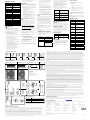 2
2


Risco eyeWAVE RWX95CM Guía de instalación
- Tipo
- Guía de instalación
en otros idiomas
Artículos relacionados
-
Risco eyeWAVE Installation Instructions Manual
-
-
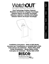 RISCO Group WatchOUT Guía de instalación
-
-
-
-
-
-
-
Risco RP432KPP2 Installation and User Manual

Otros documentos
-
SWITEL SP255 Manual de usuario
-
ADEMCO 998mx Installation Instructions Manual
-
-
RISC GROUP RW332KF1 Guía del usuario
-
CAME SIRWLFC, SIRWLWFC Guía de instalación
-
Tyco PG4914 DSC PowerG Wireless Digital Pet-Immune PIR Motion Detector Guía de instalación
-