Zoeller STBB300 Instrucciones de operación
- Tipo
- Instrucciones de operación

1
© 2020. All rights reserved.
AUTOMATIC EMERGENCY
BACKUP SUMP PUMP
SYSTEM
MODEL #STBB300
Purchase Date
Questions, problems, missing parts? Before returning to your retailer, call our customer
service department at 1-800-584-8089, 7:30 a.m. - 5:00 p.m., EST, Monday - Friday.
ATTACH YOUR RECEIPT HERE
Español p. 25
PN 156411 A SW1579 A
BY
BasementSentry.com
Zoeller
®
is a registered trademark of Zoeller
Co. All Rights Reserved.

2
© 2020. All rights reserved.
PACKAGE CONTENTS
SAFETY INFORMATION
DESCRIPTION QUANTITY
A 12V Pump with o-ring 1
B Controller/charger 1
C Dual Float 1
D Check Valve with o-ring 1
E Tee Fitting 1
F Pipe Clamps 2
G Battery Box 1
Please read and understand this entire manual before attempting to assemble, operate, or install the
product.
DANGER
• RISK OF CHEMICAL BURNS.
Battery acid is corrosive. Do not spill on skin, clothing or battery charger. Wear eye and head
protection when working with battery. Connect and disconnect DC output terminals only after
removing the controller from the AC outlet. Never allow the DC terminals to touch each other.
• FIRE/EXPLOSION HAZARD.
Keep sparks and flame (pilot light) away from battery.
• FIRE/EXPLOSION HAZARD.
Pump only clear water. Do not pump flammable or explosive fluids such as gasoline, fuel oil,
kerosene, etc. Do not use in a flammable and/or explosive atmosphere. Failure to follow these
warnings could result in death or serious injury and/or property damage.
• RISK OF ELECTRIC SHOCK.
These pumps have not been investigated for use in swimming pool or marine areas.
• RISK OF ELECTRIC SHOCK.
Always disconnect power source before attempting to install, service, or maintain the pump.
Never handle a pump with wet hands or when standing on wet or damp surface or in water. Fatal
electrical shock could occur.
• RISK OF ELECTRIC SHOCK.
Keep pump out of reach of children.
• PERSONAL INJURY OR PRODUCT DAMAGE MAY RESULT.
Failure to comply with instructions and designed operation of this product may void warranty.
Attempting to use a damaged pump can result in property damage, serious personal injury and/or
death.
A
B
C
D
E
F
G

3
© 2020. All rights reserved.
WARNING
• ELECTRICAL SHOCK ALERT.
Do not disassemble the motor housing. The motor has NO repairable internal parts and
disassembly may cause dangerous electrical wiring issues.
• ELECTRICAL SHOCK ALERT.
Before installing this product, have the electrical circuit checked by an electrician to ensure proper
grounding. All electrical installations must conform to the National Electric Code and all local codes.
• ELECTRICAL SHOCK ALERT.
Connect the controller to a properly-grounded 115 volt circuit equipped with a Ground Fault Circuit
Interrupter (GFCI) device. Make sure the electrical supply circuit is equipped with fuses or circuit
breakers with a minimum capacity of 15 amps.
• ELECTRICAL SHOCK ALERT.
Never use an extension cord.
• ELECTRICAL SHOCK ALERT.
Do not remove or replace the power cord.
• ELECTRICAL SHOCK ALERT.
Protect electrical cord from sharp objects, hot surfaces, oil, and chemicals. Avoid kinking the cord.
• ELECTRICAL SHOCK ALERT.
Do not lift pump by the power cord.
• PERSONAL INJURY ALERT.
Do not touch an operating motor housing. The motor is designed to operate at high temperatures.
• PERSONAL INJURY ALERT.
Release all pressure and drain all water from the system before servicing any component.
• PERSONAL INJURY ALERT.
Secure discharge line before starting pump. An unsecured discharge line can cause personal injury
and/or property damage.
• PERSONAL INJURY ALERT.
Wear safety glasses at all times when working with pumps.
• PROP65 WARNING FOR CALIFORNIA RESIDENTS:
Cancer and Reproductive Harm – www.P65Warnings.ca.gov
CAUTION
• PERSONAL INJURY OR PRODUCT DAMAGE MAY RESULT.
The controller operates on 115 volts. Make certain that the power source conforms to the
requirements of your equipment.
• PRODUCT DAMAGE MAY RESULT.
The continuous operating water temperature for this pump must not exceed 104°F (40°C).
• PRODUCT DAMAGE MAY RESULT.
This pump is designed to pump water only. It has not been evaluated for pumping chemicals or
corrosive materials. This pump is not designed for pumping effluent or sewage and should not be
used in applications involving salt water or brine.
• PRODUCT DAMAGE MAY RESULT.
Inspect the pump regularly for damage and perform routine maintenance as needed. Remove any
debris that may build up around the float.
• PRODUCT AND/OR PROPERTY DAMAGE MAY RESULT.
This pump is not designed for continuous operation.
SAFETY INFORMATION

4
© 2020. All rights reserved.
PREPARATION
Estimated Installation Time: 2-4 hours
Materials required for assembly: Basement Sentry brand deep cycle battery, 1-1/2-in. Schedule 40
PVC pipe, PVC primer and glue, 1-1/2-in ex coupling and clamps or
1-1/2-in. union.
GENERAL PUMP INFORMATION
SPECIFICATIONS
MODEL
PERFORMANCE IN GALLONS PER MINUTE
0 FT. 5 FT. 10 FT. 15 28 FT.
STBB300 45 43 35 27 Shut Off
This system features built-in WiFi to provide mobile monitoring and alerts. The system includes a
high-capacity 12V pump, controller, 7 amp battery charger, dual oat, check valve, battery box, tee
and pipe clamps.
This pump does not replace a primary, 115V sump pump. This pump provides additional protection
against basement ooding for your peace of mind when the power goes out. It is designed to work
only during power outages or if the primary pump does not work.
Choose this pump if your sump basin is at least 18-in. wide by 22-in. deep.
Place the battery in a cool, dry, well-ventilated area on a shelf or protective plywood board.
Carbon Monoxide Detectors
Whether you have a Basement Sentry backup pump system or a competitive brand, all use batteries
that give o gaseous by-products when charging. Some of these by-products can produce a rotten
egg odor. Also, some of these by-products can cause a CO detector to falsely activate. In order to
help prevent false activation, Basement Sentry recommends moving the battery as far away from the
CO detector as possible or, if necessary, vent the battery to the exterior. Basement Sentry provides
the previous statements only as guidelines to help prevent false activation of the CO detector. In
no way are they meant to supersede the instructions that accompany the detector, nor do they
supersede advice from the CO detector manufacturer.
If the audible alarm associated with your CO detector is activated, we recommend the following
actions:
1. Take immediate action for personal safety as recommended in the CO detector literature.
2. Contact the appropriate agency to determine if the CO is being produced by your furnace, water
heater, or any other device which uses natural gas.
3. If you are certain that no CO is being produced, a charging battery may be producing gaseous
by-products which are causing the CO detector to activate. Contact the manufacturer and ask for
recommendations to prevent the alarm activation.

5
© 2020. All rights reserved.
INSTALLATION INSTRUCTIONS
NOTE: Install the battery backup system when the
primary pump is not needed. Read instructions and
prepare all supplies before beginning installation.
1. Disconnect power to primary sump and remove
from sump basin.
115 V
GFCI outlet
1
2. Be sure the o-ring is on the discharge of the
backup pump and slip the included stainless
steel clamp over the pump discharge. Press the
backup pump into the tee. Be sure the o-ring
is completely inside the tee and not visible. Be
sure the slit on the tee is on the bottom when
the pump is installed. Tighten the clamp over
the tee to secure the backup pump.
3. Be sure the o-ring is on the check valve and
thread the check valve into the discharge of the
primary pump. Be sure the weep hole is still
visible and hand tighten.
Check valve
assembly
Primary Pump
Discharge
O-Ring
Weep hole
3
Backup
Pump
Discharge tee
Clamp
O-Ring
Pump
Discharge
2

6
© 2020. All rights reserved.
4. Slide the included stainless steel clamp over the
check valve and slide the tee (slit end down)
over the check valve. Be sure the o-ring is
completely covered. Tighten clamp over the tee
to secure the check valve.
5. NOTE: Before gluing any ttings, dry t all
connections to verify proper t.
Measure the connection from the Tee to
discharge piping and cut 1-1/2-in Sched 40
PVC to this size. Install 1-1/2-in ex coupling or
1-1/2-in union between pipe connected to the
pump and the discharge piping. Glue all pipe
and ttings once t is veried.
6. To Install the dual oat assembly on discharge
piping, locate the oat assembly so the ‘on’
level of the lower oat is above the ‘on’ position
of the primary pump. Use the included bracket
and stainless steel clamp to attach the oat to
the pipe. Tighten the clamp in place. Be sure
the oats are free to move up and down without
any interference from any part of the sump
pump system or basin.
Clamp
Mounting
Bracket
6
Measure
distance
1-1/2-in flex
coupling or
union
Check valve
assembly
Clamp
Tee
Backup
Pump
O-Ring
Weep hole
4
INSTALLATION INSTRUCTIONS
5

7
© 2020. All rights reserved.
7. Use the included anchors to install the
controller. For best cooling, attach to wall. The
controller must be installed at least 3 ft. above
the sump pit.
9. Connect backup pump and oat leads to the
controller
To controller
8
AC
POWER
FLOAT
STATUS
BATTERY
DC
PUMP
SILENCE
TEST
24/7 BASEMENT
PROTECTION
USB
RESET FLOAT
DC
PUMP
FUSE
30 AMP
by
1-800-584-8089
BasementSentry.com
DC POWER
+ 15V DC 1.6A
Controller
Anchors
Minimum
3 ft.
Sump
Basin
7
INSTALLATION INSTRUCTIONS
AC
POWER
FLOAT
STATUS
BATTERY
DC
PUMP
SILENCE
TEST
24/7 BASEMENT
PROTECTION
USB
RESET FLOAT
DC
PUMP
FUSE
30 AMP
by
FW2065 A
1-800-584-8089
BasementSentry.com
PLATINUM
From float
From
backup
pump
From battery
9
8. Place the battery inside the battery box and connect
the leads from the controller to the battery terminals.
Connect positive (+) lead to positive terminal on the
battery and black negative (-) lead to the negative
battery terminal.
NOTE: If wires are not connected properly, a loud,
constant audible alarm will sound until the leads are
attached to the correct terminals.

8
© 2020. All rights reserved.
11. Reconnect power to the primary sump pump by
plugging the primary sump pump into the outlet
on the front of the controller.This will will enable
the controller and app to monitor the primary
sump pump.
This step is optional, and you can choose to
plug the primary sump pump into a standard,
GFCI protected outlet. If you use this method,
you will not have the ability to monitor the
primary sump pump.
AC
POWER
FLOAT
STATUS
BATTERY
DC
PUMP
SILENCE
TEST
24/7 BASEMENT
PROTECTION
USB
RESET FLOAT
DC
PUMP
FUSE
30 AMP
by
1-800-584-8089
BasementSentry.com
DC POWER
+ 15V DC 1.6A
GFCI Outlet
11
INSTALLATION INSTRUCTIONS
10.Plug the controller into a GFCI-protected 115V
outlet.
Test for backup pump operation by adding
water to the sump basin.
AC
POWER
FLOAT
STATUS
BATTERY
DC
PUMP
SILENCE
TEST
24/7 BASEMENT
PROTECTION
USB
RESET FLOAT
DC
PUMP
FUSE
30 AMP
by
1-800-584-8089
BasementSentry.com
DC POWER
+ 15V DC 1.6A
GFCI Outlet
10

9
© 2020. All rights reserved.
There are two buttons on the front of the controller.
1. Silence/Reset - Can be pressed to silence current
alarms for 24 hours.
Can be held for 3+ seconds to reset (or clear) alarms
and LEDs. Flashing LEDs for conditions such as bad/
disconnected battery or power outage, for example,
can’t be cleared by Silence/Reset. These conditions
must be resolved to eliminate the LED indicator.
BASEMENT SENTRY CONTROLLER FUNCTIONS
AC
POWER
FLOAT
STATUS
BATTERY
DC
PUMP
SILENCE
TEST
24/7 BASEMENT
PROTECTION
USB
RESET FLOAT
DC
PUMP
FUSE
30 AMP
by
FW2065 A
1-800-584-8089
BasementSentry.com
PLATINUM
Test
2
AC
POWER
FLOAT
STATUS
BATTERY
DC
PUMP
SILENCE
TEST
24/7 BASEMENT
PROTECTION
USB
RESET FLOAT
DC
PUMP
FUSE
30 AMP
by
FW2065 A
1-800-584-8089
BasementSentry.com
PLATINUM
Silence/
Reset
1
2. Test - Will run the pump to determine if amp draw of
pump is within range.
Controller is factory programmed to self-test the pump
for several seconds every 7 days. This schedule may
be modied once the controller is connected to the Z
Control Cloud.
Pressing the test button will start the 7 day timer for
self-testing.
Test and Silence/Reset -
Holding both buttons together for about six seconds
will initiate a factory reset. This returns the rmware’s
device conguration to the state in which it left the
factory. Any over-the-air rmware updates that have
been installed will be retained.
BASEMENT SENTRY LED LIGHT FUNCTIONS
AC
POWER
BATTERY
FLOAT
STATUS
DC
PUMP
AC
POWER
BATTERY
AC
PUMP
AC
POWER
BATTERY
FLOAT
STATUS
DC
PUMP
AC
POWER
BATTERY
AC
PUMP

10
© 2020. All rights reserved.
By connecting the controller to the Z Control
®
Cloud using the built-in WiFi, the user can set up
free alert messages via email, text, and mobile
app “push” notifications. In addition, the user
can verify controller readiness, remotely silence
alarms and reset the unit, configure settings, and
modify how notifications are sent. Other visual
information such as input status and battery level
are available through the web and app interfaces.
There are two ways to connect the Basement
Sentry controller to the Z Control
®
cloud.
Option 1 - Use the Z Control
®
mobile app. See
Use the Mobile App section below.
Option 2 - Use a mobile device or computer to
connect to the controller directly. See use Mobile
Device Page 13.
CONNECTING THE CONTROLLER TO Z CONTROL
®
Option 1 - Use the Mobile App (iOS and Android)
Before you begin:
• Know what the WiFi router is named (i.e.
SSID) and password. To prevent the most
common troubleshooting issues, double
check to be sure you know exactly how the
password is spelled, including capitalization.
• Verify that your mobile device has working
WiFi with a strong signal when you are
standing next to the Basement Sentry
controller. If the signal is questionable, the
controller may not be able to maintain a stable
connection.
• Verify your WiFi router is connected to the
internet and that it is broadcasting a visible,
secure, 2.4Ghz network.
• 2.4 Ghz network is required. If you only see 5
Ghz networks, you may need to log into your
dual band router to choose to broadcast the
networks separately.
• Band steering may need to be temporarily
turned off during setup.
• The 2.4Ghz network must use WPA or WPA2
security. WEP and open networks are not
acceptable.
• Any VPNs or other network controls may need
to be temporarily turned off during setup.
• Locate the Basement Sentry Device ID
located on the top of the controller.
• Like most internet connected devices, the
Basement Sentry controller WiFi connectivity
should be used behind the security of a
firewall. Most routers have a firewall built into
them. Consult a networking professional for
specific questions about firewalls.
NOTE: The list above will also help troubleshoot
connectivity issues.
These instructions provide an overview of what
the app will do. You may find additional steps
needed.
1. Open the app and sign in to your account, or
create an account using the link at the bottom.
If you do not have an account, you will need to
click the link at the bottom of the home screen
to create an account.
1
Click to
create
account

11
© 2020. All rights reserved.
Use the Mobile App (iOS and Android) (Continued)
2
4. Once a location is created, you will need to add
a device. To add a device, choose the desired
location name and then touch the “+” to start adding
a device. Allow access to the camera so you can
scan the data matrix.
3. Once you’re logged in to your account, create
locations by touching the “+ “ from the Locations
screen.
2. Open your profile to set up any additional
phone numbers or email addresses where
notifications should be sent.
3
Touch +
to create
locations
4
Touch +
to add a
device
CONNECTING THE CONTROLLER TO Z CONTROL
®

12
© 2020. All rights reserved.
6. When the captive screen opens, use the WiFi Scan
button to find the WiFi network you want the controller
to use, select it from the list provided at the bottom
of the screen (you may need to scroll), and type the
password in the field. The Z Control
®
LED should be
solid within a minute, indicating successful connection
to the router and the Z Control
®
Cloud. Upon first
connecting to the cloud, the Basement Sentry controller
may immediately update its firmware over-the-air (OTA),
if an update is available. If an update is taking place,
the Z Control
®
LED will flicker for up to one minute while
the update is downloaded. The Z Control
®
LED will be
solid and all other LEDs will turn off while the update is
being installed. After up to one minute, the controller will
restart and return to normal operation. The controller
alert history on the Z Control
®
Cloud will also be
updated with the firmware update information, and any
email accounts that are set up will be notified.
6
7
7. You can now return to the Z Control
®
app to find
your new device set up in the location you previously
selected. You can always change a device to a
different location in your account.
Click WiFi
Scan button
5. The app will ask you to scan the data matrix QR
code on the controller. You can also bypass this
step and manually input the SSID of the controller,
which is found on the controller label.
Use the Mobile App (iOS and Android) (Continued)
5
Click to manually input SSID
SSID input eld
CONNECTING THE CONTROLLER TO Z CONTROL
®

13
© 2020. All rights reserved.
8
8. Open the Basement Sentry app to explore current
status, configuration settings, and commands
available, such as Pump Test, Buzzer Test, Silence,
etc. Perform these test to be sure everything
works as expected. Reset all alarms when you are
finished.
Option 2 - Use your mobile device or computer to connect directly to the Basement Sentry controller
Instead of using a mobile device and the Z
Control
®
app, you can also use your mobile
device or computer to directly connect to the
controller.
Before you begin:
• Know what the WiFi router is named (i.e.
SSID) and password. To prevent the most
common troubleshooting issues, double
check to be sure you know exactly how the
password is spelled, including capitalization.
• Verify that your mobile device has working
WiFi with a strong signal when you are
standing next to the Basement Sentry
controller. If the signal is questionable, the
controller may not be able to maintain a stable
connection.
• Verify your WiFi router is connected to the
internet and that it is broadcasting a visible,
secure, 2.4Ghz network.
• 2.4 Ghz network is required. If you only see 5
Ghz networks, you may need to log into your
dual band router to choose to broadcast the
networks separately.
• Band steering may need to be temporarily
turned off during setup.
• The 2.4Ghz network must use WPA or WPA2
security. WEP and open networks are not
acceptable.
• Any VPNs or other network controls may need
to be temporarily turned off during setup.
• Create a free account at zcontrolcloud.com.
• Locate the Basement Sentry Device ID
located on the top of the controller.
NOTE: The above list also helps to troubleshoot
connectivity issues.
If the controller still will not connect after trying
the above suggestions, follow the same steps to
connect the controller to a mobile phone hotspot
instead of the home WiFi router. If the controller
successfully connects to the cloud through the
hotspot, then the conflict is probably related to
router settings.
Use the Mobile App (iOS and Android) (Continued)
CONNECTING THE CONTROLLER TO Z CONTROL
®

14
© 2020. All rights reserved.
2. Standing near the controller, use your phone, tablet,
or computer to look for the Basement Sentry controller
SSID in your WiFi settings. It will look similar to
“ZCTL_Fit_xxxx” where “xxxx” is the first 4 digits of
your controller device ID. Select this, and be sure your
device displays a check mark or similar indicator that
you are connected to the controller local network. If so,
two things will happen:
A. The Z Control
®
LED will flash quickly.
B. A Z Control
®
setup screen (Figure 3) will open. This
may take up to 30 seconds.
If the setup screen does not appear, open a browser
on the same device and type “192.168.125.1” in the
address bar. If the setup screen appears but is not used
(canceled or otherwise closed), the controller will return
to AP mode and the Z Control
®
LED will turn off until the
next WiFi setup attempt. If the setup screen still does
not appear, verify your device is still connected to the
controller SSID. If it isn’t, repeat Step 2 and be sure
your device’s WiFi stays connected to the controller.
If your device shows a warning message about no
internet or no security on the controller network, ignore
this and connect to it anyway.
2
Select the
Basement
Sentry SSID.
The last 4 digits
(underlined) will
match the rst
4 digits of the
controller
Device ID.
* AP Mode is when the controller is broadcasting its “name”, or SSID. The SSID is in a format similar
to ZCTL_Fit_xxxx where “xxxx” is the first 4 digits of your controller device ID (See Figure 2). The
Basement Sentry controller SSID will show up in your phone/tablet/computer’s list of available WiFi
options, and selecting it will give you direct connectivity to the controller. This is required in order to
give your controller the password credentials needed to connect to the WiFi of your choice.
Apply AC power to the controller. The Z
Control
®
LED will blink and then turn off,
indicating the controller is in AP Mode*
and is transmitting an SSID.
If the LED is blinking and not in AP
mode, press the Z Control
®
button for 12
seconds and let go.
The LED will now be off, indicating
the controller is in AP Mode. A pen or
toothpick or similar is required to press
the Z Control
®
button.
AC
POWER
FLOAT
STATUS
BATTERY
DC
PUMP
SILENCE
TEST
24/7 BASEMENT
PROTECTION
USB
RESET FLOAT
DC
PUMP
FUSE
30 AMP
by
FW2065 A
1-800-584-8089
BasementSentry.com
DC POWER
+ 15V DC 1.6A
PLATINUM
1
Connecting with your mobile device or computer (Continued)
CONNECTING THE CONTROLLER TO Z CONTROL
®

15
© 2020. All rights reserved.
3. On the setup screen, press the WiFi Scan button,
scroll down to see the list of WiFi signals found, and
choose the WiFi you want the Basement Sentry
controller to use for internet connectivity. Enter
the password for the router you chose in the field
indicated. If the password is correct, the controller
will connect to the router and start sending status
updates to zcontrolcloud.com. You will see the Z
Control
®
LED go from blinking to solid. This could
take up to a minute or so.
If the LED does not turn solid, then the password
entered is incorrect, the router’s security is
insufficient (see note below**), or some other
network restriction is in place (see your network
administrator). The controller will return to standby
mode if the connection to router is not successful. If
you need to force the controller into AP mode again,
press the Z Control
®
button for 12 seconds (See
Figure 1). This will cause the controller to re-enter
AP mode and begin transmitting the SSID again.
Repeat Steps 2 and 3.
4
Click WiFi
Scan
button
** The controller will not connect to
routers with ‘WEP’ or ‘OPEN’ security.
Available
WiFi will
show here.
Choose the
one you
want.
4. Once the controller LED is solid, log in to your
account (or create one) at zcontrolcloud.com.
** The controller will not connect to routers with ‘WEP’
or ‘OPEN’ security.
3
Click WiFi
Scan button
Connecting with your mobile device or computer (Continued)
CONNECTING THE CONTROLLER TO Z CONTROL
®

16
© 2020. All rights reserved.
Controller Set-Up
Your Basement Sentry controller is now online.
Be sure you have added the contact information
for phone numbers and email addresses that
should receive notification. This can done by
selecting “Manage Contacts” from the main menu
(the square with 3 lines in the upper right corner).
You can also edit how each device sends out
notifications from the device “Alarm Settings” tab.
You can now open the product’s configuration by
clicking the “View” button to modify the controller
device and notification settings. You can also
install the Z Control
®
mobile app on your mobile
device (Android and iOS versions available,
search
“Z Control
®
” in the app stores).
Firmware Updates
The Basement Sentry controller is capable
of OTA, or over-the-air firmware updates. It’s
possible that the controller could perform an
update immediately if one is available at the Z
Control
®
Cloud. If an update is taking place, the
Z Control
®
LED will flicker for up to one minute
while the update is downloaded. The Z Control
®
LED will be solid and all other LEDs will turn off
while the update is being installed. After up to
one minute, the controller will restart and return
to normal operation. The controller’s alert history
on the Z Control
®
Cloud will also be updated with
the firmware upgrade information, and notification
to email accounts will occur.
START-UP AND OPERATION
The Basement Sentry controller is able to recognize potential air lock situations and remedy the issue
with an on/off/on/off/on routine which purges air from the pump. Other potential issues such as a stuck
float can also be sensed and resolved by the controller to prevent damage to the equipment.
In addition, the following LED functions provide a visual cue to the proper function of the DC pump:
• The DC pump LED will stay yellow after pumping water, alerting you when the DC pump has
turned on and has pumped water.
• If the DC pump runs and does not pump water, the LED will not stay yellow. This can occur during
a test of the system when the float is lifted manually while the pump is above the water line. This
allows the system to be tested without having to reset it each time.
5. Choose the Add New Device button next to
the location you want the controller. Follow
the directions to add your controller by either
auto-detect or entering the Device I.D. When
successful, a Basement Sentry product tile will
appear in your account.
5
CONNECTING THE CONTROLLER TO Z CONTROL
®
Connecting with your mobile device or computer (Continued)

17
© 2020. All rights reserved.
1. WARNING: Disconnect the primary pump from
the 115V outlet before touching any component
in the sump basin.
Test the installation for leaks by running water
into the sump basin. The primary pump should
operate normally.
AC
POWER
FLOAT
STATUS
BATTERY
DC
PUMP
SILENCE
TEST
24/7 BASEMENT
PROTECTION
USB
RESET FLOAT
DC
PUMP
FUSE
30 AMP
by
1-800-584-8089
BasementSentry.com
DC POWER
+ 15V DC 1.6A
1
2. Check the controller. The system light should
be green when the unit is plugged into a 115V
outlet.
3. NOTE: When the unit is first plugged in, all
lights will flash and an alarm will sound to verify
proper operation. The charger may not begin
charging for several minutes. When the battery
begins charging, the four lights in the circle will
turn blue, with the battery light flashing blue.
AC
POWER
FLOAT
STATUS
BATTERY
DC
PUMP
SILENCE
TEST
24/7 BASEMENT
PROTECTION
USB
RESET FLOAT
DC
PUMP
FUSE
30 AMP
by
FW2065 A
1-800-584-8089
BasementSentry.com
PLATINUM
Flashing blue light
when charging
Solid blue light
when charging
3
AC
POWER
FLOAT
STATUS
BATTERY
DC
PUMP
SILENCE
TEST
24/7 BASEMENT
PROTECTION
USB
RESET FLOAT
DC
PUMP
FUSE
30 AMP
by
FW2065 A
1-800-584-8089
BasementSentry.com
PLATINUM
All lights will be green when
plugged into 115V outlet
2
START-UP AND OPERATION

18
© 2020. All rights reserved.
5. Lift the lower (operational) float on the backup pump
float switch. After one second, the backup pump will
run and the alarm will sound. Be sure the inlet of the
backup pump is above the inlet of the primary pump.
Press ‘Silence’ for 3 seconds to cancel the alarm
and reset the unit.
CAUTION: Continuously running the pump dry may
cause overheating and damage the pump. Once
the lower float is released, the backup pump will run
for an additional ten seconds or until it senses that
water is no longer being pumped.
6. Lift the upper (high water) float on the backup
pump float switch. After one second, the backup
pump will run and the alarm will sound. Be
sure the inlet of the backup pump is above the
inlet of the primary pump. Press ‘Silence’ for 3
seconds to cancel the alarm and reset the unit.
CAUTION: Continuously running the pump dry
may cause overheating and damage the pump.
Once the upper float is released, the backup
pump will run for an additional ten seconds
or until it senses that water is no longer being
pumped.
Be sure there are no obstructions around the
float.
Lift
upper
float
to test
6
Lift
lower
float
to test
5
4. Once the battery is fully charged, the four lights will
turn green. To clear any other lights or alarms, press
and hold the ‘Silence’ button for three seconds.
The following LED functions provide a visual cue to the
proper function of the DC pump:
• The DC pump LED will stay yellow after pumping
water, alerting you when the DC pump has turned on
and has pumped water.
• If the DC pump runs and does not pump water, the
LED will not stay yellow. This can occur during a test of
the system when the float is lifted manually while the
pump is above the water line. This allows the system
to be tested without having to reset it each time.
AC
POWER
FLOAT
STATUS
BATTERY
DC
PUMP
SILENCE
TEST
24/7 BASEMENT
PROTECTION
USB
RESET FLOAT
DC
PUMP
FUSE
30 AMP
by
FW2065 A
1-800-584-8089
BasementSentry.com
PLATINUM
Solid green light
when charged
Press to
silence
alarms
4
START-UP AND OPERATION

19
© 2020. All rights reserved.
7. Complete the final test of the installation. Be
sure the primary pump is still disconnected from
power. Unplug the controller from the 115V
outlet. Run water into the sump basin until the
backup pump turns on. Check all connections
for leaks.
AC
POWER
FLOAT
STATUS
BATTERY
DC
PUMP
SILENCE
TEST
24/7 BASEMENT
PROTECTION
USB
RESET FLOAT
DC
PUMP
FUSE
30 AMP
by
1-800-584-8089
BasementSentry.com
DC POWER
+ 15V DC 1.6A
7
8. Push the ‘Silence’ button when the pump is
running to turn off the alarm. The pump will
continue to run for an additional ten seconds
after the float has been lowered or until the
controller senses water is being pumped.
9. Press and hold the ‘Silence’ button for three
seconds to reset the system and clear all faults
and alarms.
AC
POWER
FLOAT
STATUS
BATTERY
DC
PUMP
SILENCE
TEST
24/7 BASEMENT
PROTECTION
USB
RESET FLOAT
DC
PUMP
FUSE
30 AMP
by
FW2065 A
1-800-584-8089
BasementSentry.com
PLATINUM
Press and
hold three
seconds to
reset
system
9
AC
POWER
FLOAT
STATUS
BATTERY
DC
PUMP
SILENCE
TEST
24/7 BASEMENT
PROTECTION
USB
RESET FLOAT
DC
PUMP
FUSE
30 AMP
by
FW2065 A
1-800-584-8089
BasementSentry.com
PLATINUM
Press to
silence
alarms
8
START-UP AND OPERATION

20
© 2020. All rights reserved.
10. Connect the controller AC power and primary
pump into the receptacle on the front of the
controller. Fill basin with water to ensure
primary pump functions normally.
AC
POWER
FLOAT
STATUS
BATTERY
DC
PUMP
SILENCE
TEST
24/7 BASEMENT
PROTECTION
USB
RESET FLOAT
DC
PUMP
FUSE
30 AMP
by
1-800-584-8089
BasementSentry.com
DC POWER
+ 15V DC 1.6A
10
START-UP AND OPERATION
11. The four circle LED’s will be blue when charging
the battery. The battery LED will flash slowly.
Once charging is complete, all four circle LED’s
will turn green.
AC
POWER
FLOAT
STATUS
BATTERY
DC
PUMP
SILENCE
TEST
24/7 BASEMENT
PROTECTION
USB
RESET FLOAT
DC
PUMP
FUSE
30 AMP
by
FW2065 A
PLATINUM
1-800-584-8089
BasementSentry.com
Solid green light
when charged
Press to
silence
alarms
11

21
© 2020. All rights reserved.
CARE AND MAINTENANCE
WARNING: Always disconnect pump from power source
before handling.
At least every three months inspect and test
operation:
1.. Check to be sure green ‘system ready’ light is on
(indicates AC power is on and there are no alarm
conditions)
2. Test for operation:
A. Unplug primary pump and controller.
Fill basin with water to the ‘on’ level of the backup
pump and allow the pump to run for several
minutes.
NOTE: The alarm will sound approximately one
second after the pump starts to run.
B. Push the Silence/reset button - the alarm will shut
off. The pump will shut off after the water level is
lowered and the float drops to the ‘off’ position.
Hold the Silence/reset button for three seconds
to reset the controller and clear any alarms or
indicators
C. Plug the controller and the primary pump into the
115V outlet. The primary pump will turn on and
then off when water reaches normal level.
The pump will continue to run after the float is
lowered or until the controller senses water is
being pumping. The four circle lights will be blue.
The battery light will flash slowly after the test as
it recharges the battery. The lights will turn green
once the battery is recharged.
AC
POWER
FLOAT
STATUS
BATTERY
DC
PUMP
SILENCE
TEST
24/7 BASEMENT
PROTECTION
USB
RESET FLOAT
DC
PUMP
FUSE
30 AMP
by
1-800-584-8089
BasementSentry.com
DC POWER
+ 15V DC 1.6A
1
2A
2B
2A
2C

22
© 2020. All rights reserved.
BATTERY
This backup system requires a good quality, 12V battery
in order to provide maximum pumping time when needed.
A Basement Sentry brand battery is recommended.
Otherwise, use an AGM deep-cycle 12 volt 105 amp-hour
marine battery or larger. Wet cell batteries contain acid
and precautions must be taken when handling.
DO NOT USE gel batteries or automotive batteries.
Batteries with top terminals are recommended for ease of
installation.
Battery box will accommodate a maximum battery size of
13-1/2-in L x 7-in. W x 9-1/2-in H.
NOTE: The water level in a wet cell battery should be
checked every month. AGM batteries should not be
checked.
Battery Troubleshooting:
If pump runs without AC power but moves little or no
water, the battery may be low.
• Battery will recharge if green power ‘on’ light indicates
power has been restored and the float switch is in the
off position.
• If immediate use is required, replace old battery with
a fully charged battery.
• NOTE: The pump may continue to run on a low
battery without sufficient power to remove water.
Pump will not stop running until battery drops below
minimum voltage.
• CAUTION: Weak batteries can be recharged but
may not store enough energy for full service. A weak,
recharged battery will provide reduced pumping time.
If the backup pump is used frequently, the battery
should be checked by a qualified battery dealer.
• NOTE: The battery may take up to 24 hours to
recharge after use. This will depend on the size of
the battery and the amount the battery is discharged
during use.
If the alarm sounds during the recharge cycle, reset the
alarm. If the alarm will not reset, unplug the charger from
the 115V outlet and disconnect the black (-) negative
lead from the battery post. Check battery and replace if
necessary. Reconnect and refer to the battery installation
section in the instructions.
1

23
© 2020. All rights reserved.
TROUBLESHOOTING
PROBLEM POSSIBLE CAUSE CORRECTIVE ACTION
Backup pump
won’t run
Connections are incorrect or loose Verify connections are correctly
installed
Wire terminal points are dirty Check all terminals and clean if
required
Battery is low Service or replace battery
30 Amp controller fuse is blown Replace with 30 amp automotive
blade fuse
Pump runs but
delivers little or
no water
Connections are incorrect or loose Verify connections are correctly
installed
Weep hole is plugged and unit is air-
locked
Clean weep hole
Discharge pipe is blocked Clear discharge pipe
Check valve may not be working
correctly. It should allow water to go out of
discharge pipe but not allow water to flow
back into the sump basin after pump has
shut off.
Replace the check valve if necessary
Float switch in
‘on’ position for
3 seconds or
more but pump
won’t run
Pump is obstructed Remove pump and clear any debris
from impeller or pump cavity
Pump runs but
pumps water
intermittently
Incoming water is causing pump to air lock Divert incoming water to reduce
turbulence
Water level
stays high but
pump continues
to run
Battery is low Service or replace battery
If power is restored, check primary pump Service or replace if required
Alarm sounds
during battery
recharge cycle
Alarm needs to be reset Press ‘Silence’ button for 3 seconds
Battery is defective. Check voltage with a
multimeter. Disconnect the controller from
the battery and re-check voltage. If voltage
is below 12V after disconnecting, battery
must be replaced.
Check battery and replace if
necessary
RISK OF ELECTRIC SHOCK.
Always disconnect power source before attempting to install, service, or maintain the pump. Never
handle a pump with wet hands or when standing on wet or damp surface or in water. Fatal electrical
shock could occur.
DANGER

24
© 2020. All rights reserved.
WARRANTY
This product is warranted for three years from the date of purchase. Subject to the conditions hereinafter set
forth, the manufacturer will repair or replace to the original consumer any portion of the product which proves
defective due to defective materials or workmanship. To obtain warranty service, contact the dealer from whom
the product was purchased. The manufacturer retains the sole right and option to determine whether to repair
or replace defective equipment, parts, or components. Damage due to conditions beyond the control of the
manufacturer is not covered by this warranty.
THIS WARRANTY WILL NOT APPLY: (a) To defects or malfunctions resulting from failure to properly install,
operate, or maintain the unit in accordance with printed instructions provided; (b) to failures resulting from
abuse, accident, or negligence, or use of inappropriate chemicals or additives in the water; (c) to normal
maintenance services and the parts used in connection with such service; (d) to units which are not installed
in accordance with normal applicable local codes, ordinances, and good trade practices; and (e) if the unit is
used for purposes other than for what it was designed and manufactured.
RETURN OF WARRANTED COMPONENTS: Any item to be repaired or replaced under this warranty must be
returned to the manufacturer at Kendallville, Indiana or such other place as the manufacturer may designate,
freight prepaid.
THE WARRANTY PROVIDED HEREIN IS IN LIEU OF ALL OTHER EXPRESS WARRANTIES, AND MAY
NOT BE EXTENDED OR MODIFIED BY ANYONE. ANY IMPLIED WARRANTIES SHALL BE LIMITED TO
THE PERIOD OF THE LIMITED WARRANTY AND THEREAFTER ALL SUCH IMPLIED WARRANTIES ARE
DISCLAIMED AND EXCLUDED. THE MANUFACTURER SHALL NOT, UNDER ANY CIRCUMSTANCES, BE
LIABLE FOR INCIDENTAL, CONSEQUENTIAL OR SPECIAL DAMAGES, SUCH AS, BUT NOT LIMITED TO
DAMAGE TO, OR LOSS OF, OTHER PROPERTY OR EQUIPMENT, LOSS OF PROFITS, INCONVENIENCE,
OR OTHER INCIDENTAL OR CONSEQUENTIAL DAMAGES OF ANY TYPE OR NATURE. THE LIABILITY
OF THE MANUFACTURER SHALL NOT EXCEED THE PRICE OF THE PRODUCT UPON WHICH SUCH
LIABILITY IS BASED.
This warranty gives you specic legal rights, and you may have other rights which vary from state to
state. Some states do not allow limitations on duration of implied warranties or exclusion of incidental or
consequential damages, so the above limitations may not apply to you.
In those instances where damages are incurred as a result of an alleged pump failure, the
Homeowner must retain possession of the pump for investigation purposes.

1
© 2020. Todos los derechos reservados.
EMERGENCIA AUTOMÁTICA
SISTEMA DE BOMBA DE
SUMIDERO DE RESERVA
MODELO #STBB300
Fecha de compra
¿Preguntas, problemas, partes faltantes? Antes de acudir al minorista, llame a nuestro
departamento de servicio al cliente al 1-800-584-8089, de lunes a viernes de
7:30 a.m. a 5:00 p.m., EST.
ADJUNTE SU RECIBO AQUÍ
PN 156411 A SW1579S A
BY
BasementSentry.com
Zoeller® es una marca registrada de
Zoeller Co. Todos derechos reservados.

2
© 2020. Todos los derechos reservados.
PACKAGE CONTENTS
INFORMACIÓN DE SEGURIDAD
ADVERTENCIA
DESCRIPCIÓN CANTIDAD
A Bomba de 12 V con junta tórica 1
B Controlador/cargador
1
C Flotador doble
1
D Válvula de retención con
junta tórica
1
F Conector en T
1
F Abrazaderas para tubería 2
G
Caja de batería
1
Lea y comprenda completamente este manual antes de intentar ensamblar, usar o instalar el producto.
PELIGRO
• RIESGO DE QUEMADURAS QUÍMICAS.
El ácido de batería es corrosivo. No lo derrame sobre la piel, la ropa o el Controlador de batería. Use
protección para los ojos y la cabeza al trabajar con baterías. Conecte y desconecte los terminales de
salida de CC solo después de haber desconectado el Controlador de la toma de CA. No permita nunca
que los terminales de CC entren en contacto.
• PELIGRO DE INCENDIO O EXPLOSIÓN.
Mantenga las chispas y la llama (luz piloto) apartadas de la batería.
• PELIGRO DE INCENDIO O EXPLOSIÓN.
Bombee solo agua limpia. No bombee líquidos inflamables o explosivos como gasolina, gasoil, queroseno,
etc. No la utilice en una atmósfera inflamable o explosiva. No seguir estas instrucciones puede provocar la
muerte, lesiones graves o daños a la propiedad.
• RIESGO DE DESCARGA ELÉCTRICA.
No se ha verificado el uso de estas bombas en piscinas.
• RIESGO DE DESCARGA ELÉCTRICA.
Desconecte siempre la fuente de alimentación antes de intentar instalar, reparar o realizarle mantenimiento
a la bomba. Nunca manipule una bomba con las manos mojadas ni cuando esté parado sobre una
superficie húmeda o en el agua. Podría ocurrir una descarga eléctrica fatal.
• RIESGO DE DESCARGA ELÉCTRICA.
Mantenga la bomba alejada del alcance de los niños.
• PODRÍAN PRODUCIRSE LESIONES PERSONALES O DAÑOS EN EL PRODUCTO.
El incumplimiento de las instrucciones y del funcionamiento diseñado de este producto podría invalidar la
garantía. Intentar usar una bomba dañada puede provocar daños materiales, lesiones personales graves
y/o la muerte.
A
B
C
D
E
F
G
• ALERTA DE DESCARGA ELÉCTRICA.
No desensamble la carcasa del motor. Esta bomba no tiene piezas internas reparables y al
desensamblarla puede causar una fuga o peligrosos problemas de cableado eléctrico.

3
© 2020. Todos los derechos reservados.
• ALERTA DE DESCARGA ELÉCTRICA.
Antes de instalar este producto, haga que un electricista revise su circuito para asegurarse de que la
puesta a tierra sea adecuada. Todas las instalaciones eléctricas deben cumplir con el Código Nacional de
Electricidad (NEC, por sus siglas en inglés) y con todos los códigos locales.
• ALERTA DE DESCARGA ELÉCTRICA.
Conecte el controlador a un circuito de 115 V con la debida conexión a tierra equipado con un interruptor
de circuito con protección de falla a tierra (GFCI, por sus siglas en inglés). Asegúrese de que el circuito de
suministro eléctrico esté equipado con fusibles o disyuntores con una capacidad mínima de 15 amperios.
• ALERTA DE DESCARGA ELÉCTRICA.
Nunca utilice una extensión eléctrica.
• ALERTA DE DESCARGA ELÉCTRICA.
No retire ni reemplace el cable eléctrico.
• ALERTA DE DESCARGA ELÉCTRICA.
Proteja el cable eléctrico de objetos afilados, superficies calientes, aceite y otras sustancias químicas.
Evite torcer el cable.
• ALERTA DE DESCARGA ELÉCTRICA.
No alce la bomba por el cable de alimentación.
• ALERTA DE LESIONES PERSONALES.
No toque la carcasa de un motor en funcionamiento. El motor está diseñado para funcionar a altas
temperaturas.
• ALERTA DE LESIONES PERSONALES.
Libere toda la presión y drene toda el agua del sistema antes de reparar o darle mantenimiento a cualquier
componente.
• ALERTA DE LESIONES PERSONALES.
Asegure la línea de descarga antes de arrancar la bomba. Una línea de descarga que no esté asegurada
puede soltarse bruscamente y posiblemente causar lesiones personales y/o daños materiales.
• ALERTA DE LESIONES PERSONALES.
Use gafas de seguridad todo el tiempo cuando trabaje con bombas.
• ADVERTENCIA DE PROPOSICIÓN 65 PARA RESIDENTES DE CALIFORNIA
:
Advertencia: Cáncer y Daño Reproductivo – www.P65Warnings.ca.gov
PRECAUCIÓN
• PODRÍAN PRODUCIRSE LESIONES PERSONALES O DAÑOS AL PRODUCTO.
El controlador opera a 115 V. Asegúrese de que la fuente de alimentación cumpla con los requisitos de su
equipo.
• PRODUCT DAMAGE MAY RESULT.
La temperatura de funcionamiento continuo del agua para las bombas de modelo estándar no debe
exceder los 40 °C (104 °F).
• PODRÍAN PRODUCIRSE DAÑOS EN EL PRODUCTO.
Esta bomba fue diseñada solo para bombear agua. No se ha probado su uso para bombear productos
químicos ni materiales corrosivos. Esta bomba no está diseñada para bombear efluentes o aguas negras y
no debería usarse en aplicaciones que involucren agua salada o salmuera.
• PODRÍAN PRODUCIRSE DAÑOS EN EL PRODUCTO.
Revise de manera regular que la bomba no presente daños y realícele mantenimiento de rutina cuando
sea necesario. Quite la suciedad que pudiera acumularse alrededor del flotador.
• PODRÍAN PRODUCIRSE DAÑOS AL PRODUCTO Y/U OTROS DAÑOS MATERIALES.
Esta bomba no está diseñada para su funcionamiento continuo.
INFORMACIÓN DE SEGURIDAD

4
© 2020. Todos los derechos reservados.
PREPARACIÓN
Tiempo estimado de instalación 2-4 horas
Materiales necesarios para en ensamblaje: Batería de ciclo profundo de marca Basement Sentry de 3.8 cm
(1-1/2 pulg.). Tubería PVC 40 Imprimación y pegamento de PVC, acoplamiento exible de 3.8 cm (1-1/2 pulg.)
y abrazaderas o unión de 3.8 cm (1-1/2 pulg.).
INFORMACIÓN GENERAL DE LA BOMBA
ESPECIFICACIONES
MODELO
RENDIMIENTO EN GALONES POR MINUTO
0 m 1,52 m 3,04 m 4,57 m 8,53 m
STBB300 45 43 35 27 Cierre
Este sistema cuenta con WiFi incorporado para proporcionar monitoreo y alertas móviles. El sistema incluye una
bomba de 12 V de alta capacidad, controlador, cargador de batería de 7 A, doble flotador, válvula de retención,
caja de batería, abrazaderas para tubería y T.
Esta bomba no reemplaza una bomba principal de sumidero de 115 V. La bomba proporciona protección
adicional contra inundaciones en el sótano para su tranquilidad cuando se va la luz. Está diseñada para
funcionar solo durante cortes de energía o si la bomba principal no funciona.
Elija esta bomba si su contenedor para agua de sumidero tiene al menos 45.7 cm (18 pulg.) de ancho por 55.9
cm (22 pulg.) de profundidad.
Coloque la batería en un área fresca, seca y bien ventilada sobre un estante o un tablero contrachapado
protector.
Detectores de monóxido de carbono
Ya sea que tenga un sistema de bomba de reserva Basement Sentry o una marca competitiva, todos usan
baterías que emiten subproductos gaseosos cuando se cargan. Algunos de estos subproductos pueden producir
un olor a huevo podrido. Además, algunos de estos subproductos pueden hacer que un detector de CO se active
falsamente. Para ayudar a prevenir la activación falsa, Basement Sentry recomienda mover la batería lo más
lejos posible del detector de CO o, si es necesario, ventilar la batería hacia el exterior. Basement Sentry emite
las afirmaciones anteriores solo como pautas para ayudar a prevenir la activación falsa del detector de CO. De
ninguna manera están destinadas a reemplazar las instrucciones que acompañan al detector, ni a los consejos
del fabricante del detector de CO.
Si se activa la alarma sonora asociada con su detector de CO, le recomendamos las siguientes acciones:
Adopte medidas inmediatas para la seguridad personal como se recomienda en la documentación del detector
de CO.
Póngase en contacto con la agencia apropiada para determinar si el CO está siendo producido por su caldera,
calentador de agua o cualquier otro dispositivo que utiliza gas natural.
Si está seguro de que no se está produciendo CO, una batería que se esté cargando puede estar produciendo
subproductos gaseosos que están causando la activación del detector de CO. Póngase en contacto con el
fabricante y solicite recomendaciones para evitar la activación de la alarma.

5
© 2020. Todos los derechos reservados.
INSTRUCCIONES DE INSTALACIÓN
NOTA: instale el sistema de reserva a batería cuando
no se necesite la bomba principal. Lea las instrucciones
y prepare todos los materiales antes de comenzar la
instalación.
1. Desconecte la alimentación al sumidero principal y
retírelo de la fosa del sumidero..
115 V
GFCI outlet
1
2. Asegúrese de que la junta tórica esté en la
descarga de la bomba de reserva y deslice la
abrazadera de acero inoxidable incluida sobre
la descarga de la bomba. Presione la bomba de
reserva en la T. Asegúrese de que la junta tórica
esté completamente dentro de la T y no sea visible.
Asegúrese de que la ranura en la T esté en la
parte inferior cuando se instala la bomba. Apriete la
abrazadera sobre la T para asegurar la bomba de
reserva.
3. Asegúrese de que la junta tórica esté en la válvula
de retención y enrosque la válvula de retención en
la descarga de la bomba principal. Asegúrese de
que el orificio de drenaje aún esté visible y apriete a
mano.
Conjunto de
válvula de
retención
Descarga de
la bomba principal
Junta tórica
Orificio de drenaje
3
Bomba
de reserva
T de descarga
Abrazadera
Junta tórica
Descarga de
la bomba
2

6
© 2020. Todos los derechos reservados.
4. Deslice la abrazadera de acero inoxidable incluida
sobre la válvula de retención y deslice la T (extremo
de hendidura hacia abajo) sobre la válvula de
retención. Asegúrese de que la junta tórica esté
completamente cubierta. Apriete la abrazadera
sobre la T para asegurar la válvula de retención.
5. NOTA: antes de pegar cualquier conector, ajuste en
seco todas las conexiones para comprobar que el
acople sea correcto.
Mida la conexión desde la T (3) a la tubería de
descarga y corte PVC Sched 40 de 3.8 cm (1-1/2
pulg) a este tamaño. Instale un acoplamiento
flexible de 3.8 cm (1-1/2 pulg) o una unión de 3.8
cm (1-1/2 pulg) entre la tubería conectada a la
bomba y la tubería de descarga. Pegue todas las
tuberías y conectores una vez que se verifique el
ajuste.
6. Para instalar el conjunto de flotador doble en
la tubería de descarga, ubique el conjunto de
flotador de modo que el nivel de encendido del
flotador inferior esté por encima de la posición de
encendido de la bomba principal. Use el soporte y
la abrazadera de acero inoxidable incluidos para
unir el flotador a la tubería. Apriete la abrazadera en
su lugar. Asegúrese de que los flotadores puedan
moverse libremente hacia arriba y hacia abajo sin
ninguna interferencia de ninguna parte del sistema
de bomba de sumidero o del contenedor para agua.
Abrazadera
Soporte
de montaje
6
Medir la
distancia
Acoplamiento
flexible o unión de
3.8 cm (1-1/2 pulg)
Conjunto de
válvula de retención
Abrazadera
T
Bomba
de reserva
Junta tórica
Orificio de
drenaje
4
INSTRUCCIONES DE INSTALACIÓN
5

7
© 2020. Todos los derechos reservados.
7. Use los anclajes incluidos para instalar el
controlador. Para un mejor enfriamiento, adhiéralo a
la pared. El controlador debe instalarse al menos a
2.7 m (3 pies) por encima de la fosa del sumidero.
9. Conecte la bomba de reserva y los cables de
flotación al controlador.
Al controlador
8
AC
POWER
FLOAT
STATUS
BATTERY
DC
PUMP
SILENCE
TEST
24/7 BASEMENT
PROTECTION
USB
RESET FLOAT
DC
PUMP
FUSE
30 AMP
by
1-800-584-8089
BasementSentry.com
DC POWER
+ 15V DC 1.6A
Controlador
Anclajes
Mínimo de
2.7 m
(3 pies)
Contenedor
para agua
de sumidero
7
INSTRUCCIONES DE INSTALACIÓN
AC
POWER
FLOAT
STATUS
BATTERY
DC
PUMP
SILENCE
TEST
24/7 BASEMENT
PROTECTION
USB
RESET FLOAT
DC
PUMP
FUSE
30 AMP
by
FW2065 A
1-800-584-8089
BasementSentry.com
PLATINUM
Desde el
flotador
Desde la
bomba de
reserva
Desde la batería
Desde el cargador
de batería
9
8. Coloque la batería dentro de la caja de batería y conecte
los cables del controlador a los terminales de la batería.
Conecte el cable positivo (+) al terminal positivo de la
batería y el cable negro negativo (-) al terminal negativo de
la batería.
NOTA: si los cables no están conectados correctamente,
sonará una alarma audible fuerte y constante hasta que
los cables estén conectados a los terminales correctos.

8
© 2020. Todos los derechos reservados.
11. Vuelva a conectar la alimentación a la bomba de
sumidero principal enchufando en el receptáculo en
la parte frontal del controlador. Esto permitirá que el
controlador y la aplicación monitoreen la bomba de
sumidero principal. Este paso es opcional y puede
optar por conectar la bomba de sumidero principal a
un toma de corriente estándar protegida por GFCI.
Si usa este método, no podrá monitorear la bomba
de sumidero principal.
AC
POWER
FLOAT
STATUS
BATTERY
DC
PUMP
SILENCE
TEST
24/7 BASEMENT
PROTECTION
USB
RESET FLOAT
DC
PUMP
FUSE
30 AMP
by
1-800-584-8089
BasementSentry.com
DC POWER
+ 15V DC 1.6A
Toma de corriente GFCI
11
INSTRUCCIONES DE INSTALACIÓN
10. Enchufe el controlador en una toma de corriente de
115 V protegida por GFCI.
Pruebe el funcionamiento de la bomba de reserva
agregando agua al contenedor para agua de
sumidero.
AC
POWER
FLOAT
STATUS
BATTERY
DC
PUMP
SILENCE
TEST
24/7 BASEMENT
PROTECTION
USB
RESET FLOAT
DC
PUMP
FUSE
30 AMP
by
1-800-584-8089
BasementSentry.com
DC POWER
+ 15V DC 1.6A
Toma de corriente GFCI
10

9
© 2020. Todos los derechos reservados.
Hay dos botones en la parte frontal del controlador.
1. Silencio/Restablecer - Se puede presionar para silenciar las
alarmas actuales por 24 horas.
Se puede mantener presionado durante más de 3
segundos para restablecer (o desactivar) las alarmas y
los LED. Los LED que parpadean debido a condiciones
como una batería defectuosa/desconectada o un corte de
energía, por ejemplo, no se pueden desactivar con Silencio/
Restablecer. Estas condiciones se deben resolver para
eliminar el indicador LED.
FUNCIONES DEL CONTROLADOR BASEMENT SENTRY
AC
POWER
FLOAT
STATUS
BATTERY
DC
PUMP
SILENCE
TEST
24/7 BASEMENT
PROTECTION
USB
RESET FLOAT
DC
PUMP
FUSE
30 AMP
by
FW2065 A
1-800-584-8089
BasementSentry.com
PLATINUM
Prueba
2
AC
POWER
FLOAT
STATUS
BATTERY
DC
PUMP
SILENCE
TEST
24/7 BASEMENT
PROTECTION
USB
RESET FLOAT
DC
PUMP
FUSE
30 AMP
by
FW2065 A
1-800-584-8089
BasementSentry.com
PLATINUM
Prueba
Silencio /
Restablecer
1
2. Prueba - Pondrá la bomba en funcionamiento para
determinar si el amperaje de la bomba está dentro del
rango.
El controlador viene programado de fábrica para realizar el
autodiagnóstico de la bomba cada 24 horas durante varios
segundos. Este programa se puede modificar una vez que
el controlador esté conectado a la nube del Z Control.
Presionar el botón de diagnóstico iniciará el temporizador
de 24 horas para el autodiagnóstico.
Prueba y Silencio/Restablecer -
Mantener pulsados ambos botones a la vez durante
unos seis segundos iniciará un reinicio de fábrica. Esto
restablece la configuración del firmware del dispositivo al
estado en el que salió de fábrica. Cualquier actualización
por aire que se haya instalado se conservará.
FUNCIONES DE LA LUZ LED DEL BASEMENT SENTRY
Estos segmentos funcionan juntos para indicar la condición general del sistema.
Verde = bueno, azul = cargando, amarillo = precaución y rojo = advertencia
LED de alimentación de CA
No hay alimentación de CA > 12 horas: parpadeo
rápido en rojo
No hay alimentación de CA < 12 horas: parpadeo
lento en amarillo
Sin fallas - Verde jo
Batería
Sin batería/Polaridad inversa - Parpadeo rápido
en rojo
Batería defectuosa - Parpadeo lento
en rojo
Batería baja - Parpadeo rápido en rojo
Cargando - Parpadeo lento en azul
Sin fallas - Verde jo
Bomba de CC
Bomba sin corriente - Parpadeo rápido
en rojo
Bomba de bajo amperaje - Parpadeo
rápido en rojo
Bomba de alto amperaje - Parpadeo
lento en rojo
Bomba con corriente en funcionamiento -
Parpadeo lento en amarillo
Bomba ciclada - Parpadeo lento en
amarillo Yellow
Sin fallas - Verde jo
Estado del fl otador
Flotador operativo no instalado > 5 minutos -
Parpadeo doble en rojo
Flotador operativo no instalado < 5 minutos -
Parpadeo lento en amarillo
Fallo de otador - Parpadeo rápido en rojo
Nivel de agua alto - Parpadeo lento en rojo
Flotador operativo activo - Parpadeo lento en
amarillo
Sin fallas - Verde jo
AC
POWER
BATTERY
FLOAT
STATUS
DC
PUMP
LED de bomba de CA (solo STBB300)
Bomba de CA no instalada - APAGADA
Bomba de CA con fallas - Parpadeo
rápido en rojo
Bomba de CA de alta corriente - Par-
padeo lento en rojo
Funcionamiento continuo de la bomba
de CA > 5 minutos - Parpadeo rápido
en amarillo
Funcionamiento continuo de la bomba de
CA - Parpadeo lento en amarillo
No hay alimentación de CA - APAGADA
Bomba de CA en funcionamiento - Par-
padeo lento en verde
Sin fallas - Verde jo
LED de Z Control®
Conectado al router y a la nube - Sólido
Comunicación con la nube - Parpadeo temporal
Modo AP - Apagado
Conexión al enrutador - Parpadeo lento
Intentando volver a conectarse a un router
conocido - Parpadeo rápido
Conectado al router pero sin Internet -
Parpadeo rápido y luego parpadeo lento
alternando
SW1529 A NO QUITE ESTA ETIQUETA.
AC
POWER
BATTERY
AC
PUMP
PN 156487 A

10
© 2020. Todos los derechos reservados.
Al conectar el controlador a la nube del Z Control®
mediante el WiFi integrado, el usuario puede
configurar mensajes de alerta gratuitos por correo
electrónico, mensajes de texto y notificaciones “push”
de la aplicación móvil. Además, el usuario puede
verificar la disponibilidad del controlador, silenciar
alarmas y restablecer la unidad de manera remota,
ajustar las configuraciones y modificar la forma de
envío de las notificaciones. También hay otros tipos
de informaciones visuales, como el estado de las
entradas y el nivel de las baterías, disponibles por
Internet y a través de las interfaces de la aplicación.
Hay dos formas de conectar el controlador Basement
Sentry a la nube del Z Control®.
Opción 1 - Utilice la aplicación móvil Z Control®.
Consulte la sección Utilizar la aplicación móvil a
continuación.
Opción 2 - Utilice un dispositivo móvil o una
computadora para conectarse al controlador
directamente. Consulte Usar dispositivo móvil, página
13.
CONECTAR EL CONTROLADOR AL Z CONTROL®
Opción 1 - Utilizar la aplicación móvil (iOS y Android)
Antes de comenzar:
• Sepa cuál es el nombre (es decir, el SSID) y la
contraseña de su router WiFi. Para evitar uno de
los problemas más comunes, vuelva a verificar
la contraseña para saber cómo se escribe
exactamente, incluido si tiene mayúsculas o
minúsculas..
• Verifique que su dispositivo móvil tenga WiFi
en funcionamiento con una señal fuerte cuando
esté junto al controlador Basement Sentry. Si la
señal es dudosa, es posible que el controlador no
pueda mantener una conexión estable.
• Verifique que su router WiFi esté conectado a
Internet y que esté transmitiendo una red visible y
segura de 2.4 GHz.
• Se requiere una red de 2.4 GHz. Si solo ve redes
de 5 GHz, puede que tenga que iniciar sesión en
su router de banda dual para elegir transmitir las
redes por separado.
• Es probable que sea necesario apagar
temporalmente el direccionamiento de banda
durante la configuración.
• La red de 2.4 GHz debe utilizar seguridad WPA o
WPA2. No se aceptan redes WEP ni abiertas.
• Puede ser necesario apagar temporalmente
cualquier VPN u otros controles de red durante la
configuración.
• Localice el ID de dispositivo del Basement Sentry
situado en la parte superior del controlador.
• A igual que la mayoría de los dispositivos
conectados a Internet, la conectividad WiFi del
controlador Basement Sentry debe estar protegida
por un firewall. La mayoría de los routers
cuentan con un firewall integrado. Consulte a un
profesional de redes por preguntas específicas
sobre los firewalls.
• NOTA: La lista anterior también puede ayudar a
solucionar problemas de conectividad.
Estas instrucciones brindan una descripción general
de lo que hará la aplicación. Es posible que se
necesiten pasos adicionales.
1. Abra la aplicación e inicie sesión en su cuenta, o
cree una cuenta mediante el enlace en la parte
inferior. Si no tiene una cuenta, deberá hacer clic
en el enlace en la parte inferior de la pantalla de
inicio para crear una.
1
Haga
clic para
crear una
cuenta.

11
© 2020. Todos los derechos reservados.
Utilizar la aplicación móvil (iOS y Android) (continuación)
2
4. Una vez que se haya creado una ubicación, necesitará
agregar un dispositivo. Para agregar un dispositivo,
elija el nombre de la ubicación deseada y luego toque
el signo “+” para comenzar a agregar un dispositivo.
Permita acceso a la cámara así puede escanear la
matriz de datos.
3. Una vez que haya iniciado sesión en su cuenta, cree
ubicaciones tocando el signo “+” desde la pantalla
Ubicaciones.
2. Abra su perfil para configurar números de teléfono o
direcciones de correo electrónico adicionales donde
se deberían enviar las notificaciones.
3
Toque +
para crear
ubicaciones
4
Toque + para
agregar un
dispositivo
CONECTAR EL CONTROLADOR AL Z CONTROL®

12
© 2020. Todos los derechos reservados.
6. Cuando se abra la pantalla capacitiva, utilice el botón “WiFi
Scan” (Escanear WiFi) para buscar la red WiFi que quiera
que el controlador use, selecciónela de la lista que se
proporciona en la parte inferior de la pantalla (es posible que
deba desplazarse) y escriba la contraseña en el campo. El
LED del Z Control® debe quedar fijo dentro de un minuto
indicando una conexión exitosa con el router y la nube del Z
Control®. Al conectarse por primera vez a la nube, es posible
que el controlador Basement Sentry actualice de inmediato
su firmware por aire (OTA), si hay una actualización
disponible. Durante la actualización, el LED del Z Control®
parpadeará durante un minuto como máximo mientras se
descarga la actualización. El LED del Z Control® se quedará
fijo y todos los otros LED se apagarán durante la instalación
de la actualización. Después de un minuto como máximo, el
controlador se reiniciará y volverá a funcionar normalmente.
El historial de alertas del controlador en la nube de Z
Control® también se actualizará con la información de
actualización del firmware y se enviarán notificaciones a las
cuentas de correo electrónico que se hayan establecido.
6
7
7. Ahora puede regresar a la aplicación Z Control® para
ver su nuevo dispositivo configurado en la ubicación que
seleccionó anteriormente. Siempre puede cambiar un
dispositivo a una ubicación diferente en su cuenta.
Haga clic en
el botón “WiFi
Scan”
(Escanear WiFi)
5. La aplicación le pedirá que escanee el código QR de
la matriz de datos en el controlador. Puede omitir este
paso e ingresar manualmente el SSID del controlador,
que se encuentra en la etiqueta del controlador.
Utilizar la aplicación móvil (iOS y Android) (continuación)
5
Haga clic para ingresar
manualmente el SSID
Campo de
entrada SSID
CONECTAR EL CONTROLADOR AL Z CONTROL®

13
© 2020. Todos los derechos reservados.
8
8. Abra la aplicación Basement Sentry para explorar
el estado actual, los ajustes de configuración y los
comandos disponibles, como ser Prueba de la bomba,
Prueba del timbre, Silenciar, etc. Realice estas pruebas
para garantizar que todo funciona como es debido.
Restablezca todas las alarmas cuando termine.
Opción 2 - Utilice su dispositivo móvil o computadora para conectarse al controlador Basement Sentry
directamente
En lugar de utilizar un dispositivo móvil y la aplicación
Z Control®, también puede utilizar su dispositivo
móvil o computadora para conectarse al controlador
directamente.
Antes de comenzar:
• Sepa cuál es el nombre (es decir, el SSID) y la
contraseña de su router WiFi. Para evitar uno de
los problemas más comunes, vuelva a verificar
la contraseña para saber cómo se escribe
exactamente, incluido si tiene mayúsculas o
minúsculas.
• Verifique que su dispositivo móvil tenga WiFi
en funcionamiento con una señal fuerte cuando
esté junto al controlador Basement Sentry. Si la
señal es dudosa, es posible que el controlador no
pueda mantener una conexión estable.
• Verifique que su router WiFi esté conectado a
Internet y que esté transmitiendo una red visible y
segura de 2.4 GHz.
• Se requiere una red de 2.4 GHz. Si solo ve redes
de 5 GHz, puede que tenga que iniciar sesión en
su router de banda dual para elegir transmitir las
redes por separado.
• Es probable que sea necesario apagar
temporalmente el direccionamiento de banda
durante la configuración.
• La red de 2.4 GHz debe utilizar seguridad WPA o
WPA2. No se aceptan redes WEP ni abiertas.
• Puede ser necesario apagar temporalmente
cualquier VPN u otros controles de red durante la
configuración.
• Cree una cuenta gratuita en zcontrolcloud.com.
• Localice el ID de dispositivo del Basement Sentry
situado en la parte superior del controlador.
• NOTA: La lista anterior también puede ayudar a
solucionar problemas de conectividad.
• Si el controlador aún no se conecta después
de probar las sugerencias anteriores, siga los
mismos pasos para conectar el controlador al
punto de acceso de un teléfono móvil en lugar
del router WiFi de la casa. Si el controlador se
conecta con éxito a la nube a través del punto de
acceso, entonces es probable que el problema
esté relacionado con la configuración del router.
Utilizar la aplicación móvil (iOS y Android) (continuación)
CONECTAR EL CONTROLADOR AL Z CONTROL®

14
© 2020. Todos los derechos reservados.
2. Parado cerca del controlador, use su teléfono, tableta o
computadora para buscar el SSID del controlador Basement
Sentry en la configuración de su WiFi. Aparecerá como
“ZCTL_Fit_xxxx”, donde “xxxx” son los primeros 4 dígitos del
ID de su dispositivo controlador. Selecciónelo y asegúrese
de que su dispositivo muestra una marca de verificación o
un indicador similar de que está conectado a la red local del
controlador. De ser así, sucederán dos cosas:
A. El LED del Z Control® parpadeará rápidamente.
B. Se abrirá la pantalla de configuración (figura 3) del Z
Control®. Esto puede tardar hasta 30 segundos.
Si la pantalla de configuración no aparece, abra
un navegador en el mismo dispositivo y escriba
“192.168.125.1”en la barra de direcciones. Si la pantalla de
configuración aparece pero no es utilizada (si se cancela o
se cierra), el controlador volverá al modo AP y el LED del Z
Control® se apagará hasta que se intente la configuración
WiFi de nuevo. Si la pantalla de configuración aun no
aparece, verifique que su dispositivo esté todavía conectado
al SSID del controlador. Si no lo está, repita el paso 2 y
asegúrese de que el WiFi de su dispositivo se mantiene
conectado al controlador. Si su dispositivo muestra un
mensaje de advertencia por falta de Internet o de seguridad
en la red del controlador, ignórelo y conéctese igual.
2
Seleccione
el SSID del
Basement
Sentry.
Los últimos
4 dígitos
(subrayados)
coincidirán con
los primeros
4 dígitos del ID
del dispositivo
del controlador.
*El modo AP es cuando el controlador transmite su “nombre” o SSID. El SSID está en un formato similar a
ZCTL_Fit_xxxx, donde “xxxx” son los primeros 4 dígitos del ID de su dispositivo controlador (ver figura 2). El
SSID del controlador Basement Sentry aparecerá en la lista de opciones de WiFi disponibles en su teléfono/
tableta/computadora y al seleccionarlo le dará conectividad directa al controlador. Esto es necesario para que
su controlador reciba las credenciales necesarias de la contraseña para conectarse al WiFi que elija.
Conecte el controlador a la alimentación
de CA. El LED del Z Control® parpadeará
y luego se apagará, indicando que el
controlador está en modo AP* y está
transmitiendo el SSID.
Si el LED parpadea pero no está en modo
AP, presione el botón del Z Control®
durante 12 segundos y suéltelo.
El LED se apagará para indicar que el
controlador está en modo AP. Se requiere el
uso de una pluma o un palillo de dientes o
algo similar para presionar el botón del
Z Control®.
AC
POWER
FLOAT
STATUS
BATTERY
DC
PUMP
SILENCE
TEST
24/7 BASEMENT
PROTECTION
USB
RESET FLOAT
DC
PUMP
FUSE
30 AMP
by
FW2065 A
1-800-584-8089
BasementSentry.com
DC POWER
+ 15V DC 1.6A
PLATINUM
1
Conectarse con su dispositivo móvil o computadora (continuación)
CONECTAR EL CONTROLADOR AL Z CONTROL®

15
© 2020. Todos los derechos reservados.
3. En la pantalla de configuración, presione el botón
“WiFi Scan” (Escanear WiFi), deslícese hacia abajo
para ver la lista de señales de WiFi encontradas y
elija el WiFi que quiere usar para que el controlador
Basement Sentry tenga conexión a Internet. Ingrese la
contraseña del router que eligió en el campo indicado. Si
la contraseña es correcta, el controlador se conectará al
router y comenzará a enviar actualizaciones de estado
a zcontrolcloud.com. Verá que el LED del Z Control®
deja de parpadear y se queda fijo. Esto puede demorar
alrededor de un minuto.
Si el LED no queda fijo, entonces la contraseña
ingresada es incorrecta, la seguridad del router es
insuficiente (ver la nota a continuación**), o existe algún
tipo de restricción de red (consultar con el administrador
de red). El controlador volverá al modo de espera si la
conexión al router no tuvo éxito. Si necesita forzar el
controlador para que vuelva al modo AP, presione el
botón del Z Control® por 12 segundos (ver figura 1).
Esto hará que el controlador vuelva a ponerse en modo
AP y comience a transmitir el SSID de nuevo. Repita los
pasos 2 y 3.
4
Haga clic
en el botón
“WiFi Scan”
(Escanear
WiFi)
** El controlador no se conectará a routers
con seguridad “WEP” o “ABIERTA”.
El WiFi
disponible
se mostrará
aquí. Elija el
que preera.
4. Una vez que el LED del controlador quede fijo, inicie
sesión en su cuenta (o cree una) en zcontrolcloud.com.
** El controlador no se conectará a routers con seguridad
“WEP” o “ABIERTA”.
3
Haga clic
en el botón
“WiFi Scan”
(Escanear
WiFi)
Conectarse con su dispositivo móvil o computadora (continuación)
CONECTAR EL CONTROLADOR AL Z CONTROL®

16
© 2020. Todos los derechos reservados.
Configuración Del Controlador
Su controlador Basement Sentry está ahora en línea.
Asegúrese de que agregó la información de contacto
para números de teléfono y direcciones de correo
electrónico que deberían recibir notificaciones. Esto
se puede hacer al seleccionar “Manage Contacts”
(Administrar contactos) en el menú principal (el
cuadrado con 3 líneas en la esquina superior
derecha). También puede editar la forma en que cada
dispositivo envía notificaciones desde la pestaña
“Alarm Settings” (Configuraciones de alarma) del
dispositivo. Ahora puede abrir la configuración
del producto al hacer clic en el botón “View” (Ver)
para modificar las configuraciones del dispositivo
del controlador y de las notificaciones. También
puede instalar la aplicación móvil Z Control® en
su dispositivo móvil (versiones disponibles en iOS
y Android, busque “Z Control®” en las tiendas de
aplicaciones).
Actualizaciones de firmware:
El controlador Basement Sentry tiene capacidad OTA,
o de recibir actualizaciones de firmware por aire. Es
posible que el controlador haga una actualización
de inmediato si hay alguna disponible en la nube
del Z Control®. Durante la actualización, el LED del
Z Control® parpadeará durante un minuto como
máximo mientras se descarga la actualización.
El LED del Z Control® se quedará fijo y todos los
otros LED se apagarán durante la instalación de la
actualización. Después de un minuto como máximo,
el controlador se reiniciará y volverá a funcionar
normalmente. El historial de alertas del controlador
en la nube del Z Control® también se actualizará
con la información de actualización del firmware y
se enviarán notificaciones a las cuentas de correo
electrónico.
5. Elija el botón “Add New Device” (Agregar dispositivo
nuevo) junto a la ubicación donde quiere al
controlador (ver figura D). Siga las instrucciones
para agregar su controlador, ya sea a través de
la detección automática o el ingreso del ID del
dispositivo. Cuando lo haya logrado, aparecerá en su
cuenta la ficha del producto Basement Sentry.
5
ARRANQUE INICIAL Y FUNCIONAMIENTO
El controlador Basement Sentry es capaz de reconocer posibles situaciones de bloqueo de aire y solucionar el
problema con una rutina de encendido/apagado/encendido/apagado/encendido que purga el aire de la bomba.
El controlador también puede detectar y resolver otros posibles problemas, como un flotador atascado, para
evitar daños en el equipo.
Además, las siguientes funciones LED proporcionan una señal visual del funcionamiento correcto de la bomba
de CC:
• El LED de la bomba de CC permanecerá amarillo después de bombear agua, avisándole cuando la bomba
de CC se haya encendido y haya bombeado agua.
• Si la bomba de CC funciona y no bombea agua, el LED no permanecerá amarillo. Esto puede ocurrir
durante una prueba del sistema cuando el flotador se levanta manualmente mientras la bomba está por
encima de la línea de agua. Esto permite probar el sistema sin tener que reiniciarlo cada vez.
Conectarse con su dispositivo móvil o computadora (continuación)
CONECTAR EL CONTROLADOR AL Z CONTROL®

17
© 2020. Todos los derechos reservados.
1. ADVERTENCIA: desconecte la bomba principal
de la toma de corriente de 115 V antes de tocar
cualquier componente en el contenedor para agua
de sumidero.
Pruebe que la instalación no tenga fugas al
alimentar agua al contenedor para agua de
sumidero. La bomba principal debería funcionar
normalmente.
AC
POWER
FLOAT
STATUS
BATTERY
DC
PUMP
SILENCE
TEST
24/7 BASEMENT
PROTECTION
USB
RESET FLOAT
DC
PUMP
FUSE
30 AMP
by
1-800-584-8089
BasementSentry.com
DC POWER
+ 15V DC 1.6A
1
2. Verifique el controlador. La luz del sistema debe
estar en verde cuando la unidad está conectada a
una toma de corriente de 115 V.
3. NOTA: cuando la unidad se enchufa por primera
vez, todas las luces parpadearán y sonará una
alarma para verificar el funcionamiento correcto.
Es posible que el cargador no comience a cargarse
durante varios minutos. Cuando la batería comienza
a cargar, las cuatro luces en el círculo se volverán
azules, y la luz de la batería parpadeará en azul.
AC
POWER
FLOAT
STATUS
BATTERY
DC
PUMP
SILENCE
TEST
24/7 BASEMENT
PROTECTION
USB
RESET FLOAT
DC
PUMP
FUSE
30 AMP
by
FW2065 A
1-800-584-8089
BasementSentry.com
PLATINUM
Luz azul fija cuando
se carga
Luz azul intermitente
cuando se carga
3
AC
POWER
FLOAT
STATUS
BATTERY
DC
PUMP
SILENCE
TEST
24/7 BASEMENT
PROTECTION
USB
RESET FLOAT
DC
PUMP
FUSE
30 AMP
by
FW2065 A
1-800-584-8089
BasementSentry.com
PLATINUM
Todas las luces se verdes cuando se
enchufe a la toma de corriente de 115 V
2
ARRANQUE INICIAL Y FUNCIONAMIENTO

18
© 2020. Todos los derechos reservados.
5. Levante el flotador inferior (operativo) sobre el interruptor
de flotador de la bomba de reserva. Después de un
segundo, la bomba de reserva funcionará y sonará la
alarma. Asegúrese de que la entrada de la bomba de
reserva esté por encima de la entrada de la bomba
principal. Presione Silencio durante 3 segundos para
cancelar la alarma y restablecer la unidad.
PRECAUCIÓN: el funcionamiento continuo de la bomba
en seco puede causar sobrecalentamiento y dañar la
bomba. Una vez que se libera el flotador inferior, la
bomba de reserva funcionará durante diez segundos
adicionales o hasta que detecte que ya no se bombea
agua.
6. Levante el flotador inferior (nivel de agua alto) sobre
el interruptor de flotador de la bomba de reserva.
Después de un segundo, la bomba de reserva
funcionará y sonará la alarma. Asegúrese de que la
entrada de la bomba de reserva esté por encima de
la entrada de la bomba principal. Presione Silencio
durante 3 segundos para cancelar la alarma y
restablecer la unidad.
PRECAUCIÓN: el funcionamiento continuo de la
bomba en seco puede causar sobrecalentamiento
y dañar la bomba. Una vez que se libera el flotador
superior la bomba de reserva funcionará durante
diez segundos adicionales o hasta que detecte que
ya no se bombea agua.
Asegúrese de que no haya obstrucciones alrededor
del flotador.
Levante el
flotador
superior
para probar
6
Levante
el flotador
inferior
para
probar
5
4. Una vez que la batería esté completamente cargada, las
cuatro luces se volverán verdes. Para borrar cualquier otra
luz o alarma, mantenga presionado el botón de Silencio
durante tres segundos.
Las siguientes funciones LED proporcionan una señal
visual del funcionamiento correcto de la bomba de CC:
• El LED de la bomba de CC permanecerá amarillo
después de bombear agua, avisándole cuando la
bomba de CC se haya encendido y haya bombeado
agua.
• Si la bomba de CC funciona y no bombea agua, el LED
no permanecerá amarillo. Esto puede ocurrir durante
una prueba del sistema cuando el flotador se levanta
manualmente mientras la bomba está por encima de la
línea de agua. Esto permite probar el sistema sin tener
que reiniciarlo cada vez.
AC
POWER
FLOAT
STATUS
BATTERY
DC
PUMP
SILENCE
TEST
24/7 BASEMENT
PROTECTION
USB
RESET FLOAT
DC
PUMP
FUSE
30 AMP
by
FW2065 A
1-800-584-8089
BasementSentry.com
PLATINUM
Luz verde fija
cuando está cargada
Pulse para
silenciar
las alarmas
4
ARRANQUE INICIAL Y FUNCIONAMIENTO

19
© 2020. Todos los derechos reservados.
7. Complete la prueba final de la instalación. Asegúrese
de que la bomba principal aún esté desconectada
de la alimentación. Desenchufe el controlador de
la toma de corriente de 115 V. Deje correr el agua
hacia el contenedor para agua de sumidero hasta
que se encienda la bomba de reserva. Revise todas
las conexiones por si hay fugas.
AC
POWER
FLOAT
STATUS
BATTERY
DC
PUMP
SILENCE
TEST
24/7 BASEMENT
PROTECTION
USB
RESET FLOAT
DC
PUMP
FUSE
30 AMP
by
1-800-584-8089
BasementSentry.com
DC POWER
+ 15V DC 1.6A
Desenchufe el
controlador para probar
7
8. Pulse el botón Silencio cuando la bomba esté
funcionando para apagar la alarma. La bomba
continuará funcionando durante diez segundos
adicionales una vez que el flotador haya descendido
o hasta que el controlador detecte que se está
bombeando agua.
9. Mantenga presionado el botón Silencio durante tres
segundos para restablecer el sistema y borrar todas
las fallas y alarmas.
AC
POWER
FLOAT
STATUS
BATTERY
DC
PUMP
SILENCE
TEST
24/7 BASEMENT
PROTECTION
USB
RESET FLOAT
DC
PUMP
FUSE
30 AMP
by
FW2065 A
1-800-584-8089
BasementSentry.com
PLATINUM
Manténgalo
pulsado
durante tres
segundos
para reiniciar
el sistema
9
AC
POWER
FLOAT
STATUS
BATTERY
DC
PUMP
SILENCE
TEST
24/7 BASEMENT
PROTECTION
USB
RESET FLOAT
DC
PUMP
FUSE
30 AMP
by
FW2065 A
1-800-584-8089
BasementSentry.com
PLATINUM
Pulse para
silenciar
las alarmas
8
ARRANQUE INICIAL Y FUNCIONAMIENTO

20
© 2020. Todos los derechos reservados.
10.Conecte la alimentación de CA del controlador y
la bomba principal en el receptáculo en la parte
frontal del controlador. Llene el contenedor con
agua para asegurar que la bomba primaria funcione
normalmente.
AC
POWER
FLOAT
STATUS
BATTERY
DC
PUMP
SILENCE
TEST
24/7 BASEMENT
PROTECTION
USB
RESET FLOAT
DC
PUMP
FUSE
30 AMP
by
1-800-584-8089
BasementSentry.com
DC POWER
+ 15V DC 1.6A
10
ARRANQUE INICIAL Y FUNCIONAMIENTO
11. Los cuatro LED del círculo estarán azules cuando
la batería se esté cargando. El LED de la batería
parpadeará lentamente. Una vez que se completa
la carga, los cuatro LED del círculo se volverán
verdes.
AC
POWER
FLOAT
STATUS
BATTERY
DC
PUMP
SILENCE
TEST
24/7 BASEMENT
PROTECTION
USB
RESET FLOAT
DC
PUMP
FUSE
30 AMP
by
FW2065 A
PLATINUM
1-800-584-8089
BasementSentry.com
Luz verde fija
cuando está cargada
Pulse para
silenciar
las alarmas
11

21
© 2020. Todos los derechos reservados.
CUIDADO Y MANTENIMIENTO
ADVERTENCIA: desconecte siempre la bomba de su fuente
de alimentación antes de manipularla.
Al menos cada tres meses inspeccione y pruebe el
funcionamiento:
1. Compruebe para asegurarse de que la luz verde de
“sistema listo” está encendida (indica que la alimentación de
CA está encendida y no hay condiciones de alarma)
2. Prueba de funcionamiento:
A. Desenchufe la bomba principal y el controlador.
Llene el contenedor para agua con agua hasta el nivel
de encendido de la bomba de reserva y permita que la
bomba funcione durante varios minutos.
NOTA: la alarma sonará aproximadamente un segundo
después de que la bomba empiece a funcionar.
B. Presione el botón Silencio/Restablecer: la alarma se
apagará. La bomba se apagará después de que baje
el nivel del agua y el flotador caiga a la posición de
apagado.
Mantenga pulsado el botón Silencio/Restablecer
durante tres segundos para restablecer el controlador y
desactivar cualquier alarma o indicador.
C. Enchufe el controlador y la bomba principal en las
tomas de corriente de 115 V. La bomba principal se
encenderá y luego se apagará cuando el agua alcance
el nivel normal.
La bomba continuará funcionando después de
descender el flotador o hasta que el controlador
detecte que se está bombeando agua. Las cuatro
luces circulares estarán azules. La luz de la batería
parpadeará lentamente después de la prueba a medida
que recarga la batería. Las luces se pondrán verdes
una vez que la batería se haya recargado.
AC
POWER
FLOAT
STATUS
BATTERY
DC
PUMP
SILENCE
TEST
24/7 BASEMENT
PROTECTION
USB
RESET FLOAT
DC
PUMP
FUSE
30 AMP
by
1-800-584-8089
BasementSentry.com
DC POWER
+ 15V DC 1.6A
1
2A
2B
2A
2C

22
© 2020. Todos los derechos reservados.
BATERÍA
Este sistema de reserva requiere una batería de 12 V de
buena calidad para proporcionar el máximo tiempo de bombeo
cuando sea necesario. Se recomienda una batería de la marca
Basement Sentry. De lo contrario, use una batería marina AGM
de ciclo profundo de 12 voltios y 105 amperios o más. Las
baterías de celda húmeda contienen ácido y se deben tomar
precauciones al manipularlas.
NO USE baterías de gel o baterías automotrices. Se
recomiendan baterías con terminales superiores para facilitar
la instalación.
La caja de batería se adaptará a un tamaño máximo de batería
de 34.3 cm (13-1/2 pulg) de largo x 17.8 cm (7 pulg) de ancho
x 24.1 cm (9-1/2 pulg) de alto.
NOTA: el nivel de agua en una batería de celda húmeda
debe revisarse todos los meses. Las baterías AGM no deben
revisarse.
Solución de problemas de la batería:
Si la bomba funciona sin corriente alterna pero saca poca o
ninguna agua, la batería puede estar baja.
• La batería se recargará si la luz verde de “encendido”
indica que la energía se ha restablecido y el interruptor de
flotador está en la posición de apagado.
• Si se requiere su uso inmediato, reemplace la batería
descargada por una batería cargada completamente.
• NOTA: la bomba puede continuar funcionando con una
batería baja sin suficiente energía para eliminar el agua. La
bomba no dejará de funcionar hasta que la batería caiga
por debajo del voltaje mínimo.
• PRECAUCIÓN: las baterías débiles se pueden recargar,
pero es posible que no almacenen energía suficiente
para el servicio completo. Una batería débil y recargada
proporcionará un tiempo de bombeo reducido. Si la bomba
de reserva se usa con frecuencia, la batería debe ser
revisada por un distribuidor de baterías calificado.
• NOTA: la batería puede tardar hasta 72 horas en
recargarse después de su uso. Esto dependerá del tamaño
de la batería y la cantidad de batería descargada durante el
uso.
Si la alarma suena durante el ciclo de recarga, reinicie la
alarma. Si la alarma no se reinicia, desenchufe el cargador
de la toma de corriente de 115 V y desconecte el cable
negro (-) negativo del poste de la batería. Revise la batería y
reemplácela si es necesario. Vuelva a conectar y consulte la
sección de instalación de la batería en las instrucciones.
1

23
© 2020. Todos los derechos reservados.
SOLUCIÓN DE PROBLEMAS
PROBLEMA CAUSA POSIBLE ACCIÓN CORRECTIVA
La bomba de
reserva no funciona
Las conexiones son incorrectas o están ojas Verique que las conexiones estén
instaladas correctamente
Los puntos terminales del cable están sucios Verique todos los terminales y límpielos si
es necesario
La batería está baja Repare o reemplace la batería
El fusible del controlador de 30 A está fundido Reemplace con un fusible automotriz de 30
A
La bomba trabaja
pero saca muy
poca agua o
ninguna
Las conexiones son incorrectas o están ojas Verique que las conexiones estén
instaladas correctamente
El orificio de drenaje está obstruido y la unidad
está bloqueada por aire
Limpie el orificio de drenaje
La tubería de descarga está bloqueada Limpie la tubería de descarga
La válvula de retención puede no funcionar
correctamente. Debería permitir que el agua
salga de la tubería de descarga, pero no permitir
que el agua regrese al contenedor para agua
de sumidero después de que la bomba se haya
apagado.
Reemplace la válvula de retención si es
necesario
El interruptor
de flotador está
en la posición
de encendido
durante más de 3
segundos, pero la
bomba no funciona.
La bomba está obstruida Retire la bomba y limpie cualquier residuo
del impulsor o la cavidad de la bomba
La bomba funciona
pero saca agua
de manera
intermitente.
El agua entrante hace que la bomba se bloquee
por aire
Desvíe el agua entrante para reducir la
turbulencia
El nivel del agua se
mantiene alto pero
la bomba continúa
funcionando
La batería está baja Repare o reemplace la batería
Si se restablece la energía, verifique la bomba
principal
Repare o reemplace si es necesario
La alarma suena
durante el ciclo
de recarga de la
batería
La alarma necesita ser reiniciada Presione por 3 segundos el botón Silencio
La batería está defectuosa. Verifique el voltaje con
un multímetro. Desconecte el controlador de la
batería y vuelva a verificar el voltaje. Si el voltaje
es inferior a 12 V después de la desconexión, se
debe reemplazar la batería.
Revise la batería y reemplácela si es
necesario
RIESGO DE DESCARGA ELÉCTRICA.
Siempre desconecte la fuente de alimentación antes de intentar instalar, reparar o mantener la bomba. Nunca
manipule una bomba con las manos mojadas o cuando esté parado sobre una superficie mojada o húmeda o
en el agua. Podría producirse una descarga eléctrica mortal.
PELIGRO

24
© 2020. Todos los derechos reservados.
WARRANTY
Este producto se garantiza por un período de tres años a partir de la fecha de compra. Sujeto a las
condiciones indicadas a continuación, el fabricante se compromete a reparar o reemplazar al consumidor
original cualquier parte del producto que resulte defectuosa debido a defectos de materiales o mano de obra.
Para obtener el servicio de garantía, póngase en contacto con el distribuidor al que le compró el producto.
El fabricante se reserva el derecho y la opción exclusivos de determinar si se deben reparar o sustituir los
equipos, piezas o componentes defectuosos. Los daños debidos a circunstancias ajenas al control del
fabricante no están cubiertos por esta garantía.
ESTA GARANTÍA NO APLICARÁ: (a) a defectos o mal funcionamiento ocasionados por no instalar, operar
o mantener la unidad de acuerdo con las instrucciones impresas proporcionadas, (b) a los fallos resultantes
del abuso, accidentes o negligencia o uso inapropiado de productos químicos o aditivos en el agua, (c) a los
servicios normales de mantenimiento y las piezas utilizadas en relación con dicho servicio; (d) a las unidades
que no estén instaladas de acuerdo con los códigos locales, ordenanzas y buenas prácticas comerciales
normalmente aplicables y (e) la unidad se utiliza para nes distintos a los que fue diseñada y fabricada.
DEVOLUCIÓN DE COMPONENTES EN GARANTÍA: Cualquier elemento a ser reparado o reemplazado bajo
esta garantía debe ser devuelto al fabricante en Kendallville, Indiana o a cualquier otro lugar que el fabricante
pueda designar, con ete prepagado.
LA GARANTÍA AQUÍ CONTENIDA ESTÁ EN LUGAR DE TODAS LAS OTRAS GARANTÍAS EXPRESAS Y
NO PUEDE SER AMPLIADA O MODIFICADA POR NADIE. CUALQUIER GARANTÍA IMPLÍCITA DEBERÁ
LIMITARSE AL PERÍODO DE ESTA GARANTÍA LIMITADA Y A PARTIR DE ENTONCES TODAS DICHAS
GARANTÍAS IMPLÍCITAS QUEDARÁN RECHAZADAS Y EXCLUIDAS. EL FABRICANTE NO SERÁ
RESPONSABLE, BAJO NINGUNA CIRCUNSTANCIA, DE NINGÚN DAÑO INCIDENTAL, CONSECUENTE O
ESPECIAL, COMO, A TÍTULO ENUNCIATIVO PERO NO RESTRICTIVO, LA PÉRDIDA DE OTROS BIENES
O EQUIPOS, LA PÉRDIDA DE BENEFICIOS, INCONVENIENTES U OTROS DAÑOS INCIDENTALES O
CONSECUENTES DE CUALQUIER TIPO O CARÁCTER. LA RESPONSABILIDAD DEL FABRICANTE NO
DEBERÁ SUPERAR EL PRECIO DEL PRODUCTO EN EL CUAL SE BASE TAL RESPONSABILIDAD.
Esta garantía le otorga a usted derechos legales especícos y podría tener otros derechos que varían de un
estado a otro. Algunos estados no permiten limitaciones en la duración de una garantía implícita, de forma que
la limitación anterior podría no aplicar a usted. Algunos estados no permiten la exclusión o limitación de daños
incidentales o emergentes, de forma que la limitación o exclusión anterior podría no aplicar a usted.
En aquellas instancias en que haya daños causados por una presunta falla de la bomba, el propietario
deberá conservar la bomba a fin de investigar dicha falla.
-
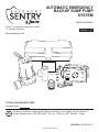 1
1
-
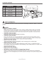 2
2
-
 3
3
-
 4
4
-
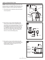 5
5
-
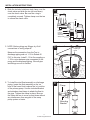 6
6
-
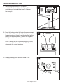 7
7
-
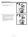 8
8
-
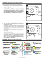 9
9
-
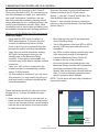 10
10
-
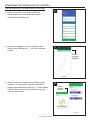 11
11
-
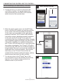 12
12
-
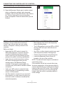 13
13
-
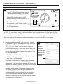 14
14
-
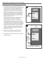 15
15
-
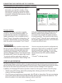 16
16
-
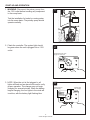 17
17
-
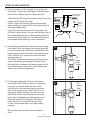 18
18
-
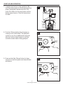 19
19
-
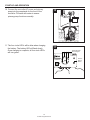 20
20
-
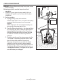 21
21
-
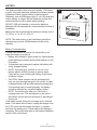 22
22
-
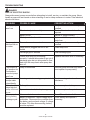 23
23
-
 24
24
-
 25
25
-
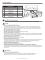 26
26
-
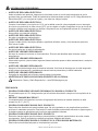 27
27
-
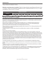 28
28
-
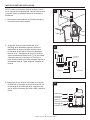 29
29
-
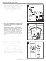 30
30
-
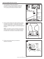 31
31
-
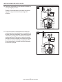 32
32
-
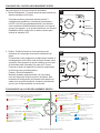 33
33
-
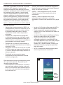 34
34
-
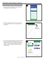 35
35
-
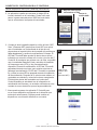 36
36
-
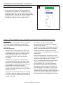 37
37
-
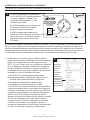 38
38
-
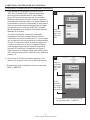 39
39
-
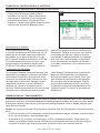 40
40
-
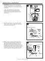 41
41
-
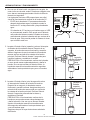 42
42
-
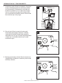 43
43
-
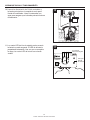 44
44
-
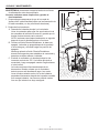 45
45
-
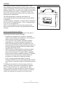 46
46
-
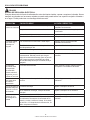 47
47
-
 48
48


Zoeller STBB300 Instrucciones de operación
- Tipo
- Instrucciones de operación
en otros idiomas
Artículos relacionados
-
Zoeller STBB300 Manual de usuario
-
Zoeller STBS700 Instrucciones de operación
-
-
-
-
-
-
-
-
Otros documentos
-
 Basement Sentry STBB100 Instrucciones de operación
-
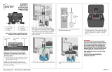 Basement Sentry STBB100 Manual de usuario
-
RIDGID RSM33 Guía de instalación
-
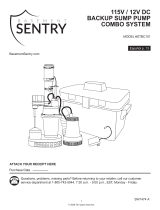 Basement Sentry 12V DC Instrucciones de operación
-
Wayne BGSP50 El manual del propietario
-
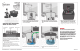 Basement Sentry STBC101 Manual de usuario
-
Simer Battery Backup 5300 El manual del propietario
-
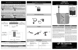 CSI Controls CSION 3R Alarm System Manual de usuario
-
Hydromatic FG-3100RF Battery Backup System El manual del propietario
-


