Craftsman 12521417 El manual del propietario
- Categoría
- Taladros combi inalámbricos
- Tipo
- El manual del propietario

OPERATOR
′
S MANUAL
MANUAL DEL USUARIO
Conserve este manual para futura referencia.
* Maximum initial battery voltage (measured without workload) is 20 volts.
Nominal working voltage is 18 volts.
* La tensión inicial máxima de la batería (medida sin carga) es 20 voltios.
La tensión de trabajo nominal es 18 voltios.
Sears Brands Management Corporation, Hoffman Estates, IL 60179 USA
Save this manual for future reference.
ADVERTENCIA:
Para reducir el riesgo de lesiones, el usuario debe leer y
comprender el manual antes de utilizar este producto.
WARNING:
To reduce the risk of injury, the user must read and understand
the Operator’s Manual before using this product.
20V MAX* LITHIUM-ION
CORDLESS DRILL/DRIVER AND IMPACT DRIVER KIT
ENSEMBLE DE COMBINACIÓN DES TALADRO-DESTORNILLADOR
Y DESTORNILLADOR DE IMPACTO
CON BATERÍA DE IONES DE LITIO DE 20V MÁX*
Model No. 125.21417
(INCLUDES (2) batteries and charger)
Número de modelo. 125.21417
(INCLUYE (2) baterías y cargador)

2 ― English
CRAFTSMAN LIMITED WARRANTY
FOR ONE YEAR from the date of sale this power tool and any supplied battery pack or charger is
warranted against defects in material or workmanship.
WITH PROOF OF SALE a defective product will be replaced free of charge.
For warranty coverage details to obtain free replacement, visit the web page:
www.craftsman.com/warranty
This warranty does not cover the bit, which is an expendable part that can wear out from normal use within
the warranty period.
This warranty applies for only 90 days from the date of sale if this product is ever used while providing
commercial services or if rented to another person.
This warranty gives you specic legal rights, and you may also have other rights which vary from state to
state.
Sears Brands Management Corporation, Hoffman Estates, IL 60179
* * *
GARANTÍA LIMITADA CRAFTSMAN
DURANTE UN AÑO a contar de la fecha de venta, esta herramienta y la batería incluida con ella están
garantizadas contra defectos en sus materiales o fabricación.
Un producto defectuoso será reemplazado de manera gratuita contra presentación de una PRUEBA DE
VENTA.
Para conocer la cobertura de la garantía y obtener un reemplazo gratuito, visite el sitio Web:
www.craftsman.com/warranty
Esta garantía no cubre la broca, la cual es una pieza desechable que puede desgastarse debido al uso
normal dentro del periodo de garantía.
La garantía se aplica durante un periodo de solo 90 días si el producto se usa para proporcionar servicios
comerciales o si se le arrienda a otra persona.
Esta garantía le entrega derechos legales especícos que pueden variar según su estado (podría tener otros
derechos adicionales).
Sears Brands Management Corporation, Hoffman Estates, IL 60179
INTRODUCTION / INTRODUCCIÓN
TABLE OF CONTENTS / TABLA DE CONTENIDOS
These tools have many features for making its use more pleasant and enjoyable. Safety, performance,
and dependability have been given top priority in the design of this product making it easy to maintain and
operate.
* * *
Esta herramienta tiene muchas funciones para hacerla más agradable y cómoda de usar. Se ha dado
máxima prioridad a la seguridad, rendimiento y dependencia en las etapas de diseño de este producto
para que sea fácil de utilizar y mantener.
ENGLISH
■ Warranty ................................................................ 2
■ Introduction ............................................................ 2
■ Safety Instructions .............................................. 3-5
■ Symbols ............................................................. 6-7
■ Features ............................................................ 8-9
■ Assembly ............................................................. 10
■
Operation For Drill/Driver .........................11-14
■
Operation For
Impact Driver .........................15-16
■
Operation For
Battery & Charger ...................16-17
■ Care & Maintenance ........................................18-19
■ Environmentally Safe Battery Disposal..................20
■ Troubleshooting ................................................... 21
■ Illustrated Parts List ........................................ 22-23
■ Figure Numbers (Illustrations) ............................ i-vi
ESPAÑOL
■ Garantía ............................Sección de Inglés pág. 2
■ Introducción ......................Sección de Inglés pág. 2
■ Instrucciones de seguridad ................................ 3-6
■ Símbolos ............................................................ 7-8
■ Características ................................................. 9-10
■ Armado ................................................................ 11
■ Uso del taladro/destornillador...........................12-15
■ Uso del destornillador de impacto......................16-17
■ Uso de la batería y cargador.............................17-19
■ Cuidado y mantenimiento.................................19-21
■ Eliminación ambientalmente segura de la batería..21
■ Resolución de problemas..................................... 22
■ Lista de piezas, ilustrada........................ 23-24
■ Números de las guras (ilustraciones)................ i-vi

3 ― English
WARNING
Read and understand all instructions. Failure
to follow all instructions listed below may result
in electric shock, re and/or serious personal injury.
Save all warnings and instructions for future
reference. The term “power tool” in the warnings
refers to your mains-operated
(corded) power
tool or battery-operated (cordless) power tool.
WORK AREA SAFETY
■ Keep work area clean and well lit. Cluttered
or dark areas invite accidents.
■ Do not operate power tools in explosive
atmospheres, such as in the presence of
ammable liquids, gases or dust. Power
tools create sparks which may ignite the dust
or fumes.
■ Keep children and bystanders away while
operating a power tool. Distractions can
cause you to lose control.
ELECTRICAL SAFETY
■ Power tool plugs must match the outlet.
Never modify the plug in any way. Do not
use any adaptor plugs with earthed
(grounded) power tools. Unmodied plugs
and matching outlets will reduce risk of
electric shock.
■ Avoid body contact with earthed or grounded
surfaces such as pipes, radiators, ranges
and refrigerators. There is an increased risk
of electric shock if your body is earthed or
grounded.
■ Do not expose power tools to rain or wet
conditions. Water entering a power tool will
increase the risk of electric shock.
■ Do not abuse the cord. Never use the cord
for carrying, pulling or unplugging the power
tool. Keep cord away from heat, oil, sharp
edges or moving parts. Damaged or
entangled cords increase the risk of electric
shock.
■ When operating a power tool outdoors,
use an extension cord suitable for outdoor
use. Use of a cord suitable for outdoor use
reduces the risk of electric shock.
■ If operating a power tool in a damp location
SAFETY INSTRUCTIONS
is unavoidable, use a ground fault circuit
interrupter (GFCI) protected supply. Use of
a GFCI reduces the risk of electric shock.
PERSONAL SAFETY
■ Stay alert, watch what you are doing and
use common sense when operating a
power tool. Do not use tool while tired or
under the inuence of drugs, alcohol, or
medication. A moment of inattention while
operating power tools may result in serious
personal injury.
■ Use personal protective equipment. Always
wear eye protection. Protective equipment
such as dust mask, non-skid safety shoes,
hard hat, or hearing protection used for
appropriate conditions will reduce personal
injuries.
■ Prevent unintentional starting. Ensure the
switch is in the off-position before
connecting to power source and/or battery
pack, picking up or carrying the tool.
Carrying power tools with your nger on the
switch or energizing power tools that have
the switch on invites accidents.
■ Remove any adjusting key or wrench
before turning the power tool on. A wrench
or a key left attached to a rotating part of
the power tool may result in personal injury.
■ Do not overreach. Keep proper footing
and balance at all times. This enables
better control of the power tool in
unexpected situations.
■ Dress properly. Do not wear loose clothing
or jewelry. Keep your hair, clothing and
gloves away from moving parts. Loose
clothes, jewelry or long hair can be caught
in moving parts.
■ If devices are provided for the connection
of dust extraction and collection facilities,
ensure these are connected and properly
used. Use of these devices can reduce dust
related hazards.
POWER TOOL USE AND CARE
■ Use only with compatible Craftsman 20V
Max powered by DieHard slide-type
lithium-ion battery packs.

4 ― English
■ Do not use the power tool if the switch
does not turn it on and off. Any power tool
that cannot be controlled with the switch is
dangerous and must be repaired.
■ Disconnect the plug from the power source
and/or the battery pack from the power tool
before making any adjustments, changing
accessories, or storing power tools. Such
preventive safety measures reduce the risk
of starting the power tool accidentally.
■ Store idle power tools out of the reach of
children and do not allow persons unfamiliar
with the power tool or these instructions
to operate the power tool. Power tools are
dangerous in the hands of untrained users.
■ Maintain power tools. Check for
misalignment or binding of moving parts,
breakage of parts and any other condition
that may affect the power tool’s operation.
If damaged, have the power tool repaired
before use. Many accidents are caused by
poorly maintained power tools.
■ Keep cutting tools sharp and clean.
Properly maintained cutting tools with sharp
cutting edges are less likely to bind and are
easier to control.
■ Use the power tool, accessories and
tool bits etc. in accordance with these
instructions, taking into account the working
conditions and the work to be performed.
Use of the power tool for operations
different from those intended could result in
a hazardous situation.
■ Hold power tool by insulated gripping
surfaces when performing an operation
where the cutting accessory may contact
hidden wiring. Cutting accessory contacting
a "live" wire may make exposed metal parts
of the power tool "live" and could give the
operator an electric shock.
■ Know your power tool. Read Operator's
Manual carefully. Learn its applications and
limitations, as well as the specic potential
hazards related to this power tool. Following
this rule will reduce the risk of electric
shock, re, or serious injury.
■ Always wear eye protection with side
shields marked to comply with ANSI
Z87.1 when assembling parts, operating
the tool, or performing maintenance.
Following this rule will reduce the risk of
serious personal injury.
■ Protect your lungs. Wear a face or dust
mask if the operation is dusty. Following
this rule will reduce the risk of serious
personal injury.
■ Protect your hearing. Wear hearing
protection during extended periods of
operation. Following this rule will reduce
the risk of serious personal injury.
■ Battery tools do not have to be plugged
into an electrical outlet; therefore, they
are always in operating condition. Be
aware of possible hazards when not
using your battery tool or when changing
accessories. Following this rule will
reduce the risk of electric shock, re, or
serious personal injury.
■ Do not use on an unstable support.
Stable footing on a solid surface enables
better control of the power tool in
unexpected situations.
■ Do not force the power tool. Use the
correct power tool for your application.
The correct power tool will do the job
better and safer at the rate for which it
was designed.
BATTERY PACK
■ Use only with compatible Craftsman
20V Max powered by DieHard slide-type
lithium-ion battery chargers and power
tools.
■ Recharge only with the charger specied
by the manufacturer and listed in the
Product Specications in this manual.
A charger that is suitable for one type of
battery pack may create a risk of re
when used with another battery pack.
■ Do not charge battery in a damp or wet
location. Following this rule will reduce
the risk of electric shock.
■ Do not place battery powered tools or
their batteries near re or heat. This will
reduce the risk of explosion and possibly
injury.
■ Do not open or mutilate the batteries.
Released electrolyte is corrosive and may
cause damage to the eyes or skin. It may
be toxic if swallowed.
SAFETY INSTRUCTIONS

5 ― English
■ Do not dispose of battery packs in re.
They will explode or leak and cause injury.
Liquid ejected from the battery may cause
irritation or burns.
■ Do not crush, drop or damage the battery
pack. Do not use a battery pack that has
been dropped or received a sharp blow.
A damaged battery is subject to explosion.
Properly dispose of a dropped or damaged
battery immediately.
■ Batteries can explode in the presence of
a source of ignition, such as a pilot light.
To reduce the risk of serious personal
injury, never use any cordless product in
the presence of open ame. An exploded
battery can propel debris and chemicals. If
exposed, ush with water immediately.
■ For best results, your battery tool should be
charged in a location where the temperature
is between 40°F (4°C) and 100°F (38°C).
To reduce the risk of serious personal
injury, do not store outside or in vehicles.
■ Under extreme usage or temperature
conditions, battery leakage may occur;
liquid may be ejected from the battery:
avoid contact. If liquid gets on your skin,
wash immediately with soap and water,
then neutralize with lemon juice or vinegar.
If liquid gets into your eyes, ush them with
clean water for at least 10 minutes, then
seek immediate medical attention.
Following this rule will reduce the risk of
serious personal injury.
■ When battery pack is not in use, keep it
away from other metal objects like: paper
clips, cons, keys, nails, screws, or other
small metal objects that can makes a
connection from one terminal to another.
Storing the battery terminals together may
cause sparks, burns, or a re.
BATTERY CHARGER
■ Use only with compatible Craftsman 20V
Max powered by DieHard slide-type
lithium-ion battery packs.
■ To reduce the risk of injury, charge only
the specied lithium-ion rechargeable
batteries. This charger is compatible with
only Craftsman 20V Max powered by
SAFETY INSTRUCTIONS
DieHard slide-type lithium-ion battery
packs. Other types of batteries may burst,
causing personal injury of damage.
■ Do not charge battery in a damp or wet
location. Following this rule will reduce the
risk of electric shock.
■ Keep cord and charger from heat to prevent
damage to housing or internal parts.
■ Do not operate charger with a damaged
cord or plug, which could cause shorting
and electric shock. If damaged, immediately
discontinue use. Replace the charger with
the identical unit as listed in the Product
Specications in this manual.
■ Do not use a charger that has been
dropped or received a sharp blow.
■ Do not disassemble charger. Take it
to a qualied service center to be checked
or replaced. Incorrect reassembly may
result in a risk of electric shock or re.
■ Do not abuse the charger cord. Never use
the cord for carrying, pulling or unplugging.
Keep cord away from heat, oil, sharp edges
or moving parts. Damaged or entangled
cords increase the risk of electric shock.
If the charger cord is damaged, replace the
charger with an identical model as listed in
the Product Specications in this manual.
■ A charger that is suitable for one type of
battery pack may create a risk of re when
used with another battery pack.
■
Save these instructions.
Refer to them frequently and use them to
instruct others who may use this product.
If you loan someone this product, loan them
these instructions also.
CALIFORNIA PROPOSITION 65
WARNING
Drilling, sawing, sanding or machining wood
products can expose you to wood dust, a
substance known to the State of California
to cause cancer. Avoid inhaling wood dust
or use a dust mask or other safeguards for
personal protection.
For more information go to:
www.P65Warnings.ca.gov/wood
Wash hands after handling.

6 ― English
SYMBOLS
Some of the following symbols may be used on this product. Please study them and
learn their meaning. Proper interpretation of these symbols will allow you to operate
the product better and safer.
V Volts Voltage
A Amperes Current
Hz Hertz Frequency (cycles per second)
W Watt Power
min Minutes Time
Alternating Current Type of current
Direct Current Type or a characteristic of current
Rotational speed, at no load
Class II Construction Double-insulated construction
.../min Per Minute
Revolutions, strokes, surface speed,
orbits, etc., per minute
Wet Conditions Alert
Do not expose to rain or use in damp
locations.
Read The Operator’s Manual
To reduce the risk of injur
y, user must
re
ad and understand operator’s manual
before using this product.
Safety Alert Precautions that involve your safety.
No-Hands Symbol
Failure to keep your hands away from the
blade will result in serious personal injury.
Hot Surface
To reduce the risk of injury or damage,
avoid contact with any hot surface.
SYMBOL NAME DESIGNATION/EXPLANATION
No-load Speed
Eye protection
Keep Away From Water
Do not dispose of battery packs in
rivers or immerse in water.
Keep Away From Fire
Do not dispose of battery packs in
explode or leak and cause injury.
Heat Alert
Do not expose battery packs to heat
in excess of 60ºC.
Lithium-Ion Battery Recycling
Recycle Symbol
This product uses lithium-ion batteries. Local, state,
or federal laws may prohibit disposal of batteries in
ordinary trash. Consult your local waste authority
for information regarding available recycling and/or
disposal options.
Designates that this tool is in compliance with
lithium-ion battery recycling program requirements.
Always wear eye protection with side
shields marked to comply with ANSI Z87.1.

7 ― English
SYMBOLS
SYMBOL SIGNAL MEANING
DANGER
Indicates an imminently hazardous situation, which, if not
avoided, will result in death or serious injury.
WARNING
Indicates a potentially hazardous situation, which, if not
avoided, could result in death or serious injury.
CAUTION
Indicates a potentially hazardous situation, which, if not
avoided, may result in minor or moderate injury.
NOTICE
(Without Safety Alert Symbol) Indicates a situation that may
result in property damage.
The following signal words and meanings are intended to explain the levels of risk
associated with this product.

8 ― English
FEATURES
PRODUCT SPECIFICATIONS
Drill / Driver
Model No. ................................................................................................................ 125.DD20A
Type...................................................................................................Cordless, battery-powered
Motor.................................................................................................................... 20 V max* d.c.
Chuck.................................................................................................................. 1/2 in (13 mm)
No-load Speed.........................................................................0-350 rpm (LO) / 0-1300 rpm (HI)
Clutch...................................................................................................................19+1 position
Maximum Torque………...............................................................…………...…………300 in-lbs
Weight
(
with included battery
)
................................................................................... 3.1 lbs
Impact Driver
Model No. ................................................................................................................. 125.ID20A
Type...................................................................................................Cordless, battery-powered
Motor.................................................................................................................... 20 V max* d.c.
Quick Release Chuck Size..........................................................................1/4 in (6.35 mm) hex
No-load Speed....................................................................................................... 0
-
2500 rpm
Impact Frequency................................................................................................... 0
-
3100 ipm
Maximum Torque…………....................................................………………………1100 in-lbs
Weight
(
with included battery
)
....................................................................................... 2.8 lbs
Battery
Model No. ................................................................................................................125.BL2015
Type ...........................................................................................................Lithium-lon
Battery Voltage ..........................................................................................20 V max* d.c.
Battery Capacity..................................................................................................1.5 Ah
Charger
Model No. ....................................................................................................................125.CL05
Rated Input Voltage/Frequency.........................................................120 V/60 Hz a.c.
Rated Output Voltage.....................................................................................20 V max* d.c.
Rated Output Current................................................................................................. 0.5 A
Optimum Charging Temperature......................................................40°F (4°C) to 100°F (38°C)

9 ― English
KNOW YOUR DRILL
See Figure 1, page i
The safe use of this product requires an
understanding of the information on the
product labeling and in this Operator’s
Manual as well as a knowledge of the
project you are attempting. Before use of this
product, familiarize yourself with all operating
features and safety rules.
ADJUSTABLE TORQUE CLUTCH
The drill has a 19+1 position clutch: The
torque adjustment clutch can be turned to
select the best torque for your application.
TWO-SPEED GEARBOX
The two-speed gearbox is designed for
driving or drilling at either LO or HI speeds.
A slide switch is located on top of the tool for
selecting the appropriate speed range.
VARIABLE SPEED
The variable-speed trigger switch delivers
higher speed with increased trigger
pressure and lower speed with decreased
trigger pressure within the selected speed
range.
KEYLESS CHUCK
The keyless chuck allows you to hand-tighten
or release the bit in the chuck jaws.
MODE SELECTOR (on the adjustable
torque clutch)
The mode selector allows you to select
among the following modes:
Driver mode (1-19 positions), and Drill mode
( ).
FORWARD / CENTER-LOCK / REVERSE
SELECTOR
The drill has a direction-of-rotation selector
located above the trigger switch for changing
the direction of bit rotation.
Set the selector in the OFF (center-lock)
position to reduce the possibility of accidental
starting when tool is not in use.
FEATURES
LED WORKLIGHT
The LED worklight, located above the trigger
switch of the drill, illuminates when the trigger
switch is depressed. This feature provides
extra light for increased visibility.
KNOW YOUR IMPACT DRIVER
See Figure 16, page iv
The safe use of this product requires an
understanding of the information on the
product labeling and in this Operator’s
Manual as well as a knowledge of the
project you are attempting. Before use of this
product, familiarize yourself with all operating
features and safety rules.
VARIABLE SPEED
The variable-speed trigger switch delivers
higher speed with increased trigger pressure
and lower speed with decreased trigger
pressure within the selected speed range.
QUICK RELEASE CHUCK
The quick release chuck allows you to quickly
and easily install or remove the driver bit.
FORWARD / CENTER-LOCK / REVERSE
SELECTOR
The impact driver has a direction-of-rotation
selector located above the trigger switch for
changing the direction of bit rotation.
Set the selector in the OFF (center-lock)
position to reduce the possibility of accidental
starting when tool is not in use.
LED WORKLIGHT
The LED worklight, located above the trigger
switch of the impact driver, illuminates when
the trigger switch is depressed. This feature
provides extra light for increased visibility.

10 ― English
ASSEMBLY
WARNING:
If any parts are broken or
missing, do not attempt to attach the battery
pack or operate the drill until the broken or
missing parts are replaced. Failure to do so
could result in possible serious injury.
WARNING:
Do not attempt to
modify this drill or create accessories not
recommended for use with this tool. Any such
alteration or modication is misuse and could
result in a hazardous condition leading to
possible serious injury.
WARNING:
To prevent accidental
starting that could cause serious personal
injury, always remove the battery pack from
the tool when changing bits.
UNPACKING
This product requires assembly.
■ Carefully remove the product and any
accessories from the box. Make sure that
all items listed in the packing list are
included.
WARNING!
Do not use this product
if any parts on the Packing List are already
assembled to your product when you unpack
it. Parts on this list are not assembled to the
product by the manufacturer and require
customer installation. Use of a product that
may have been improperly assembled could
result in serious personal injury.
■ Inspect the product carefully to make sure
no breakage or damage occurred during
shipping.
■ Do not discard the packing material until
you have carefully inspected and
satisfactorily operated the product.
■ If any parts are damaged or missing, do not
operate the product. Return it for
replacement to the retailer from which it
was purchased.
PACKING LIST
(1) 20V Cordless Drill / Driver
(1) 20V Cordless Impact Driver
(2) 20V,1.5Ah Li-ion Batteries
(2) Driver Bits
(1) 0.5A Charger
(1) Operator's Manual

11 ― English
This product will accept Craftsman 20V
Max powered by DieHard slide-type
lithium-ion battery packs. For complete
charging instructions, refer to the Operator’s
Manual for the battery packs and chargers.
WARNING:
To prevent accidental
starting that could cause serious personal
injury, always remove the battery pack from
the tool when assembling parts, making
adjustments, installing or removing bit,
cleaning, or when it is not in use.
TO ATTACH BATTERY PACK
See Figure 2, page ii
To install the battery pack, align the tongue
on the battery pack with the groove in the
housing and slide it into place. Insert it all the
way until it locks in place with a click.
OPERATION FOR DRILL/DRIVER
NOTICE:
Make sure that the latch on the
battery pack snaps into place and the battery
pack is secured to the tool before beginning
operation. Improper assembly of the
battery pack can cause damage to internal
components.
TO DETACH BATTERY PACK
See Figure 2, page ii
To remove the battery pack, slide it from the
tool while pressing the button on the front of
the pack.
WARNING:
Battery tools are always in
operating condition. To prevent accidental
starting, always set the direction-of-rotation
selector to the OFF position when the tool is
not in use or when carrying the tool at your
side. Always carry the tool by its hand grip.
VARIABLE-SPEED TRIGGER SWITCH
See Figure 3, page ii
To turn the tool ON, depress the trigger
switch. To turn it OFF, release the
trigger switch.
The variable-speed trigger switch delivers
higher speed with increased trigger pressure
and lower speed with decreased trigger
pressure.
DIRECTION-OF-ROTATION SELECTOR
(FORWARD / CENTER-LOCK / REVERSE)
See Figure 4, page ii
The direction of bit rotation is reversible and
is controlled by a selector located above the
trigger switch. With the tool held in normal
operating position, as shown in
Figure 4.
1. Position the direction-of-rotation selector
to the left of the tool for forward rotation.
2. Position the direction-of-rotation selector
to the right of the tool for reverse.
3. Set the selector in the OFF (center-
lock) position to reduce the possibility of
accidental starting when tool is not in use.
NOTICE:
To prevent gear damage, always
allow the tool to come to a complete stop
before changing the direction-of-rotation.
NOTICE:
The tool will not run unless the
direction-of-rotation selector is engaged fully
to the left or right.
ELECTRIC BRAKE
To stop the tool, release the trigger switch
and allow the tool to come to a complete
stop. The electric brake quickly stops the
chuck from rotating. This feature engages
automatically when you release the trigger
switch.
LED WORKLIGHT
See Figure 5, page ii
The LED worklight, located above the
trigger switch of the drill, will illuminate
when the trigger switch is depressed. This
provides additional light on the surface of the
workpiece. The LED worklight will turn off
when the trigger switch is released.
KEYLESS CHUCK
See Figure 6, page ii
The drill has a keyless chuck to tighten or
release bits in the chuck jaws. The arrows on
the chuck indicate the direction in which to
rotate the chuck in order to GRIP (tighten) or
RELEASE (open) the chuck jaws on the bit.

12 ― English
Use LO speed for high power and high
torque applications; use HI speed for fast
drilling, driving or drilling applications. When
using the tool in the LO speed range, the
speed will decrease and the tool will have
more power and torque. Use LO speed for
starting holes without a center punch, drilling
metals or plastic, drilling ceramics, drilling
holes in brick, concrete or in applications
requiring a higher torque. HI speed is better
for drilling wood and wood composites and
for using abrasive and polishing accessories.
OPERATION FOR DRILL/DRIVER
WARNING:
Do not hold the chuck with
one hand and use the power of the tool to
tighten the chuck jaws on the bit. The chuck
could slip in your hand, or your hand could
slip and come in contact with the rotating
bit. This could cause an accident resulting in
serious personal injury.
TWO-SPEED GEARBOX
See Figure 7, page ii
The tool has a two-speed gearbox for
drilling or driving at LO or HI speeds. A slide
switch is located on the top of the tool to
select either LO or HI speed.
1. For LO speed, slide the switch to the side
with the mark “1”.
2. For HI speed, slide the switch to the side
with the mark “2”.
NOTICE:
Avoid running the tool at HI speed
for extended periods of time. Running at HI
speed under constant usage may cause the
tool to become overheated. If this occurs,
cool the tool by running it without a load at
LO speed.
NOTICE:
Never change gears while the tool
is running. Failure to obey this caution could
result in serious damage to the tool.
MODE SELECTOR
See Figure 7, page ii
The tool is equipped with a selector for
driving different types of screws/nuts/holes
into different materials. To use the torque
setting, rotate the mode selector to the driver
mode (1-19 positions), or drill mode ( ).
The proper setting depends on the type of
material and the application.
ADJUSTABLE-TORQUE CLUTCH
See Figure 8, page ii
The higher the torque setting, the more force
the drill produces to turn an object in either
LO or HI rotation speed. When using the drill
for different driving applications, increase or
decrease the torque in order to help prevent
damage to screw heads, threads, workpieces,
etc.
Adjust the torque by rotating the torque-
adjustment ring. The proper setting depends
on the job and the type of bit, fastener, and
material you will be using. In general, use
greater torque for larger screws. If the torque
is too high, the screws may be damaged
or broken. For delicate operations, such as
removing a partially stripped screw, use a low
torque setting. For operations such as drilling
into hardwood, use a higher
torque setting.
NOTICE:
When adjusting the torque clutch
make sure that the speed switch is either
completely in the LO or HI position.
NOTICE:
Do not change the torque setting
when the tool is running.
INSTALLING BITS
See Figure 9, page ii
1. Lock the trigger switch by placing the
direction-of-rotation selector in the OFF
(center-lock) position.
2. Open or close the chuck jaws to a point
where the opening is slightly larger than
the bit you intend to use.
3. Raise the front of the drill slightly to keep
the bit from falling out of the chuck jaws.
4. Insert a bit.
5. Rotate the chuck in the direction of the
arrow marked GRIP to close the chuck
jaws.
NOTICE:
Do not use a wrench to tighten or
loosen the chuck jaws.
6. Tighten the chuck jaws securely on the bit.
NOTE:
When the bit is xed in chuck jaws,
you will hear a ‘click’.

13 ― English
OPERATION FOR DRILL/DRIVER
WARNING:
Make sure to insert the bit
straight into the chuck jaws. Do not insert the
bit into the chuck jaws at an angle and then
tighten, as shown in gure 10. This could
cause the bit to be thrown from the tool,
resulting in possible serious personal injury
or damage to the chuck.
REMOVING BITS
See Figure 9, page ii
1. Lock the trigger switch by placing the
direction-of-rotation selector in the OFF
(center-lock) position.
2. Open the chuck jaws by rotating the
chuck in the direction of the arrow marked
RELEASE.
NOTICE:
Do not use a wrench to tighten or
loosen the chuck jaws.
3. Remove the bit.
DRILLING HOLES OR DRIVING SCREWS
See Figure 11, page iii
1. Rotate the mode selector to the drill
position or one of the 19 driver torque
positions.
2. Check that the direction-of-rotation
selector is at the correct setting (forward
or reverse).
3. Use LO (1) speed for torque applications
and HI (2) speed for fast drilling or driving
applications. Refer to Two-Speed Gear
Box and Adjustable Torque Clutch.
4. When possible, secure the material in a
vise or with clamps to keep it from turning
when drilling or driving.
5. Hold the tool rmly, and place the bit at the
point to be drilled, or where the screw is to
be driven.
6. Depress the trigger switch to start the tool.
7. Move the bit into the workpiece, applying
only enough pressure to keep the bit
cutting. Do not force the tool or apply side
pressure to elongate a hole. Let the tool
do the work.
8. When drilling or driving into hard, smooth
surfaces, use a center punch to mark
the desired location of the hole. This will
prevent the bit from slipping off-center as
the hole is started.
9. If the bit jams when drilling into the
workpiece or if the tool stalls, stop the
tool immediately. Remove the bit from the
workpiece and determine the reason for
jamming.
NOTICE:
This tool is equipped with an
electric brake. When the brake is functioning
properly, sparks may be visible through the
vent slots in the housing. This is normal and
results from the action of the brake.
WOOD DRILLING
For maximum performance, use high-speed
steel or brad-point bits for wood drilling.
1. Select drill mode ( ).
2. Begin drilling at a very low speed to
prevent the bit from slipping off the starting
point.
3. Increase speed as the drill bit bites into the
material.
4. When drilling a “through” hole, place a
block of wood behind the workpiece to
prevent ragged or splintered edges on the
back side of the hole.
METAL DRILLING
For maximum performance, use high speed
steel bits for metal or steel drilling.
1. When drilling metals, use light oil on the
drill bit to keep it from overheating. The oil
will prolong the life of the bit and increase
the drilling action.
2. Select drill mode ( ).
3. Begin drilling at a very low speed to
prevent the bit from slipping off the starting
point.
4. Maintain a speed and a pressure which
allow cutting without overheating the bit.
Applying too much pressure will:
• Overheat the drill
• Wear the bearings
• Bend or burn bits
• Produce off-center or irregularly shaped
holes
5. When drilling large holes in metal, start
with a small bit, then nish with a larger
bit.

14 ― English
OPERATION FOR DRILL/DRIVER
WARNING:
To avoid serious personal
injury, always remove the battery pack from
the tool when cleaning or performing any
maintenance.
WARNING:
Always wear safety goggles
or safety glasses with side shields when
using compressed air to clean the tool. If the
operation is dusty, also wear a dust mask.
Belt Hook (Available Separately)
See Figure 12, page iii
A belt hook is available for separate purchase.
The hook enables you to conveniently hang
the tool from your belt when tool is not in use.
Install the hook on either side of the tool.
Insert the tab of the hook into the slot in the
tool base. Secure the hook by tightening the
screw through the hole in the hook into the
hole in the base.
To purchase the hook, see Replacement
Parts on page 22 of this manual.

15 ― English
WARNING:
Battery tools are always in
operating condition. To prevent accidental
starting, always set the direction-of-rotation
selector to the OFF position when the tool is
not in use or when carrying the tool at your
side. Ordinarily, always carry the tool by its
hand grip. If the tool is tted with a belt hook,
it may be hung from your belt.
VARIABLE-SPEED TRIGGER SWITCH
See Figure 18, page v
To turn the impact driver ON, depress the
trigger switch. To turn it OFF, release the
trigger switch.
The variable-speed trigger switch delivers
higher speed with increased trigger pressure
and lower speed with decreased trigger
pressure.
This product will accept Craftsman 20V
Max powered by DieHard slide-type
lithium-ion battery packs. For complete
charging instructions, refer to the Operator’s
Manual for the battery packs and chargers.
WARNING:
To prevent accidental
starting that could cause serious personal
injury, always remove the battery pack from
the tool when assembling parts, making
adjustments, installing or removing a bit,
cleaning, or when it is not in use.
TO ATTACH BATTERY PACK
See Figure 17, page v
To install the battery pack, align the tongue
on the battery pack with the groove in the
housing and slide it into place. Insert it all the
way until it locks in place with a click.
OPERATION FOR IMPACT DRIVER
NOTICE:
Make sure that the latch on the
battery pack snaps into place and the battery
pack is secured to the tool before beginning
operation. Improper assembly of the
battery pack can cause damage to internal
components.
TO DETACH BATTERY PACK
See Figure 17, page v
To remove the battery pack, slide it from the
tool while pressing the button on the front of
the pack.
DIRECTION-OF-ROTATION SELECTOR
(FORWARD / CENTER-LOCK / REVERSE)
See Figure 19, page v
The direction of bit rotation is reversible and
is controlled by a selector located above the
trigger switch. With the impact driver held in
normal operating position, as shown in Fig. 18:
1. Position the direction-of-rotation selector
to the left of the tool for forward rotation.
2. Position the direction-of-rotation selector
to the right of the tool for reverse.
3. Set the selector in the OFF (center-
lock) position to reduce the possibility of
accidental starting when the tool is not in
use.
NOTICE:
To prevent gear damage, always
allow the impact driver to come to a complete
stop before changing the direction-of-rotation.
NOTICE:
The impact driver will not run
unless the direction-of-rotation selector is
engaged fully to the left or right.
ELECTRIC BRAKE
To stop the impact driver, release the trigger
switch and allow the tool to come to a
complete stop. The electric brake quickly
stops the chuck from rotating. This feature
engages automatically when you release the
trigger switch.
LED WORKLIGHT
See Figure 20, page v
The LED worklight, located above the trigger
switch of the impact driver, will illuminate
when the trigger switch is depressed. This
provides additional light on the surface of the
workpiece. The LED worklight will turn off
when the trigger switch is released.
INSTALLING OR REMOVING BIT
See Figure 21, page v
To install the driver bit, pull the sleeve in the
direction of the arrow and insert the driver
bit into the sleeve as far as it will go. Then
release the sleeve to secure the driver bit. To
remove the driver bit, pull the sleeve in the
direction of the arrow and pull the driver bit
out.
NOTE:
Use only driver/socket bits of the
type supplied with the purchase of this impact
driver. See Figure 21, page v. The bits have
grooves near the insertion ends that allow the
sleeve to grip the bit securely. Do not use any

16 ― English
WARNING
■ Do not use other battery chargers. The
battery charger supplied is specically
designed for the lithium-ion battery used
in this tool.
■ Check the main power supply! The voltage
of the power supply must correspond with
the data on the nameplate of the battery
charger. Battery chargers operate on 120V.
■ Charge the battery pack in a location where
the temperature is between 40°F (4°C) and
100°F (38°C). If the battery pack is hot,
allow it to cool down before recharging.
NOTE:
The battery is supplied partially
charged. To ensure full capacity of the
battery, charge the battery in the battery
charger before using the product for the rst
time. The lithium-ion battery can be charged
at any time without reducing its service life.
Interrupting the charging procedure does not
affect the battery.
CHARGER INDICATORS
■ Preparation: The charging process starts
as soon as the battery charger is plugged
into a power supply socket and the battery
is inserted into the charger.
■ If the battery is not inserted, a continuous
green light indicates that the charger is
plugged into a power supply socket and is
now ready to begin charging.
OPERATION FOR BATTERY PACK & CHARGER
BECOME FAMILIAR WITH THE
CHARGER
See Figures 23 & 24, page vi
Before attempting to use this charger,
become familiar with all of its operating
features and safety requirements.
CHARGING THE BATTERY PACK
See Figure 25, page vi
WARNING
■ If any part of the charger is missing or
damaged, do not operate it! Replace the
charger with a new one. Failure to heed
this warning could result in possible serious
injury.
■ Use an electrical testing device to check
the voltage! The voltage must comply with
the information on the rating label.
BATTERY CHARGING PROCEDURE
■ Align the battery pack to the slots on the
charger and slide it in until it locks in place.
■ Connect the charger to the power supply.
■ Allow sufcient charging time (see Product
Specications), and then disconnect the
charger from the power supply.
■ Press the release button on the battery
pack and remove it from the charger.
NOTE:
It is normal for the battery pack
and charger to become warm (but not hot)
during charging process. If the battery does
not charge properly, check to make sure the
electrical outlet is "live".
Always charge the battery before storage!
other type of bit.
NOTE:
If the driver bit is not inserted deep
enough into the sleeve, the sleeve will not
return to its original position and the driver
bit will not be secured. In this case, try re-
inserting the bit according to the instructions
above.
NOTE:
After inserting the driver bit, make
sure that it is rmly secured. If it comes out,
do not use it.
NOTE:
Insert a socket adaptor into the
sleeve to use a socket with the impact driver.
Belt Hook (Available Separately)
See Figure 12, page iii
A belt hook is available for separate
purchase. The hook enables you to
conveniently hang the tool from your belt
when tool is not in use.
Install the hook on either side of the tool.
Insert the tab of the hook into the slot in the
tool base. Secure the hook by tightening the
screw through the hole in the hook into the
hole in the base.
To purchase the hook, see Replacement
Parts on page 22 of this manual.
OPERATION FOR IMPACT DRIVER

17 ― English
OPERATION FOR BATTERY PACK & CHARGER
■ Charging: a continuous red LED on
the charger indicates that the battery is
charging normally.
■ Charged: a continuous green LED on the
charger indicates that the battery is ready
for use.
■ The indicator lights on the charger show
the charger status:
the charger is plugged into, or there is
a technical issue with the battery or the
charger. Try the following steps to isolate
the issue:
1. Disconnect the battery from the charger.
If the light turns green, the issue is with
the battery.
2. If the light remains off after removing the
battery, plug the charger into a different
outlet. If the light still doesn't illuminate,
replace the charger.
3. With the continuous green indicator light
illuminated on the charger, reinstall the
battery. If the light turns off, the battery is
defective; replace the battery.
■ After continuous or repeated charging
cycles without interruption, the charger
surface may become noticeably warm.
This is normal and does not indicate a
technical defect of the battery charger.
WARNING!
To avoid risk of re, electric
shock, or electrocution
:
■ Do not use a damp cloth or detergent on
the battery or battery charger.
■ Always remove the battery pack before
cleaning, inspecting, or performing any
maintenance on the product.
■ The charger ensures maximum battery life
because it measures the existing charge
level of the battery and then charges with
the required current and voltage. Charge
battery fully before storage.
■ Preparing to Charge: a blinking red LED
light indicates that the battery voltage is
abnormally low. This might occur after
a long storage period without use. The
battery is being conditioned and will begin
charging when normal voltage is reached.
- If the charger continues this state for long
time, remove and reinstall the battery
pack.
- If the LED status repeats a second time,
try to charge another identical battery.
- If the new battery charges normally,
dispose of the defective battery pack (see
Environmentally Safe Battery Disposal
section).
- If the red light continues blinking after
installing the second battery, the charger
may be defective. Replace with a new
one.
■ No Power/ Technical Issue: if no indicator
light illuminates on the charger, either
there is no power to the outlet which
SYMBOL
INDICATOR
LIGHTS
STATUS
Red,
Blinking
Red,
Continuous
Charging
Preparing to Charge
Green,
Continuous
Light Off
Power On /
Battery Charged
No Power /
Technical Issue

18 ― English
a clockwise direction. See Figure 14,
page iii
NOTICE:
The chuck screw has reversed
threads.
6. Insert the hex key into the chuck
and tighten the chuck jaws securely.
Tap sharply with a mallet in a
counterclockwise direction. This will
loosen the chuck on the spindle. It can
now be unscrewed by hand, continuing
in a counterclockwise direction. See
Figure 15, page iii.
CHUCK INSTALLATION
1. Lock the trigger switch by placing the
direction-of-rotation selector in the
center position.
2. Screw the new chuck onto the
threaded drive shaft in a clockwise
direction until it is hand-tight.
3. Open the chuck jaws. Insert the
original chuck screw and, using a
Philips screwdriver, secure the screw
by turning it in a counterclockwise
direction.
NOTICE:
The chuck screw has reversed
threads.
4. Put a bit into the tool and check that
the new chuck is tight and does not
wobble; if it wobbles or appears to be
loose, tighten the chuck screw further.
WARNING:
Always wear safety
glasses with side shields during
maintenance.
WARNING:
To ensure safety and
reliability, all repairs should be performed by
a qualied service technician.
WARNING:
To avoid serious personal
injury, always remove the battery pack from
the drill when cleaning or performing any
maintenance.
CARE & MAINTENANCE
WARNING:
When servicing, use only
identical replacement parts as listed in this
manual. Use of any other parts may create a
hazard or cause product damage.
WARNING:
To avoid serious personal
injury, always remove the battery pack from
the tool when cleaning or performing any
maintenance.
GENERAL MAINTENANCE
Avoid using solvents when cleaning plastic
parts. Most plastics are susceptible to
damage from various types of commercial
solvents and may be damaged by their use.
Use clean clothes to remove dirt, dust, oil,
grease, etc.
WARNING:
Do not at any time let brake
uids, gasoline, petroleum-based products,
penetrating oils, etc. come in contact with
plastic parts. Chemicals can damage, weaken
or destroy plastic which may result in serious
personal injury.
WARNING:
When servicing, use only
identical replacement parts as listed in this
manual. Use of any other parts may create a
hazard or cause product damage. To ensure
safety and reliability, all repairs should be
performed by a qualied service technician.
CHUCK REMOVAL
The chuck can be removed and replaced
with a new one.
1. Lock the trigger switch by placing the
direction-of-rotation selector in the
center position.
2. Open the chuck jaws.
3. Insert a 5/16 in. or larger hex key into
the chuck of the drill and tighten the
chuck jaws securely onto the hex key.
4. Tap the hex key sharply with a mallet
in a clockwise direction. This will
loosen the screw in the chuck for easy
removal. See Figure 13, page iii
5. Open the chuck jaws and remove the
hex key. Using a Philips screwdriver,
remove the chuck screw by turning it in

19 ― English
STORAGE
■ Remove the battery pack from the tool
before storing.
■ Clean all foreign material from the tools.
■ Store the tools and its accessories in a dry,
frost free place.
■ Always store the tools in a place that is
inaccessible to children. The ideal storage
temperature is between 40°F (4°C) y 100°F
(38°C).
■ Keep tools away from corrosive agents
such as garden chemicals and de-icing
salts.
■ We recommend using the original package
for storage or covering the product with a
suitable cloth to protect it against dust.
TRANSPORTATION
■ Set the rotation selector to OFF and
remove battery pack before transporting
tool anywhere.
■ Ordinarily, always carry the tool by its hand
grip. If the tool is tted with a belt hook, it
may be hung from your belt.
■ Protect the tool from any heavy impact or
strong vibrations which may occur during
transportation in vehicles.
BATTERY MAINTENANCE
■ Store the battery pack fully charged.
■ Recharge the battery pack whenever there
is a noticeable reduction in tool
performance. Do not allow the battery pack
to become completely discharged.
■ Do not recharge a battery pack that is
already fully charged. Overcharging
shortens battery life.
■ Once the battery pack is fully charged,
remove the battery from the charger and
disconnect the charger from the outlet.
■ Do not store the battery pack on the tool or
in the charger.
■ Charge the battery pack in a location where
the temperature is between 40°F (4°C) y
100°F (38°C). If the battery pack is hot,
allow it to cool down before recharging.
CHARGER MAINTENANCE
■ Keep the charger clean and clear of
debris. Do not allow foreign material into
the recessed cavity or on the contacts.
Wipe with a dry cloth. Do not use solvents,
water, or place in wet conditions.
■ Unplug the charger when there is no
battery pack in it.
■ Store the charger at normal room
temperature. Do not store it in excessive
heat. Do not use the charger in direct
sunlight.
CLEANING
Remove the Battery Pack
■ Brush or blow dust and debris out of the air
vents using compressed air or a vacuum.
■ Keep the air vents free of obstructions,
sawdust, and wood chips. Do not spray,
wash, or immerse the air vents in water.
■ Wipe off the housing and the plastic
components using a moist, soft cloth.
■ Do not use strong solvents or detergents
on the plastic housing or plastic
components. Certain household cleaners
may cause damage, and may cause a
shock hazard.
CARE & MAINTENANCE

20 ― English
ENVIRONMENTALLY SAFE BATTERY DISPOSAL
The following toxic and corrosive materials
are in the batteries used in this battery pack:
lithium-ion, a toxic material.
WARNING:
All toxic materials must be
disposed of in a specied manner to prevent
contamination of the environment. Before
disposing of damaged or worn out
lithium-ion battery packs, contact your
local waste disposal agency, or the local
Environmental Protection Agency for
information and specic instructions.
WARNING:
If the battery pack cracks
or breaks, with or without leaks, do not
recharge it and do not use. Dispose of it and
replace with a new battery pack.
DO NOT ATTEMPT TO REPAIR IT!
To avoid injury and risk of re, explosion, or
electric shock, and to avoid damage to the
environment:
■ Cover the battery terminals with heavy-duty
adhesive tape.
■ DO NOT attempt to remove or destroy any
of the battery pack components.
■ DO NOT attempt to open the battery pack.
■ If a leak develops, the released electrolytes
are corrosive and toxic. DO NOT get the
solution in the eyes or on skin, and do not
swallow it.
■ DO NOT place these batteries in your
regular household trash.
■ DO NOT incinerate.
■ DO NOT place batteries where they will
become part of any waste landll or
municipal solid waste stream.
■ Take batteries to a certied recycling or
disposal center.

21 ― English
TROUBLESHOOTING
PROBLEM CAUSE SOLUTION
Tool will not turn on
Battery is defective Replace with new, charged battery
Switch is dead Tool must be replaced
Brushes are worn out Tool must be replaced
Bit cannot be installed
Chuck is not open (Drill/Driver) Open the chuck
Sleeve is not released (Impact
driver)
Release the sleeve
Bit does not t into the quick-change
chuck (Impact Driver)
Use appropriately sized 1/4 in.
hexagonal quick-change bit.
Motor overheats
Cooling vents are clogged with saw
dust or debris, or are being covered
by hand during operation.
Clear vents with compressed air.
Do not cover vents with hand during
operation.
Two-speed gearbox will not
properly seat into the HI or
LO position.
The gears are not fully engaged.
Run the drill/driver for a few seconds,
then adjust the two-speed gearbox
switch again.

22 ― English
TO PURCHASE REPLACEMENT PARTS, CALL 1-888-331-4569
The model number will be found on a label attached to the motor housing.
8
5
3
4
2
1
7
6
CRAFTSMAN 20V MAX* LITHIUM-ION CORDLESS COMBO KIT-MODEL NUMBER
125.21417

23 ― English
CRAFTSMAN 20V MAX* LITHIUM-ION CORDLESS COMBO KIT-MODEL NUMBER
125.21417
TO PURCHASE REPLACEMENT PARTS, CALL 1-888-331-4569
The model number will be found on a label attached to the motor housing.
ITEM NO. PART NO. DESCRIPTION QTY
1
125 .DD20A-B Drill / Driver Tool Body
1
2
411001102 Chuck
1
3
125 .ID20A-B Impact Driver Tool Body
1
4
411001104 Chuck Sleeve Set
1
5
125 .BL2015 Battery
2
6
125 .CL05 0.5A Charger
1
7
411001107 Driver Bit (set of 2)
1
8
411001108 Belt Hook Set (Available Separately)
0

See this section for all of the gures referenced in the
Operator’s Manual.
(Consulte esta sección para ver todas las guras mencionadas
en el manual del usuario.)
A
.
Torque-Adjustable Ring (Aro de ajuste de torque)
B
.
Two-Speed Gearbox Switch (Selector de dos velocidades)
C
.
Variable-Speed Trigger Switch (Gatillo de velocidad variable)
D
.
Keyless Chuck (Mandril sin llave)
E
.
Direction-of-Rotation Selector (Selector de la dirección de giro)
F
.
LED Worklight (Luz de trabajo LED)
G
.
Battery Pack (Batería)
H. Handgrip (Empuñadura)
Fig.1
i
G
B
F
C
H
D
A
E

A
A. Battery-Release Button (Botón de liberación de la batería)
A
.
Variable-Speed
Trigger Switch
(Gatillo de velocidad variable)
A
A
.
LED Worklight (Luz de trabajo LED)
Fig. 5
RELEASE (LIBERAR)
GRIP (ASEGURAR)
B
A
A
.
Two-speed Gearbox Switch (Selector de dos velocidades)
B
.
Mode Selector (Selector de modo)
A
A
B
To Decrease Torque
(Reducir el torque)
To Increase Torque
(Aumentar el torque)
A
A. Torque-adjustable Ring (Aro de ajuste de torque)
B. Keyless Chuck (Mandril sin llave)
C. Chuck Jaws (Mandíbulas del mandril)
A. Chuck Jaws (Mandíbulas del mandril)
B. Keyless Chuck (Mandril sin llave)
C. Bit (Punta)
B
C
RELEASE (LIBERAR)
GRIP (ASEGURAR)
C
A
B
Fig.2
Fig.6 Fig.7
Fig.9
Fig.8
Fig.4
Fig.3
A
A
.
Direction-Of-Rotation Selector (Selector de la dirección de giro)
A
.
Chuck Jaws (Mandíbulas del mandril)
B
.
Keyless Chuck (Mandril sin llave)
ii

WARNING!
(¡ADVERTENCIA!)
Fig.10
Fig.13
Fig.12
Fig.14
Fig.15
Fig.11
A. Mallet (Mazo)
B. Chuck Jaws (Mandíbulas del mandril)
C. Hex Key (Llave hexagonal)
A
.
Phillips Screwdriver (Destornillador Phillips)
B. Keyless Chuck (Mandril sin llave)
A. Hook (Gancho)
B. Screw (Tornillo)
A
.
Mallet (Mazo)
B
.
Hex Key (Llave hexagonal)
C
.
Chuck Jaws (Mandíbulas del mandril)
iii
A
A
B
B
A
B
A
B
C
A
B
C

See this section for all of the gures referenced in the
Operator’s Manual.
(Consulte esta sección para ver todas las guras mencionadas
en el manual del usuario.)
A. Variable-Speed Trigger Switch (Gatillo de velocidad variable)
B. Quick Release Chuck (Mandril de liberación rápida)
C. Direction-of-Rotation Selector (Selector de la dirección de giro)
D. LED Worklight (Luz de trabajo LED)
E. Battery Pack (Batería)
F. Handgrip (Empuñadura)
Fig.16
iv
B
D
A
F
E
C

A
A
B
A
.
Battery-Release Button
(Botón de liberación de la batería)
A. Bit (Punta)
B. Quick Release Chuck
(Mandril de liberación rápida)
A. LED Worklight (Luz de trabajo LED)
A
A. Direction-Of-Rotation Selector
(Selector de la dirección de giro)
Fig.17
Fig.19
Fig.18
Fig.20
Fig. 21
v
A
Fig.22
A. Belt Hook (Gancho para cinturón)
B. Screw (Tornillo)
B
A
B
A
12 mm
(15/32”)
9 mm
(3/8”)
A
A. Variable-Speed Trigger Switch
(Gatillo de velocidad variable)

See this section for all of the gures referenced in the
Operator’s Manual.
(Consulte esta sección para ver todas las guras mencionadas
en el manual del usuario.)
B
A
C
Fig. 23
Fig. 24
Fig. 25
vi
A. Battery (Batería)
B. Battery Latch (Pestillo de la batería)
C. Release Button (Botón de liberación)
B
A
A. Indicator Light
(
Luces indicadora
)
B. Power Cord
(
Cable
)
A
B
A - Battery (Batería)
B - Charger (Cargador)
.
.

3 ― Español
ADVERTENCIA
Lea y asegúrese de comprender todas las
instrucciones. El incumplimiento de las
instrucciones indicadas a continuación puede
producir descargas eléctricas, incendios o
lesiones graves.
Guarde todas las advertencias e instrucciones
para usarlas como referencia a futuro.
El término “herramienta eléctrica” en las
advertencias se reere a su herramienta con
alimentación regular (con cable) o con batería
(inalámbrica).
SEGURIDAD DEL ÁREA DE TRABAJO
■ Mantenga el área de trabajo limpia y bien
iluminada. Las zonas abarrotadas u oscuras
invitan a que ocurran accidentes.
■ No utilice herramientas eléctricas en
atmósferas explosivas como, por ejemplo,
en presencia de líquidos inamables, gases
o polvo. Las herramientas eléctricas
producen chispas que pueden hacer arder
polvo o gases.
■ Mantenga a niños y transeúntes alejados
cuando esté utilizando una herramienta
eléctrica. Las distracciones pueden provocar
que usted pierda el control.
SEGURIDAD ELÉCTRICA
■ Las herramientas eléctricas deben ser
apropiadas para el tomacorriente a utilizar.
Nunca modique el enchufe de modo
ninguno. No use enchufes adaptadores
con herramientas con conexión a tierra. Los
enchufes no modicados y los
tomacorrientes que les corresponden
reducirán el riesgo de choque eléctrico.
■ Evite el contacto corporal con supercies
conectadas a tierra, como tuberías,
radiadores, hornillos y refrigeradores. Existe
un mayor riesgo de choque eléctrico si su
cuerpo está conectado a tierra.
■ No exponga las herramientas eléctricas
a la lluvia o a condiciones de humedad. Si
entra agua en una herramienta eléctrica, se
incrementará el riesgo de que se produzcan
INSTRUCCIONES DE SEGURIDAD
descargas eléctricas.
■ No maltrate el cable. Nunca utilice el cable
para transportar la herramienta, jalar de
ella o desenchufarla. Mantenga el cable
alejado del calor, de aceites, bordes
alados o partes móviles. Los cables
dañados o enredados incrementan el
riesgo de sacudidas eléctricas.
■ Cuando maneje una herramienta eléctrica
en espacios exteriores, utilice un cable
alargador que sea adecuado para su uso al
aire libre. La utilización de un cable
adecuado para el uso en espacios
exteriores reduce el riesgo de choque
eléctrico.
■ Si no es posible evitar el uso de una
herramienta eléctrica en un entorno
húmedo, use una toma de alimentación
protegida con un interruptor de circuito para
fallas a tierra. Al usar este sistema reducirá
el riesgo de descargas eléctricas.
SEGURIDAD PERSONAL
■ Manténgase alerta, vigile lo que está
haciendo y haga uso de su sentido común
cuando maneje una herramienta eléctrica.
No use la herramienta cuando esté
cansado o bajo la inuencia de drogas,
alcohol o medicamentos. Un solo momento
de falta de atención mientras maneja
herramientas eléctricas puede derivar en
graves lesiones personales.
■ Utilice equipo protector personal. Lleve
siempre protección para los ojos. El
equipo protector, como máscaras contra el
polvo, calzado antideslizante de seguridad,
un casco duro o protección para los oídos,
utilizado en las condiciones adecuadas,
reducirá las lesiones personales.
■ Evite los arranques accidentales.
Asegúrese de que el interruptor se
encuentra en la posición de apagado antes
de conectar la herramienta a la fuente de
corriente o al paquete de batería, al cogerla
o al transportarla. Transportar herramientas
eléctricas con el dedo en el interruptor
o herramientas eléctricas energéticas
que tengan el interruptor en la posición

4― Español
de encendido invita a que se produzcan
accidentes.
■ Quite cualquier herramienta o llave de
ajuste antes de encender la máquina. Una
herramienta o llave que se haya quedado
adosada a una pieza giratoria de la
máquina puede producir lesiones
personales.
■ No se extralimite. Mantenga los pies
en tierra rme y el equilibrio en todo
momento. Esto posibilita un mejor control
de la herramienta eléctrica en situaciones
imprevistas.
■ Lleve ropa adecuada. No se ponga prendas
anchas o joyas. Mantenga el pelo, la ropa
y los guantes alejados de las piezas
móviles. Las ropas que le queden sueltas,
las joyas o el pelo largo pueden quedar
atrapados en las piezas móviles.
■ Si se suministran dispositivos para
la conexión de extractores de polvo
e instalaciones de recogida, asegúrese
de que están conectados y están siendo
correctamente utilizados. El uso de estos
dispositivos puede reducir los peligros
relacionados con el polvo.
USO Y CUIDADO DE HERRAMIENTAS
ELÉCTRICAS
■ Utilícese únicamente con Craftsman 20 V
Max alimentadas con módulos de baterías
de iones de litio de tipo deslizante DieHard.
■ No utilice la herramienta eléctrica si
el interruptor no se enciende y apaga
correctamente. Cualquier herramienta
eléctrica que no se pueda controlar con un
interruptor es peligrosa y debe ser
reparada.
■ Desconecte el enchufe de la fuente de
corriente o del paquete de batería de
la herramienta eléctrica antes de llevar a
cabo cualquier ajuste, cambiar accesorios
o almacenar las herramientas eléctricas.
Estas medidas preventivas de seguridad
reducen el riesgo de que la herramienta
arranque accidentalmente.
■ Mantenga herramientas eléctricas
apagadas fuera del alcance de los niños y
no permita que personas que no
conozcan la herramienta eléctrica o
estas instrucciones utilicen la herramienta
eléctrica. Las herramientas eléctricas son
peligrosas cuando se encuentran en
manos de usuarios que no han sido
instruidos en su uso.
■ Mantenimiento de las herramientas
eléctricas. Revise la máquina por
si hubiera señales de desalineación,
ligaduras entre piezas móviles, piezas
rotas u otras condiciones que pudieran
afectar el funcionamiento de la
herramienta eléctrica. Si estuviese
dañada, lleve la herramienta eléctrica
a reparar antes de utilizarla. Muchos
accidentes son provocados por
herramientas eléctricas que no se han
sometido a un mantenimiento adecuado.
■ Mantenga las herramientas de corte
aladas y limpias. Las herramientas de
corte con bordes losos, cuando están
bien cuidadas, es menos probable que se
liguen y se controlan mejor.
■ Utilice la herramienta eléctrica, los
accesorios, etc. según dictan estas
instrucciones, teniendo en cuenta las
condiciones de trabajo y la tarea a
realizar. El uso de la herramienta eléctrica
para operaciones diferentes de aquellas
para las que fue diseñada podría derivar
en situaciones peligrosas.
■ Sostenga la herramienta solo desde las
supercies de agarre aisladas al realizar
operaciones en las que el accesorio de
corte pueda tocar cableado oculto. Un
accesorio de corte que toca a un cable
“vivo” puede hacer que piezas metálicas
expuestas de la herramienta eléctrica
se energicen, lo cual ejerce una descarga
eléctrica sobre el operador.
■ Conozca su herramienta eléctrica.
Lea atentamente el manual del usuario.
Aprenda sus aplicaciones y limitaciones,
así como también los posibles peligros
relacionados con esta herramienta. Siga
esta regla y reducirá el riesgo de
descargas eléctricas, incendios o lesiones
graves.
INSTRUCCIONES DE SEGURIDAD

5 ― Español
■ Use siempre protección ocular con
escudos laterales para cumplir con la
normativa ANSI Z87.1 al ensamblar piezas,
operar la herramienta o realizar tareas de
mantenimiento. Siga esta regla y reducirá
el riesgo de sufrir lesiones severas.
■ Proteja sus pulmones. Utilice una
mascarilla o máscara facial si el uso del
equipo genera polvo. Siga esta regla y
reducirá el riesgo de sufrir lesiones
severas.
■ Proteja sus oídos. Use protección auditiva
durante periodos de uso extensos. Siga
esta regla y reducirá el riesgo de sufrir
lesiones severas.
■ Las herramientas con batería pueden
operar sin estar enchufadas a una toma
de corriente, por lo que siempre están
en condiciones operativas. Tenga en
cuenta posibles riesgos mientras no
utiliza su herramienta o cuando cambia
sus accesorios. Siga esta regla y reducirá
el riesgo de descargas eléctricas, incendios
o lesiones severas.
■ No use en una escalera o soporte
inestable. Pisar sobre una supercie sólida
permite un mejor control de la herramienta
eléctrica bajo situaciones inesperadas.
■ No fuerce la herramienta eléctrica. Utilice la
herramienta correcta para la tarea que
quiere realizar. La herramienta correcta
hará mejor el trabajo y de manera más
segura al ritmo para el que fue diseñada.
BATERÍA
■ Utilícese únicamente con Craftsman
20 V Max alimentadas con cargadores de
baterías de iones de litio de tipo deslizante
o herramientas eléctricas DieHard.
■ Recargue las baterías usando solo el
cargador especicado por el fabricante,
indicado en las Especicaciones del
producto de este manual. Un cargador
que es adecuado para un tipo de paquete
de batería puede crear riesgo de incendio
si se utiliza con otro paquete de batería
diferente.
■ No cargue la batería en condiciones
INSTRUCCIONES DE SEGURIDAD
húmedas o en un lugar mojado. Siga
esta regla y reducirá el riesgo de
descargas eléctricas.
■ No coloque herramientas a batería ni
sus baterías cerca del fuego o calor. Esto
reducirá el riesgo de explosión y posibles
lesiones.
■ No abra ni desarme la batería. Los
electrolitos liberados son corrosivos y
pueden dañar los ojos o la piel. Puede ser
tóxico si se ingiere.
■ No elimine las baterías utilizando fuego.
Explotarán o tendrán fugas y provocarán
lesiones. El líquido que sale de la batería
puede causar irritación o quemaduras.
■ No triture, deje caer o dañe la batería.
No utilice una batería que se haya caído o
recibido un golpe duro. Una batería
dañada puede explotar. De manera
adecuada, elimine inmediatamente una
batería dañada o que se haya caído.
■ Las baterías pueden explotar en presencia
de una fuente de ignición como, por
ejemplo, una luz piloto. Para reducir el
riesgo de lesiones severas, jamás utilice
un producto inalámbrico en presencia
de llamas abiertas. Una batería explotada
puede expulsar materiales y químicos. Si
se expone, lávese con agua
inmediatamente.
■ Para obtener mejores resultados, la
herramienta debe cargarse en un lugar
donde la temperatura esté entre 40°F
(4°C) y 100°F (38°C). Para reducir el
riesgo de lesiones severas, no almacene
la herramienta en el exterior o dentro de
vehículos.
■ Bajo condiciones de uso o temperatura
extremas, podría ocurrir una fuga de
materiales desde la batería (podría salir
líquido desde la batería); evite el contacto
con tales materiales. Si el líquido entra en
contacto con su piel, lávese
inmediatamente con agua y jabón, luego
neutralice con jugo de limón o vinagre. Si
el líquido entra en sus ojos, enjuáguelos
con agua limpia por al menos 10 minutos
y luego busque atención médica. Siga esta

6― Español
INSTRUCCIONES DE SEGURIDAD
regla y reducirá el riesgo de sufrir lesiones
severas.
■ Cuando no utilice la batería, manténgala
alejada de otros objetos metálicos como:
sujetapapeles, monedas, llaves, clavos,
tornillos u otros objetos pequeños de metal
que puedan hacer conexión de una
terminal a otra. Juntar los terminales
puede provocar chispas, quemaduras o
incendios.
CARGADOR DE LA BATERÍA
■ Utilícese únicamente con Craftsman
20 V Max alimentadas con módulos de
baterías de iones de litio de tipo deslizante
DieHard.
■ Para reducir el riesgo de lesiones,
cargue sólo las baterías recargables de
iones de litio especicadas. Este cargador
es compatible sólo con Craftsman 20 V
Max alimentadas con módulos de baterías
de iones de litio de tipo deslizante DieHard.
Otros tipos de batería podrían estallar,
provocando así lesiones personales o
daños.
■ No cargue la batería en condiciones
húmedas o en un lugar mojado. Siga
esta regla y reducirá el riesgo de
descargas eléctricas.
■ Mantenga el cable y cargador lejos de
lugares calientes para así evitar que se
dañe la carcasa o las piezas internas.
■ No utilice el cargador con un cable o
enchufe dañado, ya que podría provocar
cortocircuitos y descargas eléctricas. En
caso de presentar daños, descontinúe el
uso inmediatamente. Reemplace el
cargador con un idéntico al indicado en
la sección Especicaciones del producto
de este manual.
■ No utilice un cargador que se haya caído o
recibido un golpe duro.
■ No desarme el cargador. Llévelo a un
centro de servicio calicado para que lo
inspeccionen o cambien. Un procedimiento
de reensamblaje incorrecto puede
provocar descargas eléctricas o incendios.
■ No maltrate el cable del cargador. Jamás
utilice el cable para transportar el cargador,
para tirar del cargador o para desconectar
el cargador. Mantenga el cable alejado del
calor, de aceites, bordes alados o partes
móviles. Los cables dañados o enredados
incrementan el riesgo de sacudidas
eléctricas. Si el cable del cargador está
dañado, cambie el cargador poruno
idéntico según se indica en las
Especicaciones del Producto de este
manual.
■ Un cargador que es adecuado para un tipo
de paquete de batería puede crear riesgo
de incendio si se utiliza con otro paquete
de batería diferente.
■
Guarde estas instrucciones.
Consúltelas con frecuencia y úselas para
enseñar a otras personas a utilizar este
producto. Si le presta esta herramienta a
alguien, hágalo junto con estas
instrucciones.
PROPUESTA 65 DE CALIFORNIA
ADVERTENCIA
Perforar, serrar, lijar o manipular productos
de madera puede exponerlo al polvo de
madera, una sustancia conocida en el estado
de California como causante de cáncer.
Evite inhalar el polvo de madera o use una
mascarilla u otras medidas de protección
personal.
Para obtener más información visite:
www.P65Warnings.ca.gov/wood
Lávese las manos después de manipular
el producto.

7 ― Español
SÍMBOLOS
Algunos de los siguientes símbolos podrían aparecer en este producto. Estúdielos
y aprenda su signicado. La interpretación adecuada de estos símbolos le permitirá
utilizar el producto de mejor manera y con más seguridad.
V
A
Volts Voltaje
Amperes Corriente
Hertz Frecuencia (ciclos por segundo)
Minutos Tiempo
Corriente alterna Tipo de corriente
Corriente continua Tipo o característica de la corriente
Sin velocidad de carga
Velocidad de giro, sin carga
Construcción clase II Doble aislación
Por minuto Revoluciones, golpes, velocidad de la superficie,
órbitas, etc., por minuto
Alerta de condiciones
húmedas
No exponer a la lluvia ni usar en lugares
húmedos.
Lea el manual de uso Para reducir el riesgo de lesiones, el usuario
debe leer el manual de uso antes de utilizar
este producto.
Protección ocular
Alerta de seguridad Precauciones que involucran a su seguridad.
Mantener alejado del agua No elimine las baterías lanzándolas a ríos ni
las sumerja en agua.
Alerta de calor No exponga las baterías a un calor superior
a 60 °C.
Símbolo sin manos No mantener sus manos alejadas de la cuchilla
provocará graves lesiones personales.
Superficie caliente Para reducir el riesgo de daños o lesiones,
evite el contacto con cualquier superficie caliente.
Reciclaje de la batería
de iones de litio
Indica que esta herramienta cumple con los
requisitos del programa de reciclaje de baterías
de iones de litio
Símbolo de reciclaje Este producto utiliza baterías de iones de litio.
Las leyes locales, estatales o federales podrían
prohibir la eliminación de baterías junto con la
basura común.
Consulte a su autoridad de eliminación local para
obtener información sobre la disponibilidad de
opciones de reciclaje o eliminación.
Mantener alejado del fuego No use fuego para desechar baterías que
hayan estallado o que tengan fugas, ya podría
provocarse lesiones.
Use siempre protección ocular con escudos
laterales para cumplir con la normativa
ANSI Z87.1.
Hz
min
Vatio Energía
W
.../min
SÍMBOLO NOMBRE NOMBRE/EXPLICACIÓN

8― Español
SÍMBOLOS
SÍMBOLO SEÑAL SIGNIFICADO
PELIGRO
Indica una situación peligrosa inminente, la cual, de no
evitarse, causará una muerte o lesiones severas.
ADVERTENCIA
Indica una situación peligrosa potencial, la cual, de no
evitarse, podría causar una muerte o lesiones graves.
CUIDADO
Indica una situación peligrosa potencial, la cual, de no
evitarse, podría causar una lesión menor o moderada.
AVISO
(Sin símbolo de alerta de seguridad) Indica una situación
que podría causar daños a la propiedad.
Las siguientes palabras y signicados están diseñados para explicar los niveles de
riesgo asociados a este producto.

9 ― Español
CARACTERÍSTICAS
ESPECIFICACIONES DEL PRODUCTO
Taladro / destornillador
N° de modelo .......................................................................................................... 125.DD20A
Tipo ..................................................................................................... Inalámbrico, con batería
Motor .................................................................................................................. 20 V máx.* d.c.
Mandril..................................................................................................................13 mm (1/2 in)
Sin velocidad de carga .......................................................... 0-350 rpm (LO) / 0-1300 rpm (HI)
Embrague.......................................................................................................... Posición 19+1
Torque máximo……...............................................................…………...……… 300 in-lbs
Peso (con la batería incluida) ........................................................................1,22 Kg (3,1 lbs)
Destornillador de impacto
N° de modelo .............................................................................................................125.ID20A
Tipo ..................................................................................................... Inalámbrico, con batería
Motor................................................................................................................... 20 V máx.* d.c.
Tamaño del mandril de liberación rápida ....................................... 6,35 mm (1/4 in) hexagonal
Sin velocidad de carga ............................................................................................ 0-2500 rpm
Frecuencia de impacto ............................................................................................ 0-3100 ipm
Torque máximo …………....................................................…………………….......…1100 in-lbs
Peso (con la batería incluida) ............................................................................1,22 Kg (2,8 lbs)
Batería
N° de modelo ..........................................................................................................125.BL2015
Tipo ........................................................................................................................ Iones de litio
Voltaje de la batería ............................................................................................ 20 V máx.* d.c.
Capacidad de la batería ..........................................................................................1,5 Ah
Cargador
N° de modelo ..............................................................................................................125.CL05
Voltaje/frecuencia de entrada nominal .........................................................120 V/60 Hz a.c.
Voltaje de salida nominal .................................................................................... 20 V máx.* d.c.
Corriente de salida nominal ................................................................................................ 0,5 A
Temperatura de carga óptima ............................................................40°F (4°C) a 100°F (38°C)

10― Español
CONOZCA SU TALADRO
Consulte la Figura 1, página i
El uso seguro de este producto requiere
que conozca la información etiquetada en la
herramienta y la que aparece en este manual
así como también el proyecto en el que está
trabajando. Antes de usar este producto,
familiarícese con todas las funciones
operativas y reglas de seguridad.
EMBRAGUE DE TORQUE AJUSTABLE
El taladro posee un embrague de posición
19+1: El embrague de ajuste del torque
puede moverse para seleccionar el mejor
torque según lo que desee hacer.
CAJA DE DOS VELOCIDADES
La caja de dos velocidades está diseñada
para atornillar o taladrar en velocidad alta
o baja. Hay un interruptor deslizable en la
parte superior de la herramienta que permite
seleccionar el rango de velocidad correcto.
VELOCIDAD VARIABLE
El interruptor de velocidad variable ofrece
una mayor velocidad a una mayor presión
sobre el gatillo y una menor velocidad a una
menor presión sobre el gatillo, todo dentro
del rango de velocidad seleccionado.
MANDRIL SIN LLAVE
El mandril sin llave le permite apretar o soltar
a mano la broca.
SELECTOR DE MODO (en el embrague
de torque ajustable)
El selector de modo le permite escoger
entre los siguientes modos:
Modo destornillador (1-19 posiciones) y
modo taladro ( )
.
SELECTOR DE DIRECCIÓN HACIA
ADELANTE / BLOQUEO AL CENTRO /
REVERSA
El taladro tiene un selector de dirección de
giro ubicado debajo del gatillo, el cual permite
cambiar la dirección de giro de la broca.
Mueva el selector hacia la posición OFF
(bloqueo al centro) para reducir la posibilidad
CARACTERÍSTICAS
de un encendido accidental de la herramienta
cuando no esté en uso.
LUZ DE TRABAJO LED
La luz de trabajo LED, ubicada debajo del
gatillo del taladro, se enciende al presionar el
gatillo. Esta característica ofrece una mayor
visibilidad al trabajar.
CONOZCA SU DESTORNILLADOR DE
IMPACTO
Consulte la Figura 16, página iv
El uso seguro de este producto requiere
que conozca la información etiquetada en la
herramienta y la que aparece en este manual
así como también el proyecto en el que está
trabajando. Antes de usar este producto,
familiarícese con todas las funciones
operativas y reglas de seguridad.
VELOCIDAD VARIABLE
El interruptor de velocidad variable ofrece
una mayor velocidad a una mayor presión
sobre el gatillo y una menor velocidad a una
menor presión sobre el gatillo, todo dentro
del rango de velocidad seleccionado.
MANDRIL DE LIBERACIÓN RÁPIDA
El mandril de liberación rápida le permite
instalar o quitar de manera rápida y sencilla
las brocas.
SELECTOR DE DIRECCIÓN HACIA
ADELANTE / BLOQUEO AL CENTRO /
REVERSA
El destornillador de impacto tiene un selector
de dirección de giro ubicado debajo del
gatillo, el cual permite cambiar la dirección de
giro de la broca.
Mueva el selector hacia la posición OFF
(bloqueo al centro) para reducir la posibilidad
de un encendido accidental de la herramienta
cuando no esté en uso.
LUZ DE TRABAJO LED
La luz de trabajo LED, ubicada debajo del gatillo
del destornillador de impacto, se enciende al
presionar el gatillo. Esta característica ofrece
una mayor visibilidad al trabajar.

11 ― Español
ARMADO
ADVERTENCIA:
Si alguna pieza está
rota o ausente, no intente instalar la batería
en la podadora ni usar el taladro sino hasta
haber reemplazado la pieza rota o faltante. El
no seguir estas indicaciones puede provocar
lesiones severas.
ADVERTENCIA:
No intente
modicar este taladro o crear accesorios
no recomendados para su uso con esta
herramienta. Cualquier alteración de este tipo o
modicación se considera un uso indebido que
podría causar potenciales lesiones severas.
ADVERTENCIA:
Para evitar el
encendido accidental del producto y lesiones
personales graves, extraiga siempre la
batería de la herramienta al cambiar las
puntas de trabajo.
DESEMBALAJE
Este producto requiere armado.
■ Con cuidado, extraiga el producto y sus
accesorios de la caja. Asegúrese de que
todos los elementos mencionados en la lista
de componentes del empaque estén
incluidos.
ADVERTENCIA:
No utilice este
producto si alguna de las piezas mencionadas
en la lista de componentes del empaque ya está
ensamblada en el producto al
desempacarlo.
Las piezas mencionadas en esta lista no
vienen ensambladas al producto y requiere
que el cliente las instale. Usar un producto
que podría haberse ensamblado de manera
errónea podría causar graves lesiones.
■ Inspeccione el producto cuidadosamente
para asegurarse de que no se haya roto o
dañado durante el transporte.
■ No bote el material del empaque hasta
que haya inspeccionado completamente y
utilizado satisfactoriamente el producto.
■ No utilice el producto si alguna de las
piezas está dañada o falta. Devuélvala para
que el vendedor a quien compró la herramienta
la repare.
LISTA DE EMPAQUE
(1) Taladro / destornillador inalámbrico de 20 V
(1) Destornillador de impacto inalámbrico de 20 V
(2) Baterías de iones de litio de 20 V y 1,5 Ah
(2) Puntas de destornillador
(1) Cargador de 0,5 A
(1) Manual del usuario

12― Español
Este producto acepta Craftsman 20 V Max
alimentadas con módulos de baterías de
iones de litio de tipo deslizante DieHard. Para
ver las instrucciones de carga completas,
consulte el Manual del usuario en relación a
las baterías y los cargadores.
ADVERTENCIA:
Para evitar el
encendido accidental y lesiones personales
graves, extraiga siempre la batería de la
herramienta al desarmar sus piezas, realizar
ajustes, instalar o quitar una punta, limpiar o
cuando no esté en uso.
CÓMO INSTALAR LA BATERÍA
Consulte la Figura 2, página ii
Para instalar la batería, alinee la lengüeta
de la batería con la ranura de la carcasa y
deslícela. Insértela completamente hasta que
quede ja y suene un “clic”.
USO DEL TALADRO/DESTORNILLADOR
AVISO:
Asegúrese de que la pestaña de la
batería calce y de que quede asegurada a
la herramienta antes de usarla. Insertar la
batería de manera incorrecta puede provocar
daños a los componentes internos.
CÓMO EXTRAER LA BATERÍA
Consulte la Figura 2, página ii
Para extraer la batería, deslícela desde la
herramienta mientras presiona el botón de la
parte frontal de la batería.
ADVERTENCIA:
Las herramientas a
batería siempre están en estado operativo.
Para evitar un encendido accidental, coloque
siempre el selector de la dirección de giro en
la posición apagado cuando la herramienta no
esté en uso o cuando la esté transportando.
Transporte siempre la herramienta tomándola
desde su empuñadura.
GATILLO INTERRUPTOR DE
VELOCIDAD VARIABLE
Consulte la Figura 3, página ii
Para encender la herramienta, presione el
gatillo. Para apagar la herramienta, suelte el
gatillo.
El interruptor de velocidad variable ofrece
una mayor velocidad a una mayor presión
sobre el gatillo y una menor velocidad a una
menor presión sobre el gatillo.
SELECTOR DE LA DIRECCIÓN DE
GIRO (HACIA ADELANTE / BLOQUEO
CENTRAL / REVERSA)
La dirección de giro de la punta se puede
revertir y ésta se controla mediante un
selector ubicado sobre el gatillo. Con la
herramienta en posición de uso normal, como
se indica en la
Figura 4.
1. Coloque el selector de la dirección de giro
hacia la izquierda de la herramienta para
aplicar un giro hacia adelante.
2. Coloque el selector de la dirección de giro
hacia la derecha de la herramienta para
aplicar un giro a la inversa.
3. Mueva el selector hacia la posición
OFF (bloqueo al centro) para reducir la
posibilidad de un encendido accidental de
la herramienta cuando no esté en uso.
AVISO:
Para evitar daños a los engranajes,
deje siempre que la herramienta se detenga
por completo antes de cambiar la dirección
de giro.
AVISO:
La herramienta no funciona a menos
que el selector de la dirección de giro esté
completamente en posición hacia la izquierda
o la derecha.
FRENO ELÉCTRICO
Para detener la herramienta, suelte el
gatillo y deje que la herramienta se detenga
por completo. El freno eléctrico detiene
rápidamente al mandril. Esta característica
se activa inmediatamente al soltar el gatillo.
LUZ DE TRABAJO LED
Consulte la Figura 5, página ii
La luz de trabajo LED, ubicada debajo del
gatillo del taladro y se enciende al presionar
el gatillo. Ofrece iluminación adicional sobre
la zona de trabajo. La luz de trabajo LED se
apaga al soltar el gatillo.
MANDRIL SIN LLAVE
Consulte la Figura 6, página ii

13 ― Español
provocar sobrecalentamiento. Si esto ocurre,
enfríe la herramienta haciéndola funcionar
sin carga a velocidad baja.
AVISO:
Jamás cambie de velocidad mientras
la herramienta está andando. No seguir esta
precaución podría causar daños graves a la
herramienta.
SELECTOR DE MODO
Consulte la Figura 7, página ii
La herramienta posee un selector para
impulsar distintos tipos de tornillos/tuercas/
oricios en distintos materiales. Para usar el
ajuste de torque, mueva el selector de modo
hacia el modo destornillador (posiciones 1-19)
o al modo taladro ( ). El ajuste correcto
depende del tipo de material y aplicación.
EMBRAGUE DE TORQUE AJUSTABLE
Consulte la Figura 8, página ii
Mientras más alto sea el ajuste del torque,
mayor fuerza producirá el taladro para mover
un objeto, ya sea en velocidad alta o baja.
Al usar el taladro para distintas aplicaciones,
aumente o reduzca el torque para así evitar
daños a las puntas de tornillo, roscas, piezas
de trabajo, etc.
Ajuste el torque girando el aro de ajuste
de torque. El ajuste adecuado depende
del trabajo y tipo de punta, elemento de
jación y material que usará. En general,
use más torque para tornillos más grandes.
Si el torque es demasiado alto, los tornillos
podrían dañarse o romperse. Para
operaciones delicadas, tales como extraer
un tornillo parcialmente roto, use un torque
bajo. Para operaciones tales como perforar
madera, use un torque mayor.
AVISO: Al ajustar el embrague del torque,
asegúrese de que el selector de velocidad
esté completamente en la posición LO o HI.
AVISO: No cambie el ajuste del torque
mientras la herramienta está andando.
El taladro posee un mandril sin llave que
permite apretar o soltar brocas de manera
rápida. Las echas del mandril indican la
dirección de giro hacia donde se debe mover
para ASEGURAR o LIBERAR la broca del
mandril.
ADVERTENCIA:
No sostenga el
mandril con una mano y use la fuerza de
la herramienta para apretar la broca en el
mandril. El mandril podría resbalarse de su
mano, o bien su mano podría resbalar y tocar
la broca en movimiento. Esto podría provocar
un accidente con resultados graves.
CAJA DE DOS VELOCIDADES
Consulte la Figura 7, página ii
La herramienta posee una caja de dos
velocidades para taladrar o atornillar a
velocidad baja o alta (LO o HI). Hay un
interruptor deslizable en la parte superior de
la herramienta que permite seleccionar la
velocidad, baja o alta (LO o HI).
1. Para la velocidad baja (LO), deslice el
interruptor hacia el lado que tiene la marca
“1”.
2. Para la velocidad alta (HI), deslice el
interruptor hacia el lado que tiene la marca
“2”.
Use la velocidad baja (LO) para aplicaciones
que requieran una alta potencia y torque.
Por otro lado, utilice la velocidad alta (HI)
para aplicaciones de taladraje o
atornillado
rápido. Al usar la herramienta en el rango
de
velocidad bajo, la velocidad se
reducirá y la
herramienta tendrá más potencia y torque.
Use la velocidad baja para comenzar a
perforar agujeros sin punto, para taladrar
metales, plásticos, cerámicas, oricios en
ladrillos, concreto o en aplicaciones que
requieran un alto torque. La velocidad alta es
mejor para perforar madera y compuestos
de madera, y para usar accesorios abrasivos
y para pulir.
AVISO:
Evite hacer funcionar la herramienta
a velocidad alta por periodos de tiempo
extensos. Hacer funcionar la herramienta a
velocidad alta de manera constante puede
USO DEL TALADRO/DESTORNILLADOR

14― Español
lo cual podría causar lesiones graves o
daños al mandril.
CÓMO PERFORAR AGUJEROS O
ATORNILLAR TORNILLOS
Consulte la Figura 11, página iii
1. Gire el selector de modo hacia la posición
taladro o una de las 19 posiciones de
torque del destornillador.
2. Compruebe que el selector de la dirección
de giro esté en el ajuste correcto (hacia
adelante o en reversa).
3. Use la velocidad LO (1) para aplicaciones
alto torque y la velocidad HI (2) para
aplicaciones de perforación o atornillado
rápidas. Consulte Embrague de torque
ajustable y Caja de dos velocidad.
4. Cuando sea posible, je el material en un
tornillo de banco o con prensas para evitar
que gire al perforarlo o atornillar en él.
5. Sostenga la herramienta rmemente y
coloque la punta en el punto que desee
perforar, o donde atornillará el tornillo.
6. Presione el gatillo para encender la
herramienta.
7. Mueva la punta hacia el material de
trabajo, aplicando suciente fuerza
solo como para mantener a la broca
perforando. No fuerce la herramienta ni
aplique presión lateral para agrandar un
oricio. Deje que la herramienta haga el
trabajo.
8. Al perforar o atornillar en supercies
duras y lisas, use un punto para marcar
la ubicación deseada del oricio. Esto
evitará que la broca se deslice del centro
al momento de comenzar a perforar.
9. Si la punta se atasca al perforar en el
material de trabajo o si la herramienta
se frena, detenga la herramienta
inmediatamente Extraiga la broca del
material de trabajo y determine la razón
del atasco.
AVISO:
Esta herramienta posee un freno
eléctrico. Cuando el freno funciona correctamente,
USO DEL TALADRO/DESTORNILLADOR
ADVERTENCIA:
Asegúrese de insertar
la broca de manera recta hacia el mandril. No
inserte la broca en el mandril en un ángulo y
luego la apriete, como se indica en la gura
10. Esto podría provocar que la broca salga
disparada desde la herramienta, lo cual
podría causar lesiones graves o daños al
mandril.
CÓMO EXTRAER LAS BROCAS
Consulte la Figura 9, página ii
1. Bloquee el gatillo al colocar el selector
de la dirección de giro en la posición de
bloqueo central (OFF).
2. Abra el mandril girándolo en la dirección
de la echa que dice LIBERAR.
AVISO:
No use una llave para apretar o
soltar el mandril.
3. Extraiga la broca.
ADVERTENCIA:
Asegúrese de insertar
la broca de manera recta hacia el mandril. No
inserte la broca en el mandril en un ángulo y
luego la apriete, como se indica en la gura
10, página iii. Esto podría provocar que la
broca salga disparada desde la herramienta,
CÓMO INSTALAR BROCAS
Consulte la Figura 9, página ii
1. Bloquee el gatillo al colocar el selector de
la dirección de giro en la posición de
bloqueo central (OFF).
2. Abra o cierra el mandril hasta alcanzar una
abertura levemente mayor a la broca que
usará.
3. Levante la punta del taladro levemente para
evitar que la broca se caiga del mandril.
4. Inserte una broca.
5. Gire el mandril en la dirección de la echa
de dice asegurar para cerrarlo.
AVISO:
No use una llave para apretar o soltar
el mandril.
6. Apriete el mandril de manera segura.
NOTA:
Cuando la broca quede ja al mandril,
escuchará un “clic”.

15 ― Español
USO DEL TALADRO/DESTORNILLADOR
podrá ver chispas a través de las ranuras de
ventilación de la carcasa. Esto es normal y es
el resultado del funcionamiento del freno.
PERFORACIÓN EN MADERA
Para obtener el máximo desempeño, use
brocas para madera de acero de alta velocidad
o brocas con punta bradpoint.
1. Seleccione el modo taladro ( ).
2. Comience a taladrar a una velocidad muy
baja para evitar que la broca se deslice
del punto inicial.
3. Aumente la velocidad a medida que la
broca comience a penetrar el material.
4. Al perforar un oricio “pasado”, coloque un
bloque de madera debajo del material de
trabajo para así evitar que se produzcan
bordes astillados o irregulares en la parte
posterior del oricio.
PERFORACIÓN EN METAL
Para obtener el máximo desempeño, use
brocas para acero o metal de alta velocidad.
1. Al perforar metales, use aceite ligero
sobre la broca para así evitar que se
sobrecaliente. El aceite aumentará
la vida útil de la broca y mejorará su
funcionamiento.
2. Seleccione el modo taladro ( ).
3. Comience a taladrar a una velocidad muy
baja para evitar que la broca se deslice
del punto inicial.
4. Mantenga una velocidad y presión que
permita perforar sin sobrecalentar la broca.
Aplicar demasiada presión:
• Sobrecalentará la broca
• Gastará los cojinetes
• Doblará o quemará la broca
• Producirá oricios de forma irregular
o
alejados de la zona de perforación
deseada.
5. Al perforar agujeros grandes en metal,
comience con una broca pequeña y luego
nalice con una más grande.
ADVERTENCIA:
Para evitar graves
lesiones personales, extraiga siempre la
batería de la herramienta al limpiarla o
realizar tareas de mantenimiento.
ADVERTENCIA:
Al utilizar aire
comprimido para limpiar este producto, use
siempre antiparras o lentes de seguridad con
protección lateral. Si la operación levanta
polvo, utilice también una mascarilla.
Gancho para cinturones (disponible por
separado)
Consulte la Figura 12, página iii
Puede adquirir un gancho para cinturones,
disponible por separado. El gancho le
permite colgar la herramienta en su cinturón
cuando no la esté usando.
Instale el gancho en cualquier lado de la
herramienta Inserte la lengüeta del gancho
en la ranura de la base de la herramienta.
Asegure el gancho apretando el tornillo
a través del oricio del gancho y hacia el
oricio de la base.
Para comprar el gancho, consulte las Piezas
de repuesto que se mencionan en la página
23 de este manual.

16― Español
Este producto acepta Craftsman 20 V Max
alimentadas con módulos de baterías de
iones de litio de tipo deslizante DieHard. Para
ver las instrucciones de carga completas,
consulte el Manual del usuario en relación a
las baterías y los cargadores.
ADVERTENCIA:
Para evitar el
encendido accidental y lesiones personales
graves, extraiga siempre la batería de la
herramienta al desarmar sus piezas, realizar
ajustes, instalar o quitar una punta, limpiar o
cuando no esté en uso.
CÓMO INSTALAR LA BATERÍA
Consulte la Figura 17, página v
Para instalar la batería, alinee la lengüeta
de la batería con la ranura de la carcasa y
deslícela. Insértela completamente hasta que
quede ja y suene un “clic”.
AVISO: Asegúrese de que la pestaña de la
batería calce y de que quede asegurada a
la herramienta antes de usarla. Insertar la
batería de manera incorrecta puede provocar
daños a los componentes internos.
CÓMO EXTRAER LA BATERÍA
Consulte la Figura 17, página v
Para extraer la batería, deslícela desde la
herramienta mientras presiona el botón de la
parte frontal de la batería.
ADVERTENCIA: Las herramientas a
batería siempre están en estado operativo.
Para evitar un encendido accidental,
coloque siempre el selector de la dirección
de giro en la posición apagado cuando la
herramienta no esté en uso o cuando la esté
transportando. Normalmente, transporte
siempre la herramienta tomándola desde
su empuñadura. Si la herramienta tiene
instalado un gancho para cinturones, puede
transportarla colgando desde su cinturón.
GATILLO INTERRUPTOR DE
VELOCIDAD VARIABLE
Consulte la Figura 18, página v
Para encender el destornillador de impacto,
presione el gatillo. Para apagar la herramienta,
USO DEL DESTORNILLADOR DE IMPACTO
suelte el gatillo.
El interruptor de velocidad variable ofrece
una mayor velocidad a una mayor presión
sobre el gatillo y una menor velocidad a una
menor presión sobre el gatillo.
SELECTOR DE LA DIRECCIÓN DE
GIRO (HACIA ADELANTE / BLOQUEO
CENTRAL / REVERSA)
Consulte la Figura 19, página v
La dirección de giro de la punta se puede
revertir y ésta se controla mediante un
selector ubicado sobre el gatillo. Con el
destornillador de impacto en posición de uso
normal, como se indica en la Fig. 18:
1. Coloque el selector de la dirección de giro
hacia la izquierda de la herramienta para
aplicar un giro hacia adelante.
2. Coloque el selector de la dirección de
giro hacia la derecha de la herramienta
para aplicar un giro a la inversa.
3. Mueva el selector hacia la posición OFF
(bloqueo al centro) para reducir la
posibilidad de un encendido accidental de
la herramienta cuando no esté en uso.
AVISO: Para evitar daños a los engranajes,
deje siempre que el destornillador de impacto
se detenga por completo antes de cambiar la
dirección de giro.
AVISO: El destornillador de impacto no
funciona a menos que el selector de la
dirección de giro esté completamente en
posición hacia la izquierda o la derecha.
FRENO ELÉCTRICO
Para detener al destornillador de impacto,
suelte el gatillo y deje que la herramienta
se detenga por completo. El freno eléctrico
detiene rápidamente al mandril. Esta
característica se activa inmediatamente al
soltar el gatillo.
LUZ DE TRABAJO LED
Consulte la Figura 20, página v
La luz de trabajo LED, ubicada debajo del gatillo
del destornillador de impacto, se enciende al

17 ― Español
USO DE LA BATERÍA Y CARGADOR
FAMILIARÍCESE CON EL CARGADOR
Consulte las Figuras 23 y 24, página vi
Antes de usar este cargador, familiarícese
con todas sus características operativas y
requisitos de seguridad.
CÓMO CARGAR LA BATERÍA
Consulte la Figura 25, página vi
ADVERTENCIA
■ ¡Si alguna parte del cargador falta o
está dañada, ¡no lo utilice! Cambie el
cargador por uno nuevo. No hacer caso a
esta advertencia puede causar lesiones
severas.
■ ¡Use un dispositivo eléctrico de prueba
para comprobar el voltaje! El voltaje y la
corriente deben cumplir con la información
USO DEL DESTORNILLADOR DE IMPACTO
presionar el gatillo. Ofrece iluminación adicional
sobre la zona de trabajo. La luz de trabajo LED
se apaga al soltar el gatillo.
INSTALACIÓN O EXTRACCIÓN DE LAS
PUNTAS
Consulte la Figura 21, página v
Para instalar una punta de destornillador, jale la
manga en la dirección de la echa e inserte la
punta en la manga hasta el fondo. Luego, suelte
la manga para asegurar la punta. Para extraer
la punta de destornillador, jale la manga en la
dirección de la echa y jale la punta hacia afuera.
NOTA: Use solo puntas de destornillador/
puntas de combinación hexagonales del tipo
incluido en la compra de este destornillador
de impacto. Consulte la Figura 21, página v.
Las
puntas tienen ranuras cerca de los extremos
de inserción, los cuales permiten a la manga
asegurarse con rmeza. No use otro tipo de
puntas.
NOTA: Si la punta de destornillador no está
insertada lo suciente en la manga, ésta
no volverá a su posición original y la punta
no quedará asegurada. En tal caso, intente
reinsertar la punta siguiendo las instrucciones
anteriores.
NOTA: Tras insertar la punta de destornillador,
asegúrese de que esté asegurada con rmeza.
Si se sale, no la use.
NOTA: Inserte un adaptador en la manga para
usar una punta combinada hexagonal con el
destornillador de impacto.
Gancho para cinturones (disponible por
separado)
Consulte la Figura 12, página iii
Puede adquirir un gancho para cinturones,
disponible por separado. El gancho le permite
colgar la herramienta en su cinturón cuando no
la esté usando.
Instale el gancho en cualquier lado de la
herramienta Inserte la lengüeta del gancho en
la ranura de la base de la herramienta. Asegure
el gancho apretando el tornillo a través del
oricio del gancho y hacia el oricio de la base.
Para comprar el gancho, consulte las Piezas de
repuesto que se mencionan en la página 22 de
este manual.
indicada en la etiqueta de clasicación
eléctrica.
PROCEDIMIENTO PARA CARGAR LA
BATERÍA
■ Alinee la batería con las ranuras del
cargador y deslícela hasta que se ajuste
en su lugar.
■ Conecte el cargador a la toma de energía.
■ Deje que la batería se cargue por un tiempo
suciente (consulte las
especicaciones
del producto) y desconecte el cargador de
la toma de energía.
■ Presione el botón de liberación de la batería
y sáquela del cargador.
NOTA:
Es normal que la batería y el
cargador se calienten (pero no demasiado)

18― Español
USO DE LA BATERÍA Y CARGADOR
Rojo,
parpadeante
SÍMBOLO ESTADO
LUCES
INDICADORAS
Rojo,
Continuo
Verde,
continuo
Luz
apagada
Sin energía / problema
técnico
Encendido / batería
cargada
Cargando
Preparándose para
cargar
durante el proceso de carga. Si la batería no
carga adecuadamente, revise que la toma
eléctrica esté "viva".
Siempre cargue la batería antes de
almacenarla.
ADVERTENCIA
■ No utilice otros cargadores de batería.
El cargador de la batería incluido está
diseñado especícamente para la batería
de litio usada en esta herramienta.
■ ¡Compruebe el suministro de alimentación
principal! El voltaje del suministro de
alimentación debe corresponder con los
datos de la placa nominal del cargador
de la batería. Los cargadores de baterías
operan en 120 V.
■ Cargue la batería en un lugar donde la
temperatura se encuentre entre 40°F
(4°C) y 100°F (38°C). Si la batería está
caliente, deje que se enfríe antes de
recargarla.
NOTA: La batería que le suministramos está
parcialmente cargada. Para garantizar la
máxima capacidad de la batería, cárguela
con su cargador antes de usar el producto
por primera vez. La batería de iones de litio
se puede cargar en cualquier momento sin
reducir su vida útil. Interrumpir el proceso de
carga no afecta a la batería.
INDICADORES DEL CARGADOR
■ Preparación: El proceso de carga
comienza apenas el cargador se conecta
a una toma de corriente y la batería se
inserta en el cargador.
■ Si la batería no se inserta, una luz verde
continua indica que el cargador está
conectado a una toma de corriente, pero
que no está listo para comenzar el proceso
de carga.
■ Cargando: un LED rojo continuo en
el cargador indica que la batería está
cargando normalmente.
■ Cargada: un indicador LED verde continuo
en el cargador indica que la batería está
lista para usarse.
■ Las luces del cargador indican su estado
de carga:
■ El cargador garantiza el máximo de vida
útil de la batería, ya que mide el nivel de
carga existente de la batería y luego la
carga con la corriente y voltaje necesarios.
Cargue la batería completamente antes de
almacenarla.
■ Preparándose para cargar: una luz LED
roja parpadeante indica que el voltaje
de la batería es anormalmente bajo. Esto
podría ocurrir tras un periodo de largo
almacenamiento sin uso. La batería se
está acondicionando y comenzará a cargar
al alcanzar el voltaje normal.
- Si el cargador sigue en este estado por
demasiado tiempo, extraiga y reinstale la
batería.
- Si el estado del LED se repite una
segunda vez, intente cargar otra batería
idéntica.
- Si la batería nueva carga normalmente,
deseche la batería defectuosa (consulte
la sección Eliminación ambientalmente
segura de la batería).
- Si la luz roja sigue parpadeando tras
instalar la batería por segunda vez,
puede que el cargador esté defectuoso.
Cámbiela por otra nueva.
■ Sin energía / problema técnico: si ningún
indicador se enciende en el cargador, es
posible que no haya energía proveniente
desde la toma de corriente a la cual el
cargador está conectado, o bien que hay
un problema técnico con la batería o con
el cargador. Intente los siguientes pasos
para aislar el problema:
1. Desconecte la batería del cargador. Si
la luz se enciende de color verde, el
problema se relaciona con la batería.

19 ― Español
ADVERTENCIA:
Para evitar el
riesgo de incendio, descarga eléctrica o
electrocución:
■ No use un paño húmedo o detergente
sobre la batería o el cargador.
■ Siempre saque la batería antes de limpiar,
inspeccionar o realizar cualquier tipo de
mantenimiento en el producto.
USO DE LA BATERÍA Y CARGADOR
2. Si la luz sigue apagada tras extraer la
batería, conecte el cargador a otra toma
de corriente. Si la luz aún no se enciende,
cambie el cargador.
3. Con la luz indicadora verde encendida en
el cargador, reinstale la batería. Si la luz
se apaga, el problema se relaciona con la
batería; cambie la batería.
■ Tras ciclos de carga continuos o repetidos
sin interrupción, la supercie de carga
puede volverse evidentemente tibia. Esto
es normal y no indica defecto técnico
alguno de la batería.
ADVERTENCIA:
Al realizar reparaciones,
utilice solo piezas de repuesto idénticas a las
indicadas en este manual. El uso de otras
piezas podría generar un peligro o dañar al
producto.
ADVERTENCIA:
Para evitar graves
lesiones personales, extraiga siempre la
batería de la herramienta al limpiarla o realizar
tareas de mantenimiento.
MANTENIMIENTO GENERAL
Evite el uso de solventes al limpiar piezas
plásticas. La mayoría de los plásticos son
susceptibles a daños causados por varios
tipos de solventes comerciales. Utilice paños
limpios para retirar la suciedad, polvo, aceite,
grasa, etc.
ADVERTENCIA:
En ningún momento
permita que uidos de frenos, gasolina,
productos derivados del petróleo, aceites
penetrantes, etc. entren en contacto con las
piezas móviles. Los químicos pueden dañar,
debilitar o destruir el plástico, lo cual podría
causar graves lesiones personales.
ADVERTENCIA:
Al realizar reparaciones,
utilice solo piezas de repuesto
idénticas a las
indicadas en este manual. El uso de otras
piezas podría generar un peligro o dañar
al producto. Para garantizar la seguridad y
conabilidad, todas las reparaciones deben
ser realizadas por un técnico de servicio
calicado.
CUIDADO Y MANTENIMIENTO
EXTRACCIÓN DEL MANDRIL
El mandril puede extraerse y cambiarse
por uno nuevo.
1. Bloquee el gatillo al colocar el selector
de la dirección de giro en la posición
central.
2. Abra las mandíbulas del mandril.
3. Inserte una llave hexagonal de 5/16
in o más en el mandril y apriete las
mandíbulas con rmeza en la llave
hexagonal.
4. Golpee la llave hexagonal con un mazo
hacia la derecha. Esto soltará el tornillo
del mandril para extraerlo con facilidad.
Consulte la Figura 13, página iii
5. Abra las mandíbulas del mandril y
extraiga la llave hexagonal. Usando un
destornillador Philips, extraiga el tornillo
del mandril girándolo hacia la derecha.
Consulte la Figura 14, página iii
AVISO:
El tornillo del mandril tiene rosca
inversa.
6. Inserte la llave hexagonal en el mandril
y apriete las mandíbulas rmemente.
Golpee la llave con un mazo hacia la
izquierda. Esto soltará al mandril del eje.
Ahora podrá soltarlo a mano, continuando
con el movimiento hacia la izquierda.
Consulte la Figura 15, página iii.
INSTALACIÓN DEL MANDRIL
1. Bloquee el gatillo al colocar el selector de
la dirección de giro en la posición central.
2. Atornille el nuevo mandril en el eje motriz

20― Español
roscado moviéndolo hacia la derecha
hasta que esté apretado al tacto.
3. Abra las mandíbulas del mandril. Inserte
el tornillo del mandril original y, usando un
destornillador Philips, je el tornillo
girándolo hacia la izquierda.
AVISO:
El tornillo del mandril tiene rosca
inversa.
4. Coloque una punta en la herramienta
y compruebe que el nuevo mandril esté
apretado y no se tambalee; si se tambalea
o pareciera estar suelto, apriete más el
tornillo del mandril.
ADVERTENCIA:
Use siempre
antiparras de seguridad con protección lateral
durante el mantenimiento.
ADVERTENCIA:
Para garantizar
la seguridad y conabilidad, todas las
reparaciones deben ser realizadas por un
técnico de servicio calicado.
ADVERTENCIA:
Para evitar graves
lesiones personales, extraiga siempre la
batería del taladro al limpiarlo o realizar
tareas de mantenimiento.
ALMACENAMIENTO
■ Extraiga la batería de la herramienta antes
de almacenarla.
■ Limpie todos los materiales externos de la
herramienta.
■ Almacene las herramientas y sus
accesorios en un lugar seco y libre de
escarcha.
■ Almacene siempre las herramientas en un
lugar alejado del alcance de los niños. La
temperatura de almacenamiento ideal es
entre 40°F (4°C) y 100°F (38°C).
■ Mantenga las herramientas alejadas de
agentes corrosivos como químicos para
jardín y sales descongelantes.
■ Recomendamos guardar el producto en el
embalaje original o cubrirlo con un tejido
adecuado que lo proteja del polvo.
CUIDADO Y MANTENIMIENTO
TRANSPORTE
■ Coloque el selector de la dirección de giro
en la posición OFF y extraiga la batería
antes de transportar el producto.
■ Normalmente, transporte siempre
la herramienta tomándola desde su
empuñadura. Si la herramienta tiene
instalado un gancho para cinturones,
puede transportarla colgando desde su
cinturón.
■ Proteja la herramienta contra golpes duros
o vibraciones fuertes que pudieran ocurrir
durante el transporte en vehículos.
MANTENIMIENTO DE LA BATERÍA
■ Almacene la batería hasta que esté
cargada por completo.
■ Recargue la batería cuando exista una
evidente reducción en el desempeño de la
herramienta. No deje que las baterías se
descarguen por completo.
■ No recargue una batería que ya se ha
cargado por completo. Sobrecargar las
baterías acorta su vida útil.
■ Cuando la batería se cargue por completo,
extraiga la batería del cargador y
desconéctelo de la toma de corriente.
■ No almacene la batería puesta en la
herramienta o en el cargador.
■ Cargue la batería en un lugar donde la
temperatura se encuentre entre 40°F (4°C)
y 100°F (38°C). Si la batería está caliente,
deje que se enfríe antes de recargarla.
MANTENIMIENTO DEL CARGADOR
■ Mantenga el cargador limpio y libre de
sedimentos. No deje que materiales
extraños entren en la cavidad o en los
contactos. Limpie con un paño seco.
No use solventes, agua o exponga el
dispositivo a condiciones húmedas.
■ Desconecte el cargador cuando no tenga
una batería conectada a él.
■ Mantenga el cargador almacenado
a temperatura ambiente normal. No
almacene el cargador bajo un calor
excesivo. No utilice el cargador bajo luz
solar directa.

21 ― Español
ELIMINACIÓN AMBIENTALMENTE SEGURA
DE LA BATERÍA
Los siguientes materiales tóxicos y corrosivos
están presentes en esta batería:
Iones de litio, un material tóxico.
ADVERTENCIA:
Todos los materiales
tóxicos deben eliminarse de la manera
especicada a n de evitar contaminación al
ambiente. Antes de eliminar una batería de
litio dañada o gastada, contacte a su agencia
local de eliminación de desechos o a la
agencia local de protección ambiental para
obtener información sobre las instrucciones
especícas.
ADVERTENCIA:
Si la batería se rompe
o parte, con o sin fugas, no la recargue ni
tampoco la use. Elimínela y reemplácela con
una batería nueva.
¡NO INTENTE REPARARLA!
Para evitar el riesgo de incendio, explosión,
descarga eléctrica y daños al medioambiente:
■ Cubra las terminales de la batería con
cinta adhesiva aislante.
■ NO intente extraer ni destruir alguno de los
componentes de la batería.
■ NO intente abrir la batería.
■ Si ocurre una fuga, los electrolitos
liberados son corrosivos y tóxicos. NO
deje que la solución entre en contacto con
sus ojos o piel ni tampoco la trague.
■ NO coloque estas baterías junto con su
basura doméstica regular.
■ NO incinerar.
■ NO deje las baterías en un lugar donde
se recojan para ser llevadas a algún relleno
sanitario o sistema municipal para desechos
sólidos.
■ Llévelas a un centro de reciclaje o eliminación
certicado.
CUIDADO Y MANTENIMIENTO
LIMPIEZA
Extraiga la batería
■ Cepille o sople el polvo y basuras
que pueda haber en las ventilas de
aire utilizando aire comprimido o una
aspiradora.
■ Mantenga las ventilas libres de
obstrucciones, polvo y trozos de manera.
No rocíe, lave o sumerja las ventilas bajo el
agua.
■ Limpie la carcasa y componentes plásticos
utilizando un paño suave y húmedo.
No utilice solventes fuertes o detergentes
sobre la carcasa plástica o sobre los
componentes. Ciertos productos de
limpieza domésticos pueden causar daños
y provocar riesgo de descarga eléctrica.

22― Español
RESOLUCIÓN DE PROBLEMAS
PROBLEMA CAUSA SOLUCIÓN
La herramienta no
enciende
La batería está defectuosa Instale una batería nueva cargada
El interruptor no funciona Se debe reemplazar la herramienta
Los cepillos están gastados Se debe reemplazar la herramienta
No se pueden instalar
las puntas
El mandril está cerrado
(taladro/destornillador)
Abra el mandril
La manga está bloqueada
(destornillador de impacto)
Suelte la manga
La punta no calza en el
mandril de cambio rápido
(destornillador de impacto)
Use una punta de cambio rápido
hexagonal de 1/4 in. adecuada.
El motor se caliente en
exceso
Las rejillas de ventilación
están tapadas con polvo o
sedimentos, o bien están
cubiertas con la mano
durante el uso.
Limpie las rejillas usando aire
comprimido. No cubra las rejillas con
la mano durante el uso.
La caja de dos
velocidades no se
asienta correctamente
en las posiciones de
velocidad HI o LO.
Los engranajes no están
completamente accionados.
Haga funcionar el taladro /
destornillador durante algunos
segundos y luego ajuste nuevamente
el selector de velocidad.

23 ― Español
PARA ADQUIRIR PIEZAS DE REPUESTO, LLAME AL 1-888-331-4569
El número de modelo se encuentra en la etiqueta adjunta a la carcasa del motor.
KIT COMBINADO INALÁMBRICO CRAFTSMAN DE 20 V MAX* CON BATERÍA DE LITIO –
NÚMERO DE MODELO 125.21417
8
5
3
4
2
1
7
6

24― Español
PARA ADQUIRIR PIEZAS DE REPUESTO, LLAME AL 1-888-331-4569
N° DE ARTÍCULO N° DE PIEZA DESCRIPCIÓN CANT.
1 125.DD20A-B
Cuerpo del taladro / destornillador
1
2 411001102
Mandril
1
3 125.ID20A-B
Cuerpo del destornillador de impacto
1
4 411001104
Juego de manga del mandril
1
5 125.BL2015
Batería
2
6 125.CL05
Cargador de 0,5 A
1
7 411001107
Punta de destornillador(juego de 2)
1
8 411001108
Juego del gancho para cinturones
(disponible por separado)
0
El número de modelo se encuentra en la etiqueta adjunta a la carcasa del motor.
KIT COMBINADO INALÁMBRICO CRAFTSMAN DE 20 V MAX* CON BATERÍA DE LITIO –
NÚMERO DE MODELO 125.21417

25 ― Español
To order replacement parts
or schedule repair service
Para ordenar piezas
o pedir servicio de reparación
1-888-331-4569
-
 1
1
-
 2
2
-
 3
3
-
 4
4
-
 5
5
-
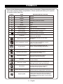 6
6
-
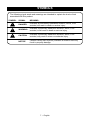 7
7
-
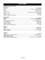 8
8
-
 9
9
-
 10
10
-
 11
11
-
 12
12
-
 13
13
-
 14
14
-
 15
15
-
 16
16
-
 17
17
-
 18
18
-
 19
19
-
 20
20
-
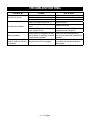 21
21
-
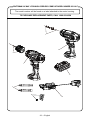 22
22
-
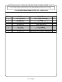 23
23
-
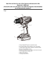 24
24
-
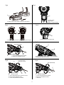 25
25
-
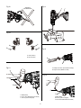 26
26
-
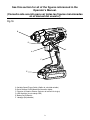 27
27
-
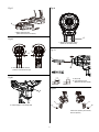 28
28
-
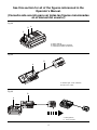 29
29
-
 30
30
-
 31
31
-
 32
32
-
 33
33
-
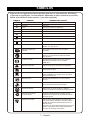 34
34
-
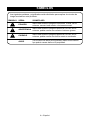 35
35
-
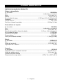 36
36
-
 37
37
-
 38
38
-
 39
39
-
 40
40
-
 41
41
-
 42
42
-
 43
43
-
 44
44
-
 45
45
-
 46
46
-
 47
47
-
 48
48
-
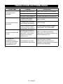 49
49
-
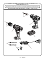 50
50
-
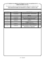 51
51
-
 52
52


Craftsman 12521417 El manual del propietario
- Categoría
- Taladros combi inalámbricos
- Tipo
- El manual del propietario
En otros idiomas
- English: Craftsman 12521417 Owner's manual
Documentos relacionados
-
Craftsman C3 Manual de usuario
-
-
-
-
-
-
-
-
-
Otros documentos
-
Genesis GL20DIDKA2 Manual de usuario
-
 i-drill 1i-drill Guía del usuario
-
 i-drill 2i-drill Guía del usuario
-
Stanley SFMCD710C2K Manual de usuario
-
Ryobi PSBCK01K-PSBRS01B-PSBCS02B El manual del propietario
-
Ryobi PBLCK01K Manual de usuario
-
-
RIDGID R9780 El manual del propietario
-
Triton T20TP02 Guía del usuario
-

