Mi-T-M Air Compressor-Generator-Welder Combination El manual del propietario
- Categoría
- Compresores de aire
- Tipo
- El manual del propietario

Operator’s Manual 1
AIR COMPRESSOR/GENERATOR/WELDER
OPERATOR’S MANUAL
CAUTION
RISK OF INJURY! READ ENTIRE MANUAL BEFORE OPERATING!
THIS MANUAL IS AN IMPORTANT PART OF THE AIR COMPRESSOR/GENERATOR/WELDER
AND MUST REMAIN WITH THIS UNIT!
©Copyright 2011, Mi-T-M Corporation® 37-1159-E/S-021319

2 Operator’s Manual
Introduction
THANK YOU for purchasing a Mi-T-M product.
READ THIS MANUAL carefully to learn how to operate
and service your machine correctly. Failure to do so could
result in personal injury or equipment damage. This manual
and safety signs on your machine may also be available
in other languages. (See your dealer to order.)
THIS MANUAL SHOULD BE CONSIDERED a permanent
part of your machine and should remain with the machine
when you sell it.
MEASUREMENTS in this manual are given in both
metric and customary U.S. unit equivalents. Use only
correct replacement parts and fasteners. Metric and inch
fasteners may require a specic metric or inch wrench.
RIGHT HAND AND LEFT HAND sides are determined by
facing the motor end of the machine.
The SERIAL NUMBER is located in the Specication or
Identication Numbers section. Accurately record all the
numbers to help in tracing the machine should it be stolen.
Your dealer also needs these numbers when you order
parts. File the identication numbers in a secure place
off the machine.
WARRANTY is provided from your dealer for customers
who operate and maintain their equipment as described
in this manual. The warranty is explained on the warranty
certicate shown in this manual.
This warranty provides you the assurance that your
dealer will back products where defects appear within
the warranty period. Should the equipment be abused,
or modied to change its performance beyond the original
factory specications, the warranty will become void.
WARNING: This product can expose you to
chemicals including carbon monoxide, which is
known to the State of California to cause birth
defects or other reproductive harm. For more
information go to www.P65Warnings.ca.gov
WARNING
WARNING: This product can expose you to
chemicals including Lead, which is known to
the State of California to cause cancer and birth
defects or other reproductive harm. For more
information go to www.P65Warnings.ca.gov
WARNING

Operator’s Manual 3
Contents
All information, illustrations and specications in this manual are based
on the latest information available at the time of publication. The right is
reserved to make changes at any time without notice.
INTRODUCTION ....................................................................................................................................................2
RECOGNIZE SAFETY INFORMATION .................................................................................................................5
CONTROLS .................................................................................................................................................. 15-16
INSTALLATION ....................................................................................................................................................18
OPERATION .......................................................................................................................................................22
START-UP .......................................................................................................................................................22
WELDING START-UP ..........................................................................................................................................22
SHUTDOWN .......................................................................................................................................................24
OPERATING CONTROLS ....................................................................................................................................24
CABLE SIZE .......................................................................................................................................................25
TROUBLESHOOTING .........................................................................................................................................26
MAINTENANCE ...................................................................................................................................................28
MAINTENANCE CHART: ..................................................................................................................................... 28
CHECKING ENGINE OIL ..................................................................................................................................... 29
CHANGING ENGINE OIL .....................................................................................................................................29
WIRING DIAGRAM/ SCHEMATIC ..................................................................................................................33-34
STORAGE........ ....................................................................................................................................................35
SPECIFICATIONS ................................................................................................................................................36
WARRANTY .......................................................................................................................................................37

4 Operator’s Manual
Contents

Operator’s Manual 5
W
A
R
N
I
N
G
W
A
R
N
I
N
G
S
I
N
TH
E
M
A
N
U
A
L
S
.
W
A
R
N
I
N
G
S
I
N
TH
E
M
A
N
U
A
L
S
.
C
A
U
T
I
O
N
O
CAU
T
I
O
N
S
I
N
O
T
H
E
M
A
N
U
A
L
S
O
CAU
T
I
O
N
S
I
N
O
T
H
E
M
A
N
U
A
L
S
O
CAU
T
I
O
N
S
I
N
O
T
H
E
M
A
N
U
A
L
S
O
CAU
T
I
O
N
S
I
N
O
T
H
E
M
A
N
U
A
L
S
Safety
RECOGNIZE SAFETY INFORMATION
This is the safety alert symbol. When you see this symbol
on your machine or in this manual, be alert to the potential
for personal injury.
Follow recommended precautions and safe operating
practices.
UNDERSTAND SIGNAL WORDS
A signal word--DANGER, WARNING or CAUTION--is used
with the safety-alert symbol. DANGER identies the most
serious hazards.
DANGER or WARNING safety signs are located near
specific hazards. General precautions are listed on
CAUTION safety signs. CAUTION also calls attention to
safety messages in this manual.
FOLLOW SAFETY INSTRUCTIONS
Carefully read all safety messages in this manual and
safety signs on your machine. Keep safety signs in good
condition. Replace missing or damaged safety signs. Be
sure new equipment components and repair parts include
the current safety signs. Replacement safety signs are
available from your dealer.
Learn how to operate the machine and how to use controls
properly. Do not let anyone operate without instruction.
Keep your machine in proper working condition.
Unauthorized modications to the machine may impair the
function and/or safety and affect machine life.
If you do not understand any part of this manual and need
assistance, contact your dealer.

6 Operator’s Manual
CARBON MONOXIDE - POISONOUS GAS
Use unit outdoors, away from open windows, vents, or doors.
Unit exhaust contains carbon monoxide - a poisonous gas that can
kill you. You CAN NOT smell or see this gas.
Never use the unit in enclosed or partially-enclosed spaces. The
unit can produce high levels of carbon monoxide very quickly. When
you use this unit, remember that you cannot smell or see carbon
monoxide. Even if you can’t smell exhaust fumes, you may still be
exposed to carbon monoxide.
If you start to feel sick, dizzy, or weak while using the unit, get to
fresh air RIGHT AWAY. DO NOT DELAY. The carbon monoxide from
the unit can rapidly lead to full incapacitation and death.
If you experience serious symptoms, get medical attention
immediately. Inform medical staff that carbon monoxide poisoning
is suspected. If you experienced symptoms while indoors, have
someone call the re department to determine when it is safe to
re-enter the building.
Never operate the unit in an explosive atmosphere, near combustible
materials or where ventilation is not sufcient to carry away exhaust
fumes. Exhaust fumes can cause serious injury or death.
NEVER use the unit indoors, including in homes, garages,
basements, crawl spaces, and other enclosed or partially-enclosed
areas, even with ventilation. Opening doors and windows or using
fans will not prevent carbon monoxide build-up in the home.
Follow the instructions that come with your unit. Locate the unit
outdoors and away from doors, windows, and vents that could allow
the carbon monoxide gas to come indoors.
ONLY run unit outdoors and away from air intakes.
NEVER run unit inside homes, garages, sheds, or other semi-
enclosed spaces. These spaces can trap poisonous gases EVEN
IF you run a fan or open doors and windows.
If you start to feel sick, dizzy, or weak while using the unit, shut if
off and get fresh air IMMEDIATELY. See a doctor. You may have
carbon monoxide poisoning.
Install battery-operated carbon monoxide alarms or plug-in carbon
monoxide alarms with battery back-up in your home, according to
the manufacturer’s installation instructions. The carbon monoxide
alarms should be certied to the requirements of the latest safety
standards for carbon monoxide alarms. (UL 2034, IAS 6-96, or
CSA 6.19.01).
Test your carbon monoxide alarm frequently and replace dead
batteries.
34-1916-092410-E-F-S.
Using a generator indoors CAN KILL YOU IN MINUTES.
Generator exhaust contains carbon monoxide. This is a
poison you cannot see or smell.
NEVER use inside a home
or garage, EVEN IF doors
and windows are open.
Only use OUTSIDE and far
away from windows, doors,
and vents.
DANGER DANGER PELIGRO
Utilizando un generador adentro
PUEDE MATARLE EN MINUTOS.
El escape de generador contiene
monóxido de carbono. Este es un
gas tóxico que usted no puede ver ni
puede oler.
Nunca utilice dentro de un hogar ni el
garaje, INCLUSO SI puertas y
ventanas estén abiertas.
Solo utilice AFUERAS y lejos de
ventanas abiertas, las puertas, y
descargas.
L'utilisation d'un groupe électrogène à
l'intérieur PEUT VOUS TUER EN
QUELQUES MINUTES.
Le gaz d'échappement du groupe
électrogène contient de l'oxyde de
carbone. C'est un gaz toxique que l'on
ne peut pas voir ou sentir.
Ne JAMAIS utiliser à l'intérieur d'une
maison ou d'un garage, MÊME SI les
portes et fenêtres s'ont ouvertes.
N'utiliser qu'à l'EXTÉRIEUR et bien éloigné
des fenêtres, portes, et conduits d'aération.

Operator’s Manual 7
SAFETY WARNING WHEN REFUELING
Injury or death may occur as a result of improper fueling. Do not smoke
while lling engine fuel tank.
Always refuel slowly to avoid the possibility of spilled fuel which may
cause a risk of re.
Gasoline is extremely ammable and its vapors can explode if ignited.
Observe all safety regulations for the safe handling of fuel. Handle fuel in
safety containers. If the container does not have a spout, use a funnel.
Do not overll the fuel tank, leave room for the fuel to expand.
Fill the tank only on an area of bare ground. While fueling the tank, keep
heat, sparks and open ame away. Carefully clean up any spilled fuel
before starting engine.
Always ll fuel tank in an area with plenty of ventilation to avoid inhaling
dangerous fumes.
NEVER store fuel for your unit in the home. Gasoline, propane, kerosene,
and other ammable liquids should be stored outside of living areas in
properly-labeled, non-glass safety containers. Do not store them near a
fuel-burning appliance, such as a natural gas water heater in a garage. If
the fuel is spilled or the container is not sealed properly, invisible vapors
from the fuel can travel along the ground and can be ignited by the
appliance’s pilot light or by arcs from electric switches in the appliance.

8 Operator’s Manual
ELECTRICAL HAZARDS
This product must be grounded. If it should malfunction or breakdown,
grounding provides a path of least resistance for electric current to
reduce the risk of electric shock. Do not touch live electrical parts.
DANGER - IMPROPER CONNECTION OF THE EQUIPMENT-
GROUNDING CONDUCTOR CAN RESULT IN A RISK OF
ELECTROCUTION. CHECK WITH A QUALIFIED ELECTRI-
CIAN OR SERVICE PERSON IF YOU ARE INDOUBT AS TO
WHETHER THE UNIT IS PROPERLY GROUNDED.
This unit is equipped with a grounding terminal for your protection.
Always complete the ground path from the unit to an external ground
source as instructed in the section labeled “Grounding Instructions” in
the Preparation section of this manual.
The unit is a potential source of electrical shock if not kept dry. Keep
the unit dry and do not use in rain or wet conditions. To protect from
moisture, operate it on a dry surface under an open, canopy-like
structure. Dry your hands if wet before touching the unit.
Plug appliances directly into the unit. Or, use a heavy duty, outdoor-
rated extension cord that is rated (in watts or amps) at least equal to
the sum of the connected appliance loads. Check that the entire cord
is free of cuts or tears and that the plug has all three prongs, especially
a grounding pin.
NEVER try to power the house wiring by plugging the unit into a
wall outlet, a practice known as “back feeding”. This is an extremely
dangerous practice that presents an electrocution risk to utility workers
and neighbors served by the same utility transformer. It also bypasses
some of the built-in household circuit protection devices.
If you must connect the unit to the house wiring to power appliances,
have a qualified electrician install the appropriate equipment in
accordance with local electrical codes. Or, check with your utility
company to see if it can install an appropriate power transfer switch.
For power outages, permanently installed stationary units are better
suited for providing backup power to the home. Even a properly
connected portable unit can become overloaded. This may result in
overheating or stressing the unit components, possibly leading to a
unit failure.
Do not use worn, damaged, undersized, or poorly spliced welding
cables. Do not drape welding cables over your body. Do not touch
electrode if you are in contact with the work, ground, or another
electrode from a different machine.

Operator’s Manual 9
RISK OF BURSTING
Serious injury or death may occur from an air tank explosion if air tanks
are not properly maintained. Drain air tank daily or after each use to
prevent moisture buildup in the air tank.
If air tank develops a leak, replace the air tank immediately. Never repair,
weld or make modications to the air tank or its attachments. Use only
genuine manufacturer repair parts for your unit. NEVER make adjustments
to the factory set pressures.
Serious injury may occur from the unit malfunction or exploding
accessories if incorrect system components, attachments or accessories
are used. Never exceed manufacturers maximum allowable pressure
rating of attachments.
Because of extreme heat, do not use plastic pipe or lead tin soldered
joints for a discharge line.
Never use the unit to inate small, low pressure objects such as toys.
RISK OF FIRE OR EXPLOSION
Serious injury or death may occur from normal sparks in the engine
ignition system or engine exhaust/mufer. Always operate the unit in a
well ventilated area free of ammable vapors, combustible dust, gases
or other combustible materials. Do not weld where the atmosphere may
contain ammable dust, gas, or liquid vapors (such as gasoline).
DO NOT SMOKE if spraying ammable material. Locate the unit at least
20 feet away from the spray area. (An additional hose may be required.)
Never ll the engine fuel tank while the engine is running or hot. Allow
the engine to cool two minutes before refueling. Do not refuel indoors
or in a poorly ventilated area.
Do not operate the unit if gasoline is spilled. Wipe the unit clean and
move it away from the spill. Avoid creating any ignition until the gasoline
has evaporated.
Do not store the unit near an open ame or any equipment such as a
stove, furnace, water heater, etc. which utilizes a pilot light or sparking
device.
A spark arrester must be added to the mufer of this engine if it is to be
used on any forest covered, brush covered or grass covered unimproved
land. The arrester must be maintained in effective working order by the
operator.
Serious injury may occur if any of the unit's ventilation openings are
restricted, causing the unit to overheat and start a re. Never place
objects against or on top of the unit. Operate the unit at least 12 inches
away from any wall or obstruction that would restrict proper ventilation.
Welding on closed containers, such as tanks, drums, or pipes, can cause
them to explode. Accidental contact of electrode to metal objects can
cause sparks, explosion, overheating, or re.
Remove all ammables within 35 ft (10.7 m) of the welding arc. Do not
weld where ying sparks can strike ammable material. Watch for re,
and keep a re extinguisher nearby.
After completion of work, inspect area to ensure it is free of sparks,
glowing embers, and ames. Remove stick electrode from holder when
not in use.

10 Operator’s Manual
RISK OF BREATHING
Serious injury or death could occur from inhaling compressed air. The air
stream may contain carbon monoxide, toxic vapors or solid particles. Never
inhale air from the unit either directly or from a breathing device connected
to the unit.
Serious injury or death may occur from inhaling engine exhaust. This unit
was designed for outdoor use. Never operate this unit in an enclosed
area. Always make certain there is adequate ventilation (fresh outside air)
for breathing and combustion. This will prevent the buildup of dangerous
carbon monoxide gases. Beware of poorly ventilated areas, or areas with
inadequate exhaust fans.
Sprayed materials such as paint, solvents, paint remover, insecticides,
weed killers, etc. contain harmful vapors and poisons. Operate the unit
only in a well ventilated area. Follow all safety instructions provided with
the materials you are spraying. Use of a respirator may be required when
working with some materials.
Welding produces fumes and gases. Breathing these fumes and gases
can be hazardous to your health. Keep your head out of the fumes. Do not
breathe the fumes.
Do not weld in locations near degreasing, cleaning, or spraying operations.
The heat and rays of the arc can react with vapors to form highly toxic and
irritating gases.
Do not weld on coated metals, such as galvanized, lead, or cadmium plated
steel. The coatings and any metals containing these elements can give off
toxic fumes if welded.
RISK OF BURNS
Serious injury could occur from touching exposed metal parts. These areas
can remain hot for some time after the unit is shutdown. Never allow any
part of your body or other materials to make contact with any exposed metal
parts on the unit.
Never allow any part of your body to contact the engine mufer, compressor
head or adjacent areas.

Operator’s Manual 11
RISK OF FLYING OBJECTS
Soft tissue damage can occur from the compressed air stream. Always wear
safety glasses to shield the eyes from ying debris.
Never point the air stream at any part of your body, anyone else or animals.
Never leave pressurized air in the unit. Shut off the unit and relieve pressure
when storing or attempting maintenance.
Serious injury can occur from loose debris being propelled at a high speed
from the compressed air stream. Always maintain a safe distance from
people and animals while operating the unit.
Do not move the unit while air tank is under pressure. Do not attempt to
move the unit by pulling on the hose.
RISK FROM MOVING PARTS
Risk of bodily injury from moving parts. Before performing maintenance,
always turn off the unit. Bleed pressure from the air hose and disconnect
spark plug wire to prevent engine from starting unexpectedly. All repairs to
the unit should be made by an Authorized Service person.
Do not operate without protective covers/guards. Always turn off the unit
before removing any guard. Replace damaged covers/guards before using
the unit.

12 Operator’s Manual
IMPORTANT SAFETY INSTRUCTIONS
WARNING: To reduce the risk of injury, read this operator’s manual
completely before using. When using this product, the following
basic precautions should always be followed:
1. Risk from Negligence: Risk of injury from negligent use. Never
allow children or adolescents to operate this unit! Stay alert-
watch what you are doing. Do not operate the unit when fatigued
or under the inuence of alcohol or drugs. Know how to stop the
unit. Be thoroughly familiar with controls.
2. Risk of Unit Damage: Risk of major repair. Do not operate the
unit without an air lter. Do not operate the unit in a corrosive
environment. Always operate the unit in a stable, secure
position to prevent the unit from falling. Follow all maintenance
instructions listed in this manual. Overuse can cause overheating;
allow cooling period; follow rated duty cycle. Reduce current or
reduce duty cycle before starting to weld again. Do not block or
lter airow to unit.
3. When starting the unit, using recoil starter grip, be sure that
nothing is in a position to be hit by the operator’s hand or arm.
Be sure the switch on electric power tools is in the “OFF” position
before plugging them into the unit.
4. Do not operate the unit or any electrical tool in any area where
water or similar materials constitute an electrical hazard to the
operator. Do not operate on wet surfaces, in rain or in snow.
5. Always be sure that the unit is on secure footing so that it cannot
slide or shift around, endangering workers.
6. Avoid contacting the hot exhaust manifold, mufer or cylinder(s).
7. Keep clear of all rotating parts.
8. Unless the tool or appliance is double insulated, it must be
grounded through a properly grounded receptacle. Tools and
appliances which have 3 prong plugs must be plugged into
extension cords and electrical receptacles with 3 holes. Before
operating any electrical item, be sure it is in good repair.
9. Beware of using this equipment in conned spaces. Conned
spaces, without sufcient fresh air ventilation, can contain
dangerous gases. Running gasoline engines in such environments
can lead to deadly explosions and/or asphyxiation.
10. Use extreme caution when lifting this unit. This unit is heavy
so proper lifting techniques should be used.
SAVE THESE INSTRUCTIONS
W
A
R
N
I
N
G
W
A
R
N
I
N
G
S
I
N
TH
E
M
A
N
U
A
L
S
.
W
A
R
N
I
N
G
S
I
N
TH
E
M
A
N
U
A
L
S
.
C
A
U
T
I
O
N
O
CAU
T
I
O
N
S
I
N
O
T
H
E
M
A
N
U
A
L
S
O
CAU
T
I
O
N
S
I
N
O
T
H
E
M
A
N
U
A
L
S
O
CAU
T
I
O
N
S
I
N
O
T
H
E
M
A
N
U
A
L
S
O
CAU
T
I
O
N
S
I
N
O
T
H
E
M
A
N
U
A
L
S

Operator’s Manual 13
WEAR PROTECTIVE CLOTHING
Wear close fitting clothing and safety equipment
appropriate to the job. Wear dry, hole-free insulating gloves
and body protection.
Wear a suitable hearing protective device such as
earmuffs or earplugs to protect against objectionable or
uncomfortable loud noises.
Operating equipment safely requires the full attention of
the operator. Do not wear radio or music headphones while
operating machine.
Arc rays from the welding process produce intense visible
and invisible (ultraviolet and infrared) rays that can burn
eyes and skin. Sparks y off from the weld. ARC RAYS
can burn eyes and skin. Wear an approved welding helmet
tted with a proper shade of lter lenses to protect your
face and eyes when welding or watching. Wear approved
safety glasses with side shields under your helmet.
Use protective screens or barriers to protect others from
ash, glare and sparks; warn others not to watch the
arc. Wear protective clothing made from durable, ame-
resistant material and foot protection.
Welding, chipping, wire brushing, and grinding cause
sparks and ying metal. As welds cool, they can throw off
slag. Wear approved safety glasses with side shields even
under your welding helmet.
INSPECT UNIT
Be sure all covers, guards and shields are tight and in
place.
Locate all operating controls and safety labels.
Inspect power cord for damage before using. There is a
hazard of electrical shock from crushing, cutting or heat
damage.
PREPARE FOR EMERGENCIES
Keep a rst aid kit and re extinguisher handy.
Keep emergency numbers for doctors, ambulance service,
hospital and re department near your telephone.
Be prepared if a re starts.
SERVICE UNIT SAFELY
Before servicing the unit, disconnect all equipment and
battery (if equipped) and allow unit to cool down.
Service unit in a clean dry at area.

14 Operator’s Manual
SAFETY SIGNS
34-1284
34-0826
34-0599
34-1616
CAUTION/PRECAUCIÓN
Do not add fuel when
product is operating. Allow
engine to cool for two (2)
minutes before refueling.
34-0599/07262012
RISK OF FIRE
RIESGO DE FUEGE
No ponga combustible cuando el
producto este en operacion.
Permita que el motor se enfrie
por 2 minutos antes de
reablastecer de combustible.
WARNING/ADVERTENCIA
RISK OF BURNS
Muffler and adjacent
areas may exceed
150°F.
RIESGO DE QUEMAR
El amortiguador y las areas
adyacentes pueden Tener
temperaturas por arriba de 65°C.
34-0598/07262012
34-0598
Beware of Hot Surfaces.
Allow unit to cool
before servicing.
RISK OF BURNS
RIESGO DE QUEMADURA
Tenga ud cuidado de los
superficies calientes. Permita
que la unidad se enfrie antes
de mantener.
34-1284/091012
WARNING/ADVERTENCIA
34-1616/091012
RISK OF ELECTRICAL SHOCK OR ELECTROCUTION! A generator is a
potential shock hazard which can result in serious injury or death.
• Generator must be kept dry.
• Do NOT operate unit with wet hands.
• Generator MUST be grounded before use. See operators manual for specific
instructions.
• Do not use around water or expose to rain. Store indoors.
RIESGO DE CALAMBRE ELECTRICO O ELECTROCUCION! Un generador es un potencial
riesgo de descarga que puede resultar en lesiones graves o muerte.
• Generadores tienen que mantener secos.
• No opere esta unidad con manos mojados.
• Generador TIENE que sea conectado a tierra antes de uso. Vea manual de operador para
instrcciones especificos.
• No use cerca aqua ni tenga la unidad en la lluvia. Débe almecenaria dentor.
WARNING / ADVERTENCIA
WARNING/ADVERTENCIA
34-0826/07262012
No opere la unidad sin todas
la cubierta correa en su sitio.
Do not operate unit
without beltguard
in place.
34-0826/07262012
No opere la unidad sin todas
la cubierta correa en su sitio.
Do not operate unit
without beltguard
in place.
RISK OF FIRE OR EXPLOSION!
• Do not spray flammable liquid in a confined area. Spray area must be well ventilated. Do not smoke
while spraying or spray where spark or flame is present. Keep compressors as far from spraying area as
possible.
• When a combustible liquid is sprayed there may be danger of fire or explosion, especially in a closed area.
• Arcing parts. Keep the unit at least 6m away from explosive vapors.
• Engine creates sparks. Do not operate in flammable environment. Follow all instructions and warnings
supplied with material to be sprayed.
• Do not smoke while filling engine fuel tank. Follow all fueling instructions in operator's manual.
• Air tanks may explode if not properly maintained. To prevent weakening of tanks caused by corrosion,
drain tanks after each use.
• This equipment incorporates parts, such as snap switches, receptacles, produce arcs or sparks and,
therefore, when located in a garage, it should be in a room or enclosure provided for the purpose, or
should be 18 inches (457mm) or more above the floor.
RISK OF ASPHYXIATION!
• Never use compressed air for breathing or respiration!
• Gasoline engines produce carbon monoxide; a poisonous, odorless gas which may cause death! Do not
start or operate compressor in an enclosed area. Area must be well ventilated.
RISK OF SEVERE INJURY!
• Before servicing gasoline unit, disconnect spark plug wire to prevent unit from starting unexpectedly.
• Wear safety glasses/face shields at all times.
• Never operate with beltguard removed. If guard becomes damaged, repair or replace before operating.
• Do not remove any air line or tank connections before relieving air pressure in the tank(s).
• Loose debris can be propelled at high speeds. Never direct air stream towards yourself or others.
RISK OF BURNS!
• Do not touch compressor head, discharge lines or engine components. Cool before servicing.
RISK OF DAMAGING COMPRESSOR AND CAUSING INJURY!
• Do not operate at pressure or speed in excess of manufacturer's recommendations.
• Do not operate with components rated less than the pressure marked on the nameplate.
Follow required maintenance procedures and intervals listed in the operator's manual. Service
should be performed only by qualified personnel. Compressor requires good ventilation to operate
properly. Use only factory replacement parts.
RIESGO DE INCENDIO O EXPLOSION!
• No rocie el líquido inflamable en una áred confinada la área para rociar tiene que ser bien ventilado. No fume cuando está
rociando ni vocie donde hay incendio o centella. Ponga los compresores lejos de la area de vociar si es posible.
• Cuando un liquido inflamable está rociado hay posible peligro de incendio o explosión, especialmente en un lugar cerrado.
• Partes de arco. Ponga la unidad menos de 6m lejos de los vapores explosívos.
• El motor se causan las centellas. No use en un lugar inflamable. Siga usted las instrucciones y advertencias con el
material para rociar.
• No fume cuando está llenando el tanque de combustible siga todas las instrucciones de combustible en el manual del
operador.
• Los tanques del aire puede explotar si no se mantenga bien. Para evitar la debilitación de los tanques del corrosión, drene
los tanques cada uso.
• Este equipo tiene los partes com interruptor de resortes, receptaculos, se producen o centellas y por eso, cuándo está en
un garaje, lebe estar en un cuarto o un encerramiento por este, o debe estar 18 pulgadas o (457 mm) o encima del suelo.
RIESGO DE LESIONES GRAVES!
• Antes de mantenerse la unidad gasolina, desconecte el hilo de la telegrafista para evitar la unidad a arrancar
inesperadamente.
RIESGO DE QUEMADURAS!
• No toque la cabeza del compresor, lineas del descargo o partes del motor. Permita que se enfrie antes del servicio.
RIESGO DE ASFIXIA!
• Nunca se use el aire del compresor para respirar o respiración!
• El motor produce carbón monóxido un vapor tóxico un olor que se puede causar morir. No use o arranca un lugar
encerrado. El área debe ser bien ventilado.
REISGO DE LESIONES!
• Lleve gafas de seguridad o blindaje todo el tiempo.
• Nunca opere sin cinturon de protección. Si el cinturon está dañado repare o reemplace antes de usarlo.
• Nunca saque cualquier linea del aire o conexione del tanque antes de eliminando del sion aire en los tanques.
• No dirija el rociado de alta presión hacia ninguna persona ni hacia usted mismo. Escombros se vuelan rapído.
RIESGO DE DAÑO DEL COMPRESOR O LESIONES!
• No opera a un presión o una velocidad más que se recomienda en el manual.
• No opera con partes clasifican menos de la presión que ha escrito en el plato de nombre.
Siga los procedimientos de mantenimiento y intervalos que se dicen en el manual de operador.
Servicio debe hacer solemento por las personas calificados. Para funcionar correctamente, necesita un lugar bien
ventilado. Use solamente partes para reemplacer de la fábrica.
READ ENTIRE INSTRUCTION MANUAL BEFORE OPERATING AIR COMPRESSOR!
LEA USTED EL MANUAL DE INSTRUCCIONES ANTES DE USAR EL COMPRESOR DEL AIRE!
SI NO SIGA USTED ESTAS ADVERTENCIAS PUEDE CAUSAR LESIONES.
NO SAQUE LA ETIQUETA!
FAILURE TO COMPLY WITH THESE WARNINGS WILL RESULT IN PERSONAL
INJURY. DO NOT REMOVE THIS LABEL!
34-1615/091012
WARNING ADVERTENCIA
34-1615
WARNING: Cancer and Reproductive Harm — www.P65warnings.ca.gov/
1. Flip the toggle on top of the pilot valve to the upright position. This provides a loadless start.
The compressor will unload and allow the engine to start easier.
2. Start the engine. (Refer to Engine Manual accompanying this unit.)
3. When engine has run for 1-2 minutes, flip toggle back to original position.
4. Stop the engine. (Refer to Engine Manual accompany this unit.)
5. Drain air from the tanks by releasing air with an attached air tool or by pulling on the safety
relief valve rings.
6. Once pressure in the tanks register under 10 pounds, open the drain valve under each thank
to drain any moisture.
ADVERTENCIA: Peligro de cáncer y daño reproductivo — www.P65warnings.ca.gov/
1. Eche la palanca acodada encima de la válvula pilota a la posición vertical. Con este hay un arranque
sin carga. El compresor va a descargar y permitir el motor a arrancar facilmente.
2. Arranque el motor. (Lea el manual del motor que está acompañado está unidad)
3. Cuanda la unidad funciona para 1-2 minutos, mueva la planaca acodada a la posicion original.
4. Cierre el motor. (Lea el manual que está acompañado está unidad)
5. Drene los tanques del aire con un instrumento acompañado del aire o tire los anillos de la válvula
segura.
6. Cuando la presión en los tanques es menos de diez libras, abre la válvula debayo de cada tanque
para des aguar cualquier humedad.
34-1286/071318
34-1286
LEA LAS INSTRUCCIONES PARA INSTRUCCIONES
PARTICULARES.
LEA USTED EL MANUAL DEL MOTOR PARA EL
MANTENIMIENTO RECOMENDADO DEL MOTOR.
Si la unidad está usado en un lugar bien sucio o de polvo, haga la frecuencia de
los examenes más.
Cada día: •Inspecciòne para el nivel de aceite y vias de aceite.
•Inspecciòne el filtro de aire (si hay).
•Drene la humidad de los tanques cada día o despúes de usar.
•Asegúrese que las guardas de seguridad son acompañados
seguridademente y correctamente.
Cada semana: •Limpie las superficies enfries del compresor.
•Inspeccióne el filtro del aire.
•Inspeccióne las válvulas con tirando los anillos.
Cada mes: •Inspeccióne la sistema para vías.
•Inspeccióne la tensión de la correa.
Cada dos •Cambie el aceite de la bomba.
cientos horas: •Reemplace filto del aire.
REFER TO INSTRUCTION MANUAL FOR
DETAILED INSTRUCTIONS.
REFER TO ENGINE MANUAL FOR RECOMMENDED
ENGINE MAINTENANCE.
If unit is operated in an excessively dirty or dusty area, increase
the frequency of all checks.
Daily: •Check for proper oil level(s) and oil leaks.
•Check engine air filter. (if applicable)
•Drain moisture from tank(s) daily or after each use.
•Ensure all safety guards are correctly & securely
attached.
Weekly: •Clean the cooling surfaces of the compressor.
•Inspect air intake filter.
•Check safety valves by pulling on rings.
Monthly: •Check system for air leaks.
•Check belt tension.
Every •Change pump oil.
200 hours: •Replace air filter.
34-1285/091012
MAINTENANCE INSTRUCTIONS INSTRUCCIONES DE MANTENIMIENTO
34-1285
DANGER DANGER PELIGRO
34-1916/083012
Using a generator indoors CAN KILL YOU IN MINUTES.
Generator exhaust contains carbon monoxide. This is a
poison you cannot see or smell.
NEVER use inside a home
or garage, EVEN IF doors
and windows are open.
Only use OUTSIDE and far
away from windows, doors,
and vents.
Utilizando un generador adentro
PUEDE MATARLE EN MINUTOS.
El escape de generador contiene
monóxido de carbono. Este es un
gas tóxico que usted no puede ver ni
puede oler.
Nunca utilice dentro de un hogar ni el
garaje, INCLUSO SI puertas y
ventanas estén abiertas.
Solo utilice AFUERAS y lejos de
ventanas abiertas, las puertas, y
descargas.
L'utilisation d'un groupe électrogène à
l'intérieur PEUT VOUS TUER EN
QUELQUES MINUTES.
Le gaz d'échappement du groupe
électrogène contient de l'oxyde de
carbone. C'est un gaz toxique que l'on
ne peut pas voir ou sentir.
Ne JAMAIS utiliser à l'intérieur d'une
maison ou d'un garage, MÊME SI les
portes et fenêtres s'ont ouvertes.
N'utiliser qu'à l'EXTÉRIEUR et bien éloigné
des fenêtres, portes, et conduits d'aération.
34-2666
34-1916
34-2666/091012
OPERATING INSTRUCTIONS FOR GENERATOR AND WELDER
GENERATOR / WELDER CAN CAUSE SERIOUS INJURY OR
DEATH IF OPERATED IMPROPERLY. BEFORE OPERATING
THIS UNIT READ AND UNDERSTAND THE ENTIRE OPERA-
TOR’S MANUAL AND FOLLOW ALL SAFETY
PRECAUTIONS.
1. Ensure the unit is grounded according to the owner’s
manual and national, state, and local codes. Wear proper
protective equipment and clear the area of any hazards
before operating the unit.
2. To maximize welder output, do not weld while simultane-
ously filling the air tank or utilizing air tools.
3. Toggle the Full Throttle / Idle Switch to select to Full
Throttle.
4. Rotate switch to select weld amperage. Do NOT adjust the
control output while welding
Use table and electrode packaging to determine the correct
size electrode and amperage.
5. For Direct Current Electrode Positive (DCEP), connect work
cable to Negative (−) terminal and electrode holder to
Positive (+) terminal. (thicker material and more penetration)
For Direct Current Electrode negative (DCEN), reverse
cable connections.
INSTRUCCIONES DE UTILIZAR PARA GENERADOR Y SOLDADOR
EL GENERADOR/SOLDADOR PUEDE CAUSAR LA HERIDA SERIA
O LA MUERTE SI UTILIZADO INCORRECTAMENTE. ANTES DE
UTILIZAR ESTA UNIDAD, LEA Y ENTIENDA EL MANUAL DEL
OPERADOR ENTERO Y SIGA TODAS LAS
PRECAUCIONES DE SEGURIDAD.
1. Asegure que la unidad es conectada a la tierra según el manual del
propietario y códigos nacionales, estatales, y locales. Lleve el
equipo protector apropiado y limpie el área de cualquier riesgo
antes de utilizar la unidad.
2. Para maximizar el rendimiento de soldador, no solde mientras
simultáneamente llenando el tanque de aire o utilizando instrumentos
de aire.
3. Cambie el Interruptor de Toda Velocidad/Ocioso para seleccionar
Toda Velocidad.
4. Gire el interruptor para seleccionar el amperaje de soldar. NO ajuste
el rendimiento de control mientras soldando.
Use la tabla y embalaje de electrodo para determinar el tamaño
de electrodo y el amperaje correctos.
5. Para el Electrodo Corriente Directo Positivo (DCEP), una el cable de
trabajo al terminal (−) Negativo y el tenedor del electrodo al terminal
Positivo (+) . (material más grueso y más penetración) Para el Electrodo
Corriente Directo Negativo (DCEN), invierta uniones de cable.
WARNING ADVERTENCIA

Operator’s Manual 15
Controls
1-Pump Air Filter
2-Fuel Cap
3-Engine Air Cleaner
4-Engine Choke
5-Engine Oil Fill
6-Engine Oil Drain
7-Air Tank Drain
8-Pump Oil Fill
9-Pilot Valve
10-Weld Amperage Setting
11-Generator/Welder Selector
Switch
12-Min/Max Weld Amperage
Toggle Switch
13-Positive Welding Terminal
14-Negative Welding Terminal
15-125V Receptacle
16-120/250V 20A Twist Lock
17-Idle Control Switch
18-20A Toggle Breaker
19-20A Push Button Breaker
20-Pump Oil Sight Glass
21-Pump Oil Drain
22-Safety Relief Valve
23-Pressure Gauge
24-Regulator
25-Quick Connect
1
3
4
5
6
2
8
9
10 11
12
13
14
20 21
22 23 24 23 25
15 16
17
18
19
7

16 Operator’s Manual
Controls
1-Engine Air Cleaner
2-Engine Oil Fill
3-Pump Oil Drain
4-Pilot Valve
5-Pump Air Filter
6-Pump Oil Fill
7-Engine Oil Drain
8-Fuel Cap
9-Air Tank Drain
10-Battery
11-Weld Amperage Setting
12-Generator/Welder Selector
Switch
13-Min/Max Weld Amperage
Toggle Switch
14-Positive Welding Terminal
15-Negative Welding Terminal
16-Engine Choke
17-125V Receptacle
18-125/250V 20A Twist Lock
19-Idle Control Switch
20-20A Toggle Breaker
21-Engine Keyswitch
22-20A Push Button Breaker
23-Safety Relief Valve
24-Pressure Gauge
25-Regulator
26-Pump Oil Sight Glass
27-Quick Connect

Operator’s Manual 17
INSTALLATION
Read safety warnings before setting-up the unit.
Ensure the oil level in the unit's pump is adequate. If low, add
SAE-30W non-detergent oil.
LOCATION:
In order to avoid damaging the unit, do not incline the unit transversely
or longitudinally more than 10°.
WARNING: RISK OF ASPHYXIATION! DO NOT OPERATE
IN AN ENCLOSED AREA. USE THIS PRODUCT ONLY IN
WELL VENTILATED AREAS! THE EXHAUST FROM THE
ENGINE CONTAINS CARBON MONOXIDE, A POISON-
OUS, ODORLESS AND INVISIBLE GAS. BREATHING
THE GAS CAN CAUSE SERIOUS INJURY, ILLNESS AND
POSSIBLE DEATH.
WARNING: RISK OF EXPLOSION OR FIRE CAUSING SERI-
OUS INJURY OR DEATH! DO NOT ALLOW THE ENGINE
OR MUFFLER TO COME IN CONTACT WITH FLAMMABLE
VAPORS, COMBUSTIBLE DUST, GASES OR OTHER COM-
BUSTIBLE MATERIALS. A SPARK MAY CAUSE A FIRE.
WHEN USING THE UNIT FOR SPRAY PAINTING, PLACE
THE UNIT AS FAR AWAY FROM THE WORK AREA AS
POSSIBLE, USING EXTRA AIR HOSES IF NEEDED.
Place unit at least 12 inches away from obstacles that may prevent
proper ventilation. Do not place unit in an area:
- where there is evidence of oil or gas leaks.
- where ammable gas vapors or materials may be present.
- where air temperatures fall below 32°F or exceed 104°F.
- where extremely dirty air or water could be drawn into the unit.
SERVICE TRUCK INSTALLATION:
Installations may vary. Mounting should be done to a rigid frame
member. Installer is responsible for securing the equipment in a
safe manner.
30 GALLON UNITS:
Optional Hardware: IX-0001 (Isolators).
Installation

Installation
18 Operator’s Manual
GROUNDING INSTRUCTIONS
This product must be grounded. If it should malfunction or breakdown,
grounding provides a path of least resistance for electric current to
reduce the risk of electric shock.
DANGER: IMPROPER CONNECTION OF THE EQUIPMENT
GROUNDING CONDUCTOR CAN RESULT IN A RISK OF
ELECTROCUTION. CHECK WITH A QUALIFIED ELECTRI-
CIAN OR SERVICE PERSON IF YOU ARE IN DOUBT AS TO
WHETHER THE UNIT IS PROPERLY GROUNDED.
The screw and ground terminal on the frame must always be used
to connect the unit to a suitable ground source. The ground path
should be made with #8 size wire. Connect the terminal of the
ground wire between the star washers and screw then tighten the
screw fully. Connect the other end of the wire securely to a suitable
ground source.
The National Electric Code contains several practical ways in which
to establish a good ground source. Examples given below illustrate a
few of the ways in which a good ground source may be established.
A metal underground water pipe in direct contact with the earth
for at least 10 feet can be used as a grounding source. If a pipe
is unavailable, an 8 foot length of pipe or rod may be used as the
ground source. The pipe should be 3/4 inch trade size or larger and
the outer surface must be noncorrosive. If a steel or iron rod is used
it should be at least 5/8 inch diameter and if a nonferrous rod is used
it should be at least 1/2 inch diameter and be listed as material for
grounding. Drive the rod or pipe to a depth of 8 feet. If a rock bottom
is encountered less than 4 feet down, bury the rod or pipe in a trench.
All electrical tools and appliances operated from this unit, must be
properly grounded by use of a third wire or be “Double Insulated”.
It is recommended to:
1. Use electrical devices with 3 prong power cords.
2. Use an extension cord with a 3 hole receptacle and a 3 prong plug
at the opposite ends to ensure continuity of the ground protection
from the unit to appliance.
Mi-T-M strongly recommends that all applicable federal, state and
local regulations relating to grounding specications be checked
and followed.
LINE TRANSFER SWITCH:
If this unit is used for standby service, it must have a transfer switch
between the utility power service and the unit. The transfer switch
not only prevents the utility power from feeding into the unit, but also
prevents the unit from feeding out into the utility company’s lines.
This is intended to protect the serviceman who may be working on
a damaged line.
THIS INSTALLATION MUST BE DONE BY A LICENSED
ELECTRICIAN AND ALL LOCAL CODES MUST BE FOLLOWED.

Installation
Operator’s Manual 19
GASOLINE ENGINE
Review "Risk of Fire or Explosion" before fueling. Read the
engine manual accompanying this unit for correct engine start-up
maintenance procedures. Read and understand the safety labels
located on the unit.
WARNING: RISK OF EXPLOSION OR FIRE CAUSING
SERIOUS INJURY OR DEATH! DO NOT SMOKE WHILE
FUELING!
DO NOT FILL FUEL TANK WHILE THE UNIT IS RUNNING
OR HOT. ALLOW THE UNIT AND ENGINE TO COOL
DOWN FOR TWO MINUTES BEFORE REFUELING.
DO NOT FILL FUEL TANK TO POINT OF OVERFLOWING.
ALLOW APPROXIMATELY 1/4" OF TANK SPACE FOR
FUEL EXPANSION.
DO NOT PLACE UNIT IN AN AREA WHERE FLAMMABLE
GAS VAPORS MAY BE PRESENT. A SPARK COULD
CAUSE AN EXPLOSION OR FIRE.
ALWAYS STORE FUEL AWAY FROM THE UNIT WHILE IT
IS RUNNING OR HOT.
WARNING: RISK OF EXPLOSION OR FIRE CAUSING
SERIOUS INJURY OR DEATH DO NOT ALLOW THE
ENGINE OR MUFFLER TO COME IN CONTACT WITH
FLAMMABLE VAPORS, COMBUSTIBLE DUST, GASES
OR OTHER COMBUSTIBLE MATERIALS. A SPARK
MAY CAUSE A FIRE.
WHEN USING THE UNIT FOR SPRAY PAINTING, PLACE
THE UNIT AS FAR AWAY FROM THE WORK AREA AS
POSSIBLE, USING EXTRA AIR HOSES IF NEEDED.
A minimum of 87 octane fuel is recommended for use with this air
compressor. Do not mix oil with gasoline.
Use of clean, fresh, lead free gasoline is recommended. Leaded
gasoline may be used if lead free is not available. Do not use
gasoline containing methanol or alcohol.
Refer to the engine manual for all necessary maintenance and
adjustments.
ENGINE OIL
Use oil viscosity based on the expected air temperature range
during the period between oil changes.
TEMPERATURE CHART

Installation
20 Operator’s Manual
MODEL # Liters Quart Ounces
AGW-SM14-30M 1.1 1.16 37.2
AGW-SH22-20M 2.0 2.1 67.6
Use a high quality detergent oil with API classications of SJ
or higher.
Check oil level before each operation and ensure that it is
maintained.
CAUTION: THIS ENGINE CRANKCASE IS NOT FILLED
WITH OIL AT THE FACTORY, SO BE SURE TO FILL
IT BEFORE OPERATING THE ENGINE.
ENGINE OIL CAPACITY
NOTE: These engines are equipped with a “Low Oil” shut-off
system for engine protection. If the engine fails to start,
check engine crankcase for oil.
To ll with oil:
1. Level the engine to ensure accurate inspection and
to prevent overlling.
2. Unscrew the oil gauge (Fig. 1), wipe the dipstick dry. Reinsert
the oil gauge back into the oil ll gauge opening. Remove
the oil gauge and check the oil level.
3. The oil level should be between the full and low marks on
the dipstick. (Fig. 2)
NOTE: When checking the oil be sure the engine is level.
4. Fill with oil as required through the oil ll gauge opening.
5. Replace the oil gauge and screw in rmly.
6. Wipe up any spilled oil.
FUELING
WARNING: EXPLOSIVE FUEL! GASOLINE IS EX-
TREMELY FLAMMABLE AND ITS VAPORS CAN
EXPLODE IF IGNITED.
STORE GASOLINE ONLY IN APPROVED CONTAIN-
ERS, IN WELL VENTILATED, UNOCCUPIED BUILD-
INGS AND AWAY FROM SPARKS OR FLAMES.
DO NOT FILL THE FUEL TANK WHILE THE ENGINE IS
HOT OR RUNNING, SINCE SPILLED FUEL COULD
IGNITE IF IT COMES IN CONTACT WITH HOT PARTS
OR SPARKS FROM IGNITION. DO NOT START
THE ENGINE NEAR SPILLED FUEL.
NEVER USE GASOLINE AS A CLEANING AGENT.
WARNING: DO NOT OVERFILL THE FUEL TANK,
LEAVE ROOM FOR THE FUEL TO EXPAND.
General Recommendations
• Purchase gasoline in small quantities and store in clean,
approved containers.
• To minimize gum deposits in your fuel system and to insure

Installation
Operator’s Manual 21
easy starting, do not use gasoline left over from the previous
season.
• Do not add oil to the gasoline.
Fuel Type
• For best results use only clean, fresh, unleaded gasoline with
a pump sticker octane rating of 87 or higher.
• Unleaded gasoline is recommended as it leaves less
combustion chamber deposits.
GASOLINE/ALCOHOL BLENDS:
Gasohol (up to 10% ethyl alcohol, 90% unleaded gasoline by
volume) is approved, as a fuel. Other gasoline/alcohol blends
are not approved.
GASOLINE/ETHER BLENDS:
Methyl Tertiary Butyl Ether (MTBE) and unleaded gasoline blends
(up to a maximum of 15% MTBE by volume) are approved as a
fuel. Other gasoline/ether blends are not approved.
BATTERY INSTALLATION
WARNING: SHOULD ONLY BE DONE BY AN AUTHO-
RIZED DEALER.
HIGH ALTITUDE
At high altitude, the standard carburetor air/fuel mixture will be
too rich. Performance will decrease, and fuel consumption will
increase. A very rich mixture will also foul the spark plug and
cause hard starting. Operation at an altitude that differs from
that at which this engine was certied, for extended periods of
time, may increase emissions.
High altitude performance can be improved by specific
modications to the carburetor. If you always operate your unit
at altitudes above 5,000 feet (1,500 meters), have your dealer
perform this carburetor modication. This engine, when operated
at high altitude with the carburetor modications for high altitude
use, will meet each emission standard throughout its useful life.
Even with carburetor modication, engine horsepower will
decrease about 3.5% for each 1,000-foot (300-meter) increase
in altitude. The effect of altitude on horsepower will be greater
than this if no carburetor modication is made.
NOTE: When the carburetor has been modied for high altitude
operation, the air/fuel mixture will be too lean for low altitude
use. Operation at altitudes below 5,000feet (1,500 meters) with
a modied carburetor may cause the engine to overheat and
result in serious engine damage.
For use at low altitudes, have your servicing dealer return the
carburetor to original factory specications.
BATTERY REPLACEMENT #
32-0058

22 Operator’s Manual
OPERATION
PRE-OPERATION:
Check the engine oil level before starting. (See engine manual.) Fill the fuel
tank according to the engine manual instruction.
Pump oil level should be checked before each use. Check the oil level
indicator on the pump crankcase. Make certain the oil is in the center of
the oil sight glass. If the level appears to be low, ll with SAE20 or 30 non-
detergent pump oil.
Remove any moisture in the unit's air tank.
WARNING: NEVER ATTEMPT TO OPEN THE AIR TANK DRAIN
VALVE WHEN MORE THAN 10 PSI OF AIR PRESSURE IS IN THE
AIR TANK!
Remove excessive pressure with an air tool, then open the Air Tank Drain
Valve in the bottom of the air tank. Close tightly when drained. Make sure
the Engine Switch is in the "OFF" position. Make sure the Safety Relief
Valve is working correctly. Make sure all guards and covers are in place and
securely mounted.
START-UP:
1. Read safety warnings before performing operation.
2. Make sure the unit is grounded. See Grounding Instructions.
NOTE: Unplug all equipment from the power receptacles before starting the
unit.
3. Flip the toggle on top of the Pilot Valve to the upright position. This provides
a load less start. The unit will unload and allow easier engine start-up.
4. Start the engine. (Refer to the Engine Manual accompanying this unit. On
Honda engine units, the choke and key switch is located on the electric box
panel.)
5. When the engine has run for 1-2 minutes, ip toggle back to the original
position.
6. Set pressure by adjusting the Pressure Regulator counterclockwise for
less pressure and clockwise for more pressure.
7. Ensure breakers are in on position.
8. Test the GFCI receptacle(s) on the unit. Push the test button. The reset
button should pop out and there should be no power at the receptacle.
Apply a test load or lamp to each receptacle to verify. IF THE RESET
BUTTON DOES NOT POP OUT, DO NOT USE THE RECEPTACLES(S).
SEE DEALER FOR SERVICE IMMEDIATELY.
9. If GFCI receptacle(s) test correctly, rmly push the reset button to restore
power. A distinctive click should be heard or felt when this is complete. IF
THE RECEPTACLE(S) DO NOT RESET PROPERLY, DO NOT USE THE
RECEPTACLE(S). SEE DEALER FOR SERVICE IMMEDIATELY.
10.Turn idle control switch to AUTO-IDLE DOWN position. Loads can now
be applied to unit.
WELDING START-UP:
1. Remove all AC electrical loads from the unit.
2. Move GEN/WELD switch to WELD position.
3. Position selector switch min/max switch for amperage setting.
Operation

Operator’s Manual 23
Operating the Unit
4. Move idle control to full throttle setting.
5. Check grounding.
6. Welding Cable Diagram (Selecting Weld Cable Sizes)*:
WARNING: DO NOT USE WORN, DAMAGED, UNDERSIZED, OR POORLY SPLICED CA-
BLES. TURN OFF POWER BEFORE CONNECTING TO WELD OUTPUT TERMINALS.
ELECTRODE CHART
Weld Output Terminals
Weld Cable Size** and Total Cable (Copper) Length in Weld Circuit Not Exceeding***
Welding
Amperes
100 ft (30 m)
or Less
150 ft
(45 m)
200 ft
(60 m)
250 ft
(70 m)
300 ft
(90 m)
350 ft
(105 m)
400 ft
(120 m)
100% Duty
Cycle
10 − 100% Duty Cycle
100 4 (20) 4 (20) 3 (30) 2 (35) 1 (50) 1/0 (60) 1/0 (60)
150 3 (30) 2 (35) 1 (50) 1 (50) 2/0 (70) 3/0 (95) 3/0 (95)
200 2 (35) 1 (50) 1/0 (60) 2/0 (70) 3/0 (95) 4/0 (120) 4/0 (120)
* This chart is a general guideline and may not suit all applications. If cable overheats, use
next size larger cable.
**Weld cable size (AWG) is based on either a 4 volts or less drop or a current density of at
least 300 circular mils per ampere ( ) = mm2 for metric use.
***For distances longer than those shown in this guide, call a representative at 800-553-
9053.
3/32
1/8
5/32
3/16
1/16
5/64
3/32
1/8
5/32
3/16
3/32
1/8
5/32
3/16
3/32
1/8
5/32
3/16
6010
and
6011
6013
7014
7018
ELECTRODE
AMPERAGE RANGE
DIAMETER
34-2670 081711
50
100
150
200
250
300

24 Operator’s Manual
NOTE: This engine is equipped with a “Low Oil” shutdown system for
engine protection. The engine stops when the oil level gets too low. The
engine will not restart without adding oil.
If you notice any unusual noise or vibration, stop the unit and refer to
"Troubleshooting".
SHUTDOWN:
1. Remove all load by turning off electrical appliances and unplugging
electric/welding cords.
2. Move the Engine Switch to the "Off" position. (Refer to the Engine
Manual accompanying this unit.)
3. Move the GEN/WELD switch to the GEN position.
4. Drain air from the air tanks by releasing air with an attached air tool
or by pulling on the Safety Relief Valve.
5. Once the Air Tank Pressure Gauge registers under 10 pounds, open
the drain valve under each air tank to drain any moisture.
6. Close fuel valve on unit or engine.
7. Wipe the unit clean and store in a safe, non-freezing, dry area.
NOTE: Failure to allow the engine to cool at idle for two (2) minutes may
result in damage to the generator.
OPERATING CONTROLS
IDLE CONTROL OPERATION:
Note: Idle control is disabled in welding mode. Idle control
switch must be at full throttle setting.
The idle control is factory installed. This electrical device is designed
to let the engine run at fuel saving low idle speed when the generator
or compressor are not loaded, and at full normal governed speed
when a load is applied. The idle system overrides the engine governor
to provide idle speed. When a load is applied, the electronic circuit
reacts to de-energize the idle system so that the engine can resume
full governed operating speed.
The idle control system controls the engine speed in the following
manner:
1. With the idle control switch in the “FULL THROTTLE” position, start
the engine.
2. After one or two minute warm up period, apply load and move the
switch to the “IDLE CONTROL” position. The engine will throttle
back to idle speed following a 5-8 second delay.
3. When a load is applied to the generator or air compressor tank
pressure drops below regulated set point. The idle control system
becomes de-energized. The engine then accelerates to normal
operating speed, controlled by the governor.
4. When the load is removed or air compressor tank pressure is
restored, the idle system becomes re-energized and throttles the
engine back to idle speed after a 5-8 second delay.
NOTE: While the engine is idling, the generator voltage is automatically
reduced to reduce generator temperatures. The voltage will return
to normal levels immediately upon the application of load.

Operator’s Manual 25
CURRENT LOAD IN WATTS MAXIMUM CABLE LENGTH (FEET)
IN AMPS 120 VOLTS 240 VOLTS #8 WIRE #10 WIRE #12 WIRE #14 WIRE #16 WIRE
2.5 300 600 1000 600 375 250
5 600 1200 500 300 200 125
7.5 900 1800 350 200 125 100
10 1200 2400 250 150 100 50
15 1800 3600 150 100 65
20 2400 4800 175 125 75 50
25 3000 6000 150 100 60
30 3600 7200 125 65
40 4800 9600 90
OPERATION
CABLE SIZE:
Equipment damage can result from low voltage. Therefore, to prevent
excessive voltage drop between the unit and the equipment, the cable
should be of adequate gauge for the length used. The cable selection
chart gives the maximum cable lengths for various gauges of wire which
can adequately carry the loads shown.
ELECTRIC MOTOR LOADS:
It is characteristic of common electric motors in normal operation to draw
up to six times their running current while starting. This table may be
used to estimate the watts required to start “CODE G” electric motors.
CAUTION: IF AN ELECTRIC MOTOR FAILS TO START OR
REACH RUNNING SPEED, TURN OFF THE APPLIANCE
OR TOOL IMMEDIATELY TO AVOID EQUIPMENT DAMAGE.
ALWAYS CHECK THE REQUIREMENTS OF THE TOOL OR
APPLIANCE BEING USED COMPARED TO THE RATED
OUTPUT OF THE UNIT.
WATTS REQUIRED TO START MOTOR
MOTOR (H.P.) RUNNING WATTS REPULSION INDUCTION CAPACITOR SPLIT PHASE
1/8 275 600 850 1200
1/6 275 600 850 2050
1/4 400 850 1050 2400
1/3 450 975 1350 2700
1/2 600 1300 1800 3600
3/4 850 1900 2600
1 1100 2500 3300

26 Operator’s Manual
Symptom Problem Solution
Engine will not start. Various engine problems. Refer to the engine manual
accompanying your unit.
Noisy operation. Loose engine pulley or pump ywheel. Tighten pulley and or ywheel.
Lack of oil in the pump. Add correct amount of oil. Check
for bearing damage.
Carbon deposits on pistons or valves. Remove cylinder head and inspect.
Clean or replace.
Bearing, piston or connecting rod failure. STOP THE UNIT! Contact
customer service.
Pressure drop in air tank or Air leaks at connections. Allow the unit to build pressure to the
rapid pressure loss when the maximum allowed. Turn off and brush
unit is shut off. a soapy water solution onto all
connections. Check connections for
air bubbles. Tighten the connections
where leaks are present.
Air leak in air tank. Air tank must be replaced. Do not
attempt to repair air tank!
Defective Pilot Valve. Clean or replace.
Insufcient pressure at air Pressure Regulator not turned to Adjust Pressure Regulator to proper
tool or accessory. high enough pressure or defective. setting or replace.
Restricted air intake. Clean or replace Air Intake Filter.
Air leaks or restrictions. Check for leaks and repair.
Hose or hose connections are too Replace with larger hose or
small or long. connectors.
Slipping belt. Tighten or replace.
The unit is not large enough for air Check the accessory air requirement.
requirement. If it is higher than the CFM or pressure
supply to the air compressor, use a
larger unit.
Restriction in Pilot Valve. Clean or replace.
Troubleshooting

Troubleshooting
Operator’s Manual 27
Symptom Problem Solution
Unit has no output. Circuit breakers tripped. Reset circuit breakers.
Inadequate cord sets or Check cord sets or extension cords
extension cords. capabilities.
Air leaks from Safety Relief Valve. Possible defective Safety Relief Operate Safety Relief Valve manually
Valves. by pulling on ring. If it still leaks, it
should be replaced.
Excessive air tank pressure. Clean, reset or replace Pilot Valve.
Air leaks at pump. Defective gaskets. Tighten bolts on compressor head to
proper torque or replace gaskets.
Air blowing from Air Intake Filter. Defective inlet (reed) valve. Contact your Customer
Service Center.
Moisture in discharge air. Condensation in air tank caused by Run the unit a minimum of one hour
high level of atmospheric humidity or to prevent condensation buildup.
the unit is not run long enough. Drain air tank more often in humid
weather and use an air line lter.
Excessive oil consumption or Restricted Air Intake Filter. Clean or replace.
oil in hose.
The unit on unlevel surface. Do not incline the unit more than 10° in
any direction while running.
Crankcase overlled with oil. Drain oil. Rell to proper level with
SAE-30W non-detergent oil.
Wrong viscosity. Drain oil. Rell to proper level with
SAE-30W non-detergent oil.
Plugged crankcase breather. Clean or replace.
Oil leaks. Tighten bolts on compressor to
proper torque or replace gaskets.
Worn piston rings or scored cylinder. Contact your Customer
Service Center.
Oil has milky appearance. Water in oil due to condensation. Change oil and move air compressor
to a less humid environment.
Unit has no output. Inadequate cord sets or extension cords. Check cord sets or extension cords
capabilities in section Maintenance;
Cable Size in this manual. Consult
your Customer Service
Center.

28 Operator’s Manual
Maintenance
MAINTENANCE CHART:
To ensure satisfactory operation over an extended period of time, an engine requires normal maintenance at regular
intervals. The Periodic Maintenance Chart below shows periodic inspection and maintenance items and suitable intervals.
The bullet mark designates that the corresponding item should be performed at that interval.
NOTE: Some adjustments require the use of special tools or other equipment. An electronic tachometer will facilitate
setting idle and running speeds.
• The pump oil must be changed after the rst 50 hours of operation and every 200 hours or 3 months, whichever comes rst.
•• The engine oil must be changed after the rst 5 hours of operation and every 50 hours or 3 months, whichever comes rst.
••• Service more frequently under dusty conditions.
Every 2 years, an Authorized Service Technician should check the safety valve, intake valves and delivery valves.
Procedure Daily Weekly Monthly 100
Hours
200
Hours
Before
Storage
Check Pump Oil Level x
Check Engine Oil Level x
Oil Leak Inspection x
Check Engine Air Filter x
Drain Condensation in Air Tank (s) x
Inspect Guards/Covers x
Check for Unusual Noise/Vibration x
Check for Air Leaks x
Check cylinder and head ns for dust and dirt x
Check battery electrolyte level x
Check fuel lines (replace if necessary) x
Clean Exterior of Compressor x
Inspect Air Filter x
Inspect Belt x
Check Safety Relief Valve x
Change engine oil (••) x
Clean fuel lter x
Clean dust and dirt from cylinder and cylinder head ns (•••) x
Change Pump Oil (•) x
Replace Air Filter x
Check Engine Spark Plug x
Add fuel stabilizer x
Run unit dry x

Maintenance
Operator’s Manual 29
MAINTENANCE
Read the instruction manual before performing maintenance.
Keep all air vents clear.
Keep the unit clean.
DO NOT spray with water.
Periodically check all fasteners and tighten, see the periodic
maintenance chart.
The following procedures must be performed when stopping
the unit for maintenance or service:
1. Turn off the unit.
2. Disconnect spark plug wire from engine.
3. Open all drains.
4. Wait for the unit to cool before starting service.
ENGINE:
The engine for this unit is governed to operate at speeds close
to 3600 RPM (60Hz) throughout the operating load range.
WARNING: DO NOT TAMPER WITH THE GO V-
ERNOR MECHANISM, CHANGE THE SETTING
EXPERIMENTALLY, OR PUSH THE THROTTLE
OPEN IN AN ATTEMPT TO GENERATE MORE
ELECTRICAL CURRENT; EQUIPMENT DAMAGE
OR PERSONAL INJURY MAY RESULT.
GOVERNOR SPEED ADJUSTMENT SHOULD BE
MADE ONLY BY A SERVICING DEALER.
CHECKING ENGINE OIL:
Check oil level before each operation and ensure that it is
maintained per engine manual.
CHANGING ENGINE OIL:
Change oil after the rst 25 hours of operation. Thereafter it
should be changed every 50 hours.
1. Make sure the unit is on level ground. Run the engine to
warm the oil.
2. Stop the engine.
3. Remove the oil drain plug. (See Fig. 1)
CAUTION: OIL BEING DRAINED MAY BE HOT. TO
REDUCE THE RISK OF BURN INJURY, HANDLE
WITH CARE. DISPOSE OF USED OIL PROPERLY.
4. Drain oil while engine is warm, into a suitable container.
5. Reinstall the oil drain plug.
6. Remove oil gauge and rell with new oil. (Fig. 2)
7. Check the oil level as instructed in the engine manual.
8. Wipe up any spilled oil.
AIR CLEANER:
WARNING: RISK OF FIRE OR EXPLOSION. DO NOT
USE GASOLINE OR LOW FLASH POINT SOLVENTS
TO CLEAN THE ELEMENT. CLEAN THE ELEMENT
(Fig. 1 MI-T-M)
(Fig. 1 Honda)
OIL DRAIN PLUG
OIL DRAIN PLUG

Maintenance
30 Operator’s Manual
IN A WELL VENTILATED AREA. ENSURE THAT
NO SPARKS OR FLAMES ARE NEAR THE WORK-
ING AREA, THIS INCLUDES ANY APPLIANCE
WITH A PILOT LIGHT.
CAUTION: NEVER RUN THE ENGINE WITHOUT THE
AIR FILTER, SERIOUS DANGER CAN RESULT.
Check the air cleaner daily or before starting the engine.
Check for and correct heavy buildup of dirt and debris along
with loose or damaged components.
1. Unscrew the air cleaner cover and remove the elements.
2. Clean the element:
PAPER AIR CLEANER ELEMENT: Do not wash the paper
element or use pressurized air, as this will damage the
element. Clean by gently tapping the element to remove
dust. Replace the element if damaged, bent or extremely
dirty. Handle new element carefully; do not use if the sealing
surfaces are bent or damaged.
NOTE: Replace the paper element every 100 hours
(more often under extremely dusty conditions.)
3. Reinstall the paper air cleaner element. Close air cleaner
cover and screw shut.
GENERATOR MAINTENANCE
EVAPORATIVE EMISSION COMPONENTS:
The unit you have purchased includes the following
components that are in compliance with California Air
Resources Board Evaporative Emission Standards;
1. Fuel Hose
2. Fuel Hose Fittings
3. Fuel Tank and Cap
4. Carbon Canister and Mounting Brackets
These components should be inspected on a daily basis
for cracks, leaks, and abnormal wear. If cracking, leaks or
abnormal wear has occurred, the components should be
replaced immediately.
IDLE CONTROL ADJUSTMENT:
NOTE: The automatic idle speed is set between 2640 and
2940 RPM.
The idle speed has been pre-set at the factory and should
rarely require readjustment. We recommend that all
adjustments of this nature be made by a Customer Service
Representative.
Erratic idle operation of the engine usually indicates a need
for carburetor adjustment to provide a smooth idle. The idle
control will not function properly when the idle speed is below
the recommended limits or the carburetor is improperly
adjusted.
HAVE THE UNIT SERVICED BY AN AUTHORIZED
CUSTOMER SERVICE REPRESENTATIVE.
(Fig. 2 Honda)
UPPER LEVEL
(Fig. 2 MI-T-M)

Maintenance
Operator’s Manual 31
GFCI TEST RECORDS:
As with any other safety devices, the GFCIs supplied with these
generators must be checked every month to insure that they are
functioning properly. To test the GFCIs, follow the instructions and
then enter the date of the test below.
1. With the generator running and the idle control switch
in the “START” position, push the “TEST” button. The
“RESET” button should pop out. This should result in the power
being off at both outlets of the duplex receptacle. Verify this
by plugging a test lamp into each outlet.
WARNING: IF THE RESET BUTTON DOES NOT POP OUT,
DO NOT USE THE RECEPTACLE(S). SEE AUTHORIZED
CUSTOMER SERVICE REPRESENTATIVE FOR SERVICE
IMMEDIATELY.
2. If the GFCI test correctly, restore power by FIRMLY pushing the
“RESET” button back in until you hear or feel a distinctive “click”. IF
THE GFCI FAILS TO RESET PROPERLY, DO NOT USE EITHER
OUTLET OF THE DUPLEX RECEPTACLE. Have the unit serviced
by an authorized Customer Service Representative immediately.
3. High vibration or severe mechanical shock loads may cause the
GFCIs to trip. IF EITHER GFCI TRIPS BY ITSELF AT ANY TIME,
reset it and perform test procedures 1 and 2.
4. Repeat steps 1-3 for the second GFCI.
WARNING: ALTHOUGH THE ABOVE TEST PROCEDURES
WILL INDICATE PROPER GFCI OPERATION ON AN UN-
GROUNDED OR IMPROPERLY GROUNDED GENERATOR,
THE GENERATOR MUST STILL BE GROUNDED PER THE
GROUNDING INSTRUCTIONS LISTED ON PAGE 14 FOR
THE GFCI TO FUNCTION PROPERLY AND PROTECT
THE USER FROM ELECTRICAL FAULTS.
Year Jan. Feb. March April May June July Aug. Sept. Oct. Nov. Dec.
NOTE: Situations exist where a GFCI will not afford any protection against the hazards of electrical shock.
EXAMPLE: if a person touches two or more conductors from a damaged cord set and is not in direct contact
with the ground, he or she may receive a shock. Since there is no path to ground for a ground fault current to
ow through, the GFCI will not operate and serious injury may result.
The GFCI are merely an added safety feature. There are no substitutes for good safety precautions, correct
electrical practices and proper maintenance of cords, equipment and connections.

Maintenance
32 Operator’s Manual
MAINTENANCE
CLEANING AND GAPPING SPARK PLUG:
If the plug is contaminated with carbon, remove it using a
plug cleaner or wire brush.
Check the spark plug gap and reset it if necessary. The spark
plug gaps are listed below. To change the gap, bend the side-
electrode only, using a spark plug tool. (Fig. 3)
Install and tighten the spark plug. Connect the spark plug
lead.
RECOMMENDED SPARK PLUG:
BELT TENSION ADJUSTMENT:
To maintain peak performance of your unit, it may be
necessary to adjust the belt tension on occasion. Follow the
procedure outlined below:
1. Remove the beltguard and loosen the two nuts on each
side of the pump or engine. There are a total of 4 nuts.
2. Turn the cap screw clockwise until a 1/2 inch belt deection
is noticed between the pulleys.
3. Tighten the side nuts.
4. Put a straight edge across both pulleys. If necessary,
loosen one set of pulley screws and adjust in or out to
properly align. Tighten the pulley screws and check the
tension again.
5. Replace the beltguard and tighten the fasteners securely.
Spark Plug Gap
(See recommendations)
(Fig. 3)
Engine MI-T-M Honda
Spark Plug NGK BPR6ES ZFR5F
Spark Plug
Gap
0.7 - 0.8 mm
(0.03 in.)
0.7 - 0.8 mm
(0.03 in.)
Torque - New 8.7-10.9 ft-lb 1/2 turn to
compress
washer
Torque -
Retighten
16.6-19.5 ft-lb 1/8 to 1/4 turn
to compress
washer

Maintenance
Operator’s Manual 33
IMPEDANCESTATORROTOR
RECTIFIER N° 1
RECTIFIER N° 2-3
SWITCH 2
WELDER OUT
WIRING SCHEMATIC

34 Operator’s Manual
Maintenance
WIRING DIAGRAM AGW-SM14-30M

Operator’s Manual 35
Maintenance
WIRING DIAGRAM AGW-SH22-20M

36 Operator’s Manual
Service
STORING UNIT
SHORT TERM (1-6 MONTHS):
1. Add gasoline conditioner & stabilizer at the specied
concentration.
2. Run the unit for two (2) minutes to ensure the mixed fuel
is in the entire fuel system. Close the fuel valve and run
the unit until it stops.
3. Remove the spark plug, pour 1-2 teaspoons (5-10cc)
of engine oil into the cylinder, slowly pull the starter
handle 2 or 3 times, reinstall the spark plug and tighten
securely.
4. Clean the exterior surface of the unit and apply a rust
inhibitor.
5. Store the unit in a dry, well ventilated place.
LONG TERM (MORE THAN 6 MONTHS):
1. Add gasoline conditioner & stabilizer at the specied
concentration.
2. Run the unit until the fuel tank and carburetor are dry.
As the engine is beginning to die, move the choke lever
to the choke position.
NOTE: Turn off the idle control to decrease the run time.
3. Remove the spark plug, pour 1-2 teaspoons (5-10cc)
of engine oil into the cylinder, slowly pull the starter
handle 2 or 3 times, reinstall the spark plug and tighten
securely.
4. Clean the exterior surface of the unit and apply a rust
inhibitor.
5. Store the unit in a dry, well ventilated place.
WARNING: FUEL SHOULD BE DRAINED IN A
WELL VENTILATED AREA AND STORED IN A
CONTAINER APPROVED FOR GASOLINE.
Storage

Operator’s Manual 37
Specications
SPECIFICATIONS
ITEM SPECIFICATION
AGW-SM14-30M AGW-SM14-B AGW-SH22-20M
Mi-T-M Mi-T-M Honda
Model R420E R420E GX690
Engine Oil ............................... 37.2 oz. ......................... 37.2 oz. ........................ 67.6 oz.
Max Watts w/o Compressor .... 5000 .............................. 5000 .............................. 5000
Cont. Watts w/o Compressor .. 4500 .............................. 4500 .............................. 4500
Cont. Watts w/ Compressor .... @100 PSI 3000 ............ @100 PSI 3000 ............ @100 PSI 4500
Cont. Watts w/ Compressor .... @150 PSI 2500 ............ @150 PSI 2500 ............ @150 PSI 4500
Rated Voltage ......................... 120 V ............................ 120 V ............................ 120 V
Frequency ............................... 60 Hz ............................ 60 Hz ............................ 60 Hz
Compressor Pump .................. 2 stage .......................... 2 stage .......................... 2 stage
Pump Oil ................................. 24.7 oz .......................... 24.7 oz ......................... 48 oz
Air Tank ................................... 30 gallons ..................... - ..................................... 20 gallons
Max. Pressure ......................... 175 PSI ......................... 175 PSI ......................... 175 PSI
RECORD SERIAL NUMBER
Write your model number, machine serial number and date
of purchase in the spaces provided below. Your dealer
needs this information when ordering parts.
Model No. _________________________________
Machine Serial No. __________________________
_________________________________________
Date of Purchase ___________________________
(To be lled in by purchaser)

38 Operator’s Manual
STATEMENT OF WARRANTY
Mi-T-M warrants all parts, (except those referred to below), of your new unit to be free from defects in materials
and workmanship during the following periods:
For Two (2) years from the date of original purchase:
Compressor Pump Plumbing
Alternator Tank Assembly
For Six (6) months from date of original purchase:
Pressure Switch Regulator
Check Valve Pilot Valve
Copper/stainless steel line
For Ninety (90) days from the date of original purchase:
Pressure Gauges Safety Relief Valves
Drain Valves
Defective parts not subject to normal wear and tear will be repaired or replaced at our option during the
warranty period. In any event, reimbursement is limited to the purchase price paid.
Exclusions
1. Engine is covered under separate warranty by its respective manufacturer and is subject to the terms set
forth therein.
2. Normal wear parts:
Isolators Air Filter
3. This warranty does not cover parts damaged due to normal wear, abnormal conditions, misapplication,
misuse, accidents, operation at other than recommended speeds, pressures or temperature, improper
storage or freight damage. Parts damaged or worn by operation in dusty environments are not warranted.
Failure to follow recommended operating and maintenance procedures also voids warranty.
4. Labor charges, loss or damage resulting from improper operation, maintenance (other than routine air tank
draining and oil changes, if applicable) or repairs made by persons other than a Authorized Service Center.
5. The use of other than Genuine Repair Parts will void warranty. Parts returned, prepaid to our factory or to
an Authorized Service Center will be inspected and replaced free of charge if found to be defective and
subject to warranty. Under no circumstances shall the manufacturer bear any responsibility for loss of use
of the unit, loss of time or rental, inconvenience, commercial loss or consequential damages. There are no
warranties which extend beyond the description of the face hereof.
For Service or Warranty Consideration, contact
Mi-T-M
®
Corporation, 50 Mi-T-M Drive, Peosta, IA 52068
563-556-7484 / 800-553-9053 / Fax 563-556-1235
Monday - Friday 8:00 a.m. - 5:00 p.m. CST

Operator’s Manual 39
CALIFORNIA EVAPORATIVE EMISSIONS CONTROL WARRANTY STATEMENT
YOUR WARRANTY RIGHTS AND OBLIGATIONS
The California Air Resources Board and Mi-T-M are pleased to explain the emission control system’s warranty on your 2018/2019
small off-road engine/equipment (SORE). In California, new equipment that use small off-road engines must be designed, built and
equipped to meet the State’s stringent anti-smog standards. Mi-T-M must warrant the evaporative emissions control system (EECS) on
your SOREs for the period listed below provided there has been no abuse, neglect or improper maintenance of your equipment leading
to the failure of the evaporative emission control system.
Your EECS may include parts such as the carburetor, fuel tanks, fuel lines (for liquid fuel and fuel vapors), fuel caps, valves,
canisters, filters, clamps, connectors, and other associated components. Where warrantable conditions exist, Mi-T-M will repair your
small off-road engine at no cost to you including diagnosis, parts and labor.
MANUFACTURER’S WARRANTY COVERAGE:
This EECS is warranted for two years. If any evaporative emissions-related part on your small off-road engine/equipment is
defective, the part will be repaired or replaced by Mi-T-M.
OWNER’S WARRANTY RESPONSIBILITIES:
-As the SORE owner, you are responsible for performance of the required maintenance listed in your owner’s manual. Mi-T-M
recommends that you retain all receipts covering maintenance on your SORE , but Mi-T-M cannot deny warranty coverage solely
for the lack of receipts.
-As the SORE owner, you should be aware that Mi-T-M may deny you warranty coverage if your SORE or a part has failed due to
abuse, neglect, or improper maintenance or unapproved modifications.
-You are responsible for presenting your SORE to distribution center or service center authorized by Mi-T-M Corporation, 50 Mi-
T-M Drive, Peosta, IA 52068 (herein Mi-T-M) as soon as the problem exists. The warranty repairs shall be completed in a
reasonable amount of time, not to exceed 30 days.
If you have a question regarding your warranty coverage, you should contact Mi-T-M Customer Service Department at 1-800-
553-9053 or by emailing us at corp@mitm.com.
GENERAL EMISSIONS WARRANTY COVERAGE
- CALIFORNIA ONLY -
Mi-T-M warrants to the ultimate purchaser and each subsequent purchaser that the SORE (1) has been designed, built and
equipped so as to conform with all applicable regulations; and (2) is free from defects in materials and workmanship that cause the
failure of a warranted part to conform with those regulations as may be applicable to the terms and conditions stated below.
(a) The warranty period begins on the date the engine is delivered to an ultimate purchaser or first placed into service. The warranty
period is two years.
(b) Subject to certain conditions and exclusions as stated below, the warranty on emissions related parts is as follows:
(1) Any warranted part that is not scheduled for replacement as required maintenance in your owner’s manual is warranted for
the warranty period stated above. If the part fails during the period of warranty coverage, the part will be repaired or replaced by
Mi-T-M according to subsection (4) below. Any such part repaired or replaced under warranty will be warranted for the remainder
of the period.
(2) Any warranted part that is scheduled only for regular inspection in your owner’s manual is warranted for the warranty period
stated above. Any such part repaired or replaced under warranty will be warranted for the remaining warranty period.
(3) Any warranted part that is scheduled for replacement as required maintenance in your owner’s manual is warranted for the
period of time before the first scheduled replacement date for that part. If the part fails before the first scheduled replacement, the
part will be repaired or replaced by Mi-T-M according to subsection (4) below. Any such part repaired or replaced under warranty
will be warranted for the remainder of the period prior to the first scheduled replacement point for the part.
(4) Repair or replacement of any warranted part under the warranty provisions herein must be performed at a warranty station at
no charge to the owner.
(5) Not withstanding the provisions herein, warranty services or repair will be provided at all of our distribution centers that are
franchised to service the subject engines.
(6) The owner must not be charged for diagnostic labor that leads to the determination that a warranted part is in fact defective,
provided that such diagnostic work is performed at a warranty station.
(7) Throughout the engine warranty period stated above, Mi-T-M will maintain a supply of warranted parts sufficient to meet the
expected demand for such parts.
(8) Any replacement parts that do not increase the exhaust or evaporative emissions of the engine or evaporative emission
control system must be used in the performance of any warranty maintenance or repairs and must be provided without charge to
the owner. Such use will not reduce the warranty obligations of Mi-T-M.
(9) Add-on or modified parts that are not exempted by the Air Resources Board may not be used. The use of any non-exempted
add-on or modified parts by the ultimate purchaser will be grounds for disallowing a warranty claims. Mi-T-M will not be liable to
warrant failures of warranted parts caused by the use of a non-exempted add-on or modified part.

40 Operator’s Manual
(10) Mi-T-M shall provide any documents that describe that Mi-T-M warranty procedures or policies within five working days of
request by the Executive Officer.
(c) WARRANTED PARTS:
The repair or replacement of any warranted part otherwise eligible for warranty coverage may be excluded from such warranty
coverage if Mi-T-M demonstrates that the engine has been abused, neglected, or improperly maintained, and that such abuse ,
neglect ,or improper maintenance was the direct cause of the need for repair or replacement of the part. That notwithstanding,
any adjustment of a component that has a factory installed, and properly operating, adjustment limiting device is still eligible for
warranty coverage. The following emissions warranty parts list are covered.
(1) Fuel Tank*
(2) Fuel Cap
(3) Fuel Lines (for liquid fuel and fuel vapors)
(4) Fuel Line Fittings
(5) Clamps*
(6) Pressure Relief Valves*
(7) Control Valves*
(8) Control Solenoids*
(9) Electronic Controls*
(10) Vacuum Control Diaphragms*
(11) Control Cables*
(12) Control Linkages*
(13) Purge Valves*
(14) Gaskets*
(15) Liquid/Vapor Separator
(16) Carbon Canister
(17) Canister Mounting Brackets
(18) Carburetor Purge Port Connector
* Note: As they relate to the evaporative emission control system.

Manual del Operador 41
Introducción
Gracias para comprando este Mi-T-M producto.
Lea este manual con cuidado para aprender como operar
y heacerie servicao su máquina correcto. Falla resultaría
en lesiones personales o daño a equipo.
Este manual debe considerar una parte permanente de
su máquina y debe quedar con máquina cuando venderla.
Medidas en este manual se dan en sistema métrico y en
equivalentes de unidades de Estado Unidos. Use sólo
partes y cierres de reemplazar correctos. Cierres métricos
y pulgadas necesitarian un tirón especial de métrico o
pulgada.
Lados de mano derecha y mano izquierda se determinan
de que da al n de máquina.
El número de serie está situada en sección de
especicaciones o números de identicación. Escriba
correcta todos números para ayndaría en encontrar la
máquina si sea robado. Su concesionario también necesite
estos números cuando ordenaría partes. Ponga números
de identicación en lugar seguro atuera de máquina.
Garantía provece de concesionario Mi-T-M para quien
opere y mantenga su equipo como describido en este
manual. Este manual está explicado en certicado de
garantía que se vea en este manual.
Esta garantía provece la seguridad que su concesionario
Mi-T-M daría garantia de productos donde defectos
aparecen durante tiempo de garantia. Debe abusar al
equipo o cambios para modicar la función atrás de
especicaciones de fabrica la garantia será vació.
ADVERTENCIA: Este producto puede expo-
nerle a químicos incluyendo carbon monoxide,
que es conocido por el Estado de California
como causante de defectos de nacimiento u
otros daños reproductivos. Para mayor
información, visite www.P65Warnings.ca.gov.
ADVERTENCIA
ADVERTENCIA: Este producto puede
exponerlo a productos químicos, incluido el
plomo, que el Estado de California conoce a
causar cáncer y defectos congénitos u otros
daños reproductivos. Para obtener más
información, visite www.P65Warnings.ca.gov
ADVERTENCIA

42 Manual del Operador
Materias
Toda información, ilustraciónes, y especicaciones en este manual se
basa en información lo último que disponible al tiempo de publicación. Se
reserva el dercho de efectuar combios sin previo aviso.
Pagiña
Seguridad ............................................................... 43
Mandos ..............................................................53-54
Instalación ............................................................. 55
Operación ............................................................... 60
Localización de fallas ............................................ 65
Mantenimiento ......................................................... 67
Almacenamiento .................................................... 75
Especicaciónes .................................................... 76
Garantia .................................................................. 77

Manual del Operador 43
W
A
R
N
I
N
G
W
A
R
N
I
N
G
S
I
N
TH
E
M
A
N
U
A
L
S
.
W
A
R
N
I
N
G
S
I
N
TH
E
M
A
N
U
A
L
S
.
C
A
U
T
I
O
N
O
CAU
T
I
O
N
S
I
N
O
T
H
E
M
A
N
U
A
L
S
O
CAU
T
I
O
N
S
I
N
O
T
H
E
M
A
N
U
A
L
S
O
CAU
T
I
O
N
S
I
N
O
T
H
E
M
A
N
U
A
L
S
O
CAU
T
I
O
N
S
I
N
O
T
H
E
M
A
N
U
A
L
S
Seguridad
RECONOZCA INFORMACIÓN DE
SEGURIDAD
Este es el símbolo de alerta de seguridad. Cuando mire
este símbolo en la máquina o manual, sea alerta de
posibilidad o potencia de graves personales.
Siga precauciones recomendables y prácticas de
operación.
COMPRENDA PALABRAS DE ALERTAS
Una palabra de alerta -- Peligro, Advertencia, Precaución
-- se usa con el símbolo de alerta de seguridad. Peligro
indica la situación más seria.
Señales de seguridad como PELIGRO y ADVERTENCIA
está situada cerca de riesgos especícos. Precauciones
generales están en una lista en las señales de seguridad
precaución a mensajes de seguridad en este manual.
SIGA LAS INSTRUCCIÓNES DE SEGURIDAD
Lea con ciudado todos mensajes de seguridad en este
manual y en las señales de seguridad en máquina.
Mantengase señales de seguridad en condición bueno.
Reemplace desaparecidos o señales de seguridad con
daño. Asegurese que componentes nuevos de equipo
y partes de reparación incluir las señales de seguridad
último. Señales de seguridad para reemplace son
disponibles de su concesario.
Aprenda como operar la máquina y como usar los mandos
correcta. No permita nadie para operar sin instrucciones.
Mantengase la máquina en condición corecta para
trabajar. Modicaciónes con no autorizado a la máquina
pueden afectar la función y/o seguridad y afecta la vida
de máquina.
Si usted no entiende cualquier parte de este manual y no
necesita ayuda, entre en contacto con a su distribuidor.
PELIGRO
ADVERTENCIA
PRECAUCION

44 Manual del Operador
MONÓXIDO DE CARBONO- GAS VENENOSO
Use unidad en aire libre, afuera de ventanas abiertas, tiros, o
puertas.
Exhausto de unidad contiene monóxido de carbono- un gas
venenoso que puede matarle. No puede oler o ver este gas.
Nunca use unidad en espacios cerrados o parcialamente cerrados.
Unidades puede producir neveles altas de monóxido de carbono
muy rápido. Cuando use un unidad portable, recuerde que no puede
oler o ver monóxido de carbono. Aunque si no pueda oler gases
de exhausto, puede exponerle a monóxido de carbono.
Si empieza sentir enfermo, mareo, o débil cuando usando unidad,
vaya adentro PRONTO. NO RETRASE. Monóxido de carbono
de generardores puede llevar rápidamente a todo incapacitado y
muerte.
Si tenga síntomas serias, tenga atención medica immediamente .
Diga empleados medicos que sospechar de venenoso de monóxido
de carbono. Si tenga síntomas mientras adentro diga alguien llamar
el departamento de fuegos para determinar cuando seguro para
entrar otra vez el edicio.
NUNCA opere unidad en atmósfera explosivo, cerca materias
combustibles o donde ventilación no es suciente para llevar gases
de exhausto afuera. Gases de exhausto puede causar lesiones
graves o muerte.
NUNCA use unidad adentro, incluyendo en casas, garajes, sótanos,
espacios pequeños, y otras áreas cerradas o parcialamente
cerradas, aunque con ventilación. Abriendo puertas y ventanas
o usando ventiladores no prevenir acumulación de monóxido de
carbono en casas.
Siga las instrucciones que viene con su unidad. Encuentre unidad
de aire libre y afuera de puertas, ventanas, y tiros que puede
permitar gas de monóxido de carbono para entrar adentro.
Funcione SOLAMENTE el unidad al aire libre y lejos de tomas de
aire.
NUNCA funcione el unidad dentro de hogares, de garages, de
vertientes, o de otros espacios semi-enclosed. Estos espacios
pueden atrapar los gases venenosos INCLUSO SI usted funciona
un ventilador o abre puertas y ventanas.
Si usted comienza a sentirse enfermo, mareado, o débil mientras
que usa el unidad, cerró si apagado y consigue el aire fresco
ENSEGUIDA. Vea a doctor. Usted puede tener envenenamiento
de monóxido de carbono.
Instale alarmasde monóxido de carbono que operados de bateria
o alarmas de monóxido de carbono enchufadas con seguridad
de batería en su casa según las instrucciones de instalación de
fabricante. Las alarmas de monóxido de carbono deben tener
certicación de requisitos de calidades de seguridad últimos para
alarmas de monóxido de carbono. (UL 2034, IAS 6-96 o CSA
6.19.01).
Examine su alarma de monóxido de carbono frecuentemente y
reemplace baterías muertas.
34-1563-062104-E-F-S.
Using a generator indoors WILL KILL YOU IN MINUTES.
Exhaust contains carbon monoxide, a poison gas you
cannot see or smell.
NEVER use in the home
or in partly enclosed areas
such as garages.
ONLY use outdoors and far
from open windows, doors,
and vents.
DANGER DANGER PELIGRO
L'utilisation d'un groupe électrogène à
l'intérieur entraînera une MORT SUBITE.
Le gaz d'échappement contient de
l'oxyde de carbone, un gaz toxique,
invisible et inodore.
Ne JAMAIS utiliser dans une maison ou
dans des espaces partiellement fermés
tels que des garages.
N'utiliser qu'à l'extérieur et loin de
fenêtres ouvertes, portes, et conduits
d'aération.
Utilizando un generador adentro
LE MATARÁ EN MINUTOS.
El escape contiene monóxido de
carbono, un gas tóxico usted no
puede ver ni puede oler.
Nunca utilice en el hogar ni en áreas
de parte encerradas como garajes.
SOLO uso afuera y lejos de ventanas
abiertas, las puertas, y descargas.

Manual del Operador 45
INSTRUCCIONES DE SEGURIDAD DE LLENDADO DE
COMBUSTIBLE
Un resulto de abastecer de combustible incorrecto es lesiones graves y la
muerte. No fumar cuando llenar el tanque de motor con combustible (fuel).
Siempre reabastecer de fuel despacio para evitar derrames que puede
causar riesgo de fuego.
Gasolina es amable extremo y sus vapores pueden explotar si inamar.
Observe todas regulaciones de seguridad para manejando seguro de
combustible. Maneje combustible en envases de seguridad. Si envase
no tiene pico, use un embudo.
No sobrellene el tanque de combustible, mantenga espacio para
expansión de combustible.
Llene el tanque solamente en una área de tierra pelada. Mientras
llenando el tanque, mantenga calor, chispas, y llamas abiertas afuera.
Con cuidado limpie todo combustible derramado antes de empezando
el motor.
Siempre llene tanque de combustible en una área con mucha ventilación
para evite inhalando gases peligrosos.
NUNCA mantenga combustible para su generado e la casa. Gasolina,
propano, kerosene, y otros liquidos amables deben mantener afuera de
áreas de viviendo en envases seguros sin vidrio y calicados correctos.
No los mantenga cerca de aparato de ardiente de combustible como
calentador de gas natural en un garaje. Si combustible derrame o
envase no cerrado correcto, vapores invisibles de lata de combustible
viaja adelante de la tierra y pueden inamar del piloto de aparato o de
arcos de interruptores eléctricos en aparato.

46 Manual del Operador
RIESGOS DE ELECTRICOS
Este producto tiene que tener la toma a tierra. Si lo debe fallar o
funcionar mal la toma a tierra proveer un camino de resistencia mínima
para corriente eléctrico para reducir el riesgo de descarga eléctrica.
No tocar las partes eléctricas.
PELIGRO - CONECCIÓN INCORRECTA DE EQUIPO - CON-
DUCTOR DE TIERRA PUEDE RESULTAR EN RIESGO
DE ELECTROCUCIÓN. HABLE CON UN ELECTRICISTA
CALIFICADO O REPRESENTANTE DE SERVICIO SI TENGA
DUDA SOBRE QUE LA UNIDAD TIENE LA TOMA A TIERRA
CORRECTA.
Este unidad tiene una terminal de tierra para su protección. Siempre
completar el camino de tierra del unidad a un fuente de tierra exterior
como enseñar en la sección se llama “ Instrucciones de Instalación”
en la sección de Preparación en este manual.
El unidad es un fuente potencial de descarga de eléctrico si no
mantenga seco. Mantenga el unidad seco y no use en lluvia o
condiciones mojados. Para porteger de humedad, opere en supercie
seco abajo de una estructura abierta y como un dosel. Seque sus
manos si mojados antes de tocando el unidad.
Tape aparatos directamente entre el unidad. O, use extensión muy
resistente que tiene indice de aire libre y tiene indice (en vatios o
amperios) por lo menos igual a la suma de las cargas de aparatos
conectadas. Revise que todo cordón sea libre de cortos, roturas, y que
la tapa tiene todos los tres dientes, especialamente un perno de tierra
NUNCA trate dar potencia a instalación de casa como tapando el unidad
entre un tomacorriente del muro, una práctica se llama “alimentando
atraso.” Esta práctica es muy peligroso que presentar un riesgo de
electrocución a trabajadores de utilidad y algunos vecinos que tienen
servicio del mismo transformador de utilidad. Esta también circunvala
aglunos aparatos de protección de circuito que son empotrados en la
casa.
Si tiene que conectar el unidad a la instalación de casa a aparatos de
potencia, tiene un electricista calicado instala el equipo apropriado de
acuerdo con códigos de électrico locales. O revise con su companía de
utilidad para preguntar sobre instalación de un interruptor apropriado
de tranferir de potencia.
Para apagados de potencia, unidades estacionarios que instalados
permanente son mejores para manteniendo potencia respalda a
la casa. Hasta un unidad portable que conecte correcto puede
sobrecargar. Este puede resultar en recalentando o recalcando los
componentes de unidad, con la posibilidad de empezar a falla del
unidad.
No use cables de soldar gastados, dañados, de tamano insuciente,
o mal empalmados. No cubra cables de soldar sobre su cuerpo.No
toque el electrodo si usted está en contacto con el trabajo, tierra, u
otro electrodo de una máquina diferente.
.

Manual del Operador 47
RIESGO DE ESTALLIDO
Si no se respeta el mantenimiento adecuado el depósito de aire podría
estallar y causar lesiones graves o la muerte. Vaciar el depósito de aire todos
los días o al nal de cada uso, para evitar que se acumule la condensación.
Si el depósito de aire tiene una fuga, sustituirlo inmediatamente. No reparar,
soldar o modicar jamàs el depósito de aire o sus accesorios. Usar sólo
piezas originales para el compresor de aire. No modicar jamàs las presiones
ajustadas en al fàbrica.
El funcionamiento incorrecto del compresor o, en el caso en que se empleen
componentes o accesorios inadecuados, el estallido de sus accesorios
podría causar lesiones graves o la muerte. No superar jamàs las presiones
màximas permitidas de los accesorios, recomendadas por el fabricante.
Debido al excesivo calor, no usar tubos de plàstico o uniones con soldaduras
de plomo en la línea de descarga.
No usar jamás un compresor de aire para inar objetos pequeños o que
requieren poca presión como los juguetes.
RIESGO DE EXPLOSIÓN
O fuego chipas normales de sistema de encendido del motor o de exhosto
de motor/moe puede causar lesiones graves y la muerte. Siempre funcionar
el compresor de aire en ambientes de bien ventilados sin vapores amables,
polvos combusible, gases, o toras materiales combustibles. No solde donde
la atmósfera puede contener polvo inamable, gas, o vapores líquidos
(como la gasolina).
No fumar si pulverizando materiales amables. Poner el compresor de aire
más de 20 pisos de ambiente de pulverizar. (Puede necesitar un otro tubo.)
Nunca llenar el tanque del motor con fuel cuando motor es calor o
funcionamiento. Permitir el motor 2 (dos) minutos para enifriarse antes
de más fuel. No dar más fuel adentro o en ambientes con mal ventilados.
No funcionar el unito si hay derrames de gasolina. Limpiar el compresor
de aire y mover afuera de derrame. Evitar encendido o funcionar hasta
gasolina ha evaporar.
No guardar el compresor de aire cerca de fuegos o máquinas como una
estufa, horno, calentador de agua, etc. cual utilizar una luz pilota o dispositivo
de chispas.
Necesitar tener arrestador de chispas en el moee de este motor para usar
con algo tierra que tener hierba o arboles. Esta parte mantener efectuar
por operador.
Abiertas limitados de ventilación de compresor de aire puded causar lesiones
graves. Necesitar ventilación para evitar excesivo calor y empieza del
fuego. No poner objectos cerca o arriba de compresor de aire. Funcionar
compresor de aire más de 12 pulgudos afuera de pared o obstrución que
limitar ventilación apropriado.
Soldando en envases cerrados, como tanques, los tambores, o los tubos,
pueden hacer que ellos exploten. El contacto accidental del electrodo a
objetos metálicos puede causar chispas, explosión, sobrecalentamiento,
o fuego.
Quite todos los objetos amables dentro de 35 pies (10.7 m) del arco de
soldar. No solde donde las chispas volantes pueden golpear el material
amable. Mire para el fuego, y guarda un extintor cerca.
Después de la nalización del trabajo, inspeccione el área para asegurar
que es sin chispas, ascuas encendidos, y llamas. Quite el electrodo del
tenedor cuando no en el uso..

48 Manual del Operador
RIESGOS A LA RESPIRACIÓN
La inhalación de aire comprimido puede causar lesiones graves e incluso
la muerte. El chorro de aire podría contener monóxido de carbono,
vapores tóxicos o partículas sólidas. No inhalar jamás el aire porcedente
del compresor de aire ni a través de cualquier dispositivo de respricaión
conectado al compresor de aire.
La inhalación de gases de motor puede causar lesiones graves y la muerte.
Este compresor de aire se disenado para funcionar en aire libre. Nunca
funcionar este compresor de aire en ambientes cerrados, empre tener
ventilación adecuado. Este prevenirá la acumule de gases peligros que
contener monóxido de carbono. Ten ciudad de ambientes de mal ventilados.
Materiales pulverizados como pinturas, solventes para pinturas,
desbarnizadores, insecticidas, herbicidas, etc. contienen vapores dañinos
y venenos. El compresor de aire debe funcionar sólo en ambientes bien
ventilados. Atenerse a las instrucciones de seguridad indicadas para los
materiales que se pulverizan. Al pulverizar ciertos materiales podría ser
necesario usar un respirador.
La soldadura produce humo y gases. La respiración de estos vapores y
gases puede ser arriesgada a su salud. Guarde su cabeza de los vapores.
No respire los vapores.
No solde en areas cerca de desengrasar, limpiar, o operaciones de rociar.
El calor y los rayos del arco pueden reaccionar con vapores para formar
gases muy tóxicos e irritantes.
No solde en metales cubiertos, como galvanizado, de plomo, o el acero de
cadmio plateado, a menos que la capa sea quitada del área de soldar, el
área es bien ventilada, y mientras llevando un respirador suministrado por
aire. Las capas y cualquier metal que contiene estos elementos pueden
emitir vapores tóxicos si son soldados.
RIESGO DE QUEMADURAS
El tocar partes metálicas expuestas podría causar lesiones graves. La
temperatura en estas zonas no baja inmediatamente al apagar el compresor
de aire. Asegurarase que ninguna parte del cuerpo o de otros materiales
entre en contacto con las partes metálicas expuestas del compresor de aire.
Nunca tener contacto de su cuerpo y el moetle del motor, cabeza del
compresor o ambientes adyacentes.

Manual del Operador 49
RIESGO DE OBJETOS VOLANTES
El chorro de aire comprimido podría causar lesiones a los tejidos blandos. Usar
siempre las gafas de protección para proteger los ojos de las particulas volantes.
No dirigir jamás el chorro de aire a cualquier parte de su cuerpo o del cuerpo
de otra persona o animal.
No dejar jamás un compresor de aire bajo presión sin vigilancia. Apagar el
compresor y descargar la presión antes de efectuar cualquier operación de
mantenimiento, conectar cualquier herramienta o accesorio.
La proyección de partículas del chorro de aire comprimido a velocidad
elevada puede causar lesiones graves. Con el compresor de aire en marcha
mantener siempre una distancia de seguridad de presonas y animales.
No debe moverse el compresor de aire cuando el depósito de aire está bajo
presión. No intentar mover el compresor de aire tirando del tubo.
RIESGO DE PARTES EN MOVIMIENTO
Riesgo de lesiones graves de partes en movimiento. Antes de hacer
mantemiento siempre parar el compresor de aire. Purgar presión de tubo
de aire y desmontar el cable de bomba de chispa para impedir el encendido
de motor. Todas reparaciones hacer de personas autorizadas de servicio.
No usar el compresor de aire sin las protecciones de seguridad. Siempre
remova el enchufe del compresor del aire antes de remover cualquier
guarda. Sustituir las protecciones dañadas antes de encender le compresor
de aire.

50 Manual del Operador
ADVERTENCIAS IMPORTANTES DE SEGURIDAD
ADVERTENCIA: Para reducir el riesgo de lesiones, lea este
manual de operador completamente. Cuando usando este
producto, seguir siempre las precauciones basicas
consiguentes:
1. Riesgo de negligencia: Un uso negligente del compresor puede
ocasionar lesiones. No permitir jamás que niños o adolescentes
pongan en marcha el compresor de aire. Prestar mucha atención
a la operación que se está cumpliendo. No se debe poner en
marcha el compresor de aire en caso de cansancio o bajo la
inuencia de alcohol o drogas. Es necesario saber apagar el
compresor de aire. Es preciso conocer bien todos los mandos.
2. Riesgo de averías del compresor de aire: Riesgo de graves
averías. No encender el compresor de aire sin el ltro de
aire. No encender el compresor de aire sin el ltro de aire. No
encender el compresor de aire en un ambiente corrosivo. El
compresor de aire debe funcionar en una posición estable y
segura para prevenir que caiga. Atenerse a las instrucciones de
mantenimiento descritas en este manual. El uso excesivo puede
causar el sobrecalentamiento; permita un período de refrescar;
siga el ciclo de deber tasado. Reduzca corriente o reduzca el
ciclo de deber antes de comenzar a soldar otra vez. No bloquee
o ltre el corriente de aire a la unidad.
3. Cuando empezando el unidad usando la empuñada de arranque
de retroceso asegúrese que nada está en posición para tocar
de mano o brazo de operador. Asegúrese que interruptor en
herramientos Eléctricos está en posición de “OFF” antes de los
tapando entre unidad.
4. No opere el unidad o alga herramienta eléctrica en área donde
agua o materiales similares constituir un riesgo eléctrico a
operador. No opere en supercies mojados, en lluvia o nieve.
5. Siempre asegúrese que unidad está en equilibrio seguro para no
puede resbalar o mover, poniendo los trabajadores en posiciones
peligrosos.
6. Evite tocando el colector de exhausto calor, moee, o cilandros.
7. Quede afuera de todas partes moviendo.
8. A menos que el herramiento o aparato es insultado doble, lo tiene
que tomoar a tierra por recipiente que conectar a tierra correcto.
Herramientos y aparatos que tienen 3 tapones de dientes tienen
que tapar entre extensiones y recipientes eléctricos con 3
agujeros. Antes de operando algo artículo eléctrico, asegúrese
que estar en arreglo bueno.
9. Ten ciudado de usando este equipo en espacios limitados.
Espacios limitados, sin ventilación insuciente de aire fresco,
pueden contener gases peligrosos. Operando motores de
gasolina en estos medios ambientes puede empezar explosiones
y / o asxia.
10. Use caución extremo o cuando levantando este unidad. Este
unidad es muy pesado entonces debe usar técnicas correctas
de levantando.
¡GUARDE ESTAS INSTRUCCIONES!
W
A
R
N
I
N
G
W
A
R
N
I
N
G
S
I
N
TH
E
M
A
N
U
A
L
S
.
W
A
R
N
I
N
G
S
I
N
TH
E
M
A
N
U
A
L
S
.
C
A
U
T
I
O
N
O
CAU
T
I
O
N
S
I
N
O
T
H
E
M
A
N
U
A
L
S
O
CAU
T
I
O
N
S
I
N
O
T
H
E
M
A
N
U
A
L
S
O
CAU
T
I
O
N
S
I
N
O
T
H
E
M
A
N
U
A
L
S
O
CAU
T
I
O
N
S
I
N
O
T
H
E
M
A
N
U
A
L
S

Manual del Operador 51
USE ROPA PROTECTORA
Use ropa medida cerca y equipo de seguridad apropiado
al trabajo.Lleve guantes de aislamiento secos y sin agujero
y protección de cuerpo.
Use devise protector de oído como orejeras o tapón para
el oído para protectar en contra de ruidos inaceptables
y altos.
Operando equipo de seguridad necesita toda atención de
operador. No use auriculares de radio o música mientras
operando máquina.
Los rayos de arco del proceso de soldar producen intenso
visible e invisible (ultravioleta e infrarrojo) rayos que
pueden quemar ojos y piel. Las chispas se van volando
de soldar. Los RAYOS DE ARCO pueden quemar ojos y
piel. Lleve un casco de soldar aprobado encajado con
una sombra apropiada de lentillas con ltro para proteger
su cara y ojos mientras soldando o mirando. Lleve las
gafas de seguridad aprobadas con escudos de lado bajo
su casco.
Use pantallas protectoras o barreras para proteger a otros
de destello, luz deslumbrante y chispas; advierta a otros
de no mirar el arco. Lleve la ropa protectora hecha de
materia duradero y resistente de llama y también lleve la
protección de pie.
Soldando, astillando, cepillando de alambre, y moliando
causa chispas y metal volante. Mientras soldadura enfrie,
ellos pueden tirar la escoria. Lleve las gafas de seguridad
aprobadas con escudos de lado bajo su casco de soldar.
INSPECCIONES UNIDAD
Asegúrese que todas tapas, guardias, y escudos son
ajustados y en posición.
Encuentre todos controles operando y etiguetas de
seguridad.
Inspeccione cordón eléctrico para daño antes de usando.
Hay un riesgo de electrocución de aplastante, cortando, o
daño de calor.
PREPARE PARA EMERGENCIAS
Mantenga primeros auxilios y extinguidor cerca.
Mantenga números de emergencia para doctores, servicio
de ambulancia, hospital, y departamento de fuego cerca
de telefono.
Sea preparado si un fuego empiece.
SERVICIO CON CIUDADO UNIDAD
Apague la unidad, desconéctela de la red eléctrica, y
permita que la unidad se enfrié antes de repararla.
Preste servicio en un área limpie, seca y planca. Embraque
el freno para evitar el movimiento de la unidad.

52 Manual del Operador
SEÑALES DE SEGURIDAD
34-1284
34-0826
34-0599
34-1616
CAUTION/PRECAUCIÓN
Do not add fuel when
product is operating. Allow
engine to cool for two (2)
minutes before refueling.
34-0599/07262012
RISK OF FIRE
RIESGO DE FUEGE
No ponga combustible cuando el
producto este en operacion.
Permita que el motor se enfrie
por 2 minutos antes de
reablastecer de combustible.
WARNING/ADVERTENCIA
RISK OF BURNS
Muffler and adjacent
areas may exceed
150°F.
RIESGO DE QUEMAR
El amortiguador y las areas
adyacentes pueden Tener
temperaturas por arriba de 65°C.
34-0598/07262012
34-0598
Beware of Hot Surfaces.
Allow unit to cool
before servicing.
RISK OF BURNS
RIESGO DE QUEMADURA
Tenga ud cuidado de los
superficies calientes. Permita
que la unidad se enfrie antes
de mantener.
34-1284/091012
WARNING/ADVERTENCIA
34-1616/091012
RISK OF ELECTRICAL SHOCK OR ELECTROCUTION! A generator is a
potential shock hazard which can result in serious injury or death.
• Generator must be kept dry.
• Do NOT operate unit with wet hands.
• Generator MUST be grounded before use. See operators manual for specific
instructions.
• Do not use around water or expose to rain. Store indoors.
RIESGO DE CALAMBRE ELECTRICO O ELECTROCUCION! Un generador es un potencial
riesgo de descarga que puede resultar en lesiones graves o muerte.
• Generadores tienen que mantener secos.
• No opere esta unidad con manos mojados.
• Generador TIENE que sea conectado a tierra antes de uso. Vea manual de operador para
instrcciones especificos.
• No use cerca aqua ni tenga la unidad en la lluvia. Débe almecenaria dentor.
WARNING / ADVERTENCIA
WARNING/ADVERTENCIA
34-0826/07262012
No opere la unidad sin todas
la cubierta correa en su sitio.
Do not operate unit
without beltguard
in place.
34-0826/07262012
No opere la unidad sin todas
la cubierta correa en su sitio.
Do not operate unit
without beltguard
in place.
RISK OF FIRE OR EXPLOSION!
• Do not spray flammable liquid in a confined area. Spray area must be well ventilated. Do not smoke
while spraying or spray where spark or flame is present. Keep compressors as far from spraying area as
possible.
• When a combustible liquid is sprayed there may be danger of fire or explosion, especially in a closed area.
• Arcing parts. Keep the unit at least 6m away from explosive vapors.
• Engine creates sparks. Do not operate in flammable environment. Follow all instructions and warnings
supplied with material to be sprayed.
• Do not smoke while filling engine fuel tank. Follow all fueling instructions in operator's manual.
• Air tanks may explode if not properly maintained. To prevent weakening of tanks caused by corrosion,
drain tanks after each use.
• This equipment incorporates parts, such as snap switches, receptacles, produce arcs or sparks and,
therefore, when located in a garage, it should be in a room or enclosure provided for the purpose, or
should be 18 inches (457mm) or more above the floor.
RISK OF ASPHYXIATION!
• Never use compressed air for breathing or respiration!
• Gasoline engines produce carbon monoxide; a poisonous, odorless gas which may cause death! Do not
start or operate compressor in an enclosed area. Area must be well ventilated.
RISK OF SEVERE INJURY!
• Before servicing gasoline unit, disconnect spark plug wire to prevent unit from starting unexpectedly.
• Wear safety glasses/face shields at all times.
• Never operate with beltguard removed. If guard becomes damaged, repair or replace before operating.
• Do not remove any air line or tank connections before relieving air pressure in the tank(s).
• Loose debris can be propelled at high speeds. Never direct air stream towards yourself or others.
RISK OF BURNS!
• Do not touch compressor head, discharge lines or engine components. Cool before servicing.
RISK OF DAMAGING COMPRESSOR AND CAUSING INJURY!
• Do not operate at pressure or speed in excess of manufacturer's recommendations.
• Do not operate with components rated less than the pressure marked on the nameplate.
Follow required maintenance procedures and intervals listed in the operator's manual. Service
should be performed only by qualified personnel. Compressor requires good ventilation to operate
properly. Use only factory replacement parts.
RIESGO DE INCENDIO O EXPLOSION!
• No rocie el líquido inflamable en una áred confinada la área para rociar tiene que ser bien ventilado. No fume cuando está
rociando ni vocie donde hay incendio o centella. Ponga los compresores lejos de la area de vociar si es posible.
• Cuando un liquido inflamable está rociado hay posible peligro de incendio o explosión, especialmente en un lugar cerrado.
• Partes de arco. Ponga la unidad menos de 6m lejos de los vapores explosívos.
• El motor se causan las centellas. No use en un lugar inflamable. Siga usted las instrucciones y advertencias con el
material para rociar.
• No fume cuando está llenando el tanque de combustible siga todas las instrucciones de combustible en el manual del
operador.
• Los tanques del aire puede explotar si no se mantenga bien. Para evitar la debilitación de los tanques del corrosión, drene
los tanques cada uso.
• Este equipo tiene los partes com interruptor de resortes, receptaculos, se producen o centellas y por eso, cuándo está en
un garaje, lebe estar en un cuarto o un encerramiento por este, o debe estar 18 pulgadas o (457 mm) o encima del suelo.
RIESGO DE LESIONES GRAVES!
• Antes de mantenerse la unidad gasolina, desconecte el hilo de la telegrafista para evitar la unidad a arrancar
inesperadamente.
RIESGO DE QUEMADURAS!
• No toque la cabeza del compresor, lineas del descargo o partes del motor. Permita que se enfrie antes del servicio.
RIESGO DE ASFIXIA!
• Nunca se use el aire del compresor para respirar o respiración!
• El motor produce carbón monóxido un vapor tóxico un olor que se puede causar morir. No use o arranca un lugar
encerrado. El área debe ser bien ventilado.
REISGO DE LESIONES!
• Lleve gafas de seguridad o blindaje todo el tiempo.
• Nunca opere sin cinturon de protección. Si el cinturon está dañado repare o reemplace antes de usarlo.
• Nunca saque cualquier linea del aire o conexione del tanque antes de eliminando del sion aire en los tanques.
• No dirija el rociado de alta presión hacia ninguna persona ni hacia usted mismo. Escombros se vuelan rapído.
RIESGO DE DAÑO DEL COMPRESOR O LESIONES!
• No opera a un presión o una velocidad más que se recomienda en el manual.
• No opera con partes clasifican menos de la presión que ha escrito en el plato de nombre.
Siga los procedimientos de mantenimiento y intervalos que se dicen en el manual de operador.
Servicio debe hacer solemento por las personas calificados. Para funcionar correctamente, necesita un lugar bien
ventilado. Use solamente partes para reemplacer de la fábrica.
READ ENTIRE INSTRUCTION MANUAL BEFORE OPERATING AIR COMPRESSOR!
LEA USTED EL MANUAL DE INSTRUCCIONES ANTES DE USAR EL COMPRESOR DEL AIRE!
SI NO SIGA USTED ESTAS ADVERTENCIAS PUEDE CAUSAR LESIONES.
NO SAQUE LA ETIQUETA!
FAILURE TO COMPLY WITH THESE WARNINGS WILL RESULT IN PERSONAL
INJURY. DO NOT REMOVE THIS LABEL!
34-1615/091012
WARNING ADVERTENCIA
34-1615
WARNING: Cancer and Reproductive Harm — www.P65warnings.ca.gov/
1. Flip the toggle on top of the pilot valve to the upright position. This provides a loadless start.
The compressor will unload and allow the engine to start easier.
2. Start the engine. (Refer to Engine Manual accompanying this unit.)
3. When engine has run for 1-2 minutes, flip toggle back to original position.
4. Stop the engine. (Refer to Engine Manual accompany this unit.)
5. Drain air from the tanks by releasing air with an attached air tool or by pulling on the safety
relief valve rings.
6. Once pressure in the tanks register under 10 pounds, open the drain valve under each thank
to drain any moisture.
ADVERTENCIA: Peligro de cáncer y daño reproductivo — www.P65warnings.ca.gov/
1. Eche la palanca acodada encima de la válvula pilota a la posición vertical. Con este hay un arranque
sin carga. El compresor va a descargar y permitir el motor a arrancar facilmente.
2. Arranque el motor. (Lea el manual del motor que está acompañado está unidad)
3. Cuanda la unidad funciona para 1-2 minutos, mueva la planaca acodada a la posicion original.
4. Cierre el motor. (Lea el manual que está acompañado está unidad)
5. Drene los tanques del aire con un instrumento acompañado del aire o tire los anillos de la válvula
segura.
6. Cuando la presión en los tanques es menos de diez libras, abre la válvula debayo de cada tanque
para des aguar cualquier humedad.
34-1286/071318
34-1286
LEA LAS INSTRUCCIONES PARA INSTRUCCIONES
PARTICULARES.
LEA USTED EL MANUAL DEL MOTOR PARA EL
MANTENIMIENTO RECOMENDADO DEL MOTOR.
Si la unidad está usado en un lugar bien sucio o de polvo, haga la frecuencia de
los examenes más.
Cada día: •Inspecciòne para el nivel de aceite y vias de aceite.
•Inspecciòne el filtro de aire (si hay).
•Drene la humidad de los tanques cada día o despúes de usar.
•Asegúrese que las guardas de seguridad son acompañados
seguridademente y correctamente.
Cada semana: •Limpie las superficies enfries del compresor.
•Inspeccióne el filtro del aire.
•Inspeccióne las válvulas con tirando los anillos.
Cada mes: •Inspeccióne la sistema para vías.
•Inspeccióne la tensión de la correa.
Cada dos •Cambie el aceite de la bomba.
cientos horas: •Reemplace filto del aire.
REFER TO INSTRUCTION MANUAL FOR
DETAILED INSTRUCTIONS.
REFER TO ENGINE MANUAL FOR RECOMMENDED
ENGINE MAINTENANCE.
If unit is operated in an excessively dirty or dusty area, increase
the frequency of all checks.
Daily: •Check for proper oil level(s) and oil leaks.
•Check engine air filter. (if applicable)
•Drain moisture from tank(s) daily or after each use.
•Ensure all safety guards are correctly & securely
attached.
Weekly: •Clean the cooling surfaces of the compressor.
•Inspect air intake filter.
•Check safety valves by pulling on rings.
Monthly: •Check system for air leaks.
•Check belt tension.
Every •Change pump oil.
200 hours: •Replace air filter.
34-1285/091012
MAINTENANCE INSTRUCTIONS INSTRUCCIONES DE MANTENIMIENTO
34-1285
DANGER DANGER PELIGRO
34-1916/083012
Using a generator indoors CAN KILL YOU IN MINUTES.
Generator exhaust contains carbon monoxide. This is a
poison you cannot see or smell.
NEVER use inside a home
or garage, EVEN IF doors
and windows are open.
Only use OUTSIDE and far
away from windows, doors,
and vents.
Utilizando un generador adentro
PUEDE MATARLE EN MINUTOS.
El escape de generador contiene
monóxido de carbono. Este es un
gas tóxico que usted no puede ver ni
puede oler.
Nunca utilice dentro de un hogar ni el
garaje, INCLUSO SI puertas y
ventanas estén abiertas.
Solo utilice AFUERAS y lejos de
ventanas abiertas, las puertas, y
descargas.
L'utilisation d'un groupe électrogène à
l'intérieur PEUT VOUS TUER EN
QUELQUES MINUTES.
Le gaz d'échappement du groupe
électrogène contient de l'oxyde de
carbone. C'est un gaz toxique que l'on
ne peut pas voir ou sentir.
Ne JAMAIS utiliser à l'intérieur d'une
maison ou d'un garage, MÊME SI les
portes et fenêtres s'ont ouvertes.
N'utiliser qu'à l'EXTÉRIEUR et bien éloigné
des fenêtres, portes, et conduits d'aération.
34-2666
34-1916
34-2666/091012
OPERATING INSTRUCTIONS FOR GENERATOR AND WELDER
GENERATOR / WELDER CAN CAUSE SERIOUS INJURY OR
DEATH IF OPERATED IMPROPERLY. BEFORE OPERATING
THIS UNIT READ AND UNDERSTAND THE ENTIRE OPERA-
TOR’S MANUAL AND FOLLOW ALL SAFETY
PRECAUTIONS.
1. Ensure the unit is grounded according to the owner’s
manual and national, state, and local codes. Wear proper
protective equipment and clear the area of any hazards
before operating the unit.
2. To maximize welder output, do not weld while simultane-
ously filling the air tank or utilizing air tools.
3. Toggle the Full Throttle / Idle Switch to select to Full
Throttle.
4. Rotate switch to select weld amperage. Do NOT adjust the
control output while welding
Use table and electrode packaging to determine the correct
size electrode and amperage.
5. For Direct Current Electrode Positive (DCEP), connect work
cable to Negative (−) terminal and electrode holder to
Positive (+) terminal. (thicker material and more penetration)
For Direct Current Electrode negative (DCEN), reverse
cable connections.
INSTRUCCIONES DE UTILIZAR PARA GENERADOR Y SOLDADOR
EL GENERADOR/SOLDADOR PUEDE CAUSAR LA HERIDA SERIA
O LA MUERTE SI UTILIZADO INCORRECTAMENTE. ANTES DE
UTILIZAR ESTA UNIDAD, LEA Y ENTIENDA EL MANUAL DEL
OPERADOR ENTERO Y SIGA TODAS LAS
PRECAUCIONES DE SEGURIDAD.
1. Asegure que la unidad es conectada a la tierra según el manual del
propietario y códigos nacionales, estatales, y locales. Lleve el
equipo protector apropiado y limpie el área de cualquier riesgo
antes de utilizar la unidad.
2. Para maximizar el rendimiento de soldador, no solde mientras
simultáneamente llenando el tanque de aire o utilizando instrumentos
de aire.
3. Cambie el Interruptor de Toda Velocidad/Ocioso para seleccionar
Toda Velocidad.
4. Gire el interruptor para seleccionar el amperaje de soldar. NO ajuste
el rendimiento de control mientras soldando.
Use la tabla y embalaje de electrodo para determinar el tamaño
de electrodo y el amperaje correctos.
5. Para el Electrodo Corriente Directo Positivo (DCEP), una el cable de
trabajo al terminal (−) Negativo y el tenedor del electrodo al terminal
Positivo (+) . (material más grueso y más penetración) Para el Electrodo
Corriente Directo Negativo (DCEN), invierta uniones de cable.
WARNING ADVERTENCIA

Manual del Operador 53
Mandos
1
3
4
5
6
2
8
9
10 11
12
13
14
20 21
22 23 24 23 25
15 16
17
18
19
7
1-Filtro de Aire de Bomba
2-Capa de Combustible
3-Filtro de Aire de Motor
4-Estárter de motores
5-Llena de Petroleo de Motor
6-Desagüe del Petroleo de Motor
7-Desagüe de Tanque de Aire
8-Llena de Petroleo de Bomba
9-Válvula de Piloto
10-Ajuste de Amperaje de Soldar
11-Interruptor Seleccionador de
Generador/Soldar
12-Interruptor Palanca de Mínimo/
Máximo Amperaje
13-Enchufe de Soldar Positivo
14-Enchufe de Soldar Negativo
15-Receptáculo de 125V
16-125/250V 20A Cerradura de
Torcedura
17-Interruptor de Control Inactivo
18-20A Interruptor de Palanca
19-20A Interruptor de Botón
Empujado
20-Cristal de Vista del Petroleo de
Bomba
21-Desagüe del Petroleo de
Bomba
22-Válvula de Alivio de Seguridad
23-Indicador de Presión
24-Regulador
25-Conexión Rápido

54 Manual del Operador
Mandos
1- Filtro de Aire de Motor
2- Llena de Petroleo de Motor
3- Desagüe del Petroleo de
Bomba
4- Válvula de Piloto
5- Filtro de Aire de Bomba
6- Llena de Petroleo de Bomba
7- Desagüe del Petroleo de Motor
8- Capa de Combustible
9- Desagüe de Tanque de Aire
10- Batería
11- Ajuste de Amperaje de Soldar
12- Interruptor Seleccionador de
Generador/Soldar
13- Interruptor Palanca de
Mínimo/Máximo Amperaje
14- Enchufe de Soldar Positivo
15- Enchufe de Soldar Negativo
16- Estárter de motores
17- Receptáculo de 125V
18- 125/250V 20A Cerradura de
Torcedura
19- Interruptor de Control Inactivo
20- 20A Interruptor de Palanca
21- Motor interruptor de llave
22- 20A Interruptor de Botón
Empujado
23- Válvula de Alivio de Seguridad
24-Indicador de Presión
25-Regulador
26-Cristal de Vista del Petroleo
de Bomba
27-Conexión Rápido

Manual del Operador 55
INSTALACIÓN
Lea las advertencias de seguridad antes de preparar el compresor
del aire.
Asegurar que el nivel del aceite en bomba de compresor de aire es
adecuado. Si bajo, agregar SAE-30W, aceite sin-detergente.
COLOCACIÓN:
Para evitar daños al compresor de aire, éste no debe inclinarse
transversalmente o longitudinalmente a más de 10°.
ADVERTENCIA: RIESGO DE ASFIXIA! NO FUNCIONAR EN
AMBIENTES DE MAL VENTILADOS. USAR ESTE PRO-
DUCTO EN AMBIENTES DE BUEN VENTILADOS SÓLO.
EL EXHUSTO DEL MOTOR CONTENER MONÓXIDO DE
CARBONO. ESUN GAS INODORO, VENENOSO, Y INVIS-
IBLE. RESPIRACIÓN DE ESTE GAS PUEDE CAUSAR LE-
SIONES GRAVES, ENFERMOS, Y POSIBLE LA MUERTE.
ADVERTENCIA: RIESGO DE EXPLOSIÓN O FUEGO QUE
PUEDE CAUSAR LESIONES GRAVES Y LA MUERTE!
NO TENER CONTACTO DE MOTOR Y MOEFLE CON VA-
PORES FLAMABLES, POLVOS COMBUSTILES, O OTRAS
MATERIALES COMBUSTIBLES. UNA CHISPA PUEDE
CAUSAR UN FUEGO.
CUANDO USANDO EL COMPRESOR DE AIRE PARA PIN-
TAR, PONER EL COMPRESOR DE AIRE DEMASIADO
AFUERA, DE AMBIENTE DE TRABAJAR. USAR MÁS
TUBOS DE AIRE SI NECESITAR.
Colocar el compresor de aire a una distancia mínima de 12 pulgadas
de cualquier obstáculo que impida una correcta ventilación. No
colocar jamás un compresor de aire en una zona:
- donde hay fugas de aceite o gas.
- donde puede haber vapores o materiales inamables.
- donde la temperatura del aire es inferior a 32°F o superior a 104°F.
- donde aire sucio o agua podria ser aspirado por el compresor de
aire.
INSTALACIÓN DE CAMIÓN DE SERVICIO:
Las instalaciones pueden variar. Montando debe ser hecho a un
marco rígido. El instalador es responsable de asegurar el equipo
en una manera segura.
PARA TODAS LAS 30 GALÓN UNIDADES:
Partes Opcionales : IX-0001 (Isoladores)
Instalación

Instalación
56 Manual del Operador
INSTRUCCIONES DE CONEXION A TIERRA
Este equipo debe conectarse a tierra. La conexión a tierra provee un camino de
resistencia reducida a la corriente elétrica para reducir el riesgo de choque, en
caso de malfuncionamiento o falla.
PELIGRO: LA CONEXIÓN INCORRECTA DEL CONDUCTOR DE CON-
EXIÓN A TIERRA DEL EQUIPO PUEDE RESULTAR EN UN RIESGO
DE ELECTROCUCIÓN. SI USTED TIENE DUDAS ACERCA DE SI EL
TOMACORRIENTE ESTÁ CORRECTAMENTE CONECTADO A TIERRA,
CONSULTE CON UN ELECTRICISTA CALIFICADO O PERSONAL DE
SERVICIO.
En todos los casos se deberán utilizar la tuerca con orejetas y el terminal de la toma
a tierra situados en el armazón para conectar el generador a una fuente de toma a
tierra adecuada. Se deberá utilizar un cable de tamaño #8 para efectuar el circuito
de la toma a tierra. Conecte el terminal del para la toma a tierra entre la arandela
de seguridad y la tuerca con orejetas y apriete la tuerca completamente. Conecte
rmemente el otro extremo del cable a una fuente de toma a tierra adecuada.
En el Código Eléctrico Nacional (<<National Electric Code>>) se indican algunos
métodos prácticos para establecer una buena fuente para la toma a tierra. Los
ejemplos que se indican a continuación ilustran algunos de estos métodos para
establecer una toma a tierra adecuada.
Como fuente para la toma a tierra se puede utilizar un conducto metálico
subterráneo para el paso de agua que se encuentre en contacto directo con el
suelo y que tenga una extensión mínima de 10 pies. En caso de que no disponga
de un tubo subterráneo, se puede utilizar un tubo o barra con una longitud de 8
pies como fuente para la toma a tierra. El tubo debería tener un tamaño estándar
de 3/4 pulgadas como mínimo, y la supercie exterior debería ser resistente a la
corrosión. En caso de que se utilice una barra de acero o hierro, el diámetro de
la misma debería ser de 5/8 pulgadas como mínimo. Si se utiliza una barra de
un material que no sea hierro, el diámetro de la misma debe ser de 1/2 pulgada
como mínimo, y debe estar clasicado como un material adecuado para efectuar
la toma a tierra. Introduzca la barra o el tubo a una profundidad de 8 pies. En
caso de que el fondo empiece a ser rocoso a una profundidad inferior a cuatro
pies, deberá enterrar el tubo o la barra en una zanja. Todas las herramientas e
instrumentos eléctricos operados desde este generador deberán tener la toma a
tierra adecuada. Para ello se habrá de utilizar un tercer cable, el cual deberá tener
un <<Aislamiento Doble>>.
Se recomienda que:
1. Use dispositivos eléctricos con cables eléctricos de 3 espigas.
2. Use un cable de extensión con 3 tomas y un enchufe de 3 espigas en los
extremos opuestos, para asegurar la continuidad de la protección de la toma a
tierra que va desde el generador hasta el aparato eléctrico.
Le recomendamos igualmente que se cumplan con todos los reglamentos
nacionales, regionales y locales relacionados con las especicaciones de toma a
tierra que resulten aplicables.
CONMUTADOR DE TRANSFERENCIA DE LINEA:
Si este generador va a ser utilizado como servicio de reserva para casos de
emergencia, será necesario que incorpore un conmutador de transferencia de línea
entre el servicio de suministro eléctrico público y el generador. El conmutador de
transferencia no sólo evita que la l ínea de suministro eléctrico público alimente
al generador, sino que además impide que el generador alimente a las líneas de
suministro de la compañía eléctrica. Se pretende con ello proteger a las personas
encargadas del servicio cuando se encuentren trabajando en una línea que pueda
estar dañada.
ESTA INSTALACIÓN DEBERÍA SER EFECTUADA POR UN ELECTRICISTA
CERTIFICADO. SE DEBERA CUMPLIR CON TODOS LOS CÓDIGOS LOCALES.

Instalación
Manual del Operador 57
MOTOR DE GASOLINA
Revisar "Riesgo de expolsión o fuego" antes de agregar fuel. Leer
manual de motor que acompando este compresor de aire para
mantenimiento correcto de encender de motor.
ADVERTENCIA RIESGO DE EXPLOSIÓN O FUEGO QUE
CAUSAR LESIONES GRAVES Y LA MUERTE! NO FUMAR
CUANDO DANDO FUEL!
NO LLENAR EL TANQUE DE FUEL CUANDO COMPRESOR DE
AIRE ENCENDIDO O CALOR. PERMITIAR DOS MINUTOS
PARA ENFRIAR ANTES DE MÁS FUEL/COMBUSTIBLE.
PERMITIR 1/4" DE ESPACIO DE TANQUE PARA EXPANSIÓN
DE FUEL. NO LLENAR EL TANQUE COMPLETO.
NO PONER EL UNITO EN AMBIENTES CON VAPORES FLAM-
ABLES. UNA CHISPA PUEDE CAUSAR UN EXPLOSIÓN O
UNFUEGO.
SIEMPRE GUARDAR EL FUEL AFUERA DE COMPRESOR DE
AIRE CUANDO FUNCIONANDO O CALOR.
ADVERTENCIA: RIESGO DE EXPLOSIÓN O FUEGO QUE
PUEDE CAUSAR LESIONES GRAVES Y LA MUERTE! NO
TENER CONTACTO DE MOTOR Y MOEFLE CON VAPORES
FLAMABLES, POLVOS COMBUSTILES, O OTRAS MATE-
RIALES COMBUSTIBLES. UNA CHISPA PUEDE CAUSAR
UN FUEGO.
CUANDO USANDO EL COMPRESOR DE AIRE PARA PINTAR,
PONER EL COMPRESOR DE AIRE DEMASIADO AFUERA,
DE AMBIENTE DE TRABAJAR. USAR MÁS TUBOS DE AIRE
SI NECESITAR.
Recomendar usar fuel del minimo de 87 octano con este compresor
de aire. No mezclar aceite con gasolina.
Recomendar usar gasolina sin plomo y limpiado y fresco. Puede usar
gasolina con plomo si no tener gasolina sin plomo. No usar gasolina
con metano o alcohol.
Referir a manual de motor para mantenimiento necesario y ajustados.
ACEITE DEL MOTOR
Use un aceite de motor de la viscosidad que corresponda a la gama
de temperatura ambiente durante el periodo entre cambios de aceite.
Usar un aceite detersivo de alta calidad con clasicación API SJ o
superior.
Revise siempre el nivel de aceite antes de poner la máquina en
marcha, y asegurarse de que se mantenga.
Tabla de Temperatura

Instalación
58 Manual del Operador
PRECAUCIÓN: ESTE MOTOR VIENE DE FÁBRICA SIN
ACEITE EN EL CÁRTER. ASEGURARSE DE CARGAR
ACEITE ANTES DE PONER EL MOTOR EN MARCHA.
VOLUMEN DE ACEITE DEL MOTOR
NOTA: Estos motores están protegidos con un sistema de corte por
bajo nivel de aceite. Si el motor no arranca, como primera
medida inspeccionar el nivel de aceite en el cárter.
Para llenar con aceite:
1. Ponga en nivel el motor para asegurar de inspeción adecuada
para prevenir sobrellenando.
2. Destornille el indicador de aceite, limpie varilla del aceite seco.
Vuelve a insertar el indicador del aceite respaldo entre la abierta
de indicador del aceite. Evite el indicador del aceite y revise
el nivel del aceite.
3. El nivel del aceite debe estar entre la marca del lleno y abajo
en varilla del aceite.
NOTA: Cuando revisando el aceite, asegúrese que motor esté
en nivel.
4. Llene con aceite como necesario por abierta del indicador de
llenado del aceite.
5. Reemplace indicador del aceite y atornille rmemente.
6. Limpie algo aceite derramado.
CARGA DE COMBUSTIBLE
ADVERTENCIA: EL COMBUSTIBLE ES EXPLOSIVO!
LA GASOLINA (NAFTA) ES UN FLUIDO EXTREMADA-
MENTE INFLAMABLE Y SUS VAPORES PUEDEN EX-
PLOTAR EN PRESENCIA DE UNA CAUSA DE IGNICIÓN.
GUARDE EL COMBUSTIBLE EN RECIPIENTES APRO
BADOS ESPECIALMENTE PARA ELLO, EN LUGARES
BIEN VENTILADOS, NO HABITADOS, Y ALEJADOS DE
LLAMAS Y CHISPAS.
NO CARGUE COMBUSTIBLE CON EL MOTOR CALIENTE
O EN MARCHA, YA QUE UN DERRAME PODRÍA INCEN-
DIARSE SI ENTRA EN CONTACTO CON UNA PIEZA
MUY CALIENTE O CON LA CHISPA DE UNA BUJÍA. NO
ARRANCAR EL MOTOR CERCA DE COMBUSTIBLE
DERRAMADO.
NO USE COMBUSTIBLE COMO LÍQUIDO LIMPIADOR.
ADVERTENCIA: NO CARGUE EN EXCESO EL TANQUE
DE COMBUSTIBLE. DEJAR ESPACIO PARA LA EXPAN-
SIÓN DEL COMBUSTIBLE.
Recomendaciones generales
• Compre gasolina en cantidades moderadas y guardarlo en
recipientes limpios especialmente aprobados para uso con
combustible.
# DE MODELO LITROS CUARTOS ONZAS
AGW-SM14-30M 1.1 1.16 37.2
AGW-SH22-20M 2.0 2.1 67.6

Instalación
Manual del Operador 59
• Es recomendable no utilizar combustible que haya quedado
del año anterior. Así se reducirá al mínimo la formación
de sedimentos en el circuito de combustible y la máquina
arrancará con más facilidad.
• No agregue aceite a la gasolina.
Tipo de combustible
• Para obener óptimo rendimiento, usar gasolina limpia, sin
contenido de plomo, y con un grado de octanaje de al menos 87.
• Es más conveniente utilizar gasolina sin plomo, ya que deja
menos sedimentos en la cámara de combustión del motor.
MEZCLAS DE GASOLINA Y ALCOHOL:
Las mezclas de gasolina sin plomo y alcohol, también
denominadas Gasohol o Alconafta, se pueden usar para motores
(hasta el 10% de alcohol etílico y 90% de gasolina sin plomo, en
proporción volumétrica). No use otros tipos de mezcla de alcohol
y gasolina con el motor.
MEZCLAS DE GASOLINA Y ÉTER:
Las mezclas de gasolina sin plomo y éter terciario butilmetílico
(MTBE) se pueden usar para motores (hasta un máximo del
15% de MTBE en proporción volumétrica). No use otros tipos
de mezcla de gasolina y éter con el motor.
INSTALACIÓN DE BATERÍA
ADVERTENCIA: DEBERÁ HACER DE UN CONCESION-
ARIO AUTHORIZADO DE MI-T-M.
ALTITUD ALTA
En altitud alta, la mezcla de aire/combustible del carburador
estandard será demasiado rico. Función disminuirá y consumpción
de combustible aumentará. Una mezcla muy rica también fallará
el chispero y causar empezando difícil. Operación a una altitud
que es diferente de altitud donde el motor fue certicado, para
una extensión de mucho tiempo, puede aumentar emissiones.
Función de altitud alta puede mejorar de modificaciones
especicos al carburador. Si siempre operar su unidad a altitudes
más de 5,000 pies (1500 metros), su concesionario haga esta
función de modificación a carburador. Este motor, cuando
operando a altitud alta con modicaciones a carburador para
uso en altitud alta, encontrará cada estandard de emissión en
toda vida de uso.
Con modicación de carburador, caballo de fuerza de motor
disminuirá sobre 3.5% para cada 1,000 pies (300-metros)
aumento en altitud. Este efecto de altitud en caballo de fuerza
será más grande de este si no haga modicación de carburador.
NOTA: Cuando el carburador modicó para operación altitud alta,
la mezcla de aire/combustible será demasiado delgado para uso
en altitud abajo. Operación a altitudes abajo de 5,000 pies (1500
metros) con carburador modicado causaría recalentado de motor
y resultaría en daño serio de motor.
Para uso a altitudes abajos, vuelva carburador a concesionario
de servicio a especicados orginales de fábrica.
# DE REEMPLACE DE BATERÍA
32-0058

60 Manual del Operador
OPERACIÓN
Controles antes del arranque:
Antes de empezar, controlar el nivel del aceite. (ver manual
de motor.) Llenar el tanque de fuel en accordancia de manual
de instruccion.
Debe revisarse el nivel del aceite de la bomba debe revisarse
antes de cada aplicación. Revise el indicador del nivel de
aciete en el cárter de la bomba. Asegúrese que el aciete esté
al nivel correcto indicado por el punto en el vidrio de nivel. Use
aceite para bombas de SAE20 o 30 no detergente si parece
que el nivel está bajo.
Eliminar la condensación del depósito del compresor de aire.
ADVERTENCIA: PELIGRO DE LESIONES AL CU-
ERPO. NO INTENTE JAMÁS ABRIR LA VÁLVULA
DE DESCARGA CUANDO HAY MÁS DE 10 PSI DE
PRESIÓN EN EL INTERIOR DEL DEPÓSITO.
Descargar la presión excesiva con una herramienta de
aire, luego abrir la válvula de descarga del depósito de aire
ubicada en la parte inferior del depósito. Cerrar bien una vez
descargado.
Controlar el boton de motor es en posición de "OFF".
Controlar que la válvula de seguridad funcionando correcto.
Controlar que todas tapas y cubiertas están en posición y
montar seguriando.OperaCiÓn
1. Leer atentamente las advertencias de seguridad antes de
efectuar esta operación.
2. Asegúrese que unidad toma a tierra. Vea Instrucciones de
Conexión a Tierra.
NOTA: Desenchufe todo el equipo de los receptáculos de
energía antes de comenzar la unidad.
3. Colocar muletilla que estar en la arriba de válvula pilota a
posición vertical. Este dar una empezada sin descargar.
Este compresor de aire puede descargar y tener una
empezada de motor más facil.
4. Encender el motor. (Referir a manual de este unito de motor.
(Referir a manual de este unito de motor. En unidades de
motor de Honda, la inductancia y la tecla del interruptor en
el panel de la caja eléctrica.)
5. Despues de 1-2 minutos de funcionando, poner muletilla
en posición orginal.
6. Ajustar la presión moviendo el regulador de presión en
el sentido contrario a las manecillas del reloj para reducir
la presión y en el sentido de las manecillas del reloj para
aumentaria.
7. Asegure que los cachones están en la posición de usar.
8. Examine recipiente(s) de GFCI en la unidad. Empuje el
botón de exam. El botón de colocar debe saltar y no debe
tener potencia al recipiente. Aplique una carga de examinar
o luz a cada recipiente para vericar. SI BOTÓN DE
COLOCAR NO SALTE, NO USE LOS RECIPIENTES. VEA
CONCESIONARIO PARA SERVICIO INMEDIATAMENTE.
9. Si recipientes examine correcto, empuje el botón de colocar
para restablecer potencia. Debe oír o sentir un taconazo
Operación

Operación
Manual del Operador 61
distincto cuando este es completo. SI RECIPIENTES NO
COLOCAR CORRECTO, NO USE RECIPIENTES. VEA
CONCESIONARIO PARA SERVICIO INMEDIATAMENTE.
10. Si unidad tiene control de ojear a posición de ANDADO DE
RALENTI AUTOMATICO. Ahora cargas pueden aplicar a la
unidad.
COMIENZO DE SOLDAR:
1.Quite toda la corriente alterna cargas eléctricas de la unidad.
2. Mueva el interruptor de GEN/SOLDAR a la posición de
SOLDAR.
3. Ponga el interruptor del seleccionador minimo/máximo en la
posicion del ajuste de amperaje.
4. Mueva interruptor de control de ralenti a la posicion de toda
velocidad.
5. Compruebe la conexion a la tierra.
6. Carta de Soldar (Selección de los Tamaños de Cable de Soldar)*
ADVERTENCIA: APAGUE EL PODER ANTES DE UNIR
CON TERMINALES DE SALIDA DE SOLDAR. NO USE
CABLES LLEVADOS PUESTOS, DAÑADOS, DE TA-
MANO INSUFICIENTE, O MAL EMPALMADOS.
NOTA: Este motor está protegido con un sistema que para el
motor cuando el aceite alcanza un nivel muy bajo. El motor no
volverá a arrancar si no se agrega aceite.
En caso de ruidos o vibraciones anómalos, detener el compresor
de aire y consultar la sección "Localización de Averías".
APAGAMIENTO:
1. Quite todas cargas como desconecten cordones électricos y
apagadando aparatos électricos.
2. Para parar el compresor de aire mover el boton de motor a
posición de "OFF". (Referir a manual de motor de este unito.)
3. Mueva el interruptor de GEN/SOLDAR a la posición de GEN.
4. Descargar el aire de los depósitos de aire, por medio de una
herramienta conectada o tirando los anillos de la válvula de
seguridad.
Terminales de Salida de Soldar
Tamaño de Cable de Soldar** y la Longitud del Cable Total (Cobre) en el Recorrido de Soldar que No Excede ***
Amperios
de Soldar
100 ft (30 m)
or Less
150 ft (45 m) 200 ft (60 m) 250 ft (70 m) 300 ft (90 m) 350 ft (105 m) 400 ft (120 m)
100% Duty
Cycle
10 − 100% Deber Cyclev
100 4 (20) 4 (20) 3 (30) 2 (35) 1 (50) 1/0 (60) 1/0 (60)
150 3 (30) 2 (35) 1 (50) 1 (50) 2/0 (70) 3/0 (95) 3/0 (95)
200 2 (35) 1 (50) 1/0 (60) 2/0 (70) 3/0 (95) 4/0 (120) 4/0 (120)
* Esta carta es una pauta general y es posible que no satisfeche todas las aplicaciones. Si el cable se recalienta,
use el tamaño cable proximo más grande.
** El tamaño de cable de soldar (AWG) está basado en 4 voltios o en menos descenso o una densidad corriente de
al menos 300 circular mils por amperio. () = mm2 para uso métrico
*** Para distancias más largas que aquellos mostrados en esta guía, llame un representante de aplicaciones de
fábrica en 800-553-9053.

Operación
62 Manual del Operador
CARTA DE ELECTRODO
5. Una vez que le presión en el interior de los depósitos de aire es
inferior a 10 libras, abrir la válvula de descarga debajo de cada
depósito de aire para eliminar la humedad.
6. Permite el motor a operar a velocidad de flojear para
enfriarse por dos (2) minutos.
7. Cierre válvula de comestible en unidad o motor.
8. Apague interruptor de ingnición de motor.
9. Limpiar el compresor de aire con un paño y colocarlo en un lugar
seguro, donde no exista el riesgo de congelación.
NOTA: El motor podría dañarse si no se lo deja enfriar en vacío
durante dos (2) minutos antes de parario.
CONTROLES DE OPERAR
CONTROL DE MARCHA EN VACÍO:
Nota: el control inactivo es incapacitado en el modo de soldar.
El control de marcha en vacío viene instalado de fábrica, y es
un dispositivo electrónico que comanda la economización de
combustible durante la marcha en vacío del motor (sin carga), y pasa
automáticamente a marcha gobernada a velocidad normal cuando se
aplican cargas eléctricas. Cuando interviene el control de marcha en
vacío, anula la intervención del gobernador de velocidad del motor. Al
aplicar una carga, el circuito electrónico reacciona desenergizando
el sistema de comando en vacío y vuelve a intervenir el gobernador
de velocidad normal de servicio.
3/32
1/8
5/32
3/16
1/16
5/64
3/32
1/8
5/32
3/16
3/32
1/8
5/32
3/16
3/32
1/8
5/32
3/16
6010
and
6011
6013
7014
7018
ELECTRODO
VARIEDAD DE AMPERAJE
DIÁMETRO
34-2670 081711
50
100
150
200
250
300

Operación
Manual del Operador 63
El control de marcha en vacío comanda la velocidad del motor de
la siguiente manera:
1. Con interruptor del control de marcha en vacío en posición de a
toda velocidad (OFF), arranque el motor.
2. Después de precalentar el motor durante un par de minutos,
llevar el interruptor de control de marcha en vacío a la posición
de marcha (ON). Después de un período de retardo de 5 a 8
segundos, el motor pasará a velocidad en vacío.
3. Cuando se aplica una carga al generador, o la presión de
tanque de compresor de aire se cae debajo de setpoint (punto
jado) regulado el sistema de control en vacío se desenergiza
automáticamente y el motor se acelera a velocidad normal
comandado por el gobernador.
4. Al desconectarse la carga del generador, o la presión de tanque
de compresor de aire es restaurada., se vuelve a energizar el
control de marcha en vacío y después de un retardo de 5 a 8
segundos, el motor pasa a velocidad en vacío.

Operación
64 Manual del Operador
CONTROLES
TAMAÑO DEL CABLE:
Un voltaje bajo puede dañar el equipo. Por consiguiente, para evitar las
caídas de tensión excesivas entre el generador y el equipo, el cable deberá
tener el calibre adecuado para la longitud requerida. La tabla de datos para
la selección del cable proporciona la longitud máxima para los distintos
calibres de alambre que pueden tolerar las cargas indicadas a continuación.
CARGAS DEL MOTOR ELECTRICO:
Una de las características de los motores eléctricos comunes es que, en el
momento de arrancar, necesitan mulitplicarsels veces la potencia requerida
para su funcionamiento. Ud. puede utilizer esta tabla para calcular los
vatios requeridos para el arranque de los motores eléctricos de “CODE
G” (CODIGO G).
PRECAUCIÓN: EN EL CASO DE QUE UN MOTOR NO ARRANQUE
O NO ALCANCE LA VELOCIDAD NECESARIA PAR SU FUNCIO-
NAMIENTO, DEBERÁ APAGAR INMEDIATAMENTE EL EQUIPO
ELÉCTRICO O EL INSTRUMENTO PARA EVITAR DAÑOS A LOS
MISMOS. SIEMPRE DEBERÁ COMPROBAR LOS REQUISITOS
DEL INSTRUMENTO O EQUIPO ELÉCTRICO QUE SE VA A
UTILIZAR, EN COMPARACIÓN CON LA CAPACIDAD NOMINAL
DEL GENERADOR.
TAMAÑO DEL VATIOS DE VATIOS REQUERIDOS PARA ARRANCAR EL MOTOR
MOTOR (CV) FUNCIONAMIENTO REPULSIÓN DE INDUCCIÓN CAPACITOR FASE DIVIDIDA
1/8 275 600 850 1200
1/6 275 600 850 2050
1/4 400 850 1050 2400
1/3 450 975 1350 2700
1/2 600 1300 1800 3600
3/4 850 1900 2600
1 1100 2500 3300
CORRIENTE CARGA EN VATIOS MAXIMA LONGITUD ADECUADA DE CABLE (ALAMBRE DE CABLE)
EN AMPERIOS A 120 VOLTIOS A 240 VOLTIOS #8 #10 #12 #14 #16
2.5 300 600 1000 ft 600 ft 375 ft 250 ft
5 600 1200 500 300 200 125
7.5 900 1800 350 200 125 100
10 1200 2400 250 150 100 50
15 1800 3600 150 100 65
20 2400 4800 175 ft 125 75 50
25 3000 6000 150 100 60
30 3600 7200 125 65
40 4800 9600 90

Manual del Operador 65
Localización de Fallas
Síntoma Problema Soluciones
El motor no encender. Varias problemos de motor. Referir a manual de motor de su
compresor de aire.
Funcionamiento ruidoso. Polea de motor o bomba de rueda Apretar polea y/o rueda volado.
voldao es suelto.
Falta aceite en la bomba. Reponer la cantidad de aceite
necesaria. Controlar que los cojinetes
no se hayan dañado.
Residuos de carbono en los pistones o Desmontar e inspeccionar la culata
en las válvulas. del cilindro. Limpiar y sustituir.
Avería del cojinete, pistón o biela. PARAR EL COMPRESOR! Póngase
en contacto con la Asistencia Clientes.
Abajo de presión en tanque de Los accesorios no han sido apretados Aretar los accesorios donde se oye
aire o abajo de presión bien. que el aire dale. Controlar los
rapidamente cuando el compresor accesorios con una solución de agua y
de aire está apagado. jabón. No apretar demasiado.
La válvula de retención y la válvula Desmontar, limpiar o sustituir.
piloto es defectuose.
Fugas de aire del depósito de aire. Sustituir el depósito de aire. No
intentar reparar el depósito.
Presión insuciente en la Fugas de aire. Localizar las fugas y reparar.
herramienta o en los accesorios.
Filtro aspiración aire obstruido. Limpiar o sustituir.
Los tubos o los empalmes de los Sustituir con tubos o empalmes más
tubos son demasiado pequeños grandes.
o largos.
El compresor de aire no produce la Controlar el requisito de aire del
capacidad de aire requerida. accesorio. Si es superior al CMF o a la
presión suministrada or el compresor
de aire, es necesario usar un
compresor más grande.
El regulador de presión no ha sido Ajustar el regulador de presión al
ajustado a una presión sucientemente valor adecuado o sustituir.
alta o avería del regulador de presión.
Las resbalaban de correa. Haga mas apretado o reemplace.
Válvula pilota restrica. Limpie o reemplace.
El aire sale de la válvula de La válvula de seguridad Activar la válvula de seguridad
seguridad. probablemente es defectuosa. manualmente tirando del anillo.
La presión de aire en el depósito Si el aire sigue saliendo, debe ser
es excesiva. sustituida. Interruptor motor/presión
defectuoso. Sustituir.

Localización de Fallas
66 Manual del Operador
Síntoma Problema Soluciones
No hay salida de voltaje del Arranque de control de marcha en Coloque control de marcha en vacío.
unidad. vacío.
Serie de cordon o extensiones Revise capabilidades de series de
inadecuados. cordon o extensiones.
Fugas de aire en la bomba. Juntas defectuosas. Apriete los pernos en el compresor
usando la fuerza de torsión correcta o
reemplace las empaquetaduras.
Soufement d'air provenant Soupape (reed) d'admission Sustituir.
du ltre d'admission d'air. défectuuese.
Condensación en el aire de Condensación en el depósito de aire Opera el compresor de aire por una
descarga. debido a una elevada humedad hora para impedir demasiado
atmosférica o el compresor de aire condensión. Vaciar el depósito de aire
no ha funcionado por un tiempo después de cada empleo. Vaciar el
suciente. depósito de aire más frecuentemente
en climas húmedos y usar un ltro en
la línea de aire.
Excesivo consumo de aceite en Filtro aspiración aire obstrucido. Limpiar o sustituir.
la bomba.
Compresor de aire sobre supercie No inclinar el compresor de aire
no nivelada. a un ángulo superior a 10° en
ninguna dirección mientras esté
en marcha.
Cárter demasiado lleno de aceite. Vaciar el aceite. Reponer con aceite
hasta el nivel apropiado.
Viscocidad incorrecto. Elimina el aceite. Llene al nivel
correcto con SAE-30W aceite sin
detergente.
Pérdidas de aceite. Apriete los pernos en el cabeza del
compresor usando la fuerza de torsión
correcta o reemplace las
empaquetaduras.
Anillos del pistón desgastados o Ponerse en contacto con la Asistencia
cilindro rayado. Clientes.
Respirado de cárter es taparo. Limpiar o sustituir.
Condensación en el aire de Condensación en el depósito de aire Opera el compresor de aire por una
descarga. debido a una elevada humedad hora para impedir demasiado
atmosférica. condensión. Vaciar el depósito de aire
después de cada empleo. Vaciar el
depósito de aire más frcuentemente
en climas húmedos y usar un ltro en
la línea de aire.
No hay salida de voltaje del Serie de cordon o extensiones Revise capabilidades de series de
unidad. inadecuados. cordon o extensiones en sección de
Controles; Tamaño de Cable en este
manual. Consultar con un
concesionario de distribuidor.

Manual del Operador 67
MANTENIMIENTO
Leer el manual de instrucciónes antes de efecturar cualquier
operación de mantenimiento. Mantener limpias las aberturas de
ventilación. Mantenga el unidad limpiado. No rociar con agua.
Revisar periódicamente los tornillos y pernos, y ajustarlos en
la medida de lo necesario (véase el cuadro de mantenimiento
periódico).
Las operaciónes descritas a continuación deben ser llevadas
a cabo cuando el compresor se apaga por mantenimiento o
reparaciónes:
1. Apagar el compresor de aire.
2. Desconectar el cable de la toma de corriente principal.
3. Abrir todas las descargas.
4. Esperar que el compresor de aire se haya enfriado antes de
comenzar las operaciónes.
Cuadro de Mantenimiento periódico:
Mantenimiento
El mantenimiento de un motor a intervalos regulares asegura su funcionamientosatisfactorio por largos periodos. En el
siguiente cuadro de mantenimiento periódico se indican los elementos a inspeccionar y mantener, y la frecuencia de
ejecución de las tareas, que está marcada con un punto alineado con la tarea involucrada.
NOTA: Para ciertas tareas de regulación y calibración es necesario utilizar herramientas y equipos especiales. Para
calibrar la velocidad en vacío y de servicio, es sumamente conveniente contar con un tacómetro electrónico.
• El aceite de la bomba debe cambiarse después de 50 horas de trabajo y cada 200 horas o 3 meses, según la condición que
ocurra antes. Se recomienda el uso de sustancias puras sin detergente.
•• Ejecutar esta tareas después de las primeras cinco (5) horas de servicio, y después con la frecuencia indicada.
••• Aumentar la frecuencia si la unidad trabaja en ambientes muy polvorientos.
Cada dos anòs, un técnico autorizado de servicio debe inspeccionar la válvula, válvulas de entrar y válvulas de liberar.
Operación Diaria Semanal Mensual Cada 100
Horas
Cada 200
Horas
Antes de
almacenar
Controlar el nivel del aceite de la bomba x
Controlar el nivel del aceite de motor x
Inspeccionar que no haya pérdidas de aceite
x
Controlar el ltro de aire de motor x
Descargar la condensación del depósito/s de aire x
Controlar el cubierta/tapa x
Controlar que no hay ruidos/viraciones anómalos x
Inspeccionar que no hay fugas de aire x
Inspección de limpieza de aletas de cilindro y tapa de cilindros x
Inspección de nivel de electrolito de batería x
Inspección de línea de combustible (cambiar si fuera necesario) x
Limpiar el compresor de aire exteriormente x
Controlar el ltro del aire x
Controlar el correa x
Controlar la válvla de seguridad x
Cambio de aceite del motor (••) x
Limpieza del ltro de combustible x
Cambio del elemento de papel del ltro de aire (•••) x
Cambiar el aceite de la bomba (•) x
Sustituir el ltro del aire x
Compruebe el enchufe de chispa del motor x
Agregar estabilizador de combustible x
Dejar la unidad marcha hasta consumir el combustible x

Mantenimiento
68 Manual del Operador
MANTENIMIENTO
MOTOR:
El motor de este generador está gobernado para funcionar a
velocidades próximas a 3600 RPM (60Hz) durante la marcha dentro
del rango de cargas admisibles. La velocidad del motor antes de la
aplicación de la carga es levemente mayor que la velocidad baja
carga, y normalmente está regulada a 3750 RPM.
ADVERTENCIA: NO ALTERAR EL MECANISMO DEL
GOBERNADOR DE VELOCIDAD DE LA MÁQUINA, NI
CAMBIAR SU CALIBRACIÓN PARA EXPERIMENTAR, NI
ABRIR AL MÁXIMO EL ACELERADOR PARA TRATAR
DE GENERAR MÁS POTENCIA ELÉCTRICA, YA QUE SE
PUEDE DAÑAR EL EQUIPO O CAUSAR ACCIDENTES
PERSONALES.
LA REGULACIÓN DEL GOBERNADOR DE VELOCIDAD SE
DEBE LLEVAR A CABO ÚNICAMENTE EN UN CONESION-
ARIO DE JOHN DEERE.
INSPECCIÓN DEL NIVEL DE ACEITE:
Antes de ponga en marcha la máquina, revise siempre el nivel de
aceite y mantener seguido en las pautas; referir a manual de motor
de este unidad.
CAMBIO DE ACEITE DEL MOTOR:
Cambie el aceite después de las primeras 25 horas de funcionamiento,
y después hacerio cada 50 horas.
1. Asegúrese que la unidad está en tierra nivel. Opere el motor para
calentar el aceite.
2. Pare el motor.
3. Evite tapón de descarga del aceite. (Fig. 1)
PRECAUCIÓN: EL ACEITE PODRÍA ESTAR MUY CALIENTE.
TOMAR PRECAUCIONES PAR EVITAR LESIONES PER-
SONALES. DESECHAR EL ACEITE USADO SEGÚN LOS
REGLAMENTOS VIGENTES.
4. Decargue aceite mientras motor es tipido entre envase apropiado.
5. Reinstale tapón de descarga del aceite.
6. Evite indicador de aceite y rellenar con aceite nuevo. (Fig. 2)
7. Revise el nivel del aceite como informado del manual el motor.
8. Limpie algo aceite que derramado.
FILTRO DE AIRE:
ADVERTENCIA: LIMPIE EL ELEMENTO DEL FILTRO EN
UN ÁREA BIEN VENTILADA. ASEGURARSE DE QUE
NO HAYAN ELEMENTOS QUE PRODUZCAN CHISPAS NI
LLAMAS EN LAS CERCANÍAS DEL LUGAR DE TRABAJO,
INCLUYENDO LLAMAS PILOTO. NO USE COMBUS-
TIBLES NI SOLVENTES DE BAJO PUNTO DE IGNICIÓN
PARA LIMPIAR EL ELEMENTO DEL FILTRO, YA QUE SE
PONRÍA GENERAR UN INCENDIO O UNA EXPLOSIÓN..
PRECAUCIÓN: NO PONGA EL MARCHA EL MOTOR SIN
EL FILTRO DE AIRE, YA QUE SE PONDRÍAN CAUSAR
SERIAS AVERÍAS.
(Fig. 1 MI-T-M)
(Fig. 1 Honda)
OIL DRAIN PLUG
OIL DRAIN PLUG

Mantenimiento
Manual del Operador 69
Inspeccione el estado del ltro de aire todos los días, o antes
de arrancar el motor. No permite que se acumule suciedad
ni residuos en el ltro, y cambiar los componentes que se
encuentren dañados.
1. Incerrar la tapa de limpiador de aire y envitar los elementos.
2. Limpie los elemento:
ELEMENTO FILTRANTE DE PAPEL: No lave el ltro de
papel ni limpiarlo con aire comprimido, ya que se pondría
dañar. Simplemente golpeario y sacudirlo con suavidad
para eliminar el polvo. Cambiar el ltro de papel si estuviera
dañado, doblado o muy sucio. Manejar con cuidado el
ltro de papel nuevo, y no usario si las superces de unión
estuvieran dobladas o averiadas.
NOTA: Cambie el ltro de papel cada 100 horas de servicio
(o con mayor frecuencia si las condiciones de servicio son
extremadamente polvorientas o sucias).
3. Reinstale el elemento de filtro de papel con aire
comprimido. Cierre tapa de ltro y sujetar.
COMPONENTES DE EMISIÓN EVAPORADO:
La unidad que compró incluir los components siguentes que
son de acuerdo con los Estandardes de Emisión Evaporado
de California Air Resources Board de 2006.
Estandardes de Emisión:
1. Manguera de combustible
2. Instalaciones de Manguera de combustible
3. Del tanque de combustible y la tapa
4. Carbon Canister y soportes de montaje
Estos componenetes deben tener inspección en un base
diario para grietas, agujeros y uso abnormal. Si ocurrió las
grietas, agujeros o uso abnormal, reemplace los components
inmediatamente.
REGULACIÓN DE VELOCIDAD DEL CONTROL DE
MARCHA EN VACIO:
NOTA: La velocidad automática en vacío está calibrada entre
2640 y 2940 RPM.
La velocidad de vacío viene regulada de fábrica y raramente
necesita recalibración. Es recomendable llevar a cabo las
regulaciones de este tipo en un concesionario de Mi-T-M.
Cuando se produce funcionamiento errático del motor en
vacío, normalmente es indicación de que se debe regular el
carburador. Si la velocidad en vacío es menor que el límite
inferior recomendado o el carburador está mal regulado, el
control de velocidad en vacío no funcionará normalmente.
TENGA SERVICIO PARA SU UNIDAD DE UN CON-
CESIONARIO AUTHORIZADO DE MI-T-M.
REGISTRO DE PRUEBAS DE DISYUNTORES DE FALLA
A TIERRA:
Al igual que otros dispositivos de seguridad, el GFCI
incorporado a estos generadores requiere una inspección
mensual para comprobar que funcione correctamente. Para
someter el GFCI a prueba, siga las instrucciones y registre la
fecha de la prueba en el cuadro que véase la ilustraciónura
(Fig. 2 Honda)
UPPER LEVEL
(Fig. 2 MI-T-M)

Mantenimiento
70 Manual del Operador
más abajo.
1. Ponga el conmutador de control de marcha lenta en la posición
<<START>> (arranque) (Si se encuentra equipado de esta manera).
A continuación, oprima el botón <<TEST>> (prueba), lo cual hará que
se levante el botón ><<RESET>> (posición inicial). Esto interrumpirá
el suministro de electricidad hacia ambos toma corrientess
del enchufe doble. Compruebe la interrupción una lámpara en cada
tomacorrientes.
ADVERTENCIA: SI EL BOTÓN DE COLOCAR NO SALTE
AFUERA, NO USE EL RECIPIENTE(S). VEA UN CONC-
ESIONARIO AUTORIZADO DE MI-T-M PARA SERVICIO
INMEDIATAMENTE.
2. Si el resultado de la prueba indica que el GFCI funciona
correctamente, conéctelo nuevamente a la electricidad presionando
FIRMEMENTE el botón <<RESET>> (posición inicial) hasta que
escuche con claridad un clic o sienta que ha vuelto a caer en
posición.
3. La alta vibración o el efecto de cargas mecánicas severas pueden
hacer que el GFCI se dispare. SI EL GFCI SE DISPARA POR
SI MISMO EN CUALQUIER MOMENTO, vuelva a ponerlo en la
posición inicial y póngalo a prueba según se indica en los puntos
anteriores 1 y 2.
4. Para el segundo disyuntor de falla a tierra, repetir los pasos 1 a 3.
ADVERTENCIA: AUNQUE LOS PROCEDIMIENTOS DE EXA-
MEN ARRIBA INDICARÁN OPERACIÓN CORRECTO EN UN
GENERADOR BAJO TIERRA O A TIERRA INCORRECTO, EL
GENERADOR TIENE QUE TOMAR A TIERRA DE INSTRUC-
CIONES DE CONEXIÓN A TIERRA QUE ESTÁ EN UNALISTA
DE PAGIÑA 82 PARA GFCI OPERE CORRECTO Y PARA
PROTEJAR EL USADOR DE FALLAS ELÉCTRICAS.
NOTA: Existen casos en los que el GFCI no ofrece protección contra el peligro de contacto con la electricidad,
EJEMPLO: Si une apersona toca dos conductores o más de un cordón eléctrico defectuoso y no se encuentra
en contacto con la tierra, puede entonces experimentar un contacto con la electricidad. Dado que no existe una
vía para que pase la corriene de pérdida a tierra, el GFCI no funcionará y puede ocasionar daños graves.
El GFCI es simplemente una característica de seguridad adicional. No existe ningún dispositivo que pueda
reemplazar las buenas medidas de seguridad en las tareas eléctricas y el mantenimiento adecuado de los
cables, del equipo y de las conexiones.
Año Ene. Feb. Mar. Apr. Mayo Jun. Jul. Ago. Sep. Oct. Nov. Dic.

Mantenimiento
Manual del Operador 71
MAINTENANCE
LIMPIEZA Y CALIBRACIÓN DE LUZ DE BUJÍA:
Si tapón sea contaminado con carbono, lo evite usando una
limpieza de tapón o cepilla de alambre.
Revise espacio de chispero y colocar si es necesario. Los
espacios de chispero están en una lista abajo. Para cambiar
el espacio, torcer sólo el lado-electrodo, usando herramiento
de chispero. (Fig. 3)
Instale y aprete el chispero. Conecte el cable de chispero.
Chispero Recomendado:
AJUSTE DE TENSIÓN DE CORREAS: Para mantener la
máxima eciencia de su lavadora de alta presión, puede ser
necesario ajustar la tensión de las correas ocasionalmente.
Siga el procedimiento que se describe a continuación.
1. Quite el protector de correas y aoje las tuercas que están
a los lados de la bomba. Hay un total de 4 tuercas.
2. Gire el tornillo en el sentido de las manecillas del reloj
hasta observar que la correa se exiona una 1/2 pulgada
(1,3 cm) entre las poleas.
3. Apriete las tuercas laterales.
4. Ponga una regla tocando el costado de ambas poleas.
Si es necesario, afloje los tornillos de una polea y
muévala hacia adentro o hacia afuera para que quede
correctamente alineada. Apriete los tornillos de la polia y
verique otra vez la tensión.
5. Vuelva a poner la protección y apriete los sujetadores
rmemente.
(Fig. 3)
Espacio de Tapón de
Chispa
(Vea recomendaciones)
MOTOR MI-T-M HONDA
CHISPERO NGK BPR6ES ZFR5F
ESPACIO DE CHISPER 0.7 Milímetros
(0.03 pulgadas)
0.7 Milímetros
(0.03 pulgadas)
ESFUERZO DE TOR-
SIÓNNUEVO
8.7-10.9 pie-libra 1/2 vuelta para
comprimir la
arandela
ESFUERZO DE TOR-
SIÓNREAPRETE
16.6-19.5 pie-libra 1/8 a 1/4 de
vuelta para
comprimir la
arandela

72 Manual del Operador
Mantenimiento
IMPEDANCESTATORROTOR
RECTIFIER N° 1
RECTIFIER N° 2-3
SWITCH 2
WELDER OUT
Esquema de Cableado

Manual del Operador 73
Mantenimiento
Diagrama de Cableado AGW-SM14-30M

74 Manual del Operador
Mantenimiento
Diagrama de Cableado AGW-SH22-20M

Manual del Operador 75
ALMACENAMIENTO
A CORTO PLAZO (1 A 6 MESES):
1. Agregue acondicionador y estabilizador de combustible,
con la concentración adecuada.
2. Ponga en marcha la unidad durnate dos (2) minutos para
asegurar que la mezcla de combustible se distribuya en
todo el circuito. Cierre la válvula de combustible y dejar
en marcha la unidad hasta que se detenga.
3. Seque la bujía, ponga directamente en el cilindro una o
dos cucharadas (5 a 10 centímetros cúbicos) de aceite
para motor, tirar lentamente 2 o 3 veces de la cuerda
del arrancador, colocar la bujía y ajustarla rmemente.
4. Limpie la supercie externa del generador y aplique una
capa de inhibidor de corrosión.
5. Almacene el generador en un lugar seco y bien
ventilado.
A LARGO PLAZO (MÁS DE 6 MESES):
1. Agregue acondicionador y estabilizador de combustible,
con la concentración adecuada.
2. Ponga en marcha la unidad hasta se consuma el
combustible en el tanque y en el carburador. Cuando
el motor está aminorando la marcha, lleve la palanca
del cebador a la posición de cebado.
NOTA: Anular el control de marcha en vacío para reducir
el tiempo en marcha.
3. Seque la bujía, poner directamente en el cilindro una o
dos cucharadas (5 a 10 centímetros cúbicos) de aceite
para motor, tirar lentamente 2 o 3 veces de la cuerda
del arrancador, colocar la bujía y ajustarla rmemente.
4. Limpie la supercie externa del generador y aplique una
capa de inhibidor de corrosión.
5. Almacene el generador en un lugar seco y bien
ventilado.
ADVERTENCIA: VACIE EL COMBUSTIBLE EN UN
ÁREA BIEN VENTILADA Y GUARDARLO EN UN
RECIPIENTE APROBADO PARA DICHO USO.
Almacenamiento

76 Manual del Operador
ESPECIFICACIÓNES
ARTÍCULO ESPECIFICACIÓN
AGW-SR14-30M AGW-SM14-B AGW-SH22-20M
Motor ....................................... Mi-T-M........................... Mi-T-M ........................Honda
Modél ...................................... R420E ........................... R420E ........................ GX690
Aceite ...................................... 1.1 L .............................. 1.1 L ........................... 1.99 L
Vatios con el compresor .......... 5000 .............................. 5000 ........................... 5000
Vatios sin el compresor ........... 4500 .............................. 4500 ........................... 4500
Vatios con el compresor .......... @100 PSI- 3000 ........... @100 PSI- 3000 ........@100 PSI- 4500
Vatios con el compresor .......... @150 PSI- 2500 ........... @150 PSI- 2500 ........@150 PSI- 4500
Tension nominale .................... 120 V ............................ 120 V .........................120 V
Frecuencia .............................. 60 Hz ............................ 60 Hz .........................60 Hz
Bomba Compresor .................. Doble Fase ................... Doble Fase ................Doble Fase
Aceite ...................................... 0.73 L ............................ 0.73 L ......................... 1.42 L
Depósito Aire ........................... 113.5 ............................ - ..................................88 L
Presión máximo ...................... 175 PSI ......................... 175 PSI ......................175 PSI
Especicaciónes
ANOTE NÚMERO SERIE
Escriba número de modelo, numero serie de máquina
(vea etiqueta de número serie (A) en ilustración y fecha
de compra en espacios abajo. Su concesario necesita
esta información cuando ordenando partes.
Num. de modelo ____________________________
Num. serie de máquina _______________________
_________________________________________
Fecha de compra ___________________________
(llene de comprador)

Manual del Operador 77
DECLARACIÓN DE GARANTÍA
Mi-T-M garantiza que todas las piezas (excepto aquellas a las que se hace referencia abajo), de su nueva
generador libres de defectos en materiales y mano de obra durante los periodos siguientes:
Por dos (2) años a partir de la fecha original de compra:
Bomba de Compresor Cañerias
Generador Asamblea de Tanque
Por seis (6) mes a partir de la fecha original de compra:
Interruptor de Presión Reguladores
Vàlvula de revisar Válvula de piloto
Linea de cobre/acero inoxidable
Por noventa (90) días a partir de la fecha original de compra:
Indicadores de presión Válvula de alivio de seguridad
Válvulas de desagüe
Las piezas defectuosas que no están sujetas a deterioro causado por el uso serán reparadas o reemplazadas
a nuestra opción durante el periodo de garantía. En todo caso, el reembolso está limitado al precio de
compra pagado.
EXCLUSIONES
1. El motor está cubierto bajo una garantía separada proporcionada por el fabricante respectivo y está
sujeta a los términos en ella establecidos.
2. Partes de desgaste normal:
Aisladores Filtro de aire
3. Esta garantía no cubre las piezas dañadas debido al deterioro normal causado por el uso, mala aplicación,
mal uso, operación a velocidades, presiones o temperaturas diferentes a las recomendadas. Las piezas
dañadas o gastadas a causa del uso de líquidos cáusticos o por la operación en medios ambientes
abrasivos o corrosivos o bajo condiciones que causan cavitación de la bomba no están garantizadas.
La falla en seguir los procedimientos recomendados de operación y mantenimiento también cancela la
garantía.
4. Cobras de trabajar, peridio o daño resultando de operación mala, mantenimiento (otro de descarga de
tanque de aire rutina y cambios de aceite si aplica) o reparaciones hace por personas otro de Mi-T-M
Centro de servicio autorizado.
5. El uso de piezas de repuesto diferentes a las genuinas Mi-T-M cancelará la garantía. Las piezas devueltas,
con franqueo pagado a un Centro de Servicio Autorizado Mi-T-M serán inspeccionadas y reemplazadas,
libre de cargos, si se determina que están defectuosas y sujetas a la garantía. No existen garantías
que se extiendan más allá de la descripción contenida aquí. Bajo ninguna circunstancia Mi-T-M será
responsable por la pérdida de uso de la unidad, pérdida de tiempo, inconvenientes, pérdida comercial
o daños consecuentes.
PARA SERVICIO O CONSIDERACION DE LA GARANTIA CONSULTE CON:
Mi-T-M
®
Corporation/50 Mi-T-M Drive, Box 50/Peosta, IA 52068-0050
Telefono: 563-556-7484 / 800-553-9053 / Fax 563-556-1235
Lunes - Viernes 8:00 a.m. - 5:00 p.m. CST

78 Manual del Operador
DECLARACIÓN Y TÉRMINOS DE GARANTÍA DEL SISTEMA DE CONTROL DE EMISIONES DE ESCAPE Y
EVAPORACIÓN FEDERAL Y DEL ESTADO DE CALIFORNIA
DERECHOS Y OBLIGACIONES DE SU GARANTÍA
La Junta de Recursos de Aire de California, y la Corporación Mi-T-M (Mi-T-M) se complacen en explicar la garantía del sistema de control de
emisiones (“emisiones”) de su motor/equipamiento pequeño para uso fuera de carreteras 2018/2019. En California, los nuevos equipamientos
que utilizan motores pequeños para uso fuera de carreteras deben ser diseñados, construidos, y equipados para cumplir con las estrictas
normas estándares anti smog del estado. Mi-T-M debe garantizar el sistema de control de emisiones (EECS) en su motor/equipamiento
pequeño para uso fuera de carreteras durante el periodo listado a continuación, siempre que no haya habido ningún abuso, negligencia o
mantenimiento inadecuado de su motor/equipamiento pequeño para uso fuera de carreteras que conlleve al mal funcionamiento del sistema
de control de emisiones.
Su sistema de control de emisiones puede incluir partes/piezas como el carburador, tanques de combustible, líneas de combustible (para
combustibles líquidos y de vapor), tapas de tanque de combustible, válvulas, depósitos, filtros, abrazaderas y otros componentes asociados.
Cuando exista una condición amparable en la garantía, Mi-T-M reparara su motor/equipamiento pequeño sin costo alguno para usted,
incluyendo diagnósticos, partes y manos de obra.
COBERTURA DE GARANTIA DEL FABRICANTE:
El sistema de control de emisiones de evaporación y escape en su motor/equipamiento pequeño para uso fuera de carreras está garantizado
por dos años. Si alguna parte/pieza en su motor/equipamiento pequeño para uso fuera de carreteras es defectuoso, esta parte/pieza será
reparada y reemplazada por Mi-T-M.
RESPONSABILIDADES DE GARANTÍA DEL PROPIETARIO:
Como propietario del motor/equipamiento pequeño para uso fuera de carreteras, usted es responsable del rendimiento y mantenimiento
necesario listado en su manual del propietario. Mi-T-M recomienda que conserve todos los recibos que cubran el mantenimiento de su
motor/equipamiento pequeño para uso fuera de carreteras, pero Mi-T-M no puede negar cobertura de la garantía únicamente por la carencia
de recibos.
Como propietario del motor/equipamiento pequeño para uso fuera de carreteras, usted debe ser consciente de que Mi-T-M puede negar
cobertura de garantía si su motor/equipamiento pequeño para uso fuera de carreteras o alguna parte ha fallado debido a abuso, negligencia,
mantenimiento indebido o modificaciones no autorizadas.
Usted es responsable de presentar su motor/equipamiento pequeño para uso fuera de carreteras en un centro de distribución o servicio de
Mi-T-M autorizado por la Corporación Mi-T-M, 50 Mi-T-M Drive, Peosta, IA, 52068 (dado Mi-T-M) tan pronto como surja un problema. Las
reparaciones de garantía deben ser completadas en un período razonable de tiempo, que no debe exceder los 30 días.
Si tiene preguntas acerca de los derechos y responsabilidades de esta garantía, tenga a bien comunicarse con Mi-T-M, Departamento de
Servicios, al 1-800-553-9053 o en la dirección electrónica corp@mitm.com
.
GARANTIA DE COBERTURA GENERAL DE EMISIONES - SOLO PARA CALIFORNIA -
Mi-T-M le garantiza al comprador original y cada comprador subsecuente que su motor/equipamiento pequeño para uso fuera de
carreteras (1) ha sido diseñado, construido y equipado como para conformar con todas las regulaciones aplicables; y (2) que se
encuentra libre de defectos de materiales y construcción que causen fallas a alguna de las partes garantizadas que conforman con
dichas regulaciones, así como pueden ser aplicables a los términos y condiciones fijados abajo.
(a) El periodo de garantía comienza en la fecha en la que el motor/equipamiento pequeño para uso fuera de carreteras es entregado a su
comprador original o puesto primeramente en servicio. El periodo de garantía es de dos años.
(b) Sujeto a ciertas condiciones y exclusiones como se indica a continuación, la garantía de las partes relacionadas con las emisiones es
la siguiente:
(1) Cualquier parte/pieza garantizada que no esté programada para recambio como mantenimiento requerido en las instrucciones
escritas deben ser garantizadas por el período de garantía indicado anteriormente. Si la parte es defectuosa o falla durante el
periodo de cobertura de la garantía, la parte será reparada o reemplazada por Mi-T-M de acuerdo con la Subsección (4) que
se describe debajo. Cualquier parte reparada o reemplazada bajo esta garantía debe ser garantizada por el período restante
de dicha garantía.
(2) Cualquier parte garantizada que se encuentre programada solo por revisiones periódicas en las instrucciones escritas deben
estar garantizadas en el periodo de garantía descripto arriba. Cualquier parte reparada o reemplazada en acordancia con la
garantía debe ser garantizada por el periodo remanente de dicha garantía.
(3) Cualquier parte garantizada que se encuentre programada para reemplazo así sea requerida en las instrucciones escritas de
mantenimiento debe ser garantizada por el periodo de tiempo anterior al primer punto de reemplazamiento programado para
esa parte/pieza. Si la parte/pieza falla con anterioridad al primer reemplazamiento programado, la parte debe ser reparada o
reemplazada por Mi-T-M de acuerdo a la Subsección (4) que se describe debajo. Cualquier parte reemplazada o reparada en
acordancia con la garantía debe ser garantizada por el período remanente a la primer fecha de reemplazamiento programada
para dicha parte.
(4) El reparo o reemplazamiento de cualquier parte garantizada cubierta por las obligaciones de esta garantía debe ser realizada por
un distribuidor autorizado o estación de servicio de garantía y de manera gratuita para el propietario.
(5) A pesar de las disposiciones de la Subsección (4) descriptas arriba, los servicios de garantía o reparaciones deben ser provistos
en un centro de distribución que posee la franquicia para revisar el motor/equipamiento.
(6) Al propietario no se le debe cobrar mano de obra del diagnóstico que conlleve a determinar que parte garantizada es de hecho
defectiva, proveyendo que el trabajo de diagnóstico sea ejecutado en una estación de garantías.
(7) A lo largo del período de garantía del sistema de control de emisiones, Mi-T-M debe mantener un suministro suficiente de
partes garantizadas para satisfacer la demanda esperada de dichas partes.

Manual del Operador 79
(8) Cualquiera de las partes/piezas de repuesto que no aumenten las emisiones de evaporación o escape del motor o el sistema
de control de emisiones, deben usarse en la ejecución de cualquier garantía de mantenimiento o reparación y deben
proporcionarse sin cargo para el propietario. Dicho uso no reducirá las obligaciones de garantía de Mi-T-M.
(9) No se deben utilizar partes/piezas adicionales o modificadas que no estén exentas por la Junta de Recursos de Aire. El uso
de cualquier parte/pieza adicional o modificada no exenta será motivo para rechazar un reclamo de garantía. Mi-T-M no será
responsable de garantizar fallas de piezas garantizadas causadas por el uso de una pieza adicional o modificada no exenta.
(10) Mi-T-M, deberá proporcionar todos los documentos descritos en procedimientos o políticas de la garantía dentro de los cinco
días hábiles posteriores a la solicitud hecha por un Oficial Ejecutivo.
(c) PARTES GARANTIZADAS:
La reparación o el reemplazo de cualquier pieza garantizada que de otra manera sea elegible para la cobertura de la garantía puede
ser excluida de dicha cobertura de la garantía si Mi-T-M demuestra que esta ha sido abusada, descuidada o mantenida
incorrectamente, y que dicho abuso, negligencia o mantenimiento inadecuado fue la causa directa de la necesidad de reparación o
reemplazo de dicha pieza. No obstante, cualquier ajuste de algún componente que tenga un dispositivo de limitación de ajuste
instalado de fábrica y que funcione correctamente sigue siendo elegible para la cobertura de la garantía. La garantía cubre la
siguiente lista de piezas de emisiones.
(1) Tanque de Combustible
(2) Tapa de Tanque de Combustible
(3) Líneas de Combustible (para combustible líquido y vapores de combustible)
(4) Accesorios de Líneas de Combustible
(5) Abrazaderas*
(6) Válvulas Limitadoras de Presión*
(7) Válvulas de Control*
(8) Control de Solenoides*
(9) Controles Electrónicos*
(10) Diafragmas de Control de Vacío*
(11) Cables de Control*
(12) Enlaces de Control*
(13) Válvula de Purga*
(14) Juntas*
(15) Separador de Liquido/Vapor
(16) Depósito De Carbón
(17) Depósito de Soporte de Montaje
(18) Conector de Puerto de Purga del Carburador
*Nota: Al estar estos relacionados con el sistema de control de emisiones por evaporación.

80 Manual del Operador
Manufactured by Mi-T-M
50 Mi-T-M Drive, Peosta IA 52068
563-556-7484/ Fax 563-556-1235
-
 1
1
-
 2
2
-
 3
3
-
 4
4
-
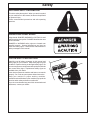 5
5
-
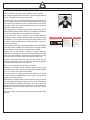 6
6
-
 7
7
-
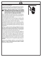 8
8
-
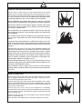 9
9
-
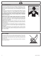 10
10
-
 11
11
-
 12
12
-
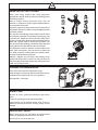 13
13
-
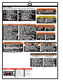 14
14
-
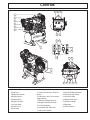 15
15
-
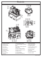 16
16
-
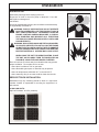 17
17
-
 18
18
-
 19
19
-
 20
20
-
 21
21
-
 22
22
-
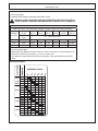 23
23
-
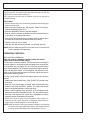 24
24
-
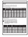 25
25
-
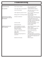 26
26
-
 27
27
-
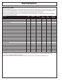 28
28
-
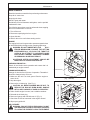 29
29
-
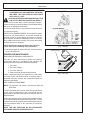 30
30
-
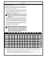 31
31
-
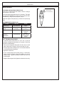 32
32
-
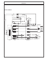 33
33
-
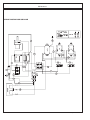 34
34
-
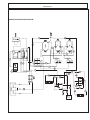 35
35
-
 36
36
-
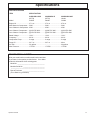 37
37
-
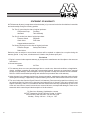 38
38
-
 39
39
-
 40
40
-
 41
41
-
 42
42
-
 43
43
-
 44
44
-
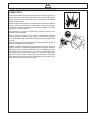 45
45
-
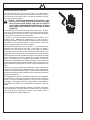 46
46
-
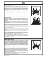 47
47
-
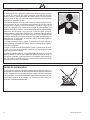 48
48
-
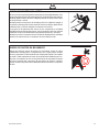 49
49
-
 50
50
-
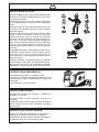 51
51
-
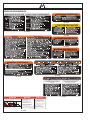 52
52
-
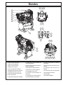 53
53
-
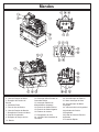 54
54
-
 55
55
-
 56
56
-
 57
57
-
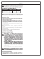 58
58
-
 59
59
-
 60
60
-
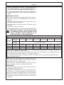 61
61
-
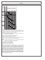 62
62
-
 63
63
-
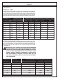 64
64
-
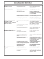 65
65
-
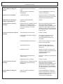 66
66
-
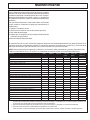 67
67
-
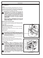 68
68
-
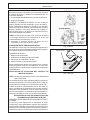 69
69
-
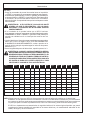 70
70
-
 71
71
-
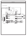 72
72
-
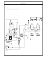 73
73
-
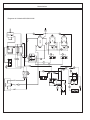 74
74
-
 75
75
-
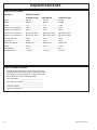 76
76
-
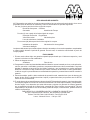 77
77
-
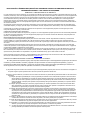 78
78
-
 79
79
-
 80
80


Mi-T-M Air Compressor-Generator-Welder Combination El manual del propietario
- Categoría
- Compresores de aire
- Tipo
- El manual del propietario
en otros idiomas
Artículos relacionados
-
Mi-T-M 5 Gallon Work Pro Series Gasoline El manual del propietario
-
-
 Mi-T-M AC1-HH04-05M Guía del usuario
-
 Mi-T-M Portable Gas El manual del propietario
-
 Mi-T-M Air Compressor-Generator Combination El manual del propietario
-
 Mi-T-M 2000 Watt Inverter El manual del propietario
-
 Mi-T-M 2000 Watt Inverter El manual del propietario
-
 Mi-T-M Choremaster Series Generator El manual del propietario
-
Mi-T-M GEN-3000-0MH0 Manual de usuario
-
 Mi-T-M Choremaster Series Generator El manual del propietario


Otros documentos
-
 John Deere AC2-CG35H Manual de usuario
-
Togo POWER GG1000 El manual del propietario
-
Simplicity 074011-0 Manual de usuario
-
 Dayton 1RKU2 Instrucciones de operación
-
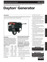 Dayton 2ZRP9 Manual de usuario
-
 John Deere PR-G7500M Manual de usuario
-
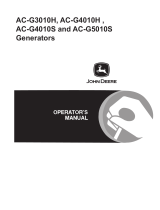 John Deere AC-G4010H Manual de usuario
-
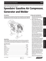 Speedaire 15D802 Operating Instructions Manual
-
Silverline DIY Series Manual de usuario
-
Hobart 5359D Operation and Maintenance Manual


