Sonel CMP-1015-PV Manual de usuario
- Categoría
- Medición
- Tipo
- Manual de usuario


CMP-1015-PV – INSTRUKCJA OBSŁUGI
2
Multimetr True RMS CMP-1015-PV przeznaczony jest do pomiaru
napięcia stałego i przemiennego, prądu stałego i przemiennego, re-
zystancji, pojemności elektrycznej, częstotliwości, cyklu roboczego
(wypełnienia) i temperatury, a także testowania diod oraz ciągłości.
Do najważniejszych cech przyrządu CMP-1015-PV należą:
możliwość prowadzenia pomiarów w obwodach wyjściowych
falowników i przekształtników częstotliwości,
bezdotykowy wskaźnik napięcia,
bezprzewodowa komunikacja Bluetooth do transmisji wyników
pomiarowych na urządzenia mobilne z systemem Android,
automatyczna i ręczna zmiana zakresów,
funkcja REL umożliwiająca dokonywanie pomiarów względnych,
funkcja MAX/MIN umożliwiająca wyświetlanie wartości maksy-
malnej i minimalnej,
funkcja PEAK umożliwiająca wyświetlenie wartości szczytowej,
funkcja INRUSH umożliwiająca precyzyjne uchwycenie wartości
prądu rozruchu z początkowego, 100-milisekundowego okresu
tuż po załączeniu urządzenia,
funkcja HOLD zatrzymująca odczyt na ekranie miernika,
wbudowana latarka umożliwiająca oświetlenie miejsca pomiaro-
wego,
sygnalizacja dźwiękowa ciągłości obwodu,
samoczynne wyłączanie nieużywanego przyrządu,
graficzny wyświetlacz LCD (odczyt 6000).

CMP-1015-PV – INSTRUKCJA OBSŁUGI
3
SPIS TREŚCI
1 Wstęp ............................................................................ 5
2 Bezpieczeństwo ........................................................... 6
2.1 Zasady ogólne .................................................................... 6
2.2 Symbole bezpieczeństwa ................................................... 7
3 Przygotowanie miernika do pracy .............................. 8
4 Opis funkcjonalny ...................................................... 10
4.1 Gniazda i funkcje pomiarowe ............................................ 10
4.2 Wyświetlacz ..................................................................... 13
4.3 Przewody ......................................................................... 14
5 Pomiary ....................................................................... 15
5.1 Pomiar prądu .................................................................... 15
5.2 Bezdotykowy wskaźnik napięcia ....................................... 16
5.3 Pomiar napięcia................................................................ 17
5.4 Pomiar LoZ (eliminacja napięć zakłócających
i indukowanych)................................................................ 18
5.5 Pomiar częstotliwości (sieć) .............................................. 18
5.6 Pomiar częstotliwości (elektronika) ................................... 18
5.7 Pomiar % cyklu roboczego (współczynnika wypełnienia
impulsu) ........................................................................... 19
5.8 Pomiar rezystancji ............................................................ 19
5.9 Test ciągłości obwodu ...................................................... 20
5.10 Test diody ........................................................................ 20
5.11 Pomiar pojemności ........................................................... 21
5.12 Pomiar temperatury .......................................................... 22
6 Funkcje specjalne ...................................................... 23
6.1 Przycisk HOLD/REL ......................................................... 23
6.1.1 Funkcja HOLD ........................................................... 23
6.1.2 Funkcja REL .............................................................. 23
6.2 Funkcja VFD .................................................................... 24
6.3 Funkcja HVDC ................................................................. 24
6.4 Funkcja AC+DC ............................................................... 24
6.5 Funkcja PEAK .................................................................. 24
6.6 Funkcja INRUSH .............................................................. 25

CMP-1015-PV – INSTRUKCJA OBSŁUGI
4
6.7 Funkcja MAX/MIN ............................................................ 25
6.8 Przycisk .................................................................... 25
6.9 Przycisk MENU i menu główne ......................................... 26
6.9.1 Język ......................................................................... 26
6.9.2 Ustawienia ................................................................. 26
6.9.3 Komunikacja bezprzewodowa .................................... 26
6.9.4 Czas i data ................................................................. 26
6.9.5 Informacje .................................................................. 26
6.9.6 Ustawienia fabryczne ................................................. 26
6.9.7 Rejestrator i pamięć wyników pomiarów ..................... 27
7 Wymiana baterii ......................................................... 28
8 Utrzymanie i konserwacja ......................................... 29
9 Magazynowanie ......................................................... 30
10 Rozbiórka i utylizacja ................................................ 30
11 Dane techniczne ........................................................ 31
11.1 Dane podstawowe ............................................................ 31
11.2 Dane eksploatacyjne ........................................................ 35
11.3 Specyfikacja Bluetooth ..................................................... 36
12 Producent ................................................................... 36

CMP-1015-PV – INSTRUKCJA OBSŁUGI
5
1 Wstęp
Dziękujemy za zakup multimetru firmy Sonel. Miernik
CMP-1015-PV jest nowoczesnym, wysokiej jakości przyrządem
pomiarowym, łatwym i bezpiecznym w obsłudze. Przeczytanie ni-
niejszej instrukcji pozwoli uniknąć błędów przy pomiarach i zapo-
biegnie ewentualnym problemom przy obsłudze miernika.
W niniejszej instrukcji posługujemy się trzema rodzajami
ostrzeżeń. Są to teksty w ramkach, opisujące możliwe zagrożenia
zarówno dla użytkownika, jak i miernika. Teksty
OSTRZEŻENIE opisują sytuacje, w których może dojść do za-
grożenia życia lub zdrowia, jeżeli nie przestrzega się instrukcji. Tek-
sty UWAGA! rozpoczynają opis sytuacji, w której niezastoso-
wanie się do instrukcji grozi uszkodzeniem przyrządu. Wskazania
ewentualnych problemów są poprzedzone symbolem .
OSTRZEŻENIE
Miernik CMP-1015-PV jest przeznaczony do pomia-
rów prądu oraz napięcia stałego i przemiennego,
częstotliwości, rezystancji, pojemności, a także te-
stów diod i ciągłości. Każde inne zastosowanie niż
podane w niniejszej instrukcji może spowodować
uszkodzenie przyrządu i być źródłem poważnego
niebezpieczeństwa dla użytkownika.
Miernik CMP-1015-PV może być używany jedynie
przez wykwalifikowane osoby, posiadające odpo-
wiednie uprawnienia do prac przy instalacjach elek-
trycznych. Posługiwanie się miernikiem przez osoby
nieuprawnione może spowodować uszkodzenie przy-
rządu i być źródłem poważnego niebezpieczeństwa
dla użytkownika.
Przed użyciem przyrządu należy dokładnie przeczy-
tać niniejszą instrukcję i zastosować się do przepi-
sów bezpieczeństwa i zaleceń producenta. Niesto-
sowanie się do powyższych zaleceń może spowodo-
wać uszkodzenie przyrządu i być źródłem poważne-
go niebezpieczeństwa dla użytkownika.

CMP-1015-PV – INSTRUKCJA OBSŁUGI
6
2 Bezpieczeństwo
2.1 Zasady ogólne
Aby zapewnić odpowiednią obsługę i poprawność uzyskiwa-
nych wyników należy przestrzegać następujących zaleceń:
przed rozpoczęciem eksploatacji miernika należy dokładnie zapo-
znać się z niniejszą instrukcją,
przyrząd powinien być obsługiwany wyłącznie przez osoby odpo-
wiednio wykwalifikowane i przeszkolone w zakresie BHP,
należy zachować dużą ostrożność przy pomiarze napięć przekra-
czających (wg normy PN-EN 61010-1:2010/AMD1:2016):
Warunki normalne
Warunki wilgotne
60 V DC
35 V DC
30 V AC RMS
16 V RMS
42,4 V AC wartości szczytowej
22,6 V AC wartości szczytowej
gdyż stanowią one potencjalne zagrożenie porażeniem,
nie wolno przekraczać maksymalnych limitów sygnału wejściowe-
go,
w trakcie pomiarów napięcia nie należy przełączać urządzenia w
tryb pomiaru prądu lub rezystancji i odwrotnie,
w przypadku zmiany zakresów zawsze należy odłączyć przewody
pomiarowe od mierzonego obwodu,
sondy pomiarowe należy trzymać za miejsca do tego przezna-
czone, ograniczone specjalną barierą, w celu uniknięcia przypad-
kowego dotknięcia nieosłoniętych części metalowych,
jeżeli w trakcie pomiaru na ekranie pojawi się symbol OL, ozna-
cza to, że wartość mierzona przekracza zakres pomiarowy,
niedopuszczalne jest używanie:
miernika, który uległ uszkodzeniu i jest całkowicie lub czę-
ściowo niesprawny
przewodów z uszkodzoną izolacją
miernika przechowywanego zbyt długo w złych warunkach
(np. zawilgoconego)
naprawy mogą być wykonywane wyłącznie przez autoryzowany
serwis.

CMP-1015-PV – INSTRUKCJA OBSŁUGI
7
OSTRZEŻENIE
Nigdy nie wolno przystępować do pomiarów, jeżeli
użytkownik ma mokre lub wilgotne dłonie.
Nie wolno dokonywać pomiarów w atmosferze gro-
żącej wybuchem (np. w obecności gazów palnych,
oparów, pyłów, itp.). Używanie miernika w tych wa-
runkach może wywołać iskrzenia i spowodować eks-
plozję.
Wartości graniczne sygnału wejściowego
Funkcja
Maksymalna wartość
wejściowa
A DC, A AC
1000 A DC/AC
V DC, V AC
1500 V DC/1000 V AC RMS
Rezystancja, ciągłość, test
diody, pojemność, częstotli-
wość, cykl roboczy
1000 V DC/AC RMS
Temperatura
1000 V DC/AC
2.2 Symbole bezpieczeństwa
Niniejszy symbol umieszczony w pobliżu innego symbolu
lub gniazda wskazuje, że użytkownik powinien zapoznać
się z dalszymi informacjami zamieszczonymi w instrukcji
obsługi.
Niniejszy symbol umieszczony w pobliżu gniazda
wskazuje, że w warunkach normalnego użytkowania
istnieje możliwość wystąpienia niebezpiecznych napięć.
II klasa ochronności – izolacja podwójna
Tak oznaczone gniazda nie mogą być podłączone do
obwodu, gdzie napięcie względem ziemi przekracza
maksymalne napięcie bezpieczne przyrządu.

CMP-1015-PV – INSTRUKCJA OBSŁUGI
8
3 Przygotowanie miernika do pracy
Po zakupie miernika należy sprawdzić kompletność zawartości
opakowania.
Przed przystąpieniem do wykonywania pomiarów należy:
upewnić się, że stan baterii pozwoli na wykonanie pomiarów,
sprawdzić, czy obudowa miernika i izolacja przewodów pomiaro-
wych nie są uszkodzone,
dla zapewnienia jednoznaczności wyników pomiarów zaleca się
do gniazda COM podłączać przewód czarny, a do pozostałych
gniazd przewód czerwony,
gdy miernik nie jest używany, należy ustawić przełącznik funkcyj-
ny w położeniu OFF (wyłączony).
Przyrząd wyposażono w funkcję automatycznego wyłączania
po upływie 15…60 minut braku działania w zależności od ustawień.
Aby ponownie włączyć miernik, należy ustawić przełącznik funkcyj-
ny do położenia OFF, a następnie do żądanej funkcji.
OSTRZEŻENIE
Podłączanie nieodpowiednich lub uszkodzonych
przewodów grozi porażeniem prądem elektrycznym.
Nie wolno podłączać miernika do źródła napięcia,
gdy ustawiony jest pomiar prądu, rezystancji lub test
diody. Niezastosowanie się do zalecenia grozi usz-
kodzeniem miernika!
Użytkując miernik należy pamiętać, by:
rozładować kondensatory w badanych źródłach zasilania,
odłączyć zasilanie podczas pomiarów rezystancji i testowania
diod,
wyłączyć miernik i odłączyć przewody pomiarowe przed demon-
tażem tylnej pokrywy celem wymiany akumulatora.

CMP-1015-PV – INSTRUKCJA OBSŁUGI
9
OSTRZEŻENIE
Nie wolno użytkować miernika, jeżeli zdemontowana
jest pokrywa akumulatora.
Istnieje możliwość, że w pewnych niskich zakresach napię-
cia zmiennego lub stałego, gdy do miernika nie podłączono
przewodów pomiarowych, na ekranie pojawią się przypad-
kowe i zmienne odczyty. Jest to normalne zjawisko, które
wynika z czułości wejścia o dużej rezystancji wejściowej.
Po podłączeniu do obwodu odczyt ustabilizuje się i miernik
poda prawidłową wartość.

CMP-1015-PV – INSTRUKCJA OBSŁUGI
10
4 Opis funkcjonalny
4.1 Gniazda i funkcje pomiarowe

CMP-1015-PV – INSTRUKCJA OBSŁUGI
11
Bezdotykowy wskaźnik napięcia
Cęgi prądowe
Latarka
Kontrolka bezdotykowego wskaźnika napięcia
Spust otwierający cęgi
Wyświetlacz LCD
Przyciski funkcyjne
Przycisk MODE / VFD
o Wybór podfunkcji i trybów przypisanych do wybranej funkcji
pomiarowej
o Zmiana trybu pomiaru w funkcjach: A / V / LoZ / częstotliwość /
cykl roboczy / rezystancja / test diody / ciągłość / pojemność /
pomiar temperatury (nacisnąć krótko)
o Pomiar prądu i napięcia za falownikiem, przekształtnikiem czę-
stotliwości, w układzie VFD (nacisnąć i przytrzymać)
Przycisk MENU / INRUSH
o Wyświetla menu (nacisnąć krótko)
o Wyświetla prąd rozruchu (nacisnąć i przytrzymać)
Przyciski strzałek
o Wybór podfunkcji i trybów przypisanych do wybranej funkcji
pomiarowej
o Wybór funkcji w menu
o Poruszanie się po ekranie
Przycisk HOLD / REL
o Wybór podfunkcji i trybów przypisanych do wybranej funkcji
pomiarowej
o Tryb HOLD – zatrzymanie wyniku pomiaru na wyświetlaczu
(nacisnąć krótko)
o Tryb REL – nacisnąć i przytrzymać:
Zerowanie wskazania (pomiar prądu DC)
Wyświetlenie pomiaru względem wartości odniesienia (po-
zostałe funkcje pomiarowe)

CMP-1015-PV – INSTRUKCJA OBSŁUGI
12
Przycisk RANGE
Ustawianie zakresu pomiarowego:
o automatyczny (nacisnąć i przytrzymać)
o ręczny (nacisnąć krótko)
Przycisk – tryb latarki (nacisnąć krótko)
Przełącznik obrotowy
Wybór funkcji:
60A – pomiar prądu stałego i przemiennego do 60 A
600A – pomiar prądu stałego i przemiennego do 600 A
1000A – pomiar prądu stałego i przemiennego do 1000 A
OFF – miernik wyłączony
V AC+DC – pomiar napięcia stałego, przemiennego i składowych
AC oraz DC napięcia
LoZ AC+DC – niskoimpedancyjny pomiar napięcia przemiennego,
niskoimpedancyjny pomiar składowych AC oraz DC napięcia
przemiennego
Hz% – pomiar częstotliwości i cyklu roboczego
Ω CAP – pomiar rezystancji, test diod, pomiar ciągłości, po-
jemności
K-Temp ºC ºF – pomiar temperatury
Gniazdo pomiarowe COM
Wejście pomiarowe wspólne dla wszystkich funkcji pomiarowych
oprócz pomiaru prądu.
Gniazdo pomiarowe VΩLoZV CAP Hz%K-Temp
Wejście pomiarowe dla wszystkich pomiarów oprócz pomiaru prądu.

CMP-1015-PV – INSTRUKCJA OBSŁUGI
13
4.2 Wyświetlacz
V
Pomiar napięcia
A
Pomiar prądu
Sygnał przemienny
Sygnał stały
Sygnał przemienny z rozróżnie-
niem jego składowych: AC oraz
DC
Napięcie przekracza 30 V AC/DC
Zachowaj ostrożność!
Pomiar względny
Szerokość impulsu
VFD
Pomiar za falownikiem, prze-
kształtnikiem częstotliwości,
w układzie VFD
HVDC
Pomiar wysokiego napięcia DC
Prąd rozruchowy
–
Ujemna wartość odczytu
Ω
Pomiar rezystancji
Test ciągłości
Test diody
F
Pomiar pojemności
n / µ / m / k / M
Przedrostek wielokrotności jed-
nostki pomiaru
OL
Przekroczenie zakresu pomiaru
Bateria rozładowana
Auto Range
Automatyczne ustawianie zakresu
H
Włączona funkcja HOLD
LoZ
Niskoimpedancyjny pomiar na-
pięcia
MAX / MIN
Wartość maksymalna / minimalna

CMP-1015-PV – INSTRUKCJA OBSŁUGI
14
4.3 Przewody
Producent gwarantuje poprawność wskazań jedynie przy użyciu
dostarczonych przez niego przewodów.
OSTRZEŻENIE
Podłączanie nieodpowiednich przewodów grozi pora-
żeniem prądem elektrycznym lub możliwością wystą-
pienia błędów pomiarowych.
Sondy pomiarowe wyposażone są w dodatkowe, demon-
towalne osłony ostrzy.
Sondy należy przechowywać wyłącznie w miejscu do te-
go przeznaczonym.

CMP-1015-PV – INSTRUKCJA OBSŁUGI
15
5 Pomiary
Należy dokładnie zapoznać się z treścią niniejszego rozdziału,
ponieważ zostały w nim opisane sposoby wykonywania pomiarów i
podstawowe zasady interpretacji wyników.
5.1 Pomiar prądu
OSTRZEŻENIE
Przed pomiarem prądu za pomocą cęgów należy odłą-
czyć przewody pomiarowe.
Aby wykonać pomiar prądu, należy:
ustawić przełącznik obrotowy w pozycji 60A / 600A / 1000 A,
nacisnąć przycisk MODE/VFD w celu wyświetlenia na wyświetla-
czu symbolu:
, jeśli mierzony będzie prąd przemienny,
, jeśli mierzony będzie prąd stały,
używając spustu zapiąć cęgi na mierzony przewód. W obrębie
szczęk musi się znajdować pojedynczy przewód,
odczytać wynik pomiaru na wyświetlaczu.

CMP-1015-PV – INSTRUKCJA OBSŁUGI
16
Jeżeli mierzony jest prąd DC i miernik nie jest zapięty na
mierzony obwód, a mimo to wskazuje niezerową wartość
pomiaru, należy wyzerować wskazanie miernika poprzez
naciśnięcie i przytrzymanie przycisku HOLD/REL.
5.2 Bezdotykowy wskaźnik napięcia
OSTRZEŻENIE
Wskaźnik służy do wykrywania obecności napięcia, a
nie do stwierdzania jego braku.
Niebezpieczeństwo porażenia. Zanim użyjesz wskaź-
nika, potwierdź jego sprawność, sprawdzając go na
znanym napięciu AC (np. najbliższe dostępne gniaz-
do będące pod napięciem).
Aby uaktywnić wskaźnik, należy:
ustawić przełącznik obrotowy w dowolnej pozycji,
przyłożyć końcówkę wskaźnika do badanego obiektu.
Jeżeli napięcie przemienne jest obecne, dioda wskaźnika będzie
świecić czerwonym światłem.
Przewody w przedłużaczach są często skręcone. Aby
uzyskać najlepszy wynik, należy przesunąć końcówkę
wskaźnika wzdłuż przewodu, by zlokalizować linię będą-
cą pod napięciem.
Wskaźnik ma wysoką czułość. Może być losowo pobu-
dzany przez ładunki elektrostatyczne lub inne źródła
energii. Jest to normalne zjawisko.
Rodzaj i grubość izolacji, odległość od źródła napięcia,
przewody ekranowane oraz inne czynniki mogą wpłynąć
na skuteczność działania wskaźnika. W przypadku braku
pewności co do wyniku testu, stwierdź obecność napię-
cia w inny sposób.

CMP-1015-PV – INSTRUKCJA OBSŁUGI
17
5.3 Pomiar napięcia
OSTRZEŻENIE
Niebezpieczeństwo porażenia. Końcówki sond po-
miarowych, z uwagi na swą długość, mogą nie do-
sięgnąć elementów pod napięciem wewnątrz niektó-
rych przyłączy sieciowych niskiego napięcia dla
urządzeń elektrycznych, ponieważ styki są umiesz-
czone w głębi gniazdek. W takiej sytuacji odczyt bę-
dzie wynosił 0 V przy jednoczesnej obecności napię-
cia w gnieździe.
Przed orzeczeniem o braku napięcia w gnieździe na-
leży upewnić się, że końcówki sondy dotykają meta-
lowych styków wewnątrz gniazda.
UWAGA!
Nie mierzyć napięcia w momencie, gdy znajdujący się w
obwodzie silnik elektryczny jest włączany lub wyłączany.
Wiążące się z tym skoki napięcia mogą uszkodzić miernik.
Aby wykonać pomiar napięcia przemiennego należy:
ustawić przełącznik obrotowy w pozycji V AC+DC,
nacisnąć przycisk MODE/VFD w celu wyświetlenia na wyświetla-
czu symbolu:
, jeśli mierzone będzie napięcie przemienne,
, jeśli mierzone będzie napięcie stałe,
, jeśli mierzone będą składowe AC oraz DC napięcia,
podłączyć czarny przewód pomiarowy do gniazda COM, a czer-
wony do gniazda VΩLoZV CAP Hz%K-Temp,
przyłożyć ostrza sond do punktów pomiarowych,
odczytać wynik pomiaru na wyświetlaczu.

CMP-1015-PV – INSTRUKCJA OBSŁUGI
18
5.4 Pomiar LoZ (eliminacja napięć zakłócających
i indukowanych)
Funkcja pomiaru w trybie LoZ pozwala na eliminację wpływu
napięć zakłócających lub indukowanych na pomiar, przez co jest on
bardziej dokładny i rzetelny. Napięcia takie mogą występować w
wyniku pojemnościowego sprzężenia pomiędzy przewodami pod
napięciem a nieużywanymi przewodami występującymi w sąsiedz-
twie.
Aby wykonać pomiar, należy:
ustawić przełącznik obrotowy w pozycji LoZAC+DC,
podłączyć czarny przewód pomiarowy do gniazda COM, a czer-
wony do gniazda VΩLoZV CAP Hz%K-Temp,
przyłożyć ostrza sond do punktów pomiarowych,
odczytać wynik pomiaru na wyświetlaczu.
5.5 Pomiar częstotliwości (sieć)
Aby wykonać pomiar częstotliwości należy:
ustawić przełącznik obrotowy w pozycji V AC+DC,
nacisnąć przycisk MODE/VFD w celu wyświetlenia na wyświetla-
czu symbolu Hz,
podłączyć czarny przewód pomiarowy do gniazda COM, a czer-
wony do gniazda VΩLoZV CAP Hz%K-Temp,
przyłożyć ostrza sond do punktów pomiarowych,
odczytać wynik pomiaru na wyświetlaczu.
5.6 Pomiar częstotliwości (elektronika)
Aby wykonać pomiar częstotliwości należy:
ustawić przełącznik obrotowy w pozycji Hz%,
podłączyć czarny przewód pomiarowy do gniazda COM, a czer-
wony do gniazda VΩLoZV CAP Hz%K-Temp,
przyłożyć ostrza sond do punktów pomiarowych,
odczytać wynik pomiaru na wyświetlaczu.

CMP-1015-PV – INSTRUKCJA OBSŁUGI
19
5.7 Pomiar % cyklu roboczego (współczynnika wypeł-
nienia impulsu)
Aby wykonać pomiar należy:
ustawić przełącznik obrotowy w pozycji Hz% lub V AC+DC,
nacisnąć przycisk MODE do momentu wyświetlenia symbolu %
na wyświetlaczu,
podłączyć czarny przewód pomiarowy do gniazda COM, a czer-
wony do gniazda VΩLoZV CAP Hz%K-Temp,
przyłożyć ostrza sond do punktów pomiarowych,
odczytać na wyświetlaczu wynik pomiaru (szerokość impul-
su ).
5.8 Pomiar rezystancji
OSTRZEŻENIE
Nie wolno dokonywać pomiarów w obwodzie będącym
pod napięciem. Przed pomiarem odłączyć napięcie i
rozładować kondensatory.
Aby wykonać pomiar rezystancji, należy:
ustawić przełącznik obrotowy w pozycji Ω CAP,
podłączyć czarny przewód pomiarowy do gniazda COM, a czer-
wony do gniazda VΩLoZV CAP Hz%K-Temp,
przyłożyć ostrza sond do punktów pomiarowych; najlepiej jest roz-
łączyć jedną stronę testowanego elementu, tak aby pozostała
część obwodu nie zakłócała odczytu wartości rezystancji,
odczytać wynik pomiaru na wyświetlaczu.

CMP-1015-PV – INSTRUKCJA OBSŁUGI
20
5.9 Test ciągłości obwodu
OSTRZEŻENIE
Nie wolno dokonywać pomiarów w obwodzie będącym
pod napięciem. Przed pomiarem odłączyć napięcie i
rozładować kondensatory.
Aby wykonać test ciągłości obwodu, należy:
ustawić przełącznik obrotowy w pozycji Ω CAP,
podłączyć czarny przewód pomiarowy do gniazda COM, a czer-
wony do gniazda VΩLoZV CAP Hz%K-Temp,
nacisnąć przycisk MODE, aby wyświetlić Ω na wyświetlaczu,
przyłożyć ostrza sond do punktów pomiarowych,
odczytać wynik pomiaru na wyświetlaczu; sygnał dźwiękowy po-
jawia się przy wartościach rezystancji poniżej ok. 50 Ω.
5.10 Test diody
OSTRZEŻENIE
Nie wolno dokonywać pomiarów w obwodzie będącym
pod napięciem. Przed pomiarem odłączyć napięcie i
rozładować kondensatory. Nie wolno badać diody
znajdującej się pod napięciem.
Aby wykonać test diody, należy:
ustawić przełącznik obrotowy w pozycji Ω CAP,
podłączyć czarny przewód pomiarowy do gniazda COM, a czer-
wony do gniazda VΩLoZV CAP Hz%K-Temp,
nacisnąć przycisk MODE, aby wyświetlić V na wyświetlaczu,
przyłożyć ostrza sond do diody. Czerwona sonda powinna być
przyłożona do anody, a czarna do katody,
odczytać wynik testu na wyświetlaczu – wyświetlane jest napięcie
przewodzenia.
Dla typowej diody prostowniczej krzemowej wynosi ono ok.
0,7 V, a dla diody germanowej ok. 0,3 V.

CMP-1015-PV – INSTRUKCJA OBSŁUGI
21
Dla diod LED małej mocy typowa wartość napięcia mieści się
w zakresie 1,2…5,0 V w zależności od koloru.
Jeśli dioda spolaryzowana jest w kierunku zaporowym lub jest
przerwa w obwodzie, na wyświetlaczu pojawi się odczyt OL.
W przypadku diody zwartej miernik wskaże wartość bli-
ską 0 V,
po zakończeniu pomiarów wyjąć przewody z gniazd pomiarowych
miernika.
5.11 Pomiar pojemności
OSTRZEŻENIE
Ryzyko porażenia prądem. Należy odłączyć zasilanie
od badanego kondensatora i rozładować wszystkie
kondensatory przed jakimikolwiek pomiarami pojem-
ności.
Aby wykonać pomiar należy:
ustawić przełącznik obrotowy w pozycji Ω CAP,
nacisnąć przycisk MODE, aby wyświetlić nF na wyświetlaczu,
podłączyć czarny przewód pomiarowy do gniazda COM, a czer-
wony do gniazda VΩLoZV CAP Hz%K-Temp,
przyłożyć ostrza sond do testowanego kondensatora,
odczytać wynik pomiaru na wyświetlaczu.

CMP-1015-PV – INSTRUKCJA OBSŁUGI
22
5.12 Pomiar temperatury
Aby wykonać pomiar, należy:
ustawić przełącznik obrotowy w pozycji K-Temp ºC ºF,
w celu zmiany jednostki nacisnąć MODE,
adapter sondy temperaturowej umieścić w gnieździe COM
(czarna nóżka) oraz VΩLoZV CAP Hz%K-Temp (czer-
wona nóżka):
sondę temperaturową umieścić w adapterze zgodnie z ry-
sunkiem:
cienki bolec sondy oznaczony + pasuje do gniazda +;
gruby bolec sondy oznaczony K pasuje do gniazda –;
odwrotne podłączenie sondy jest mechanicznie
niemożliwe,
przyłożyć głowicę sondy temperatury do testowanego
urządzenia. Kontakt głowicy z mierzoną częścią testowanego
urządzenia należy utrzymywać, dopóki odczyt się nie
ustabilizuje,
odczytać wynik pomiaru na wyświetlaczu,
po zakończeniu pomiarów odłączyć sondę od miernika.
UWAGA!
Ryzyko poparzenia. Sonda temperaturowa nagrzewa się,
przyjmując temperaturę mierzonego obiektu.

CMP-1015-PV – INSTRUKCJA OBSŁUGI
23
6 Funkcje specjalne
6.1 Przycisk HOLD/REL
6.1.1 Funkcja HOLD
Funkcja służy do zatrzymania wyniku pomiaru na wyświetlaczu.
W tym celu nacisnąć krótko przycisk HOLD/REL. Kiedy funkcja jest
włączona, na wyświetlaczu widnieje symbol HOLD.
Aby powrócić do normalnego trybu funkcjonowania urządzenia,
nacisnąć ponownie przycisk HOLD/REL.
6.1.2 Funkcja REL
Tryb umożliwia wykonanie pomiaru względem wartości odniesienia.
Aby włączyć tryb, nacisnąć i przytrzymać przycisk HOLD/REL.
Wyświetlana wówczas wartość odczytu zostanie przyjęta jako
wartość odniesienia, a sam odczyt – wyzerowany.
Od tej pory odczyty będą przedstawiać jako stosunek wartości
mierzonej do wartości odniesienia.
Aby wyłączyć tryb, nacisnąć przycisk HOLD/REL.
Wyświetlany główny wynik to różnica wartości odniesienia (odczytu
w momencie włączenia trybu REL) i odczytu aktualnego. Przykład:
jeżeli wartością odniesienia jest 20 A, a aktualny odczyt wynosi
12,5 A, to główny wynik na wyświetlaczu będzie miał wartość
-7,5 A. Jeżeli nowy odczyt jest identyczny z wartością odniesienia,
to główny wynik wyniesie zero.
Gdy funkcja jest aktywna, automatyczne dostosowywa-
nie zakresu pomiarowego jest niedostępne.
Jeżeli odczyt przekracza zakres pomiaru, wyświetla się
symbol OL. W takiej sytuacji należy wyłączyć funkcję i
ręcznie przełączyć zakres na wyższy.
Funkcja jest niedostępna dla testu diody.

CMP-1015-PV – INSTRUKCJA OBSŁUGI
24
6.2 Funkcja VFD
Aby zmierzyć prąd lub napięcie AC za falownikiem, przekształtni-
kiem częstotliwości lub w układzie VFD, należy:
ustawić przełącznik obrotowy w pozycji pomiaru napięcia lub prądu,
nacisnąć i przytrzymać przycisk MODE/VFD, aż pojawi się sym-
bol „VFD”).
6.3 Funkcja HVDC
Aby zmierzyć wysokie napięcie DC (HVDC) np. w instalacji fo-
towoltaicznej, należy:
podłączyć do przyrządu adapter wysokonapięciowy,
ustawić przełącznik obrotowy w pozycji V AC+DC,
nacisnąć przycisk MODE/VFD w celu wyświetlenia na wyświetla-
czu symbolu ,
przyciskiem ►wybrać opcję HVDC.
6.4 Funkcja AC+DC
Miernik mierzy składową okresową AC i stałą DC mierzonego
sygnału. Aby wykonać pomiar, należy:
ustawić przełącznik obrotowy w pozycji V AC+DC,
nacisnąć przycisk MODE/VFD w celu wyświetlenia na wyświetla-
czu symbolu .
6.5 Funkcja PEAK
Funkcja pomiaru wartości szczytowej PEAK różni się od funkcji
pomiaru wartości maksymalnej MAX czasem występowania zareje-
strowanego zdarzenia. W przypadku funkcji PEAK jest to ok. 1 ms. Po-
zwala to na zarejestrowanie bardzo krótkich skoków napięcia prze-
miennego.
Miernik będzie aktualizował wyświetlane dane za każdym ra-
zem, gdy wystąpi niższa ujemna lub wyższa dodatnia wartość
szczytowa. Funkcja automatycznego wyłączenia zasilania zostanie
w tym trybie dezaktywowana.

CMP-1015-PV – INSTRUKCJA OBSŁUGI
25
Aby włączyć tryb, przyciskami wybrać opcję PEAK.
Aby wyłączyć tryb, ponownie wybrać opcję PEAK.
Funkcja dostępna tylko podczas pomiaru prądu AC.
W czasie gdy funkcja PEAK jest aktywna, nie działa automatyczne
dobieranie zakresów, dlatego zaleca się uruchamiać funkcję dopiero
po podłączenia przewodów do punktu pomiarowego. Uruchomienie
funkcji PEAK przed podłączeniem miernika do punktu mierzonego
może powodować wyświetlanie symboli przekroczenia zakresu.
6.6 Funkcja INRUSH
Funkcja INRUSH umożliwia precyzyjne uchwycenie wartości
prądu rozruchu z początkowego ok. 100-milisekundowego okresu,
tuż po załączeniu badanego urządzenia. Aby wykonać pomiar:
włączyć pomiar prądu przemiennego,
nacisnąć i przytrzymać przycisk MENU/INRUSH,
zapiąć cęgi na przewód zasilający badany obiekt,
włączyć obiekt,
odczytać wynik.
6.7 Funkcja MAX/MIN
Aby włączyć tryb, przyciskami wybrać opcję MAX.
Symbol Max – miernik wyświetla największą wartość spośród
dotychczasowych odczytów pomiaru.
Symbol Min – miernik wyświetla najmniejszą wartość spośród
dotychczasowych odczytów pomiaru.
Aby wyłączyć funkcję, ponownie wybrać opcję MAX.
Gdy funkcja jest aktywna, automatyczne dostosowywa-
nie zakresu pomiarowego jest niedostępne.
Jeżeli odczyt przekracza zakres pomiaru, wyświetla się
symbol OL.
6.8 Przycisk
Nacisnąć krótko przycisk , aby włączyć lub wyłączyć tryb
latarki.

CMP-1015-PV – INSTRUKCJA OBSŁUGI
26
6.9 Przycisk MENU i menu główne
Nacisnąć krótko przycisk MENU, aby wywołać menu główne.
Przyciskami ▲▼zaznacza się pozycję.
Przyciskiem ► lub MENU wchodzi się w daną pozycję.
Przyciskiem ◄ wraca się do menu wyższego poziomu.
Wyjście z menu głównego odbywa się za pomocą przycisków
◄, MODE/VFD, RANGE, HOLD/REL.
6.9.1 Język
Tu można ustawić język interfejsu.
6.9.2 Ustawienia
Tu można włączyć/wyłączyć:
dźwięki przycisków,
komunikację Bluetooth
jasność wyświetlacza,
czas do automatycznego wyłączenia.
6.9.3 Komunikacja bezprzewodowa
Multimetr wyposażony jest w tryb bezprzewodowego transferu
danych do urządzeń z zainstalowanym oprogramowaniem mobil-
nym Sonel Multimeter Mobile. Aby włączyć ten tryb, należy włą-
czyć komunikację Bluetooth. Miernik będzie widoczny w menedże-
rze urządzeń Bluetooth dowolnego urządzenia odbiorczego pod
nazwą CMP-1015-PV.
Szczegóły dotyczące współpracy z aplikacją mobilną znajdują
się w instrukcji Sonel Multimeter Mobile.
6.9.4 Czas i data
Tu można zmienić datę, godzinę i jej format.
6.9.5 Informacje
Tu można sprawdzić wersję sprzętową i firmware’u miernika.
6.9.6 Ustawienia fabryczne
Tu można przywrócić miernik do ustawień fabrycznych.

CMP-1015-PV – INSTRUKCJA OBSŁUGI
27
6.9.7 Rejestrator i pamięć wyników pomiarów
Tu dostępne są poniższe funkcje.
Rozpocznij rejestrację – wybranie tej pozycji powoduje przejście
do ekranu pomiarowego i rozpoczęcie rejestrowania wyników do
pamięci. Aby zakończyć rejestrację, wybrać pozycję Zatrzymana.
Aby zapisać ją do pamięci, wybrać ZAPISZ.
Odtwórz – wybranie tej pozycji powoduje przejście do ekranu
przeglądania pamięci.
Aby podejrzeć daną rejestrację, nacisnąć przycisk ►. Składa-
jące się na nią wyniki tworzą wykres.
Przyciski ◄► przesuwają kursor, który wyświetla jednostko-
wy wynik.
Przycisk ▲(funkcja ZBLIŻ) rozszerza oś czasu.
Wyjście do listy rejestracji przyciskiem MODE/VFD (COFNIJ).
Zamknięcie wykresu przyciskiem HOLD/REL (ZAMKNIJ).
▲►
Próbkowanie – ustawienia interwału próbkowania.
Czas trwania – ustawianie czasu trwania rejestracji.
Pamięć – wyświetla liczbę rejestracji i ilość wolnej pamięci.
Usuń rejestracje – usunięcie wszystkich rejestracji.

CMP-1015-PV – INSTRUKCJA OBSŁUGI
28
7 Wymiana baterii
OSTRZEŻENIE
Aby uniknąć porażenia elektrycznego nie należy uży-
wać miernika, jeżeli pokrywa baterii nie znajduje się na
swoim miejscu i nie jest prawidłowo zamocowana.
Miernik CMP-1015-PV jest zasilany z akumulatora Li-Pol 7,4 V
1200 mAh.
Aby wymienić akumulator, należy:
przełącznik obrotowy ustawić w pozycji OFF,
wyjąć przewody z gniazd pomiarowych miernika,
przekręcić śrubę mocującą pokrywę komory do pozycji:
zdjąć pokrywę,
wyjąć akumulator i włożyć nowy przestrzegając biegunowości,
założyć pokrywę i przekręcić śrubę mocującą do pozycji:
Dokonując pomiarów przy wyświetlonym symbolu rozła-
dowanej baterii należy się liczyć z dodatkowymi nieokre-
ślonymi niepewnościami pomiaru lub niestabilnym dzia-
łaniem przyrządu.
Jeżeli miernik nie funkcjonuje prawidłowo, należy spraw-
dzić akumulator celem upewnienia się, że znajduje się on
we właściwym stanie oraz jest prawidłowo zamontowany
w urządzeniu.

CMP-1015-PV – INSTRUKCJA OBSŁUGI
29
8 Utrzymanie i konserwacja
Multimetr cyfrowy został zaprojektowany z myślą o wielu latach
niezawodnego użytkowania, pod warunkiem przestrzegania poniż-
szych zaleceń dotyczących jego utrzymania i konserwacji:
1. MIERNIK MUSI BYĆ SUCHY. Zawilgocony miernik należy
wytrzeć.
2. MIERNIK NALEŻY STOSOWAĆ ORAZ PRZECHOWYWAĆ
W NORMALNYCH TEMPERATURACH. Temperatury skrajne
mogą skrócić żywotność elektronicznych elementów miernika
oraz zniekształcić lub stopić elementy plastikowe.
3. Z MIERNIKIEM NALEŻY OBCHODZIĆ SIĘ OSTROŻNIE
I DELIKATNIE. Upadek miernika może spowodować
uszkodzenie elektronicznych elementów lub obudowy.
4. MIERNIK MUSI BYĆ UTRZYMYWANY W CZYSTOŚCI.
Od czasu do czasu należy przetrzeć jego obudowę wilgotną
tkaniną. NIE wolno stosować środków chemicznych,
rozpuszczalników ani detergentów.
5. NALEŻY STOSOWAĆ WYŁĄCZNIE NOWE BATERIE
ZALECANEGO ROZMIARU I TYPU. Wyjąć z miernika stare
lub wyczerpane baterie, aby uniknąć wycieku elektrolitu i
uszkodzenia urządzenia.
6. JEŻELI MIERNIK MA BYĆ PRZECHOWYWANY DŁUŻEJ NIŻ
60 DNI, należy wyjąć z niego baterie i trzymać je oddzielnie.
Układ elektroniczny miernika nie wymaga konserwacji.

CMP-1015-PV – INSTRUKCJA OBSŁUGI
30
9 Magazynowanie
Przy przechowywaniu przyrządu należy przestrzegać poniż-
szych zaleceń:
odłączyć od miernika przewody,
upewnić się, że miernik i akcesoria są suche,
przy dłuższym okresie przechowywania należy wyjąć baterię.
10 Rozbiórka i utylizacja
Zużyty sprzęt elektryczny i elektroniczny należy gromadzić se-
lektywnie, tj. nie umieszczać z odpadami innego rodzaju.
Zużyty sprzęt elektroniczny należy przekazać do punktu zbiórki
zgodnie z Ustawą o zużytym sprzęcie elektrycznym i elektronicz-
nym.
Przed przekazaniem sprzętu do punktu zbiórki nie należy sa-
modzielnie demontować żadnych części z tego sprzętu.
Należy przestrzegać lokalnych przepisów dotyczących wyrzu-
cania opakowań, zużytych baterii i akumulatorów.

CMP-1015-PV – INSTRUKCJA OBSŁUGI
31
11 Dane techniczne
11.1 Dane podstawowe
„w.m.” oznacza wartość mierzoną wzorcową.
Pomiar prądu przemiennego (True RMS)
Zakres
Rozdzielczość
Dokładność
60,00 A
0,01 A
(2,5% w.m. + 5 cyfr)
600,0 A
0,1 A
1000 A
1 A
Wszystkie prądy AC są określone w przedziale 10%…100% zakresu
Zakres częstotliwości: 50 Hz…60 Hz
Zabezpieczenie przed przeciążeniem 1000 V DC/AC RMS
Pomiar prądu stałego
Zakres
Rozdzielczość
Dokładność
60,00 A
0,01 A
(2,0% w.m. + 8 cyfr)
600,0 A
0,1 A
1000 A
1 A
Zabezpieczenie przed przeciążeniem 1000 V DC/AC RMS
Pomiar napięcia przemiennego (True RMS)
Zakres
Rozdzielczość
Dokładność
6,000 V
0,001 V
f = 50…60 Hz
(1,2% w.m. + 5 cyfr)
f = 61…1000 Hz
(2,5% w.m. + 5 cyfr)
60,00 V
0,01 V
600,0 V
0,1 V
1000 V
1 V
Wszystkie napięcia AC są określone w przedziale 10%…100% zakresu
Impedancja wejściowa: 9 MΩ
Dokładność funkcji PEAK: 10% w.m.
Zakres częstotliwości: 50 Hz…1000 Hz
Zabezpieczenie przed przeciążeniem 1000 V DC/AC RMS

CMP-1015-PV – INSTRUKCJA OBSŁUGI
32
Pomiar napięcia stałego
Zakres
Rozdzielczość
Dokładność
600,0 mV
0,1 mV
(0,8% w.m. + 8 cyfr)
6,000 V
0,001 V
(0,5% w.m. + 5 cyfr)
60,00 V
0,01 V
600,0 V
0,1 V
(0,8% w.m. + 5 cyfr)
1500 V
1 V
Impedancja wejściowa: 10 MΩ
Zabezpieczenie przed przeciążeniem 1500 V DC
Pomiar napięcia AC+DC
Zakres
Rozdzielczość
Dokładność
6,000 V
0,001 V
(1,5% w.m. + 20 cyfr)
60,00 V
0,01 V
600,0 V
0,1 V
1000 V
1 V
(2,5% w.m. + 20 cyfr)
Impedancja wejściowa: 10 MΩ
Zakres częstotliwości: 50 Hz…1000 Hz
Zabezpieczenie przed przeciążeniem 1000 V DC/AC RMS
Pomiar LoZ
Zakres
Rozdzielczość
Dokładność
6,000 V
0,001 V
(3,0% w.m. + 40 cyfr)
60,00 V
0,01 V
300,0 V
0,1 V
600,0 V
0,1 V
niespecyfikowana
1000 V
1 V
Wszystkie napięcia AC są określone w przedziale 10%…100% zakresu
Impedancja wejściowa: 300 kΩ
Zabezpieczenie przed przeciążeniem 1000 V DC/AC RMS

CMP-1015-PV – INSTRUKCJA OBSŁUGI
33
Pomiar LoZ AC+DC
Zakres
Rozdzielczość
Dokładność
6,000 V
0,001 V
(3,5% w.m. + 40 cyfr)
60,00 V
0,01 V
300,0 V
0,1 V
600,0 V
0,1 V
niespecyfikowana
1000 V
1 V
Wszystkie napięcia AC są określone w przedziale 10%…100% zakresu
Impedancja wejściowa: 300 kΩ
Zabezpieczenie przed przeciążeniem 1000 V DC/AC RMS
Pomiar rezystancji
Zakres
Rozdzielczość
Dokładność
600,0 Ω
0,1 Ω
(1,0% w.m. + 10 cyfr)
6,000 kΩ
0,001 kΩ
(0,8% w.m. + 5 cyfr)
60,00 kΩ
0,01 kΩ
600,0 kΩ
0,1 kΩ
6,000 MΩ
0,001 MΩ
60,00 MΩ
0,01 MΩ
(2,5% w.m. + 10 cyfr)
Zabezpieczenie przed przeciążeniem 1000 V DC/AC RMS
Pomiar pojemności
Zakres
Rozdzielczość
Dokładność
60,00 nF
0,01 nF
(3,0% w.m. + 20 cyfr)
600,0 nF
0,1 nF
(3,0% w.m. + 8 cyfr)
6,000 µF
0,001 µF
60,00 µF
0,01 µF
600,0 µF
0,1 µF
6000 µF
1 µF
(3,5% w.m. + 20 cyfr)
60,00 mF
0,01 mF
niespecyfikowana
100,0 mF
0,1 mF
Zabezpieczenie przed przeciążeniem 1000 V DC/AC RMS

CMP-1015-PV – INSTRUKCJA OBSŁUGI
34
Pomiar częstotliwości
Zakres
Rozdzielczość
Dokładność
60,00 Hz
0,01 Hz
(0,2% w.m. + 5 cyfr)
600,0 Hz
0,1 Hz
6,000 kHz
0,001 kHz
60,00 kHz
0,01 kHz
600,0 kHz
0,1 kHz
6,000 MHz
0,001 MHz
10,00 MHz
0,01 MHz
Czułość:
o >2 V RMS dla 20…80% cyklu wypełnienia i <100 kHz
o >5 V RMS dla 20…80% cyklu wypełnienia i >100 kHz
Zabezpieczenie przed przeciążeniem 1000 V DC/AC RMS
Pomiar cyklu roboczego (wypełnienia)
Zakres
Rozdzielczość
Dokładność
10,0... 90,0%
0,1%
(1,2 % w.m. + 8 cyfr)
Amplituda impulsu: ±5 V
Szerokość impulsu: 0,1 ms…100 ms
Częstotliwość: 40 Hz…10 kHz
Zabezpieczenie przed przeciążeniem 1000 V DC/AC RMS
Pomiar temperatury
Zakres
Rozdzielczość
Dokładność
-40,0…+1000C
0,1 lub 1C
± (1,5% w.m. + 3C)
-40,0…+1832F
0,1 lub 1F
± (1,0% w.m. + 5,4F)
Dokładność sondy temperaturowej nie jest uwzględniana
Zabezpieczenie przed przeciążeniem 1000 V DC/AC RMS

CMP-1015-PV – INSTRUKCJA OBSŁUGI
35
11.2 Dane eksploatacyjne
a) kategoria pomiarowa wg PN-EN 61010-1 ................................................CAT IV 600 V (III 1000 V)
b) rodzaj izolacji ......................................................................................................... podwójna, klasa II
c) rodzaj obudowy ..................................................................................................... dwukompozytowa
d) stopień ochrony obudowy wg PN-EN 60529 ............................................................................. IP40
e) stopień zanieczyszczenia ................................................................................................................ 2
f) rozwarcie szczęk cęgów ............................................................................................... 48 mm (1,9”)
g) zasilanie miernika ....................................................................... akumulator Li-Pol 7,4 V 1200 mAh
h) test diody .................................................................................................. I = 1,5 mA, U0 < 3,3 V DC
i) test ciągłości .................................................................................... sygnał dźwiękowy dla R < 50 Ω
................................................................................................................... prąd pomiarowy <0,5 mA
j) wskazanie przekroczenia zakresu .................................................................................... symbol OL
k) sygnalizacja rozładowania baterii ................................................................................ symbol
l) częstotliwość pomiarów .................................................................................. 3 odczyty na sekundę
m) funkcja INRUSH
▪ czas próbkowania ................................................................. 37,5 Hz (RMS), 2,4576 MHz (zegar)
▪ czas integracji ...................................................................................................................... 100 ms
n) funkcja VFD
▪ maksymalne napięcie pracy ..................................................................... 1500 V DC / 1000 V AC
o) funkcja HVDC
▪ maksymalne napięcie pracy ..................................... określone przez adapter wysokonapięciowy
p) zakres bezdotykowego wskaźnika napięcia ....................................... 100…1000 V AC (50/60 Hz)
q) czas odpowiedzi dla funkcji PEAK .............................................................................................1 ms
r) czujnik temperatury .......................................................................... sonda termoelektryczna typu K
s) impedancja wejściowa
▪ V AC .........................................................................................................................................9 MΩ
▪ V DC.......................................................................................................................................10 MΩ
t) odczyt AC ............................................................................................. True RMS (A AC oraz V AC)
u) pasmo AC ...................................................................................................................... 50…1000 Hz
v) wyświetlacz............................................................................................. podświetlany LCD ze skalą
.................................................................................................. odczyt 6000 ze wskaźnikami funkcji
w) pamięć rejestratora
▪ pojemność................................................................................. do 16 rejestracji, 100 000 próbek1
▪ częstotliwość próbkowania .................................................................................................od 1 Hz1
x) wymiary ................................................................................................................. 273 x 96 x 48 mm
y) masa miernika ........................................................................................................................... 490 g
z) temperatura pracy ............................................................................................................ +5…+40C
aa) wilgotność pracy ....................................................................................................................... < 80%
bb) temperatura przechowywania ......................................................................................... -20…+60C
cc) wilgotność przechowywania .................................................................................................... < 80%
dd) maks. wysokość pracy ........................................................................................................... 2000 m
ee) czas bezczynności do automatycznego wyłączenia ....................................................... 15…60 min
ff) zgodność z wymaganiami norm ..................................................................................... EN 61326-1
gg) standard jakości .................................................................................................................. ISO 9001
1 w zależności od ustawionego czasu próbkowania

CMP-1015-PV – INSTRUKCJA OBSŁUGI
36
SONEL S.A. niniejszym oświadcza, że typ urządzenia radiowego
CMP-1015-PV jest zgodny z dyrektywą 2014/53/UE. Pełny tekst
deklaracji zgodności UE jest dostępny pod następującym adresem
internetowym: https://www.sonel.pl/pl/pobierz/deklaracje-zgodnosci/
11.3 Specyfikacja Bluetooth
Wersja ............................................................................................................................. v4.0+EDR
Zakres częstotliwości ......................................................... 2400 MHz…2483,5 MHz (pasmo ISM)
Pasmo ochronne............................................................................................ 2 MHz < f < 3,5 MHz
Metoda modulacji................................................................................ GFSK, 1 Mbps, 0,5 gausów
Pasmo odbioru sygnału ............................................................................................ -82…-20 dBm
Minimalna moc transmisji .......................................................................................... -18…+4 dBm
12 Producent
Prowadzącym serwis gwarancyjny i pogwarancyjny jest:
SONEL S.A.
ul. Wokulskiego 11
58-100 Świdnica
tel. +48 74 884 10 53 (Biuro Obsługi Klienta)
e-mail: bok@sonel.pl
internet: www.sonel.pl
UWAGA!
Do prowadzenia napraw serwisowych upoważniony jest je-
dynie producent.
Wyprodukowano w Chińskiej Republice Ludowej na zlecenie
SONEL S.A.


CMP-1015-PV – USER MANUAL
38
CMP-1015-PV True RMS multimeter is intended for measuring di-
rect and alternating voltage, direct and alternating current, re-
sistance, capacitance, frequency, duty cycle (filling) and tempera-
ture and for testing diodes and circuit continuity.
The most important features of CMP-1015-PV include:
possibility of carrying out measurements in the output cir-
cuits of inverters and frequency converters,
non-contact voltage detector,
Bluetooth wireless communication used for transmitting the
measurement results to mobile devices with Android OS,
automatic and manual range setting,
REL function for relative measurements,
MAX/MIN function for displaying maximum, minimum and aver-
age values,
PEAK function for displaying the peak value,
the INRUSH function captures the starting current precisely in the
beginning of 100-millisecond period when the device is just started,
HOLD function used to maintain the read-pot on the meter
screen,
built-in flashlight for lighting the measurement location,
sound signal for circuit continuity,
AUTO-OFF function,
graphical LCD display (read-out 6000).

CMP-1015-PV – USER MANUAL
39
CONTENTS
1 Introduction ................................................................ 41
2 Safety .......................................................................... 42
2.1 General rules .................................................................... 42
2.2 Safety symbols ................................................................. 43
3 Preparing the meter for operation ............................ 44
4 Functional Description .............................................. 46
4.1 Measuring terminals and functions ................................... 46
4.2 Display ............................................................................. 49
4.3 Leads ............................................................................... 50
5 Measurements ............................................................ 51
5.1 Current measurement ....................................................... 51
5.2 Non-contact voltage detector ............................................ 52
5.3 Voltage measurement ...................................................... 53
5.4 LoZ measurement (elimination of interference and induced
voltages) .......................................................................... 54
5.5 Frequency measurement (mains) ..................................... 54
5.6 Frequency measurement (electronics) .............................. 54
5.7 Measurement % of duty cycle (pulse filling indicator) ........ 55
5.8 Measurement of resistance .............................................. 55
5.9 Circuit continuity test ........................................................ 56
5.10 Diode test ......................................................................... 56
5.11 Measurement of capacitance ............................................ 57
5.12 Temperature measurement .............................................. 58
6 Special features ......................................................... 59
6.1 Button HOLD/REL ............................................................ 59
6.1.1 HOLD function ........................................................... 59
6.1.2 REL function .............................................................. 59
6.2 VFD function .................................................................... 60
6.3 HVDC function ................................................................. 60
6.4 AC+DC function ............................................................... 60
6.5 PEAK function .................................................................. 60
6.6 INRUSH function .............................................................. 61
6.7 MAX/MIN function ............................................................ 61

CMP-1015-PV – USER MANUAL
40
6.8 button ....................................................................... 61
6.9 MENU button and main menu .......................................... 62
6.9.1 Language ................................................................... 62
6.9.2 Setup ......................................................................... 62
6.9.3 Wireless communication ............................................ 62
6.9.4 Time/date ................................................................... 62
6.9.5 Information ................................................................. 62
6.9.6 Factory set ................................................................. 62
6.9.7 Recorder and memory of measurement results .......... 63
7 Replacing the battery ................................................ 64
8 Maintenance and care ............................................... 65
9 Storage ....................................................................... 66
10 Dismantling and disposal ......................................... 66
11 Technical data ............................................................ 67
11.1 Basic data ........................................................................ 67
11.2 Operating data ................................................................. 71
11.3 Bluetooth specification ...................................................... 72
12 Manufacturer .............................................................. 72

CMP-1015-PV – USER MANUAL
41
1 Introduction
Thank you for purchasing Sonel multimeter. CMP-1015-PV me-
ter is a modern, easy and safe measuring device. Please acquaint
yourself with this manual in order to avoid measuring errors and
prevent possible problems in operation of the meter.
This manual contains three types of warnings. They are pre-
sented as a framed text describing the possible risks for the user
and the device. Texts WARNING describe situations, which
may endanger user's life or health, when instructions are not fol-
lowed. Texts CAUTION! begin a description of a situation,
which may result in device damage, when instructions are not fol-
lowed. Indication of possible problems is preceded by symbol .
WARNING
CMP-1015-PV meter is designed to measure the cur-
rent and AC/DC voltage, frequency, resistance, ca-
pacitance, as well as to test the circuit continuity and
diodes. Any application that differs from those speci-
fied in the present manual may result in a damage to
the device and constitute a source of danger for the
user.
CMP-1015-PV meter must be operated only by ap-
propriately qualified personnel with relevant certifi-
cates authorising the personnel to perform works on
electric systems. Unauthorized use of the meter may
result in its damage and may be a source of serious
hazard to the user.
Before operating the device, read thoroughly this
manual and observe the safety regulations and
guidelines provided by the producer. Failure to fol-
low instructions specified in this manual may result
in a damage to the device and be a source of serious
hazard to the user.

CMP-1015-PV – USER MANUAL
42
2 Safety
2.1 General rules
In order to provide conditions for correct operation and the cor-
rectness of the obtained results, the following recommendations
must be observed:
before using the meter read carefully this manual,
the meter should be operated only by qualified persons that have
passed health and safety training,
be very careful when measuring voltages exceeding (as per IEC
61010-1:2010/AMD1:2016):
Normal locations
Wet locations
60 V DC
35 V DC
30 V AC RMS
16 V RMS
42.4 V AC of peak value
22.6 V AC of peak value
as they generate a potential risk of electric shock,
do not exceed the maximum limits of the input signal,
during the voltage measurements do not switch the device in the
current or resistance measuring mode and vice versa,
when changing ranges, always disconnect the test leads from the
tested circuit,
hold the measuring probes by the spot provided, restricted by a
special barrier to avoid accidental contact with exposed metal
parts,
If during the measurement symbol OL appears on the screen, it
indicates that the measured value exceeds the measurement
range,
It is unacceptable to operate:
a damaged meter which is completely or partially out of or-
der,
a device with damaged insulation of test leads,
a meter stored for an excessive period of time in disadvan-
tageous conditions (e.g. excessive humidity).
repairs may be carried out only by an authorised service point.

CMP-1015-PV – USER MANUAL
43
WARNING
Never start the measurements if you have wet or
damp hands.
Do not perform measurements in explosive atmos-
phere (e.g. in the presence of flammable gases, va-
pours, dusts, etc.). Using the meter in such condi-
tions may result in sparking and cause an explosion.
The limit values of the input signal
Function
The maximum
input value
A DC, A AC
1000 A DC/AC
V DC, V AC
1500 V DC/1000 V AC RMS
Resistance, continuity, diode
test, capacitance, frequency,
duty cycle
1000 V DC/AC RMS
Temperature
1000 V DC/AC
2.2 Safety symbols
This symbol located near another symbol or terminal,
indicates that the user should read the further information
contained in the manual.
This symbol located near the terminal, indicates that in
normal use there is a possibility of dangerous voltages.
Protection class II – double insulation
Terminals with this marking cannot be connected to a
circuit where the voltage to ground exceeds the maximum
safe voltage of the device.

CMP-1015-PV – USER MANUAL
44
3 Preparing the meter for operation
After purchasing the meter, check whether the content of the
package is complete.
Before performing the measurement:
make sure that the battery level is sufficient for measurements,
check whether the meter casing and insulation of the test leads
are not damaged,
to ensure consistent measurement results it is recommended to
connect black lead to COM terminal and red lead to other termi-
nals,
when the meter is not in use, set the function switch in OFF posi-
tion.
The device has the AUTO-OFF function triggered after
15…60 minutes of user inactivity depending on the settings To turn
the meter on again, set the function switch to OFF position and then
set it at the desired function.
WARNING
Connecting wrong or damaged leads may cause
electric shock.
The meter must not be connected to the voltage
source when it is set to current or resistance meas-
urement or to diode test. Failure to observe this pre-
caution may damage the meter!
When using the meter, be sure to:
discharge capacitors in the tested power sources,
disconnect the power supply when measuring the resistance and
diode tests,
turn off the meter and disconnect test leads before removing the
back cover to replace the rechargeable battery.

CMP-1015-PV – USER MANUAL
45
WARNING
Do not use the meter if the cover of battery compart-
ment is removed.
It is possible that in certain low ranges of AC or DC volt-
age, when the meter is not connected to the leads, the
screen will show random and variable readings. This is a
normal phenomenon, which results from the input sensitivi-
ty with high input resistance. When connected to a circuit,
the read-out will stabilize and the meter will provide the cor-
rect value.

CMP-1015-PV – USER MANUAL
46
4 Functional Description
4.1 Measuring terminals and functions

CMP-1015-PV – USER MANUAL
47
Non-contact voltage detector
Current clamp
Flashlight
Indicator light of the non-contact voltage detector
Clamp-opening trigger
LCD display
Function buttons
MODE / VFD button
o The choice of sub-functions and modes assigned to the select-
ed measurement function
o Changing the measurement mode in functions: A / V / LoZ / fre-
quency / duty cycle / resistance / diode test / continuity / capaci-
tance / temperature measurement (press shortly)
o Measurement of current and voltage behind the inverter, fre-
quency converter, in the VFD system (press and hold)
MENU / INRUSH button
o Displays the menu (press shortly)
o Displays the starting current (press and hold)
Arrow buttons
o The choice of sub-functions and modes assigned to the select-
ed measurement function
o Function selection in menu
o Moving around the screen
HOLD / REL button
o The choice of sub-functions and modes assigned to the select-
ed measurement function
o HOLD mode – freezing the measurement results on the display
(press shortly)
o REL mode – press and hold:
Reset display (DC current measurement)
Displaying the measurement result related to the reference
value (other measuring functions)

CMP-1015-PV – USER MANUAL
48
RANGE button
Setting the measurement range:
o automatic (press and hold)
o manual (press shortly)
Button – flashlight mode (press shortly)
Turn the rotary switch
Function selection:
60A – measurement of direct and alternating current up to 60 A
600A – measurement of direct and alternating current up to
600 A
1000A – measurement of direct and alternating current up to
1000 A
OFF – the meter is switched off
V AC+DC – measurement of direct and alternating current, as
well as AC and DC voltage components
LoZ AC+DC – low impedance AC voltage measurement, low im-
pedance AC and DC voltage measurement
Hz% – frequency and duty cycle measurement
Ω CAP – measurement of resistance, diode test, measure-
ment of continuity, capacitance
K-Temp ºC ºF – temperature measurement
COM measuring terminal
Measuring input, common for all measuring functions excluding current.
Measurement terminal VΩLoZV CAP Hz%K-Temp
Measuring input for measurements other than current measurement.

CMP-1015-PV – USER MANUAL
49
4.2 Display
V
Voltage measurement
A
Current measurement
Alternating signal
Constant signal
Alternating signal with differentia-
tion of its components: AC and
DC
Voltage exceeds 30 V AC/DC
Be careful!
Relative measurement
Pulse width
VFD
Measurement behind the inverter,
frequency converter, in the VFD
system
HVDC
DC voltage measurement
Inrush current
–
Negative read-out value
Ω
Measurement of resistance
Continuity test
Diode test
F
Measurement of capacitance
n / µ / m / k / M
The prefix of multiple measure-
ment unit
OL
Exceeded measurement range
Low battery
Auto Range
Automatic range setting
H
HOLD function activated
LoZ
Low-impedance voltage meas-
urement
MAX / MIN
Maximum / Minimum value

CMP-1015-PV – USER MANUAL
50
4.3 Leads
The manufacturer guarantees the correctness of read-outs only
when original test leads are used.
WARNING
Connecting wrong leads may cause electric shock or
measurement errors.
The probes are equipped with additional removable tip
guards.
The probes must be stored in a designated area.

CMP-1015-PV – USER MANUAL
51
5 Measurements
The content of this chapter should be thoroughly read and un-
derstood since it describes methods of measurements and basic
principles of interpreting measurement results.
5.1 Current measurement
WARNING:
Disconnect the test leads before measuring current us-
ing clamp.
To perform the current measurement:
set the rotary switch at 60A / 600A / 1000 A,
press MODE/VFD button to display the following symbol:
, if you are measuring alternating current,
, if you are measuring direct current,
use the clamp-opening trigger and attach the clamps on the
tested conduit. Only one conduit must be within the testing range
of the clamps,
read the measurement result on the display.

CMP-1015-PV – USER MANUAL
52
If DC current is measured and the meter is not attached to
the tested circuit, but it still indicates a non-zero value, then
you must reset it by pressing and holding HOLD/REL but-
ton.
5.2 Non-contact voltage detector
WARNING
The detector is designed to detect the presence of a
voltage, not for determining its absence.
Electric shock hazard. Before using the tester, check
if its operational by testing it on a known AC voltage
(i.e. next applicable socket with live voltages).
To activate the detector:
set the rotary switch at any position,
touch the tip of the detector to the tested object.
If the AC voltage is present, the indicator light will glow red.
The wires in the extension cords are often twisted. For
best results, move the tip of the detector along the wire to
locate the live line.
The indicator has a high sensitivity. It can be randomly
actuated by static electricity or other energy sources.
This is normal.
The type and thickness of the insulation, distance from
the power source, shielded cables and other factors may
affect the operation of the tester. If you are unsure about
the test result, check the presence of voltage in a differ-
ent way.

CMP-1015-PV – USER MANUAL
53
5.3 Voltage measurement
WARNING
Electric shock hazard. The ends of measuring
probes, due to their length, may not reach the live
parts inside some network connections of low-
voltage electrical equipment, because the contacts
are arranged inside the sockets. In such a case, the
read-out will be 0 V with the simultaneous presence
of voltage in the socket.
Before acknowledging the absence of voltage in the
socket make sure that the ends of the of the probe
touch the metal contacts inside the socket.
CAUTION!
Do not measure the voltage when an electric motor lo-
cated within the circuit is being switched on or off. Re-
sulting voltage spikes may damage the meter.
To perform AC voltage measurement:
set the rotary switch at VAC+DC,
press MODE/VFD button to display the following symbol:
, if an alternating voltage is to be measured,
, if a constant voltage is to be measured,
, if the AC and DC voltage components are measured,
connect black test lead to COM terminal, and red test lead to
VΩLoZV CAP Hz%K-Temp terminal,
contact the tips of test probes to the points of measurement,
read the measurement result on the display.

CMP-1015-PV – USER MANUAL
54
5.4 LoZ measurement (elimination of interference and
induced voltages)
Measurement function in 'LoZ' mode eliminates the influence or
interference voltages or induced voltages, making the measurement
more accurate and reliable. These voltages may occur due to ca-
pacitive feedback between the live conductors and the unused con-
ductors located in the vicinity:
set the rotary switch at LoZAC+DC,
connect black test lead to COM terminal, and red test lead to
VΩLoZV CAP Hz%K-Temp,
contact probe blades to measurement points,
read the measurement result on the display.
5.5 Frequency measurement (mains)
To perform frequency measurement:
set the rotary switch at VAC+DC,
press MODE/VFD button to display the symbol Hz,
connect black test lead to COM terminal, and red test lead to
VΩLoZV CAP Hz%K-Temp terminal,
contact the tips of test probes to the points of measurement,
read the measurement result on the display.
5.6 Frequency measurement (electronics)
To perform frequency measurement:
set the rotary switch at Hz%,
connect black test lead to COM terminal, and red test lead to
VΩLoZV CAP Hz%K-Temp terminal,
contact the tips of test probes to the points of measurement,
read the measurement result on the display.

CMP-1015-PV – USER MANUAL
55
5.7 Measurement % of duty cycle (pulse filling indica-
tor)
To perform the measurement:
set the rotary switch at Hz% or V AC+DC,
press MODE button, until symbol % is shown on the display,
connect black test lead to COM terminal, and red test lead to
VΩLoZV CAP Hz%K-Temp terminal,
contact the tips of test probes to the points of measurement,
read the measurement result on the display (pulse width ).
5.8 Measurement of resistance
WARNING
Do not perform measurements on the circuit under the
voltage. Before the measurement disconnect the pow-
er and discharge capacitors.
To perform measurement of resistance:
set the rotary switch at Ω CAP,
connect black test lead to COM terminal, and red test lead to
VΩLoZV CAP Hz%K-Temp terminal,
contact the tips of test probes to the points of measurement; the
best solution is to disconnect one side of the tested element, to
prevent the remaining part of the circuit interfere with the read-out
of the resistance value,
read the measurement result on the display.

CMP-1015-PV – USER MANUAL
56
5.9 Circuit continuity test
WARNING
Do not perform measurements on the circuit under the
voltage. Before the measurement disconnect the pow-
er and discharge capacitors.
To perform the continuity test:
set the rotary switch at Ω CAP,
connect black test lead to COM terminal, and red test lead to
VΩLoZV CAP Hz%K-Temp terminal,
press MODE button, to display Ω on the screen,
contact the tips of test probes to the points of measurement,
read the measurement result on the display; the beep will be acti-
vated when resistance values are below approx. 50 Ω.
5.10 Diode test
WARNING
Do not perform measurements on the circuit under the
voltage. Before the measurement disconnect the pow-
er and discharge capacitors. Do not test the diode un-
der voltage.
To perform the diode test:
set the rotary switch at Ω CAP,
connect black test lead to COM terminal, and red test lead to
VΩLoZV CAP Hz%K-Temp terminal,
press MODE button, to display V on the screen,
contact the tips of test probes to the diode. The red test probe
should contact the anode and the black should contact cathode,
read the test result on the display – the forward voltage is dis-
played.
For a typical silicon rectifier diode, it is approx. 0.7 V, and for
a germanium diode it is approx. 0.3 V

CMP-1015-PV – USER MANUAL
57
For LEDs with a low power, typical voltage value is in the
range of 1.2…5.0 V depending on the colour.
If the diode is polarized in the reverse direction, or there is a
break in the circuit, the display will show OL.
When the diode is shorted, the meter will show a value near 0 V,
after completing the measurements, remove test leads from the
terminals of the meter.
5.11 Measurement of capacitance
WARNING
Risk of electric shock. Disconnect the power supply
from the tested capacitor and discharge all capacitors
before any starting capacity measurements.
To perform the measurement:
set the rotary switch at Ω CAP,
press MODE button to display nF on the screen,
connect black test lead to COM terminal, and red test lead to
VΩLoZV CAP Hz%K-Temp terminal,
contact the probe tips to the tested capacitor,
read the measurement result on the display.

CMP-1015-PV – USER MANUAL
58
5.12 Temperature measurement
To perform the measurement:
set the rotary switch at K-Temp ºC ºF,
to change the unit, press MODE,
place the adapter of the temperature probe in COM terminal
(black leg) and VΩLoZV CAP Hz%K-Temp (red leg):
place the temperature probe in the adapter, as shown in the
figure:
thin pin of the probe (marked as +) fits to terminal +;
thick pin of the probe (marked as K) fits to terminal –;
reversed connection of the probe is mechanically
impossible,
contact the head of the temperature probe to the device under
test. Maintain the contact of the probe head with the part of the
device under test, until the reading stabilizes.
read the measurement result on the display,
after completing the measurements, disconnect the probe from
the meter.
CAUTION!
Risk of burns. The temperature probe heats up, adapting to the
temperature of tested object.

CMP-1015-PV – USER MANUAL
59
6 Special features
6.1 Button HOLD/REL
6.1.1 HOLD function
This function is used to 'freeze' the measurement result on the
display. To do this, shortly press HOLD/REL button. When the func-
tion is enabled, the display shows symbol HOLD.
To return to the normal operation mode of the device, press
HOLD/REL button again.
6.1.2 REL function
This mode enables a measurement relative to a reference value.
To enable the mode, press and hold HOLD/REL. Then, the dis-
played readout value is taken as the reference value, and the
readout will be reset.
From this moment, the readings will be presented as the ratio of
the measured value to the reference value.
To enable the mode, press HOLD/REL.
The displayed main result is the difference between the reference
value (read-out at the moment of activating REL mode) and the cur-
rent read-out. Example: if the reference value is 20 A, and the cur-
rent reading is 12.5 A, then the main result on the display will be
-7.5 A. If the new reading is identical to the reference value, then
the result will be zero.
When the function is activated, the automatic adjustment
of the measuring range is not available.
If the reading is outside the measurement range, symbol
OL is displayed In this situation, turn off the function and
manually switch to a higher range.
This function is not available for diode test.

CMP-1015-PV – USER MANUAL
60
6.2 VFD function
To measure the AC current or voltage behind the inverter, fre-
quency converter or in the VFD system:
set the rotary switch to the voltage or current measurement posi-
tion,
press and hold the MODE/VFD button until the "VFD" symbol ap-
pears.
6.3 HVDC function
To measure the high DC voltage (HVDC) e.g. in a photovoltaic
installation:
connect the high-voltage adapter to the device,
set the rotary switch at VAC+DC,
press the MODE/VFD button to display the symbol ,
using the ► button, select the HVDC option.
6.4 AC+DC function
The meter measures the AC and DC component of the measured
signal. To perform AC+DC voltage measurement:
set the rotary switch at VAC+DC,
press MODE/VFD button to display the following symbol .
6.5 PEAK function
PEAK function is intended to measure peak values and it is dif-
ferent from MAX function, which measures maximum values, by the
duration of recorded event. In case of PEAK function, it is 1 ms.
This allows user to record very short alternating voltage surges.
The meter will update the display each time a lower negative, or
higher positive peak occurs. Auto Power Off feature will be disabled
automatically in this mode.
To activate the mode, use the buttons to select the PEAK
option.
To deactivate the mode, select the PEAK option again.

CMP-1015-PV – USER MANUAL
61
This function is available only when measuring AC voltage and cur-
rent.
While PEAK is active, autoranging is disabled, therfore it is advised to
start the function after connecting test leads to the measurement
point. Running PEAK before that may cause overrange symbols to
appear.
6.6 INRUSH function
The INRUSH function captures the starting current precisely in
the beginning of 100-millisecond period when the device is just
started. To perform the measurement:
activate the AC measurement,
press and hold MENU/INRUSH button,
fasten the clamp on the cord supplying power to the tested object,
turn ON the tested object,
read the results.
6.7 MAX/MIN function
To activate the mode, use the buttons to select the MAX
option.
Max symbol – the meter displays the highest value out of ex-
isting measurement readings.
Min symbol – the meter displays the lowest value out of exist-
ing measurement readings.
To deactivate the function, select the MAX option again.
When the function is activated, the automatic adjustment
of the measuring range is not available.
If the reading is outside the measurement range, symbol
OL is displayed.
6.8 button
Briefly press , to turn on or off the flashlight mode

CMP-1015-PV – USER MANUAL
62
6.9 MENU button and main menu
Press the MENU button shortly to call up the main menu.
Use the ▲▼ buttons to select the item.
Use the ► or MENU button to enter the desired item.
Use the ◄ button to return to the higher level menu.
To exit the main menu, use the ◄, MODE/VFD, RANGE,
HOLD/REL. buttons.
6.9.1 Language
Here you can set the interface language.
6.9.2 Setup
Here you can enable/disable:
button sounds,
Bluetooth function
display brightness,
AUTO-OFF time.
6.9.3 Wireless communication
The multimeter is equipped with a wireless data transfer mode
for devices with installed Sonel Multimeter Mobile software. To
enable the mode, turn on the Bluetooth communication. The meter
will be visible in the Bluetooth manager of any receiver device as
CMP-1015-PV.
Details of cooperation with the mobile application are provided
in Sonel Multimeter Mobile manual.
6.9.4 Time/date
Here you can change the date and time and their format.
6.9.5 Information
Here you can check the meter hardware and firmware version.
6.9.6 Factory set
Here you can restore the meter to factory settings.

CMP-1015-PV – USER MANUAL
63
6.9.7 Recorder and memory of measurement results
The following functions are available here.
Start recording – by selecting this item you switch to the meas-
urement screen and start recording results into the memory. To
stop recording, select Stopped. To save it to memory, select
SAVE.
Recall – by selecting this item you go to the memory viewing
screen.
To view a specific registration, press the ► button. The re-
sults of the recording are displayed in the form of a graph.
The ◄► buttons move the cursor, which displays the unit result.
The ▲ button (ZOOM function) expands the timeline.
To exit to the registration list press the MODE/VFD (BACK) but-
ton. To close the graph press the HOLD/REL (CLOSE) button.
▲►
Sample interval – setting the sample interval.
Duration – setting the recording duration.
Memory – displays the number of registrations and the amount of
free memory.
Delete all recordings – deletes all recordings.

CMP-1015-PV – USER MANUAL
64
7 Replacing the battery
WARNING
To avoid electric shock, do not use the meter if the bat-
tery compartment cover is not in place or is not
properly fastened.
CMP-1015-PV is powered by one Li-Pol 7.4 V 1200 mAh re-
chargeable battery.
To replace the rechargeable battery:
set the rotational function selector at OFF,
remove test leads from the terminals of the meter.
turn the fixing screw of the compartment cover to the position:
remove the cover,
remove the rechargeable battery and insert a new one, observ-
ing the polarity,
put on the cover and turn the fixing screw to the position:
While performing the measurements with the low battery
symbol displayed, the user must be aware of additional
measurement uncertainties or unstable operation of the
device.
If the meter does not work properly, check the recharge-
able battery in order to ensure that it is in proper condi-
tion and properly installed in the device.

CMP-1015-PV – USER MANUAL
65
8 Maintenance and care
The digital multimeter has been designed for many years of re-
liable use, provided that the following recommendations are ob-
served for its maintenance and care:
1. THE METER MUST BE DRY. Wipe the dampened meter.
2. THE METER MUST BE USED AND STORED IN NORMAL
TEMPERATURES. Extreme temperatures may shorten the life
of electronic components and distort or melt plastic parts.
3. THE METER MUST BE HANDLED CAREFULLY AND
GENTLY. Dropping the meter may damage its electronic
elements or the housing.
4. THE METER MUST BE KEPT CLEAN. From time to time wipe
the housing with a damp cloth. DO NOT use chemicals,
solvents or detergents.
5. USE ONLY NEW BATTERIES OF RECOMMENDED SIZE
AND TYPE. Remove the old or discharged batteries from the
meter to avoid leakage and damage.
6. IF THE METER IS TO BE STORED FOR LONGER THAN 60
DAYS, remove the batteries and keep them separately.
The electronic system of the meter does not require
maintenance.

CMP-1015-PV – USER MANUAL
66
9 Storage
During the storage of the device, the following recommenda-
tions must be observed:
disconnect the test leads from the meter,
make sure that the meter and accessories are dry,
when the device is to be stored for longer time, remove the bat-
tery.
10 Dismantling and disposal
Worn-out electric and electronic equipment should be gathered
selectively, i.e. it must not be placed with waste of another kind.
Worn-out electronic equipment should be sent to a collection
point in accordance with the law of waste electrical and electronic
equipment.
Before the equipment is sent to a collection point, do not dis-
mantle any elements.
Observe local regulations concerning disposal of packages,
waste batteries and accumulators.

CMP-1015-PV – USER MANUAL
67
11 Technical data
11.1 Basic data
"m.v." means a standard measured value.
True RMS measurement for AC current
Range
Resolution
Accuracy
60.00 A
0.01 A
(2.5% m.v. + 5 digits)
600.0 A
0.1 A
1000 A
1 A
All AC current ranges are specified from 10% to 100% of range
Frequency range: 50 Hz…60 Hz
Overload protection: 1000 V DC/AC RMS
DC current measurement
Range
Resolution
Accuracy
60.00 A
0.01 A
(2.0% m.v. + 8 digits)
600.0 A
0.1 A
1000 A
1 A
Overload protection: 1000 V DC/AC RMS
True RMS voltage measurement
Range
Resolution
Accuracy
6.000 V
0.001 V
f = 50…60 Hz
(1.2% m.v. + 5 digits)
f = 61…1000 Hz
(2.5% m.v. + 5 digits)
60.00 V
0.01 V
600.0 V
0.1 V
1000 V
1 V
All AC voltage ranges are specified from 10% to 100% of range
Input impedance: 9 MΩ
PEAK function accuracy: 10% m.v.
Frequency range: 50 Hz…1000 Hz
Overload protection: 1000 V DC/AC RMS

CMP-1015-PV – USER MANUAL
68
DC voltage measurement
Range
Resolution
Accuracy
600.0 mV
0.1 mV
(0.8% m.v. + 8 digits)
6.000 V
0.001 V
(0.5% m.v. + 5 digits)
60.00 V
0.01 V
600.0 V
0.1 V
(0.8% m.v. + 5 digits)
1500 V
1 V
Input impedance: 10 MΩ
Overload protection: 1500 V DC
AC+DC voltage measurement
Range
Resolution
Accuracy
6.000 V
0.001 V
(1.5% m.v. + 20 digits)
60.00 V
0.01 V
600.0 V
0.1 V
1000 V
1 V
(2.5% m.v. + 20 digits)
Input impedance: 10 MΩ
Frequency range: 50 Hz…1000 Hz
Overload protection: 1000 V DC/AC RMS
LoZ measurement
Range
Resolution
Accuracy
6.000 V
0.001 V
(3.0% m.v. + 40 digits)
60.00 V
0.01 V
300.0 V
0.1 V
600.0 V
0.1 V
unspecified
1000 V
1 V
All AC voltage ranges are specified from 10% to 100% of range
Input impedance: 300 kΩ
Overload protection: 1000 V DC/AC RMS

CMP-1015-PV – USER MANUAL
69
LoZ AC+DC measurement
Range
Resolution
Accuracy
6.000 V
0.001 V
(3.5% m.v. + 40 digits)
60.00 V
0.01 V
300.0 V
0.1 V
600.0 V
0.1 V
unspecified
1000 V
1 V
All AC voltage ranges are specified from 10% to 100% of range
Input impedance: 300 kΩ
Overload protection: 1000 V DC/AC RMS
Resistance measurement
Range
Resolution
Accuracy
600.0 Ω
0.1 Ω
(1.0% m.v. + 10 digits)
6.000 kΩ
0.001 kΩ
(0.8% m.v. + 5 digits)
60.00 kΩ
0.01 kΩ
600.0 kΩ
0.1 kΩ
6.000 MΩ
0.001 MΩ
60.00 MΩ
0.01 MΩ
(2.5% m.v. + 10 digits)
Overload protection: 1000 V DC/AC RMS
Capacitance measurement
Range
Resolution
Accuracy
60.00 nF
0.01 nF
(3.0% m.v. + 20 digits)
600.0 nF
0.1 nF
(3.0% m.v. + 8 digits)
6.000 µF
0.001 µF
60.00 µF
0.01 µF
600.0 µF
0.1 µF
6000 µF
1 µF
(3.5% m.v. + 20 digits)
60.00 mF
0.01 mF
unspecified
100.0 mF
0.1 mF
Overload protection: 1000 V DC/AC RMS

CMP-1015-PV – USER MANUAL
70
Frequency measurement
Range
Resolution
Accuracy
60.00 Hz
0.01 Hz
(0.2% m.v. + 5 digits)
600.0 Hz
0.1 Hz
6.000 kHz
0.001 kHz
60.00 kHz
0.01 kHz
600.0 kHz
0.1 kHz
6.000 MHz
0.001 MHz
10.00 MHz
0.01 MHz
Sensitivity:
o >2 V RMS for 20…80% of duty cycle and <100 kHz
o >5 V RMS for 20…80% of duty cycle and >100 kHz
Overload protection: 1000 V DC/AC RMS
Duty cycle measurement
Range
Resolution
Accuracy
10.0... 90.0%
0.1%
(1.2 % m.v. + 8 digits)
Pulse amplitude: ±5 V
Pulse width: 0.1 ms…100 ms
Frequency: 40 Hz…10 kHz
Overload protection: 1000 V DC/AC RMS
Temperature measurement
Range
Resolution
Accuracy
-40.0…+1000C
0.1 or 1C
± (1.5% m.v. + 3C)
-40.0…+1832F
0.1 or 1F
± (1.0% m.v. + 5.4F)
The accuracy of the temperature probe is not taken into account
Overload protection: 1000 V DC/AC RMS

CMP-1015-PV – USER MANUAL
71
11.2 Operating data
a) measurement category according to IEC 61010-1 ..................................CAT IV 600 V (III 1000 V)
b) type of insulation ...................................................................................................... double, Class II
c) housing type .......................................................................................................... double-composite
d) degree of housing protection acc. to EN 60529 ......................................................................... IP40
e) pollution degree ................................................................................................................................ 2
f) opening of measurement clamp ................................................................................... 48 mm (1.9”)
g) power supply of the meter ......................................... Li-Pol 7.4 V 1200 mAh rechargeable battery
h) diode test ................................................................................................. I = 1.5 mA, U0 < 3.3 V DC
i) continuity test ....................................................................................... acoustic signal for R < 50 Ω
................................................................................................................ measuring current <0.5 mA
j) indication for range exceeding ......................................................................................... OL symbol
k) low battery indication .................................................................................................. symbol
l) measurement rate ............................................................................... 3 measurements per second
m) INRUSH function
▪ sampling time......................................................................... 37.5 Hz (RMS), 2.4576 MHz (clock)
▪ integration time .................................................................................................................... 100 ms
n) VFD function
▪ maximum operating voltage ..................................................................... 1500 V DC / 1000 V AC
o) HVDC function
▪ maximum operating voltage ................................................ specified by the high-voltage adapter
p) range of the non-contact voltage detector .......................................... 100…1000 V AC (50/60 Hz)
q) response time for PEAK function ...............................................................................................1 ms
r) temperature sensor ........................................................................................... type K thermocouple
s) input impedance
▪ V AC .........................................................................................................................................9 MΩ
▪ V DC.......................................................................................................................................10 MΩ
t) AC read-out ........................................................................................... True RMS (A AC and V AC)
u) AC bandwidth ................................................................................................................ 50…1000 Hz
v) display...................................................................................................... backlit LCD with bargraph
.................................................................................................. 6000 counts with function indicators
w) recorder memory
▪ capacity ............................................................................ up to 16 recordings, 100 000 samples1
▪ sampling frequency ........................................................................................................ from 1 Hz1
x) dimensions ............................................................................................................ 273 x 96 x 48 mm
y) meter weight .............................................................................................................................. 490 g
z) operating temperature ........................................................................................................+5..+40C
aa) operating humidity .................................................................................................................... < 80%
bb) storage temperature ......................................................................................................... -20..+60C
cc) storage humidity ....................................................................................................................... < 80%
dd) maximum operating altitude................................................................................................... 2000 m
ee) Auto-Off function ............................................................................................................. 15…60 min
ff) compliance with the requirements of the following standards ....................................... EN 61326-1
gg) quality standard .................................................................................................................. ISO 9001
1 depending on the sampling time set

CMP-1015-PV – USER MANUAL
72
SONEL S.A. hereby declares that the radio device type CMP-1015-
PV complies with Directive 2014/53/EU. The full text of the EU Dec-
laration of Conformity is available at the following website address:
https://sonel.pl/en/download/declaration-of-conformity/
11.3 Bluetooth specification
Version ............................................................................................................................ v4.0+EDR
Frequency range................................................................... 2400 MHz…2483.5 MHz (ISM band)
Guard band .................................................................................................... 2 MHz < f < 3.5 MHz
Modulation method ................................................................................ GFSK, 1 Mbps, 0.5 gauss
Receiving signal range ............................................................................................. -82…-20 dBm
Transmission power minimum................................................................................... -18…+4 dBm
12 Manufacturer
The provider of guarantee and post-guarantee services is:
SONEL S.A.
Wokulskiego 11
58-100 Świdnica
Poland
tel. +48 74 884 10 53 (Customer Service)
e-mail: customer[email protected]m
web page: www.sonel.com
CAUTION!
Service repairs must be performed only by the manufacturer.


CMP-1015-PV – MANUAL DE USO
74
El multímetro True RMS CMP-1015-PV está diseñado para medir la
tensión continua y alterna, corriente continua y alterna, resistencia,
capacidad eléctrica, frecuencia, ciclo de trabajo (de llenado),
y temperatura y prueba de diodos y de la continuidad.
Las características más importantes del instrumento CMP-1015-PV son:
la posibilidad de realizar mediciones en los circuitos de
salida de inversores y convertidores de frecuencia,
probador de voltaje sin contacto,
comunicación inalámbrica Bluetooth para transmitir los
resultados de las mediciones a los dispositivos móviles con
Android,
selección del rango automática y manual,
la función REL permite tomar las mediciones relativas,
la función MAX/MIN permite la visualización del valor máximo,
mínimo y medio,
la función PEAK permite la visualización del pico,
la función INRUSH permite tener el valor preciso de la corriente
de arranque en el período inicial de 100 milisegundos después de
encender el aparato.
función HOLD que retiene la lectura en la pantalla del medidor,
linterna incorporada permite iluminar el lugar de medición,
señalización sonora de la continuidad del circuito,
desactivación automática del dispositivo sin usar,
pantalla LCD gráfica (lectura 6000).

CMP-1015-PV – MANUAL DE USO
75
ÍNDICE
1 Introducción ............................................................... 77
2 Seguridad ................................................................... 78
2.1 Normas generales ............................................................ 78
2.2 Símbolos de seguridad ..................................................... 79
3 Preparación del medidor para el trabajo ................. 80
4 Descripción funcional ............................................... 82
4.1 Tomas y funciones de medición ....................................... 82
4.2 Pantalla ............................................................................ 85
4.3 Cables .............................................................................. 86
5 Mediciones ................................................................. 87
5.1 Medición de corriente ....................................................... 87
5.2 Probador de voltaje sin contacto....................................... 88
5.3 Medición de la tensión ...................................................... 89
5.4 Medición LoZ (eliminación de tensiones de interferencia e
inducidas) ......................................................................... 90
5.5 Medición de frecuencia (red) ............................................ 90
5.6 Medición de frecuencia (electrónica) ................................ 90
5.7 Medición % del ciclo de trabajo (coeficiente de relleno de
impulso) ........................................................................... 91
5.8 Medición de resistencia .................................................... 91
5.9 Prueba de continuidad del circuito .................................... 92
5.10 Prueba de diodo ............................................................... 92
5.11 Medición de la capacidad ................................................. 93
5.12 Medición de la temperatura .............................................. 94
6 Funciones especiales ................................................ 95
6.1 Botón HOLD/REL ............................................................. 95
6.1.1 Función HOLD ........................................................... 95
6.1.2 Función REL .............................................................. 95
6.2 Función VFD .................................................................... 96
6.3 Función HVDC ................................................................. 96
6.4 Función AC+DC ............................................................... 96
6.5 Función PEAK .................................................................. 96
6.6 Función INRUSH .............................................................. 97

CMP-1015-PV – MANUAL DE USO
76
6.7 Función MAX/MIN ............................................................ 97
6.8 Botón ........................................................................ 98
6.9 Botón MENU y menú de inicio .......................................... 98
6.9.1 Idioma ........................................................................ 98
6.9.2 Config ........................................................................ 98
6.9.3 Comunicación inalámbrica ......................................... 98
6.9.4 Fecha/Hora ................................................................ 98
6.9.5 Información ................................................................ 98
6.9.6 Conf. defecto.............................................................. 99
6.9.7 Registro y memoria de los resultados de mediciones . 99
7 Cambio de baterías .................................................. 100
8 Mantenimiento y conservación .............................. 101
9 Almacenamiento ...................................................... 102
10 Desmontaje y utilización ......................................... 102
11 Datos técnicos ......................................................... 103
11.1 Datos básicos ................................................................. 103
11.2 Datos de uso .................................................................. 107
11.3 Especificación Bluetooth ................................................ 108
12 Fabricante ................................................................. 108

CMP-1015-PV – MANUAL DE USO
77
1 Introducción
Gracias por comprar el multímetro de la marca Sonel. El
medidor CMP-1015-PV es un instrumento de medición moderno,
de alta calidad, fácil y seguro de usar. Lea estas instrucciones para
evitar errores de medición y prevenir posibles problemas
relacionados con el funcionamiento del medidor.
En este manual se utilizan tres tipos de avisos. Se trata de textos
en el marco que describen los posibles riesgos tanto para el
usuario como para el medidor. Los textos ADVERTENCIA
describen las situaciones en las que puede haber un peligro para la
vida o la salud, si no cumple con las instrucciones. La palabra
¡ATENCIÓN! da comienzo a la descripción de la situación en la
que el incumplimiento de las instrucciones puede dañar el
dispositivo. Las indicaciones de posibles problemas son precedidas
por el símbolo .
ADVERTENCIA
El medidor CMP-1015-PV está diseñado para medir la
tensión continua y alterna, frecuencia, resistencia,
capacidad, así como las pruebas de diodos y
continuidad. El uso del instrumento distinto del
especificado en este manual de instrucciones, puede
causar daño y ser fuente de un grave peligro para el
usuario.
El medidor CMP-1015-PV puede ser utilizado sólo
por las personas cualificadas que estén facultadas
para trabajar con las instalaciones eléctricas. El uso
del medidor por personas no autorizadas puede
dañar el dispositivo y ser fuente de un grave peligro
para el usuario.
Antes de utilizar el instrumento debe leer
cuidadosamente este manual de instrucciones y seguir
las normas de seguridad y las recomendaciones del
fabricante. El incumplimiento de las recomendaciones
especificadas puede dañar el instrumento y ser fuente
de un grave peligro para el usuario.

CMP-1015-PV – MANUAL DE USO
78
2 Seguridad
2.1 Normas generales
Para garantizar el servicio adecuado y la exactitud de los
resultados obtenidos hay que seguir las siguientes precauciones:
antes de utilizar el medidor debe leer atentamente el presente
manual de instrucciones,
el instrumento debe ser utilizado únicamente por el personal
adecuadamente cualificado y formado en materia de Seguridad e
Higiene en el Trabajo,
se debe tener precaución al medir tensiones superiores a (según
la norma IEC 61010-1:2010/AMD1:2016):
Condiciones normales
Condiciones húmedas
60 V DC
35 V DC
30 V AC RMS
16 V RMS
42,4 V AC del pico
22,6 V AC del pico
ya que plantean un riesgo de descarga eléctrica,
no exceda los límites máximos de la señal de entrada,
durante las mediciones de tensión no se debe cambiar el
instrumento en el modo de medición de corriente o resistencia,
al cambiar los rangos debe desconectar siempre los cables de
medición del circuito medido,
las sondas deben conservarse en un espacio especial con
barrera para evitar el contacto accidental de las piezas metálicas,
si durante la medición aparece el símbolo OL en la pantalla, esto
significa que el valor medido excede el rango de medición,
es inaceptable el uso de:
el medidor que ha sido dañado y está total o parcialmente
estropeado
los cables con aislamiento dañado
el medidor guardado demasiado tiempo en malas
condiciones (p. ej. húmedas)
las reparaciones pueden ser realizadas sólo por el servicio
autorizado.

CMP-1015-PV – MANUAL DE USO
79
ADVERTENCIA
No se puede medir si el usuario tiene las manos
mojadas o húmedas.
No tome mediciones en atmósfera explosiva (por
ejemplo, en la presencia de gases inflamables, vapores,
polvo, etc.). El uso del medidor en estas condiciones
puede causar chispas y provocar una explosión.
Valores límites de señal de entrada
Función
Valor máximo
de entrada
A DC, A AC
1000 A DC/AC
V DC, V AC
1500 V DC/1000 V AC RMS
Resistencia, continuidad,
prueba de diodo, capacidad,
frequencia, ciclo de trabajo
1000 V DC/AC RMS
Temperatura
1000 V DC/AC
2.2 Símbolos de seguridad
Este símbolo, situado cerca de otro símbolo o un
enchufe, indica que el usuario debe consultar más
información en el manual de instrucciones.
Este símbolo, situado cerca del enchufe, sugiere que en
condiciones normales de uso, existe la posibilidad de
tensiones peligrosas.
clase de protección II – aislamiento doble.
Las tomas con este símbolo no se pueden conectar al
circuito donde el voltaje respecto a la tensión de tierra
excede el voltaje máximo seguro para el dispositivo.

CMP-1015-PV – MANUAL DE USO
80
3 Preparación del medidor para el trabajo
Después de comprar el medidor, hay que comprobar la
integridad del contenido del paquete.
Antes de realizar la medición hay que:
asegurarse si el estado de la batería permite las mediciones,
comprobar si la carcasa del medidor y el aislamiento de los
cables de medición no están dañados,
para asegurar la interpretación única de los resultados de la
medición, se recomienda conectar al enchufe COM conectar el
cable negro, el cable rojo a los otros enchufes,
ajustar el conmutador de función en OFF (apagado) cuando no
se utiliza el medidor.
El instrumento está equipado con la función del apagado
automático después de 15…60 minutos de inactividad
dependiendo de los ajustes. Para volver a encender el medidor,
ajustar el conmutador de función en OFF, y luego poner la función
deseada.
ADVERTENCIA
La conexión de los cables incorrectos o dañados
puede causar descarga de corriente.
El medidor no debe estar conectado a la fuente de
tensión cuando se establece la medición de
corriente, resistencia o prueba de diodo. ¡El incum-
plimiento con esta recomendación puede dañar el
medidor!
Al utilizar el medidor, asegurarse de:
descargar los condensadores en las fuentes de alimentación
examinadas,
desconectar la alimentación cuando se mide la resistencia y se
prueban los diodos,
apagar el medidor y desconectar los cables de medición antes de
desmontar la tapa posterior para reemplazar la batería
recargable.

CMP-1015-PV – MANUAL DE USO
81
ADVERTENCIA
No utilizar el medidor si la tapa de la batería recargable
está desmontada.
Existe la posibilidad de que en ciertos rangos bajos de la
tensión continua o alterna, cuando los cables de medición
no están conectados al medidor, aparecerán lecturas
aleatorias y variables en la pantalla. Este es un fenómeno
normal que resulta de la sensibilidad de entrada con
elevada resistencia de entrada. La lectura se estabilizará y
el medidor dará el valor correcto después de conectarlo a
un circuito.

CMP-1015-PV – MANUAL DE USO
82
4 Descripción funcional
4.1 Tomas y funciones de medición

CMP-1015-PV – MANUAL DE USO
83
Probador de voltaje sin contacto
Pinza de corriente
Linterna
Luz indicadora de tensión sin contacto
Gatillo de abertura de pinza
Pantalla LCD
Botones de función
Botón MODE / VFD
o Selección de sub-funciones y modos asignados a la función de
medición seleccionada
o Cambio del modo de medición en funciones: A / V / LoZ /
frecuencia / ciclo de trabajo / resistencia / prueba de diodo
/continuidad / capacidad / medición de temperatura (pulsar
brevemente)
o Medición de corriente y tensión detrás del inversor, convertidor
de frecuencia, en el sistema VFD (pulsar y mantener pulsado)
Botón MENU / INRUSH
o Mostrar el menú (pulsar brevemente)
o Muestra la corriente de arranque (pulsar y mantener pulsado)
Botones de flechas
o Selección de sub-funciones y modos asignados a la función de
medición seleccionada
o Selección de función en el menú
o Moverse por la pantalla
Botón HOLD / REL
o Selección de sub-funciones y modos asignados a la función de
medición seleccionada
o Modo HOLD – mantener el resultado de medición en la pantalla
(pulsar brevemente)
o Modo REL – pulsar y mantener pulsado:
Restablecimiento de la indicación (medición de la corriente
continua)

CMP-1015-PV – MANUAL DE USO
84
Visualización de la medición respecto al valor de referencia
(otras funciones de medición)
Botón RANGE
Ajuste del rango de medición:
o automático (pulsar y mantener pulsado)
o manual (pulsar brevemente)
Botón – modo de linterna (pulsar brevemente)
Conmutador rotativo
Selección de función:
60A – medición de corriente continua y alterna de hasta 60 A
600A – medición de corriente continua y alterna de hasta 600 A
1000A – medición de corriente continua y alterna de hasta 1000 A
OFF – medidor apagado
VAC+DC – medición de tensión continua y alterna, así como
componentes de tensión en AC y DC
LoZ AC+DC – medición de baja impedancia de tensión alterna,
medición de baja impedancia de componentes de tensión alterna
en AC y DC
Hz%medición de frecuencia y del ciclo de trabajo
ΩCAP – medición de resistencia, prueba de diodos,
continuidad, capacidad
K-Temp ºC ºF – medición de temperatura
Toma de medición COM
Entrada de medición común para todas las funciones de medición.
Toma de medición VΩLoZV CAP Hz%K-Temp
Entrada de medición para las otras mediciones aparte de la medición
de corriente.

CMP-1015-PV – MANUAL DE USO
85
4.2 Pantalla
V
Medición de tensión
A
Medición de corriente
Señal alterna
Señal continua
Señal alterna con distinción de
sus componentes: AC y DC
La tensión excede 30 V AC/DC
¡Tener cuidado!
Medición relativa
Anchura del impulso
VFD
Medición detrás del inversor,
convertidor de frecuencia, en el
sistema VFD
HVDC
Medición de alta tensión en DC
Corriente de irrupción
–
Valor negativo de la lectura
Ω
Medición de resistencia
Prueba de continuidad
Prueba de diodo
F
Medición de capacidad
n / µ / m / k / M
Prefijo de múltiples de la unidad
de medición
OL
Rango de medición excedido
Batería descargada
Auto Range
Ajuste automático de rango
H
Función HOLD activada
LoZ
Medición de tensión de baja
impedancia
MAX / MIN
Valor máximo / mínimo

CMP-1015-PV – MANUAL DE USO
86
4.3 Cables
El fabricante garantiza la exactitud de las indicaciones sólo si
se utilizan los cables proporcionados por él.
ADVERTENCIA
La conexión de los cables incorrectos puede causar
descarga de corriente o se pueden producir errores de
medición.
Las sondas están equipadas con unos protectores
adiciones y extraíbles de puntas.
Las sondas deben ser almacenadas en un lugar
destinado para este fin.

CMP-1015-PV – MANUAL DE USO
87
5 Mediciones
Por favor, lea cuidadosamente el contenido de este capítulo, ya
que se ha descrito la forma de tomar las medidas y los principios
básicos de interpretación de los resultados.
5.1 Medición de corriente
ADVERTENCIA
Antes de medir la corriente con la pinza hay que
desconectar los cables de medición.
Para realizar la medición de la corriente hay que:
poner el conmutador rotativo en posición 60A / 600A /
1000 A,
pulsar el botón MODE/VFD para visualizar en la pantalla el
símbolo:
, si se mide la corriente alterna,
, si se mide la corriente continua,
usando el gatillo poner la pina en el conducto examinado. En
sus mordazas debe haber un solo conductor,
leer el resultado de la medición en la pantalla.

CMP-1015-PV – MANUAL DE USO
88
Si se mide la corriente continua y el medidor no está
puesto en el circuito examinado, pero indica una medición
del valor distinto de cero, hay que ponerlo a cero
presionando y manteniendo presionado el botón
HOLD/REL.
5.2 Probador de voltaje sin contacto
ADVERTENCIA
El indicador sirve para detectar la presencia de
tensión, y no para determinar su ausencia.
Peligro de descarga eléctrica. Antes de usar el
probador, comprobar si funciona correctamente en
la tensión alterna conocida (es decir, el siguiente
enchufe aplicable con persencia de tensiones).
Para activar el indicador hay que:
poner el conmutador rotativo en cualquier posición,
poner la punta del indicador al objeto examinado.
Si la tensión alterna está presente, la luz indicadora se ilumina en
rojo.
Los cables en los cables de extensión están retorcidos a
menudo. Para recibir el mejor resultado, mueva el
extremo del indicador a lo largo del conducto para
localizar la línea bajo tensión.
El indicador tiene una alta sensibilidad. Puede ser
conducido al azar por la electricidad estática u otras
fuentes de energía. Es un fenómeno normal.
El tipo y grosor de aislamiento, la distancia de la fuente
de alimentación, los cables apantallados y otros factores
pueden afectar la eficacia del probador. Si no está
seguro acerca del resultado de la prueba, compruebe la
presencia de tensión de otra forma.

CMP-1015-PV – MANUAL DE USO
89
5.3 Medición de la tensión
ADVERTENCIA
Peligro de descarga eléctrica. Las puntas de las
sondas de medición pueden no ser lo
suficientemente largas para llegar a los elementos
bajo tensión de algunas conexiones de baja tensión
para los aparatos eléctricos, ya que los contactos
están colocados profundamente en los enchufes. En
este caso, la lectura será 0 V mientras hay tensión en
la toma.
Antes de afirmar la ausencia de tensión en la toma
hay que asegurarse de que las puntas de la sonda
tocan los contactos de metal dentro de la toma.
¡ATENCIÓN!
No se puede medir la tensión cuando estamos
encendiendo o apagando el motor eléctrico en el circuito.
Esto se debe a los picos de voltaje que pueden dañar el
medidor.
Para realizar la medición de la tensión alterna hay que:
poner el conmutador rotativo en la posición V AC+DC,
pulsar el botón MODE/VFD para visualizar en la pantalla el
símbolo:
, si se mide la tensión alterna,
, si se mide la tensión continua,
, si se miden los componentes de la tensión en AC y DC,
conectar el cable negro de medición a la toma COM, el cable rojo
a la toma VΩLoZV CAP Hz%K-Temp,
poner las puntas de las sondas en los puntos de la medición,
leer el resultado de la medición en la pantalla.

CMP-1015-PV – MANUAL DE USO
90
5.4 Medición LoZ (eliminación de tensiones de
interferencia e inducidas)
La función de medición en modo LoZ permite eliminar las
tensiones de interferencia o inducidas en la medición, por lo que es
más precisa y fiable. Estas tensiones pueden producirse debido al
acoplamiento capacitivo entre los conductores bajo tensión y los
conductores no utilizados que están cerca.
Para realizar la medición hay que:
poner el conmutador rotativo en la posición LoZAC+DC,
conectar el cable negro de medición a la toma COM, el cable rojo
a la toma VΩLoZV CAP Hz%K-Temp,
conectar las puntas de sondas a los puntos de medición,
leer el resultado de la medición en la pantalla.
5.5 Medición de frecuencia (red)
Para realizar la medición de frecuencia hay que:
poner el conmutador rotativo en la posición V AC+DC,
pulsar el botón MODE/VFD para visualizar en la pantalla el
símbolo Hz%,
conectar el cable negro de medición a la toma COM, el cable rojo
a la toma VΩLoZV CAP Hz%K-Temp,
poner las puntas de las sondas en los puntos de la medición,
leer el resultado de la medición en la pantalla.
5.6 Medición de frecuencia (electrónica)
Para realizar la medición de frecuencia hay que:
poner el conmutador rotativo en la posición Hz%,
conectar el cable negro de medición a la toma COM, el cable rojo
a la toma VΩLoZV CAP Hz%K-Temp,
poner las puntas de las sondas en los puntos de la medición,
leer el resultado de la medición en la pantalla.

CMP-1015-PV – MANUAL DE USO
91
5.7 Medición % del ciclo de trabajo (coeficiente de
relleno de impulso)
Para realizar la medición hay que:
poner el conmutador rotativo en la posición Hz% o V AC+DC,
pulsar brevemente el botón MODE hasta que el símbolo %
aparezca en la pantalla,
conectar el cable negro de medición a la toma COM, el cable rojo
a la toma VΩLoZV CAP Hz%K-Temp,
poner las puntas de las sondas en los puntos de la medición,
leer el resultado de la medición en la pantalla (ancho de
impulso ).
5.8 Medición de resistencia
ADVERTENCIA
No realice mediciones en el circuito que esté bajo
tensión. Antes de la medición desconectar la tensión y
descargar los condensadores.
Para realizar la medición de la resistencia hay que:
poner el conmutador rotativo en la posición Ω CAP,
conectar el cable negro de medición a la toma COM, el cable rojo
a la toma VΩLoZV CAP Hz%K-Temp,
poner las puntas de las sondas en los puntos de medición; es
mejor desconectar un lado del elemento de prueba para que el
resto del circuito no distorsione la lectura de la resistencia,
leer el resultado de la medición en la pantalla.

CMP-1015-PV – MANUAL DE USO
92
5.9 Prueba de continuidad del circuito
ADVERTENCIA
No realice mediciones en el circuito que esté bajo
tensión. Antes de la medición desconectar la tensión y
descargar los condensadores.
Para llevar a cabo una prueba de continuidad del circuito se debe:
poner el conmutador rotativo en la posición Ω CAP,
conectar el cable negro de medición a la toma COM, el cable rojo
a la toma VΩLoZV CAP Hz%K-Temp,
pulsar el botón MODE, para mostrar Ω en la pantalla,
poner las puntas de las sondas en los puntos de la medición,
leer el resultado de la medición en la pantalla; la señal sonora se
produce cuando los valores de resistencia son inferiores a 50 Ω.
5.10 Prueba de diodo
ADVERTENCIA
No realice mediciones en el circuito que esté bajo
tensión. Antes de la medición desconectar la tensión y
descargar los condensadores. No examinar el diodo
que está bajo tensión.
Para probar los diodos se debe:
poner el conmutador rotativo en la posición Ω CAP,
conectar el cable negro de medición a la toma COM, el cable rojo
a la toma VΩLoZV CAP Hz%K-Temp,
pulsar el botón MODE, para mostrar V en la pantalla,
poner las puntas de sondas al diodo. La sonda roja debe ser
puesta al ánodo y la sonda negra al cátodo,
leer el resultado de la prueba en la pantalla – se mostrará la
tensión directa.
Para un diodo rectificador típico de silicio es de aprox. 0,7 V,
y para el diodo de germanio es de aprox. 0,3 V.

CMP-1015-PV – MANUAL DE USO
93
Para los LEDs de poca potencia, la tensión típica está en el
rango entre 1,2…5,0 V en función del color.
Si el diodo está polarizado en la dirección inversa, o hay una
ruptura en el circuito, en la pantalla aparecerá OL.
En caso del LED compacto, el medidor indicará el valor
cercano a 0 V,
al terminar las mediciones quitar los cables de los enchufes de
medición del medidor.
5.11 Medición de la capacidad
ADVERTENCIA
No realice mediciones en el circuito que esté bajo
tensión. Antes de la medición desconectar la tensión y
descargar los condensadores.
Para realizar la medición hay que:
poner el conmutador rotativo en la posición Ω CAP,
pulsar el botón MODE para mostrar nF en la pantalla,
conectar el cable negro de medición a la toma COM, el cable rojo
a la toma VΩLoZV CAP Hz%K-Temp,
poner las puntas de las sondas al condensador bajo prueba,
leer el resultado de la medición en la pantalla.

CMP-1015-PV – MANUAL DE USO
94
5.12 Medición de la temperatura
Para realizar la medición hay que:
poner el conmutador rotativo en la posición K-Temp ºC ºF,
para cambiar la unidad, pulsar MODE,
el adaptador de la sonda de temperatura poner en la toma
COM (pie negro) y VΩLoZV CAP Hz%K-Temp (pie
rojo):
sonda de temperatura poner en el adaptador según la
figura:
el pin delgado de la sonda marcado con + es adecuado
para la toma +;
el pin gordo de la sonda marcado con K es adecuado para
la toma –;
la conexión al revés de la sonda es mecánicamente
imposible,
poner el cabezal de la sonda de temperatura al instrumento de
prueba. El contacto del cabezal con la parte medida del
dispositivo bajo prueba se debe mantener hasta que la lectura
sea estable,
leer el resultado de la medición en la pantalla,
después de terminar la medición, desconectar la sonda del
medidor.
¡ATENCIÓN!
Riesgo de quemaduras. La sonda de temperatura se calienta,
ya que coge la temperatura del objeto examinado.

CMP-1015-PV – MANUAL DE USO
95
6 Funciones especiales
6.1 Botón HOLD/REL
6.1.1 Función HOLD
Esta función sirve para mantener el resultado de medición en la
pantalla. Para ello, pulsar brevemente el botón HOLD/REL.
Cuando la función está activada, en la pantalla aparece el símbolo
HOLD.
Para volver al modo normal de funcionamiento del instrumento,
volver a pulsar el botón HOLD/REL.
6.1.2 Función REL
El modo permite realizar medición respecto al valor de referencia.
Para activar el modo, pulsar y mantener pulsado el botón
HOLD/REL. El valor de lectura mostrado se toma como el valor
de referencia.
Desde ese momento, las lecturas serán presentadas como la
relación del valor medido al valor de referencia.
Para desactivar el modo, pulsar el botón HOLD/REL.
El resultado principal mostrado es la diferencia del valor de
referencia (lectura en el momento de activar el modo REL) y la
lectura actual. Ejemplo: si el valor de referencia es 20 A, y la
lectura actual es 12,5 A, entonces el resultado principal en la
pantalla tendrá el valor -7,5 A. Si la nueva lectura es idéntica al
valor de referencia, el resultado principal será cero.
Cuando la función esta activa, el ajuste automático del
rango de medición no está disponible.
Si la lectura excede del rango de medición, se muestra el
símbolo OL. En esta situación, hay que desactivar la
función y cambiar manualmente al rango más alto.
Esta función no está disponible para la prueba de
diodos.

CMP-1015-PV – MANUAL DE USO
96
6.2 Función VFD
Para medir la corriente o tensión de AC detrás del inversor,
convertidor de frecuencia o en el sistema VFD, hay que:
poner el conmutador rotativo en la posición de medición de tensión
o corriente,
pulsar y mantener pulsado el botón MODE/VFD hasta que
aparezca el símbolo "VFD".
6.3 Función HVDC
Para medir la DC en alta tensión (HVDC) por ej. en
instalaciones fotovoltaicas hay que:
conectar el adaptador de alto voltaje al dispositivo,
poner el conmutador rotativo en la posición VAC+DC,
pulsar el botón MODE/VFD para visualizar en la pantalla el
símbolo ,
con el botón ►seleccionar la opción HVDC.
6.4 Función AC+DC
El medidor mide la componente periódica AC y constante DC de la
señal medida. Para realizar la medición de la tensión AC+DC hay que:
poner el conmutador rotativo en la posición V AC+DC,
pulsar el botón MODE/VFD para visualizar en la pantalla el
símbolo: .
6.5 Función PEAK
La función de medición del valor pico PEAK es diferente de la
función de medición del valor máximo MAX por el tiempo del
evento registrado. En caso de la función PEAK es 1 ms. Esto
permite registrar unos saltos muy cortos de la tensión alterna.
El medidor actualizará los datos mostrados en la pantalla
cuando aparezca un valor de pico más negativo o positivo. La
función del apagado automático de la alimentación se desactivará
en este modo.
Para activar el modo, con los botones seleccionar la opción
PEAK.
Para activar el modo, volver a seleccionar la opción PEAK.

CMP-1015-PV – MANUAL DE USO
97
Esta función sólo está disponible para la medición de la tensión y
corriente AC.
Mientras la función PEAK está activa, la selección automática de
rango no funciona, por lo tanto, se recomienda ejecutar la
función solo después de conectar los cables al punto de
medición. La activación de la función PEAK antes de conectar el
medidor al punto de medición puede provocar la visualización de
los símbolos de rango excesivo.
6.6 Función INRUSH
La función INRUSH permite tener el valor preciso de la
corriente de arranque en el período inicial de aprox. 100
milisegundos después de encender el dispositivo examinado. Para
realizar la medición:
activar la medición de la corriente alterna,
pulsar brevemente el botón MENU/INRUSH,
poner la pina en el conducto que alimenta el objeto examinado,
encender el objeto,
leer el resultado.
6.7 Función MAX/MIN
Para activar el modo, con los botones seleccionar la opción
MAX.
Símbolo Max – el medidor muestra el valor más alto de todas
las lecturas de medición.
Símbolo Min – el medidor muestra el valor más bajo de todas
las lecturas de medición.
Para desactivar la función, volver a seleccionar la opción MAX.
Cuando la función esta activa, el ajuste automático del
rango de medición no está disponible.
Si la lectura excede del rango de medición, se muestra el
símbolo OL.

CMP-1015-PV – MANUAL DE USO
98
6.8 Botón
Pulsar brevemente el botón , para encender o apagar la
linterna.
6.9 Botón MENU y menú de inicio
Pulse brevemente el botón MENUpara abrir el menú de inicio.
Marcar la posición con los botones ▲▼.
Con el botón ► o MENU se entra en la posición deseada.
Con el botón ◄ se vuelve al menú de nivel superior.
La salida del menú de inicio se realiza mediante los botones
◄, MODE/VFD, RANGE, HOLD/REL.
6.9.1 Idioma
Aquí se puede configurar el idioma de la interfaz.
6.9.2 Config
Aquí se puede activar/desactivar:
sonidos de botones,
comunicación Bluetooth
brillo de la pantalla,
tiempo hasta el apagado automático.
6.9.3 Comunicación inalámbrica
El multímetro está equipado con un modo de transferencia de datos
inalámbrica a los dispositivos con el software Sonel Multimeter Mobile
instalado. Para activar el modo, hay que encender Bluetooth. El medidor
será visible en el administrador de dispositivos Bluetooth de cualquier
dispositivo receptor bajo el nombre CMP-1015-PV.
Los detalles de la colaboración con la aplicación de análisis se
pueden encontrar en el manual Sonel Multimeter Mobile.
6.9.4 Fecha/Hora
Aquí se puede cambiar la fecha, la hora y su formato.
6.9.5 Información
Aquí se pueden consultar las versiones de hardware y firmware del
medidor.

CMP-1015-PV – MANUAL DE USO
99
6.9.6 Conf. defecto
Aquí se puede restaurar el medidor a la configuración de fábrica.
6.9.7 Registro y memoria de los resultados de mediciones
Las siguientes funciones están disponibles aquí.
Inicio de registro – al seleccionar este elemento se pasa a la
pantalla de medición y el inicio de registro de los resultados en la
memoria. Para completar el registro, seleccionar la posición
Detenido. Para guardarlo en la memoria, seleccionar GUAR.
Rellamar – al seleccionar este elemento, se pasa a la pantalla de
visualización de la memoria.
Para ver un registro en particular, pulsar el botón ►. Los
resultados que lo componen forman un gráfico.
Los botones ◄► mueven el cursor que muestra el resultado
individual.
El botón ▲(función ZOOM) amplía el eje de tiempo.
Ir a la lista de registro con el botón MODE/VFD (VOLVER). Cerrar el
gráfico con el botón HOLD/REL (CERRAR).
▲►
Interv. muestra – ajustes del intervalo de muestreo.
Duración – ajustes de duración del registro.
Memoria – muestra el número de registros y la cantidad de memoria
libre.
Borrar todos registros – borrar todos los registros.

CMP-1015-PV – MANUAL DE USO
100
7 Cambio de baterías
ADVERTENCIA
Para evitar una descarga eléctrica, no utilizar el
medidor si la tapa de los baterías no está en su lugar y
no está fijada de forma segura.
El medidor CMP-1015-PV es alimentado por batería recargable
Li-Pol 7,4 V 1200 mAh.
Para reemplazar la batería recargable hay que:
poner el conmutador rotativo en la posición OFF,
sacar los cables de las tomas de medición del medidor,
poner el tornillo. que fija la tapa del compartimento, en la
posición:
retirar la tapa,
retirar la batería e insertar una nueva respetando la polaridad,
poner la tapa y poner el tornillo de fijación en la posición:
Haciendo mediciones en el mostrado mnemónico de la
batería descargada hay que tener en cuenta las
incertidumbres adicionales de medición no especificadas
o el funcionamiento inestable del instrumento.
Si el medidor no funciona correctamente, verificar la
batería para asegurarse de que esté en buenas
condiciones y correctamente instalada en el dispositivo.

CMP-1015-PV – MANUAL DE USO
101
8 Mantenimiento y conservación
El multímetro digital está diseñado para que sirva muchos
años, siempre y cuando se cumplan las siguientes
recomendaciones para su mantenimiento y conservación:
1. EL MEDIDOR DEBE ESTAR SECO. Secar el medidor
húmedo.
2. EL MEDIDOR SE USA Y GUARDA A UNA TEMPERATURA
NORMAL. Las temperaturas extremas pueden acortar la vida
útil de los componentes electrónicos del medidor y deformar o
derretir algunos elementos plásticos.
3. EL MEDIDOR DEBE SER MANEJADO CON CUIDADO Y
DELICADEZA. La caída del medidor puede causar daños de
los componentes electrónicos o de la carcasa.
4. EL MEDIDOR DEBE SER MANTENIDO LIMPIO. De vez en
cuando debe limpiar la carcasa con un paño húmedo. NO use
productos químicos, disolventes ni detergentes.
5. UTILIZAR SOLAMENTE LAS PILAS NUEVAS DEL TAMAÑO
Y TIPO RECOMENDADO. Retirar del medidor las pilas viejas o
gastadas para evitar fugas y daños del instrumento.
6. SI ESTÁ PREVISTO ALMACENAR EL MEDIDOR DURANTE
MÁS DE 60 DÍAS, retirar las pilas y guardarlas por separado.
El sistema electrónico del medidor no requiere
mantenimiento.

CMP-1015-PV – MANUAL DE USO
102
9 Almacenamiento
Durante el almacenamiento del instrumento, hay que seguir las
siguientes instrucciones:
desconectar los cables del medidor,
asegurarse de que el medidor y los accesorios estén secos,
durante un almacenamiento prolongado se debe retirar la pila.
10 Desmontaje y utilización
Los residuos de aparatos eléctricos y electrónicos deben ser
recogidos por separado, es decir, no se depositan con los residuos
de otro tipo.
Los residuos de dispositivos electrónicos deben ser llevados al
punto limpio conforme con la Ley sobre los residuos de aparatos
eléctricos y electrónicos.
Antes de enviar el equipo a un punto de recolección no intente
desmontar ninguna pieza del equipo.
Hay que seguir las normativas locales en cuanto a la
eliminación de envases, pilas usadas y baterías.

CMP-1015-PV – MANUAL DE USO
103
11 Datos técnicos
11.1 Datos básicos
"v.m" significa el valor de medición patrón.
Medición de la corriente alterna (True RMS)
Rango
Resolución
Precisión
60,00 A
0,01 A
(2,5% v.m. + 5 dígitos)
600,0 A
0,1 A
1000 A
1 A
Todos los rangos de corriente de AC especificados desde el
10% al 100% del rango
Rango de frecuencia: 50 Hz…400 Hz
Protección contra sobrecarga de 1000 V DC/AC RMS
Medición de la corriente continua
Rango
Resolución
Precisión
60,00 A
0,01 A
(2,0% v.m. + 8 dígitos)
600,0 A
0,1 A
1000 A
1 A
Protección contra sobrecarga de 1000 V DC/AC RMS
Medición de la tensión alterna (True RMS)
Rango
Resolución
Precisión
6,000 V
0,001 V
f = 50…60 Hz
(1,2% v.m. + 5 dígitos)
f = 61…1000 Hz
(2,5% v.m. + 5 dígitos)
60,00 V
0,01 V
600,0 V
0,1 V
1000 V
1 V
Todos los rangos de voltaje de AC especificados desde el 10%
al 100% del rango
Impedancia de entrada: 9 MΩ
Precisión de la función PEAK: 10% v.m.
Rango de frecuencia: 50 Hz…1000 Hz
Protección contra sobrecarga de 1000 V DC/AC RMS

CMP-1015-PV – MANUAL DE USO
104
Medición de la tensión continua
Rango
Resolución
Precisión
600,0 mV
0,1 mV
(0,8% v.m. + 8 dígitos)
6,000 V
0,001 V
(0,5% v.m. + 5 dígitos)
60,00 V
0,01 V
600,0 V
0,1 V
(0,8% v.m. + 5 dígitos)
1500 V
1 V
Impedancia de entrada: 10 MΩ
Protección contra sobrecarga de 1500 V DC
Medición de la tensión AC+DC
Rango
Resolución
Precisión
6,000 V
0,001 V
(1,5% v.m. + 20 dígitos)
60,00 V
0,01 V
600,0 V
0,1 V
1000 V
1 V
(2,5% v.m. + 20 dígitos)
Impedancia de entrada: 10 MΩ
Rango de frecuencia: 50 Hz…1000 Hz
Protección contra sobrecarga de 1000 V DC/AC RMS
Medición de LoZ
Rango
Resolución
Precisión
6,000 V
0,001 V
(3,0% v.m. + 40 dígitos)
60,00 V
0,01 V
300,0 V
0,1 V
600,0 V
0,1 V
no especificado
1000 V
1 V
Todos los rangos de corriente de AC especificados desde el
10% al 100% del rango
Impedancia de entrada: 300 kΩ
Protección contra sobrecarga de 1000 V DC/AC RMS

CMP-1015-PV – MANUAL DE USO
105
Medición de LoZ AC+DC
Rango
Resolución
Precisión
6,000 V
0,001 V
(3,5% v.m. + 40 dígitos)
60,00 V
0,01 V
300,0 V
0,1 V
600,0 V
0,1 V
no especificado
1000 V
1 V
Todos los rangos de corriente de AC especificados desde el
10% al 100% del rango
Impedancia de entrada: 300 kΩ
Protección contra sobrecarga de 1000 V DC/AC RMS
Medición de resistencia
Rango
Resolución
Precisión
600,0 Ω
0,1 Ω
(1,0% v.m. + 10 dígitos)
6,000 kΩ
0,001 kΩ
(0,8% v.m. + 5 dígitos)
60,00 kΩ
0,01 kΩ
600,0 kΩ
0,1 kΩ
6,000 MΩ
0,001 MΩ
60,00 MΩ
0,01 MΩ
(2,5% v.m. + 10 dígitos)
Protección contra sobrecarga de 1000 V DC/AC RMS
Medición de capacidad
Rango
Resolución
Precisión
60,00 nF
0,01 nF
(3,0% v.m. + 20 dígitos)
600,0 nF
0,1 nF
(3,0% v.m. + 8 dígitos)
6,000 µF
0,001 µF
60,00 µF
0,01 µF
600,0 µF
0,1 µF
6000 µF
1 µF
(3,5% v.m. + 20 dígitos)
60,00 mF
0,01 mF
no especificado
100,0 mF
0,1 mF
Protección contra sobrecarga de 1000 V DC/AC RMS

CMP-1015-PV – MANUAL DE USO
106
Medición de frecuencia
Rango
Resolución
Precisión
60,00 Hz
0,01 Hz
(0,2% v.m. + 5 dígitos)
600,0 Hz
0,1 Hz
6,000 kHz
0,001 kHz
60,00 kHz
0,01 kHz
600,0 kHz
0,1 kHz
6,000 MHz
0,001 MHz
10,00 MHz
0,01 MHz
Sensibilidad:
o >2 V RMS para 20…80% del ciclo de trabajo y <100 kHz
o >5 V RMS para 20…80% del ciclo de trabajo y >100 kHz
Protección contra sobrecarga de 1000 V DC/AC RMS
Medición del ciclo de trabajo (llenado)
Rango
Resolución
Precisión
10,0... 90,0%
0,1%
(1,2 % v.m. + 8 dígitos)
Amplitud de impulso: ±5 V
Ancho de impulso: 0,1 ms...100 ms
Frecuencia: 40 Hz...10 kHz
Protección contra sobrecarga de 1000 V DC/AC RMS
Medición de la temperatura
Rango
Resolución
Precisión
-40,0…+1000C
0,1 o 1C
± (1,5% v.m. + 3C)
-40,0…+1832F
0,1 o 1F
± (1,0% v.m. + 5,4F)
Precisión de la sonda de temperatura no incluida
Protección contra sobrecarga de 1000 V DC/AC RMS

CMP-1015-PV – MANUAL DE USO
107
11.2 Datos de uso
a) categoría de medición según EN 61010-1 ...............................................CAT IV 600 V (III 1000 V)
b) tipo de aislamiento ...................................................................................................... doble, clase II
c) tipo de carcasa ....................................................................................................... dos compuestos
d) grado de protección de la carcasa según EN 60529 ................................................................. IP40
e) grado de contaminación................................................................................................................... 2
f) apertura de las mordazas de pinza .............................................................................. 48 mm (1,9”)
g) fuente de alimentación del medidor .............................. batería recargable Li-Pol 7,4 V 1200 mAh
h) prueba de diodo ....................................................................................... I = 1,5 mA, U0 < 3,3 V DC
i) prueba de continuidad ........................................................................ señal acústica para R < 50 Ω
......................................................................................................... corriente de medición < 0,5 mA
j) indicación de exceder el rango ........................................................................................ símbolo OL
k) señalización de la pila gastada ................................................................................... símbolo
l) frecuencia de las mediciones ....................................................................... 3 lecturas por segundo
m) función INRUSH
▪ tiempo de muestreo ................................................................37,5 Hz (RMS), 2,4576 MHz (reloj)
▪ tiempo de integración .......................................................................................................... 100 ms
n) función VFD
▪ tensión máxima de trabajo ....................................................................... 1500 V DC / 1000 V AC
o) función HVDC
▪ tensión máxima de trabajo ..................................... determinada por el adaptador de alta tensión
p) rango del indicador de tensión sin contacto ........................................ 100…1000 V AC (50/60 Hz)
q) tiempo de respuesta para la función PEAK ...............................................................................1 ms
r) sensor de temperatura ........................................................................... sonda termoeléctrica tipo K
s) impedancia de entrada
▪ V AC .........................................................................................................................................9 MΩ
▪ V DC.......................................................................................................................................10 MΩ
t) lectura AC .................................................................................................. True RMS (A AC y V AC)
u) banda AC....................................................................................................................... 50…1000 Hz
v) pantalla ........................................................................................... LCD, retroiluminada, con escala
................................................................................ lectura de 6000 con los indicadores de función
w) memoria del registrador
▪ capacidad........................................................................... hasta 16 registros, 100 000 muestras1
▪ frecuencia de muestreo ................................................................................................desde 1 Hz1
x) dimensión .............................................................................................................. 273 x 96 x 48 mm
y) peso del medidor ....................................................................................................................... 490 g
z) temperatura de trabajo .......................................................................................................+5..+40C
aa) humedad de trabajo ................................................................................................................. < 80%
bb) temperatura de almacenamiento .................................................................................... -20...+60C
cc) humedad de almacenamiento ................................................................................................. < 80%
dd) máx. altura de trabajo ............................................................................................................ 2000 m
ee) tiempo de inactividad hasta el apagado automático ....................................................... 15…60 min
ff) cumple con los requisitos de las normas ....................................................................... EN 61326-1
gg) norma de calidad ................................................................................................................. ISO 9001
1 dependiendo del tiempo establecido de muestreo

CMP-1015-PV – MANUAL DE USO
108
SONEL S.A. declara que el tipo de dispositivo de radio CMP-1015-
PV cumple con la Directiva 2014/53/UE. El texto completo de la
declaración UE de conformidad está disponible en la siguiente
dirección web: https://sonel.pl/es/descargar/declaraciones-de-
conformidad/
11.3 Especificación Bluetooth
Versión ................................................................................................................. v4.0+EDR
Rango de frecuencia ................................................ 2400 MHz…2483,5 MHz (banda ISM)
Banda de guarda ................................................................................. 2 MHz < f < 3,5 MHz
Método de modulación ................................................................ GFSK, 1 Mbps, 0,5 gauss
Rango de señal de recepción ........................................................................ -82…-20 dBm
Potencia de transmisión mínima ..................................................................... -18…+4 dBm
12 Fabricante
El servicio de garantía y postgarantía lo presta:
SONEL S.A.
Wokulskiego 11
58-100 Świdnica
Polonia
tel. +48 74 884 10 53 (Servicio al cliente)
e-mail: customer[email protected]m
internet: www.sonel.com
¡ATENCIÓN!
Para el servicio de reparaciones sólo está autorizado el
fabricante.


CMP-1015-PV – BEDIENUNGSANLEITUNG
110
Das Echteffektiv-Multimeter CMP-1015-PV ist für die Messung von
Gleich- und Wechselspannung, Gleich- und Wechselstrom, Wider-
stand, Kapazität, Frequenz, Tastverhältnis (Füllung) und Tempera-
tur sowie für die Prüfung von Dioden und Schaltkreiskontinuität vor-
gesehen.
Zu den wichtigsten Merkmalen des CMP-1015-PV gehören:
Möglichkeit, Messungen in den Ausgangskreisen von Wech-
selrichtern und Frequenzumrichtern durchzuführen,
Berührungsloser Spannungsdetektor,
Die drahtlose Bluetooth-Kommunikation dient zur Übertragung
der Messergebnisse an mobile Geräte mit Android OS,
Automatische und manuelle Bereichseinstellung,
REL-Funktion für relative Messungen,
MAX/MIN-Funktion zur Anzeige von Maximal-, Minimal- und
Durchschnittswerten,
PEAK-Funktion zur Anzeige des Spitzenwertes,
Die INRUSH-Funktion erfasst den Anlaufstrom genau zu Beginn
der 100-Millisekunden-Periode, wenn das Gerät gerade gestartet
wird,
HOLD-Funktion, um den abgelesenen Wert auf dem Bildschirm
des Messgeräts beizubehalten,
Eingebaute Taschenlampe zur Beleuchtung des Messortes,
Tonsignal für Stromkreisdurchgang,
AUTO-OFF-Funktion,
Grafisches LCD-Display (Auslesung 6000).

CMP-1015-PV – BEDIENUNGSANLEITUNG
111
INHALT
1 Einführung ................................................................ 113
2 Sicherheit ................................................................. 114
2.1 Allgemeine Regeln ......................................................... 114
2.2 Sicherheitssymbole ........................................................ 115
3 Messgerät für den Betrieb vorbereiten .................. 116
4 Funktionsbeschreibung .......................................... 118
4.1 Messklemmen und Funktionen ....................................... 118
4.2 Anzeige .......................................................................... 121
4.3 Leitungen ....................................................................... 122
5 Messungen ............................................................... 123
5.1 Strommessung ............................................................... 123
5.2 Berührungsloser Spannungsdetektor.............................. 124
5.3 Spannungsmessung ....................................................... 125
5.4 LoZ Messung (Eliminierung von Störungen und induzierten
Spannungen) .................................................................. 126
5.5 Frequenzmessung (Netzwerk) ........................................ 126
5.6 Frequenzmessung (Elektronik) ....................................... 126
5.7 Messung % der Einschaltdauer (Impulsfüllungsanzeige) ......... 127
5.8 Messung des Widerstands ............................................. 127
5.9 Durchgangsprüfung des Stromkreises ............................ 128
5.10 Diodentest ...................................................................... 128
5.11 Messung der Kapazität ................................................... 129
5.12 Temperaturmessung ...................................................... 130
6 Besondere Funktionen ............................................ 131
6.1 Taste HOLD/REL ........................................................... 131
6.1.1 HOLD-Funktion ........................................................ 131
6.1.2 REL-Funktion ........................................................... 131
6.2 VFD-Funktion ................................................................. 132
6.3 HVDC-Funktion .............................................................. 132
6.4 AC+DC-Funktion ............................................................ 132
6.5 PEAK-Funktion ............................................................... 132
6.6 INRUSH-Funktion ........................................................... 133
6.7 MAX/MIN-Funktion ......................................................... 133

CMP-1015-PV – BEDIENUNGSANLEITUNG
112
6.8 Taste ...................................................................... 133
6.9 MENU-Taste und Hauptmenü ........................................ 134
6.9.1 Sprache ................................................................... 134
6.9.2 Einstellung ............................................................... 134
6.9.3 Drahtlose Kommunikation ........................................ 134
6.9.4 Datum/Zeit ............................................................... 134
6.9.5 Information ............................................................... 134
6.9.6 Reset der Parameter ................................................ 134
6.9.7 Aufzeichnung und Speicherung der Messergebnisse135
7 Auswechseln der Batterie ....................................... 136
8 Wartung und Pflege ................................................. 137
9 Lagerung .................................................................. 138
10 Demontage und Entsorgung ................................... 138
11 Technische Daten .................................................... 139
11.1 Grundlegende Daten ...................................................... 139
11.2 Betriebsdaten ................................................................. 143
11.3 Bluetooth-Spezifikation ................................................... 144
12 Hersteller .................................................................. 144

CMP-1015-PV – BEDIENUNGSANLEITUNG
113
1 Einführung
Vielen Dank, dass Sie sich für ein Sonel-Multimeter entschie-
den haben. Das Messgerät CMP-1015-PV ist ein modernes, einfa-
ches und sicheres Messgerät. Machen Sie sich bitte mit dieser An-
leitung vertraut, um Messfehler zu vermeiden und mögliche Prob-
leme bei der Bedienung des Messgeräts zu verhindern.
Dieses Handbuch enthält drei Arten von Warnhinweisen. Sie
werden als eingerahmter Text dargestellt, der die möglichen Gefah-
ren für den Benutzer und das Gerät beschreibt. Die Texte
WARNUNG beschreiben Situationen, die das Leben oder die
Gesundheit des Benutzers gefährden können, wenn die Anweisun-
gen nicht befolgt werden. Texte VORSICHT! leiten die Be-
schreibung einer Situation ein, die zu einer Beschädigung des Ge-
rätes führen kann, wenn die Anweisungen nicht befolgt werden. Der
Hinweis auf mögliche Probleme wird durch das Symbol eingelei-
tet .
WARNUNG
Das Messgerät CMP-1015-PV ist für die Messung von Strom
und AC/DC-Spannung, Frequenz, Widerstand, Kapazität so-
wie für die Prüfung des Stromkreisdurchgangs und der Dio-
den bestimmt. Jede Anwendung, die von den in dieser Anlei-
tung angegebenen abweicht, kann zu einer Beschädigung
des Geräts führen und eine Gefahrenquelle für den Benutzer
darstellen.
Das Messgerät CMP-1015-PV darf nur von entsprechend
qualifiziertem Personal mit entsprechenden Zertifikaten be-
dient werden, die das Personal zur Durchführung von Arbei-
ten an elektrischen Anlagen berechtigen. Unbefugte Ver-
wendung des Messgeräts kann zu seiner Beschädigung füh-
ren und eine Quelle ernsthafter Gefahren für den Benutzer
sein.
Lesen Sie vor der Inbetriebnahme des Geräts dieses Hand-
buch sorgfältig durch und beachten Sie die Sicherheitsvor-
schriften und Richtlinien des Herstellers. Die Nichtbeach-
tung der in diesem Handbuch angegebenen Anweisungen
kann zu einer Beschädigung des Geräts führen und eine
ernsthafte Gefahr für den Benutzer darstellen.

CMP-1015-PV – BEDIENUNGSANLEITUNG
114
2 Sicherheit
2.1 Allgemeine Regeln
Um die Voraussetzungen für einen ordnungsgemäßen Betrieb und
die Korrektheit der erzielten Ergebnisse zu gewährleisten, müssen die
folgenden Empfehlungen beachtet werden:
Lesen Sie vor der Verwendung des Messgeräts diese Anleitung sorg-
fältig durch,
Das Messgerät darf nur von qualifizierten Personen bedient werden,
die eine Gesundheits- und Sicherheitsschulung absolviert haben,
Seien Sie sehr vorsichtig bei der Messung von Spannungen, die (ge-
mäß IEC 61010-1:2010/AMD1:2016) überschritten werden:
Normale Standorte
Nasse Standorte
60 V DC
35 V DC
30 V AC RMS
16 V RMS
42,4 V AC des Spitzenwertes
22,6 V AC des Spitzenwertes
da sie ein potenzielles Risiko eines Stromschlags darstellen,
überschreiten Sie nicht die maximalen Grenzen des Eingangssignals,
schalten Sie das Gerät während der Spannungsmessungen nicht in
den Strom- oder Widerstandsmessmodus und umgekehrt,
Trennen Sie beim Bereichswechsel immer die Messleitungen vom ge-
prüften Stromkreis,
Halten Sie die Messfühler an der vorgesehenen Stelle, die durch eine
spezielle Barriere begrenzt ist, um versehentlichen Kontakt mit freilie-
genden Metallteilen zu vermeiden,
Wenn während der Messung das Symbol OL auf dem Bildschirm er-
scheint, zeigt es an, dass der Messwert den Messbereich überschrei-
tet,
Der Betrieb ist nicht zulässig wenn:
ein beschädigtes Messgerät, das ganz oder teilweise außer Be-
trieb ist,
ein Gerät mit beschädigter Isolierung der Messleitungen,
ein Messgerät, das über einen zu langen Zeitraum unter un-
günstigen Bedingungen (z. B. zu hohe Luftfeuchtigkeit) gelagert
wurde.
Reparaturen dürfen nur von einer autorisierten Servicestelle durchge-
führt werden.

CMP-1015-PV – BEDIENUNGSANLEITUNG
115
WARNUNG
Starten Sie die Messungen niemals, wenn Sie nasse o-
der feuchte Hände haben.
Führen Sie keine Messungen in explosiver Atmosphäre
durch (z. B. in Gegenwart von brennbaren Gasen, Dämp-
fen, Stäuben usw.). Die Verwendung des Messgeräts un-
ter solchen Bedingungen kann zu Funkenbildung führen
und eine Explosion verursachen.
Die Grenzwerte des Eingangssignals
Funktion
Der maximale
Eingangswert
A DC, A AC
1000 A DC/AC
V DC, V AC
1500 V DC/1000 V AC RMS
Widerstand, Durchgang, Dio-
dentest, Kapazität, Frequenz,
Tastverhältnis
1000 V DC/AC RMS
Temperatur
1000 V DC/AC
2.2 Sicherheitssymbole
Dieses Symbol, das sich in der Nähe eines anderen Symbols
oder einer Klemme befindet, weist darauf hin, dass der
Benutzer die weiteren Informationen im Handbuch lesen
sollte.
Dieses Symbol, das sich in der Nähe der Klemme befindet,
weist darauf hin, dass bei normalem Gebrauch die
Möglichkeit besteht, dass gefährliche Spannungen auftreten.
Schutzklasse II - doppelte Isolierung
Klemmen mit dieser Kennzeichnung können nicht an einen
Stromkreis angeschlossen werden, bei dem die Spannung
gegen Erde die maximale sichere Spannung des Geräts
überschreitet.

CMP-1015-PV – BEDIENUNGSANLEITUNG
116
3 Messgerät für den Betrieb vorbereiten
Prüfen Sie nach dem Kauf des Messgeräts, ob der Inhalt der
Verpackung vollständig ist.
Bevor Sie die Messung durchführen:
stellen Sie sicher, dass der Batteriestand für die Messungen aus-
reicht,
Prüfen Sie, ob das Gehäuse des Messgeräts und die Isolierung
der Messleitungen nicht beschädigt sind,
Um konsistente Messergebnisse zu gewährleisten, wird empfoh-
len, die schwarze Leitung an die COM-Klemme und die rote Lei-
tung an die anderen Klemmen anzuschließen,
Wenn das Messgerät nicht verwendet wird, stellen Sie den Funk-
tionsschalter in die Position OFF.
Das Gerät hat die Funktion AUTO-OFF, die nach 15…60 Mi-
nuten Inaktivität des Benutzers ausgelöst wird (abhängig von den
Einstellungen). Um das Messgerät wieder einzuschalten, stellen Sie
den Funktionsschalter auf die Position OFF und dann auf die ge-
wünschte Funktion.
WARNUNG
Der Anschluss von falschen oder beschädigten Lei-
tungen kann zu einem elektrischen Schlag führen.
Das Messgerät darf nicht an die Spannungsquelle
angeschlossen werden, wenn es auf Strom- oder Wi-
derstandsmessung oder auf Diodentest eingestellt
ist. Bei Nichtbeachtung dieser Vorsichtsmaßnahme
kann das Messgerät beschädigt werden!
Wenn Sie das Messgerät verwenden, achten Sie darauf:
Entladekondensatoren in den getesteten Stromquellen,
Trennen Sie die Spannungsversorgung, wenn Sie die Wider-
stands- und Diodenprüfung durchführen,
Schalten Sie das Messgerät aus und trennen Sie die Messleitun-
gen ab, bevor Sie die hintere Abdeckung entfernen, um die Batte-
rien zu ersetzen.

CMP-1015-PV – BEDIENUNGSANLEITUNG
117
WARNUNG
Verwenden Sie das Messgerät nicht, wenn die Abde-
ckung des Batteriefachs entfernt ist.
Es ist möglich, dass in bestimmten niedrigen Bereichen der
Wechsel- oder Gleichspannung, wenn das Messgerät nicht
an die Leitungen angeschlossen ist, der Bildschirm zufälli-
ge und variable Messwerte anzeigt. Dies ist ein normales
Phänomen, das aus der Eingangsempfindlichkeit mit ho-
hem Eingangswiderstand resultiert. Wenn das Messgerät
an einen Stromkreis angeschlossen wird, stabilisiert sich
die Anzeige und das Messgerät liefert den richtigen Wert.

CMP-1015-PV – BEDIENUNGSANLEITUNG
118
4 Funktionsbeschreibung
4.1 Messklemmen und Funktionen

CMP-1015-PV – BEDIENUNGSANLEITUNG
119
Berührungsloser Spannungsdetektor
Stromzange
Lampe
Meldeleuchte des berührungslosen Spannungsdetektors
Zangenöffner
Drehschalter
Funktionstasten
MODE / VFD-Taste
o Auswahl der Unterfunktionen und Modi, die der ausgewählten
Messfunktion zugeordnet sind
o Umschalten des Messmodus in Funktionen: A / V / LoZ / Fre-
quenz / Tastverhältnis / Widerstand / Diodentest / Durchgang /
Kapazität / Temperaturmessung (kurz drücken)
o Messung von Strom und Spannung nach einem Wechselrichter,
Frequenzumrichter, im VFD-System (drücken und halten)
MENU / INRUSH-Taste
o Zeigt das Menü an (kurz drücken)
o Anzeige des Einschaltstroms (drücken und halten)
Pfeiltasten
o Auswahl der Unterfunktionen und Modi, die der ausgewählten
Messfunktion zugeordnet sind
o Funktionsauswahl im Menü
o Bewegung auf dem Bildschirm
HOLD / REL-Taste
o Auswahl der Unterfunktionen und Modi, die der ausgewählten
Messfunktion zugeordnet sind
o HOLD-Modus – einfrieren der Messergebnisse auf dem Display
(kurz drücken)
o REL-Modus – drücken und halten:
Nullstellung des Ergebnisses (DC-Strommessung)
Anzeige des Messergebnisses bezogen auf den Refe-
renzwert (andere Messfunktionen)

CMP-1015-PV – BEDIENUNGSANLEITUNG
120
RANGE-Taste
Einstellung des Messbereichs:
o automatisch (drücken und halten)
o manuell (kurz drücken)
-Taste – Taschenlampenmodus (kurz drücken)
Drehschalter
Funktionsauswahl:
60A – Messung von Gleich- und Wechselstrom, bis zu 60 A
600A – Messung von Gleich- und Wechselstrom, bis zu 600 A
1000A – Messung von Gleich- und Wechselstrom, bis zu 1000 A
OFF – das Messgerät ist ausgeschaltet
V AC+DC – Messung von Gleich- und Wechselspannung und
AC- und DC-Spannungskomponenten
LoZ AC+DC – niederohmige Messung der Wechselspannung,
niederohmige Messung der AC- und DC-Anteile der Wechsel-
spannung
Hz% – Messung von Frequenz und Tastverhältnis
Ω CAP – Messung von Widerstand, Diodentest, Durchgang,
Kapazität
K-Temp ºC ºF – Temperaturmessung
COM-Messanschluss
Messeingang, gemeinsam für alle Messfunktionen außer Strom.
Messanschluss VΩLoZV CAP Hz%K-Temp
Messeingang für andere Messungen als die Strommessung.

CMP-1015-PV – BEDIENUNGSANLEITUNG
121
4.2 Anzeige
V
Spannungsmessung
A
Strommessung
Wechselsignal
Konstantes Signal
Wechselsignal mit der Unter-
scheidung seiner AC- und DC-
Komponenten
Die Spannung überschreitet 30 V
AC/DC
Vorsichtig vorgehen!
Messwert relativ
Impulsbreite
VFD
Messung nach einem Wechsel-
richter, Frequenzumrichter, im
VFD-System
HVDC
DC-Hochspannungsmessung
Einschaltstrom
–
Negativer Auslesewert
Ω
Messung des Widerstands
Durchgangsprüfung
Diodentest
F
Messung der Kapazität
n / µ / m / k / M
Das Präfix der Mehrfachmes-
seinheit
OL
Überschreitung des Messbereichs
Schwache Batterie
Auto Range
Automatische Bereichseinstellung
H
HOLD-Funktion aktiviert
LoZ
Niederohmige Span-
nungsmessung
MAX / MIN
Maximaler / Minimaler Wert

CMP-1015-PV – BEDIENUNGSANLEITUNG
122
4.3 Leitungen
Der Hersteller garantiert die Korrektheit der Ablesungen nur bei
Verwendung von Original-Messleitungen.
WARNUNG
Der Anschluss falscher Leitungen kann zu Strom-
schlägen oder Messfehlern führen.
Die Tastköpfe sind zusätzlich mit einem abnehmbaren
Spitzenschutz ausgestattet.
Die Sonden müssen in einem dafür vorgesehenen Be-
reich gelagert werden.

CMP-1015-PV – BEDIENUNGSANLEITUNG
123
5 Messungen
Der Inhalt dieses Kapitels sollte gründlich gelesen und verstan-
den werden, da es Messmethoden und Grundprinzipien der Inter-
pretation von Messergebnissen beschreibt.
5.1 Strommessung
WARNUNG!
Klemmen Sie die Messleitungen ab, bevor Sie den
Strom mit der Zange messen.
Um die Strommessung durchzuführen:
Stellen Sie den Drehschalter auf 60A / 600A / 1000 A,
Drücken Sie die MODE/VFD-Taste, um das folgende Symbol an-
zuzeigen:
, wenn Sie Wechselstrom messen,
, wenn Sie Gleichstrom messen,
verwenden Sie den Klemmenöffnungsauslöser und befestigen
Sie die Klemmen am geprüften Kabelkanal. Es darf sich nur ein
Rohr im Prüfbereich der Klemmen befinden,
lesen Sie das Messergebnis auf dem Display ab.

CMP-1015-PV – BEDIENUNGSANLEITUNG
124
Wenn Gleichstrom gemessen wird und das Messgerät
nicht an den zu prüfenden Stromkreis angeschlossen ist,
es aber trotzdem einen Wert ungleich Null anzeigt, müssen
Sie es durch Drücken und Halten der HOLD/REL-Taste zu-
rücksetzen.
5.2 Berührungsloser Spannungsdetektor
WARNUNG
Der Detektor ist für die Erkennung des Vorhandens-
eins einer Spannung ausgelegt, nicht für die Fest-
stellung ihrer Abwesenheit.
Gefahr eines elektrischen Schlages. Prüfen Sie vor
der Verwendung des Prüfgeräts, ob es betriebsbereit
ist, indem Sie es an einer bekannten Wechselspan-
nung testen (d. h. an der nächsten geeigneten Steck-
dose mit stromführenden Spannungen).
So aktivieren Sie den Detektor:
Stellen Sie den Drehschalter auf eine beliebige Position,
Berühren Sie mit der Spitze des Detektors das getestete Objekt.
Wenn die Wechselspannung vorhanden ist, leuchtet die Kontroll-
leuchte rot.
Die Drähte in den Verlängerungskabeln sind oft verdreht.
Die besten Ergebnisse erzielen Sie, wenn Sie die Spitze
des Detektors entlang der Leitung bewegen, um die
stromführende Leitung zu lokalisieren.
Der Indikator hat eine hohe Empfindlichkeit. Er kann
durch statische Elektrizität oder andere Energiequellen
zufällig ausgelöst werden. Dies ist normal.
Die Art und Dicke der Isolierung, der Abstand zur Strom-
quelle, abgeschirmte Kabel und andere Faktoren können
den Betrieb des Prüfgeräts beeinflussen. Wenn Sie sich
über das Prüfergebnis unsicher sind, prüfen Sie das Vor-
handensein von Spannung auf andere Weise.

CMP-1015-PV – BEDIENUNGSANLEITUNG
125
5.3 Spannungsmessung
WARNUNG
Gefahr eines elektrischen Schlages. Die Enden der
Messfühler können aufgrund ihrer Länge die span-
nungsführenden Teile innerhalb einiger Netzan-
schlüsse von elektrischen Niederspannungsgeräten
nicht erreichen, da die Kontakte innerhalb der Steck-
dosen angeordnet sind. In einem solchen Fall beträgt
die Anzeige 0 V bei gleichzeitigem Vorhandensein
von Spannung in der Steckdose.
Bevor Sie die Spannungsfreiheit in der Steckdose
quittieren, stellen Sie sicher, dass die Enden der
Sonde die Metallkontakte in der Steckdose berühren.
VORSICHT!
Messen Sie die Spannung nicht, wenn ein im Stromkreis
befindlicher Elektromotor ein- oder ausgeschaltet wird. Da-
durch entstehende Spannungsspitzen können das
Messgerät beschädigen.
So führen Sie eine Wechselspannungsmessung durch:
Stellen Sie den Drehschalter auf VAC+DC,
Drücken Sie die MODE/VFD-Taste, um das folgende Symbol anzu-
zeigen:
, wenn eine Wechselspannung gemessen werden soll,
, wenn eine konstante Spannung gemessen werden soll,
, wenn die AC- und DC-Anteile der Spannung gemessen
werden,
Schließen Sie die schwarze Messleitung an die Anschluss COM und
die rote Messleitung an die Klemme VΩLoZV CAP Hz%K-
Temp an,
Kontaktieren Sie die Spitzen der Prüfspitzen mit den Messpunkten,
Lesen Sie das Messergebnis auf dem Display ab.

CMP-1015-PV – BEDIENUNGSANLEITUNG
126
5.4 LoZ Messung (Eliminierung von Störungen und in-
duzierten Spannungen)
Die Messfunktion im LoZ-Modus ermöglicht es Ihnen, den Ein-
fluss von Stör- oder induzierten Spannungen auf die Messung zu eli-
minieren, was diese genauer und zuverlässiger macht. Solche Span-
nungen können durch kapazitive Kopplung zwischen unter Spannung
stehenden Leitern und benachbarten unbenutzten Leitern auftreten.
So führen Sie eine Frequenzmessung durch:
Stellen Sie den Drehschalter auf LoZAC+DC,
Schließen Sie die schwarze Messleitung an die Anschluss COM und
die rote Messleitung an die Klemme VΩLoZV CAP Hz%K-
Temp an,
Kontaktieren Sie die Spitzen der Prüfspitzen mit den Messpunkten,
Lesen Sie das Messergebnis auf dem Display ab.
5.5 Frequenzmessung (Netzwerk)
So führen Sie eine Frequenzmessung durch:
Stellen Sie den Drehschalter auf VAC+DC,
Drücken Sie die MODE/VFD-Taste, um das Symbol Hz anzuzeigen,
Schließen Sie die schwarze Messleitung an die Anschluss COM und
die rote Messleitung an die Klemme VΩLoZV CAP Hz%K-
Temp an,
Kontaktieren Sie die Spitzen der Prüfspitzen mit den Messpunkten,
Lesen Sie das Messergebnis auf dem Display ab.
5.6 Frequenzmessung (Elektronik)
So führen Sie eine Frequenzmessung durch:
Stellen Sie den Drehschalter auf Hz%,
Schließen Sie die schwarze Messleitung an die Anschluss COM und
die rote Messleitung an die Klemme VΩLoZV CAP Hz%K-
Temp an,
Kontaktieren Sie die Spitzen der Prüfspitzen mit den Messpunkten,
Lesen Sie das Messergebnis auf dem Display ab.

CMP-1015-PV – BEDIENUNGSANLEITUNG
127
5.7 Messung % der Einschaltdauer (Impulsfüllungsanzeige)
So führen Sie eine Frequenzmessung durch:
Stellen Sie den Drehschalter auf Hz% oder V AC+DC,
Drücken Sie die MODE-Taste, bis das Symbol % im Display an-
gezeigt wird,,
Schließen Sie die schwarze Messleitung an die Anschluss COM und
die rote Messleitung an die Klemme VΩLoZV CAP Hz%K-
Temp an,
Kontaktieren Sie die Spitzen der Prüfspitzen mit den Messpunkten,
Lesen Sie das Messergebnis auf dem Display ab (Impulsbrei-
te ).
5.8 Messung des Widerstands
WARNUNG
Führen Sie keine Messungen an dem unter Spannung
stehenden Stromkreis durch. Trennen Sie vor der Mes-
sung die Stromversorgung und entladen Sie die Kon-
densatoren.
So führen Sie eine Widerstandsmessung durch:
Stellen Sie den Drehschalter auf Ω CAP,
Schließen Sie die schwarze Messleitung an die Anschluss COM
und die rote Messleitung an die Anschluss VΩLoZV CAP
Hz%K-Temp an,
Kontaktieren Sie die Spitzen der Prüfspitzen mit den Messpunk-
ten; am besten ist es, eine Seite des zu prüfenden Elements ab-
zutrennen, um zu verhindern, dass der verbleibende Teil des
Stromkreises das Ablesen des Widerstandswertes stört,
Lesen Sie das Messergebnis auf dem Display ab.

CMP-1015-PV – BEDIENUNGSANLEITUNG
128
5.9 Durchgangsprüfung des Stromkreises
WARNUNG
Führen Sie keine Messungen an dem unter Spannung
stehenden Stromkreis durch. Trennen Sie vor der Mes-
sung die Stromversorgung und entladen Sie die Kon-
densatoren.
So führen Sie die Durchgangsprüfung durch:
Stellen Sie den Drehschalter auf Ω CAP,
Schließen Sie die schwarze Messleitung an die Anschluss COM
und die rote Messleitung an die Anschluss VΩLoZV CAP
Hz%K-Temp an,
Drücken Sie die MODE-Taste, um Ω auf dem Bildschirm an-
zuzeigen,
Kontaktieren Sie die Spitzen der Prüfspitzen mit den Messpunkten,
Lesen Sie das Messergebnis auf dem Display ab; der Signalton
wird aktiviert, wenn die Widerstandswerte unter ca. 50 Ω liegen.
5.10 Diodentest
WARNUNG
Führen Sie keine Messungen an dem unter Spannung
stehenden Stromkreis durch. Trennen Sie vor der Mes-
sung die Stromversorgung und entladen Sie die Kon-
densatoren. Testen Sie die Diode nicht unter
Spannung.
So führen Sie den Diodentest durch:
Stellen Sie den Drehschalter auf Ω CAP,
Schließen Sie die schwarze Messleitung an die Anschluss COM
und die rote Messleitung an die Anschluss VΩLoZV CAP
Hz%K-Temp an,
Drücken Sie die MODE-Taste, um V auf dem Bildschirm an-
zuzeigen,

CMP-1015-PV – BEDIENUNGSANLEITUNG
129
Kontaktieren Sie die Spitzen der Prüfspitzen mit der Diode. Die
rote Prüfspitze sollte die Anode und die schwarze die Kathode
berühren,
Lesen Sie das Testergebnis auf dem Display ab - die Vor-
wärtsspannung wird angezeigt.
Für eine typische Silizium-Gleichrichterdiode beträgt sie ca.
0,7 V, für eine Germanium-Diode ca. 0,3 V.
Für LEDs mit geringer Leistung liegt der typische Span-
nungswert je nach Farbe im Bereich von 1,2...5,0 V.
Wenn die Diode in umgekehrter Richtung gepolt ist oder eine
Unterbrechung im Stromkreis vorliegt, zeigt das Display OL an.
Wenn die Diode kurzgeschlossen ist, zeigt das Messgerät einen
Wert nahe 0 V an,
Entfernen Sie nach Abschluss der Messungen die Messleitungen
von den Klemmen des Messgeräts.
5.11 Messung der Kapazität
WARNUNG
Gefahr eines Stromschlags. Trennen Sie die Span-
nungsversorgung vom getesteten Kondensator und
entladen Sie alle Kondensatoren, bevor Sie mit Kapazi-
tätsmessungen beginnen.
So führen Sie die Messung durch:
Stellen Sie den Drehschalter auf Ω CAP,
Drücken Sie die MODE-Taste, um nF auf dem Bildschirm anzu-
zeigen,
Schließen Sie die schwarze Messleitung an die Klemme COM
und die rote Messleitung an die Anschluss VΩLoZV CAP
Hz%K-Temp,
Kontaktieren Sie die Tastspitzen mit dem zu prüfenden Konden-
sator,
Lesen Sie das Messergebnis auf dem Display ab.

CMP-1015-PV – BEDIENUNGSANLEITUNG
130
5.12 Temperaturmessung
So führen Sie die Messung durch:
Stellen Sie den Drehschalter auf K-Temp ºC ºF,
Um die Einheit zu ändern, drücken Sie MODE,
Stecken Sie den Adapter des Temperaturfühlers in die An-
schluss COM (schwarzes Bein) und VΩLoZV
CAP Hz%K-Temp (rotes Bein),
Setzen Sie den Temperaturfühler in den Adapter ein, wie in
der Abbildung gezeigt:
Der dünne Stift der Sonde (als + gekennzeichnet) passt an
die Klemme +;
Der dicke Stift der Sonde (als K gekennzeichnet) passt auf
die Klemme -;
Der umgekehrte Anschluss der Sonde ist mechanisch
unmöglich,
Kontaktieren Sie den Kopf der Temperatursonde mit dem
Prüfling. Halten Sie den Kontakt des Sondenkopfes mit dem
zu prüfenden Teil des Geräts aufrecht, bis sich der Messwert
stabilisiert.
Lesen Sie das Messergebnis auf dem Display ab,
Trennen Sie nach Abschluss der Messungen die Sonde vom
Messgerät.
VORSICHT!
Gefahr von Verbrennungen. Der Temperaturfühler erwärmt
sich und passt sich der Temperatur des getesteten Objekts an.

CMP-1015-PV – BEDIENUNGSANLEITUNG
131
6 Besondere Funktionen
6.1 Taste HOLD/REL
6.1.1 HOLD-Funktion
Diese Funktion dient zum "Einfrieren" des Messergebnisses auf
dem Display. Drücken Sie dazu kurz die HOLD/REL-Taste. Wenn
die Funktion aktiviert ist, zeigt das Display das Symbol HOLD.
Um in den normalen Betriebsmodus des Geräts zurückzukehren,
drücken Sie erneut die HOLD/REL-Taste.
6.1.2 REL-Funktion
Dieser Modus ermöglicht eine Messung relativ zu einem Referenz-
wert.
Um den Modus zu aktivieren, halten Sie HOLD/REL. Dann wird
der angezeigte Auslesewert als Referenzwert genommen, und
die Anzeige wird zurückgesetzt.
Ab diesem Moment werden die Messwerte als Verhältnis des
Messwerts zum Referenzwert dargestellt.
Um den Modus zu aktivieren, drücken Sie HOLD/REL.
Das angezeigte Hauptergebnis ist die Differenz zwischen dem Re-
ferenzwert (ausgelesen im Moment der Aktivierung des REL-
Modus) und dem aktuellen Auslesen. Beispiel: Wenn der Refe-
renzwert 20 A beträgt und der aktuelle Messwert 12,5 A, dann ist
das Hauptergebnis auf dem Display -7,5 A. Wenn der neue Mess-
wert mit dem Referenzwert identisch ist, dann ist das Ergebnis Null.
Wenn die Funktion aktiviert ist, ist die automatische An-
passung des Messbereichs nicht verfügbar.
Wenn der Messwert außerhalb des Messbereichs liegt,
wird das Symbol OL angezeigt Schalten Sie in dieser Si-
tuation die Funktion aus und wechseln Sie manuell zu
einem höheren Bereich.
Diese Funktion ist für den Diodentest nicht verfügbar.

CMP-1015-PV – BEDIENUNGSANLEITUNG
132
6.2 VFD-Funktion
Um die Wechselspannung nach einem Wechselrichter, Frequen-
zumrichter oder im VFD-System zu messen:
stellen Sie den Drehschalter auf die Position Spannung- bzw.
Strommessung,
halten Sie die MODE/VFD-Taste gedrückt, bis „VFD“ erscheint.
6.3 HVDC-Funktion
Um die DC-Hochspannung (HVDC) z. B. in einer Photovoltaikanla-
ge zu messen:
schließen Sie den Hochspannungsadapter an das Gerät an,
Stellen Sie den Drehschalter auf VAC+DC,
Drücken Sie die MODE/VFD-Taste, um auf dem Bildschirm an-
zuzeigen,
währen Sie mit ►die Option HVDC aus.
6.4 AC+DC-Funktion
Das Messgerät misst die periodischen Wechsel- konstanten
Gleichstromkomponenten des Messsignals. So führen Sie eine Mes-
sung durch:
Stellen Sie den Drehschalter auf VAC+DC,
Drücken Sie die MODE/VFD-Taste, um auf dem Bildschirm anzu-
zeigen.
6.5 PEAK-Funktion
Die Funktion PEAK ist für die Messung von Spitzenwerten vorgese-
hen und unterscheidet sich von der Funktion MAX, die Maximalwerte
misst, durch die Dauer des aufgezeichneten Ereignisses. Im Fall der
PEAK-Funktion beträgt sie 1 ms. Dies ermöglicht dem Benutzer, sehr
kurze Wechselspannungsspitzen aufzuzeichnen.
Das Messgerät aktualisiert die Anzeige jedes Mal, wenn eine niedri-
gere negative oder eine höhere positive Spitze auftritt. Die automatische
Abschaltfunktion wird in diesem Modus automatisch deaktiviert.
Um den Modus zu aktivieren, wählen Sie mit den Tasten die
Option PEAK aus.
Um den Modus zu deaktivieren, wählen Sie erneut PEAK aus.

CMP-1015-PV – BEDIENUNGSANLEITUNG
133
Diese Funktion ist nur bei der Messung von Wechselspannung und -
strom verfügbar.
Während PEAK aktiv ist, ist die automatische Messwertanpassung
deaktiviert, daher ist es ratsam, die Funktion zu starten, nachdem die
Messleitungen an die Messstelle angeschlossen wurden. Wenn Sie
PEAK vorher starten, kann es zu Messbereichsüberschreitungen
kommen.
6.6 INRUSH-Funktion
Die INRUSH-Funktion erfasst den Einschaltstrom genau zu Be-
ginn der 100-Millisekunden-Periode, wenn das Gerät gerade ge-
startet wird, Um die Messung durchzuführen:
Aktivieren Sie die AC-Messung,
Halten Sie die Taste MENU/INRUSH,
Befestigen Sie die Klemme an dem Kabel, das das geprüfte Ob-
jekt mit Strom versorgt,
Schalten Sie das getestete Objekt EIN,
Lesen Sie die Ergebnisse.
6.7 MAX/MIN-Funktion
Um den Modus zu aktivieren, wählen Sie mit den Tasten
die Option MAX aus.
Max-Symbol – das Messgerät zeigt den höchsten Wert aus
den vorhandenen Messwerten an.
Min-Symbol – das Messgerät zeigt den niedrigsten Wert aus
den vorhandenen Messwerten an.
Um den Modus zu deaktivieren, wählen Sie erneut MAX aus.
Wenn die Funktion aktiviert ist, ist die automatische An-
passung des Messbereichs nicht verfügbar.
Wenn der Messwert außerhalb des Messbereichs liegt,
wird das Symbol OL angezeigt.
6.8 Taste
Drücken Sie kurz , um den Taschenlampenmodus ein- oder
auszuschalten.

CMP-1015-PV – BEDIENUNGSANLEITUNG
134
6.9 MENU-Taste und Hauptmenü
Drücken Sie kurz die MENU-Taste, um das Hauptmenü aufzurufen.
Verwenden Sie die Tasten ▲▼, um eine Position auszuwählen.
Verwenden Sie die Taste ► oder MENU um zu einer bestimmten Po-
sition zu gelangen.
Mit der Taste ◄ gelangen Sie zurück in das übergeordnete Menü.
Das Verlassen des Hauptmenüs erfolgt mit den Tasten
◄, MODE/VFD, RANGE, HOLD/REL.
6.9.1 Sprache
Hier können Sie die Sprache der Benutzeroberfläche einstellen.
6.9.2 Einstellung
Hier können Sie Folgendes aktivieren/deaktivieren:
Tastentöne,
Bluetooth-Kommunikation,
Bildschirmhelligkeit,
automatische Abschaltungszeit.
6.9.3 Drahtlose Kommunikation
Das Multimeter ist mit einem drahtlosen Datenübertragungsmodus
für Geräte mit installierter Sonel Multimeter Mobile Software ausge-
stattet. Um den Modus zu aktivieren, należy włączyć komunikację Bluet-
ooth. Das Messgerät wird im Bluetooth-Manager eines beliebigen Emp-
fangsgeräts als CMP-1015-PV sichtbar sein.
Details zur Zusammenarbeit mit der mobilen Anwendung finden Sie
im Handbuch Sonel Multimeter Mobile.
6.9.4 Datum/Zeit
Hier können Sie Datum, Uhrzeit und deren Format ändern.
6.9.5 Information
Hier können Sie die Hardware- und Firmware-Version des Messgeräts
überprüfen.
6.9.6 Reset der Parameter
Hier können Sie das Messgerät auf die Werkseinstellungen zurücksetzen.

CMP-1015-PV – BEDIENUNGSANLEITUNG
135
6.9.7 Aufzeichnung und Speicherung der Messergebnisse
Folgende Funktionen stehen Ihnen hier zur Verfügung.
Aufzeichnung starten – Durch Auswahl dieses Elements ge-
langen Sie zum Messbildschirm und beginnen mit der Aufzeich-
nung der Ergebnisse im Speicher. Um die Aufzeichnung ab-
zuschließen, wählen Sie Gestoppt. Um sie im Speicher zu
speichern, wählen Sie SAVE.
Erinnern – Wenn Sie dieses Element auswählen, gelangen Sie
zum Speicherübersichtsbildschirm.
Um eine bestimmte Aufzeichnung anzuzeigen, drücken Sie
die Taste ►. Die Ergebnisse, aus denen sie besteht, bilden
ein Diagramm.
Mit den Tasten ◄ / ► bewegen Sie den Cursor, der das
Einzelergebnis anzeigt.
Die ▲-Taste (ZOOM-Funktion) erweitert die Zeitleiste.
Um zur Liste der Aufzeichnungen zu wechseln, drücken Sie die
Taste MODE/VFD (ZURÜCK). Um das Diagramm zu schließen,
drücken Sie die Taste HOLD/REL (SCHLIES.).
▲►
Messintervall – Einstellungen für das Abtastintervall.
Dauer – Einstellung der Aufzeichnugnsdauer.
Erinnerung – Anzeige der Anzahl von Aufzeichnungen und
Menge des freien Speicherplatzes
Alle Aufzeich. Löschen – Alle Aufzeichnungen löschen.

CMP-1015-PV – BEDIENUNGSANLEITUNG
136
7 Auswechseln der Batterie
WARNUNG
Um einen Stromschlag zu vermeiden, verwenden Sie
das Messgerät nicht, wenn die Batteriefachabdeckung
nicht vorhanden oder nicht richtig befestigt ist.
Das CMP-1015-PV wird mit einem 7,4 V 1200 mAh Li-Pol-Akku
betrieben.
So tauschen Sie den Akku aus:
Stellen Sie den Drehfunktionswähler auf OFF,
Entfernen Sie die Messleitungen von den Klemmen des
Messgeräts,
Drehen Sie die Schraube, mit der die Kamerabdeckung befes-
tigt ist, in die Position:
Entfernen Sie die Abdeckung,
Entfernen Sie den Akku und setzen Sie einen neuen an, ach-
ten Sie dabei auf die Polarität,
Setzen Sie die Abdeckung auf und drehen Sie die Schraube in
die Position:
Bei der Durchführung der Messungen mit angezeigtem
Batteriesymbol muss der Anwender mit zusätzlichen
Messunsicherheiten oder instabilem Betrieb des Gerätes
rechnen.
Wenn das Messgerät nicht ordnungsgemäß funktioniert,
überprüfen Sie die Akku, um sicherzustellen, dass sie in
einwandfreiem Zustand und richtig im Gerät installiert ist.

CMP-1015-PV – BEDIENUNGSANLEITUNG
137
8 Wartung und Pflege
Das Digitalmultimeter ist für einen langjährigen, zuverlässigen
Einsatz ausgelegt, sofern Sie die folgenden Empfehlungen zur War-
tung und Pflege beachten:
1. DAS MESSGERÄT MUSS TROCKEN SEIN. Wischen Sie das
angefeuchtete Messgerät ab.
2. DAS MESSGERÄT MUSS BEI NORMALEN
TEMPERATUREN VERWENDET UND GELAGERT WERDEN.
Extreme Temperaturen können die Lebensdauer der
elektronischen Komponenten verkürzen und Kunststoffteile
verformen oder schmelzen.
3. DAS MESSGERÄT MUSS VORSICHTIG UND BEHUTSAM
BEHANDELT WERDEN. Wenn Sie das Messgerät fallen
lassen, können seine elektronischen Elemente oder das
Gehäuse beschädigt werden.
4. DAS MESSGERÄT MUSS SAUBER GEHALTEN WERDEN.
Wischen Sie das Gehäuse von Zeit zu Zeit mit einem feuchten
Tuch ab. Verwenden Sie KEINE Chemikalien, Lösungsmittel
oder Reinigungsmittel.
5. VERWENDEN SIE NUR NEUE BATTERIEN DER
EMPFOHLENEN GRÖSSE UND DES EMPFOHLENEN TYPS.
Entfernen Sie die alten oder entladenen Batterien aus dem
Messgerät, um ein Auslaufen und Schäden zu vermeiden.
6. WENN DAS MESSGERÄT LÄNGER ALS 60 TAGE
GELAGERT WERDEN MUSS, nehmen Sie die Batterien
heraus und bewahren Sie sie separat auf.
Das elektronische System des Messgeräts erfordert
keine Wartung.

CMP-1015-PV – BEDIENUNGSANLEITUNG
138
9 Lagerung
Bei der Lagerung des Geräts sind die folgenden Empfehlungen
zu beachten:
Trennen Sie die Messleitungen vom Messgerät,
Stellen Sie sicher, dass das Messgerät und das Zubehör trocken
sind,
wenn das Gerät für längere Zeit gelagert werden soll, entfernen
Sie den Akku.
10 Demontage und Entsorgung
Ausgediente Elektro- und Elektronikgeräte sollten selektiv ge-
sammelt werden, d.h. sie dürfen nicht mit Abfällen anderer Art zu-
sammengelegt werden.
Ausgediente elektronische Geräte sind gemäß dem Gesetz
über Elektro- und Elektronik-Altgeräte an einer Sammelstelle abzu-
geben.
Bevor das Gerät an eine Sammelstelle geschickt wird, dürfen
keine Elemente demontiert werden.
Beachten Sie die örtlichen Vorschriften zur Entsorgung von
Verpackungen, Altbatterien und -akkumulatoren.

CMP-1015-PV – BEDIENUNGSANLEITUNG
139
11 Technische Daten
11.1 Grundlegende Daten
"v.Mw." bedeutet vom gemessenen Wert.
True-RMS-Messung für AC-Strom
Bereich
Auflösung
Genauigkeit
60,00 A
0,01 A
(2,5% v.Mw. + 5 Digits)
600,0 A
0,1 A
1000 A
1 A
Alle AC-Strombereiche sind von 10% bis 100% des Bereichs
angegeben
Frequenzbereich: 50 Hz…60 Hz
Überlastschutz 1000 V DC/AC RMS
DC-Strommessung
Bereich
Auflösung
Genauigkeit
60,00 A
0,01 A
(2,0% v.Mw. + 8 Digits)
600,0 A
0,1 A
1000 A
1 A
Überlastschutz 1000 V DC/AC RMS
Pomiar napięcia przemiennego (True RMS)
Bereich
Auflösung
Genauigkeit
6,000 V
0,001 V
f = 50…60 Hz
(1,2% v.Mw. + 5 Digits)
f = 61…1000 Hz
(2,5% v.Mw. + 5 Digits)
60,00 V
0,01 V
600,0 V
0,1 V
1000 V
1 V
Alle AC-Strombereiche sind von 10% bis 100% des Bereichs
angegeben
Eingangsimpedanz: 9 MΩ
Genauigkeit der PEAK-Funktion: 10% v.Mw.
Frequenzbereich: 50 Hz…1000 Hz
Überlastschutz 1000 V DC/AC RMS

CMP-1015-PV – BEDIENUNGSANLEITUNG
140
DC-Spannungsmessung
Bereich
Auflösung
Genauigkeit
600,0 mV
0,1 mV
(0,8% v.Mw. + 8 Digits)
6,000 V
0,001 V
(0,5% v.Mw. + 5 Digits)
60,00 V
0,01 V
600,0 V
0,1 V
(0,8% v.Mw. + 5 Digits)
1500 V
1 V
Eingangsimpedanz: 10 MΩ
Überlastschutz 1500 V DC
AC+DC-Spannungsmessung
Bereich
Auflösung
Genauigkeit
6,000 V
0,001 V
(1,5% v.Mw. + 20 Digits)
60,00 V
0,01 V
600,0 V
0,1 V
1000 V
1 V
(2,5% v.Mw. + 20 Digits)
Eingangsimpedanz: 10 MΩ
Frequenzbereich: 50 Hz…1000 Hz
Überlastschutz 1000 V DC/AC RMS
LoZ-Messung
Bereich
Auflösung
Genauigkeit
6,000 V
0,001 V
(3,0% v.Mw. + 40 Digits)
60,00 V
0,01 V
300,0 V
0,1 V
600,0 V
0,1 V
nicht spezifiziert
1000 V
1 V
Alle AC-Strombereiche sind von 10% bis 100% des Bereichs
angegeben
Eingangsimpedanz: 300 kΩ
Überlastschutz 1000 V DC/AC RMS

CMP-1015-PV – BEDIENUNGSANLEITUNG
141
LoZ AC+DC-Messung
Bereich
Auflösung
Genauigkeit
6,000 V
0,001 V
(3,5% v.Mw. + 40 Digits)
60,00 V
0,01 V
300,0 V
0,1 V
600,0 V
0,1 V
nicht spezifiziert
1000 V
1 V
Alle AC-Strombereiche sind von 10% bis 100% des Bereichs
angegeben
Eingangsimpedanz: 300 kΩ
Überlastschutz 1000 V DC/AC RMS
Widerstandsmessung
Bereich
Auflösung
Genauigkeit
600,0 Ω
0,1 Ω
(1,0% v.Mw. + 10 Digits)
6,000 kΩ
0,001 kΩ
(0,8% v.Mw. + 5 Digits)
60,00 kΩ
0,01 kΩ
600,0 kΩ
0,1 kΩ
6,000 MΩ
0,001 MΩ
60,00 MΩ
0,01 MΩ
(2,5% v.Mw. + 10 Digits)
Überlastschutz 1000 V DC/AC RMS
Kapazitätsmessung
Bereich
Auflösung
Genauigkeit
60,00 nF
0,01 nF
(3,0% v.Mw. + 20 Digits)
600,0 nF
0,1 nF
(3,0% v.Mw. + 8 Digits)
6,000 µF
0,001 µF
60,00 µF
0,01 µF
600,0 µF
0,1 µF
6000 µF
1 µF
(3,5% v.Mw. + 20 Digits)
60,00 mF
0,01 mF
nicht spezifiziert
100,0 mF
0,1 mF
Überlastschutz 1000 V DC/AC RMS

CMP-1015-PV – BEDIENUNGSANLEITUNG
142
Frequenzmessung
Bereich
Auflösung
Genauigkeit
60,00 Hz
0,01 Hz
(0,2% v.Mw. + 5 Digits)
600,0 Hz
0,1 Hz
6,000 kHz
0,001 kHz
60,00 kHz
0,01 kHz
600,0 kHz
0,1 kHz
6,000 MHz
0,001 MHz
10,00 MHz
0,01 MHz
Empfindlichkeit:
o >2 V RMS für 20…80% des Tastverhältnisses und <100 kHz
o >5 V RMS für 20…80% des Tastverhältnisses und >100 kHz
Überlastschutz 1000 V DC/AC RMS
Messung der Einschaltdauer
Bereich
Auflösung
Genauigkeit
10,0... 90,0%
0,1%
(1,2 % v.Mw. + 8 Digits)
Amplitude des Impulses: ±5 V
Impulsbreite: 0,1 ms…100 ms
Frequenz: 40 Hz…10 kHz
Überlastschutz 1000 V DC/AC RMS
Temperaturmessung
Bereich
Auflösung
Genauigkeit
-40,0…+1000C
0,1 oder 1C
± (1,5% v.Mw. + 3C)
-40,0…+1832F
0,1 oder 1F
± (1,0% v.Mw. + 5,4F)
Die Genauigkeit des Temperaturfühlers wird nicht berücksichtigt
Überlastschutz 1000 V DC/AC RMS

CMP-1015-PV – BEDIENUNGSANLEITUNG
143
11.2 Betriebsdaten
a) Messkategorie nach EN 61010-1 .............................................................CAT IV 600 V (III 1000 V)
b) Art der Isolierung .................................................................................................... doppelt, Klasse II
c) Gehäusetyp ............................................................................................................................ Doppelt
d) Schutzart des Gehäuses nach EN 60529 .................................................................................. IP40
e) Verschmutzungsgrad ....................................................................................................................... 2
f) Öffnung der Messzange................................................................................................ 48 mm (1,9”)
g) Spannungsversorgung des Messgerätes............................................ Akku Li-Pol 7,4 V 1200 mAh
h) Diodentest ................................................................................................ I = 1,5 mA, U0 < 3,3 V DC
i) Durchgangsprüfung......................................................................... akustisches Signal für R < 50 Ω
............................................................................................................................Messstrom <0,5 mA
j) Anzeige für Bereichsüberschreitung ............................................................................... OL-Symbol
k) Symbol für schwache Batterieanzeige .....................................................................................
l) Messrate ................................................................................................. 3 Messungen pro Sekunde
m) INRUSH-Funktion
▪ Abtastzeit .............................................................................. 37,5 Hz (RMS), 2,4576 MHz (zegar)
▪ Integrationszeit .................................................................................................................... 100 ms
n) VFD-Funktion
▪ Maximale Betriebsspannung .................................................................... 1500 V DC / 1000 V AC
o) HVDC-Funktion
▪ Maximale Betriebsspannung .....................................definiert durch den Hochspannungsadapter
p) Bereich des berührungslosen Spannungsdetektors ........................... 100…1000 V AC (50/60 Hz)
q) Reaktionszeit für PEAK-Funktion ...............................................................................................1 ms
r) Temperatursensor .......................................................................................... Thermoelement Typ K
s) Eingangsimpedanz
▪ V AC .........................................................................................................................................9 MΩ
▪ V DC.......................................................................................................................................10 MΩ
t) AC-Anzeige ........................................................................................... True RMS (A AC und V AC)
u) AC-Bandbreite ............................................................................................................... 50…1000 Hz
v) Anzeige .......................................................................................... LCD mit Hintergrundbeleuchtung
............................................................................................ 6000 Zählungen mit Funktionsanzeigen
w) Rekorderspeicher
▪ Kapazität ...................................................................................bis zu 16 Logs, 100 000 Samples1
▪ Abtastfrequenz....................................................................................................................ab 1 Hz1
x) Abmessungen ....................................................................................................... 273 x 96 x 48 mm
y) Metergewicht ............................................................................................................................. 490 g
z) Betriebstemperatur........................................................................................................... +5…+40C
aa) Betriebsfeuchtigkeit .................................................................................................................. < 80%
bb) Lagertemperatur .............................................................................................................. -20…+60C
cc) Lagerfeuchtigkeit ...................................................................................................................... < 80%
dd) maximale Betriebshöhe ......................................................................................................... 2000 m
ee) Auto-Off-Funktion ............................................................................................................. 15…60 min
ff) Einhaltung der Anforderungen der folgenden Normen .................................................. EN 61326-1
gg) Qualitätsnorm ...................................................................................................................... ISO 9001
1 abhängig von der eingestellten Abtastzeit

CMP-1015-PV – BEDIENUNGSANLEITUNG
144
SONEL S. A. erklärt hiermit, dass der Radiogerättyp CMP-1015-PV
mit der Richtlnie 2014/53/EU vereinbar ist. Der volle Text der EU-
Konformitätserklärung ist unter der folgenden Internetadresse ver-
fügbar: https://sonel.pl/de/download/konformitatserklarungen/
11.3 Bluetooth-Spezifikation
Version ............................................................................................................................ v4.0+EDR
Frequenzbereich ................................................................... 2400 MHz...2483,5 MHz (ISM-Band)
Schutzband .................................................................................................... 2 MHz < f < 3,5 MHz
Modulationsverfahren ........................................................................... GFSK, 1 Mbps, 0,5 Gauss
Empfangssignalbereich ............................................................................................ -82...-20 dBm
Sendeleistung minimal .............................................................................................. -18...+4 dBm
12 Hersteller
Gerätehersteller für Garantieansprüche und Service:
SONEL S.A.
Wokulskiego 11
58-100 Świdnica
Polen
Tel. +48 74 884 10 53 (Kundenbetreuung)
E-Mail: customerservice@sonel.com
Webseite: www.sonel.com
HINWEIS!
Servicereparaturen dürfen nur vom Hersteller durchgeführt
werden.


CMP-1015-PV – BEDIENUNGSANLEITUNG
2
-
 1
1
-
 2
2
-
 3
3
-
 4
4
-
 5
5
-
 6
6
-
 7
7
-
 8
8
-
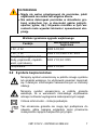 9
9
-
 10
10
-
 11
11
-
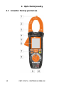 12
12
-
 13
13
-
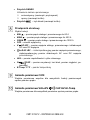 14
14
-
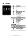 15
15
-
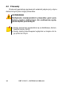 16
16
-
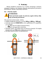 17
17
-
 18
18
-
 19
19
-
 20
20
-
 21
21
-
 22
22
-
 23
23
-
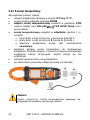 24
24
-
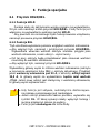 25
25
-
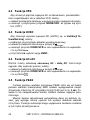 26
26
-
 27
27
-
 28
28
-
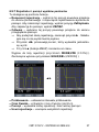 29
29
-
 30
30
-
 31
31
-
 32
32
-
 33
33
-
 34
34
-
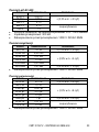 35
35
-
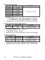 36
36
-
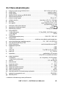 37
37
-
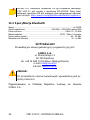 38
38
-
 39
39
-
 40
40
-
 41
41
-
 42
42
-
 43
43
-
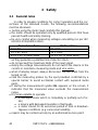 44
44
-
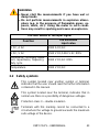 45
45
-
 46
46
-
 47
47
-
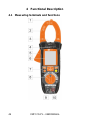 48
48
-
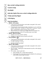 49
49
-
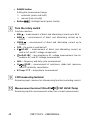 50
50
-
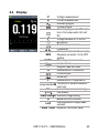 51
51
-
 52
52
-
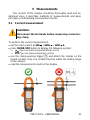 53
53
-
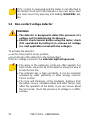 54
54
-
 55
55
-
 56
56
-
 57
57
-
 58
58
-
 59
59
-
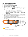 60
60
-
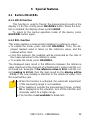 61
61
-
 62
62
-
 63
63
-
 64
64
-
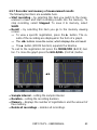 65
65
-
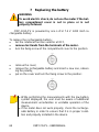 66
66
-
 67
67
-
 68
68
-
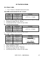 69
69
-
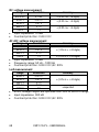 70
70
-
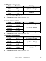 71
71
-
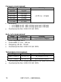 72
72
-
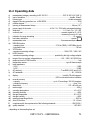 73
73
-
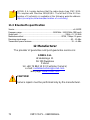 74
74
-
 75
75
-
 76
76
-
 77
77
-
 78
78
-
 79
79
-
 80
80
-
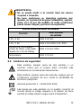 81
81
-
 82
82
-
 83
83
-
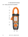 84
84
-
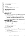 85
85
-
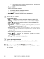 86
86
-
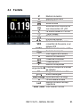 87
87
-
 88
88
-
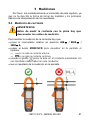 89
89
-
 90
90
-
 91
91
-
 92
92
-
 93
93
-
 94
94
-
 95
95
-
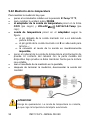 96
96
-
 97
97
-
 98
98
-
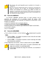 99
99
-
 100
100
-
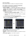 101
101
-
 102
102
-
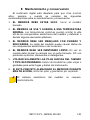 103
103
-
 104
104
-
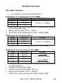 105
105
-
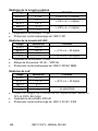 106
106
-
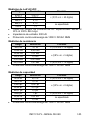 107
107
-
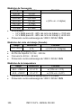 108
108
-
 109
109
-
 110
110
-
 111
111
-
 112
112
-
 113
113
-
 114
114
-
 115
115
-
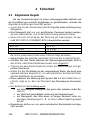 116
116
-
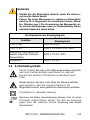 117
117
-
 118
118
-
 119
119
-
 120
120
-
 121
121
-
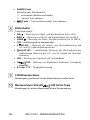 122
122
-
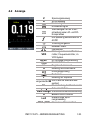 123
123
-
 124
124
-
 125
125
-
 126
126
-
 127
127
-
 128
128
-
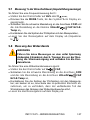 129
129
-
 130
130
-
 131
131
-
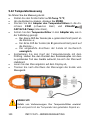 132
132
-
 133
133
-
 134
134
-
 135
135
-
 136
136
-
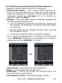 137
137
-
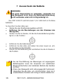 138
138
-
 139
139
-
 140
140
-
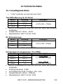 141
141
-
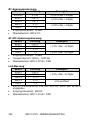 142
142
-
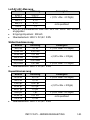 143
143
-
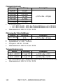 144
144
-
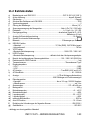 145
145
-
 146
146
-
 147
147
-
 148
148


Sonel CMP-1015-PV Manual de usuario
- Categoría
- Medición
- Tipo
- Manual de usuario
en otros idiomas
- Deutsch: Sonel CMP-1015-PV Benutzerhandbuch
- polski: Sonel CMP-1015-PV Instrukcja obsługi
Artículos relacionados
-
Sonel CMP-3000 Manual de usuario
-
-
-
Sonel CMM-60 Manual de usuario
-
Sonel CMM-40 Manual de usuario
-
-
-
-
Sonel CMP-200F Manual de usuario
-