
Need help? Visit Sauder.com to view video assembly tips or chat with a live rep.
Prefer the phone? Call 1-800-523-3987.
Share your journey!
sauder.com
NOTE: THIS INSTRUCTION
BOOKLET CONTAINS IMPORTANT
SAFETY INFORMATION.
PLEASE READ AND KEEP FOR
FUTURE REFERENCE.
English pg 1-27
Français pg 28-31
Español pg 32-36
Lot # 510604 11/09/17
Purchased: __________________
Be sure to give us a ring before
making any returns. 1-800-523-3987
Welcome to the
big kid desk.
Sit/Stand Desk
Model 422357

Table of Contents Assembly Tools Required
Part Identifi cation
Hardware Identifi cation
Assembly Steps
Français
Español
Safety
Warranty
Hammer
Not actual size
No. 2 Phillips Screwdriver
Tip Shown Actual Size
3
3-5
6-27
28-31
32-36
37- 38
39
Skip the power trip.
This time.
Short Screwdriver
422357 www.sauder.com/servicesPage 2
Adjustable Wrench

å While not all parts are labeled, some of the parts will have a label or an inked letter on the edge
to help distinguish similar parts from each other. Use this part identifi cation to help identify similar parts.
Now you know
our ABCs.
Part Identifi cation
A RIGHT END (1)
B LEFT END (1)
C MODESTY PANEL (1)
D SHELF (1)
E2 UPRIGHT (1)
F2 LIFT TOP BACK (1)
G LIFT TOP LEFT END (1)
H LIFT TOP RIGHT END (1)
I LIFT TOP (1)
A
B
C
D
E2
F2
G
H
I
Hardware Identifi cation
(EXTENSION SET SHOWN SEPARATED)
EXTENSION RAIL - 2
J
EXTENSION SLIDE - 2
K
7F
TWIST-LOCK
®
FASTENER - 21
ROD - 1
26A
422357www.sauder.com/services
Page 3
16E
LEVELER - 4

Hardware Identifi cation
å Screws are shown actual size. You may receive extra hardware with your unit.
COTTER PIN - 2
19M
RACK TENSIONER - 2
121M
ACTUATOR PULL - 1
120M
WHEEL - 2
123M
LEFT AND RIGHT RACK
DRIVE SET - 1
122M
CYLINDER - 1
124M
PROPEL NUT - 4
14M
GROMMET CAP - 1
1P
61P
TWIST-LOCK
®
FASTENER COVER - 12
62P
MINI TWIST-LOCK
®
COVER - 1
65P
CORD
MANAGER - 2
SCREW COVER - 4
20P
METAL PIN - 2
1R
CORD CLIP - 2
9P
GROMMET - 3
10P
32G
LEVELER
BRACKET - 4
CABLE BRACKET - 1
72G
CYLINDER BRACKET - 2
71G
13F
MINI TWIST-LOCK
®
FASTENER - 1
422357 www.sauder.com/servicesPage 4
NUT - 4
24M
WASHER - 4
13M

Hardware Identifi cation
å Screws are shown actual size. You may receive extra hardware with your unit.
BLACK 9/16" PAN HEAD SCREW -14
51S
BLACK 9/16" LARGE HEAD SCREW - 12
1S
BROWN 7/16" LARGE HEAD SCREW - 2
6S
BROWN 1-1/2" FLAT HEAD SCREW - 6
14S
SILVER 5/8" FLAT HEAD SCREW - 20
23S
BLACK 1-15/16" FLAT HEAD SCREW - 5
113S
422357www.sauder.com/services
Page 5
BLACK 1-1/4" MACHINE SCREW - 4
93S

Step 1
Look for this icon. It means a
video assembly tip is available at
www.sauder.com/services/tips
å
Assemble your unit on a carpeted fl oor or on the empty
carton to avoid scratching your unit or the fl oor.
å
To begin assembly, push a SAUDER TWIST-LOCK®
FASTENER (7F) into the large holes in the MODESTY
PANEL (C), SHELF (D), UPRIGHT (E2), and LIFT
TOP ENDS (G and H).
422357 www.sauder.com/servicesPage 6
G
H
Do not tighten the TWIST-LOCK® FASTENERS in this step.
(21 used)
7F
7F
7F
D
E2
C
Scan this QR code or go to this address:
http://qr.sauder.com/?ID=1933
to watch a video on how to assemble your unit.

å
Fasten the LEFT RACK DRIVE to the LIFT TOP LEFT END (G) and
the RIGHT RACK DRIVE to the LIFT TOP RIGHT END (H). Use
fourteen BLACK 9/16" PAN HEAD SCREWS (51S).
å
NOTE: Be sure to use the exact holes with dashed lines.
Step 2
G
H
The LEFT RACK
DRIVE will have an
L stamped here.
The RIGHT RACK
DRIVE will have an
R stamped here.
BLACK 9/16" PAN HEAD SCREW
(14 used in this step)
51S
422357www.sauder.com/services
Page 7
These edges must be even.

Step 3
å
Push a SAUDER MINI TWIST-LOCK® FASTENER (13F) into
the hole in the LIFT TOP BACK (F2).
Do not tighten the MINI TWIST-LOCK® FASTENER in this step.
13F
F2
422357 www.sauder.com/servicesPage 8

å
Fasten the LIFT TOP BACK (F2) to the LIFT TOP (I).
Tighten the MINI TWIST-LOCK® FASTENER.
Step 4
How to use the SAUDER TWIST-LOCK® FASTENER
and MINI TWISTLOCK® FASTENER
1. Insert the dowel end of the FASTENER into the
hole of the adjoining part.
NOTE: The dowel end of the FASTENER must
remain fully inserted in the hole of the adjoining
part while locking the FASTENER.
2. Tighten the FASTENER with a Phillips
screwdriver as tight as possible.
F2
I
This large hole
must be here.
Surface with MINI TWIST-LOCK® FASTENER
Surface with holes
422357www.sauder.com/services
Page 9
Remember:
Righty tighty.
Lefty loosey.
Meet Part (I). This component has
been engineered to be lighter, stronger,
faster… well ok. Not technically faster.
But defi nitely makes for a sturdier Sit/
Stand Desk that’s easier to assemble
and friendlier to the environment.

å
Fasten the LIFT TOP ENDS (G and H) to the LIFT TOP BACK (F2).
Use six BROWN 1-1/2" FLAT HEAD SCREWS (14S).
å
Fasten the LIFT TOP ENDS (G and H) to the LIFT TOP (I). Tighten
six TWIST-LOCK® FASTENERS.
Step 5
H
G
BROWN 1-1/2" FLAT HEAD SCREW
(6 used in this step)
14S
14S
I
F2
422357 www.sauder.com/servicesPage 10
Surface with TWIST-LOCK® FASTENERS
Surface with TWIST-LOCK® FASTENERS

å
Separate the EXTENSION SLIDES (K) from the EXTENSION RAILS (J) as shown
in the upper diagram below. Be prepared, the parts are greasy.
å
Fasten the EXTENSION SLIDES (K) to the LIFT TOP ENDS (G and H). Use ten
SILVER 5/8" FLAT HEAD SCREWS (23S).
å
Fasten the CABLE BRACKET (72G) to the LIFT TOP (I). Use two BLACK 9/16"
LARGE HEAD SCREWS (1S).
Step 6
H
G
Open end
Open end
BLACK 9/16" LARGE HEAD SCREW
(2 used in this step)
1S
SILVER 5/8" FLAT HEAD SCREW
(10 used for the EXTENSION SLIDES)
23S
I
422357www.sauder.com/services
Page 11
Pull down the release lever and pull the SLIDE from the RAIL.
J
K
72G
K
K

å
Fasten two CORD MANAGERS (65P) to the LIFT TOP BACK (F2). Use
two BROWN 7/16" LARGE HEAD SCREWS (6S).
å
Fasten a CYLINDER BRACKET (71G) to the LIFT TOP BACK (F2). Use
two BLACK 1-1/4" MACHINE SCREWS (93S), two WASHERS (13M),
and two NUTS (24M).
å
NOTE: Position the CORD MANAGERS and CYLINDER BRACKET
exactly as shown.
Step 7
65P
65P
F2
422357 www.sauder.com/servicesPage 12
71G
BLACK 1-1/4" MACHINE SCREW
(2 used in this step)
93S
24M
13M
BROWN 7/16" LARGE HEAD SCREW
(2 used in this step)
6S

å
Fasten the SHELF (D) to the MODESTY PANEL (C).
Tighten three TWIST-LOCK® FASTENERS.
å
Push two GROMMETS (10P) into the SHELF (D).
Step 8
Surface with
TWIST-LOCK®
FASTENERS
Surface with TWIST-LOCK® FASTENERS
C
D
10P
422357www.sauder.com/services
Page 13

å
Fasten a CYLINDER BRACKET (71G) to the UPRIGHT (E2).
Use two BLACK 1-1/4" MACHINE SCREWS (93S), two
WASHERS (13M), and two NUTS (24M).
Step 9
Surface with TWIST-LOCK® FASTENERS
This hole must be here.
The post on the
BRACKET must be
pointing this direction.
E2
422357 www.sauder.com/servicesPage 14
71G
24M
13M
BLACK 1-1/4" MACHINE SCREW
(2 used in this step)
93S

å
Fasten the UPRIGHT (E2) to the SHELF (D). Use fi ve
BLACK 1-15/16" FLAT HEAD SCREWS (113S).
å
Push two CORD CLIPS (9P) into the MODESTY PANEL (C).
Step 10
E2
D
BLACK 1-15/16" FLAT HEAD SCREW
(5 used in this step)
113S
9P
C
422357www.sauder.com/services
Page 15
Now might be a
good time to refresh
your drink.
Surface without TWIST-LOCK®
FASTENERS

Step 11
å
Fasten the EXTENSION RAILS (J) to the ENDS (A and B). Use ten SILVER 5/8" FLAT HEAD SCREWS (23S).
å
NOTE: For each EXTENSION RAIL, turn a SCREW into the holes shown in the enlarged diagram. Then, slide
the inner cartridge of the EXTENSION RAIL in to fi nd the other holes that lines up with the hole in the END.
Turn a SCREW into these holes.
å
Insert a METAL PIN (1R) into each END (A and B) as shown.
Open end
Open end
1R
A
B
J
J
These four small
holes must be here.
422357 www.sauder.com/servicesPage 16
SILVER 5/8" FLAT HEAD SCREW
(10 used in this step)
23S
These four small
holes must be here.

å
NOTE: You will need a short screwdriver in this step.
å
Fasten the ENDS (A and B) to the MODESTY PANEL (C),
SHELF (D), and UPRIGHT (E2). Tighten twelve
TWIST-LOCK® FASTENERS.
å
NOTE: Be sure the METAL PIN in each END inserts into
the UPRIGHT (E2).
Step 12
A
B
C
D
E2
422357www.sauder.com/services
Page 17

å
Push four LEVELER BRACKETS (32G) over the exact holes shown in the bottom edges of the ENDS (A and B).
å
Using your hammer, gently tap a PROPEL NUT (14M) into the holes in the LEVELER BRACKETS (32G) and
ENDS (A and B). Now, turn a LEVELER (16E) into each PROPEL NUT.
å
NOTE: Position the BRACKETS exactly as shown.
Step 13
Use these holes in the second unit if
you will be standing them side by side.
422357 www.sauder.com/servicesPage 18
A
B
16E
14M
32G

å
Carefully stand your unit upright.
å
Fasten a RACK TENSIONER (121M) to the RIGHT END (A).
Use four BLACK 9/16" LARGE HEAD SCREWS (1S).
å
NOTE: Position the RACK TENSIONER exactly as shown.
Step 14
A
422357www.sauder.com/services
Page 19
BLACK 9/16" LARGE HEAD SCREW
(4 used in this step)
1S
121M
Use the exact
holes shown.

å
Push two WHEELS (123M) onto the ROD (26A)
a few inches in from the end.
Step 15
Flat edge
26A
123M
123M
422357 www.sauder.com/servicesPage 20
Push the WHEEL onto
the ROD a few inches.
Push the WHEEL onto
the ROD a few inches.

å
Follow the numbered sequence.
å
1. Push the ROD (26A) into the RACK
TENSIONER (121M) on the RIGHT END (A)
as shown.
å
2. Push the ROD (26A) into the RACK
TENSIONER (121M) on the left.
å
3. Continue holding the assembly intact.
Fasten the RACK TENSIONER (121M) to
the LEFT END (B). Use four BLACK 9/16"
LARGE HEAD SCREWS (1S).
å
4. Push the WHEELS (123M) back into
position inside the RACK TENSIONERS on
each END (A and B). See the large diagram
below for the fi nal position of the ROD,
WHEELS, and RACK TENSIONER on the
LEFT END (B).
Step 16
26A
26A
121M
121M
121M
123M
1.
3.
4.
2.
B
B
B
A
422357www.sauder.com/services
Page 21
BLACK 9/16" LARGE HEAD SCREW
(4 used in this step)
1S

å
This is a two person step. Carefully lay your unit onto its back edges.
å
Push down on both levers of the RACK TENSIONERS (121M) until you
hear a click. This disengages the wheel from the LEFT and RIGHT RACK
DRIVE SETS (122M) to prepare for insertion of the LIFT TOP.
å
To insert the LIFT TOP assembly into your unit, carefully place the
LEFT and RIGHT DRIVE SET (122M) onto the WHEELS (123M). Then,
line up the EXTENSION SLIDES on the LIFT TOP ENDS (G and H) with
the EXTENSION RAILS on the ENDS (A and B) and push the LIFT TOP
assembly evenly into the unit until it is fully inserted.
Step 17
Pro Tip: Lift with your
legs. And, you know,
your arms.
422357 www.sauder.com/servicesPage 22
A
B
H
G
Lever
Lever
122M
121M
123M
IMPORTANT: Push the LIFT
TOP in evenly on both sides
until it is fully inserted.

å
IMPORTANT: Before you fasten the CYLINDER (124M), be sure the
two gold nuts and silver cable assembly are turned tight onto the
black CYLINDER.
å
Pull the LIFT TOP (I) open as shown below.
å
Push the CYLINDER (124M) completely onto the posts of the
CYLINDER BRACKETS (71G) as shown in both large views.
Step 18
The MODESTY PANEL, SHELF, and UPRIGHT
have been cut for clarity of assembly.
422357www.sauder.com/services
Page 23
I
IMPORTANT:
Be sure the two gold nuts and
silver cable assembly are turned
tight onto the black cylinder.
124M
124M
124M
71G
71G

å
This is a two person step. Carefully stand your unit upright.
å
Completely push two COTTER PINS (19M) into the holes in the CYLINDER BRACKETS (71G) as shown in each large diagram.
å
The cable at the top of the CYLINDER will come assembled for optimal performance. With an adjustable wrench, you can
adjust the two nuts on both sides of the cylinder bracket. The same length of threads should be on both sides of the nuts
as shown in the upper large diagram. Be sure to tighten the nuts after making adjustments.
å
Push the end of the cable through the large hole in the LIFT TOP BACK (F2) as shown in the upper large diagram.
Step 19
422357 www.sauder.com/servicesPage 24
Pro Tip: Lift with your
legs. And, you know,
your arms.
F2
The MODESTY PANEL and LIFT TOP
have been cut for clarity of assembly.
IMPORTANT: Use the
CORD MANAGEMENT
for excess cable.
71G
19M
Push the cable end
through this hole.
19M
71G
The two nuts on
both sides of the
cylinder bracket
can be adjusted. For
optimal performance,
the same length of
threads should be on
both sides of each nut.

å
Follow the numbered diagram in numerical order and in the direction of the dashed arrows.
1. Turn the nut closest to the hammer end o the threaded area.
å
2. Slip the threaded portion of the cable through the opening in the CABLE BRACKET (72G). Turn the nut back onto the
threaded end of the cable. Be sure both nuts are tight against the bar of the CABLE BRACKET (72G).
å
3. Push the hammer shaped end of the cable into the opening of the pointed end of the ACTUATOR PULL (120M).
å
4. While holding the ACTUATOR PULL (120M) and cable assembly together, fasten the ACTUATOR PULL (120M) to the
LIFT TOP (I). Use two BLACK 9/16" LARGE HEAD SCREWS (1S).
å
NOTE: The screws should be centered in the slotted holes and should not be completely tighten to allow the ACTUATOR
PULL to slide back and forth.
Step 20
422357www.sauder.com/services
Page 25
2.
3.
4.
120M
BLACK 9/16" LARGE HEAD SCREW
(2 used in this step)
1S
72G
I
I
1. Turn this nut
o the threads.

Step 21
å
Push the LIFT TOP (I) down against the ENDS (A and B).
å
With a screwdriver, push in the buttons on the RACK
TENSIONERS (121M) to engage the wheels onto the
tracks of the LEFT and RIGHT RACK DRIVES (122M).
å
To raise and lower the LIFT TOP (I), pull the lever of the
ACTUATOR PULL and allow the LIFT TOP (I) to raise.
When you reach your desired position, release the lever.
å
If your LIFT TOP is not functioning properly, refer back to
steps 18, 19, and 20.
122M
122M
121M
Button
A
B
121M
I
422357 www.sauder.com/servicesPage 26

Step 22
å
Cover the MINI TWIST-LOCK and TWIST-LOCKS with the TWIST-LOCK FASTENER COVERS (61P and 62P).
å
Center a SCREW COVER (20P) over the head of each SCREW and gently tap in with your hammer.
å
Insert the GROMMET (10P) and GROMMET CAP (1P) into the large hole in the LIFT TOP (I).
å
NOTE: To raise a corner of the unit, turn the LEVELER counter-clockwise. To lower a corner, turn the LEVELER clockwise.
å
NOTE: Please read the back pages of the instruction booklet for important safety information.
å
This completes assembly. Clean with a damp cloth. Wipe dry.
To cover screws
1P
10P
61P
62P
I
20P
422357www.sauder.com/services
Page 27
And to celebrate, why not share your success story?
35 lbs.
To raise a corner of the unit, turn the
LEVELER counter-clockwise. To lower
a corner, turn the LEVELER clockwise.
25 lbs.
IMPORTANT: If you are using a
mouse with your computer, it is
recommended to use a mouse pad.

A l’usage exclusif du
Canada Noter la date
d’achat de cet élément
et conserver le livret
pour future référence.
Pour contacter Sauder
en ce qui concerne cet
élément, faire référence
au numéro de lot et
numéro de modèle en
appelant notre numéro
sans frais.
Lot nº : ____________
Date de
l’achat: ____________
LISTE DE PIÈCES
REFERENCE DESCRIPTION QUANTITÉ
LISTE DE PIÈCES
REFERENCE DESCRIPTION QUANTITÉ
NOUS SOMMES LA POUR VOUS AIDER!
Nous faisons de notre mieux pour nous assurer que votre meuble
arrive dans d’excellentes conditions. Nos représentants du service
Clientèle sont aimables et prêts à vous aider au cas où une pièce
aurait été endommagée ou manquerait (ou si vous aviez besoin
d’aide pour l’assemblage). NE RAMENEZ PAS LE MEUBLE AU
MAGASIN. Au Canada, composez ce numéro d’appel gratuit:
1-800-523-3987
Du lundi au vendredi, de 9 heures du matin à
5:30 heures du soir (horaire Côte Est)
(sauf jours fériés)
Si une pièce a besoin d’être remplacée, la pièce de remplacement
sera envoyée dans les 48 heures. (Sauf week-ends et jours fériés)
Utilisez les instructions d’assemblage en français avec les
schémas étape par étape du manuel d’instruction en anglais.
Chaque étape en français correspond à la même étape
en anglais. La pièce devant être attachée à l’élément est
représentée en gris sur les schémas de chaque étape pour plus
de précision. Comparer la “Liste de pièces” ci-dessous avec
la “PART IDENTIFICATION” du manuel en anglais pour vous
familiariser avec les pièces avant l’assemblage.
REMARQUE : CE MANUEL D’INSTRUCTIONS CONTIENT
D’IMPORTANTES INFORMATIONS RELATIVES À LA SÉCURITÉ.
À LIRE ET CONSERVER POUR TOUTE RÉFÉRENCE FUTURE.
24M ÉCROU ............................................................................4
120M TIRAGE D’ACTIONNEUR ...................................1
121M TENDEUR DE RACK ..............................................2
122M DISPOSITIF D’ENTRAINEMENT
RACKS GAUCHE ET DROIT ............................1
123M ROULETTE ...................................................................2
124M CYLINDRE ......................................................................1
1P COUVERCLE DE PASSE-CÂBLES .............1
9P CLIP POUR CORDONS ......................................2
10P PASSE-CÂBLES .......................................................3
20P CACHE-VIS ..................................................................4
61P COUVERCLE DE FIXATION
TWIST-LOCK® ..........................................................12
62P COUVERCLE DE PETITE TWIST-LOCK® 1
65P GESTIONNAIRE DE CORDONS ..................2
1R GOUPILLE EN MÉTAL .........................................2
1S VIS TÊTE LARGE 14 mm NOIRE ..............12
6S VIS TÊTE LARGE 11 mm MARRON ..........2
14S VIS TÊTE PLATE 38 mm MARRON .........6
23S VIS TÊTE PLATE 16 mm ARGENTÉE..20
51S VIS TÊTE GOUTTE DE
SUIF 14 mm NOIRE ............................................14
93S VIS À MÉTAUX 32 mm NOIRE .....................4
113S VIS TÊTE PLATE 49 mm NOIRE ................5
A EXTRÉMITÉ DROITE ..............................................1
B EXTRÉMITÉ GAUCHE...........................................1
C VOILE DE FOND .......................................................1
D TABLETTE ......................................................................1
E2 MONTANT .....................................................................1
F2 ARRIÈRE DU DESSUS RELEVABLE .........1
G EXTRÉMITÉ GAUCHE DU
DESSUS RELEVABLE............................................1
H EXTRÉMITÉ DROITE
DU DESSUS RELEVABLE ..................................1
I DESSUS RELEVABLE............................................1
J GLISSIÈRE D'EXTENSION ................................2
K COULISSE D'EXTENSION ................................2
26A TRINGLE ..........................................................................1
16E VÉRIN................................................................................4
7F FIXATION TWIST-LOCK® .................................21
13F PETITE FIXATION TWIST-LOCK® ................1
32G CONSOLE DE VÉRIN ...........................................4
71G GARNITURE DE CYLINDRE.............................2
72G CROCHET DE CÂBLE ..........................................1
13M RONDELLE ...................................................................4
14M ÉCROU À AILETTE ................................................4
19M GOUPILLE FENDUE ..............................................2
Bureau assis/deboutModèle 422357
422357 www.sauder.com/servicesPage 28

ÉTAPE 9
Fixer une GARNITURE DE CYLINDRE (71G) sur le MONTANT (E2).
Utiliser deux VIS À MÉTAUX 32 mm NOIRES (93S), deux
RONDELLES (13M) et deux ÉCROUS (24M).
ÉTAPE 10
Fixer le MONTANT (E2) à la TABLETTE (D). Utiliser cinq VIS TÊTE
PLATE 49 mm NOIRES (113S).
Enfoncer deux CLIPS POUR CORDON (9P) dans le VOILE
DE FOND (C).
ÉTAPE 8
Fixer la TABLETTE (D) au VOILE DE FOND (C). Serrer trois
FIXATIONS TWIST-LOCK®.
Enfoncer deux PASSE-CÂBLES (10P) dans la TABLETTE (D).
ÉTAPE 7
Fixer les GESTIONNAIRES DE CORDON (65P) sur l'ARRIÈRE
DU DESSUS RELEVABLE (F2). Utiliser deux VIS TÊTE
LARGE 11 mm MARRON (6S).
Fixer une GARNITURE DE CYLINDRE (71G) sur l’ARRIÈRE DU
DESSUS RELEVABLE (F2). Utiliser deux VIS À MÉTAUX 32 mm
NOIRES (93S), deux RONDELLES (13M) et deux ÉCROUS (24M).
REMARQUE : Positionner les PASSE-CÂBLES et GARNITURE DE
CYLINDRE exactement comme il l’est indiqué.
ÉTAPE 6
Séparer les COULISSES D'EXTENSION (K) des GLISSIÈRES
D'EXTENSION (J) comme l'indique le schéma ci-dessous
supérieure. Faire attention car les pièces sont graissées.
Fixer les COULISSES D'EXTENSION (K) aux EXTRÉMITÉS DU
DESSUS RELEVABLE (G et H). Utiliser dix VIS TÊTE
PLATE 16 mm ARGENT (23S).
Fixer le CROCHET DE CÂBLE (72G) sur le DESSUS RELEVABLE (I).
Utiliser deux VIS TÊTE LARGE 14 mm NOIRES (1S).
ÉTAPE 4
Fixer l'ARRIÈRE DU DESSUS RELEVABLE (F2) au DESSUS
RELEVABLE (I). Serrer la PETITE FIXATION TWIST-LOCK®.
Utilisation de la FIXATION TWIST-LOCK® SAUDER et de la PETITE
FIXATION TWIST-LOCK®
1. Insérer l'extrémité fi letée de la FIXATION dans le trou de la
pièce attenante.
REMARQUE : L'extrémité fi letée de la FIXATION doit rester
complètement insérée dans le trou de la pièce attenante lorsque
l'on bloque la FIXATION.
2. Bien serrer la FIXATION à l'aide d'un tournevis Phillips.
ÉTAPE 5
Fixer les EXTRÉMITÉS DU DESSUS RELEVABLE (G et H) et
l'ARRIÈRE DU DESSUS RELEVABLE (F2). Utiliser six VIS TÊTE
PLATE 38 mm MARRON (14S).
Fixer les EXTRÉMITÉS DU DESSUS RELEVABLE (G et H) au
DESSUS RELEVABLE (I). Serrer six FIXATIONS TWIST-LOCK®.
ÉTAPE 3
Ne pas serrer la PETITE FIXATION TWIST-LOCK® à cette étape.
Enfoncer une PETITE FIXATION TWIST-LOCK® SAUDER (13F)
dans le trou indiqué de l'ARRIÈRE DU DESSUS RELEVABLE (F2).
ÉTAPE 2
Fixer l'ENTRAINEMENT DE RACK GAUCHE sur l'EXTRÉMITÉ
GAUCHE DU DESSUS RELEVABLE (G) et l’ENTRAINEMENT DE
RACK DROIT sur l’EXTRÉMITÉ DROITE DU DESSUS RELEVABLE (H).
Utiliser quatorze VIS TÊTE GOUTTE DE SUIF 14 mm NOIRES (51S).
REMARQUE : S’assurer d’utiliser les trous exacts avec des lignes
en pointillés.
ÉTAPE 1
Ne pas serrer les FIXATIONS TWIST-LOCK® à cette étape.
Assembler l'élément sur un sol à moquette ou sur le carton vide
pour éviter d'endommager l'élément ou le sol.
Pour commencer l'assemblage, enfoncer une FIXATION
TWIST-LOCK® SAUDER (7F) dans les gros trous du VOILE
DE FOND (C), de la TABLETTE (D), du MONTANT (E2) et les
EXTRÉMITÉS DU DESSUS RELEVABLE (G et H).
422357www.sauder.com/services
Page 29

ÉTAPE 18
IMPORTANT : Avant de fi xer le CYLINDRE (124M), s'assurer que
les deux écrous d’or et l’ensemble de câble argent sont bien serrés
sur le CYLINDRE noir.
Ouvrir le DESSUS RELEVABLE (I) comme il l’est indiqué ci-dessous.
Enfoncer le CYLINDRE (124M) complètement sur les montants
des GARNITURES DE CYLINDRE (71G) comme l’indique le
schéma dans les grandes vues.
ÉTAPE 17
Il faut deux personnes pour e ectuer cette tâche. Avec précaution,
retourner l'élément sur ses chants arrière.
Appuyer sur les leviers des TENDEURS DE RACK (121M)
jusqu’au déclic. Ceci dégage la roulette des DISPOSITIFS
D’ENTRAINEMENT DES RACKS GAUCHE et DROIT (122M) pour
les préparer à l’insertion du DESSUS RELEVABLE.
Pour insérer l’ensemble du DESSUS RELEVABLE dans l’unité,
placer soigneusement les DISPOSITIFS D’ENTRAINEMENT DES
RACKS GAUCHE et DROIT (122M) sur les ROULETTES (123M).
Ensuite, aligner les COULISSES D’EXTENSION sur les EXTRÉMITÉS
DU DESSUS RELEVABLE (G et H) sur les RAILS D’EXTENSION
des EXTRÉMITÉS (A et B) et enfoncer l’ensemble du DESSUS
RELEVABLE dans l’unité jusqu’à ce qu’il soit complètement inséré.
ÉTAPE 16
Suivre la séquence numérotée.
1. Enfoncer la TIGE (26A) dans le TENDEUR DE RACK (121M) sur
l’EXTRÉMITÉ DROITE (A) comme il l’est indiqué.
2. Enfoncer la TIGE (26A) dans le TENDEUR DE RACK (121M) sur
la gauche.
3. Continuer de maintenir l’ensemble intact. Fixer le TENDEUR
DE RACK (121M) à l’EXTRÉMITÉ GAUCHE (B). Utiliser quatre VIS
TÊTE LARGE 14 mm NOIRES (1S).
4. Renfoncer les ROULETTES (123M) en position à l’intérieur des
TENDEURS DE RACK sur chaque EXTRÉMITÉ (A et B). Voir le
grand schéma ci-dessous pour la position fi nale de la TIGE, des
ROUES et du TENDEUR DE RACK sur l’EXTRÉMITÉ GAUCHE (B).
ÉTAPE 14
Relever, avec précaution, l'élément dans sa position verticale.
Fixer un TENDEUR DE RACK (121M) à l’EXTRÉMITÉ DROITE (A).
Utiliser quatre VIS TÊTE LARGE 14 mm NOIRES (1S).
REMARQUE : Positionner le TENDEUR DE RACK exactement
comme il l’est indiqué.
ÉTAPE 15
Enfoncer deux ROULETTES (123M) sur la TIGE (26A) de
quelques pouces depuis l’extrémité.
ÉTAPE 13
Placer quatre CONSOLES DE VÉRIN (32G) sur les trous exacts
illustrés dans les chants inférieurs des EXTRÉMITÉS (A et B).
À l'aide d'un marteau, enfoncer légèrement un
TOURILLON (14M) dans les trous dans les CONSOLES
DE VÉRIN (32G) et les EXTRÉMITÉS (A et B). Maintenant, faire
tourner un VÉRIN (16E) dans chaque TOURILLON.
REMARQUE : Placer les CONSOLES exactement comme l'indique
le schéma.
ÉTAPE 12
REMARQUE : Il faudra peut-être utiliser un tournevis court pour
cette étape.
Fixer les EXTRÉMITÉS (A et B) au VOILE DE FOND (C), à la
TABLETTE (D) et au MONTANT (E2). Serrer douze FIXATIONS
TWIST-LOCK®.
REMARQUE : S'assurer de bien insérer la GOUPILLE EN MÉTAL
située sur chaque EXTRÉMITÉ dans le MONTANT (E2).
ÉTAPE 11
Fixer les GLISSIÈRES D'EXTENSION (J) aux EXTRÉMITÉS (A et B).
Utiliser dix VIS TÊTE PLATE 16 mm ARGENT (23S).
REMARQUE : Pour chaque GLISSIÈRE D'EXTENSION, faire tourner
une VIS dans les trous indiqués dans les schémas agrandis.
Ensuite, enfi ler la cartouche interne de la GLISSIÈRE D'EXTENSION
vers l'intérieur pour trouver les autres trous qui sont alignés sur le
trou dans l’EXTRÉMITÉ. Faire tourner une VIS dans ces trous.
Insérer une GOUPILLE EN MÉTAL (1R) dans chaque
EXTRÉMITÉ (A et B) comme l'indique le schéma.
422357 www.sauder.com/servicesPage 30

ÉTAPE 3
ÉTAPE 22
Couvrir les fi xations PETITE TWIST-LOCK et TWIST-LOCKS avec
les COUVERCLES DE FIXATION TWIST-LOCK (61P et 62P).
Centrer un COUVERCLE DE VIS (20P) sur la tête de chaque VIS
et taper délicatement à l'aide d'un marteau.
Insérer le PASSE-CÂBLES (10P) et un COUVERCLE DE PASSE-
CÂBLES (1P) dans le gros trou du DESSUS RELEVABLE (I).
REMARQUE : Pour soulever un coin de l'élément, faire tourner
le VÉRIN dans le sens contraire des aiguilles d'une montre. Pour
baisser un coin, faire tourner le VÉRIN dans le sens des aiguilles
d'une montre.
REMARQUE : Prière de lire les informations importantes sur la
sécurité fi gurant sur les pages arrière du manuel d’instructions.
Ceci complète l'assemblage. Nettoyer à l’aide d’une encaustique
pour meubles ou d’un chi on humide. Essuyer.
ÉTAPE 21
Enfoncer le DESSUS RELEVABLE (I) contre les EXTRÉMITÉS (A et B).
À l’aide d'un tournevis, enfoncer les boutons sur les TENDEURS
DE RACK (121M) pour enclencher les roues sur les rails des
ENTRAINEMENTS DE RACK GAUCHE et DROIT (122M).
Pour élever et abaisser le DESSUS RELEVABLE (I), tirer le levier
du TIRAGE D’ACTIONNEUR et de permettre d’élever le DESSUS
RELEVABLE (I). Lorsque la position souhaitée est atteinte, relever
le levier.
Si le DESSUS RELEVABLE ne fonctionne pas correctement,
consulter les étapes 18, 19 et 20.
ÉTAPE 20
Suivre le schéma numéroté en ordre numérique et dans le sens
des fl èches en pointillés.
1. Faire tourner l’écrou le plus proche de l’extrémité marteau de la
zone fi letée.
2. Enfi ler la portion fi letée du câble dans l’ouverture dans la
GARNITURE DE CÂBLE (72G). Faire tourner l'écrou sur l'extrémité
fi letée du câble. S’assurer que les deux écrous sont serrés contre
la barre de la GARNITURE DE CÂBLE (72G).
3.
Enfoncer l’extrémité en forme de marteau du câble dans
l’ouverture de l’extrémité pointue du TIRAGE D’ACTIONNEUR (120M).
4. Tout en maintenant du TIRAGE D’ACTIONNEUR (120M) et
l’ensemble de câble ensemble, fi xer le TIRAGE
D’ACTIONNEUR (120M) sur le DESSUS RELEVABLE (I).
Utiliser deux VIS TÊTE LARGE 14 mm NOIRES (1S).
REMARQUE : Les vis doivent être centrées sur les trous fendus et
ne doivent pas être complètement serrées pour permettre de faire
entrer et sortir le TIRAGE D’ACTIONNEUR en glissant.
ÉTAPE 19
Il faut deux personnes pour e ectuer cette tâche. Relever, avec
précaution, l'élément dans sa position verticale.
Enfoncer complètement deux GOUPILLES FENDUES (19M) dans
les trous des GARNITURES DE CYLINDRE (71G) comme indiqué
dans chaque schéma agrandi.
Le câble en haut du CYLINDRE est livré assemblé pour une
performance optimale. À l’aide d'une clé réglable, on peut ajuster
les deux écrous de part et d’autre de la garniture de cylindre.
La même longueur de fi ls doit être des deux côtés des écrous
comme il l’est indiqué dans le grand schéma du haut. S’assurer de
serrer les écrous après avoir e ectué des réglages.
Enfoncer l’extrémité du câble par le grand trou dans l’ARRIÈRE DU
DESSUS RELEVABLE (F2) comme il l’est indiqué dans le grand schéma.
422357www.sauder.com/services
Page 31

A l’usage exclusif du
Canada Noter la date
d’achat de cet élément
et conserver le livret
pour future référence.
Pour contacter Sauder
en ce qui concerne cet
élément, faire référence
au numéro de lot et
numéro de modèle en
appelant notre numéro
sans frais.
Lot nº : ____________
Date de
l’achat: ____________
LISTA DE PARTES
ITEM DESCRIPCIÓN CANTIDAD
ESTAMOS AQUI PARA AYUDAR!
Tratamos de asegurar que su mueble llega en condición excelente.
Nuestros representantes de Servicio al Cliente son amables y
listos para ayudarle con servicio rápido y efi ciente si una parte
está defectuosa o ausente (o si necesita ayuda con el ensamblaje).
NO DEVUELVA LA UNIDAD A LA TIENDA. Llame este número sin
cargo:
1-800-523-3987
Lunes a viernes, 9:00 a.m. - 5:30 p.m.
Hora ofi cial del Este
(excepto días festivos)
Si requiere un repuesto de una parte, será enviado dentro de
48 horas (excepto los fi nes de semana y días festivos)
Use estas instrucciones de ensamblaje en español junto con las
fi guras paso-a-paso provistas en el folleto inglés. Cada paso
en español corresponde al mismo paso en inglés. Se destacan
las fi guras de cada paso con una tonalidad oscura para mostrar
precisamente cual parte se debe montar a la unidad. Compare
la “Lista de Part” abajo con la “Part Identifi cation” en el folleto en
inglés para familiarizarse con Las partes de ensamblaje.
NOTA: ESTE FOLLETO DE INSTRUCCIONES CONTIENE
INFORMACIÓN IMPORTANTE SOBRE LA SEGURIDAD. POR
FAVOR LEA Y GUÁRDELO PARA REFERENCIA EN EL FUTURO.
LISTA DE PARTES
ITEM DESCRIPCIÓN CANTIDAD
121M TENSOR DEL RACK .............................................2
122M CONJUNTO DE ACCIONAMIENTO
IZQUIERDO Y DERECHO ..................................1
123M RUEDA ............................................................................2
124M CILINDRO ......................................................................1
1P CUBIERTA DE OJAL ..............................................1
9P GRAPA DE CABLE .................................................2
10P OJAL .................................................................................3
20P CUBIERTA DE TORNILLO ................................4
61P CUBIERTA DE SUJETADOR
TWIST-LOCK® ..........................................................12
62P CUBIERTA DE MINI SUJETADOR
TWIST-LOCK® .............................................................1
65P ORGANIZADOR DE CABLE ...........................2
1R ESPIGA DE METAL ...............................................2
1S TORNILLO NEGRO DE
CABEZA GRANDE de 14 mm .....................12
6S TORNILLO MARRÓN DE
CABEZA GRANDE de 11 mm ........................2
14S TORNILLO MARRÓN DE
CABEZA PERDIDA de 38 mm .....................6
23S TORNILLO PLATEADO DE
CABEZA PERDIDA de 16 mm ..................20
51S TORNILLO NEGRO DE
CABEZA REDONDA de 14 mm .................14
93S TORNILLO NEGRO PARA
METAL de 32 mm..................................................4
113S TORNILLO NEGRO DE
CABEZA PERDIDA de 49 mm .....................5
A EXTREMO DERECHO ..........................................1
B EXTREMO IZQUIERDO .......................................1
C VELO DE FONDO ....................................................1
D ESTANTE ........................................................................1
E2 PARAL ..............................................................................1
F2 DORSO DE PANEL SUPERIOR DE
ELEVACIÓN .................................................................1
G EXTREMO IZQUIERDO DE PANEL
SUPERIOR DE ELEVACIÓN .............................1
H EXTREMO DERECHO DE PANEL
SUPERIOR DE ELEVACIÓN .............................1
I PANEL SUPERIOR DE ELEVACIÓN ..........1
J RIEL DE EXTENSIÓN ...........................................2
K CORREDERA DE EXTENSIÓN ......................2
26A VARILLA ..........................................................................1
16E NIVELADOR ................................................................4
7F SUJETADOR TWIST-LOCK®. ........................21
13F MINI SUJETADOR TWIST-LOCK® ...............1
32G MÉNSULA DE NIVELADOR ............................4
71G SOPORTE DEL CILINDRO ..............................2
72G SOPORTE DE CABLE ..........................................1
13M ARANDELA ..................................................................4
14M TUERCA DE HÉLICE ............................................4
19M CLAVIJA .........................................................................2
24M TUERCA .........................................................................4
120M ACTUADOR DE TIRAR ........................................1
Escritorio de sentar/pararModelo 422357
422357 www.sauder.com/servicesPage 32

PASO 8
Fije el ESTANTE (D) al VELO DE FONDO (C). Apriete tres
SUJETADORES TWIST-LOCK®.
Empuje dos OJALES (10P) en el ESTANTE (D).
PASO 7
Fije dos ORGANIZADORES DE CABLES (65P) al DORSO DE
PANEL SUPERIOR DE ELEVACIÓN (F2). Utilice dos TORNILLOS
MARRONES DE CABEZA GRANDE de 11 mm (6S).
Fije el SOPORTE DEL CILINDRO (71G) al DORSO DE PANEL
SUPERIOR DE ELEVACIÓN (F2). Utilice dos TORNILLO NEGROS
PARA METAL de 32 mm (93S), dos ARANDELAS (13M) y
dos TUERCAS (24M).
NOTA: Coloque los ORGANIZADORES DE CABLES y el
SOPORTE DEL CILINDRO exactamente como se muestra.
PASO 6
Separe las CORREDERAS DE EXTENSIÓN (K) de los RIELES DE
EXTENSIÓN (J) como se muestra en el diagrama superior mas
abajo. Prepárese, las piezas son grasientas.
Fije las CORREDERAS DE EXTENSIÓN (K) a los EXTREMOS
DE PANEL SUPERIOR DE ELEVACIÓN (G y H). Utilice diez
TORNILLOS PLATEADOS DE CABEZA PERDIDA de 16 mm (23S).
Fije el SOPORTE DE CABLE (72G) al PANEL SUPERIOR DE
ELEVACIÓN (I). Utilice dos TORNILLOS NEGROS DE CABEZA
GRANDE de 14 mm (1S).
PASO 5
Fije los EXTREMOS DE PANEL SUPERIOR DE ELEVACIÓN (G y H)
al DORSO DE PANEL SUPERIOR DE ELEVACIÓN (F2). Utilice seis
TORNILLOS MARRONES DE CABEZA PERDIDA de 38 mm (14S).
Fije los EXTREMOS DE PANEL SUPERIOR DE
ELEVACIÓN (G y H) al PANEL SUPERIOR DE ELEVACIÓN (I).
Apriete seis SUJETADORES TWIST-LOCK®.
PASO 4
Fije el DORSO DE PANEL SUPERIOR DE ELEVACIÓN (F2)
al PANEL SUPERIOR DE ELEVACIÓN (I). Apriete el MINI
SUJETADOR TWIST-LOCK®.
Cómo utilizar el SUJETADOR TWIST-LOCK® et el MINI
SUJETADOR SAUDER
1. Inserte el extremo con cabilla del SUJETADOR en el agujero de
la parte adjunta.
NOTA: El extremo con cabilla del SUJETADOR debe quedarse
completamente insertado en el agujero de la parte adjunta
cuando se enclava el SUJETADOR.
2. Apriete el SUJETADOR lo más apretado posible con un
destornillador Phillips (cruz).
PASO 3
No apriete el MINI SUJETADORE TWIST-LOCK® en este paso.
Empuje un MINI SUJETADOR TWIST-LOCK® SAUDER (13F)
dentro de los agujeros indicados del DORSO DE PANEL
SUPERIOR DE ELEVACIÓN (F2).
PASO 2
Fije el ACCIONAMIENTO DEL RACK IZQUIERDO al EXTREMO
IZQUIERDO PANEL SUPERIOR DE ELEVACIÓN (G) y el
ACCIONAMIENTO DEL RACK DERECHO al EXTREMO DERECHO
DE LA TAPA DE ELEVACIÓN (H). Utilice catorce TORNILLOS
NEGROS DE CABEZA REDONDA de 14 mm (51S).
NOTA: Asegúrese de utilizar los agujeros exactos con
líneas discontinuas.
PASO 1
No apriete los SUJETADORES TWIST-LOCK® en este paso.
Ensamble la unidad sobre un piso alfombrado o sobre el cartón
vacío para evitar rayar la unidad o el piso.
Para comenzar el ensamblaje, empuje un SUJETADOR
TWIST-LOCK® SAUDER (7F) dentro de los agujeros grandes del
VELO DE FONDO (C), del ESTANTE (D), del PARAL (E2) y de los
EXTREMOS DE PANEL SUPERIOR DE ELEVACIÓN (G y H).
422357www.sauder.com/services
Page 33

PASO 16
Siga la secuencia numerada.
1. Empuje la VARILLA (26A) hacia el TENSOR DE RACK (121M) en
el EXTREMO DERECHO (A) como se muestra.
2. Empuje la VARILLA (26A) hacia el TENSOR DE RACK (121M)
en la parte izquierda.
3. Continúe sosteniendo el montaje intacto. Fije el TENSOR
DE RACK (121M) al EXTREMO IZQUIERDO (B). Utilice cuatro
TORNILLOS NEGROS DE CABEZA GRANDE de 14 mm (1S).
4. Empuje las RUEDAS (123M) de nuevo a su posición dentro
de los TENSORES DE RACK en cada EXTREMO (A y B). Vea
el diagrama grande abajo para la posición fi nal de la VARILLA,
RUEDAS, y TENSOR DE RACK en el EXTREMO IZQUIERDO (B).
PASO 15
Empuje dos RUEDAS (123M) sobre la VARILLA (26A) a unas
pulgadas del extremo.
PASO 14
Cuidadosamente ponga la unidad en posición vertical.
Fije un TENSOR DE RACK (121M) al EXTREMO DERECHO (A). Utilice
cuatro TORNILLOS NEGROS DE CABEZA GRANDE de 14 mm (1S).
NOTA: Coloque el TENSOR DE RACK exactamente como
se muestra.
PASO 13
Empuje cuatro MÉNSULAS DE NIVELADOR (32G) sobre los
agujeros correspondientes indicados en los bordes inferiores de
los EXTREMOS (A y B).
Utilice un martillo para clave ligeramente un TUERCE DE HÉLICE (14M)
dentro de los agujeros de las MÉNSULAS DE NIVELADOR (32G) y los
EXTREMOS (A y B). Ahora, gire un NIVELADOR (16E) dentro de cada
TUERCE DE HÉLICE.
NOTA: Coloque los SOPORTES exactamente como se muestra.
PASO 12
NOTA: Usted puede necesitar la utilización un destornillador corto
para este paso.
Fije los EXTREMOS (A y B) al VELO DE FONDO (C), al ESTANTE (D)
y al PARAL (E2). Apriete doce SUJETADORES TWIST-LOCK®.
NOTA: Asegúrese de que la ESPIGA DE METAL fi jada en cada
EXTREMO se inserte en el PARAL (E2).
PASO 11
Fije los RIELES DE EXTENSIÓN (J) a los EXTREMOS (A y B). Utilice
diez TORNILLOS PLATEADOS DE CABEZA PERDIDA de 16 mm (23S).
NOTA: Para cada RIEL DE EXTENSIÓN, atornille un TORNILLO
dentro de los agujeros indicados en el diagrama ampliado. A
continuación deslice el cartucho interno del RIEL DE EXTENSIÓN
hacia el interior para encontrar los otros agujeros que se alinean
con el agujero del EXTREMO. Atornille un TORNILLO dentro de
estos agujeros.
Inserte una ESPIGA DE METAL (1R) en cada EXTREMO (A y B)
como se muestra.
PASO 10
Fije el PARAL (E2) al ESTANTE (D). Utilice cinco TORNILLOS
NEGROS DE CABEZA PERDIDA de 49 mm (113S).
Empuje dos GRAPAS DE CABLE (9P) en el VELO DE FONDO (C).
PASO 9
Fije un SOPORTE DEL CILINDRO (71G) al PARAL (E2). Utilice
dos TORNILLO NEGROS PARA METAL de 32 mm (93S), dos
ARANDELAS (13M) y dos TUERCAS (24M).
422357 www.sauder.com/servicesPage 34

PASO 20
Siga el diagrama numerado en orden numérico y en la dirección
de las fl echas.
1. Gire la tuerca más cercana al extremo del martillo fuera
del área roscada.
2. Deslice la parte roscada del cable a través de la apertura en
el SOPORTE DEL CABLE (72G). Vuelva a girar la tuerca en el
extremo roscado del cable. Asegúrese de que ambas tuercas
estén apretadas contra la barra del SOPORTE DEL CABLE (72G).
3. Empuje el extremo del cable que tiene en forma de martillo
hacia la apertura del extremo puntiagudo del ACTUADOR
DE TIRAR (120M).
4. Mientras sujeta el ACTUADOR DE TIRAR (120M) y el montaje
del cable juntos, sujete el ACTUADOR DE TIRAR (120M) al PANEL
SUPERIOR DE ELEVACIÓN (I). Utilice dos TORNILLOS NEGROS
DE CABEZA GRANDE de 14 mm (1S).
NOTA: Los tornillos deben centrarse en los orifi cios ranurados
y no deben ser apretados completamente para permitir que el
ACTUADOR DE TIRAR se deslice hacia adelante y hacia atrás.
PASO 19
Éste es un trabajo para dos personas. Cuidadosamente ponga la
unidad en posición vertical.
Empuje completamente dos CLAVIJAS (19M) en los agujeros de
los SOPORTES DEL CILINDRO (71G) como se muestra en cada
diagrama grande.
El cable en la parte superior del CILINDRO vendrá montado para
un rendimiento óptimo. Con una llave ajustable, puedes ajustar
las dos tuercas en ambos lados del soporte del cilindro. La misma
longitud de hilos debe estar en ambos lados de las tuercas como
se indica en el diagrama superior grande. Asegúrese de apretar
las tuercas después de hacer los ajustes.
Empuje el extremo del cable a través del agujero grande en el
DORSO DE PANEL SUPERIOR DE ELEVACIÓN (F2) como se
muestra en el diagrama superior grande.
PASO 18
IMPORTANTE: Antes de fi jar el CILINDRO (124M), asegúrese de
que las dos tuercas dorados y el montaje del cable plateado se
vuelven apretados sobre el cilindro negro.
Tire del PANEL SUPERIOR DE ELEVACIÓN (I) como se
indica a continuación.
Empuje del CILINDRO (124M) por completo sobre los postes de
los SOPORTES DEL CILINDRO (71G) como se muestra en los dos
diagramas grandes.
PASO 17
Éste es un trabajo para dos personas. Cuidadosamente coloque la
unidad para que repose sobre los bordes posteriores.
Empuje hacia abajo sobre las palancas de los TENSORES DE
RACK (121M) hasta que escuche un clic. Esto desconecta la
rueda de los CONJUNTOS DE ACCIONAMIENTO IZQUIERDOS y
DERECHOS (122M) para prepararse para la colocación del PANEL
SUPERIOR DE ELEVACIÓN.
Para insertar el PANEL SUPERIOR DE ELEVACIÓN dentro
de la unidad, cuidadosamente coloque el CONJUNTO DE
ACCIONAMIENTO IZQUIERDO Y DERECHO (122M) sobre las
RUEDAS (123M). A continuación, alinee las CORREDERAS DE
EXTENSIÓN sujetadas a los EXTREMOS DE PANEL SUPERIOR DE
ELEVACIÓN (G y H) con los RIELES DE EXTENSIÓN sujetados a los
EXTREMOS (A y B) y empuje el PANEL SUPERIOR DE ELEVACIÓN
dentro de la unidad hasta que esté completamente insertado.
422357www.sauder.com/services
Page 35

PASO 22
Cubra el MINI SUJETADOR TWIST-LOCK y los TWIST-LOCKS con
las CUBIERTAS DE SUJETADOR TWIST-LOCK (61P y 62P).
Centre una CUBIERTA DE TORNILLO (20P) sobre la cabeza de
cada TORNILLO y clave ligeramente adentro con un martillo.
Inserte un OJAL (10P) y la CUBIERTA DE OJAL (1P) dentro del
agujero grande del PANEL SUPERIOR DE ELEVACIÓN (I).
NOTA: Para levantar una esquina de la unidad, gire el NIVELADOR
hacia la izquierda. Para bajar una esquina, gire el NIVELADOR
hacia la derecha.
NOTA: Por favor, lea las páginas de atrás del folleto de
instrucciones en cuanto a importante información de seguridad.
Ceci complète l'assemblage. Nettoyer à l’aide d’une encaustique
pour meubles ou d’un chi on humide. Essuyer.
PASO 21
Empuje el PANEL SUPERIOR DE ELEVACIÓN (I) hacia abajo
contra los EXTREMOS (A y B).
Con un destornillador, presione los botones de los TENSORES DEL
RACK (121M) para acoplar las ruedas a las pistas del CONJUNTO
DE ACCIONAMIENTO IZQUIERDO y DERECHO (122M).
Para levantar y bajar el PANEL SUPERIOR DE ELEVACIÓN (I),
tire de la palanca del ACTUADOR DE TIRAR y deje que el PANEL
SUPERIOR DE ELEVACIÓN (I) se eleve. Cuando alcance la
posición deseada, suelte la palanca.
Si su PANEL SUPERIOR DE ELEVACIÓN no funciona
correctamente, consulte de nuevo los pasos 18, 19 y 20.
422357 www.sauder.com/servicesPage 36

WARNING
Please use your furniture correctly and safely. Improper use can cause safety hazards,
or damage to your furniture or household items. Carefully read the following chart.
Look out for: What can happen: How to avoid the problem:
• Overloaded shelves or drawers.
• Improper loading can cause the product
to be top-heavy.
• Risk of injury.
• Top-heavy furniture can tip over.
• Overloaded shelves and drawers can
break.
• Never exceed the weight limits shown in
the instructions.
• Work from bottom to top when loading
shelves and drawers. Place the heavier
items on the lower shelves or in lower
drawers.
• Improperly moving furniture that is not
designed and equipped with casters.
• Furniture can tip over or break if
improperly moved.
• Physical injury. Furniture can be very
heavy.
• Breakage of tops - particularly with
double pedestal furniture (drawers at both
ends).
• Unload shelves and drawers from top to
bottom before moving the unit.
• Do not push furniture, especially on a
carpeted fl oor. Have a friend help you lift
the item and set it in place.
• Provide support to the center section of
the top when lifting the furniture.
• Moving parts and pinch points. • Pinched body parts • Keep all body parts clear of the moveable
connections when adjusting the product.
• Placing TVs on furniture items that are
not designed to support a television is
hazardous.
• Risk of injury or death. TVs can be very
heavy. Plus the weight and location of the
picture tube tends to make TVs unbalanced
and prone to tipping forward.
• This product is not designed to support a
television.
AVERTISSEMENT
Prière d’utiliser le mobilier à bon escient et avec prudence. Une mauvaise utilisation peut être à l’origine de risques
d’accident ou peut endommager le mobilier et les articles ménagers. Lire attentivement le tableau suivant.
À surveiller : Danger éventuel : Solution :
• Tablettes ou tiroirs surchargés.
• En cas de chargement inadéquat
l’élément peut être lourd du haut.
• Risque de blessure.
• Du mobilier mal équilibré risque de se
renverser.
• Tablettes et tiroirs surchargés risquent de
casser.
• Ne jamais excéder les limites de poids
indiquées dans les instructions.
• Pour charger les tablettes et tiroirs,
commencer par remplir celui du bas pour
fi nir par celui du haut. Placer les articles
plus lourds sur les tablettes inférieures ou
dans les tiroirs inférieurs.
• Déplacement inadéquat d’un mobilier qui
n’est pas conçu pour avoir des roulettes et
n’en est pas équipé.
• Le mobilier risque de se renverser ou de
casser en cas de déplacement inadéquat.
• Blessure physique. Le mobilier peut être
très lourd.
• Défaillance des dessus surtout avec les
éléments de double piédestaux (tiroirs en
chaque extrémité).
• Décharger les tablettes et tiroirs en
commençant par celui du haut avant de
déplacer l’élément.
• Ne pas pousser le meuble, surtout sur
la moquette. Se faire aider par une autre
personne pour soulever l'élément et le
mettre en place.
• Supporter la section centrale du dessus
lorsque l’on soulève le meuble.
• Il est dangereux de placer des téléviseurs
sur des meubles que ne sont pas prévus à
cet e et.
• Risque de blessures graves, voire mortelles.
Les téléviseurs peuvent être particulièrement
lourds. De plus, le poids et l’emplacement
du tube image ont tendance à rendre les
téléviseurs instables et enclins à tomber vers
l’avant.
• Ce produit n’est pas destiné à supporter
un téléviseur.
422357www.sauder.com/services
Page 37

ADVERTENCIA
Por favor use el mobiliario correcta y seguramente. El mal uso puede causar riesgos de seguridad
o daño a las unidades o artículos domésticos. Cuidadosamente lea la tabla a continuación.
Esté alerto de: Puede ocurrir: Evitar el problema:
• Estantes o cajones sobrecargados.
• Cargar el producto de manera inadecuada
puede causar la inestabilidad.
• Riesgo de lesiones.
• El mobiliario inestable puede volcarse.
• Estantes y cajones sobrecargados pueden
romperse.
• Nunca exceder los límites de peso
indicados en las instrucciones.
• Cargue los estantes y cajones a partir de
la base y trabaje hacia arriba. Coloque los
artículos más pesados sobre los estantes
inferiores o en los cajones inferiores.
• Mover incorrectamente el mobiliario que
no está diseñado y provisto con ruedecitas.
• La inclinación o rotura del mobiliario es
posible si se mueve de manera inadecuada.
• Lesión física. El mobiliario puede ser muy
pesado.
• Rotura de las superfi cies especialmente
las unidades con dos pedestales (con
cajones en cada extremo).
• Descargue los estantes y cajones desde
arriba hacia abajo antes de mover la unidad.
• No empuje la unidad, especialmente sobre
un piso alfombrado. Pide la ayuda de otra
persona para levantar la unidad y colocarla
en lugar.
• Soporte la sección central del panel
superior cuando levanta el mueble.
• Es peligroso colocar los televisores
sobre unidades de mobiliario que no están
diseñadas para soportar un televisor.
• Riesgo de lesiones o muerte. Los
televisores pueden ser muy pesados.
Además, el peso y la ubicación del tubo de
imagen tienden a causar la inestabilidad
de televisores y propensa a volcarse hacia
adelante.
• Este producto no está diseñado para
soportar un televisor.
422357 www.sauder.com/servicesPage 38

1. Sauder Woodworking Co. (Sauder®) provee cobertura de garantía limitada al
comprador original de este producto por un período de cinco años, a partir de la fecha
de compra, contra defectos en los materiales o de mano de obra en los componentes
de muebles Sauder. Como es utilizado en esta Garantía, “defecto” signifi ca
imperfecciones en los componentes que de manera fundamental afecta la utilidad del
producto. Esta Garantía le permite a usted ciertos derechos legales, y usted también
podría poseer otros derechos adicionales, los cuales varían de estado a estado.
2. No hay cobertura de garantía para defectos o estados que resulten del
incumplimiento en seguir las instrucciones, la información o las advertencias sobre el
ensamblaje del producto; del uso incorrecto o maltrato, del daño intencional, incendio,
inundación, cambio o modifi cación del producto; o de la utilización del producto de
manera contradictoria con el uso para el cual fue fabricado, ni por ningún estado que
resulte del mantenimiento, limpieza o cuidado incorrecto o inadecuado. Tampoco no
hay cobertura de garantía para los productos rentados o para cualesquiera productos
comprados “de uso” o “como está”, en una venta de bienes embargados o en una
venta por salirse del negocio, o comprados a un liquidador.
3. Como un recurso exclusivo bajo esta Garantía, Sauder (sólo a su opción) reparará,
reemplazará o reembolsará el valor de cualquier componente defectuoso de mueble.
Sauder puede requerir una confi rmación independiente de un defecto reclamado y una
prueba de compra. Las piezas de repuesto serán garantizadas solamente por el período
de tiempo que queda de la Garantía original. SAUDER NO TENDRÁ RESPONSABILIDAD
por NINGÚN DAÑO INCIDENTAL O CONSECUENTE DE NINGÚN TIPO y todos dichos
daños SE EXCLUYEN DE ESTA GARANTÍA, tales como pérdida de uso, desensamblaje,
transportación, trabajo o daño a la propiedad en o cerca del producto. Algunos estados
no permiten la exclusión o limitación de daños incidentales o consecuentes, en tales
instancias la limitación o exclusión antes mencionada podría no ser aplicable a usted.
4. Esta Garantía sólo es aplicable a defectos garantizados que primeramente surjan
y se informen a Sauder dentro del período de cobertura de garantía. La Garantía
no puede ser transferida a propietarios o usuarios subsiguientes del producto, y
ésta será inmediatamente invalidada en el caso que el producto sea revendido,
transferido, arrendado o rentado a cualquier tercero u otra persona que no sea el
comprador original.
5. NO HAY OTRA GARANTÍA APLICABLE A ESTE PRODUCTO. Bajo las leyes
de ciertos estados, pueden no haber garantías implícitas de Sauder y se hace
renuncia de responsabilidad de todas las garantías implícitas donde lo permita la
ley, INCLUYENDO CUALQUIER GARANTÍA IMPLÍCITA DE MERCANTIBILIDAD O
DE APTITUD PARA UN PROPÓSITO EN PARTICULAR. EN LA MEDIDA CUALQUIER
GARANTÍA IMPLÍCITA ES APLICABLE, CUALESQUIERA GARANTÍAS IMPLÍCITAS,
INCLUYENDO AQUELLA DE MERCANTIBILIDAD O DE APTITUD PARA UN
PROPÓSITO EN PARTICULAR, SE LIMITAN EN DURACIÓN HASTA LA DURACIÓN
DE ESTA GARANTÍA IMPLÍCITA o hasta el periodo mínimo permitido por la ley,
la que sea más corta. Algunos estados no permiten limitaciones en cuanto a la
duración de una garantía implícita, por eso la limitación arriba citada pueda no ser
aplicable a usted.
6. Para solicitud de información o reclamación de Garantía, por favor, visite nuestro
sitio Web www.sauder.com. Usted también puede contactar a Sauder llamando al
1.800.523.3987. Sauder puede solicitar que las reclamaciones sean presentadas por
escrito a: Sauder Woodworking Co., 502 Middle Street, Archbold, OH 43502 USA.
Por favor incluya su recibo de venta u otra prueba de compra y una descripción
detallada del defecto del producto.
GARANTÍA LIMITADA DE 5 AÑOS
1. Sauder Woodworking Co. (Sauder®) o re une couverture de garantie limitée à l'acheteur
initial du présent produit pendant une période de cinq ans à compter de la date d'achat
contre tout défaut de matériaux ou de fabrication des composantes de mobilier Sauder.
Le mot « défaut », tel qu’il est utilisé sous les termes de la présente garantie, comprend
les imperfections des pièces qui empêchent substantiellement l’utilisation du produit. La
présente garantie vous donne des droits légaux spécifi ques et il est possible que vous
ayez des droits supplémentaires variant d’État en État ou de province en province.
2. La présente garantie ne saurait couvrir les défauts ou conditions qui surviendraient
à la suite du non respect des instructions, informations ou mises en garde de
montage, d’une mauvaise utilisation ou d’un abus, d’un dommage intentionnel, d’un
incendie, d’une inondation, d’une altération ou modifi cation du produit, d’une utilisation
du produit allant à l’encontre de son usage prévu, ni aucune condition résultant d'une
maintenance, d'un nettoyage ou d'un entretien inappropriés ou inadéquats. De plus,
il n'existe aucune garantie pour les produits loués ou tous les produits achetés «
d'occasion » ou « en l'état », dans le cadre d'une vente aux enchères ou de solde
pour cessation de commerce, ou auprès d'un liquidateur.
3. En tant que recours exclusif en vertu de la présente garantie, Sauder réparera,
remplacera ou rembourser (sur sa seule décision) la valeur de toute composante de
mobilier défectueuse. Sauder peut exiger une confi rmation indépendante du défaut
revendiqué ainsi qu'une preuve d'achat. Les pièces de rechange seront garanties
uniquement pendant la période restante de la garantie originale. SAUDER NE SERA EN
AUCUN CAS RESPONSABLE de TOUT DOMMAGE ACCESSOIRE OU CONSÉCUTIF
DE TOUTE SORTE et lesdits dommages sont EXCLUS DE LA PRÉSENTE GARANTIE,
à savoir perte d'utilisation, démontage, transport, main d'œuvre ou dommages
matériels sur ou à proximité du produit. Certains États ou provinces ne permettant pas
l’exclusion ou la limite aux responsabilités pour dommages accidentels ou consécutifs,
la limite ou l’exclusion ci -dessus peut ne pas être applicable.
4. La présente garantie ne s'applique qu'aux défauts garantis qui se produisent pour
la première fois et qui sont signalés à Sauder dans les limites de couverture de la
garantie. La garantie ne peut pas être transférée à des propriétaires ou utilisateurs
subséquents du produit, et sera immédiatement invalidée dans le cas où le produit
est revendu, transféré, loué sous bail ou loué à une tierce partie ou personne autre
que l’acheteur original.
5. IL N'EXISTE AUCUNE AUTRE GARANTIE EN VIGUEUR POUR LE PRÉSENT
PRODUIT. En vertu des lois de certains États ou provinces, il ne peut y avoir
de garanties implicites de la part de Sauder et toutes les garanties implicites,
Y COMPRIS TOUTE GARANTIE IMPLICITE DE COMMERCIABILITÉ OU
D'ADAPTATION À UN USAGE PARTICULIER sont déclinées partout où la
loi l'autorise. DANS LA MESURE OÙ TOUTE GARANTIE IMPLICITE EST
APPLICABLE, TOUTE GARANTIE IMPLICITE, Y COMPRIS TOUTE GARANTIE
DE COMMERCIABILITÉ OU D'ADAPTATION À UN USAGE PARTICULIER, EST
LIMITÉE À LA DURÉE DE LA PRÉSENTE GARANTIE EXPRESSE ou à la période
minimum autorisée par la loi, la période la plus courte étant retenue. Certains États
ne permettant pas que des limites soient imposées quant à la durée d’une garantie
implicite, la limite ci-dessus peut donc ne pas être applicable.
6. Pour toute question concernant la garantie ou toute demande de réclamation,
consulter le site Web www.sauder.com. Il est également possible de contacter Sauder
en composant le 1.800.523.3987. Sauder peut exiger de soumettre les demandes de
réclamation sous garantie par écrit à : Sauder Woodworking Co., 502 Middle Street,
Archbold, OH 43502 USA. Veuillez joindre votre ticket de caisse ou toute autre
preuve d’achat ainsi qu’une description spécifi que du défaut de produit.
GARANTIE LIMITÉE DE 5 ANS
1. Sauder Woodworking Co. (Sauder®) provides limited warranty coverage to the
original purchaser of this product for a period of fi ve years from the date of purchase
against defects in materials or workmanship of Sauder furniture components.
As used in this Warranty, “defect” means imperfections in components which
substantially impair the utility of the product. This Warranty gives you specifi c legal
rights, and you may also have other rights which vary from state to state.
2. There is no warranty coverage for defects or conditions that result from the failure
to follow product assembly instructions, information or warnings, misuse or abuse,
intentional damage, fi re, fl ood, alteration or modifi cation of the product, or use of the
product in a manner inconsistent with its intended use, nor any condition resulting
from incorrect or inadequate maintenance, cleaning, or care. There is also no
warranty coverage for rented products or any products purchased “used” or “as is”, at
a distress or going-out-of business sale, or from a liquidator.
3. As the exclusive remedy under this Warranty, Sauder will (at its sole option) repair,
replace or refund the value of any defective furniture component. Sauder may require
independent confi rmation of the claimed defect and proof of purchase. Replacement
parts will be warranted for only the remaining period of the original Warranty. SAUDER
SHALL HAVE NO LIABILITY for ANY INCIDENTAL OR CONSEQUENTIAL DAMAGES
OF ANY KIND and all such damages are EXCLUDED FROM THIS WARRANTY, such
as loss of use, disassembly, transportation, labor or damage to property on or near
the product. Some states do not allow the exclusion or limitation of incidental or
consequential damages, so the above limitation or exclusion may not apply to you.
4. This Warranty applies only to warranted defects that fi rst arise and are reported to
Sauder within the warranty coverage period. The Warranty cannot be transferred to
subsequent owners or users of the product, and it shall be immediately void in the
event the product is resold, transferred, leased or rented to any third party or person
other than the original purchaser.
5. THERE ARE NO OTHER WARRANTIES APPLICABLE TO THIS PRODUCT. Under
the laws of certain states, there may be no implied warranties from Sauder and all
implied warranties, INCLUDING ANY IMPLIED WARRANTY OF MERCHANTABILITY
OR FITNESS FOR A PARTICULAR PURPOSE are disclaimed where allowed by law.
TO THE EXTENT ANY IMPLIED WARRANTIES ARE APPLICABLE, ANY IMPLIED
WARRANTIES, INCLUDING ANY IMPLIED WARRANTY OF MERCHANTABILITY OR
FITNESS FOR A PARTICULAR PURPOSE, ARE LIMITED IN DURATION TO THE
DURATION OF THIS EXPRESS WARRANTY or the minimum period allowed by law,
whichever is shorter. Some states do not allow limitations on how long an implied
Warranty lasts, so the above limitation may not apply to you.
6. For Warranty inquiries or claims, please visit our website www.sauder.com. You
can also contact Sauder at 1.800.523.3987. Sauder may require Warranty claims to
be submitted in writing to: Sauder Woodworking Co., 502 Middle Street, Archbold,
OH 43502 USA. Please include your sales receipt or other proof of purchase and a
specifi c description of the product defect.
5-YEAR LIMITED WARRANTY
422357www.sauder.com/services
Page 39

Register your new
product online
For immediate service, our website is available
24 hours per day, seven days per week, to order
replacement parts, access assembly tips, register your
product and view Sauder products. www.sauder.com
Customer Services in United States and Canada
Monday through Friday – 9 a.m. to 5:30 p.m. ET
(except holidays) 1-800-523-3987
Dear Valued Customer:
Thanks so much for choosing Sauder® furniture. I hope the
purchase and assembly process was a positive experience
and you feel good about the furniture you just built. If you
need assistance or want to learn more, please contact our
award-winning, Ohio-based customer service team at
800-523-3987 or Sauder.com.
My grandfather, Erie Sauder, founded the company in 1934
and later invented and patented the fi rst commercially
successful ready-to-assemble tables. We strive to hold true
to his core values of innovation, integrity, servanthood and
stewardship.
Sauder products are made with environmentally
responsible materials and world-class manufacturing
processes. Our 2,000+ dedicated employees in Archbold,
Ohio, along with our global manufacturing partners, are
committed to providing you furniture with great value, style
and quality.
From our family to you. Enjoy!
Kevin J. Sauder
President/CEO
So, how did it go?
Set a world record for speed?
Feeling good about yourself?
Nice. Get social with it on any
of these quality share sites.
General Conformity Certifi cate
1. This certifi cate applies to the Sauder Woodworking
Product identifi ed by this Instruction Book.
2. This certifi cate applies to compliance of this
product with the CPSC Ban on Lead-Containing
Paint (16 CFR 1303).
3. This product is manufactured by:
Sauder Woodworking Company
502 Middle St.
Archbold, OH 43502
419-446-2711
4. Date of Manufacture: __________________________
And don’t forget to rate and
review your piece at Sauder.com
in the product detail page.
Transcripción de documentos
sauder.com Welcome to the big kid desk. Sit/Stand Desk Model 422357 NOTE: THIS INSTRUCTION BOOKLET CONTAINS IMPORTANT SAFETY INFORMATION. Need help? Visit Sauder.com to view video assembly tips or chat with a live rep. Prefer the phone? Call 1-800-523-3987. Share your journey! PLEASE READ AND KEEP FOR FUTURE REFERENCE. English pg 1-27 Français pg 28-31 Español pg 32-36 Lot # 510604 11/09/17 Purchased: __________________ Be sure to give us a ring before making any returns. 1-800-523-3987 Table of Contents Part Identification Hardware Identification Assembly Steps Assembly Tools Required 3 No. 2 Phillips Screwdriver Tip Shown Actual Size 3-5 6-27 Hammer Français 28-31 Español 32-36 Not actual size Short Screwdriver Safety Warranty 37- 38 Adjustable Wrench 39 Skip the power trip. This time. Page 2 422357 www.sauder.com/services Now you know our ABCs. Part Identification å While not all parts are labeled, some of the parts will have a label or an inked letter on the edge to help distinguish similar parts from each other. Use this part identification to help identify similar parts. A RIGHT END (1) D B LEFT END (1) C MODESTY PANEL (1) SHELF (1) G LIFT TOP LEFT END (1) E2 UPRIGHT (1) H LIFT TOP RIGHT END (1) F2 LIFT TOP BACK (1) I LIFT TOP (1) I H C G A F2 B E2 D Hardware Identification J EXTENSION RAIL - 2 K EXTENSION SLIDE - 2 26A ROD - 1 16E LEVELER - 4 7F TWIST-LOCK® FASTENER - 21 (EXTENSION SET SHOWN SEPARATED) www.sauder.com/services 422357 Page 3 Hardware Identification å Screws are shown actual size. You may receive extra hardware with your unit. 13F MINI TWIST-LOCK® LEVELER 32G FASTENER - 1 BRACKET - 4 14M PROPEL NUT - 4 19M COTTER PIN - 2 LEFT AND RIGHT RACK DRIVE SET - 1 122M 71G CYLINDER BRACKET - 2 24M NUT - 4 123M WHEEL - 2 1P GROMMET CAP - 1 9P CORD CLIP - 2 61P TWIST-LOCK® FASTENER COVER - 12 62P Page 4 72G CABLE BRACKET - 1 120M ACTUATOR PULL - 1 121M 13M WASHER - 4 RACK TENSIONER - 2 124M CYLINDER - 1 10P GROMMET - 3 MINI TWIST-LOCK® COVER - 1 65P 422357 CORD MANAGER - 2 20P SCREW COVER - 4 1R METAL PIN - 2 www.sauder.com/services Hardware Identification å Screws are shown actual size. You may receive extra hardware with your unit. 1S BLACK 9/16" LARGE HEAD SCREW - 12 6S BROWN 7/16" LARGE HEAD SCREW - 2 14S BROWN 1-1/2" FLAT HEAD SCREW - 6 23S SILVER 5/8" FLAT HEAD SCREW - 20 51S BLACK 9/16" PAN HEAD SCREW -14 93S BLACK 1-1/4" MACHINE SCREW - 4 113S BLACK 1-15/16" FLAT HEAD SCREW - 5 www.sauder.com/services 422357 Page 5 Look for this icon. It means a video assembly tip is available at www.sauder.com/services/tips Step 1 å Assemble your unit on a carpeted floor or on the empty carton to avoid scratching your unit or the floor. å To begin assembly, push a SAUDER TWIST-LOCK® FASTENER (7F) into the large holes in the MODESTY PANEL (C), SHELF (D), UPRIGHT (E2), and LIFT TOP ENDS (G and H). Scan this QR code or go to this address: http://qr.sauder.com/?ID=1933 to watch a video on how to assemble your unit. 7F (21 used) H G C E2 D 7F 7F Do not tighten the TWIST-LOCK® FASTENERS in this step. Page 6 422357 www.sauder.com/services Step 2 å Fasten the LEFT RACK DRIVE to the LIFT TOP LEFT END (G) and the RIGHT RACK DRIVE to the LIFT TOP RIGHT END (H). Use fourteen BLACK 9/16" PAN HEAD SCREWS (51S). å NOTE: Be sure to use the exact holes with dashed lines. 51S BLACK 9/16" PAN HEAD SCREW (14 used in this step) These edges must be even. The RIGHT RACK DRIVE will have an R stamped here. H G The LEFT RACK DRIVE will have an L stamped here. www.sauder.com/services 422357 Page 7 Step 3 å Push a SAUDER MINI TWIST-LOCK® FASTENER (13F) into the hole in the LIFT TOP BACK (F2). Do not tighten the MINI TWIST-LOCK® FASTENER in this step. F2 13F Page 8 422357 www.sauder.com/services Step 4 å Fasten the LIFT TOP BACK (F2) to the LIFT TOP (I). Tighten the MINI TWIST-LOCK® FASTENER. Remember: Righty tighty. Lefty loosey. How to use the SAUDER TWIST-LOCK® FASTENER and MINI TWISTLOCK® FASTENER 1. Insert the dowel end of the FASTENER into the hole of the adjoining part. NOTE: The dowel end of the FASTENER must remain fully inserted in the hole of the adjoining part while locking the FASTENER. 2. Tighten the FASTENER with a Phillips screwdriver as tight as possible. fa Sur IT MIN h t i ce w O T-L S I W NER E T S ® FA CK F2 I This large hole must be here. e fac Sur s ole h h wit Meet Part (I). This component has been engineered to be lighter, stronger, faster… well ok. Not technically faster. But definitely makes for a sturdier Sit/ Stand Desk that’s easier to assemble and friendlier to the environment. www.sauder.com/services 422357 Page 9 Step 5 å Fasten the LIFT TOP ENDS (G and H) to the LIFT TOP BACK (F2). Use six BROWN 1-1/2" FLAT HEAD SCREWS (14S). å Fasten the LIFT TOP ENDS (G and H) to the LIFT TOP (I). Tighten six TWIST-LOCK® FASTENERS. 14S G Surface with TWIST-LOCK® FASTENERS F2 H I Surface with TWIST-LOCK® FASTENERS 14S BROWN 1-1/2" FLAT HEAD SCREW (6 used in this step) Page 10 422357 www.sauder.com/services Step 6 å Separate the EXTENSION SLIDES (K) from the EXTENSION RAILS (J) as shown in the upper diagram below. Be prepared, the parts are greasy. å Fasten the EXTENSION SLIDES (K) to the LIFT TOP ENDS (G and H). Use ten SILVER 5/8" FLAT HEAD SCREWS (23S). å Fasten the CABLE BRACKET (72G) to the LIFT TOP (I). Use two BLACK 9/16" LARGE HEAD SCREWS (1S). J K Pull down the release lever and pull the SLIDE from the RAIL. Open end 23S SILVER 5/8" FLAT HEAD SCREW (10 used for the EXTENSION SLIDES) G K Open end H I K 72G 1S BLACK 9/16" LARGE HEAD SCREW (2 used in this step) www.sauder.com/services 422357 Page 11 Step 7 å Fasten two CORD MANAGERS (65P) to the LIFT TOP BACK (F2). Use two BROWN 7/16" LARGE HEAD SCREWS (6S). å Fasten a CYLINDER BRACKET (71G) to the LIFT TOP BACK (F2). Use two BLACK 1-1/4" MACHINE SCREWS (93S), two WASHERS (13M), and two NUTS (24M). å NOTE: Position the CORD MANAGERS and CYLINDER BRACKET exactly as shown. 6S BROWN 7/16" LARGE HEAD SCREW (2 used in this step) 65P 65P 24M 13M F2 71G 93S BLACK 1-1/4" MACHINE SCREW (2 used in this step) Page 12 422357 www.sauder.com/services Step 8 å Fasten the SHELF (D) to the MODESTY PANEL (C). Tighten three TWIST-LOCK® FASTENERS. å Push two GROMMETS (10P) into the SHELF (D). 10P Sur f TW ace wi IS th FAS T-LO TEN CK® ERS C Sur fac ew ith T D www.sauder.com/services 422357 WIS T-L O CK ® FA STE NER S Page 13 Step 9 å Fasten a CYLINDER BRACKET (71G) to the UPRIGHT (E2). Use two BLACK 1-1/4" MACHINE SCREWS (93S), two WASHERS (13M), and two NUTS (24M). 24M 13M E2 Sur fac ew ith T WIS T-L O 71G CK ® FA STE NER S 93S BLACK 1-1/4" MACHINE SCREW (2 used in this step) The post on the BRACKET must be pointing this direction. Page 14 422357 This hole must be here. www.sauder.com/services Step 10 å Fasten the UPRIGHT (E2) to the SHELF (D). Use five BLACK 1-15/16" FLAT HEAD SCREWS (113S). å Push two CORD CLIPS (9P) into the MODESTY PANEL (C). Now might be a good time to refresh your drink. 9P E2 D S FAS urfac TEN e wit ERS hou tT W IS T-L O C CK ® 113S BLACK 1-15/16" FLAT HEAD SCREW (5 used in this step) www.sauder.com/services 422357 Page 15 Step 11 å å Fasten the EXTENSION RAILS (J) to the ENDS (A and B). Use ten SILVER 5/8" FLAT HEAD SCREWS (23S). å Insert a METAL PIN (1R) into each END (A and B) as shown. NOTE: For each EXTENSION RAIL, turn a SCREW into the holes shown in the enlarged diagram. Then, slide the inner cartridge of the EXTENSION RAIL in to find the other holes that lines up with the hole in the END. Turn a SCREW into these holes. These four small holes must be here. Open end 1R J A These four small holes must be here. J B Open end 23S SILVER 5/8" FLAT HEAD SCREW (10 used in this step) Page 16 422357 www.sauder.com/services Step 12 å å NOTE: You will need a short screwdriver in this step. å NOTE: Be sure the METAL PIN in each END inserts into the UPRIGHT (E2). Fasten the ENDS (A and B) to the MODESTY PANEL (C), SHELF (D), and UPRIGHT (E2). Tighten twelve TWIST-LOCK® FASTENERS. B D E2 C A www.sauder.com/services 422357 Page 17 Step 13 å å Push four LEVELER BRACKETS (32G) over the exact holes shown in the bottom edges of the ENDS (A and B). å NOTE: Position the BRACKETS exactly as shown. Using your hammer, gently tap a PROPEL NUT (14M) into the holes in the LEVELER BRACKETS (32G) and ENDS (A and B). Now, turn a LEVELER (16E) into each PROPEL NUT. Use these holes in the second unit if you will be standing them side by side. B A 14M 32G 16E Page 18 422357 www.sauder.com/services Step 14 å å Carefully stand your unit upright. å NOTE: Position the RACK TENSIONER exactly as shown. Fasten a RACK TENSIONER (121M) to the RIGHT END (A). Use four BLACK 9/16" LARGE HEAD SCREWS (1S). Use the exact holes shown. 1S 121M BLACK 9/16" LARGE HEAD SCREW (4 used in this step) A www.sauder.com/services 422357 Page 19 Step 15 å Push two WHEELS (123M) onto the ROD (26A) a few inches in from the end. 123M Push the WHEEL onto the ROD a few inches. Flat edge 26A Push the WHEEL onto the ROD a few inches. 123M Page 20 422357 www.sauder.com/services Step 16 å å Follow the numbered sequence. å 2. Push the ROD (26A) into the RACK TENSIONER (121M) on the left. å 3. Continue holding the assembly intact. Fasten the RACK TENSIONER (121M) to the LEFT END (B). Use four BLACK 9/16" LARGE HEAD SCREWS (1S). å 121M 1. Push the ROD (26A) into the RACK TENSIONER (121M) on the RIGHT END (A) as shown. 2. 26A B 121M 1. 4. Push the WHEELS (123M) back into position inside the RACK TENSIONERS on each END (A and B). See the large diagram below for the final position of the ROD, WHEELS, and RACK TENSIONER on the LEFT END (B). A 3. 121M 123M 4. B 26A B 1S BLACK 9/16" LARGE HEAD SCREW (4 used in this step) www.sauder.com/services 422357 Page 21 Step 17 å å This is a two person step. Carefully lay your unit onto its back edges. å To insert the LIFT TOP assembly into your unit, carefully place the LEFT and RIGHT DRIVE SET (122M) onto the WHEELS (123M). Then, line up the EXTENSION SLIDES on the LIFT TOP ENDS (G and H) with the EXTENSION RAILS on the ENDS (A and B) and push the LIFT TOP assembly evenly into the unit until it is fully inserted. Pro Tip: Lift with your legs. And, you know, your arms. Push down on both levers of the RACK TENSIONERS (121M) until you hear a click. This disengages the wheel from the LEFT and RIGHT RACK DRIVE SETS (122M) to prepare for insertion of the LIFT TOP. IMPORTANT: Push the LIFT TOP in evenly on both sides until it is fully inserted. 122M 121M 123M Lever G B H A Lever Page 22 422357 www.sauder.com/services Step 18 å IMPORTANT: Before you fasten the CYLINDER (124M), be sure the two gold nuts and silver cable assembly are turned tight onto the black CYLINDER. å å Pull the LIFT TOP (I) open as shown below. The MODESTY PANEL, SHELF, and UPRIGHT have been cut for clarity of assembly. Push the CYLINDER (124M) completely onto the posts of the CYLINDER BRACKETS (71G) as shown in both large views. 71G IMPORTANT: Be sure the two gold nuts and silver cable assembly are turned tight onto the black cylinder. 124M I 124M 71G 124M www.sauder.com/services 422357 Page 23 Step 19 This is a two person step. Carefully stand your unit upright. å å å Completely push two COTTER PINS (19M) into the holes in the CYLINDER BRACKETS (71G) as shown in each large diagram. å Push the end of the cable through the large hole in the LIFT TOP BACK (F2) as shown in the upper large diagram. The cable at the top of the CYLINDER will come assembled for optimal performance. With an adjustable wrench, you can adjust the two nuts on both sides of the cylinder bracket. The same length of threads should be on both sides of the nuts as shown in the upper large diagram. Be sure to tighten the nuts after making adjustments. The MODESTY PANEL and LIFT TOP have been cut for clarity of assembly. Pro Tip: Lift with your legs. And, you know, your arms. Push the cable end through this hole. F2 IMPORTANT: Use the CORD MANAGEMENT for excess cable. 71G 19M The two nuts on both sides of the cylinder bracket can be adjusted. For optimal performance, the same length of threads should be on both sides of each nut. 71G 19M Page 24 422357 www.sauder.com/services Step 20 å Follow the numbered diagram in numerical order and in the direction of the dashed arrows. 1. Turn the nut closest to the hammer end off the threaded area. å 2. Slip the threaded portion of the cable through the opening in the CABLE BRACKET (72G). Turn the nut back onto the threaded end of the cable. Be sure both nuts are tight against the bar of the CABLE BRACKET (72G). å å 3. Push the hammer shaped end of the cable into the opening of the pointed end of the ACTUATOR PULL (120M). å NOTE: The screws should be centered in the slotted holes and should not be completely tighten to allow the ACTUATOR PULL to slide back and forth. 4. While holding the ACTUATOR PULL (120M) and cable assembly together, fasten the ACTUATOR PULL (120M) to the LIFT TOP (I). Use two BLACK 9/16" LARGE HEAD SCREWS (1S). 1. Turn this nut off the threads. 1S 72G BLACK 9/16" LARGE HEAD SCREW (2 used in this step) 2. 4. 3. I 120M I www.sauder.com/services 422357 Page 25 Step 21 å å Push the LIFT TOP (I) down against the ENDS (A and B). å To raise and lower the LIFT TOP (I), pull the lever of the ACTUATOR PULL and allow the LIFT TOP (I) to raise. When you reach your desired position, release the lever. å If your LIFT TOP is not functioning properly, refer back to steps 18, 19, and 20. With a screwdriver, push in the buttons on the RACK TENSIONERS (121M) to engage the wheels onto the tracks of the LEFT and RIGHT RACK DRIVES (122M). I 122M 121M B 122M Button A Page 26 121M 422357 www.sauder.com/services Step 22 å å å å å å Cover the MINI TWIST-LOCK and TWIST-LOCKS with the TWIST-LOCK FASTENER COVERS (61P and 62P). Center a SCREW COVER (20P) over the head of each SCREW and gently tap in with your hammer. Insert the GROMMET (10P) and GROMMET CAP (1P) into the large hole in the LIFT TOP (I). NOTE: To raise a corner of the unit, turn the LEVELER counter-clockwise. To lower a corner, turn the LEVELER clockwise. NOTE: Please read the back pages of the instruction booklet for important safety information. This completes assembly. Clean with a damp cloth. Wipe dry. And to celebrate, why not share your success story? 1P 20P IMPORTANT: If you are using a mouse with your computer, it is recommended to use a mouse pad. 10P To cover screws 35 lbs. I 25 lbs. 61P 62P To raise a corner of the unit, turn the LEVELER counter-clockwise. To lower a corner, turn the LEVELER clockwise. www.sauder.com/services 422357 Page 27 Modèle 422357 Utilisez les instructions d’assemblage en français avec les schémas étape par étape du manuel d’instruction en anglais. Chaque étape en français correspond à la même étape en anglais. La pièce devant être attachée à l’élément est représentée en gris sur les schémas de chaque étape pour plus de précision. Comparer la “Liste de pièces” ci-dessous avec la “PART IDENTIFICATION” du manuel en anglais pour vous familiariser avec les pièces avant l’assemblage. REMARQUE : CE MANUEL D’INSTRUCTIONS CONTIENT D’IMPORTANTES INFORMATIONS RELATIVES À LA SÉCURITÉ. À LIRE ET CONSERVER POUR TOUTE RÉFÉRENCE FUTURE. A l’usage exclusif du Canada Noter la date d’achat de cet élément et conserver le livret pour future référence. Pour contacter Sauder en ce qui concerne cet élément, faire référence au numéro de lot et numéro de modèle en appelant notre numéro sans frais. Lot nº : ____________ Date de l’achat: ____________ Page 28 Bureau assis/debout NOUS SOMMES LA POUR VOUS AIDER! Nous faisons de notre mieux pour nous assurer que votre meuble arrive dans d’excellentes conditions. Nos représentants du service Clientèle sont aimables et prêts à vous aider au cas où une pièce aurait été endommagée ou manquerait (ou si vous aviez besoin d’aide pour l’assemblage). NE RAMENEZ PAS LE MEUBLE AU MAGASIN. Au Canada, composez ce numéro d’appel gratuit: 1-800-523-3987 Du lundi au vendredi, de 9 heures du matin à 5:30 heures du soir (horaire Côte Est) (sauf jours fériés) Si une pièce a besoin d’être remplacée, la pièce de remplacement sera envoyée dans les 48 heures. (Sauf week-ends et jours fériés) LISTE DE PIÈCES REFERENCE DESCRIPTION QUANTITÉ LISTE DE PIÈCES REFERENCE DESCRIPTION QUANTITÉ A EXTRÉMITÉ DROITE..............................................1 24M B EXTRÉMITÉ GAUCHE...........................................1 120M TIRAGE D’ACTIONNEUR ...................................1 C VOILE DE FOND .......................................................1 121M D TABLETTE ......................................................................1 E2 MONTANT .....................................................................1 122M DISPOSITIF D’ENTRAINEMENT RACKS GAUCHE ET DROIT............................1 F2 ARRIÈRE DU DESSUS RELEVABLE .........1 123M ROULETTE ...................................................................2 G EXTRÉMITÉ GAUCHE DU DESSUS RELEVABLE............................................1 124M CYLINDRE ......................................................................1 H EXTRÉMITÉ DROITE DU DESSUS RELEVABLE ..................................1 1P COUVERCLE DE PASSE-CÂBLES .............1 9P CLIP POUR CORDONS......................................2 I DESSUS RELEVABLE............................................1 10P PASSE-CÂBLES .......................................................3 20P CACHE-VIS ..................................................................4 61P COUVERCLE DE FIXATION TWIST-LOCK® ..........................................................12 ÉCROU ............................................................................4 TENDEUR DE RACK ..............................................2 J GLISSIÈRE D'EXTENSION ................................2 62P COUVERCLE DE PETITE TWIST-LOCK®1 K COULISSE D'EXTENSION................................2 65P GESTIONNAIRE DE CORDONS ..................2 26A TRINGLE..........................................................................1 1R GOUPILLE EN MÉTAL .........................................2 16E VÉRIN................................................................................4 7F FIXATION TWIST-LOCK®.................................21 1S VIS TÊTE LARGE 14 mm NOIRE ..............12 13F PETITE FIXATION TWIST-LOCK® ................1 6S VIS TÊTE LARGE 11 mm MARRON ..........2 32G CONSOLE DE VÉRIN ...........................................4 14S VIS TÊTE PLATE 38 mm MARRON .........6 71G GARNITURE DE CYLINDRE.............................2 23S VIS TÊTE PLATE 16 mm ARGENTÉE..20 72G CROCHET DE CÂBLE ..........................................1 13M RONDELLE ...................................................................4 51S VIS TÊTE GOUTTE DE SUIF 14 mm NOIRE ............................................14 14M ÉCROU À AILETTE ................................................4 93S VIS À MÉTAUX 32 mm NOIRE.....................4 19M GOUPILLE FENDUE..............................................2 113S VIS TÊTE PLATE 49 mm NOIRE ................5 422357 www.sauder.com/services ÉTAPE 1 ÉTAPE 6 Ne pas serrer les FIXATIONS TWIST-LOCK® à cette étape. Séparer les COULISSES D'EXTENSION (K) des GLISSIÈRES D'EXTENSION (J) comme l'indique le schéma ci-dessous supérieure. Faire attention car les pièces sont graissées. Assembler l'élément sur un sol à moquette ou sur le carton vide pour éviter d'endommager l'élément ou le sol. Pour commencer l'assemblage, enfoncer une FIXATION TWIST-LOCK® SAUDER (7F) dans les gros trous du VOILE DE FOND (C), de la TABLETTE (D), du MONTANT (E2) et les EXTRÉMITÉS DU DESSUS RELEVABLE (G et H). ÉTAPE 2 Fixer l'ENTRAINEMENT DE RACK GAUCHE sur l'EXTRÉMITÉ GAUCHE DU DESSUS RELEVABLE (G) et l’ENTRAINEMENT DE RACK DROIT sur l’EXTRÉMITÉ DROITE DU DESSUS RELEVABLE (H). Utiliser quatorze VIS TÊTE GOUTTE DE SUIF 14 mm NOIRES (51S). Fixer les COULISSES D'EXTENSION (K) aux EXTRÉMITÉS DU DESSUS RELEVABLE (G et H). Utiliser dix VIS TÊTE PLATE 16 mm ARGENT (23S). Fixer le CROCHET DE CÂBLE (72G) sur le DESSUS RELEVABLE (I). Utiliser deux VIS TÊTE LARGE 14 mm NOIRES (1S). ÉTAPE 7 Fixer les GESTIONNAIRES DE CORDON (65P) sur l'ARRIÈRE DU DESSUS RELEVABLE (F2). Utiliser deux VIS TÊTE LARGE 11 mm MARRON (6S). REMARQUE : S’assurer d’utiliser les trous exacts avec des lignes en pointillés. Fixer une GARNITURE DE CYLINDRE (71G) sur l’ARRIÈRE DU DESSUS RELEVABLE (F2). Utiliser deux VIS À MÉTAUX 32 mm NOIRES (93S), deux RONDELLES (13M) et deux ÉCROUS (24M). ÉTAPE 3 REMARQUE : Positionner les PASSE-CÂBLES et GARNITURE DE CYLINDRE exactement comme il l’est indiqué. Ne pas serrer la PETITE FIXATION TWIST-LOCK® à cette étape. Enfoncer une PETITE FIXATION TWIST-LOCK® SAUDER (13F) dans le trou indiqué de l'ARRIÈRE DU DESSUS RELEVABLE (F2). ÉTAPE 4 Fixer l'ARRIÈRE DU DESSUS RELEVABLE (F2) au DESSUS RELEVABLE (I). Serrer la PETITE FIXATION TWIST-LOCK®. Utilisation de la FIXATION TWIST-LOCK® SAUDER et de la PETITE FIXATION TWIST-LOCK® 1. Insérer l'extrémité filetée de la FIXATION dans le trou de la pièce attenante. REMARQUE : L'extrémité filetée de la FIXATION doit rester complètement insérée dans le trou de la pièce attenante lorsque l'on bloque la FIXATION. 2. Bien serrer la FIXATION à l'aide d'un tournevis Phillips. ÉTAPE 5 ÉTAPE 8 Fixer la TABLETTE (D) au VOILE DE FOND (C). Serrer trois FIXATIONS TWIST-LOCK®. Enfoncer deux PASSE-CÂBLES (10P) dans la TABLETTE (D). ÉTAPE 9 Fixer une GARNITURE DE CYLINDRE (71G) sur le MONTANT (E2). Utiliser deux VIS À MÉTAUX 32 mm NOIRES (93S), deux RONDELLES (13M) et deux ÉCROUS (24M). ÉTAPE 10 Fixer le MONTANT (E2) à la TABLETTE (D). Utiliser cinq VIS TÊTE PLATE 49 mm NOIRES (113S). Enfoncer deux CLIPS POUR CORDON (9P) dans le VOILE DE FOND (C). Fixer les EXTRÉMITÉS DU DESSUS RELEVABLE (G et H) et l'ARRIÈRE DU DESSUS RELEVABLE (F2). Utiliser six VIS TÊTE PLATE 38 mm MARRON (14S). Fixer les EXTRÉMITÉS DU DESSUS RELEVABLE (G et H) au DESSUS RELEVABLE (I). Serrer six FIXATIONS TWIST-LOCK®. www.sauder.com/services 422357 Page 29 ÉTAPE 11 ÉTAPE 16 Fixer les GLISSIÈRES D'EXTENSION (J) aux EXTRÉMITÉS (A et B). Utiliser dix VIS TÊTE PLATE 16 mm ARGENT (23S). Suivre la séquence numérotée. REMARQUE : Pour chaque GLISSIÈRE D'EXTENSION, faire tourner une VIS dans les trous indiqués dans les schémas agrandis. Ensuite, enfiler la cartouche interne de la GLISSIÈRE D'EXTENSION vers l'intérieur pour trouver les autres trous qui sont alignés sur le trou dans l’EXTRÉMITÉ. Faire tourner une VIS dans ces trous. Insérer une GOUPILLE EN MÉTAL (1R) dans chaque EXTRÉMITÉ (A et B) comme l'indique le schéma. ÉTAPE 12 REMARQUE : Il faudra peut-être utiliser un tournevis court pour cette étape. Fixer les EXTRÉMITÉS (A et B) au VOILE DE FOND (C), à la TABLETTE (D) et au MONTANT (E2). Serrer douze FIXATIONS TWIST-LOCK®. REMARQUE : S'assurer de bien insérer la GOUPILLE EN MÉTAL située sur chaque EXTRÉMITÉ dans le MONTANT (E2). ÉTAPE 13 Placer quatre CONSOLES DE VÉRIN (32G) sur les trous exacts illustrés dans les chants inférieurs des EXTRÉMITÉS (A et B). À l'aide d'un marteau, enfoncer légèrement un TOURILLON (14M) dans les trous dans les CONSOLES DE VÉRIN (32G) et les EXTRÉMITÉS (A et B). Maintenant, faire tourner un VÉRIN (16E) dans chaque TOURILLON. REMARQUE : Placer les CONSOLES exactement comme l'indique le schéma. ÉTAPE 14 Relever, avec précaution, l'élément dans sa position verticale. Fixer un TENDEUR DE RACK (121M) à l’EXTRÉMITÉ DROITE (A). Utiliser quatre VIS TÊTE LARGE 14 mm NOIRES (1S). REMARQUE : Positionner le TENDEUR DE RACK exactement comme il l’est indiqué. 1. Enfoncer la TIGE (26A) dans le TENDEUR DE RACK (121M) sur l’EXTRÉMITÉ DROITE (A) comme il l’est indiqué. 2. Enfoncer la TIGE (26A) dans le TENDEUR DE RACK (121M) sur la gauche. 3. Continuer de maintenir l’ensemble intact. Fixer le TENDEUR DE RACK (121M) à l’EXTRÉMITÉ GAUCHE (B). Utiliser quatre VIS TÊTE LARGE 14 mm NOIRES (1S). 4. Renfoncer les ROULETTES (123M) en position à l’intérieur des TENDEURS DE RACK sur chaque EXTRÉMITÉ (A et B). Voir le grand schéma ci-dessous pour la position finale de la TIGE, des ROUES et du TENDEUR DE RACK sur l’EXTRÉMITÉ GAUCHE (B). ÉTAPE 17 Il faut deux personnes pour effectuer cette tâche. Avec précaution, retourner l'élément sur ses chants arrière. Appuyer sur les leviers des TENDEURS DE RACK (121M) jusqu’au déclic. Ceci dégage la roulette des DISPOSITIFS D’ENTRAINEMENT DES RACKS GAUCHE et DROIT (122M) pour les préparer à l’insertion du DESSUS RELEVABLE. Pour insérer l’ensemble du DESSUS RELEVABLE dans l’unité, placer soigneusement les DISPOSITIFS D’ENTRAINEMENT DES RACKS GAUCHE et DROIT (122M) sur les ROULETTES (123M). Ensuite, aligner les COULISSES D’EXTENSION sur les EXTRÉMITÉS DU DESSUS RELEVABLE (G et H) sur les RAILS D’EXTENSION des EXTRÉMITÉS (A et B) et enfoncer l’ensemble du DESSUS RELEVABLE dans l’unité jusqu’à ce qu’il soit complètement inséré. ÉTAPE 18 IMPORTANT : Avant de fixer le CYLINDRE (124M), s'assurer que les deux écrous d’or et l’ensemble de câble argent sont bien serrés sur le CYLINDRE noir. Ouvrir le DESSUS RELEVABLE (I) comme il l’est indiqué ci-dessous. Enfoncer le CYLINDRE (124M) complètement sur les montants des GARNITURES DE CYLINDRE (71G) comme l’indique le schéma dans les grandes vues. ÉTAPE 15 Enfoncer deux ROULETTES (123M) sur la TIGE (26A) de quelques pouces depuis l’extrémité. Page 30 422357 www.sauder.com/services ÉTAPE 19 ÉTAPE 21 Il faut deux personnes pour effectuer cette tâche. Relever, avec précaution, l'élément dans sa position verticale. Enfoncer le DESSUS RELEVABLE (I) contre les EXTRÉMITÉS (A et B). Enfoncer complètement deux GOUPILLES FENDUES (19M) dans les trous des GARNITURES DE CYLINDRE (71G) comme indiqué dans chaque schéma agrandi. Le câble en haut du CYLINDRE est livré assemblé pour une performance optimale. À l’aide d'une clé réglable, on peut ajuster les deux écrous de part et d’autre de la garniture de cylindre. La même longueur de fils doit être des deux côtés des écrous comme il l’est indiqué dans le grand schéma du haut. S’assurer de serrer les écrous après avoir effectué des réglages. Enfoncer l’extrémité du câble par le grand trou dans l’ARRIÈRE DU DESSUS RELEVABLE (F2) comme il l’est indiqué dans le grand schéma. ÉTAPE 20 Suivre le schéma numéroté en ordre numérique et dans le sens des flèches en pointillés. 1. Faire tourner l’écrou le plus proche de l’extrémité marteau de la zone filetée. 2. Enfiler la portion filetée du câble dans l’ouverture dans la GARNITURE DE CÂBLE (72G). Faire tourner l'écrou sur l'extrémité filetée du câble. S’assurer que les deux écrous sont serrés contre la barre de la GARNITURE DE CÂBLE (72G). ÉTAPE 3 3. Enfoncer l’extrémité en forme de marteau du câble dans l’ouverture de l’extrémité pointue du TIRAGE D’ACTIONNEUR (120M). 4. Tout en maintenant du TIRAGE D’ACTIONNEUR (120M) et l’ensemble de câble ensemble, fixer le TIRAGE D’ACTIONNEUR (120M) sur le DESSUS RELEVABLE (I). Utiliser deux VIS TÊTE LARGE 14 mm NOIRES (1S). À l’aide d'un tournevis, enfoncer les boutons sur les TENDEURS DE RACK (121M) pour enclencher les roues sur les rails des ENTRAINEMENTS DE RACK GAUCHE et DROIT (122M). Pour élever et abaisser le DESSUS RELEVABLE (I), tirer le levier du TIRAGE D’ACTIONNEUR et de permettre d’élever le DESSUS RELEVABLE (I). Lorsque la position souhaitée est atteinte, relever le levier. Si le DESSUS RELEVABLE ne fonctionne pas correctement, consulter les étapes 18, 19 et 20. ÉTAPE 22 Couvrir les fixations PETITE TWIST-LOCK et TWIST-LOCKS avec les COUVERCLES DE FIXATION TWIST-LOCK (61P et 62P). Centrer un COUVERCLE DE VIS (20P) sur la tête de chaque VIS et taper délicatement à l'aide d'un marteau. Insérer le PASSE-CÂBLES (10P) et un COUVERCLE DE PASSECÂBLES (1P) dans le gros trou du DESSUS RELEVABLE (I). REMARQUE : Pour soulever un coin de l'élément, faire tourner le VÉRIN dans le sens contraire des aiguilles d'une montre. Pour baisser un coin, faire tourner le VÉRIN dans le sens des aiguilles d'une montre. REMARQUE : Prière de lire les informations importantes sur la sécurité figurant sur les pages arrière du manuel d’instructions. Ceci complète l'assemblage. Nettoyer à l’aide d’une encaustique pour meubles ou d’un chiffon humide. Essuyer. REMARQUE : Les vis doivent être centrées sur les trous fendus et ne doivent pas être complètement serrées pour permettre de faire entrer et sortir le TIRAGE D’ACTIONNEUR en glissant. www.sauder.com/services 422357 Page 31 Modelo 422357 Use estas instrucciones de ensamblaje en español junto con las figuras paso-a-paso provistas en el folleto inglés. Cada paso en español corresponde al mismo paso en inglés. Se destacan las figuras de cada paso con una tonalidad oscura para mostrar precisamente cual parte se debe montar a la unidad. Compare la “Lista de Part” abajo con la “Part Identification” en el folleto en inglés para familiarizarse con Las partes de ensamblaje. Escritorio de sentar/parar ESTAMOS AQUI PARA AYUDAR! Tratamos de asegurar que su mueble llega en condición excelente. Nuestros representantes de Servicio al Cliente son amables y listos para ayudarle con servicio rápido y eficiente si una parte está defectuosa o ausente (o si necesita ayuda con el ensamblaje). NO DEVUELVA LA UNIDAD A LA TIENDA. Llame este número sin cargo: 1-800-523-3987 NOTA: ESTE FOLLETO DE INSTRUCCIONES CONTIENE INFORMACIÓN IMPORTANTE SOBRE LA SEGURIDAD. POR FAVOR LEA Y GUÁRDELO PARA REFERENCIA EN EL FUTURO. Lunes a viernes, 9:00 a.m. - 5:30 p.m. Hora oficial del Este (excepto días festivos) Si requiere un repuesto de una parte, será enviado dentro de 48 horas (excepto los fines de semana y días festivos) A l’usage exclusif du Canada Noter la date d’achat de cet élément et conserver le livret pour future référence. Pour contacter Sauder en ce qui concerne cet élément, faire référence au numéro de lot et numéro de modèle en appelant notre numéro sans frais. Lot nº : ____________ Date de l’achat: ____________ ITEM LISTA DE PARTES DESCRIPCIÓN CANTIDAD LISTA DE PARTES DESCRIPCIÓN CANTIDAD A EXTREMO DERECHO ..........................................1 121M TENSOR DEL RACK .............................................2 B EXTREMO IZQUIERDO .......................................1 122M C VELO DE FONDO....................................................1 CONJUNTO DE ACCIONAMIENTO IZQUIERDO Y DERECHO ..................................1 D ESTANTE ........................................................................1 123M RUEDA ............................................................................2 E2 PARAL ..............................................................................1 124M CILINDRO ......................................................................1 F2 DORSO DE PANEL SUPERIOR DE ELEVACIÓN .................................................................1 1P CUBIERTA DE OJAL ..............................................1 9P GRAPA DE CABLE.................................................2 EXTREMO IZQUIERDO DE PANEL SUPERIOR DE ELEVACIÓN.............................1 10P OJAL .................................................................................3 20P CUBIERTA DE TORNILLO ................................4 H EXTREMO DERECHO DE PANEL SUPERIOR DE ELEVACIÓN.............................1 61P CUBIERTA DE SUJETADOR TWIST-LOCK®..........................................................12 I PANEL SUPERIOR DE ELEVACIÓN ..........1 62P CUBIERTA DE MINI SUJETADOR TWIST-LOCK®.............................................................1 J RIEL DE EXTENSIÓN ...........................................2 65P ORGANIZADOR DE CABLE ...........................2 K CORREDERA DE EXTENSIÓN......................2 1R ESPIGA DE METAL ...............................................2 26A VARILLA ..........................................................................1 16E NIVELADOR ................................................................4 1S 7F SUJETADOR TWIST-LOCK®.........................21 TORNILLO NEGRO DE CABEZA GRANDE de 14 mm .....................12 13F MINI SUJETADOR TWIST-LOCK®...............1 6S 32G MÉNSULA DE NIVELADOR............................4 TORNILLO MARRÓN DE CABEZA GRANDE de 11 mm ........................2 71G SOPORTE DEL CILINDRO ..............................2 14S TORNILLO MARRÓN DE CABEZA PERDIDA de 38 mm .....................6 72G SOPORTE DE CABLE ..........................................1 23S 13M ARANDELA..................................................................4 TORNILLO PLATEADO DE CABEZA PERDIDA de 16 mm ..................20 14M TUERCA DE HÉLICE ............................................4 51S 19M CLAVIJA .........................................................................2 TORNILLO NEGRO DE CABEZA REDONDA de 14 mm .................14 24M TUERCA .........................................................................4 93S TORNILLO NEGRO PARA METAL de 32 mm..................................................4 113S TORNILLO NEGRO DE CABEZA PERDIDA de 49 mm .....................5 G 120M ACTUADOR DE TIRAR ........................................1 Page 32 ITEM 422357 www.sauder.com/services PASO 1 PASO 5 No apriete los SUJETADORES TWIST-LOCK® en este paso. Fije los EXTREMOS DE PANEL SUPERIOR DE ELEVACIÓN (G y H) al DORSO DE PANEL SUPERIOR DE ELEVACIÓN (F2). Utilice seis TORNILLOS MARRONES DE CABEZA PERDIDA de 38 mm (14S). Ensamble la unidad sobre un piso alfombrado o sobre el cartón vacío para evitar rayar la unidad o el piso. Para comenzar el ensamblaje, empuje un SUJETADOR TWIST-LOCK® SAUDER (7F) dentro de los agujeros grandes del VELO DE FONDO (C), del ESTANTE (D), del PARAL (E2) y de los EXTREMOS DE PANEL SUPERIOR DE ELEVACIÓN (G y H). PASO 2 Fije el ACCIONAMIENTO DEL RACK IZQUIERDO al EXTREMO IZQUIERDO PANEL SUPERIOR DE ELEVACIÓN (G) y el ACCIONAMIENTO DEL RACK DERECHO al EXTREMO DERECHO DE LA TAPA DE ELEVACIÓN (H). Utilice catorce TORNILLOS NEGROS DE CABEZA REDONDA de 14 mm (51S). NOTA: Asegúrese de utilizar los agujeros exactos con líneas discontinuas. PASO 3 Fije los EXTREMOS DE PANEL SUPERIOR DE ELEVACIÓN (G y H) al PANEL SUPERIOR DE ELEVACIÓN (I). Apriete seis SUJETADORES TWIST-LOCK®. PASO 6 Separe las CORREDERAS DE EXTENSIÓN (K) de los RIELES DE EXTENSIÓN (J) como se muestra en el diagrama superior mas abajo. Prepárese, las piezas son grasientas. Fije las CORREDERAS DE EXTENSIÓN (K) a los EXTREMOS DE PANEL SUPERIOR DE ELEVACIÓN (G y H). Utilice diez TORNILLOS PLATEADOS DE CABEZA PERDIDA de 16 mm (23S). Fije el SOPORTE DE CABLE (72G) al PANEL SUPERIOR DE ELEVACIÓN (I). Utilice dos TORNILLOS NEGROS DE CABEZA GRANDE de 14 mm (1S). No apriete el MINI SUJETADORE TWIST-LOCK® en este paso. PASO 7 Empuje un MINI SUJETADOR TWIST-LOCK® SAUDER (13F) dentro de los agujeros indicados del DORSO DE PANEL SUPERIOR DE ELEVACIÓN (F2). Fije dos ORGANIZADORES DE CABLES (65P) al DORSO DE PANEL SUPERIOR DE ELEVACIÓN (F2). Utilice dos TORNILLOS MARRONES DE CABEZA GRANDE de 11 mm (6S). PASO 4 Fije el SOPORTE DEL CILINDRO (71G) al DORSO DE PANEL SUPERIOR DE ELEVACIÓN (F2). Utilice dos TORNILLO NEGROS PARA METAL de 32 mm (93S), dos ARANDELAS (13M) y dos TUERCAS (24M). Fije el DORSO DE PANEL SUPERIOR DE ELEVACIÓN (F2) al PANEL SUPERIOR DE ELEVACIÓN (I). Apriete el MINI SUJETADOR TWIST-LOCK®. Cómo utilizar el SUJETADOR TWIST-LOCK® et el MINI SUJETADOR SAUDER 1. Inserte el extremo con cabilla del SUJETADOR en el agujero de la parte adjunta. NOTA: El extremo con cabilla del SUJETADOR debe quedarse completamente insertado en el agujero de la parte adjunta cuando se enclava el SUJETADOR. NOTA: Coloque los ORGANIZADORES DE CABLES y el SOPORTE DEL CILINDRO exactamente como se muestra. PASO 8 Fije el ESTANTE (D) al VELO DE FONDO (C). Apriete tres SUJETADORES TWIST-LOCK®. Empuje dos OJALES (10P) en el ESTANTE (D). 2. Apriete el SUJETADOR lo más apretado posible con un destornillador Phillips (cruz). www.sauder.com/services 422357 Page 33 PASO 9 PASO 13 Fije un SOPORTE DEL CILINDRO (71G) al PARAL (E2). Utilice dos TORNILLO NEGROS PARA METAL de 32 mm (93S), dos ARANDELAS (13M) y dos TUERCAS (24M). Empuje cuatro MÉNSULAS DE NIVELADOR (32G) sobre los agujeros correspondientes indicados en los bordes inferiores de los EXTREMOS (A y B). PASO 10 Utilice un martillo para clave ligeramente un TUERCE DE HÉLICE (14M) dentro de los agujeros de las MÉNSULAS DE NIVELADOR (32G) y los EXTREMOS (A y B). Ahora, gire un NIVELADOR (16E) dentro de cada TUERCE DE HÉLICE. Fije el PARAL (E2) al ESTANTE (D). Utilice cinco TORNILLOS NEGROS DE CABEZA PERDIDA de 49 mm (113S). NOTA: Coloque los SOPORTES exactamente como se muestra. Empuje dos GRAPAS DE CABLE (9P) en el VELO DE FONDO (C). PASO 11 PASO 14 Cuidadosamente ponga la unidad en posición vertical. Fije los RIELES DE EXTENSIÓN (J) a los EXTREMOS (A y B). Utilice diez TORNILLOS PLATEADOS DE CABEZA PERDIDA de 16 mm (23S). Fije un TENSOR DE RACK (121M) al EXTREMO DERECHO (A). Utilice cuatro TORNILLOS NEGROS DE CABEZA GRANDE de 14 mm (1S). NOTA: Para cada RIEL DE EXTENSIÓN, atornille un TORNILLO dentro de los agujeros indicados en el diagrama ampliado. A continuación deslice el cartucho interno del RIEL DE EXTENSIÓN hacia el interior para encontrar los otros agujeros que se alinean con el agujero del EXTREMO. Atornille un TORNILLO dentro de estos agujeros. NOTA: Coloque el TENSOR DE RACK exactamente como se muestra. Inserte una ESPIGA DE METAL (1R) en cada EXTREMO (A y B) como se muestra. PASO 12 NOTA: Usted puede necesitar la utilización un destornillador corto para este paso. Fije los EXTREMOS (A y B) al VELO DE FONDO (C), al ESTANTE (D) y al PARAL (E2). Apriete doce SUJETADORES TWIST-LOCK®. NOTA: Asegúrese de que la ESPIGA DE METAL fijada en cada EXTREMO se inserte en el PARAL (E2). PASO 15 Empuje dos RUEDAS (123M) sobre la VARILLA (26A) a unas pulgadas del extremo. PASO 16 Siga la secuencia numerada. 1. Empuje la VARILLA (26A) hacia el TENSOR DE RACK (121M) en el EXTREMO DERECHO (A) como se muestra. 2. Empuje la VARILLA (26A) hacia el TENSOR DE RACK (121M) en la parte izquierda. 3. Continúe sosteniendo el montaje intacto. Fije el TENSOR DE RACK (121M) al EXTREMO IZQUIERDO (B). Utilice cuatro TORNILLOS NEGROS DE CABEZA GRANDE de 14 mm (1S). 4. Empuje las RUEDAS (123M) de nuevo a su posición dentro de los TENSORES DE RACK en cada EXTREMO (A y B). Vea el diagrama grande abajo para la posición final de la VARILLA, RUEDAS, y TENSOR DE RACK en el EXTREMO IZQUIERDO (B). Page 34 422357 www.sauder.com/services PASO 17 PASO 19 Éste es un trabajo para dos personas. Cuidadosamente coloque la unidad para que repose sobre los bordes posteriores. Éste es un trabajo para dos personas. Cuidadosamente ponga la unidad en posición vertical. Empuje hacia abajo sobre las palancas de los TENSORES DE RACK (121M) hasta que escuche un clic. Esto desconecta la rueda de los CONJUNTOS DE ACCIONAMIENTO IZQUIERDOS y DERECHOS (122M) para prepararse para la colocación del PANEL SUPERIOR DE ELEVACIÓN. Empuje completamente dos CLAVIJAS (19M) en los agujeros de los SOPORTES DEL CILINDRO (71G) como se muestra en cada diagrama grande. Para insertar el PANEL SUPERIOR DE ELEVACIÓN dentro de la unidad, cuidadosamente coloque el CONJUNTO DE ACCIONAMIENTO IZQUIERDO Y DERECHO (122M) sobre las RUEDAS (123M). A continuación, alinee las CORREDERAS DE EXTENSIÓN sujetadas a los EXTREMOS DE PANEL SUPERIOR DE ELEVACIÓN (G y H) con los RIELES DE EXTENSIÓN sujetados a los EXTREMOS (A y B) y empuje el PANEL SUPERIOR DE ELEVACIÓN dentro de la unidad hasta que esté completamente insertado. PASO 18 IMPORTANTE: Antes de fijar el CILINDRO (124M), asegúrese de que las dos tuercas dorados y el montaje del cable plateado se vuelven apretados sobre el cilindro negro. Tire del PANEL SUPERIOR DE ELEVACIÓN (I) como se indica a continuación. Empuje del CILINDRO (124M) por completo sobre los postes de los SOPORTES DEL CILINDRO (71G) como se muestra en los dos diagramas grandes. El cable en la parte superior del CILINDRO vendrá montado para un rendimiento óptimo. Con una llave ajustable, puedes ajustar las dos tuercas en ambos lados del soporte del cilindro. La misma longitud de hilos debe estar en ambos lados de las tuercas como se indica en el diagrama superior grande. Asegúrese de apretar las tuercas después de hacer los ajustes. Empuje el extremo del cable a través del agujero grande en el DORSO DE PANEL SUPERIOR DE ELEVACIÓN (F2) como se muestra en el diagrama superior grande. PASO 20 Siga el diagrama numerado en orden numérico y en la dirección de las flechas. 1. Gire la tuerca más cercana al extremo del martillo fuera del área roscada. 2. Deslice la parte roscada del cable a través de la apertura en el SOPORTE DEL CABLE (72G). Vuelva a girar la tuerca en el extremo roscado del cable. Asegúrese de que ambas tuercas estén apretadas contra la barra del SOPORTE DEL CABLE (72G). 3. Empuje el extremo del cable que tiene en forma de martillo hacia la apertura del extremo puntiagudo del ACTUADOR DE TIRAR (120M). 4. Mientras sujeta el ACTUADOR DE TIRAR (120M) y el montaje del cable juntos, sujete el ACTUADOR DE TIRAR (120M) al PANEL SUPERIOR DE ELEVACIÓN (I). Utilice dos TORNILLOS NEGROS DE CABEZA GRANDE de 14 mm (1S). NOTA: Los tornillos deben centrarse en los orificios ranurados y no deben ser apretados completamente para permitir que el ACTUADOR DE TIRAR se deslice hacia adelante y hacia atrás. www.sauder.com/services 422357 Page 35 PASO 21 PASO 22 Empuje el PANEL SUPERIOR DE ELEVACIÓN (I) hacia abajo contra los EXTREMOS (A y B). Cubra el MINI SUJETADOR TWIST-LOCK y los TWIST-LOCKS con las CUBIERTAS DE SUJETADOR TWIST-LOCK (61P y 62P). Con un destornillador, presione los botones de los TENSORES DEL RACK (121M) para acoplar las ruedas a las pistas del CONJUNTO DE ACCIONAMIENTO IZQUIERDO y DERECHO (122M). Centre una CUBIERTA DE TORNILLO (20P) sobre la cabeza de cada TORNILLO y clave ligeramente adentro con un martillo. Para levantar y bajar el PANEL SUPERIOR DE ELEVACIÓN (I), tire de la palanca del ACTUADOR DE TIRAR y deje que el PANEL SUPERIOR DE ELEVACIÓN (I) se eleve. Cuando alcance la posición deseada, suelte la palanca. Si su PANEL SUPERIOR DE ELEVACIÓN no funciona correctamente, consulte de nuevo los pasos 18, 19 y 20. Page 36 Inserte un OJAL (10P) y la CUBIERTA DE OJAL (1P) dentro del agujero grande del PANEL SUPERIOR DE ELEVACIÓN (I). NOTA: Para levantar una esquina de la unidad, gire el NIVELADOR hacia la izquierda. Para bajar una esquina, gire el NIVELADOR hacia la derecha. NOTA: Por favor, lea las páginas de atrás del folleto de instrucciones en cuanto a importante información de seguridad. Ceci complète l'assemblage. Nettoyer à l’aide d’une encaustique pour meubles ou d’un chiffon humide. Essuyer. 422357 www.sauder.com/services WARNING Please use your furniture correctly and safely. Improper use can cause safety hazards, or damage to your furniture or household items. Carefully read the following chart. Look out for: What can happen: How to avoid the problem: • Overloaded shelves or drawers. • Improper loading can cause the product to be top-heavy. • Risk of injury. • Top-heavy furniture can tip over. • Overloaded shelves and drawers can break. • Never exceed the weight limits shown in the instructions. • Work from bottom to top when loading shelves and drawers. Place the heavier items on the lower shelves or in lower drawers. • Improperly moving furniture that is not designed and equipped with casters. • Furniture can tip over or break if improperly moved. • Physical injury. Furniture can be very heavy. • Breakage of tops - particularly with double pedestal furniture (drawers at both ends). • Unload shelves and drawers from top to bottom before moving the unit. • Do not push furniture, especially on a carpeted floor. Have a friend help you lift the item and set it in place. • Provide support to the center section of the top when lifting the furniture. • Moving parts and pinch points. • Pinched body parts • Keep all body parts clear of the moveable connections when adjusting the product. • Placing TVs on furniture items that are not designed to support a television is hazardous. • Risk of injury or death. TVs can be very • This product is not designed to support a heavy. Plus the weight and location of the television. picture tube tends to make TVs unbalanced and prone to tipping forward. AVERTISSEMENT Prière d’utiliser le mobilier à bon escient et avec prudence. Une mauvaise utilisation peut être à l’origine de risques d’accident ou peut endommager le mobilier et les articles ménagers. Lire attentivement le tableau suivant. À surveiller : Danger éventuel : Solution : • Tablettes ou tiroirs surchargés. • En cas de chargement inadéquat l’élément peut être lourd du haut. • Risque de blessure. • Du mobilier mal équilibré risque de se renverser. • Tablettes et tiroirs surchargés risquent de casser. • Ne jamais excéder les limites de poids indiquées dans les instructions. • Pour charger les tablettes et tiroirs, commencer par remplir celui du bas pour finir par celui du haut. Placer les articles plus lourds sur les tablettes inférieures ou dans les tiroirs inférieurs. • Déplacement inadéquat d’un mobilier qui n’est pas conçu pour avoir des roulettes et n’en est pas équipé. • Le mobilier risque de se renverser ou de casser en cas de déplacement inadéquat. • Blessure physique. Le mobilier peut être très lourd. • Défaillance des dessus surtout avec les éléments de double piédestaux (tiroirs en chaque extrémité). • Décharger les tablettes et tiroirs en commençant par celui du haut avant de déplacer l’élément. • Ne pas pousser le meuble, surtout sur la moquette. Se faire aider par une autre personne pour soulever l'élément et le mettre en place. • Supporter la section centrale du dessus lorsque l’on soulève le meuble. • Il est dangereux de placer des téléviseurs sur des meubles que ne sont pas prévus à cet effet. • Risque de blessures graves, voire mortelles. Les téléviseurs peuvent être particulièrement lourds. De plus, le poids et l’emplacement du tube image ont tendance à rendre les téléviseurs instables et enclins à tomber vers l’avant. • Ce produit n’est pas destiné à supporter un téléviseur. www.sauder.com/services 422357 Page 37 ADVERTENCIA Por favor use el mobiliario correcta y seguramente. El mal uso puede causar riesgos de seguridad o daño a las unidades o artículos domésticos. Cuidadosamente lea la tabla a continuación. Esté alerto de: Puede ocurrir: Evitar el problema: • Estantes o cajones sobrecargados. • Riesgo de lesiones. • Cargar el producto de manera inadecuada • El mobiliario inestable puede volcarse. puede causar la inestabilidad. • Estantes y cajones sobrecargados pueden romperse. • Nunca exceder los límites de peso indicados en las instrucciones. • Cargue los estantes y cajones a partir de la base y trabaje hacia arriba. Coloque los artículos más pesados sobre los estantes inferiores o en los cajones inferiores. • Mover incorrectamente el mobiliario que no está diseñado y provisto con ruedecitas. • La inclinación o rotura del mobiliario es posible si se mueve de manera inadecuada. • Lesión física. El mobiliario puede ser muy pesado. • Rotura de las superficies especialmente las unidades con dos pedestales (con cajones en cada extremo). • Descargue los estantes y cajones desde arriba hacia abajo antes de mover la unidad. • No empuje la unidad, especialmente sobre un piso alfombrado. Pide la ayuda de otra persona para levantar la unidad y colocarla en lugar. • Soporte la sección central del panel superior cuando levanta el mueble. • Es peligroso colocar los televisores sobre unidades de mobiliario que no están diseñadas para soportar un televisor. • Riesgo de lesiones o muerte. Los televisores pueden ser muy pesados. Además, el peso y la ubicación del tubo de imagen tienden a causar la inestabilidad de televisores y propensa a volcarse hacia adelante. • Este producto no está diseñado para soportar un televisor. Page 38 422357 www.sauder.com/services 5-YEAR LIMITED WARRANTY 1. Sauder Woodworking Co. (Sauder®) provides limited warranty coverage to the original purchaser of this product for a period of five years from the date of purchase against defects in materials or workmanship of Sauder furniture components. As used in this Warranty, “defect” means imperfections in components which substantially impair the utility of the product. This Warranty gives you specific legal rights, and you may also have other rights which vary from state to state. 2. There is no warranty coverage for defects or conditions that result from the failure to follow product assembly instructions, information or warnings, misuse or abuse, intentional damage, fire, flood, alteration or modification of the product, or use of the product in a manner inconsistent with its intended use, nor any condition resulting from incorrect or inadequate maintenance, cleaning, or care. There is also no warranty coverage for rented products or any products purchased “used” or “as is”, at a distress or going-out-of business sale, or from a liquidator. 3. As the exclusive remedy under this Warranty, Sauder will (at its sole option) repair, replace or refund the value of any defective furniture component. Sauder may require independent confirmation of the claimed defect and proof of purchase. Replacement parts will be warranted for only the remaining period of the original Warranty. SAUDER SHALL HAVE NO LIABILITY for ANY INCIDENTAL OR CONSEQUENTIAL DAMAGES OF ANY KIND and all such damages are EXCLUDED FROM THIS WARRANTY, such as loss of use, disassembly, transportation, labor or damage to property on or near the product. Some states do not allow the exclusion or limitation of incidental or consequential damages, so the above limitation or exclusion may not apply to you. GARANTIE LIMITÉE DE 5 ANS 1. Sauder Woodworking Co. (Sauder®) offre une couverture de garantie limitée à l'acheteur initial du présent produit pendant une période de cinq ans à compter de la date d'achat contre tout défaut de matériaux ou de fabrication des composantes de mobilier Sauder. Le mot « défaut », tel qu’il est utilisé sous les termes de la présente garantie, comprend les imperfections des pièces qui empêchent substantiellement l’utilisation du produit. La présente garantie vous donne des droits légaux spécifiques et il est possible que vous ayez des droits supplémentaires variant d’État en État ou de province en province. 2. La présente garantie ne saurait couvrir les défauts ou conditions qui surviendraient à la suite du non respect des instructions, informations ou mises en garde de montage, d’une mauvaise utilisation ou d’un abus, d’un dommage intentionnel, d’un incendie, d’une inondation, d’une altération ou modification du produit, d’une utilisation du produit allant à l’encontre de son usage prévu, ni aucune condition résultant d'une maintenance, d'un nettoyage ou d'un entretien inappropriés ou inadéquats. De plus, il n'existe aucune garantie pour les produits loués ou tous les produits achetés « d'occasion » ou « en l'état », dans le cadre d'une vente aux enchères ou de solde pour cessation de commerce, ou auprès d'un liquidateur. 3. En tant que recours exclusif en vertu de la présente garantie, Sauder réparera, remplacera ou rembourser (sur sa seule décision) la valeur de toute composante de mobilier défectueuse. Sauder peut exiger une confirmation indépendante du défaut revendiqué ainsi qu'une preuve d'achat. Les pièces de rechange seront garanties uniquement pendant la période restante de la garantie originale. SAUDER NE SERA EN AUCUN CAS RESPONSABLE de TOUT DOMMAGE ACCESSOIRE OU CONSÉCUTIF DE TOUTE SORTE et lesdits dommages sont EXCLUS DE LA PRÉSENTE GARANTIE, à savoir perte d'utilisation, démontage, transport, main d'œuvre ou dommages matériels sur ou à proximité du produit. Certains États ou provinces ne permettant pas l’exclusion ou la limite aux responsabilités pour dommages accidentels ou consécutifs, la limite ou l’exclusion ci -dessus peut ne pas être applicable. GARANTÍA LIMITADA DE 5 AÑOS 1. Sauder Woodworking Co. (Sauder®) provee cobertura de garantía limitada al comprador original de este producto por un período de cinco años, a partir de la fecha de compra, contra defectos en los materiales o de mano de obra en los componentes de muebles Sauder. Como es utilizado en esta Garantía, “defecto” significa imperfecciones en los componentes que de manera fundamental afecta la utilidad del producto. Esta Garantía le permite a usted ciertos derechos legales, y usted también podría poseer otros derechos adicionales, los cuales varían de estado a estado. 2. No hay cobertura de garantía para defectos o estados que resulten del incumplimiento en seguir las instrucciones, la información o las advertencias sobre el ensamblaje del producto; del uso incorrecto o maltrato, del daño intencional, incendio, inundación, cambio o modificación del producto; o de la utilización del producto de manera contradictoria con el uso para el cual fue fabricado, ni por ningún estado que resulte del mantenimiento, limpieza o cuidado incorrecto o inadecuado. Tampoco no hay cobertura de garantía para los productos rentados o para cualesquiera productos comprados “de uso” o “como está”, en una venta de bienes embargados o en una venta por salirse del negocio, o comprados a un liquidador. 3. Como un recurso exclusivo bajo esta Garantía, Sauder (sólo a su opción) reparará, reemplazará o reembolsará el valor de cualquier componente defectuoso de mueble. Sauder puede requerir una confirmación independiente de un defecto reclamado y una prueba de compra. Las piezas de repuesto serán garantizadas solamente por el período de tiempo que queda de la Garantía original. SAUDER NO TENDRÁ RESPONSABILIDAD por NINGÚN DAÑO INCIDENTAL O CONSECUENTE DE NINGÚN TIPO y todos dichos daños SE EXCLUYEN DE ESTA GARANTÍA, tales como pérdida de uso, desensamblaje, transportación, trabajo o daño a la propiedad en o cerca del producto. Algunos estados no permiten la exclusión o limitación de daños incidentales o consecuentes, en tales instancias la limitación o exclusión antes mencionada podría no ser aplicable a usted. www.sauder.com/services 4. This Warranty applies only to warranted defects that first arise and are reported to Sauder within the warranty coverage period. The Warranty cannot be transferred to subsequent owners or users of the product, and it shall be immediately void in the event the product is resold, transferred, leased or rented to any third party or person other than the original purchaser. 5. THERE ARE NO OTHER WARRANTIES APPLICABLE TO THIS PRODUCT. Under the laws of certain states, there may be no implied warranties from Sauder and all implied warranties, INCLUDING ANY IMPLIED WARRANTY OF MERCHANTABILITY OR FITNESS FOR A PARTICULAR PURPOSE are disclaimed where allowed by law. TO THE EXTENT ANY IMPLIED WARRANTIES ARE APPLICABLE, ANY IMPLIED WARRANTIES, INCLUDING ANY IMPLIED WARRANTY OF MERCHANTABILITY OR FITNESS FOR A PARTICULAR PURPOSE, ARE LIMITED IN DURATION TO THE DURATION OF THIS EXPRESS WARRANTY or the minimum period allowed by law, whichever is shorter. Some states do not allow limitations on how long an implied Warranty lasts, so the above limitation may not apply to you. 6. For Warranty inquiries or claims, please visit our website www.sauder.com. You can also contact Sauder at 1.800.523.3987. Sauder may require Warranty claims to be submitted in writing to: Sauder Woodworking Co., 502 Middle Street, Archbold, OH 43502 USA. Please include your sales receipt or other proof of purchase and a specific description of the product defect. 4. La présente garantie ne s'applique qu'aux défauts garantis qui se produisent pour la première fois et qui sont signalés à Sauder dans les limites de couverture de la garantie. La garantie ne peut pas être transférée à des propriétaires ou utilisateurs subséquents du produit, et sera immédiatement invalidée dans le cas où le produit est revendu, transféré, loué sous bail ou loué à une tierce partie ou personne autre que l’acheteur original. 5. IL N'EXISTE AUCUNE AUTRE GARANTIE EN VIGUEUR POUR LE PRÉSENT PRODUIT. En vertu des lois de certains États ou provinces, il ne peut y avoir de garanties implicites de la part de Sauder et toutes les garanties implicites, Y COMPRIS TOUTE GARANTIE IMPLICITE DE COMMERCIABILITÉ OU D'ADAPTATION À UN USAGE PARTICULIER sont déclinées partout où la loi l'autorise. DANS LA MESURE OÙ TOUTE GARANTIE IMPLICITE EST APPLICABLE, TOUTE GARANTIE IMPLICITE, Y COMPRIS TOUTE GARANTIE DE COMMERCIABILITÉ OU D'ADAPTATION À UN USAGE PARTICULIER, EST LIMITÉE À LA DURÉE DE LA PRÉSENTE GARANTIE EXPRESSE ou à la période minimum autorisée par la loi, la période la plus courte étant retenue. Certains États ne permettant pas que des limites soient imposées quant à la durée d’une garantie implicite, la limite ci-dessus peut donc ne pas être applicable. 6. Pour toute question concernant la garantie ou toute demande de réclamation, consulter le site Web www.sauder.com. Il est également possible de contacter Sauder en composant le 1.800.523.3987. Sauder peut exiger de soumettre les demandes de réclamation sous garantie par écrit à : Sauder Woodworking Co., 502 Middle Street, Archbold, OH 43502 USA. Veuillez joindre votre ticket de caisse ou toute autre preuve d’achat ainsi qu’une description spécifique du défaut de produit. 4. Esta Garantía sólo es aplicable a defectos garantizados que primeramente surjan y se informen a Sauder dentro del período de cobertura de garantía. La Garantía no puede ser transferida a propietarios o usuarios subsiguientes del producto, y ésta será inmediatamente invalidada en el caso que el producto sea revendido, transferido, arrendado o rentado a cualquier tercero u otra persona que no sea el comprador original. 5. NO HAY OTRA GARANTÍA APLICABLE A ESTE PRODUCTO. Bajo las leyes de ciertos estados, pueden no haber garantías implícitas de Sauder y se hace renuncia de responsabilidad de todas las garantías implícitas donde lo permita la ley, INCLUYENDO CUALQUIER GARANTÍA IMPLÍCITA DE MERCANTIBILIDAD O DE APTITUD PARA UN PROPÓSITO EN PARTICULAR. EN LA MEDIDA CUALQUIER GARANTÍA IMPLÍCITA ES APLICABLE, CUALESQUIERA GARANTÍAS IMPLÍCITAS, INCLUYENDO AQUELLA DE MERCANTIBILIDAD O DE APTITUD PARA UN PROPÓSITO EN PARTICULAR, SE LIMITAN EN DURACIÓN HASTA LA DURACIÓN DE ESTA GARANTÍA IMPLÍCITA o hasta el periodo mínimo permitido por la ley, la que sea más corta. Algunos estados no permiten limitaciones en cuanto a la duración de una garantía implícita, por eso la limitación arriba citada pueda no ser aplicable a usted. 6. Para solicitud de información o reclamación de Garantía, por favor, visite nuestro sitio Web www.sauder.com. Usted también puede contactar a Sauder llamando al 1.800.523.3987. Sauder puede solicitar que las reclamaciones sean presentadas por escrito a: Sauder Woodworking Co., 502 Middle Street, Archbold, OH 43502 USA. Por favor incluya su recibo de venta u otra prueba de compra y una descripción detallada del defecto del producto. 422357 Page 39 Dear Valued Customer: So, how did it go? Thanks so much for choosing Sauder® furniture. I hope the purchase and assembly process was a positive experience and you feel good about the furniture you just built. If you need assistance or want to learn more, please contact our award-winning, Ohio-based customer service team at 800-523-3987 or Sauder.com. Set a world record for speed? Feeling good about yourself? Nice. Get social with it on any of these quality share sites. My grandfather, Erie Sauder, founded the company in 1934 and later invented and patented the first commercially successful ready-to-assemble tables. We strive to hold true to his core values of innovation, integrity, servanthood and stewardship. And don’t forget to rate and review your piece at Sauder.com in the product detail page. Sauder products are made with environmentally responsible materials and world-class manufacturing processes. Our 2,000+ dedicated employees in Archbold, Ohio, along with our global manufacturing partners, are committed to providing you furniture with great value, style and quality. From our family to you. Enjoy! Kevin J. Sauder President/CEO Register your new product online For immediate service, our website is available 24 hours per day, seven days per week, to order replacement parts, access assembly tips, register your product and view Sauder products. www.sauder.com Customer Services in United States and Canada Monday through Friday – 9 a.m. to 5:30 p.m. ET (except holidays) 1-800-523-3987 General Conformity Certificate 1. This certificate applies to the Sauder Woodworking Product identified by this Instruction Book. 2. This certificate applies to compliance of this product with the CPSC Ban on Lead-Containing Paint (16 CFR 1303). 3. This product is manufactured by: Sauder Woodworking Company 502 Middle St. Archbold, OH 43502 419-446-2711 4. Date of Manufacture: __________________________-
 1
1
-
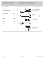 2
2
-
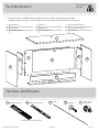 3
3
-
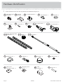 4
4
-
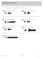 5
5
-
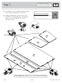 6
6
-
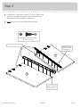 7
7
-
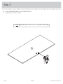 8
8
-
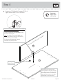 9
9
-
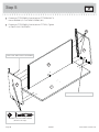 10
10
-
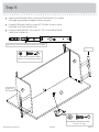 11
11
-
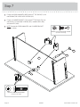 12
12
-
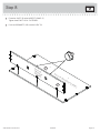 13
13
-
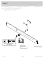 14
14
-
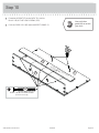 15
15
-
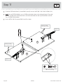 16
16
-
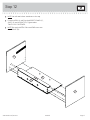 17
17
-
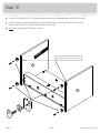 18
18
-
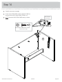 19
19
-
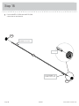 20
20
-
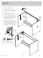 21
21
-
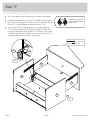 22
22
-
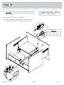 23
23
-
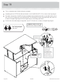 24
24
-
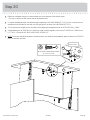 25
25
-
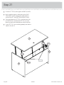 26
26
-
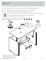 27
27
-
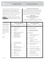 28
28
-
 29
29
-
 30
30
-
 31
31
-
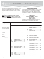 32
32
-
 33
33
-
 34
34
-
 35
35
-
 36
36
-
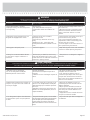 37
37
-
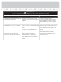 38
38
-
 39
39
-
 40
40


En otros idiomas
- français: Sauder 422357 Manuel utilisateur
- English: Sauder 422357 User manual
Documentos relacionados
-
Sauder 419321 Manual de usuario
-
-
-
-
-
-
-
-
-