
Page 1 of 8
Installation and Operation Instructions
Citadel Series
MATRIX
®
Enabled
IMPORTANT! Read all instructions before installing and using. Installer: This manual must be delivered to the end user.
WARNING!
Failure to install or use this product according to manufacturer’s recommendations may result in property damage, serious bodily/
personal injury, and/or death to you and those you are seeking to protect!
Do not install and/or operate this safety product unless you have read and understand the safety
information contained in this manual.
1. Proper installation combined with operator training in the use, care and maintenance of emergency warning devices are essential to
ensure the safety of emergency personnel and the public.
2. Emergency warning devices often require high electrical voltages and/or currents. Exercise caution when working with live electrical
connections.
3. This product must be properly grounded. Inadequate grounding and/or shorting of electrical connections can cause high current
arcing, which can cause personal injury and/or severe vehicle damage, including re.
4. Proper placement and installation is vital to the performance of this warning device. Install this product so that output performance of
the system is maximized and the controls are placed within convenient reach of the operator so that s/he can operate the system
without losing eye contact with the roadway.
5. It is the responsibility of the vehicle operator to ensure daily that all features of this product work correctly. In use, the vehicle operator
should ensure the projection of the warning signal is not blocked by vehicle components (i.e., open trunks or compartment doors),
people, vehicles or other obstructions.
6. The use of this or any other warning device does not ensure all drivers can or will observe or react to an emergency warning signal.
Never take the right-of-way for granted. It is your responsibility to be sure you can proceed safely before entering an intersection, drive
against trac, respond at a high rate of speed, or walk on or around trac lanes.
7. This equipment is intended for use by authorized personnel only. The user is responsible for understanding and obeying all laws
regarding emergency warning devices. Therefore, the user should check all applicable city, state, and federal laws and regulations.
The manufacturer assumes no liability for any loss resulting from the use of this warning device.
8. This product may contain high intensity LEDs. Staring directly into these lights could result in temporary and/or permanent vision
impairment.
Input Voltage: 12-24 VDC
Input Current: 6.3 A max.
Output Power: 80.6 W max.
Fusing Requirement: 10A
Matrix
®
Connectivity: CAT5
Operating Temperature: -40ºC to 65ºC
(-40ºF to 149ºF)
Specications:

Page 2 of 8
Unpacking and Pre-Installation:
Carefully remove the product and place it on a at surface. Examine the unit for transit damage and locate all parts. If damage is found or
parts are missing, contact the transit company or Code 3. Do not use damaged or broken parts.
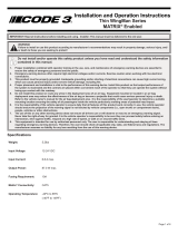
Ensure the product voltage is compatible with the planned installation.
Refer to vehicle specic installation for mounting instructions.
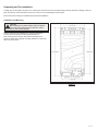
Control box recommended mounting hardware: #8-#10.
Max mounting torque 35in-lbs using #10-32 with ange nut or
washer on at surface. Dierent mounting hardware or surface will
aect max torque limits
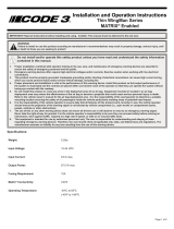
Installation and Mounting:
Figure 1
CAUTION!
When drilling into any vehicle surface, make sure that the
area is free from any electrical wires, fuel lines, vehicle
upholstery, etc. that could be damaged.

Page 3 of 8
Wiring Instructions:
IMPORTANT! This unit is a safety device and it must be connected to its own separate, fused power point to assure its continued operation
should any other electrical accessory fail. Do not wire in parallel with any other accessory.
Notes:
• Larger wires and tight connections will provide longer service life for components. For high current wires it is highly recommended
that terminal blocks or soldered connections be used with shrink tubing to protect the connections. Do not use insulation displace-
ment connectors (e.g., 3M Scotchlock type connectors).
• Route wiring using grommets and sealant when passing through compartment walls. Minimize the number of splices to reduce volt-
age drop. High ambient temperatures (e.g., under-hood) will signicantly reduce the current carrying capacity of wires, fuses, and
circuit breakers. All wiring should conform to the minimum wire size and other recommendations of the manufacturer and be pro-
tected from moving parts and hot surfaces. Looms, grommets, cable ties, and similar installation hardware should be used to anchor
and protect all wiring.
• Fuses or circuit breakers should be located as close to the power takeo points as possible and properly sized to protect the wiring
and devices.
• Particular attention should be paid to the location and method of making electrical connections and splices to protect these points
from corrosion and loss of conductivity.
• Ground termination should only be made to substantial chassis components, preferably directly to the vehicle battery.
• Circuit breakers are very sensitive to high temperatures and will “false trip” when mounted in hot environments or operated close to
their capacity.
Caution:
Disconnect the battery before wiring up the product, to prevent accidental shorting, arcing and/or electrical shock.
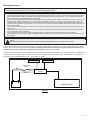
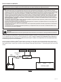
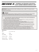
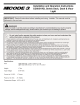
Connect the red (power) and black (ground) wires from the Matrix
®
enabled Citadel to a nominal 12-24 VDC supply, along with a customer
supplied in-line, 10A slow blow ATC style fuse. Please note that the fuse holder selected by the customer must also be rated by its
manufacturer to meet or exceed the corresponding fuse ampacity. See Figure 2 for details.
All Matrix
®
enabled Citadels must also connect back to a central node, such as the Serial Interface Box or Z3 Serial Siren, to establish serial
communication with the larger network. Please note, for CAT5 connections the PRI-1 port must always be utilized rst, before additional
devices can be connected to the SEC-2 port. See Figure 2 for details.
Figure 2
10 A In-Line
Fuse
Matrix® enabled
Citadel
Right Modules
Left Modules
BLACK
RED
CENTRAL NODE
PRI-1 SEC-2 B Y
CAT 5

Page 4 of 8
The Matrix
®
network is designed to accommodate a large number of accessory devices. However, Matrix
®
enabled Citadel utilizing CAT5 will
always be the last device in either the PRI-1 or SEC-2 chain. Further instructions, features, and control options are detailed in the installation
manual of the customer selected “Central Node”.
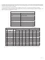
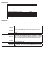
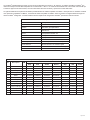
The following table indicates the default ash patterns of the Matrix
®
enabled Citadel. These patterns are activated by other Matrix
®
compatible products, connected to the Matrix
®
enabled Citadel. These can easily be recongured as desired, in the Matrix
®
Congurator. See
Matrix
®
Conguration Quick Start Manual for details.
Default Flash Patterns
Default Description
Dim 30%
Cruise Dim, Primary Steady
Level 3 Primary w/ Secondary Pops Triple Flash 150
Level 2 Primary Double Flash 115
Level 1 Primary Smooth Sweep
Brake Steady Red
Rear Cut
Left Arrow Tertiary Left Building Fast
Right Arrow Tertiary Right Building Fast
Center Out Tertiary Center Out Building Fast
Arrow Flash Tertiary Simultaneous Fast Flash
Matrix Citadel Flash Pattern Compliance Chart
No. Description FPM
SAE J595 CA TITLE 13
Red Blue Amber White Red Blue Amber
1 Double 75 Pending Pending Pending Pending Pending Pending Pending
2 Triple 75 Pending Pending Pending Pending Pending Pending Pending
3 Quad 75 Pending Pending Pending Pending Pending Pending Pending
4 Quint 75 Pending Pending Pending Pending Pending Pending Pending
5 Double 150 Pending Pending Pending Pending - - -
6 Triple 150 Pending Pending Pending Pending - - -
7 Quad 150 Pending Pending Pending Pending - - -
8 Quint 150 Pending Pending Pending Pending - - -
9 Triple Pop 150 Pending Pending Pending Pending Pending Pending Pending
10 Quad Pop 150 Pending Pending Pending Pending Pending Pending Pending
11 Single 375 Pending Pending Pending Pending - - -
12 Title 13 Double 75 Pending Pending Pending Pending Pending Pending Pending
13 Title 13 Double 115 Pending Pending Pending Pending Pending Pending Pending

Page 5 of 8
Description Part No.
Gaskets
replacement control box CZ42001
replacement housings, PIU20 CZ42002
replacement LHS & RHS harnesses, PIU20 CZ42003
replacement housings, Tahoe 2015+ CZ42004
replacement LHS & RHS harnesses, Tahoe 2015+ CZ42005
replacement housings, 2015-2019 PIU CZ42006
replacement LHS & RHS harnesses, 2015-2019 PIU CZ42007
replacement Mega Thin light head, RBA CZ42008RBA
replacement Mega Thin light head, RBW CZ42008RBW
replacement Mega Thin light head, RAW CZ4200RAW
replacement Mega Thin light head, BAW CZ4200BAW
Replacement Parts:
All lightbars are thoroughly tested prior to shipment. However, should you encounter a problem during installation or during the life of the
product, follow the guide below for troubleshooting and repair information. If the problem cannot be rectied using the solutions given below,
additional information may be obtained from the manufacturer – contact details are at the end of this document.
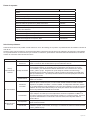
Troubleshooting:
Problem Possible Cause(s) Comments / Response
No Power
Faulty wiring
Ensure power and ground connections to the product are secured. Remove and reconnect the
red power wire to the vehicle battery.
Input Voltage
The product is equipped with an over voltage lockout circuit. During a sustained overvoltage
event, the controller inside will maintain communication with the rest of the Matrix
®
network,
but disable power out to the light modules. Look for the solid red V_FAULT LED. Ensure that
input voltage does not exceed the specied range for your particular model. When overvoltage
occurs, the input must temporarily drop ~1V below the maximum limit in order to resume normal
operation.
Blown fuse The product may have blown an upstream fuse. Check and replace fuse if necessary.
No Communication
Ignition input
An ignition wire input is rst required to bring the central node out of a sleep state. From that
point, the central node controls the status of all other Matrix
®
compatible devices, including the
Citadel. If the device is active, you should see a ashing green STATUS LED on the controller
inside. See the installation manual of the customer selected central node for further trouble-
shooting of the ignition input.
Connectivity
Ensure that the CAT5 cable is securely connected back to a central node. Ensure that any
other cables connecting Matrix
®
compatible accessory devices in a CAT5 daisy chain are fully
seated with positive lock. Remember that the PRI-1 jack at the central node must rst be used,
before the SEC-2 jack can be used.
Bad Light Module
No Response Verify that the left and right harness connections are secure at the Citadel control box.
Short Circuit
If any one light module is shorted out, and the user attempts to activate a ash pattern, the pat-
tern will not operate. Instead, the controller inside the Citadel will display a solid red I_FAULT
LED.

Page 6 of 8
Notes:

Page 7 of 8
Notes:

Page 8 of 8
Product Returns:
If a product must be returned for repair or replacement*, please contact our factory to obtain a Return Goods Authorization Number (RGA
number) before you ship the product to Code 3®, Inc. Write the RGA number clearly on the package near the mailing label. Be sure you use
sucient packing materials to avoid damage to the product being returned while in transit.
*Code 3®, Inc. reserves the right to repair or replace at its discretion. Code 3®, Inc. assumes no responsibility or liability for expenses incurred for the removal and /or reinstallation of products requiring
service and/or repair.; nor for the packaging, handling, and shipping: nor for the handling of products returned to sender after the service has been rendered.
Manufacturer Limited Warranty Policy:
Manufacturer warrants that on the date of purchase this product will conform to Manufacturer’s specications for this product (which are avail-
able from the Manufacturer upon request). This Limited Warranty extends for Sixty (60) months from the date of purchase.
DAMAGE TO PARTS OR PRODUCTS RESULTING FROM TAMPERING, ACCIDENT, ABUSE, MISUSE, NEGLIGENCE, UNAPPROVED MODIFICA-
TIONS, FIRE OR OTHER HAZARD; IMPROPER INSTALLATION OR OPERATION; OR NOT BEING MAINTAINED IN ACCORDANCE WITH THE
MAINTENANCE PROCEDURES SET FORTH IN MANUFACTURER’S INSTALLATION AND OPERATING INSTRUCTIONS VOIDS THIS LIMITED WAR-
RANTY.
Exclusion of Other Warranties:
MANUFACTURER MAKES NO OTHER WARRANTIES, EXPRESS OR IMPLIED. THE IMPLIED WARRANTIES FOR MERCHANTABILITY, QUALITY
OR FITNESS FOR A PARTICULAR PURPOSE, OR ARISING FROM A COURSE OF DEALING, USAGE OR TRADE PRACTICE ARE HEREBY EX-
CLUDED AND SHALL NOT APPLY TO THE PRODUCT AND ARE HEREBY DISCLAIMED, EXCEPT TO THE EXTENT PROHIBITED BY APPLICABLE
LAW. ORAL STATEMENTS OR REPRESENTATIONS ABOUT THE PRODUCT DO NOT CONSTITUTE WARRANTIES.
Remedies and Limitation of Liability:
MANUFACTURER’S SOLE LIABILITY AND BUYER’S EXCLUSIVE REMEDY IN CONTRACT, TORT (INCLUDING NEGLIGENCE), OR UNDER ANY
OTHER THEORY AGAINST MANUFACTURER REGARDING THE PRODUCT AND ITS USE SHALL BE, AT MANUFACTURER’S DISCRETION, THE
REPLACEMENT OR REPAIR OF THE PRODUCT, OR THE REFUND OF THE PURCHASE PRICE PAID BY BUYER FOR NON-CONFORMING PROD-
UCT. IN NO EVENT SHALL MANUFACTURER’S LIABILITY ARISING OUT OF THIS LIMITED WARRANTY OR ANY OTHER CLAIM RELATED TO
THE MANUFACTURER’S PRODUCTS EXCEED THE AMOUNT PAID FOR THE PRODUCT BY BUYER AT THE TIME OF THE ORIGINAL PURCHASE.
IN NO EVENT SHALL MANUFACTURER BE LIABLE FOR LOST PROFITS, THE COST OF SUBSTITUTE EQUIPMENT OR LABOR, PROPERTY
DAMAGE, OR OTHER SPECIAL, CONSEQUENTIAL, OR INCIDENTAL DAMAGES BASED UPON ANY CLAIM FOR BREACH OF CONTRACT, IM-
PROPER INSTALLATION, NEGLIGENCE, OR OTHER CLAIM, EVEN IF MANUFACTURER OR A MANUFACTURER’S REPRESENTATIVE HAS BEEN
ADVISED OF THE POSSIBILITY OF SUCH DAMAGES. MANUFACTURER SHALL HAVE NO FURTHER OBLIGATION OR LIABILITY WITH RESPECT
TO THE PRODUCT OR ITS SALE, OPERATION AND USE, AND MANUFACTURER NEITHER ASSUMES NOR AUTHORIZES THE ASSUMPTION OF
ANY OTHER OBLIGATION OR LIABILITY IN CONNECTION WITH SUCH PRODUCT.
This Limited Warranty denes specic legal rights. You may have other legal rights which vary from jurisdiction to jurisdiction. Some jurisdic-
tions do not allow the exclusion or limitation of incidental or consequential damages.
Warranty:
© 2020 Code 3, Inc. all rights reserved.
920-0837-00 Rev. B
10986 North Warson Road
St. Louis, MO 63114
Technical Service
USA (314) 996-2800
Customer Service
UK +44 (0)113 237 5340
AUS +61 (0)3 63322444
CODE3ESG.com
An ECCO SAFETY GROUP™ Brand
www.eccosafetygroup.com

Pàgina 1 de 8
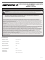
Instrucciones de instalación y operación
Serie Citadel
MATRIX
®
activado
¡IMPORTANTE! Lea todas las instrucciones antes de instalar y utilizar. Instalador: Este manual se debe entregar al usuario nal.
ADVERTENCIA
El no instalar o utilizar este producto de acuerdo con las recomendaciones del fabricante podría tener como resultado daño a la
propiedad, lesiones graves corporales/personales o la muerte de usted y de las personas que busca proteger.
No instale ni opere este producto de seguridad, a menos que haya leído y comprenda la
información de seguridad contenida en este manual.
1. La correcta instalación, junto con la capacitación del operador respecto del uso, así como el cuidado y el mantenimiento de los
dispositivos de alerta de emergencia, son esenciales para garantizar la seguridad del personal de emergencia y del público.
2. Los dispositivos de advertencia en emergencias a menudo requieren altos voltajes o corrientes eléctricas. Tenga precaución cuando
trabaje con conexiones eléctricas con carga.
3. Este producto debe estar correctamente conectado a tierra. Una conexión a tierra inadecuada o un cortocircuito en las conexiones
eléctricas pueden causar arcos con alta corriente, que pueden provocar lesiones personales o daños graves en el vehículo, incluido
un incendio.
4. La correcta ubicación e instalación son cruciales para el rendimiento de este dispositivo de advertencia. Instale este producto de
forma que el rendimiento de producción del sistema se maximice y los controles estén situados a una distancia apropiada que permita
al operador operar el sistema sin perder el contacto visual con el área de trabajo.
5. Es responsabilidad del operador del vehículo asegurarse de que todas las funciones de este producto funcionen correctamente todos
los días. Durante el uso, el operador del vehículo debe asegurarse de que los componentes del vehículo no bloqueen la proyección
del haz de luz (es decir, maleteros o puertas de compartimientos abiertas), personas, vehículos u otras obstrucciones.
6. El uso de este o cualquier otro dispositivo de advertencia no garantiza que todos los conductores puedan o sean capaces de observar
o reaccionar ante una señal de advertencia en emergencias. Nunca tome el derecho de paso por sentado. Es su responsabilidad
asegurarse de que pueda continuar de forma segura antes de entrar en una intersección, conducir en dirección contraria al tráco,
reaccionar mientras se desplaza a alta velocidad, o pasar sobre los carriles de tráco o alrededor de estos.
7. Este equipo está diseñado para su uso únicamente por parte de personal autorizado. El usuario es responsable de entender y
obedecer todas las leyes relacionadas con los dispositivos de advertencia en emergencias. Por lo tanto, el usuario debe comprobar
todas las leyes y regulaciones de la ciudad, el estado y el país. El fabricante no asume ninguna responsabilidad por cualquier pérdida
ocasionada por el uso de este dispositivo de advertencia.
8. Este producto puede contar con LED de alta intensidad. Mirar directamente estas luces podría provocar un deterioro temporal o
permanente de la vista.
Voltaje de entrada: De 12 a 24 V CC
Corriente de entrada: 6,3 A máx.
Potencia de salida: 80,6 W máx.
Requisitos de fusión: 10 A
Conectividad Matrix
®
: CAT5
Temperatura de
funcionamiento:
Entre –40 °C y 65 °C
(entre –40 °F y 149 °F)
Especicaciones:

Pàgina 2 de 8
Desembalaje y preinstalación:
Retire el producto con cuidado y colóquelo sobre una supercie plana. Examine la unidad en busca de daños que se hayan producido en
el transporte y localice todas las piezas. Si encuentra algún daño, o faltan piezas, comuníquese con la empresa de transporte o Code 3. No
utilice piezas dañadas o rotas.
Asegúrese de que la tensión del producto sea compatible con la instalación planicada.
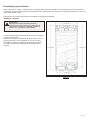
Consulte las instrucciones especícas del vehículo para conocer las
instrucciones de montaje.
Tornillería de montaje recomendada de la caja de control: n.º 8-10.
Par de montaje máx.: 35 lb-in utilizando el n.º 10-32 con tuerca
embridada o arandela en supercie plana. Utilizar una tornillería
de montaje o una supercie diferentes afecta los límites de par
máximos.
Instalación y montaje:
Figura 1
PRECAUCIÓN
Cuando perfore cualquier supercie del vehículo,
asegúrese de que el área esté libre de cualquier tipo de
cables eléctricos, tuberías de combustible, tapicería de
vehículos, etc., que pudieran resultar dañados.

Pàgina 3 de 8
Instrucciones de cableado:
¡IMPORTANTE! Esta unidad es un dispositivo de seguridad y se debe conectar a su propia fuente de poder de fusibles separada para asegurar
su funcionamiento continuo si cualquier otro accesorio eléctrico falla. No cablee en paralelo con ningún otro accesorio.
Notas:
• Los cables más anchos y las conexiones jas ofrecen una mayor vida útil para los componentes. Para los cables de corriente
intensa, se recomienda encarecidamente que los bloques terminales o las conexiones soldadas se utilicen con un tubo retráctil para
proteger las conexiones. No utilice conectores con desplazamiento de aislamiento (por ejemplo, conectores de tipo Scotchlock 3M).
• Pase el cableado con la ayuda de los pasacables y un sellador cuando los pase a través de las paredes del compartimiento.
Minimice el número de empalmes para reducir la caída de voltaje. Las altas temperaturas ambientales (por ejemplo, bajo el capó)
reducirán signicativamente la capacidad conductora de corriente de los cables, fusibles y disyuntores. Todo el cableado se debe
ajustar al tamaño mínimo de cables y otras recomendaciones del fabricante, además de estar protegidos de las piezas móviles y
supercies calientes. Los telares, los pasacables, las bridas para cables y el hardware de instalación similar se deben utilizar para
jar y proteger todo el cableado.
• Los fusibles o disyuntores se deben ubicar lo más cerca posible de los puntos de toma de potencia y deben ser de la capacidad
correcta para proteger el cableado y los dispositivos.
• Se debe prestar especial atención a la ubicación y el método para hacer conexiones y empalmes eléctricos a n de proteger estos
puntos de la corrosión y de la pérdida de conductividad.
• La terminación de conexión a tierra solo se debe realizar a los componentes importantes del chasis, de preferencia, directamente a
la batería del vehículo.
• Los disyuntores son muy sensibles a las altas temperaturas y se "dispararán en falso" si se montan en ambientes cálidos o si se
hacen funcionar cerca de su capacidad.
Precaución:
Desconecte la batería antes de conectar el producto para evitar cortocircuitos, arcos eléctricos o descargas eléctricas accidentales.
Conecte los cables rojo (alimentación) y negro (tierra) del Citadel compatible con Matrix
®
a una alimentación nominal de 12 a 24 V CC, junto
con un fusible tipo ATC de 10 A de acción lenta suministrado por el cliente. Tenga en cuenta que el portafusibles seleccionado por el
cliente también debe estar clasicado por su fabricante para cumplir o superar la correspondiente corriente máxima del fusible.
Consulte la Figura 2 para conocer más detalles.
Todos los Citadel compatibles con Matrix
®
también deben conectarse a un nodo central, como la caja de interfaz serial o la sirena serie
Z3, para establecer una comunicación en serie con la red mayor. Tenga en cuenta que para las conexiones CAT5, el puerto PRI-1 siempre
debe utilizarse primero, antes de que se puedan conectar dispositivos adicionales al puerto SEC-2. Consulte la Figura 2 para conocer más
detalles.
Figura 2
10 A In-Line
Fuse
Matrix® enabled
Citadel
Right Modules
Left Modules
BLACK
RED
CENTRAL NODE
PRI-1 SEC-2 B Y
CAT 5

Pàgina 4 de 8
La red Matrix
®
está diseñada para alojar un gran número de dispositivos accesorios. Sin embargo, un Citadel compatible con Matrix
®
que
utilice CAT5 siempre será el último dispositivo de la cadena PRI-1 o SEC-2. En el manual de instalación del “nodo central” seleccionado por
el cliente se proporcionan instrucciones, así como información sobre sus funciones y opciones de control adicionales.
La siguiente tabla indica los patrones de destello predeterminados de Citadel compatible con Matrix
®
. Estos patrones se activados mediante
otros productos compatibles con Matrix
®
, conectados al Citadel compatible con Matrix
®
. Estos se pueden recongurar fácilmente según se
desee en Matrix
®
Congurator. Consulte el Manual de inicio rápido de la conguración de Matrix
®
para obtener más información.
Patrones de destello predeterminados
Predeterminado Descripción
Atenuación 30 %
Crucero Atenuación, principal estable
Nivel 3 Principal con chispa secundaria triple
destello 150
Nivel 2 Principal doble destello 115
Nivel 1 Principal con barrido suave
Freno Rojo jo
Corte trasero
Flecha izquierda Terciario izquierdo con aumento rápido
Flecha derecha Terciario derecho con aumento rápido
Del centro hacia afuera Terciario central externo con aumento rápido
Destello de echa Terciario de destello rápido simultáneo
Tabla de cumplimiento de patrones de destello para Citadel con Matrix
N.º Descripción FPM
SAE J595 TÍTULO CA 13
Rojo Azul Ámbar Blanco Rojo Azul Ámbar
1 Doble 75 Pendiente Pendiente Pendiente Pendiente Pendiente Pendiente Pendiente
2 Triple 75 Pendiente Pendiente Pendiente Pendiente Pendiente Pendiente Pendiente
3 Cuádruple 75 Pendiente Pendiente Pendiente Pendiente Pendiente Pendiente Pendiente
4 Quíntuple 75 Pendiente Pendiente Pendiente Pendiente Pendiente Pendiente Pendiente
5 Doble 150 Pendiente Pendiente Pendiente Pendiente - - -
6 Triple 150 Pendiente Pendiente Pendiente Pendiente - - -
7 Cuádruple 150 Pendiente Pendiente Pendiente Pendiente - - -
8 Quíntuple 150 Pendiente Pendiente Pendiente Pendiente - - -
9 Chispa triple 150 Pendiente Pendiente Pendiente Pendiente Pendiente Pendiente Pendiente
10 Chispa cuádruple 150 Pendiente Pendiente Pendiente Pendiente Pendiente Pendiente Pendiente
11 Simple 375 Pendiente Pendiente Pendiente Pendiente - - -
12 Título 13 doble 75 Pendiente Pendiente Pendiente Pendiente Pendiente Pendiente Pendiente
13 Título 13 doble 115 Pendiente Pendiente Pendiente Pendiente Pendiente Pendiente Pendiente

Pàgina 5 de 8
Descripción N.° de pieza
Juntas
Caja de control de repuesto CZ42001
Carcasas de repuesto, PIU20 CZ42002
Mazos de cables de repuesto LHS y RHS, PIU20 CZ42003
Carcasas de repuesto, Tahoe 2015+ CZ42004
Mazos de cables de repuesto LHS y RHS, Tahoe 2015+ CZ42005
Carcasas de repuesto, 2015-2019 PIU CZ42006
Mazos de cables de repuesto para conducción del lado derecho y lado
izquierdo, 2015-2019 PIU
CZ42007
Cabezal de luz Mega Thin de repuesto, RBA CZ42008RBA
Cabezal de luz Mega Thin de repuesto, RBW CZ42008RBW
Cabezal de luz Mega Thin de repuesto, RAW CZ4200RAW
Cabezal de luz Mega Thin de repuesto, BAW CZ4200BAW
Piezas de repuesto:
Todas las barras de luces se prueban a fondo antes de su envío. Sin embargo, si se produce un problema durante la instalación o durante la
vida útil del
producto, siga la guía que aparece a continuación para obtener información sobre la solución de problemas y la reparación. Si el problema
no se puede solucionar con las soluciones que se indican a continuación, puede obtener información adicional del fabricante; los datos de
contacto se encuentran al nal de este documento.
Solución de problemas:
Problema Posibles causas Comentarios o respuesta
No hay
alimentación de
corriente
Cableado
defectuoso
Asegúrese de que las conexiones de alimentación y tierra al producto estén jadas. Retire y
vuelva a conectar el cable de alimentación rojo a la batería del vehículo.
Voltaje de entrada
El producto está equipado con un circuito de bloqueo de sobrevoltaje. Durante un evento
de sobrevoltaje sostenido, el controlador interno mantendrá la comunicación con el resto
de la red Matrix
®
, pero desactivará la salida de alimentación a los módulos de luz. Busque
el LED V_FAULT rojo jo. Asegúrese de que el voltaje de entrada no exceda el rango
especicado para su modelo en particular. Cuando se produce sobrevoltaje, la entrada debe
bajar aproximadamente 1 V por debajo del límite máximo de forma temporal para reanudar el
funcionamiento normal.
Fusible fundido
Es posible que el producto haya fundido un fusible anterior en el circuito. Revise y sustituya el
fusible si es necesario.
Sin comunicación
Entrada de
encendido
Primero se necesita una entrada de cable de encendido para que el nodo central salga de un
estado de reposo. Desde ese punto, el nodo central controla el estado de todos los demás
dispositivos compatibles con Matrix
®
, incluido el Citadel. Si el dispositivo está activo, debería
ver un LED de ESTADO verde parpadeante en el interior del controlador. Consulte el manual de
instalación del nodo central seleccionado por el cliente para obtener más información sobre la
solución de problemas de la entrada de encendido.
Conectividad
Asegúrese de que el cable CAT5 está conectado correctamente a un nodo central. Asegúrese
de que cualquier otro cable que conecte dispositivos accesorios compatibles con Matrix
®
en
una cadena margarita CAT5 esté completamente encajado con un bloqueo positivo. Recuerde
que primero debe utilizarse el conector PRI-1 del nodo central, antes de poder utilizar el
conector SEC-2.
Módulo de luces
defectuoso
Sin respuesta
Compruebe que las conexiones del mazo de cables izquierdo y derecho estén bien jadas en la
caja de control de Citadel.
Cortocircuito
Si se produce un cortocircuito en algún módulo de luces y el usuario intenta activar un patrón
de destello, el patrón no funcionará. En su lugar, el controlador del interior de Citadel mostrará
un LED I_FAUDE rojo jo.

Pàgina 6 de 8
Notas:

Pàgina 7 de 8
Notas:

Pàgina 8 de 8
Devoluciones de productos:
Si un producto debe devolverse para su reparación o reemplazo*, comuníquese con nuestra fábrica para obtener un número de autorización de
devolución de mercancías (número RGA, del inglés Return Goods Authorization) antes de enviar el producto a Code 3®, Inc. Escriba el número
RGA claramente en el paquete cerca de la etiqueta postal. Asegúrese de utilizar materiales de embalaje sucientes para evitar daños durante el
transporte en el producto que se va a devolver.
* Code 3®, Inc. se reserva el derecho de realizar reparaciones o reemplazos a su discreción. Code 3®, Inc. no asume ninguna responsabilidad por los gastos incurridos por la remoción o reinstalación de
productos que requieran mantenimiento o reparación; ni por el embalaje, manejo y envío; ni por el manejo de productos devueltos al remitente después de que el mantenimiento se haya realizado.
Política de garantía limitada del fabricante:
El fabricante garantiza que, para la fecha de compra, este producto se ajustará a las especicaciones del fabricante para este producto (que
pueden solicitarse al fabricante). Esta garantía limitada se extiende por sesenta (60) meses desde la fecha de compra.
LOS DAÑOS A LAS PIEZAS O LOS PRODUCTOS DEBIDO A MANIPULACIÓN, ACCIDENTE, ABUSO, MAL USO, NEGLIGENCIA, MODIFICACIONES
NO APROBADAS, FUEGO U OTRO PELIGRO, INSTALACIÓN U OPERACIÓN INCORRECTAS, O NO REALIZAR EL MANTENIMIENTO SEGÚN
LOS PROCEDIMIENTOS DE MANTENIMIENTO INDICADOS EN LAS INSTRUCCIONES DE INSTALACIÓN Y OPERACIÓN DEL FABRICANTE
ANULARÁN ESTA GARANTÍA LIMITADA.
Exclusión de otras garantías:
EL FABRICANTE NO OTORGA OTRAS GARANTÍAS, EXPRESAS O IMPLÍCITAS. LAS GARANTÍAS IMPLÍCITAS DE COMERCIABILIDAD, CALIDAD
O IDONEIDAD PARA UN FIN DETERMINADO, O DERIVADAS DE UN PROCESO DE NEGOCIACIÓN, USO O PRÁCTICAS COMERCIALES,
QUEDAN EXCLUIDAS POR LA PRESENTE Y NO SE APLICARÁN AL PRODUCTO, SALVO EN LA MEDIDA EN QUE LO PROHÍBA LA
LEGISLACIÓN VIGENTE. LAS DECLARACIONES O REPRESENTACIONES ORALES SOBRE EL PRODUCTO NO CONSTITUYEN GARANTÍAS.
Recursos y limitación de responsabilidad:
LA ÚNICA RESPONSABILIDAD DEL FABRICANTE Y EL RECURSO EXCLUSIVO DEL COMPRADOR POR CONTRATO, AGRAVIO (INCLUIDA
NEGLIGENCIA) O BAJO CUALQUIER OTRA TEORÍA CONTRA EL FABRICANTE SOBRE EL PRODUCTO Y SU USO SERÁ, A DISCRECIÓN
DEL FABRICANTE, LA SUSTITUCIÓN O REPARACIÓN DEL PRODUCTO, O EL REEMBOLSO DEL PRECIO DE COMPRA PAGADO POR EL
COMPRADOR POR EL PRODUCTO QUE NO CUMPLA CON LOS REQUISITOS. EN NINGÚN CASO LA RESPONSABILIDAD DEL FABRICANTE
DERIVADA DE ESTA GARANTÍA LIMITADA O DE CUALQUIER OTRA RECLAMACIÓN RELACIONADA CON LOS PRODUCTOS DEL FABRICANTE
SUPERARÁ LA CANTIDAD PAGADA POR EL PRODUCTO POR PARTE DEL COMPRADOR EN EL MOMENTO DE LA COMPRA ORIGINAL. EN
NINGÚN CASO EL FABRICANTE SERÁ RESPONSABLE DE PÉRDIDA DE GANANCIAS, EL COSTO DEL EQUIPO DE REEMPLAZO O LA MANO
DE OBRA, DAÑO A LA PROPIEDAD U OTROS DAÑOS ESPECIALES, DERIVADOS O INCIDENTALES BASADOS EN CUALQUIER RECLAMACIÓN
POR INCUMPLIMIENTO DE CONTRATO, INSTALACIÓN INADECUADA, NEGLIGENCIA U OTRA RECLAMACIÓN, INCLUSO SI AL FABRICANTE
O SU REPRESENTANTE SE LE HA INFORMADO DE LA POSIBILIDAD DE DICHOS DAÑOS. EL FABRICANTE NO TENDRÁ MAYOR OBLIGACIÓN
O RESPONSABILIDAD EN CUANTO AL PRODUCTO O SU VENTA, OPERACIÓN Y USO, Y EL FABRICANTE TAMPOCO ASUME NI AUTORIZA LA
CONJETURA DE CUALQUIER OTRA OBLIGACIÓN O RESPONSABILIDAD RELACIONADA CON TAL PRODUCTO.
Esta garantía limitada dene derechos legales especícos. Es posible que tenga otros derechos legales que varían entre jurisdicciones.
Algunas jurisdicciones no permiten la exclusión o limitación de daños derivados o incidentales.
Garantía:
© 2020, Code 3, Inc. Todos los derechos reservados.
920-0837-00 Rev. B
10986 North Warson Road
St. Louis, MO 63114
Sevicio Técnico
(314) 996-2800
CODE3ESG.com
An ECCO SAFETY GROUP™ Brand
www.eccosafetygroup.com
-
 1
1
-
 2
2
-
 3
3
-
 4
4
-
 5
5
-
 6
6
-
 7
7
-
 8
8
-
 9
9
-
 10
10
-
 11
11
-
 12
12
-
 13
13
-
 14
14
-
 15
15
-
 16
16


Code 3 Matrix Citadel Manual de usuario
- Tipo
- Manual de usuario
- Este manual también es adecuado para
en otros idiomas
- English: Code 3 Matrix Citadel User manual
Artículos relacionados
-
 Code 3 Matrix Thin Supervisor Install Instructions
-
 Code 3 Thin Wingman Install Instructions
-
 Code 3 CD5051VDL Series Install Instructions
-
 Code 3 Ford PIU 2015-2019 Matrix Citadel Install Instructions
-
 Code 3 Emergency Systems 2021 Guía del usuario
-
 Code 3 CB7265 Install Instructions
-
 Code 3 Thin Wingman Matrix Install Instructions
-
 Code 3 CD5051VDL2 Install Instructions
-
 Code 3 Chevy Tahoe 2015-2020 Matrix Citadel Install Instructions


Otros documentos
-
Ecco EW2461 Installation Instructions Manual
-
Munters RHS Plus Guía de instalación
-
Innova 3150b El manual del propietario
-
-
-
-
-
Innova 5010 El manual del propietario
-
Maxim Lighting 88960WT Manual de usuario
-
 Cyron HTP1502E Manual de usuario
