Code 3 Ford PIU 2015-2019 Matrix Citadel Install Instructions
- Tipo
- Install Instructions

Page 1 of 8
Installation and Operation Instructions
Citadel™ EZ Mount™ LED Lighting System
for 2013+ Ford Police Interceptor Utility Vehicles
IMPORTANT! Read all instructions before installing and using. Installer: This manual must be delivered to the end user.
WARNING!
Failure to install or use this product according to manufacturer’s recommendations may result in property damage, serious injury, and/
or death to those you are seeking to protect!
Do not install and/or operate this safety product unless you have read and understood the safety information
contained in this manual.
1. Proper installation combined with operator training in the use, care, and maintenance of emergency warning devices are essential to
ensure the safety of emergency personnel and the public.
2. Emergency warning devices often require high electrical voltages and/or currents. Exercise caution when working with live electrical
connections.
3. This product must be properly grounded. Inadequate grounding and/or shorting of electrical connections can cause high current arcing,
which can cause personal injury and/or severe vehicle damage, including re.
4. Proper placement and installation is vital to the performance of this warning device. Install this product so that output performance of
the system is maximized and the controls are placed within convenient reach of the operator so that they can operate the system without
losing eye contact with the roadway.
5. Do not install this product or route any wires in the deployment area of an air bag. Equipment mounted or located in an air bag
deployment area may reduce the eectiveness of the air bag or become a projectile that could cause serious personal injury or death.
Refer to the vehicle owner’s manual for the air bag deployment area. It is the responsibility of the user/operator to determine a suitable
mounting location ensuring the safety of all passengers inside the vehicle particularly avoiding areas of potential head impact.
6. It is the responsibility of the vehicle operator to ensure daily that all features of this product work correctly. In use, the vehicle operator
should ensure the projection of the warning signal is not blocked by vehicle components (i.e., open trunks or compartment doors),
people, vehicles or other obstructions.
7. The use of this or any other warning device does not ensure all drivers can or will observe or react to an emergency warning signal.
Never take the right-of-way for granted. It is the vehicle operator’s responsibility to be sure they can proceed safely before entering an
intersection, drive against trac, respond at a high rate of speed, or walk on or around trac lanes.
8. This equipment is intended for use by authorized personnel only. The user is responsible for understanding and obeying all laws
regarding emergency warning devices. Therefore, the user should check all applicable city, state, and federal laws and regulations. The
manufacturer assumes no liability for any loss resulting from the use of this warning device.

Page 2 of 8
Installation and Mounting:
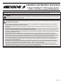
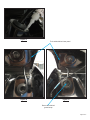
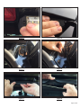
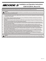
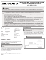
Step 1. With the lift gate closed, clean the rear window with detergent and water. Then prepare the glass surface area directly behind the
housings by wiping with isopropyl (rubbing) alcohol pads. Then coat the area with tape primer and allow the primer to dry thoroughly. Both
are included with the installation kit. The vehicles’s surface temperature should be at least 50°F(10ºC), but 70°F(21ºC) is preferred. Remove
the outer protective paper, shown in Figure 1, covering the VHB tape and position the housing under the spoiler as shown in Figure 2. Do this
carefully, once contact is made, readjustment may not be possible. Make sure to align the curved edge of the housing to the mating curved
edge of the spoiler next to the center mounted brake light as shown in Figure 3. Do not lift or displace the spoiler when installing the housing.
There should be a slight gap between the housing and the spoiler with the spoiler remaining in its original position when the installation is
complete. Do this for both housings being sure the harnesses remain located in their respective notches at the end of the housings as shown
in Figure 4. Apply heavy pressure at each end of the housing and then at the center when installing. Hold the pressure for 10-15 seconds to
assure the VHB tape has achieved full adhesion to the glass surface.
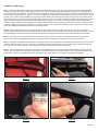
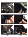
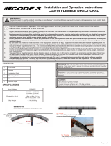
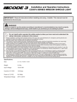
Step 2. Raise the lift gate and remove the grommet near the door hinge on both sides of the vehicle as shown in Figures 5 through 9.
Carefully pull back the lift gate water seal rubber extrusion to expose the edge of the headliner. Pull down the edge of the headliner to expose
the areas adjacent to the grommet holes, and loosen the corner trim molding to get more access to the corner area above the headliner.
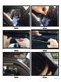
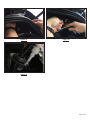
Step 3. Route each harness around the edge of the spoiler as shown in Figures 10 through 16 and feed the harness end through the
grommet hole. Do this while guiding the harness end along the edge of the headliner to the area near the center of the vehicle.
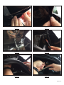
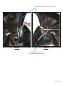
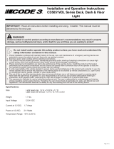
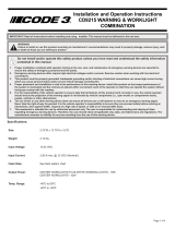
Step 4. Apply adhesive supplied with the kit to the outer edges of the harness grommets. Install and fully seat the harness grommets in their
respective holes as shown in Figures 17 through 19. The cables must be located under the rear door’s inner panel and behind the ground
wire as shown in the previous gures to insure the grommets remain seated and the cable is not pinched.
Step 5. Tuck the wiring inside the headliner area and push the headliner back up into position being sure the retaining magnets make full
contact. Push the corner trim molding back into position and reinstall the rubber extrusion gasket back over the edge of the headliner. Close
the lift gate to check for any interference that may be caused by the wiring, gaskets, or trim molding not being fully reinstalled
Figure 1
Figure 2
Figure 3
Figure 4

Page 3 of 8
Figure 5
Figure 6
Figure 7
Figure 8
Figure 9
Figure 10

Page 4 of 8
Figure 11
Figure 13
Figure 14
Figure 16Figure 15
Figure 12

Page 5 of 8
Figure 17
Figure 18
Figure 19
Tuck cables behind inner panel
Route cable behind
ground strap

Page 6 of 8
Notes:

Page 7 of 8
Notes:

Page 8 of 8
Product Returns:
If a product must be returned for repair or replacement*, please contact our factory to obtain a Return Goods Authorization Number (RGA
number) before you ship the product to Code 3®, Inc. Write the RGA number clearly on the package near the mailing label. Be sure you use
sucient packing materials to avoid damage to the product being returned while in transit.
*Code 3®, Inc. reserves the right to repair or replace at its discretion. Code 3®, Inc. assumes no responsibility or liability for expenses incurred for the removal and /or reinstallation of products requiring
service and/or repair.; nor for the packaging, handling, and shipping: nor for the handling of products returned to sender after the service has been rendered.
Manufacturer Limited Warranty Policy:
Manufacturer warrants that on the date of purchase this product will conform to Manufacturer’s specications for this product (which are avail-
able from the Manufacturer upon request). This Limited Warranty extends for Sixty (60) months from the date of purchase.
DAMAGE TO PARTS OR PRODUCTS RESULTING FROM TAMPERING, ACCIDENT, ABUSE, MISUSE, NEGLIGENCE, UNAPPROVED MODIFICA-
TIONS, FIRE OR OTHER HAZARD; IMPROPER INSTALLATION OR OPERATION; OR NOT BEING MAINTAINED IN ACCORDANCE WITH THE
MAINTENANCE PROCEDURES SET FORTH IN MANUFACTURER’S INSTALLATION AND OPERATING INSTRUCTIONS VOIDS THIS LIMITED WAR-
RANTY.
Exclusion of Other Warranties:
MANUFACTURER MAKES NO OTHER WARRANTIES, EXPRESS OR IMPLIED. THE IMPLIED WARRANTIES FOR MERCHANTABILITY, QUALITY
OR FITNESS FOR A PARTICULAR PURPOSE, OR ARISING FROM A COURSE OF DEALING, USAGE OR TRADE PRACTICE ARE HEREBY EX-
CLUDED AND SHALL NOT APPLY TO THE PRODUCT AND ARE HEREBY DISCLAIMED, EXCEPT TO THE EXTENT PROHIBITED BY APPLICABLE
LAW. ORAL STATEMENTS OR REPRESENTATIONS ABOUT THE PRODUCT DO NOT CONSTITUTE WARRANTIES.
Remedies and Limitation of Liability:
MANUFACTURER’S SOLE LIABILITY AND BUYER’S EXCLUSIVE REMEDY IN CONTRACT, TORT (INCLUDING NEGLIGENCE), OR UNDER ANY
OTHER THEORY AGAINST MANUFACTURER REGARDING THE PRODUCT AND ITS USE SHALL BE, AT MANUFACTURER’S DISCRETION, THE
REPLACEMENT OR REPAIR OF THE PRODUCT, OR THE REFUND OF THE PURCHASE PRICE PAID BY BUYER FOR NON-CONFORMING PROD-
UCT. IN NO EVENT SHALL MANUFACTURER’S LIABILITY ARISING OUT OF THIS LIMITED WARRANTY OR ANY OTHER CLAIM RELATED TO
THE MANUFACTURER’S PRODUCTS EXCEED THE AMOUNT PAID FOR THE PRODUCT BY BUYER AT THE TIME OF THE ORIGINAL PURCHASE.
IN NO EVENT SHALL MANUFACTURER BE LIABLE FOR LOST PROFITS, THE COST OF SUBSTITUTE EQUIPMENT OR LABOR, PROPERTY
DAMAGE, OR OTHER SPECIAL, CONSEQUENTIAL, OR INCIDENTAL DAMAGES BASED UPON ANY CLAIM FOR BREACH OF CONTRACT, IM-
PROPER INSTALLATION, NEGLIGENCE, OR OTHER CLAIM, EVEN IF MANUFACTURER OR A MANUFACTURER’S REPRESENTATIVE HAS BEEN
ADVISED OF THE POSSIBILITY OF SUCH DAMAGES. MANUFACTURER SHALL HAVE NO FURTHER OBLIGATION OR LIABILITY WITH RESPECT
TO THE PRODUCT OR ITS SALE, OPERATION AND USE, AND MANUFACTURER NEITHER ASSUMES NOR AUTHORIZES THE ASSUMPTION OF
ANY OTHER OBLIGATION OR LIABILITY IN CONNECTION WITH SUCH PRODUCT.
This Limited Warranty denes specic legal rights. You may have other legal rights which vary from jurisdiction to jurisdiction. Some jurisdic-
tions do not allow the exclusion or limitation of incidental or consequential damages.
© 2017 Code 3, Inc. all rights reserved.
920-0693-00 Rev. H
Warranty:
10986 North Warson Road
St. Louis, MO 63114
Technical Service
USA (314) 996-2800
Customer Service
UK +44 (0)113 237 5340
AUS +61 (0)3 63322444
www.code3esg.com
An ECCO SAFETY GROUP™ Brand
www.eccosafetygroup.com

Página 1 de 8
Instrucciones de instalación y operación
Sistema de iluminación LED Citadel™ EZ Mount™ para
vehículos Police Interceptor Utility Ford 2013+
¡IMPORTANTE! Lea todas las instrucciones antes de instalar y utilizar. Instalador: Este manual se debe entregar al usuario nal.
ADVERTENCIA
Si no sigue las recomendaciones del fabricante para instalar o utilizar este producto, podría tener como resultado daño a la propiedad,
lesiones graves o la muerte de usted y de las personas que busca proteger.
No instale ni opere este producto de seguridad, a menos que haya leído y comprendido la información de
seguridad contenida en este manual.
1. La correcta instalación junto con la capacitación del operador respecto del uso, el cuidado y el mantenimiento de los dispositivos de
alerta de emergencias son esenciales para garantizar la seguridad del personal de emergencia y del público.
2. Los dispositivos de alerta de emergencias a menudo requieren altos voltajes o corrientes eléctricas. Tenga precaución cuando trabaje
con conexiones eléctricas con carga.
3. Este producto debe estar conectado a tierra correctamente. La conexión inadecuada a tierra o el cortocircuito de las conexiones
eléctricas pueden causar arcos con alta corriente, lo que puede causar lesiones físicas o daños graves en vehículos, incluido fuego.
4. La correcta ubicación e instalación son vitales para el rendimiento de este dispositivo de alerta. Instale este producto de forma que el
rendimiento de producción del sistema se maximice y los controles estén situados a una distancia apropiada para el operador, de modo
que pueda operar el sistema sin perder contacto visual con el camino.
5. No instale este producto ni tienda los cables en el área de despliegue de una bolsa de aire. Los equipos instalados o montados en el
área de despliegue de una bolsa de aire pueden reducir su ecacia o convertirse en un proyectil que podría causar daños corporales
o la muerte. Consulte el manual del propietario del vehículo para ver el área de despliegue de la bolsa de aire. Es responsabilidad del
operador/usuario determinar la ubicación idónea para el montaje que garantice la seguridad de todos los pasajeros en el interior del
vehículo. En particular, se deben evitar las áreas de posible impacto con la cabeza.
6. Es responsabilidad del operador del vehículo asegurarse de que todas las funciones de este producto funcionen correctamente todos
los días. Durante el uso, el operador del vehículo debe garantizar que los componentes de este (es decir, maleteros o puertas de
compartimientos abiertas), personas, vehículos u otras obstrucciones no bloqueen la proyección de la señal de advertencia.
7. El uso de este o cualquier otro dispositivo de alerta no garantiza que todos los conductores puedan observar o reaccionar ante una señal
de alerta de emergencias ni que lo harán. Nunca tome el derecho de paso por sentado. Es responsabilidad del operador del vehículo
asegurarse de que pueda continuar de forma segura antes de entrar en una intersección, conducir contra el tráco, responder a un índice
alto de velocidad, o caminar sobre los carriles de tráco o cerca de estos.
8. Este equipo está diseñado para que solamente el personal autorizado pueda utilizarlo. El usuario es responsable de entender y obedecer
todas las leyes relacionadas con los dispositivos de advertencia en emergencias. Por lo tanto, el usuario debe comprobar todas las leyes
y regulaciones de la ciudad, el estado y el país. El fabricante no asume ninguna responsabilidad por cualquier pérdida ocasionada por el
uso de este dispositivo de advertencia.

Página 2 de 8
Instalación y montaje:
Paso 1. Con la puerta levadiza cerrada, limpie la ventana trasera con detergente y agua. Luego, limpie con una toalla impregnada con
alcohol isopropílico para preparar la supercie de vidrio directamente detrás de las carcasas. Después, recubra el área con un imprimador
para cinta y deje que se seque completamente. Ambos se incluyen en el kit de instalación. La temperatura de la supercie del vehículo
debe ser de, al menos, 10 °C (50 °F), pero se preere una temperatura de 21 °C (70 °F). Retire el papel protector exterior, que se muestra
en la Figura 1, que cubre la cinta VHB y coloque la carcasa debajo del alerón como se muestra en la Figura 2. Hágalo con cuidado, una
vez que haga contacto, es posible que no pueda volver a ajustarlo. Asegúrese de alinear el borde curvo de la carcasa con el borde curvo
de acoplamiento del alerón junto a la luz de freno montada en el centro, como se muestra en la Figura 3. No levante ni desplace el alerón
cuando instale la carcasa. Debe haber un pequeño espacio entre la carcasa y el alerón, con el alerón en su posición original cuando se
complete la instalación. Realice esto con ambas carcasas y asegúrese de que los mazos permanezcan en sus respectivas muescas al nal
de las carcasas, como se muestra en la Figura 4. Cuando realice la instalación, aplique una fuerte presión en cada extremo de la carcasa y,
luego, en el centro. Mantenga la presión durante 10 a 15 segundos para asegurarse de que la cinta VHB esté completamente adherida a la
supercie de vidrio.
Paso 2. Levante la puerta levadiza y quite la arandela cerca de la bisagra de la puerta en ambos lados del vehículo, como se muestra en
las Figuras de 5 a 9. Tire con cuidado de la extrusión de goma de la junta de agua de la puerta levadiza para exponer el borde de la cubierta
interior del techo. Tire hacia abajo el borde de la cubierta interior del techo para exponer las áreas adyacentes a los oricios de la arandela y
aoje la moldura del borde de la esquina para tener más acceso a la zona de la esquina por encima de la cubierta interior del techo.
Paso 3. Tienda cada mazo de cables alrededor del borde del alerón, como se muestra en las Figuras de 10 a 16, e introduzca el extremo
del mazo a través del oricio de la arandela. Hágalo mientras guía el extremo del mazo a lo largo del borde de la cubierta interna del techo
hacia el área cerca del centro del vehículo.
Paso 4. Aplique el adhesivo suministrado con el kit en los bordes exteriores de las arandelas del mazo. Instale y ajuste completamente las
arandelas del mazo de cables en sus oricios respectivos, tal como se muestra en las Figuras de 17 a 19. Los cables deben estar ubicados
debajo del panel interno de la puerta trasera y detrás del cable a tierra, como se muestra en las guras anteriores, para garantizar que las
arandelas permanezcan ajustadas y que el cable no esté aplastado.
Paso 5. Inserte el cableado dentro de la zona de la cubierta interior del techo y empuje la cubierta hacia arriba para que quede en la
posición correcta. Asegúrese de que los imanes de retención hagan contacto por completo. Vuelva a colocar la moldura de borde de la
esquina en su posición original y vuelva a instalar la junta de extrusión de goma en el borde de la cubierta interior del techo. Cierre la puerta
levadiza para comprobar si hay interferencias causadas por el cableado, las juntas o p.or molduras de bordes que no se estén reinstaladas
por completo
Figura 1
Figura 2

Página 3 de 8
Figura 3
Figura 4
Figura 5
Figura 6
Figura 7
Figura 8

Página 4 de 8
Figura 11
Figura 13
Figura 14
Figura 12
Figura 9
Figura 10

Página 5 de 8
Figura 16
Figura 15
Figura 17

Página 6 de 8
Figura 18
Figura 19
Introduzca los cables detrás del panel interior
Tienda el cable por detrás
de la correa para conexión a tierra

Página 7 de 8
Notas:

Página 8 de 8
Devolución de productos:
Si se debe devolver un producto para su reparación o reemplazo*, comuníquese con nuestra fábrica para obtener un Número de autorización
de devolución de mercancías (número RGA) antes de enviar el producto a Code 3®, Inc. Escriba claramente el número RGA en el paquete cerca
de la etiqueta de envío. Asegúrese de utilizar sucientes materiales de embalaje para evitar que se dañe el producto durante el envío.
* Code 3®, Inc. se reserva el derecho a realizar reparaciones o reemplazar productos según su criterio. Code 3®, Inc. no asume responsabilidad alguna por los gastos efectuados para remover o reinstalar
los productos que requieren servicios o reparaciones, por el embalaje, la manipulación y el envío ni por la manipulación de los productos devueltos al remitente después de que se haya prestado el servicio.
Política de garantía limitada del fabricante:
El fabricante garantiza que, en la fecha de compra, este producto se ajustará a las especicaciones del fabricante para este producto
(disponible de parte del fabricante a petición). Esta garantía limitada se extiende por sesenta (60) meses desde la fecha de compra.
LOS DAÑOS A LAS PIEZAS O LOS PRODUCTOS DEBIDO A MANIPULACIÓN, ACCIDENTE, ABUSO, MAL USO, NEGLIGENCIA, MODIFICACIONES
NO APROBADAS, FUEGO U OTRO PELIGRO, INSTALACIÓN U OPERACIÓN INCORRECTAS, O NO REALIZAR EL MANTENIMIENTO SEGÚN
LOS PROCEDIMIENTOS DE MANTENIMIENTO INDICADOS EN LAS INSTRUCCIONES DE INSTALACIÓN Y OPERACIÓN DEL FABRICANTE
ANULARÁN ESTA GARANTÍA LIMITADA.
Exclusión de otras garantías:
EL FABRICANTE NO REALIZA OTRAS GARANTÍAS, ESCRITAS O IMPLÍCITAS. LAS GARANTÍAS IMPLÍCITAS PARA LA COMERCIALIZACIÓN,
CALIDAD O ADECUACIÓN CON UN PROPÓSITO ESPECÍFICO O QUE SURJAN DEL CURSO DE NEGOCIACIÓNES, USO O PRÁCTICA
COMERCIAL QUEDAN, POR LA PRESENTE, EXCLUIDAS Y NO SE APLICARÁN AL PRODUCTO, SALVO EN LA MEDIDA EN QUE ESTÉ
PROHIBIDO POR LA LEY VIGENTE. LAS DECLARACIONES O DESCRIPCIONES ORALES SOBRE EL PRODUCTO NO CORRESPONDEN A
GARANTÍAS.
Soluciones y limitación de responsabilidad:
LA RESPONSABILIDAD EXCLUSIVA DEL FABRICANTE Y EXCLUSIVO RECURSO DEL COMPRADOR EN EL CONTRATO, AGRAVIO (INCLUIDAS
NEGLIGENCIAS) O CUALQUIER OTRA TEORÍA CONTRA EL FABRICANTE SOBRE EL PRODUCTO Y SU USO SERÁ, BAJO EL CRITERIO DEL
FABRICANTE, EL REEMPLAZO O LA REPARACIÓN DEL PRODUCTO, O EL REEMBOLSO DEL PRECIO DE LA COMPRA PAGADO POR EL
COMPRADOR POR EL PRODUCTO QUE NO CUMPLA CON LOS REQUISITOS. EN NINGÚN CASO LA RESPONSABILIDAD DEL FABRICANTE
QUE SURGE DE ESTA GARANTÍA LIMITADA O DE OTRA DECLARACIÓN RELACIONADA CON LOS PRODUCTOS DEL FABRICANTE EXCEDE
LA CANTIDAD PAGADA POR EL COMPRADOR POR EL PRODUCTO EN LA COMPRA ORIGINAL. EN NINGÚN CASO EL FABRICANTE SERÁ
RESPONSABLE DE LA PÉRDIDA DE GANANCIAS, EL COSTO DEL EQUIPO DE REEMPLAZO O EL TRABAJO, DAÑO A LA PROPIEDAD U OTROS
DAÑOS ESPECIALES, DERIVADOS O INCIDENTALES BASADOS EN CUALQUIER RECLAMACIÓN POR INCUMPLIMIENTO DE CONTRATO,
INSTALACIÓN INADECUADA, NEGLIGENCIA U OTRA RECLAMACIÓN, INCLUSO SI AL FABRICANTE O EL REPRESENTANTE DE ESTE SE
LE HA INFORMADO DE LA POSIBILIDAD DE DICHOS DAÑOS. EL FABRICANTE NO TENDRÁ MAYOR OBLIGACIÓN O RESPONSABILIDAD
EN CUANTO AL PRODUCTO O SU VENTA, OPERACIÓN Y USO, Y EL FABRICANTE TAMPOCO ASUME NI AUTORIZA LA CONJETURA DE
CUALQUIER OTRA OBLIGACIÓN O RESPONSABILIDAD RELACIONADA CON TAL PRODUCTO.
Esta garantía limitada dene derechos legales especícos. Puede tener otros derechos legales que varían entre jurisdicciones. Algunas
jurisdicciones no permiten la exclusión o limitación de daños derivados o incidentales.
© 2017, Code 3, Inc. Todos los derechos reservados.
920-0693-00 Rev. H
10986 North Warson Road
St. Louis, MO 63114
Sevicio Técnico
(314) 996-2800
CODE3ESG.com
An ECCO SAFETY GROUP™ Brand
www.eccosafetygroup.com
Garantía:
-
 1
1
-
 2
2
-
 3
3
-
 4
4
-
 5
5
-
 6
6
-
 7
7
-
 8
8
-
 9
9
-
 10
10
-
 11
11
-
 12
12
-
 13
13
-
 14
14
-
 15
15
-
 16
16


Code 3 Ford PIU 2015-2019 Matrix Citadel Install Instructions
- Tipo
- Install Instructions
en otros idiomas
Artículos relacionados
-
 Code 3 Chevy Tahoe 2015-2020 Matrix Citadel Install Instructions
-
 Code 3 Matrix Thin Supervisor Install Instructions
-
 Code 3 Matrix Citadel Manual de usuario
-
 Code 3 Thin Wingman Install Instructions
-
 Code 3 CZ6015/16 Install Instructions
-
 Code 3 CD3794 Install Instructions
-
 Code 3 CD5051VDL2 Install Instructions
-
 Code 3 CB7265 Install Instructions
-
 Code 3 CD5051VDL Series Install Instructions
-
 Code 3 CD9215 Series Install Instructions


