
Page 1 of 4
Installation and Operation Instructions
CD3794 FLEXIBLE DIRECTIONAL
CONTENTS:
1 Light Head
2 Screws
1 Installation Guide
1 Mounting Gasket
1 Bezel
1 Alcohol Wipe
SPECIFICATIONS:
Input Voltage 12-24VDC
Current 0.8A Max @ 12VDC
0.5A Max @ 24VDC
Physical H x W x L 3.9 in x 0.9 in x 0.4 in
9.9 cm x 2.3 cm x 1 cm
Ship Weight 0.1 lb (0.05 Kg)
Important! This unit is a safety device and it must be connected to its own
separate, fused power point to assure its continued operation should any other
electrical accessory fail.
Caution: When drilling into any vehicle surface, make sure the area is
free from any electrical wires, fuel lines, vehicle upholstery, etc. that could be
damaged.
Caution:
- light cannot be twisted or pulled
- do not bend in the lens direction
- mounts to curved surfaces up to 120-deg curvature
(Maximum bend of 30 degrees measured from center of light to end of light)
WARNING!
Failure to install or use this product according to manufacturer’s recommendations may result in property damage, serious injury, and/or death
to those you are seeking to protect!
Do not install and/or operate this safety product unless you have read and understood the safety
information contained in this manual.
1. Proper installation combined with operator training in the use, care, and maintenance of emergency warning devices are essential to ensure the
safety of emergency personnel and the public.
2. Emergency warning devices often require high electrical voltages and/or currents. Exercise caution when working with live electrical connections.
3. This product must be properly grounded. Inadequate grounding and/or shorting of electrical connections can cause high current arcing, which
can cause personal injury and/or severe vehicle damage, including re.
4. Proper placement and installation is vital to the performance of this warning device. Install this product so that output performance of the system
is maximized and the controls are placed within convenient reach of the operator so that they can operate the system without losing eye contact
with the roadway.
5. Do not install this product or route any wires in the deployment area of an air bag. Equipment mounted or located in an air bag deployment area
may reduce the eectiveness of the air bag or become a projectile that could cause serious personal injury or death. Refer to the vehicle owner’s
manual for the air bag deployment area. It is the responsibility of the user/operator to determine a suitable mounting location ensuring the safety
of all passengers inside the vehicle particularly avoiding areas of potential head impact.
6. It is the responsibility of the vehicle operator to ensure daily that all features of this product work correctly. In use, the vehicle operator should
ensure the projection of the warning signal is not blocked by vehicle components (i.e., open trunks or compartment doors), people, vehicles or
other obstructions.
7. The use of this or any other warning device does not ensure all drivers can or will observe or react to an emergency warning signal. Never take
the right-of-way for granted. It is the vehicle operator’s responsibility to be sure they can proceed safely before entering an intersection, drive
against trac, respond at a high rate of speed, or walk on or around trac lanes.
8. This equipment is intended for use by authorized personnel only. The user is responsible for understanding and obeying all laws regarding
emergency warning devices. Therefore, the user should check all applicable city, state, and federal laws and regulations. The manufacturer
assumes no liability for any loss resulting from the use of this warning device.
No Pulling
Can not pull the wire because the PCB and
components will be damaged.
No Twisting
The product can’t be twisted because the PCB and
components will be damaged.
Standard test
External bending is about 120 degrees max.
Max 30 degree
angle from
center

Mounting:
Wire:
RED: Positive, Colors 1 & 3 (need to add 5A fuse)
WHITE: Positive, Colors 2 & 4 (need to add 5A fuse)
BLACK: Negative
BLUE: Pattern select to negative
YELLOW: Synchronized Function
(Up to 8 units can be Synchronized)
Phase Operation:
Phase 1 (Ph1) ashes simultaneously with Ph1
Phase 2 (Ph2) ashes simultaneously with Ph2
Ph1 alternates with Ph2
(Up to 8 units can be Synchronized)
Apply BLUE TO BLACK wire:
-Less than 1 sec. for next pattern
-Between 1-3 sec for previous pattern
-Between 3-5 sec. for factory default
-More than 5 sec. for steady burn
Operation Environment:
Ambient Temperature: -30 to 50°C
Mounting on a curved surface:
1. Use template on page 3 to verify light will t curved surface.
2. Mark hole location using gasket as a template and drill hole for wire exit using
11/32 in. drill bit.
3. Wipe surface clean with alcohol wipe. Wait until dry.
4. Mount light using VHB adhesive. Peel adhesive backing and apply pressure
to adhere to surface for 20 seconds. It is recommended to allow 24 hours for
adhesive to fully adhere before powering on light.
* Do not use hardware, gasket or bezel when mounting on curved surface.
* Max surface curvature 120°.
Mounting on at surface:
1. Mark wire and screw locations using gasket as a template. Drill wire exit hole
using 11/32 in. drill bit. Pre-drill screw holes using 3/64 in. drill bit.
2. Peel VHB backing and apply light to surface, aligning screw holes and wire exit.
Apply pressure for 20 seconds. Insert screws through bezel to nish mounting
lighthead. It is recommended to allow 24 hours for adhesive to fully adhere
before powering on light.
*For extra adhesion, use 3M Tape Primer. For product & application information, go to: https://multimedia.3m.com/mws/media/65952O/3mtm-tape-primer-94.pdf
Use this cut-out to verify surface curvature is appropriate for install of exible directional light. Light must be mounted on curved or elliptical surface, it cannot be mounted
on abrupt edges. See Figures 1 and 2 below. Verify template is sized to 5” dimension provided.
Figure 1 Figure 2
Light will mount on this surface as vehicle curve does
not touch inner surface of template.
Light will not mount on this surface as vehicle curve is
touching inner surface of template.
Page 2 of 4
Mounting:
Synchronization: Yellow
Pattern Switch: Blue
Negative: Black
Positive - LED Color 2 & Color 4: White
Positive - LED Color 1 & Color 3: Red
SCREWS
BEZEL
LIGHTHEAD
VHB Adhesive

RED AMBER BLUE WHITE RED AMBER BLUE RED AMBER BLUE RED AMBER BLUE WHITE
1-Default 1 Single 75FPM Ph1 Color 1 Synchronous Color 3 YES Class 1 Class 1 Class 1 Class 1 Class B Class B Class B N/C N/C N/C Class 1S ± 30° Class 1S ± 30° Class 1S ± 30° Class 1S ± 20°
2 2 Single 75FPM Ph2 Color 1 Synchronous Color 3 YES Class 1 Class 1 Class 1 Class 1 Class B Class B Class B N/C N/C N/C Class 1S ± 30° Class 1S ± 30° Class 1S ± 30° Class 1S ± 20°
3 Single 75FPM Ph1 Color 1 Alternately Color 4 YES N/C N/C N/C N/C N/C N/C N/C N/C N/C N/C N/C N/C N/C N/C
4 Single 75FPM Ph2 Color 1 Alternat
ely Color 4 YES N/C N/C N/C N/C N/C N/C N/C N/C N/C N/C N/C N/C N/C N/C
1-Default 5 Single 75FPM Ph1 Color 2 Synchronous Color 4 YES Class 1 Class 1 Class 1 Class 1 Class B Class B Class B N/C N/C N/C Class 1S ± 30° Class 1S ± 30° Class 1S ± 30° Class 1S ± 20°
2 6 Single 75FPM Ph2 Color 2 Synchronous Color 4 YES Class 1 Class 1 Class 1 Class 1 Class B Class B Class B N/C N/C N/C Class 1S ± 30° Class 1S ± 30° Class 1S ± 30° Class 1S ± 20°
3 3 7 Single 75FPM Ph1(Color 1 Synchronous Color 3) Alternately (Color 2
Synchronous Color 4) YES N/C N/C N/C N/C N/C N/C N/C N/C N/C N/C N/C N/C N/C N/C
4 4 8 Single 75FPM Ph2(Color 1 Synchronous Color 3) Alternately (Color 2 Synchronous Color 4) YES N/C N/C N/C N/C N/C N/C N/C N/C N/C N/C N/C N/C N/C N/C
5 5 9 Single 75FPM (Color 1 Alternately Color 2) Alternately (Color 3 Alternately Color 4) YES N/C N/C N/C N/C N/C N/C N/C N/C N/C N/C N/C N/C N/C N/C
6 10 Single 375FPM Ph1 Color 1 Synchronous Color 3 YES N/C N/C N/C N/C N/C N/C N/C N/C N/C N/C N/C N/C N/C N/C
7 11 S
ingle 375FPM Ph2 Color 1 Synchronous Color 3 YES N/C N/C N/C N/C N/C N/C N/C N/C N/C N/C N/C N/C N/C N/C
12 Single 375FPM Ph1 Color 1 Alternately Color 4 YES N/C N/C N/C N/C N/C N/C N/C N/C N/C N/C N/C N/C N/C N/C
13 Single 375FPM Ph2 Color 1 Alternately Color 4 YES N/C N/C N/C N/C N/C N/C N/C N/C N/C N/C N/C N/C N/C N/C
6 14 Single 375FPM Ph1 Color 2 Synchronous Color 4 YES N/C N/C N/C N/C N/C N/C N/C N/C N/C N/C N/C N/C N/C N/C
7 15 Single 375FPM Ph2 Color 2 Synchronous Color 4 YES N/C N/C N/C N/C N/C N/C N
/C N/C N/C N/C N/C N/C N/C N/C
8 8 16 Single 375FPM Ph1 (Color 1 Synchronous Color 3) Alternately (Color 2 Synchronous Color 4) YES N/C N/C N/C N/C N/C N/C N/C N/C N/C N/C N/C N/C N/C N/C
9 9 17 Single 375FPM Ph2 (Color 1 Synchronous Color 3) Alternately (Color 2 Synchronous Color 4) YES N/C N/C N/C N/C N/C N/C N/C N/C N/C N/C N/C N/C N/C N/C
10 10 18 Single 375FPM (Color 1 Alternately Color 2) Alternately (Color 3 Alternately Color 4) YES N/C N/C N/C N/C N/C N/C N/C N/C N/C N/C N/C N/C N/C N/C
11 19 Double 75FPM Ph1 Color 1 Synchronous Color 3 YES Class 1 Class 1 Class 1 Class 1 Class B Class B Class B N/C N/C N/C Class 1S ± 30° Class 1S ± 30° Class 1S ± 30° Class 1S ± 20°
12 20 Double 75FPM Ph2 Color 1 Synchronous Color 3 YES Class 1 Class 1 Class 1 Class 1 Class B Class B Class B N/C N/C N/C Class 1S ± 30° Class 1S ± 30° Class 1S ± 30° Class 1S ± 20°
21 Double 75FPM Ph1 Color 1 Alternately Color 4 YES N/C N/C N/C N/C N/C N/C N/C N/C N/C N/C N/C N/C N/C N/C
22 Double 75FPM Ph2 Color 1 Alternately Color 4 YES N/
C N/C N/C N/C N/C N/C N/C N/C N/C N/C N/C N/C N/C N/C
11 23 Double 75FPM Ph1 Color 2 Synchronous Color 4 YES Class 1 Class 1 Class 1 Class 1 Class B Class B Class B N/C N/C N/C Class 1S ± 30° Class 1S ± 30° Class 1S ± 30° Class 1S ± 20°
12 24 Double 75FPM Ph2 Color 2 Synchronous Color 4 YES Class 1 Class 1 Class 1 Class 1 Class B Class B Class B N/C N/C N/C Class 1S ± 30° Class 1S ± 30° Class 1S ± 30° Class 1S ± 20°
13 13 25 Double 75FPM Ph1 (Color 1 Synchronous Color 3) Alternately (Color 2 Synchronous Color 4) YES N/C N/C N/C N
/C N/C N/C N/C N/C N/C N/C N/C N/C N/C N/C
14 14 26 Double 75FPM Ph2 (Color 1 Synchronous Color 3) Alternately (Color 2 Synchronous Color 4) YES N/C N/C N/C N/C N/C N/C N/C N/C N/C N/C N/C N/C N/C N/C
15 15 27 Double 75FPM (Color 1 Alternately Color 2) Alternately (Color 3 Alternately Color 4) YES N/C N/C N/C N/C N/C N/C N/C N/C N/C N/C N/C N/C N/C N/C
16 28 Double 120FPM Ph1 Color 1 Synchronous Color 3 YES Class 1 Class 1 Class 1 Class 1 N/C N/C N/C XR1 XA1 XB1 Class 2S ± 30° Class 1S ± 30° Class 2S ± 30° Class
1S ± 20°
17 29 Double 120FPM Ph2 Color 1 Synchronous Color 3 YES Class 1 Class 1 Class 1 Class 1 N/C N/C N/C XR1 XA1 XB1 Class 2S ± 30° Class 1S ± 30° Class 2S ± 30° Class 1S ± 20°
30 Double 120FPM Ph1 Color 1 Alternately Color 4 YES N/C N/C N/C N/C N/C N/C N/C N/C N/C N/C N/C N/C N/C N/C
31 Double 120FPM Ph2 Color 1 Alternately Color 4 YES N/C N/C N/C N/C N/C N/C N/C N/C N/C N/C N/C N/C N/C N/C
16 32 Double 120FPM Ph1 Color 2 Synchronous Color 4 YES Class 1 Class 1 Class 1 Class 1 N/C N/C N/C XR1 XA1 XB1 Class 2S ± 30° Class
1S ± 30° Class 2S ± 30° Class 1S ± 20°
17 33 Double 120FPM Ph2 Color 2 Synchronous Color 4 YES Class 1 Class 1 Class 1 Class 1 N/C N/C N/C XR1 XA1 XB1 Class 2S ± 30° Class 1S ± 30° Class 2S ± 30° Class 1S ± 20°
18 18 34 Double 120FPM Ph1 (Color 1 Synchronous Color 3) Alternately (Color 2 Synchronous Color 4) YES N/C N/C N/C N/C N/C N/C N/C N/C N/C N/C N/C N/C N/C N/C
19 19 35 Double 120FPM Ph2 (Color 1 Synchronous Color 3) Alternately (Color 2 Synchronous Color 4) YES N/C N/C N/C N/C N/C N/C N/C N/C N/C N/C N/C N/C N/C N/C
20
20 36 Double 120FPM (Color 1 Alternately Color 2) Alternately (Color 3 Alternately Color 4) YES N/C N/C N/C N/C N/C N/C N/C N/C N/C N/C N/C N/C N/C N/C
21 37 Triple 75FPM Ph1 Color 1 Synchronous Color 3 YES Class 1 Class 1 Class 1 Class 1 Class B Class B Class B N/C N/C N/C Class 2S ± 30° Class 1S ± 30° Class 1S ± 30° Class 1S ± 20°
22 38 Triple 75FPM Ph2 Color 1 Synchronous Color 3 YES Class 1 Class 1 Class 1 Class 1 Class B Class B Class B N/C N/C N/C Class 2S ± 30° Class 1S ± 30° Class 1S ± 30° Class 1S ±
20°
39 Triple 75FPM Ph1 Color 1 Alternately Color 4 YES N/C N/C N/C N/C N/C N/C N/C N/C N/C N/C N/C N/C N/C N/C
40 Triple 75FPM Ph2 Color 1 Alternately Color 4 YES N/C N/C N/C N/C N/C N/C N/C N/C N/C N/C N/C N/C N/C N/C
21 41 Triple 75FPM Ph1 Color 2 Synchronous Color 4 YES Class 1 Class 1 Class 1 Class 1 Class B Class B Class B N/C N/C N/C Class 2S ± 30° Class 1S ± 30° Class 1S ± 30° Class 1S ± 20°
22 42 Triple 75FPM Ph2 Color 2 Synchronous Color 4 YES Class 1 Class 1 Class 1 Class 1 Class B Class B Class
B N/C N/C N/C Class 2S ± 30° Class 1S ± 30° Class 1S ± 30° Class 1S ± 20°
23 23 43 Triple 75FPM Ph1 (Color 1 Synchronous Color 3) Alternately (Color 2 Synchronous Color 4) YES N/C N/C N/C N/C N/C N/C N/C N/C N/C N/C N/C N/C N/C N/C
24 24 44 Triple 75FPM Ph2 (Color 1 Synchronous Color 3) Alternately (Color 2 Synchronous Color 4) YES N/C N/C N/C N/C N/C N/C N/C N/C N/C N/C N/C N/C N/C N/C
25 25 45 Triple 75FPM (Color 1 Alternately Color 2) Alternately (Color 3 Alternately Color 4) YES N/C N/C N/
C N/C N/C N/C N/C N/C N/C N/C N/C N/C N/C N/C
26 46 Quad 75FPM Ph1 Color 1 Synchronous Color 3 YES Class 1 Class 1 Class 1 Class 1 N/C N/C N/C N/C N/C N/C Class 2S ± 30° Class 1S ± 30° Class 1S ± 30° Class 1S ± 20°
27 47 Quad 75FPM Ph2 Color 1 Synchronous Color 3 YES Class 1 Class 1 Class 1 Class 1 N/C N/C N/C N/C N/C N/C Class 2S ± 30° Class 1S ± 30° Class 1S ± 30° Class 1S ± 20°
48 Quad 75FPM Ph1 Color 1 Alternately Color 4 YES N/C N/C N/C N/C N/C N/C N/C N/C N/C N/C N/C N/C N/C N/C
49 Quad 75FPM Ph2 Color 1 Alte
rnately Color 4 YES N/C N/C N/C N/C N/C N/C N/C N/C N/C N/C N/C N/C N/C N/C
26 50 Quad 75FPM Ph1 Color 2 Synchronous Color 4 YES Class 1 Class 1 Class 1 Class 1 N/C N/C N/C N/C N/C N/C Class 2S ± 30° Class 1S ± 30° Class 1S ± 30° Class 1S ± 20°
27 51 Quad 75FPM Ph2 Color 2 Synchronous Color 4 YES Class 1 Class 1 Class 1 Class 1 N/C N/C N/C N/C N/C N/C Class 2S ± 30° Class 1S ± 30° Class 1S ± 30° Class 1S ± 20°
28 28 52-Default Quad 75FPM Ph1 (Color 1 Synchronous Color 3) Alternately (Color 2 Synchronous Color 4)
YES N/C N/C N/C N/C N/C N/C N/C N/C N/C N/C N/C N/C N/C N/C
29 29 53 Quad 75FPM Ph2 (Color 1 Synchronous Color 3) Alternately (Color 2 Synchronous Color 4) YES N/C N/C N/C N/C N/C N/C N/C N/C N/C N/C N/C N/C N/C N/C
30 30 54 Quad 75FPM (Color 1 Alternately Color 2) Alternately (Color 3 Alternately Color 4) YES N/C N/C N/C N/C N/C N/C N/C N/C N/C N/C N/C N/C N/C N/C
31 55 Quad 120FPM Ph1 Color 1 Synchronous Color 3 YES Class 1 Class 1 Class 1 Class 1 N/C N/C N/C N/C N/C N/C Class 2S ± 30° Class 1S ±
30° Class 1S ± 30° Class 1S ± 20°
32 56 Quad 120FPM Ph2 Color 1 Synchronous Color 3 YES Class 1 Class 1 Class 1 Class 1 N/C N/C N/C N/C N/C N/C Class 2S ± 30° Class 1S ± 30° Class 1S ± 30° Class 1S ± 20°
57 Quad 120FPM Ph1 Color 1 Alternately Color 4 YES N/C N/C N/C N/C N/C N/C N/C N/C N/C N/C N/C N/C N/C N/C
58 Quad 120FPM Ph2 Color 1 Alternately Color 4 YES N/C N/C N/C N/C N/C N/C N/C N/C N/C N/C N/C N/C N/C N/C
31 59 Quad 120FPM Ph1 Color 2 Synchronous Color 4 YES Class 1 Class 1 Class 1 Class 1 N/C N/C N/C N/C N
/C N/C Class 2S ± 30° Class 1S ± 30° Class 1S ± 30° Class 1S ± 20°
32 60 Quad 120FPM Ph2 Color 2 Synchronous Color 4 YES Class 1 Class 1 Class 1 Class 1 N/C N/C N/C N/C N/C N/C Class 2S ± 30° Class 1S ± 30° Class 1S ± 30° Class 1S ± 20°
33 33 61 Quad 120FPM Ph1 (Color 1 Synchronous Color 3) Alternately (Color 2 Synchronous Color 4) YES N/C N/C N/C N/C N/C N/C N/C N/C N/C N/C N/C N/C N/C N/C
34 34 62 Quad 120FPM Ph2 (Color 1 Synchronous Color 3) Alternately (Color 2 Synchronous Color 4) YES N/C N/C N/C N/C N/C N/C N/
C N/C N/C N/C N/C N/C N/C N/C
35 35 63 Quad 120FPM (Color 1 Alternately Color 2) Alternately (Color 3 Alternately Color 4) YES N/C N/C N/C N/C N/C N/C N/C N/C N/C N/C N/C N/C N/C N/C
8 64 Modulation (Color 1 Synchronous Color 3) Alternately (Color 2 Synchronous Color 4) NO N/C N/C N/C N/C N/C N/C N/C N/C N/C N/C N/C N/C N/C N/C
9 65 2 Double, 2 Quad (Color 1 Synchronous Color 3) Alternately (Color 2 Synchronous Color 4) NO N/C N/C N/C N/C N/C N/C N/C N/C N/C N/C N/C N/C N/C N/C
10 66 4 Single, 2
Triple (Color 1 Synchronous Color 3) Alternately (Color 2 Synchronous Color 4) NO N/C N/C N/C N/C N/C N/C N/C N/C N/C N/C N/C N/C N/C N/C
11 67 1 Double, 1 Triple, 1 Quad (Color 1 Synchronous Color 3) Alternately (Color 2 Synchronous Color 4) NO N/C N/C N/C N/C N/C N/C N/C N/C N/C N/C N/C N/C N/C N/C
36 68 Steady burn - Color 1 & 3 NO N/C N/C N/C N/C N/C N/C N/C N/C N/C N/C N/C N/C N/C N/C
36 69 Steady burn - Color 2 & 4 NO N/C N/C N/C N/C N/C N/C N/C N/C N/C N/C N/C N/C N/C N/C
12
*when mounted flat
SAE J845*
1
2
3
4
5
Red Wire White Wire
Red & White
Wire
PATTERNS SYNC.
SAE J595
CA T13
ECE R65
6
7
CD3794 DUAL COLOR FLASH PATTERN CHART
Page 3 of 4

An ECCO SAFETY GROUP™ Brand
ECCOSAFETYGROUP.com
10986 North Warson Road, St. Louis, MO 63114 USA
Technical Service USA (314) 996-2800
CODE3ESG.com
Manufacturer Limited Warranty and Limitation of Liability:
Manufacturer warrants that on the date of purchase, this product will conform to Manufacturer’s specications for this product (which are available from the Manufacturer
upon request). This Limited Warranty extends for Thirty-six (36) months from the date of purchase.
DAMAGE TO PARTS OR PRODUCTS RESULTING FROM TAMPERING, ACCIDENT, ABUSE, MISUSE, NEGLIGENCE, UNAPPROVED MODIFICATIONS, FIRE OR
OTHER HAZARD; IMPROPER INSTALLATION OR OPERATION; OR NOT BEING MAINTAINED IN ACCORDANCE WITH THE MAINTENANCE PROCEDURES SET
FORTH IN MANUFACTURER’S INSTALLATION AND OPERATING INSTRUCTIONS VOIDS THIS LIMITED WARRANTY.
Exclusion of Other Warranties:
MANUFACTURER MAKES NO OTHER WARRANTIES, EXPRESSED OR IMPLIED. THE IMPLIED WARRANTIES FOR MERCHANTABILITY, QUALITY OR FITNESS
FOR A PARTICULAR PURPOSE, OR ARISING FROM A COURSE OF DEALING, USAGE OR TRADE PRACTICE ARE HEREBY EXCLUDED AND SHALL NOT APPLY
TO THE PRODUCT AND ARE HEREBY DISCLAIMED, EXCEPT TO THE EXTENT PROHIBITED BY APPLICABLE LAW. ORAL STATEMENTS OR REPRESENTA-
TIONS ABOUT THE PRODUCT DO NOT CONSTITUTE WARRANTIES.
Remedies and Limitation of Liability:
MANUFACTURER’S SOLE LIABILITY AND BUYER’S EXCLUSIVE REMEDY IN CONTRACT, TORT (INCLUDING NEGLIGENCE), OR UNDER ANY OTHER THEORY
AGAINST MANUFACTURER REGARDING THE PRODUCT AND ITS USE SHALL BE, AT MANUFACTURER’S DISCRETION, THE REPLACEMENT OR REPAIR OF
THE PRODUCT, OR THE REFUND OF THE PURCHASE PRICE PAID BY BUYER FOR NON-CONFORMING PRODUCT. IN NO EVENT SHALL MANUFACTURER’S
LIABILITY ARISING OUT OF THIS LIMITED WARRANTY OR ANY OTHER CLAIM RELATED TO THE MANUFACTURER’S PRODUCTS EXCEED THE AMOUNT PAID
FOR THE PRODUCT BY BUYER AT THE TIME OF THE ORIGINAL PURCHASE. IN NO EVENT SHALL MANUFACTURER BE LIABLE FOR LOST PROFITS, THE
COST OF SUBSTITUTE EQUIPMENT OR LABOR, PROPERTY DAMAGE, OR OTHER SPECIAL, CONSEQUENTIAL, OR INCIDENTAL DAMAGES BASED UPON
ANY CLAIM FOR BREACH OF CONTRACT, IMPROPER INSTALLATION, NEGLIGENCE, OR OTHER CLAIM, EVEN IF MANUFACTURER OR A MANUFACTURER’S
REPRESENTATIVE HAS BEEN ADVISED OF THE POSSIBILITY OF SUCH DAMAGES. MANUFACTURER SHALL HAVE NO FURTHER OBLIGATION OR LIABILITY
WITH RESPECT TO THE PRODUCT OR ITS SALE, OPERATION AND USE, AND MANUFACTURER NEITHER ASSUMES NOR AUTHORIZES THE ASSUMPTION
OF ANY OTHER OBLIGATION OR LIABILITY IN CONNECTION WITH SUCH PRODUCT.
This Limited Warranty denes specic legal rights. You may have other legal rights which vary from jurisdiction to jurisdiction. Some jurisdictions do not allow the exclu-
sion or limitation of incidental or consequential damages.
920-0677-00 Rev. B Page 4 of 4

Instrucciones de instalación y operación
CD3794 FLEXIBLE DIRECCIONAL
CONTENIDO:
1 Cabezal de luces
2 Tornillos
1 Guía de instalación
1 Junta de montaje
1 Bisel
1 Toallita con alcohol
ESPECIFICACIONES:
Voltaje de entrada 12-24VCC
Corriente 0,8 A máx. a 12 V CC
0,5 A máx. a 24 V CC
Dimensiones físicas alto x
ancho x largo
9,9 cm x 2,3 cm x 1 cm
3,9 in x 0,9 in x 0,4 in
Peso sin envase 0,05 kg (0,1 lb)
ADVERTENCIA
Si este producto no se instala o se utiliza de acuerdo con las recomendaciones del fabricante, esto podría tener como resultado daños a la
propiedad, lesiones graves o la muerte de las personas que se busca proteger.
No instale ni opere este producto de seguridad, a menos que haya leído y comprendido la información
de seguridad contenida
1. Tanto la instalación correcta como la capacitación del operador respecto del uso, el cuidado y el mantenimiento de los dispositivos de alerta de
emergencia son esenciales para garantizar la seguridad de usted y de las personas que intenta proteger.
2. Tenga precaución cuando trabaje con conexiones eléctricas con carga.
3. Este producto debe estar conectado a tierra correctamente. La conexión inadecuada a tierra o el cortocircuito de las conexiones eléctricas pueden
causar arcos con alta corriente, lo que puede causar lesiones físicas o daños graves en vehículos, incluido fuego.
4. La ubicación e instalación correctas son vitales para el rendimiento de este dispositivo de advertencia. Instale este producto de forma que el
rendimiento de producción del sistema se maximice y los controles estén situados a una distancia apropiada para el operador, de modo que pueda
operar el sistema sin perder contacto visual con el camino.
5. No instale este producto ni tienda los cables en el área de despliegue de una bolsa de aire. Los equipos instalados o montados en el área de
despliegue de una bolsa de aire pueden reducir su ecacia o convertirse en un proyectil que podría causar lesiones personales graves o la
muerte. Consulte el manual del propietario del vehículo para ver el área de despliegue de la bolsa de aire. Es responsabilidad del operador/usuario
determinar la ubicación idónea para el montaje que garantice la seguridad de todos los pasajeros en el interior del vehículo. En particular, se deben
evitar las áreas de posible impacto con la cabeza.
6. Es responsabilidad del operador del vehículo asegurarse de que todas las funciones de este producto funcionen correctamente durante su uso.
Durante el uso, el operador del vehículo debe garantizar que los componentes de este (es decir, maleteros o puertas de compartimientos abiertas),
personas, vehículos u otras obstrucciones no bloqueen la proyección de la señal de advertencia.
7. El uso de este o cualquier otro dispositivo de advertencia no garantiza que todos los conductores puedan observar la señal de advertencia,
reaccionar ante esta ni que vayan a hacerlo. Nunca tome el derecho de paso por sentado. Es su responsabilidad asegurarse de que puede continuar
de forma segura antes de entrar en una intersección, conducir contra el tráco, responder a alta velocidad o caminar sobre los carriles de tráco o
alrededor de estos.
8. Este equipo está diseñado para su uso únicamente por parte de personal autorizado. El usuario es responsable de entender y obedecer todas las
leyes relacionadas con los dispositivos de señal de advertencia. Por lo tanto, el usuario debe comprobar todas las leyes y regulaciones de la ciudad,
el estado y el país. El fabricante no asume ninguna responsabilidad por cualquier pérdida ocasionada por el uso de este dispositivo de advertencia.
¡Importante! Esta unidad es un dispositivo de seguridad y se debe
conectar a su propia fuente de poder de fusibles separada para asegurar su
funcionamiento continuo si cualquier otro accesorio eléctrico falla.
Precaución: Cuando perfore cualquier supercie del vehículo,
asegúrese de que el área esté libre de cualquier tipo de cables eléctricos,
tuberías de combustible, tapicería de vehículos, etc., que pudieran resultar
dañados
Precaución:
- la luz no puede torcerse ni tirarse
- no la doble en la dirección de la lente
- se monta en supercies con una curvatura de hasta 120 grados (se dobla
un máximo de 30 grados medidos desde el centro de la luz hasta el nal de
la luz)
Página 1 de 3
Sin tirones
No se puede tirar del cable porque se pueden
dañar la PCB y los componentes.
Sin torsión
No se puede torcer el producto ya que se pueden
dañar la PCB y los componentes.
Prueba estándar
La flexión externa es de un máximo de aprox. 120 grados
La flexión externa
es de un máximo
de aprox. 120 grados
dentro
120°

Montaje:
Montaje:
Sincronización: amarillo
Interruptor de patrón: azul
Negativo: negro
Positivo - Color 2 y 4 del LED: blanco
Positivo - Color 1 y 3 del LED: rojo
Tornillos
Bisel
Cabezal de luz
Adhesivo VHB
Cable:
ROJO: Positivo, colores 1 y 3 (se debe agregar un fusible de 5 A)
BLANCO: Positivo, colores 2 y 4 (se debe agregar un fusible de 5 A)
NEGRO: Negativo
AZUL: Selección de patrón a negativo
AMARILLO: Función sincronizada
(Se pueden sincronizar hasta 8 unidades)
Funcionamiento de fase:
La fase 1 (Ph1) parpadea simultáneamente con Ph1
La fase 2 (Ph2) parpadea simultáneamente con Ph2
Ph1 se alterna con Ph2
(Se pueden sincronizar hasta 8 unidades)
Aplique el cable de AZUL A NEGRO:
- Menos de 1 segundo para el siguiente patrón
- Entre 1 y 3 segundos para el patrón anterior
- Entre 3 y 5 segundos para los valores predeterminados de fábrica
- Más de 5 segundos para iluminación permanente
Entorno de funcionamiento:
Temperatura ambiente: de -30 a 50 °C
Montaje en una supercie curva:
1. Utilice la plantilla de la página 3 para vericar que la luz se ajuste a la supercie
curva.
2. Utilice la junta como plantilla para marcar la ubicación del oricio y perfore el
oricio para la salida del cable con una broca de 11/32 in.
3. Limpie la supercie con una toallita con alcohol. Espere a que se seque.
4. Monte la luz con adhesivo VHB. Despegue la parte trasera del adhesivo y
aplique presión para que se adhiera a la supercie durante 20 segundos. Se
recomienda dejar pasar 24 horas para que el adhesivo se adhiera por completo
antes de encender la luz.
* No utilice accesorios, juntas ni biseles durante el montaje en una supercie
curva.
* La curvatura máxima de la supercie es de 120°.
Montaje en una supercie plana:
1. Marque las ubicaciones de los cables y los tornillos utilizando la junta como
plantilla. Perfore el oricio de salida del cable con una broca de 11/32 in.
Perfore oricios para tornillos con una broca de 3/64 in.
2. Despegue la parte trasera del adhesivo VHB y aplique la luz a la supercie,
alineando los oricios de los tornillos y la salida de cables. Aplique presión
durante 20 segundos. Inserte los tornillos a través del bisel para nalizar el
montaje del cabezal de luces. Se recomienda dejar pasar 24 horas para que el
adhesivo se adhiera por completo antes de encender la luz.
* Para obtener una adherencia adicional, utilice un imprimador para cinta 3M. Para obtener más información sobre el producto y su aplicación, visite:
https://multimedia.3m.com/mws/media/65952O/3mtm-tape-primer-94.pdf
Utilice este recorte para vericar que la curvatura de la supercie sea adecuada para instalar la luz direccional exible. La luz se debe montar sobre una supercie curva
o elíptica, no se puede montar sobre bordes abruptos. Consulte las guras 1 y 2 a continuación. Verique que la plantilla venga dimensionada a 127 mm (5").
Figura 1 Figura 2
La luz se montará en esta supercie, ya que la curva
del vehículo no toca la supercie interna de la plantilla.
La luz no se montará en esta supercie, ya que la curva
del vehículo toca la supercie interna de la plantilla.
Utilice esta plantilla para comprobar que el equipo flexible direccional puede colocarse sobre la superficie.
Toque los bordes de la curva en la superficie del vehículo (1) y compruebe que la curva no toca el borde
interior de la curva en la plantilla (2). Verifique que la referencia tiene el tamaño estipulado de 5".
(2) La curva del vehículo no
debe tocar esta superficie
(1) Toque
el vehículo
aquí
(1) Toque
el vehículo
aquí
(2) La curva del vehículo no
debe tocar esta superficie
Página 2 de 3

Garantía limitada y limitación de responsabilidad del fabricante:
El fabricante garantiza que, en la fecha de compra, este producto se ajustará a las especicaciones del fabricante para este producto (disponible de parte del fabricante
a petición). Esta garantía limitada se extiende por treinta y seis (36) meses desde la fecha de compra.
LOS DAÑOS A LAS PIEZAS O LOS PRODUCTOS DEBIDO A MANIPULACIÓN, ACCIDENTE, ABUSO, MAL USO, NEGLIGENCIA, MODIFICACIONES
NO APROBADAS, FUEGO U OTRO PELIGRO, INSTALACIÓN U OPERACIÓN INCORRECTAS, O NO REALIZAR EL MANTENIMIENTO SEGÚN LOS
PROCEDIMIENTOS DE MANTENIMIENTO INDICADOS EN LAS INSTRUCCIONES DE INSTALACIÓN Y OPERACIÓN DEL FABRICANTE ANULARÁN ESTA
GARANTÍA LIMITADA.
Exclusión de otras garantías:
EL FABRICANTE NO REALIZA OTRAS GARANTÍAS, EXPRESAS NI IMPLÍCITAS. LAS GARANTÍAS IMPLÍCITAS PARA LA COMERCIALIZACIÓN, CALIDAD
O ADECUACIÓN CON UN PROPÓSITO ESPECÍFICO O QUE SURJAN DEL CURSO DE NEGOCIACIONES, USO O PRÁCTICA COMERCIAL QUEDAN,
POR LA PRESENTE, EXCLUIDAS Y NO SE APLICARÁN AL PRODUCTO, SALVO EN LA MEDIDA EN QUE ESTÉ PROHIBIDO POR LA LEY VIGENTE. LAS
DECLARACIONES O DESCRIPCIONES ORALES SOBRE EL PRODUCTO NO CONSTITUYEN GARANTÍAS.
Soluciones y limitación de responsabilidad:
LA RESPONSABILIDAD EXCLUSIVA DEL FABRICANTE Y EXCLUSIVO RECURSO DEL COMPRADOR, YA SEA DE ACUERDO CON EL CONTRATO, COMO
RESPONSABILIDAD CIVIL EXTRACONTRACTUAL (INCLUIDAS NEGLIGENCIAS) O CUALQUIER OTRO FUNDAMENTO LEGAL CONTRA EL FABRICANTE
SOBRE EL PRODUCTO Y SU USO SERÁ, BAJO EL CRITERIO DEL FABRICANTE, EL REEMPLAZO O LA REPARACIÓN DEL PRODUCTO, O EL REEMBOLSO
DEL PRECIO DE LA COMPRA PAGADO POR EL COMPRADOR POR EL PRODUCTO QUE NO CUMPLA CON LOS REQUISITOS. EN NINGÚN CASO LA
RESPONSABILIDAD DEL FABRICANTE QUE SURGE DE ESTA GARANTÍA LIMITADA O DE OTRA DECLARACIÓN RELACIONADA CON LOS PRODUCTOS DEL
FABRICANTE EXCEDE LA CANTIDAD PAGADA POR EL COMPRADOR POR EL PRODUCTO EN LA COMPRA ORIGINAL. EN NINGÚN CASO EL FABRICANTE
SERÁ RESPONSABLE DE LA PÉRDIDA DE GANANCIAS, EL COSTO DE EQUIPOS DE REEMPLAZO O MANO DE OBRA, DAÑO A LA PROPIEDAD U OTROS
DAÑOS ESPECIALES, DERIVADOS O INCIDENTALES BASADOS EN CUALQUIER RECLAMACIÓN POR INCUMPLIMIENTO DE CONTRATO, INSTALACIÓN
INADECUADA, NEGLIGENCIA U OTRA RECLAMACIÓN, INCLUSO SI AL FABRICANTE O EL REPRESENTANTE DE ESTE SE LE HA INFORMADO DE LA
POSIBILIDAD DE DICHOS DAÑOS. EL FABRICANTE NO TENDRÁ MAYOR OBLIGACIÓN O RESPONSABILIDAD EN CUANTO AL PRODUCTO O SU VENTA,
OPERACIÓN Y USO, Y EL FABRICANTE TAMPOCO ASUME NI AUTORIZA LA CONJETURA DE CUALQUIER OTRA OBLIGACIÓN O RESPONSABILIDAD
RELACIONADA CON TAL PRODUCTO.
Esta garantía limitada dene derechos legales especícos. Puede tener otros derechos legales que varían entre jurisdicciones. Algunas jurisdicciones no permiten la
exclusión o limitación de daños derivados o incidentales.
920-0677-00 Rev. B Página 3 de 3
An ECCO SAFETY GROUP™ Brand
ECCOSAFETYGROUP.com
10986 North Warson Road, St. Louis, MO 63114 USA
Sevicio Técnico USA (314) 996-2800
CODE3ESG.com

Page 1 sur 3
Instructions d'installation et d'utilisation
CD3794 DIRECTIONNEL FLEXIBLE
CONTENU :
1 Tête d'éclairage
2 Vis
1 Guide d'installation
1 Joint de montage
1 Cadre
1 Lingette imbibée d'alcool
CARACTÉRISTIQUES :
Tension d'entrée 12-24 VCC
Courant 0,8 A max. à 12 VCC
0,5 A max. à 24 VCC
Physique x l x L 99,1 mm x 22,9 mm x 10,2 mm
(3,9 in x 0,9 in x 0,4 in)
Poids du produit non emballé 0,05 kg (0,1 lb)
Attention ! Cette unité est un dispositif de sécurité et elle doit être
connectée à son propre point d’alimentation indépendant protégé par fusible
pour garantir son fonctionnement continu en cas de défaillance d’un autre
accessoire électrique.
Attention : en cas de perçage de la surface d’un véhicule, s’assurer
qu’elle ne comporte aucun l électrique, aucune conduite de carburant,
aucune garniture du véhicule, etc. susceptibles d’être endommagés
Attention :
- le faisceau ne peut ni être tordu ni tiré
- ne pas se pencher dans la direction de la lumière
- se monte sur des surfaces courbes jusqu’à une courbure de 120 degrés
(courbure maximale de 30 degrés mesurée à partir du centre du faisceau à la
n du faisceau)
AVERTISSEMENT !
Une installation ou une utilisation non conforme aux recommandations du fabricant peut entraîner des dommages matériels et des blessures
graves, voire mortelles pour les personnes que vous cherchez à protéger !
Assurez-vous d’avoir lu et compris les consignes de sécurité fournies avant d’installer et/ou d’utiliser
ce produit de sécurité
1. Pour garantir votre sécurité et celle des autres, il est essentiel que le produit soit correctement installé et que l’opérateur soit formé à l’utilisation,
l’entretien et la maintenance des dispositifs d’avertissement d’urgence.
2. Manipulez les connexions électriques sous tension avec prudence.
3. Ce produit doit être correctement mis à la masse. Une mise à la masse inadéquate ou un court-circuit des connexions électriques peut provoquer
l’apparition d’un arc électrique haute tension, susceptible de causer des blessures corporelles ou des dommages graves sur le véhicule, ainsi
qu’un incendie.
4. Une installation et un positionnement corrects sont essentiels au bon fonctionnement de ce dispositif d’avertissement. Installez ce produit de
manière à optimiser les performances de sortie du système et de sorte que les commandes soient à portée de main de l’opérateur, an qu’il
puisse utiliser le système sans perdre le contact visuel avec la chaussée.
5. N’installez pas ce produit dans la zone de déploiement d’un airbag ; n’acheminez pas non plus de câbles dans cette zone. Tout équipement monté
ou situé dans la zone de déploiement d’un airbag est susceptible de réduire l’ecacité de cet airbag ou de devenir un projectile pouvant causer
des blessures graves, voire mortelles. Reportez-vous au manuel d’utilisation du véhicule pour en savoir davantage sur la zone de déploiement
de l’airbag. Il incombe à l’utilisateur/à l’opérateur de dénir un emplacement de montage approprié assurant la sécurité de tous les passagers à
l’intérieur du véhicule, en évitant en particulier les zones d’impact potentiel de la tête.
6. Il incombe à l’opérateur du véhicule de s’assurer que toutes les fonctionnalités de ce produit fonctionnent correctement au cours de l’utilisation.
Lorsque le produit est en cours d’utilisation, l’opérateur du véhicule doit s’assurer que le signal d’avertissement n’est pas inhibé par des
composants du véhicule (comme un core ou des portes de compartiment ouverts), des personnes, des véhicules ou d’autres éléments.
7. L’utilisation de ce dispositif d’avertissement ou de tout autre dispositif similaire ne garantit pas que tous les conducteurs observeront un signal
d’avertissement ou réagiront à ce signal. Ne prenez jamais la priorité pour acquise. Il est de votre responsabilité de vous assurer que vous
pouvez vous déplacer en toute sécurité avant de vous engager dans une intersection, de conduire en sens inverse de la circulation, de réagir à
une vitesse élevée et de marcher sur ou autour des voies de circulation.
8. Cet équipement est destiné uniquement au personnel autorisé. Il incombe à l’utilisateur de comprendre et de respecter toutes les lois relatives
aux dispositifs de signalisation d’avertissement. Par conséquent, l’utilisateur doit s’informer sur toutes les lois et réglementations en vigueur
dans la ville, la région et le pays où il se trouve. Le fabricant décline toute responsabilité en cas de perte découlant de l’utilisation de ce dispositif
d’avertissement.

Montage :
Fil :
ROUGE : positif, couleurs 1 et 3 (ajout d’un fusible 5 A nécessaire)
BLANC : positif, couleurs 2 et 4 (ajout d’un fusible 5 A nécessaire)
NOIR : négatif
BLEU : sélection du mode sur négatif
JAUNE : fonction synchronisée
(jusqu’à 8 unités peuvent être synchronisées)
Fonctionnement en phase :
La phase 1 (Ph1) clignote simultanément avec Ph1
La phase 2 (Ph2) clignote simultanément avec Ph2
Ph1 alterne avec Ph2
(jusqu’à 8 unités peuvent être synchronisées)
Appliquer le l BLEU VERS NOIR :
-Moins de 1 sec pour le mode suivant
-Entre 1 et 3 sec pour le mode précédent
-Entre 3 et 5 sec pour le mode d’usine par défaut
-Plus de 5 sec pour une lumière xe
Environnement de fonctionnement :
Température ambiante : -30 à 50°C
Montage sur une surface courbe :
1. Utilisez le modèle de la page 3 pour vérier que le faisceau s’adapte à la
surface courbe.
2. Marquez l’emplacement des trous en utilisant le joint comme modèle et percez
le trou pour la sortie du l en utilisant un foret de 279,2/812,8 mm (11/32 in).
3. Nettoyez la surface avec un chion imbibé d’alcool. Attendez qu’elle soit sèche.
4. Montez le faisceau à l’aide de l’adhésif grande adhésion. Décollez le support
adhésif et appliquez une pression pour qu’il adhère à la surface pendant
20 secondes. Il est recommandé d’attendre 24 heures pour que l’adhésif
adhère complètement avant d’allumer le faisceau.
* N’utilisez pas de matériel, de joint ou de cadre lors du montage sur une
surface courbe.
* Courbure de la surface max. 120°.
Montage sur une surface plane :
1. Marquez les emplacements des ls et des vis en utilisant le joint comme
modèle. Percez un trou de sortie de l avec foret de 279,2/812,8 mm (11/32 in)
de diamètre. Pré-percez les trous de vis à l’aide d’un foret de 76,2/1625,6 mm
(3/64 in)
2. Décollez le support grande adhésion et éclairez la surface en alignant les trous
de vis et la sortie de l. Appliquez une pression pendant 20 secondes. Insérez
les vis à travers le cadre pour terminer le montage de la tête d’éclairage. Il est
recommandé d’attendre 24 heures pour que l’adhésif adhère complètement
avant d’allumer le faisceau.
*Pour une meilleure adhérence, utilisez le primaire pour bandes adhésives 3M. Si vous souhaitez en savoir plus sur ce produit et ses applications, consultez le
document suivant : https://multimedia.3m.com/mws/media/65952O/3mtm-tape-primer-94.pdf
Utilisez cette découpe pour vérier que la courbure de la surface est appropriée pour l’installation d’un faisceau directionnel exible. Le faisceau doit être monté sur une
surface courbe ou elliptique ; il ne peut pas être monté sur des bords abrupts. Voir les gures 1 et 2 ci-dessous. Vériez que le modèle est de 127 mm (5») selon la
dimension fournie.
Figure 1 Figure 2
Le faisceau sera monté sur cette surface, car la courbe du
véhicule ne touche pas la surface interne du modèle.
Le faisceau ne sera pas monté sur cette surface, car la
courbe du véhicule touche la surface interne du modèle.
Utilisez ce modèle pour vérifier que la direction flexible s'adapte à la surface. Touchez les bords de la courbe
à la surface du véhicule (1) et assurez-vous que la courbe n'entre pas en contact avec le bord intérieur de la
courbe du modèle (2). Vérifiez que le modèle est de 127 mm (5") selon la dimension fournie.
(2) La courbe du véhicule ne doit
pas entrer en contact avec
cette surface
(1) Touchez le
véhicule ici
(1) Touchez le
véhicule ici
(2) La courbe du véhicule ne doit
pas entrer en contact avec
cette surface
Montage:
Synchronisation : jaune
Interrupteur de motif : bleu
Négatif : noir
Positif - LED couleur 2 et couleur 4 : blanc
Positif - LED couleur 1 et couleur 3 : rouge
Vis
Cadre
Tête d'éclairage
Ruban adhésif VHB
Page 2 sur 3

Garantie limitée du fabricant et limitation de responsabilité :
Le fabricant garantit qu'à la date d'achat, ce produit est conforme aux spécications du fabricant (disponibles sur demande auprès du fabricant). Cette garantie limitée
s'étend jusqu'à trente-six (36) mois à compter de la date d'achat.
LES DOMMAGES AUX PIÈCES OU AUX PRODUITS RÉSULTANT D'UNE ALTÉRATION, D'UN ACCIDENT, D'UNE UTILISATION ABUSIVE OU INCORRECTE, D'UNE
NÉGLIGENCE, DE MODIFICATIONS NON APPROUVÉES, D'UN INCENDIE OU AUTRE DANGER, D'UNE MAUVAISE INSTALLATION OU D'UNE UTILISATION
INCORRECTE ; OU D'UN ENTRETIEN NON CONFORME AUX PROCÉDURES D'ENTRETIEN DÉFINIES DANS LES INSTRUCTIONS D'INSTALLATION ET D'UTILI-
SATION DU FABRICANT ANNULENT CETTE GARANTIE LIMITÉE.
Exclusion d'autres garanties :
LE FABRICANT N'ACCORDE AUCUNE AUTRE GARANTIE, EXPLICITE OU IMPLICITE. LES GARANTIES IMPLICITES DE VALEUR MARCHANDE, DE QUALITÉ OU
D'ADÉQUATION À UN USAGE PARTICULIER, OU LES GARANTIES DÉCOULANT D'UNE TRANSACTION, D'UN EMPLOI OU D'UNE PRATIQUE COMMERCIALE
SONT PAR LA PRÉSENTE EXCLUES ET NE S'APPLIQUENT PAS AU PRODUIT, ET SONT PAR LA PRÉSENTE REJETÉES, SAUF DANS LA MESURE INTERDITE
PAR LA LOI EN VIGUEUR. LES DÉCLARATIONS ORALES OU LES REPRÉSENTATIONS CONCERNANT LE PRODUIT NE CONSTITUENT PAS UNE GARANTIE.
Recours et limitation de responsabilité :
LA SEULE RESPONSABILITÉ DU FABRICANT ET LE RECOURS EXCLUSIF DE L'ACHETEUR DANS LE CADRE D'UN CONTRAT, D'UN DÉLIT (Y COMPRIS EN
CAS DE NÉGLIGENCE) OU EN VERTU DE TOUTE AUTRE THÉORIE À L'ENCONTRE DU FABRICANT CONCERNANT LE PRODUIT ET SON UTILISATION SONT,
À LA DISCRÉTION DU FABRICANT, LE REMPLACEMENT OU LA RÉPARATION DU PRODUIT OU LE REMBOURSEMENT DU PRIX D'ACHAT PAYÉ PAR L'ACHE-
TEUR POUR UN PRODUIT NON CONFORME. LA RESPONSABILITÉ DU FABRICANT DÉCOULANT DE LA PRÉSENTE GARANTIE LIMITÉE OU DE TOUTE AUTRE
RÉCLAMATION RELATIVE AUX PRODUITS DU FABRICANT NE POURRA EN AUCUN CAS DÉPASSER LE MONTANT PAYÉ POUR LE PRODUIT PAR L'ACHETEUR
AU MOMENT DE L'ACHAT INITIAL. LE FABRICANT NE POURRA EN AUCUN CAS ÊTRE TENU RESPONSABLE DES PERTES DE PROFITS, DU COÛT DE
L'ÉQUIPEMENT OU DE LA MAIN-D'ŒUVRE DE REMPLACEMENT, DES DOMMAGES MATÉRIELS OU D'AUTRES DOMMAGES SPÉCIAUX, CONSÉCUTIFS OU AC-
CESSOIRES FONDÉS SUR TOUTE RÉCLAMATION EN CAS DE RUPTURE DE CONTRAT, D'INSTALLATION INCORRECTE, DE NÉGLIGENCE OU D'UNE AUTRE
RÉCLAMATION, MÊME SI LE FABRICANT OU UN REPRÉSENTANT DU FABRICANT A ÉTÉ INFORMÉ DE LA POSSIBILITÉ DE TELS DOMMAGES. LE FABRICANT
N'A AUCUNE OBLIGATION OU RESPONSABILITÉ SUPPLÉMENTAIRE EN CE QUI CONCERNE LE PRODUIT OU SA VENTE, SON FONCTIONNEMENT ET SON
UTILISATION, LE FABRICANT N'ASSUME NI N'AUTORISE AUCUNE AUTRE OBLIGATION OU RESPONSABILITÉ RELATIVE À CE PRODUIT.
Cette garantie limitée dénit des droits légaux spéciques. Vous pouvez jouir d'autres droits légaux qui varient d'une juridiction à l'autre. Dans certaines juridictions,
An ECCO SAFETY GROUP™ Brand
ECCOSAFETYGROUP.com
10986 North Warson Road, St. Louis, MO 63114 USA
Service Technique USA (314) 996-2800
CODE3ESG.com
920-0677-00 Rev. B Page 3 sur 3

Seite 1 von 3
Installations- und Bedienungsanleitung
CD3794 FLEXIBLE
GERICHTETE BELEUCHTUNG
INHALT:
1 Leuchtenkopf
2 Schrauben
1 Installationsanleitung
1 Montagedichtung
1 Blende
1 Alkoholgetränktes Tuch
SPEZIFIKATIONEN:
Eingangsspannung 12–24 V DC
Strom 0,8 A max bei 12 V DC
0,5 A max bei 24 V DC
Abmessungen H x B x L 9,9 cm x 2,3 cm x 1 cm
(3,9" x 0,9" x 0,4")
Produktgewicht ohne Verpackung 0,05 kg (0,1 lb)
Wichtig! Dieses Gerät ist eine Sicherheitsvorrichtung und muss an eine
separate, abgesicherte Stromversorgung angeschlossen werden, um den
weiteren Betrieb bei Ausfall eines anderen elektrischen Zubehörs zu gewähr-
leisten.
Achtung: Achten Sie beim Bohren in eine Fahrzeugoberäche darauf,
dass der Bereich frei von elektrischen Leitungen, Kraftstoeitungen, Fahr-
zeugpolstern usw. ist, die beschädigt werden könnten
Achtung:
- die Leuchte kann nicht gedreht oder herausgezogen werden
- nicht in die Linsenrichtung biegen
- Befestigung an gekrümmten Oberächen mit einer Krümmung von bis zu
120 Grad möglich (maximale Biegung von 30 Grad gemessen von der Mitte
der Leuchte bis zum Ende der Leuchte)
WARNUNG!
Wenn Sie dieses Produkt nicht gemäß den Empfehlungen des Herstellers installieren oder verwenden, kann dies zu Sachschäden, ernsthaften
Verletzungen und/oder zum Tod für die Personen, denen Sie helfen möchten, führen!
Installieren und/oder verwenden Sie dieses Sicherheitsprodukt nur, wenn Sie die Sicherheitsinformatio-
nen gelesen und verstanden haben
1. Eine ordnungsgemäße Installation sowie eine Bedienerschulung in Hinsicht auf die Verwendung, Pege und Wartung von Warnvorrichtungen
sind unerlässlich, um Ihre Sicherheit und die Sicherheit der Personen, denen Sie helfen möchten, zu gewährleisten.
2. Gehen Sie bei der Arbeit mit stromführenden elektrischen Anschlüssen vorsichtig vor.
3. Dieses Produkt muss ordnungsgemäß geerdet werden. Eine unzureichende Erdung und/oder ein Kurzschluss der elektrischen Anschlüsse
können zu Hochstromlichtbögen führen, die Verletzungen und/oder schwere Schäden am Fahrzeug, einschließlich Fahrzeugbrand, verursachen
können.
4. Die richtige Platzierung und Installation sind für die Leistung der Warnvorrichtung von entscheidender Bedeutung. Installieren Sie dieses Produkt
so, dass die Ausgangsleistung des Systems maximiert wird und die Bedienelemente sich in Reichweite des Bedieners benden damit er/sie das
System bedienen kann, ohne den Blick von der Fahrbahn nehmen zu müssen.
5. Montieren Sie dieses Produkt nicht im Entfaltungsbereich eines Airbags und verlegen Sie dort auch keine Kabel. Geräte, die sich im
Entfaltungsbereich eines Airbags benden bzw. dort montiert sind, beeinträchtigen möglicherweise die Wirksamkeit des Airbags oder können zu
„Geschossen“ werden, die schwere Verletzungen oder den Tod verursachen können. Informationen zum Entfaltungsbereich des Airbags nden
Sie im Fahrerhandbuch des Fahrzeugs. Es liegt in der Verantwortung des Benutzers/Bedieners, einen geeigneten Montageort festzulegen, um
die Sicherheit aller Fahrzeuginsassen zu gewährleisten und insbesondere Bereiche zu vermeiden, in denen möglicherweise Kopfverletzungen
auftreten können.
6. Es liegt in der Verantwortung des Fahrers, sicherzustellen, dass während der Verwendung alle Funktionen dieses Produkts ordnungsgemäß
funktionieren. Der Fahrer muss während der Verwendung sicherstellen, dass das Warnsignal nicht durch Fahrzeugkomponenten (z. B. oene
Koerraumklappe oder Türen), Personen, Fahrzeuge oder andere Hindernisse blockiert wird.
7. Durch die Verwendung dieser oder anderer Warnvorrichtungen kann nicht gewährleistet werden, dass alle Verkehrsteilnehmer das Warnsignal
sehen oder darauf reagieren. Sehen Sie das Vorfahrtsrecht niemals als selbstverständlich an. Es liegt in Ihrer Verantwortung sicherzustellen, dass
keine Gefahr für Sie besteht, bevor Sie eine Kreuzung überqueren, entgegen der Verkehrsrichtung oder mit hoher Geschwindigkeit fahren oder
sich außerhalb des Fahrzeugs auf oder in der Nähe der Fahrspur bewegen.
8. Dieses Gerät darf nur von autorisiertem Personal verwendet werden. Der Benutzer ist dafür verantwortlich, alle Gesetze in Bezug auf
Warnsysteme zu verstehen und einzuhalten. Daher sollte der Benutzer alle geltenden Gesetzte und Vorschriften auf Stadt-, Landes- und
Bundesebene prüfen. Der Hersteller übernimmt keine Haftung für Verluste, die durch die Verwendung dieser Warnvorrichtung entstehen.

Montage:
Verkabelung:
ROT: Positiv, Farben 1 und 3 (zusätzliche 5-A-Sicherung erforderlich)
WEISS: Positiv, Farben 2 und 4 (zusätzliche 5-A-Sicherung erforderlich)
SCHWARZ: Negativ
BLAU: Muster zu negativ auswählen
GELB: Synchronisierte Funktion
(Bis zu 8 Einheiten können synchronisiert werden)
Phasenbetrieb:
Phase 1 (Ph1) blinkt gleichzeitig mit Ph1
Phase 2 (Ph2) blinkt gleichzeitig mit Ph2
Ph1 wechselt sich mit Ph2 ab
(Bis zu 8 Einheiten können synchronisiert werden)
Führen Sie das BLAUE MIT DEM SCHWARZEN Kabel
zusammen:
- Weniger als 1 Sek. für das nächste Muster
- Zwischen 1 und 3 Sek. für vorheriges Muster
- Zwischen 3 und 5 Sek. für Werkseinstellung
- Mehr als 5 Sek. für ein stetiges Aueuchten
Betriebsumgebung:
Umgebungstemperatur: -30 bis 50 °C (-22 bis 122 °F)
Montage auf einer gekrümmten Oberäche:
1. Verwenden Sie die Vorlage auf Seite 3, um zu überprüfen, ob die Leuchte auf
die gekrümmte Oberäche passt.
2. Markieren Sie die Position der Bohrung mit der Dichtung als Schablone
und bohren Sie das Loch für den Drahtausgang mit dem 8,7 mm (11/32”)
Bohreinsatz.
3. Wischen Sie die Oberäche mit einem alkoholgetränkten Tuch sauber. Warten
Sie, bis sie trocken ist.
4. Montieren Sie die Leuchte mit einem Kleber mit hoher Haftung. Ziehen Sie
die Klebefolie ab und drücken Sie sie 20 Sekunden lang an, damit sie an der
Oberäche haftet. Es wird empfohlen, 24 Stunden zu warten, bis der Kleber
vollständig haftet, bevor Sie die Leuchte einschalten.
* Verwenden Sie keine Hardware, Dichtung oder Blende bei der Montage auf
gekrümmter Oberäche.
* Maximale Oberächenkrümmung 120Grad.
Montage auf acher Oberäche:
1. Markieren Sie Draht- und Schraubenpositionen mit der Dichtung als Schablone.
Bohren Sie das Loch für den Drahtausgang mit dem 8,7 mm (11/32”)
Bohreinsatz. Bohren Sie Schraubenlöcher mit dem 1,2 mm (3/64”) Bohreinsatz.
2. Ziehen Sie die Folie mit hoher Haftung ab und richten Sie die Schraubenlöcher
und den Kabelausgang aus. Üben Sie 20 Sekunden lang Druck aus. Setzen
Sie die Schrauben in die Blende ein, um die Montage des Leuchtenkopfes
abzuschließen. Es wird empfohlen, 24 Stunden zu warten, bis der Kleber
vollständig haftet, bevor Sie die Leuchte einschalten.
* Für zusätzliche Haftung verwenden Sie 3M Tape Primer. Informationen zu Produkten und Anwendungen nden Sie unter: https://multimedia.3m.com/mws/
media/65952O/3mtm-tape-primer-94.pdf
Verwenden Sie diesen Ausschnitt, um zu überprüfen, ob die Krümmung der Oberäche für die Installation einer exiblen, gerichteten Leuchte geeignet ist. Die Leuchte
muss auf einer gekrümmten oder elliptischen Oberäche montiert werden, es kann nicht an Kanten montiert werden. Siehe Abbildungen 1 und 2 unten. Überprüfen Sie,
dass die Schablone auf die angegebene Größe von 127 mm (5“) dimensioniert ist.
Abbildung 1 Abbildung 2
Die Leuchte wird auf dieser Fläche montiert, da die Fahrzeugkrümmung die innere
Oberäche der Schablone nicht berührt.
Die Leuchte wird nicht auf dieser Fläche montiert, da die Fahrzeugkrümmung die
innere Oberäche der Schablone berührt.
Verwenden Sie diese Vorlage, um zu überprüfen, ob die flexible gerichtete Beleuchtung auf die Oberfläche
passt. Berühren Sie die Kanten der Kurve zur Fahrzeugoberfläche (1) und stellen Sie sicher, dass die Kurve
nicht die Innenkante der Schablonenkurve (2) berührt. Überprüfen Sie, dass die Schablone auf die angegebene
Größe von 127 mm (5") dimensioniert ist.
(2) Fahrzeugkurve darf diese
Oberfläche nicht berühren
(1) Fahrzeug
hier berühren
(1) Fahrzeug
hier berühren
(2) Fahrzeugkurve darf diese
Oberfläche nicht berühren
Montage:
Synchronisierung: Gelb
Schemawechsel: Blau
Negativ: Schwarz
Positiv – LED-Farbe 2 und -Farbe 4: Weiß
Positiv – LED-Farbe 1 und -Farbe 3: Rot
Schrauben
Blende
Lampenkopf
VHB-Klebeband
Seite 2 von 3

Herstellergarantie und Haftungsbeschränkung:
Der Hersteller garantiert, dass dieses Produkt zum Zeitpunkt des Erwerbs den Spezikationen des Herstellers für dieses Produkt (auf Anfrage beim Hersteller erhältlich)
entspricht. Diese beschränkte Garantie gilt sechsunddreißig (36) Monate ab dem Zeitpunkt des Erwerbs.
BEI SCHÄDEN AN TEILEN ODER PRODUKTEN, DIE DURCH MANIPULATION, UNFALL, MISSBRAUCH, UNSACHGEMÄSSE VERWENDUNG, FAHRLÄSSIGKEIT,
NICHT GENEHMIGTE VERÄNDERUNGEN, FEUER ODER SONSTIGE GEFAHR; UNSACHGEMÄSSE INSTALLATION ODER BEDIENUNG; ODER NICHTEINHAL-
TUNG DER IN DEN VOM HERSTELLER FESTGELEGTEN INSTALLATIONS- UND BEDIENUNGSANWEISUNGEN FESTGELEGTEN WARTUNGSVERFAHREN IST
DIESE BESCHRÄNKTE GARANTIE UNGÜLTIG.
Ausschluss sonstiger Garantieansprüche:
DER HERSTELLER ÜBERNIMMT KEINE DARÜBER HINAUSGEHENDEN GARANTIEN, WEDER AUSDRÜCKLICH NOCH STILLSCHWEIGEND. DIE STILLSCHWEI-
GENDEN GARANTIEN FÜR MARKTGÄNGIGKEIT, QUALITÄT ODER EIGNUNG FÜR EINEN BESTIMMTEN ZWECK; ODER DIE SICH AUS DEM REGELMÄSSIGEN
GESCHÄFTSGANG, DER NUTZUNG ODER DES HANDELSBRAUCHS ERGEBEN; WERDEN HIERMIT AUSGESCHLOSSEN UND GELTEN NICHT FÜR DAS PRO-
DUKT, SOWEIT NACH ANWENDBAREM RECHT ZULÄSSIG. MÜNDLICHE AUSSAGEN ODER ZUSICHERUNGEN ZUM PRODUKT STELLEN KEINE GARANTIEN
DAR.
Rechtsbehelfe und Haftungsbeschränkung:
DIE ALLEINIGE HAFTUNG DES HERSTELLERS UND DER AUSSCHLIESSLICHE RECHTSBEHELF DES KÄUFERS, OB AUF VERTRAGLICHER GRUNDLAGE,
AUS UNERLAUBTER HANDLUNG (EINSCHLIESSLICH FAHRLÄSSIGKEIT) ODER EINEM SONSTIGEN RECHTLICHEN GRUND GEGEN DEN HERSTELLER IN
HINSICHT AUF DAS PRODUKT UND SEINE VERWENDUNG BESTEHEN NACH ERMESSEN DES HERSTELLERS IM ERSATZ ODER IN DER REPARATUR DES
PRODUKTES ODER IN DER RÜCKERSTATTUNG DES KAUFPREISES, DEN DER KÄUFER FÜR DAS NICHT KONFORME PRODUKT BEZAHLT HAT. UNTER
KEINEN UMSTÄNDEN ÜBERSTEIGT DIE AUS DIESER BESCHRÄNKTEN GARANTIE ODER EINEM ANDEREN ANSPRUCH IM ZUSAMMENHANG MIT DEN PRO-
DUKTEN DES HERSTELLERS ENTSTEHENDE HAFTUNG DES HERSTELLERS DEN KAUFPREIS DES PRODUKTES ZUM ZEITPUNKT DES URSPRÜNGLICHEN
ERWERBS DURCH DEN KÄUFER. UNTER KEINEN UMSTÄNDEN HAFTET DER HERSTELLER FÜR ENTGANGENE GEWINNE, KOSTEN FÜR ERSATZGERÄTE
ODER ARBEITSAUFWAND, SACHSCHADEN, ODER SONSTIGE SPEZIELLE SCHÄDEN, FOLGESCHÄDEN ODER BEILÄUFIGE SCHÄDEN BASIEREND AUF AN-
SPRÜCHEN AUFGRUND VON VERTRAGSVERLETZUNG, FEHLERHAFTER INSTALLATION, FAHRLÄSSIGKEIT, ODER ANDEREN ANSPRÜCHEN, SELBST WENN
DER HERSTELLER ODER EIN VERTRETER DES HERSTELLERS AUF DIE MÖGLICHKEIT SOLCHER SCHÄDEN HINGEWIESEN WURDE. DER HERSTELLER
ÜBERNIMMT KEINE WEITERE VERPFLICHTUNG ODER HAFTUNG HINSICHTLICH DES PRODUKTES ODER SEINES VERKAUFS, SEINER BEDIENUNG UND
SEINER VERWENDUNG, UND DER HERSTELLER ÜBERNIMMT KEINE HAFTUNG UND GENEHMIGT KEINE ÜBERNAHME ANDERER VERPFLICHTUNGEN
Riedweg 58-60,
Ulm, 89081, Germany
+49 731 935 210
CODE3ESG.co.uk
10986 North Warson Road
St. Louis, MO 63114 USA
(314) 996-2800
CODE3ESG.com
An ECCO SAFETY GROUP™ Brand
ECCOSAFETYGROUP.com
920-0642-00 Überarbeitet B Seite 3 von 3
Transcripción de documentos
Installation and Operation Instructions CD3794 FLEXIBLE DIRECTIONAL WARNING! Failure to install or use this product according to manufacturer’s recommendations may result in property damage, serious injury, and/or death to those you are seeking to protect! Do not install and/or operate this safety product unless you have read and understood the safety information contained in this manual. 1. 2. 3. 4. 5. 6. 7. 8. Proper installation combined with operator training in the use, care, and maintenance of emergency warning devices are essential to ensure the safety of emergency personnel and the public. Emergency warning devices often require high electrical voltages and/or currents. Exercise caution when working with live electrical connections. This product must be properly grounded. Inadequate grounding and/or shorting of electrical connections can cause high current arcing, which can cause personal injury and/or severe vehicle damage, including fire. Proper placement and installation is vital to the performance of this warning device. Install this product so that output performance of the system is maximized and the controls are placed within convenient reach of the operator so that they can operate the system without losing eye contact with the roadway. Do not install this product or route any wires in the deployment area of an air bag. Equipment mounted or located in an air bag deployment area may reduce the effectiveness of the air bag or become a projectile that could cause serious personal injury or death. Refer to the vehicle owner’s manual for the air bag deployment area. It is the responsibility of the user/operator to determine a suitable mounting location ensuring the safety of all passengers inside the vehicle particularly avoiding areas of potential head impact. It is the responsibility of the vehicle operator to ensure daily that all features of this product work correctly. In use, the vehicle operator should ensure the projection of the warning signal is not blocked by vehicle components (i.e., open trunks or compartment doors), people, vehicles or other obstructions. The use of this or any other warning device does not ensure all drivers can or will observe or react to an emergency warning signal. Never take the right-of-way for granted. It is the vehicle operator’s responsibility to be sure they can proceed safely before entering an intersection, drive against traffic, respond at a high rate of speed, or walk on or around traffic lanes. This equipment is intended for use by authorized personnel only. The user is responsible for understanding and obeying all laws regarding emergency warning devices. Therefore, the user should check all applicable city, state, and federal laws and regulations. The manufacturer assumes no liability for any loss resulting from the use of this warning device. CONTENTS: 1 Light Head 2 Screws 1 Installation Guide 1 Mounting Gasket 1 Bezel 1 Alcohol Wipe Important! This unit is a safety device and it must be connected to its own separate, fused power point to assure its continued operation should any other electrical accessory fail. Caution: When drilling into any vehicle surface, make sure the area is free from any electrical wires, fuel lines, vehicle upholstery, etc. that could be damaged. Caution: - light cannot be twisted or pulled - do not bend in the lens direction - mounts to curved surfaces up to 120-deg curvature (Maximum bend of 30 degrees measured from center of light to end of light) SPECIFICATIONS: Input Voltage 12-24VDC Current 0.8A Max @ 12VDC 0.5A Max @ 24VDC Physical H x W x L 3.9 in x 0.9 in x 0.4 in 9.9 cm x 2.3 cm x 1 cm Ship Weight 0.1 lb (0.05 Kg) Standard test External bending is about 120 degrees max. Max 30 degree angle from center No Pulling Can not pull the wire because the PCB and components will be damaged. No Twisting The product can’t be twisted because the PCB and components will be damaged. Page 1 of 4 Mounting: Mounting: Synchronization: Yellow Pattern Switch: Blue Negative: Black Positive - LED Color 2 & Color 4: White Positive - LED Color 1 & Color 3: Red VHB Adhesive Mounting on a curved surface: 1. Use template on page 3 to verify light will fit curved surface. 2. Mark hole location using gasket as a template and drill hole for wire exit using 11/32 in. drill bit. 3. Wipe surface clean with alcohol wipe. Wait until dry. 4. Mount light using VHB adhesive. Peel adhesive backing and apply pressure to adhere to surface for 20 seconds. It is recommended to allow 24 hours for adhesive to fully adhere before powering on light. * Do not use hardware, gasket or bezel when mounting on curved surface. * Max surface curvature 120°. LIGHTHEAD BEZEL SCREWS Mounting on flat surface: 1. Mark wire and screw locations using gasket as a template. Drill wire exit hole using 11/32 in. drill bit. Pre-drill screw holes using 3/64 in. drill bit. 2. Peel VHB backing and apply light to surface, aligning screw holes and wire exit. Apply pressure for 20 seconds. Insert screws through bezel to finish mounting lighthead. It is recommended to allow 24 hours for adhesive to fully adhere before powering on light. *For extra adhesion, use 3M Tape Primer. For product & application information, go to: https://multimedia.3m.com/mws/media/65952O/3mtm-tape-primer-94.pdf Wire: Phase Operation: RED: Positive, Colors 1 & 3 (need to add 5A fuse) WHITE: Positive, Colors 2 & 4 (need to add 5A fuse) BLACK: Negative BLUE: Pattern select to negative YELLOW: Synchronized Function (Up to 8 units can be Synchronized) Phase 1 (Ph1) flashes simultaneously with Ph1 Phase 2 (Ph2) flashes simultaneously with Ph2 Ph1 alternates with Ph2 (Up to 8 units can be Synchronized) Operation Environment: Ambient Temperature: -30 to 50°C Apply BLUE TO BLACK wire: -Less than 1 sec. for next pattern -Between 1-3 sec for previous pattern -Between 3-5 sec. for factory default -More than 5 sec. for steady burn Use this cut-out to verify surface curvature is appropriate for install of flexible directional light. Light must be mounted on curved or elliptical surface, it cannot be mounted on abrupt edges. See Figures 1 and 2 below. Verify template is sized to 5” dimension provided. Figure 1 Light will mount on this surface as vehicle curve does not touch inner surface of template. Figure 2 Light will not mount on this surface as vehicle curve is touching inner surface of template. Page 2 of 4 CD3794 DUAL COLOR FLASH PATTERN CHART Red Wire White Wire Red & White Wire SAE J845* WHITE RED AMBER BLUE RED AMBER BLUE RED AMBER BLUE WHITE Class 1 Class 1 Class 1 Class B Class B Class B N/C N/C N/C Class 1S ± 30° Class 1S ± 30° Class 1S ± 30° Class 1S ± 20° Single 75FPM Ph2 Color 1 Synchronous Color 3 YES Class 1 Class 1 Class 1 Class 1 Class B Class B Class B N/C N/C N/C Class 1S ± 30° Class 1S ± 30° Class 1S ± 30° Class 1S ± 20° 3 Single 75FPM Ph1 Color 1 Alternately Color 4 YES N/C N/C N/C N/C N/C N/C N/C N/C N/C N/C N/C N/C N/C Single 75FPM Ph2 Color 1 Alternately Color 4 YES N/C N/C N/C N/C N/C N/C N/C N/C N/C N/C N/C N/C N/C N/C 5 Single 75FPM Ph1 Color 2 Synchronous Color 4 YES Class 1 Class 1 Class 1 Class 1 Class B Class B Class B N/C N/C N/C Class 1S ± 30° Class 1S ± 30° Class 1S ± 30° Class 1S ± 20° 2 6 Single 75FPM Ph2 Color 2 Synchronous Color 4 YES Class 1 Class 1 Class 1 Class 1 Class B Class B Class B N/C N/C N/C Class 1S ± 30° Class 1S ± 30° Class 1S ± 30° Class 1S ± 20° N/C 3 3 4 5 5 6 7 N/C 4 1-Default 4 6 7 Single 75FPM Ph1(Color 1 Synchronous Color 3) Alternately (Color 2 Synchronous Color 4) YES N/C N/C N/C N/C N/C N/C N/C N/C N/C N/C N/C N/C N/C 8 Single 75FPM Ph2(Color 1 Synchronous Color 3) Alternately (Color 2 Synchronous Color 4) YES N/C N/C N/C N/C N/C N/C N/C N/C N/C N/C N/C N/C N/C 9 Single 75FPM (Color 1 Alternately Color 2) Alternately (Color 3 Alternately Color 4) YES N/C N/C N/C N/C N/C N/C N/C N/C N/C N/C N/C N/C N/C 10 Single 375FPM Ph1 Color 1 Synchronous Color 3 YES N/C N/C N/C N/C N/C N/C N/C N/C N/C N/C N/C N/C N/C N/C 11 Single 375FPM Ph2 Color 1 Synchronous Color 3 YES N/C N/C N/C N/C N/C N/C N/C N/C N/C N/C N/C N/C N/C N/C 12 Single 375FPM Ph1 Color 1 Alternately Color 4 YES N/C N/C N/C N/C N/C N/C N/C N/C N/C N/C N/C N/C N/C N/C 13 Single 375FPM Ph2 Color 1 Alternately Color 4 YES N/C N/C N/C N/C N/C N/C N/C N/C N/C N/C N/C N/C N/C N/C 14 Single 375FPM Ph1 Color 2 Synchronous Color 4 YES N/C N/C N/C N/C N/C N/C N/C N/C N/C N/C N/C N/C N/C N/C N/C N/C 7 15 Single 375FPM Ph2 Color 2 Synchronous Color 4 YES N/C N/C N/C N/C N/C N/C N/C N/C N/C N/C N/C N/C N/C N/C 8 8 16 Single 375FPM Ph1 (Color 1 Synchronous Color 3) Alternately (Color 2 Synchronous Color 4) YES N/C N/C N/C N/C N/C N/C N/C N/C N/C N/C N/C N/C N/C N/C 9 9 17 Single 375FPM Ph2 (Color 1 Synchronous Color 3) Alternately (Color 2 Synchronous Color 4) YES N/C N/C N/C N/C N/C N/C N/C N/C N/C N/C N/C N/C N/C N/C 10 10 18 Single 375FPM (Color 1 Alternately Color 2) Alternately (Color 3 Alternately Color 4) YES N/C N/C N/C N/C N/C N/C N/C 11 19 Double 75FPM Ph1 Color 1 Synchronous Color 3 YES Class 1 Class 1 Class 1 Class 1 Class B Class B Class B 12 20 Double 75FPM Ph2 Color 1 Synchronous Color 3 YES Class 1 Class 1 Class 1 Class 1 Class B Class B Class B 21 Double 75FPM Ph1 Color 1 Alternately Color 4 YES N/C N/C N/C N/C N/C N/C N/C N/C N/C N/C N/C N/C N/C N/C 22 Double 75FPM Ph2 Color 1 Alternately Color 4 YES N/C N/C N/C N/C N/C N/C N/C N/C N/C N/C N/C N/C N/C N/C Double 75FPM Ph1 Color 2 Synchronous Color 4 YES Class 1 Class 1 Class 1 Class 1 YES Class 1 Class 1 Class 1 11 23 N/C N/C N/C N/C N/C N/C N/C N/C Class 1S ± 30° Class 1S ± 30° Class 1S ± 30° Class 1S ± 20° N/C Class 1S ± 30° Class 1S ± 30° Class 1S ± 30° Class 1S ± 20° Class B Class B Class B N/C Class 1S ± 30° Class 1S ± 30° Class 1S ± 30° Class 1S ± 20° Class 1 Class B Class B Class B N/C N/C N/C Class 1S ± 30° Class 1S ± 30° Class 1S ± 30° Class 1S ± 20° 13 25 Double 75FPM Ph1 (Color 1 Synchronous Color 3) Alternately (Color 2 Synchronous Color 4) YES N/C N/C N/C N/C N/C N/C N/C N/C N/C N/C N/C N/C N/C 14 26 Double 75FPM Ph2 (Color 1 Synchronous Color 3) Alternately (Color 2 Synchronous Color 4) YES N/C N/C N/C N/C N/C N/C N/C N/C N/C N/C N/C N/C N/C 15 15 27 Double 75FPM (Color 1 Alternately Color 2) Alternately (Color 3 Alternately Color 4) YES N/C N/C N/C N/C N/C N/C N/C N/C N/C N/C N/C N/C N/C N/C 16 28 Double 120FPM Ph1 Color 1 Synchronous Color 3 YES Class 1 Class 1 Class 1 Class 1 N/C N/C N/C XR1 XA1 XB1 Class 2S ± 30° Class 1S ± 30° Class 2S ± 30° Class 1S ± 20° 17 29 Double 120FPM Ph2 Color 1 Synchronous Color 3 YES Class 1 Class 1 Class 1 Class 1 N/C N/C N/C XR1 XA1 XB1 Class 2S ± 30° Class 1S ± 30° Class 2S ± 30° Class 1S ± 20° 30 Double 120FPM Ph1 Color 1 Alternately Color 4 YES N/C N/C N/C N/C N/C N/C N/C N/C N/C N/C N/C N/C N/C N/C 31 18 Double 75FPM Ph2 Color 2 Synchronous Color 4 N/C N/C N/C 16 32 Double 120FPM Ph1 Color 2 Synchronous Color 4 YES Class 1 Class 1 Class 1 Class 1 N/C N/C N/C XR1 XA1 XB1 Class 2S ± 30° Class 1S ± 30° Class 2S ± 30° Class 1S ± 20° 33 Double 120FPM Ph2 Color 2 Synchronous Color 4 YES Class 1 Class 1 Class 1 Class 1 N/C N/C N/C XR1 XA1 XB1 Class 2S ± 30° Class 1S ± 30° Class 2S ± 30° Class 1S ± 20° 34 Double 120FPM Ph1 (Color 1 Synchronous Color 3) Alternately (Color 2 Synchronous Color 4) YES N/C N/C N/C N/C N/C N/C N/C N/C N/C N/C N/C N/C N/C N/C 19 20 N/C N/C N/C N/C N/C Double 120FPM Ph2 (Color 1 Synchronous Color 3) Alternately (Color 2 Synchronous Color 4) YES N/C N/C N/C N/C Double 120FPM (Color 1 Alternately Color 2) Alternately (Color 3 Alternately Color 4) YES N/C N/C N/C N/C N/C N/C N/C N/C N/C N/C N/C N/C N/C N/C Triple 75FPM Ph1 Color 1 Synchronous Color 3 YES Class 1 Class 1 Class 1 Class 1 Class B Class B Class B N/C N/C N/C Class 2S ± 30° Class 1S ± 30° Class 1S ± 30° Class 1S ± 20° 38 Triple 75FPM Ph2 Color 1 Synchronous Color 3 YES Class 1 Class 1 Class 1 Class 1 Class B Class B Class B N/C N/C N/C Class 2S ± 30° Class 1S ± 30° Class 1S ± 30° Class 1S ± 20° 39 Triple 75FPM Ph1 Color 1 Alternately Color 4 YES N/C N/C N/C N/C N/C N/C N/C N/C N/C N/C N/C N/C N/C N/C 40 41 Triple 75FPM Ph2 Color 1 Alternately Color 4 Triple 75FPM Ph1 Color 2 Synchronous Color 4 42 Triple 75FPM Ph2 Color 2 Synchronous Color 4 43 Triple 75FPM Ph1 (Color 1 Synchronous Color 3) Alternately (Color 2 Synchronous Color 4) 24 24 25 25 44 N/C N/C N/C N/C N/C N/C N/C Class 1 Class 1 Class 1 Class 1 Class B Class B Class B N/C N/C N/C Class 2S ± 30° Class 1S ± 30° Class 1S ± 30° Class 1S ± 20° YES Class 1 Class 1 Class 1 Class 1 Class B Class B Class B N/C N/C N/C Class 2S ± 30° Class 1S ± 30° Class 1S ± 30° Class 1S ± 20° N/C N/C N/C N/C N/C N/C N/C N/C N/C N/C N/C N/C N/C N/C N/C N/C N/C N/C N/C N/C N/C N/C 45 Triple 75FPM (Color 1 Alternately Color 2) Alternately (Color 3 Alternately Color 4) YES N/C N/C N/C N/C N/C N/C N/C N/C N/C N/C N/C N/C N/C N/C Quad 75FPM Ph1 Color 1 Synchronous Color 3 YES Class 1 Class 1 Class 1 Class 1 N/C N/C N/C N/C N/C N/C Class 2S ± 30° Class 1S ± 30° Class 1S ± 30° Class 1S ± 20° 47 Quad 75FPM Ph2 Color 1 Synchronous Color 3 YES Class 1 Class 1 Class 1 Class 1 N/C N/C N/C N/C N/C N/C Class 2S ± 30° Class 1S ± 30° Class 1S ± 30° Class 1S ± 20° Quad 75FPM Ph1 Color 1 Alternately Color 4 YES N/C N/C N/C N/C N/C N/C N/C 49 Quad 75FPM Ph2 Color 1 Alternately Color 4 YES N/C N/C N/C N/C N/C N/C N/C N/C N/C N/C N/C N/C N/C N/C 50 Quad 75FPM Ph1 Color 2 Synchronous Color 4 YES Class 1 Class 1 Class 1 Class 1 N/C N/C N/C N/C N/C N/C Class 2S ± 30° Class 1S ± 30° Class 1S ± 30° Class 1S ± 20° 51 Quad 75FPM Ph2 Color 2 Synchronous Color 4 YES Class 1 Class 1 Class 1 Class 1 N/C N/C N/C N/C N/C N/C Class 2S ± 30° Class 1S ± 30° Class 1S ± 30° Class 1S ± 20° N/C 28 28 52-Default 29 53 30 N/C N/C N/C 27 30 N/C N/C 26 29 N/C N/C N/C 46 N/C N/C N/C 27 48 N/C N/C N/C YES N/C N/C N/C YES N/C N/C N/C YES YES N/C N/C 26 6 Triple 75FPM Ph2 (Color 1 Synchronous Color 3) Alternately (Color 2 Synchronous Color 4) N/C N/C 37 22 N/C N/C 35 21 N/C N/C 36 23 N/C N/C 22 23 N/C N/C 21 5 N/C N/C N/C 18 20 YES N/C 17 19 Double 120FPM Ph2 Color 1 Alternately Color 4 N/C N/C N/C 13 24 N/C N/C N/C 14 4 N/C N/C Quad 75FPM Ph1 (Color 1 Synchronous Color 3) Alternately (Color 2 Synchronous Color 4) YES N/C N/C N/C N/C N/C N/C Quad 75FPM Ph2 (Color 1 Synchronous Color 3) Alternately (Color 2 Synchronous Color 4) YES N/C N/C N/C N/C N/C N/C N/C 54 Quad 75FPM (Color 1 Alternately Color 2) Alternately (Color 3 Alternately Color 4) YES N/C N/C N/C N/C N/C N/C N/C N/C N/C N/C N/C N/C N/C N/C 31 55 Quad 120FPM Ph1 Color 1 Synchronous Color 3 YES Class 1 Class 1 Class 1 Class 1 N/C N/C N/C N/C N/C N/C Class 2S ± 30° Class 1S ± 30° Class 1S ± 30° Class 1S ± 20° 32 56 Quad 120FPM Ph2 Color 1 Synchronous Color 3 YES Class 1 Class 1 Class 1 Class 1 N/C N/C N/C N/C N/C N/C Class 2S ± 30° Class 1S ± 30° Class 1S ± 30° Class 1S ± 20° 57 Quad 120FPM Ph1 Color 1 Alternately Color 4 YES N/C N/C N/C N/C N/C N/C N/C N/C N/C N/C N/C N/C N/C N/C 58 7 33 12 ECE R65 BLUE Class 1 2 12 11 CA T13 AMBER YES 2 3 9 SAE J595 RED Single 75FPM Ph1 Color 1 Synchronous Color 3 2 8 SYNC. 1 1 10 PATTERNS 1-Default Quad 120FPM Ph2 Color 1 Alternately Color 4 YES N/C N/C N/C N/C N/C N/C N/C N/C N/C N/C N/C N/C N/C N/C N/C N/C 59 Quad 120FPM Ph1 Color 2 Synchronous Color 4 YES Class 1 Class 1 Class 1 Class 1 N/C N/C N/C N/C N/C N/C Class 2S ± 30° Class 1S ± 30° Class 1S ± 30° Class 1S ± 20° Quad 120FPM Ph2 Color 2 Synchronous Color 4 YES Class 1 Class 1 Class 1 Class 1 N/C N/C N/C N/C N/C N/C Class 2S ± 30° Class 1S ± 30° Class 1S ± 30° Class 1S ± 20° Quad 120FPM Ph1 (Color 1 Synchronous Color 3) Alternately (Color 2 Synchronous Color 4) YES N/C N/C N/C N/C N/C N/C N/C N/C N/C N/C N/C N/C N/C N/C N/C N/C N/C N/C N/C N/C N/C N/C 34 34 62 Quad 120FPM Ph2 (Color 1 Synchronous Color 3) Alternately (Color 2 Synchronous Color 4) YES 35 35 63 Quad 120FPM (Color 1 Alternately Color 2) Alternately (Color 3 Alternately Color 4) YES 64 Modulation (Color 1 Synchronous Color 3) Alternately (Color 2 Synchronous Color 4) 65 2 Double, 2 Quad (Color 1 Synchronous Color 3) Alternately (Color 2 Synchronous Color 4) NO N/C N/C N/C N/C N/C N/C N/C N/C N/C N/C N/C N/C N/C N/C 66 4 Single, 2 Triple (Color 1 Synchronous Color 3) Alternately (Color 2 Synchronous Color 4) NO N/C N/C N/C N/C N/C N/C N/C N/C N/C N/C N/C N/C N/C N/C 67 1 Double, 1 Triple, 1 Quad (Color 1 Synchronous Color 3) Alternately (Color 2 Synchronous Color 4) NO N/C N/C N/C N/C N/C N/C N/C N/C N/C N/C N/C N/C N/C N/C 68 Steady burn - Color 1 & 3 NO N/C N/C N/C N/C N/C N/C N/C N/C N/C N/C N/C N/C N/C N/C 69 Steady burn - Color 2 & 4 NO N/C N/C N/C N/C N/C N/C N/C N/C N/C N/C N/C N/C N/C N/C 36 36 NO N/C N/C N/C N/C N/C N/C N/C N/C N/C N/C N/C N/C N/C 61 N/C N/C N/C 60 N/C N/C N/C 31 N/C N/C N/C 33 N/C N/C N/C 32 N/C N/C N/C N/C N/C N/C N/C N/C N/C N/C N/C N/C N/C N/C N/C N/C N/C N/C N/C N/C N/C *when mounted flat Page 3 of 4 Manufacturer Limited Warranty and Limitation of Liability: Manufacturer warrants that on the date of purchase, this product will conform to Manufacturer’s specifications for this product (which are available from the Manufacturer upon request). This Limited Warranty extends for Thirty-six (36) months from the date of purchase. DAMAGE TO PARTS OR PRODUCTS RESULTING FROM TAMPERING, ACCIDENT, ABUSE, MISUSE, NEGLIGENCE, UNAPPROVED MODIFICATIONS, FIRE OR OTHER HAZARD; IMPROPER INSTALLATION OR OPERATION; OR NOT BEING MAINTAINED IN ACCORDANCE WITH THE MAINTENANCE PROCEDURES SET FORTH IN MANUFACTURER’S INSTALLATION AND OPERATING INSTRUCTIONS VOIDS THIS LIMITED WARRANTY. Exclusion of Other Warranties: MANUFACTURER MAKES NO OTHER WARRANTIES, EXPRESSED OR IMPLIED. THE IMPLIED WARRANTIES FOR MERCHANTABILITY, QUALITY OR FITNESS FOR A PARTICULAR PURPOSE, OR ARISING FROM A COURSE OF DEALING, USAGE OR TRADE PRACTICE ARE HEREBY EXCLUDED AND SHALL NOT APPLY TO THE PRODUCT AND ARE HEREBY DISCLAIMED, EXCEPT TO THE EXTENT PROHIBITED BY APPLICABLE LAW. ORAL STATEMENTS OR REPRESENTATIONS ABOUT THE PRODUCT DO NOT CONSTITUTE WARRANTIES. Remedies and Limitation of Liability: MANUFACTURER’S SOLE LIABILITY AND BUYER’S EXCLUSIVE REMEDY IN CONTRACT, TORT (INCLUDING NEGLIGENCE), OR UNDER ANY OTHER THEORY AGAINST MANUFACTURER REGARDING THE PRODUCT AND ITS USE SHALL BE, AT MANUFACTURER’S DISCRETION, THE REPLACEMENT OR REPAIR OF THE PRODUCT, OR THE REFUND OF THE PURCHASE PRICE PAID BY BUYER FOR NON-CONFORMING PRODUCT. IN NO EVENT SHALL MANUFACTURER’S LIABILITY ARISING OUT OF THIS LIMITED WARRANTY OR ANY OTHER CLAIM RELATED TO THE MANUFACTURER’S PRODUCTS EXCEED THE AMOUNT PAID FOR THE PRODUCT BY BUYER AT THE TIME OF THE ORIGINAL PURCHASE. IN NO EVENT SHALL MANUFACTURER BE LIABLE FOR LOST PROFITS, THE COST OF SUBSTITUTE EQUIPMENT OR LABOR, PROPERTY DAMAGE, OR OTHER SPECIAL, CONSEQUENTIAL, OR INCIDENTAL DAMAGES BASED UPON ANY CLAIM FOR BREACH OF CONTRACT, IMPROPER INSTALLATION, NEGLIGENCE, OR OTHER CLAIM, EVEN IF MANUFACTURER OR A MANUFACTURER’S REPRESENTATIVE HAS BEEN ADVISED OF THE POSSIBILITY OF SUCH DAMAGES. MANUFACTURER SHALL HAVE NO FURTHER OBLIGATION OR LIABILITY WITH RESPECT TO THE PRODUCT OR ITS SALE, OPERATION AND USE, AND MANUFACTURER NEITHER ASSUMES NOR AUTHORIZES THE ASSUMPTION OF ANY OTHER OBLIGATION OR LIABILITY IN CONNECTION WITH SUCH PRODUCT. This Limited Warranty defines specific legal rights. You may have other legal rights which vary from jurisdiction to jurisdiction. Some jurisdictions do not allow the exclusion or limitation of incidental or consequential damages. 10986 North Warson Road, St. Louis, MO 63114 USA Technical Service USA (314) 996-2800 [email protected] CODE3ESG.com An ECCO SAFETY GROUP™ Brand 920-0677-00 Rev. B ECCOSAFETYGROUP.com Page 4 of 4 Instrucciones de instalación y operación CD3794 FLEXIBLE DIRECCIONAL ADVERTENCIA Si este producto no se instala o se utiliza de acuerdo con las recomendaciones del fabricante, esto podría tener como resultado daños a la propiedad, lesiones graves o la muerte de las personas que se busca proteger. No instale ni opere este producto de seguridad, a menos que haya leído y comprendido la información de seguridad contenida 1. Tanto la instalación correcta como la capacitación del operador respecto del uso, el cuidado y el mantenimiento de los dispositivos de alerta de emergencia son esenciales para garantizar la seguridad de usted y de las personas que intenta proteger. 2. Tenga precaución cuando trabaje con conexiones eléctricas con carga. 3. Este producto debe estar conectado a tierra correctamente. La conexión inadecuada a tierra o el cortocircuito de las conexiones eléctricas pueden causar arcos con alta corriente, lo que puede causar lesiones físicas o daños graves en vehículos, incluido fuego. 4. La ubicación e instalación correctas son vitales para el rendimiento de este dispositivo de advertencia. Instale este producto de forma que el rendimiento de producción del sistema se maximice y los controles estén situados a una distancia apropiada para el operador, de modo que pueda operar el sistema sin perder contacto visual con el camino. 5. No instale este producto ni tienda los cables en el área de despliegue de una bolsa de aire. Los equipos instalados o montados en el área de despliegue de una bolsa de aire pueden reducir su eficacia o convertirse en un proyectil que podría causar lesiones personales graves o la muerte. Consulte el manual del propietario del vehículo para ver el área de despliegue de la bolsa de aire. Es responsabilidad del operador/usuario determinar la ubicación idónea para el montaje que garantice la seguridad de todos los pasajeros en el interior del vehículo. En particular, se deben evitar las áreas de posible impacto con la cabeza. 6. Es responsabilidad del operador del vehículo asegurarse de que todas las funciones de este producto funcionen correctamente durante su uso. Durante el uso, el operador del vehículo debe garantizar que los componentes de este (es decir, maleteros o puertas de compartimientos abiertas), personas, vehículos u otras obstrucciones no bloqueen la proyección de la señal de advertencia. 7. El uso de este o cualquier otro dispositivo de advertencia no garantiza que todos los conductores puedan observar la señal de advertencia, reaccionar ante esta ni que vayan a hacerlo. Nunca tome el derecho de paso por sentado. Es su responsabilidad asegurarse de que puede continuar de forma segura antes de entrar en una intersección, conducir contra el tráfico, responder a alta velocidad o caminar sobre los carriles de tráfico o alrededor de estos. 8. Este equipo está diseñado para su uso únicamente por parte de personal autorizado. El usuario es responsable de entender y obedecer todas las leyes relacionadas con los dispositivos de señal de advertencia. Por lo tanto, el usuario debe comprobar todas las leyes y regulaciones de la ciudad, el estado y el país. El fabricante no asume ninguna responsabilidad por cualquier pérdida ocasionada por el uso de este dispositivo de advertencia. CONTENIDO: 1 Cabezal de luces 2 Tornillos 1 Guía de instalación 1 Junta de montaje 1 Bisel 1 Toallita con alcohol ¡Importante! Esta unidad es un dispositivo de seguridad y se debe conectar a su propia fuente de poder de fusibles separada para asegurar su funcionamiento continuo si cualquier otro accesorio eléctrico falla. Precaución: Cuando perfore cualquier superficie del vehículo, asegúrese de que el área esté libre de cualquier tipo de cables eléctricos, tuberías de combustible, tapicería de vehículos, etc., que pudieran resultar dañados Precaución: ESPECIFICACIONES: Voltaje de entrada 12-24VCC Corriente 0,8 A máx. a 12 V CC 0,5 A máx. a 24 V CC Dimensiones físicas alto x ancho x largo 9,9 cm x 2,3 cm x 1 cm 3,9 in x 0,9 in x 0,4 in Peso sin envase 0,05 kg (0,1 lb) - la luz no puede torcerse ni tirarse - no la doble en la dirección de la lente - se monta en superficies con una curvatura de hasta 120 grados (se dobla un máximo de 30 grados medidos desde el centro de la luz hasta el final de la luz) Prueba estándar La flexión externa es de un máximo de aprox. 120 grados Sin tirones No se puede tirar del cable porque se pueden dañar la PCB y los componentes. La flexión externa es de un máximo de aprox. 120 grados dentro 120° Sin torsión No se puede torcer el producto ya que se pueden dañar la PCB y los componentes. Página 1 de 3 Montaje: Montaje: Sincronización: amarillo Interruptor de patrón: azul Negativo: negro Positivo - Color 2 y 4 del LED: blanco Positivo - Color 1 y 3 del LED: rojo Adhesivo VHB Cabezal de luz Bisel Tornillos Montaje en una superficie curva: 1. Utilice la plantilla de la página 3 para verificar que la luz se ajuste a la superficie curva. 2. Utilice la junta como plantilla para marcar la ubicación del orificio y perfore el orificio para la salida del cable con una broca de 11/32 in. 3. Limpie la superficie con una toallita con alcohol. Espere a que se seque. 4. Monte la luz con adhesivo VHB. Despegue la parte trasera del adhesivo y aplique presión para que se adhiera a la superficie durante 20 segundos. Se recomienda dejar pasar 24 horas para que el adhesivo se adhiera por completo antes de encender la luz. * No utilice accesorios, juntas ni biseles durante el montaje en una superficie curva. * La curvatura máxima de la superficie es de 120°. Montaje en una superficie plana: 1. Marque las ubicaciones de los cables y los tornillos utilizando la junta como plantilla. Perfore el orificio de salida del cable con una broca de 11/32 in. Perfore orificios para tornillos con una broca de 3/64 in. 2. Despegue la parte trasera del adhesivo VHB y aplique la luz a la superficie, alineando los orificios de los tornillos y la salida de cables. Aplique presión durante 20 segundos. Inserte los tornillos a través del bisel para finalizar el montaje del cabezal de luces. Se recomienda dejar pasar 24 horas para que el adhesivo se adhiera por completo antes de encender la luz. * Para obtener una adherencia adicional, utilice un imprimador para cinta 3M. Para obtener más información sobre el producto y su aplicación, visite: https://multimedia.3m.com/mws/media/65952O/3mtm-tape-primer-94.pdf Cable: Funcionamiento de fase: ROJO: Positivo, colores 1 y 3 (se debe agregar un fusible de 5 A) BLANCO: Positivo, colores 2 y 4 (se debe agregar un fusible de 5 A) NEGRO: Negativo AZUL: Selección de patrón a negativo AMARILLO: Función sincronizada (Se pueden sincronizar hasta 8 unidades) La fase 1 (Ph1) parpadea simultáneamente con Ph1 La fase 2 (Ph2) parpadea simultáneamente con Ph2 Ph1 se alterna con Ph2 (Se pueden sincronizar hasta 8 unidades) Entorno de funcionamiento: - Menos de 1 segundo para el siguiente patrón - Entre 1 y 3 segundos para el patrón anterior - Entre 3 y 5 segundos para los valores predeterminados de fábrica - Más de 5 segundos para iluminación permanente Temperatura ambiente: de -30 a 50 °C Aplique el cable de AZUL A NEGRO: Utilice esta plantilla para comprobar que el equipo flexible direccional puede colocarse sobre la superficie. Toque los bordes de la curva en la superficie del vehículo (1) y compruebe que la curva no toca el borde interior de la curva en la plantilla (2). Verifique que la referencia tiene el tamaño estipulado de 5". (1) Toque el vehículo aquí (2) La curva del vehículo no debe tocar esta superficie (2) La curva del vehículo no debe tocar esta superficie (1) Toque el vehículo aquí Utilice este recorte para verificar que la curvatura de la superficie sea adecuada para instalar la luz direccional flexible. La luz se debe montar sobre una superficie curva o elíptica, no se puede montar sobre bordes abruptos. Consulte las figuras 1 y 2 a continuación. Verifique que la plantilla venga dimensionada a 127 mm (5"). Figura 1 La luz se montará en esta superficie, ya que la curva del vehículo no toca la superficie interna de la plantilla. Figura 2 La luz no se montará en esta superficie, ya que la curva del vehículo toca la superficie interna de la plantilla. Página 2 de 3 Garantía limitada y limitación de responsabilidad del fabricante: El fabricante garantiza que, en la fecha de compra, este producto se ajustará a las especificaciones del fabricante para este producto (disponible de parte del fabricante a petición). Esta garantía limitada se extiende por treinta y seis (36) meses desde la fecha de compra. LOS DAÑOS A LAS PIEZAS O LOS PRODUCTOS DEBIDO A MANIPULACIÓN, ACCIDENTE, ABUSO, MAL USO, NEGLIGENCIA, MODIFICACIONES NO APROBADAS, FUEGO U OTRO PELIGRO, INSTALACIÓN U OPERACIÓN INCORRECTAS, O NO REALIZAR EL MANTENIMIENTO SEGÚN LOS PROCEDIMIENTOS DE MANTENIMIENTO INDICADOS EN LAS INSTRUCCIONES DE INSTALACIÓN Y OPERACIÓN DEL FABRICANTE ANULARÁN ESTA GARANTÍA LIMITADA. Exclusión de otras garantías: EL FABRICANTE NO REALIZA OTRAS GARANTÍAS, EXPRESAS NI IMPLÍCITAS. LAS GARANTÍAS IMPLÍCITAS PARA LA COMERCIALIZACIÓN, CALIDAD O ADECUACIÓN CON UN PROPÓSITO ESPECÍFICO O QUE SURJAN DEL CURSO DE NEGOCIACIONES, USO O PRÁCTICA COMERCIAL QUEDAN, POR LA PRESENTE, EXCLUIDAS Y NO SE APLICARÁN AL PRODUCTO, SALVO EN LA MEDIDA EN QUE ESTÉ PROHIBIDO POR LA LEY VIGENTE. LAS DECLARACIONES O DESCRIPCIONES ORALES SOBRE EL PRODUCTO NO CONSTITUYEN GARANTÍAS. Soluciones y limitación de responsabilidad: LA RESPONSABILIDAD EXCLUSIVA DEL FABRICANTE Y EXCLUSIVO RECURSO DEL COMPRADOR, YA SEA DE ACUERDO CON EL CONTRATO, COMO RESPONSABILIDAD CIVIL EXTRACONTRACTUAL (INCLUIDAS NEGLIGENCIAS) O CUALQUIER OTRO FUNDAMENTO LEGAL CONTRA EL FABRICANTE SOBRE EL PRODUCTO Y SU USO SERÁ, BAJO EL CRITERIO DEL FABRICANTE, EL REEMPLAZO O LA REPARACIÓN DEL PRODUCTO, O EL REEMBOLSO DEL PRECIO DE LA COMPRA PAGADO POR EL COMPRADOR POR EL PRODUCTO QUE NO CUMPLA CON LOS REQUISITOS. EN NINGÚN CASO LA RESPONSABILIDAD DEL FABRICANTE QUE SURGE DE ESTA GARANTÍA LIMITADA O DE OTRA DECLARACIÓN RELACIONADA CON LOS PRODUCTOS DEL FABRICANTE EXCEDE LA CANTIDAD PAGADA POR EL COMPRADOR POR EL PRODUCTO EN LA COMPRA ORIGINAL. EN NINGÚN CASO EL FABRICANTE SERÁ RESPONSABLE DE LA PÉRDIDA DE GANANCIAS, EL COSTO DE EQUIPOS DE REEMPLAZO O MANO DE OBRA, DAÑO A LA PROPIEDAD U OTROS DAÑOS ESPECIALES, DERIVADOS O INCIDENTALES BASADOS EN CUALQUIER RECLAMACIÓN POR INCUMPLIMIENTO DE CONTRATO, INSTALACIÓN INADECUADA, NEGLIGENCIA U OTRA RECLAMACIÓN, INCLUSO SI AL FABRICANTE O EL REPRESENTANTE DE ESTE SE LE HA INFORMADO DE LA POSIBILIDAD DE DICHOS DAÑOS. EL FABRICANTE NO TENDRÁ MAYOR OBLIGACIÓN O RESPONSABILIDAD EN CUANTO AL PRODUCTO O SU VENTA, OPERACIÓN Y USO, Y EL FABRICANTE TAMPOCO ASUME NI AUTORIZA LA CONJETURA DE CUALQUIER OTRA OBLIGACIÓN O RESPONSABILIDAD RELACIONADA CON TAL PRODUCTO. Esta garantía limitada define derechos legales específicos. Puede tener otros derechos legales que varían entre jurisdicciones. Algunas jurisdicciones no permiten la exclusión o limitación de daños derivados o incidentales. 10986 North Warson Road, St. Louis, MO 63114 USA Sevicio Técnico USA (314) 996-2800 [email protected] CODE3ESG.com An ECCO SAFETY GROUP™ Brand ECCOSAFETYGROUP.com 920-0677-00 Rev. B Página 3 de 3 Instructions d'installation et d'utilisation CD3794 DIRECTIONNEL FLEXIBLE AVERTISSEMENT ! Une installation ou une utilisation non conforme aux recommandations du fabricant peut entraîner des dommages matériels et des blessures graves, voire mortelles pour les personnes que vous cherchez à protéger ! Assurez-vous d’avoir lu et compris les consignes de sécurité fournies avant d’installer et/ou d’utiliser ce produit de sécurité 1. 2. 3. 4. 5. 6. 7. 8. Pour garantir votre sécurité et celle des autres, il est essentiel que le produit soit correctement installé et que l’opérateur soit formé à l’utilisation, l’entretien et la maintenance des dispositifs d’avertissement d’urgence. Manipulez les connexions électriques sous tension avec prudence. Ce produit doit être correctement mis à la masse. Une mise à la masse inadéquate ou un court-circuit des connexions électriques peut provoquer l’apparition d’un arc électrique haute tension, susceptible de causer des blessures corporelles ou des dommages graves sur le véhicule, ainsi qu’un incendie. Une installation et un positionnement corrects sont essentiels au bon fonctionnement de ce dispositif d’avertissement. Installez ce produit de manière à optimiser les performances de sortie du système et de sorte que les commandes soient à portée de main de l’opérateur, afin qu’il puisse utiliser le système sans perdre le contact visuel avec la chaussée. N’installez pas ce produit dans la zone de déploiement d’un airbag ; n’acheminez pas non plus de câbles dans cette zone. Tout équipement monté ou situé dans la zone de déploiement d’un airbag est susceptible de réduire l’efficacité de cet airbag ou de devenir un projectile pouvant causer des blessures graves, voire mortelles. Reportez-vous au manuel d’utilisation du véhicule pour en savoir davantage sur la zone de déploiement de l’airbag. Il incombe à l’utilisateur/à l’opérateur de définir un emplacement de montage approprié assurant la sécurité de tous les passagers à l’intérieur du véhicule, en évitant en particulier les zones d’impact potentiel de la tête. Il incombe à l’opérateur du véhicule de s’assurer que toutes les fonctionnalités de ce produit fonctionnent correctement au cours de l’utilisation. Lorsque le produit est en cours d’utilisation, l’opérateur du véhicule doit s’assurer que le signal d’avertissement n’est pas inhibé par des composants du véhicule (comme un coffre ou des portes de compartiment ouverts), des personnes, des véhicules ou d’autres éléments. L’utilisation de ce dispositif d’avertissement ou de tout autre dispositif similaire ne garantit pas que tous les conducteurs observeront un signal d’avertissement ou réagiront à ce signal. Ne prenez jamais la priorité pour acquise. Il est de votre responsabilité de vous assurer que vous pouvez vous déplacer en toute sécurité avant de vous engager dans une intersection, de conduire en sens inverse de la circulation, de réagir à une vitesse élevée et de marcher sur ou autour des voies de circulation. Cet équipement est destiné uniquement au personnel autorisé. Il incombe à l’utilisateur de comprendre et de respecter toutes les lois relatives aux dispositifs de signalisation d’avertissement. Par conséquent, l’utilisateur doit s’informer sur toutes les lois et réglementations en vigueur dans la ville, la région et le pays où il se trouve. Le fabricant décline toute responsabilité en cas de perte découlant de l’utilisation de ce dispositif d’avertissement. CONTENU : 1 Tête d'éclairage 2 Vis 1 Guide d'installation 1 Joint de montage 1 Cadre 1 Lingette imbibée d'alcool Attention ! Cette unité est un dispositif de sécurité et elle doit être connectée à son propre point d’alimentation indépendant protégé par fusible pour garantir son fonctionnement continu en cas de défaillance d’un autre accessoire électrique. Attention : en cas de perçage de la surface d’un véhicule, s’assurer qu’elle ne comporte aucun fil électrique, aucune conduite de carburant, aucune garniture du véhicule, etc. susceptibles d’être endommagés Attention : CARACTÉRISTIQUES : Tension d'entrée 12-24 VCC Courant 0,8 A max. à 12 VCC 0,5 A max. à 24 VCC Physique x l x L 99,1 mm x 22,9 mm x 10,2 mm (3,9 in x 0,9 in x 0,4 in) Poids du produit non emballé 0,05 kg (0,1 lb) - le faisceau ne peut ni être tordu ni tiré - ne pas se pencher dans la direction de la lumière - se monte sur des surfaces courbes jusqu’à une courbure de 120 degrés (courbure maximale de 30 degrés mesurée à partir du centre du faisceau à la fin du faisceau) Page 1 sur 3 Montage : Montage: Synchronisation : jaune Interrupteur de motif : bleu Négatif : noir Positif - LED couleur 2 et couleur 4 : blanc Positif - LED couleur 1 et couleur 3 : rouge Ruban adhésif VHB Tête d'éclairage Cadre Vis Montage sur une surface courbe : 1. Utilisez le modèle de la page 3 pour vérifier que le faisceau s’adapte à la surface courbe. 2. Marquez l’emplacement des trous en utilisant le joint comme modèle et percez le trou pour la sortie du fil en utilisant un foret de 279,2/812,8 mm (11/32 in). 3. Nettoyez la surface avec un chiffon imbibé d’alcool. Attendez qu’elle soit sèche. 4. Montez le faisceau à l’aide de l’adhésif grande adhésion. Décollez le support adhésif et appliquez une pression pour qu’il adhère à la surface pendant 20 secondes. Il est recommandé d’attendre 24 heures pour que l’adhésif adhère complètement avant d’allumer le faisceau. * N’utilisez pas de matériel, de joint ou de cadre lors du montage sur une surface courbe. * Courbure de la surface max. 120°. Montage sur une surface plane : 1. Marquez les emplacements des fils et des vis en utilisant le joint comme modèle. Percez un trou de sortie de fil avec foret de 279,2/812,8 mm (11/32 in) de diamètre. Pré-percez les trous de vis à l’aide d’un foret de 76,2/1625,6 mm (3/64 in) 2. Décollez le support grande adhésion et éclairez la surface en alignant les trous de vis et la sortie de fil. Appliquez une pression pendant 20 secondes. Insérez les vis à travers le cadre pour terminer le montage de la tête d’éclairage. Il est recommandé d’attendre 24 heures pour que l’adhésif adhère complètement avant d’allumer le faisceau. *Pour une meilleure adhérence, utilisez le primaire pour bandes adhésives 3M. Si vous souhaitez en savoir plus sur ce produit et ses applications, consultez le document suivant : https://multimedia.3m.com/mws/media/65952O/3mtm-tape-primer-94.pdf Fil : Fonctionnement en phase : ROUGE : positif, couleurs 1 et 3 (ajout d’un fusible 5 A nécessaire) BLANC : positif, couleurs 2 et 4 (ajout d’un fusible 5 A nécessaire) NOIR : négatif BLEU : sélection du mode sur négatif JAUNE : fonction synchronisée (jusqu’à 8 unités peuvent être synchronisées) La phase 1 (Ph1) clignote simultanément avec Ph1 La phase 2 (Ph2) clignote simultanément avec Ph2 Ph1 alterne avec Ph2 (jusqu’à 8 unités peuvent être synchronisées) Environnement de fonctionnement : -Moins de 1 sec pour le mode suivant -Entre 1 et 3 sec pour le mode précédent -Entre 3 et 5 sec pour le mode d’usine par défaut -Plus de 5 sec pour une lumière fixe Température ambiante : -30 à 50°C Appliquer le fil BLEU VERS NOIR : Utilisez ce modèle pour vérifier que la direction flexible s'adapte à la surface. Touchez les bords de la courbe à la surface du véhicule (1) et assurez-vous que la courbe n'entre pas en contact avec le bord intérieur de la courbe du modèle (2). Vérifiez que le modèle est de 127 mm (5") selon la dimension fournie. (1) Touchez le véhicule ici (2) La courbe du véhicule ne doit pas entrer en contact avec cette surface (2) La courbe du véhicule ne doit pas entrer en contact avec (1) Touchez le cette surface véhicule ici Utilisez cette découpe pour vérifier que la courbure de la surface est appropriée pour l’installation d’un faisceau directionnel flexible. Le faisceau doit être monté sur une surface courbe ou elliptique ; il ne peut pas être monté sur des bords abrupts. Voir les figures 1 et 2 ci-dessous. Vérifiez que le modèle est de 127 mm (5») selon la dimension fournie. Figure 1 Le faisceau sera monté sur cette surface, car la courbe du véhicule ne touche pas la surface interne du modèle. Figure 2 Le faisceau ne sera pas monté sur cette surface, car la courbe du véhicule touche la surface interne du modèle. Page 2 sur 3 Garantie limitée du fabricant et limitation de responsabilité : Le fabricant garantit qu'à la date d'achat, ce produit est conforme aux spécifications du fabricant (disponibles sur demande auprès du fabricant). Cette garantie limitée s'étend jusqu'à trente-six (36) mois à compter de la date d'achat. LES DOMMAGES AUX PIÈCES OU AUX PRODUITS RÉSULTANT D'UNE ALTÉRATION, D'UN ACCIDENT, D'UNE UTILISATION ABUSIVE OU INCORRECTE, D'UNE NÉGLIGENCE, DE MODIFICATIONS NON APPROUVÉES, D'UN INCENDIE OU AUTRE DANGER, D'UNE MAUVAISE INSTALLATION OU D'UNE UTILISATION INCORRECTE ; OU D'UN ENTRETIEN NON CONFORME AUX PROCÉDURES D'ENTRETIEN DÉFINIES DANS LES INSTRUCTIONS D'INSTALLATION ET D'UTILISATION DU FABRICANT ANNULENT CETTE GARANTIE LIMITÉE. Exclusion d'autres garanties : LE FABRICANT N'ACCORDE AUCUNE AUTRE GARANTIE, EXPLICITE OU IMPLICITE. LES GARANTIES IMPLICITES DE VALEUR MARCHANDE, DE QUALITÉ OU D'ADÉQUATION À UN USAGE PARTICULIER, OU LES GARANTIES DÉCOULANT D'UNE TRANSACTION, D'UN EMPLOI OU D'UNE PRATIQUE COMMERCIALE SONT PAR LA PRÉSENTE EXCLUES ET NE S'APPLIQUENT PAS AU PRODUIT, ET SONT PAR LA PRÉSENTE REJETÉES, SAUF DANS LA MESURE INTERDITE PAR LA LOI EN VIGUEUR. LES DÉCLARATIONS ORALES OU LES REPRÉSENTATIONS CONCERNANT LE PRODUIT NE CONSTITUENT PAS UNE GARANTIE. Recours et limitation de responsabilité : LA SEULE RESPONSABILITÉ DU FABRICANT ET LE RECOURS EXCLUSIF DE L'ACHETEUR DANS LE CADRE D'UN CONTRAT, D'UN DÉLIT (Y COMPRIS EN CAS DE NÉGLIGENCE) OU EN VERTU DE TOUTE AUTRE THÉORIE À L'ENCONTRE DU FABRICANT CONCERNANT LE PRODUIT ET SON UTILISATION SONT, À LA DISCRÉTION DU FABRICANT, LE REMPLACEMENT OU LA RÉPARATION DU PRODUIT OU LE REMBOURSEMENT DU PRIX D'ACHAT PAYÉ PAR L'ACHETEUR POUR UN PRODUIT NON CONFORME. LA RESPONSABILITÉ DU FABRICANT DÉCOULANT DE LA PRÉSENTE GARANTIE LIMITÉE OU DE TOUTE AUTRE RÉCLAMATION RELATIVE AUX PRODUITS DU FABRICANT NE POURRA EN AUCUN CAS DÉPASSER LE MONTANT PAYÉ POUR LE PRODUIT PAR L'ACHETEUR AU MOMENT DE L'ACHAT INITIAL. LE FABRICANT NE POURRA EN AUCUN CAS ÊTRE TENU RESPONSABLE DES PERTES DE PROFITS, DU COÛT DE L'ÉQUIPEMENT OU DE LA MAIN-D'ŒUVRE DE REMPLACEMENT, DES DOMMAGES MATÉRIELS OU D'AUTRES DOMMAGES SPÉCIAUX, CONSÉCUTIFS OU ACCESSOIRES FONDÉS SUR TOUTE RÉCLAMATION EN CAS DE RUPTURE DE CONTRAT, D'INSTALLATION INCORRECTE, DE NÉGLIGENCE OU D'UNE AUTRE RÉCLAMATION, MÊME SI LE FABRICANT OU UN REPRÉSENTANT DU FABRICANT A ÉTÉ INFORMÉ DE LA POSSIBILITÉ DE TELS DOMMAGES. LE FABRICANT N'A AUCUNE OBLIGATION OU RESPONSABILITÉ SUPPLÉMENTAIRE EN CE QUI CONCERNE LE PRODUIT OU SA VENTE, SON FONCTIONNEMENT ET SON UTILISATION, LE FABRICANT N'ASSUME NI N'AUTORISE AUCUNE AUTRE OBLIGATION OU RESPONSABILITÉ RELATIVE À CE PRODUIT. Cette garantie limitée définit des droits légaux spécifiques. Vous pouvez jouir d'autres droits légaux qui varient d'une juridiction à l'autre. Dans certaines juridictions, 10986 North Warson Road, St. Louis, MO 63114 USA Service Technique USA (314) 996-2800 [email protected] CODE3ESG.com An ECCO SAFETY GROUP™ Brand 920-0677-00 Rev. B ECCOSAFETYGROUP.com Page 3 sur 3 Installations- und Bedienungsanleitung CD3794 FLEXIBLE GERICHTETE BELEUCHTUNG WARNUNG! Wenn Sie dieses Produkt nicht gemäß den Empfehlungen des Herstellers installieren oder verwenden, kann dies zu Sachschäden, ernsthaften Verletzungen und/oder zum Tod für die Personen, denen Sie helfen möchten, führen! Installieren und/oder verwenden Sie dieses Sicherheitsprodukt nur, wenn Sie die Sicherheitsinformationen gelesen und verstanden haben 1. 2. 3. 4. 5. 6. 7. 8. Eine ordnungsgemäße Installation sowie eine Bedienerschulung in Hinsicht auf die Verwendung, Pflege und Wartung von Warnvorrichtungen sind unerlässlich, um Ihre Sicherheit und die Sicherheit der Personen, denen Sie helfen möchten, zu gewährleisten. Gehen Sie bei der Arbeit mit stromführenden elektrischen Anschlüssen vorsichtig vor. Dieses Produkt muss ordnungsgemäß geerdet werden. Eine unzureichende Erdung und/oder ein Kurzschluss der elektrischen Anschlüsse können zu Hochstromlichtbögen führen, die Verletzungen und/oder schwere Schäden am Fahrzeug, einschließlich Fahrzeugbrand, verursachen können. Die richtige Platzierung und Installation sind für die Leistung der Warnvorrichtung von entscheidender Bedeutung. Installieren Sie dieses Produkt so, dass die Ausgangsleistung des Systems maximiert wird und die Bedienelemente sich in Reichweite des Bedieners befinden damit er/sie das System bedienen kann, ohne den Blick von der Fahrbahn nehmen zu müssen. Montieren Sie dieses Produkt nicht im Entfaltungsbereich eines Airbags und verlegen Sie dort auch keine Kabel. Geräte, die sich im Entfaltungsbereich eines Airbags befinden bzw. dort montiert sind, beeinträchtigen möglicherweise die Wirksamkeit des Airbags oder können zu „Geschossen“ werden, die schwere Verletzungen oder den Tod verursachen können. Informationen zum Entfaltungsbereich des Airbags finden Sie im Fahrerhandbuch des Fahrzeugs. Es liegt in der Verantwortung des Benutzers/Bedieners, einen geeigneten Montageort festzulegen, um die Sicherheit aller Fahrzeuginsassen zu gewährleisten und insbesondere Bereiche zu vermeiden, in denen möglicherweise Kopfverletzungen auftreten können. Es liegt in der Verantwortung des Fahrers, sicherzustellen, dass während der Verwendung alle Funktionen dieses Produkts ordnungsgemäß funktionieren. Der Fahrer muss während der Verwendung sicherstellen, dass das Warnsignal nicht durch Fahrzeugkomponenten (z. B. offene Kofferraumklappe oder Türen), Personen, Fahrzeuge oder andere Hindernisse blockiert wird. Durch die Verwendung dieser oder anderer Warnvorrichtungen kann nicht gewährleistet werden, dass alle Verkehrsteilnehmer das Warnsignal sehen oder darauf reagieren. Sehen Sie das Vorfahrtsrecht niemals als selbstverständlich an. Es liegt in Ihrer Verantwortung sicherzustellen, dass keine Gefahr für Sie besteht, bevor Sie eine Kreuzung überqueren, entgegen der Verkehrsrichtung oder mit hoher Geschwindigkeit fahren oder sich außerhalb des Fahrzeugs auf oder in der Nähe der Fahrspur bewegen. Dieses Gerät darf nur von autorisiertem Personal verwendet werden. Der Benutzer ist dafür verantwortlich, alle Gesetze in Bezug auf Warnsysteme zu verstehen und einzuhalten. Daher sollte der Benutzer alle geltenden Gesetzte und Vorschriften auf Stadt-, Landes- und Bundesebene prüfen. Der Hersteller übernimmt keine Haftung für Verluste, die durch die Verwendung dieser Warnvorrichtung entstehen. INHALT: Wichtig! Dieses Gerät ist eine Sicherheitsvorrichtung und muss an eine 1 Leuchtenkopf 2 Schrauben 1 Installationsanleitung 1 Montagedichtung 1 Blende 1 Alkoholgetränktes Tuch separate, abgesicherte Stromversorgung angeschlossen werden, um den weiteren Betrieb bei Ausfall eines anderen elektrischen Zubehörs zu gewährleisten. Achtung: Achten Sie beim Bohren in eine Fahrzeugoberfläche darauf, dass der Bereich frei von elektrischen Leitungen, Kraftstoffleitungen, Fahrzeugpolstern usw. ist, die beschädigt werden könnten Achtung: SPEZIFIKATIONEN: Eingangsspannung 12–24 V DC Strom 0,8 A max bei 12 V DC 0,5 A max bei 24 V DC Abmessungen H x B x L 9,9 cm x 2,3 cm x 1 cm (3,9" x 0,9" x 0,4") Produktgewicht ohne Verpackung 0,05 kg (0,1 lb) - die Leuchte kann nicht gedreht oder herausgezogen werden - nicht in die Linsenrichtung biegen - Befestigung an gekrümmten Oberflächen mit einer Krümmung von bis zu 120 Grad möglich (maximale Biegung von 30 Grad gemessen von der Mitte der Leuchte bis zum Ende der Leuchte) Seite 1 von 3 Montage: Montage: Synchronisierung: Gelb Schemawechsel: Blau Negativ: Schwarz Positiv – LED-Farbe 2 und -Farbe 4: Weiß Positiv – LED-Farbe 1 und -Farbe 3: Rot VHB-Klebeband Lampenkopf Blende Schrauben Montage auf einer gekrümmten Oberfläche: 1. Verwenden Sie die Vorlage auf Seite 3, um zu überprüfen, ob die Leuchte auf die gekrümmte Oberfläche passt. 2. Markieren Sie die Position der Bohrung mit der Dichtung als Schablone und bohren Sie das Loch für den Drahtausgang mit dem 8,7 mm (11/32”) Bohreinsatz. 3. Wischen Sie die Oberfläche mit einem alkoholgetränkten Tuch sauber. Warten Sie, bis sie trocken ist. 4. Montieren Sie die Leuchte mit einem Kleber mit hoher Haftung. Ziehen Sie die Klebefolie ab und drücken Sie sie 20 Sekunden lang an, damit sie an der Oberfläche haftet. Es wird empfohlen, 24 Stunden zu warten, bis der Kleber vollständig haftet, bevor Sie die Leuchte einschalten. * Verwenden Sie keine Hardware, Dichtung oder Blende bei der Montage auf gekrümmter Oberfläche. * Maximale Oberflächenkrümmung 120Grad. Montage auf flacher Oberfläche: 1. Markieren Sie Draht- und Schraubenpositionen mit der Dichtung als Schablone. Bohren Sie das Loch für den Drahtausgang mit dem 8,7 mm (11/32”) Bohreinsatz. Bohren Sie Schraubenlöcher mit dem 1,2 mm (3/64”) Bohreinsatz. 2. Ziehen Sie die Folie mit hoher Haftung ab und richten Sie die Schraubenlöcher und den Kabelausgang aus. Üben Sie 20 Sekunden lang Druck aus. Setzen Sie die Schrauben in die Blende ein, um die Montage des Leuchtenkopfes abzuschließen. Es wird empfohlen, 24 Stunden zu warten, bis der Kleber vollständig haftet, bevor Sie die Leuchte einschalten. * Für zusätzliche Haftung verwenden Sie 3M Tape Primer. Informationen zu Produkten und Anwendungen finden Sie unter: https://multimedia.3m.com/mws/ media/65952O/3mtm-tape-primer-94.pdf Verkabelung: Phasenbetrieb: ROT: Positiv, Farben 1 und 3 (zusätzliche 5-A-Sicherung erforderlich) WEISS: Positiv, Farben 2 und 4 (zusätzliche 5-A-Sicherung erforderlich) SCHWARZ: Negativ BLAU: Muster zu negativ auswählen GELB: Synchronisierte Funktion (Bis zu 8 Einheiten können synchronisiert werden) Phase 1 (Ph1) blinkt gleichzeitig mit Ph1 Phase 2 (Ph2) blinkt gleichzeitig mit Ph2 Ph1 wechselt sich mit Ph2 ab (Bis zu 8 Einheiten können synchronisiert werden) Betriebsumgebung: Umgebungstemperatur: -30 bis 50 °C (-22 bis 122 °F) Führen Sie das BLAUE MIT DEM SCHWARZEN Kabel zusammen: - Weniger als 1 Sek. für das nächste Muster - Zwischen 1 und 3 Sek. für vorheriges Muster - Zwischen 3 und 5 Sek. für Werkseinstellung - Mehr als 5 Sek. für ein stetiges Aufleuchten Verwenden Sie diese Vorlage, um zu überprüfen, ob die flexible gerichtete Beleuchtung auf die Oberfläche passt. Berühren Sie die Kanten der Kurve zur Fahrzeugoberfläche (1) und stellen Sie sicher, dass die Kurve nicht die Innenkante der Schablonenkurve (2) berührt. Überprüfen Sie, dass die Schablone auf die angegebene Größe von 127 mm (5") dimensioniert ist. (1) Fahrzeug hier berühren (2) Fahrzeugkurve darf diese Oberfläche nicht berühren (2) Fahrzeugkurve darf diese Oberfläche nicht berühren (1) Fahrzeug hier berühren Verwenden Sie diesen Ausschnitt, um zu überprüfen, ob die Krümmung der Oberfläche für die Installation einer flexiblen, gerichteten Leuchte geeignet ist. Die Leuchte muss auf einer gekrümmten oder elliptischen Oberfläche montiert werden, es kann nicht an Kanten montiert werden. Siehe Abbildungen 1 und 2 unten. Überprüfen Sie, dass die Schablone auf die angegebene Größe von 127 mm (5“) dimensioniert ist. Abbildung 1 Die Leuchte wird auf dieser Fläche montiert, da die Fahrzeugkrümmung die innere Oberfläche der Schablone nicht berührt. Abbildung 2 Die Leuchte wird nicht auf dieser Fläche montiert, da die Fahrzeugkrümmung die innere Oberfläche der Schablone berührt. Seite 2 von 3 Herstellergarantie und Haftungsbeschränkung: Der Hersteller garantiert, dass dieses Produkt zum Zeitpunkt des Erwerbs den Spezifikationen des Herstellers für dieses Produkt (auf Anfrage beim Hersteller erhältlich) entspricht. Diese beschränkte Garantie gilt sechsunddreißig (36) Monate ab dem Zeitpunkt des Erwerbs. BEI SCHÄDEN AN TEILEN ODER PRODUKTEN, DIE DURCH MANIPULATION, UNFALL, MISSBRAUCH, UNSACHGEMÄSSE VERWENDUNG, FAHRLÄSSIGKEIT, NICHT GENEHMIGTE VERÄNDERUNGEN, FEUER ODER SONSTIGE GEFAHR; UNSACHGEMÄSSE INSTALLATION ODER BEDIENUNG; ODER NICHTEINHALTUNG DER IN DEN VOM HERSTELLER FESTGELEGTEN INSTALLATIONS- UND BEDIENUNGSANWEISUNGEN FESTGELEGTEN WARTUNGSVERFAHREN IST DIESE BESCHRÄNKTE GARANTIE UNGÜLTIG. Ausschluss sonstiger Garantieansprüche: DER HERSTELLER ÜBERNIMMT KEINE DARÜBER HINAUSGEHENDEN GARANTIEN, WEDER AUSDRÜCKLICH NOCH STILLSCHWEIGEND. DIE STILLSCHWEIGENDEN GARANTIEN FÜR MARKTGÄNGIGKEIT, QUALITÄT ODER EIGNUNG FÜR EINEN BESTIMMTEN ZWECK; ODER DIE SICH AUS DEM REGELMÄSSIGEN GESCHÄFTSGANG, DER NUTZUNG ODER DES HANDELSBRAUCHS ERGEBEN; WERDEN HIERMIT AUSGESCHLOSSEN UND GELTEN NICHT FÜR DAS PRODUKT, SOWEIT NACH ANWENDBAREM RECHT ZULÄSSIG. MÜNDLICHE AUSSAGEN ODER ZUSICHERUNGEN ZUM PRODUKT STELLEN KEINE GARANTIEN DAR. Rechtsbehelfe und Haftungsbeschränkung: DIE ALLEINIGE HAFTUNG DES HERSTELLERS UND DER AUSSCHLIESSLICHE RECHTSBEHELF DES KÄUFERS, OB AUF VERTRAGLICHER GRUNDLAGE, AUS UNERLAUBTER HANDLUNG (EINSCHLIESSLICH FAHRLÄSSIGKEIT) ODER EINEM SONSTIGEN RECHTLICHEN GRUND GEGEN DEN HERSTELLER IN HINSICHT AUF DAS PRODUKT UND SEINE VERWENDUNG BESTEHEN NACH ERMESSEN DES HERSTELLERS IM ERSATZ ODER IN DER REPARATUR DES PRODUKTES ODER IN DER RÜCKERSTATTUNG DES KAUFPREISES, DEN DER KÄUFER FÜR DAS NICHT KONFORME PRODUKT BEZAHLT HAT. UNTER KEINEN UMSTÄNDEN ÜBERSTEIGT DIE AUS DIESER BESCHRÄNKTEN GARANTIE ODER EINEM ANDEREN ANSPRUCH IM ZUSAMMENHANG MIT DEN PRODUKTEN DES HERSTELLERS ENTSTEHENDE HAFTUNG DES HERSTELLERS DEN KAUFPREIS DES PRODUKTES ZUM ZEITPUNKT DES URSPRÜNGLICHEN ERWERBS DURCH DEN KÄUFER. UNTER KEINEN UMSTÄNDEN HAFTET DER HERSTELLER FÜR ENTGANGENE GEWINNE, KOSTEN FÜR ERSATZGERÄTE ODER ARBEITSAUFWAND, SACHSCHADEN, ODER SONSTIGE SPEZIELLE SCHÄDEN, FOLGESCHÄDEN ODER BEILÄUFIGE SCHÄDEN BASIEREND AUF ANSPRÜCHEN AUFGRUND VON VERTRAGSVERLETZUNG, FEHLERHAFTER INSTALLATION, FAHRLÄSSIGKEIT, ODER ANDEREN ANSPRÜCHEN, SELBST WENN DER HERSTELLER ODER EIN VERTRETER DES HERSTELLERS AUF DIE MÖGLICHKEIT SOLCHER SCHÄDEN HINGEWIESEN WURDE. DER HERSTELLER ÜBERNIMMT KEINE WEITERE VERPFLICHTUNG ODER HAFTUNG HINSICHTLICH DES PRODUKTES ODER SEINES VERKAUFS, SEINER BEDIENUNG UND SEINER VERWENDUNG, UND DER HERSTELLER ÜBERNIMMT KEINE HAFTUNG UND GENEHMIGT KEINE ÜBERNAHME ANDERER VERPFLICHTUNGEN 10986 North Warson Road St. Louis, MO 63114 USA (314) 996-2800 [email protected] CODE3ESG.com Riedweg 58-60, Ulm, 89081, Germany +49 731 935 210 [email protected] CODE3ESG.co.uk An ECCO SAFETY GROUP™ Brand 920-0642-00 Überarbeitet B ECCOSAFETYGROUP.com Seite 3 von 3-
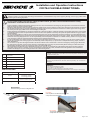 1
1
-
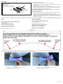 2
2
-
 3
3
-
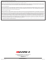 4
4
-
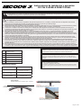 5
5
-
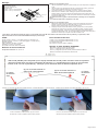 6
6
-
 7
7
-
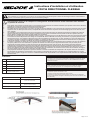 8
8
-
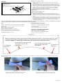 9
9
-
 10
10
-
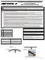 11
11
-
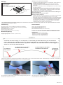 12
12
-
 13
13


En otros idiomas
- français: Code 3 CD3794
- English: Code 3 CD3794
- Deutsch: Code 3 CD3794
Documentos relacionados
-
 Code 3 CD9215 Series Install Instructions
-
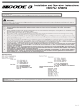 Code 3 HB12PAK Install Instructions
-
 Code 3 CD5051VDL Series Install Instructions
-
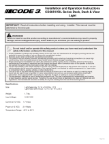 Code 3 CD5051VDL2 Install Instructions
-
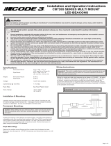 Code 3 CB7265 Install Instructions
-
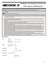 Code 3 C5517 Install Instructions
-
 Code 3 CZ6015/16 Install Instructions
-
 Code 3 Chevy Tahoe 2015-2020 Matrix Citadel Install Instructions
-
 Code 3 Thin Wingman Matrix Install Instructions
-
 Code 3 Ford PIU 2015-2019 Matrix Citadel Install Instructions


Otros documentos
-
Ecco ED3511A El manual del propietario
-
-
Yamaha PLG150 El manual del propietario
-
Marantec PA68 El manual del propietario
-
-
Key Gates CT20224 Manual de usuario
-
Key Gates CT102 Manual de usuario
-
-
-
Skil SD561204 Manual de usuario