
Page 1 of 6
Do not install and/or operate this safety product unless you have read and understand the
safety information contained in this manual.
1. Proper installation combined with operator training in the use, care, and maintenance of emergency warning devices are
essential to ensure the safety of you and those you are seeking to protect.
2. Exercise caution when working with live electrical connections.
3. This product must be properly grounded. Inadequate grounding and/or shorting of electrical connections can cause high
current arcing, which can cause personal injury and/or severe vehicle damage, including re.
4. Proper placement and installation are vital to the performance of this warning device. Install this product so that output
performance of the system is maximized and the controls are placed within convenient reach of the operator so that s/he
can operate the system without losing eye contact with the roadway.
5. It is the responsibility of the vehicle operator to ensure during use that all features of this product work correctly. In use, the
vehicle operator should ensure the projection of the warning signal is not blocked by vehicle components (i.e., open trunks
or compartment doors), people, vehicles, or other obstructions.
6. The use of this or any other warning device does not ensure all drivers can or will observe or react to a warning signal.
Never take the right-of-way for granted. It is your responsibility to be sure you can proceed safely before entering an
intersection, driving against trac, responding at a high rate of speed, or walking on or around trac lanes.
7. This equipment is intended for use by authorized personnel only. The user is responsible for understanding and obeying
all laws regarding warning signal devices. Therefore, the user should check all applicable city, state, and federal laws and
regulations. The manufacturer assumes no liability for any loss resulting from the use of this warning device.
WARNING!
Failure to install or use this product according to manufacturer’s recommendations may result in property
damage, serious bodily/personal injury, and/or death to you and those you are seeking to protect!
!
Specications:
Size: Light head only: 1.2 H x 12.8 W x 1.7 D
Light head with shroud: 1.3 H x 13.7 W x 2.8 D
Weight: 1.7 lbs.
Input Voltage: 12-24 VDC
Current at 12 VDC: 1.7 Amps
Power at 12 VDC: 21.1Watts
Temperature Range: -40°C to 65°C
IMPORTANT! Read all instructions before installing and using. Installer: This manual must be
delivered to the end user.
Installation and Operation Instructions
CD5051VDL Series Deck, Dash & Visor
Light

Page 2 of 6
Installation & Mounting:
Carefully remove the unit from its packaging. Examine the
unit for transit damage. If damage is found, return the product
to your local dealer for warranty replacement. Do not use
damaged or broken parts. Determine a mounting location that
ensures a clear line of sight for oncoming trac.
!
Caution: When drilling into any vehicle
surface, make sure that the area is free from any
electrical wires, fuel lines, vehicle upholstery, etc. that
could be damaged.
!
Caution: When installing using VHB tape
into any vehicle with aftermarket tinted glass, it is best
practice to trim the lm around the surface where
bracket will be mounted to ensure adhesion and avoid
damage to the tint lm.
MOUNTING WITH VHB TAPE:
1. Ensure that the light head is securely attached to the shroud.
2. Install rubber gasket onto the shroud.
3. Remove the suction cup from each shroud bracket.
4. Clean the brackets with supplied alcohol wipe.
* for extra adhesion, see notes below.
5 Remove one side of the adhesive liner & apply to both brackets. Apply light pressure
for 20 seconds.
6. Install the bracket as shown on Figures 4 & 5. Gently hand tighten the nut.
7. WITHOUT removing the second adhesive liner, hold the product to desired location.
Loosen & hand tighten the nut as needed to adjust the light head angle. Once
desired angle is achieved, gently tighten the fastener using a 10mm wrench or
socket.
8. Clean mounting surface with supplied alcohol wipe.
*for extra adhesion, see notes below.
9. Remove the second adhesive liner.
10. Apply product on to the treated surface. Apply light pressure for 20 seconds.
MOUNTING WITH SUCTION CUP:
1. Ensure that the light head is securely attached to the shroud.
2. Install the shroud bracket as shown on Figures 4 & 5. Gently hand tighten the nut.
3. Clean mounting surface with supplied alcohol wipe.
4. Apply the product on to the treated surface by gently pressing the suction cups on to
the glass. Apply light pressure for 20 seconds. Gently adjust the light head to its
desired angle if needed.
5 Once desired angle is achieved, gently tighten the fastener using a 10mm wrench
or socket.
MOUNTING WITH HARDWARE (NOT PROVIDED):
1. Ensure that the light head is securely attached to the shroud.
2. Install the shroud bracket as shown on Figures 4 & 5. Gently hand tighten the nut.
3. Clean mounting surface with supplied alcohol wipe.
4. Install product on to the treated surface by using #8 hardware screw (not included).
5. Gently adjust the light head to its desired angle if needed.
6. Once desired angle is achieved, gently tighten the fastener using a 10mm wrench
or socket.
** MOUNTING HARDWARE NOT PROVIDED
Mounting with Shroud:
FIGURE 1
FIGURE 2
FIGURE 3
*For extra adhesion, use 3M Tape Primer. For product & application information, go to: https://multimedia.3m.com/
mws/media/65952O/3mtm-tape-primer-94.pdf

Page 3 of 6
FIGURE 4
FIGURE 5
TOP VIEW SIDE VIEW
Standard Mounting without Shroud:
MOUNTING WITH VHB TAPE:
1. Carefully remove the light head from the shroud.
CAUTION: gently release the locking tabs to avoid breaking the tabs shown in
Figure A .
2. Clean the light head brackets with supplied alcohol wipe.
* for extra adhesion, see notes below.
3. Remove one side of the adhesive liner & apply to both brackets. Apply light pressure
for 20 seconds.
4. Insert bracket as shown on Figure B.
5. WITHOUT removing the second adhesive liner, hold the product to desired location.
Adjust the light head to its desired angle by adjusting the bracket.
6. Clean mounting surface with supplied alcohol wipe.
*for extra adhesion, see notes below.
7. Remove the second adhesive liner.
8. Apply product on to the treated surface. Apply light pressure for 20 seconds.
9. Insert the provided screws in the light head locking mechanism as shown in Figure C.
This will hold the brackets in position & the light head in the desired angle.
MOUNTING WITH SUCTION CUP:
1. Carefully remove the light head from the shroud.
CAUTION: gently release the locking tabs to avoid breaking the tabs shown on
Figure A.
2. Remove the suction cups from the shroud mounting brackets.
3. Install each suction cup to each bracket using the existing screws as shown on
Figure D.
4. Insert bracket as shown on Figure B.
5. Clean mounting surface with supplied alcohol wipe.
6. Apply the product on to the treated surface gently pressing the suction cups on to the
glass. Apply light pressure for 20 seconds. Gently adjust the light head to its desired
angle if needed.
7. Insert the provided screws in the light head locking mechanism as shown in Figure C.
This will hold the brackets in position & the light head in the desired angle.
MOUNTING WITH HARDWARE (HARDWARE NOT PROVIDED):
1. Carefully remove the light head from the shroud.
CAUTION: gently release the locking tabs to avoid breaking the tabs shown on
Figure A.
2. Insert the light head bracket as shown on Figure B.
3. Hold the product to desired location. Adjust the light head to its desired angle
by adjusting the bracket.
4. Clean mounting surface with supplied alcohol wipe.
5. Install product on to the treated surface by using #8 hardware screw (not
included) as shown on Figure E.
6. Insert the provided screws in the light head locking mechanism as shown in Figure C.
This will hold the brackets in position & the light head in the desired angle.
FIGURE 6 FIGURE 7
FIGURE 8
** MOUNTING HARDWARE NOT PROVIDED
*For extra adhesion, use 3M Tape Primer. For product & application information, go to: https://multimedia.3m.com/
mws/media/65952O/3mtm-tape-primer-94.pdf

Page 4 of 6
FIGURE A
FIGURE B FIGURE C
FIGURE D
FIGURE E
Hardwire Wiring Instructions:
IMPORTANT!: This unit is a safety device and
it must be connected to its own separate, fused
power point to assure its continued operation
should any other electrical accessory fail.
All wiring should be stranded and a minimum of 20 AWG. The
positive line must have an in-line 3 AMP slow-blow fuse for each
directional as shown in FIGURE 9. Isolate the yellow and blue
wires when not in use.
YELLOW -
(SYNC)
+ -
BLACK - GROUND
BLUE -
FLASH PATTERN
SELECT (MOMENTARY
TO GROUND),
DIMMING(+)
RED - POSITIVE
SWITCH
(USER SUPPLIED)
IN-LINE FUSE
(USER SUPPLIED)
WHITE -
POSITIVE
SWITCH
(USER SUPPLIED)
FIGURE 9
Flash pattern select:
To select a ash pattern, apply power to the RED or WHITE or both RED and WHITE wires.
Apply blue to black wire for ash pattern change:
Dimming Function:
Connect blue wire to Red power wire.
Synchronization:
The CD5051VDL series is capable of syncing with other compatible CODE 3 products by following these steps:
1.Set the desired ash pattern on each unit individually. It is also strongly recommended that the same style of ash pattern be used
on all units to produce the most eective warning pattern. NOTE: Phases A and B for each style of ash pattern in the table denote the
relative timing between units connected in a synchronizing installation. To operate simultaneously, each unit must be set to the same
phase (A +A or B + B); to operate alternately, units must be set to have the opposite phase (A + B or B + A).
2.Connect the yellow sync wires together and check that the units are ashing in a synchronized manner as expected. If a pattern on
one unit appears incorrect, the blue pattern select wire can be used to cycle forward or backward on that individual unit until the correct
pattern is selected. NOTE: This will only change the pattern in the one unit and will not aect the other units connected to the yellow
sync wire.
Push Times Function
0-1 secs. next pattern
1-3 secs. previous pattern
3-5 secs. factory default pattern
5+ secs. last pattern

Page 5 of 6
PATTERN SELECT
ON - COLOR 2
OFF
ON - COLOR 1
Flash Pattern Selection (Cigarette Adapter):
Paern Mode
Descripon Phase FPM RW BW AW RWBW RW BW AW RWBW RW BW AW RWBW
1
Single Flash - Simultaneous Color 1 A 75 Class 1 Class 1 Class 1 N/C Class B Class B Class B N/C N/C N/C N/C N/C
2
Single Flash - Simultaneous Color 1 B 75 Class 1 Class 1 Class 1 N/C Class B Class B Class B N/C N/C N/C N/C N/C
3
Single Flash - Alternang Color 1 A 75 N/C N/C N/C N/C N/C N/C N/C N/C N/C N/C N/C N/C
4
Single Flash - Alternang Color 1 B 75 N/C N/C N/C N/C N/C N/C N/C N/C N/C N/C N/C N/C
5
Double
Flash - Simultaneous Color 1 A 75 Class 1 Class 1 Class 1 N/C Class B Class B Class B N/C N/C N/C N/C N/C
6
Double Flash - Simultaneous Color 1 B 75 Class 1 Class 1 Class 1 N/C Class B Class B Class B N/C N/C N/C N/C N/C
7
Double Flash - Alternang Color 1 A 75 N/C N/C N/C N/C N/C N/C N/C N/C N/C N/C N/C N/C
8
Double Flash - Alternang Color 1 B 75 N/C N/C N/C N/C N/C N/C N/C N/C N/C N/C N/C N/C
9
Quad Flash - Simultaneous Color 1 A 75 Class 1 Class 1 Class 1 N/C Class B Class
B Class B N/C N/C N/C N/C N/C
10
Quad Flash - Simultaneous Color 1 B 75 Class 1 Class 1 Class 1 N/C Class B Class B Class B N/C N/C N/C N/C N/C
11
Quad Flash - Alternang Color 1 A 75 N/C N/C N/C N/C N/C N/C N/C N/C N/C N/C N/C N/C
12
Quad Flash - Alternang Color 1 B 75 N/C N/C N/C N/C N/C N/C N/C N/C N/C N/C N/C N/C
13
Single Flash - Simultaneous Color 1 A 120 Class 1 Class 1 Class 1 N/C N/C N/C N/C N/C Class 1 Class 1 Class 1 N/C
14
Single Flash - Simultaneous Color 1 B 120
Class 1 Class 1 Class 1 N/C N/C N/C N/C N/C Class 1 Class 1 Class 1 N/C
15
Single Flash - Alternang Color 1 A 120 N/C N/C N/C N/C N/C N/C N/C N/C N/C N/C N/C N/C
16
Single Flash - Alternang Color 1 B 120 N/C N/C N/C N/C N/C N/C N/C N/C N/C N/C N/C N/C
17
Double Flash - Simultaneous Color 1 A 120 Class 1 Class 1 Class 1 N/C N/C N/C N/C N/C Class 1 Class 1 Class 1 N/C
18
Double Flash - Simultaneous Color 1 B 120 Class 1 Class 1 Class 1 N/C N/C N/C N/C N/C Class 1 Class 1 Class 1 N
/C
19
Double Flash - Alternang Color 1 A 120 N/C N/C N/C N/C N/C N/C N/C N/C N/C N/C N/C N/C
20
Double Flash - Alternang Color 1 B 120 N/C N/C N/C N/C N/C N/C N/C N/C N/C N/C N/C N/C
21
Quad Flash - Simultaneous Color 1 A 120 Class 1 Class 1 Class 1 N/C N/C N/C N/C N/C Class 1 Class 1 Class 1 N/C
22
Quad Flash - Simultaneous Color 1 B 120 Class1 Class1 Class1 N/C N/C N/C N/C N/C Class 1 Class 1 Class 1 N/C
23
Quad Flash - Alternang Color 1 A 120 N/C N/C N/C N/C N/C N/C N/C N/C N/C
N/C N/C N/C
24
Quad Flash - Alternang Color 1 B 120 N/C N/C N/C N/C N/C N/C N/C N/C N/C N/C N/C N/C
25
Single Flash - Simultaneous Color 1 A 350 N/C N/C N/C N/C N/C N/C N/C N/C N/C N/C N/C N/C
26
Single Flash - Simultaneous Color 1 B 350 N/C N/C N/C N/C N/C N/C N/C N/C N/C N/C N/C N/C
27
Single Flash - Alternang Color 1 A 350 N/C N/C N/C N/C N/C N/C N/C N/C N/C N/C N/C N/C
28
Single Flash - Alternang Color 1 B 350 N/C N/C N/C N/C N/C N/C N/C N/C N/C N/C N/C N/C
29
Single Flash - Simulta
neous Color 2 A 75 Class 1 Class 1 Class 1 Class 1 N/C N/C N/C N/C N/C N/C N/C N/C
30
Single Flash - Simultaneous Color 2 B 75 Class 1 Class 1 Class 1 Class 1 N/C N/C N/C N/C N/C N/C N/C N/C
31
Single Flash - Alternang Color 2 A 75 N/C N/C N/C N/C N/C N/C N/C N/C N/C N/C N/C N/C
32
Single Flash - Alternang Color 2 B 75 N/C N/C N/C N/C N/C N/C N/C N/C N/C N/C N/C N/C
33
Double Flash - Simultaneous Color 2 A 120 Class 1 Class 1 Class 1 Class 1 N/C N/C N/C N/C N/C N/C N/C N/C
34
Doubl
e Flash - Simultaneous Color 2 B 120 Class 1 Class 1 Class 1 Class 1 N/C N/C N/C N/C N/C N/C N/C N/C
35
Double Flash - Alternang Color 2 A 120 N/C N/C N/C N/C N/C N/C N/C N/C N/C N/C N/C N/C
36
Double Flash - Alternang Color 2 B 120 N/C N/C N/C N/C N/C N/C N/C N/C N/C N/C N/C N/C
37
Single Flash - Simultaneous Color 1 & Color 2 A 75 N/C N/C N/C N/C N/C N/C N/C N/C N/C N/C N/C N/C
38
Single Flash - Simultaneous Color 1 & Color 2 B 75 N/C N/C N/C N/C N/C N/C N/C N/C N/C N/C N/C N/C
39
S
ingle Flash - Alternang Color 1 & Color 2 A 75 N/C N/C N/C N/C N/C N/C N/C N/C N/C N/C N/C N/C
40
Single Flash - Alternang Color 1 & Color 2 B 75 N/C N/C N/C N/C N/C N/C N/C N/C N/C N/C N/C N/C
41
Double Flash - Simultaneous Color 1 & Color 2 A 120 N/C N/C N/C N/C N/C N/C N/C N/C N/C N/C N/C N/C
42
Double Flash - Simultaneous Color 1 & Color 2 B 120 N/C N/C N/C N/C N/C N/C N/C N/C N/C N/C N/C N/C
43
Double Flash - Alternang Color 1 & Color 2 A 120 N/C N/C N/C N/C N/C N/C N/C N
/C N/C N/C N/C N/C
44
Double Flash - Alternang Color 1 & Color 2 B 120 N/C N/C N/C N/C N/C N/C N/C N/C N/C N/C N/C N/C
45
Single Flash - Simultaneous Color 2 & Color 1 A 75 N/C N/C N/C N/C N/C N/C N/C N/C N/C N/C N/C N/C
46
Single Flash - Simultaneous Color 2 & Color 1 B 75 N/C N/C N/C N/C N/C N/C N/C N/C N/C N/C N/C N/C
47
Single Flash - Alternang Color 2 & Color 1 A 75 N/C N/C N/C N/C N/C N/C N/C N/C N/C N/C N/C N/C
48
Single Flash - Alternang Color 2 & Color 1 B 75 N/C
N/C N/C N/C N/C N/C N/C N/C N/C N/C N/C N/C
49
Double Flash - Simultaneous Color 2 & Color 1 A 120 N/C N/C N/C N/C N/C N/C N/C N/C N/C N/C N/C N/C
50
Double Flash - Simultaneous Color 2 & Color 1 B 120 N/C N/C N/C N/C N/C N/C N/C N/C N/C N/C N/C N/C
51
Double Flash - Alternang Color 2 & Color 1 A 120 N/C N/C N/C N/C N/C N/C N/C N/C N/C N/C N/C N/C
52
Double Flash - Alternang Color 2 & Color 1 B 120 N/C N/C N/C N/C N/C N/C N/C N/C N/C N/C N/C N/C
53
Steady Burn - Color 1 & Single Fl
ash - Color 1 75 N/C N/C N/C N/C N/C N/C N/C N/C N/C N/C N/C N/C
54
Single Flash - Color 1 & Steady Burn - Color 1 75 N/C N/C N/C N/C N/C N/C N/C N/C N/C N/C N/C N/C
55
Steady Burn - Color 1 & Single Flash - Color 2 75 N/C N/C N/C N/C N/C N/C N/C N/C N/C N/C N/C N/C
56
Single Flash - Color 1 & Steady Burn - Color 2 75 N/C N/C N/C N/C N/C N/C N/C N/C N/C N/C N/C N/C
57
Steady Burn - Color 2 & Single Flash - Color 1 75 N/C N/C N/C N/C N/C N/C N/C N/C N/C N/C N/C N/C
58
Sin
gle Flash - Color 2 & Steady Burn - Color 1 75 N/C N/C N/C N/C N/C N/C N/C N/C N/C N/C N/C N/C
59
Steady Burn - Color 1 & Quad Flash - Color 1 75 N/C N/C N/C N/C N/C N/C N/C N/C N/C N/C N/C N/C
60
Quad Flash - Color 1 & Steady Burn - Color 1 75 N/C N/C N/C N/C N/C N/C N/C N/C N/C N/C N/C N/C
61
Steady Burn - Color 1 & Quad Flash - Color 2 75 N/C N/C N/C N/C N/C N/C N/C N/C N/C N/C N/C N/C
62
Quad Flash - Color 1 & Steady Burn - Color 2 75 N/C N/C N/C N/C N/C N/C N
/C N/C N/C N/C N/C N/C
63
Steady Burn - Color 2 & Quad Flash - Color 1 75 N/C N/C N/C N/C N/C N/C N/C N/C N/C N/C N/C N/C
64
Quad Flash - Color 2 & Steady Burn - Color 1 75 N/C N/C N/C N/C N/C N/C N/C N/C N/C N/C N/C N/C
65
Steady Burn - Color 1 N/A N/C N/C N/C N/C N/C N/C N/C N/C N/C N/C N/C N/C
66
Steady Burn - Color 2 N/A N/C N/C N/C N/C N/C N/C N/C N/C N/C N/C N/C N/C
17 67
O N/A N/C N/C N/C N/C N/C N/C N/C N/C N/C N/C N/C N/C
16
7
8
9
10
11
Flash Paern Chart
Tabla de patrones d
e destello
Tableau des eets clignotants
Blitzmusterdiagramm
12
13
14
15
2
3
4
5
6
SAE J595
CA Title 13
ECE R65
1

Page 6 of 6
Manufacturer Limited Warranty and Limitation of Liability:
Manufacturer warrants that on the date of purchase this product will conform to Manufacturer’s specications for this product (which are available from the
Manufacturer upon request), and Manufacturer further warrants that this product is free from defects in materials and workmanship. This Limited Warranty
extends for sixty (60) months from the date of purchase. Other warranties may apply, call Manufacturer for details. Manufacturer will, at its discretion,
repair or replace any product found by the Manufacturer to be defective and subject to this Limited Warranty.
DAMAGE TO PARTS OR PRODUCTS RESULTING FROM TAMPERING, ACCIDENT, ABUSE, MISUSE, NEGLIGENCE, UNAPPROVED
MODIFICATIONS, FIRE OR OTHER HAZARD; IMPROPER INSTALLATION OR OPERATION; OR NOT BEING MAINTAINED IN ACCORDANCE WITH
THE MAINTENANCE PROCEDURES SET FORTH IN MANUFACTURER’S INSTALLATION AND OPERATING INSTRUCTIONS VOIDS THIS LIMITED
WARRANTY.
ORAL STATEMENTS OR REPRESENTATIONS ABOUT THE PRODUCT WHICH MAY HAVE BEEN MADE BY SALESPEOPLE, DEALERS, AGENTS
OR OTHER MANUFACTURER’S REPRESENTATIVES DO NOT CONSTITUTE WARRANTIES. THIS LIMITED WARRANTY MAY NOT BE AMENDED,
MODIFIED, OR ENLARGED EXCEPT BY A WRITTEN AGREEMENT SIGNED BY AN AUTHORIZED OFFICIAL OF MANUFACTURER WHICH
EXPRESSLY REFERS TO THIS LIMITED WARRANTY.
Exclusion of Other Warranties: MANUFACTURER MAKES NO OTHER WARRANTIES, EXPRESS OR IMPLIED. THE IMPLIED WARRANTIES FOR
MERCHANTABILITY OR FITNESS FOR A PARTICULAR PURPOSE ARE HEREBY EXCLUDED AND SHALL NOT APPLY TO THE PRODUCT.
BUYER’S SOLE AND EXCLUSIVE REMEDY IN CONTRACT, TORT, OR UNDER ANY OTHER THEORY AGAINST MANUFACTURER REGARDING
THE PRODUCT AND ITS USE SHALL BE THE REPLACEMENT OR REPAIR OF THE PRODUCT AS DESCRIBED ABOVE.
Limitation of Liability: IN THE EVENT OF LIABILITY FOR DAMAGES ARISING OUT OF THIS LIMITED WARRANTY OR ANY OTHER CLAIM
RELATED TO THE MANUFACTURER’S PRODUCTS, MANUFACTURER’S LIABILITY FOR DAMAGES SHALL BE LIMITED TO THE AMOUNT PAID
FOR THE PRODUCT AT THE TIME OF THE ORIGINAL PURCHASE. IN NO EVENT SHALL MANUFACTURER BE LIABLE FOR LOST PROFITS,
THE COST OF SUBSTITUTE EQUIPMENT OR LABOR, PROPERTY DAMAGE, OR OTHER SPECIAL, CONSEQUENTIAL, OR INCIDENTAL
DAMAGES BASED UPON ANY CLAIM FOR BREACH OF CONTRACT, IMPROPER INSTALLATION, NEGLIGENCE, OR OTHER CLAIM,
EVEN IF MANUFACTURER OR A MANUFACTURER’S REPRESENTATIVE HAS BEEN ADVISED OF THE POSSIBILITY OF SUCH DAMAGES.
MANUFACTURER SHALL HAVE NO FURTHER OBLIGATION OR LIABILITY WITH RESPECT TO THE PRODUCT OR ITS SALE, OPERATION
AND USE, AND MANUFACTURER NEITHER ASSUMES NOR AUTHORIZES THE ASSUMPTION OF ANY OTHER OBLIGATION OR LIABILITY IN
CONNECTION WITH SUCH PRODUCT.
This Limited Warranty denes specic legal rights. You may have other legal rights, which vary from state to state. Some states do not allow the exclusion
or limitation of incidental or consequential damages.
© 2020 CODE 3
920-0839-01 Rev. C
Unit 1, Green Park, Coal Road
Seacroft, Leeds, England LS14 1FB
+44 (0)113 2375340
CODE3ESG.co.uk
10986 North Warson Road
St. Louis, MO 63114 USA
(314) 996-2800
CODE3ESG.com
An ECCO SAFETY GROUP™ Brand
ECCOSAFETYGROUP.com
439 Boundary Road
Truganina Victoria, Australia
+61 (0)3 8336 0680
CODE3ESG.com/au/en

Página 1 de 6
No instale ni opere este producto de seguridad, a menos que haya leído y comprendido la
información de seguridad de este manual.
1. Para garantizar la seguridad del personal de emergencias y la de las personas a las que este intenta proteger, es esencial una
instalación correcta, combinada con la formación del operador en el uso, cuidado y mantenimiento de los dispositivos de alerta de
emergencia.
2. Los dispositivos de alerta de emergencia a menudo requieren tensiones eléctricas o corrientes de entrada altas. Tenga cuidado
cuando manipule conexiones eléctricas.
3. Este producto debe estar conectado a tierra correctamente. Una conexión a tierra incorrecta o unas conexiones eléctricas
cortocircuitadas pueden provocar arcos de corriente alta, lo que puede ocasionar lesiones personales o daños graves en el
vehículo, incluso un incendio.
4. La colocación e instalación adecuadas son vitales para el buen funcionamiento de este dispositivo de advertencia. Instale este
producto de forma que permita un rendimiento óptimo del sistema y de que los controles estén situados de modo que el operador
pueda alcanzarlos cómodamente y manejar el sistema sin perder en ningún momento el contacto visual con la calzada.
5. Es responsabilidad del operador del vehículo asegurarse todos los días de que todas las características de este producto funcionan
correctamente. Durante su uso, el operador del vehículo debe asegurarse de que no haya componentes del vehículo (como los
maleteros o puertas del habitáculo abiertos), personas, vehículos u otros obstáculos que bloqueen la señal de alarma.
6. El uso de este o cualquier otro dispositivo de advertencia no garantiza que los conductores puedan respetar la señal de alarma o
reaccionar ante ella o vayan a hacerlo. Nunca dé por hecho que tiene prioridad de paso. Es responsabilidad del operador del
vehículo asegurarse de que puede continuar de forma segura antes de entrar en una intersección, conducir en sentido contrario,
responder a una gran velocidad o caminar por los carriles con tráco o cerca de ellos.
7. El uso de este equipo está destinado exclusivamente a personal autorizado. El usuario es responsable de conocer y acatar
todas las leyes vigentes relacionadas con dispositivos de señales de alerta de emergencia. Por lo tanto, el usuario debe comprobar
todas las leyes y normativas de ámbito metropolitano, regional, nacional y cualquier otro ámbito pertinente. El fabricante no asume
todas las leyes y normativas de ámbito metropolitano, regional, nacional y cualquier otro ámbito pertinente. El fabricante no asume
responsabilidad alguna por pérdidas derivadas del uso de este dispositivo de alarma.
¡ADVERTENCIA!
El no instalar o utilizar este producto de acuerdo con las recomendaciones del fabricante podría tener como
resultado daño a la propiedad, lesiones graves corporales/personales o la muerte de usted y de las personas
que busca proteger.
!
ESPECIFICACIONES:
Tamaño:
Solo cabezal de luz: 30,5 mm x 325,1 mm x 43,1 mm (1,2” al. x 12,8” an. x 1,7” pr.)
Cabezal de luz con cubierta protectora: 33 mm x 348 mm x 71,1 mm (1,3” al. x 13,7” an. x 2,8” pr.)
Peso: 0,8 kg (1,7 lb)
Voltaje de entrada: 12-24 V CC
Corriente a 12 V CC nominal: 1,7 A
Potencia a 12 V CC nominal: 21,1 W
Rango de temperatura: de -40 °C a 65 °C
¡IMPORTANTE! Lea todas las instrucciones antes de instalar y utilizar. Instalador: Este manual se
debe entregar al usuario nal.
Instrucciones de instalación y operación
Luz de cubierta, tablero y
visor de la serie CD5051VDL

Página 2 de 3
*Para obtener una mayor adherencia, utilice imprimación para cintas 3M. Para obtener información sobre productos
y aplicaciones, visite: https://multimedia.3m.com/mws/media/65952O/3mtm-tape-primer-94.pdf
Instalación y montaje:
Retire cuidadosamente la unidad de su embalaje. Examinar la
unidad en busca de daños producidos durante el transporte. Si se
detectan daños, devuelva el producto a nuestro distribuidor local para
obtener un reemplazo de garantía. No utilice piezas dañadas o rotas.
Determine una ubicación de montaje que garantice una línea de
visión clara para el tráco en sentido opuesto.
!
PRECAUCIÓN: Cuando taladre cualquier
supercie del vehículo, asegúrese de que no exista
el riesgo de dañar cables eléctricos, tubos de
combustible, tapicería de vehículo, etc.
!
PRECAUCIÓN: Cuando realice la instalación
con cinta de adherencia muy alta en cualquier vehículo con
vidrios polarizados de otros fabricantes, se recomienda
recortar la película alrededor de la supercie en la que se
montará el soporte para garantizar su adherencia y evitar
daños en la película polarizada.
MONTAJE CON CINTA DE ADHERENCIA MUY ALTA:
1. Asegúrese de que el cabezal de luz esté rmemente sujeto a la cubierta.
2. Instale la junta de goma en la cubierta.
3. Retire la ventosa de cada soporte de la cubierta.
4. Limpie los soportes con la toallita con alcohol suministrada.
* Para lograr una mayor adherencia, consulte las siguientes notas.
5 Quite un lado del recubrimiento del adhesivo y aplique en ambos soportes.
Presione suavemente durante 20 segundos.
6. Instale el soporte como se muestra en la guras 4 & 5. Apriete la tuerca con la mano
suavemente.
7. SIN quitar el segundo recubrimiento del adhesivo, sujete el producto en la
ubicación deseada. Aoje y apriete con la mano la tuerca, según sea necesario,
para ajustar el ángulo del cabezal de luz. Una vez que logre el ángulo deseado,
apriete con cuidado la tuerca del tornillo con una llave de 10 mm o una llave de cubo.
8. Limpie la supercie de montaje con la toallita con alcohol suministrada.
* Para lograr una mayor adherencia, consulte las siguientes notas.
9. Retire el segundo recubrimiento del adhesivo.
10. Aplique el producto sobre la supercie tratada. Presione suavemente
durante 20 segundos.
MONTAJE CON VENTOSA:
1. Asegúrese de que el cabezal de luz esté rmemente sujeto a la cubierta.
2. Instale el soporte de la cubierta como se muestra en la guras 4 & 5. Apriete la
tuerca con la mano suavemente.
3. Limpie la supercie de montaje con la toallita con alcohol suministrada.
4. Aplique el producto sobre la supercie tratada presionando suavemente las
ventosas en el vidrio. Presione suavemente durante 20 segundos. Ajuste
suavemente el cabezal de luz en el ángulo deseado, si es necesario.
5 Una vez que logre el ángulo deseado, apriete con cuidado la tuerca del
tornillo con una llave de 10 mm o una llave de cubo.
MONTAJE CON TORNILLOS (NO INCLUIDOS):
1. Asegúrese de que el cabezal de luz esté rmemente sujeto a la cubierta.
2. Instale el soporte de la cubierta como se muestra en la gura 6. Apriete la
tuerca con la mano suavemente.
3. Limpie la supercie de montaje con la toallita con alcohol suministrada.
4. Instale el producto en la supercie tratada con un tornillo de jación n.º 8
(no incluido).
5. Ajuste suavemente el cabezal de luz en el ángulo deseado, si es necesario.
6. Una vez que logre el ángulo deseado, apriete con cuidado la tuerca del
tornillo con una llave de 10 mm o una llave de cubo.
Montaje con cubierta protectora:
FIGURA 1
FIGURA 2
FIGURA 3
** No se proporciona la tornillería de montaje.

Página 3 de 6
FIGURA 4
FIGURA 5
VISTA SUPERIOR VISTA LATERAL
Montaje estándar sin cubierta:
MONTAJE CON CINTA DE ADHERENCIA MUY ALTA:
1. Retire con cuidado el cabezal de luz de la cubierta.
PRECAUCIÓN: Suelte suavemente las pestañas de bloqueo para evitar que se
rompan las pestañas que se muestran en la Figure A .
2. Limpie los soportes del cabezal de luz con la toallita con alcohol suministrada.
* Para lograr una mayor adherencia, consulte las siguientes notas.
3. Quite un lado del recubrimiento del adhesivo y aplique en ambos soportes. Presione
suavemente durante 20 segundos.
4. Inserte el soporte como se muestra en la Figura B.
5. SIN quitar el segundo recubrimiento del adhesivo, sujete el producto en la ubicación
deseada. Ajuste el soporte para colocar el cabezal de luz en el ángulo deseado.
6. Limpie la supercie de montaje con la toallita con alcohol suministrada.
* Para lograr una mayor adherencia, consulte las siguientes notas.
7. Retire el segundo recubrimiento del adhesivo.
8. Aplique el producto sobre la supercie tratada. Presione suavemente durante 20
segundos.
9 .Inserte los tornillos suministrados en el mecanismo de bloqueo del cabezal de luz
como se muestra en la gura 3. Esto mantendrá los soportes en su posición y el
cabezal de luz en el ángulo deseado.
MONTAJE CON VENTOSA:
1. Retire con cuidado el cabezal de luz de la cubierta.
PRECAUCIÓN: Suelte suavemente las pestañas de bloqueo para evitar que se
rompan las pestañas que se muestran en la Figure A.
2. Retire las ventosas de los soportes de montaje de la cubierta.
3. Instale cada ventosa en cada soporte con los tornillos existentes, como se muestra
en la Figure D.
4. Inserte el soporte como se muestra en la Figure B.
5. Limpie la supercie de montaje con la toallita con alcohol suministrada.
6. Coloque el producto sobre la supercie tratada presionando suavemente las
ventosas de succión sobre el vidrio. Presione suavemente durante 20 segundos.
Ajuste suavemente el cabezal de luz en el ángulo deseado, si es necesario.
7. Inserte los tornillos suministrados en el mecanismo de bloqueo del cabezal de luz
como se muestra en la Figura C. Esto mantendrá los soportes en su posición y el
cabezal de luz en el ángulo deseado.
MONTAJE CON TORNILLOS (NO SE INCLUYEN LOS TORNILLOS):
1. Retire con cuidado el cabezal de luz de la cubierta.
PRECAUCIÓN: Suelte suavemente las pestañas de bloqueo para evitar que
se rompan las pestañas que se muestran en la Figure A.
2. Inserte el soporte del cabezal de luz como se muestra en la Figura B
3. Mantenga el producto en la ubicación deseada. Ajuste el soporte para
colocar el cabezal de luz en el ángulo deseado.
4. Limpie la supercie de montaje con la toallita con alcohol suministrada.
5. Instale el producto en la supercie tratada con un tornillo de jación n.º 8
(no incluido) como se muestra en la Figura E.
6. Inserte los tornillos suministrados en el mecanismo de bloqueo del
cabezal de luz como se muestra en la Figura C. Esto mantendrá los soportes
en su posición y el cabezal de luz en el ángulo deseado.
FIGURA 6 FIGURA 7
FIGURA 8
** No se proporciona la tornillería de montaje.

Página 4 de 3
Inserte el tornillo
en uno o ambos orificios.
FIGURA A
FIGURA B FIGURA C
FIGURA D
Instrucciones de cableado:
¡Importante!: Esta unidad es un dispositivo de
seguridad y se debe conectar a su propia fuente
de poder de fusibles separada para asegurar
su funcionamiento continuo si cualquier otro
accesorio eléctrico falla.
Todo el cableado debe ser trenzado y de un mínimo de 20
AWG. La línea positiva debe tener un fusible de acción
retardada de 3 amperios en línea para cada luz direccional,
según se muestra en la FIGURA 9. Aísle los cables amarillo
y azul cuando no los utilice.
AMARILLO -
Sincronización
+ -
NEGRO - TIERRA
BLUE -
Selección del patrón
de destellos
(momentáneo a tierra)
(+) Función de atenuación
ROJO - POSITIVOInterruptor:
(suministrado
por el usuario)
FUSIBLE EN LÍNEA
(SUMINISTRADO POR El
USUARIO).
BLANCA -
POSITIVO
Interruptor:
(suministrado
por el usuario)
FIGURA E
Tiempos de presión: Función:
0-1 s siguiente patrón
1-3 s patrón anterior
3-5 s patrón predeterminado de fábrica
más de 5 s último patrón
Selección de patrones de destello:
Para seleccionar un patrón de destello, aplique energía al cable ROJO, al BLANCO o a AMBOS.
Aplique energía a los cables azul y negro para cambiar el patrón de destello:
Función de atenuación:
Conecte el cable azul al cable de alimentación rojo.
Sincronización:
La serie CD5051VDL es capaz de sincronizarse con otros productos CODE 3 compatibles siguiendo estos pasos:
1. Ajuste el patrón de destello deseado en cada unidad de manera individual. También se recomienda encarecidamente que
se utilice el mismo estilo de patrón de destello en todas las unidades para producir el patrón de advertencia más efectivo.
NOTA: Las fases A y B para cada estilo de patrón de destello en la tabla indican la sincronización relativa entre las unidades
conectadas en una instalación en sincronización. Para operar simultáneamente, cada unidad debe congurarse en la misma
fase (A + A o B + B); para funcionar de manera alternada, se deben congurar unidades en fases opuestas (A + B o B + A).
2.Conecte los cables amarillos de sincronización entre sí y revise que las unidades estén destellando de manera sincronizada
según lo previsto. Si el patrón de una unidad parece incorrecto, el cable azul de selección del patrón se puede utilizar para
cambiar el patrón hacia delante o hacia atrás en esa unidad en particular hasta que se seleccione el patrón correcto. NOTA:
Esto solo cambiará el patrón en una unidad y no afectará a las otras unidades conectadas al cable amarillo de sincronización.
FIGURA 9

Página 5 de 6
SELECCIONAR PATRÓN
ENCENDIDO - COLOR 2
APAGADO
ENCENDIDO - COLOR 1
Selección de patrón de parpadeo (Adaptador de cigarrillos):

Página 6 de 3
Garantía limitada del fabricante y restricción de la responsabilidad:
El fabricante garantiza que en la fecha de compra este producto cumplirá con las especicaciones del fabricante
para este producto (que el fabricante pone a su disposición si se solicitan). Esta garantía limitada se extiende
por sesenta (60) meses a partir de la fecha de compra.
EL DAÑO A LAS PIEZAS O LOS PRODUCTOS CAUSADO POR LA ALTERACIÓN, ACCIDENTE, ABUSO,
MAL USO, NEGLIGENCIA, MODIFICACIONES NO AUTORIZADAS, FUEGO U OTRO PELIGRO; INSTALACIÓN
U OPERACIÓN INCORRECTAS; O NO REALIZAR EL MANTENIMIENTO DE ACUERDO CON LOS ROCEDIMIENTOS
DE MANTENIMIENTO ESTABLECIDOS EN LAS INSTRUCCIONES DE INSTALACIÓN Y DE OPERACIÓN DEL
FABRICANTE ANULA ESTA Garantía LIMITADA.
Exclusión de otras garantías:
EL FABRICANTE NO OFRECE NINGUNA OTRA GARANTÍA, EXPRESA O IMPLÍCITA. LAS GARANTÍAS IMPLÍCITAS
DE COMERCIABILIDAD, CALIDAD O IDONEIDAD PARA UN OBJETIVO PARTICULAR, O QUE SURJAN DE UNA
TRANSACCIÓN, USO O PRÁCTICA DE COMERCIO QUEDAN EXCLUIDAS POR MEDIO DE LA PRESENTE Y NO
SERÁN VÁLIDAS PARA EL PRODUCTO, Y SE ANULAN POR MEDIO DE LA PRESENTE, EXCEPTO EN LA MEDIDA
EN QUE LO PROHÍBAN LAS LEYES VIGENTES. LAS DECLARACIONES VERBALES O REPRESENTACIONES
SOBRE EL PRODUCTO NO CONSTITUYEN GARANTÍAS.
Compensaciones y restricción de la responsabilidad:
LA ÚNICA RESPONSABILIDAD DEL FABRICANTE Y LA ÚNICA Y EXCLUSIVA COMPENSACIÓN DEL COMPRADOR
EN VIRTUD DE UN CONTRATO, POR ILÍCITO CIVIL O SEGÚN CUALQUIER SUPUESTO EN CONTRA DEL
FABRICANTE RESPECTO AL PRODUCTO Y SU USO SERÁ EL REEMPLAZO O LA REPARACIÓN DEL PRODUCTO,
O EL REEMBOLSO DEL PRECIO DE COMPRA PAGADO QUE HAYA PAGADO EL COMPRADOR POR EL PRODUCTO
QUE NO CUMPLE CON LOS REQUISITOS. EN NINGÚN CASO LA RESPONSABILIDAD DEL FABRICANTE QUE
SURJA DE ESTA GARANTÍA LIMITADA O POR CUALQUIER OTRA RECLAMACIÓN RELACIONADA CON LOS
PRODUCTOS DEL FABRICANTE EXCEDERÁ LA CANTIDAD QUE EL COMPRADOR PAGÓ POR EL PRODUCTO
EN EL MOMENTO DE LA COMPRA ORIGINAL. EN NINGÚN CASO EL FABRICANTE SERÁ RESPONSABLE POR
LUCRO CESANTE, EL COSTO DE LA SUSTITUCIÓN DEL EQUIPO O LA MANO DE OBRA, DAÑOS A LA PROPIEDAD
U OTROS DAÑOS ESPECIALES, CONSECUENCIALES O INCIDENTALES QUE SE BASEN EN CUALQUIER
RECLAMACIÓN POR INCUMPLIMIENTO DE CONTRATO, INSTALACIÓN INAPROPIADA, NEGLIGENCIA O DE OTRO
TIPO, INCLUSO SI SE LE HA INFORMADO AL FABRICANTE O A UN REPRESENTANTE DEL FABRICANTE SOBRE
LA POSIBILIDAD DE QUE OCURRAN TALES DAÑOS. EL FABRICANTE NO TENDRÁ NINGUNA OTRA OBLIGACIÓN
O RESPONSABILIDAD CON RESPECTO AL PRODUCTO O SU VENTA, OPERACIÓN Y USO, Y EL FABRICANTE NO
ASUME NI AUTORIZA EL SUPUESTO DE CUALQUIER OTRA OBLIGACIÓN O RESPONSABILIDAD EN RELACIÓN
CON DICHO PRODUCTO.
Esta garantía limitada dene derechos legales especícos. Usted puede tener otros derechos legales que varían
de una jurisdicción a otra. Algunas jurisdicciones no permiten la exclusión ni la limitación de daños incidentales
o consecuenciales.
© 2020 CODE 3
920-0839-01 Rev. C
An ECCO SAFETY GROUP™ Brand
ECCOSAFETYGROUP.com
10986 North Warson Road, St. Louis, MO 63114 USA
Sevicio Técnico USA (314) 996-2800
CODE3ESG.com

Page 1 sur 6
N’installez pas ce produit de sécurité et ne l’utilisez pas à moins d’avoir lu et compris les
informations de sécurité contenues dans ce manuel.
1. Une installation appropriée et un opérateur formé à utiliser, entretenir et réparer des dispositifs d’avertissement d’urgence sont
essentiels pour garantir la sécurité du personnel d’urgence et du public.
2. Les dispositifs d’avertissement d’urgence nécessitent souvent des tensions et des courants électriques élevés. Soyez prudent
lorsque vous travaillez avec des connexions électriques sous tension.
3. Ce produit doit être mis à la terre adéquatement. Une mise à la terre inadéquate ou un court-circuit des connexions électriques
peuvent provoquer un arc électrique à courant élevé, ce qui peut provoquer des blessures corporelles ou des dommages
importants au véhicule, y compris un incendie.
4. Un positionnement et une installation adéquats sont essentiels au bon fonctionnement de ce dispositif d’avertissement. Installez
ce produit an que les performances de productivité du système soient optimales et que les commandes soient à portée de main de
l’opérateur pour qu’il puisse utiliser le système sans perdre le contact visuel avec la chaussée.
5. Il incombe à l’opérateur du véhicule de s’assurer à tous les jours que toutes les fonctionnalités de ce produit fonctionnent
correctement. En cours d’utilisation, l’opérateur du véhicule doit s’assurer que la visibilité du signal d’avertissement n’est pas
bloquée par des composantes du véhicule (c.-à-d., des cores ou des portes de compartiment ouverts), des personnes, des
véhicules ou d’autres obstacles.
6. L’utilisation de ce dispositif ou de tout autre dispositif d’avertissement ne garantit pas que tous les conducteurs seront attentifs aux
signaux ou qu’ils réagiront conséquemment à un signal d’urgence. Ne tenez jamais la priorité de passage pour acquise. Il est de la
responsabilité de l’opérateur du véhicule de s’assurer qu’il puisse procéder en toute sécurité avant d’entrer dans une
intersection, de conduire dans le sens inverse de la circulation, de répondre à un appel en conduisant à une vitesse élevée, de
marcher sur ou autour des voies de circulation.
7. Cet équipement est destiné uniquement au personnel autorisé. Il incombe à l’utilisateur de comprendre et de respecter toutes les
lois relatives aux dispositifs d’avertissement d’urgence. Par conséquent, l’utilisateur doit vérier toutes les lois et réglementations
en vigueur dans la ville, la province et le pays. Le fabricant décline toute responsabilité en cas de perte résultant de l’utilisation de
ce dispositif d’avertissement.
ADVERTISSEMENT!
Le non-respect des recommandations du fabricant lors de l’installation ou de l’utilisation de ce produit peut
entraîner des dommages matériels et vous causer à vous-même ainsi qu’à ceux que vous souhaitez protéger
des blessures corporelles graves voire mortelles!
!
Spécications:
Taille :
Tête d’éclairage uniquement : 1,2 H x 12,8 L x 1,7 P
Tête d’éclairage avec déecteur : 1,3 H x 13,7 L x 2,8 P
Poids : 0,45 kg (1,7 lb)
Tension d’entrée : 12 à 24 V c. c.
Courant à 12 V c. c. (nominal) : 1,7 A
Puissance à 12 V c. c. (nominal) : 21,1 W
Plage de températures : de -40 °C à 65 °C
IMPORTANT! Lisez toutes les instructions avant l’installation et l’utilisation. Installateur : ce manuel
doit être remis à l’utilisateur nal.
Instructions d'installation et d'utilisation
Éclairage de pont, de tableau de bord et
de pare-soleil de la série CD5051VDL

Page 2 sur 6
*Pour une meilleure adhérence, utilisez une couche adhésive 3M. Pour obtenir des informations sur les produits et
les applications, rendez-vous sur le site Web : https://multimedia.3m.com/mws/media/65952O/3mtm-tape-primer-94.
pdf
Installation et montage:
Retirer délicatement l’appareil de son emballage. Vérier que
l’appareil n’a pas été endommagé pendant le transport.
En cas de dommage, renvoyer le produit à son détaillant local
pour qu’il soit remplacé au titre de la garantie. Ne pas
utiliser de pièces endommagées ou cassées. Déterminer un
emplacement de montage qui garantit une portée
optique dégagée pour la circulation venant en sens inverse.
!
Attention: Lors du perçage dans toute
surface d’un véhicule, s’assurer qu’il n’y a aucun
l électrique, aucune conduite de carburant,
aucune garniture du véhicule,etc. susceptible d’être
endommagé.
!
Attention: Lors de l’installation du ruban
adhésif VHB sur un véhicule équipé d’une vitre teintée
en après-vente, il est recommandé de découper le lm
autour de la surface sur laquelle le support sera monté
an d’assurer l’adhérence et d’éviter d’endommager la
vitre teintée.
MONTAGE AVEC RUBAN ADHÉSIF VHB:
1. S’assurer que la tête d’éclairage est correctement xée au déecteur.
2. Poser le joint en caoutchouc sur le déecteur.
3. Retirer la ventouse de chaque support de déecteur.
4. Nettoyer les supports avec la lingette à base d’alcool fournie.
*pour une adhérence supplémentaire, voir les notes ci-dessous.
5. Retirer un côté du revêtement adhésif et l’appliquer aux deux supports.
Appliquez une légère pression pendant 20 secondes.
6. Installer le support comme indiqué à la gure 6. Serrer doucement l’écrou à la main.
7. SANS retirer le deuxième lm adhésif, maintenir le produit à l’emplacement
souhaité. Desserrer et serrer à la main l’écrou selon les besoins pour régler
l’angle de la tête d’éclairage. Une fois l’angle souhaité atteint, serrer doucement
l’écrou de la vis à l’aide d’une clé ou d’une douille de 10 mm.
8. Nettoyez la surface de montage avec la lingette à base d’alcool fournie.
*pour une adhérence supplémentaire, voir les notes ci-dessous.
9. Déposer le deuxième lm adhésif.
10. Appliquez le produit sur la surface traitée. Appliquez une légère pression pendant
20 secondes.
MONTAGE AVEC VENTOUSE :
1. S’assurer que la tête d’éclairage est correctement xée au déecteur.
2. Installer le support de déecteur comme indiqué à la gures 4 & 5. Serrer
doucement l’écrou à la main.
3. Nettoyez la surface de montage avec la lingette à base d’alcool fournie.
4. Appliquer le produit sur la surface traitée en appuyant doucement sur les
ventouses sur le verre. Appliquez une légère pression pendant 20 secondes.
Régler doucement la tête d’éclairage à l’angle souhaité si nécessaire.
5 Une fois l’angle souhaité atteint, serrer doucement l’écrou de la vis à l’aide d’une clé
ou d’une douille de 10 mm.
MONTAGE AVEC VENTOUSE (QUINCAILLERIE NON FOURNIE):
1. S’assurer que la tête d’éclairage est correctement xée au déecteur.
2. Installer le support de déecteur comme indiqué à la gures 4 & 5. Serrer doucement
l’écrou à la main.
3. Nettoyez la surface de montage avec la lingette à base d’alcool fournie.
4. Appliquer le produit sur la surface traitée en appuyant doucement sur les
ventouses sur le verre. Appliquez une légère pression pendant 20 secondes.
Régler doucement la tête d’éclairage à l’angle souhaité si nécessaire.
5. Une fois l’angle souhaité atteint, serrer doucement l’écrou de la vis à l’aide d’une clé
ou d’une douille de 10 mm.
** quincaillerie de montage non fournie
Montage avec déecteur:
FIGURE 1
FIGURE 2
FIGURE 3

Page 3 sur 6
FIGURE 4
FIGURE 5
Vue de dessus Vue latérale
Montage standard sans déecteur:
MONTAGE AVEC RUBAN ADHÉSIF VHB:
1. Retirer avec précaution la tête d’éclairage du déecteur.
ATTENTION : relâcher doucement les languettes de verrouillage pour éviter de les
casser comme illustré à la Figure A.
2. Nettoyer les supports de la tête d’éclairage avec la lingette à base d’alcool fournie.
* pour une adhérence supplémentaire, voir les notes ci-dessous.
3. Retirer un côté du revêtement adhésif et l’appliquer aux deux supports. Appliquez
une légère pression pendant 20 secondes.
4. Insérer le support comme indiqué à la Figure B.
5. SANS retirer le deuxième lm adhésif, maintenir le produit à l’emplacement souhaité.
Ajuster la tête d’éclairage à l’angle souhaité en ajustant le support.
6. Nettoyez la surface de montage avec la lingette à base d’alcool fournie.
*pour une adhérence supplémentaire, voir les notes ci-dessous.
7. Déposer le deuxième lm adhésif.
8. Appliquez le produit sur la surface traitée. Appliquez une légère pression pendant 20
secondes.
9. Insérer les vis fournies dans le mécanisme de verrouillage de la tête d’éclairage,
comme indiqué à la gure 3. Cela permet de maintenir les supports en position et la
tête d’éclairage à l’angle souhaité.
MONTAGE AVEC VENTOUSE:
1. Retirer avec précaution la tête d’éclairage du déecteur.
ATTENTION : relâcher doucement les languettes de verrouillage pour éviter de les
casser comme illustré à la Figure A.
2. Retirer les ventouses des supports de montage de déecteur.
3. Installer chaque ventouse sur chaque support à l’aide des vis existantes, comme
indiqué à la Figure D.
4. Insérer le support comme indiqué à la Figure B.
5. Nettoyez la surface de montage avec la lingette à base d’alcool fournie.
6. Appliquer le produit sur la surface traitée en appuyant doucement sur les ventouses
sur le verre. Appliquez une légère pression pendant 20 secondes. Régler doucement
la tête d’éclairage à l’angle souhaité si nécessaire.
7. Insérer les vis fournies dans le mécanisme de verrouillage de la tête d’éclairage
comme indiqué à la Figure C. Cela permet de maintenir les supports en position et la
tête d’éclairage à l’angle souhaité.
MONTAGE AVEC QUINCAILLERIE (QUINCAILLERIE NON FOURNIE):
1. Retirer avec précaution la tête d’éclairage du déecteur.
ATTENTION : relâcher doucement les languettes de verrouillage pour éviter
de les casser comme illustré à la Figure A.
2. Insérer le support de la tête d’éclairage comme indiqué à la Figure B.
3. Maintenir le produit à l’emplacement souhaité. Ajuster la tête d’éclairage à
l’angle souhaité en ajustant le support.
4. Nettoyez la surface de montage avec la lingette à base d’alcool fournie.
5. Installer le produit sur la surface traitée à l’aide de la vis de xation no 8
(non fournie) comme indiqué à la Figure E.
6. Insérer les vis fournies dans le mécanisme de verrouillage de la tête d’éclairage,
comme indiqué à la gure 3. Cela permet de maintenir les supports en position et la
tête d’éclairage à l’angle souhaité.
FIGURE 6 FIGURE 7
FIGURE 8
* quincaillerie de montage non fournie
*Pour une meilleure adhérence, utilisez une couche adhésive 3M. Pour obtenir des informations sur les produits et les
applications, rendez-vous sur le site Web : https://multimedia.3m.com/mws/media/65952O/3mtm-tape-primer-94.pdf

Page 4 sur 6
Insérer la vis dans l’un
des trous ou dans
les deux.
FIGURE A
FIGURE B FIGURE C
FIGURE D
FIGURE E
Instructions de câblage:
IMPORTANT!: Cet appareil est un dispositif de
sécurité et doit être branché à son propre point
d’alimentation protégé par fusible pour garantir son
fonctionnement continu en cas de défaillance
d’un autre accessoire accesorio eléctrico falla.
Tout le câblage doit être toronné et d’un calibre minimal de
20 AWG. La ligne positive doit être dotée d’un fusible en
ligne à action retardée de 3 A pour chaque DEL
directionnelle, comme illustré à la FIGURE 9. Isolez les ls
jaune et bleu lorsqu’ils ne sont pas utilisés.
JAUNE -
Synchronisation
+ -
NOIR-MASSE
BLEU -
Sélection du modèle de flash
(momentané au sol)
(+) Fonction de réglage de
l’intensité
ROUGE - POSITIF
Commutateur
(fourni par
l’utilisateur)
FUSIBLE EN LIGNE
(FOURNI PAR
L’UTILISATEUR)
BLANC-
POSITIF
Commutateur
(fourni par
l’utilisateur)
FIGURE 9
Sélection du schéma de clignotement:
Pour sélectionner un eet de clignotement, mettez sous tension les ls ROUGE ou BLANC ou les ls ROUGE et BLANC.
Appliquer le l bleu sur le l noir pour modier le schéma de clignotement:
Fonction de réglage de l’intensité:
Connecter le l bleu au l d’alimentation rouge.
Synchronisation:
La série CD5051VDL est capable de se synchroniser avec d’autres produits CODE 3 compatibles en suivant ces étapes:
1.Régler le schéma de clignotement souhaité sur chaque unité individuellement. Il est aussi fortement recommandé d’utiliser
le même style d’eet de clignotement sur toutes les unités pour produire l’avertissement le plus ecace. Remarque : les
phases A et B pour chaque style d’eet de clignotement dans le tableau indiquent la synchronisation relative entre les unités
branchées dans une installation synchronisée. Pour fonctionner simultanément, chaque unité doit être réglée sur la même
phase (A + A ou B + B); pour fonctionner en alternance, les unités doivent être réglées pour sur des phases opposées (A + B ou B + A).
2.Brancher les ls de synchronisation jaunes ensemble et vérier que les unités clignotent de manière synchronisée comme
prévu. Si l’eet d’une unité semble incorrect, le l bleu de sélection de l’eet peut être utilisé pour faire déler les eets
précédents ou subséquents sur cette unité jusqu’à ce que l’eet correct soit sélectionné. REMARQUE : cette mesure modie
uniquement l’eet d’une unité et ne touche pas aux autres unités branchées au l de synchronisation jaune.
Temps de poussée Fonction
0 à 1 secondes prochain schéma
1 à 3 secondes schéma précédent
3 à 5 secondes schéma d’usine par défaut
plus de 5 secondes dernier schéma

Page 5 sur 6
SÉLECTION DE MODÈLE
ON - COULEUR 2
DE
ON - COULEUR 1
Sélection du modèle de clignotement (ADAPTATEUR CIGARETTE):

Page 6 sur 6
Garantie limitée du fabricant et limitation de responsabilité :
Le Fabricant garantit qu’à la date de l’achat, ce produit est conforme aux spécications du Fabricant le concernant (qui
sont disponibles sur demande auprès du Fabricant). Cette Garantie limitée s’étend sur soixante (60) mois à compter de la
date d’achat.
LES DOMMAGES À DES PIÈCES OU À DES PRODUITS RÉSULTANT D’UNE ALTÉRATION, D’UN ACCIDENT,
D’UN ABUS, D’UNE NÉGLIGENCE, DE MODIFICATIONS NON AUTORISÉES, D’UN INCENDIE OU DE TOUT
AUTRE DANGER ; DE L’INSTALLATION OU D’UNE UTILISATION INCORRECTE ; OU D’UN DÉFAUT D’ENTRETIEN
CONFORME AUX PROCÉDURES DE MAINTENANCE DÉCRITES DANS LES CONSIGNES D’INSTALLATION ET
D’UTILISATION DU FABRICANT ANNULENT CETTE GARANTIE LIMITÉE.
Exclusion d’autres garanties :
LE FABRICANT N’ÉMET AUCUNE AUTRE GARANTIE, QU’ELLE SOIT EXPRESSE OU IMPLICITE. LES GARANTIES
IMPLICITES DE QUALITÉ MARCHANDE, DE QUALITÉ OU D’ADAPTATION À UN OBJECTIF PARTICULIER, OU
DÉCOULANT D’UNE TRANSACTION, D’UN USAGE OU DE PRATIQUES COMMERCIALES, SONT EXCLUES
PAR LES PRÉSENTES, NE S’APPLIQUERONT PAS AU PRODUIT, ET SONT DÉCLINÉES PAR LES PRÉSENTES,
EXCEPTÉ DANS LA MESURE INTERDITE PAR LA LÉGISLATION EN VIGUEUR. LES DÉCLARATIONS ORALES OU
AUTRES DÉCLARATIONS CONCERNANT LE PRODUIT NE CONSTITUENT PAS DES GARANTIES.
Recours et limitation de responsabilité :
LA SEULE RESPONSABILITÉ DU FABRICANT ET LE RECOURS EXCLUSIF DE L’ACHETEUR CONTRE LE
FABRICANT, PAR CONTRAT, EN CAS DE DÉLIT (Y COMPRIS LA NÉGLIGENCE), OU SELON TOUTE AUTRE
THÉORIE, EN CE QUI CONCERNE LE PRODUIT ET SON UTILISATION, SE LIMITERONT, À LA DISCRÉTION DU
FABRICANT, AU REMPLACEMENT OU À LA RÉPARATION DU PRODUIT, OU AU REMBOURSEMENT DU PRIX
D’ACHAT PAYÉ PAR L’ACHETEUR POUR LE PRODUIT NON CONFORME. EN AUCUN CAS LA RESPONSABILITÉ
DU FABRICANT DÉCOULANT DE CETTE GARANTIE LIMITÉE OU DE TOUTE AUTRE RÉCLAMATION RELATIVE
AUX PRODUITS DU FABRICANT NE DÉPASSERA LE MONTANT PAYÉ PAR L’ACHETEUR POUR LE PRODUIT AU
MOMENT DE L’ACHAT INITIAL. EN AUCUN CAS LE FABRICANT NE POURRA ÊTRE TENU POUR RESPONSABLE
DE LA PERTE DE PROFITS, DU COÛT DE L’ÉQUIPEMENT OU DE LA MAIN D’OEUVRE DE REMPLACEMENT,
DES DOMMAGES MATÉRIELS, OU D’AUTRES DOMMAGES SPÉCIAUX, CONSÉCUTIFS OU INCIDENTS EN SE
BASANT SUR UNE RÉCLAMATION POUR RUPTURE DE CONTRAT, INSTALLATION INAPPROPRIÉE, NÉGLIGENCE
OU TOUTE AUTRE RÉCLAMATION, MÊME SI LE FABRICANT OU UN REPRÉSENTANT DU FABRICANT A ÉTÉ
AVERTI DE LA POSSIBILITÉ DE TELS DOMMAGES. LE FABRICANT N’A AUCUNE AUTRE OBLIGATION OU
RESPONSABILITÉ EN CE QUI CONCERNE LE PRODUIT OU SA VENTE, SON FONCTIONNEMENT ET SON
UTILISATION, ET LE FABRICANT N’ASSUME NI N’AUTORISE EN AUCUN CAS L’HYPOTHÈSE D’UNE AUTRE
OBLIGATION OU RESPONSABILITÉ EN RELATION AVEC CE PRODUIT.
Cette Garantie limitée dénit des droits légaux spéciques. Vous pouvez avoir d’autres droits légaux qui varient d’une
juridiction à l’autre. Certaines juridictions ne permettent pas l’exclusion ou la limitation des dommages indirects ou
consécutifs.
© 2020 CODE 3
920-0839-01 Rév. C
An ECCO SAFETY GROUP™ Brand
ECCOSAFETYGROUP.com
10986 North Warson Road, St. Louis, MO 63114 USA
Service Technique USA (314) 996-2800
CODE3ESG.com

Seite 1 von 6
Installieren und/oder verwenden Sie dieses Sicherheitsprodukt nur, wenn Sie die
Sicherheitsinformationen in dieser Anleitung gelesen und verstanden haben.
1. Eine ordnungsgemäße Installation sowie eine Bedienerschulung in Hinsicht auf die Verwendung, Pege und Wartung von
Warnvorrichtungen sind unerlässlich, um die Sicherheit von Rettungskräften sowie der Öentlichkeit zu gewährleisten.
2. Notfallwarnvorrichtungen erfordern oft eine hohe elektrische Spannung und/oder Stromstärke. Gehen Sie bei der Arbeit mit
stromführenden elektrischen Anschlüssen vorsichtig vor.
3. Dieses Produkt muss ordnungsgemäß geerdet werden. Eine unzureichende Erdung und/oder ein Kurzschluss der elektrischen
Anschlüsse können zu Hochstromlichtbögen führen, die Verletzungen und/oder schwere Schäden am Fahrzeug, einschließlich
Fahrzeugbrand, verursachen können.
4. Die richtige Platzierung und Installation ist für die Leistung der Warnvorrichtung von entscheidender Bedeutung. Installieren Sie
dieses Produkt so, dass die Ausgangsleistung des Systems maximiert wird und die Bedienelemente sich in Reichweite des
Bedieners benden, damit das System bedient werden kann, ohne den Blick von der Fahrbahn nehmen zu müssen.
5. Es liegt in der Verantwortung des Fahrers, täglich sicherzustellen, dass alle Funktionen dieses Produkts ordnungsgemäß
funktionieren. Der Fahrer muss während der Verwendung sicherstellen, dass das Warnsignal nicht durch Fahrzeugkomponenten (z.
B. oene Koerraumklappe oder Türen), Personen, Fahrzeuge oder andere Hindernisse blockiert wird.
6. Durch die Verwendung dieser oder anderer Warnvorrichtungen kann nicht gewährleistet werden, dass alle Verkehrsteilnehmer
das Notfallwarnsignal sehen oder darauf reagieren. Sehen Sie das Vorfahrtsrecht niemals als selbstverständlich an. Es liegt
in der Verantwortung des Fahrers, sicherzustellen, dass keine Gefahr besteht, bevor eine Kreuzung überquert, entgegen der
Nähe der Fahrspur bewegt wird.
7. Dieses Gerät darf nur von autorisiertem Personal verwendet werden. Der Benutzer ist dafür verantwortlich, alle Gesetze in Bezug
auf Notfallwarnvorrichtungen zu verstehen und einzuhalten. Daher sollte der Benutzer alle geltenden Gesetzte und Vorschriften
auf Stadt-, Landes- und Bundesebene prüfen. Der Hersteller übernimmt keine Haftung für Verluste, die durch die Verwendung
dieser Warnvorrichtung entstehen.
WARNUNG!
Wenn Sie dieses Produkt nicht gemäß den Empfehlungen des Herstellers installieren oder verwenden, kann
dies zu Sachschäden,schweren Personenschäden und/oder zum Tod für Sie und die Personen, denen Sie helfen
möchten, führen!
!
Spezikationen:
Größe:
Nur Leuchtenkopf: 30,5 mm H x 325,1 mm B x 43,2 mm T (1,2” H x 12,8” B x 1,7” T)
Leuchtenkopf mit Einfassung: 33,0 mm H x 348,0 mm B x 71,1 mm T (1,3” H x 13,7” B x 2,8” T)
Gewicht: 0,77 kg (1,7 lbs.)
Eingangsspannung: 12–24 V DC
Strom bei 12 V DC Nominal: 1,7 A
Leistung bei 12 V DC Nominal: 21,1 W
Temperaturbereich: -40 bis 65°C
WICHTIG! Lesen Sie vor der Installation und Verwendung alle Anweisungen. Monteur: Diese
Anleitung muss dem Endbenutzer zugestellt werden.
Installations- und Bedienungsanleitung:Leuchte der
Serie CD5051VDL zum Anbringen an Verdeck,
Armaturenbrett und Sonnenblende

Seite 2 von 6
Installation und Montage:
Nehmen Sie das Produkt vorsichtig aus der Verpackung. Überprüfen
Sie das Produkt auf Transportschäden. Wenn Schäden festgestellt
werden, senden Sie das Produkt an unseren lokalen Händler, um
es im Rahmen der Garantie auszutauschen. Verwenden Sie keine
beschädigten Teile. Bestimmen Sie einen Montageort, der eine freie
Sicht auf entgegenkommenden Verkehr gewährleistet.
!
Auchtung: Achten Sie beim Bohren in eine
Fahrzeugoberäche darauf, dass der Bereich frei von elektrischen
Leitungen, Kraftstoeitungen, Fahrzeugpolstern usw. ist, die
beschädigt werden könnten.
!
Achtung: Bei der Montage mithilfe von
Klebeband mit hoher Haftung an Fahrzeugen mit
nachträglich getönten Scheiben empehlt es sich, die
Folie um die Oberäche herum zu schneiden, auf der
die Halterung montiert werden soll, um eine Haftung
zu gewährleisten und Schäden an der Tönung zu
vermeiden.
BEFESTIGUNG MIT KLEBEBAND MIT HOHER HAFTUNG:
1. Stellen Sie sicher, dass der Leuchtenkopf fest an der Einfassung befestigt ist.
2. Montieren Sie die Gummidichtung an der Einfassung.
3. Entfernen Sie den Saugnapf von den Halterungen der Einfassung.
4. Reinigen Sie die Halterungen mit dem mitgelieferten alkoholgetränkten Tuch.
* Für zusätzliche Haftung siehe Hinweise unten.
5. Entfernen Sie eine Seite der Klebefolie und bringen Sie sie an den beiden
Halterungen an. Üben Sie 20 Sekunden lang leichten Druck aus.
6. Montieren Sie die Halterung wie in Abb. 6 dargestellt. Ziehen Sie die Mutter
vorsichtig handfest an.
7. Halten Sie das Produkt an der gewünschten Stelle, OHNE die zweite Klebefolie
zu entfernen. Lösen und ziehen Sie die Mutter nach Bedarf handfest an, um den
Winkel des Leuchtenkopfes einzustellen. Sobald der gewünschte Winkel erreicht
ist, ziehen Sie die Schraubenmutter vorsichtig mit einem 10-mm-Schrauben- oder-
-Sechskantschlüssel an.
8. Reinigen Sie die Montageäche mit dem mitgelieferten alkoholgetränkten Tuch.
*Für zusätzliche Haftung siehe Hinweise unten.
9. Entfernen Sie die zweite Klebefolie.
10. Bringen Sie das Produkt auf der behandelten Oberäche an. Üben Sie 20
Sekunden lang leichten Druck aus.
MONTAGE MIT SAUGNAPF:
1. Stellen Sie sicher, dass der Leuchtenkopf fest an der Einfassung befestigt ist.
2. Montieren Sie die Halterung der Einfassung wie in Abb. 6 dargestellt. Ziehen
Sie die Mutter vorsichtig handfest an.
3. Reinigen Sie die Montageäche mit dem mitgelieferten alkoholgetränkten Tuch.
4. Tragen Sie das Produkt auf die behandelte Oberäche auf, indem Sie die
Saugnäpfe vorsichtig auf das Glas drücken. Üben Sie 20 Sekunden lang leichten
Druck aus. Passen Sie den Winkel des Leuchtenkopfes bei Bedarf vorsichtig an.
5. Sobald der gewünschte Winkel erreicht ist, ziehen Sie die Schraubenmutter
vorsichtig mit einem 10-mm-Schrauben- oder -Sechskantschlüssel an.
MONTAGE MIT HARDWARE (NICHT IM LIEFERUMFANG ENTHALTEN):
1. Stellen Sie sicher, dass der Leuchtenkopf fest an der Einfassung befestigt ist.
2. Montieren Sie die Halterung der Einfassung wie in Abb. 6 dargestellt. Ziehen
Sie die Mutter vorsichtig handfest an.
3. Reinigen Sie die Montageäche mit dem mitgelieferten alkoholgetränkten Tuch.
4. Montieren Sie das Produkt mit der Nr. 8-Befestigungsschraube (nicht im
Lieferumfang enthalten) an der behandelten Oberäche.
5. Passen Sie den Winkel des Leuchtenkopfes bei Bedarf vorsichtig an.
6. Sobald der gewünschte Winkel erreicht ist, ziehen Sie die Schraubenmutter
vorsichtig mit einem 10-mm-Schrauben- oder -Sechskantschlüssel an.
** Befestigungselemente nicht im Lieferumfang enthalten
Montage mit Einfassung:
ABBILDUNG 1
ABBILDUNG 2
ABBILDUNG 3
** Für zusätzliche Haftung verwenden Sie 3M Tape Primer. Informationen zu Produkten und Anwendungen nden Sie
unter: https://multimedia.3m.com/mws/media/65952O/3mtm-tape-primer-94.pdf

Seite 3 von 6
ABBILDUNG 4
ABBILDUNG 5
Ansicht von oben
Ansicht von der Seite
Standardmontage ohne Einfassung:
BEFESTIGUNG MIT KLEBEBAND MIT HOHER HAFTUNG:
1. Entfernen Sie vorsichtig den Leuchtenkopf von der Einfassung.
ACHTUNG: Lösen Sie vorsichtig die Verriegelungslaschen, um zu vermeiden, dass
die in Abb. A dargestellten Laschen brechen.
2. Reinigen Sie die Leuchtenkopfhalterungen mit dem mitgelieferten alkoholgetränkten
tuch.
* Für zusätzliche Haftung siehe Hinweise unten.
3. Entfernen Sie eine Seite der Klebefolie und bringen Sie sie an den beiden
Halterungen an. Üben Sie 20 Sekunden lang leichten Druck aus.
4. Bringen Sie die Halterung wie in Abb. B dargestellt an.
5. Halten Sie das Produkt an der gewünschten Stelle, OHNE die zweite Klebefolie zu
entfernen. Bringen Sie den Leuchtenkopf in den gewünschten Winkel, indem Sie die
Halterung einstellen.
6. Reinigen Sie die Montageäche mit dem mitgelieferten alkoholgetränkten Tuch.
*Für zusätzliche Haftung siehe Hinweise unten.
7. Entfernen Sie die zweite Klebefolie.
8. Bringen Sie das Produkt auf der behandelten Oberäche an. Üben Sie 20 Sekunden
lang leichten Druck aus.
9. Setzen Sie die mitgelieferten Schrauben wie in Abb. C dargestellt in den
Leuchtenkopf-Verriegelungsmechanismus ein. So werden die Halterungen in
position und der Leuchtenkopf im gewünschten Winkel gehalten.
MONTAGE MIT SAUGNAPF:
1. Entfernen Sie vorsichtig den Leuchtenkopf von der Einfassung.
ACHTUNG: Lösen Sie vorsichtig die Verriegelungslaschen, um zu vermeiden, dass
die in Abb. A dargestellten Laschen brechen.
2. Entfernen Sie die Saugnäpfe von den Halterungen der Einfassung.
3. Montieren Sie die Saugnäpfe wie in Abb. D dargestellt an den Halterungen mit den
vorhandenen Schrauben.
4. Bringen Sie die Halterung wie in Abb. B dargestellt an.
5. Reinigen Sie die Montageäche mit dem mitgelieferten alkoholgetränkten Tuch.
6. Bringen Sie das Produkt auf der behandelten Oberäche an, indem Sie die
Saugnäpfe vorsichtig auf das Glas drücken. Üben Sie 20 Sekunden lang leichten
Druck aus. Passen Sie den Winkel des Leuchtenkopfes bei Bedarf vorsichtig an.
7. Setzen Sie die mitgelieferten Schrauben wie in Abb. C dargestellt in den
Leuchtenkopf-Verriegelungsmechanismus ein. So werden die Halterungen in
Position und der Leuchtenkopf im gewünschten Winkel gehalten.
MONTAGE MIT HARDWARE (HARDWARE NICHT IM LIEFERUMFANG
ENTHALTEN):
1. Entfernen Sie vorsichtig den Leuchtenkopf von der Einfassung.
ACHTUNG: Lösen Sie vorsichtig die Verriegelungslaschen, um zu vermeiden,
dass die in Abb. A dargestellten Laschen brechen.
2. Bringen Sie die Leuchtenkopfhalterung wie in Abb. B dargestellt an.
3. Halten Sie das Produkt an der gewünschten Position. Bringen Sie den
Leuchtenkopf in den gewünschten Winkel, indem Sie die Halterung einstellen.
4. Reinigen Sie die Montageäche mit dem mitgelieferten alkoholgetränkten Tuch.
5. Montieren Sie das Produkt mit der Nr. 8-Befestigungsschraube (nicht im
Lieferumfang enthalten) wie in Abb. E dargestellt an der behandelten Oberäche.
6. Setzen Sie die mitgelieferten Schrauben wie in Abb. C dargestellt in den
Leuchtenkopf-Verriegelungsmechanismus ein. So werden die Halterungen in
Position und der Leuchtenkopf im gewünschten Winkel gehalten.
ABBILDUNG 6
ABBILDUNG 7
ABBILDUNG 8
** Befestigungselemente nicht im Lieferumfang enthalten
** Für zusätzliche Haftung verwenden Sie 3M Tape Primer. Informationen zu Produkten und Anwendungen nden Sie
unter: https://multimedia.3m.com/mws/media/65952O/3mtm-tape-primer-94.pdf

Seite 4 von 6
ABBILDUNG A
ABBILDUNG B ABBILDUNG C
ABBILDUNG D
ABBILDUNG E
Anweisungen zur Verkabelung der Hardware:
WICHTIG!: Dieses Gerät ist eine Sicherheitsvorrichtung
und muss an eine separate, abgesicherte Stromversorgung
angeschlossen werden, um den weiteren Betrieb bei Ausfall
eines anderen elektrischen Zubehörs zu gewährleisten.
Alle Kabel sollten verseilt sein und mindestens über 20 AWG
verfügen. Die positive Leitung muss wie in ABBILDUNG 6
dargestellt für jede Richtung über eine träge 3-A-Inline-Sicherung
verfügen. Isolieren Sie die gelben und blauen Kabel, wenn sie nicht
verwendet werden.
Gelb -
Synchronisierung
+ -
SCHWARZ - BODEN
BLAU -
Auswahl
des Blitzmusters
(kurz vor Masse)
(+) Dimmfunktion
ROT - POSITIV
INLINE-SICHERU
NG (NICHT IM
LIEFERUMFANG
ENTHALTEN)
Weiß -
POSITIV
Schalter
(Vom Kunden
bereitgestellt)
Schalter
(Vom Kunden
bereitgestellt)
ABBILDUNG 9
Auswahl des Leuchtmusters:
Um ein Leuchtmuster auszuwählen, verbinden Sie das ROTE und/oder das WEISSE Kabel mit dem Strom.
Führen Sie das blaue und schwarze Kabel zusammen, um das Blinkmuster zu ändern:
Dimmfunktion:
Verbinden Sie das blaue Kabel mit dem roten Stromkabel.
Synchronisierung:
Die CD5051VDL-Serie kann mithilfe der folgenden Schritte mit anderen kompatiblen CODE 3-Produkten synchronisiert werden:
1.Stellen Sie das gewünschte Leuchtmuster für jedes Gerät einzeln ein. Es wird außerdem dringend empfohlen, für alle Geräte dasselbe Leuchtmuster zu
verwenden, um ein eektives Warnmuster zu erzeugen. HINWEIS: Die Phasen A und B für alle Leuchtmuster in der Tabelle bezeichnen die Zeitdierenz
zwischen den in einer Synchronisierungsinstallation verbunden Einheiten. Damit sie gleichzeitig funktionieren, muss jede Einheit auf dieselbe Phase
eingestellt sein (A + A oder B + B). Damit Sie abwechselnd funktionieren, müssen die Einheiten so eingestellt sein, dass sie die gegenüberliegende Phase
haben (A + B oder B + A).
2.Verbinden Sie die gelben Synchronisierungskabel miteinander und prüfen Sie, ob die Einheiten wie erwartet synchron blinken. Wenn eine Einheit ein
falsches Muster ausgibt, kann mit dem blauen Kabel zur Auswahl des Leuchtmusters auf dieser einzelnen Einheit vor- oder zurückgeschaltet
werden, bis das richtige Muster ausgewählt ist. HINWEIS: Dadurch wird nur das Muster in dieser Einheit geändert. Einheiten, die mit dem gelben
Synchronisierungskabel verbunden sind, werden nicht beeinusst.
Dauer Funktion
0-1 sek. nächstes Muster
1-3 sek. vorheriges Muster
3-5 sek. werkseitiges Standardmuster
5+ sek. letztes Muster

Seite 5 von 6
MUSTER AUSWÄHLEN
EIN - FARBE 2
AUS
EIN - FARBE 1
Auswahl des Leuchtmusters(ZIGARETTENADAPTER):

Seite 6 von 6
Der Hersteller garantiert, dass dieses Produkt zum Zeitpunkt des Erwerbs den Spezikationen von der hersteller für dieses
Produkt (auf Anfrage bei der hersteller erhältlich) entspricht. Diese beschränkte Garantie gilt sechzig (60) Monate ab dem
Zeitpunkt des Erwerbs.
BEI SCHÄDEN AN TEILEN ODER PRODUKTEN, DIE DURCH MANIPULATION, UNFALL, MISSBRAUCH,
UNSACHGEMÄSSE VERWENDUNG, FAHRLÄSSIGKEIT, NICHT GENEHMIGTE VERÄNDERUNGEN, FEUER ODER
SONSTIGE GEFAHR; UNSACHGEMÄSSE INSTALLATION ODER BEDIENUNG; ODER NICHTEINHALTUNG DER IN DEN
VON DER HERSTELLER FESTGELEGTEN INSTALLATIONS- UND BEDIENUNGSANWEISUNGEN FESTGELEGTEN
WARTUNGSVERFAHREN IST DIESE BESCHRÄNKTE GARANTIE UNGÜLTIG.
Ausschluss sonstiger Garantieansprüche:
DER HERSTELLER ÜBERNIMMT KEINE DARÜBER HINAUSGEHENDEN GARANTIEN, WEDER AUSDRÜCKLICH NOCH
STILLSCHWEIGEND. DIE STILLSCHWEIGENDEN GARANTIEN FÜR MARKTGÄNGIGKEIT, QUALITÄT ODER EIGNUNG
FÜR EINEN BESTIMMTEN ZWECK; ODER DIE SICH AUS DEM REGELMÄSSIGEN GESCHÄFTSGANG, DER NUTZUNG
ODER DES HANDELSBRAUCHS ERGEBEN; WERDEN HIERMIT AUSGESCHLOSSEN UND GELTEN NICHT FÜR DAS
PRODUKT, SOWEIT NACH ANWENDBAREM RECHT ZULÄSSIG. MÜNDLICHE AUSSAGEN ODER ZUSICHERUNGEN
ZUM PRODUKT STELLEN KEINE GARANTIEN DAR.
Rechtsbehelfe und Haftungsbeschränkung:
DIE ALLEINIGE HAFTUNG VON DER HERSTELLER UND DER AUSSCHLIESSLICHE RECHTSBEHELF DES KÄUFERS,
OB AUF VERTRAGLICHER GRUNDLAGE, AUS UNERLAUBTER HANDLUNG (EINSCHLIESSLICH FAHRLÄSSIGKEIT)
ODER EINEM SONSTIGEN RECHTLICHEN GRUND GEGEN DER HERSTELLER IN HINSICHT AUF DAS PRODUKT UND
SEINE VERWENDUNG BESTEHEN NACH ERMESSEN VON DER HERSTELLER IM ERSATZ ODER IN DER REPARATUR
DES PRODUKTES ODER IN DER RÜCKERSTATTUNG DES KAUFPREISES, DEN DER KÄUFER FÜR DAS NICHT
KONFORME PRODUKT BEZAHLT HAT. UNTER KEINEN UMSTÄNDEN ÜBERSTEIGT DIE AUS DIESER BESCHRÄNKTEN
GARANTIE ODER EINEM ANDEREN ANSPRUCH IM ZUSAMMENHANG MIT DEN PRODUKTEN VON DER HERSTELLER
ENTSTEHENDE HAFTUNG VON DER HERSTELLER DEN KAUFPREIS DES PRODUKTES ZUM ZEITPUNKT DES
URSPRÜNGLICHEN ERWERBS DURCH DEN KÄUFER. UNTER KEINEN UMSTÄNDEN HAFTET DER HERSTELLER
FÜR ENTGANGENE GEWINNE, KOSTEN FÜR ERSATZGERÄTE ODER ARBEITSAUFWAND, SACHSCHADEN, ODER
SONSTIGE SPEZIELLE SCHÄDEN, FOLGESCHÄDEN ODER BEILÄUFIGE SCHÄDEN BASIEREND AUF ANSPRÜCHEN
AUFGRUND VON VERTRAGSVERLETZUNG, FEHLERHAFTER INSTALLATION, FAHRLÄSSIGKEIT, ODER ANDEREN
ANSPRÜCHEN, SELBST WENN DER HERSTELLER ODER EIN VERTRETER VON DER HERSTELLER AUF DIE
MÖGLICHKEIT SOLCHER SCHÄDEN HINGEWIESEN WURDE. DER HERSTELLER ÜBERNIMMT KEINE WEITERE
VERPFLICHTUNG ODER HAFTUNG HINSICHTLICH DES PRODUKTES ODER SEINES VERKAUFS, SEINER
BEDIENUNG UND SEINER VERWENDUNG, UND DER HERSTELLER ÜBERNIMMT KEINE HAFTUNG UND GENEHMIGT
KEINE ÜBERNAHME ANDERER VERPFLICHTUNGEN ODER HAFTUNGEN IM ZUSAMMENHANG MIT DIESEM
PRODUKT.
Diese beschränkte Garantie deniert bestimmte Rechte. Möglicherweise haben Sie andere Rechte, die je nach
Rechtsprechung variieren.
In einigen Rechtsprechungen ist der Ausschluss oder die Beschränkung von Neben- oder Folgeschäden nicht
zulässig.
© 2020 CODE 3
920-0839-01 Rev. C
Riedweg 58-60,
Ulm, 89081, Germany
+49 731 935 210
CODE3ESG.co.uk
10986 North Warson Road
St. Louis, MO 63114 USA
(314) 996-2800
CODE3ESG.com
An ECCO SAFETY GROUP™ Brand
ECCOSAFETYGROUP.com
Transcripción de documentos
Installation and Operation Instructions CD5051VDL Series Deck, Dash & Visor Light IMPORTANT! Read all instructions before installing and using. Installer: This manual must be delivered to the end user. ! WARNING! Failure to install or use this product according to manufacturer’s recommendations may result in property damage, serious bodily/personal injury, and/or death to you and those you are seeking to protect! Do not install and/or operate this safety product unless you have read and understand the safety information contained in this manual. 1. Proper installation combined with operator training in the use, care, and maintenance of emergency warning devices are essential to ensure the safety of you and those you are seeking to protect. 2. Exercise caution when working with live electrical connections. 3. This product must be properly grounded. Inadequate grounding and/or shorting of electrical connections can cause high current arcing, which can cause personal injury and/or severe vehicle damage, including fire. 4. Proper placement and installation are vital to the performance of this warning device. Install this product so that output performance of the system is maximized and the controls are placed within convenient reach of the operator so that s/he can operate the system without losing eye contact with the roadway. 5. It is the responsibility of the vehicle operator to ensure during use that all features of this product work correctly. In use, the vehicle operator should ensure the projection of the warning signal is not blocked by vehicle components (i.e., open trunks or compartment doors), people, vehicles, or other obstructions. 6. The use of this or any other warning device does not ensure all drivers can or will observe or react to a warning signal. Never take the right-of-way for granted. It is your responsibility to be sure you can proceed safely before entering an intersection, driving against traffic, responding at a high rate of speed, or walking on or around traffic lanes. 7. This equipment is intended for use by authorized personnel only. The user is responsible for understanding and obeying all laws regarding warning signal devices. Therefore, the user should check all applicable city, state, and federal laws and regulations. The manufacturer assumes no liability for any loss resulting from the use of this warning device. Specifications: Size: Light head only: 1.2 H x 12.8 W x 1.7 D Light head with shroud: 1.3 H x 13.7 W x 2.8 D Weight: 1.7 lbs. Input Voltage: 12-24 VDC Current at 12 VDC: 1.7 Amps Power at 12 VDC: 21.1Watts Temperature Range: -40°C to 65°C Page 1 of 6 Installation & Mounting: Carefully remove the unit from its packaging. Examine the unit for transit damage. If damage is found, return the product to your local dealer for warranty replacement. Do not use damaged or broken parts. Determine a mounting location that ensures a clear line of sight for oncoming traffic. ! Caution: When installing using VHB tape into any vehicle with aftermarket tinted glass, it is best practice to trim the film around the surface where bracket will be mounted to ensure adhesion and avoid damage to the tint film. ! Caution: When drilling into any vehicle surface, make sure that the area is free from any electrical wires, fuel lines, vehicle upholstery, etc. that could be damaged. Mounting with Shroud: FIGURE 1 FIGURE 2 MOUNTING WITH VHB TAPE: 1. Ensure that the light head is securely attached to the shroud. 2. Install rubber gasket onto the shroud. 3. Remove the suction cup from each shroud bracket. 4. Clean the brackets with supplied alcohol wipe. * for extra adhesion, see notes below. 5 Remove one side of the adhesive liner & apply to both brackets. Apply light pressure for 20 seconds. 6. Install the bracket as shown on Figures 4 & 5. Gently hand tighten the nut. 7. WITHOUT removing the second adhesive liner, hold the product to desired location. Loosen & hand tighten the nut as needed to adjust the light head angle. Once desired angle is achieved, gently tighten the fastener using a 10mm wrench or socket. 8. Clean mounting surface with supplied alcohol wipe. *for extra adhesion, see notes below. 9. Remove the second adhesive liner. 10. Apply product on to the treated surface. Apply light pressure for 20 seconds. ** MOUNTING HARDWARE NOT PROVIDED FIGURE 3 MOUNTING WITH SUCTION CUP: 1. Ensure that the light head is securely attached to the shroud. 2. Install the shroud bracket as shown on Figures 4 & 5. Gently hand tighten the nut. 3. Clean mounting surface with supplied alcohol wipe. 4. Apply the product on to the treated surface by gently pressing the suction cups on to the glass. Apply light pressure for 20 seconds. Gently adjust the light head to its desired angle if needed. 5 Once desired angle is achieved, gently tighten the fastener using a 10mm wrench or socket. MOUNTING WITH HARDWARE (NOT PROVIDED): 1. Ensure that the light head is securely attached to the shroud. 2. Install the shroud bracket as shown on Figures 4 & 5. Gently hand tighten the nut. 3. Clean mounting surface with supplied alcohol wipe. 4. Install product on to the treated surface by using #8 hardware screw (not included). 5. Gently adjust the light head to its desired angle if needed. 6. Once desired angle is achieved, gently tighten the fastener using a 10mm wrench or socket. *For extra adhesion, use 3M Tape Primer. For product & application information, go to: https://multimedia.3m.com/ mws/media/65952O/3mtm-tape-primer-94.pdf Page 2 of 6 TOP VIEW SIDE VIEW FIGURE 4 Standard Mounting without Shroud: FIGURE 6 MOUNTING WITH VHB TAPE: 1. Carefully remove the light head from the shroud. CAUTION: gently release the locking tabs to avoid breaking the tabs shown in Figure A . 2. Clean the light head brackets with supplied alcohol wipe. * for extra adhesion, see notes below. 3. Remove one side of the adhesive liner & apply to both brackets. Apply light pressure for 20 seconds. 4. Insert bracket as shown on Figure B. 5. WITHOUT removing the second adhesive liner, hold the product to desired location. Adjust the light head to its desired angle by adjusting the bracket. 6. Clean mounting surface with supplied alcohol wipe. *for extra adhesion, see notes below. 7. Remove the second adhesive liner. 8. Apply product on to the treated surface. Apply light pressure for 20 seconds. 9. Insert the provided screws in the light head locking mechanism as shown in Figure C. This will hold the brackets in position & the light head in the desired angle. ** MOUNTING HARDWARE NOT PROVIDED FIGURE 5 FIGURE 7 MOUNTING WITH SUCTION CUP: 1. Carefully remove the light head from the shroud. CAUTION: gently release the locking tabs to avoid breaking the tabs shown on Figure A. 2. Remove the suction cups from the shroud mounting brackets. 3. Install each suction cup to each bracket using the existing screws as shown on Figure D. 4. Insert bracket as shown on Figure B. 5. Clean mounting surface with supplied alcohol wipe. 6. Apply the product on to the treated surface gently pressing the suction cups on to the glass. Apply light pressure for 20 seconds. Gently adjust the light head to its desired angle if needed. 7. Insert the provided screws in the light head locking mechanism as shown in Figure C. This will hold the brackets in position & the light head in the desired angle. MOUNTING WITH HARDWARE (HARDWARE NOT PROVIDED): 1. Carefully remove the light head from the shroud. CAUTION: gently release the locking tabs to avoid breaking the tabs shown on Figure A. 2. Insert the light head bracket as shown on Figure B. 3. Hold the product to desired location. Adjust the light head to its desired angle by adjusting the bracket. 4. Clean mounting surface with supplied alcohol wipe. 5. Install product on to the treated surface by using #8 hardware screw (not included) as shown on Figure E. 6. Insert the provided screws in the light head locking mechanism as shown in Figure C. This will hold the brackets in position & the light head in the desired angle. FIGURE 8 *For extra adhesion, use 3M Tape Primer. For product & application information, go to: https://multimedia.3m.com/ mws/media/65952O/3mtm-tape-primer-94.pdf Page 3 of 6 FIGURE A FIGURE B FIGURE D FIGURE C Hardwire Wiring Instructions: All wiring should be stranded and a minimum of 20 AWG. The positive line must have an in-line 3 AMP slow-blow fuse for each directional as shown in FIGURE 9. Isolate the yellow and blue wires when not in use. SWITCH (USER SUPPLIED) IN-LINE FUSE (USER SUPPLIED) WHITE POSITIVE SWITCH RED - POSITIVE (USER SUPPLIED) BLACK - GROUND + FIGURE E IMPORTANT!: This unit is a safety device and it must be connected to its own separate, fused power point to assure its continued operation should any other electrical accessory fail. YELLOW (SYNC) BLUE FLASH PATTERN SELECT (MOMENTARY TO GROUND), DIMMING(+) - FIGURE 9 Flash pattern select: To select a flash pattern, apply power to the RED or WHITE or both RED and WHITE wires. Apply blue to black wire for flash pattern change: Push Times Function 0-1 secs. next pattern 1-3 secs. previous pattern 3-5 secs. factory default pattern 5+ secs. last pattern Dimming Function: Connect blue wire to Red power wire. Synchronization: The CD5051VDL series is capable of syncing with other compatible CODE 3 products by following these steps: 1.Set the desired flash pattern on each unit individually. It is also strongly recommended that the same style of flash pattern be used on all units to produce the most effective warning pattern. NOTE: Phases A and B for each style of flash pattern in the table denote the relative timing between units connected in a synchronizing installation. To operate simultaneously, each unit must be set to the same phase (A +A or B + B); to operate alternately, units must be set to have the opposite phase (A + B or B + A). 2.Connect the yellow sync wires together and check that the units are flashing in a synchronized manner as expected. If a pattern on one unit appears incorrect, the blue pattern select wire can be used to cycle forward or backward on that individual unit until the correct pattern is selected. NOTE: This will only change the pattern in the one unit and will not affect the other units connected to the yellow sync wire. Page 4 of 6 Flash Pattern Selection (Cigarette Adapter): ON - COLOR 2 PATTERN SELECT Pa�ern 1 2 3 4 5 6 7 8 9 10 11 12 13 14 15 16 17 Mode 1 2 3 4 5 6 7 8 9 10 11 12 13 14 15 16 17 18 19 20 21 22 23 24 25 26 27 28 29 30 31 32 33 34 35 36 37 38 39 40 41 42 43 44 45 46 47 48 49 50 51 52 53 54 55 56 57 58 59 60 61 62 63 64 65 66 67 Descrip�on Single Flash - Simultaneous Color 1 Single Flash - Simultaneous Color 1 Single Flash - Alterna�ng Color 1 Single Flash - Alterna�ng Color 1 Double Flash - Simultaneous Color 1 Double Flash - Simultaneous Color 1 Double Flash - Alterna�ng Color 1 Double Flash - Alterna�ng Color 1 Quad Flash - Simultaneous Color 1 Quad Flash - Simultaneous Color 1 Quad Flash - Alterna�ng Color 1 Quad Flash - Alterna�ng Color 1 Single Flash - Simultaneous Color 1 Single Flash - Simultaneous Color 1 Single Flash - Alterna�ng Color 1 Single Flash - Alterna�ng Color 1 Double Flash - Simultaneous Color 1 Double Flash - Simultaneous Color 1 Double Flash - Alterna�ng Color 1 Double Flash - Alterna�ng Color 1 Quad Flash - Simultaneous Color 1 Quad Flash - Simultaneous Color 1 Quad Flash - Alterna�ng Color 1 Quad Flash - Alterna�ng Color 1 Single Flash - Simultaneous Color 1 Single Flash - Simultaneous Color 1 Single Flash - Alterna�ng Color 1 Single Flash - Alterna�ng Color 1 Single Flash - Simultaneous Color 2 Single Flash - Simultaneous Color 2 Single Flash - Alterna�ng Color 2 Single Flash - Alterna�ng Color 2 Double Flash - Simultaneous Color 2 Double Flash - Simultaneous Color 2 Double Flash - Alterna�ng Color 2 Double Flash - Alterna�ng Color 2 Single Flash - Simultaneous Color 1 & Color 2 Single Flash - Simultaneous Color 1 & Color 2 Single Flash - Alterna�ng Color 1 & Color 2 Single Flash - Alterna�ng Color 1 & Color 2 Double Flash - Simultaneous Color 1 & Color 2 Double Flash - Simultaneous Color 1 & Color 2 Double Flash - Alterna�ng Color 1 & Color 2 Double Flash - Alterna�ng Color 1 & Color 2 Single Flash - Simultaneous Color 2 & Color 1 Single Flash - Simultaneous Color 2 & Color 1 Single Flash - Alterna�ng Color 2 & Color 1 Single Flash - Alterna�ng Color 2 & Color 1 Double Flash - Simultaneous Color 2 & Color 1 Double Flash - Simultaneous Color 2 & Color 1 Double Flash - Alterna�ng Color 2 & Color 1 Double Flash - Alterna�ng Color 2 & Color 1 Steady Burn - Color 1 & Single Flash - Color 1 Single Flash - Color 1 & Steady Burn - Color 1 Steady Burn - Color 1 & Single Flash - Color 2 Single Flash - Color 1 & Steady Burn - Color 2 Steady Burn - Color 2 & Single Flash - Color 1 Single Flash - Color 2 & Steady Burn - Color 1 Steady Burn - Color 1 & Quad Flash - Color 1 Quad Flash - Color 1 & Steady Burn - Color 1 Steady Burn - Color 1 & Quad Flash - Color 2 Quad Flash - Color 1 & Steady Burn - Color 2 Steady Burn - Color 2 & Quad Flash - Color 1 Quad Flash - Color 2 & Steady Burn - Color 1 Steady Burn - Color 1 Steady Burn - Color 2 Off Phase FPM A 75 B 75 A 75 B 75 A 75 B 75 A 75 B 75 A 75 B 75 A 75 B 75 A 120 B 120 A 120 B 120 A 120 B 120 A 120 B 120 A 120 B 120 A 120 B 120 A 350 B 350 A 350 B 350 A 75 B 75 A 75 B 75 A 120 B 120 A 120 B 120 A 75 B 75 A 75 B 75 A 120 B 120 A 120 B 120 A 75 B 75 A 75 B 75 A 120 B 120 A 120 B 120 75 75 75 75 75 75 75 75 75 75 75 75 N/A N/A N/A RW Class 1 Class 1 N/C N/C Class 1 Class 1 N/C N/C Class 1 Class 1 N/C N/C Class 1 Class 1 N/C N/C Class 1 Class 1 N/C N/C Class 1 Class1 N/C N/C N/C N/C N/C N/C Class 1 Class 1 N/C N/C Class 1 Class 1 N/C N/C N/C N/C N/C N/C N/C N/C N/C N/C N/C N/C N/C N/C N/C N/C N/C N/C N/C N/C N/C N/C N/C N/C N/C N/C N/C N/C N/C N/C N/C N/C N/C OFF ON - COLOR 1 BW Class 1 Class 1 N/C N/C Class 1 Class 1 N/C N/C Class 1 Class 1 N/C N/C Class 1 Class 1 N/C N/C Class 1 Class 1 N/C N/C Class 1 Class1 N/C N/C N/C N/C N/C N/C Class 1 Class 1 N/C N/C Class 1 Class 1 N/C N/C N/C N/C N/C N/C N/C N/C N/C N/C N/C N/C N/C N/C N/C N/C N/C N/C N/C N/C N/C N/C N/C N/C N/C N/C N/C N/C N/C N/C N/C N/C N/C SAE J595 Flash Pa�ern Chart Tabla de patrones de destello Tableau des effets clignotants Blitzmusterdiagramm AW Class 1 Class 1 N/C N/C Class 1 Class 1 N/C N/C Class 1 Class 1 N/C N/C Class 1 Class 1 N/C N/C Class 1 Class 1 N/C N/C Class 1 Class1 N/C N/C N/C N/C N/C N/C Class 1 Class 1 N/C N/C Class 1 Class 1 N/C N/C N/C N/C N/C N/C N/C N/C N/C N/C N/C N/C N/C N/C N/C N/C N/C N/C N/C N/C N/C N/C N/C N/C N/C N/C N/C N/C N/C N/C N/C N/C N/C RWBW N/C N/C N/C N/C N/C N/C N/C N/C N/C N/C N/C N/C N/C N/C N/C N/C N/C N/C N/C N/C N/C N/C N/C N/C N/C N/C N/C N/C Class 1 Class 1 N/C N/C Class 1 Class 1 N/C N/C N/C N/C N/C N/C N/C N/C N/C N/C N/C N/C N/C N/C N/C N/C N/C N/C N/C N/C N/C N/C N/C N/C N/C N/C N/C N/C N/C N/C N/C N/C N/C RW Class B Class B N/C N/C Class B Class B N/C N/C Class B Class B N/C N/C N/C N/C N/C N/C N/C N/C N/C N/C N/C N/C N/C N/C N/C N/C N/C N/C N/C N/C N/C N/C N/C N/C N/C N/C N/C N/C N/C N/C N/C N/C N/C N/C N/C N/C N/C N/C N/C N/C N/C N/C N/C N/C N/C N/C N/C N/C N/C N/C N/C N/C N/C N/C N/C N/C N/C CA Title 13 BW AW Class B Class B Class B Class B N/C N/C N/C N/C Class B Class B Class B Class B N/C N/C N/C N/C Class B Class B Class B Class B N/C N/C N/C N/C N/C N/C N/C N/C N/C N/C N/C N/C N/C N/C N/C N/C N/C N/C N/C N/C N/C N/C N/C N/C N/C N/C N/C N/C N/C N/C N/C N/C N/C N/C N/C N/C N/C N/C N/C N/C N/C N/C N/C N/C N/C N/C N/C N/C N/C N/C N/C N/C N/C N/C N/C N/C N/C N/C N/C N/C N/C N/C N/C N/C N/C N/C N/C N/C N/C N/C N/C N/C N/C N/C N/C N/C N/C N/C N/C N/C N/C N/C N/C N/C N/C N/C N/C N/C N/C N/C N/C N/C N/C N/C N/C N/C N/C N/C N/C N/C N/C N/C N/C N/C N/C N/C N/C N/C N/C N/C N/C N/C N/C N/C RWBW N/C N/C N/C N/C N/C N/C N/C N/C N/C N/C N/C N/C N/C N/C N/C N/C N/C N/C N/C N/C N/C N/C N/C N/C N/C N/C N/C N/C N/C N/C N/C N/C N/C N/C N/C N/C N/C N/C N/C N/C N/C N/C N/C N/C N/C N/C N/C N/C N/C N/C N/C N/C N/C N/C N/C N/C N/C N/C N/C N/C N/C N/C N/C N/C N/C N/C N/C RW N/C N/C N/C N/C N/C N/C N/C N/C N/C N/C N/C N/C Class 1 Class 1 N/C N/C Class 1 Class 1 N/C N/C Class 1 Class 1 N/C N/C N/C N/C N/C N/C N/C N/C N/C N/C N/C N/C N/C N/C N/C N/C N/C N/C N/C N/C N/C N/C N/C N/C N/C N/C N/C N/C N/C N/C N/C N/C N/C N/C N/C N/C N/C N/C N/C N/C N/C N/C N/C N/C N/C BW N/C N/C N/C N/C N/C N/C N/C N/C N/C N/C N/C N/C Class 1 Class 1 N/C N/C Class 1 Class 1 N/C N/C Class 1 Class 1 N/C N/C N/C N/C N/C N/C N/C N/C N/C N/C N/C N/C N/C N/C N/C N/C N/C N/C N/C N/C N/C N/C N/C N/C N/C N/C N/C N/C N/C N/C N/C N/C N/C N/C N/C N/C N/C N/C N/C N/C N/C N/C N/C N/C N/C ECE R65 AW N/C N/C N/C N/C N/C N/C N/C N/C N/C N/C N/C N/C Class 1 Class 1 N/C N/C Class 1 Class 1 N/C N/C Class 1 Class 1 N/C N/C N/C N/C N/C N/C N/C N/C N/C N/C N/C N/C N/C N/C N/C N/C N/C N/C N/C N/C N/C N/C N/C N/C N/C N/C N/C N/C N/C N/C N/C N/C N/C N/C N/C N/C N/C N/C N/C N/C N/C N/C N/C N/C N/C RWBW N/C N/C N/C N/C N/C N/C N/C N/C N/C N/C N/C N/C N/C N/C N/C N/C N/C N/C N/C N/C N/C N/C N/C N/C N/C N/C N/C N/C N/C N/C N/C N/C N/C N/C N/C N/C N/C N/C N/C N/C N/C N/C N/C N/C N/C N/C N/C N/C N/C N/C N/C N/C N/C N/C N/C N/C N/C N/C N/C N/C N/C N/C N/C N/C N/C N/C N/C Page 5 of 6 Manufacturer Limited Warranty and Limitation of Liability: Manufacturer warrants that on the date of purchase this product will conform to Manufacturer’s specifications for this product (which are available from the Manufacturer upon request), and Manufacturer further warrants that this product is free from defects in materials and workmanship. This Limited Warranty extends for sixty (60) months from the date of purchase. Other warranties may apply, call Manufacturer for details. Manufacturer will, at its discretion, repair or replace any product found by the Manufacturer to be defective and subject to this Limited Warranty. DAMAGE TO PARTS OR PRODUCTS RESULTING FROM TAMPERING, ACCIDENT, ABUSE, MISUSE, NEGLIGENCE, UNAPPROVED MODIFICATIONS, FIRE OR OTHER HAZARD; IMPROPER INSTALLATION OR OPERATION; OR NOT BEING MAINTAINED IN ACCORDANCE WITH THE MAINTENANCE PROCEDURES SET FORTH IN MANUFACTURER’S INSTALLATION AND OPERATING INSTRUCTIONS VOIDS THIS LIMITED WARRANTY. ORAL STATEMENTS OR REPRESENTATIONS ABOUT THE PRODUCT WHICH MAY HAVE BEEN MADE BY SALESPEOPLE, DEALERS, AGENTS OR OTHER MANUFACTURER’S REPRESENTATIVES DO NOT CONSTITUTE WARRANTIES. THIS LIMITED WARRANTY MAY NOT BE AMENDED, MODIFIED, OR ENLARGED EXCEPT BY A WRITTEN AGREEMENT SIGNED BY AN AUTHORIZED OFFICIAL OF MANUFACTURER WHICH EXPRESSLY REFERS TO THIS LIMITED WARRANTY. Exclusion of Other Warranties: MANUFACTURER MAKES NO OTHER WARRANTIES, EXPRESS OR IMPLIED. THE IMPLIED WARRANTIES FOR MERCHANTABILITY OR FITNESS FOR A PARTICULAR PURPOSE ARE HEREBY EXCLUDED AND SHALL NOT APPLY TO THE PRODUCT. BUYER’S SOLE AND EXCLUSIVE REMEDY IN CONTRACT, TORT, OR UNDER ANY OTHER THEORY AGAINST MANUFACTURER REGARDING THE PRODUCT AND ITS USE SHALL BE THE REPLACEMENT OR REPAIR OF THE PRODUCT AS DESCRIBED ABOVE. Limitation of Liability: IN THE EVENT OF LIABILITY FOR DAMAGES ARISING OUT OF THIS LIMITED WARRANTY OR ANY OTHER CLAIM RELATED TO THE MANUFACTURER’S PRODUCTS, MANUFACTURER’S LIABILITY FOR DAMAGES SHALL BE LIMITED TO THE AMOUNT PAID FOR THE PRODUCT AT THE TIME OF THE ORIGINAL PURCHASE. IN NO EVENT SHALL MANUFACTURER BE LIABLE FOR LOST PROFITS, THE COST OF SUBSTITUTE EQUIPMENT OR LABOR, PROPERTY DAMAGE, OR OTHER SPECIAL, CONSEQUENTIAL, OR INCIDENTAL DAMAGES BASED UPON ANY CLAIM FOR BREACH OF CONTRACT, IMPROPER INSTALLATION, NEGLIGENCE, OR OTHER CLAIM, EVEN IF MANUFACTURER OR A MANUFACTURER’S REPRESENTATIVE HAS BEEN ADVISED OF THE POSSIBILITY OF SUCH DAMAGES. MANUFACTURER SHALL HAVE NO FURTHER OBLIGATION OR LIABILITY WITH RESPECT TO THE PRODUCT OR ITS SALE, OPERATION AND USE, AND MANUFACTURER NEITHER ASSUMES NOR AUTHORIZES THE ASSUMPTION OF ANY OTHER OBLIGATION OR LIABILITY IN CONNECTION WITH SUCH PRODUCT. This Limited Warranty defines specific legal rights. You may have other legal rights, which vary from state to state. Some states do not allow the exclusion or limitation of incidental or consequential damages. 10986 North Warson Road St. Louis, MO 63114 USA (314) 996-2800 [email protected] CODE3ESG.com 439 Boundary Road Truganina Victoria, Australia +61 (0)3 8336 0680 [email protected] CODE3ESG.com/au/en Unit 1, Green Park, Coal Road Seacroft, Leeds, England LS14 1FB +44 (0)113 2375340 [email protected] CODE3ESG.co.uk An ECCO SAFETY GROUP™ Brand ECCOSAFETYGROUP.com © 2020 CODE 3 920-0839-01 Rev. C Page 6 of 6 Instrucciones de instalación y operación Luz de cubierta, tablero y visor de la serie CD5051VDL ¡IMPORTANTE! Lea todas las instrucciones antes de instalar y utilizar. Instalador: Este manual se debe entregar al usuario final. ! ¡ADVERTENCIA! El no instalar o utilizar este producto de acuerdo con las recomendaciones del fabricante podría tener como resultado daño a la propiedad, lesiones graves corporales/personales o la muerte de usted y de las personas que busca proteger. No instale ni opere este producto de seguridad, a menos que haya leído y comprendido la información de seguridad de este manual. 1. Para garantizar la seguridad del personal de emergencias y la de las personas a las que este intenta proteger, es esencial una instalación correcta, combinada con la formación del operador en el uso, cuidado y mantenimiento de los dispositivos de alerta de emergencia. 2. Los dispositivos de alerta de emergencia a menudo requieren tensiones eléctricas o corrientes de entrada altas. Tenga cuidado cuando manipule conexiones eléctricas. 3. Este producto debe estar conectado a tierra correctamente. Una conexión a tierra incorrecta o unas conexiones eléctricas cortocircuitadas pueden provocar arcos de corriente alta, lo que puede ocasionar lesiones personales o daños graves en el vehículo, incluso un incendio. 4. La colocación e instalación adecuadas son vitales para el buen funcionamiento de este dispositivo de advertencia. Instale este producto de forma que permita un rendimiento óptimo del sistema y de que los controles estén situados de modo que el operador pueda alcanzarlos cómodamente y manejar el sistema sin perder en ningún momento el contacto visual con la calzada. 5. Es responsabilidad del operador del vehículo asegurarse todos los días de que todas las características de este producto funcionan correctamente. Durante su uso, el operador del vehículo debe asegurarse de que no haya componentes del vehículo (como los maleteros o puertas del habitáculo abiertos), personas, vehículos u otros obstáculos que bloqueen la señal de alarma. 6. El uso de este o cualquier otro dispositivo de advertencia no garantiza que los conductores puedan respetar la señal de alarma o reaccionar ante ella o vayan a hacerlo. Nunca dé por hecho que tiene prioridad de paso. Es responsabilidad del operador del vehículo asegurarse de que puede continuar de forma segura antes de entrar en una intersección, conducir en sentido contrario, responder a una gran velocidad o caminar por los carriles con tráfico o cerca de ellos. 7. El uso de este equipo está destinado exclusivamente a personal autorizado. El usuario es responsable de conocer y acatar todas las leyes vigentes relacionadas con dispositivos de señales de alerta de emergencia. Por lo tanto, el usuario debe comprobar todas las leyes y normativas de ámbito metropolitano, regional, nacional y cualquier otro ámbito pertinente. El fabricante no asume todas las leyes y normativas de ámbito metropolitano, regional, nacional y cualquier otro ámbito pertinente. El fabricante no asume responsabilidad alguna por pérdidas derivadas del uso de este dispositivo de alarma. ESPECIFICACIONES: Tamaño: Solo cabezal de luz: 30,5 mm x 325,1 mm x 43,1 mm (1,2” al. x 12,8” an. x 1,7” pr.) Cabezal de luz con cubierta protectora: 33 mm x 348 mm x 71,1 mm (1,3” al. x 13,7” an. x 2,8” pr.) Peso: 0,8 kg (1,7 lb) Voltaje de entrada: 12-24 V CC Corriente a 12 V CC nominal: 1,7 A Potencia a 12 V CC nominal: 21,1 W Rango de temperatura: de -40 °C a 65 °C Página 1 de 6 Instalación y montaje: Retire cuidadosamente la unidad de su embalaje. Examinar la unidad en busca de daños producidos durante el transporte. Si se detectan daños, devuelva el producto a nuestro distribuidor local para obtener un reemplazo de garantía. No utilice piezas dañadas o rotas. Determine una ubicación de montaje que garantice una línea de visión clara para el tráfico en sentido opuesto. ! PRECAUCIÓN: Cuando realice la instalación con cinta de adherencia muy alta en cualquier vehículo con vidrios polarizados de otros fabricantes, se recomienda recortar la película alrededor de la superficie en la que se montará el soporte para garantizar su adherencia y evitar daños en la película polarizada. ! PRECAUCIÓN: Cuando taladre cualquier superficie del vehículo, asegúrese de que no exista el riesgo de dañar cables eléctricos, tubos de combustible, tapicería de vehículo, etc. Montaje con cubierta protectora: FIGURA 1 FIGURA 2 MONTAJE CON CINTA DE ADHERENCIA MUY ALTA: 1. Asegúrese de que el cabezal de luz esté firmemente sujeto a la cubierta. 2. Instale la junta de goma en la cubierta. 3. Retire la ventosa de cada soporte de la cubierta. 4. Limpie los soportes con la toallita con alcohol suministrada. * Para lograr una mayor adherencia, consulte las siguientes notas. 5 Quite un lado del recubrimiento del adhesivo y aplique en ambos soportes. Presione suavemente durante 20 segundos. 6. Instale el soporte como se muestra en la figuras 4 & 5. Apriete la tuerca con la mano suavemente. 7. SIN quitar el segundo recubrimiento del adhesivo, sujete el producto en la ubicación deseada. Afloje y apriete con la mano la tuerca, según sea necesario, para ajustar el ángulo del cabezal de luz. Una vez que logre el ángulo deseado, apriete con cuidado la tuerca del tornillo con una llave de 10 mm o una llave de cubo. 8. Limpie la superficie de montaje con la toallita con alcohol suministrada. * Para lograr una mayor adherencia, consulte las siguientes notas. 9. Retire el segundo recubrimiento del adhesivo. 10. Aplique el producto sobre la superficie tratada. Presione suavemente durante 20 segundos. FIGURA 3 ** No se proporciona la tornillería de montaje. MONTAJE CON VENTOSA: 1. Asegúrese de que el cabezal de luz esté firmemente sujeto a la cubierta. 2. Instale el soporte de la cubierta como se muestra en la figuras 4 & 5. Apriete la tuerca con la mano suavemente. 3. Limpie la superficie de montaje con la toallita con alcohol suministrada. 4. Aplique el producto sobre la superficie tratada presionando suavemente las ventosas en el vidrio. Presione suavemente durante 20 segundos. Ajuste suavemente el cabezal de luz en el ángulo deseado, si es necesario. 5 Una vez que logre el ángulo deseado, apriete con cuidado la tuerca del tornillo con una llave de 10 mm o una llave de cubo. MONTAJE CON TORNILLOS (NO INCLUIDOS): 1. Asegúrese de que el cabezal de luz esté firmemente sujeto a la cubierta. 2. Instale el soporte de la cubierta como se muestra en la figura 6. Apriete la tuerca con la mano suavemente. 3. Limpie la superficie de montaje con la toallita con alcohol suministrada. 4. Instale el producto en la superficie tratada con un tornillo de fijación n.º 8 (no incluido). 5. Ajuste suavemente el cabezal de luz en el ángulo deseado, si es necesario. 6. Una vez que logre el ángulo deseado, apriete con cuidado la tuerca del tornillo con una llave de 10 mm o una llave de cubo. *Para obtener una mayor adherencia, utilice imprimación para cintas 3M. Para obtener información sobre productos y aplicaciones, visite: https://multimedia.3m.com/mws/media/65952O/3mtm-tape-primer-94.pdf Página 2 de 3 VISTA SUPERIOR VISTA LATERAL FIGURA 4 Montaje estándar sin cubierta: FIGURA 6 MONTAJE CON CINTA DE ADHERENCIA MUY ALTA: 1. Retire con cuidado el cabezal de luz de la cubierta. PRECAUCIÓN: Suelte suavemente las pestañas de bloqueo para evitar que se rompan las pestañas que se muestran en la Figure A . 2. Limpie los soportes del cabezal de luz con la toallita con alcohol suministrada. * Para lograr una mayor adherencia, consulte las siguientes notas. 3. Quite un lado del recubrimiento del adhesivo y aplique en ambos soportes. Presione suavemente durante 20 segundos. 4. Inserte el soporte como se muestra en la Figura B. 5. SIN quitar el segundo recubrimiento del adhesivo, sujete el producto en la ubicación deseada. Ajuste el soporte para colocar el cabezal de luz en el ángulo deseado. 6. Limpie la superficie de montaje con la toallita con alcohol suministrada. * Para lograr una mayor adherencia, consulte las siguientes notas. 7. Retire el segundo recubrimiento del adhesivo. 8. Aplique el producto sobre la superficie tratada. Presione suavemente durante 20 segundos. 9 .Inserte los tornillos suministrados en el mecanismo de bloqueo del cabezal de luz como se muestra en la figura 3. Esto mantendrá los soportes en su posición y el cabezal de luz en el ángulo deseado. ** No se proporciona la tornillería de montaje. FIGURA 5 FIGURA 7 MONTAJE CON VENTOSA: 1. Retire con cuidado el cabezal de luz de la cubierta. PRECAUCIÓN: Suelte suavemente las pestañas de bloqueo para evitar que se rompan las pestañas que se muestran en la Figure A. 2. Retire las ventosas de los soportes de montaje de la cubierta. 3. Instale cada ventosa en cada soporte con los tornillos existentes, como se muestra en la Figure D. 4. Inserte el soporte como se muestra en la Figure B. 5. Limpie la superficie de montaje con la toallita con alcohol suministrada. 6. Coloque el producto sobre la superficie tratada presionando suavemente las ventosas de succión sobre el vidrio. Presione suavemente durante 20 segundos. Ajuste suavemente el cabezal de luz en el ángulo deseado, si es necesario. 7. Inserte los tornillos suministrados en el mecanismo de bloqueo del cabezal de luz como se muestra en la Figura C. Esto mantendrá los soportes en su posición y el cabezal de luz en el ángulo deseado. MONTAJE CON TORNILLOS (NO SE INCLUYEN LOS TORNILLOS): 1. Retire con cuidado el cabezal de luz de la cubierta. PRECAUCIÓN: Suelte suavemente las pestañas de bloqueo para evitar que se rompan las pestañas que se muestran en la Figure A. 2. Inserte el soporte del cabezal de luz como se muestra en la Figura B 3. Mantenga el producto en la ubicación deseada. Ajuste el soporte para colocar el cabezal de luz en el ángulo deseado. 4. Limpie la superficie de montaje con la toallita con alcohol suministrada. 5. Instale el producto en la superficie tratada con un tornillo de fijación n.º 8 (no incluido) como se muestra en la Figura E. 6. Inserte los tornillos suministrados en el mecanismo de bloqueo del cabezal de luz como se muestra en la Figura C. Esto mantendrá los soportes en su posición y el cabezal de luz en el ángulo deseado. FIGURA 8 Página 3 de 6 Inserte el tornillo en uno o ambos orificios. FIGURA A FIGURA B FIGURA D FIGURA C Instrucciones de cableado: Todo el cableado debe ser trenzado y de un mínimo de 20 AWG. La línea positiva debe tener un fusible de acción retardada de 3 amperios en línea para cada luz direccional, según se muestra en la FIGURA 9. Aísle los cables amarillo y azul cuando no los utilice. Interruptor: (suministrado por el usuario) FUSIBLE EN LÍNEA (SUMINISTRADO POR El USUARIO). Interruptor: (suministrado por el usuario) BLANCA POSITIVO ROJO - POSITIVO NEGRO - TIERRA + FIGURA E ¡Importante!: Esta unidad es un dispositivo de seguridad y se debe conectar a su propia fuente de poder de fusibles separada para asegurar su funcionamiento continuo si cualquier otro accesorio eléctrico falla. AMARILLO Sincronización BLUE Selección del patrón de destellos (momentáneo a tierra) (+) Función de atenuación - FIGURA 9 Selección de patrones de destello: Para seleccionar un patrón de destello, aplique energía al cable ROJO, al BLANCO o a AMBOS. Aplique energía a los cables azul y negro para cambiar el patrón de destello: Tiempos de presión: Función: 0-1 s siguiente patrón 1-3 s patrón anterior 3-5 s patrón predeterminado de fábrica más de 5 s último patrón Función de atenuación: Conecte el cable azul al cable de alimentación rojo. Sincronización: La serie CD5051VDL es capaz de sincronizarse con otros productos CODE 3 compatibles siguiendo estos pasos: 1. Ajuste el patrón de destello deseado en cada unidad de manera individual. También se recomienda encarecidamente que se utilice el mismo estilo de patrón de destello en todas las unidades para producir el patrón de advertencia más efectivo. NOTA: Las fases A y B para cada estilo de patrón de destello en la tabla indican la sincronización relativa entre las unidades conectadas en una instalación en sincronización. Para operar simultáneamente, cada unidad debe configurarse en la misma fase (A + A o B + B); para funcionar de manera alternada, se deben configurar unidades en fases opuestas (A + B o B + A). 2.Conecte los cables amarillos de sincronización entre sí y revise que las unidades estén destellando de manera sincronizada según lo previsto. Si el patrón de una unidad parece incorrecto, el cable azul de selección del patrón se puede utilizar para cambiar el patrón hacia delante o hacia atrás en esa unidad en particular hasta que se seleccione el patrón correcto. NOTA: Esto solo cambiará el patrón en una unidad y no afectará a las otras unidades conectadas al cable amarillo de sincronización. Página 4 de 3 Selección de patrón de parpadeo (Adaptador de cigarrillos): SELECCIONAR PATRÓN ENCENDIDO - COLOR 2 APAGADO ENCENDIDO - COLOR 1 Página 5 de 6 Garantía limitada del fabricante y restricción de la responsabilidad: El fabricante garantiza que en la fecha de compra este producto cumplirá con las especificaciones del fabricante para este producto (que el fabricante pone a su disposición si se solicitan). Esta garantía limitada se extiende por sesenta (60) meses a partir de la fecha de compra. EL DAÑO A LAS PIEZAS O LOS PRODUCTOS CAUSADO POR LA ALTERACIÓN, ACCIDENTE, ABUSO, MAL USO, NEGLIGENCIA, MODIFICACIONES NO AUTORIZADAS, FUEGO U OTRO PELIGRO; INSTALACIÓN U OPERACIÓN INCORRECTAS; O NO REALIZAR EL MANTENIMIENTO DE ACUERDO CON LOS ROCEDIMIENTOS DE MANTENIMIENTO ESTABLECIDOS EN LAS INSTRUCCIONES DE INSTALACIÓN Y DE OPERACIÓN DEL FABRICANTE ANULA ESTA Garantía LIMITADA. Exclusión de otras garantías: EL FABRICANTE NO OFRECE NINGUNA OTRA GARANTÍA, EXPRESA O IMPLÍCITA. LAS GARANTÍAS IMPLÍCITAS DE COMERCIABILIDAD, CALIDAD O IDONEIDAD PARA UN OBJETIVO PARTICULAR, O QUE SURJAN DE UNA TRANSACCIÓN, USO O PRÁCTICA DE COMERCIO QUEDAN EXCLUIDAS POR MEDIO DE LA PRESENTE Y NO SERÁN VÁLIDAS PARA EL PRODUCTO, Y SE ANULAN POR MEDIO DE LA PRESENTE, EXCEPTO EN LA MEDIDA EN QUE LO PROHÍBAN LAS LEYES VIGENTES. LAS DECLARACIONES VERBALES O REPRESENTACIONES SOBRE EL PRODUCTO NO CONSTITUYEN GARANTÍAS. Compensaciones y restricción de la responsabilidad: LA ÚNICA RESPONSABILIDAD DEL FABRICANTE Y LA ÚNICA Y EXCLUSIVA COMPENSACIÓN DEL COMPRADOR EN VIRTUD DE UN CONTRATO, POR ILÍCITO CIVIL O SEGÚN CUALQUIER SUPUESTO EN CONTRA DEL FABRICANTE RESPECTO AL PRODUCTO Y SU USO SERÁ EL REEMPLAZO O LA REPARACIÓN DEL PRODUCTO, O EL REEMBOLSO DEL PRECIO DE COMPRA PAGADO QUE HAYA PAGADO EL COMPRADOR POR EL PRODUCTO QUE NO CUMPLE CON LOS REQUISITOS. EN NINGÚN CASO LA RESPONSABILIDAD DEL FABRICANTE QUE SURJA DE ESTA GARANTÍA LIMITADA O POR CUALQUIER OTRA RECLAMACIÓN RELACIONADA CON LOS PRODUCTOS DEL FABRICANTE EXCEDERÁ LA CANTIDAD QUE EL COMPRADOR PAGÓ POR EL PRODUCTO EN EL MOMENTO DE LA COMPRA ORIGINAL. EN NINGÚN CASO EL FABRICANTE SERÁ RESPONSABLE POR LUCRO CESANTE, EL COSTO DE LA SUSTITUCIÓN DEL EQUIPO O LA MANO DE OBRA, DAÑOS A LA PROPIEDAD U OTROS DAÑOS ESPECIALES, CONSECUENCIALES O INCIDENTALES QUE SE BASEN EN CUALQUIER RECLAMACIÓN POR INCUMPLIMIENTO DE CONTRATO, INSTALACIÓN INAPROPIADA, NEGLIGENCIA O DE OTRO TIPO, INCLUSO SI SE LE HA INFORMADO AL FABRICANTE O A UN REPRESENTANTE DEL FABRICANTE SOBRE LA POSIBILIDAD DE QUE OCURRAN TALES DAÑOS. EL FABRICANTE NO TENDRÁ NINGUNA OTRA OBLIGACIÓN O RESPONSABILIDAD CON RESPECTO AL PRODUCTO O SU VENTA, OPERACIÓN Y USO, Y EL FABRICANTE NO ASUME NI AUTORIZA EL SUPUESTO DE CUALQUIER OTRA OBLIGACIÓN O RESPONSABILIDAD EN RELACIÓN CON DICHO PRODUCTO. Esta garantía limitada define derechos legales específicos. Usted puede tener otros derechos legales que varían de una jurisdicción a otra. Algunas jurisdicciones no permiten la exclusión ni la limitación de daños incidentales o consecuenciales. 10986 North Warson Road, St. Louis, MO 63114 USA Sevicio Técnico USA (314) 996-2800 [email protected] CODE3ESG.com An ECCO SAFETY GROUP™ Brand ECCOSAFETYGROUP.com © 2020 CODE 3 920-0839-01 Rev. C Página 6 de 3 Instructions d'installation et d'utilisation Éclairage de pont, de tableau de bord et de pare-soleil de la série CD5051VDL IMPORTANT! Lisez toutes les instructions avant l’installation et l’utilisation. Installateur : ce manuel doit être remis à l’utilisateur final. ! ADVERTISSEMENT! Le non-respect des recommandations du fabricant lors de l’installation ou de l’utilisation de ce produit peut entraîner des dommages matériels et vous causer à vous-même ainsi qu’à ceux que vous souhaitez protéger des blessures corporelles graves voire mortelles! N’installez pas ce produit de sécurité et ne l’utilisez pas à moins d’avoir lu et compris les informations de sécurité contenues dans ce manuel. 1. Une installation appropriée et un opérateur formé à utiliser, entretenir et réparer des dispositifs d’avertissement d’urgence sont essentiels pour garantir la sécurité du personnel d’urgence et du public. 2. Les dispositifs d’avertissement d’urgence nécessitent souvent des tensions et des courants électriques élevés. Soyez prudent lorsque vous travaillez avec des connexions électriques sous tension. 3. Ce produit doit être mis à la terre adéquatement. Une mise à la terre inadéquate ou un court-circuit des connexions électriques peuvent provoquer un arc électrique à courant élevé, ce qui peut provoquer des blessures corporelles ou des dommages importants au véhicule, y compris un incendie. 4. Un positionnement et une installation adéquats sont essentiels au bon fonctionnement de ce dispositif d’avertissement. Installez ce produit afin que les performances de productivité du système soient optimales et que les commandes soient à portée de main de l’opérateur pour qu’il puisse utiliser le système sans perdre le contact visuel avec la chaussée. 5. Il incombe à l’opérateur du véhicule de s’assurer à tous les jours que toutes les fonctionnalités de ce produit fonctionnent correctement. En cours d’utilisation, l’opérateur du véhicule doit s’assurer que la visibilité du signal d’avertissement n’est pas bloquée par des composantes du véhicule (c.-à-d., des coffres ou des portes de compartiment ouverts), des personnes, des véhicules ou d’autres obstacles. 6. L’utilisation de ce dispositif ou de tout autre dispositif d’avertissement ne garantit pas que tous les conducteurs seront attentifs aux signaux ou qu’ils réagiront conséquemment à un signal d’urgence. Ne tenez jamais la priorité de passage pour acquise. Il est de la responsabilité de l’opérateur du véhicule de s’assurer qu’il puisse procéder en toute sécurité avant d’entrer dans une intersection, de conduire dans le sens inverse de la circulation, de répondre à un appel en conduisant à une vitesse élevée, de marcher sur ou autour des voies de circulation. 7. Cet équipement est destiné uniquement au personnel autorisé. Il incombe à l’utilisateur de comprendre et de respecter toutes les lois relatives aux dispositifs d’avertissement d’urgence. Par conséquent, l’utilisateur doit vérifier toutes les lois et réglementations en vigueur dans la ville, la province et le pays. Le fabricant décline toute responsabilité en cas de perte résultant de l’utilisation de ce dispositif d’avertissement. Spécifications: Taille : Tête d’éclairage uniquement : 1,2 H x 12,8 L x 1,7 P Tête d’éclairage avec déflecteur : 1,3 H x 13,7 L x 2,8 P Poids : 0,45 kg (1,7 lb) Tension d’entrée : 12 à 24 V c. c. Courant à 12 V c. c. (nominal) : 1,7 A Puissance à 12 V c. c. (nominal) : 21,1 W Plage de températures : de -40 °C à 65 °C Page 1 sur 6 Installation et montage: Retirer délicatement l’appareil de son emballage. Vérifier que l’appareil n’a pas été endommagé pendant le transport. En cas de dommage, renvoyer le produit à son détaillant local pour qu’il soit remplacé au titre de la garantie. Ne pas utiliser de pièces endommagées ou cassées. Déterminer un emplacement de montage qui garantit une portée optique dégagée pour la circulation venant en sens inverse. ! Attention: Lors de l’installation du ruban adhésif VHB sur un véhicule équipé d’une vitre teintée en après-vente, il est recommandé de découper le film autour de la surface sur laquelle le support sera monté afin d’assurer l’adhérence et d’éviter d’endommager la vitre teintée. ! Attention: Lors du perçage dans toute surface d’un véhicule, s’assurer qu’il n’y a aucun fil électrique, aucune conduite de carburant, aucune garniture du véhicule,etc. susceptible d’être endommagé. Montage avec déflecteur: FIGURE 1 FIGURE 2 MONTAGE AVEC RUBAN ADHÉSIF VHB: 1. S’assurer que la tête d’éclairage est correctement fixée au déflecteur. 2. Poser le joint en caoutchouc sur le déflecteur. 3. Retirer la ventouse de chaque support de déflecteur. 4. Nettoyer les supports avec la lingette à base d’alcool fournie. *pour une adhérence supplémentaire, voir les notes ci-dessous. 5. Retirer un côté du revêtement adhésif et l’appliquer aux deux supports. Appliquez une légère pression pendant 20 secondes. 6. Installer le support comme indiqué à la figure 6. Serrer doucement l’écrou à la main. 7. SANS retirer le deuxième film adhésif, maintenir le produit à l’emplacement souhaité. Desserrer et serrer à la main l’écrou selon les besoins pour régler l’angle de la tête d’éclairage. Une fois l’angle souhaité atteint, serrer doucement l’écrou de la vis à l’aide d’une clé ou d’une douille de 10 mm. 8. Nettoyez la surface de montage avec la lingette à base d’alcool fournie. *pour une adhérence supplémentaire, voir les notes ci-dessous. 9. Déposer le deuxième film adhésif. 10. Appliquez le produit sur la surface traitée. Appliquez une légère pression pendant 20 secondes. FIGURE 3 ** quincaillerie de montage non fournie MONTAGE AVEC VENTOUSE : 1. S’assurer que la tête d’éclairage est correctement fixée au déflecteur. 2. Installer le support de déflecteur comme indiqué à la figures 4 & 5. Serrer doucement l’écrou à la main. 3. Nettoyez la surface de montage avec la lingette à base d’alcool fournie. 4. Appliquer le produit sur la surface traitée en appuyant doucement sur les ventouses sur le verre. Appliquez une légère pression pendant 20 secondes. Régler doucement la tête d’éclairage à l’angle souhaité si nécessaire. 5 Une fois l’angle souhaité atteint, serrer doucement l’écrou de la vis à l’aide d’une clé ou d’une douille de 10 mm. MONTAGE AVEC VENTOUSE (QUINCAILLERIE NON FOURNIE): 1. S’assurer que la tête d’éclairage est correctement fixée au déflecteur. 2. Installer le support de déflecteur comme indiqué à la figures 4 & 5. Serrer doucement l’écrou à la main. 3. Nettoyez la surface de montage avec la lingette à base d’alcool fournie. 4. Appliquer le produit sur la surface traitée en appuyant doucement sur les ventouses sur le verre. Appliquez une légère pression pendant 20 secondes. Régler doucement la tête d’éclairage à l’angle souhaité si nécessaire. 5. Une fois l’angle souhaité atteint, serrer doucement l’écrou de la vis à l’aide d’une clé ou d’une douille de 10 mm. *Pour une meilleure adhérence, utilisez une couche adhésive 3M. Pour obtenir des informations sur les produits et les applications, rendez-vous sur le site Web : https://multimedia.3m.com/mws/media/65952O/3mtm-tape-primer-94. pdf Page 2 sur 6 Vue de dessus Vue latérale FIGURE 4 Montage standard sans déflecteur: FIGURE 6 MONTAGE AVEC RUBAN ADHÉSIF VHB: 1. Retirer avec précaution la tête d’éclairage du déflecteur. ATTENTION : relâcher doucement les languettes de verrouillage pour éviter de les casser comme illustré à la Figure A. 2. Nettoyer les supports de la tête d’éclairage avec la lingette à base d’alcool fournie. * pour une adhérence supplémentaire, voir les notes ci-dessous. 3. Retirer un côté du revêtement adhésif et l’appliquer aux deux supports. Appliquez une légère pression pendant 20 secondes. 4. Insérer le support comme indiqué à la Figure B. 5. SANS retirer le deuxième film adhésif, maintenir le produit à l’emplacement souhaité. Ajuster la tête d’éclairage à l’angle souhaité en ajustant le support. 6. Nettoyez la surface de montage avec la lingette à base d’alcool fournie. *pour une adhérence supplémentaire, voir les notes ci-dessous. 7. Déposer le deuxième film adhésif. 8. Appliquez le produit sur la surface traitée. Appliquez une légère pression pendant 20 secondes. 9. Insérer les vis fournies dans le mécanisme de verrouillage de la tête d’éclairage, comme indiqué à la figure 3. Cela permet de maintenir les supports en position et la tête d’éclairage à l’angle souhaité. * quincaillerie de montage non fournie FIGURE 5 FIGURE 7 MONTAGE AVEC VENTOUSE: 1. Retirer avec précaution la tête d’éclairage du déflecteur. ATTENTION : relâcher doucement les languettes de verrouillage pour éviter de les casser comme illustré à la Figure A. 2. Retirer les ventouses des supports de montage de déflecteur. 3. Installer chaque ventouse sur chaque support à l’aide des vis existantes, comme indiqué à la Figure D. 4. Insérer le support comme indiqué à la Figure B. 5. Nettoyez la surface de montage avec la lingette à base d’alcool fournie. 6. Appliquer le produit sur la surface traitée en appuyant doucement sur les ventouses sur le verre. Appliquez une légère pression pendant 20 secondes. Régler doucement la tête d’éclairage à l’angle souhaité si nécessaire. 7. Insérer les vis fournies dans le mécanisme de verrouillage de la tête d’éclairage comme indiqué à la Figure C. Cela permet de maintenir les supports en position et la tête d’éclairage à l’angle souhaité. MONTAGE AVEC QUINCAILLERIE (QUINCAILLERIE NON FOURNIE): 1. Retirer avec précaution la tête d’éclairage du déflecteur. ATTENTION : relâcher doucement les languettes de verrouillage pour éviter de les casser comme illustré à la Figure A. 2. Insérer le support de la tête d’éclairage comme indiqué à la Figure B. 3. Maintenir le produit à l’emplacement souhaité. Ajuster la tête d’éclairage à l’angle souhaité en ajustant le support. 4. Nettoyez la surface de montage avec la lingette à base d’alcool fournie. 5. Installer le produit sur la surface traitée à l’aide de la vis de fixation no 8 (non fournie) comme indiqué à la Figure E. 6. Insérer les vis fournies dans le mécanisme de verrouillage de la tête d’éclairage, comme indiqué à la figure 3. Cela permet de maintenir les supports en position et la tête d’éclairage à l’angle souhaité. FIGURE 8 *Pour une meilleure adhérence, utilisez une couche adhésive 3M. Pour obtenir des informations sur les produits et les applications, rendez-vous sur le site Web : https://multimedia.3m.com/mws/media/65952O/3mtm-tape-primer-94.pdf Page 3 sur 6 Insérer la vis dans l’un des trous ou dans les deux. FIGURE A FIGURE B Instructions de câblage: Tout le câblage doit être toronné et d’un calibre minimal de 20 AWG. La ligne positive doit être dotée d’un fusible en ligne à action retardée de 3 A pour chaque DEL directionnelle, comme illustré à la FIGURE 9. Isolez les fils jaune et bleu lorsqu’ils ne sont pas utilisés. Commutateur (fourni par l’utilisateur) FUSIBLE EN LIGNE (FOURNI PAR L’UTILISATEUR) Commutateur (fourni par l’utilisateur) BLANCPOSITIF ROUGE - POSITIF NOIR-MASSE + FIGURE D FIGURE C FIGURE E IMPORTANT!: Cet appareil est un dispositif de sécurité et doit être branché à son propre point d’alimentation protégé par fusible pour garantir son fonctionnement continu en cas de défaillance d’un autre accessoire accesorio eléctrico falla. JAUNE Synchronisation BLEU Sélection du modèle de flash (momentané au sol) (+) Fonction de réglage de l’intensité - FIGURE 9 Sélection du schéma de clignotement: Pour sélectionner un effet de clignotement, mettez sous tension les fils ROUGE ou BLANC ou les fils ROUGE et BLANC. Appliquer le fil bleu sur le fil noir pour modifier le schéma de clignotement: Temps de poussée Fonction 0 à 1 secondes prochain schéma 1 à 3 secondes schéma précédent 3 à 5 secondes schéma d’usine par défaut plus de 5 secondes dernier schéma Fonction de réglage de l’intensité: Connecter le fil bleu au fil d’alimentation rouge. Synchronisation: La série CD5051VDL est capable de se synchroniser avec d’autres produits CODE 3 compatibles en suivant ces étapes: 1.Régler le schéma de clignotement souhaité sur chaque unité individuellement. Il est aussi fortement recommandé d’utiliser le même style d’effet de clignotement sur toutes les unités pour produire l’avertissement le plus efficace. Remarque : les phases A et B pour chaque style d’effet de clignotement dans le tableau indiquent la synchronisation relative entre les unités branchées dans une installation synchronisée. Pour fonctionner simultanément, chaque unité doit être réglée sur la même phase (A + A ou B + B); pour fonctionner en alternance, les unités doivent être réglées pour sur des phases opposées (A + B ou B + A). 2.Brancher les fils de synchronisation jaunes ensemble et vérifier que les unités clignotent de manière synchronisée comme prévu. Si l’effet d’une unité semble incorrect, le fil bleu de sélection de l’effet peut être utilisé pour faire défiler les effets précédents ou subséquents sur cette unité jusqu’à ce que l’effet correct soit sélectionné. REMARQUE : cette mesure modifie uniquement l’effet d’une unité et ne touche pas aux autres unités branchées au fil de synchronisation jaune. Page 4 sur 6 Sélection du modèle de clignotement (ADAPTATEUR CIGARETTE): SÉLECTION DE MODÈLE ON - COULEUR 2 DE ON - COULEUR 1 Page 5 sur 6 Garantie limitée du fabricant et limitation de responsabilité : Le Fabricant garantit qu’à la date de l’achat, ce produit est conforme aux spécifications du Fabricant le concernant (qui sont disponibles sur demande auprès du Fabricant). Cette Garantie limitée s’étend sur soixante (60) mois à compter de la date d’achat. LES DOMMAGES À DES PIÈCES OU À DES PRODUITS RÉSULTANT D’UNE ALTÉRATION, D’UN ACCIDENT, D’UN ABUS, D’UNE NÉGLIGENCE, DE MODIFICATIONS NON AUTORISÉES, D’UN INCENDIE OU DE TOUT AUTRE DANGER ; DE L’INSTALLATION OU D’UNE UTILISATION INCORRECTE ; OU D’UN DÉFAUT D’ENTRETIEN CONFORME AUX PROCÉDURES DE MAINTENANCE DÉCRITES DANS LES CONSIGNES D’INSTALLATION ET D’UTILISATION DU FABRICANT ANNULENT CETTE GARANTIE LIMITÉE. Exclusion d’autres garanties : LE FABRICANT N’ÉMET AUCUNE AUTRE GARANTIE, QU’ELLE SOIT EXPRESSE OU IMPLICITE. LES GARANTIES IMPLICITES DE QUALITÉ MARCHANDE, DE QUALITÉ OU D’ADAPTATION À UN OBJECTIF PARTICULIER, OU DÉCOULANT D’UNE TRANSACTION, D’UN USAGE OU DE PRATIQUES COMMERCIALES, SONT EXCLUES PAR LES PRÉSENTES, NE S’APPLIQUERONT PAS AU PRODUIT, ET SONT DÉCLINÉES PAR LES PRÉSENTES, EXCEPTÉ DANS LA MESURE INTERDITE PAR LA LÉGISLATION EN VIGUEUR. LES DÉCLARATIONS ORALES OU AUTRES DÉCLARATIONS CONCERNANT LE PRODUIT NE CONSTITUENT PAS DES GARANTIES. Recours et limitation de responsabilité : LA SEULE RESPONSABILITÉ DU FABRICANT ET LE RECOURS EXCLUSIF DE L’ACHETEUR CONTRE LE FABRICANT, PAR CONTRAT, EN CAS DE DÉLIT (Y COMPRIS LA NÉGLIGENCE), OU SELON TOUTE AUTRE THÉORIE, EN CE QUI CONCERNE LE PRODUIT ET SON UTILISATION, SE LIMITERONT, À LA DISCRÉTION DU FABRICANT, AU REMPLACEMENT OU À LA RÉPARATION DU PRODUIT, OU AU REMBOURSEMENT DU PRIX D’ACHAT PAYÉ PAR L’ACHETEUR POUR LE PRODUIT NON CONFORME. EN AUCUN CAS LA RESPONSABILITÉ DU FABRICANT DÉCOULANT DE CETTE GARANTIE LIMITÉE OU DE TOUTE AUTRE RÉCLAMATION RELATIVE AUX PRODUITS DU FABRICANT NE DÉPASSERA LE MONTANT PAYÉ PAR L’ACHETEUR POUR LE PRODUIT AU MOMENT DE L’ACHAT INITIAL. EN AUCUN CAS LE FABRICANT NE POURRA ÊTRE TENU POUR RESPONSABLE DE LA PERTE DE PROFITS, DU COÛT DE L’ÉQUIPEMENT OU DE LA MAIN D’OEUVRE DE REMPLACEMENT, DES DOMMAGES MATÉRIELS, OU D’AUTRES DOMMAGES SPÉCIAUX, CONSÉCUTIFS OU INCIDENTS EN SE BASANT SUR UNE RÉCLAMATION POUR RUPTURE DE CONTRAT, INSTALLATION INAPPROPRIÉE, NÉGLIGENCE OU TOUTE AUTRE RÉCLAMATION, MÊME SI LE FABRICANT OU UN REPRÉSENTANT DU FABRICANT A ÉTÉ AVERTI DE LA POSSIBILITÉ DE TELS DOMMAGES. LE FABRICANT N’A AUCUNE AUTRE OBLIGATION OU RESPONSABILITÉ EN CE QUI CONCERNE LE PRODUIT OU SA VENTE, SON FONCTIONNEMENT ET SON UTILISATION, ET LE FABRICANT N’ASSUME NI N’AUTORISE EN AUCUN CAS L’HYPOTHÈSE D’UNE AUTRE OBLIGATION OU RESPONSABILITÉ EN RELATION AVEC CE PRODUIT. Cette Garantie limitée définit des droits légaux spécifiques. Vous pouvez avoir d’autres droits légaux qui varient d’une juridiction à l’autre. Certaines juridictions ne permettent pas l’exclusion ou la limitation des dommages indirects ou consécutifs. 10986 North Warson Road, St. Louis, MO 63114 USA Service Technique USA (314) 996-2800 [email protected] CODE3ESG.com An ECCO SAFETY GROUP™ Brand ECCOSAFETYGROUP.com © 2020 CODE 3 920-0839-01 Rév. C Page 6 sur 6 Installations- und Bedienungsanleitung:Leuchte der Serie CD5051VDL zum Anbringen an Verdeck, Armaturenbrett und Sonnenblende WICHTIG! Lesen Sie vor der Installation und Verwendung alle Anweisungen. Monteur: Diese Anleitung muss dem Endbenutzer zugestellt werden. ! WARNUNG! Wenn Sie dieses Produkt nicht gemäß den Empfehlungen des Herstellers installieren oder verwenden, kann dies zu Sachschäden,schweren Personenschäden und/oder zum Tod für Sie und die Personen, denen Sie helfen möchten, führen! Installieren und/oder verwenden Sie dieses Sicherheitsprodukt nur, wenn Sie die Sicherheitsinformationen in dieser Anleitung gelesen und verstanden haben. 1. Eine ordnungsgemäße Installation sowie eine Bedienerschulung in Hinsicht auf die Verwendung, Pflege und Wartung von Warnvorrichtungen sind unerlässlich, um die Sicherheit von Rettungskräften sowie der Öffentlichkeit zu gewährleisten. 2. Notfallwarnvorrichtungen erfordern oft eine hohe elektrische Spannung und/oder Stromstärke. Gehen Sie bei der Arbeit mit stromführenden elektrischen Anschlüssen vorsichtig vor. 3. Dieses Produkt muss ordnungsgemäß geerdet werden. Eine unzureichende Erdung und/oder ein Kurzschluss der elektrischen Anschlüsse können zu Hochstromlichtbögen führen, die Verletzungen und/oder schwere Schäden am Fahrzeug, einschließlich Fahrzeugbrand, verursachen können. 4. Die richtige Platzierung und Installation ist für die Leistung der Warnvorrichtung von entscheidender Bedeutung. Installieren Sie dieses Produkt so, dass die Ausgangsleistung des Systems maximiert wird und die Bedienelemente sich in Reichweite des Bedieners befinden, damit das System bedient werden kann, ohne den Blick von der Fahrbahn nehmen zu müssen. 5. Es liegt in der Verantwortung des Fahrers, täglich sicherzustellen, dass alle Funktionen dieses Produkts ordnungsgemäß funktionieren. Der Fahrer muss während der Verwendung sicherstellen, dass das Warnsignal nicht durch Fahrzeugkomponenten (z. B. offene Kofferraumklappe oder Türen), Personen, Fahrzeuge oder andere Hindernisse blockiert wird. 6. Durch die Verwendung dieser oder anderer Warnvorrichtungen kann nicht gewährleistet werden, dass alle Verkehrsteilnehmer das Notfallwarnsignal sehen oder darauf reagieren. Sehen Sie das Vorfahrtsrecht niemals als selbstverständlich an. Es liegt in der Verantwortung des Fahrers, sicherzustellen, dass keine Gefahr besteht, bevor eine Kreuzung überquert, entgegen der Nähe der Fahrspur bewegt wird. 7. Dieses Gerät darf nur von autorisiertem Personal verwendet werden. Der Benutzer ist dafür verantwortlich, alle Gesetze in Bezug auf Notfallwarnvorrichtungen zu verstehen und einzuhalten. Daher sollte der Benutzer alle geltenden Gesetzte und Vorschriften auf Stadt-, Landes- und Bundesebene prüfen. Der Hersteller übernimmt keine Haftung für Verluste, die durch die Verwendung dieser Warnvorrichtung entstehen. Spezifikationen: Größe: Nur Leuchtenkopf: 30,5 mm H x 325,1 mm B x 43,2 mm T (1,2” H x 12,8” B x 1,7” T) Leuchtenkopf mit Einfassung: 33,0 mm H x 348,0 mm B x 71,1 mm T (1,3” H x 13,7” B x 2,8” T) Gewicht: 0,77 kg (1,7 lbs.) Eingangsspannung: 12–24 V DC Strom bei 12 V DC Nominal: 1,7 A Leistung bei 12 V DC Nominal: 21,1 W Temperaturbereich: -40 bis 65°C Seite 1 von 6 Installation und Montage: ! Nehmen Sie das Produkt vorsichtig aus der Verpackung. Überprüfen Sie das Produkt auf Transportschäden. Wenn Schäden festgestellt werden, senden Sie das Produkt an unseren lokalen Händler, um es im Rahmen der Garantie auszutauschen. Verwenden Sie keine beschädigten Teile. Bestimmen Sie einen Montageort, der eine freie Sicht auf entgegenkommenden Verkehr gewährleistet. Achtung: Bei der Montage mithilfe von Klebeband mit hoher Haftung an Fahrzeugen mit nachträglich getönten Scheiben empfiehlt es sich, die Folie um die Oberfläche herum zu schneiden, auf der die Halterung montiert werden soll, um eine Haftung zu gewährleisten und Schäden an der Tönung zu vermeiden. ! Auchtung: Achten Sie beim Bohren in eine Fahrzeugoberfläche darauf, dass der Bereich frei von elektrischen Leitungen, Kraftstoffleitungen, Fahrzeugpolstern usw. ist, die beschädigt werden könnten. Montage mit Einfassung: ABBILDUNG 1 ABBILDUNG 2 BEFESTIGUNG MIT KLEBEBAND MIT HOHER HAFTUNG: 1. Stellen Sie sicher, dass der Leuchtenkopf fest an der Einfassung befestigt ist. 2. Montieren Sie die Gummidichtung an der Einfassung. 3. Entfernen Sie den Saugnapf von den Halterungen der Einfassung. 4. Reinigen Sie die Halterungen mit dem mitgelieferten alkoholgetränkten Tuch. * Für zusätzliche Haftung siehe Hinweise unten. 5. Entfernen Sie eine Seite der Klebefolie und bringen Sie sie an den beiden Halterungen an. Üben Sie 20 Sekunden lang leichten Druck aus. 6. Montieren Sie die Halterung wie in Abb. 6 dargestellt. Ziehen Sie die Mutter vorsichtig handfest an. 7. Halten Sie das Produkt an der gewünschten Stelle, OHNE die zweite Klebefolie zu entfernen. Lösen und ziehen Sie die Mutter nach Bedarf handfest an, um den Winkel des Leuchtenkopfes einzustellen. Sobald der gewünschte Winkel erreicht ist, ziehen Sie die Schraubenmutter vorsichtig mit einem 10-mm-Schrauben- oder-Sechskantschlüssel an. 8. Reinigen Sie die Montagefläche mit dem mitgelieferten alkoholgetränkten Tuch. *Für zusätzliche Haftung siehe Hinweise unten. 9. Entfernen Sie die zweite Klebefolie. 10. Bringen Sie das Produkt auf der behandelten Oberfläche an. Üben Sie 20 Sekunden lang leichten Druck aus. ** Befestigungselemente nicht im Lieferumfang enthalten ABBILDUNG 3 MONTAGE MIT SAUGNAPF: 1. Stellen Sie sicher, dass der Leuchtenkopf fest an der Einfassung befestigt ist. 2. Montieren Sie die Halterung der Einfassung wie in Abb. 6 dargestellt. Ziehen Sie die Mutter vorsichtig handfest an. 3. Reinigen Sie die Montagefläche mit dem mitgelieferten alkoholgetränkten Tuch. 4. Tragen Sie das Produkt auf die behandelte Oberfläche auf, indem Sie die Saugnäpfe vorsichtig auf das Glas drücken. Üben Sie 20 Sekunden lang leichten Druck aus. Passen Sie den Winkel des Leuchtenkopfes bei Bedarf vorsichtig an. 5. Sobald der gewünschte Winkel erreicht ist, ziehen Sie die Schraubenmutter vorsichtig mit einem 10-mm-Schrauben- oder -Sechskantschlüssel an. MONTAGE MIT HARDWARE (NICHT IM LIEFERUMFANG ENTHALTEN): 1. Stellen Sie sicher, dass der Leuchtenkopf fest an der Einfassung befestigt ist. 2. Montieren Sie die Halterung der Einfassung wie in Abb. 6 dargestellt. Ziehen Sie die Mutter vorsichtig handfest an. 3. Reinigen Sie die Montagefläche mit dem mitgelieferten alkoholgetränkten Tuch. 4. Montieren Sie das Produkt mit der Nr. 8-Befestigungsschraube (nicht im Lieferumfang enthalten) an der behandelten Oberfläche. 5. Passen Sie den Winkel des Leuchtenkopfes bei Bedarf vorsichtig an. 6. Sobald der gewünschte Winkel erreicht ist, ziehen Sie die Schraubenmutter vorsichtig mit einem 10-mm-Schrauben- oder -Sechskantschlüssel an. ** Für zusätzliche Haftung verwenden Sie 3M Tape Primer. Informationen zu Produkten und Anwendungen finden Sie unter: https://multimedia.3m.com/mws/media/65952O/3mtm-tape-primer-94.pdf Seite 2 von 6 Ansicht von oben Ansicht von der Seite ABBILDUNG 4 Standardmontage ohne Einfassung: ABBILDUNG 6 BEFESTIGUNG MIT KLEBEBAND MIT HOHER HAFTUNG: 1. Entfernen Sie vorsichtig den Leuchtenkopf von der Einfassung. ACHTUNG: Lösen Sie vorsichtig die Verriegelungslaschen, um zu vermeiden, dass die in Abb. A dargestellten Laschen brechen. 2. Reinigen Sie die Leuchtenkopfhalterungen mit dem mitgelieferten alkoholgetränkten tuch. * Für zusätzliche Haftung siehe Hinweise unten. 3. Entfernen Sie eine Seite der Klebefolie und bringen Sie sie an den beiden Halterungen an. Üben Sie 20 Sekunden lang leichten Druck aus. 4. Bringen Sie die Halterung wie in Abb. B dargestellt an. 5. Halten Sie das Produkt an der gewünschten Stelle, OHNE die zweite Klebefolie zu entfernen. Bringen Sie den Leuchtenkopf in den gewünschten Winkel, indem Sie die Halterung einstellen. 6. Reinigen Sie die Montagefläche mit dem mitgelieferten alkoholgetränkten Tuch. *Für zusätzliche Haftung siehe Hinweise unten. 7. Entfernen Sie die zweite Klebefolie. 8. Bringen Sie das Produkt auf der behandelten Oberfläche an. Üben Sie 20 Sekunden lang leichten Druck aus. 9. Setzen Sie die mitgelieferten Schrauben wie in Abb. C dargestellt in den Leuchtenkopf-Verriegelungsmechanismus ein. So werden die Halterungen in position und der Leuchtenkopf im gewünschten Winkel gehalten. ABBILDUNG 5 ABBILDUNG 7 MONTAGE MIT SAUGNAPF: 1. Entfernen Sie vorsichtig den Leuchtenkopf von der Einfassung. ACHTUNG: Lösen Sie vorsichtig die Verriegelungslaschen, um zu vermeiden, dass die in Abb. A dargestellten Laschen brechen. 2. Entfernen Sie die Saugnäpfe von den Halterungen der Einfassung. 3. Montieren Sie die Saugnäpfe wie in Abb. D dargestellt an den Halterungen mit den vorhandenen Schrauben. 4. Bringen Sie die Halterung wie in Abb. B dargestellt an. 5. Reinigen Sie die Montagefläche mit dem mitgelieferten alkoholgetränkten Tuch. 6. Bringen Sie das Produkt auf der behandelten Oberfläche an, indem Sie die Saugnäpfe vorsichtig auf das Glas drücken. Üben Sie 20 Sekunden lang leichten Druck aus. Passen Sie den Winkel des Leuchtenkopfes bei Bedarf vorsichtig an. 7. Setzen Sie die mitgelieferten Schrauben wie in Abb. C dargestellt in den Leuchtenkopf-Verriegelungsmechanismus ein. So werden die Halterungen in Position und der Leuchtenkopf im gewünschten Winkel gehalten. MONTAGE MIT HARDWARE (HARDWARE NICHT IM LIEFERUMFANG ENTHALTEN): 1. Entfernen Sie vorsichtig den Leuchtenkopf von der Einfassung. ACHTUNG: Lösen Sie vorsichtig die Verriegelungslaschen, um zu vermeiden, dass die in Abb. A dargestellten Laschen brechen. 2. Bringen Sie die Leuchtenkopfhalterung wie in Abb. B dargestellt an. 3. Halten Sie das Produkt an der gewünschten Position. Bringen Sie den Leuchtenkopf in den gewünschten Winkel, indem Sie die Halterung einstellen. 4. Reinigen Sie die Montagefläche mit dem mitgelieferten alkoholgetränkten Tuch. 5. Montieren Sie das Produkt mit der Nr. 8-Befestigungsschraube (nicht im Lieferumfang enthalten) wie in Abb. E dargestellt an der behandelten Oberfläche. 6. Setzen Sie die mitgelieferten Schrauben wie in Abb. C dargestellt in den Leuchtenkopf-Verriegelungsmechanismus ein. So werden die Halterungen in Position und der Leuchtenkopf im gewünschten Winkel gehalten. ** Befestigungselemente nicht im Lieferumfang enthalten ABBILDUNG 8 ** Für zusätzliche Haftung verwenden Sie 3M Tape Primer. Informationen zu Produkten und Anwendungen finden Sie unter: https://multimedia.3m.com/mws/media/65952O/3mtm-tape-primer-94.pdf Seite 3 von 6 ABBILDUNG A ABBILDUNG B ABBILDUNG C ABBILDUNG D Anweisungen zur Verkabelung der Hardware: Alle Kabel sollten verseilt sein und mindestens über 20 AWG verfügen. Die positive Leitung muss wie in ABBILDUNG 6 dargestellt für jede Richtung über eine träge 3-A-Inline-Sicherung verfügen. Isolieren Sie die gelben und blauen Kabel, wenn sie nicht verwendet werden. INLINE-SICHERU NG (NICHT IM LIEFERUMFANG ENTHALTEN) Schalter (Vom Kunden bereitgestellt) Schalter (Vom Kunden bereitgestellt) Weiß POSITIV ROT - POSITIV SCHWARZ - BODEN + ABBILDUNG E WICHTIG!: Dieses Gerät ist eine Sicherheitsvorrichtung und muss an eine separate, abgesicherte Stromversorgung angeschlossen werden, um den weiteren Betrieb bei Ausfall eines anderen elektrischen Zubehörs zu gewährleisten. Gelb Synchronisierung BLAU Auswahl des Blitzmusters (kurz vor Masse) (+) Dimmfunktion - ABBILDUNG 9 Auswahl des Leuchtmusters: Um ein Leuchtmuster auszuwählen, verbinden Sie das ROTE und/oder das WEISSE Kabel mit dem Strom. Führen Sie das blaue und schwarze Kabel zusammen, um das Blinkmuster zu ändern: Dauer Funktion 0-1 sek. nächstes Muster 1-3 sek. vorheriges Muster 3-5 sek. werkseitiges Standardmuster 5+ sek. letztes Muster Dimmfunktion: Verbinden Sie das blaue Kabel mit dem roten Stromkabel. Synchronisierung: Die CD5051VDL-Serie kann mithilfe der folgenden Schritte mit anderen kompatiblen CODE 3-Produkten synchronisiert werden: 1.Stellen Sie das gewünschte Leuchtmuster für jedes Gerät einzeln ein. Es wird außerdem dringend empfohlen, für alle Geräte dasselbe Leuchtmuster zu verwenden, um ein effektives Warnmuster zu erzeugen. HINWEIS: Die Phasen A und B für alle Leuchtmuster in der Tabelle bezeichnen die Zeitdifferenz zwischen den in einer Synchronisierungsinstallation verbunden Einheiten. Damit sie gleichzeitig funktionieren, muss jede Einheit auf dieselbe Phase eingestellt sein (A + A oder B + B). Damit Sie abwechselnd funktionieren, müssen die Einheiten so eingestellt sein, dass sie die gegenüberliegende Phase haben (A + B oder B + A). 2.Verbinden Sie die gelben Synchronisierungskabel miteinander und prüfen Sie, ob die Einheiten wie erwartet synchron blinken. Wenn eine Einheit ein falsches Muster ausgibt, kann mit dem blauen Kabel zur Auswahl des Leuchtmusters auf dieser einzelnen Einheit vor- oder zurückgeschaltet werden, bis das richtige Muster ausgewählt ist. HINWEIS: Dadurch wird nur das Muster in dieser Einheit geändert. Einheiten, die mit dem gelben Synchronisierungskabel verbunden sind, werden nicht beeinflusst. Seite 4 von 6 Auswahl des Leuchtmusters(ZIGARETTENADAPTER): MUSTER AUSWÄHLEN EIN - FARBE 2 AUS EIN - FARBE 1 Seite 5 von 6 Der Hersteller garantiert, dass dieses Produkt zum Zeitpunkt des Erwerbs den Spezifikationen von der hersteller für dieses Produkt (auf Anfrage bei der hersteller erhältlich) entspricht. Diese beschränkte Garantie gilt sechzig (60) Monate ab dem Zeitpunkt des Erwerbs. BEI SCHÄDEN AN TEILEN ODER PRODUKTEN, DIE DURCH MANIPULATION, UNFALL, MISSBRAUCH, UNSACHGEMÄSSE VERWENDUNG, FAHRLÄSSIGKEIT, NICHT GENEHMIGTE VERÄNDERUNGEN, FEUER ODER SONSTIGE GEFAHR; UNSACHGEMÄSSE INSTALLATION ODER BEDIENUNG; ODER NICHTEINHALTUNG DER IN DEN VON DER HERSTELLER FESTGELEGTEN INSTALLATIONS- UND BEDIENUNGSANWEISUNGEN FESTGELEGTEN WARTUNGSVERFAHREN IST DIESE BESCHRÄNKTE GARANTIE UNGÜLTIG. Ausschluss sonstiger Garantieansprüche: DER HERSTELLER ÜBERNIMMT KEINE DARÜBER HINAUSGEHENDEN GARANTIEN, WEDER AUSDRÜCKLICH NOCH STILLSCHWEIGEND. DIE STILLSCHWEIGENDEN GARANTIEN FÜR MARKTGÄNGIGKEIT, QUALITÄT ODER EIGNUNG FÜR EINEN BESTIMMTEN ZWECK; ODER DIE SICH AUS DEM REGELMÄSSIGEN GESCHÄFTSGANG, DER NUTZUNG ODER DES HANDELSBRAUCHS ERGEBEN; WERDEN HIERMIT AUSGESCHLOSSEN UND GELTEN NICHT FÜR DAS PRODUKT, SOWEIT NACH ANWENDBAREM RECHT ZULÄSSIG. MÜNDLICHE AUSSAGEN ODER ZUSICHERUNGEN ZUM PRODUKT STELLEN KEINE GARANTIEN DAR. Rechtsbehelfe und Haftungsbeschränkung: DIE ALLEINIGE HAFTUNG VON DER HERSTELLER UND DER AUSSCHLIESSLICHE RECHTSBEHELF DES KÄUFERS, OB AUF VERTRAGLICHER GRUNDLAGE, AUS UNERLAUBTER HANDLUNG (EINSCHLIESSLICH FAHRLÄSSIGKEIT) ODER EINEM SONSTIGEN RECHTLICHEN GRUND GEGEN DER HERSTELLER IN HINSICHT AUF DAS PRODUKT UND SEINE VERWENDUNG BESTEHEN NACH ERMESSEN VON DER HERSTELLER IM ERSATZ ODER IN DER REPARATUR DES PRODUKTES ODER IN DER RÜCKERSTATTUNG DES KAUFPREISES, DEN DER KÄUFER FÜR DAS NICHT KONFORME PRODUKT BEZAHLT HAT. UNTER KEINEN UMSTÄNDEN ÜBERSTEIGT DIE AUS DIESER BESCHRÄNKTEN GARANTIE ODER EINEM ANDEREN ANSPRUCH IM ZUSAMMENHANG MIT DEN PRODUKTEN VON DER HERSTELLER ENTSTEHENDE HAFTUNG VON DER HERSTELLER DEN KAUFPREIS DES PRODUKTES ZUM ZEITPUNKT DES URSPRÜNGLICHEN ERWERBS DURCH DEN KÄUFER. UNTER KEINEN UMSTÄNDEN HAFTET DER HERSTELLER FÜR ENTGANGENE GEWINNE, KOSTEN FÜR ERSATZGERÄTE ODER ARBEITSAUFWAND, SACHSCHADEN, ODER SONSTIGE SPEZIELLE SCHÄDEN, FOLGESCHÄDEN ODER BEILÄUFIGE SCHÄDEN BASIEREND AUF ANSPRÜCHEN AUFGRUND VON VERTRAGSVERLETZUNG, FEHLERHAFTER INSTALLATION, FAHRLÄSSIGKEIT, ODER ANDEREN ANSPRÜCHEN, SELBST WENN DER HERSTELLER ODER EIN VERTRETER VON DER HERSTELLER AUF DIE MÖGLICHKEIT SOLCHER SCHÄDEN HINGEWIESEN WURDE. DER HERSTELLER ÜBERNIMMT KEINE WEITERE VERPFLICHTUNG ODER HAFTUNG HINSICHTLICH DES PRODUKTES ODER SEINES VERKAUFS, SEINER BEDIENUNG UND SEINER VERWENDUNG, UND DER HERSTELLER ÜBERNIMMT KEINE HAFTUNG UND GENEHMIGT KEINE ÜBERNAHME ANDERER VERPFLICHTUNGEN ODER HAFTUNGEN IM ZUSAMMENHANG MIT DIESEM PRODUKT. Diese beschränkte Garantie definiert bestimmte Rechte. Möglicherweise haben Sie andere Rechte, die je nach Rechtsprechung variieren. In einigen Rechtsprechungen ist der Ausschluss oder die Beschränkung von Neben- oder Folgeschäden nicht zulässig. 10986 North Warson Road St. Louis, MO 63114 USA (314) 996-2800 [email protected] CODE3ESG.com Riedweg 58-60, Ulm, 89081, Germany +49 731 935 210 [email protected] CODE3ESG.co.uk An ECCO SAFETY GROUP™ Brand ECCOSAFETYGROUP.com © 2020 CODE 3 920-0839-01 Rev. C Seite 6 von 6-
 1
1
-
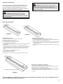 2
2
-
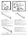 3
3
-
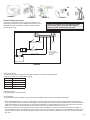 4
4
-
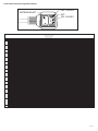 5
5
-
 6
6
-
 7
7
-
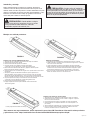 8
8
-
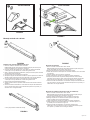 9
9
-
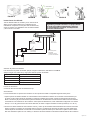 10
10
-
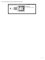 11
11
-
 12
12
-
 13
13
-
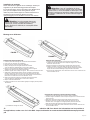 14
14
-
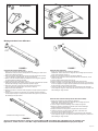 15
15
-
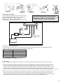 16
16
-
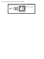 17
17
-
 18
18
-
 19
19
-
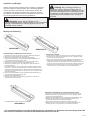 20
20
-
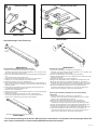 21
21
-
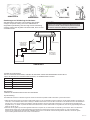 22
22
-
 23
23
-
 24
24


en otros idiomas
- français: Code 3 CD5051VDL2
- English: Code 3 CD5051VDL2
- Deutsch: Code 3 CD5051VDL2
Artículos relacionados
-
 Code 3 CD5051VDL Series Install Instructions
-
 Code 3 Emergency Systems 2021 Guía del usuario
-
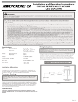 Code 3 CB7265 Install Instructions
-
 Code 3 CD3794 Install Instructions
-
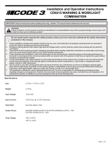 Code 3 CD9215 Series Install Instructions
-
 Code 3 CZ6015/16 Install Instructions
-
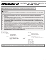 Code 3 HB12PAK Install Instructions
-
 Code 3 Chevy Tahoe 2015-2020 Matrix Citadel Install Instructions
-
 Code 3 Ford PIU 2015-2019 Matrix Citadel Install Instructions
-
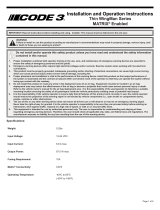 Code 3 Thin Wingman Install Instructions


