dBTechnologies IA504 R El manual del propietario
- Categoría
- Amplificador de instrumentos musicales
- Tipo
- El manual del propietario

7XWWHOHTXRWHVRQRLQPLOOLPHWUL
$OOYDOXHVDUHLQPLOOLPHWHUV
(WLFKHWWDDGHVLYDLQSROLFDUERQDWRGHDQWLJUDIILRVDWLQDWRVSHVVRUHPP
FRORUHQHURFRQVHULJUDILDJULJLD
%LDGHVLYRWUDVSDUHQWHPROWRUHVLVWHQWH1,772SHUVXSSRUWLPHWDOOLFLHUHVLVWHQWHDOO¶DFTXD
$GKHVLYH/DEHOPDGHLQSRO\FDUERQDWHGHVFUDWFKSURRIJOD]HGWKLFNQHVVPP
EODFNFRORXUZLWKJUH\DUWZRUN
'RXEOHVLGHGDGKHVLYHYHU\UHVLVWDQW1,772IRUPHWDOVXSSRUWDQGZDWHUUHVLVWDQW
5$/3$1721(%ODFN&FRORUH1HURRSDFR
5$/%ODFNFRORXUPDW
5$/3$1721(&RRO*UD\&FRORUH*LDOORRSDFR
5$/3$1721(&RRO*UD\&<HOORZFRORUPDW
$
3URMHFW &RPSLOHU &KDQJHLQJREMHFW
9HULI\
$SSURYHG
'LPHQVLRQVWROOHUDQFH &UHDWLRQ'DWH
'HVFULSWLRQ
$(%,1'8675,$/(VUO9LD%URGROLQL1/RF&UHVSHOODQR9$/6$02**,$%2,7$/<7HO)D[
6FDOHGUDZLQJ 8SGDWLQJ'DWH 1RWH
)LOHQDPH
&RGLWHP
$FWXDO9HUV3UHFHGHQW9HUV
1 1
PP
,$5
(WLFKHWWDSDQQHOORIURQWDOH
)URQWDOSDQHOODEHO
FGU
&2WWDQL
77LQWL (OLPLQDWDLQGLFD]LRQHGL5(6(7
&DPELDWDLQGLFD]LRQH/('GD5HDG\D
3RZHU6WDQGE\
55RFFDWHOOR
)RQGR&RORUHQHUR
%DFNJURXQG%ODFNFRORU
6HULJUDILD&RORUHJULJLR
$UWZRUN*UH\FRORU
&+
3HDN
)DXOW
6LJQDO
86%'DWD
&RQWURO
&+ &+
&+
5HPRWH
$FWLYH
%ULGJH
0RGH
&KDQQHOV'LJLWDO$PSOLILHU ['630DWUL[
'PP
[5 5
5
'LPHQVLRQHHWLFKHWWD
/DEHOGLPHQVLRQ
)XVWHOOD
&XWWLQJ
7UDVSDUHQWHRSDFR
7UDQVSDUHQWRSDTXH 7UDVSDUHQWHRSDFR
7UDQVSDUHQWRSDTXH
9XRWR
(PSW\
&+ &+
3HDN
)DXOW
3HDN
)DXOW
6LJQDO 6LJQDO
86%'DWD
&RQWURO
86%'DWD
&RQWURO
&+ &+&+ &+
&+ &+
5HPRWH
$FWLYH
5HPRWH
$FWLYH
%ULGJH
0RGH
%ULGJH
0RGH
&KDQQHOV'LJLWDO$PSOLILHU &KDQQHOV'LJLWDO$PSOLILHU
(WLFKHWWDFRPSOHWD
&RPSOHWHODEHO
&RQWUROORSDUWL
&KHFNSDUWV
['630DWUL[ ['630DWUL[
3RZHU
6WDQGE\
3RZHU
6WDQGE\
3RZHU
6WDQGE\
Professional Amplifier
MANUALE D’USO – Sezione 1
Le avvertenze nel presente manuale devono essere osservate congiuntamente al “MANUALE D’USO - Sezione 2”.
USER MANUAL - Section 1
The warnings in this manual must be observed in conjunction with the “USER MANUAL - Section 2”.
BEDIENUNGSANLEITUNG – Abschnitt 1
Die Hinweise in der vorliegenden Bedienungsanleitung sind ebenso zu befolgen wie die in der „BEDIENUNGSANLEITUNG – Abschnitt 2“.
MANUEL D’UTILISATION – Section 1
Respecter à la fois les avertissements donnés dans ce document et dans le MANUEL D’UTILISATION - Section 2.
MANUAL DE USO – Sección 1
Respete las advertencias de este manual y los contenidos del “MANUAL DE USO - Sección 2”.

IA540R Cod. 420120398 REV. 1.0
EMI CLASSIFICATION
FCC CLASS B STATEMENT ACCORDING TO TITLE 47, PART 15, SUBPART B,
§15.105
According to the standards EN 55032 and 55035 this is a class B equipment, designed and suitable to operate in
residential environments.
This equipment has been tested and found to comply with the limits for a Class B digital device, pursuant to part
15 of the FCC Rules.
These limits are designed to provide reasonable protection against harmful interference in a residential
installation.
This equipment generates, uses and can radiate radio frequency energy and, if not installed and used in
accordance with the instructions, may cause harmful interference to radio communications.
However, there is no guarantee that interference will not occur in a particular installation. If this equipment does
cause harmful interference to radio or television reception, which can be determined by turning the equipment.
off and on, the user is encouraged to try to correct the interference by one or more of the following measures:
1. Reorient or relocate the receiving antenna.
2. Increase the separation between the equipment and receiver.
3. Connect the equipment into an outlet on a circuit different from that to which the receiver is connected.
4. Consult the dealer or an experienced radio/TV technician for help.
Changes or modications not expressly approved by the party responsible for compliance could void the user’s
authority to operate the equipment.
Make sure that the device is securely installed in a stable position to avoid any injuries or damages to persons or
properties.
Before installing the device check all the components for damages, deformations, missing or damaged parts that
may compromise safety during installation.
Follow the instructions in this user manual to properly install the device. It’s suggested to keep enough distance
from other devices to allow the right cooling.
The warnings in this manual must be observed in conjunction with the “USER – MANUAL - Section 2”.
WARNING


4
IA540R Cod. 420120398 REV. 1.0
Italiano
INDICE
1. INFORMAZIONI GENERALI ................................................................................................................. 5
BENVENUTI! .................................................................................................................................................... 5
PANORAMICA INTRODUTTIVA ....................................................................................................................... 5
RIFERIMENTI PER L’UTENTE ............................................................................................................................ 5
CARATTERISTICHE MECCANICHE ................................................................................................................... 6
CARATTERISTICHE DELLA SEZIONE DI AMPLIFICAZIONE E DI CONTROLLO ............................................... 6
SEZIONE DI INGRESSO, USCITA E DI CONTROLLO ....................................................................................................... 7
SEZIONE DI ALIMENTAZIONE ....................................................................................................................................... 8
2. PRIMA ACCENSIONE ............................................................................................................................ 9
CONTENUTO DELLA CONFEZIONE ................................................................................................................ 9
SIGNAL PROCESSING ...................................................................................................................................... 9
3. AURORA NET ........................................................................................................................................ 9
MONITORING ................................................................................................................................................ 10
ROUTING ....................................................................................................................................................... 12
EQ .................................................................................................................................................................. 14
LIMITER .......................................................................................................................................................... 15
GPIO .............................................................................................................................................................. 16
SETUP ............................................................................................................................................................ 17
LOAD/SAVE .................................................................................................................................................... 18
LOG ................................................................................................................................................................ 18
LOCK DEVICE ................................................................................................................................................. 19
4. ESEMPI DI UTILIZZO ............................................................................................................................ 20
CABLAGGI INGRESSI ..................................................................................................................................... 20
INGRESSO ANALOGICO BILANCIATO ......................................................................................................................... 20
INGRESSO ANALOGICO SBILANCIATO ....................................................................................................................... 20
CABLAGGI USCITE ......................................................................................................................................... 20
STEREO SETUP ............................................................................................................................................................. 20
BRIDGE SETUP ............................................................................................................................................................. 21
70/100V SETUP ............................................................................................................................................................ 21
CABLAGGI RETE............................................................................................................................................. 21
RDNET .......................................................................................................................................................................... 21
CONTROLS ..................................................................................................................................................... 22
STANDBY ..................................................................................................................................................................... 22
GPI - COLLEGAMENTO PULSANTE .............................................................................................................................. 22
GPO - COLLEGAMENTO LED ....................................................................................................................................... 22
GPO - COLLEGAMENTO RELE’ .................................................................................................................................... 23
GPO - DISPOSITIVO ESTERNO..................................................................................................................................... 23
ANALOG - COLLEGAMENTO ROTARY ........................................................................................................................ 23
5. ACCESSORI .......................................................................................................................................... 24
INSTALLAZIONE A RACK ............................................................................................................................... 24
INSTALLAZIONE A TAVOLO .......................................................................................................................... 25
6. AGGIORNAMENTO DEL FIRMWARE ................................................................................................ 26
7. RISOLUZIONE DEI PROBLEMI ........................................................................................................... 26
8. SPECIFICHE TECNICHE ....................................................................................................................... 27
GENERALE ................................................................................................................................................................... 27
DATI ACUSTICI ............................................................................................................................................................. 27
AMPLIFICATORE .......................................................................................................................................................... 27
PROCESSORE ............................................................................................................................................................... 28
INTERFACCIA UTENTE ................................................................................................................................................. 28
INGRESSI E USCITE ...................................................................................................................................................... 28
SPECIFICHE DI ALIMENTAZIONE ................................................................................................................................. 28
DIMENSIONI E PESO ................................................................................................................................................... 28

5
IA504R Cod. 420120398 REV. 1.0
Italiano
1. INFORMAZIONI GENERALI
Grazie per aver acquistato un prodotto progettato e sviluppato in Italia da dBTechnologies! Questo amplicatore
professionale è frutto di una lunga esperienza nel campo della diffusione sonora. Impiega soluzioni ottimizzate in
campo acustico ed elettronico, oltre che nella scelta dei materiali.
IA504 è la nuova linea di amplicatori digitali realizzata da dBTechnologies e pensata per il pilotaggio di sistemi
audio passivi in installazioni sse. La serie si sviluppa su due modelli che si differenziano per connettività e
caratteristiche. IA504R è la versione RDnet che permette di gestire segnali audio analogici in ingresso e in uscita
con un controllo tramite interfacce hardware RDnet.
Le sue caratteristiche principali sono:
Per utilizzare al meglio il vostro IA504R consigliamo di:
• dimensioni compatte su mezza unità rack
• tutti i controlli gestibili tramite software AURORA NET
• potente DSP interno
• preset per ottimizzare la risposta di speaker passivi prodotti da dBTechnologies
• molteplici possibilità di congurazione tramite la matrice interna
• leggere il manuale d’uso quick start presente nella confezione e questo manuale d’uso completo in
ogni sua parte e conservarlo per tutta la durata di vita del prodotto.
• registrare il prodotto sul sito http://www.dbtechnologies.com nella sezione “SUPPORTO”.
• scaricare e installare il rmware pi aggiornato dal sito http://www.dbtechnologies.com nella sezione
“DOWNLOADS” (vedi il capitolo AGGIORNAMENTO DEL FIRMWARE).
• conservare prova d’acquisto e GARANZIA (Manuale d’uso “sezione 2”).
BENVENUTI!
PANORAMICA INTRODUTTIVA
RIFERIMENTI PER L’UTENTE

6
IA540R Cod. 420120398 REV. 1.0
Italiano
CARATTERISTICHE MECCANICHE
L’amplicatore digitale IA504R è progettato con una particolare attenzione all’ottimizzazione di peso e
ingombro. Può essere installato in rack da mezza unità o in rack standard grazie agli accessori dedicati. Ha un
peso di 1.82 kg.
Le misure sono: 222 mm (L) x 44 mm (A) x 256,5 mm (P).
CARATTERISTICHE DELLA SEZIONE DI AMPLIFICAZIONE E DI CONTROLLO
L’amplicatore digitale di nuova generazione IA504R è in classe D, assicura una potenza di amplicazione
complessiva di 500 W RMS. Lo stadio di conversione AD/DA è a 48 kHz - 24 bit. Le connessioni permettono un
indirizzamento essibile e includono:
- quattro ingressi audio analogici bilanciati su connettore Euroblock 3,81mm
- quattro uscite di potenza in formato Euroblock 5,08mm
- due porte RDnet su connettore RJ45
- porta USB
- quattro porte congurabili GPIO (General Purpose Input/Output)
- ingresso di stand-by
ATTENZIONE!
• Proteggere il modulo dall’umidità
• Non tentare in nessun modo di aprire l’amplicatore
• In caso di malfunzionamento, interrompere immediatamente l’alimentazione, scollegando il
modulo dalla rete, e contattare un centro di assistenza autorizzato
222
44
(263)
256,5

7
IA504R Cod. 420120398 REV. 1.0
Italiano
SEZIONE DI INGRESSO, USCITA E DI CONTROLLO
1. REMOTE ACTIVE LED
Quando è acceso in maniera ssa, questo LED indica che è attiva la connessione RDNet o USB; se lampeggia indica
un warning dell’amplicatore.
2. POWER/STANDBY LED
Quando è acceso in maniera ssa, questo LED fornisce un’indicazione sullo stato dell’amplicatore; quando
lampeggia segnala che l’amplicatore è in stato di standby.
3. RESET BUTTON
Quando questo pulsante viene premuto per pi di tre secondi l’amplicatore si riavvia. Se viene mantenuto
premuto per pi di 10 secondi riporta l’amplicatore alle impostazioni di fabbrica.
4. BRIDGE MODE
Questi LED indicano il funzionamento in modalità bridge dei canali 1-2 e 3-4.
5. SIGNAL
Questo LED indica la presenza di segnale su uno dei quattro canali in uscita.
6. USB DATA CONTROL
Grazie a questa porta standard USB di tipo B è possibile controllare l’unità con software AURORA NET ed
effettuare l’aggiornamento del rmware tramite USB BURNER MANAGER. Per ulteriori informazioni consultare il
sito http://www.dbtechnologies.com alla sezione “DOWNLOADS” ed il capitolo AGGIORNAMENTO DEL FIRMWARE
su questo manuale.
7. PEAK FAULT
Questo LED segnala l’intervento del limiter di picco dell’uscita. È utilizzato anche per segnalare i
malfunzionamenti dell’amplicatore e del canale specico.
1
4
7
5
6
2
3

8
IA540R Cod. 420120398 REV. 1.0
Italiano
8. INGRESSI AUDIO ANALOGICI
Ingressi audio analogici su connettore Euroblock 3.81mm.
9. CONTROLS
Connessioni in formato Euroblock 3.81mm utilizzabili come GPI, GPO, analogico e come ingresso stand-by
dedicato. Per maggiori informazioni leggere il capitolo dedicato a GPIO su questo manuale.
10. PORTE RDNET
Connessione in formato RJ45 per il controllo dell’amplicatore tramite interfacce hardware RDNet Control 2 o
RDNet Control 8.
11. POWER OUTPUT
Uscite di potenza su connettore Euroblock 5.08mm. L’impedenza utilizzabile in uscita è 4, 8 o 16 Ohm in modalità
singolo canale oppure 8 o 16 Ohm in modalità bridge, è possibile pilotare sistemi 100V o 70V. dB Technologies
ha creato dei preset per speaker passivi proprietari caricabili tramite software AURORA NET per un’esperienza di
ascolto ottimale.
SEZIONE DI ALIMENTAZIONE
12. PRESA DI ALIMENTAZIONE
Consente la connessione del cavo di alimentazione fornito in dotazione. L’alimentazione è di tipo full range.
ATTENZIONE!
• Non ostruire le alette posteriori di raffreddamento dell’amplicatore. In caso di
surriscaldamento eccessivo, il volume audio viene ridotto gradualmente no alla
stabilizzazione termica del modulo. Il livello viene ristabilito automaticamente al
raggiungimento della corretta temperatura di funzionamento.
• In caso di malfunzionamento, interrompere immediatamente l’alimentazione, e
scollegare il modulo dalla rete. Rivolgersi ad un centro di assistenza autorizzato.
• Non tentare in nessun modo di aprire l’amplicatore.
• Controllare periodicamente l’integrità dei cavi utilizzati per i collegamenti
121110
8 9

9
IA504R Cod. 420120398 REV. 1.0
Italiano
2. PRIMA ACCENSIONE
3. AURORA NET
Tramite il software AURORA NET, l’utente ha la possibilità di visualizzare e controllare tutti i parametri
dell’amplicatore IA504R. Di seguito viene mostrata una panoramica dei comandi che l’utente troverà caricando
nel proprio progetto su AURORA NET un’istanza di IA504R (sezione Ampliers).
Vericate, aprendo la confezione, che il contenuto dell’imballo dell’amplicatore IA504R sia completo. L’imballo
contiene:
• cavo di alimentazione
• amplicatore IA504R
• n.5 connettori femmina Euroblock (n.2 connettori 6 poli con passo 3.81mm, n.1 connettore 8 poli con passo
3.81mm e n.2 connettori 4 poli con passo 5.08mm)
• quick start e documentazione relativa alla garanzia
Il processing di segnale è gestito dal software AURORA NET; dall’ingresso della sorgente audio all’uscita verso gli
speaker si suddivide nelle sezioni Input Section, Processing Channels e Output Section.
Dalla Input Section l’utente può impostare gain in ingresso, ritardo ed eq dei segnali provenienti dai quattro
ingressi analogici; la matrice di input (Input Selection) permette di inviare i segnali a uno o pi canali di
processing. A questi è possibile applicare delay, equalizzazione e compressione. La matrice di uscita accetta sia i
canali pre che post processing e li invia alle uscite power output. L’utente può caricare preset creati appositamente
da dB Technologies per speaker passivi proprietari.
Per ulteriori approfondimenti leggere le pagine successive ddedicate ad AURORA NET.
CONTENUTO DELLA CONFEZIONE
SIGNAL PROCESSING

10
IA540R Cod. 420120398 REV. 1.0
Italiano
Dalla sezione INPUT è possibile monitorare il livello dei segnali in ingresso, impostare gain e tempo di ritardo,
mettere in solo, in mute, invertire la polarità e mettere in link tra loro i canali 1-2 e 3-4. Il comando Link agisce su
tutta la catena di processing. Di default Gain è impostato a 0 dB, Delay a 0 ms e il link tra i canali non è attivo.
Dalla sezione Processing è possibile monitorare il livello e la compressione dei segnali nei canali di processing,
mettere in solo, in mute, invertire la polarità, apportare del ritardo e mettere in link i canali A-B, B-C e C-D. Il
comando Link agisce su tutta la catena del processing. Il meter del compressore è relativo al compressore attivato
dalla sezione Limiter => Processing Channels.
Di default Gain è impostato a 0 dB, Delay a 0 ms e il link tra i canali non è attivo
MONITORING

11
IA504R Cod. 420120398 REV. 1.0
Italiano
Dalla sezione Output l’utente può visualizzare il livello delle uscite dell’amplicatore, l’ammontare della
compressione e mettere in muto i singoli canali.
La sezione Levels fornisce informazioni circa il livello e l’ammontare della compressione dei segnali in ingresso,
post processing e in uscita, della temperatura dell’amplicatore, del DSP e del sistema di raffreddamento.

12
IA540R Cod. 420120398 REV. 1.0
Italiano
La matrice di assegnazione dei segnali in ingresso ai quattro canali di processing si suddivide nei pannelli CH
A, CH B, CH C e CH D. Ogni canale di processing può accettare in ingresso gli input o il tono pilota; si possono
stabilire tre livelli di priorità:
• l’amplicatore individua il canale con la priorità pi alta presente e lo seleziona
• quando il canale selezionato perde lo stato di Link passa all’ingresso con priorità pi bassa
L’utente può forzare la selezione di un ingresso grazie al pulsante Force, bloccando l’amplicatore alla selezione di
un ingresso sso.
Dalla sezione Backup Mode è possibile selezionare la modalità con cui l’amplicatore rileva su ogni ingresso la
presenza o meno di segnale (di default impostata su None). Questa funzionalità ha un ruolo fondamentale nella
selezione automatica dei canali in ingresso; assicurarsi di impostare correttamente i parametri. Se non si utilizza
questa funzione impostare su “NONE” il campo “BackUp Mode”.
ROUTING

13
IA504R Cod. 420120398 REV. 1.0
Italiano
Dalla pagina Output è possibile personalizzare il routing a seconda delle proprie esigenze tramite la matrice.
La congurazione di routing di Default prevede:
Routing Input
Backup Mode è di default impostato su NONE.
Routing Output
CH A => Out 1
CH B => Out 2
CH C => Out 3
CH D => Out 4
CH A CH B CH C CH D
1st Analog 1 Analog 2 Analog 3 Analog 4
2nd NONE NONE NONE NONE
3rd NONE NONE NONE NONE

14
IA540R Cod. 420120398 REV. 1.0
Italiano
Ai segnali in Input è possibile applicare un’equalizzazione con un massimo di otto ltri per canale a scelta tra
diverse tipologie con frequenza di taglio, gain e Q modicabili. L’equalizzazione è applicabile anche ai Processing
Channels, in questo caso si possono caricare no a 16 ltri per canale. Di default l’EQ è attivo con impostazioni
at.
EQ Input channels
EQ Processing channels
EQ

15
IA504R Cod. 420120398 REV. 1.0
Italiano
Ai Processing Channels è possibile applicare un compressore/limiter di cui si possono impostare threshold,
ratio, make up gain e tempi di attacco, rilascio e hold. Sui canali in uscita è altresì attivo un limiter con ratio
preimpostata con valore ∞:1; il limiter si disattiva in congurazione di output 70/100V e quando viene caricato un
preset nella sezione di output.
Di default il Limiter è attivo con impostazioni at.
Limiter Input channels
Limiter Processing channels
LIMITER

16
IA540R Cod. 420120398 REV. 1.0
Italiano
Dalla sezione GPIO cliccando sul pulsante Congure è possibile personalizzare il comportamento delle quattro
porte GPIO; alcuni esempi di congurazione sono riportati nel capitolo ESEMPI DI UTILIZZO di questo manuale.
GPIO
Di seguito lo stato di default dei GPIO.
Conguration
Action Object Channel Reverse
GPIO 1Analog Gain Processing CH A Yes
GPIO 2 Analog Gain Processing CH B Yes
GPIO 3 Analog Gain Processing CH C Yes
GPIO 4 Analog Gain Processing CH D Yes

17
IA504R Cod. 420120398 REV. 1.0
Italiano
La nestra Setup permette di scegliere il tipo di ingresso (dal menu a discesa), congurare le uscite
dell’amplicatore e regolare il livello del sine tone. Cliccando sul pulsante Congure l’utente ha la possibilità di
caricare dei preset realizzati da dBTechnologies (menu Out Mode), modicare la modalità di uscita tra Stereo,
Bridge e 70/100V.
Di default la modalità bridge è disattiva, l’impedenza di uscita è impostata su 4 Ohm.
SETUP

18
IA540R Cod. 420120398 REV. 1.0
Italiano
Dalla nestra Load/Save è possibile impostare da quale Snapshot far avviare l’amplicatore (menu a discesa Start
Snapshot), importare ed esportare la congurazione di sistema.
Dalla nestra Log l’utente può consultare l’elenco di tutte le operazioni svolte sull’amplicatore da Aurora.
LOAD/SAVE
LOG


20
IA540R Cod. 420120398 REV. 1.0
Italiano
4. ESEMPI DI UTILIZZO
CABLAGGI INGRESSI
CABLAGGI USCITE
INGRESSO ANALOGICO BILANCIATO
STEREO SETUP
INGRESSO ANALOGICO SBILANCIATO
Balanced Analog IN
+
-
UnBalanced Analog IN
+
IN 4IN 1 IN 2 IN 3 * Jumper between
Negative [-] and GND
Balanced Digital IN/OUT
+
-INPUT
OUTPUT
+
-
IN 4IN 1 IN 2 IN 3
IN 4IN 1 IN 2 IN 3
Balanced Analog IN
+
-
UnBalanced Analog IN
+
IN 4IN 1 IN 2 IN 3 * Jumper between
Negative [-] and GND
Balanced Digital IN/OUT
+
-INPUT
OUTPUT
+
-
IN 4IN 1 IN 2 IN 3
IN 4IN 1 IN 2 IN 3
Di seguito sono riportati a titolo di esempio alcuni utilizzi comuni dell’amplificatore IA504R.
Collegare i due poli positivo e negativo e la
massa del segnale in ingresso ai corrispettivi
sull’ingresso dell’amplificatore desiderato come
indicato dall’etichetta.
Collegamento di una coppia di speaker in
modalità stereo. Richiamare il corretto setup
da AURORA NET nella sezione Setup => Output.
L’impedenza minima deve essere di 4 Ohm.
Collegare il polo positivo e la massa del
segnale in ingresso al corrispettivo sull’ingresso
dell’amplificatore.

21
IA504R Cod. 420120398 REV. 1.0
Italiano
BRIDGE SETUP
70/100V SETUP
ATTENZIONE!
• Non connettere le uscite a terra!
CABLAGGI RETE
RDNET
Collegamento e rilancio del segnale di controllo
proveniente da interfaccia RDNet.
Collegamento di uno speaker in modalità bridge.
Richiamare il corretto setup da AURORA NET
nella sezione Setup => Output. L’impedenza
minima deve essere di 8 Ohm.
Collegamento di speaker in modalità 70/100V.
Richiamare il corretto setup da AURORA NET
nella sezione Setup => Output.

22
IA540R Cod. 420120398 REV. 1.0
Italiano
CONTROLS
STANDBY
GPI - COLLEGAMENTO PULSANTE/INTERRUTTORE
GPO - COLLEGAMENTO LED
Collegamento di un interruttore per mettere
l’amplificatore in standby. Contatto chiuso => stand-by
mode. La configurazione è tramite software AURORA
NET, sezione GPIO => Configure.
Collegamento di un pulsante/interruttore alimentato dall’amplificatore IA504R (a sinistra) o alimentato
esternamente (a destra). La configurazione è tramite software AURORA NET, sezione GPIO => Configure.
Collegamento di un LED alimentato dall’amplificatore IA504R (a sinistra) o alimentato esternamente (a destra). La
configurazione è tramite software AURORA NET, sezione GPIO => Configure.

23
IA504R Cod. 420120398 REV. 1.0
Italiano
GPO - COLLEGAMENTO RELE’
GPO - DISPOSITIVO ESTERNO
ANALOG - COLLEGAMENTO ROTARY
Collegamento di un relè alimentato esternamente. La
configurazione è tramite software AURORA NET, sezione
GPIO => Configure.
Collegamento di un dispositivo esterno alimentato dall’amplificatore IA504R (a sinistra) o alimentato
esternamente (a destra). La configurazione è tramite software AURORA NET, sezione GPIO => Configure.
Collegamento di un potenziometro analogico alimentato dall’amplificatore IA504R (a sinistra) o alimentato
esternamente (a destra). La configurazione è tramite software AURORA NET, sezione GPIO => Configure.

24
IA540R Cod. 420120398 REV. 1.0
Italiano
5. ACCESSORI
L’amplicatore IA504R si può montare in armadi rack da mezza o intera unità 19”. È disponibile il kit accessori
RMK-1 che permette diverse installazioni mostrate di seguito; il kit è composto da:
• n° 3 staffe per installazione a rack di una o due unità (n.2 laterali e n.1 di collegamento)
• n° 2 staffe per installazione a tavolo
• n°1 pannello cieco per ssaggio a rack di singola unità
• n°4 viti M4x12
INSTALLAZIONE A RACK
Per l’installazione in mezzo rack ssare le staffe laterali al pannello frontale dell’amplicatore.

25
IA504R Cod. 420120398 REV. 1.0
Italiano
INSTALLAZIONE A TAVOLO
Per installare l’amplicatore a tavolo è necessario utilizzare le apposite staffe e avvitarle ai lati dell’amplicatore.A
seconda delle necessità di montaggio, le staffe possono essere rivolte con la base verso l’alto o con la base
verso il basso.
Nel caso di montaggio di singola unità in rack da 19” utilizzare l’apposito pannello cieco.
Nel caso di montaggio di doppia unità in rack da 19” utilizzare l’apposta staffa di collegamento.

26
IA540R Cod. 420120398 REV. 1.0
Italiano
1
4
7
5
6
2
3
6. AGGIORNAMENTO DEL FIRMWARE
È molto importante mantenere aggiornato il firmware del prodotto, per garantirne una piena funzionalità.
Controllare periodicamente il sito http://www.dbtechnologies.com nella sezione “DOWNLOADS”.
1. Scaricare ed installare USB BURNER MANAGER nella sezione “SOFTWARE & CONTROLLER” sul proprio
computer.
2. Scaricare il file .zip dell’ultimo firmware nella sezione “DOWNLOADS” relativa al proprio prodotto.
3. Collegare il prodotto al PC tramite un cavo USB (non fornito) con il connettore del tipo corretto (vedere
questo dettaglio nel capitolo “CARATTERISTICHE DELLA SEZIONE DI AMPLIFICAZIONE E DI CONTROLLO“
4. Nella schermata dell’USB BURNER MANAGER, in alto a destra, selezionare “Apertura File”.
5. Selezionare il file del firmware precedentemente scaricato.
6. Seguire le operazioni mostrate a video.
7. Cliccare “AGGIORNA”.
È possibile aggiornare il firmware di IA504R anche tramite software AURORA NET, nella sezione Firmware Update.
1. Vericare il livello del segnale della sorgente audio
2. Se il led Peak/Fault di uno o pi canali si accende, il segnale potrebbe arrivare agli speaker già in
condizioni di distorsione. Regolare quindi il livello in uscita.
3. Vericare che i cavi utilizzati per il collegamento agli speaker non siano danneggiati, nel qual caso
sostituirli (un cavo danneggiato può portare a perdita o alterazione del segnale).
L’amplicatore emette un suono distorto:
1. Vericare che i collegamenti in ingresso del segnale audio siano correttamente effettuati.
2. Vericare che i cavi utilizzati non siano danneggiati.
3. Vericare che la sorgente audio sia accesa e mostri chiaramente la presenza di segnale in uscita.
7. RISOLUZIONE DEI PROBLEMI
L’amplicatore si accende ma non emette nessun suono:
1. Vericare la corretta presenza dell’alimentazione a monte dell’impianto.
2. Vericare che il cavo di alimentazione con connettore IEC 10A sia correttamente inserito.
3. In caso il problema persista, contattare l’assistenza.
L’amplicatore non si accende:

27
IA504R Cod. 420120398 REV. 1.0
Italiano
Classe di amplicazione: Classe D
Potenza max singolo canale (picco)
425 W @ 4 Ω
245 W @ 8 Ω
135 W @ 16 Ω
619 W @ 8 Ω (bridge)
Potenza max singolo canale (RMS)
280 W @ 4 Ω
245 W @ 8 Ω
135 W @ 16 Ω
280 W @ 8 Ω (bridge)
250 W @ 70V
240 W @ 100V
Potenza max tutti i canali (picco)
225 W @ 4 Ω
180 W @ 8 Ω
125 W @ 16 Ω
440 W @ 8 Ω (bridge)
Potenza max tutti i canali (RMS)
70 W @ 4 Ω
70 W @ 8 Ω
70 W @ 16 Ω
140 W @ 8 Ω (bridge)
140 W @ 70V
140 W @ 100V
Potenza RMS massima: 280 W @ 230 VAC
250 W @ 120 VAC
Raffreddamento ventola (da fronte a retro)
Risposta in frequenza [8 Ohm]: 20 Hz - 20 kHz (+0,5 dB)
Gain amplicatore: 31 dB
Rapporto segnale/rumore: > 103 dB(A)
Sensibilità in ingresso: +4 dBU
Livello massimo in ingresso: +18 dBU
Crosstalk: 100 dB
Impedenza in ingresso: 20 kOhm
Tipologia: Amplicatore digitale
GENERALE
8. SPECIFICHE TECNICHE
AMPLIFICATORE
DATI ACUSTICI

28
IA540R Cod. 420120398 REV. 1.0
Italiano
** NOTA PER L’INSTALLATORE: Valori riferiti a 1/3 della potenza, in condizioni pesanti di funzionamento (programma musicale con frequente
clipping e intervento del limiter). E’ consigliabile il dimensionamento secondo questi valori in caso di installazioni e tour professionali.
* NOTA PER L’INSTALLATORE: Valori riferiti a 1/8 della potenza, in condizioni medie di funzionamento (programma musicale con clipping raro
o assente). Si consiglia per qualsiasi tipo di congurazione di considerarli i valori minimi di dimensionamento.
Assorbimento a 1/8 della potenza in
condizioni medie di utilizzo (*): 0.36 A (220-240V~) - 0.66 A (100-120V~)
Assorbimento a 1/3 della potenza in
condizioni massime di utilizzo (**): 0.7 A (220-240V~) - 1.4 A (100-120V~)
Assorbimento con speaker acceso in
assenza di segnale (idle): 0.16 A (220-240V~) - 0.25 A (100-120V~)
Corrente di inrush: 3.8 A
SPECIFICHE DI ALIMENTAZIONE (ASSORBIMENTO)
INTERFACCIA UTENTE
Ingressi audio: 4x Analog (Euroblock)
Uscite audio: 4x Analog (Euroblock)
USB (controllo/aggiornamento del
rmware): 1x USB tipo B
INGRESSI ED USCITE
Presets: Flat, dB Technologies speaker, User preset
Controlli: Pulsante Reset
PROCESSORE
Convertitore A/D D/A: 24 bit / 48 kHz
Limiter: Dual Active Peak, RMS, Termico
Larghezza: 222 mm (8.7 inch.)
Altezza: 44 mm (1.7 inch.)
Profondità: 256 mm (10.1 inch.)
Peso: 1.82 kg (4.01 lbs.)
DIMENSIONI E PESO
Le caratteristiche, le speciche e l’aspetto dei prodotti sono soggetti a possibili cambiamenti senza previa comunicazione.
dBTechnologies si riserva il diritto di apportare cambiamenti o miglioramenti nel design o nelle lavorazioni senza assumersi
l’obbligo di cambiare o migliorare anche i prodotti precedentemente realizzati.


30
IA540R Cod. 420120398 REV. 1.0
English
CONTENTS
1. GENERAL INFORMATION .................................................................................................................. 31
WELCOME! .................................................................................................................................................... 31
INTRODUCTORY OVERVIEW ........................................................................................................................ 31
USER INFORMATION .................................................................................................................................... 31
MECHANICAL FEATURES .............................................................................................................................. 32
AMPLIFIER AND CONTROL SECTION FEATURES ......................................................................................... 32
INPUT, OUTPUT AND CONTROL SECTION ................................................................................................................. 33
POWER SUPPLY SECTION............................................................................................................................................ 34
2. FIRST POWER-ON ............................................................................................................................... 35
PACKAGE CONTENTS .................................................................................................................................... 35
SIGNAL PROCESSING .................................................................................................................................... 35
3. AURORA NET ...................................................................................................................................... 35
MONITORING ................................................................................................................................................ 36
ROUTING ....................................................................................................................................................... 38
EQ .................................................................................................................................................................. 40
LIMITER .......................................................................................................................................................... 41
GPIO .............................................................................................................................................................. 42
SETUP ............................................................................................................................................................ 43
LOAD/SAVE .................................................................................................................................................... 44
LOG ................................................................................................................................................................ 44
LOCK DEVICE ................................................................................................................................................. 45
4. EXAMPLES OF USE .............................................................................................................................. 46
INPUT WIRING .............................................................................................................................................. 46
BALANCED ANALOGUE INPUT ................................................................................................................................... 46
UNBALANCED ANALOGUE INPUT .............................................................................................................................. 46
OUTPUT WIRING ........................................................................................................................................... 46
STEREO SETUP ............................................................................................................................................................. 46
BRIDGE SETUP ............................................................................................................................................................. 47
70/100V SETUP ............................................................................................................................................................ 47
NETWORK WIRING ....................................................................................................................................... 47
RDNET .......................................................................................................................................................................... 47
CONTROLS ..................................................................................................................................................... 48
STANDBY ..................................................................................................................................................................... 48
GPI - BUTTON CONNECTION ...................................................................................................................................... 48
GPO - LED CONNECTION ............................................................................................................................................ 48
GPO - RELAY CONNECTION ........................................................................................................................................ 49
GPO - EXTERNAL DEVICE ............................................................................................................................................ 49
ANALOG - ROTARY CONNECTION .............................................................................................................................. 49
5. ACCESSORIES ...................................................................................................................................... 50
RACK MOUNTING ......................................................................................................................................... 50
WALL MOUNTING ......................................................................................................................................... 51
6. UPDATING THE FIRMWARE .............................................................................................................. 52
7. TROUBLESHOOTING .......................................................................................................................... 52
8. TECHNICAL SPECIFICATIONS ............................................................................................................ 53
GENERAL ..................................................................................................................................................................... 53
ACOUSTIC DATA .......................................................................................................................................................... 53
AMPLIFIER ................................................................................................................................................................... 53
PROCESSOR ................................................................................................................................................................. 54
USER INTERFACE ......................................................................................................................................................... 54
INPUTS AND OUTPUTS ............................................................................................................................................... 54
POWER SUPPLY SPECIFICATIONS ............................................................................................................................... 54
DIMENSIONS AND WEIGHT ........................................................................................................................................ 54

31
IA504R Cod. 420120398 REV. 1.0
English
1. GENERAL INFORMATION
Thanks for purchasing a product that was designed and developed in Italy by dBTechnologies! This professional
amplier embodies years of experience and innovation in the eld of sound reproduction, with the use of cutting
edge solutions in the elds of acoustics, electronics and materials research.
IA504 is the new amplier line created by dBTechnologies, designed to drive passive audio systems in xed
installations. The series consists of two models with different connectivity and features. IA504R is the RDNet
version, which can handing analogue input and output signals with control via an RDNet hardware interface.
The main features are:
To use your IA504R system in the best way, we recommend that you:
• small size in a half-rack unit
• all controls can be managed via AURORA NET software
• powerful internal DSP
• presets to optimise the response of passive speakers made by dBTechnologies
• multiple conguration options via the internal matrix
• read the Quick Start manual included in the package and all of this User Manual, and keep them
throughout the entire life of the product.
• register the product at http://www.dbtechnologies.com in the section “SUPPORT”.
• download and install the latest version of the rmware from the “DOWNLOADS” section of the dB
Technologies website (see the UPDATING THE FIRMWARE chapter).
• keep proof of purchase and the WARRANTY (User manual “section 2”).
WELCOME!
INTRODUCTORY OVERVIEW
USER INFORMATION

32
IA540R Cod. 420120398 REV. 1.0
English
MECHANICAL FEATURES
The IA504R digital amplier has been designed with particular attention to optimising its weight and overall
size. With dedicated accessories, it can be installed in a half-rack unit or in a standard rack. It weighs 1.82 kg.
The dimensions are: 222 mm (L) x 44 mm (H) x 256,5 mm (D).
AMPLIFIER AND CONTROL SECTION FEATURES
The IA504R new generation class D digital amplier offers a total amplication power of 500 W RMS. The AD/DA
conversion stage is 48 kHz - 24 bit. The connections offer application exibility, and include:
• four balanced analogue audio inputs on 3.81mm Euroblock connectors
• four power outputs in 5.08mm Euroblock format
• two RDNet ports on RJ45 connectors
• USB port
• four congurable GPIO (General Purpose Input/Output) ports
• standby input
CAUTION!
• Protect the unit from humidity.
• Do not attempt to open the amplier.
• In the event of malfunction, immediately turn off the power, disconnect the unit from the mains
and contact an authorised service centre.
222
44
(263)
256,5

33
IA504R Cod. 420120398 REV. 1.0
English
INPUT, OUTPUT AND CONTROL SECTION
1. REMOTE ACTIVE LED
When on continuously, this LED indicates that the RDNet or USB connection is active; when ashing, it indicates
an amplier warning.
2. POWER/STANDBY LED
When on continuously, this LED indicates the amplier status; when ashing, it indicates that the amplier is in
standby.
3. RESET BUTTON
Pressing this button for longer than three seconds restarts the amplier. Holding it down for longer than 10
seconds resets the amplier to the factory settings.
4. BRIDGE MODE
These LEDs indicate that channels 1-2 and 3-4 are operating in bridge mode.
5. SIGNAL
This LED indicates that there is a signal on one of the four output channels.
6. USB DATA CONTROL
This standard type B USB port can be used with the AURORA NET software to update the rmware via the USB
BURNER MANAGER. For further information, refer to the “DOWNLOADS” section of the dBTechnologies website
and the UPDATING THE FIRMWARE chapter.
7. PEAK FAULT
This LED indicates that the output peak limiter has triggered. It is also used to indicate a malfunction in the
amplier or in a specic channel.
1
4
7
5
6
2
3

34
IA540R Cod. 420120398 REV. 1.0
English
8. ANALOGUE AUDIO INPUTS
Analogue audio inputs on 3.81mm Euroblock connectors.
9. CONTROLS
Connections in 3.81mm Euroblock format, which can be used as GPI, GPO, analogue and as a dedicated standby
input. For further details, read the GPIO chapter in this manual.
10. RDNET PORT
Connection in RJ45 format to control the amplier via an RDNet Control 2 or RDNet Control 8 hardware interface.
11. POWER OUTPUT
Power output on a 5.08mm Euroblock connector. It can be used with an impedance of 4, 8 or 16 Ohm in single-
channel mode, or 8 or 16 Ohm in bridge mode, and can drive 100V or 70V systems. dBTechnologies has created
presets for its own passive speakers, which can be downloaded via the AURORA NET software for an optimal
listening experience.
POWER SUPPLY SECTION
12. POWER SOCKET
For use with the power cable provided. The power supply is of the full range type.
ATTENZIONE!
• Do not obstruct the amplier cooling ns at the back. In the event of overheating, the
audio volume is gradually reduced until the module is thermally stable. The level is
automatically restored on reaching the correct operating temperature.
• In the event of malfunction, immediately turn off the power and disconnect the module
from the mains. Contact an authorised service centre.
• Do not attempt to open the amplier.
• Periodically check the connection cables to ensure they are in good condition.
121110
8 9

35
IA504R Cod. 420120398 REV. 1.0
English
2. FIRST POWER-UP
3. AURORA NET
The AURORA NET software can be used to display and control all the parameters of the IA504R amplier. Below
there is an overview of the controls available when you load an instance of IA504R into your project on AURORA
NET (Ampliers section).
On opening the IA504R amplier package, check that no items are missing. The package contains:
• power cable
• IA504R amplier
• 5x female Euroblock connectors (2x 6 poles 3.81mm pitch connectors, 1x 8 poles 3.81mm pitch connector and
2x 4 poles 5.08mm pitch connectors)
• quick start manual and warranty documentation
The signal processing is managed by the AURORA NET software; it is divided into the following sections from the
audio source input to the speaker outputs: Input Section, Processing Channels and Output Section.
You can use the Input Section to set the input gain, delay and eq for the signals from the four analogue inputs;
the input matrix (Input Selection) sends the signals to one or more processing channels. Delay, equalisation and
compression can be applied to them. The output matrix accepts both pre- and post-processing channels and sends
them to the power outputs. You can load presets created specially by dBTechnologies for its own passive speakers.
For further details, read the AURORA NET section in this manual.
PACKAGE CONTENTS
SIGNAL PROCESSING

36
IA540R Cod. 420120398 REV. 1.0
English
From the Input section, you can monitor the input signal levels, set the gain and delay time, solo, mute, invert the
polarity and link channels 1-2 and 3-4 together. The Link control affects the entire processing chain.
By default, Gain is set to 0 dB, Delay to 0 ms and the channels are not linked.
From the Processing section, you can monitor the signal levels and compression in the processing channels, solo,
mute, invert the polarity, apply a delay and link channels A-B, B-C and C-D. The Link control affects the entire
processing chain. The compressor meter refers to the compressor enabled in the Limiter => Processing Channels
section.
By default, Gain is set to 0 dB, Delay to 0 ms and the channels are not linked.
MONITORING

37
IA504R Cod. 420120398 REV. 1.0
English
From the Output section, you can view the amplier output levels, the total compression, and mute the single
channels.
The Levels section provides information about the signal levels and total compression at the inputs, post-
processing and outputs, and the amplier, DSP and cooling system temperatures.

38
IA540R Cod. 420120398 REV. 1.0
English
The matrix that assigns the input signals to the four processing channels is divided into CH A, CH B, CH C and CH D
panels. Each processing channel can receive the inputs or a pilot tone; there are three possible priority levels:
• the amplier detects the channel with the highest priority and selects it
• when the selected channel loses the Link status, it switches to the input with the lower priority
You can use the Force button to force the amplier to select a specic input.
From the Backup Mode section, you can select the mode the amplier uses to detect a signal at each input (set
to None by default). This feature has a critical role in automatic input channel selection; take care to set the
parameters correctly. When not using this function, set the “BackUp Mode” eld to “NONE”.
ROUTING

39
IA504R Cod. 420120398 REV. 1.0
English
From the Output page, you can use the matrix to customise the routing to suit your needs. The Default routing
conguration is as follows:
Routing Input
Backup Mode is set to NONE by default.
Routing Output
CH A => Out 1
CH B => Out 2
CH C => Out 3
CH D => Out 4
CH A CH B CH C CH D
1st Analog 1 Analog 2 Analog 3 Analog 4
2nd NONE NONE NONE NONE
3rd NONE NONE NONE NONE

40
IA540R Cod. 420120398 REV. 1.0
English
You can pass the input signals through an equaliser with up to eight lters per channel, which can be chosen from
the various types with editable cut-off frequency, gain and Q. The equaliser can also be applied to the Processing
Channels, in which case up to 16 lters can be loaded per channel. The EQ is enabled with at settings by default.
EQ Input channels
EQ Processing channels
EQ

41
IA504R Cod. 420120398 REV. 1.0
English
You can pass the Processing Channels through a compressor/limiter, for which you can set the threshold, ratio,
make up gain, and the attack, release and hold times. The output channels also have a limiter with the ratio pre-
set to ∞:1; the limiter is disabled in the 70/100V output conguration and when a preset is loaded into the output
section.
The Limiter is enabled with at settings by default.
Limiter Input channels
Limiter Processing channels
LIMITER

42
IA540R Cod. 420120398 REV. 1.0
English
From the GPIO section, you can click the Congure button to customise the behaviour of the GPIO ports; some
conguration examples are given in the EXAMPLES OF USE chapter in this manual.
GPIO
The default GPIO status is given below.
Conguration
Action Object Channel Reverse
GPIO 1Analog Gain Processing CH A Yes
GPIO 2 Analog Gain Processing CH B Yes
GPIO 3 Analog Gain Processing CH C Yes
GPIO 4 Analog Gain Processing CH D Yes

43
IA504R Cod. 420120398 REV. 1.0
English
The Setup window lets you choose the input type (from the drop-down menu), congure the amplier outputs
and adjust the sine tone level. You can click the Congure button to load presets created by dBTechnologies (Out
Mode menu), and select the output mode from Stereo, Bridge or 70/100V.
By default, bridge is disabled and the output impedance is set to 4 Ohm.
SETUP

44
IA540R Cod. 420120398 REV. 1.0
English
From the Load/Save window, you can set from which Snapshot to start the amplier (Start Snapshot drop-down
menu), and import and export the system conguration.
From the Log window, you can view a list of all operations performed on the amplier from Aurora.
LOAD/SAVE
LOG


46
IA540R Cod. 420120398 REV. 1.0
English
4. EXAMPLES OF USE
INPUT WIRING
OUTPUT WIRING
BALANCED ANALOGUE INPUT
STEREO SETUP
UNBALANCED ANALOGUE INPUT
Balanced Analog IN
+
-
UnBalanced Analog IN
+
IN 4IN 1 IN 2 IN 3 * Jumper between
Negative [-] and GND
Balanced Digital IN/OUT
+
-INPUT
OUTPUT
+
-
IN 4IN 1 IN 2 IN 3
IN 4IN 1 IN 2 IN 3
Balanced Analog IN
+
-
UnBalanced Analog IN
+
IN 4IN 1 IN 2 IN 3 * Jumper between
Negative [-] and GND
Balanced Digital IN/OUT
+
-INPUT
OUTPUT
+
-
IN 4IN 1 IN 2 IN 3
IN 4IN 1 IN 2 IN 3
Below there are some common examples of how the IA504R amplifier can be used.
Connect the input signal positive, negative
and ground to the corresponding pins on the
amplifier input you want, as indicated by the
label.
Connecting a pair of speakers in stereo mode.
Load the correct setup from the Setup => Output
section of AURORA NET. The impedance must be
4 Ohm or greater.
Connect the signal positive and ground to the
corresponding pins on the amplifier input.

47
IA504R Cod. 420120398 REV. 1.0
English
BRIDGE SETUP
70/100V SETUP
CAUTION!
• Do not connect the outputs to ground.
NETWORK WIRING
RDNET
Connecting and linking the control signal from
the RDNet interface.
Connecting one speaker in bridge mode. Load
the correct setup from the Setup => Output
section of AURORA NET. The impedance must be
8 Ohm or greater.
Connecting a speaker in 70/100V mode. Load the
correct setup from the Setup => Output section of
AURORA NET.

48
IA540R Cod. 420120398 REV. 1.0
English
CONTROLS
STANDBY
GPI - BUTTON/SWITCH CONNECTION
GPO - LED CONNECTION
Connecting a switch to put the amplifier in standby.
Contact closed => standby mode. It is configured in the
GPIO => Configure section of the AURORA NET software.
Connecting a button/switch powered by the IA504R amplifier (on the left) or powered externally (on the right). It
is configured in the GPIO => Configure section of the AURORA NET software.
Connecting a LED powered by the IA504R amplifier (on the left) or powered externally (on the right). It is
configured in the GPIO => Configure section of the AURORA NET software.

49
IA504R Cod. 420120398 REV. 1.0
English
GPO - RELAY CONNECTION
GPO - EXTERNAL DEVICE
ANALOG - ROTARY CONNECTION
Connecting a relay powered externally. It is configured
in the GPIO => Configure section of the AURORA NET
software.
Connecting an external device powered by the IA504R amplifier (on the left) or powered externally (on the right).
It is configured in the GPIO => Configure section of the AURORA NET software.
Connecting an analogue potentiometer powered by the IA504R amplifier (on the left) or powered externally (on
the right). It is configured in the GPIO => Configure section of the AURORA NET software.

50
IA540R Cod. 420120398 REV. 1.0
English
5. ACCESSORIES
The IA504R amplier can be mounted in a half-rack or whole 19” rack unit. The RMK-1 kit of accessories is
available for the various installations shown below; the kit consists of:
• 3x brackets for rack mounting one or two units (2 side brackets and 1 connection bracket)
• 2x brackets for table mounting
• 1x blanking panel for rack mounting a single unit.
• 4x M4x12 screws
RACK MOUNTING
When mounting in a half rack, fasten the side brackets to the front panel of the amplier.

51
IA504R Cod. 420120398 REV. 1.0
English
TABLE MOUNTING
To mount the amplier on a table, screw the special brackets to the sides of the amplier.
The brackets can be oriented with the base facing upwards or downwards, as required.
When mounting a single unit in a 19” rack, use the special blanking panel.
When mounting two units in a 19” rack, use the special connection bracket.

52
IA540R Cod. 420120398 REV. 1.0
English
1
4
7
5
6
2
3
6. UPDATING THE FIRMWARE
It is very important to keep the product firmware updated to ensure full functionality. Periodically check the
“DOWNLOADS” section of the http://www.dbtechnologies.com website.
1. Download and install the USB BURNER MANAGER onto your computer from the “SOFTWARE &
CONTROLLER” section.
2. Download the .zip file of the latest firmware for your product from the “DOWNLOADS” section.
3. Connect the product to the PC using a USB cable (not supplied) with the correct connector type (see this
detail in the AMPLIFIER AND CONTROL SECTION FEATURES chapter).
4. Select “Open File” at the top right of the USB BURNER MANAGER screen.
5. Select the previously downloaded firmware file.
6. Follow the instructions shown on the screen.
7. Click “UPDATE”.
You can also update the IA504R firmware from the Firmware Update section of the AURORA NET software.
1. Check the signal level from the audio source.
2. If the Peak/Fault LED lights on one or more channels, the signal may already be distorted before it
reaches the speakers. In this case, adjust the output level.
3. Check that the speaker connection cables are not damaged. If they are, replace them (a damaged cable
may cause signal loss or alteration).
The sound from the amplier is distorted:
1. Check that the audio signal inputs are connected correctly.
2. Check that the connection cables are not damaged.
3. Check that the audio source is on and clearly shows an output signal.
7. TROUBLESHOOTING
The amplier turns on but does not produce any sound:
1. Check that the system is connected to a working power supply.
2. Check that the power cable with 10A IEC connector is plugged in properly.
3. If the problem persists, contact an authorised service centre.
The amplier does not power up:

53
IA504R Cod. 420120398 REV. 1.0
English
Amplication class: Class D
Max. power for a single channel (peak):
425 W @ 4 Ω
245 W @ 8 Ω
135 W @ 16 Ω
619 W @ 8 Ω (bridge)
Max power for a single channel (RMS):
280 W @ 4 Ω
245 W @ 8 Ω
135 W @ 16 Ω
280 W @ 8 Ω (bridge)
250 W @ 70V
240 W @ 100V
Max. power for all channels (peak):
225 W @ 4 Ω
180 W @ 8 Ω
125 W @ 16 Ω
440 W @ 8 Ω (bridge)
Max. power for all channels (RMS):
70 W @ 4 Ω
70 W @ 8 Ω
70 W @ 16 Ω
140 W @ 8 Ω (bridge)
140 W @ 70V
140 W @ 100V
Maximum RMS power: 280 W @ 230 VAC
250 W @ 120 VAC
Cooling: Fan (from front to rear)
Frequency response [8 Ohm]: 20 Hz - 20 kHz (+0,5 dB)
Amplier gain: 31 dB
Signal/noise ratio: > 103 dB(A)
Input sensitivity: +4 dBU
Maximum input level: +18 dBU
Crosstalk: 100 dB
Input impedance: 20 kOhm
Type: Digital amplier
GENERAL
8. TECHNICAL SPECIFICATIONS
AMPLIFIER
ACOUSTIC DATA

54
IA540R Cod. 420120398 REV. 1.0
English
** NOTE FOR THE INSTALLER: Values refer to 1/3 power under heavy operating conditions (music program with frequent clipping and
limiting). We recommend dimensioning in accordance with these values for professional installations and tours.
* NOTE FOR THE INSTALLER: Values refer to 1/8 power under normal operating conditions (music program with rare or no clipping). For any
conguration type, we recommend considering them to be the minimum values for dimensioning.
Power consumption at 1/8 power in
medium use conditions (*): 0.36 A (220-240V~) - 0.66 A (100-120V~)
Power consumption at 1/3 power in
medium use conditions (**): 0.7 A (220-240V~) - 1.4 A (100-120V~)
Power consumption with speaker on
but no signal (idle): 0.16 A (220-240V~) - 0.25 A (100-120V~)
Inrush current: 3.8 A
POWER SUPPLY SPECIFICATIONS
USER INTERFACE
Audio inputs: 4x Analogue (Euroblock)
Audio outputs: 4x Analogue (Euroblock)
USB (control/rmware update): Type B USB
INPUTS AND OUTPUTS
Presets: Flat, dB Technologies speaker, User preset
Controls: Reset button
PROCESSOR
A/D D/A converter: 24 bit / 48 kHz
Limiter: Dual Active Peak, RMS, Thermal
Width: 222 mm (8.7 inch.)
Height: 44 mm (1.7 inch.)
Depth: 256 mm (10.1 inch.)
Weight: 1.82 kg (4.01 lbs.)
DIMENSIONS AND WEIGHT
Product features, specications and appearance are subject to change without prior notice. dBTechnologies reserves the
right to make changes or improvements in design or manufacturing without any obligation to change or improve previously
manufactured products.


56
IA540R Cod. 420120398 REV. 1.0
Deutsch
INHALTSVERZEICHNIS
1. ALLGEMEINE HINWEISE .................................................................................................................... 57
WILLKOMMEN! ............................................................................................................................................. 57
KURZBESCHREIBUNG .................................................................................................................................... 57
HINWEISE FÜR DEN BENUTZER ................................................................................................................... 57
MECHANISCHE EIGENSCHAFTEN ................................................................................................................. 58
EIGENSCHAFTEN DES VERSTÄRKER- UND STEUERBEREICHS ..................................................................... 58
EINGANGS, AUSGANGS UND STEUERBEREICH ......................................................................................................... 59
STROMVERSORGUNGSTEIL ........................................................................................................................................ 60
2. ERSTE INBETRIEBNAHME ................................................................................................................. 61
LIEFERUMFANG ............................................................................................................................................. 61
SIGNAL PROCESSING .................................................................................................................................... 61
3. AURORA NET ...................................................................................................................................... 61
MONITORING ................................................................................................................................................ 62
ROUTING ....................................................................................................................................................... 64
EQ .................................................................................................................................................................. 66
LIMITER .......................................................................................................................................................... 67
GPIO .............................................................................................................................................................. 68
SETUP ............................................................................................................................................................ 69
LOAD/SAVE .................................................................................................................................................... 70
LOG ................................................................................................................................................................ 70
LOCK DEVICE ................................................................................................................................................. 71
4. VERWENDUNGSBEISPIELE ................................................................................................................. 72
EINGANGSVERKABELUNG ............................................................................................................................ 72
SYMMETRISCHER ANALOGEINGANG......................................................................................................................... 72
UNSYMMETRISCHER ANALOGEINGANG ................................................................................................................... 72
AUSGANGSVERKABELUNG ........................................................................................................................... 72
STEREO SETUP ............................................................................................................................................................. 72
BRIDGE SETUP ............................................................................................................................................................. 73
70/100V SETUP ............................................................................................................................................................ 73
NETZWERKVERKABELUNG ........................................................................................................................... 73
RDNET .......................................................................................................................................................................... 73
CONTROLS ..................................................................................................................................................... 74
STANDBY ..................................................................................................................................................................... 74
GPI - TASTENANSCHLUSS ............................................................................................................................................ 74
GPO - LED ANSCHLUSS ............................................................................................................................................... 74
GPO - RELAIS-ANSCHLUSS .......................................................................................................................................... 75
GPO - EXTERNES GERÄT.............................................................................................................................................. 75
ANALOG - DREHSCHALTER-ANSCHLUSS .................................................................................................................... 75
5. ZUBEHÖR ........................................................................................................................................... 76
RACKMONTAGE ............................................................................................................................................ 76
WANDMONTAGE .......................................................................................................................................... 77
6. FIRMWAREAKTUALISIERUNG .......................................................................................................... 78
7. FEHLERBEHEBUNG ............................................................................................................................ 78
8. TECHNISCHE DATEN .......................................................................................................................... 79
ALLGEMEINES .............................................................................................................................................................. 79
AKUSTISCHE DATEN .................................................................................................................................................... 79
VERSTÄRKER ................................................................................................................................................................ 79
PROZESSOR ................................................................................................................................................................. 80
BENUTZEROBERFLÄCHE ............................................................................................................................................. 80
EIN- UND AUSGÄNGE ................................................................................................................................................. 80
DATEN ZUR STROMVERSORGUNG ............................................................................................................................. 80
ABMESSUNGEN UND GEWICHT ................................................................................................................................. 80

57
IA504R Cod. 420120398 REV. 1.0
Deutsch
1. ALLGEMEINE HINWEISE
Danke, dass Sie ein Produkt erworben haben, das von dBTechnologies in Italien entworfen und entwickelt
wurde! Dieser professionelle Verstärker ist das Ergebnis langjähriger Erfahrung und Innovation im Bereich der
Soundsysteme. Er bietet fortschrittliche Lösungen in Sachen Akustik und Elektronik sowie im Hinblick auf die
Materialauswahl.
IA504 ist die neue Reihe von Digitalverstärkern, die von dBTechnologies für die Ansteuerung passiver
Audiosysteme in Festinstallationen entwofen und hergestellt wurden. Die Serie beinhaltet zwei Modelle, die sich
in Konnektivität und Ausstattung unterscheiden. IA504R ist die RDnet-Version, mit der Sie analoge Audiosignale in
Ein- und Ausgang mit einer Steuerung über RDnet-Hardwareschnittstellen verwalten können.
Hauptfeatures:
Für die optimale Nutzung Ihres IA504R raten wir Ihnen:
• kompakte Abmessungen im halben Rackformat
• alle Steuerungen sind über AURORA NET Software verwaltbar
• leistungsstarker interner DSP
• Presets zur Optimierung des Ansprechverhaltens von passiven Lautsprechern von dBTechnologies
• vielfältige Kongurationsmöglichkeiten über die interne Matrix
• die in der Packung enthaltene Quick Start-Anleitung sowie diese Bedienungsanleitung vollständig zu
lesen und sie über die gesamte Lebensdauer des Produktes aufzubewahren.
• Registrierung des Produktes auf der Website http://www.dbtechnologies.com unter „SUPPORT“.
• die neueste Firmware von der Website http://www.dbtechnologies.com im Bereich „DOWNLOADS“
(siehe Kapitel FIRMWAREAKTUALISIERUNG) herunterzuladen und zu installieren.
• den Kaufbeleg und die GARANTIE aufzubewahren (Benutzerhandbuch, „Abschnitt 2“).
WILLKOMMEN!
KURZBESCHREIBUNG
HINWEISE FÜR DEN BENUTZER

58
IA540R Cod. 420120398 REV. 1.0
Deutsch
MECHANISCHE EIGENSCHAFTEN
Der Digitalverstärker IA504R zeichnet sich durch optimiertes Gewicht und kompakte Abmessungen aus. Er
kann dank speziellem Zubehör in halben Racks oder in Standard-Racks installiert werden. Er hat ein Gewicht
von 1,82 kg. Abmessungen:
222 mm (B) x 44 mm (H) x 256,5 mm (T).
EIGENSCHAFTEN DES VERSTÄRKER- UND STEUERBEREICHES
Der Class-D-Digitalverstärker neuer Generation IA504R liefert eine Gesamt-Verstärkerleistung von 500 W RMS.
Die AD/DA-Umwandlung beträgt 48 kHz - 24 Bit. Die Anschlüsse ermöglichen eine exible Adressierung und
umfassen:
- vier symmetrische analoge Audioeingänge am 3,81 mm Euroblock-Steckverbinder
- vier Leistungsausgänge im 5,08 mm Euroblock-Format
- Zwei RDnet-Anschlüsse am RJ45-Stecker
- USB-Anschluss
- vier kongurierbare GPIO-Anschlüsse (General Purpose Input/Output)
- Standby-Eingang
ACHTUNG!
• Das Modul vor Feuchtigkeit schützen.
• Keinesfalls versuchen, den Verstärker eigenmächtig zu öffnen.
• Bei Funktionsstörungen sofort die Stromversorgung unterbrechen, das Modul vom Netz trennen
und eine autorisierte Servicestelle kontaktieren.
222
44
(263)
256,5

59
IA504R Cod. 420120398 REV. 1.0
Deutsch
EINGANGS, AUSGANGS UND STEUERBEREICH
1. REMOTE ACTIVE LED
Ein dauerhaftes Leuchten dieser LED zeigt an, dass die RDNet- oder USB-Verbindung aktiv ist; ein Blinken zeigt
eine Verstärkerwarnung an.
2. POWER/STANDBY LED
Ein dauerhaftes Leuchten dieser LED liefert einen Hinweis zum Verstärkerstatus; ein Blinken zeigt an, dass der
Verstärker in Standby ist.
3. RESET BUTTON
Wird diese Taste länger als drei Sekunden gedrückt, wird der Verstärker neu gestartet. Wird sie länger als 10
Sekunden gedrückt gehalten, wird der Verstärker auf die Werkseinstellungen zurückgesetzt.
4. BRIDGE MODE
Diese LEDs zeigen den Betrieb der Kanäle 1-2 und 3-4 im Bridge-Modus an.
5. SIGNAL
Diese LED zeigt das Vorhandensein eines Signals auf einem der vier Ausgangskanäle an.
6. USB DATA CONTROL
Mit diesem Standard-USB-Typ B-Anschluss können Sie die Einheit mit der AURORA NET-Software steuern und die
Firmwareaktualisierung über den USB BURNER MANAGER durchführen. Weitere Informationen nden Sie auf der
Website http://www.dbtechnologies.com in Bereich „DOWNLOADS” und im Kapitel FIRMWAREAKTUALISIERUNG.
7. PEAK FAULT
Diese LED signalisiert die Aktivierung des Limiters des Ausgangspegels. Sie signalisiert ebenfalls Fehlfunktionen
des Verstärkers und des spezischen Kanals.
1
4
7
5
6
2
3

60
IA540R Cod. 420120398 REV. 1.0
Deutsch
8. ANALOGE AUDIOEINGÄNGE
Analoge Audioeingänge am 3,81mm Euroblock-Steckverbinder.
9. CONTROLS
Anschlüsse im Euroblock 3,81-mm-Format, die als GPI, GPO, analog und als dedizierter Stand-by-Eingang
verwendbar sind. Weitere Informationen nden Sie im Kapitel GPIO in diesem Handbuch.
10. RDNET-ANSCHLÜSSE
Anschluss im RJ45-Format zur Verstärkersteuerung über Hardware-Schnittstellen RDNet Control 2 oder RDNet
Control 8.
11. POWER OUTPUT
Leistungsausgänge am 5,08 mm Euroblock-Steckverbinder. Die nutzbare Ausgangsimpedanz beträgt 4, 8 oder
16 Ohm im Einkanalbetrieb oder 8 oder 16 Ohm im Bridge-Modus, es ist möglich, 100V- oder 70V-Systeme
anzusteuern. dB Technologies hat proprietäre Passiv-Lautsprecher-Presets entwickelt, die über die AURORA NET-
Software für ein optimales Hörerlebnis geladen werden können.
STROMVERSORGUNGSTEIL
12. NETZBUCHSE
Ermöglicht den Anschluss des mitgelieferten Netzkabels. Full-Range-Stromversorgung.
WARNUNG!
• Die hinteren Kühlrippen des Verstärkers nicht abdecken. Bei Überhitzung sinkt
die Wiedergabelautstärke allmählich ab, bis die Modultemperatur stabil ist. Bei
Wiedererreichen der richtigen Betriebstemperatur wird die Lautstärke automatisch
wieder eingestellt.
• Bei Funktionsstörungen sofort die Stromversorgung unterbrechen und das Modul vom
Netz trennen. Wenden Sie sich bitte an ein ofzielles Service-Center.
• Keinesfalls versuchen, den Verstärker eigenmächtig zu öffnen
• Den ordnungsgemäßen Zustand der Anschlusskabel regelmäßig überprüfen
121110
8 9

61
IA504R Cod. 420120398 REV. 1.0
Deutsch
2. ERSTE INBETRIEBNAHME
3. AURORA NET
Über die AURORA NET Software kann der Benutzer alle Parameter des IA504R-Verstärkers anzeigen und steuern.
Es folgt eine Übersicht über die Bedienelemente, die der Benutzer vorndet, wenn er eine Instanz von IA504R
(Bereich Ampliers) in sein Projekt auf AURORA NET hochlädt.
Beim Öffnen sicherstellen, dass der Packungsinhalt des des Verstärkers IA504R vollständig ist. Die Packung
enthält:
• Netzkabel
• Verstärker IA504R
• 5x Euroblock-Buchsen (2x 6 polig 3.81mm, 1x 8 polig 3.81mm und 2x 4 polig 5.08mm)
• Quick Start Anleitung und Garantieunterlagen
Die Signalverarbeitung wird von der AURORA NET-Software verwaltet; vom Eingang der Audioquelle bis zum
Ausgang zu den Lautsprechern ist sie in die Bereiche Input Section, Processing Channels und Output Section
unterteilt.
Von der Input-Sektion aus kann der Benutzer die Eingangsverstärkung, das Delay und den EQ der von den
vier analogen Eingängen kommenden Signale einstellen; die Eingangsmatrix (Input Selection) ermöglicht es,
die Signale an einen oder mehrere Verarbeitungskanäle zu senden. Auf diese können Delay, Equalizer und
Kompression angewandt werden. Die Ausgangsmatrix akzeptiert sowohl Pre- als auch Post-Processing-Kanäle und
sendet sie an die Power Output Ausgänge. Der Benutzer kann speziell von dB Technologies erstellte Presets für
proprietäre Passiv-Lautsprecher laden.
Weitere Informationen nden Sie im Abschnitt über AURORA NET in diesem Handbuch.
LIEFERUMFANG
SIGNAL PROCESSING

62
IA540R Cod. 420120398 REV. 1.0
Deutsch
Von der Input-Sektion aus ist es möglich, den Pegel der Eingangssignale zu überwachen, Gain und
Verzögerungszeit einzustellen, auf Solo oder Mute zu schalten, die Polarität umzukehren und die Kanäle 1-2 und
3-4 miteinander zu verbinden. Der Link-Befehl wirkt sich auf die gesamte Prozessorkette aus.
Standardmäßig ist Gain auf 0 dB, Delay auf 0 ms eingestellt und die Verbindung zwischen den Kanälen ist nicht
aktiv.
Von der Processing-Sektion aus ist es möglich, den Pegel und die Kompression der Signale in den
Verarbeitungskanälen zu überwachen, auf Solo oder Mute zu schalten, die Polarität umzukehren, die Verzögerung
einzustellen und die Kanäle A-B-, B-C und C-D zu verbinden. Der Link-Befehl wirkt sich auf die gesamte
Prozessorkette aus. Die Kompressoranzeige bezieht sich auf den Kompressor, der im Bereich Limiter => Processing
Channels aktiviert wird.
Standardmäßig ist Gain auf 0 dB, Delay auf 0 ms eingestellt und die Verbindung zwischen den Kanälen ist nicht
aktiv.
MONITORING

63
IA504R Cod. 420120398 REV. 1.0
Deutsch
In der Output-Sektion kann der Benutzer den Pegel der Verstärkerausgänge und den Grad der Kompression
einsehen und die einzelnen Kanäle stummschalten.
Die Levels-Sektion enthält Informationen über den Pegel und den Grad der Kompression von Eingangs-,
Nachbearbeitungs- und Ausgangssignalen, die Verstärkertemperatur, den DSP und das Kühlsystem.

64
IA540R Cod. 420120398 REV. 1.0
Deutsch
Die Matrix für die Zuordnung der Eingangssignale zu den vier Verarbeitungskanälen ist in CH A-, CH-B-, CH-C- und
CH-D-Panels unterteilt. Jeder Verarbeitungskanal kann im Eingang die Inputs oder den Pilotton akzeptieren. Es
können drei Prioritätsstufen festgelegt werden:
• der Verstärker sucht den Kanal mit der höchsten Priorität und wählt ihn aus
• wenn der ausgewählte Kanal den Link-Status verliert, wechselt er zum Eingang mit niedrigerer Priorität
Der Benutzer kann die Auswahl eines Eingangs mit der Force-Taste erzwingen und den Verstärker auf die Auswahl
eines Festeingangs festlegen.
In der Sektion Backup Mode können Sie den Modus auswählen, mit dem der Verstärker an jedem Eingang das
Vorhandensein oder Fehlen eines Signals erkennt (standardmäßig auf None eingestellt). Diese Funktion spielt eine
grundlegende Rolle bei der automatischen Auswahl der Eingangskanäle. Achten Sie auf eine richtige Einstellung
der Parameter. Wenn Sie diese Funktion nicht verwenden, setzen Sie das Feld „BackUp Mode“ auf „NONE“.
ROUTING

65
IA504R Cod. 420120398 REV. 1.0
Deutsch
Auf der Seite Output können Sie das Routing über die Matrix an Ihre Anforderungen anpassen. Die Standard-
Routing-Konguration sieht vor:
Routing Input
Der Backup Mode ist standardmäßig auf NONE eingestellt.
Routing Output
CH A => Out 1
CH B => Out 2
CH C => Out 3
CH D => Out 4
CH A CH B CH C CH D
1st Analog 1 Analog 2 Analog 3 Analog 4
2nd NONE NONE NONE NONE
3rd NONE NONE NONE NONE

66
IA540R Cod. 420120398 REV. 1.0
Deutsch
Auf die Input-Signale kann eine Entzerrung mit bis zu acht Filtern pro Kanal angewandt werden, die aus
verschiedenen Typen mit veränderbarer Grenzfrequenz, Verstärkung und Q auswählbar sind. Die Entzerrung ist
auch auf die Processing Channels anwendbar, in diesem Fall können bis zu 16 Filter pro Kanal geladen werden.
Standardmäßig ist der EQ mit Flat-Einstellungen aktiv.
EQ Input channels
EQ Processing channels
EQ

67
IA504R Cod. 420120398 REV. 1.0
Deutsch
Auf die Processing Channels kann ein Kompressor/Limiter angewendet werden, für den Threshold, Ratio, Make-
up-Gain sowie Attack-, Release- und Hold-Zeiten einstellbar sind. Auf den Ausgangskanälen ist ebenffalls ein
Limiter mit voreingestelltem Ratio-Wert von ∞:1 aktiv; der Limiter ist in der 70/100V-Ausgangskonguration und
beim Laden eines Presets in der Output-Sektion deaktiviert.
Standardmäßig ist der Limiter mit Flat-Einstellungen aktiv.
Limiter Input channels
Limiter Processing channels
LIMITER

68
IA540R Cod. 420120398 REV. 1.0
Deutsch
In der GPIO-Sektion können Sie durch Klicken auf die Schaltäche Kongurieren das Verhalten der vier GPIO-Ports
anpassen: einige Kongurationsbeispiele nden Sie im Kapitel VERWENDUNGSBEISPIELE dieses Handbuchs.
GPIO
Nachfolgend nden Sie den Standardstatus der GPIOs.
Conguration
Action Object Channel Reverse
GPIO 1Analog Gain Processing CH A Yes
GPIO 2 Analog Gain Processing CH B Yes
GPIO 3 Analog Gain Processing CH C Yes
GPIO 4 Analog Gain Processing CH D Yes

69
IA504R Cod. 420120398 REV. 1.0
Deutsch
Im Setup-Fenster kann der Eingangstyp (aus dem Dropdown-Menü) ausgewählt, die Verstärkerausgänge
konguriert und der Sinustonpegel geregelt werden. Durch Klicken auf die Schaltäche „Congure“ hat der
Benutzer die Möglichkeit, Presets von dBTechnologies zu laden (Menü „Out Mode“), den Ausgangsmodus
zwischen Stereo, Bridge und 70/100V zu ändern.
Standardmäßig ist der Bridge-Modus ausgeschaltet, die Ausgangsimpedanz ist auf 4 Ohm eingestellt.
SETUP

70
IA540R Cod. 420120398 REV. 1.0
Deutsch
Im Fenster Load/Save können Sie einstellen, von welchem Snapshot aus der Verstärker gestartet werden soll
(Dropdown-Menü Start Snapshot), die Systemkonguration importieren und exportieren.
Im Log-Fenster kann der Benutzer die Liste aller Vorgänge einsehen, die Aurora am Verstärker durchgeführt hat.
LOAD/SAVE
LOG


72
IA540R Cod. 420120398 REV. 1.0
Deutsch
4. VERWENDUNGSBEISPIELE
EINGANGSVERKABELUNG
AUSGANGSVERKABELUNG
SYMMETRISCHER ANALOGEINGANG
STEREO SETUP
UNSYMMETRISCHER ANALOGEINGANG
Balanced Analog IN
+
-
UnBalanced Analog IN
+
IN 4IN 1 IN 2 IN 3 * Jumper between
Negative [-] and GND
Balanced Digital IN/OUT
+
-INPUT
OUTPUT
+
-
IN 4IN 1 IN 2 IN 3
IN 4IN 1 IN 2 IN 3
Balanced Analog IN
+
-
UnBalanced Analog IN
+
IN 4IN 1 IN 2 IN 3 * Jumper between
Negative [-] and GND
Balanced Digital IN/OUT
+
-INPUT
OUTPUT
+
-
IN 4IN 1 IN 2 IN 3
IN 4IN 1 IN 2 IN 3
Nachfolgend sind einige häufige Verwendungszwecke des IA504R-Verstärkers aufgeführt.
Verbinden Sie die beiden Plus- und Minuspole
und die Masse des Eingangssignals mit den
entsprechenden Polen am gewünschten
Verstärkereingang, wie auf dem Etikett angegeben.
Anschluss eines Lautsprecherpaars im
Stereomodus. Rufen Sie das korrekte Setup von
AURORA NET in der Sektion Setup=> Output auf.
Die Mindestimpedanz muss 4 Ohm betragen.
Verbinden Sie den Pluspol und die Masse des
Eingangssignals mit dem entsprechenden Pol am
Verstärkereingang.

73
IA504R Cod. 420120398 REV. 1.0
Deutsch
BRIDGE SETUP
70/100V SETUP
ACHTUNG!
• Die Ausgänge nicht an Erde legen.
NETZWERKVERKABELUNG
RDNET
Anschluss und Weiterleitung des Steuersignals
von der RDNet-Schnittstelle.
Anschluss eines Lautsprechers im Bridge-Modus.
Rufen Sie das korrekte Setup von AURORA
NET in der Sektion Setup=> Output auf. Die
Mindestimpedanz muss 8 Ohm betragen.
Anschluss eines Lautsprechers im 70/100V-Modus.
Rufen Sie das korrekte Setup von AURORA NET in
der Sektion Setup=> Output auf.

74
IA540R Cod. 420120398 REV. 1.0
Deutsch
CONTROLS
STANDBY
GPI - TASTER-/SCHALTERANSCHLUSS
GPO - LED-ANSCHLUSS
Anschluss eines Schalters, um den Verstärker in den
Standby-Modus zu versetzen. Kontakt geschlossen =>
Standby-Modus. Die Konfiguration erfolgt über die
AURORA NET Software, Bereich GPIO => Configure.
Anschluss einer Taste/eines Schalters, der vom IA504R-Verstärker (links) oder extern mit Strom versorgt wird
(rechts). Die Konfiguration erfolgt über die AURORA NET Software, Bereich GPIO => Configure.
Anschluss einer LED, die vom IA504R-Verstärker (links) oder extern mit Strom versorgt wird (rechts). Die
Konfiguration erfolgt über die AURORA NET Software, Bereich GPIO => Configure.

75
IA504R Cod. 420120398 REV. 1.0
Deutsch
GPO - RELAIS-ANSCHLUSS
GPO - EXTERNES GERÄT
ANALOG - DREHSCHALTER-ANSCHLUSS
Anschluss eines extern gespeisten Relais. Die
Konfiguration erfolgt über die AURORA NET Software,
Bereich GPIO => Configure.
Anschluss eines externen Geräts, das vom IA504R-Verstärker (links) oder extern mit Strom versorgt wird (rechts).
Die Konfiguration erfolgt über die AURORA NET Software, Bereich GPIO => Configure.
Anschluss eines analogen Potentiometers, das vom IA504R-Verstärker (links) oder extern mit Strom versorgt wird
(rechts). Die Konfiguration erfolgt über die AURORA NET Software, Bereich GPIO => Configure.

76
IA540R Cod. 420120398 REV. 1.0
Deutsch
5. ZUBEHÖR
• Der IA504R-Verstärker kann in 19-Zoll-Rackschränke mit voller oder halber Rackbreite eingebaut werden.
Erhältlich ist das RMK-1-Zubehörset, das verschiedene unten gezeigte Installationen ermöglicht. Das Kit
besteht aus:
• 3x Halterungen für die Rackmontage von ein oder zwei Einheiten (2 seitliche und 1 Verbindungshalterung)
• 2x Halterungen für Tischmontage
• 1x Blindblende zur Rackbefestigung von einer Einheit
• 4x Schrauben M4x12
RACKMONTAGE
Für den Einbau in ein halbes Rack befestigen Sie die seitlichen Halterungen an der Frontplatte des Verstärkers.

77
IA504R Cod. 420120398 REV. 1.0
Deutsch
TISCHMONTAGE
Für die Tischmontage des Verstärkers müssen die entsprechenden Halterungen verwendet und an den Seiten des
Verstärkers verschraubt werden.
Bei der Montage von einer Einheit in ein 19“-Rack verwenden Sie die entsprechende Blindblende.
Bei der Montage von zwei Einheiten in ein 19”-Rack verwenden Sie die spezielle Verbindungshalterung.

78
IA540R Cod. 420120398 REV. 1.0
Deutsch
1
4
7
5
6
2
3
6. FIRMWAREAKTUALISIERUNG
Um die volle Funktionsfähigkeit des Systems zu gewährleisten, sollte die Firmware des Produktes auf dem
neuesten Stand sein. In regelmäßigen Zeitabständen auf der Seite http://www.dbtechnologies.com unter
„DOWNLOADS“ nach Aktualisierungen suchen.
1. Download und Installation von USB BURNER MANAGER im Bereich „SOFTWARE & CONTROLLER“ auf dem
eigenen Computer.
2. Download der .zip-Datei mit der neuesten Firmware für das betreffende Produkt im Bereich
„DOWNLOADS“.
3. Anschluss des Produktes an den PC über ein (nicht im Lieferumfang enthaltenes) USB-Kabel des richtigen
Typs (Details hierzu finden sich im Kapitel EIGENSCHAFTEN DES VERSTÄRKER- UND STEUERBEREICHS)
4. Oben rechts auf dem Bildschirm USB BURNER MANAGER „Datei öffnen“ auswählen.
5. Auswahl der zuvor heruntergeladenen Firmware-Datei.
6. Dann den auf dem Bildschirm gezeigten Anweisungen folgen.
7. Auf „UPDATE“ klicken.
Die Firmwareaktualisierung von IA504R kann auch mit der Software AURORA NET im Bereich Firmware Update
ausgeführt werden.
1. Den Signalpegel der Audioquelle überprüfen
2. Wenn die Peak/Fault-LED eines oder mehrerer Kanäle aueuchtet, kann das Signal bereits verzerrt in
den Lautsprechern ankommen. Stellen Sie dann den Ausgangspegel ein.
3. Überprüfen, ob die für den Anschluss an die Lautsprecher verwendeten Kabel Beschädigungen
aufweisen; ist dies der Fall, sind diese zu ersetzen (ein beschädigtes Kabel kann zu Signalverlust oder
-veränderung führen).
Der aus dem Verstärker kommende Klang ist verzerrt:
1. Überprüfen, ob die Eingangsanschlüsse des Audiosignals korrekt ausgeführt wurden.
2. Überprüfen, ob die verwendeten Kabel beschädigt sind
3. Überprüfen, ob die Audioquelle eingeschaltet ist und eindeutig das Vorhandensein eines
Ausgangssignals anzeigt.
7. FEHLERBEHEBUNG
Der Verstärker lässt sich zwar einschalten, gibt aber keinen Klang wieder:
1. Überprüfen, ob die Anlage korrekt mit der Stromversorgung verbunden ist.
2. Überprüfen, ob das Netzkabel mit 10A IEC-Stecker korrekt eingesteckt ist.
3. Bei Fortbestehen des Problems den Kundendienst verständigen.
Der Verstärker schaltet sich nicht ein:

79
IA504R Cod. 420120398 REV. 1.0
Deutsch
Verstärkungsklasse: Class D
Max. Leistung Einzelkanal (Spit-
zenwert)
425 W @ 4 Ω
245 W @ 8 Ω
135 W @ 16 Ω
619 W @ 8 Ω (bridge)
Max. Leistung Einzelkanal (RMS)
280 W @ 4 Ω
245 W @ 8 Ω
135 W @ 16 Ω
280 W @ 8 Ω (bridge)
250 W @ 70V
240 W @ 100V
Max. Leistung aller Kanäle (Spit-
zenwert)
225 W @ 4 Ω
180 W @ 8 Ω
125 W @ 16 Ω
440 W @ 8 Ω (bridge)
Max. Leistung aller Kanäle (RMS)
70 W @ 4 Ω
70 W @ 8 Ω
70 W @ 16 Ω
140 W @ 8 Ω (bridge)
140 W @ 70V
140 W @ 100V
Maximale RMS-Leistung: 280 W @ 230 VAC
250 W @ 120 VAC
Kühlung: Lüfter (von vorne nach hinten)
Frequenzgang [8 Ohm]: 20 Hz - 20 kHz (+0,5 dB)
Gain Verstärker: 31 dB
Signal-Rausch-Abstand: > 103 dB(A)
Eingangsempndlichkeit: +4 dBU
Maximaler Eingangspegel: +18 dBU
Crosstalk: 100 dB
Eingangsimpedanz: 20 kOhm
Typologie: Digitalverstärker
ALLGEMEINES
8. TECHNISCHE DATEN
VERSTÄRKER
AKUSTISCHE DATEN

80
IA540R Cod. 420120398 REV. 1.0
Deutsch
** HINWEIS FÜR DEN INSTALLATEUR: Die Werte beziehen sich auf 1/3 der Leistung unter schweren Einsatzbedingungen (Musikprogramm mit
häugem Clipping und Ansprechen des Limiters). Bei professionellen Installationen und Touren ist eine Wahl der Abmessungen nach diesen
Werten empfehlenswert.
* HINWEIS FÜR DEN INSTALLATEUR: Die genannten Werte beziehen sich auf 1/8 der Leistung unter durchschnittlichen Einsatzbedingungen
(Musikprogramm mit seltenem bzw. ohne Clipping). Für jeden Kongurationstyp wird empfohlen, die minimalen Abmessungen zu beachten.
Aufnahme bei 1/8 der Leistung unter
durchschnittlichen Einsatzbedingungen (*) 0.36 A (220-240V~) - 0.66 A (100-120V~)
Aufnahme bei 1/3 der Leistung unter
durchschnittlichen Einsatzbedingungen (**) 0.7 A (220-240V~) - 1.4 A (100-120V~)
Aufnahme bei eingeschaltetem Lautsprecher
ohne Signal (Idle): 0.16 A (220-240V~) - 0.25 A (100-120V~)
Inrush-Strom 3.8 A
DATEN ZUR STROMVERSORGUNG
BENUTZEROBERFLÄCHE
Audioeingänge: 4x Analog (Euroblock)
Audio-Ausgänge: 4x Analog (Euroblock)
USB (Kontrolle/Aktualisierung Firmware): USB Typ B
EIN- UND AUSGÄNGE
Presets: Flat, dB Technologies speaker, User preset
Bedienelemente: Reset-Taste
PROZESSOR
A/D D/A-Wandler: 24 bit / 48 kHz
Limiter: Dual Active Peak, RMS, Temperatur
Breite: 222 mm (8.7 inch.)
Höhe: 44 mm (1.7 inch.)
Tiefe: 256 mm (10.1 inch.)
Gewicht: 1.82 kg (4.01 lbs.)
ABMESSUNGEN UND GEWICHT
Die Eigenschaften, spezischen Daten und Optik des Produktes können ohne vorherige Ankündigung Änderungen
unterworfen sein. dBTechnologies behält sich das Recht vor, Änderungen und Verbesserungen an Design und der Verarbeitung
vorzunehmen, ohne dabei dazu verpichtet zu sein, auch zuvor realisierte Produkte zu verändern und zu verbessern.


82
IA540R Cod. 420120398 REV. 1.0
Français
TABLE DES MATIÈRES
1. INFORMATIONS GÉNÉRALES ............................................................................................................ 83
BIENVENUE ! ................................................................................................................................................. 83
INTRODUCTION ............................................................................................................................................ 83
RÉFÉRENCES POUR L’UTILISATEUR ............................................................................................................... 83
CARACTÉRISTIQUES MÉCANIQUES .............................................................................................................. 84
CARACTÉRISTIQUES DE LA SECTION D’AMPLIFICATION ET DE COMMANDE............................................ 84
SECTION ENTRÉE, SORTIE ET COMMANDE ............................................................................................................... 85
SECTION ALIMENTATION ............................................................................................................................................ 86
2. PREMIER ALLUMAGE ......................................................................................................................... 87
CONTENU DE L’EMBALLAGE ......................................................................................................................... 87
SIGNAL PROCESSING .................................................................................................................................... 87
3. AURORA NET ...................................................................................................................................... 87
MONITORING ................................................................................................................................................ 88
ROUTING ....................................................................................................................................................... 90
EQ .................................................................................................................................................................. 92
LIMITER .......................................................................................................................................................... 93
GPIO .............................................................................................................................................................. 94
SETUP ............................................................................................................................................................ 95
LOAD/SAVE .................................................................................................................................................... 96
LOG ................................................................................................................................................................ 96
LOCK DEVICE ................................................................................................................................................. 97
4. EXEMPLES D’UTILISATION ................................................................................................................. 98
CÂBLAGES ENTRÉE ........................................................................................................................................ 98
ENTRÉE ANALOGIQUE SYMÉTRIQUE ......................................................................................................................... 98
ENTRÉE ANALOGIQUE ASYMÉTRIQUE ...................................................................................................................... 98
CÂBLAGES SORTIES ....................................................................................................................................... 98
STEREO SETUP ............................................................................................................................................................. 98
BRIDGE SETUP ............................................................................................................................................................. 99
70/100V SETUP ............................................................................................................................................................ 99
CÂBLAGES RÉSEAU ....................................................................................................................................... 99
RDNET .......................................................................................................................................................................... 99
CONTROLS ................................................................................................................................................... 100
STANDBY ................................................................................................................................................................... 100
GPI - BRANCHEMENT BOUTON ................................................................................................................................ 100
GPO - BRANCHEMENT LED ....................................................................................................................................... 100
GPO - BRANCHEMENT RELAI .................................................................................................................................... 101
GPO - DISPOSITIF EXTERNE ...................................................................................................................................... 101
ANALOG - BRANCHEMENT ROTARY ........................................................................................................................ 101
5. ACCESSOIRES .................................................................................................................................... 102
INSTALLATION EN RACK ............................................................................................................................. 102
INSTALLATION MURALE ............................................................................................................................. 103
6. MISE À JOUR DU MICROLOGICIEL ................................................................................................. 104
7. DÉPANNAGE ..................................................................................................................................... 104
8. SPÉCIFICATIONS TECHNIQUES ....................................................................................................... 105
GÉNÉRALES ................................................................................................................................................................ 105
DONNÉES ACOUSTIQUES ......................................................................................................................................... 105
AMPLIFICATEUR ........................................................................................................................................................ 105
PROCESSEUR ............................................................................................................................................................. 106
INTERFACE UTILISATEUR ........................................................................................................................................... 106
ENTRÉES ET SORTIES ................................................................................................................................................. 106
SPÉCIFICATIONS DE L’ALIMENTATION....................................................................................................................... 106
DIMENSIONS ET POIDS ............................................................................................................................................. 106

83
IA504R Cod. 420120398 REV. 1.0
Français
1. INFORMATIONS GÉNÉRALES
Merci d’avoir acheté un produit étudié et développé en Italie par dBTechnologies ! Cet amplicateur professionnel
s’appuie sur de nombreuses années d’expérience et d’innovation dans le domaine du son et sur des solutions
acoustiques et électroniques d’avant-garde avec une recherche poussée sur les matériaux.
IA504 est une nouvelle ligne d’amplicateurs numériques fabriquée par dBTechnologies et étudiée pour piloter
les systèmes audio passifs dans des installations xes. La série comprend deux modèles qui diffèrent par leur
connectivité et leurs caractéristiques. IA504R est la version RDnet : elle gère les signaux audio analogiques en
entrée et en sortie avec une commande par interface matérielle RDnet.
Caractéristiques principales du système:
Quelques conseils pour utiliser au mieux IA504R:
• Dimensions compactes sur demi-rack
• Commandes entièrement gérées par le logiciel AURORA NET
• DSP interne puissant
• Préréglages pour l’optimisation de la réponse des enceintes passives fabriquées par dBTechnologies
• Nombreuses congurations possibles par la matrice interne
• Lire entièrement le guide rapide qui se trouve dans l’emballage ainsi que ce manuel d’utilisation et le
conserver soigneusement pendant toute la durée de vie de l’appareil.
• Enregistrer l’appareil sur le site http://www.dbtechnologies.com dans la section SUPPORT.
• Télécharger et installer la dernière version du micrologiciel sur le site http://www.dbtechnologies.com
dans la section DOWNLOADS (voir chapitre MISE À JOUR DU MICROLOGICIEL)
• Conserver la preuve d’achat et la GARANTIE (Manuel d’utilisation Section 2).
BIENVENUE !
INTRODUCTION
REPÈRES POUR L’UTILISATEUR

84
IA540R Cod. 420120398 REV. 1.0
Français
CARACTÉRISTIQUES MÉCANIQUES
L’amplicateur numérique IA504R a été étudié avec une attention particulière pour optimiser le poids et
l’encombrement. Il peut être installé sur demi-rack ou rack standard avec les accessoires dédiés. Il pèse 1,82 kg.
Dimensions:
222 mm (L) x 44 mm (H) x 256,5 mm (P).
CARACTÉRISTIQUES DE LA SECTION D’AMPLIFICATION ET DE COMMANDE
L’amplicateur numérique de dernière génération IA504R classe D délivre une puissance d’amplication totale
de 500 W RMS. L’étage de conversion AD/DA se situe à 48 kHz - 24 bit. Les connexions permettent un adressage
exible et comprennent :
• quatre entrées audio analogiques symétriques sur connecteur Euroblock 3,81 mm
• quatre sorties de puissance format Euroblock 5,08 mm
• deux ports RDnet sur connecteur RJ45
• un port USB
• quatre ports GPIO congurables (General Purpose Input/Output)
• une entrée stand-by.
ATTENTION !
• Protéger le module contre l’humidité.
• Ne tenter en aucun cas d’ouvrir l’amplicateur.
• En cas de disfonctionnement, couper immédiatement l’alimentation électrique en débranchant le
module du secteur et faire appel à un réparateur agréé.
222
44
(263)
256,5

85
IA504R Cod. 420120398 REV. 1.0
Français
SECTION ENTRÉE, SORTIE ET COMMANDE
1. REMOTE ACTIVE LED
Quand elle est allumée xe, cette LED indique que la connexion RDNet ou USB est active ; quand elle clignote, elle
signale un warning de l’amplicateur.
2. POWER/STANDBY LED
Quand elle est allumée xe, cette LED indique l’état de l’amplicateur; quand elle clignote, elle signale que
l’amplicateur est en standby.
3. RESET BUTTON
Appuyer sur ce bouton trois secondes pour redémarrer l’amplicateur. Maintenir la pression 10 secondes pour
rappeler les paramètres d’usine.
4. BRIDGE MODE
Ces LED indiquent le fonctionnement des canaux 1-2 et 3-4 en mode bridge.
5. SIGNAL
Cette LED indique un signal sur un des quatre canaux de sortie.
6. USB DATA CONTROL
Ce port USB standard de type B permet de commander l’unité avec le logiciel AURORA NET et de mettre à
jour le microprogramme avec USB BURNER MANAGER. Pour toute information, consulter le site http://www.
dbtechnologies.com à la section DOWNLOADS et le chapitre MISE À JOUR DU MICROLOGICIEL.
7. PEAK FAULT
Cette LED signale l’intervention du limiteur de crête en sortie. Elle signale également les disfonctionnements de
l’amplicateur et du canal dédié.
1
4
7
5
6
2
3

86
IA540R Cod. 420120398 REV. 1.0
Français
8. ENTRÉES AUDIO ANALOGIQUES
Entrées audio analogiques sur connecteur Euroblock 3,81 mm.
9. CONTROLS
Connexions au format Euroblock 3,81 mm pouvant être utilisées comme GPI, GPO, analogique et entrée stand-by
dédiée. Pour toute information, lire le chapitre dédié aux connexions GPIO dans ce manuel.
10. RDNET PORT
Connexion au format RJ45 pour la commande de l’amplicateur par les interfaces matérielles RDNet Control 2 ou
RDNet Control 8.
11. POWER OUTPUT
Sorties de puissance sur connecteur Euroblock 5,08 mm. L’impédance disponible en sortie est de 4,8 ou 16 ohms
en mode canal unique et de 8 ou 16 ohms en mode bridge ; elle permet de piloter des systèmes sur 100 V ou 70
V. dB Technologies a créé des préréglages pour enceintes passives propriétaires téléchargeables avec le logiciel
AURORA NET pour une écoute optimale.
SECTION D’ALIMENTATION
12. PRISE D’ALIMENTATION
Elle permet de brancher le câble d’alimentation de série. L’alimentation est de type full range.
ATTENTION !
• Ne pas boucher les ailettes arrière qui permettent le refroidissement de l’amplicateur.
En cas d’échauffement de l’appareil, le volume audio baisse progressivement jusqu’à
la stabilisation thermique du module. Le niveau est rétabli automatiquement à la
température de fonctionnement normale.
• En cas de disfonctionnement, couper immédiatement l’alimentation électrique en
débranchant le module secteur. S’adresser à un centre d’assistance agréé.
• Ne tenter en aucun cas d’ouvrir l’amplicateur.
• Vérier régulièrement l’état des câbles utilisés pour les branchements.
121110
8 9

87
IA504R Cod. 420120398 REV. 1.0
Français
2. PREMIER ALLUMAGE
3. AURORA NET
Le logiciel AURORA NET permet à l’utilisateur d’afcher et de commander les paramètres de l’amplicateur
IA504R. L’illustration ci-dessous montre les commandes que l’utilisateur voit en quand il télécharge une instance
de IA504R (section Ampliers) dans son projet sur AURORA NET.
• Ouvrir l’emballage de l’amplicateur IA504R et vérier que le contenu est complet. L’emballage contient :
• un câble d’alimentation
• un amplicateur IA504R
• 5 connecteurs femelles Euroblock (2x pas de 3.81mm 6 pôles, 1x pas de 3.81mm 8 pôles et 2x pas de 5.08mm 4
pôles)
• un guide rapide et les documents de garantie
Le traitement du signal est géré par le logiciel AURORA NET ; de l’entrée de la source audio à la sortie vers les
enceintes, il comprend plusieurs sections : Input Section, Processing Channels et Output Section.
L’Input Section permet à l’utilisateur de sélectionner le gain en entrée, le retard et l’égalisation des signaux
arrivant des quatre entrées analogiques ; la matrice d’input (Input Selection) permet d’envoyer des signaux à
un ou plusieurs canaux de traitement. Il est possible d’appliquer aux canaux un délai, une égalisation et une
compression. La matrice de sortie gère les canaux de pré et post processing et les envoie vers les sorties power
output. L’utilisateur peut télécharger les préréglages spécialement créés par dB Technologies pour ses enceintes
passives propriétaires.
Pour toute information complémentaire, consulter la section dédiée à AURORA NET dans ce manuel.
CONTENU DE L’EMBALLAGE
SIGNAL PROCESSING

88
IA540R Cod. 420120398 REV. 1.0
Français
La section Input permet de superviser le niveau des signaux en entrée, de dénir le gain et le retard, de mettre
en solo, en mute, d’inverser la polarité et de mettre en link les canaux 1-2 et 3-4. La commande Link intervient sur
toute la chaîne de traitement.
Par défaut, Gain est réglé sur 0 dB, Delay sur 0 ms et le link entre les canaux n’est pas actif.
La section Processing permet de monitorer le niveau et la compression des signaux dans les canaux de traitement,
de mettre en solo, en mute, d’inverser la polarité, de dénir un retard et de mettre en link les canaux A-B, B-C et
C-D. La commande Link gère toute la chaîne de traitement. Le vumètre du compresseur se réfère au compresseur
activé dans la section Limiter => Processing Channels.
Par défaut, Gain est réglé sur 0 dB, Delay sur 0 ms et le link entre les canaux n’est pas actif.
MONITORING

89
IA504R Cod. 420120398 REV. 1.0
Français
La section Output permet à l’utilisateur de visualiser le niveau des sorties de l’amplicateur, d’augmenter la
compression et de mettre en mute chaque canal.
La section Levels donne des informations sur le niveau et le taux de compression des signaux en entrée, en post
processing et en sortie, sur la température de l’amplicateur, du DSP et du système de refroidissement.

90
IA540R Cod. 420120398 REV. 1.0
Français
La matrice d’attribution des signaux d’entrée aux quatre canaux de traitement comprend quatre bandeaux CH A,
CH B, CH C et CH D. Chaque canal peut gérer les entrées ou la tonalité pilote avec trois niveaux de priorité :
• l’amplicateur reconnaît le canal avec la priorité la plus haute et le sélectionne.
• Quand le canal sélectionné perd le statut de link, il passe à l’entrée avec la priorité la plus faible.
L’utilisateur peut forcer la sélection d’une entrée avec le bouton Force et bloquer l’amplicateur sur la sélection
d’une entrée xe.
La section Backup Mode permet de sélectionner le mode de relevé du signal sur chaque entrée par l’amplicateur
(None par défaut). Cette fonction joue un rôle important pour la sélection automatique des canaux en entrée
; vérier que les paramètres sont sélectionnés correctement. Si on n’utilise pas cette fonction, régler le champ
BackUp Mode sur NONE.
ROUTING

91
IA504R Cod. 420120398 REV. 1.0
Français
La page Output permet de personnaliser le routage avec la matrice en fonction des besoins. La conguration du
routage par Default comprend les paramètres suivants :
Routing Input
Backup Mode est réglé sur NONE par défaut.
Routing Output
CH A => Out 1
CH B => Out 2
CH C => Out 3
CH D => Out 4
CH A CH B CH C CH D
1st Analog 1 Analog 2 Analog 3 Analog 4
2nd NONE NONE NONE NONE
3rd NONE NONE NONE NONE

92
IA540R Cod. 420120398 REV. 1.0
Français
Il est possible d’appliquer aux signaux d’entrée une égalisation de huit ltres par canal, sélectionnables parmi
plusieurs types, avec une fréquence de coupure, de gain et de Q modiable. L’égalisation s’applique aussi aux
Processing Channels, avec une sélection de 16 ltres par canal. Par défaut, l’EQ est active et réglée sur at.
EQ Input channels
EQ Processing channels
EQ

93
IA504R Cod. 420120398 REV. 1.0
Français
Il est possible d’appliquer aux Processing Channels un compresseur/limiteur et de sélectionner les paramètres
threshold, ratio, gain de sortie, attaque, release et hold. Un limiteur avec ratio préréglé sur ∞:1 est actif sur les
canaux en sortie ; il se désactive en conguration output 70/100 V et quand on télécharge un préréglage dans la
section output.
Par défaut, le limiteur est actif et réglé sur at.
Limiter Input channels
Limiter Processing channels
LIMITEUR

94
IA540R Cod. 420120398 REV. 1.0
Français
La section GPIO permet de personnaliser le comportement des quatre ports GPIO en cliquant sur le bouton
Congure ; le chapitre EXEMPLES D’UTILISATION de ce manuel illustre quelques possibilités de conguration.
GPIO
Ci-dessous, le statut par défaut des GPIO.
Conguration
Action Object Channel Reverse
GPIO 1Analog Gain Processing CH A Yes
GPIO 2 Analog Gain Processing CH B Yes
GPIO 3 Analog Gain Processing CH C Yes
GPIO 4 Analog Gain Processing CH D Yes

95
IA504R Cod. 420120398 REV. 1.0
Français
La fenêtre Setup permet de sélectionner le type d’entrée (dans le menu déroulant), de congurer les sorties de
l’amplicateur et de régler le niveau de la tonalité pure. Cliquer sur le bouton Congure pour télécharger les
préréglages créés par dBTechnologies (menu Out Mode) et modier le mode de sortie : Stereo, Bridge ou 70/100 V.
Le mode bridge est désactivé par défaut et l’impédance des sorties est réglée sur 4 ohms.
SETUP

96
IA540R Cod. 420120398 REV. 1.0
Français
La fenêtre Load/Save permet de dénir quel Snapshot sélectionner pour démarrer l’amplicateur (menu déroulant
Start Snapshot), importer et exporter la conguration du système.
La fenêtre Log permet de consulter la liste des opérations réalisées par Aurora sur l’amplicateur.
LOAD/SAVE
LOG


98
IA540R Cod. 420120398 REV. 1.0
Français
4. EXEMPLES D’UTILISATION
CÂBLAGES ENTRÉE
CÂBLAGES SORTIES
ENTRÉE ANALOGIQUE SYMÉTRIQUE
STEREO SETUP
ENTRÉE ANALOGIQUE ASYMÉTRIQUE
Balanced Analog IN
+
-
UnBalanced Analog IN
+
IN 4IN 1 IN 2 IN 3 * Jumper between
Negative [-] and GND
Balanced Digital IN/OUT
+
-INPUT
OUTPUT
+
-
IN 4IN 1 IN 2 IN 3
IN 4IN 1 IN 2 IN 3
Balanced Analog IN
+
-
UnBalanced Analog IN
+
IN 4IN 1 IN 2 IN 3 * Jumper between
Negative [-] and GND
Balanced Digital IN/OUT
+
-INPUT
OUTPUT
+
-
IN 4IN 1 IN 2 IN 3
IN 4IN 1 IN 2 IN 3
Ci-dessous, quelques exemples d’utilisations courantes de l’amplificateur IA504R.
Relier les pôles négatif et positif et la masse du
signal en entrée aux éléments correspondants
sur l’entrée de l’amplificateur en suivant les
indications données sur l’étiquette.
Branchement de deux enceintes en mode stéreo.
Rappeler le réglage depuis AURORA NET dans la
section Setup => Output. L’impédance minimale
est de 4 ohms.
Relier le pôle positif et la masse du signal en
entrée aux éléments correspondants sur l’entrée
de l’amplificateur.

99
IA504R Cod. 420120398 REV. 1.0
Français
BRIDGE SETUP
70/100V SETUP
ATTENTION !
• Ne pas relier les sorties à la terre.
CÂBLAGES RÉSEAU
RDNET
Branchement et relance du signal de commande
arrivant de l’interface RDNet.
Branchement d’une enceinte en mode bridge.
Rappeler le réglage depuis AURORA NET dans la
section Setup => Output. L’impédance minimale
est de 8 ohms.
Branchement d’une enceinte en mode 70/100 V.
Rappeler le réglage depuis AURORA NET dans la
section Setup => Output.

100
IA540R Cod. 420120398 REV. 1.0
Français
CONTROLS
STANDBY
GPI - BRANCHEMENT BOUTON/INTERRUPTEUR
GPO - BRANCHEMENT LED
Branchement d’un interrupteur pour mettre
l’amplificateur en standby. Contact fermé => stand-
by mode. La configuration est réalisée par le logiciel
AURORA NET, section GPIO => Configure.
Branchement d’un bouton/interrupteur alimenté par l’amplificateur IA504R (à gauche) ou de l’extérieur (à droite).
La configuration est réalisée par le logiciel AURORA NET, section GPIO => Configure.
Branchement d’une LED alimentée par l’amplificateur IA504R (à gauche) ou de l’extérieur (à droite). La
configuration est réalisée par le logiciel AURORA NET, section GPIO => Configure.

101
IA504R Cod. 420120398 REV. 1.0
Français
GPO - BRANCHEMENT RELAI
GPO - DISPOSITIF EXTERNE
ANALOG - BRANCHEMENT ROTARY
Branchement d’un relai alimenté de l’extérieur. La
configuration est réalisée par le logiciel AURORA NET,
section GPIO => Configure.
Branchement d’un dispositif externe alimenté par l’amplificateur IA504R (à gauche) ou de l’extérieur (à droite). La
configuration est réalisée par le logiciel AURORA NET, section GPIO => Configure.
Branchement d’un potentiomètre analogique alimenté par l’amplificateur IA504R (à gauche) ou de l’extérieur (à
droite). La configuration est réalisée par le logiciel AURORA NET, section GPIO => Configure.

102
IA540R Cod. 420120398 REV. 1.0
Français
5. ACCESSOIRES
L’amplicateur IA504R s’installe sur une armoire rack 19 pouces ou sur demi-rack. Un kit d’accessoires RMK-1 est
disponible pour réaliser les installations illustrées ci-dessous. Il se compose des éléments suivants :
• 3x xations pour installation sur rack d’une ou deux unités (2 latérales, 1 de branchement)
• 2x xations pur installation sur table
• 1x panneau borgne pour xation sur rack d’une seule unité
• 4x vis M4x12
INSTALLATION SUR RACK
Pour l’installation sur demi-rack, xer les attaches latérales au panneau frontal de l’amplicateur.

103
IA504R Cod. 420120398 REV. 1.0
Français
INSTALLATION SUR TABLE
Pour installer l’amplicateur sur une table, utiliser les xations spéciales et les visser sur les côtés de l’amplica-
teur.
Selon les besoins du montage, tourner les xations avec la base vers le haut ou vers le bas.
Pour le montage d’une seule unité en rack de 19 pouces, utiliser le panneau borgne spécial.
Pour monter deux unités sur un rack de 19 pouces, utiliser la xation de liaison spéciale.

104
IA540R Cod. 420120398 REV. 1.0
Français
1
4
7
5
6
2
3
6. MISE À JOUR DU MICROLOGICIEL
Il est très important de mettre à jour régulièrement le micrologiciel de l’appareil pour garantir son efficacité.
Vérifier régulièrement le site http://www.dbtechnologies.com à la section DOWNLOADS.
1. Télécharger et installer USB BURNER MANAGER dans la section << SOFTWARE & CONTROLLER >> sur un
PC.
2. Télécharger le fichier .zip de la dernière version du micrologiciel dans la section << DOWNLOADS >>
dédiée au produit.
3. Relier l’appareil au PC avec un câble USB (hors équipement standard) et le bon connecteur (voir détails
dans le chapitre CARACTÉRISTIQUES DE LA SECTION D’AMPLIFICATION ET DE COMMANDE).
4. En haut et à droite de l’écran USB BURNER MANAGER, sélectionner l’option Ouvrir fichier.
5. Sélectionner le fichier du micrologiciel précédemment téléchargé.
6. Suivre les opérations sur l’écran.
7. Cliquer sur METTRE À JOUR.
Le micrologiciel de IA504R peut aussi être mis à jour avec le logiciel AURORA NET, dans la section Firmware
Update.
1. Vérier le niveau du signal de la source audio
2. Si la led Peak/Fault d’un ou plusieurs canaux s’allume, il est possible que le signal arrive aux enceintes
déjà distordu. Régler le niveau en sortie.
3. Vérier que les câbles utilisés pour le branchement aux enceintes ne sont pas endommagés ; les
remplacer si nécessaire (un câble abîmé peut entraîner une perte ou une altération du signal).
L’enceinte émet un son distordu:
1. Vérier que les branchements entrée du signal audio sont correctement réalisés.
2. Vérier que les câbles ne sont pas endommagés.
3. Vérier que la source audio est allumée et qu’elle indique clairement la présence du signal en sortie.
7. DÉPANNAGE
L’amplicateur s’allume mais n’émet aucun son:
1. Vérier l’alimentation électrique en amont de l’installation.
2. Vérier que le câble d’alimentation équipé du connecteur IEC 10A est correctement branché.
3. Si le problème persiste, contacter l’assistance.
L’amplicateur ne s’allume pas:

105
IA504R Cod. 420120398 REV. 1.0
Français
Classe d’amplication : Classe D
Puissance max d’un seul canal (crête) :
425 W à 4 Ω
245 W à 8 Ω
135 W à 16 Ω
619 W à 8 Ω (bridge)
Puissance max d’un seul canal (RMS) :
280 W à 4 Ω
245 W à 8 Ω
135 W à 16 Ω
280 W à 8 Ω (bridge)
250 W à 70V
240 W à 100V
Puissance max de tous les canaux (crête) :
225 W à 4 Ω
180 W à 8 Ω
125 W à 16 Ω
440 W à 8 Ω (bridge)
Puissance max de tous les canaux (RMS) :
70 W à 4 Ω
70 W à 8 Ω
70 W à 16 Ω
140 W à 8 Ω (bridge)
140 W à 70V
140 W à 100V
Puissance RMS maximale : 280 W à 230 VAC
250 W à 120 VAC
Refroidissement : ventilateur (de l’avant vers l’arrière)
Réponse en fréquence [8 Ohm] : 20 Hz - 20 kHz (+0,5 dB)
Gain amplicateur : 31 dB
Rapport signal/bruit : > 103 dB(A)
Sensibilité en entrée : +4 dBU
Niveau maximum en entrée : +18 dBU
Crosstalk : 100 dB
Impédance en entrée : 20 kOhm
Type : amplicateur numérique
GÉNÉRALES
8. SPÉCIFICATIONS TECHNIQUES
AMPLIFICATEUR
DONNÉES ACOUSTIQUES

106
IA540R Cod. 420120398 REV. 1.0
Français
** REMARQUE POUR L’INSTALLATEUR Les valeurs se réfèrent à 1/3 de la puissance, en conditions de fonctionnement sévères, par exemple
programme musical avec écrêtage (clipping) fréquent et intervention du limiteur. Il est conseillé de sélectionner ces valeurs pour le
dimensionnement des installations et tournées professionnelles
* REMARQUE POUR L’INSTALLATEUR: Les valeurs se réfèrent à 1/8 de la puissance, en conditions de fonctionnement moyennes, par exemple
programme musical avec écrêtage (clipping) rare ou absent. Il est conseillé pour tout type de conguration de les considérer comme les
valeurs minimales de dimensionnement.
Consommation à 1/8 de la puissance
(conditions d’utilisation moyennes) : 0.36 A (220-240V~) - 0.66 A (100-120V~)
Consommation à 1/3 de la puissance
en conditions d’utilisation moyennes
(**) :
0.7 A (220-240V~) - 1.4 A (100-120V~)
Consommation avec enceinte allumée
sans signal (idle) : 0.16 A (220-240V~) - 0.25 A (100-120V~)
Courant d’appel (inrush) : 3.8 A
SPÉCIFICATIONS DE L’ALIMENTATION
INTERFACE UTILISATEUR
Entrées audio : 4x Analogue (Euroblock)
Sorties audio : 4x Analogue (Euroblock)
USB (commande/mise à jour du micro-
logiciel) : USB de type B
ENTRÉES ET SORTIES
Préréglages : Flat, dB Technologies speaker, User preset
Commandes : bouton Reset
PROCESSEUR
Convertisseur A/D D/A : 24 bit / 48 kHz
Limiteur : Dual Active Peak, RMS, Thermique
Largeur : 222 mm (8.7 pouces)
Hauteur : 44 mm (1.7 pouces)
Profondeur : 256 mm (10.1 pouces)
Poids : 1.82 kg (4.01 lbs)
DIMENSIONS ET POIDS
Les caractéristiques, les spécications et l’aspect des appareils peuvent être modiés sans préavis. dBTechnologies se réserve
le droit d’apporter des modications ou des améliorations d’esthétique ou de fabrication à ses appareils sans modier ou
améliorer les précédents.


108
IA540R Cod. 420120398 REV. 1.0
Español
ÍNDICE
1. INFORMACIÓN GENERAL ................................................................................................................ 109
¡ENHORABUENA! ....................................................................................................................................... 109
INTRODUCCIÓN .......................................................................................................................................... 109
NOTAS PARA EL USUARIO .......................................................................................................................... 109
CARACTERÍSTICAS MECÁNICAS ................................................................................................................. 110
CARACTERÍSTICAS DE LA SECCIÓN DE AMPLIFICACIÓN Y CONTROL ...................................................... 110
SECCIÓN DE ENTRADA, SALIDA Y CONTROL ........................................................................................................... 111
SECCIÓN DE ALIMENTACIÓN ..................................................................................................................................... 112
2. PRIMER ENCENDIDO ........................................................................................................................ 113
CONTENIDO DEL EMBALAJE ....................................................................................................................... 113
PROCESAMIENTO DE SEÑALES ................................................................................................................... 113
3. AURORA NET .................................................................................................................................... 113
MONITORING .............................................................................................................................................. 114
ROUTING ..................................................................................................................................................... 116
EQ ................................................................................................................................................................ 118
LIMITER ........................................................................................................................................................ 119
GPIO ............................................................................................................................................................ 120
SETUP .......................................................................................................................................................... 121
LOAD/SAVE .................................................................................................................................................. 122
LOG .............................................................................................................................................................. 122
LOCK DEVICE ............................................................................................................................................... 123
4. EJEMPLOS DE UTILIZACIÓN ............................................................................................................. 124
CABLEADO DE ENTRADAS ......................................................................................................................... 124
ENTRADA ANALÓGICA BALANCEADA ..................................................................................................................... 124
ENTRADA ANALÓGICA NO BALANCEADA ............................................................................................................... 124
CABLEADO DE SALIDAS.............................................................................................................................. 124
STEREO SETUP ........................................................................................................................................................... 124
BRIDGE SETUP ........................................................................................................................................................... 125
70/100V SETUP .......................................................................................................................................................... 125
CABLEADO DE RED ..................................................................................................................................... 125
RDNET ........................................................................................................................................................................ 125
CONTROLES ................................................................................................................................................. 126
STANDBY ................................................................................................................................................................... 126
GPI - CONEXIÓN PULSADOR .................................................................................................................................... 126
GPO - CONEXIÓN LED ............................................................................................................................................... 126
GPO - CONEXIÓN RELÉ ............................................................................................................................................. 127
GPO - DISPOSITIVO EXTERNO .................................................................................................................................. 127
ANALOG - CONEXIÓN ROTARY ................................................................................................................................ 127
5. ACCESORIOS ..................................................................................................................................... 128
MONTAJE EN RACK ..................................................................................................................................... 128
MONTAJE EN PARED ................................................................................................................................... 129
6. ACTUALIZACIÓN DEL FIRMWARE .................................................................................................. 130
7. SOLUCIÓN DE PROBLEMAS ............................................................................................................ 130
8. CARACTERÍSTICAS TÉCNICAS ......................................................................................................... 131
GENERALES ................................................................................................................................................................ 131
DATOS ACÚSTICOS .................................................................................................................................................... 131
AMPLIFICADOR ......................................................................................................................................................... 131
PROCESADOR ............................................................................................................................................................ 132
INTERFAZ DE USUARIO ............................................................................................................................................. 132
ENTRADAS Y SALIDAS ............................................................................................................................................... 132
CARACTERÍSTICAS DE LA ALIMENTACIÓN ............................................................................................................... 132
MEDIDAS Y PESO ...................................................................................................................................................... 132

109
IA504R Cod. 420120398 REV. 1.0
Español
1. INFORMACIÓN GENERAL
Gracias por elegir un producto diseñado y desarrollado en Italia por dBTechnologies. Este amplicador profesional
es fruto de años de experiencia e innovación en los sistemas de sonido, con la utilización de soluciones de
vanguardia en el campo acústico y electrónico, así como la selección de materiales.
IA504 es la nueva línea de amplicadores digitales realizada por dBTechnologies y estudiada para controlar
sistemas de audio pasivos en instalaciones permanentes. La serie incluye dos modelos que se distinguen por
conectividad y características. IA504R es la versión RDnet que permite controlar señales de audio analógicas de
entrada y salida mediante interfaces hardware RDnet.
Principales características:
Para aprovechar al máximo el amplicador IA504R, recomendamos:
• tamaño compacto en media unidad rack;
• controles manejables con el software AURORA NET;
• potente DSP interno;
• preajustes para optimizar la respuesta de altavoces pasivos fabricados por dBTechnologies;
• múltiples opciones de conguración mediante matriz interna.
• Leer la guía rápida “Quick Start” incluida en el embalaje y este manual de uso completo, que debe
conservarse durante toda la vida útil del producto.
• Registrar el producto en el sitio http://www.dbtechnologies.com en la sección “SOPORTE TÉCNICO”.
• Descargar e instalar el rmware más actualizado en el sitio http://www.dbtechnologies.com en la
sección “DOWNLOAD” (consulte el apartado ACTUALIZACIÓN DEL FIRMWARE).
• Conservar el documento de compra y GARANTÍA (Manual de uso, sección 2).
¡ENHORABUENA!
INTRODUCCIÓN
NOTAS PARA EL USUARIO

110
IA540R Cod. 420120398 REV. 1.0
Español
CARACTERÍSTICAS MECÁNICAS
El amplicador digital IA504R se ha diseñado prestando especial atención a la optimización del peso y las
dimensiones. Se puede instalar en rack de media unidad o estándar con los accesorios especícos. Pesa 1,82
kg. Mide:
222 mm (An) x 44 mm (Al) x 256,5 mm (F).
CARACTERÍSTICAS DE LA SECCIÓN DE AMPLIFICACIÓN Y CONTROL
El amplicador digital de nueva generación IA504R, clase D, asegura una potencia de amplicación total de 500 W
RMS. La etapa de conversión AD/DA es de 48 kHz - 24 bits. Las conexiones permiten un direccionamiento exible e
incluyen:
- 4 entradas de audio analógicas balanceadas en conector Euroblock 3,81 mm
- 4 salidas de potencia en formato Euroblock 5,08 mm
- 2 puertos RDnet en conector RJ45
- puerto USB
- 4 puertos congurables GPIO (General Purpose Input/Output)
- entrada de standby
¡ATENCIÓN!
• Proteja el módulo contra la humedad.
• No intente abrir el amplicador bajo ningún concepto.
• En caso de fallo, desconecte inmediatamente el módulo de la red eléctrica y diríjase a un centro de
asistencia autorizado.
222
44
(263)
256,5

111
IA504R Cod. 420120398 REV. 1.0
Español
SECCIÓN DE ENTRADA, SALIDA Y CONTROL
1. REMOTE ACTIVE LED
Este led encendido jo indica que está activada la conexión RDNet o USB; si parpadea, indica un aviso del
amplicador.
2. POWER/STANDBY LED
Este led encendido jo indica el estado del amplicador; cuando parpadea, indica que el amplicador se
encuentra en espera.
3. RESET BUTTON
El amplicador se reinicia al pulsar este botón durante más de tres segundos. Si se mantiene pulsado durante más
de 10 segundos, en el amplicador se restaura la conguración predeterminada de fábrica.
4. BRIDGE MODE
Estos ledes indican el funcionamiento de los canales 1-2 y 3-4 en el modo bridge (o modo puente).
5. SIGNAL
Este led indica la presencia de señal en uno de los cuatro canales de salida.
6. USB DATA CONTROL
Gracias a este puerto estándar USB de tipo B es posible controlar la unidad con software AURORA NET y realizar
la actualización del rmware mediante USB BURNER MANAGER. Para más información, consulte en el sitio http://
www.dbtechnologies.com la sección “DOWNLOAD” y el apartado ACTUALIZACIÓN DEL FIRMWARE.
7. PEAK FAULT
Este led indica la actuación del limitador de pico de la salida. Se utiliza también para indicar fallos del
amplicador y del canal especíco.
1
4
7
5
6
2
3

112
IA540R Cod. 420120398 REV. 1.0
Español
8. ENTRADAS DE AUDIO ANALÓGICAS
Entradas de audio analógicas en el conector Euroblock 3,81 mm.
9. CONTROLES
Conexiones en formato Euroblock 3,81 mm que se pueden utilizar como GPI, GPO, analógico y como entrada
standby especíca. Para más información, consulte el apartado dedicado a GPIO en este manual.
10. PUERTOS RDNET
Conexión en formato RJ45 para el control del amplicador mediante interfaces hardware RDNET CONTROL 2 o
RDNET CONTROL 8.
11. POWER OUTPUT
Salidas de potencia en conector Euroblock 5,08 mm La impedancia de salida utilizable es de 4, 8 o 16 ohmios en
el modo de un canal o bien 8 o 16 ohmios en el modo bridge, siendo posible controlar sistemas de 100 V o 70 V.
DB Technologies ha creado unos preajustes para altavoces pasivos propietarios que se pueden cargar mediante el
software AURORA NET para una experiencia de escucha óptima.
SECCIÓN DE ALIMENTACIÓN
12. TOMA DE ALIMENTACIÓN
Permite la conexión del cable de alimentación suministrado. La alimentación es de tipo full range.
ATTENZIONE!
• No obstruya las aletas posteriores de refrigeración del amplicador. En caso de
calentamiento excesivo, el volumen del sonido se reduce gradualmente hasta que la
temperatura del módulo se estabiliza. El volumen se restablece automáticamente cuando
se alcanza la temperatura correcta de funcionamiento.
• En caso de fallo, corte inmediatamente la alimentación y desconecte el módulo de la red.
Diríjase a un centro de asistencia autorizado.
• No intente abrir el amplicador de ninguna manera
• Compruebe periódicamente el estado de los cables utilizados para las conexiones.
121110
8 9

113
IA504R Cod. 420120398 REV. 1.0
Español
2. PRIMER ENCENDIDO
3. AURORA NET
Mediante el software AURORA NET, el usuario puede ver y controlar todos los parámetros del amplicador
IA504R. A continuación se muestra la descripción de los mandos que el usuario encontrará al cargar en su
proyecto en AURORA NET una instancia de IA504R (sección Ampliers).
Compruebe que el embalaje del amplicador IA504R contenga todos los elementos declarados. El embalaje
contiene:
• cable de alimentación
• amplicador IA504R
• 5 conectores hembra Euroblock (2x paso 3.81mm 6 polos, 1x paso 3.81mm 8 polos and 2x paso 5.08mm 4
polos)
• Guía rápida y documentación de garantía
El procesamiento de señal es controlado por el software AURORA NET; desde la entrada de la fuente de sonido
hasta la salida hacia los altavoces se divide en las secciones Input Section, Processing Channels y Output Section.
Desde la Input Section el usuario puede congurar la ganancia de entrada, el retardo y ecualización de las señales
procedentes de las cuatro entradas analógicas; la matriz de entrada (Input Selection) permite enviar las señales
a uno o varios canales de procesamiento, siendo posible aplicar retardo, ecualización y compresión. La matriz de
salida acepta los canales pre/post-procesamiento y los envía a las salidas Power output. El usuario puede cargar
preajustes creados expresamente por DB Technologies para altavoces pasivos propietarios.
Para más detalles, consulte el apartado dedicado a AURORA NET en este manual.
CONTENIDO DEL EMBALAJE
PROCESAMIENTO DE SEÑALES

114
IA540R Cod. 420120398 REV. 1.0
Español
Desde la sección Input es posible monitorizar el nivel de las señales de entrada, congurar ganancia y tiempo de
retardo, poner en solo, silenciar, invertir la polaridad y enlazar entre sí los canales 1-2 y 3-4. El mando Link actúa
en toda la cadena de procesamiento.
De forma predeterminada la ganancia Gain está ajustada a 0 dB, el retardo Delay a 0 ms y el enlace entre los
canales no está activado.
Desde la sección Processing es posible monitorizar el nivel y la compresión de las señales en los canales de
procesamiento, poner en solo, silenciar, invertir la polaridad, introducir un retardo y enlazar los canales A-B,
B-C y C-D. El mando Link actúa en toda la cadena del procesamiento. El limitador del compresor corresponde al
compresor activado en la sección Limiter => Processing Channels.
De forma predeterminada la ganancia Gain está ajustada a 0 dB, el retardo Delay a 0 ms y el enlace entre los
canales no está activado.
MONITORING

115
IA504R Cod. 420120398 REV. 1.0
Español
Desde la sección Output el usuario puede ver el nivel de las salidas del amplicador, la cantidad de compresión y
silenciar cada canal.
La sección Levels proporciona información acerca del nivel y la cantidad de compresión de las señales de entrada,
post-procesamiento y de salida, la temperatura del amplicador, el DSP y el sistema de refrigeración.

116
IA540R Cod. 420120398 REV. 1.0
Español
La matriz de asignación de las señales de entrada a los cuatro canales de procesamiento se divide en los paneles
CH A, CH B, CH C y CH D. Cada canal de procesamiento puede admitir las entradas o el tono piloto; se pueden
establecer distintos niveles de prioridad:
• el amplicador detecta el canal con la prioridad más alta y lo selecciona;
• cuando el canal seleccionado pierde el estado de Link, pasa a la entrada con prioridad más baja.
El usuario puede forzar la selección de una entrada con el boton Force, bloqueando el amplicador en la selección
de una entrada ja.
Desde la sección Backup Mode es posible seleccionar el modo en el que el amplicador detecta en cada entrada
la presencia o no de señal (de forma predeterminada se ajusta en None). Esta función desempeña un papel
fundamental en la selección automática de los canales de entrada: asegúrese de que los parámetros estén
congurados correctamente. Si no se utiliza esta función, congure en “NONE” el campo “BackUp Mode”.
ROUTING

117
IA504R Cod. 420120398 REV. 1.0
Español
Desde la página Output, mediante la matriz es posible personalizar el enrutamiento según las necesidades. La
conguración predeterminada de enrutamiento es la siguiente:
Routing Input
La conguración predeterminada de Backup Mode es NONE.
Routing Output
CH A => Out 1
CH B => Out 2
CH C => Out 3
CH D => Out 4
CH A CH B CH C CH D
1st Analog 1 Analog 2 Analog 3 Analog 4
2nd NONE NONE NONE NONE
3rd NONE NONE NONE NONE

118
IA540R Cod. 420120398 REV. 1.0
Español
A las señales de entrada es posible aplicar una ecualización con un máximo de 8 ltros por canal a elegir entre
distintas tipologías con frecuencia de corte, ganancia y Q editables. La ecualización es aplicable también a los
Processing Channels, pudiéndose cargar en este caso hasta 16 ltros por canal. De forma predeterminada EQ está
activado con ajustes Flat.
EQ Input channels
EQ Processing channels
EQ

119
IA504R Cod. 420120398 REV. 1.0
Español
A los Processing Channels es posible aplicar un compresor/limitador donde se pueden congurar Threshold, Ratio,
Make up gain y tiempos de Attack, Realease y Hold. En los canales de salida también está activo un limitador con
ratio predeterminado con valor ∞:1; el limitador se desactiva en conguración de salida 70/100 V y cuando se
carga un preajuste en la sección Output.
De forma predeterminada Limiter está activado con ajustes Flat.
Limiter Input channels
Limiter Processing channels
LIMITER

120
IA540R Cod. 420120398 REV. 1.0
Español
Desde la sección GPIO pulsando el botón Congure es posible personalizar el comportamiento de los cuatro
puertos GPIO; en el apartado EJEMPLOS DE UTILIZACIÓN de este manual se muestran algunos ejemplos de
conguración.
GPIO
Este el estado predeterminado de los puertos GPIO.
Conguration
Action Object Channel Reverse
GPIO 1Analog Gain Processing CH A Yes
GPIO 2 Analog Gain Processing CH B Yes
GPIO 3 Analog Gain Processing CH C Yes
GPIO 4 Analog Gain Processing CH D Yes

121
IA504R Cod. 420120398 REV. 1.0
Español
La ventana Setup permite elegir el tipo de entrada (en el menú desplegable), congurar las salidas del
amplicador y ajustar el nivel de la onda sinusoidal. Al pulsar el botón Congure, el usuario puede cargar los
preajustes realizados por dBTechnologies (menú Out Mode) y cambiar el modo de salida entre Stereo, Bridge y
70/100V.
De forma predeterminada el modo Bridge está desactivado y la impedancia de salida está programada a 4
ohmios.
SETUP

122
IA540R Cod. 420120398 REV. 1.0
Español
En la ventana Load/Save es posible congurar el Snapshot desde el cual se va a poner en marcha el amplicador
(menú desplegable Start Snapshot), importar y exportar la conguración de sistema.
En la ventana Log el usuario puede consultar la lista de todas las operaciones que Aurora ha llevado a cabo en el
amplicador.
LOAD/SAVE
LOG


124
IA540R Cod. 420120398 REV. 1.0
Español
4. EJEMPLOS DE UTILIZACIÓN
CABLEADO DE ENTRADAS
CABLEADO DE SALIDAS
ENTRADA ANALÓGICA BALANCEADA
STEREO SETUP
ENTRADA ANALÓGICA
NO BALANCEADA
Balanced Analog IN
+
-
UnBalanced Analog IN
+
IN 4IN 1 IN 2 IN 3 * Jumper between
Negative [-] and GND
Balanced Digital IN/OUT
+
-INPUT
OUTPUT
+
-
IN 4IN 1 IN 2 IN 3
IN 4IN 1 IN 2 IN 3
Balanced Analog IN
+
-
UnBalanced Analog IN
+
IN 4IN 1 IN 2 IN 3 * Jumper between
Negative [-] and GND
Balanced Digital IN/OUT
+
-INPUT
OUTPUT
+
-
IN 4IN 1 IN 2 IN 3
IN 4IN 1 IN 2 IN 3
A continuación se muestran ejemplos de usos comunes del amplificador IA504R.
Conecte los polos positivo y negativo y la
masa de la señal de entrada a sus respectivos
alojamientos en la entrada del amplificador
deseado como se indica en la etiqueta.
Conexión de una pareja de altavoces en el modo
estéreo. Recupere el ajuste desde AURORA NET
en la sección Setup => Output. La impedancia
mínima debe ser de 4 ohmios.
Conecte el polo positivo y la masa de la señal
de entrada a sus respectivos alojamientos en la
entrada del amplificador.

125
IA504R Cod. 420120398 REV. 1.0
Español
BRIDGE SETUP
70/100V SETUP
¡ATENCIÓN!
• No conecte las salidas a tierra.
CABLEADO DE RED
RDNET
Conexión y transmisión de la señal de control
procedente de la interfaz RDNet.
Conexión de un altavoz en el modo Bridge.
Recupere el ajuste desde AURORA NET en la
sección Setup => Output. La impedancia mínima
debe ser de 8 ohmios.
Conexión de altavoz en el modo 70/100 V.
Recupere el ajuste desde AURORA NET en la
sección Setup => Output.

126
IA540R Cod. 420120398 REV. 1.0
Español
CONTROLES
STANDBY
GPI - CONEXIÓN BOTÓN/INTERRUPTOR
GPO - CONEXIÓN LED
Conexión de un interruptor para poner el amplificador
en standby. Contacto cerrado => modo Standby. La
configuración se realiza mediante el software AURORA
NET, sección GPIO => Configure.
Conexión de un botón/interruptor alimentado por el amplificador IA504R (a la izquierda) o alimentado
externamente (a la derecha). La configuración se realiza mediante el software AURORA NET, sección GPIO =>
Configure.
Conexión de un led alimentado por el amplificador IA504R (a la izquierda) o alimentado externamente (a la
derecha). La configuración se realiza mediante el software AURORA NET, sección GPIO => Configure.

127
IA504R Cod. 420120398 REV. 1.0
Español
GPO - CONEXIÓN RELÉ
GPO - DISPOSITIVO EXTERNO
ANALOG - CONEXIÓN ROTARY
Conexión de un relé alimentado externamente. La
configuración se realiza mediante el software AURORA
NET, sección GPIO => Configure.
Conexión de un dispositivo externo alimentado por el amplificador IA504R (a la izquierda) o alimentado
externamente (a la derecha). La configuración se realiza mediante el software AURORA NET, sección GPIO =>
Configure
Conexión de un potenciómetro analógico alimentado por el amplificador IA504R (a la izquierda) o alimentado
externamente (a la derecha). La configuración se realiza mediante el software AURORA NET, sección GPIO =>
Configure.

128
IA540R Cod. 420120398 REV. 1.0
Español
5. ACCESORIOS
El amplicador IA504R se puede montar en armarios rack de media unidad o unidad entera de 19”. Está
disponible el kit de accesorios RMK-1 que permite distintas instalaciones, como se muestra a continuación; el kit
incluye:
• 3x soportes para montaje en rack de una o dos unidades (2 laterales y 1 de conexión)
• 2x soportes para instalación de sobremesa
• 1x panel ciego para jación en rack de una unidad
• 4x tornillos M4x12
MONTAJE EN RACK
Para la instalación en medio rack, sujete los soportes laterales al panel frontal del amplicador.

129
IA504R Cod. 420120398 REV. 1.0
Español
MONTAJE DE SOBREMESA
Para el montaje del amplicador de sobremesa, utilice los soportes correspondientes y sujételos con tornillos en
los lados del amplicador.
Dependiendo de las necesidades de montaje, los soportes se pueden colocar con la base hacia arriba o hacia
abajo.
Para el montaje de una unidad en rack de 19”, utilice el panel ciego correspondiente.
Para el montaje de dos unidades en rack de 19”, utilice el correspondiente soporte de conexión.

130
IA540R Cod. 420120398 REV. 1.0
Español
1
4
7
5
6
2
3
6. ACTUALIZACIÓN DEL FIRMWARE
Mantener actualizado el firmware del producto es muy importante para asegurar todas sus prestaciones. Visite
periódicamente la sección “DOWNLOAD” del sitio http://www.dbtechnologies.com.
1. Descargue USB BURNER MANAGER de la sección “SOFTWARE & CONTROLLER” e instálelo en su ordenador.
2. Descargue el archivo .zip del último firmware de su producto en la sección “DOWNLOAD”.
3. Conecte el producto al ordenador con un cable USB (no suministrado) con conector adecuado (vea este
detalle en el apartado CARACTERÍSTICAS DE LA SECCIÓN DE AMPLIFICACIÓN Y CONTROL).
4. En la pantalla del USB BURNER MANAGER, arriba a la derecha, seleccione “File Opening”.
5. Seleccione el archivo del firmware que ha descargado.
6. Siga las instrucciones que aparecen en la pantalla.
7. Haga clic en “UPDATE”.
El firmware del amplificador IA504R se puede actualizar también con el software AURORA NET, en la sección
Firmware Update.
1. Compruebe el nivel de la señal de la fuente de sonido
2. Si se enciende el led Peak/Fault de uno o varios canales, la señal puede llegar distorsionada a los
altavoces. Ajuste entonces el nivel de salida.
3. Compruebe que los cables de conexión a los altavoces no estén dañados y, si lo están, reemplácelos: un
cable dañado puede conllevar la pérdida o alteración de la señal.
El amplicador emite un sonido distorsionado:
1. Compruebe que la conexión de entrada de la señal de audio se haya realizado correctamente.
2. Compruebe que los cables no estén dañados.
3. Compruebe que la fuente de sonido se haya encendido y muestre claramente la presencia de la señal de
salida.
7. SOLUCIÓN DE PROBLEMAS
El amplicador se enciende pero no emite ningún sonido:
1. Compruebe que el sistema reciba alimentación eléctrica.
2. Compruebe que el cable de alimentación con conector IEC 10A esté correctamente conectado.
3. Si el problema persiste, diríjase a la asistencia técnica.
El amplicador no se enciende:

131
IA504R Cod. 420120398 REV. 1.0
Español
Clase de amplicación: Clase D
Potencia máx de un canal (pico):
425 W @ 4 Ω
245 W @ 8 Ω
135 W @ 16 Ω
619 W @ 8 Ω (puente)
Potencia máx de un canal (RMS):
280 W @ 4 Ω
245 W @ 8 Ω
135 W @ 16 Ω
280 W @ 8 Ω (puente)
250 W @ 70V
240 W @ 100V
Potencia máx de todos los canales (pico)
225 W @ 4 Ω
180 W @ 8 Ω
125 W @ 16 Ω
440 W @ 8 Ω (puente)
Potencia máx de todos los canales (RMS)
70 W @ 4 Ω
70 W @ 8 Ω
70 W @ 16 Ω
140 W @ 8 Ω (puente)
140 W @ 70V
140 W @ 100V
Potencia RMS máxima: 280 W @ 230 Vca
250 W @ 120 Vca
Refrigeración: ventilador (del frente a la parte trasera)
Respuesta en frecuencia [8 Ohm]: 20 Hz - 20 kHz (+0,5 dB)
Ganancia del amplicador: 31 dB
Relación señal/ruido: > 103 dB(A)
Sensibilidad de entrada: +4 dBU
Nivel máximo de entrada: +18 dBU
Diafonía: 100 dB
Impedancia de entrada: 20 kOhmios
Tipo: Amplicador digital
GENERALES
8. CARACTERÍSTICAS TÉCNICAS
AMPLIFICADOR
DATOS ACÚSTICOS

132
IA540R Cod. 420120398 REV. 1.0
Español
** NOTA PARA EL INSTALADOR: Valores referidos a 1/3 de la potencia, en condiciones pesadas de funcionamiento (programa musical con
recorte frecuente y activación del limitador). Se recomienda hacer el dimensionamiento con estos valores en caso de instalaciones y giras
profesionales.
* NOTA PARA EL INSTALADOR: Valores referidos a 1/8 de la potencia, en condiciones medias de funcionamiento (programa musical con recorte
infrecuente o nulo). Se recomienda considerarlos como valores mínimos de dimensionamiento para todos los tipos de conguración.
Absorción a 1/8 de la potencia en
condiciones medias de uso (*): 0.36 A (220-240V~) - 0.66 A (100-120V~)
Absorción a 1/3 de la potencia en
condiciones medias de uso (**): 0.7 A (220-240V~) - 1.4 A (100-120V~)
Absorción con altavoz encendido a falta
de señal (en reposo): 0.16 A (220-240V~) - 0.25 A (100-120V~)
Corriente de arranque: 3.8 A
CARACTERÍSTICAS DE LA ALIMENTACIÓN
INTERFAZ DE USUARIO
Entradas de audio: 4 para Analog (Euroblock)
Salidas de audio: 4 para Analog (Euroblock)
USB (control/actualización del rmware): USB de tipo B
ENTRADAS Y SALIDAS
Preajustes: Flat, dB Technologies speaker, User preset
Controles: Botón Reset
PROCESADOR
Convertidor A/D D/A: 24 bit / 48 kHz
Limitador: Dual Active Peak, RMS, Térmico
Ancho: 222 mm (8.7 inch.)
Alto: 44 mm (1.7 inch.)
Fondo: 256 mm (10.1 inch.)
Peso: 1.82 kg (4.01 lbs.)
MEDIDAS Y PESO
Las características y el aspecto de los productos pueden cambiar sin previo aviso. dBTechnologies se reserva el derecho de
realizar las modicaciones y mejoras que considere necesarias, sin obligación de cambiar ni mejorar los productos fabricados
previamente.

-
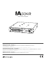 1
1
-
 2
2
-
 3
3
-
 4
4
-
 5
5
-
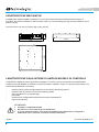 6
6
-
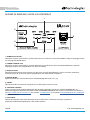 7
7
-
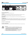 8
8
-
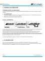 9
9
-
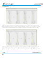 10
10
-
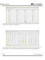 11
11
-
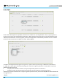 12
12
-
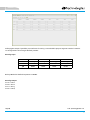 13
13
-
 14
14
-
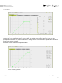 15
15
-
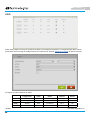 16
16
-
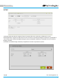 17
17
-
 18
18
-
 19
19
-
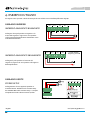 20
20
-
 21
21
-
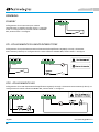 22
22
-
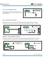 23
23
-
 24
24
-
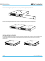 25
25
-
 26
26
-
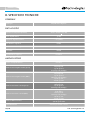 27
27
-
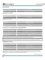 28
28
-
 29
29
-
 30
30
-
 31
31
-
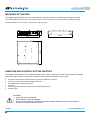 32
32
-
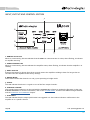 33
33
-
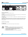 34
34
-
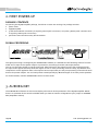 35
35
-
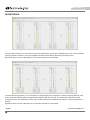 36
36
-
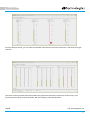 37
37
-
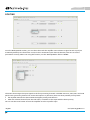 38
38
-
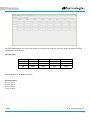 39
39
-
 40
40
-
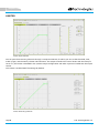 41
41
-
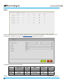 42
42
-
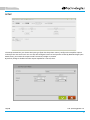 43
43
-
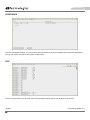 44
44
-
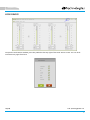 45
45
-
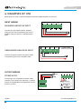 46
46
-
 47
47
-
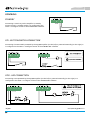 48
48
-
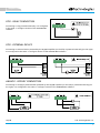 49
49
-
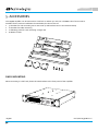 50
50
-
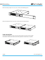 51
51
-
 52
52
-
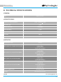 53
53
-
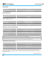 54
54
-
 55
55
-
 56
56
-
 57
57
-
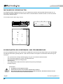 58
58
-
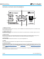 59
59
-
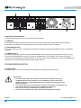 60
60
-
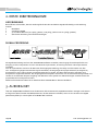 61
61
-
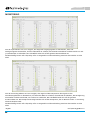 62
62
-
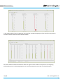 63
63
-
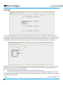 64
64
-
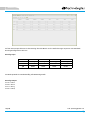 65
65
-
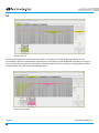 66
66
-
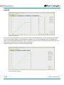 67
67
-
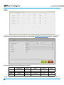 68
68
-
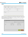 69
69
-
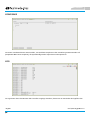 70
70
-
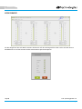 71
71
-
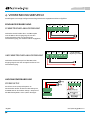 72
72
-
 73
73
-
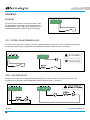 74
74
-
 75
75
-
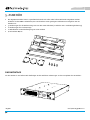 76
76
-
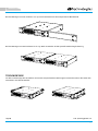 77
77
-
 78
78
-
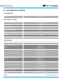 79
79
-
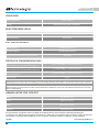 80
80
-
 81
81
-
 82
82
-
 83
83
-
 84
84
-
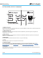 85
85
-
 86
86
-
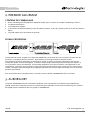 87
87
-
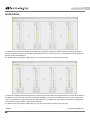 88
88
-
 89
89
-
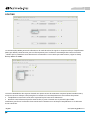 90
90
-
 91
91
-
 92
92
-
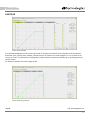 93
93
-
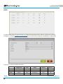 94
94
-
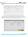 95
95
-
 96
96
-
 97
97
-
 98
98
-
 99
99
-
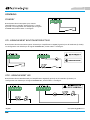 100
100
-
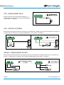 101
101
-
 102
102
-
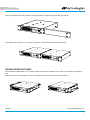 103
103
-
 104
104
-
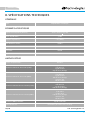 105
105
-
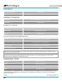 106
106
-
 107
107
-
 108
108
-
 109
109
-
 110
110
-
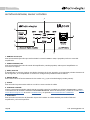 111
111
-
 112
112
-
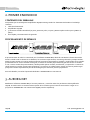 113
113
-
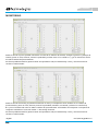 114
114
-
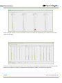 115
115
-
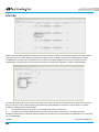 116
116
-
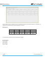 117
117
-
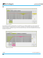 118
118
-
 119
119
-
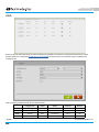 120
120
-
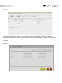 121
121
-
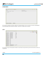 122
122
-
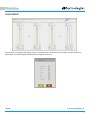 123
123
-
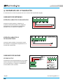 124
124
-
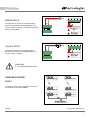 125
125
-
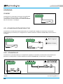 126
126
-
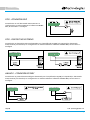 127
127
-
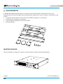 128
128
-
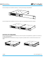 129
129
-
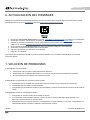 130
130
-
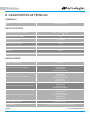 131
131
-
 132
132
-
 133
133


dBTechnologies IA504 R El manual del propietario
- Categoría
- Amplificador de instrumentos musicales
- Tipo
- El manual del propietario
en otros idiomas
Artículos relacionados
-
dBTechnologies VIO X310 El manual del propietario
-
-
-
-
dB Technologies OPERA UNICA 15 El manual del propietario
-
dBTechnologies IS5T El manual del propietario
-
-
-
-
 dB VIOS118 Manual de usuario

