dBTechnologies VIO X310 El manual del propietario
- Categoría
- Equipo de música suplementario
- Tipo
- El manual del propietario

MANUALE D’USO – Sezione 1
Le avvertenze nel presente manuale devono essere osservate congiuntamente al “MANUALE D’USO - Sezione 2”.
USER MANUAL - Section 1
The warnings in this manual must be observed in conjunction with the “USER MANUAL - Section 2”.
BEDIENUNGSANLEITUNG – Abschnitt 1
Die Hinweise in der vorliegenden Bedienungsanleitung sind ebenso zu befolgen wie die in der „BEDIENUNGSANLEITUNG – Abschnitt 2“.
MANUEL D’UTILISATION – Section 1
Respecter à la fois les avertissements donnés dans ce document et dans le MANUEL D’UTILISATION - Section 2.
MANUAL DE USO – Sección 1
Respete las advertencias de este manual y los contenidos del “MANUAL DE USO - Sección 2”.
Professional Active 3-Way Loudspeaker

II
VIO X310 Cod. 420120424 REV. 1.0
EMI CLASSIFICATION
According to the standards EN 55032 and 55035 this is a class A equipment, designed and suitable to operate in
residential environments.
FCC CLASS A STATEMENT ACCORDING TO TITLE 47, PART 15, SUBPART B, §15.105
This equipment has been tested and found to comply with the limits for a Class A digital device, pursuant to part
15 of the FCC Rules. These limits are designed to provide reasonable protection against harmful interference in
a commercial environment. This equipment generates, uses and can radiate radio frequency energy and, if not
installed and used in accordance with the instruction manual, may cause harmful interference to radio communi-
cations. Operation of this equipment in a residential area is likely to cause harmful interference in which case the
user will be required to correct the interference at his own expense.
WARNING: Make sure that the loudspeaker is securely installed in a stable position to avoid any injuries or dam-
ages to persons or properties. For safety reasons do not place one loudspeaker on top of another without proper
fastening systems. Before hanging the loudspeaker check all the components for damages, deformations, missing
or damaged parts that may compromise safety during installation. If you use the loudspeakers outdoor avoid spots
exposed to bad weather conditions. Contact dB Technologies for accessories to be used with speakers. dBTech-
nologies will not accept any responsibility for damages caused by inappropriate accessories or additional devices.
Features, specication and appearance of products are subject to change without notice. dBTechnologies reserves the right to
make changes or improvements in design or manufacturing without assuming any obligation to change or improve products
previously manufactured.
WARNING
Only expert personnel may use the product and its accessories! To prevent hazards to people, animals and/or objects, make sure that
the installation is stable and secure. Comply with the safety regulations and laws in force in the country in which you use the product.
For safe use, periodically check that all parts are in good working condition before use. Only authorised personnel may carry out de-
sign, calculations, installation, testing and maintenance of professional own or stacked audio systems. AEB Industriale shall not
be liable for improper installation carried out without adequate safety measures. Never suspend the speakers from the handles!
Only use the accessories and congurations described in this manual, and proceed in accordance with the instructions given in the
manuals for the accessories. Do not obstruct the amplier cooling ns at the back. In the event of overheating, the audio volume is gra-
dually reduced until the module is thermally stable. The level is automatically restored on reaching the correct operating temperature.
Do not attempt to open the amplier. In the event of malfunction, immediately turn off the power, disconnect the unit from the mains and
contact an authorised service centre. Only use the power cable provided. The USB SERVICE DATA connection is to be used exclusively for upda-
ting the product’s rmware; do not connect any other USB device to the unit to avoid the risk of damage and malfunction. Do not use the
monitor for a prolonged period with the limiter LED steadily lit or ashing as this indicates operation under stress with excessive distortion.
Check periodically the integrity and the functionality of the accessories and the technical equipments for a safe installation. user should never
apply a load that exceeds the working load limits of any rigging components or equipment here presented. design, calculation, installation,
testing and maintanance of suspension and stack systems for audio equipment must be performed only by qualied and authorized personnel.
AEB Industriale s.r.l. denies any and all responsibility for improper installations, in the absence of safety requirements.

III
VIO X310 Cod. 420120424 REV. 1.0
IMPORTANT SAFETY INSTRUCIONS:
1. Read these instructions
2. Keep these instructions.
3. Heed all warnings.
4. Follow all instructions.
5. Do not use this apparatus near water.
6. Clean only with dry cloth.
7. Do not block any ventilation openings. Install in accordance with the manufacturer’s instructions.
8. Do not install near any heat sources such as radiators, heat registers, stoves, or other apparatus (including
ampliers) that produce heat.
9. Do not defeat the safety purpose of the polarized or grounding-type plug. A polarized plug has two
blades with one wider than the other. A grounding type plug has two blades and a third grounding
prong. The wide blade or the third prong are provided for your safety. If the provided plug does not t
into your outlet, consult an electrician for replacement of the obsolete outlet.
10. Protect the power cord from being walked on or pinched particularly at plugs, convenience receptacles,
and the point where they exit from the apparatus.
11. Only use attachments/accessories specied by the manufacturer.
12. Use only with the cart, stand tripod, bracket, or table specied by the manufacturer, or sold
with the apparatus. When a cart is used, use caution, when moving the cart/apparatus combi-
nation to avoid injury from tip-over.
13. Unplug this apparatus during lightning storms or when unused for long periods of time.
14. Refer all servicing to qualied service personnel. Servicing is required when the apparatus has been dam-
aged in any way, such as power-supply cord or plug is damaged, liquid has been spilled or objects have
fallen into the apparatus the apparatus has been exposed to rain or moisture, does not operate normally,
or has been dropped.
ADDITIONAL SAFETY INSTRUCTIONS:
• No naked ame sources, such as lighted candles, should be placed on the apparatus
• Do not use the apparatus in tropical climates


Italiano
5
VIO X310 Cod. 420120424 REV. 1.0
INDICE
1. INFORMAZIONI GENERALI .......................................................................................................... 6
BENVENUTI! ..................................................................................................................................6
PANORAMICA INTRODUTTIVA ......................................................................................................6
RIFERIMENTI PER L’UTENTE .......................................................................................................... 6
CARATTERISTICHE MECCANICHE ED ACUSTICHE ........................................................................7
DIMENSIONI E PESO ............................................................................................................................................ 7
COPERTURA ACUSTICA ....................................................................................................................................... 8
MECCANICA ......................................................................................................................................................... 8
ACCESSORI ........................................................................................................................................................... 9
CARATTERISTICHE DELLA SEZIONE DI AMPLIFICAZIONE E DI CONTROLLO ............................10
SEZIONE DI INGRESSO, USCITA E CONTROLLO ................................................................................................ 11
SEZIONE DI ALIMENTAZIONE ............................................................................................................................ 12
2. COLLEGAMENTI ..........................................................................................................................13
COLLEGAMENTO E RILANCIO DELL’ALIMENTAZIONE....................................................................................... 13
COLLEGAMENTO E RILANCIO DEL SEGNALE AUDIO ....................................................................................... 13
COLLEGAMENTO E RILANCIO DEL SEGNALE RDNET ....................................................................................... 14
3. CONTROLLO REMOTO ...............................................................................................................14
4. INSTALLAZIONE E CONFIGURAZIONE .....................................................................................16
CONTENUTO DELLA CONFEZIONE ............................................................................................16
INSTALLAZIONE A MURO ............................................................................................................16
INSTALLAZIONE SU PALO ............................................................................................................17
INSTALLAZIONE APPESA ..............................................................................................................17
5. AGGIORNAMENTO DEL FIRMWARE ........................................................................................18
6. RISOLUZIONE DEI PROBLEMI ....................................................................................................18
7. SPECIFICHE TECNICHE ................................................................................................................19
GENERALE .......................................................................................................................................................... 19
DATI ACUSTICI .................................................................................................................................................... 19
AMPLIFICATORE ................................................................................................................................................. 19
PROCESSORE ...................................................................................................................................................... 19
INTERFACCIA UTENTE ........................................................................................................................................ 19
INGRESSI E USCITE ............................................................................................................................................. 19
SPECIFICHE DI ALIMENTAZIONE (ASSORBIMENTO/INSTALLAZIONE) ............................................................. 20
DIMENSIONI ....................................................................................................................................................... 20

Italiano
6
VIO X310 Cod. 420120424 REV. 1.0
1. INFORMAZIONI GENERALI
BENVENUTI!
Grazie per aver acquistato un prodotto progettato e sviluppato in Italia da dBTechnologies! Questo diffusore
professionale racchiude in sé anni di esperienza ed innovazione nel campo della diffusione sonora, con l’impiego
di soluzioni d’avanguardia in campo acustico, elettronico e di ricerca sui materiali.
PANORAMICA INTRODUTTIVA
VIO X310 è un diffusore attivo a tre vie di tipo point source dalla spiccata versatilità. Le dimensioni e il peso
contenuti e le maniglie integrate permettono di trasportarlo con estrema semplicità; l’installazione è facilitata
dalle meccaniche integrate sui quattro lati che permettono il montaggio in orizzontale e verticale tramite gli
accessori dedicati.
Le basse frequenze sono affidate al doppio woofer da 10” (V.C. 2,5”), mentre il driver coassiale MF-HF è lo stesso
utilizzato sul sistema line array VIO L1610; questi componenti garantiscono una riproduzione estremamente
dettagliata e fedele su tutto lo spettro udibile e in particolare nella parte più critica, il range delle medie
frequenze.
Le caratteristiche principali di VIO X310 sono:
• installazione semplice e veloce
• facilità di trasporto
• grande versatilità
• amplificatore interno di nuova concezione
• grandi potenze sonore
• tromba ruotabile
RIFERIMENTI PER L’UTENTE
Per utilizzare al meglio il vostro diffusore VIO X310 consigliamo di:
• leggere il manuale d’uso Quick start presente nella confezione e questo manuale d’uso completo in ogni
sua parte e conservarlo per tutta la durata di vita del prodotto.
• registrare il prodotto sul sito http://www.dbtechnologies.com nella sezione “SUPPORTO”.
• scaricare ed installare il firmware più aggiornato dal sito http://www.dbtechnologies.com nella sezione
“DOWNLOADS” (vedi il capitolo “AGGIORNAMENTO DEL FIRMWARE”).
• conservare prova d’acquisto e GARANZIA (Manuale d’uso “sezione 2”).

Italiano
7
VIO X310 Cod. 420120424 REV. 1.0
CARATTERISTICHE MECCANICHE ED ACUSTICHE
DIMENSIONI E PESO
Il diffusore VIO X310 è stato progettato con una particolare attenzione all’ottimizzazione di peso e ingombro. Il
peso è di 28 kg, mentre le dimensioni sono:
300 mm (W) x 780 (H) x 430 mm (D)
W
D
H

Italiano
8
VIO X310 Cod. 420120424 REV. 1.0
COPERTURA ACUSTICA
Come mostrato in figura il diffusore VIO X310 ha normalmente una dispersione di 90° in orizzontale (H) e di 40° in
verticale (V). E’ possibile ruotare la tromba per utilizzare lo speaker anche in orizzontale.
MECCANICA
Per un facile trasporto sono presenti due maniglie, nel lato posteriore.
L’ergonomia ed il rapido montaggio (flown o stacked) del diffusore sono garantiti da:
• n.4 meccaniche laterali per fissaggio ad accessori HB-3X10 e VB-3X10
HV

Italiano
9
VIO X310 Cod. 420120424 REV. 1.0
ACCESSORI
Per il trasporto e un montaggio rapido e in sicurezza di VIO X310 sono previsti i seguenti accessori:
HB-3X10,
staffa per il montaggio orizzontale o verticale a muro o
appeso.
VB-3X10,
staffa per il montaggio verticale su palo, su piantana o
appeso.
RC-X3,
protezione anti-pioggia per la sezione amplificatore.
TC-VIOX310,
copertura per il trasporto.

Italiano
10
VIO X310 Cod. 420120424 REV. 1.0
CARATTERISTICHE DELLA SEZIONE DI AMPLIFICAZIONE E DI CONTROLLO
L’amplificatore digitale di nuova generazione Digipro G4®, in classe D, è il cuore del diffusore VIO X310.
Totalmente silenzioso, assicura una potenza di amplificazione di 1400 W RMS.
Tutti gli ingressi e i controlli sono nel pannello preamplificatore, nel retro del box.
Il pannello delle connessioni è caratterizzato da:
• Sezione di Ingresso, Uscita e Controllo
• Sezione di Alimentazione
ATTENZIONE!
• Proteggere il modulo dall’umidità.
• Non tentare in nessun modo di aprire l’amplificatore.
• In caso di malfunzionamento, interrompere immediatamente l’alimentazione, scollegando il
modulo dalla rete, e contattare un centro di assistenza autorizzato.
SEZIONE DI INGRESSO, USCITA E
CONTROLLO
SEZIONE DI ALIMENTAZIONE

Italiano
11
VIO X310 Cod. 420120424 REV. 1.0
SEZIONE DI INGRESSO, USCITA E CONTROLLO
1. USB SERVICE DATA
Grazie a questa porta standard USB di tipo B è possibile,
tramite PC e USB BURNER MANAGER, aggiornare
il firmware del prodotto. Per ulteriori informazioni
consultare il sito http://www.dbtechnologies.com
alla sezione “DOWNLOADS” ed il capitolo
“AGGIORNAMENTO DEL FIRMWARE”.
2. INGRESSO E RILANCIO DELLA CONNESSIONE DI
RETE RDNet, LED DI CONTROLLO RDnet
Sezione compatibile con cavi di rete dotati di connettori
di tipo etherCON/RJ45. In particolare:
• “Data In” è utilizzato per il collegamento con il
segnale di rete proveniente da un dispositivo tipo
RDNet Control 2 o Control 8 oppure dalla porta
Data Out di un altro dispositivo RDNet
• “Data Out” viene utilizzato per il rilancio della
rete ad ulteriori dispositivi in configurazione
daisy-chain
I Led sono relativi al funzionamento in rete (RDNet) del modulo.
In particolare:
• “Link” acceso segnala che la rete RDNet è attiva e ha riconosciuto il dispositivo
• “Active” in modalità lampeggiante indica che il traffico dati è presente
• “Remote Preset Active” avvisa che tutti i controlli locali sul pannello amplificatore sono by-passati dal
controllo remoto RDNet o da una memoria “User” richiamabile dall’utente tramite l’apposito tasto “User”
3. INGRESSO E RILANCIO AUDIO (“Balanced audio”)
Ingresso e uscita compatibili con cavi XLR bilanciati.
In particolare:
• “Input” è utilizzato per il collegamento del segnale audio proveniente da un dispositivo audio;
• “Output Link” per il rilancio del segnale ad altri diffusori in configurazione daisy-chain.
4. DSP Preset
Ruotando questo controllo è possibile modificare la frequenza di taglio del filtro passa alto nei valori: 60, 65, 70,
75, 80, 90 Hz. Nella posizione Fullrange il filtro passa alto non agisce; la posizione Service/User va utilizzata per lo
stato di aggiornamento del firmware o per richiamare un’impostazione USER (vedi il manuale di AURORA Net).
Vedi anche la sezione AGGIORNAMENTO DEL FIRMWARE.
5. SYSTEM TEST:
Effettua un test con segnale sweep (generato dall’amplificatore stesso) per verificare l’integrità dei componenti
acustici del diffusore. Questo test non va considerato esaustivo, ma solo un primo controllo nell’analisi di
eventuali problematiche. Assicurarsi di effettuare il test nelle migliori condizioni possibili, senza ostruire il fronte
dello speaker, liberando il diffusore da eventuali cover davanti alla griglia, per ottenere risultati più affidabili.
6. STATUS LED Main
I LED mostrano indicazioni di stato del diffusore in modo immediato, secondo la logica sintetizzata nella tabella
nella prossima pagina:
5
6
12
3
4

Italiano
12
VIO X310 Cod. 420120424 REV. 1.0
Limiter Signal Status On
Accensione SPENTO SPENTO ACCESO FISSO PER
QUALCHE SECONDO SPENTO
Utilizzo COMPRESSION
LIMITER STATUS
SIGNAL OUTPUT
STATUS SPENTO ACCESO FISSO
Anomalia parziale ATTIVO ATTIVO LAMPEGGIO CICLICO ACCESO FISSO
Anomalia totale LAMPEGGIO CICLICO SPENTO ACCESO FISSO SPENTO
SEZIONE DI ALIMENTAZIONE
7. CONNETTORE DI ALIMENTAZIONE “MAINS INPUT”
Compatibile con connettore powerCON TRUE1®.
Alimentazione full range.
8. RILANCIO DI ALIMENTAZIONE “MAINS LINK”
Compatibile con connettore tipo powerCON TRUE1®
per il rilancio dell’alimentazione ad altri moduli. Per
conoscere il numero massimo di moduli che si possono
connettere in un sistema rilanciato, consultare la
sezione “COLLEGAMENTI” di questo manuale.
9. MAINS FUSE
Alloggio per il fusibile di rete.
• Utilizzare solo il cavo di alimentazione in dotazione o cavi di alimentazione dBTechnologies.
• La connessione USB SERVICE DATA deve essere utilizzata esclusivamente per l’aggiornamento
firmware del prodotto, non connettere nessun dispositivo USB all’apparecchio, per evitare
danneggiamenti o malfunzionamenti.
• Non utilizzare il diffusore per un lungo periodo con il led limiter acceso o lampeggiante, che
indica un funzionamento di stress eccessivo in condizioni di distorsione.
7 8 9

Italiano
13
VIO X310 Cod. 420120424 REV. 1.0
2. COLLEGAMENTI
COLLEGAMENTO E RILANCIO DELL’ALIMENTAZIONE
Su VIO X310 è possibile rilanciare l’alimentazione da un primo diffusore ad uno successivo, fino ad un totale di 8 (7+1)
nei Paesi con tensione di alimentazione 220-240Vac e di 5 (4+1) nei Paesi con tensione di alimentazione 100-120Vac.
Per fornire l’alimentazione è sufficiente collegare il cavo di alimentazione fornito a corredo sull’ingresso MAINS
INPUT del primo diffusore, connettere un secondo cavo con connettori adatti (opzionali) tra l’uscita MAINS LINK e
l’ingresso MAINS INPUT del diffusore successivo e ripetere il collegamento fino al raggiungimento della massima
corrente ammessa e indicata dal connettore MAINS LINK del primo diffusore.
COLLEGAMENTO E RILANCIO DEL SEGNALE AUDIO
Per il collegamento del segnale audio del sistema connettere innanzitutto la sorgente sonora nell’ingresso
“INPUT” del primo diffusore.
Collegare poi con un cavo bilanciato XLR l’uscita “OUTPUT LINK” del primo diffusore all’ingresso “INPUT” del
secondo e così via.
LOUDSPEAKER 2
LOUDSPEAKER 1
POWER SUPPLY
LOUDSPEAKER 2
LOUDSPEAKER 1
AUDIO SOURCE

Italiano
14
VIO X310 Cod. 420120424 REV. 1.0
COLLEGAMENTO E RILANCIO DEL SEGNALE RDNET
Per il controllo remoto, collegare il Data Input del primo diffusore al controller hardware (RDNet Control 2 o
RDNet Control 8) con cavi equipaggiati con connettori etherCON. Quindi connettere il Data Output del primo
diffusore al Data Input del secondo e così via. Una volta accesi i diffusori e dopo aver richiesto “GoOnline” da
software AURORA NET, i LED “Link” indicheranno l’avvenuto collegamento.
I LED “Active” inizieranno a lampeggiare in presenza di traffico dati.
3. CONTROLLO REMOTO
Tramite software AURORA NET è possibile gestire in tempo reale diversi parametri del diffusore VIO X310.
Nel dettaglio:
• Monitorare il segnale in ingresso e in uscita
• Visualizzare l’eventuale presenza di compressione audio sul segnale in uscita e sui componenti acustici
• Attenuare il segnale in ingresso
• Mettere in MUTE driver, midrange e woofer in maniera distinta
• Ascoltare in modalità SOLO driver, midrange e woofer in maniera distinta
• Monitorare la temperatura dell’amplificatore
• Modificare la frequenza di taglio del filtro passa alto
• Salvare impostazioni in preset e richiamarli in seguito da remoto
• Equalizzare lo speaker
• Aggiungere delay
RDNET
CONTROL

Italiano
15
VIO X310 Cod. 420120424 REV. 1.0

Italiano
16
VIO X310 Cod. 420120424 REV. 1.0
4. INSTALLAZIONE E CONFIGURAZIONE
CONTENUTO DELLA CONFEZIONE
Verificate, aprendo la confezione, che il contenuto dell’imballo del diffusore VIO X310 sia completo. L’imballo
contiene:
• cavo di alimentazione con connettore POWERCON® TRUE1
• diffusore VIO X310
• quick start e documentazione relativa alla garanzia
ATTENZIONE!
Il prodotto e gli accessori devono essere utilizzati solo da personale esperto! Assicurarsi
che l’installazione sia posizionata in modo stabile e sicuro per scongiurare ogni condizione
di pericolo per persone, animali e/o cose. L’utilizzatore è tenuto a seguire le
regolamentazioni e le leggi cogenti in materia di sicurezza nel Paese in cui si utilizza il
prodotto. Per l’utilizzo in sicurezza, verificare periodicamente la funzionalità di tutte le
parti e l’integrità prima dell’utilizzo. La progettazione, i calcoli, l’installazione, il collaudo e
la manutenzione di sistemi sospesi o stack audio professionali deve essere effettuata
esclusivamente da personale autorizzato. AEB Industriale non è responsabile per
installazioni improprie, effettuate in assenza dei requisiti di sicurezza.
In questa sezione sono presentati degli esempi di installazione. Per ogni riferimento consultare anche le istruzioni
degli accessori, nonché le prescrizioni riportate su eventuali etichette dei prodotti.
INSTALLAZIONE A MURO
E’ possibile installare il diffusore a muro in verticale o orizzontale (ruotando la tromba) tramite staffa opzionale
HB-3X10. Per ogni ulteriore informazione si prega di consultare il manuale relativo a questo accessorio.
ATTENZIONE!
- Non utilizzare mai le maniglie presenti sul fianco del diffusore per appenderlo ma
servirsi delle staffe e accessori omologati dall’azienda
- In caso di utilizzo all’aperto è sempre consigliabile ancorare il sistema per prevenire
eventuali oscillazioni dovute al vento o agli agenti atmosferici

Italiano
17
VIO X310 Cod. 420120424 REV. 1.0
INSTALLAZIONE SU PALO
E’ possibile installare il diffusore su stativo a treppiede opzionale standard con palo di diametro 35mm sia in
verticale (utilizzando la staffa opzionale VB-3X10) che in orizzontale (ruotando la tromba e utilizzando la staffa
opzionale HB-3X10). La massima altezza ammessa tra la base del diffusore e il pavimento in entrambi i casi è
120cm; per altezze maggiori è necessario prevedere un fissaggio addizionale.
Per ogni ulteriore informazione si prega di consultare il manuale relativo a questo accessorio.
INSTALLAZIONE APPESA
Utilizzando gli accessori HB-3X10 e VB-3X10 e dispositivi Aliscaff (non forniti) è possibile appendere il diffusore a
una struttura tipo americana. Per ogni ulteriore informazione si prega di consultare il manuale relativo a questo
accessorio.

Italiano
18
VIO X310 Cod. 420120424 REV. 1.0
5. AGGIORNAMENTO DEL FIRMWARE
È molto importante mantenere aggiornato il firmware del prodotto, per garantirne una piena funzionalità.
Controllare periodicamente il sito http://www.dbtechnologies.com nella sezione “DOWNLOADS”.
1. Scaricare ed installare USB BURNER MANAGER nella sezione “SOFTWARE & CONTROLLER” sul proprio
computer.
2. Scaricare il file .zip dell’ultimo firmware nella sezione “DOWNLOADS” relativa al proprio prodotto.
3. Collegare il prodotto al PC tramite un cavo USB (non fornito) con il connettore del tipo corretto (vedere
questo dettaglio nel capitolo ”CARATTERISTICHE DELLA SEZIONE DI AMPLIFICAZIONE E DI CONTROLLO”)
4. Nella schermata dell’USB BURNER MANAGER, in alto a destra, selezionare “Apertura File”.
5. Selezionare il file del firmware precedentemente scaricato.
6. Seguire le operazioni mostrate a video.
7. Cliccare “AGGIORNA”.
È possibile aggiornare il firmware del prodotto anche tramite software AURORA NET, nella sezione Firmware
Update.
6. RISOLUZIONE DEI PROBLEMI
Il diffusore non si accende:
1. Verificare la corretta presenza dell’alimentazione a monte dell’impianto.
2. Verificare che il cavo di alimentazione con connettore POWERCON® TRUE1 sia correttamente inserito.
3. In caso il problema persista, contattare l’assistenza.
Il diffusore si accende ma non emette nessun suono:
1. Verificare che i collegamenti in ingresso del segnale audio siano correttamente effettuati, utilizzare
preferibilmente cavi con connettori Neutrik®.
2. Verificare che i cavi utilizzati non siano danneggiati.
3. Verificare che il mixer o la sorgente audio sia accesa e mostri chiaramente la presenza di segnale in uscita.
Il diffusore emette un suono distorto:
1. A impianto acceso, regolare per primo il volume della sorgente. Se il led di LIMITER della sorgente è
acceso, il segnale potrebbe arrivare al diffusore già in condizioni di distorsione.
2. Verificare che i cavi utilizzati non siano danneggiati, nel qual caso sostituirli (un cavo danneggiato può
portare a perdita o alterazione del segnale).
3. Verificare le impostazioni del preset memorizzato sul pulsante Service/User che influisce sulla risposta in
frequenza in uscita.

Italiano
19
VIO X310 Cod. 420120424 REV. 1.0
7. SPECIFICHE TECNICHE
GENERALE
Tipologia: diffusore attivo 3 vie
DATI ACUSTICI
Risposta in frequenza [-6 dB]: 57 - 19200 Hz
Max SPL (@ 1m): 138 dB
HF-MF exit: 1,4"
HF Voice Coil: 4” - 2.5”
Frequenza di crossover: 540 Hz (LF-MF) - 4 kHz (MF-HF) 24 dB/oct
Copertura (HxV): 90° x 40° (ruotabile)
LF: 2 x 10”
LF Voice Coil: 2,5”
AMPLIFICATORE
Tipologia: Digipro G4
Classe di amplificazione: Classe D (4 ch.)
Potenza di picco: 2800 W
Potenza RMS: 1400 W
Alimentazione: Full range PFC
Tecnica di raffreddamento: Convenzione passiva
PROCESSORE
Calcolo interno: DSP 32 bit
Convertitore A/D D/A: 24 bit / 96 kHz
Limiter: Dual Active Peak, RMS, Termico
INTERFACCIA UTENTE
Presets: Full range, HPF (60, 65, 70, 75, 80, 90 Hz), Service/User
Controlli: Rotary encoder (Preset),
4 System LED, 3 RDNet LED
INGRESSI E USCITE
Ingressi audio: XLR
Uscite audio: XLR Link OUT
USB (aggiornamento del firmware): USB di tipo B

Italiano
20
VIO X310 Cod. 420120424 REV. 1.0
SPECIFICHE DI ALIMENTAZIONE (ASSORBIMENTO/INSTALLAZIONE)
Assorbimento a 1/8 della potenza in condizioni medie
di utilizzo (*):
1.5 A @115V A
0.8 A @230V AC
Assorbimento a 1/3 della potenza in condizioni
pesanti di utilizzo (**):
3.7 A @115V AC
1.8 A @230V AC
Assorbimento con speaker acceso in assenza di
segnale (idle):
0.28 A @115 V AC
0.25 A @ 230 V AC
Corrente di inrush: 31.7 A
Corrente e potenze totali ammesse in un sistema
rilanciato:
16.3 A - 1800 W (100-120V)
14.2 A - 3200 W (220-240V)
* NOTA PER L’INSTALLATORE: Valori riferiti a 1/8 della potenza, in condizioni medie di funzionamento (programma
musicale con clipping raro o assente). Si consiglia per qualsiasi tipo di configurazione di considerarli i valori minimi di
dimensionamento.
** NOTA PER L’INSTALLATORE: Valori riferiti a 1/3 della potenza, in condizioni pesanti di funzionamento (programma
musicale con frequente clipping e intervento del limiter). E’ consigliabile il dimensionamento secondo questi valori in caso
di installazioni e tour professionali.
DIMENSIONI
Materiale: Legno multistrato con vernice poliuretanica
Griglia: Metallo verniciato / lavorazione CNC
Montaggio flown e stacked: Con accessori HB-3X10 e VB-3X10
Maniglie: Integrate (2 nel lato posteriore)
Montaggio su palo: SI tramite staffa opzionale
Larghezza: 300 mm (11.8 inch.)
Altezza: 780 mm (30.7 inch.)
Profondità: 430 mm (16.9 inch.)
Peso: 28 kg (61.5 lbs.)
Caratteristiche, specifiche e aspetto dei prodotti sono soggetti a possibili cambiamenti senza previa
comunicazione. dBTechnologies si riserva il diritto di apportare cambiamenti o miglioramenti nel design o nelle
lavorazioni senza assumersi l’obbligo di cambiare o migliorare anche i prodotti precedentemente realizzati.
A.E.B. Industriale Srl
Via Brodolini, 8
Località Crespellano
40053 VALSAMOGGIA
BOLOGNA (ITALIA)
Tel +39 051 969870
Fax +39 051 969725
www.dbtechnologies.com

English
21
VIO X310 Cod. 420120424 REV. 1.0
CONTENTS
1. GENERAL INFORMATION ..........................................................................................................22
WELCOME! ..................................................................................................................................22
INTRODUCTORY OVERVIEW .......................................................................................................22
USER INFORMATION ...................................................................................................................22
MECHANICAL AND ACOUSTIC FEATURES ..................................................................................29
DIMENSIONS AND WEIGHT .............................................................................................................................. 29
ACOUSTIC COVERAGE ....................................................................................................................................... 24
MECHANICAL FEATURES ................................................................................................................................... 24
ACCESSORIES .....................................................................................................................................................25
AMPLIFIER AND CONTROL SECTION FEATURES ........................................................................26
INPUT, OUTPUT AND CONTROL SECTION ........................................................................................................ 27
POWER SUPPLY SECTION .................................................................................................................................. 28
2. CONNECTIONS ............................................................................................................................29
CONNECTING AND LINKING THE POWER SUPPLY........................................................................................... 29
CONNECTING AND LINKING THE AUDIO SIGNAL ............................................................................................ 29
CONNECTING AND LINKING THE RDNET SIGNAL ............................................................................................ 30
3. REMOTE CONTROL ..................................................................................................................... 30
4. INSTALLATION AND CONFIGURATION ....................................................................................32
PACKAGE CONTENTS ...................................................................................................................32
WALL MOUNTING ........................................................................................................................32
POLE MOUNTING ........................................................................................................................33
FLOWN MOUNTING ....................................................................................................................33
5. UPDATING THE FIRMWARE.......................................................................................................34
6. TROUBLESHOOTING ..................................................................................................................34
7. TECHNICAL SPECIFICATIONS .....................................................................................................35
GENERAL ............................................................................................................................................................ 35
ACOUSTIC DATA ................................................................................................................................................. 35
AMPLIFIER .......................................................................................................................................................... 35
PROCESSOR ........................................................................................................................................................ 35
USER INTERFACE ................................................................................................................................................ 35
INPUTS AND OUTPUTS ...................................................................................................................................... 35
POWER SUPPLY SPECIFICATIONS (POWER CONSUMPTION/INSTALLATION) .................................................. 36
DIMENSIONS ...................................................................................................................................................... 36

English
22
VIO X310 Cod. 420120424 REV. 1.0
1. GENERAL INFORMATION
WELCOME!
Thanks for purchasing a product that was designed and developed in Italy by dBTechnologies! This professional
speaker embodies years of experience and innovation in the field of sound reproduction, with the use of cutting
edge solutions in the fields of acoustics, electronics and materials research.
INTRODUCTORY OVERVIEW
VIO X310 is a highly versatile 3-way active speaker of the point source type. Its small size and weight and the
built-in handles make it easy to transport. It has built-in mechanical devices on the four sides for horizontal and
vertical mounting with special accessories.
The low frequencies are handled by the dual 10” woofer (2.5” V.C.), while the MF-HF coaxial driver is the same
as that used on the VIO L1610 line array system. These components ensure extremely detailed and faithful
reproduction over the whole audible spectrum, especially in the most critical part, the mid-frequency range.
The main characteristics of this VIO X310 are:
• quick and easy installation
• easy to transport
• great versatility
• newly designed internal amplifier
• high sound powers
• rotatable horn
USER INFORMATION
To use your VIO X310 speaker in the best way, we recommend that you:
• read the Quick Start manual included in the package and all of this User Manual, and keep them
throughout the entire life of the product.
• register the product in the “SUPPORT” section at the http://www.dbtechnologies.com website.
• download and install the latest version of the firmware from the “DOWNLOADS” section of the http://www.
dbtechnologies.com website (see the UPDATING THE FIRMWARE chapter).
• keep proof of purchase and the WARRANTY (User manual “section 2”).

English
23
VIO X310 Cod. 420120424 REV. 1.0
MECHANICAL AND ACOUSTIC FEATURES
DIMENSIONS AND WEIGHT
The VIO X310 speaker has been designed with particular attention to optimising its weight and overall size. It
weighs 28 kg, and its dimensions are:
300 mm (W) x 780 (H) x 430 mm (D).
W
D
H

English
24
VIO X310 Cod. 420120424 REV. 1.0
ACOUSTIC COVERAGE
As shown in the figure, the VIO X310 has a horizontal coverage (H) of 90° and vertical coverage (V) of 40°. The
horn is rotatable.
MECHANICAL FEATURES
There are two handles at the rear for easy transport.
Speaker ergonomics and quick installation (flown or stacked) are ensured by:
• 4 mechanical devices at the sides for fastening with HB-3X10 and VB-3X10 accessories
HV

English
25
VIO X310 Cod. 420120424 REV. 1.0
ACCESSORIES
The following accessories are provided for transporting and quickly installing the VIO X310 safely:
HB-3X10,
bracket for horizontal or vertical wall or suspended
mounting.
VB-3X10,
bracket for vertical pole, stand or suspended mounting.
RC-X3,
rain-proof protection for the amplifier section.
TC-VIOX310,
transport cover.

English
26
VIO X310 Cod. 420120424 REV. 1.0
AMPLIFIER AND CONTROL SECTION FEATURES
The new generation Digipro G4® Class D digital amplifier is the heart of the VIO X310 speaker. Totally silent, it
delivers amplification power of 1400 W RMS.
All the inputs and controls are grouped together on the preamp panel.
The connection panel features:
• Input, Output and Control section
• Power supply section
CAUTION!
• Protect the unit from moisture.
• Do not attempt to open the amplifier.
• In the event of malfunction, immediately turn off the power, disconnect the unit from the
mains and contact an authorised service centre.
INPUT, OUTPUT AND CONTROL SECTION
POWER SUPPLY SECTION

English
27
VIO X310 Cod. 420120424 REV. 1.0
INPUT, OUTPUT AND CONTROL SECTION
1. USB SERVICE DATA
Using this standard type B USB port, you can
update the product’s firmware using a PC and USB
BURNER MANAGER. For further information, refer
to the “DOWNLOADS” section of the http://www.
dbtechnologies.com website and the “UPDATING THE
FIRMWARE” chapter.
2. RDnet NETWORK CONNECTION INPUT AND
LINKING, RDNet STATUS LEDs
Section compatible with network cables fitted with
etherCON/RJ45 connectors. In particular:
• “Data In” is used to connect the network signal
from a device such as RDNet Control 2 or Control
8, or from the Data Out port of another RDNet
device
• “Data Out” is used to link the network to other
devices in a daisy-chain configuration.
The LEDs indicate the network (RDNet) operating status
of the monitor.
In particular:
• Link” illuminates to indicate that the RDNet network is active and has recognised the device
• “Active” flashes to indicate the presence of data traffic
• “Remote Preset Active” warns that all local controls on the amplifier panel are bypassed by the RDNet
remote control or by a “User” memory, which can be loaded by pressing the “User” button
3. AUDIO INPUT AND LINKING (“Balanced audio”)
Input and output compatible with balanced XLR cables.
In particular:
• “Input” is used to connect the audio signal from an audio device;
• “Output Link” is used to link the signal to other speakers in a daisy-chain configuration.
4. DSP Preset
Turning this control selects the high pass filter cut-off frequency from the following values: 60, 65, 70, 75, 80, 90
Hz. In the Fullrange position, the high-pass filter has no effect. The Service/User position is used for the firmware
update status or to recall a USER setting (see the AURORA Net manual). See also the UPDATING THE FIRMWARE
section.
5. SYSTEM TEST:
Carries out a test using a sweep signal (generated by the amplifier) to check that the acoustic components
of the speaker are in good working condition. This test should not be considered exhaustive, but just a first
troubleshooting check. For more reliable results, be sure to test under the best possible conditions, without
obstructing the front of the speaker, and with the speaker free of any covers in front of the grille.
6. STATUS LED Main
The LEDs provide an immediate indication of the speaker status, in accordance with the logic summarised on the
next page:
5
6
12
3
4

English
28
VIO X310 Cod. 420120424 REV. 1.0
Limiter Signal Status On
Power up OFF OFF STEADILY LIT FOR A
FEW SECONDS OFF
Use COMPRESSION
LIMITER STATUS
SIGNAL OUTPUT
STATUS OFF STEADILY LIT
Partial malfunction ACTIVE ACTIVE CYCLIC FLASHING STEADILY LIT
Total malfunction CYCLIC FLASHING OFF STEADILY LIT OFF
POWER SUPPLY SECTION
7. “MAINS INPUT” POWER SUPPLY CONNECTOR
Compatible with powerCON TRUE1® connectors. Full-
range power supply.
8. “MAINS LINK” POWER SUPPLY LINK
Compatible with powerCON TRUE1® connectors to link
the power supply to other modules. To find out how
many modules can be connected in a linked system,
refer to the “CONNECTIONS” section in this manual.
9. MAINS FUSE
Mains fuse holder.
CAUTION!
• Only use the power cable provided or other dBTechnologies power cables.
• The USB SERVICE DATA connection is to be used exclusively for updating the product’s
firmware; do not connect any other USB device to the unit to avoid the risk of damage and
malfunction.
• Do not use the monitor for a prolonged period with the limiter LED steadily lit or flashing as
this indicates operation under stress with excessive distortion.
7 8 9

English
29
VIO X310 Cod. 420120424 REV. 1.0
2. CONNECTIONS
CONNECTING AND LINKING THE POWER SUPPLY
On the VIO X310, you can link the power supply from the first speaker to the next, up to a total of 8 (7+1) in countries
with a 220–240Vac mains supply, and up to 5 (4+1) in countries with a 100–120Vac mains supply.
To supply power, simply connect the power cable provided to the MAINS INPUT on the first speaker and connect a
second cable with suitable connectors (optional) from the MAINS LINK output to the MAINS INPUT of the next speaker.
Repeat the connection to supply up to the maximum permissible current specified on the MAINS LINK connector of the
first speaker.
CONNECTING AND LINKING THE AUDIO SIGNAL
When connecting the system audio signal, connect the sound source to the “INPUT” of the first speaker first of all.
Then connect a balanced XLR cable from the “OUTPUT LINK” of the first monitor to the “INPUT” of the second,
and so on.
LOUDSPEAKER 2
LOUDSPEAKER 1
POWER SUPPLY
LOUDSPEAKER 2LOUDSPEAKER 1
AUDIO SOURCE

English
30
VIO X310 Cod. 420120424 REV. 1.0
CONNECTING AND LINKING THE RDNET SIGNAL
To enable remote control, connect the Data Input of the first speaker to the hardware interface (RDNet Control
2 or RDNet Control 8) using cables fitted with etherCON connectors. Then connect the Data Output of the first
speaker to the Data Input of the second, and so on. Power up the speakers and make a “GoOnline” request in the
AURORA NET software; the “Link” LEDs will confirm that they are connected.
The “Active” LEDs will start flashing to indicate that there is data traffic.
3. REMOTE CONTROL
The AURORA NET software lets you manage several parameters of the VIO X310 speaker in real time.
In detail:
• Monitor the input and output signals
• View if there is audio compression on the output signal and acoustic components
• Attenuate the input signal
• MUTE the driver, midrange and woofer separately
• SOLO the driver, midrange and woofer separately
• Monitor the temperature of the amplifier
• Select the high pass filter cut-off frequency
• Save settings as presets for subsequent remote recall
• Equalise the speaker
• Add delay
RDNET
CONTROL

English
31
VIO X310 Cod. 420120424 REV. 1.0

English
32
VIO X310 Cod. 420120424 REV. 1.0
4. INSTALLATION AND CONFIGURATION
PACKAGE CONTENTS
On opening the VIO X310 monitor package, check that no items are missing. The package contains:
• power cable with POWERCON® TRUE1 connector
• VIO X310 speaker
• quick start manual and warranty documentation
CAUTION!
Only expert personnel may use the product and its accessories! To prevent hazards to
people, animals and/or objects, make sure that the installation is stable and secure. Comply
with the safety regulations and laws in force in the country in which you use the product.
For safe use, periodically check that all parts are in good working condition before use.
Only authorised personnel may carry out design, calculations, installation, testing and
maintenance of professional flown or stacked audio systems. AEB Industriale shall not be
liable for improper installation carried out without adequate safety measures.
This section illustrates some installation examples. Also consult the instructions for the accessories, as well as any
prescriptions reported on the product labels.
WALL MOUNTING
The speaker can be wall mounted horizontally or vertically using the optional HB-3X10 bracket. For further
information, refer to the specific manual for the accessory.
CAUTION!
• Never hang the subwoofer from the handles on the sides! Always use brackets and
accessories approved by the manufacturer
• If the speaker is to be used outdoors, we recommend that the system is securely
anchored to prevent movement due to wind or atmospheric agents

English
33
VIO X310 Cod. 420120424 REV. 1.0
POLE MOUNTING
The speaker can be mounted either vertically (using the optional VB-3X10 bracket) or horizontally (using the
optional HB-3X10 bracket) on the optional standard tripod stand with a 35 mm diameter pole. In either case, the
maximum permissible height of the speaker base from the floor is 120 cm; additional fastening is required for
higher heights.
For further information, refer to the specific manual for the accessory.
FLOWN MOUNTING
The speaker can be suspended from a truss adapter using the HB-3X10 and VB-3X10 accessories and Aliscaff
equipment (not supplied). For further information, refer to the specific manual for the
accessory.

English
34
VIO X310 Cod. 420120424 REV. 1.0
5. UPDATING THE FIRMWARE
It is very important to keep the product firmware updated to ensure full functionality. Periodically check the
“DOWNLOADS” section of the http://www.dbtechnologies.com website.
1. Download and install the USB BURNER MANAGER onto your computer from the “SOFTWARE &
CONTROLLER” section.
2. Download the .zip file of the latest firmware for your product from the “DOWNLOADS” section.
3. Connect the product to the PC using a USB cable (not supplied) with the correct connector type (see this
detail in the “AMPLIFIER AND CONTROL SECTION FEATURES” chapter)
4. Select “Open File” at the top right of the USB BURNER MANAGER screen.
5. Select the previously downloaded firmware file.
6. Follow the instructions shown on the screen.
7. Click “UPDATE”.
You can also update the product firmware from the Firmware Update section of the AURORA NET software.
6. TROUBLESHOOTING
The speaker does not power up:
1. Check that the system is connected to a working power supply.
2. Check that the power cable with the POWERCON® TRUE1 connector is plugged in correctly.
3. If the problem persists, contact an authorised service centre.
The monitor turns on but does not produce any sound:
1. Check that the audio signal inputs are connected correctly, preferably using cables with Neutrik®
connectors.
2. Check that the cables used are not damaged.
3. Check that the mixer or audio source is on and clearly shows an output signal.
The sound from the monitor is distorted:
1. With the system powered on, first adjust the volume of the audio source. If the source LIMITER LED is on,
the signal may already be distorted before it reaches the speaker.
2. Check that the connection cables are not damaged. If they are, replace them (a damaged cable may cause
signal loss or alteration).
3. Check the preset EQ saved on the Service/User button that alters the frequency response of the output
signal.

English
35
VIO X310 Cod. 420120424 REV. 1.0
7. TECHNICAL SPECIFICATIONS
GENERAL
Type: 3-way active speaker
ACOUSTIC DATA
Frequency response [-6 dB]: 57 - 19200 Hz
Max SPL (@ 1m): 138 dB
HF-MF exit: 1,4"
HF Voice Coil: 4” - 2.5”
Crossover frequency: 540 Hz (LF-MF) - 4 kHz (MF-HF) 24 dB/oct
Coverage (HxV): 90° x 40° (rotatable)
LF: 2 x 10”
LF Voice Coil: 2,5”
AMPLIFIER
Type: Digipro G4
Amplification class: Classe D (4 ch.)
Peak power: 2800 W
RMS power: 1400 W
Power supply: Full range PFC
Cooling method: Passive convection
PROCESSOR
Internal processing: DSP 32 bit
A/D D/A converter: 24 bit / 96 kHz
Limiter: Dual Active Peak, RMS, Thermal
USER INTERFACE
Presets: Full range, HPF (60, 65, 70, 75, 80, 90 Hz), Service/User
Controls: Rotary encoder (Preset),
4 System LED, 3 RDNet LED
INPUTS AND OUTPUTS
Audio inputs: XLR
Audio outputs: XLR Link OUT
USB (firmware update): type B USB

English
36
VIO X310 Cod. 420120424 REV. 1.0
POWER SUPPLY SPECIFICATIONS (POWER CONSUMPTION / INSTALLATION)
Power consumption at 1/8 power in medium use
conditions (*):
1.5 A @115V A
0.8 A @230V AC
Power consumption at 1/3 power in heavy use
conditions
3.7 A @115V AC
1.8 A @230V AC
Power consumption with speaker on but no signal
(idle):
0.28 A @115 V AC
0.25 A @ 230 V AC
Inrush current: 31.7 A
Total permissible current and power in a linked
system:
16.3 A - 1800 W (100-120V)
14.2 A - 3200 W (220-240V)
* NOTE FOR THE INSTALLER: Values refer to 1/8 power under normal operating conditions (music program with
rare or no clipping). For any configuration type, we recommend considering them to be the minimum values for
dimensioning.
** NOTE FOR THE INSTALLER: Values refer to 1/3 power under heavy operating conditions (music program with frequent
clipping and limiting). We recommend dimensioning in accordance with these values for professional installations and
tours.
DIMENSIONS
Material: Coated plywood cabinet with polyurea finish
Grille: Painted metal / CNC machined
Flown and stacked installation: With HB-3X10 and VB-3X10 accessories
Handles: Built in (2 at the rear)
Pole mounting: Yes using optional bracket
Width: 300 mm (11.8 inch.)
Height: 780 mm (30.7 inch.)
Depth: 430 mm (16.9 inch.)
Weight: 28 kg (61.5 lbs.)
Product features, specifications and appearance are subject to change without prior notice. dBTechnologies
reserves the right to make changes or improvements in design or manufacturing without any obligation to change
or improve previously manufactured products.
A.E.B. Industriale Srl
Via Brodolini, 8
Località Crespellano
40053 VALSAMOGGIA
BOLOGNA (ITALIA)
Tel +39 051 969870
Fax +39 051 969725
www.dbtechnologies.com

Deutsch
37
VIO X310 Cod. 420120424 REV. 1.0
INHALTSVERZEICHNIS
1. GENERAL INFORMATION ..........................................................................................................38
WILLKOMMEN! ...........................................................................................................................38
KURZBESCHREIBUNG ...................................................................................................................38
HINWEISE FÜR DEN BENUTZER ..................................................................................................38
MECHANISCHE UND AKUSTISCHE EIGENSCHAFTEN .................................................................39
ABMESSUNGEN UND GEWICHT ........................................................................................................................ 39
ABSTRAHLWINKEL ............................................................................................................................................. 40
MECHANIK ......................................................................................................................................................... 40
ZUBEHÖR ...........................................................................................................................................................41
EIGENSCHAFTEN DES VERSTÄRKER- UND STEUERBEREICHS ....................................................42
EINGANGS-, AUSGANGS- UND STEUERBEREICH .............................................................................................. 43
STROMVERSORGUNGSTEIL ............................................................................................................................... 44
2. ANSCHLÜSSE ...............................................................................................................................45
ANSCHLUSS UND WEITERLEITUNG DER STROMVERSORGUNG ...................................................................... 45
ANSCHLUSS UND WEITERLEITUNG DES AUDIOSIGNALS ................................................................................. 45
ANSCHLUSS UND WEITERLEITUNG DES RDNET-SIGNALS ................................................................................ 46
3. FERNSTEUERUNG .......................................................................................................................46
4. INSTALLATION UND KONFIGURATION ....................................................................................48
LIEFERUMFANG ...........................................................................................................................48
WANDMONTAGE .........................................................................................................................48
MONTAGE AUF STÄNDER ............................................................................................................49
HÄNGEINSTALLATION ..................................................................................................................49
5. FIRMWAREAKTUALISIERUNG ...................................................................................................50
6. FEHLERBEHEBUNG .....................................................................................................................50
7. TECHNISCHE DATEN ................................................................................................................... 51
ALLGEMEINES .................................................................................................................................................... 51
AKUSTISCHE DATEN ........................................................................................................................................... 51
VERSTÄRKER ...................................................................................................................................................... 51
PROZESSOR ........................................................................................................................................................ 51
BENUTZEROBERFLÄCHE .................................................................................................................................... 51
EIN- UND AUSGÄNGE ........................................................................................................................................ 51
STROMSPEZIFIKATIONEN (AUFNAHME/INSTALLATION) .................................................................................. 52
ABMESSUNGEN .................................................................................................................................................. 52

Deutsch
38
VIO X310 Cod. 420120424 REV. 1.0
1. ALLGEMEINE HINWEISE
WILLKOMMEN!
Danke, dass Sie ein Produkt erworben haben, das von dBTechnologies in Italien entworfen und entwickelt
wurde! Dieser professionelle Lautsprecher ist das Ergebnis langjähriger Erfahrung und Innovation im Bereich
der Soundsysteme. Er bietet fortschrittliche Lösungen in Sachen Akustik und Elektronik sowie im Hinblick auf die
Materialauswahl.
KURZBESCHREIBUNG
VIO X310 ist ein äußerst vielseitiger Dreiwege-Aktiv-Punktquellenlautsprecher. Die kompakte Größe und das
geringe Gewicht sowie die integrierten Griffe sorgen für einen extrem einfachen Transport. Die Installation wird
durch die integrierte Mechanik an allen vier Seiten erleichtert, die eine horizontale und vertikale Montage mit
speziellem Zubehör ermöglicht.
Für die tiefen Frequenzen ist der 10” Doppelwoofer (V.C. 2,5”) zuständig, während der MF-HF-Koaxialtreiber
derselbe ist, der auch beim VIO L1610 Line-Array-System verwendet wird; diese Komponenten garantieren eine
äußerst detail- und originalgetreue Wiedergabe über das gesamte hörbare Spektrum und insbesondere im
kritischsten Teil, dem mittleren Frequenzbereich.
Die Hauptfeatures von VIO X310 sind:
• einfache und schnelle Installation
• einfacher Transport
• vielseitiges Einsatzspektrum
• eingebaute Endstufe neuer Konzeption
• hohe Schallleistung
HINWEISE FÜR DEN BENUTZER
Für die optimale Nutzung Ihres VIO X310 Lautsprechers raten wir Ihnen:
• die in der Packung enthaltene Quick Start-Anleitung sowie diese Bedienungsanleitung vollständig zu lesen
und sie über die gesamte Lebensdauer des Produktes aufzubewahren
• das Produkt auf der Website http://www.dbtechnologies.com unter „SUPPORT“ zu registrieren
• die neueste Firmware von der Website http://www.dbtechnologies.com unter „DOWNLOADS“ (siehe Kapitel
„FIRMWAREAKTUALISIERUNG“) herunterzuladen und zu installieren
• den Kaufbeleg und die GARANTIE aufzubewahren (Benutzerhandbuch, „Abschnitt 2“).

Deutsch
39
VIO X310 Cod. 420120424 REV. 1.0
MECHANISCHE UND AKUSTISCHE EIGENSCHAFTEN
ABMESSUNGEN UND GEWICHT
Der Lautsprecher VIO X310 zeichnet sich durch optimiertes Gewicht und kompakte Abmessungen aus. Das
Gewicht beträgt 28 kg und die Abmessungen betragen:
300 mm (B) x 780 (H) x 430 mm (T).
B
T
H

Deutsch
40
VIO X310 Cod. 420120424 REV. 1.0
ABSTRAHLWINKEL
Wie in der Abbildung gezeigt hat der Lautsprecher VIO X310 eine Abstrahlung von horizontal 90° (H) und vertikal
40° (V). Das Horn ist drehbar.
MECHANIK
Der einfache Transport wird durch zwei Griffe auf der Rückseite gewährleistet.
Die Ergonomie und die schnelle Montage (flown oder stacked) des Lautsprechers werden garantiert durch:
• 4 seitliche Mechaniken zur Befestigung am Zubehör HB-3X10 und VB-3X10
HV

Deutsch
41
VIO X310 Cod. 420120424 REV. 1.0
ZUBEHÖR
Für den Transport und die schnelle und sichere Montage von VIO X310 ist folgendes Zubehör vorgesehen:
HB-3X10,
Halterung für die horizontale oder vertikale Wandmontage
oder Hängemontage.
VB-3X10,
Halterung für die vertikale Mast-, Ständer- oder
Hängemontage.
RC-X3,
Regenschutz für die Endstufensektion.
TC-VIOX310,
Transportabdeckung.

Deutsch
42
VIO X310 Cod. 420120424 REV. 1.0
EIGENSCHAFTEN DES VERSTÄRKER- UND STEUERBEREICHS
Der Digitalverstärker neuer Generation Digipro G4® der Klasse D ist das Herzstück des Lautsprechers VIO X310.
Der Verstärker ist extrem leise und hat 1400 W RMS Leistung.
Alle Eingänge und Bedienelemente befinden sich auf dem Bedienfeld des Vorverstärkers.
Das Bedienfeld mit den Anschlüssen ist gekennzeichnet durch:
• Eingangs-, Ausgangs- und Steuerbereich
• Stromversorgungsteil
ACHTUNG!
• Das Modul vor Feuchtigkeit schützen.
• Keinesfalls versuchen, den Verstärker eigenmächtig zu öffnen.
• Bei Funktionsstörungen sofort die Stromversorgung unterbrechen, das Modul vom Netz
trennen und eine autorisierte Servicestelle kontaktieren.
EINGANGS-, AUSGANGS- UND
STEUERBEREICH
STROMVERSORGUNGSTEIL

Deutsch
43
VIO X310 Cod. 420120424 REV. 1.0
EINGANGS-, AUSGANGS- UND STEUERBEREICH
1. USB SERVICE DATA
Durch diesen USB-Anschluss Typ B kann die Firmware
des Produkts über PC und USB BURNER MANAGER
aktualisiert werden. Weitere Informationen finden
sie auf der Website http://www.dbtechnologies.
com unter „DOWNLOADS“ und im Kapitel
„FIRMWAREAKTUALISIERUNG“.
2. EINGANG UND WEITERLEITUNG DES RDNet
NETZWERKANSCHLUSSES, RDNet-Kontroll-LED
Mit Netzwerkkabeln mit etherCON RJ45-Steckverbindern
kompatibler Bereich. Insbesondere:
• wird „Data In“ für den Anschluss des
Netzwerksignals von einem Gerät des Typs
RDNet Control 2 oder Control 8 oder vom Data
Out-Anschluss eines anderen RDNet Gerätes
verwendet
• wird “Data Out” für die Weiterleitung des
Netzwerks an andere Geräte in Daisy-Chain-
Konfiguration verwendet
Die LEDs weisen auf den Netzwerkbetrieb (RDNet) des Moduls hin.
Insbesondere:
• weist die erleuchtete LED “Link” darauf hin, dass das RDNet-Netzwerks aktiv ist und das Gerät erkannt hat
• weist die blinkende LED “Active” auf den ablaufenden Datenverkehr hin
• „Remote Preset Active” weist darauf hin, dass alle lokalen Steuerungen auf dem Verstärker-Bedienfeld
durch die RDNet-Fernsteuerung deaktiviert werden oder durch einen „User“ Speicher, den der Bediener
über die Taste „User“ aufrufen kann
3. EINGANG UND AUDIO-WEITERLEITUNG (“Balanced audio”)
Mit symmetrischen XLR-Kabeln kompatibler Ein- und Ausgang.
Insbesondere:
• wird „Input“ für den Anschluss des Audiosignals von einem Audiogerät verwendet
• wird „Output Link“ für die Weiterleitung des Signals an andere Lautsprecher in Daisy-Chain-Konfiguration
verwendet.
4. DSP Preset
Durch Drehen dieses Reglers kann die Grenzfrequenz des Hochpassfilters auf folgende Werte geändert werden:
60, 65, 70, 75, 80, 90 Hz. In der Fullrange Position hat der Hochpassfilter keine Auswirkung; die Position Service/
User wird für den Aktualisierungsstatus der Firmware oder zum Aufruf einer USER-Einstellung verwendet (siehe
Anleitung von AURORA NET). Es wird auch auf den Abschnitt FIRMWAREAKTUALISIERUNG verwiesen.
5. SYSTEM TEST:
Führt einen Test mit Sweep-Signal durch (das Signal wird vom Verstärker erzeugt), um die Funktionstüchtigkeit
der akustischen Komponenten des Lautsprechers zu überprüfen. Dieser Test ist nicht als vollständig zu betrachten,
sondern nur als eine erste Kontrolle bei der Analyse eventueller Störungen. Führen Sie den Test unter den
bestmöglichen Bedingungen durch, ohne die Vorderseite des Lautsprechers zu verdecken und entfernen Sie
eventuelle Abdeckungen vor dem Schutzgitter des Lautsprechers, um zuverlässigere Ergebnisse zu erzielen.
6. STATUS LED Main
Die LEDs zeigen unmittelbar den Status des Lautsprechers nach der in der Übersicht auf der nächsten Seite
veranschaulichten Logik an:
5
6
12
3
4

Deutsch
44
VIO X310 Cod. 420120424 REV. 1.0
Limiter Signal Status On
Einschaltung ERLOSCHEN ERLOSCHEN EINIGE SEKUNDEN
ERLEUCHTET ERLOSCHEN
Betrieb COMPRESSION
LIMITER STATUS
SIGNAL OUTPUT
STATUS ERLOSCHEN DURCHGEHEND
ERLEUCHTET
Partielle Störung AKTIV AKTIV ZYKLISCHES BLINKEN DURCHGEHEND
ERLEUCHTET
Vollständige
Störung ZYKLISCHES BLINKEN ERLOSCHEN DURCHGEHEND
ERLEUCHTET ERLOSCHEN
STROMVERSORGUNGSTEIL
7. NETZSTECKER “MAINS INPUT”
Kompatibel mit powerCON TRUE1® Stecker. Full-Range-
Versorgung.
8. WEITERLEITUNG DER STROMVERSORGUNG
“MAINS LINK”
Kompatibel mit powerCON TRUE1® Stecker zur
Weiterleitung der Stromversorgung an andere Module.
Hinsichtlich der maximalen Anzahl von Modulen, die in
einem System mit Weiterleitung angeschlossen werden
können, wird auf den Abschnitt „ANSCHLÜSSE“ in
dieser Anleitung verwiesen.
9. MAINS FUSE
Aufnahme für die Netzsicherung.
ACHTUNG!
• Nur das mitgelieferte Stromkabel oder dBTechnologies Stromkabel verwenden.
• Der Anschluss USB SERVICE DATA darf nur für die Firmwareaktualisierung des Produkts
verwendet werden. Kein USB-Gerät an das Gerät anschließen, um Schäden oder
Betriebsstörungen zu vermeiden.
• Den Lautsprecher nicht über längere Zeit mit erleuchteter oder blinkender LED Limiter
einsetzen, da dies auf einen stark beanspruchten Betrieb im Verzerrungszustand hinweist.
7 8 9

Deutsch
45
VIO X310 Cod. 420120424 REV. 1.0
2. ANSCHLÜSSE
ANSCHLUSS UND WEITERLEITUNG DER STROMVERSORGUNG
Bei VIO X310 kann die Stromversorgung vom ersten Lautsprecher an den nächsten und bis an maximal 8 (7+1)
Lautsprecher in Ländern mit 220-240Vac Spannung und bis an 5 (4+1) Lautsprecher in Ländern mit 100-120Vac Spannung
weitergeleitet werden.
Für die Stromversorgung reicht es aus, das im Lieferumfang enthaltene Stromkabel an den Eingang MAINS INPUT des
ersten Lautsprechers und ein zweites Kabel mit passenden (optionalen) Steckern zwischen dem Ausgang MAINS LINK
und dem Eingang MAINS INPUT des nächsten Lautsprechers anzuschließen. Diese Schaltung kann bis zum Erreichen des
maximal zulässigen Stroms lt. Angabe am Stecker MAINS LINK des ersten Lautsprechers wiederholt werden.
ANSCHLUSS UND WEITERLEITUNG DES AUDIOSIGNALS
Für den Anschluss des Audiosignals des Systems zunächst die Audioquelle an den Eingang „INPUT“ des ersten
Lautsprechers anschließen.
Mit einem symmetrischen Kabel XLR dann den Ausgang „OUTPUT LINK“ des ersten Lautsprechers an den Eingang
„INPUT“ des zweiten Lautsprechers usw. anschließen.
LOUDSPEAKER 2
LOUDSPEAKER 1
POWER SUPPLY
LOUDSPEAKER 2LOUDSPEAKER 1
AUDIO SOURCE

Deutsch
46
VIO X310 Cod. 420120424 REV. 1.0
ANSCHLUSS UND WEITERLEITUNG DES RDNET-SIGNALS
Zur Fernsteuerung den Dateneingang des ersten Lautsprechers über Kabel mit etherCON Steckern an den
Hardware-Controller (RDNet Control 2 oder RDNet Control 8) anschließen. Daraufhin den Datenausgang des
ersten Lautsprechers an den Dateneingang des zweiten anschließen usw. Nach Einschalten der Lautsprecher und
nach der „GoOnline“ Anfrage über die Software AURORA NET zeigen die LEDs „Link” die erfolgte Verbindung an.
Die LEDs „Active” blinken bei ablaufendem Datenverkehr auf.
3. FERNSTEUERUNG
Anhand der Software AURORA NET können verschiedene Parameter des Lautsprechers VIO X310 in Echtzeit
gesteuert werden.
Im Einzelnen:
• Überwachung des ein- und ausgehenden Signals
• Anzeige der gegebenenfalls verwendeten Audio-Kompression am Ausgangssignal und an den akustischen
Komponenten
• Dämpfung des Eingangssignals
• Separate MUTE-Schaltung für Treiber, Midrange und Tieftöner
• Separates Abhören von Treiber, Midrange und Tieftöner im SOLO-Modus
• Temperaturüberwachung des Verstärkers
• Änderung der Grenzfrequenz des Hochpassfilters
• Speichern und Fernabruf der Voreinstellungen
• Entzerren des Lautsprechers
• Hinzufügen des Delay
RDNET
CONTROL

Deutsch
47
VIO X310 Cod. 420120424 REV. 1.0

Deutsch
48
VIO X310 Cod. 420120424 REV. 1.0
4. INSTALLATION UND KONFIGURATION
LIEFERUMFANG
Beim Öffnen der Verpackung sicherstellen, dass der Lieferumfang des Lautsprechers VIO X310 vollständig ist. Die
Packung enthält:
• Stromkabel mit POWERCON® TRUE1 Stecker
• Lautsprecher VIO X310
• Quick Start Anleitung und Garantieunterlagen
ACHTUNG!
In diesem Abschnitt werden Installationsbeispiele veranschaulicht. Als Bezug dienen ebenfalls die Anweisungen
des Zubehörs sowie die Hinweise auf den Etiketten der Produkte.
WANDMONTAGE
Der Lautsprecher kann mit der optionalen Halterung HB-3X10 horizontal oder vertikal an der Wand montiert
werden. Für jede weitere Information bitten wir, die entsprechenden Anleitungen einzusehen.
ACHTUNG!
• Den Lautsprecher auf keinen Fall an den seitlichen Griffen aufhängen, sondern dazu
die von der Firma zugelassenen Halterungen und Zubehörteile verwenden
• Beim Einsatz in Freien sollte das System stets befestigt werden, um Schwingungen
durch Windstöße oder Witterungseinflüsse zu vermeiden
Das Produkt und das Zubehör dürfen nur von erfahrenem Personal verwendet werden!
Sicherstellen, dass die Anlage stabil und sicher aufgestellt ist, um Gefahrensituationen
für Personen, Tiere und/oder Gegenstände zu vermeiden. Der Benutzer ist verpflichtet,
die in dem Land, in dem das Produkt verwendet wird, geltenden Sicherheitsvorschriften
und -gesetze zu befolgen. Für den sicheren Gebrauch regelmäßig die Funktionstüchtigkeit
aller Komponenten und deren Unversehrtheit vor der Verwendung überprüfen.
Planung, Berechnungen, Installation, Prüfung und Wartung von professionellen,
hängenden oder gestapelten Audiosystemen haben ausschließlich durch Fachpersonal
zu erfolgen. AEB Industriale haftet nicht für unsachgemäße Installationen, die nicht den
Sicherheitsanforderungen entsprechen.

Deutsch
49
VIO X310 Cod. 420120424 REV. 1.0
MONTAGE AUF STÄNDER
Der Lautsprecher kann auf das optionale Standardstativ mit Ständerdurchmesser 35 mm sowohl vertikal (mit der
optionalen Halterung VB-3X10) als auch horizontal (mit der optionalen Halterung HB-3X10) installiert werden.
Die maximal zulässige Höhe zwischen Lautsprecherbasis und Boden beträgt in beiden Fällen 120 cm; bei einem
größeren Bodenabstand ist eine zusätzliche Befestigung erforderlich.
Für jede weitere Information bitten wir, die entsprechenden Anleitungen einzusehen.
HÄNGEINSTALLATION
Anhand der Zubehörteile HB-3X10 und VB-3X10 und der Flugbügel (nicht mitgeliefert) kann der Lautsprecher an
einem Gitterträger aufgehängt werden. Für jede weitere Information bitten wir, die entsprechenden Anleitungen
einzusehen.

Deutsch
50
VIO X310 Cod. 420120424 REV. 1.0
5. FIRMWAREAKTUALISIERUNG
Um die volle Funktionsfähigkeit des Systems zu gewährleisten, sollte die Firmware des Produktes auf dem
neuesten Stand sein. In regelmäßigen Zeitabständen auf der Seite http://www.dbtechnologies.com unter
“DOWNLOADS” nach Aktualisierungen suchen.
1. Download und Installation von USB BURNER MANAGER im Bereich „SOFTWARE & CONTROLLER“ auf dem
eigenen Computer.
2. Download der .zip-Datei mit der neuesten Firmware für das betreffende Produkt im Bereich
„DOWNLOADS“.
3. Anschluss des Produktes an den PC über ein (nicht im Lieferumfang enthaltenes) USB-Kabel des richtigen
Typs (Details hierzu finden sich im Kapitel EIGENSCHAFTEN DES VERSTÄRKER- UND STEUERBEREICHS)
4. Oben rechts auf dem Bildschirm USB BURNER MANAGER “Datei öffnen” auswählen.
5. Auswahl der zuvor heruntergeladenen Firmware-Datei.
6. Dann den auf dem Bildschirm gezeigten Anweisungen folgen.
7. Auf „UPDATE“ klicken.
Die Firmwareaktualisierung des Produkts kann auch mit der Software AURORA NET im Bereich Firmware Update
ausgeführt werden.
6. FEHLERBEHEBUNG
Der Lautsprecher lässt sich nicht einschalten:
1. Überprüfen, ob das Gerät korrekt mit der Stromversorgung verbunden ist.
2. Überprüfen, ob das Stromkabel mit POWERCON® TRUE1-Stecker korrekt eingesteckt ist.
3. Bei Fortbestehen des Problems den Kundendienst verständigen.
Der Lautsprecher lässt sich zwar einschalten, gibt aber keinen Klang wieder:
1. Überprüfen, ob die Eingangsanschlüsse des Audiosignals korrekt ausgeführt wurden, hierzu vorzugsweise
Kabel mit Neutrik®-Steckern verwenden.
2. Überprüfen, ob die verwendeten Kabel beschädigt sind.
3. Überprüfen, ob der Mixer oder die Audioquelle eingeschaltet ist und eindeutig das Vorhandensein eines
Ausgangssignals anzeigt.
Der aus dem Lautsprecher kommende Klang ist verzerrt:
1. Bei eingeschalteter Anlage als erstes die Lautstärke der Audioquelle einstellen. Ist die LED LIMITER der
Audioquelle erleuchtet, könnte das Signal bereits verzerrt im Lautsprecher eingehen.
2. Überprüfen, ob die eingesetzten Kabel Beschädigungen aufweisen; ist dies der Fall, sind diese zu ersetzen
(ein beschädigtes Kabel kann zu Signalverlust oder -Veränderung führen).
3. Die Einstellungen der an der Taste Service/User gespeicherten Voreinstellung überprüfen, die sich auf den
Frequenzgang am Ausgang auswirkt.

Deutsch
51
VIO X310 Cod. 420120424 REV. 1.0
7. TECHNISCHE DATEN
ALLGEMEINES
Typologie: Aktiver 3-Wege-Lautsprecher
AKUSTISCHE DATEN
Frequenzgang [-6 dB]: 57 - 19200 Hz
Max SPL (@ 1m): 138 dB
HF-MF exit: 1,4"
HF Schwingspule: 4” - 2.5”
Übergangsfrequenz: 540 Hz (LF-MF) - 4 kHz (MF-HF) 24 dB/oct
Abdeckung (HxV): 90° x 40° (drehbar)
LF: 2 x 10”
LF Schwingspule: 2,5”
VERSTÄRKER
Typologie: Digipro G4
Verstärkungsklasse: Classe D (4 ch.)
Spitzenleistung: 2800 W
RMS-Leistung: 1400 W
Stromversorgung: Full range PFC
Kühlsystem: Passive Konvektionskühlung
PROZESSOR
Interner processing: DSP 32 bit
A/D D/A-Wandler: 24 bit / 96 kHz
Limiter: Dual Active Peak, RMS, Temperatur
BENUTZEROBERFLÄCHE
Presets: Full range, HPF (60, 65, 70, 75, 80, 90 Hz), Service/User
Bedienelemente: Rotary encoder (Preset),
4 System LED, 3 RDNet LED
EIN- UND AUSGÄNGE
Audioeingänge: XLR
Audio-Ausgänge: XLR Link OUT
USB (Firmwareaktualisierung): USB Typ B

Deutsch
52
VIO X310 Cod. 420120424 REV. 1.0
STROMSPEZIFIKATIONEN (AUFNAHME/INSTALLATION)
Aufnahme bei 1/8 der Leistung unter
durchschnittlichen Einsatzbedingungen (*):
1.5 A @115V A
0.8 A @230V AC
Aufnahme bei 1/3 der Leistung unter schweren
Einsatzbedingungen (**)
3.7 A @115V AC
1.8 A @230V AC
Aufnahme bei eingeschaltetem Lautsprecher ohne
Signal (idle):
0.28 A @115 V AC
0.25 A @ 230 V AC
Inrush-Strom: 31.7 A
Zulässige Stromwerte und Gesamtleistungen in einem
weitergeleiteten System:
16.3 A - 1800 W (100-120V)
14.2 A - 3200 W (220-240V)
* HINWEIS FÜR DEN INSTALLATEUR:Die genannten Werte beziehen sich auf 1/8 der Leistung unter durchschnittlichen
Einsatzbedingungen (Musikprogramm mit seltenem bzw. ohne Clipping). Für jeden Konfigurationstyp wird empfohlen, die
minimalen Abmessungen zu beachten.
** HINWEIS FÜR DEN INSTALLATEUR: Die Werte beziehen sich auf 1/3 der Leistung unter schweren Einsatzbedingungen
(Musikprogramm mit häufigem Clipping und Ansprechen des Limiters). Bei professionellen Installationen und Touren ist eine
Wahl der Abmessungen nach diesen Werten empfehlenswert.
ABMESSUNGEN
Material: Mehrschichtholz mit PUR-Beschichtung
Schutzgitter: Lackiertes Metall/CNC-Verarbeitung
Flown- und Stacked-Montage: Mit Zubehör HB-3X10 und VB-3X10
Griffe: Integriert (2 auf der Rückseite)
Ständermontage: Ja mit optionaler Halterung
Breite: 300 mm (11.8 inch.)
Höhe: 780 mm (30.7 inch.)
Tiefe: 430 mm (16.9 inch.)
Gewicht: 28 kg (61.5 lbs.)
Die Eigenschaften, spezifischen Daten und Optik des Produktes können ohne vorherige Ankündigung Änderungen
unterworfen sein. dBTechnologies behält sich das Recht vor, Änderungen und Verbesserungen an Design und der
Verarbeitung vorzunehmen, ohne dabei dazu verpflichtet zu sein, auch zuvor realisierte Produkte zu verändern
und zu verbessern.
A.E.B. Industriale Srl
Via Brodolini, 8
Località Crespellano
40053 VALSAMOGGIA
BOLOGNA (ITALIA)
Tel +39 051 969870
Fax +39 051 969725
www.dbtechnologies.com

Français
53
VIO X310 Cod. 420120424 REV. 1.0
TABLE DES MATIÈRES
1. INFORMATIONS GÉNÉRALES ....................................................................................................54
BIENVENUE ! ...............................................................................................................................54
INTRODUCTION ...........................................................................................................................54
REPÈRES POUR L’UTILISATEUR ...................................................................................................54
CARACTÉRISTIQUES MÉCANIQUES ET ACOUSTIQUES ...............................................................55
DIMENSIONS ET POIDS...................................................................................................................................... 55
COUVERTURE SONORE ..................................................................................................................................... 56
MÉCANIQUE ....................................................................................................................................................... 56
ACCESSOIRES .....................................................................................................................................................57
CARACTÉRISTIQUES DE LA SECTION D’AMPLIFICATION ET DE COMMANDE ..........................58
SECTION ENTRÉE, SORTIE ET COMMANDE ...................................................................................................... 59
SECTION D’ALIMENTATION ................................................................................................................................ 60
2. CONNEXIONS ..............................................................................................................................61
BRANCHEMENT ET RELANCE DE L’ALIMENTATION ........................................................................................... 61
BRANCHEMENT ET RELANCE DU SIGNAL AUDIO ............................................................................................ 61
BRANCHEMENT ET RELANCE DU SIGNAL RDNET ............................................................................................ 62
3. COMMANDE À DISTANCE .........................................................................................................62
4. INSTALLATION ET CONFIGURATION ........................................................................................64
CONTENU DE L’EMBALLAGE .......................................................................................................64
INSTALLATION MURALE ..............................................................................................................64
INSTALLATION SUR POTEAU .......................................................................................................65
INSTALLATION SUSPENDUE ........................................................................................................65
5. MISE À JOUR DU MICROLOGICIEL ...........................................................................................66
6. DÉPANNAGE ................................................................................................................................ 66
7. SPÉCIFICATIONS TECHNIQUES .................................................................................................. 67
GÉNÉRALES ........................................................................................................................................................ 67
DONNÉES ACOUSTIQUES .................................................................................................................................. 67
AMPLIFICATEUR ................................................................................................................................................. 67
PROCESSEUR ...................................................................................................................................................... 67
INTERFACE UTILISATEUR ................................................................................................................................... 67
ENTRÉES ET SORTIES.......................................................................................................................................... 67
SPÉCIFICATIONS D’ALIMENTATION (CONSOMMATION/INSTALLATION) ......................................................... 68
DIMENSIONS ...................................................................................................................................................... 68

Français
54
VIO X310 Cod. 420120424 REV. 1.0
1. INFORMATIONS GÉNÉRALES
BIENVENUE !
Merci d’avoir acheté un produit étudié et développé en Italie par dBTechnologies ! Cette enceinte professionnelle
s’appuie sur de nombreuses années d’expérience et d’innovation dans le domaine du son et sur des solutions
acoustiques et électroniques d’avant-garde avec une recherche poussée sur les matériaux.
INTRODUCTION
Le VIO X310 est un haut-parleur actif à trois voies, à source ponctuelle, d’une grande polyvalence. Ses dimensions
et son poids contenus, ainsi que les poignées intégrées, permettent de la transporter avec une extrême facilité ;
l’installation est facilitée par les mécaniques intégrées sur les quatre côtés qui permettent un montage horizontal
et vertical à l’aide des accessoires prévus à cet effet.
Les basses fréquences sont confiées au double woofer de 10” (V.C. 2,5”), tandis que le driver coaxial MF-HF est
le même que celui utilisé sur le système VIO L1610 line array ; ces composants garantissent une reproduction
extrêmement détaillée et fidèle sur l’ensemble du spectre audible et en particulier dans la partie la plus critique, la
gamme des fréquences moyennes.
Les principales caractéristiques du VIO X310 sont les suivantes :
• installation simple et rapide
• facilité de transport
• grande polyvalence
• amplificateur interne de nouvelle conception
• grande puissance sonore
REPÈRES POUR L’UTILISATEUR
Pour utiliser au mieux l’enceinte VIO X310 il est recommandé de :
• Lire entièrement le guide rapide qui se trouve dans l’emballage ainsi que ce manuel d’utilisation et le
conserver soigneusement pendant toute la durée de vie de l’appareil.
• Enregistrer l’appareil sur le site http://www.dbtechnologies.com dans la section « SUPPORT ».
• Télécharger et installer la dernière version du micrologiciel sur le site http://www.dbtechnologies.com dans
la section « DOWNLOADS » (voir chapitre MISE À JOUR DU MICROLOGICIEL).
• conserver la preuve d’achat et la GARANTIE (Manuel d’utilisation Section 2).

Français
55
VIO X310 Cod. 420120424 REV. 1.0
CARACTÉRISTIQUES MÉCANIQUES ET ACOUSTIQUES
DIMENSIONS ET POIDS
L’enceinte VIO X310 a été conçue avec une attention particulière pour optimiser le poids et l’encombrement. Le
poids est de 28 kg et les dimensions sont les suivantes :
300 mm (W) x 780 (H) x 430 mm (D)
W
D
H

Français
56
VIO X310 Cod. 420120424 REV. 1.0
COUVERTURE SONOREA
Comme l’indique la figure, l’enceinte VIO X310 a un angle de dispersion de 90° à l’horizontale et de 40° à la
verticale. Il est possible de tourner la trompe pour utiliser le haut-parleur également en position horizontale.
MÉCANIQUE
Pour faciliter le transport, deux poignées se trouvent à l’arrière.
L’ergonomie et le montage rapide (suspendu ou posé) de l’enceinte sont assurés par :
• N° 4 mécanismes latérauax pour la fixation des accessoires HB-3X10 et VB-3X10
HV

Français
57
VIO X310 Cod. 420120424 REV. 1.0
ACCESSOIRES
Les accessoires suivants permettent un montage rapide et en sécurité du VIO X310 :
HB-3X10,
étrier pour un montage mural horizontal ou vertical ou une
suspension.
VB-3X10,
étrier pour un montage vertical sur un poteau, un support de
sol ou une suspension.
RC-X3,
protection contre la pluie pour la section de l’amplificateur.
TC-VIOX310,
couverture de transport.

Français
58
VIO X310 Cod. 420120424 REV. 1.0
CARACTÉRISTIQUES DE LA SECTION D’AMPLIFICATION ET DE COMMANDE
L’amplicateur numérique de classe D Digipro G4® de nouvelle génération est le cœur de l’enceinte VIO X310.
Totalement silencieux, il distribue une puissance d’amplication de 1400 W RMS.
Les entrées et les commandes sont concentrées sur le bandeau du pré-amplicateur.
Le bandeau des connexions contient :
• Section entrée, sortie et commande
• Section d’alimentation
ATTENTION !
• Protéger le module contre l’humidité.
• Ne tenter en aucun cas d’ouvrir l’amplificateur.
• En cas de disfonctionnement, couper immédiatement l’alimentation électrique en
débranchant le module du secteur et faire appel à un réparateur agréé.
SECTION ENTRÉE, SORTIE ET
COMMANDE
SECTION D’ALIMENTATION

Français
59
VIO X310 Cod. 420120424 REV. 1.0
SECTION ENTRÉE, SORTIE ET COMMANDE
1. USB SERVICE DATA
Ce port USB standard de type B permet de mettre à jour
le micrologiciel de l’appareil sur un PC avec USB BURNER
MANAGER. Pour toute information, consulter le site
http://www.dbtechnologies.com section « DOWNLOADS
» et le chapitre « MISE À JOUR DU LOGICIEL ».
2. ENTRÉE ET RELANCE DE LA CONNEXION DE RÉSEAU
RDNet, LED DE COMMANDE RDnet
Section compatible avec les câbles de réseau équipés de
connecteurs type etherCON/RJ45. Notamment :
• “Data In” est utilisé pour se connecter au signal
réseau d’un dispositif RDNet de type Control
2 ou Control 8 ou au port Data Out d’un autre
dispositif RDNet.
• « Data Out » permet de relancer le réseau vers
d’autres dispositifs en configuration daisy-chain
Les LED se réfèrent au fonctionnement en réseau
(RDNet) du module.
Notamment :
• Link allumée signale que le réseau RDNet est actif et qu’il a reconnu le dispositif
• Active clignotante signale qu’un trafic de données est en cours
• Remote Preset Active avertit que les commandes locales sur le bandeau de l’amplificateur sont mises en
by-pass par la commande à distance RDNet ou par une mémoire utilisateur qui peut être rappelée par la
touche spéciale Utilisateur.
3. ENTRÉE ET RELANCE AUDIO (“Balanced audio”)
Entrée et sortie compatibles avec les câbles XLR symétriques.
Notamment :
• Input pour la connexion au signal audio arrivant d’un dispositif audio ;
• « Output Link » pour la relance du signal audio vers d’autres enceintes en configuration daisy-chain.
4. DSP Preset
En tournant cette commande, la fréquence de coupure du filtre passe-haut peut être modifiée dans les valeurs
: 60, 65, 70, 75, 80, 90 Hz. En position Fullrange, le filtre passe-haut n’agit pas ; la position Service/User doit être
utilisée pour la mise à jour du micrologiciel ou pour rappeler un réglage USER (voir le manuel AURORA Net). Voir
aussi la section MISE À JOUR DU MICROLOGICIEL.
5. SYSTEM TEST:
Effectue un test avec un signal de balayage pour vérifier l’intégrité des composants acoustiques de l’enceinte (le
signal est généré par l’amplificateur lui-même). Ce test non exhaustif est seulement une première vérification
pour l’analyse des problèmes. Veillez à effectuer le test dans les meilleures conditions possibles, sans obstruer la
face avant du haut-parleur, en libérant l’enceinte de tout cache devant la grille, pour obtenir les résultats les plus
fiables.
6. STATUS LED Main
Les LED donnent des indications immédiates sur l’état de l’enceinte, selon la procédure résumée dans le tableau
sur la page suivante :
5
6
12
3
4

Français
60
VIO X310 Cod. 420120424 REV. 1.0
Limiteur Signal Statut On
Allumage ÉTEINTE ÉTEINTE ALLUMÉE FIXE
QUELQUES SECONDES ÉTEINTE
Utilisation COMPRESSION
LIMITER STATUS
SIGNAL OUTPUT
STATUS ÉTEINTE ALLUMÉE FIXE
Anomalie partielle ACTIVE ACTIVE CLIGNOTANTE PAR
CYCLE ALLUMÉE FIXE
Anomalie totale CLIGNOTANTE PAR
CYCLE ÉTEINTE ACCESO FISSO ÉTEINTE
SECTION D’ALIMENTATION
7. CONNECTEUR D’ALIMENTATION “MAINS INPUT”
Compatible avec un connecteur power CON TRUE1®.
Alimentation full range.
8. RELANCE D’ALIMENTATION “MAINS LINK”
Compatible avec un connecteur type powerCON
TRUE1® pour la relance de l’alimentation à d’autres
modules. Pour connaître le nombre maximum de
modules connectés à un système relancé, consulter la
section « CONNEXIONS » de ce manuel.
9. MAINS FUSE
Logement du fusible de réseau.
ATTENTION !
• Utiliser exclusivement le câble d’alimentation de série ou les câbles d’alimentation
dBTechnologies.
• La connexion USB SERVICE DATA doit servir exclusivement à mettre à jour le micrologiciel
de l’appareil, ne pas connecter de dispositif USB à l’appareil pour éviter tout dommage ou
disfonctionnement.
• Ne pas utiliser l’enceinte longtemps avec la led limiteur allumée ou clignotante car elle
signale un stress excessif pendant les distorsions.
7 8 9

Français
61
VIO X310 Cod. 420120424 REV. 1.0
2. CONNEXIONS
BRANCHEMENT ET RELANCE DE L’ALIMENTATION
Sur VIO X310, il est possible de relancer l’alimentation de la première enceinte à la suivante, jusqu’à 8 (7+1) appareils au
total dans les pays où la tension d’alimentation est de 220-240 Vca et 5 (4+1) dans les pays où la tension d’alimentation
est de 100-120 Vca.
Pour alimenter le système, il suffit de connecter le câble d’alimentation de série sur l’entrée MAINS INPUT de la première
enceinte, de brancher un second câble avec les connecteurs adaptés (en option) entre la sortie MAINS LINK et l’entrée
MAINS INPUT de l’enceinte suivante puis de répéter le branchement pour alimenter le TOP en permanence, au moins
jusqu’à l’obtention du courant maximal admis indiqué par le connecteur MAINS LINK de la première enceinte.
BRANCHEMENT ET RELANCE DU SIGNAL AUDIO
Pour connecter le signal audio du système, brancher d’abord la source sonore sur l’entrée INPUT de la première
enceinte.
Brancher ensuite la sortie OUTPUT LINK de la première enceinte à l’entrée INPUT de la seconde avec un câble
symétrique XLR., et ainsi de suite.
LOUDSPEAKER 2
LOUDSPEAKER 1
POWER SUPPLY
LOUDSPEAKER 2LOUDSPEAKER 1
AUDIO SOURCE

Français
62
VIO X310 Cod. 420120424 REV. 1.0
BRANCHEMENT ET RELANCE DU SIGNAL RDNET
Pour la commande à distance, relier le Data Input de la première enceinte au contrôleur hardware (RDNet
Control 2 ou RDNet Control 8) avec des câbles équipés de connecteurs ethernCON. Relier ensuite le Data Output
de la première enceinte au Data Input du second, et ainsi de suite. Quand les enceintes sont allumées et que la
commande GoOnline est activée sur le logiciel AURORA NET, les LED Link confirment la connexion.
Les LED Active clignotent pour signaler un trafic de données en cours.
3. COMMANDE À DISTANCE
Le logiciel AURORA NET gère en temps réel plusieurs paramètres de l’enceinte VIO X310.
Il s’agit des paramètres ci-dessous.
• Monitorage du signal en entrée et en sortie
• Affichage de la compression audio sur le signal de sortie et sur les composants acoustiques
• Atténuation du signal en entrée
• Réglage sur MUTE séparé du driver, midrange et du woofer
• Écoute en mode SOLO séparé du driver, midrange et du woofer
• Monitorage de la température de l’amplificateur
• Modification de la fréquence de coupure du filtre passe-haut
• Enregistrement des paramètres en préréglage et rappel à distance
• Égalisation du haut-parleur
• Ajout d’un delay
RDNET
CONTROL

Français
63
VIO X310 Cod. 420120424 REV. 1.0

Français
64
VIO X310 Cod. 420120424 REV. 1.0
4. INSTALLATION ET CONFIGURATION
CONTENU DE L’EMBALLAGE
Ouvrir l’emballage de l’enceinte VIO X310 et vérifier que le contenu est complet. L’emballage contient :
• un câble d’alimentation avec connecteur POWERCON® TRUE1
• enceinte VIO X310
• un guide rapide et les documents de garantie
ATTENTION !
L’appareil et les accessoires doivent être utilisés uniquement par des techniciens
expérimentés ! Vérifier que l’installation est positionnée de façon stable et sûre pour
prévenir tout danger pour les personnes, les animaux et les biens. L’utilisateur est tenu de
suivre les réglementations et les lois en vigueur en matière de sécurité dans le pays
d’utilisation. Pour une utilisation en sécurité, vérifier périodiquement le fonctionnement
de toutes les pièces et leur intégrité avant la mise en service. Le projet, les calculs,
l’installation, les essais et la maintenance des systèmes audio professionnels suspendus ou
posés doivent être confiés exclusivement à des techniciens agréés. AEB Industriale décline
toute responsabilité concernant les installations impropres, non conformes aux conditions
de sécurité.
Des exemples d’installation sont présentés dans ce paragraphe. Pour toute information complémentaire, consulter
également les instructions des accessoires et les consignes qui figurent sur l’étiquette des produits.
INSTALLATION MURALE
Il est possible d’installer l’enceinte au mur horizontalement ou verticalement à l’aide du support optionnel HB-
3X10. Pour toute information complémentaire, se référer au manuel de cet accessoire.
ATTENTION !
• Ne jamais se servir des poignées latérales de l’enceinte pour la suspendre, utiliser les
étriers et les accessoires homologués par le fabricant
• À l’extérieur, il est conseillé de fixer le système pour éviter l’oscillation générée par le
vent et les agents atmosphériques

Français
65
VIO X310 Cod. 420120424 REV. 1.0
INSTALLATION SUR POTEAU
Il est possible d’installer l’enceinte sur un trépied standard optionnel de 35 mm de diamètre, soit verticalement
(en utilisant le support optionnel VB-3X10), soit horizontalement (en utilisant le support optionnel HB-3X10).
La hauteur maximale autorisée entre la base de l’enceinte et le sol dans les deux cas est de 120 cm ; pour des
hauteurs supérieures, une xation supplémentaire doit être prévue.
Pour toute information complémentaire, se référer au manuel de cet accessoire.
INSTALLATION SUSPENDUE
En utilisant les accessoires HB-3X10 et VB-3X10 et les dispositifs Aliscaff (non fournis), il est possible de suspendre
l’enceinte à une structure de type américain. Pour toute information complémentaire, se référer au manuel de cet
accessoire.

Français
66
VIO X310 Cod. 420120424 REV. 1.0
5. MISE À JOUR DU MICROLOGICIEL
Il est très important de mettre à jour régulièrement le micrologiciel de l’appareil pour garantir son efficacité.
Vérifier régulièrement le site http://www.dbtechnologies.com à la section « DOWNLOADS ».
1. Télécharger et installer USB BURNER MANAGER dans la section « SOFTWARE & CONTROLLER » sur votre
ordinateur.
2. Télécharger le fichier avec extension .zip de la dernière version du micrologiciel dans la section «
DOWNLOADS » relative à votre produit.
3. Relier l’appareil au PC avec un câble USB (hors équipement standard) et le bon connecteur (voir détails
dans le chapitre CARACTÉRISTIQUES DE LA SECTION D’AMPLIFICATION ET DE COMMANDE.
4. En haut et à droite de l’écran USB BURNER MANAGER, sélectionner l’option Ouvrir fichier.
5. Sélectionner le fichier du micrologiciel préalablement téléchargé.
6. Suivre les opérations sur l’écran.
7. Cliquer sur METTRE À JOUR.
Le micrologiciel du système peut aussi être mis à jour avec le logiciel AURORA NET dans la section Firmware
Update.
6. DÉPANNAGE
L’enceinte ne s’allume pas :
1. Vérifier l’alimentation électrique en amont de l’installation.
2. Vérifier que le câble d’alimentation équipé d’un connecteur POWERCON® TRUE1 est correctement
branché.
3. Si le problème persiste, contacter l’assistance.
L’enceinte s’allume mais n’émet aucun son :
1. Vérifier les branchements à l’entrée du signal audio, utiliser de préférence des câbles équipés de
connecteurs Neutrik®.
2. Vérifier que les câbles utilisés ne sont pas endommagés.
3. Vérifier que la table de mixage ou la source audio est allumée et qu’elle indique clairement la présence du
signal en sortie.
L’enceinte émet un son distordu :
1. allumer l’installation et régler d’abord le volume de la source. Si la led du LIMITEUR de la source est
allumée, il est possible que le signal arrive au moniteur déjà distordu.
2. Vérifier que les câbles ne sont pas endommagés ; les remplacer si nécessaire (un câble abîmé peut
entraîner une perte ou une altération du signal).
3. Vérifier les paramètres du préréglage enregistré sur le bouton Service/User qui peuvent influencer la
réponse en fréquence à la sortie.

Français
67
VIO X310 Cod. 420120424 REV. 1.0
7. SPÉCIFICATIONS TECHNIQUES
GÉNÉRALES
Type : enceinte active à 3-voies
DONNÉES ACOUSTIQUES
Réponse en fréquence [-6 dB]: 57 - 19200 Hz
Max SPL (@ 1m): 138 dB
HF-MF exit: 1,4"
HF Voice Coil: 4” - 2.5”
Fréquence de crossover: 540 Hz (LF-MF) - 4 kHz (MF-HF) 24 dB/oct
Couverture (HxV): 90° x 40° (pivotant)
LF: 2 x 10”
LF Voice Coil: 2,5”
AMPLIFICATEUR
Type : Digipro G4
Classe d’amplification: Classe D (4 ch.)
Puissance de crête: 2800 W
Puissance RMS: 1400 W
Alimentation : Full range PFC
Technique de refroidissement: Convention passive
PROCESSEUR
Calcul interne: DSP 32 bit
Convertisseur A/D D/A: 24 bit / 96 kHz
Limiteur : Dual Active Peak, RMS, Thermique
INTERFACE UTILISATEUR
Préréglages : Full range, HPF (60, 65, 70, 75, 80, 90 Hz), Service/User
Commandes : Rotary encoder (Preset),
4 System LED, 3 RDNet LED
ENTRÉES ET SORTIES
Entrées audio: XLR
Sorties audio: XLR Link OUT
USB (mise à jour du micrologiciel) : USB de type B

Français
68
VIO X310 Cod. 420120424 REV. 1.0
SPÉCIFICATIONS D’ALIMENTATION (CONSOMMATION/INSTALLATION)
Consommation à 1/8 de la puissance (conditions
d’utilisation moyennes)(*)
1.5 A @115V A
0.8 A @230V AC
Consommation à 1/3 de la puissance (conditions
d’utilisation sévères)(**)
3.7 A @115V AC
1.8 A @230V AC
Consommation avec enceinte allumée sans signal
(idle) :
0.28 A @115 V AC
0.25 A @ 230 V AC
Courant d’appel (inrush) : 31.7 A
Courant et puissance totaux autorisés dans un
système relancé :
16.3 A - 1800 W (100-120V)
14.2 A - 3200 W (220-240V)
* REMARQUE POUR L’INSTALLATEUR: Les valeurs se réfèrent à 1/8 de la puissance, en conditions de fonctionnement
moyennes, par exemple programme musical avec écrêtage (clipping) rare ou absent. Il est conseillé pour tout type de
configuration de les considérer comme les valeurs minimales de dimensionnement.
** REMARQUE POUR L’INSTALLATEUR Les valeurs se réfèrent à 1/3 de la puissance, en conditions de fonctionnement
sévères, par exemple programme musical avec écrêtage (clipping) fréquent et intervention du limiteur. Il est conseillé de
sélectionner ces valeurs pour le dimensionnement des installations et tournées professionnelles
DIMENSIONS
Matériau : bois stratifié protégé par un vernis polyuréthane
Grille : Métal peint / Usinage CNC
Montage suspendu ou posé : Avec les accessoires HB-3X10 et VB-3X10
Poignées : Intégrées (2 à l’arrière)
Montage sur mât : OUI par le biais d’un support optionnel
Largeur : 300 mm (11.8 pouces)
Hauteur : 780 mm (30.7 pouces)
Profondeur : 430 mm (16.9 pouces)
Poids : 28 kg (61.5 lbs.)
Les caractéristiques, les spécifications et l’aspect des appareils peuvent être modifiés sans préavis. dBTechnologies
se réserve le droit d’apporter des modifications ou des améliorations d’esthétique ou de fabrication à ses appareils
sans modifier ou améliorer les précédents.
A.E.B. Industriale Srl
Via Brodolini, 8
Località Crespellano
40053 VALSAMOGGIA
BOLOGNA (ITALIA)
Tel +39 051 969870
Fax +39 051 969725
www.dbtechnologies.com

Español
69
VIO X310 Cod. 420120424 REV. 1.0
ÍNDICE
1. INFORMACIÓN GENERAL ..........................................................................................................70
¡ENHORABUENA! ........................................................................................................................70
INTRODUCCIÓN ...........................................................................................................................70
NOTAS PARA EL USUARIO ..........................................................................................................70
CARACTERÍSTICAS MECÁNICAS Y ACÚSTICAS ...........................................................................71
MEDIDAS Y PESO ............................................................................................................................................... 71
COBERTURA DE SONIDO .................................................................................................................................. 72
MECÁNICA ......................................................................................................................................................... 72
ACCESORIOS ...................................................................................................................................................... 73
CARACTERÍSTICAS DE LA SECCIÓN DE AMPLIFICACIÓN Y CONTROL .......................................74
SECCIÓN DE ENTRADA, SALIDA Y CONTROL ................................................................................................... 75
SECCIÓN DE ALIMENTACIÓN ............................................................................................................................. 76
2. CONEXIONES ...............................................................................................................................77
CONEXIÓN Y TRANSMISIÓN DE LA ALIMENTACIÓN ....................................................................................... 77
CONEXIÓN Y TRANSMISIÓN DE LA SEÑAL DE AUDIO ..................................................................................... 77
CONEXIÓN Y TRANSMISIÓN DE LA SEÑAL DE RDNET ..................................................................................... 78
3. CONTROL REMOTO ....................................................................................................................78
4. INSTALACIÓN Y CONFIGURACIÓN ...........................................................................................80
CONTENIDO DEL EMBALAJE ......................................................................................................80
MONTAJE EN LA PARED...............................................................................................................80
MONTAJE SOBRE POSTE ............................................................................................................. 81
MONTAJE SUSPENDIDO ..............................................................................................................81
5. ACTUALIZACIÓN DEL FIRMWARE ............................................................................................82
6. SOLUCIÓN DE PROBLEMAS .......................................................................................................82
7. CARACTERÍSTICAS TÉCNICAS .................................................................................................... 83
GENERALES ........................................................................................................................................................ 83
DATOS ACÚSTICOS ............................................................................................................................................. 83
AMPLIFICADOR .................................................................................................................................................. 83
PROCESADOR..................................................................................................................................................... 83
INTERFAZ DE USUARIO ...................................................................................................................................... 83
ENTRADAS Y SALIDAS ....................................................................................................................................... 83
CARACTERÍSTICAS DE LA ALIMENTACIÓN (ABSORCIÓN/INSTALACIÓN) ......................................................... 84
DIMENSIONES .................................................................................................................................................... 84

Español
70
VIO X310 Cod. 420120424 REV. 1.0
1. INFORMACIÓN GENERAL
¡ENHORABUENA!
Gracias por elegir un producto diseñado y desarrollado en Italia por dBTechnologies. Este altavoz profesional
es fruto de años de experiencia e innovación en los sistemas de sonido, con la utilización de soluciones de
vanguardia en el campo acústico y electrónico, así como la selección de materiales.
INTRODUCCIÓN
VIO X310 es un altavoz activo de tres vías de tipo fuente puntual que destaca por su versatilidad. Por sus medidas
y peso reducido, así como por la presencia de asas, se puede transportar con extrema facilidad; los elementos
mecánicos incorporados en los cuatro lados facilitan el montaje que puede ser horizontal o vertical utilizando los
accesorios correspondientes.
Las bajas frecuencias están a cargo del doble woofer de 10” (V.C. 2,5”), mientras que el motor de compresión
coaxial MF-HF es el mismo que se utiliza en el sistema line array VIO L1610; estos componentes garantizan una
reproducción muy precisa y fiel en todo el espectro audible y especialmente en la parte más crítica, es decir el
rango de medias frecuencias.
Principales características de VIO X310:
• montaje rápido y sencillo
• facilidad de transporte
• gran versatilidad
• amplificador interno de nueva concepción
• grandes potencias sonoras
• trompa giratoria.
NOTAS PARA EL USUARIO
Para sacar el máximo partido de su altavoz VIO X310 se recomienda:
• Leer la guía rápida “Quick Start” incluida en el embalaje y este manual de uso completo, que debe
conservarse durante toda la vida útil del producto.
• Registrar el producto en el sitio http://www.dbtechnologies.com en la sección “SOPORTE TÉCNICO”.
• Descargar e instalar el firmware más actualizado en el sitio http://www.dbtechnologies.com en la sección
“DOWNLOAD” (consulte el apartado “ACTUALIZACIÓN DEL FIRMWARE”).
• Conservar el documento de compra y GARANTÍA (Manual de uso, sección 2).

Español
71
VIO X310 Cod. 420120424 REV. 1.0
MECHANICAL AND ACOUSTIC FEATURES
MEDIDAS Y PESO
El altavoz VIO X310 se ha diseñado prestando especial atención a la optimización del peso y las dimensiones. Pesa
28 kg y mide:
300 mm (W) x 780 (H) x 430 mm (D).
W
D
H

Español
72
VIO X310 Cod. 420120424 REV. 1.0
COBERTURA DE SONIDO
Como se muestra en la figura, el altavoz VIO X310 tiene una dispersión de 90° en horizontal (H) y 40° en vertical
(V). La trompa es giratoria.
MECÁNICA
Para facilitar su transporte, hay dos asas en el lado trasero.
La ergonomía y el montaje rápido (suspendido o apilado) del altavoz están garantizados por:
• 4 elementos mecánicos laterales para fijación a accesorios HB-3X10 y VB-3X10
HV

Español
73
VIO X310 Cod. 420120424 REV. 1.0
ACCESORIOS
Para el transporte y el montaje rápido y seguro de VIO X310 están previstos los siguientes accesorios:
HB-3X10,
soporte para montaje horizontal o vertical en pared o
suspendido.
VB-3X10,
soporte para montaje vertical en poste, trípode o suspendido.
RC-X3,
protección antilluvia para la sección amplificador.
TC-VIOX310,
funda para transporte.

Español
74
VIO X310 Cod. 420120424 REV. 1.0
CARACTERÍSTICAS DE LA SECCIÓN DE AMPLIFICACIÓN Y CONTROL
El amplificador digital de nueva generación Digipro G4®, clase D, es el corazón del altavoz VIO X310. Totalmente
silencioso, garantiza una potencia de amplificación de 1400 W RMS.
Todas las entradas y los controles se concentran en el panel preamplificador.
El panel de las conexiones contiene:
• Sección de entrada, salida y control
• Sección de alimentación
¡ATENCIÓN!
• Proteja el módulo contra la humedad.
• No intente abrir el amplificador bajo ningún concepto.
• En caso de fallo, desconecte inmediatamente el módulo de la red eléctrica y diríjase a un
centro de asistencia autorizado.
INPUT, OUTPUT AND CONTROL SECTION
POWER SUPPLY SECTION

Español
75
VIO X310 Cod. 420120424 REV. 1.0
SECCIÓN DE ENTRADA, SALIDA Y CONTROL
1. USB SERVICE DATA
Gracias a este puerto estándar USB de Tipo B es posible
actualizar el firmware del producto a través de PC y USB
BURNER MANAGER. Para más información, consulte
en el sitio http://www.dbtechnologies.com la sección
“DOWNLOAD” y el apartado “ACTUALIZACIÓN DEL
FIRMWARE”.
2. RDnet ENTRADA Y TRANSMISIÓN DE LA CONEXIÓN
DE RED, LED DE CONTROL
Sección compatible con cables de red dotados de
conectores EtherCON/RJ45. En concreto:
• “Data In” se utiliza para la conexión con la señal
de red procedente de un dispositivo tipo RDNet
Control 2 o Control 8 o bien del puerto Data Out
de otro dispositivo RDNet
• “Data Out” se utiliza para la transmisión de la red
a los demás dispositivos en cadena tipo margarita
Los ledes indican el funcionamiento del módulo en
red (RDNet).
En concreto:
• “Link” encendido indica que la red RDNet está activada y ha reconocido el dispositivo
• “Active” parpadeante indica que hay transferencia de datos
• “Remote Preset Active” avisa que todos los controles locales en el panel amplificador están puenteados por
el control remoto RDNet o una memoria “User” que el usuario puede activar con el correspondiente botón
“User”
3. BALANCED AUDIO - ENTRADA Y TRANSMISIÓN DE SEÑAL DE AUDIO
Entrada y salida compatibles con cables XLR balanceados.
En concreto:
• “Input” se utiliza para la conexión de la señal de audio procedente de un dispositivo de audio.
• “Output Link” se utiliza para transmitir la señal a otros altavoces en cadena tipo margarita.
4. DSP Preset
Girando este mando es posible cambiar la frecuencia de corte del filtro paso alto a los valores: 60, 65, 70, 75, 80,
90 Hz. En la posición Fullrange el filtro paso alto no actúa; la posición Service/User se utiliza para el estado de
actualización del firmware o para recuperar un ajuste de USER (consulte el manual de AURORA Net). Consulte
también el apartado ACTUALIZACIÓN DEL FIRMWARE.
5. SYSTEM TEST:
Realiza una prueba con señal de barrido para comprobar el estado de los componentes acústicos del altavoz (la
señal es generada por el amplificador). Esta prueba no debe considerarse exhaustiva, sino sólo un primer análisis
de posibles problemas. Asegúrese de realizar la prueba en las mejores condiciones posibles, sin obstruir el frente
del altavoz y retirando de la rejilla cualquier elemento de protección, para obtener resultados más fiables.
6. STATUS LED Main
Los ledes muestran indicaciones del estado del altavoz de forma inmediata, según la lógica resumida en la tabla
de la página siguiente:
5
6
12
3
4

Español
76
VIO X310 Cod. 420120424 REV. 1.0
Limiter Signal Status On
Encendido APAGADO APAGADO
ENCENDIDO FIJO
DURANTE UNOS
SEGUNDOS
APAGADO
Utilización COMPRESSION
LIMITER STATUS
SIGNAL OUTPUT
STATUS APAGADO ENCENDIDO FIJO
Fallo parcial ACTIVO ACTIVO PARPADEO CÍCLICO ENCENDIDO FIJO
Fallo total PARPADEO CÍCLICO APAGADO ENCENDIDO FIJO APAGADO
SECCIÓN DE ALIMENTACIÓN
7. CONECTOR DE ALIMENTACIÓN “MAINS INPUT”
Compatible con conector powerCON TRUE1®.
Alimentación de espectro completo.
8. TRANSMISIÓN DE LA ALIMENTACIÓN “MAINS
LINK”
Compatible con conector powerCON TRUE1®, se utiliza
para transmitir la alimentación a otros módulos.
Para conocer el número máximo de módulos que se
pueden conectar en un sistema de este tipo, consulte el
apartado “CONEXIONES” de este manual.
9. MAINS FUSE
Alojamiento para el fusible de red.
¡ATENCIÓN!
• Utilice solo el cable de alimentación suministrado de serie o cables de alimentación
dBTechnologies.
• La conexión USB DATA SERVICE se debe utilizar exclusivamente para la actualización del
firmware del producto: no conecte ningún dispositivo USB al aparato, para evitar fallos o
daños.
• No utilice el altavoz por un tiempo prolongado estando el LED Limiter encendido o
parpadeando, ya que indica un funcionamiento de estrés excesivo en condiciones de
distorsión.
7 8 9

Español
77
VIO X310 Cod. 420120424 REV. 1.0
2. CONEXIONES
CONEXIÓN Y TRANSMISIÓN DE LA ALIMENTACIÓN
En el VIO X310 es posible transmitir la alimentación del primer altavoz al siguiente, hasta un total de 8 (7+1) en los
países con tensión de alimentación de 220-240 Vca o bien hasta 5 (4+1) en los países con tensión de alimentación de
100-120 Vca.
Para suministrar la alimentación basta con conectar el cable de alimentación suministrado a la entrada MAINS INPUT
del primer altavoz, conectar un segundo cable con conectores adecuados (opcionales) entre la salida MAINS LINK y la
entrada MAINS INPUT del altavoz siguiente y repetir la conexión hasta alcanzar la máxima corriente admitida, indicada
por el conector MAINS LINK del primer altavoz.
CONEXIÓN Y TRANSMISIÓN DE LA SEÑAL DE AUDIO
Para la conexión de la señal de audio del sistema, conecte en primer lugar la fuente sonora a la entrada “INPUT”
del primer altavoz. Luego, con un cable balanceado XLR, conecte la salida “OUTPUT LINK” del primer altavoz a la
entrada “INPUT” del segundo y así sucesivamente.
LOUDSPEAKER 2
LOUDSPEAKER 1
POWER SUPPLY
LOUDSPEAKER 2LOUDSPEAKER 1
AUDIO SOURCE

Español
78
VIO X310 Cod. 420120424 REV. 1.0
CONEXIÓN Y TRANSMISIÓN DE LA SEÑAL DE RDNET
Para el control remoto, conecte la entrada Data Input del primer altavoz al controlador hardware (RDNet Control 2
o RDNet Control 8) con cables equipados con conectores EthernCON. Conecte entonces la salida Data Output del
primer altavoz a la entrada Data Input del segundo y así sucesivamente. Una vez encendidos los altavoces y tras
solicitar “GoOnline” a través del software AURORA NET, los ledes “Link” indican que se ha establecido la conexión.
Los ledes “Active” comienzan a parpadear al producirse la transferencia de datos.
3. CONTROL REMOTO
Con el software AURORA NET es posible controlar en tiempo real varios parámetros del altavoz VIO X310.
Más concretamente:
• Monitorizar la señal de entrada y salida
• Ver la posible presencia de compresión sonora en la señal de salida y los componentes acústicos.
• Atenuar la señal de entrada
• Colocar el motor de compresión, el midrange y el woofer en MUTE de forma distinta
• Escuchar en modo SOLO el motor de compresión, el midrange y el woofer de forma distinta
• Controlar la temperatura del amplificador
• Modificar la frecuencia de corte del filtro paso alto
• Guardar los ajustes en preajuste para utilizarlos en otro momento en remoto
• Ecualizar el altavoz
• Añadir retraso
RDNET
CONTROL

Español
79
VIO X310 Cod. 420120424 REV. 1.0

Español
80
VIO X310 Cod. 420120424 REV. 1.0
4. INSTALACIÓN Y CONFIGURACIÓN
CONTENIDO DEL EMBALAJE
Compruebe que el embalaje del altavoz VIO X310 contenga todos los elementos declarados. El embalaje contiene:
• Cable de alimentación con conector POWERCON® TRUE1
• Altavoz VIO X310
• Guía rápida y documentación de garantía
¡ATENCIÓN!
El producto y los accesorios deben ser utilizados solo por personal experto. Asegúrese de
que la instalación sea estable y segura para evitar peligros a personas, animales y cosas. El
usuario tiene la obligación de cumplir los reglamentos y leyes en materia de seguridad del
país donde se utilice el producto. Por seguridad, compruebe periódicamente el
funcionamiento y la integridad de todos los componentes antes de su uso. El diseño, los
cálculos, la instalación, las pruebas y el mantenimiento de los equipos de audio
profesionales suspendidos o apilados debe ser realizada exclusivamente por personal
autorizado. AEB Industriale declina toda responsabilidad por montajes incorrectos,
realizados sin cumplir los requisitos de seguridad.
En este apartado se presentan ejemplos de montaje. Por cada referencia consulte también las instrucciones de los
accesorios, así como las prescripciones en las etiquetas de los productos.
MONTAJE EN LA PARED
El altavoz se puede colgar a la pared en horizontal o vertical con el soporte opcional HB-3X10. Para más
información, consulte el manual correspondiente a este accesorio.
¡ATENCIÓN!
• Para el montaje suspendido, no utilice nunca las asas laterales del altavoz, sino
únicamente los soportes y accesorios homologados por la empresa.
• En caso de utilización al aire libre siempre es recomendable anclar el sistema para
prevenir posibles oscilaciones debidas al viento o los agentes atmosféricos.

Español
81
VIO X310 Cod. 420120424 REV. 1.0
MONTAJE SOBRE POSTE
El altavoz se puede montar sobre un trípode opcional estándar con poste de 35 mm de diámetro, tanto en vertical
(utilizando el soporte opcional VB-3X10) como en horizontal (con el soporte opcional HB-3X10). En ambos casos,
la altura máxima permitida entre la base del altavoz y el suelo es de 120 cm; para más altura es necesaria una
sujeción adicional.
Para más información, consulte el manual correspondiente a este accesorio.
MONTAJE SUSPENDIDO
Utilizando los accesorios HB-3X10 y VB-3X10 y los ganchos Aliscaff (no incluidos) es posible colgar el monitor a
una estructura de tipo truss. Para más información, consulte el manual correspondiente a este
accesorio.

Español
82
VIO X310 Cod. 420120424 REV. 1.0
5. ACTUALIZACIÓN DEL FIRMWARE
Mantener actualizado el firmware del producto es muy importante para asegurar todas sus prestaciones. Visite
periódicamente la sección “DOWNLOAD” del sitio http://www.dbtechnologies.com
1. Descargue USB BURNER MANAGER de la sección “SOFTWARE & CONTROLLER” e instálelo en su
ordenador.
2. Descargue el archivo .zip del último firmware de su producto en la sección “DOWNLOAD”.
3. Conecte el producto al ordenador con un cable USB (no suministrado) con conector adecuado (vea este
detalle en el apartado “CARACTERÍSTICAS DE LA SECCIÓN DE AMPLIFICACIÓN Y CONTROL”).
4. En la pantalla del USB BURNER MANAGER, arriba a la derecha, seleccione “File Opening”.
5. Seleccione el archivo del firmware que ha descargado.
6. Siga las instrucciones que aparecen en la pantalla.
7. Haga clic en “UPDATE”.
El firmware del producto se puede actualizar también con el software AURORA NET, en la sección Firmware
Update.
6. SOLUCIÓN DE PROBLEMAS
El altavoz no se enciende:
1. Compruebe que el sistema reciba alimentación eléctrica.
2. Compruebe que el cable de alimentación con conector POWERCON® TRUE1 esté correctamente
conectado.
3. Si el problema persiste, diríjase a la asistencia técnica.
El altavoz se enciende pero no emite ningún sonido:
1. Compruebe que las conexiones a la entrada de la señal de audio se hayan realizado correctamente,
preferiblemente con cables con conectores Neutrik®.
2. Controle que los cables no estén dañados.
3. Compruebe que la mesa de mezclas o la fuente de sonido se haya encendido y muestre claramente la
presencia de la señal de salida.
El altavoz emite un sonido distorsionado:
1. Con el equipo encendido, ajuste primero el volumen de la fuente. Si el LED LIMITER de la fuente está
encendido, puede que la señal llegue al altavoz ya en condiciones de distorsión.
2. Compruebe que los cables no estén dañados y, si lo están, reemplácelos: un cable dañado puede conllevar
la pérdida o alteración de la señal.
3. Compruebe los ajustes del preajuste memorizado en el botón Service/User que afecta la respuesta en
frecuencia de salida.

Español
83
VIO X310 Cod. 420120424 REV. 1.0
7. CARACTERÍSTICAS TÉCNICAS
GENERALES
Tipo: altavoz activo de 3 vías
DATOS ACÚSTICOS
Respuesta en frecuencia [-6 dB]: 57 - 19200 Hz
Max SPL (@ 1m): 138 dB
HF-MF exit: 1,4"
HF bobina móvil: 4” - 2.5”
Frecuencia de cruce: 540 Hz (LF-MF) - 4 kHz (MF-HF) 24 dB/oct
Cobertura (HxV): 90° x 40° (giratoria)
LF: 2 x 10”
LF bobina móvil: 2,5”
AMPLIFICADOR
Tipo: Digipro G4
Clase de amplificación: Classe D (4 ch.)
Potencia de pico: 2800 W
Potencia RMS: 1400 W
Alimentación: Full range PFC
Refrigeración: Convención pasiva
PROCESADOR
Cálculo interno: DSP 32 bit
Convertidor A/D D/A: 24 bit / 96 kHz
Limitador: Dual Active Peak, RMS, Térmico
INTERFAZ DE USUARIO
Preajustes: Full range, HPF (60, 65, 70, 75, 80, 90 Hz), Service/User
Controles: Rotary encoder (Preset),
4 System LED, 3 RDNet LED
ENTRADAS Y SALIDAS
Entradas de audio: XLR
Salidas de audio: XLR Link OUT
USB (actualización del firmware): USB de tipo B

Español
84
VIO X310 Cod. 420120424 REV. 1.0
CARACTERÍSTICAS DE LA ALIMENTACIÓN (ABSORCIÓN/INSTALACIÓN)
Absorción a 1/8 de la potencia en condiciones
normales de uso (*):
1.5 A @115V A
0.8 A @230V AC
Absorción a 1/3 de la potencia en condiciones
pesadas de uso (**)
3.7 A @115V AC
1.8 A @230V AC
Absorción con altavoz encendido a falta de señal (en
reposo):
0.28 A @115 V AC
0.25 A @ 230 V AC
Corriente de arranque: 31.7 A
Corriente y potencias totales admitidas en un sistema
enlazado:
16.3 A - 1800 W (100-120V)
14.2 A - 3200 W (220-240V)
* NOTA PARA EL INSTALADOR: Valores referidos a 1/8 de la potencia, en condiciones medias de funcionamiento (programa
musical con recorte infrecuente o nulo). Se recomienda considerarlos como valores mínimos de dimensionamiento para
todos los tipos de configuración.
** NOTA PARA EL INSTALADOR: Valores referidos a 1/3 de la potencia, en condiciones pesadas de funcionamiento
(programa musical con recorte frecuente y activación del limitador). Se recomienda hacer el dimensionamiento con estos
valores en caso de instalaciones y giras profesionales.
DIMENSIONES
Material: Tablero de contrachapado con pintura de poliuretano
Rejilla: Metal pintado / mecanizado CNC
Montaje suspendido y apilado: Con accesorios HB-3X10 y VB-3X10
Asas: Integradas (2 en la parte trasera)
Montaje sobre poste: SÍ con soporte opcional
Ancho: 300 mm (11.8 inch.)
Alto: 780 mm (30.7 inch.)
Fondo: 430 mm (16.9 inch.)
Peso: 28 kg (61.5 lbs.)
Las características y el aspecto de los productos pueden cambiar sin previo aviso. dBTechnologies se reserva el
derecho de realizar las modificaciones y mejoras que considere necesarias, sin obligación de cambiar ni mejorar
los productos fabricados previamente.
A.E.B. Industriale Srl
Via Brodolini, 8
Località Crespellano
40053 VALSAMOGGIA
BOLOGNA (ITALIA)
Tel +39 051 969870
Fax +39 051 969725
www.dbtechnologies.com
-
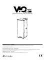 1
1
-
 2
2
-
 3
3
-
 4
4
-
 5
5
-
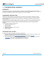 6
6
-
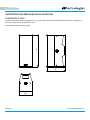 7
7
-
 8
8
-
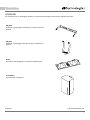 9
9
-
 10
10
-
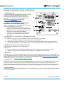 11
11
-
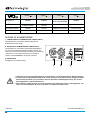 12
12
-
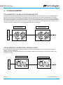 13
13
-
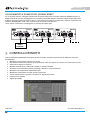 14
14
-
 15
15
-
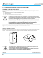 16
16
-
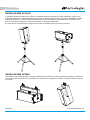 17
17
-
 18
18
-
 19
19
-
 20
20
-
 21
21
-
 22
22
-
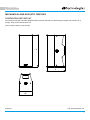 23
23
-
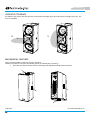 24
24
-
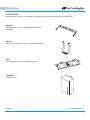 25
25
-
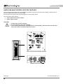 26
26
-
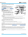 27
27
-
 28
28
-
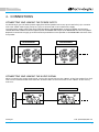 29
29
-
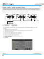 30
30
-
 31
31
-
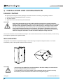 32
32
-
 33
33
-
 34
34
-
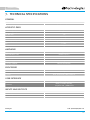 35
35
-
 36
36
-
 37
37
-
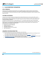 38
38
-
 39
39
-
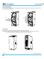 40
40
-
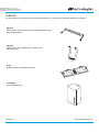 41
41
-
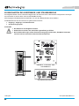 42
42
-
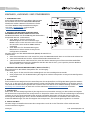 43
43
-
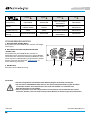 44
44
-
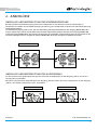 45
45
-
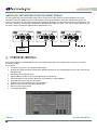 46
46
-
 47
47
-
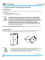 48
48
-
 49
49
-
 50
50
-
 51
51
-
 52
52
-
 53
53
-
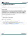 54
54
-
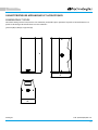 55
55
-
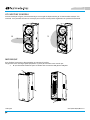 56
56
-
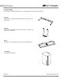 57
57
-
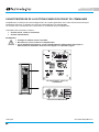 58
58
-
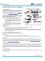 59
59
-
 60
60
-
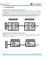 61
61
-
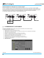 62
62
-
 63
63
-
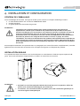 64
64
-
 65
65
-
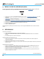 66
66
-
 67
67
-
 68
68
-
 69
69
-
 70
70
-
 71
71
-
 72
72
-
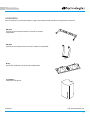 73
73
-
 74
74
-
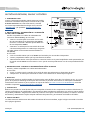 75
75
-
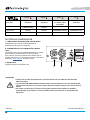 76
76
-
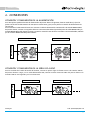 77
77
-
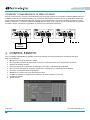 78
78
-
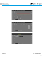 79
79
-
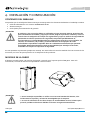 80
80
-
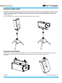 81
81
-
 82
82
-
 83
83
-
 84
84


dBTechnologies VIO X310 El manual del propietario
- Categoría
- Equipo de música suplementario
- Tipo
- El manual del propietario
En otros idiomas
Documentos relacionados
-
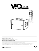 dB VIOS118 Manual de usuario
-
dBTechnologies VIO L208 El manual del propietario
-
-
dB Technologies VIO L212 Manual de usuario
-
-
-
-
-
-

