
iNSTALLATiON AND SERVICE MUST BE PERFORMED BY
A QUALiFiED iNSTALLER.
iMPORTANT: SAVE FOR LOCAL ELECTRICAL iNSPECTOR'S USE.
READ AND SAVE THESE iNSTRUCTiONS FOR FUTURE REFERENCE.
If the information in this manual isnot followed exactly, a fire or explosion may result causing
property damage, personal injury or death.
FOR YOUR SAFETY:
-- Do not store or use gasoline or other flammable vapors and liquids in the vicinity of this or any other
appliance,
-- WHAT TO DO IF YOU SMELL GAS:
• Do not try to light any appliance.
• Do not touch any electrical switch; do not use any phone in your building.
• Immediately call your gas supplier from a neighbor's phone, Follow the gas supplier's instructions.
• If you cannot reach your gas supplier, call the fire department.
-- Installation and service must be performed by a qualified installer, service agency or the gas supplier.
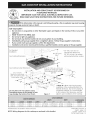
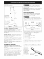
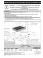
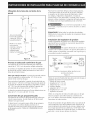
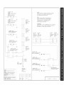
For Standard
installation:
30" (76.2 cm)
Gas Cooktop Dimensions :: Min.*
_A
* 30" (76.2 cm) min. for
unprotected cabinet and
24" (61 cm) min. for cabinet
with )rotected bottom surface.
Gas Cooktop Cutout Dimensions
2"(5.1 cm) Dia.
Opening to route power
cable. Seal opening
routing power cable.
3"(7,6 cm)
C
_"X 4" (10.2 cm x 10.2 cm)
opening to route gas supply.
Seal opening after routing
gas line.
7V4
cm)
F
G
Do not slide unit into cabinet cutout.
Protruding screws on the bottom of unit
may damage the bottom front finish. Figure 1
**Note: D & E are critical to the proper
installation of the cooktop. D reflects the
finished dimension. Due to the variation in
countertop materials, it is recommended
to first undercut this dimension, and then
adjust it upon installation of the cooktop.
30(76.2)
36(91.4)
All dimensions are stated in inches and (cm).
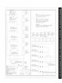
NOTE: Wiring diagrams for this cooktop are enclosed in this booklet
318201494 (1302) Rev.B
English - pages 1-8
Espaflol - p_iginas 9-16
Wiring Diagram page -16

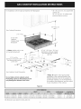
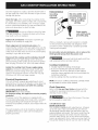
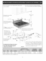
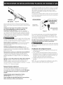
For Installation with the optional Stainless Steel Backsplash.
Gas Cooktop Dimensions
* 30" (76.2 cm) min. for unprotected
cabinet and
24" (61 cm) min. for cabinet with
protected bottom surface.
30"(76.2 cm)
Min.*
2 "(5.1 cm)
9"(22.9cm)
Optional
StainlessSteel
Backsplash
C
***Note: Applies only in case
of countertop backwall.
4"X 4" (10.2 cmx 10.2 cm)
opening to route gas supply.
Seal opening after routing
gas line.
2 "(5.1 cm) Dia.
Opening to route power cable --
Seal opening after routing
power cable.
F
Gas Cooktop Cutout Dimensidns
6
Do not slide unit into cabinet cutout.
Protruding screws on the bottom of unit
may damage the bottom front finish.
i
7¼"(18,4 cm)
,, . oo_ o::: :: ::
**Note" D & E are critical to the proper
installation of the cooktop. D reflects the
finished dimension. Due to the variation in
countertop materials, it is recommended to
first undercut this dimension, and then adjust
it upon installation of the cooktop.
Figure 2
36(91.4) 357/8(91.1) 25(63.5) 73A(19.7) 35_s/16(91.3) 353/16(89.4) 22(55.9)1_/8 (2.9)Max.
All dimensions are stated in inches and (cm).
2
71/2(19.1)
7Y2(19.1) 35_5/16(91.3)

Important Notes to the Installer
1. Readallinstructionscontainedintheseinstallation
instructionsbeforeinstallingthecooktop.
2. Removeallpackingmaterialbeforeconnectingthe
electricalsupplytothecooktop.
3. Observeallgoverningcodesandordinances.
4. Besuretoleavetheseinstructionswiththeconsumer.
5. Note:Foroperationat2000ft. elevationsabovesee
level,applianceratingshallbereducedby4 percent
foreachadditional1000ft.
Important Note to the Consumer
KeeptheseinstructionswithyourUseandCare Guide for
future reference.
Depth Adjustment Filler Kit #903051-9100
This cooktop isdesigned to replace existing unit. If the
depth of your countertop opening isbigger than 71/4'`
(18.4 cm) and lessthan 81/2'` (21.6 cm) you can order a
free filler kit #903051-9100 by calling Sears Parts& Repair
Center at 1-800-4-MY-HOME®.
Optional Item Available:
= A 9" (22.9 cm) Stainless Steel Backsplash
Kit #903048-9100 (for the 30" model);
Kit #903048-9010 (for the 36" model)
This kit can be ordered for purchase through Sears Parts
& Repair Center at 1-800-4-MY-HOME®.
IMPORTANT SAFETY
INSTRUCTIONS
Installation of this cooktop must conform with local
codes or, in the absence of local codes, with the National
Fuel Gas Code ANSI Z223.1/NFPA54--1atest edition in
the United States, or in Canada, with the Canadian Fuel
Gas Code, CAN/CGA B149 and CAN/CGA B149.2.
• When installed in a manufactured (mobile) home
installation must conform with the Manufactured
Home Construction and Safety Standard, title 24 CFR,
part 3280 [Formerly the Federal Standard for Mobile
Home Construction and Safety, title 24, HUD (part
280)] or, when such standard is not applicable, the
Standard for Manufactured Home Installation, ANSI/
NCSBCSA225.1 or with local codes where applicable.
This cooktop has been design certified by CSA
International. As with any appliance using gas and
generating heat, there are certain safety precautions you
should follow. You will find them in the Use and Care
Guide, read it carefully.
Air curtain or other overhead hoods, which operate
by blowing a downward air flow on to a range, shall
not be used in conjunction with gas ranges other
than when the hood and range have been designed,
tested and listen by an independent test laboratory
for use in combination with each other.
Be sure your cooktop is installed and grounded
properly by a qualified installer or service
technician.
This cooktop must be electrically grounded in
accordance with local codes or, in their absence,
with the National Electrical Code ANSI/NFPA
No. 70--latest edition in the United States, or in
Canada, with the Canadian Electrical Code, CSA
C22.1 Part 1.
The burners can be lit manually during an
electrical power outage. To light a burner, hold a
lit match to the burner head, then slowly turn the
Surface Control knob to LITE. Use caution when
lighting burners manually.
Do not store items of interest to children in
cabinets above the cooktop. Children could be
seriously burned climbing on the cooktop to reach
items.
To eliminate the need to reach over the surface
burners, cabinet storage space above the burners
should be avoided.
Adjust surface burner flame size so it does not
extend beyond the edge of the cooking utensil.
Excessiveflame is hazardous.
Never use your cooktop for warming or heating
the room. Prolonged use of the cooktop without
adequate ventilation can be hazardous.
Do not store or use gasoline or other flammable
vapors and liquids near this or any other
appliance. Explosions or fires could result.
The electrical power to the cooktop
must be shut off while gas line connections are
being made. Failure to do so could result in serious
injury or death.
3

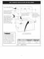
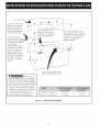
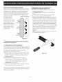
13"(33cm)max.depthfor -,
cabinetinstalledabovecookto
4- A
30" (76.2 cm) Min. Clearance
Between the Top of the
Cooking Platform and the
Bottom of an Unprotected
Wood or Metal Cabinet
24" (61 cm) Min. when
Bottom of Wood or Metal
Cabinet is Protected by
Not LessThan 1/8" Flame
Retardant Millboard Covered
With Not LessThan No. 28
MGS Sheet Steel, 0.015"
(0.4 mm) Stainless Steel,
0.024" (0.6 mm) Aluminum
or 0.020" (0.5 mm) Copper
18" (45.7 cm)
Min.
, ii _ iiiiii i
......--_<I
2" (5.1 cm) min. distance
between rear edge of cutout
and nearest combustible
surface above countertop
t
30" (76.2 cm) min.
clearance between
the top of the cooking
platform and the bottom
of an unprotected wood
or metal cabinet.
_To eliminate
the risk of burns or fire from
reaching over heated surfaces,
cabinet storage space located
above the cooktop should be
avoided. If cabinet storage is
provided, risk can be reduced
by installing a range hood that
projects horizontally a minimum
of 7" (17.8 cm) beyond the
bottom of the cabinets.
It is not recommended to use
drawer underneath cooktop.
36"(91.4cm) 36"(91.4cm)
Figure 3 - CABINET DESIGN
7"(17.8cm) 7"(17.8cm)

Wall Outlet Location
4"
(10_ cm).-.4_
(12.7 cm)
on rear wall. __ 16"
CENTRE(40.6 cm)
LINE
OF UNIT
NOTE: If an outlet I
is not available,
have one installed I
by a qualified _._
technician._,,
.. _ CENTRE
LINE
"_Ngure4 OFUNIT
Provide an Adequate Gas Supply
This cooktop is designed to operate on natural gas at 4"
(10.2 cm) of manifold pressure only.
A pressure regulator is connected in series with the
manifold on the cooktop and must remain in series with
the supply line.
For proper operation, the maximum inlet pressure to
the regulator must be no more than 14" (35.6 cm) of
water column (W.C.) pressure.
For checking the regulator, the inlet pressure must be at
least 1"(2.5 cm) (or 2.5 kPa) greater than the regulator
manifold pressure setting. The regulator is set for 4"
(10.2 cm) of manifold pressure, the inlet pressure must
be at least 5" (12.7 cm).
The gas supply line to the appliance should be 1/2" (1.3
cm) or 3/4" (1.9 cm) pipe.
LP/Propane Gas Conversion
This appliance can be used with Natural gas or LP/
Propane gas. It is shipped from the factory for use with
natural gas.
A kit for converting to LPgas is supplied with your
cooktop. The kit is marked "FOR LP/PROPANEGAS
CONVERSION".
The conversion must be performed by a qualified service
technician in accordance with the kit instructions and
all local codes and requirements. Failure to follow
instructions could result in serious injury or property
damage. The qualified agency performing this work
assumes responsibility for the conversion.
Failure to make the appropriate
conversion can result in serious personal injury and
property damage.
Important: Remove all packing material and literature
from cooktop before connecting gas and electrical
supply to cooktop.
Install Pressure Regulator
Install the pressure regulator with the arrow on the
regulator pointing up toward the unit in a position
where you can reach the access cap.
_J__ Do not make the connection too
tight. The regulator is die cast. Overtightening may crack
the regulator resulting in a gas leak and possible fire or
explosion.
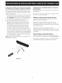
GAS FLOW
Manual --_ Pressure
Shutoff Flare Flare Regulator
Valve Union Union
Flexible Connector
off
All connections must be wrench-tightened
Figure 5
Assemble the flexible connector from the gas supply pipe
to the pressure regulator in the followinc order:
1. manual shutoff valve
2. 1/2" (1.3 cm) nipple
3. 1/2" (1.3 cm) flare union adapter
4. flexible connector
5. 1/2" (1.3 cm) flare union adapter
6. 1/2" (1.3 cm) nipple
7. pressure regulator
Use pipe-joint compound made for use with Natural and
LP/Propane gas to seal all gas connections. If flexible
connectors are used, be certain connectors are not
kinked.
The supply line should be equipped with an approved
shutoff valve. This valve should be located in the same
room as the cooktop and should be in a location that
allows ease of
opening and
closing. Do not
block access to
the shutoff valve.
The valve is for
turning on or
shutting off gas
to the appliance.
Open position
Figure 6

Oncetheregulatorisinplace,opentheshutoffvalvein
thegassupplyline.Waitafewminutesforgasto move
throughthegasline.
Checkfor leaks.Afterconnectingthecooktoptothe
gassupply,checkthesystemforleakswithamanometer.
Ifamanometerisnotavailable,turnonthegassupply
andusealiquidleakdetector(orsoapandwater)atall
jointsandconnectionsto checkforleaks.
Preferred Method
Grounding
type wall
receptacle
\
Do not, under any
circumstances, cut,
remove, or bypass
the grounding
prong.
/
Do not use a flame to check for leaks
from gas connections. Checking for leaks with a flame
may result in a fire or explosion.
Tighten all connections if necessary to prevent gas
leakage in the cooktop or supply line.
Check alignment of control knob valves after
connecting the cooktop to the gas supply to be sure the
cooktop manifold pipe has not moved. A misalignment
could cause the valve stems to rub on the control panel,
resulting in a gas leak at the valve.
Figure 7
Power supply
cord with 3-prong
grounding plug.
Where a standard 2-prong wall receptacle is installed,
it is the personal responsibility and obligation of the
consumer to have it replaced by a properly grounded
3-prong wall receptacle.
Do not, under any circumstances, cut or remove the
third (ground) prong from the power cord.
Disconnect this cooktop and its individual shutoff
valve from the gas supply piping system during any
pressure testing of that system at test pressures greater
than 1/2 psig (3.5 kPa or 14" (35.6 cm) water column).
Isolate the cooktop from the gas supply piping
system by closing its individual manual shutoff valve
during any pressure testing of the gas supply piping
system at test pressures equal to or less than 1/2 psig
(3.5 kPa or 14" (35.6 cm) water column).
Electrical Requirements
120 volt, 60 Hertz, properly grounded branch circuit
protected by a 15 amp circuit breaker or time delay fuse.
Do not use an extension cord with this cooktop.
Grounding Instructions
IMPORTANT Pleaseread carefully.
For personal safety, this appliance must be properly
grounded.
The power cord of this appliance isequipped with a
3-prong (grounding) plug which mates with a standard
3-prong grounding wall receptacle (see Figure 7) to
minimize the possibility of electric shock hazard from the
appliance.
The wall receptacle and circuit should be checked by
a qualified electrician to make sure the receptacle is
properly grounded.
Disconnect electrical supply cord from
wall receptacle before servicing cooktop.
Cooktop Installation
1. Visually inspect the cooktop for damage.
2. If you are installing the optional Stainless Steel
backsplash, first fix it at the back of the cooktop
using the screws supplied with the kit and follow the
instructions attached.
3. Set the cooktop into the countertop cutout.
NOTE: Do not use caulking compound; cooktop should
be removable for service when needed.
Check Operation
Refer to the Use and Care Guide packaged with the
cooktop for operating instructions and for care and
cleaning of your cooktop.
_Do not touch the burners. They may
be hot enough to cause burns.
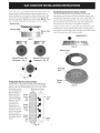
1.Install Burner Caps
Round Style Burners
This cooktop is equipped with sealed burners. All pieces
are at their place. Take note where they are. Remove
all packaging material. Make sure the burner caps are
properly aligned and leveled. The burner cap lip (See Fig.
8) should fit snug into the center of burner head and
rest level. Refer to Figs. 9 & 10 for correct and incorrect
burner cap placement. Once in place, you may check the
fit by gently sliding the burner cap from side to side (Fig.

11)to besureit iscenteredandfirmlyseated.Whenthe
burnercaplipmakescontactinsidethecenterofthe
burnerheadyouwillbeableto feelit. Pleasenotethat
theburnercapshouldNOTmoveoffthecenterofthe
burnerheadwhenslidingfromsidetoside.NOTE: There
are no burner adjustments necessary on this cooktop.
Burner Cap _
Burner Head _lV
Burner Cap
Lip
Fig. 8
Double Ring Style Burners (some models)
The Double Ring burner only operates properly with
two burner caps in place. Be sure the burner cap lips are
positioned facing down towards the burner head (Fig. 13)
and into the recessed areas (Fig. 14) on each side of the
burner head. Be sure both burner caps are seated firmly
and rest level on the burner head before operating.
Check the fit for each cap using the same method for the
round burner caps by gently sliding each cap from side to
side. Pleasenote that the burner cap lips should NOT move
out of recessed areasof the burner head.
Burner Caps
Correct Burner Cap Incorrect Burner Cap
Placement- Fig. 9 ,Ak Placement- Fig. 10
Recessed
area
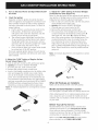
Bridge Style Burners (some models)
Install Burner Caps, these include one Bridge Burner
Center Cap (rectangular shaped) and the two Bridge
Burner End Caps (The Bridge Burner End Caps will fit
either the front or
rear Bridge Burner
Head locations).
Make sure that Bridge
the lips located Burner
under the Bridge End
Burner Caps fall Cap
into the slots
located in the
Bridge Burner Bridge
Burner
Head (See arrows
Center
in Figure 12) and Cap
that all the Bridge
Burner Caps lie
flat and evenly on Bridge
the Bridge Burner Burner
Head. End
Cap
Bridge Burner Head
[
Igniter
Hole
Igniter
Hole
Burner
Head
Fig. 13
Fig. 14
Fig. 12 7

2_
3_
Turn on Electrical Power and Open Main Shutoff
Gas Valve
Check the Igniters
Operation of electric igniters should be checked
after the appliance and supply line connectors have
been carefully checked for leaks and the appliance
has been connected to electric power. To check for
proper lighting:
a. Push in and turn a surface burner knob to the
LITEposition. All electronic surface ignitors
will spark at the same time. However, only the
burner you are turning on will ignite.
b. The surface burner should light once the flow
of gas reached the surface burner. Each burner
should light within four (4) seconds in normal
operation after air has been purged from supply
lines. Visually check that burner has lit.
c. Once the burner lights, the control knob should
be rotated out of the LITEposition.
There are separate ignition devices for each burner.
Try each knob separately until all burner valves have
been checked.
5. Adjust the "LOW" Setting of the Dual (Bridge)
Surface Burner Valve (Figure 16):
Note: On the dual valve the low setting of each portion
(rear portion of bridge burner and the center portion of
bridge burner) should be adjusted individually.
a. Push in and turn control to LITEuntil the rear portion
of the bridge burner ignites only.
b,
C.
d.
e.
Quickly turn knob to LOWEST POSITION.
If burner goes out, reset control to OFF.
Remove the surface burner control knob.
The rear portion of the bridge burner flame size
can be increased or decreased by turning screw A
(see Figure 16). Use screw B to adjust the flame
size of the center portion of the bridge burner. Turn
counterclockwise the screw to increase flame size.
Turn clockwise the screw to decrease flame size.
Adjust flame until you can quickly turn knob from
LITEto LOWEST POSITIONwithout extinguishing the
flame. Flame should be as small as possible without
going out.
Note: Air mixture adjustment is not required on surface
burners.
4. Adjust the "LOW" Setting of Regular Surface
Burner Valves (Figure 15):
a. Push in and turn control to LITEuntil burner ignites.
b. Quickly turn knob to LOWEST POSITION.
c. If burner goes out, reset control to OFF.
d. Remove the surface burner control knob.
e. Insert a thin-bladed screwdriver into the hollow valve
stem and engage the slotted screw inside. Flame
size can be increased or decreased by turning the
screw. Turn counterclockwise to increase flame size.
Turn clockwise to decrease flame size. Adjust flame
until you can quickly turn knob from LITEto LOWEST
POSITIONwithout extinguishing the flame. Flame
should be as small as possible without going out.
Note: Air mixture adjustment is not required on surface
burners.
Figure 16
When All Hookups are Complete
Make sure all controls are left in the OFFposition.
Model and Serial Number Location
The serial plate is located under the cooktop burner box.
When ordering parts for or making inquires about your
oven, always be sure to include the model and serial
numbers and a lot number or letter from the serial plate
on your oven.
Figure 15
Before You Call for Service
Read the Before You Call for Service Checklist and
operating instructions in your Use and Care Guide.
It may save you time and expense. The list includes
common occurrences that are not the result of defective
workmanship or materials in this appliance.
Refer to your Use and Care Guide for Sears service
phone numbers, or call 1-800-4-MY-HOME ®

LA INSTALACION Y EL SERVICIO DEBEN SER REAUZADOS POR UN INSTALADOR
CAUFICADO.
IMPORTANTE: GUARDE ESTAS INSTRUCCIONES PARA USO DEL iNSPECTOR
ELI'CTRICO LOCAL.
LEA Y GUARDE ESTAS INSTRUCCIONES PARA FUTURAS REFERENCIAS
II!_ Sitodas las instruccionesde _ste manual no son observadas a la letra, se puede ocurrir incendioso
explosiones que pueden causardaffos materiales, lesiones o la muerte.
PARASUSEGURIDAD:
-- No almacene o utilice gasolina u otros vapores y liquidos inflamablescerca de _ste o cualquier otro artefacto.
-- QUE HACERSIHAY FUGASDEGAS/E
• No intente de encender ningun artefacto
• No toque ningun interruptor el_ctrko; no utilice ningun aparato telef6nico en su edifido.
• Llameinmediatamenteel abastecedordegasdesdeel tel_fono de un vecino. Sigalasinstrucdonesdel abastecedorde gas.
• Encaso que no puede contactar el abastecedor de gas Ilame al departamento de bomberos.
-- Lainstalad6n y el servkio telef6nko deben set realizadospot un instaladorcalificado, pot un servkio t_cnico certificado o
pot el abastecedor de gas.
Para la InstalaciOn i
Estandar:
Dimensiones de la
parrilla de cocinar a gas
Abertura de 2" (5.1
cm) de di_imetro para
hacer pasar el cable de
alimentaci6n. Selle abrir
despu_s de dirigir cable
de energia electrica.
30" (76.2 cm)
Min.*
* 30" (76.2 cm) m[n para un armario
protegido.
24" (61 cm) rain para una
superficie no protegida.
C
"turade4" X4" (10.2cmx 10.2cm) ....
para el suministro de gas. Selle abrir:::::::::::::_
d_spu_sdedirigir elgasI[nea. '_
7Y4"(18.4cm)
F
Dimensionesdelhueco
para la parrillade
cocinaragas
G
No deslizar dentro del hueco de la
alacena. Los tornillos que sobresalen de
la parte inferior de la unidad pueden
daffar el acabado inferior del frente.
29%
(74 cm)
Figura I
Nota: "D & E" son criticos para la instalaci6n
adecuada de la cocina. Porfavor, aseg0rese
de respetar estas dimensiones. "D" refleja una
dimensi6n terminada que se recomienda para
socavar esta dimensi6n y ajustar en el momento de
la instalaci6n del aparato debido a la variaci6n de los
materiales de la cocina.
357/8(91.1) 25(63.5) 73A(19.7) 35_s/16(91.3) 353/16(89.4) 22(55.9)1 _/8(Z9)Max.
Todas las dimensiones se dan en pulgadas (cm).
La dimensi6n Fincluye un espacio de 5" por debajo de la plancha de
cocinar para la conexi6n de la linea de suministro de gas.
NOTA: Se adjunta los diagramas de cables de esta plancha de
cocinar con el libreta.
318201494 (1302) Rev.B
English - pages 1-8
Espaflol - p_Sginas9-16
Diagrama de la instalaciOn al_imbrica p_igina - 16

Para ver la Instalaci6n con el Panel Protector Opcional de * 30" (76.2 cm) min para un armario protegido.
Acero Inoxidable. 24" (61 cm) min para una superficie no protegida.
Dimensiones de la parrilla
de cocinar a gas
30"(76.2 cm)
Min.*
2"(5.1 cm) A _
Panel Protector Opcional
de Acero Inoxidable de
9" (22,9 cm)
C
***Nota: Se aplica s61o en
caso de Panel Protector.
Abertura de 2" (5.1
cm) de di_imetro para
hacer pasar el cable de
alimentaci6n. Selle abrir
despu@sde dirigir cable
de energia electrica.
Abertura de 4" X 4" (10.2cm x 10.2cm)
para el suministro de gas. Selle abrir
despu@sde dirigir el gas linea.
7¼" (18.4 cm)
F
Dimensiones del hueco
para la parrilla de
cocinar a gas
No deslizar dentro del hueco de la alacena.
Los tornillos que sobresalen de la parte
inferior de la unidad pueden da_ar el
acabado inferior del frente. Figura 2
29Vs
(74 cm)
**Nota: "D & E" son cr[ticos para lainstalaci6n adecuada
de la cocina. Por favor, aseg0rese de respetar estas
dimensiones. "D" refleja una dimensi6n terminada que
se recomienda para socavar esta dimensi6n y ajustar en
el momento de la instalaci6n del aparato debido a la
variaci6n de los materiales de la cocina.
36(91.4) 357/8(91.1) 73A(19.7) 351s/16(913)35s/16(89.4)22(55.9) 1Y8(Z9)Max.
Todas las dimensiones se dan en pulgadas (cm).
25(63.5)
7Y_(19.1)
7Y2(19.1) 35ls/16(91.3)
10

Notas importantes para el instalador:
1. Leatodas las instrucciones de instalaciOn antes de
realizar la instalaci6n de la plancha de cocinar.
2. Retire todos los articulos de embalaje antes de realizar
lasconexiones el_ctricas a la plancha de cocinar.
3. Observe todos los c6digos o reglamentos estatales
4. Aseg0rese que el consumidor tenga estas instrucciones.
5. NOTA: Para la utilizaci6n a m_isde 2 000 pies de altura,
la potencia del aparato deber_i set reducida de 4 pot
ciento a cada 1 000 pies adicionales.
Notas importantes para el consumidor
Guarde todas las instrucciones con su manual del usuario
para futuras referencias.
Juego de Relleno para Ajuste de
Profundidad #903051-9100
Esta cocina ha sido disehada para reemplazar la unidad
existente. Si la profundidad de la abertura de su cocina es
mayor que 71/4'' (18,4 cm) y menor que 81/2"(21,6 cm),
pueden ordenar un juego de relleno gratuito Ilamando
al Centro de Partes y Reparaci6n Searsal 1-888-SU-
HOGARsM.
Accesorios Opcionales Disponibles:
• Juego de Panel Protector Opcional de Acero Inoxidable
de 9" (22,9 cm) #903048-9100
Se puede ordenar a trav_s del Centro de Partes y
ReparaciOn Sears, Ilamando al 1-888-SU-HOGARsM.
INSTRUCCIONES DE
SEGURIDAD IMPORTANTES
La instalaciOn de esta plancha de cocinar debe realizarse
en conformidad con los c6digos locales o, si estos no
existen, con el National Fuel Gas Code ANSI Z223.1/
NFPA54 - Oltima edici6n en los Estados Unidos, o en
Canada, con el Canadian Fuel Gas Code, CAN/CGA B149
y CAN/CGA B149.2.
La instalaciOn de aparatos diseflados para instalaciOn
en casas prefabricadas (m6viles) debe conformar con el
Maufactured Home Consturction and Safet Standard,
titulo 24CFR, parte 3280 [Anteriormente el Federal
Standard for Mobil Home Construction and Safety,
titulo 24, HUD (parte 280)] o cuando tal est_indar no se
aplica, el Standard fo Manufactured Home Installation,
ANSI/NCSBCS 225.1, o con los c6digos locales.
No se deben usar cortinas de aire ni ninguna
otra campana de ventilation superior que sople
aire hada abajo sobre la estufa a gas a menos
que la campana de ventilaci6n y la estufa hayan
sido dise_adas, probadas y certificadas por un
laboratorio de pruebas independiente para el uso
combinado de la una con la otra.
Asegurese que la plancha de codnar sea instalada
y puesta a tierra correctamente por un instalador
o t_cnico calificado.
La plancha de codnar debe conectarse
electricamente a tierra de acuerdo con los c6digos
locales o, de no existir, con el c6digo electrico
ANSI/NFPA No. 70 - ultima edici6n en los Estados
Unidos, or in Canada, con el Canadian Electrical
Code, CSA C22.1 Parte 1.
Los quemadores pueden encenderse
manualmente durante una interruption del
suministro el_ctrico. Para encender un quemador,
mantenga un fosforo encendido en el extremo del
quemador, luego gire suavemente la perilla hasta
LITE (encendido). Tenga cuidado al encender los
quemadores en forma manual.
No deje articulos que interesan los ni_os en los
armarios que est_n sobre la plancha de codnar.
Lespodria causar quemaduras graves si intentan
subirse para alcanzarlos.
• Para eliminar el riesgo de extender por endma
de los quemadores superiores, deberia evitar
el espado de almacenamiento del armario,
Iocalizado por encima de estos quemadores.
Gradue el tama_o de la llama de modo que
no sobrepase el borde del utensilio de codna.
Demasiada llama es peligrosa.
• No utilice jamas la codna como calefactor El uso
prolongado de la cocina sin la ventilaciOn adecuada
puede set peligroso.
Mantenga el area cerca de este artefacto
o de cualquier otro artefacto despejada de
sustandas combustibles, gasolina y otros liquidos
inflamables. Se puede ocurrir incendios o explosiones.
El suministro el_ctrico a la
plancha de codnar debe de ser cerrado durante
las conexiones a la linea. De Io contrario se puede
resultar lesiones graves o la muerte.
El diseho de esta plancha de cocinar cuenta con la
aprobaci6n del CSA international. AI igual que todos los
artefactos a gas que generan calor, deben seguirse ciertas
medidas de seguridad. Vienen con el Manual del Usuario.
Lea atentamente el manual.
11

13"(33cm)m_qx.
30"(76.2cm)min.de
espacioentrelaparte
superiordelfogOny
laparteinferiordeun
armariodemaderao
metalsinprotecciOn.
24"(61cm)min. _j_
cuandolaparteinferior
delarmariodemader29''T
ometalest_qprotegida
porunaplaca
cortafuegoretardante
dellamadenomenos
de1/4",cubiertacon
unaI_iminadeacero
msgnoinferioralNo.
28,deaceroinoxidable
de0.015",aluminio
de0.024"ocobrede
0.020".
F
2"(5.1 cm) Minimo distancia
i entre el horde posterior
-_ del hueco y la m_qscerca
i_\ superficie combustible por
| encima del mostrador.
!
18" (45.7 cm)
Min.
i
24" (61 cm_
i
>
No es recomendable utilizar
cajones debajo de la estufa.
Para eliminar el
riesgo de alargar sobre los unidades en
calentamiento de la superficie, deberia
evitarse el espacio de almacenamiento
del armario, ubicado sobre las unidades
de la superficie. Si se cuenta con este
espacio, se puede disminuir el peligro
instalando una cubierta de cocina que
se extienda horizontalmente en 7"
(17.8 cm) minimo por sobre la parte
inferior delantera en los armarios.
30" (76.2cm) 30" (76,2cm)
36" (91.4cm) 36" (91.4cm)
30" (76.2 cm) Minimo de
espacio entre la parte superior
de la plataforma de la plancha
de cocinar y el fondo de una
madera non protegida o
armario met_qlico.
5"(12,7cm) 5"(12.7cm)
7"(17.8cm) 7"(17.8cm)
Figura 3- DESENO DEL ARMARIO
12

Ubicad6n de ia toma de corriente de ia
pared
NOTA: Si no existe
una toma de
corriente, contacte
a un electricista
(12.7 cm)
la pared posterior. _/- 16"
DEE (40.6 cm)
APARATO
i
I
i
calificado para I
realizar la ins_ I_
"'" _r DEL
APARATO
Figura 4
Provea un adecuado surnJnistro de gas
Esta plancha de cocinar est_qdisehada para utilizar gas
natural de 4" (10.2 cm) de presi6n m01tiple solamente.
Se conecta un regulador de presi6n en serie al m01tiple de
la plancha de cocinar y debe permanecer en serie con la
linea de suministro de gas.
Para que manejo correcto, la presiOnde entrada m_qxima
hacia el regulador no debe exceder 14" (35.6 cm) de
presi0n de la columna de agua.
Para controlar el regulador, la presi6n de entrada debe ser
de al menos 1" (25 cm) (o 2.5 Kpa) mayor que el ajuste de
la presi6n del m01tiple del regulador. El regulador se ajusta
a 4" (10.2 cm) de la presi6n del m01tiple, la presi6n de
entrada debe de ser de al menos 5" (12.7 cm).
La linea de suministro de gas por el homo deberia tener un
tubo de 1/2" (1.3 cm) o de 3/4" (1.9 cm).
Conversi6n de gas propano/licuado
Esta plancha de cocinar ha sido disehada para utilizar gas
natural o gas propano. Ha sido fijada en la f_ibrica para
utilizarse con gas natural.
Si desea hacer la conversi6n para utilizar el gas propano,
use laspiezas con orificios fijados provistos en el
paquete del manual de instrucciones para la instalaci6n
en el paquete escrito "PARA LA CONVERSIONENGAS
PROPANO".
Para hacer la conversi6n del gas natural al gas propano,
es necesario utilizar el servicio de un t@cnicocalificado,
in acuerdo con las instrucciones del fabricante y todos
los c6digos y reglamentos reguladores. Si todas las
instrucciones no son observadas, se puede ocurrir severos
lesiones o dahos materiales. La agencia calificada que hace
el trabajo asuma la responsabilidad para la conversi6n.
Si la conversi6n apropiada no esta
observada, se puede ocurrir severos lesiones o dahos
materiales.
Importante: Retire todos los articulos de embalaje y
folletos de la cocina antes de realizar lasconexiones de gas
y el@ctricasa la cocina.
Instalaci6n del regulador de presi6n
Instale el regulador de presiOn con la flecha del regulador
apuntando hacia la unidad en una posici6n que permita
alcanzar la tapa de entrada.
No ajuste demasiado la conexi6n. El
regular est,1 fundida a presi6n. AI ajustar demasiado se
puede romper el regulador causando una fuga de gas y
un posible incendio o explosi6n.
13
FLUJO DEL GAS
Valvula de _ Regulador
cierre de pTsidn
manual Uni6n Uni6n
( ) _ Conector flexible
Apagado
(Off)
Todas las conexiones deben ajustarse con
una Ilave de tuerca
Figura 5
Monte el conector flexible del tubo del suministro de gas al
regulador de presi6n en funcionamiento:
1. wilvula de cierre manual
2. boquilla de 1/2" (1.3 cm)
3. adaptor de 1/2" (1.3 cm)
4. conector flexible
5. adaptator de 1/2" (1.3 cm)
6. boquilla de 1/2" (1.3 cm)
7. regulador de presi6n
Utilice un compuesto de tubo articulado para uso de gas
natural y propano para sellar todas las conexiones de
gas. Si se utilizan conectores flexibles, aseg0rese que los
conectores no est_qntorcidos.
El tubo de suministro de gas deberia incluir una wilvula de
cierre certificada. Estawilvula deberia estar ubicada en la
misma habitaci6n de la plancha de cocinar y deberia estar
en un lugar que permita una abertura y cierre f_iciles. No
bloquee las entradas de la wilvula de cierre. La wilvula sirve
para abrir o cerrar el paso del gas al artefacto.

V lvula
de cierre Figura6
El cable de encendido de este artefacto incluye un enchufe
de tres patas (a tierra) que calza con un enchufe de pared
de tres patas de conexiOn a tierra (vet Figura 7) para
disminuir la posibilidad de peligro de choques el_ctricos
desde el artefacto.
Un electricista calificado debe verificar el enchufe de pared
y el circuito para asegurar que el enchufe est_qconectado a
tierra correctamente.
MI_TODO PREFERIDO
debe, b_
Abra la wilvula de cierre en el tubo de suministro de gas.
Espere unos minutos para que el gas pase a trav_s del tubo
de gas.
Verifique si hay fugas. Para verificar si hay fugas
en el electrodomestico se debe de seguir las
instrucciones del fabricante. Luego de conectar la
cocina al gas, verifique el sistema con un manOmetro. Si
no cuenta con _ste instrumento, d_ la vuelta al suministro
de gas de la cocina y utilice un detector de fugas liquidas
(o agua y jabOn) en todas las articulaciones y conexiones
para verificar si existen fugas.
No use ning0n tipo de llama para
verificar si hay fugas de gas. Verifique si hay fugas con
una llama puede ocasionar incendio o explosion.
Ajuste todas las conexiones en caso que sea necesario,
para evitar fugas de gas en la cocina o en el tubo de
suministr6 de gas.
Verifique la alineacion de las v_lvulas luego de
conectar la plancha de cocinar al suministro de gas para
asegurar que no se ha movido la wilvula del m01tiple de la
plancha de cocinar.
Desconecte la cocina y su v_lvula de cierre individual
del sistema de tuberia del suministro de gas durante
cualquier ensayo de presiOndel sistema en ensayos de
presiOn superiores a 1/2 psig (3.5 kPao 14" columna de
agua).
Aparte la cocina del sistema de tuberia del suministro
de gas cerrando su wilvula de cierre individual manual,
durante cualquier ensayo de presiOndel sistema de
suministro de gas en ensayos iguales o inferiores a 1/2 psig
(3.5 kPao 14" columna de agua).
Enchure de
pared a tierra
Figura 7
encendido.
Cablo de encendido
con enchufe de tres
patas a tierra
En caso de encontrarse con un enchufe de pared de dos
patas, es la personal responsabilidad y la obligaci6n del
consumidor reemplazarlo pot el enchufe de pared a tierra
de tres patas correspondiente.
No debe, bajo ninguna circunstancia cortar o retirar
la tercera pata (tierra) del cable de encendido
Desconecte el cable del suministro
el_ctrico del enchufe de pared antes de reparar la plancha
de cocinar.
Instalacion de la Tapa de Cocina
1. Inspeccione visualmente la tapa de la cocina para ver
si est_qdahada.
2. Si va a instalar el Panel Protector Opcional de Acero
Inoxidable, primero colOquelo en la parte posterior de
la tapa de la cocina usando los tornillos provistos con
el juego y siga las instrucciones provistas.
3. Coloque la tapa de la cocina en la marca de la
mesada.
NOTA: No use un compuesto de calafateo; la tapa de la
cocina se debe poder desmontar para revisarla.
Requerimientos electricos
Un circuito derivado conectado correctamente a tierra
de 120 voltios, 60 Herz protegido pot un interruptor
autom_itico de 15 amp o un fusible de retardo. No utilice
un cable flexible de extension en esta plancha de
cocinar.
Instrucdones para ia puesta a tierra
IMPORTANTE Pot favor, lea atentamente.
Como medida de seguridad personal, est_ artefacto
debe conectarse a tierra correctamente.
14

Verifique la operacion
Refiera al Manual del Usuario que viene con la plancha
de cocinar para las instrucciones de funcionamiento y el
mantenimiento y la limpieza de su plancha de cocinar.
No toque a los quemadores. Pueden estar suficientemente
calientes par causar quemaduras.
1. Instalaci6n de las tapas de quemadores
Quemadores Redondos
El reborde de la tapa del quemador (vea la Fig. 8) debe
calzar firmemente en el centro de la cabeza del quemador
y quedar nivelado. Consulte la figuras 9 y 10 para conocer
las maneras correctas e incorrectas de colocar la tapa del
quemador. Una vez que est@en su lugar, puede verificar
si cabe deslizando suavemente la tapa del quemador de
lado a lado (Fig 11) para asegurarse de que est@centrada
y firmemente asentada. Cuando el reborde de la tapa del
quemador haga contacto en el centro de la cabeza del
quemador, podr_i escuchar un chasquido. Tenga en cuenta
que la tapa del quemador NO sedebe mover del centro
de la cabeza del quemador cuando intente moverlade lado
a lado.
Quemadores de anillo doble (algunos modelos)
El quemador de anillo doble s61ofunciona debidamente con
sus dostapas de quemador ensu lugar. AsegOresede que
los rebordes de lastapas de los quemadores est_n orientados
hacia abajo hacia la cabeza del quemador (Fig. 12) yen las
cavidades(Fig. 13)a cada lado de lacabeza del quemador.
AsegOreseque lastapas de ambos quemadores est_n
firmemente asentadasy descansenen posici6n nivelada
sobre la cabeza del quemador antes de usarlo.
Verifique la colocaci6n de cada tapa usando el mismo
m_todo utilizado con lastapas de los quemadores redondos
deslizando cada tapa de lado a lado. Tengaen cuenta que
los rebordes de lastapas de los quemadores NO deben
moverse pot fuera de lascavidadesde la cabeza del
quemador.
Tapadel
quemador "_
"_ "_" Rebordede
Cabezadel la tapadel
quemador uemador
Figure 8
Tapas de los
quemadores
Cabeza del
quemador
Colocaci6n correcta de la
tapa del quemador
Figure 9
Colocaci6n incorrecta de la
tapa del quemador
Figure 10
Figure 12
Figure 13
Figure 11
15

Quemador de Puente (algunos modelos)
Vuelva a colocar lastapas del quemador de puente. Estas
incluyen una tapa del quemador de puente central (forma
rectangular) y dos tapas de los extremos del quemador
de puente (_stas calzan tanto en el extremo delantero
como en el trasero de la cabeza del quemador de puente).
Aseg0rese de que las leng0etas ubicadas debajo de las
tapas del quemador
Cabeza del quemador
I
de puente entren en
las ranuras que se
encuentran en la cabeza
Tapa
del quemador de puente del-
(vea las flechas en la e×tremo
Figura 14) y que todas las
tapas del quemador de
puente queden planas y
parejas sobre la cabeza Tapa
central =
del quemador.
Tapa
del =
extremo
Figure 14
4. Ajuste bajo ("LO") ara la v&lvula de los
quemadores de superficie (Figura 15)
a. Presioney gire el control hasta la posici6n LITEpara
prender los quemadores.
b. Gire r&pidamente gire la perilla a la POSICIONMAS
BAJA.
c. Si el quemador seapaga, reajuste el control a OFF.
d. Retire la perilla del quemador de superficie.
e. Inserte un destornillador fino-aplanado en el orifico del
w%tago de la wilvula e inserte en el tornillo ranurado.
El tamaho de la llama puede aumentarse o disminuirse
d_indole vuelta al tomillo. D_vuelta en sentido opuesto
a las manecillas del reloj para aumentar el tamaho de
la llama. D_ vuelta en sentido alas manecillas del reloj
para disminuir la llama. Ajuste la llama hasta que usted
puede dar vuelta r_ipidamente a la perilla de la posici6n
LITEa la POSICIONM/kS BAJA sin extinguir la llama.
La llama debe set tan pequeha como sea posible sin
apagarse.
Nota: Elajuste de la mezcla del aire no se requiere en
los quemadores de superficie
2. Encienda la corriente el_ctrica y abra la v_lvula
principal de alimentaci6n.
3. Comprobaci6n de los Encendedores
El funcionamiento de las bujias electr6nicas desde set
comprobado una vez que los conectores del suministro de
gas ban sido verificados y no exista ning0n tipo de fuga. Y
el suministro de electricidad se conecte a la estufa.
Para verificar un encendido correcto:
A. Presioney gire a una perilla a la posici6n de LITE.Todos
lasbujias electr6nicas chispear_in al mismo tiempo. Sin
embargo, solamente el quemador que usted seest,1
girando encender_i.
B. El quemador se deber_i encender en cuatro (4)
segundos para un funcionamiento normal, luego
de que el aire haya sido purgado de la tuberia de
suministro de gas. Controle visualmente que el
quemador se hay encendido.
C. Luego que el quemador se haya encendido, la perilla
debe set girada fuera de la posici6n LITE.
Cada quemador tiene su encendedor individual. Controle
las perillas separadamente hasta que todas las wilvulas
hayan sido controladas.
Figura 15
16

5.Ajustebajo"LOW"paralav&lvuladequemador
desuperfidepuente(Figura16)(algunosmodelos)
Nota:Enlawilvuladequemadortripleelajuste<<LOW>>
decadaporciOn(porciOnposteriordelquemadorpuente
ylaporciOndecentrodelquemadordelpuente)sedebe
ajustarindividualmente.
a. Presioneygireelcontrolalaposici6nLITEhastaquela
porci6nposteriordelquemadorpuenteseencienda.
b.Girer,ipidamentealaperillaalaPOSICIONMASBAJA.
c. Sielquemadorseapaga,reajusteelcontrolaOFE
d. Retirelaperilladelquemadordesuperficie.
e. Eltamaflodelaflamadelaporci6nposteriordel
quemadorpuentepuedeaumentarseodisminuirse
d_indolevueltaaltornilloA(veaFigura16).Utilice
eltornilloBparaajustareltamaNodelallamade
laporci6ncentraldelquemadorpuente.D_vuelta
ensentidoopuestodelasmanecillasdelrelojpara
aumentareltamaflodelallama.D_vueltaensentido
alasmanecillasdelrelojparadisminuirlallama.Ajuste
lallamahastaqueustedpuededarvueltar_ipidamente
alaperilladelaposici6nLITEalaPOSICIONMASBAJA
sinextinguirlallama.Lallamadebesertanpequefla
comoseaposiblesinapagarse.
Nota:Elajustedelamezcladelairenoserequiereenlos
quemadoresdesuperficie.
Cuando se han realizado todos los sisternas
de conexion
Aseg0rese que todos los controlos est_inen la posiciOn de
OFF(apagado).
AsegOrese que el flujo de combusti6n y ventilaci6n de aire
de la cocina no est_in obstruidos
Modeio y ubicad6n del numero de serie
La placa de nOmero de serie est,1ubicada en el lado de
abajo de la caja de quemadores.
AsegOrese de incluir el modelo, nOmero de serie y el
nOmero o letra del Iote que se encuentran en la placa, en
todo pedido de partes o solicitud de informaci6n acerca de
su plancha de cocinar.
La placa de nOmero de serie tambi_n indica las
especificaciones de los quemadores, el tipo de combustible
y la presi6n para la cual fue ajustada la plancha de cocinar
en la f_ibrica.
Antes de Iiarnar ai servicio t_cnico
Lea la lista titulada "Evitando Llamadas de Servicio" y las
instrucciones de funcionamiento en su Manual del Usuario
Verifique que los fusibles de la casa no se hayan fundido o
el cortacircuitos del homo no haya saltado o abierto.
Figura 16
17

18

TOP BURNER IGNITER
OoTiONAL
OUEMADOR DE ENCENO!DO SUPERIOR
OPC/ONAL
BOUGIE D'ALLUMAGE-BRULEUR
TOP BURNER IGNITER I]4_T_
OPTIONAL
QUEMADOR DE ENCENDIDO SUPERIOR
QPCIONAL
BOUGIE D_ALLUMAGE-BRULEUR
FACULTATIF
TOP BURNER IGNITER
OUEMADOR DE ENCENB!DO SUPERIOR
BOUGIE D'ALLUMAGE-BRULEUR
TOP BURNER IGNITER
OUEMADOR DE ENCENDIDO SUPERIOR
BOUGIE D'ALLUMAGE-BRULEUR
WARNING
DISCONNECT POWER BEFORE SERVICING UNiT
AVISO
DESOONECTE LA ENERG/A ANTES DE REALIZAR
EL MANTENIMIENTO DEL ELECTRODOMESTICO
AVERT/SSEHENT
COUPER LE COURANT AVANT D'EFFECTUER LA
REPARATION
COLOR CODE / CODIGOS DE COLOR / C0OE COL__EUR
8KIBLACK / NEGRO / NOIR
GROUND
PUESTA A TIERRA
MISE A LA TERRE
I
WiRE
ALAMBRE
FIL
RIGHT REAR
IGNSV_
INTENCTRASERO
OERECHO
INTERALLUM_
BAR
LE_T REAR
IGN, SW
INTENCTRASERO
IZOUIERO0
INTER. ALLUM,
G,AR
CAUTION:
LABEL ALL WIRES PRIOR TO DISCONNECTION WHEN SERVICING CONTROLS.
W}RING ERROR CAN CAUSE IMPROPER AND DANGEROUS OPERATION_
VERIFY PROPER OPERATION AFTER SERVICING.
AVISO:
ETIQUETE TOOO5 LOS ALAMBRES ANTES DE DESCONECTAR PAR
REALIZAR ET MANTENIMIENTO DE LOS CONTROLEB.ERROR DE
ALAMBRAJE PUEDE CAUSAR UN FUNCIONAMIENTO INCORRECTO
Y PELIGROSOVERIOUE S/ EL FUNCIONAMIENTO ESTA
CORRECTO DESPUES DEL MANTENIMIENTO
AVERTISSEMFNT:
ETIQUETER CHAQUE FIL AVANT LE DEBRANCHEMENT DE CEUX CI.UNE ERREUR DE
BRANCHEMENT PEUT CAUSER UNE OPERATION DANGEREUSEVERIFIER LE BON
FONCTIBNNEMENT DE L'APPAREIL APRES TOUTE REPARATION.
RIGHT FRONT LEFT FRONT LEFT REAR RIGHT REAR
IGNSW [GNSW IGNBW. [GNSW
INT_ENC. DE INTENC DE [NT ENC, TRASERO INTENCTRASERO
FRENTE DERECHO FRENTE IZOUIE_aO IZOUIEROO DERECHO
INTERALLUM [NTERALLUM. ]NTERALLUM INTERALLUM
DAV. GAV G, AR, DAR
POWER CORD
PARR TRANSPORTE
DE FUERZA
CABLE
D'ALIMENTATION
CONNECTOR
EMPALME
CONNECTEUR
18 200
20 /50
GAGE
MEOIDA TEMP-°C
CAL
LEFT FRONT
IGN. SW.
INTENC DE
FRENTE ]ZQUIERDO
INTERALLUM
GAV
RIGHT FRONT
IGN. BW
INT. ENC, DE
FRENTE OERECHO
INTBR. ALLUM,
DAV
1 3321
I
TOP BURNER IGNITER
OUEMADOR DE ENCEND[DO SUPERIOR
BOUGIE D'ALLUMAGE-BRULEUR _
TOP BURNER IGNITER
QUEMADOR DE ENCENDIDO SUPERIOR
BOUGIE D'ALLUMAGE-BRULEUR _ ............ _>
TOP BURNER IGNITER
OUEMAOOR DE ENCENDIDO SUPERIOR
BOUGIE D'ALLUMAGE-BRULEUR _
TOP BURNER IGNITER
OUEMAOOR BE ENCENDIDO SUPERIOR
BOUBIE D'ALLUMAGE-BRULEUR
<_
IGNI TER MODULE BOARD
CUAORO DE MODULO DE ENCENDIDO
BLOC CONNECT ION ALLUMEUR
i
STYLE UL 3 18 0 4 7 I I 1 REV. B

TOP BURNER iGNITER
OPTIONAL
OuENADOR DE ENCENDIDO SUPERIOR
OPCIONAL
BOUGIE O' ALLUMAGE BRULEUR
TOP BURNER iGNiTER
OPTIONAL
OUEMADOR DE ENCENDiDO SU_RiOR
OPCiONAL
BOuGiE D'ALLUMAGE BRULEUR
FACULTATIF
i
I
I
T0P BURNER iGNITER
OUEMAOOR DE ENCENOiD0 SUPERIOR
BOUGIE D'ALLUMAGE-BRULEUR
TOP BURNER IGNITER
QUENADOR DE ENCEND]DO SUPERIOR
BOUGiE D'ALLUHAGE-BRULEUR
TOP BURNER IGNITER
OUEMADOR DE ENCENDIDO SUPERIOR
BOUGiE D'ALLUMAOE BRULEUR
WARNING
DISCONNECT POWER BEFORE SERVICING UNIT
AVIS0
OESCONEC_E LA ENEROiA AN]ES DE REALiZAR
EL MANTENIMiENTO DEL ELECTRODOMEBTICB
DISCONNECT POWER BEFORE SERVICING UNIT
AVERTiSSEMENT
_ C£ CCORANT AVAN1D'EFFEC1UER LA
REPARATION
COLOR CODE / COD_GOS DE COLOR / CODE COULEUR
BK BLACK / NEGRO / NO]R
_HITE / BLANCO / BLANC
91< I " B4 I
K i _< I
i
i
i
i
i
i i
i i
8KI :: 8_41
• ! f
'i
i
i i
i i
i i
i i
i i
i i
i
RIGHT REAR
iGNBW
iNTENCTRABERO
DERECBO
iNTER ALLUM
DAR
R_GHT FRONT
iGNSW
iNTENC DE
FRENTE DERECHO
INTERALLUM
DAV
CENTER REAR
IGNSW
IN]END DE
CENm[iO TRAf_RO
DERECHO
JNTERALLUM
CENTRE ARRIERE
CENTER FRONT
IGNSW
[NTENC DE
CENTRO }ZOUIERDO
[NiER ALLUM
CENTRE AVANT
LEF] REAR
iGN SW
INTENC_RASERO
IZOUIERDO
INTERALLuM
GAR
LEF1 FRONT
IGNSW
iN] ENC DE
FRENTE IZOUiERO0
INTERALLUM
O AV
$ $] CONNECTOR
E PALMECO NECTEUR
GROUND
PU TAA ',R_'A
M/BE A LA TERRE POWER CORD
V PARA TRANBPORTE
DE UERZA
CABE
O' A MENTAT 10N
00 5304
w ] RE GAGE
ALAMBRE MED DA
F]L CAL
CAUT ON :
L 1 LABEL ALL WIRES PR}OR TO DISCONN CI]ON WHN BE VICING CON1ROLS N
WIR NG ERROR CAN C!_U _IPROP R AND DANGEROU OPRAT ON
VERIFY PROPER OPERATION AFTER r£RVIC NO.
AV !}0:
_L}_sl 1OOOS LOB ALAMBBES ANTS DE DESCONECTAR PAR
REALIZAR E1 MARTEN MIENTO DE LOS CONT OLES ERRO DE
ALAMBRAJE PUEDE CAUSAR UN UNCIONAM] NIO NCORREC]O
Y P LIG_OSO VEBIQUE S] EL _U CIO AMI NlO S1A
CORRECTO DESPUEB DEL _IANTEN b!IENTO
AVERT SSEMENT :
E L AVANT E DEBRANC MENT DE CEUX C[ UNE ERREUR DE
BRANCHEMENT PEUT CAUSER UN OPERATION DANG REU5. VERFIER LE BON
FONCTIONNEMENT DE L'APPARE]L APRES TOUTE REPARATION
FT R A CENTER REAR RIGHT FRONT !_}GdT REAR
LEFT FRONT LE E R CN/ER FRONT GN %_ 'ON SW GN c,W
iON SW GNSW GNSW NT[ C O NT NC DE NT],_'N(_: TRABERO
INT ENC DE IN1 ENC 1RASERO NT ENC DE CENTRO TRASERO rRENTE DE ECHO DERECHO
:: FRENTE IZQU RDO ZBU ERDO CEN1RO ZOUJERDO OERECHO 'NTER AIIUN N]ER ALLUN
INTR ALLUM NTER ALLUM NTER ALLUM NTER ALLM D AV :" AR
:: G AV OAR, CENTF/E AVANT CENIRE AR ERE _"
ii o o .... !, ......o
P BURNER R
0 ENADOR D ENCENDIDO SUPERIOR
BObG I)'A bMAQ2 BRP_ UR_
TOP B.f/NER iGN TEA
ou_A_.'OR_ _NOrNO_BOBUP_-R_OR
BOUG_O'ALLU,AO:"B:_UU__ "_
TOP BURNER [GN] TR
OU MADO DE ENCEND/DO SUPE_/i Or/
t
TOP BURNER iGNITER
QUEMADOR DE ENCENDIDO SUPERIOR
BOUGIE D'ALLUMAGE-BRULEUR _
TOP BURNER iGNITER
QUEMADOR DE ENCENDIDO SUPERIOR
BOUGIE D'ALLUMAGE_BRULEUR
TOP BURNER IGNITER
QUEMADOR DE ENCENDiDO SUPERIOR
io?
IGNITER MODULE BOARD
CUADRO DE MODULO DE ENCENDIDO
BLOC CONNECTION ALLUNEUR
3381 BO_!E D'ALLUMAGE BRULEUR __ _
UL STYLE
TENP'C i _ODO UL
I
STYLE UL
._/8047/ i0 REV.A
-
 1
1
-
 2
2
-
 3
3
-
 4
4
-
 5
5
-
 6
6
-
 7
7
-
 8
8
-
 9
9
-
 10
10
-
 11
11
-
 12
12
-
 13
13
-
 14
14
-
 15
15
-
 16
16
-
 17
17
-
 18
18
-
 19
19
-
 20
20


Kenmore Pro 79030503602 Guía de instalación
- Tipo
- Guía de instalación
- Este manual también es adecuado para
en otros idiomas
Artículos relacionados
Otros documentos
-
Kenmore 79032413900 Guía de instalación
-
Electrolux E36GC76GPS1 Guía de instalación
-
-
-
-
-
Kenmore 790.34913511 Guía de instalación
-
Electrolux E36GC76PRS0 Guía de instalación
-
-