Twin-Star International 36WM2383 Assembly Instruction Manual
- Tipo
- Assembly Instruction Manual

1
ATTENTION
IF YOU HAVE ANY PROBLEMS OR QUESTIONS, EMAIL
OR CALL CUSTOMER SERVICE BEFORE YOU RETURN
THIS PRODUCT TO THE STORE WHERE IT WAS PURCHASED.
For Customer Service: www.twinstarhome.com
in English Call: 866-661-1218
in Spanish Call: 866-661-1218
in French Call: 866-374-9203
ATENCIÓN
SI TIENE ALGÚN PROBLEMA O PREGUNTAS,
ENVÍE UN MENSAJE DE CORREO ELECTRÓNICO O LLAME AL SERVICIO
DE ATENCIÓN AL CLIENTE ANTES DE DEVOLVER
ESTE PRODUCTO A LA TIENDA EN LA QUE LO COMPRÓ.
Servicio de atención al cliente: www.twinstarhome.com
Línea para llamadas en inglés: 866-661-1218
Línea para llamadas en español: 866-661-1218
Línea para llamadas en francés: 866-374-9203
STOP
STOP
PARE
PARE
ATTENTION
SI VOUS AVEZ DES PROBLÈMES OU QUESTIONS,
ENVOYEZ UN COURRIEL AU SERVICE À LA CLIENTÈLE OU APPELEZ LE
SERVICE À LA CLIENTÈLE AVANT DE RETOURNER
CE PRODUIT OÙ VOUS L’AVEZ ACHETÉ.
Pour le service à la clientèle : www.twinstarhome.com
pour le service en anglais, composez le 866-661-1218
pour le service en espagnol, composez le 866-661-1218
pour le service en français, composez le 866-374-9203
ARRÊT
ARRÊT
INSTRUCTION MANUAL ENCLOSED
MANUEL D’INSTRUCTION À L’INTÉRIEUR
MANUAL DE INSTRUCCIONES ADJUNTO
INSTRUCTION MANUAL ENCLOSED
MANUEL D’INSTRUCTION À L’INTÉRIEUR
MANUAL DE INSTRUCCIONES ADJUNTO

1
ELECTRIC FIREPLACE MANTEL
36WM2383
ASSEMBLY INSTRUCTION
Requires-Electric Fireplace Requires-Electric Fireplace
Insert with HeaterInsert with Heater
www.twinstarhome.com
In English call: 866-661-1218
In French call: 866-374-9203
In Spanish call: 866-661-1218
ATTENTION
For Customer Service:
Twin-Star International, Inc.
Delray Beach, FL 33445
Made in China
Printed in China
Españo p. 7
Français p. 13

2
PACKAGE CONTENTS
Part Description Quantity
A Hearth/Base 1
B Left Front Panel 1
C Right Front Panel 1
D Center Front Panel 1
E Left Side Panel 1
F Right Side Panel 1
G Mantel/Top 1
H Center Lower Front Panel 1
I Connect Block 2
J Center Support Panel 3
G
H
I
I
J
J
J
B
A
E
C
F
D

3
HARDWARE CONTENTS
Part
Description
Bolt
Washer
Wood Dowel
Screw ø4*50mm
Screw ø4*19mm
Screw ø3*14mm
33+1 extra
33+1 extra
37+1 extra
2
2
4
4
2
Quantity
Picture
BB
CC
DD
EE
FF
GG
HH
AA
SAFETY INFORMATION
WARNING
• Before assembly, carefully use scissors or utility knife to cut and unwrap all parts.
Make sure you do not discard the hardware.
CAUTION
• Use care in assembling your new fireplace. Take your time and use the hardware
provided and a quality Phillips head screwdriver. Never overtighten bolts.
• Do not sit on any part of the mantel.
• All panels are labeled left and right as viewed from the front of unit.
Touch-up Pen
1
ZZ
Metal “L” Bracket
Wall Anchor

4
ASSEMBLY INSTRUCTIONS
PREPARATION
Before beginning assembly of product, make sure all parts are present. Compare parts with
package contents list and diagram above. If any part is missing or damaged, do not attempt to
assemble, install or operate the product. Contact customer service for replacement parts.
Estimated Assembly Time: 60 Minutes
Tools Required for Assembly (not included): Phillips head screwdriver, scissors and utility knife
B
BB
BB
BB
BB
C
D
H
AA
AA
AA
AA
x 4
x 4
x 8
Fig. 2
Fig. 1
CC
CC
J
A
CC
CC
CC
CC
AA
BB
x 8
x 8
x 11
Hardware Used
BB
AA
CC
Bolt
Washer
Wood Dowel
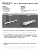
1. Locate the Center Front Panel (D), Center Lower
Front Panel (H), Right Front Panel (C) and Left
Front Panel (B) and set out face down on a
scratch-free surface.
Insert one Wood Dowel (CC) into each of the
pre-drilled holes.
Push the Right Front Panel and Left Front Panel
snug to the center front panel (D) and center lower
front panel (H). Make sure the Wood Dowels are
seated in the pre-drilled holes. Insert Bolts (AA) and
Washers (BB) into the holes in the mounting blocks.
HAND TIGHTEN ONLY.
Hardware Used
BB
AA
CC
Bolt
Washer
Wood Dowel
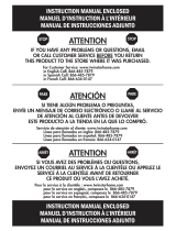
2. Locate Hearth/Base (A) and set out finished side up
on the floor.
Insert one Wood Dowel (CC) into each of the
pre- drilled holes.
Attach the completed Front panel assembly from
step 1 and Center Support Panel (J) to the
Hearth/Base (A). Make sure the dowels are seated
into the pre-drilled holes in the Hearth/Base. Using
Bolts (AA) and Washers (BB) attach panels through
pre-drilled holes in the mounting blocks.
HAND TIGHTEN ONLY.

5
Fig. 3
Fig. 4
x 7
x 7
x 10
BB
BB
BB
E
G
CC
G
F
EE
GG
AA
AA
AA
CC
Fig. 5
Hardware Used
BB
AA
CC
Bolt x 10
Washer x 10
Wood Dowel
x 4
3. Locate Left Side Panel (E) and Right Side Panel (F),
insert one Wood Dowel (CC) into each of the
pre-drilled holes. Attach to the completed front panel
assembly and Hearth/Base using Bolts (AA) and
Washers (BB) through the pre-drilled holes in the
mounting blocks.
HAND TIGHTEN ONLY.
Hardware Used
Hardware Used
EE
BB
GG
AA
CC
Screw ø3*14mm
Bolt
x 4
Metal “L” Bracket
Washer
x 2
Wood Dowel
4. Locate Mantel Top (G) and set out face down on a
non-scratch surface. Attach the Metal “L” Bracket
(EE) to underside of the Mantel/Top (G) as diagram,
tighten Screw (GG) through the pre-drilled holes.
You may want to adjust the position of Metal “L”
Brackets to align with wall studs.
5. Insert one Wood Dowel (CC) into each of the
pre-drilled holes on the top edges of the Assembly
from step 3. Then locate Mantel/Top (G) and lay
fi nished side up on top of completed assembly.
From the inside, attach Mantel/Top (G) using Bolts
(AA) and Washers (BB) through the pre-drilled holes
in the mounting blocks.
HAND TIGHTEN ONLY.

6
Fig. 6
Fig. 7
Fig. 8
Electric
Fireplace Insert
Install
Insert
From
Front
WALL
BB
CC
I
DD
EE
HH
I
AA
Hardware Used
Hardware Used
BB
AA
CC
Bolt x 4
Washer x 4
Wood Dowel
x 4
DD
HH
Screw ø4*50mm
Wall Anchor
x 2
x 2
Hardware Used
FF
Screw ø4*19mm x 4
8. PLEASE READ ALL “ELECTRIC FIREPLACE
INSERT” INSTRUCTIONS PRIOR TO INSTALLING
ELECTRIC INSERT IN YOUR COMPLETED
FIREPLACE MANTEL. INSTALL THE INSERT IN
YOUR FIREPLACE CLOSE TO ITS FINAL
POSITION.
Lift insert carefully into the front of the unit and
center in the insert opening. Do not drag insert
across Hearth/Base (A) as it may scratch your unit.
Please refer to Section 4: “Mounting” in the Electric
Builders Box Installation Guide, provided with
Firebox - Model #’s 36EB110-GRT, 36EB111-GRC,
36EB220-GRT, 36EB221-GRC
6. Insert one Wood Dowel (CC) into each of the
pre-drilled holes, then attach the Connect Block (I)
to the front panel, using Bolts (AA) and Washers
(BB) through the pre-drilled holes.
HAND TIGHTEN ONLY.
Using Phillips head screwdriver tighten all Bolts
alternating top and bottom, left and right.
7. MOVE YOUR COMPLETED UNIT ONLY SHORT
DISTANCES. MOVE COMPLETED UNIT WITH
GREAT CARE. IT TAKES TWO PEOPLE TO MOVE
COMPLETED UNIT INTO ITS FINAL POSITION.
To secure the completed Mantel to the wall tighten
screw (DD) through the Metal “L” Bracket into the
wall. It is recommended that you use wall anchors
when not screwing into wall studs.

7
36WM2383
MANTEQU DE CHEMINÉE ÉLECTRIQUE
INSTRUCTION DE L'ASSEMBLAGE
English p. 1
Français p. 13
Nécessite AUSSI un foyer-insert Nécessite AUSSI un foyer-insert
électrique avec chauffageélectrique avec chauffage
www.twinstarhome.com
Appel en anglais : 866-661-1218
Appel en français : 866-374-9203
Appel en espagnol : 866-661-1218
ATTENTION
Pour le service à la clientèle :
Twin-Star International, Inc.
Delray Beach, FL 33445
Fabriqué en Chine
Imprimé en Chine

8
G
H
I
I
J
J
J
B
A
E
C
F
D
CONTENU DU CARTON
Pièce Description Quantité
A Suelo/Base 1
B Panel Frontal Izquierdo 1
C Panel Frontal Derecho 1
D Panel Frontal Central 1
E panel Lateral Izquierdo 1
F Panel Lateral Derecho 1
G Repisa/Parte Superior 1
H Panel Frontal Inferior Central 1
I Bloque Conector 2
J Panel de Soporte Central 3

9
Tornillo ø4*50mm
Tornillo ø4*19mm
Tornillo ø3*14mm
33+1 adicional
33+1 adicional
37+1 adicional
2
2
4
4
2
BB
CC
DD
EE
FF
GG
HH
AA
1
ZZ
Soporte “L” Metálico
Ancla de Pared
CONTENU DU MATÉRIEL
Pièce
Description Quantité
Illustration
Boulon
Bolígrafo Para Retocar
Espiga De Madera
Arandela
INFORMACIÓN DE SEGURIDAD
ADVERTENCIA
• Antes del montaje, corte con unas tijeras o un bisturí y desenvuelva las piezas
cuidadosamente. Asegúrese de no desechar los herrajes.
PRECAUCIÓN
• Tenga cuidado al armar su nueva chimenea. Tómese su tiempo y use los elementos
suministrados y un destornillador Phillips de calidad. No apriete demasiado los pernos.
• No se siente en ninguna parte de la repisa de la chimenea.
• Todos los paneles están etiquetados izquierda y derecha, vistos desde el frente de la unidad.

10
B
BB
BB
BB
BB
C
D
H
AA
AA
AA
AA
x 4
x 4
x 8
Fig. 2
Fig. 1
CC
CC
J
A
CC
CC
CC
CC
AA
BB
x 8
x 8
x 11
Herrajes utilizados
Herrajes utilizados
BB
AA
CC
Perno
Perno
Arandela
Arandela
Clavija De
Madera
Clavija De
Madera
1. Coloque el Panel Frontal Central (D), el Panel
Frontal Inferior Central (H), el Panel Frontal Derecho
(C) y el Panel Frontal Izquierdo (B) mirando hacia
abajo en una superfi cie sin ralladuras.
Inserte un Tonel de Madera (CC) en cada uno de
los agujeros pre-agujereados. Empuje el Panel
Frontal Derecho y el Panel Frontal Izquierdo ajuste
al Panel Frontal Central (D) y al Panel Frontal
Inferior Central (H). Asegúrese que los Toneles de
Madera están sentados en los agujeros
pre-agujereados. Inserte Tornillos (AA) y Arandelas
(BB) en los agujeros de los bloques montantes.
AJUSTE SÓLO MANUALMENTE.
BB
AA
CC
2. Localice el Suelo/Base (A) y póngalo con la cara
mirando hacia arriba en el suelo. Inserte Toneles
de Madera (CC) en cada uno de los agujeros
pre-agujereados. Adjunte el Panel Frontal Completo
del paso 1 y al Panel de Soporte Central (J) al
Suelo/Base (A). Augúrese que los toneles están
sentados en los agujeros pre-agujereados del
Suelo/Base. Utilizando Tornillos (AA) y Arandelas
(BB) adjunte los paneles a través de los agujeros
pre-agujereados de los bloques montantes.
AJUSTE SÓLO MANUALMENTE.
PREPARACIÓN
Antes de empezar el montaje del producto, asegúrese de que todas las partes estén
presentes. Compare las piezas con la lista de empaque del paquete y el diagrama de ar-
riba. Si alguna pieza falta o está dañada, no trate de armar, instalar o utilizar el producto.
Llame a servicio al cliente para piezas de repuesto.
Tiempo estimado para el montaje: 60 Minutos
Herramientas necesarias para el armado (no incluidas): Destornillador Phillips, tijeras y
un bisturí.
INSTRUCCIONES DE MONTAJE

11
Fig. 3
Fig. 4
x 7
x 7
x 10
BB
BB
BB
E
G
CC
G
F
EE
GG
AA
AA
AA
CC
Fig. 5
BB
AA
CC
x 10
x 10
x 4
3. Localice el panel Lateral Izquierdo (E) y el Panel
Lateral Derecho (F), inserte un Tonel de Madera
(CC) en dada uno de los agujeros pre-agujereados.
Adjúntelos al montaje completo del Panel Frontal
y el Suelo/Base utilizando Tornillos (AA) y Arandelas
(BB) a través de los agujeros pre-agujereados de los
bloques montantes.
AJUSTE SÓLO MANUALMENTE.
EE
BB
GG
AA
CC
Tornillo
ø3*14mm
x 4
Metal “L” Bracket x 2
4. Localice la Cubierta (G) y póngala con la cara
mirando hacia abajo en una superfi cie sin ralladuras.
Adjunte el Soporte Metálico (EE) a la parte inferior
de la Cubierta (G) como se muestra en el diagrama,
apriete tornillos (GG) a través de los agujeros
pre-agujereados. Usted puede ajustar la posición del
Soporte “L” Metálico para alinearlo con la pared
5. Inserte una Espiga De Madera (CC) en cada uno de
los orifi cios previamente perforados del borde
superior del Conjunto que armó en el paso 3. Luego,
tome la Repisa/Parte Superior (G) y colóquela, con
el lado acabado hacia arrinba, sobre el conjunto
armado. Desde el interior, ajuste la Repisa
colocando un Pernos (AA) y una Arandelas (BB) en
los orifi cios previamente perforados de los bloques
de montaje.
AJUSTE SÓLO MANUALMENTE.
Herrajes utilizados
Herrajes utilizados
Herrajes utilizados
Perno
Perno
Arandela
Arandela
Clavija De
Madera
Clavija De
Madera

12
Fig. 6
Fig. 7
Fig. 8
Instalar
Hogar
Desde
frente
WALL
BB
CC
I
DD
EE
HH
I
AA
Herrajes utilizados
BB
AA
CC
x 4
x 4
x 4
DD
HH
Tornillo
ø4*50mm
Ancla de Pared
x 2
x 2
Herrajes utilizados
FF
Tornillo
ø4*19mm
x 4
8. LEA ATENTAMENTE TODAS LAS INSTRUCCIONES
DEL “HOGAR ELÉCTRICO” ANTES DE SU
INSTALACIÓN EN LA CHIMENEA DECORATIVA.
UBIQUE EL HOGAR ELÉCTRICO EN LA
POSICIÓN DEFINITIVA DENTRO DE LA
CHIMENEA.
Levante el hogar cuidadosamente, colóquelo en la
parte posterior de la unidad y céntrelo en la abertura
de la chimenea. No empuje el hogar desde su
Base dado que la unidad se puede dañar.
Por favor, vea la Sección 4: “Montaje” en la Guía de
Instalación de la Caja Eléctrica, provenida con el
Modelo – Firebox #’s 36EB110-GRT, 36EB111-GRC,
36EB220-GRT, 36EB221-GRC
6. Inserte un Tonel de Madera (CC) en cada uno de los
agujeros pre-agujereados, luego adjunte el Bloque
Conector (I) al panel frontal, utilizando Tornillos (AA)
y Arandelas (BB) a través de los agujeros
pre-agujereados.
AJUSTE SÓLO MANUALMENTE.
Utilizando un destornillador Phillips (cruciforme),
apriete todos los pernos, alternando entre la parte
superior e inferior, la izquierda y la derecha.
7. MUEVA LA UNIDAD COMPLETA SÓLO A
DISTANCIAS CORTAS. MUEVA LA UNIDAD
COMPLETA CON EXTREMO CUIDADO. SE
NECESITAN DOS PERSONAS PARA MOVER LA
UNIDAD COMPLETA A LA POSICIÓN FINAL.
Para asegurar el Mueble completo a la pared apriete
los tornillos (DD) a través del Soporte “L” Metálico
a la pared. Se recomienda que utilice las anclas de
la pared cuando no se atornille a otros montantes de
la pared.
Herrajes utilizados
Perno
Arandela
Clavija De
Madera
Hogar
Eléctrico

13
36WM2383
English p. 1
Españo p. 7
MANTEQU DE CHEMINÉE ÉLECTRIQUE
INSTRUCTION DE L'ASSEMBLAGE
Nécessite AUSSI un foyer-insert Nécessite AUSSI un foyer-insert
électrique avec chauffageélectrique avec chauffage
www.twinstarhome.com
Appel en anglais : 866-661-1218
Appel en français : 866-374-9203
Appel en espagnol : 866-661-1218
ATTENTION
Pour le service à la clientèle :
Twin-Star International, Inc.
Delray Beach, FL 33445
Fabriqué en Chine
Imprimé en Chine

14
G
H
I
I
J
J
J
B
A
E
C
F
D
CONTENU DU CARTON
Pièce Description Quantité
A Base du Foyer 1
B Panneau Avant Gauche 1
C Panneau Avant Droit 1
D Panneau Avant Central 1
E Panneau Latéral Gauche 1
F Panneau Latéral Droit 1
G Manteau/dessus 1
H Panneau Avant Inférieur Central 1
I Bloc de Connexion 2
J Panneau de Support Centre 3

15
Boulon
Rondelle
Goujon en bois
Vis ø4*50mm
Vis ø4*19mm
Vis ø3*14mm
33+1 extra
33+1 extra
37+1 extra
2
2
4
4
2
BB
CC
DD
EE
FF
GG
HH
AA
Crayon pour retouches
1
ZZ
Support “L” en Métal
Fixation Murale
INFORMATION DE SÉCURITÉ
AVERTISSEMENT
• Avant l’assemblage, à l’aide de ciseaux ou d’un couteau universel, coupez et déballez
soigneusement toutes les pièces. Assurez-vous de ne pas jeter de matériel.
MISE EN GARDE
• Faites preuve de prudence dans l’assemblage de votre nouvelle cheminée. Prenez
votre temps et utilisez le matériel fourni et un tournevis cruciforme de qualité. Ne serrez
pas trop les boulons.
• Ne vous asseyez pas sur des pièces du manteau.
• Tous les panneaux sont étiquetés de gauche et de Droit quand on les regarde
en se tenant face à la cheminée.
CONTENU DU MATÉRIEL
Pièce
Description Quantité
Illustration

16
B
BB
BB
BB
BB
C
D
H
AA
AA
AA
AA
x 4
x 4
x 8
Fig. 2
Fig. 1
CC
CC
J
A
CC
CC
CC
CC
AA
BB
x 8
x 8
x 11
BB
AA
CC
1. Localisez le Panneau Avant Central (D), le Panneau
Avant Inférieur Central (H), le Panneau Avant Droit
(C) et le Panneau Avant Gauche (B) et placez les à
l’envers sur une surface sans rayures.
Insérer une Cheville en Bois (CC) dans chacun des
trous pré-perforés.
Poussez et ajustez le Panneau Avant Droit et le
Panneau Avant Gauche au Panneau Avant Central
(D) et le Panneau Avant Inférieur Central (H).
Assurez-vous que les chevilles de bois soient bien
assis dans les trous pré-perforés.
Insérez des Boulons (AA) et des Rondelles (BB )
dans les trous des blocs de montage.
SERRER À LA MAIN SEULEMENT.
BB
AA
CC
2. Localisez la Base du Foyer(A) et placez-la le côté
fi ni en haut sur le sol.
Insérer une Cheville en bois (CC) dans chacun des
trous pré-perforés.
Fixez l’assemblage du panneau Avant complété de
l’étape 1 et le Panneau de Support Centre (J) à la
Base du Foyer(A). Assurez-vous que les chevilles
soient bien placés dans les trous pré-perforés dans
la Base du Foyer. En utilisant des Boulons (AA) et
des Rondelles (BB) fi xez les panneaux par le biais
des trous pré-perforés dans les blocs de montage.
SERRER À LA MAIN SEULEMENT.
PRÉPARATION
Avant de commencer l’assemblage du produit, assurez-vous que toutes les pièces sont présentes.
Comparez les pièces avec la liste du contenu de la boîte et le schéma ci-dessus. Si une pièce est
manquante ou endommagée, n’essayez pas d’assembler, d’installer ou de faire fonctionner le produit.
Communiquez avec le service à la clientèle pour obtenir des pièces de rechange.
Durée d’assemblage estimée : 60 minutes
Outils requis pour l’assemblage (non inclus) : Tournevis cruciforme, ciseaux et couteau universel
INSTRUCTIONS POUR L’ASSEMBLAGE
Matériel utilisé
Matériel utilisé
Boulon
Boulon
Rondelle
Rondelle
Goujon en bois
Goujon en bois

17
Fig. 3
Fig. 4
x 7
x 7
x 10
BB
BB
BB
E
G
CC
G
F
EE
GG
AA
AA
AA
CC
Fig. 5
BB
AA
CC
x 10
x 10
x 4
3. Localisez le Panneau Latéral Gauche (E) et le
Panneau Latéral Droit (F), insérez une Cheville en
Bois (CC) dans chacun des trous pré-perforés. Fixez
l’assemblage du panneau avant terminé à la Base
du Foyer à l’aide de Boulons (AA) et de Rondelles
(BB) à travers les trous pré-perforés dans les blocs
de montage.
SERRER À LA MAIN SEULEMENT.
Matériel utilisé
EE
BB
GG
AA
CC
Vis ø3*14mm x 4
Support “L” en
Métal
x 2
4. Localisez le Haut de la Cheminée (G) et placez le à
l’envers sur une surface sans rayures. Fixez le
support “L” en métal (EE) en dessous du Haut de la
Cheminée (G) comme sur le schéma, serrez la Vis
(GG) à travers le trous pré-perforés. Vous pouvez
ajuster la position du Support “L”en métal pour
l’aligner sur les montants du mur.
SERRER À LA MAIN SEULEMENT.
5. Insérez un Goujon En Bois (CC) dans chacun des
trous pré-percés de la bordure supérieure du
panneau assemblé à l’étape 3. Trouvez ensuite le
Manteau/Dessus (G). Déposez le côté fi ni du
manteau sur le dessus du panneau entièrement
monté. De l’intérieur, fi xez le manteau à l’aide
d’un Boulons (AA) et d’une Rondelles (BB), en les
insérant dans les trous pré-percés des blocs de
montage.
SERRER À LA MAIN SEULEMENT.
Matériel utilisé
Matériel utilisé
Boulon
Boulon
Rondelle
Rondelle
Goujon en bois
Goujon en bois

18
Fig. 6
Fig. 7
Fig. 8
Foyer encastrable
électrique
Installer
le foyer
encas-
trable
par
l’avant
WALL
BB
CC
I
DD
EE
HH
I
AA
Matériel utilisé
BB
AA
CC
x 4
x 4
x 4
DD
HH
Vis ø4*50mm
Fixation Murale
x 2
x 2
Matériel utilisé
FF
Vis ø4*19mm x 4
8. VEUILLEZ LIRE TOUTES LES INSTRUCTIONS
D’INSTALLATION DU FOYER ÉLECTRIQUE
ENCASTRABLE AVANT D’INSTALLER LE FOYER
DANS LE MANTEAU, UNE FOIS CELUI-CI
ASSEMBLÉ. INSTALLEZ LE FOYER DANS
L’ESPACE PRÉVU, PRÈS DE SA POSITION
FINALE.
Soulevez doucement le foyer encastrable pour le
déposer par l’arrière du manteau, dans le centre de
l’ouverture de celui-ci. Ne pas tirer le foyer
encastrable sur Âtre/Base (A) car cela pourrait
égratigner la base du manteau.
S’il vous plaît consulter à la section 4: “Montage”
dans le Guide d’installation électrique de la boîte
constructeurs, fourni avec le Foyer - Modèle # l
‘36EB110-TJB, 36EB111-GRC, 36EB220-TJB,
36EB221-GRC
6. Insérez une Cheville en Bois (CC) dans chacun des
trous pré-perforés, puis fi xez le Bloc de Connexion
(I) au Panneau Avant, en utilisant des Boulons (AA)
et des Rondelles (BB) à travers les trous
pré-perforés.
SERRER À LA MAIN SEULEMENT.
Avec un tournevis cruciforme, serrez tous les
goujons, en alternant entre le haut et le bas, la
gauche et la Droit.
7. NE DEPLACER VOTRE UNITE COMPLETE QUE
SUR DES DISTANCES COURTES. DEPLACER
L’UNITE COMPLETE AVEC PRECAUTION. IL FAUT
DEUX PERSONNES POUR METTRE L’UNITE
COMPLETE DANS SA POSITION FINALE.
Pour fi xer la Cheminée complété au mur serrer la vis
(DD) à travers le Support “L” en métal au mur. Il est
recommandé d’utiliser des fi xations murales quand
vous ne vissez pas aux montants du mur.
Matériel utilisé
Boulon
Rondelle
Goujon en bois
Transcripción de documentos
INSTRUCTION MANUAL ENCLOSED MANUEL D’INSTRUCTION À L’INTÉRIEUR MANUAL DE INSTRUCCIONES ADJUNTO STOP ATTENTION STOP IF YOU HAVE ANY PROBLEMS OR QUESTIONS, EMAIL OR CALL CUSTOMER SERVICE BEFORE YOU RETURN THIS PRODUCT TO THE STORE WHERE IT WAS PURCHASED. For Customer Service: www.twinstarhome.com in English Call: 866-661-1218 in Spanish Call: 866-661-1218 in French Call: 866-374-9203 PARE ATENCIÓN PARE SI TIENE ALGÚN PROBLEMA O PREGUNTAS, ENVÍE UN MENSAJE DE CORREO ELECTRÓNICO O LLAME AL SERVICIO DE ATENCIÓN AL CLIENTE ANTES DE DEVOLVER ESTE PRODUCTO A LA TIENDA EN LA QUE LO COMPRÓ. Servicio de atención al cliente: www.twinstarhome.com Línea para llamadas en inglés: 866-661-1218 Línea para llamadas en español: 866-661-1218 Línea para llamadas en francés: 866-374-9203 ARRÊT ATTENTION ARRÊT SI VOUS AVEZ DES PROBLÈMES OU QUESTIONS, ENVOYEZ UN COURRIEL AU SERVICE À LA CLIENTÈLE OU APPELEZ LE SERVICE À LA CLIENTÈLE AVANT DE RETOURNER CE PRODUIT OÙ VOUS L’AVEZ ACHETÉ. Pour le service à la clientèle : www.twinstarhome.com pour le service en anglais, composez le 866-661-1218 pour le service en espagnol, composez le 866-661-1218 pour le service en français, composez le 866-374-9203 INSTRUCTION MANUAL ENCLOSED MANUEL D’INSTRUCTION À L’INTÉRIEUR MANUAL DE INSTRUCCIONES ADJUNTO 1 ELECTRIC FIREPLACE MANTEL 36WM2383 ASSEMBLY INSTRUCTION Españo p. 7 Français p. 13 For Customer Service: Twin-Star International, Inc. Delray Beach, FL 33445 Made in China Printed in China www.twinstarhome.com In English call: 866-661-1218 In French call: 866-374-9203 In Spanish call: 866-661-1218 1 AT T E N T I O N Requires-Electric Fireplace Insert with Heater PACKAGE CONTENTS G F C D E B I I J J J H A Part A B C Description Hearth/Base Left Front Panel Right Front Panel Quantity 1 1 1 D E F G H I J Center Front Panel Left Side Panel Right Side Panel Mantel/Top Center Lower Front Panel Connect Block Center Support Panel 1 1 1 1 1 2 3 2 HARDWARE CONTENTS Quantity Part Description AA Bolt 33+1 extra BB Washer 33+1 extra CC Wood Dowel 37+1 extra DD Screw ø4*50mm 2 EE Metal “L” Bracket 2 FF Screw ø4*19mm 4 GG Screw ø3*14mm 4 HH Wall Anchor 2 ZZ Touch-up Pen 1 Picture SAFETY INFORMATION WARNING • Before assembly, carefully use scissors or utility knife to cut and unwrap all parts. Make sure you do not discard the hardware. CAUTION • Use care in assembling your new fireplace. Take your time and use the hardware provided and a quality Phillips head screwdriver. Never overtighten bolts. • Do not sit on any part of the mantel. • All panels are labeled left and right as viewed from the front of unit. 3 PREPARATION Before beginning assembly of product, make sure all parts are present. Compare parts with package contents list and diagram above. If any part is missing or damaged, do not attempt to assemble, install or operate the product. Contact customer service for replacement parts. Estimated Assembly Time: 60 Minutes Tools Required for Assembly (not included): Phillips head screwdriver, scissors and utility knife ASSEMBLY INSTRUCTIONS 1. Locate the Center Front Panel (D), Center Lower Front Panel (H), Right Front Panel (C) and Left Front Panel (B) and set out face down on a scratch-free surface. Insert one Wood Dowel (CC) into each of the pre-drilled holes. Push the Right Front Panel and Left Front Panel snug to the center front panel (D) and center lower front panel (H). Make sure the Wood Dowels are seated in the pre-drilled holes. Insert Bolts (AA) and Washers (BB) into the holes in the mounting blocks. HAND TIGHTEN ONLY. Fig. 1 CC D CC B BB AA C H Hardware Used CC Bolt x4 BB Washer x4 CC Wood Dowel x8 AA CC BB AA 2. Locate Hearth/Base (A) and set out finished side up on the floor. Insert one Wood Dowel (CC) into each of the pre- drilled holes. Attach the completed Front panel assembly from step 1 and Center Support Panel (J) to the Hearth/Base (A). Make sure the dowels are seated into the pre-drilled holes in the Hearth/Base. Using Bolts (AA) and Washers (BB) attach panels through pre-drilled holes in the mounting blocks. HAND TIGHTEN ONLY. Fig. 2 AA BB Hardware Used AA Bolt x8 Washer x8 Wood Dowel x 11 A BB CC J CC 4 CC 3. Locate Left Side Panel (E) and Right Side Panel (F), insert one Wood Dowel (CC) into each of the pre-drilled holes. Attach to the completed front panel assembly and Hearth/Base using Bolts (AA) and Washers (BB) through the pre-drilled holes in the mounting blocks. HAND TIGHTEN ONLY. Fig. 3 BB AA Hardware Used AA Bolt E x 10 AA F BB Washer x 10 CC Wood Dowel x4 BB CC 4. Locate Mantel Top (G) and set out face down on a non-scratch surface. Attach the Metal “L” Bracket (EE) to underside of the Mantel/Top (G) as diagram, tighten Screw (GG) through the pre-drilled holes. You may want to adjust the position of Metal “L” Brackets to align with wall studs. Fig. 4 GG EE Hardware Used GG Screw ø3*14mm x4 EE Metal “L” Bracket x2 G 5. Insert one Wood Dowel (CC) into each of the pre-drilled holes on the top edges of the Assembly from step 3. Then locate Mantel/Top (G) and lay finished side up on top of completed assembly. From the inside, attach Mantel/Top (G) using Bolts (AA) and Washers (BB) through the pre-drilled holes in the mounting blocks. HAND TIGHTEN ONLY. Hardware Used Fig. 5 G BB AA Bolt x7 BB Washer x7 CC Wood Dowel x 10 AA 5 CC 6. Insert one Wood Dowel (CC) into each of the pre-drilled holes, then attach the Connect Block (I) to the front panel, using Bolts (AA) and Washers (BB) through the pre-drilled holes. HAND TIGHTEN ONLY. Fig. 6 Using Phillips head screwdriver tighten all Bolts alternating top and bottom, left and right. I CC Hardware Used BB AA Bolt x4 BB Washer x4 CC Wood Dowel x4 I AA 7. MOVE YOUR COMPLETED UNIT ONLY SHORT DISTANCES. MOVE COMPLETED UNIT WITH GREAT CARE. IT TAKES TWO PEOPLE TO MOVE COMPLETED UNIT INTO ITS FINAL POSITION. Fig. 7 To secure the completed Mantel to the wall tighten screw (DD) through the Metal “L” Bracket into the wall. It is recommended that you use wall anchors when not screwing into wall studs. WALL Hardware Used DD Screw ø4*50mm x2 HH Wall Anchor x2 HH EE 8. PLEASE READ ALL “ELECTRIC FIREPLACE INSERT” INSTRUCTIONS PRIOR TO INSTALLING ELECTRIC INSERT IN YOUR COMPLETED FIREPLACE MANTEL. INSTALL THE INSERT IN YOUR FIREPLACE CLOSE TO ITS FINAL POSITION. Lift insert carefully into the front of the unit and center in the insert opening. Do not drag insert across Hearth/Base (A) as it may scratch your unit. Fig. 8 Install Insert From Front Please refer to Section 4: “Mounting” in the Electric Builders Box Installation Guide, provided with Firebox - Model #’s 36EB110-GRT, 36EB111-GRC, 36EB220-GRT, 36EB221-GRC Hardware Used FF Screw ø4*19mm Electric Fireplace Insert x4 6 DD MANTEQU DE CHEMINÉE ÉLECTRIQUE 36WM2383 INSTRUCTION DE L'ASSEMBLAGE English p. 1 Français p. 13 Pour le service à la clientèle : Twin-Star International, Inc. Delray Beach, FL 33445 Fabriqué en Chine Imprimé en Chine www.twinstarhome.com Appel en anglais : 866-661-1218 Appel en français : 866-374-9203 Appel en espagnol : 866-661-1218 7 AT T E N T I O N Nécessite AUSSI un foyer-insert électrique avec chauffage CONTENU DU CARTON G F C D E B I I J J J H A Pièce A B C D E F G H I J Description Suelo/Base Panel Frontal Izquierdo Panel Frontal Derecho Panel Frontal Central panel Lateral Izquierdo Panel Lateral Derecho Repisa/Parte Superior Panel Frontal Inferior Central Bloque Conector Panel de Soporte Central 8 Quantité 1 1 1 1 1 1 1 1 2 3 CONTENU DU MATÉRIEL Pièce Description Quantité AA Boulon 33+1 adicional BB Arandela 33+1 adicional CC Espiga De Madera 37+1 adicional DD Tornillo ø4*50mm 2 EE Soporte “L” Metálico 2 FF Tornillo ø4*19mm 4 GG Tornillo ø3*14mm 4 HH Ancla de Pared 2 ZZ Bolígrafo Para Retocar 1 Illustration INFORMACIÓN DE SEGURIDAD ADVERTENCIA • Antes del montaje, corte con unas tijeras o un bisturí y desenvuelva las piezas cuidadosamente. Asegúrese de no desechar los herrajes. PRECAUCIÓN • Tenga cuidado al armar su nueva chimenea. Tómese su tiempo y use los elementos suministrados y un destornillador Phillips de calidad. No apriete demasiado los pernos. • No se siente en ninguna parte de la repisa de la chimenea. • Todos los paneles están etiquetados izquierda y derecha, vistos desde el frente de la unidad. 9 PREPARACIÓN Antes de empezar el montaje del producto, asegúrese de que todas las partes estén presentes. Compare las piezas con la lista de empaque del paquete y el diagrama de arriba. Si alguna pieza falta o está dañada, no trate de armar, instalar o utilizar el producto. Llame a servicio al cliente para piezas de repuesto. Tiempo estimado para el montaje: 60 Minutos Herramientas necesarias para el armado (no incluidas): Destornillador Phillips, tijeras y un bisturí. INSTRUCCIONES DE MONTAJE 1. Coloque el Panel Frontal Central (D), el Panel Frontal Inferior Central (H), el Panel Frontal Derecho (C) y el Panel Frontal Izquierdo (B) mirando hacia abajo en una superficie sin ralladuras. Inserte un Tonel de Madera (CC) en cada uno de los agujeros pre-agujereados. Empuje el Panel Frontal Derecho y el Panel Frontal Izquierdo ajuste al Panel Frontal Central (D) y al Panel Frontal Inferior Central (H). Asegúrese que los Toneles de Madera están sentados en los agujeros pre-agujereados. Inserte Tornillos (AA) y Arandelas (BB) en los agujeros de los bloques montantes. AJUSTE SÓLO MANUALMENTE. Herrajes utilizados AA BB Perno x4 Arandela x4 Fig. 1 CC D CC B BB AA C H CC CC BB Clavija De x8 Madera 2. Localice el Suelo/Base (A) y póngalo con la cara mirando hacia arriba en el suelo. Inserte Toneles de Madera (CC) en cada uno de los agujeros pre-agujereados. Adjunte el Panel Frontal Completo del paso 1 y al Panel de Soporte Central (J) al Suelo/Base (A). Augúrese que los toneles están sentados en los agujeros pre-agujereados del Suelo/Base. Utilizando Tornillos (AA) y Arandelas (BB) adjunte los paneles a través de los agujeros pre-agujereados de los bloques montantes. AJUSTE SÓLO MANUALMENTE. AA CC Fig. 2 AA BB Herrajes utilizados Perno x8 BB Arandela x8 CC Clavija De Madera x 11 AA A J CC 10 CC 3. Localice el panel Lateral Izquierdo (E) y el Panel Lateral Derecho (F), inserte un Tonel de Madera (CC) en dada uno de los agujeros pre-agujereados. Adjúntelos al montaje completo del Panel Frontal y el Suelo/Base utilizando Tornillos (AA) y Arandelas (BB) a través de los agujeros pre-agujereados de los bloques montantes. AJUSTE SÓLO MANUALMENTE. Fig. 3 BB AA Herrajes utilizados AA Perno E x 10 AA F BB Arandela x 10 CC Clavija De Madera x4 BB CC 4. Localice la Cubierta (G) y póngala con la cara mirando hacia abajo en una superficie sin ralladuras. Adjunte el Soporte Metálico (EE) a la parte inferior de la Cubierta (G) como se muestra en el diagrama, apriete tornillos (GG) a través de los agujeros pre-agujereados. Usted puede ajustar la posición del Soporte “L” Metálico para alinearlo con la pared Fig. 4 GG EE Herrajes utilizados GG Tornillo ø3*14mm x4 EE Metal “L” Bracket x2 G 5. Inserte una Espiga De Madera (CC) en cada uno de los orificios previamente perforados del borde superior del Conjunto que armó en el paso 3. Luego, tome la Repisa/Parte Superior (G) y colóquela, con el lado acabado hacia arrinba, sobre el conjunto armado. Desde el interior, ajuste la Repisa colocando un Pernos (AA) y una Arandelas (BB) en los orificios previamente perforados de los bloques de montaje. AJUSTE SÓLO MANUALMENTE. Herrajes utilizados AA Perno x7 BB Arandela x7 CC Clavija De Madera x 10 Fig. 5 G BB AA 11 CC 6. Inserte un Tonel de Madera (CC) en cada uno de los agujeros pre-agujereados, luego adjunte el Bloque Conector (I) al panel frontal, utilizando Tornillos (AA) y Arandelas (BB) a través de los agujeros pre-agujereados. AJUSTE SÓLO MANUALMENTE. Fig. 6 Utilizando un destornillador Phillips (cruciforme), apriete todos los pernos, alternando entre la parte superior e inferior, la izquierda y la derecha. Herrajes utilizados I CC BB I AA Perno x4 BB Arandela x4 CC Clavija De Madera x4 AA 7. MUEVA LA UNIDAD COMPLETA SÓLO A DISTANCIAS CORTAS. MUEVA LA UNIDAD COMPLETA CON EXTREMO CUIDADO. SE NECESITAN DOS PERSONAS PARA MOVER LA UNIDAD COMPLETA A LA POSICIÓN FINAL. Para asegurar el Mueble completo a la pared apriete los tornillos (DD) a través del Soporte “L” Metálico a la pared. Se recomienda que utilice las anclas de la pared cuando no se atornille a otros montantes de la pared. Fig. 7 WALL Herrajes utilizados DD HH Tornillo ø4*50mm Ancla de Pared HH x2 EE x2 8. LEA ATENTAMENTE TODAS LAS INSTRUCCIONES DEL “HOGAR ELÉCTRICO” ANTES DE SU INSTALACIÓN EN LA CHIMENEA DECORATIVA. UBIQUE EL HOGAR ELÉCTRICO EN LA POSICIÓN DEFINITIVA DENTRO DE LA CHIMENEA. Levante el hogar cuidadosamente, colóquelo en la parte posterior de la unidad y céntrelo en la abertura de la chimenea. No empuje el hogar desde su Base dado que la unidad se puede dañar. Fig. 8 Instalar Hogar Desde frente Por favor, vea la Sección 4: “Montaje” en la Guía de Instalación de la Caja Eléctrica, provenida con el Modelo – Firebox #’s 36EB110-GRT, 36EB111-GRC, 36EB220-GRT, 36EB221-GRC Hogar Eléctrico Herrajes utilizados FF Tornillo ø4*19mm DD x4 12 MANTEQU DE CHEMINÉE ÉLECTRIQUE 36WM2383 INSTRUCTION DE L'ASSEMBLAGE English p. 1 Españo p. 7 Pour le service à la clientèle : Twin-Star International, Inc. Delray Beach, FL 33445 Fabriqué en Chine Imprimé en Chine www.twinstarhome.com Appel en anglais : 866-661-1218 Appel en français : 866-374-9203 Appel en espagnol : 866-661-1218 13 AT T E N T I O N Nécessite AUSSI un foyer-insert électrique avec chauffage CONTENU DU CARTON G F C D E B I I J J J H A Pièce A B C D E F G H I J Description Base du Foyer Panneau Avant Gauche Panneau Avant Droit Panneau Avant Central Panneau Latéral Gauche Panneau Latéral Droit Manteau/dessus Panneau Avant Inférieur Central Bloc de Connexion Panneau de Support Centre 14 Quantité 1 1 1 1 1 1 1 1 2 3 CONTENU DU MATÉRIEL Pièce Description Quantité AA Boulon 33+1 extra BB Rondelle 33+1 extra CC Goujon en bois 37+1 extra DD Vis ø4*50mm 2 EE Support “L” en Métal 2 FF Vis ø4*19mm 4 GG Vis ø3*14mm 4 HH Fixation Murale 2 ZZ Crayon pour retouches 1 Illustration INFORMATION DE SÉCURITÉ AVERTISSEMENT • Avant l’assemblage, à l’aide de ciseaux ou d’un couteau universel, coupez et déballez soigneusement toutes les pièces. Assurez-vous de ne pas jeter de matériel. MISE EN GARDE • Faites preuve de prudence dans l’assemblage de votre nouvelle cheminée. Prenez votre temps et utilisez le matériel fourni et un tournevis cruciforme de qualité. Ne serrez pas trop les boulons. • Ne vous asseyez pas sur des pièces du manteau. • Tous les panneaux sont étiquetés de gauche et de Droit quand on les regarde en se tenant face à la cheminée. 15 PRÉPARATION Avant de commencer l’assemblage du produit, assurez-vous que toutes les pièces sont présentes. Comparez les pièces avec la liste du contenu de la boîte et le schéma ci-dessus. Si une pièce est manquante ou endommagée, n’essayez pas d’assembler, d’installer ou de faire fonctionner le produit. Communiquez avec le service à la clientèle pour obtenir des pièces de rechange. Durée d’assemblage estimée : 60 minutes Outils requis pour l’assemblage (non inclus) : Tournevis cruciforme, ciseaux et couteau universel INSTRUCTIONS POUR L’ASSEMBLAGE 1. Localisez le Panneau Avant Central (D), le Panneau Avant Inférieur Central (H), le Panneau Avant Droit (C) et le Panneau Avant Gauche (B) et placez les à l’envers sur une surface sans rayures. Insérer une Cheville en Bois (CC) dans chacun des trous pré-perforés. Poussez et ajustez le Panneau Avant Droit et le Panneau Avant Gauche au Panneau Avant Central (D) et le Panneau Avant Inférieur Central (H). Assurez-vous que les chevilles de bois soient bien assis dans les trous pré-perforés. Insérez des Boulons (AA) et des Rondelles (BB ) dans les trous des blocs de montage. SERRER À LA MAIN SEULEMENT. Matériel utilisé Boulon x4 BB Rondelle x4 CC Goujon en bois x8 AA Fig. 1 CC D CC B BB AA C H CC CC BB AA Fig. 2 2. Localisez la Base du Foyer(A) et placez-la le côté fini en haut sur le sol. Insérer une Cheville en bois (CC) dans chacun des trous pré-perforés. Fixez l’assemblage du panneau Avant complété de l’étape 1 et le Panneau de Support Centre (J) à la Base du Foyer(A). Assurez-vous que les chevilles soient bien placés dans les trous pré-perforés dans la Base du Foyer. En utilisant des Boulons (AA) et des Rondelles (BB) fixez les panneaux par le biais des trous pré-perforés dans les blocs de montage. SERRER À LA MAIN SEULEMENT. Matériel utilisé AA Boulon x8 BB Rondelle x8 CC Goujon en bois x 11 AA BB A J CC 16 CC 3. Localisez le Panneau Latéral Gauche (E) et le Panneau Latéral Droit (F), insérez une Cheville en Bois (CC) dans chacun des trous pré-perforés. Fixez l’assemblage du panneau avant terminé à la Base du Foyer à l’aide de Boulons (AA) et de Rondelles (BB) à travers les trous pré-perforés dans les blocs de montage. SERRER À LA MAIN SEULEMENT. Fig. 3 BB AA Matériel utilisé AA Boulon E x 10 AA F BB Rondelle x 10 CC Goujon en bois x4 BB CC 4. Localisez le Haut de la Cheminée (G) et placez le à l’envers sur une surface sans rayures. Fixez le support “L” en métal (EE) en dessous du Haut de la Cheminée (G) comme sur le schéma, serrez la Vis (GG) à travers le trous pré-perforés. Vous pouvez ajuster la position du Support “L”en métal pour l’aligner sur les montants du mur. SERRER À LA MAIN SEULEMENT. Matériel utilisé GG Vis ø3*14mm x4 EE Support “L” en Métal x2 Fig. 4 GG EE G 5. Insérez un Goujon En Bois (CC) dans chacun des trous pré-percés de la bordure supérieure du panneau assemblé à l’étape 3. Trouvez ensuite le Manteau/Dessus (G). Déposez le côté fini du manteau sur le dessus du panneau entièrement monté. De l’intérieur, fixez le manteau à l’aide d’un Boulons (AA) et d’une Rondelles (BB), en les insérant dans les trous pré-percés des blocs de montage. SERRER À LA MAIN SEULEMENT. Matériel utilisé Fig. 5 G BB AA Boulon x7 BB Rondelle x7 CC Goujon en bois x 10 AA 17 CC 6. Insérez une Cheville en Bois (CC) dans chacun des trous pré-perforés, puis fixez le Bloc de Connexion (I) au Panneau Avant, en utilisant des Boulons (AA) et des Rondelles (BB) à travers les trous pré-perforés. SERRER À LA MAIN SEULEMENT. Avec un tournevis cruciforme, serrez tous les goujons, en alternant entre le haut et le bas, la gauche et la Droit. Matériel utilisé Fig. 6 I CC BB I AA AA Boulon x4 BB Rondelle x4 CC Goujon en bois x4 7. NE DEPLACER VOTRE UNITE COMPLETE QUE SUR DES DISTANCES COURTES. DEPLACER L’UNITE COMPLETE AVEC PRECAUTION. IL FAUT DEUX PERSONNES POUR METTRE L’UNITE COMPLETE DANS SA POSITION FINALE. Fig. 7 Pour fixer la Cheminée complété au mur serrer la vis (DD) à travers le Support “L” en métal au mur. Il est recommandé d’utiliser des fixations murales quand vous ne vissez pas aux montants du mur. WALL Matériel utilisé DD Vis ø4*50mm x2 HH Fixation Murale x2 HH EE 8. VEUILLEZ LIRE TOUTES LES INSTRUCTIONS D’INSTALLATION DU FOYER ÉLECTRIQUE ENCASTRABLE AVANT D’INSTALLER LE FOYER DANS LE MANTEAU, UNE FOIS CELUI-CI ASSEMBLÉ. INSTALLEZ LE FOYER DANS L’ESPACE PRÉVU, PRÈS DE SA POSITION FINALE. Soulevez doucement le foyer encastrable pour le déposer par l’arrière du manteau, dans le centre de l’ouverture de celui-ci. Ne pas tirer le foyer encastrable sur Âtre/Base (A) car cela pourrait égratigner la base du manteau. S’il vous plaît consulter à la section 4: “Montage” dans le Guide d’installation électrique de la boîte constructeurs, fourni avec le Foyer - Modèle # l ‘36EB110-TJB, 36EB111-GRC, 36EB220-TJB, 36EB221-GRC Matériel utilisé FF Vis ø4*19mm x4 18 Fig. 8 Foyer encastrable électrique DD Installer le foyer encastrable par l’avant-
 1
1
-
2
-
3
-
4
-
5
-
6
-
7
-
8
-
9
-
10
-
11
-
12
-
13
-
14
-
15
-
16
-
17
-
18
-
19
Twin-Star International 36WM2383 Assembly Instruction Manual
- Tipo
- Assembly Instruction Manual
en otros idiomas
- français: Twin-Star International 36WM2383
- English: Twin-Star International 36WM2383
Artículos relacionados
-
Twin-Star International 18DF2433 Manual de usuario
-
-
-
-
-
-
-
Otros documentos
-
Classic Flame 36EB220-GRT Manual de usuario
-
-
ClassicFlame 36EB221-GRC Manual de usuario
-
 Tresanti TC72-9313-B974 Manual de usuario
-
-
none 75119 Guía de instalación
-
 Ornamental Mouldings CLASSIC5WHW Guía de instalación
-
Ornamental Mouldings RUSTIC5WM Guía de instalación
-
 Tresanti KC7005-T401-42 Guía de instalación


