Allen-Bradley 140G Series Guía de instalación
- Tipo
- Guía de instalación

DIR 1000437R0002 Version 02
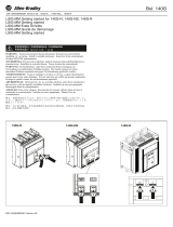
DIR 1000437R0002 Version 02 - 140G-K_; 140MG-K_
Bul. 140G/140MG
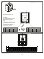
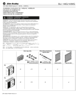
WARNING: To prevent electrical shock, disconnect from power source before
installing or servicing. Install in suitable enclosure. Keep free from contaminants.
(Follow NFPA70E requirements).
AVVERTENZA: Per prevenire infortuni, togliere tensione prima dell'installazione o
manutenzione. Installare in custodia idonea. Tenere lontano da contaminanti.
(Seguire i requisiti NFPA70E).
WARNUNG: Vor Installations- oder Servicearbeiten Stromversorgung zur
Vermeidung von elektrischen Unfällen trennen. Die Geräte müssen in einem
passenden Gehäuse eingebaut und gegen Verschmutzung geschützt werden. (Befolgen
Sie die Anforderungen nach NFPA70E).
AVERTISSEMENT: Avant le montage et la mise en service, couper l'alimentation
secteur pour éviter toute décharge. Prévoir une mise en coffret ou armoire appropriée.
Protéger le produit contre les environnements agressifs. (Vous devez respecter la
norme NFPA70E).
ADVERTENCIA: Desconéctese de la corriente eléctrica, antes de la instalación o
del servicio, a fin de impedir sacudidas eléctricas. Instálelo en una caja apropiada.
Manténgalo libre de contaminantes. (Cumpla con los requisitos NFPA70E).
ATENÇÃO: Para evitar choques, desconectar da corrente elétrica antes de fazer a
instalação ou a manutenção. Instalar em caixa apropriada. Manter livre de
contaminantes. (Cumpra as exigências da norma NFPA70E).
Installation - Installazione - Instalación
Instalação - -
警告:感電事故防止のため、取付けまたは修理の際は電源から取り外してく
ださい。適切なケース内に取付けてください。また、汚染物質がないことを
確認してください。(NFPA70Eの要件に従ってください)
警告:为了防止触电,在安装或维修之前必须先切断电源。安装在合适的设备
箱内。防止接触污染 。符合NFPA70E要求)物
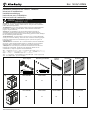
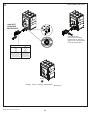
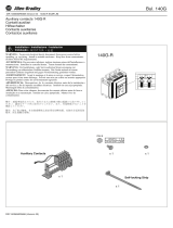
x6
3p
4p
Phase
barrier
End cap kit Insulator Insulator
140G-K-ECM3
Mounting hardware
x8
140G-K-ECM4
x4
140G-K-MH4
x4
140G-K-MH4
x4
140G-K-PB3M
x6
140G-K-PB4M
x1
140G-K-BP3
-
x1
140G-K-BP4
-
LENGTH M
85 mm (3.35" ) M 5
LENGTH M
22 mm (0.87") M 1 0
CH 8
Installation instruction for 140G-K, 140MG-K
Istruzioni di installazione
Installationsanleitung
Instructions pour l’installation
Instrucciones de instalación

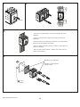
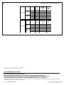
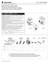
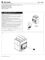
1
2
CLACK
150 mm
5.90"
3
4
- Use cable or insulated busbars/ or perform specific type test on the
installation.
- Usare cavi o barre isolate/ o eseguire prove di tipo specifiche sull'
installazione.
- Kabel oder isolierte Sammelschienen verwenden / oder die spezifische
Typprüfung auf der Installation durchführen.
- Utiliser un câble ou des barres isolées/ ou réaliser un test de type spé -
cifique sur installation.
- Utilizar un cable o barras aisladas / o efectuar una prueba de tipo es
-
pecífico sobre instalacíon.
2 Nm
17 lb-in
(2)
Mandatory for UL application
Mandatory for IEC application
when Ue ≥ 500V
150 mm
5.90"
DIR 1000437R0002 Version 02
Maximum recommended conductor support distance

(3)
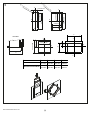
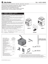
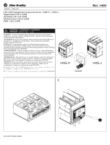
5
Y
Y
XX
2.99 76 mm"/
5.43 138 mm"/
4. 117 mm61"/
= =
Y
Y
X
X
3.46 88 mm"/
6.93 176 mm"/
1.83 46.5 mm"/
= =
Y
Y
X
X
3.66 93 mm"/
0.92 23.25 mm"/
dia. 0.22"/ø 5.5 mm - M5
3.46 88 mm"/
6.93 176 mm"/
dia. 0.22"/ø 5.5 mm - M5
X
Y
X
Y
B
= =
A
C
D
A B C D
WITH ESCUTCHEON
4.53"
115 mm
4.53"
115 mm
2.54"
64.5 mm
4.25"
108 mm
WITHOUT ESCUTCHEON
4.21"
107 mm
4.21"
107 mm
2.38"
60.5 mm
4.25"
108 mm
OPTIONAL
DIR 1000437R0002 Version 02

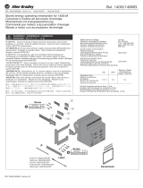
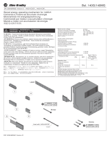
6
(4)
- Manually trip the breaker prior to any
adjustment of the magnetic trip settings.
- E’obbligatorio mettere l'interruttore in
posizione Trip test prima di regolare il
termomagnetico.
- Der Leistungsschalter muss vor Einstellung
des thermomagnetischen Auslösers
zwingend in die Prüfstellung geschaltet
werden.
- Il est obligatoire de mettre le disjoncteur en
position de Test de Déclenchement avant de
régler le déclencheur magnétothermique.
- Es obligatorio situar el interruptor en
posición “Test de Disparo” antes de realizar
el ajuste del relé termomagnético.
Ith (40°)
Ith=800 A
Im
MAX
800
MEDMIN
8000
MAX
6000
MED
4000 560
MIN
680
MED
MINMAX
MED
MINMAX
CLACK
THERMO-MAGNETIC TRIP UNIT
I1 [A]
In MIN (Inx0.7) MED (Inx0.85) MAX (Inx1)
300 A 210 255 300
400 A 280 340 400
I3 [A]
In MIN (Inx5) MED (Inx7.5) MAX (Inx10)
300 A 1500 2250 3000
400 A 2000 3000 4000
1
2
1 1,5 2 2,5 3 3,5 4,5 5,5 6,5 7 7,5 8 8,5 9 10
300 A 300 450 600 750 900 1050 1350 1650 1950 2100 2250 2400 2550 2700 3000
400 A 400 600 800 1000 1200 1400 1800 2200 2600 2800 3000 3200 3400 3600 4000
I3 [A]
1xIn...10xIn
In
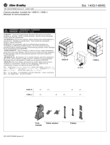
7
MOTOR CIRCUIT PROTECTOR
DIR 1000437R0002 Version 02

8
ELECTRONIC TRIP TEST
LED TRIP UNIT DEVICE
- Green
- Verde
- Grün
- Vert
- Verde
- Red
- Rosso
- Rot
- Rouge
- Rojo
- Device ON
- Dispositivo acceso
- Einrichtung eingeschaltet
- Dispositif allumé
- Dispositivo encendido
- Change battery
- Sostituire batterie
- Batterie ersetzen
- Remplacer batteries
- Sustituir baterías
CLACK
4
1
Push TEST button
Premere pulsante TEST
Drücken Sie die Test-Taste
Appuyer sur le bouton TEST
Pulse el pulsador TEST
2
140G-ELTT
(ORDERED
SEPARATELY)
3
Charge - Carica - Ladung - Alimentation -
Alimentación
(5)
DIR 1000437R0002 Version 02

DIR 1000437R0002 Version 02 (L2233) - B0942
Copyright © 2016 Rockwell Automation, Inc. All Rights Reserved. Printed in Italy.
Allen-Bradley, Rockwell Software, and Rockwell Automation are trademarks of Rockwell Automation, Inc.
Trademarks not belonging to Rockwell Automation are property of their respective companies.
Publication 140G-IN021C-MU-P - June 2016
Rockwell Automation maintains current product environmental compliance information on its website at http://www.rockwellautomation.com/rockwellautomation/about-us/
sustainability-ethics/product-environmental-compliance.page
9
V kA
I
2
t
(10
6
A
2
s)
PEAK
CURRENT
(A)
FREQ
(Hz)
10 1.4 20000 60
65 2.8 43900 60
100 3 47300 60
10 1.5 21000 60
30 2.6 36000 60
65 3 44000 60
140G-KC6 480
600
V kA
I
2
t
(10
6
A
2
s)
PEAK
CURRENT
(A)
FREQ
(Hz)
10 1.4 20000 60
30 2.4 35000 60
65 2.8 43900 60
10 1.5 21000 60
22 2.2 31000 60
35 2.8 38000 60
140G-KC0 480
600
CURRENT LIMITING PERFORMANCES
Transcripción de documentos
Bul. 140G/140MG DIR 1000437R0002 Version 02 - 140G-K_; 140MG-K_ Installation instruction for 140G-K, 140MG-K Istruzioni di installazione Installationsanleitung Instructions pour l’installation Instrucciones de instalación Installation - Installazione - Instalación Instalação WARNING: To prevent electrical shock, disconnect from power source before installing or servicing. Install in suitable enclosure. Keep free from contaminants. (Follow NFPA70E requirements). AVVERTENZA: Per prevenire infortuni, togliere tensione prima dell'installazione o manutenzione. Installare in custodia idonea. Tenere lontano da contaminanti. (Seguire i requisiti NFPA70E). WARNUNG: Vor Installations- oder Servicearbeiten Stromversorgung zur Vermeidung von elektrischen Unfällen trennen. Die Geräte müssen in einem passenden Gehäuse eingebaut und gegen Verschmutzung geschützt werden. (Befolgen Sie die Anforderungen nach NFPA70E). AVERTISSEMENT: Avant le montage et la mise en service, couper l'alimentation secteur pour éviter toute décharge. Prévoir une mise en coffret ou armoire appropriée. Protéger le produit contre les environnements agressifs. (Vous devez respecter la norme NFPA70E). ADVERTENCIA: Desconéctese de la corriente eléctrica, antes de la instalación o del servicio, a fin de impedir sacudidas eléctricas. Instálelo en una caja apropiada. Manténgalo libre de contaminantes. (Cumpla con los requisitos NFPA70E). ATENÇÃO: Para evitar choques, desconectar da corrente elétrica antes de fazer a instalação ou a manutenção. Instalar em caixa apropriada. Manter livre de contaminantes. (Cumpra as exigências da norma NFPA70E). 警告:感電事故防止のため、取付けまたは修理の際は電源から取り外してく ださい。適切なケース内に取付けてください。また、汚染物質がないことを 確認してください。(NFPA70Eの要件に従ってください) 警告:为了防止触电,在安装或维修之前必须先切断电源。安装在合适的设备 箱内。防止接触污染物。符合NFPA70E要求) End cap kit CH 8 LENGTH M 22 m m (0.87" ) M 10 3p 4p DIR 1000437R0002 Version 02 Mounting hardware LENGTH 85 mm (3.35") Phase barrier Insulator Insulator M M5 140G-K-ECM3 140G-K-MH4 140G-K-PB3M 140G-K-BP3 x6 x4 x4 x1 140G-K-ECM4 140G-K-MH4 140G-K-PB4M x8 x4 x6 - 140G-K-BP4 - x1 2 Maximum recommended conductor support distance 5.90" 150 mm 5.90" 150 mm 1 CLACK 3 - Use cable or insulated busbars/ or perform specific type test on the installation. - Usare cavi o barre isolate/ o eseguire prove di tipo specifiche sull' installazione. - Kabel oder isolierte Sammelschienen verwenden / oder die spezifische Typprüfung auf der Installation durchführen. - Utiliser un câble ou des barres isolées/ ou réaliser un test de type spé cifique sur installation. - Utilizar un cable o barras aisladas / o efectuar una prueba de tipo es pecífico sobre instalacíon. 4 Mandatory for UL application Mandatory for IEC application when Ue ≥ 500V 17 lb-in 2 Nm DIR 1000437R0002 Version 02 (2) .22 "/ø 5.5 mm Y -M 0. 22 "/ø 5. 5 1.83"/46.5 mm == 5 m m -M Y 5 X X 3.46"/88 mm .0 X X 3.66"/93 mm 6.93"/176 mm a. 3.46"/88 mm 6.93"/176 mm 5 di dia 0.92"/23.25 mm Y Y A == OPTIONAL Y 4.61"/117 mm C == X D X X X B 2.99"/76 mm 5.43"/138 mm Y Y Y WITH ESCUTCHEON WITHOUT ESCUTCHEON DIR 1000437R0002 Version 02 A B C D 4.53" 115 mm 4.21" 107 mm 4.53" 115 mm 4.21" 107 mm 2.54" 64.5 mm 2.38" 60.5 mm 4.25" 108 mm 4.25" 108 mm (3) 6 THERMO-MAGNETIC TRIP UNIT 1 CLACK - Manually trip the breaker prior to any adjustment of the magnetic trip settings. - E’obbligatorio mettere l'interruttore in posizione Trip test prima di regolare il termomagnetico. - Der Leistungsschalter muss vor Einstellung des thermomagnetischen Auslösers zwingend in die Prüfstellung geschaltet werden. MAX MIN MAX MED - Il est obligatoire de mettre le disjoncteur en position de Test de Déclenchement avant de régler le déclencheur magnétothermique. MIN MED Im Ith (40°) MAX MED MIN MAX MED MIN 8000 6000 4000 800 680 560 Ith=800 A - Es obligatorio situar el interruptor en posición “Test de Disparo” antes de realizar el ajuste del relé termomagnético. I1 [A] I3 [A] In MIN (Inx5) MED (Inx7.5) MAX (Inx10) 300 A 1500 2250 3000 400 A 2000 3000 In 2 4000 MIN (Inx0.7) MED (Inx0.85) MAX (Inx1) 300 A 210 255 300 400 A 280 340 400 7 MOTOR CIRCUIT PROTECTOR I3 [A] In 1xIn...10xIn 1 1,5 2 2,5 300 A 300 450 600 750 3 3,5 4,5 5,5 6,5 7 7,5 8 8,5 9 10 900 1050 1350 1650 1950 2100 2250 2400 2550 2700 3000 400 A 400 600 800 1000 1200 1400 1800 2200 2600 2800 3000 3200 3400 3600 4000 DIR 1000437R0002 Version 02 (4) 8 ELECTRONIC TRIP TEST 1 140G-ELTT (ORDERED SEPARATELY) 3 Push TEST button Premere pulsante TEST Drücken Sie die Test-Taste Appuyer sur le bouton TEST Pulse el pulsador TEST 2 LED TRIP UNIT DEVICE - Red - Green - Rosso - Verde - Rot - Grün - Rouge - Vert Rojo - Verde - Device ON - Change battery - Dispositivo acceso - Sostituire batterie - Einrichtung eingeschaltet - Batterie ersetzen - Dispositif allumé - Remplacer batteries - Dispositivo encendido - Sustituir baterías CLACK 4 Charge - Carica - Ladung - Alimentation - Alimentación DIR 1000437R0002 Version 02 (5) 9 CURRENT LIMITING PERFORMANCES V 140G-KC6 480 600 V 140G-KC0 480 600 kA I2t (106A2s) 10 65 100 10 30 65 1.4 2.8 3 1.5 2.6 3 kA I2t (106A2s) 10 30 65 10 22 35 1.4 2.4 2.8 1.5 2.2 2.8 PEAK CURRENT (A) 20000 43900 47300 21000 36000 44000 PEAK CURRENT (A) 20000 35000 43900 21000 31000 38000 FREQ (Hz) 60 60 60 60 60 60 FREQ (Hz) 60 60 60 60 60 60 Allen-Bradley, Rockwell Software, and Rockwell Automation are trademarks of Rockwell Automation, Inc. Trademarks not belonging to Rockwell Automation are property of their respective companies. Rockwell Automation maintains current product environmental compliance information on its website at http://www.rockwellautomation.com/rockwellautomation/about-us/ sustainability-ethics/product-environmental-compliance.page Publication 140G-IN021C-MU-P - June 2016 DIR 1000437R0002 Version 02 (L2233) - B0942 Copyright © 2016 Rockwell Automation, Inc. All Rights Reserved. Printed in Italy.-
 1
1
-
 2
2
-
 3
3
-
 4
4
-
 5
5
-
 6
6


Allen-Bradley 140G Series Guía de instalación
- Tipo
- Guía de instalación
en otros idiomas
Artículos relacionados
-
 Allen-Bradley 140G-H Guía de instalación
-
 Allen-Bradley 140G-M Guía de instalación
-
 Allen-Bradley 140G Guía de instalación
-
 Allen-Bradley 140G-J-EOP Manual de usuario
-
 Allen-Bradley 140G-M-EOP Manual de usuario
-
 Allen-Bradley 140G-R Guía de instalación
-
Allen-Bradley 140MG-H Adjustment Instruction
-
 Allen-Bradley 140G Series Adjustment Instructions
-
 Allen-Bradley 140G-J Guía de inicio rápido
-
 Allen-Bradley 140MG Series Manual de usuario