Yamaha RX-V800 Manual de usuario
- Categoría
- Receptores AV
- Tipo
- Manual de usuario

YAMAHA ELECTRONICS CORPORATION, USA 6660 ORANGETHORPE AVE., BUENA PARK, CALIF. 90620, U.S.A.
YAMAHA CANADA MUSIC LTD. 135 MILNER AVE., SCARBOROUGH, ONTARIO M1S 3R1, CANADA
YAMAHA ELECTRONIK EUROPA G.m.b.H. SIEMENSSTR. 22-34, 25462 RELLINGEN BEI HAMBURG, F.R. OF GERMANY
YAMAHA ELECTRONIQUE FRANCE S.A. RUE AMBROISE CROIZAT BP70 CROISSY-BEAUBOURG 77312 MARNE-LA-VALLEE CEDEX02, FRANCE
YAMAHA ELECTRONICS (UK) LTD. YAMAHA HOUSE, 200 RICKMANSWORTH ROAD WATFORD, HERTS WD1 7JS, ENGLAND
YAMAHA SCANDINAVIA A.B. J A WETTERGRENS GATA 1, BOX 30053, 400 43 VÄSTRA FRÖLUNDA, SWEDEN
YAMAHA MUSIC AUSTRALIA PTY, LTD. 17-33 MARKET ST., SOUTH MELBOURNE, 3205 VIC., AUSTRALIA
Printed in Malaysia ID
V624910-1
OWNER’S MANUAL
RX-V800
Natural Sound AV Receiver
U A
0100V800(UA)-cv1/4 10/3/0, 9:15 AM1

II
II
SAFETY INSTRUCTIONS
CAUTION: TO REDUCE THE RISK OF
ELECTRIC SHOCK, DO NOT REMOVE
COVER (OR BACK). NO USER-SERVICEABLE
PARTS INSIDE. REFER SERVICING TO
QUALIFIED SERVICE PERSONNEL.
RISK OF ELECTRIC SHOCK
DO NOT OPEN
CAUTION
• Explanation of Graphical Symbols
The lightning flash with arrowhead symbol,
within an equilateral triangle, is intended to alert
you to the presence of uninsulated “dangerous
voltage” within the product’s enclosure that may
be of sufficient magnitude to constitute a risk of
electric shock to persons.
The exclamation point within an equilateral
triangle is intended to alert you to the presence of
important operating and maintenance (servicing)
instructions in the literature accompanying the
appliance.
1 Read Instructions – All the safety and operating instructions
should be read before the unit is operated.
2 Retain Instructions – The safety and operating instructions
should be retained for future reference.
3 Heed Warnings – All warnings on the unit and in the operating
instructions should be adhered to.
4 Follow Instructions – All operating and other instructions
should be followed.
5 Water and Moisture – The unit should not be used near
water – for example, near a bathtub, washbowl, kitchen
sink, laundry tub, in a wet basement, or near a swimming
pool, etc.
6 Carts and Stands – The unit should be used only with a cart
or stand that is recommended by the manufacturer.
6A A unit and cart combination should be
moved with care. Quick stops, excessive
force, and uneven surfaces may cause the
unit and cart combination to overturn.
7 Wall or Ceiling Mounting – The unit
should be mounted to a wall or ceiling only as
recommended by the manufacturer.
8 Ventilation – The unit should be situated so that its location
or position does not interfere with its proper ventilation. For
example, the unit should not be situated on a bed, sofa, rug,
or similar surface, that may block the ventilation openings; or
placed in a built-in installation, such as a bookcase or cabinet
that may impede the flow of air through the ventilation
openings.
9 Heat – The unit should be situated away from heat sources
such as radiators, stoves, or other appliances that produce
heat.
10 Power Sources – The unit should be connected to a power
supply only of the type described in the operating instructions or
as marked on the unit.
11 Power-Cord Protection – Power-supply cords should be
routed so that they are not likely to be walked on or pinched
by items placed upon or against them, paying particular
attention to cords at plugs, convenience receptacles, and the
point where they exit from the unit.
12 Cleaning – The unit should be cleaned only as
recommended by the manufacturer.
13 Nonuse Periods – The power cord of the unit should be
unplugged from the outlet when left unused for a long
period of time.
14 Object and Liquid Entry – Care should be taken so that
objects do not fall into and liquids are not spilled into the
inside of the unit.
15 Damage Requiring Service – The unit should be serviced by
qualified service personnel when:
A. The power-supply cord or the plug has been damaged;
or
B. Objects have fallen, or liquid has been spilled into the
unit; or
C. The unit has been exposed to rain; or
D. The unit does not appear to operate normally or
exhibits a marked change in performance; or
E. The unit has been dropped, or the cabinet damaged.
16 Servicing – The user should not attempt to service the unit
beyond those means described in the operating instructions.
All other servicing should be referred to qualified service
personnel.
17 Power Lines – An outdoor antenna should be located away
from power lines.
18 Grounding or Polarization – Precautions should be taken so
that the grounding or polarization is not defeated.
WARNING
TO REDUCE THE RISK OF FIRE OR
ELECTRIC SHOCK, DO NOT EXPOSE THIS UNIT TO
RAIN OR MOISTURE.
I CAUTION

III
English
INTRODUCTION PREPARATION
BASIC OPERA-
TION
ADVANCED
OPERATION
ADDITIONAL
INFORMATION
APPENDIX
III
SAFETY INSTRUCTIONSSAFETY INSTRUCTIONS
1. IMPORTANT NOTICE : DO NOT MODIFY THIS
UNIT!
This product, when installed as indicated in the
instructions contained in this manual, meets FCC
requirements. Modifications not expressly approved
by Yamaha may void your authority, granted by the
FCC, to use the product.
2. IMPORTANT : When connecting this product to
accessories and/or another product use only high
quality shielded cables. Cable/s supplied with this
product MUST be used. Follow all installation
instructions. Failure to follow instructions could void
your FCC authorization to use this product in the USA.
3. NOTE : This product has been tested and found to
comply with the requirements listed in FCC
Regulations, Part 15 for Class “B” digital devices.
Compliance with these requirements provides a
reasonable level of assurance that your use of this
product in a residential environment will not result in
harmful interference with other electronic devices.
This equipment generates/uses radio frequencies and,
if not installed and used according to the instructions
found in the users manual, may cause interference
harmful to the operation of other electronic devices.
Compliance with FCC regulations does not guarantee
that interference will not occur in all installations. If
this product is found to be the source of interference,
which can be determined by turning the unit “OFF” and
“ON”, please try to eliminate the problem by using one
of the following measures:
Relocate either this product or the device that is being
affected by the interference.
Utilize power outlets that are on different branch (circuit
breaker or fuse) circuits or install AC line filter/s.
In the case of radio or TV interference, relocate/reorient
the antenna. If the antenna lead-in is 300 ohm ribbon
lead, change the lead-in to coaxial type cable.
If these corrective measures do not produce satisfactory
results, please contact the local retailer authorized to
distribute this type of product. If you can not locate the
appropriate retailer, please contact Yamaha Electronics
Corp., U.S.A. 6660 Orangethorpe Ave, Buena Park, CA
90620.
The above statements apply ONLY to those products
distributed by Yamaha Corporation of America or its
subsidiaries.
We Want You Listening For A Lifetime
YAMAHA and the Electronic Industries Association’s Consumer
Electronics Group want you to get the most out of your equipment
by playing it at a safe level. One that lets the sound come through
loud and clear without annoying blaring or distortion – and, most
importantly, without affecting your sensitive hearing.
19 For US customers only:
Outdoor Antenna Grounding – If an outside antenna is
connected to this unit, be sure the antenna system is
grounded so as to provide some protection against voltage
surges and built-up static charges. Article 810 of the
National Electrical Code, ANSI/NFPA 70, provides
information with regard to proper grounding of the mast
and supporting structure, grounding of the lead-in wire to
an antenna discharge unit, size of grounding conductors,
location of antenna discharge unit, connection to grounding
electrodes, and requirements for the grounding electrode.
EXAMPLE OF ANTENNA GROUNDING
MAST
GROUND
CLAMP
ANTENNA
LEAD IN
WIRE
ANTENNA
DISCHARGE UNIT
(NEC SECTION 810–20)
GROUNDING CONDUCTORS
(NEC SECTION 810–21)
GROUND CLAMPS
POWER SERVICE GROUNDING
ELECTRODE SYSTEM
(NEC ART 250. PART H)
ELECTRIC
SERVICE
EQUIPMENT
NEC
– NATIONAL ELECTRICAL CODE
FCC INFORMATION (for US customers only)
Since hearing damage from loud sounds is often
undetectable until it is too late, YAMAHA and the
Electronic Industries Association’s Consumer
Electronics Group recommend you to avoid
prolonged exposure from excessive volume levels.
Note to CATV system installer:
This reminder is provided to call the CATV system
installer’s attention to Article 820-40 of the NEC that
provides guidelines for proper grounding and, in
particular, specifies that the cable ground shall be
connected to the grounding system of the building, as
close to the point of cable entry as practical.
CAUTION II

IV
IV
1 To assure the finest performance, please read this
manual carefully. Keep it in a safe place for future
reference.
2 Install this unit in a well ventilated, cool, dry, clean
place with at least 30 cm on the top, 20 cm on the
right and left, and 10 cm at the back of this unit
— away from direct sunlight, heat sources,
vibration, dust, moisture, and/or cold.
3 Locate this unit away from other electrical
appliances, motors, or transformers to avoid
humming sounds. To prevent fire or electrical
shock, do not place this unit where it may get
exposed to rain, water, and/or any type of liquid.
4 Do not expose this unit to sudden temperature
changes from cold to hot, and do not locate this
unit in a environment with high humidity (i.e. a room
with a humidifier) to prevent condensation inside
this unit, which may cause an electrical shock, fire,
damage to this unit, and/or personal injury.
5 On the top of this unit, do not place:
– Other components, as they may cause damage
and/or discoloration on the surface of this unit.
– Buring objects (i.e. candles), as they may cause
fire, damage to this unit, and/or personal injury.
– Containers with liquid in them, as they may cause
electrical shock to the user and/or damage to this
unit.
6 Do not cover this unit with a newspaper, tablecloth,
curtain, etc. in order not to obstruct heat radiation.
If the temperature inside this unit rises, it may
cause fire, damage to this unit, and/or personal
injury.
7 Do not plug in this unit to a wall outlet until all
connections are complete.
8 Do not operate this unit upside-down. It may
overheat, possibly causing damage.
9 Do not use force on switches, knobs and/or cords.
10 When disconnecting the power cord from the wall
outlet, grasp the plug; do not pull the cord.
11 Do not clean this unit with chemical solvents; this
might damage the finish. Use a clean, dry cloth.
12 Only voltage specified on this unit must be used.
Using this unit with a higher voltage than specified
is dangerous and may cause fire, damage to this
unit, and/or personal injury. YAMAHA will not be
held responsible for any damage resulting from use
of this unit with a voltage other than specified.
13 To prevent damage by lightning, disconnect the
power cord from the wall outlet during an electrical
storm.
14 Take care of this unit so that no foreign objects and/
or liquid drops inside this unit.
CAUTION: READ THIS BEFORE OPERATING YOUR UNIT.
15 Do not attempt to modify or fix this unit. Contact
qualified YAMAHA service personnel when any
service is needed. The cabinet should never be
opened for any reasons.
16 When not planning to use this unit for long periods
of time (i.e. vacation), disconnect the AC power plug
from the wall outlet.
17 Be sure to read the “TROUBLESHOOTING” section
on common operating errors before concluding that
this unit is faulty.
18 Before moving this unit, press STANDBY/ON to set
this unit in the standby mode, and disconnect the
AC power plug from the wall outlet.
19 VOLTAGE SELECTOR (China and general models
only)
The VOLTAGE SELECTOR on the rear panel of this
unit must be set for your local main voltage
BEFORE plugging into the AC main supply.
Voltages are 110/120/220/240 V AC, 50/60 Hz.
This unit is not disconnected from the AC power
source as long as it is connected to the wall outlet,
even if this unit itself is turned off. This state is called
the standby mode. In this state, this unit is designed to
consume a very small quantity of power.
FREQUENCY STEP switch
(China and general models only)
Because the interstation frequency spacing differs in
different areas, set the FREQUENCY STEP switch
(locating at the rear) according to the frequency
spacing in your area.
North, Central and South America: 100 kHz/10 kHz
Other area: 50 kHz/9 kHz
Before setting this switch, disconnect the AC power
plug of this unit from the AC outlet.
IMPORTANT
Please record the serial number of this unit in the
space below.
MODEL:
Serial No.:
The serial number is located on the rear of the unit.
Retain this Owner’s Manual in a safe place for future
reference.
FOR CANADIAN CUSTOMERS
To prevent electric shock, match wide blade of plug to
wide slot and fully insert.
This Class B digital apparatus complies with Canadian
ICES-003.
III CAUTION

1
English
INTRODUCTION
PREPARATION
BASIC
OPERATION
ADVANCED
OPERATION
ADDITIONAL
INFORMATION
APPENDIX
CONTENTS
INTRODUCTION
INTRODUCTION
CONTENTS ........................................................... 1
FEATURES ............................................................ 2
GETTING STARTED ........................................... 3
Checking the Package Contents ............................... 3
Installing Batteries in the Remote Control ............... 3
CONTROLS AND FUNCTIONS ........................ 4
Front Panel ............................................................... 4
Remote Control ........................................................ 6
Description of the Numeric Buttons......................... 7
Using the Remote Control ........................................ 8
Front Panel Display .................................................. 9
Rear Panel .............................................................. 10
PREPARATION
SPEAKER SETUP .............................................. 11
Speakers to Be Used ............................................... 11
Speaker Placement ................................................. 11
CONNECTIONS ................................................. 12
Before Connecting Components ............................ 12
Connecting Audio Components ............................. 12
Connecting Video Components .............................. 14
Connecting the Speakers ........................................ 16
Connecting to an External Amplifier ..................... 18
Connecting an External Decoder ............................ 18
IMPEDANCE SELECTOR Switch ....................... 19
Connecting the Power Supply Cords ...................... 19
ON-SCREEN DISPLAY (OSD) ......................... 20
OSD Modes ............................................................ 20
Selecting the OSD Mode ........................................ 20
SPEAKER MODE SETTINGS ......................... 21
Summary of SPEAKER SET Items
1A through 1E .................................................... 21
ADJUSTING THE SPEAKER
OUTPUT LEVELS ......................................... 22
Before You Begin ................................................... 22
Using the Test Tone (TEST DOLBY SUR.) .......... 22
BASIC OPERATION
BASIC PLAYBACK ............................................ 24
Input Modes and Indications .................................. 26
Selecting a Sound Field Program ........................... 28
Normal Stereo Reproduction .................................. 29
TUNING ............................................................... 30
Connecting the Antennas ........................................ 30
Automatic (or Manual) Tuning .............................. 31
Presetting Stations .................................................. 32
Tuning in to a Preset Station .................................. 33
Exchanging Preset Stations .................................... 34
BASIC RECORDING ......................................... 35
ADVANCED OPERATION
SET MENU .......................................................... 36
Adjusting the Items on the SET MENU................. 36
1 SPEAKER SET (speaker mode settings) ........... 37
2 LOW FRQ TEST ............................................... 39
3 L/R BALANCE (balance of
the left and right main speakers) ........................ 40
4 HP TONE CTRL (headphone tone control) ....... 40
5 CENTER GEQ (center graphic equalizer) ......... 40
6 INPUT RENAME .............................................. 41
7 I/O ASSIGNMENT ............................................ 41
8 INPUT MODE (initial input mode) ................... 41
9 PARAM. INI (parameter initialization) ............. 41
10 DOLBY D. SET (Dolby Digital set) ................ 42
11 DTS LFE LEVEL ............................................. 42
12 6.1/ES AUTO .................................................... 42
13 SP DELAY TIME ............................................. 43
14 DISPLAY SET .................................................. 43
15 MEMORY GUARD ......................................... 43
ADJUSTING THE LEVEL OF
THE EFFECT SPEAKERS ........................... 44
SLEEP TIMER .................................................... 45
Setting the Sleep Timer .......................................... 45
Canceling the Sleep Timer ..................................... 45
REMOTE CONTROL FEATURES .................. 46
Selector Dial ........................................................... 46
Commonly Used Buttons in Any Position of
the Selector Dial ................................................. 47
Controlling the Components
Connected to This Unit ...................................... 47
Button Names and Functions in Each Position ...... 48
Setting the Manufacturer Code .............................. 51
Programming a New Remote Control Function
(Learn Feature) ................................................... 52
Returning to the Factory Setting ............................ 53
ZONE 2 (U.S.A., Canada and
Australia models only) .................................... 54
Zone 2 Connections ................................................ 54
ADDITIONAL INFORMATION
SOUND FIELD PROGRAM ............................. 55
Hi-Fi DSP Programs ............................................... 55
CINEMA DSP Programs ....................................... 56
MOVIE THEATER Programs ................................ 59
SOUND FIELD PROGRAM PARAMETER
EDITING ......................................................... 60
What is a sound field? ............................................ 60
Sound Field Program Parameters ........................... 60
Changing Parameter Settings ................................. 61
Resetting a Parameter to the Factory-set Value ...... 61
Digital Sound Field Parameter Descriptions .......... 62
APPENDIX
TROUBLESHOOTING ...................................... 66
SPECIFICATIONS ............................................. 71

2
Thank you for selecting this YAMAHA AV receiver.
FEATURES
Other Features
◆ 96-kHz/24-bit D/A Converter
◆ “SET MENU” which Provides You with 15 Items
for Optimizing This Unit for Your Audio/Video
System
◆ Test Tone Generator for Easier Speaker Balance
Adjustment
◆ 6-Channel External Decoder Input for Other
Future Formats
◆ BASS EXTENSION Button for Reinforcing
Bass Response
◆ On Screen Display Function Helpful in
Controlling This Unit
◆ S Video Signal Input/Output Capability
◆ Component Video Input/Output Capability
◆ Optical and Coaxial Digital Audio Signal Jacks
◆ Sleep Timer
◆ Remote Control with Preset Manufacturer Codes
and “Learning” Capability
◆ Custom Installation Facility (U.S.A., Canada and
Australia models only)
• y indicates a tip for your operation.
• Some operations can be performed by using either the buttons on the main unit or on the remote control. In cases when the button
names differ between the main unit and the remote control, the button name on the remote control is given in parentheses in this
manual.
Built-in 5-Channel Power Amplifier
◆ Minimum RMS Output Power
(0.04% THD, 20 Hz – 20 kHz)
Main: 100 W + 100 W (8 Ω)
Center: 100 W (8 Ω)
Rear: 100 W + 100 W (8 Ω)
◆ Maximum Power (EIAJ)
(10% THD, 1 kHz)
[China and general models]
Main: 140 W + 140 W (8 Ω)
Center: 140 W (8 Ω)
Rear: 140 W + 140 W (8 Ω)
Multi-Mode Digital Sound Field
Processing
◆ Digital Sound Field Processor (DSP)
◆ Dolby Pro Logic Decoder
◆ Dolby Digital/Dolby Digital Matrix 6.1 Decoder
◆ DTS/DTS ES Decoder
◆ CINEMA DSP: Combination of YAMAHA DSP
Technology and Dolby Pro Logic, Dolby Digital
or DTS
◆ Virtual CINEMA DSP
◆ SILENT CINEMA DSP
Sophisticated AM/FM Tuner
◆ 40-Station Random Access Preset Tuning
◆ Automatic Preset Tuning
◆ Preset Station Shifting Capability (Preset
Editing)
Manufactured under license from Dolby Laboratories.
“Dolby”, “AC-3”, “Pro Logic”, “Surround EX” and the double-D
symbol are trademarks of Dolby Laboratories.
Confidential Unpublished Works. ©1992-1997 Dolby
Laboratories, Inc. All rights reserved.
Manufactured under license from Digital Theater Systems, Inc.
US Pat. No. 5,451,942 and other world-wide patents issued and
pending. “DTS”, “DTS Digital Surround” and “DTS ES” are
trademarks of Digital Theater Systems, Inc. Copyright 1996
Digital Theater Systems, Inc. All Rights Reserved.

3
English
INTRODUCTION PREPARATION
BASIC
OPERAIONT
ADVANCED
OPERATION
ADDITIONAL
INFORMATION
APPENDIX
Remote control
Installing Batteries in the Remote
Control
Insert the batteries in the correct direction by aligning the
+ and – marks on the batteries with the polarity markings
(+ and –) inside the battery compartment.
■ Notes on batteries
• Change the batteries periodically.
• Do not use old batteries together with new ones.
• Do not use different types of batteries (such as alkaline
and manganese batteries) together. Read the packaging
carefully as these different types of batteries may have
the same shape and color.
GETTING STARTED
Checking the Package Contents
Check your package to make sure it has the following items.
Manganese batteries (4)
(AAA, R03, UM-4)
Indoor FM antenna
(U.S.A., Canada, China and
general models)
AM loop antenna
Quick Reference Card
■ Changing batteries
As the batteries lose power, the operating range of the
remote control decreases and the indicator does not flash
or its light becomes dim. When you notice any of these
conditions, change all of the batteries.
If the remote control is without batteries for more than
2 minutes, or if exhausted batteries remain in the
remote control, the contents of the memory may be
cleared. When the memory is cleared, insert new
batteries, set up the manufacturer code and program
any acquired functions that may have been cleared.
Note
• If the batteries have leaked, dispose of them immediately.
Avoid touching the leaked material or letting it come into
contact with clothing, etc. Clean the battery compartment
thoroughly before installing new batteries.
1
2
3
A/B/C/D/E
Quick Reference Card
(Australia and
Singapore models)

4
CONTROLS AND FUNCTIONS
Front Panel
1 STANDBY/ON
Turns on and sets this unit in the standby mode. When
you turn on this unit, you will hear a click and there will
be a 4 to 5-second delay before this unit can reproduce
sound.
Standby mode
In this mode, this unit consumes a small amount of
power to receive infrared-signals from the remote
control.
2 Remote control sensor
Receives signals from the remote control.
3 Front panel display
Shows information about the operational status of this
unit (see page 9).
4 INPUT MODE
Selects the mode of input for sources that send two or
more types of signals to this unit (see page 26).
You cannot control the input mode when you select 6CH
INPUT as the input source.
5 INPUT l / h
Selects the input source (DVD, D-TV/LD, CBL/SAT,
VCR 1, VCR 2/DVR, V-AUX, PHONO, CD, TUNER,
CD-R, MD/TAPE) you want to listen to or watch.
6 VOLUME
Controls the output level of all audio channels.
This does not affect the REC OUT level.
7 6CH INPUT
Selects the source connected to the 6CH INPUT jacks.
The source selected by pressing 6CH INPUT takes
priority over the source selected with INPUT l / h (or
the input selector buttons).
8 SPEAKERS A/B
Turn on or off the set of main speakers connected to the A
and/or B terminals on the rear panel.
9 BASS EXTENSION ON/OFF
When pushed in (ON), this feature boosts the bass
frequency of the left and right main channels by +6 dB
(60 Hz) while maintaining overall tonal balance. This
boost is useful if you do not use a subwoofer.
However, this boost may not be noticeable if “1B MAIN
SP” on the SET MENU is set to SMALL and “1D LFE/
BASS OUT” is set to SWFR.
0 PROCESSOR DIRECT ON/OFF
When pushed in (ON), BASS, TREBLE, and BASS
EXTENSION are bypassed, eliminating any alteration of
the original signal.
TUNER
A/B/C/D/E
SPEAKERS
STANDBY
/ON
AB
BASS
EXTENSION
PROCESSOR
DIRECT
PRESET/
TUNING
BASS
6CH INPUT
VOLUME
INPUT
INPUT MODE
–
+
TREBLE
–
+
PRESET
/TUNING
EDIT
MEMORY
MAN'L/AUTO FM
TUNING
MODE
AUTO/MAN'L MONO
FM/AM
PHONES S VIDEO VIDEO
L AUDIO R OPTICAL
SILENT
VIDEO AUX
EFFECT
PROGRAM
ON OFF
SURROUND
DIGITAL
DIGITAL
DSP
1
2
3
4
5
67
8
90 q
w
e
r
t
y
s
a
PRESET
/TUNING
EDIT
MEMORY
MAN'L/AUTO FM
TUNING
MODE
AUTO/MAN'L MONO
FM/AM
i
o
pu

5
English
INTRODUCTION PREPARATION
BASIC
OPERAIONT
ADVANCED
OPERATION
ADDITIONAL
INFORMATION
APPENDIX
CONTROLS AND FUNCTIONS
q EFFECT
Switches the effect speakers (center and rear) on and off.
If you turn off the output of these speakers by using
EFFECT, all Dolby Digital and DTS audio signals except
for the LFE channel are directed to the main left and right
channels.
When Dolby Digital or DTS signals are mixed, the left
and right main channel signal levels may not match.
w A/B/C/D/E
Selects one of the 5 preset station groups (A to E).
e PROGRAM l / h
Selects the DSP program (see page 28).
r PRESET/TUNING l / h
Selects preset station number 1 to 8 when the colon (:)
appears next to the band indication on the front panel
display, and selects the tuning frequency when the colon
(:) does not appear.
t PHONES jack
Outputs audio signals for private listening with
headphones. When you connect headphones, no signals
are output to the OUTPUT jacks or to the speakers.
y VIDEO AUX jacks
Inputs audio and video signals from a portable external
source such as a game console. To reproduce source
signals from these jacks, select V-AUX as the input
source.
u PRESET/TUNING (EDIT)
Switches the function of PRESET/TUNING l / h (the
colon (:) turns on or off) between selecting a preset
station number and tuning.
This button is also used to exchange the assignment of
two preset stations with each other.
i FM/AM
Switches the reception band between FM and AM.
o MEMORY (MAN’L/AUTO FM)
Stores a station in the memory. Hold down this button for
more than 3 seconds to start automatic preset tuning.
To open, press gently on the lower part of the panel.
p TUNING MODE (AUTO/MAN’L MONO)
Switches the tuning mode between automatic and manual.
To select the automatic tuning mode, press this button so
that the “AUTO” indicator lights up on the front panel
display. To select the manual tuning mode, press this
button so that the “AUTO” indicator does not light up.
a BASS
Adjusts the low-frequency response for the left and right
main channels.
Turn the control to the right to increase or to the left to
decrease the low-frequency response.
s TREBLE
Adjusts the high-frequency response for the left and right
main channels.
Turn the control to the right to increase or to the left to
decrease the high-frequency response.
Note
• If you increase or decrease the high-frequency or the low-
frequency sound to an extreme level, the tonal quality from the
center and rear speakers may not match that of the left and
right main speakers.
■ Opening and closing the front
panel door
When you are not operating the controls behind the front
panel door, close the door.
D
I
G
I
T
A
L

6
CONTROLS AND FUNCTIONS
Remote Control
This section describes the basic operation of this unit with
the remote control. First, set the selector dial to the AMP/
TUN position. See “REMOTE CONTROL FEATURES”
on pages 46 to 53 for full details.
3 Numeric buttons (Input selector buttons)
These buttons select the input source.
See pages 7 and 8 for the numeric buttons.
4 TEST
Outputs the test tone.
5 ON SCREEN
Selects the on-screen display (OSD) mode for your video
monitor.
6 j / i
Adjust DSP program parameters and SET MENU items.
7 LEVEL
Selects the effect speaker channel (center, rear and
subwoofer) so you can adjust their output level
independently.
8 SLEEP
Sets the sleep timer.
9 INPUT
Switches the function of the numeric buttons to the input
selector (see page 7).
0 Indicator
Flashes while the remote control is sending signals.
q Selector dial
Turn this dial to select the position for the component to
be controlled. (The proper code must be set up for your
component. See “Setting the Manufacture Codes” on
page 51.) When the position is selected, the remote
control is set to that component operation mode.
w A/B/C/D/E, PRESET–/+
These buttons are used to select a preset station.
A/B/C/D/E: To select one of 5 preset station groups (A
to E)
PRESET –/+: To select a preset station number (1 to 8)
e u/d
Select DSP program parameters and SET MENU items.
r SET MENU
Enters the SET MENU.
t POWER
Turns on the power of this unit.
y STANDBY
Sets this unit in the standby mode.
Select the
AMP/TUN
position.
See
page 7.
A/B/C/D/E
TV INPUT
TV VOLUME
TV POWER
EFFECT
w
e
1
2
3
4
5
6
7
8
0
q
9
r
t
y
u
i
1 DSP
Switches the function of the numeric buttons to the DSP
program selector (see page 7).
2 Indicator window
Shows the name of components which can be controlled.

7
English
INTRODUCTION PREPARATION
BASIC
OPERAIONT
ADVANCED
OPERATION
ADDITIONAL
INFORMATION
APPENDIX
CONTROLS AND FUNCTIONS
A B
u VOLUME +/–
Increases or decreases the volume level.
i MUTE
Mutes the sound. Press again to restore the audio output
to the previous volume level.
EFFECT
Switches the effect speakers (center and rear) on and off
in the following cases:
• When the selector dial is set to the DSP/TUN position.
• While the indicator is lit for about 3 seconds after
pressing DSP.
Description of the Numeric
Buttons
The numeric buttons function in various ways depending
on the position of the selector dial or the combination of
other instructions.
A
1 Press DSP regardless of the position of the
selector dial.
The indicator lights up for about 3 seconds.
2 You can select a DSP program with the
numeric buttons, turn on or off the effect
speakers (center and rear) by pressing
EFFECT and turn on or off the Dolby Digital
Matrix 6.1 or DTS ES decoder by pressing
6.1/ES while the indicator is lit.
B
1 Set the selector dial to the DSP/TUN
position.
2 You can select a DSP program directly with
the numeric buttons, turn on or off the effect
speakers (center and rear) by pressing
EFFECT and turn on or off the Dolby Digital
Matrix 6.1 or DTS ES decoder by pressing
6.1/ES.
■ When selecting a DSP program
and turning on or off the effect
speakers (center and rear)
Input selector
buttons
■ When selecting an input source
1 Press INPUT regardless of the position of
the selector dial.
The indicator lights up for about 3 seconds.
2 You can select an input source with the
numeric buttons while the indicator is lit.
DSP program
group buttons

8
CONTROLS AND FUNCTIONS
■ When selecting a preset station
number
1 Set code number “0023” in the AMP/TUN (or
DSP/TUN) position.
See page 51 for setting the code.
2 Set the selector dial to the AMP/TUN (or
DSP/TUN) position.
3 You can select a preset station number
directly with the numeric buttons (1 to 8).
See page 34.
STANDBY
/ON
–
+
–
+
30° 30°
SURROUND
DIGITAL
DIGITAL
The remote control transmits a directional infrared beam.
Be sure to aim the remote control directly at the remote
control sensor on the main unit during operation.
■ Handling the remote control
• Do not spill water or other liquids on the remote
control.
• Do not drop the remote control.
• Do not leave or store the remote control in the
following types of conditions:
– high humidity or temperature such as near a heater,
stove or bath;
– dusty places; or
– in places subject to extremely low temperatures.
Approximately 6 m (20 feet)
Using the Remote Control

9
English
INTRODUCTION PREPARATION
BASIC
OPERAIONT
ADVANCED
OPERATION
ADDITIONAL
INFORMATION
APPENDIX
CONTROLS AND FUNCTIONS
Front Panel Display
1 t indicator
Lights up when the built-in DTS decoder is on.
2 VIRTUAL indicator
Lights up when using Virtual CINEMA DSP (see
page 29).
3 g and o indicators
Light up according to the type of Dolby signals this unit
is reproducing. “ g ” lights up when the built-
in Dolby Digital decoder is on. “ o ” lights up
when the built-in Dolby Pro Logic decoder is on.
4 x indicator
Lights up when you select a DSP program.
5 DSP program indicators
The name of the selected DSP program lights up when
the ENTERTAINMENT, MOVIE THEATER 1, MOVIE
THEATER 2 or V/DTS SURROUND DSP program is
selected.
6 STEREO indicator
Lights up when the unit is receiving a strong signal for an
FM stereo broadcast while the “AUTO” indicator is lit.
7 AUTO indicator
Shows that this unit is in the automatic tuning mode.
8 VOLUME level indicator
Indicates the volume level.
9 Input source indicator
Shows the current input source with the arrow-shaped
cursor.
0 c indicator
Lights up when the built-in Dolby Digital Matrix 6.1 or
DTS ES decoder is on.
q v indicator
Lights up when this unit is reproducing PCM (pulse code
modulation) digital audio signals.
w SP A/B indicator
Lights up according to which set of main speakers is
selected. Both indicators light up when both sets of
speakers are selected.
e Headphones indicator
Lights up when headphones are connected.
r Multi-information display
Shows the current DSP program name and other
information when adjusting or changing settings.
t MEMORY indicator
Flashes to show a station can be stored.
y TUNED indicator
Lights up when this unit tunes in to a station.
u SLEEP indicator
Lights up while the sleep timer is on.
DIGITAL
DTS MOVIE THEATER 1
2
DOLBY DIGITAL
PRO LOGIC ENTERTAINMENT
DSP
6.1/ES
PCM
PRO LOGIC
A
SP
B
D-TV/LD
CBL/SAT
VCR 1
VCR2/DVR
V-AUX
DVD
MD/TAPE
CD-R
TUNER
CD
PHONO
VIRTUAL
PS
PTY
RT
CT
PTY
HOLD
EON
NEWS INFO AFFAIRS SPORT
MEMORY TUNED
VOLUME
dB
ms
SLEEP
STEREO
AUTO
12
34
5
6
78
9
0
q
w
e
r
t
yu

10
CONTROLS AND FUNCTIONS
Rear Panel
1 DIGITAL INPUT jacks
2 DIGITAL OUTPUT jacks
3 Antenna input terminals
See page 30 for connection information.
4 Audio component jacks
See pages 12 and 13 for connection information.
5 Video component jacks
See pages 14 and 15 for connection information.
6 Speaker terminals
See pages 16 and 17 for connection information.
7 OUTPUT jacks
See page 18 for connection information.
8 AC power cord
Connect to a power outlet.
9 AC OUTLET(S)
Use these outlets to supply power to your other A/V
components (see page 19).
0 REMOTE CONTROL IN/OUT jacks (U.S.A.,
Canada and Australia models only)
See page 54 for details.
q 6CH INPUT jacks
See pages 13 and 18 for connection information.
w ZONE 2 OUT jacks (U.S.A., Canada and
Australia models only)
See page 54 for details.
e IMPEDANCE SELECTOR switch
Use this switch to match the amplifier output to your
speaker impedance. Set this unit in the standby mode
before you change the setting of this switch (see page 19).
China and general models only
FREQUENCY STEP switch
See page 30.
VOLTAGE SELECTOR
See page 19.
*1 As this terminal is used for an examination in the factory, do not
connect any equipment to this terminal.
DIGITAL OUTPUT AUDIO AUDIO VIDEO
SPEAKERS OUTPUT
MAIN
CENTER
REAR
(SURROUND)
TUNER
DIGITAL INPUT
REMOTE CONTROL
6CH INPUT
MD/
TAPE
CD-R
CD-R
CD
DVD
FM
ANT
AM
ANT
GND
GND
IN
75
UNBAL.
D-TV
/LD
OPTICAL
OPTICAL
COAXIAL
CD
IN
(PLAY)
DVD
S VIDEO VIDEO COMPONENT
DVD
Y
P
B/
C
B
PR/
C
R
S VIDEO VIDEO
D-TV
/LD
CBL
/SAT
IN
VCR 1
OUT
IN
VCR 2
/DVR
OUT
ZONE 2 OUT
MONITOR
OUT
R
MD/TAPE
CBL
/SAT
OUT
OUT
(REC)
CD
PHONO
MAIN
CENTER
SUB
WOOFER
SURROUND
IN
(PLAY)
CD-R
OUT
(REC)
L R L
MAIN
CENTER
SUB
WOOFER
R L
LR
R
+ –
L
R L
D-TV/LD
A
Y
P
B/
C
B
PR/
C
R
MONITOR
OUT
Y
P
B/
C
B
PR/
C
R
+ –
– +
+ – – +
B
REAR
(SURROUND)
MAIN A OR B: 4
MIN. /SPEAKER
A
+
B: 8
MIN. /SPEAKER
CENTER
: 6
MIN. /SPEAKER
REAR
: 6
MIN. /SPEAKER
MAIN A OR B: 8
MIN. /SPEAKER
A
+
B:
16
MIN. /SPEAKER
CENTER
: 8
MIN. /SPEAKER
REAR
: 8
MIN. /SPEAKER
IMPEDANCE SELECTOR
SET BEFORE POWER ON
SWITCHED
120V 60Hz
100W MAX. TOTAL
AC OUTLETS
1
2
3
4
5
6
7
8
9
0q
we
*1
(U.S.A. model)

11
English
INTRODUCTION
PREPARATION
BASIC OPERA-
TION
ADVANCED
OPERATION
ADDITIONAL
INFORMATION
APPENDIX
SPEAKER SETUP
Speakers to Be Used
This unit has been designed to provide the best sound-
field quality with a 5-speaker system, using left and right
main speakers, left and right rear speakers, and a center
speaker. If you use different brands of speakers (with
different tonal qualities) in your system, the tone of a
moving human voice and other types of sound may not
shift smoothly. We recommend that you use speakers
from the same manufacturer or speakers with the same
tonal quality.
The main speakers are used for the main source sound
plus the effect sounds. They will probably be the speakers
from your present stereo system. The rear speakers are
used for the effect and surround sounds, and the center
speaker is for the center sounds (dialog, vocals, etc.). If
for some reason it is not practical to use a center speaker,
you can do without it. Best results, however, are obtained
with the full system.
The main speakers should be high-performance models
and have enough power-handling capacity to accept the
maximum output of your audio system. The other
speakers do not have to be equal to the main speakers. For
precise sound localization, however, it is ideal to use
high-performance models that can reproduce sounds over
the full range for the center speaker and the rear speakers.
■ Use of a subwoofer expands your
sound field
It is also possible to further expand your system with the
addition of a subwoofer. The use of a subwoofer is
effective not only for reinforcing bass frequencies from
any or all channels, but also for reproducing the LFE
(low-frequency effect) channel with high fidelity when
the Dolby Digital signal or the DTS signal is played back.
The YAMAHA Active Servo Processing Subwoofer
System is ideal for natural and lively bass reproduction.
Speaker Placement
Refer to the following diagram when you place the
speakers.
Main
speaker (L)
Center speaker
Main speaker (R)
Rear speaker (R)
Rear speaker (L)
1.8 m
■ Main speakers
Place the left and right main speakers an equal distance
from the ideal listening position. The distance of each
speaker from each side of the video monitor should be the
same.
■ Rear speakers
Place these speakers behind your listening position,
facing slightly inwards, nearly 1.8 m (approx. 6 feet)
above the floor.
■ Center speaker
Align the front face of the center speaker with the front
face of your video monitor. Place the speaker as close to
the monitor as possible, such as directly over or under the
monitor and centrally between the main speakers.
Note
• If the center speaker is not used, the center channel sound will
be heard from the left and right main speakers. In this case,
“1A CENTER SP” on the SET MENU is set to NONE (see
page 38 for details).
■ Subwoofer
The position of the subwoofer is not so critical, because
low bass sounds are not highly directional. But it is better
to place the subwoofer near the main speakers. Turn it
slightly toward the center of the room to reduce the wall
reflections.
CAUTION
Some types of speakers interfere with a video monitor.
If this problem occurs, move the speakers away from
the monitor. If you cannot avoid installing the center
speaker or subwoofer near the video monitor, use a
magnetically shielded speaker.
PREPARATION
Subwoofer

12
CONNECTIONS
Before Connecting Components
CAUTION
Never connect this unit and other components to mains power until all connections between components have been
completed.
• Be sure all connections are made correctly, that is to say L (left) to L, R (right) to R, “+” to “+” and “–” to “–”. Some
components require different connection methods and have different jack names. Refer to the operation instructions
for each component to be connected to this unit.
• When you connect other YAMAHA audio components (such as a tape deck, MD recorder and CD player or
changer), connect them to the jack with the same number labels as !, #, $ etc. YAMAHA applies this labeling
system to all its products.
• After you have completed all connections, check them again to make sure they are correct.
Connecting Audio Components
■ Connecting to digital jacks
This unit has digital jacks for direct transmission of
digital signals through either coaxial or fiber optic cables.
You can use the digital jacks to input PCM, Dolby Digital
and DTS bitstreams. When you connect components to
both the COAXIAL and OPTICAL jacks, priority is given
to the input signals from the COAXIAL jack. All digital
input jacks are acceptable for 96-kHz sampling digital
signals (see page 25 for details).
y
• You can designate the input for each digital jacks according to
your component by using “7 I/O ASSIGNMENT” on the SET
MENU (see page 41 for details).
About the dust protection cap
Pull out the cap from the optical jack
before you connect the fiber optic cable.
Do not discard the cap. When you are not
using the optical jack, be sure to put the
cap back in place. This cap protects the
jack from dust.
Note
• The OPTICAL jacks on this unit conform to the EIA standard.
If you use a fiber optic cable that does not conform to this
standard, this unit may not function properly.
■ Connecting a turntable
PHONO jacks are for connecting a turntable with an MM
or high-output MC cartridge. If you have a turntable with
a low-output MC cartridge, use an inline boosting
transformer or MC-head amplifier when connecting to
these jacks.
y
• The GND terminal does not electrically ground the turntable. It
simply reduces noise in the signal. In some cases, you may
hear less noise if you do not connect to the GND terminal.
■ Connecting a CD player
y
• The COAXIAL CD and OPTICAL CD jacks are available for a
CD player which has coaxial or optical digital output jacks.
• When you connect a CD player to both the COAXIAL CD and
OPTICAL CD jacks, priority is given to the input signals from
the COAXIAL CD jack.
■ Connecting an MD recorder, tape
deck or CD recorder
y
• Only digital signals input from a source such as a CD or DVD
are output from the DIGITAL OUTPUT jacks.
• When you connect your recording component to both the
analog and digital input and output jacks, the priority is given
to the digital signal.
• You can connect an MD recorder to any digital input jack by
using “7 I/O ASSIGNMENT” on the SET MENU (see
page 41).
Notes
• When you connect a recording component to this unit, keep its
power on while using this unit. If the power is off, this unit may
distort the sound from other components.
• When you record from a source component connected to this
unit while this unit is set in the standby mode, the recorded
sound may be distorted. To avoid this problem, turn on this
unit.

13
English
INTRODUCTION
PREPARATION
BASIC OPERA-
TION
ADVANCED
OPERATION
ADDITIONAL
INFORMATION
APPENDIX
CONNECTIONS
DIGITAL OUTPUT AUDIO AUDIO VIDEO
TUNER
DIGITAL INPUT
REMOTE CONTROL
6CH INPUT
MD/
TAPE
CD-R
CD-R
CD
DVD
FM
ANT
AM
ANT
GND
GND
IN
75
UNBAL.
D-TV
/LD
OPTICAL
OPTICAL
COAXIAL
CD
IN
(PLAY)
DVD
S VIDEO VIDEO COMPONENT
DVD
Y
P
B
/
C
B
P
R
/
C
R
S VIDEO VIDEO
D-TV
/LD
CBL
/SAT
IN
VCR 1
OUT
IN
VCR 2
/DVR
OUT
ZONE 2 OUT
MONITOR
OUT
R
MD/TAPE
CBL
/SAT
OUT
OUT
(REC)
CD
PHONO
MAIN
CENTER
SUB
WOOFER
SURROUND
IN
(PLAY)
CD-R
OUT
(REC)
L R L
D-TV/LD
Y
P
B
/
C
B
P
R
/
C
R
MONITOR
OUT
Y
P
B
/
C
B
P
R
/
C
R
L
R
L
R
O
O
O
OUTPUT
GND
L
R
L R
L R
INPUT OUTPUT INPUTOUTPUT
OUTPUT
O
C
COAXIAL
OUTPUT
L
R
L
R
OPTICAL
OUTPUT
OPTICAL
INPUT
OPTICAL
INPUT
OPTICAL
OUTPUT
SUBWOOFER
OUTPUT
CENTER OUTPUT
MAIN
OUTPUT
SURROUND
OUTPUT
L R
L
R
C
O
MD recorder or
tape deck
indicates signal direction
indicates coaxial cables
CD recorder
CD player
Turntable
External decoder
See page 18.
indicates left analog cables
indicates right analog cables
indicates optical cables
(U.S.A. model)

14
CONNECTIONS
Y
P
B/
C
B
PR/
C
R
Connecting Video Components
■ About the video jacks
There are three types of video jacks. Video signals input through the VIDEO jacks are the conventional composit video
signals. Video signals input through the S VIDEO jacks are separated into luminance (Y) and color (C) video signals.
The S-video signals achieve high-quality color reproduction. Video signals input through the COMPONENT VIDEO
jacks are separated into luminance (Y) and color difference (P
B
/C
B
, P
R
/C
R
) video signals. The jacks are also separated
into three for each signal. The description of the component video jacks may be different depending on the component
(e.g. Y, C
B
, C
R
/Y, P
B
, P
R
/Y, B-Y, R-Y etc.). Component video signals provide the best quality in picture reproduction.
If your video component has an S-video output or component video output, you can connect it to this unit. Connect the
S-video signal output jack on your video component to the S VIDEO jack or connect the component signal output jacks
on your video component to the COMPONENT VIDEO jacks.
VIDEO jack
(composite)
S VIDEO jack COMPONENT VIDEO
jacks
y
• Each type of video jack works independently. Signals input
through the composite video, S-video and component jacks are
output through the corresponding composite video, S-video,
and component jacks, respectively.
• If you make S-video connections to this unit, it is not necessary
to make composite video connections. If both types of
connections are made, this unit gives priority to the S-video
signal.
• You can designate the input for the COMPONENT VIDEO A
and B jacks according to your component by using “7 I/O
ASSIGNMENT” on the SET MENU (see page 41 for details).
Notes
• Use a commercially available S-video cable when connecting to the S VIDEO jack, and commercially available video cables when
connecting to the COMPONENT VIDEO jacks.
• When you are using the COMPONENT VIDEO jacks, check the details in the owner’s manual that came with the component being
connected.
■ VIDEO AUX jacks (on the front panel)
These jacks are used to connect any video input source
such as a game console to this unit.
S VIDEO VIDEO
L AUDIO R OPTICAL
VIDEO AUX
AUDIO OUT R
AUDIO OUT L
VIDEO OUT
OPTICAL OUT
S VIDEO OUT
O
V
L
R
S
Game console

15
English
INTRODUCTION
PREPARATION
BASIC OPERA-
TION
ADVANCED
OPERATION
ADDITIONAL
INFORMATION
APPENDIX
CONNECTIONS
DIGITAL OUTPUT AUDIO AUDIO VIDEO
TUNER
DIGITAL INPUT
REMOTE CONTROL
6CH INPUT
MD/
TAPE
CD-R
CD-R
CD
DVD
FM
ANT
AM
ANT
GND
GND
IN
75
UNBAL.
D-TV
/LD
OPTICAL
OPTICAL
COAXIAL
CD
IN
(PLAY)
DVD
S VIDEO VIDEO COMPONENT
DVD
Y
P
B
/
C
B
P
R
/
C
R
S VIDEO VIDEO
D-TV
/LD
CBL
/SAT
IN
VCR 1
OUT
IN
VCR 2
/DVR
OUT
ZONE 2 OUT
MONITOR
OUT
R
MD/TAPE
CBL
/SAT
OUT
OUT
(REC)
CD
PHONO
MAIN
CENTER
SUB
WOOFER
SURROUND
IN
(PLAY)
CD-R
OUT
(REC)
L R L
D-TV/LD
Y
P
B
/
C
B
P
R
/
C
R
MONITOR
OUT
Y
P
B
/
C
B
P
R
/
C
R
L
R
S VIDEO
OUTPUT
S VIDEO
OUTPUT
S VIDEO
OUTPUT
S VIDEO
INPUT
VIDEO
INPUT
S VIDEO
OUTPUT
AUDIO
OUTPUT
AUDIO
OUTPUT
AUDIO INPUT
AUDIO OUTPUT
COAXIAL
OUTPUT
OPTICAL
OUTPUT
RF
OUTPUT
OPTICAL
OUTPUT
VIDEO
OUTPUT
VIDEO
OUTPUT
AUDIO
OUTPUT
VIDEO
OUTPUT
S VIDEO
INPUT
RF
INPUT
VIDEO
OUTPUT
VIDEO
INPUT
O
V
S
O
L
R
L
R
L
R
V
S
COMPONENT
INPUT
COMPONENT
OUTPUT
COMPONENT
OUTPUT
V
S
V
V
S S
L
R
C
C
V
S
*1
L
S
R
V
C
O
Note
• If your LD player has an Dolby Digital RF signal output jack, connect it to this unit
through an RF demodulator (separately purchased).
indicates signal direction
indicates left analog cables
indicates right analog cables
indicates S-video cables
TV/digital TV or
LD player
DVD player
Cable TV or
Satellite tuner
VCR 1 or VCR 2/
DVR (digital
video recorder)
Video monitor
indicates optical cables
indicates coaxial cables
indicates video cables
(U.S.A. model)
LD player
RF
demodulator
*1 You can connect the Dolby
Digital RF signal output of
your LD player to the
COAXIAL jack by using
“7 I/O ASSIGNMENT” on
the SET MENU (see
page 41).

16
CONNECTIONS
Connecting the Speakers
Be sure to connect the left channel (L), right channel (R), “+” (red) and “–” (black) properly. If the connections are
faulty, no sound will be heard from the speakers, and if the polarity of the speaker connections is incorrect, the sound
will be unnatural and lack bass.
CAUTION
• Use speakers with the specified impedance shown on the rear panel of this unit.
• Do not let the bare speaker wires touch each other and do not let them touch any metal part of this unit. This could
damage the unit and/or speakers.
If necessary, use the SET MENU to change the speaker mode settings according to the number and size of the speakers
in your configuration after you finish connecting your speakers.
■ Speaker cables
A speaker cord is actually a pair of insulated cables
running side by side. One of the cables is colored or
shaped differently, perhaps with a stripe, groove or ridge.
1 Remove approx. 10 mm (3/8”) of insulation
from each of the speaker cables.
2 Twist the exposed wires of the cable
together to prevent short circuits.
12
■ Connecting to the SPEAKERS terminals
1 Unscrew the knob.
2 Insert one bare wire into the hole in the side
of each terminal.
3 Tighten the knob to secure the wire.
y
(U.S.A., Canada, Australia, China and general models only)
• Banana plug connections are also possible. First, tighten the
knob and then insert the banana plug connector into the end of
the corresponding terminal.
2
1
3
Red: positive (+)
Black: negative (–)
■ MAIN SPEAKERS terminals
One or two speaker systems can be connected to these terminals. If you use only one speaker system, connect it to either
of the MAIN A or B terminals.
■ REAR SPEAKERS terminals
A rear speaker system can be connected to these terminals.
■ CENTER SPEAKER terminals
A center speaker can be connected to these terminals.
10 mm (3/8”)

17
English
INTRODUCTION
PREPARATION
BASIC OPERA-
TION
ADVANCED
OPERATION
ADDITIONAL
INFORMATION
APPENDIX
CONNECTIONS
SPEAKERS OUTPUT
MAIN
CENTER
REAR
(SURROUND)
MAIN
CENTER
SUB
WOOFER
R L
LR
R
+
–
L
R L
A
+
–
–
+
+
– –
+
B
REAR
(SURROUND)
MAIN A OR B: 4
MIN. /SPEAKER
A
+
B: 8
MIN. /SPEAKER
CENTER
: 6
MIN. /SPEAKER
REAR
: 6
MIN. /SPEAKER
MAIN A OR B: 8
MIN. /SPEAKER
A
+
B:
16
MIN. /SPEAKER
CENTER
: 8
MIN. /SPEAKER
REAR
: 8
MIN. /SPEAKER
IMPEDANCE SELECTOR
SET BEFORE POWER ON
SWITCHED
120V 60Hz
100W MAX. TOTAL
AC OUTLETS
Main speakers A
Right Left
Main speakers B
Right Left
(U.S.A. model)
Center speaker
Rear speakers
Right Left
Subwoofer
system
Subwoofer connection
See “SUBWOOFER jack” on page 18.

18
CONNECTIONS
Connecting to an External
Amplifier
If you want to increase the power output to the speakers,
or want to use another amplifier, connect an external
amplifier to the OUTPUT jacks as follows.
Note
• When RCA pin plugs are connected to the OUTPUT jacks for
output to an external amplifier, it is not necessary to use the
corresponding SPEAKERS terminals.
1 MAIN jacks
Main channel line output jacks.
Note
• The signals output through these jacks are affected by the
BASS, TREBLE and BASS EXTENSION settings.
2 SUBWOOFER jack
When using a subwoofer with built-in amplifier, including
the YAMAHA Active Servo Processing Subwoofer
System, connect the input jack of the subwoofer system
to this jack. Low bass signals distributed from the main,
center and/or rear channels are directed to this jack. (The
cut-off frequency of this jack is 90 Hz.) The LFE (low-
frequency effect) signals generated when Dolby Digital or
DTS is decoded are also directed if they are assigned to
this jack.
Notes
• Adjust the volume level of the subwoofer with the control on
the subwoofer. The subwoofer volume cannot be adjusted from
this unit.
• Depending on the settings of “1 SPEAKER SET”, “10A LFE
LEVEL” and “11 DTS LFE LEVEL” on the SET MENU,
some signals may not be output from the SUBWOOFER jack.
3 CENTER jack
Center channel line output jack.
4 REAR (SURROUND) jacks
Rear channel line output jacks.
OUTPUT
MAIN
CENTER
SUB
WOOFER
R L
LR
REAR
(SURROUND)
1
2
3
4
Connecting an External Decoder
This unit is equipped with 6 additional input jacks (left
and right MAIN, CENTER, left and right SURROUND
and SUBWOOFER) for discrete multi-channel input from
an external decoder, sound processor or pre-amplifier.
Connect the output jacks on your external decoder to the
6CH INPUT jacks. Be sure to match the left and right
outputs to the left and right input jacks for the main and
surround channels.
Notes
• When you select 6CH INPUT as the input source, this unit
automatically turns off the digital sound field processor, and
you cannot listen to DSP programs.
• When you select 6CH INPUT as the input source, changing
items 1A to 1E on the SET MENU is not affected.

19
English
INTRODUCTION
PREPARATION
BASIC
OPERAIONT
ADVANCED
OPERATION
ADDITIONAL
INFORMATION
APPENDIX
CONNECTIONS
MAIN A OR B: 4 MIN. /SPEAKER
A
+
B: 8 MIN. /SPEAKER
CENTER
: 6 MIN. /SPEAKER
REAR : 6 MIN. /SPEAKER
MAIN A OR B: 8 MIN. /SPEAKER
A
+
B:
16
MIN. /SPEAKER
CENTER
: 8 MIN. /SPEAKER
REAR : 8 MIN. /SPEAKER
IMPEDANCE SELECTOR
SET BEFORE POWER ON
SWITCHED
100W MAX. TOTAL
AC OUTLETS
VOLTAGE SELECTOR
IMPEDANCE SELECTOR Switch
WARNING
Do not change the IMPEDANCE SELECTOR switch setting while the power of this unit is on, otherwise the unit
may be damaged.
If this unit fails to turn on when STANDBY/ON (or POWER) is pressed, the IMPEDANCE SELECTOR switch may
not be fully slid to either position. If so, slide the switch to either position fully when this unit is in the standby mode.
Select the left and right position according to the impedance of the speakers in your system. Be sure to move this switch
only when this unit is in the standby mode.
Switch
position
Speaker Impedance level
Main
If you use one set of main speakers, the impedance of
each speaker must be 4 Ω or higher.
If you use two sets of main speakers, the impedance of
each speaker must be 8 Ω or higher.
Center
The impedance must be 6 Ω or higher.
Rear The impedance of each speaker must be 6 Ω or higher.
Right
Main
If you use one set of main speakers, the impedance of
each speaker must be 8 Ω or higher.
If you use two sets of main speakers, the impedance of
each speaker must be 16 Ω or higher.
[Canada model only]
The impedance of each speaker must be 8 Ω or higher.
Center The impedance must be 8 Ω or higher.
Rear The impedance of each speaker must be 8 Ω or higher.
Left
Connecting the Power Supply Cords
After completing all connections, connect the AC power cord to an AC power outlet. Disconnect the AC power cord if
you will not use this unit for a long period of time.
■ AC OUTLET(S) (SWITCHED)
U.S.A., Canada, Singapore, China and
general models ............................................. 2 OUTLETS
Australia model .............................................. 1 OUTLET
Use these outlets to connect the power cords from your
components to this unit. The power to the AC
OUTLET(S) is controlled by this unit’s STANDBY/ON
(or POWER and STANDBY). These outlets will supply
power to any connected component whenever this unit is
turned on. The maximum power (total power
consumption of components) that can be connected to the
AC OUTLET(S) is 100 W.
MAIN A OR B: 4 MIN. /SPEAKER
A
+
B: 8 MIN. /SPEAKER
CENTER
: 6 MIN. /SPEAKER
REAR : 6 MIN. /SPEAKER
MAIN A OR B: 8 MIN. /SPEAKER
A
+
B:
16
MIN. /SPEAKER
CENTER
: 8 MIN. /SPEAKER
REAR : 8 MIN. /SPEAKER
IMPEDANCE SELECTOR
SET BEFORE POWER ON
SWITCHED
120V 60Hz
100W MAX. TOTAL
AC OUTLETS
SWITCHED
(U.S.A. model)
(General model)
IMPEDANCE SELECTOR
To AC outlet
■ VOLTAGE SELECTOR (China and general models only)
The VOLTAGE SELECTOR on the rear panel of this unit must be set for your local main voltage BEFORE plugging
into the AC main supply. Voltages are 110/120/220/240 V AC, 50/60 Hz.
VOLTAGE SELECTOR

20
ON-SCREEN DISPLAY (OSD)
Full display Short display
You can display the operation information for this unit on
a video monitor. If you display the SET MENU and DSP
program parameter settings on a monitor, it is much easier
to see the available options and parameters than it is by
reading this information on the front panel display.
y
• If a video source is being reproduced, the OSD is
superimposed over the image.
• The OSD signal is not output to the REC OUT jack, and will
not be recorded with any video signal.
• You can set the OSD to turn on (blue background) or off when
a video source is not being reproduced (or the source
component is turned off) by using “14 DISPLAY SET” on the
SET MENU (see page 43).
OSD Modes
You can change the amount of information the OSD
shows.
Full display
This mode always shows the DSP program parameter
settings on the video monitor (see page 61).
Short display
This mode briefly shows the same contents as the front
panel display at the bottom of the screen and then
disappears.
Display off
This mode briefly shows the “DISPLAY OFF” message at
the bottom of the screen and then disappears. Afterwards,
no changes to operations appear on the monitor except
those of the ON SCREEN button.
P01 CONCERT HALL
INIT. DLY
45ms
ROOM SIZE 1.0
LIVENESS
5
P01 CONCERT HALL
y
• When you choose the full display mode, INPUT l / h,
VOLUME and some other types of operation information are
displayed at the bottom of the screen in the same format as that
for the front panel display.
• The SET MENU and test tone display appear regardless of the
OSD mode.
Selecting the OSD Mode
1 When you turn on the power, the video
monitor and front panel display show the
level of the main volume for a few seconds
and then switch to show the current DSP
program.
2 Press ON SCREEN on the remote control
repeatedly to change the display mode.
The OSD mode changes in the following order: full
display, short display, and display off.
Notes
• If you choose a video input source that has a component
connected to both the S VIDEO IN and composite VIDEO IN
jacks, and both the S VIDEO OUT and composite VIDEO
OUT jacks are connected to a video monitor, the video signal is
output to both the S VIDEO OUT and VIDEO OUT jacks.
However, the OSD is carried only on the S-video signal. If no
video signal is input, the OSD is carried on both the S-video
and composite video signals.
• If your video monitor is connected only to the COMPONENT
VIDEO jacks of this unit, the OSD is not shown. Make sure to
connect your video monitor to the COMPONENT VIDEO
jacks and either VIDEO or S VIDEO jacks if you want to see
the OSD.
• Playing back video software that has an anti-copy signal or
video signals with a lot of noise may produce unstable images.

21
English
INTRODUCTION
PREPARATION
BASIC
OPERAIONT
ADVANCED
OPERATION
ADDITIONAL
INFORMATION
APPENDIX
SPEAKER MODE SETTINGS
This unit has 5 SPEAKER SET items on the SET MENU that you must set according to the number of speakers in your
configuration and their size. The following table summarizes these SPEAKER SET items, and shows the initial settings
as well as other possible settings. If the initial settings are not appropriate for your speaker configuration, change the
settings on the SET MENU (see page 36).
Summary of SPEAKER SET Items 1A through 1E
Item Description Initial setting
1A CENTER SP Selects the center channel output mode according to the size of the center speaker.
The possible settings are LRG (large), SML (small) and NONE.
LRG
1B MAIN SP Selects the main channel output mode according to the size of the main speakers.
The possible settings are LARGE and SMALL.
LARGE
1C REAR L/R SP Selects the rear channel output mode according to the size of the rear speakers.
The possible settings are LRG (large), SML (small) and NONE.
LRG
1D LFE/BASS OUT Selects a speaker for the LFE signal output and low bass signal.
The possible settings are SWFR (subwoofer), MAIN, and BOTH.
BOTH
1E MAIN LEVEL Selects the output level for the main channel signal.
The possible settings are Normal and –10 dB.
Normal

22
ADJUSTING THE SPEAKER OUTPUT LEVELS
This section explains how to adjust the speaker output
levels by using the test tone generator. When this
adjustment is made, the output level heard at the listening
position will be the same from each speaker. This is
important for the best performance of the digital sound
field processor, the Dolby Pro Logic decoder, Dolby
Digital decoder and DTS decoder.
Note
• Since this unit cannot enter the test mode while headphones are
connected to this unit, be sure to unplug the headphones from
the PHONES jack when using the test tone.
Before You Begin
1 Press STANDBY/ON to
turn on the power. Turn on
the video monitor.
2 Press SPEAKERS A or B
to select the main
speakers to be used.
If you are using two sets of the
main speakers, press both A
and B.
3 Set BASS and TREBLE on the front panel to
the center position and set BASS
EXTENSION to OFF.
Using the Test Tone (TEST DOLBY
SUR.)
Use the test tone to balance the output levels of the 5
speakers required for a surround sound system. The
adjustment of each speaker output level should be made at
your listening position with the remote control. After
completing the adjustments, use VOLUME +/– at your
listening position to check if the adjustments are
satisfactory.
1 Set the selector dial to the
AMP/TUN (or DSP/TUN)
position.
2 Press TEST to output the test tone.
3 Adjust the volume so you can hear the test
tone.
The test tone is heard from the left main speaker,
center speaker, right main speaker, right rear speaker
and left rear speaker in order. The tone is produced
for 2.5 seconds each time.
BASS
–
+
TREBLE
–
+
LEFT SURROUND
(TEST L SUR.)
RIGHT SURROUND
(TEST R SUR.)
CENTER
(TEST CENTER)
RIGHT
(TEST RIGHT)
LEFT
(TEST LEFT)
TUNER
A/B/C/D/E
SPEAKERS
STANDBY
/ON
AB
BASS
EXTENSION
PROCESSOR
DIRECT
PRESET/
TUNING
BASS
6CH INPUT
VOLUME
INPUT
INPUT MODE
–
+
TREBLE
–
+
PRESET
/TUNING
EDIT
MEMORY
MAN'L/AUTO FM
TUNING
MODE
AUTO/MAN'L MONO
FM/AM
PHONES S VIDEO VIDEO
L AUDIO R OPTICAL
SILENT
VIDEO AUX
EFFECT
PROGRAM
ON OFF
SURROUND
DIGITAL
DIGITAL
DSP
1
2
33
2,6
5
4
1
3
BASS
EXTENSION
PROCESSOR
DIRECT
ON OFF
Set to OFF.
STANDBY
/ON
SPEAKERS
AB

23
English
INTRODUCTION
PREPARATION
BASIC
OPERAIONT
ADVANCED
OPERATION
ADDITIONAL
INFORMATION
APPENDIX
CONNECTIONSADJUSTING THE SPEAKER OUTPUT LEVELS
The state of the test tone output is also shown on the
monitor by an image of the audio listening room.
This is convenient for adjusting each speaker level.
y
• If “1A CENTER SP” on the SET MENU is set to NONE, the
center channel sound is automatically output from the left and
right main speakers.
Note
• If the test tone cannot be heard, turn down the volume, set the
unit in the standby mode and check the speaker connections.
4 Press LEVEL repeatedly
to select the speaker to be
adjusted.
y
• Once you press LEVEL, you can also select the speaker to be
adjusted by pressing d. (Pressing u changes the selection in
the reverse order.)
5 Press j / i repeatedly to
adjust the output level of
the effect speakers so that
the output level coming
from each speaker is the
same.
While adjusting, the test tone is heard from the
selected speaker.
6 When the adjustment is complete, press
TEST.
The test tone stops and the
current DSP program appears
on the front panel display and
on the video monitor.
y
• The tonal quality of the center speaker can be adjusted by using
“5 CENTER GEQ” on the SET MENU (see page 40).
• You can increase the output levels of the effect speakers
(center, left rear and right rear) to +10 dB. If the output level of
these speakers is lower than that of the main speakers even
after you have increased the output level of these speakers up to
+10 dB, set “1E MAIN LEVEL” on the SET MENU to –10 dB
(see page 39). This setting decreases the main speaker output
level to about one-third of the normal level. After you have set
“1E MAIN LEVEL” on the SET MENU to –10 dB, adjust the
levels for the center and rear speakers again.
TEST DOLBY SUR.
LEFT

24
BASIC PLAYBACK
3 Press INPUT l / h repeatedly (or press one
of the input selector buttons) to select the
input source.
• The current input source is indicated on the front
panel display with an arrow.
• The current input source name and input mode
appear on the front panel display and on the video
monitor for a few seconds.
Front panel
or
Remote control
Selected input source
BASIC OPERATION
When using the remote control, set the selector dial to
the AMP/TUN position.
2 Press SPEAKERS A or B
to select the main
speakers to be used.
If you are using two sets of
main speakers, press both A
and B.
1 Press STANDBY/ON (or POWER) to turn on
the power. Turn on the video monitor.
The front panel display and the video monitor show
the level of the main volume for a few seconds and
then switch to show the current DSP program.
Select this: To reproduce the signal from
this component
DVD: DVD player
D-TV/LD: TV or digital TV/LD player
CBL/SAT: Cable TV/satellite tuner
VCR 1: Video cassette deck 1
VCR 2/DVR: Video cassette deck 2/digital
video recorder
V-AUX: Another A/V component
(connected to the VIDEO AUX
jacks on the front panel)
PHONO: Turntable
CD: CD player
TUNER: AM/FM tuner
CD-R: CD recorder
MD/TAPE: MD recorder/tape deck
INPUT
1
5
6
3
DIGITAL
DIGITAL
DTS MOVIE THEATER 1
DTS
MOVIE
THEATER
1
2
DOLBY DIGITAL
DOLBY
DIGITAL
PRO LOGIC ENTERTAINMENT
PRO
LOGIC
ENTERTAINMENT
DSP
DSP
6.1/ES
PCM
PRO LOGIC
PRO LOGIC
A
SP
B
D-TV/LD
CBL/SAT
VCR 1
VCR2/DVR
V-AUX
DVD
MD/TAPE
CD-R
TUNER
CD
PHONO
VIRTUAL
VIRTUAL
PS
PS
PTY
PTY
RT
RT
CT
CT
PTY
PTY
HOLD
HOLD
EON
EON
STEREO
STEREO
AUTO
AUTO
NEWS INFO AFFAIRS SPORT
NEWS INFO AFFAIRS SPORT
MEMORY TUNED
MEMORY TUNED
ZONE 2
ZONE 2
VOLUME
dB
dB
ms
ms
SLEEP
SLEEP
TUNER
A/B/C/D/E
SPEAKERS
STANDBY
/ON
AB
BASS
EXTENSION
PROCESSOR
DIRECT
PRESET/
TUNING
BASS
6CH INPUT
VOLUME
INPUT
INPUT MODE
–
+
TREBLE
–
+
PRESET
/TUNING
EDIT
MEMORY
MAN'L/AUTO FM
TUNING
MODE
AUTO/MAN'L MONO
FM/AM
PHONES S VIDEO VIDEO
L AUDIO R OPTICAL
SILENT
VIDEO AUX
EFFECT
PROGRAM
ON OFF
SURROUND
DIGITAL
DIGITAL
DSP
1
5
353
25
6
Front panel
Remote controlFront panel
or
STANDBY
/ON
SPEAKERS
AB

25
English
INTRODUCTION
PREPARATION
BASIC
OPERATION
ADVANCED
OPERATION
ADDITIONAL
INFORMATION
APPENDIX
BASIC PLAYBACK
6CH INPUT
PROGRAM
DIGITAL
DTS MOVIE THEATER 1
2
DOLBY DIGITAL
PRO LOGIC ENTERTAINMENT
DSP
6.1/ES
PCM
PRO LOGIC
A
SP
B
D-TV/LD
CBL/SAT
VCR 1
VCR2/DVR
V-AUX
DVD
MD/TAPE
CD-R
TUNER
CD
PHONO
VIRTUAL
PS
PTY
RT
CT
PTY
HOLD
EON
STEREO
AUTO
NEWS INFO AFFAIRS SPORT
MEMORY TUNED
ZONE 2
VOLUME
dB
ms
SLEEP
To select a source connected to the 6CH INPUT
jacks
Press 6CH INPUT until “6CH INPUT” appears on the
front panel display and on the video monitor.
Front panel
or
Remote control
Notes
• If “6CH INPUT” is shown on the front panel display and on
the video monitor, no other source can be played. To select
another input source with INPUT l / h (or the input selector
buttons), press 6CH INPUT to turn off “6CH INPUT” from the
front panel display and the video monitor.
• If you want to enjoy an audio source connected to the 6CH
INPUT jacks together with a video source, first select the video
source and then press 6CH INPUT.
4 Start playback (or select a broadcast station)
on the source component.
Refer to the operation instructions for the
component.
5 Adjust the volume to the desired output
level.
If desired, use BASS, TREBLE and BASS
EXTENSION etc. These controls are only effective
for sound from the main speakers.
or
Front panel
Note
• If the component connected to the VCR 1 OUT, VCR 2/DVR
OUT, CD-R OUT and MD/TAPE OUT jacks is turned off, the
reproduced sound may be distorted or the volume may be
lowered. In these cases, turn on the component.
6 Use the digital sound field processor.
See page 28.
Front panel
or
Remote control
■ To mute the sound
Press MUTE on the
remote control.
To restore the audio output to
the previous volume level,
press MUTE again.
y
• You can also cancel mute to press any operation buttons such as
VOLUME +/–.
• During muting, “MUTE ON” appears on the front panel
display and on the video monitor.
■ When you have finished using
this unit
Press STANDBY/ON (or STANDBY) to set
this unit in the standby mode.
■ Notes on the digital signal
The digital input jacks of this unit can also handle
96-kHz sampling digital signals. (To utilize this, use a
source that supports 96-kHz sampling digital signals and
set the player for digital output. Refer to the operation
instructions for the player.) Note the following when a 96-
kHz sampling digital signal is input to this unit:
1. The following indication will appear on the front panel
display.
2. DSP programs cannot be selected. Sound will be
output as normal 2-channel stereo sound from only the
left and right main speakers.
Note
• If “1B MAIN SP” on the SET MENU is set to SMALL or “1D
LFE/BASS OUT” is set to BOTH, the sound is also output
from the subwoofer.
3. Adjustment of the speaker output level described on
page 44 cannot be made.
VOLUME
BASS
–
+
TREBLE
–
+
BASS
EXTENSION
PROCESSOR
DIRECT
ON OFF
Front panel Remote control

26
BASIC PLAYBACK
INPUT MODE
■ BGV (background video) function
The BGV function allows you to combine a video image
from a video source with a sound from an audio source.
(For example, you can listen to classical music while you
are watching a video.)
Select a source from the video group and then select a
source from the audio group with the input selector
buttons on the remote control. The BGV function does
not work if you select the sources with INPUT l / h on
the front panel.
Input Modes and Indications
This unit comes with various input jacks. If your
component is connected to more than one type of input
jack, you can set the priority of the input signal.
When you turn on the power of this unit, the input mode
is set according to “8 INPUT MODE” on the SET MENU
(see page 41 for details).
Press INPUT MODE (or the input selector
button that you have pressed to select the
input source on the remote control)
repeatedly until the desired input mode is
shown on the front panel display and on the
video monitor.
Front panel
or
Remote control
Input mode
AUTO: In this mode, the input signal is
automatically selected in the following
order:
1) Dolby Digital or DTS signal
2) Digital (PCM) signal
3) Analog signal
DTS: In this mode, only the digital input signal
encoded with DTS is selected even if
another signal is input at the same time.
ANALOG: In this mode, only the analog input signal is
selected even if a digital signal is input at
the same time.
Notes
• If digital signals are input from both the COAXIAL and
OPTICAL jacks, the digital signal from the COAXIAL jack is
selected.
• When AUTO is selected, this unit automatically determines the
type of signal. If this unit detects a Dolby Digital or DTS
signal, the decoder automatically switches to the appropriate
setting and reproduces 5.1 channel source.
• The sound output may be interrupted for some LD and DVD
players in the following situation: The input mode is set to
AUTO. A search is performed while playing the disc encoded
with Dolby Digital or DTS, and then disc playing is restored.
The sound output is interrupted for a moment because the
digital signal was selected again.
DIGITAL
DTS MOVIE THEATER 1
DTS
MOVIE
THEATER
1
2
DOLBY DIGITAL
DOLBY
DIGITAL
PRO LOGIC ENTERTAINMENT
PRO
LOGIC
ENTERTAINMENT
DSP
6.1/ES
PCM
PRO LOGIC
PRO LOGIC
A
SP
B
D-TV/LD
CBL/SAT
VCR 1
VCR2/DVR
V-AUX
DVD
MD/TAPE
CD-R
TUNER
CD
PHONO
VIRTUAL
VIRTUAL
PS
PS
PTY
PTY
RT
RT
CT
CT
PTY
PTY
HOLD
HOLD
EON
EON
STEREO
STEREO
AUTO
AUTO
NEWS INFO AFFAIRS SPORT
NEWS INFO AFFAIRS SPORT
MEMORY TUNED
MEMORY TUNED
ZONE 2
ZONE 2
VOLUME
dB
dB
ms
ms
SLEEP
SLEEP

27
English
INTRODUCTION
PREPARATION
BASIC
OPERATION
ADVANCED
OPERATION
ADDITIONAL
INFORMATION
APPENDIX
BASIC PLAYBACK
■ Notes on playing a source
encoded with a DTS signal
• If the digital output data of the player has been
processed in any way, you may not be able to
perform DTS decoding even if you make a digital
connection between this unit and the player.
• If you play a source encoded with a DTS signal and
set the input mode to ANALOG, this unit reproduces
the noise of an unprocessed DTS signal. When you
want to play a DTS source, be sure to connect the
source to a digital input jack and set the input mode
to AUTO or DTS.
• If you switch the input mode to ANALOG while
playing a source encoded with a DTS signal, this unit
reproduces no sound.
• If you play a source encoded with a DTS signal and
set the input mode to AUTO, there will be a moment
of noise while the unit recognizes the DTS signal and
turns on the DTS decoder. This is not a malfunction.
You can avoid this by setting the input mode to DTS
beforehand.
• If you continue to play a source encoded with a DTS
signal with the input mode setting left to AUTO, this
unit automatically switches to the “DTS-decoding”
mode to prevent noise from being generated during
subsequent operation. (The “t” indicator lights
up on the front panel display.) The “t” indicator
will flash immediately after playback of a source
encoded with a DTS signal has finished. Only a
source encoded with a DTS signal can be played
back while this indicator is flashing. If you want to
play a normal PCM source soon, set the input mode
back to AUTO.
• The “t” indicator will flash when the input mode
is set to AUTO and a search or skip operation is
performed while playing back a source encoded with
a DTS signal. If this status continues for 30 or more
seconds, the unit will automatically switch from the
“DTS-decoding” mode to PCM digital signal input
mode and the “t” indicator will go out.
■ Notes on playing an LD source
• For LD software that does not contain a digital
soundtrack, connect the LD player to the analog jacks
and set the input mode to AUTO or ANALOG.
• If the LD player is transmitting a signal by a non-
standard method, this unit cannot detect the Dolby
Digital or DTS signal. In this case, the decoder
automatically switches to PCM or analog.
• Some A/V components such as LD players output
different audio signals through their analog and digital
jacks. Change the input mode as necessary.
• While you are operating the LD player and playing a
disc encoded with a Dolby Digital signal, if you
switch from the pause or chapter forwarding function
to normal playback, you may hear the PCM or analog
sound an instant before the Dolby Digital signal is
played.

28
BASIC PLAYBACK
DIGITAL
DTS MOVIE THEATER 1
2
DSP
6.1/ES
PCM
PRO LOGIC
A
SP
B
D-TV/LD
CBL/SAT
VCR 1
VCR2/DVR
V-AUX
DVD
MD/TAPE
CD-R
TUNER
CD
PHONO
VIRTUAL
VIRTUAL
PS
PTY
RT
CT
PTY
HOLD
EON
STEREO
AUTO
NEWS INFO AFFAIRS SPORT
MEMORY TUNED
ZONE 2
VOLUME
dB
ms
SLEEP
Selecting a Sound Field Program
You can enhance your listening experience by selecting a
DSP program. For details about each program, see pages
55 to 58.
1 Press DSP on the remote
control.
The indicator lights up for
about 3 seconds.
Remote control
y
• If the selector dial is set to the DSP/TUN position, skip this
step.
2 Use the numeric buttons to select the
desired program before the indicator goes
off (or press PROGRAM l / h repeatedly on
the front panel).
• For example, to select the sub-program
“Spectacle”, press MOVIE THEATER 1
repeatedly.
• The name of the selected program appears on the
front panel display and on the video monitor.
PROGRAM
Front panel
or
Remote control
Program group
Program name (sub-program)
Notes
• Choose a DSP program based on your listening preference, and
not on the name of the program. The acoustics of your listening
room affect the DSP program. Minimize the sound reflections
in your room to maximize the effect created by the program.
• When you select an input source, this unit automatically selects
the last DSP program used with that source.
• When you set this unit in the standby mode, the current source
and DSP program are memorized and are automatically
selected when you turn on the power again.
• If a Dolby Digital or DTS signal is input when the input mode
is set to AUTO, the DSP program automatically switches to the
appropriate decoding program.
• When a monaural source is being played with PRO LOGIC/
Normal or PRO LOGIC/ENHANCED, no sound will be heard
from the main speakers and the rear speakers. Sound can only
be heard from the center speaker. However, if “1A CENTER
SP” on the SET MENU is set to NONE, the center channel
sound is output from the main speakers.
• When a source connected to the 6CH INPUT jacks of this unit
is selected, the digital sound field processor cannot be used.
• When 96-kHz sampling digital signals are input to this unit, the
DSP program cannot be selected. In this case, the sound is
reproduced as normal 2-channel stereo.
TUNER
A/B/C/D/E
SPEAKERS
STANDBY
/ON
AB
BASS
EXTENSION
PROCESSOR
DIRECT
PRESET/
TUNING
BASS
6CH INPUT
VOLUME
INPUT
INPUT MODE
–
+
TREBLE
–
+
PRESET
/TUNING
EDIT
MEMORY
MAN'L/AUTO FM
TUNING
MODE
AUTO/MAN'L MONO
FM/AM
PHONES S VIDEO VIDEO
L AUDIO R OPTICAL
SILENT
VIDEO AUX
EFFECT
PROGRAM
ON OFF
SURROUND
DIGITAL
DIGITAL
DSP
2
1
2

29
English
INTRODUCTION
PREPARATION
BASIC
OPERATION
ADVANCED
OPERATION
ADDITIONAL
INFORMATION
APPENDIX
BASIC PLAYBACK
EFFECT
■ Dolby Digital Matrix 6.1 or DTS
ES decoder
If you want to use the Dolby Digital Surround EX or DTS
ES software, press 6.1/ES to turn on the Dolby Digital
Matrix 6.1 or DTS ES decoder (see “12 6.1/ES AUTO”
on page 42 and 58 for details).
Remote control
■ Virtual CINEMA DSP and SILENT
CINEMA DSP
You can experience the virtual CINEMA DSP sound field
by setting “1C REAR L/R SP” on the SET MENU to
NONE. The sound field processing is changed to the
Virtual CINEMA DSP mode according to the selected
DSP program. Virtual CINEMA DSP is performed by
using the main speakers. You can also listen to SILENT
CINEMA DSP by connecting your headphones to the
PHONES jack while the digital sound field processor is
on.
Note
• This unit is not set in the virtual CINEMA DSP mode even if
“1C REAR L/R SP” is set to NONE in the following cases:
– when the 5ch Stereo, DOLBY DIGITAL/Normal or DTS/
Normal program is selected;
– when the sound effect is turned off;
– when 6CH INPUT is selected as the input source;
– when 96-kHz sampling digital signals are input to this unit;
– when the Dolby Digital KARAOKE source is played;
– when using the test tone; or
– when connecting the headphones.
Front panel
or
Remote control
y
• If the selector dial is set to a position other than the DSP/TUN
position, first press DSP and then EFFECT on the remote
control.
Notes
• If you turn off the sound effect, no sound is output from the
center and rear speakers.
• If you turn off the sound effect while a Dolby Digital or DTS
signal is being output, the dynamic range of the signal is
automatically compressed and the sounds of the center and rear
speaker channels are mixed and output from the main speakers.
• The volume may be greatly reduced when you turn off the
sound effect or if you set “10B D-RANGE” on the SET MENU
to MIN. In this case turn on the sound effect.
Normal Stereo Reproduction
Press EFFECT to turn off the sound effect
for normal stereo reproduction.
Press EFFECT again to turn the sound effect back
on.
DIGITAL
DTS MOVIE THEATER 1
2
DSP
6.1/ES
PCM
PRO LOGIC
A
SP
B
D-TV/LD
CBL/SAT
VCR 1
VCR2/DVR
V-AUX
DVD
MD/TAPE
CD-R
TUNER
CD
PHONO
VIRTUAL
VIRTUAL
PS
PTY
RT
CT
PTY
HOLD
EON
STEREO
AUTO
NEWS INFO AFFAIRS SPORT
MEMORY TUNED
ZONE 2
VOLUME
SLEEP
The “ c ” indicator lights up.

30
TUNING
Connecting the Antennas
Both AM and FM indoor antennas are included with this unit. In general, these antennas should provide sufficient signal
strength.
Connect each antenna correctly to the designated terminals.
Indoor FM
antenna
(included)
AM loop antenna
(included)
Ground (GND terminal)
For maximum safety and minimum
interference, connect the antenna GND
terminal to a good earth ground. A
good earth ground is a metal stake
driven into moist earth.
■ Connecting the indoor FM
antenna
Connect the included indoor FM antenna to the 75Ω
UNBAL. FM ANT terminal.
Note
• Do not connect an outdoor FM antenna and the indoor FM
antenna at the same time.
DIGITAL OUTPUT
TUNER
DIGITAL INPUT
REMOTE CONTROL
MD/
TAPE
CD-R
CD-R
CD
DVD
FM
ANT
AM
ANT
GND
GND
IN
75
UNBAL.
D-TV
/LD
OPTICAL
OPTICAL
COAXIAL
CD
CBL
/SAT
OUT
5
4
Antenna stand
■ Connecting the AM loop antenna
1 Press and hold the tab to unlock the terminal
hole.
2 Insert the AM loop antenna lead wires into
the AM ANT and GND terminals.
3 Release the tab to lock the lead wires.
Lightly pull the lead wires to confirm a good
connection.
4 Attach the loop antenna to the antenna
stand.
5 Orient the AM loop antenna so that the best
reception is obtained.
y
• The AM loop antenna can be removed from the stand and
attached to a wall, etc.
Notes
• The AM loop antenna should be placed away from this unit.
• The AM loop antenna should always be connected, even if an
outdoor AM antenna is connected to this unit.
A properly installed outdoor antenna provides clearer
reception than an indoor one. If you experience poor
reception quality, an outdoor antenna may improve the
quality. Consult the nearest authorized YAMAHA
dealer or service center about the outdoor antennas.
FREQUENCY STEP switch (China and general
models only)
Because the interstation frequency spacing
differs in different areas, set the
FREQUENCY STEP switch (locating at
the rear) according to the frequency
spacing in your area.
North, Central and South America:
100 kHz/10 kHz
Other area: 50 kHz/9 kHz
Before setting this switch, disconnect the
AC power plug of this unit from the AC
outlet.
1
2
3
100 kHz/10 kHz
50 kHz/ 9 kHz
FREQUENCY
STEP
FM AM
(U.S.A. model)

31
English
INTRODUCTION
PREPARATION
BASIC
OPERATION
ADVANCED
OPERATION
ADDITIONAL
INFORMATION
APPENDIX
TUNING
y
• Use the manual tuning method if the tuning search does not
stop at the desired station because the signal is weak.
• When tuned in to a station, the “TUNED” indicator lights up
and the frequency of the received station is shown on the front
panel display.
If the signal from the station you want to select is weak,
you must tune in to it manually.
3 Press TUNING MODE (AUTO/MAN’L MONO)
so that the “AUTO” indicator goes off from
the front panel display.
If the colon (:) appears on the front panel display
next to the band indication, press PRESET/TUNING
(EDIT) to turn it off.
3 Press TUNING MODE (AUTO/MAN’L MONO)
so that the “AUTO” indicator lights up on the
front panel display.
If the colon (:) appears on the front panel display
next to the band indication, press PRESET/TUNING
(EDIT) to turn it off.
4 Press PRESET/TUNING l / h to tune in to
the desired station manually.
Hold down the button to
continue the tuning search.
Note
• Manually tuning in to an FM station will automatically change
the reception mode to monaural to increase the signal quality.
INPUT
4 Press PRESET/TUNING l or h once to
begin automatic tuning.
Press h to tune in to a higher
frequency, or press l to tune
in to a lower frequency. Press
the same button again if the
tuning search does not stop at
the desired station.
PRESET/
TUNING
TUNING
MODE
AUTO/MAN'L MONO
AUTO
Goes off
PRESET
/TUNING
EDIT
DIGITAL
DIGITAL
DTS MOVIE THEATER 1
DTS
MOVIE
THEATER
1
2
DOLBY DIGITAL
DOLBY
DIGITAL
PRO LOGIC ENTERTAIN
MPRO
LOGIC
ENTERTAINMENT
DSP
DSP
6.1/ES
PCM
PRO LOGIC
PRO LOGIC
A
SP
B
VIRTUAL
VIRTUAL
PS
PTY
RT
CT
PTY
HOLD
EON
STEREO
AUTO
NEWS INFO AFFAIRS SPORT
MEMORY TUNED
ZONE 2
dB
ms
SLEEP
Turn this indicator off.
PRESET/
TUNING
TUNER
A/B/C/D/E
SPEAKERS
STANDBY
/ON
AB
BASS
EXTENSION
PROCESSOR
DIRECT
PRESET/
TUNING
BASS
6CH INPUT
VOLUME
INPUT
INPUT MODE
–
+
TREBLE
–
+
PRESET
/TUNING
EDIT
MEMORY
MAN'L/AUTO FM
TUNING
MODE
AUTO/MAN'L MONO
FM/AM
PHONES S VIDEO VIDEO
L AUDIO R OPTICAL
SILENT
VIDEO AUX
EFFECT
PROGRAM
ON OFF
SURROUND
DIGITAL
DIGITAL
DSP
4
1
23
Automatic (or Manual) Tuning
Automatic tuning is effective when station signals are
strong and there is no interference.
1 Press INPUT l / h to
select TUNER as the input
source.
2 Press FM/AM to select the reception band.
“FM” or “AM” appears on the front panel display.
or
FM/AM
TUNING
MODE
AUTO/MAN'L MONO
AUTO
Lights up
PRESET
/TUNING
EDIT
DIGITAL
DIGITAL
DTS MOVIE THEATER 1
DTS
MOVIE
THEATER
1
2
DOLBY DIGITAL
DOLBY
DIGITAL
PRO LOGIC ENTERTAIN
MPRO
LOGIC
ENTERTAINMENT
DSP
DSP
6.1/ES
PCM
PRO LOGIC
PRO LOGIC
A
SP
B
VIRTUAL
VIRTUAL
PS
PTY
RT
CT
PTY
HOLD
EON
STEREO
AUTO
NEWS INFO AFFAIRS SPORT
MEMORY TUNED
ZONE 2
dB
ms
SLEEP
Turn this indicator off.

32
TUNING
3 Press and hold MEMORY (MAN’L/AUTO FM)
for more than 3 seconds.
The preset number, the “MEMORY” and “AUTO”
indicators flash. Then, after about 5 seconds,
automatic preset tuning begins from the frequency
currently displayed toward the higher frequencies.
When automatic preset tuning is completed, the front
panel display shows the frequency of the last preset
station.
TUNING
MODE
AUTO/MAN'L MONO
MEMORY
MAN'L/AUTO FM
AUTO
FM/AM
Presetting Stations
■ Automatically presetting stations
(for FM stations)
You can use the automatic preset tuning feature to store
FM stations. This function enables the unit to
automatically tune in to FM stations with strong signals,
and to store up to 40 (8 stations x 5 groups) of those
stations in order. This feature enables you to easily tune in
to any preset station by selecting the preset station
number (see page 33).
1 Press FM/AM to select the FM band.
2 Press TUNING MODE (AUTO/MAN’L MONO)
so that the “AUTO” indicator lights up on the
front panel display
Notes
• Any stored station data existing under a preset number is
cleared when you store a new station under that preset
number.
• You can manually replace a preset station with another FM or
AM station by simply following the procedure in the section
“Manually presetting stations” on page 33.
• If the number of the received stations does not reach E8,
automatic preset tuning has automatically stopped after
searching all stations.
• Only FM stations with sufficient signal strength are stored
automatically by automatic preset tuning. If the station you
want to store is weak in signal strength, tune in to it manually
in the monaural mode, and store it by following the procedure
in “Manually presetting stations” on page 33.
Automatic preset tuning options
You can select the preset number from which the unit
will store FM stations and/or begin tuning toward lower
frequencies. Before automatic preset tuning begins
(after pressing MEMORY in step 3):
1. Press A/B/C/D/E and PRESET/TUNING l / h to
select the preset number under which the first station
will be stored. Automatic preset tuning will stop
when stations have all been stored up to E8.
2. Press PRESET/TUNING (EDIT) to turn off the
colon (:) and then press PRESET/TUNING l to
begin tuning toward lower frequencies.
Memory back-up
The memory back-up circuit prevents the stored data
from being lost even if this unit is set in the standby
mode, the power cord is disconnected from the AC
outlet, or the power supply is temporarily cut due to
power failure. However, if the power is cut for more
than one week, the preset stations may be cleared. If
so, store the stations again by using the presetting
station methods.
Lights up
DIGITAL
DTS MOVIE THEATER 1
DTS
MOVIE
THEATER
1
2
DOLBY DIGITAL
DOLBY
DIGITAL
PRO LOGIC ENTERTAINMENT
PRO
LOGIC
ENTERTAINMENT
DSP
6.1/ES
PCM
PRO LOGIC
PRO LOGIC
A
SP
B
VIRTUAL
VIRTUAL
PS
PS
PTY
PTY
RT
RT
CT
CT
PTY
PTY
HOLD
HOLD
EON
EON
STEREO
AUTO
NEWS INFO AFFAIRS SPORT
NEWS INFO AFFAIRS SPORT
MEMORY TUNED
ZO
ZONE 2
dB
ms
SL
ESLEEP
TUNER
A/B/C/D/E
SPEAKERS
STANDBY
/ON
AB
BASS
EXTENSION
PROCESSOR
DIRECT
PRESET/
TUNING
BASS
6CH INPUT
VOLUME
INPUT
INPUT MODE
–
+
TREBLE
–
+
PRESET
/TUNING
EDIT
MEMORY
MAN'L/AUTO FM
TUNING
MODE
AUTO/MAN'L MONO
FM/AM
PHONES S VIDEO VIDEO
L AUDIO R OPTICAL
SILENT
VIDEO AUX
EFFECT
PROGRAM
ON OFF
SURROUND
DIGITAL
DIGITAL
DSP
1
23

33
English
INTRODUCTION
PREPARATION
BASIC
OPERATION
ADVANCED
OPERATION
ADDITIONAL
INFORMATION
APPENDIX
TUNING
■ Manually presetting stations
You can also store up to 40 stations (8 stations x 5
groups) manually.
1 Tune in to a station.
See page 31 for tuning instructions.
2 Press MEMORY (MAN’L/AUTO FM).
The “MEMORY” indicator flashes for about
5 seconds.
Flashes
3 Press A/B/C/D/E repeatedly to select a preset
station group (A to E) while the “MEMORY”
indicator is flashing.
The group letter appears and make sure that the
colon (:) appears on the front panel display next to
the band indication.
4 Press PRESET/TUNING l / h to select a
preset station number (1 to 8) while the
“MEMORY” indicator is flashing.
Press h to select a higher
preset station number. Press l
to select a lower preset station
number.
5 Press MEMORY (MAN’L/AUTO FM) while the
“MEMORY” indicator is flashing.
The station band and
frequency appear on the front
panel display with the preset
group and number you have
selected.
6 Repeat steps 1 to 5 to store other stations.
Notes
• Any stored station data existing under a preset number is
cleared when you store a new station under that preset number.
• The reception mode (stereo or monaural) is stored along with
the station frequency.
Tuning in to a Preset Station
You can tune any desired station simply by selecting the
preset station number under which it was stored.
You can also tune a preset station with the remote control.
Set the selector dial to the AMP/TUN position and press
TUNER to select TUNER as the input source.
MEMORY
MAN'L/AUTO FM
MEMORY
A/B/C/D/E
DIGITAL
DIGITAL
DTS MOVIE THEATER 1
DTS
MOVIE
THEATER
1
2
DOLBY DIGITAL
DOLBY
DIGITAL
PRO LOGIC ENTERTAIN
MPRO
LOGIC
ENTERTAINMENT
DSP
DSP
6.1/ES
PCM
PRO LOGIC
PRO LOGIC
A
SP
B
VIRTUAL
VIRTUAL
PS
PTY
RT
CT
PTY
HOLD
EON
STEREO
AUTO
NEWS INFO AFFAIRS SPORT
MEMORY TUNED
ZONE 2
dB
ms
SLEEP
PRESET/
TUNING
MEMORY
MAN'L/AUTO FM
DIGITAL
DIGITAL
DTS MOVIE THEATER 1
DTS
MOVIE
THEATER
1
2
DOLBY DIGITAL
DOLBY
DIGITAL
PRO LOGIC ENTERTAINMENT
PRO
LOGIC
ENTERTAINMENT
DSP
DSP
6.1/ES
PCM
PRO LOGIC
PRO LOGIC
A
SP
B
D-TV/LD
CBL/SAT
VCR 1
VCR2/DVR
V-AUX
DVD
MD/TAPE
CD-R
TUNER
CD
PHONO
VIRTUAL
VIRTUAL
PS
PS
PTY
PTY
RT
RT
CT
CT
PTY
PTY
HOLD
HOLD
EON
EON
STEREO
AUTO
NEWS INFO AFFAIRS SPORT
NEWS INFO AFFAIRS SPORT
MEMORY
MEMORY
TUNED
ZONE 2
ZONE 2
VOLUME
dB
dB
ms
ms
SLEEP
SLEEP
Shows the displayed station has been stored as A1.
TUNER
A/B/C/D/E
SPEAKERS
STANDBY
/ON
AB
BASS
EXTENSION
PROCESSOR
DIRECT
PRESET/
TUNING
BASS
6CH INPUT
VOLUME
INPUT
INPUT MODE
–
+
TREBLE
–
+
PRESET
/TUNING
EDIT
MEMORY
MAN'L/AUTO FM
TUNING
MODE
AUTO/MAN'L MONO
FM/AM
PHONES S VIDEO VIDEO
L AUDIO R OPTICAL
SILENT
VIDEO AUX
EFFECT
PROGRAM
ON OFF
SURROUND
DIGITAL
DIGITAL
DSP
4
2,5
3
TUNER
A/B/C/D/E
SPEAKERS
STANDBY
/ON
AB
BASS
EXTENSION
PROCESSOR
DIRECT
PRESET/
TUNING
BASS
6CH INPUT
VOLUME
INPUT
INPUT MODE
–
+
TREBLE
–
+
PRESET
/TUNING
EDIT
MEMORY
MAN'L/AUTO FM
TUNING
MODE
AUTO/MAN'L MONO
FM/AM
PHONES S VIDEO VIDEO
L AUDIO R OPTICAL
SILENT
VIDEO AUX
EFFECT
PROGRAM
ON OFF
SURROUND
DIGITAL
DIGITAL
DSP
1
2
2
1

34
TUNING
2 Press PRESET/TUNING l / h (or
PRESET –/+) to select a preset station
number (1 to 8).
The preset group and number appear on the front
panel display along with the station band, frequency
and the “TUNED” indicator lights up.
Front panel
or
Remote control
Exchanging Preset Stations
You can exchange the assignment of two preset stations
with each other. The example below describes the
procedure for exchanging preset station “E1” with “A5”.
1 Tune in to preset station “E1”.
See “Tuning in to a Preset Station” on page 33.
2 Press and hold PRESET/TUNING (EDIT) for
more than 3 seconds.
“E1” and the “MEMORY” indicator flash on the
front panel display.
3 Tune in to preset station “A5” by using the
buttons on the front panel.
“A5” and the “MEMORY” indicator flash on the
front panel display.
4 Press PRESET/TUNING (EDIT) again.
The stations stored at the two preset assignments are
exchanged.
PRESET
/TUNING
EDIT
PRESET
/TUNING
EDIT
PRESET/
TUNING
A/B/C/D/E
A/B/C/D/E
Front panel
or
Remote control
1 Press A/B/C/D/E to select the preset station
group.
The preset group letter appears on the front panel
display and changes each time you press A/B/C/D/E.
y
• You can select the preset station number with the numeric
buttons (1 to 8) on the remote control if code number “0023”
has been set up in the AMP/TUN (or DSP/TUN) position.
DIGITAL
DTS MOVIE THEATER 1
DTS
MOVIE
THEATER
1
2
DOLBY DIGITAL
DOLBY
DIGITAL
PRO LOGIC ENTERTAINMENT
PRO
LOGIC
ENTERTAINMENT
DSP
6.1/ES
PCM
PRO LOGIC
PRO LOGIC
A
SP
B
D-TV/LD
CBL/SAT
VCR 1
VCR2/DVR
V-AUX
DVD
MD/TAPE
CD-R
TUNER
CD
PHONO
VIRTUAL
VIRTUAL
PS
PS
PTY
PTY
RT
RT
CT
CT
PTY
PTY
HOLD
HOLD
EON
EON
STEREO
AUTO
NEWS INFO AFFAIRS SPORT
NEWS INFO AFFAIRS SPORT
MEMORY
MEMORY
TUNED
ZONE 2
ZONE 2
VOLUME
dB
dB
ms
ms
SLEEP
SLEEP
DIGITAL
DIGITAL
DTS MOVIE THEATER 1
DTS
MOVIE
THEATER
1
2
DOLBY DIGITAL
DOLBY
DIGITAL
PRO LOGIC ENTERTAINMENT
PRO
LOGIC
ENTERTAINMENT
DSP
6.1/ES
6.1/ES
PCM
PCM
PRO LOGIC
PRO LOGIC
A
SP
B
VIRTUAL
VIRTUAL
PS
PS
PT
YPTY
RT
CT
PTY
PTY
HOLD
HOLD
EO
NEON
NEWS INFO AF
FNEWS INFO AFFAIRS SPORT
MEMORY
T
ZONE 2
dB
ms
SLEEP
PS
PS
PTY
PTY
RT
RT
CT
CT
PTY
PTY
HOLD
HOLD
EON
EON
STEREO
AUTO
NEWS INFO AFFAIRS SPORT
NEWS INFO AFFAIRS SPORT
MEMORY TUNED
DTS
MOVIE
THEATER
1
2
DOLBY
DIGITAL
PRO
LOGIC
ENTERTAINMENT
DIGITAL
DIGITAL
DSP
DSP
6.1/ES
PCM
PRO LOGIC
PRO LOGIC
A
SP
B
VIRTUAL
VIRTUAL
ZONE 2
dB
ms
SLEEP
DIGITAL
DIGITAL
DTS MOVIE THEATER 1
DTS
MOVIE
THEATER
1
2
DOLBY DIGITAL
DOLBY
DIGITAL
PRO LOGIC ENTERTAINMENT
PRO
LOGIC
ENTERTAINMENT
DSP
DSP
6.1/ES
PCM
PRO LOGIC
PRO LOGIC
A
SP
B
VIRTUAL
VIRTUAL
PS
PS
PTY
PTY
RT
RT
CT
CT
PTY
PTY
HOLD
HOLD
EON
EON
STEREO
AUTO
NEWS INFO AFFAIRS SPORT
NEWS INFO AFFAIRS SPORT
MEMORY TUNED
ZO
NZONE 2
dB
ms
SL
ESLEEP
Shows the exchange of stations
has been completed.
TUNER
A/B/C/D/E
SPEAKERS
STANDBY
/ON
AB
BASS
EXTENSION
PROCESSOR
DIRECT
PRESET/
TUNING
BASS
6CH INPUT
VOLUME
INPUT
INPUT MODE
–
+
TREBLE
–
+
PRESET
/TUNING
EDIT
MEMORY
MAN'L/AUTO FM
TUNING
MODE
AUTO/MAN'L MONO
FM/AM
PHONES S VIDEO VIDEO
L AUDIO R OPTICAL
SILENT
VIDEO AUX
EFFECT
PROGRAM
ON OFF
SURROUND
DIGITAL
DIGITAL
DSP
2,4

35
English
INTRODUCTION
PREPARATION
BASIC
OPERATION
ADVANCED
OPERATION
ADDITIONAL
INFORMATION
APPENDIX
BASIC RECORDING
Recording adjustments and other operations are
performed from the recording components. Refer to the
operation instructions for these components.
1 Turn on the power to the unit and all
connected component.
2 Select the source component you want to
record from.
Front panel
or
Remote control
3 Start playback (or select a broadcast station)
on the source component.
4 Start recording on the recording component.
Notes
• Do a test recording before you start an actual recording.
• When this unit is set in the standby mode, you cannot record
between other components connected to this unit.
• The setting of BASS, TREBLE, BASS EXTENSION,
VOLUME, “3 L/R BALANCE” on the SET MENU and DSP
programs does not affect the recorded material.
• A source connected to the 6CH INPUT jacks of this unit cannot
be recorded.
• S-video and composite video signals pass independently
through this unit’s video circuits. Therefore, when recording or
dubbing video signals, if your video source component is
connected to provide only an S-video (or only a composite
video) signal, you can record only an S-video (or only a
composite video) signal by your VCR.
• A given input source is not output on the same REC OUT
channel. (For example, the signal input from VCR 1 IN is not
output on VCR 1 OUT.)
• Check the copyright laws in your country to record from
records, CDs, radio, etc. Recording of copyrighted material
may infringe copyright laws.
If you playback a video source that uses scrambled or
encoded signals to prevent it from being dubbed, the
picture itself may be disturbed due to those signals.
■ Special considerations when
recording DTS software
The DTS signal is a digital bitstream. Attempting to
digitally record the DTS bitstream will result in noise
being recorded. Therefore, if you want to use this unit to
record sources that have DTS signals recorded on them,
the following considerations and adjustments need to be
made.
For LDs, DVDs and CDs encoded with DTS
Only 2-channel analog audio signals may be recorded as
follows:
• LDs
Set your LD player’s left and right outputs to the
analog soundtrack.
• DVDs
Use the disc menu to set the DVD player’s mixed 2-
channel left and right audio outputs to the PCM or
Dolby Digital soundtrack.
• CDs
The DTS signal recorded on CDs can only be output
as a digital bitstream, and therefore cannot be
recorded.
INPUT
2
TUNER
A/B/C/D/E
SPEAKERS
STANDBY
/ON
AB
BASS
EXTENSION
PROCESSOR
DIRECT
PRESET/
TUNING
BASS
6CH INPUT
VOLUME
INPUT
INPUT MODE
–
+
TREBLE
–
+
PRESET
/TUNING
EDIT
MEMORY
MAN'L/AUTO FM
TUNING
MODE
AUTO/MAN'L MONO
FM/AM
PHONES S VIDEO VIDEO
L AUDIO R OPTICAL
SILENT
VIDEO AUX
EFFECT
PROGRAM
ON OFF
SURROUND
DIGITAL
DIGITAL
DSP
2

36
Adjusting the Items on the SET
MENU
Adjustment should be made with the remote control.
Note
• Some items require extra steps to change to the desired setting.
1 Set the selector dial to the
AMP/TUN (or DSP/TUN)
position.
2 Press SET MENU to enter the SET MENU.
3 Press u/d repeatedly to select the item (1 to
15) you want to adjust.
y
• By pressing SET MENU repeatedly, you can select items in the
same order as when pressing d.
4 Press j or i once to enter the setup mode of
the selected item.
The last setting you adjusted appears on the video
monitor or on the front panel display.
SET MENU
ADVANCED OPERATION
3,6
4,5
1
2
The SET MENU consists of 15 items including the
speaker mode setting, center graphic equalizer and
parameter initialization features. Choose the appropriate
item and adjust or select the values as necessary.
y
• You can adjust the items on the SET MENU while playing a
source.
• We recommend that you adjust the items on the SET MENU
while using a video monitor. It is easier to see the video
monitor than it is to see the front panel display on this unit
while adjusting the items.
Note
• The indication on the front panel display is the abbreviation of
the OSD.
1 SPEAKER SET
1A CENTER SP
1B MAIN SP
1C REAR L/R SP
1D LFE/BASS OUT
1E MAIN LEVEL
2 LOW FRQ TEST
3 L/R BALANCE
4 HP TONE CTRL
5 CENTER GEQ
6 INPUT RENAME
7 I/O ASSIGNMENT
8 INPUT MODE
9 PARAM. INI
10 DOLBY D. SET
10A LFE LEVEL
10B D-RANGE
11 DTS LFE LEVEL
12 6.1/ES AUTO
13 SP DELAY TIME
14 DISPLAY SET
15 MEMORY GUARD
SET MENU 1/4
1 SPEAKER SET
2 LOW FRQ TEST
3 L/R BALANCE
4 HP TONE CTRL
:Up/Down
/
–/+ Enter
SET MENU 1/4
1 SPEAKER SET
2 LOW FRQ TEST
3 L/R BALANCE
4 HP TONE CTRL
:Up/Down
/
–/+ Enter
2 LOW FRQ TEST
TEST TONE • • • • • OFF
OUTPUT • • • MAIN L/R
FRQ • • • • • • • • • • 88Hz

37
English
INTRODUCTION
PREPARATION
BASIC OPERA-
TION
ADVANCED
OPERATION
ADDITIONAL
INFORMATION
APPENDIX
SET MENU
2 LOW FRQ TEST
TEST TONE • • • • • OFF
OUTPUT • • • MAIN L/R
FRQ • • • • • • • • • 88Hz
Depending on the item, press u/d to select a sub
item.
5 Press j / i repeatedly to change the setting
of the item.
6 Press u/d repeatedly until the current DSP
program appears or simply press one of the
DSP program group button to exit from the
SET MENU.
2 LOW FRQ TEST
TEST TONE • • • • • •ON
OUTPUT • • • MAIN L/R
FRQ • • • • • • • • • 88Hz
1 SPEAKER SET (speaker mode
settings)
Use this feature to select suitable output modes for your
speaker configuration. You must set the output mode
when you use a subwoofer.
Notes
• When 96-kHz sampling digital signals are input to this unit,
level adjustments in items 1B and 1D are possible, but those in
items 1A,1C and 1E are not affected.
• When 6CH INPUT is selected as the input source, level
adjustments in items 1A through 1E are not affected.
■ 1A CENTER SP (center speaker
mode)
By adding a center speaker to your speaker configuration,
the unit can provide good dialog localization for many
listeners and superior synchronization of sound and
images. The OSD shows a large, small or no center
speaker depending on how you set this item.
Choices: LRG (large), SML (small), NONE
Initial setting: LRG
LRG
Select this if you have a large center speaker. The entire
range of the center channel signal is directed to the center
speaker.
SML
Select this if you have a small center speaker. The low-
frequency signals (90 Hz and below) of the center channel
are directed to the speakers selected with “1D LFE/BASS
OUT”.
1A CENTER SP
LRG
SML
NONE
1A CENTER SP
LRG
SML
NONE
or
Memory back-up
The memory back-up circuit prevents the stored data
from being lost even if this unit is set in the standby
mode, the power cord is disconnected from the AC
outlet, or the power supply is temporarily cut due to
power failure. However, if the power is cut for more
than one week, the settings of the SET MENU you
adjusted will return to the factory settings. If so, adjust
the items again.

38
SET MENU
■ 1C REAR L/R SP (rear speaker
mode)
The OSD shows large, small or no rear speakers
depending on how you set this item.
Choices: LRG (large), SML (small), NONE
Initial setting: LRG
LRG
Select this if you have large left and right rear speakers or
if a rear subwoofer is connected to the rear speakers. The
entire range of the rear channel signal is directed to the
left and right rear speakers.
SML
Select this if you have small left and right rear speakers.
The low-frequency signals (90 Hz and below) of the rear
channel are directed to the speakers selected with “1D
LFE/BASS OUT”.
NONE
Select this if you do not have rear speakers.
y
• This unit is set in the virtual CINEMA DSP mode by selecting
NONE for “1C REAR L/R SP”.
NONE
Select this if you do not have a center speaker. All of the
center channel signal are directed to the left and right
main speakers.
■ 1B MAIN SP (main speaker mode)
The OSD shows large or small main speakers depending
on how you set this item.
Choices: LARGE, SMALL
Initial setting: LARGE
LARGE
Select this if you have large main speakers. The entire
range of the left and right main channel signal is directed
to the left and right main speakers.
SMALL
Select this if you have small main speakers. The low-
frequency signals (90 Hz and below) of the main channel
are directed to the speakers selected with “1D LFE/BASS
OUT”.
Note
• When you select MAIN for “1D LFE/BASS OUT”, the low-
frequency signals (90 Hz and below) of the main channel are
directed to the main speakers even if you select SMALL for the
main speaker mode.
1A CENTER SP
LRG
SML
NONE
1B MAIN SP
LARGE
SMALL
1C REAR L/R SP
LRG
SML
NONE
1C REAR L/R SP
LRG
SML
NONE
1C REAR L/R SP
LRG
SML
NONE
1B MAIN SP
LARGE
SMALL

39
English
INTRODUCTION
PREPARATION
BASIC OPERA-
TION
ADVANCED
OPERATION
ADDITIONAL
INFORMATION
APPENDIX
SET MENU
■ 1D LFE/BASS OUT (bass out
mode)
LFE signals carry low-frequency effects when this unit
decodes a Dolby Digital or DTS signal. Low-frequency
signals are defined as 90 Hz and below.
Choices: SWFR (subwoofer), MAIN, BOTH
Initial setting: BOTH
SWFR
Select this if you use a subwoofer. The LFE signals are
directed to the subwoofer.
MAIN
Select this if you do not use a subwoofer. The LFE signals
are directed to the main speakers.
BOTH
Select this if you use a subwoofer and you want to mix
the main channel low-frequency signals with the LFE
signals.
Note
• The low-frequency signals (90 Hz and below) from all main,
center and rear channels are directed to the LFE channel when
you select the small speaker setting in items 1A, 1B and 1C.
1D LFE/BASS OUT
SWFR
MAIN
BOTH
1D LFE/BASS OUT
SWFR
MAIN
BOTH
1D LFE/BASS OUT
SWFR
MAIN
BOTH
■ 1E MAIN LEVEL (main level
mode)
Change this setting if you cannot match the output level
of the center and rear speakers with the main speakers
because of the unusually high-efficiency performance of
the main speakers.
Choices: Normal, –10 dB
Initial setting: Normal
Normal
Select this if you can match the output level of your effect
speakers with that of your main speakers when using the
test tone.
–10 dB
Select this if you cannot match the output level of your
effect speakers with that of your main speakers when
using the test tone.
2 LOW FRQ TEST
Use this feature to adjust the output level of the
subwoofer so it matches that of the other speakers in your
configuration. Change the setting with the remote control
while sitting in the listening position.
1 Press j / i to set “TEST TONE” to ON, and
adjust the volume with VOLUME +/– so you
can hear the tone.
Notes
• Do not turn up the volume too high.
• If no test tone is heard, turn down the volume, set this unit in
the standby mode and make sure all the necessary connections
are correct.
1E MAIN LEVEL
Normal
–10dB
1E MAIN LEVEL
Normal
–10dB

40
SET MENU
2 Press d to go to “OUTPUT” and press j / i
to select the speaker you want to compare
with the subwoofer.
If SWFR is selected, the test tone above 90 Hz will
not be output from the subwoofer. The test tone will
not necessarily be output from the selected speakers.
The output mode of the test tone depends on the
settings of “1 SPEAKER SET” on the SET MENU.
3 Press d to go to “FRQ” and press j / i to
select the frequency you want to use.
4 Adjust the volume of the subwoofer with the
controls on the subwoofer so it matches that
of the speaker you are comparing it to.
■ About the test tone
The test tone is produced by the tone generator.
The tone generator produces a narrow-band noise
centered on a specified frequency by the band pass filter.
You can change this center frequency from 35 Hz through
250 Hz in one-sixth octave steps.
You can use the test tone not only for adjusting the
subwoofer level, but also for checking the low-frequency
characteristics of your listening room. Low-frequency
sounds are especially affected by the listener’s position,
speaker placement, subwoofer polarity and other
conditions.
3 L/R BALANCE (balance of the
left and right main speakers)
Use this feature to adjust the balance of the output level
from the left and right main speakers.
Control range: 10 steps for L/R
Initial setting: 0
Press i to decrease the output level for the
left main speaker. Press j for the right main
speaker.
4 HP TONE CTRL (headphone tone
control)
Use this feature to adjust the level of the bass and treble
when you use your headphones.
Control range (dB): –6 to +3
Initial setting: 0 dB for both BASS and TRBL (treble)
5 CENTER GEQ (center graphic
equalizer)
Use this feature to adjust the built-in 5-band graphic
equalizer so that the center speaker tonal quality matches
that of the left and right main speakers. You can select the
100 Hz, 300 Hz, 1 kHz, 3 kHz, or 10 kHz frequencies.
Control range (dB): –6 to +6
Initial setting: 0 dB for 5-band
1 Press d to select a higher frequency and u
to select a lower frequency.
2 Press j / i to adjust the level of that
frequency.
y
• You can monitor the center speaker sound while adjusting this
item by using the test tone. Press TEST before starting the
foregoing procedure. “TEST DOLBY SUR.” appears on the
video monitor, and the test tone starts alternating among the
speakers. Once you begin this procedure, the test tone remains
at the center speaker and you can hear how the sound changes
as you adjust the various frequency levels. To stop the test tone,
press TEST (see pages 22 and 23).
Digital generator
(wide band noise produced)
Noise
Freq.
Center freq. 35 Hz – 250 Hz
Band pass filter

41
English
INTRODUCTION
PREPARATION
BASIC OPERA-
TION
ADVANCED
OPERATION
ADDITIONAL
INFORMATION
APPENDIX
SET MENU
6 INPUT RENAME
Use this feature to change the name of the input which
appears on the OSD or the front panel display.
1 Press an input selector button (or use INPUT
l / h) to select the input you want to
change the name of.
2 Press j / i to place the _ (under-bar) under
the space or the character you want to edit.
3 Press u/d to select the character you want
to use and j / i to move to the next one.
• Press d to change the character in the following
order, or press u to go in the reverse order.
A to Z, a space, 0 to 9, a space, a to z, a space, #,
*, +, and so on.
• Follow the foregoing procedure to rename other
inputs.
Note
• You can use up to 8 characters to rename the inputs.
4 Press i repeatedly to exit from INPUT
RENAME.
7 I/O ASSIGNMENT
Use this feature to designate the input for the
COMPONENT jacks (A and B) and the DIGITAL
INPUT/OUTPUT jacks (1 to 8) to any sources you
want.
■ 7A [A] [B] (for the COMPONENT
VIDEO jacks)
Initial settings: [A] DVD
[B] D-TV/LD
■ 7B (1) (2) (for the OPTICAL
OUTPUT jacks)
Initial settings: (1) MD/TAPE
(2) CD-R
■ 7C (3) to (6) (for the OPTICAL
INPUT jacks)
Initial settings: (3) CD
(4) CD-R
(5) DVD
(6) D-TV/LD
■ 7D (7) (8) (for the COAXIAL INPUT
jacks)
Initial settings: (7) CD
(8) CBL/SAT
Note
• You cannot select an item more than once for the same type of
jack.
8 INPUT MODE (initial input
mode)
Use this feature to designate the input mode for sources
connected to the DIGITAL INPUT jacks when you turn
on this unit (see page 26 for details about the input
mode).
Choices: AUTO, LAST
Initial setting: AUTO
AUTO
Select this to allow this unit to automatically detect the
type of input signal and select the appropriate input mode.
LAST
Select this to set this unit to automatically select the last
input mode used for that source.
9 PARAM. INI (parameter
initialization)
Use this feature to initialize the parameters for each DSP
program within a DSP program group. When you
initialize a DSP program group, all of the parameter
values within that group revert to their initial settings.
1 Press DSP.
2 Press the numeric button (DSP program
group button) on the remote control for the
DSP program you want to initialize.
All of the DSP programs within the selected program
group are initialized.
y
• The asterisk mark (*) next to a DSP program group number
indicates that you have changed the parameter values in one or
more DSP programs within that group.
Notes
• You cannot initialize the individual DSP programs within a
group separately.
• The parameter values of the DSP programs do not change if
you initialize a program group that does not have the asterisk
mark (*).
• When “15 MEMORY GUARD” is set to ON (see page 43),
you cannot initialize any program groups.
• Once you initialize a DSP program group, you cannot
automatically revert to the previous parameter settings.

42
SET MENU
10 DOLBY D. SET (Dolby Digital
set)
This setting is effective only when this unit decodes
Dolby Digital signals.
■ 10A LFE LEVEL
Use this feature to adjust the output level of the LFE
(low-frequency effect) channel when playing back a
Dolby Digital signal. The LFE signal carries the low-
frequency special effect sound which is only added to
certain scenes.
Control value (dB): –20 to 0
Initial setting: 0 dB for both SPEAKER and
HEADPHONE
Note
• Adjust the LFE level according to the capacity of your
subwoofer or headphones.
■ 10B D-RANGE (dynamic range)
Use this feature to adjust the dynamic range.
Choices: MAX, STD (standard), MIN
Initial setting: MAX for both SP (speaker) and HP
(headphones)
• Select MAX for feature films.
• Select STD for general use.
• Select MIN for listening to sources at an extremely
low volume level.
L-LEVEL BST
H-LEVEL CUT
0.0
0.0
1.0
1.0
MAX
11 DTS LFE LEVEL
This setting is effective only when this unit decodes DTS
signals.
Use this feature to adjust the output level of the LFE
(low-frequency effect) channel when playing back a DTS
signal. The LFE signal carries the low-frequency special
effect sound which is only added to certain scenes.
Control range (dB): –10 to +10
Initial setting: 0 dB for both SPEAKER and
HEADPHONE
Note
• Adjust the LFE level according to the capacity of your
subwoofer or headphones.
12 6.1/ES AUTO
Use this feature to switch the auto mode of the Dolby
Digital Matrix 6.1 or DTS ES decoder on or off.
Choices: ON, OFF
Initial setting: ON
ON
Select this to allow this unit to automatically turn on the
Dolby Digital Matrix 6.1 or DTS ES decoder when a
signal with the appropriate identification is detected.
OFF
Select this if you want to turn on or off the Dolby Digital
Matrix 6.1 or DTS ES decoder manually by pressing 6.1/
ES on the remote control.
Dialog
level
Input level
Output level
STD
Dialog
level
Input level
Output level
MIN
Dialog
level
Input level
Output level
Note
• When you select MIN, the sound output may be faint because
some Dolby Digital signals are not compatible with the
minimum-level dynamic range. In this case, select MAX or
STD.

43
English
INTRODUCTION
PREPARATION
BASIC OPERA-
TION
ADVANCED
OPERATION
ADDITIONAL
INFORMATION
APPENDIX
SET MENU
13 SP DELAY TIME
Use this feature to adjust the delay of the center channel
sound. This feature works when this unit decodes a Dolby
Digital or DTS signal. Ideally, the center speaker should
be the same distance from the listening position as the left
and right main speakers. However, in most home
situations, the center speaker is placed in line with the
main speakers. By delaying the sound from the center
speaker, the apparent distance from the center speaker to
the listening position can be adjusted to make it seem the
same as the distance between the left and right main
speakers to the listening position. Adjusting the delay
time for the center speaker is especially important for
giving depth to the dialog.
Control range (ms): 0 to 5
14 DISPLAY SET
■ BLUE BACK > AUTO/OFF
You can set the OSD background to blue if the video
source is not being reproduced (or the power of fhe
source component is off).
■ OSD SHIFT (OSD off-set position)
This setting is used to adjust the vertical position of the
OSD.
■ DIMMER
You can adjust the brightness of the front panel display.
15 MEMORY GUARD
Use this feature to prevent accidental changes to DSP
program parameter values and other settings on this unit.
Choices: ON, OFF
Initial setting: OFF
Select ON to protect the following features:
• DSP program parameters
• All SET MENU items
• Center, rear speakers and subwoofer levels
• The on-screen display (OSD) mode
Notes
• When “15 MEMORY GUARD” is set to ON, you cannot use
the test tone.
• When “15 MEMORY GUARD” is set to ON, you cannot select
any other SET MENU items.
L
C
C
R
RL
RR
Center speaker image
y
• Increasing the delay by 1 ms simulates moving the speakers
about 30 cm (one foot) farther away from the listening position.

44
ADJUSTING THE LEVEL OF THE EFFECT SPEAKERS
2
1
3
Center speaker output
level
Right rear speaker output
level
Left rear speaker output
level
Subwoofer output level
y
• Once you press LEVEL, you can also select the speaker(s) to
be adjusted by pressing d. (Pressing u changes the selection
in the reverse order.)
3 Press j / i to adjust the speaker output level.
• The control range for the center or left and right
rear speakers is from +10 dB to –10 dB.
• The control range for the subwoofer is from 0 dB
to –20 dB.
Notes
• If the speaker output mode is set to NONE, the output level of
that speaker cannot be adjusted.
• When you adjust the output level with LEVEL, the settings you
made with the test tone will be changed.
Memory back-up
The memory back-up circuit prevents the stored data
from being lost even if this unit is set in the standby
mode, the power cord is disconnected from the AC
outlet, or the power supply is temporarily cut due to
power failure. However, if the power is cut for more
than one week, the output level of the effect speakers
you adjusted will return to the factory settings. If so,
adjust the output level again.
You can adjust the output level of each effect speaker
(center, left and right rear and subwoofer) while listening
to a music source.
Adjustment should be made with the remote control.
1 Set the selector dial to the
AMP/TUN (or DSP/TUN)
position.
2 Press LEVEL repeatedly to select the
speaker(s) you want to adjust.
Each time you press LEVEL, the selected speaker
changes and appears on the front panel display and
on the video monitor as follows: center, right rear,
left rear and subwoofer.

45
English
INTRODUCTION
PREPARATION
BASIC
OPERAIONT
ADVANCED
OPERATION
ADDITIONAL
INFORMATION
APPENDIX
SLEEP TIMER
2
3
DTS MOVIE THEATER 1
DTS
MOVIE
THEATER
1
2
DOLBY DIGITAL
DOLBY
DIGITAL
PRO LOGIC ENTERTAINMENT
PRO
LOGIC
ENTERTAINMENT
DSP
6.1/ES
PCM
PRO LOGIC
PRO LOGIC
A
SP
B
D-TV/LD
CBL/SAT
VCR 1
VCR2/DVR
V-AUX
DVD
MD/TAPE
CD-R
TUNER
CD
PHONO
VIRTUAL
PS
PTY
RT
CT
PTY
HOLD
EON
EON
STEREO
AUTO
NEWS INFO AFFAIRS SPORT
MEMORY
TUNED
ZONE 2
VOLUME
dB
ms
SLEEP
DIGITAL
4 The “SLEEP” indicator soon lights up on the
front panel display after the sleep timer has
been set.
The display then returns to the previous indication.
Canceling the Sleep Timer
Press SLEEP repeatedly until “SLEEP OFF”
appears on the front panel display.
After a few seconds, “SLEEP OFF” disappears, the
“SLEEP” indicator goes off and the display returns
to the previous indication.
y
• The sleep timer setting can also be canceled by setting this unit
in the standby mode by using STANDBY on the remote control
(or STANDBY/ON on the front panel) or by disconnecting the
AC power cord from the AC outlet.
DTS MOVIE THEATER 1
DTS
MOVIE
THEATER
1
2
DOLBY DIGITAL
DOLBY
DIGITAL
PRO LOGIC ENTERTAINMENT
PRO
LOGIC
ENTERTAINMENT
DSP
6.1/ES
6.1/ES
PCM
PCM
PRO LOGIC
PRO LOGIC
A
SP
B
D-TV/LD
CBL/SAT
VCR 1
VCR2/DVR
V-AUX
DVD
MD/TAPE
CD-R
TUNER
CD
PHONO
VIRTUAL
VIRTUAL
PS
PS
PTY
PTY
RT
RT
CT
CT
PTY
PTY
HOLD
HOLD
EON
EON
STEREO
AUTO
NEWS INFO AFFAIRS SPORT
NEWS INFO AFFAIRS SPORT
MEMORY
TUNED
ZONE 2
ZONE 2
VOLUME
dB
dB
ms
ms
SLEEP
DIGITAL
Use this feature to automatically set this unit in the
standby mode after the amount of time you have set. The
sleep timer is useful when you are going to sleep while
this unit is playing or recording a source. The sleep timer
also automatically turns off the external components
connected to AC OUTLET(S).
The sleep timer can only be set with the remote control.
y
• By connecting a commercially available timer to this unit, you
can also set a wake-up timer. Refer to the operation instructions
of the timer.
Setting the Sleep Timer
1 Select a source and start playback on the
source component.
2 Set the selector dial to a
position other than the TV
position.
3 Press SLEEP repeatedly
to set the amount of time
before this unit
automatically turns off.
Each time you press SLEEP, the front panel display
changes as shown below.

46
REMOTE CONTROL FEATURES
The remote control can operate this unit as well as other YAMAHA A/V components. To control the components from
other manufacturers (or some from YAMAHA), you must set up the remote control with the manufacturer codes.
This remote control also has a sophisticated feature: Learn. The Learn feature allows it to acquire functions from the
remote controls of other components in your system (or other household appliances) equipped with a infrared remote
control receiver. This feature makes it possible for you to reduce the number of remote control in your entertainment
room.
Notes
• For the operating distance of the remote contorol and notes about batteries, see pages 3 and 8.
• For the name and function of each part and button, see pages 6 to 8.
• If the memory on the remote control becomes full, no further learning is possible, even if there are still some programmable buttons
available (see page 52).
Selector Dial
There are 9 positions that you can select to control connected components with this remote control. For example, if the
CD position is selected, the remote control is set in the CD operation mode, allowing the CD player to be controlled by
the buttons on the remote control. When turning the selector dial, the position changes as follows:
Selector
dial
AMP/TUN
You can perform the basic operations of
this unit. See pages 6 and 7.
CD
The code for a YAMAHA CD
player is factory-set.
CBL/SAT
A cable TV or satellite tuner can be controlled.
VCR
A VCR can be controlled.
TV
A TV can be controlled.
TAPE/MD
The code for a YAMAHA tape deck is factory-
set. Be sure to set the proper code when
operating an MD recorder or CD recorder.
DVD/LD & DVD MENU
An LD player can be controlled in
the DVD/LD position. A DVD player
can be controlled in the DVD/LD and
DVD MENU positions. The code for
a YAMAHA DVD player is factory-
set. If the remote control does not
operate your YAMAHA DVD player,
you need to set the code number
“0048”.
DSP/TUN
This unit can be controlled and DSP
programs can be selected directly.
Note
• The general operational buttons on the remote control differ depending on the position of the selector dial. See the following pages
for details.

47
English
INTRODUCTION
PREPARATION
BASIC
OPERAIONT
ADVANCED
OPERATION
ADDITIONAL
INFORMATION
APPENDIX
REMOTE CONTROL FEATURES
2
1
3
5
4
@
#
!
2
5
4
1
3
6
Commonly Used Buttons in Any
Position of the Selector Dial
Regardless of the position of the selector dial, you can
control this unit and your TV with the following buttons.
Note
• You have to set up the code for your TV in the TV position
before you can control the TV.
■ Controlling this unit
See pages 6 and 7.
1 STANDBY
2 POWER
3 VOLUME +/–
4 SLEEP
Note
• If you have set up the code for your TV and set the selector dial
to the TV position, this button is used to set the sleep timer for
the TV.
5 MUTE
Note
• If you have set up the code for your TV and set the selector dial
to the TV position, this button is used to mute the TV sound.
■ Controlling your TV
! TV POWER
@ TV INPUT
# TV VOLUME +/–
Controlling the Components
Connected to This Unit
The example below describes the procedure for
controlling a YAMAHA CD player.
1 Set the selector dial to the
CD position.
2 Turn on the power.
3 Press INPUT.
The indicator lights up for
about 3 second.
4 Press CD while the
indicator is lit.
5 Press p.
See page 48 for the CD player
operation buttons.
6 Adjust the volume.
If you set the remote control with the manufacturer
codes listed from page i at the end of this
manual, you can control other brands of components.
See “Setting the Manufacturer Codes” on page 51 for
details.

48
REMOTE CONTROL FEATURES
A/B/C/D/E
A/B/C/D/E
Button Names and Functions in Each Position
■ TAPE/MD position (tape deck, MD recorder or CD recorder)
Select the TAPE/MD position.
r Rec/Pause (tape/MD)
p Play
b DIR A (tape)
This button selects the playing direction of deck A.
Skip – (MD/CD-R)
w Rewind (tape)
Search (MD/CD-R)
Numeric buttons (MD/CD-R)
INDEX (CD-R)
+10 (MD/CD-R)
Deck A/B (tape)
This button selects deck A or B on a double-cassette
tape deck.
DISPLAY (MD/CD-R)
e Pause (MD/CD-R)
a DIR B (tape)
This button selects the playing direction of deck B.
Skip + (MD/CD-R)
AV POWER
(Tape) This button turns on the tape deck that has a remote control with a power button if you have set up the code for another manufacturer.
(MD) This button turns on the MD recorder that has a remote control with a power button if you have set up the code for another manufacturer.
(CD-R) This button turns on the CD recorder that has a remote control with a power button if you have set up the code for another manufacturer.
■ CD position
Select the CD position.
DISC SKIP –/+
(for a CD player with CD changer)
p Play
b Skip –
w Search
Numeric buttons
INDEX
+10
DISPLAY
e Pause
YAMAHA CD player (factory settings): Pause/Stop
a Skip +
s Stop
YAMAHA CD player (factory settings): Pause/Stop
f Search
AV POWER
This button turns on the CD player that has a remote
control with a power button if you have set up the
code for another manufacturer.
y Pause/Stop function
• Press the button once to give
a pause in operation and press
once more to stop operation.
Notes
• The dark-shaded buttons do not function even if you have set up the manufacturer code.
• Some of them may not function depending on the component you have. Refer to the operation instructions for your component.
You can program a remote control function to all buttons except DSP and INPUT. See “Programming a New Remote
Control Function” on page 52.
s Stop
f Fast forward (tape)
Search (MD/CD-R)

49
English
INTRODUCTION
PREPARATION
BASIC
OPERAIONT
ADVANCED
OPERATION
ADDITIONAL
INFORMATION
APPENDIX
REMOTE CONTROL FEATURES
A/B/C/D/E
A/B/C/D/E
■ DVD/LD position
Select the DVD/LD position.
DISC SKIP –/+ (DVD)
p Play
b Skip – (DVD)
Skip/Chapter – (LD)
w Search
Numeric buttons
INDEX/Time (DVD)
Chapter/Time (LD)
+10
DISPLAY
e Pause
a Skip + (DVD)
Skip/Chapter + (LD)
s Stop
f Search
AV POWER
(DVD) This button turns on the YAMAHA DVD player if you have set up the code number “0048”. Also this button turns on the DVD player
that has a remote control with a power button if you have set up the code for another manufacturer.
(LD) This button turns on the LD player that has a remote control with a power button if you have set up the code for another manufacturer.
■ DVD MENU position
Note
• DVD MENU operations cannot be performed for some DVD players.
Select the DVD MENU position.
DISC SKIP –/+
Return
Menu select
Menu left
TITLE
Numeric buttons
INDEX
+10
DISPLAY
Menu up
Menu right
Menu down
MENU
AV POWER
This button turns on the YAMAHA DVD player if you have set up the code number “0048”. Also this
button turns on the DVD player that has a remote control with a power button if you have set up the
code for another manufacturer.
Notes
• The dark-shaded buttons do not function even if you have set up the manufacturer code.
• Some of them may not function depending on the component you have. Refer to the operation instructions for your component.
You can program a remote control function to all buttons except DSP and INPUT. See “Programming a New Remote
Control Function” on page 52.

50
REMOTE CONTROL FEATURES
A/B/C/D/E
A/B/C/D/E
A/B/C/D/E
■ VCR position
Select the VCR
position.
VCR REC
Press this button twice
to start recording.
p Play
w Rewind
Numeric
buttons
Ch enter/Recall
_/_ _
CH –/+
DISPLAY
e Pause
s Stop
f
Fast forward
AV POWER
This button turns on a VCR that has a remote control with a power
button if you have set up the code for your VCR.
■ CBL/SAT position
Select the CBL/SAT
position.
CH –/+
Menu select
Menu left
Recall
Numeric buttons
Ch enter
_/_ _
DISPLAY/
Guide (SAT)
Menu up
Menu right
Menu down
MENU
AV POWER
This button turns on a cable TV/satellite tuner that has a remote
control with a power button if you have set up the code for your cable
TV/satellite tuner.
■ TV position
Note
• You can control your VCR if you have set up the code for it in
the VCR position.
Select the TV
position.
VCR REC
Press this button twice.
p VCR play
w VCR rewind
TV POWER
This button turns on a TV that
has a remote control with a
power button if you have set up
the code for your TV.
TV VOL +/–
TV INPUT
Numeric buttons
Ch enter/Recall
_/_ _
CH –/+
DISPLAY
e VCR pause
s VCR stop
f
VCR fast forward
VCR power
TV SLEEP
TV MUTE
Notes
• The dark-shaded buttons do not function even if you have set up the manufacturer code.
• Some of them may not function depending on the component you have. Refer to the operation instructions for your component.
You can program a remote control function to all buttons except DSP and INPUT. See “Programming a New Remote
Control Function” on page 52.

51
English
INTRODUCTION
PREPARATION
BASIC
OPERAIONT
ADVANCED
OPERATION
ADDITIONAL
INFORMATION
APPENDIX
REMOTE CONTROL FEATURES
Setting the Manufacturer Code
You can set up the code for the manufacturer of your
component in each position of the selector dial.
1 Turn on your component to be used.
2 Set the selector dial to the
desired position for the
component (TAPE/MD,
CD, DVD/LD, etc.).
3 Press j / i at the same time for about
4 seconds.
The indicator flashes twice.
4 Use the numeric buttons
to enter the four-digit
manufacturer code for the
component to be used.
Make sure that the
indicator flashes twice.
If the indicator does not flash
or flashes rapidly several
times, repeat step 3 and re-
enter the code.
5 Press AV POWER (or any other button) to
check if you have set up the code correctly.
If your component cannot be
controlled with the remote
control, try setting another
code for the same
manufacturer.
Notes
• You can set up only one code for one position.
• In the DVD/LD and DVD MENU positions:
Be sure to set the selector dial to the DVD/LD position before
entering the code for the DVD/LD player. The code set up in
the DVD/LD position is also simultaneously set up in the DVD
MENU position. You cannot set up the code for a DVD player
when the selector dial is set to the DVD MENU position.
• If your component does not respond to any of the codes listed
for the manufacturer, you can program functions from the other
remote control’s functions (see page 52 for details).
• If you have already programmed a remote control function to a
button, the function by programming (see page 52) takes
priority over the set up manufacturer code’s function.
■ To use a second (and third) VCR
You can control a second (and third) VCR in the CBL/
SAT and DVD MENU positions if a cable TV/satellite
tuner or DVD player is not being used.
Note
• If you want to control a second (and third) VCR in the DVD
MENU position, you must set up the code for an LD player in
the DVD/LD position.
1 Turn on the VCR to be used.
2 Set the selector dial to the
CBL/SAT or DVD MENU
position.
3 Press j / i at the same time for about
4 seconds.
The indicator flashes twice.
4 Use the numeric buttons
to enter the four-digit
code for the second (and
third) VCR. Make sure that
the indicator flashes
twice.
If the indicator does not flash
or flashes rapidly several
times, repeat step 3 and re-
enter the code.
5 Press AV POWER (or any other button) to
check if you have set up the code correctly.
If the VCR cannot be
controlled with the remote
control, try setting another
code for the same
manufacturer.

52
REMOTE CONTROL FEATURES
Programming a New Remote
Control Function (Learn Feature)
If you want to program functions not included in the basic
operations covered by the manufacturer code, or a
manufacturer code is not available, the following
procedure needs to be performed. You can program
functions to all buttons except DSP and INPUT in all
positions of the selector dial other than AMP/TUN and
DSP/TUN, so the buttons are programmable
independently for each position of the selector dial.
y
• You can program about 60 buttons.
Note
• This remote control transmits infrared rays. If the other remote
control also uses infrared rays, this remote control can learn
most of the other remote control’s functions. However, you
may not be able to program some special signals or extremely
long transmissions. (Refer to the operation instructions for the
other remote control.)
1 Set the selector dial to the
desired position for the
component to be
programmed.
2 Place this remote control and the other
remote control about 10 to 40 mm (3/8” to
1-1/2”) apart on a flat surface so that their
infrared transmitters are aimed at each other
10 to 40 mm (3/8” to 1-1/2”)
3 Press and hold e and p at the same time
for about 4 seconds.
The indicator flashes twice.
Note
• If you do not press any button within 30 seconds during steps 4
and 5, the indicator flashes twice and the learning process is
canceled. If this happens, start over from step 3.
4 Press the button for which you want to
program the new function.
The indicator lights up.
Lights up
5 Press and hold the button on the other
remote control that has the function you
want to program into this remote control
until the indicator goes off.
Goes off
Notes
• If this remote control cannot receive the signals from other
remote control, the indicator flashes rapidly.
• When the memory is full, the indicator flashes twice and this
remote control cannot acquire any more functions. Clear
unnecessary programmed functions to allow this remote
control to acquire new functions.
• If you do not press any button within 30 seconds after step 5,
the indicator flashes twice. This indicates that the learning
process is complete and the remote control has exited from the
learning mode.
6 Repeat steps 4 and 5 to program additional
functions.
7 Press DSP or INPUT, or turn the selector dial
to exit from the learning mode.
The indicator flashes twice.
Notes
• Even if the batteries in the other remote control have enough
power to transmit signals for operation, they may not have
enough power to transmit signals to this remote control.
• When the remote controls are either too close together or too
far apart, you may not be able to program this remote control.
• Direct sunlight interferes with infrared rays.
Memory back-up
If the remote control is without batteries for more than
2 minutes, or if exhausted batteries remain in the
remote control, the contents of the memory may be
cleared. When the memory is cleared, insert new
batteries, set up the manufacturer code and program
any acquired functions that may have been cleared.

53
English
INTRODUCTION
PREPARATION
BASIC
OPERAIONT
ADVANCED
OPERATION
ADDITIONAL
INFORMATION
APPENDIX
REMOTE CONTROL FEATURES
Returning to the Factory Setting
■ To return to the factory-set codes
and to clear the learned functions
in all positions
1 Press j / i at the same time for about
4 seconds.
The indicator flashes twice.
2 Enter the code number “9990”.
Make sure that the indicator flashes twice.
■ To return to the factory-set codes
and to clear the learned functions
in each position
1 Set the selector dial to the
position for the
component to be returned
to the factory setting.
2 Press j / i at the same time for about
4 seconds.
The indicator flashes twice.
3 Enter the code number “0000”.
Make sure that the indicator flashes twice.
The following codes are factory set.
Selector dial
position
Component
Code
TV TV 0101
CBL/SAT Satellite tuner 0006
VCR VCR 0002
DVD/LD DVD player
0008 (YAMAHA DVD
player)
CD CD player
0005 (YAMAHA CD
player)
TAPE/MD Tape deck
0004 (YAMAHA Tape
deck)
AMP/TUN this unit 0003
DSP/TUN this unit 0013
We recommend that you write all the code numbers you
have set on the “Quick Reference Card”.

54
REMOTE CONTROL OUT REMOTE CONTROL IN
ZONE 2 AUDIO OUT
OUT
IN
OUT
IN
REMOTE
CONTROL OUT
ZONE 2 (U.S.A., Canada and Australia models only)
You can make up a multi-room audio system with this unit. You can enjoy an audio source selected with INPUT l / h
(or input selector buttons) in the second room (Zone 2).
Only analog signals are sent to the second room. For any source you want to listen to in the second room, you must
connect the analog output jack from the source to the corresponding analog input jack on this unit.
Zone 2 Connections
To use the multi-room functions of this unit, you need the following additional equipment:
• An infrared signal receiver in the second room
• An infrared emitter in the main room
This emitter transmits the infrared signals from the remote control in the second room to the main room
(for example, to a CD player).
• An amplifier and speakers for the second room
y
• Since there are so many ways to connect and use this unit in a
multi-room installation, we recommend that you consult with
the nearest authorized YAMAHA dealer or service center for
the zone 2 connections which will best meet your requirements.
• Some YAMAHA models are able to connect directly to the
REMOTE CONTROL OUT jack of this unit. If you own these
products, you may not need to use an infrared emitter.
This unit
■ Example of a system configuration and connections
Main room
CD player
(or other component)
This unit
Infrared emitter
Second room
Amplifier
Remote control
Infrared signal
receiver
Notes
• When not using the main room, turn down the volume of this unit in the main room. Adjust the Zone 2 volume with the control on
the amplifier in the second room.
• DO NOT USE the Zone 2 feature for CDs encoded with DTS.

55
English
INTRODUCTION
PREPARATION
BASIC OPERA-
TION
ADVANCED
OPERATION
ADDITIONAL
INFORMATION
APPENDIX
SOUND FIELD PROGRAM
This unit incorporates a sophisticated, multi-program digital sound field processor (DSP). This processor allows you to
electronically expand and change the shape of the audio sound field from both audio and video sources, creating a
theater-like experience in your listening room. You can create outstanding audio sound field by selecting a suitable DSP
program (this will, of course, depend on what you are listening to) and making desired adjustments.
The following list gives you a brief description of the sound fields produced by each of the DSP programs. Keep in
mind that most of these are precise digital recreations of actual acoustic environments.
Note
• Select the DSP program that you feel sounds best regardless of the name and description given for it below.
Hi-Fi DSP Programs
■ For audio sources: Nos. 1 to 5
ADDITIONAL INFORMATION
No. Program (group) Sub-program Features
1 CONCERT HALL —
A large round concert hall with a rich surround effect. Pronounced reflections
from all directions emphasize the extension of sounds. The sound field has a great
deal of presence, and your virtual seat is near the center, close to the stage.
2 CHURCH — This program recreates the acoustic environment of a big church with a high
dome and columns along each side. The reverberation delay is very long while
the early reflections are smaller than with other sound field programs.
3 JAZZ CLUB —
This is the sound field at stage front in “The Bottom Line”, a famous New York
jazz club. The floor can seat 300 people to the left and right in a sound field
offering a real and vibrant sound.
4 ROCK CONCERT —
The ideal program for lively, dynamic rock music. The data for this program was
recorded at LA’s “hottest” rock club. The listener’s virtual seat is at the center-left
of the hall.
5 ENTERTAINMENT Disco This program recreates the acoustic environment of a lively disco in the heart of a
big city. The sound is dense and highly concentrated. It is also characterized by a
high-energy, “immediate” sound.
5ch Stereo
Note
• If “1A CENTER SP” on the SET MENU is set to NONE, no sound is output from the center speaker.
Using this program increases the listening position range. This is a sound field
suitable for background music at parties.

56
SOUND FIELD PROGRAM
No.
MOVIE
THEATER 1
Analog,
PCM, Dolby
Digital in
2-channel
DGTL Spectacle *
1
Spectacle 6.1 *
2
DTS Spectacle *
1
Spectacle ES *
2
This program creates the extremely wide sound
field of a 70-mm movie theater. It precisely
reproduces the source sound in detail, making
both the video and the sound field incredibly real.
This is ideal for any kind of video source encoded
with Dolby Surround, Dolby Digital or DTS
(especially large-scale movie productions).
Sci-Fi 70 mm Sci-Fi
Analog,
PCM, Dolby
Digital in
2-channel
DGTL Sci-Fi *
1
Sci-Fi 6.1 *
2
DTS Sci-Fi *
1
Sci-Fi ES *
2
This program clearly reproduces dialog and sound
effects in the latest sound form of science fiction
films, thus creating a broad and expansive
cinematic space amid the silence. You can enjoy
science fiction films in a virtual-space sound field
that includes Dolby Surround, Dolby Digital and
DTS-encoded software employing the most
advanced techniques.
Program
(group)
8
Sub-program
Input source Features
Spectacle 70 mm Spectacle
Dolby
Digital
DTS
Dolby
Digital
DTS
CINEMA DSP Programs
■ For audio-video sources: Nos. 5 to 7
■ For movie programs: Nos. 8 to 10
No. Program (group) Sub-program Features
5 ENTERTAINMENT Game
This program adds a deep and spatial feeling to video game sounds.
7 MONO MOVIE —
This program is provided for reproducing monaural video sources (such as old
movies). The program produces the optimum reverberation to create sound depth
by using only the presence sound field.
6 TV SPORTS — Although the presence sound field is relatively narrow, the surround sound field
employs the sound environment of a large concert hall. With this program, you
can enjoy watching various TV programs such as news, variety shows, music
programs or sports programs. In a stereo broadcast of a sports game, the
commentator is oriented at the center position, and the shouts and the
atmosphere in the stadium spread on the surround side, while their spread to the
rear is properly restrained.

57
English
INTRODUCTION
PREPARATION
BASIC OPERA-
TION
ADVANCED
OPERATION
ADDITIONAL
INFORMATION
APPENDIX
SOUND FIELD PROGRAM
9 MOVIE
THEATER 2
Analog,
PCM, Dolby
Digital in
2-channel
DGTL Adventure *
1
Adventure 6.1 *
2
DTS Adventure *
1
Adventure ES *
2
This program is ideal for precisely reproducing
the sound design of the newest 70-mm and
multichannel soundtrack films. The sound field
is made to be similar to that of the newest movie
theaters, so the reverberations of the sound field
itself are restrained as much as possible.
General 70 mm General Analog,
PCM, Dolby
Digital in
2-channel
DGTL General *
1
General 6.1 *
2
DTS General *
1
General ES *
2
This program is for reproducing sounds from
70-mm and multichannel soundtrack films, and
is characterized by a soft and extensive sound
field. The presence sound field is relatively
narrow. It spatially spreads all around and
toward the screen, restraining the echo effect of
conversations without losing clarity. For the
surround sound field, the harmony of music or
chorus sounds beautifully in a wide space at the
rear of the sound field.
Adventure 70 mm Adventure
Dolby
Digital
DTS
Dolby
Digital
DTS
No.
Program
(group)
Sub-program
Input source
Features

58
SOUND FIELD PROGRAM
No.
q/DTS
SURROUND
Normal/
Matrix
6.1/ES
Analog, PCM,
Dolby Digital
in 2-channel
*1 The Dolby Digital Matrix 6.1 or DTS ES decoder is off.
*2 The Dolby Digital Matrix 6.1 or DTS ES decoder is on. The “ c ” indicator lights up on the front panel display.
y
• If a Dolby Digital signal or DTS signal is input when the input mode is set to AUTO, the DSP program will be automatically
switched to the Dolby Digital playback sound field or DTS playback sound field.
• If Dolby Digital Surround EX software or DTS ES software is played when “12 6.1/ES AUTO” on the SET MENU is set to ON, the
Dolby Digital Matrix 6.1 or DTS ES decoder will automatically turn on and the corresponding DSP program will be selected.
• 6.1/ES on the remote control can be used to turn the Dolby Digital Matrix 6.1 or DTS ES decoder on or off during Dolby Digital 5.1-
channel source or DTS 5.1-channel source playback.
Notes
• The “ x ” indicator does not light up when selecting the sub-program “Normal” of the q/DTS SURROUND program.
• If “1A CENTER SP” on the SET MENU is set to NONE, no sound is output from the center speaker.
• The effect sound is output from the main speakers when a monaural source is played with CINEMA DSP program groups 5 (Game)
and 6 to 9.
Program
(group)
10 PRO LOGIC/Normal
DOLBY DIGITAL/
Normal *
1
DOLBY DIGITAL/
Matrix 6.1 *
2
DTS DIGITAL SUR./
Normal *
1
DTS DIGITAL SUR./
ES *
2
The built-in decoder precisely reproduces sounds
and sound effects from sources.
The highly efficient decoding process improves
crosstalk and channel separation, and makes sound
positioning smoother and more precise.
In this program, the digital sound field processor is
not turned on.
Enhanced PRO LOGIC/Enhanced Analog, PCM,
Dolby Digital
in 2-channel
DOLBY DIGITAL/
Enhanced *
1
DOLBY DIGITAL/
Enhanced 6.1 *
2
DTS DIGITAL SUR./
Enhanced *
1
DTS DIGITAL SUR./
Enhanced ES *
2
This program ideally simulates the multi-surround
speaker systems of the 35-mm film theaters. Dolby
Pro Logic decoding, Dolby Digital decoding or
DTS decoding and digital sound field processing
create precise effects without altering the original
sound orientation.
The surround effects produced by this sound field
wrap around the viewer naturally from the back to
the left and right, and toward the screen.
Sub-program
Input source Features
Dolby Digital
DTS
Dolby Digital
DTS

59
English
INTRODUCTION
PREPARATION
BASIC OPERA-
TION
ADVANCED
OPERATION
ADDITIONAL
INFORMATION
APPENDIX
SOUND FIELD PROGRAM
MOVIE THEATER Programs
Most movie software has 4-channel (left, center, right and surround) sound information encoded by Dolby Surround
matrix processing and stored on the left and right tracks. These signals are processed by the Dolby Pro Logic decoder.
The MOVIE THEATER programs are designed to recreate the spaciousness and delicate nuances of sound that tend to
be lost in the encoding and decoding processes.
The 6-channel soundtracks found on 70-mm film produce precise sound field localization and rich, deep sound without
using matrix processing. This unit’s MOVIE THEATER 70 mm programs provide the same quality of sound and sound
localization that 6-channel soundtracks do. The built-in Dolby Digital or DTS decoder brings the professional-quality
sound designed for movie theaters into your home. With the unit’s MOVIE THEATER programs, you can recreate a
dynamic sound that gives you the feeling of being at a public theater in your listening room by using Dolby Digital or
DTS technology.
■ Dolby Pro Logic + DSP sound field effect
These programs express an immense sound field and a
large surround effect. They also give depth to the sound
from the main speakers to recreate the realistic sound of a
Dolby Stereo theater.
Presence DSP
sound field
Right surround DSP
sound field
Left surround DSP
sound field
Presence DSP
sound field
Surround DSP
sound field
■ Dolby Digital/DTS + DSP sound field effect
These programs use YAMAHA’s tri-field DSP processing
on each of the Dolby Digital or DTS signals for the front,
left surround and right surround channels. This
processing enables this unit to reproduce the immense
sound field and surround expression of a Dolby Digital-
or DTS-equipped movie theater without sacrificing the
clear separation of all channels.

60
SOUND FIELD PROGRAM PARAMETER EDITING
What is a sound field?
What really creates the rich, full tones of a live instrument
are the multiple reflections from the walls of the room. In
addition to making the sound “live”, these reflections
enable us to tell where the player is situated, and the size
and shape of the room in which we are sitting.
■ Elements of a sound field
In any environment, in addition to the direct sound
coming straight to our ears from the player’s instrument,
there are two distinct types of sound reflections that
combine to make up the sound field:
Early reflections
Reflected sounds reach our ears extremely rapidly
(50 ms – 100 ms after the direct sound), after reflecting
from one surface only — for example, from the ceiling or
a wall. These reflections fall into specific patterns as
shown in the diagram on page 62 for any particular
environment, and provide vital information to our ears.
Early reflections actually add clarity to the direct sound.
Reverberations
These are caused by reflections from more than one
surface — walls, ceiling, the back of the room — so
numerous that they merge together to form a continuous
sonic “afterglow”. They are non-directional, and lessen
the clarity of the direct sound.
Direct sound, early reflections and subsequent
reverberation taken together help us to determine the
subjective size and shape of the room, and it is this
information that the digital sound field processor
reproduces in order to create sound fields.
If you could create the appropriate early reflections and
subsequent reverberations in your listening room, you
would be able to create your own listening environment.
The acoustics in your room could be changed to those of
a concert hall, a dance floor, or virtually any size room at
all. This ability to create sound fields at will is exactly
what YAMAHA has done with the digital sound field
processor.
Sound Field Program Parameters
DSP programs consist of some parameters to determine
the apparent room size, reverberation time, distance from
you to the performer, etc. In each program, these
parameters are set with values precisely calculated by
YAMAHA to create a sound field unique to the program.
It is recommended to use DSP programs without
changing the values of parameters; however, this unit also
allows you to create your own sound fields. Starting with
one of the built-in programs, you can adjust those
parameters.
Each DSP program has a set of parameters that allow you
to change the characteristics of the acoustic environment
to precisely create the effect you want. These parameters
correspond to the many natural acoustic factors that create
the sound field you experience in an actual concert hall or
other listening environment. The size of the room, for
example, affects the length of time between the early
reflections. The “ROOM SIZE” parameter provided in
many of the DSP programs alters the timing between
these reflections, thus changing the shape of the “room”
you are listening. In addition to room size, the shape of
the room and the characteristics of its surfaces have a
significant effect on the final sound. Surfaces that absorb
sound, for example, cause the reflections and
reverberations to die out more quickly, while highly
reflective surfaces allow the reflections to carry on for a
longer period of time. The digital sound field parameters
allow you to control these and many other factors that
contribute to your personal sound field, allowing you to
essentially “redesign” the concert halls, theaters, etc.
provided to create custom-tailored listening environments
that ideally match your mood and music.
See “Digital Sound Field Parameter Descriptions” on
pages 62 to 65.

61
English
INTRODUCTION
PREPARATION
BASIC OPERA-
TION
ADVANCED
OPERATION
ADDITIONAL
INFORMATION
APPENDIX
SOUND FIELD PROGRAM PARAMETER EDITING
Changing Parameter Settings
You can enjoy good quality sound with the factory-set
parameters. Although you do not have to change the
initial settings, you can change some of the parameters to
better suit the input source or your listening room.
Adjustments should be made with the remote control.
y
• We recommend that you edit the parameter while using a video
monitor. It is easier to see the video monitor than it is to see the
front panel display.
1 Set the selector dial to the DSP/TUN (or
AMP/TUN) position.
or
2 Turn on the video monitor
and press ON SCREEN
repeatedly to select the
full display mode.
3 Select a DSP program you want to adjust.
2
5
4
1
3
3
Program No. Program name (group)
Cursor
Parameters
Example of the ROCK CONCERT
4 Press u/d to select the
parameter.
5 Press j / i to change the
parameter value.
y
• When you set the parameter to a value other than the factory-
set value, an asterisk mark (*) appears by the parameter name
on the video monitor
6 Repeat steps 3 to 5 above as necessary to
change other program parameters.
Memory back-up
The memory back-up circuit prevents the stored data
from being lost even if this unit is set in the standby
mode, the power cord is disconnected from the AC
outlet, or the power supply is temporarily cut due to
power failure. However, if the power is cut for more
than one week, the parameter value you edited will
return to the factory setting. If so, edit the parameter
value again.
Resetting a Parameter to the
Factory-set Value
■ To reset some of the parameters
to the factory-set values
Select the parameter you want to reset. Then press and
hold j or i until the value temporarily stops at the
factory-set value. The asterisk mark (*) by the parameter
name disappears on the video monitor.
■ To reset all of the parameters to
the factory-set values
Use “9 PARAM. INI” on the SET MENU to reset all of
the parameter values of all DSP programs within the
selected group to the factory-set values (see page 41).
This operation resets all of the parameter values of all
DSP programs within that group to the factory-set values.
Notes
• The available parameters may be displayed on more than one
OSD page for some of the programs. To scroll through pages,
press u/d.
• You cannot change parameter values when “15 MEMORY
GUARD” on the SET MENU is set to ON. If you want to
change the parameter values, set “15 MEMORY GUARD” to
OFF (see page 43).
P04 ROCK CONCERT
INIT.DLY
15ms
5
7%
REV.TIME
LIVENESS
REV.DELAY
REV.LEVEL
100ms
1.6s

62
SOUND FIELD PROGRAM PARAMETER EDITING
Digital Sound Field Parameter Descriptions
You can adjust the values of certain digital sound field parameters so the sound fields are recreated accurately in your
listening room.
Note
• Not all of the following parameters can be found in every program.
■ INIT.DLY (initial delay)
(P.INIT.DLY — for the presence sound field)
Function: This parameter changes the apparent distance from the sound source by adjusting the delay between the
direct sound and the first reflection heard by the listener.
Control range: 1 – 99 msec
Description: The smaller the value, the closer the sound source seems to the listener. The larger the value, the farther
the apparent distance seems. For a small room, this parameter would be set to a small value, for a large
room, set it to a large value.
INT. DLY INT. DLY INT. DLY
Level
Time
Level
Sound source
Early
reflections
Time
Level
Time
Sound source
Reflection surface
Small value = 1 ms
Large value = 99 ms
■ ROOM SIZE
(P.ROOM SIZE — for the presence sound field)
Function: This parameter adjusts the apparent size of the surround sound field. The larger the value, the larger the
surround sound field becomes.
Control range: 0.1 – 2.0
Description: As the sound is repeatedly reflected around a room, the larger the hall is, the longer the time between
the original reflected sound and the subsequent reflections. By controlling the time between the
reflected sounds, you can change the apparent size of the virtual venue. Changing this parameter from
one to two, doubles the apparent length of the room.
Level
Time
Level
Time
Sound source
Early reflections
Level
Time
Sound source
First reflection
Small value = 0.1
Large value = 2.0

63
English
INTRODUCTION
PREPARATION
BASIC OPERA-
TION
ADVANCED
OPERATION
ADDITIONAL
INFORMATION
APPENDIX
SOUND FIELD PROGRAM PARAMETER EDITINGSOUND FIELD PROGRAM PARAMETER EDITING
■ LIVENESS
Function: This parameter adjusts the reflectivity of the virtual walls in the hall by changing the rate at which the
early reflections decay.
Control range: 0 – 10
Description: The early reflections of a sound source decay much faster in a room with acoustically absorbent wall
surfaces than in one which has highly reflective surfaces. A room with acoustically absorbent surfaces
is referred to as “dead,” while a room with highly reflective surfaces is referred to as “live.” The
“LIVENESS” parameter lets you adjust the early reflection decay rate, and thus the “liveness” of the
room.
Level
Time
Dead
Level
Sound source
Time
Level
Time
Live
Sound source
Small reflected sound
Small value = 0
Large reflected sound
Large value = 10
■ S.DELAY (surround delay)
Function: This parameter adjusts the delay between the direct sound and the first reflection in the surround sound
field.
Control range: 0 – 49 msec (The range depends on the signal format.)
■ S.INIT.DLY (surround initial delay)
Function: This parameter adjusts the delay between the direct sound and the first reflection on the surround side
of the sound field. You can only adjust this parameter when at least two front channels and two rear
channels are used.
Control range: 1 – 49 msec
■ S.ROOM SIZE (surround room size)
Function: This parameter adjusts the apparent size of the surround sound field.
Control range: 0.1 – 2.0
■ S.LIVENESS (surround liveness)
Function: This parameter adjusts the apparent reflectivity of the virtual walls in the surround sound field.
Control range: 0 – 10

64
SOUND FIELD PROGRAM PARAMETER EDITING
■ RC.INIT.DLY (rear center initial delay)
Function: This parameter adjusts the delay between the direct sound and the first reflection in the rear center
sound field.
Control range: 1 – 49 msec
■ RC.ROOM SIZE (rear center room size)
Function: This parameter adjusts the apparent size of the rear center sound field.
Control range: 0.1 – 2.0
■ RC.LIVENESS (rear center liveness)
Function: This parameter adjusts the apparent reflectivity of the virtual wall in the rear center sound field.
Control range: 0 – 10
■ REV.TIME (reverberation time)
Function: This parameter adjusts the amount of time it takes for the dense, subsequent reverberation sound to
decay by 60 dB (at 1 kHz). This changes the apparent size of the acoustic environment over an
extremely wide range.
Control range: 1.0 – 5.0 sec
Description: Set a longer reverberation time for “dead” sources and listening room environments and a shorter time
for “live” sources and listening room environments.
60 dB
REV. TIME REV. TIME REV. TIME
60 dB 60 dB
Level
Time
Level
Time
Sound source
Early reflections
Level
Time
Short reverberations
Long reverberations
Small value = 1.0 s
Large value = 5.0 s
Reverberations
Reverberations
Reverberations
Sound source

65
English
INTRODUCTION
PREPARATION
BASIC OPERA-
TION
ADVANCED
OPERATION
ADDITIONAL
INFORMATION
APPENDIX
SOUND FIELD PROGRAM PARAMETER EDITINGSOUND FIELD PROGRAM PARAMETER EDITING
■ REV.DELAY (reverberation delay)
Function: This parameter adjusts the time difference between the beginning of the direct sound and the beginning
of the reverberation sound.
Control range: 0 – 250 msec
Description: The larger the value, the later the reverberation sound begins. A later reverberation sound makes you
feel like you are in the larger acoustic environment.
REV. LEVEL
60 dB
(dB)
REV.
DELAY
REV TIME
Level
Sound source
Reverberation
Time
■ REV.LEVEL (reverberation level)
Function: This parameter adjusts the volume of the reverberation sound.
Control range: 0 – 100%
Description: The larger the value, the stronger the reverberation becomes.
Level
Sound source
Time
■ CT.DELAY (center delay)
■ LS.DELAY (left surround delay)
■ RS.DELAY (right surround delay)
Function: These parameters adjust the sound delay for each channel in 5 channel stereo mode.
Control range: 0 – 50 msec

66
TROUBLESHOOTING
Refer to the chart below when the unit does not function properly. If the problem you are experiencing is not listed
below or if the instruction below does not help, set this unit in the standby mode, disconnect the power cord and contact
the nearest authorized YAMAHA dealer or service center.
■ General
Problem Cause Remedy
Refer to
page
The unit fails to turn
on when STANDBY/ON
(or POWER) is
pressed, or enters in
the standby mode
soon after the power
has been turned on.
19
The power cord is not connected or the plug
is not completely inserted.
Firmly connect the power cord.
The IMPEDANCE SELECTOR switch on
the rear panel is not fully set to the left or
right position.
Set the switch fully to the left or right position
when the unit is in the standby mode.
The protection circuitry has been
activated.
Make sure all speaker wire connections on
this unit and on all speakers are secure and
that the wire for each connection does not
touch anything other than its respective
connection.
No sound and/or no
picture.
Incorrect input or output cable connections. Connect the cables properly. If the problem
persists, the cables may be defective.
An appropriate input source has not been
selected.
Select an appropriate input source with
INPUT l / h or 6CH INPUT (or the input
selector buttons).
The speaker connections are not secure. Secure the connections.
The main speakers to be used have not
been selected properly.
Select the main speakers with SPEAKERS A
and/or B.
The volume is turned down. Turn up the volume.
The sound is muted. Press MUTE or any operation buttons of this
unit to cancel a mute and adjust the volume.
No picture. There is no S-video connection between this
unit and the video monitor, although S-
video signals are being input to this unit.
Connect the monitor’s S-video input jack to
this unit’s S VIDEO MONITOR OUT jack.
The sound suddenly
goes off.
The protection circuit has been activated
because of a short circuit, etc.
Check the IMPEDANCE SELECTOR switch
is set to the appropriate position and then turn
the unit back on.
Only the speaker on
one side can be heard.
Connect the cables properly. If the problem
persists, the cables may be defective.
Incorrect setting of “3 L/R BALANCE”
on the SET MENU.
Adjust it to the appropriate position.
19
16, 17
12 – 15
24
16, 17
25
24
APPENDIX
The sleep timer has functioned. Turn on the power, and play the source again.
Incorrect cable connections.
Check the speaker wires are not touching
each other and then turn the unit back on.
—
14, 15
19
16, 17
45
12 – 17
40
The sound is muted. Press MUTE or any operation buttons of this
unit to cancel a mute and adjust the volume.
25
Digital signals other than PCM audio,
Dolby Digital or DTS signal which this
unit cannot reproduce are being input to
this unit by playing a CD-ROM, etc.
Play a source whose signals this unit can
reproduce.
25

67
English
INTRODUCTION
PREPARATION
BASIC
OPERAIONT
ADVANCED
OPERATION
ADDITIONAL
INFORMATION
APPENDIX
TROUBLESHOOTING
Problem Cause Remedy
Refer to
page
No sound from the
effect speakers.
The sound effect is off.
Press EFFECT to turn it on.
A Dolby Surround, Dolby Digital or DTS
decoding DSP program is being used with
material not encoded with Dolby Surround,
Dolby Digital or DTS.
Select another DSP program.
A 96-kHz sampling digital signal is being
input to this unit.
No sound from the
center speaker.
The output level of the center speaker is set
to minimum.
Raise the level of the center speaker.
“1A CENTER SP” on the SET MENU is
set to NONE.
Select the appropriate mode for your center
speaker.
One of the Hi-Fi DSP programs (1 to 5)
has been selected.
Select another DSP program.
The source encoded with a Dolby Digital
or DTS signal does not have a center
channel signal.
No sound from the
rear speakers.
The output level of the rear speakers is set
to minimum.
Raise the output level of the rear speakers.
A monaural source is being played with the
program 10.
Select another DSP program.
No sound from the
subwoofer.
“1D LFE/BASS OUT” on the SET MENU
is set to SWFR or MAIN when a 2-channel
source is being played.
Select BOTH.
The source does not contain low bass
signals (90 Hz and below).
“1D LFE/BASS OUT” on the SET MENU
is set to MAIN when a Dolby Digital or
DTS signal is being played.
Select SWFR or BOTH.
Poor bass
reproduction.
“1D LFE/BASS OUT” on the SET MENU
is set to SWFR or BOTH and your system
does not include a subwoofer.
Select MAIN.
The output mode for each speaker (main,
center or rear) on the SET MENU does not
match your speaker configuration.
Select the appropriate output mode for each
speaker based on the size of the speakers in
your configuration.
29
55 – 58
25
44
37
55 – 58
—
44
55 – 58
39
39
—
39
37, 38
12 – 15
12, 13
12
A “humming” sound
can be heard.
Incorrect cable connections.
Firmly connect the audio plugs. If the
problem persists, the cables may be
defective.
No connection from the turntable to the
GND terminal.
Connect the grounding cord of your
turntable to the GND terminal of this unit.
The volume level is
low while playing a
record.
The record is being played on a
turntable with an MC cartridge.
The turntable should be connected to the unit
through an MC-head amplifier.

68
TROUBLESHOOTING
Problem Cause Remedy
Refer to
page
The volume level
cannot be increased,
or the sound is
distorted.
The component connected to the REC OUT
jacks of this unit is turned off.
Turn on the power to the component.
The sound effect
cannot be recorded.
It is not possible to record the sound effect by
a recording component.
“CHECK SP WIRES”
appears on the front
panel display.
The sound is degraded
when listening with
headphones
connected to a tape
deck or CD player that
is connected to this
unit.
There is noise
interference from
digital or high-
frequency equipment,
or the unit.
The unit is too close to the digital or high-
frequency equipment.
Move the unit further away from such
equipment.
This unit does not
operate properly.
The internal microcomputer has been frozen
by an external electric shock (such as
lightning or excessive static electricity) or by
a power supply with low voltage.
Disconnect the AC power cord from the
outlet and then plug it in again after about
30 seconds.
A source cannot be
recorded by a digital
recording component
connected to the
DIGITAL OUTPUT jack
of this unit.
A source component is only connected to the
analog input jacks of this unit.
Connect the source component to the digital
input jacks of this unit.
The sound field
parameters and some
other settings on this
unit cannot be
changed.
“15 MEMORY GUARD” on the SET MENU
is set to ON.
Select OFF.
Speaker cables are short circuited. Make sure all speaker cables are connected
correctly.
This unit is in the standby mode. Turn on the power of the unit.
12
35
12 – 15
43
—
16, 17
—
—

69
English
INTRODUCTION
PREPARATION
BASIC
OPERAIONT
ADVANCED
OPERATION
ADDITIONAL
INFORMATION
APPENDIX
TROUBLESHOOTING
■ Tuner
Problem Cause Remedy
Refer to
page
FM stereo
reception is noisy.
The characteristics of FM stereo broadcasts
may cause this problem when the
transmitter is too far away or the antenna
input is poor.
Check the antenna connections.
Try using a high-quality directional FM
antenna.
Use the manual tuning method.
There is distortion,
and clear reception
cannot be obtained
even with a good
FM antenna.
There is multipath interference.
Adjust the antenna position to eliminate
multipath interference.
The desired station
cannot be tuned in
with the automatic
tuning method.
The station is too weak. Use the manual tuning method.
Use a high-quality directional FM antenna.
Previously preset
stations can no
longer be tuned in.
The unit has been disconnected for a long
period.
Re-store the stations.
The desired station
cannot be tuned in
with the automatic
tuning method.
The signal is weak or the antenna
connections are loose.
Tighten the AM loop antenna connections and
orient it for best reception.
Use the manual tuning method.
There are
continuous
crackling and
hissing noises.
Noises result from lightning, fluorescent
lamps, motors, thermostats and other
electrical equipment.
Use an outdoor antenna and a ground wire.
This will help somewhat, but it is difficult to
eliminate all noise.
There are buzzing
and whining noises
(especially in the
evening).
A TV set is being used nearby. Move this unit away from the TV.
FM
AM
30, 31
30
30, 31
32
30, 31
30
—

70
TROUBLESHOOTING
■ Remote control
Problem Cause Remedy
Refer to
page
The remote control
does not work nor
function properly.
Wrong distance or angle.
The remote control will function within a
maximum range of 6 m (20 feet) and no more
than 30 degrees off-axis from the front panel.
Direct sunlight or lighting (from an
inverter type of fluorescent lamp, etc.) is
striking the remote control sensor of this
unit.
Reposition the unit.
The batteries are weak. Replace all batteries with new ones.
The unit or other
component cannot be
controlled.
The component to be controlled has not been
selected.
Set the selector dial to the appropriate position,
corresponding to the component to be
controlled.
The remote control cannot control system
components.
The manufacturer code has not been set up
properly.
Enter the code again.
Try setting another code for the same
manufacturer.
Depending on the manufacturer or the
model, some components cannot be
controlled with this unit’s remote control
even though the code has been set up
properly.
Program functions from the other remote
control’s function into this remote control.
The remote control
does not “learn” new
functions.
The batteries of this remote control and/or
the other remote control are too weak.
Replace the batteries.
The distance between the two remote
controls is too much or too little.
Place the remote controls at the proper
distance.
The signal coding or modulation of the
other remote control is not compatible with
this remote control.
Learning is not possible.
Memory capacity is full. Further learning is not possible without
deleting unnecessary functions.
8
—
3
46
—
51
52
3
52
52
52
After this unit has been exposed to a strong external electric shock (such as lightning and strong static electricity) or if
you mishandle the operation of this unit, it may not function properly. In these cases, set this unit in the standby mode,
disconnect the power cord, plug it back in after 30 seconds, and start operating.

71
English
INTRODUCTION
PREPARATION
BASIC
OPERAIONT
ADVANCED
OPERATION
ADDITIONAL
INFORMATION
APPENDIX
SPECIFICATIONS
AUDIO SECTION
• Minimum RMS Output Power for Main, Center, Rear
20 Hz to 20 kHz, 0.04% THD, 8 ohms ............................... 100 W
1 kHz, 0.04% THD, 8 ohms ................................................ 105 W
• Maximum Power (EIAJ)
[China and general models]
1 kHz, 10% THD, 8 ohms ................................................... 140 W
• Dynamic Power (IHF)
8/6/4/2 ohms ................................................... 125/160/195/230 W
[U.S.A. model] 135/170/205/245 W
• Damping Factor
20 Hz to 20 kHz, 8 ohms .............................................. 80 or more
• Frequency Response
CD to Main L/R ...................................... 10 Hz to 100 kHz, –3 dB
• Total Harmonic Distortion
20 Hz to 20 kHz, 50 W, 8 ohms, Main L/R ..........................0.04%
• Signal to Noise Ratio (IHF-A Network)
PHONO MM to REC OUT (5 mV, shorted)
[U.S.A., Canada, China and general models] .................... 86 dB
[Australia and Singapore models] ..................................... 81 dB
CD (250 mV, shorted) to Main L/R, Effect Off ................. 100 dB
• Residual Noise (IHF-A Network)
Main L/R ................................................................ 150 µV or less
• Channel Separation (1 kHz/10 kHz)
CD (5.1 kohms terminated) to Main L/R .................. 60 dB/45 dB
• Tone Control (Main L/R)
BASS Boost/Cut ...................................................... ±10 dB/50 Hz
TREBLE Boost/Cut ............................................... ±10 dB/20 kHz
BASS EXTENSION ................................................. +6 dB/60 Hz
• Phones Output ..................................................... 150 mV/100 ohms
• Input Sensitivity
CD, etc .............................................................. 150 mV/47 kohms
PHONO ............................................................. 2.5 mV/47 kohms
6CH INPUT .............................................. 150 mV/40 – 47 kohms
• Output Level
REC OUT ........................................................ 150 mV/0.9 kohms
PRE OUT ............................................................ 2.6 V/1.2 kohms
SUBWOOFER .................................................... 4.0 V/1.2 kohms
VIDEO SECTION
• Video Signal Type ...................................................... NTSC or PAL
• Composite Video Signal Level ................................ 1 Vp-p/75 ohms
• S-Video Signal Level
Y ........................................................................... 1 Vp-p/75 ohms
C .................................................................... 0.286 Vp-p/75 ohms
• Component Video Signal Level
Y ........................................................................... 1 Vp-p/75 ohms
P
B
/C
B
, P
R
/C
R
....................................................... 0.7 Vp-p/75 ohms
• Signal to Noise Ratio ............................................................... 50 dB
• Frequency Response (MONITOR OUT)
Composite, S-Video ................................. 5 Hz to 10 MHz, –3 dB
Component ................................................. DC to 30 MHz, –3 dB
FM SECTION
• Tuning Range
[U.S.A. and Canada models] ............................ 87.5 to 107.9 MHz
[Others] ......................................................... 87.50 to 108.00 MHz
• 50 dB Quieting Sensitivity (IHF, 100% mod.)
Mono/Stereo ........................ 2.0 µV (17.3 dBf) /25 µV (39.2 dBf)
• Selectivity (400 kHz) ............................................................... 70 dB
• Signal to Noise Ratio (IHF)
Mono/Stereo .............................................................. 76 dB/70 dB
• Harmonic Distortion (1 kHz)
Mono/Stereo ................................................................. 0.2%/0.3%
• Stereo Separation (1 kHz) ....................................................... 45 dB
• Frequency Response ........................... 20 Hz to 15 kHz +0.5, –2 dB
AM SECTION
• Tuning Range ......................................... 530/531 to 1710/1611 kHz
• Usable Sensitivity ............................................................. 300 µV/m
GENERAL
• Power Supply
[U.S.A. and Canada models] ............................... AC 120 V/60 Hz
[Australia model] ................................................. AC 240 V/50 Hz
[Singapore model] ............................................... AC 230 V/50 Hz
[China model] ...................................................... AC 220 V/50 Hz
[General model] ........................ AC 110/120/220/240 V, 50/60 Hz
• Power Consumption ..................................... approx. 300 W/360 VA
Standby Mode ......................................................... approx. 1.5 W
• AC Outlets (Total 100 W/1A maximum) ................ 2 (SWITCHED)
[Australia model] .................................................. 1 (SWITCHED)
• Dimension (W x H x D)
............................ 435 x 171 x 432 mm (17-1/8” x 6-3/4” x 17”)
• Weight ......................................................................... 15 kg (33 lbs)
• Accessories .............................................................. Remote Control
....................................................................................... Batteries
......................................................................... AM loop antenna
...................................................................... Indoor FM antenna
................................................................. Quick Reference Card
*Specifications are subject to change without notice.

LIST OF MANUFACTURER CODES
LISTES DES CODES FABRICANT
LISTA DE CÓDIGOS DE FABRICANTES
TV ( )
A-MARK 1161
A TANDY 0941
ABEX 1151
ADMIRA 1141
ADVENTURA 1131
AIKO 1121
AIWA 1481
AKAI 0331, 1101, 1111
ALBA 0431
ALLERON 1091
AMBASSADOR 1081
AMSTRAD 0481, 1081
ANAM 0251, 1041, 1051,
1061, 1071
ANAM NATIONAL 1041
AOC 0361, 1021, 1031,
1111, 1161
ARCHER 1161
AUDIOSONIC 1001
AUDIOVOX 1051, 1161
BAUER 0441
BAUR 1001
BEIJING 1511, 1551, 1561
BELCOR 1031
BELL & HOWELL 0981, 0991
BEON 1001
BRADFORD 1051
BROCKWOOD 1031
BROKSONIC 1161
BUSH 1001
CANDLE 0351, 0361, 0961,
0971, 1111, 1131
CAPEHART 1021
CARVER 0101
CATHAY 1001
CELEBRITY 0951
CENTURION 0411
CHANGHONG 1541, 1551, 1561,
1621
CITIZEN 0351, 0361, 0921,
0931, 0941, 0961,
0971, 1111, 1121,
1131
CLAIRTONE 1011
CLARIVOX 1001
CONCERTO 0351, 0971
CONROWA 1751
CONTEC 0901, 0911, 1011,
1051
CORANDO 0941
CRAIG 0251, 1051
CROWN 0941, 1051
CURTIS MATHES 0161, 0361,
0931, 0941,
0981, 1111
CXC 1051
DAEWOO 0291, 0301, 0331,
0721, 0941, 1001,
1031, 1121, 1191,
1531, 1581, 1591,
1601
DANSAI 1001
DAYTRON 0941, 1031
DECCA 0271, 1001
DIXI 0331, 1001, 1071
DUMONT 0891, 1031
DYNATECH 0881
ELECTROBAND 0951, 1011
ELECTROHOME 0941
ELECTRON 0941
ELIN 1001
ELTA 0331
EMERSON 0001, 0021, 0061,
0071, 0081, 0091,
0111, 0811, 0821,
0831, 0841, 0851,
0861, 0871, 0901,
0921, 0941, 0981,
1011, 1031, 1051,
1081, 1091
ENVISION 0361, 1111
ERRES 1001
ETRON 0331
FERGUSON 1001
FINLUX 1001
FISHER 0171, 0801, 0981
FORMENTI 0441
FORMONTI 1001
FORTRESS 1141
FUJITSU 1091
FUNAI 1051, 1091, 1501,
1521
FUTURETECH 1051
GE 0131, 0161, 0201,
0751, 0761, 0771,
0781, 0791, 0811,
0861, 1041
GEC 0271, 1001
GEMINI 0391
GENEXXA 0431
GIBRALTER 0891, 1031, 1111
GOLDSTAR 0031, 0121, 0351,
0411, 0731, 0741,
0861, 0941, 0971,
1001, 1031, 1111,
1151
GOODMANS/TASHIKO
0271, 0661, 1001
GRANADA 1001
GRUNDIG 1781, 1791, 1801,
1811, 1821, 1831,
1841, 1851, 1861,
1871, 1881
GUNPY 1051, 1091
H/K 0721
HALLMARK 0861
HANSEATIC 1001
HARVARD 1051, 1061
HINARI 1001, 1091
HITACHI 0181, 0351, 0671,
0681, 0691, 0701,
0711, 0871, 0941,
0971, 1351
HYPSON 1001
IMA 1051
INDIANA 1001
INFINITY REFERENCE
0101
INTERFUNK 1001
ITT 0611
JANEIL 1131
JBL 0101
JCB 0951
JENSEN 0311
JINXING 1531, 1541, 1551,
1561, 1571, 1621,
1631, 1641, 1651,
1691, 1731
JVC 0261, 0281, 0641,
0651, 0661, 0841
KAWASHO 0901
KAYPANI 1021
KENWOOD 0361, 1031, 1111
KLOSS 0631, 0721, 1131
KTV 0921, 0941, 1011,
1051, 1111
LEYCO 1001
LIESENK & TTER 1001
LLOYTRON 0941
LOEWE 1001
LOGIK 0991, 1771
LUXMAN 0351, 0971
LXI 0101, 0621, 0761,
0861, 0981
MAGNAVOX 0101, 0341, 0391,
0401, 0411, 0421,
0581, 0591, 0601,
0611, 0631, 0661,
0961, 1111
MAJESTIC 0991
MARANTZ 0101, 0221, 0361,
1001, 1111
MARK 1001
MATSUI 0271, 0331, 1001
MEDIATOR 1001
MEGATRON 0691, 0861, 1161
MEI 1011
M-ELECTRONIC 1001
MEMOREX 0331, 0571, 0861,
0971, 0981, 0991,
1771
METZ 1791, 1831, 1891,
1901, 1911, 1921,
1931, 1941
MGA 0361, 0561, 0571,
0861, 1031, 1111
MIDLAND 0751, 0761, 0891,
0941, 1151
MITSUBISHI 0221, 0321, 0561,
0571, 0661, 0861,
1031, 1101, 1381
MONTGOMERY 1091
MOTOROLA 1041, 1141
MTC 0351, 0361, 0881,
0931, 0971, 1011,
1031, 1111
MULTITECH 0881, 1051
NAD 0551, 0621, 0861
NEC 0241, 0351, 0361,
0661, 0971, 1031,
1111, 1321, 1711
NECKERMANN 1001
NEI 1001
NIKKAI 0271, 0431, 1001,
1151
NIKKO 0861, 1111, 1121
NOVABEAM 0721
NTC 1121
ONWA 1051
OPTIMUS 0551
OPTONICA 0541, 1141
ORION 0831, 1001
OSAKI 0271, 1151
OTTO VERSAND 1001
PANASONIC 0101, 0191, 0251,
0751, 1041, 1311,
1371, 1431
PANDA 1541, 1721
PENNY 0161, 0361, 0521,
0531, 0621, 0731,
0751, 0761, 0781,
0791, 0861, 0931,
0941, 1031, 1041,
1111, 1151, 1161
PEONY 1561, 1621
PHILCO 0361, 0581, 0591,
0601, 0611, 0631,
0961, 1031, 1111
PHILIPS 0101, 0401, 1001
PHONOLA 1001
PILOT 0941, 1031, 1111
PIONEER 0511, 0551, 0871
PORTLAND 0941, 1031, 1121
PRICECLUB 0931
PRISM 0751
PROSCAN 0761
PROTECH 1001
PROTON 0501, 0861, 0941,
1021, 1161
PULSAR 0891
PULSER 1031
QUASAR 0251, 0751, 1041
QUELLE 1001
RADIO SHACK 0541, 0941,
1031, 1051,
1151
RADIOLA 1001
RCA 0051, 0141, 0151,
0181, 0411, 0491,
0531, 0761, 0771,
0871, 1031
REALISTIC 0541, 0861, 0941,
0971, 0981, 1031,
1051, 1111, 1151
RHAPSODY 1011
R-LINE 1001
RUNCO 0891, 1111
SAISHO 0331, 1081
SAMPO 0361, 0941, 1021,
1111, 1151
SAMSUNG 0331, 0341, 0351,
0361, 0861, 0931,
0941, 0971, 1001,
1031, 1111, 1151
SAMSUX 0941
ii
03V800(UA)_code(US) 8/1/0, 11:19 AM2

ii
SANYO 0171, 0231, 0271,
0661, 0801, 0911,
0981, 1231, 1251,
1261
SBR 1001
SCHEIDER 1001
SCIMITSU 1031
SCOTCH 0861
SCOTT 0831, 0861, 0941,
1031, 1051, 1091
SEARS 0101, 0161, 0171,
0351, 0481, 0521,
0621, 0761, 0801,
0861, 0971, 0981,
1091
SHANGHAI 1561, 1681
SHARP 0461, 0471, 0541,
0661, 0911, 0941,
1141
SHOGUN 1031
SIGNATURE 0991, 1771
SIMPSON 0581, 0961
SOLAVOX 1151
SONOKO 1001
SONTEC 1001
SONY 0371, 0451, 0661,
0841, 0951, 1281,
1441
SOUNDESIGN 0861, 0961, 1051,
1091
SOUNDWAVE 1001
SPECTRICON 1161
SQUAREVIEW 0481
SSS 1031, 1051
STAR-LITE 1051
SUPREM 0951
SUPRE-MACY 1131
SURPA 0351, 0971
SYLVANIA 0101, 0361, 0441,
0581, 0591, 0601,
0611, 0631, 0961,
1111
SYMPHONIC 0481
SYSLINE 1001
TANDY 0271, 0431, 1141
TATUNG 0271, 0881, 1001,
1041, 1161
TCL 1561, 1631, 1701
TECHNICS 0751
TECHWOOD 0351, 0751, 0971
TEKNIKA 0101, 0351, 0571,
0931, 0941, 0961,
0971, 0991, 1031,
1051, 1091, 1121,
1131, 1771
TELETECH 0331
TERA 0501
THAKRAL 1671
THORM 1001
TMK 0351, 0861, 0971,
1081
TOSHIBA 0381, 0521, 0621,
0661, 0931, 0981,
1301
TOSONIC 1011
TOTEVISION 0941
TRICAL 0911
UNIVERSAL 0781, 0791
UNIVERSUM 1001
VECTOR RESEARCH 0361,
1111
VESTEL 1001
VICTOR 0651
VIDEO CONCEPT 1101
VIDIKRON 0101, 0211
VIDTECH 0861, 1031
VIKING 1131
WARDS 0101, 0361, 0451,
0541, 0581, 0591,
0601, 0611, 0771,
0781, 0791, 0861,
0971, 0991, 1031,
1091, 1111, 1771
WATSON 1001
XOGEGO 1611, 1621, 1661,
1741, 1761
YAMAHA 0361, 1031, 1111
YOKO 1001
ZENITH 0011, 0041, 0891,
0991, 1771
ZONDA 1161
CABLE TV ( )
ABC 0256, 0376
ANTRONIX 0136
ARCHER 0136, 0286
BBT 0076
CABLETIME 0166
CABLEVISION 0196
COLOUR VOICE 0306, 0346
COMTRONICS 0216, 0276
EAGLE COMTRONICS
0276
EASTERN 0066
ELECTRICORD 0206
ELECTUS 0266
GE 0116, 0126
GEC CABLE SYSTEM
0196
HAMLIN H5 0676
HAMLIN H6 0666
HAMLIN H6S 0656
HAMLIN H8 0646
HAMLIN H9 0636
JERROLD 0256
JERROLD 400L 0626
JERROLD 450L 0616
JERROLD 550 0606
JERROLD OSD CATV
0596
JERROLD SPRUCER
0436
MAGNAVOX/PHILIPS
0416, 0426
MAMM 0296
MEMOREX 0386
MOVIE TIME 0146, 0206
NORTHCOAST 0016
NSC 0146
OAK 0106
OAK SIGMA 450 0546
OAK SIGMA 550 0536
PANASONIC TZ 120/130
0476
PANASONIC TZ 170/180
0446
PANASONIC TZ140 0466
PANASONIC TZ150/160
0456
PARAGON 0386
PHILIPS 0036, 0216, 0306,
0316, 0326, 0336,
0346
PIONEER 0006, 0086
PIONEER BR50 0846
PIONEER BR60/70/80/81/82
0696
PIONEER BR90 0556
PULSAR 0386
RCA DIGITAL SATELLITE
SYSTEM 0396, 0406
REALISTIC 0136
REGENCY/EASTERN 0686
RUNCO 0386
SAMSUNG 0276
SCIENTIFIC ATLANTA 175/475
0576
SCIENTIFIC ATLANTA 75
0366, 0586
SCIENTIFIC ATLANTA 8650
0566
SIGNAL 0276
SL MARX 0276
SPECTAVISION 0236
STANDARD COMPONENTS
0186
STARCOM V 0256
STARGATE 0276
SYLVANIA/TEXSCAN
0376, 0496
TEKNIKA 0176
TELESERVICE 0056
TELEVIEW 0276
TEXSCAN 0186, 0376
TFC 0026
TOCOM 0226, 0356
TOCOM 5503A 0526
TOCOM 5503VIP/5507 0516
TOCOM TC56 0506
TOSHIBA 0386
TUDI 0046
UNIKA 0136
UNIVERSAL 0136, 0156, 0206,
0286
VIDEOWAY 0096
VIEWSTAR 0216
ZENITH 0246, 0386, 0486
SATELLITE TUNER
( )
ALPHA STAR 0826
CHAPARRAL 0756
ECHOSTAR 0836
GENERAL INSTRUMENT
0776, 0876
HTS 0836
HUGHES NETWORK SYSTEMS
0816
JERROLD 0776, 0786
PANASONIC 0806
PRIMESTAR 0776, 0786
RCA 0766
SONY 0796
(DSS)
HITACHI 0856
MAGNAVOX 0886
MEMOREX 0886
PHILIPS 0886
STAR CHOICE 0876
TOSHIBA 0866
UNIDEN 0886
VCR ( )
A TANDY 0902
ADVENTURA 0992
AIKO 0982
AIWA 0992
AKAI 0262, 0942, 0952,
0962, 0972
AMERICAN HIGH 0932
AMSTRAD 0992
ASA 0002, 0912
ASHA 0922
AUDIO DYNAMICS 0202
AUDIOVOX 0912
BEAUMARK 0922
BELL & HOWELL 0902
BLAUPUNKT 0412
BROKSONIC 0872, 0882, 0892
BUSH 0852
CALIX 0912
CANON 0862, 0932
CCE 0852, 0982
CITIZEN 0912, 0982
COLT 0852
CRAIG 0832, 0842, 0852,
0912, 0922
CURTIS MATHES 0662, 0822,
0932
CYBERNEX 0922
DAEWOO 0802, 0812, 0982
DBX 0202
DYNATECH 0472, 0992
ELECTROHOME 0912
ELECTROPHONIC 0912
EMEREX 0792
EMERSON 0072, 0132, 0142,
0152, 0162, 0172,
0182, 0192, 0212,
0702, 0712, 0722,
0732, 0742, 0752,
0762, 0772, 0782,
0872, 0882, 0892,
0912, 0952, 0992,
1072
FINLUX 0002, 0992
FISHER 0682, 0692, 0842,
0902
FUJI 0672, 0932
FUNAI 0992
GARRARD 0992
GE 0662, 0822, 0932
GO VIDEO 0642, 0652
GOLDSTAR 0082, 0632, 0912
GOODMANS 0402
GRADIENTE 0992
GRANDA 0612, 0902
GRUNDIG 0002
H/K 1082
HARLEY DAVIDSON
0992
HARMAN/KARDON
0632,1082
HARWOOD 0752, 0852
HEADQUARTER 0612
HI-Q 0842
HINARI 0852
HITACHI 0102, 0562, 0572,
0582, 0592, 0602,
0992
ITT 0942
JVC 0202, 0522, 0532,
0542, 0552
KENWOOD 0202, 0542, 0612,
0632, 0902
03V800(UA)_code(US) 8/1/0, 11:19 AM3

iii
KLH 0852
KODAK 0912, 0932
LLOYD 0992
LOGIK 0852
LUXOR 0942
LXI 0022, 0912
MAGNAVOX 0002, 0482, 0492,
0502, 0512, 0932
MAGNIN 0922
MARANTZ 0002, 0202, 0402,
0632, 0932
MARTA 0912
MATSUSHITA 0932
MATSUI 0722
MEI 0222, 0932
MEMOREX 0232, 0242, 0472,
0512, 0612, 0842,
0902, 0912, 0922,
0932, 0992
MGA 0762, 0952
MGA TECHNOLOGY
0922
MINOLTA 0592, 0602
MITSUBISHI 0452, 0462, 0542,
0762, 0952, 1082
MOTOROLA 0472, 0932
MTC 0922, 0992
MULTITECH 0852, 0992
NAD 0442
NEC 0122, 0202, 0292,
0422, 0432, 0542,
0632
NIKKO 0912
NOBLEX 0922
OLYMPUS 0412, 0932
OPTIMUS 0442, 0472, 0912
OPTONICA 0402
ORION 0212, 0722, 0742,
0772
OSAKI 0912
PANASONIC 0012, 0052, 0092,
0222, 0372, 0382,
0392, 0412, 0932
PENNY 0202, 0432, 0602,
0632, 0692, 0912,
0922, 0932
PENTAX 0592, 0602
PERDIO 0992
PHILCO 0002, 0932
PHILIPS 0002, 0282, 0402,
0492, 0932
PILOT 0912
PIONEER 0442, 0542
PROSCAN 1002, 1012, 1022,
1032, 1042, 1052,
1062
PULSAR 0512
QUARTER 0612
QUARTZ 0272, 0612
QUASAR 0382, 0392, 0932
RADIO SHACK 0912, 0992
RADIX 0912
RANDEX 0912
RCA 0112, 0382, 0392,
0482, 0592, 0602,
0662, 0822, 0942
REALISTIC 0402, 0472, 0612,
0682, 0842, 0902,
0912, 0922, 0932,
0992
RICOH 0352, 0362
SAISHO 0212, 0582, 0722,
0732, 0742, 0772
SALORA 0612, 0762
SAMSUNG 0212, 0312, 0922,
0962
SANKY 0472, 0512
SANSUI 0292, 0542, 0832
SANYO 0242, 0612, 0842,
0902, 0922
SBR 0002, 0282
SCHEIDER 0852
SCOTT 0342, 0712, 0762,
0872, 0882, 0892
SEARS 0302, 0592, 0602,
0612, 0682, 0692,
0842, 0902, 0912,
0932
SHARP 0402, 0472
SHINTOM 0852
SHOGUN 0922
SINGER 0852
SONY 0032, 0332, 0352,
0362, 0672, 0792,
0932
STS 0602
SUNPAK 0352
SYLVANIA 0002, 0492, 0502,
0762, 0932, 0992
SYMPHONIC 0992
TANDY 0992
TASHIKO 0712, 0992
TEAC 0992
TECHNICS 0932
TEKNIKA 0322, 0912, 0932,
0992
TELEFUNKEN 0252
TMK 0212, 0732, 0772,
0922
TOSHIBA 0062, 0302, 0342,
0622, 0682, 0712,
0762
TOTEVISION 0912, 0922
UNITECH 0922
VECTOR RESEARCH
0202, 0432, 0632
VICTOR 0542, 0552
VIDEO CONCEPTS
0202, 0432, 0632,
0952
WARDS 0322, 0402, 0472,
0482, 0602, 0712,
0842, 0852, 0922,
0932, 0992
YAMAHA 0202, 0632
ZENITH 0042, 0362, 0512,
0672
DVD PLAYER
(
)
AKAI 0108
JVC 0168, 0348
KENWOOD 0288
MAGNAVOX 0248
MITSUBISHI 0268
ONKYO 0128, 0248
PANASONIC 0048
PHILIPS 0188, 0248
PIONEER 0208, 0228
PROSCAN 0308
RCA 0308
SAMSUNG 0148
SHARP 0068
SONY 0028
TECHNICS 0048
THOMSON 0328
TOSHIBA 0088, 0248
YAMAHA 0008, 0048, 0188
ZENITH 0248
LD PLAYER ( )
AIWA 0157
DENON 0147
DISCO VISION 0017
FUNAI 0157
HITACHI (E) 0017
KENWOOD 0087, 0107
MAGNAVOX 0027
MARANTZ 0027
MITSUBISHI 0137
NAD 0137
PANASONIC 0077, 0177
PHILIPS 0027
PIONEER 0017, 0037, 0137
RCA 0167
REALISTIC 0157
SHARP 0127
SONY 0047, 0057, 0117
VICTOR 0097
YAMAHA 0007, 0067
CD PLAYER ( )
ACOUSTIC RESEARCH
1295
ADC 0025, 0065
ADCOM 0205, 0255, 1015
ADS 0265
AIWA 0295, 0945, 1035,
1055
AKAI 0175, 0485, 0535
ALPINE 1215, 1305
AUDIO-TECHNICA 0545
BSR 0245, 0655, 0775
CALIFORNIA AUDIO LAB
0055
CAPETRONIC 1205
CARRERA 0245
CARVER 0285, 1135
CASIO 0345
CROWN 0185
CURTIS MATHS 0345
DENON 0275, 0875, 0885
DEUAL (E) 0505
DYNAMIC BASS (H)
0555
EMERSON 0205, 0325, 1105
EROICA 1275
FISHER 0095, 0555, 0925,
1005
GARRARD 0365
GENEXXA 0305, 0325, 1105
GOLDSTAR 1135, 1225, 1265,
1335
H/K 0105, 0175, 0465,
0995
HITACHI 0195, 0205, 0505,
0815
INKEL 0115, 0395
JVC 0315
KENWOOD 0045, 0095, 0405,
0585, 0725, 0735,
0745, 0755, 0895
KYOCERA 0025
LUXMAN 0075, 0425, 0675,
0705, 0715, 0985
MAGNAVOX 0165, 0215, 0645,
0955
MARANTZ 0215, 0235, 0375,
0785, 1345
MCINTOSH 0355, 1085
MCS 0905, 1315
MEMOREX 0205, 0225, 0235,
0305, 0325, 1105
MGA 0135
MISSION 0215
MITSUBISHI 0135, 0445
MTC 1255
NAD 0035, 0615, 0685,
0695
NAKAMICHI 0125, 0435, 0515
NEC 0255, 0905, 0965
NIKKO 0545, 1005
ONKYO 0155, 0455, 0495,
0805, 1155
OPTIMUS 0225, 0245, 0555,
0595, 0845, 0855,
0865, 0895, 0935
PANASONIC 0055, 0825, 1095,
1125
PENNY 0905
PHILIPS 0165, 0215
PIONEER 0305, 0935, 1045
PROTON 0215, 1185
QUASAR 0055
RCA 0205, 0915, 1115
REALISTIC 0205, 0225, 0235,
0325, 0555, 0845
REVOX 1175
ROTEL 0215
SABA TELECOMMANDER (E)
0505
SAE 0215
SAMSUNG 1285
SANSUI 0215, 0625, 0975,
1025, 1105
SANYO 0145, 0555, 0635,
0765
SCOTT 0325, 1105
SEARS 0345
SHARP 0235, 0665, 0895,
1065, 1075
SHERWOOD 0115, 0235, 0395,
0475
SIEMENTS GARRARD
1245
SIGNATURE 0175
SONTEC 1165
SONY 0065, 0565, 0865,
1145
STARON 1235
STS 0025
SYLVANIA 0215
SYMPHONIC 0335
TANDY 0305
TANGBERG 1195
TEAC 0235, 0335, 0385,
0525, 0795, 0835,
1355
TECHNICS 0055, 0605, 1095
TECHWOOD 1325
TELEFUNKEN (E) 0505
THOMSON (E) 0505
TOSHIBA 0035, 0685
VECTOR RESEARCH
0065, 1135
VICTOR 0315
WARDS 0175
YAMAHA 0005, 0015, 0085,
0415, 0545, 0575,
1065
03V800(UA)_code(US) 8/1/0, 11:19 AM4

iv
CD RECORDER
( )
YAMAHA 0414
MD RECORDER
( )
YAMAHA 0024, 0394, 0404
KENWOOD 0384
SONY 0394
TAPE DECK ( )
AIWA 0094, 0214, 0224
AKAI 0184
CARVER 0094
DENON 0304
FISHER 0144
GARRARD 0194, 0204
JVC 0274, 0284, 0294
KENWOOD 0124, 0134, 0154,
0234, 0244, 0264
MAGNAVOX 0094
MARANTZ 0094, 0344
MITSUBISHI 0184
OPTIMUS 0034, 0064, 0204,
0334
ONKYO 0364, 0374
PHILIPS 0094
PIONEER 0034, 0044, 0064
REVOX 0354
SANSUI 0094, 0344
SHARP 0264
SHERWOOD 0334
SONY 0054, 0084, 0324
TEAC 0194, 0254
TECHNICS 0074, 0314
VICTOR 0294
WARDS 0034
YAMAHA 0004, 0014, 0104,
0114, 0164, 0174,
0264
03V800(UA)_code(US) 8/1/0, 11:19 AM5

YAMAHA ELECTRONICS CORPORATION, USA 6660 ORANGETHORPE AVE., BUENA PARK, CALIF. 90620, U.S.A.
YAMAHA CANADA MUSIC LTD. 135 MILNER AVE., SCARBOROUGH, ONTARIO M1S 3R1, CANADA
YAMAHA ELECTRONIK EUROPA G.m.b.H. SIEMENSSTR. 22-34, 25462 RELLINGEN BEI HAMBURG, F.R. OF GERMANY
YAMAHA ELECTRONIQUE FRANCE S.A. RUE AMBROISE CROIZAT BP70 CROISSY-BEAUBOURG 77312 MARNE-LA-VALLEE CEDEX02, FRANCE
YAMAHA ELECTRONICS (UK) LTD. YAMAHA HOUSE, 200 RICKMANSWORTH ROAD WATFORD, HERTS WD1 7JS, ENGLAND
YAMAHA SCANDINAVIA A.B. J A WETTERGRENS GATA 1, BOX 30053, 400 43 VÄSTRA FRÖLUNDA, SWEDEN
YAMAHA MUSIC AUSTRALIA PTY, LTD. 17-33 MARKET ST., SOUTH MELBOURNE, 3205 VIC., AUSTRALIA
Printed in Malaysia ID
V624910-2
OWNER’S MANUAL
RX-V800
Natural Sound AV Receiver
U A
0100V800(UA)-cv1/4 10/3/0, 9:15 AM1

u/d
Numeric buttons (MD/CD-R)
Quick Reference Card
TAPE/MD (CD-R)
AMP/TUN
DSP/TUN
INPUT
p Play
r Rec/Pause
(tape/MD)
DSP
b DIR A (tape)
Skip – (MD/CD-R)
w Rewind (tape)
Search (MD/CD-R)
Numeric buttons
p Play
DISC SKIP –/+
DSP
CD
b Skip –
w Search
INDEX
INPUT
+10
DISPLAY
e Pause
a Skip +
s Stop
f Search
AV POWER
PRESET –/+
DSP
DSP
A/B/C/D/E
j / i
Input
selector
buttons
DSP
program
group
buttons
EFFECT
INPUT
DSP
program
group
buttons
EFFECT
6.1/ES
6.1/ES
INPUT
SET MENU
STANDBY
TEST
Input
selector
buttons
LEVEL
ON SCREEN
TV POWER
TV VOLUME
TV INPUT
POWER
VOLUME +/–
SLEEP
MUTE
V624990-1
+10 (MD/CD-R)
Deck A/B (tape)
DISPLAY (MD/CD-R)
e Pause (MD/CD-R)
a DIR B (tape)
Skip + (MD/CD-R)
s Stop
f Fast
forward (tape)
Search (MD/CD-R)
AV POWER
INDEX (CD-R)
A/B/C/D/E
A/B/C/D/E
A/B/C/D/E

Quick Reference Card
Press this button twice to start recording.
Appuyer deux fois sur cette touche pour commencer l’enregistrement.
Drücken Sie diese Taste zweimal, um die Aufnahme zu starten.
Tryck två gånger på den här knappen för att börja spela in.
V624990-1
*1 Premere due volte questo tasto per iniziare la registrazione.
Presione dos veces este botón para empezar a grabar.
Druk tweemaal op deze toets om met opnemen te beginnen.
DISC SKIP –/+ (DVD)
DSP
DVD/LD DVD MENU
CBL/SAT
TV
VCR
INDEX/Time (DVD)
Chapter/Time (LD)
INPUT
Numeric buttons
Numeric
buttons
Numeric
buttons
+10
DISPLAY
e Pause
a Skip + (DVD)
Skip/Chapter + (LD)
s Stop
f Search
AV POWER
AV POWER
Numeric
buttons
AV POWER
Numeric buttons
AV POWER
p Play
b Skip – (DVD)
Skip/Chapter – (LD)
w Search
DISC SKIP –/+
Return
DSP
INDEX
+10
INPUT
DISPLAY
Menu up
Menu right
Menu down
MENU
Menu select
Menu left
TITLE
Ch enter/
Recall
INPUT
DISPLAY
_/_ _
e Pause
s Stop
f Fast
forward
p Play
w Rewind
TV INPUT
TV VOL +/–
TV
POWER
CH –/+
DSP
Ch enter/
Recall
_/_ _
INPUT
DISPLAY
VCR pause
VCR stop
VCR fast
forward
VCR power
TV SLEEP
TV MUTE
VCR play
VCR REC
VCR rewind
CH –/+
DSP
VCR REC
CH –/+
DSP
Ch enter
INPUT
_/_ _
DISPLAY/
Guide
(SAT)
Menu up
Menu
right
Menu
down
MENU
Menu
select
Menu left
Recall
*1
*1
A/B/C/D/E
A/B/C/D/E
A/B/C/D/E
A/B/C/D/E
A/B/C/D/E
Transcripción de documentos
UA RX-V800 Natural Sound AV Receiver YAMAHA YAMAHA YAMAHA YAMAHA YAMAHA YAMAHA YAMAHA ELECTRONICS CORPORATION, USA 6660 ORANGETHORPE AVE., BUENA PARK, CALIF. 90620, U.S.A. CANADA MUSIC LTD. 135 MILNER AVE., SCARBOROUGH, ONTARIO M1S 3R1, CANADA ELECTRONIK EUROPA G.m.b.H. SIEMENSSTR. 22-34, 25462 RELLINGEN BEI HAMBURG, F.R. OF GERMANY ELECTRONIQUE FRANCE S.A. RUE AMBROISE CROIZAT BP70 CROISSY-BEAUBOURG 77312 MARNE-LA-VALLEE CEDEX02, FRANCE ELECTRONICS (UK) LTD. YAMAHA HOUSE, 200 RICKMANSWORTH ROAD WATFORD, HERTS WD1 7JS, ENGLAND SCANDINAVIA A.B. J A WETTERGRENS GATA 1, BOX 30053, 400 43 VÄSTRA FRÖLUNDA, SWEDEN MUSIC AUSTRALIA PTY, LTD. 17-33 MARKET ST., SOUTH MELBOURNE, 3205 VIC., AUSTRALIA 0100V800(UA)-cv1/4 1 OWNER’S MANUAL Printed in Malaysia ID V624910-1 10/3/0, 9:15 AM SAFETY INSTRUCTIONS 8 CAUTION RISK OF ELECTRIC SHOCK DO NOT OPEN CAUTION: TO REDUCE THE RISK OF ELECTRIC SHOCK, DO NOT REMOVE COVER (OR BACK). NO USER-SERVICEABLE PARTS INSIDE. REFER SERVICING TO QUALIFIED SERVICE PERSONNEL. 9 10 • Explanation of Graphical Symbols The lightning flash with arrowhead symbol, within an equilateral triangle, is intended to alert you to the presence of uninsulated “dangerous voltage” within the product’s enclosure that may be of sufficient magnitude to constitute a risk of electric shock to persons. 11 The exclamation point within an equilateral triangle is intended to alert you to the presence of important operating and maintenance (servicing) instructions in the literature accompanying the appliance. 12 WARNING TO REDUCE THE RISK OF FIRE OR ELECTRIC SHOCK, DO NOT EXPOSE THIS UNIT TO RAIN OR MOISTURE. Read Instructions – All the safety and operating instructions should be read before the unit is operated. 2 Retain Instructions – The safety and operating instructions should be retained for future reference. 3 Heed Warnings – All warnings on the unit and in the operating instructions should be adhered to. 4 Follow Instructions – All operating and other instructions should be followed. 5 Water and Moisture – The unit should not be used near water – for example, near a bathtub, washbowl, kitchen sink, laundry tub, in a wet basement, or near a swimming pool, etc. 6 Carts and Stands – The unit should be used only with a cart or stand that is recommended by the manufacturer. 6A A unit and cart combination should be moved with care. Quick stops, excessive force, and uneven surfaces may cause the unit and cart combination to overturn. 7 Wall or Ceiling Mounting – The unit should be mounted to a wall or ceiling only as recommended by the manufacturer. 13 14 15 1 II IIICAUTION 16 17 18 Ventilation – The unit should be situated so that its location or position does not interfere with its proper ventilation. For example, the unit should not be situated on a bed, sofa, rug, or similar surface, that may block the ventilation openings; or placed in a built-in installation, such as a bookcase or cabinet that may impede the flow of air through the ventilation openings. Heat – The unit should be situated away from heat sources such as radiators, stoves, or other appliances that produce heat. Power Sources – The unit should be connected to a power supply only of the type described in the operating instructions or as marked on the unit. Power-Cord Protection – Power-supply cords should be routed so that they are not likely to be walked on or pinched by items placed upon or against them, paying particular attention to cords at plugs, convenience receptacles, and the point where they exit from the unit. Cleaning – The unit should be cleaned only as recommended by the manufacturer. Nonuse Periods – The power cord of the unit should be unplugged from the outlet when left unused for a long period of time. Object and Liquid Entry – Care should be taken so that objects do not fall into and liquids are not spilled into the inside of the unit. Damage Requiring Service – The unit should be serviced by qualified service personnel when: A. The power-supply cord or the plug has been damaged; or B. Objects have fallen, or liquid has been spilled into the unit; or C. The unit has been exposed to rain; or D. The unit does not appear to operate normally or exhibits a marked change in performance; or E. The unit has been dropped, or the cabinet damaged. Servicing – The user should not attempt to service the unit beyond those means described in the operating instructions. All other servicing should be referred to qualified service personnel. Power Lines – An outdoor antenna should be located away from power lines. Grounding or Polarization – Precautions should be taken so that the grounding or polarization is not defeated. SAFETY SAFETY INSTRUCTIONS INSTRUCTIONS 19 ANTENNA LEAD IN WIRE MAST GROUND CLAMP ANTENNA DISCHARGE UNIT (NEC SECTION 810–20) ELECTRIC SERVICE EQUIPMENT GROUNDING CONDUCTORS (NEC SECTION 810–21) GROUND CLAMPS POWER SERVICE GROUNDING ELECTRODE SYSTEM (NEC ART 250. PART H) NEC – NATIONAL ELECTRICAL CODE 1. 3. APPENDIX We Want You Listening For A Lifetime Since hearing damage from loud sounds is often undetectable until it is too late, YAMAHA and the Electronic Industries Association’s Consumer Electronics Group recommend you to avoid prolonged exposure from excessive volume levels. English YAMAHA and the Electronic Industries Association’s Consumer Electronics Group want you to get the most out of your equipment by playing it at a safe level. One that lets the sound come through loud and clear without annoying blaring or distortion – and, most importantly, without affecting your sensitive hearing. ADDITIONAL INFORMATION Compliance with FCC regulations does not guarantee that interference will not occur in all installations. If this product is found to be the source of interference, which can be determined by turning the unit “OFF” and “ON”, please try to eliminate the problem by using one of the following measures: Relocate either this product or the device that is being affected by the interference. Utilize power outlets that are on different branch (circuit breaker or fuse) circuits or install AC line filter/s. In the case of radio or TV interference, relocate/reorient the antenna. If the antenna lead-in is 300 ohm ribbon lead, change the lead-in to coaxial type cable. If these corrective measures do not produce satisfactory results, please contact the local retailer authorized to distribute this type of product. If you can not locate the appropriate retailer, please contact Yamaha Electronics Corp., U.S.A. 6660 Orangethorpe Ave, Buena Park, CA 90620. The above statements apply ONLY to those products distributed by Yamaha Corporation of America or its subsidiaries. ADVANCED OPERATION 2. IMPORTANT NOTICE : DO NOT MODIFY THIS UNIT! This product, when installed as indicated in the instructions contained in this manual, meets FCC requirements. Modifications not expressly approved by Yamaha may void your authority, granted by the FCC, to use the product. IMPORTANT : When connecting this product to accessories and/or another product use only high quality shielded cables. Cable/s supplied with this product MUST be used. Follow all installation instructions. Failure to follow instructions could void your FCC authorization to use this product in the USA. NOTE : This product has been tested and found to comply with the requirements listed in FCC Regulations, Part 15 for Class “B” digital devices. Compliance with these requirements provides a reasonable level of assurance that your use of this product in a residential environment will not result in harmful interference with other electronic devices. This equipment generates/uses radio frequencies and, if not installed and used according to the instructions found in the users manual, may cause interference harmful to the operation of other electronic devices. BASIC OPERATION FCC INFORMATION (for US customers only) PREPARATION Note to CATV system installer: This reminder is provided to call the CATV system installer’s attention to Article 820-40 of the NEC that provides guidelines for proper grounding and, in particular, specifies that the cable ground shall be connected to the grounding system of the building, as close to the point of cable entry as practical. EXAMPLE OF ANTENNA GROUNDING INTRODUCTION For US customers only: Outdoor Antenna Grounding – If an outside antenna is connected to this unit, be sure the antenna system is grounded so as to provide some protection against voltage surges and built-up static charges. Article 810 of the National Electrical Code, ANSI/NFPA 70, provides information with regard to proper grounding of the mast and supporting structure, grounding of the lead-in wire to an antenna discharge unit, size of grounding conductors, location of antenna discharge unit, connection to grounding electrodes, and requirements for the grounding electrode. III CAUTIONIII II CAUTION: READ THIS BEFORE OPERATING YOUR UNIT. 1 To assure the finest performance, please read this manual carefully. Keep it in a safe place for future reference. 2 Install this unit in a well ventilated, cool, dry, clean place with at least 30 cm on the top, 20 cm on the right and left, and 10 cm at the back of this unit — away from direct sunlight, heat sources, vibration, dust, moisture, and/or cold. 3 Locate this unit away from other electrical appliances, motors, or transformers to avoid humming sounds. To prevent fire or electrical shock, do not place this unit where it may get exposed to rain, water, and/or any type of liquid. 15 Do not attempt to modify or fix this unit. Contact qualified YAMAHA service personnel when any service is needed. The cabinet should never be opened for any reasons. 16 When not planning to use this unit for long periods of time (i.e. vacation), disconnect the AC power plug from the wall outlet. 17 Be sure to read the “TROUBLESHOOTING” section on common operating errors before concluding that this unit is faulty. 18 Before moving this unit, press STANDBY/ON to set this unit in the standby mode, and disconnect the AC power plug from the wall outlet. 4 Do not expose this unit to sudden temperature changes from cold to hot, and do not locate this unit in a environment with high humidity (i.e. a room with a humidifier) to prevent condensation inside this unit, which may cause an electrical shock, fire, damage to this unit, and/or personal injury. 19 VOLTAGE SELECTOR (China and general models only) The VOLTAGE SELECTOR on the rear panel of this unit must be set for your local main voltage BEFORE plugging into the AC main supply. Voltages are 110/120/220/240 V AC, 50/60 Hz. 5 On the top of this unit, do not place: – Other components, as they may cause damage and/or discoloration on the surface of this unit. – Buring objects (i.e. candles), as they may cause fire, damage to this unit, and/or personal injury. – Containers with liquid in them, as they may cause electrical shock to the user and/or damage to this unit. This unit is not disconnected from the AC power source as long as it is connected to the wall outlet, even if this unit itself is turned off. This state is called the standby mode. In this state, this unit is designed to consume a very small quantity of power. 6 Do not cover this unit with a newspaper, tablecloth, curtain, etc. in order not to obstruct heat radiation. If the temperature inside this unit rises, it may cause fire, damage to this unit, and/or personal injury. 7 Do not plug in this unit to a wall outlet until all connections are complete. 8 Do not operate this unit upside-down. It may overheat, possibly causing damage. 9 Do not use force on switches, knobs and/or cords. 10 When disconnecting the power cord from the wall outlet, grasp the plug; do not pull the cord. 11 Do not clean this unit with chemical solvents; this might damage the finish. Use a clean, dry cloth. 12 Only voltage specified on this unit must be used. Using this unit with a higher voltage than specified is dangerous and may cause fire, damage to this unit, and/or personal injury. YAMAHA will not be held responsible for any damage resulting from use of this unit with a voltage other than specified. 13 To prevent damage by lightning, disconnect the power cord from the wall outlet during an electrical storm. 14 Take care of this unit so that no foreign objects and/ or liquid drops inside this unit. IV III IVCAUTION FREQUENCY STEP switch (China and general models only) Because the interstation frequency spacing differs in different areas, set the FREQUENCY STEP switch (locating at the rear) according to the frequency spacing in your area. North, Central and South America: 100 kHz/10 kHz Other area: 50 kHz/9 kHz Before setting this switch, disconnect the AC power plug of this unit from the AC outlet. IMPORTANT Please record the serial number of this unit in the space below. MODEL: Serial No.: The serial number is located on the rear of the unit. Retain this Owner’s Manual in a safe place for future reference. FOR CANADIAN CUSTOMERS To prevent electric shock, match wide blade of plug to wide slot and fully insert. This Class B digital apparatus complies with Canadian ICES-003. INTRODUCTION CONTENTS CONTENTS ........................................................... 1 FEATURES ............................................................ 2 GETTING STARTED ........................................... 3 Checking the Package Contents ............................... 3 Installing Batteries in the Remote Control ............... 3 CONTROLS AND FUNCTIONS ........................ 4 PREPARATION SPEAKER SETUP .............................................. 11 CONNECTIONS ................................................. 12 Before Connecting Components ............................ 12 Connecting Audio Components ............................. 12 Connecting Video Components .............................. 14 Connecting the Speakers ........................................ 16 Connecting to an External Amplifier ..................... 18 Connecting an External Decoder ............................ 18 IMPEDANCE SELECTOR Switch ....................... 19 Connecting the Power Supply Cords ...................... 19 Adjusting the Items on the SET MENU ................. 36 1 SPEAKER SET (speaker mode settings) ........... 37 2 LOW FRQ TEST ............................................... 39 3 L/R BALANCE (balance of the left and right main speakers) ........................ 40 4 HP TONE CTRL (headphone tone control) ....... 40 5 CENTER GEQ (center graphic equalizer) ......... 40 6 INPUT RENAME .............................................. 41 7 I/O ASSIGNMENT ............................................ 41 8 INPUT MODE (initial input mode) ................... 41 9 PARAM. INI (parameter initialization) ............. 41 10 DOLBY D. SET (Dolby Digital set) ................ 42 11 DTS LFE LEVEL ............................................. 42 12 6.1/ES AUTO .................................................... 42 13 SP DELAY TIME ............................................. 43 14 DISPLAY SET .................................................. 43 15 MEMORY GUARD ......................................... 43 ADJUSTING THE LEVEL OF THE EFFECT SPEAKERS ........................... 44 SLEEP TIMER .................................................... 45 Setting the Sleep Timer .......................................... 45 Canceling the Sleep Timer ..................................... 45 REMOTE CONTROL FEATURES .................. 46 ZONE 2 (U.S.A., Canada and Australia models only) .................................... 54 Before You Begin ................................................... 22 Using the Test Tone (TEST DOLBY SUR.) .......... 22 Zone 2 Connections ................................................ 54 SPEAKER MODE SETTINGS ......................... 21 BASIC OPERATION BASIC PLAYBACK ............................................ 24 Input Modes and Indications .................................. 26 Selecting a Sound Field Program ........................... 28 Normal Stereo Reproduction .................................. 29 TUNING ............................................................... 30 BASIC RECORDING ......................................... 35 ADDITIONAL INFORMATION SOUND FIELD PROGRAM ............................. 55 Hi-Fi DSP Programs ............................................... 55 CINEMA DSP Programs ....................................... 56 MOVIE THEATER Programs ................................ 59 SOUND FIELD PROGRAM PARAMETER EDITING ......................................................... 60 What is a sound field? ............................................ 60 Sound Field Program Parameters ........................... 60 Changing Parameter Settings ................................. 61 Resetting a Parameter to the Factory-set Value ...... 61 Digital Sound Field Parameter Descriptions .......... 62 APPENDIX Connecting the Antennas ........................................ 30 Automatic (or Manual) Tuning .............................. 31 Presetting Stations .................................................. 32 Tuning in to a Preset Station .................................. 33 Exchanging Preset Stations .................................... 34 ADDITIONAL INFORMATION ADJUSTING THE SPEAKER OUTPUT LEVELS ......................................... 22 OSD Modes ............................................................ 20 Selecting the OSD Mode ........................................ 20 ADVANCED OPERATION Summary of SPEAKER SET Items 1A through 1E .................................................... 21 Selector Dial ........................................................... 46 Commonly Used Buttons in Any Position of the Selector Dial ................................................. 47 Controlling the Components Connected to This Unit ...................................... 47 Button Names and Functions in Each Position ...... 48 Setting the Manufacturer Code .............................. 51 Programming a New Remote Control Function (Learn Feature) ................................................... 52 Returning to the Factory Setting ............................ 53 ON-SCREEN DISPLAY (OSD) ......................... 20 BASIC OPERATION Speakers to Be Used ............................................... 11 Speaker Placement ................................................. 11 SET MENU .......................................................... 36 PREPARATION Front Panel ............................................................... 4 Remote Control ........................................................ 6 Description of the Numeric Buttons ......................... 7 Using the Remote Control ........................................ 8 Front Panel Display .................................................. 9 Rear Panel .............................................................. 10 ADVANCED OPERATION INTRODUCTION INTRODUCTION APPENDIX English TROUBLESHOOTING ...................................... 66 SPECIFICATIONS ............................................. 71 1 Thank you for selecting this YAMAHA AV receiver. FEATURES Built-in 5-Channel Power Amplifier Other Features ◆ Minimum RMS Output Power (0.04% THD, 20 Hz – 20 kHz) Main: 100 W + 100 W (8 Ω) Center: 100 W (8 Ω) Rear: 100 W + 100 W (8 Ω) ◆ Maximum Power (EIAJ) (10% THD, 1 kHz) [China and general models] Main: 140 W + 140 W (8 Ω) Center: 140 W (8 Ω) Rear: 140 W + 140 W (8 Ω) ◆ 96-kHz/24-bit D/A Converter ◆ “SET MENU” which Provides You with 15 Items for Optimizing This Unit for Your Audio/Video System ◆ Test Tone Generator for Easier Speaker Balance Adjustment ◆ 6-Channel External Decoder Input for Other Future Formats ◆ BASS EXTENSION Button for Reinforcing Bass Response ◆ On Screen Display Function Helpful in Controlling This Unit ◆ S Video Signal Input/Output Capability ◆ Component Video Input/Output Capability ◆ Optical and Coaxial Digital Audio Signal Jacks ◆ Sleep Timer ◆ Remote Control with Preset Manufacturer Codes and “Learning” Capability ◆ Custom Installation Facility (U.S.A., Canada and Australia models only) Multi-Mode Digital Sound Field Processing ◆ ◆ ◆ ◆ ◆ Digital Sound Field Processor (DSP) Dolby Pro Logic Decoder Dolby Digital/Dolby Digital Matrix 6.1 Decoder DTS/DTS ES Decoder CINEMA DSP: Combination of YAMAHA DSP Technology and Dolby Pro Logic, Dolby Digital or DTS ◆ Virtual CINEMA DSP ◆ SILENT CINEMA DSP Sophisticated AM/FM Tuner ◆ 40-Station Random Access Preset Tuning ◆ Automatic Preset Tuning ◆ Preset Station Shifting Capability (Preset Editing) • y indicates a tip for your operation. • Some operations can be performed by using either the buttons on the main unit or on the remote control. In cases when the button names differ between the main unit and the remote control, the button name on the remote control is given in parentheses in this manual. Manufactured under license from Dolby Laboratories. “Dolby”, “AC-3”, “Pro Logic”, “Surround EX” and the double-D symbol are trademarks of Dolby Laboratories. Confidential Unpublished Works. ©1992-1997 Dolby Laboratories, Inc. All rights reserved. 2 Manufactured under license from Digital Theater Systems, Inc. US Pat. No. 5,451,942 and other world-wide patents issued and pending. “DTS”, “DTS Digital Surround” and “DTS ES” are trademarks of Digital Theater Systems, Inc. Copyright 1996 Digital Theater Systems, Inc. All Rights Reserved. GETTING STARTED INTRODUCTION Checking the Package Contents Check your package to make sure it has the following items. Remote control AM loop antenna Indoor FM antenna (U.S.A., Canada, China and general models) Quick Reference Card PREPARATION Manganese batteries (4) (AAA, R03, UM-4) Quick Reference Card A/B/C/D/E BASIC OPERAIONT (Australia and Singapore models) Insert the batteries in the correct direction by aligning the + and – marks on the batteries with the polarity markings (+ and –) inside the battery compartment. 3 If the remote control is without batteries for more than 2 minutes, or if exhausted batteries remain in the remote control, the contents of the memory may be cleared. When the memory is cleared, insert new batteries, set up the manufacturer code and program any acquired functions that may have been cleared. Note • If the batteries have leaked, dispose of them immediately. Avoid touching the leaked material or letting it come into contact with clothing, etc. Clean the battery compartment thoroughly before installing new batteries. APPENDIX ■ Notes on batteries As the batteries lose power, the operating range of the remote control decreases and the indicator does not flash or its light becomes dim. When you notice any of these conditions, change all of the batteries. ADDITIONAL INFORMATION 2 1 ■ Changing batteries ADVANCED OPERATION Installing Batteries in the Remote Control • Change the batteries periodically. • Do not use old batteries together with new ones. • Do not use different types of batteries (such as alkaline and manganese batteries) together. Read the packaging carefully as these different types of batteries may have the same shape and color. English 3 CONTROLS AND FUNCTIONS Front Panel 2 1 4 3 6 5 INPUT VOLUME 7 6CH INPUT INPUT MODE D I G I T A L D I G I TA L SURROUND STANDBY /ON A/B/C/D/E PRESET/ TUNING PRESET TUNING /TUNING FM/AM MEMORY MODE BASS TREBLE TUNER SPEAKERS A B BASS PROCESSOR EXTENSION DIRECT EDIT PHONES EFFECT ON OFF MAN'L/AUTO FM AUTO/MAN'L MONO S VIDEO VIDEO L AUDIO R OPTICAL PROGRAM DSP + – SILENT + – VIDEO AUX PRESET TUNING /TUNING FM/AM MEMORY MODE EDIT 8 9 0 q w e r t y u MAN'L/AUTO FM AUTO/MAN'L MONO i op a 1 STANDBY/ON 6 VOLUME Turns on and sets this unit in the standby mode. When you turn on this unit, you will hear a click and there will be a 4 to 5-second delay before this unit can reproduce sound. Controls the output level of all audio channels. This does not affect the REC OUT level. Standby mode In this mode, this unit consumes a small amount of power to receive infrared-signals from the remote control. 2 Remote control sensor s 7 6CH INPUT Selects the source connected to the 6CH INPUT jacks. The source selected by pressing 6CH INPUT takes priority over the source selected with INPUT l / h (or the input selector buttons). 8 SPEAKERS A/B Receives signals from the remote control. Turn on or off the set of main speakers connected to the A and/or B terminals on the rear panel. 3 Front panel display 9 BASS EXTENSION ON/OFF Shows information about the operational status of this unit (see page 9). When pushed in (ON), this feature boosts the bass frequency of the left and right main channels by +6 dB (60 Hz) while maintaining overall tonal balance. This boost is useful if you do not use a subwoofer. However, this boost may not be noticeable if “1B MAIN SP” on the SET MENU is set to SMALL and “1D LFE/ BASS OUT” is set to SWFR. 4 INPUT MODE Selects the mode of input for sources that send two or more types of signals to this unit (see page 26). You cannot control the input mode when you select 6CH INPUT as the input source. 5 INPUT l / h Selects the input source (DVD, D-TV/LD, CBL/SAT, VCR 1, VCR 2/DVR, V-AUX, PHONO, CD, TUNER, CD-R, MD/TAPE) you want to listen to or watch. 4 0 PROCESSOR DIRECT ON/OFF When pushed in (ON), BASS, TREBLE, and BASS EXTENSION are bypassed, eliminating any alteration of the original signal. CONTROLS AND FUNCTIONS p TUNING MODE (AUTO/MAN’L MONO) Switches the effect speakers (center and rear) on and off. If you turn off the output of these speakers by using EFFECT, all Dolby Digital and DTS audio signals except for the LFE channel are directed to the main left and right channels. When Dolby Digital or DTS signals are mixed, the left and right main channel signal levels may not match. Switches the tuning mode between automatic and manual. To select the automatic tuning mode, press this button so that the “AUTO” indicator lights up on the front panel display. To select the manual tuning mode, press this button so that the “AUTO” indicator does not light up. w A/B/C/D/E Selects one of the 5 preset station groups (A to E). e PROGRAM l / h a BASS Adjusts the low-frequency response for the left and right main channels. Turn the control to the right to increase or to the left to decrease the low-frequency response. s TREBLE r PRESET/TUNING l / h Adjusts the high-frequency response for the left and right main channels. Turn the control to the right to increase or to the left to decrease the high-frequency response. Selects preset station number 1 to 8 when the colon (:) appears next to the band indication on the front panel display, and selects the tuning frequency when the colon (:) does not appear. t PHONES jack y VIDEO AUX jacks Inputs audio and video signals from a portable external source such as a game console. To reproduce source signals from these jacks, select V-AUX as the input source. ■ Opening and closing the front panel door When you are not operating the controls behind the front panel door, close the door. ADVANCED OPERATION u PRESET/TUNING (EDIT) Switches the function of PRESET/TUNING l / h (the colon (:) turns on or off) between selecting a preset station number and tuning. This button is also used to exchange the assignment of two preset stations with each other. BASIC OPERAIONT Outputs audio signals for private listening with headphones. When you connect headphones, no signals are output to the OUTPUT jacks or to the speakers. Note • If you increase or decrease the high-frequency or the lowfrequency sound to an extreme level, the tonal quality from the center and rear speakers may not match that of the left and right main speakers. PREPARATION Selects the DSP program (see page 28). INTRODUCTION q EFFECT D I G I T A L Switches the reception band between FM and AM. o MEMORY (MAN’L/AUTO FM) Stores a station in the memory. Hold down this button for more than 3 seconds to start automatic preset tuning. To open, press gently on the lower part of the panel. ADDITIONAL INFORMATION i FM/AM APPENDIX English 5 CONTROLS AND FUNCTIONS Remote Control This section describes the basic operation of this unit with the remote control. First, set the selector dial to the AMP/ TUN position. See “REMOTE CONTROL FEATURES” on pages 46 to 53 for full details. 3 Numeric buttons (Input selector buttons) These buttons select the input source. See pages 7 and 8 for the numeric buttons. 4 TEST Outputs the test tone. 5 ON SCREEN 1 2 9 0 Selects the on-screen display (OSD) mode for your video monitor. 6 j/i Select the AMP/TUN position. q Adjust DSP program parameters and SET MENU items. 7 LEVEL Selects the effect speaker channel (center, rear and subwoofer) so you can adjust their output level independently. 8 SLEEP 3 Sets the sleep timer. 9 INPUT EFFECT See page 7. 4 5 6 7 w A/B/C/D/E e r Switches the function of the numeric buttons to the input selector (see page 7). 0 Indicator Flashes while the remote control is sending signals. q Selector dial Turn this dial to select the position for the component to be controlled. (The proper code must be set up for your component. See “Setting the Manufacture Codes” on page 51.) When the position is selected, the remote control is set to that component operation mode. w A/B/C/D/E, PRESET–/+ TV POWER t y TV VOLUME u These buttons are used to select a preset station. A/B/C/D/E: To select one of 5 preset station groups (A to E) PRESET –/+: To select a preset station number (1 to 8) e u/d Select DSP program parameters and SET MENU items. 8 TV INPUT i r SET MENU Enters the SET MENU. t POWER Turns on the power of this unit. 1 DSP Switches the function of the numeric buttons to the DSP program selector (see page 7). 2 Indicator window Shows the name of components which can be controlled. 6 y STANDBY Sets this unit in the standby mode. CONTROLS AND FUNCTIONS u VOLUME +/– Increases or decreases the volume level. i MUTE ■ When selecting a DSP program and turning on or off the effect speakers (center and rear) A INTRODUCTION Mutes the sound. Press again to restore the audio output to the previous volume level. B EFFECT Switches the effect speakers (center and rear) on and off in the following cases: • When the selector dial is set to the DSP/TUN position. • While the indicator is lit for about 3 seconds after pressing DSP. PREPARATION Description of the Numeric Buttons The numeric buttons function in various ways depending on the position of the selector dial or the combination of other instructions. DSP program group buttons A 2 You can select a DSP program with the numeric buttons, turn on or off the effect speakers (center and rear) by pressing EFFECT and turn on or off the Dolby Digital Matrix 6.1 or DTS ES decoder by pressing 6.1/ES while the indicator is lit. Input selector buttons ADVANCED OPERATION Press DSP regardless of the position of the selector dial. The indicator lights up for about 3 seconds. BASIC OPERAIONT 1 B 1 Set the selector dial to the DSP/TUN position. 1 Press INPUT regardless of the position of the selector dial. The indicator lights up for about 3 seconds. 2 2 You can select an input source with the numeric buttons while the indicator is lit. You can select a DSP program directly with the numeric buttons, turn on or off the effect speakers (center and rear) by pressing EFFECT and turn on or off the Dolby Digital Matrix 6.1 or DTS ES decoder by pressing 6.1/ES. ADDITIONAL INFORMATION ■ When selecting an input source APPENDIX English 7 CONTROLS AND FUNCTIONS ■ When selecting a preset station number Using the Remote Control D I G I TA L D I G I TA L STANDBY /ON SURROUND – 30° 1 Set code number “0023” in the AMP/TUN (or DSP/TUN) position. See page 51 for setting the code. 2 Set the selector dial to the AMP/TUN (or DSP/TUN) position. 3 You can select a preset station number directly with the numeric buttons (1 to 8). See page 34. 8 30° + – + Approximately 6 m (20 feet) The remote control transmits a directional infrared beam. Be sure to aim the remote control directly at the remote control sensor on the main unit during operation. ■ Handling the remote control • Do not spill water or other liquids on the remote control. • Do not drop the remote control. • Do not leave or store the remote control in the following types of conditions: – high humidity or temperature such as near a heater, stove or bath; – dusty places; or – in places subject to extremely low temperatures. CONTROLS AND FUNCTIONS Front Panel Display 2 34 VIRTUAL 0 q PS PTY RT CT DTS MOVIE THEATER 1 2 PTY HOLD EON STEREO AUTO DOLBY DIGITAL NEWS INFO AFFAIRS SPORT SLEEP PRO LOGIC ENTERTAINMENT MEMORY TUNED w e 9 8 VOLUME dB ms r t y D-TV/LD CBL/SAT VCR 1 VCR2/DVR V-AUX DVD MD/TAPE CD-R TUNER CD PHONO u 9 Input source indicator Lights up when the built-in DTS decoder is on. Shows the current input source with the arrow-shaped cursor. Lights up when using Virtual CINEMA DSP (see page 29). 3 g and o indicators 0 c indicator Lights up when the built-in Dolby Digital Matrix 6.1 or DTS ES decoder is on. Light up according to the type of Dolby signals this unit is reproducing. “ g ” lights up when the builtin Dolby Digital decoder is on. “ o ” lights up when the built-in Dolby Pro Logic decoder is on. q v indicator 4 x indicator Lights up according to which set of main speakers is selected. Both indicators light up when both sets of speakers are selected. 5 DSP program indicators w SP A/B indicator e Headphones indicator Lights up when headphones are connected. r Multi-information display 6 STEREO indicator Shows the current DSP program name and other information when adjusting or changing settings. Lights up when the unit is receiving a strong signal for an FM stereo broadcast while the “AUTO” indicator is lit. t MEMORY indicator 7 AUTO indicator Shows that this unit is in the automatic tuning mode. Indicates the volume level. Flashes to show a station can be stored. y TUNED indicator Lights up when this unit tunes in to a station. u SLEEP indicator APPENDIX 8 VOLUME level indicator ADDITIONAL INFORMATION The name of the selected DSP program lights up when the ENTERTAINMENT, MOVIE THEATER 1, MOVIE THEATER 2 or V/DTS SURROUND DSP program is selected. Lights up when this unit is reproducing PCM (pulse code modulation) digital audio signals. ADVANCED OPERATION Lights up when you select a DSP program. BASIC OPERAIONT 1 t indicator 2 VIRTUAL indicator PREPARATION DIGITAL PRO LOGIC DSP 6.1/ES SP PCM AB 6 7 5 INTRODUCTION 1 Lights up while the sleep timer is on. English 9 CONTROLS AND FUNCTIONS Rear Panel 1 2 4 3 DIGITAL OUTPUT MD/ TAPE AUDIO TUNER R AUDIO L R IN (PLAY) CD-R OPTICAL AM ANT S VIDEO L OUT (REC) GND 75 FM ANT Y D-TV /LD PB/ CB CBL /SAT PR/ CR + – SPEAKERS – + Y VCR 1 CD PHONO *1 SWITCHED 120V 60Hz 100W MAX. TOTAL L OUT PB/ CB IN PR/ CR VCR 2 /DVR MAIN MAIN B CENTER SURROUND + SUB WOOFER – IMPEDANCE SELECTOR MONITOR OUT Y OUT SET BEFORE POWER ON CENTER R CBL /SAT AC OUTLETS MAIN D-TV/LD IN DVD GND OUTPUT L A R UNBAL. CD-R OUT (REC) D-TV /LD CD 9 VIDEO VIDEO COMPONENT DVD DVD R IN (PLAY) OPTICAL COAXIAL 8 7 MD/TAPE CD CD-R 6 5 + – – + MAIN A OR B: 4 A + B: 8 CENTER :6 :6 REAR L PB/ CB ZONE 2 OUT MIN. /SPEAKER MIN. /SPEAKER MIN. /SPEAKER MIN. /SPEAKER MAIN A OR B: 8 A + B:16 :8 :8 CENTER REAR MIN. /SPEAKER MIN. /SPEAKER MIN. /SPEAKER MIN. /SPEAKER IN PR/ CR MONITOR OUT OUT CENTER DIGITAL INPUT REMOTE CONTROL SUB WOOFER S VIDEO REAR (SURROUND) R REAR (SURROUND) L VIDEO 6CH INPUT (U.S.A. model) 0 q w e 1 DIGITAL INPUT jacks q 6CH INPUT jacks 2 DIGITAL OUTPUT jacks See pages 13 and 18 for connection information. 3 Antenna input terminals See page 30 for connection information. 4 Audio component jacks See pages 12 and 13 for connection information. 5 Video component jacks See pages 14 and 15 for connection information. w ZONE 2 OUT jacks (U.S.A., Canada and Australia models only) See page 54 for details. e IMPEDANCE SELECTOR switch Use this switch to match the amplifier output to your speaker impedance. Set this unit in the standby mode before you change the setting of this switch (see page 19). 6 Speaker terminals See pages 16 and 17 for connection information. 7 OUTPUT jacks See page 18 for connection information. 8 AC power cord Connect to a power outlet. 9 AC OUTLET(S) Use these outlets to supply power to your other A/V components (see page 19). 0 REMOTE CONTROL IN/OUT jacks (U.S.A., Canada and Australia models only) See page 54 for details. 10 China and general models only FREQUENCY STEP switch See page 30. VOLTAGE SELECTOR See page 19. *1 As this terminal is used for an examination in the factory, do not connect any equipment to this terminal. PREPARATION SPEAKER SETUP ■ Use of a subwoofer expands your sound field Subwoofer Main speaker (L) 1.8 m Center speaker Rear speaker (L) ■ Main speakers Place the left and right main speakers an equal distance from the ideal listening position. The distance of each speaker from each side of the video monitor should be the same. ■ Rear speakers Place these speakers behind your listening position, facing slightly inwards, nearly 1.8 m (approx. 6 feet) above the floor. ■ Center speaker Align the front face of the center speaker with the front face of your video monitor. Place the speaker as close to the monitor as possible, such as directly over or under the monitor and centrally between the main speakers. Note • If the center speaker is not used, the center channel sound will be heard from the left and right main speakers. In this case, “1A CENTER SP” on the SET MENU is set to NONE (see page 38 for details). ADDITIONAL INFORMATION It is also possible to further expand your system with the addition of a subwoofer. The use of a subwoofer is effective not only for reinforcing bass frequencies from any or all channels, but also for reproducing the LFE (low-frequency effect) channel with high fidelity when the Dolby Digital signal or the DTS signal is played back. The YAMAHA Active Servo Processing Subwoofer System is ideal for natural and lively bass reproduction. Rear speaker (R) ADVANCED OPERATION The main speakers should be high-performance models and have enough power-handling capacity to accept the maximum output of your audio system. The other speakers do not have to be equal to the main speakers. For precise sound localization, however, it is ideal to use high-performance models that can reproduce sounds over the full range for the center speaker and the rear speakers. Main speaker (R) BASIC OPERATION The main speakers are used for the main source sound plus the effect sounds. They will probably be the speakers from your present stereo system. The rear speakers are used for the effect and surround sounds, and the center speaker is for the center sounds (dialog, vocals, etc.). If for some reason it is not practical to use a center speaker, you can do without it. Best results, however, are obtained with the full system. Refer to the following diagram when you place the speakers. PREPARATION This unit has been designed to provide the best soundfield quality with a 5-speaker system, using left and right main speakers, left and right rear speakers, and a center speaker. If you use different brands of speakers (with different tonal qualities) in your system, the tone of a moving human voice and other types of sound may not shift smoothly. We recommend that you use speakers from the same manufacturer or speakers with the same tonal quality. Speaker Placement INTRODUCTION Speakers to Be Used ■ Subwoofer APPENDIX The position of the subwoofer is not so critical, because low bass sounds are not highly directional. But it is better to place the subwoofer near the main speakers. Turn it slightly toward the center of the room to reduce the wall reflections. CAUTION 11 English Some types of speakers interfere with a video monitor. If this problem occurs, move the speakers away from the monitor. If you cannot avoid installing the center speaker or subwoofer near the video monitor, use a magnetically shielded speaker. CONNECTIONS Before Connecting Components CAUTION Never connect this unit and other components to mains power until all connections between components have been completed. • Be sure all connections are made correctly, that is to say L (left) to L, R (right) to R, “+” to “+” and “–” to “–”. Some components require different connection methods and have different jack names. Refer to the operation instructions for each component to be connected to this unit. • When you connect other YAMAHA audio components (such as a tape deck, MD recorder and CD player or changer), connect them to the jack with the same number labels as !, #, $ etc. YAMAHA applies this labeling system to all its products. • After you have completed all connections, check them again to make sure they are correct. Connecting Audio Components ■ Connecting to digital jacks This unit has digital jacks for direct transmission of digital signals through either coaxial or fiber optic cables. You can use the digital jacks to input PCM, Dolby Digital and DTS bitstreams. When you connect components to both the COAXIAL and OPTICAL jacks, priority is given to the input signals from the COAXIAL jack. All digital input jacks are acceptable for 96-kHz sampling digital signals (see page 25 for details). y • You can designate the input for each digital jacks according to your component by using “7 I/O ASSIGNMENT” on the SET MENU (see page 41 for details). About the dust protection cap Pull out the cap from the optical jack before you connect the fiber optic cable. Do not discard the cap. When you are not using the optical jack, be sure to put the cap back in place. This cap protects the jack from dust. Note • The OPTICAL jacks on this unit conform to the EIA standard. If you use a fiber optic cable that does not conform to this standard, this unit may not function properly. ■ Connecting a turntable PHONO jacks are for connecting a turntable with an MM or high-output MC cartridge. If you have a turntable with a low-output MC cartridge, use an inline boosting transformer or MC-head amplifier when connecting to these jacks. y • The GND terminal does not electrically ground the turntable. It simply reduces noise in the signal. In some cases, you may hear less noise if you do not connect to the GND terminal. 12 ■ Connecting a CD player y • The COAXIAL CD and OPTICAL CD jacks are available for a CD player which has coaxial or optical digital output jacks. • When you connect a CD player to both the COAXIAL CD and OPTICAL CD jacks, priority is given to the input signals from the COAXIAL CD jack. ■ Connecting an MD recorder, tape deck or CD recorder y • Only digital signals input from a source such as a CD or DVD are output from the DIGITAL OUTPUT jacks. • When you connect your recording component to both the analog and digital input and output jacks, the priority is given to the digital signal. • You can connect an MD recorder to any digital input jack by using “7 I/O ASSIGNMENT” on the SET MENU (see page 41). Notes • When you connect a recording component to this unit, keep its power on while using this unit. If the power is off, this unit may distort the sound from other components. • When you record from a source component connected to this unit while this unit is set in the standby mode, the recorded sound may be distorted. To avoid this problem, turn on this unit. CONNECTIONS OPTICAL INPUT MD recorder or tape deck INPUT OUTPUT R L L R OPTICAL AM ANT OUT (REC) GND FM ANT L UNBAL. CD-R OUT (REC) Y D-TV /LD PB/ CB PR/ CR D-TV/LD Y IN O VCR 1 DVD GND R VIDEO VIDEO COMPONENT DVD DVD CD BASIC OPERATION OUTPUT S VIDEO L CBL /SAT IN (PLAY) 75 R R MD/TAPE CD CD-R L AUDIO L IN (PLAY) O CD player AUDIO TUNER R PREPARATION DIGITAL OUTPUT MD/ TAPE O OPTICAL OUTPUT INPUT L O CD-R OPTICAL OUTPUT CD recorder OUTPUT R INTRODUCTION OPTICAL INPUT PB/ CB OUT D-TV /LD PHONO C COAXIAL OUTPUT PR/ CR IN VCR 2 /DVR OPTICAL COAXIAL MAIN CD CBL /SAT MONITOR OUT Y OUT SURROUND PB/ CB ZONE 2 OUT IN PR/ CR MONITOR OUT OUT DIGITAL INPUT L GND S VIDEO VIDEO 6CH INPUT L R R SURROUND OUTPUT L R MAIN OUTPUT SUBWOOFER OUTPUT CENTER OUTPUT ADDITIONAL INFORMATION OUTPUT REMOTE CONTROL SUB WOOFER ADVANCED OPERATION (U.S.A. model) CENTER External decoder See page 18. Turntable indicates signal direction indicates left analog cables R indicates right analog cables O indicates optical cables C indicates coaxial cables APPENDIX L English 13 CONNECTIONS Connecting Video Components ■ About the video jacks There are three types of video jacks. Video signals input through the VIDEO jacks are the conventional composit video signals. Video signals input through the S VIDEO jacks are separated into luminance (Y) and color (C) video signals. The S-video signals achieve high-quality color reproduction. Video signals input through the COMPONENT VIDEO jacks are separated into luminance (Y) and color difference (PB/CB, PR/CR) video signals. The jacks are also separated into three for each signal. The description of the component video jacks may be different depending on the component (e.g. Y, CB, CR/Y, PB, PR/Y, B-Y, R-Y etc.). Component video signals provide the best quality in picture reproduction. If your video component has an S-video output or component video output, you can connect it to this unit. Connect the S-video signal output jack on your video component to the S VIDEO jack or connect the component signal output jacks on your video component to the COMPONENT VIDEO jacks. y Y VIDEO jack (composite) P B/ CB PR/ CR S VIDEO jack COMPONENT VIDEO jacks • Each type of video jack works independently. Signals input through the composite video, S-video and component jacks are output through the corresponding composite video, S-video, and component jacks, respectively. • If you make S-video connections to this unit, it is not necessary to make composite video connections. If both types of connections are made, this unit gives priority to the S-video signal. • You can designate the input for the COMPONENT VIDEO A and B jacks according to your component by using “7 I/O ASSIGNMENT” on the SET MENU (see page 41 for details). Notes • Use a commercially available S-video cable when connecting to the S VIDEO jack, and commercially available video cables when connecting to the COMPONENT VIDEO jacks. • When you are using the COMPONENT VIDEO jacks, check the details in the owner’s manual that came with the component being connected. ■ VIDEO AUX jacks (on the front panel) S VIDEO VIDEO L AUDIO R These jacks are used to connect any video input source such as a game console to this unit. OPTICAL VIDEO AUX S V L R O OPTICAL OUT AUDIO OUT R AUDIO OUT L VIDEO OUT Game console S VIDEO OUT 14 CONNECTIONS Note • If your LD player has an Dolby Digital RF signal output jack, connect it to this unit through an RF demodulator (separately purchased). OPTICAL OUTPUT AUDIO OUTPUT OPTICAL OUTPUT LD player COMPONENT OUTPUT AUDIO OUTPUT TV/digital TV or LD player VIDEO OUTPUT V S DIGITAL OUTPUT MD/ TAPE AUDIO TUNER R AUDIO L R IN (PLAY) L AM ANT CD-R OUT (REC) CD FM ANT UNBAL. CD-R OUT (REC) PB/ CB PR/ CR *1 You can connect the Dolby Digital RF signal output of your LD player to the COAXIAL jack by using “7 I/O ASSIGNMENT” on the SET MENU (see page 41). Y IN VCR 1 GND O RF demodulator D-TV /LD (U.S.A. model) D-TV/LD DVD RF INPUT Y CBL /SAT IN (PLAY) 75 CD-R DVD CD PB/ CB OUT D-TV /LD PHONO O *1 MAIN CD MONITOR OUT Y OUT SURROUND PB/ CB ZONE 2 OUT ADVANCED OPERATION CBL /SAT C PR/ CR IN VCR 2 /DVR OPTICAL COAXIAL C VIDEO OUTPUT MD/TAPE GND OPTICAL VIDEO VIDEO COMPONENT DVD S VIDEO L V S IN PR/ CR MONITOR OUT OUT CENTER DIGITAL INPUT REMOTE CONTROL SUB WOOFER S VIDEO VIDEO 6CH INPUT L R S VIDEO OUTPUT AUDIO OUTPUT V L R L R S S Cable TV or Satellite tuner COAXIAL OUTPUT S VIDEO OUTPUT V V S VIDEO INPUT VIDEO OUTPUT ADDITIONAL INFORMATION S VIDEO OUTPUT VIDEO INPUT VCR 1 or VCR 2/ DVR (digital video recorder) AUDIO INPUT AUDIO OUTPUT APPENDIX indicates signal direction S V indicates left analog cables R indicates right analog cables O indicates optical cables C indicates coaxial cables V indicates video cables S indicates S-video cables VIDEO INPUT S VIDEO INPUT COMPONENT INPUT Video monitor 15 English L BASIC OPERATION R DVD player S VIDEO OUTPUT R L COMPONENT OUTPUT PREPARATION S VIDEO OUTPUT INTRODUCTION RF OUTPUT CONNECTIONS Connecting the Speakers Be sure to connect the left channel (L), right channel (R), “+” (red) and “–” (black) properly. If the connections are faulty, no sound will be heard from the speakers, and if the polarity of the speaker connections is incorrect, the sound will be unnatural and lack bass. CAUTION • Use speakers with the specified impedance shown on the rear panel of this unit. • Do not let the bare speaker wires touch each other and do not let them touch any metal part of this unit. This could damage the unit and/or speakers. If necessary, use the SET MENU to change the speaker mode settings according to the number and size of the speakers in your configuration after you finish connecting your speakers. ■ Speaker cables A speaker cord is actually a pair of insulated cables running side by side. One of the cables is colored or shaped differently, perhaps with a stripe, groove or ridge. 10 mm (3/8”) 1 1 Remove approx. 10 mm (3/8”) of insulation from each of the speaker cables. 2 Twist the exposed wires of the cable together to prevent short circuits. 2 ■ Connecting to the SPEAKERS terminals Red: positive (+) Black: negative (–) 1 2 1 2 Unscrew the knob. 3 Tighten the knob to secure the wire. Insert one bare wire into the hole in the side of each terminal. 3 y (U.S.A., Canada, Australia, China and general models only) • Banana plug connections are also possible. First, tighten the knob and then insert the banana plug connector into the end of the corresponding terminal. ■ MAIN SPEAKERS terminals One or two speaker systems can be connected to these terminals. If you use only one speaker system, connect it to either of the MAIN A or B terminals. ■ REAR SPEAKERS terminals A rear speaker system can be connected to these terminals. ■ CENTER SPEAKER terminals A center speaker can be connected to these terminals. 16 CONNECTIONS Main speakers A Right Left Right INTRODUCTION Main speakers B Left (U.S.A. model) – SPEAKERS – AC OUTLETS OUTPUT + SWITCHED 120V 60Hz 100W MAX. TOTAL L MAIN R PREPARATION + R A L MAIN B CENTER + SUB WOOFER – BASIC OPERATION IMPEDANCE SELECTOR SET BEFORE POWER ON CENTER R + – – + L MAIN A OR B: 8 MIN. /SPEAKER A + B:16 MIN. /SPEAKER CENTER : 8 MIN. /SPEAKER REAR : 8 MIN. /SPEAKER R REAR (SURROUND) L REAR (SURROUND) Subwoofer connection See “SUBWOOFER jack” on page 18. Left Rear speakers ADVANCED OPERATION Right Center speaker MAIN A OR B: 4 MIN. /SPEAKER A + B: 8 MIN. /SPEAKER CENTER : 6 MIN. /SPEAKER REAR : 6 MIN. /SPEAKER Subwoofer system ADDITIONAL INFORMATION APPENDIX English 17 CONNECTIONS Connecting to an External Amplifier If you want to increase the power output to the speakers, or want to use another amplifier, connect an external amplifier to the OUTPUT jacks as follows. Note • When RCA pin plugs are connected to the OUTPUT jacks for output to an external amplifier, it is not necessary to use the corresponding SPEAKERS terminals. Connecting an External Decoder This unit is equipped with 6 additional input jacks (left and right MAIN, CENTER, left and right SURROUND and SUBWOOFER) for discrete multi-channel input from an external decoder, sound processor or pre-amplifier. Connect the output jacks on your external decoder to the 6CH INPUT jacks. Be sure to match the left and right outputs to the left and right input jacks for the main and surround channels. OUTPUT Notes MAIN 1 R L 2 SUB WOOFER CENTER 3 4 R REAR (SURROUND) L 1 MAIN jacks Main channel line output jacks. Note • The signals output through these jacks are affected by the BASS, TREBLE and BASS EXTENSION settings. 2 SUBWOOFER jack When using a subwoofer with built-in amplifier, including the YAMAHA Active Servo Processing Subwoofer System, connect the input jack of the subwoofer system to this jack. Low bass signals distributed from the main, center and/or rear channels are directed to this jack. (The cut-off frequency of this jack is 90 Hz.) The LFE (lowfrequency effect) signals generated when Dolby Digital or DTS is decoded are also directed if they are assigned to this jack. Notes • Adjust the volume level of the subwoofer with the control on the subwoofer. The subwoofer volume cannot be adjusted from this unit. • Depending on the settings of “1 SPEAKER SET”, “10A LFE LEVEL” and “11 DTS LFE LEVEL” on the SET MENU, some signals may not be output from the SUBWOOFER jack. 3 CENTER jack Center channel line output jack. 4 REAR (SURROUND) jacks Rear channel line output jacks. 18 • When you select 6CH INPUT as the input source, this unit automatically turns off the digital sound field processor, and you cannot listen to DSP programs. • When you select 6CH INPUT as the input source, changing items 1A to 1E on the SET MENU is not affected. CONNECTIONS IMPEDANCE SELECTOR Switch Select the left and right position according to the impedance of the speakers in your system. Be sure to move this switch only when this unit is in the standby mode. Switch Speaker position Center The impedance must be 6 Ω or higher. Rear The impedance of each speaker must be 6 Ω or higher. Main If you use one set of main speakers, the impedance of each speaker must be 8 Ω or higher. If you use two sets of main speakers, the impedance of each speaker must be 16 Ω or higher. [Canada model only] The impedance of each speaker must be 8 Ω or higher. Left AC OUTLETS IMPEDANCE SELECTOR SET BEFORE POWER ON MAIN A OR B: 4 A + B: 8 :6 :6 CENTER REAR MIN. /SPEAKER MIN. /SPEAKER MIN. /SPEAKER MIN. /SPEAKER MAIN A OR B: 8 A + B:16 :8 :8 CENTER REAR MIN. /SPEAKER MIN. /SPEAKER MIN. /SPEAKER MIN. /SPEAKER Right The impedance must be 8 Ω or higher. Rear The impedance of each speaker must be 8 Ω or higher. IMPEDANCE SELECTOR ■ VOLTAGE SELECTOR (China and general models only) The VOLTAGE SELECTOR on the rear panel of this unit must be set for your local main voltage BEFORE plugging into the AC main supply. Voltages are 110/120/220/240 V AC, 50/60 Hz. After completing all connections, connect the AC power cord to an AC power outlet. Disconnect the AC power cord if you will not use this unit for a long period of time. ■ AC OUTLET(S) (SWITCHED) (U.S.A. model) IMPEDANCE SELECTOR SET BEFORE POWER ON MAIN A OR B: 8 MIN. /SPEAKER A + B:16 MIN. /SPEAKER : 8 MIN. /SPEAKER : 8 MIN. /SPEAKER CENTER REAR SWITCHED To AC outlet English MAIN A OR B: 4 MIN. /SPEAKER A + B: 8 MIN. /SPEAKER CENTER : 6 MIN. /SPEAKER REAR : 6 MIN. /SPEAKER APPENDIX AC OUTLETS SWITCHED 120V 60Hz 100W MAX. TOTAL U.S.A., Canada, Singapore, China and general models ............................................. 2 OUTLETS Australia model .............................................. 1 OUTLET Use these outlets to connect the power cords from your components to this unit. The power to the AC OUTLET(S) is controlled by this unit’s STANDBY/ON (or POWER and STANDBY). These outlets will supply power to any connected component whenever this unit is turned on. The maximum power (total power consumption of components) that can be connected to the AC OUTLET(S) is 100 W. ADDITIONAL INFORMATION Connecting the Power Supply Cords ADVANCED OPERATION Center BASIC OPERAIONT Main If you use one set of main speakers, the impedance of each speaker must be 4 Ω or higher. If you use two sets of main speakers, the impedance of each speaker must be 8 Ω or higher. VOLTAGE SELECTOR SWITCHED 100W MAX. TOTAL Impedance level PREPARATION (General model) VOLTAGE SELECTOR INTRODUCTION WARNING Do not change the IMPEDANCE SELECTOR switch setting while the power of this unit is on, otherwise the unit may be damaged. If this unit fails to turn on when STANDBY/ON (or POWER) is pressed, the IMPEDANCE SELECTOR switch may not be fully slid to either position. If so, slide the switch to either position fully when this unit is in the standby mode. 19 ON-SCREEN DISPLAY (OSD) You can display the operation information for this unit on a video monitor. If you display the SET MENU and DSP program parameter settings on a monitor, it is much easier to see the available options and parameters than it is by reading this information on the front panel display. Selecting the OSD Mode 1 When you turn on the power, the video monitor and front panel display show the level of the main volume for a few seconds and then switch to show the current DSP program. 2 Press ON SCREEN on the remote control repeatedly to change the display mode. The OSD mode changes in the following order: full display, short display, and display off. y • If a video source is being reproduced, the OSD is superimposed over the image. • The OSD signal is not output to the REC OUT jack, and will not be recorded with any video signal. • You can set the OSD to turn on (blue background) or off when a video source is not being reproduced (or the source component is turned off) by using “14 DISPLAY SET” on the SET MENU (see page 43). OSD Modes You can change the amount of information the OSD shows. Full display This mode always shows the DSP program parameter settings on the video monitor (see page 61). Short display This mode briefly shows the same contents as the front panel display at the bottom of the screen and then disappears. Display off This mode briefly shows the “DISPLAY OFF” message at the bottom of the screen and then disappears. Afterwards, no changes to operations appear on the monitor except those of the ON SCREEN button. P01 CONCERT HALL INIT. DLY ROOM SIZE LIVENESS 45ms 1.0 5 P01 CONCERT HALL Full display Short display y • When you choose the full display mode, INPUT l / h, VOLUME and some other types of operation information are displayed at the bottom of the screen in the same format as that for the front panel display. • The SET MENU and test tone display appear regardless of the OSD mode. 20 Notes • If you choose a video input source that has a component connected to both the S VIDEO IN and composite VIDEO IN jacks, and both the S VIDEO OUT and composite VIDEO OUT jacks are connected to a video monitor, the video signal is output to both the S VIDEO OUT and VIDEO OUT jacks. However, the OSD is carried only on the S-video signal. If no video signal is input, the OSD is carried on both the S-video and composite video signals. • If your video monitor is connected only to the COMPONENT VIDEO jacks of this unit, the OSD is not shown. Make sure to connect your video monitor to the COMPONENT VIDEO jacks and either VIDEO or S VIDEO jacks if you want to see the OSD. • Playing back video software that has an anti-copy signal or video signals with a lot of noise may produce unstable images. SPEAKER MODE SETTINGS Summary of SPEAKER SET Items 1A through 1E Description Initial setting 1A CENTER SP Selects the center channel output mode according to the size of the center speaker. The possible settings are LRG (large), SML (small) and NONE. LRG 1B MAIN SP Selects the main channel output mode according to the size of the main speakers. The possible settings are LARGE and SMALL. LARGE 1C REAR L/R SP Selects the rear channel output mode according to the size of the rear speakers. The possible settings are LRG (large), SML (small) and NONE. 1D LFE/BASS OUT Selects a speaker for the LFE signal output and low bass signal. The possible settings are SWFR (subwoofer), MAIN, and BOTH. BOTH 1E MAIN LEVEL Selects the output level for the main channel signal. The possible settings are Normal and –10 dB. Normal PREPARATION Item INTRODUCTION This unit has 5 SPEAKER SET items on the SET MENU that you must set according to the number of speakers in your configuration and their size. The following table summarizes these SPEAKER SET items, and shows the initial settings as well as other possible settings. If the initial settings are not appropriate for your speaker configuration, change the settings on the SET MENU (see page 36). LRG BASIC OPERAIONT ADVANCED OPERATION ADDITIONAL INFORMATION APPENDIX English 21 ADJUSTING THE SPEAKER OUTPUT LEVELS This section explains how to adjust the speaker output levels by using the test tone generator. When this adjustment is made, the output level heard at the listening position will be the same from each speaker. This is important for the best performance of the digital sound field processor, the Dolby Pro Logic decoder, Dolby Digital decoder and DTS decoder. Note • Since this unit cannot enter the test mode while headphones are connected to this unit, be sure to unplug the headphones from the PHONES jack when using the test tone. Using the Test Tone (TEST DOLBY SUR.) Use the test tone to balance the output levels of the 5 speakers required for a surround sound system. The adjustment of each speaker output level should be made at your listening position with the remote control. After completing the adjustments, use VOLUME +/– at your listening position to check if the adjustments are satisfactory. 2,6 1 Before You Begin 5 4 1 INPUT VOLUME 3 6CH INPUT INPUT MODE D I G I T A L D I G I TA L SURROUND STANDBY /ON A/B/C/D/E PRESET/ TUNING EFFECT PROGRAM PRESET TUNING /TUNING FM/AM MEMORY MODE BASS TREBLE TUNER SPEAKERS A B BASS PROCESSOR EXTENSION DIRECT ON EDIT PHONES OFF MAN'L/AUTO FM AUTO/MAN'L MONO S VIDEO VIDEO L AUDIO R OPTICAL DSP – SILENT + + VIDEO AUX 2 3 1 – 3 Press STANDBY/ON to turn on the power. Turn on the video monitor. Set the selector dial to the AMP/TUN (or DSP/TUN) position. 2 Press TEST to output the test tone. 3 Adjust the volume so you can hear the test tone. The test tone is heard from the left main speaker, center speaker, right main speaker, right rear speaker and left rear speaker in order. The tone is produced for 2.5 seconds each time. STANDBY /ON 2 Press SPEAKERS A or B to select the main speakers to be used. If you are using two sets of the main speakers, press both A and B. 3 Set BASS and TREBLE on the front panel to the center position and set BASS EXTENSION to OFF. BASS 1 SPEAKERS A B LEFT RIGHT (TEST LEFT) (TEST RIGHT) TREBLE BASS PROCESSOR EXTENSION DIRECT – + – + ON OFF Set to OFF. CENTER (TEST CENTER) LEFT SURROUND (TEST L SUR.) 22 RIGHT SURROUND (TEST R SUR.) ADJUSTING THE SPEAKER OUTPUT CONNECTIONS LEVELS The state of the test tone output is also shown on the monitor by an image of the audio listening room. This is convenient for adjusting each speaker level. LEFT y • The tonal quality of the center speaker can be adjusted by using “5 CENTER GEQ” on the SET MENU (see page 40). • You can increase the output levels of the effect speakers (center, left rear and right rear) to +10 dB. If the output level of these speakers is lower than that of the main speakers even after you have increased the output level of these speakers up to +10 dB, set “1E MAIN LEVEL” on the SET MENU to –10 dB (see page 39). This setting decreases the main speaker output level to about one-third of the normal level. After you have set “1E MAIN LEVEL” on the SET MENU to –10 dB, adjust the levels for the center and rear speakers again. PREPARATION • If “1A CENTER SP” on the SET MENU is set to NONE, the center channel sound is automatically output from the left and right main speakers. Note • If the test tone cannot be heard, turn down the volume, set the unit in the standby mode and check the speaker connections. 4 BASIC OPERAIONT Press LEVEL repeatedly to select the speaker to be adjusted. y • Once you press LEVEL, you can also select the speaker to be adjusted by pressing d. (Pressing u changes the selection in the reverse order.) 6 When the adjustment is complete, press TEST. The test tone stops and the current DSP program appears on the front panel display and on the video monitor. ADDITIONAL INFORMATION Press j / i repeatedly to adjust the output level of the effect speakers so that the output level coming from each speaker is the same. While adjusting, the test tone is heard from the selected speaker. ADVANCED OPERATION 5 INTRODUCTION TEST DOLBY SUR. y APPENDIX English 23 BASIC OPERATION BASIC PLAYBACK When using the remote control, set the selector dial to the AMP/TUN position. 1 3 5 INPUT VOLUME 3 6CH INPUT INPUT MODE D I G I T A L D I G I TA L SURROUND STANDBY /ON A/B/C/D/E PRESET/ TUNING EFFECT PROGRAM PRESET TUNING /TUNING FM/AM MEMORY MODE BASS 3 Press INPUT l / h repeatedly (or press one of the input selector buttons) to select the input source. • The current input source is indicated on the front panel display with an arrow. • The current input source name and input mode appear on the front panel display and on the video monitor for a few seconds. TREBLE TUNER SPEAKERS A B BASS PROCESSOR EXTENSION DIRECT ON EDIT PHONES OFF MAN'L/AUTO FM AUTO/MAN'L MONO S VIDEO VIDEO L AUDIO R INPUT OPTICAL DSP – SILENT + – + VIDEO AUX or 2 5 5 6 Front panel 6 VIRTUAL 1 3 DIGITAL PRO LOGIC DSP 6.1/ES SP PCM AB Remote control PS PTY RT CT DTS MOVIE THEATER 1 2 PTY HOLD EON STEREO AUTO DOLBY DIGITAL ZONE 2 NEWS INFO AFFAIRS SPORT SLEEP PRO LOGIC ENTERTAINMENT MEMORY TUNED VOLUME dB ms D-TV/LD CBL/SAT VCR 1 VCR2/DVR V-AUX DVD MD/TAPE CD-R TUNER CD PHONO 5 Selected input source Select this: 1 Press STANDBY/ON (or POWER) to turn on the power. Turn on the video monitor. The front panel display and the video monitor show the level of the main volume for a few seconds and then switch to show the current DSP program. DVD: D-TV/LD: CBL/SAT: VCR 1: VCR 2/DVR: V-AUX: STANDBY /ON or Front panel 2 24 Press SPEAKERS A or B to select the main speakers to be used. If you are using two sets of main speakers, press both A and B. Remote control SPEAKERS A B Front panel PHONO: CD: TUNER: CD-R: MD/TAPE: To reproduce the signal from this component DVD player TV or digital TV/LD player Cable TV/satellite tuner Video cassette deck 1 Video cassette deck 2/digital video recorder Another A/V component (connected to the VIDEO AUX jacks on the front panel) Turntable CD player AM/FM tuner CD recorder MD recorder/tape deck BASIC PLAYBACK 6 Use the digital sound field processor. See page 28. INTRODUCTION To select a source connected to the 6CH INPUT jacks Press 6CH INPUT until “6CH INPUT” appears on the front panel display and on the video monitor. PROGRAM 6CH INPUT or or Front panel Remote control Front panel Remote control ■ To mute the sound 5 Start playback (or select a broadcast station) on the source component. Refer to the operation instructions for the component. VOLUME or Front panel Remote control TREBLE • You can also cancel mute to press any operation buttons such as VOLUME +/–. • During muting, “MUTE ON” appears on the front panel display and on the video monitor. ■ When you have finished using this unit Press STANDBY/ON (or STANDBY) to set this unit in the standby mode. ■ Notes on the digital signal The digital input jacks of this unit can also handle 96-kHz sampling digital signals. (To utilize this, use a source that supports 96-kHz sampling digital signals and set the player for digital output. Refer to the operation instructions for the player.) Note the following when a 96kHz sampling digital signal is input to this unit: 1. The following indication will appear on the front panel display. BASS PROCESSOR EXTENSION DIRECT VIRTUAL – + – + ON OFF Front panel Note PS PTY RT CT DTS MOVIE THEATER 1 2 PTY HOLD EON STEREO AUTO DOLBY DIGITAL ZONE 2 NEWS INFO AFFAIRS SPORT SLEEP PRO LOGIC ENTERTAINMENT MEMORY TUNED VOLUME dB ms D-TV/LD CBL/SAT VCR 1 VCR2/DVR V-AUX DVD MD/TAPE CD-R TUNER CD PHONO 2. DSP programs cannot be selected. Sound will be output as normal 2-channel stereo sound from only the left and right main speakers. Note • If “1B MAIN SP” on the SET MENU is set to SMALL or “1D LFE/BASS OUT” is set to BOTH, the sound is also output from the subwoofer. 3. Adjustment of the speaker output level described on page 44 cannot be made. APPENDIX • If the component connected to the VCR 1 OUT, VCR 2/DVR OUT, CD-R OUT and MD/TAPE OUT jacks is turned off, the reproduced sound may be distorted or the volume may be lowered. In these cases, turn on the component. DIGITAL PRO LOGIC DSP 6.1/ES SP PCM AB ADDITIONAL INFORMATION BASS y ADVANCED OPERATION Adjust the volume to the desired output level. If desired, use BASS, TREBLE and BASS EXTENSION etc. These controls are only effective for sound from the main speakers. Press MUTE on the remote control. To restore the audio output to the previous volume level, press MUTE again. BASIC OPERATION 4 PREPARATION Notes • If “6CH INPUT” is shown on the front panel display and on the video monitor, no other source can be played. To select another input source with INPUT l / h (or the input selector buttons), press 6CH INPUT to turn off “6CH INPUT” from the front panel display and the video monitor. • If you want to enjoy an audio source connected to the 6CH INPUT jacks together with a video source, first select the video source and then press 6CH INPUT. English 25 BASIC PLAYBACK ■ BGV (background video) function The BGV function allows you to combine a video image from a video source with a sound from an audio source. (For example, you can listen to classical music while you are watching a video.) Select a source from the video group and then select a source from the audio group with the input selector buttons on the remote control. The BGV function does not work if you select the sources with INPUT l / h on the front panel. AUTO: In this mode, the input signal is automatically selected in the following order: 1) Dolby Digital or DTS signal 2) Digital (PCM) signal 3) Analog signal DTS: In this mode, only the digital input signal encoded with DTS is selected even if another signal is input at the same time. ANALOG: In this mode, only the analog input signal is selected even if a digital signal is input at the same time. Notes Input Modes and Indications This unit comes with various input jacks. If your component is connected to more than one type of input jack, you can set the priority of the input signal. When you turn on the power of this unit, the input mode is set according to “8 INPUT MODE” on the SET MENU (see page 41 for details). Press INPUT MODE (or the input selector button that you have pressed to select the input source on the remote control) repeatedly until the desired input mode is shown on the front panel display and on the video monitor. INPUT MODE or Front panel VIRTUAL DIGITAL PRO LOGIC DSP 6.1/ES SP PCM AB Remote control PS PTY RT CT DTS MOVIE THEATER 1 2 PTY HOLD EON STEREO AUTO DOLBY DIGITAL ZONE 2 NEWS INFO AFFAIRS SPORT SLEEP PRO LOGIC ENTERTAINMENT MEMORY TUNED VOLUME dB ms Input mode 26 D-TV/LD CBL/SAT VCR 1 VCR2/DVR V-AUX DVD MD/TAPE CD-R TUNER CD PHONO • If digital signals are input from both the COAXIAL and OPTICAL jacks, the digital signal from the COAXIAL jack is selected. • When AUTO is selected, this unit automatically determines the type of signal. If this unit detects a Dolby Digital or DTS signal, the decoder automatically switches to the appropriate setting and reproduces 5.1 channel source. • The sound output may be interrupted for some LD and DVD players in the following situation: The input mode is set to AUTO. A search is performed while playing the disc encoded with Dolby Digital or DTS, and then disc playing is restored. The sound output is interrupted for a moment because the digital signal was selected again. BASIC PLAYBACK ■ Notes on playing a source encoded with a DTS signal PREPARATION • For LD software that does not contain a digital soundtrack, connect the LD player to the analog jacks and set the input mode to AUTO or ANALOG. • If the LD player is transmitting a signal by a nonstandard method, this unit cannot detect the Dolby Digital or DTS signal. In this case, the decoder automatically switches to PCM or analog. • Some A/V components such as LD players output different audio signals through their analog and digital jacks. Change the input mode as necessary. • While you are operating the LD player and playing a disc encoded with a Dolby Digital signal, if you switch from the pause or chapter forwarding function to normal playback, you may hear the PCM or analog sound an instant before the Dolby Digital signal is played. INTRODUCTION BASIC OPERATION ADVANCED OPERATION ADDITIONAL INFORMATION • If the digital output data of the player has been processed in any way, you may not be able to perform DTS decoding even if you make a digital connection between this unit and the player. • If you play a source encoded with a DTS signal and set the input mode to ANALOG, this unit reproduces the noise of an unprocessed DTS signal. When you want to play a DTS source, be sure to connect the source to a digital input jack and set the input mode to AUTO or DTS. • If you switch the input mode to ANALOG while playing a source encoded with a DTS signal, this unit reproduces no sound. • If you play a source encoded with a DTS signal and set the input mode to AUTO, there will be a moment of noise while the unit recognizes the DTS signal and turns on the DTS decoder. This is not a malfunction. You can avoid this by setting the input mode to DTS beforehand. • If you continue to play a source encoded with a DTS signal with the input mode setting left to AUTO, this unit automatically switches to the “DTS-decoding” mode to prevent noise from being generated during subsequent operation. (The “t” indicator lights up on the front panel display.) The “t” indicator will flash immediately after playback of a source encoded with a DTS signal has finished. Only a source encoded with a DTS signal can be played back while this indicator is flashing. If you want to play a normal PCM source soon, set the input mode back to AUTO. • The “t” indicator will flash when the input mode is set to AUTO and a search or skip operation is performed while playing back a source encoded with a DTS signal. If this status continues for 30 or more seconds, the unit will automatically switch from the “DTS-decoding” mode to PCM digital signal input mode and the “t” indicator will go out. ■ Notes on playing an LD source APPENDIX English 27 BASIC PLAYBACK 2 Selecting a Sound Field Program You can enhance your listening experience by selecting a DSP program. For details about each program, see pages 55 to 58. INPUT VOLUME 6CH INPUT INPUT MODE D I G I T A L D I G I TA L SURROUND STANDBY /ON A/B/C/D/E PRESET/ TUNING EFFECT PROGRAM PRESET TUNING /TUNING FM/AM MEMORY MODE BASS Use the numeric buttons to select the desired program before the indicator goes off (or press PROGRAM l / h repeatedly on the front panel). • For example, to select the sub-program “Spectacle”, press MOVIE THEATER 1 repeatedly. • The name of the selected program appears on the front panel display and on the video monitor. TREBLE TUNER SPEAKERS A B BASS PROCESSOR EXTENSION DIRECT ON OFF EDIT PHONES MAN'L/AUTO FM AUTO/MAN'L MONO S VIDEO VIDEO L AUDIO R OPTICAL DSP – SILENT + – + VIDEO AUX PROGRAM or 2 Front panel 1 Remote control Program group VIRTUAL DIGITAL PRO LOGIC DSP 6.1/ES SP PCM AB 2 DTS MOVIE THEATER 1 2 PS PTY RT CT PTY HOLD EON STEREO AUTO ZONE 2 NEWS INFO AFFAIRS SPORT SLEEP MEMORY TUNED VOLUME dB ms D-TV/LD CBL/SAT VCR 1 VCR2/DVR V-AUX DVD MD/TAPE CD-R TUNER CD PHONO Program name (sub-program) Notes 1 Press DSP on the remote control. The indicator lights up for about 3 seconds. Remote control y • If the selector dial is set to the DSP/TUN position, skip this step. 28 • Choose a DSP program based on your listening preference, and not on the name of the program. The acoustics of your listening room affect the DSP program. Minimize the sound reflections in your room to maximize the effect created by the program. • When you select an input source, this unit automatically selects the last DSP program used with that source. • When you set this unit in the standby mode, the current source and DSP program are memorized and are automatically selected when you turn on the power again. • If a Dolby Digital or DTS signal is input when the input mode is set to AUTO, the DSP program automatically switches to the appropriate decoding program. • When a monaural source is being played with PRO LOGIC/ Normal or PRO LOGIC/ENHANCED, no sound will be heard from the main speakers and the rear speakers. Sound can only be heard from the center speaker. However, if “1A CENTER SP” on the SET MENU is set to NONE, the center channel sound is output from the main speakers. • When a source connected to the 6CH INPUT jacks of this unit is selected, the digital sound field processor cannot be used. • When 96-kHz sampling digital signals are input to this unit, the DSP program cannot be selected. In this case, the sound is reproduced as normal 2-channel stereo. BASIC PLAYBACK ■ Dolby Digital Matrix 6.1 or DTS ES decoder Normal Stereo Reproduction Press EFFECT to turn off the sound effect for normal stereo reproduction. Press EFFECT again to turn the sound effect back on. EFFECT or Remote control Front panel DTS MOVIE THEATER 1 2 PS PTY RT CT PTY HOLD EON STEREO AUTO ZONE 2 NEWS INFO AFFAIRS SPORT SLEEP MEMORY TUNED VOLUME D-TV/LD CBL/SAT VCR 1 VCR2/DVR V-AUX DVD MD/TAPE CD-R TUNER CD PHONO The “ c ” indicator lights up. ■ Virtual CINEMA DSP and SILENT CINEMA DSP y • If the selector dial is set to a position other than the DSP/TUN position, first press DSP and then EFFECT on the remote control. Notes • If you turn off the sound effect, no sound is output from the center and rear speakers. • If you turn off the sound effect while a Dolby Digital or DTS signal is being output, the dynamic range of the signal is automatically compressed and the sounds of the center and rear speaker channels are mixed and output from the main speakers. • The volume may be greatly reduced when you turn off the sound effect or if you set “10B D-RANGE” on the SET MENU to MIN. In this case turn on the sound effect. BASIC OPERATION You can experience the virtual CINEMA DSP sound field by setting “1C REAR L/R SP” on the SET MENU to NONE. The sound field processing is changed to the Virtual CINEMA DSP mode according to the selected DSP program. Virtual CINEMA DSP is performed by using the main speakers. You can also listen to SILENT CINEMA DSP by connecting your headphones to the PHONES jack while the digital sound field processor is on. Remote control PREPARATION VIRTUAL DIGITAL PRO LOGIC DSP 6.1/ES SP PCM AB INTRODUCTION If you want to use the Dolby Digital Surround EX or DTS ES software, press 6.1/ES to turn on the Dolby Digital Matrix 6.1 or DTS ES decoder (see “12 6.1/ES AUTO” on page 42 and 58 for details). ADVANCED OPERATION Note ADDITIONAL INFORMATION • This unit is not set in the virtual CINEMA DSP mode even if “1C REAR L/R SP” is set to NONE in the following cases: – when the 5ch Stereo, DOLBY DIGITAL/Normal or DTS/ Normal program is selected; – when the sound effect is turned off; – when 6CH INPUT is selected as the input source; – when 96-kHz sampling digital signals are input to this unit; – when the Dolby Digital KARAOKE source is played; – when using the test tone; or – when connecting the headphones. APPENDIX English 29 TUNING Connecting the Antennas Both AM and FM indoor antennas are included with this unit. In general, these antennas should provide sufficient signal strength. Connect each antenna correctly to the designated terminals. FREQUENCY STEP switch (China and general models only) Because the interstation frequency spacing 100 kHz/10 kHz differs in different areas, set the 50 kHz/ 9 kHz FM AM FREQUENCY STEP switch (locating at FREQUENCY STEP the rear) according to the frequency spacing in your area. North, Central and South America: 100 kHz/10 kHz Other area: 50 kHz/9 kHz Before setting this switch, disconnect the AC power plug of this unit from the AC outlet. AM loop antenna (included) (U.S.A. model) DIGITAL OUTPUT MD/ TAPE CD-R OPTICAL Indoor FM antenna (included) ■ Connecting the AM loop antenna 2 5 Antenna stand 1 Press and hold the tab to unlock the terminal hole. 2 Insert the AM loop antenna lead wires into the AM ANT and GND terminals. 3 Release the tab to lock the lead wires. Lightly pull the lead wires to confirm a good connection. 4 Attach the loop antenna to the antenna stand. 5 Orient the AM loop antenna so that the best reception is obtained. GND CD CD-R 75 UNBAL. 3 4 TUNER AM ANT 1 FM ANT DVD y GND D-TV /LD • The AM loop antenna can be removed from the stand and attached to a wall, etc. OPTICAL COAXIAL CD Notes CBL /SAT IN OUT DIGITAL INPUT REMOTE CONTROL Ground (GND terminal) For maximum safety and minimum interference, connect the antenna GND terminal to a good earth ground. A good earth ground is a metal stake driven into moist earth. ■ Connecting the indoor FM antenna Connect the included indoor FM antenna to the 75Ω UNBAL. FM ANT terminal. Note • Do not connect an outdoor FM antenna and the indoor FM antenna at the same time. 30 • The AM loop antenna should be placed away from this unit. • The AM loop antenna should always be connected, even if an outdoor AM antenna is connected to this unit. A properly installed outdoor antenna provides clearer reception than an indoor one. If you experience poor reception quality, an outdoor antenna may improve the quality. Consult the nearest authorized YAMAHA dealer or service center about the outdoor antennas. TUNING y Automatic (or Manual) Tuning Automatic tuning is effective when station signals are strong and there is no interference. 1 INPUT VOLUME If the signal from the station you want to select is weak, you must tune in to it manually. 6CH INPUT INPUT MODE INTRODUCTION • Use the manual tuning method if the tuning search does not stop at the desired station because the signal is weak. • When tuned in to a station, the “TUNED” indicator lights up and the frequency of the received station is shown on the front panel display. D I G I T A L D I G I TA L 3 SURROUND STANDBY /ON A/B/C/D/E PRESET/ TUNING EFFECT PROGRAM PRESET TUNING /TUNING FM/AM MEMORY MODE BASS TREBLE TUNER SPEAKERS A B BASS PROCESSOR EXTENSION DIRECT ON OFF EDIT PHONES MAN'L/AUTO FM AUTO/MAN'L MONO S VIDEO VIDEO L AUDIO R OPTICAL DSP – SILENT + – Press TUNING MODE (AUTO/MAN’L MONO) so that the “AUTO” indicator goes off from the front panel display. + VIDEO AUX AUTO/MAN'L MONO 4 1 2 2 3 Press INPUT l / h to select TUNER as the input source. INPUT PRESET /TUNING EDIT 4 Press TUNING MODE (AUTO/MAN’L MONO) so that the “AUTO” indicator lights up on the front panel display. • Manually tuning in to an FM station will automatically change the reception mode to monaural to increase the signal quality. Lights up If the colon (:) appears on the front panel display next to the band indication, press PRESET/TUNING (EDIT) to turn it off. VIRTUAL PS PTY RT CT CT DTS MOVIE THEATER 1 2 PTY HOLD EON STEREO AUTO DOLBY DIGITAL ZONE 2 NEWS INFO AFFAIRS SPORT SLEEP PRO LOGIC ENTERTAINM ENTERTAINMENT MEMORY TUNED dB ms Turn this indicator off. 4 RT ADDITIONAL INFORMATION DIGITAL PRO LOGIC DSP 6.1/ES SP PCM AB Press PRESET/TUNING l / h to tune in to the desired station manually. PRESET/ Hold down the button to TUNING continue the tuning search. Note AUTO PTY ADVANCED OPERATION TUNING MODE EDIT PS DTS MOVIE THEATER 1 2 PTY HOLD EON STEREO AUTO DOLBY DIGITAL ZONE 2 NEWS INFO AFFAIRS SPORT SLEEP PRO LOGIC ENTERTAINM ENTERTAINMENT MEMORY TUNED Turn this indicator off. or PRESET /TUNING VIRTUAL DIGITAL PRO LOGIC DSP 6.1/ES SP PCM AB BASIC OPERATION Press FM/AM to select the reception band. “FM” or “AM” appears on the front panel display. AUTO/MAN'L MONO AUTO Goes off If the colon (:) appears on the front panel display next to the band indication, press PRESET/TUNING (EDIT) to turn it off. FM/AM 3 PREPARATION TUNING MODE APPENDIX Press PRESET/TUNING l or h once to begin automatic tuning. Press h to tune in to a higher PRESET/ TUNING frequency, or press l to tune in to a lower frequency. Press the same button again if the tuning search does not stop at the desired station. English 31 TUNING Notes Presetting Stations ■ Automatically presetting stations (for FM stations) You can use the automatic preset tuning feature to store FM stations. This function enables the unit to automatically tune in to FM stations with strong signals, and to store up to 40 (8 stations x 5 groups) of those stations in order. This feature enables you to easily tune in to any preset station by selecting the preset station number (see page 33). INPUT VOLUME 6CH INPUT INPUT MODE • Any stored station data existing under a preset number is cleared when you store a new station under that preset number. • You can manually replace a preset station with another FM or AM station by simply following the procedure in the section “Manually presetting stations” on page 33. • If the number of the received stations does not reach E8, automatic preset tuning has automatically stopped after searching all stations. • Only FM stations with sufficient signal strength are stored automatically by automatic preset tuning. If the station you want to store is weak in signal strength, tune in to it manually in the monaural mode, and store it by following the procedure in “Manually presetting stations” on page 33. D I G I T A L Automatic preset tuning options You can select the preset number from which the unit will store FM stations and/or begin tuning toward lower frequencies. Before automatic preset tuning begins (after pressing MEMORY in step 3): 1. Press A/B/C/D/E and PRESET/TUNING l / h to select the preset number under which the first station will be stored. Automatic preset tuning will stop when stations have all been stored up to E8. 2. Press PRESET/TUNING (EDIT) to turn off the colon (:) and then press PRESET/TUNING l to begin tuning toward lower frequencies. D I G I TA L SURROUND STANDBY /ON A/B/C/D/E PRESET/ TUNING EFFECT PROGRAM PRESET TUNING /TUNING FM/AM MEMORY MODE BASS TREBLE TUNER SPEAKERS A B BASS PROCESSOR EXTENSION DIRECT ON EDIT PHONES OFF MAN'L/AUTO FM AUTO/MAN'L MONO S VIDEO VIDEO L AUDIO R OPTICAL DSP – SILENT + + – VIDEO AUX 132 1 Press FM/AM to select the FM band. FM/AM 2 Press TUNING MODE (AUTO/MAN’L MONO) so that the “AUTO” indicator lights up on the front panel display TUNING MODE AUTO Lights up AUTO/MAN'L MONO 3 Press and hold MEMORY (MAN’L/AUTO FM) for more than 3 seconds. The preset number, the “MEMORY” and “AUTO” indicators flash. Then, after about 5 seconds, automatic preset tuning begins from the frequency currently displayed toward the higher frequencies. MEMORY MAN'L/AUTO FM VIRTUAL DIGITAL PRO LOGIC DSP 6.1/ES SP PCM AB PS PTY RT CT DTS MOVIE THEATER 1 2 PTY HOLD EON STEREO AUTO DOLBY DIGITAL ZONE 2 ZO NEWS INFO AFFAIRS SPORT SLEEP SLE PRO LOGIC ENTERTAINMENT MEMORY TUNED When automatic preset tuning is completed, the front panel display shows the frequency of the last preset station. 32 Memory back-up The memory back-up circuit prevents the stored data from being lost even if this unit is set in the standby mode, the power cord is disconnected from the AC outlet, or the power supply is temporarily cut due to power failure. However, if the power is cut for more than one week, the preset stations may be cleared. If so, store the stations again by using the presetting station methods. dB ms TUNING ■ Manually presetting stations 5 INPUT VOLUME 6CH INPUT INPUT MODE D I G I T A L D I G I TA L SURROUND STANDBY /ON A/B/C/D/E PRESET/ TUNING EFFECT PROGRAM PRESET TUNING /TUNING FM/AM MEMORY MODE BASS TREBLE TUNER SPEAKERS A B BASS PROCESSOR EXTENSION DIRECT ON OFF EDIT PHONES MAN'L/AUTO FM AUTO/MAN'L MONO S VIDEO VIDEO VIRTUAL L AUDIO R OPTICAL DIGITAL PRO LOGIC DSP 6.1/ES SP PCM AB DSP – SILENT + – + VIDEO AUX PS PTY RT CT DTS MOVIE THEATER 1 2 PTY HOLD EON STEREO AUTO DOLBY DIGITAL ZONE 2 NEWS INFO AFFAIRS SPORT SLEEP PRO LOGIC ENTERTAINMENT MEMORY TUNED VOLUME dB ms DVD MD/TAPE CD-R TUNER CD PHONO D-TV/LD CBL/SAT VCR 1 VCR2/DVR V-AUX INTRODUCTION Press MEMORY (MAN’L/AUTO FM) while the “MEMORY” indicator is flashing. The station band and MEMORY frequency appear on the front MAN'L/AUTO FM panel display with the preset group and number you have selected. You can also store up to 40 stations (8 stations x 5 groups) manually. Shows the displayed station has been stored as A1. 6 2,5 Repeat steps 1 to 5 to store other stations. Notes 1 Tune in to a station. See page 31 for tuning instructions. 2 Press MEMORY (MAN’L/AUTO FM). The “MEMORY” indicator flashes for about 5 seconds. MEMORY Flashes 3 You can tune any desired station simply by selecting the preset station number under which it was stored. You can also tune a preset station with the remote control. Set the selector dial to the AMP/TUN position and press TUNER to select TUNER as the input source. INPUT VOLUME 6CH INPUT INPUT MODE D I G I T A L D I G I TA L SURROUND STANDBY /ON A/B/C/D/E VIRTUAL DIGITAL PRO LOGIC DSP 6.1/ES SP PCM AB PS PTY RT CT DTS MOVIE THEATER 1 2 PTY HOLD EON STEREO AUTO DOLBY DIGITAL ZONE 2 NEWS INFO AFFAIRS SPORT SLEEP MEMORY TUNED PRO LOGIC ENTERTAINMENT ENTERTAINM A/B/C/D/E PRESET/ TUNING EFFECT PROGRAM PRESET TUNING /TUNING FM/AM MEMORY MODE BASS BASS PROCESSOR EXTENSION DIRECT ON dB ms OFF EDIT PHONES MAN'L/AUTO FM AUTO/MAN'L MONO S VIDEO VIDEO L AUDIO R OPTICAL DSP – SILENT 4 TREBLE TUNER SPEAKERS A B ADVANCED OPERATION Press A/B/C/D/E repeatedly to select a preset station group (A to E) while the “MEMORY” indicator is flashing. The group letter appears and make sure that the colon (:) appears on the front panel display next to the band indication. Tuning in to a Preset Station BASIC OPERATION MEMORY MAN'L/AUTO FM • Any stored station data existing under a preset number is cleared when you store a new station under that preset number. • The reception mode (stereo or monaural) is stored along with the station frequency. PREPARATION 3 4 – + ADDITIONAL INFORMATION Press PRESET/TUNING l / h to select a preset station number (1 to 8) while the “MEMORY” indicator is flashing. PRESET/ Press h to select a higher TUNING preset station number. Press l to select a lower preset station number. + VIDEO AUX 1 2 APPENDIX 2 1 English 33 TUNING 1 Press A/B/C/D/E to select the preset station group. The preset group letter appears on the front panel display and changes each time you press A/B/C/D/E. A/B/C/D/E Exchanging Preset Stations You can exchange the assignment of two preset stations with each other. The example below describes the procedure for exchanging preset station “E1” with “A5”. or INPUT VOLUME 6CH INPUT INPUT MODE A/B/C/D/E D I G I T A L Front panel Remote control D I G I TA L SURROUND STANDBY /ON 2 Press PRESET/TUNING l / h (or PRESET –/+) to select a preset station number (1 to 8). The preset group and number appear on the front panel display along with the station band, frequency and the “TUNED” indicator lights up. PRESET/ TUNING VIRTUAL DIGITAL PRO LOGIC DSP 6.1/ES SP PCM AB PS PTY RT CT VOLUME dB ms D-TV/LD CBL/SAT VCR 1 VCR2/DVR V-AUX PRESET TUNING /TUNING FM/AM MEMORY MODE BASS MAN'L/AUTO FM AUTO/MAN'L MONO S VIDEO VIDEO L AUDIO R TREBLE OPTICAL DSP SILENT + + – VIDEO AUX 2,4 1 Tune in to preset station “E1”. See “Tuning in to a Preset Station” on page 33. 2 Press and hold PRESET/TUNING (EDIT) for more than 3 seconds. “E1” and the “MEMORY” indicator flash on the front panel display. DVD MD/TAPE CD-R TUNER CD PHONO PRESET /TUNING VIRTUAL DIGITAL PRO LOGIC DSP 6.1/ES SP PCM AB EDIT y • You can select the preset station number with the numeric buttons (1 to 8) on the remote control if code number “0023” has been set up in the AMP/TUN (or DSP/TUN) position. PROGRAM EDIT PHONES OFF – Remote control DTS MOVIE THEATER 1 2 PTY HOLD EON STEREO AUTO DOLBY DIGITAL ZONE 2 NEWS INFO AFFAIRS SPORT SLEEP PRO LOGIC ENTERTAINMENT MEMORY TUNED PRESET/ TUNING EFFECT BASS PROCESSOR EXTENSION DIRECT ON or Front panel A/B/C/D/E TUNER SPEAKERS A B 3 PS PTY RT CT DTS MOVIE THEATER 1 2 PTY HOLD EON DOLBY DIGITAL NEWS INFO AFF AFFAIRS SPORT PRO LOGIC ENTERTAINMENT MEMORY T ZONE 2 SLEEP Tune in to preset station “A5” by using the buttons on the front panel. “A5” and the “MEMORY” indicator flash on the front panel display. VIRTUAL DIGITAL PRO LOGIC DSP PS PTY RT CT DTS MOVIE THEATER 1 2 PTY HOLD EON DOLBY DIGITAL NEWS INFO AFFAIRS SPORT PRO LOGIC ENTERTAINMENT ZONE 2 SLEEP dB PS PTY RT CTms PTY HOLD EON STEREO AUTO NEWS INFO AFFAIRS SPORT MEMORY TUNED VIRTUAL DIGITAL PRO LOGIC DSP 6.1/ES SP PCM AB 4 Press PRESET/TUNING (EDIT) again. The stations stored at the two preset assignments are exchanged. PRESET /TUNING EDIT VIRTUAL DIGITAL PRO LOGIC DSP 6.1/ES SP PCM AB PS PTY RT CT DTS MOVIE THEATER 1 2 PTY HOLD EON STEREO AUTO DOLBY DIGITAL ZONE ZON 2 NEWS INFO AFFAIRS SPORT SLE SLEEP PRO LOGIC ENTERTAINMENT MEMORY TUNED Shows the exchange of stations has been completed. 34 dB ms BASIC RECORDING 2 INPUT VOLUME 6CH INPUT INPUT MODE D I G I T A L D I G I TA L SURROUND STANDBY /ON PRESET/ TUNING EFFECT PROGRAM BASS PROCESSOR EXTENSION DIRECT ON PRESET TUNING /TUNING FM/AM MEMORY MODE EDIT PHONES OFF BASS MAN'L/AUTO FM AUTO/MAN'L MONO S VIDEO VIDEO L AUDIO R TREBLE OPTICAL DSP – SILENT + – + VIDEO AUX 2 Turn on the power to the unit and all connected component. Select the source component you want to record from. INPUT Front panel Remote control 3 Start playback (or select a broadcast station) on the source component. 4 Start recording on the recording component. The DTS signal is a digital bitstream. Attempting to digitally record the DTS bitstream will result in noise being recorded. Therefore, if you want to use this unit to record sources that have DTS signals recorded on them, the following considerations and adjustments need to be made. APPENDIX For LDs, DVDs and CDs encoded with DTS Only 2-channel analog audio signals may be recorded as follows: • LDs Set your LD player’s left and right outputs to the analog soundtrack. • DVDs Use the disc menu to set the DVD player’s mixed 2channel left and right audio outputs to the PCM or Dolby Digital soundtrack. • CDs The DTS signal recorded on CDs can only be output as a digital bitstream, and therefore cannot be recorded. ADDITIONAL INFORMATION or ■ Special considerations when recording DTS software ADVANCED OPERATION 1 If you playback a video source that uses scrambled or encoded signals to prevent it from being dubbed, the picture itself may be disturbed due to those signals. BASIC OPERATION 2 PREPARATION A/B/C/D/E TUNER SPEAKERS A B Notes • Do a test recording before you start an actual recording. • When this unit is set in the standby mode, you cannot record between other components connected to this unit. • The setting of BASS, TREBLE, BASS EXTENSION, VOLUME, “3 L/R BALANCE” on the SET MENU and DSP programs does not affect the recorded material. • A source connected to the 6CH INPUT jacks of this unit cannot be recorded. • S-video and composite video signals pass independently through this unit’s video circuits. Therefore, when recording or dubbing video signals, if your video source component is connected to provide only an S-video (or only a composite video) signal, you can record only an S-video (or only a composite video) signal by your VCR. • A given input source is not output on the same REC OUT channel. (For example, the signal input from VCR 1 IN is not output on VCR 1 OUT.) • Check the copyright laws in your country to record from records, CDs, radio, etc. Recording of copyrighted material may infringe copyright laws. INTRODUCTION Recording adjustments and other operations are performed from the recording components. Refer to the operation instructions for these components. English 35 ADVANCED OPERATION SET MENU The SET MENU consists of 15 items including the speaker mode setting, center graphic equalizer and parameter initialization features. Choose the appropriate item and adjust or select the values as necessary. y Adjusting the Items on the SET MENU Adjustment should be made with the remote control. • You can adjust the items on the SET MENU while playing a source. • We recommend that you adjust the items on the SET MENU while using a video monitor. It is easier to see the video monitor than it is to see the front panel display on this unit while adjusting the items. 3,6 4,5 2 1 Note • The indication on the front panel display is the abbreviation of the OSD. 1 SPEAKER SET 1A CENTER SP 1B MAIN SP 1C REAR L/R SP Note • Some items require extra steps to change to the desired setting. 1 Set the selector dial to the AMP/TUN (or DSP/TUN) position. 2 Press SET MENU to enter the SET MENU. 1D LFE/BASS OUT 1E MAIN LEVEL 2 LOW FRQ TEST 3 L/R BALANCE 4 HP TONE CTRL 5 CENTER GEQ 6 INPUT RENAME 7 I/O ASSIGNMENT 8 INPUT MODE 9 PARAM. INI SET MENU 1/4 1 SPEAKER SET 2 LOW FRQ TEST 3 L/R BALANCE 4 HP TONE CTRL / :Up/Down –/+ Enter 3 Press u/d repeatedly to select the item (1 to 15) you want to adjust. SET MENU 1/4 10 DOLBY D. SET 1 SPEAKER SET 2 LOW FRQ TEST 3 L/R BALANCE 4 HP TONE CTRL / :Up/Down –/+ Enter 10A LFE LEVEL 10B D-RANGE 11 DTS LFE LEVEL y 12 6.1/ES AUTO • By pressing SET MENU repeatedly, you can select items in the same order as when pressing d. 13 SP DELAY TIME 4 14 DISPLAY SET 15 MEMORY GUARD Press j or i once to enter the setup mode of the selected item. The last setting you adjusted appears on the video monitor or on the front panel display. 2 LOW FRQ TEST TEST TONE • • • • • OFF OUTPUT • • • MAIN L/R FRQ • • • • • • • • • • 88Hz 36 SET MENU Depending on the item, press u/d to select a sub item. 2 LOW FRQ TEST Use this feature to select suitable output modes for your speaker configuration. You must set the output mode when you use a subwoofer. Notes 5 Press j / i repeatedly to change the setting of the item. TEST TONE • • • • • •ON OUTPUT • • • MAIN L/R FRQ • • • • • • • • • 88Hz 6 or By adding a center speaker to your speaker configuration, the unit can provide good dialog localization for many listeners and superior synchronization of sound and images. The OSD shows a large, small or no center speaker depending on how you set this item. Choices: LRG (large), SML (small), NONE Initial setting: LRG LRG Select this if you have a large center speaker. The entire range of the center channel signal is directed to the center speaker. LRG SML NONE SML Select this if you have a small center speaker. The lowfrequency signals (90 Hz and below) of the center channel are directed to the speakers selected with “1D LFE/BASS OUT”. 1A CENTER SP APPENDIX LRG SML NONE ADDITIONAL INFORMATION Memory back-up The memory back-up circuit prevents the stored data from being lost even if this unit is set in the standby mode, the power cord is disconnected from the AC outlet, or the power supply is temporarily cut due to power failure. However, if the power is cut for more than one week, the settings of the SET MENU you adjusted will return to the factory settings. If so, adjust the items again. ADVANCED OPERATION 1A CENTER SP BASIC OPERATION Press u/d repeatedly until the current DSP program appears or simply press one of the DSP program group button to exit from the SET MENU. ■ 1A CENTER SP (center speaker mode) PREPARATION 2 LOW FRQ TEST • When 96-kHz sampling digital signals are input to this unit, level adjustments in items 1B and 1D are possible, but those in items 1A,1C and 1E are not affected. • When 6CH INPUT is selected as the input source, level adjustments in items 1A through 1E are not affected. INTRODUCTION TEST TONE • • • • • OFF OUTPUT • • • MAIN L/R FRQ • • • • • • • • • 88Hz 1 SPEAKER SET (speaker mode settings) English 37 SET MENU NONE Select this if you do not have a center speaker. All of the center channel signal are directed to the left and right main speakers. 1A CENTER SP LRG SML NONE ■ 1B MAIN SP (main speaker mode) ■ 1C REAR L/R SP (rear speaker mode) The OSD shows large, small or no rear speakers depending on how you set this item. Choices: LRG (large), SML (small), NONE Initial setting: LRG LRG Select this if you have large left and right rear speakers or if a rear subwoofer is connected to the rear speakers. The entire range of the rear channel signal is directed to the left and right rear speakers. The OSD shows large or small main speakers depending on how you set this item. 1C REAR L/R SP Choices: LARGE, SMALL Initial setting: LARGE LRG SML NONE LARGE Select this if you have large main speakers. The entire range of the left and right main channel signal is directed to the left and right main speakers. 1B MAIN SP SML Select this if you have small left and right rear speakers. The low-frequency signals (90 Hz and below) of the rear channel are directed to the speakers selected with “1D LFE/BASS OUT”. 1C REAR L/R SP LARGE SMALL SMALL Select this if you have small main speakers. The lowfrequency signals (90 Hz and below) of the main channel are directed to the speakers selected with “1D LFE/BASS OUT”. LRG SML NONE NONE Select this if you do not have rear speakers. 1C REAR L/R SP 1B MAIN SP LARGE LRG SML NONE SMALL y Note • When you select MAIN for “1D LFE/BASS OUT”, the lowfrequency signals (90 Hz and below) of the main channel are directed to the main speakers even if you select SMALL for the main speaker mode. 38 • This unit is set in the virtual CINEMA DSP mode by selecting NONE for “1C REAR L/R SP”. SET MENU ■ 1E MAIN LEVEL (main level mode) LFE signals carry low-frequency effects when this unit decodes a Dolby Digital or DTS signal. Low-frequency signals are defined as 90 Hz and below. Change this setting if you cannot match the output level of the center and rear speakers with the main speakers because of the unusually high-efficiency performance of the main speakers. Choices: SWFR (subwoofer), MAIN, BOTH Initial setting: BOTH SWFR Select this if you use a subwoofer. The LFE signals are directed to the subwoofer. Normal Select this if you can match the output level of your effect speakers with that of your main speakers when using the test tone. 1E MAIN LEVEL SWFR MAIN BOTH 1D LFE/BASS OUT Normal –10dB –10 dB Select this if you cannot match the output level of your effect speakers with that of your main speakers when using the test tone. 1E MAIN LEVEL SWFR BASIC OPERATION MAIN Select this if you do not use a subwoofer. The LFE signals are directed to the main speakers. PREPARATION 1D LFE/BASS OUT Choices: Normal, –10 dB Initial setting: Normal INTRODUCTION ■ 1D LFE/BASS OUT (bass out mode) MAIN BOTH 1D LFE/BASS OUT Note • The low-frequency signals (90 Hz and below) from all main, center and rear channels are directed to the LFE channel when you select the small speaker setting in items 1A, 1B and 1C. –10dB 2 LOW FRQ TEST Use this feature to adjust the output level of the subwoofer so it matches that of the other speakers in your configuration. Change the setting with the remote control while sitting in the listening position. 1 Press j / i to set “TEST TONE” to ON, and adjust the volume with VOLUME +/– so you can hear the tone. Notes APPENDIX • Do not turn up the volume too high. • If no test tone is heard, turn down the volume, set this unit in the standby mode and make sure all the necessary connections are correct. ADDITIONAL INFORMATION SWFR MAIN BOTH Normal ADVANCED OPERATION BOTH Select this if you use a subwoofer and you want to mix the main channel low-frequency signals with the LFE signals. English 39 SET MENU 2 Press d to go to “OUTPUT” and press j / i to select the speaker you want to compare with the subwoofer. If SWFR is selected, the test tone above 90 Hz will not be output from the subwoofer. The test tone will not necessarily be output from the selected speakers. The output mode of the test tone depends on the settings of “1 SPEAKER SET” on the SET MENU. 3 Press d to go to “FRQ” and press j / i to select the frequency you want to use. 4 Adjust the volume of the subwoofer with the controls on the subwoofer so it matches that of the speaker you are comparing it to. ■ About the test tone The test tone is produced by the tone generator. The tone generator produces a narrow-band noise centered on a specified frequency by the band pass filter. You can change this center frequency from 35 Hz through 250 Hz in one-sixth octave steps. You can use the test tone not only for adjusting the subwoofer level, but also for checking the low-frequency characteristics of your listening room. Low-frequency sounds are especially affected by the listener’s position, speaker placement, subwoofer polarity and other conditions. Digital generator (wide band noise produced) 3 L/R BALANCE (balance of the left and right main speakers) Use this feature to adjust the balance of the output level from the left and right main speakers. Control range: 10 steps for L/R Initial setting: 0 Press i to decrease the output level for the left main speaker. Press j for the right main speaker. 4 HP TONE CTRL (headphone tone control) Use this feature to adjust the level of the bass and treble when you use your headphones. Control range (dB): –6 to +3 Initial setting: 0 dB for both BASS and TRBL (treble) 5 CENTER GEQ (center graphic equalizer) Use this feature to adjust the built-in 5-band graphic equalizer so that the center speaker tonal quality matches that of the left and right main speakers. You can select the 100 Hz, 300 Hz, 1 kHz, 3 kHz, or 10 kHz frequencies. Noise Control range (dB): –6 to +6 Initial setting: 0 dB for 5-band Freq. 1 Press d to select a higher frequency and u to select a lower frequency. 2 Press j / i to adjust the level of that frequency. Center freq. 35 Hz – 250 Hz y Band pass filter 40 • You can monitor the center speaker sound while adjusting this item by using the test tone. Press TEST before starting the foregoing procedure. “TEST DOLBY SUR.” appears on the video monitor, and the test tone starts alternating among the speakers. Once you begin this procedure, the test tone remains at the center speaker and you can hear how the sound changes as you adjust the various frequency levels. To stop the test tone, press TEST (see pages 22 and 23). SET MENU 6 INPUT RENAME Press an input selector button (or use INPUT l / h) to select the input you want to change the name of. 2 Press j / i to place the _ (under-bar) under the space or the character you want to edit. 3 Press u/d to select the character you want to use and j / i to move to the next one. • Press d to change the character in the following order, or press u to go in the reverse order. A to Z, a space, 0 to 9, a space, a to z, a space, #, *, +, and so on. • Follow the foregoing procedure to rename other inputs. Note 4 Press i repeatedly to exit from INPUT RENAME. 7 I/O ASSIGNMENT AUTO Select this to allow this unit to automatically detect the type of input signal and select the appropriate input mode. LAST Select this to set this unit to automatically select the last input mode used for that source. 9 PARAM. INI (parameter initialization) Use this feature to initialize the parameters for each DSP program within a DSP program group. When you initialize a DSP program group, all of the parameter values within that group revert to their initial settings. 1 2 ■ 7A [A] [B] (for the COMPONENT VIDEO jacks) Initial settings: [A] DVD [B] D-TV/LD Initial settings: (1) MD/TAPE (2) CD-R ■ 7C (3) to (6) (for the OPTICAL INPUT jacks) y • The asterisk mark (*) next to a DSP program group number indicates that you have changed the parameter values in one or more DSP programs within that group. Notes • You cannot initialize the individual DSP programs within a group separately. • The parameter values of the DSP programs do not change if you initialize a program group that does not have the asterisk mark (*). • When “15 MEMORY GUARD” is set to ON (see page 43), you cannot initialize any program groups. • Once you initialize a DSP program group, you cannot automatically revert to the previous parameter settings. ■ 7D (7) (8) (for the COAXIAL INPUT jacks) APPENDIX Initial settings: (3) CD (4) CD-R (5) DVD (6) D-TV/LD Press the numeric button (DSP program group button) on the remote control for the DSP program you want to initialize. All of the DSP programs within the selected program group are initialized. ADDITIONAL INFORMATION ■ 7B (1) (2) (for the OPTICAL OUTPUT jacks) Press DSP. ADVANCED OPERATION Use this feature to designate the input for the COMPONENT jacks (A and B) and the DIGITAL INPUT/OUTPUT jacks (1 to 8) to any sources you want. Choices: AUTO, LAST Initial setting: AUTO BASIC OPERATION • You can use up to 8 characters to rename the inputs. Use this feature to designate the input mode for sources connected to the DIGITAL INPUT jacks when you turn on this unit (see page 26 for details about the input mode). PREPARATION 1 INTRODUCTION Use this feature to change the name of the input which appears on the OSD or the front panel display. 8 INPUT MODE (initial input mode) Initial settings: (7) CD (8) CBL/SAT English Note • You cannot select an item more than once for the same type of jack. 41 SET MENU 10 DOLBY D. SET (Dolby Digital set) This setting is effective only when this unit decodes Dolby Digital signals. ■ 10A LFE LEVEL Use this feature to adjust the output level of the LFE (low-frequency effect) channel when playing back a Dolby Digital signal. The LFE signal carries the lowfrequency special effect sound which is only added to certain scenes. Control value (dB): –20 to 0 Initial setting: 0 dB for both SPEAKER and HEADPHONE 11 DTS LFE LEVEL This setting is effective only when this unit decodes DTS signals. Use this feature to adjust the output level of the LFE (low-frequency effect) channel when playing back a DTS signal. The LFE signal carries the low-frequency special effect sound which is only added to certain scenes. Control range (dB): –10 to +10 Initial setting: 0 dB for both SPEAKER and HEADPHONE Note • Adjust the LFE level according to the capacity of your subwoofer or headphones. Note • Adjust the LFE level according to the capacity of your subwoofer or headphones. ■ 10B D-RANGE (dynamic range) 12 6.1/ES AUTO Use this feature to switch the auto mode of the Dolby Digital Matrix 6.1 or DTS ES decoder on or off. Use this feature to adjust the dynamic range. Choices: MAX, STD (standard), MIN Initial setting: MAX for both SP (speaker) and HP (headphones) • Select MAX for feature films. • Select STD for general use. • Select MIN for listening to sources at an extremely low volume level. Output level MAX Dialog level Input level Dialog level MIN H-LEVEL CUT 0.0 1.0 0.0 L-LEVEL BST Input level 1.0 Output level Output level STD Dialog level Input level Note • When you select MIN, the sound output may be faint because some Dolby Digital signals are not compatible with the minimum-level dynamic range. In this case, select MAX or STD. 42 Choices: ON, OFF Initial setting: ON ON Select this to allow this unit to automatically turn on the Dolby Digital Matrix 6.1 or DTS ES decoder when a signal with the appropriate identification is detected. OFF Select this if you want to turn on or off the Dolby Digital Matrix 6.1 or DTS ES decoder manually by pressing 6.1/ ES on the remote control. SET MENU 13 SP DELAY TIME 14 DISPLAY SET ■ OSD SHIFT (OSD off-set position) This setting is used to adjust the vertical position of the OSD. ■ DIMMER You can adjust the brightness of the front panel display. R Choices: ON, OFF Initial setting: OFF BASIC OPERATION C Use this feature to prevent accidental changes to DSP program parameter values and other settings on this unit. Select ON to protect the following features: • DSP program parameters • All SET MENU items • Center, rear speakers and subwoofer levels • The on-screen display (OSD) mode RL RR Notes • When “15 MEMORY GUARD” is set to ON, you cannot use the test tone. • When “15 MEMORY GUARD” is set to ON, you cannot select any other SET MENU items. • Increasing the delay by 1 ms simulates moving the speakers about 30 cm (one foot) farther away from the listening position. ADVANCED OPERATION y PREPARATION Center speaker image C You can set the OSD background to blue if the video source is not being reproduced (or the power of fhe source component is off). 15 MEMORY GUARD Control range (ms): 0 to 5 L ■ BLUE BACK > AUTO/OFF INTRODUCTION Use this feature to adjust the delay of the center channel sound. This feature works when this unit decodes a Dolby Digital or DTS signal. Ideally, the center speaker should be the same distance from the listening position as the left and right main speakers. However, in most home situations, the center speaker is placed in line with the main speakers. By delaying the sound from the center speaker, the apparent distance from the center speaker to the listening position can be adjusted to make it seem the same as the distance between the left and right main speakers to the listening position. Adjusting the delay time for the center speaker is especially important for giving depth to the dialog. ADDITIONAL INFORMATION APPENDIX English 43 ADJUSTING THE LEVEL OF THE EFFECT SPEAKERS You can adjust the output level of each effect speaker (center, left and right rear and subwoofer) while listening to a music source. Adjustment should be made with the remote control. 3 Press j / i to adjust the speaker output level. • The control range for the center or left and right rear speakers is from +10 dB to –10 dB. • The control range for the subwoofer is from 0 dB to –20 dB. 3 1 2 Notes • If the speaker output mode is set to NONE, the output level of that speaker cannot be adjusted. • When you adjust the output level with LEVEL, the settings you made with the test tone will be changed. 1 Set the selector dial to the AMP/TUN (or DSP/TUN) position. 2 Press LEVEL repeatedly to select the speaker(s) you want to adjust. Each time you press LEVEL, the selected speaker changes and appears on the front panel display and on the video monitor as follows: center, right rear, left rear and subwoofer. Center speaker output level Right rear speaker output level Left rear speaker output level Subwoofer output level y • Once you press LEVEL, you can also select the speaker(s) to be adjusted by pressing d. (Pressing u changes the selection in the reverse order.) 44 Memory back-up The memory back-up circuit prevents the stored data from being lost even if this unit is set in the standby mode, the power cord is disconnected from the AC outlet, or the power supply is temporarily cut due to power failure. However, if the power is cut for more than one week, the output level of the effect speakers you adjusted will return to the factory settings. If so, adjust the output level again. SLEEP TIMER 4 The “SLEEP” indicator soon lights up on the front panel display after the sleep timer has been set. The display then returns to the previous indication. VIRTUAL DIGITAL PRO LOGIC DSP 6.1/ES SP PCM AB The sleep timer can only be set with the remote control. PS PTY RT CT DTS MOVIE THEATER 1 2 PTY HOLD EON STEREO AUTO DOLBY DIGITAL ZONE 2 NEWS INFO AFFAIRS SPORT SLEEP PRO LOGIC ENTERTAINMENT MEMORY TUNED VOLUME dB ms D-TV/LD CBL/SAT VCR 1 VCR2/DVR V-AUX DVD MD/TAPE CD-R TUNER CD PHONO INTRODUCTION Use this feature to automatically set this unit in the standby mode after the amount of time you have set. The sleep timer is useful when you are going to sleep while this unit is playing or recording a source. The sleep timer also automatically turns off the external components connected to AC OUTLET(S). y Canceling the Sleep Timer Press SLEEP repeatedly until “SLEEP OFF” appears on the front panel display. After a few seconds, “SLEEP OFF” disappears, the “SLEEP” indicator goes off and the display returns to the previous indication. Setting the Sleep Timer y • The sleep timer setting can also be canceled by setting this unit in the standby mode by using STANDBY on the remote control (or STANDBY/ON on the front panel) or by disconnecting the AC power cord from the AC outlet. 3 2 Set the selector dial to a position other than the TV position. 3 Press SLEEP repeatedly to set the amount of time before this unit automatically turns off. Each time you press SLEEP, the front panel display changes as shown below. PS PTY RT CT DTS MOVIE THEATER 1 2 PTY HOLD EON STEREO AUTO DOLBY DIGITAL ZONE 2 NEWS INFO AFFAIRS SPORT SLEEP PRO LOGIC ENTERTAINMENT MEMORY TUNED VOLUME dB ms D-TV/LD CBL/SAT VCR 1 VCR2/DVR V-AUX APPENDIX VIRTUAL DIGITAL PRO LOGIC DSP 6.1/ES SP PCM AB ADDITIONAL INFORMATION Select a source and start playback on the source component. ADVANCED OPERATION 1 BASIC OPERAIONT 2 PREPARATION • By connecting a commercially available timer to this unit, you can also set a wake-up timer. Refer to the operation instructions of the timer. DVD MD/TAPE CD-R TUNER CD PHONO English 45 REMOTE CONTROL FEATURES The remote control can operate this unit as well as other YAMAHA A/V components. To control the components from other manufacturers (or some from YAMAHA), you must set up the remote control with the manufacturer codes. This remote control also has a sophisticated feature: Learn. The Learn feature allows it to acquire functions from the remote controls of other components in your system (or other household appliances) equipped with a infrared remote control receiver. This feature makes it possible for you to reduce the number of remote control in your entertainment room. Notes • For the operating distance of the remote contorol and notes about batteries, see pages 3 and 8. • For the name and function of each part and button, see pages 6 to 8. • If the memory on the remote control becomes full, no further learning is possible, even if there are still some programmable buttons available (see page 52). Selector Dial There are 9 positions that you can select to control connected components with this remote control. For example, if the CD position is selected, the remote control is set in the CD operation mode, allowing the CD player to be controlled by the buttons on the remote control. When turning the selector dial, the position changes as follows: AMP/TUN You can perform the basic operations of this unit. See pages 6 and 7. TAPE/MD The code for a YAMAHA tape deck is factoryset. Be sure to set the proper code when operating an MD recorder or CD recorder. CD The code for a YAMAHA CD player is factory-set. CBL/SAT A cable TV or satellite tuner can be controlled. VCR A VCR can be controlled. TV A TV can be controlled. Selector dial DVD/LD & DVD MENU An LD player can be controlled in the DVD/LD position. A DVD player can be controlled in the DVD/LD and DVD MENU positions. The code for a YAMAHA DVD player is factoryset. If the remote control does not operate your YAMAHA DVD player, you need to set the code number “0048”. DSP/TUN This unit can be controlled and DSP programs can be selected directly. Note • The general operational buttons on the remote control differ depending on the position of the selector dial. See the following pages for details. 46 REMOTE CONTROL FEATURES Commonly Used Buttons in Any Position of the Selector Dial INTRODUCTION Regardless of the position of the selector dial, you can control this unit and your TV with the following buttons. Controlling the Components Connected to This Unit The example below describes the procedure for controlling a YAMAHA CD player. Note 1 • You have to set up the code for your TV in the TV position before you can control the TV. 3 4 1 2 # 3 4 5 Turn on the power. 3 Press INPUT. The indicator lights up for about 3 second. 4 Press CD while the indicator is lit. 5 Press p. See page 48 for the CD player operation buttons. 6 Adjust the volume. See pages 6 and 7. 1 2 3 4 STANDBY POWER VOLUME +/– SLEEP Note • If you have set up the code for your TV and set the selector dial to the TV position, this button is used to set the sleep timer for the TV. 5 MUTE Note • If you have set up the code for your TV and set the selector dial to the TV position, this button is used to mute the TV sound. ■ Controlling your TV APPENDIX ! TV POWER @ TV INPUT # TV VOLUME +/– If you set the remote control with the manufacturer codes listed from page i at the end of this manual, you can control other brands of components. See “Setting the Manufacturer Codes” on page 51 for details. ADDITIONAL INFORMATION 2 ADVANCED OPERATION Set the selector dial to the CD position. BASIC OPERAIONT ■ Controlling this unit 1 2 6 PREPARATION ! @ 5 English 47 REMOTE CONTROL FEATURES Button Names and Functions in Each Position ■ TAPE/MD position (tape deck, MD recorder or CD recorder) Select the TAPE/MD position. Numeric buttons (MD/CD-R) INDEX (CD-R) +10 (MD/CD-R) r Rec/Pause (tape/MD) e Pause (MD/CD-R) p Play A/B/C/D/E b DIR A (tape) This button selects the playing direction of deck A. Skip – (MD/CD-R) Deck A/B (tape) This button selects deck A or B on a double-cassette tape deck. DISPLAY (MD/CD-R) a DIR B (tape) This button selects the playing direction of deck B. Skip + (MD/CD-R) s Stop f Fast forward (tape) Search (MD/CD-R) w Rewind (tape) Search (MD/CD-R) AV POWER (Tape) This button turns on the tape deck that has a remote control with a power button if you have set up the code for another manufacturer. (MD) This button turns on the MD recorder that has a remote control with a power button if you have set up the code for another manufacturer. (CD-R) This button turns on the CD recorder that has a remote control with a power button if you have set up the code for another manufacturer. ■ CD position Select the CD position. DISC SKIP –/+ (for a CD player with CD changer) p Play b Skip – w Search A/B/C/D/E Numeric buttons INDEX +10 y Pause/Stop function DISPLAY • Press the button once to give a pause in operation and press once more to stop operation. e Pause YAMAHA CD player (factory settings): Pause/Stop a Skip + s Stop YAMAHA CD player (factory settings): Pause/Stop f Search AV POWER This button turns on the CD player that has a remote control with a power button if you have set up the code for another manufacturer. Notes • The dark-shaded buttons do not function even if you have set up the manufacturer code. • Some of them may not function depending on the component you have. Refer to the operation instructions for your component. You can program a remote control function to all buttons except DSP and INPUT. See “Programming a New Remote Control Function” on page 52. 48 REMOTE CONTROL FEATURES ■ DVD/LD position INTRODUCTION Select the DVD/LD position. Numeric buttons PREPARATION INDEX/Time (DVD) Chapter/Time (LD) +10 DISC SKIP –/+ (DVD) DISPLAY p Play A/B/C/D/E e Pause a Skip + (DVD) Skip/Chapter + (LD) s Stop f Search AV POWER (DVD) This button turns on the YAMAHA DVD player if you have set up the code number “0048”. Also this button turns on the DVD player that has a remote control with a power button if you have set up the code for another manufacturer. (LD) This button turns on the LD player that has a remote control with a power button if you have set up the code for another manufacturer. BASIC OPERAIONT b Skip – (DVD) Skip/Chapter – (LD) w Search ■ DVD MENU position ADVANCED OPERATION Note • DVD MENU operations cannot be performed for some DVD players. Select the DVD MENU position. ADDITIONAL INFORMATION Numeric buttons INDEX +10 DISC SKIP –/+ Return Menu select TITLE Menu up Menu right Menu down MENU APPENDIX Menu left DISPLAY A/B/C/D/E AV POWER This button turns on the YAMAHA DVD player if you have set up the code number “0048”. Also this button turns on the DVD player that has a remote control with a power button if you have set up the code for another manufacturer. Notes You can program a remote control function to all buttons except DSP and INPUT. See “Programming a New Remote Control Function” on page 52. 49 English • The dark-shaded buttons do not function even if you have set up the manufacturer code. • Some of them may not function depending on the component you have. Refer to the operation instructions for your component. REMOTE CONTROL FEATURES ■ VCR position ■ CBL/SAT position Select the VCR position. Select the CBL/SAT position. VCR REC Press this button twice to start recording. p Play A/B/C/D/E Numeric buttons Numeric buttons Ch enter/Recall Ch enter _/_ _ _/_ _ CH –/+ DISPLAY CH –/+ e Pause Menu select s Stop w Rewind f Fast forward AV POWER This button turns on a VCR that has a remote control with a power button if you have set up the code for your VCR. DISPLAY/ Guide (SAT) A/B/C/D/E Menu up Menu right Menu down MENU Menu left Recall AV POWER This button turns on a cable TV/satellite tuner that has a remote control with a power button if you have set up the code for your cable TV/satellite tuner. ■ TV position Note • You can control your VCR if you have set up the code for it in the VCR position. Select the TV position. Numeric buttons Ch enter/Recall VCR REC Press this button twice. _/_ _ CH –/+ DISPLAY p VCR play A/B/C/D/E e VCR pause s VCR stop w VCR rewind TV POWER This button turns on a TV that has a remote control with a power button if you have set up TV VOL +/– the code for your TV. TV INPUT f VCR fast forward VCR power TV SLEEP TV MUTE Notes • The dark-shaded buttons do not function even if you have set up the manufacturer code. • Some of them may not function depending on the component you have. Refer to the operation instructions for your component. You can program a remote control function to all buttons except DSP and INPUT. See “Programming a New Remote Control Function” on page 52. 50 REMOTE CONTROL FEATURES Setting the Manufacturer Code 1 2 3 Press j / i at the same time for about 4 seconds. The indicator flashes twice. Use the numeric buttons to enter the four-digit manufacturer code for the component to be used. Make sure that the indicator flashes twice. If the indicator does not flash or flashes rapidly several times, repeat step 3 and reenter the code. 3 Press j / i at the same time for about 4 seconds. The indicator flashes twice. 4 Use the numeric buttons to enter the four-digit code for the second (and third) VCR. Make sure that the indicator flashes twice. If the indicator does not flash or flashes rapidly several times, repeat step 3 and reenter the code. 5 Press AV POWER (or any other button) to check if you have set up the code correctly. If the VCR cannot be controlled with the remote control, try setting another code for the same manufacturer. Set the selector dial to the CBL/SAT or DVD MENU position. APPENDIX • You can set up only one code for one position. • In the DVD/LD and DVD MENU positions: Be sure to set the selector dial to the DVD/LD position before entering the code for the DVD/LD player. The code set up in the DVD/LD position is also simultaneously set up in the DVD MENU position. You cannot set up the code for a DVD player when the selector dial is set to the DVD MENU position. • If your component does not respond to any of the codes listed for the manufacturer, you can program functions from the other remote control’s functions (see page 52 for details). • If you have already programmed a remote control function to a button, the function by programming (see page 52) takes priority over the set up manufacturer code’s function. Turn on the VCR to be used. ADDITIONAL INFORMATION Notes 1 2 ADVANCED OPERATION Press AV POWER (or any other button) to check if you have set up the code correctly. If your component cannot be controlled with the remote control, try setting another code for the same manufacturer. Note • If you want to control a second (and third) VCR in the DVD MENU position, you must set up the code for an LD player in the DVD/LD position. BASIC OPERAIONT 5 Set the selector dial to the desired position for the component (TAPE/MD, CD, DVD/LD, etc.). PREPARATION 4 Turn on your component to be used. You can control a second (and third) VCR in the CBL/ SAT and DVD MENU positions if a cable TV/satellite tuner or DVD player is not being used. INTRODUCTION You can set up the code for the manufacturer of your component in each position of the selector dial. ■ To use a second (and third) VCR English 51 REMOTE CONTROL FEATURES Programming a New Remote Control Function (Learn Feature) If you want to program functions not included in the basic operations covered by the manufacturer code, or a manufacturer code is not available, the following procedure needs to be performed. You can program functions to all buttons except DSP and INPUT in all positions of the selector dial other than AMP/TUN and DSP/TUN, so the buttons are programmable independently for each position of the selector dial. 4 Press the button for which you want to program the new function. The indicator lights up. Lights up 5 y • You can program about 60 buttons. Press and hold the button on the other remote control that has the function you want to program into this remote control until the indicator goes off. Note • This remote control transmits infrared rays. If the other remote control also uses infrared rays, this remote control can learn most of the other remote control’s functions. However, you may not be able to program some special signals or extremely long transmissions. (Refer to the operation instructions for the other remote control.) 1 Set the selector dial to the desired position for the component to be programmed. 2 Place this remote control and the other remote control about 10 to 40 mm (3/8” to 1-1/2”) apart on a flat surface so that their infrared transmitters are aimed at each other 10 to 40 mm (3/8” to 1-1/2”) 3 Press and hold e and p at the same time for about 4 seconds. The indicator flashes twice. Note • If you do not press any button within 30 seconds during steps 4 and 5, the indicator flashes twice and the learning process is canceled. If this happens, start over from step 3. 52 Goes off Notes • If this remote control cannot receive the signals from other remote control, the indicator flashes rapidly. • When the memory is full, the indicator flashes twice and this remote control cannot acquire any more functions. Clear unnecessary programmed functions to allow this remote control to acquire new functions. • If you do not press any button within 30 seconds after step 5, the indicator flashes twice. This indicates that the learning process is complete and the remote control has exited from the learning mode. 6 Repeat steps 4 and 5 to program additional functions. 7 Press DSP or INPUT, or turn the selector dial to exit from the learning mode. The indicator flashes twice. Notes • Even if the batteries in the other remote control have enough power to transmit signals for operation, they may not have enough power to transmit signals to this remote control. • When the remote controls are either too close together or too far apart, you may not be able to program this remote control. • Direct sunlight interferes with infrared rays. Memory back-up If the remote control is without batteries for more than 2 minutes, or if exhausted batteries remain in the remote control, the contents of the memory may be cleared. When the memory is cleared, insert new batteries, set up the manufacturer code and program any acquired functions that may have been cleared. REMOTE CONTROL FEATURES Returning to the Factory Setting 1 Set the selector dial to the position for the component to be returned to the factory setting. 2 Press j / i at the same time for about 4 seconds. The indicator flashes twice. 3 Enter the code number “0000”. Make sure that the indicator flashes twice. PREPARATION 2 Press j / i at the same time for about 4 seconds. The indicator flashes twice. 1 INTRODUCTION ■ To return to the factory-set codes and to clear the learned functions in all positions ■ To return to the factory-set codes and to clear the learned functions in each position Enter the code number “9990”. Make sure that the indicator flashes twice. BASIC OPERAIONT The following codes are factory set. CD CD player TAPE/MD Tape deck AMP/TUN DSP/TUN this unit this unit Code 0101 0006 0002 0008 (YAMAHA DVD player) 0005 (YAMAHA CD player) 0004 (YAMAHA Tape deck) 0003 0013 We recommend that you write all the code numbers you have set on the “Quick Reference Card”. ADDITIONAL INFORMATION TV Satellite tuner VCR DVD player Component ADVANCED OPERATION Selector dial position TV CBL/SAT VCR DVD/LD APPENDIX English 53 ZONE 2 (U.S.A., Canada and Australia models only) You can make up a multi-room audio system with this unit. You can enjoy an audio source selected with INPUT l / h (or input selector buttons) in the second room (Zone 2). Only analog signals are sent to the second room. For any source you want to listen to in the second room, you must connect the analog output jack from the source to the corresponding analog input jack on this unit. Zone 2 Connections To use the multi-room functions of this unit, you need the following additional equipment: • An infrared signal receiver in the second room • An infrared emitter in the main room This emitter transmits the infrared signals from the remote control in the second room to the main room (for example, to a CD player). • An amplifier and speakers for the second room y OUT IN OUT IN REMOTE CONTROL OUT This unit • Since there are so many ways to connect and use this unit in a multi-room installation, we recommend that you consult with the nearest authorized YAMAHA dealer or service center for the zone 2 connections which will best meet your requirements. • Some YAMAHA models are able to connect directly to the REMOTE CONTROL OUT jack of this unit. If you own these products, you may not need to use an infrared emitter. ■ Example of a system configuration and connections ZONE 2 AUDIO OUT Main room Second room Amplifier CD player (or other component) Infrared signal receiver This unit Remote control Infrared emitter REMOTE CONTROL OUT REMOTE CONTROL IN Notes • When not using the main room, turn down the volume of this unit in the main room. Adjust the Zone 2 volume with the control on the amplifier in the second room. • DO NOT USE the Zone 2 feature for CDs encoded with DTS. 54 ADDITIONAL INFORMATION SOUND FIELD PROGRAM The following list gives you a brief description of the sound fields produced by each of the DSP programs. Keep in mind that most of these are precise digital recreations of actual acoustic environments. INTRODUCTION This unit incorporates a sophisticated, multi-program digital sound field processor (DSP). This processor allows you to electronically expand and change the shape of the audio sound field from both audio and video sources, creating a theater-like experience in your listening room. You can create outstanding audio sound field by selecting a suitable DSP program (this will, of course, depend on what you are listening to) and making desired adjustments. Note PREPARATION • Select the DSP program that you feel sounds best regardless of the name and description given for it below. Hi-Fi DSP Programs ■ For audio sources: Nos. 1 to 5 No. Program (group) Sub-program Features — A large round concert hall with a rich surround effect. Pronounced reflections from all directions emphasize the extension of sounds. The sound field has a great deal of presence, and your virtual seat is near the center, close to the stage. 2 CHURCH — This program recreates the acoustic environment of a big church with a high dome and columns along each side. The reverberation delay is very long while the early reflections are smaller than with other sound field programs. 3 JAZZ CLUB — This is the sound field at stage front in “The Bottom Line”, a famous New York jazz club. The floor can seat 300 people to the left and right in a sound field offering a real and vibrant sound. 4 ROCK CONCERT — The ideal program for lively, dynamic rock music. The data for this program was recorded at LA’s “hottest” rock club. The listener’s virtual seat is at the center-left of the hall. 5 ENTERTAINMENT This program recreates the acoustic environment of a lively disco in the heart of a big city. The sound is dense and highly concentrated. It is also characterized by a high-energy, “immediate” sound. 5ch Stereo Using this program increases the listening position range. This is a sound field suitable for background music at parties. ADDITIONAL INFORMATION Disco ADVANCED OPERATION CONCERT HALL BASIC OPERATION 1 Note • If “1A CENTER SP” on the SET MENU is set to NONE, no sound is output from the center speaker. APPENDIX English 55 SOUND FIELD PROGRAM CINEMA DSP Programs ■ For audio-video sources: Nos. 5 to 7 No. Program (group) Sub-program Game Features This program adds a deep and spatial feeling to video game sounds. 5 ENTERTAINMENT 6 TV SPORTS — Although the presence sound field is relatively narrow, the surround sound field employs the sound environment of a large concert hall. With this program, you can enjoy watching various TV programs such as news, variety shows, music programs or sports programs. In a stereo broadcast of a sports game, the commentator is oriented at the center position, and the shouts and the atmosphere in the stadium spread on the surround side, while their spread to the rear is properly restrained. 7 MONO MOVIE — This program is provided for reproducing monaural video sources (such as old movies). The program produces the optimum reverberation to create sound depth by using only the presence sound field. ■ For movie programs: Nos. 8 to 10 No. 8 Program (group) Sub-program MOVIE Spectacle 70 mm Spectacle THEATER 1 DGTL Spectacle *1 Spectacle 6.1 *2 DTS Spectacle *1 Input source Features Analog, PCM, Dolby Digital in 2-channel This program creates the extremely wide sound field of a 70-mm movie theater. It precisely reproduces the source sound in detail, making both the video and the sound field incredibly real. This is ideal for any kind of video source encoded with Dolby Surround, Dolby Digital or DTS (especially large-scale movie productions). Dolby Digital DTS Spectacle ES *2 Sci-Fi 70 mm Sci-Fi Analog, PCM, Dolby Digital in 2-channel DGTL Sci-Fi *1 Dolby Digital Sci-Fi 6.1 *2 DTS Sci-Fi *1 Sci-Fi ES *2 56 DTS This program clearly reproduces dialog and sound effects in the latest sound form of science fiction films, thus creating a broad and expansive cinematic space amid the silence. You can enjoy science fiction films in a virtual-space sound field that includes Dolby Surround, Dolby Digital and DTS-encoded software employing the most advanced techniques. SOUND FIELD PROGRAM No. 9 Program (group) Sub-program Input source DGTL Adventure *1 Adventure 6.1 *2 DTS Adventure *1 Analog, PCM, Dolby Digital in 2-channel Dolby Digital This program is ideal for precisely reproducing the sound design of the newest 70-mm and multichannel soundtrack films. The sound field is made to be similar to that of the newest movie theaters, so the reverberations of the sound field itself are restrained as much as possible. DTS INTRODUCTION MOVIE Adventure 70 mm Adventure THEATER 2 Features Adventure ES *2 70 mm General Analog, PCM, Dolby Digital in 2-channel DGTL General *1 Dolby Digital General 6.1 * 2 DTS This program is for reproducing sounds from 70-mm and multichannel soundtrack films, and is characterized by a soft and extensive sound field. The presence sound field is relatively narrow. It spatially spreads all around and toward the screen, restraining the echo effect of conversations without losing clarity. For the surround sound field, the harmony of music or chorus sounds beautifully in a wide space at the rear of the sound field. BASIC OPERATION DTS General *1 PREPARATION General General ES *2 ADVANCED OPERATION ADDITIONAL INFORMATION APPENDIX English 57 SOUND FIELD PROGRAM No. Program (group) Sub-program Normal/ 10 q/DTS SURROUND Matrix 6.1/ES Input source PRO LOGIC/Normal Analog, PCM, Dolby Digital in 2-channel DOLBY DIGITAL/ Normal *1 Dolby Digital DOLBY DIGITAL/ Matrix 6.1 *2 DTS DIGITAL SUR./ Normal *1 Features The built-in decoder precisely reproduces sounds and sound effects from sources. The highly efficient decoding process improves crosstalk and channel separation, and makes sound positioning smoother and more precise. In this program, the digital sound field processor is not turned on. DTS DTS DIGITAL SUR./ ES *2 Enhanced PRO LOGIC/Enhanced DOLBY DIGITAL/ Enhanced *1 Analog, PCM, Dolby Digital in 2-channel Dolby Digital DOLBY DIGITAL/ Enhanced 6.1 *2 DTS DIGITAL SUR./ Enhanced *1 This program ideally simulates the multi-surround speaker systems of the 35-mm film theaters. Dolby Pro Logic decoding, Dolby Digital decoding or DTS decoding and digital sound field processing create precise effects without altering the original sound orientation. The surround effects produced by this sound field wrap around the viewer naturally from the back to the left and right, and toward the screen. DTS DTS DIGITAL SUR./ Enhanced ES *2 *1 The Dolby Digital Matrix 6.1 or DTS ES decoder is off. *2 The Dolby Digital Matrix 6.1 or DTS ES decoder is on. The “ c ” indicator lights up on the front panel display. y • If a Dolby Digital signal or DTS signal is input when the input mode is set to AUTO, the DSP program will be automatically switched to the Dolby Digital playback sound field or DTS playback sound field. • If Dolby Digital Surround EX software or DTS ES software is played when “12 6.1/ES AUTO” on the SET MENU is set to ON, the Dolby Digital Matrix 6.1 or DTS ES decoder will automatically turn on and the corresponding DSP program will be selected. • 6.1/ES on the remote control can be used to turn the Dolby Digital Matrix 6.1 or DTS ES decoder on or off during Dolby Digital 5.1channel source or DTS 5.1-channel source playback. Notes • The “ x ” indicator does not light up when selecting the sub-program “Normal” of the q/DTS SURROUND program. • If “1A CENTER SP” on the SET MENU is set to NONE, no sound is output from the center speaker. • The effect sound is output from the main speakers when a monaural source is played with CINEMA DSP program groups 5 (Game) and 6 to 9. 58 SOUND FIELD PROGRAM MOVIE THEATER Programs ■ Dolby Pro Logic + DSP sound field effect These programs express an immense sound field and a large surround effect. They also give depth to the sound from the main speakers to recreate the realistic sound of a Dolby Stereo theater. Presence DSP sound field BASIC OPERATION Surround DSP sound field ■ Dolby Digital/DTS + DSP sound field effect Right surround DSP sound field ADDITIONAL INFORMATION Left surround DSP sound field ADVANCED OPERATION These programs use YAMAHA’s tri-field DSP processing on each of the Dolby Digital or DTS signals for the front, left surround and right surround channels. This processing enables this unit to reproduce the immense sound field and surround expression of a Dolby Digitalor DTS-equipped movie theater without sacrificing the clear separation of all channels. Presence DSP sound field PREPARATION The 6-channel soundtracks found on 70-mm film produce precise sound field localization and rich, deep sound without using matrix processing. This unit’s MOVIE THEATER 70 mm programs provide the same quality of sound and sound localization that 6-channel soundtracks do. The built-in Dolby Digital or DTS decoder brings the professional-quality sound designed for movie theaters into your home. With the unit’s MOVIE THEATER programs, you can recreate a dynamic sound that gives you the feeling of being at a public theater in your listening room by using Dolby Digital or DTS technology. INTRODUCTION Most movie software has 4-channel (left, center, right and surround) sound information encoded by Dolby Surround matrix processing and stored on the left and right tracks. These signals are processed by the Dolby Pro Logic decoder. The MOVIE THEATER programs are designed to recreate the spaciousness and delicate nuances of sound that tend to be lost in the encoding and decoding processes. APPENDIX English 59 SOUND FIELD PROGRAM PARAMETER EDITING What is a sound field? What really creates the rich, full tones of a live instrument are the multiple reflections from the walls of the room. In addition to making the sound “live”, these reflections enable us to tell where the player is situated, and the size and shape of the room in which we are sitting. ■ Elements of a sound field In any environment, in addition to the direct sound coming straight to our ears from the player’s instrument, there are two distinct types of sound reflections that combine to make up the sound field: Early reflections Reflected sounds reach our ears extremely rapidly (50 ms – 100 ms after the direct sound), after reflecting from one surface only — for example, from the ceiling or a wall. These reflections fall into specific patterns as shown in the diagram on page 62 for any particular environment, and provide vital information to our ears. Early reflections actually add clarity to the direct sound. Reverberations These are caused by reflections from more than one surface — walls, ceiling, the back of the room — so numerous that they merge together to form a continuous sonic “afterglow”. They are non-directional, and lessen the clarity of the direct sound. Direct sound, early reflections and subsequent reverberation taken together help us to determine the subjective size and shape of the room, and it is this information that the digital sound field processor reproduces in order to create sound fields. If you could create the appropriate early reflections and subsequent reverberations in your listening room, you would be able to create your own listening environment. The acoustics in your room could be changed to those of a concert hall, a dance floor, or virtually any size room at all. This ability to create sound fields at will is exactly what YAMAHA has done with the digital sound field processor. 60 Sound Field Program Parameters DSP programs consist of some parameters to determine the apparent room size, reverberation time, distance from you to the performer, etc. In each program, these parameters are set with values precisely calculated by YAMAHA to create a sound field unique to the program. It is recommended to use DSP programs without changing the values of parameters; however, this unit also allows you to create your own sound fields. Starting with one of the built-in programs, you can adjust those parameters. Each DSP program has a set of parameters that allow you to change the characteristics of the acoustic environment to precisely create the effect you want. These parameters correspond to the many natural acoustic factors that create the sound field you experience in an actual concert hall or other listening environment. The size of the room, for example, affects the length of time between the early reflections. The “ROOM SIZE” parameter provided in many of the DSP programs alters the timing between these reflections, thus changing the shape of the “room” you are listening. In addition to room size, the shape of the room and the characteristics of its surfaces have a significant effect on the final sound. Surfaces that absorb sound, for example, cause the reflections and reverberations to die out more quickly, while highly reflective surfaces allow the reflections to carry on for a longer period of time. The digital sound field parameters allow you to control these and many other factors that contribute to your personal sound field, allowing you to essentially “redesign” the concert halls, theaters, etc. provided to create custom-tailored listening environments that ideally match your mood and music. See “Digital Sound Field Parameter Descriptions” on pages 62 to 65. SOUND FIELD PROGRAM PARAMETER EDITING Changing Parameter Settings Press u/d to select the parameter. 5 Press j / i to change the parameter value. Adjustments should be made with the remote control. INTRODUCTION You can enjoy good quality sound with the factory-set parameters. Although you do not have to change the initial settings, you can change some of the parameters to better suit the input source or your listening room. 4 y • We recommend that you edit the parameter while using a video monitor. It is easier to see the video monitor than it is to see the front panel display. 3 Set the selector dial to the DSP/TUN (or AMP/TUN) position. or 3 Turn on the video monitor and press ON SCREEN repeatedly to select the full display mode. Select a DSP program you want to adjust. Repeat steps 3 to 5 above as necessary to change other program parameters. Memory back-up The memory back-up circuit prevents the stored data from being lost even if this unit is set in the standby mode, the power cord is disconnected from the AC outlet, or the power supply is temporarily cut due to power failure. However, if the power is cut for more than one week, the parameter value you edited will return to the factory setting. If so, edit the parameter value again. Resetting a Parameter to the Factory-set Value ■ To reset some of the parameters to the factory-set values ■ To reset all of the parameters to the factory-set values P04 ROCK CONCERT Cursor INIT.DLY LIVENESS REV.TIME REV.DELAY REV.LEVEL 15ms 5 1.6s 100ms 7% Notes Parameters Example of the ROCK CONCERT 61 English • The available parameters may be displayed on more than one OSD page for some of the programs. To scroll through pages, press u/d. • You cannot change parameter values when “15 MEMORY GUARD” on the SET MENU is set to ON. If you want to change the parameter values, set “15 MEMORY GUARD” to OFF (see page 43). APPENDIX Program No. Program name (group) Use “9 PARAM. INI” on the SET MENU to reset all of the parameter values of all DSP programs within the selected group to the factory-set values (see page 41). This operation resets all of the parameter values of all DSP programs within that group to the factory-set values. ADDITIONAL INFORMATION Select the parameter you want to reset. Then press and hold j or i until the value temporarily stops at the factory-set value. The asterisk mark (*) by the parameter name disappears on the video monitor. ADVANCED OPERATION 2 6 BASIC OPERATION 1 • When you set the parameter to a value other than the factoryset value, an asterisk mark (*) appears by the parameter name on the video monitor PREPARATION 2 4 5 3 1 y SOUND FIELD PROGRAM PARAMETER EDITING Digital Sound Field Parameter Descriptions You can adjust the values of certain digital sound field parameters so the sound fields are recreated accurately in your listening room. Note • Not all of the following parameters can be found in every program. ■ INIT.DLY (initial delay) (P.INIT.DLY — for the presence sound field) Function: This parameter changes the apparent distance from the sound source by adjusting the delay between the direct sound and the first reflection heard by the listener. Control range: 1 – 99 msec Description: The smaller the value, the closer the sound source seems to the listener. The larger the value, the farther the apparent distance seems. For a small room, this parameter would be set to a small value, for a large room, set it to a large value. Sound source First reflection Time Level Level Level Early reflections Time Time INT. DLY INT. DLY INT. DLY Sound source Reflection surface Large value = 99 ms Small value = 1 ms ■ ROOM SIZE (P.ROOM SIZE — for the presence sound field) Function: This parameter adjusts the apparent size of the surround sound field. The larger the value, the larger the surround sound field becomes. Control range: 0.1 – 2.0 Description: As the sound is repeatedly reflected around a room, the larger the hall is, the longer the time between the original reflected sound and the subsequent reflections. By controlling the time between the reflected sounds, you can change the apparent size of the virtual venue. Changing this parameter from one to two, doubles the apparent length of the room. Level Level Level Sound source Early reflections Time Time Time Sound source Small value = 0.1 62 Large value = 2.0 SOUND FIELD PROGRAM PARAMETER EDITING ■ LIVENESS Function: Sound source INTRODUCTION This parameter adjusts the reflectivity of the virtual walls in the hall by changing the rate at which the early reflections decay. Control range: 0 – 10 Description: The early reflections of a sound source decay much faster in a room with acoustically absorbent wall surfaces than in one which has highly reflective surfaces. A room with acoustically absorbent surfaces is referred to as “dead,” while a room with highly reflective surfaces is referred to as “live.” The “LIVENESS” parameter lets you adjust the early reflection decay rate, and thus the “liveness” of the room. Level Level Dead Time Time Small reflected sound Time Large reflected sound BASIC OPERATION Sound source Small value = 0 PREPARATION Level Live Large value = 10 ■ S.DELAY (surround delay) Function: ■ S.INIT.DLY (surround initial delay) Function: This parameter adjusts the delay between the direct sound and the first reflection on the surround side of the sound field. You can only adjust this parameter when at least two front channels and two rear channels are used. Control range: 1 – 49 msec ADVANCED OPERATION This parameter adjusts the delay between the direct sound and the first reflection in the surround sound field. Control range: 0 – 49 msec (The range depends on the signal format.) ADDITIONAL INFORMATION ■ S.ROOM SIZE (surround room size) Function: This parameter adjusts the apparent size of the surround sound field. Control range: 0.1 – 2.0 ■ S.LIVENESS (surround liveness) Function: This parameter adjusts the apparent reflectivity of the virtual walls in the surround sound field. Control range: 0 – 10 APPENDIX English 63 SOUND FIELD PROGRAM PARAMETER EDITING ■ RC.INIT.DLY (rear center initial delay) Function: This parameter adjusts the delay between the direct sound and the first reflection in the rear center sound field. Control range: 1 – 49 msec ■ RC.ROOM SIZE (rear center room size) Function: This parameter adjusts the apparent size of the rear center sound field. Control range: 0.1 – 2.0 ■ RC.LIVENESS (rear center liveness) Function: This parameter adjusts the apparent reflectivity of the virtual wall in the rear center sound field. Control range: 0 – 10 ■ REV.TIME (reverberation time) Function: This parameter adjusts the amount of time it takes for the dense, subsequent reverberation sound to decay by 60 dB (at 1 kHz). This changes the apparent size of the acoustic environment over an extremely wide range. Control range: 1.0 – 5.0 sec Description: Set a longer reverberation time for “dead” sources and listening room environments and a shorter time for “live” sources and listening room environments. Sound source Early reflections Reverberations Time REV. TIME Short reverberations Reverberations Level 60 dB Level Level Reverberations 60 dB 60 dB Time Time REV. TIME REV. TIME Long reverberations Sound source Small value = 1.0 s 64 Large value = 5.0 s SOUND FIELD PROGRAM PARAMETER EDITING ■ REV.DELAY (reverberation delay) Reverberation Sound source INTRODUCTION This parameter adjusts the time difference between the beginning of the direct sound and the beginning of the reverberation sound. Control range: 0 – 250 msec Description: The larger the value, the later the reverberation sound begins. A later reverberation sound makes you feel like you are in the larger acoustic environment. Level Function: (dB) PREPARATION 60 dB Time REV. DELAY REV TIME ■ REV.LEVEL (reverberation level) Level BASIC OPERATION Function: This parameter adjusts the volume of the reverberation sound. Control range: 0 – 100% Description: The larger the value, the stronger the reverberation becomes. Sound source REV. LEVEL ADVANCED OPERATION Time ■ CT.DELAY (center delay) ADDITIONAL INFORMATION ■ LS.DELAY (left surround delay) ■ RS.DELAY (right surround delay) Function: These parameters adjust the sound delay for each channel in 5 channel stereo mode. Control range: 0 – 50 msec APPENDIX English 65 APPENDIX TROUBLESHOOTING Refer to the chart below when the unit does not function properly. If the problem you are experiencing is not listed below or if the instruction below does not help, set this unit in the standby mode, disconnect the power cord and contact the nearest authorized YAMAHA dealer or service center. ■ General Problem The unit fails to turn on when STANDBY/ON (or POWER) is pressed, or enters in the standby mode soon after the power has been turned on. No sound and/or no picture. Cause Remedy Refer to page The power cord is not connected or the plug is not completely inserted. Firmly connect the power cord. 19 The IMPEDANCE SELECTOR switch on the rear panel is not fully set to the left or right position. Set the switch fully to the left or right position when the unit is in the standby mode. 19 The protection circuitry has been activated. Make sure all speaker wire connections on this unit and on all speakers are secure and that the wire for each connection does not touch anything other than its respective connection. 16, 17 Incorrect input or output cable connections. Connect the cables properly. If the problem persists, the cables may be defective. 12 – 15 An appropriate input source has not been selected. Select an appropriate input source with INPUT l / h or 6CH INPUT (or the input selector buttons). 24 16, 17 The speaker connections are not secure. Secure the connections. The main speakers to be used have not been selected properly. Select the main speakers with SPEAKERS A and/or B. The volume is turned down. Turn up the volume. 25 The sound is muted. Press MUTE or any operation buttons of this unit to cancel a mute and adjust the volume. 25 Digital signals other than PCM audio, Dolby Digital or DTS signal which this unit cannot reproduce are being input to this unit by playing a CD-ROM, etc. Play a source whose signals this unit can reproduce. — No picture. There is no S-video connection between this unit and the video monitor, although Svideo signals are being input to this unit. Connect the monitor’s S-video input jack to this unit’s S VIDEO MONITOR OUT jack. The sound suddenly goes off. The protection circuit has been activated because of a short circuit, etc. Check the IMPEDANCE SELECTOR switch is set to the appropriate position and then turn the unit back on. Check the speaker wires are not touching each other and then turn the unit back on. Only the speaker on one side can be heard. 66 24 14, 15 19 16, 17 The sleep timer has functioned. Turn on the power, and play the source again. 45 The sound is muted. Press MUTE or any operation buttons of this unit to cancel a mute and adjust the volume. 25 Incorrect cable connections. Connect the cables properly. If the problem persists, the cables may be defective. Incorrect setting of “3 L/R BALANCE” on the SET MENU. Adjust it to the appropriate position. 12 – 17 40 TROUBLESHOOTING Problem No sound from the effect speakers. Cause Remedy Press EFFECT to turn it on. 29 A Dolby Surround, Dolby Digital or DTS decoding DSP program is being used with material not encoded with Dolby Surround, Dolby Digital or DTS. Select another DSP program. 55 – 58 25 Raise the level of the center speaker. 44 “1A CENTER SP” on the SET MENU is set to NONE. Select the appropriate mode for your center speaker. 37 One of the Hi-Fi DSP programs (1 to 5) has been selected. Select another DSP program. The source encoded with a Dolby Digital or DTS signal does not have a center channel signal. No sound from the rear speakers. — The output level of the rear speakers is set to minimum. Raise the output level of the rear speakers. A monaural source is being played with the program 10. Select another DSP program. “1D LFE/BASS OUT” on the SET MENU is set to MAIN when a Dolby Digital or DTS signal is being played. Select SWFR or BOTH. 39 “1D LFE/BASS OUT” on the SET MENU is set to SWFR or MAIN when a 2-channel source is being played. Select BOTH. 39 39 “1D LFE/BASS OUT” on the SET MENU is set to SWFR or BOTH and your system does not include a subwoofer. Select MAIN. The output mode for each speaker (main, center or rear) on the SET MENU does not match your speaker configuration. Select the appropriate output mode for each speaker based on the size of the speakers in your configuration. 37, 38 Incorrect cable connections. Firmly connect the audio plugs. If the problem persists, the cables may be defective. 12 – 15 No connection from the turntable to the GND terminal. Connect the grounding cord of your turntable to the GND terminal of this unit. 12, 13 The record is being played on a turntable with an MC cartridge. The turntable should be connected to the unit through an MC-head amplifier. ADDITIONAL INFORMATION The volume level is low while playing a record. ADVANCED OPERATION A “humming” sound can be heard. 55 – 58 — The source does not contain low bass signals (90 Hz and below). Poor bass reproduction. 44 BASIC OPERAIONT No sound from the subwoofer. 55 – 58 PREPARATION The output level of the center speaker is set to minimum. INTRODUCTION The sound effect is off. A 96-kHz sampling digital signal is being input to this unit. No sound from the center speaker. Refer to page 12 APPENDIX English 67 TROUBLESHOOTING Problem Cause Remedy Refer to page 12 The volume level cannot be increased, or the sound is distorted. The component connected to the REC OUT jacks of this unit is turned off. The sound effect cannot be recorded. It is not possible to record the sound effect by a recording component. A source cannot be recorded by a digital recording component connected to the DIGITAL OUTPUT jack of this unit. A source component is only connected to the analog input jacks of this unit. Connect the source component to the digital input jacks of this unit. The sound field parameters and some other settings on this unit cannot be changed. “15 MEMORY GUARD” on the SET MENU is set to ON. Select OFF. 43 — Turn on the power to the component. 35 12 – 15 This unit does not operate properly. The internal microcomputer has been frozen by an external electric shock (such as lightning or excessive static electricity) or by a power supply with low voltage. Disconnect the AC power cord from the outlet and then plug it in again after about 30 seconds. “CHECK SP WIRES” appears on the front panel display. Speaker cables are short circuited. Make sure all speaker cables are connected correctly. The sound is degraded when listening with headphones connected to a tape deck or CD player that is connected to this unit. This unit is in the standby mode. Turn on the power of the unit. — There is noise interference from digital or highfrequency equipment, or the unit. The unit is too close to the digital or highfrequency equipment. Move the unit further away from such equipment. — 68 16, 17 TROUBLESHOOTING ■ Tuner The characteristics of FM stereo broadcasts may cause this problem when the transmitter is too far away or the antenna input is poor. Check the antenna connections. Try using a high-quality directional FM antenna. Use the manual tuning method. 30, 31 There is multipath interference. Adjust the antenna position to eliminate multipath interference. 30 The desired station cannot be tuned in with the automatic tuning method. The station is too weak. Use the manual tuning method. Use a high-quality directional FM antenna. Previously preset stations can no longer be tuned in. The unit has been disconnected for a long period. Re-store the stations. The desired station cannot be tuned in with the automatic tuning method. The signal is weak or the antenna connections are loose. Tighten the AM loop antenna connections and orient it for best reception. Use the manual tuning method. Noises result from lightning, fluorescent lamps, motors, thermostats and other electrical equipment. Use an outdoor antenna and a ground wire. This will help somewhat, but it is difficult to eliminate all noise. 30 A TV set is being used nearby. Move this unit away from the TV. — There are buzzing and whining noises (especially in the evening). 32 30, 31 BASIC OPERAIONT There are continuous AM crackling and hissing noises. 30, 31 PREPARATION FM stereo reception is noisy. INTRODUCTION Cause There is distortion, and clear reception cannot be obtained even with a good FM FM antenna. Remedy Refer to page Problem ADVANCED OPERATION ADDITIONAL INFORMATION APPENDIX English 69 TROUBLESHOOTING ■ Remote control Problem The remote control does not work nor function properly. The unit or other component cannot be controlled. Remedy Refer to page Wrong distance or angle. The remote control will function within a maximum range of 6 m (20 feet) and no more than 30 degrees off-axis from the front panel. 8 Direct sunlight or lighting (from an inverter type of fluorescent lamp, etc.) is striking the remote control sensor of this unit. Reposition the unit. — The batteries are weak. Replace all batteries with new ones. 3 The component to be controlled has not been selected. Set the selector dial to the appropriate position, corresponding to the component to be controlled. 46 Cause — The remote control cannot control system components. The remote control does not “learn” new functions. The manufacturer code has not been set up properly. Enter the code again. 51 Depending on the manufacturer or the model, some components cannot be controlled with this unit’s remote control even though the code has been set up properly. Program functions from the other remote control’s function into this remote control. 52 The batteries of this remote control and/or the other remote control are too weak. Replace the batteries. 3 The distance between the two remote controls is too much or too little. Place the remote controls at the proper distance. 52 The signal coding or modulation of the other remote control is not compatible with this remote control. Learning is not possible. 52 Memory capacity is full. Further learning is not possible without deleting unnecessary functions. 52 Try setting another code for the same manufacturer. After this unit has been exposed to a strong external electric shock (such as lightning and strong static electricity) or if you mishandle the operation of this unit, it may not function properly. In these cases, set this unit in the standby mode, disconnect the power cord, plug it back in after 30 seconds, and start operating. 70 SPECIFICATIONS FM SECTION • Minimum RMS Output Power for Main, Center, Rear 20 Hz to 20 kHz, 0.04% THD, 8 ohms ............................... 100 W 1 kHz, 0.04% THD, 8 ohms ................................................ 105 W • Tuning Range [U.S.A. and Canada models] ............................ 87.5 to 107.9 MHz [Others] ......................................................... 87.50 to 108.00 MHz • Maximum Power (EIAJ) [China and general models] 1 kHz, 10% THD, 8 ohms ................................................... 140 W • 50 dB Quieting Sensitivity (IHF, 100% mod.) Mono/Stereo ........................ 2.0 µV (17.3 dBf) /25 µV (39.2 dBf) • Damping Factor 20 Hz to 20 kHz, 8 ohms .............................................. 80 or more • Frequency Response CD to Main L/R ...................................... 10 Hz to 100 kHz, –3 dB • Total Harmonic Distortion 20 Hz to 20 kHz, 50 W, 8 ohms, Main L/R .......................... 0.04% • Residual Noise (IHF-A Network) Main L/R ................................................................ 150 µV or less • Channel Separation (1 kHz/10 kHz) CD (5.1 kohms terminated) to Main L/R .................. 60 dB/45 dB • Signal to Noise Ratio (IHF) Mono/Stereo .............................................................. 76 dB/70 dB • Harmonic Distortion (1 kHz) Mono/Stereo ................................................................. 0.2%/0.3% • Stereo Separation (1 kHz) ....................................................... 45 dB • Frequency Response ........................... 20 Hz to 15 kHz +0.5, –2 dB AM SECTION • Tuning Range ......................................... 530/531 to 1710/1611 kHz • Usable Sensitivity ............................................................. 300 µV/m GENERAL • Power Supply [U.S.A. and Canada models] ............................... AC 120 V/60 Hz [Australia model] ................................................. AC 240 V/50 Hz [Singapore model] ............................................... AC 230 V/50 Hz [China model] ...................................................... AC 220 V/50 Hz [General model] ........................ AC 110/120/220/240 V, 50/60 Hz • Power Consumption ..................................... approx. 300 W/360 VA Standby Mode ......................................................... approx. 1.5 W • Phones Output ..................................................... 150 mV/100 ohms • Dimension (W x H x D) ............................ 435 x 171 x 432 mm (17-1/8” x 6-3/4” x 17”) • Input Sensitivity CD, etc .............................................................. 150 mV/47 kohms PHONO ............................................................. 2.5 mV/47 kohms 6CH INPUT .............................................. 150 mV/40 – 47 kohms • Weight ......................................................................... 15 kg (33 lbs) • Accessories .............................................................. Remote Control ....................................................................................... Batteries ......................................................................... AM loop antenna ...................................................................... Indoor FM antenna ................................................................. Quick Reference Card *Specifications are subject to change without notice. VIDEO SECTION • Video Signal Type ...................................................... NTSC or PAL • Composite Video Signal Level ................................ 1 Vp-p/75 ohms ADDITIONAL INFORMATION • Output Level REC OUT ........................................................ 150 mV/0.9 kohms PRE OUT ............................................................ 2.6 V/1.2 kohms SUBWOOFER .................................................... 4.0 V/1.2 kohms • AC Outlets (Total 100 W/1A maximum) ................ 2 (SWITCHED) [Australia model] .................................................. 1 (SWITCHED) ADVANCED OPERATION • Tone Control (Main L/R) BASS Boost/Cut ...................................................... ±10 dB/50 Hz TREBLE Boost/Cut ............................................... ±10 dB/20 kHz BASS EXTENSION ................................................. +6 dB/60 Hz BASIC OPERAIONT • Signal to Noise Ratio (IHF-A Network) PHONO MM to REC OUT (5 mV, shorted) [U.S.A., Canada, China and general models] .................... 86 dB [Australia and Singapore models] ..................................... 81 dB CD (250 mV, shorted) to Main L/R, Effect Off ................. 100 dB • Selectivity (400 kHz) ............................................................... 70 dB PREPARATION • Dynamic Power (IHF) 8/6/4/2 ohms ................................................... 125/160/195/230 W [U.S.A. model] 135/170/205/245 W INTRODUCTION AUDIO SECTION • S-Video Signal Level Y ........................................................................... 1 Vp-p/75 ohms C .................................................................... 0.286 Vp-p/75 ohms APPENDIX • Component Video Signal Level Y ........................................................................... 1 Vp-p/75 ohms PB/CB, PR/CR ....................................................... 0.7 Vp-p/75 ohms • Signal to Noise Ratio ............................................................... 50 dB • Frequency Response (MONITOR OUT) Composite, S-Video ................................. 5 Hz to 10 MHz, –3 dB Component ................................................. DC to 30 MHz, –3 dB English 71 LIST OF MANUFACTURER CODES LISTES DES CODES FABRICANT LISTA DE CÓDIGOS DE FABRICANTES TV ( ) A-MARK 1161 A TANDY 0941 ABEX 1151 ADMIRA 1141 ADVENTURA 1131 AIKO 1121 AIWA 1481 AKAI 0331, 1101, 1111 ALBA 0431 ALLERON 1091 AMBASSADOR 1081 AMSTRAD 0481, 1081 ANAM 0251, 1041, 1051, 1061, 1071 ANAM NATIONAL 1041 AOC 0361, 1021, 1031, 1111, 1161 ARCHER 1161 AUDIOSONIC 1001 AUDIOVOX 1051, 1161 BAUER 0441 BAUR 1001 BEIJING 1511, 1551, 1561 BELCOR 1031 BELL & HOWELL 0981, 0991 BEON 1001 BRADFORD 1051 BROCKWOOD 1031 BROKSONIC 1161 BUSH 1001 CANDLE 0351, 0361, 0961, 0971, 1111, 1131 CAPEHART 1021 CARVER 0101 CATHAY 1001 CELEBRITY 0951 CENTURION 0411 CHANGHONG 1541, 1551, 1561, 1621 CITIZEN 0351, 0361, 0921, 0931, 0941, 0961, 0971, 1111, 1121, 1131 CLAIRTONE 1011 CLARIVOX 1001 CONCERTO 0351, 0971 CONROWA 1751 CONTEC 0901, 0911, 1011, 1051 CORANDO 0941 CRAIG 0251, 1051 CROWN 0941, 1051 CURTIS MATHES 0161, 0361, 0931, 0941, 0981, 1111 CXC 1051 DAEWOO 0291, 0301, 0331, 0721, 0941, 1001, 1031, 1121, 1191, 1531, 1581, 1591, 1601 DANSAI 1001 DAYTRON 0941, 1031 DECCA 0271, 1001 DIXI 0331, 1001, 1071 DUMONT 0891, 1031 DYNATECH 0881 ELECTROBAND 0951, 1011 ELECTROHOME 0941 ELECTRON 0941 ELIN 1001 ELTA 0331 EMERSON 0001, 0021, 0061, 0071, 0081, 0091, 0111, 0811, 0821, 0831, 0841, 0851, 0861, 0871, 0901, 0921, 0941, 0981, 1011, 1031, 1051, 1081, 1091 ENVISION 0361, 1111 ERRES 1001 ETRON 0331 FERGUSON 1001 FINLUX 1001 FISHER 0171, 0801, 0981 FORMENTI 0441 FORMONTI 1001 FORTRESS 1141 FUJITSU 1091 FUNAI 1051, 1091, 1501, 1521 FUTURETECH 1051 GE 0131, 0161, 0201, 0751, 0761, 0771, 0781, 0791, 0811, 0861, 1041 GEC 0271, 1001 GEMINI 0391 GENEXXA 0431 GIBRALTER 0891, 1031, 1111 GOLDSTAR 0031, 0121, 0351, 0411, 0731, 0741, 0861, 0941, 0971, 1001, 1031, 1111, 1151 GOODMANS/TASHIKO 0271, 0661, 1001 GRANADA 1001 GRUNDIG 1781, 1791, 1801, 1811, 1821, 1831, 1841, 1851, 1861, 1871, 1881 GUNPY 1051, 1091 H/K 0721 HALLMARK 0861 HANSEATIC 1001 HARVARD 1051, 1061 HINARI 1001, 1091 HITACHI 0181, 0351, 0671, 0681, 0691, 0701, 0711, 0871, 0941, 0971, 1351 HYPSON 1001 IMA 1051 INDIANA 1001 INFINITY REFERENCE 0101 INTERFUNK 1001 ITT 0611 JANEIL 1131 JBL 0101 JCB 0951 JENSEN 0311 JINXING 1531, 1541, 1551, 1561, 1571, 1621, 1631, 1641, 1651, 1691, 1731 JVC 0261, 0281, 0641, 0651, 0661, 0841 KAWASHO 0901 KAYPANI 1021 KENWOOD 0361, 1031, 1111 KLOSS 0631, 0721, 1131 KTV 0921, 0941, 1011, 1051, 1111 LEYCO 1001 LIESENK & TTER 1001 LLOYTRON 0941 LOEWE 1001 LOGIK 0991, 1771 LUXMAN 0351, 0971 LXI 0101, 0621, 0761, 0861, 0981 MAGNAVOX 0101, 0341, 0391, 0401, 0411, 0421, 0581, 0591, 0601, 0611, 0631, 0661, 0961, 1111 MAJESTIC 0991 MARANTZ 0101, 0221, 0361, 1001, 1111 MARK 1001 MATSUI 0271, 0331, 1001 MEDIATOR 1001 MEGATRON 0691, 0861, 1161 MEI 1011 M-ELECTRONIC 1001 MEMOREX 0331, 0571, 0861, 0971, 0981, 0991, 1771 METZ 1791, 1831, 1891, 1901, 1911, 1921, 1931, 1941 MGA 0361, 0561, 0571, 0861, 1031, 1111 MIDLAND 0751, 0761, 0891, 0941, 1151 MITSUBISHI 0221, 0321, 0561, 0571, 0661, 0861, 1031, 1101, 1381 MONTGOMERY 1091 MOTOROLA 1041, 1141 MTC 0351, 0361, 0881, 0931, 0971, 1011, 1031, 1111 MULTITECH 0881, 1051 NAD 0551, 0621, 0861 NEC 0241, 0351, 0361, 0661, 0971, 1031, 1111, 1321, 1711 i 03V800(UA)_code(US) 2 8/1/0, 11:19 AM NECKERMANN 1001 NEI 1001 NIKKAI 0271, 0431, 1001, 1151 NIKKO 0861, 1111, 1121 NOVABEAM 0721 NTC 1121 ONWA 1051 OPTIMUS 0551 OPTONICA 0541, 1141 ORION 0831, 1001 OSAKI 0271, 1151 OTTO VERSAND 1001 PANASONIC 0101, 0191, 0251, 0751, 1041, 1311, 1371, 1431 PANDA 1541, 1721 PENNY 0161, 0361, 0521, 0531, 0621, 0731, 0751, 0761, 0781, 0791, 0861, 0931, 0941, 1031, 1041, 1111, 1151, 1161 PEONY 1561, 1621 PHILCO 0361, 0581, 0591, 0601, 0611, 0631, 0961, 1031, 1111 PHILIPS 0101, 0401, 1001 PHONOLA 1001 PILOT 0941, 1031, 1111 PIONEER 0511, 0551, 0871 PORTLAND 0941, 1031, 1121 PRICECLUB 0931 PRISM 0751 PROSCAN 0761 PROTECH 1001 PROTON 0501, 0861, 0941, 1021, 1161 PULSAR 0891 PULSER 1031 QUASAR 0251, 0751, 1041 QUELLE 1001 RADIO SHACK 0541, 0941, 1031, 1051, 1151 RADIOLA 1001 RCA 0051, 0141, 0151, 0181, 0411, 0491, 0531, 0761, 0771, 0871, 1031 REALISTIC 0541, 0861, 0941, 0971, 0981, 1031, 1051, 1111, 1151 RHAPSODY 1011 R-LINE 1001 RUNCO 0891, 1111 SAISHO 0331, 1081 SAMPO 0361, 0941, 1021, 1111, 1151 SAMSUNG 0331, 0341, 0351, 0361, 0861, 0931, 0941, 0971, 1001, 1031, 1111, 1151 SAMSUX 0941 VECTOR RESEARCH 0361, 1111 VESTEL 1001 VICTOR 0651 VIDEO CONCEPT 1101 VIDIKRON 0101, 0211 VIDTECH 0861, 1031 VIKING 1131 WARDS 0101, 0361, 0451, 0541, 0581, 0591, 0601, 0611, 0771, 0781, 0791, 0861, 0971, 0991, 1031, 1091, 1111, 1771 WATSON 1001 XOGEGO 1611, 1621, 1661, 1741, 1761 YAMAHA 0361, 1031, 1111 YOKO 1001 ZENITH 0011, 0041, 0891, 0991, 1771 ZONDA 1161 SANYO 0171, 0231, 0271, 0661, 0801, 0911, 0981, 1231, 1251, 1261 SBR 1001 SCHEIDER 1001 SCIMITSU 1031 SCOTCH 0861 SCOTT 0831, 0861, 0941, 1031, 1051, 1091 SEARS 0101, 0161, 0171, 0351, 0481, 0521, 0621, 0761, 0801, 0861, 0971, 0981, 1091 SHANGHAI 1561, 1681 SHARP 0461, 0471, 0541, 0661, 0911, 0941, 1141 SHOGUN 1031 SIGNATURE 0991, 1771 SIMPSON 0581, 0961 SOLAVOX 1151 SONOKO 1001 SONTEC 1001 SONY 0371, 0451, 0661, 0841, 0951, 1281, 1441 SOUNDESIGN 0861, 0961, 1051, 1091 SOUNDWAVE 1001 SPECTRICON 1161 SQUAREVIEW 0481 SSS 1031, 1051 STAR-LITE 1051 SUPREM 0951 SUPRE-MACY 1131 SURPA 0351, 0971 SYLVANIA 0101, 0361, 0441, 0581, 0591, 0601, 0611, 0631, 0961, 1111 SYMPHONIC 0481 SYSLINE 1001 TANDY 0271, 0431, 1141 TATUNG 0271, 0881, 1001, 1041, 1161 TCL 1561, 1631, 1701 TECHNICS 0751 TECHWOOD 0351, 0751, 0971 TEKNIKA 0101, 0351, 0571, 0931, 0941, 0961, 0971, 0991, 1031, 1051, 1091, 1121, 1131, 1771 TELETECH 0331 TERA 0501 THAKRAL 1671 THORM 1001 TMK 0351, 0861, 0971, 1081 TOSHIBA 0381, 0521, 0621, 0661, 0931, 0981, 1301 TOSONIC 1011 TOTEVISION 0941 TRICAL 0911 UNIVERSAL 0781, 0791 UNIVERSUM 1001 CABLE TV ( ) ABC 0256, 0376 ANTRONIX 0136 ARCHER 0136, 0286 BBT 0076 CABLETIME 0166 CABLEVISION 0196 COLOUR VOICE 0306, 0346 COMTRONICS 0216, 0276 EAGLE COMTRONICS 0276 EASTERN 0066 ELECTRICORD 0206 ELECTUS 0266 GE 0116, 0126 GEC CABLE SYSTEM 0196 HAMLIN H5 0676 HAMLIN H6 0666 HAMLIN H6S 0656 HAMLIN H8 0646 HAMLIN H9 0636 JERROLD 0256 JERROLD 400L 0626 JERROLD 450L 0616 JERROLD 550 0606 JERROLD OSD CATV 0596 JERROLD SPRUCER 0436 MAGNAVOX/PHILIPS 0416, 0426 MAMM 0296 MEMOREX 0386 MOVIE TIME 0146, 0206 NORTHCOAST 0016 NSC 0146 OAK 0106 OAK SIGMA 450 0546 OAK SIGMA 550 0536 PANASONIC TZ 120/130 0476 PANASONIC TZ 170/180 0446 PANASONIC TZ140 0466 PANASONIC TZ150/160 0456 PARAGON 0386 PHILIPS 0036, 0216, 0306, 0316, 0326, 0336, 0346 PIONEER 0006, 0086 PIONEER BR50 0846 PIONEER BR60/70/80/81/82 0696 PIONEER BR90 0556 PULSAR 0386 RCA DIGITAL SATELLITE SYSTEM 0396, 0406 REALISTIC 0136 REGENCY/EASTERN 0686 RUNCO 0386 SAMSUNG 0276 SCIENTIFIC ATLANTA 175/475 0576 SCIENTIFIC ATLANTA 75 0366, 0586 SCIENTIFIC ATLANTA 8650 0566 SIGNAL 0276 SL MARX 0276 SPECTAVISION 0236 STANDARD COMPONENTS 0186 STARCOM V 0256 STARGATE 0276 SYLVANIA/TEXSCAN 0376, 0496 TEKNIKA 0176 TELESERVICE 0056 TELEVIEW 0276 TEXSCAN 0186, 0376 TFC 0026 TOCOM 0226, 0356 TOCOM 5503A 0526 TOCOM 5503VIP/5507 0516 TOCOM TC56 0506 TOSHIBA 0386 TUDI 0046 UNIKA 0136 UNIVERSAL 0136, 0156, 0206, 0286 VIDEOWAY 0096 VIEWSTAR 0216 ZENITH 0246, 0386, 0486 SATELLITE TUNER ( ) ALPHA STAR 0826 CHAPARRAL 0756 ECHOSTAR 0836 GENERAL INSTRUMENT 0776, 0876 HTS 0836 HUGHES NETWORK SYSTEMS 0816 JERROLD 0776, 0786 PANASONIC 0806 PRIMESTAR 0776, 0786 RCA 0766 SONY 0796 (DSS) HITACHI MAGNAVOX MEMOREX PHILIPS STAR CHOICE TOSHIBA UNIDEN 0856 0886 0886 0886 0876 0866 0886 VCR ( ) A TANDY ADVENTURA AIKO AIWA AKAI 0902 0992 0982 0992 0262, 0942, 0952, 0962, 0972 AMERICAN HIGH 0932 AMSTRAD 0992 ASA 0002, 0912 ASHA 0922 AUDIO DYNAMICS 0202 AUDIOVOX 0912 BEAUMARK 0922 BELL & HOWELL 0902 BLAUPUNKT 0412 BROKSONIC 0872, 0882, 0892 BUSH 0852 CALIX 0912 CANON 0862, 0932 CCE 0852, 0982 CITIZEN 0912, 0982 COLT 0852 CRAIG 0832, 0842, 0852, 0912, 0922 CURTIS MATHES 0662, 0822, 0932 CYBERNEX 0922 DAEWOO 0802, 0812, 0982 DBX 0202 DYNATECH 0472, 0992 ELECTROHOME 0912 ELECTROPHONIC 0912 EMEREX 0792 EMERSON 0072, 0132, 0142, 0152, 0162, 0172, 0182, 0192, 0212, 0702, 0712, 0722, 0732, 0742, 0752, 0762, 0772, 0782, 0872, 0882, 0892, 0912, 0952, 0992, 1072 FINLUX 0002, 0992 FISHER 0682, 0692, 0842, 0902 FUJI 0672, 0932 FUNAI 0992 GARRARD 0992 GE 0662, 0822, 0932 GO VIDEO 0642, 0652 GOLDSTAR 0082, 0632, 0912 GOODMANS 0402 GRADIENTE 0992 GRANDA 0612, 0902 GRUNDIG 0002 H/K 1082 HARLEY DAVIDSON 0992 HARMAN/KARDON 0632, 1082 HARWOOD 0752, 0852 HEADQUARTER 0612 HI-Q 0842 HINARI 0852 HITACHI 0102, 0562, 0572, 0582, 0592, 0602, 0992 ITT 0942 JVC 0202, 0522, 0532, 0542, 0552 KENWOOD 0202, 0542, 0612, 0632, 0902 ii 03V800(UA)_code(US) 3 8/1/0, 11:19 AM KLH KODAK LLOYD LOGIK LUXOR LXI MAGNAVOX 0852 0912, 0932 0992 0852 0942 0022, 0912 0002, 0482, 0492, 0502, 0512, 0932 MAGNIN 0922 MARANTZ 0002, 0202, 0402, 0632, 0932 MARTA 0912 MATSUSHITA 0932 MATSUI 0722 MEI 0222, 0932 MEMOREX 0232, 0242, 0472, 0512, 0612, 0842, 0902, 0912, 0922, 0932, 0992 MGA 0762, 0952 MGA TECHNOLOGY 0922 MINOLTA 0592, 0602 MITSUBISHI 0452, 0462, 0542, 0762, 0952, 1082 MOTOROLA 0472, 0932 MTC 0922, 0992 MULTITECH 0852, 0992 NAD 0442 NEC 0122, 0202, 0292, 0422, 0432, 0542, 0632 NIKKO 0912 NOBLEX 0922 OLYMPUS 0412, 0932 OPTIMUS 0442, 0472, 0912 OPTONICA 0402 ORION 0212, 0722, 0742, 0772 OSAKI 0912 PANASONIC 0012, 0052, 0092, 0222, 0372, 0382, 0392, 0412, 0932 PENNY 0202, 0432, 0602, 0632, 0692, 0912, 0922, 0932 PENTAX 0592, 0602 PERDIO 0992 PHILCO 0002, 0932 PHILIPS 0002, 0282, 0402, 0492, 0932 PILOT 0912 PIONEER 0442, 0542 PROSCAN 1002, 1012, 1022, 1032, 1042, 1052, 1062 PULSAR 0512 QUARTER 0612 QUARTZ 0272, 0612 QUASAR 0382, 0392, 0932 RADIO SHACK 0912, 0992 RADIX 0912 RANDEX 0912 RCA 0112, 0382, 0392, 0482, 0592, 0602, 0662, 0822, 0942 REALISTIC 0402, 0472, 0612, 0682, 0842, 0902, 0912, 0922, 0932, 0992 RICOH 0352, 0362 SAISHO 0212, 0582, 0722, 0732, 0742, 0772 SALORA SAMSUNG 0612, 0762 0212, 0312, 0922, 0962 SANKY 0472, 0512 SANSUI 0292, 0542, 0832 SANYO 0242, 0612, 0842, 0902, 0922 SBR 0002, 0282 SCHEIDER 0852 SCOTT 0342, 0712, 0762, 0872, 0882, 0892 SEARS 0302, 0592, 0602, 0612, 0682, 0692, 0842, 0902, 0912, 0932 SHARP 0402, 0472 SHINTOM 0852 SHOGUN 0922 SINGER 0852 SONY 0032, 0332, 0352, 0362, 0672, 0792, 0932 STS 0602 SUNPAK 0352 SYLVANIA 0002, 0492, 0502, 0762, 0932, 0992 SYMPHONIC 0992 TANDY 0992 TASHIKO 0712, 0992 TEAC 0992 TECHNICS 0932 TEKNIKA 0322, 0912, 0932, 0992 TELEFUNKEN 0252 TMK 0212, 0732, 0772, 0922 TOSHIBA 0062, 0302, 0342, 0622, 0682, 0712, 0762 TOTEVISION 0912, 0922 UNITECH 0922 VECTOR RESEARCH 0202, 0432, 0632 VICTOR 0542, 0552 VIDEO CONCEPTS 0202, 0432, 0632, 0952 WARDS 0322, 0402, 0472, 0482, 0602, 0712, 0842, 0852, 0922, 0932, 0992 YAMAHA 0202, 0632 ZENITH 0042, 0362, 0512, 0672 DVD PLAYER ( ) AKAI JVC KENWOOD MAGNAVOX MITSUBISHI ONKYO PANASONIC PHILIPS PIONEER PROSCAN RCA SAMSUNG SHARP SONY TECHNICS THOMSON TOSHIBA 0108 0168, 0348 0288 0248 0268 0128, 0248 0048 0188, 0248 0208, 0228 0308 0308 0148 0068 0028 0048 0328 0088, 0248 YAMAHA ZENITH 0008, 0048, 0188 0248 LD PLAYER ( ) AIWA 0157 DENON 0147 DISCO VISION 0017 FUNAI 0157 HITACHI (E) 0017 KENWOOD 0087, 0107 MAGNAVOX 0027 MARANTZ 0027 MITSUBISHI 0137 NAD 0137 PANASONIC 0077, 0177 PHILIPS 0027 PIONEER 0017, 0037, 0137 RCA 0167 REALISTIC 0157 SHARP 0127 SONY 0047, 0057, 0117 VICTOR 0097 YAMAHA 0007, 0067 CD PLAYER ( ) ACOUSTIC RESEARCH 1295 ADC 0025, 0065 ADCOM 0205, 0255, 1015 ADS 0265 AIWA 0295, 0945, 1035, 1055 AKAI 0175, 0485, 0535 ALPINE 1215, 1305 AUDIO-TECHNICA 0545 BSR 0245, 0655, 0775 CALIFORNIA AUDIO LAB 0055 CAPETRONIC 1205 CARRERA 0245 CARVER 0285, 1135 CASIO 0345 CROWN 0185 CURTIS MATHS 0345 DENON 0275, 0875, 0885 DEUAL (E) 0505 DYNAMIC BASS (H) 0555 EMERSON 0205, 0325, 1105 EROICA 1275 FISHER 0095, 0555, 0925, 1005 GARRARD 0365 GENEXXA 0305, 0325, 1105 GOLDSTAR 1135, 1225, 1265, 1335 H/K 0105, 0175, 0465, 0995 HITACHI 0195, 0205, 0505, 0815 INKEL 0115, 0395 JVC 0315 KENWOOD 0045, 0095, 0405, 0585, 0725, 0735, 0745, 0755, 0895 KYOCERA 0025 LUXMAN 0075, 0425, 0675, 0705, 0715, 0985 MAGNAVOX 0165, 0215, 0645, 0955 MARANTZ 0215, 0235, 0375, 0785, 1345 MCINTOSH 0355, 1085 iii 03V800(UA)_code(US) 4 8/1/0, 11:19 AM MCS MEMOREX 0905, 1315 0205, 0225, 0235, 0305, 0325, 1105 MGA 0135 MISSION 0215 MITSUBISHI 0135, 0445 MTC 1255 NAD 0035, 0615, 0685, 0695 NAKAMICHI 0125, 0435, 0515 NEC 0255, 0905, 0965 NIKKO 0545, 1005 ONKYO 0155, 0455, 0495, 0805, 1155 OPTIMUS 0225, 0245, 0555, 0595, 0845, 0855, 0865, 0895, 0935 PANASONIC 0055, 0825, 1095, 1125 PENNY 0905 PHILIPS 0165, 0215 PIONEER 0305, 0935, 1045 PROTON 0215, 1185 QUASAR 0055 RCA 0205, 0915, 1115 REALISTIC 0205, 0225, 0235, 0325, 0555, 0845 REVOX 1175 ROTEL 0215 SABA TELECOMMANDER (E) 0505 SAE 0215 SAMSUNG 1285 SANSUI 0215, 0625, 0975, 1025, 1105 SANYO 0145, 0555, 0635, 0765 SCOTT 0325, 1105 SEARS 0345 SHARP 0235, 0665, 0895, 1065, 1075 SHERWOOD 0115, 0235, 0395, 0475 SIEMENTS GARRARD 1245 SIGNATURE 0175 SONTEC 1165 SONY 0065, 0565, 0865, 1145 STARON 1235 STS 0025 SYLVANIA 0215 SYMPHONIC 0335 TANDY 0305 TANGBERG 1195 TEAC 0235, 0335, 0385, 0525, 0795, 0835, 1355 TECHNICS 0055, 0605, 1095 TECHWOOD 1325 TELEFUNKEN (E) 0505 THOMSON (E) 0505 TOSHIBA 0035, 0685 VECTOR RESEARCH 0065, 1135 VICTOR 0315 WARDS 0175 YAMAHA 0005, 0015, 0085, 0415, 0545, 0575, 1065 CD RECORDER ( ) YAMAHA 0414 MD RECORDER ( ) YAMAHA KENWOOD SONY 0024, 0394, 0404 0384 0394 TAPE DECK ( AIWA AKAI CARVER DENON FISHER GARRARD JVC KENWOOD MAGNAVOX MARANTZ MITSUBISHI OPTIMUS ONKYO PHILIPS PIONEER REVOX SANSUI SHARP SHERWOOD SONY TEAC TECHNICS VICTOR WARDS YAMAHA ) 0094, 0214, 0224 0184 0094 0304 0144 0194, 0204 0274, 0284, 0294 0124, 0134, 0154, 0234, 0244, 0264 0094 0094, 0344 0184 0034, 0064, 0204, 0334 0364, 0374 0094 0034, 0044, 0064 0354 0094, 0344 0264 0334 0054, 0084, 0324 0194, 0254 0074, 0314 0294 0034 0004, 0014, 0104, 0114, 0164, 0174, 0264 iv 03V800(UA)_code(US) 5 8/1/0, 11:19 AM UA RX-V800 Natural Sound AV Receiver YAMAHA YAMAHA YAMAHA YAMAHA YAMAHA YAMAHA YAMAHA ELECTRONICS CORPORATION, USA 6660 ORANGETHORPE AVE., BUENA PARK, CALIF. 90620, U.S.A. CANADA MUSIC LTD. 135 MILNER AVE., SCARBOROUGH, ONTARIO M1S 3R1, CANADA ELECTRONIK EUROPA G.m.b.H. SIEMENSSTR. 22-34, 25462 RELLINGEN BEI HAMBURG, F.R. OF GERMANY ELECTRONIQUE FRANCE S.A. RUE AMBROISE CROIZAT BP70 CROISSY-BEAUBOURG 77312 MARNE-LA-VALLEE CEDEX02, FRANCE ELECTRONICS (UK) LTD. YAMAHA HOUSE, 200 RICKMANSWORTH ROAD WATFORD, HERTS WD1 7JS, ENGLAND SCANDINAVIA A.B. J A WETTERGRENS GATA 1, BOX 30053, 400 43 VÄSTRA FRÖLUNDA, SWEDEN MUSIC AUSTRALIA PTY, LTD. 17-33 MARKET ST., SOUTH MELBOURNE, 3205 VIC., AUSTRALIA 0100V800(UA)-cv1/4 1 OWNER’S MANUAL Printed in Malaysia ID V624910-2 10/3/0, 9:15 AM Quick Reference Card AMP/TUN DSP DSP/TUN INPUT DSP INPUT Input selector buttons DSP program group buttons EFFECT PRESET –/+ 6.1/ES A/B/C/D/E TEST j/i A/B/C/D/E u/d SET MENU ON SCREEN LEVEL STANDBY TV POWER POWER VOLUME +/– TV VOLUME DSP program TV INPUT group SLEEP MUTE buttons Input selector buttons EFFECT 6.1/ES TAPE/MD (CD-R) INPUT DSP DIR A (tape) b Skip – (MD/CD-R) w Rewind (tape) Search (MD/CD-R) A/B/C/D/E DSP INPUT Numeric buttons (MD/CD-R) INDEX (CD-R) +10 (MD/CD-R) Numeric buttons Deck A/B (tape) DISPLAY (MD/CD-R) INDEX +10 e Pause (MD/CD-R) r Rec/Pause (tape/MD) p Play CD a DIR B (tape) Skip + (MD/CD-R) s Stop f Fast forward (tape) Search (MD/CD-R) AV POWER DISC SKIP –/+ p Play A/B/C/D/E DISPLAY e Pause b Skip – a Skip + s Stop w Search f Search AV POWER V624990-1 Quick Reference Card DVD/LD DVD MENU INPUT DSP INPUT DSP Numeric buttons Numeric buttons INDEX/Time (DVD) Chapter/Time (LD) +10 INDEX +10 DISC SKIP –/+ (DVD) DISC SKIP –/+ p Play A/B/C/D/E b Skip – (DVD) Skip/Chapter – (LD) w Search DISPLAY e Pause a Skip + (DVD) Skip/Chapter + (LD) s Stop f Search Return Menu select A/B/C/D/E Menu right Menu left Menu down MENU TITLE AV POWER AV POWER TV VCR INPUT DSP CBL/SAT INPUT DSP Numeric buttons Ch enter/ Recall CH –/+ A/B/C/D/E DISPLAY e Pause DSP INPUT Numeric buttons Ch enter/ Recall CH –/+ Numeric buttons CH –/+ _/_ _ _/_ _ *1 VCR REC p Play DISPLAY Menu up *1 VCR REC VCR play A/B/C/D/E DISPLAY VCR pause Menu select A/B/C/D/E Menu left s Stop w Rewind VCR stop VCR fast forward f Fast VCR rewind forward AV POWER TV POWER TV INPUT TV VOL +/– TV SLEEP Recall VCR power Ch enter _/_ _ DISPLAY/ Guide (SAT) Menu up Menu right Menu down MENU AV POWER TV MUTE *1 Press this button twice to start recording. Appuyer deux fois sur cette touche pour commencer l’enregistrement. Drücken Sie diese Taste zweimal, um die Aufnahme zu starten. Tryck två gånger på den här knappen för att börja spela in. Premere due volte questo tasto per iniziare la registrazione. Presione dos veces este botón para empezar a grabar. Druk tweemaal op deze toets om met opnemen te beginnen. V624990-1-
 1
1
-
 2
2
-
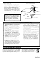 3
3
-
 4
4
-
 5
5
-
 6
6
-
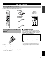 7
7
-
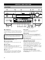 8
8
-
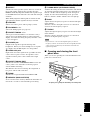 9
9
-
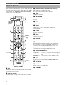 10
10
-
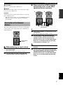 11
11
-
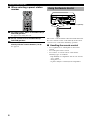 12
12
-
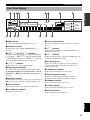 13
13
-
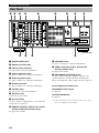 14
14
-
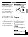 15
15
-
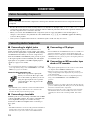 16
16
-
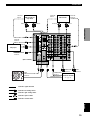 17
17
-
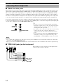 18
18
-
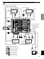 19
19
-
 20
20
-
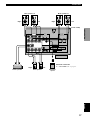 21
21
-
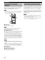 22
22
-
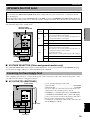 23
23
-
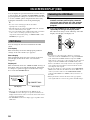 24
24
-
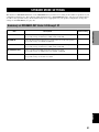 25
25
-
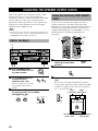 26
26
-
 27
27
-
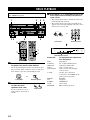 28
28
-
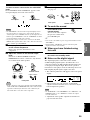 29
29
-
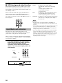 30
30
-
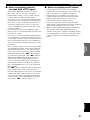 31
31
-
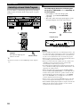 32
32
-
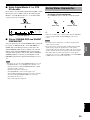 33
33
-
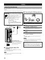 34
34
-
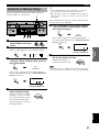 35
35
-
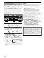 36
36
-
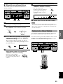 37
37
-
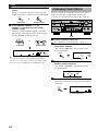 38
38
-
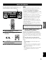 39
39
-
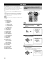 40
40
-
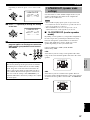 41
41
-
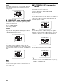 42
42
-
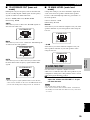 43
43
-
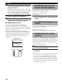 44
44
-
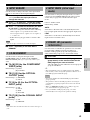 45
45
-
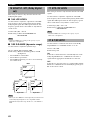 46
46
-
 47
47
-
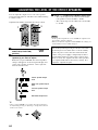 48
48
-
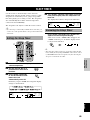 49
49
-
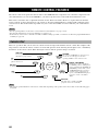 50
50
-
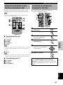 51
51
-
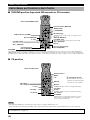 52
52
-
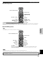 53
53
-
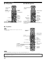 54
54
-
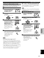 55
55
-
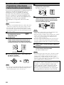 56
56
-
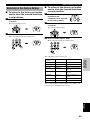 57
57
-
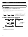 58
58
-
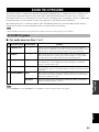 59
59
-
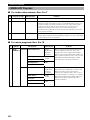 60
60
-
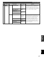 61
61
-
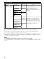 62
62
-
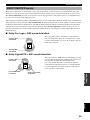 63
63
-
 64
64
-
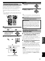 65
65
-
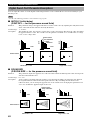 66
66
-
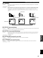 67
67
-
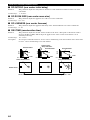 68
68
-
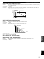 69
69
-
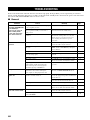 70
70
-
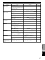 71
71
-
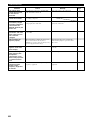 72
72
-
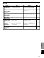 73
73
-
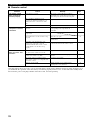 74
74
-
 75
75
-
 76
76
-
 77
77
-
 78
78
-
 79
79
-
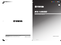 80
80
-
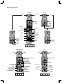 81
81
-
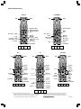 82
82


Yamaha RX-V800 Manual de usuario
- Categoría
- Receptores AV
- Tipo
- Manual de usuario
en otros idiomas
- français: Yamaha RX-V800 Manuel utilisateur
- italiano: Yamaha RX-V800 Manuale utente
- English: Yamaha RX-V800 User manual
- Deutsch: Yamaha RX-V800 Benutzerhandbuch
- русский: Yamaha RX-V800 Руководство пользователя
- Nederlands: Yamaha RX-V800 Handleiding
- português: Yamaha RX-V800 Manual do usuário
- dansk: Yamaha RX-V800 Brugermanual
- polski: Yamaha RX-V800 Instrukcja obsługi
- čeština: Yamaha RX-V800 Uživatelský manuál
- svenska: Yamaha RX-V800 Användarmanual
- suomi: Yamaha RX-V800 Ohjekirja
- română: Yamaha RX-V800 Manual de utilizare
Artículos relacionados
-
Yamaha RX-V1000 Manual de usuario
-
-
Yamaha HTR-5590 El manual del propietario
-
-
Yamaha RX-V530 Manual de usuario
-
-
Yamaha RX-497 El manual del propietario
-
-
-