LD Systems DSP 45 K Manual de usuario
- Categoría
- Altavoces de la barra de sonido
- Tipo
- Manual de usuario

USER´S MANUAL
BEDIENUNGSANLEITUNG
MANUEL D`UTILISATION
MANUAL DE USUARIO
INSTRUKCJA OBSŁUGI
MANUALE D‘ USO
DSP 45 K
4-CHANNEL DSP AMPLIFIER
LDDSP45K
DSP 44 K
4-CHANNEL DSP AMPLIFIER WITH DANTE
LDDSP44K

DEUTSCHFRANCAIS
ESPAÑOL
ENGLISH
ITALIANO POLSKI
ITALIANO
POLSKI
ESPAÑOL
FRANCAIS
DEUTSCHENGLISH
CONTENTS / INHALTSVERZEICHNIS / CONTENU / CONTENIDO / TREŚĆ / CONTENUTO
ENGLISH
PREVENTIVE MEASURES 3-4
INTRODUCTION 4
CONNECTIONS, OPERATING AND DISPLAY ELEMENTS 5-6
OPERATION 7-11
TECHNICAL DATA 11-12
MANUFACTURER’S DECLARATIONS 12
DEUTSCH
SICHERHEITSHINWEISE 13-14
EINFÜHRUNG 14
ANSCHLÜSSE, BEDIEN- UND ANZEIGEELEMENTE 15-16
BEDIENUNG 17-21
TECHNISCHE DATEN 21-22
HERSTELLERERKLÄRUNGEN 22
FRANCAIS
MESURES PRÉVENTIVES 23-24
INTRODUCTION 24
RACCORDEMENTS, ÉLÉMENTS DE COMMANDE ET
D’AFFICHAGE 25-27
UTILISATION 27-31
CARACTÉRISTIQUES TECHNIQUES 31-32
DÉCLARATIONS DU FABRICANT 32
ESPAÑOL
MEDIDAS DE SEGURIDAD 33-34
INTRODUCCIÓN 34
CONEXIONES, ELEMENTOS DE MANDO Y ELEMENTOS
DE VISUALIZACIÓN 35-36
FUNCIONAMIENTO 37-41
DATOS TÉCNICOS 41-42
DECLARACIONES DEL FABRICANTE 42
POLSKI
ŚRODKI OSTROŻNOŚCI 43-44
WPROWADZENIE 44
GNIAZDA, PANEL OBSŁUGI I WSKAŹNIKI 45-46
OBSŁUGA 47-50
DANE TECHNICZNE 51-52
OŚWIADCZENIA PRODUCENTA 52
ITALIANO
MISURE PRECAUZIONALI 53-54
INTRODUZIONE 54
CONNETTORI, ELEMENTI DI COMANDO E DI VISUALIZZAZIONE 55-56
UTILIZZO 57-61
DATI TECNICI 61-62
DICHIARAZIONI DEL PRODUTTORE 62

3
DEUTSCHFRANCAIS
ESPAÑOL
ENGLISH
ITALIANO POLSKI
ITALIANO
POLSKI
ESPAÑOL
FRANCAIS
DEUTSCHENGLISH
ENGLISH
YOU‘VE MADE THE RIGHT CHOICE!
We have designed this product to operate reliably over many years. LD Systems stands for this with its name and many years of experience
as a manufacturer of high-quality audio products. Please read this User‘s Manual carefully, so that you can begin making optimum use of
your LD Systems product quickly.
You can find more information about LD-SYSTEMS at our Internet site WWW.LD-SYSTEMS.COM
PREVENTIVE MEASURES
1. Please read these instructions carefully.
2. Keep all information and instructions in a safe place.
3. Follow the instructions.
4. Observe all safety warnings. Never remove safety warnings or other information from the equipment.
5. Use the equipment only in the intended manner and for the intended purpose.
6. Use only sufficiently stable and compatible stands and/or mounts (for fixed installations). Make certain that wall mounts are properly installed and
secured. Make certain that the equipment is installed securely and cannot fall down.
7. During installation, observ e the applicable safety regulations for your country.
8. Never install and operate the equipment near radiators, heat registers, ovens or other sources of heat. Make certain that the equipment is always
installed so that is cooled sufficiently and cannot overheat.
9. Never place sources of ignition, e.g., burning candles, on the equipment.
10. Ventilation slits must not be blocked.
11. Keep a minimum distance of 20 cm around and above the device.
12. Do not use this equipment in the immediate vicinity of water (does not apply to special outdoor equipment - in this case, observe the
special instructions noted below. Do not expose this equipment to flammable materials, fluids or gases. Avoid direct sunlight!
13. Make certain that dripping or splashed water cannot enter the equipment. Do not place containers filled with liquids, such as vases or
drinking vessels, on the equipment.
14. Make certain that objects cannot fall into the device.
15. Use this equipment only with the accessories recommended and intended by the manufacturer.
16. Do not open or modify this equipment.
17. After connecting the equipment, check all cables in order to prevent damage or accidents, e.g., due to tripping hazards.
18. During transport, make certain that the equipment cannot fall down and possibly cause property damage and personal injuries.
19. If your equipment is no longer functioning properly, if fluids or objects have gotten inside the equipment or if it has been damaged in anot
her way, switch it off immediately and unplug it from the mains outlet (if it is a powered device). This equipment may only be repaired by
authorized, qualified personnel.
20. Clean the equipment using a dry cloth.
21. Comply with all applicable disposal laws in your country. During disposal of packaging, please separate plastic and paper/cardboard.
22. Plastic bags must be kept out of reach of children.
23. Please note that changes or modifications not expressly approved by the party responsible for compliance could void the user´s authority
to operate the equipment.
FOR EQUIPMENT THAT CONNECTS TO THE POWER MAINS
24. CAUTION: If the power cord of the device is equipped with an earthing contact, then it must be connected to an outlet with a protective
ground. Never deactivate the protective ground of a power cord.
25. If the equipment has been exposed to strong fluctuations in temperature (for example, after transport), do not switch it on immediately.
Moisture and condensation could damage the equipment. Do not switch on the equipment until it has reached room temperature.
26. Before connecting the equipment to the power outlet, first verify that the mains voltage and frequency match the values specified on the
equipment. If the equipment has a voltage selection switch, connect the equipment to the power outlet only if the equipment values and the
mains power values match. If the included power cord or power adapter does not fit in your wall outlet, contact your electrician.
27. Do not step on the power cord. Make certain that the power cable does not become kinked, especially at the mains outlet and/or power
adapter and the equipment connector.
28. When connecting the equipment, make certain that the power cord or power adapter is always freely accessible. Always disconnect the
equipment from the power supply if the equipment is not in use or if you want to clean the equipment. Always unplug the power cord and
power adapter from the power outlet at the plug or adapter and not by pulling on the cord. Never touch the power cord and power adapter
with wet hands.
29. Whenever possible, avoid switching the equipment on and off in quick succession because otherwise this can shorten the useful life of
the equipment.
30. IMPORTANT INFORMATION: Replace fuses only with fuses of the same type and rating. If a fuse blows repeatedly, please contact an
authorised service centre.
31. To disconnect the equipment from the power mains completely, unplug the power cord or power adapter from the power outlet.
32. If your device is equipped with a Volex power connector, the mating Volex equipment connector must be unlocked before it can be removed.
However, this also means that the equipment can slide and fall down if the power cable is pulled, which can lead to personal injuries and/or
other damage. For this reason, always be careful when laying cables.
33. Unplug the power cord and power adapter from the power outlet if there is a risk of a lightning strike or before extended periods of disuse.

4
DEUTSCHFRANCAIS
ESPAÑOL
ENGLISH
ITALIANO POLSKI
ITALIANO
POLSKI
ESPAÑOL
FRANCAIS
DEUTSCHENGLISH
CAUTION:
To reduce the risk of electric shock, do not remove cover (or back). There are no user serviceable parts
inside. Maintenance and repairs should be exclusively carried out by qualified service personnel.
The warning triangle with lightning symbol indicates dangerous uninsulated voltage inside the unit, which may cause an
electrical shock.
The warning triangle with exclamation mark indicates important operating and maintenance instructions.
Warning! This symbol indicates a hot surface. Certain parts of the housing can become hot during operation. After use, wait for
a cool-down period of at least 10 minutes before handling or transporting the device.
Warning! This device is designed for use below 2000 metres in altitude.
Warning! This product is not intended for use in tropical climates.
CAUTION! HIGH VOLUMES IN AUDIO PRODUCTS!
This device is meant for professional use. Therefore, commercial use of this equipment is subject to the respectively applicable national
accident prevention rules and regulations. As a manufacturer, Adam Hall is obligated to notify you formally about the existence of potential
health risks.
Hearing damage due to high volume and prolonged exposure: When in use, this product is capable of producing high sound-pressure levels
(SPL) that can lead to irreversible hearing damage in performers, employees, and audience members. For this reason, avoid prolonged
exposure to volumes in excess of 90 dB.
NOTE: This equipment has been tested and found to comply with the limits for a Class B digital device, pursuant to Part 15 of the FCC
Rules. These limits are designed to provide reasonable protection against harmful interference in a residential installation. This equipment
generates, uses and can radiate radio frequency energy and, if not installed and used in accordance with the instructions, may cause
harmful interference to radio communications. However, there is no guarantee that interference will not occur in a particular installation. If
this equipment does cause harmful interference to radio or television reception, which can be determined by turning the equipment off and
on, the user is encouraged to try to correct the interference by one or more of the following measures:
- Reorient or relocate the receiving antenna.
- Increase the separation between the equipment and receiver.
- Connect the equipment into an outlet on a circuit different from that to which the receiver is connected.
- Consult the dealer or an experienced radio/TV technician for help.
INTRODUCTION
The LD Systems
®
DSP 44 K and DSP 45 K are designed to meet the very highest audio demands in terms of performance and functional
reliability. The professional 4-channel power amplifiers feature an extensive range of DSP functions (DSP 44 K with Dante™ interface),
delivering stunning performance and uncompromising sound quality with an output of 1,200 watts per channel and 2 x 2,400 watts bridged.
The high-efficiency Class H topology with switching power supply and power factor correction (PFC) provide a wide dynamic range and
excellent impulse fidelity. The power amplifiers are equipped with a soft starter and comprehensive circuitry protection, including DC,
overcurrent, thermal and short circuit protection. Additional protection is provided by two limiters preventing power supply overload and
power amplifier clipping, as well as by both temperature-controlled fans. These ensure exceptional operational safety even under extreme
conditions. The 24-bit DSP allows precise control with FIR and IIR filters, parametric EQ, crossover, delay, RMS and peak limiters. User-con-
figurable loudspeaker presets with password protection enable fast set-up. Both power amplifiers sport a menu driven 4-line display and
rotary encoder with push button switch for easy configuration. The Dante™ interface (in the DSP 44 K) allows instant integration in Dante™
networks, while the software included enables computer control and monitoring. The LD Systems
®
DSP 44 K and DSP 45 K power amplifiers
are housed in a dual rack space all-steel chassis and weigh just 7 kg. They provide balanced Neutrik
®
XLR inputs, speakON
®
output connec-
tors plus USB and Ethernet ports. The preset library ensures optimum performance and safe operation of LD Systems
®
loudspeakers.

5
DEUTSCHFRANCAIS
ESPAÑOL
ENGLISH
ITALIANO POLSKI
ITALIANO
POLSKI
ESPAÑOL
FRANCAIS
DEUTSCHENGLISH
1
7
3
2
4 5
6
8 8
9
CONNECTIONS, OPERATING AND DISPLAY ELEMENTS
1
DISPLAY
Multi-functional LC screen for display of speaker presets, audio signal level and channel mute. It also shows menu items in the edit menu,
allowing system settings to be made as required.
2
MENU / ENTER
Combined push-and-turn dial to access the edit menu and select and edit individual menu items.
3
EXIT / LOCK
1. EXIT: Press the button briefly to move up one level in the menu structure to the main display (more than once if necessary).
2. LOCK: Press and hold the button for about 5 seconds to lock the controls and prevent unintentional
and unauthorised changes being made. To deactivate the lock, press and hold the MENU dial for approximately 3 seconds.
4
SELECT / MUTE A - D
1. SELECT: Briefly press the relevant button to select the desired channel in the edit menu.
2. MUTE: Press and hold the relevant button for about 3 seconds to mute the selected
channel and for about 3 seconds to unmute it.
5
CLIP
The CLIP LED display lights up when the relevant amp channel is operated in the upper threshold range. Brief illumination of the LED is
uncritical here. In order to protect the system, an excessive signal level is gently down-regulated by the integrated limiters. If the CLIP LED
lights up for a prolonged period or permanently, reduce the volume level.
6
PMS (POWER MANAGEMENT SYSTEM)
The PMS is a an electronic protection system which permanently monitors the main amp parameters so as to only draw from the power
supply the amount of current required to maintain safe operation (monitoring of
signal input, capacity, temperature, current). The PMS LED lights up in the following situations:
1. During the power-up process until the amp is fully functional. The outputs are muted at the same time.
2. Due to unfavourable operating conditions, the internal temperature rises to near the point when the system would automatically
shutdown to prevent overheating. Here the system takes control, restricting current
so as to maintain operational continuity at the power level which the amp is capable of withstanding at that particular moment.
3. Excessive mains current consumption. This only occurs either under laboratory conditions during protracted sinusoidal signal testing
using dummy loads or in conditions of prolonged acoustic feedback. Here the PMS takes control to avoid any damage to the speakers
and to prevent the mains breaker from tripping or the fuses blowing.
7
DATA
The USB interface enables management and control of the DSP amp via LD Systems OCS software (can be downloaded free of charge on
the product page at WWW.LD-SYSTEMS.COM).
8
VENTILATION GRILL
In order to avoid overheating of the device, ensure that the ventilation grill is not covered and that air can circulate freely.

6
DEUTSCHFRANCAIS
ESPAÑOL
ENGLISH
ITALIANO POLSKI
ITALIANO
POLSKI
ESPAÑOL
FRANCAIS
DEUTSCHENGLISH
9
POWER ON/OFF
On/off switch for device’s power supply.
13
16
15
14
12
11
13
10
10
POWER CABLE
Permanently attached power cable with CEE 7/7 mains plug.
11
LINE INPUT IN CH 1–4
Balanced line inputs for channels 1 to 4 with 3-pin XLR sockets (female). Control by unbalanced cables is also possible but balanced signal
transmission is preferable due to the higher level of noise immunity.
Balanced pin connections: Pin 1 = shield, Pin 2 = +, Pin 3 = -
Unbalanced pin connections: Pin 1 & 3 = shield & -, Pin 2 = +
12
LINK CH 1–4
Balanced line outputs for channels 1 to 4 with 3-pin XLR sockets (male). The sockets for the CH 1 to 4 line outputs are connected in parallel
with the relevant input sockets IN CH 1 to 4.
13
OUTPUT CH A - CH D
SpeakON speaker outputs for channels A to D. To avoid damage to the equipment, make sure that the total impedance of the connected
speakers is at least 2 ohms.
Socket assignment OUT CH A/B: plus 1
& minus 1 = CH A / plus 2 & minus 2 = CH B
Socket assignment OUT CH B: plus 1
& minus 1 = CH B
Socket assignment OUT CH C/D: plus 1
& minus 1 = CH C / plus 2 & minus 2 = CH D
Socket assignment OUT CH D: plus 1
& minus 1 = CH D
In Bridge mode, the channel pairs CH A / CH B and CH C / CH D are linked to create higher-performance mono amps. The line input for Bridge
A/B is XLR socket IN CH 1, for Bridge C/D the line input is XLR socket IN CH 3. In Bridge mode, the minimum impedance for connected speakers
is 4 ohms.
Socket assignment OUT CH A/B BRD: plus 1
& minus 2
Socket assignment OUT CH C/D BRD: plus 1 & minus 2
14
ETHERNET
The Ethernet interface enables management and remote control of the DSP amp via LD Systems OCS software (can be downloaded free of
charge on the product page at WWW.LD-SYSTEMS.COM).
15
DANTE™ (DSP 44 K only)
The Dante™ interface allows loss-free and interference-free transmission of digital audio signals over long distances using commonly
available CAT5e (or better) Ethernet cables (Primary = Network 1, Secondary = Network 2).
16
HOUSING FAN
In order to avoid overheating of the device, ensure that the fan is not covered and that air can circulate freely.

7
DEUTSCHFRANCAIS
ESPAÑOL
ENGLISH
ITALIANO POLSKI
ITALIANO
POLSKI
ESPAÑOL
FRANCAIS
DEUTSCHENGLISH
OPERATION
MAIN DISPLAY
When the amp is switched on, the model name of the device and “Initializing Dante” (DSP44K only) appear briefly, then “Press A - Mute all”
for a few seconds. In order to permanently mute all outputs at this point, press SELECT / MUTE button A to the right of the display briefly
for as long as “Press A - Mute all” is shown. “All Muted” then briefly appears on the display. During the power-up process, all outputs are
always muted and the PMS display LEDs for channels A to D light up. After the power-up process, the PMS display LEDs turn off and the
main display appears showing the following information: speaker preset and audio level, channel mute (Mute), or amp limiter activated
(LIMIT) for channels A to D.
Speaker preset
Sound level
Channel mute (MUTE)
Limiter active (LIMIT)
A
B
C
D
NOTE: Up to 80 so-called amp presets are available for the internal storage of individual settings in menu items 1 to 7 and 9 (see
“ADVANCED MENU”). Only menu item 8 Input Configuration (analogue / Dante, DSP44K only) cannot be saved as an amp preset. Here the
setting has to made separately.
MENU ITEM 1 - SPEAKER PRESET (Speaker Select)
Three libraries are available from which to select a speaker preset.
1. LD SYSTEMS: Presets for selected LD SYSTEMS speakers.
2. User: presets which can be created by the user (only using LD Systems OCS software).
3. Flat: three presets in which the audio signal is not processed by the internal DSP (01 Single Flat, 02 2Ways Flat, 03 Bridge Flat).
Briefly press the MENU dial to access the device settings selection menu and then turn the dial to select menu item 1. Spk. Sel. off. Now
press one of the buttons SELECT A to D to open the desired preset library for the relevant channel. To do this, turn the dial to move the arrow
to Library, confirm by pressing the dial, select the desired library by turning the dial and confirm again by pressing the dial. In order to load a
speaker preset, turn the dial to move the arrow to the bottom line of the display, select the desired speaker preset by turning the dial and then
press the dial. To confirm, press the dial until Yes appears in the bottom line and then press the dial again. In order to select and edit one of
the other channels A to D, turn the dial to move the arrow to Output Channel, press the dial, select the desired channel by turning the dial and
confirm by pressing the dial once again (further steps as described above). When speaker presets are loaded, the data of the previously loaded
preset is overwritten. In order to return to the main display, briefly press the EXIT / LOCK button, several times if necessary.
MENU ITEM 2 - GAIN
Set the gain of channels A to D from -60dB to +12dB.
Briefly press the MENU dial to access the device settings selection menu and then turn the dial to select menu item 2. Gain off. Now press
one of the buttons SELECT A to D and make the desired setting in the relevant channel by turning the dial (turn slowly for fine adjustment
and quickly for rough adjustment). Press the dial to activate. In order to select and edit one of the other channels A to D, turn the dial to
move the arrow to the desired channel, press the dial and make the settings as described above. In order to return to
the main display, briefly press the EXIT / LOCK button, several times if necessary.

8
DEUTSCHFRANCAIS
ESPAÑOL
ENGLISH
ITALIANO POLSKI
ITALIANO
POLSKI
ESPAÑOL
FRANCAIS
DEUTSCHENGLISH
MENU ITEM 3 - CHANNEL MUTE (Mute)
Mute channels A to D.
Briefly press the MENU dial to access the device settings selection menu and then turn the dial to select menu item 3. Mute off. Now press
one of the buttons SELECT A to D and make the desired setting in the relevant channel by turning the dial (Mute On/Mute Off). Press the dial to
activate. In order to select and edit one of the other channels A to D, turn the dial to move the arrow to the desired channel, press the dial and
make the settings as described above. In order to return to the main display, briefly press the EXIT / LOCK button, several times if necessary.
MENU ITEM 4 - POLARITY
Set the polarity of channels A to D.
Briefly press the MENU dial to access the device settings selection menu and then turn the dial to select menu item 4. Pol. off. Press one of
the buttons SELECT A to D and make the desired setting in the relevant channel by turning the dial (Normal (+) = polarity not inverted, Invert
(-) = polarity inverted). Press the dial to activate. In order to select and edit one of the other channels A to D, turn the dial to move the arrow
to the desired channel, press the dial and make the settings as described above. In order to return to the main display, briefly press the EXIT
/ LOCK button, several times if necessary.
MENU ITEM 5 - DELAY
Set the channel delay for channels A to D.
Briefly press the MENU dial to access the device settings selection menu and then turn the dial to select menu item 5. Delay off. Now press
one of the buttons SELECT A to D and make the desired setting in the relevant channel by turning the dial (delay is displayed in metres and
milliseconds, delay up to max. 138 ms, 25°C = reference temperature – setting for reference temperature via LD Systems OCS software).
Press the dial to activate. In order to select and edit one of the other channels A to D, turn the dial to move the arrow to the desired channel,
press the dial and make the settings as described above. In order to return to the main display, briefly press the EXIT / LOCK button, several
times if necessary.
MENU ITEM 6 - PARAMETRIC EQUALIZER
12-band parametric equalizer for channels A to D.
Briefly press the MENU dial to access the device settings selection menu and then turn the dial to select menu item 6. PEQ off. Press one
of the buttons SELECT A to D to make the desired setting in the relevant channel. Turn the dial to select the desired equalizer band 1 to 12
in order to edit, then confirm by pressing the dial (Band 1 = Low Shelf, Band 2–11 = Bell, Band 12 = High Shelf). Now you can edit the filter
quality (Q), frequency (Freq.) and gain (Gain) of the selected band according to preference by moving the arrow to the relevant position,
pressing the dial to confirm and making settings by turning the dial. Press the dial to activate. In order to select and edit one of the other
channels A to D, press EXIT once, move the arrow to the desired channel, press the dial and make the settings as described above. In order
to return to the main display, briefly press the EXIT / LOCK button, several times if necessary.

9
DEUTSCHFRANCAIS
ESPAÑOL
ENGLISH
ITALIANO POLSKI
ITALIANO
POLSKI
ESPAÑOL
FRANCAIS
DEUTSCHENGLISH
MENU ITEM 7 - INPUT ROUTING
Route inputs 1 to 4 to channels A to D.
Briefly press the MENU dial to access the device settings selection menu and then turn the dial to select menu item 7. Input Route off.
Now press one of the buttons SELECT A to D and make the desired setting in the relevant channel by turning the dial (route inputs 1–4, 1
+ 2 , 3 + 4). Press the dial to activate. In order to select and edit one of the other channels A to D, turn the dial to move the arrow to the
desired channel, press the dial and make the settings as described above. In order to return to the main display, briefly press the EXIT /
LOCK button, several times if necessary.
MENU ITEM 8 - INPUT SIGNAL
Set the input signal (analogue, DANTE - LD DSP44K only.
Briefly press the MENU dial to access the device settings selection menu and then turn the dial to select menu item 8. Input Conf. off.
Press one of the buttons SELECT A to D to make the desired setting in the relevant input pair by turning the dial (input 1 + 2, input 3 + 4).
Press the dial to activate. In order to select and edit the other input pair, turn the dial to move the arrow to the desired pair, press the dial
and make the settings as described above. In order to return to the main display, briefly press the EXIT / LOCK button, several times if
necessary.
MENU ITEM 9 - OUTPUT CONFIGURATION
Set the output configuration (Single, 2-Way active, Bridge).
Briefly press the MENU dial to access the device settings selection menu and then turn the dial to select menu item 9. Outp. Conf. off.
Press one of the buttons SELECT A to D and set the desired output configuration for the relevant channel pair by turning the dial. Press the
dial. Turn the dial until Yes appears in the bottom line and then press again to confirm. In order to select and edit the other channel pair, turn
the dial to move the arrow to the desired pair, press the dial and make the settings as described above. When the output configuration is
changed, the data of the previously loaded preset is overwritten. In order to return to the main display, briefly press the EXIT / LOCK button,
several times if necessary.
ADVANCED MENU
Press and hold the MENU dial for about 3 seconds to get to the advanced menu. Select the desired menu item by turning the MENU dial
(note position of arrow) and confirm by pressing the dial. The menu item Amp Preset is for managing the amp presets, while the menu
item Amp Setup allows an individual amp name to be entered, as well as the IP address and a password if required. The temperature of
the individual amp channels can be viewed as a percentage under the menu item Amp Temperature, while Amp Info provides the serial
number, firmware version and operation time.
Amp Preset - Load Amp Preset
In order to load a saved amp preset from the internal memory, select the menu item Load Amp Preset by turning the MENU dial and
confirming by pressing the dial. Now select the amp preset to be loaded by turning the dial once again and confirm by pressing the dial. In
the subsequent dialogue, turn the dial to select “Yes” and confirm by pressing the dial. In order to return to the main display, briefly press
the EXIT / LOCK button twice.

10
DEUTSCHFRANCAIS
ESPAÑOL
ENGLISH
ITALIANO POLSKI
ITALIANO
POLSKI
ESPAÑOL
FRANCAIS
DEUTSCHENGLISH
Amp Preset - Save Amp Preset
Up to 80 presets are available for internal storage of individual settings in menu items 1–7 and 9. Only menu item 8 Input Signal (analogue
/ Dante, DSP44K only) cannot be saved as an amp preset. Here the setting has to made separately. Make the settings in menu items 1 to 7
and 9 as required then select the menu item Save Amp Preset in the advanced menu and select an empty preset (Empty) by turning the
dial. Confirm by pressing the dial and enter the characters for the preset name one by one by repeated turning and pressing of the dial (15
characters maximum). To save the preset, press the SELECT / MUTE button D. In order to return to the main display, briefly press the EXIT
/ LOCK button twice.
Amp Preset - Factory Settings
To return the amp to its factory settings, select the menu item Factory Settings, press the MENU dial, turn the dial to select “Yes” in the
following dialogue and confirm by pressing the dial. Speaker presets in the LD SYSTEMS library are preserved, password request is set to
disabled and the password is reset to 0000
(four zeros).
Amp Setup - Name
To give the amp an individual name, select the menu item Name, press the MENU dial and enter the characters of the name one by one by
repeated turning and pressing of the dial (10 characters maximum). When the tenth character has been entered, press the dial once again
to confirm entry.
Amp Setup - IP address
To manually assign an IP address to the amp, select the menu item IP and press the MENU dial. Now the number can be entered for the
first of four number blocks by turning the dial. Confirm entry by pressing the dial, then the number for the second block can be entered.
Proceed in the same way to enter the numbers for blocks three and four.
Amp Setup - Password
In order to protect the amp from unwanted and unauthorised access, the password request can be enabled and a 4-digit number can be set
as the password. Select the menu item Password, press the MENU dial, turn the dial to select “enable” and confirm by pressing the dial.
Now the number can be entered for the first digit by turning the dial. Press the dial to confirm this entry and then set the
second digit. Proceed in the same way to enter the numbers for digits three and four. Password entry is
now requested before it is possible to access the amp menu. To disable the password request, select “disable” and confirm by
pressing the dial.
Amp Temperature
The temperature of the individual amp channels can be viewed as a percentage under the menu item Amp Temperature. Select the menu
item Amp Temperature and press the MENU dial (0% = low temperature, no danger to the system, 100% = high temperature, the PMS
(Power Management System) takes over control and regulates the power supply). In order to return to the main display, briefly press the
EXIT / LOCK button twice.

11
DEUTSCHFRANCAIS
ESPAÑOL
ENGLISH
ITALIANO POLSKI
ITALIANO
POLSKI
ESPAÑOL
FRANCAIS
DEUTSCHENGLISH
TECHNICAL DATA
Model number: LDDSP44K LDDSP45K
Product type: DSP controlled amplifier DSP controlled amplifier
Type: 4-Channel 4-Channel
Rated output power (1 kHz @ 2 Ohm): 4 x 1200 W 4 x 1200 W
Rated output power (1 kHz @ 2,7 Ohm): 4 x 1500 W 4 x 1500 W
Rated output power (1 kHz @ 4 Ohm): 4 x 1200 W 4 x 1200 W
Rated output power (1 kHz @ 8 Ohm): 4 x 675 W 4 x 675 W
Rated output power (Bridge @ 4 Ohm): 2 x 2400 W 2 x 2400 W
Rated output power @ 70 V Mode: 4 x 1200 W 4 x 1200 W
Rated output power @ 100 V Mode: 2 x 2400 W 2 x 2400 W
Output circuitry: Class H Class H
Frequency response +/- 1dB: 10 Hz - 22000 Hz (depending on preset) 10 Hz - 22000 Hz (depending on preset)
THD: < 0,05 % @ 1 kHz (depending on preset) < 0,05 % @ 1 kHz (depending on preset)
Gain: 32 dB (depending on preset) 32 dB (depending on preset)
Protection circuits: Over-current, soft-start, DC, thermal over-
load, short circuit, multiband peak limiter,
RMS limiter, SMPS overload limiter, output
clip limiter
Over-current, soft-start, DC, thermal over-
load, short circuit, multiband peak limiter,
RMS limiter, SMPS overload limiter, output
clip limiter
Controls: Push encoder; 4 direct access buttons; exit/
lock button ; Power Switch
Push encoder; 4 direct access buttons; exit/
lock button ; Power Switch
Indicators: 4 line LC Display with backlight 4 line LC Display with backlight
AD/DA converter sampling frequency: 48 kHz 48 kHz
AD/DA converter resolution: 24 Bit 24 Bit
Dynamic range: 104 dB 104 dB
Maximum delay / Channel: input: 48m(141ms) / output: 1m(3ms) input: 48m(141ms) / output: 1m(3ms)
DSP Functions: FIR and IIR filters, parametric EQ, crossover,
I/O delay, RMS and Peak limiters, input
matrix, password protected loudspeaker
presets
FIR and IIR filters, parametric EQ, crossover,
I/O delay, RMS and Peak limiters, input
matrix, password protected loudspeaker
presets
Line inputs: 4 4
Line input connectors: Neutrik XLR Neutrik XLR
Line through: 4 4
Line through connectors: Neutrik XLR Neutrik XLR
Loudspeaker outputs: 4 4
Speaker output connections: Speakon Speakon
Digital audio interface: DANTE™ (Digital Audio Network Through
Ethernet)
Cooling: two temperature controlled fans two temperature controlled fans
Operating voltage: Switching power supply, 100-240 V AC,
50-60Hz
Switching power supply, 100-240 V AC,
50-60Hz
Power consumption @ full load: 1900 W 1900 W
Ambient temperature (in operation): 0°C - 40°C 0°C - 40°C
Relative humidity (in operation): <80% (non condensing) <80% (non condensing)
Amp Info
The menu item Amp Info provides the serial number, firmware version and operation time in hours and minutes. Select the menu item
Amp Info and press the MENU dial. In order to return to the main display, briefly press the EXIT / LOCK button twice.

DEUTSCHFRANCAIS
ESPAÑOL
ENGLISH
ITALIANO POLSKI
ITALIANO
POLSKI
ESPAÑOL
FRANCAIS
DEUTSCHENGLISH
12
DEUTSCHFRANCAIS
ESPAÑOL
ENGLISH
ITALIANO POLSKI
ITALIANO
POLSKI
ESPAÑOL
FRANCAIS
DEUTSCHENGLISH
MANUFACTURER´S DECLARATIONS
MANUFACTURER‘S WARRANTY & LIMITATIONS OF LIABILITY
You can find our current warranty conditions and limitations of liability at: https://cdn-shop.adamhall.com/media/pdf/Manufacturers-Decla-
rations-LDSYSTEMS_DE_EN_ES_FR.pdf. To request warranty service for a product, please contact Adam Hall GmbH, Adam-Hall-Str. 1,
61267 Neu Anspach / Email: [email protected] / +49 (0)6081 / 9419-0.
CORRECT DISPOSAL OF THIS PRODUCT
(valid in the European Union and other European countries with a differentiated waste collection system)
This symbol on the product, or on its documents indicates that the device may not be treated as household waste. This is to avoid
environmental damage or personal injury due to uncontrolled waste disposal. Please dispose of this product separately from other waste
and have it recycled to promote sustainable economic activity. Household users should contact either the retailer where they purchased
this product, or their local government office, for details on where and how they can recycle this item in an environmentally friendly manner.
Business users should contact their supplier and check the terms and conditions of the purchase contract. This product should not be mixed
with other commercial waste for disposal.
FCC STATEMENT
This device complies with Part 15 of the FCC Rules. Operation is subject to the following two conditions:
(1) This device may not cause harmful interference, and
(2) This device must accept any interference received, including interference that may cause undesired operation
CE Compliance
Adam Hall GmbH states that this product meets the following guidelines (where applicable):
R&TTE (1999/5/EC) or RED (2014/53/EU) from June 2017
Low voltage directive (2014/35/EU)
EMV directive (2014/30/EU)
RoHS (2011/65/EU)
The complete declaration of conformity can be found at www.adamhall.com.
Furthermore, you may also direct your enquiry to [email protected].
Width: 482 mm 482 mm
Height: 89 mm 89 mm
Depth: 320 mm 320 mm
Weight: 7.9 kg 7.9 kg
Features: 4-channel DSP controlled, Smart 19“/ 2U
housing, active PFC, Dante™ Interface,
Ethernet, USB front port, LD Systems
loudspeaker preset library, computer
control software
4-channel DSP controlled, Smart 19“/
2U housing, active PFC, Ethernet, USB
front port, LD Systems loudspeaker preset
library, computer control software

13
DEUTSCHFRANCAIS
ESPAÑOL
ENGLISH
ITALIANO POLSKI
ITALIANO
POLSKI
ESPAÑOL
FRANCAIS
DEUTSCHENGLISH
DEUTSCHFRANCAIS
ESPAÑOL
ENGLISH
ITALIANO POLSKI
ITALIANO
POLSKI
ESPAÑOL
FRANCAIS
DEUTSCHENGLISH
DEUTSCH
SIE HABEN DIE RICHTIGE WAHL GETROFFEN!
Dieses Gerät wurde unter hohen Qualitätsanforderungen entwickelt und gefertigt, um viele Jahre einen reibungslosen Betrieb zu gewährleisten.
Dafür steht LD Systems mit seinem Namen und der langjährigen Erfahrung als Hersteller hochwertiger Audioprodukte. Bitte lesen Sie diese
Bedienungsanleitung sorgfältig, damit Sie Ihr neues Produkt von LD Systems schnell optimal einsetzen können.
Mehr Informationen zu LD SYSTEMS finden Sie auf unserer Internetseite WWW.LD-SYSTEMS.COM
SICHERHEITSHINWEISE
1. Lesen Sie diese Anleitung bitte sorgfältig durch.
2. Bewahren Sie alle Informationen und Anleitungen an einem sicheren Ort auf.
3. Befolgen Sie die Anweisungen.
4. Beachten Sie alle Warnhinweise. Entfernen Sie keine Sicherheitshinweise oder andere Informationen vom Gerät.
5. Verwenden Sie das Gerät nur in der vorgesehenen Art und Weise.
6. Verwenden Sie ausschließlich stabile und passende Stative bzw. Befestigungen (bei Festinstallationen). Stellen Sie sicher, dass Wandhalterungen
ordnungsgemäß installiert und gesichert sind. Stellen Sie sicher, dass das Gerät sicher installiert ist und nicht herunterfallen kann.
7. Beachten Sie bei der Installation die für Ihr Land geltenden Sicherheitsvorschriften.
8. Installieren und betreiben Sie das Gerät nicht in der Nähe von Heizkörpern, Wärmespeichern, Öfen oder sonstigen Wärmequellen. Sorgen
Sie dafür, dass das Gerät immer so installiert ist, dass es ausreichend gekühlt wird und nicht überhitzen kann.
9. Platzieren Sie keine Zündquellen wie z.B. brennende Kerzen auf dem Gerät.
10. Lüftungsschlitze dürfen nicht blockiert werden.
11. Halten Sie einen Mindestabstand von 20 cm seitlich und oberhalb des Geräts ein.
12. Betreiben Sie das Gerät nicht in unmittelbarer Nähe von Wasser. Bringen Sie das Gerät nicht mit brennbaren Materialien, Flüssigkeiten
oder Gasen in Berührung. Direkte Sonneneinstrahlung vermeiden!
13. Sorgen Sie dafür, dass kein Tropf- oder Spritzwasser in das Gerät eindringen kann. Stellen Sie keine mit Flüssigkeit gefüllten Behältnisse
wie Vasen oder Trinkgefäße auf das Gerät.
14. Sorgen Sie dafür, dass keine Gegenstände in das Gerät fallen können.
15. Betreiben Sie das Gerät nur mit dem vom Hersteller empfohlenen und vorgesehenen Zubehör.
16. Öffnen Sie das Gerät nicht und verändern Sie es nicht.
17. Überprüfen Sie nach dem Anschluss des Geräts alle Kabelwege, um Schäden oder Unfälle, z. B. durch Stolperfallen zu vermeiden.
18. Achten Sie beim Transport darauf, dass das Gerät nicht herunterfallen und dabei möglicherweise Sach- und Personenschäden verursachen kann.
19. Wenn Ihr Gerät nicht mehr ordnungsgemäß funktioniert, Flüssigkeiten oder Gegenstände in das Geräteinnere gelangt sind, oder das
Gerät anderweitig beschädigt wurde, schalten Sie es sofort aus und trennen es von der Netzsteckdose (sofern es sich um ein aktives Gerät
handelt). Dieses Gerät darf nur von autorisiertem Fachpersonal repariert werden.
20. Verwenden Sie zur Reinigung des Geräts ein trockenes Tuch.
21. Beachten Sie alle in Ihrem Land geltenden Entsorgungsgesetze. Trennen Sie bei der Entsorgung der Verpackung bitte Kunststoff und
Papier bzw. Kartonagen voneinander.
22. Kunststoffbeutel müssen außer Reichweite von Kindern aufbewahrt werden.
23. Sämtliche vom Benutzer vorgenommenen Änderungen und Modifikationen, denen die für die Einhaltung der Richtlinien verantwortliche
Partei nicht ausdrücklich zugestimmt hat, können zum Entzug der Betriebserlaubnis für das Gerät führen.
BEI GERÄTEN MIT NETZANSCHLUSS
24. ACHTUNG: Wenn das Netzkabel des Geräts mit einem Schutzkontakt ausgestattet ist, muss es an einer Steckdose mit Schutzleiter
angeschlossen werden. Deaktivieren Sie niemals den Schutzleiter eines Netzkabels.
25. Schalten Sie das Gerät nicht sofort ein, wenn es starken Temperaturschwankungen ausgesetzt war (beispielsweise nach dem Transport).
Feuchtigkeit und Kondensat könnten das Gerät beschädigen. Schalten Sie das Gerät erst ein, wenn es Zimmertemperatur erreicht hat.
26. Bevor Sie das Gerät an die Steckdose anschließen, prüfen Sie zuerst, ob die Spannung und die Frequenz des Stromnetzes mit den auf
dem Gerät angegebenen Werten übereinstimmen. Verfügt das Gerät über einen Spannungswahlschalter, schließen Sie das Gerät nur an die
Steckdose an, wenn die Gerätewerte mit den Werten des Stromnetzes übereinstimmen. Wenn das mitgelieferte Netzkabel bzw. der mitgelie-
ferte Netzadapter nicht in Ihre Netzsteckdose passt, wenden Sie sich an Ihren Elektriker.
27. Treten Sie nicht auf das Netzkabel. Sorgen Sie dafür, dass spannungsführende Kabel speziell an der Netzbuchse bzw. am Netzadapter
und der Gerätebuchse nicht geknickt werden.
28. Achten Sie bei der Verkabelung des Geräts immer darauf, dass das Netzkabel bzw. der Netzadapter stets frei zugänglich ist. Trennen Sie
das Gerät stets von der Stromzuführung, wenn das Gerät nicht benutzt wird, oder Sie das Gerät reinigen möchten. Ziehen Sie Netzkabel und
Netzadapter immer am Stecker bzw. am Adapter und nicht am Kabel aus der Steckdose. Berühren Sie Netzkabel und Netzadapter niemals mit
nassen Händen.
29. Schalten Sie das Gerät möglichst nicht schnell hintereinander ein und aus, da sonst die Lebensdauer des Geräts beeinträchtigt werden könnte.
30. WICHTIGER HINWEIS: Ersetzen Sie Sicherungen ausschließlich durch Sicherungen des gleichen Typs und Wertes. Sollte eine Sicherung
wiederholt auslösen, wenden Sie sich bitte an ein autorisiertes Servicezentrum.
31. Um das Gerät vollständig vom Stromnetz zu trennen, entfernen Sie das Netzkabel bzw. den Netzadapter aus der Steckdose.
32. Wenn Ihr Gerät mit einem verriegelbaren Netzanschluss bestückt ist, muss der passende Gerätestecker entsperrt werden, bevor er entfernt
werden kann. Das bedeutet aber auch, dass das Gerät durch ein Ziehen am Netzkabel verrutschen und herunterfallen kann, wodurch Personen
verletzt werden und/oder andere Schäden auftreten können. Verlegen Sie Ihre Kabel daher immer sorgfältig.
33. Entfernen Sie Netzkabel und Netzadapter aus der Steckdose bei Gefahr eines Blitzschlags oder wenn Sie das Gerät länger nicht verwenden.

14
DEUTSCHFRANCAIS
ESPAÑOL
ENGLISH
ITALIANO POLSKI
ITALIANO
POLSKI
ESPAÑOL
FRANCAIS
DEUTSCHENGLISH
ACHTUNG
Entfernen Sie niemals die Abdeckung, da sonst das Risiko eines elektrischen Schlages besteht. Im
Inneren des Geräts befinden sich keine Teile, die vom Bediener repariert oder gewartet werden können.
Lassen Sie Wartung und Reparaturen ausschließlich von qualifiziertem Servicepersonal durchführen.
Das gleichseitige Dreieck mit Blitzsymbol warnt vor nichtisolierten, gefährlichen Spannungen im Geräteinneren, die einen
elektrischen Schlag verursachen können.
Das gleichseitige Dreieck mit Ausrufungszeichen kennzeichnet wichtige Bedienungs- und Wartungshinweise.
Warnung! Dieses Symbol kennzeichnet heiße Oberflächen. Während des Betriebs können bestimmte Teile des Gehäuses heiß
werden. Berühren oder transportieren Sie das Gerät nach einem Einsatz erst nach einer Abkühlzeit von mindestens 10 Minuten.
Warnung! Dieses Gerät ist für eine Nutzung bis zu einer Höhe von maximal 2000 Metern über dem Meeresspiegel bestimmt.
Warnung! Dieses Gerät ist nicht für den Einsatz in tropischen Klimazonen bestimmt.
ACHTUNG HOHE LAUTSTÄRKEN BEI AUDIOPRODUKTEN!
Dieses Gerät ist für den professionellen Einsatz vorgesehen. Der kommerzielle Betrieb dieses Geräts unterliegt den jeweils gültigen
nationalen Vorschriften und Richtlinien zur Unfallverhütung. Als Hersteller ist Adam Hall gesetzlich verpflichtet, Sie ausdrücklich auf mögliche
Gesundheitsrisiken hinzuweisen. Gehörschäden durch hohe Lautstärken und Dauerbelastung: Bei der Verwendung dieses Produkts können
hohe Schalldruckpegel (SPL) erzeugt werden, die bei Künstlern, Mitarbeitern und Zuschauern zu irreparablen Gehörschäden führen können.
Vermeiden Sie länger anhaltende Belastung durch hohe Lautstärken über 90 dB.
EINFÜHRUNG
Die LD Systems® Endstufen DSP 44 K und DSP 45 K sind für Beschallungsaufgaben konzipiert, die höchste Anforderungen an Leistung
und Funktionssicherheit stellen. Die professionellen Vierkanal-Leistungsverstärker verfügen über umfangreiche DSP-Funktionen (DSP 44
K mit Dante™- Schnittstelle) und liefern mit einer Leistung von 1.200 Watt pro Kanal und 2 x 2.400 Watt im Brückenbetrieb eine kraftvolle
Performance und kompromisslose Klangqualität. Der hocheffiziente Schaltungsaufbau in Class H mit Schaltnetzteil und Leistungsfaktorkor-
rekturfilter (PFC) erzielt einen weiten Dynamikumfang und ausgezeichnete Impulstreue. Die Endstufen sind mit einem Softstart ausgestattet
und gegen Gleichstrom, Überstrom, Überhitzung und Kurzschluss geschützt. Weiteren Schutz bieten zwei Limiter, die eine Überlast des
Netzteils und Endstufenclipping begrenzen, und die beiden temperaturgesteuerten Lüfter. So wird eine hervorragende Betriebssicherheit
selbst unter extremen Bedingungen sichergestellt. Die 24-Bit Signalbearbeitung bietet mit FIR- und IIR-Filtern, parametrischem Equalizer,
Frequenzweiche, Delay, RMS- und Peak Limitern präzise Regelmöglichkeiten. Nutzerdefinierbare Lautsprecher-Presets mit Passwortschutz
ermöglichen einen schnellen Systemaufbau. Zur leichten Konfiguration haben beide Endstufen ein vierzeiliges, menügeführtes Display und
einen Drehencoder mit integriertem Taster. Die Dante™-Schnittstelle (bei DSP 44 K) erlaubt die sofortige Integration in Dante™-Netzwerke,
die mitgelieferte Software eine Steuerung und Überwachung per Computer. Die LD Systems® Endstufen DSP 44 K und DSP 45 K wiegen
mit ihrem 2 HE Stahlgehäuse gerade 7 kg. Sie besitzen symmetrische Audio-Eingänge über Neutrik® XLR-Buchsen, speakON® Lautspre-
cherausgänge sowie USB- und Ethernet-Anschlüsse. Die Preset-Bibliothek sorgt für die optimale Performance und Betriebssicherheit von
LD Systems® Lautsprechern.

15
DEUTSCHFRANCAIS
ESPAÑOL
ENGLISH
ITALIANO POLSKI
ITALIANO
POLSKI
ESPAÑOL
FRANCAIS
DEUTSCHENGLISH
ANSCHLÜSSE, BEDIEN- UND ANZEIGEELEMENTE
1
7
3
2
4 5
6
8 8
9
1
DISPLAY
Multifunktionales LC-Display für die Anzeige von Lautsprecher-Presets, Audiosignal-Pegel und Kanal-Stummschaltung. Zeigt weiterhin die
Menüpunkte im Bearbeitungsmenü an, um Systemeinstellungen nach Wunsch vorzunehmen.
2
MENU / ENTER
Kombinierter Drück-Dreh-Geber, um in das Bearbeitungsmenü zu gelangen und die einzelnen Menüpunkte auszuwählen und zu editieren.
3
EXIT / LOCK
1. EXIT: Drücken Sie den Taster kurz, um in der Menüstruktur eine Ebene höher zu gelangen, bis zur Hauptanzeige (ggf. wiederholt).
2. LOCK: Drücken und halten Sie den Taster für circa 5 Sekunden, um die Bedienelemente zu sperren und zu verhindern,
dass unbeasichtigt und unbefugt Änderungen vorgenommen werden können. Um die Sperre aufzuheben, drücken und halten Sie
den Geber MENU für die Dauer von circa 3 Sekunden.
4
SELECT / MUTE A - D
1. SELECT: Drücken Sie den entsprechenden Taster kurz, um im Bearbeitungsmenü den gewünschten Kanal auszuwählen.
2. MUTE: Drücken und halten Sie den entsprechenden Taster für circa 3 Sekunden, um den gewünschten Kanal stummzuschalten und
circa 3 Sekunden, um die Stummschaltung wieder aufzuheben.
5
CLIP
Die Anzeige-LED CLIP leuchtet auf, wenn der entsprechende Endstufenkanal im oberen Grenzbereich betrieben wird. Ein kurzes Aufleuchten
der LED ist dabei unkritisch. Um das System zu schützen, wird ein überhöhter Signal-Pegel vom integrierten Limitern sanft heruntergeregelt.
Leuchtet die CLIP-LED länger oder dauerhaft, reduzieren Sie den Lautstärkepegel.
6
PMS (POWER MANAGEMENT SYSTEM)
Das PMS ist ein elektronisches Schutzsystem, das die wichtigsten Endstufenparameter permanent überwacht und reguliert, um von der
Stromversorgung nur die Menge Strom zu beziehen, die für einen betriebssicheren Arbeitsablauf notwendig ist (Überwachung von
Signaleingang, Auslastung, Temperatur, Stromstärke). Die PMS-LED leuchtet in folgenden Situationen:
1. Während des Anschaltvorgangs, bis die Endstufe voll funktionsbereit ist. Gleichzeitig werden die Ausgänge stummgeschaltet.
2. Die Innentemperatur steigt aufgrund ungünstiger Arbeitsbedingungen nahe des Grenzwertes, bei dem die automatische Ausschal
funktion aktiviert werden würde, um eine Überhitzung des Systems zu vermeiden. In diesem Fall übernimmt das System die Kontrolle
und reduziert die Stromzufuhr auf ein Niveau, bei dem die Endstufe in dieser Situation nicht abgeschaltet wird.
3. Bei überhöhtem Stromverbrauch. Diese Situation stellt sich ausschließlich unter Laborbedingungen ein, bei Langzeittests mit
sinusförmigen Audiosignalen mit Dummylasten, oder in langanhaltenden akustischen Feedback Bedingungen. Hier greift das PMS
System ein, um eine Schädigung der Lautsprecher zu vermeiden und um zu verhindern, dass der Hauptunterbrecher ausgelöst wird,
oder die elektrischen Sicherungen durchbrennen.
7
DATA
Die USB-Schnittstelle ermöglicht die Verwaltung und Steuerung der DSP-Endstufe via LD Systems OCS-Software (kostenloser Download von
der Produktseite auf WWW.LD-SYSTEMS.COM).

16
DEUTSCHFRANCAIS
ESPAÑOL
ENGLISH
ITALIANO POLSKI
ITALIANO
POLSKI
ESPAÑOL
FRANCAIS
DEUTSCHENGLISH
8
LÜFTUNGSGITTER
Um Überhitzung des Geräts zu vermeiden, achten Sie darauf, dass das Lüftungsgitter nicht abgedeckt wird und Luft ungehindert zirkulieren kann.
9
POWER ON / OFF
Ein- / Ausschalter für die Spannungsversorgung des Geräts.
13
16
15
14
12
11
13
10
10
NETZKABEL
Fest angeschlossenes Netzkabel mit CEE 7/7 Netzstecker.
11
LINE INPUT IN CH 1 - 4
Symmetrische Line-Eingänge der Kanäle 1 bis 4 mit 3-Pol XLR-Buchsen (weiblich). Die Ansteuerung mit unsymmetrischen Kabeln ist
ebenso möglich, symmetrische Signalführung ist aber aufgrund der höheren Störsicherheit vorzuziehen.
Steckerbelegung symmetrisch: Pin 1 = Schirm, Pin 2 = +, Pin 3 = -
Steckerbelegung unsymmetrisch: Pin 1 & 3 = Schirm & -, Pin 2 = +
12
LINK CH 1 - 4
Symmetrische Line-Ausgänge der Kanäle 1 bis 4 mit 3-Pol XLR-Buchsen (männlich). Die Buchsen der Line-Ausgänge CH 1 bis 4 sind
parallel mit den entsprechenden Eingangsbuchsen IN CH 1 bis 4 geschaltet.
13
OUTPUT CH A - CH D
SpeakON Lautsprecherausgänge der Kanäle A bis D. Um Schäden am Gerät zu vermeiden, achten Sie darauf, dass die Gesamtimpedanz
angeschlossener Lautsprecher minimal 2 Ohm beträgt.
Buchsenbelegung OUT CH A/B: plus 1
& minus 1 = CH A / plus 2 & minus 2 = CH B
Buchsenbelegung OUT CH B: plus 1
& minus 1 = CH B
Buchsenbelegung OUT CH C/D: plus 1
& minus 1 = CH C / plus 2 & minus 2 = CH D
Buchsenbelegung OUT CH D: plus 1
& minus 1 = CH D
Im Bridge-Modus werden die beiden Endstufen CH A und CH B, bzw. CH C und CH D zu leistungsstärkeren Mono-Endstufen verschaltet. Als
Line-Eingang für Bridge A/B dient die XLR-Buchse IN CH 1, für Bridge C/D XLR-Buchse IN CH 3. Die Minimalimpedanz für angeschlossene
Lautsprecher liegt im Bridge-Modus bei 4 Ohm.
Buchsenbelegung OUT CH A/B BRD: plus 1
& minus 2
Buchsenbelegung OUT CH C/D BRD: plus 1 & minus 2
14
ETHERNET
Die Ethernet-Schnittstelle ermöglicht die Verwaltung und Fernsteuerung der DSP-Endstufe via LD Systems OCS-Software (kostenloser
Download von der Produktseite auf WWW.LD-SYSTEMS.COM).
15
DANTE™ (nur DSP 44 K)
Die Dante™-Schnittstelle ermöglicht das Übertragen von digitalen Audiosignalen verlustfrei und störunanfällig über weite Strecken über
handelsübliche CAT5e (oder besser) Ethernet-Kabel (Primary = Netzwerk 1, Secondary = Netzwerk 2).
16
GEHÄUSELÜFTER
Um Überhitzung des Geräts zu vermeiden, achten Sie darauf, dass die Lüfter nicht abgedeckt werden und Luft ungehindert zirkulieren kann.

17
DEUTSCHFRANCAIS
ESPAÑOL
ENGLISH
ITALIANO POLSKI
ITALIANO
POLSKI
ESPAÑOL
FRANCAIS
DEUTSCHENGLISH
BEDIENUNG
DISPLAY HAUPTANZEIGE
Nach dem Einschalten des Verstärkers wird für kurz Zeit der Modellname des Verstärkers und „Initializing Dante“ (nur DSP44K) angezeigt,
danach für einige Sekunden „Press A - Mute all“. Um nun alle Ausgänge auf Dauer stummzuschalten, drücken Sie kurz, solange „Press
A - Mute all“ angezeigt wird, auf den SELECT / MUTE-Taster A rechts neben dem Display. Im Display wird nun kurz „All Muted“ angezeigt.
Während des Anschaltvorgangs sind stets alle Ausgänge stummgeschaltet und die Anzeige-LEDs PMS der Kanäle A bis D leuchten. Nach
dem Anschaltvorgang erlöschen die Anzeige-LEDs PMS und die Hauptanzeige erscheint mit folgenden Informationen: Lautsprecher-Preset
und Audiopegel, Kanal-Stummschaltung (Mute), oder aktivierter Verstärker-Limiter (LIMIT) der Kanäle A bis D.
Lautsprecher-Preset
Audio-Pegel
Kanal-Stummschaltung (MUTE)
Limiter aktiv (LIMIT)
A
B
C
D
HINWEIS: Individuelle Einstellungen in den Menüpunkten 1 bis 7 und 9 können als sogenannte Amp Presets auf bis zu 80 Speicherplätzen
im internen Gerätespeicher gesichert werden (siehe „ERWEITERTES MENÜ“). Lediglich Menüpunkt 8 Eingangskonfiguration (Analog / Dante,
nur DSP44K) kann in einem Amp Preset nicht abgespeichert werden und die Einstellung muss separat erfolgen.
MENÜPUNKT 1 - LAUTSPRECHER-PRESET (Speaker Select)
Drei Ordner (Library) stehen für die Auswahl eines Lautsprecher-Presets zur Verfügung.
1. LD SYSTEMS: Presets für ausgewählte LD SYSTEMS Lautsprecher.
2. User: Presets, die vom Nutzer erstellt werden können (ausschließlich via LD Systems OCS-Software).
3. Flat: Drei Presets, bei denen das Audio-Signal vom internen DSP unbearbeitet bleibt (01 Single Flat, 02 2Ways Flat, 03 Bridge Flat).
Drücken Sie kurz auf den Drück-Dreh-Geber MENU um ins Auswahlmenü für die Geräteeinstellungen zu gelangen und wählen durch
Drehen des Gebers den Menüpunkt 1. Spk. Sel. aus. Drücken Sie nun auf einen der Taster SELECT A bis D, um im entsprechenden Kanal
den gewünschten Preset-Ordner (Library) zu öffnen. Bringen Sie hierzu das Pfeilsymbol durch Drehen am Geber auf Library, bestätigen
durch Drücken auf den Geber, wählen den gewünschten Ordner durch Drehen des Gebers aus und bestätigen die Auswahl durch Drücken
auf den Geber. Um nun ein Lautsprecher-Preset zu laden, bringen Sie das Pfeilsymbol durch Drehen des Gebers in die unterste Zeile des
Displays, drücken auf den Geber, wählen durch Drehen des Gebers das gewünschte Lautsprecher-Preset aus und drücken auf den Geber.
Zum Bestätigen drehen Sie nun am Geber, bis in der untersten Zeile Yes angezeigt wird und drücken abermals auf den Geber. Um einen
der anderen Kanäle A bis D auszuwählen und zu editieren, bringen Sie nun das Pfeilsymbol durch Drehen des Gebers auf Output Channel,
drücken auf den Geber, wählen den gewünschten Kanal durch Drehen des Gebers aus und bestätigen durch Drücken auf den Geber (weitere
Schritte, wie zuvor beschrieben). Beim Laden von Lautsprecher-Presets werden die Daten des zuvor geladenen Presets überschrieben. Um
zur Hauptanzeige zurückzugelangen, drücken Sie ggf. mehrfach kurz auf den Taster EXIT / LOCK.

18
DEUTSCHFRANCAIS
ESPAÑOL
ENGLISH
ITALIANO POLSKI
ITALIANO
POLSKI
ESPAÑOL
FRANCAIS
DEUTSCHENGLISH
MENÜPUNKT 2 - VERSTÄRKUNGSEINSTELLUNG (Gain)
Einstellen der Verstärkung der Kanäle A bis D von -60dB bis +12dB.
Drücken Sie kurz auf den Drück-Dreh-Geber MENU um ins Auswahlmenü für die Geräteeinstellungen zu gelangen und wählen durch Drehen des
Gebers den Menüpunkt 2. Gain aus. Drücken Sie nun auf einen der Taster SELECT A bis D, um nun im entsprechenden Kanal die gewünschte
Einstellung durch Drehen des Gebers vorzunehmen (langsame Drehung für Feineinstellung, schnelle Drehung für Grobeinstellung). Zum Bestätigen
drücken Sie auf den Geber. Um einen der anderen Kanäle A bis D auszuwählen und zu editieren, bringen Sie nun das Pfeilsymbol durch Drehen des
Gebers auf den gewünschten Kanal, drücken auf den Geber und nehmen Einstellungen wie zuvor beschrieben vor. Um zur Hauptanzeige
zurückzugelangen, drücken Sie ggf. mehrfach kurz auf den Taster EXIT / LOCK.
MENÜPUNKT 3 - KANAL-STUMMSCHALTUNG (Mute)
Stummschalten der Kanäle A bis D.
Drücken Sie kurz auf den Drück-Dreh-Geber MENU um ins Auswahlmenü für die Geräteeinstellungen zu gelangen und wählen durch
Drehen des Gebers den Menüpunkt 3. Mute aus. Drücken Sie nun auf einen der Taster SELECT A bis D, um nun im entsprechenden Kanal
die gewünschte Einstellung durch Drehen des Gebers vorzunehmen (Mute On = Stummschaltung aktiviert, Mute Off = Stummschaltung
deaktiviert). Zum Bestätigen drücken Sie auf den Geber. Um einen der anderen Kanäle A bis D auszuwählen und zu editieren, bringen Sie
nun das Pfeilsymbol durch Drehen des Gebers auf den gewünschten Kanal, drücken auf den Geber und nehmen Einstellungen wie zuvor
beschrieben vor. Um zur Hauptanzeige zurückzugelangen, drücken Sie ggf. mehrfach kurz auf den Taster EXIT / LOCK.
MENÜPUNKT 4 - POLARITÄT
Einstellen der Polarität der Kanäle A bis D.
Drücken Sie kurz auf den Drück-Dreh-Geber MENU um ins Auswahlmenü für die Geräteeinstellungen zu gelangen und wählen durch
Drehen des Gebers den Menüpunkt 4. Pol. aus. Drücken Sie nun auf einen der Taster SELECT A bis D, um nun im entsprechenden Kanal die
gewünschte Einstellung durch Drehen des Gebers vorzunehmen (Normal (+) = Polarität nicht invertiert, Invert (-) = Polarität invertiert). Zum
Bestätigen drücken Sie auf den Geber. Um einen der anderen Kanäle A bis D auszuwählen und zu editieren, bringen Sie nun das Pfeilsymbol
durch Drehen des Gebers auf den gewünschten Kanal, drücken auf den Geber und nehmen Einstellungen wie zuvor beschrieben vor. Um zur
Hauptanzeige zurückzugelangen, drücken Sie ggf. mehrfach kurz auf den Taster EXIT / LOCK.
MENÜPUNKT 5 - DELAY
Einstellen der Kanalverzögerung der Kanäle A bis D.
Drücken Sie kurz auf den Drück-Dreh-Geber MENU um ins Auswahlmenü für die Geräteeinstellungen zu gelangen und wählen durch
Drehen des Gebers den Menüpunkt 5. Delay aus. Drücken Sie nun auf einen der Taster SELECT A bis D, um nun im entsprechenden Kanal
die gewünschte Einstellung durch Drehen des Gebers vorzunehmen (Anzeige der Verzögerung in Metern und Millisekunden, Verzögerung bis
maximal 138ms, 25°C = Bezugstemperatur - Einstellung der Bezugstemperatur via LD Systems OCS-Software). Zum Bestätigen drücken
Sie auf den Geber. Um einen der anderen Kanäle A bis D auszuwählen und zu editieren, bringen Sie nun das Pfeilsymbol durch Drehen des
Gebers auf den gewünschten Kanal, drücken auf den Geber und nehmen Einstellungen wie zuvor beschrieben vor. Um zur Hauptanzeige
zurückzugelangen, drücken Sie ggf. mehrfach kurz auf den Taster EXIT / LOCK.

19
DEUTSCHFRANCAIS
ESPAÑOL
ENGLISH
ITALIANO POLSKI
ITALIANO
POLSKI
ESPAÑOL
FRANCAIS
DEUTSCHENGLISH
MENÜPUNKT 6 - PARAMETRISCHER EQUALIZER
12-Band parametrischer Equalizer der Kanäle A bis D.
Drücken Sie kurz auf den Drück-Dreh-Geber MENU um ins Auswahlmenü für die Geräteeinstellungen zu gelangen und wählen durch
Drehen des Gebers den Menüpunkt 6. PEQ aus. Drücken Sie auf einen der Taster SELECT A bis D, um nun im entsprechenden Kanal die
gewünschte Einstellung vorzunehmen. Wählen Sie durch Drehen am Geber das gewünschte Equalizer-Band 1 bis 12 zum Bearbeiten aus
und bestätigen durch Drücken auf den Geber (Band 1 = Low Shelf, Band 2 - 11 = Bell, Band 12 = High Shelf). Nun können Sie Filtergüte (Q),
Frequenz (Freq.) und Verstärkung (Gain) des ausgewählten Bands nach Wunsch bearbeiten, indem Sie das Pfeilsymbol an die entsprechende
Position bringen, durch Drücken des Gebers bestätigen und Einstellungen durch Drehen des Gebers vornehmen. Zum Bestätigen drücken
Sie auf den Geber. Um einen der anderen Kanäle A bis D auszuwählen und zu editieren, drücken Sie 1x auf EXIT, bringen das Pfeilsymbol
durch Drehen des Gebers auf den gewünschten Kanal, drücken auf den Geber und nehmen Einstellungen wie zuvor beschrieben vor. Um zur
Hauptanzeige zurückzugelangen, drücken Sie ggf. mehrfach kurz auf den Taster EXIT / LOCK.
MENÜPUNKT 7 - KANALZUORDNUNG (Input Routing)
Eingänge 1 bis 4 den Kanälen A bis D zuordnen.
Drücken Sie kurz auf den Drück-Dreh-Geber MENU um ins Auswahlmenü für die Geräteeinstellungen zu gelangen und wählen durch Drehen
des Gebers den Menüpunkt 7. Input Rout aus. Drücken Sie nun auf einen der Taster SELECT A bis D, um nun im entsprechenden Kanal die
gewünschte Einstellung durch Drehen des Gebers vorzunehmen (zuordnen der Eingänge 1 - 4, 1 + 2 , 3 + 4). Zum Bestätigen drücken Sie auf
den Geber. Um einen der anderen Kanäle A bis D auszuwählen und zu editieren, bringen Sie nun das Pfeilsymbol durch Drehen des Gebers auf
den gewünschten Kanal, drücken auf den Geber und nehmen Einstellungen wie zuvor beschrieben vor. Um zur Hauptanzeige zurückzugelangen,
drücken Sie ggf. mehrfach kurz auf den Taster EXIT / LOCK.
MENÜPUNKT 8 - EINGANGSKONFIGURATION (Input Signal)
Einstellen der Eingangsquelle (Analog, DANTE - nur Modell LD DSP44K).
Drücken Sie kurz auf den Drück-Dreh-Geber MENU um ins Auswahlmenü für die Geräteeinstellungen zu gelangen und wählen durch
Drehen des Gebers den Menüpunkt 8. Input Conf. aus. Drücken Sie nun auf einen der Taster SELECT A bis D, um nun im entsprechenden
Eingangs-Paar die gewünschte Einstellung durch Drehen des Gebers vorzunehmen (Eingang 1 + 2, Eingang 3 + 4). Zum Bestätigen drücken
Sie auf den Geber. Um das jeweilig andere Eingangs-Paar auszuwählen und zu editieren, bringen Sie nun das Pfeilsymbol durch Drehen
des Gebers auf das gewünschte Paar, drücken auf den Geber und nehmen Einstellungen wie zuvor beschrieben vor. Um zur Hauptanzeige
zurückzugelangen, drücken Sie ggf. mehrfach kurz auf den Taster EXIT / LOCK.
MENÜPUNKT 9 - AUSGANGSKONFIGURATION (Output Configuration)
Einstellen der Ausgangskonfiguration (Single, 2-Way active, Bridge).
Drücken Sie kurz auf den Drück-Dreh-Geber MENU um ins Auswahlmenü für die Geräteeinstellungen zu gelangen und wählen durch Drehen
des Gebers den Menüpunkt 9. Outp. Conf. aus. Drücken Sie nun auf einen der Taster SELECT A bis D, um für das entsprechende Kanal-Paar
die gewünschte Ausgangskonfiguration durch Drehen des Gebers einzustellen. Drücken Sie auf den Geber. Drehen Sie nun den Geber, bis in
der untersten Zeile Yes angezeigt wird und drücken zum Bestätigen abermals auf den Geber. Um das jeweilig andere Kanal-Paar auszuwählen
und zu editieren, bringen Sie nun das Pfeilsymbol durch Drehen des Gebers auf das gewünschte Paar, drücken auf den Geber und nehmen
Einstellungen wie zuvor beschrieben vor. Beim Ändern der Ausgangskonfiguration werden die Daten des zuvor geladenen Lautsprecher-Presets
überschrieben. Um zur Hauptanzeige zurückzugelangen, drücken Sie ggf. mehrfach kurz auf den Taster EXIT / LOCK.

20
DEUTSCHFRANCAIS
ESPAÑOL
ENGLISH
ITALIANO POLSKI
ITALIANO
POLSKI
ESPAÑOL
FRANCAIS
DEUTSCHENGLISH
ERWEITERTES MENÜ
Drücken und halten Sie den Drück-Dreh-Geber MENU für circa 3 Sekunden, um ins erweiterte Menü zu gelangen. Wählen Sie den
gewünschten Menüpunkt durch Drehen am Drück-Dreh-Geber MENU aus (Pfeilsymbol beachten) und bestätigen durch Drücken auf
den Geber. Der Menüpunkt Amp Preset dient der Verwaltung der Amp Presets, im Menüpunkt Amp Setup können ein individueller
Verstärkername, die IP-Adresse und ein Passwort nach Wunsch eingestellt werden. Die Temperatur der einzelnen Verstärkerkanäle wird im
Menüpunkt Amp Temperature in Prozent ausgelesen und der Menüpunkt Amp Info gibt Auskunft über Seriennummer, Firmware-Version
und Betriebsdauer.
Amp Preset - Load Amp Preset
Um ein im internen Speicher gesichertes Amp Preset zu laden, wählen Sie den Menüpunkt Load Amp Preset durch Drehen am Geber MENU
aus und bestätigen durch Drücken auf den Geber. Wählen Sie nun wiederum durch Drehen am Geber das Amp Preset aus, welches geladen
werden soll und bestätigen die Auswahl durch Drücken auf den Geber. Wählen Sie im folgenden Dialog durch Drehen am Geber „Yes“ (Ja) aus
und bestätigen durch Drücken auf den Geber. Um zur Hauptanzeige zurückzugelangen, drücken Sie 2x auf den Taster EXIT / LOCK.
Amp Preset - Save Amp Preset
Individuelle Einstellungen in den Menüpunkten 1 bis 7 und 9 können als Amp Presets auf bis zu 80 Speicherplätzen im internen Gerätespeicher
gesichert werden. Lediglich Menüpunkt 8 Eingangskonfiguration (Analog / Dante, nur DSP44K) kann in einem Amp Preset nicht abgespeichert
werden und die Einstellung muss separat erfolgen. Nehmen Sie die Einstellungen in den Menüpunkten 1 bis 7 und 9 nach Wunsch vor, wählen dann
den Menüpunkt Save Amp Preset im erweiterten Menü aus und wählen nun ein leeres Preset (Empty) durch Drehen am Geber aus. Bestätigen
Sie durch Drücken auf den Geber und stellen die Zeichen für den Preset-Namen nacheinander durch wiederholtes Drehen und Drücken am Geber
ein (maximal 15 Zeichen). Um das Preset abzuspeichern, drücken Sie auf den SELECT / MUTE-Taster D. Um zur Hauptanzeige zurückzugelangen,
drücken Sie 2x auf den Taster EXIT / LOCK.
Amp Preset - Factory Settings
Um den Verstärker auf die Werkseinstellungen zurückzustellen, wählen Sie den Menüpunkt Factory Settings, drücken auf den Geber MENU,
wählen dann durch Drehen am Geber im folgenden Dialog „Yes“ (Ja) aus und bestätigen durch Drücken auf den Geber. Die Lautsprecher-Presets in
der LD SYSTEMS Library bleiben dabei erhalten, die Passwortabfrage wird auf disable (deaktiviert) und das Passwort auf 0000
(4x die Zahl Null) zurückgesetzt.
Amp Setup - Name
Geben Sie dem Verstärker einen individuellen Namen, indem Sie den Menüpunkt Name auswählen, auf den Geber MENU drücken und die
Zeichen für den Verstärker-Namen nacheinander durch wiederholtes Drehen und Drücken am Geber einstellen (maximal 10 Zeichen). Ist das
zehnte Zeichen gesetzt, drücken Sie abermals auf den Geber, um die Eingabe zu bestätigen.
Amp Setup - IP-Adresse
Um dem Verstärker eine IP-Adresse manuell zuzuweisen, wählen Sie den Menüpunkt IP aus und drücken auf den Geber MENU. Nun kann
die Zahl für den ersten von vier Zahlenblöcken durch Drehen am Geber eingestellt werden. Bestätigen Sie die Eingabe durch Drücken auf
den Geber, gleichzeitig kann nun die Zahl für den zweiten Zahlenblock eingestellt werden. Gehen Sie in gleicher Weise zum Eingeben der
Zahlen für Zahlenblock Drei und Vier vor.

21
DEUTSCHFRANCAIS
ESPAÑOL
ENGLISH
ITALIANO POLSKI
ITALIANO
POLSKI
ESPAÑOL
FRANCAIS
DEUTSCHENGLISH
Amp Setup - Password
Um den Verstärker vor ungewolltem und unbefugtem Zugriff zu schützen, kann die Passwortabfrage aktiviert und eine 4-stellige Ziffernfolge
als Passwort eingestellt werden. Wählen Sie den Menüpunkt Password aus, drücken auf den Geber MENU, wählen durch Drehen des Gebers
„enable“ (aktiviert) aus und bestätigen durch Drücken auf den Geber. Nun kann die Zahl für die erste Stelle durch Drehen des Gebers eingestellt
werden. Drücken Sie nun auf den Geber, wird zum Einen die Eingabe bestätigt, zum Anderen kann die Zahl für die zweite Stelle eingestellt
werden. Gehen Sie in gleicher Weise zum Eingeben der Zahlen für die Stellen Drei und Vier vor. Bevor nun auf das Menü des Verstärkers
zugegriffen werden kann, wird das Passwort abgefragt. Zum Deaktivieren der Passwortabfrage wählen Sie „disable“ (deaktiviert) und
bestätigen durch Drücken auf den Geber.
Amp Temperature
Die Temperatur der einzelnen Verstärkerkanäle kann im Menüpunkt Amp Temperature in Prozent ausgelesen werden. Wählen Sie den
Menüpunkt Amp Temperature aus und drücken auf den Geber MENU (0% = geringe Temperatur, keine Gefahr für das System. 100% =
hohe Temperatur, das PMS (Power Management System) übernimmt die Kontrolle und reguliert die Stromzufuhr). Um zur Hauptanzeige
zurückzugelangen, drücken Sie 2x auf den Taster EXIT / LOCK.
Amp Info
Der Menüpunkt Amp Info gibt Auskunft über Seriennummer, Firmware-Version und Betriebsdauer in Stunden und Minuten. Wählen Sie den
Menüpunkt Amp Info aus und drücken auf den Geber MENU. Um zur Hauptanzeige zurückzugelangen, drücken Sie 2x auf den Taster EXIT / LOCK.
TECHNISCHE DATEN
Modellnummer: LDDSP44K LDDSP45K
Produkttyp: DSP-gesteuerter Leistungsverstärker DSP-gesteuerter Leistungsverstärker
Produktart: 4-Kanal 4-Kanal
Nennausgangsleistung (1 kHz @ 2 Ohm): 4 x 1200 W 4 x 1200 W
Nennausgangsleistung (1 kHz @ 2,7 Ohm): 4 x 1500 W 4 x 1500 W
Nennausgangsleistung (1 kHz @ 4 Ohm): 4 x 1200 W 4 x 1200 W
Nennausgangsleistung (1 kHz @ 8 Ohm): 4 x 675 W 4 x 675 W
Nennausgangsleistung (Bridge-Betrieb @
4 Ohm):
2 x 2400 W 2 x 2400 W
Nennausgangsleistung, 70-V-Betrieb: 4 x 1200 W 4 x 1200 W
Nennausgangsleistung, 100-V-Betrieb: 2 x 2400 W 2 x 2400 W
Schaltungskonzept: Class H Class H
Frequenzgang +/-1dB: 10 Hz – 22.000 Hz (je nach Preset) 10 Hz – 22.000 Hz (je nach Preset)
Klirrfaktor (THD): <0,05 % @ 1 kHz (je nach Preset) <0,05 % @ 1 kHz (je nach Preset)
Gain: 32 dB (je nach Preset) 32 dB (je nach Preset)
Schutzschaltungen: Soft-Start (Einschaltverzögerung),
Überlastung, Gleichstrom, Überhitzung,
Kurzschluss, Überlastung des Schaltnetz-
teils, Multiband-Peak-Limiter, RMS-Limiter,
Clip-Limiter (Ausgang)
Soft-Start (Einschaltverzögerung),
Überlastung, Gleichstrom, Überhitzung,
Kurzschluss, Überlastung des Schaltnetz-
teils, Multiband-Peak-Limiter, RMS-Limiter,
Clip-Limiter (Ausgang)
Bedienelemente: Push-Encoder (Multifunktionsdrehgeber);
4 Direktzugriffstasten; Exit/Lock-Taste;
Netzschalter
Push-Encoder (Multifunktionsdrehgeber);
4 Direktzugriffstasten; Exit/Lock-Taste;
Netzschalter

DEUTSCHFRANCAIS
ESPAÑOL
ENGLISH
ITALIANO POLSKI
ITALIANO
POLSKI
ESPAÑOL
FRANCAIS
DEUTSCHENGLISH
22
DEUTSCHFRANCAIS
ESPAÑOL
ENGLISH
ITALIANO POLSKI
ITALIANO
POLSKI
ESPAÑOL
FRANCAIS
DEUTSCHENGLISH
HERSTELLERERKLÄRUNGEN
HERSTELLERGARANTIE & HAFTUNGSBESCHRÄNKUNG
Unsere aktuellen Garantiebedingungen und Haftungsbeschränkung finden Sie unter: https://cdn-shop.adamhall.com/media/pdf/Manufactu-
rers-Declarations-LDSYSTEMS_DE_EN_ES_FR.pdf. Im Service Fall wenden Sie sich bitte an Adam Hall GmbH, Adam-Hall-Str. 1,
61267 Neu Anspach / E-Mail [email protected] / +49 (0)6081 / 9419-0.
KORREKTE ENTSORGUNG DIESES PRODUKTS
(Gültig in der Europäischen Union und anderen europäischen Ländern mit Mülltrennung) Dieses Symbol auf dem Produkt oder dazu-
gehörigen Dokumenten weist darauf hin, dass das Gerät am Ende der Produktlebenszeit nicht zusammen mit dem normalen Hausmüll
entsorgt werden darf, um Umwelt- oder Personenschäden durch unkontrollierte Abfallentsorgung zu vermeiden. Bitte entsorgen Sie dieses
Produkt getrennt von anderen Abfällen und führen es zur Förderung nachhaltiger Wirtschaftskreisläufe dem Recycling zu. Als Privatkunde
erhalten Sie Informationen zu umweltfreundlichen Entsorgungsmöglichkeiten über den Händler, bei dem das Produkt erwor¬ben wurde, oder
über die entsprechenden regionalen Behörden. Als gewerblicher Nutzer kontaktieren Sie bitte Ihren Lieferanten und prüfen die ggf. vertraglich
vereinbarten Konditionen zur Entsorgung der Geräte. Dieses Produkt darf nicht zusammen mit anderen gewerblichen Abfällen entsorgt werden.
CE-Konformität
Hiermit erklärt die Adam Hall GmbH, dass dieses Produkt folgenden Richtlinien entspricht (soweit zutreffend):
R&TTE (1999/5/EG) bzw. RED (2014/53/EU) ab Juni 2017
Niederspannungsrichtlinie (2014/35/EU)
EMV-Richtlinie (2014/30/EU)
RoHS (2011/65/EU)
Die vollständige Konformitätserklärung finden Sie unter www.adamhall.com.
Des Weiteren können Sie diese auch unter [email protected] anfragen.
Anzeigeelemente: Hintergrundbeleuchtetes LC-Display, 4
Zeilen
Hintergrundbeleuchtetes LC-Display, 4
Zeilen
Samplerate, AD/DA-Wandler: 48 kHz 48 kHz
Auflösung, AD/DA-Wandler: 24 Bit 24 Bit
Dynamikumfang: 104 dB 104 dB
Max. Delay / Kanal: Eingang: 48 m (141 ms) / Ausgang: 1 m
(3 ms)
Eingang: 48 m (141 ms) / Ausgang: 1 m
(3 ms)
DSP-Funktionen: FIR- und IIR-Filter, parametrischer EQ,
Frequenzweiche, I/O-Delay, RMS- und
Peak-Limiter, Eingangs-Matrix, passwortge-
schützte Lautsprecher-Presets
FIR- und IIR-Filter, parametrischer EQ,
Frequenzweiche, I/O-Delay, RMS- und
Peak-Limiter, Eingangs-Matrix, passwortge-
schützte Lautsprecher-Presets
Line-Eingänge: 4 4
Anschlüsse Line-Eingänge: Neutrik XLR Neutrik XLR
Line-Through: 4 4
Anschlüsse Line-Through: Neutrik XLR Neutrik XLR
Lautsprecherausgänge: 4 4
Anschlüsse Lautsprecherausgänge: speakON speakON
Digitale Audio-Schnittstelle: DANTE™ (Digital Audio Network Through
Ethernet)
Kühlung: 2 temperaturgeregelte Lüfter 2 temperaturgeregelte Lüfter
Betriebsspannung: Schaltnetzteil, 100 – 240 V AC, 50 – 60 Hz Schaltnetzteil, 100 – 240 V AC, 50 – 60 Hz
Leistungsaufnahme (Volllast): 1900 W 1900 W
Umgebungstemperatur (Betrieb): 0 °C – 40 °C 0 °C – 40 °C
Relative Luftfeuchte (Betrieb): <80% (nicht kondensierend) <80% (nicht kondensierend)
Breite: 482 mm 482 mm
Höhe: 89 mm 89 mm
Tiefe: 320 mm 320 mm
Gewicht: 7,9 kg 7,9 kg
Features: 4-Kanal (DSP-gesteuert), Smart-19"-Ge-
häuse (2 HE), aktive Leistungsfaktorkorrek-
tur (PFC), Dante™-Schnittstelle, Ethernet,
USB-Anschluss vorne, LD Systems-Laut-
sprecher-Preset-Library, Steuerungssoft-
ware für Computer
4-Kanal (DSP-gesteuert), Smart-19"-Ge-
häuse (2 HE), aktive Leistungsfaktorkorrek-
tur (PFC), Ethernet, USB-Anschluss vorne,
LD Systems-Lautsprecher-Preset-Library,
Steuerungssoftware für Computer

23
DEUTSCHFRANCAIS
ESPAÑOL
ENGLISH
ITALIANO POLSKI
ITALIANO
POLSKI
ESPAÑOL
FRANCAIS
DEUTSCHENGLISH
DEUTSCHFRANCAIS
ESPAÑOL
ENGLISH
ITALIANO POLSKI
ITALIANO
POLSKI
ESPAÑOL
FRANCAIS
DEUTSCHENGLISH
FRANCAIS
VOUS AVEZ FAIT LE BON CHOIX!
Cet appareil a été développé et fabriqué en appliquant des exigences de qualité très élevées : il garantit des années de fonctionnement sans
problème. Grâce à de nombreuses années d‘expérience, LD Systems est un nom connu dans le domaine des produits audio haut de gamme.
Veuillez lire attentivement ce Manuel Utilisateur : vous apprendrez rapidement à utiliser votre appareil LD Systems de façon optimale.
Pour plus d‘informations sur LD Systems, visitez notre site Web, WWW.LD-SYSTEMS.COM
MESURES PRÉVENTIVES
1. Veuillez lire attentivement ce manuel.
2. Rangez tous les documents d‘information et d‘instructions en lieu sûr.
3. Veuillez suivre toutes les instructions
4. Observez tous les messages d‘avertissement N‘enlevez pas de l‘appareil les étiquettes de sécurité ou autres informations.
5. N‘utilisez l‘appareil que pour des applications et de la façon appropriées.
6. Utilisez exclusivement des pieds et des dispositifs de fixation stables et adaptés lorsque l‘appareil est utilisé en installation fixe.
Assurez-vous que les fixations murales ont été montées correctement, et qu‘elles sont sécurisées. Vérifiez que l‘appareil est installé en toute
sécurité, et qu‘il ne peut pas tomber.
7. Lors de l‘installation, observez les règlementations de sécurité en vigueur dans votre pays.
8. N‘installez et n‘utilisez pas l‘appareil à proximité de radiateurs, d‘accumulateurs de chaleur, de fours ou de toute autre source de chaleur. Vérifiez
que l‘appareil est installé de façon à bénéficier en permanence d‘un refroidissement efficace et qu‘il ne peut pas chauffer de façon excessive.
9. Ne placez aucune source de flamme sur l‘appareil – par exemple, une bougie allumée.
10. Ne bloquez pas les ouïes d‘aération. Éviter toute exposition directe aux rayons du soleil !
11. Gardez une distance minimale de 20 cm autour et au-dessus de l‘appareil.
12. N‘utilisez pas l‘appareil à proximité immédiate d‘eau (à moins qu‘il ne s‘agisse d‘un appareil conçu pour une utilisation en extérieur –
dans ce cas, respectez les instructions correspondantes ci après) Ne mettez pas l‘appareil en contact avec des matériaux, des liquides ou
des gaz inflammables.
13. Vérifiez qu‘aucune projection ou liquide ne puisse s‘introduire dans l‘appareil. Ne posez sur l‘appareil aucun objet renfermant du liquide
: vase, verre d‘eau...
14. Vérifiez qu‘aucun petit objet ne puisse tomber à l‘intérieur de l‘appareil.
15. N‘utilisez avec cet appareil que des accessoires recommandés et approuvés par le fabricant.
16. N‘ouvrez pas l‘appareil, et n‘essayez pas de le modifier.
17. Lors du branchement de l‘appareil, sécurisez le passage du câble secteur, afin d‘éviter tout dommage ou accident, par exemple quel-
qu‘un qui trébuche sur le câble.
18. Lors du transport, vérifiez que l‘appareil ne peut tomber, ce qui pourrait provoquer des dommages matériels et/ou corporels.
19. Si votre appareil ne fonctionne plus correctement, que de l‘eau ou des objets ont pénétré à l‘intérieur, ou qu‘il a été endommagé de
quelque façon que ce soit, éteignez-le immédiatement et débranchez sa prise secteur (s‘il s‘agit d‘un appareil alimenté). Cet appareil ne
doit être réparé que par un personnel autorisé.
20. Pour le nettoyage de l‘appareil, utilisez un chiffon sec/
21. Observez toutes les réglementations en vigueur dans votre pays pour mettre l‘appareil au rebut. Lorsque vous jetez l‘emballage de
l‘appareil, veuillez séparer plastique, papier et carton.
22. Les films plastique doivent être mis hors de portée des enfants.
23. Veuillez noter que les changements ou modifications n‘ayant pas été expressément approuvés par la partie responsable de la conformité
pourraient annuler le droit accordé à l‘utilisateur de faire fonctionner l‘équipement.
APPAREILS RELIÉS AU SECTEUR
24. ATTENTION : Si le câble de l‘appareil est muni d‘un fil de terre, il doit être relié à une prise murale avec terre. Ne désactivez jamais la
mise à la terre d‘un appareil.
25. N‘allumez pas l‘appareil immédiatement s‘il a subi une grande différence de température ambiante (par exemple, lors du transport). L‘humidité
et la condensation pourraient l‘endommager. Ne mettez l‘appareil sous tension que lorsqu‘il est parvenu à la température de la pièce.
26. Avant de relier l‘appareil à la prise murale, vérifiez que la valeur et la fréquence de tension secteur sur laquelle il est réglé correspon-
dent bien à la valeur et à la fréquence de la tension secteur locale. Si l‘appareil possède un sélecteur de tension, ne le branchez sur la prise
murale qu‘après avoir vérifié que la valeur réglée correspond à la valeur effective de la tension secteur. Si la fiche du cordon secteur ou du
bloc adaptateur livré avec votre appareil ne correspond pas au format de votre prise murale, veuillez consulter un électricien.
27. Ne piétinez pas le câble secteur. Assurez-vous que le câble secteur n‘est pas trop pincé, notamment au niveau de l‘arrière de l‘appareil
(ou de son adaptateur secteur) et de la prise murale.
28. Lors du branchement de l‘appareil, vérifiez que l‘accès au câble secteur ou au bloc adaptateur reste facile. Sortez la fiche secteur de la
prise murale dès que vous n‘utilisez pas l‘appareil pendant un certain temps, ou si vous désirez nettoyer l‘appareil. Pour ce faire, tirez toujours
sur la fiche elle-même, ou sur le bloc secteur lui-même ; ne tirez jamais sur le câble. Ne manipulez jamais le câble secteur ou l‘adaptateur
secteur avec des mains mouillées.
29. N‘éteignez/rallumez pas l‘appareil rapidement plusieurs fois de suite : vosu risquez de réduire la longévité de ses composants internes.
30. CONSEIL IMPORTANT : Ne remplacez le fusible que par un fusible de même type et du même calibre. Si le fusible fond de façon répétée,
veuillez consulter un centre de réparations agréé.
31. Pour séparer complètement l‘appareil du secteur, débranchez le cordon secteur ou l‘adaptateur de la prise murale.
32. Si votre appareil est muni d‘un connecteur secteur verrouillable (Volex), il faut d‘abord déverrouiller le mécanisme avant d‘enlever le
cordon secteur. Attention, lorsque vous retirez le câble secteur, à ne pas faire bouger l‘appareil, ce qui pourrait se traduire par un risque de
chute, de blesser quelqu‘un, ou tout autre dommage. Manipulez toujours le cordon secteur avec soin.

24
DEUTSCHFRANCAIS
ESPAÑOL
ENGLISH
ITALIANO POLSKI
ITALIANO
POLSKI
ESPAÑOL
FRANCAIS
DEUTSCHENGLISH
33. Débranchez la fiche secteur ou l‘adaptateur de la prise murale en cas d‘orage, ou si vous n‘utilisez pas l‘appareil pendant une longue période.
ATTENTION :
Ne démontez jamais le couvercle de l‘appareil, vous risquez de recevoir un choc électrique.
L‘appareil ne renferme aucune pièce ni composant réparable ou remplaçable par l‘utilisateur. Ne
confiez l‘entretien et la réparation qu‘à un personnel qualifié.
Le pictogramme en forme de triangle équilatéral contenant un éclair terminé d‘une flèche avertit l‘utilisateur de la présence
d‘une tension dangereuse à l‘intérieur de l‘appareil, tension susceptible de provoquer un choc électrique.
Le pictogramme en forme de triangle équilatéral renfermant un point d‘exclamation signale à l‘utilisateur la présence
d‘instructions importantes concernant l‘utilisation ou l‘entretien de l‘appareil.
ATTENTION ! Ce symbole correspond à des surfaces chaudes. En cours de fonctionnement, certaines parties de l’appareil peuvent
devenir chaudes. Après utilisation, ne manipulez ou ne transportez l’appareil qu’au bout de 10 minutes de refroidissement.
Attention ! Cet appareil est conçu pour une utilisation à une altitude maximale de 2000 m au-dessus du niveau de la mer.
Attention ! Ce produit ne convient pas à une utilisation dans les climats tropicaux.
ATTENTION ! NIVEAUX SONORES ÉLEVÉS SUR LES PRODUITS AUDIO
Cet appareil a été conçu en vue d‘une utilisation professionnelle. L‘utilisation commerciale de cet appareil est soumise aux réglementations
et directives en vigueur dans votre pays en matière de prévention d‘accident. En tant que fabricant, Adam Hall est tenu de vous avertir
formellement des risques relatifs à la santé. Risques provoqués par une exposition prolongée à des niveaux sonores élevés : Lors de
l‘utilisation de ce produit, il est possible d‘atteindre des niveaux de pression sonore (exprimés en dB SPL) élevés, susceptibles de provoquer
des dommages auditifs irréparables chez les artistes, les techniciens et le public. Évitez toute exposition prolongée à des niveaux de
pression sonore élevés (supérieurs à 90 dB SPL).
INTRODUCTION
Les amplificateurs DSP44K et DSP45K de LDSystems® sont conçus pour les applications de sonorisation devant répondre à des
exigences très strictes en termes de puissance et de fiabilité d'utilisation. Ces amplificateurs de puissance professionnels à quatre canaux
possèdent de nombreuses fonctions DSP (DSP44K avec interface Dante™). Dotés d'une puissance de 1200W par canal et 2x2400W
en mode bridgé, ils offrent une performance puissante et une qualité sonore irréprochable. Très efficace, leur configuration de circuit en
classeH avec alimentation commutée et filtre de correction du facteur de puissance(PFC) atteint une grande dynamique ainsi qu'une excel-
lente réponse impulsionnelle. Ces amplificateurs intègrent une temporisation de mise sous tension et sont protégés contre les composantes
continues, les surcharges, la surchauffe et les courts-circuits. Une protection supplémentaire est en outre assurée par les deux limiteurs,
qui limitent la surcharge du bloc d'alimentation et l'écrêtage des amplificateurs, ainsi que les deux ventilateurs thermorégulés. Ainsi, même
dans des conditions extrêmes, une sécurité de fonctionnement optimale est garantie. Avec les filtres FIR et IIR, l'égaliseur paramétrique,
le crossover, le Delay et les limiteurs de puissance (RMS et crête), le traitement du signal en 24bits offre des possibilités de réglage d'une
grande précision. De plus, l'utilisateur peut créer des préréglages de haut-parleurs protégés par mot de passe qui assurent une installation
rapide du système. Pour une configuration simplifiée, les deux amplificateurs sont munis d'un écran à quatre lignes piloté par menus
et d'un encodeur rotatif avec touche intégrée. L'interface Dante™ (sur le DSP44K) garantit une intégration immédiate dans le réseau
Dante™, et le logiciel fourni permet de piloter et de contrôler l'appareil par ordinateur. Avec leur boîtier en acier de 2U, les amplificateurs
DSP44K et DSP45K de LDSystems® ne pèsent que 7kg. Ils présentent des entrées audio symétriques avec connecteurs XLR Neutrik®,
des sorties de haut-parleur speakON®, ainsi que des ports Ethernet et USB. La banque de préréglages assure la performance optimale et la
sécurité de fonctionnement des haut-parleurs de la marque LDSystems®.

25
DEUTSCHFRANCAIS
ESPAÑOL
ENGLISH
ITALIANO POLSKI
ITALIANO
POLSKI
ESPAÑOL
FRANCAIS
DEUTSCHENGLISH
1
7
3
2
4 5
6
8 8
9
RACCORDEMENTS, ÉLÉMENTS DE COMMANDE ET D'AFFICHAGE
1
ÉCRAN
Écran LCD multifonctionnel qui affiche les préréglages de haut-parleurs, le niveau du signal audio et la mise en sourdine des canaux. Affiche
les options du menu d’édition afin de configurer les paramètres du système comme souhaité.
2
MENU/ENTER
Codeur rotatif permettant d’accéder au menu d’édition, mais aussi de sélectionner et d’éditer les différentes options de menu.
3
EXIT/LOCK
1. EXIT: Appuyer brièvement sur la touche pour remonter d’un niveau dans la structure du menu, jusqu’à l’affichage principal
(éventuellement à plusieurs reprises).
2. LOCK: Appuyer sur cette touche et la maintenir enfoncée durant environ 5secondes pour verrouiller les éléments de commande et
empêcher toute manipulation non intentionnelle ou indésirable. Pour désactiver le verrouillage, appuyer sur le bouton MENU et le
maintenir enfoncé durant environ 3secondes.
4
SELECT/MUTE A-D
1. SELECT: Appuyer brièvement sur la touche correspondante pour sélectionner le canal souhaité dans le menu d’édition.
2. MUTE: Appuyer sur la touche correspondante et la maintenir enfoncée durant environ 3secondes pour mettre en sourdine le canal
souhaité et environ 3secondes également pour désactiver la mise en sourdine.
5
CLIP
La LED d’affichage CLIP s’allume dès que le canal correspondant de l’amplificateur arrive à ses limites de fonctionnement. Si la LED ne
s’allume que brièvement, la situation n’est pas critique. Pour protéger le système, des limiteurs intégrés permettent de réduire légèrement
tout niveau de signal excessif. Si la LED CLIP s’allume plus longtemps ou de façon permanente, baisser le volume sonore.
6
PMS (POWER MANAGEMENT SYSTEM)
Le PMS est un système de protection électronique qui permet de contrôler et de réguler en permanence les principaux paramètres de
l’amplificateur, afin qu’il ne consomme pas plus de courant électrique que ne le requiert son fonctionnement en toute sécurité (Contrôle de
l’entrée des signaux, de la charge, de la température, de l’intensité du courant). La LED PMS s’allume dans les cas suivants:
1. Durant la phase de mise en marche, jusqu’à ce que l’amplificateur soit totalement opérationnel. Les sorties sont alors mises en
sourdine.
2. La température interne augmente en raison des conditions de fonctionnement défavorables, à savoir lorsqu’elles sont proches de la
valeur limite nécessitant l’activation de la fonction
d’extinction automatique, laquelle vise à éviter toute surchauffe du système. Le cas échéant, le système prend le contrôle
et réduit l’alimentation électrique à un niveau n’entraînant pas l’extinction de l’amplificateur.
3. En cas de consommation électrique excessive. Cette situation se produit exclusivement dans des conditions d’essai en laboratoire, en
cas de tests de longue durée avec des signaux sonores sinusoïdaux et des charges fictives, ou de rétroaction acoustique prolongée.
Le système PMS s’active alors pour empêcher toute dégradation des amplificateurs et éviter de déclencher le disjoncteur principal
ou de griller les fusibles.
7
DATA
Le port USB permet la gestion et le pilotage de l’amplificateurDSP via le logicielOCS de LDSystems (téléchargement gratuit sur la page du
produit, sur le site WWW.LD-SYSTEMS.COM).

26
DEUTSCHFRANCAIS
ESPAÑOL
ENGLISH
ITALIANO POLSKI
ITALIANO
POLSKI
ESPAÑOL
FRANCAIS
DEUTSCHENGLISH
8
GRILLE DE VENTILATION
Pour éviter la surchauffe de l’appareil, veiller à ne pas couvrir la grille de ventilation et à assurer une bonne circulation de l’air.
9
POWERON/OFF
Interrupteur de mise en marche et d’arrêt pour l’alimentation en tension de l’appareil.
13
16
15
14
12
11
13
10
10
CÂBLE D'ALIMENTATION
Câble d'alimentation non amovible avec fiche d'alimentation CEE7/7.
11
LINE INPUTIN CH1-4
Les entrées de ligne symétriques des canaux 1à4 se présentent sous forme de connecteurs XLR à 3broches (femelles). Le pilotage
avec des câbles asymétriques est donc également possible, mais en raison de l'immunité élevée contre les perturbations, la transmission
symétrique des signaux est préférable.
Affectation des broches en liaison symétrique: Pin1=Écran, Pin2=+, Pin3=-
Affectation des broches en liaison asymétrique: Pin1 et3 =Écran et-, Pin2=+
12
LINKCH1-4
Les sorties de ligne symétriques des canaux 1à4 se présentent sous forme de connecteurs XLR à 3 broches (mâles). Les connecteurs des
sorties de ligne CH1à4 sont raccordés en parallèle avec les connecteurs d'entrée correspondants INCH1à4.
13
OUTPUT CHA-CHD
Sorties de haut-parleur SpeakON des canaux AàD. Pour éviter tout dommage de l'appareil, veiller à ce que l'impédance totale des haut-
parleurs raccordés soit au minimum de 2ohms.
Affectation des connecteurs OUTCHA/B: plus1
et moins1 =CHA /plus2 et moins2 =CHB
Affectation des connecteurs OUTCHB: plus1
et moins1 =CHB
Affectation des connecteurs OUTCHC/D: plus1
et moins1 =CHC / plus2 et moins2 =CHD
Affectation des connecteurs OUTCHD: plus1
et moins1 =CHD
En mode bridge, les deux canaux de l'amplificateur, CHA et CHB ou CHC et CHD, sont connectés à des amplificateurs mono performants.
Le connecteur XLR INCH1 et le connecteur XLR INCH3 servent respectivement d'entrée de ligne pour le bridge A/B et le bridge C/D. En
mode bridge, l'impédance minimale pour les haut-parleurs raccordés est de 4ohms.
Affectation des connecteurs OUTCHA/B BRD: plus1
et moins2
Affectation des connecteurs OUTCHC/D BRD: plus1 et moins2
14
ETHERNET
Le port Ethernet permet la gestion et le pilotage à distance de l'amplificateurDSP via le logiciel OCS de LDSystems (téléchargement gratuit
sur la page du produit, sur le site WWW.LD-SYSTEMS.COM).
15
DANTE™ (DSP44K uniquement)
L'interface Dante™ permet de transmettre des signaux audio numériques insensibles aux perturbations, sans pertes et sur de longues
distances, via un câble Ethernet de catégorie CAT5e (ou mieux), couramment vendu dans le commerce (Primary =réseau1, Secondary
=réseau2).

27
DEUTSCHFRANCAIS
ESPAÑOL
ENGLISH
ITALIANO POLSKI
ITALIANO
POLSKI
ESPAÑOL
FRANCAIS
DEUTSCHENGLISH
16
VENTILATEURS DE L'APPAREIL
Pour éviter la surchauffe de l'appareil, veiller à ne pas couvrir les grilles de ventilation et à assurer une bonne circulation de l'air.
UTILISATION
AFFICHAGE PRINCIPAL DE L'ÉCRAN
Dès la mise en marche de l'amplificateur, le nom du modèle de l'amplificateur et la mention «Initializing Dante» (pour le DSP44K uni-
quement) s'affichent brièvement, suivis de la consigne «PressA -Mute all» durant quelques secondes. Pour mettre en sourdine toutes les
sorties de façon permanente, appuyer brièvement sur la toucheA SELECT/MUTE à droite de l'écran, tant que la consigne «PressA -Mute
all» reste affichée. L'écran affiche ensuite brièvement «All Muted». Durant la phase de mise en marche, toutes les sorties sont toujours
mises en sourdine et les LED d'affichage PMS des canauxA àD sont allumées. Après la phase de mise en marche, les LED d'affichage
PMS s'éteignent et l'écran principal apparaît, affichant les informations suivantes: préréglages de haut-parleurs et niveau audio, mise en
sourdine des canaux (Mute) ou limiteur d'amplificateur (LIMIT) des canaux AàD activé.
Préréglage de haut-parleurs
Niveau audio
Mise en sourdine des canaux (Mute)
Limiteur actif (LIMIT)
A
B
C
D
REMARQUE: Les paramètres individuels des options de menu 1à7 et9 peuvent être sauvegardés en tant que «Amp Presets» sur l'un des
80emplacements de mémoire interne de l'appareil (voir «MENU AVANCÉ»). Seule l'option de menu8 intitulée Configuration des entrées
(Analogique/Dante, uniquement pour le DSP44K) ne peut être sauvegardée dans un «Amp Preset». Le réglage doit être réalisé séparément.
OPTION DE MENU1 -PRÉRÉGLAGE DE HAUT-PARLEURS (Speaker Select)
Trois dossiers (Library) proposent une sélection de préréglages de haut-parleurs.
1. LDSYSTEMS: Préréglagles destinés à une sélection de haut-parleurs de LDSYSTEMS.
2. User: Préréglages pouvant être créés par l’utilisateur (exclusivement via le logicielOCS de LDSystems).
3. Flat: Trois préréglages pour lesquels le signal audio n’est pas traité par le DSP interne (01Single Flat, 022Ways Flat, 03Bridge Flat).
Appuyer brièvement sur le codeur rotatif MENU pour accéder au menu de sélection des paramètres de l’appareil et le tourner pour sélectionner
l’option de menu 1.Spk.Sel. Appuyer ensuite sur l’une des touches SELECT AàD pour ouvrir le dossier de préréglages (Library) souhaité dans le
canal correspondant. Déplacer le symbole de la flèche sur Library en tournant le bouton, valider en appuyant sur le bouton, sélectionner le dossier
souhaité en tournant le bouton et valider la sélection en appuyant sur le bouton. Pour charger un préréglage de haut-parleurs, déplacer le symbole
de la flèche sur la ligne tout en bas de l’écran en tournant le bouton, appuyer sur le bouton, sélectionner le préréglage de haut-parleurs souhaité
en tournant le bouton et appuyer sur le bouton. Pour valider, tourner le bouton jusqu’à ce que «Yes» apparaisse sur la ligne inférieure et appuyer
encore une fois sur le bouton. Pour sélectionner et éditer un des autres canaux AàD, déplacer le symbole de la flèche sur OutputChannel en
tournant le bouton, appuyer sur le bouton, sélectionner le canal souhaité en tournant le bouton et valider la sélection en appuyant sur le bouton
(pour les étapes suivantes, procéder comme décrit précédemment). En cas de chargement de préréglages de haut-parleurs, les données relatives
au préréglage précédemment chargé sont écrasées. Pour revenir à l’affichage principal, appuyer brièvement et éventuellement à plusieurs reprises
sur la touche EXIT/LOCK.

28
DEUTSCHFRANCAIS
ESPAÑOL
ENGLISH
ITALIANO POLSKI
ITALIANO
POLSKI
ESPAÑOL
FRANCAIS
DEUTSCHENGLISH
OPTION DE MENU2 -RÉGLAGE DE L’AMPLIFICATION (Gain)
Réglage de l’amplification des canaux AàD de -60dB à +12dB.
Appuyer brièvement sur le bouton-poussoir rotatif MENU pour accéder au menu de sélection des paramètres de l’appareil et le tourner pour
sélectionner l’option de menu 2.Gain. Appuyer ensuite sur l’une des touches SELECT AàD et tourner le bouton pour effectuer le réglage
souhaité dans le canal correspondant (tourner lentement pour un réglage précis et rapidement pour un réglage approximatif). Appuyer sur
le bouton pour valider. Pour sélectionner et éditer un des autres canaux AàD, déplacer le symbole de la flèche sur le canal souhaité en
tournant le bouton, appuyer sur le bouton et procéder comme décrit précédemment pour effectuer les réglages. Pour revenir
à l’affichage principal, appuyer brièvement et éventuellement à plusieurs reprises sur la touche EXIT/LOCK.
OPTION DE MENU3 -MISE EN SOURDINE DES CANAUX (Mute)
Mise en sourdine des canaux AàD.
Appuyer brièvement sur le bouton-poussoir rotatif MENU pour accéder au menu de sélection des paramètres de l’appareil et le tourner pour
sélectionner l’option de menu 3.Mute. Appuyer ensuite sur l’une des touches SELECT AàD et tourner le bouton pour effectuer le réglage
souhaité dans le canal correspondant (Mute On =Mise en sourdine activée, Mute Off =Mise en sourdine désactivée). Appuyer sur le bouton
pour valider. Pour sélectionner et éditer un des autres canaux AàD, déplacer le symbole de la flèche sur le canal souhaité en tournant le
bouton, appuyer sur le bouton et procéder comme décrit précédemment pour effectuer les réglages. Pour revenir à l’affichage principal,
appuyer brièvement et éventuellement à plusieurs reprises sur la touche EXIT/LOCK.
OPTION DE MENU4 -POLARITÉ
Réglage de la polarité des canaux AàD.
Appuyer brièvement sur le bouton-poussoir rotatif MENU pour accéder au menu de sélection des paramètres de l’appareil et le tourner pour
sélectionner l’option de menu 4.Pol. Appuyer ensuite sur l’une des touches SELECT AàD et tourner le bouton pour effectuer le réglage
souhaité dans le canal correspondant (Normal(+) = Polarité non inversée, Invert(-) =Polarité inversée). Appuyer sur le bouton pour valider.
Pour sélectionner et éditer un des autres canaux AàD, déplacer le symbole de la flèche sur le canal souhaité en tournant le bouton, appuyer
sur le bouton et procéder comme décrit précédemment pour effectuer les réglages. Pour revenir à l’affichage principal, appuyer brièvement
et éventuellement à plusieurs reprises sur la touche EXIT/LOCK.
OPTION DE MENU5 -DELAY
Réglage du délai de temporisation des canaux AàD.
Appuyer brièvement sur le bouton-poussoir rotatif MENU pour accéder au menu de sélection des paramètres de l’appareil et le tourner pour
sélectionner l’option de menu 5.Delay. Appuyer ensuite sur l’une des touches SELECT AàD et tourner le bouton pour effectuer le réglage
souhaité dans le canal correspondant (Affichage du délai de temporisation en mètres et millisecondes, délai de temporisation maximal:
138ms, 25°C =température de référence -réglage de la température de référence via le logicielOCS de LDSystems). Appuyer sur le bouton
pour valider. Pour sélectionner et éditer un des autres canaux AàD, déplacer le symbole de la flèche sur le canal souhaité en tournant le
bouton, appuyer sur le bouton et procéder comme décrit précédemment pour effectuer les réglages. Pour revenir à l’affichage principal,
appuyer brièvement et éventuellement à plusieurs reprises sur la touche EXIT/LOCK.
OPTION DE MENU6 -ÉGALISEUR PARAMÉTRIQUE
Égaliseur paramétrique à 12bandes des canaux AàD.
Appuyer brièvement sur le bouton-poussoir rotatif MENU pour accéder au menu de sélection des paramètres de l’appareil et le tourner
pour sélectionner l’option de menu 6.PEQ. Appuyer ensuite sur l’une des touches SELECT AàD pour effectuer le réglage souhaité dans le
canal correspondant. Sélectionner la bande de l’égaliseur (1à12) à paramétrer en tournant le bouton et valider la sélection en appuyant sur
le bouton (Bande1 =Low Shelf, Bande 2à11 =Bell, Bande12 =High Shelf). La qualité du filtre(Q), la fréquence (Freq.) et l’amplification
(Gain) de la bande sélectionnée peuvent désormais être paramétrées comme souhaité. Pour ce faire, déplacer le symbole de la flèche
sur la position correspondante, appuyer sur le bouton pour valider et tourner le bouton pour effectuer les réglages. Appuyer sur le bouton

29
DEUTSCHFRANCAIS
ESPAÑOL
ENGLISH
ITALIANO POLSKI
ITALIANO
POLSKI
ESPAÑOL
FRANCAIS
DEUTSCHENGLISH
pour valider. Pour sélectionner et éditer un des autres canaux AàD, appuyer 1fois sur EXIT, déplacer le symbole de la flèche sur le canal
souhaité en tournant le bouton, appuyer sur le bouton et procéder comme décrit précédemment pour effectuer les réglages. Pour revenir à
l’affichage principal, appuyer brièvement et éventuellement à plusieurs reprises sur la touche EXIT/LOCK.
OPTION DE MENU7 -AFFECTATION DES CANAUX (Input Routing)
Affectation des entrées 1à4 aux canaux AàD.
Appuyer brièvement sur le codeur rotatif MENU pour accéder au menu de sélection des paramètres de l’appareil et le tourner pour sélectionner
l’option de menu 7.Input Rout. Appuyer ensuite sur l’une des touches SELECT AàD et tourner le bouton pour effectuer le réglage souhaité
dans le canal correspondant (affectation des entrées 1-4, 1+2, 3+4). Appuyer sur le bouton pour valider. Pour sélectionner et éditer un des
autres canaux AàD, déplacer le symbole de la flèche sur le canal souhaité en tournant le bouton, appuyer sur le bouton et procéder comme décrit
précédemment pour effectuer les réglages. Pour revenir à l’affichage principal, appuyer brièvement et éventuellement à plusieurs reprises sur la
touche EXIT/LOCK.
OPTION DE MENU8 -CONFIGURATION DES ENTRÉES (Input Signal)
Réglage de la source d’entrée (Analogique, DANTE -uniquement sur le modèle LDDSP44K).
Appuyer brièvement sur le codeur rotatif MENU pour accéder au menu de sélection des paramètres de l’appareil et le tourner pour sélectionner
l’option de menu 8.Input Conf. Appuyer ensuite sur l’une des touches SELECT AàD et tourner le bouton pour effectuer le réglage souhaité
dans la paire d’entrées correspondante (entrée 1+2, entrée 3+4). Appuyer sur le bouton pour valider. Pour sélectionner et éditer l’autre
paire d’entrées, déplacer le symbole de la flèche sur la paire souhaitée en tournant le bouton, appuyer sur le bouton et procéder comme décrit
précédemment pour effectuer les réglages. Pour revenir à l’affichage principal, appuyer brièvement et éventuellement à plusieurs reprises sur
la touche EXIT/LOCK.
OPTION DE MENU9 -CONFIGURATION DES SORTIES (Output Configuration)
Réglage de la configuration des sorties (Single, 2-Way active, Bridge).
Appuyer brièvement sur le codeur rotatif MENU pour accéder au menu de sélection des paramètres de l’appareil et le tourner pour sélectionner
l’option de menu 9.Outp. Conf. Appuyer ensuite sur l’une des touches SELECT AàD et tourner le bouton pour régler la configuration de sortie
souhaitée pour la paire de canaux correspondante. Appuyer sur le bouton. Tourner le bouton jusqu’à ce que «Yes» apparaisse sur la ligne inférieure
et appuyer encore une fois sur le bouton pour valider. Pour sélectionner et éditer l’autre paire de canaux, déplacer le symbole de la flèche sur la
paire souhaitée en tournant le bouton, appuyer sur le bouton et procéder comme décrit précédemment pour effectuer les réglages. En cas de
modification de la configuration des sorties, les données relatives au préréglage de haut-parleurs précédemment chargé sont écrasées. Pour
revenir à l’affichage principal, appuyer brièvement et éventuellement à plusieurs reprises sur la touche EXIT/LOCK.
MENU AVANCÉ
Appuyer sur le codeur rotatif MENU et le maintenir enfoncé durant environ 3secondes pour accéder au menu avancé. Sélectionner l’option
de menu souhaitée en tournant le codeur rotatif MENU (voir symbole de la flèche) et valider la sélection en appuyant sur le bouton. L’option
de menu Amp Preset permet de gérer les préréglages d’amplificateur. L’option de menu Amp Setup offre quant à elle la possibilité d’at-
tribuer un nom à l’amplificateur et de paramétrer l’adresse IP ainsi qu’un mot de passe. La température de chaque canal de l’amplificateur
s’affiche en pourcentage dans l’option de menu Amp Temperature, tandis que l’option de menu Amp Info fournit des informations sur le
numéro de série, la version du firmware et la durée de fonctionnement.

30
DEUTSCHFRANCAIS
ESPAÑOL
ENGLISH
ITALIANO POLSKI
ITALIANO
POLSKI
ESPAÑOL
FRANCAIS
DEUTSCHENGLISH
Amp Preset -Load Amp Preset
Pour charger un préréglage d’amplificateur sauvegardé dans la mémoire interne, sélectionner l’option de menu Load Amp Preset en
tournant le bouton MENU et valider en appuyant sur le bouton. Sélectionner ensuite le préréglage d’amplificateur devant être chargé en
tournant de nouveau le bouton et valider la sélection en appuyant sur le bouton. Dans le dialogue qui s’affiche, sélectionner «Yes» (Oui) en
tournant le bouton et appuyer sur le bouton pour valider. Pour revenir à l’affichage principal, appuyer 2fois sur la touche EXIT/LOCK.
Amp Preset -Save Amp Preset
Les paramètres individuels des options de menu 1à7 et9 peuvent être sauvegardés en tant que «Amp Presets» sur l’un des 80emplacements de
la mémoire interne de l’appareil. Seule l’option de menu8 intitulée Configuration des entrées (Analogique/Dante, uniquement pour le DSP44K) ne
peut être sauvegardée dans un «Amp Preset». Le réglage doit être réalisé séparément. Effectuer les réglages souhaités dans les options de menu
1à7 et9, puis sélectionner l’option de menu Save Amp Preset dans le menu avancé et sélectionner un préréglage vide (Empty) en tournant le
bouton. Valider en appuyant sur le bouton. Pour attribuer un nom au préréglage, saisir un à un les caractères en tournant et en appuyant sur le
bouton à plusieurs reprises (15caractères maximum). Pour sauvegarder le préréglage, appuyer sur la toucheD SELECT/MUTE. Pour revenir à
l’affichage principal, appuyer 2fois sur la touche EXIT/LOCK.
Amp Preset -Factory Settings
Pour restaurer les valeurs par défaut (réglage usine) de l’amplificateur, sélectionner l’option de menu Factory Settings, appuyer sur le bouton
MENU, sélectionner «Yes» (Oui) dans le dialogue qui s’affiche en tournant le bouton et appuyer sur le bouton pour valider. Les préréglages de
haut-parleurs du dossier «LDSYSTEMS Library» sont alors conservés, la demande de mot de passe est réglée sur «disable» (désactivé) et le mot
de passe est réinitialisé sur0000 (4fois le chiffre zéro).
Amp Setup -Name
Pour attribuer un nom à l’amplificateur, sélectionner l’option de menu Name, appuyer sur le bouton MENU, puis saisir un à un les caractères
composant le nom de l’amplificateur en tournant et en appuyant sur le bouton à plusieurs reprises (10caractères maximum). Après avoir entré
le dixième caractère, appuyer encore une fois sur le bouton pour valider la saisie.
Amp Setup -IP-Adresse
Pour attribuer manuellement une adresseIP à l’amplificateur, sélectionner l’option de menuIP et appuyer sur le bouton MENU. Saisir les
chiffres du premier des quatre blocs de chiffres en tournant le bouton. Confirmer la saisie en appuyant sur le bouton et entrer les chiffres du
deuxième bloc de chiffres dans la foulée. Procéder de la même façon pour saisir les chiffres du troisième et du quatrième bloc.
Amp Setup -Password
L’activation de la demande de mot de passe et le paramétrage d’un mot de passe à 4chiffres vise à empêcher toute manipulation non
intentionnelle ou indésirable de l’amplificateur. Sélectionner l’option de menu Password, appuyer sur le bouton MENU, sélectionner «enable»
(activé) en tournant le bouton et appuyer sur le bouton pour valider. Saisir le premier chiffre du mot de passe en tournant le bouton. Après avoir
validé la saisie en appuyant sur le bouton, le deuxième chiffre peut être entré
à son tour. Procéder de la même façon pour saisir le troisième et le quatrième chiffre. Désormais, pour accéder au menu de
l’amplificateur, le mot de passe est demandé. Pour désactiver la demande de mot de passe, sélectionner «disable» (désactivé) et
valider la sélection en appuyant sur le bouton.

31
DEUTSCHFRANCAIS
ESPAÑOL
ENGLISH
ITALIANO POLSKI
ITALIANO
POLSKI
ESPAÑOL
FRANCAIS
DEUTSCHENGLISH
Amp Temperature
La température de chaque canal de l’amplificateur s’affiche en pourcentage dans l’option de menu Amp Temperature. Sélectionner
l’option de menu Amp Temperature et appuyer sur le bouton MENU (0% =basse température, aucun danger pour le système. 100%
=haute température, le PMS (Power Management System) prend le contrôle et régule l’alimentation électrique). Pour revenir à l’affichage
principal, appuyer 2fois sur la touche EXIT/LOCK.
Amp Info
L’option de menu Amp Info fournit des informations sur le numéro de série, la version du firmware et la durée de fonctionnement en heures
et en minutes. Sélectionner l’option de menu Amp Info et appuyer sur le bouton MENU. Pour revenir à l’affichage principal, appuyer 2fois
sur la touche EXIT/LOCK.
CARACTÉRISTIQUES TECHNIQUES
Référence du modèle: LDDSP44K LDDSP45K
Type de produit: Amplificateur contrôlé par DSP Amplificateur contrôlé par DSP
Type: 4canaux 4canaux
Puissance de sortie (1kHz @ 2ohms): 4 x 1200W 4 x 1200W
Puissance de sortie (1kHz @ 2,7ohms): 4 x 1500W 4 x 1500W
Puissance de sortie (1kHz @ 4ohms): 4 x 1200W 4 x 1200W
Puissance de sortie (1kHz @ 8ohms): 4 x 675W 4 x 675W
Puissance de sortie (bridge @ 4ohms): 2 x 2400W 2 x 2400W
Puissance de sortie @ 70V Mode: 4 x 1200W 4 x 1200W
Puissance de sortie @ 100V Mode: 2 x 2400W 2 x 2400W
Circuit de sortie: Classe H Classe H
Réponse en fréquence +/- 1dB: 10Hz - 22000Hz (en fonction du preset) 10Hz - 22000Hz (en fonction du preset)
Taux de distorsion (THD): < 0,05% @ 1kHz (en fonction du preset) < 0,05% @ 1kHz (en fonction du preset)
Gain: 32dB (en fonction du preset) 32dB (en fonction du preset)
Circuits de protection: Surtension, temporisation au démarrage,
courant continu, surchauffe, court-circuit,
limiteur multibande, limiteur RMS, limiteur
de surcharge SMPS, limiteur de clip de
sortie
Surtension, temporisation au démarrage,
courant continu, surchauffe, court-circuit,
limiteur multibande, limiteur RMS, limiteur
de surcharge SMPS, limiteur de clip de
sortie
Réglages: Encodeur-poussoir rotatif; 4 boutons d'ac-
cès direct; bouton de sortie/verrouillage;
interrupteur d'alimentation
Encodeur-poussoir rotatif; 4 boutons d'ac-
cès direct; bouton de sortie/verrouillage;
interrupteur d'alimentation
Indicateurs: Écran LC 4 lignes avec rétroéclairage Écran LC 4 lignes avec rétroéclairage
Fréquence d'échantillonnage du convertisseur
A/N-N/A:
48kHz 48kHz
Résolution du convertisseur A/N-N/A: 24bits 24bits
Plage dynamique: 104dB 104dB
Délai maximum/ canal: entrée: 48m (141ms) / sortie: 1m (3ms) entrée: 48m (141ms) / sortie: 1m (3ms)

DEUTSCHFRANCAIS
ESPAÑOL
ENGLISH
ITALIANO POLSKI
ITALIANO
POLSKI
ESPAÑOL
FRANCAIS
DEUTSCHENGLISH
32
DEUTSCHFRANCAIS
ESPAÑOL
ENGLISH
ITALIANO POLSKI
ITALIANO
POLSKI
ESPAÑOL
FRANCAIS
DEUTSCHENGLISH
Fonctions DSP: Filtres FIR et IIR, égaliseur paramétrique,
filtre répartiteur, délai E/S, limiteur RMS et
crête, matrice d'entrée, presets d'enceinte
protégés par mot de passe
Filtres FIR et IIR, égaliseur paramétrique,
filtre répartiteur, délai E/S, limiteur RMS et
crête, matrice d'entrée, presets d'enceinte
protégés par mot de passe
Entrées de ligne: 4 4
Connecteurs d'entrée de ligne: Neutrik XLR Neutrik XLR
Passage de ligne: 4 4
Connecteurs passage de ligne: Neutrik XLR Neutrik XLR
Sorties enceinte 4 4
Connecteurs de sortie enceintes: Speakon Speakon
Interface audio numérique: DANTE™ (Digital Audio Network Through
Ethernet)
Refroidissement: deux ventilateurs à température contrôlée deux ventilateurs à température contrôlée
Tension secteur: Bloc secteur, 100-240V CA, 50-60Hz Bloc secteur, 100-240V CA, 50-60Hz
Intensité consommée (à pleine charge): 1900W 1900W
Température ambiante (en fonctionnement): 0°C - 40°C 0°C - 40°C
Humidité relative (en fonctionnement): <80% (sans condensation) <80% (sans condensation)
Largeur: 482mm 482mm
Hauteur: 89mm 89mm
Profondeur: 320mm 320mm
Poids: 7,9kg 7,9kg
Caractéristiques: Contrôle DSP à 4 canaux, élégant boîtier
19“/ 2U, PFC actif, interface Dante™,
Ethernet, port USB avant, banque de
presets d'enceintes LDSystems, logiciel de
commande informatique
Contrôle DSP à 4 canaux, élégant boîtier
19“/ 2U, PFC actif, interface Dante™,
Ethernet, port USB avant, banque de
presets d'enceintes LD Systems, logiciel de
commande informatique
DECLARATIONS
GARANTIE FABRICANT & LIMITATION DE RESPONSABILITÉ
Nos conditions actuelles de garantie et de limitation de responsabilité sont disponibles à l‘adresse suivante : https://cdn-shop.adamhall.com/
media/pdf/Manufacturers-Declarations-LDSYSTEMS_DE_EN_ES_FR.pdf. Pour les réparations, veuillez contacter Adam Hall GmbH, Adam-
Hall-Str. 1, 61267 Neu Anspach / E-Mail [email protected] / +49 (0)6081 / 9419-0.
TRI ET MISE AUX DÉCHETS CORRECTE DE CE PRODUIT
(Valid in the European Union and other European countries with waste separation)
(Applicable dans l‘Union Européenne et les autres pays européens pratiquant le tri des déchets) La présence de ce symbole sur le
produit ou sur la documentation correspondante indique qu‘en fin de vie, le produit ne doit pas être jeté avec les déchets normaux, afin
d‘éviter tout dommage à l‘environnement ou aux personnes consécutive à une élimination non contrôlée des déchets. Séparez-le des aut-
res types de déchets et recyclez-le, afin de promouvoir la réutilisation durable des ressources naturelles. Nous conseillons aux utilisateurs
non professionnels de contacter le revendeur chez qui ils ont acheté le produit, ou un représentant gouvernemental local, pour plus de
détails sur le lieu de collecte et la façon de recycler cet appareil dans le meilleur respect de l‘environnement possible.. Nous invitons les
utilisateurs professionnels à contacter leur fournisseur et à vérifier les termes et conditions de leur contrat d‘achat. Ce produit ne doit pas
être mélangé à d‘autres déchets commerciaux lors de la collecte.
Conformité CE
La société Adam Hall GmbH déclare par la présente que ce produit est compatible avec les régulations suivantes (le cas échéant) :
R&TTE (1999/5/EG) et RED (2014/53/EU) à partir de juin 2017
Directive basse tension (2014/35/EU)
Directive CEM (2014/30/EU)
RoHS (2011/65/EU)
La Déclaration de Conformité complète est disponible sur le site Web www.adamhall.com.
Pour toute information complémentaire, contactez-nous : [email protected].

33
DEUTSCHFRANCAIS
ESPAÑOL
ENGLISH
ITALIANO POLSKI
ITALIANO
POLSKI
ESPAÑOL
FRANCAIS
DEUTSCHENGLISH
DEUTSCHFRANCAIS
ESPAÑOL
ENGLISH
ITALIANO POLSKI
ITALIANO
POLSKI
ESPAÑOL
FRANCAIS
DEUTSCHENGLISH
ESPAÑOL
¡GRACIAS POR ELEGIR LD-SYSTEMS!
Este equipo está diseñado y fabricado con los estándares de calidad más exigentes, para garantizar un correcto funcionamiento durante
muchos años. Los productos de LD-Systems se caracterizan por su gran calidad, avalada por el prestigio de la marca y una dilatada expe-
riencia como fabricante. Lea atentamente este manual de usuario para poder aprovechar rápidamente toda la funcionalidad de su nuevo
producto de LD Systems.
Si desea obtener información sobre LD-SYSTEMS, visite nuestro sitio web WWW.LD-SYSTEMS.COM
MEDIDAS DE SEGURIDAD
1. Lea atentamente las instrucciones de este manual.
2. Guarde toda la información en un lugar seguro para futuras consultas.
3. Siga las instrucciones indicadas.
4. Siga todas las advertencias. No quite las instrucciones de seguridad ni cualquier otra información indicada en el equipo.
5. Utilice el equipo únicamente según la finalidad prevista.
6. Utilice solo soportes y fijaciones que sean robustos y adecuados cuando instale el equipo en instalaciones fijas. Asegúrese de que los soportes de
pared están correctamente instalados y firmemente fijados. Asegúrese de que el equipo está sólidamente instalado y no se puede caer.
7. Al instalar el equipo, respete las normas de seguridad aplicables en su país.
8. Evite instalar el equipo cerca de radiadores, acumuladores de calor, estufas o cualquier otra fuente de calor. Asegúrese de que el equipo esté
instalado en un lugar con ventilación suficiente para evitar cualquier sobrecalentamiento.
9. No coloque sobre el equipo fuentes de llamas sin protección, por ejemplo, velas encendidas.
10. Evite bloquear las rejillas de ventilación. ¡Evite la luz solar directa!
11. Mantenga una distancia mínima de 20 cm alrededor y encima del equipo.
12. No utilice este equipo cerca del agua (excepto los equipos específicamente diseñados para uso en exterior, en cuyo caso tenga en cuenta las
indicaciones mencionadas a continuación). No exponga este equipo a materiales, líquidos o gases inflamables.
13. Evite exponer el equipo a gotas o salpicaduras que puedan caer dentro del mismo. No coloque recipientes llenos de líquido, como floreros o
vasos, sobre el equipo.
14. Asegúrese de no dejar caer ningún objeto dentro del equipo.
15. Emplee el equipo únicamente con los accesorios recomendados por el fabricante.
16. No abra el equipo ni intente modificarlo.
17. Una vez conectado el equipo, compruebe que en toda la longitud del cableado no hay peligro de que provoque una caída, por ejemplo.
18. Durante el transporte, asegúrese de que el equipo no se caiga y pueda causar daños personales o materiales.
19. Si el equipo no funciona correctamente, o si se ha vertido líquido sobre él, o si un objeto ha caído en su interior o si ha sufrido algún
desperfecto, apague inmediatamente el equipo y desenchufe el cable eléctrico (si se trata de un equipo activo). Únicamente un técnico
especialista debe reparar el equipo.
20. Para limpiar el equipo utilice un paño seco.
21. Procure seguir las normas vigentes en su país sobre reciclaje de desechos. Separe los componentes de plástico, papel y cartón del paquete
para reciclarlos en sus contenedores respectivos.
22. No deje las bolsas de plástico al alcance de los niños.
23. Tenga en cuenta que la realización de cambios o modificaciones que no estén expresamente autorizados por el responsable de cumplimiento
normativo podría anular la autoridad del usuario para utilizar el equipo.
PARA LOS EQUIPOS CON TOMA ELÉCTRICA
24. ADVERTENCIA: Si el cable eléctrico está provisto de un contacto de protección, debe conectarse a una toma eléctrica con conexión a tierra. No
desactivar nunca esta conexión de protección a tierra del cable eléctrico.
25. Si el equipo ha estado expuesto a un cambio brusco de temperatura (por ejemplo, después del transporte), no lo encienda inmediatamente. La
condensación o la humedad podrían dañar el equipo. Deje que el equipo alcance la temperatura ambiente antes de encenderlo.
26. Antes de conectar el cable eléctrico a la toma de corriente, compruebe si la tensión y la frecuencia del suministro eléctrico coinciden
con las especificaciones de este equipo. Si el equipo dispone de un selector de tensión, antes de enchufarlo a la red eléctrica, asegúrese de
que el valor seleccionado coincide con la tensión de suministro. Si el enchufe o el adaptador de corriente no encajan en la toma eléctrica,
consulte a un electricista.
27. Asegúrese de que el cable eléctrico no está pinzado. Evite que el cable resulte pellizcado, sobre todo en los extremos de conexión al equipo y en
la toma eléctrica.
28. Al conectar el equipo, asegúrese de que el cable eléctrico o el adaptador de corriente estén siempre accesibles. Desconecte el equipo de la
toma de corriente cuando no esté en uso o antes de limpiarlo. Para ello, desconecte el cable eléctrico y el adaptador de corriente del conector del
equipo en vez de desenchufar el cable de la toma eléctrica. No tocar el cable eléctrico ni el adaptador de corriente con las manos húmedas.
29. No encienda y apague el equipo en cortos intervalos de tiempo, ya que se reduce así la vida útil del sistema.
30. NOTA IMPORTANTE: Sustituya los fusibles únicamente por otros del mismo tipo y de las mismas características. Si el fusible se funde continua-
mente, póngase en contacto con un servicio técnico autorizado.
31. Para desconectar completamente el equipo de la tensión eléctrica, desenchufe el cable eléctrico o el adaptador de corriente de la toma eléctrica.
32. Si el equipo dispone de un enchufe eléctrico Volex, deberá desbloquearse el Volex del equipo para desenchufarlo. Esto implica que un tirón en el
cable eléctrico puede desplazar el equipo y provocar daños personales o materiales. Por tanto, asegúrese de instalar los cables con sumo cuidado.

34
DEUTSCHFRANCAIS
ESPAÑOL
ENGLISH
ITALIANO POLSKI
ITALIANO
POLSKI
ESPAÑOL
FRANCAIS
DEUTSCHENGLISH
33. Si es probable que caiga un rayo por una tormenta eléctrica o si no va a emplear el equipo durante mucho tiempo, desenchufe el cable eléctrico
y el adaptador de corriente.
ATENCIÓN:
Para evitar el riesgo de descarga eléctrica, no retire la tapa. El equipo no contiene elementos que
el usuario pueda reparar o sustituir. Para cualquier tarea de mantenimiento o reparación, acuda a
un técnico cualificado.
El símbolo de rayo dentro de un triángulo equilátero advierte al usuario de la presencia de tensiones peligrosas sin aislamiento
dentro del equipo que pueden causar una descarga eléctrica.
El símbolo de exclamación dentro de un triángulo equilátero advierte al usuario de la existencia de importantes instrucciones
de uso y mantenimiento.
¡Advertencia! Este símbolo indica la presencia de superficies calientes. Durante el funcionamiento, algunas partes de la
carcasa pueden llegar a calentarse bastante. Por ello, una vez apagado el equipo, espere al menos 10 minutos antes de
manipularlo o transportarlo.
¡Advertencia! Este equipo está diseñado para ser utilizado a una altura que no supere los 2000metros sobre el nivel del mar.
¡Advertencia! Este equipo no está diseñado para funcionar en climas tropicales.
¡ADVERTENCIA: ALTO VOLUMEN!
Este equipo se destina a un uso profesional. Por consiguiente, si se aplica a un uso comercial, estará sujeto a las normas y reglamentos
de la Asociación para la prevención de accidentes de su sector profesional. Como fabricante, Adam Hall tiene la obligación de informar
formalmente a los usuarios de la existencia de posibles riesgos para la salud. Daños auditivos por exposición prolongada a un nivel SPL
alto: este equipo puede generar fácilmente un nivel de presión sonora (SPL) lo suficientemente elevado como para causar daños auditivos
permanentes a los artistas, el personal de producción y el público. Deben tomarse precauciones para evitar la exposición prolongada a un
SPL de más de 90dB.
INTRODUCCIÓN
Los amplificadores de potencia DSP 44 K y DSP 45 K de LD Systems® están diseñados para las aplicaciones de sonorización más
exigentes en cuanto a potencia y fiabilidad funcional. Estos amplificadores profesionales de cuatro canales cuentan con diversas funciones
de DSP (DSP 44 K con interfaz Dante™) y ofrecen un rendimiento y una calidad de sonido excepcionales gracias a su potencia de 1200W
por canal (2 × 2400W en modo puente). La etapa de potencia de claseH de gran eficiencia, la fuente de alimentación conmutada y el filtro
con corrección del factor de potencia (PFC) garantizan un amplio rango dinámico y una excepcional respuesta al impulso. Los amplifica-
dores de potencia disponen de arranque suave y cuentan con protecciones contra nivel de continua, sobreintensidad, sobrecalentamiento
y cortocircuito. Como protección adicional están provistos de dos limitadores, que evitan la sobrecarga de la fuente de alimentación o la
saturación de las etapas de potencia, y de dos ventiladores controlados por temperatura. Así se garantiza una excelente seguridad operativa
incluso en condiciones extremas. El procesador de señales de 24 bits ofrece posibilidades de regulación precisa mediante filtros FIR e IIR,
un ecualizador paramétrico, crossover, retardo y limitadores de RMS y de picos. Los presets de altavoz, definibles por el usuario y protegi-
dos por contraseña, permiten configurar el sistema con rapidez. Para facilitar la configuración, ambos amplificadores tienen una pantalla
de cuatro líneas con navegación por menús y un control giratorio con pulsador integrado. La interfaz Dante™(en el DSP 44 K) permite la
integración inmediata en las redes Dante™, mientras que el software suministrado hace posibles el control y la supervisión por ordenador.
Los amplificadores de potencia DSP 44 K y DSP 45 K de LD Systems® pesan exactamente 7 kg con su carcasa de acero de 2 U de altura.
Poseen entradas de audio balanceadas mediante conectores hembra XLR Neutrik® y salidas de altavoces speakON®, así como puertos
USB y Ethernet. La biblioteca de presets garantiza el rendimiento óptimo y la seguridad operativa de los altavoces de LD Systems®.

35
DEUTSCHFRANCAIS
ESPAÑOL
ENGLISH
ITALIANO POLSKI
ITALIANO
POLSKI
ESPAÑOL
FRANCAIS
DEUTSCHENGLISH
1
7
3
2
4 5
6
8 8
9
CONEXIONES, ELEMENTOS DE MANDO Y ELEMENTOS DE VISUALIZACIÓN
1
PANTALLA
Pantalla LCD multifuncional para mostrar los presets de altavoz, el nivel de la señal de audio y la silenciación de canales. También muestra
las opciones del menú de edición para hacer los ajustes del sistema que se deseen.
2
MENU / ENTER
Control giratorio y pulsador para acceder al menú de edición y seleccionar y editar las diversas opciones del menú.
3
EXIT / LOCK
1. EXIT: Pulse el botón brevemente para subir un nivel en la estructura del menú hasta llegar a la pantalla principal
(tantas veces como sea necesario).
2. LOCK: Mantenga pulsado el botón durante unos 5 segundos para bloquear los elementos de mando e impedir que se hag
an modificaciones involuntarias o no autorizadas. Para desactivar el bloqueo, mantenga pulsado el c ontrol MENU durante unos 3
segundos.
4
SELECT / MUTE A - D
1. SELECT: Pulse brevemente el botón correspondiente para seleccionar el canal deseado en el menú de edición.
2. MUTE: Mantenga pulsado el botón correspondiente durante unos 3 segundos para silenciar el canal deseado y otros 3 segundo
s aproximadamente para desactivar la silenciación.
5
CLIP
El LED del indicador CLIP se enciende cuando se utiliza el canal correspondiente del amplificador en el rango máximo. Si el LED se enciende
brevemente, no supone un problema. A fin de proteger el sistema, los limitadores integrados regulan el nivel de la señal bajándolo levemente
cuando es excesivo. Si el LED del indicador CLIP se enciende durante más tiempo o de forma permanente, baje el volumen.
6
PMS (POWER MANAGEMENT SYSTEM)
El PMS es un sistema electrónico de protección que supervisa y regula los parámetros más importantes de los amplificadores de potencia
para tomar solo la cantidad necesaria de corriente para un funcionamiento seguro (supervisión de la entrada de la señal , la carga, la
temperatura y la intensidad de corriente). El LED del PMS se enciende en las siguientes situaciones:
1. Durante el proceso de encendido hasta que el amplificador de potencia está operativo. Al mismo tiempo se silencian las salidas.
2. La temperatura interna aumenta debido a unas condiciones operativas desfavorables cerca del valor límite a partir de cual
se activaría la función de apagado automático para evitar el sobrecalentamiento del sistema. En este caso, el sistema toma el control y
reduce la alimentación de corriente hasta un nivel en el que no se apague el amplificador de potencia dadas las condiciones operativas.
3. Si el consumo de corriente es excesivo. Esta situación se da solamente en condiciones de laboratorio, cuando se realizan pruebas de
larga duración con señales de audio senoidales con cargas fantasma o en condiciones de acople acústico duradero. En estos casos, el
sistema PMS interviene para evitar que se dañen los altavoces y que salte el disyuntor principal o que se fundan los fusibles.
7
DATA
La interfaz USB permite administrar y controlar el amplificador de potencia DSP a través del software OCS de LD Systems (descarga gratuita
desde la página del producto en WWW.LD-SYSTEMS.COM).

36
DEUTSCHFRANCAIS
ESPAÑOL
ENGLISH
ITALIANO POLSKI
ITALIANO
POLSKI
ESPAÑOL
FRANCAIS
DEUTSCHENGLISH
8
REJILLA DE VENTILACIÓN
Para evitar que se sobrecaliente el equipo, asegúrese de que la rejilla de ventilación no esté tapada y de que pueda circular aire libremente.
9
POWER ON / OFF
Interruptor de encendido/apagado para la alimentación eléctrica del equipo.
13
16
15
14
12
11
13
10
10
CABLE DE RED
Cable de red de conexión fija con conector CEE 7/7.
11
LINE INPUT IN CH 1 - 4
Entradas de línea balanceadas de los canales 1 a 4 con conectores XLR hembra de 3 pines. También es posible el funcionamiento con
cables no balanceados, pero se prefiere la transmisión balanceada de la señal porque evita en gran medida su distorsión.
Asignación de conectores con cable balanceado: Pin 1 = masa, pin 2 = +, pin 3 = –
Asignación de conectores con cable no balanceado: Pin 1 y 3 = masa y –, pin 2 = +
12
LINK CH 1 - 4
Salidas de línea balanceadas de los canales 1 a 4 con conectores XLR macho de 3 pines. Los conectores de las salidas de línea CH 1 a 4
forman parte de un circuito en paralelo con los conectores de entrada correspondientes IN CH 1 a 4.
13
OUTPUT CH A - CH D
Salidas de altavoz SpeakON de los canales identificados con las letras A, B, C y D. Para evitar daños en el equipo, tenga en cuenta que la
impedancia total de los altavoces conectados debe ser de 2 ohmios como mínimo.
Asignación de conectores OUT CH A/
B: positiv o 1 y negativo 1 = CH A / positivo 2 y negativo 2 = CH B
Asignación de conectores OUT CH
B: positiv o 1 y negativo 1 = CH B
Asignación de conectores OUT CH C/
D: positiv o 1 y negativo 1 = CH C / positivo 2 y negativo 2 = CH D
Asignación de conectores OUT CH
D: positiv o 1 y negativo 1 = CH D
En el modo puente, las dos etapas de potencia CH A y CH B o CH C y CH D se convierten en etapas de potencia mono más potentes. Para el
puente A/B la entrada de línea tiene lugar a través del conector XLR IN CH 1, mientras que para el puente C/D se utiliza el conector XLR IN
CH 3. En el modo puente, la impedancia mínima de los altavoces conectados es de 4 ohmios.
Asignación de conectores OUT CH A/B BR
D: positivo 1 y negativo 2
Asignación de conectores OUT CH C/D BR D: positivo 1 y negativo 2
14
ETHERNET
La interfaz Ethernet permite administrar y controlar a distancia el amplificador de potencia DSP a través del software OCS de LD Systems
(descarga gratuita desde la página del producto en WWW.LD-SYSTEMS.COM).
15
DANTE™ (solo DSP 44 K)
La interfaz Dante™ permite transmitir señales de audio digitales sin pérdidas ni interferencias a largas distancias por medio de cables
Ethernet CAT5e (o superiores) convencionales (Primary = red 1, Secondary = red 2).
16
VENTILADORES DE LA CARCASA
Para evitar que se sobrecaliente el equipo, asegúrese de que los ventiladores no estén tapados y de que pueda circular aire libremente.

37
DEUTSCHFRANCAIS
ESPAÑOL
ENGLISH
ITALIANO POLSKI
ITALIANO
POLSKI
ESPAÑOL
FRANCAIS
DEUTSCHENGLISH
FUNCIONAMIENTO
PANTALLA PRINCIPAL
Después de encender el amplificador, aparece el nombre del modelo brevemente seguido del mensaje «Initializing Dante» (solo DSP44K),
tras lo cual se muestra «Press A - Mute all» durante unos segundos. Para silenciar todas las salidas en este momento, mientras se muestra
el mensaje «Press A - Mute all» debe presionar brevemente el botón A de SELECT / MUTE a la derecha de la pantalla. Ahora aparecerá «All
Muted» brevemente en la pantalla. Durante el proceso de encendido permanecen silenciadas todas las salidas y se encienden los LED
de PMS de los canales identificados con las letras A, B, C y D. Una vez terminado el proceso de encendido, se apagan los LED de PMS y
aparece la siguiente información en la pantalla principal: preset de altavoz y volumen, silenciación de canal (Mute) o limitador activado del
amplificador (LIMIT) de los canales (letras A, B, C y D).
Preset de altavoz
Volumen
Silenciación de canal (MUTE)
Limitador activo (LIMIT)
A
B
C
D
NOTA:Se pueden guardar ajustes individuales en las opciones de menú 1 a 7 y 9 como «Amp Presets» en hasta 80 posiciones de memoria
en la memoria interna del equipo (véase «MENÚ AVANZADO»). La opción de menú 8 de configuración de entrada (analógica/Dante, solo
DSP44K) es la única que no se puede guardar en un Amp Preset y el ajuste debe hacerse por separado.
OPCIÓN DE MENÚ 1: PRESET DE ALTAVOZ (Speaker Select)
Hay disponibles tres carpetas (Library) entre las que seleccionar un preset de altavoz.
1. LD SYSTEMS: presets para los altavoces LD SYSTEMS seleccionados.
2. User: presets que puede crear el usuario (únicamente a través del software OCS de LD Systems).
3. Flat: tres presets con los que el DSP interno no procesa la señal de audio (01 Single Flat, 02 2Ways Flat, 03 Bridge Flat).
Pulse brevemente el control giratorio MENU para acceder al menú de selección de los ajustes del equipo y gire el control para seleccionar la opción
de menú 1. Spk. Sel. A continuación, pulse uno de los botones SELECT, identificados con las letras A, B, C y D, para abrir la carpeta de presets
deseada (Library) en el canal correspondiente. Para ello, gire el control hasta que la flecha esté en Library, pulse el control para confirmar, después
gírelo para seleccionar la carpeta deseada y púlselo de nuevo para confirmar la selección. Ahora, para cargar un preset de altavoz, gire el control
hasta que la flecha esté en la última fila de la pantalla, pulse el control, gírelo para seleccionar el preset de altavoz deseado y vuelva a pulsar el
control. Para confirmar, gire el control hasta que aparezca Yes en la última fila de la pantalla y vuelva a pulsar el control. Para seleccionar y editar
uno de los otros canales (letras A, B, C y D), gire el control hasta que la flecha esté en Output Channel, pulse el control, gírelo para seleccionar
el canal deseado y púlselo de nuevo para confirmar (para seguir haciendo ajustes, siga los pasos anteriormente descritos). Al cargar presets de
altavoz se sobrescriben los datos del preset que se había cargado previamente. Para volver a la pantalla principal, pulse brevemente el botón EXIT /
LOCK tantas veces como sea necesario.
OPCIÓN DE MENÚ 2: AJUSTE DE LA GANANCIA (Gain)
Ajuste de la ganancia de los canales identificados con las letras A, B, C y D entre –60 dB y +12 dB.
Pulse brevemente el control giratorio MENU para acceder al menú de selección de los ajustes del equipo y gire el control para seleccionar la opción
de menú 2. Gain. A continuación, pulse uno de los botones SELECT, identificados con las letras A, B, C y D, para establecer el ajuste deseado en
el canal correspondiente girando el control (giro lento para ajuste preciso, giro rápido para ajuste aproximado). Pulse el control para confirmar.
Para seleccionar y editar uno de los otros canales (letras A, B, C y D), gire el control hasta que la flecha esté en el canal deseado, pulse el control
y establezca el ajuste como se ha descrito anteriormente. Para volver a la pantalla principal, pulse brevemente el botón EXIT / LOCK tantas veces
como sea necesario.

38
DEUTSCHFRANCAIS
ESPAÑOL
ENGLISH
ITALIANO POLSKI
ITALIANO
POLSKI
ESPAÑOL
FRANCAIS
DEUTSCHENGLISH
OPCIÓN DE MENÚ 3: SILENCIACIÓN DE CANAL (Mute)
Silenciación de los canales identificados con las letras A, B, C y D.
Pulse brevemente el control giratorio MENU para acceder al menú de selección de los ajustes del equipo y gire el control para seleccionar
la opción de menú 3. Mute. A continuación, pulse uno de los botones SELECT, identificados con las letras A, B, C y D, para establecer el
ajuste deseado en el canal correspondiente girando el control (Mute On = silenciación activada, Mute Off = silenciación desactivada). Pulse
el control para confirmar. Para seleccionar y editar uno de los otros canales (letras A, B, C y D), gire el control hasta que la flecha esté en el
canal deseado, pulse el control y establezca el ajuste como se ha descrito anteriormente. Para volver a la pantalla principal, pulse breve-
mente el botón EXIT / LOCK tantas veces como sea necesario.
OPCIÓN DE MENÚ 4: POLARIDAD
Ajuste de la polaridad de los canales identificados con las letras A, B, C y D.
Pulse brevemente el control giratorio MENU para acceder al menú de selección de los ajustes del equipo y gire el control para seleccionar
la opción de menú 4. Pol. A continuación, pulse uno de los botones SELECT, identificados con las letras A, B, C y D, para establecer el ajuste
deseado en el canal correspondiente girando el control (Normal [+] = polaridad no invertida, Invert [-] = polaridad invertida). Pulse el control
para confirmar. Para seleccionar y editar uno de los otros canales (letras A, B, C y D), gire el control hasta que la flecha esté en el canal
deseado, pulse el control y establezca el ajuste como se ha descrito anteriormente. Para volver a la pantalla principal, pulse brevemente el
botón EXIT / LOCK tantas veces como sea necesario.
OPCIÓN DE MENÚ 5: RETARDO
Ajuste del retardo de los canales identificados con las letras A, B, C y D.
Pulse brevemente el control giratorio MENU para acceder al menú de selección de los ajustes del equipo y gire el control para seleccionar
la opción de menú 5. Delay. A continuación, pulse uno de los botones SELECT, identificados con las letras A, B, C y D, para establecer el
ajuste deseado en el canal correspondiente girando el control (indicación del retardo en metros y milisegundos, retardo máximo de 138ms,
25°C = temperatura de referencia [se puede ajustar la temperatura de referencia a través del software OCS de LD Systems]). Pulse el con-
trol para confirmar. Para seleccionar y editar uno de los otros canales (letras A, B, C y D), gire el control hasta que la flecha esté en el canal
deseado, pulse el control y establezca el ajuste como se ha descrito anteriormente. Para volver a la pantalla principal, pulse brevemente el
botón EXIT / LOCK tantas veces como sea necesario.
OPCIÓN DE MENÚ 6: ECUALIZADOR PARAMÉTRICO
Ecualizador paramétrico de 12 bandas de los canales identificados con las letras A, B, C y D.
Pulse brevemente el control giratorio MENU para acceder al menú de selección de los ajustes del equipo y gire el control para seleccionar
la opción de menú 6. PEQ. Pulse uno de los botones SELECT, identificados con las letras A, B, C y D, para hacer los ajustes deseados en
el canal correspondiente. Gire el control para seleccionar la banda del ecualizador que desea editar, de la 1 a la 12, y pulse el control para
confirmar (banda 1 = Low Shelf, bandas 2-11 = Bell, banda 12 = High Shelf). Ahora puede editar a su gusto el factor de calidad (Q), la fre-
cuencia (Freq.) y la ganancia (Gain) de la banda seleccionada. Para ello, gire el control para situar la flecha en la posición correspondiente,
púlselo para confirmar la selección y gírelo de nuevo para ajustar los parámetros. Pulse el control para confirmar. Para seleccionar y editar
uno de los otros canales (letras A, B, C y D), pulse EXIT una vez, gire el control hasta que la flecha esté en el canal deseado, pulse el control
y establezca el ajuste como se ha descrito anteriormente. Para volver a la pantalla principal, pulse brevemente el botón EXIT / LOCK tantas
veces como sea necesario.

39
DEUTSCHFRANCAIS
ESPAÑOL
ENGLISH
ITALIANO POLSKI
ITALIANO
POLSKI
ESPAÑOL
FRANCAIS
DEUTSCHENGLISH
OPCIÓN DE MENÚ 7: ASIGNACIÓN DE CANALES (Input Routing)
Asignación de las entradas 1 a 4 entre los canales identificados con las letras A, B, C y D.
Pulse brevemente el control giratorio MENU para acceder al menú de selección de los ajustes del equipo y gire el control para seleccionar la
opción de menú 7. Input Rout. A continuación, pulse uno de los botones SELECT, identificados con las letras A, B, C y D, para establecer el
ajuste deseado en el canal correspondiente girando el control (asignación de las entradas 1 - 4, 1 + 2, 3 + 4). Pulse el control para confirmar.
Para seleccionar y editar uno de los otros canales (letras A, B, C y D), gire el control hasta que la flecha esté en el canal deseado, pulse el
control y establezca el ajuste como se ha descrito anteriormente. Para volver a la pantalla principal, pulse brevemente el botón EXIT / LOCK
tantas veces como sea necesario.
OPCIÓN DE MENÚ 8: CONFIGURACIÓN DE ENTRADA (Input Signal)
Ajuste de la fuente de entrada (analógica, DANTE [solo modelo LD DSP44K]).
Pulse brevemente el control giratorio MENU para acceder al menú de selección de los ajustes del equipo y gire el control para seleccionar
la opción de menú 8. Input Conf. A continuación, pulse uno de los botones SELECT, identificados con las letras A, B, C y D, para establecer
el ajuste deseado en el par de entradas correspondiente girando el control (entrada 1 + 2, entrada 3 + 4). Pulse el control para confirmar.
Para seleccionar y editar el otro par de entradas, gire el control hasta que la flecha esté en el par deseado, pulse el control y establezca el
ajuste como se ha descrito anteriormente. Para volver a la pantalla principal, pulse brevemente el botón EXIT / LOCK tantas veces como
sea necesario.
OPCIÓN DE MENÚ 9: CONFIGURACIÓN DE SALIDA (Output Configuration)
Ajuste de la configuración de salida (Single, 2-Way active, Bridge).
Pulse brevemente el control giratorio MENU para acceder al menú de selección de los ajustes del equipo y gire el control para seleccionar la
opción de menú 9. Outp. Conf. A continuación, pulse uno de los botones SELECT, identificados con las letras A, B, C y D, para establecer la
configuración de salida deseada para el par de canales correspondiente girando el control. Pulse el control. Ahora, gire el control hasta que
aparezca «Yes» en la última fila de la pantalla y vuelva a pulsar el control para confirmar. Para seleccionar y editar el otro par de canales, gire
el control hasta que la flecha esté en el par deseado, pulse el control y establezca el ajuste como se ha descrito anteriormente. Al modificar la
configuración de salida se sobrescriben los datos del preset de altavoz que se había cargado previamente. Para volver a la pantalla principal,
pulse brevemente el botón EXIT / LOCK tantas veces como sea necesario.
MENÚ AVANZADO
Mantenga pulsado el control giratorio MENU durante unos 3 segundos para acceder al menú avanzado. Gire el control giratorio MENU
para seleccionar la opción de menú deseada (observe la flecha) y pulse el control para confirmar. La opción de menú Amp Preset sirve
para administrar los presets de amplificación, en la opción de menú Amp Setup se puede definir un nombre de amplificador individual, la
dirección IP y una contraseña. La temperatura de los distintos canales de amplificador aparece en la opción de menú Amp Temperature
en forma de porcentaje, mientras que la opción de menú Amp Info ofrece información sobre el número de serie, la versión del firmware y
el tiempo de funcionamiento.
Amp Preset - Load Amp Preset
Para cargar un Amp Preset guardado en la memoria interna, seleccione la opción de menú Load Amp Preset girando el control MENU y
confirme pulsando el control. A continuación, gire el control para seleccionar el Amp Preset que desea cargar y pulse el control para confirmar
la selección. En el siguiente cuadro de diálogo, gire el control para seleccionar «Yes» (Sí) y púlselo para confirmar. Para volver a la pantalla
principal, pulse el botón EXIT / LOCK dos veces.

40
DEUTSCHFRANCAIS
ESPAÑOL
ENGLISH
ITALIANO POLSKI
ITALIANO
POLSKI
ESPAÑOL
FRANCAIS
DEUTSCHENGLISH
Amp Preset - Save Amp Preset
Se pueden guardar ajustes individuales en las opciones de menú 1 a 7 y 9 como «Amp Presets» en hasta 80 posiciones de memoria en la memoria
interna del equipo. La opción de menú 8 de configuración de la entrada (analógica/Dante, solo DSP44K) es la única que no se puede guardar en un
Amp Preset y el ajuste debe hacerse por separado. Haga los ajustes deseados en las opciones de menú 1 a 7 y 9, después seleccione la opción de
menú Save Amp Preset en el menú avanzado y, luego, escoja un preset vacío (Empty) girando el control. Pulse el control para confirmar y dé un
nombre al preset introduciendo los caracteres uno a uno girando y pulsando el control cada vez (máximo 15 caracteres). Para guardar el preset,
pulse el botón D de SELECT / MUTE. Para volver a la pantalla principal, pulse dos veces el botón EXIT / LOCK.
Amp Preset - Factory Settings
Para restablecer el amplificador a la configuración de fábrica, seleccione la opción de menú Factory Settings, pulse el control MENU, gire el
control para seleccionar «Yes» (Sí) en el siguiente cuadro de diálogo y pulse el control para confirmar. Los presets de altavoz de la LD SYSTEMS
Library se mantendrán, la protección por contraseña pasará a «disable» (desactivada) y la contraseña se restablecerá a 0000(cuatro ceros).
Amp Setup - Name
Para dar un nombre al amplificador, seleccione la opción de menú Name, pulse el control MENU e introduzca los caracteres del nombre
del amplificador uno a uno girando y pulsando el control cada vez (máximo 10 caracteres). Una vez introducido el décimo carácter, vuelva a
pulsar el control para confirmar la entrada.
Amp Setup - Dirección IP
Para asignar una dirección IP manualmente al amplificador, seleccione la opción de menú IP y pulse el control MENU. Ahora puede
introducir el número del primero de los cuatro bloques numéricos girando el control. Pulse el control para confirmar la entrada, tras lo cual
podrá introducir el número del segundo bloque numérico. Proceda de la misma forma para introducir los números del tercer y cuarto bloque
numérico.
Amp Setup - Password
Para proteger el amplificador frente a accesos no deseados o no autorizados, se puede activar la protección por contraseña y establecer un
código de 4 dígitos como contraseña. Vaya a la opción de menú Password, pulse el control MENU, gírelo para seleccionar «enable» (activada)
y púlselo de nuevo para confirmar. Ahora puede introducir el primer dígito girando el control. Si ahora pulsa el control, se confirmará la entrada
y se podrá introducir el segundo dígito.
Proceda de la misma forma para introducir el tercer y cuarto dígito. A partir de ahora, para poder acceder
al menú del amplificador será necesario introducir la contraseña. Para desactivar la protección por contraseña, seleccione «disable» (desacti
vada) y pulse el control para confirmar.

41
DEUTSCHFRANCAIS
ESPAÑOL
ENGLISH
ITALIANO POLSKI
ITALIANO
POLSKI
ESPAÑOL
FRANCAIS
DEUTSCHENGLISH
Amp Temperature
La temperatura de los distintos canales del amplificador aparece en la opción de menú Amp Temperature en forma de porcentaje. Vaya a
la opción de menú Amp Temperature y pulse el control MENU (0% = temperatura baja, no hay peligro para el sistema. 100% = tempe-
ratura alta, el PMS (Power Management System) toma el control y regula la alimentación de corriente). Para volver a la pantalla principal,
pulse el botón EXIT / LOCK dos veces.
Amp Info
La opción de menú Amp Info ofrece información sobre el número de serie, la versión del firmware y el tiempo de funcionamiento en horas y
minutos. Vaya a la opción de menú Amp Info y pulse el control MENU. Para volver a la pantalla principal, pulse el botón EXIT / LOCK dos veces.
DATOS TÉCNICOS
Número de modelo: LDDSP44K LDDSP45K
Tipo de producto: Amplificador controlado por DSP Amplificador controlado por DSP
Tipo: De 4 canales De 4 canales
Potencia nominal de salida (1 kHz a 2
ohmios):
4 x 1200 W 4 x 1200 W
Potencia nominal de salida (1 kHz a 2,7
ohmios):
4 x 1500 W 4 x 1500 W
Potencia nominal de salida (1 kHz a 4
ohmios):
4 x 1200 W 4 x 1200 W
Potencia nominal de salida (1 kHz a 8
ohmios):
4 × 675 W 4 × 675 W
Potencia nominal de salida (puente a 4
ohmios):
2 x 2400 W 2 x 2400 W
Potencia nominal de salida en modo de 70 V: 4 x 1200 W 4 x 1200 W
Potencia nominal de salida en modo de 100 V: 2 x 2400 W 2 x 2400 W
Circuitos de salida: Clase H Clase H
Respuesta en frecuencia +/- 1 dB: 10 Hz - 22000 Hz (en función del preset) 10 Hz - 22000 Hz (en función del preset)
Distorsión armónica total: <0,05 % a 1 kHz (en función del preset) <0,05 % a 1 kHz (en función del preset)
Ganancia: 32 dB (en función del preset) 32 dB (en función del preset)
Circuitos de protección: Sobrecorriente, arranque suave, nivel de
continua, sobrecalentamiento, cortocircuito,
limitador de picos multibanda, limitador
RMS, limitador de sobrecarga de la SMPS,
limitador de clip
Sobrecorriente, arranque suave, nivel de
continua, sobrecalentamiento, cortocircuito,
limitador de picos multibanda, limitador
RMS, limitador de sobrecarga de la SMPS,
limitador de clip
Controles: Control giratorio, 4 botones de acceso
directo, botón Exit/Lock (salida/bloqueo),
botón de encendido
Control giratorio, 4 botones de acceso
directo, botón Exit/Lock (salida/bloqueo),
botón de encendido
Indicadores: Pantalla LCD retroiluminada de 4 líneas Pantalla LCD retroiluminada de 4 líneas
Frecuencia de muestreo del conversor AD/DA: 48 kHz 48 kHz
Resolución del conversor AD/DA: 24 bits 24 bits
Rango dinámico: 104dB 104dB
Retardo máximo por canal: Entrada: 48 m (141 ms) / salida: 1 m (3 ms) Entrada: 48 m (141 ms) / salida: 1 m (3 ms)
Funciones DSP: Filtros FIR e IIR, ecualizador paramétrico,
crossover, retardo de E/S, limitadores RMS
y de picos, matriz de entrada, presets de
altavoces protegidos por contraseña
Filtros FIR e IIR, ecualizador paramétrico,
crossover, retardo de E/S, limitadores RMS
y de picos, matriz de entrada, presets de
altavoces protegidos por contraseña
Entradas de línea: 4 4

DEUTSCHFRANCAIS
ESPAÑOL
ENGLISH
ITALIANO POLSKI
ITALIANO
POLSKI
ESPAÑOL
FRANCAIS
DEUTSCHENGLISH
42
DEUTSCHFRANCAIS
ESPAÑOL
ENGLISH
ITALIANO POLSKI
ITALIANO
POLSKI
ESPAÑOL
FRANCAIS
DEUTSCHENGLISH
Conectores de entrada de línea: Neutrik XLR Neutrik XLR
Salida through: 4 4
Conectores de salida through: Neutrik XLR Neutrik XLR
Salidas de altavoz: 4 4
Conexiones de salida de altavoz: Speakon Speakon
Interfaz de audio digital: DANTE™ (Digital Audio Network Through
Ethernet)
Refrigeración: Dos ventiladores controlados por tem-
peratura
Dos ventiladores controlados por tem-
peratura
Tensión operativa: Fuente de alimentación conmutada, 100-
240 V CA, 50-60 Hz
Fuente de alimentación conmutada, 100-
240 V CA, 50-60 Hz
Consumo eléctrico a máxima potencia: 1900 W 1900 W
Temperatura ambiente (en funcionamiento): 0 °C - 40 °C 0 °C - 40 °C
Humedad relativa (en funcionamiento): <80 % (sin condensación) <80 % (sin condensación)
Anchura: 482 mm 482 mm
Altura: 89 mm 89 mm
Profundidad: 320 mm 320 mm
Peso: 7,9 kg 7,9 kg
Características: De 4 canales, controlado por DSP, carcasa
inteligente de 19"/2U, PFC activo, interfaz
Dante™, Ethernet, puerto USB frontal,
biblioteca de presets de altavoces de LD
Systems, software de control por ordenador
De 4 canales, controlado por DSP, carcasa
inteligente de 19"/2U, PFC activo, Ethernet,
puerto USB frontal, biblioteca de presets
de altavoces de LD Systems, software de
control por ordenador
DECLARACIÓN DEL FABRICANTE
GARANTÍA DEL FABRICANTE Y LIMITACIÓN DE RESPONSABILIDAD
Consulte nuestras condiciones de garantía y limitaciones de responsabilidad en: https://cdn-shop.adamhall.com/media/pdf/Manufactu-
rers-Declarations-LDSYSTEMS_DE_EN_ES_FR.pdf. En caso de necesitar servicio técnico, póngase en contacto con Adam Hall GmbH, Adam-
Hall-Str. 1, 61267 Neu Anspach (Alemania); correo electrónico [email protected]; +49 (0)6081 / 9419-0.
ELIMINACIÓN CORRECTA DE ESTE PRODUCTO
(Aplicable en la Unión Europea y en los países europeos que dispongan de un sistema de recogida selectiva) El símbolo que aparece
sobre el producto o en la documentación adjunta indica que al final de la vida útil del equipo, no deberá desecharlo con los demás
residuos domésticos, con el fin de evitar posibles efectos negativos en el medio ambiente y en la salud humana debidos al vertido
incontrolado de desechos. La recogida selectiva ayuda a su posterior reciclaje y fomenta la reutilización sostenible de los componentes de
este equipo. Si es un particular, póngase en contacto con el distribuidor donde adquirió este producto, o con el ayuntamiento, para
informarse sobre el reciclaje adecuado de este equipo. Si es una empresa, póngase en contacto con su proveedor para informarse sobre los
términos y condiciones de su contrato de compra-venta. Este producto no debe mezclarse con otros residuos industriales.
Conformidad CE
Adam Hall GmbH declara por la presente que este producto es conforme con las siguientes directivas (según sea aplicable):
R&TTE (1999/5/CE) o RED (2014/53/UE) a partir de junio de 2017
Directiva de baja tensión (2014/35/UE)
Directiva EMC (2014/30/UE)
RoHS (2011/65/UE)
Puede consultar la declaración de conformidad completa en www.adamhall.com.
También puede solicitarla a [email protected].

43
DEUTSCHFRANCAIS
ESPAÑOL
ENGLISH
ITALIANO POLSKI
ITALIANO
POLSKI
ESPAÑOL
FRANCAIS
DEUTSCHENGLISH
DEUTSCHFRANCAIS
ESPAÑOL
ENGLISH
ITALIANO POLSKI
ITALIANO
POLSKI
ESPAÑOL
FRANCAIS
DEUTSCHENGLISH
POLSKI
GRATULUJEMY WYBORU!
To urządzenie zostało zaprojektowane i wyprodukowane przy zastosowaniu najwyższych kryteriów jakościowych w celu zapewnienia wie-
loletniej bezawaryjnej eksploatacji. Firma LD Systems gwarantuje to swoją marką i wieloletnim doświadczeniem w wytwarzaniu wysokiej
jakości produktów audio. Proszę starannie przeczytać niniejszą instrukcję obsługi, aby móc jak najszybciej zacząć użytkować ten produkt
marki LD Systems.
Dalsze informacje na temat firmy LD SYSTEMS dostępne są na naszej stronie internetowej WWW.LD-SYSTEMS.COM
ŚRODKI OSTROŻNOŚCI
1. Należy dokładnie przeczytać niniejszą instrukcję.
2. Wszystkie informacje i instrukcje przechowywać w bezpiecznym miejscu.
3. Należy przestrzegać zaleceń.
4. Należy przestrzegać wszystkich wskazówek ostrzegawczych. Nie wolno usuwać wskazówek bezpieczeństwa ani innych informacji
znajdujących się na urządzeniu.
5. Używać urządzenia wyłącznie w sposób zgodny z jego przeznaczeniem.
6. Stosować wyłącznie stabilne i pasujące statywy, ew. elementy mocujące (w przypadku instalacji stałych). Należy zadbać o prawidłową instalację
uchwytów ściennych i ich odpowiednie zabezpieczenie. Zapewnić bezpieczną instalację urządzenia i upewnić się, że urządzenie nie spadnie.
7. Podczas instalacji przestrzegać obowiązujących w danym kraju przepisów bezpieczeństwa.
8. Urządzenie instalować i eksploatować z dala od grzejników, zasobników ciepła, pieców i innych źródeł ciepła. Zadbać o zainstalowanie urządzenia w
taki sposób, aby zawsze było ono wystarczająco chłodzone i nie mogło ulec przegrzaniu.
9. Nie umieszczać na urządzeniu źródeł zapłonu, takich jak np. palące się świece.
10. Nie wolno blokować szczelin wentylacyjnych. Unikać bezpośredniego działania promieni słonecznych!
11. Zachowaj odległość co najmniej 20 cm wokół i nad urządzeniem.
12. Nie używać urządzenia w bezpośrednim sąsiedztwie wody (nie dotyczy specjalnych urządzeń do stosowania na zewnątrz – w takim
przypadku należy przestrzegać podanych poniżej wskazówek specjalnych). Urządzenie nie może mieć kontaktu z palnymi materiałami,
płynami ani gazami.
13. Zabezpieczyć urządzenie przed wniknięciem kapiącej lub pryskającej wody. Nie wolno stawiać na urządzeniu pojemników napełnionych
płynami, takich jak wazony czy naczynia z piciem.
14. Należy zadbać o to, aby do urządzenia nie wpadały żadne przedmioty.
15. Urządzenie można eksploatować tylko przy użyciu akcesoriów zalecanych i przewidzianych przez producenta.
16. Nie otwierać urządzenia ani nie dokonywać w nim zmian.
17. Po podłączeniu urządzenia sprawdzić wszystkie ciągi kablowe, aby zapobiec szkodom lub wypadkom np. w wyniku potknięcia.
18. Podczas transportu zadbać o to, aby urządzenie nie upadło, gdyż może to spowodować uszkodzenie mienia i obrażenia ciała.
19. Jeśli urządzenie nie działa prawidłowo, do jego wnętrza dostały się płyny lub przedmioty lub jeśli urządzenie zostało uszkodzone w inny
sposób, należy je natychmiast wyłączyć i odłączyć od gniazda sieciowego (jeśli urządzenie jest aktywne). Naprawę takiego urządzenia może
wykonać tylko autoryzowany personel specjalistyczny.
20. Do czyszczenia urządzenia stosować suchą ściereczkę.
21. Przestrzegać obowiązujących w danym kraju przepisów dotyczących usuwania odpadów. Podczas utylizacji opakowania oddzielić
tworzywo sztuczne od papieru i tektury.
22. Worki z tworzywa sztucznego należy przechowywać w miejscu niedostępnym dla dzieci.
23. Wszelkie zmiany czy modyfikacje urządzeń, które nie zostały wyraźnie zatwierdzone przez stronę odpowiedzialną za zgodność, mogą
spowodować utratę przez użytkownika prawa do posługiwania się tym sprzętem.
DOTYCZY URZĄDZEŃ Z ZASILANIEM SIECIOWYM
24. UWAGA: jeśli kabel sieciowy urządzenia jest wyposażony w zestyk ochronny, należy go podłączyć do gniazda z przewodem uziemia-
jącym. Nigdy nie wolno dezaktywować przewodu uziemiającego kabla sieciowego.
25. Nie włączać urządzenia bezpośrednio po narażeniu go na silne wahania temperatury (np. po transporcie). Wilgoć i skropliny mogą uszkodzić
urządzenie. Włączyć urządzenie dopiero wtedy, gdy osiągnie temperaturę pokojową.
26. Przed podłączeniem urządzenia do gniazda elektrycznego należy sprawdzić, czy napięcie i częstotliwość sieci elektrycznej odpowi-
ada wartościom podanym na urządzeniu. Jeśli urządzenie jest wyposażone w przełącznik napięcia, należy podłączyć je do gniazda tylko
wówczas, gdy wartości urządzenia odpowiadają wartościom sieci elektrycznej. Jeśli dołączony kabel sieciowy lub dołączony adapter
sieciowy nie pasuje do gniazda elektrycznego, należy skontaktować się z elektrykiem.
27. Nie stawać na kablu sieciowym. Należy zadbać o to, aby kable przewodzące napięcie nie były zagięte przy gnieździe sieciowym, przy
adapterze sieciowym ani przy gnieździe urządzenia.
28. Przy podłączaniu urządzenia zawsze należy zadbać o to, aby kabel sieciowy lub adapter sieciowy był zawsze łatwo dostępny. Odłączyć
urządzenie od źródła zasilania, gdy nie jest ono używane lub gdy ma zostać poddane czyszczeniu. Zawsze należy wyjmować kabel sieciowy
i adapter sieciowy z gniazda, chwytając za wtyczkę lub adapter, a nie za kabel. Nigdy nie dotykać kabla sieciowego i adaptera sieciowego
mokrymi dłońmi.
29. W miarę możliwości nie włączać i wyłączać urządzenia w krótkich odstępach czasu, gdyż może to mieć negatywny wpływ na jego żywot-
ność.
30. WAŻNA INFORMACJA: bezpieczniki należy wymieniać wyłącznie na bezpieczniki tego samego typu i o takich samych wartościach. Jeśli bezpiecznik
stale się przepala, należy skontaktować się z autoryzowanym centrum serwisowym.
31. Aby całkowicie odłączyć urządzenie od sieci, należy wyjąć kabel sieciowy lub adapter sieciowy z gniazda.

44
DEUTSCHFRANCAIS
ESPAÑOL
ENGLISH
ITALIANO POLSKI
ITALIANO
POLSKI
ESPAÑOL
FRANCAIS
DEUTSCHENGLISH
32. Jeśli urządzenie jest wyposażone w przyłącze sieciowe Volex, konieczne jest odblokowanie odpowiedniej wtyczki urządzenia Volex, zanim
będzie możliwe jej odłączenie. Oznacza to także, iż w wyniku pociągnięcia za kabel urządzenie może się przesunąć i spaść, co może spowodować
obrażenia ciała i/lub inne szkody, dlatego ważne jest, aby przewody były odpowiednio poprowadzone.
33. W przypadku zagrożenia uderzeniem pioruna lub jeśli urządzenie przez dłuższy czas nie jest używane, należy wyjąć kabel sieciowy i
adapter sieciowy z gniazda.
UWAGA:
Nigdy nie zdejmować pokrywy, gdyż grozi to porażeniem prądem. We wnętrzu urządzenia nie ma
żadnych części, które mogłyby zostać naprawione bądź poddane czynnościom konserwacyjnym przez
użytkownika. Czynności konserwacyjne i naprawy może przeprowadzać wyłącznie wykwalifikowany
personel serwisowy.
Trójkąt równoboczny z symbolem błyskawicy sygnalizuje nieizolowane, niebezpieczne napięcie we wnętrzu urządzenia, które
może spowodować porażenie prądem.
Trójkąt równoboczny z wykrzyknikiem oznacza ważne wskazówki dotyczące obsługi i konserwacji.
Ostrzeżenie! Ten symbol ostrzega przed gorącymi powierzchniami. Podczas użytkowania niektóre elementy mogą się nagrzać.
Urządzenie można dotykać lub transportować dopiero po jego ostygnięciu (po odczekaniu co najmniej 10 minut).
Ostrzeżenie! To urządzenie przeznaczone jest do użytku do maksymalnej wysokości 2000 m n.p.m.
Ostrzeżenie! To urządzenie nie jest przewidziane do użytku w tropikalnych strefach klimatycznych.
UWAGA! WYSOKI POZIOM GŁOŚNOŚCI PRODUKTÓW AUDIO!
To urządzenie przewidziane jest do zastosowań profesjonalnych. Komercyjne stosowanie tego urządzenia podlega obowiązującym w danym
kraju przepisom i wytycznym dotyczącym zapobiegania wypadkom. Firma Adam Hall jest jako producent zobowiązana do wyraźnego
informowania o potencjalnym zagrożeniu dla zdrowia. Utrata słuchu w wyniku wysokiego poziomu głośności i długotrwałego narażenia: po-
dczas stosowania tego produktu może powstać wysoki poziom ciśnienia akustycznego (SPL), który może doprowadzić do nieodwracalnego
uszkodzenia słuchu u artystów, pracowników i widzów. Należy unikać długotrwałego narażenia na wysoki poziom głośności powyżej 90 dB.
WPROWADZENIE
Wzmacniacze mocy DSP 44 K i DSP 45 K firmy LD Systems® są przeznaczone do zastosowań nagłośnieniowych, które wymagają
najwyższej wydajności i niezawodności. Profesjonalne czterokanałowe wzmacniacze mocy udostępniają szeroki zakres funkcji DSP (DSP
44K z interfejsem Dante™) i zapewniają potężną wydajność i znakomitą jakość dźwięku przy mocy 1200 W na kanał i 2 x 2400 W w trybie
mostkowym. Wydajny zintegrowany obwód klasy H z zasilaczem impulsowym i filtrem korekcji współczynnika mocy (PFC) zapewnia szeroki
zakres dynamiki i doskonałą odpowiedź impulsową. Wzmacniacze mocy są wyposażone w funkcję łagodnego rozruchu oraz zabezpiecze-
nie przed prądem stałym, prądem przeciążeniowym, przegrzaniem i zwarciami. Dodatkową ochronę stanowią dwa limitery ograniczające
przeciążenie zasilacza sieciowego oraz przycinanie mocy na końcówce mocy. Ponadto urządzenie jest wyposażone w dwa wentylatory
regulujące temperaturę. Zapewnia to duże bezpieczeństwo użytkowania, także w ekstremalnych warunkach Obróbka sygnału 24-bitowego
przy dodatkowym zastosowaniu filtrów FIR i IIR, korektora parametrycznego, zwrotnicy głośnikowej, opóźniacza, ograniczników RMS i
Peak umożliwia precyzyjną regulację. Definiowane przez użytkownika ustawienia głośników chronione hasłem przyspieszają konfigurację
systemu. W celu ułatwienia konfiguracji obie końcówki mocy są wyposażone w czterowierszowy wyświetlacz menu oraz koder obrotowy
ze zintegrowanym przyciskiem. Interfejs Dante™ (w DSP 44 K) umożliwia natychmiastową integrację z sieciami Dante™, a dołączone
oprogramowanie służy do sterowania systemem i monitorowania go za pośrednictwem komputera. Wzmacniacze LD Systems® DSP 44 K
i DSP 45 K wraz ze stalowymi obudowami 2 U ważą zaledwie 7 kg. Są one wyposażone w symetryczne wejścia audio przez gniazda Neu-
trik® XLR, wyjścia głośnikowe speakON® oraz złącza USB i Ethernet. Biblioteka ustawień zapewnia optymalny efekt oraz bezpieczeństwo
użytkowania głośników LD Systems.

45
DEUTSCHFRANCAIS
ESPAÑOL
ENGLISH
ITALIANO POLSKI
ITALIANO
POLSKI
ESPAÑOL
FRANCAIS
DEUTSCHENGLISH
1
7
3
2
4 5
6
8 8
9
GNIAZDA, PANEL OBSŁUGI I WSKAŹNIKI
1
WYŚWIETLACZ
Wielofunkcyjny wyświetlacz LCD, na którym są pokazywane ustawienia głośnika, poziom sygnału audio i wyciszenie kanału. W menu edycji
są wyświetlane opcje, które umożliwiają modyfikowanie ustawień systemu zgodnie z potrzebami użytkownika.
2
MENU / ENTER
Za pomocą pokrętła przyciskowego można wejść w menu edycji i wybierać poszczególne opcje celem ich modyfikacji.
3
EXIT / LOCK
1. EXIT: Krótko naciśnij przycisk, aby przejść w menu o jeden poziom w górę, do ekranu głównego (kilkukrotnie, jeśli to konieczne).
2. LOCK: Naciśnij i przytrzymaj przycisk przez 5 sekund, aby zablokować elementy sterujące i zapobiec wprowadzeniu niezamierzonych i
nieautoryzowanych zmian. Aby odblokować, naciśnij i przytrzymaj przycisk pokrętła MENU przez około 3 sekundy.
4
SELECT / MUTE A - D
1. SELECT: Naciśnij krótko odpowiedni przycisk, aby w menu edycji wybrać żądany kanał.
2. MUTE: Naciśnij i przytrzymaj odpowiedni przycisk przez około 3 sekundy, aby wyciszyć wybrany kanał. Aby ponownie włączyć fonię,
należy ponownie nacisnąć i przytrzymać przycisk przez 3 sekundy.
5
CLIP
Gdy odpowiedni kanał wzmacniacza pracuje przy górnej granicy zakresu, świeci się wskaźnik LED CLIP. Jeśli dioda zaświeci się na krótko,
nie jest to zdarzenie krytyczne. Aby chronić system, zbyt wysoki poziom sygnału można płynnie regulować za pomocą zintegrowanych
limiterów. Jeśli dioda LED CLIP świeci się dłużej lub stale, należy zmniejszyć poziom głośności.
6
PMS (POWER MANAGEMENT SYSTEM)
PMS to elektroniczny system zabezpieczający, który stale nadzoruje parametry tej końcówki mocy i reguluje je w odniesieniu do wartości
prądu zasilającego, który jest niezbędny dla niezawodnej pracy (monitorowanie sygnału wejściowego, obciążenie, temperatura, natężenie
prądu). Dioda LED PMS zaświeci się w następujących sytuacjach:
1. Podczas procesu rozruchu do momentu uzyskania pełnej funkcjonalności stopnia końcowego. Jednocześnie wyjścia zostają wyciszone.
2. Temperatura wewnętrzna wzrasta ze względu na niekorzystne warunki pracy w pobliżu wartości granicznych, przy których nastąpi
automatyczne wyłączenie w celu uniknięcia przegrzania systemu. W tym przypadku system przejmuje kontrolę i redukuje moc do
poziomu, przy którym końcówka mocy nie zostanie wyłączona.
3. Przy nadmiernym poborze prądu. Sytuacja ta występuje wyłącznie w warunkach laboratoryjnych przy długotrwałych testach z użyciem
sinusoidalnych sygnałów audio z symulowanym obciążeniem lub przy długotrwałych warunkach sprzężenia akustycznego. W takim
przypadku system PMS interweniuje, aby zapobiec uszkodzeniu głośników i wyzwoleniu głównego wyłącznika lub przepaleniu bezpieczników.
7
DANE
Interfejs USB umożliwia wykorzystanie końcówki mocy DSP i sterowanie nią za pomocą oprogramowania OCS firmy LD Systems (można je
pobrać bezpłatnie ze strony produktu w witrynie: WWW.LD-SYSTEMS.COM).

46
DEUTSCHFRANCAIS
ESPAÑOL
ENGLISH
ITALIANO POLSKI
ITALIANO
POLSKI
ESPAÑOL
FRANCAIS
DEUTSCHENGLISH
8
KRATKA WENTYLATORA
Aby zapobiec przegrzaniu się urządzenia, nie wolno zakrywać kratki wentylatora i należy zapewnić swobodną cyrkulację powietrza.
9
POWER ON / OFF
Włącznik/wyłącznik zasilania sieciowego urządzenia.
13
16
15
14
12
11
13
10
10
KABEL SIECIOWY
Przymocowany na stałe kabel zasilający z wtyczką CEE 7/7
11
LINE INPUT IN CH 1 - 4
Symetryczne wejścia liniowe kanałów od 1 do 4 z 3-biegunowymi gniazdami XLR (żeńskimi) Możliwe jest również sterowanie za pomocą
przewodów niesymetrycznych, jednak ze względu na większą odporność na szum zalecane jest symetryczne sterowanie sygnałem.
Symetryczne przyporządkowanie styków: Pin 1 = ekran, Pin 2 = +, Pin 3 = -
Niesymetryczne przyporządkowanie styków: Pin 1 i 3 = ekran i -, Pin 2 = +
12
LINK CH 1 - 4
Symetryczne wejścia liniowe kanałów od 1 do 4 z 3-biegunowymi gniazdami XLR (męskimi) Gniazda linii wyjściowych CH 1 do 4 są połą-
czone równolegle z odpowiednimi zaciskami wejściowymi IN CH 1 do 4
13
OUTPUT CH A - CH D
Wyjścia głośnikowe kanałów SpeakON od A do D. Aby uniknąć uszkodzeń urządzenia, należy dopilnować, aby całkowita impedancja podłą-
czanych głośników wynosiła co najmniej 2 omy.
Przyporządkowanie gniazd OUT CH A/B: plus 1
i minus 1 = CH A / plus 2 i minus 2 = CH B
Przyporządkowanie gniazd OUT CH B: plus 1
i minus 1 = CH B
Przyporządkowanie gniazd OUT CH C/D: plus 1
i minus 1 = CH C / plus 2 i minus 2 = CH D
Przyporządkowanie gniazd OUT CH D: plus 1
i minus 1 = CH D
W trybie mostkowym oba kanały CH A i CH B, ewentualnie CH C i CH D, zostaną połączone ze sobą w celu utworzenia bardziej wydajnych
wzmacniaczy mono. Jako linia wejściowa dla mostka A/B służą gniazda XLR IN CH 1, a dla mostka C/D — gniazda XLR IN CH 3. Minimalna
impedancja przyłączonego głośnika wynosi w trybie mostkowym około 4 omy.
Przyporządkowanie gniazd OUT CH A/B BRD: plus 1
i minus 2
Przyporządkowanie gniazd OUT CH C/D BRD: plus 1 i minus 2
14
ETHERNET
Interfejs Ethernet umożliwia wykorzystanie końcówki mocy DSP i zdalne sterowanie nią za pomocą oprogramowania OCS firmy LD Systems
(można je pobrać bezpłatnie ze strony produktu w witrynie: WWW.LD-SYSTEMS.COM).
15
DANTE™ (tylko DSP 44 K)
Interfejs Dante™ umożliwia bezstratne przesyłanie cyfrowych sygnałów audio odpornych na zakłócenia na długich dystansach poprzez
standardowy kabel ethernetowy CAT5e (lub lepszej jakości) (Primary = sieć 1, Secondary = sieć 2).
16
WENTYLATOR OBUDOWY
Aby zapobiec przegrzaniu się urządzenia, nie wolno zakrywać wentylatora i należy zapewnić swobodną cyrkulację powietrza.

47
DEUTSCHFRANCAIS
ESPAÑOL
ENGLISH
ITALIANO POLSKI
ITALIANO
POLSKI
ESPAÑOL
FRANCAIS
DEUTSCHENGLISH
OBSŁUGA
GŁÓWNE WSKAŹNIKI WYŚWIETLACZA
Po włączeniu wzmacniacza przez krótki czas na wyświetlaczu widnieje nazwa modelu wzmacniacza i komunikat „Initializing Dante” (tylko
DSP44K). Następnie przez kilka sekund wyświetlany jest komunikat: „Press A - Mute all”. Aby wyciszyć wszystkie wyjścia na dłużej, należy
nacisnąć krótko w trakcie wyświetlania komunikatu „Press A - Mute all” przycisk A w grupie przycisków SELECT / MUTE po prawej stronie
wyświetlacza. Na wyświetlaczu pojawi się na krótko komunikat: „All Muted”. Podczas rozruchu wszystkie wyjścia są zawsze wyciszone, a
wskaźniki LED systemu PMS świecą się dla kanałów od A do D. Po włączeniu urządzenia diody LED systemu PMS zgasną, a na głównym
wyświetlaczu pokażą się następujące informacje: ustawienie głośnika i poziom sygnału audio, wyciszenie kanałów (Mute) lub aktywowany
limiter wzmacniacza (LIMIT) kanałów od A do D.
Preset głośnika
Poziom sygnału audio
Wyciszenie kanału (MUTE)
Włączenie limitera (LIMIT)
A
B
C
D
WSKAZÓWKA: Indywidualne ustawienia dla opcji menu od 1 do 7 i 9 mogą być zapisywane jako tzw. Amp Presets w 80 lokalizacjach w
pamięci wewnętrznej urządzenia (patrz punkt „MENU ROZSZERZONE”). Jedynie pozycja menu 8 Konfiguracja wejścia (Analog/Dante, tylko
DSP44K) nie może być przechowywana jako Amp Presets, a jej ustawienie należy skonfigurować oddzielnie.
POZYCJA MENU 1 — USTAWIENIE GŁOŚNIKA (Speaker Select)
Do wyboru ustawień głośnika są dostępne trzy foldery (Library).
1. LD SYSTEMS: Ustawienia wybranego głośnika LD SYSTEMS
2. User: Ustawienia, które mogą być wykonane przez użytkownika (wyłącznie za pośrednictwem oprogramowania OCS firmy LD Systems)
3. Flat: Trzy ustawienia, przy których sygnał audio z wewnętrznego DSP pozostaje nieprzetworzony (01 Single Flat, 02 2Ways Flat, 03 Bridge Flat).
Naciśnij krótko pokrętło MENU, aby wejść do menu ustawień urządzenia i wybrać przez obrócenie pokrętła pozycję menu 1. Spk. Sel.
Następnie naciśnij jeden z przycisków SELECT od A do D, aby otworzyć żądany folder (Library) dla danego kanału. Za pomocą pokrętła ustaw
symbol strzałki w pozycjiLibrary, potwierdź naciskając pokrętło, wybierz pokrętłem żądany folder i potwierdź wybór przez naciśnięcie pokrętła.
Aby wczytać ustawienia głośnika, przesuń strzałkę do dolnego wiersza wyświetlacza, obracając pokrętło, a następnie naciśnij przycisk pokrętła,
wybierz żądane ustawienie głośnika i znów naciśnij przycisk pokrętła. Aby potwierdzić, obróć pokrętło do momentu, gdy w najniższym wierszu
pokaże się Yes i ponownie naciśnij przycisk pokrętła. Aby wybrać inny kanał od A do D i edytować go, przesuń symbol strzałki za pomocą po-
krętła na pozycję Output Channel, naciśnij przycisk pokrętła, wybierz żądany kanał, obracając pokrętło, a następnie naciśnij je, aby potwierdzić
wybór (dalsze czynności należy wykonać tak, jak opisano powyżej). Podczas wczytywania ustawień głośnika nadpisywane są dane poprzednio
wczytanych ustawień. Aby powrócić do głównego ekranu, naciśnij krótko przycisk EXIT / LOCK.
POZYCJA 2 MENU — USTAWIENIE WZMOCNIENIA (Gain)
Regulacja wzmocnienia kanałów od A do D w zakresie od -60 dB do +12 dB
Naciśnij krótko pokrętło MENU, aby wejść do menu ustawień urządzenia i wybrać przez obrócenie pokrętła pozycję menu 2. Gain. Następnie
naciśnij jeden z przycisków SELECT od A do D, aby wskazać odpowiedni kanał i wybierz żądane ustawienie przez obrót pokrętła (powolne obracanie
umożliwia precyzyjne ustawianie, szybki obrót służy do zgrubnej regulacji). Aby potwierdzić, naciśnij przycisk pokrętła. Aby wybrać i edytować
jeden z pozostałych kanałów od A do D, obracając pokrętło, przesuń symbol strzałki do żądanego kanału, a następnie naciśnij przycisk pokrętła i
wprowadź ustawienia, jak opisano powyżej. Aby powrócić do głównego ekranu, naciśnij krótko przycisk EXIT / LOCK.

48
DEUTSCHFRANCAIS
ESPAÑOL
ENGLISH
ITALIANO POLSKI
ITALIANO
POLSKI
ESPAÑOL
FRANCAIS
DEUTSCHENGLISH
POZYCJA 3 MENU — WYCISZENIE KANAŁU (Mute)
Wyciszenie kanałów od A do D
Naciśnij krótko pokrętło MENU, aby wejść do menu ustawień urządzenia i wybrać przez obrócenie pokrętła pozycję menu 3. Mute. Następ-
nie naciśnij jeden z przycisków SELECT od A do D, aby wskazać odpowiedni kanał i wybrać żądane ustawienie przez obrót pokrętła (Mute
On = wyciszenie aktywne, Mute Off = wyciszenie nieaktywne). Aby potwierdzić, naciśnij przycisk pokrętła. Aby wybrać i edytować jeden z
pozostałych kanałów od A do D, obracając pokrętło, przesuń symbol strzałki do żądanego kanału, a następnie naciśnij przycisk pokrętła i
wprowadź ustawienia, jak opisano powyżej. Aby powrócić do głównego ekranu, naciśnij krótko przycisk EXIT / LOCK.
POZYCJA 4 MENU — POLARYZACJA
Ustawienie polaryzacji kanałów od A do D
Naciśnij krótko pokrętło MENU, aby wejść do menu ustawień urządzenia i wybrać przez obrócenie pokrętła pozycję menu 4. Pol.. Następnie
naciśnij jeden z przycisków SELECT od A do D, aby wskazać odpowiedni kanał i wybrać żądane ustawienie przez obrót pokrętła (Normal (+)
= polaryzacja nieodwrócona, Invert (-) = polaryzacja odwrócona). Aby potwierdzić, naciśnij przycisk pokrętła. Aby wybrać i edytować jeden
z pozostałych kanałów od A do D, obracając pokrętło, przesuń symbol strzałki do żądanego kanału, a następnie naciśnij przycisk pokrętła i
wprowadź ustawienia, jak opisano powyżej. Aby powrócić do głównego ekranu, naciśnij krótko przycisk EXIT / LOCK.
POZYCJA 5 MENU — DELAY
Ustawienie opóźnienia dla kanałów od A do D
Naciśnij krótko pokrętło MENU, aby wejść do menu ustawień urządzenia i wybrać przez obrócenie pokrętła pozycję menu 5. Delay. Aby
wybrać i edytować jeden z pozostałych kanałów od A do D, obracając pokrętło, przesuń symbol strzałki do żądanego kanału (wyświetlanie
opóźnienia w metrach i milisekundach, opóźnienie maksymalne do 138 ms, 25°C = temperatura odniesienia – ustawienie temperatury
odniesienia za pośrednictwem oprogramowania OCS LD Systems). Aby potwierdzić, naciśnij przycisk pokrętła. Aby wybrać i edytować jeden
z pozostałych kanałów od A do D, obracając pokrętło, przesuń symbol strzałki do żądanego kanału, a następnie naciśnij przycisk pokrętła i
wprowadź ustawienia, jak opisano powyżej. Aby powrócić do głównego ekranu, naciśnij krótko przycisk EXIT / LOCK.
POZYCJA 6 MENU — EQUALIZER PARAMETRYCZNY
12-pasmowy equalizer parametryczny kanałów od A do D
Naciśnij krótko pokrętło MENU, aby wejść do menu ustawień urządzenia i wybrać przez obrócenie pokrętła pozycję menu 6. PEQ. Naciśnij
jeden z przycisków SELECT od A do D, aby wybrać odpowiednie ustawienie dla danego kanału. Za pomocą pokrętła wybierz do edycji
żądane pasmo equalizera od 1 do 12 i potwierdź, naciskając przycisk pokrętła (pasmo 1 = Low Shelf, pasma 2–11 = Bell, pasmo 12 = High
Shelf). Teraz można określić jakość filtra (Q), częstotliwość (Freq.) i wzmocnienie (Gain) wybranego pasma, przesuwając symbol strzałki do
odpowiedniej lokalizacji. Potwierdź, naciskając przycisk pokrętła i wybierz ustawienia, obracając pokrętło. Aby potwierdzić, naciśnij przycisk
pokrętła. Aby wybrać i edytować jeden z pozostałych kanałów od A do D, naciśnij jednokrotnie EXIT, za pomocą pokrętła przesuń symbol
strzałki do żądanego kanału, naciśnij przycisk pokrętła i wprowadź ustawienia, jak opisano powyżej. Aby powrócić do głównego ekranu,
naciśnij krótko przycisk EXIT / LOCK.
POZYCJA 7 MENU — PRZYPORZĄDKOWANIE KANAŁÓW (Input Routing)
Przypisanie wejść od 1 do 4 do kanałów od A do D
Naciśnij krótko pokrętło MENU, aby wejść do menu ustawień urządzenia i wybrać przez obrócenie pokrętła pozycję menu 7. Input Rout.
Następnie naciśnij jeden z przycisków SELECT od A do D, aby wskazać odpowiedni kanał i wybierz żądane ustawienie przez obrót pokrętła
(przyporządkowanie wejść 1 - 4, 1 + 2 , 3 + 4). Aby potwierdzić, naciśnij przycisk pokrętła. Aby wybrać i edytować jeden z pozostałych

49
DEUTSCHFRANCAIS
ESPAÑOL
ENGLISH
ITALIANO POLSKI
ITALIANO
POLSKI
ESPAÑOL
FRANCAIS
DEUTSCHENGLISH
kanałów od A do D, obracając pokrętło, przesuń symbol strzałki do żądanego kanału, a następnie naciśnij przycisk pokrętła i wprowadź
ustawienia, jak opisano powyżej. Aby powrócić do głównego ekranu, naciśnij krótko przycisk EXIT / LOCK.
POZYCJA 8 MENU — KONFIGURACJA WEJŚCIA (Input Signal)
Ustawianie źródła wejściowego (Analog, DANTE – tylko model LD DSP44K)
Naciśnij krótko pokrętło MENU, aby wejść do menu ustawień urządzenia i wybrać przez obrócenie pokrętła pozycję menu 8. Input Conf.
Następnie naciśnij jeden z przycisków SELECT od A do D, aby wskazać odpowiednie pary wejść i wybierz żądane ustawienie przez obrót
pokrętła (wejście 1 + 2, wejście 3 + 4). Aby potwierdzić, naciśnij przycisk pokrętła. Aby wybrać i edytować inną parę wejść, obracając
pokrętło, przesuń symbol strzałki do żądanej pary, naciśnij przycisk pokrętła i wprowadź ustawienia, jak opisano powyżej. Aby powrócić do
głównego ekranu, naciśnij krótko przycisk EXIT / LOCK.
POZYCJA 9 MENU — KONFIGURACJA WYJŚCIA (Output Configuration)
Ustawienie konfiguracji wyjściowej (Single, 2-Way active, Bridge)
Naciśnij krótko pokrętło MENU, aby wejść do menu ustawień urządzenia i wybrać przez obrócenie pokrętła pozycję menu 9. Outp. Conf.
Następnie naciśnij jeden z przycisków SELECT od A do D, aby przez obrót pokrętła ustawić żądaną konfigurację wyjściową dla odpowiedniej
pary kanałów. Naciśnij przycisk pokrętła. Obróć pokrętło do momentu, gdy w najniższym wierszu pokaże się Yes i ponownie naciśnij przy-
cisk pokrętła. Aby wybrać i edytować inną parę kanałów, obracając pokrętło, przesuń symbol strzałki do żądanej pary, a następnie naciśnij
przycisk pokrętła i wprowadź ustawienia, jak opisano powyżej. Podczas zmiany konfiguracji wyjściowej nadpisywane są dane poprzednio
wczytanych ustawień głośnika. Aby powrócić do głównego ekranu, naciśnij krótko przycisk EXIT / LOCK.
MENU ROZSZERZONE
Naciśnij i przytrzymaj przycisk pokrętła MENU przez około 3 sekundy, aby uzyskać dostęp do rozszerzonego menu. Wybierz za pomocą pokrętła
przyciskowego żądaną pozycję MENU (obserwuj symbol strzałki) i potwierdź, naciskając przycisk pokrętła. Pozycja menu Amp Preset służy
do zarządzania ustawieniami wzmacniacza (Amp Presets). W menu Amp Setup można ustawić indywidualną nazwę wzmacniacza, adres IP i
hasło. Temperatura pojedynczego kanału wzmacniacza jest pokazywana jako wartość procentowa w menu Amp Temperature, a w menu Amp
Info są podawane informacje o numerze seryjnym, wersji oprogramowania wbudowanego oraz czasie pracy urządzenia.
Amp Preset — Load Amp Preset
Aby odczytać ustawienia Amp Preset zapisane w pamięci wewnętrznej, wybierz pozycję Load Amp Preset za pomocą pokrętła MENU i
potwierdź, naciskając przycisk pokrętła. Następnie wybierz przez obrócenie pokrętła ustawienia, które chcesz wczytać, i potwierdź wybór
poprzez naciśnięcie przycisku pokrętła. W kolejnym oknie przekręć pokrętło na „Yes” (tak) i potwierdź, naciskając przycisk pokrętła. Aby
powrócić do głównego ekranu, naciśnij 2 razy przycisk EXIT / LOCK.
Amp Preset — Save Amp Preset
Indywidualne ustawienia opcji menu od 1 do 7 i 9 mogą być zapisane jako Amp Presets w 80 lokalizacjach w pamięci wewnętrznej urządze-
nia. Jedynie pozycja menu 8 Konfiguracja wejścia (Analog/Dante, tylko DSP44K) nie może być przechowywana jako Amp Presets, a jej
ustawienie należy skonfigurować oddzielnie. Skonfiguruj żądane opcje od 1 do 7 i 9 i za pomocą pokrętła przyciskowego wybierz pozycję
menu Save Amp Preset w menu rozszerzonym oraz puste ustawienia (Empty). Potwierdź, naciskając przycisk pokrętła i wprowadź znaki
nazwy ustawień, wielokrotnie obracając pokrętło i naciskając przycisk pokrętła (maks. 15 znaków). Aby zapisać ustawienie, naciśnij przycisk
SELECT / MUTE D. Aby powrócić do głównego ekranu, naciśnij 2 razy przycisk EXIT / LOCK.

50
DEUTSCHFRANCAIS
ESPAÑOL
ENGLISH
ITALIANO POLSKI
ITALIANO
POLSKI
ESPAÑOL
FRANCAIS
DEUTSCHENGLISH
Amp Preset — Factory Settings
Aby przywrócić fabryczne ustawienia wzmacniacza, wybierz pozycję menu Factory Settings, naciśnij MENU, a następnie wybierz w
oknie dialogowym „Yes” (tak) i potwierdź, naciskając przycisk pokrętła. Ustawienia głośnika zostaną również zachowane w bibliotece LD
SYSTEMS. Zostanie także wyłączone pytanie o hasło, a hasło zostanie przywrócone do wartości 0000 (4 x cyfra zero).
Amp Setup — Name
Możesz nadać wzmacniaczowi indywidualną nazwę. Wybierz pozycję menu Name, a następnie naciśnij MENU na pokrętle i wprowadź
kolejne litery nazwy, wielokrotnie obracając i naciskając pokrętło (maksymalnie 10 znaków). Po wpisaniu 10 znaków ponownie naciśnij
przycisk pokrętła, aby potwierdzić.
Amp Setup — IP-Adresse
Aby ręcznie przypisać adres IP do wzmacniacza, wybierz pozycję menu IP i naciśnij MENU. Obracając pokrętło, możesz ustawić numer dla
pierwszego z czterech bloków numerycznych. Potwierdź wprowadzane dane, naciskając przycisk pokrętła, równocześnie możesz ustawić
numer dla drugiego bloku numerycznego. Postępuj w ten sam sposób, aby wprowadzić numery dla trzeciego i czwartego bloku numerycznego.
Amp Setup — Password
Aby chronić wzmacniacz przed niechcianym i nieautoryzowanym dostępem, można włączyć pytanie o hasło. Jako hasło można ustawić
4-cyfrowy numer. Wybierz pozycję menu Password, naciśnij przycisk pokrętła MENU, obróć pokrętło przyciskowe do pozycji „enable”
(włącz) i potwierdź, naciskając przycisk pokrętła. Obracając pokrętło, możesz ustawić cyfrę dla pierwszej pozycji. Następnie naciśnij przycisk
pokrętła, co potwierdzi wprowadzoną wartość i jednocześnie umożliwi wprowadzenie cyfry dla drugiej pozycji. Postępuj w ten sam sposób,
aby wprowadzić cyfry dla trzeciej i czwartej pozycji. Teraz, aby uzyskać dostęp do menu wzmacniacza, należy podać hasło. Aby wyłączyć
pytanie o hasło, wybierz opcję „disable” (wyłącz) i potwierdź, naciskając przycisk pokrętła.
Amp Temperature
Temperatura poszczególnych kanałów wzmacniacza przedstawiana jest jako wartość procentowa w pozycji menu Amp Temperature. Należy
wybrać pozycję menu Amp Temperature i nacisnąć pokrętło MENU (0% = niska temperatura, brak zagrożenia dla systemu. 100% =
wysoka temperatura, system PMS (Power Management System) przejmuje kontrolę nad zasilaniem i reguluje je). Aby powrócić do głównego
ekranu, naciśnij 2 razy przycisk EXIT / LOCK.
Amp Info
Pozycja menu Amp Info zapewnia informacje o numerze seryjnym, wersji oprogramowania wbudowanego oraz czasie pracy urządzenia
w godzinach i minutach. Wybierz pozycję menu Amp Info i naciśnij przycisk MENU. Aby powrócić do głównego ekranu, naciśnij 2 razy
przycisk EXIT / LOCK.

51
DEUTSCHFRANCAIS
ESPAÑOL
ENGLISH
ITALIANO POLSKI
ITALIANO
POLSKI
ESPAÑOL
FRANCAIS
DEUTSCHENGLISH
DANE TECHNICZNE
Numer modelu: LDDSP44K LDDSP45K
Typ produktu: Wzmacniacz sterowany DSP Wzmacniacz sterowany DSP
Typ: 4-kanałowy 4-kanałowy
Znamionowa moc wyjściowa (1 kHz przy 2
omach):
4 x 1200 W 4 x 1200 W
Znamionowa moc wyjściowa (1 kHz przy
2,7 oma):
4 x 1500 W 4 x 1500 W
Znamionowa moc wyjściowa (1 kHz przy 4
omach):
4 x 1200 W 4 x 1200 W
Znamionowa moc wyjściowa (1 kHz przy 8
omach):
4 x 675 W 4 x 675 W
Znamionowa moc wyjściowa (mostek przy
4 omach):
2 x 2400 W 2 x 2400 W
Znamionowa moc wyjściowa w trybie 70 V: 4 x 1200 W 4 x 1200 W
Znamionowa moc wyjściowa w trybie 100 V: 2 x 2400 W 2 x 2400 W
Obwody wyjściowe: Klasa H Klasa H
Charakterystyka częstotliwościowa +/- 1dB: 10 Hz–22 000 Hz (zależnie od konfiguracji
wstępnej)
10 Hz–22 000 Hz (zależnie od konfiguracji
wstępnej)
THD: < 0,05% przy 1 kHz (zależnie od konfigu-
racji wstępnej)
< 0,05% przy 1 kHz (zależnie od konfigu-
racji wstępnej)
Wzmocnienie: 32 dB (zależnie od konfiguracji wstępnej) 32 dB (zależnie od konfiguracji wstępnej)
Obwody ochronne: ochrona przed przeciążeniem prądo-
wym, miękki start, DC, ochrona przed
przeciążeniem termicznym, ochrona przed
zwarciami, ograniczenie szczytowe wielo-
pasmowe, ogranicznik RMS, ogranicznik
przeciążeniowy SMPS, ogranicznik zacisku
wyjściowego
ochrona przed przeciążeniem prądo-
wym, miękki start, DC, ochrona przed
przeciążeniem termicznym, ochrona przed
zwarciami, ograniczenie szczytowe wielo-
pasmowe, ogranicznik RMS, ogranicznik
przeciążeniowy SMPS, ogranicznik zacisku
wyjściowego
Sterowniki: koder impulsowy: 4 przyciski dostępu
bezpośredniego, przycisk wyjścia/blokady,
przełącznik zasilania
koder impulsowy: 4 przyciski dostępu
bezpośredniego, przycisk wyjścia/blokady,
przełącznik zasilania
Kontrolki: 4-liniowy wyświetlacz LED z podświe-
tleniem
4-liniowy wyświetlacz LED z podświe-
tleniem
Częstotliwość próbkowania konwertera AD/
DA
48 kHz 48 kHz
Rozdzielczość konwertera AD/DA: 24 bity 24 bity
Zakres dynamiczny: 104dB 104dB
Maksymalne opóźnienie/ kanał: wejście: 48 m (141 ms)/ wyjście: 1 m (3
ms)
wejście: 48 m (141 ms)/ wyjście: 1 m (3
ms)
Funkcje DSP: filtry FIR i IIR, korektor parametryczny,
krzyżowanie, opóźnienie wł./wył., ogranicz-
nik RMS i szczytowy, macierz wejściowa,
głośniki chronione wstępnie ustawionym
hasłem
filtry FIR i IIR, korektor parametryczny,
krzyżowanie, opóźnienie wł./wył., ogranicz-
nik RMS i szczytowy, macierz wejściowa,
głośniki chronione wstępnie ustawionym
hasłem
Wejścia liniowe: 4 4
Złącza wejść liniowych: Neutrik XLR Neutrik XLR
Przejścia liniowe: 4 4
Złącza przejść liniowych: Neutrik XLR Neutrik XLR
Wyjścia głośnikowe: 4 4
Złącza wyjść głośnikowych: Speakon Speakon
Cyfrowy interfejs audio: DANTE™ (cyfrowa sieć audio przez
Ethernet)
Chłodzenie: dwa wentylatory sterowane temperaturą dwa wentylatory sterowane temperaturą
Napięcie robocze: Zasilanie przełączające, 100–240 V AC,
50–60 Hz
Zasilanie przełączające, 100–240 V AC,
50–60 Hz

DEUTSCHFRANCAIS
ESPAÑOL
ENGLISH
ITALIANO POLSKI
ITALIANO
POLSKI
ESPAÑOL
FRANCAIS
DEUTSCHENGLISH
52
DEUTSCHFRANCAIS
ESPAÑOL
ENGLISH
ITALIANO POLSKI
ITALIANO
POLSKI
ESPAÑOL
FRANCAIS
DEUTSCHENGLISH
Zużycie energii przy pełnym obciążeniu: 1900 W 1900 W
Temperatura otoczenia (podczas pracy): 0°C–40°C 0°C–40°C
Wilgotność względna (podczas pracy): <80% (bez kondensacji) <80% (bez kondensacji)
Szerokość: 482 mm 482 mm
Wysokość: 89 mm 89 mm
Głębokość: 320 mm 320 mm
Masa: 7,9 kg 7,9 kg
Charakterystyka: sterowanie poprzez 4-kanałowy DSP, obu-
dowa Smart 19”/ 2U, aktywna funkcja PFC,
interfejs Dante™, Ethernet, przedni port
USB, skonfigurowana fabrycznie biblioteka
głośników LD Systems, oprogramowanie do
sterowania za pomocą komputera
sterowanie poprzez 4-kanałowy DSP,
obudowa Smart 19”/ 2U, aktywna funkcja
PFC, Ethernet, przedni port USB, skonfigu-
rowana fabrycznie biblioteka głośników LD
Systems, oprogramowanie do sterowania
za pomocą komputera
DEKLARACJE PRODUCENTA
GWARANCJA PRODUCENTA I OGRANICZENIE ODPOWIEDZIALNOŚCI
Nasze aktualne warunki gwarancji i informacje dotyczące ograniczenia odpowiedzialności znajdą Państwo na stronie: https://cdn-shop.
adamhall.com/media/pdf/Manufacturers-Declarations-LDSYSTEMS_DE_EN_ES_FR.pdf. W razie konieczności skorzystania z serwisu proszę
skontaktować się z firmą Adam Hall GmbH, Adam-Hall-Str. 1, 61267 Neu Anspach / e-mail [email protected] / +49 (0)6081 / 9419-0.
PRAWIDŁOWA UTYLIZACJA NINIEJSZEGO PRODUKTU
(Obowiązuje w Unii Europejskiej i innych krajach europejskich stosujących system sortowania odpadów) Niniejszy symbol na produkcie lub
związanych z nim dokumentach wskazuje, iż urządzenie po zakończeniu okresu użytkowania nie może być utylizowane razem ze standar-
dowymi odpadami domowymi, aby uniknąć szkód w środowisku lub szkód na osobie powstałych w wyniku niekontrolowanego usuwania odpadów.
Niniejszy produkt należy utylizować oddzielnie od innych odpadów i przekazać do punktu recyklingu w celu ponownego wykorzystania użytych w
nim materiałów w ramach idei zrównoważonego rozwoju. Klienci prywatni otrzymują informacje w zakresie przyjaznych dla środowiska możliwości
usuwania odpadów od sprzedawcy, u którego produkt został zakupiony, lub w odpowiednich placówkach regionalnych. Użytkownicy będący
przedsiębiorcami proszeni są o kontakt ze swoimi dostawcami i ewentualne sprawdzenie uzgodnionych umownie warunków utylizacji urządzeń.
Niniejszy produkt nie może być utylizowany razem z innymi odpadami przemysłowymi.
Deklaracja zgodności CE
Firma Adam Hall GmbH niniejszym oświadcza, że produkt ten jest zgodny z następującymi dyrektywami (o ile mają zastosowanie):
dyrektywa w sprawie urządzeń radiowych i końcowych urządzeń telekomunikacyjnych (1999/5/WE) lub dyrektywa w sprawie urządzeń
radiowych (2014/53/UE) od czerwca 2017 r.
dyrektywa niskonapięciowa (2014/35/UE)
dyrektywa w sprawie kompatybilności elektromagnetycznej (2014/30/UE)
dyrektywa w sprawie ograniczenia stosowania niektórych niebezpiecznych substancji w sprzęcie elektrycznym i elektronicznym (2011/65/UE)
Pełna wersja deklaracji zgodności znajduje się na stronie internetowej www.adamhall.com.
Ponadto zapytania w tej sprawie można przesyłać na adres e-mail [email protected].

53
DEUTSCHFRANCAIS
ESPAÑOL
ENGLISH
ITALIANO POLSKI
ITALIANO
POLSKI
ESPAÑOL
FRANCAIS
DEUTSCHENGLISH
DEUTSCHFRANCAIS
ESPAÑOL
ENGLISH
ITALIANO POLSKI
ITALIANO
POLSKI
ESPAÑOL
FRANCAIS
DEUTSCHENGLISH
ITALIANO
AVETE FATTO LA SCELTA GIUSTA!
Quest‘apparecchio è stato sviluppato e prodotto secondo elevati standard qualitativi che garantiscono un funzionamento regolare per molti
anni. Per questo motivo LD Systems, con il suo nome e la pluriennale esperienza, rappresenta un‘azienda produttrice di prodotti audio di
qualità. Leggete attentamente questo manuale d‘uso per utilizzare al meglio il vostro nuovo prodotto LD Systems.
Per maggiori informazioni su LD SYSTEMS, consultate la nostra pagina web WWW.LD-SYSTEMS.COM
MISURE PRECAUZIONALI
1. Leggere attentamente il presente manuale di istruzioni.
2. Conservare tutte le indicazioni e le istruzioni in un luogo sicuro.
3. Seguire le istruzioni.
4. Rispettare tutte le avvertenze. Non rimuovere dal dispositivo le indicazioni sulla sicurezza o altre informazioni.
5. Utilizzare il dispositivo solo nei modi previsti dal manuale.
6. Utilizzare esclusivamente stativi e fissaggi stabili e adatti (per installazioni fisse). Verificare che i supporti a parete siano installati e fissati a
regola d‘arte. Verificare che il dispositivo sia installato in modo stabile e non possa cadere.
7. Durante l‘installazione, osservare le normative sulla sicurezza in vigore nel proprio Paese.
8. Non installare né azionare il dispositivo in prossimità di radiatori, accumulatori termici, stufe o altre fonti di calore. Accertarsi che il dispositivo
sia sempre installato in modo che venga raffreddato a sufficienza e non possa surriscaldarsi.
9. Non appoggiare sul dispositivo fonti di combustione, quali candele accese.
10. Le fessure di areazione non devono essere bloccate. Evitare l‘esposizione diretta ai raggi solari.
11. Mantenere una distanza minima di 20 cm intorno e sopra al dispositivo.
12. Non attivare il dispositivo nelle immediate vicinanze di acqua (questo punto non interessa i dispositivi specifici per l‘esterno, per i quali
valgono le speciali indicazioni riportate di seguito). Non portare mai il dispositivo a contatto con materiali, liquidi o gas infiammabili.
13. Accertarsi che all‘interno del dispositivo non possa penetrare acqua per gocciolamento o spruzzo. Non collocare sul dispositivo oggetti
contenenti liquidi, quali vasi, tazze o bicchieri.
14. Assicurarsi che non sia possibile la caduta di oggetti nel dispositivo.
15. Azionare il dispositivo esclusivamente con gli accessori appositamente consigliati e previsti dal produttore.
16. Non aprire né modificare il dispositivo.
17. Una volta collegato il dispositivo, verificare tutti i cavi per evitare danni o incidenti, ad esempio per inciampo.
18. Durante il trasporto, assicurarsi che il dispositivo non possa cadere e causare possibili danni a cose e/o persone.
19. Se il dispositivo non funzionasse più correttamente, vi fosse caduto sopra del liquido o un oggetto o fosse stato danneggiato in altro
modo, spegnerlo immediatamente e staccare la spina (se si tratta di un dispositivo attivo). La riparazione del dispositivo deve essere affidata
esclusivamente a personale qualificato autorizzato.
20. Per la pulizia del dispositivo utilizzare un panno pulito.
21. Rispettare le leggi sullo smaltimento in vigore nel Paese di installazione. Al momento di smaltire l‘imballo, separare la plastica dalla
carta e dal cartone.
22. I sacchetti di plastica devono essere tenuti lontani dalla portata dei bambini.
23. Notare che eventuali modifiche o alterazioni non espressamente approvate dal responsabile della conformità possono annullare la
facoltà dell‘utente di utilizzare l‘apparecchiatura.
DISPOSITIVI CON ALLACCIAMENTO DI RETE
24. ATTENZIONE: se il cavo di rete è dotato di contatto di protezione, deve essere collegato a una presa di rete con messa a terra. Non
disattivare mai la connessione di messa a terra di un cavo di rete.
25. Non accendere il dispositivo subito dopo essere stato sottoposto a forti variazioni di temperatura (ad esempio dopo il trasporto). Umidità
e condensa potrebbero danneggiare il dispositivo. Accendere il dispositivo solo dopo che ha raggiunto la temperatura ambiente.
26. Prima di collegare il dispositivo alla presa, controllare innanzitutto se la tensione e la frequenza della rete elettrica coincidono con i
valori indicati sul dispositivo stesso. Nel caso di dispositivo munito di selettore di tensione, collegarlo alla presa unicamente se i valori del
dispositivo coincidono con quelli della rete elettrica. Se il cavo di rete o l‘adattatore di rete forniti in dotazione non sono compatibili con la
presa, rivolgersi a un elettricista.
27. Non calpestare il cavo di rete. Accertarsi che i cavi sotto tensione, in particolare della presa di rete o dell‘adattatore di rete,
non vengano pizzicati.
28. Durante il cablaggio del dispositivo, verificare sempre che il cavo di rete e l‘adattatore di rete siano costantemente accessibili. Staccare
sempre il dispositivo dall‘alimentazione di rete quando non è utilizzato o durante la pulizia. Per staccare dalla presa il cavo di rete e l‘adattatore
di rete, tirare sempre dalla spina o dall‘adattatore e non dal cavo. Non toccare mai il cavo di alimentazione e l’alimentatore con le mani umide.
29. Evitare per quanto possibile di accendere e spegnere velocemente il dispositivo per non pregiudicarne la durata.
30. NOTA IMPORTANTE: Sostituire i fusibili esclusivamente con fusibili dello stesso tipo e valore. Se un fusibile continua a saltare, rivolgersi a
un centro di assistenza autorizzato.
31. Per staccare completamente il dispositivo dalla rete elettrica, rimuovere il cavo di rete o l‘adattatore di rete dalla presa.
32. Per staccare un dispositivo provvisto di presa Volex, è prima necessario sbloccare la relativa spina Volex del dispositivo stesso. Tirando il
cavo di rete, però, il dispositivo potrebbe spostarsi e cadere, provocando danni alle persone o di altro genere. Prestare quindi la più scrupo-
losa attenzione durante la posa dei cavi.
33. In caso di pericolo di caduta di fulmine, o se il dispositivo rimane inutilizzato a lungo, staccare sempre il cavo di rete e l‘adattatore di
rete dalla presa.

54
DEUTSCHFRANCAIS
ESPAÑOL
ENGLISH
ITALIANO POLSKI
ITALIANO
POLSKI
ESPAÑOL
FRANCAIS
DEUTSCHENGLISH
ATTENZIONE:
non togliere mai il coperchio di protezione perché sussiste il pericolo di scosse elettriche.
L‘interno del dispositivo non contiene parti che possono essere riparate o sottoposte a
manutenzione da parte dell‘utente. Per gli interventi di manutenzione e di riparazione rivolgersi
esclusivamente a personale qualificato.
Il triangolo equilatero con il simbolo del lampo segnala la presenza di tensioni pericolose non isolate all‘interno
dell‘apparecchio che possono causare scosse elettriche.
Il triangolo equilatero con punto esclamativo segnala la presenza di importanti informazioni relative all’uso e alla manutenzione.
Avvertimento! Questo simbolo indica superfici calde. Alcune parti della cassa potrebbero scaldarsi durante l‘impiego. Dopo aver
usato l‘apparecchiatura, lasciarla raffreddare per almeno 10 minuti prima di toccarla o trasportarla.
Avvertimento! Questo dispositivo è destinato per l’utilizzo a un’altitudine non superiore ai 2.000metri sul livello del mare.
Avvertimento! Questo dispositivo non è destinato all’uso nei climi tropicali.
ATTENZIONE! PRODOTTI AUDIO con LIVELLI SONORI ELEVATI!
Questo dispositivo è destinato a uso professionale. Il suo utilizzo in ambito commerciale è soggetto alle normative e alle direttive nazionali
vigenti in materia di prevenzione di infortuni. In qualità di produttore, Adam Hall è tenuto per legge a informare espressamente gli utenti
degli eventuali rischi per la salute. Danni all‘udito provocati da un’esposizione prolungata a un livello sonoro elevato: l‘utilizzo di questo
prodotto può generare elevati livelli di pressione sonora (SPL) che possono provocare danni irreparabili all‘udito di artisti, collaboratori e
spettatori. Evitare l‘esposizione prolungata a livelli sonori elevati, superiori a 90dB.
INTRODUZIONE
I finali di potenza DSP 44 K e DSP 45 K di LD Systems® sono concepiti per attività di diffusione acustica che richiedono i massimi livelli
di prestazioni e affidabilità. Questi amplificatori di potenza professionali a quattro canali dispongono di ampie funzioni DSP (DSP 44 K
con interfaccia Dante™) e, grazie a una potenza di 1.200 watt per canale e 2 x 2.400 watt in modalità ponticello, forniscono una potente
prestazione e una qualità audio senza compromessi. La struttura del circuito ad alta efficienza in classe H con alimentatore switching e filtro
di correzione del fattore di potenza (PFC) raggiunge un ampio intervallo dinamico e un'eccellente fedeltà agli impulsi. I finali di potenza sono
dotati di un dispositivo di avvio progressivo ("soft start") e sono protetti contro la corrente continua, la sovracorrente, il surriscaldamento
e i cortocircuiti. Un'ulteriore protezione è fornita da due limitatori, che limitano l'eventuale sovraccarico dell'alimentatore e il clipping del
finale di potenza, e da due ventole termoregolate. Ciò garantisce un'eccellente affidabilità anche in condizioni estreme. L'elaborazione del
segnale a 24 bit offre opzioni di regolazione precise, grazie a filtri FIR e IIR, equalizzatore parametrico, crossover, delay, limitatori RMS e di
picco. I preset degli altoparlanti definibili dall'utente e protetti da password consentono una rapida configurazione del sistema. Per facilitare
la configurazione, entrambi i finali di potenza dispongono di un display a quattro righe, guidato da un menu e di un encoder rotativo con
tasto integrato. L'interfaccia Dante™ (per DSP 44 K) consente l’immediata integrazione in reti Dante™, mentre il software in dotazione
permette il controllo e il monitoraggio tramite computer. I finali di potenza DSP 44 K e DSP 45 K di LD Systems® pesano 7 kg, incluso il loro
alloggiamento in acciaio 2 U. Possiedono ingressi audio bilanciati su prese XLR Neutrik®, uscite altoparlante speakON®, nonché connettori
USB ed Ethernet. La libreria dei preset garantisce prestazioni ottimali e l'affidabilità degli altoparlanti LD Systems®.

55
DEUTSCHFRANCAIS
ESPAÑOL
ENGLISH
ITALIANO POLSKI
ITALIANO
POLSKI
ESPAÑOL
FRANCAIS
DEUTSCHENGLISH
1
7
3
2
4 5
6
8 8
9
CONNETTORI, ELEMENTI DI COMANDO E DI VISUALIZZAZIONE
1
DISPLAY
Display LCD multifunzione per la visualizzazione dei preset degli altoparlanti, del livello del segnale audio e del silenziamento dei canali.
Mostra inoltre le voci del menu di elaborazione con cui eseguire le impostazioni di sistema desiderate.
2
MENU / ENTER
Manopola combinata a pressione/rotazione che consente di accedere al menu di elaborazione da cui selezionare e modificare le singole
voci di menu.
3
EXIT / LOCK
1. EXIT: premere brevemente il tasto per salire di un livello nella struttura del menu, fino alla schermata principale
(eventualmente più volte).
2. LOCK: tenere premuto il tasto per circa 5 secondi per bloccare gli elementi di comando ed evitare che possano essere apportate
modifiche involontariamente e senza autorizzazione. Per rimuovere il blocco, tenere premuta la manopola MENU per circa 3 secondi.
4
SELECT / MUTE A - D
1. SELECT: premere brevemente il tasto corrispondente per selezionare il canale desiderato nel menu di elaborazione.
2. MUTE: tenere premuto il tasto corrispondente per circa 3 secondi per silenziare il canale desiderato e per circa 3 secondi per rimuovere
la funzione di silenziamento.
5
CLIP
L’indicatore LED “CLIP” si accende se il canale del finale di potenza corrispondente supera la gamma limite. Una breve accensione del LED
non è un segnale critico. Per proteggere il sistema, i limitatori integrati regolano delicatamente un livello di segnale eccessivo. Se il LED CLIP
lampeggia a lungo o resta acceso, abbassare il volume.
6
PMS (POWER MANAGEMENT SYSTEM)
Il PMS è un sistema di protezione elettronico che monitora e regola in modo permanente i parametri principali dei finali di potenza, per ricevere
dall’alimentazione soltanto la quantità di corrente necessaria per eseguire una procedura di lavoro affidabile (monitoraggio dell’ingresso del
segnale, carico, temperatura, intensità di corrente). Il LED PMS si accende nelle seguenti situazioni:
1. Durante il processo di accensione, finché il finale di potenza non si trova in uno stato operativo completo. Al contempo le uscite
vengono silenziate.
2. La temperatura interna aumenta a causa di condizioni di lavoro sfavorevoli in prossimità del valore limite consentito, dove la funzione di
spegnimento automatico verrebbe attivata per evitare il surriscaldamento del sistema. In questo caso il sistema prende il controllo e
riduce l’alimentazione a un livello tale da impedire lo spegnimento del finale di potenza.
3. In presenza di consumo energetico eccessivo. Questa situazione si verifica esclusivamente in condizioni di laboratorio, in caso di test
a lunga durata con segnali audio sinusoidali con carichi fittizi o in condizioni di retroazione acustica duratura. In questo caso interviene
il sistema PMS per evitare di danneggiare gli altoparlanti e impedire che l’interruttore principale venga attivato o i fusibili elettrici saltino.
7
DATA
L’interfaccia USB consente di gestire e controllare il finale di potenza DSP tramite il software OCS di LD Systems (download gratuito dalla
pagina del prodotto su WWW.LD-SYSTEMS.COM).

56
DEUTSCHFRANCAIS
ESPAÑOL
ENGLISH
ITALIANO POLSKI
ITALIANO
POLSKI
ESPAÑOL
FRANCAIS
DEUTSCHENGLISH
8
GRIGLIE DI VENTILAZIONE
Per evitare il surriscaldamento del dispositivo, verificare che le griglie di ventilazione non vengano coperte e che l’aria possa circolare
liberamente.
9
POWER ON / OFF
Interruttore di accensione/spegnimento del dispositivo.
13
16
15
14
12
11
13
10
10
CAVO DI ALIMENTAZIONE
Cavo di alimentazione fisso con spina CEE 7/7.
11
LINE INPUT IN CH 1 - 4
Ingressi di linea bilanciati dei canali 1-4 con prese XLR a 3 poli (femmina). È possibile effettuare il controllo anche con cavi non bilanciati,
ma è preferibile un'elaborazione del segnale bilanciata che assicura una maggior resistenza alle interferenze.
Configurazione dei connettori bilanciata: Pin 1 = schermo, Pin 2 = +, Pin 3 = -
Configurazione dei connettori non bilanciata: Pin 1 e 3 = schermo e -, Pin 2 = +
12
LINK CH 1 - 4
Ingressi di linea bilanciati dei canali 1-4 con prese XLR a 3 poli (maschio). Le prese delle uscite di linea CH 1-4 sono collegate in parallelo
alle prese di ingresso corrispondenti IN CH 1-4.
13
OUTPUT CH A - CH D
Uscite degli altoparlanti speakON dei canali A-D. Per evitare eventuali danni al dispositivo, verificare che l'impedenza complessiva degli
altoparlanti collegati sia pari ad almeno 2 Ohm.
Configurazione delle prese OUT CH A/B: plus 1
e minus 1 = CH A / plus 2 e minus 2 = CH B
Configurazione delle prese OUT CH B: plus 1
e minus 1 = CH B
Configurazione delle prese OUT CH C/D: plus 1
e minus 1 = CH C / plus 2 e minus 2 = CH D
Configurazione delle prese OUT CH D: plus 1
e minus 1 = CH D
Nella modalità ponticello, entrambi i finali di potenza CH A e CH B, o CH C e CH D vengono interconnessi a finali di potenza mono più potenti.
Come ingresso di linea per ponticello A/B si utilizza la presa XLR IN CH 1, per ponticello C/D la presa XLR IN CH 3. L'impedenza minima per
gli altoparlanti collegati è di 4 Ohm nella modalità ponticello.
Configurazione delle prese OUT CH A/B BRD: plus 1
e minus 2
Configurazione delle prese OUT CH C/D BRD: plus 1 e minus 2
14
ETHERNET
L'interfaccia Ethernet consente di gestire e controllare da remoto il finale di potenza DSP tramite il software OCS di LD Systems (download
gratuito dalla pagina del prodotto su WWW.LD-SYSTEMS.COM).
15
DANTE™ (solo DSP 44 K)
L'interfaccia Dante™ consente di trasferire i segnali audio digitali senza perdite né interferenze su lunghe distanze mediante cavi Ethernet
CAT5e standard (o migliori) (Primary = rete 1, Secondary = rete 2).
16
VENTOLE
Per evitare il surriscaldamento del dispositivo, verificare che le ventole non vengano coperte e che l'aria possa circolare liberamente.

57
DEUTSCHFRANCAIS
ESPAÑOL
ENGLISH
ITALIANO POLSKI
ITALIANO
POLSKI
ESPAÑOL
FRANCAIS
DEUTSCHENGLISH
UTILIZZO
SCHERMATA PRINCIPALE DEL DISPLAY
Dopo aver acceso l'amplificatore appare brevemente il nome del modello e la scritta "Initializing Dante" (solo DSP44K), successivamente
per alcuni secondi "Press A - Mute all". Per silenziare tutte le uscite in modo permanente, premere brevemente il tasto A SELECT / MUTE
a destra accanto al display, finché non viene visualizzato "Press A - Mute all“. Ora nel display appare brevemente "All Muted". Durante
il processo di accensione tutte le uscite sono sempre silenziate e gli indicatori LED PMS dei canali A-D si accendono. Dopo il processo di
accessione gli indicatori LED PMS si spengono e la schermata principale appare con le seguenti informazioni: preset altoparlanti e livello
audio, silenziamento dei canali (Mute) o limitatore amplificatore (LIMIT) attivato dei canali A-D.
Preset altoparlanti
Livello audio
Silenziamento dei canali (MUTE)
Limitatore attivo (LIMIT)
A
B
C
D
NOTA: le impostazioni individuali delle voci di menu da 1 a 7 e 9 possono essere salvate come Amp Preset nella memoria interna del dispo-
sitivo su massimo 80 spazi di memoria (vedi "MENU AVANZATO"). Soltanto la voce di menu 8 "Configurazione degli ingressi " (analogico /
Dante, solo DSP44K) non può essere salvata in un Amp Preset e la regolazione deve essere effettuata separatamente.
VOCE DI MENU 1 - PRESET ALTOPARLANTI (Speaker Select)
Per la selezione di un preset altoparlanti sono disponibili tre cartelle (Library).
1. LD SYSTEMS: preset per altoparlanti LD SYSTEMS selezionati.
2. User: preset che possono essere creati dall’utente (esclusivamente tramite il software OCS di LD Systems).
3. Flat: tre preset in cui il segnale audio proveniente dal DSP interno rimane invariato (01 Single Flat, 02 2Ways Flat, 03 Bridge Flat).
Premere brevemente la manopola a pressione/rotazione MENU per accedere al menu di selezione delle impostazioni del dispositivo e,
ruotandola, selezionare la voce di menu 1 Spk. Sel. Ora premere uno dei tasti SELECT A-D per aprire la cartella dei preset desiderata
(Library) nel canale corrispondente. Per farlo, portare il simbolo della freccia su Library ruotando la manopola e premerla per confermare,
selezionare quindi la cartella desiderata ruotando la manopola e premerla per confermare la selezione. Per caricare un preset altopar-
lanti, portare il simbolo della freccia sull’ultima riga del display ruotando la manopola, quindi premerla. Selezionare il preset altoparlanti
desiderato ruotando la manopola e premerla. Per confermare, ruotare ora la manopola finché nell’ultima riga non appare Yes e premere
nuovamente la manopola. Per selezionare e modificare uno degli altri canali A-D, portare ora il simbolo della freccia su Output Channel
ruotando la manopola e premerla. Selezionare quindi il canale desiderato ruotando la manopola e premerla per confermare (altri passaggi,
come descritto in precedenza). Caricando i preset degli altoparlanti i dati del preset caricato in precedenza vengono sovrascritti. Per tornare
alla schermata principale, premere eventualmente più volte brevemente il tasto EXIT / LOCK.
VOCE DI MENU 2 - REGOLAZIONE DELL’AMPLIFICAZIONE (Gain)
Regolazione dell’amplificazione dei canali A-D da -60 dB a +12 dB.
Premere brevemente la manopola a pressione/rotazione MENU per accedere al menu di selezione delle impostazioni del dispositivo e,
ruotandola, selezionare la voce di menu 2 Gain. Premere ora uno dei tasti SELECT A-D ed effettuare la regolazione desiderata nel canale
corrispondente ruotando la manopola (rotazione lenta per regolazione di precisione, rotazione veloce per regolazione di massima). Per
confermare premere la manopola. Per selezionare e modificare uno degli altri canali A-D, portare ora il simbolo della freccia sul canale
desiderato ruotando la manopola, quindi premerla ed effettuare le regolazioni come descritto in precedenza. Per tornare alla schermata
principale, premere eventualmente più volte brevemente il tasto EXIT / LOCK.

58
DEUTSCHFRANCAIS
ESPAÑOL
ENGLISH
ITALIANO POLSKI
ITALIANO
POLSKI
ESPAÑOL
FRANCAIS
DEUTSCHENGLISH
VOCE DI MENU 3 - SILENZIAMENTO DEI CANALI (Mute)
Silenziamento dei canali A-D.
Premere brevemente la manopola a pressione/rotazione MENU per accedere al menu di selezione delle impostazioni del dispositivo e,
ruotandola, selezionare la voce di menu 3 Mute. Premere ora uno dei tasti SELECT A-D ed effettuare la regolazione desiderata nel canale
corrispondente ruotando la manopola (Mute On = silenziamento attivato, Mute Off = silenziamento disattivato). Per confermare premere
la manopola. Per selezionare e modificare uno degli altri canali A-D, portare ora il simbolo della freccia sul canale desiderato ruotando
la manopola, quindi premerla ed effettuare le regolazioni come descritto in precedenza. Per tornare alla schermata principale, premere
eventualmente più volte brevemente il tasto EXIT / LOCK.
VOCE DI MENU 4 - POLARITÀ
Regolazione della polarità dei canali A-D.
Premere brevemente la manopola a pressione/rotazione MENU per accedere al menu di selezione delle impostazioni del dispositivo e,
ruotandola, selezionare la voce di menu 4 Pol. Premere ora uno dei tasti SELECT A-D ed effettuare la regolazione desiderata nel canale
corrispondente ruotando la manopola (Normal (+) = polarità non invertita, Invert (-) = polarità invertita). Per confermare premere la mano-
pola. Per selezionare e modificare uno degli altri canali A-D, portare ora il simbolo della freccia sul canale desiderato ruotando la manopola,
quindi premerla ed effettuare le regolazioni come descritto in precedenza. Per tornare alla schermata principale, premere eventualmente più
volte brevemente il tasto EXIT / LOCK.
VOCE DI MENU 5 - DELAY
Regolazione del ritardo dei canali A-D.
Premere brevemente la manopola a pressione/rotazione MENU per accedere al menu di selezione delle impostazioni del dispositivo e, ruo-
tandola, selezionare la voce di menu 5 Delay. Premere ora il tasto SELECT A-D ed effettuare la regolazione desiderata nel canale corrispon-
dente ruotando la manopola (visualizzazione del ritardo in metri e millisecondi, ritardo fino a un massimo di 138 ms, 25°C = temperatura di
riferimento - regolazione della temperatura di riferimento tramite il software OCS di LD Systems). Per confermare premere la manopola. Per
selezionare e modificare uno degli altri canali A-D, portare ora il simbolo della freccia sul canale desiderato ruotando la manopola, quindi
premerla ed effettuare le regolazioni come descritto in precedenza. Per tornare alla schermata principale, premere eventualmente più volte
brevemente il tasto EXIT / LOCK.
VOCE DI MENU 6 - EQUALIZZATORE PARAMETRICO
Equalizzatore parametrico a 12 bande dei canali A-D.
Premere la manopola a pressione/rotazione MENU per accedere al menu di selezione delle impostazioni del dispositivo e, ruotandola, sele-
zionare la voce di menu 6 PEQ. Premere il tasto SELECT A-D per effettuare la regolazione desiderata nel canale corrispondente. Ruotando
la manopola selezionare la banda dell’equalizzatore da 1 a 12 che si desidera elaborare e premerla per confermare (banda 1 = Low Shelf,
banda 2 - 11 = Bell, banda 12 = High Shelf). Ora è possibile elaborare a piacere la caratteristica del filtro (Q), la frequenza (Freq.) e l’am-
plificazione (Gain) della banda selezionata, portando il simbolo della freccia nella posizione corrispondente. Confermare quindi premendo la
manopola ed effettuare le regolazioni ruotandola. Per confermare premere la manopola. Per selezionare e modificare uno degli altri canali
A-D, premere una volta EXIT, portare il simbolo della freccia sul canale desiderato ruotando la manopola, premerla ed effettuare le regolazio-
ni come descritto in precedenza. Per tornare alla schermata principale, premere eventualmente più volte brevemente il tasto EXIT / LOCK.

59
DEUTSCHFRANCAIS
ESPAÑOL
ENGLISH
ITALIANO POLSKI
ITALIANO
POLSKI
ESPAÑOL
FRANCAIS
DEUTSCHENGLISH
VOCE DI MENU 7 - ASSEGNAZIONE DEI CANALI (Input Routing)
Assegnazione degli ingressi 1-4 ai canali A-D.
Premere brevemente la manopola a pressione/rotazione MENU per accedere al menu di selezione delle impostazioni del dispositivo e,
ruotandola, selezionare la voce di menu 7 Input Rout. Premere ora uno dei tasti SELECT A-D ed effettuare la regolazione desiderata nel
canale corrispondente ruotando la manopola (assegnazione degli ingressi 1 - 4, 1 + 2 , 3 + 4). Per confermare premere la manopola. Per
selezionare e modificare uno degli altri canali A-D, portare ora il simbolo della freccia sul canale desiderato ruotando la manopola, quindi
premerla ed effettuare le regolazioni come descritto in precedenza. Per tornare alla schermata principale, premere eventualmente più volte
brevemente il tasto EXIT / LOCK.
VOCE DI MENU 8 - CONFIGURAZIONE DEGLI INGRESSI (Input Signal)
Regolazione della sorgente di ingresso (analogica, DANTE - solo modello LD DSP44K).
Premere brevemente la manopola a pressione/rotazione MENU per accedere al menu di selezione delle impostazioni del dispositivo e, ruo-
tandola, selezionare la voce di menu 8 Input Conf. Premere ora uno dei tasti SELECT A-D ed effettuare la regolazione desiderata nella cop-
pia di ingresso corrispondente (ingresso 1 + 2, ingresso 3 + 4). Per confermare premere la manopola. Per selezionare e modificare l’altra
coppia di ingresso, portare il simbolo della freccia sulla coppia desiderata ruotando la manopola, quindi premerla ed effettuare le regolazioni
come descritto in precedenza. Per tornare alla schermata principale, premere eventualmente più volte brevemente il tasto EXIT / LOCK.
VOCE DI MENU 9 - CONFIGURAZIONE DELLE USCITE (Output Configuration)
Regolazione della configurazione delle uscite (Single, 2-Way active, Bridge).
Premere brevemente la manopola a pressione/rotazione MENU per accedere al menu di selezione delle impostazioni del dispositivo e,
ruotandola, selezionare la voce di menu 9 Outp. Conf. Premere ora uno dei tasti SELECT A-D e, ruotando la manopola, effettuare la configu-
razione dell’uscita desiderata per la coppia di canali corrispondente. Premere la manopola. Ruotare ora la manopola, finché non appare Yes
nell’ultima riga e premerla nuovamente per confermare. Per selezionare e modificare l’altra coppia di canali, portare il simbolo della freccia
sulla coppia desiderata ruotando la manopola, quindi premerla ed effettuare le regolazioni come descritto in precedenza. Modificando la
configurazione delle uscite i dati del preset altoparlanti caricato in precedenza vengono sovrascritti. Per tornare alla schermata principale,
premere eventualmente più volte brevemente il tasto EXIT / LOCK.
MENU AVANZATO
Premere la manopola a pressione/rotazione MENU per circa 3 secondi per accedere al menu avanzato. Selezionare la voce di menu desi-
derata ruotando la manopola a pressione/rotazione MENU (prestare attenzione al simbolo della freccia) e confermare premendola. La voce
di menu Amp Preset serve per gestire gli Amp Preset, mentre con la voce di menu Amp Setup è possibile impostare un nome individuale
dell’amplificatore, l’indirizzo IP e una password. La temperatura dei singoli canali dell’amplificatore viene visualizzata in percentuale nella
voce di menu Amp Temperature, mentre nella voce di menu Amp Info sono disponibili informazioni riguardanti il numero di serie, la
versione del firmware e la durata di esercizio.
Amp Preset - Load Amp Preset
Per caricare nella memoria interna un Amp Preset salvato, ruotare la manopola MENU per selezionare la voce di menu Load Amp Preset e
confermare la selezione premendola. Ruotando nuovamente la manopola, selezionare ora l’Amp Preset che deve essere caricato e confer-
mare la selezione premendola. Selezionare “Yes“ (Sì) nella seguente finestra di dialogo ruotando la manopola e premerla per confermare.
Per tornare alla schermata principale, premere due volte il tasto EXIT / LOCK.

60
DEUTSCHFRANCAIS
ESPAÑOL
ENGLISH
ITALIANO POLSKI
ITALIANO
POLSKI
ESPAÑOL
FRANCAIS
DEUTSCHENGLISH
Amp Preset - Save Amp Preset
Le impostazioni individuali delle voci di menu da 1 a 7 e 9 possono essere salvate come Amp Preset nella memoria interna del dispositivo
su massimo 80 spazi di memoria. Soltanto la voce di menu 8 “Configurazione degli ingressi “ (analogico / Dante, solo DSP44K) non può es-
sere salvata in un Amp Preset e la regolazione deve essere effettuata separatamente. Effettuare le regolazioni desiderate nelle voci di menu
da 1 a 7 e 9, selezionare quindi la voce di menu Save Amp Preset nel menu avanzato e scegliere ora un preset vuoto (Empty) ruotando la
manopola. Confermare premendo la manopola e, ruotandola e premendola ripetutamente, impostare i caratteri in successione per il nome
del preset (massimo 15 caratteri). Per salvare il preset, premere il tasto D SELECT / MUTE. Per tornare alla schermata principale, premere
due volte il tasto EXIT / LOCK.
Amp Preset - Factory Settings
Per ripristinare le impostazioni di fabbrica dell’amplificatore, selezionare la voce di menu Factory Settings, premere la manopola MENU e,
ruotandola, selezionare “Yes“ (Sì) nella seguente finestra di dialogo, quindi confermare premendola. I preset degli altoparlanti presenti nella
biblioteca (Library) LD SYSTEMS rimangono invariati, la richiesta della password viene impostata su “disable” (disattivata) e la password
ripristinata su 0000 (quattro volte zero).
Amp Setup - Name
Assegnare all’amplificatore un nome individuale, selezionando la voce di menu Name, premere la manopola MENUe, ruotando e premendo
ripetutamente la manopola, impostare in successione i caratteri per il nome dell’amplificatore (massimo 10 caratteri). Una volta impostato il
decimo carattere, premere nuovamente la manopola per confermare l’inserimento.
Amp Setup - Indirizzo IP
Per assegnare manualmente un indirizzo IP all’amplificatore, selezionare la voce di menu IP e premere la manopola MENU. Ora ruotando la
manopola è possibile impostare il numero della prima serie di cifre su quattro. Confermare l’inserimento premendo la manopola, impostan-
do al contempo il numero della seconda serie. Procedere allo stesso modo per inserire i numeri della terza e quarta serie.
Amp Setup - Password
Per proteggere l’amplificatore da accessi involontari e non autorizzati, è possibile attivare la richiesta della password e impostare come
password una sequenza numerica a quattro cifre. Selezionare la voce di menu Password, premere la manopola MENU, selezionare
“enable“ (attivata) ruotandola e premerla per confermare la selezione. Ora, ruotando la manopola, è possibile impostare il numero della
prima posizione. Premendo la manopola, si conferma l’inserimento ed è possibile impostare il numero della seconda posizione. Procedere
allo stesso modo per inserire i numeri della terza e quarta posizione. Prima di poter accedere al menu dell’amplificatore, viene richiesta la
password. Per disattivare la richiesta della password, selezionare “disable“ (disattivata) e confermare premendo la manopola.

61
DEUTSCHFRANCAIS
ESPAÑOL
ENGLISH
ITALIANO POLSKI
ITALIANO
POLSKI
ESPAÑOL
FRANCAIS
DEUTSCHENGLISH
Amp Temperature
La temperatura dei singoli canali dell’amplificatore può essere visualizzata in percentuale nella voce di menu Amp Temperature. Selezio-
nare la voce di menu Amp Temperature e premere la manopolaMENU (0% = bassa temperatura, nessun pericolo per il sistema. 100%
= alta temperatura, il PMS (Power Management System) prende il controllo e regola la corrente). Per tornare alla schermata principale,
premere due volte il tasto EXIT / LOCK.
Amp Info
La voce di menu Amp Info offre informazioni su numero di serie, versione firmware e durata di esercizio in ore e minuti. Selezionare la voce
di menuAmp Info e premere la manopolaMENU. Per tornare alla schermata principale, premere due volte il tasto EXIT / LOCK.
DATI TECNICI
Numero modello: LDDSP44K LDDSP45K
Tipo di prodotto: amplificatore con controllo DSP amplificatore con controllo DSP
Tipo: 4 canali 4 canali
Potenza nominale in uscita (1 kHz a 2 Ohm): 4 x 1200 W 4 x 1200 W
Potenza nominale in uscita (1 kHz a 2,7 Ohm): 4 x 1500 W 4 x 1500 W
Potenza nominale in uscita (1 kHz a 4 Ohm): 4 x 1200 W 4 x 1200 W
Potenza nominale in uscita (1 kHz a 8 Ohm): 4 x 675 W 4 x 675 W
Potenza nominale in uscita (ponte a 4 Ohm): 2 x 2400 W 2 x 2400 W
Potenza nominale in uscita in modalità a 70 V: 4 x 1200 W 4 x 1200 W
Potenza nominale in uscita in modalità a
100 V:
2 x 2400 W 2 x 2400 W
Circuiteria di uscita: Classe H Classe H
Risposta in frequenza +/- 1dB: 10 Hz - 22000 Hz (a seconda del preset) 10 Hz - 22000 Hz (a seconda del preset)
THD: < 0,05% a 1 kHz (a seconda del preset) < 0,05% a 1 kHz (a seconda del preset)
Guadagno: 32 dB (a seconda del preset) 32 dB (a seconda del preset)
Circuiti di protezione: sovracorrente, avviamento progressivo, DC,
sovraccarico termico, cortocircuito, limita-
tore di picco multibanda, limitatore RMS,
limitatore di sovraccarico alimentatore
switching, limitatore clip in uscita
sovracorrente, avviamento progressivo, DC,
sovraccarico termico, cortocircuito, limita-
tore di picco multibanda, limitatore RMS,
limitatore di sovraccarico alimentatore
switching, limitatore clip in uscita
Controlli: encoder a pressione; 4 pulsanti di accesso
diretto; pulsante di uscita/blocco; interrut-
tore Power
encoder a pressione; 4 pulsanti di accesso
diretto; pulsante di uscita/blocco; interrut-
tore Power
Indicatori: display LCD a 4 righe con retroillumina-
zione
display LCD a 4 righe con retroillumina-
zione
Frequenza di campionamento convertitore
AD/DA:
48 kHz 48 kHz
Risoluzione convertitore AD/DA: 24 bit 24 bit
Range dinamico: 104dB 104dB
Ritardo massimo / Canale: ingresso: 48 m (141 ms) / uscita: 1 m (3
ms)
ingresso: 48 m (141 ms) / uscita: 1 m (3
ms)
Funzioni DSP: filtri FIR e IIR, equalizzatore parametrico,
crossover, delay ingresso/uscita, limitatori
RMS e di picco, matrice di ingresso, preset
altoparlanti protetti da password
filtri FIR e IIR, equalizzatore parametrico,
crossover, delay ingresso/uscita, limitatori
RMS e di picco, matrice di ingresso, preset
altoparlanti protetti da password
Ingressi di linea: 4 4
Connettori ingressi in linea: Neutrik XLR Neutrik XLR

62
DEUTSCHFRANCAIS
ESPAÑOL
ENGLISH
ITALIANO POLSKI
ITALIANO
POLSKI
ESPAÑOL
FRANCAIS
DEUTSCHENGLISH
Line through: 4 4
Connettori line through: Neutrik XLR Neutrik XLR
Uscite altoparlante: 4 4
Connessioni d'uscita altoparlante: Speakon Speakon
Interfaccia audio digitale: DANTE™ (Digital Audio Network Through
Ethernet)
Raffreddamento: due ventole termoregolate due ventole termoregolate
Tensione di esercizio: alimentatore switching, 100-240 V AC,
50-60 Hz
alimentatore switching, 100-240 V AC,
50-60 Hz
Consumo elettrico a pieno carico: 1900 W 1900 W
Temperatura ambiente (in esercizio): 0°C - 40°C 0°C - 40°C
Umidità relativa (in esercizio): <80% (senza condensa) <80% (senza condensa)
Larghezza: 482 mm 482 mm
Altezza: 89 mm 89 mm
Profondità: 320 mm 320 mm
Peso: 7,9 kg 7,9 kg
Caratteristiche: controllo DSP a 4 canali, comodo alloggia-
mento da 19" / 2 U, PFC attiva, interfaccia
Dante™, Ethernet, porta frontale USB,
biblioteca di preset altoparlanti LD Systems,
software di controllo del computer
controllo DSP a 4 canali, comodo
alloggiamento da 19" / 2 U, PFC attiva,
Ethernet, porta frontale USB, biblioteca di
preset altoparlanti LD Systems, software di
controllo del computer
DICHIARAZIONI DEL PRODUTTORE
MANUFACTURER’S WARRANTY & LIMITATION OF LIABILITY
Le nostre attuali condizioni di garanzia e la limitazione di responsabilità sono consultabili alla pagina: https://cdn-shop.adamhall.com/media/
pdf/Manufacturers-Declarations-LDSYSTEMS_DE_EN_ES_FR.pdf . In caso di assistenza, rivolgersi a Adam Hall GmbH, Adam-Hall-Str. 1,
61267 Neu Anspach / E-mail [email protected] / +49 (0)6081 / 9419-0.
CORRETTO SMALTIMENTO DEL PRODOTTO
(In vigore nell‘Unione Europea e in altri Paesi europei in cui si attui la raccolta differenziata) Questo simbolo apposto sul prodotto o
sui relativi documenti indica che, per evitare danni all‘ambiente e alle persone causati da uno smaltimento incontrollato dei rifiuti,
alla fine del suo ciclo di vita l‘apparecchio non deve essere smaltito insieme ai normali rifiuti domestici. Il prodotto deve quindi essere
smaltito separatamente da altri rifiuti e riciclato nell‘ottica dell‘incentivazione di cicli economici sostenibili. I clienti privati possono richiedere
informazioni sulle possibilità di smaltimento ecosostenibile al rivenditore presso il quale è stato acquistato il prodotto o presso le autorità
regionali competenti. I clienti aziendali devono invece contattare il proprio fornitore e controllare le eventuali condizioni contrattuali inerenti
allo smaltimento degli apparecchi. Questo prodotto non deve essere smaltito assieme ad altri rifiuti industriali.
Conformità CE
Con la presente Adam Hall GmbH dichiara che questo prodotto soddisfa le seguenti direttive (ove pertinente):
Direttiva R&TTE (1999/5/CE) e RED (2014/53/UE) da giugno 2017
Direttiva bassa tensione (2014/35/CE)
Direttiva CEM (2014/30/UE)
RoHS (2011/65/UE)
La dichiarazione di conformità completa è reperibile al sito www.adamhall.com.
Per ulteriori informazioni è inoltre possibile scrivere a [email protected].

63
DEUTSCHFRANCAIS
ESPAÑOL
ENGLISH
ITALIANO POLSKI
ITALIANO
POLSKI
ESPAÑOL
FRANCAIS
DEUTSCHENGLISH

Adam Hall GmbH | Adam-Hall-Str. 1 | 61267 Neu-Anspach | Germany
Tel. +49(0)6081/9419-0 | Fax +49(0)6081/9419-1000
web : www.adamhall.com | e-mail : [email protected]
WWW.LD-SYSTEMS.COM
REV: 04
Transcripción de documentos
USER´S MANUAL BEDIENUNGSANLEITUNG MANUEL D`UTILISATION MANUAL DE USUARIO INSTRUKCJA OBSŁUGI MANUALE D‘ USO DSP 44 K 4-CHANNEL DSP AMPLIFIER WITH DANTE LDDSP44K DSP 45 K 4-CHANNEL DSP AMPLIFIER LDDSP45K CONTENTS / INHALTSVERZEICHNIS / CONTENU / CONTENIDO / TREŚĆ / CONTENUTO ENGLISH ENGLISH DEUTSCH PREVENTIVE MEASURES INTRODUCTION CONNECTIONS, OPERATING AND DISPLAY ELEMENTS OPERATION TECHNICAL DATA MANUFACTURER’S DECLARATIONS ESPAÑOL 3-4 4 5-6 7-11 11-12 12 DEUTSCH FRANCAIS SICHERHEITSHINWEISE EINFÜHRUNG ANSCHLÜSSE, BEDIEN- UND ANZEIGEELEMENTE BEDIENUNG TECHNISCHE DATEN HERSTELLERERKLÄRUNGEN FRANCAIS ESPAÑOL MESURES PRÉVENTIVES INTRODUCTION RACCORDEMENTS, ÉLÉMENTS DE COMMANDE ET D’AFFICHAGE UTILISATION CARACTÉRISTIQUES TECHNIQUES DÉCLARATIONS DU FABRICANT 13-14 14 15-16 17-21 21-22 22 MEDIDAS DE SEGURIDAD INTRODUCCIÓN CONEXIONES, ELEMENTOS DE MANDO Y ELEMENTOS DE VISUALIZACIÓN FUNCIONAMIENTO DATOS TÉCNICOS DECLARACIONES DEL FABRICANTE 33-34 34 35-36 37-41 41-42 42 POLSKI ŚRODKI OSTROŻNOŚCI WPROWADZENIE GNIAZDA, PANEL OBSŁUGI I WSKAŹNIKI OBSŁUGA DANE TECHNICZNE OŚWIADCZENIA PRODUCENTA 23-24 ITALIANO MISURE PRECAUZIONALI 24 INTRODUZIONE 25-27 CONNETTORI, ELEMENTI DI COMANDO E DI VISUALIZZAZIONE 27-31 UTILIZZO 31-32 DATI TECNICI DICHIARAZIONI DEL PRODUTTORE 32 43-44 44 45-46 47-50 51-52 52 53-54 54 55-56 57-61 61-62 62 POLSKI ITALIANO ENGLISH ENGLISH YOU‘VE MADE THE RIGHT CHOICE! We have designed this product to operate reliably over many years. LD Systems stands for this with its name and many years of experience as a manufacturer of high-quality audio products. Please read this User‘s Manual carefully, so that you can begin making optimum use of your LD Systems product quickly. You can find more information about LD-SYSTEMS at our Internet site WWW.LD-SYSTEMS.COM PREVENTIVE MEASURES ESPAÑOL FRANCAIS DEUTSCH 1. Please read these instructions carefully. 2. Keep all information and instructions in a safe place. 3. Follow the instructions. 4. Observe all safety warnings. Never remove safety warnings or other information from the equipment. 5. Use the equipment only in the intended manner and for the intended purpose. 6. Use only sufficiently stable and compatible stands and/or mounts (for fixed installations). Make certain that wall mounts are properly installed and secured. Make certain that the equipment is installed securely and cannot fall down. 7. During installation, observ e the applicable safety regulations for your country. 8. Never install and operate the equipment near radiators, heat registers, ovens or other sources of heat. Make certain that the equipment is always installed so that is cooled sufficiently and cannot overheat. 9. Never place sources of ignition, e.g., burning candles, on the equipment. 10. Ventilation slits must not be blocked. 11. Keep a minimum distance of 20 cm around and above the device. 12. Do not use this equipment in the immediate vicinity of water (does not apply to special outdoor equipment - in this case, observe the special instructions noted below. Do not expose this equipment to flammable materials, fluids or gases. Avoid direct sunlight! 13. Make certain that dripping or splashed water cannot enter the equipment. Do not place containers filled with liquids, such as vases or drinking vessels, on the equipment. 14. Make certain that objects cannot fall into the device. 15. Use this equipment only with the accessories recommended and intended by the manufacturer. 16. Do not open or modify this equipment. 17. After connecting the equipment, check all cables in order to prevent damage or accidents, e.g., due to tripping hazards. 18. During transport, make certain that the equipment cannot fall down and possibly cause property damage and personal injuries. 19. If your equipment is no longer functioning properly, if fluids or objects have gotten inside the equipment or if it has been damaged in anot her way, switch it off immediately and unplug it from the mains outlet (if it is a powered device). This equipment may only be repaired by authorized, qualified personnel. 20. Clean the equipment using a dry cloth. 21. Comply with all applicable disposal laws in your country. During disposal of packaging, please separate plastic and paper/cardboard. 22. Plastic bags must be kept out of reach of children. 23. Please note that changes or modifications not expressly approved by the party responsible for compliance could void the user´s authority to operate the equipment. ITALIANO POLSKI FOR EQUIPMENT THAT CONNECTS TO THE POWER MAINS 24. CAUTION: If the power cord of the device is equipped with an earthing contact, then it must be connected to an outlet with a protective ground. Never deactivate the protective ground of a power cord. 25. If the equipment has been exposed to strong fluctuations in temperature (for example, after transport), do not switch it on immediately. Moisture and condensation could damage the equipment. Do not switch on the equipment until it has reached room temperature. 26. Before connecting the equipment to the power outlet, first verify that the mains voltage and frequency match the values specified on the equipment. If the equipment has a voltage selection switch, connect the equipment to the power outlet only if the equipment values and the mains power values match. If the included power cord or power adapter does not fit in your wall outlet, contact your electrician. 27. Do not step on the power cord. Make certain that the power cable does not become kinked, especially at the mains outlet and/or power adapter and the equipment connector. 28. When connecting the equipment, make certain that the power cord or power adapter is always freely accessible. Always disconnect the equipment from the power supply if the equipment is not in use or if you want to clean the equipment. Always unplug the power cord and power adapter from the power outlet at the plug or adapter and not by pulling on the cord. Never touch the power cord and power adapter with wet hands. 29. Whenever possible, avoid switching the equipment on and off in quick succession because otherwise this can shorten the useful life of the equipment. 30. IMPORTANT INFORMATION: Replace fuses only with fuses of the same type and rating. If a fuse blows repeatedly, please contact an authorised service centre. 31. To disconnect the equipment from the power mains completely, unplug the power cord or power adapter from the power outlet. 32. If your device is equipped with a Volex power connector, the mating Volex equipment connector must be unlocked before it can be removed. However, this also means that the equipment can slide and fall down if the power cable is pulled, which can lead to personal injuries and/or other damage. For this reason, always be careful when laying cables. 33. Unplug the power cord and power adapter from the power outlet if there is a risk of a lightning strike or before extended periods of disuse. 3 ENGLISH CAUTION: To reduce the risk of electric shock, do not remove cover (or back). There are no user serviceable parts inside. Maintenance and repairs should be exclusively carried out by qualified service personnel. The warning triangle with lightning symbol indicates dangerous uninsulated voltage inside the unit, which may cause an electrical shock. The warning triangle with exclamation mark indicates important operating and maintenance instructions. DEUTSCH Warning! This symbol indicates a hot surface. Certain parts of the housing can become hot during operation. After use, wait for a cool-down period of at least 10 minutes before handling or transporting the device. Warning! This device is designed for use below 2000 metres in altitude. FRANCAIS Warning! This product is not intended for use in tropical climates. ESPAÑOL CAUTION! HIGH VOLUMES IN AUDIO PRODUCTS! This device is meant for professional use. Therefore, commercial use of this equipment is subject to the respectively applicable national accident prevention rules and regulations. As a manufacturer, Adam Hall is obligated to notify you formally about the existence of potential health risks. Hearing damage due to high volume and prolonged exposure: When in use, this product is capable of producing high sound-pressure levels (SPL) that can lead to irreversible hearing damage in performers, employees, and audience members. For this reason, avoid prolonged exposure to volumes in excess of 90 dB. POLSKI NOTE: This equipment has been tested and found to comply with the limits for a Class B digital device, pursuant to Part 15 of the FCC Rules. These limits are designed to provide reasonable protection against harmful interference in a residential installation. This equipment generates, uses and can radiate radio frequency energy and, if not installed and used in accordance with the instructions, may cause harmful interference to radio communications. However, there is no guarantee that interference will not occur in a particular installation. If this equipment does cause harmful interference to radio or television reception, which can be determined by turning the equipment off and on, the user is encouraged to try to correct the interference by one or more of the following measures: - Reorient or relocate the receiving antenna. - Increase the separation between the equipment and receiver. - Connect the equipment into an outlet on a circuit different from that to which the receiver is connected. - Consult the dealer or an experienced radio/TV technician for help. INTRODUCTION ITALIANO The LD Systems® DSP 44 K and DSP 45 K are designed to meet the very highest audio demands in terms of performance and functional reliability. The professional 4-channel power amplifiers feature an extensive range of DSP functions (DSP 44 K with Dante™ interface), delivering stunning performance and uncompromising sound quality with an output of 1,200 watts per channel and 2 x 2,400 watts bridged. The high-efficiency Class H topology with switching power supply and power factor correction (PFC) provide a wide dynamic range and excellent impulse fidelity. The power amplifiers are equipped with a soft starter and comprehensive circuitry protection, including DC, overcurrent, thermal and short circuit protection. Additional protection is provided by two limiters preventing power supply overload and power amplifier clipping, as well as by both temperature-controlled fans. These ensure exceptional operational safety even under extreme conditions. The 24-bit DSP allows precise control with FIR and IIR filters, parametric EQ, crossover, delay, RMS and peak limiters. User-configurable loudspeaker presets with password protection enable fast set-up. Both power amplifiers sport a menu driven 4-line display and rotary encoder with push button switch for easy configuration. The Dante™ interface (in the DSP 44 K) allows instant integration in Dante™ networks, while the software included enables computer control and monitoring. The LD Systems® DSP 44 K and DSP 45 K power amplifiers are housed in a dual rack space all-steel chassis and weigh just 7 kg. They provide balanced Neutrik® XLR inputs, speakON® output connectors plus USB and Ethernet ports. The preset library ensures optimum performance and safe operation of LD Systems® loudspeakers. 4 4 5 ENGLISH CONNECTIONS, OPERATING AND DISPLAY ELEMENTS 6 1 7 3 8 2 9 DEUTSCH 8 1 DISPLAY Multi-functional LC screen for display of speaker presets, audio signal level and channel mute. It also shows menu items in the edit menu, allowing system settings to be made as required. FRANCAIS 2 MENU / ENTER Combined push-and-turn dial to access the edit menu and select and edit individual menu items. 3 EXIT / LOCK 1. EXIT: Press the button briefly to move up one level in the menu structure to the main display (more than once if necessary). 2. LOCK: Press and hold the button for about 5 seconds to lock the controls and prevent unintentional and unauthorised changes being made. To deactivate the lock, press and hold the MENU dial for approximately 3 seconds. ESPAÑOL 4 SELECT / MUTE A - D 1. SELECT: Briefly press the relevant button to select the desired channel in the edit menu. 2. MUTE: Press and hold the relevant button for about 3 seconds to mute the selected channel and for about 3 seconds to unmute it. 5 CLIP POLSKI The CLIP LED display lights up when the relevant amp channel is operated in the upper threshold range. Brief illumination of the LED is uncritical here. In order to protect the system, an excessive signal level is gently down-regulated by the integrated limiters. If the CLIP LED lights up for a prolonged period or permanently, reduce the volume level. 6 PMS (POWER MANAGEMENT SYSTEM) The PMS is a an electronic protection system which permanently monitors the main amp parameters so as to only draw from the power supply the amount of current required to maintain safe operation (monitoring of signal input, capacity, temperature, current). The PMS LED lights up in the following situations: 1. During the power-up process until the amp is fully functional. The outputs are muted at the same time. ITALIANO 2. Due to unfavourable operating conditions, the internal temperature rises to near the point when the system would automatically shutdown to prevent overheating. Here the system takes control, restricting current so as to maintain operational continuity at the power level which the amp is capable of withstanding at that particular moment. 3. Excessive mains current consumption. This only occurs either under laboratory conditions during protracted sinusoidal signal testing using dummy loads or in conditions of prolonged acoustic feedback. Here the PMS takes control to avoid any damage to the speakers and to prevent the mains breaker from tripping or the fuses blowing. 7 DATA The USB interface enables management and control of the DSP amp via LD Systems OCS software (can be downloaded free of charge on the product page at WWW.LD-SYSTEMS.COM). 8 VENTILATION GRILL In order to avoid overheating of the device, ensure that the ventilation grill is not covered and that air can circulate freely. 5 9 POWER ON/OFF ENGLISH On/off switch for device’s power supply. 13 13 11 16 15 10 14 12 DEUTSCH 10 POWER CABLE Permanently attached power cable with CEE 7/7 mains plug. 11 LINE INPUT IN CH 1–4 FRANCAIS Balanced line inputs for channels 1 to 4 with 3-pin XLR sockets (female). Control by unbalanced cables is also possible but balanced signal transmission is preferable due to the higher level of noise immunity. Balanced pin connections: Pin 1 = shield, Pin 2 = +, Pin 3 = Unbalanced pin connections: Pin 1 & 3 = shield & -, Pin 2 = + 12 LINK CH 1–4 Balanced line outputs for channels 1 to 4 with 3-pin XLR sockets (male). The sockets for the CH 1 to 4 line outputs are connected in parallel with the relevant input sockets IN CH 1 to 4. ESPAÑOL 13 OUTPUT CH A - CH D SpeakON speaker outputs for channels A to D. To avoid damage to the equipment, make sure that the total impedance of the connected speakers is at least 2 ohms. Socket assignment OUT CH A/B: plus 1 & minus 1 = CH A / plus 2 & minus 2 = CH B Socket assignment OUT CH B: plus 1 & minus 1 = CH B Socket assignment OUT CH C/D: plus 1 & minus 1 = CH C / plus 2 & minus 2 = CH D Socket assignment OUT CH D: plus 1 & minus 1 = CH D POLSKI In Bridge mode, the channel pairs CH A / CH B and CH C / CH D are linked to create higher-performance mono amps. The line input for Bridge A/B is XLR socket IN CH 1, for Bridge C/D the line input is XLR socket IN CH 3. In Bridge mode, the minimum impedance for connected speakers is 4 ohms. Socket assignment OUT CH A/B BRD: plus 1 & minus 2 Socket assignment OUT CH C/D BRD: plus 1 & minus 2 ITALIANO 14 ETHERNET The Ethernet interface enables management and remote control of the DSP amp via LD Systems OCS software (can be downloaded free of charge on the product page at WWW.LD-SYSTEMS.COM). 15 DANTE™ (DSP 44 K only) The Dante™ interface allows loss-free and interference-free transmission of digital audio signals over long distances using commonly available CAT5e (or better) Ethernet cables (Primary = Network 1, Secondary = Network 2). 16 HOUSING FAN In order to avoid overheating of the device, ensure that the fan is not covered and that air can circulate freely. 6 OPERATION ENGLISH MAIN DISPLAY DEUTSCH When the amp is switched on, the model name of the device and “Initializing Dante” (DSP44K only) appear briefly, then “Press A - Mute all” for a few seconds. In order to permanently mute all outputs at this point, press SELECT / MUTE button A to the right of the display briefly for as long as “Press A - Mute all” is shown. “All Muted” then briefly appears on the display. During the power-up process, all outputs are always muted and the PMS display LEDs for channels A to D light up. After the power-up process, the PMS display LEDs turn off and the main display appears showing the following information: speaker preset and audio level, channel mute (Mute), or amp limiter activated (LIMIT) for channels A to D. A B C Speaker preset FRANCAIS D Sound level Channel mute (MUTE) Limiter active (LIMIT) ESPAÑOL NOTE: Up to 80 so-called amp presets are available for the internal storage of individual settings in menu items 1 to 7 and 9 (see “ADVANCED MENU”). Only menu item 8 Input Configuration (analogue / Dante, DSP44K only) cannot be saved as an amp preset. Here the setting has to made separately. MENU ITEM 1 - SPEAKER PRESET (Speaker Select) Three libraries are available from which to select a speaker preset. 1. LD SYSTEMS: Presets for selected LD SYSTEMS speakers. 2. User: presets which can be created by the user (only using LD Systems OCS software). 3. Flat: three presets in which the audio signal is not processed by the internal DSP (01 Single Flat, 02 2Ways Flat, 03 Bridge Flat). ITALIANO POLSKI Briefly press the MENU dial to access the device settings selection menu and then turn the dial to select menu item 1. Spk. Sel. off. Now press one of the buttons SELECT A to D to open the desired preset library for the relevant channel. To do this, turn the dial to move the arrow to Library, confirm by pressing the dial, select the desired library by turning the dial and confirm again by pressing the dial. In order to load a speaker preset, turn the dial to move the arrow to the bottom line of the display, select the desired speaker preset by turning the dial and then press the dial. To confirm, press the dial until Yes appears in the bottom line and then press the dial again. In order to select and edit one of the other channels A to D, turn the dial to move the arrow to Output Channel, press the dial, select the desired channel by turning the dial and confirm by pressing the dial once again (further steps as described above). When speaker presets are loaded, the data of the previously loaded preset is overwritten. In order to return to the main display, briefly press the EXIT / LOCK button, several times if necessary. MENU ITEM 2 - GAIN Set the gain of channels A to D from -60dB to +12dB. Briefly press the MENU dial to access the device settings selection menu and then turn the dial to select menu item 2. Gain off. Now press one of the buttons SELECT A to D and make the desired setting in the relevant channel by turning the dial (turn slowly for fine adjustment and quickly for rough adjustment). Press the dial to activate. In order to select and edit one of the other channels A to D, turn the dial to move the arrow to the desired channel, press the dial and make the settings as described above. In order to return to the main display, briefly press the EXIT / LOCK button, several times if necessary. 7 MENU ITEM 3 - CHANNEL MUTE (Mute) Mute channels A to D. ENGLISH Briefly press the MENU dial to access the device settings selection menu and then turn the dial to select menu item 3. Mute off. Now press one of the buttons SELECT A to D and make the desired setting in the relevant channel by turning the dial (Mute On/Mute Off). Press the dial to activate. In order to select and edit one of the other channels A to D, turn the dial to move the arrow to the desired channel, press the dial and make the settings as described above. In order to return to the main display, briefly press the EXIT / LOCK button, several times if necessary. DEUTSCH MENU ITEM 4 - POLARITY Set the polarity of channels A to D. Briefly press the MENU dial to access the device settings selection menu and then turn the dial to select menu item 4. Pol. off. Press one of the buttons SELECT A to D and make the desired setting in the relevant channel by turning the dial (Normal (+) = polarity not inverted, Invert (-) = polarity inverted). Press the dial to activate. In order to select and edit one of the other channels A to D, turn the dial to move the arrow to the desired channel, press the dial and make the settings as described above. In order to return to the main display, briefly press the EXIT / LOCK button, several times if necessary. FRANCAIS MENU ITEM 5 - DELAY Set the channel delay for channels A to D. ESPAÑOL Briefly press the MENU dial to access the device settings selection menu and then turn the dial to select menu item 5. Delay off. Now press one of the buttons SELECT A to D and make the desired setting in the relevant channel by turning the dial (delay is displayed in metres and milliseconds, delay up to max. 138 ms, 25°C = reference temperature – setting for reference temperature via LD Systems OCS software). Press the dial to activate. In order to select and edit one of the other channels A to D, turn the dial to move the arrow to the desired channel, press the dial and make the settings as described above. In order to return to the main display, briefly press the EXIT / LOCK button, several times if necessary. POLSKI MENU ITEM 6 - PARAMETRIC EQUALIZER 12-band parametric equalizer for channels A to D. Briefly press the MENU dial to access the device settings selection menu and then turn the dial to select menu item 6. PEQ off. Press one of the buttons SELECT A to D to make the desired setting in the relevant channel. Turn the dial to select the desired equalizer band 1 to 12 in order to edit, then confirm by pressing the dial (Band 1 = Low Shelf, Band 2–11 = Bell, Band 12 = High Shelf). Now you can edit the filter quality (Q), frequency (Freq.) and gain (Gain) of the selected band according to preference by moving the arrow to the relevant position, pressing the dial to confirm and making settings by turning the dial. Press the dial to activate. In order to select and edit one of the other channels A to D, press EXIT once, move the arrow to the desired channel, press the dial and make the settings as described above. In order to return to the main display, briefly press the EXIT / LOCK button, several times if necessary. ITALIANO 8 MENU ITEM 7 - INPUT ROUTING Route inputs 1 to 4 to channels A to D. DEUTSCH ENGLISH Briefly press the MENU dial to access the device settings selection menu and then turn the dial to select menu item 7. Input Route off. Now press one of the buttons SELECT A to D and make the desired setting in the relevant channel by turning the dial (route inputs 1–4, 1 + 2 , 3 + 4). Press the dial to activate. In order to select and edit one of the other channels A to D, turn the dial to move the arrow to the desired channel, press the dial and make the settings as described above. In order to return to the main display, briefly press the EXIT / LOCK button, several times if necessary. MENU ITEM 8 - INPUT SIGNAL Set the input signal (analogue, DANTE - LD DSP44K only. FRANCAIS Briefly press the MENU dial to access the device settings selection menu and then turn the dial to select menu item 8. Input Conf. off. Press one of the buttons SELECT A to D to make the desired setting in the relevant input pair by turning the dial (input 1 + 2, input 3 + 4). Press the dial to activate. In order to select and edit the other input pair, turn the dial to move the arrow to the desired pair, press the dial and make the settings as described above. In order to return to the main display, briefly press the EXIT / LOCK button, several times if necessary. MENU ITEM 9 - OUTPUT CONFIGURATION Set the output configuration (Single, 2-Way active, Bridge). POLSKI ESPAÑOL Briefly press the MENU dial to access the device settings selection menu and then turn the dial to select menu item 9. Outp. Conf. off. Press one of the buttons SELECT A to D and set the desired output configuration for the relevant channel pair by turning the dial. Press the dial. Turn the dial until Yes appears in the bottom line and then press again to confirm. In order to select and edit the other channel pair, turn the dial to move the arrow to the desired pair, press the dial and make the settings as described above. When the output configuration is changed, the data of the previously loaded preset is overwritten. In order to return to the main display, briefly press the EXIT / LOCK button, several times if necessary. ADVANCED MENU Press and hold the MENU dial for about 3 seconds to get to the advanced menu. Select the desired menu item by turning the MENU dial (note position of arrow) and confirm by pressing the dial. The menu item Amp Preset is for managing the amp presets, while the menu item Amp Setup allows an individual amp name to be entered, as well as the IP address and a password if required. The temperature of the individual amp channels can be viewed as a percentage under the menu item Amp Temperature, while Amp Info provides the serial number, firmware version and operation time. ITALIANO Amp Preset - Load Amp Preset In order to load a saved amp preset from the internal memory, select the menu item Load Amp Preset by turning the MENU dial and confirming by pressing the dial. Now select the amp preset to be loaded by turning the dial once again and confirm by pressing the dial. In the subsequent dialogue, turn the dial to select “Yes” and confirm by pressing the dial. In order to return to the main display, briefly press the EXIT / LOCK button twice. 9 Amp Preset - Save Amp Preset ENGLISH Up to 80 presets are available for internal storage of individual settings in menu items 1–7 and 9. Only menu item 8 Input Signal (analogue / Dante, DSP44K only) cannot be saved as an amp preset. Here the setting has to made separately. Make the settings in menu items 1 to 7 and 9 as required then select the menu item Save Amp Preset in the advanced menu and select an empty preset (Empty) by turning the dial. Confirm by pressing the dial and enter the characters for the preset name one by one by repeated turning and pressing of the dial (15 characters maximum). To save the preset, press the SELECT / MUTE button D. In order to return to the main display, briefly press the EXIT / LOCK button twice. DEUTSCH Amp Preset - Factory Settings To return the amp to its factory settings, select the menu item Factory Settings, press the MENU dial, turn the dial to select “Yes” in the following dialogue and confirm by pressing the dial. Speaker presets in the LD SYSTEMS library are preserved, password request is set to disabled and the password is reset to 0000 (four zeros). FRANCAIS Amp Setup - Name To give the amp an individual name, select the menu item Name, press the MENU dial and enter the characters of the name one by one by repeated turning and pressing of the dial (10 characters maximum). When the tenth character has been entered, press the dial once again to confirm entry. ESPAÑOL Amp Setup - IP address To manually assign an IP address to the amp, select the menu item IP and press the MENU dial. Now the number can be entered for the first of four number blocks by turning the dial. Confirm entry by pressing the dial, then the number for the second block can be entered. Proceed in the same way to enter the numbers for blocks three and four. POLSKI Amp Setup - Password ITALIANO In order to protect the amp from unwanted and unauthorised access, the password request can be enabled and a 4-digit number can be set as the password. Select the menu item Password, press the MENU dial, turn the dial to select “enable” and confirm by pressing the dial. Now the number can be entered for the first digit by turning the dial. Press the dial to confirm this entry and then set the second digit. Proceed in the same way to enter the numbers for digits three and four. Password entry is now requested before it is possible to access the amp menu. To disable the password request, select “disable” and confirm by pressing the dial. Amp Temperature The temperature of the individual amp channels can be viewed as a percentage under the menu item Amp Temperature. Select the menu item Amp Temperature and press the MENU dial (0% = low temperature, no danger to the system, 100% = high temperature, the PMS (Power Management System) takes over control and regulates the power supply). In order to return to the main display, briefly press the EXIT / LOCK button twice. 10 Amp Info ENGLISH The menu item Amp Info provides the serial number, firmware version and operation time in hours and minutes. Select the menu item Amp Info and press the MENU dial. In order to return to the main display, briefly press the EXIT / LOCK button twice. 4-Channel 4-Channel Rated output power (1 kHz @ 2 Ohm): 4 x 1200 W 4 x 1200 W Rated output power (1 kHz @ 2,7 Ohm): 4 x 1500 W 4 x 1500 W Rated output power (1 kHz @ 4 Ohm): 4 x 1200 W 4 x 1200 W Rated output power (1 kHz @ 8 Ohm): 4 x 675 W 4 x 675 W Rated output power (Bridge @ 4 Ohm): 2 x 2400 W 2 x 2400 W Rated output power @ 70 V Mode: 4 x 1200 W 4 x 1200 W Rated output power @ 100 V Mode: 2 x 2400 W 2 x 2400 W Output circuitry: Class H Class H Frequency response +/- 1dB: 10 Hz - 22000 Hz (depending on preset) 10 Hz - 22000 Hz (depending on preset) THD: < 0,05 % @ 1 kHz (depending on preset) < 0,05 % @ 1 kHz (depending on preset) Gain: 32 dB (depending on preset) 32 dB (depending on preset) Protection circuits: Over-current, soft-start, DC, thermal overload, short circuit, multiband peak limiter, RMS limiter, SMPS overload limiter, output clip limiter Over-current, soft-start, DC, thermal overload, short circuit, multiband peak limiter, RMS limiter, SMPS overload limiter, output clip limiter Controls: Push encoder; 4 direct access buttons; exit/ Push encoder; 4 direct access buttons; exit/ lock button ; Power Switch lock button ; Power Switch Indicators: 4 line LC Display with backlight 4 line LC Display with backlight AD/DA converter sampling frequency: 48 kHz 48 kHz AD/DA converter resolution: 24 Bit 24 Bit Dynamic range: 104 dB 104 dB Maximum delay / Channel: input: 48m(141ms) / output: 1m(3ms) input: 48m(141ms) / output: 1m(3ms) DSP Functions: FIR and IIR filters, parametric EQ, crossover, I/O delay, RMS and Peak limiters, input matrix, password protected loudspeaker presets FIR and IIR filters, parametric EQ, crossover, I/O delay, RMS and Peak limiters, input matrix, password protected loudspeaker presets Line inputs: 4 4 Line input connectors: Neutrik XLR Neutrik XLR Line through: 4 4 Line through connectors: Neutrik XLR Neutrik XLR Loudspeaker outputs: 4 4 Speaker output connections: Speakon Speakon Digital audio interface: DANTE™ (Digital Audio Network Through Ethernet) Cooling: two temperature controlled fans two temperature controlled fans Operating voltage: Switching power supply, 100-240 V AC, 50-60Hz Switching power supply, 100-240 V AC, 50-60Hz Power consumption @ full load: 1900 W 1900 W Ambient temperature (in operation): 0°C - 40°C 0°C - 40°C Relative humidity (in operation): <80% (non condensing) <80% (non condensing) FRANCAIS DSP controlled amplifier Type: ESPAÑOL LDDSP45K DSP controlled amplifier POLSKI LDDSP44K Product type: ITALIANO Model number: DEUTSCH TECHNICAL DATA 11 ENGLISH Width: 482 mm 482 mm Height: 89 mm 89 mm Depth: 320 mm 320 mm Weight: 7.9 kg 7.9 kg Features: 4-channel DSP controlled, Smart 19“/ 2U housing, active PFC, Dante™ Interface, Ethernet, USB front port, LD Systems loudspeaker preset library, computer control software 4-channel DSP controlled, Smart 19“/ 2U housing, active PFC, Ethernet, USB front port, LD Systems loudspeaker preset library, computer control software DEUTSCH MANUFACTURER´S DECLARATIONS MANUFACTURER‘S WARRANTY & LIMITATIONS OF LIABILITY You can find our current warranty conditions and limitations of liability at: https://cdn-shop.adamhall.com/media/pdf/Manufacturers-Declarations-LDSYSTEMS_DE_EN_ES_FR.pdf. To request warranty service for a product, please contact Adam Hall GmbH, Adam-Hall-Str. 1, 61267 Neu Anspach / Email: [email protected] / +49 (0)6081 / 9419-0. FRANCAIS CORRECT DISPOSAL OF THIS PRODUCT (valid in the European Union and other European countries with a differentiated waste collection system) This symbol on the product, or on its documents indicates that the device may not be treated as household waste. This is to avoid environmental damage or personal injury due to uncontrolled waste disposal. Please dispose of this product separately from other waste and have it recycled to promote sustainable economic activity. Household users should contact either the retailer where they purchased this product, or their local government office, for details on where and how they can recycle this item in an environmentally friendly manner. Business users should contact their supplier and check the terms and conditions of the purchase contract. This product should not be mixed with other commercial waste for disposal. ESPAÑOL FCC STATEMENT This device complies with Part 15 of the FCC Rules. Operation is subject to the following two conditions: (1) This device may not cause harmful interference, and (2) This device must accept any interference received, including interference that may cause undesired operation CE Compliance Adam Hall GmbH states that this product meets the following guidelines (where applicable): R&TTE (1999/5/EC) or RED (2014/53/EU) from June 2017 Low voltage directive (2014/35/EU) EMV directive (2014/30/EU) RoHS (2011/65/EU) The complete declaration of conformity can be found at www.adamhall.com. Furthermore, you may also direct your enquiry to [email protected]. POLSKI ITALIANO 12 DEUTSCH ENGLISH SIE HABEN DIE RICHTIGE WAHL GETROFFEN! Dieses Gerät wurde unter hohen Qualitätsanforderungen entwickelt und gefertigt, um viele Jahre einen reibungslosen Betrieb zu gewährleisten. Dafür steht LD Systems mit seinem Namen und der langjährigen Erfahrung als Hersteller hochwertiger Audioprodukte. Bitte lesen Sie diese Bedienungsanleitung sorgfältig, damit Sie Ihr neues Produkt von LD Systems schnell optimal einsetzen können. Mehr Informationen zu LD SYSTEMS finden Sie auf unserer Internetseite WWW.LD-SYSTEMS.COM SICHERHEITSHINWEISE 13 ITALIANO BEI GERÄTEN MIT NETZANSCHLUSS 24. ACHTUNG: Wenn das Netzkabel des Geräts mit einem Schutzkontakt ausgestattet ist, muss es an einer Steckdose mit Schutzleiter angeschlossen werden. Deaktivieren Sie niemals den Schutzleiter eines Netzkabels. 25. Schalten Sie das Gerät nicht sofort ein, wenn es starken Temperaturschwankungen ausgesetzt war (beispielsweise nach dem Transport). Feuchtigkeit und Kondensat könnten das Gerät beschädigen. Schalten Sie das Gerät erst ein, wenn es Zimmertemperatur erreicht hat. 26. Bevor Sie das Gerät an die Steckdose anschließen, prüfen Sie zuerst, ob die Spannung und die Frequenz des Stromnetzes mit den auf dem Gerät angegebenen Werten übereinstimmen. Verfügt das Gerät über einen Spannungswahlschalter, schließen Sie das Gerät nur an die Steckdose an, wenn die Gerätewerte mit den Werten des Stromnetzes übereinstimmen. Wenn das mitgelieferte Netzkabel bzw. der mitgelieferte Netzadapter nicht in Ihre Netzsteckdose passt, wenden Sie sich an Ihren Elektriker. 27. Treten Sie nicht auf das Netzkabel. Sorgen Sie dafür, dass spannungsführende Kabel speziell an der Netzbuchse bzw. am Netzadapter und der Gerätebuchse nicht geknickt werden. 28. Achten Sie bei der Verkabelung des Geräts immer darauf, dass das Netzkabel bzw. der Netzadapter stets frei zugänglich ist. Trennen Sie das Gerät stets von der Stromzuführung, wenn das Gerät nicht benutzt wird, oder Sie das Gerät reinigen möchten. Ziehen Sie Netzkabel und Netzadapter immer am Stecker bzw. am Adapter und nicht am Kabel aus der Steckdose. Berühren Sie Netzkabel und Netzadapter niemals mit nassen Händen. 29. Schalten Sie das Gerät möglichst nicht schnell hintereinander ein und aus, da sonst die Lebensdauer des Geräts beeinträchtigt werden könnte. 30. WICHTIGER HINWEIS: Ersetzen Sie Sicherungen ausschließlich durch Sicherungen des gleichen Typs und Wertes. Sollte eine Sicherung wiederholt auslösen, wenden Sie sich bitte an ein autorisiertes Servicezentrum. 31. Um das Gerät vollständig vom Stromnetz zu trennen, entfernen Sie das Netzkabel bzw. den Netzadapter aus der Steckdose. 32. Wenn Ihr Gerät mit einem verriegelbaren Netzanschluss bestückt ist, muss der passende Gerätestecker entsperrt werden, bevor er entfernt werden kann. Das bedeutet aber auch, dass das Gerät durch ein Ziehen am Netzkabel verrutschen und herunterfallen kann, wodurch Personen verletzt werden und/oder andere Schäden auftreten können. Verlegen Sie Ihre Kabel daher immer sorgfältig. 33. Entfernen Sie Netzkabel und Netzadapter aus der Steckdose bei Gefahr eines Blitzschlags oder wenn Sie das Gerät länger nicht verwenden. POLSKI ESPAÑOL FRANCAIS DEUTSCH 1. Lesen Sie diese Anleitung bitte sorgfältig durch. 2. Bewahren Sie alle Informationen und Anleitungen an einem sicheren Ort auf. 3. Befolgen Sie die Anweisungen. 4. Beachten Sie alle Warnhinweise. Entfernen Sie keine Sicherheitshinweise oder andere Informationen vom Gerät. 5. Verwenden Sie das Gerät nur in der vorgesehenen Art und Weise. 6. Verwenden Sie ausschließlich stabile und passende Stative bzw. Befestigungen (bei Festinstallationen). Stellen Sie sicher, dass Wandhalterungen ordnungsgemäß installiert und gesichert sind. Stellen Sie sicher, dass das Gerät sicher installiert ist und nicht herunterfallen kann. 7. Beachten Sie bei der Installation die für Ihr Land geltenden Sicherheitsvorschriften. 8. Installieren und betreiben Sie das Gerät nicht in der Nähe von Heizkörpern, Wärmespeichern, Öfen oder sonstigen Wärmequellen. Sorgen Sie dafür, dass das Gerät immer so installiert ist, dass es ausreichend gekühlt wird und nicht überhitzen kann. 9. Platzieren Sie keine Zündquellen wie z.B. brennende Kerzen auf dem Gerät. 10. Lüftungsschlitze dürfen nicht blockiert werden. 11. Halten Sie einen Mindestabstand von 20 cm seitlich und oberhalb des Geräts ein. 12. Betreiben Sie das Gerät nicht in unmittelbarer Nähe von Wasser. Bringen Sie das Gerät nicht mit brennbaren Materialien, Flüssigkeiten oder Gasen in Berührung. Direkte Sonneneinstrahlung vermeiden! 13. Sorgen Sie dafür, dass kein Tropf- oder Spritzwasser in das Gerät eindringen kann. Stellen Sie keine mit Flüssigkeit gefüllten Behältnisse wie Vasen oder Trinkgefäße auf das Gerät. 14. Sorgen Sie dafür, dass keine Gegenstände in das Gerät fallen können. 15. Betreiben Sie das Gerät nur mit dem vom Hersteller empfohlenen und vorgesehenen Zubehör. 16. Öffnen Sie das Gerät nicht und verändern Sie es nicht. 17. Überprüfen Sie nach dem Anschluss des Geräts alle Kabelwege, um Schäden oder Unfälle, z. B. durch Stolperfallen zu vermeiden. 18. Achten Sie beim Transport darauf, dass das Gerät nicht herunterfallen und dabei möglicherweise Sach- und Personenschäden verursachen kann. 19. Wenn Ihr Gerät nicht mehr ordnungsgemäß funktioniert, Flüssigkeiten oder Gegenstände in das Geräteinnere gelangt sind, oder das Gerät anderweitig beschädigt wurde, schalten Sie es sofort aus und trennen es von der Netzsteckdose (sofern es sich um ein aktives Gerät handelt). Dieses Gerät darf nur von autorisiertem Fachpersonal repariert werden. 20. Verwenden Sie zur Reinigung des Geräts ein trockenes Tuch. 21. Beachten Sie alle in Ihrem Land geltenden Entsorgungsgesetze. Trennen Sie bei der Entsorgung der Verpackung bitte Kunststoff und Papier bzw. Kartonagen voneinander. 22. Kunststoffbeutel müssen außer Reichweite von Kindern aufbewahrt werden. 23. Sämtliche vom Benutzer vorgenommenen Änderungen und Modifikationen, denen die für die Einhaltung der Richtlinien verantwortliche Partei nicht ausdrücklich zugestimmt hat, können zum Entzug der Betriebserlaubnis für das Gerät führen. ENGLISH ACHTUNG Entfernen Sie niemals die Abdeckung, da sonst das Risiko eines elektrischen Schlages besteht. Im Inneren des Geräts befinden sich keine Teile, die vom Bediener repariert oder gewartet werden können. Lassen Sie Wartung und Reparaturen ausschließlich von qualifiziertem Servicepersonal durchführen. Das gleichseitige Dreieck mit Blitzsymbol warnt vor nichtisolierten, gefährlichen Spannungen im Geräteinneren, die einen elektrischen Schlag verursachen können. Das gleichseitige Dreieck mit Ausrufungszeichen kennzeichnet wichtige Bedienungs- und Wartungshinweise. DEUTSCH Warnung! Dieses Symbol kennzeichnet heiße Oberflächen. Während des Betriebs können bestimmte Teile des Gehäuses heiß werden. Berühren oder transportieren Sie das Gerät nach einem Einsatz erst nach einer Abkühlzeit von mindestens 10 Minuten. Warnung! Dieses Gerät ist für eine Nutzung bis zu einer Höhe von maximal 2000 Metern über dem Meeresspiegel bestimmt. Warnung! Dieses Gerät ist nicht für den Einsatz in tropischen Klimazonen bestimmt. FRANCAIS ACHTUNG HOHE LAUTSTÄRKEN BEI AUDIOPRODUKTEN! Dieses Gerät ist für den professionellen Einsatz vorgesehen. Der kommerzielle Betrieb dieses Geräts unterliegt den jeweils gültigen nationalen Vorschriften und Richtlinien zur Unfallverhütung. Als Hersteller ist Adam Hall gesetzlich verpflichtet, Sie ausdrücklich auf mögliche Gesundheitsrisiken hinzuweisen. Gehörschäden durch hohe Lautstärken und Dauerbelastung: Bei der Verwendung dieses Produkts können hohe Schalldruckpegel (SPL) erzeugt werden, die bei Künstlern, Mitarbeitern und Zuschauern zu irreparablen Gehörschäden führen können. Vermeiden Sie länger anhaltende Belastung durch hohe Lautstärken über 90 dB. ESPAÑOL EINFÜHRUNG POLSKI Die LD Systems® Endstufen DSP 44 K und DSP 45 K sind für Beschallungsaufgaben konzipiert, die höchste Anforderungen an Leistung und Funktionssicherheit stellen. Die professionellen Vierkanal-Leistungsverstärker verfügen über umfangreiche DSP-Funktionen (DSP 44 K mit Dante™- Schnittstelle) und liefern mit einer Leistung von 1.200 Watt pro Kanal und 2 x 2.400 Watt im Brückenbetrieb eine kraftvolle Performance und kompromisslose Klangqualität. Der hocheffiziente Schaltungsaufbau in Class H mit Schaltnetzteil und Leistungsfaktorkorrekturfilter (PFC) erzielt einen weiten Dynamikumfang und ausgezeichnete Impulstreue. Die Endstufen sind mit einem Softstart ausgestattet und gegen Gleichstrom, Überstrom, Überhitzung und Kurzschluss geschützt. Weiteren Schutz bieten zwei Limiter, die eine Überlast des Netzteils und Endstufenclipping begrenzen, und die beiden temperaturgesteuerten Lüfter. So wird eine hervorragende Betriebssicherheit selbst unter extremen Bedingungen sichergestellt. Die 24-Bit Signalbearbeitung bietet mit FIR- und IIR-Filtern, parametrischem Equalizer, Frequenzweiche, Delay, RMS- und Peak Limitern präzise Regelmöglichkeiten. Nutzerdefinierbare Lautsprecher-Presets mit Passwortschutz ermöglichen einen schnellen Systemaufbau. Zur leichten Konfiguration haben beide Endstufen ein vierzeiliges, menügeführtes Display und einen Drehencoder mit integriertem Taster. Die Dante™-Schnittstelle (bei DSP 44 K) erlaubt die sofortige Integration in Dante™-Netzwerke, die mitgelieferte Software eine Steuerung und Überwachung per Computer. Die LD Systems® Endstufen DSP 44 K und DSP 45 K wiegen mit ihrem 2 HE Stahlgehäuse gerade 7 kg. Sie besitzen symmetrische Audio-Eingänge über Neutrik® XLR-Buchsen, speakON® Lautsprecherausgänge sowie USB- und Ethernet-Anschlüsse. Die Preset-Bibliothek sorgt für die optimale Performance und Betriebssicherheit von LD Systems® Lautsprechern. ITALIANO 14 4 5 ENGLISH ANSCHLÜSSE, BEDIEN- UND ANZEIGEELEMENTE 6 1 7 3 2 8 9 DEUTSCH 8 1 DISPLAY Multifunktionales LC-Display für die Anzeige von Lautsprecher-Presets, Audiosignal-Pegel und Kanal-Stummschaltung. Zeigt weiterhin die Menüpunkte im Bearbeitungsmenü an, um Systemeinstellungen nach Wunsch vorzunehmen. FRANCAIS 2 MENU / ENTER Kombinierter Drück-Dreh-Geber, um in das Bearbeitungsmenü zu gelangen und die einzelnen Menüpunkte auszuwählen und zu editieren. 3 EXIT / LOCK 1. EXIT: Drücken Sie den Taster kurz, um in der Menüstruktur eine Ebene höher zu gelangen, bis zur Hauptanzeige (ggf. wiederholt). ESPAÑOL 2. LOCK: Drücken und halten Sie den Taster für circa 5 Sekunden, um die Bedienelemente zu sperren und zu verhindern, dass unbeasichtigt und unbefugt Änderungen vorgenommen werden können. Um die Sperre aufzuheben, drücken und halten Sie den Geber MENU für die Dauer von circa 3 Sekunden. 4 SELECT / MUTE A - D 1. SELECT: Drücken Sie den entsprechenden Taster kurz, um im Bearbeitungsmenü den gewünschten Kanal auszuwählen. 2. MUTE: Drücken und halten Sie den entsprechenden Taster für circa 3 Sekunden, um den gewünschten Kanal stummzuschalten und circa 3 Sekunden, um die Stummschaltung wieder aufzuheben. 6 PMS (POWER MANAGEMENT SYSTEM) POLSKI 5 CLIP Die Anzeige-LED CLIP leuchtet auf, wenn der entsprechende Endstufenkanal im oberen Grenzbereich betrieben wird. Ein kurzes Aufleuchten der LED ist dabei unkritisch. Um das System zu schützen, wird ein überhöhter Signal-Pegel vom integrierten Limitern sanft heruntergeregelt. Leuchtet die CLIP-LED länger oder dauerhaft, reduzieren Sie den Lautstärkepegel. Das PMS ist ein elektronisches Schutzsystem, das die wichtigsten Endstufenparameter permanent überwacht und reguliert, um von der Stromversorgung nur die Menge Strom zu beziehen, die für einen betriebssicheren Arbeitsablauf notwendig ist (Überwachung von Signaleingang, Auslastung, Temperatur, Stromstärke). Die PMS-LED leuchtet in folgenden Situationen: ITALIANO 1. Während des Anschaltvorgangs, bis die Endstufe voll funktionsbereit ist. Gleichzeitig werden die Ausgänge stummgeschaltet. 2. Die Innentemperatur steigt aufgrund ungünstiger Arbeitsbedingungen nahe des Grenzwertes, bei dem die automatische Ausschal funktion aktiviert werden würde, um eine Überhitzung des Systems zu vermeiden. In diesem Fall übernimmt das System die Kontrolle und reduziert die Stromzufuhr auf ein Niveau, bei dem die Endstufe in dieser Situation nicht abgeschaltet wird. 3. Bei überhöhtem Stromverbrauch. Diese Situation stellt sich ausschließlich unter Laborbedingungen ein, bei Langzeittests mit sinusförmigen Audiosignalen mit Dummylasten, oder in langanhaltenden akustischen Feedback Bedingungen. Hier greift das PMS System ein, um eine Schädigung der Lautsprecher zu vermeiden und um zu verhindern, dass der Hauptunterbrecher ausgelöst wird, oder die elektrischen Sicherungen durchbrennen. 7 DATA Die USB-Schnittstelle ermöglicht die Verwaltung und Steuerung der DSP-Endstufe via LD Systems OCS-Software (kostenloser Download von der Produktseite auf WWW.LD-SYSTEMS.COM). 15 8 LÜFTUNGSGITTER ENGLISH Um Überhitzung des Geräts zu vermeiden, achten Sie darauf, dass das Lüftungsgitter nicht abgedeckt wird und Luft ungehindert zirkulieren kann. 9 POWER ON / OFF Ein- / Ausschalter für die Spannungsversorgung des Geräts. 13 13 11 DEUTSCH 16 15 10 14 12 10 NETZKABEL Fest angeschlossenes Netzkabel mit CEE 7/7 Netzstecker. FRANCAIS 11 LINE INPUT IN CH 1 - 4 Symmetrische Line-Eingänge der Kanäle 1 bis 4 mit 3-Pol XLR-Buchsen (weiblich). Die Ansteuerung mit unsymmetrischen Kabeln ist ebenso möglich, symmetrische Signalführung ist aber aufgrund der höheren Störsicherheit vorzuziehen. Steckerbelegung symmetrisch: Pin 1 = Schirm, Pin 2 = +, Pin 3 = Steckerbelegung unsymmetrisch: Pin 1 & 3 = Schirm & -, Pin 2 = + ESPAÑOL 12 LINK CH 1 - 4 Symmetrische Line-Ausgänge der Kanäle 1 bis 4 mit 3-Pol XLR-Buchsen (männlich). Die Buchsen der Line-Ausgänge CH 1 bis 4 sind parallel mit den entsprechenden Eingangsbuchsen IN CH 1 bis 4 geschaltet. 13 OUTPUT CH A - CH D SpeakON Lautsprecherausgänge der Kanäle A bis D. Um Schäden am Gerät zu vermeiden, achten Sie darauf, dass die Gesamtimpedanz angeschlossener Lautsprecher minimal 2 Ohm beträgt. Buchsenbelegung OUT CH A/B: plus 1 & minus 1 = CH A / plus 2 POLSKI & minus 2 = CH B & minus 2 = CH D Buchsenbelegung OUT CH B: plus 1 & minus 1 = CH B Buchsenbelegung OUT CH C/D: plus 1 & minus 1 = CH C / plus 2 Buchsenbelegung OUT CH D: plus 1 & minus 1 = CH D Im Bridge-Modus werden die beiden Endstufen CH A und CH B, bzw. CH C und CH D zu leistungsstärkeren Mono-Endstufen verschaltet. Als Line-Eingang für Bridge A/B dient die XLR-Buchse IN CH 1, für Bridge C/D XLR-Buchse IN CH 3. Die Minimalimpedanz für angeschlossene Lautsprecher liegt im Bridge-Modus bei 4 Ohm. ITALIANO Buchsenbelegung OUT CH A/B BRD: plus 1 & minus 2 Buchsenbelegung OUT CH C/D BRD: plus 1 & minus 2 14 ETHERNET Die Ethernet-Schnittstelle ermöglicht die Verwaltung und Fernsteuerung der DSP-Endstufe via LD Systems OCS-Software (kostenloser Download von der Produktseite auf WWW.LD-SYSTEMS.COM). 15 DANTE™ (nur DSP 44 K) Die Dante™-Schnittstelle ermöglicht das Übertragen von digitalen Audiosignalen verlustfrei und störunanfällig über weite Strecken über handelsübliche CAT5e (oder besser) Ethernet-Kabel (Primary = Netzwerk 1, Secondary = Netzwerk 2). 16 GEHÄUSELÜFTER Um Überhitzung des Geräts zu vermeiden, achten Sie darauf, dass die Lüfter nicht abgedeckt werden und Luft ungehindert zirkulieren kann. 16 BEDIENUNG ENGLISH DISPLAY HAUPTANZEIGE DEUTSCH Nach dem Einschalten des Verstärkers wird für kurz Zeit der Modellname des Verstärkers und „Initializing Dante“ (nur DSP44K) angezeigt, danach für einige Sekunden „Press A - Mute all“. Um nun alle Ausgänge auf Dauer stummzuschalten, drücken Sie kurz, solange „Press A - Mute all“ angezeigt wird, auf den SELECT / MUTE-Taster A rechts neben dem Display. Im Display wird nun kurz „All Muted“ angezeigt. Während des Anschaltvorgangs sind stets alle Ausgänge stummgeschaltet und die Anzeige-LEDs PMS der Kanäle A bis D leuchten. Nach dem Anschaltvorgang erlöschen die Anzeige-LEDs PMS und die Hauptanzeige erscheint mit folgenden Informationen: Lautsprecher-Preset und Audiopegel, Kanal-Stummschaltung (Mute), oder aktivierter Verstärker-Limiter (LIMIT) der Kanäle A bis D. A B C Lautsprecher-Preset FRANCAIS D Audio-Pegel Kanal-Stummschaltung (MUTE) Limiter aktiv (LIMIT) ESPAÑOL HINWEIS: Individuelle Einstellungen in den Menüpunkten 1 bis 7 und 9 können als sogenannte Amp Presets auf bis zu 80 Speicherplätzen im internen Gerätespeicher gesichert werden (siehe „ERWEITERTES MENÜ“). Lediglich Menüpunkt 8 Eingangskonfiguration (Analog / Dante, nur DSP44K) kann in einem Amp Preset nicht abgespeichert werden und die Einstellung muss separat erfolgen. MENÜPUNKT 1 - LAUTSPRECHER-PRESET (Speaker Select) Drei Ordner (Library) stehen für die Auswahl eines Lautsprecher-Presets zur Verfügung. 1. LD SYSTEMS: Presets für ausgewählte LD SYSTEMS Lautsprecher. 2. User: Presets, die vom Nutzer erstellt werden können (ausschließlich via LD Systems OCS-Software). 3. Flat: Drei Presets, bei denen das Audio-Signal vom internen DSP unbearbeitet bleibt (01 Single Flat, 02 2Ways Flat, 03 Bridge Flat). ITALIANO POLSKI Drücken Sie kurz auf den Drück-Dreh-Geber MENU um ins Auswahlmenü für die Geräteeinstellungen zu gelangen und wählen durch Drehen des Gebers den Menüpunkt 1. Spk. Sel. aus. Drücken Sie nun auf einen der Taster SELECT A bis D, um im entsprechenden Kanal den gewünschten Preset-Ordner (Library) zu öffnen. Bringen Sie hierzu das Pfeilsymbol durch Drehen am Geber auf Library, bestätigen durch Drücken auf den Geber, wählen den gewünschten Ordner durch Drehen des Gebers aus und bestätigen die Auswahl durch Drücken auf den Geber. Um nun ein Lautsprecher-Preset zu laden, bringen Sie das Pfeilsymbol durch Drehen des Gebers in die unterste Zeile des Displays, drücken auf den Geber, wählen durch Drehen des Gebers das gewünschte Lautsprecher-Preset aus und drücken auf den Geber. Zum Bestätigen drehen Sie nun am Geber, bis in der untersten Zeile Yes angezeigt wird und drücken abermals auf den Geber. Um einen der anderen Kanäle A bis D auszuwählen und zu editieren, bringen Sie nun das Pfeilsymbol durch Drehen des Gebers auf Output Channel, drücken auf den Geber, wählen den gewünschten Kanal durch Drehen des Gebers aus und bestätigen durch Drücken auf den Geber (weitere Schritte, wie zuvor beschrieben). Beim Laden von Lautsprecher-Presets werden die Daten des zuvor geladenen Presets überschrieben. Um zur Hauptanzeige zurückzugelangen, drücken Sie ggf. mehrfach kurz auf den Taster EXIT / LOCK. 17 MENÜPUNKT 2 - VERSTÄRKUNGSEINSTELLUNG (Gain) Einstellen der Verstärkung der Kanäle A bis D von -60dB bis +12dB. ENGLISH Drücken Sie kurz auf den Drück-Dreh-Geber MENU um ins Auswahlmenü für die Geräteeinstellungen zu gelangen und wählen durch Drehen des Gebers den Menüpunkt 2. Gain aus. Drücken Sie nun auf einen der Taster SELECT A bis D, um nun im entsprechenden Kanal die gewünschte Einstellung durch Drehen des Gebers vorzunehmen (langsame Drehung für Feineinstellung, schnelle Drehung für Grobeinstellung). Zum Bestätigen drücken Sie auf den Geber. Um einen der anderen Kanäle A bis D auszuwählen und zu editieren, bringen Sie nun das Pfeilsymbol durch Drehen des Gebers auf den gewünschten Kanal, drücken auf den Geber und nehmen Einstellungen wie zuvor beschrieben vor. Um zur Hauptanzeige zurückzugelangen, drücken Sie ggf. mehrfach kurz auf den Taster EXIT / LOCK. DEUTSCH MENÜPUNKT 3 - KANAL-STUMMSCHALTUNG (Mute) Stummschalten der Kanäle A bis D. FRANCAIS Drücken Sie kurz auf den Drück-Dreh-Geber MENU um ins Auswahlmenü für die Geräteeinstellungen zu gelangen und wählen durch Drehen des Gebers den Menüpunkt 3. Mute aus. Drücken Sie nun auf einen der Taster SELECT A bis D, um nun im entsprechenden Kanal die gewünschte Einstellung durch Drehen des Gebers vorzunehmen (Mute On = Stummschaltung aktiviert, Mute Off = Stummschaltung deaktiviert). Zum Bestätigen drücken Sie auf den Geber. Um einen der anderen Kanäle A bis D auszuwählen und zu editieren, bringen Sie nun das Pfeilsymbol durch Drehen des Gebers auf den gewünschten Kanal, drücken auf den Geber und nehmen Einstellungen wie zuvor beschrieben vor. Um zur Hauptanzeige zurückzugelangen, drücken Sie ggf. mehrfach kurz auf den Taster EXIT / LOCK. MENÜPUNKT 4 - POLARITÄT ESPAÑOL Einstellen der Polarität der Kanäle A bis D. Drücken Sie kurz auf den Drück-Dreh-Geber MENU um ins Auswahlmenü für die Geräteeinstellungen zu gelangen und wählen durch Drehen des Gebers den Menüpunkt 4. Pol. aus. Drücken Sie nun auf einen der Taster SELECT A bis D, um nun im entsprechenden Kanal die gewünschte Einstellung durch Drehen des Gebers vorzunehmen (Normal (+) = Polarität nicht invertiert, Invert (-) = Polarität invertiert). Zum Bestätigen drücken Sie auf den Geber. Um einen der anderen Kanäle A bis D auszuwählen und zu editieren, bringen Sie nun das Pfeilsymbol durch Drehen des Gebers auf den gewünschten Kanal, drücken auf den Geber und nehmen Einstellungen wie zuvor beschrieben vor. Um zur Hauptanzeige zurückzugelangen, drücken Sie ggf. mehrfach kurz auf den Taster EXIT / LOCK. POLSKI MENÜPUNKT 5 - DELAY Einstellen der Kanalverzögerung der Kanäle A bis D. ITALIANO Drücken Sie kurz auf den Drück-Dreh-Geber MENU um ins Auswahlmenü für die Geräteeinstellungen zu gelangen und wählen durch Drehen des Gebers den Menüpunkt 5. Delay aus. Drücken Sie nun auf einen der Taster SELECT A bis D, um nun im entsprechenden Kanal die gewünschte Einstellung durch Drehen des Gebers vorzunehmen (Anzeige der Verzögerung in Metern und Millisekunden, Verzögerung bis maximal 138ms, 25°C = Bezugstemperatur - Einstellung der Bezugstemperatur via LD Systems OCS-Software). Zum Bestätigen drücken Sie auf den Geber. Um einen der anderen Kanäle A bis D auszuwählen und zu editieren, bringen Sie nun das Pfeilsymbol durch Drehen des Gebers auf den gewünschten Kanal, drücken auf den Geber und nehmen Einstellungen wie zuvor beschrieben vor. Um zur Hauptanzeige zurückzugelangen, drücken Sie ggf. mehrfach kurz auf den Taster EXIT / LOCK. 18 MENÜPUNKT 6 - PARAMETRISCHER EQUALIZER ENGLISH MENÜPUNKT 7 - KANALZUORDNUNG (Input Routing) DEUTSCH Drücken Sie kurz auf den Drück-Dreh-Geber MENU um ins Auswahlmenü für die Geräteeinstellungen zu gelangen und wählen durch Drehen des Gebers den Menüpunkt 6. PEQ aus. Drücken Sie auf einen der Taster SELECT A bis D, um nun im entsprechenden Kanal die gewünschte Einstellung vorzunehmen. Wählen Sie durch Drehen am Geber das gewünschte Equalizer-Band 1 bis 12 zum Bearbeiten aus und bestätigen durch Drücken auf den Geber (Band 1 = Low Shelf, Band 2 - 11 = Bell, Band 12 = High Shelf). Nun können Sie Filtergüte (Q), Frequenz (Freq.) und Verstärkung (Gain) des ausgewählten Bands nach Wunsch bearbeiten, indem Sie das Pfeilsymbol an die entsprechende Position bringen, durch Drücken des Gebers bestätigen und Einstellungen durch Drehen des Gebers vornehmen. Zum Bestätigen drücken Sie auf den Geber. Um einen der anderen Kanäle A bis D auszuwählen und zu editieren, drücken Sie 1x auf EXIT, bringen das Pfeilsymbol durch Drehen des Gebers auf den gewünschten Kanal, drücken auf den Geber und nehmen Einstellungen wie zuvor beschrieben vor. Um zur Hauptanzeige zurückzugelangen, drücken Sie ggf. mehrfach kurz auf den Taster EXIT / LOCK. FRANCAIS 12-Band parametrischer Equalizer der Kanäle A bis D. Eingänge 1 bis 4 den Kanälen A bis D zuordnen. ESPAÑOL Drücken Sie kurz auf den Drück-Dreh-Geber MENU um ins Auswahlmenü für die Geräteeinstellungen zu gelangen und wählen durch Drehen des Gebers den Menüpunkt 7. Input Rout aus. Drücken Sie nun auf einen der Taster SELECT A bis D, um nun im entsprechenden Kanal die gewünschte Einstellung durch Drehen des Gebers vorzunehmen (zuordnen der Eingänge 1 - 4, 1 + 2 , 3 + 4). Zum Bestätigen drücken Sie auf den Geber. Um einen der anderen Kanäle A bis D auszuwählen und zu editieren, bringen Sie nun das Pfeilsymbol durch Drehen des Gebers auf den gewünschten Kanal, drücken auf den Geber und nehmen Einstellungen wie zuvor beschrieben vor. Um zur Hauptanzeige zurückzugelangen, drücken Sie ggf. mehrfach kurz auf den Taster EXIT / LOCK. MENÜPUNKT 8 - EINGANGSKONFIGURATION (Input Signal) Einstellen der Eingangsquelle (Analog, DANTE - nur Modell LD DSP44K). ITALIANO POLSKI Drücken Sie kurz auf den Drück-Dreh-Geber MENU um ins Auswahlmenü für die Geräteeinstellungen zu gelangen und wählen durch Drehen des Gebers den Menüpunkt 8. Input Conf. aus. Drücken Sie nun auf einen der Taster SELECT A bis D, um nun im entsprechenden Eingangs-Paar die gewünschte Einstellung durch Drehen des Gebers vorzunehmen (Eingang 1 + 2, Eingang 3 + 4). Zum Bestätigen drücken Sie auf den Geber. Um das jeweilig andere Eingangs-Paar auszuwählen und zu editieren, bringen Sie nun das Pfeilsymbol durch Drehen des Gebers auf das gewünschte Paar, drücken auf den Geber und nehmen Einstellungen wie zuvor beschrieben vor. Um zur Hauptanzeige zurückzugelangen, drücken Sie ggf. mehrfach kurz auf den Taster EXIT / LOCK. MENÜPUNKT 9 - AUSGANGSKONFIGURATION (Output Configuration) Einstellen der Ausgangskonfiguration (Single, 2-Way active, Bridge). Drücken Sie kurz auf den Drück-Dreh-Geber MENU um ins Auswahlmenü für die Geräteeinstellungen zu gelangen und wählen durch Drehen des Gebers den Menüpunkt 9. Outp. Conf. aus. Drücken Sie nun auf einen der Taster SELECT A bis D, um für das entsprechende Kanal-Paar die gewünschte Ausgangskonfiguration durch Drehen des Gebers einzustellen. Drücken Sie auf den Geber. Drehen Sie nun den Geber, bis in der untersten Zeile Yes angezeigt wird und drücken zum Bestätigen abermals auf den Geber. Um das jeweilig andere Kanal-Paar auszuwählen und zu editieren, bringen Sie nun das Pfeilsymbol durch Drehen des Gebers auf das gewünschte Paar, drücken auf den Geber und nehmen Einstellungen wie zuvor beschrieben vor. Beim Ändern der Ausgangskonfiguration werden die Daten des zuvor geladenen Lautsprecher-Presets überschrieben. Um zur Hauptanzeige zurückzugelangen, drücken Sie ggf. mehrfach kurz auf den Taster EXIT / LOCK. 19 ERWEITERTES MENÜ ENGLISH Drücken und halten Sie den Drück-Dreh-Geber MENU für circa 3 Sekunden, um ins erweiterte Menü zu gelangen. Wählen Sie den gewünschten Menüpunkt durch Drehen am Drück-Dreh-Geber MENU aus (Pfeilsymbol beachten) und bestätigen durch Drücken auf den Geber. Der Menüpunkt Amp Preset dient der Verwaltung der Amp Presets, im Menüpunkt Amp Setup können ein individueller Verstärkername, die IP-Adresse und ein Passwort nach Wunsch eingestellt werden. Die Temperatur der einzelnen Verstärkerkanäle wird im Menüpunkt Amp Temperature in Prozent ausgelesen und der Menüpunkt Amp Info gibt Auskunft über Seriennummer, Firmware-Version und Betriebsdauer. Amp Preset - Load Amp Preset DEUTSCH Um ein im internen Speicher gesichertes Amp Preset zu laden, wählen Sie den Menüpunkt Load Amp Preset durch Drehen am Geber MENU aus und bestätigen durch Drücken auf den Geber. Wählen Sie nun wiederum durch Drehen am Geber das Amp Preset aus, welches geladen werden soll und bestätigen die Auswahl durch Drücken auf den Geber. Wählen Sie im folgenden Dialog durch Drehen am Geber „Yes“ (Ja) aus und bestätigen durch Drücken auf den Geber. Um zur Hauptanzeige zurückzugelangen, drücken Sie 2x auf den Taster EXIT / LOCK. Amp Preset - Save Amp Preset FRANCAIS Individuelle Einstellungen in den Menüpunkten 1 bis 7 und 9 können als Amp Presets auf bis zu 80 Speicherplätzen im internen Gerätespeicher gesichert werden. Lediglich Menüpunkt 8 Eingangskonfiguration (Analog / Dante, nur DSP44K) kann in einem Amp Preset nicht abgespeichert werden und die Einstellung muss separat erfolgen. Nehmen Sie die Einstellungen in den Menüpunkten 1 bis 7 und 9 nach Wunsch vor, wählen dann den Menüpunkt Save Amp Preset im erweiterten Menü aus und wählen nun ein leeres Preset (Empty) durch Drehen am Geber aus. Bestätigen Sie durch Drücken auf den Geber und stellen die Zeichen für den Preset-Namen nacheinander durch wiederholtes Drehen und Drücken am Geber ein (maximal 15 Zeichen). Um das Preset abzuspeichern, drücken Sie auf den SELECT / MUTE-Taster D. Um zur Hauptanzeige zurückzugelangen, drücken Sie 2x auf den Taster EXIT / LOCK. ESPAÑOL Amp Preset - Factory Settings Um den Verstärker auf die Werkseinstellungen zurückzustellen, wählen Sie den Menüpunkt Factory Settings, drücken auf den Geber MENU, wählen dann durch Drehen am Geber im folgenden Dialog „Yes“ (Ja) aus und bestätigen durch Drücken auf den Geber. Die Lautsprecher-Presets in der LD SYSTEMS Library bleiben dabei erhalten, die Passwortabfrage wird auf disable (deaktiviert) und das Passwort auf 0000 (4x die Zahl Null) zurückgesetzt. POLSKI Amp Setup - Name Geben Sie dem Verstärker einen individuellen Namen, indem Sie den Menüpunkt Name auswählen, auf den Geber MENU drücken und die Zeichen für den Verstärker-Namen nacheinander durch wiederholtes Drehen und Drücken am Geber einstellen (maximal 10 Zeichen). Ist das zehnte Zeichen gesetzt, drücken Sie abermals auf den Geber, um die Eingabe zu bestätigen. ITALIANO Amp Setup - IP-Adresse Um dem Verstärker eine IP-Adresse manuell zuzuweisen, wählen Sie den Menüpunkt IP aus und drücken auf den Geber MENU. Nun kann die Zahl für den ersten von vier Zahlenblöcken durch Drehen am Geber eingestellt werden. Bestätigen Sie die Eingabe durch Drücken auf den Geber, gleichzeitig kann nun die Zahl für den zweiten Zahlenblock eingestellt werden. Gehen Sie in gleicher Weise zum Eingeben der Zahlen für Zahlenblock Drei und Vier vor. 20 Amp Setup - Password DEUTSCH ENGLISH Um den Verstärker vor ungewolltem und unbefugtem Zugriff zu schützen, kann die Passwortabfrage aktiviert und eine 4-stellige Ziffernfolge als Passwort eingestellt werden. Wählen Sie den Menüpunkt Password aus, drücken auf den Geber MENU, wählen durch Drehen des Gebers „enable“ (aktiviert) aus und bestätigen durch Drücken auf den Geber. Nun kann die Zahl für die erste Stelle durch Drehen des Gebers eingestellt werden. Drücken Sie nun auf den Geber, wird zum Einen die Eingabe bestätigt, zum Anderen kann die Zahl für die zweite Stelle eingestellt werden. Gehen Sie in gleicher Weise zum Eingeben der Zahlen für die Stellen Drei und Vier vor. Bevor nun auf das Menü des Verstärkers zugegriffen werden kann, wird das Passwort abgefragt. Zum Deaktivieren der Passwortabfrage wählen Sie „disable“ (deaktiviert) und bestätigen durch Drücken auf den Geber. Amp Temperature FRANCAIS Die Temperatur der einzelnen Verstärkerkanäle kann im Menüpunkt Amp Temperature in Prozent ausgelesen werden. Wählen Sie den Menüpunkt Amp Temperature aus und drücken auf den Geber MENU (0% = geringe Temperatur, keine Gefahr für das System. 100% = hohe Temperatur, das PMS (Power Management System) übernimmt die Kontrolle und reguliert die Stromzufuhr). Um zur Hauptanzeige zurückzugelangen, drücken Sie 2x auf den Taster EXIT / LOCK. Amp Info ESPAÑOL Der Menüpunkt Amp Info gibt Auskunft über Seriennummer, Firmware-Version und Betriebsdauer in Stunden und Minuten. Wählen Sie den Menüpunkt Amp Info aus und drücken auf den Geber MENU. Um zur Hauptanzeige zurückzugelangen, drücken Sie 2x auf den Taster EXIT / LOCK. LDDSP44K LDDSP45K Produkttyp: DSP-gesteuerter Leistungsverstärker DSP-gesteuerter Leistungsverstärker Produktart: 4-Kanal 4-Kanal Nennausgangsleistung (1 kHz @ 2 Ohm): 4 x 1200 W 4 x 1200 W Nennausgangsleistung (1 kHz @ 2,7 Ohm): 4 x 1500 W 4 x 1500 W Nennausgangsleistung (1 kHz @ 4 Ohm): 4 x 1200 W 4 x 1200 W Nennausgangsleistung (1 kHz @ 8 Ohm): 4 x 675 W 4 x 675 W Nennausgangsleistung (Bridge-Betrieb @ 4 Ohm): 2 x 2400 W 2 x 2400 W Nennausgangsleistung, 70-V-Betrieb: 4 x 1200 W 4 x 1200 W Nennausgangsleistung, 100-V-Betrieb: 2 x 2400 W 2 x 2400 W Schaltungskonzept: Class H Class H Frequenzgang +/-1 dB: 10 Hz – 22.000 Hz (je nach Preset) 10 Hz – 22.000 Hz (je nach Preset) Klirrfaktor (THD): <0,05 % @ 1 kHz (je nach Preset) <0,05 % @ 1 kHz (je nach Preset) Gain: 32 dB (je nach Preset) 32 dB (je nach Preset) Schutzschaltungen: Soft-Start (Einschaltverzögerung), Überlastung, Gleichstrom, Überhitzung, Kurzschluss, Überlastung des Schaltnetzteils, Multiband-Peak-Limiter, RMS-Limiter, Clip-Limiter (Ausgang) Soft-Start (Einschaltverzögerung), Überlastung, Gleichstrom, Überhitzung, Kurzschluss, Überlastung des Schaltnetzteils, Multiband-Peak-Limiter, RMS-Limiter, Clip-Limiter (Ausgang) Bedienelemente: Push-Encoder (Multifunktionsdrehgeber); 4 Direktzugriffstasten; Exit/Lock-Taste; Netzschalter Push-Encoder (Multifunktionsdrehgeber); 4 Direktzugriffstasten; Exit/Lock-Taste; Netzschalter ITALIANO Modellnummer: POLSKI TECHNISCHE DATEN 21 ENGLISH DEUTSCH FRANCAIS ESPAÑOL POLSKI Anzeigeelemente: Hintergrundbeleuchtetes LC-Display, 4 Zeilen Hintergrundbeleuchtetes LC-Display, 4 Zeilen Samplerate, AD/DA-Wandler: 48 kHz 48 kHz Auflösung, AD/DA-Wandler: 24 Bit 24 Bit Dynamikumfang: 104 dB 104 dB Max. Delay / Kanal: Eingang: 48 m (141 ms) / Ausgang: 1 m (3 ms) Eingang: 48 m (141 ms) / Ausgang: 1 m (3 ms) DSP-Funktionen: FIR- und IIR-Filter, parametrischer EQ, Frequenzweiche, I/O-Delay, RMS- und Peak-Limiter, Eingangs-Matrix, passwortgeschützte Lautsprecher-Presets FIR- und IIR-Filter, parametrischer EQ, Frequenzweiche, I/O-Delay, RMS- und Peak-Limiter, Eingangs-Matrix, passwortgeschützte Lautsprecher-Presets Line-Eingänge: 4 4 Anschlüsse Line-Eingänge: Neutrik XLR Neutrik XLR Line-Through: 4 4 Anschlüsse Line-Through: Neutrik XLR Neutrik XLR Lautsprecherausgänge: 4 4 Anschlüsse Lautsprecherausgänge: speakON speakON Digitale Audio-Schnittstelle: DANTE™ (Digital Audio Network Through Ethernet) Kühlung: 2 temperaturgeregelte Lüfter 2 temperaturgeregelte Lüfter Betriebsspannung: Schaltnetzteil, 100 – 240 V AC, 50 – 60 Hz Schaltnetzteil, 100 – 240 V AC, 50 – 60 Hz Leistungsaufnahme (Volllast): 1900 W 1900 W Umgebungstemperatur (Betrieb): 0 °C – 40 °C 0 °C – 40 °C Relative Luftfeuchte (Betrieb): <80 % (nicht kondensierend) <80 % (nicht kondensierend) Breite: 482 mm 482 mm Höhe: 89 mm 89 mm Tiefe: 320 mm 320 mm Gewicht: 7,9 kg 7,9 kg Features: 4-Kanal (DSP-gesteuert), Smart-19"-Gehäuse (2 HE), aktive Leistungsfaktorkorrektur (PFC), Dante™-Schnittstelle, Ethernet, USB-Anschluss vorne, LD Systems-Lautsprecher-Preset-Library, Steuerungssoftware für Computer 4-Kanal (DSP-gesteuert), Smart-19"-Gehäuse (2 HE), aktive Leistungsfaktorkorrektur (PFC), Ethernet, USB-Anschluss vorne, LD Systems-Lautsprecher-Preset-Library, Steuerungssoftware für Computer HERSTELLERERKLÄRUNGEN HERSTELLERGARANTIE & HAFTUNGSBESCHRÄNKUNG Unsere aktuellen Garantiebedingungen und Haftungsbeschränkung finden Sie unter: https://cdn-shop.adamhall.com/media/pdf/Manufacturers-Declarations-LDSYSTEMS_DE_EN_ES_FR.pdf. Im Service Fall wenden Sie sich bitte an Adam Hall GmbH, Adam-Hall-Str. 1, 61267 Neu Anspach / E-Mail [email protected] / +49 (0)6081 / 9419-0. ITALIANO KORREKTE ENTSORGUNG DIESES PRODUKTS (Gültig in der Europäischen Union und anderen europäischen Ländern mit Mülltrennung) Dieses Symbol auf dem Produkt oder dazugehörigen Dokumenten weist darauf hin, dass das Gerät am Ende der Produktlebenszeit nicht zusammen mit dem normalen Hausmüll entsorgt werden darf, um Umwelt- oder Personenschäden durch unkontrollierte Abfallentsorgung zu vermeiden. Bitte entsorgen Sie dieses Produkt getrennt von anderen Abfällen und führen es zur Förderung nachhaltiger Wirtschaftskreisläufe dem Recycling zu. Als Privatkunde erhalten Sie Informationen zu umweltfreundlichen Entsorgungsmöglichkeiten über den Händler, bei dem das Produkt erwor¬ben wurde, oder über die entsprechenden regionalen Behörden. Als gewerblicher Nutzer kontaktieren Sie bitte Ihren Lieferanten und prüfen die ggf. vertraglich vereinbarten Konditionen zur Entsorgung der Geräte. Dieses Produkt darf nicht zusammen mit anderen gewerblichen Abfällen entsorgt werden. CE-Konformität Hiermit erklärt die Adam Hall GmbH, dass dieses Produkt folgenden Richtlinien entspricht (soweit zutreffend): R&TTE (1999/5/EG) bzw. RED (2014/53/EU) ab Juni 2017 Niederspannungsrichtlinie (2014/35/EU) EMV-Richtlinie (2014/30/EU) RoHS (2011/65/EU) Die vollständige Konformitätserklärung finden Sie unter www.adamhall.com. Des Weiteren können Sie diese auch unter [email protected] anfragen. 22 FRANCAIS ENGLISH VOUS AVEZ FAIT LE BON CHOIX! Cet appareil a été développé et fabriqué en appliquant des exigences de qualité très élevées : il garantit des années de fonctionnement sans problème. Grâce à de nombreuses années d‘expérience, LD Systems est un nom connu dans le domaine des produits audio haut de gamme. Veuillez lire attentivement ce Manuel Utilisateur : vous apprendrez rapidement à utiliser votre appareil LD Systems de façon optimale. Pour plus d‘informations sur LD Systems, visitez notre site Web, WWW.LD-SYSTEMS.COM MESURES PRÉVENTIVES POLSKI ESPAÑOL FRANCAIS DEUTSCH 1. Veuillez lire attentivement ce manuel. 2. Rangez tous les documents d‘information et d‘instructions en lieu sûr. 3. Veuillez suivre toutes les instructions 4. Observez tous les messages d‘avertissement N‘enlevez pas de l‘appareil les étiquettes de sécurité ou autres informations. 5. N‘utilisez l‘appareil que pour des applications et de la façon appropriées. 6. Utilisez exclusivement des pieds et des dispositifs de fixation stables et adaptés lorsque l‘appareil est utilisé en installation fixe. Assurez-vous que les fixations murales ont été montées correctement, et qu‘elles sont sécurisées. Vérifiez que l‘appareil est installé en toute sécurité, et qu‘il ne peut pas tomber. 7. Lors de l‘installation, observez les règlementations de sécurité en vigueur dans votre pays. 8. N‘installez et n‘utilisez pas l‘appareil à proximité de radiateurs, d‘accumulateurs de chaleur, de fours ou de toute autre source de chaleur. Vérifiez que l‘appareil est installé de façon à bénéficier en permanence d‘un refroidissement efficace et qu‘il ne peut pas chauffer de façon excessive. 9. Ne placez aucune source de flamme sur l‘appareil – par exemple, une bougie allumée. 10. Ne bloquez pas les ouïes d‘aération. Éviter toute exposition directe aux rayons du soleil ! 11. Gardez une distance minimale de 20 cm autour et au-dessus de l‘appareil. 12. N‘utilisez pas l‘appareil à proximité immédiate d‘eau (à moins qu‘il ne s‘agisse d‘un appareil conçu pour une utilisation en extérieur – dans ce cas, respectez les instructions correspondantes ci après) Ne mettez pas l‘appareil en contact avec des matériaux, des liquides ou des gaz inflammables. 13. Vérifiez qu‘aucune projection ou liquide ne puisse s‘introduire dans l‘appareil. Ne posez sur l‘appareil aucun objet renfermant du liquide : vase, verre d‘eau... 14. Vérifiez qu‘aucun petit objet ne puisse tomber à l‘intérieur de l‘appareil. 15. N‘utilisez avec cet appareil que des accessoires recommandés et approuvés par le fabricant. 16. N‘ouvrez pas l‘appareil, et n‘essayez pas de le modifier. 17. Lors du branchement de l‘appareil, sécurisez le passage du câble secteur, afin d‘éviter tout dommage ou accident, par exemple quelqu‘un qui trébuche sur le câble. 18. Lors du transport, vérifiez que l‘appareil ne peut tomber, ce qui pourrait provoquer des dommages matériels et/ou corporels. 19. Si votre appareil ne fonctionne plus correctement, que de l‘eau ou des objets ont pénétré à l‘intérieur, ou qu‘il a été endommagé de quelque façon que ce soit, éteignez-le immédiatement et débranchez sa prise secteur (s‘il s‘agit d‘un appareil alimenté). Cet appareil ne doit être réparé que par un personnel autorisé. 20. Pour le nettoyage de l‘appareil, utilisez un chiffon sec/ 21. Observez toutes les réglementations en vigueur dans votre pays pour mettre l‘appareil au rebut. Lorsque vous jetez l‘emballage de l‘appareil, veuillez séparer plastique, papier et carton. 22. Les films plastique doivent être mis hors de portée des enfants. 23. Veuillez noter que les changements ou modifications n‘ayant pas été expressément approuvés par la partie responsable de la conformité pourraient annuler le droit accordé à l‘utilisateur de faire fonctionner l‘équipement. ITALIANO APPAREILS RELIÉS AU SECTEUR 24. ATTENTION : Si le câble de l‘appareil est muni d‘un fil de terre, il doit être relié à une prise murale avec terre. Ne désactivez jamais la mise à la terre d‘un appareil. 25. N‘allumez pas l‘appareil immédiatement s‘il a subi une grande différence de température ambiante (par exemple, lors du transport). L‘humidité et la condensation pourraient l‘endommager. Ne mettez l‘appareil sous tension que lorsqu‘il est parvenu à la température de la pièce. 26. Avant de relier l‘appareil à la prise murale, vérifiez que la valeur et la fréquence de tension secteur sur laquelle il est réglé correspondent bien à la valeur et à la fréquence de la tension secteur locale. Si l‘appareil possède un sélecteur de tension, ne le branchez sur la prise murale qu‘après avoir vérifié que la valeur réglée correspond à la valeur effective de la tension secteur. Si la fiche du cordon secteur ou du bloc adaptateur livré avec votre appareil ne correspond pas au format de votre prise murale, veuillez consulter un électricien. 27. Ne piétinez pas le câble secteur. Assurez-vous que le câble secteur n‘est pas trop pincé, notamment au niveau de l‘arrière de l‘appareil (ou de son adaptateur secteur) et de la prise murale. 28. Lors du branchement de l‘appareil, vérifiez que l‘accès au câble secteur ou au bloc adaptateur reste facile. Sortez la fiche secteur de la prise murale dès que vous n‘utilisez pas l‘appareil pendant un certain temps, ou si vous désirez nettoyer l‘appareil. Pour ce faire, tirez toujours sur la fiche elle-même, ou sur le bloc secteur lui-même ; ne tirez jamais sur le câble. Ne manipulez jamais le câble secteur ou l‘adaptateur secteur avec des mains mouillées. 29. N‘éteignez/rallumez pas l‘appareil rapidement plusieurs fois de suite : vosu risquez de réduire la longévité de ses composants internes. 30. CONSEIL IMPORTANT : Ne remplacez le fusible que par un fusible de même type et du même calibre. Si le fusible fond de façon répétée, veuillez consulter un centre de réparations agréé. 31. Pour séparer complètement l‘appareil du secteur, débranchez le cordon secteur ou l‘adaptateur de la prise murale. 32. Si votre appareil est muni d‘un connecteur secteur verrouillable (Volex), il faut d‘abord déverrouiller le mécanisme avant d‘enlever le cordon secteur. Attention, lorsque vous retirez le câble secteur, à ne pas faire bouger l‘appareil, ce qui pourrait se traduire par un risque de chute, de blesser quelqu‘un, ou tout autre dommage. Manipulez toujours le cordon secteur avec soin. 23 33. Débranchez la fiche secteur ou l‘adaptateur de la prise murale en cas d‘orage, ou si vous n‘utilisez pas l‘appareil pendant une longue période. ENGLISH ATTENTION : Ne démontez jamais le couvercle de l‘appareil, vous risquez de recevoir un choc électrique. L‘appareil ne renferme aucune pièce ni composant réparable ou remplaçable par l‘utilisateur. Ne confiez l‘entretien et la réparation qu‘à un personnel qualifié. Le pictogramme en forme de triangle équilatéral contenant un éclair terminé d‘une flèche avertit l‘utilisateur de la présence d‘une tension dangereuse à l‘intérieur de l‘appareil, tension susceptible de provoquer un choc électrique. DEUTSCH Le pictogramme en forme de triangle équilatéral renfermant un point d‘exclamation signale à l‘utilisateur la présence d‘instructions importantes concernant l‘utilisation ou l‘entretien de l‘appareil. ATTENTION ! Ce symbole correspond à des surfaces chaudes. En cours de fonctionnement, certaines parties de l’appareil peuvent devenir chaudes. Après utilisation, ne manipulez ou ne transportez l’appareil qu’au bout de 10 minutes de refroidissement. Attention ! Cet appareil est conçu pour une utilisation à une altitude maximale de 2000 m au-dessus du niveau de la mer. FRANCAIS Attention ! Ce produit ne convient pas à une utilisation dans les climats tropicaux. ESPAÑOL ATTENTION ! NIVEAUX SONORES ÉLEVÉS SUR LES PRODUITS AUDIO Cet appareil a été conçu en vue d‘une utilisation professionnelle. L‘utilisation commerciale de cet appareil est soumise aux réglementations et directives en vigueur dans votre pays en matière de prévention d‘accident. En tant que fabricant, Adam Hall est tenu de vous avertir formellement des risques relatifs à la santé. Risques provoqués par une exposition prolongée à des niveaux sonores élevés : Lors de l‘utilisation de ce produit, il est possible d‘atteindre des niveaux de pression sonore (exprimés en dB SPL) élevés, susceptibles de provoquer des dommages auditifs irréparables chez les artistes, les techniciens et le public. Évitez toute exposition prolongée à des niveaux de pression sonore élevés (supérieurs à 90 dB SPL). INTRODUCTION POLSKI ITALIANO Les amplificateurs DSP 44 K et DSP 45 K de LD Systems® sont conçus pour les applications de sonorisation devant répondre à des exigences très strictes en termes de puissance et de fiabilité d'utilisation. Ces amplificateurs de puissance professionnels à quatre canaux possèdent de nombreuses fonctions DSP (DSP 44 K avec interface Dante™). Dotés d'une puissance de 1 200 W par canal et 2 x 2 400 W en mode bridgé, ils offrent une performance puissante et une qualité sonore irréprochable. Très efficace, leur configuration de circuit en classe H avec alimentation commutée et filtre de correction du facteur de puissance (PFC) atteint une grande dynamique ainsi qu'une excellente réponse impulsionnelle. Ces amplificateurs intègrent une temporisation de mise sous tension et sont protégés contre les composantes continues, les surcharges, la surchauffe et les courts-circuits. Une protection supplémentaire est en outre assurée par les deux limiteurs, qui limitent la surcharge du bloc d'alimentation et l'écrêtage des amplificateurs, ainsi que les deux ventilateurs thermorégulés. Ainsi, même dans des conditions extrêmes, une sécurité de fonctionnement optimale est garantie. Avec les filtres FIR et IIR, l'égaliseur paramétrique, le crossover, le Delay et les limiteurs de puissance (RMS et crête), le traitement du signal en 24 bits offre des possibilités de réglage d'une grande précision. De plus, l'utilisateur peut créer des préréglages de haut-parleurs protégés par mot de passe qui assurent une installation rapide du système. Pour une configuration simplifiée, les deux amplificateurs sont munis d'un écran à quatre lignes piloté par menus et d'un encodeur rotatif avec touche intégrée. L'interface Dante™ (sur le DSP 44 K) garantit une intégration immédiate dans le réseau Dante™, et le logiciel fourni permet de piloter et de contrôler l'appareil par ordinateur. Avec leur boîtier en acier de 2 U, les amplificateurs DSP 44 K et DSP 45 K de LD Systems® ne pèsent que 7 kg. Ils présentent des entrées audio symétriques avec connecteurs XLR Neutrik®, des sorties de haut-parleur speakON®, ainsi que des ports Ethernet et USB. La banque de préréglages assure la performance optimale et la sécurité de fonctionnement des haut-parleurs de la marque LD Systems®. 24 4 5 ENGLISH RACCORDEMENTS, ÉLÉMENTS DE COMMANDE ET D'AFFICHAGE 6 1 7 3 2 8 9 DEUTSCH 8 1 ÉCRAN Écran LCD multifonctionnel qui affiche les préréglages de haut-parleurs, le niveau du signal audio et la mise en sourdine des canaux. Affiche les options du menu d’édition afin de configurer les paramètres du système comme souhaité. FRANCAIS 2 MENU / ENTER Codeur rotatif permettant d’accéder au menu d’édition, mais aussi de sélectionner et d’éditer les différentes options de menu. 3 EXIT / LOCK 1. EXIT : Appuyer brièvement sur la touche pour remonter d’un niveau dans la structure du menu, jusqu’à l’affichage principal (éventuellement à plusieurs reprises). ESPAÑOL 2. LOCK : Appuyer sur cette touche et la maintenir enfoncée durant environ 5 secondes pour verrouiller les éléments de commande et empêcher toute manipulation non intentionnelle ou indésirable. Pour désactiver le verrouillage, appuyer sur le bouton MENU et le maintenir enfoncé durant environ 3 secondes. 4 SELECT / MUTE A - D 1. SELECT : Appuyer brièvement sur la touche correspondante pour sélectionner le canal souhaité dans le menu d’édition. 2. MUTE : Appuyer sur la touche correspondante et la maintenir enfoncée durant environ 3 secondes pour mettre en sourdine le canal souhaité et environ 3 secondes également pour désactiver la mise en sourdine. 5 CLIP POLSKI La LED d’affichage CLIP s’allume dès que le canal correspondant de l’amplificateur arrive à ses limites de fonctionnement. Si la LED ne s’allume que brièvement, la situation n’est pas critique. Pour protéger le système, des limiteurs intégrés permettent de réduire légèrement tout niveau de signal excessif. Si la LED CLIP s’allume plus longtemps ou de façon permanente, baisser le volume sonore. 6 PMS (POWER MANAGEMENT SYSTEM) Le PMS est un système de protection électronique qui permet de contrôler et de réguler en permanence les principaux paramètres de l’amplificateur, afin qu’il ne consomme pas plus de courant électrique que ne le requiert son fonctionnement en toute sécurité (Contrôle de l’entrée des signaux, de la charge, de la température, de l’intensité du courant). La LED PMS s’allume dans les cas suivants : ITALIANO 1. Durant la phase de mise en marche, jusqu’à ce que l’amplificateur soit totalement opérationnel. Les sorties sont alors mises en sourdine. 2. La température interne augmente en raison des conditions de fonctionnement défavorables, à savoir lorsqu’elles sont proches de la valeur limite nécessitant l’activation de la fonction d’extinction automatique, laquelle vise à éviter toute surchauffe du système. Le cas échéant, le système prend le contrôle et réduit l’alimentation électrique à un niveau n’entraînant pas l’extinction de l’amplificateur. 3. En cas de consommation électrique excessive. Cette situation se produit exclusivement dans des conditions d’essai en laboratoire, en cas de tests de longue durée avec des signaux sonores sinusoïdaux et des charges fictives, ou de rétroaction acoustique prolongée. Le système PMS s’active alors pour empêcher toute dégradation des amplificateurs et éviter de déclencher le disjoncteur principal ou de griller les fusibles. 7 DATA Le port USB permet la gestion et le pilotage de l’amplificateur DSP via le logiciel OCS de LD Systems (téléchargement gratuit sur la page du produit, sur le site WWW.LD-SYSTEMS.COM). 25 8 GRILLE DE VENTILATION ENGLISH Pour éviter la surchauffe de l’appareil, veiller à ne pas couvrir la grille de ventilation et à assurer une bonne circulation de l’air. 9 POWER ON / OFF Interrupteur de mise en marche et d’arrêt pour l’alimentation en tension de l’appareil. 13 13 11 DEUTSCH 16 15 10 14 12 10 CÂBLE D'ALIMENTATION Câble d'alimentation non amovible avec fiche d'alimentation CEE 7/7. FRANCAIS 11 LINE INPUT IN CH 1 - 4 Les entrées de ligne symétriques des canaux 1 à 4 se présentent sous forme de connecteurs XLR à 3 broches (femelles). Le pilotage avec des câbles asymétriques est donc également possible, mais en raison de l'immunité élevée contre les perturbations, la transmission symétrique des signaux est préférable. Affectation des broches en liaison symétrique : Pin 1 = Écran, Pin 2 = +, Pin 3 = Affectation des broches en liaison asymétrique : Pin 1 et 3 = Écran et -, Pin 2 = + ESPAÑOL 12 LINK CH 1 - 4 Les sorties de ligne symétriques des canaux 1 à 4 se présentent sous forme de connecteurs XLR à 3 broches (mâles). Les connecteurs des sorties de ligne CH 1 à 4 sont raccordés en parallèle avec les connecteurs d'entrée correspondants IN CH 1 à 4. 13 OUTPUT CH A - CH D Sorties de haut-parleur SpeakON des canaux A à D. Pour éviter tout dommage de l'appareil, veiller à ce que l'impédance totale des hautparleurs raccordés soit au minimum de 2 ohms. POLSKI Affectation des connecteurs OUT CH A/B : plus 1 et moins 1 = CH A / plus 2 et moins 2 = CH B et moins 2 = CH D Affectation des connecteurs OUT CH B : plus 1 et moins 1 = CH B Affectation des connecteurs OUT CH C/D : plus 1 et moins 1 = CH C / plus 2 Affectation des connecteurs OUT CH D : plus 1 et moins 1 = CH D En mode bridge, les deux canaux de l'amplificateur, CH A et CH B ou CH C et CH D, sont connectés à des amplificateurs mono performants. Le connecteur XLR IN CH 1 et le connecteur XLR IN CH 3 servent respectivement d'entrée de ligne pour le bridge A/B et le bridge C/D. En mode bridge, l'impédance minimale pour les haut-parleurs raccordés est de 4 ohms. ITALIANO Affectation des connecteurs OUT CH A/B BRD : plus 1 et moins 2 Affectation des connecteurs OUT CH C/D BRD : plus 1 et moins 2 14 ETHERNET Le port Ethernet permet la gestion et le pilotage à distance de l'amplificateur DSP via le logiciel OCS de LD Systems (téléchargement gratuit sur la page du produit, sur le site WWW.LD-SYSTEMS.COM). 15 DANTE™ (DSP 44 K uniquement) L'interface Dante™ permet de transmettre des signaux audio numériques insensibles aux perturbations, sans pertes et sur de longues distances, via un câble Ethernet de catégorie CAT5e (ou mieux), couramment vendu dans le commerce (Primary = réseau 1, Secondary = réseau 2). 26 16 VENTILATEURS DE L'APPAREIL ENGLISH Pour éviter la surchauffe de l'appareil, veiller à ne pas couvrir les grilles de ventilation et à assurer une bonne circulation de l'air. UTILISATION AFFICHAGE PRINCIPAL DE L'ÉCRAN DEUTSCH Dès la mise en marche de l'amplificateur, le nom du modèle de l'amplificateur et la mention « Initializing Dante » (pour le DSP 44 K uniquement) s'affichent brièvement, suivis de la consigne « Press A - Mute all » durant quelques secondes. Pour mettre en sourdine toutes les sorties de façon permanente, appuyer brièvement sur la touche A SELECT / MUTE à droite de l'écran, tant que la consigne « Press A - Mute all » reste affichée. L'écran affiche ensuite brièvement « All Muted ». Durant la phase de mise en marche, toutes les sorties sont toujours mises en sourdine et les LED d'affichage PMS des canaux A à D sont allumées. Après la phase de mise en marche, les LED d'affichage PMS s'éteignent et l'écran principal apparaît, affichant les informations suivantes : préréglages de haut-parleurs et niveau audio, mise en sourdine des canaux (Mute) ou limiteur d'amplificateur (LIMIT) des canaux A à D activé. A B FRANCAIS C D Préréglage de haut-parleurs Niveau audio Mise en sourdine des canaux (Mute) Limiteur actif (LIMIT) ESPAÑOL REMARQUE : Les paramètres individuels des options de menu 1 à 7 et 9 peuvent être sauvegardés en tant que « Amp Presets » sur l'un des 80 emplacements de mémoire interne de l'appareil (voir « MENU AVANCÉ »). Seule l'option de menu 8 intitulée Configuration des entrées (Analogique / Dante, uniquement pour le DSP 44 K) ne peut être sauvegardée dans un « Amp Preset ». Le réglage doit être réalisé séparément. OPTION DE MENU 1 - PRÉRÉGLAGE DE HAUT-PARLEURS (Speaker Select) Trois dossiers (Library) proposent une sélection de préréglages de haut-parleurs. 1. LD SYSTEMS : Préréglagles destinés à une sélection de haut-parleurs de LD SYSTEMS. POLSKI 2. User : Préréglages pouvant être créés par l’utilisateur (exclusivement via le logiciel OCS de LD Systems). 3. Flat : Trois préréglages pour lesquels le signal audio n’est pas traité par le DSP interne (01 Single Flat, 02 2Ways Flat, 03 Bridge Flat). ITALIANO Appuyer brièvement sur le codeur rotatif MENU pour accéder au menu de sélection des paramètres de l’appareil et le tourner pour sélectionner l’option de menu 1. Spk. Sel. Appuyer ensuite sur l’une des touches SELECT A à D pour ouvrir le dossier de préréglages (Library) souhaité dans le canal correspondant. Déplacer le symbole de la flèche sur Library en tournant le bouton, valider en appuyant sur le bouton, sélectionner le dossier souhaité en tournant le bouton et valider la sélection en appuyant sur le bouton. Pour charger un préréglage de haut-parleurs, déplacer le symbole de la flèche sur la ligne tout en bas de l’écran en tournant le bouton, appuyer sur le bouton, sélectionner le préréglage de haut-parleurs souhaité en tournant le bouton et appuyer sur le bouton. Pour valider, tourner le bouton jusqu’à ce que « Yes » apparaisse sur la ligne inférieure et appuyer encore une fois sur le bouton. Pour sélectionner et éditer un des autres canaux A à D, déplacer le symbole de la flèche sur Output Channel en tournant le bouton, appuyer sur le bouton, sélectionner le canal souhaité en tournant le bouton et valider la sélection en appuyant sur le bouton (pour les étapes suivantes, procéder comme décrit précédemment). En cas de chargement de préréglages de haut-parleurs, les données relatives au préréglage précédemment chargé sont écrasées. Pour revenir à l’affichage principal, appuyer brièvement et éventuellement à plusieurs reprises sur la touche EXIT / LOCK. 27 OPTION DE MENU 2 - RÉGLAGE DE L’AMPLIFICATION (Gain) Réglage de l’amplification des canaux A à D de -60 dB à +12 dB. ENGLISH Appuyer brièvement sur le bouton-poussoir rotatif MENU pour accéder au menu de sélection des paramètres de l’appareil et le tourner pour sélectionner l’option de menu 2. Gain. Appuyer ensuite sur l’une des touches SELECT A à D et tourner le bouton pour effectuer le réglage souhaité dans le canal correspondant (tourner lentement pour un réglage précis et rapidement pour un réglage approximatif). Appuyer sur le bouton pour valider. Pour sélectionner et éditer un des autres canaux A à D, déplacer le symbole de la flèche sur le canal souhaité en tournant le bouton, appuyer sur le bouton et procéder comme décrit précédemment pour effectuer les réglages. Pour revenir à l’affichage principal, appuyer brièvement et éventuellement à plusieurs reprises sur la touche EXIT / LOCK. DEUTSCH OPTION DE MENU 3 - MISE EN SOURDINE DES CANAUX (Mute) Mise en sourdine des canaux A à D. FRANCAIS Appuyer brièvement sur le bouton-poussoir rotatif MENU pour accéder au menu de sélection des paramètres de l’appareil et le tourner pour sélectionner l’option de menu 3. Mute. Appuyer ensuite sur l’une des touches SELECT A à D et tourner le bouton pour effectuer le réglage souhaité dans le canal correspondant (Mute On = Mise en sourdine activée, Mute Off = Mise en sourdine désactivée). Appuyer sur le bouton pour valider. Pour sélectionner et éditer un des autres canaux A à D, déplacer le symbole de la flèche sur le canal souhaité en tournant le bouton, appuyer sur le bouton et procéder comme décrit précédemment pour effectuer les réglages. Pour revenir à l’affichage principal, appuyer brièvement et éventuellement à plusieurs reprises sur la touche EXIT / LOCK. OPTION DE MENU 4 - POLARITÉ ESPAÑOL Réglage de la polarité des canaux A à D. Appuyer brièvement sur le bouton-poussoir rotatif MENU pour accéder au menu de sélection des paramètres de l’appareil et le tourner pour sélectionner l’option de menu 4. Pol. Appuyer ensuite sur l’une des touches SELECT A à D et tourner le bouton pour effectuer le réglage souhaité dans le canal correspondant (Normal (+) = Polarité non inversée, Invert (-) = Polarité inversée). Appuyer sur le bouton pour valider. Pour sélectionner et éditer un des autres canaux A à D, déplacer le symbole de la flèche sur le canal souhaité en tournant le bouton, appuyer sur le bouton et procéder comme décrit précédemment pour effectuer les réglages. Pour revenir à l’affichage principal, appuyer brièvement et éventuellement à plusieurs reprises sur la touche EXIT / LOCK. POLSKI OPTION DE MENU 5 - DELAY Réglage du délai de temporisation des canaux A à D. ITALIANO Appuyer brièvement sur le bouton-poussoir rotatif MENU pour accéder au menu de sélection des paramètres de l’appareil et le tourner pour sélectionner l’option de menu 5. Delay. Appuyer ensuite sur l’une des touches SELECT A à D et tourner le bouton pour effectuer le réglage souhaité dans le canal correspondant (Affichage du délai de temporisation en mètres et millisecondes, délai de temporisation maximal : 138 ms, 25 °C = température de référence - réglage de la température de référence via le logiciel OCS de LD Systems). Appuyer sur le bouton pour valider. Pour sélectionner et éditer un des autres canaux A à D, déplacer le symbole de la flèche sur le canal souhaité en tournant le bouton, appuyer sur le bouton et procéder comme décrit précédemment pour effectuer les réglages. Pour revenir à l’affichage principal, appuyer brièvement et éventuellement à plusieurs reprises sur la touche EXIT / LOCK. OPTION DE MENU 6 - ÉGALISEUR PARAMÉTRIQUE Égaliseur paramétrique à 12 bandes des canaux A à D. Appuyer brièvement sur le bouton-poussoir rotatif MENU pour accéder au menu de sélection des paramètres de l’appareil et le tourner pour sélectionner l’option de menu 6. PEQ. Appuyer ensuite sur l’une des touches SELECT A à D pour effectuer le réglage souhaité dans le canal correspondant. Sélectionner la bande de l’égaliseur (1 à 12) à paramétrer en tournant le bouton et valider la sélection en appuyant sur le bouton (Bande 1 = Low Shelf, Bande 2 à 11 = Bell, Bande 12 = High Shelf). La qualité du filtre (Q), la fréquence (Freq.) et l’amplification (Gain) de la bande sélectionnée peuvent désormais être paramétrées comme souhaité. Pour ce faire, déplacer le symbole de la flèche sur la position correspondante, appuyer sur le bouton pour valider et tourner le bouton pour effectuer les réglages. Appuyer sur le bouton 28 DEUTSCH ENGLISH pour valider. Pour sélectionner et éditer un des autres canaux A à D, appuyer 1 fois sur EXIT, déplacer le symbole de la flèche sur le canal souhaité en tournant le bouton, appuyer sur le bouton et procéder comme décrit précédemment pour effectuer les réglages. Pour revenir à l’affichage principal, appuyer brièvement et éventuellement à plusieurs reprises sur la touche EXIT / LOCK. OPTION DE MENU 7 - AFFECTATION DES CANAUX (Input Routing) Affectation des entrées 1 à 4 aux canaux A à D. FRANCAIS Appuyer brièvement sur le codeur rotatif MENU pour accéder au menu de sélection des paramètres de l’appareil et le tourner pour sélectionner l’option de menu 7. Input Rout. Appuyer ensuite sur l’une des touches SELECT A à D et tourner le bouton pour effectuer le réglage souhaité dans le canal correspondant (affectation des entrées 1 - 4, 1 + 2, 3 + 4). Appuyer sur le bouton pour valider. Pour sélectionner et éditer un des autres canaux A à D, déplacer le symbole de la flèche sur le canal souhaité en tournant le bouton, appuyer sur le bouton et procéder comme décrit précédemment pour effectuer les réglages. Pour revenir à l’affichage principal, appuyer brièvement et éventuellement à plusieurs reprises sur la touche EXIT / LOCK. OPTION DE MENU 8 - CONFIGURATION DES ENTRÉES (Input Signal) Réglage de la source d’entrée (Analogique, DANTE - uniquement sur le modèle LD DSP 44 K). POLSKI ESPAÑOL Appuyer brièvement sur le codeur rotatif MENU pour accéder au menu de sélection des paramètres de l’appareil et le tourner pour sélectionner l’option de menu 8. Input Conf. Appuyer ensuite sur l’une des touches SELECT A à D et tourner le bouton pour effectuer le réglage souhaité dans la paire d’entrées correspondante (entrée 1 + 2, entrée 3 + 4). Appuyer sur le bouton pour valider. Pour sélectionner et éditer l’autre paire d’entrées, déplacer le symbole de la flèche sur la paire souhaitée en tournant le bouton, appuyer sur le bouton et procéder comme décrit précédemment pour effectuer les réglages. Pour revenir à l’affichage principal, appuyer brièvement et éventuellement à plusieurs reprises sur la touche EXIT / LOCK. OPTION DE MENU 9 - CONFIGURATION DES SORTIES (Output Configuration) Réglage de la configuration des sorties (Single, 2-Way active, Bridge). ITALIANO Appuyer brièvement sur le codeur rotatif MENU pour accéder au menu de sélection des paramètres de l’appareil et le tourner pour sélectionner l’option de menu 9. Outp. Conf. Appuyer ensuite sur l’une des touches SELECT A à D et tourner le bouton pour régler la configuration de sortie souhaitée pour la paire de canaux correspondante. Appuyer sur le bouton. Tourner le bouton jusqu’à ce que « Yes » apparaisse sur la ligne inférieure et appuyer encore une fois sur le bouton pour valider. Pour sélectionner et éditer l’autre paire de canaux, déplacer le symbole de la flèche sur la paire souhaitée en tournant le bouton, appuyer sur le bouton et procéder comme décrit précédemment pour effectuer les réglages. En cas de modification de la configuration des sorties, les données relatives au préréglage de haut-parleurs précédemment chargé sont écrasées. Pour revenir à l’affichage principal, appuyer brièvement et éventuellement à plusieurs reprises sur la touche EXIT / LOCK. MENU AVANCÉ Appuyer sur le codeur rotatif MENU et le maintenir enfoncé durant environ 3 secondes pour accéder au menu avancé. Sélectionner l’option de menu souhaitée en tournant le codeur rotatif MENU (voir symbole de la flèche) et valider la sélection en appuyant sur le bouton. L’option de menu Amp Preset permet de gérer les préréglages d’amplificateur. L’option de menu Amp Setup offre quant à elle la possibilité d’attribuer un nom à l’amplificateur et de paramétrer l’adresse IP ainsi qu’un mot de passe. La température de chaque canal de l’amplificateur s’affiche en pourcentage dans l’option de menu Amp Temperature, tandis que l’option de menu Amp Info fournit des informations sur le numéro de série, la version du firmware et la durée de fonctionnement. 29 Amp Preset - Load Amp Preset ENGLISH Pour charger un préréglage d’amplificateur sauvegardé dans la mémoire interne, sélectionner l’option de menu Load Amp Preset en tournant le bouton MENU et valider en appuyant sur le bouton. Sélectionner ensuite le préréglage d’amplificateur devant être chargé en tournant de nouveau le bouton et valider la sélection en appuyant sur le bouton. Dans le dialogue qui s’affiche, sélectionner « Yes » (Oui) en tournant le bouton et appuyer sur le bouton pour valider. Pour revenir à l’affichage principal, appuyer 2 fois sur la touche EXIT / LOCK. DEUTSCH Amp Preset - Save Amp Preset Les paramètres individuels des options de menu 1 à 7 et 9 peuvent être sauvegardés en tant que « Amp Presets » sur l’un des 80 emplacements de la mémoire interne de l’appareil. Seule l’option de menu 8 intitulée Configuration des entrées (Analogique / Dante, uniquement pour le DSP 44 K) ne peut être sauvegardée dans un « Amp Preset ». Le réglage doit être réalisé séparément. Effectuer les réglages souhaités dans les options de menu 1 à 7 et 9, puis sélectionner l’option de menu Save Amp Preset dans le menu avancé et sélectionner un préréglage vide (Empty) en tournant le bouton. Valider en appuyant sur le bouton. Pour attribuer un nom au préréglage, saisir un à un les caractères en tournant et en appuyant sur le bouton à plusieurs reprises (15 caractères maximum). Pour sauvegarder le préréglage, appuyer sur la touche D SELECT / MUTE. Pour revenir à l’affichage principal, appuyer 2 fois sur la touche EXIT / LOCK. FRANCAIS Amp Preset - Factory Settings Pour restaurer les valeurs par défaut (réglage usine) de l’amplificateur, sélectionner l’option de menu Factory Settings, appuyer sur le bouton MENU, sélectionner « Yes » (Oui) dans le dialogue qui s’affiche en tournant le bouton et appuyer sur le bouton pour valider. Les préréglages de haut-parleurs du dossier « LD SYSTEMS Library » sont alors conservés, la demande de mot de passe est réglée sur « disable » (désactivé) et le mot de passe est réinitialisé sur 0000 (4 fois le chiffre zéro). ESPAÑOL Amp Setup - Name Pour attribuer un nom à l’amplificateur, sélectionner l’option de menu Name, appuyer sur le bouton MENU, puis saisir un à un les caractères composant le nom de l’amplificateur en tournant et en appuyant sur le bouton à plusieurs reprises (10 caractères maximum). Après avoir entré le dixième caractère, appuyer encore une fois sur le bouton pour valider la saisie. POLSKI Amp Setup - IP-Adresse ITALIANO Pour attribuer manuellement une adresse IP à l’amplificateur, sélectionner l’option de menu IP et appuyer sur le bouton MENU. Saisir les chiffres du premier des quatre blocs de chiffres en tournant le bouton. Confirmer la saisie en appuyant sur le bouton et entrer les chiffres du deuxième bloc de chiffres dans la foulée. Procéder de la même façon pour saisir les chiffres du troisième et du quatrième bloc. Amp Setup - Password L’activation de la demande de mot de passe et le paramétrage d’un mot de passe à 4 chiffres vise à empêcher toute manipulation non intentionnelle ou indésirable de l’amplificateur. Sélectionner l’option de menu Password, appuyer sur le bouton MENU, sélectionner « enable » (activé) en tournant le bouton et appuyer sur le bouton pour valider. Saisir le premier chiffre du mot de passe en tournant le bouton. Après avoir validé la saisie en appuyant sur le bouton, le deuxième chiffre peut être entré à son tour. Procéder de la même façon pour saisir le troisième et le quatrième chiffre. Désormais, pour accéder au menu de l’amplificateur, le mot de passe est demandé. Pour désactiver la demande de mot de passe, sélectionner « disable » (désactivé) et valider la sélection en appuyant sur le bouton. 30 ENGLISH Amp Temperature DEUTSCH La température de chaque canal de l’amplificateur s’affiche en pourcentage dans l’option de menu Amp Temperature. Sélectionner l’option de menu Amp Temperature et appuyer sur le bouton MENU (0 % = basse température, aucun danger pour le système. 100 % = haute température, le PMS (Power Management System) prend le contrôle et régule l’alimentation électrique). Pour revenir à l’affichage principal, appuyer 2 fois sur la touche EXIT / LOCK. Amp Info FRANCAIS L’option de menu Amp Info fournit des informations sur le numéro de série, la version du firmware et la durée de fonctionnement en heures et en minutes. Sélectionner l’option de menu Amp Info et appuyer sur le bouton MENU. Pour revenir à l’affichage principal, appuyer 2 fois sur la touche EXIT / LOCK. LDDSP45K Amplificateur contrôlé par DSP Amplificateur contrôlé par DSP Type : 4 canaux 4 canaux Puissance de sortie (1 kHz @ 2 ohms) : 4 x 1200 W 4 x 1200 W Puissance de sortie (1 kHz @ 2,7 ohms) : 4 x 1500 W 4 x 1500 W Puissance de sortie (1 kHz @ 4 ohms) : 4 x 1200 W 4 x 1200 W Puissance de sortie (1 kHz @ 8 ohms) : 4 x 675 W 4 x 675 W Puissance de sortie (bridge @ 4 ohms) : 2 x 2400 W 2 x 2400 W Puissance de sortie @ 70 V Mode : 4 x 1200 W 4 x 1200 W Puissance de sortie @ 100 V Mode : 2 x 2400 W 2 x 2400 W Circuit de sortie : Classe H Classe H Réponse en fréquence +/- 1 dB : 10 Hz - 22 000 Hz (en fonction du preset) 10 Hz - 22 000 Hz (en fonction du preset) Taux de distorsion (THD) : < 0,05 % @ 1 kHz (en fonction du preset) < 0,05 % @ 1 kHz (en fonction du preset) Gain : 32 dB (en fonction du preset) 32 dB (en fonction du preset) Circuits de protection : Surtension, temporisation au démarrage, courant continu, surchauffe, court-circuit, limiteur multibande, limiteur RMS, limiteur de surcharge SMPS, limiteur de clip de sortie Surtension, temporisation au démarrage, courant continu, surchauffe, court-circuit, limiteur multibande, limiteur RMS, limiteur de surcharge SMPS, limiteur de clip de sortie Réglages : Encodeur-poussoir rotatif ; 4 boutons d'accès direct ; bouton de sortie/verrouillage ; interrupteur d'alimentation Encodeur-poussoir rotatif ; 4 boutons d'accès direct ; bouton de sortie/verrouillage ; interrupteur d'alimentation Indicateurs : Écran LC 4 lignes avec rétroéclairage Écran LC 4 lignes avec rétroéclairage Fréquence d'échantillonnage du convertisseur 48 kHz A/N-N/A : 48 kHz Résolution du convertisseur A/N-N/A : 24 bits 24 bits Plage dynamique : 104 dB 104 dB Délai maximum / canal : entrée : 48 m (141 ms) / sortie : 1 m (3 ms) entrée : 48 m (141 ms) / sortie : 1 m (3 ms) POLSKI LDDSP44K Type de produit : ITALIANO Référence du modèle : ESPAÑOL CARACTÉRISTIQUES TECHNIQUES 31 ENGLISH DEUTSCH FRANCAIS ESPAÑOL Fonctions DSP : Filtres FIR et IIR, égaliseur paramétrique, filtre répartiteur, délai E/S, limiteur RMS et crête, matrice d'entrée, presets d'enceinte protégés par mot de passe Filtres FIR et IIR, égaliseur paramétrique, filtre répartiteur, délai E/S, limiteur RMS et crête, matrice d'entrée, presets d'enceinte protégés par mot de passe Entrées de ligne : 4 4 Connecteurs d'entrée de ligne : Neutrik XLR Neutrik XLR Passage de ligne : 4 4 Connecteurs passage de ligne : Neutrik XLR Neutrik XLR Sorties enceinte 4 4 Connecteurs de sortie enceintes : Speakon Speakon Interface audio numérique : DANTE™ (Digital Audio Network Through Ethernet) Refroidissement : deux ventilateurs à température contrôlée deux ventilateurs à température contrôlée Tension secteur : Bloc secteur, 100-240 V CA, 50-60 Hz Bloc secteur, 100-240 V CA, 50-60 Hz Intensité consommée (à pleine charge) : 1900 W 1900 W Température ambiante (en fonctionnement) : 0 °C - 40 °C 0 °C - 40 °C Humidité relative (en fonctionnement) : < 80 % (sans condensation) < 80 % (sans condensation) Largeur : 482 mm 482 mm Hauteur : 89 mm 89 mm Profondeur : 320 mm 320 mm Poids : 7,9 kg 7,9 kg Caractéristiques : Contrôle DSP à 4 canaux, élégant boîtier 19“/ 2U, PFC actif, interface Dante™, Ethernet, port USB avant, banque de presets d'enceintes LD Systems, logiciel de commande informatique Contrôle DSP à 4 canaux, élégant boîtier 19“/ 2U, PFC actif, interface Dante™, Ethernet, port USB avant, banque de presets d'enceintes LD Systems, logiciel de commande informatique DECLARATIONS GARANTIE FABRICANT & LIMITATION DE RESPONSABILITÉ Nos conditions actuelles de garantie et de limitation de responsabilité sont disponibles à l‘adresse suivante : https://cdn-shop.adamhall.com/ media/pdf/Manufacturers-Declarations-LDSYSTEMS_DE_EN_ES_FR.pdf. Pour les réparations, veuillez contacter Adam Hall GmbH, AdamHall-Str. 1, 61267 Neu Anspach / E-Mail [email protected] / +49 (0)6081 / 9419-0. POLSKI TRI ET MISE AUX DÉCHETS CORRECTE DE CE PRODUIT (Valid in the European Union and other European countries with waste separation) (Applicable dans l‘Union Européenne et les autres pays européens pratiquant le tri des déchets) La présence de ce symbole sur le produit ou sur la documentation correspondante indique qu‘en fin de vie, le produit ne doit pas être jeté avec les déchets normaux, afin d‘éviter tout dommage à l‘environnement ou aux personnes consécutive à une élimination non contrôlée des déchets. Séparez-le des autres types de déchets et recyclez-le, afin de promouvoir la réutilisation durable des ressources naturelles. Nous conseillons aux utilisateurs non professionnels de contacter le revendeur chez qui ils ont acheté le produit, ou un représentant gouvernemental local, pour plus de détails sur le lieu de collecte et la façon de recycler cet appareil dans le meilleur respect de l‘environnement possible.. Nous invitons les utilisateurs professionnels à contacter leur fournisseur et à vérifier les termes et conditions de leur contrat d‘achat. Ce produit ne doit pas être mélangé à d‘autres déchets commerciaux lors de la collecte. ITALIANO Conformité CE La société Adam Hall GmbH déclare par la présente que ce produit est compatible avec les régulations suivantes (le cas échéant) : R&TTE (1999/5/EG) et RED (2014/53/EU) à partir de juin 2017 Directive basse tension (2014/35/EU) Directive CEM (2014/30/EU) RoHS (2011/65/EU) La Déclaration de Conformité complète est disponible sur le site Web www.adamhall.com. Pour toute information complémentaire, contactez-nous : [email protected]. 32 ESPAÑOL ENGLISH ¡GRACIAS POR ELEGIR LD-SYSTEMS! Este equipo está diseñado y fabricado con los estándares de calidad más exigentes, para garantizar un correcto funcionamiento durante muchos años. Los productos de LD-Systems se caracterizan por su gran calidad, avalada por el prestigio de la marca y una dilatada experiencia como fabricante. Lea atentamente este manual de usuario para poder aprovechar rápidamente toda la funcionalidad de su nuevo producto de LD Systems. Si desea obtener información sobre LD-SYSTEMS, visite nuestro sitio web WWW.LD-SYSTEMS.COM MEDIDAS DE SEGURIDAD POLSKI ESPAÑOL FRANCAIS DEUTSCH 1. Lea atentamente las instrucciones de este manual. 2. Guarde toda la información en un lugar seguro para futuras consultas. 3. Siga las instrucciones indicadas. 4. Siga todas las advertencias. No quite las instrucciones de seguridad ni cualquier otra información indicada en el equipo. 5. Utilice el equipo únicamente según la finalidad prevista. 6. Utilice solo soportes y fijaciones que sean robustos y adecuados cuando instale el equipo en instalaciones fijas. Asegúrese de que los soportes de pared están correctamente instalados y firmemente fijados. Asegúrese de que el equipo está sólidamente instalado y no se puede caer. 7. Al instalar el equipo, respete las normas de seguridad aplicables en su país. 8. Evite instalar el equipo cerca de radiadores, acumuladores de calor, estufas o cualquier otra fuente de calor. Asegúrese de que el equipo esté instalado en un lugar con ventilación suficiente para evitar cualquier sobrecalentamiento. 9. No coloque sobre el equipo fuentes de llamas sin protección, por ejemplo, velas encendidas. 10. Evite bloquear las rejillas de ventilación. ¡Evite la luz solar directa! 11. Mantenga una distancia mínima de 20 cm alrededor y encima del equipo. 12. No utilice este equipo cerca del agua (excepto los equipos específicamente diseñados para uso en exterior, en cuyo caso tenga en cuenta las indicaciones mencionadas a continuación). No exponga este equipo a materiales, líquidos o gases inflamables. 13. Evite exponer el equipo a gotas o salpicaduras que puedan caer dentro del mismo. No coloque recipientes llenos de líquido, como floreros o vasos, sobre el equipo. 14. Asegúrese de no dejar caer ningún objeto dentro del equipo. 15. Emplee el equipo únicamente con los accesorios recomendados por el fabricante. 16. No abra el equipo ni intente modificarlo. 17. Una vez conectado el equipo, compruebe que en toda la longitud del cableado no hay peligro de que provoque una caída, por ejemplo. 18. Durante el transporte, asegúrese de que el equipo no se caiga y pueda causar daños personales o materiales. 19. Si el equipo no funciona correctamente, o si se ha vertido líquido sobre él, o si un objeto ha caído en su interior o si ha sufrido algún desperfecto, apague inmediatamente el equipo y desenchufe el cable eléctrico (si se trata de un equipo activo). Únicamente un técnico especialista debe reparar el equipo. 20. Para limpiar el equipo utilice un paño seco. 21. Procure seguir las normas vigentes en su país sobre reciclaje de desechos. Separe los componentes de plástico, papel y cartón del paquete para reciclarlos en sus contenedores respectivos. 22. No deje las bolsas de plástico al alcance de los niños. 23. Tenga en cuenta que la realización de cambios o modificaciones que no estén expresamente autorizados por el responsable de cumplimiento normativo podría anular la autoridad del usuario para utilizar el equipo. ITALIANO PARA LOS EQUIPOS CON TOMA ELÉCTRICA 24. ADVERTENCIA: Si el cable eléctrico está provisto de un contacto de protección, debe conectarse a una toma eléctrica con conexión a tierra. No desactivar nunca esta conexión de protección a tierra del cable eléctrico. 25. Si el equipo ha estado expuesto a un cambio brusco de temperatura (por ejemplo, después del transporte), no lo encienda inmediatamente. La condensación o la humedad podrían dañar el equipo. Deje que el equipo alcance la temperatura ambiente antes de encenderlo. 26. Antes de conectar el cable eléctrico a la toma de corriente, compruebe si la tensión y la frecuencia del suministro eléctrico coinciden con las especificaciones de este equipo. Si el equipo dispone de un selector de tensión, antes de enchufarlo a la red eléctrica, asegúrese de que el valor seleccionado coincide con la tensión de suministro. Si el enchufe o el adaptador de corriente no encajan en la toma eléctrica, consulte a un electricista. 27. Asegúrese de que el cable eléctrico no está pinzado. Evite que el cable resulte pellizcado, sobre todo en los extremos de conexión al equipo y en la toma eléctrica. 28. Al conectar el equipo, asegúrese de que el cable eléctrico o el adaptador de corriente estén siempre accesibles. Desconecte el equipo de la toma de corriente cuando no esté en uso o antes de limpiarlo. Para ello, desconecte el cable eléctrico y el adaptador de corriente del conector del equipo en vez de desenchufar el cable de la toma eléctrica. No tocar el cable eléctrico ni el adaptador de corriente con las manos húmedas. 29. No encienda y apague el equipo en cortos intervalos de tiempo, ya que se reduce así la vida útil del sistema. 30. NOTA IMPORTANTE: Sustituya los fusibles únicamente por otros del mismo tipo y de las mismas características. Si el fusible se funde continuamente, póngase en contacto con un servicio técnico autorizado. 31. Para desconectar completamente el equipo de la tensión eléctrica, desenchufe el cable eléctrico o el adaptador de corriente de la toma eléctrica. 32. Si el equipo dispone de un enchufe eléctrico Volex, deberá desbloquearse el Volex del equipo para desenchufarlo. Esto implica que un tirón en el cable eléctrico puede desplazar el equipo y provocar daños personales o materiales. Por tanto, asegúrese de instalar los cables con sumo cuidado. 33 33. Si es probable que caiga un rayo por una tormenta eléctrica o si no va a emplear el equipo durante mucho tiempo, desenchufe el cable eléctrico y el adaptador de corriente. ENGLISH ATENCIÓN: Para evitar el riesgo de descarga eléctrica, no retire la tapa. El equipo no contiene elementos que el usuario pueda reparar o sustituir. Para cualquier tarea de mantenimiento o reparación, acuda a un técnico cualificado. El símbolo de rayo dentro de un triángulo equilátero advierte al usuario de la presencia de tensiones peligrosas sin aislamiento dentro del equipo que pueden causar una descarga eléctrica. DEUTSCH El símbolo de exclamación dentro de un triángulo equilátero advierte al usuario de la existencia de importantes instrucciones de uso y mantenimiento. ¡Advertencia! Este símbolo indica la presencia de superficies calientes. Durante el funcionamiento, algunas partes de la carcasa pueden llegar a calentarse bastante. Por ello, una vez apagado el equipo, espere al menos 10 minutos antes de manipularlo o transportarlo. ¡Advertencia! Este equipo está diseñado para ser utilizado a una altura que no supere los 2000 metros sobre el nivel del mar. FRANCAIS ¡Advertencia! Este equipo no está diseñado para funcionar en climas tropicales. ESPAÑOL ¡ADVERTENCIA: ALTO VOLUMEN! Este equipo se destina a un uso profesional. Por consiguiente, si se aplica a un uso comercial, estará sujeto a las normas y reglamentos de la Asociación para la prevención de accidentes de su sector profesional. Como fabricante, Adam Hall tiene la obligación de informar formalmente a los usuarios de la existencia de posibles riesgos para la salud. Daños auditivos por exposición prolongada a un nivel SPL alto: este equipo puede generar fácilmente un nivel de presión sonora (SPL) lo suficientemente elevado como para causar daños auditivos permanentes a los artistas, el personal de producción y el público. Deben tomarse precauciones para evitar la exposición prolongada a un SPL de más de 90 dB. INTRODUCCIÓN POLSKI ITALIANO Los amplificadores de potencia DSP 44 K y DSP 45 K de LD Systems® están diseñados para las aplicaciones de sonorización más exigentes en cuanto a potencia y fiabilidad funcional. Estos amplificadores profesionales de cuatro canales cuentan con diversas funciones de DSP (DSP 44 K con interfaz Dante™) y ofrecen un rendimiento y una calidad de sonido excepcionales gracias a su potencia de 1200 W por canal (2 × 2400 W en modo puente). La etapa de potencia de clase H de gran eficiencia, la fuente de alimentación conmutada y el filtro con corrección del factor de potencia (PFC) garantizan un amplio rango dinámico y una excepcional respuesta al impulso. Los amplificadores de potencia disponen de arranque suave y cuentan con protecciones contra nivel de continua, sobreintensidad, sobrecalentamiento y cortocircuito. Como protección adicional están provistos de dos limitadores, que evitan la sobrecarga de la fuente de alimentación o la saturación de las etapas de potencia, y de dos ventiladores controlados por temperatura. Así se garantiza una excelente seguridad operativa incluso en condiciones extremas. El procesador de señales de 24 bits ofrece posibilidades de regulación precisa mediante filtros FIR e IIR, un ecualizador paramétrico, crossover, retardo y limitadores de RMS y de picos. Los presets de altavoz, definibles por el usuario y protegidos por contraseña, permiten configurar el sistema con rapidez. Para facilitar la configuración, ambos amplificadores tienen una pantalla de cuatro líneas con navegación por menús y un control giratorio con pulsador integrado. La interfaz Dante™ (en el DSP 44 K) permite la integración inmediata en las redes Dante™, mientras que el software suministrado hace posibles el control y la supervisión por ordenador. Los amplificadores de potencia DSP 44 K y DSP 45 K de LD Systems® pesan exactamente 7 kg con su carcasa de acero de 2 U de altura. Poseen entradas de audio balanceadas mediante conectores hembra XLR Neutrik® y salidas de altavoces speakON®, así como puertos USB y Ethernet. La biblioteca de presets garantiza el rendimiento óptimo y la seguridad operativa de los altavoces de LD Systems®. 34 4 5 ENGLISH CONEXIONES, ELEMENTOS DE MANDO Y ELEMENTOS DE VISUALIZACIÓN 6 1 7 3 2 8 9 DEUTSCH 8 1 PANTALLA Pantalla LCD multifuncional para mostrar los presets de altavoz, el nivel de la señal de audio y la silenciación de canales. También muestra las opciones del menú de edición para hacer los ajustes del sistema que se deseen. FRANCAIS 2 MENU / ENTER Control giratorio y pulsador para acceder al menú de edición y seleccionar y editar las diversas opciones del menú. 3 EXIT / LOCK 1. EXIT: Pulse el botón brevemente para subir un nivel en la estructura del menú hasta llegar a la pantalla principal (tantas veces como sea necesario). ESPAÑOL 2. LOCK: Mantenga pulsado el botón durante unos 5 segundos para bloquear los elementos de mando e impedir que se hag an modificaciones involuntarias o no autorizadas. Para desactivar el bloqueo, mantenga pulsado el control MENU durante unos 3 segundos. 4 SELECT / MUTE A - D 1. SELECT: Pulse brevemente el botón correspondiente para seleccionar el canal deseado en el menú de edición. 2. MUTE: Mantenga pulsado el botón correspondiente durante unos 3 segundos para silenciar el canal deseado y otros 3 segundo s aproximadamente para desactivar la silenciación. 5 CLIP POLSKI El LED del indicador CLIP se enciende cuando se utiliza el canal correspondiente del amplificador en el rango máximo. Si el LED se enciende brevemente, no supone un problema. A fin de proteger el sistema, los limitadores integrados regulan el nivel de la señal bajándolo levemente cuando es excesivo. Si el LED del indicador CLIP se enciende durante más tiempo o de forma permanente, baje el volumen. 6 PMS (POWER MANAGEMENT SYSTEM) El PMS es un sistema electrónico de protección que supervisa y regula los parámetros más importantes de los amplificadores de potencia para tomar solo la cantidad necesaria de corriente para un funcionamiento seguro (supervisión de la entrada de la señal , la carga, la temperatura y la intensidad de corriente). El LED del PMS se enciende en las siguientes situaciones: ITALIANO 1. Durante el proceso de encendido hasta que el amplificador de potencia está operativo. Al mismo tiempo se silencian las salidas. 2. La temperatura interna aumenta debido a unas condiciones operativas desfavorables cerca del valor límite a partir de cual se activaría la función de apagado automático para evitar el sobrecalentamiento del sistema. En este caso, el sistema toma el control y reduce la alimentación de corriente hasta un nivel en el que no se apague el amplificador de potencia dadas las condiciones operativas. 3. Si el consumo de corriente es excesivo. Esta situación se da solamente en condiciones de laboratorio, cuando se realizan pruebas de larga duración con señales de audio senoidales con cargas fantasma o en condiciones de acople acústico duradero. En estos casos, el sistema PMS interviene para evitar que se dañen los altavoces y que salte el disyuntor principal o que se fundan los fusibles. 7 DATA La interfaz USB permite administrar y controlar el amplificador de potencia DSP a través del software OCS de LD Systems (descarga gratuita desde la página del producto en WWW.LD-SYSTEMS.COM). 35 8 REJILLA DE VENTILACIÓN ENGLISH Para evitar que se sobrecaliente el equipo, asegúrese de que la rejilla de ventilación no esté tapada y de que pueda circular aire libremente. 9 POWER ON / OFF Interruptor de encendido/apagado para la alimentación eléctrica del equipo. 13 13 11 DEUTSCH 16 15 10 14 12 10 CABLE DE RED Cable de red de conexión fija con conector CEE 7/7. FRANCAIS 11 LINE INPUT IN CH 1 - 4 Entradas de línea balanceadas de los canales 1 a 4 con conectores XLR hembra de 3 pines. También es posible el funcionamiento con cables no balanceados, pero se prefiere la transmisión balanceada de la señal porque evita en gran medida su distorsión. Asignación de conectores con cable balanceado: Pin 1 = masa, pin 2 = +, pin 3 = – Asignación de conectores con cable no balanceado: Pin 1 y 3 = masa y –, pin 2 = + ESPAÑOL 12 LINK CH 1 - 4 Salidas de línea balanceadas de los canales 1 a 4 con conectores XLR macho de 3 pines. Los conectores de las salidas de línea CH 1 a 4 forman parte de un circuito en paralelo con los conectores de entrada correspondientes IN CH 1 a 4. 13 OUTPUT CH A - CH D Salidas de altavoz SpeakON de los canales identificados con las letras A, B, C y D. Para evitar daños en el equipo, tenga en cuenta que la impedancia total de los altavoces conectados debe ser de 2 ohmios como mínimo. Asignación de conectores OUT CH A/ B: positiv o 1 y negativo 1 = CH A / positivo 2 y negativo 2 = CH B POLSKI Asignación de conectores OUT CH B: positiv o 1 y negativo 1 = CH B Asignación de conectores OUT CH C/ D: positiv o 1 y negativo 1 = CH C / positivo 2 y negativo 2 = CH D Asignación de conectores OUT CH D: positiv o 1 y negativo 1 = CH D En el modo puente, las dos etapas de potencia CH A y CH B o CH C y CH D se convierten en etapas de potencia mono más potentes. Para el puente A/B la entrada de línea tiene lugar a través del conector XLR IN CH 1, mientras que para el puente C/D se utiliza el conector XLR IN CH 3. En el modo puente, la impedancia mínima de los altavoces conectados es de 4 ohmios. ITALIANO Asignación de conectores OUT CH A/B BR D: positivo 1 y nega t i vo 2 Asignación de conectores OUT CH C/D BR D: positivo 1 y nega t i vo 2 14 ETHERNET La interfaz Ethernet permite administrar y controlar a distancia el amplificador de potencia DSP a través del software OCS de LD Systems (descarga gratuita desde la página del producto en WWW.LD-SYSTEMS.COM). 15 DANTE™ (solo DSP 44 K) La interfaz Dante™ permite transmitir señales de audio digitales sin pérdidas ni interferencias a largas distancias por medio de cables Ethernet CAT5e (o superiores) convencionales (Primary = red 1, Secondary = red 2). 16 VENTILADORES DE LA CARCASA Para evitar que se sobrecaliente el equipo, asegúrese de que los ventiladores no estén tapados y de que pueda circular aire libremente. 36 FUNCIONAMIENTO ENGLISH PANTALLA PRINCIPAL DEUTSCH Después de encender el amplificador, aparece el nombre del modelo brevemente seguido del mensaje «Initializing Dante» (solo DSP44K), tras lo cual se muestra «Press A - Mute all» durante unos segundos. Para silenciar todas las salidas en este momento, mientras se muestra el mensaje «Press A - Mute all» debe presionar brevemente el botón A de SELECT / MUTE a la derecha de la pantalla. Ahora aparecerá «All Muted» brevemente en la pantalla. Durante el proceso de encendido permanecen silenciadas todas las salidas y se encienden los LED de PMS de los canales identificados con las letras A, B, C y D. Una vez terminado el proceso de encendido, se apagan los LED de PMS y aparece la siguiente información en la pantalla principal: preset de altavoz y volumen, silenciación de canal (Mute) o limitador activado del amplificador (LIMIT) de los canales (letras A, B, C y D). A B C Preset de altavoz FRANCAIS D Volumen Silenciación de canal (MUTE) Limitador activo (LIMIT) ESPAÑOL NOTA:Se pueden guardar ajustes individuales en las opciones de menú 1 a 7 y 9 como «Amp Presets» en hasta 80 posiciones de memoria en la memoria interna del equipo (véase «MENÚ AVANZADO»). La opción de menú 8 de configuración de entrada (analógica/Dante, solo DSP44K) es la única que no se puede guardar en un Amp Preset y el ajuste debe hacerse por separado. OPCIÓN DE MENÚ 1: PRESET DE ALTAVOZ (Speaker Select) Hay disponibles tres carpetas (Library) entre las que seleccionar un preset de altavoz. 1. LD SYSTEMS: presets para los altavoces LD SYSTEMS seleccionados. 2. User: presets que puede crear el usuario (únicamente a través del software OCS de LD Systems). 3. Flat: tres presets con los que el DSP interno no procesa la señal de audio (01 Single Flat, 02 2Ways Flat, 03 Bridge Flat). ITALIANO POLSKI Pulse brevemente el control giratorio MENU para acceder al menú de selección de los ajustes del equipo y gire el control para seleccionar la opción de menú 1. Spk. Sel. A continuación, pulse uno de los botones SELECT, identificados con las letras A, B, C y D, para abrir la carpeta de presets deseada (Library) en el canal correspondiente. Para ello, gire el control hasta que la flecha esté en Library, pulse el control para confirmar, después gírelo para seleccionar la carpeta deseada y púlselo de nuevo para confirmar la selección. Ahora, para cargar un preset de altavoz, gire el control hasta que la flecha esté en la última fila de la pantalla, pulse el control, gírelo para seleccionar el preset de altavoz deseado y vuelva a pulsar el control. Para confirmar, gire el control hasta que aparezca Yes en la última fila de la pantalla y vuelva a pulsar el control. Para seleccionar y editar uno de los otros canales (letras A, B, C y D), gire el control hasta que la flecha esté en Output Channel, pulse el control, gírelo para seleccionar el canal deseado y púlselo de nuevo para confirmar (para seguir haciendo ajustes, siga los pasos anteriormente descritos). Al cargar presets de altavoz se sobrescriben los datos del preset que se había cargado previamente. Para volver a la pantalla principal, pulse brevemente el botón EXIT / LOCK tantas veces como sea necesario. OPCIÓN DE MENÚ 2: AJUSTE DE LA GANANCIA (Gain) Ajuste de la ganancia de los canales identificados con las letras A, B, C y D entre –60 dB y +12 dB. Pulse brevemente el control giratorio MENU para acceder al menú de selección de los ajustes del equipo y gire el control para seleccionar la opción de menú 2. Gain. A continuación, pulse uno de los botones SELECT, identificados con las letras A, B, C y D, para establecer el ajuste deseado en el canal correspondiente girando el control (giro lento para ajuste preciso, giro rápido para ajuste aproximado). Pulse el control para confirmar. Para seleccionar y editar uno de los otros canales (letras A, B, C y D), gire el control hasta que la flecha esté en el canal deseado, pulse el control y establezca el ajuste como se ha descrito anteriormente. Para volver a la pantalla principal, pulse brevemente el botón EXIT / LOCK tantas veces como sea necesario. 37 OPCIÓN DE MENÚ 3: SILENCIACIÓN DE CANAL (Mute) Silenciación de los canales identificados con las letras A, B, C y D. ENGLISH Pulse brevemente el control giratorio MENU para acceder al menú de selección de los ajustes del equipo y gire el control para seleccionar la opción de menú 3. Mute. A continuación, pulse uno de los botones SELECT, identificados con las letras A, B, C y D, para establecer el ajuste deseado en el canal correspondiente girando el control (Mute On = silenciación activada, Mute Off = silenciación desactivada). Pulse el control para confirmar. Para seleccionar y editar uno de los otros canales (letras A, B, C y D), gire el control hasta que la flecha esté en el canal deseado, pulse el control y establezca el ajuste como se ha descrito anteriormente. Para volver a la pantalla principal, pulse brevemente el botón EXIT / LOCK tantas veces como sea necesario. DEUTSCH OPCIÓN DE MENÚ 4: POLARIDAD Ajuste de la polaridad de los canales identificados con las letras A, B, C y D. FRANCAIS Pulse brevemente el control giratorio MENU para acceder al menú de selección de los ajustes del equipo y gire el control para seleccionar la opción de menú 4. Pol. A continuación, pulse uno de los botones SELECT, identificados con las letras A, B, C y D, para establecer el ajuste deseado en el canal correspondiente girando el control (Normal [+] = polaridad no invertida, Invert [-] = polaridad invertida). Pulse el control para confirmar. Para seleccionar y editar uno de los otros canales (letras A, B, C y D), gire el control hasta que la flecha esté en el canal deseado, pulse el control y establezca el ajuste como se ha descrito anteriormente. Para volver a la pantalla principal, pulse brevemente el botón EXIT / LOCK tantas veces como sea necesario. OPCIÓN DE MENÚ 5: RETARDO ESPAÑOL Ajuste del retardo de los canales identificados con las letras A, B, C y D. Pulse brevemente el control giratorio MENU para acceder al menú de selección de los ajustes del equipo y gire el control para seleccionar la opción de menú 5. Delay. A continuación, pulse uno de los botones SELECT, identificados con las letras A, B, C y D, para establecer el ajuste deseado en el canal correspondiente girando el control (indicación del retardo en metros y milisegundos, retardo máximo de 138 ms, 25 °C = temperatura de referencia [se puede ajustar la temperatura de referencia a través del software OCS de LD Systems]). Pulse el control para confirmar. Para seleccionar y editar uno de los otros canales (letras A, B, C y D), gire el control hasta que la flecha esté en el canal deseado, pulse el control y establezca el ajuste como se ha descrito anteriormente. Para volver a la pantalla principal, pulse brevemente el botón EXIT / LOCK tantas veces como sea necesario. POLSKI OPCIÓN DE MENÚ 6: ECUALIZADOR PARAMÉTRICO Ecualizador paramétrico de 12 bandas de los canales identificados con las letras A, B, C y D. ITALIANO Pulse brevemente el control giratorio MENU para acceder al menú de selección de los ajustes del equipo y gire el control para seleccionar la opción de menú 6. PEQ. Pulse uno de los botones SELECT, identificados con las letras A, B, C y D, para hacer los ajustes deseados en el canal correspondiente. Gire el control para seleccionar la banda del ecualizador que desea editar, de la 1 a la 12, y pulse el control para confirmar (banda 1 = Low Shelf, bandas 2-11 = Bell, banda 12 = High Shelf). Ahora puede editar a su gusto el factor de calidad (Q), la frecuencia (Freq.) y la ganancia (Gain) de la banda seleccionada. Para ello, gire el control para situar la flecha en la posición correspondiente, púlselo para confirmar la selección y gírelo de nuevo para ajustar los parámetros. Pulse el control para confirmar. Para seleccionar y editar uno de los otros canales (letras A, B, C y D), pulse EXIT una vez, gire el control hasta que la flecha esté en el canal deseado, pulse el control y establezca el ajuste como se ha descrito anteriormente. Para volver a la pantalla principal, pulse brevemente el botón EXIT / LOCK tantas veces como sea necesario. 38 OPCIÓN DE MENÚ 7: ASIGNACIÓN DE CANALES (Input Routing) Asignación de las entradas 1 a 4 entre los canales identificados con las letras A, B, C y D. DEUTSCH ENGLISH Pulse brevemente el control giratorio MENU para acceder al menú de selección de los ajustes del equipo y gire el control para seleccionar la opción de menú 7. Input Rout. A continuación, pulse uno de los botones SELECT, identificados con las letras A, B, C y D, para establecer el ajuste deseado en el canal correspondiente girando el control (asignación de las entradas 1 - 4, 1 + 2, 3 + 4). Pulse el control para confirmar. Para seleccionar y editar uno de los otros canales (letras A, B, C y D), gire el control hasta que la flecha esté en el canal deseado, pulse el control y establezca el ajuste como se ha descrito anteriormente. Para volver a la pantalla principal, pulse brevemente el botón EXIT / LOCK tantas veces como sea necesario. OPCIÓN DE MENÚ 8: CONFIGURACIÓN DE ENTRADA (Input Signal) Ajuste de la fuente de entrada (analógica, DANTE [solo modelo LD DSP44K]). FRANCAIS Pulse brevemente el control giratorio MENU para acceder al menú de selección de los ajustes del equipo y gire el control para seleccionar la opción de menú 8. Input Conf. A continuación, pulse uno de los botones SELECT, identificados con las letras A, B, C y D, para establecer el ajuste deseado en el par de entradas correspondiente girando el control (entrada 1 + 2, entrada 3 + 4). Pulse el control para confirmar. Para seleccionar y editar el otro par de entradas, gire el control hasta que la flecha esté en el par deseado, pulse el control y establezca el ajuste como se ha descrito anteriormente. Para volver a la pantalla principal, pulse brevemente el botón EXIT / LOCK tantas veces como sea necesario. OPCIÓN DE MENÚ 9: CONFIGURACIÓN DE SALIDA (Output Configuration) ESPAÑOL Ajuste de la configuración de salida (Single, 2-Way active, Bridge). POLSKI Pulse brevemente el control giratorio MENU para acceder al menú de selección de los ajustes del equipo y gire el control para seleccionar la opción de menú 9. Outp. Conf. A continuación, pulse uno de los botones SELECT, identificados con las letras A, B, C y D, para establecer la configuración de salida deseada para el par de canales correspondiente girando el control. Pulse el control. Ahora, gire el control hasta que aparezca «Yes» en la última fila de la pantalla y vuelva a pulsar el control para confirmar. Para seleccionar y editar el otro par de canales, gire el control hasta que la flecha esté en el par deseado, pulse el control y establezca el ajuste como se ha descrito anteriormente. Al modificar la configuración de salida se sobrescriben los datos del preset de altavoz que se había cargado previamente. Para volver a la pantalla principal, pulse brevemente el botón EXIT / LOCK tantas veces como sea necesario. MENÚ AVANZADO ITALIANO Mantenga pulsado el control giratorio MENU durante unos 3 segundos para acceder al menú avanzado. Gire el control giratorio MENU para seleccionar la opción de menú deseada (observe la flecha) y pulse el control para confirmar. La opción de menú Amp Preset sirve para administrar los presets de amplificación, en la opción de menú Amp Setup se puede definir un nombre de amplificador individual, la dirección IP y una contraseña. La temperatura de los distintos canales de amplificador aparece en la opción de menú Amp Temperature en forma de porcentaje, mientras que la opción de menú Amp Info ofrece información sobre el número de serie, la versión del firmware y el tiempo de funcionamiento. Amp Preset - Load Amp Preset Para cargar un Amp Preset guardado en la memoria interna, seleccione la opción de menú Load Amp Preset girando el control MENU y confirme pulsando el control. A continuación, gire el control para seleccionar el Amp Preset que desea cargar y pulse el control para confirmar la selección. En el siguiente cuadro de diálogo, gire el control para seleccionar «Yes» (Sí) y púlselo para confirmar. Para volver a la pantalla principal, pulse el botón EXIT / LOCK dos veces. 39 Amp Preset - Save Amp Preset ENGLISH Se pueden guardar ajustes individuales en las opciones de menú 1 a 7 y 9 como «Amp Presets» en hasta 80 posiciones de memoria en la memoria interna del equipo. La opción de menú 8 de configuración de la entrada (analógica/Dante, solo DSP44K) es la única que no se puede guardar en un Amp Preset y el ajuste debe hacerse por separado. Haga los ajustes deseados en las opciones de menú 1 a 7 y 9, después seleccione la opción de menú Save Amp Preset en el menú avanzado y, luego, escoja un preset vacío (Empty) girando el control. Pulse el control para confirmar y dé un nombre al preset introduciendo los caracteres uno a uno girando y pulsando el control cada vez (máximo 15 caracteres). Para guardar el preset, pulse el botón D de SELECT / MUTE. Para volver a la pantalla principal, pulse dos veces el botón EXIT / LOCK. DEUTSCH Amp Preset - Factory Settings Para restablecer el amplificador a la configuración de fábrica, seleccione la opción de menú Factory Settings, pulse el control MENU, gire el control para seleccionar «Yes» (Sí) en el siguiente cuadro de diálogo y pulse el control para confirmar. Los presets de altavoz de la LD SYSTEMS Library se mantendrán, la protección por contraseña pasará a «disable» (desactivada) y la contraseña se restablecerá a 0000(cuatro ceros). FRANCAIS Amp Setup - Name Para dar un nombre al amplificador, seleccione la opción de menú Name, pulse el control MENU e introduzca los caracteres del nombre del amplificador uno a uno girando y pulsando el control cada vez (máximo 10 caracteres). Una vez introducido el décimo carácter, vuelva a pulsar el control para confirmar la entrada. ESPAÑOL Amp Setup - Dirección IP Para asignar una dirección IP manualmente al amplificador, seleccione la opción de menú IP y pulse el control MENU. Ahora puede introducir el número del primero de los cuatro bloques numéricos girando el control. Pulse el control para confirmar la entrada, tras lo cual podrá introducir el número del segundo bloque numérico. Proceda de la misma forma para introducir los números del tercer y cuarto bloque numérico. POLSKI Amp Setup - Password ITALIANO Para proteger el amplificador frente a accesos no deseados o no autorizados, se puede activar la protección por contraseña y establecer un código de 4 dígitos como contraseña. Vaya a la opción de menú Password, pulse el control MENU, gírelo para seleccionar «enable» (activada) y púlselo de nuevo para confirmar. Ahora puede introducir el primer dígito girando el control. Si ahora pulsa el control, se confirmará la entrada y se podrá introducir el segundo dígito. Proceda de la misma forma para introducir el tercer y cuarto dígito. A partir de ahora, para poder acceder al menú del amplificador será necesario introducir la contraseña. Para desactivar la protección por contraseña, seleccione «disable» (desacti vada) y pulse el control para confirmar. 40 Amp Temperature ENGLISH La temperatura de los distintos canales del amplificador aparece en la opción de menú Amp Temperature en forma de porcentaje. Vaya a la opción de menú Amp Temperature y pulse el control MENU (0% = temperatura baja, no hay peligro para el sistema. 100% = temperatura alta, el PMS (Power Management System) toma el control y regula la alimentación de corriente). Para volver a la pantalla principal, pulse el botón EXIT / LOCK dos veces. DEUTSCH Amp Info La opción de menú Amp Info ofrece información sobre el número de serie, la versión del firmware y el tiempo de funcionamiento en horas y minutos. Vaya a la opción de menú Amp Info y pulse el control MENU. Para volver a la pantalla principal, pulse el botón EXIT / LOCK dos veces. Amplificador controlado por DSP Tipo: De 4 canales De 4 canales Potencia nominal de salida (1 kHz a 2 ohmios): 4 x 1200 W 4 x 1200 W Potencia nominal de salida (1 kHz a 2,7 ohmios): 4 x 1500 W 4 x 1500 W Potencia nominal de salida (1 kHz a 4 ohmios): 4 x 1200 W 4 x 1200 W Potencia nominal de salida (1 kHz a 8 ohmios): 4 × 675 W 4 × 675 W Potencia nominal de salida (puente a 4 ohmios): 2 x 2400 W 2 x 2400 W Potencia nominal de salida en modo de 70 V: 4 x 1200 W 4 x 1200 W Potencia nominal de salida en modo de 100 V: 2 x 2400 W 2 x 2400 W Circuitos de salida: Clase H Clase H Respuesta en frecuencia +/- 1 dB: 10 Hz - 22 000 Hz (en función del preset) 10 Hz - 22 000 Hz (en función del preset) Distorsión armónica total: <0,05 % a 1 kHz (en función del preset) <0,05 % a 1 kHz (en función del preset) Ganancia: 32 dB (en función del preset) 32 dB (en función del preset) Circuitos de protección: Sobrecorriente, arranque suave, nivel de continua, sobrecalentamiento, cortocircuito, limitador de picos multibanda, limitador RMS, limitador de sobrecarga de la SMPS, limitador de clip Sobrecorriente, arranque suave, nivel de continua, sobrecalentamiento, cortocircuito, limitador de picos multibanda, limitador RMS, limitador de sobrecarga de la SMPS, limitador de clip Controles: Control giratorio, 4 botones de acceso directo, botón Exit/Lock (salida/bloqueo), botón de encendido Control giratorio, 4 botones de acceso directo, botón Exit/Lock (salida/bloqueo), botón de encendido Indicadores: Pantalla LCD retroiluminada de 4 líneas Pantalla LCD retroiluminada de 4 líneas Frecuencia de muestreo del conversor AD/DA: 48 kHz 48 kHz Resolución del conversor AD/DA: 24 bits 24 bits Rango dinámico: 104 dB 104 dB Retardo máximo por canal: Entrada: 48 m (141 ms) / salida: 1 m (3 ms) Entrada: 48 m (141 ms) / salida: 1 m (3 ms) Funciones DSP: Filtros FIR e IIR, ecualizador paramétrico, crossover, retardo de E/S, limitadores RMS y de picos, matriz de entrada, presets de altavoces protegidos por contraseña Filtros FIR e IIR, ecualizador paramétrico, crossover, retardo de E/S, limitadores RMS y de picos, matriz de entrada, presets de altavoces protegidos por contraseña Entradas de línea: 4 4 ESPAÑOL LDDSP45K Amplificador controlado por DSP POLSKI LDDSP44K Tipo de producto: ITALIANO Número de modelo: FRANCAIS DATOS TÉCNICOS 41 ENGLISH DEUTSCH FRANCAIS Conectores de entrada de línea: Neutrik XLR Neutrik XLR Salida through: 4 4 Conectores de salida through: Neutrik XLR Neutrik XLR Salidas de altavoz: 4 4 Conexiones de salida de altavoz: Speakon Speakon Interfaz de audio digital: DANTE™ (Digital Audio Network Through Ethernet) Refrigeración: Dos ventiladores controlados por temperatura Dos ventiladores controlados por temperatura Tensión operativa: Fuente de alimentación conmutada, 100240 V CA, 50-60 Hz Fuente de alimentación conmutada, 100240 V CA, 50-60 Hz Consumo eléctrico a máxima potencia: 1900 W 1900 W Temperatura ambiente (en funcionamiento): 0 °C - 40 °C 0 °C - 40 °C Humedad relativa (en funcionamiento): <80 % (sin condensación) <80 % (sin condensación) Anchura: 482 mm 482 mm Altura: 89 mm 89 mm Profundidad: 320 mm 320 mm Peso: 7,9 kg 7,9 kg Características: De 4 canales, controlado por DSP, carcasa inteligente de 19"/2U, PFC activo, interfaz Dante™, Ethernet, puerto USB frontal, biblioteca de presets de altavoces de LD Systems, software de control por ordenador De 4 canales, controlado por DSP, carcasa inteligente de 19"/2U, PFC activo, Ethernet, puerto USB frontal, biblioteca de presets de altavoces de LD Systems, software de control por ordenador ESPAÑOL DECLARACIÓN DEL FABRICANTE GARANTÍA DEL FABRICANTE Y LIMITACIÓN DE RESPONSABILIDAD Consulte nuestras condiciones de garantía y limitaciones de responsabilidad en: https://cdn-shop.adamhall.com/media/pdf/Manufacturers-Declarations-LDSYSTEMS_DE_EN_ES_FR.pdf. En caso de necesitar servicio técnico, póngase en contacto con Adam Hall GmbH, AdamHall-Str. 1, 61267 Neu Anspach (Alemania); correo electrónico [email protected]; +49 (0)6081 / 9419-0. POLSKI ELIMINACIÓN CORRECTA DE ESTE PRODUCTO (Aplicable en la Unión Europea y en los países europeos que dispongan de un sistema de recogida selectiva) El símbolo que aparece sobre el producto o en la documentación adjunta indica que al final de la vida útil del equipo, no deberá desecharlo con los demás residuos domésticos, con el fin de evitar posibles efectos negativos en el medio ambiente y en la salud humana debidos al vertido incontrolado de desechos. La recogida selectiva ayuda a su posterior reciclaje y fomenta la reutilización sostenible de los componentes de este equipo. Si es un particular, póngase en contacto con el distribuidor donde adquirió este producto, o con el ayuntamiento, para informarse sobre el reciclaje adecuado de este equipo. Si es una empresa, póngase en contacto con su proveedor para informarse sobre los términos y condiciones de su contrato de compra-venta. Este producto no debe mezclarse con otros residuos industriales. ITALIANO Conformidad CE Adam Hall GmbH declara por la presente que este producto es conforme con las siguientes directivas (según sea aplicable): R&TTE (1999/5/CE) o RED (2014/53/UE) a partir de junio de 2017 Directiva de baja tensión (2014/35/UE) Directiva EMC (2014/30/UE) RoHS (2011/65/UE) Puede consultar la declaración de conformidad completa en www.adamhall.com. También puede solicitarla a [email protected]. 42 POLSKI ENGLISH GRATULUJEMY WYBORU! To urządzenie zostało zaprojektowane i wyprodukowane przy zastosowaniu najwyższych kryteriów jakościowych w celu zapewnienia wieloletniej bezawaryjnej eksploatacji. Firma LD Systems gwarantuje to swoją marką i wieloletnim doświadczeniem w wytwarzaniu wysokiej jakości produktów audio. Proszę starannie przeczytać niniejszą instrukcję obsługi, aby móc jak najszybciej zacząć użytkować ten produkt marki LD Systems. Dalsze informacje na temat firmy LD SYSTEMS dostępne są na naszej stronie internetowej WWW.LD-SYSTEMS.COM ŚRODKI OSTROŻNOŚCI POLSKI ESPAÑOL FRANCAIS DEUTSCH 1. Należy dokładnie przeczytać niniejszą instrukcję. 2. Wszystkie informacje i instrukcje przechowywać w bezpiecznym miejscu. 3. Należy przestrzegać zaleceń. 4. Należy przestrzegać wszystkich wskazówek ostrzegawczych. Nie wolno usuwać wskazówek bezpieczeństwa ani innych informacji znajdujących się na urządzeniu. 5. Używać urządzenia wyłącznie w sposób zgodny z jego przeznaczeniem. 6. Stosować wyłącznie stabilne i pasujące statywy, ew. elementy mocujące (w przypadku instalacji stałych). Należy zadbać o prawidłową instalację uchwytów ściennych i ich odpowiednie zabezpieczenie. Zapewnić bezpieczną instalację urządzenia i upewnić się, że urządzenie nie spadnie. 7. Podczas instalacji przestrzegać obowiązujących w danym kraju przepisów bezpieczeństwa. 8. Urządzenie instalować i eksploatować z dala od grzejników, zasobników ciepła, pieców i innych źródeł ciepła. Zadbać o zainstalowanie urządzenia w taki sposób, aby zawsze było ono wystarczająco chłodzone i nie mogło ulec przegrzaniu. 9. Nie umieszczać na urządzeniu źródeł zapłonu, takich jak np. palące się świece. 10. Nie wolno blokować szczelin wentylacyjnych. Unikać bezpośredniego działania promieni słonecznych! 11. Zachowaj odległość co najmniej 20 cm wokół i nad urządzeniem. 12. Nie używać urządzenia w bezpośrednim sąsiedztwie wody (nie dotyczy specjalnych urządzeń do stosowania na zewnątrz – w takim przypadku należy przestrzegać podanych poniżej wskazówek specjalnych). Urządzenie nie może mieć kontaktu z palnymi materiałami, płynami ani gazami. 13. Zabezpieczyć urządzenie przed wniknięciem kapiącej lub pryskającej wody. Nie wolno stawiać na urządzeniu pojemników napełnionych płynami, takich jak wazony czy naczynia z piciem. 14. Należy zadbać o to, aby do urządzenia nie wpadały żadne przedmioty. 15. Urządzenie można eksploatować tylko przy użyciu akcesoriów zalecanych i przewidzianych przez producenta. 16. Nie otwierać urządzenia ani nie dokonywać w nim zmian. 17. Po podłączeniu urządzenia sprawdzić wszystkie ciągi kablowe, aby zapobiec szkodom lub wypadkom np. w wyniku potknięcia. 18. Podczas transportu zadbać o to, aby urządzenie nie upadło, gdyż może to spowodować uszkodzenie mienia i obrażenia ciała. 19. Jeśli urządzenie nie działa prawidłowo, do jego wnętrza dostały się płyny lub przedmioty lub jeśli urządzenie zostało uszkodzone w inny sposób, należy je natychmiast wyłączyć i odłączyć od gniazda sieciowego (jeśli urządzenie jest aktywne). Naprawę takiego urządzenia może wykonać tylko autoryzowany personel specjalistyczny. 20. Do czyszczenia urządzenia stosować suchą ściereczkę. 21. Przestrzegać obowiązujących w danym kraju przepisów dotyczących usuwania odpadów. Podczas utylizacji opakowania oddzielić tworzywo sztuczne od papieru i tektury. 22. Worki z tworzywa sztucznego należy przechowywać w miejscu niedostępnym dla dzieci. 23. Wszelkie zmiany czy modyfikacje urządzeń, które nie zostały wyraźnie zatwierdzone przez stronę odpowiedzialną za zgodność, mogą spowodować utratę przez użytkownika prawa do posługiwania się tym sprzętem. ITALIANO DOTYCZY URZĄDZEŃ Z ZASILANIEM SIECIOWYM 24. UWAGA: jeśli kabel sieciowy urządzenia jest wyposażony w zestyk ochronny, należy go podłączyć do gniazda z przewodem uziemiającym. Nigdy nie wolno dezaktywować przewodu uziemiającego kabla sieciowego. 25. Nie włączać urządzenia bezpośrednio po narażeniu go na silne wahania temperatury (np. po transporcie). Wilgoć i skropliny mogą uszkodzić urządzenie. Włączyć urządzenie dopiero wtedy, gdy osiągnie temperaturę pokojową. 26. Przed podłączeniem urządzenia do gniazda elektrycznego należy sprawdzić, czy napięcie i częstotliwość sieci elektrycznej odpowiada wartościom podanym na urządzeniu. Jeśli urządzenie jest wyposażone w przełącznik napięcia, należy podłączyć je do gniazda tylko wówczas, gdy wartości urządzenia odpowiadają wartościom sieci elektrycznej. Jeśli dołączony kabel sieciowy lub dołączony adapter sieciowy nie pasuje do gniazda elektrycznego, należy skontaktować się z elektrykiem. 27. Nie stawać na kablu sieciowym. Należy zadbać o to, aby kable przewodzące napięcie nie były zagięte przy gnieździe sieciowym, przy adapterze sieciowym ani przy gnieździe urządzenia. 28. Przy podłączaniu urządzenia zawsze należy zadbać o to, aby kabel sieciowy lub adapter sieciowy był zawsze łatwo dostępny. Odłączyć urządzenie od źródła zasilania, gdy nie jest ono używane lub gdy ma zostać poddane czyszczeniu. Zawsze należy wyjmować kabel sieciowy i adapter sieciowy z gniazda, chwytając za wtyczkę lub adapter, a nie za kabel. Nigdy nie dotykać kabla sieciowego i adaptera sieciowego mokrymi dłońmi. 29. W miarę możliwości nie włączać i wyłączać urządzenia w krótkich odstępach czasu, gdyż może to mieć negatywny wpływ na jego żywotność. 30. WAŻNA INFORMACJA: bezpieczniki należy wymieniać wyłącznie na bezpieczniki tego samego typu i o takich samych wartościach. Jeśli bezpiecznik stale się przepala, należy skontaktować się z autoryzowanym centrum serwisowym. 31. Aby całkowicie odłączyć urządzenie od sieci, należy wyjąć kabel sieciowy lub adapter sieciowy z gniazda. 43 ENGLISH 32. Jeśli urządzenie jest wyposażone w przyłącze sieciowe Volex, konieczne jest odblokowanie odpowiedniej wtyczki urządzenia Volex, zanim będzie możliwe jej odłączenie. Oznacza to także, iż w wyniku pociągnięcia za kabel urządzenie może się przesunąć i spaść, co może spowodować obrażenia ciała i/lub inne szkody, dlatego ważne jest, aby przewody były odpowiednio poprowadzone. 33. W przypadku zagrożenia uderzeniem pioruna lub jeśli urządzenie przez dłuższy czas nie jest używane, należy wyjąć kabel sieciowy i adapter sieciowy z gniazda. UWAGA: Nigdy nie zdejmować pokrywy, gdyż grozi to porażeniem prądem. We wnętrzu urządzenia nie ma żadnych części, które mogłyby zostać naprawione bądź poddane czynnościom konserwacyjnym przez użytkownika. Czynności konserwacyjne i naprawy może przeprowadzać wyłącznie wykwalifikowany personel serwisowy. DEUTSCH Trójkąt równoboczny z symbolem błyskawicy sygnalizuje nieizolowane, niebezpieczne napięcie we wnętrzu urządzenia, które może spowodować porażenie prądem. Trójkąt równoboczny z wykrzyknikiem oznacza ważne wskazówki dotyczące obsługi i konserwacji. Ostrzeżenie! Ten symbol ostrzega przed gorącymi powierzchniami. Podczas użytkowania niektóre elementy mogą się nagrzać. Urządzenie można dotykać lub transportować dopiero po jego ostygnięciu (po odczekaniu co najmniej 10 minut). FRANCAIS Ostrzeżenie! To urządzenie przeznaczone jest do użytku do maksymalnej wysokości 2000 m n.p.m. Ostrzeżenie! To urządzenie nie jest przewidziane do użytku w tropikalnych strefach klimatycznych. ESPAÑOL UWAGA! WYSOKI POZIOM GŁOŚNOŚCI PRODUKTÓW AUDIO! To urządzenie przewidziane jest do zastosowań profesjonalnych. Komercyjne stosowanie tego urządzenia podlega obowiązującym w danym kraju przepisom i wytycznym dotyczącym zapobiegania wypadkom. Firma Adam Hall jest jako producent zobowiązana do wyraźnego informowania o potencjalnym zagrożeniu dla zdrowia. Utrata słuchu w wyniku wysokiego poziomu głośności i długotrwałego narażenia: podczas stosowania tego produktu może powstać wysoki poziom ciśnienia akustycznego (SPL), który może doprowadzić do nieodwracalnego uszkodzenia słuchu u artystów, pracowników i widzów. Należy unikać długotrwałego narażenia na wysoki poziom głośności powyżej 90 dB. WPROWADZENIE POLSKI ITALIANO Wzmacniacze mocy DSP 44 K i DSP 45 K firmy LD Systems® są przeznaczone do zastosowań nagłośnieniowych, które wymagają najwyższej wydajności i niezawodności. Profesjonalne czterokanałowe wzmacniacze mocy udostępniają szeroki zakres funkcji DSP (DSP 44K z interfejsem Dante™) i zapewniają potężną wydajność i znakomitą jakość dźwięku przy mocy 1200 W na kanał i 2 x 2400 W w trybie mostkowym. Wydajny zintegrowany obwód klasy H z zasilaczem impulsowym i filtrem korekcji współczynnika mocy (PFC) zapewnia szeroki zakres dynamiki i doskonałą odpowiedź impulsową. Wzmacniacze mocy są wyposażone w funkcję łagodnego rozruchu oraz zabezpieczenie przed prądem stałym, prądem przeciążeniowym, przegrzaniem i zwarciami. Dodatkową ochronę stanowią dwa limitery ograniczające przeciążenie zasilacza sieciowego oraz przycinanie mocy na końcówce mocy. Ponadto urządzenie jest wyposażone w dwa wentylatory regulujące temperaturę. Zapewnia to duże bezpieczeństwo użytkowania, także w ekstremalnych warunkach Obróbka sygnału 24-bitowego przy dodatkowym zastosowaniu filtrów FIR i IIR, korektora parametrycznego, zwrotnicy głośnikowej, opóźniacza, ograniczników RMS i Peak umożliwia precyzyjną regulację. Definiowane przez użytkownika ustawienia głośników chronione hasłem przyspieszają konfigurację systemu. W celu ułatwienia konfiguracji obie końcówki mocy są wyposażone w czterowierszowy wyświetlacz menu oraz koder obrotowy ze zintegrowanym przyciskiem. Interfejs Dante™ (w DSP 44 K) umożliwia natychmiastową integrację z sieciami Dante™, a dołączone oprogramowanie służy do sterowania systemem i monitorowania go za pośrednictwem komputera. Wzmacniacze LD Systems® DSP 44 K i DSP 45 K wraz ze stalowymi obudowami 2 U ważą zaledwie 7 kg. Są one wyposażone w symetryczne wejścia audio przez gniazda Neutrik® XLR, wyjścia głośnikowe speakON® oraz złącza USB i Ethernet. Biblioteka ustawień zapewnia optymalny efekt oraz bezpieczeństwo użytkowania głośników LD Systems. 44 4 5 ENGLISH GNIAZDA, PANEL OBSŁUGI I WSKAŹNIKI 6 1 7 3 2 8 9 DEUTSCH 8 1 WYŚWIETLACZ Wielofunkcyjny wyświetlacz LCD, na którym są pokazywane ustawienia głośnika, poziom sygnału audio i wyciszenie kanału. W menu edycji są wyświetlane opcje, które umożliwiają modyfikowanie ustawień systemu zgodnie z potrzebami użytkownika. FRANCAIS 2 MENU / ENTER Za pomocą pokrętła przyciskowego można wejść w menu edycji i wybierać poszczególne opcje celem ich modyfikacji. 3 EXIT / LOCK 1. EXIT: Krótko naciśnij przycisk, aby przejść w menu o jeden poziom w górę, do ekranu głównego (kilkukrotnie, jeśli to konieczne). ESPAÑOL 2. LOCK: Naciśnij i przytrzymaj przycisk przez 5 sekund, aby zablokować elementy sterujące i zapobiec wprowadzeniu niezamierzonych i nieautoryzowanych zmian. Aby odblokować, naciśnij i przytrzymaj przycisk pokrętła MENU przez około 3 sekundy. 4 SELECT / MUTE A - D 1. SELECT: Naciśnij krótko odpowiedni przycisk, aby w menu edycji wybrać żądany kanał. 2. MUTE: Naciśnij i przytrzymaj odpowiedni przycisk przez około 3 sekundy, aby wyciszyć wybrany kanał. Aby ponownie włączyć fonię, należy ponownie nacisnąć i przytrzymać przycisk przez 3 sekundy. 5 CLIP POLSKI Gdy odpowiedni kanał wzmacniacza pracuje przy górnej granicy zakresu, świeci się wskaźnik LED CLIP. Jeśli dioda zaświeci się na krótko, nie jest to zdarzenie krytyczne. Aby chronić system, zbyt wysoki poziom sygnału można płynnie regulować za pomocą zintegrowanych limiterów. Jeśli dioda LED CLIP świeci się dłużej lub stale, należy zmniejszyć poziom głośności. 6 PMS (POWER MANAGEMENT SYSTEM) ITALIANO PMS to elektroniczny system zabezpieczający, który stale nadzoruje parametry tej końcówki mocy i reguluje je w odniesieniu do wartości prądu zasilającego, który jest niezbędny dla niezawodnej pracy (monitorowanie sygnału wejściowego, obciążenie, temperatura, natężenie prądu). Dioda LED PMS zaświeci się w następujących sytuacjach: 1. Podczas procesu rozruchu do momentu uzyskania pełnej funkcjonalności stopnia końcowego. Jednocześnie wyjścia zostają wyciszone. 2. Temperatura wewnętrzna wzrasta ze względu na niekorzystne warunki pracy w pobliżu wartości granicznych, przy których nastąpi automatyczne wyłączenie w celu uniknięcia przegrzania systemu. W tym przypadku system przejmuje kontrolę i redukuje moc do poziomu, przy którym końcówka mocy nie zostanie wyłączona. 3. Przy nadmiernym poborze prądu. Sytuacja ta występuje wyłącznie w warunkach laboratoryjnych przy długotrwałych testach z użyciem sinusoidalnych sygnałów audio z symulowanym obciążeniem lub przy długotrwałych warunkach sprzężenia akustycznego. W takim przypadku system PMS interweniuje, aby zapobiec uszkodzeniu głośników i wyzwoleniu głównego wyłącznika lub przepaleniu bezpieczników. 7 DANE Interfejs USB umożliwia wykorzystanie końcówki mocy DSP i sterowanie nią za pomocą oprogramowania OCS firmy LD Systems (można je pobrać bezpłatnie ze strony produktu w witrynie: WWW.LD-SYSTEMS.COM). 45 8 KRATKA WENTYLATORA ENGLISH Aby zapobiec przegrzaniu się urządzenia, nie wolno zakrywać kratki wentylatora i należy zapewnić swobodną cyrkulację powietrza. 9 POWER ON / OFF Włącznik/wyłącznik zasilania sieciowego urządzenia. 13 13 11 DEUTSCH 16 15 10 14 12 10 KABEL SIECIOWY Przymocowany na stałe kabel zasilający z wtyczką CEE 7/7 FRANCAIS 11 LINE INPUT IN CH 1 - 4 Symetryczne wejścia liniowe kanałów od 1 do 4 z 3-biegunowymi gniazdami XLR (żeńskimi) Możliwe jest również sterowanie za pomocą przewodów niesymetrycznych, jednak ze względu na większą odporność na szum zalecane jest symetryczne sterowanie sygnałem. Symetryczne przyporządkowanie styków: Pin 1 = ekran, Pin 2 = +, Pin 3 = Niesymetryczne przyporządkowanie styków: Pin 1 i 3 = ekran i -, Pin 2 = + ESPAÑOL 12 LINK CH 1 - 4 Symetryczne wejścia liniowe kanałów od 1 do 4 z 3-biegunowymi gniazdami XLR (męskimi) Gniazda linii wyjściowych CH 1 do 4 są połączone równolegle z odpowiednimi zaciskami wejściowymi IN CH 1 do 4 13 OUTPUT CH A - CH D Wyjścia głośnikowe kanałów SpeakON od A do D. Aby uniknąć uszkodzeń urządzenia, należy dopilnować, aby całkowita impedancja podłączanych głośników wynosiła co najmniej 2 omy. Przyporządkowanie gniazd OUT CH A/B: plus 1 i minus 1 = CH A / plus 2 i minus 2 = CH B POLSKI Przyporządkowanie gniazd OUT CH B: plus 1 i minus 1 = CH B Przyporządkowanie gniazd OUT CH C/D: plus 1 i minus 1 = CH C / plus 2 i minus 2 = CH D Przyporządkowanie gniazd OUT CH D: plus 1 i minus 1 = CH D W trybie mostkowym oba kanały CH A i CH B, ewentualnie CH C i CH D, zostaną połączone ze sobą w celu utworzenia bardziej wydajnych wzmacniaczy mono. Jako linia wejściowa dla mostka A/B służą gniazda XLR IN CH 1, a dla mostka C/D — gniazda XLR IN CH 3. Minimalna impedancja przyłączonego głośnika wynosi w trybie mostkowym około 4 omy. ITALIANO Przyporządkowanie gniazd OUT CH A/B BRD: plus 1 i minus 2 Przyporządkowanie gniazd OUT CH C/D BRD: plus 1 i minus 2 14 ETHERNET Interfejs Ethernet umożliwia wykorzystanie końcówki mocy DSP i zdalne sterowanie nią za pomocą oprogramowania OCS firmy LD Systems (można je pobrać bezpłatnie ze strony produktu w witrynie: WWW.LD-SYSTEMS.COM). 15 DANTE™ (tylko DSP 44 K) Interfejs Dante™ umożliwia bezstratne przesyłanie cyfrowych sygnałów audio odpornych na zakłócenia na długich dystansach poprzez standardowy kabel ethernetowy CAT5e (lub lepszej jakości) (Primary = sieć 1, Secondary = sieć 2). 16 WENTYLATOR OBUDOWY Aby zapobiec przegrzaniu się urządzenia, nie wolno zakrywać wentylatora i należy zapewnić swobodną cyrkulację powietrza. 46 OBSŁUGA ENGLISH GŁÓWNE WSKAŹNIKI WYŚWIETLACZA DEUTSCH Po włączeniu wzmacniacza przez krótki czas na wyświetlaczu widnieje nazwa modelu wzmacniacza i komunikat „Initializing Dante” (tylko DSP44K). Następnie przez kilka sekund wyświetlany jest komunikat: „Press A - Mute all”. Aby wyciszyć wszystkie wyjścia na dłużej, należy nacisnąć krótko w trakcie wyświetlania komunikatu „Press A - Mute all” przycisk A w grupie przycisków SELECT / MUTE po prawej stronie wyświetlacza. Na wyświetlaczu pojawi się na krótko komunikat: „All Muted”. Podczas rozruchu wszystkie wyjścia są zawsze wyciszone, a wskaźniki LED systemu PMS świecą się dla kanałów od A do D. Po włączeniu urządzenia diody LED systemu PMS zgasną, a na głównym wyświetlaczu pokażą się następujące informacje: ustawienie głośnika i poziom sygnału audio, wyciszenie kanałów (Mute) lub aktywowany limiter wzmacniacza (LIMIT) kanałów od A do D. A B C Preset głośnika FRANCAIS D Poziom sygnału audio Wyciszenie kanału (MUTE) Włączenie limitera (LIMIT) ESPAÑOL WSKAZÓWKA: Indywidualne ustawienia dla opcji menu od 1 do 7 i 9 mogą być zapisywane jako tzw. Amp Presets w 80 lokalizacjach w pamięci wewnętrznej urządzenia (patrz punkt „MENU ROZSZERZONE”). Jedynie pozycja menu 8 Konfiguracja wejścia (Analog/Dante, tylko DSP44K) nie może być przechowywana jako Amp Presets, a jej ustawienie należy skonfigurować oddzielnie. POZYCJA MENU 1 — USTAWIENIE GŁOŚNIKA (Speaker Select) Do wyboru ustawień głośnika są dostępne trzy foldery (Library). 1. LD SYSTEMS: Ustawienia wybranego głośnika LD SYSTEMS 2. User: Ustawienia, które mogą być wykonane przez użytkownika (wyłącznie za pośrednictwem oprogramowania OCS firmy LD Systems) 3. Flat: Trzy ustawienia, przy których sygnał audio z wewnętrznego DSP pozostaje nieprzetworzony (01 Single Flat, 02 2Ways Flat, 03 Bridge Flat). ITALIANO POLSKI Naciśnij krótko pokrętło MENU, aby wejść do menu ustawień urządzenia i wybrać przez obrócenie pokrętła pozycję menu 1. Spk. Sel. Następnie naciśnij jeden z przycisków SELECT od A do D, aby otworzyć żądany folder (Library) dla danego kanału. Za pomocą pokrętła ustaw symbol strzałki w pozycjiLibrary, potwierdź naciskając pokrętło, wybierz pokrętłem żądany folder i potwierdź wybór przez naciśnięcie pokrętła. Aby wczytać ustawienia głośnika, przesuń strzałkę do dolnego wiersza wyświetlacza, obracając pokrętło, a następnie naciśnij przycisk pokrętła, wybierz żądane ustawienie głośnika i znów naciśnij przycisk pokrętła. Aby potwierdzić, obróć pokrętło do momentu, gdy w najniższym wierszu pokaże się Yes i ponownie naciśnij przycisk pokrętła. Aby wybrać inny kanał od A do D i edytować go, przesuń symbol strzałki za pomocą pokrętła na pozycję Output Channel, naciśnij przycisk pokrętła, wybierz żądany kanał, obracając pokrętło, a następnie naciśnij je, aby potwierdzić wybór (dalsze czynności należy wykonać tak, jak opisano powyżej). Podczas wczytywania ustawień głośnika nadpisywane są dane poprzednio wczytanych ustawień. Aby powrócić do głównego ekranu, naciśnij krótko przycisk EXIT / LOCK. POZYCJA 2 MENU — USTAWIENIE WZMOCNIENIA (Gain) Regulacja wzmocnienia kanałów od A do D w zakresie od -60 dB do +12 dB Naciśnij krótko pokrętło MENU, aby wejść do menu ustawień urządzenia i wybrać przez obrócenie pokrętła pozycję menu 2. Gain. Następnie naciśnij jeden z przycisków SELECT od A do D, aby wskazać odpowiedni kanał i wybierz żądane ustawienie przez obrót pokrętła (powolne obracanie umożliwia precyzyjne ustawianie, szybki obrót służy do zgrubnej regulacji). Aby potwierdzić, naciśnij przycisk pokrętła. Aby wybrać i edytować jeden z pozostałych kanałów od A do D, obracając pokrętło, przesuń symbol strzałki do żądanego kanału, a następnie naciśnij przycisk pokrętła i wprowadź ustawienia, jak opisano powyżej. Aby powrócić do głównego ekranu, naciśnij krótko przycisk EXIT / LOCK. 47 POZYCJA 3 MENU — WYCISZENIE KANAŁU (Mute) Wyciszenie kanałów od A do D ENGLISH Naciśnij krótko pokrętło MENU, aby wejść do menu ustawień urządzenia i wybrać przez obrócenie pokrętła pozycję menu 3. Mute. Następnie naciśnij jeden z przycisków SELECT od A do D, aby wskazać odpowiedni kanał i wybrać żądane ustawienie przez obrót pokrętła (Mute On = wyciszenie aktywne, Mute Off = wyciszenie nieaktywne). Aby potwierdzić, naciśnij przycisk pokrętła. Aby wybrać i edytować jeden z pozostałych kanałów od A do D, obracając pokrętło, przesuń symbol strzałki do żądanego kanału, a następnie naciśnij przycisk pokrętła i wprowadź ustawienia, jak opisano powyżej. Aby powrócić do głównego ekranu, naciśnij krótko przycisk EXIT / LOCK. DEUTSCH POZYCJA 4 MENU — POLARYZACJA Ustawienie polaryzacji kanałów od A do D Naciśnij krótko pokrętło MENU, aby wejść do menu ustawień urządzenia i wybrać przez obrócenie pokrętła pozycję menu 4. Pol.. Następnie naciśnij jeden z przycisków SELECT od A do D, aby wskazać odpowiedni kanał i wybrać żądane ustawienie przez obrót pokrętła (Normal (+) = polaryzacja nieodwrócona, Invert (-) = polaryzacja odwrócona). Aby potwierdzić, naciśnij przycisk pokrętła. Aby wybrać i edytować jeden z pozostałych kanałów od A do D, obracając pokrętło, przesuń symbol strzałki do żądanego kanału, a następnie naciśnij przycisk pokrętła i wprowadź ustawienia, jak opisano powyżej. Aby powrócić do głównego ekranu, naciśnij krótko przycisk EXIT / LOCK. FRANCAIS POZYCJA 5 MENU — DELAY Ustawienie opóźnienia dla kanałów od A do D ESPAÑOL Naciśnij krótko pokrętło MENU, aby wejść do menu ustawień urządzenia i wybrać przez obrócenie pokrętła pozycję menu 5. Delay. Aby wybrać i edytować jeden z pozostałych kanałów od A do D, obracając pokrętło, przesuń symbol strzałki do żądanego kanału (wyświetlanie opóźnienia w metrach i milisekundach, opóźnienie maksymalne do 138 ms, 25°C = temperatura odniesienia – ustawienie temperatury odniesienia za pośrednictwem oprogramowania OCS LD Systems). Aby potwierdzić, naciśnij przycisk pokrętła. Aby wybrać i edytować jeden z pozostałych kanałów od A do D, obracając pokrętło, przesuń symbol strzałki do żądanego kanału, a następnie naciśnij przycisk pokrętła i wprowadź ustawienia, jak opisano powyżej. Aby powrócić do głównego ekranu, naciśnij krótko przycisk EXIT / LOCK. POLSKI POZYCJA 6 MENU — EQUALIZER PARAMETRYCZNY 12-pasmowy equalizer parametryczny kanałów od A do D ITALIANO Naciśnij krótko pokrętło MENU, aby wejść do menu ustawień urządzenia i wybrać przez obrócenie pokrętła pozycję menu 6. PEQ. Naciśnij jeden z przycisków SELECT od A do D, aby wybrać odpowiednie ustawienie dla danego kanału. Za pomocą pokrętła wybierz do edycji żądane pasmo equalizera od 1 do 12 i potwierdź, naciskając przycisk pokrętła (pasmo 1 = Low Shelf, pasma 2–11 = Bell, pasmo 12 = High Shelf). Teraz można określić jakość filtra (Q), częstotliwość (Freq.) i wzmocnienie (Gain) wybranego pasma, przesuwając symbol strzałki do odpowiedniej lokalizacji. Potwierdź, naciskając przycisk pokrętła i wybierz ustawienia, obracając pokrętło. Aby potwierdzić, naciśnij przycisk pokrętła. Aby wybrać i edytować jeden z pozostałych kanałów od A do D, naciśnij jednokrotnie EXIT, za pomocą pokrętła przesuń symbol strzałki do żądanego kanału, naciśnij przycisk pokrętła i wprowadź ustawienia, jak opisano powyżej. Aby powrócić do głównego ekranu, naciśnij krótko przycisk EXIT / LOCK. POZYCJA 7 MENU — PRZYPORZĄDKOWANIE KANAŁÓW (Input Routing) Przypisanie wejść od 1 do 4 do kanałów od A do D Naciśnij krótko pokrętło MENU, aby wejść do menu ustawień urządzenia i wybrać przez obrócenie pokrętła pozycję menu 7. Input Rout. Następnie naciśnij jeden z przycisków SELECT od A do D, aby wskazać odpowiedni kanał i wybierz żądane ustawienie przez obrót pokrętła (przyporządkowanie wejść 1 - 4, 1 + 2 , 3 + 4). Aby potwierdzić, naciśnij przycisk pokrętła. Aby wybrać i edytować jeden z pozostałych 48 ENGLISH kanałów od A do D, obracając pokrętło, przesuń symbol strzałki do żądanego kanału, a następnie naciśnij przycisk pokrętła i wprowadź ustawienia, jak opisano powyżej. Aby powrócić do głównego ekranu, naciśnij krótko przycisk EXIT / LOCK. POZYCJA 8 MENU — KONFIGURACJA WEJŚCIA (Input Signal) Ustawianie źródła wejściowego (Analog, DANTE – tylko model LD DSP44K) DEUTSCH Naciśnij krótko pokrętło MENU, aby wejść do menu ustawień urządzenia i wybrać przez obrócenie pokrętła pozycję menu 8. Input Conf. Następnie naciśnij jeden z przycisków SELECT od A do D, aby wskazać odpowiednie pary wejść i wybierz żądane ustawienie przez obrót pokrętła (wejście 1 + 2, wejście 3 + 4). Aby potwierdzić, naciśnij przycisk pokrętła. Aby wybrać i edytować inną parę wejść, obracając pokrętło, przesuń symbol strzałki do żądanej pary, naciśnij przycisk pokrętła i wprowadź ustawienia, jak opisano powyżej. Aby powrócić do głównego ekranu, naciśnij krótko przycisk EXIT / LOCK. FRANCAIS POZYCJA 9 MENU — KONFIGURACJA WYJŚCIA (Output Configuration) Ustawienie konfiguracji wyjściowej (Single, 2-Way active, Bridge) ESPAÑOL Naciśnij krótko pokrętło MENU, aby wejść do menu ustawień urządzenia i wybrać przez obrócenie pokrętła pozycję menu 9. Outp. Conf. Następnie naciśnij jeden z przycisków SELECT od A do D, aby przez obrót pokrętła ustawić żądaną konfigurację wyjściową dla odpowiedniej pary kanałów. Naciśnij przycisk pokrętła. Obróć pokrętło do momentu, gdy w najniższym wierszu pokaże się Yes i ponownie naciśnij przycisk pokrętła. Aby wybrać i edytować inną parę kanałów, obracając pokrętło, przesuń symbol strzałki do żądanej pary, a następnie naciśnij przycisk pokrętła i wprowadź ustawienia, jak opisano powyżej. Podczas zmiany konfiguracji wyjściowej nadpisywane są dane poprzednio wczytanych ustawień głośnika. Aby powrócić do głównego ekranu, naciśnij krótko przycisk EXIT / LOCK. Naciśnij i przytrzymaj przycisk pokrętła MENU przez około 3 sekundy, aby uzyskać dostęp do rozszerzonego menu. Wybierz za pomocą pokrętła przyciskowego żądaną pozycję MENU (obserwuj symbol strzałki) i potwierdź, naciskając przycisk pokrętła. Pozycja menu Amp Preset służy do zarządzania ustawieniami wzmacniacza (Amp Presets). W menu Amp Setup można ustawić indywidualną nazwę wzmacniacza, adres IP i hasło. Temperatura pojedynczego kanału wzmacniacza jest pokazywana jako wartość procentowa w menu Amp Temperature, a w menu Amp Info są podawane informacje o numerze seryjnym, wersji oprogramowania wbudowanego oraz czasie pracy urządzenia. Amp Preset — Load Amp Preset POLSKI MENU ROZSZERZONE ITALIANO Aby odczytać ustawienia Amp Preset zapisane w pamięci wewnętrznej, wybierz pozycję Load Amp Preset za pomocą pokrętła MENU i potwierdź, naciskając przycisk pokrętła. Następnie wybierz przez obrócenie pokrętła ustawienia, które chcesz wczytać, i potwierdź wybór poprzez naciśnięcie przycisku pokrętła. W kolejnym oknie przekręć pokrętło na „Yes” (tak) i potwierdź, naciskając przycisk pokrętła. Aby powrócić do głównego ekranu, naciśnij 2 razy przycisk EXIT / LOCK. Amp Preset — Save Amp Preset Indywidualne ustawienia opcji menu od 1 do 7 i 9 mogą być zapisane jako Amp Presets w 80 lokalizacjach w pamięci wewnętrznej urządzenia. Jedynie pozycja menu 8 Konfiguracja wejścia (Analog/Dante, tylko DSP44K) nie może być przechowywana jako Amp Presets, a jej ustawienie należy skonfigurować oddzielnie. Skonfiguruj żądane opcje od 1 do 7 i 9 i za pomocą pokrętła przyciskowego wybierz pozycję menu Save Amp Preset w menu rozszerzonym oraz puste ustawienia (Empty). Potwierdź, naciskając przycisk pokrętła i wprowadź znaki nazwy ustawień, wielokrotnie obracając pokrętło i naciskając przycisk pokrętła (maks. 15 znaków). Aby zapisać ustawienie, naciśnij przycisk SELECT / MUTE D. Aby powrócić do głównego ekranu, naciśnij 2 razy przycisk EXIT / LOCK. 49 Amp Preset — Factory Settings ENGLISH Aby przywrócić fabryczne ustawienia wzmacniacza, wybierz pozycję menu Factory Settings, naciśnij MENU, a następnie wybierz w oknie dialogowym „Yes” (tak) i potwierdź, naciskając przycisk pokrętła. Ustawienia głośnika zostaną również zachowane w bibliotece LD SYSTEMS. Zostanie także wyłączone pytanie o hasło, a hasło zostanie przywrócone do wartości 0000 (4 x cyfra zero). Amp Setup — Name DEUTSCH Możesz nadać wzmacniaczowi indywidualną nazwę. Wybierz pozycję menu Name, a następnie naciśnij MENU na pokrętle i wprowadź kolejne litery nazwy, wielokrotnie obracając i naciskając pokrętło (maksymalnie 10 znaków). Po wpisaniu 10 znaków ponownie naciśnij przycisk pokrętła, aby potwierdzić. Amp Setup — IP-Adresse FRANCAIS Aby ręcznie przypisać adres IP do wzmacniacza, wybierz pozycję menu IP i naciśnij MENU. Obracając pokrętło, możesz ustawić numer dla pierwszego z czterech bloków numerycznych. Potwierdź wprowadzane dane, naciskając przycisk pokrętła, równocześnie możesz ustawić numer dla drugiego bloku numerycznego. Postępuj w ten sam sposób, aby wprowadzić numery dla trzeciego i czwartego bloku numerycznego. ESPAÑOL Amp Setup — Password Aby chronić wzmacniacz przed niechcianym i nieautoryzowanym dostępem, można włączyć pytanie o hasło. Jako hasło można ustawić 4-cyfrowy numer. Wybierz pozycję menu Password, naciśnij przycisk pokrętła MENU, obróć pokrętło przyciskowe do pozycji „enable” (włącz) i potwierdź, naciskając przycisk pokrętła. Obracając pokrętło, możesz ustawić cyfrę dla pierwszej pozycji. Następnie naciśnij przycisk pokrętła, co potwierdzi wprowadzoną wartość i jednocześnie umożliwi wprowadzenie cyfry dla drugiej pozycji. Postępuj w ten sam sposób, aby wprowadzić cyfry dla trzeciej i czwartej pozycji. Teraz, aby uzyskać dostęp do menu wzmacniacza, należy podać hasło. Aby wyłączyć pytanie o hasło, wybierz opcję „disable” (wyłącz) i potwierdź, naciskając przycisk pokrętła. POLSKI Amp Temperature Temperatura poszczególnych kanałów wzmacniacza przedstawiana jest jako wartość procentowa w pozycji menu Amp Temperature. Należy wybrać pozycję menu Amp Temperature i nacisnąć pokrętło MENU (0% = niska temperatura, brak zagrożenia dla systemu. 100% = wysoka temperatura, system PMS (Power Management System) przejmuje kontrolę nad zasilaniem i reguluje je). Aby powrócić do głównego ekranu, naciśnij 2 razy przycisk EXIT / LOCK. ITALIANO Amp Info Pozycja menu Amp Info zapewnia informacje o numerze seryjnym, wersji oprogramowania wbudowanego oraz czasie pracy urządzenia w godzinach i minutach. Wybierz pozycję menu Amp Info i naciśnij przycisk MENU. Aby powrócić do głównego ekranu, naciśnij 2 razy przycisk EXIT / LOCK. 50 4-kanałowy Znamionowa moc wyjściowa (1 kHz przy 2 omach): 4 x 1200 W 4 x 1200 W Znamionowa moc wyjściowa (1 kHz przy 2,7 oma): 4 x 1500 W 4 x 1500 W Znamionowa moc wyjściowa (1 kHz przy 4 omach): 4 x 1200 W 4 x 1200 W Znamionowa moc wyjściowa (1 kHz przy 8 omach): 4 x 675 W 4 x 675 W Znamionowa moc wyjściowa (mostek przy 4 omach): 2 x 2400 W 2 x 2400 W Znamionowa moc wyjściowa w trybie 70 V: 4 x 1200 W 4 x 1200 W Znamionowa moc wyjściowa w trybie 100 V: 2 x 2400 W 2 x 2400 W Obwody wyjściowe: Klasa H Klasa H Charakterystyka częstotliwościowa +/- 1dB: 10 Hz–22 000 Hz (zależnie od konfiguracji wstępnej) 10 Hz–22 000 Hz (zależnie od konfiguracji wstępnej) THD: < 0,05% przy 1 kHz (zależnie od konfiguracji wstępnej) < 0,05% przy 1 kHz (zależnie od konfiguracji wstępnej) Wzmocnienie: 32 dB (zależnie od konfiguracji wstępnej) 32 dB (zależnie od konfiguracji wstępnej) Obwody ochronne: ochrona przed przeciążeniem prądowym, miękki start, DC, ochrona przed przeciążeniem termicznym, ochrona przed zwarciami, ograniczenie szczytowe wielopasmowe, ogranicznik RMS, ogranicznik przeciążeniowy SMPS, ogranicznik zacisku wyjściowego ochrona przed przeciążeniem prądowym, miękki start, DC, ochrona przed przeciążeniem termicznym, ochrona przed zwarciami, ograniczenie szczytowe wielopasmowe, ogranicznik RMS, ogranicznik przeciążeniowy SMPS, ogranicznik zacisku wyjściowego Sterowniki: koder impulsowy: 4 przyciski dostępu bezpośredniego, przycisk wyjścia/blokady, przełącznik zasilania koder impulsowy: 4 przyciski dostępu bezpośredniego, przycisk wyjścia/blokady, przełącznik zasilania Kontrolki: 4-liniowy wyświetlacz LED z podświetleniem 4-liniowy wyświetlacz LED z podświetleniem Częstotliwość próbkowania konwertera AD/ DA 48 kHz 48 kHz Rozdzielczość konwertera AD/DA: 24 bity 24 bity Zakres dynamiczny: 104 dB 104 dB Maksymalne opóźnienie/ kanał: wejście: 48 m (141 ms)/ wyjście: 1 m (3 ms) wejście: 48 m (141 ms)/ wyjście: 1 m (3 ms) Funkcje DSP: filtry FIR i IIR, korektor parametryczny, krzyżowanie, opóźnienie wł./wył., ogranicznik RMS i szczytowy, macierz wejściowa, głośniki chronione wstępnie ustawionym hasłem filtry FIR i IIR, korektor parametryczny, krzyżowanie, opóźnienie wł./wył., ogranicznik RMS i szczytowy, macierz wejściowa, głośniki chronione wstępnie ustawionym hasłem Wejścia liniowe: 4 4 Złącza wejść liniowych: Neutrik XLR Neutrik XLR Przejścia liniowe: 4 4 Złącza przejść liniowych: Neutrik XLR Neutrik XLR Wyjścia głośnikowe: 4 4 Złącza wyjść głośnikowych: Speakon Speakon Cyfrowy interfejs audio: DANTE™ (cyfrowa sieć audio przez Ethernet) Chłodzenie: dwa wentylatory sterowane temperaturą dwa wentylatory sterowane temperaturą Napięcie robocze: Zasilanie przełączające, 100–240 V AC, 50–60 Hz Zasilanie przełączające, 100–240 V AC, 50–60 Hz DEUTSCH 4-kanałowy FRANCAIS Wzmacniacz sterowany DSP Typ: ESPAÑOL LDDSP45K Wzmacniacz sterowany DSP POLSKI LDDSP44K Typ produktu: ITALIANO Numer modelu: ENGLISH DANE TECHNICZNE 51 ENGLISH 1900 W 1900 W Temperatura otoczenia (podczas pracy): 0°C–40°C 0°C–40°C Wilgotność względna (podczas pracy): <80% (bez kondensacji) <80% (bez kondensacji) Szerokość: 482 mm 482 mm Wysokość: 89 mm 89 mm Głębokość: 320 mm 320 mm Masa: 7,9 kg 7,9 kg Charakterystyka: sterowanie poprzez 4-kanałowy DSP, obudowa Smart 19”/ 2U, aktywna funkcja PFC, interfejs Dante™, Ethernet, przedni port USB, skonfigurowana fabrycznie biblioteka głośników LD Systems, oprogramowanie do sterowania za pomocą komputera sterowanie poprzez 4-kanałowy DSP, obudowa Smart 19”/ 2U, aktywna funkcja PFC, Ethernet, przedni port USB, skonfigurowana fabrycznie biblioteka głośników LD Systems, oprogramowanie do sterowania za pomocą komputera DEUTSCH Zużycie energii przy pełnym obciążeniu: DEKLARACJE PRODUCENTA FRANCAIS GWARANCJA PRODUCENTA I OGRANICZENIE ODPOWIEDZIALNOŚCI Nasze aktualne warunki gwarancji i informacje dotyczące ograniczenia odpowiedzialności znajdą Państwo na stronie: https://cdn-shop. adamhall.com/media/pdf/Manufacturers-Declarations-LDSYSTEMS_DE_EN_ES_FR.pdf. W razie konieczności skorzystania z serwisu proszę skontaktować się z firmą Adam Hall GmbH, Adam-Hall-Str. 1, 61267 Neu Anspach / e-mail [email protected] / +49 (0)6081 / 9419-0. ESPAÑOL PRAWIDŁOWA UTYLIZACJA NINIEJSZEGO PRODUKTU (Obowiązuje w Unii Europejskiej i innych krajach europejskich stosujących system sortowania odpadów) Niniejszy symbol na produkcie lub związanych z nim dokumentach wskazuje, iż urządzenie po zakończeniu okresu użytkowania nie może być utylizowane razem ze standardowymi odpadami domowymi, aby uniknąć szkód w środowisku lub szkód na osobie powstałych w wyniku niekontrolowanego usuwania odpadów. Niniejszy produkt należy utylizować oddzielnie od innych odpadów i przekazać do punktu recyklingu w celu ponownego wykorzystania użytych w nim materiałów w ramach idei zrównoważonego rozwoju. Klienci prywatni otrzymują informacje w zakresie przyjaznych dla środowiska możliwości usuwania odpadów od sprzedawcy, u którego produkt został zakupiony, lub w odpowiednich placówkach regionalnych. Użytkownicy będący przedsiębiorcami proszeni są o kontakt ze swoimi dostawcami i ewentualne sprawdzenie uzgodnionych umownie warunków utylizacji urządzeń. Niniejszy produkt nie może być utylizowany razem z innymi odpadami przemysłowymi. POLSKI Deklaracja zgodności CE Firma Adam Hall GmbH niniejszym oświadcza, że produkt ten jest zgodny z następującymi dyrektywami (o ile mają zastosowanie): dyrektywa w sprawie urządzeń radiowych i końcowych urządzeń telekomunikacyjnych (1999/5/WE) lub dyrektywa w sprawie urządzeń radiowych (2014/53/UE) od czerwca 2017 r. dyrektywa niskonapięciowa (2014/35/UE) dyrektywa w sprawie kompatybilności elektromagnetycznej (2014/30/UE) dyrektywa w sprawie ograniczenia stosowania niektórych niebezpiecznych substancji w sprzęcie elektrycznym i elektronicznym (2011/65/UE) Pełna wersja deklaracji zgodności znajduje się na stronie internetowej www.adamhall.com. Ponadto zapytania w tej sprawie można przesyłać na adres e-mail [email protected]. ITALIANO 52 ITALIANO ENGLISH AVETE FATTO LA SCELTA GIUSTA! Quest‘apparecchio è stato sviluppato e prodotto secondo elevati standard qualitativi che garantiscono un funzionamento regolare per molti anni. Per questo motivo LD Systems, con il suo nome e la pluriennale esperienza, rappresenta un‘azienda produttrice di prodotti audio di qualità. Leggete attentamente questo manuale d‘uso per utilizzare al meglio il vostro nuovo prodotto LD Systems. Per maggiori informazioni su LD SYSTEMS, consultate la nostra pagina web WWW.LD-SYSTEMS.COM MISURE PRECAUZIONALI 53 ITALIANO DISPOSITIVI CON ALLACCIAMENTO DI RETE 24. ATTENZIONE: se il cavo di rete è dotato di contatto di protezione, deve essere collegato a una presa di rete con messa a terra. Non disattivare mai la connessione di messa a terra di un cavo di rete. 25. Non accendere il dispositivo subito dopo essere stato sottoposto a forti variazioni di temperatura (ad esempio dopo il trasporto). Umidità e condensa potrebbero danneggiare il dispositivo. Accendere il dispositivo solo dopo che ha raggiunto la temperatura ambiente. 26. Prima di collegare il dispositivo alla presa, controllare innanzitutto se la tensione e la frequenza della rete elettrica coincidono con i valori indicati sul dispositivo stesso. Nel caso di dispositivo munito di selettore di tensione, collegarlo alla presa unicamente se i valori del dispositivo coincidono con quelli della rete elettrica. Se il cavo di rete o l‘adattatore di rete forniti in dotazione non sono compatibili con la presa, rivolgersi a un elettricista. 27. Non calpestare il cavo di rete. Accertarsi che i cavi sotto tensione, in particolare della presa di rete o dell‘adattatore di rete, non vengano pizzicati. 28. Durante il cablaggio del dispositivo, verificare sempre che il cavo di rete e l‘adattatore di rete siano costantemente accessibili. Staccare sempre il dispositivo dall‘alimentazione di rete quando non è utilizzato o durante la pulizia. Per staccare dalla presa il cavo di rete e l‘adattatore di rete, tirare sempre dalla spina o dall‘adattatore e non dal cavo. Non toccare mai il cavo di alimentazione e l’alimentatore con le mani umide. 29. Evitare per quanto possibile di accendere e spegnere velocemente il dispositivo per non pregiudicarne la durata. 30. NOTA IMPORTANTE: Sostituire i fusibili esclusivamente con fusibili dello stesso tipo e valore. Se un fusibile continua a saltare, rivolgersi a un centro di assistenza autorizzato. 31. Per staccare completamente il dispositivo dalla rete elettrica, rimuovere il cavo di rete o l‘adattatore di rete dalla presa. 32. Per staccare un dispositivo provvisto di presa Volex, è prima necessario sbloccare la relativa spina Volex del dispositivo stesso. Tirando il cavo di rete, però, il dispositivo potrebbe spostarsi e cadere, provocando danni alle persone o di altro genere. Prestare quindi la più scrupolosa attenzione durante la posa dei cavi. 33. In caso di pericolo di caduta di fulmine, o se il dispositivo rimane inutilizzato a lungo, staccare sempre il cavo di rete e l‘adattatore di rete dalla presa. POLSKI ESPAÑOL FRANCAIS DEUTSCH 1. Leggere attentamente il presente manuale di istruzioni. 2. Conservare tutte le indicazioni e le istruzioni in un luogo sicuro. 3. Seguire le istruzioni. 4. Rispettare tutte le avvertenze. Non rimuovere dal dispositivo le indicazioni sulla sicurezza o altre informazioni. 5. Utilizzare il dispositivo solo nei modi previsti dal manuale. 6. Utilizzare esclusivamente stativi e fissaggi stabili e adatti (per installazioni fisse). Verificare che i supporti a parete siano installati e fissati a regola d‘arte. Verificare che il dispositivo sia installato in modo stabile e non possa cadere. 7. Durante l‘installazione, osservare le normative sulla sicurezza in vigore nel proprio Paese. 8. Non installare né azionare il dispositivo in prossimità di radiatori, accumulatori termici, stufe o altre fonti di calore. Accertarsi che il dispositivo sia sempre installato in modo che venga raffreddato a sufficienza e non possa surriscaldarsi. 9. Non appoggiare sul dispositivo fonti di combustione, quali candele accese. 10. Le fessure di areazione non devono essere bloccate. Evitare l‘esposizione diretta ai raggi solari. 11. Mantenere una distanza minima di 20 cm intorno e sopra al dispositivo. 12. Non attivare il dispositivo nelle immediate vicinanze di acqua (questo punto non interessa i dispositivi specifici per l‘esterno, per i quali valgono le speciali indicazioni riportate di seguito). Non portare mai il dispositivo a contatto con materiali, liquidi o gas infiammabili. 13. Accertarsi che all‘interno del dispositivo non possa penetrare acqua per gocciolamento o spruzzo. Non collocare sul dispositivo oggetti contenenti liquidi, quali vasi, tazze o bicchieri. 14. Assicurarsi che non sia possibile la caduta di oggetti nel dispositivo. 15. Azionare il dispositivo esclusivamente con gli accessori appositamente consigliati e previsti dal produttore. 16. Non aprire né modificare il dispositivo. 17. Una volta collegato il dispositivo, verificare tutti i cavi per evitare danni o incidenti, ad esempio per inciampo. 18. Durante il trasporto, assicurarsi che il dispositivo non possa cadere e causare possibili danni a cose e/o persone. 19. Se il dispositivo non funzionasse più correttamente, vi fosse caduto sopra del liquido o un oggetto o fosse stato danneggiato in altro modo, spegnerlo immediatamente e staccare la spina (se si tratta di un dispositivo attivo). La riparazione del dispositivo deve essere affidata esclusivamente a personale qualificato autorizzato. 20. Per la pulizia del dispositivo utilizzare un panno pulito. 21. Rispettare le leggi sullo smaltimento in vigore nel Paese di installazione. Al momento di smaltire l‘imballo, separare la plastica dalla carta e dal cartone. 22. I sacchetti di plastica devono essere tenuti lontani dalla portata dei bambini. 23. Notare che eventuali modifiche o alterazioni non espressamente approvate dal responsabile della conformità possono annullare la facoltà dell‘utente di utilizzare l‘apparecchiatura. ENGLISH ATTENZIONE: non togliere mai il coperchio di protezione perché sussiste il pericolo di scosse elettriche. L‘interno del dispositivo non contiene parti che possono essere riparate o sottoposte a manutenzione da parte dell‘utente. Per gli interventi di manutenzione e di riparazione rivolgersi esclusivamente a personale qualificato. Il triangolo equilatero con il simbolo del lampo segnala la presenza di tensioni pericolose non isolate all‘interno dell‘apparecchio che possono causare scosse elettriche. Il triangolo equilatero con punto esclamativo segnala la presenza di importanti informazioni relative all’uso e alla manutenzione. DEUTSCH Avvertimento! Questo simbolo indica superfici calde. Alcune parti della cassa potrebbero scaldarsi durante l‘impiego. Dopo aver usato l‘apparecchiatura, lasciarla raffreddare per almeno 10 minuti prima di toccarla o trasportarla. Avvertimento! Questo dispositivo è destinato per l’utilizzo a un’altitudine non superiore ai 2.000 metri sul livello del mare. FRANCAIS Avvertimento! Questo dispositivo non è destinato all’uso nei climi tropicali. ATTENZIONE! PRODOTTI AUDIO con LIVELLI SONORI ELEVATI! Questo dispositivo è destinato a uso professionale. Il suo utilizzo in ambito commerciale è soggetto alle normative e alle direttive nazionali vigenti in materia di prevenzione di infortuni. In qualità di produttore, Adam Hall è tenuto per legge a informare espressamente gli utenti degli eventuali rischi per la salute. Danni all‘udito provocati da un’esposizione prolungata a un livello sonoro elevato: l‘utilizzo di questo prodotto può generare elevati livelli di pressione sonora (SPL) che possono provocare danni irreparabili all‘udito di artisti, collaboratori e spettatori. Evitare l‘esposizione prolungata a livelli sonori elevati, superiori a 90 dB. ESPAÑOL INTRODUZIONE POLSKI I finali di potenza DSP 44 K e DSP 45 K di LD Systems® sono concepiti per attività di diffusione acustica che richiedono i massimi livelli di prestazioni e affidabilità. Questi amplificatori di potenza professionali a quattro canali dispongono di ampie funzioni DSP (DSP 44 K con interfaccia Dante™) e, grazie a una potenza di 1.200 watt per canale e 2 x 2.400 watt in modalità ponticello, forniscono una potente prestazione e una qualità audio senza compromessi. La struttura del circuito ad alta efficienza in classe H con alimentatore switching e filtro di correzione del fattore di potenza (PFC) raggiunge un ampio intervallo dinamico e un'eccellente fedeltà agli impulsi. I finali di potenza sono dotati di un dispositivo di avvio progressivo ("soft start") e sono protetti contro la corrente continua, la sovracorrente, il surriscaldamento e i cortocircuiti. Un'ulteriore protezione è fornita da due limitatori, che limitano l'eventuale sovraccarico dell'alimentatore e il clipping del finale di potenza, e da due ventole termoregolate. Ciò garantisce un'eccellente affidabilità anche in condizioni estreme. L'elaborazione del segnale a 24 bit offre opzioni di regolazione precise, grazie a filtri FIR e IIR, equalizzatore parametrico, crossover, delay, limitatori RMS e di picco. I preset degli altoparlanti definibili dall'utente e protetti da password consentono una rapida configurazione del sistema. Per facilitare la configurazione, entrambi i finali di potenza dispongono di un display a quattro righe, guidato da un menu e di un encoder rotativo con tasto integrato. L'interfaccia Dante™ (per DSP 44 K) consente l’immediata integrazione in reti Dante™, mentre il software in dotazione permette il controllo e il monitoraggio tramite computer. I finali di potenza DSP 44 K e DSP 45 K di LD Systems® pesano 7 kg, incluso il loro alloggiamento in acciaio 2 U. Possiedono ingressi audio bilanciati su prese XLR Neutrik®, uscite altoparlante speakON®, nonché connettori USB ed Ethernet. La libreria dei preset garantisce prestazioni ottimali e l'affidabilità degli altoparlanti LD Systems®. ITALIANO 54 4 5 ENGLISH CONNETTORI, ELEMENTI DI COMANDO E DI VISUALIZZAZIONE 6 1 7 3 2 8 9 DEUTSCH 8 1 DISPLAY Display LCD multifunzione per la visualizzazione dei preset degli altoparlanti, del livello del segnale audio e del silenziamento dei canali. Mostra inoltre le voci del menu di elaborazione con cui eseguire le impostazioni di sistema desiderate. FRANCAIS 2 MENU / ENTER Manopola combinata a pressione/rotazione che consente di accedere al menu di elaborazione da cui selezionare e modificare le singole voci di menu. 3 EXIT / LOCK 1. EXIT: premere brevemente il tasto per salire di un livello nella struttura del menu, fino alla schermata principale (eventualmente più volte). ESPAÑOL 2. LOCK: tenere premuto il tasto per circa 5 secondi per bloccare gli elementi di comando ed evitare che possano essere apportate modifiche involontariamente e senza autorizzazione. Per rimuovere il blocco, tenere premuta la manopola MENU per circa 3 secondi. 4 SELECT / MUTE A - D 1. SELECT: premere brevemente il tasto corrispondente per selezionare il canale desiderato nel menu di elaborazione. 2. MUTE: tenere premuto il tasto corrispondente per circa 3 secondi per silenziare il canale desiderato e per circa 3 secondi per rimuovere la funzione di silenziamento. 5 CLIP POLSKI L’indicatore LED “CLIP” si accende se il canale del finale di potenza corrispondente supera la gamma limite. Una breve accensione del LED non è un segnale critico. Per proteggere il sistema, i limitatori integrati regolano delicatamente un livello di segnale eccessivo. Se il LED CLIP lampeggia a lungo o resta acceso, abbassare il volume. 6 PMS (POWER MANAGEMENT SYSTEM) Il PMS è un sistema di protezione elettronico che monitora e regola in modo permanente i parametri principali dei finali di potenza, per ricevere dall’alimentazione soltanto la quantità di corrente necessaria per eseguire una procedura di lavoro affidabile (monitoraggio dell’ingresso del segnale, carico, temperatura, intensità di corrente). Il LED PMS si accende nelle seguenti situazioni: ITALIANO 1. Durante il processo di accensione, finché il finale di potenza non si trova in uno stato operativo completo. Al contempo le uscite vengono silenziate. 2. La temperatura interna aumenta a causa di condizioni di lavoro sfavorevoli in prossimità del valore limite consentito, dove la funzione di spegnimento automatico verrebbe attivata per evitare il surriscaldamento del sistema. In questo caso il sistema prende il controllo e riduce l’alimentazione a un livello tale da impedire lo spegnimento del finale di potenza. 3. In presenza di consumo energetico eccessivo. Questa situazione si verifica esclusivamente in condizioni di laboratorio, in caso di test a lunga durata con segnali audio sinusoidali con carichi fittizi o in condizioni di retroazione acustica duratura. In questo caso interviene il sistema PMS per evitare di danneggiare gli altoparlanti e impedire che l’interruttore principale venga attivato o i fusibili elettrici saltino. 7 DATA L’interfaccia USB consente di gestire e controllare il finale di potenza DSP tramite il software OCS di LD Systems (download gratuito dalla pagina del prodotto su WWW.LD-SYSTEMS.COM). 55 8 GRIGLIE DI VENTILAZIONE ENGLISH Per evitare il surriscaldamento del dispositivo, verificare che le griglie di ventilazione non vengano coperte e che l’aria possa circolare liberamente. 9 POWER ON / OFF Interruttore di accensione/spegnimento del dispositivo. 13 13 DEUTSCH 11 16 15 10 14 12 10 CAVO DI ALIMENTAZIONE FRANCAIS Cavo di alimentazione fisso con spina CEE 7/7. 11 LINE INPUT IN CH 1 - 4 Ingressi di linea bilanciati dei canali 1-4 con prese XLR a 3 poli (femmina). È possibile effettuare il controllo anche con cavi non bilanciati, ma è preferibile un'elaborazione del segnale bilanciata che assicura una maggior resistenza alle interferenze. Configurazione dei connettori bilanciata: Pin 1 = schermo, Pin 2 = +, Pin 3 = Configurazione dei connettori non bilanciata: Pin 1 e 3 = schermo e -, Pin 2 = + ESPAÑOL 12 LINK CH 1 - 4 Ingressi di linea bilanciati dei canali 1-4 con prese XLR a 3 poli (maschio). Le prese delle uscite di linea CH 1-4 sono collegate in parallelo alle prese di ingresso corrispondenti IN CH 1-4. 13 OUTPUT CH A - CH D Uscite degli altoparlanti speakON dei canali A-D. Per evitare eventuali danni al dispositivo, verificare che l'impedenza complessiva degli altoparlanti collegati sia pari ad almeno 2 Ohm. POLSKI Configurazione delle prese OUT CH A/B: plus 1 e minus 1 = CH A / plus 2 e minus 2 = CH B Configurazione delle prese OUT CH B: plus 1 e minus 1 = CH B Configurazione delle prese OUT CH C/D: plus 1 e minus 1 = CH C / plus 2 e minus 2 = CH D Configurazione delle prese OUT CH D: plus 1 e minus 1 = CH D Nella modalità ponticello, entrambi i finali di potenza CH A e CH B, o CH C e CH D vengono interconnessi a finali di potenza mono più potenti. Come ingresso di linea per ponticello A/B si utilizza la presa XLR IN CH 1, per ponticello C/D la presa XLR IN CH 3. L'impedenza minima per gli altoparlanti collegati è di 4 Ohm nella modalità ponticello. ITALIANO Configurazione delle prese OUT CH A/B BRD: plus 1 e minus 2 Configurazione delle prese OUT CH C/D BRD: plus 1 e minus 2 14 ETHERNET L'interfaccia Ethernet consente di gestire e controllare da remoto il finale di potenza DSP tramite il software OCS di LD Systems (download gratuito dalla pagina del prodotto su WWW.LD-SYSTEMS.COM). 15 DANTE™ (solo DSP 44 K) L'interfaccia Dante™ consente di trasferire i segnali audio digitali senza perdite né interferenze su lunghe distanze mediante cavi Ethernet CAT5e standard (o migliori) (Primary = rete 1, Secondary = rete 2). 16 VENTOLE 56 Per evitare il surriscaldamento del dispositivo, verificare che le ventole non vengano coperte e che l'aria possa circolare liberamente. UTILIZZO ENGLISH SCHERMATA PRINCIPALE DEL DISPLAY DEUTSCH Dopo aver acceso l'amplificatore appare brevemente il nome del modello e la scritta "Initializing Dante" (solo DSP44K), successivamente per alcuni secondi "Press A - Mute all". Per silenziare tutte le uscite in modo permanente, premere brevemente il tasto A SELECT / MUTE a destra accanto al display, finché non viene visualizzato "Press A - Mute all“. Ora nel display appare brevemente "All Muted". Durante il processo di accensione tutte le uscite sono sempre silenziate e gli indicatori LED PMS dei canali A-D si accendono. Dopo il processo di accessione gli indicatori LED PMS si spengono e la schermata principale appare con le seguenti informazioni: preset altoparlanti e livello audio, silenziamento dei canali (Mute) o limitatore amplificatore (LIMIT) attivato dei canali A-D. A B C Preset altoparlanti FRANCAIS D Livello audio Silenziamento dei canali (MUTE) Limitatore attivo (LIMIT) ESPAÑOL NOTA: le impostazioni individuali delle voci di menu da 1 a 7 e 9 possono essere salvate come Amp Preset nella memoria interna del dispositivo su massimo 80 spazi di memoria (vedi "MENU AVANZATO"). Soltanto la voce di menu 8 "Configurazione degli ingressi " (analogico / Dante, solo DSP44K) non può essere salvata in un Amp Preset e la regolazione deve essere effettuata separatamente. VOCE DI MENU 1 - PRESET ALTOPARLANTI (Speaker Select) Per la selezione di un preset altoparlanti sono disponibili tre cartelle (Library). 1. LD SYSTEMS: preset per altoparlanti LD SYSTEMS selezionati. 2. User: preset che possono essere creati dall’utente (esclusivamente tramite il software OCS di LD Systems). 3. Flat: tre preset in cui il segnale audio proveniente dal DSP interno rimane invariato (01 Single Flat, 02 2Ways Flat, 03 Bridge Flat). ITALIANO POLSKI Premere brevemente la manopola a pressione/rotazione MENU per accedere al menu di selezione delle impostazioni del dispositivo e, ruotandola, selezionare la voce di menu 1 Spk. Sel. Ora premere uno dei tasti SELECT A-D per aprire la cartella dei preset desiderata (Library) nel canale corrispondente. Per farlo, portare il simbolo della freccia su Library ruotando la manopola e premerla per confermare, selezionare quindi la cartella desiderata ruotando la manopola e premerla per confermare la selezione. Per caricare un preset altoparlanti, portare il simbolo della freccia sull’ultima riga del display ruotando la manopola, quindi premerla. Selezionare il preset altoparlanti desiderato ruotando la manopola e premerla. Per confermare, ruotare ora la manopola finché nell’ultima riga non appare Yes e premere nuovamente la manopola. Per selezionare e modificare uno degli altri canali A-D, portare ora il simbolo della freccia su Output Channel ruotando la manopola e premerla. Selezionare quindi il canale desiderato ruotando la manopola e premerla per confermare (altri passaggi, come descritto in precedenza). Caricando i preset degli altoparlanti i dati del preset caricato in precedenza vengono sovrascritti. Per tornare alla schermata principale, premere eventualmente più volte brevemente il tasto EXIT / LOCK. VOCE DI MENU 2 - REGOLAZIONE DELL’AMPLIFICAZIONE (Gain) Regolazione dell’amplificazione dei canali A-D da -60 dB a +12 dB. Premere brevemente la manopola a pressione/rotazione MENU per accedere al menu di selezione delle impostazioni del dispositivo e, ruotandola, selezionare la voce di menu 2 Gain. Premere ora uno dei tasti SELECT A-D ed effettuare la regolazione desiderata nel canale corrispondente ruotando la manopola (rotazione lenta per regolazione di precisione, rotazione veloce per regolazione di massima). Per confermare premere la manopola. Per selezionare e modificare uno degli altri canali A-D, portare ora il simbolo della freccia sul canale desiderato ruotando la manopola, quindi premerla ed effettuare le regolazioni come descritto in precedenza. Per tornare alla schermata principale, premere eventualmente più volte brevemente il tasto EXIT / LOCK. 57 VOCE DI MENU 3 - SILENZIAMENTO DEI CANALI (Mute) Silenziamento dei canali A-D. ENGLISH Premere brevemente la manopola a pressione/rotazione MENU per accedere al menu di selezione delle impostazioni del dispositivo e, ruotandola, selezionare la voce di menu 3 Mute. Premere ora uno dei tasti SELECT A-D ed effettuare la regolazione desiderata nel canale corrispondente ruotando la manopola (Mute On = silenziamento attivato, Mute Off = silenziamento disattivato). Per confermare premere la manopola. Per selezionare e modificare uno degli altri canali A-D, portare ora il simbolo della freccia sul canale desiderato ruotando la manopola, quindi premerla ed effettuare le regolazioni come descritto in precedenza. Per tornare alla schermata principale, premere eventualmente più volte brevemente il tasto EXIT / LOCK. DEUTSCH VOCE DI MENU 4 - POLARITÀ Regolazione della polarità dei canali A-D. FRANCAIS Premere brevemente la manopola a pressione/rotazione MENU per accedere al menu di selezione delle impostazioni del dispositivo e, ruotandola, selezionare la voce di menu 4 Pol. Premere ora uno dei tasti SELECT A-D ed effettuare la regolazione desiderata nel canale corrispondente ruotando la manopola (Normal (+) = polarità non invertita, Invert (-) = polarità invertita). Per confermare premere la manopola. Per selezionare e modificare uno degli altri canali A-D, portare ora il simbolo della freccia sul canale desiderato ruotando la manopola, quindi premerla ed effettuare le regolazioni come descritto in precedenza. Per tornare alla schermata principale, premere eventualmente più volte brevemente il tasto EXIT / LOCK. VOCE DI MENU 5 - DELAY ESPAÑOL Regolazione del ritardo dei canali A-D. Premere brevemente la manopola a pressione/rotazione MENU per accedere al menu di selezione delle impostazioni del dispositivo e, ruotandola, selezionare la voce di menu 5 Delay. Premere ora il tasto SELECT A-D ed effettuare la regolazione desiderata nel canale corrispondente ruotando la manopola (visualizzazione del ritardo in metri e millisecondi, ritardo fino a un massimo di 138 ms, 25°C = temperatura di riferimento - regolazione della temperatura di riferimento tramite il software OCS di LD Systems). Per confermare premere la manopola. Per selezionare e modificare uno degli altri canali A-D, portare ora il simbolo della freccia sul canale desiderato ruotando la manopola, quindi premerla ed effettuare le regolazioni come descritto in precedenza. Per tornare alla schermata principale, premere eventualmente più volte brevemente il tasto EXIT / LOCK. POLSKI VOCE DI MENU 6 - EQUALIZZATORE PARAMETRICO Equalizzatore parametrico a 12 bande dei canali A-D. ITALIANO Premere la manopola a pressione/rotazione MENU per accedere al menu di selezione delle impostazioni del dispositivo e, ruotandola, selezionare la voce di menu 6 PEQ. Premere il tasto SELECT A-D per effettuare la regolazione desiderata nel canale corrispondente. Ruotando la manopola selezionare la banda dell’equalizzatore da 1 a 12 che si desidera elaborare e premerla per confermare (banda 1 = Low Shelf, banda 2 - 11 = Bell, banda 12 = High Shelf). Ora è possibile elaborare a piacere la caratteristica del filtro (Q), la frequenza (Freq.) e l’amplificazione (Gain) della banda selezionata, portando il simbolo della freccia nella posizione corrispondente. Confermare quindi premendo la manopola ed effettuare le regolazioni ruotandola. Per confermare premere la manopola. Per selezionare e modificare uno degli altri canali A-D, premere una volta EXIT, portare il simbolo della freccia sul canale desiderato ruotando la manopola, premerla ed effettuare le regolazioni come descritto in precedenza. Per tornare alla schermata principale, premere eventualmente più volte brevemente il tasto EXIT / LOCK. 58 VOCE DI MENU 7 - ASSEGNAZIONE DEI CANALI (Input Routing) Assegnazione degli ingressi 1-4 ai canali A-D. DEUTSCH ENGLISH Premere brevemente la manopola a pressione/rotazione MENU per accedere al menu di selezione delle impostazioni del dispositivo e, ruotandola, selezionare la voce di menu 7 Input Rout. Premere ora uno dei tasti SELECT A-D ed effettuare la regolazione desiderata nel canale corrispondente ruotando la manopola (assegnazione degli ingressi 1 - 4, 1 + 2 , 3 + 4). Per confermare premere la manopola. Per selezionare e modificare uno degli altri canali A-D, portare ora il simbolo della freccia sul canale desiderato ruotando la manopola, quindi premerla ed effettuare le regolazioni come descritto in precedenza. Per tornare alla schermata principale, premere eventualmente più volte brevemente il tasto EXIT / LOCK. VOCE DI MENU 8 - CONFIGURAZIONE DEGLI INGRESSI (Input Signal) Regolazione della sorgente di ingresso (analogica, DANTE - solo modello LD DSP44K). FRANCAIS Premere brevemente la manopola a pressione/rotazione MENU per accedere al menu di selezione delle impostazioni del dispositivo e, ruotandola, selezionare la voce di menu 8 Input Conf. Premere ora uno dei tasti SELECT A-D ed effettuare la regolazione desiderata nella coppia di ingresso corrispondente (ingresso 1 + 2, ingresso 3 + 4). Per confermare premere la manopola. Per selezionare e modificare l’altra coppia di ingresso, portare il simbolo della freccia sulla coppia desiderata ruotando la manopola, quindi premerla ed effettuare le regolazioni come descritto in precedenza. Per tornare alla schermata principale, premere eventualmente più volte brevemente il tasto EXIT / LOCK. VOCE DI MENU 9 - CONFIGURAZIONE DELLE USCITE (Output Configuration) Regolazione della configurazione delle uscite (Single, 2-Way active, Bridge). POLSKI ESPAÑOL Premere brevemente la manopola a pressione/rotazione MENU per accedere al menu di selezione delle impostazioni del dispositivo e, ruotandola, selezionare la voce di menu 9 Outp. Conf. Premere ora uno dei tasti SELECT A-D e, ruotando la manopola, effettuare la configurazione dell’uscita desiderata per la coppia di canali corrispondente. Premere la manopola. Ruotare ora la manopola, finché non appare Yes nell’ultima riga e premerla nuovamente per confermare. Per selezionare e modificare l’altra coppia di canali, portare il simbolo della freccia sulla coppia desiderata ruotando la manopola, quindi premerla ed effettuare le regolazioni come descritto in precedenza. Modificando la configurazione delle uscite i dati del preset altoparlanti caricato in precedenza vengono sovrascritti. Per tornare alla schermata principale, premere eventualmente più volte brevemente il tasto EXIT / LOCK. MENU AVANZATO ITALIANO Premere la manopola a pressione/rotazione MENU per circa 3 secondi per accedere al menu avanzato. Selezionare la voce di menu desiderata ruotando la manopola a pressione/rotazione MENU (prestare attenzione al simbolo della freccia) e confermare premendola. La voce di menu Amp Preset serve per gestire gli Amp Preset, mentre con la voce di menu Amp Setup è possibile impostare un nome individuale dell’amplificatore, l’indirizzo IP e una password. La temperatura dei singoli canali dell’amplificatore viene visualizzata in percentuale nella voce di menu Amp Temperature, mentre nella voce di menu Amp Info sono disponibili informazioni riguardanti il numero di serie, la versione del firmware e la durata di esercizio. Amp Preset - Load Amp Preset Per caricare nella memoria interna un Amp Preset salvato, ruotare la manopola MENU per selezionare la voce di menu Load Amp Preset e confermare la selezione premendola. Ruotando nuovamente la manopola, selezionare ora l’Amp Preset che deve essere caricato e confermare la selezione premendola. Selezionare “Yes“ (Sì) nella seguente finestra di dialogo ruotando la manopola e premerla per confermare. Per tornare alla schermata principale, premere due volte il tasto EXIT / LOCK. 59 Amp Preset - Save Amp Preset ENGLISH Le impostazioni individuali delle voci di menu da 1 a 7 e 9 possono essere salvate come Amp Preset nella memoria interna del dispositivo su massimo 80 spazi di memoria. Soltanto la voce di menu 8 “Configurazione degli ingressi “ (analogico / Dante, solo DSP44K) non può essere salvata in un Amp Preset e la regolazione deve essere effettuata separatamente. Effettuare le regolazioni desiderate nelle voci di menu da 1 a 7 e 9, selezionare quindi la voce di menu Save Amp Preset nel menu avanzato e scegliere ora un preset vuoto (Empty) ruotando la manopola. Confermare premendo la manopola e, ruotandola e premendola ripetutamente, impostare i caratteri in successione per il nome del preset (massimo 15 caratteri). Per salvare il preset, premere il tasto D SELECT / MUTE. Per tornare alla schermata principale, premere due volte il tasto EXIT / LOCK. DEUTSCH Amp Preset - Factory Settings Per ripristinare le impostazioni di fabbrica dell’amplificatore, selezionare la voce di menu Factory Settings, premere la manopola MENU e, ruotandola, selezionare “Yes“ (Sì) nella seguente finestra di dialogo, quindi confermare premendola. I preset degli altoparlanti presenti nella biblioteca (Library) LD SYSTEMS rimangono invariati, la richiesta della password viene impostata su “disable” (disattivata) e la password ripristinata su 0000 (quattro volte zero). FRANCAIS Amp Setup - Name Assegnare all’amplificatore un nome individuale, selezionando la voce di menu Name, premere la manopola MENUe, ruotando e premendo ripetutamente la manopola, impostare in successione i caratteri per il nome dell’amplificatore (massimo 10 caratteri). Una volta impostato il decimo carattere, premere nuovamente la manopola per confermare l’inserimento. ESPAÑOL Amp Setup - Indirizzo IP Per assegnare manualmente un indirizzo IP all’amplificatore, selezionare la voce di menu IP e premere la manopola MENU. Ora ruotando la manopola è possibile impostare il numero della prima serie di cifre su quattro. Confermare l’inserimento premendo la manopola, impostando al contempo il numero della seconda serie. Procedere allo stesso modo per inserire i numeri della terza e quarta serie. POLSKI Amp Setup - Password ITALIANO Per proteggere l’amplificatore da accessi involontari e non autorizzati, è possibile attivare la richiesta della password e impostare come password una sequenza numerica a quattro cifre. Selezionare la voce di menu Password, premere la manopola MENU, selezionare “enable“ (attivata) ruotandola e premerla per confermare la selezione. Ora, ruotando la manopola, è possibile impostare il numero della prima posizione. Premendo la manopola, si conferma l’inserimento ed è possibile impostare il numero della seconda posizione. Procedere allo stesso modo per inserire i numeri della terza e quarta posizione. Prima di poter accedere al menu dell’amplificatore, viene richiesta la password. Per disattivare la richiesta della password, selezionare “disable“ (disattivata) e confermare premendo la manopola. 60 Amp Temperature Amp Info La voce di menu Amp Info offre informazioni su numero di serie, versione firmware e durata di esercizio in ore e minuti. Selezionare la voce di menuAmp Info e premere la manopolaMENU. Per tornare alla schermata principale, premere due volte il tasto EXIT / LOCK. DEUTSCH ENGLISH La temperatura dei singoli canali dell’amplificatore può essere visualizzata in percentuale nella voce di menu Amp Temperature. Selezionare la voce di menu Amp Temperature e premere la manopolaMENU (0% = bassa temperatura, nessun pericolo per il sistema. 100% = alta temperatura, il PMS (Power Management System) prende il controllo e regola la corrente). Per tornare alla schermata principale, premere due volte il tasto EXIT / LOCK. amplificatore con controllo DSP Tipo: 4 canali 4 canali Potenza nominale in uscita (1 kHz a 2 Ohm): 4 x 1200 W 4 x 1200 W Potenza nominale in uscita (1 kHz a 2,7 Ohm): 4 x 1500 W 4 x 1500 W Potenza nominale in uscita (1 kHz a 4 Ohm): 4 x 1200 W 4 x 1200 W Potenza nominale in uscita (1 kHz a 8 Ohm): 4 x 675 W 4 x 675 W Potenza nominale in uscita (ponte a 4 Ohm): 2 x 2400 W 2 x 2400 W Potenza nominale in uscita in modalità a 70 V: 4 x 1200 W 4 x 1200 W Potenza nominale in uscita in modalità a 100 V: 2 x 2400 W 2 x 2400 W Circuiteria di uscita: Classe H Classe H Risposta in frequenza +/- 1dB: 10 Hz - 22000 Hz (a seconda del preset) 10 Hz - 22000 Hz (a seconda del preset) THD: < 0,05% a 1 kHz (a seconda del preset) < 0,05% a 1 kHz (a seconda del preset) Guadagno: 32 dB (a seconda del preset) 32 dB (a seconda del preset) Circuiti di protezione: sovracorrente, avviamento progressivo, DC, sovraccarico termico, cortocircuito, limitatore di picco multibanda, limitatore RMS, limitatore di sovraccarico alimentatore switching, limitatore clip in uscita sovracorrente, avviamento progressivo, DC, sovraccarico termico, cortocircuito, limitatore di picco multibanda, limitatore RMS, limitatore di sovraccarico alimentatore switching, limitatore clip in uscita Controlli: encoder a pressione; 4 pulsanti di accesso diretto; pulsante di uscita/blocco; interruttore Power encoder a pressione; 4 pulsanti di accesso diretto; pulsante di uscita/blocco; interruttore Power Indicatori: display LCD a 4 righe con retroilluminazione display LCD a 4 righe con retroilluminazione Frequenza di campionamento convertitore AD/DA: 48 kHz 48 kHz Risoluzione convertitore AD/DA: 24 bit 24 bit Range dinamico: 104 dB 104 dB Ritardo massimo / Canale: ingresso: 48 m (141 ms) / uscita: 1 m (3 ms) ingresso: 48 m (141 ms) / uscita: 1 m (3 ms) Funzioni DSP: filtri FIR e IIR, equalizzatore parametrico, crossover, delay ingresso/uscita, limitatori RMS e di picco, matrice di ingresso, preset altoparlanti protetti da password filtri FIR e IIR, equalizzatore parametrico, crossover, delay ingresso/uscita, limitatori RMS e di picco, matrice di ingresso, preset altoparlanti protetti da password Ingressi di linea: 4 4 Connettori ingressi in linea: Neutrik XLR Neutrik XLR ESPAÑOL LDDSP45K amplificatore con controllo DSP POLSKI LDDSP44K Tipo di prodotto: ITALIANO Numero modello: FRANCAIS DATI TECNICI 61 ENGLISH DEUTSCH FRANCAIS Line through: 4 4 Connettori line through: Neutrik XLR Neutrik XLR Uscite altoparlante: 4 4 Connessioni d'uscita altoparlante: Speakon Speakon Interfaccia audio digitale: DANTE™ (Digital Audio Network Through Ethernet) Raffreddamento: due ventole termoregolate due ventole termoregolate Tensione di esercizio: alimentatore switching, 100-240 V AC, 50-60 Hz alimentatore switching, 100-240 V AC, 50-60 Hz Consumo elettrico a pieno carico: 1900 W 1900 W Temperatura ambiente (in esercizio): 0°C - 40°C 0°C - 40°C Umidità relativa (in esercizio): <80% (senza condensa) <80% (senza condensa) Larghezza: 482 mm 482 mm Altezza: 89 mm 89 mm Profondità: 320 mm 320 mm Peso: 7,9 kg 7,9 kg Caratteristiche: controllo DSP a 4 canali, comodo alloggiamento da 19" / 2 U, PFC attiva, interfaccia Dante™, Ethernet, porta frontale USB, biblioteca di preset altoparlanti LD Systems, software di controllo del computer controllo DSP a 4 canali, comodo alloggiamento da 19" / 2 U, PFC attiva, Ethernet, porta frontale USB, biblioteca di preset altoparlanti LD Systems, software di controllo del computer DICHIARAZIONI DEL PRODUTTORE ESPAÑOL MANUFACTURER’S WARRANTY & LIMITATION OF LIABILITY Le nostre attuali condizioni di garanzia e la limitazione di responsabilità sono consultabili alla pagina: https://cdn-shop.adamhall.com/media/ pdf/Manufacturers-Declarations-LDSYSTEMS_DE_EN_ES_FR.pdf . In caso di assistenza, rivolgersi a Adam Hall GmbH, Adam-Hall-Str. 1, 61267 Neu Anspach / E-mail [email protected] / +49 (0)6081 / 9419-0. POLSKI CORRETTO SMALTIMENTO DEL PRODOTTO (In vigore nell‘Unione Europea e in altri Paesi europei in cui si attui la raccolta differenziata) Questo simbolo apposto sul prodotto o sui relativi documenti indica che, per evitare danni all‘ambiente e alle persone causati da uno smaltimento incontrollato dei rifiuti, alla fine del suo ciclo di vita l‘apparecchio non deve essere smaltito insieme ai normali rifiuti domestici. Il prodotto deve quindi essere smaltito separatamente da altri rifiuti e riciclato nell‘ottica dell‘incentivazione di cicli economici sostenibili. I clienti privati possono richiedere informazioni sulle possibilità di smaltimento ecosostenibile al rivenditore presso il quale è stato acquistato il prodotto o presso le autorità regionali competenti. I clienti aziendali devono invece contattare il proprio fornitore e controllare le eventuali condizioni contrattuali inerenti allo smaltimento degli apparecchi. Questo prodotto non deve essere smaltito assieme ad altri rifiuti industriali. ITALIANO Conformità CE Con la presente Adam Hall GmbH dichiara che questo prodotto soddisfa le seguenti direttive (ove pertinente): Direttiva R&TTE (1999/5/CE) e RED (2014/53/UE) da giugno 2017 Direttiva bassa tensione (2014/35/CE) Direttiva CEM (2014/30/UE) RoHS (2011/65/UE) La dichiarazione di conformità completa è reperibile al sito www.adamhall.com. Per ulteriori informazioni è inoltre possibile scrivere a [email protected]. 62 63 ITALIANO POLSKI ESPAÑOL FRANCAIS DEUTSCH ENGLISH WWW.LD-SYSTEMS.COM Adam Hall GmbH | Adam-Hall-Str. 1 | 61267 Neu-Anspach | Germany Tel. +49(0)6081/9419-0 | Fax +49(0)6081/9419-1000 web : www.adamhall.com | e-mail : [email protected] REV: 04-
 1
1
-
 2
2
-
 3
3
-
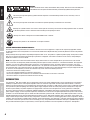 4
4
-
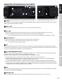 5
5
-
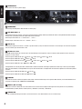 6
6
-
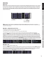 7
7
-
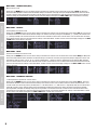 8
8
-
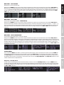 9
9
-
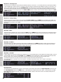 10
10
-
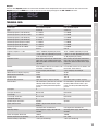 11
11
-
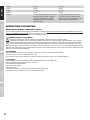 12
12
-
 13
13
-
 14
14
-
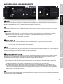 15
15
-
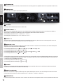 16
16
-
 17
17
-
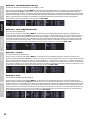 18
18
-
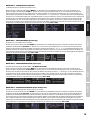 19
19
-
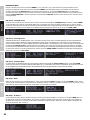 20
20
-
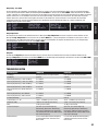 21
21
-
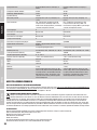 22
22
-
 23
23
-
 24
24
-
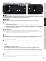 25
25
-
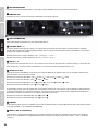 26
26
-
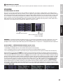 27
27
-
 28
28
-
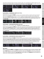 29
29
-
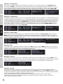 30
30
-
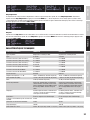 31
31
-
 32
32
-
 33
33
-
 34
34
-
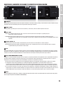 35
35
-
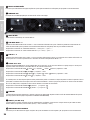 36
36
-
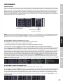 37
37
-
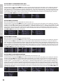 38
38
-
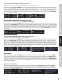 39
39
-
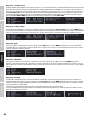 40
40
-
 41
41
-
 42
42
-
 43
43
-
 44
44
-
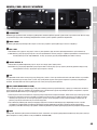 45
45
-
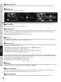 46
46
-
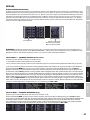 47
47
-
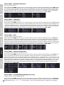 48
48
-
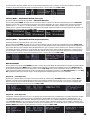 49
49
-
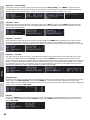 50
50
-
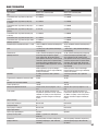 51
51
-
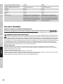 52
52
-
 53
53
-
 54
54
-
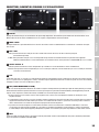 55
55
-
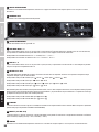 56
56
-
 57
57
-
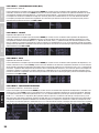 58
58
-
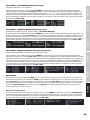 59
59
-
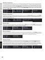 60
60
-
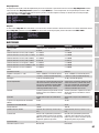 61
61
-
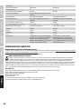 62
62
-
 63
63
-
 64
64


LD Systems DSP 45 K Manual de usuario
- Categoría
- Altavoces de la barra de sonido
- Tipo
- Manual de usuario
en otros idiomas
- français: LD Systems DSP 45 K Manuel utilisateur
- italiano: LD Systems DSP 45 K Manuale utente
- English: LD Systems DSP 45 K User manual
- Deutsch: LD Systems DSP 45 K Benutzerhandbuch
- polski: LD Systems DSP 45 K Instrukcja obsługi
Artículos relacionados
-
LD Systems DJ500 Power Amplifier 2 x 250 W 4 Ohms Manual de usuario
-
-
LD Systems DSP 44 K RACK Manual de usuario
-
LD Systems CURV500IAMP 4-Channel Installation Amplifier Manual de usuario
-
-
LD Systems DIO 44 Manual de usuario
-
-
Otros documentos
-
Mio DigiWalker C230 Guía de inicio rápido
-
Yamaha PF1000 El manual del propietario
-
-
-
-
-
-
RAM V 12044 Instrucciones de operación
-
Lynx XT-10K Manual de usuario
-
PRESONUS StudioLive 18sAI Guía del usuario