
USER´S MANUAL
BEDIENUNGSANLEITUNG
MANUEL D´UTILISATION
MANUAL DE USUARIO
INSTRUKCJA OBSŁUGI
MANUALE D´USO
DIO 04
4 OUTPUT DANTE INTERFACE
LDDIO04

CONTENTS / INHALTSVERZEICHNIS / CONTENU / CONTENIDO / TREŚĆ / CONTENUTO
ENGLISH
ABOUT THIS MANUAL 4
INTENDED USE 4
EXPLANATIONS OF TERMS AND SYMBOLS 4
SAFETY INSTRUCTIONS 5
NOTES FOR INDOOR INSTALLATION EQUIPMENT 7
PACKAGING CONTENT 8
INTRODUCTION 8
CONNECTIONS, OPERATING AND
DISPLAY ELEMENTS 9
CONNECTION EXAMPLES 10
TERMINAL BLOCK CONNECTIONS 12
DANTE® CONTROLLER 13
UNDER / ON-TABLE MOUNTING 14
CARE, MAINTENANCE AND REPAIR 14
DIMENSIONS 15
TECHNICAL DATA 16
DISPOSAL 17
MANUFACTURER´S DECLARATIONS 18
DEUTSCH
INFORMATIONEN ZU DIESER
BEDIENUNGSANLEITUNG 19
BESTIMMUNGSGEMÄSSER GEBRAUCH 19
BEGRIFFS- UND SYMBOLERKLÄRUNGEN 19
SICHERHEITSHINWEISE 20
HINWEISE FÜR INDOOR-INSTALLATIONSGERÄTE 23
LIEFERUMFANG 23
EINLEITUNG 23
ANSCHLÜSSE, BEDIEN- UND ANZEIGEELEMENTE 24
ANSCHLUSSBEISPIELE 26
KLEMMLEISTENANSCHLÜSSE 27
DANTE® CONTROLLER 28
UNTER- / AUFTISCHMONTAGE 29
PFLEGE, WARTUNG UND REPARATUR 29
ABMESSUNGEN 30
TECHNISCHE DATEN 31
ENTSORGUNG 32
HERSTELLERERKLÄRUNGEN 33
FRANCAIS
INFORMATIONS SUR CE MODE D‘EMPLOI 34
UTILISATION RÉGLEMENTÉE 34
EXPLICATIONS DES TERMES ET DES SYMBOLES 34
CONSIGNES DE SÉCURITÉ 35
NOTES POUR L’ÉQUIPEMENT
D’INSTALLATION À L’INTÉRIEUR 38
CONTENU DU CARTON 38
INTRODUCTION 38
CONNECTEURS, UTILISATION ET INDICATEURS 39
EXEMPLES DE CONNEXION 41
CONNECTEURS EUROBLOCK (BORNIERS) 42
LOGICIEL DANTE® CONTROLLER 43
MONTAGE SOUS / SUR TABLE 44
ENTRETIEN, MAINTENANCE ET RÉPARATION 44
DIMENSIONS 45
CARACTÉRISTIQUES TECHNIQUES 46
MISE EN DÉCHETTERIE 47
DÉCLARATIONS DU FABRICANT 48
ESPAÑOL
INFORMACIÓN SOBRE ESTAS
INSTRUCCIONES DE USO 49
USO CONFORME A LA NORMATIVA 49
EXPLICACIONES DE TÉRMINOS Y SíMBOLOS 49
INSTRUCCIONES DE SEGURIDAD 50
NOTAS PARA LOS EQUIPOS
DE INSTALACIÓN EN INTERIORES 53
CONTENIDO DEL EMBALAJE 53
INTRODUCCIÓN 53
CONEXIONES, MANDOS E INDICADORES 54
EJEMPLOS DE CONEXIÓN 56
CONEXIONES DEL BLOQUE DE TERMINALES 57
DANTE® CONTROLLER 58
MONTAJE BAJO/SOBRE LA MESA 59
CUIDADO, MANTENIMIENTO Y REPARACIÓN 59
DIMENSIONES 60
DATOS TÉCNICOS 61
DISPOSICIÓN 62
DECLARACIONES DEL FABRICANTE 63

POLSKI
INFORMACJE DOTYCZĄCE NINIEJSZEJ INSTRUKCJI
OBSŁUGI 64
STOSOWANIE ZGODNIE Z PRZEPISAMI 64
OBJAŚNIENIA TERMINÓW I SYMBOLI 64
INSTRUKCJE BEZPIECZEŃSTWA 65
UWAGI DOTYCZĄCE SPRZĘTU DO INSTALACJI
WEWNĘTRZNYCH 67
ZAWARTOŚĆ OPAKOWANIA 67
WPROWADZENIE 67
PRZYŁĄCZA, ELEMENTY OBSŁUGI I WSKAŹNIKI 68
PRZYKŁADY POŁĄCZEŃ 70
POŁĄCZENIA TERMINALI ZACISKOWYCH 71
KONTROLER DANTE 72
MONTAŻ POD / NA BLACIE 73
PIELĘGNACJA, KONSERWACJA I NAPRAWA 73
WYMIARY 74
DANE TECHNICZNE 75
DYSPOZYCJA 76
OŚWIADCZENIA PRODUCENTA 77
ITALIANO
INFORMAZIONI SU QUESTE ISTRUZIONI PER L‘USO 78
UTILIZZO IN CONFORMITÀ ALLE NORMATIVE 78
SPIEGAZIONI DI TERMINI E SIMBOLI 78
ISTRUZIONI DI SICUREZZA 79
NOTE PER LE APPARECCHIATURE
DI INSTALLAZIONE ALL’INTERNO 81
CONTENUTO DELL’IMBALLAGGIO 82
INTRODUZIONE 82
CONNESSIONI, ELEMENTI DI COMANDO E
DI VISUALIZZAZIONE 83
ESEMPI DI CONNESSIONE 85
COLLEGAMENTI DELLA MORSETTIERA 86
DANTE® CONTROLLER 87
MONTAGGIO SOTTO/SU TAVOLO 88
CURA, MANUTENZIONE E RIPARAZIONE 88
DIMENSIONI 89
DATI TECNICI 90
SMALTIMENTO 91
DICHIARAZIONI DEL PRODUTTORE 92

4
ENGLISH
YOU MADE THE RIGHT CHOICE!
This device was developed and manufactured under high quality requirements to ensure many
years of trouble-free operation. This is what LD Systems stands for with its name and many years
of experience as a manufacturer of high-quality audio products. Please read these operating
instructions carefully so that you can quickly and optimally use your new LD Systems product.
You can find more information about LD Systems on our website WWW.LD-SYSTEMS.COM
ABOUT THIS MANUAL
• Read the safety instructions and the entire manual carefully before commissioning.
• Observe the warnings on the unit and in the operating instructions.
• Always keep the operating instructions within reach.
• If you sell or pass on the appliance, be sure to hand over these operating instructions as well,
as they are an essential part of the product.
INTENDED USE
The product is a device for professional audio installation! The product has been developed for
professional use in the field of audio installation and is not intended for use in households!
Furthermore, this product is intended for installation by qualified persons with specialist
knowledge and for operation by instructed persons! The use of the product outside the specified
technical data and operating conditions is considered as not intended! Liability for damages and
third party damages to persons and property due to non-intended use is excluded!
The product is not suitable for:
• Persons (including children) with limited physical, sensory or mental capabilities or lack of
experience and knowledge.
• Children (children must be instructed not to play with the device).
EXPLANATIONS OF TERMS AND SYMBOLS
1. DANGER: The word DANGER, possibly in combination with a symbol, indicates immediately
dangerous situations or conditions for life and limb.
2. WARNING: The word WARNING, possibly in combination with a symbol, indicates potentially
dangerous situations or conditions for life and limb.
3. CAUTION: The word CAUTION, possibly in combination with a symbol, is used to indicate
situations or conditions that may lead to injury.
4. ATTENTION: The word ATTENTION, possibly in combination with a symbol, refers to situations
or states that can lead to damage to property and/or the environment.
ITALIANO
POLSKI
ESPAÑOL
FRANCAIS
DEUTSCHENGLISH

5
This symbol indicates hazards that can cause an electric shock.
This symbol indicates danger spots or dangerous situations.
This symbol indicates danger from hot surfaces.
This symbol indicates danger from high volumes.
This symbol indicates supplementary information on the operation of the product.
This symbol denotes a device that does not contain any user-serviceable parts.
This symbol indicates electrical equipment designed primarily for indoor use.
SAFETY INSTRUCTIONS
DANGER:
1. Do not open or modify the device.
2. If your device is no longer working properly, liquids or objects have gotten inside
the device, or the device has been damaged in any other way, switch it off immediately
and disconnect it from the power supply. This device may only be repaired by
authorized specialist personnel.
3. For devices of protection class 1, the protective conductor must be connected
correctly. Never interrupt the protective conductor. Protection class 2 devices
do not have a protective conductor.
4. Ensure that live cables are not kinked or otherwise mechanically damaged.
5. Never bypass the device fuse.
WARNING:
1. The device must not be put into operation if it shows obvious signs of damage.
2. The device may only be installed in a voltage-free state.
3. If the power cord of the device is damaged, the device must not be put into operation.
4. Permanently connected power cords may only be replaced by a qualified person.
DEUTSCHFRANCAIS
ESPAÑOL ENGLISH
ITALIANO POLSKI

6
DANGER:
1. Do not operate the device if it has been exposed to severe temperature fluctuations
(e.g. after transport). Humidity and condensation could damage the device.
Do not switch on the device until it has reached the ambient temperature.
2. Make sure that the voltage and frequency of the mains supply correspond to the
values indicated on the device. If the device has a voltage selector switch, do not
connect the device until this is set correctly. Only use suitable power cords.
3. To disconnect the device from the mains at all poles, it is not enough to press the
on/off switch on the device.
4. Ensure that the fuse used corresponds to the type printed on the device.
5. Make sure that appropriate measures against overvoltage (e.g. lightning) have
been taken.
6. Note the specified maximum output current on devices with a power out connection.
Make sure that the total power consumption of all connected devices does not
exceed the specified value.
7. Only replace pluggable power cords with original cables.
DANGER:
1. Danger of suffocation! Plastic bags and small parts must be kept out of the reach of
people (including children) with reduced physical, sensory or mental abilities.
2. Danger from falling! Make sure the device is installed securely and cannot fall.
Only use suitable tripods or attachments (especially for fixed installations).
Make sure accessories are properly installed and secured. Make sure that the
applicable safety regulations are observed.
WARNING:
1. Only use the device in the manner intended.
2. Only operate the device with the accessories recommended and intended by the
manufacturer.
3. During installation, observe the safety regulations applicable in your country.
4. After connecting the unit, check all cable routes to avoid damage or accidents,
e.g. due to tripping hazards.
5. Be sure to observe the specified minimum distance to normally flammable
materials! Unless this is explicitly stated, the minimum distance is 0.3 m.
ATTENTION:
1. There is a risk of jamming with moving components such as mounting brackets or
other moving components.
2. In the case of units with motor-driven components, there is a risk of injury from the
movement of the unit. Sudden device movement can cause shockreactions.
ITALIANO
POLSKI
ESPAÑOL
FRANCAIS
DEUTSCHENGLISH

7
DANGER:
1. Do not install or operate the device near radiators, heat registers, stoves or other
heat sources. Make sure that the device is always installed in such a way that it is
sufficiently cooled and cannot overheat.
2. Do not place any sources of ignition such as burning candles near the device.
3. Ventilation openings must not be covered and fans must not be blocked.
4. Use the original packaging or packaging provided by the manufacturer for transport.
5. Avoid shock or shock to the device.
6.
Observe the IP protection class and the environmental conditions such as temperature
and humidity according to the specification.
7. Devices can be continuously developed. In the event of deviating information on
operating conditions, performance or other device properties between the operating
instructions and the device labeling, the information on the device always has
priority.
8. The device is not suitable for tropical climate zones and for operation above
2000 m above sea level.
ATTENTION:
Connecting signal cables can result in significant noise interference. Make sure that
devices connected to the output are muted during plugging. Otherwise, noise levels
can cause damage.
ATTENTION HIGH VOLUMES WITH AUDIO PRODUCTS!
This device is intended for professional use.
The commercial operation of this device is subject to the applicable national
regulations and guidelines for accident prevention.
Hearing damage due to high volumes and continuous exposure: The use of this product
can generate high sound pressure levels (SPL) which can cause hearing damage.
Avoid exposure to high volumes.
NOTES FOR INDOOR INSTALLATION EQUIPMENT
1. Units for installation applications are designed for continuous operation.
2. Units for indoor installation are not weatherproof.
3. Surfaces and plastic parts of installation equipment can also age, e.g. due to UV
radiation and temperature fluctuations. This does not usually lead to functional
restrictions.
4. with permanently installed units, the deposition of impurities, e.g. dust, is to be
expected. Be sure to observe the care instructions.
5. Unless explicitly stated otherwise on the unit, the units are intended for installation
heights of less than 5 m.
DEUTSCHFRANCAIS
ESPAÑOL ENGLISH
ITALIANO POLSKI

8
PACKAGING CONTENT
Remove the product from the packaging and remove all packaging material.
Please check the completeness and integrity of the delivery and notify your distribution partner
immediately after purchase if the delivery is not complete or if it is damaged.
The packaging includes:
• 1 x DIO 04 Dante Break Out Box
• 1 set of terminal blocks
• 1 set of rubber feet (pre-assembled)
• 1 mounting set for on-table or under-table installation
• User manual
INTRODUCTION
Part of the TICA® series, the DIO 04 is a four output Dante interface that delivers the capabilities
that audio and AV professionals really need. Equipped with four balanced outputs to connect
to any analogue audio device such as power amplifiers Signal presence lights on each channel
speed installation and fault-finding.
Power from any PoE+ network switch or use the optional, external power supply. Since it comes
with two Dante networked ports, you can daisy chain devices together. It also works as a PoE+
injector: if you use the external power supply, you can power one further networked device in
the chain.
It’s tiny form factor (106 x 44 x 222 mm) and included mounting plates allow it to be installed
discreetly behind screens or under tables. Alternatively, it fits into 1/3 19 inch rack.
Use the optional rack tray to slot up to three TICA® DIO series products alongside each other
and build a system to your exact requirements, using minimal rack space.
Terminal block connections on the analogue outputs make wiring easy.
The perfect solution for professional installers wanting to interface into Dante equipment.
Dante Domain Manager and AES 67 compliant.
FEATURES
• Four output Dante interface
• Connect Dante to line level audio equipment
• Terminal blocks for all analogue connecitons
• Signal indicators on each channel
• Use PoE or an external power supply
• Use as a PoE injector to power another networked device
• Daisy-chain Dante devices together
ITALIANO
POLSKI
ESPAÑOL
FRANCAIS
DEUTSCHENGLISH

9
CONNECTIONS, OPERATING AND DISPLAY ELEMENTS
4
3
5
1 2
1 TERMINAL BLOCK CONNECTION FOR POWER SUPPLY
Terminal block connection for the device's power supply. To avoid damage to the unit, please use
only the original power supply unit (power supply unit optionally available).
Alternative power supply: Ethernet switch or PoE injector with PoE+ (Power over Ethernet plus)
or better.
2 STRAIN RELIEF
Use the strain relief for the flexible cable of the power supply unit to protect the device's power
terminal block connector and the power supply terminal block from damage and to prevent the
terminal block from being pulled out unintentionally.
3 OUTPUT 1 – 4
Analogue audio outputs with balanced terminal block connections. The poles +, - and G are
intended for the balanced output signal (suitable for unbalanced cabling). Terminal blocks are
included in the packaging content. If there is no audio signal at the line outputs OUTPUT 1 to 4,
they are automatically muted after some time. If an audio signal is detected, the mute function
is automatically deactivated.
4 PSE+DATA (Power Sourcing Equipment)
Dante® interface with RJ45 socket for connecting further Dante® devices to the Dante® network.
If the DIO 04 is supplied with power via an external power supply unit, another DIO 04 can be
supplied with power via PoE (see connection example 2).
5 PD+DATA (Powered Device)
Dante® interface with RJ45 socket for connecting the DIO 04 to a Dante® network.
The DIO 04 can be supplied with voltage via PoE+ (Power over Ethernet plus) or better.
7
6
DEUTSCHFRANCAIS
ESPAÑOL ENGLISH
ITALIANO POLSKI

10
6 POWER SYMBOL
As soon as the DIO 04 is supplied with voltage, the starting process begins. During the start-up
process, the white power symbol flashes and the line outputs OUTPUT 1 to 4 are muted.
When the start-up process is completed after a few seconds, the symbol lights up permanently
and the unit is ready for operation.
7 SIGNAL OUTPUT 1 – 4
Two-colour illuminated digits 1 to 4 for signal detection and clip display.
OUTPUT: As soon as an audio signal with sufficient level is present at an output channel, the
corresponding digit lights up white. As soon as one of the digits lights up red, the corresponding
output stage is operated at the distortion limit. In this case, reduce the level on the source player
so that the digit no longer lights up red.
AIR VENTS
To prevent damage to the device, do not cover the ventilation openings on the left and right
sides and on the top and bottom of the device and ensure that air can circulate freely. Covering
the ventilation openings on the top or bottom of the enclosure when mounting it underneath
or on top of a table is not critical, as the cooling provided by the ventilation openings on the
remaining sides is sufficient.
Tip: Preferably use balanced audio cables for wiring analogue line inputs and outputs.
CONNECTION EXAMPLES
1
Dante™ Mixer
Dante® Controller
Questra
Dante® Controller
INPUTS
1 2 3 4 5 6 7 8 1 2 3 4 5 6 7 8POWER
ZONE X 1208D
NETWORK
REMOTE
9 10 11 12
OUTPUTS
Active Loudspeaker
Active Loudspeaker
ON
23 4
DIP
ON
1 2 3 4
DIP
ON
1 2 3 4
DIPON
1 2 3 4
DIP
24V DC
Power supply
24V DC
Power supply
Ethernet Switch
Ethernet Switch
PoEPoE
OUTPUT 1 - 4
touch control wall panel
ITALIANO
POLSKI
ESPAÑOL
FRANCAIS
DEUTSCHENGLISH

11
2
Dante™ Mixer
Dante® Controller
Questra
Dante® Controller
INPUTS
1 2 3 4 5 6 7 8 1 2 3 4 5 6 7 8POWER
ZONE X 1208D
NETWORK
REMOTE
9 10 11 12
OUTPUTS
Active Loudspeaker
Active Loudspeaker
ON
23 4
DIP
ON
1 2 3 4
DIP
ON
1 2 3 4
DIPON
1 2 3 4
DIP
24V DC
Power supply
24V DC
Power supply
Ethernet Switch
Ethernet Switch
PoEPoE
OUTPUT 1 - 4
touch control wall panel
3
Dante™ Mixer
Dante® Controller
Questra
Dante® Controller
INPUTS
1 2 3 4 5 6 7 8 1 2 3 4 5 6 7 8POWER
ZONE X 1208D
NETWORK
REMOTE
9 10 11 12
OUTPUTS
Active Loudspeaker
Active Loudspeaker
ON
23 4
DIP
ON
1 2 3 4
DIP
ON
1 2 3 4
DIPON
1 2 3 4
DIP
24V DC
Power supply
24V DC
Power supply
Ethernet Switch
Ethernet Switch
PoEPoE
OUTPUT 1 - 4
touch control wall panel
4
Dante® Controller
INPUTS
1 2 3 4 5 6 7 8 1 2 3 4 5 6 7 8POWER
ZONE X 1208D
NETWORK
REMOTE
9 10 11 12
OUTPUTS
Ethernet Switch
PoEPoE
OUTPUT 1 - 4
touch control wall panel
QTP 8
DEUTSCHFRANCAIS
ESPAÑOL ENGLISH
ITALIANO POLSKI


13
DANTE® CONTROLLER
A Dante® network is set up using the freely available DANTE® CONTROLLER software. Download
the software from the manufacturer's website www.audinate.com and install it on a computer.
Connect the computer's Ethernet interface to a network interface using a network cable (Cat. 5e
or better) and run the Dante® Controller software. The software has an automatic device detection
function. Signal routing is done by mouse click and the unit and channel designations can be
individually edited by the user. IP address, MAC address and other information about the devices
in the Dante® network can be displayed in the software.
Once the configuration of the devices on the Dante® network is complete, the Dante® Controller
software can be closed and the computer disconnected from the network. The settings in the
units in the network are retained.
When the DIO 04 is disconnected from the Dante® network, the unit's audio outputs are muted
and the power icon on the front panel starts flashing.
DEUTSCHFRANCAIS
ESPAÑOL ENGLISH
ITALIANO POLSKI

14
UNDER / ON-TABLE MOUNTING
There are two recesses on the top and bottom of the enclosure, each with two M3 threaded
holes, for mounting underneath or on top of the table. Screw the two enclosed mounting plates
to the top or bottom using the enclosed M3 countersunk screws. Now the amplifier can be fixed
in the desired position (see illustration, fixing screws not included). For tabletop mounting, the
four rubber feet must be removed beforehand.
CARE, MAINTENANCE AND REPAIR
To ensure the proper functioning of the unit in the long term, it must be cared for regularly and
serviced as required. The need for care and maintenance depends on the intensity of use and
the environment.
We generally recommend a visual inspection before each start-up. Furthermore, we recommend
that you carry out all the maintenance measures listed below every 500 operating hours or, in
the case of low intensity of use, after one year at the latest. Defects caused by inadequate care
may result in limitations of the warranty claims.
CARE (CAN BE CARRIED OUT BY THE USER)
WARNING! Before carrying out any maintenance work, disconnect the power supply
and, if possible, all appliance connections.
NOTE! Improper care can lead to impairment or even destruction of the unit.
ITALIANO
POLSKI
ESPAÑOL
FRANCAIS
DEUTSCHENGLISH

15
1. Housing surfaces must be cleaned with a clean, damp cloth. Make sure that no moisture can
penetrate the unit.
2. Air inlets and outlets must be regularly cleaned of dust and dirt. If compressed air is used,
make sure that damage to the unit is prevented (e.g. fans must be blocked in this case).
3. Cables and plug contacts must be cleaned regularly and freed from dust and dirt.
4. In general, no cleaning agents, disinfectants or agents with an abrasive effect may be used
for maintenance, otherwise the surface finish may be impaired. Especially solvents, such as
alcohol, can impair the function of the housing seals.
5. Units should generally be stored in a dry place and protected from dust and dirt.
MAINTENANCE AND REPAIR (BY QUALIFIED PERSONNEL ONLY)
DANGER! There are live components in the unit. Even after disconnecting from the
mains, residual voltage may still be present in the unit, e.g. due to charged capacitors.
NOTE! There are no assemblies in the unit that require maintenance by the user.
NOTE! Maintenance and repair work may only be carried out by specialist personnel
authorised by the manufacturer. In case of doubt, contact the manufacturer.
NOTE! Improperly performed maintenance work can affect the warranty claim.
DIMENSIONS (mm)
142
221
215
43
53
DEUTSCHFRANCAIS
ESPAÑOL ENGLISH
ITALIANO POLSKI

16
TECHNICAL DATA
Item number LDDIO04
Product type 0x4 I/O Dante Interface
Inputs 0
Input type Switchable balanced mic or line level
Line outputs 4
Output type Balanced line level with auto mute relay on loss of Dante/AES67 signal
Cooling Convection
Analogue Line Output
Number of output connectors 4
Connection type 3-pin terminal block, Pitch 3.81 mm
Max. Output Level 18 dBu
Interm. Distortion SMPTE < 0.005 % (-20 dBFS to 0 dBFS)
THD + Noise < 0.002% (10 dBu, 20 kHz BW)
Idle Noise Better than -92dBu
Dynamic Range > 107 dB (0 dBFS, AES 17, CCIR-2k Weighting)
Frequency response 15 Hz – 20 kHz (-0.5 dB)
Dante® Specications
Audio Channels 4 outputs
Bit depth 24 bit
Sample Rate 48 kHz
Latency Minimum 1ms
Dante Connector 100 BASE-T RJ45
Power over Ethernet (PoE) Specications
Minimum PoE Requirements PoE+ IEEE 802.3at
PSE+Data Capable of powering 1 extra PD unit
Power Input Requirements
Input Voltage 24 V DC
Minimum Current 1.5 A
Power Input Connector Pitch 5.08 mm terminal block (2-pin)
Max power consumption 10 W
Idle power consumption 7.5 W (no signal input)
Power Consumption with
Secondary Port use
22 W
Mains Inrush Current 1.7 A @ 230 V AC
Operating Temperature 0°C – 40°C; < 85% humidity, non condensing
ITALIANO
POLSKI
ESPAÑOL
FRANCAIS
DEUTSCHENGLISH

17
Item number LDDIO04
General
Material Steel chassis, Plastic front panel
Dimensions (W x H x D) 142 x 53 x 221.7 mm (height with rubber feet)
Weight 1.0 kg
Included Accessories Mounting plates for surface mount applications,
Terminal blocks for Electrical Connections, rubber feet
DISPOSAL
Packaging:
1. Packaging can be disposed of via the usual waste disposal channels.
2. Please separate the packaging according to the waste disposal and materials
regulations in your country.
Device:
1. This device is subject to the European Directive on Waste Electrical and Electronic
Equipment in its applicable version. WEEE Directive-Waste Electrical and Electronical
Equipment. Old devices and batteries do not belong in household waste. The old
device or batteries must be disposed of via an approved waste disposal service or
a municipal waste disposal facility. Follow the directives in your country!
2. Follow the disposal laws in your country.
3. As a private customer, you can obtain information on environmentally friendly
disposal options from the retailer from whom you purchased the product or from
the relevant regional authorities.
DEUTSCHFRANCAIS
ESPAÑOL ENGLISH
ITALIANO POLSKI

18
MANUFACTURER´S DECLARATIONS
MANUFACTURER‘S WARRANTY & LIMITATIONS OF LIABILITY
Adam Hall GmbH, Adam-Hall-Str. 1, D-61267 Neu Anspach / E-mail [email protected] /
+49 (0)6081 / 9419-0.
Our current warranty conditions and limitation of liability can be found at:
https://cdn-shop.adamhall.com/media/pdf/MANUFACTURERS-DECLARATIONS_LD_SYSTEMS.pdf.
Contact your distribution partner for service.
UKCA-CONFORMITY
Hereby, Adam Hall Ltd. declares that this product meets the following guidelines
(where applicable):
Electrical Equipment (Safety) Regulations 2016
Electromagnetic Compatibility Regulations 2016 (SI 2016/1091)
The Restriction of the Use of Certain Hazardous Substances in Electrical and Electronic Equipment
Regulation 2012 (SI 2012/3032)
Radio Equipment Regulations 201 7(SI 2016/2015)
UKCA-DECLARATION OF CONFORMITY
Products that are subject to Electrical Equipment(Safety)Regulation 2016, EMC Regulation 2016 or
RoHS Regulation can be requested at [email protected].
Products that are subject to the Radio Equipments Regulations 2017
(SI2017/1206) can be downloaded from www.adamhall.com/compliance/
CE CONFORMITY
Adam Hall GmbH hereby confirm that this product meets the following guidelines
(where applicable):
R&TTE (1999/5/EC) or RED (2014/53/EU) as of June 2017.
Low Voltage Directive (2014/35/EU)
EMC Directive (2014/30/EU)
RoHS (2011/65/EU)
The complete Declaration of Conformity can be found at www.adamhall.com.
Furthermore, you can also request it at [email protected].
CE DECLARATION OF CONFORMITY
Declarations of conformity for products subject to the LVD, EMC, RoHS Directive
can be requested from [email protected].
Declarations of conformity for products subject to RED Directive
can be downloaded from www.adamhall.com/compliance/.
Subject to misprints and errors, as well as technical or other modifications!
ITALIANO
POLSKI
ESPAÑOL
FRANCAIS
DEUTSCHENGLISH

19
DEUTSCH
SIE HABEN DIE RICHTIGE WAHL GETROFFEN!
Dieses Gerät wurde unter hohen Qualitätsanforderungen entwickelt und gefertigt, um viele
Jahre einen reibungslosen Betrieb zu gewährleisten. Dafür steht LD Systems mit seinem Namen
und der langjährigen Erfahrung als Hersteller hochwertiger Audioprodukte. Bitte lesen Sie diese
Bedienungsanleitung sorgfältig, damit Sie Ihr neues Produkt von LD Systems schnell optimal
einsetzen können.
Mehr Informationen zu LD Systems finden Sie auf unserer Internetseite WWW.LD-SYSTEMS.COM
INFORMATIONEN ZU DIESER BEDIENUNGSANLEITUNG
• Lesen Sie vor Inbetriebnahme die Sicherheitshinweise und die gesamte Anleitung
aufmerksam durch.
• Beachten Sie die Warnungen auf dem Gerät und in der Bedienungsanleitung.
• Bewahren Sie die Bedienungsanleitung immer in Reichweite auf.
• Wenn Sie das Gerät verkaufen oder weitergeben, händigen Sie unbedingt auch diese
Bedienungs anleitung aus, da sie ein wesentlicher Bestandteil des Produkts ist.
BESTIMMUNGSGEMÄSSER GEBRAUCH
Bei dem Produkt handelt es sich um ein Gerät für professionelle Audioinstallation!
Das Produkt ist für den professionellen Einsatz im Bereich der Audioinstallation entwickelt
worden und ist nicht für die Verwendung in Haushalten vorgesehen!
Weiterhin ist dieses Produkt zur Installation durch qualifizierte Personen mit Fachkenntnissen,
sowie zur Bedienung durch unterwiesene Personen vorgesehen!
Die Benutzung des Produkts außerhalb der spezifizierten technischen Daten und Betriebs-
bedingungen gilt als nicht bestimmungsgemäß!
Haftung für Schäden und Drittschäden an Personen und Sachen durch nicht bestimmungs-
gemäßen Gebrauch ist ausgeschlossen!
Das Produkt ist nicht geeignet für:
– Personen (einschließlich Kinder) mit eingeschränkten körperlichen, sensorischen oder
geistigen Fähigkeiten oder mangelnder Erfahrung und Kenntnis.
– Kinder (Kinder müssen angewiesen werden, nicht mit dem Gerät zu spielen).
BEGRIFFS- UND SYMBOLERKLÄRUNGEN
1. GEFAHR: Mit dem Wort GEFAHR, evtl. in Kombination mit einem Symbol, wird auf unmittelbar
gefährliche Situationen oder Zustände für Leib und Leben hingewiesen.
2. WARNUNG: Mit dem Wort WARNUNG, evtl. in Kombination mit einem Symbol, wird auf potentiell
gefährliche Situationen oder Zustände für Leib und Leben hingewiesen.
3. VORSICHT: Mit dem Wort VORSICHT, evtl. in Kombination mit einem Symbol, wird auf Situationen
oder Zustände hingewiesen, die zu Verletzungen führen können.
4. ACHTUNG: Mit dem Wort ACHTUNG, evtl. in Kombination mit einem Symbol, wird auf Situationen
oder Zustände hingewiesen, die zu Sach- und/oder Umweltschäden führen können.
DEUTSCHFRANCAIS
ESPAÑOL ENGLISH
ITALIANO POLSKI

20
Dieses Symbol kennzeichnet Gefahren, die einen elektrischen Schlag verursachen können.
Dieses Symbol kennzeichnet Gefahrenstellen oder gefährliche Situationen.
Dieses Symbol kennzeichnet Gefahren durch heiße Oberflächen.
Dieses Symbol kennzeichnet Gefahren durch hohe Lautstärken.
Dieses Symbol kennzeichnet ergänzende Informationen zur Bedienung des Produkts.
Dieses Symbol kennzeichnet ein Gerät, in dem sich keine vom Benutzer austauschbaren
Teile befinden.
Dieses Symbol kennzeichnet ein Gerät, das nur in trockenen Räumen verwendet
werden darf.
SICHERHEITSHINWEISE
GEFAHR:
1. Öffnen Sie das Gerät nicht und verändern Sie es nicht.
2. Wenn Ihr Gerät nicht mehr ordnungsgemäß funktioniert, Flüssigkeiten oder Gegen-
stände in das Geräteinnere gelangt sind, oder das Gerät anderweitig beschädigt
wurde, schalten Sie es sofort aus und trennen es von der Spannungsversorgung.
Dieses Gerät darf nur von autorisiertem Fachpersonal repariert werden.
3. Bei Geräten der Schutzklasse 1 muss der Schutzleiter korrekt angeschlossen
werden. Unterbrechen Sie niemals den Schutzleiter. Geräte der Schutzklasse 2
haben keinen Schutzleiter.
4. Sorgen Sie dafür, dass spannungsführende Kabel nicht geknickt oder anderweitig
mechanisch beschädigt werden.
5. Überbrücken Sie niemals die Gerätesicherung.
WARNUNG:
1. Das Gerät darf nicht in Betrieb genommen werden, wenn es offensichtliche
Beschädigungen aufweist.
2. Das Gerät darf nur im spannungsfreien Zustand installiert werden.
3. Wenn das Netzkabel des Geräts beschädigt ist, darf das Gerät nicht in Betrieb
genommen werden.
4. Fest angeschlossene Netzleitungen dürfen nur von einer qualifizierten Person
ersetzt werden.
ITALIANO
POLSKI
ESPAÑOL
FRANCAIS
DEUTSCHENGLISH

21
ACHTUNG:
1. Nehmen Sie das Gerät nicht in Betrieb, wenn es starken Temperaturschwankungen
ausgesetzt war (beispielsweise nach dem Transport). Feuchtigkeit und Kondensat
könnten das Gerät beschädigen. Schalten Sie das Gerät erst ein, wenn es
Umgebungstemperatur erreicht hat.
2. Stellen Sie sicher, dass die Spannung und die Frequenz des Stromnetzes mit den
auf dem Gerät angegebenen Werten übereinstimmen. Verfügt das Gerät über
einen Spannungswahlschalter, schließen Sie das Gerät erst an, wenn dieser korrekt
eingestellt ist. Nutzen Sie nur geeignete Netzkabel.
3. Um das Gerät allpolig vom Netz zu trennen genügt es nicht, den Ein-/Aus-Schalter
am Gerät zu betätigen.
4. Stellen Sie sicher, dass die eingesetzte Sicherung dem auf dem Gerät abgedruckten
Typ entspricht.
5. Stellen Sie sicher, dass geeignete Maßnahmen gegen Überspannung
(z.B. Blitzschlag) ergriffen wurden.
6. Beachten Sie den angegebenen maximalen Ausgangsstrom an Geräten mit Power
Out Anschluss. Beachten Sie, dass die gesamte Stromaufnahme aller angeschlossenen
Geräte den vorgegebenen Wert nicht überschreitet.
7. Ersetzen Sie steckbare Netzleitungen nur durch Originalleitungen.
GEFAHR:
1. Erstickungsgefahr! Kunststoffbeutel und Kleinteile müssen außer Reichweite von
Personen (einschließlich Kindern) mit eingeschränkten körperlichen, sensorischen
oder geistigen Fähigkeiten aufbewahrt werden.
2. Gefahr durch Herabfallen! Stellen Sie sicher, dass das Gerät sicher installiert ist
und nicht herunterfallen kann. Verwenden Sie ausschließlich geeignete Stative
bzw. Befestigungen (im Besonderen bei Festinstallationen). Stellen Sie sicher, dass
Zubehör ordnungsgemäß installiert und gesichert ist. Achten Sie dabei darauf, dass
geltende Sicherheitsbestimmungen eingehalten werden.
WARNUNG:
1. Verwenden Sie das Gerät nur in der vorgesehenen Art und Weise.
2. Betreiben Sie das Gerät nur mit dem vom Hersteller empfohlenen und
vorgesehenen Zubehör.
3. Beachten Sie bei der Installation die für Ihr Land geltenden Sicherheitsvorschriften.
4. Überprüfen Sie nach dem Anschluss des Geräts alle Kabelwege, um Schäden oder
Unfälle, z. B. durch Stolperfallen zu vermeiden.
5.
Beachten Sie unbedingt den angegebenen Mindestabstand zu normal entflammbaren
Materialien! Sofern dieser nicht explizit ausgewiesen ist, beträgt der Mindest-
abstand 0,3 m.
DEUTSCHFRANCAIS
ESPAÑOL ENGLISH
ITALIANO POLSKI

22
VORSICHT:
1. Bei beweglichen Bauteilen wie Montagebügeln, oder sonstigen beweglichen
Bauteilen besteht die Möglichkeit sich zu klemmen.
2. Bei Geräten mit motorisch angetriebenen Bauteilen besteht Verletzungsgefahr
durch die Bewegung des Gerätes. Plötzliche Gerätebewegungen können zu
Schreckreaktionen führen.
ACHTUNG:
1.
Installieren und betreiben Sie das Gerät nicht in der Nähe von Heizkörpern, Wärme-
speichern, Öfen oder sonstigen Wärmequellen. Sorgen Sie dafür, dass das Gerät
immer so installiert ist, dass es ausreichend gekühlt wird und nicht überhitzen kann.
2. Platzieren Sie keine Zündquellen wie z.B. brennende Kerzen in der Nähe des Geräts.
3. Lüftungsöffnungen dürfen nicht abgedeckt und Lüfter nicht blockiert werden.
4. Nutzen Sie zum Transport die Originalverpackung oder vom Hersteller dafür vorge-
sehene Verpackungen.
5. Vermeiden Sie, dass Erschütterung oder Schläge auf das Gerät einwirken.
6. Beachten sie die IP-Schutzart, sowie die Umgebungsbedingungen wie Temperatur
und Luftfeuchtigkeit entsprechend der Spezifizierung.
7. Geräte können stetig weiterentwickelt werden. Bei abweichenden Angaben zu
Betriebsbedingungen, Leistung oder sonstigen Geräteeigenschaften zwischen
Bedienungsanleitung und Gerätebeschriftung, hat immer die Angabe auf dem
Gerät Priorität.
8. Das Gerät ist nicht für tropische Klimazonen und für den Betrieb oberhalb 2000 m
über NN geeignet.
VORSICHT:
Das Anschließen von Signalkabeln kann zu erheblichen Störgeräuschen führen. Achten
Sie darauf, dass am Ausgang angeschlossene Geräte bei Steckvorgängen stumm-
geschaltet sind. Andernfalls können Pegel von Störgeräuschen zu Schäden führen.
ACHTUNG HOHE LAUTSTÄRKEN BEI AUDIOPRODUKTEN!
Dieses Gerät ist für den professionellen Einsatz vorgesehen.
Der kommerzielle Betrieb dieses Geräts unterliegt den jeweils gültigen nationalen
Vorschriften und Richtlinien zur Unfallverhütung.
Gehörschäden durch hohe Lautstärken und Dauerbelastung: Bei der Verwendung
dieses Produkts können hohe Schalldruckpegel (SPL) erzeugt werden, die zu Gehör-
schäden führen können. Vermeiden Sie die Belastung durch hohe Lautstärken.
ITALIANO
POLSKI
ESPAÑOL
FRANCAIS
DEUTSCHENGLISH

23
HINWEISE FÜR INDOOR-INSTALLATIONSGERÄTE
1. Geräte für Installationsanwendungen sind für den Dauerbetrieb ausgelegt.
2. Geräte für die Inneninstallation sind nicht witterungsbeständig.
3. Oberflächen sowie Kunststoffteile können auch bei Installationsgeräten,
z.B. durch UV-Einstrahlung und Temperaturschwankungen altern.
Dies führt i.d.R. nicht zu Funktionseinschränkungen.
4. Bei fest installierten Geräten ist mit der Ablagerung von Verunreinigungen,
z.B. Staub, zu rechnen. Beachten Sie unbedingt die Pflegehinweise.
5. Sofern nicht auf dem Gerät explizit anders ausgewiesen, sind die Geräte für
Montagehöhen kleiner 5 m vorgesehen.
LIEFERUMFANG
Entnehmen Sie das Produkt aus der Verpackung und entfernen Sie sämtliches Verpackungsmaterial.
Überprüfen Sie die Vollständigkeit und Unversehrtheit der Lieferung und benachrichtigen Sie
Ihren Vertriebspartner bitte unverzüglich nach dem Kauf, falls die Lieferung nicht komplett oder
beschädigt ist.
Im Lieferumfang des Produkts sind enthalten:
• 1 x DIO 04 Dante Break Out Box
• 1 Satz Klemmleisten
• 1 Satz Gummifüße (vormontiert)
• 1 Montageset für Auf- bzw. Untertischmontage
• Bedienungsanleitung
EINLEITUNG
Das DIO 04 aus der TICA® Serie ist ein Dante-Interface mit vier Ausgängen, das genau die Funk-
tionen bietet, die Audio- und AV-Profis wirklich brauchen. Es verfügt über vier symmetrische
Ausgängen zum Anschluss an analoge Audiogeräte, wie z.B. Leistungsverstärker. Signalanzeigen
für jeden Kanal beschleunigen die Installation und Fehlersuche.
Die Stromversorgung erfolgt über einen PoE+ Netzwerk-Switch oder über das optionale, externe
Netzteil. Da das Interface mit zwei Dante-Netzwerkanschlüssen ausgestattet ist, kannst du mehrere
Dante-Geräte kaskadieren. Es funktioniert zudem als PoE+ Injektor: Wenn du das externe Netzteil
verwendest, kannst du ein weiteres vernetztes Gerät in der Kette mit Strom versorgen.
Dank seiner kompakten Größe (142 x 53 x 221 mm) und der mitgelieferten Montageplatten kann
das DIO 04 unauffällig hinter Bildschirmen oder unter Tischen installiert werden. Alternativ
passt es auch in 1/3 19-Zoll-Racks. Verwende die optionale Rackwanne, um bis zu drei Produkte
der TICA® Serie nebeneinander zu platzieren und so ein System zu erstellen, das genau deinen
Anforderungen entspricht und nur wenig Platz im Rack benötigt.
Klemmleistenanschlüsse an den analogen Ausgängen erleichtern die Verkabelung erheblich.
Es ist die perfekte Lösung für professionelle Techniker, die ein Interface zu Dante-Geräten benötigen.
Kompatibel mit Dante Domain Manager und AES 67.
DEUTSCHFRANCAIS
ESPAÑOL ENGLISH
ITALIANO POLSKI

24
FEATURES
• Dante-Interface mit vier Ausgängen
• Verbinde Dante- mit Line-Level-Audiogeräten
• Klemmleisten-Anschlüsse für alle analogen Verbindungen
• Signalanzeigen auf jedem Kanal
• Betrieb über PoE oder eine externe Stromversorgung
• Kann als PoE-Injektor zur Stromversorgung eines anderen Netzwerkgeräts genutzt werden
• Ermöglicht die Kaskadierung von Dante-Geräten
ANSCHLÜSSE, BEDIEN- UND ANZEIGEELEMENTE
4
3
5
1 2
1 KLEMMLEISTENANSCHLUSS ZUR SPANNUNGSVERSORGUNG
Klemmleistenanschluss zur Spannungsversorgung des Geräts. Um Schäden am Gerät zu vermeiden,
verwenden Sie bitte ausschließlich das Original Netzteil (Netzteil optional erhältlich).
Alternative Spannungsversorgung: Ethernet Switch oder PoE-Injektor mit PoE+
(Power over Ethernet plus) oder besser.
2 ZUGENTLASTUNG
Nutzen Sie die Zugentlastung für das flexible Kabel des Netzteils, um den Klemmleistenanschluss
für die Spannungsversorgung des Geräts und die Klemmleiste des Netzteils vor Beschädigung zu
schützen und ein ungewolltes Herausziehen der Klemmleiste zu vermeiden.
3 OUTPUT 1 – 4
Analoge Audioausgänge mit symmetrischen Klemmleistenanschlüssen. Die Pole +, - und G sind
für das symmetrische Ausgangssignal vorgesehen (für unsymmetrische Verkabelung geeignet).
Klemmleisten sind im Lieferumfang enthalten. Wenn kein Audiosignal an den Line-Ausgängen
OUTPUT 1 bis 4 anliegt, werden diese nach einiger Zeit automatisch stummgeschaltet. Wird ein
Audiosignal erkannt, wird die Stummschaltung automatisch aufgehoben.
4 PSE+DATA (Power Sourcing Equipment)
Dante®-Schnittstelle mit RJ45-Buchse zum Anbinden weiterer Dante®-Geräte an das Dante®-Netzwerk.
Wenn die DIO 04 via externem Netzteil mit Spannung versorgt wird, kann eine weitere DIO 04 per
PoE mit Spannung mitversorgt werden (siehe Anschlussbeispiel 2).
5 PD+DATA (Powered Device)
Dante®-Schnittstelle mit RJ45-Buchse zum Anschließen der DIO 04 an ein Dante®-Netzwerk.
Die DIO 04 kann per PoE+ (Power over Ethernet plus) oder besser mit Spannung versorgt werden.
ITALIANO
POLSKI
ESPAÑOL
FRANCAIS
DEUTSCHENGLISH

25
7
6
6 POWER-SYMBOL
Sobald die DIO 04 mit Spannung versorgt wird, beginnt der Startvorgang. Während des Startvorgangs
blinkt das weiße Power-Symbol und die Line-Ausgänge OUTPUT 1 bis 4 sind stummgeschaltet. Wenn
der Startvorgang nach wenigen Sekunden abgeschlossen ist, leuchtet das Symbol permanent und
das Gerät ist betriebsbereit.
7 SIGNAL OUTPUT 1 – 4
Zweifarbig beleuchtete Ziffern 1 bis 4 für die Signalerkennung und Clip-Anzeige.
OUTPUT: Sobald ein Audiosignal mit ausreichendem Pegel an einem Ausgangskanal anliegt,
leuchtet die entsprechende Ziffer weiß. Sobald eine der Ziffern rot leuchtet, wird die entsprechende
Ausgangsstufe an der Verzerrungsgrenze betrieben. Reduzieren Sie in diesem Fall den Pegel am
Zuspielgerät, so dass die Ziffer nicht mehr rot leuchtet.
LÜFTUNGSÖFFNUNGEN
Um Schäden am Gerät zu vermeiden, decken Sie die Lüftungsöffnungen auf den Seiten links und
rechts und der Ober- und Unterseite nicht ab und sorgen dafür, dass Luft ungehindert zirkulieren
kann. Das Verdecken der Lüftungsöffnungen auf der Ober- oder Unterseite des Gehäuses bei der
Unter- oder Auftischmontage ist dabei unkritisch, da die Kühlung durch die Lüftungsöffnungen
der verbleibenden Seiten ausreichend ist.
Tipp: Verwenden Sie für die Verkabelung von analogen Line-Eingängen und
-Ausgängen vorzugsweise symmetrische Audiokabel.
DEUTSCHFRANCAIS
ESPAÑOL ENGLISH
ITALIANO POLSKI

26
ANSCHLUSSBEISPIELE
1
Dante™ Mixer
Dante® Controller
Questra
Dante® Controller
INPUTS
1 2 3 4 5 6 7 8 1 2 3 4 5 6 7 8POWER
ZONE X 1208D
NETWORK
REMOTE
9 10 11 12
OUTPUTS
Active Loudspeaker
Active Loudspeaker
ON
23 4
DIP
ON
1 2 3 4
DIP
ON
1 2 3 4
DIPON
1 2 3 4
DIP
24V DC
Power supply
24V DC
Power supply
Ethernet Switch
Ethernet Switch
PoEPoE
OUTPUT 1 - 4
touch control wall panel
2
Dante™ Mixer
Dante® Controller
Questra
Dante® Controller
INPUTS
1 2 3 4 5 6 7 8 1 2 3 4 5 6 7 8POWER
ZONE X 1208D
NETWORK
REMOTE
9 10 11 12
OUTPUTS
Active Loudspeaker
Active Loudspeaker
ON
23 4
DIP
ON
1 2 3 4
DIP
ON
1 2 3 4
DIPON
1 2 3 4
DIP
24V DC
Power supply
24V DC
Power supply
Ethernet Switch
Ethernet Switch
PoEPoE
OUTPUT 1 - 4
touch control wall panel
3
Dante™ Mixer
Dante® Controller
Questra
Dante® Controller
INPUTS
1 2 3 4 5 6 7 8 1 2 3 4 5 6 7 8POWER
ZONE X 1208D
NETWORK
REMOTE
9 10 11 12
OUTPUTS
Active Loudspeaker
Active Loudspeaker
ON
23 4
DIP
ON
1 2 3 4
DIP
ON
1 2 3 4
DIPON
1 2 3 4
DIP
24V DC
Power supply
24V DC
Power supply
Ethernet Switch
Ethernet Switch
PoEPoE
OUTPUT 1 - 4
touch control wall panel
ITALIANO
POLSKI
ESPAÑOL
FRANCAIS
DEUTSCHENGLISH

27
4
Dante™ Mixer
Dante® Controller
Questra
Dante® Controller
INPUTS
1 2 3 4 5 6 7 8 1 2 3 4 5 6 7 8POWER
ZONE X 1208D
NETWORK
REMOTE
9 10 11 12
OUTPUTS
Active Loudspeaker
Active Loudspeaker
ON
23 4
DIP
ON
1 2 3 4
DIP
ON
1 2 3 4
DIPON
1 2 3 4
DIP
24V DC
Power supply
24V DC
Power supply
Ethernet Switch
Ethernet Switch
PoEPoE
OUTPUT 1 - 4
touch control wall panel
KLEMMLEISTENANSCHLÜSSE
Anschlüsse OUTPUT
balanced
unbalanced
Beachten Sie bei der Verdrahtung von Klemmleisten bitte die korrekte Zuordnung der
Pole/Klemmen. Der Hersteller übernimmt keine Haftung für Schäden, die durch durch
fehlerhafte Verdrahtung entstehen!
DEUTSCHFRANCAIS
ESPAÑOL ENGLISH
ITALIANO POLSKI

28
DANTE® CONTROLLER
Die Einrichtung eines Dante®-Netzwerks erfolgt mit Hilfe der frei verfügbaren Software DANTE®
CONTROLLER. Laden Sie die Software von der Herstellerseite www.audinate.com herunter und
installieren sie auf einem Computer. Verbinden Sie die Ethernet-Schnittstelle des Computers mit
Hilfe eines Netzwerkkabels (Cat. 5e oder besser) mit einer Netzwerk-Schnittstelle und führen die
Software Dante® Controller aus. Die Software verfügt über eine automatische Geräteerkennung.
Signal-Routing erfolgt durch Mausklick und die Geräte- und Kanalbezeichnungen können indivi-
duell vom Nutzer bearbeitet werden. IP-Adresse, MAC-Adresse und weitere Informationen zu den
Geräten im Dante®-Netzwerk können in der Software angezeigt werden.
Ist die Konfiguration der Geräte im Dante®-Netzwerk abgeschlossen, kann die Software Dante®
Controller geschlossen und der Computer vom Netzwerk getrennt werden. Die Einstellungen in
den Geräten im Netzwerk bleiben erhalten.
Wenn die DIO 04 vom Dante®-Netzwerk getrennt wird, werden die Audioausgänge des Geräts
stummgeschaltet und das Power-Symbol auf der Vorderseite beginnt zu blinken.
ITALIANO
POLSKI
ESPAÑOL
FRANCAIS
DEUTSCHENGLISH

29
UNTER- / AUFTISCHMONTAGE
Für die Unter- bzw. Auftischmontage befinden sich auf der Ober- und Unterseite des Gehäuses
je zwei Aussparungen mit wiederum je zwei M3 Gewindebohrungen. Schrauben Sie die beiden
beiliegenden Montageplatten mittels der beiliegenden M3 Senkkopfschrauben an die Ober- bzw.
Unterseite. Nun kann der Verstärker in der gewünschten Position befestigt werden (siehe Abbil-
dung, Befestigungsschrauben nicht im Lieferumfang enthalten). Bei Auftischmontage müssen
die vier Gummifüße zuvor demontiert werden.
PFLEGE, WARTUNG UND REPARATUR
Um die einwandfreie Funktion des Geräts auf Dauer zu gewährleisten, muss es regelmäßig
gepflegt und bei Bedarf gewartet werden. Der Pflege- bzw. Wartungsbedarf steht in Abhängigkeit
der Nutzungsintensität und -umgebung.
Wir empfehlen generell eine Sichtprüfung vor jeder Inbetriebnahme. Weiterhin empfehlen wir
alle 500 Betriebsstunden, oder bei geringerer Nutzungsintensität spätestens nach Ablauf eines
Jahres alle unten genannten und zutreffenden Pflegemaßnahmen durchzuführen. Bei Mängeln,
die auf eine unzureichende Pflege zurückzuführen sind, kann es zu Einschränkungen der Garan-
tieansprüche kommen.
PFLEGE (VOM ANWENDER DURCHFÜHRBAR)
WARNUNG! Vor jeglichen Pflegemaßnahmen müssen die Spannungsversorgung und
sofern möglich sämtliche Geräteverbindungen getrennt werden.
HINWEIS! Unsachgemäße Pflege kann zu Beeinträchtigung des Gerätes führen bis hin
zur Zerstörung.
1. Gehäuseoberflächen müssen mit einem sauberen, feuchten Tuch gereinigt werden.
Dabei ist darauf zu achten, dass keine Feuchtigkeit in das Gerät eindringen kann.
DEUTSCHFRANCAIS
ESPAÑOL ENGLISH
ITALIANO POLSKI

30
2. Luft Ein- und Austrittsöffnungen müssen regelmäßig von Staub und Schmutz befreit werden.
Im Fall des Einsatzes von Druckluft ist darauf zu achten, dass Beschädigungen am Gerät
verhindert werden (z.B. müssen Lüfter für diesen Fall blockiert werden).
3. Leitungen und Steckkontakte sind regelmäßig zu reinigen und von Staub und Schmutz zu
befreien.
4. Es dürfen generell keine Reinigungs-, Desinfektionsmittel oder Mittel mit schleifender Wir-
kung zur Pflege verwendet werden, andernfalls ist mit Beeinträchtigung der Oberflächenbe-
schaffenheit zu rechnen. Speziell durch Lösemittel, wie Alkohol, können Gehäusedichtungen
in ihrer Funktion beeinträchtigt werden.
5. Geräte sind generell trocken zu lagern und vor Staub und Verschmutzung zu schützen.
WARTUNG UND REPARATUR (NUR DURCH FACHPERSONAL)
GEFAHR! Im Gerät befinden sich Spannungsführende Bauteile. Auch nach Trennung
der Netzverbindung kann noch Restspannung im Gerät vorhanden sein, z.B. durch
geladene Kondensatoren.
HINWEIS! Im Gerät befinden sich keine für den Anwender zu wartenden Baugruppen.
HINWEIS!
Wartungs- und Reparaturmaßnahmen dürfen nur vom Hersteller autorisiertem
Fachpersonal durchgeführt werden. Im Zweifel wenden Sie sich an den Hersteller.
HINWEIS! Unsachgemäß ausgeführte Wartungsarbeiten können den Gewährleistungs-
anspruch beeinträchtigen.
ABMESSUNGEN (mm)
142
221
215
43
53
ITALIANO
POLSKI
ESPAÑOL
FRANCAIS
DEUTSCHENGLISH

31
TECHNISCHE DATEN
Artikelnummer LDDIO04
Produktart 0x4 I/O Dante Interface
Eingänge 0
Eingangsart Switchable Balanced mic or line level
Line-Ausgänge 4
Ausgangsart Symmetrischer Leitungspegel mit automatischer Stummschaltung bei
Verlust des Dante/AES67-Signals
Kühlung Konvektion
Analoge Line Ausgänge
Anzahl Ausgangsanschlüsse 4
Anschluss 3-Pin Terminal Block (3,81 mm)
Max. Ausgangspegel 18 dBu
Intermodulationsverzerrungen
(SMPTE)
< 0.005 % (-20 dBFS to 0 dBFS)
THD + N < 0.002% (10 dBu, 20 kHz BW)
Leerlauf-Geräusch Besser als -92dBu
Dynamikbereich > 107 dB (0 dBFS, AES 17, CCIR-2k Weighting)
Frequenzbereich 15 Hz − 20 kHz (-0.5 dB)
Dante™ Spezikationen
Audiokanäle 4 Ausgänge
Bit – Tiefe AD / DA Wandler 24 Bit
Samplerate 48 kHz
System Latenz Minimum 1ms
Anschluss DANTE 100 BASE-T RJ45
PoE ( Power over Ethernet )
Mindestanforderungen für PoE PoE+ IEEE 802.3at
PSE+Data Kann 1 zusätzliches PD-Gerät versorgen
Stromversorgung
Eingangsspannung 24 V DC
Minimale Stromstärke 1.5 A
Stromversorgungsanschluss Rastermaß 5,08 mm Klemmblock (2-pin)
Max. Leistungsaufnahme 10 W
Leistungsaufnahme (Leerlauf) 7.5 W (no signal input)
Stromverbrauch mit
sekundärem Anschluss
22 W
DEUTSCHFRANCAIS
ESPAÑOL ENGLISH
ITALIANO POLSKI

32
Artikelnummer LDDIO04
Netzeinschaltstrom 1.7 A @ 230 V AC
Betriebstemperatur (nicht
kondensierend )
0°C − 40°C; < 85% humidity, non condensing
Allgemeine Daten
Material Kunststoff Frontblende, Stahl Gehäuse
Abmessungen (B x H x T)
(Höhe mit Gummifüßen )
142 x 53 x 221 mm
Gewicht 1.0 kg
Zubehör (im Lieferumfang) Gummifüße, Klemmenblöcke für elektrische Anschlüsse,
Montageplatten für die Oberflächenmontage
ENTSORGUNG
Verpackung:
1. Verpackungen können über die üblichen Entsorgungswege dem Wertstoffkreislauf
zugeführt werden.
2. Bitte trennen Sie die Verpackung entsprechend der Entsorgungsgesetze und Wert-
stoffverordnungen in Ihrem Land.
Gerät:
1. Dieses Gerät unterliegt der europäischen Richtlinie für Elektro- und Elektronik-Alt-
geräte in der jeweils geltenden aktuellen Fassung. WEEE-Richtlinie Waste Electrical
and Electronical Equipment. Altgeräte und Batterien gehören nicht in den Haus-
müll. Das Altgerät bzw. Batterien müssen über einen zugelassenen Entsorgungs-
betrieb oder eine kommunale Entsorgungseinrichtung entsorgt werden. Bitte
beachten Sie geltende Vorschriften in Ihrem Land!
2. Beachten Sie alle in Ihrem Land geltenden Entsorgungsgesetze.
3. Als Privatkunde erhalten Sie Informationen zu umweltfreundlichen Entsorgungs-
möglichkeiten über den Händler, bei dem das Produkt erworben wurde, oder über
die entsprechenden regionalen Behörden.
ITALIANO
POLSKI
ESPAÑOL
FRANCAIS
DEUTSCHENGLISH

33
HERSTELLERERKLÄRUNGEN
HERSTELLERGARANTIE & HAFTUNGSBESCHRÄNKUNG
Adam Hall GmbH, Adam-Hall-Str. 1, D-61267 Neu Anspach / E-Mail [email protected] /
+49 (0)6081 / 9419-0.
Unsere aktuellen Garantiebedingungen und Haftungsbeschränkung finden Sie unter:
https://cdn-shop.adamhall.com/media/pdf/MANUFACTURERS-DECLARATIONS_LD_SYSTEMS.pdf.
Im Servicefall wenden Sie sich an Ihren Vertriebspartner.
CE-KONFORMITÄT
Hiermit erklärt die Adam Hall GmbH, dass dieses Produkt folgender Richtlinie entspricht
(soweit zutreffend).
R&TTE (1999/5/EG) bzw. RED (2014/53/EU) ab Juni 2017
Niederspannungsrichtlinie (2014/35/EU)
EMV-Richtlinie (2014/30/EU)
RoHS (2011/65/EU)
Die vollständige Konformitätserklärung finden Sie unter www.adamhall.com.
Des Weiteren können Sie diese auch unter [email protected] anfragen.
EU-KONFORMITÄTSERKLÄRUNG
Konformitätserklärungen für Produkte, die unter die LVD-, EMV- und RoHS Richtlinien fallen,
können unter [email protected] angefordert werden.
Konformitätserklärungen für Produkte, die der RED-Richtlinie unterliegen,
können unter www.adamhall.com/compliance/ abgerufen werden.
Druckfehler und Irrtümer, sowie technische oder sonstige Änderungen sind vorbehalten!
DEUTSCHFRANCAIS
ESPAÑOL ENGLISH
ITALIANO POLSKI

34
FRANCAIS
VOUS AVEZ FAIT LE BON CHOIX !
Cet appareil a été conçu et fabriqué selon des normes de qualité élevées afin de garantir un
fonctionnement sans faille pendant de nombreuses années. C’est ce que LD Systems représente
avec son nom et sa longue expérience en tant que fabricant de produits audio de haute qualité.
Veuillez lire attentivement ce mode d’emploi afin de pouvoir utiliser rapidement votre nouveau
produit LD Systems de manière optimale.
Vous trouverez plus d’informations sur LD Systems sur notre site Internet WWW.LD-SYSTEMS.COM
INFORMATIONS SUR CE MODE D‘EMPLOI
• Avant la mise en service, lisez attentivement les consignes de sécurité et l’ensemble du mode
d’emploi.
• Respectez les avertissements figurant sur l’appareil et dans le mode d’emploi.
• Conservez toujours le mode d’emploi à portée de main.
• Si vous vendez ou cédez l’appareil, remettez impérativement aussi ce mode d’emploi,
car il fait partie intégrante du produit.
UTILISATION RÉGLEMENTÉE
Le produit est un appareil destiné à une installation audio professionnelle !
Le produit a été développé pour une utilisation professionnelle dans le domaine de
l’installation audio et n’est pas destiné à être utilisé dans les foyers !
En outre, ce produit est destiné à être installé par des personnes qualifiées ayant des
connaissances spécialisées et à être utilisé par des personnes instruites !
L’utilisation du produit en dehors des caractéristiques techniques et des conditions
d’exploitation spécifiées est considérée comme non conforme à l’usage prévu !
La responsabilité pour les dommages et les dommages causés à des personnes et à des
biens par une utilisation non conforme est exclue !
Le produit n’est pas adapté pour :
• Les personnes (y compris les enfants) dont les capacités physiques, sensorielles ou
mentales sont réduites, ou qui manquent d’expérience et de connaissances.
• Les enfants (les enfants doivent être informés de ne pas jouer avec l’appareil)
EXPLICATIONS DES TERMES ET DES SYMBOLES
1. DANGER : le mot DANGER, éventuellement associé à un symbole, indique des situations ou des
états directement dangereux pour la vie et l’intégrité corporelle.
2. AVERTISSEMENT : le mot DANGER, éventuellement associé à un symbole, indique des
situations ou des états éventuellement dangereux pour la vie et l’intégrité corporelle.
3. ATTENTION : le mot ATTENTION, éventuellement accompagné d’un symbole, est utilisé pour
attirer l’attention sur des situations ou des états pouvant entraîner des blessures.
4. ATTENTION : le mot ATTENTION, éventuellement accompagné d’un symbole, est utilisé pour
attirer l’attention sur des situations ou des états pouvant entraîner des dommages matériels
et/ou environnementaux.
ITALIANO
POLSKI
ESPAÑOL
FRANCAIS
DEUTSCHENGLISH

35
Ce symbole indique les dangers qui peuvent provoquer un choc électrique.
Ce symbole signale les endroits dangereux ou les situations dangereuses.
Ce symbole indique les dangers liés aux surfaces chaudes.
Ce symbole indique les dangers liés à un volume sonore élevé.
Ce symbole signale des informations complémentaires sur l'utilisation du produit.
Ce symbole indique un appareil qui ne contient aucune pièce remplaçable par l'utilisateur.
Ce symbole indique un équipement électrique conçu principalement pour une
utilisation en intérieur.
CONSIGNES DE SÉCURITÉ
DANGER :
1. N'ouvrez pas l'appareil et ne le modifiez pas.
2. Si votre appareil ne fonctionne plus correctement, si des liquides ou des objets ont
pénétré à l'intérieur de l'appareil ou si l'appareil a été endommagé d'une autre
manière, éteignez-le immédiatement et débranchez-le de l'alimentation électrique.
Cet appareil ne peut être réparé que par un personnel qualifié et autorisé.
3. Pour les appareils de la classe de protection 1, le conducteur de protection doit
être correctement raccordé. N'interrompez jamais le conducteur de protection.
Les appareils de la classe de protection 2 n'ont pas de conducteur de protection.
4. Veillez à ce que les câbles sous tension ne soient pas pliés ou endommagés
mécaniquement d'une autre manière.
5. Ne shuntez jamais le fusible de l'appareil.
AVERTISSEMENT
1. L'appareil ne doit pas être mis en service s'il présente des dommages évidents.
2. L'appareil ne doit être installé que lorsqu'il est hors tension.
3. Si le câble d'alimentation de l'appareil est endommagé, l'appareil ne doit pas être
mis en service.
4. Les câbles d'alimentation raccordés de manière fixe ne peuvent être remplacés
que par une personne qualifiée.
DEUTSCHFRANCAIS
ESPAÑOL ENGLISH
ITALIANO POLSKI

36
ATTENTION
1. Ne mettez pas l'appareil en service s'il a été exposé à de fortes variations de
température (par exemple après le transport). L'humidité et la condensation
pourraient endommager l'appareil. Ne mettez pas l'appareil en marche tant qu'il
n'a pas atteint la température ambiante.
2. Assurez-vous que la tension et la fréquence du réseau électrique correspondent
aux valeurs indiquées sur l'appareil. Si l'appareil dispose d'un sélecteur de tension,
ne branchez pas l'appareil tant que celui-ci n'est pas correctement réglé.
N'utilisez que des câbles d'alimentation appropriés.
3. Pour couper l'appareil du secteur sur tous les pôles, il ne suffit pas d'actionner
l'interrupteur marche/arrêt de l'appareil.
4. Assurez-vous que le fusible utilisé correspond au type imprimé sur l'appareil.
5. Assurez-vous que des mesures appropriées ont été prises contre les surtensions
(par exemple, la foudre).
6. Respectez le courant de sortie maximal indiqué pour les appareils équipés d'une
connexion Power Out. Veillez à ce que la consommation totale de courant de tous
les appareils connectés ne dépasse pas la valeur prédéfinie.
7. Ne remplacez les câbles d'alimentation enfichables que par des câbles d'origine.
DANGER :
1. Risque d'étouffement ! Les sacs en plastique et les petites pièces doivent être
tenus hors de portée des personnes (y compris les enfants) dont les capacités
physiques, sensorielles ou mentales sont réduites.
2. Danger de chute ! Assurez-vous que l'appareil est installé de manière sûre et qu'il
ne peut pas tomber. Utilisez uniquement des trépieds ou des fixations appropriés
(en particulier pour les installations fixes). Assurez-vous que les accessoires sont
correctement installés et sécurisés. Veillez à ce que les règles de sécurité en
vigueur soient respectées.
AVERTISSEMENT
1. N'utilisez l'appareil que de la manière prévue.
2. N'utilisez l'appareil qu'avec les accessoires recommandés et prévus par le fabricant.
3. Lors de l'installation, respectez les consignes de sécurité en vigueur dans votre pays.
4. Après avoir branché l'appareil, vérifiez tous les chemins de câbles afin d'éviter tout
dommage ou accident, par exemple en cas de trébuchement.
5. Respectez impérativement la distance minimale indiquée par rapport aux
matériaux normalement inflammables ! Dans la mesure où celle-ci n'est pas
explicitement indiquée, la distance minimale est de 0,3 mètre.
ITALIANO
POLSKI
ESPAÑOL
FRANCAIS
DEUTSCHENGLISH

37
ATTENTION
1. Les éléments mobiles tels que les étriers de montage ou autres éléments mobiles
peuvent se coincer.
2. Les appareils dotés de composants entraînés par un moteur présentent un risque
de blessure dû au mouvement de l'appareil. Des mouvements soudains de
l'appareil peuvent entraîner des réactions de peur.
ATTENTION
1. N'installez pas et n'utilisez pas l'appareil à proximité de radiateurs, d'accumulateurs
de chaleur, de fours ou d'autres sources de chaleur. Veillez à ce que l'appareil soit
toujours installé de manière à ce qu'il soit suffisamment refroidi et qu'il ne puisse
pas surchauffer.
2. Ne placez pas de sources d'inflammation telles que des bougies allumées à
proximité de l'appareil.
3. Les ouvertures de ventilation ne doivent pas être recouvertes et les ventilateurs ne
doivent pas être bloqués.
4. Pour le transport, utilisez l'emballage d'origine ou les emballages prévus à cet effet
par le fabricant.
5. Éviter de soumettre l'appareil à des secousses ou à des chocs.
6. Respectez l'indice de protection IP, ainsi que les conditions ambiantes telles que
la température et l'humidité de l'air, conformément aux spécifications.
7. Les appareils peuvent être développés en permanence. En cas de divergence entre
les indications relatives aux conditions de fonctionnement, à la puissance ou à
d'autres caractéristiques de l'appareil entre le mode d'emploi et l'inscription sur
l'appareil, c'est toujours l'indication sur l'appareil qui prime.
8. L'appareil n'est pas adapté aux climats tropicaux ni à une utilisation au-dessus de
2000 m d'altitude.
ATTENTION :
Le raccordement de câbles de signal peut entraîner des bruits parasites importants.
Veillez à ce que les appareils raccordés à la sortie soient mis en sourdine lors des
opérations de branchement. Dans le cas contraire, les niveaux de bruits parasites
peuvent entraîner des dommages.
ATTENTION AUX VOLUMES ÉLEVÉS DES PRODUITS AUDIO !
Cet appareil est destiné à un usage professionnel.
L'utilisation commerciale de cet appareil est soumise aux réglementations et
directives nationales en vigueur en matière de prévention des accidents.
Lésions auditives dues à un volume sonore élevé et à une exposition continue :
l'utilisation de ce produit peut générer des niveaux de pression sonore (SPL) élevés
susceptibles d'entraîner des lésions auditives. Évitez l'exposition à des volumes
sonores élevés.
DEUTSCHFRANCAIS
ESPAÑOL ENGLISH
ITALIANO POLSKI

38
NOTES POUR L’ÉQUIPEMENT D’INSTALLATION À L’INTÉRIEUR
1. Les appareils destinés aux applications d’installation sont conçus pour un
fonctionnement continu.
2. Les unités destinées à une installation intérieure ne sont pas étanches.
3. Les surfaces et les pièces en plastique des équipements d’installation peuvent
également vieillir, par exemple sous l’effet des rayons UV et des variations de
température. Cela n’entraîne généralement pas de restrictions fonctionnelles.
4. Pour les appareils installés à demeure, il faut s’attendre à un dépôt d’impuretés,
par exemple de la poussière. Veillez à respecter les instructions d’entretien.
5. Sauf indication contraire explicite sur l’appareil, les appareils sont prévus pour des
hauteurs d’installation inférieures à 5 m.
CONTENU DU CARTON
Sortez le produit du carton et retirez tous les matériaux d'emballage.
Veuillez vérifier l'intégralité et l'intégrité de la livraison et informer votre partenaire de distribution
immédiatement après l'achat si la livraison n'est pas complète ou si elle est endommagée.
Le carton contient :
• 1 interface de sortie Dante DIO 04
• 1 jeu de connecteurs Euroblock
- 1 jeu de pieds en caoutchouc (pré-assemblés)
• 1 kit de montage pour installation sur ou sous table
• Manuel de l'utilisateur
INTRODUCTION
Membre de la série TICA®, la DIO 04 est une interface Dante à quatre sorties offrant les
fonctionnalités dont les professionnels de l'audio et de l'audiovisuel ont vraiment besoin.
Elle est équipée de quatre sorties symétriques pour se connecter à n'importe quel appareil
audio analogique tel que les amplificateurs de puissance. Les voyants de présence du signal sur
chaque canal accélèrent l'installation et le repérage des pannes.
Elle s'alimente depuis n'importe quel switch réseau PoE+ ou via bloc secteur externe (optionnel).
Ses deux ports réseau Dante autorisent la connexion de périphériques en cascade (daisy chain).
Elle fait également office d'injecteur PoE+: si vous utilisez une alimentation externe, vous pouvez
alimenter un périphérique réseau supplémentaire dans la chaîne.
Son format réduit (106 x 44 x 222mm) et les plaques de montage livrées permettent de l'installer
discrètement derrière un écran ou sous une table. Autre possibilité: l'insertion dans un rack
19pouces (tiers de largeur). Un accessoire de rack optionnel permet de juxtaposer jusqu'à trois
produits de la série TICA®, afin de constituer un système répondant exactement à vos besoins,
en utilisant le minimum de place dans votre rack.
Les sorties analogiques s'effectuent sur connecteurs Euroblock, afin de faciliter le câblage.
Une solution parfaite pour les installateurs professionnels qui souhaitent s'interfacer avec les
équipements Dante.
Compatible avec le logiciel Dante Domain Manager et le format AES 67.
ITALIANO
POLSKI
ESPAÑOL
FRANCAIS
DEUTSCHENGLISH

39
POINTS FORTS
• Interface Dante à quatre sorties
• Extrait quatre signaux d'un flux Dante pour envoi à un appareil audio au niveau ligne
• Borniers Euroblock pour toutes les connexions analogiques
• Indicateurs de signal sur chaque canal
• S'alimente via PoE ou bloc secteur externe
• S'utilise comme injecteur PoE pour alimenter un autre périphérique réseau
• Cascadez plusieurs périphériques Dante
CONNECTEURS, UTILISATION ET INDICATEURS
4
3
5
1 2
1 CONNECTEUR EUROBLOCK POUR L'ALIMENTATION ÉLECTRIQUE
Connecteur Euroblock pour l'alimentation électrique de l'appareil. Pour éviter d'endommager
l'appareil, veuillez utiliser uniquement le bloc secteur d'origine (bloc d'alimentation disponible
en option).
Autre source d'alimentation possible: commutateur Ethernet ou injecteur PoE avec PoE+
(Power over Ethernet plus) ou mieux.
2 DÉCHARGE DE TRACTION
Faites passer le câble souple issu du bloc d'alimentation par la décharge de traction afin d'éviter
d'endommager le connecteur Euroblock d'alimentation de l'appareil et celui du bloc d'alimentation
et d'éviter tout débranchement accidentel.
3 OUTPUT 1 - 4
Sorties audio analogiques symétriques sur connecteur Euroblock. Les points +, - et G sont
affectés au signal de sortie symétrique (compatible asymétrique). Les connecteurs Euroblock
sont livrés avec l'amplificateur. S'il n'y a pas de signal sur les sorties ligne OUTPUT 1 à 4, elles sont
automatiquement coupées (Mute) au bout d'un certain temps. Si un signal audio est détecté,
la fonction Mute est automatiquement désactivée.
4 PSE+DATA (Power Sourcing Equipment)
Ce port RJ45 alimenté assure l'interface Dante®, et permet de connecter d'autres appareils
Dante® au réseau Dante®.
Si la DIO 04 est alimentée par un bloc secteur externe, une autre DIO 04 peut être alimentée par
PoE (voir l'exemple de connexion 2).
DEUTSCHFRANCAIS
ESPAÑOL ENGLISH
ITALIANO POLSKI

40
5 PD+DATA (Powered Device)
Interface Dante® avec prise RJ45 pour connecter la DIO 04 à un réseau Dante®.
La DIO 04 peut être alimentée en tension via PoE+ (Power over Ethernet plus) ou mieux.
7
6
6 SYMBOLE POWER
Dès que la DIO 04 est alimentée en tension, le processus de démarrage commence. Tout au
long de ce processus, le symbole blanc d'alimentation clignote et les sorties de ligne OUTPUT
1 à 4 sont coupées (Mute). Une fois le processus de démarrage terminé, au bout de quelques
secondes, le symbole reste allumé en fixe et l'interface est prête à l'emploi.
7 SIGNAL OUTPUT 1 – 4
Chiffres lumineux 1 à 4 bicolores indiquant la présence de signal et son écrêtage (Clip).
OUTPUT : Dès qu'un signal audio d'un niveau suffisant est présent sur un canal de sortie, le
chiffre correspondant au canal s'allume en blanc. Si l'un des chiffres s'allume en rouge, l'étage
de sortie correspondant fonctionne à la limite de distorsion. Dans ce cas, réduisez le niveau sur la
source audio, de manière à ce que le chiffre ne s'allume plus en rouge.
OUVERTURES DE VENTILATION
Pour éviter d'endommager l'appareil, ne couvrez pas les ouvertures de ventilation situées sur les
côtés gauche et droit et sur le dessus et le dessous de l'appareil, et veillez à ce que l'air puisse
circuler librement. Il n'est pas nocif de couvrir les ouvertures de ventilation situées sur le dessus
ou le dessous du boîtier lorsque celui-ci est monté sous ou sur une table, car le refroidissement
assuré par les ouvertures de ventilation situées sur les autres côtés est suffisant.
Conseil : Utilisez de préférence des câbles audio symétriques pour le câblage des
entrées et sorties analogiques.
ITALIANO
POLSKI
ESPAÑOL
FRANCAIS
DEUTSCHENGLISH

41
EXEMPLES DE CONNEXION
1
Dante™ Mixer
Dante® Controller
Questra
Dante® Controller
INPUTS
1 2 3 4 5 6 7 8 1 2 3 4 5 6 7 8POWER
ZONE X 1208D
NETWORK
REMOTE
9 10 11 12
OUTPUTS
Active Loudspeaker
Active Loudspeaker
ON
23 4
DIP
ON
1 2 3 4
DIP
ON
1 2 3 4
DIPON
1 2 3 4
DIP
24V DC
Power supply
24V DC
Power supply
Ethernet Switch
Ethernet Switch
PoEPoE
OUTPUT 1 - 4
touch control wall panel
2
Dante™ Mixer
Dante® Controller
Questra
Dante® Controller
INPUTS
1 2 3 4 5 6 7 8 1 2 3 4 5 6 7 8POWER
ZONE X 1208D
NETWORK
REMOTE
9 10 11 12
OUTPUTS
Active Loudspeaker
Active Loudspeaker
ON
23 4
DIP
ON
1 2 3 4
DIP
ON
1 2 3 4
DIPON
1 2 3 4
DIP
24V DC
Power supply
24V DC
Power supply
Ethernet Switch
Ethernet Switch
PoEPoE
OUTPUT 1 - 4
touch control wall panel
3
Dante™ Mixer
Dante® Controller
Questra
Dante® Controller
INPUTS
1 2 3 4 5 6 7 8 1 2 3 4 5 6 7 8POWER
ZONE X 1208D
NETWORK
REMOTE
9 10 11 12
OUTPUTS
Active Loudspeaker
Active Loudspeaker
ON
23 4
DIP
ON
1 2 3 4
DIP
ON
1 2 3 4
DIPON
1 2 3 4
DIP
24V DC
Power supply
24V DC
Power supply
Ethernet Switch
Ethernet Switch
PoEPoE
OUTPUT 1 - 4
touch control wall panel
DEUTSCHFRANCAIS
ESPAÑOL ENGLISH
ITALIANO POLSKI

42
4
Dante® Controller
INPUTS
1 2 3 4 5 6 7 8 1 2 3 4 5 6 7 8POWER
ZONE X 1208D
NETWORK
REMOTE
9 10 11 12
OUTPUTS
Ethernet Switch
PoEPoE
OUTPUT 1 - 4
touch control wall panel
QTP 8
CONNECTEURS EUROBLOCK (BORNIERS)
Connecteurs OUTPUT
balanced
unbalanced
Lors du câblage des connecteurs Euroblock, veuillez respecter l'affectation correcte
des pôles/bornes. Le fabricant n'accepte aucune responsabilité pour les dommages
causés par un câblage défectueux.
ITALIANO
POLSKI
ESPAÑOL
FRANCAIS
DEUTSCHENGLISH

43
LOGICIEL DANTE® CONTROLLER
Un réseau Dante® se configure à l'aide du logiciel DANTE® CONTROLLER, disponible gratuitement.
Téléchargez le logiciel depuis le site Web du fabricant www.audinate.com et installez-le sur
un ordinateur. Connectez le port Ethernet de l'ordinateur à une interface réseau à l'aide d'un
câble réseau (Cat. 5e ou mieux) et exécutez le logiciel Dante® Controller. Le logiciel dispose d'une
fonction de détection automatique des appareils. Le routage des signaux s'effectue d'un clic de
souris, et l'utilisateur peut modifier à volonté les noms des appareils et des canaux. L'adresse
IP, l'adresse MAC et d'autres informations sur les appareils du réseau Dante® peuvent être
affichées dans le logiciel.
Une fois la configuration des appareils du réseau Dante® terminée, le logiciel Dante® Controller
peut être fermé et l'ordinateur déconnecté du réseau. Les réglages des appareils du réseau sont
enregistrés. Lorsque la DIO 04 est déconnectée du réseau Dante®, les sorties audio de l'interface
sont coupées et l'icône d'alimentation en face avant commence à clignoter.
DEUTSCHFRANCAIS
ESPAÑOL ENGLISH
ITALIANO POLSKI

44
MONTAGE SOUS / SUR TABLE
Deux évidements sur le haut et le bas du boîtier, chacun avec deux trous filetés M3, sont prévus
pour un montage sous ou sur une table. Vissez les deux plaques de montage fournies sur le côté
supérieur ou inférieur à l'aide des vis à tête fraisée M3 fournies. L'amplificateur peut maintenant
être fixé dans la position souhaitée (voir illustration, vis de fixation non incluses). Pour un montage
sur table, les quatre pieds en caoutchouc doivent être retirés au préalable.
ENTRETIEN, MAINTENANCE ET RÉPARATION
Pour garantir le bon fonctionnement de l’appareil à long terme, il faut l’entretenir régulièrement
et le réviser si nécessaire. Les besoins en matière d’entretien et de maintenance dépendent de
l’intensité et de l’environnement d’utilisation.
Nous recommandons généralement un contrôle visuel avant chaque mise en service.
En outre, nous recommandons d’effectuer toutes les 500 heures de fonctionnement ou,
en cas d’utilisation moins intensive, au plus tard après un an, toutes les mesures d’entretien
mentionnées ci-dessous et applicables. En cas de défauts dus à un entretien insuffisant,
les droits à la garantie peuvent être limités.
ENTRETIEN (RÉALISABLE PAR L’UTILISATEUR)
AVERTISSEMENT ! Avant toute opération d'entretien, il faut couper l'alimentation
électrique et, si possible, toutes les connexions de l'appareil.
REMARQUE ! Un entretien inapproprié peut entraîner une détérioration de l'appareil,
voire sa destruction.
1. Les surfaces du boîtier doivent être nettoyées avec un chiffon propre et humide. Il faut veiller
à ce que l’humidité ne puisse pas pénétrer dans l’appareil.
2. Air Les ouvertures d’entrée et de sortie doivent être régulièrement nettoyées de la poussière
et de la saleté. En cas d’utilisation d’air comprimé, il faut veiller à éviter d’endommager
l’appareil (par exemple, les ventilateurs doivent être bloqués pour ce cas).
ITALIANO
POLSKI
ESPAÑOL
FRANCAIS
DEUTSCHENGLISH

45
3. Les câbles et les contacts enfichables doivent être nettoyés régulièrement et débarrassés
de la poussière et de la saleté.
4. En règle générale, il ne faut pas utiliser de produits de nettoyage, de désinfection ou de
produits à effet abrasif pour l’entretien, sinon il faut s’attendre à une détérioration de la
qualité de la surface. Le fonctionnement des joints de boîtier peut être altéré, en particulier
par des solvants tels que l’alcool.
5. Les appareils doivent généralement être stockés au sec et protégés de la poussière et des
salissures.
ENTRETIEN ET RÉPARATION (UNIQUEMENT PAR DU PERSONNEL QUALIFIÉ)
DANGER ! Il y a des composants vivants dans l'unité. Même après le débranchement
de l'alimentation, une tension résiduelle peut encore être présente dans l'unité,
par exemple en raison de condensateurs chargés.
REMARQUE ! L'appareil ne contient pas de modules à entretenir par l'utilisateur.
REMARQUE ! Les mesures de maintenance et de réparation ne doivent être effectuées
que par un personnel spécialisé autorisé par le fabricant. En cas de doute,
adressez-vous au fabricant.
REMARQUE ! Les travaux d'entretien réalisés de manière incorrecte peuvent
compromettre le droit à la garantie.
DIMENSIONS (mm)
142
221
215
43
53
DEUTSCHFRANCAIS
ESPAÑOL ENGLISH
ITALIANO POLSKI

46
CARACTÉRISTIQUES TECHNIQUES
Référence produit LDDIO04
Type de produit Interface Dante 0entrée/4sorties
Connecteur d'entrée 0
Type d'entrée Symétrique, commutable niveau micro/ligne
Nombre de sorties ligne 4
Type de sortie Symétrique, niveau ligne, relais automatique en cas de perte du signal
Dante/AES67
Refroidissement Convection
Sortie ligne analogique
Nombre de connecteurs de sortie 4
Type de connecteur Bornier à 3broches, pas de 3,81mm
Niveau maximal de sortie +18dBu
Taux de distorsion par
intemodulation, selon SMPTE
< 0,005% (de -20dBFS à 0dBFS)
Taux de distorsion harmonique
(THD) + bruit
< 0,002% (+10dBu, largeur de bande de mesure 20kHz)
Niveau de bruit de fond, sans
signal audio
Meilleur que -92 dBu
Plage dynamique > 107dB (0dBFS, AES 17, pondération CCIR-2k)
Réponse en fréquence 15Hz – 20kHz (-0,5dB)
Spécications Dante®
Nombre de canaux audio 4 sorties
Résolution numérique 24bits
Fréquence d'échantillonnage 48kHz
Latence Minimale 1ms
Connecteur Dante RJ45 100 BASE-T
Caractéristiques de l'alimentation par Ethernet (PoE)
Exigences minimales en matière
de PoE
PoE+ IEEE 802.3at
PSE+Data Possibilité d'alimenter 1 périphérique supplémentaire
Exigences en matière d'alimentation électrique
Tension d'entrée 24V, continue
Intensité minimale 1,5A
Connecteur d'entrée
d'alimentation
Bornier 2broches, pas de 5,08mm
ITALIANO
POLSKI
ESPAÑOL
FRANCAIS
DEUTSCHENGLISH

47
Référence produit LDDIO04
Consommation électrique
maximale
10W
Consommation électrique
au repos
7,5W (sans signal d'entrée)
Consommation électrique en cas
utilisation du port secondaire
22W
Courant d'appel 1,7A (tension secteur 230V)
Température d'utilisation 0°C – 40°C; humidité < 85 %, sans condensation
Généralités
Matériaux Châssis en acier, face avant en plastique
Dimensions (L x H x P) 142 x 53 x 221,7mm (hauteur avec pieds en caoutchouc)
Masse 1,0kg
Accessoires livrés Plaques de montage pour les applications de montage en surface,
borniers pour les connexions électriques, pieds en caoutchouc.
MISE EN DÉCHETTERIE
Emballage :
1. Les emballages peuvent être intégrés au circuit de recyclage par les voies de
déchets habituelles.
2. Veuillez trier les emballages conformément aux lois sur l'élimination des déchets
et aux décrets sur les matériaux recyclables en vigueur dans votre pays.
Appareil :
1. Cet appareil est soumis à la directive européenne relative aux déchets d'équipements
électriques et électroniques (DEEE) dans sa version actuelle. Directive WEEE Waste
Electrical and Electronical Equipment. Les appareils usagés et les piles ne doivent
pas être jetés avec les ordures ménagères. L'appareil usagé ou les piles doivent
être éliminés par une entreprise de recyclage agréée ou par un service de recyclage
communal. Veuillez respecter la réglementation en vigueur dans votre pays !
2. Respectez toutes les lois sur l'élimination des déchets en vigueur dans votre pays.
3. En tant que client privé, vous pouvez obtenir des informations sur les possibilités
d'élimination respectueuses de l'environnement auprès du revendeur auprès
duquel le produit a été acheté ou auprès des autorités régionales correspondantes.
DEUTSCHFRANCAIS
ESPAÑOL ENGLISH
ITALIANO POLSKI

48
DÉCLARATIONS DU FABRICANT
GARANTIE DU FABRICANT & LIMITATION DE RESPONSABILITÉ
Adam Hall GmbH, Adam-Hall-Str. 1, D-61267 Neu Anspach / E-Mail [email protected] /
+49 (0)6081 / 9419-0.
Vous trouverez nos conditions de garantie actuelles et la limitation de responsabilité sur:
https://cdn-shop.adamhall.com/media/pdf/MANUFACTURERS-DECLARATIONS_LD_SYSTEMS.pdf.
En cas de service, adressez-vous à votre partenaire commercial.
CONFORMITÉ CE
Par la présente, Adam Hall GmbH déclare que ce produit est conforme à la directive suivante
(le cas échéant):
R&TTE (1999/5/CE) ou RED (2014/53/UE) à partir de juin 2017.
Directive basse tension (2014/35/EU)
Directive EMV (2014/30/EU)
RoHS (2011/65/EU)
La déclaration de conformité complète peut être consultée sur le site www.adamhall.com.
En outre, vous pouvez également la demander à l‘adresse [email protected].
DÉCLARATION DE CONFORMITÉ EU
Les déclarations de conformité pour les produits couverts par les directives LVD, EMC et RoHS
peuvent être demandées à l’adresse [email protected].
Les déclarations de conformité pour les produits soumis à la directive RED,
peuvent être obtenues à l’adresse www.adamhall.com/compliance/.
Sous réserve de fautes d’impression et d’erreurs, ainsi que de modifications techniques ou
autres !
ITALIANO
POLSKI
ESPAÑOL
FRANCAIS
DEUTSCHENGLISH

49
ESPAÑOL
HA TOMADO LA DECISIÓN CORRECTA
Esta unidad ha sido diseñada y fabricada con altos estándares de calidad para garantizar muchos
años de funcionamiento sin problemas. Esto es lo que representa LD Systems con su nombre
y sus muchos años de experiencia como fabricante de productos de audio de alta calidad.
Lea atentamente este manual de instrucciones para poder sacar rápidamente el máximo partido
a su nuevo producto de LD Systems.
Puede encontrar más información sobre LD Systems en nuestra página web WWW.LD-SYSTEMS.COM
INFORMACIÓN SOBRE ESTAS INSTRUCCIONES DE USO
• Lea atentamente las instrucciones de seguridad y todo el manual antes de la puesta en marcha.
• Respete las advertencias del aparato y de las instrucciones de uso.
• Tenga siempre a mano el manual de instrucciones.
• Si vende o cede la unidad, asegúrese de entregar también estas instrucciones de uso, ya que
son una parte esencial del producto.
USO CONFORME A LA NORMATIVA
El producto es un dispositivo para la instalación de audio profesional.
El producto ha sido desarrollado para el uso profesional en el campo de la instalación de audio
y no está destinado al uso doméstico.
Además, este producto está destinado a ser instalado por personas cualificadas con
conocimientos especializados y a ser manejado por personas instruidas.
El uso del producto sin tener en cuenta de los datos técnicos y las condiciones de
funcionamiento especificadas se considera un uso inadecuado.
Queda excluida la responsabilidad por daños y perjuicios a personas y bienes debido a un uso
inadecuado. El producto no es adecuado para:
• Personas (incluidos niños) con capacidades físicas, sensoriales o mentales reducidas o con
falta de experiencia o conocimientos.
• Niños (los niños deben ser instruidos para no jugar con el aparato).
EXPLICACIONES DE TÉRMINOS Y SíMBOLOS
1. PELIGRO : La palabra PELIGRO, posiblemente en combinación con un símbolo, indica
inmediatamente situaciones o condiciones peligrosas para la vida y la integridad física.
2. ADVERTENCIA : La palabra ADVERTENCIA, posiblemente en combinación con un símbolo, indica
situaciones o condiciones potencialmente peligrosas para la vida y la integridad física.
3. CUIDADO : La palabra CUIDADO, posiblemente en combinación con un símbolo, se utiliza para
indicar situaciones o condiciones que pueden provocar lesiones.
4. PRECAUCIÓN : La palabra PRECAUCIÓN, posiblemente en combinación con un símbolo, se utiliza
para indicar situaciones o condiciones que pueden provocar daños a la propiedad y/o al
medio ambiente.
DEUTSCHFRANCAIS
ESPAÑOL ENGLISH
ITALIANO POLSKI

50
Este símbolo indica los peligros que pueden causar una descarga eléctrica.
Este símbolo indica los puntos de peligro o las situaciones peligrosas.
Este símbolo indica los peligros debidos a las superficies calientes.
Este símbolo indica los peligros debidos a niveles de volumen elevados.
Este símbolo indica información complementaria sobre el funcionamiento del producto.
Este símbolo indica una unidad que no contiene ninguna pieza reemplazable por el
usuario.
Este símbolo indica que el equipo eléctrico está diseñado principalmente para su uso
en interiores.
INSTRUCCIONES DE SEGURIDAD
PELIGRO:
1. No abra ni modifique la unidad.
2. Si el aparato deja de funcionar correctamente, si se han introducido líquidos u
objetos en el interior del aparato, o si éste ha sufrido algún otro tipo de daño,
apáguelo inmediatamente y desconéctelo de la red eléctrica. Este aparato sólo
puede ser reparado por especialistas autorizados.
3. Para las unidades de la clase de protección 1, el conductor de tierra de protección
debe estar conectado correctamente. No interrumpa nunca el conductor de
protección de tierra. Los dispositivos de la clase de protección 2 no tienen un
conductor de protección a tierra.
4.
Asegúrese de que los cables con tensión no estén doblados o dañados mecánicamente.
5. Nunca puentee el fusible de la unidad.
ADVERTENCIA:
1. La unidad no debe ponerse en funcionamiento si presenta daños evidentes.
2. La unidad sólo puede instalarse sin conectar a la corriente.
3. Si el cable de alimentación de la unidad está dañado, no utilice la unidad.
4. Los cables de red conectados permanentemente sólo pueden ser sustituidos por
una persona cualificada.
ITALIANO
POLSKI
ESPAÑOL
FRANCAIS
DEUTSCHENGLISH

51
ATENCIÓN:
1. No utilice el aparato si ha estado expuesto a grandes fluctuaciones de temperatura
(por ejemplo, después del transporte). La humedad y la condensación podrían
dañar la unidad. No encienda el aparato hasta que haya alcanzado la temperatura
ambiente.
2. Asegúrese de que la tensión y la frecuencia de la red eléctrica coinciden con los
valores indicados en el aparato. Si el aparato dispone de un selector de tensión,
no lo conecte hasta que esté correctamente ajustado. Utilice únicamente cables
de red adecuados.
3. Para desconectar el aparato de la red eléctrica en todos los polos, no basta con
pulsar el interruptor de encendido/apagado del aparato.
4. Asegúrese de que el fusible utilizado corresponde al tipo impreso en la unidad.
5. Asegúrese de que se han tomado las medidas adecuadas contra la sobretensión
(por ejemplo, la caída de un rayo).
6. Respete la corriente de salida máxima especificada en las unidades con conexión
Power Out. Asegúrese de que el consumo total de corriente de todas las unidades
conectadas no supera el valor especificado.
7. Sustituya los cables de red enchufables únicamente por cables originales.
PELIGRO:
1. ¡Peligro de asfixia! Las bolsas de plástico y las piezas pequeñas deben mantenerse
fuera del alcance de las personas (incluidos los niños) con capacidades físicas,
sensoriales o mentales reducidas.
2. ¡Peligro de caída! Asegúrese de que la unidad está bien instalada y no puede
caerse. Utilice únicamente soportes o fijaciones adecuadas (especialmente para
instalaciones permanentes). Asegúrese de que los accesorios están correctamente
instalados y
asegurados. Asegúrese de que se respetan las normas de seguridad aplicables.
ADVERTENCIA:
1. Utilice el aparato sólo de la manera prevista.
2. Utilice el aparato sólo con los accesorios recomendados y previstos por el fabricante.
3. Durante la instalación, respete las normas de seguridad aplicables en su país.
4. Después de conectar el aparato, compruebe todos los recorridos de los cables para
evitar daños o accidentes, por ejemplo, por peligro de tropiezo.
5. Asegúrese de respetar la distancia mínima especificada con respecto a los materiales
normalmente inflamables Si no se indica explícitamente, la distancia mínima es de
0,3 m.
DEUTSCHFRANCAIS
ESPAÑOL ENGLISH
ITALIANO POLSKI

52
ATENCIÓN:
1. En el caso de los componentes móviles, como los soportes de montaje u otros
componentes móviles, existe la posibilidad de que se produzcan atascos.
2. En el caso de las unidades con componentes accionados por motor, existe el riesgo
de lesiones por el movimiento de la unidad. Los movimientos bruscos del equipo
pueden provocar reacciones de sobresalto.
ATENCIÓN:
1. No instale ni haga funcionar el aparato cerca de radiadores, registros de calor,
estufas u otras fuentes de calor. Asegúrese siempre que la unidad está instalada
de forma que esté suficientemente refrigerada y no pueda sobrecalentarse.
2. No coloque fuentes de ignición, como velas encendidas, cerca del aparato.
3. Las aberturas de ventilación no deben estar cubiertas y los ventiladores no deben
estar bloqueados.
4.
Utilice la protección original o la caja proporcionada por el fabricante para el transporte.
5. Evite golpes o impactos en la unidad.
6. Tenga en cuenta la clase de protección IP, así como las condiciones ambientales,
como la temperatura y la humedad, según la especificación.
7. Los dispositivos pueden seguir desarrollándose constantemente. En caso de
discrepancias entre las instrucciones de uso y el etiquetado del aparato en lo que
respecta a las condiciones de funcionamiento, el rendimiento u otras características
del aparato, siempre tiene prioridad la información del aparato.
8. La unidad no es adecuada para climas tropicales y para el funcionamiento por
encima de los 2000 m sobre el nivel del mar.
ATENCIÓN:
La conexión de los cables de señal puede provocar un ruido considerable. Asegúrese
de que los dispositivos conectados a la salida están silenciados cuando se enchufan.
De lo contrario, los niveles de ruido pueden causar daños.
¡ATENCIÓN A LOS PRODUCTOS DE AUDIO DE ALTO VOLUMEN!
Esta unidad está destinada a un uso profesional.
La operación comercial de este aparato está sujeta a las regulaciones y directrices
nacionales aplicables para la prevención de accidentes.
Daños auditivos debidos a un volumen elevado y a una exposición continua: El uso de
este producto puede generar niveles de presión sonora (SPL) elevados que pueden
causar daños auditivos. Evitar la exposición a un volumen alto.
ITALIANO
POLSKI
ESPAÑOL
FRANCAIS
DEUTSCHENGLISH

53
NOTAS PARA LOS EQUIPOS DE INSTALACIÓN EN INTERIORES
1. Las unidades para aplicaciones de instalación están diseñadas para un
funcionamiento continuo.
2. Las unidades para instalación en interiores no son resistentes a la intemperie.
3. Las superficies y las piezas de plástico de los equipos de instalación también
pueden envejecer, por ejemplo, debido a la radiación UV y a las fluctuaciones de
temperatura. Por lo general, esto no conlleva restricciones de funcionamiento.
4. En los equipos instalados de forma permanente es de esperar que se depositen
impurezas, por ejemplo, polvo. Tenga en cuenta las instrucciones de cuidado.
5. A menos que se indique explícitamente lo contrario en la unidad, las unidades
están previstas para alturas de instalación inferiores a 5 m.
CONTENIDO DEL EMBALAJE
Saque el producto del envase y retire todo el material de embalaje.
Compruebe que la entrega está completa e intacta y notifique a su distribuidor inmediatamente
después de la compra si la entrega no está completa o está dañada.
En el embalaje se incluyen los siguientes componentes:
• 1xcaja de conexiones Dante DIO04
• 1juego de bloques de terminales
• 1juego de pies de goma (premontados)
• 1juego de montaje para instalación debajo o sobre la mesa
• Manual de usuario
INTRODUCCIÓN
Perteneciente a la serie TICA®, DIO04 es una interfaz Dante de cuatro salidas que ofrece las
funcionalidades que los profesionales del audio y AV realmente necesitan. Está equipada con
cuatro salidas balanceadas para conectar a cualquier equipo de audio analógico, como los
amplificadores. Los indicadores luminosos de presencia de señal en cada canal agilizan la
instalación y la localización de fallos.
Se puede alimentar desde cualquier conmutador PoE+ o con una fuente de alimentación externa
opcional. Al tener dos puertos de red Dante, es posible conectar dispositivos en cadena. También
se puede utilizar como inyector de PoE+: si se utiliza la fuente de alimentación externa, se puede
alimentar otro dispositivo en red de la cadena.
Su pequeño formato (106x44x222mm) y las placas de montaje incluidas permiten instalarla
discretamente detrás de una pantalla o debajo de la mesa. Alternativamente, cabe en 1/3 de rack
de 19pulgadas. Utilice la bandeja de rack opcional para instalar hasta tres productos de la serie
TICA® uno junto a otro y construir un sistema según sus requisitos exactos de y ocupando
el mínimo espacio de rack.
Los bloques de terminales de las salidas analógicas facilitan el conexionado. Es la solución
perfecta para los instaladores profesionales que deseen conectarse a equipos Dante.
Compatible con Dante Domain Manager y con AES67.
DEUTSCHFRANCAIS
ESPAÑOL ENGLISH
ITALIANO POLSKI

54
CARACTERÍSTICAS
• Interfaz Dante de cuatro salidas.
• Conecte la interfaz Dante a un equipo de audio de nivel de línea.
• Bloques de terminales para todas las conexiones analógicas.
• Indicadores de señal en cada canal.
• PoE o fuente de alimentación externa.
• Se puede utilizar como inyector de PoE para alimentar otro dispositivo en red.
• Conecta en cadena dispositivos Dante.
CONEXIONES, MANDOS E INDICADORES
4
3
5
1 2
1 CONEXIÓN DEL BLOQUE DE TERMINALES DE ALIMENTACIÓN
Conexión del bloque de terminales para alimentar el equipo. Para evitar que se dañe el equipo,
utilice solo la fuente de alimentación original (suministrada opcionalmente).
Fuente de alimentación alternativa: Conmutador Ethernet o inyector PoE con PoE+ (Power over
Ethernet plus) o superior.
2 SUJETACABLES
Utilice el sujetacables para el cable flexible de la fuente de alimentación, para así proteger los
bloques de terminales de alimentación del equipo y del cable y evitar que el conector se suelte
involuntariamente.
3 OUTPUT 1 – 4
Salidas de audio analógicas y balanceadas por bloques de terminales. Los pines +, − y G están
destinados a la señal de salida balanceada (adecuadas también para cableado no balanceado).
Se suministran los bloques de terminales. Si no hay señal de audio en las salidas de línea OUTPUT
1 a 4, estas se silenciarán de forma automática al cabo de un tiempo. Si se detecta una señal de
audio, la función de silenciamiento se desactivará automáticamente.
4 PSE+DATA (Power Sourcing Equipment)
Interfaz Dante® RJ45 para conectar otros dispositivos Dante® a la red Dante®.
Si la DIO04 recibe alimentación a través de una fuente de alimentación externa, otra DIO04
podrá alimentarse por PoE (véase el ejemplo de conexión2).
5 PD+DATA (Powered Device)
Conector Dante® con RJ45 para conectar la DIO04 a una red Dante®.
La interfaz DIO04 puede alimentarse por PoE+ (Power over Ethernet plus) o superior.
ITALIANO
POLSKI
ESPAÑOL
FRANCAIS
DEUTSCHENGLISH

55
7
6
6 SÍMBOLO DE ENCENDIDO
En cuanto se suministra tensión al DIO04, la interfaz comenzará a iniciarse. Durante el proceso
de puesta en marcha, el símbolo de encendido parpadeará de color blanco y las salidas de línea
OUTPUT1 a 4 estarán silenciadas. Al cabo de unos segundos después de finalizar el proceso de
arranque, el símbolo de encendido se iluminará de forma permanente y el equipo estará operativo.
7 SIGNAL OUTPUT 1 – 4
Dígitos luminosos de dos colores 1 a 4 para la detección de señal y la visualización de recortes de señal.
OUTPUT: En cuanto haya una señal de audio con nivel suficiente en un canal de salida, el dígito
correspondiente se iluminará de color blanco. Si uno de los dígitos se ilumina de color rojo,
significa que la etapa de salida correspondiente está distorsionando. En este caso, reduzca el
nivel en el reproductor de señal hasta que el dígito deje de estar encendido en color rojo.
REJILLAS DE VENTILACIÓN
Para evitar daños en el equipo, no tape las rejillas de ventilación de los laterales izquierdo y
derecho y de la parte superior e inferior del equipo y asegúrese de que el aire puede circular sin
obstáculos. Si se cubren las rejillas de ventilación de la parte superior o inferior de la carcasa
cuando se monta debajo o encima de una mesa no es crítico, ya que la refrigeración proporcionada
por las aberturas de ventilación de los laterales es suficiente.
Sugerencia: Utilice preferentemente cables de audio balanceado para las entradas y
salidas de línea analógicas.
DEUTSCHFRANCAIS
ESPAÑOL ENGLISH
ITALIANO POLSKI

56
EJEMPLOS DE CONEXIÓN
1
Dante™ Mixer
Dante® Controller
Questra
Dante® Controller
INPUTS
1 2 3 4 5 6 7 8 1 2 3 4 5 6 7 8POWER
ZONE X 1208D
NETWORK
REMOTE
9 10 11 12
OUTPUTS
Active Loudspeaker
Active Loudspeaker
ON
23 4
DIP
ON
1 2 3 4
DIP
ON
1 2 3 4
DIPON
1 2 3 4
DIP
24V DC
Power supply
24V DC
Power supply
Ethernet Switch
Ethernet Switch
PoEPoE
OUTPUT 1 - 4
touch control wall panel
2
Dante™ Mixer
Dante® Controller
Questra
Dante® Controller
INPUTS
1 2 3 4 5 6 7 8 1 2 3 4 5 6 7 8POWER
ZONE X 1208D
NETWORK
REMOTE
9 10 11 12
OUTPUTS
Active Loudspeaker
Active Loudspeaker
ON
23 4
DIP
ON
1 2 3 4
DIP
ON
1 2 3 4
DIPON
1 2 3 4
DIP
24V DC
Power supply
24V DC
Power supply
Ethernet Switch
Ethernet Switch
PoEPoE
OUTPUT 1 - 4
touch control wall panel
3
Dante™ Mixer
Dante® Controller
Questra
Dante® Controller
INPUTS
1 2 3 4 5 6 7 8 1 2 3 4 5 6 7 8POWER
ZONE X 1208D
NETWORK
REMOTE
9 10 11 12
OUTPUTS
Active Loudspeaker
Active Loudspeaker
ON
23 4
DIP
ON
1 2 3 4
DIP
ON
1 2 3 4
DIPON
1 2 3 4
DIP
24V DC
Power supply
24V DC
Power supply
Ethernet Switch
Ethernet Switch
PoEPoE
OUTPUT 1 - 4
touch control wall panel
ITALIANO
POLSKI
ESPAÑOL
FRANCAIS
DEUTSCHENGLISH

57
4
Dante® Controller
INPUTS
1 2 3 4 5 6 7 8 1 2 3 4 5 6 7 8POWER
ZONE X 1208D
NETWORK
REMOTE
9 10 11 12
OUTPUTS
Ethernet Switch
PoEPoE
OUTPUT 1 - 4
touch control wall panel
QTP 8
CONEXIONES DEL BLOQUE DE TERMINALES
Conectores DE SALIDA
balanced
unbalanced
Cuando conectorice los bloques de terminales, tenga en cuenta la asignación correcta
de los pines/terminales. ¡El fabricante no asume ninguna responsabilidad por los
daños causados por un cableado incorrecto!
DEUTSCHFRANCAIS
ESPAÑOL ENGLISH
ITALIANO POLSKI

58
DANTE® CONTROLLER
Una red Dante® se configura utilizando el software DANTE® CONTROLLER, disponible de forma
gratuita. Descargue el software desde la web del fabricante www.audinate.com e instálelo en
un ordenador. Conecte la toma Ethernet del ordenador a la interfaz mediante un cable de red
(cat.5e o superior) y ejecute el software Dante® Controller. El software detecta automáticamente
los dispositivos. El usuario puede encaminar las señales con un clic del ratón y editar los nombres
de cada dispositivo y canal. El software puede mostrar la dirección IP, la dirección MAC e
información sobre los dispositivos de la red Dante®.
Una vez terminada la configuración de los dispositivos de la red Dante® puede cerrar el software
Dante® Controller y desconectar el ordenador de la red. La configuración de los dispositivos de la
red se guarda en memoria.
Si la interfaz DIO04 se desconecta de la red Dante®, las salidas de audio se silenciarán y el icono
de encendido del panel frontal empezará a parpadear.
ITALIANO
POLSKI
ESPAÑOL
FRANCAIS
DEUTSCHENGLISH

59
MONTAJE BAJO/SOBRE LA MESA
En la parte superior e inferior de la carcasa hay dos huecos, cada uno con dos orificios roscados
M3, para montar el equipo debajo o encima de una mesa. Atornille las dos placas de montaje
suministradas a la parte superior o inferior utilizando los tornillos avellanados M3 también sumi-
nistrados. Ahora puede fijar el equipo en la posición deseada (ver la siguiente imagen; tornillos
de fijación no suministrados). Para el montaje sobre una mesa, es necesario retirar previamente
los cuatro pies de goma.
CUIDADO, MANTENIMIENTO Y REPARACIÓN
Para garantizar el buen funcionamiento de la unidad a largo plazo, es necesario realizar un
mantenimiento periódico y las revisiones necesarias. La necesidad de cuidado y mantenimiento
depende de la intensidad de uso y del entorno.
Por lo general, recomendamos una inspección visual antes de cada puesta en marcha. Además,
le recomendamos que lleve a cabo todas las medidas de mantenimiento que se indican a
continuación cada 500 horas de funcionamiento o, en el caso de un uso menos intensivo,
después de un año como máximo. Los defectos causados por un cuidado insuficiente pueden
dar lugar a la limitación de los derechos de garantía.
CUIDADO DEL EQUIPO (PUEDE SER REALIZADO POR EL USUARIO)
ADVERTENCIA Antes de realizar cualquier trabajo de mantenimiento, desconecte la
alimentación eléctrica y, si es posible, todas las conexiones del aparato.
¡ATENCIÓN! Un cuidado inadecuado del equipo puede provocar el deterioro o incluso
la destrucción de la unidad.
1. Las superficies de la carcasa deben limpiarse con un paño limpio y húmedo. Asegúrese de
que no pueda penetrar la humedad en la unidad.
DEUTSCHFRANCAIS
ESPAÑOL ENGLISH
ITALIANO POLSKI

60
2. Las entradas y salidas de aire deben limpiarse regularmente de polvo y suciedad. Si se utiliza
aire comprimido, asegúrese de que se evitan daños en la unidad (por ejemplo, los ventiladores
deben estar bloqueados para este caso).
3. Los cables y los contactos de los enchufes deben limpiarse regularmente y liberarse del polvo
y la suciedad.
4. En general, para el mantenimiento no se pueden utilizar agentes de limpieza, desinfectantes
o agentes con efecto abrasivo, ya que de lo contrario el acabado de la superficie puede verse
perjudicado. Especialmente los disolventes, como el alcohol, pueden perjudicar el funcionamiento
de las juntas de la carcasa.
5. Por lo general, las unidades deben almacenarse en un lugar seco y protegido del polvo y la
suciedad.
MANTENIMIENTO Y REPARACIÓN (SÓLO POR PERSONAL CUALIFICADO)
¡PELIGRO! Hay componentes vivos en la unidad. Incluso después de la desconexión de
la red, puede haber tensión residual en el aparato, por ejemplo, debido a condensadores
cargados.
¡ATENCIÓN! No hay conjuntos en la unidad que requieran mantenimiento por parte
del usuario.
¡ATENCIÓN! Los trabajos de mantenimiento y reparación sólo pueden ser realizados
por personal especializado autorizado por el fabricante. En caso de duda, póngase en
contacto con el fabricante.
¡ATENCIÓN! Los trabajos de mantenimiento realizados de forma incorrecta pueden
afectar a la reclamación de la garantía.
DIMENSIONES (mm)
142
221
215
43
53
ITALIANO
POLSKI
ESPAÑOL
FRANCAIS
DEUTSCHENGLISH

61
DATOS TÉCNICOS
Referencia del producto LDDIO04
Tipo de producto Interfaz Dante de 0entradas/4salidas
Entradas 0
Tipo de entrada Conmutador de nivel de línea/micro balanceado
Salidas de línea 4
Tipo de salida Nivel de línea balanceado con relé de silenciamiento automático en
caso de pérdida de señal Dante/AES67
Refrigeración Por convección
Salida de línea analógica
Número de conectores de salida 4
Conexión Bloque de terminales de 3pines (3,81mm de paso)
Nivel de salida máx.: 18dBu
Intermodulación SMPTE <0,005% (-20dBFS a 0dBFS)
THD + ruido <0,002% (10dBu, ancho de banda 20kHz)
Ruido sin señal Mejor que -92dBu
Rango dinámico: >107dB (0dBFS, AES17, ponderaciónCCIR-2k)
Respuesta en frecuencia 15Hz – 20kHz (-0,5dB)
Especicaciones Dante®
Canales de audio 4salidas
Resolución 24bits
Frecuencia de muestreo 48kHz
Latencia 1ms (mínima)
Conector Dante 100 BASE-T RJ45
Especicaciones PoE (alimentación por Ethernet)
Requisito PoE PoE+ IEEE 802.3at
PSE+datos Capaz de alimentar 1equipo PD adicional
Requisitos de entrada de alimentación
Tensión de entrada 24Vcc
Corriente mínima 1,5A
Conector de entrada de
alimentación
Bloque de terminales de 5,08mm de paso (2pines)
Consumo eléctrico máx. 10W
Consumo eléctrico en reposo 7,5W (sin señal de entrada)
DEUTSCHFRANCAIS
ESPAÑOL ENGLISH
ITALIANO POLSKI

62
Referencia del producto LDDIO04
Consumo usando el puerto
secundario
22W
Corriente de inicio 1,7A a 230Vca
Temperatura operativa 0 – 40°C, <85% de humedad, sin condensación
General
Material Chasis de acero, panel frontal de plástico
Dimensiones (An.xAl.xF.): 142x53x221,7mm (altura con pies de goma)
Peso 1,0kg
Accesorios incluidos Placas de montaje en superficie, bloques de terminales para
conexiones eléctricas, pies de goma.
DISPOSICIÓN
Embalaje:
1. Los envases pueden introducirse en el sistema de reciclaje a través de los canales
habituales de eliminación.
2. Por favor, separe el embalaje de acuerdo con las leyes de eliminación y las normas
de reciclaje de su país.
Dispositivo:
1. Este aparato está sujeto a la Directiva Europea sobre Residuos de Aparatos
Eléctricos y Electrónicos en su versión modificada. Directiva RAEE Residuos de
aparatos eléctricos y electrónicos. Los electrodomésticos y las pilas viejas no
deben depositarse en la basura doméstica. El aparato viejo o las pilas deben
eliminarse a través de una empresa de eliminación de residuos autorizada o de
una instalación municipal de eliminación de residuos. Respete la normativa
vigente en su país
2. Respete todas las leyes de eliminación aplicables en su país.
3. Como cliente particular, puede obtener información sobre las opciones de eliminación
respetuosa con el medio ambiente del distribuidor al que compró el producto o de
las autoridades regionales pertinentes.
ITALIANO
POLSKI
ESPAÑOL
FRANCAIS
DEUTSCHENGLISH

63
DECLARACIONES DEL FABRICANTE
GARANTíA DEL FABRICANTE Y LIMITACIÓN DE RESPONSABILIDAD
Adam Hall GmbH, Adam-Hall-Str. 1, D-61267 Neu Anspach / E-Mail [email protected] /
+49 (0)6081 / 9419-0.
Nuestras condiciones de garantía actuales y la limitación de responsabilidad se pueden encontrar en:
https://cdn-shop.adamhall.com/media/pdf/MANUFACTURERS-DECLARATIONS_LD_SYSTEMS.pdf.
En caso de servicio, póngase en contacto con su distribuidor.
CONFORMIDAD CE
Adam Hall GmbH declara por la presente que este producto cumple con la siguiente directiva
(si procede):
RTTE (1999/5/CE) o RED (2014/53/UE) a partir de junio de 2017
Directiva de baja tensión (2014/35/UE)
Directiva EMV (2014/30/UE)
RoHS (2011/65/UE)
Puede consultar la declaración de conformidad completa en www.adamhall.com.
Además, también puede solicitarla en [email protected].
DECLARACIÓN DE CONFORMIDAD DE LA EU
Las declaraciones de conformidad de los productos cubiertos por las Directivas LVD, EMC y RoHS
pueden solicitarse en [email protected].
Las Declaraciones de Conformidad para productos sujetos a la Directiva RED
pueden solicitarse en www.adamhall.com/compliance/.
Se reservan las erratas y los errores, así como los cambios técnicos o de otro tipo!
DEUTSCHFRANCAIS
ESPAÑOL ENGLISH
ITALIANO POLSKI

64
POLSKI
DOKONAŁEŚ WŁAŚCIWEGO WYBORU!
Urządzenie to zostało zaprojektowane i wyprodukowane zgodnie z wysokimi standardami jakości,
aby zapewnić wiele lat bezproblemowej pracy. To właśnie oznacza LD Systems ze swoją nazwą
i wieloletnim doświadczeniem jako producent wysokiej jakości produktów audio. Prosimy o
dokładne zapoznanie się z niniejszą instrukcją obsługi, aby szybko uzyskać jak najwięcej korzyści
z nowego produktu LD Systems. Więcej informacji o
LD Systems
znajdziecie Państwo na naszej
stronie internetowej WWW.
LD-SYSTEMS
.COM
INFORMACJE DOTYCZĄCE NINIEJSZEJ INSTRUKCJI OBSŁUGI
• Przed uruchomieniem należy dokładnie przeczytać wskazówki bezpieczeństwa i całą instrukcję.
• Przestrzegać ostrzeżeń umieszczonych na urządzeniu oraz w instrukcji obsługi.
• Instrukcję obsługi należy zawsze przechowywać w zasięgu ręki.
• W przypadku sprzedaży lub przekazania urządzenia należy przekazać również niniejszą
instrukcję obsługi, ponieważ stanowi ona istotną część produktu.
STOSOWANIE ZGODNIE Z PRZEPISAMI
Produkt jest urządzeniem przeznaczonym do profesjonalnej instalacji audio!
Produkt został opracowany do profesjonalnego zastosowania w dziedzinie
instalacji audio i nie jest przeznaczony do użytku w gospodarstwach domowych!
Ponadto produkt ten przeznaczony jest do instalacji przez osoby wykwalifikowane, posiadające
specjalistyczną wiedzę oraz do obsługi przez osoby poinstruowane! Użytkowanie produktu poza
podanymi danymi technicznymi i warunkami
eksploatacji jest uważane za niezgodne z przeznaczeniem!
Odpowiedzialność za szkody osobowe i rzeczowe osób trzecich, powstałe w wyniku nieprawidło-
wego użytkowania, jest wykluczona!
Produkt nie jest odpowiedni dla:
• Osoby (w tym dzieci) o ograniczonych możliwościach fizycznych, sensorycznych lub umysłowych
lub braku doświadczenia i wiedzy.
• Dzieci (dzieci należy poinstruować, aby nie bawiły się urządzeniem).
OBJAŚNIENIA TERMINÓW I SYMBOLI
1. NIEBEZPIECZEŃSTWO : Słowo NIEBEZPIECZEŃSTWO, ewentualnie w połączeniu z symbolem,
wskazuje natychmiast sytuacje lub warunki niebezpieczne dla życia i zdrowia.
2. OSTRZEŻENIE : Słowo OSTRZEŻENIE, ewentualnie w połączeniu z symbolem, wskazuje na
sytuacje lub warunki potencjalnie niebezpieczne dla życia i zdrowia.
3. PRZESTROGA : Słowo PRZESTROGA, ewentualnie w połączeniu z symbolem, jest używane do
wskazania sytuacji lub warunków, które mogą prowadzić do obrażeń.
4. PRZESTROGA : Słowo PRZESTROGA, ewentualnie w połączeniu z symbolem, jest używane do
wskazania sytuacji lub warunków, które mogą prowadzić do szkód materialnych i/lub
środowiskowych.
ITALIANO
POLSKI
ESPAÑOL
FRANCAIS
DEUTSCHENGLISH

65
Ten symbol wskazuje na zagrożenia, które mogą spowodować porażenie prądem.
Ten symbol oznacza miejsca niebezpieczne lub sytuacje niebezpieczne.
Ten symbol wskazuje na zagrożenia związane z gorącymi powierzchniami.
Ten symbol wskazuje na niebezpieczeństwo związane z wysokim poziomem głośności.
Ten symbol oznacza dodatkowe informacje dotyczące działania produktu.
Ten symbol oznacza urządzenie, które nie zawiera żadnych części wymienianych przez
użytkownika.
Ten symbol oznacza sprzęt elektryczny przeznaczony głównie do użytku wewnątrz
pomieszczeń.
INSTRUKCJE BEZPIECZEŃSTWA
NIEBEZPIECZEŃSTWO:
1. Nie należy otwierać ani modyfikować urządzenia.
2. Jeśli urządzenie nie działa prawidłowo, jeśli do jego wnętrza dostały się płyny lub
przedmioty, lub jeśli urządzenie zostało uszkodzone w inny sposób, należy je
natychmiast wyłączyć i odłączyć od zasilania. Urządzenie może być naprawiane
wyłącznie przez autoryzowanych specjalistów.
3. W przypadku urządzeń klasy ochrony 1 należy prawidłowo podłączyć przewód
ochronny. Nigdy nie przerywać przewodu ochronnego. Urządzenia klasy ochrony 2
nie posiadają przewodu ochronnego.
4. Upewnij się, że przewody pod napięciem nie są zagięte lub w inny sposób
uszkodzone mechanicznie.
5. Nigdy nie należy omijać bezpiecznika urządzenia.
OSTRZEŻENIE:
1. Nie wolno uruchamiać urządzenia, jeśli wykazuje ono widoczne uszkodzenia.
2. Urządzenie może być instalowane tylko w stanie bez napięcia.
3. Jeśli kabel sieciowy urządzenia jest uszkodzony, nie należy obsługiwać urządzenia.
4. Kable sieciowe podłączone na stałe mogą być wymieniane tylko przez
wykwalifikowaną osobę.
DEUTSCHFRANCAIS
ESPAÑOL ENGLISH
ITALIANO POLSKI

66
UWAGA:
1. W przypadku ruchomych elementów, takich jak uchwyty montażowe lub inne
ruchome elementy, istnieje możliwość zakleszczenia.
2.
W przypadku urządzeń z elementami napędzanymi silnikiem istnieje niebezpieczeństwo
obrażeń spowodowanych ruchem urządzenia. Nagłe ruchy urządzeń mogą powodować
reakcje zaskoczenia.
UWAGA:
1. Nie należy instalować ani obsługiwać urządzenia w pobliżu grzejników, rejestrów
ciepła, pieców lub innych źródeł ciepła. Należy zawsze upewnić się, że urządzenie
jest zainstalowane w taki sposób, że jest wystarczająco chłodzone i nie może się
przegrzać.
2. W pobliżu urządzenia nie należy umieszczać źródeł zapłonu, takich jak płonące
świece.
3. Nie wolno zakrywać otworów wentylacyjnych i blokować wentylatorów.
4. Do transportu należy używać oryginalnego opakowania lub opakowania
dostarczonego przez producenta.
5. Unikać wstrząsów lub uderzeń w urządzenie.
6. Należy przestrzegać stopnia ochrony IP, jak również warunków otoczenia, takich
jak temperatura i wilgotność, zgodnie ze specyfikacją.
7. Urządzenia mogą być stale rozwijane. W przypadku rozbieżności pomiędzy instrukcją
obsługi a oznakowaniem urządzenia w odniesieniu do warunków pracy, wydajności
lub innych cech urządzenia, pierwszeństwo mają zawsze informacje umieszczone
na urządzeniu.
8. Urządzenie nie nadaje się do pracy w klimacie tropikalnym oraz do pracy powyżej
2000 m n.p.m.
UWAGA:
Podłączenie kabli sygnałowych może powodować znaczne zakłócenia. Upewnij się, że
urządzenia podłączone do wyjścia są wyciszone po podłączeniu. W przeciwnym razie
poziom hałasu może spowodować uszkodzenia.
UWAGA PRODUKTY AUDIO O WYSOKIEJ GŁOŚNOŚCI!
To urządzenie jest przeznaczone do użytku profesjonalnego.
Komercyjna eksploatacja tego urządzenia podlega obowiązującym krajowym
przepisom i wytycznym dotyczącym zapobiegania wypadkom.
Uszkodzenie słuchu z powodu dużej głośności i ciągłego narażenia: Używanie tego
produktu może powodować wysoki poziom ciśnienia akustycznego (SPL), który może
spowodować uszkodzenie słuchu. Unikać ekspozycji na duże ilości.
ITALIANO
POLSKI
ESPAÑOL
FRANCAIS
DEUTSCHENGLISH

67
UWAGI DOTYCZĄCE SPRZĘTU DO INSTALACJI WEWNĘTRZNYCH
1. Urządzenia do zastosowań instalacyjnych są przeznaczone do pracy ciągłej.
2. Jednostki do zastosowań w instalacjach wewnętrznych nie są odporne na warunki
atmosferyczne.
3. Powierzchnie i części z tworzyw sztucznych urządzeń instalacyjnych mogą się
również starzeć, np. na skutek promieniowania UV i wahań temperatury.
Z reguły nie prowadzi to do ograniczeń funkcjonalnych.
4. W przypadku urządzeń zamontowanych na stałe należy spodziewać się osadzania
zanieczyszczeń, np. kurzu. Należy przestrzegać wskazówek dotyczących pielęgnacji.
5. O ile na urządzeniu nie podano wyraźnie inaczej, urządzenia przeznaczone są do
montażu na wysokości poniżej 5 m.
ZAWARTOŚĆ OPAKOWANIA
Wyjąć produkt z opakowania i usunąć wszystkie materiały opakowaniowe.
Proszę sprawdzić kompletność i integralność dostawy i niezwłocznie po zakupie powiadomić
sprzedawcę, jeśli dostawa nie jest kompletna lub jest uszkodzona.
Opakowanie zawiera:
• 1 x DIO 04 Dante Break Out Box
• 1 x zestaw terminali zaciskowych
• 1 zestaw gumowych nóżek (wstępnie zmontowanych)
• 1 x zestaw montażowy do instalacji na stole lub pod blatem
• INSTRUKCJA UŻYTKOWANIA
WPROWADZENIE
Będący częścią serii TICA®, DIO 04 to czterowyjściowy interfejs Dante, zapewniający możliwości,
których naprawdę potrzebują profesjonaliści audio i AV. Wyposażony w cztery zbalansowane
wyjścia do podłączenia dowolnego analogowego urządzenia audio, takiego jak wzmacniacze
mocy. Kontrolki obecności sygnału na każdym kanale, prędkości i wykrywanie usterek.
Zasilanie z dowolnego przełącznika sieciowego PoE+ lub za pomocą opcjonalnego, zewnętrznego
zasilacza. Ponieważ interfejs jest wyposażony w dwa porty sieciowe Dante, możesz łączyć ze
sobą urządzenia łańcuchowo. Działa również jako injector PoE+: jeśli korzystasz z zewnętrznego
zasilacza, możesz zasilić jeszcze jedno urządzenie sieciowe w łańcuchu.
Jego niewielki rozmiar (106 x 44 x 222 mm) i dołączone płyty montażowe pozwalają na dyskretną
instalację za ekranami lub pod blatami stołów. Alternatywnie, urządzenia pasują do rozmiaru 1/3
19-calowej szafy rack. Za pomocą opcjonalnej półki rack można umieścić obok siebie do trzech
produktów z serii TICA® i zbudować system spełniający dokładnie Państwa wymagania,
wykorzystując minimalną ilość miejsca w szafie rack.
Połączenia bloku zacisków na wyjściach analogowych ułatwiają okablowanie.
Idealne rozwiązanie dla profesjonalnych instalatorów chcących połączyć się ze sprzętem Dante.
Dante Domain Manager i zgodność z AES 67.
DEUTSCHFRANCAIS
ESPAÑOL ENGLISH
ITALIANO POLSKI

68
CHARAKTERYSTYKA
• Interfejs Dante z czterema wyjściami
• Podłącz Dante do wejścia liniowego sprzętu audio
• Bloki zacisków dla wszystkich połączeń analogowych
• Wskaźniki sygnału na każdym kanale
• Użyj PoE lub zewnętrznego źródła zasilania
• Użyj jako injector PoE do zasilania innego urządzenia sieciowego
• Połącz urządzenia Dante w łańcuch
PRZYŁĄCZA, ELEMENTY OBSŁUGI I WSKAŹNIKI
4
3
5
1 2
1 PODŁĄCZENIE BLOKU ZACISKÓW DO ZASILANIA
Przyłącze bloku zacisków do zasilania urządzenia. Aby uniknąć uszkodzenia urządzenia, proszę
używać wyłącznie oryginalnego zasilacza (zasilacz dostępny opcjonalnie).
Alternatywne źródło zasilania: Przełącznik Ethernet lub Injector PoE z funkcją PoE+ (Power over
Ethernet plus) lub lepszą.
2 ZMNIEJSZENIE OBCIĄŻENIA
Zastosować odciążenie kabla elastycznego zasilacza, aby chronić złącze bloku zacisków zasilania
urządzenia i blok zacisków zasilacza przed uszkodzeniem oraz aby zapobiec niezamierzonemu
wyciągnięciu bloku zacisków.
3 OUTPUT 1 – 4
Analogowe wyjścia audio ze zbalansowanymi połączeniami bloku zacisków. Bieguny +, - i G
przeznaczone są dla zbalansowanego sygnału wyjściowego (nadają się do okablowania
niezbalansowanego). Listwy zaciskowe znajdują się w zawartości opakowania. Jeśli na wyjściach
liniowych OUTPUT 1-4 nie ma sygnału audio, są one automatycznie wyciszane po pewnym czasie.
Jeśli wykryty zostanie sygnał audio, funkcja wyciszenia zostanie automatycznie wyłączona.
4 PSE+DATA (Power Sourcing Equipment)
Interfejs Dante® z gniazdem RJ45 do podłączania kolejnych urządzeń Dante® do sieci Dante®.
Jeśli DIO 04 jest zasilany przez zewnętrzny zasilacz, inny DIO 04 może być zasilany przez PoE (patrz
przykład połączenia 2).
5 PD+DATA (urządzenie zasilane)
Interfejs Dante® z gniazdem RJ45 do podłączenia DIO 04 do sieci Dante®.
DIO 04 może być zasilany napięciem przez PoE+ (Power over Ethernet plus) lub lepszym.
ITALIANO
POLSKI
ESPAÑOL
FRANCAIS
DEUTSCHENGLISH

69
7
6
6 SYMBOL "POWER"
Gdy tylko DIO 04 zostanie zasilony napięciem, rozpoczyna się proces uruchamiania. Podczas
procesu uruchamiania miga biały symbol zasilania, a wyjścia liniowe OUTPUT 1-4 są wyciszone.
Gdy proces uruchamiania zostanie zakończony po kilku sekundach, symbol zaświeci się na stałe,
a urządzenie będzie gotowe do pracy.
7 WYJŚCIE SYGNAŁU 1 – 4
Dwukolorowo podświetlane cyfry od 1 do 4 do wykrywania sygnału i wyświetlania klipu.
OUTPUT: Gdy tylko na kanale wyjściowym pojawi się sygnał audio o wystarczającym poziomie,
odpowiednia cyfra zaświeci się na biało. Gdy tylko jedna z cyfr zaświeci się na czerwono, odpowiedni
stopień wyjściowy pracuje na granicy zniekształceń. W takim przypadku należy zmniejszyć poziom
odtwarzacza źródłowego, aby cyfra nie świeciła już na czerwono.
OTWORY WENTYLACYJNE
Aby zapobiec uszkodzeniu urządzenia, proszę nie zakrywać otworów wentylacyjnych po lewej
i prawej stronie oraz na górze i na dole urządzenia i zapewnić swobodną cyrkulację powietrza.
Zakrycie otworów wentylacyjnych na górze lub na dole obudowy w przypadku montażu pod lub
na blacie nie jest krytyczne, ponieważ chłodzenie zapewnione przez otwory wentylacyjne na
pozostałych stronach obudowy jest wystarczające.
Wskazówka: Do okablowania analogowych wejść i wyjść liniowych najlepiej używać
zbalansowanych kabli audio.
DEUTSCHFRANCAIS
ESPAÑOL ENGLISH
ITALIANO POLSKI

70
PRZYKŁADY POŁĄCZEŃ
1
Dante™ Mixer
Dante® Controller
Questra
Dante® Controller
INPUTS
1 2 3 4 5 6 7 8 1 2 3 4 5 6 7 8POWER
ZONE X 1208D
NETWORK
REMOTE
9 10 11 12
OUTPUTS
Active Loudspeaker
Active Loudspeaker
ON
23 4
DIP
ON
1 2 3 4
DIP
ON
1 2 3 4
DIPON
1 2 3 4
DIP
24V DC
Power supply
24V DC
Power supply
Ethernet Switch
Ethernet Switch
PoEPoE
OUTPUT 1 - 4
touch control wall panel
2
Dante™ Mixer
Dante® Controller
Questra
Dante® Controller
INPUTS
1 2 3 4 5 6 7 8 1 2 3 4 5 6 7 8POWER
ZONE X 1208D
NETWORK
REMOTE
9 10 11 12
OUTPUTS
Active Loudspeaker
Active Loudspeaker
ON
23 4
DIP
ON
1 2 3 4
DIP
ON
1 2 3 4
DIPON
1 2 3 4
DIP
24V DC
Power supply
24V DC
Power supply
Ethernet Switch
Ethernet Switch
PoEPoE
OUTPUT 1 - 4
touch control wall panel
3
Dante™ Mixer
Dante® Controller
Questra
Dante® Controller
INPUTS
1 2 3 4 5 6 7 8 1 2 3 4 5 6 7 8POWER
ZONE X 1208D
NETWORK
REMOTE
9 10 11 12
OUTPUTS
Active Loudspeaker
Active Loudspeaker
ON
23 4
DIP
ON
1 2 3 4
DIP
ON
1 2 3 4
DIPON
1 2 3 4
DIP
24V DC
Power supply
24V DC
Power supply
Ethernet Switch
Ethernet Switch
PoEPoE
OUTPUT 1 - 4
touch control wall panel
ITALIANO
POLSKI
ESPAÑOL
FRANCAIS
DEUTSCHENGLISH

71
4
Dante® Controller
INPUTS
1 2 3 4 5 6 7 8 1 2 3 4 5 6 7 8POWER
ZONE X 1208D
NETWORK
REMOTE
9 10 11 12
OUTPUTS
Ethernet Switch
PoEPoE
OUTPUT 1 - 4
touch control wall panel
QTP 8
POŁĄCZENIA TERMINALI ZACISKOWYCH
PRZYŁĄCZA wyjściowe
balanced
unbalanced
Podczas podłączania listew zaciskowych, proszę przestrzegać prawidłowego
przyporządkowania biegunów/zacisków. Producent nie ponosi odpowiedzialności za
szkody spowodowane wadliwym okablowaniem!
DEUTSCHFRANCAIS
ESPAÑOL ENGLISH
ITALIANO POLSKI

72
KONTROLER DANTE
Sieć Dante® jest konfigurowana za pomocą bezpłatnego oprogramowania DANTE® CONTROLLER.
Pobierz oprogramowanie ze strony producenta www.audinate.com i zainstaluj je na komputerze.
Podłącz interfejs Ethernet komputera do interfejsu sieciowego za pomocą kabla sieciowego (kat.
5e lub lepszego) i uruchom oprogramowanie Dante® Controller. Oprogramowanie posiada funkcję
automatycznego wykrywania urządzeń. Routing sygnału odbywa się za pomocą kliknięcia myszą,
a oznaczenia jednostek i kanałów mogą być indywidualnie edytowane przez użytkownika. W
programie można wyświetlić adres IP, adres MAC i inne informacje o urządzeniach w sieci Dante®
Po zakończeniu konfiguracji urządzeń w sieci Dante® można zamknąć oprogramowanie Dante®
Controller i odłączyć komputer od sieci. Ustawienia w urządzeniach w sieci zostaną zachowane.
Gdy DIO 04 zostanie odłączony od sieci Dante®, wyjścia audio urządzenia zostaną wyciszone, a
ikona zasilania na panelu przednim zacznie migać.
ITALIANO
POLSKI
ESPAÑOL
FRANCAIS
DEUTSCHENGLISH

73
MONTAŻ POD / NA BLACIE
Na górze i na dole obudowy znajdują się dwa wgłębienia, każde z dwoma otworami gwintowanymi
M3, do montażu pod lub na blacie. Przykręcić dwie załączone płyty montażowe do górnej lub
dolnej strony za pomocą załączonych śrub M3 z łbem stożkowym. Teraz można zamocować
urządzenie w żądanej pozycji (patrz ilustracja, śruby mocujące nie są dołączone). W przypadku
montażu na blacie, należy wcześniej zdjąć cztery gumowe nóżki.
PIELĘGNACJA, KONSERWACJA I NAPRAWA
Aby zapewnić prawidłowe funkcjonowanie urządzenia w długim okresie czasu, należy je
regularnie konserwować i serwisować w miarę potrzeb. Potrzeba pielęgnacji i konserwacji zależy
od intensywności użytkowania i środowiska.
Generalnie zalecamy przeprowadzenie kontroli wzrokowej przed każdym uruchomieniem.
Ponadto zalecamy wykonywanie wszystkich wymienionych poniżej czynności konserwacyjnych
co 500 godzin pracy lub w przypadku mniej intensywnego użytkowania najpóźniej po roku.
Usterki spowodowane niedostateczną pielęgnacją mogą spowodować ograniczenie roszczeń
gwarancyjnych.
CARE (MOŻE BYĆ PRZEPROWADZONA PRZEZ UŻYTKOWNIKA)
OSTRZEŻENIE! Przed przystąpieniem do prac konserwacyjnych należy odłączyć
zasilanie elektryczne i w miarę możliwości wszystkie połączenia z urządzeniem.
UWAGA! Niewłaściwa pielęgnacja może doprowadzić do pogorszenia stanu
technicznego lub nawet zniszczenia urządzenia.
1. Powierzchnie obudowy należy czyścić czystą, wilgotną szmatką. Upewnij się, że do urządzenia
nie przedostaje się wilgoć.
DEUTSCHFRANCAIS
ESPAÑOL ENGLISH
ITALIANO POLSKI

74
2. Wloty i wyloty powietrza muszą być regularnie czyszczone z kurzu i zanieczyszczeń.
W przypadku zastosowania sprężonego powietrza należy zwrócić uwagę, aby nie dopuścić do
uszkodzenia urządzenia (np. wentylatory muszą być w tym przypadku zablokowane).
3. Kable i styki wtyczek muszą być regularnie czyszczone i uwalniane od kurzu i brudu.
4. Ogólnie rzecz biorąc, do konserwacji nie można stosować środków czyszczących,
dezynfekujących ani środków o działaniu ściernym, ponieważ w przeciwnym razie może dojść
do pogorszenia jakości wykończenia powierzchni. Szczególnie rozpuszczalniki, takie jak
alkohol, mogą pogorszyć działanie uszczelek obudowy.
5. Urządzenia powinny być zasadniczo przechowywane w suchym miejscu i chronione przed
kurzem i brudem.
KONSERWACJA I NAPRAWA (TYLKO PRZEZ WYKWALIFIKOWANY PERSONEL)
NIEBEZPIECZEŃSTWO! W urządzeniu znajdują się elementy pod napięciem. Nawet po
odłączeniu od sieci w urządzeniu może występować napięcie szczątkowe, np. z powodu
naładowanych kondensatorów.
UWAGA! W urządzeniu nie ma zespołów, które wymagają konserwacji przez użytkownika.
UWAGA! Prace konserwacyjne i naprawcze mogą być wykonywane wyłącznie przez
wyspecjalizowany personel upoważniony przez producenta. W razie wątpliwości należy
skontaktować się z producentem.
UWAGA! Nieprawidłowo wykonane prace konserwacyjne mogą wpłynąć na roszczenie
gwarancyjne.
WYMIARY (mm)
142
221
215
43
53
ITALIANO
POLSKI
ESPAÑOL
FRANCAIS
DEUTSCHENGLISH

75
DANE TECHNICZNE
Numer artykułu LDDIO04
Typ produktu 0x4 Interfejs I/O Dante
Wejścia: 0
Typ wejścia Przełączany zbalansowany poziom mikrofonowy lub liniowy
Wyjścia liniowe 4
Typ wyjścia Zbalansowany poziom liniowy z automatycznym przekaźnikiem
wyciszenia przy utracie sygnału Dante/AES67
Chłodzenie Konwekcyjne
Analogowe wyjście liniowe
Liczba złączy wyjściowych 4
Typ połączenia 3-stykowa listwa zaciskowa, skok 3,81 mm
Maks. Poziom wyjściowy 18 dBu
Intermodulacja Zniekształcenia
SMPTE
< 0,005% (-20 dBFS do 0 dBFS)
THD + Szum < 0,002% (10 dBu, 20 kHz BW)
Hałas biegu jałowego Lepiej niż -92dBu
Zakres dynamiki > 107 dB (0 dBFS, AES 17, ważenie CCIR-2k)
Pasmo przenoszenia 15 Hz – 20 kHz (-0,5 dB)
Specykacja Dante®
Kanały audio 4 wyjścia
Głębokość bitowa 24 bit
Częstotliwość próbkowania 48 kHz
Latencja Minimum 1 ms
Złącze Dante 100 BASE-T RJ45
Specykacja zasilania przez sieć Ethernet (PoE)
Minimalne wymagania PoE PoE+ IEEE 802.3at
PSE+Data Możliwość zasilania 1 dodatkowego urządzenia PD
Wymagania dotyczące zasilania
Napięcie wejściowe 24 V DC
Minimalny prąd 1,5 A
Złącze wejścia zasilania Listwa zaciskowa o skoku 5,08 mm (2-stykowa)
Maks. pobór mocy 10 W
Pobór mocy w stanie
bezczynności
7,5 W (brak sygnału wejściowego)
DEUTSCHFRANCAIS
ESPAÑOL ENGLISH
ITALIANO POLSKI

76
Numer artykułu LDDIO04
Zużycie energii przy korzystaniu
z portu dodatkowego
22 W
Prąd rozruchowy sieci 1,7 A PRZY 230 VAC
Temperatura robocza 0°C – 40°C; wilgotność < 85%, bez kondensacji
Ogólna charakterystyka
Materiał Obudowa stalowa, panel przedni z tworzywa sztucznego
Wymiary (szer. x wys. x dł.) 142 x 53 x 221,7 mm (wysokość z gumowymi nóżkami)
Waga 1,0 kg
Dołączone akcesoria Płyty montażowe do montażu powierzchniowego,
Bloki zacisków do połączeń elektrycznych, gumowe nóżki.
DYSPOZYCJA
Pakowanie:
1. Opakowania mogą być wprowadzane do systemu recyklingu poprzez zwykłe kanały
utylizacji.
2. Prosimy o oddzielenie opakowania zgodnie z przepisami dotyczącymi utylizacji i
recyklingu obowiązującymi w danym kraju.
Urządzenie:
1. Niniejsze urządzenie podlega europejskiej dyrektywie w sprawie zużytego sprzętu
elektrycznego i elektronicznego z późniejszymi zmianami. Dyrektywa WEEE Zużyty
sprzęt elektryczny i elektroniczny. Stare urządzenia i baterie nie należą do odpadów
domowych. Stare urządzenie lub baterie należy oddać do utylizacji za pośrednictwem
autoryzowanego przedsiębiorstwa utylizacji odpadów lub zakładu utylizacji odpadów
komunalnych. Należy przestrzegać przepisów obowiązujących w danym kraju!
2. Przestrzegać wszystkich przepisów dotyczących utylizacji obowiązujących w danym
kraju.
3. Jako klient prywatny możesz uzyskać informacje na temat możliwości utylizacji
przyjaznej dla środowiska od sprzedawcy, u którego zakupiono produkt lub od
odpowiednich władz regionalnych.
ITALIANO
POLSKI
ESPAÑOL
FRANCAIS
DEUTSCHENGLISH

77
OŚWIADCZENIA PRODUCENTA
GWARANCJA PRODUCENTA I OGRANICZENIE ODPOWIEDZIALNOŚCI
Adam Hall GmbH, Adam-Hall-Str. 1, D-61267 Neu Anspach / E-Mail [email protected] /
+49 (0)6081 / 9419-0.
Nasze aktualne warunki gwarancji i ograniczenia odpowiedzialności znajdują się na stronie:
https://cdn-shop.adamhall.com/media/pdf/MANUFACTURERS-DECLARATIONS_LD_SYSTEMS.pdf.
W przypadku serwisu prosimy o kontakt z partnerem handlowym.
ZGODNOŚĆ CE
Adam Hall GmbH oświadcza niniejszym, że ten produkt jest zgodny z następującą dyrektywą
(jeśli dotyczy):
R&TTE (1999/5/EC) lub RED (2014/53/EU) od czerwca 2017 r.
Dyrektywa niskonapięciowa (2014/35/UE)
Dyrektywa EMV (2014/30/UE)
RoHS (2011/65/EU)
Pełna deklaracja zgodności znajduje się na stronie www.adamhall.com.
Ponadto można ją również zamówić na stronie [email protected].
DEKLARACJA ZGODNOŚCI EU
Deklaracje zgodności dla produktów objętych dyrektywami LVD, EMC i RoHS
można zamówić na stronie [email protected].
Deklaracje zgodności dla produktów podlegających dyrektywie RED,
można uzyskać na stronie www.adamhall.com/compliance/.
Pomyłki i błędy, jak również zmiany techniczne lub inne są zastrzeżone!
DEUTSCHFRANCAIS
ESPAÑOL ENGLISH
ITALIANO POLSKI

78
ITALIANO
AVETE FATTO LA SCELTA GIUSTA!
Questa unità è stata progettata e prodotta secondo standard di alta qualità per garantire un
funzionamento senza problemi per molti anni. Questo è ciò che LD Systems rappresenta con il
suo nome e la sua pluriennale esperienza come produttore di prodotti audio di alta qualità.
Leggere attentamente le presenti istruzioni per l’uso in modo da poter sfruttare al meglio il
nuovo prodotto LD Systems.
Ulteriori informazioni su LD Systems sono disponibili sul nostro sito web WWW.LD-SYSTEMS.COM
INFORMAZIONI SU QUESTE ISTRUZIONI PER L‘USO
• Prima della messa in funzione, leggere attentamente le istruzioni di sicurezza e l’intero manuale.
• Osservare le avvertenze riportate sull’apparecchio e nelle istruzioni per l’uso.
• Tenere sempre a portata di mano le istruzioni per l’uso.
• In caso di vendita o cessione dell’apparecchio, assicurarsi di consegnare anche le presenti
istruzioni per l’uso, in quanto costituiscono una parte essenziale del prodotto.
UTILIZZO IN CONFORMITÀ ALLE NORMATIVE
Il prodotto è un dispositivo per l’installazione audio professionale!
Il prodotto è stato sviluppato per l’uso professionale nel campo dell’installazione audio e non è
destinato all’uso domestico!
Inoltre, questo prodotto è destinato all’installazione da parte di persone qualificate con
conoscenze specifiche e all’uso da parte di persone istruite!
L’uso del prodotto al di fuori dei dati tecnici e delle condizioni operative specificate è
considerato un uso improprio!
È esclusa la responsabilità per danni a persone e cose dovuti a un uso improprio!
Il prodotto non è adatto a:
• Persone (compresi i bambini) con ridotte capacità fisiche, sensoriali o mentali o con
mancanza di esperienza e conoscenza.
• Bambini (i bambini devono essere istruiti a non giocare con l’apparecchio)
SPIEGAZIONI DI TERMINI E SIMBOLI
1. PERICOLO : la parola PERICOLO, eventualmente in combinazione con un simbolo, indica
immediatamente situazioni o condizioni pericolose per la vita e l’incolumità delle persone.
2. AVVERTENZA : la parola AVVERTENZA, eventualmente abbinata a un simbolo, indica situazioni
o condizioni potenzialmente pericolose per la vita e l’incolumità delle persone.
3. ATTENZIONE : la parola ATTENZIONE, eventualmente abbinata a un simbolo, viene utilizzata per
indicare situazioni o condizioni che possono provocare lesioni.
4. ATTENZIONE : la parola ATTENZIONE, eventualmente abbinata a un simbolo, viene utilizzata per
indicare situazioni o condizioni che possono causare danni a cose e/o all’ambiente.
ITALIANO
POLSKI
ESPAÑOL
FRANCAIS
DEUTSCHENGLISH

79
Questo simbolo indica i pericoli che possono causare scosse elettriche.
Questo simbolo indica punti di pericolo o situazioni pericolose.
Questo simbolo indica i pericoli dovuti alle superfici calde.
Questo simbolo indica i pericoli dovuti a livelli di volume elevati.
Questo simbolo indica informazioni supplementari sul funzionamento del prodotto.
Questo simbolo indica un'unità che non contiene parti sostituibili dall'utente.
Questo simbolo indica un’apparecchiatura elettrica progettata principalmente per
l’uso in interni.
ISTRUZIONI DI SICUREZZA
PERICOLO:
1. Non aprire o modificare l'unità.
2. Se l'apparecchio non funziona più correttamente, se liquidi o oggetti sono penetrati
all'interno dell'apparecchio o se l'apparecchio è stato danneggiato in qualsiasi
altro modo, spegnerlo immediatamente e scollegarlo dall'alimentazione. Questo
apparecchio può essere riparato solo da personale specializzato autorizzato.
3. Per le unità di classe di protezione 1, il conduttore di terra deve essere collegato
correttamente. Non interrompere mai il conduttore di protezione. I dispositivi della
classe di protezione 2 non dispongono di un conduttore di terra di protezione.
4. Assicurarsi che i cavi sotto tensione non siano attorcigliati o danneggiati
meccanicamente in altro modo.
5. Non escludere mai il fusibile dell'apparecchio.
ATTENZIONE:
1. L'apparecchio non deve essere messo in funzione se presenta danni evidenti.
2. L'unità può essere installata solo in stato di assenza di tensione.
3. Se il cavo di alimentazione dell'apparecchio è danneggiato, non mettere in
funzione l'apparecchio.
4. I cavi di rete collegati in modo permanente possono essere sostituiti solo da
personale qualificato.
DEUTSCHFRANCAIS
ESPAÑOL ENGLISH
ITALIANO POLSKI

80
ATTENZIONE:
1. Non mettere in funzione l'unità se è stata esposta a forti sbalzi di temperatura
(ad esempio, dopo il trasporto). L'umidità e la condensa potrebbero danneggiare
l'unità. Non accendere l'unità finché non ha raggiunto la temperatura ambiente.
2. Assicurarsi che la tensione e la frequenza della rete di alimentazione corrispondano
ai valori indicati sull'apparecchio. Se l'unità è dotata di un selettore di tensione,
non collegare l'unità finché non è impostata correttamente.
Utilizzare esclusivamente cavi di rete idonei.
3. Per scollegare l'apparecchio dalla rete elettrica in tutti i poli, non è sufficiente
premere l'interruttore di accensione/spegnimento dell'apparecchio.
4. Assicurarsi che il fusibile utilizzato corrisponda al tipo stampato sull'unità.
5. Assicurarsi che siano state adottate misure adeguate contro le sovratensioni
(ad es. fulmini).
6. Rispettare la corrente di uscita massima specificata per le unità con collegamento
Power Out. Assicurarsi che l'assorbimento totale di corrente di tutte le unità
collegate non superi il valore specificato.
7. Sostituire i cavi di rete collegabili solo con quelli originali.
PERICOLO:
1. Pericolo di soffocamento! I sacchetti di plastica e le piccole parti devono essere
tenuti fuori dalla portata di persone (compresi i bambini) con ridotte capacità
fisiche, sensoriali o mentali.
2. Pericolo di caduta! Assicurarsi che l'unità sia installata in modo sicuro e non possa
cadere. Usare solo supporti o supporti adeguati (soprattutto per le installazioni
permanenti). Assicurarsi che gli accessori siano installati e fissati correttamente.
Assicurarsi che vengano rispettate le norme di sicurezza applicabili.
ATTENZIONE:
1. Utilizzare l'apparecchio solo nel modo previsto.
2. Utilizzare l'apparecchio solo con gli accessori raccomandati e previsti dal produttore.
3. Durante l'installazione, rispettare le norme di sicurezza vigenti nel proprio Paese.
4. Dopo aver collegato l'unità, controllare tutti i percorsi dei cavi per evitare danni o
incidenti, ad esempio per il rischio di inciampare.
5. Rispettare la distanza minima specificata dai materiali normalmente infiammabili!
Se non è esplicitamente indicato, la distanza minima è di 0,3 m.
ATTENZIONE:
1. Nel caso di componenti mobili, come le staffe di montaggio o altri componenti
mobili, esiste la possibilità di incepparsi.
2. Nel caso di unità con componenti a motore, esiste il rischio di lesioni dovute al
movimento dell'unità. I movimenti improvvisi dell'apparecchiatura possono
provocare reazioni di spavento.
ITALIANO
POLSKI
ESPAÑOL
FRANCAIS
DEUTSCHENGLISH

81
ATTENZIONE:
1. Non installare o far funzionare l'apparecchio in prossimità di radiatori, bocchette di
calore, stufe o altre fonti di calore. Assicurarsi sempre che l'unità sia installata in
modo da essere sufficientemente raffreddata e da non surriscaldarsi.
2. Non collocare fonti di accensione come candele accese vicino all'apparecchio.
3. Le aperture di ventilazione non devono essere coperte e le ventole non devono
essere bloccate.
4. Per il trasporto, utilizzare l'imballaggio originale o quello fornito dal produttore.
5. Evitare urti o colpi all'unità.
6. Rispettare la classe di protezione IP e le condizioni ambientali, quali temperatura e
umidità, secondo le specifiche.
7. I dispositivi possono essere costantemente sviluppati. In caso di discrepanze tra le
istruzioni per l'uso e l'etichetta dell'apparecchio per quanto riguarda le condizioni
di funzionamento, le prestazioni o altre caratteristiche dell'apparecchio,
le informazioni sull'apparecchio hanno sempre la precedenza.
8. L'unità non è adatta ai climi tropicali e al funzionamento al di sopra dei 2000 m di
altitudine.
ATTENZIONE:
Il collegamento dei cavi di segnale può causare un notevole rumore. Assicurarsi che i
dispositivi collegati all'uscita siano silenziosi quando sono collegati. In caso contrario,
i livelli di rumore possono causare danni.
ATTENZIONE AI PRODOTTI AUDIO AD ALTO VOLUME!
Questa unità è destinata all'uso professionale.
Il funzionamento commerciale di questo apparecchio è soggetto alle normative e alle
linee guida nazionali applicabili per la prevenzione degli incidenti.
Danni all'udito dovuti al volume elevato e all'esposizione continua: l'uso di questo
prodotto può generare livelli di pressione sonora (SPL) elevati che possono causare
danni all'udito. Evitare l'esposizione a volumi elevati.
NOTE PER LE APPARECCHIATURE DI INSTALLAZIONE ALL’INTERNO
1. Le unità per applicazioni di installazione sono progettate per il funzionamento
continuo.
2. Le unità per installazione interna non sono resistenti alle intemperie.
3. Anche le superfici e le parti in plastica delle apparecchiature di installazione
possono invecchiare, ad esempio a causa dei raggi UV e delle variazioni di
temperatura. In genere, ciò non comporta limitazioni funzionali.
4. In caso di installazione permanente, è prevedibile il deposito di impurità,
ad esempio polvere. Osservare le istruzioni per la manutenzione.
5. A meno che non sia esplicitamente indicato diversamente sull’unità,
le unità sono destinate ad altezze di installazione inferiori a 5 m.
DEUTSCHFRANCAIS
ESPAÑOL ENGLISH
ITALIANO POLSKI

82
CONTENUTO DELL’IMBALLAGGIO
Estrarre il prodotto dalla confezione ed eliminare tutto il materiale di imballaggio.
Controllare che la consegna sia completa e intatta, e informare il partner di distribuzione
immediatamente dopo l’acquisto se non è completa o è danneggiata.
La confezione comprende:
• 1 breakout box Dante DIO 04
• 1 set di morsettiere
• 1 set di piedini in gomma (preassemblati)
• 1set di montaggio per installazione sopra o sotto tavolo
• Manuale di istruzioni
INTRODUZIONE
DIO04 è un’interfaccia Dante a quattro uscite della serie TICA®. Offre funzionalità davvero
indispensabili per chi opera a livello professionale in ambito audio e AV. Le quattro uscite
bilanciate ne consentono il collegamento a qualsiasi dispositivo audio analogico, come i finali di
potenza. Le spie di presenza del segnale su ogni canale rendono veloce eseguire l’installazione e
individuare i guasti.
Per l’alimentazione si può utilizzare qualsiasi switch di rete PoE+ oppure l’alimentatore esterno
opzionale. Le due porte Dante in rete permettono di collegare i dispositivi a margherita. Funge
anche da iniettore PoE+: se viene utilizzato l’alimentatore esterno, è possibile alimentare un
ulteriore dispositivo collegato in rete nella catena.
Il formato ridotto (106x44x222mm) e le piastre di montaggio fornite in dotazione ne consentono
l’installazione a scomparsa, ad esempio dietro gli schermi o sotto i tavoli oppure l’alloggiamento
in 1/3 di rack da 19". Con il vassoio rack opzionale si possono affiancare fino a tre prodotti della
serie TICA® DIO e realizzare un sistema a misura delle proprie esigenze con uno spazio rack
minimo.
Le connessioni a morsettiera sulle uscite analogiche facilitano il cablaggio.
La soluzione perfetta per installatori professionisti che vogliono collegarsi alle apparecchiature Dante.
Compatibile con Dante Domain Manager e AES67.
CARATTERISTICHE
• Interfaccia Dante a quattro uscite
• Collega Dante a un’apparecchiatura audio a livello di linea
• Morsettiere per tutti i collegamenti analogici
• Indicatori di segnale su ogni canale
• PoE o alimentatore esterno
• Utilizzabile come iniettore PoE per alimentare un altro dispositivo collegato in rete
• Consente il collegamento a margherita di dispositivi Dante
ITALIANO
POLSKI
ESPAÑOL
FRANCAIS
DEUTSCHENGLISH

83
CONNESSIONI, ELEMENTI DI COMANDO E DI VISUALIZZAZIONE
4
3
5
1 2
1 COLLEGAMENTO A MORSETTIERA PER ALIMENTAZIONE
Collegamento a morsettiera per alimentazione del dispositivo. Per evitare di danneggiare il
dispositivo, utilizzare solo l’alimentatore originale (alimentatore disponibile come optional).
Fonte di alimentazione alternativa: Switch Ethernet o iniettore PoE con PoE+ (Power over
Ethernet plus) o migliore.
2 RILASCIO ANTISTRAPPO
Utilizzare il rilascio antistrappo del cavo flessibile dell’alimentatore per proteggere dai danni il
connettore della morsettiera dell’alimentazione del dispositivo e la morsettiera di alimentazione
e per evitare che la morsettiera venga estratta involontariamente.
3 OUTPUT 1 – 4
Uscite audio analogiche con connessioni bilanciate a morsettiera. I poli +, − e G servono per il
segnale di uscita bilanciato (adatto al cablaggio non bilanciato). Le morsettiere sono incluse
nella confezione. In assenza di segnale audio sulle uscite di linea OUTPUT da 1 a 4, dopo un certo
tempo queste vengono silenziate automaticamente. Se viene rilevato un segnale audio,
la funzione “Mute” si disattiva automaticamente.
4
PSE+DATA (Power Sourcing Equipment, apparecchiature di approvvigionamento energetico)
Interfaccia Dante® con presa RJ45 per collegare altri dispositivi Dante® alla rete Dante®.
Se DIO04 è alimentato tramite un alimentatore esterno, è possibile alimentare un altro DIO04
mediante PoE (vedere l’esempio di collegamento2).
5 PD+DATA (Powered Device, dispositivo alimentato)
Interfaccia Dante® con presa RJ45 per collegare DIO04 a una rete Dante®.
Il DIO04 può essere alimentato tramite PoE+ (Power over Ethernet plus) o meglio.
DEUTSCHFRANCAIS
ESPAÑOL ENGLISH
ITALIANO POLSKI

84
7
6
6 SIMBOLO DELL’ALIMENTAZIONE
Non appena il DIO04 è collegato alla tensione, parte il processo di avviamento. Durante il
processo di avvio, il simbolo bianco dell’alimentazione lampeggia e le uscite di linea OUTPUT
da 1 a 4 sono silenziate. Qualche secondo dopo che il processo di avvio si è concluso, il simbolo
rimane acceso e il dispositivo è pronto per funzionare.
7 SIGNAL OUTPUT 1 – 4
Numeri da 1 a 4 illuminati in due colori per il rilevamento del segnale e la visualizzazione clip.
USCITA: non appena su un canale di uscita è presente un segnale audio di livello sufficiente, il
numero corrispondente a si illumina di bianco. Quando uno dei numeri s’illumina di colore rosso,
lo stadio di uscita corrispondente funziona al limite di distorsione. In questo caso, ridurre il livello
sul lettore sorgente in modo che il numero non sia più rosso.
BOCCHE DI VENTILAZIONE
Per evitare di danneggiare il dispositivo, non coprire le bocche di ventilazione sui lati destro e
sinistro e sulla parte superiore e inferiore del dispositivo, per assicurarsi che l’aria possa circolare
liberamente. Coprire le aperture di ventilazione sulla parte superiore o inferiore dell’involucro
quando lo si monta sotto o sopra un tavolo non è fondamentale, in quanto il raffreddamento
fornito dalle aperture di ventilazione sui lati restanti è sufficiente.
Suggerimento: per cablare gli ingressi e le uscite di linea analogici, sono preferibili
cavi audio bilanciati.
ITALIANO
POLSKI
ESPAÑOL
FRANCAIS
DEUTSCHENGLISH

85
ESEMPI DI CONNESSIONE
1
Dante™ Mixer
Dante® Controller
Questra
Dante® Controller
INPUTS
1 2 3 4 5 6 7 8 1 2 3 4 5 6 7 8POWER
ZONE X 1208D
NETWORK
REMOTE
9 10 11 12
OUTPUTS
Active Loudspeaker
Active Loudspeaker
ON
23 4
DIP
ON
1 2 3 4
DIP
ON
1 2 3 4
DIPON
1 2 3 4
DIP
24V DC
Power supply
24V DC
Power supply
Ethernet Switch
Ethernet Switch
PoEPoE
OUTPUT 1 - 4
touch control wall panel
2
Dante™ Mixer
Dante® Controller
Questra
Dante® Controller
INPUTS
1 2 3 4 5 6 7 8 1 2 3 4 5 6 7 8POWER
ZONE X 1208D
NETWORK
REMOTE
9 10 11 12
OUTPUTS
Active Loudspeaker
Active Loudspeaker
ON
23 4
DIP
ON
1 2 3 4
DIP
ON
1 2 3 4
DIPON
1 2 3 4
DIP
24V DC
Power supply
24V DC
Power supply
Ethernet Switch
Ethernet Switch
PoEPoE
OUTPUT 1 - 4
touch control wall panel
3
Dante™ Mixer
Dante® Controller
Questra
Dante® Controller
INPUTS
1 2 3 4 5 6 7 8 1 2 3 4 5 6 7 8POWER
ZONE X 1208D
NETWORK
REMOTE
9 10 11 12
OUTPUTS
Active Loudspeaker
Active Loudspeaker
ON
23 4
DIP
ON
1 2 3 4
DIP
ON
1 2 3 4
DIPON
1 2 3 4
DIP
24V DC
Power supply
24V DC
Power supply
Ethernet Switch
Ethernet Switch
PoEPoE
OUTPUT 1 - 4
touch control wall panel
DEUTSCHFRANCAIS
ESPAÑOL ENGLISH
ITALIANO POLSKI

86
4
Dante® Controller
INPUTS
1 2 3 4 5 6 7 8 1 2 3 4 5 6 7 8POWER
ZONE X 1208D
NETWORK
REMOTE
9 10 11 12
OUTPUTS
Ethernet Switch
PoEPoE
OUTPUT 1 - 4
touch control wall panel
QTP 8
COLLEGAMENTI DELLA MORSETTIERA
Connessioni DI USCITA
balanced
unbalanced
Nel cablare i blocchetti terminali, rispettare la corretta assegnazione dei poli/connettori.
Il produttore non si assume alcuna responsabilità per i danni causati da cablaggio
difettoso!
ITALIANO
POLSKI
ESPAÑOL
FRANCAIS
DEUTSCHENGLISH

87
DANTE® CONTROLLER
Una rete Dante® si configura con il software DANTE® CONTROLLER, disponibile gratuitamente.
Scaricare il software dal sito web del produttore www.audinate.com e installarlo su un computer.
Collegare l’interfaccia Ethernet del computer a un’interfaccia di rete utilizzando un cavo di rete
(categoria5e o superiore) e avviare il software Dante® Controller. Il software dispone di una
funzione per il rilevamento automatico del dispositivo. Per instradare il segnale, fare clic con il
mouse; le denominazioni del dispositivo e dei canali possono essere modificate individualmente
dall’utente. L’indirizzo IP, l’indirizzo MAC e altre informazioni sui dispositivi della rete Dante®
possono essere visualizzati nel software.
Una volta completata la configurazione dei dispositivi sulla rete Dante®, è possibile chiudere il
software Dante® Controller e staccare il computer dalla rete. Le impostazioni dei dispositivi in
rete permangono.
Quando il DIO04 viene scollegato dalla rete Dante®, le uscite audio del dispositivo vengono
silenziate e l’icona di accensione sul pannello frontale inizia a lampeggiare.
DEUTSCHFRANCAIS
ESPAÑOL ENGLISH
ITALIANO POLSKI

88
MONTAGGIO SOTTO/SU TAVOLO
Sulla parte superiore e inferiore dell’alloggiamento sono presenti due rientranze, ciascuna con
due fori filettati M3, utilizzate per il montaggio sotto o sopra tavolo. Con le viti svasate M3 in
dotazione, avvitare sull’alloggiamento (sopra o sotto) le due piastre di montaggio in dotazione.
Ora il finale di potenza può essere fissato nella posizione desiderata (v.illustrazione. Viti di fissaggio
non incluse). Per il montaggio su piano, occorre prima togliere i quattro piedini in gomma.
CURA, MANUTENZIONE E RIPARAZIONE
Per garantire il corretto funzionamento dell’unità a lungo termine, è necessario sottoporla a
manutenzione regolare e a interventi di assistenza come richiesto. La necessità di cura e
manutenzione dipende dall’intensità d’uso e dall’ambiente.
In genere si consiglia un’ispezione visiva prima di ogni messa in funzione. Inoltre, si consiglia di
eseguire tutte le misure di manutenzione elencate di seguito ogni 500 ore di funzionamento o,
in caso di uso meno intensivo, al massimo dopo un anno. I difetti causati da una cura insufficiente
possono comportare la limitazione dei diritti di garanzia.
CURA (PUÒ ESSERE EFFETTUATA DALL’UTENTE)
ATTENZIONE! Prima di effettuare qualsiasi intervento di manutenzione, scollegare
l'alimentazione e, se possibile, tutti i collegamenti all'unità.
NOTA! Una cura impropria può causare il danneggiamento o addirittura la distruzione
dell'unità.
1. Le superfici dell’alloggiamento devono essere pulite con un panno pulito e umido.
Assicurarsi che l’umidità non penetri nell’unità.
2. Le entrate e le uscite dell’aria devono essere pulite regolarmente da polvere e sporcizia.
Se si utilizza l’aria compressa, assicurarsi di evitare danni all’unità (ad esempio, in questo caso
le ventole devono essere bloccate).
ITALIANO
POLSKI
ESPAÑOL
FRANCAIS
DEUTSCHENGLISH

89
3. I cavi e i contatti della spina devono essere puliti regolarmente e liberati da polvere e sporcizia.
4. In generale, per la manutenzione non si possono usare detergenti, disinfettanti o agenti con
effetto abrasivo, altrimenti si rischia di compromettere la finitura della superficie.
Soprattutto i solventi, come l’alcol, possono compromettere il funzionamento delle
guarnizioni dell’alloggiamento.
5. Le unità devono essere conservate in un luogo asciutto e protetto da polvere e sporcizia.
MANUTENZIONE E RIPARAZIONE (SOLO DA PARTE DI PERSONALE QUALIFICATO)
PERICOLO! Nell'unità sono presenti componenti sotto tensione. Anche dopo la
disconnessione dalla rete, nell'apparecchio può essere presente una tensione residua,
ad esempio a causa di condensatori carichi.
NOTA!
Non ci sono gruppi nell'unità che richiedono manutenzione da parte dell'utente.
NOTA! Gli interventi di manutenzione e riparazione devono essere eseguiti
esclusivamente da personale specializzato autorizzato dal produttore.
In caso di dubbio, contattare il produttore.
NOTA! Gli interventi di manutenzione eseguiti in modo improprio possono
compromettere il diritto alla garanzia.
DIMENSIONI (mm)
142
221
215
43
53
DEUTSCHFRANCAIS
ESPAÑOL ENGLISH
ITALIANO POLSKI

90
DATI TECNICI
Codice articolo LDDIO04
Tipologia di prodotto Interfaccia Dante I/O 0x4
Ingressi 0
Tipo di ingresso Livello microfonico o di linea bilanciato commutabile
Uscite di linea 4
Tipo di uscita Livello di linea bilanciato con relè di silenziamento automatico in caso
di perdita del segnale Dante/AES67
Raffreddamento Convezione
Uscita di linea analogica
Numero di connessioni di uscita 4
Tipo di connessione: Morsettiera a 3poli (passo 3,81mm)
Livello massimo di uscita 18dBu
Intermodulazione SMPTE <0,005% (da -20dBFS a 0dBFS)
THD + rumore <0,002% (10dBu, 20kHzBW)
Rumore in modalità inattiva Migliore di −92 dBu
Intervallo dinamico >107dB (0dBFS, AES17, ponderazione CCIR-2k)
Risposta in frequenza 15Hz – 20kHz (-0,5dB)
Speciche di Dante®
Canali audio 4uscite
Profondità di bit 24bit
Frequenza di campionamento 48kHz
Latenza Minimo 1ms
Connettore Dante 100 BASE-T RJ45
Speciche alimentazione via Ethernet (PoE)
Requisiti minimi PoE PoE+ IEEE 802.3at
PSE+Dati In grado di alimentare 1unità PD extra
Requisiti potenza in ingresso
Tensione di ingresso 24V DC
Corrente minima 1,5A
Connettore potenza in ingresso Passo morsettiera 5,08mm (2pin)
Consumo energetico max 10W
Consumo energetico in modalità
inattiva
7,5W (nessun segnale in ingresso)
ITALIANO
POLSKI
ESPAÑOL
FRANCAIS
DEUTSCHENGLISH

91
Codice articolo LDDIO04
Consumo energetico con utilizzo
della porta secondaria
22W
Corrente di spunto di rete 1,7A a 230VCA
Temperatura di esercizio 0°C – 40°C; <85% di umidità, senza formazione di condensa
Dati generali
Materiale Telaio in acciaio, pannello frontale in plastica
Dimensioni (LxHxP): 142x53x221,7mm (altezza con piedini in gomma)
Peso 1,0kg
Accessori inclusi Piastre di montaggio a superficie, morsettiere per collegamenti
elettrici, piedini in gomma.
SMALTIMENTO
Imballaggio:
1. Gli imballaggi possono essere immessi nel sistema di riciclaggio attraverso i
consueti canali di smaltimento.
2. Separare l'imballaggio in base alle leggi sullo smaltimento e alle norme sul
riciclaggio vigenti nel proprio Paese.
Dispositivo:
1. Questo apparecchio è soggetto alla Direttiva europea sui rifiuti di apparecchiature
elettriche ed elettroniche e successive modifiche. Direttiva WEEE Rifiuti di
apparecchiature elettriche ed elettroniche. I vecchi elettrodomestici e le batterie
non vanno gettati nei rifiuti domestici. Il vecchio apparecchio o le batterie devono
essere smaltiti tramite un'azienda autorizzata allo smaltimento dei rifiuti o un
impianto di smaltimento
comunale. Osservare le norme vigenti nel proprio paese!
2. Osservare tutte le leggi sullo smaltimento vigenti nel proprio Paese.
3. In qualità di clienti privati, è possibile ottenere informazioni sulle opzioni di
smaltimento ecologico dal rivenditore presso il quale è stato acquistato il prodotto
o dalle autorità regionali competenti.
DEUTSCHFRANCAIS
ESPAÑOL ENGLISH
ITALIANO POLSKI

92
DICHIARAZIONI DEL PRODUTTORE
GARANZIA DEL PRODUTTORE E LIMITAZIONE DI RESPONSABILITÀ
Adam Hall GmbH, Adam-Hall-Str. 1, D-61267 Neu Anspach / E-Mail [email protected] /
+49 (0)6081 / 9419-0.
Le nostre attuali condizioni di garanzia e la limitazione di responsabilità sono disponibili all’indirizzo:
https://cdn-shop.adamhall.com/media/pdf/MANUFACTURERS-DECLARATIONS_LD_SYSTEMS.pdf.
In caso di assistenza, contattare il proprio partner commerciale.
CONFORMITÀ CE
Adam Hall GmbH dichiara che questo prodotto è conforme alla seguente direttiva (se applicabile):
R&TTE (1999/5/CE) o RED (2014/53/UE) a partire da giugno 2017
Direttiva Bassa Tensione (2014/35/UE)
Direttiva EMV (2014/30/UE)
RoHS (2011/65/UE)
La dichiarazione di conformità completa è disponibile sul sito www.adamhall.com.
Inoltre, è possibile richiederla all‘indirizzo [email protected].
DICHIARAZIONE DI CONFORMITÀ EU
Le dichiarazioni di conformità per i prodotti coperti dalle direttive LVD, EMC e RoHS
possono essere richieste a [email protected].
Le dichiarazioni di conformità per i prodotti soggetti alla Direttiva RED,
possono essere richieste all’indirizzo www.adamhall.com/compliance/.
I refusi e gli errori, così come le modifiche tecniche o di altro tipo sono riservati!
ITALIANO
POLSKI
ESPAÑOL
FRANCAIS
DEUTSCHENGLISH

This page has been intentionally left blank

LD-SYSTEMS.COM
REV: 01
Adam Hall GmbH | Adam-Hall-Str. 1 | 61267 Neu-Anspach | Germany
Phone: +49 6081 9419-0 | adamhall.com
Adam Hall Ltd. | The Seedbed Business Centre | SS3 9QY Essex | UK
-
 1
1
-
 2
2
-
 3
3
-
 4
4
-
 5
5
-
 6
6
-
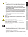 7
7
-
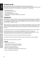 8
8
-
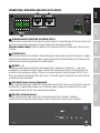 9
9
-
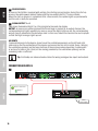 10
10
-
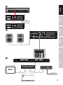 11
11
-
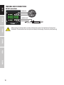 12
12
-
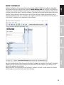 13
13
-
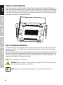 14
14
-
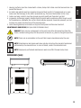 15
15
-
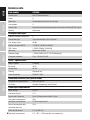 16
16
-
 17
17
-
 18
18
-
 19
19
-
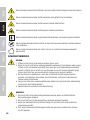 20
20
-
 21
21
-
 22
22
-
 23
23
-
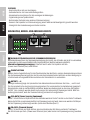 24
24
-
 25
25
-
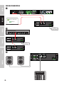 26
26
-
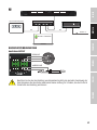 27
27
-
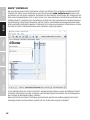 28
28
-
 29
29
-
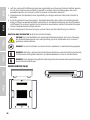 30
30
-
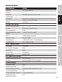 31
31
-
 32
32
-
 33
33
-
 34
34
-
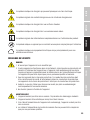 35
35
-
 36
36
-
 37
37
-
 38
38
-
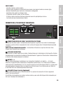 39
39
-
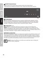 40
40
-
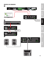 41
41
-
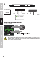 42
42
-
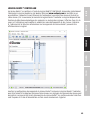 43
43
-
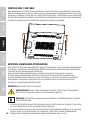 44
44
-
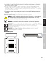 45
45
-
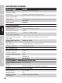 46
46
-
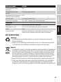 47
47
-
 48
48
-
 49
49
-
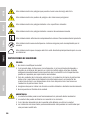 50
50
-
 51
51
-
 52
52
-
 53
53
-
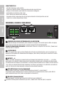 54
54
-
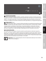 55
55
-
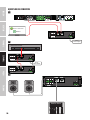 56
56
-
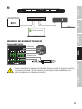 57
57
-
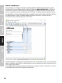 58
58
-
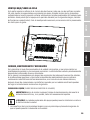 59
59
-
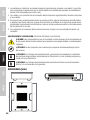 60
60
-
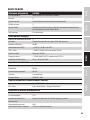 61
61
-
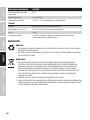 62
62
-
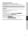 63
63
-
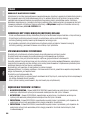 64
64
-
 65
65
-
 66
66
-
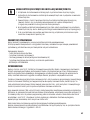 67
67
-
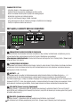 68
68
-
 69
69
-
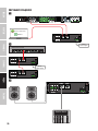 70
70
-
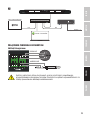 71
71
-
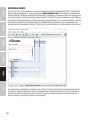 72
72
-
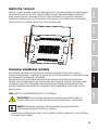 73
73
-
 74
74
-
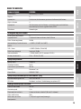 75
75
-
 76
76
-
 77
77
-
 78
78
-
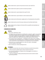 79
79
-
 80
80
-
 81
81
-
 82
82
-
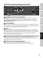 83
83
-
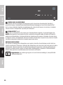 84
84
-
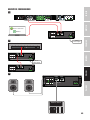 85
85
-
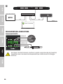 86
86
-
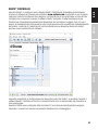 87
87
-
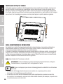 88
88
-
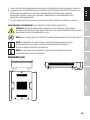 89
89
-
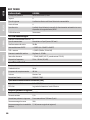 90
90
-
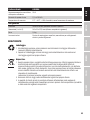 91
91
-
 92
92
-
 93
93
-
 94
94


en otros idiomas
- français: LD Systems DIO 04 Manuel utilisateur
- italiano: LD Systems DIO 04 Manuale utente
- Deutsch: LD Systems DIO 04 Benutzerhandbuch
- polski: LD Systems DIO 04 Instrukcja obsługi