Yamaha DM1000 Manual de usuario
- Categoría
- Equipo de música suplementario
- Tipo
- Manual de usuario
Este manual también es adecuado para

Owner’s Manual
Owner’s Manual
Keep This Manual For Future Reference.
Keep This Manual For Future Reference.
E

1. IMPORTANT NOTICE: DO NOT MODIFY THIS UNIT!
This product, when installed as indicated in the instructions con-
tained in this manual, meets FCC requirements. Modifications not
expressly approved by Yamaha may void your authority, granted by
the FCC, to use the product.
2. IMPORTANT:
When connecting this product to accessories and/
or another product use only high quality shielded cables. Cable/s
supplied with this product MUST be used. Follow all installation
instructions. Failure to follow instructions could void your FCC
authorization to use this product in the USA.
3. NOTE:
This product has been tested and found to comply with the
requirements listed in FCC Regulations, Part 15 for Class “B” digital
devices. Compliance with these requirements provides a reason-
able level of assurance that your use of this product in a residential
environment will not result in harmful interference with other elec-
tronic devices. This equipment generates/uses radio frequencies
and, if not installed and used according to the instructions found in
the users manual, may cause interference harmful to the operation
of other electronic devices. Compliance with FCC regulations does
* This applies only to products distributed by YAMAHA CORPORATION OF AMERICA. (class B)
not guarantee that interference will not occur in all installations. If
this product is found to be the source of interference, which can be
determined by turning the unit “OFF” and “ON”, please try to elimi-
nate the problem by using one of the following measures:
Relocate either this product or the device that is being affected by
the interference.
Utilize power outlets that are on different branch (circuit breaker or
fuse) circuits or install AC line filter/s.
In the case of radio or TV interference, relocate/reorient the
antenna. If the antenna lead-in is 300 ohm ribbon lead, change the
lead-in to co-axial type cable.
If these corrective measures do not produce satisfactory results,
please contact the local retailer authorized to distribute this type of
product. If you can not locate the appropriate retailer, please con-
tact Yamaha Corporation of America, Electronic Service Division,
6600 Orangethorpe Ave, Buena Park, CA90620
The above statements apply ONLY to those products distributed by
Yamaha Corporation of America or its subsidiaries.
FCC INFORMATION (U.S.A.)
IMPORTANT NOTICE FOR THE UNITED KINGDOM
Connecting the Plug and Cord
WARNING:
THIS APPARATUS MUST BE EARTHED
IMPORTANT. The wires in this mains lead are coloured in accordance
with the following code:
GREEN-AND-YELLOW : EARTH
BLUE : NEUTRAL
BROWN : LIVE
As the colours of the wires in the mains lead of this apparatus may not
correspond with the coloured markings identifying the terminals in
your plug proceed as follows:
The wire which is coloured GREEN-and-YELLOW must be connected
to the terminal in the plug which is marked by the letter E or by the
safety earth symbol or colored GREEN or GREEN-and-YELLOW.
The wire which is coloured BLUE must be connected to the terminal
which is marked with the letter N or coloured BLACK.
The wire which is coloured BROWN must be connected to the termi-
nal which is marked with the letter L or coloured RED.
• This applies only to products distributed by Yamaha-Kemble Music (U.K.) Ltd. (3 wires)
ADVARSEL!
Lithiumbatteri—Eksplosionsfare ved fejlagtig håndtering. Udskiftning
må kun ske med batteri af samme fabrikat og type. Levér det brugte
batteri tilbage til leverandoren.
VARNING
Explosionsfara vid felaktigt batteribyte. Använd samma batterityp eller
en ekvivalent typ som rekommenderas av apparattillverkaren.
Kassera använt batteri enligt fabrikantens instruktion.
VAROITUS
Paristo voi räjähtää, jos se on virheellisesti asennettu. Vaihda paristo
ainoastaan laitevalmistajan suosittelemaan tyyppiin. Hävitä käytetty
paristo valmistajan ohjeiden mukaisesti.
(lithium caution)
This product contains a high intensity lamp that contains
a small amount of mercury. Disposal of this material
may be regulated due to environmental considerations.
For disposal information in the United States, refer to
the Electronic Industries Alliance web site:
www.eiae.org
(mercury)* This applies only to products distributed by
YAMAHA CORPORATION OF AMERICA.
NEDERLAND / THE NETHERLANDS
• Dit apparaat bevat een lithium batterij voor geheugen back-up.
• This apparatus contains a lithium battery for memory back-up.
• Raadpleeg uw leverancier over de verwijdering van de batterij op
het moment dat u het apparaat ann het einde van de levensduur of
gelieve dan contact op te nemen met de vertegenwoordiging van
Yamaha in uw land.
•For the removal of the battery at the moment of the disposal at the
end of life please consult your retailer or Yamaha representative
office in your country.
• Gooi de batterij niet weg, maar lever hem in als KCA.
• Do not throw away the battery. Instead, hand it in as small chemical
waste.
(lithium disposal)
* This applies only to products distributed by
YAMAHA CORPORATION OF AMERICA.
COMPLIANCE INFORMATION STATEMENT
(DECLARATION OF CONFORMITY PROCEDURE)
Responsible Party : Yamaha Corporation of America
Address : 6600 Orangethorpe Ave., Buena Park, Calif.
90620
Telephone : 714-522-9011
Type of Equipment : Digital Production Console
Model Name : DM1000
This device complies with Part 15 of the FCC Rules.
Operation is subject to the following two conditions:
1) this device may not cause harmful interference, and
2) this device must accept any interference received including interfer-
ence that may cause undesired operation.
See user manual instructions if interference to radio reception is sus-
pected.
(FCC DoC)
This product contains a battery that contains perchlorate material.
Perchlorate Material—special handling may apply,
See www.dtsc.ca.gov/hazardouswaste/perchlorate.
(Perchlorate)* This applies only to products distributed by
YAMAHA CORPORATION OF AMERICA.

The above warning is located on the side
of the unit
• Explanation of Graphical Symbols
The lightning flash with arrowhead symbol
within an equilateral triangle is intended to
alert the user to the presence of uninsulated
“dangerous voltage” within the product’s
enclosure that may be of sufficient magnitude
to constitute a risk of electric shock to persons.
The exclamation point within an equilateral
triangle is intended to alert the user to the
presence of important operating and mainte-
nance (servicing) instructions in the literature
accompanying the product.
IMPORTANT SAFETY INSTRUCTIONS
1 Read these instructions.
2Keep these instructions.
3 Heed all warnings.
4 Follow all instructions.
5 Do not use this apparatus near water.
6 Clean only with dry cloth.
7 Do not block any ventilation openings. Install in
accordance with the manufacturer’s instruc-
tions.
8 Do not install near any heat sources such as
radiators, heat registers, stoves, or other appa-
ratus (including amplifiers) that produce heat.
9 Do not defeat the safety purpose of the polar-
ized or grounding-type plug. A polarized plug
has two blades with one wider than the other. A
grounding type plug has two blades and a third
grounding prong. The wide blade or the third
prong are provided for your safety. If the pro-
vided plug does not fit into your outlet, consult
an electrician for replacement of the obsolete
outlet.
10 Protect the power cord from being walked on or
pinched particularly at plugs, convenience
receptacles, and the point where they exit from
the apparatus.
11 Only use attachments/accessories specified by
the manufacturer.
12 Use only with the cart, stand,
tripod, bracket, or table spec-
ified by the manufacturer, or
sold with the apparatus.
When a cart is used, use cau-
tion when moving the cart/
apparatus combination to
avoid injury from tip-over.
13 Unplug this apparatus during lightning storms
or when unused for long periods of time.
14 Refer all servicing to qualified service person-
nel. Servicing is required when the apparatus
has been damaged in any way, such as power-
supply cord or plug is damaged, liquid has been
spilled or objects have fallen into the apparatus,
the apparatus has been exposed to rain or mois-
ture, does not operate normally, or has been
dropped.
CAUTION: TO REDUCE THE RISK OF
ELECTRIC SHOCK, DO NOT REMOVE
COVER (OR BACK). NO USER-SERVICEABLE
PARTS INSIDE. REFER SERVICING TO
QUALIFIED SERVICE PERSONNEL.
CAUTION
RISK OF ELECTRIC SHOCK
DO NOT OPEN
WARNING
TO REDUCE THE RISK OF FIRE OR ELECTRIC SHOCK,
DO NOT EXPOSE THIS APPARATUS TO RAIN OR MOISTURE.

(5)-1 1/2
PRECAUTIONS
PLEASE READ CAREFULLY BEFORE PROCEEDING
* Please keep this manual in a safe place for future reference.
WARNING
Always follow the basic precautions listed below to avoid the possibility of serious injury or even death from electrical
shock, short-circuiting, damages, fire or other hazards. These precautions include, but are not limited to, the following:
• Only use the voltage specified as correct for the device. The required voltage is
printed on the name plate of the device.
• Use only the specified power code.
• Do not place the power cord near heat sources such as heaters or radiators, and
do not excessively bend or otherwise damage the cord, place heavy objects on
it, or place it in a position where anyone could walk on, trip over, or roll anything
over it.
• Be sure to connect to an appropriate outlet with a protective grounding
connection. Improper grounding can result in electrical shock.
• Do not open the device or attempt to disassemble the internal parts or modify
them in any way. The device contains no user-serviceable parts. If it should
appear to be malfunctioning, discontinue use immediately and have it inspected
by qualified Yamaha service personnel.
• Do not expose the device to rain, use it near water or in damp or wet conditions,
or place containers on it containing liquids which might spill into any openings.
• Never insert or remove an electric plug with wet hands.
• If the power cord or plug becomes frayed or damaged, or if there is a sudden
loss of sound during use of the device, or if any unusual smells or smoke
should appear to be caused by it, immediately turn off the power switch,
disconnect the electric plug from the outlet, and have the device inspected by
qualified Yamaha service personnel.
• If this device should be dropped or damaged, immediately turn off the power
switch, disconnect the electric plug from the outlet, and have the device
inspected by qualified Yamaha service personnel.
CAUTION
Always follow the basic precautions listed below to avoid the possibility of physical injury to you or others, or damage
to the device or other property. These precautions include, but are not limited to, the following:
• Remove the electric plug from the outlet when the device is not to be used for
extended periods of time, or during electrical storms.
• When removing the electric plug from the device or an outlet, always hold the
plug itself and not the cord. Pulling by the cord can damage it.
• When transporting or moving the device, always use two or more people.
• Before moving the device, remove all connected cables. When you move the
device with the MB1000 attached, do not permit impact or stress on the cable
connector that connects the MB1000 to the device.
• When setting up the product, make sure that the AC outlet you are using is
easily accessible. If some trouble or malfunction occurs, immediately turn off
the power switch and disconnect the plug from the outlet. Even when the power
switch is turned off, electricity is still flowing to the product at the minimum
level. When you are not using the product for a long time, make sure to unplug
the power cord from the wall AC outlet.
•Avoid setting all equalizer controls and faders to their maximum. Depending on
the condition of the connected devices, doing so may cause feedback and may
damage the speakers.
• Do not expose the device to excessive dust or vibrations, or extreme cold or heat
(such as in direct sunlight, near a heater, or in a car during the day) to prevent
the possibility of panel disfiguration or damage to the internal components.
• Do not place the device in an unstable position where it might accidentally fall
over.
• Do not block the vents. This device has ventilation holes at the top/front/rear/
sides to prevent the internal temperature from rising too high. In particular, do
not place the device on its side or upside down, or place it in any poorly-
ventilated location, such as a bookcase or closet.
• Do not use the device in the vicinity of a TV, radio, stereo equipment, mobile
phone, or other electric devices. Otherwise, the device, TV, or radio may
generate noise.
• If you are using the optional MB1000 Peak Meter Bridge, do not hold only the
MB1000 when moving this unit. Otherwise, the meter brackets may be
damaged, the main unit may malfunction, or you may be injured if the unit falls.
• Before connecting the device to other devices, turn off the power for all devices.
Before turning the power on or off for all devices, set all volume levels to
minimum.
• Be sure to connect to a properly grounded power source. A ground screw
terminal is provided on the rear panel for safely grounding the device and
preventing electrical shock.
Power supply/Power cord
Do not open
Water warning
If you notice any abnormality
Power supply/Power cord
Location
Connections

(5)-1 2/2
• Do not insert your fingers or hand in any gaps or openings on the device (vents,
etc.).
•Avoid inserting or dropping foreign objects (paper, plastic, metal, etc.) into any
gaps or openings on the device (vents, etc.) If this happens, turn off the power
immediately and unplug the power cord from the AC outlet. Then have the
device inspected by qualified Yamaha service personnel.
• Do not use headphones for a long period of time at a high or uncomfortable
volume level, since this can cause permanent hearing loss. If you experience
any hearing loss or ringing in the ears, consult a physician.
• Do not apply oil, grease, or contact cleaner to the faders. Doing so may cause
problems with electrical contact or fader motion.
• Do not rest your weight on the device or place heavy objects on it, and avoid use
excessive force on the buttons, switches or connectors.
• This device has rear-panel slots for installing mini-YGDAI cards. For technical
reasons, certain card combinations are not supported. Before installing any
cards, check the Yamaha web site (see page 6) to see whether your card is
compatible. Also check the total number of cards that can be installed in the
unit.
Installing cards that are not endorsed by Yamaha may cause electrical shock,
fire, or damage to the unit.
• This device has a built-in backup battery. When you unplug the power cord from
the AC outlet, the internal data is retained. However, if the backup battery fully
discharges, this data will be lost. If the backup battery is running low, when you
turn on the device the display indicates “WARNING Low Battery!.” In this case,
immediately save the data to an external media using MIDI Bulk Dump, then
have qualified Yamaha service personnel replace the backup battery.
• Using a mobile telephone near this unit may induce noise. If noise occurs, use the telephone away from the unit.
• The digital circuits of this unit may induce a slight noise into nearby radios and TVs. If noise occurs, relocate the affected equipment.
• When connecting D-sub cables, be sure to tighten the screws on both sides of the connector securely. To disconnect the cable, loosen the screws completely, then remove
the cable by holding the connector part. Do not remove the plug by pulling the cable while the screws are still attached. Otherwise, the connector may be damaged, leading
to malfunction.
• When you change the wordclock settings on any device in your digital audio system, some devices may output noise, so turn down your power amps beforehand,
otherwise your speakers may be damaged.
XLR-type connectors are wired as follows (IEC60268 standard): pin 1: ground, pin 2: hot (+), and pin 3: cold (-).
Yamaha cannot be held responsible for damage caused by improper use or modifications to the device, or data that is lost or destroyed.
Always turn the power off when the device is not in use.
The performance of components with moving contacts, such as switches, volume controls, and connectors, deteriorates over time. Consult qualified Yamaha service
personnel about replacing defective components.
* The illustrations and screen displays as shown in this Owner’s Manual are for instructional purposes only, and may be different from the ones on your device.
* The company names and product names in this Owner’s Manual are the trademarks or registered trademarks of their respective companies.
* THX and THX pm3 are registered trademarks of THX Ltd.
Handling caution Backup battery

6
Yamaha Pro Audio global website
DM1000 Version 2—Owner’s Manual
Yamaha Pro Audio global website
http://www.yamahaproaudio.com/
Package Contents
• DM1000 Digital Production Console
• CD-ROM
•Power cord
•This manual
•Studio Manager Installation Guide
Optional Extras
• MB1000 Peak Meter Bridge
• SP1000 Wooden Side Panels
• RK1 Rack Mount Kit
• mini YGDAI I/O cards
About this Owner’s Manual
This
Owner’s Manual
explains how to operate the DM1000 Digital Production Console.
The table of contents can help you familiarize yourself with the manual’s organization and
to locate tasks and topics The index can help you locate specific information.
Before diving in, it is recommended that you read the “Operating Basics” chapter, starting
on page 29.
Each chapter in this manual discusses a specific section or function of the DM1000. The
Input and Output Channels are explained in the following chapters: “Input Channels,” “Bus
Outs,” and “Aux Sends.” Where possible, these chapters have been organized in order of sig-
nal flow, from input to output.
Conventions Used in this Manual
The DM1000 features two types of buttons: physical buttons that you can press (e.g.,
ENTER and DISPLAY) and buttons that appear on the display pages. References to physical
buttons are enclosed in square brackets, for example, “press the [ENTER] button.” Refer-
ences to display page buttons are not emphasized, for example, “move the cursor to the ON
button.”
You can select display pages by using the [DISPLAY] buttons or the Left Tab Scroll, Right
Tab Scroll, and F1–4 buttons below the display. In order to simplify explanations, the pro-
cedures reference only the [DISPLAY] button method. See “Selecting Display Pages” on
page 30 for details on all the ways in which pages can be selected.

New Functions in DM1000 Version 2 7
DM1000 Version 2—Owner’s Manual
New Functions in DM1000 Version 2
The following functions have been added to the DM1000 as part of the upgrade of the firm-
ware from version 1.0 to version 2.0.
Control Surface
• Encoder mode now features an assignable function, ALT LAYER, which enables you to con-
trol the channel level for all 32 channels without switching between layers. → page 36
•There are now 50 assignable Encoder mode parameters. → page 38
Aux Sends
•If an Aux Send is set to pre-fader, you can set the Pre point before or after channel mute.
→ page 99
•The AUX SELECT [AUX 1–8] buttons enable you to solo or unsolo Aux Sends without
switching to the Master layer. → page 107
Control Room Monitor
•You can select whether the Input Channel’s Pan setting is used when the Input Channel Solo
signal is set to Pre Fader. → page 120
•Raising the channel faders for soloed Channels from –∞ can unsolo the Channels.
→ page 121
•You can simultaneously select 2TR D1 or 2TR D2, and STEREO as control room monitor
sources. → page 123
Surround Function
•The on/off status of the Follow Pan button is reflected in the pan and Surround Pan
settings. → page 125
•The Surround Monitor function now supports THX Surround. → page 138
•You can simultaneously select BUS and SLOT as surround monitor sources. → page 137
Group/Link
•The Fader Group Master function enables you to control the overall level of the Fader group
channels simultaneously while maintaining the relative level balance of each channel.
→ page 150
•The Mute Group Master function enables you to mute all channels in a Mute group
simultaneously. → page 152
Internal Effects
•You can add optional Add-On Effects to the preset effects. → page 161
Scene Memory
•Any channel or parameter settings in the current scene can be copied and pasted into other
scenes. → page 171
•You can select additional parameters for the Recall Safe function. → page 170

8
New Functions in DM1000 Version 2
DM1000 Version 2—Owner’s Manual
Automix
•You can insert the mix parameters in a region specified in the Automix data.
→
page 193
•Touching the faders can punch parameter values in and out if the corresponding OVER-
WRITE button is set to on (Touch Sence Edit In ALL ).
→
page 271
Remote Control
•Cubase SX has been added as a target of the Remote layer.
→
page 215
•The Joystick or the controls in the SELECTED CHANNEL section enable you to control Pro
To ols Surround Pan settings.
→
page 216
•Yamaha’s proprietary Advanced DAW protocol has been added to Nuendo, Cubase SX, and
General DAW. This enables you to control these devices using the DM1000’s SELECTED
CHANNEL section. (Controllable functions vary depending on the DAW software and ver-
sion you are using.)
Other Functions
•You can control the DM1000 from a connected Video Editor via the ESAM protocol.
→
page 259
•You can set the Routing ST Pair Link so that the routing from paired channels to the Stereo
Bus is linked.
→
page 268
•Some Operation Lock Safe parameters have been added.
→
page 280
•You can remotely control a connected Yamaha AD8HR A/D converter.
→
page 287
•You can assign the selected channels to a Fader or Mute group using the USER DEFINED
KEYS.
→
page 293
•You can switch the windows of the included Studio Manager software application using the
USER DEFINED KEYS.
→
page 293

Contents
9
DM1000 Version 2—Owner’s Manual
Contents
1 Welcome . . . . . . . . . . . . . . . . . . . . . . . . . . . . . . . . . . . 13
2 Control Surface & Rear Panel . . . . . . . . . . . . . . . . . . . 15
Control Surface . . . . . . . . . . . . . . . . . . . . . . . . . . . . . . . . . . . . . . . . . . . . . . . . . . . . . 15
Rear Panel . . . . . . . . . . . . . . . . . . . . . . . . . . . . . . . . . . . . . . . . . . . . . . . . . . . . . . . . . 25
Installing an Optional Card . . . . . . . . . . . . . . . . . . . . . . . . . . . . . . . . . . . . . . . . . . . 28
3 Operating Basics . . . . . . . . . . . . . . . . . . . . . . . . . . . . . 29
About the Display . . . . . . . . . . . . . . . . . . . . . . . . . . . . . . . . . . . . . . . . . . . . . . . . . . . 29
Selecting Display Pages . . . . . . . . . . . . . . . . . . . . . . . . . . . . . . . . . . . . . . . . . . . . . . . 30
Display Interface . . . . . . . . . . . . . . . . . . . . . . . . . . . . . . . . . . . . . . . . . . . . . . . . . . . . 31
Selecting Layers . . . . . . . . . . . . . . . . . . . . . . . . . . . . . . . . . . . . . . . . . . . . . . . . . . . . . 33
Selecting Channels . . . . . . . . . . . . . . . . . . . . . . . . . . . . . . . . . . . . . . . . . . . . . . . . . . . 34
Selecting Fader Modes . . . . . . . . . . . . . . . . . . . . . . . . . . . . . . . . . . . . . . . . . . . . . . . 35
Selecting Encoder Modes . . . . . . . . . . . . . . . . . . . . . . . . . . . . . . . . . . . . . . . . . . . . . 36
Assigning Parameters to the ENCODER MODE [ASSIGN] button . . . . . . . . . . 37
Metering . . . . . . . . . . . . . . . . . . . . . . . . . . . . . . . . . . . . . . . . . . . . . . . . . . . . . . . . . . . 39
4 Connections and Setup . . . . . . . . . . . . . . . . . . . . . . . . 43
Connections . . . . . . . . . . . . . . . . . . . . . . . . . . . . . . . . . . . . . . . . . . . . . . . . . . . . . . . . 43
Wordclock Connections and Settings . . . . . . . . . . . . . . . . . . . . . . . . . . . . . . . . . . . 46
Input and Output Patching . . . . . . . . . . . . . . . . . . . . . . . . . . . . . . . . . . . . . . . . . . . 49
5 Analog I/O & Digital I/O . . . . . . . . . . . . . . . . . . . . . . . 53
Analog Inputs & Outputs . . . . . . . . . . . . . . . . . . . . . . . . . . . . . . . . . . . . . . . . . . . . . 53
Digital Inputs & Outputs . . . . . . . . . . . . . . . . . . . . . . . . . . . . . . . . . . . . . . . . . . . . . 54
Converting Sampling Rates of Signals Received at 2TR Digital Inputs . . . . . . . . 55
Monitoring Digital Input Channel Status . . . . . . . . . . . . . . . . . . . . . . . . . . . . . . . . 57
Dithering Digital Outputs . . . . . . . . . . . . . . . . . . . . . . . . . . . . . . . . . . . . . . . . . . . . 58
Setting the Transfer Format for Higher Sampling Rates . . . . . . . . . . . . . . . . . . . . 59
6 Input Channels . . . . . . . . . . . . . . . . . . . . . . . . . . . . . . 61
About Input Channels . . . . . . . . . . . . . . . . . . . . . . . . . . . . . . . . . . . . . . . . . . . . . . . 61
Setting the Input Channels from the Display . . . . . . . . . . . . . . . . . . . . . . . . . . . . . 63
Setting the Input Channels from the Control Surface . . . . . . . . . . . . . . . . . . . . . . 75
Pairing Input Channels . . . . . . . . . . . . . . . . . . . . . . . . . . . . . . . . . . . . . . . . . . . . . . . 76
Naming Input Channels . . . . . . . . . . . . . . . . . . . . . . . . . . . . . . . . . . . . . . . . . . . . . . 79
Using MS Stereo Microphone . . . . . . . . . . . . . . . . . . . . . . . . . . . . . . . . . . . . . . . . . 80
7 Bus Outs . . . . . . . . . . . . . . . . . . . . . . . . . . . . . . . . . . . 81
About Stereo Out . . . . . . . . . . . . . . . . . . . . . . . . . . . . . . . . . . . . . . . . . . . . . . . . . . . 81
Bus Out 1–8 . . . . . . . . . . . . . . . . . . . . . . . . . . . . . . . . . . . . . . . . . . . . . . . . . . . . . . . . 82
Setting the Stereo Out and Bus Out 1–8 from the Display . . . . . . . . . . . . . . . . . . 83
Setting the Stereo Out and Bus Out 1–8 from the Control Surface . . . . . . . . . . . 88
Pairing Buses or Aux Sends . . . . . . . . . . . . . . . . . . . . . . . . . . . . . . . . . . . . . . . . . . . 89
Attenuating Output Signals . . . . . . . . . . . . . . . . . . . . . . . . . . . . . . . . . . . . . . . . . . . 90
Naming the Stereo Out and Bus Outs . . . . . . . . . . . . . . . . . . . . . . . . . . . . . . . . . . . 91

10
Contents
DM1000 Version 2—Owner’s Manual
8 Aux Sends . . . . . . . . . . . . . . . . . . . . . . . . . . . . . . . . . . . 93
Aux Out 1–8 . . . . . . . . . . . . . . . . . . . . . . . . . . . . . . . . . . . . . . . . . . . . . . . . . . . . . . . 93
Setting Aux Out 1–8 from the Control Surface . . . . . . . . . . . . . . . . . . . . . . . . . . . 94
Setting Aux Out 1–8 from the Display . . . . . . . . . . . . . . . . . . . . . . . . . . . . . . . . . . 94
Setting Aux Send Levels . . . . . . . . . . . . . . . . . . . . . . . . . . . . . . . . . . . . . . . . . . . . . . 98
Viewing Aux Send Settings for Multiple Channels . . . . . . . . . . . . . . . . . . . . . . . . 102
Panning Aux Sends . . . . . . . . . . . . . . . . . . . . . . . . . . . . . . . . . . . . . . . . . . . . . . . . . . 104
Excluding Certain Channels from Aux Sends (Mix Minus) . . . . . . . . . . . . . . . . . 105
Copying Channel Fader Positions to Aux Sends . . . . . . . . . . . . . . . . . . . . . . . . . . 106
Soloing AUX Sends using the [AUX 1]–[AUX 8] Buttons . . . . . . . . . . . . . . . . . . 107
9 Input & Output Patching . . . . . . . . . . . . . . . . . . . . . . 109
Input Patching . . . . . . . . . . . . . . . . . . . . . . . . . . . . . . . . . . . . . . . . . . . . . . . . . . . . . . 109
Output Patching . . . . . . . . . . . . . . . . . . . . . . . . . . . . . . . . . . . . . . . . . . . . . . . . . . . . 112
Patching Direct Outs . . . . . . . . . . . . . . . . . . . . . . . . . . . . . . . . . . . . . . . . . . . . . . . . 115
Insert Patching . . . . . . . . . . . . . . . . . . . . . . . . . . . . . . . . . . . . . . . . . . . . . . . . . . . . . 116
10 Control Room Monitoring . . . . . . . . . . . . . . . . . . . . . 119
Control Room Monitor . . . . . . . . . . . . . . . . . . . . . . . . . . . . . . . . . . . . . . . . . . . . . . 119
Solo Setup . . . . . . . . . . . . . . . . . . . . . . . . . . . . . . . . . . . . . . . . . . . . . . . . . . . . . . . . . 120
Using the Solo Function . . . . . . . . . . . . . . . . . . . . . . . . . . . . . . . . . . . . . . . . . . . . . . 121
Using the Control Room Monitor . . . . . . . . . . . . . . . . . . . . . . . . . . . . . . . . . . . . . 122
Using the Talkback Function . . . . . . . . . . . . . . . . . . . . . . . . . . . . . . . . . . . . . . . . . . 123
11 Surround Functions . . . . . . . . . . . . . . . . . . . . . . . . . . 125
Using Surround Pan . . . . . . . . . . . . . . . . . . . . . . . . . . . . . . . . . . . . . . . . . . . . . . . . . 125
Surround Monitoring . . . . . . . . . . . . . . . . . . . . . . . . . . . . . . . . . . . . . . . . . . . . . . . . 136
12 Grouping Channels & Linking Parameters . . . . . . . . . 147
Grouping & Linking . . . . . . . . . . . . . . . . . . . . . . . . . . . . . . . . . . . . . . . . . . . . . . . . . 147
Using Fader Groups and Mute Groups . . . . . . . . . . . . . . . . . . . . . . . . . . . . . . . . . 148
Using Fader Group Master . . . . . . . . . . . . . . . . . . . . . . . . . . . . . . . . . . . . . . . . . . . 150
Using Mute Group Master . . . . . . . . . . . . . . . . . . . . . . . . . . . . . . . . . . . . . . . . . . . . 152
Linking EQ and Compressor Parameters . . . . . . . . . . . . . . . . . . . . . . . . . . . . . . . . 152
13 Internal Effects . . . . . . . . . . . . . . . . . . . . . . . . . . . . . . 155
About the Internal Effects . . . . . . . . . . . . . . . . . . . . . . . . . . . . . . . . . . . . . . . . . . . . 155
Using Effects Processors via Aux Sends . . . . . . . . . . . . . . . . . . . . . . . . . . . . . . . . . 156
Inserting the Internal Effects into Channels . . . . . . . . . . . . . . . . . . . . . . . . . . . . . . 158
Editing Effects . . . . . . . . . . . . . . . . . . . . . . . . . . . . . . . . . . . . . . . . . . . . . . . . . . . . . . 159
About Surround Effects . . . . . . . . . . . . . . . . . . . . . . . . . . . . . . . . . . . . . . . . . . . . . . 161
About Add-On Effects . . . . . . . . . . . . . . . . . . . . . . . . . . . . . . . . . . . . . . . . . . . . . . . 161
About Plug-Ins . . . . . . . . . . . . . . . . . . . . . . . . . . . . . . . . . . . . . . . . . . . . . . . . . . . . . 162
14 Scene Memories . . . . . . . . . . . . . . . . . . . . . . . . . . . . . 163
About Scene Memories . . . . . . . . . . . . . . . . . . . . . . . . . . . . . . . . . . . . . . . . . . . . . . 163
Storing and Recalling Scenes . . . . . . . . . . . . . . . . . . . . . . . . . . . . . . . . . . . . . . . . . . 165
Auto Scene Memory Update . . . . . . . . . . . . . . . . . . . . . . . . . . . . . . . . . . . . . . . . . . 167
Fading Scenes . . . . . . . . . . . . . . . . . . . . . . . . . . . . . . . . . . . . . . . . . . . . . . . . . . . . . . 168
Recalling Scenes Safely . . . . . . . . . . . . . . . . . . . . . . . . . . . . . . . . . . . . . . . . . . . . . . . 170
Sorting Scenes . . . . . . . . . . . . . . . . . . . . . . . . . . . . . . . . . . . . . . . . . . . . . . . . . . . . . . 171
Copying and Pasting a Scene (Global Paste) . . . . . . . . . . . . . . . . . . . . . . . . . . . . . 171

Contents
11
DM1000 Version 2—Owner’s Manual
15 Libraries . . . . . . . . . . . . . . . . . . . . . . . . . . . . . . . . . . . 173
About the Libraries . . . . . . . . . . . . . . . . . . . . . . . . . . . . . . . . . . . . . . . . . . . . . . . . . . 173
General Library Operation . . . . . . . . . . . . . . . . . . . . . . . . . . . . . . . . . . . . . . . . . . . . 173
Using Libraries . . . . . . . . . . . . . . . . . . . . . . . . . . . . . . . . . . . . . . . . . . . . . . . . . . . . . . 175
16 Automix . . . . . . . . . . . . . . . . . . . . . . . . . . . . . . . . . . . . 187
About Automix . . . . . . . . . . . . . . . . . . . . . . . . . . . . . . . . . . . . . . . . . . . . . . . . . . . . . 187
Setting Up for Automix Recording . . . . . . . . . . . . . . . . . . . . . . . . . . . . . . . . . . . . . 188
Recording an Automix . . . . . . . . . . . . . . . . . . . . . . . . . . . . . . . . . . . . . . . . . . . . . . . 190
Inserting Mix Parameters into Automix . . . . . . . . . . . . . . . . . . . . . . . . . . . . . . . . . 193
Punching In & Out . . . . . . . . . . . . . . . . . . . . . . . . . . . . . . . . . . . . . . . . . . . . . . . . . . 197
[SEL] Button Functions While the [AUTO] Button Indicator Is On . . . . . . . . . 199
Playing Back an Automix . . . . . . . . . . . . . . . . . . . . . . . . . . . . . . . . . . . . . . . . . . . . . 199
Automix Main Page . . . . . . . . . . . . . . . . . . . . . . . . . . . . . . . . . . . . . . . . . . . . . . . . . 200
Automix Memory Page . . . . . . . . . . . . . . . . . . . . . . . . . . . . . . . . . . . . . . . . . . . . . . . 204
Fader1 &2 pages . . . . . . . . . . . . . . . . . . . . . . . . . . . . . . . . . . . . . . . . . . . . . . . . . . . . . 205
Editing Events Offline . . . . . . . . . . . . . . . . . . . . . . . . . . . . . . . . . . . . . . . . . . . . . . . . 207
17 Remote Control . . . . . . . . . . . . . . . . . . . . . . . . . . . . . . 215
About Remote Function . . . . . . . . . . . . . . . . . . . . . . . . . . . . . . . . . . . . . . . . . . . . . . 215
Pro Tools Remote Layer . . . . . . . . . . . . . . . . . . . . . . . . . . . . . . . . . . . . . . . . . . . . . . 216
Nuendo/Cubase SX Remote Layer . . . . . . . . . . . . . . . . . . . . . . . . . . . . . . . . . . . . . . 235
Other DAW Remote Layers . . . . . . . . . . . . . . . . . . . . . . . . . . . . . . . . . . . . . . . . . . . 235
MIDI Remote Layer . . . . . . . . . . . . . . . . . . . . . . . . . . . . . . . . . . . . . . . . . . . . . . . . . 236
Machine Control Function . . . . . . . . . . . . . . . . . . . . . . . . . . . . . . . . . . . . . . . . . . . . 242
18 MIDI . . . . . . . . . . . . . . . . . . . . . . . . . . . . . . . . . . . . . . . 245
MIDI & the DM1000 . . . . . . . . . . . . . . . . . . . . . . . . . . . . . . . . . . . . . . . . . . . . . . . . . 245
MIDI Port Setup . . . . . . . . . . . . . . . . . . . . . . . . . . . . . . . . . . . . . . . . . . . . . . . . . . . . 246
Assigning Scenes to Program Changes for Remote Recall . . . . . . . . . . . . . . . . . . . 249
Assigning Parameters to Control Changes for Real-time Control . . . . . . . . . . . . 250
Controlling Parameters by Using Parameter Changes . . . . . . . . . . . . . . . . . . . . . . 256
Transmitting Parameter Settings via MIDI (Bulk Dump) . . . . . . . . . . . . . . . . . . 256
19 Controlling the DM1000 from a Video Editor . . . . . . 259
About ESAM . . . . . . . . . . . . . . . . . . . . . . . . . . . . . . . . . . . . . . . . . . . . . . . . . . . . . . . 259
Connection Example . . . . . . . . . . . . . . . . . . . . . . . . . . . . . . . . . . . . . . . . . . . . . . . . . 259
Crossfade via ESAM Commands . . . . . . . . . . . . . . . . . . . . . . . . . . . . . . . . . . . . . . . 260
Video Editors with confirmed compatibility . . . . . . . . . . . . . . . . . . . . . . . . . . . . . 264
Supported Commands . . . . . . . . . . . . . . . . . . . . . . . . . . . . . . . . . . . . . . . . . . . . . . . 264
Remote Connector Pin Assignment . . . . . . . . . . . . . . . . . . . . . . . . . . . . . . . . . . . . 264
20 Other Functions . . . . . . . . . . . . . . . . . . . . . . . . . . . . . . 265
Changing the Input and Output Connector Names . . . . . . . . . . . . . . . . . . . . . . . 265
Setting Preferences . . . . . . . . . . . . . . . . . . . . . . . . . . . . . . . . . . . . . . . . . . . . . . . . . . 266
Creating a Custom Layer by Combining Channels (User Assignable Layer) . . . 272
Using the Oscillator . . . . . . . . . . . . . . . . . . . . . . . . . . . . . . . . . . . . . . . . . . . . . . . . . . 273
Using the User Defined Keys . . . . . . . . . . . . . . . . . . . . . . . . . . . . . . . . . . . . . . . . . . 274
Using GPI (General Purpose Interface) . . . . . . . . . . . . . . . . . . . . . . . . . . . . . . . . . 276
Using Operation Lock . . . . . . . . . . . . . . . . . . . . . . . . . . . . . . . . . . . . . . . . . . . . . . . . 280
Cascading Consoles . . . . . . . . . . . . . . . . . . . . . . . . . . . . . . . . . . . . . . . . . . . . . . . . . . 282
Using the AD8HR/AD824 . . . . . . . . . . . . . . . . . . . . . . . . . . . . . . . . . . . . . . . . . . . . 287
Checking the Battery and the System Version . . . . . . . . . . . . . . . . . . . . . . . . . . . . 289
Initializing the DM1000 . . . . . . . . . . . . . . . . . . . . . . . . . . . . . . . . . . . . . . . . . . . . . . 289
Calibrating the Faders . . . . . . . . . . . . . . . . . . . . . . . . . . . . . . . . . . . . . . . . . . . . . . . . 290

12 Contents
DM1000 Version 2—Owner’s Manual
Appendix A: Parameter Lists . . . . . . . . . . . . . . . . . . . . . . 293
USER DEFINED KEYS . . . . . . . . . . . . . . . . . . . . . . . . . . . . . . . . . . . . . . . . . . . . . . . 293
USER DEFINED KEYS Initial Assignments . . . . . . . . . . . . . . . . . . . . . . . . . . . . . . 295
Input Patch Parameters . . . . . . . . . . . . . . . . . . . . . . . . . . . . . . . . . . . . . . . . . . . . . . 296
Initial Input Patch Settings . . . . . . . . . . . . . . . . . . . . . . . . . . . . . . . . . . . . . . . . . . . 298
Output Patch Parameters . . . . . . . . . . . . . . . . . . . . . . . . . . . . . . . . . . . . . . . . . . . . . 300
Initial Output Patch Settings . . . . . . . . . . . . . . . . . . . . . . . . . . . . . . . . . . . . . . . . . . 302
GPI Trigger Source & Target List . . . . . . . . . . . . . . . . . . . . . . . . . . . . . . . . . . . . . . 304
User Defined Remote Layer Initial Bank Settings . . . . . . . . . . . . . . . . . . . . . . . . . 306
Effects Parameters . . . . . . . . . . . . . . . . . . . . . . . . . . . . . . . . . . . . . . . . . . . . . . . . . . . 310
Effects and tempo synchronization . . . . . . . . . . . . . . . . . . . . . . . . . . . . . . . . . . . . . 322
Preset EQ Parameters . . . . . . . . . . . . . . . . . . . . . . . . . . . . . . . . . . . . . . . . . . . . . . . . 323
Preset Gate Parameters (fs = 44.1 kHz) . . . . . . . . . . . . . . . . . . . . . . . . . . . . . . . . . 324
Preset Compressor Parameters (fs = 44.1 kHz) . . . . . . . . . . . . . . . . . . . . . . . . . . . 325
Dynamics Parameters . . . . . . . . . . . . . . . . . . . . . . . . . . . . . . . . . . . . . . . . . . . . . . . . 327
Appendix B: Specifications . . . . . . . . . . . . . . . . . . . . . . . . 332
General Spec . . . . . . . . . . . . . . . . . . . . . . . . . . . . . . . . . . . . . . . . . . . . . . . . . . . . . . . 332
Libraries . . . . . . . . . . . . . . . . . . . . . . . . . . . . . . . . . . . . . . . . . . . . . . . . . . . . . . . . . . . 337
Analog Input Spec . . . . . . . . . . . . . . . . . . . . . . . . . . . . . . . . . . . . . . . . . . . . . . . . . . . 337
Analog Output Spec . . . . . . . . . . . . . . . . . . . . . . . . . . . . . . . . . . . . . . . . . . . . . . . . . 337
Digital Input Spec . . . . . . . . . . . . . . . . . . . . . . . . . . . . . . . . . . . . . . . . . . . . . . . . . . . 338
Digital Output Spec . . . . . . . . . . . . . . . . . . . . . . . . . . . . . . . . . . . . . . . . . . . . . . . . . 338
I/O Slot Spec (1–2) . . . . . . . . . . . . . . . . . . . . . . . . . . . . . . . . . . . . . . . . . . . . . . . . . . 339
Control I/O Spec . . . . . . . . . . . . . . . . . . . . . . . . . . . . . . . . . . . . . . . . . . . . . . . . . . . . 339
REMOTE Port . . . . . . . . . . . . . . . . . . . . . . . . . . . . . . . . . . . . . . . . . . . . . . . . . . . . . . 340
CONTROL Port . . . . . . . . . . . . . . . . . . . . . . . . . . . . . . . . . . . . . . . . . . . . . . . . . . . . 340
Dimensions . . . . . . . . . . . . . . . . . . . . . . . . . . . . . . . . . . . . . . . . . . . . . . . . . . . . . . . . 341
Appendix C: MIDI . . . . . . . . . . . . . . . . . . . . . . . . . . . . . . . 343
Scene Memory to Program Change Table . . . . . . . . . . . . . . . . . . . . . . . . . . . . . . . 343
Initial Parameter to Control Change Table . . . . . . . . . . . . . . . . . . . . . . . . . . . . . . 344
MIDI Data Format . . . . . . . . . . . . . . . . . . . . . . . . . . . . . . . . . . . . . . . . . . . . . . . . . . 360
Appendix D: About Optional Product . . . . . . . . . . . . . . . 374
MB1000 Peak Meter Bridge . . . . . . . . . . . . . . . . . . . . . . . . . . . . . . . . . . . . . . . . . . . 374
Installing the SP1000 Side Panels . . . . . . . . . . . . . . . . . . . . . . . . . . . . . . . . . . . . . . 377
Rack Mounting the DM1000 Using the RK1 Rack Mount Kit . . . . . . . . . . . . . . . 377
Index . . . . . . . . . . . . . . . . . . . . . . . . . . . . . . . . . . . . . . . . . 378
MIDI Implementation Chart . . . . . . . . . . . . . . . End of Manual
DM1000 Block Diagram. . . . . . . . . . . . . . . . . . . End of Manual
DM1000 Level Diagram . . . . . . . . . . . . . . . . . . . End of Manual

Welcome 13
DM1000 Version 2—Owner’s Manual
1
Welcome
1 Welcome
Thank you for choosing the Yamaha DM1000 Digital Production Console.
The compact DM1000 Digital Console features 24-bit/96 kHz digital audio processing
without compromise, as well as 48-channel simultaneous mixing. The DM1000 covers a
broad range of needs and applications, including multi-track recording, 2-channel mix-
down, and cutting-edge surround sound production. This integrated, comprehensive
audio system features remote control function for DAWs (Digital Audio Workstations) as
popularized by the DM2000 and 02R96 Digital Mixing Consoles.
The DM1000 offers the following features:
■ Hardware Features
• 17 touch-sensitive 100-mm motorized faders (for touch-sensitive selection of channels,
or for punching in and out during Automix recording)
•Faders can set levels for Input Channels, Aux Sends, and Bus Outs.
•Rotary Encoders enable you to control panning for each channel, AUX send levels, and
various parameters.
•Six selectable software layers determine the function of channel faders and Encoders.
• 320 x 240 dot LCD display with fluorescent backlighting
•Buttons and controls in the SELECTED CHANNEL section enable direct editing of
channel mix parameters.
• 12 USER-DEFINED KEYS enable you to assign functions to control DM1000 internal
parameters.
•Two expansion slots for optional digital I/O, AD, and DA cards.
■ Sonic Specifications
• Linear 24-bit, 128-times oversampling A/D converters
• Linear 24-bit, 128-times oversampling D/A converters
• 20 Hz through 40 kHz frequency response at 96 kHz sampling rate.
• 106 dB typical dynamic range
• 32-bit internal signal processing (58-bit accumulator)
■ Inputs and Outputs
• 16 mic/line inputs with switchable +48 V phantom power and 4 line inputs
• 12 Omni Outs assignable to Stereo Out, Bus Out, Monitor Out, and Input Channel
Direct Outs.
•Two optional slots allow a maximum of 32 inputs.
•Two 2-track digital inputs, with sampling rate converters capable of converting sam-
pling rates of 44.1 kHz through 96 kHz.
•Double Channel support for recording and playing at 88.2/96 kHz on 44.1/48 kHz leg-
acy multi-track digital recorders.
•You can cascade two DM1000s while remaining in the digital domain.
•Input patches enable assignment of input signals to desired signal paths.
•Output patches enable assignment of Bus Out signals and Input Channel Direct Outs to
desired output jacks.

14 Chapter 1—Welcome
DM1000 Version 2—Owner’s Manual
■ Channel Configuration
•Simultaneous mixing of up to 48 Input Channels. Group multiple channels and pair
channels for stereo.
•8 Bus Outs and 8 AUX Sends. Buses 1-8 can be routed to Stereo Buses for use as Group
Buses.
•Channel library for storing and recalling the channel settings for each Input Channel
and Output Channel.
• 4-band EQ and dynamics processor equip all channels. Dynamics processor and EQ set-
tings can be stored in libraries and recalled.
■ Effects
•Four high-quality multi-channel effects (Apply effects via AUX Sends or Channel
Inserts).
• Effect library for storing and recalling effect settings.
•Optional Add-On Effects packages for adding effects that utilize a variety of new algo-
rithms.
■ Scene Memory
•Scene memories for storing and recalling the mix settings as Scenes.
•Snapshot style automation with Scene memories recallable via Automix.
■ Surround Sound
•Supports 3-1, 5.1, and 6.1 channel surround sound production.
•Joystick for adjusting each channel's surround pan.
■ Automix
•Automated controls of channel faders and parameters via Automix. (Even more power-
ful when combined with an MTR, DAW, and MIDI sequence system.)
•Control parameters of connected MIDI devices via Automix.
■ Remote Control
•Control and manage your DM1000 from your Mac or PC using bundled Studio Man-
ager software
•Remote Layers for controlling popular DAWs (Digital Audio Workstations), including
Pro Tools, Nuendo, etc.
•Control an external recorder via MMC commands and P2 commands.
■ MIDI
•Equipped with MIDI ports and a USB port for computer connection.
•Scene recall and mix parameter changes via MIDI
■ ESAM
•Controls the DM1000 from a connected Video Editor via the ESAM II protocol

Control Surface & Rear Panel 15
DM1000 Version 2—Owner’s Manual
2
Control Surface & Rear Panel
2 Control Surface & Rear Panel
Control Surface
AUXPAN
DISPLAY
ASSIGN
ENCODER MODE
EQUALIZER
LOW
HIGH
GAIN
Q
FREQUENCY
LOW MID
HIGH MID
ROUTING
12
34
56
78
STEREO DIRECT
DISPLAY
DISPLAY
SELECTED CHANNEL
16
BUS 8
32 48
15
BUS 7
31 47
14
BUS 6
30 46
13
BUS 5
29 45
12
BUS 4
28 44
11
BUS 3
27 43
10
16151413121110
20dB
ONOFF
+48V
1
2
3
4
5
6
78 1213
14
15
16
91011
1615141312111098765432
PEAK
SIGNAL
1
-16
-60
GAIN
-16
-60
GAIN
-16
-60
GAIN
-16
-60
GAIN
-16
-60
GAIN
-16
-60
GAIN
-16
-60
GAIN
-16
-60
GAIN
-16
-60
GAIN
-16
-60
GAIN
-16
-60
GAIN
-16
-60
GAIN
-16
-60
GAIN
-16
-60
GAIN
-16
-60
GAIN
-16
-60
GAIN
PEAK
SIGNAL
PEAK
SIGNAL
PEAK
SIGNAL
PEAK
SIGNAL
PEAK
SIGNAL
PEAK
SIGNAL
PEAK
SIGNAL
PEAK
SIGNAL
PEAK
SIGNAL
PEAK
SIGNAL
PEAK
SIGNAL
PEAK
SIGNAL
PEAK
SIGNAL
PEAK
SIGNAL
PEAK
SIGNAL
PAD
20dB 20dB 20dB 20dB 20dB 20dB 20dB 20dB 20dB 20dB 20dB 20dB 20dB 20dB 20dB
ONOFF
+48V
ONOFF
+48V
ONOFF
+48V
ONOFF
+48V
ONOFF
+48V
ONOFF
+48V
ONOFF
+48V
ONOFF
+48V
ONOFF
+48V
ONOFF
+48V
ONOFF
+48V
ONOFF
+48V
ONOFF
+48V
ONOFF
+48V
ONOFF
+48V
0
5
10
15
20
30
40
50
60
70
50
40
30
20
15
10
+10
5
0
5
ON
SOLO
SEL
AUX 1
1
1
17 33
0
5
10
15
20
30
40
50
60
70
50
40
30
20
15
10
+10
5
0
5
ON
SOLO
SEL
AUX 2
2
2
18 34
0
5
10
15
20
30
40
50
60
70
50
40
30
20
15
10
+10
5
0
5
ON
SOLO
SEL
AUX 3
3
3
19 35
0
5
10
15
20
30
40
50
60
70
50
40
30
20
15
10
+10
5
0
5
ON
SOLO
SEL
AUX 4
4
4
20 36
0
5
10
15
20
30
40
50
60
70
50
40
30
20
15
10
+10
5
0
5
ON
SOLO
SEL
AUX 5
5
5
21 37
0
5
10
15
20
30
40
50
60
70
50
40
30
20
15
10
+10
5
0
5
ON
SOLO
SEL
AUX 6
6
6
22 38
0
5
10
15
20
30
40
50
60
70
50
40
30
20
15
10
+10
5
0
5
ON
SOLO
SEL
AUX 7
7
7
23 39
0
5
10
15
20
30
40
50
60
70
50
40
30
20
15
10
+10
5
0
5
ON
SOLO
SEL
AUX 8
8
8
24 40
0
5
10
15
20
30
40
50
60
70
50
40
30
20
15
10
+10
5
0
5
ON
SOLO
SEL
BUS 1
9
9
25 41
0
5
10
15
20
30
40
50
60
70
50
40
30
20
15
10
+10
5
0
5
ON
SOLO
SEL
0
5
10
15
20
30
40
50
60
70
50
40
30
20
15
10
+10
5
0
5
0
5
10
15
20
30
40
50
60
70
50
40
30
20
15
10
+10
5
0
5
0
5
10
15
20
30
40
50
60
70
50
40
30
20
15
10
+10
5
0
5
0
5
10
15
20
30
40
50
60
70
50
40
30
20
15
10
+10
5
0
5
0
5
10
15
20
30
40
50
60
70
50
40
30
20
15
10
+10
5
0
5
0
5
10
15
20
30
40
50
60
70
50
40
30
20
15
10
+10
5
0
5
ON
SOLO
SEL
ON
SOLO
SEL
ON
SOLO
SEL
ON
SOLO
SEL
ON
SOLO
SEL
ON
SOLO
SEL
BUS 2
26 42
AUTO
ON
SEL
STEREO
70
60
50
40
30
20
15
10
5
0
AUX2 AUX 3 AUX4
AUX6AU X5 AUX7 AU X8
AUX SELECT
DISPLAY
FADER MODE
FADER
AUX
DISPLAY ACCESS
AUTOMIX DIO SETUP UTILITY
MIDI REMOTE METER VIEW
PAI R /GROUP
INPUT
OUTPUT
EFFECTSURROUND DYNAMICS SCENE
/
PAN/
INSERT/ DELAY
PATCH
PATC H
GRAB
SCENE MEMORY
STORERECALL
DISPLAY
USER DEFINED
KEYS
ENTER
INC
DEC
TAL KB ACK LEVEL
PHONES
LEVEL
010
010
PHONES
MONITOR
LEVEL
SOLO CLEAR
2TR D1
2TR D2
DIMMER
TALKBACK
MONITOR
STEREO
SLOT
BUS
DISPLAY
100
F1 F2 F 3
F4
0
OVER
-2
-4
-6
-8
-10
-12
-14
-18
-24
-30
-36
-42
-48
-56
-72
0
OVER
-2
-4
-6
-8
-10
-12
-14
-18
-24
-30
-36
-42
-48
-56
-72
LR
AD Input Section (p. 16) SELECTED CHANNEL Section (p. 21)
Headphones
& Talkback
Section
(p. 23)
MONITOR
Section (p. 24)
Channel Strip Section (p. 17) STEREO Section (p. 17) USER DEFINED KEYS
Section (p. 23)
Data Entry
Section (p. 23)
LAYER Section
(p. 22)
SCENE MEMORY
Section (p. 22)
Display Section
(p. 20)
DISPLAY ACCESS Section
(p. 19)
AUX SELECT
Section (p. 18)
ENCODER
MODE Section
(p. 18)
FADER MODE
Section (p. 18)

16
Chapter 2—Control Surface & Rear Panel
DM1000 Version 2—Owner’s Manual
AD Input Section
A
+48V ON/OFF switches 1–16
These switches turn on or off the +48 V phantom power feed to each INPUT.
B
PAD switches 1–16
These switches turn on or off the 20 dB pad (attenuator) for each AD Input.
C
GAIN controls 1–16
These controls adjust input sensitivity for each AD Input. Input sensitivity is +4 dB to
–40 dB when the Pad is on, and –16 dB to –60 dB when the Pad is off.
D
PEAK indicators 1–16
These indicators light up when the input signal level is 3 dB below clipping. Adjust the Pad
switch and GAIN control so that the indicator rarely lights up at signal peak.
E
SIGNAL indicators
These indicators light up when the input signal level is 20 dB below nominal.
Note: Screw holes for attaching a cover are located at both sides of the AD input section of the
DM1000. (Size M3, horizontal spacing 417 mm, vertical spacing 36 mm.) You may wish to
fabricate your own cover and attach it to the front panel to prevent the controls from being
operated inadvertently. Yamaha does not sell such a cover. If you fabricate and attach your
own cover, make sure that the mounting screws do not extend more than 10 mm into the front
panel. You will need to allow approximately 15–20 mm between the top panel and the cover
in order to clear the control knobs and buttons.
20dB
ONOFF
+48V
1
2
3
4
5
6
78 1213
14
15
16
91011
1615141312111098765432
PEAK
SIGNAL
1
-16
-60
GAIN
-16
-60
GAIN
-16
-60
GAIN
-16
-60
GAIN
-16
-60
GAIN
-16
-60
GAIN
-16
-60
GAIN
-16
-60
GAIN
-16
-60
GAIN
-16
-60
GAIN
-16
-60
GAIN
-16
-60
GAIN
-16
-60
GAIN
-16
-60
GAIN
-16
-60
GAIN
-16
-60
GAIN
PEAK
SIGNAL
PEAK
SIGNAL
PEAK
SIGNAL
PEAK
SIGNAL
PEAK
SIGNAL
PEAK
SIGNAL
PEAK
SIGNAL
PEAK
SIGNAL
PEAK
SIGNAL
PEAK
SIGNAL
PEAK
SIGNAL
PEAK
SIGNAL
PEAK
SIGNAL
PEAK
SIGNAL
PEAK
SIGNAL
PAD
20dB 20dB 20dB 20dB 20dB 20dB 20dB 20dB 20dB 20dB 20dB 20dB 20dB 20dB 20dB
ONOFF
+48V
ONOFF
+48V
ONOFF
+48V
ONOFF
+48V
ONOFF
+48V
ONOFF
+48V
ONOFF
+48V
ONOFF
+48V
ONOFF
+48V
ONOFF
+48V
ONOFF
+48V
ONOFF
+48V
ONOFF
+48V
ONOFF
+48V
ONOFF
+48V
2
3
4
5
1

Control Surface 17
DM1000 Version 2—Owner’s Manual
2
Control Surface & Rear Panel
Channel Strip Section
A Encoders 1–16
These rotary Encoders adjust the channel parameter settings. Depending on the button
selected in the ENCODER MODE section (see page 18), the Encoders will adjust the chan-
nel pan setting (when the ENCODER MODE [PAN] button indicator is lit), the AUX Send
level (when the ENCODER MODE [AUX] button indicator is lit), or any parameter (when
the ENCODER MODE [ASSIGN] button indicator is lit).
These Encoders also feature push switches that are used to view the value of the parameter
currently assigned to the Encoder, or to punch in or out during Automix recording.
B [SEL] buttons 1–16
These buttons enable you to select desired channels. The [SEL] button indicator for the cur-
rently-selected channel lights up. The channel selected by each [SEL] button depends on the
currently-selected button in the LAYER section (see page 22).
These buttons also allow you to select channels for Automix recording and playback, create
or cancel channel pairs, and add channels to (or remove them from) Fader, Mute, EQ, and
Compressor groups.
C [SOLO] buttons 1–16
These buttons solo the selected channels. The [SOLO] button indicator of the cur-
rently-soloed channel lights up.
D [ON] buttons 1–16
These buttons turn the selected channels on or off. The [ON] button indicators for On
channels light up.
E Channel faders 1–16
These are touch-sensitive 100 mm motorized faders. Depending on the button selected in
the FADER MODE Section (see page 18), the faders will adjust the input or output level of
the selected channels or buses, or adjust the AUX Send level.
STEREO Section
A [AUTO] button
When this button is turned on, you can use the [SEL] buttons 1–16 to turn the Automix
function on or off.
B [SEL] button
Selects the Stereo Bus.
C [ON] button
Tur ns the selected bus on or off.
D [STEREO] fader
This touch-sensitive 100 mm motorized fader adjusts the final output level of the Stereo
Bus.
0
5
10
15
20
30
40
50
60
70
50
40
30
20
15
10
+10
5
0
5
ON
SOLO
SEL
AUX 1
1
1
17 33
1
2
3
4
5
AUTO
ON
SEL
STEREO
70
60
50
40
30
20
15
10
5
0
1
2
3
4

18 Chapter 2—Control Surface & Rear Panel
DM1000 Version 2—Owner’s Manual
AUX SELECT Section
A [DISPLAY] button
This button displays an Aux-related page (see page 99).
B [AUX 1]–[AUX 8] buttons
These buttons select an Aux Send. When you press a button to select an AUX Send, the cor-
responding button indicator lights up.
ENCODER MODE Section
A [DISPLAY] button
This button displays an Encoder page, enabling you to assign functions to Encoders 1–16
(see page 37). To use a function assigned to an Encoder, press the [ASSIGN] button to turn
on the button indicator.
B [PAN] button
If you press this button, the button indicator turns on and Encoders 1–16 function as chan-
nel panpots.
C [AUX] button
If you press this button, the button indicator turns on and Encoders 1–16 function as chan-
nel Aux Send. The Send destination is selected in the AUX SELECT Section.
D [ASSIGN] button
If you press this button, the button indicator turns on and Encoders 1–16 function as
assignable controls for the parameters assigned on the Encoder pages. (By default, Input
Patches of the corresponding Input Channels are assigned.)
FADER MODE Section
A [FADER/AUX] button
Toggles between the desired parameter to be adjusted by channel faders 1–16. The faders
adjust the Channel or Bus level when the FADER indicator is lit, and adjust the Aux Send
level when the AUX indicator is lit.
B FADER indicator
C AUX indicator
An indicator lights up to indicate the parameter selected via the [FADER/AUX] button.
AUX2 AUX3 AUX4
AUX6AUX5 AUX7 AUX8
AUX SELECT
DISPLAY
AUX1
1
2
AUXPAN
DISPLAY
ASSIGN
ENCODER MODE
1
2 3 4
FADER MODE
FADE R
AUX
1
2
3

Control Surface 19
DM1000 Version 2—Owner’s Manual
2
Control Surface & Rear Panel
DISPLAY ACCESS Section
A [AUTOMIX] button
This button displays an Automix page, enabling you to make Automix settings (see
page 187).
B [DIO] button
This button displays a DIO page, enabling you to make digital I/O settings (see page 55).
C [SETUP] button
This button displays a Setup page, enabling you to make the DM1000 internal settings.
D [UTILITY] button
This button displays a Utility page, enabling you to use the internal oscillators and view
information about installed optional cards.
E [MIDI] button
This button displays a MIDI page, enabling you to make MIDI settings (see page 248).
F [REMOTE] button
This button displays a Remote page, enabling you to control a DAW remotely and make
machine control settings (see page 215).
G [METER] button
This button displays a Meter page, which displays Input Channel levels, or Bus Out or Aux
Send Out levels (see page 39).
H [VIEW] button
This button displays a View page, enabling you to view and set mix parameters for a specific
channel (see page 72).
I [PAIR/GROUP] button
This button displays a Pair/Group page, enabling you to pair channels, group multiple fad-
ers, or mute channels (see page 78 and 147).
J [ /INSERT/DELAY] button
This button displays a /INS/DLY page, enabling you to switch the signal phase, set the
signal to be inserted, or set the delay parameters (see page 63 and 158).
K [INPUT PATCH] button
This button displays an In Patch page, enabling you to patch input signals and Bus Out sig-
nals to the desired Input Channels (see page 109).
L [OUTPUT PATCH] button
This button displays an Out Patch page, enabling you to patch Bus Out and Insert Out sig-
nals to the desired destination (see page 112).
M [PAN/SURROUND] button
This button displays a Pan/Surr page, enabling you to adjust stereo or surround pan settings
(see page 70 and 125).
DISPLAY ACCESS
AUTOMIX DIO SETUP UTILITY
MIDI REMOTE METER VIEW
PAIR/GROUP
INPUT
OUTPUT
EFFECTSURROUND DYNAMICS SCENE
/
PA N/
INSERT/ DELAY
PAT CH
PATCH
1 2 3
M
N O P
J
4
K
9
L
5
6
8
7

20 Chapter 2—Control Surface & Rear Panel
DM1000 Version 2—Owner’s Manual
N [DYNAMICS] button
This button displays a Dynamics page, enabling you to control channel gates and compres-
sors (see page 65).
O [EFFECT] button
This button displays an Effect page, enabling you to edit the internal effects processors and
use optional plug-in cards (see page 159).
P [SCENE] button
This button displays a Scene page, enabling you to store and recall Scenes (see page 163).
Display Section
A Display
This is a 320 x 240 dot LCD display with a fluorescent backlight.
B Stereo meters
These 32-segment level meters display the final output level of the Stereo Bus.
C Contrast control
This control adjusts the display contrast.
D [F1]–[F4] buttons
These buttons select a page from a multi-page screen. Selecting a tab at the bottom of the
screen using one of these buttons displays the corresponding page. (See page 30 for more
information on displaying a page.)
E Left Tab Scroll [ ] button
F Right Tab Scroll [ ] button
If there are more pages available than the four whose tabs are currently displayed, use these
buttons to display the additional tabs. These buttons are available only when the left or right
Tab Scroll arrow appears.
F1 F2 F 3
F4
0
OVER
-2
-4
-6
-8
-10
-12
-14
-18
-24
-30
-36
-42
-48
-56
-72
0
OVER
-2
-4
-6
-8
-10
-12
-14
-18
-24
-30
-36
-42
-48
-56
-72
LR
2
3
45 6
1
Tab Scroll arrow

Control Surface 21
DM1000 Version 2—Owner’s Manual
2
Control Surface & Rear Panel
SELECTED CHANNEL Section
A ROUTING [DISPLAY] button
This button displays a Routing page, enabling you to route selected channels to the desired
Bus, and adjust the level of the signals routed from Buses 1–8 to the Stereo Bus (see page 71
and 85).
B ROUTING [1]–[8] buttons
C ROUTING [STEREO] button
D ROUTING [DIRECT] button
These buttons select the desired Bus for routing the selected Input Channel signals. The cor-
responding button indicator for the currently-selected Bus lights up.
E EQUALIZER [DISPLAY] button
This button displays an EQ page, enabling you to set the selected channel equalizer (see
page 67 and 68).
F EQUALIZER [HIGH] button
G EQUALIZER [HIGH-MID] button
H EQUALIZER [LOW-MID] button
I EQUALIZER [LOW] button
These buttons select the EQ band (HIGH, HIGH-MID, LOW-MID, LOW). The corre-
sponding button indicator of the currently-selected band lights up.
J EQUALIZER [Q] control
This control adjusts the currently-selected band Q.
K EQUALIZER [FREQUENCY] control
This control adjusts the currently-selected band frequency.
L EQUALIZER [GAIN] control
This control adjusts the currently-selected band gain.
M [GRAB] button
This button enables Joystick control of the surround pan setting for the currently-selected
Input Channel. This button can be turned on only when the surround pan setting is avail-
able.
N Joystick
The Joystick is used to set the surround pan position (see page 131).
EQUALIZER
LOW
HIGH
GAIN
Q
FREQUENCY
LOW MID
HIGH MID
ROUTING
12
34
56
78
STEREO DIRECT
DISPLAY
DISPLAY
SELECTED CHANNEL
GRAB
2
1 5
6
J
7
8
9
K
MN
3
L
4

22 Chapter 2—Control Surface & Rear Panel
DM1000 Version 2—Owner’s Manual
LAYER Section
A [1-16]/[17-32]/[33-48] buttons
These buttons select an Input Channel Layer. The channel strips control Channels 1–16,
17–32, or 33–48, depending on the button selected here. (See page 33 for more information
on Layers.)
B [REMOTE 1]/[REMOTE 2] buttons
These buttons select the Remote Layer, which can be used to control external devices,
including DAWs. (See page 215 for more information on the Remote Layer.)
C [MASTER] button
This button selects the Master Layer, which can be used to control Bus and Aux Send. (See
page 33 for more information on the Master Layer.)
SCENE MEMORY Section
A Scene memory display
The number of the currently-selected Scene memory is displayed here.
B Edit indicator
If you adjust a mix parameter after a Scene has been recalled or stored, a dot flashes here.
C [STORE] button
This button enables you to store the current mix settings (See page 163 for more informa-
tion on Scene Memories).
D Scene Up [ ] / Down [ ] buttons
These buttons select a Scene to store or recall. Pressing the Scene Up [ ] button increments
the selection; pressing the Scene Down [ ] button decrements the selection. Holding down
either key increments or decrements the selection continuously.
E [RECALL] button
This button recalls the Scene memory selected by the Scene Up [ ] / Down [ ] buttons.
1
3
2
SCENE MEMORY
STORERECALL
21 3 4 5

Control Surface 23
DM1000 Version 2—Owner’s Manual
2
Control Surface & Rear Panel
USER DEFINED KEYS Section
A [DISPLAY] button
This button displays a User Def page, enabling you to assign functions to but-
tons 1–12 (see page 274).
B [1]–[12] buttons
These buttons perform the functions assigned in the User Def pages.
Data Entry Section
A Parameter wheel
This control adjusts the parameter values shown on the display. Turning it
clockwise increases the value; turning it counterclockwise decreases the value.
This wheel also enables you to scroll a displayed list and select a character for
entry (see page 32).
B [ENTER] button
This button activates a selected (highlighted) button on the display, and con-
firms the edited parameter values.
C [DEC] & [INC] buttons
These buttons increment or decrement a parameter value by one. Pressing the
[INC] button increments the value; pressing the [DEC] button decrements
the value. Holding down either key increments or decrements the value con-
tinuously.
D Left, Right, Up, Down ([ ]/[ ]/[ ]/[ ]) cursor buttons
These buttons move the cursor around the display pages, or select parameters
and options. Holding down a cursor button moves the cursor continuously
in the respective direction.
Headphones & Talkback Section
A TALKBACK LEVEL control
This control sets the level of the built-in talkback microphone. (See page 123 for more
information on the Talkback function.)
B Talkback mic
This built-in microphone is used for talkback.
C PHONES LEVEL control
This control sets the level of the PHONES. (See page 119 for more information on moni-
toring through the headphones.)
D PHONES jack
You can connect a set of stereo headphones to this stereo phone jack.
DISPLAY
USER DEFINED
KEYS
1
2
ENTER
INC
DEC
2
1
3
4
TALKBACK LEVEL
PHONES
LEVEL
010
010
PHONES
21
43

24 Chapter 2—Control Surface & Rear Panel
DM1000 Version 2—Owner’s Manual
MONITOR Section
A [DISPLAY] button
This button displays a Monitor page, enabling you to adjust monitor settings (see page 119
and 136).
B [SOLO] indicator
This indicator flashes when a single or multiple channels are soloed.
C [CLEAR] button
This button “unsolos” all soloed Channels.
D [2TR D1] button
E [2TR D2] button
F [STEREO] button
These buttons select the Control Room Monitor output signal. When the [2TR D1] button
indicator is lit, the signal at the 2TR OUT DIGITAL 1 jack is selected. When the [2TR D2]
button indicator is lit, the signal at the 2TR OUT DIGITAL 2 jack is selected. When the
[STEREO] button indicator is lit, the Stereo Bus signal is selected.
If you change the parameter setting on the Monitor | C-R/TB page (see page 122), you can
monitor the OMNI IN signal, instead of the 2TR IN DIGITAL signal, when you press the
[2TR D1] or [2TR D2] button.
G [SLOT] button
H [BUS] button
These buttons select the Surround Monitor signal source. When the [BUS] button indicator
is lit, the Bus 1–8 signals are selected. When the [SLOT] button indicator is lit, the signals
from Slots 1/2 are selected. (See page 136 for more information on the Surround Monitor.)
I [DIMMER] button
This button activates the Dimmer function, which lowers the Monitor and Surround Mon-
itor signals. This function is convenient when you wish to talk in the control room during
mixdown. The [TALKBACK] button indicator flashes while the Talkback function is active
(see page 120).
J [TALKBACK] button
This button turns on the Talkback function. While the button indicator is lit, the Talkback
mic signal is sent to any desired Bus or Slot (see page 123).
K MONITOR LEVEL control
This control adjusts the monitor level.
Note:
• The DM1000 allows you to patch source signals to any output jack (other than the PHONES
jack). Therefore, the console does not feature a dedicated monitor output jack. Instead, you
can route monitoring signals to any desired output jack (typically to OMNI OUT jacks
1–12).
•By default, monitoring signals are assigned to OMNI OUT jacks 11 and 12.
MONITOR
LEVEL
SOLO CLEAR
2TR D1
2TR D2
DIMMER
TALKBACK
MONITOR
STEREO
SLOT
BUS
DISPLAY
100
9 J K
1
2
7
4
3
8
6
5

Rear Panel 25
DM1000 Version 2—Owner’s Manual
2
Control Surface & Rear Panel
Rear Panel
AD Input and Output Section
A INPUT connectors 1–16
These balanced XLR-3-31-type con-
nectors accept line-level and micro-
phone signals. The nominal signal level
ranges from –60 dB through +4 dB.
B OMNI IN connectors 1–4
These balanced XLR-3-31-type connectors accept line-level signals. The nominal signal
level is +4 dB.
C OMNI OUT connectors 1–4
These balanced XLR-3-32-type con-
nectors output any Bus signals and
channel Direct Out signals. The nomi-
nal signal level is +4 dB.
WORD CLOCK
INOUT
CONTROL
INOUT
TO HOST
USB
REMOTE MIDI
SMPTE IN
COAXIAL AES/EBUCOAXIALAES/EBU
2
2
1
2TR IN
DIGITAL
METER
1
SLOT
SLOT
INPUT
OMNI
IN
23456781101112131415 9
23456781101112 9
213
16
4
AC IN
POWER
ON
OFF
AD Input and Output Section (p. 25)
Power Section (p. 27) Digital I/O & Control Section (p. 26) SLOT Section (p. 26)
INPUT
OMNI
IN
23456781101112131415 9
23456781101112 9
213
16
4
1
2 3
Male XLR plug
1 (ground)
2 (hot)
3 (cold)
Female XLR plug
1 (ground)
2 (hot)
3 (cold)

26 Chapter 2—Control Surface & Rear Panel
DM1000 Version 2—Owner’s Manual
SLOT Section
A SLOT 1 & 2
You can insert optional mini-YGDAI cards into these slots. (See page 28 for more informa-
tion on installing these cards.)
Digital I/O & Control Section
A METER connector
This connector enables you to connect an optional MB1000 Meter Bridge.
B CONTROL connector
This 25-pin D-sub connector provides access to the GPI (General Purpose Interface).
Through this connector, the Talkback function can be turned on and off from external
equipment, or external equipment can be started or stopped from the DM1000 (see
page 276).
C SMPTE TIME CODE INPUT connector
This balanced XLR-3-31-type connector is used to input SMPTE timecode to synchronize
the Automix function.
D REMOTE connector
This 9-pin D-Sub connector is used to remotely control external equipment that supports
the Yamaha AD8HR, AD824 and Sony P2 Protocol (remote control commands that are
used on TASCAM DA-98HR and other professional video recorders). Use a reverse cable to
connect an AD8HR/AD824, and use a straight cable to connect a P2 Protocol device. Use a
reverse cable to connect two DM1000s to each other. Connecting two DM1000s to each
other enables communication via MIDI Protocol and SOLO Logic synchronization.
This connector can also be used to control the DM1000 from a video editor that supports
the ESAM II protocol. In this case, use the dedicated cable to make the connection (see
page 264).
E MIDI IN & OUT ports
These standard MIDI IN and OUT ports enable you to connect the DM1000 to other MIDI
equipment.
F TO HOST USB port
This USB port enables you to connect a computer equipped with a USB port.
SLOT
SLOT
1
WORD CLOCK
INOUT
CONTROL
INOUT
TO HOST
USB
REMOTE MIDI
SMPTE IN
COAXIAL AES/EBUCOAXIALAES/EBU
2
2
1
2TR IN
DIGITAL
METER
1
432
1
6 7 8 9 J L K5

Rear Panel 27
DM1000 Version 2—Owner’s Manual
2
Control Surface & Rear Panel
G WORD CLOCK OUT connector
This BNC connector outputs a wordclock signal from the DM1000 to a connected external
device.
H WORD CLOCK IN connector
This BNC connector inputs a wordclock signal from a connected external device to the
DM1000.
I 2TR OUT DIGITAL AES/EBU 1
This XLR-3-31-type connector outputs AES/EBU format digital audio. The connector is
typically used to connect the digital stereo input (AES/EBU format) of a DAT recorder, MD
recorder, or CD recorder.
J 2TR OUT DIGITAL COAXIAL 2
This phono connector outputs consumer format (IEC-60958) digital audio. The connector
is typically used to connect the digital stereo input (consumer format) of a DAT recorder,
MD recorder, or CD recorder.
K 2TR IN DIGITAL AES/EBU 1
This XLR-3-32-type connector accepts AES/EBU format digital audio. The connector is
typically used to connect the digital stereo output (AES/EBU format) of a DAT recorder,
MD recorder, or CD recorder.
L 2TR IN DIGITAL COAXIAL 2
This phono connector accepts consumer format (IEC-60958) digital audio. The connector
is typically used to connect the digital stereo output (consumer format) of a DAT recorder,
MD recorder, or CD recorder.
Power Section
A Grounding screw
Be sure to use this screw to ground the DM1000 to protect yourself against electrical shock.
The supplied power cord features a three-pin plug. If the ground terminal of the AC outlet
is grounded, then the unit will be grounded sufficiently via the power cord. If the AC outlet
does not provide a suitable ground, this screw must be connected to a suitable ground
point. Grounding is also an effective method for eliminating hum, interference, and other
noise.
B POWER ON/OFF switch
This switch turns the power to the DM1000 on or off.
C AC IN connector
This connector enables you to connect the DM1000 to an AC outlet via the supplied power
cord.
Note: To prevent loud clicks and thumps in your speakers, turn on your audio equipment in
the following order (reverse this order when turning off)—sound sources, multitrack and mas-
ter recorders, DM1000, monitoring power amplifiers.
POWER
ON
OFF
AC IN
32
1

28 Chapter 2—Control Surface & Rear Panel
DM1000 Version 2—Owner’s Manual
Installing an Optional Card
Visit the following Yamaha Pro Audio web site to ensure that the card you are installing is
supported by the DM1000. Also, verify the number of cards (including other Yamaha or
third-party cards) that can be installed in the unit.
<http://www.yamahaproaudio.com/>.
Follow the steps below to install an optional mini-YGDAI card.
1 Make sure that the power to the DM1000 is turned off.
2 Undo the two fixing screws and remove the slot cover, as shown below.
Keep the cover and fixing screws in a safe place for future use.
3 Insert the card between the guide rails and slide it all the way into the slot,
as shown below.
You may have to push firmly to fully insert the card into the internal connector.
4 Secure the card using the attached thumbscrews.
Tighten the screws firmly, or else the card may not be grounded correctly, which may cause
the DM1000 to malfunction.
WORD
CLOCK
IN
OUT
CONTROL
IN
OUT
TO HOST
USB
REMOTE MIDI
SMPTE IN
COAXIAL AES/EBU
COAXIAL
AES/EBU
2
2
1
2TR IN
DIGITAL
METER
POWER
ON
OFF
1
SLOT
SLOT
INPUT
OMNI
IN
23
4
56
78
1
10
1112
13
145
9
23
4
567
8
1
10
11
12
9
2
1
3
DIGITAL MIXING CONSOLE
MODEL DM1000
AC IN
WORD
CLOCK
IN
OUT
CONTROL
IN
OUT
TO HOST
USB
REMOTE MIDI
SMPTE IN
COAXIAL AES/EBU
COAXIAL
AES/EBU
2
2
1
2TR IN
DIGITAL
METER
POWER
ON
OFF
1
SLOT
SLOT
INPUT
OMNI
IN
23
4
56
78
1
10
1112
13
145
9
23
4
567
8
1
10
11
12
9
2
1
3
DIGITAL MIXING CONSOLE
MODEL DM1000
AC IN

Operating Basics 29
DM1000 Version 2—Owner’s Manual
3
Operating Basics
3 Operating Basics
This chapter describes basic operations on the DM1000, including how to use the display
and operate the controls on the top panel.
About the Display
The top panel display indicates various parameters that you must set before you can operate
the DM1000. The display indicates the following items:
A Selected DISPLAY
This section indicates the currently-selected display page group.
B Selected channel
This section indicates the Input or Output Channel currently selected by its correspond-
ing [SEL] button or fader. The first four characters are the Channel ID (e.g.,
CH1–CH48, BUS1–BUS8, AUX1–AUX8, ST-L, ST-R). The second four characters are
the channel’s Short name. You can edit the channel’s Short name if you desire (see
page 79 and 91).
C Current Scene
This section indicates the number and title of the currently-selected Scene memory (see
page 164). If the selected Scene is write-protected, a padlock icon ( ) appears.
D EDIT indicator
This indicator appears when the current mix settings no longer match those of the Scene
that was most-currently recalled. It works in unison with the Edit indicator dot on the
Scene Memory display.
E ESAM indicator
This indicator appears when you select ESAM for the REMOTE FUNCTION parameter
on the Setup | Remote page (see page 260).
1Selected DISPLAY
2Selected channel
JPage title
NTab Scroll arrowsMPage tabs
KChannel name
LPage area
3Current Scene
4EDIT indicator 6MIDI indicator
7Surround mode indicator
8Sampling rate indicator
9Timecode counter
5EDIT indicator

30 Chapter 3—Operating Basics
DM1000 Version 2—Owner’s Manual
F MIDI indicator
This indicator appears when the DM1000 is receiving MIDI data via the MIDI IN port,
USB port, REMOTE connector, or an installed MY8-mLAN card.
G Surround mode indicator
This indicator identifies the currently-selected Surround mode (ST=stereo, 3-1, 5.1, or
6.1) (see page 125).
H Sampling rate indicator
This indicator identifies the DM1000’s current sampling rate: 44.1 kHz (44k), 48 kHz
(48k), 88.2 kHz (88k), or 96 kHz (96k).
I Timecode counter
This counter displays the current position in the MIDI timecode being received via the
MIDI IN port, USB port, REMOTE connector, or an installed MY8-mLAN card. It
works in unison with the timecode counter on an optional MB1000 Meter Bridge.
If MIDI clock is selected as the timecode source on the Setup | Time Ref page, this
counter indicates the current MIDI clock position in bars:beats:clocks.
J Page title
This section indicates the title of the current page.
K Channel name
Depending on which page is currently selected, the channel name is the Long name of
the channel currently selected by its corresponding [SEL] button or the cursor buttons.
L Page area
This page area displays various page contents.
M Page tabs
These tabs enable you to select a display page.
N Tab Scroll arrows
These arrows indicate that more pages are available.
Selecting Display Pages
To select a display page:
1 Press the corresponding button on the top panel to select the desired page
group.
Display pages are grouped by function. To select a page group, press the [DISPLAY] button
in the following sections: AUX SELECT, ENCODER MODE, ROUTING, EQUALIZER,
MONITOR, USER DEFINED KEY. You can select additional page groups by pressing the
desired button in the DISPLAY ACCESS section.
2You can select pages that have currently-displayed tabs by pressing the
[F1]–[F4] buttons.
If the selected display page group contains multiple pages, press the [F1]–[F4] buttons
below the corresponding tab to select a specific page.
3To select a page for which a tab is not currently displayed, press either the
Left or Right [ ]/[ ] Tab Scroll button (depending on where the page is
located) to display the page tab, then press the corresponding [F1]–[F4] but-
ton.
If display page groups contain more than four pages, either the left or right arrow appears.
To display the currently-hidden tabs, press the Right or Left [ ]/[ ] Tab Scroll button.
You can also select a page from a page group as follows:

Display Interface 31
DM1000 Version 2—Owner’s Manual
3
Operating Basics
• Selecting the next page in a page group:
Press the button you selected in Step 1 repeatedly. This enables you to select a page that has
a hidden tab.
•To select the previous page in a page group:
Press and hold down the button you selected in Step 1. The screen steps back through the
pages one by one. Release the button when the desired page is displayed. This enables you
to select a page that has a hidden tab.
•To select the first page in the group:
Double-click the button you selected in Step 1.
4 Press the cursor buttons to move the cursor (a bold frame) to a button,
parameter box, rotary control, or fader so that you can change the value.
Display Interface
This section describes how to use the display interface.
Rotary Controls & Faders
The rotary controls and faders enable you to adjust the contin-
uously variable parameter values, including Input Channel lev-
els and effects parameters. Press the cursor buttons to move the
cursor to a rotary control or fader you want to adjust, then
rotate the Parameter wheel or press the [INC]/[DEC] buttons
to modify the value.
Buttons
The buttons enable you to turn certain functions on (enabled)
or off (disabled). Move the cursor to the appropriate button,
then press the [ENTER] button to turn the function on (high-
lighted) or off. The buttons also enable you to select one of two
options or to execute certain functions.
Parameter Boxes
The parameter boxes enable you to select one of multiple
options. Press the cursor buttons to move the cursor to a
parameter box, then rotate the Parameter wheel or press the
[INC]/[DEC] buttons to select the setting.
You may need to press the [ENTER] button to confirm the
change of certain parameter box. If you edit a value in this type
of parameter boxes, the value flashes. Press the [ENTER] but-
ton to confirm the change, and the flashing stops. If you move
the cursor to other parameters while the edited value is flash-
ing, the edit is cancelled.
Tip: The DM1000 remembers the current page and parameter when you select a new page
group. If you return to the previous page group, the DM1000 displays the correct page, with
the same parameter selected. You can also select a page by using the controls or buttons on the
top panel (see page 266).

32 Chapter 3—Operating Basics
DM1000 Version 2—Owner’s Manual
Confirmation Messages
For certain functions, the DM1000 prompts you for confirmation before executing the
functions, as shown here.
Move the cursor to YES and press [ENTER] to execute the function, or move the cursor to
NO and press [ENTER] to cancel.
If you take no action for awhile, the confirmation window closes automatically and the
function is not executed.
Title Edit Window
The Title Edit window enables you to enter titles for Scene and library memories, Auto-
mixes, and so on. You can enter 4, 12, or 16 characters, depending on the item.
The figure on the left shows uppercase characters and various punctuation marks. The fig-
ure on the right shows lowercase characters and numbers.
Use the cursor buttons to select characters, and press the [ENTER] button to enter them
into the title. The cursor moves to the right automatically as each character is entered. To
move the cursor accross the title, use the Parameter wheel or the left and right arrows in the
display page.
Use the SHIFT LOCK button to select uppercase or lowercase characters, and use the SPC
button to enter a space.
To insert a space at the cursor position and move subsequent characters to the right, move
the cursor to the INS button and press [ENTER].
To delete the character at the cursor position and move subsequent characters to the left,
move the cursor to the DEL button and press [ENTER].
When you have finished, move the cursor to the OK button, then press [ENTER] to confirm
the title. To cancel the title entry, move the cursor to the CANCEL button, then press
[ENTER].

Selecting Layers 33
DM1000 Version 2—Owner’s Manual
3
Operating Basics
Selecting Layers
Input Channels and Output Channels (Bus Outs & Aux Outs) are arranged into layers, as
illustrated below. There are six layers altogether.
The currently-selected layer determines the function of the channel
strip Encoders, [SEL] buttons, [SOLO] buttons, [ON] buttons, and fad-
ers. Use the LAYER buttons to select a layer you wish to edit using the
channel strip controls.
The following table shows the layers that you can access using the LAYER buttons, and the
parameters you can control using the channel strips on each layer.
LAYER buttons Layers
Channel Strips
1–8 9–16
[1-16] button
Input Channel Layer 1–16 Input Channels 1–16
[17-32] button
Input Channel Layer 17–32 Input Channels 17–32
[33-48] button
Input Channel Layer 33–48 Input Channels 33–48
[REMOTE 1] button
Remote Layer 1
Operation depends on the selected
target (see page 215).
[REMOTE 2] button
Remote Layer 2
[MASTER] button
Master Layer
Aux Send masters
1–8
Bus Out masters
1–8
Tip: The function of each channel strip fader and Encoder depends on the currently-selected
Fader mode (see page 35) and Encoder mode (see page 36) respectively.
16
BUS 8
32 48
15
BUS 7
31 47
14
BUS 6
30 46
13
BUS 5
29 45
12
BUS 4
28 44
11
BUS 3
27 43
10
0
5
10
15
20
30
40
50
60
70
50
40
30
20
15
10
+10
5
0
5
AUX 1
1
17 33
0
5
10
15
20
30
40
50
60
70
50
40
30
20
15
10
+10
5
0
5
AUX 2
2
18 34
0
5
10
15
20
30
40
50
60
70
50
40
30
20
15
10
+10
5
0
5
AUX 3
3
19 35
0
5
10
15
20
30
40
50
60
70
50
40
30
20
15
10
+10
5
0
5
AUX 4
4
20 36
0
5
10
15
20
30
40
50
60
70
50
40
30
20
15
10
+10
5
0
5
AUX 5
5
21 37
0
5
10
15
20
30
40
50
60
70
50
40
30
20
15
10
+10
5
0
5
AUX 6
6
22 38
0
5
10
15
20
30
40
50
60
70
50
40
30
20
15
10
+10
5
0
5
AUX 7
7
23 39
0
5
10
15
20
30
40
50
60
70
50
40
30
20
15
10
+10
5
0
5
AUX 8
8
24 40
0
5
10
15
20
30
40
50
60
70
50
40
30
20
15
10
+10
5
0
5
BUS 1
9
25 41
0
5
10
15
20
30
40
50
60
70
50
40
30
20
15
10
+10
5
0
5
0
5
10
15
20
30
40
50
60
70
50
40
30
20
15
10
+10
5
0
5
0
5
10
15
20
30
40
50
60
70
50
40
30
20
15
10
+10
5
0
5
0
5
10
15
20
30
40
50
60
70
50
40
30
20
15
10
+10
5
0
5
0
5
10
15
20
30
40
50
60
70
50
40
30
20
15
10
+10
5
0
5
0
5
10
15
20
30
40
50
60
70
50
40
30
20
15
10
+10
5
0
5
0
5
10
15
20
30
40
50
60
70
50
40
30
20
15
10
+10
5
0
5
BUS 2
26 42
STEREO
70
60
50
40
30
20
15
10
5
0
Input Channel Layer 1–16
Input Channel Layer 17–32
Input Channel Layer 33–48
Master Layer
Remote Layer 1
Remote Layer 2

34 Chapter 3—Operating Basics
DM1000 Version 2—Owner’s Manual
Selecting Channels
The SELECTED CHANNEL controls enable you to edit
main mix parameters for a channel selected from the Input
Channels and Output Channels (Aux Outs, Bus Outs, and
Stereo Out).
To select a channel for editing using the SELECTED
CHANNEL controls, follow the steps below:
1 Press the corresponding LAYER button to select a
layer that includes the desired channel (see
page 33).
2 Use the corresponding [SEL] button or fader to
select the desired Input or Output Channel.
The channel is selected and the [SEL] button indicator
lights up.
If the Fader Touch Sense parameter is enabled on the Setup | Prefer2 page (see page 268),
operating a fader selects the corresponding channel.
The Channel’s ID and Short name appear in the upper-left corner of the display. If the cur-
rently-displayed page contains a relevant channel parameter, the cursor moves to that
parameter automatically. If the currently-displayed page contains no such parameter, a page
that does contain such a parameter is selected automatically.
3To select the Stereo Out, press the STEREO [SEL] button or touch the [STE-
REO] fader.
Repeatedly pressing the STEREO [SEL] button toggles between the Stereo Out left and Ste-
reo Out right channels.
If the currently-displayed page contains a relevant Stereo Out parameter, the cursor moves
to that parameter automatically. If the currently-displayed page contains no such parame-
ter, a page that does contain such a parameter is selected automatically.
Tip: For paired Input or Output Channels, the channel for which you pressed the [SEL] button
is selected, and its indicator lights up. The [SEL] button indicator of the paired partner flashes.
Tip: If the Auto Channel Select parameter is enabled on the Setup | Prefer1 page (see
page 266), operating a fader or Encoder, or turning on a [SOLO] or [ON] button selects the
corresponding channel.
EQUALIZER
LOW
HIGH
GAIN
Q
FREQUENCY
LOW MID
HIGH MID
ROUTING
12
34
56
78
STEREO DIRECT
DISPLAY
DISPLAY
SELECTED CHANNEL
GRAB

Selecting Fader Modes 35
DM1000 Version 2—Owner’s Manual
3
Operating Basics
Selecting Fader Modes
The function of channel faders (1–16) depends on the selected Layer and Fader mode.
1 Select a layer that includes the desired channel (see page 33).
2 Press the FADER MODE [FADER/AUX] button to select a Fader
mode.
•When the [FADER]indicator
lights up: .............................................. You can use channel faders to
control Input Channel levels or
Output Channel (Aux Out 1–8,
Bus Out 1–8) master levels.
•When the [AUX] indicator
lights up: .............................................. You can use channel faders to control Input
Channel Aux Send levels.
The following table shows the channel fader functions for each Layer and Fader mode.
LAYER buttons Fader Mode
Channel Strip Fader
1–8 9–16
[1-16] button
Fader Input Channels 1–16 level
Aux Input Channels 1–16 Aux Send level
[17-32] button
Fader Input Channels 17–32 level
Aux Input Channels 17–32 Aux Send level
[33-48] button
Fader Input Channels 33–48 level
Aux Input Channels 33–48 Aux Send level
[REMOTE 1] button
Fader
Operation depends on the selected target (see
page 215).
Aux No operation No operation
[REMOTE 2] button
Fader
Operation depends on the selected target (see
page 215).
Aux No operation No operation
[MASTER] button
Fader
Aux Send master 1–8
output level
Bus Out master1–8 out-
put level
Aux No operation No operation
Note: Yo u cannot select Aux mode while the Master layer is selected. If you switch to the Master
layer while the FADER MODE [AUX] indicator is lit, the indicator automatically turns off
and the [FADER] indicator lights up.
FADER MODE
FADER
AUX

36 Chapter 3—Operating Basics
DM1000 Version 2—Owner’s Manual
Selecting Encoder Modes
The function of Encoders (1–16) depends on the selected Layer and Encoder mode.
1 Select a layer that includes the desired channel (see page 33).
2 Press the corresponding ENCODER MODE button to
select an Encoder mode.
•When the [PAN] button indicator
lights up: ...............................................Encoders 1–16 function as
Pan controls for the
selected layer.
•When the [AUX] button indicator
lights up: ...............................................Encoders 1–16 function as Aux Send level con-
trols for the selected layer.
•When the [ASSIGN] button indicator
lights up: ...............................................Encoders control the parameters assigned to the
[ASSIGN] button for the selected layer. (See the
next section for more information on how to
assign parameters to the [ASSIGN] button.)
The following table shows the Encoder functions for each Layer and Encoder mode.
LAYER buttons Encoder Mode
Channel Strip Encoder
1–8 9–16
[1-16] button
Pan Input Channels 1–16 pan
Aux Input Channels 1–16 Aux Send level
Assign
Assigned parameter
1
1. If ALT LAYER is assigned, the Encoder controls the parameters assigned to the faders of the layer that
is currently not selected (if Layer 1-16 is currently selected, the Encoder controls the parameters as-
signed to the faders in Layer 17-32; if Layer 17-32 is currently selected, the Encoder controls the pa-
rameters assigned to the faders in Layer 1-16).
[17-32] button
Pan Input Channels 17–32 pan
Aux Input Channels 17–32 Aux Send level
Assign
Assigned parameter
1
[33-48] button
Pan Input Channels 33–48 pan
Aux Input Channels 33–48 Aux Send level
Assign Assigned parameter
[REMOTE 1] button
Pan
Operation depends on the selected target (see
page 215).
Aux
Assign
[REMOTE 2] button
Pan
Aux
Assign
[MASTER] button
Pan
No operation
Aux
Assign Assigned parameter
AUXPAN
DISPLAY
ASSIGN
ENCODER MODE

Assigning Parameters to the ENCODER MODE [ASSIGN] button 37
DM1000 Version 2—Owner’s Manual
3
Operating Basics
Assigning Parameters to the ENCODER MODE [ASSIGN]
button
While the ENCODER MODE [ASSIGN] button indicator is lit, you can use Encoders 1–16
to control a parameter assigned to the [ASSIGN] button. Follow the steps below to assign a
parameter to the [ASSIGN] button.
1 Press the ENCODER MODE [DISPLAY] button.
The Encoder | Encoder page appears. The name of the parameter currently assigned to the
[ASSIGN] button is displayed in the left-hand box. All assignable parameters are displayed
in the right-hand box. (The parameter currently-assigned to the button is highlighted in the
right-hand box.)
2 Use the Parameter wheel or press the [INC]/[DEC] buttons to select a param-
eter in the right-hand box.
A parameter is selected when it appears inside the dotted box. Refer to the next page for a
complete list of assignable parameters.
3 Press [ENTER] to confirm the assignment.
Once assigned, press the ENCODER MODE [ASSIGN] button to turn on the button indi-
cator. You can now use Encoders 1–16 to control the assigned parameter.
Note: When channels that do not feature the currently-assigned parameter are selected, the
Encoders are inactive. For example, if the assigned Encoder parameter is “Phase,” and the Mas-
ter layer is selected, Encoders are inactive, because the Aux Sends and Bus Outs do not feature
Phase parameters.

38 Chapter 3—Operating Basics
DM1000 Version 2—Owner’s Manual
• Assignable Encoder Mode Parameter List
# Parameters Encoder Operation Push Switch Operation
1
No Assign
——
2
Attenuator
Attenuator Display the settings.
3
Input Patch
Input Channel patch
Confirm patch selection.
4
Insert In Patch
Insert In patch
5
Insert Out Patch
Insert Out patch
6
Direct Out
Direct Out patch
7
Phase:
Phase: normal/reverse
Display the settings.
8
Insert On
Insert on/off
9
Aux pre/post
Aux pre/post
10
Delay On
Delay on/off
11
Delay Time
Delay Time
12
Delay FB.Gain
Delay FB.Gain
13
Delay Mix
Delay Mix
14
EQ On
EQ on/off
15
EQ Type
EQ Type
16
EQ Low Q
EQ Low Q
17
EQ Low F
EQ Low Frequency
18
EQ Low G
EQ Low Gain
19
EQ Low-Mid Q
EQ Low-Mid Q
20
EQ Low-Mid F
EQ Low-Mid Frequency
21
EQ Low-Mid G
EQ Low-Mid Gain
22
EQ High-Mid Q
EQ High-Mid Q
23
EQ High-Mid F
EQ High-Mid Frequency
24
EQ High-Mid G
EQ High-Mid Gain
25
EQ High Q
EQ High Q
26
EQ High F
EQ High Frequency
27
EQ High G
EQ High Gain
28
Gate On
Gate on/off
29
Gate Threshold
Gate Threshold
30
Gate Range
Gate Range
31
Gate Attack
Gate Attack
32
Gate Decay
Gate Decay
33
Gate Hold
Gate Hold
34
Comp On
Comp on/off
35
Comp Threshold
Comp Threshold
36
Comp Ratio
Comp Ratio
37
Comp Attack
Comp Attack
38
Comp Release
Comp Release
39
Comp Out Gain
Comp Out Gain
40
Comp Knee/Width
Comp Knee/Width
41
Surr L/R Pan
Surr L/R Pan
42
Surr F/R Pan
Surr F/R Pan
43
Surr Front DIV
Surr Front DIV
44
Surr Rear DIV
Surr Rear DIV
45
Surr LFE Level
Surr LFE Level
46
Surr Pan Wheel
Surr Pan Wheel
47
Scene Fade Time
Scene Fade Time
48
ALT LAYER
Alt Layer
49
HA Gain
HA Gain
50
Ins HA Gain
HA Ins Gain

Metering 39
DM1000 Version 2—Owner’s Manual
3
Operating Basics
Metering
This section describes how to check Input and Output Channel levels using the Meter pages
or an optional MB1000 Peak Meter Bridge.
1 Press the DISPLAY ACCESS [METER] button repeatedly until the Meter | Posi-
tion page appears.
This page enables you to set the metering position for Input and Output Channels.
A INPUT section
This section enables you to select the metering position for Input Channel signals.
B OUTPUT section
This section enables you to select the metering position for Output Channel (Aux Out
1–8, Bus Out 1–8, Stereo Out) signals.
2 Move the cursor to the desired parameter button in the INPUT or OUTPUT
section, then press [ENTER].
You can select one of the following three positions in each section.
• PRE EQ ..........................Immediately before EQ.
• PRE FADER ..................Immediately before the fader.
• POST FADER ...............Immediately after the fader.
3 Press the DISPLAY ACCESS [METER] button repeatedly until the page listed
below that contains the desired channels appears.
- CH1-32 page
- CH33-48 page
These pages display the Input Channel 1–32 levels and Input Channel 33–48 levels
respectively.
- CH1-48 page
This page displays the Input Channel 1–48 levels altogether.
-Master page
This page displays the Output Channel (Aux Out 1–8, Bus Out 1–8, Stereo Out) levels
altogether.
-Effect page
This page displays the internal effects processor 1–4 input and output levels altogether.
Tip: If an optional MB1000 Peak Meter Bridge is installed, changes on this page will be
reflected on the Input & Output Metering Position parameters on the Peak Meter Bridge.
1
2

40 Chapter 3—Operating Basics
DM1000 Version 2—Owner’s Manual
-Stereo page
This page displays the Stereo Out or Control Room Monitor output level.
4 If you selected the CH1-32 page, the CH33-48 page, or the Master page, use
the MASTER MODE parameter to select one of the following three metering
signal types:
• GATE GR....................... The amount of gain reduction for the gate (except for the Mas-
ter page)
• COMP GR..................... The amount of gain reduction for the compressor
• LEVEL ...........................Input Channel input level, or Output Channel output level
Tip: You can also select the CH1-32 page, the CH33-48 page, or the Master page using the
LAYER buttons. In this case, if an optional MB1000 Peak Meter Bridge is installed, the Peak
Meter Bridge displays the same signal meters in unison with the DM1000 meters.
Tip: These pages also allow you to change the metering position using the POSITION param-
eter. This parameter setting operates in unison with the Meter | Position page setting.
• CH1-32 page • CH33-48 page
• CH1-48 page • Master page

Metering 41
DM1000 Version 2—Owner’s Manual
3
Operating Basics
5 If you selected the Stereo page, use the METER MODE parameter to select
one of the following two metering signal types:
• C-R .................................Control Room Monitor output signal
• STEREO.........................Stereo Out signal
This parameter setting affects the meters on the Meter | Master page, the ST meter on the
Stereo page, and the stereo meter on the right side of the display.
6To activate the Peak Hold function, move the cursor to the PEAK HOLD but-
ton, then press [ENTER].
The PEAK HOLD button turns on, and the peak level is held on the meters on the page and
on the Peak Meter Bridge. To cancel the Peak Hold function, turn the PEAK HOLD button
off. If an optional MB1000 Peak Meter Bridge is installed, its Peak Hold function switches
in unison with the DM1000 meters.

42 Chapter 3—Operating Basics
DM1000 Version 2—Owner’s Manual

Connections and Setup 43
DM1000 Version 2—Owner’s Manual
4
Connections and Setup
4 Connections and Setup
This chapter explains how to connect and set up your DM1000.
Connections
The following section explains three typical ways to connect the DM1000 to external equip-
ment, although there are numerous others.
■ Configuring an analog 32-channel mixing system
In this system, the DM1000, with optional AD cards (MY8-AD, MY8-AD96, etc.) installed
in Slots 1 and 2, is used as a keyboard mixer or sound re-enforcement mixer. Up to 32 ana-
log channels, including Inputs 1–16 and line inputs on the AD cards, are available for mix-
ing.
Tip: You can adjust the gain of the AD card channels by setting the DIP switches on the cards.
For more information, see your AD card documentation.
AUXPAN
DISPLAY
ASSIGN
ENCODER MODE
EQUALIZER
LOW
HIGH
GAIN
Q
FREQUENCY
LOW MID
HIGH MID
ROUTING
12
34
56
78
STEREO DIRECT
DISPLAY
DISPLAY
SELECTED CHANNEL
16
BUS 8
32 48
15
BUS 7
31 47
14
BUS 6
30 46
13
BUS 5
29 45
12
BUS 4
28 44
11
BUS 3
27 43
10
16151413121110
20dB
ONOFF
+48V
1
2
3
4
5
6
78 1213 14 15
16
91011
1615141312111098765432
PEAK
SIGNAL
1
-16
-60
GAIN
-16
-60
GAIN
-16
-60
GAIN
-16
-60
GAIN
-16
-60
GAIN
-16
-60
GAIN
-16
-60
GAIN
-16
-60
GAIN
-16
-60
GAIN
-16
-60
GAIN
-16
-60
GAIN
-16
-60
GAIN
-16
-60
GAIN
-16
-60
GAIN
-16
-60
GAIN
-16
-60
GAIN
PEAK
SIGNAL
PEAK
SIGNAL
PEAK
SIGNAL
PEAK
SIGNAL
PEAK
SIGNAL
PEAK
SIGNAL
PEAK
SIGNAL
PEAK
SIGNAL
PEAK
SIGNAL
PEAK
SIGNAL
PEAK
SIGNAL
PEAK
SIGNAL
PEAK
SIGNAL
PEAK
SIGNAL
PEAK
SIGNAL
PAD
20dB 20dB 20dB 20dB 20dB 20dB 20dB 20dB 20dB 20dB 20dB 20dB 20dB 20dB 20dB
ONOFF
+48V
ONOFF
+48V
ONOFF
+48V
ONOFF
+48V
ONOFF
+48V
ONOFF
+48V
ONOFF
+48V
ONOFF
+48V
ONOFF
+48V
ONOFF
+48V
ONOFF
+48V
ONOFF
+48V
ONOFF
+48V
ONOFF
+48V
ONOFF
+48V
0
5
10
15
20
30
40
50
60
70
50
40
30
20
15
10
+10
5
0
5
ON
SOLO
SEL
AUX 1
1
1
17 33
0
5
10
15
20
30
40
50
60
70
50
40
30
20
15
10
+10
5
0
5
ON
SOLO
SEL
AUX 2
2
2
18 34
0
5
10
15
20
30
40
50
60
70
50
40
30
20
15
10
+10
5
0
5
ON
SOLO
SEL
AUX 3
3
3
19 35
0
5
10
15
20
30
40
50
60
70
50
40
30
20
15
10
+10
5
0
5
ON
SOLO
SEL
AUX 4
4
4
20 36
0
5
10
15
20
30
40
50
60
70
50
40
30
20
15
10
+10
5
0
5
ON
SOLO
SEL
AUX 5
5
5
21 37
0
5
10
15
20
30
40
50
60
70
50
40
30
20
15
10
+10
5
0
5
ON
SOLO
SEL
AUX 6
6
6
22 38
0
5
10
15
20
30
40
50
60
70
50
40
30
20
15
10
+10
5
0
5
ON
SOLO
SEL
AUX 7
7
7
23 39
0
5
10
15
20
30
40
50
60
70
50
40
30
20
15
10
+10
5
0
5
ON
SOLO
SEL
AUX 8
8
8
24 40
0
5
10
15
20
30
40
50
60
70
50
40
30
20
15
10
+10
5
0
5
ON
SOLO
SEL
BUS 1
9
9
25 41
0
5
10
15
20
30
40
50
60
70
50
40
30
20
15
10
+10
5
0
5
ON
SOLO
SEL
0
5
10
15
20
30
40
50
60
70
50
40
30
20
15
10
+10
5
0
5
0
5
10
15
20
30
40
50
60
70
50
40
30
20
15
10
+10
5
0
5
0
5
10
15
20
30
40
50
60
70
50
40
30
20
15
10
+10
5
0
5
0
5
10
15
20
30
40
50
60
70
50
40
30
20
15
10
+10
5
0
5
0
5
10
15
20
30
40
50
60
70
50
40
30
20
15
10
+10
5
0
5
0
5
10
15
20
30
40
50
60
70
50
40
30
20
15
10
+10
5
0
5
ON
SOLO
SEL
ON
SOLO
SEL
ON
SOLO
SEL
ON
SOLO
SEL
ON
SOLO
SEL
ON
SOLO
SEL
BUS 2
26 42
AUTO
ON
SEL
STEREO
70
60
50
40
30
20
15
10
5
0
AUX2 AUX3 AUX4
AUX6AUX5 AUX7 AUX8
AUXSELECT
DISPLAY
AUX1
FADER MODE
FADER
AUX
DISPLAY ACCESS
AUTOMIX DIO SETUP UTILITY
MIDI REMOTE METER VIEW
PAIR /G ROUP
INPUT
OUTPUT
EFFECTSURROUND DYNAMICS SCENE
/
PAN/
INSERT/DELAY
PATCH
PATCH
GRAB
SCENE MEMORY
STORE RE CALL
DISPLAY
USER DEFINED
KEYS
ENTER
INC
DEC
TALKBACK LEVEL
PHONES
LEVEL
010
010
PHONES
MONITOR
LEVEL
SOLO CLEAR
2TR D1
2TR D2
DIMMER
TALKB ACK
MONITOR
STEREO
SLOT
BUS
DISPLAY
100
F1 F2 F3
F4
0
OVER
-2
-4
-6
-8
-10
-12
-14
-18
-24
-30
-36
-42
-48
-56
-72
0
OVER
-2
-4
-6
-8
-10
-12
-14
-18
-24
-30
-36
-42
-48
-56
-72
LR
REC
SONG SCENE
MUSIC
PRODUCTION
SYNTHESIZER
Integrated
Sampling
Sequencer
Real-timeExternalControl
Surface
Modular
SynthesisPlug-in
System
REC
SONG SCENE
MUSIC
PRODUCTION
SYNTHESIZER
Integrated
Sampling
Sequencer
Real-timeExternalControl
Surface
Modular
SynthesisPlug-in
System
88
VOL VOL
Synthesizer Synthesizer
MY8-AD96
etc.
Effects processor
Master recorder
Monitoring system
Guitar
SLOT 1 SLOT 2
OMNI IN connector
OMNI OUT connector
2TR IN DIGITAL
connector
2TR OUT DIGITAL connector
OMNI OUT
connectors 11–12
PHONES jack
INPUT connector
INPUT connector
MY8-AD96
etc.

44 Chapter 4—Connections and Setup
DM1000 Version 2—Owner’s Manual
■ Configuring a recording system with a hard disk recorder
In this system, the DM1000, with optional I/O cards (MY8-AT, MY16-AT, MY8-TD, etc.)
installed in Slots 1 and 2, is one component in a system that includes a digital MTR, such as
a hard disk recorder. This system will support track recording, overdubbing, track bounc-
ing, and mixdown. You can also control the hard disk recorder’s transport section by send-
ing MMC commands from the DM1000 to the recorder.
AUXPAN
DISPLAY
ASSIGN
ENCODER MODE
EQUALIZER
LOW
HIGH
GAIN
Q
FREQUENCY
LOW MID
HIGH MID
ROUTING
12
34
56
78
STEREO DIRECT
DISPLAY
DISPLAY
SELECTED CHANNEL
16
BUS 8
32 48
15
BUS 7
31 47
14
BUS 6
30 46
13
BUS 5
29 45
12
BUS 4
28 44
11
BUS 3
27 43
10
16151413121110
20dB
ONOFF
+48V
1
2
3
4
5
6
78 1213 14 15
16
91011
1615141312111098765432
PEAK
SIGNAL
1
-16
-60
GAIN
-16
-60
GAIN
-16
-60
GAIN
-16
-60
GAIN
-16
-60
GAIN
-16
-60
GAIN
-16
-60
GAIN
-16
-60
GAIN
-16
-60
GAIN
-16
-60
GAIN
-16
-60
GAIN
-16
-60
GAIN
-16
-60
GAIN
-16
-60
GAIN
-16
-60
GAIN
-16
-60
GAIN
PEAK
SIGNAL
PEAK
SIGNAL
PEAK
SIGNAL
PEAK
SIGNAL
PEAK
SIGNAL
PEAK
SIGNAL
PEAK
SIGNAL
PEAK
SIGNAL
PEAK
SIGNAL
PEAK
SIGNAL
PEAK
SIGNAL
PEAK
SIGNAL
PEAK
SIGNAL
PEAK
SIGNAL
PEAK
SIGNAL
PAD
20dB 20dB 20dB 20dB 20dB 20dB 20dB 20dB 20dB 20dB 20dB 20dB 20dB 20dB 20dB
ONOFF
+48V
ONOFF
+48V
ONOFF
+48V
ONOFF
+48V
ONOFF
+48V
ONOFF
+48V
ONOFF
+48V
ONOFF
+48V
ONOFF
+48V
ONOFF
+48V
ONOFF
+48V
ONOFF
+48V
ONOFF
+48V
ONOFF
+48V
ONOFF
+48V
0
5
10
15
20
30
40
50
60
70
50
40
30
20
15
10
+10
5
0
5
ON
SOLO
SEL
AUX 1
1
1
17 33
0
5
10
15
20
30
40
50
60
70
50
40
30
20
15
10
+10
5
0
5
ON
SOLO
SEL
AUX 2
2
2
18 34
0
5
10
15
20
30
40
50
60
70
50
40
30
20
15
10
+10
5
0
5
ON
SOLO
SEL
AUX 3
3
3
19 35
0
5
10
15
20
30
40
50
60
70
50
40
30
20
15
10
+10
5
0
5
ON
SOLO
SEL
AUX 4
4
4
20 36
0
5
10
15
20
30
40
50
60
70
50
40
30
20
15
10
+10
5
0
5
ON
SOLO
SEL
AUX 5
5
5
21 37
0
5
10
15
20
30
40
50
60
70
50
40
30
20
15
10
+10
5
0
5
ON
SOLO
SEL
AUX 6
6
6
22 38
0
5
10
15
20
30
40
50
60
70
50
40
30
20
15
10
+10
5
0
5
ON
SOLO
SEL
AUX 7
7
7
23 39
0
5
10
15
20
30
40
50
60
70
50
40
30
20
15
10
+10
5
0
5
ON
SOLO
SEL
AUX 8
8
8
24 40
0
5
10
15
20
30
40
50
60
70
50
40
30
20
15
10
+10
5
0
5
ON
SOLO
SEL
BUS 1
9
9
25 41
0
5
10
15
20
30
40
50
60
70
50
40
30
20
15
10
+10
5
0
5
ON
SOLO
SEL
0
5
10
15
20
30
40
50
60
70
50
40
30
20
15
10
+10
5
0
5
0
5
10
15
20
30
40
50
60
70
50
40
30
20
15
10
+10
5
0
5
0
5
10
15
20
30
40
50
60
70
50
40
30
20
15
10
+10
5
0
5
0
5
10
15
20
30
40
50
60
70
50
40
30
20
15
10
+10
5
0
5
0
5
10
15
20
30
40
50
60
70
50
40
30
20
15
10
+10
5
0
5
0
5
10
15
20
30
40
50
60
70
50
40
30
20
15
10
+10
5
0
5
ON
SOLO
SEL
ON
SOLO
SEL
ON
SOLO
SEL
ON
SOLO
SEL
ON
SOLO
SEL
ON
SOLO
SEL
BUS 2
26 42
AUTO
ON
SEL
STEREO
70
60
50
40
30
20
15
10
5
0
AUX2 AUX3 AUX4
AUX6AUX5 AUX7 AUX8
AUXSELECT
DISPLAY
AUX1
FADER MODE
FADER
AUX
DISPLAY ACCESS
AUTOMIX DIO SETUP UTILITY
MIDI REMOTE METER VIEW
PAIR /GROUP
INPUT
OUTPUT
EFFECTSURROUND DYNAMICS SCENE
/
PAN/
INSERT/DELAY
PATCH
PATCH
GRAB
SCENE MEMORY
STORE RE CALL
DISPLAY
USER DEFINED
KEYS
ENTER
INC
DEC
TALKBACK LEVEL
PHONES
LEVEL
010
010
PHONES
MONITOR
LEVEL
SOLO CLEAR
2TR D1
2TR D2
DIMMER
TALKBACK
MONITOR
STEREO
SLOT
BUS
DISPLAY
100
F1 F2 F3
F4
0
OVER
-2
-4
-6
-8
-10
-12
-14
-18
-24
-30
-36
-42
-48
-56
-72
0
OVER
-2
-4
-6
-8
-10
-12
-14
-18
-24
-30
-36
-42
-48
-56
-72
LR
REC
SONG SCENE
MUSIC
PRODUCTION
SYNTHESIZER
Integrated
Sampling
Sequencer
Real-timeExternalControl
Surface
Modular
SynthesisPlug-in
System
88
VOL VOL
Synthesizer
Computer
MY8-AT
etc.
Effects processor
HDR (Hard Disk Recorder)
MIDI IN
MIDI OUT
WORD CLOCK OUT connector
TO HOST USB port
MIDI OUT
MIDI IN
WORD CLOCK IN connector
IN OUT IN OUT
Monitoring system
Master recorder
SLOT 1 SLOT 2
OMNI IN connector
OMNI OUT connector
2TR IN DIGITAL
connector
2TR OUT DIGITAL connector
OMNI OUT
connectors 11–12
PHONES jack
INPUT connector
INPUT connector
MY8-AT
etc.

Connections 45
DM1000 Version 2—Owner’s Manual
4
Connections and Setup
■ Configuring a recording system that uses a DAW (Digital Audio
Workstation)
In this system, the DM1000, with optional I/O cards (MY8-AT, MY16-AT, MY8-AE, etc.)
installed in Slots 1 and 2, is connected to a computer-based DAW (Digital Audio Worksta-
tion). The DM1000 can provide audio input and output for the DAW. If you connect the
DM1000 and the computer via USB, the DM1000’s Remote function enables you to control
the DAW’s locate and transport functions and change the parameters.
REC
SONG SCENE
MUSIC
PRODUCTION
SYNTHESIZER
Integrated
Sampling
Sequencer
Real-timeExternalControl
Surface
Modular
SynthesisPlug-in
System
AUXPAN
DISPLAY
ASSIGN
ENCODER MODE
EQUALIZER
LOW
HIGH
GAIN
Q
FREQUENCY
LOW MID
HIGH MID
ROUTING
12
34
56
78
STEREO DIRECT
DISPLAY DISPLAY
SELECTED CHANNEL
16
BUS 8
32 48
15
BUS 7
31 47
14
BUS 6
30 46
13
BUS 5
29 45
12
BUS 4
28 44
11
BUS 3
27 43
10
16151413121110
20dB
ONOFF
+48V
1
2
3
4
5
6
78 1213 14 15
16
91011
1615141312111098765432
PEAK
SIGNAL
1
-16
-60
GAIN
-16
-60
GAIN
-16
-60
GAIN
-16
-60
GAIN
-16
-60
GAIN
-16
-60
GAIN
-16
-60
GAIN
-16
-60
GAIN
-16
-60
GAIN
-16
-60
GAIN
-16
-60
GAIN
-16
-60
GAIN
-16
-60
GAIN
-16
-60
GAIN
-16
-60
GAIN
-16
-60
GAIN
PEAK
SIGNAL
PEAK
SIGNAL
PEAK
SIGNAL
PEAK
SIGNAL
PEAK
SIGNAL
PEAK
SIGNAL
PEAK
SIGNAL
PEAK
SIGNAL
PEAK
SIGNAL
PEAK
SIGNAL
PEAK
SIGNAL
PEAK
SIGNAL
PEAK
SIGNAL
PEAK
SIGNAL
PEAK
SIGNAL
PAD
20dB 20dB 20dB 20dB 20dB 20dB 20dB 20dB 20dB 20dB 20dB 20dB 20dB 20dB 20dB
ONOFF
+48V
ONOFF
+48V
ONOFF
+48V
ONOFF
+48V
ONOFF
+48V
ONOFF
+48V
ONOFF
+48V
ONOFF
+48V
ONOFF
+48V
ONOFF
+48V
ONOFF
+48V
ONOFF
+48V
ONOFF
+48V
ONOFF
+48V
ONOFF
+48V
0
5
10
15
20
30
40
50
60
70
50
40
30
20
15
10
+10
5
0
5
ON
SOLO
SEL
AUX 1
1
1
17 33
0
5
10
15
20
30
40
50
60
70
50
40
30
20
15
10
+10
5
0
5
ON
SOLO
SEL
AUX 2
2
2
18 34
0
5
10
15
20
30
40
50
60
70
50
40
30
20
15
10
+10
5
0
5
ON
SOLO
SEL
AUX 3
3
3
19 35
0
5
10
15
20
30
40
50
60
70
50
40
30
20
15
10
+10
5
0
5
ON
SOLO
SEL
AUX 4
4
4
20 36
0
5
10
15
20
30
40
50
60
70
50
40
30
20
15
10
+10
5
0
5
ON
SOLO
SEL
AUX 5
5
5
21 37
0
5
10
15
20
30
40
50
60
70
50
40
30
20
15
10
+10
5
0
5
ON
SOLO
SEL
AUX 6
6
6
22 38
0
5
10
15
20
30
40
50
60
70
50
40
30
20
15
10
+10
5
0
5
ON
SOLO
SEL
AUX 7
7
7
23 39
0
5
10
15
20
30
40
50
60
70
50
40
30
20
15
10
+10
5
0
5
ON
SOLO
SEL
AUX 8
8
8
24 40
0
5
10
15
20
30
40
50
60
70
50
40
30
20
15
10
+10
5
0
5
ON
SOLO
SEL
BUS 1
9
9
25 41
0
5
10
15
20
30
40
50
60
70
50
40
30
20
15
10
+10
5
0
5
ON
SOLO
SEL
0
5
10
15
20
30
40
50
60
70
50
40
30
20
15
10
+10
5
0
5
0
5
10
15
20
30
40
50
60
70
50
40
30
20
15
10
+10
5
0
5
0
5
10
15
20
30
40
50
60
70
50
40
30
20
15
10
+10
5
0
5
0
5
10
15
20
30
40
50
60
70
50
40
30
20
15
10
+10
5
0
5
0
5
10
15
20
30
40
50
60
70
50
40
30
20
15
10
+10
5
0
5
0
5
10
15
20
30
40
50
60
70
50
40
30
20
15
10
+10
5
0
5
ON
SOLO
SEL
ON
SOLO
SEL
ON
SOLO
SEL
ON
SOLO
SEL
ON
SOLO
SEL
ON
SOLO
SEL
BUS 2
26 42
AUTO
ON
SEL
STEREO
70
60
50
40
30
20
15
10
5
0
AUX2 AUX3 AUX4
AUX6AUX5 AUX7 AUX8
AUXSELECT
DISPLAY
AUX1
FADER MODE
FADER
AUX
DISPLAY ACCESS
AUTOMIX DIO SETUP UTILITY
MIDI REMOTE METER VIEW
PAIR /GROUP
INPUT
OUTPUT
EFFECTSURROUND DYNAMICS SCENE
/
PAN/
INSERT/DELAY
PATCH
PATCH
GRAB
SCENE MEMORY
STORE RECALL
DISPLAY
USER DEFINED
KEYS
ENTER
INC
DEC
TALK BACK LEVEL
PHONES
LEVEL
010
010
PHONES
MONITOR
LEVEL
SOLO CLEAR
2TR D1
2TR D2
DIMMER
TALKBACK
MONITOR
STEREO
SLOT
BUS
DISPLAY
100
F1 F2 F3
F4
0
OVER
-2
-4
-6
-8
-10
-12
-14
-18
-24
-30
-36
-42
-48
-56
-72
0
OVER
-2
-4
-6
-8
-10
-12
-14
-18
-24
-30
-36
-42
-48
-56
-72
LR
88
VOL VOL
Synthesizer
Computer
MY-16AT
etc.
Effects processor
Audio interface
MIDI IN
MIDI OUT
WORD CLOCK OUT
connector
MIDI interface
Monitoring system
IN OUT IN OUT
Master recorder
SLOT 1 SLOT 2
OMNI IN connector
OMNI OUT connector
2TR IN DIGITAL
connector
2TR OUT DIGITAL connector
OMNI OUT
connectors 11–12
PHONES jack
INPUT connector
INPUT connector
TO HOST USB port
MIDI OUT
MIDI IN
WORD CLOCK IN connector
MY-16AT
etc.

46 Chapter 4—Connections and Setup
DM1000 Version 2—Owner’s Manual
Wordclock Connections and Settings
About wordclock
Digital audio equipment must be synchronized when digital audio signals are transferred
from one device to another. Even if both devices use identical sampling rates, digital signals
may not transfer correctly, or audible noise or unwanted clicks may occur if the digital
audio processing circuits inside each digital audio device are not synchronized with each
other.
Wo rdclocks are signals that enable digital audio processing circuits to synchronize with each
other. In a typical digital audio system, one device operates as the wordclock master, trans-
mitting wordclock signals, and the other devices operate as wordclock slaves, synchronizing
to the wordclock master.
If you are digitally connecting the DM1000 to other equipment, you must decide which
device to use as the wordclock master and which devices to use as slaves, then set up all the
devices accordingly. The DM1000 can be used as the wordclock master running at either
44.1 kHz, 48 kHz, 88.2 kHz, or 96 kHz, or slaved to an external wordclock source.
Wordclock connections
To establish wordclock synchronization between the DM1000 and external devices, you can
distribute wordclock signals independently via dedicated cables, or you can use clock infor-
mation derived from digital audio connections.
The WORD CLOCK IN and OUT connectors transmit and receive wordclock signals inde-
pendently on the DM1000. The following examples show two ways in which wordclock sig-
nals can be distributed and received via the WORD CLOCK IN and OUT connectors.
• Daisy Chain Distribution
In this example, the wordclock signal is distributed in a “daisy-chain” fashion, with each
device feeding the wordclock signal from the wordclock out connector on to the wordclock
in connector of the next device. This method of distribution is not recommended for larger
systems.
• Star Distribution
In this example, a dedicated wordclock distribution box is used to supply wordclock signals
from the wordclock master to each wordclock slave individually.
WC IN
(BNC)
WC OUT
(BNC)
WC OUT (BNC)
WC IN
(BNC)
WC IN
(BNC)
WC OUT
(BNC)
Wordclock
master
Device A
Wordclock slave
Device B
Wordclock slave
Device C
Wordclock slave
WC OUT
(BNC)
WC IN (BNC) WC IN (BNC) WC IN (BNC) WC IN (BNC)
Wordclock
master
Device A
Wordclock slave
Device B
Wordclock slave
Device D
Wordclock slave
Device C
Wordclock slave
Wordclock
distribution box

Wordclock Connections and Settings 47
DM1000 Version 2—Owner’s Manual
4
Connections and Setup
If the external devices do not have wordclock in and out connectors, you can use the clock
information included in the digital audio signals. In this case, digital audio signals and
wordclock signals are transferred via the 2TR OUT DIGITAL and 2TR IN DIGITAL jacks
or via the digital I/O cards installed in the rear panel slots.
Specifying the Wordclock Source
To digitally connect the DM1000 to external devices, you must specify the wordclock source
for the system. Follow the steps below.
1 Press the DISPLAY ACCESS [DIO] button, then press the [F1] (WORD CLOCK)
button.
The Word Clock page appears. On this page, you can view the current synchronization sta-
tus of input signals at each slot and connector.
Note: When you change the wordclock settings on any device in your digital audio system,
some devices may output noise due to being out of synchronization. Be sure to turn down your
monitoring device before changing wordclock settings.
AUXPAN
DISPLAY
ASSIGN
ENCODER MODE
EQUALIZER
LOW
HIGH
GAIN
Q
FREQUENCY
LOW MID
HIGH MID
ROUTING
12
34
56
78
STEREO DIRECT
DISPLAY
DISPLAY
SELECTED CHANNEL
16
BUS 8
32 48
15
BUS 7
31 47
14
BUS 6
30 46
13
BUS 5
29 45
12
BUS 4
28 44
11
BUS 3
27 43
10
16151413121110
20dB
ONOFF
+48V
1
2
3
4
5
6
78 1213 14 15
16
91011
1615141312111098765432
PEAK
SIGNAL
1
-16
-60
GAIN
-16
-60
GAIN
-16
-60
GAIN
-16
-60
GAIN
-16
-60
GAIN
-16
-60
GAIN
-16
-60
GAIN
-16
-60
GAIN
-16
-60
GAIN
-16
-60
GAIN
-16
-60
GAIN
-16
-60
GAIN
-16
-60
GAIN
-16
-60
GAIN
-16
-60
GAIN
-16
-60
GAIN
PEAK
SIGNAL
PEAK
SIGNAL
PEAK
SIGNAL
PEAK
SIGNAL
PEAK
SIGNAL
PEAK
SIGNAL
PEAK
SIGNAL
PEAK
SIGNAL
PEAK
SIGNAL
PEAK
SIGNAL
PEAK
SIGNAL
PEAK
SIGNAL
PEAK
SIGNAL
PEAK
SIGNAL
PEAK
SIGNAL
PAD
20dB 20dB 20dB 20dB 20dB 20dB 20dB 20dB 20dB 20dB 20dB 20dB 20dB 20dB 20dB
ONOFF
+48V
ONOFF
+48V
ONOFF
+48V
ONOFF
+48V
ONOFF
+48V
ONOFF
+48V
ONOFF
+48V
ONOFF
+48V
ONOFF
+48V
ONOFF
+48V
ONOFF
+48V
ONOFF
+48V
ONOFF
+48V
ONOFF
+48V
ONOFF
+48V
0
5
10
15
20
30
40
50
60
70
50
40
30
20
15
10
+10
5
0
5
ON
SOLO
SEL
AUX 1
1
1
17 33
0
5
10
15
20
30
40
50
60
70
50
40
30
20
15
10
+10
5
0
5
ON
SOLO
SEL
AUX 2
2
2
18 34
0
5
10
15
20
30
40
50
60
70
50
40
30
20
15
10
+10
5
0
5
ON
SOLO
SEL
AUX 3
3
3
19 35
0
5
10
15
20
30
40
50
60
70
50
40
30
20
15
10
+10
5
0
5
ON
SOLO
SEL
AUX 4
4
4
20 36
0
5
10
15
20
30
40
50
60
70
50
40
30
20
15
10
+10
5
0
5
ON
SOLO
SEL
AUX 5
5
5
21 37
0
5
10
15
20
30
40
50
60
70
50
40
30
20
15
10
+10
5
0
5
ON
SOLO
SEL
AUX 6
6
6
22 38
0
5
10
15
20
30
40
50
60
70
50
40
30
20
15
10
+10
5
0
5
ON
SOLO
SEL
AUX 7
7
7
23 39
0
5
10
15
20
30
40
50
60
70
50
40
30
20
15
10
+10
5
0
5
ON
SOLO
SEL
AUX 8
8
8
24 40
0
5
10
15
20
30
40
50
60
70
50
40
30
20
15
10
+10
5
0
5
ON
SOLO
SEL
BUS 1
9
9
25 41
0
5
10
15
20
30
40
50
60
70
50
40
30
20
15
10
+10
5
0
5
ON
SOLO
SEL
0
5
10
15
20
30
40
50
60
70
50
40
30
20
15
10
+10
5
0
5
0
5
10
15
20
30
40
50
60
70
50
40
30
20
15
10
+10
5
0
5
0
5
10
15
20
30
40
50
60
70
50
40
30
20
15
10
+10
5
0
5
0
5
10
15
20
30
40
50
60
70
50
40
30
20
15
10
+10
5
0
5
0
5
10
15
20
30
40
50
60
70
50
40
30
20
15
10
+10
5
0
5
0
5
10
15
20
30
40
50
60
70
50
40
30
20
15
10
+10
5
0
5
ON
SOLO
SEL
ON
SOLO
SEL
ON
SOLO
SEL
ON
SOLO
SEL
ON
SOLO
SEL
ON
SOLO
SEL
BUS 2
26 42
AUTO
ON
SEL
STEREO
70
60
50
40
30
20
15
10
5
0
AUX2 AUX3 AUX4
AUX6AUX5 AUX7 AUX8
AUXSELECT
DISPLAY
AUX1
FADER MODE
FADER
AUX
DISPLAY ACCESS
AUTOMIX DIO SETUP UTILITY
MIDI REMOTE METER VIEW
PAIR /GROUP
INPUT
OUTPUT
EFFECTSURROUND DYNAMICS SCENE
/
PAN/
INSERT/DELAY
PATCH
PATCH
GRAB
SCENE MEMORY
STORE RE CALL
DISPLAY
USER DEFINED
KEYS
ENTER
INC
DEC
TALKBACK LEVEL
PHONES
LEVEL
010
010
PHONES
MONITOR
LEVEL
SOLO CLEAR
2TR D1
2TR D2
DIMMER
TALKBACK
MONITOR
STEREO
SLOT
BUS
DISPLAY
100
F1 F2 F3
F4
0
OVER
-2
-4
-6
-8
-10
-12
-14
-18
-24
-30
-36
-42
-48
-56
-72
0
OVER
-2
-4
-6
-8
-10
-12
-14
-18
-24
-30
-36
-42
-48
-56
-72
LR
Digital I/O
card
External device
Digital audio signal
+
Wordclock signal

48 Chapter 4—Connections and Setup
DM1000 Version 2—Owner’s Manual
The source select button indicators are explained below:
A usable wordclock signal is present at this input, and it is in sync with the current
DM1000 internal clock.
No wordclock signal is present at this input.
A usable wordclock signal is present at this input, but it is out of sync with the current
DM1000 internal clock.
This input is the currently-selected wordclock source.
This input was selected as the wordclock source, but no usable signal was received.
This input cannot be selected as the wordclock source because (a) a wordclock signal
cannot be sourced from this input on this type of I/O card, or (b) no I/O card is
installed.
2 Use the cursor buttons to move the cursor to a source, then press [ENTER].
The following are possible wordclock sources:
• SLOT1/SLOT2.............. These buttons select the inputs from the digital I/O cards
installed in Slots 1 and 2 as the wordclock source. Inputs are
selected in pairs (odd and even numbers in this order). The
SLOT TYPE column displays the names of any installed I/O
cards. The number of pairs depends on the type of I/O card
installed.
• WC IN............................ This button selects the wordclock signal input at the WORD
CLOCK IN connector on the rear panel.
• 2TRD1 ........................... This button selects the 2TR IN DIGITAL 1 input as the word-
clock source.
• 2TRD2 ........................... This button selects the 2TR IN DIGITAL 2 input as the word-
clock source.
• INT 44.1k, INT 48k,
INT 88.2, INT 96k........ These buttons select the internal clock generator as the word-
clock source. The DM1000 will function as the wordclock mas-
ter.
Tip:
• The FS box displays the sampling frequency at which the DM1000 is currently operating.
• The SLOT TYPE column displays the names of any installed I/O cards.
• The IN and OUT columns indicate the number of input and output channels available for
each installed I/O card.
Note: To transfer data at higher sampling frequencies (88.2 kHz or 96 kHz) between the
DM1000 and connected external devices, you need to set the data transfer format. See page 59
for more information.
Tip: If the wordclock signal is interrupted while the DM1000 is syncing to an external device,
the DM1000 will automatically switch to an internal clock (INT 44.1k/ INT 48k/INT
88.2k/INT 96k) that is closest to the interrupted clock.

Input and Output Patching 49
DM1000 Version 2—Owner’s Manual
4
Connections and Setup
Input and Output Patching
The DM1000 is designed to enable you to patch (assign) signals to Inputs and Outputs.
This section explains how to view the signals patched to Inputs and Outputs and change the
assignment.
Patching Input Channels
By default, the Input Channels are patched as follows:
• INPUT connectors 1–16 .................... Input Channels 1–16
• Channels 1–8 of Slot 1 ....................... Input Channels 17–24
• Channels 1–8 of Slot 2 ....................... Input Channels 25–32
•Outputs 1–2 of Internal Effects
Processor 1–4 ...................................... Input Channels 33–40
• L&R of 2TR IN DIGITAL
connectors 1–2 .................................... Input Channels 41–44
• OMNI IN connectors 1–4.................. Input Channels 45–48
Follow the steps below to view or change the patching.
1 Press the DISPLAY ACCESS [INPUT PATCH] button repeatedly until the fol-
lowing page appears.
Inputs and Slot channels that are currently assigned to Input Channels are shown in the
parameter boxes (
1) beneath the channel numbers. The parameter indicators are
explained below:
• – .....................................No assignment
• AD1–AD16....................INPUT connectors 1–16
• OMN1–OMN4 .............OMNI IN connectors 1–4
• S1-1–S116......................Channels 1–16 of Slot 1
• S2-1–S216......................Channels 1–16 of Slot 2
• FX1-1–FX1-8 ................Outputs 1–8 of Internal Effects Processor 1
• FX2-1–FX2-2 ................Outputs 1–2 of Internal Effects Processor 2
• FX3-1–FX3-2 ................Outputs 1–2 of Internal Effects Processor 3
• FX4-1–FX4-2 ................Outputs 1–2 of Internal Effects Processor 4
• 2D1L & 2D1R ...............2TR DIGITAL IN 1 (L/R)
Tip: If the data from a connected instrument fails to be input, or if you are unable to monitor
an OMNI OUT, check the I/O patching, as explained below:
1

50 Chapter 4—Connections and Setup
DM1000 Version 2—Owner’s Manual
• 2D2L & 2D2R ............... 2TR DIGITAL IN 2 (L/R)
• BUS1–8.......................... Bus 1–8 Outputs
• AUX1–8.........................Aux Send 1–8 Outputs
2 Use the cursor buttons to move the cursor to a patch parameter (
1) for
which you want to change the assignment, and rotate the Parameter wheel
or press the [INC]/[DEC] buttons to modify the patching.
3 Press [ENTER] to confirm the change.
Patching Omni Outs
By default, the Omni Outs are patched as follows:
• OMNI OUT connectors 1–8 ..............Aux Sends 1–8
• OMNI OUT connectors 9–10 ............Stereo Bus L & R
• OMNI OUT connectors 11–12..........Control Room Monitor L & R
Follow the steps below to view or change the patching.
1 Press the DISPLAY ACCESS [OUTPUT PATCH] button repeatedly until the fol-
lowing page appears.
Signals that are currently assigned to the OMNI OUT connectors are shown in the param-
eter boxes (
1) underneath the connector numbers. The parameter indicators are
explained below:
• – .............................................................No assignment
• BUS1–BUS8..........................................Bus 1–8 signals
• AUX1–AUX8 ........................................Aux Send 1–8 Signals
• ST L/R....................................................Stereo Bus signals
• INS CH1–INS CH48 ...........................Input Channels 1–48 Insert Outs
• INS BUS1–INS BUS8 ..........................Bus 1–8 Insert Outs
• INS AUX1–INS AUX8 .........................Aux Send 1–8 Insert Outs
• INS ST-L/ST-R......................................Stereo Bus Insert Outs
Tip:
•By default, you can also use the Encoders to select Input Channel sources. Rotate the Encoders
to display the In Patch/In Patch page and select sources. Press the Encoder push switches to
confirm the changes.
•To restore the default patching, recall Input Patch memory #00 (see page 176).
1

Input and Output Patching 51
DM1000 Version 2—Owner’s Manual
4
Connections and Setup
• SURR XXX
(“XXX” is a channel name). .............. Surround Monitor Outs
• CR-L/CR-R........................................... Control Room Monitor signals
• CAS BUS1–BUS8 ................................ Bus 1–8 Cascade Outs
• CAS AUX1–AUX8............................... Aux Send 1–8 Cascade Outs
• CAS ST-L/ST-R.................................... Stereo Bus Cascade Outs
• CASSOLOL/CASSOLOR ................... Solo Bus Cascade Outs
• SOLO-L/SOLO-R................................ Solo signals
• M.MX XXX
(“XXX” is a channel name.) .............. Surround Monitor Outs
2 Use the cursor buttons to move the cursor to a patch parameter (
1) you
wish to change, and rotate the Parameter wheel or press the [INC]/[DEC]
buttons to modify the patching.
3 Press [ENTER] to confirm the change.
Tip: To restore the default patching, recall Output Patch memory #00 (see page 177).

52 Chapter 4—Connections and Setup
DM1000 Version 2—Owner’s Manual

Analog I/O & Digital I/O 53
DM1000 Version 2—Owner’s Manual
5
Analog I/O & Digital I/O
5 Analog I/O & Digital I/O
This chapter describes the DM1000’s analog and digital input/output connectors as well as
the basic operations involving the digital I/Os.
Analog Inputs & Outputs
AD Input Section
The DM1000’s rear panel features Input connectors 1–16, which enable you to connect
microphone and line-level sources, and OMNI IN connectors, which enable you to connect
line-level sources. Signals input at these connectors can be patched to Input Channels. (See
page 109 for more information on patching Input Channels.)
• INPUT connectors 1–16
These balanced XLR-3-31-type connectors accept line-level and
microphone signals. The nominal input range is –60 dB through
+4 dB.
• OMNI IN connectors 1–4
These balanced XLR-3-31-type connectors accept line-level signals.
The nominal signal level is +4 dB.
• Phantom Power
Inputs 1 through 16 feature switchable +48V phantom powering for
use with condenser-type microphones and direct boxes. Individual
+48V [ON/OFF] switches on each input turn phantom power on
and off.
•PAD switches
Inputs 1 through 16 feature pad switches, which attenuate input sig-
nals by 20 dB.
• GAIN controls
Inputs 1 through 16 feature rotary gain controls that adjust input
sensitivity. Input sensitivity ranges from +4 dB to –40 dB when the
Pad is on, and from –16 dB to –60 dB when the Pad is off.
• PEAK & SIGNAL Indicators
The SIGNAL indicator lights up when the input signal level is 20 dB
below nominal. The PEAK indicator lights up when the input signal
level is 3 dB below clipping.
INPUT
89
OMNI
IN
23
ONOFF
+48V
1
20dB
1
PAD
-16
-60
GAIN
PEAK
SIGNAL

54 Chapter 5—Analog I/O & Digital I/O
DM1000 Version 2—Owner’s Manual
Omni Outs
• OMNI OUT connectors 1–12
The DM1000 rear panel features OMNI OUT connectors 1–12 for
connecting line-level sources, such as a monitoring system, master
recorder, external effects processor. The OMNI OUT connectors use
balanced XLR-3-32-type jacks, with a rated output level of +4 dB.
These outputs can be patched to Bus Outs and Input Channel Direct
Outs. (See page 113 for more information on patching outputs to the
Omni Outs.)
Digital Inputs & Outputs
The DM1000 rear panel features digital input and output connectors that enable you to
connect external digital devices. Any signal path can be patched to these digital inputs and
outputs.
You can also add analog and digital I/Os by installing optional I/O cards in Slots 1 and 2.
Digital I/O Connectors
• 2TR IN DIGITAL connector
These connectors accept signals from a DAT or other 2-track digital recorder or consumer
format digital audio device.
2TR IN DIGITAL 1 uses an XLR-3-31-type connector and accepts
AES/EBU format digital audio.
2TR IN DIGITAL 2 is an RCA phono connector and accepts con-
sumer format (IEC-60958) digital audio.
You can patch signals input at these connectors to any Input Chan-
nels (see page 114). You can monitor these inputs via the Control
Room monitors by using the MONITOR [2TR D1] and [2TR D2]
buttons.
• 2TR OUT DIGITAL connectors
These connectors output signals to a DAT or other 2-track digital recorder or consumer for-
mat digital audio device.
2TR OUT DIGITAL 1 uses an XLR-3-32-type connector and outputs
AES/EBU format digital audio.
2TR OUT DIGITAL 2 is an RCA phono connector and outputs con-
sumer format (IEC-60958) digital audio.
You can patch outputs to Bus Outs and Input Channel Direct Outs
(see page 114).
SLOT 1–2
These slots allow you to install optional mini-YGDAI (Yamaha General Digital Audio Inter-
face) I/O cards. These cards offer AD/DA conversion, and various analog I/O options and
digital I/O interfaces in all the popular digital audio interconnect formats, including
AES/EBU, ADAT, and Tascam. You can patch signals input at these card connectors to any
Input Channels or Insert Ins (see page 110).
You can patch the card outputs to Bus Outs or Input Channel Direct Outs (see page 115).
INPUT
89
COAXIAL AES/EBU
2
2TR IN
DIGITAL
1
2TR D1
2TR D2
COAXIALAES/EBU
2
1

Converting Sampling Rates of Signals Received at 2TR Digital Inputs 55
DM1000 Version 2—Owner’s Manual
5
Analog I/O & Digital I/O
The following mini-YGDAI I/O cards are currently available.
See the Yamaha Professional Audio Web site at the following URL for up-to-date news on
I/O cards:
<http://www.yamahaproaudio.com/>.
Converting Sampling Rates of Signals Received at 2TR
Digital Inputs
The DM1000’s 2TR Digital Inputs and an optional MY8-AE96S Digital I/O card feature
sampling rate converters, so you can easily convert the sampling frequency of digital inputs
to the current DM1000 sampling rate.
1To convert the sampling rate of the signals input at the 2TR Digital Inputs,
press the DISPLAY ACCESS [DIO] button, then press the [F1] button.
Card Format In Out Resolution/Sampling Rate Connectors
MY8-AD
Analog in
8
—
20-bit, 44.1/48 kHz
Phone jack (balanced) x8
MY8-AD24
1
1. This card is a substitution for a 20-bit MY8-AD card.
24-bit, 44.1/48 kHz
MY4-AD
4 XLR-3-31 type (balanced) x4
MY8-AD96
8 24-bit, 44.1/48/88.2/96 kHz D-sub 25-pin
MY4-DA
Analog out —
4 20-bit, 44.1/48 kHz XLR-3-32 type (balanced) x4
MY8-DA96
8
24-bit, 44.1/48/88.2/96 kHz
D-sub 25-pin
MY8-ADDA96
Analog
in/out
88 Euroblock x4
MY8-AE
2
2. These cards support 24-bit/96 kHz in Double Channel mode. (Separate 96 kHz wordclock required.)
AES/EBU I/O
88
24-bit, 44.1/48 kHz
D-sub 25-pin
MY16-AE
2
16 16
MY8-AEB
88 BNC connector x8
MY8-AE96
8824-bit, 44.1/48/88.2/96 kHz
D-sub 25-pin
MY8-AE96S
3
3. This card is identical to the MY8-AE96, except that it features a sampling rate converter.
MY8-AT
2
ADAT I/O
88
24-bit, 44.1/48 kHz
Optical x2
MY16-AT
2
16 16 Optical x4
MY8-TD
2
Tascam
88
D-sub 25-pin
BNC wordclock output
MY16-TD
2
16 16 D-sub 25-pin
MY8-mLAN
2
IEEE1394
88
6-pin 1394 connector x2
MY16-mLAN
2
16 16
WAVES Y56K
ADAT 8 8
24-bit, 44.1/48 kHz
Optical x2
WAVES Y96K
24-bit, 44.1/48/88.2/96 kHz

56 Chapter 5—Analog I/O & Digital I/O
DM1000 Version 2—Owner’s Manual
The DIO | Word Clock page appears. Use the following buttons to turn the sampling rate
converter on and off.
• 2TR IN D1..................... This button turns on and off the sampling rate converter for
2TR IN DIGITAL 1.
• 2TR IN D2..................... This button turns on and off the sampling rate converter for
2TR IN DIGITAL 2.
2 Use the cursor buttons to move the cursor to the 2TR IN D1 or 2TR IN D2
button, then press [ENTER].
The sampling rate converter for the selected 2TR Digital Input turns on or off. When on,
the sampling rate of the received digital audio is converted to the DM1000’s current sam-
pling rate.
3To convert the sampling rate of the signals input at the installed I/O card
inputs, press the DISPLAY ACCESS [DIO] button, then press the [F2] button.
The DIO | Format page appears.
Use the buttons in the SRC sections (
1) to turn the sampling rate converters on and off.
You can turn the sampling rate converters of the digital I/O cards on or off in pairs (odd &
even channels, in this order).
Tip:
• The FS box displays the sampling frequency at which the DM1000 is currently operating.
• The AES/EBU and COAXIAL parameter fields display the converted sampling rate. (If the
current wordclock is not synched, they display “Unlock.”)
Note: The sampling rate converter is available only on the Yamaha MY8-AE96S Digital I/O
card. If you have installed other types of I/O cards in the slots, or if no cards are installed in
the DM1000, the buttons in the SRC sections are disabled.
1

Monitoring Digital Input Channel Status 57
DM1000 Version 2—Owner’s Manual
5
Analog I/O & Digital I/O
4 Use the cursor buttons to move the cursor to any two-channel button in the
SRC sections (
1), then press [ENTER].
The sampling rate converter for the selected 2-channel input turns on or off. When on, the
sampling rate of the received digital audio is converted to the DM1000’s current sampling
rate.
Monitoring Digital Input Channel Status
You can view and monitor the Channel Status (sampling rate, emphasis, etc.) of digital
audio signals connected to the 2TR Digital Inputs and Slot Inputs as follows.
1 Press the DISPLAY ACCESS [UTILITY] button, then press the [F2] button.
The Utility | CH Status page appears.
On this page, use the following buttons to select a slot or connector for which you want to
view the channel status.
A SLOT1, SLOT2
These buttons enable you to view the Channel Status of each two adjacent (odd and
even, in this order) channel signals connected to the digital I/O cards installed in Slots 1
and 2.
B 2TR IN
This button enables you to view the Channel Status of input signals connected to the
2TR Digital Inputs.
2 Move the cursor to the desired input or slot button, then press [ENTER].
Channel Status information for the selected input is displayed. However, if a mini-YGDAI
I/O card other than AES/EBU format is installed, Channel Status information will be grayed
out. Channel Status information includes the following items:
C FS
Indicates the sampling rate. If no signal is being input, or if the incoming wordclock is
not synching to the internal clock, “Unlock” appears.
D EMPHASIS
Indicates the Emphasis on/off status.
1
2
3
4
5
6

58 Chapter 5—Analog I/O & Digital I/O
DM1000 Version 2—Owner’s Manual
E CATEGORY
Indicates the status of “Category Code Bit” included in the IEC958 Part 2 (S/PDIF-Con-
sumer) format. This parameter can display the following values:
F COPY
Indicates the status of copy protection information included in the IEC958 Part2
(S/PDIF-Consumer) format signals. “OK” appears if copying is allowed. “Prohibit”
appears if copy-protected.
3 If you select the SLOT button for a slot that has an
MY16-AE card installed, use the 01–08 and 09–16 but-
tons located in the lower-right corner of the screen
to select a channel group you wish to display.
Parameter values Description
General
Temporarily used.
Laser Optical
Laser optical device
D/D Conv
Digital - Digital converter and signal processing device
Magnetic
Magnetic tape device and magnetic disk device
D.Broadcast
Digital broadcast reception
Instruments
Musical instrument, microphone, and sources that generate string
signals
A/D Conv
A/D converter (without copyright information)
A/D Conv with(C)
A/D converter (with copyright information)
Solid Memory
Solid memory device
Experimental
Experimental device
Unknown
Unknown
Note: “AES/EBU” appears in the Category row when you are monitoring IEC958 Part 3
(AES/EBU-Professional) format signals (that do not include Category Code Bit).

Dithering Digital Outputs 59
DM1000 Version 2—Owner’s Manual
5
Analog I/O & Digital I/O
Dithering Digital Outputs
When digital audio is transferred to lower-resolution systems, truncated bits may generate
unpleasant noise. To cancel the audible effect of this noise, a small complement of noise is
intentionally added to the digital outputs. This process is called “dithering.”
On the DM1000, you can dither the 2TR Digital Outputs and Slot Outputs. For example,
you can apply dithering to the DM1000 stereo mix data and record to a 16-bit DAT recorder.
1 Press the DISPLAY ACCESS [DIO] button, then press the [F2] button.
The DIO | Format page appears. The dithering settings are displayed on the bottom of the
page.
2 Move the cursor to the output or channel to which you want to apply dith-
ering, and rotate the Parameter wheel or press the [INC]/[DEC] buttons to
select the value that matches the resolution of the receiving device.
Setting the Transfer Format for Higher Sampling Rates
To operate the DM1000 at higher sampling frequencies (88.2 kHz or 96 kHz) and transfer
digital audio signals to and from connected external devices, you must set the data transfer
format in accordance with the sampling frequencies supported by the external devices.
1 Press the DISPLAY ACCESS [DIO] button, then press the [F1] button.
The DIO | Word Clock page appears.
2 Select INT88.2k, INT96k, or an external device running at the higher sam-
pling rates as the wordclock source.
Note:
•You cannot apply dithering to outputs or channels that are set to “OFF.”
•Dithering is effective only when the resolution of the receiving device is lower than that of
the DM1000.
Tip: To copy the currently-selected setting to all channels, double-click the [ENTER] button.
The copy confirmation window is displayed.

60 Chapter 5—Analog I/O & Digital I/O
DM1000 Version 2—Owner’s Manual
3 Press the DISPLAY ACCESS [DIO] button, then press the [F2] button.
The DIO | Format page appears.
4 Use the cursor buttons to move the cursor to an IN/OUT parameter field
(
1), and rotate the Parameter wheel or press the [INC]/[DEC] buttons to
set the data transfer format.
The IN/OUT parameters are used to set one of the following data transfer formats for each
slot input and output. However, you cannot select this mode unless the DM1000 is operat-
ing at a higher sampling rate.
• DOUBLE CHANNEL
In Double Channel mode, digital audio data is received and transmitted as mono signals at
a sampling rate that is exactly half (44.1/48 kHz) the current higher sampling rate. Data is
handled by two channels. This is useful when you wish to transfer data between the
DM1000 running at a higher sampling rate and legacy 44.1/48 kHz digital MTRs or HDRs.
• DOUBLE SPEED
In Double Speed mode, digital audio data is received and transmitted at the current higher
sampling rate (i.e., 88.2 kHz or 96 kHz). Select this mode if the devices that support the
higher sampling rates transmit or receive data.
• SINGLE
In Single mode, digital audio data is received and transmitted at a sampling rate that is half
(44.1/48 kHz) the current higher sampling rate of the DM1000. For example, this is useful
when you wish to send 44.1 kHz digital signals from an external HDR to the DM1000 run-
ning at 88.2 kHz.
Note: Double Channel mode reduces the total number of inputs or outputs on the correspond-
ing slot. The even-numbered channels are disabled.
Note: Yo u can select this setting only for slots in which a digital I/O card that inputs/outputs
double-speed digital audio data (e.g., MY8-AE96, MY8-AE96S) is installed.
Note: Yo u cannot select this setting for slots in which a digital I/O card that inputs/outputs
double-speed digital audio data (e.g., MY8-AE96, MY8-AE96S) is installed.
Tip: The parameter fields display “–” if the corresponding slots contain no I/O cards or if
AD/DA cards or other I/O cards that do not allow you to set the transfer format have been
installed.
1

Input Channels 61
DM1000 Version 2—Owner’s Manual
6
Input Channels
6 Input Channels
This chapter describes how to adjust the DM1000’s Input Channel parameters.
About Input Channels
The input Channel section enables you to adjust the level and tone of the signals input to
the DM1000 and route the signals to Bus 1–8, Stereo Bus, and Aux Out 1–8. The following
diagram illustrates the Input Channel signal flow.
• (Phase)
This section switches the phase of input signals.
•GATE
This dynamics processor can be used as a gate or for ducking.
• COMP (Compressor)
This dynamics processor can be used as compressor, expander or limiter. The compressor
can be pre-EQ, pre-fader, or post-fader.
•ATT (Attenuator)
This section enables you to attenuate or amplify the level of signals that will be input to the
EQ. The attenuator enables you to prevent post-EQ signals from clipping and to correct sig-
nal levels that are too low.
•4 BAND EQ (4-band equalizer)
This parametric EQ features four bands (high, high-mid, low-mid, and low).
• INPUT DELAY (Input delay)
This section enables you to delay input signals. You can use this delay to fine-tune the timing
between channels, or as a delay effect with feedback.
• ON (On/Off)
This section enables you to turn the channel on or off. The channel is muted with the Off
setting.
• LEVEL
This section enables you to adjust the input level of the Input Channel signal.
INPUT 1(...48)
INPUT PATCH

62 Chapter 6—Input Channels
DM1000 Version 2—Owner’s Manual
•PAN
This section enables you to adjust the pan setting of the signals routed from the Input Chan-
nels to the Stereo Bus. You can also apply the pan setting to a pair of Bus channels.
If the internal Surround Sound setting is activated, the Surround Pan settings for 3-1, 5.1,
and 6.1 channels are available (see page 125).
• AUX (Aux Send level)
This section enables you to adjust the level of signals routed to Aux Out 1–8. The signals can
be routed to Aux Sends from either the pre-fader or post-fader position.
• INSERT
This section enables you to patch input signals to external devices via the on-board I/O con-
nectors or I/O cards, or insert the internal effect processors.
• METER
This section enables you to switch the metering position of the signal levels that are dis-
played in the Meter page or on the optional MB1000 Meter Bridge. (See page 39 for more
information on selecting the metering position.)
Tip: You can store these channel parameter settings in the Channel library. You can also store
the Gate, Compressor, and EQ parameter settings to the corresponding libraries.

Setting the Input Channels from the Display 63
DM1000 Version 2—Owner’s Manual
6
Input Channels
Setting the Input Channels from the Display
To set the Input Channel parameters, you can either move the cursor to the desired param-
eter on the display and change the value, or operate the desired button or control on the top
panel to directly change the setting.
This section explains how to set the parameters via the display.
Switching the Signal Phase
To switch the phase of each Input Channel, press the [ /INSERT/DELAY] button repeat-
edly until the following /INS/DLY | Phase page appears.
Move the cursor to the NOR/REV button of the channel for which you want to change the
phase, then press the [ENTER] or [INC]/[DEC] buttons to change the setting.
A NOR/REV
These buttons switch the corresponding Input Channel phase. NOR buttons indicate
normal phase, and REV buttons indicate reversed phase.
B GLOBAL
The GLOBAL NOR/REV buttons allow you to set the phase for all Input Channels
simultaneously.
Delaying Input Channels
To set the delay for each channel, press the [ /INSERT/DELAY] button repeatedly until
the page listed below that contains the desired channels appears.
-DLY 1-16 page
This page enables you to set the Delay function for Input Channels 1–16.
-DLY 17-32 page
This page enables you to set the Delay function for Input Channels 17–32.
-DLY 33-48 page
This page enables you to set the Delay function for Input Channels 33–48.
Tip:
• The name of the currently-selected channel is indicated in the upper-right corner of the
screen.
•You can set the phase separately for each channel in a channel pair.
1
2

64 Chapter 6—Input Channels
DM1000 Version 2—Owner’s Manual
The parameters on these three pages (and the procedure for setting them) are the same.
A DELAY SCALE
The following buttons determine the units of the delay value shown below the msec
value.
• meter ............................. Units are set to meters.
• feet ................................. Units are set to feet.
• sample ...........................Units are set to samples.
• beat ................................Units are set to beats.
• frame .............................Units are set to timecode frames.
B GANG button
When this button is turned on (highlighted), the delay time for each channel in a chan-
nel pair can be set simultaneously. When this option is turned off, the delay time can be
set for each channel in a channel pair individually.
C Channel section
You can set individual delay parameters here. The delay parameters include the follow-
ing items:
• msec...............................This parameter sets the delay time in milliseconds.
•meter/feet/sample/
beat/frame .................... The delay time can be set using units of meters, feet, samples,
beats, or frames, which you select by using the DELAY SCALE
buttons.
• MIX................................ This parameter sets the mix balance of dry (Input Channel)
and wet (delayed) signals.
• FB.GAIN .......................This parameter sets the amount of delay feedback.
Tip:
• The delay time range depends on the sampling rate at which the DM1000 is operating. (For
example, at 44.1 kHz, the range is 0 through 984.1 msec.)
•If you select the DELAY SCALE meter or feet button, the distance value can be converted to
the delay time based on sonic speeds (about 340 m/sec at 15 degrees Celsius). This option is
useful if you wish to correct the timing difference between two sound sources that are far
apart.
•If you select the DELAY SCALE beat button, a parameter box for setting a note that repre-
sents the beat and a parameter box for a tempo (BPM) setting appear below the DELAY
SCALE parameter. Setting the note and BPM settings in these parameter boxes enables you
to set a delay time that synchronizes to the song tempo.
2
1
3

Setting the Input Channels from the Display 65
DM1000 Version 2—Owner’s Manual
6
Input Channels
Gating Input Channels
To set the Input Channel gates, use the [SEL] buttons to select the desired Input Channel,
then press the DISPLAY ACCESS [DYNAMICS] button, then the [F1] button. The Dynam-
ics | Gate Edit page appears.
A KEYIN SOURCE
Select one of the following buttons to determine the trigger source for the cur-
rently-selected Input Channel’s gate.
• SELF ...............................The selected channel’s own input signal is the trigger source.
• CHANNEL ....................Another Channel’s input signal is the trigger source. Select the
desired channel in the parameter box below the CHANNEL
button.
• AUX................................An Aux Send signal is the trigger source. Select the desired bus
in the parameter box below the AUX button.
B STEREO LINK
This parameter’s ON/OFF button enables you to pair gates for stereo operation even
when the Input Channels are not paired.
C CURVE
This area displays the current gate curve.
D TYPE
This area displays the current gate type (GATE or DUCKING).
E Meters
These meters indicate the levels of the post-gate signals and the amount of gain reduc-
tion.
F ON/OFF
The ON/OFF button turns the currently-selected Input Channel’s gate on or off.
G PARAMETER
These controls enable you to set the gate parameters. (See page 324 for more informa-
tion on the parameters.)
Note: Yo u cannot change the gate type on this page. To change the gate type, recall a pro-
gram that uses the desired gate type from the Gate library.
Tip: You can store the gate settings in the Gate library, which features preset programs
that can be used for various applications (see page 181).
4
5
7
6
1
3
2

66 Chapter 6—Input Channels
DM1000 Version 2—Owner’s Manual
Compressing Input Channels
To set the Input Channel compressors, use the [SEL] buttons to select the desired Input
Channel, then press the DISPLAY ACCESS [DYNAMICS] button, then the [F3] button to
display the Dynamics | Comp Edit page.
A POSITION
Use the Parameter wheel, or the [INC]/[DEC] buttons to select the position of the com-
pressor within the channel from the following options:
• PRE EQ.......................... Immediately before EQ (default)
• PRE FADER..................Immediately before the fader
• POST FADER ............... Immediately after the fader
B STEREO LINK
This ON/OFF button enables you to pair compressors for stereo operation even when
channels are not paired.
C CURVE
This area displays the current compressor curve.
D TYPE
This field indicates the compressor type used by the currently-selected channel’s com-
pressor (COMP/EXPAND/COMP (H)/COMP (S)).
E Meters
These meters indicate the levels of the post-compressor signals and the amount of gain
reduction.
F ON/OFF
The ON/OFF button turns the currently-selected Input Channel’s compressor on or off.
G PARAMETER section
These controls enable you to set the compressor parameters. (See page 325 for more
information on the parameters of each compressor type.)
Note: Yo u cannot change the compressor type on this page. To change the compressor type,
recall a program that uses the desired compressor type from the compressor library.
Tip: You can store the compressor settings in the Compressor library, which features preset
programs that can be used for various applications (see page 183).
4
5
7
6
1
3
2

Setting the Input Channels from the Display 67
DM1000 Version 2—Owner’s Manual
6
Input Channels
Attenuating Input Channels
To set the attenuator for each channel, press the SELECTED CHANNEL EQUALIZER
[DISPLAY] button repeatedly until the page listed below that contains the desired channels
appears.
-ATT 1-16 page
This page enables you to set the attenuators for Input Channels 1–16.
-ATT 17-32 page
This page enables you to set the attenuators for Input Channels 17–32.
-ATT 33-48 page
This page enables you to set the attenuators for Input Channels 33–48.
The parameters on these three pages (and the procedure for setting them) are the same.
Move the cursor to the knob for the desired Input Channel, then rotate the Parameter wheel
to set the amount of attenuation in the range of –96 dB to +12 dB. To reset the attenuation
amount to 0 dB, move the cursor to the desired knob, then press the [ENTER] button.
You can also copy the currently-selected Input Channel attenuation setting to all Input
Channels (including those not currently displayed on the screen). To do this, move the cur-
sor to the source knob that you wish to copy, then double-click the [ENTER] button. The
confirmation window appears. Select YES to execute the copy operation.
You can also set the amount of attenuation in bits. To set the amount in bits in the range of
+2 bits to –24 bits, move the cursor to the desired bit shift parameter below the attenuator
knob, then rotate the Parameter wheel. (This function is available only for the Input Chan-
nel attenuators. You cannot use this function for the Output Channel attenuators.) You can
copy the currently-selected attenuation setting in bits to all Input Channels. To do this,
move the cursor to the source bit shift parameter box that you wish to copy, then dou-
ble-click the [ENTER] button. The confirmation window appears.
Select YES to execute the copy operation.
Tip:
•You can also display the desired page by pressing the EQUALIZER [DISPLAY] button once,
then press the [SEL] button or move the fader of the corresponding channel.
•You can also set the attenuation amount (in dB) for the currently-selected channel on the
EQ | EQ Edit page.

68 Chapter 6—Input Channels
DM1000 Version 2—Owner’s Manual
EQ’ing Input Channels
The DM1000’s Input Channels feature 4-band (LOW, LOW-MID, HIGH-MID, HIGH)
parametric EQ. The LOW-MID and HIGH-MID bands are a peaking type of EQ. The LOW
and HIGH bands can be set to shelving, peaking, or HPF and LPF respectively.
1 Press the [SEL] button or move the fader of the channel for which you wish
to adjust EQ.
2 Press the SELECTED CHANNEL EQUALIZER [DISPLAY] button repeatedly to
display the EQ | EQ Edit page.
The parameters on this page are described below:
A EQ ON
The ON/OFF button turns the currently-selected Input Channel’s EQ on or off. You can
press the [ENTER] button to turn the EQ on or off as long as the cursor is located on
any parameter other than TYPE.
B TYPE
Selects the type of EQ. TYPE I is the EQ type used on legacy Yamaha 02R series digital
mixing consoles. TYPE II is a newly developed algorithm.
C ATT
Determines the amount of pre-EQ signal attenuation in dB. It is the same Attenuator
parameter that appears on the EQ | ATT 1-16, ATT 17-32, and ATT 33-48 pages.
D CURVE
This area displays the current EQ curve.
E Meters
These meters indicate the post-EQ signal levels of the currently-selected Input Channel
and its available pair partner.
5
1
4
32
6

Setting the Input Channels from the Display 69
DM1000 Version 2—Owner’s Manual
6
Input Channels
F LOW, L-MID, H-MID, HIGH sections
These sections contain the Q, Frequency (F), and Gain (G) parameters for the four
bands. These parameter values range as follows:
3 Move the cursor to the desired parameter, then rotate the Parameter wheel
to change the value.
Parameter LOW LOW-MID HIGH-MID HIGH
Q
HPF, 10.0 to 0.10
(41 steps), L.SHELF
10.0 to 0.10 (41 steps)
LPF, 10.0 to 0.10
(41 steps), H.SHELF
Frequency
21.2 Hz to 20.0 kHz (120 steps per 1/12 octave)
Gain
–18.0 dB to +18.0 dB (0.1 dB steps)
1
1. The LOW and HIGH GAIN controls function as filter on/off controls when Q is set to HPF or LPF
respectively.
Tip:
• The LOW-band EQ functions as a high-pass filter when the Q parameter in the LOW section
is set to HPF. It functions as a shelving-type EQ when the Q parameter is set to L.SHELF.
• The HIGH-band EQ functions as a low-pass filter when the Q parameter in the HIGH sec-
tion is set to LPF. It functions as a shelving-type EQ when the Q parameter is set to H.SHELF.
Tip:
•You can also press the buttons in the SELECTED CHANNEL section to select the desired
band and use the rotary controls to directly edit the Q, F, and G parameters (see page 75).
•You can store the EQ settings in the EQ library, which features preset programs that can be
used for various applications (see page 184).

70 Chapter 6—Input Channels
DM1000 Version 2—Owner’s Manual
Panning Input Channels
Input Channels can be panned in the range of L63 through CENTER to R63. To pan each
channel, press the [PAN/SURROUND] button repeatedly until one of the following pages
that contains the desired channels appears.
-Pan1-32 page
This page enables you to set the pan for Input Channels 1–32.
-Pan33-48 page
This page enables you to set the pan for Input Channels 33–48.
The parameters on these two pages (and the procedure for setting them) are the same. Move
the cursor to the desired Pan control, then rotate the Parameter wheel to set the value.
A Pan controls
These knobs adjust the channel pan settings.
Press the [ENTER] button to reset the currently-selected Pan control to center.
B MODE
The MODE parameter determines how paired Input Channels are panned. There are
three Pan modes as follows:
• INDIVIDUAL............... In Individual mode, paired Input Channel
pan controls operate independently.
• GANG............................ In Gang mode, paired Input Channel pan
controls operate in unison, maintaining the
current pan range.
• INV GANG ................... In Inverse Gang mode, paired Input Channel
pan controls operate in unison but move in
opposite directions.
Tip:
•You can use the Encoders to change the Input Channel pan settings (see page 75). This is
useful if you wish to change the pan settings quickly. You can also use the Joystick in the
SELECTED CHANNEL section to change the pan settings, unless the DM1000 is in Sur-
round mode.
•Surround Pan is available when the DM1000 is in Surround mode. Refer to Chapter 11
“Surround Functions” on page 125 for more information on Surround Pan.
2
1

Setting the Input Channels from the Display 71
DM1000 Version 2—Owner’s Manual
6
Input Channels
Routing Input Channels
You can route each Input Channel to the Stereo Bus, Bus 1–8, or its own Direct Out. With
the default setting, signals are routed only to the Stereo Bus. However, you can patch signals
to a single or multiple destinations, if necessary.
1 Press the SELECTED CHANNEL ROUTING [DISPLAY] button repeatedly until
the page listed below that contains the desired channels appears.
- CH1-16 page
This page enables you to change the routing for Input Channels 1–16.
- CH17-32 page
This page enables you to change the routing for Input Channels 17–32.
- CH33-48 page
This page enables you to change the routing for Input Channels 33–48.
The parameters on these three pages (and the procedure for setting them) are the same.
A PAN buttons
These buttons determine whether the Input Channel’s Pan setting is applied to the Bus
Outs. In surround mode, they also determine whether the Surround Pan setting is
applied to the Bus Outs.
B Bus buttons 1–8
These buttons route the currently-selected Input Channel to the Bus Outs. If the
DM1000 is in Surround mode, the button indicators change as follows, depending on
the selected Surround mode:
L=Left, R=Right, C=Center, S=Surround, Ls=Left Surround
Rs=Right Surround, E=Low Frequency Effect, Bs=Back Surround
The above table shows the default assignment. The actual assignment may vary, depend-
ing on the settings on the Setup | Surround Bus Setup page.
C S button
When this button is turned on, the currently-selected Input Channel is routed to the
Stereo Bus.
Tip: You can also display the desired page by pressing the ROUTING [DISPLAY] button once,
then press the [SEL] button or move the fader of the corresponding channel.
Bus buttons 12345678
Surround mode: 3-1
LRCS 5678
Surround mode: 5.1
LRLsRs C E 7 8
Surround mode: 6.1
LRLsRs C Bs E 8
5
6
7
1
3
4
2
8

72 Chapter 6—Input Channels
DM1000 Version 2—Owner’s Manual
D D button
When this button is turned on, the currently-selected Input Channel is routed to its
Direct Out. See page 115 for more information on the Direct Out.
E ALL STEREO button
This button turns on the S button for all channels on the page.
F ALL BUS button
This button turns on the Bus buttons 1–8 for all channels on the page.
G ALL CLEAR button
This button clears all routing assignments on the page.
H SURROUND MODE
This field displays the current Surround mode.
Viewing Input Channel Settings
You can view and adjust parameter settings for the currently-selected Input Channel on the
View | Parameter or Fader pages.
■ Viewing the Gate, Compressor, and EQ Settings
To display the View | Parameter page for a specific Input Channel, use the corresponding
[SEL] button or fader to select the desired channel, then press the DISPLAY ACCESS
[VIEW] button, then the [F1] button.
Move the cursor to a parameter you wish to change, and rotate the Parameter wheel or press
the [INC]/[DEC] buttons or [ENTER] button to modify the setting.
A GATE section
This section enables you to turn the gate-type dynamics processor on or off and set the
parameters. (See page 65 for more information.)
B COMP section
This section enables you to turn the compressor-type dynamics processor on or off and
set the parameters. (See page 66 for more information.)
C INSERT section
This section enables you to turn the Insert on or off and patch the Insert In and Out.
(See page 116 for more information.)
D EQ section
This section enables you to set various EQ parameters. (See page 68 for more informa-
tion.)
5
8
7
6
1
2
34

Setting the Input Channels from the Display 73
DM1000 Version 2—Owner’s Manual
6
Input Channels
E Meters
These meters indicate the signal levels of the currently-selected Input Channel and its
available pair partner.
F (Phase) section
You can reverse the signal phase of the currently-selected Input Channel. (See page 63
for more information.)
G DELAY section
This section enables you to set the currently-selected channel’s Delay function. (See
page 63 for more information.)
H PAIR section
This section indicates whether or not channels are paired. The heart icon ( ) is in one
piece when channels are paired. The heart icon is broken ( ) when channels are not
paired. (See page 76 for more information.)
■ Viewing the Pan, Fader, and Aux Send Level Settings
To display the View | Fader page of a certain Input Channel, use the corresponding [SEL]
button or fader to select the desired channel, then press the DISPLAY ACCESS [VIEW] but-
ton, then the [F2] button.
Move the cursor to a parameter you wish to change, then rotate the Parameter wheel or
press the [INC]/[DEC] buttons to modify the setting.
A PAN/ON/Fader section
• PAN control..................This control adjusts the currently-selected Input Channel’s Pan
parameter.
Press the [ENTER] button to reset the Pan control to Center.
• ON/OFF button ...........This button turns on or off the currently-selected Input Chan-
nel.
• Fader ..............................This parameter sets the fader position of the currently-selected
Input Channel. The fader knob is highlighted when the fader is
set to 0.0 dB.
Press the [ENTER] button to reset the Fader to 0.0 dB.
B SURROUND PAN section
• SURROUND PAN........The Surround pan parameters for the currently-selected Input
Channel are displayed only when a Surround mode is selected.
See page 125 for more information on Surround pan.
5
6
321 4

74 Chapter 6—Input Channels
DM1000 Version 2—Owner’s Manual
C BUS ROUTING/FOLLOW PAN section
• BUS ROUTING............ This section enables you to select a destination Bus for the
selected channel. When the D button is turned on, the channel
signal is patched to the Direct Out selected in the parameter
box below the button.
• FOLLOW PAN .............This button determines whether the Input Channel’s Pan set-
ting is applied to the paired Bus Outs (Follow Pan function).
When the button is turned off, the Follow Pan function is dis-
abled and an identical signal is sent to the paired Bus Outs. In
surround mode, it also determines whether the Surround Pan
setting is applied to the Bus Outs.
D AUX section
• AUX ............................... These controls set the currently-selected Input Channel’s Aux
Send 1–8 levels and positions. (See page 93 for more informa-
tion on Aux Sends.)
E Meter section
• Meters............................ These meters indicate the levels of the currently-selected Input
Channel.
• PRE EQ/PRE FADER/POST FADER ........... The metering position is displayed below
the meters.
F GROUP section
• FADER/MUTE/EQ/COMP ................These buttons indicate which Fader, Mute, EQ,
or Comp group, if any, the currently-selected
Input Channel is in. If the channel is in a group,
the group number appears. If the channel is not
in a group, “—” appears.

Setting the Input Channels from the Control Surface 75
DM1000 Version 2—Owner’s Manual
6
Input Channels
Setting the Input Channels from the Control Surface
You can use the faders, Encoders, [SEL] buttons, and various buttons and controls in the
SELECTED CHANNEL section on the top panel to directly control most parameters for
Input Channels.
Setting Input Channel Levels and Panning the Channels
1 Press the LAYER [1-16], [17-32], or [33-48] button to select a Layer.
2 Use the faders to set the Input Channel levels.
3 Press the ENCODER MODE [PAN] button, then rotate the corresponding
Encoder to pan the desired Input Channel.
When you rotate the Encoder, the current pan setting display pops up.
Routing and EQ’ing Input Channels
1 Press the [SEL] button or move the fader for the channel you wish to control.
2To route each Input Channel, use the following buttons in the SELECTED
CHANNEL section:
• ROUTING [1]–[8] buttons ............... These buttons route the currently-selected Input
Channel to a Bus.
• ROUTING [STEREO] button........... When this button is turned on, Input Channel
signals are routed to the Stereo Bus.
• ROUTING [DIRECT] button ........... When this button is turned on, the cur-
rently-selected Input Channel is routed to its
Direct Out. (See page 115 for more information
on Direct Out.)
The corresponding button indicator lights up.
3To control EQ for the currently-selected channel, press one of the following
buttons to select the band you wish to adjust:
• EQUALIZER [HIGH] button............ HIGH band
• EQUALIZER [H-MID] button.......... HIGH-MID band
• EQUALIZER [L-MID] button........... LOW-MID band
• EQUALIZER [LOW] button.............. LOW band

76 Chapter 6—Input Channels
DM1000 Version 2—Owner’s Manual
4 Use the EQUALIZER [Q], [FREQUENCY], and [GAIN] controls to adjust the Q,
frequency, and gain of the band selected in Step 3.
See page 68 for more information on EQ.
Pairing Input Channels
On the DM1000, you can pair adjacent odd-even Input Channels or counterpart channels
on Layer 1 and Layer 2 that share the same physical fader. Faders and most parameters of
paired channels are linked for stereo operation. Paired channels’ linked parameters and
non-linked parameters (that are available for independent control) are listed below:
* You can set this parameter for each channel independent-
ly if the GANG button is turned off on the /INS/DLY |
DLY page.
** You can set this parameter for each channel independent-
ly on the EQ | ATT page, but the paired channel settings
are linked on the EQ | Edit and View pages.
To pair channels, or to cancel channel pairs, you can use the [SEL] buttons on the top panel
or access the Pair/Group pages.
Tip:
•Pressing and holding down the button selected in Step 3 resets the corresponding band gain.
•Pressing the SELECTED CHANNEL [HIGH] and [LOW] buttons simultaneously resets the
Q, frequency and gain for each band.
Linked parameters
[SEL] buttons
Faders
Channel on/off
Insert on/off
Solo on/off
Solo Safe
Aux on/off
Aux Send level
Aux Sends as Pre or Post
Gate
Comp settings
EQ settings
Fader group
Mute group
Fade time
Recall Safe
Non-linked parameters
Input patches
Insert patches
Output patches
Comp insert position
Phase
Delay on/off
Delay time*
Delay feedback
Delay mix
Routing
Pan, Follow Pan
Surround pan
Aux Send pan
Balance
Attenuators**

Pairing Input Channels 77
DM1000 Version 2—Owner’s Manual
6
Input Channels
■ Pairing Channels by Using the [SEL] Buttons
1 While pressing and holding down the [SEL] button for one of the channels
you wish to pair, press the [SEL] button for the adjacent channel. (The paired
channel numbers should be odd and even in this order).
The Channel Pairing window appears.
2 Move the cursor to the desired button in the Channel Pairing window, then
press [ENTER].
The following buttons are available in this window:
• CANCEL
Cancels the operation.
• CH x ➔ y
Copies the odd channel parameter values to the even channel.
• CH y ➔ x
Copies the even channel parameter values to the odd channel.
• RESET BOTH
Resets both channel parameters to the default settings (same as when Channel memory #01
is recalled).
Move the cursor to the desired button, then press [ENTER] to confirm the pair.
Note: The settings of the first channel are copied to the second channel and the channels are
paired if the Pair Confirmation check box on the Preference1 page is not checked (default).
(If the selected channels have already been paired, this procedure will cancel the pair setting.)
Note: Yo u can pair only channels that are adjacent, odd-even (in this order) channels. Pressing
the [SEL] button for a non-adjacent channel will be ignored. You cannot pair or cancel a pair
of vertical partners.
Tip: Pressing and holding down the first [SEL] button of the paired channels and pressing
the second [SEL] button cancels the pair.

78 Chapter 6—Input Channels
DM1000 Version 2—Owner’s Manual
■ Pairing Input Channels Using the Display
1 Press the [PAIR/GROUP] button repeatedly until the Pair/Grup | Input page
appears.
The parameters on this page are described below:
A PAIR MODE
Determines how channels are paired.
B STEREO/MONO x2 buttons
These buttons turn pairs on or off.
C MS buttons
These buttons are available when an MS microphone is connected. MS Decoding can be
used to decode signals from MS microphones arranged as MS pairs. (See page 80 for
more information on MS Decoding.)
2 Move the cursor to the PAIR MODE parameter field (
1), then select the
HORIZONTAL or VERTICAL button.
The function of each mode is described below:
• HORIZONTAL............. This button pairs adjacent odd-even channels (default).
• VERTICAL.................... This button pairs counterpart channels on Layer 1 and Layer 2
that share the same physical fader (e.g., CH1 & CH17, CH16 &
CH32, etc.). This mode is useful when you wish to use one
fader to control both stereo channels.
When you switch the Pair Mode, the combinations of channel numbers displayed on the
page also change.
3 Move the cursor to the desired channel’s MONOx2 button, then press
[ENTER].
The channels are paired.
4To cancel a pair, move the cursor to the desired channel’s STEREO button,
then press [ENTER].
Note:
• When Pair mode is switched, only the channel numbers change. The mix parameters of the
paired partners do not change.
•For example, if you change Pair mode from Horizontal to Vertical, the Input Channel “2”
indication changes to Input Channel “17.” However, its parameters do not change. (If Chan-
nels 1 and 2 have been paired, switching the mode will pair Channels 1 and 17.)
Tip: You can also pair or cancel a pair of Output Channels in the same way on the Pair/Group
| Output page (see page 89).
1
2
3

Naming Input Channels 79
DM1000 Version 2—Owner’s Manual
6
Input Channels
Naming Input Channels
By default, Input Channels are named CH1, CH2, etc. You can change these names if nec-
essary. For example, it may be helpful for mixdown if you name a particular Input Channel
with the type of musical instrument connected to the corresponding input jack.
1 Press the DISPLAY ACCESS [INPUT PATCH] button repeatedly until the In
Patch | CH Name page appears.
You can specify Short names in the center column (1) and Long (full) names in the right
column (
2).
When the Name Input Auto Copy check box (
3) is on, the first four characters of a
newly-entered Long name are automatically copied to the Short name. On the other hand,
a newly-entered Short name is automatically added to the beginning of the Long name.
You can reset all channel names to their default names by moving the cursor to the INI-
TIALIZE button, then pressing [ENTER].
2 Move the cursor to a name you wish to change, then press [ENTER].
The Title Edit window appears, enabling you to enter a name.
3 Edit the name, move the cursor to the OK button, then press [ENTER].
The new name is now effective.
Tip: The edited name is stored in the Input Patch library.
1 2
3

80 Chapter 6—Input Channels
DM1000 Version 2—Owner’s Manual
Using MS Stereo Microphone
The MS system is a type of stereo recording that uses two microphones; mono-directional
M (Middle) and bi-directional S (Side) microphones. An M microphone picks up main sig-
nals, and an S microphone picks up directional signals. These two signals are decoded by
calculating a sum (M plus S) and a difference (M minus S), and are recorded to L and R
channels.
An MS microphone is usually a stereo microphone that has both M and S functions. Use an
MS microphone in the following way:
1 Connect the L connector of an MS microphone to an odd channel input jack,
and the R connector to an even channel input jack.
Signals from the MS microphone are
input from the L and R connectors. To
use an MS microphone with the
DM1000, connect the L connector to
the input jack of an odd Input Chan-
nel, and connect the R connector to
the input jack of the partner channel.
2 Press the [PAIR/GROUP] button repeatedly until the Pair/Group | Input page
appears.
3Turn on the MS button for the channels to which the MS microphone is con-
nected.
The two channels are automatically paired and MS Decoding is turned on. With MS Decod-
ing turned on, the faders and Encoders (Pan parameters) function as follows:
• Odd-channel faders ................M level (Controls the volume level.)
• Odd-channel Encoders...........ML/MR balance
• Even-channel faders................S level (Controls the left and right directional spread.)
• Even-channel Encoders..........SL/SR balance
4 Use the faders and Encoders to adjust the MS microphone level and balance.
When the signals are routed to paired Buses or the Stereo Bus, a sum of signals (ML plus
SL) is sent to the odd-numbered Bus, and a difference of signals (ML minus SL) is sent to
the even-numbered Bus.
INPUT
234567819
234567819
MS microphone
R connector L connector

Bus Outs 81
DM1000 Version 2—Owner’s Manual
7
Bus Outs
7 Bus Outs
This chapter describes how to adjust the DM1000’s Stereo Out and Bus Out parameters.
About Stereo Out
The Stereo Out section receives Input Channel and Bus Out 1–8 signals, mixes them into
two channels, processes them using on-board EQ, compressor, etc., then routes them to two
channel output connectors. The following diagram illustrates the Stereo Out signal flow.
• INSERT
This section enables you to route the Stereo Out signals to external devices via the on-board
connectors or I/O cards, or insert internal effects processors.
•ATT (Attenuator)
This section enables you to attenuate or amplify the level of signals to be input to the EQ.
The attenuator prevents post-EQ signals from clipping or corrects signal levels that are too
low.
•4 BAND EQ (4-band equalizer)
This parametric EQ features four bands (HIGH, HIGH-MID, LOW-MID, and LOW).
• COMP (Compressor)
This dynamics processor can be used as compressor, expander, or limiter. The processor can
be located pre-EQ, pre-[STEREO] fader, or post-[STEREO] fader.
• ON (On/Off)
This button turns the Stereo Out on or off.
• LEVEL
The [STEREO] fader adjusts the Stereo Out output levels.
• Balance
This section enables you to adjust the level balance between the L and R channels of the Ste-
reo Out.
• OUTPUT DELAY (Output delay)
This section delays the output signals. It is mainly used to fine-tune the signal timing.
• METER
This section enables you to switch the metering position of signal levels that are displayed
on the Meter page or by the stereo meter to the right of the screen. (See page 39 for more
information on selecting the metering position.)
Note: By default, the Stereo Out signals are output to OMNI OUT 9–10. However, you can
patch these signals to other output connectors or I/O cards using the Output Patch pages.
OUTPUT PATCH
OUTPUT
DELAY
METER
ATT
4BAND
EQ
INSERT
INSERT
LEVEL
STEREO L
ON
COMP
METER
(Gain Reduction)
BAL
INSERT
Same as stereo master L
STEREO R
METER
METER
(Out Meter)
STEREO L
STEREO R
BUS1
BUS2
BUS3
BUS4
BUS5
BUS6
BUS7
BUS8

82 Chapter 7—Bus Outs
DM1000 Version 2—Owner’s Manual
Bus Out 1–8
The Bus Out 1–8 section mixes signals routed from Input Channels to the specified buses,
processes them using on-board EQ, compressor, etc., then routes them to the specified out-
put connectors or I/O cards.
The following diagram illustrates the Bus Out signal flow.
• INSERT
•ATT (Attenuator)
•4 BAND EQ (4-band equalizer)
• COMP (Compressor)
• ON (On/Off)
• LEVEL
• OUTPUT DELAY (Output delay)
• METER
The parameters and sections listed above are identical to those for the Stereo Out. For more
information, refer to the explanation the Stereo Out (see page 81).
• Bus to Stereo
Bus Out 1–8 signals are also routed to the Stereo Bus. In addition to the ON, LEVEL, and
other parameters, you can also set the Send Level, On/Off, Pan, and other parameters.
Tip: You can also pair adjacent odd-even buses (in this order) for stereo operation (see
page 89).
Note: By default, channels 1–8 and 9–16 of Slots 1 and 2 are patched to the Bus Out 1–8
outputs. However, you can change this patching on the Output Patch page.
OUTPUT PATCH
OUTPUT
DELAY
METER
ATT
4BAND
EQ
INSERT
INSERT
LEVEL
ON
COMP
METER
(Gain Reduction)
INSERT
METER
METER
(Out Meter)
STEREO L
STEREO R
BUS1
BUS2
BUS3
BUS4
BUS5
BUS6
BUS7
BUS8
TO INPUT PATCH
PA N
BUS to STEREO
LEVEL
ON
BUS 1(...8)
BUS 1(...8)

Setting the Stereo Out and Bus Out 1–8 from the Display 83
DM1000 Version 2—Owner’s Manual
7
Bus Outs
Setting the Stereo Out and Bus Out 1–8 from the Display
To set the Stereo Out and Bus Out 1–8 parameters, you can either move the cursor to the
desired parameter on the display and change the value, or operate the desired button or
control on the top panel.
This section explains how to set the parameters on the display.
Attenuating the Stereo Out and Bus Out
To attenuate the Stereo Out and Bus Out signals, press the SELECTED CHANNEL EQUAL-
IZER [DISPLAY] button repeatedly to display the EQ | Out Att page. On this page, you can
attenuate the Bus Out 1–8, Aux Out 1–8, and Stereo Out signals.
The parameters on this page (and the procedure for setting them) are the same as for Input
Channels, except that this page does not include the bit shift parameters (see page 67).
Delaying the Stereo Out and Bus Outs
To delay the Stereo Out and Bus Out 1–8 signals, press the [ /INSERT/DELAY] button
repeatedly until the /INS/DLY | Out Dly page appears.
The parameters on this page (and the procedure for setting them) are the same as for Input
Channels, except that this page does not include the MIX/FB.GAIN parameters (see
page 63).
Tip: Refer to Chapter 9 “Input & Output Patching” on page 109 for more information on
how to set inserts.
Tip: You can also display the Out Dly page by pressing the [ /INSERT/DELAY] button once,
then press the [SEL] button or move the fader to select the Stereo Out or Bus Out 1–8.

84 Chapter 7—Bus Outs
DM1000 Version 2—Owner’s Manual
Compressing the Stereo Out and Bus Outs
To set the Stereo Out and Bus Out 1–8 compressors, press the [DYNAMICS] button, then
the [F3] button to display the Dynamics | Comp Edit page, and use the [SEL] buttons or
faders to select the Stereo Out or Bus Out 1–8.
The parameters on this page (and the procedure for setting them) are the same as for Input
Channels (see page 66).
EQ’ing the Stereo Out and Bus Outs
To set the EQ for the Stereo Out and Bus Out 1–8 EQ, press the EQUALIZER [DISPLAY]
button repeatedly to display the EQ | EQ Edit page, and use the [SEL] buttons or faders to
select the Stereo Out or Bus Out 1–8.
The parameters on this page (and the procedure for setting them) are the same as for Input
Channels (see page 68).

Setting the Stereo Out and Bus Out 1–8 from the Display 85
DM1000 Version 2—Owner’s Manual
7
Bus Outs
Routing Bus Out 1–8 Signals to the Stereo Bus
You can patch Bus Out 1–8 signals to Outputs and Slots 1/2, as well as to the Stereo Bus. You
can adjust the level and pan settings of the signals routed to the Stereo Bus for each bus. This
is convenient when you wish to use Bus Outs (1–8) as a Group Bus.
To patch the Bus Out 1–8 signals to the Stereo Bus, press the SELECTED CHANNEL
ROUTING [DISPLAY] button repeatedly to display the Routing | Bus To St page.
Move the cursor to the desired parameter you wish to change, then rotate the Parameter
wheel or press the [INC]/[DEC] buttons to modify the setting.
A TO ST PAN
These controls pan the Bus Out 1–8 signals between the left and right Stereo Out buses.
B TO ST ON/OFF
These buttons turn on and off the Bus Out 1–8 to the Stereo Bus routing.
C TO ST Faders
These faders set the Bus Out 1–8 to Stereo Bus levels.
1
2
3

86 Chapter 7—Bus Outs
DM1000 Version 2—Owner’s Manual
Viewing the Stereo Out and Bus Out Settings
You can view and adjust parameter settings for the currently-selected Stereo Out or Bus Out
on the View | Parameter and Fader pages.
■ Viewing the Compressor and EQ Settings
To display the View | Parameter page, use the corresponding [SEL] button or fader to select
the desired bus, then press the DISPLAY ACCESS [VIEW] button, then the [F1] button.
The parameters on this page (and the procedure for setting them) are the same as for Input
Channels, except for the following items:
•The Stereo Out and Bus Out 1–8 Parameter pages do not contain the Gate and Phase
parameters.
•The Stereo Out Parameter page does not contain the Pair parameter.
■ Viewing Faders and Other Parameters
To display the View | Fader page, use the corresponding [SEL] button or fader to select the
desired bus, then press the DISPLAY ACCESS [VIEW] button, then the [F2] button.
The Fader page layouts for Stereo Out and Bus Out 1–8 are slightly different.
• Stereo Out Fader page
A BAL
This control adjusts the level balance between the L and R channels of the Stereo Out.
B ON/OFF
This button turns the Stereo Out on or off, and links with the [ON] button in the STE-
REO section.
1
2
3

Setting the Stereo Out and Bus Out 1–8 from the Display 87
DM1000 Version 2—Owner’s Manual
7
Bus Outs
C Fader
This fader adjusts the Stereo Out output levels, and links with the [STEREO] fader. The
fader knob is highlighted when the fader is set to 0.0 dB.
• Bus Out (1–8) Fader page
A ON/OFF
This button turns the currently-selected Bus Out (1–8) on or off, and links with the
[ON] (9–16) button in the Master layer.
B Fader
This fader sets the currently-selected Bus Out (1–8) level, and links with the fader (9–16)
in the Master layer. The fader knob is highlighted when the fader is set to 0.0 dB.
C TO ST PAN
This control sets the Bus Out to Stereo Out Pan position for the currently-selected Bus
Out (1–8).
D TO ST ON/OFF
This button turns on or off the Bus Out to Stereo Out signal for the currently-selected
Bus Out (1–8).
E TO ST Fader
This fader sets the Bus Out to Stereo Out signal level for the currently-selected Bus Out
(1–8).
Tip: The TO ST PAN, ON/OFF, and TO ST Fader parameters also appear on the Routing
| Bus to St page.
1
2
345

88 Chapter 7—Bus Outs
DM1000 Version 2—Owner’s Manual
Setting the Stereo Out and Bus Out 1–8 from the
Control Surface
You can use the faders, Encoders, [SEL] buttons, and various buttons and controls in the
SELECTED CHANNEL section on the top panel to directly control certain parameters for
the Stereo Out and Bus Out 1–8.
Setting the Levels
Move the [STEREO] fader to adjust the Stereo Out levels. Press the [ON] button in the STE-
REO section to turn the Stereo Out on or off.
To set Bus Out 1–8 levels, press the [MASTER] button in the LAYER section to select the
Master layer, then move faders 9–16. At this time, you can turn Bus Out 1–8 on or off using
the [ON] 9–16 buttons.
EQ’ing the Stereo Out and Bus Outs
1 Press the [SEL] button or move the fader of the bus to which you want to
apply EQ.
2To control the EQ of the currently-selected bus, select the desired band to
adjust by pressing one of the following buttons:
• EQUALIZER [HIGH] button ............HIGH band
• EQUALIZER [H-MID] button ..........HIGH-MID band
• EQUALIZER [L-MID] button ...........LOW-MID band
• EQUALIZER [LOW] button ..............LOW band
3 Use the EQUALIZER [Q], [FREQUENCY], and [GAIN] controls to adjust the Q,
frequency, and gain of the band selected in Step 2.
See page 68 for more information on EQ.

Pairing Buses or Aux Sends 89
DM1000 Version 2—Owner’s Manual
7
Bus Outs
Pairing Buses or Aux Sends
You can pair adjacent odd-even (in this order) buses or Aux Sends for stereo operation.
Paired bus and Aux Send linked parameters and non-linked parameters (that are available
for independent controls) are listed below:
** You can set this parameter for each channel independent-
ly if the GANG button is turned off on the /INS/DLY |
DLY page.
*** You can set this parameter for each channel independent-
ly on the EQ | ATT page, but the paired channel settings
are linked on the EQ | Edit and View pages.
Parameters marked with an asterisk * are available only for Bus Outs.
1 Press the DISPLAY ACCESS [PAIR/GROUP] button repeatedly until the
Pair/Grup | Output page appears.
The parameters on this page are described below.
A STEREO/MONOx2
These buttons turn Bus or Aux Send pairs on or off.
B F.S
This button determines whether Aux Sends follow the Input Channel Surround Pan
when the DM1000 is in a Surround mode. When this button is turned on, Aux Sends
follow the Input Channel Surround Pan. This is useful for feeding Surround signals to
external Surround effects processors.
2 Move the cursor to the MONOx2 button for the desired Bus or Aux Send,
then press [ENTER].
The buses or Aux Sends are paired.
3To cancel a pair, move the cursor to the STEREO button for the desired Bus
or Aux Send, then press [ENTER].
Linked parameters
[SEL] buttons
Fader
Channel on/off
Insert on/off
Solo on/off
Comp settings
Comp insert position
EQ settings
Fader group
Mute group
Fade time
Recall safe
Bus to Stereo on/off*
Bus to Stereo fader*
Non-linked parameters
Output Patching
Insert Patching
Delay on/off**
Delay time
Bus to Stereo Pan*
Attenuators
***
1
2

90 Chapter 7—Bus Outs
DM1000 Version 2—Owner’s Manual
Attenuating Output Signals
To attenuate the DM1000’s output signals, display the EQ | Out Att page and adjust the Ste-
reo Out and Bus Out 1–8 attenuators individually.
If necessary, you can also select Output and I/O card channels and specify the amount of
attenuation. This technique is convenient when you want to attenuate output signals
quickly, regardless of the source signal patching.
1 Press the DISPLAY ACCESS [SETUP] button repeatedly until the Setup | Out-
put Att page appears.
2 Move the cursor in the left column (
1), then scroll the list up or down using
the Parameter wheel to select the desired output or slot channel for which
you want to adjust attenuation.
The following outputs and slot channels can be selected:
• OMNI OUT 1–12.....................OMNI OUT connectors 1–12
• SLOT 1-1 through 1-16...........Channels 1–16 of Slot 1
• SLOT 2-1 through 2-16...........Channels 1–16 of Slot 2
3 Move the cursor to the parameter value in the right column (
2), then rotate
the Parameter wheel or press the [INC]/[DEC] buttons to set the amount of
attenuation.
The amount of attenuation can be set from 0 dB to –9 dB.
Tip: To reset the attenuation amount of all Output Channels to 0 dB, move the cursor to the
INITIALIZE button, then press [ENTER].
12

Naming the Stereo Out and Bus Outs 91
DM1000 Version 2—Owner’s Manual
7
Bus Outs
Naming the Stereo Out and Bus Outs
You can change the default Bus names (BUS1, AUX4, STEREO, etc.). It may be convenient
to name the buses “Monitor Out” or “Effect Send,” for example, so that you can easily iden-
tify the signal type.
1 Press the DISPLAY ACCESS [OUTPUT PATCH] button repeatedly until the Out
Patch | CH Name page appears.
You can specify Short names in the center column (1) and Long (full) names in the right
column (
2).
When the Name Input Auto Copy check box (
3) is on, the first four characters of a
newly-entered Long name are automatically copied to the Short name.
You can reset all bus names to their default names by moving the cursor to the INITIALIZE
button, then pressing [ENTER].
2 Move the cursor to a name you wish to change, then press [ENTER].
The Title Edit window appears, which enables you to edit the name.
3 Edit the name, move the cursor to the OK button, then press [ENTER].
The new name is now effective.
Tip: The edited name is stored in the Output Patch library.
1 2
3

92 Chapter 7—Bus Outs
DM1000 Version 2—Owner’s Manual

Aux Sends 93
DM1000 Version 2—Owner’s Manual
8
Aux Sends
8 Aux Sends
This chapter describes how to control Aux Out 1–8.
Aux Out 1–8
The Aux Out 1–8 section mixes signals routed from the Input Channels to the correspond-
ing Aux Sends, processes them using on-board EQ, compressor, etc., then routes them to
the specified internal effects processors, output connectors or I/O card connectors.
The DM1000 features eight Aux Sends, which can be used to send signals to the internal and
external effects processors and monitors.
The following diagram illustrates the Aux Out 1–8 signal flow.
• INSERT
•ATT (Attenuator)
•4 BAND EQ (4-band equalizer)
• COMP (Compressor)
• ON (On/Off)
• LEVEL
• OUTPUT DELAY (Output delay)
• METER
These parameters are the same as the Stereo Out and Bus Out 1–8 (see page 81).
Tip: You can also pair adjacent odd-even Aux Sends (in this order) for stereo Aux operation.
Note: With the default setting, Aux Out 1–8 are patched to OMNI OUT connectors 1–8 and
Aux Out 1–4 are patched to internal effects processors 1–4. However, you can change this
patching on the Out Patch page.
OUTPUT PATCH
OUTPUT
DELAY
METER
ATT
4BAND
EQ
INSERT
INSERT
LEVEL
ON
COMP
METER
(Gain Reduction)
INSERT
METER
METER
(Out Meter)
TO INPUT PATCH
AUX 1(...8)
AUX 1(...8)
AUX 1
AUX 8

94 Chapter 8—Aux Sends
DM1000 Version 2—Owner’s Manual
Setting Aux Out 1–8 from the Control Surface
You can use the faders, Encoders, [SEL] buttons, and various buttons and controls in the
SELECTED CHANNEL section on the top panel to directly control certain parameters for
Aux Out 1–8.
Setting Levels
To set Aux Out 1–8 levels, press the [MASTER] button in the LAYER section to select the
Master layer, then move faders 1–8. At this time, you can turn Aux Out 1–8 on or off using
the corresponding [ON] 1–8 buttons.
EQ settings
To control Aux Out 1–8 EQ parameters, select the desired Aux Out (1–8) using the corre-
sponding [SEL] button or fader, then use the buttons and controls in the SELECTED
CHANNEL section. The parameters on this page (and the procedure for setting them) are
the same as for Input Channels (see page 75).
Setting Aux Out 1–8 from the Display
To set Aux Out 1–8 parameters, you can either move the cursor to the desired parameter on
the screen and change the value, or operate the desired button or control on the top panel.
This section explains how to set the parameters on the screen.
Attenuating Aux Outs
To attenuate Aux Out 1–8 signals, press the SELECTED CHANNEL EQUALIZER [DIS-
PLAY] button repeatedly to display the EQ | Out Att page.
The parameters on this page (and the procedure for setting them) are the same as for Input
Channels, except that this page does not include the bit shift parameters (see page 67).
Tip: Refer to Chapter 9 “Input & Output Patching” on page 109 for more information on
how to set inserts.

Setting Aux Out 1–8 from the Display 95
DM1000 Version 2—Owner’s Manual
8
Aux Sends
Delaying Aux Outs
To delay Aux Out 1–8 signals, press the [ /INSERT/DELAY] button repeatedly until the
/INS/DLY | Out Dly page appears.
The parameters on this page (and the procedure for setting them) are the same as for Input
Channels, except that this page does not have the MIX/FB.GAIN parameters (see page 63).
Comp settings
To set the Aux Out 1–8 compressors, press the [DYNAMICS] button, then the [F3] button
to display the Dynamics | Comp Edit page, and select the desired Aux Out 1–8 by using the
corresponding [SEL] buttons or faders.
The parameters on this page (and the procedure for setting them) are the same as for Input
Channels (see page 66).
Tip: You can also display the Out Dly page by pressing the [ /INSERT/DELAY] button once,
then selecting the desired Aux Out (1–8) by pressing the corresponding [SEL] button or moving
the fader.

96 Chapter 8—Aux Sends
DM1000 Version 2—Owner’s Manual
EQ settings
To set the EQ for Aux Out 1–8, press the EQUALIZER [DISPLAY] button repeatedly to dis-
play the EQ | EQ Edit page, and use the [SEL] buttons or faders to select Aux Out 1–8.
The parameters on this page (and the procedure for setting them) are the same as for Input
Channels (see page 68).
Viewing Aux Out settings
You can view and adjust the parameter settings for the currently-selected Aux Out on the
View | Parameter and Fader pages.
■ Viewing the Compressor and EQ Settings
To display the View | Parameter page, use the corresponding [SEL] button or fader to select
the desired Aux Out (1–8), then press the DISPLAY ACCESS [VIEW] button, then the [F1]
button.
The parameters on this page (and the procedure for setting them) are the same as for Input
Channels, except that this page does not include the Gate and Phase parameters (see
page 72).

Setting Aux Out 1–8 from the Display 97
DM1000 Version 2—Owner’s Manual
8
Aux Sends
■ Viewing Faders and On/Off Parameters
To display the View | Fader page, use the corresponding [SEL] button or fader to select the
desired Aux Out (1–8), then press the DISPLAY ACCESS [VIEW] button, then the [F2] but-
ton.
• ON/OFF.........................This button turns the currently-selected Aux Out (1–8) on or
off. It links with the corresponding [ON] (1–8) button in the
Master layer.
• Fader ..............................This fader sets the currently-selected Aux Out (1–8) level. It
links with the corresponding fader (1–8) in the Master layer.
The fader knob is highlighted when the fader is set to 0.0dB.

98 Chapter 8—Aux Sends
DM1000 Version 2—Owner’s Manual
Setting Aux Send Levels
You can adjust the level of signals routed from Input Channels to the corresponding Aux
Out (1–8). To do this, you can either use the Encoders on the top panel or set the parameters
on the screen.
Using the Encoders
1 Press the AUX SELECT [AUX 1]–[AUX 8] buttons to select the sends.
2 Press the ENCODER MODE [AUX] button.
When the ENCODER MODE [AUX] button is turned on, you can rotate the Encoders to
set Aux Send levels.
3 Select a layer that contains the source Input Channels, then rotate the cor-
responding Encoders.
The DM1000 displays the Send level of the currently-selected channel.
Note: If rotating the Encoders seems ineffective, check the Mode and Pre/Post parameters on
the Aux | Send page (see page 99).

Setting Aux Send Levels 99
DM1000 Version 2—Owner’s Manual
8
Aux Sends
Setting Send Levels from the Display
You can view multiple channels’ Aux Send levels on the screen and adjust them individually.
1 Press the AUX SELECT [AUX 1]–[AUX 8] buttons to select the Aux Sends.
2 Press the AUX SELECT [DISPLAY] button repeatedly until the page listed
below that contains the desired channels appears.
-Send1-32 page
This page displays the Aux Send levels of Input Channels 1–32.
-Send33-48 page
This page displays the Aux Send levels of Input Channels 33–48.
The parameters on these two pages (and the procedure for setting them) are the same.
• Aux Send rotary controls
These controls adjust the Aux Send level of the Input Channels. The current numeric levels
appear below the rotary controls.
• PRE/POST
These buttons enable you to specify the Aux Sends signal source points. The PRE buttons
send pre-fader signals, and the POST buttons send post-fader signals.
• MODE
Aux Sends have two operating modes that determine how signals are sent: Fixed (Aux Send
levels are fixed); and Variable (Aux Send levels are variable).
• GLOBAL
The GLOBAL PRE and POST buttons enable you to set all Input Channels for the selected
Aux Send to pre-fader or post-fader simultaneously.
• PRE POINT
The PRE POINT PRE ON and POST ON buttons enable you to set the pre-fader channels
to pre-on (before the [ON] button) or post-on (after the [ON] button).
Note: In Fixed mode, Aux Send ON/OFF buttons appear instead of the Aux Send rotary con-
trols, PRE/POST buttons, GLOBAL PRE/POST buttons, and PRE POINT PRE ON/POST
ON. These ON/OFF buttons turn on or off each Input Channel for the currently-selected Aux
Send.

100 Chapter 8—Aux Sends
DM1000 Version 2—Owner’s Manual
3 Move the cursor to the FIXED or VARIABLE button in the MODE section for
the currently-selected Aux Send to select a mode.
• Fixed Mode
In this mode, Aux Send levels are fixed at nominal (0.0dB). Also, channel ON/OFF buttons
appear instead of the Send level rotary controls and PRE/POST buttons.
•Variable Mode
In this mode, Aux Send levels are variable and the signal source point can be either pre-fader
or post-fader. Channel Send level rotary controls and PRE/POST buttons appear on the
screen.
Tip: You can select Variable or Fixed mode individually for each of the eight Aux Sends.
Note:
•In Fixed mode, all ON/OFF buttons are turned OFF.
• When you switch to Variable mode, the signal source points are set to post-fader (PRE/POST
buttons are set to POST), and Send level rotary controls are reset to –∞.

Setting Aux Send Levels 101
DM1000 Version 2—Owner’s Manual
8
Aux Sends
4 If you switched to Fixed mode in Step 3, the ON/OFF buttons turn on or off
each Input Channel on or off for the currently-selected Aux Send.
5 If you switched to Variable mode in Step 3, the PRE/POST buttons and Send
level rotary controls enable you to adjust the signal source points and Send
levels.
You can turn each Input Channel on or off for the currently-selected Aux Send even in Vari-
able mode. To do this, move the cursor to the desired Send level control, then press
[ENTER]. (The rotary controls for Off channels are grayed out.)
Note: In Fixed mode, the Aux On/Off parameters for paired Input Channels are not linked
to each other.
Tip:
•In Variable mode, Aux Send levels, Aux On/Off, and Pre/Post parameters for paired Input
Channels are linked to each other.
•GLOBAL PRE/POST buttons enable you to set all Input Channels simultaneously (includ-
ing those not displayed on the current page) to pre-fader or post-fader.

102 Chapter 8—Aux Sends
DM1000 Version 2—Owner’s Manual
Viewing Aux Send Settings for Multiple Channels
You can view and set parameters for all Aux Send 1–8, including setting levels and Pre/Post
parameters.
This is convenient when you wish to visually check all Aux Send settings or simultaneously
adjust the levels of certain channels routed to Aux 1–8.
1 Press the AUX SELECT [DISPLAY] button repeatedly until the page listed
below that contains the desired channels appears.
-View1–16 page
This page displays the Aux Send levels of Input Channels 1–16.
-View17–32 page
This page displays the Aux Send levels of Input Channels 17–32.
-View33–48 page
This page displays the Aux Send levels of Input Channels 33–48.
These pages display the source Input channels and the corresponding Aux Sends in a
matrix. The parameters on these three pages (and the procedure for setting them) are the
same.
A DISPLAY
Use the following buttons to display the desired parameters.
• LEVEL ...........................Select the LEVEL button to display Send level bar graphs for
Input Channels routed to Aux 1–8.
• PRE/POST ....................Select the PRE/POST button to display signal source points for
Input Channels routed to Aux 1–8.
B FIX/VARI
These buttons indicate the Aux mode (Fixed or Variable) for Aux Out 1–8 and are only
for display purposes.
C LEVEL
This field displays in dB the level of the Aux Send currently-selected by the cursor.
2 Move the cursor to either the DISPLAY LEVEL or PRE/POST button and press
[ENTER] to display the Level or Pre/Post parameters.
1
3
2

Viewing Aux Send Settings for Multiple Channels 103
DM1000 Version 2—Owner’s Manual
8
Aux Sends
3 If you selected the PRE/POST button in Step 2, move the cursor to the desired
Input Channel and Aux intersection, then press the [ENTER] button to
change the signal source point.
4 If you selected the LEVEL button in Step 2, move the cursor to the desired
Input Channel and Aux intersection, then edit the Send level or turn the cur-
rently-selected AUX Send on or off.
Rotate the Parameter wheel or press the [INC]/[DEC] buttons to set the Send level, and
press the [ENTER] button to turn the currently-selected Aux Send on or off.
One of the following indicators appears, depending on the current Aux mode.
• Aux Sends in Fixed mode .................. A “FIX” indicator appears for On Aux Sends, and
a dot “ . ” appears for Off Aux Sends.
• Aux Sends in Variable mode ............. The current Send levels are displayed by the bar
graphs. If the level is set to nominal (0.0 dB), “N”
appears in the bar. The bars for Aux Sends that
are set to off are highlighted.
Note: Yo u can switch between Pre and Post only for Aux Sends that are set to Variable mode.
The “FIX” indication appears for Aux Sends that are set to Fixed mode, and you cannot switch
Pre/Post.

104 Chapter 8—Aux Sends
DM1000 Version 2—Owner’s Manual
Panning Aux Sends
You can pair adjacent odd-even (in this order) Aux Sends for stereo operation. This enables
you to pan signals from Input Channels to paired Aux Sends.
1 Pair the desired two Aux Sends. (See page 89 for more information on pair-
ing channels.)
2 Use the AUX SELECT [AUX 1]–[AUX 8] buttons to select one of the paired
Aux Sends.
3 Press the AUX SELECT [DISPLAY] button repeatedly until the page listed
below that contains the desired channels appears.
-Pan1–32 page
This page enables you to pan signals routed from Input Channels 1–32 to Aux Sends.
-Pan33–48 page
This page enables you to pan signals routed from Input Channels 33–48 to Aux Sends.
The parameters on these two pages (and the procedure for setting them) are the same.
A Aux pan controls
These controls adjust the pan setting of signals routed from Input Channels to paired
Aux buses.
B MODE
The MODE parameter determines how paired Input Channels are panned.
C INPUT PAN LINK
When this parameter is turned on, Aux Sends follow the Input Channel Pan.
4 Move the cursor to the Aux pan control of the desired Input Channel and
rotate the Parameter wheel to set the pan value.
5 If necessary, move the cursor to the MODE parameter box and rotate the
Parameter wheel to select INDIVIDUAL, GANG, or INV GANG, then press
[ENTER].
If the INPUT PAN LINK ON/OFF button is turned off, this Mode setting is independent of
the Mode parameter on the Pan page. (See page 70 for more information on Mode
options.)
3
2
1

Excluding Certain Channels from Aux Sends (Mix Minus) 105
DM1000 Version 2—Owner’s Manual
8
Aux Sends
6To link the Input Channel Pan setting with the Aux Send Pan setting, move
the cursor to the INPUT PAN LINK ON/OFF button, then press [ENTER].
The pan positions on the Pan page are copied to the Aux pan setting, and the pan controls
on both pages are linked.
Excluding Certain Channels from Aux Sends (Mix Minus)
You can quickly exclude signals from certain channels from Aux Sends by using the controls
on the top panel. This operation is called “Mix Minus.”
For example, when Aux Sends are being used as monitors for the musicians or a narrator,
you can turn off the audio signals of the musicians or narrator, excluding them from the
monitor sound.
1 Press and hold down the AUX SELECT [AUX 1]–[AUX 8] buttons of the desired
Aux Sends.
The [ON] button indicators in the channel strip section remain lit while you hold down the
button. This means that signals routed from channels with a lit [ON] button indicator to
the Aux Send are turned on.
2 Press the [ON] buttons of the Input Channels you wish to exclude from the
Aux Send. You can select multiple channels.
The selected channels’ [ON] button indicators turn off, and signals routed from those
channels to the corresponding Aux Send are turned off. “MIX MINUS FOR AUX * ”
appears on the bottom of the screen. (The asterisk represents an Aux number.)
3To reset the setting, while pressing and holding down the [AUX 1]–[AUX 8]
buttons you pressed in Step 1, press the [ON] buttons you pressed in Step 2.
The corresponding [ON] button indicators light up.
Tip:
•If paired Aux Sends are in Variable mode, the Aux Send levels, Aux On/Off, and Pre/Post
parameters for paired Input Channels are linked to each other.
•If paired Aux Sends are in Fixed mode, the Aux On/Off parameters for paired Input Chan-
nels are not linked to each other.
Note: If you release the button in the AUX SELECT section before you proceed to Step 2, you
will be unable to complete the Mix Minus operation.
Tip: At this time, the Send Level controls on the Aux | Send page are grayed out.

106 Chapter 8—Aux Sends
DM1000 Version 2—Owner’s Manual
Copying Channel Fader Positions to Aux Sends
While Aux Sends are in Variable mode, you can copy all Input Channel fader positions on
one layer to the corresponding Aux Sends.
This is convenient when you wish to send to the musicians monitor signals that have the
same balance setting as the Stereo Out signals.
1 Press and hold down the copy source layer (LAYER [1-16], [17-32], or [33-48])
button.
2 Press one of the AUX SELECT [AUX 1]–[AUX 8] buttons to select the desired
Aux Send copy destination.
The confirmation window for the Copy operation appears.
3To execute the Copy operation, move the cursor to the YES button, then
press [ENTER].
To cancel the Copy operation, move the cursor to the NO button, then press [ENTER].
Note: If you release the button in the LAYER section before you proceed to Step 2, you will be
unable to complete the Copy operation.
Tip: If the copy destination Input Channel has been paired with a vertical partner in another
Layer, the fader position will be copied to the partner’s Aux Send.

Soloing AUX Sends using the [AUX 1]–[AUX 8] Buttons 107
DM1000 Version 2—Owner’s Manual
8
Aux Sends
Soloing AUX Sends using the [AUX 1]–[AUX 8] Buttons
You can turn the Solo function on and off using the AUX SELECT [AUX 1]–[AUX 8] but-
tons, without having to switch to the Master layer. This is convenient when you wish to con-
trol the Solo function for Aux Out 1-8 while adjusting the Aux Sends from Input Channels.
1 Press the MONITOR [DISPLAY] button repeatedly until the Monitor | Solo
page appears.
2 Make sure that the SOLO parameter is set to Enabled.
3 Move the cursor to the AUX/SOLO LINK check box, then press the [ENTER]
button.
A pop-up window appears, asking you to confirm the setting.
4To check the AUX/SOLO LINK check box, move the cursor to the YES button,
then press the [ENTER] button.
5 Press the desired AUX SELECT [AUX 1]–[AUX 8] buttons (for the Aux Sends
that you wish to solo) to light up the button indicators, then press the same
buttons again.
Only the selected Aux Sends are soloed, and the corresponding [AUX 1]–[AUX 8] buttons
flash.

108 Chapter 8—Aux Sends
DM1000 Version 2—Owner’s Manual

Input & Output Patching 109
DM1000 Version 2—Owner’s Manual
9
Input & Output Patching
9 Input & Output Patching
This chapter describes how to patch (assign) signal paths within the DM1000 to its inputs,
outputs, and slot channels
Input Patching
Signals input at INPUT connectors 1–16, 2TR IN DIGITAL connectors 1–2, and Slot I/O
cards are patched to Input Channels for use.
Patch example:
By default, the Input Channels are patched as follows:
You can change these patches, if you desire. To change input patching, you can either use
the Encoders on the top panel or set the parameters on the display.
Input Channels Input connectors and Slot channels
1–16
INPUT connectors 1–16
17–24
Channels 1–8 of Slot 1
25–32
Channels 1–8 of Slot 2
33–40
Internal Effects Processor 1–4 Outputs 1–2
41/42
2TR DIGITAL IN 1 (L/R)
43/44
2TR DIGITAL IN 2 (L/R)
45–48
OMNI IN connectors 1–4
Input Patching
INPUT connector 1
INPUT connector 2
INPUT connector 3
INPUT connector 4
INPUT connector 5
INPUT connector 6
INPUT connector 7
INPUT connector 8
Input Channel 1
Input Channel 2
Input Channel 3
Input Channel 4
Input Channel 5
Input Channel 6
Input Channel 7
Input Channel 8

110 Chapter 9—Input & Output Patching
DM1000 Version 2—Owner’s Manual
Input Patching from the Display
1 Press the DISPLAY ACCESS [INPUT PATCH] button repeatedly until the In
Patch | In Patch page appears.
Inputs and slot channels that are currently assigned to Input Channels are shown in the
parameter boxes (
1) below the channel numbers. The parameter indicators are explained
below:
2 Move the cursor to an input patch parameter you wish to change, and rotate
the Parameter wheel or press the [INC]/[DEC] buttons to modify the patch-
ing.
The long name of the currently-selected channel is
indicated in the upper-right corner of the screen (
1).
Below the channel name is the long name of the
selected input/slot channel (
2). (See page 79 and 265
for more information on changing channel names.)
3 Press [ENTER] to confirm the change.
Parameter values Description
–
No assignment
AD1–AD16
INPUT connectors 1–16
OMN1–OMN4
OMNI IN connectors 1–4
S1-1–S116
Channels 1–16 of Slot 1
S2-1–S216
Channels 1–16 of Slot 2
FX1-1–FX1-8
Outputs 1–8 of Internal Effects Processor 1
FX2-1–FX2-2
Outputs 1 & 2 of Internal Effects Processor 2
FX3-1–FX3-2
Outputs 1 & 2 of Internal Effects Processor 3
FX4-1–FX4-2
Outputs 1 & 2 of Internal Effects Processor 4
2D1L & 2D1R
2TR DIGITAL IN 1 (L/R)
2D2L & 2D2R
2TR DIGITAL IN 2 (L/R)
BUS1–8
Bus 1–8 Outputs
AUX1–8
Aux 1–8 Outputs
Tip:
•You can patch an input signal to multiple Input Channels.
•You can store the Input Patch settings to the Input Patch library. Refer to Chapter 15 “Librar-
ies” on page 173 for more information.
• The number of outputs of internal Effects processor 1 varies depending on the selected effect
program. (See page 155 for more information on effect programs.)
1
1
2

Input Patching 111
DM1000 Version 2—Owner’s Manual
9
Input & Output Patching
Using the Encoders for Input Patching
By default, you can also use the Encoders on the top panel to change the Input Patching.
1 Press the ENCODER MODE [ASSIGN] button. The button indicator lights up.
By default, you can use the Encoders to change Input Patching while the [ASSIGN] button
indicator is lit.
2 Rotate the Encoder of the Input Channel for which you want to change
patching. (Alternatively, press the corresponding Encoder push switch.)
The In Patch | In Patch page appears, and the cursor moves to the corresponding Input
Channel parameter box.
3 Rotate the Encoder to select the desired input/slot channel number you
want to patch.
4 Press the Encoder push switch to confirm the setting (or press the [ENTER]
button).
Tip: On the Encoder page, you can specify the Encoder function that works while the
[ASSIGN] button indicator is lit (see page 37).

112 Chapter 9—Input & Output Patching
DM1000 Version 2—Owner’s Manual
Output Patching
The DM1000’s Stereo Out, Bus Out 1–8, Aux Out 1–8 signals can be patched to any outputs
and slot channels.
Patch example:
By default, the following signal paths are patched to outputs and slot output channels:
You can change these patches, if you desire. The procedure for patching signals to output
varies depending on the output connectors and slots.
Output connectors and slot
channels
Signal flow
OMNI OUT connectors 1–8
Aux Outs 1–8
OMNI OUT connectors 9–10
Stereo Out L & R
OMNI OUT connectors 11–12
Control Room Monitor L & R
Channels 1–8 of Slot 1
Bus Outs 1–8
Channels 9–16 of Slot 1
Bus Outs 1–8
Channels 1–8 of Slot 2
Bus Outs 1–8
Channels 9–16 of Slot 2
Bus Outs 1–8
2TR OUT DIGITAL 1 (L)
Stereo Out L
2TR OUT DIGITAL 1 (R)
Stereo Out R
2TR OUT DIGITAL 2 (L)
Stereo Out L
2TR OUT DIGITAL 2 (R)
Stereo Out R
Tip:
•You can patch a signal to multiple outputs and slot channels.
•You can store the Output Patch settings to the Output Patch library. Refer to Chapter 15
“Libraries” on page 173 for more information.
Output Patching
Stereo Out L
Stereo Out R
Aux Out 1
Aux Out 2
Aux Out 3
Aux Out 4
Aux Out 5
Aux Out 6
OMNI Out connector 1
OMNI Out connector 2
OMNI Out connector 3
OMNI Out connector 4
OMNI Out connector 5
OMNI Out connector 6
OMNI Out connector 7
OMNI Out connector 8

Output Patching 113
DM1000 Version 2—Owner’s Manual
9
Input & Output Patching
Patching Omni Outs
You can route the DM1000’s internal signals to OMNI OUT 1–12.
1 Press the DISPLAY ACCESS [OUTPUT PATCH] button repeatedly until the Out
Patch | Omni Out page appears.
The OMNI 1–12 parameter boxes (
1) indicate the currently-patched signals. The param-
eter indicators are explained below:
2 Move the cursor to a patch parameter you wish to change, and rotate the
Parameter wheel or press the [INC]/[DEC] buttons to modify the patching.
3 Press [ENTER] to confirm the change.
Parameter values Description
–
No assignment
BUS1–BUS8
Bus Out 1–8 signal
AUX1–AUX8
Aux Out 1–8 signal
ST L/R
Stereo Out signal
INS CH1–INS CH48
Input Channel 1–48 Insert Out
INS BUS1–INS BUS8
Bus Out 1–8 Insert Out
INS AUX1–INS AUX8
Aux Out 1–8 Insert Out
INS ST-L/ST-R
Stereo Out Insert Out
SURR XXX
(“XXX” represents a channel name.)
Surround Monitor Outs
CR-L/CR-R
Control Room Monitor signals
CAS BUS1–BUS8
Bus 1–8 Cascade Outs
CAS AUX1–AUX8
Aux Bus 1–8 Cascade Outs
CAS ST-L/ST-R
Stereo Bus Cascade Outs
CASSOLOL/CASSOLOR
Solo Bus Cascade Outs
SOLO-L/SOLO-R
Solo Bus signal
M.MX XXX
(“XXX” represents a channel name.)
Output signals from the surround monitor
monitor matrix
Tip: You can store the Output Patch settings to the Output Patch library. Refer to Chapter 15
“Libraries” on page 173 for more information.
1

114 Chapter 9—Input & Output Patching
DM1000 Version 2—Owner’s Manual
Patching the 2TR Digital Outputs
You can route the DM1000’s internal signals to 2TR OUT DIGITAL connectors 1–2.
1 Press the DISPLAY ACCESS [OUTPUT PATCH] button repeatedly until the Out
Patch | 2TR Out page appears.
Signals assigned on the Omni Out page can also be assigned to the 2TR digital outputs.
2 Move the cursor to a patch parameter you wish to change, and rotate the
Parameter wheel or press the [INC]/[DEC] buttons to modify the patching.
3 Press [ENTER] to confirm the change.
Patching Slot Outputs
You can route the DM1000’s internal signals to optional mini-YGDAI cards installed in Slot
1 and 2.
1 Press the DISPLAY ACCESS [OUTPUT PATCH] button repeatedly until the Out
Patch | Slot Out page appears.
Signals assigned on the Omni Out page can also be assigned to the slot outputs. However,
you cannot assign SURR. XXX and M.MX XXX.
2 Move the cursor to a patch parameter you wish to change, and rotate the
Parameter wheel or press the [INC]/[DEC] buttons to modify the patching.
3 Press [ENTER] to confirm the change.

Patching Direct Outs 115
DM1000 Version 2—Owner’s Manual
9
Input & Output Patching
Patching Direct Outs
Input Channel 1–48 signals can be directly patched to any outputs or slot outputs, as well
as Bus Out 1–8 and Stereo Out. This patching is convenient when you wish to record each
Input Channel signal to an individual track on a connected recorder.
1 Press the DISPLAY ACCESS [OUTPUT PATCH] button repeatedly until the Out
Patch | Direct Out page appears.
The parameters on this page are described below.
A 1–48
These boxes indicate the Direct Out destination (outputs and slot channels) for Input
Channels 1–48.
B DIRECT OUT
Determines the Direct Out signal source position from the following three options:
• PRE EQ ..........................Immediately before Input Channel EQ
• PRE FADER ..................Immediately before Input Channel fader
• POST FADER ...............Immediately after Input Channel fader
2 Move the cursor to a patch parameter (1–48) you wish to change, and rotate
the Parameter wheel or press the [INC]/[DEC] buttons to select the destina-
tion.
If necessary, specify the signal source position using the DIRECT OUT parameter.
3 Press [ENTER] to confirm the change.
4 Press the [SEL] button or move the fader of the Input Channel that is patched
to the Direct Out assigned in Steps 2 and 3.
5 Press the SELECTED CHANNEL ROUTING [DIRECT] button.
The Direct Out patching is now effective, and the signals are routed to the assigned outputs
or slot channels.
Note: If you select a destination that is already used by an Output Patch setting and turn on
the ROUTING [DIRECT] button, the Output Patch setting will be disabled. To restore the
Output Patch setting, select another DIRECT OUT destination or turn off the ROUTING
[DIRECT] button.
Tip: Press the SELECTED CHANNEL ROUTING [DISPLAY] button repeatedly to display
the Routing page. On this page, you can simultaneously route multiple Input Channels to
Direct Outs.
1
2

116 Chapter 9—Input & Output Patching
DM1000 Version 2—Owner’s Manual
Insert Patching
The DM1000’s Input Channels and Output Channels (Stereo Out, Bus Out 1–8, Aux Out
1–8) feature independent Insert Ins and Outs. Inputs, outputs, slot channels, and internal
effects processor inputs and outputs can be patched to the Output Channel Insert Ins and
Outs. In this way, you can send the signals to external effects processors for processing, or
insert internal effects.
Individual Insert Patching
You can patch the DM1000’s inputs, outputs, slot channels, and effects processor inputs and
outputs to the Insert Ins and Outs. The same procedure applies to both Input Channels and
Output Channels.
1 Press the [SEL] button or move the fader of an Input Channel or Output
Channel for Insert patching.
2 Press the [ /INSERT/DELAY] button repeatedly until the /INS/DLY | Insert
page appears.
This page contains the following parameters:
A POSITION
This parameter determines the insert position of the Insert patch or compressor. The
insert position is indicated by highlighted COMP or INSERT buttons.
Effects
Input Output
Output connector Input connector
Insert Out Insert In
Channel
3
1
2

Insert Patching 117
DM1000 Version 2—Owner’s Manual
9
Input & Output Patching
B INSERT section
• ON/OFF.........................This button turns Insert on or off.
• OUT ...............................This parameter enables you to select outputs, slot channels, or
internal effects inputs as the Insert Out destination.
• IN....................................This parameter enables you to select inputs, slot channels, or
internal effects outputs as the Insert In source.
C COMP section
• ON/OFF.........................This button turns the compressor on or off.
• ORDER..........................This parameter determines the order of Insert patch and com-
pressor when they are inserted at the same signal path point.
With the “COMP → INS” setting, signals pass through the
compressor first, then the Insert. With the “INS → COMP” set-
ting, signals pass through the Insert first, then the compressor.
3 Move the cursor to the OUT parameter box, and rotate the Parameter wheel
or press the [INC]/[DEC] buttons to select the desired outputs, slot channels,
or internal effects inputs to be patched to Insert Out. The parameter indi-
cators are explained below:
4 Press [ENTER] to confirm the change.
If you move the cursor to another parameter box or display another page before you press
the [ENTER] button, all settings on this page will be cancelled.
5 Move the cursor to the desired IN parameter box, and rotate the Parameter
wheel or press the [INC]/[DEC] buttons to select the inputs or slot channels
to be patched to the Insert In.
Refer to the explanation regarding the Input Patch for more information on the parameter
values (see page 110).
6 Press [ENTER] to confirm the change.
7To enable the specified Insert patch, move the cursor to the ON/OFF button
in the INSERT section, and press [ENTER] to turn it on or off.
Parameter values Description
–
No assignment
S1-1–S116
Channels 1–16 of Slot 1
S2-1–S216
Channels 1–16 of Slot 2
OMN1–OM12
OMNI OUT connectors 1–12
2D1L & 2D1R
2TR OUT DIGITAL1 (L/R)
2D2L & 2D2R
2TR OUT DIGITAL2 (L/R)
FX1-1–FX1-8
Inputs 1–8 of Internal Effects Processor 1
FX2-1 & FX2-2
Inputs 1 & 2 of Internal Effects Processor 2
FX3-1 & FX3-2
Inputs 1 & 2 of Internal Effects Processor 3
FX4-1 & FX4-2
Inputs 1 & 2 of Internal Effects Processor 4
Tip: Move the cursor to an empty OUT or IN parameter box and press the [ENTER] button.
The Patch Select window appears. Rotate the Parameter wheel or press the cursor buttons to
select an item to be patched and press [ENTER]. Then, move the cursor to the YES button and
press [ENTER]. The selected item is now patched.

118 Chapter 9—Input & Output Patching
DM1000 Version 2—Owner’s Manual
Viewing and Changing Insert In Patch
You can view and also change the items patched to the Insert Ins of all Input Channels (or
all Output Channels). This is useful when you wish to find out if multiple channels have the
same patch.
1To view the Input Channels’ Insert Ins, press the [INPUT PATCH] button
repeatedly until the In Patch | Insert In page appears.
This page displays Input Channels 1–48 Insert In Patches.
2 Move the cursor to a channel patch parameter box you wish to change, then
rotate the Parameter wheel or press the [INC]/[DEC] buttons to modify the
patching.
3 Press [ENTER] to confirm the change.
4To view the Output Channels’ Insert Ins, press the [OUTPUT PATCH] button
repeatedly until the Out Patch | Insert In page appears.
5 Move the cursor to a channel patch parameter box you wish to change, then
rotate the Parameter wheel or press the [INC]/[DEC] buttons to modify the
patching.
6 Press [ENTER] to confirm the change.

Control Room Monitoring 119
DM1000 Version 2—Owner’s Manual
Control Room Monitoring
10
10 Control Room Monitoring
This chapter explains how to set up control room monitoring and use the Solo and Talkback
functions on the DM1000.
Control Room Monitor
The DM1000 features the Control Room stereo signal path to feed the control room’s main
monitors. By default, the Control Room signal source is patched to OMNI OUT connectors
11 & 12, which can feed the Control Room signal to the control room’s monitor.
• MONITOR SELECT
As a Control Room Monitor signal, you can select one from Stereo Out output, 2TR IN
DIGITAL 1 input, and 2TR IN DIGITAL 2 input.
If you change the parameter setting on the Monitor | C-R/TB page (see page 122), you can
monitor the OMNI IN signal, instead of the 2TR IN DIGITAL signal, when you press the
[2TR D1] or [2TR D2] button.
• SOLO bus
This special bus routes soloed Input Channels to the Control Room Monitor output,
bypassing Bus 1–8 and the Stereo Bus.
• OUTPUT SOLO
This section routes soloed Output Channels (Aux Out 1–8, Bus Out 1–8) to the Control
Room Monitor output.
• MONITOR LEVEL
Use the MONITOR [MONITOR LEVEL] control on the top panel to adjust the Control
Room Monitor level.
• DIMM (Dimmer)
The [DIMMER] button lowers the Control Room Monitor signal by the specified amount.
• PHONES
The Control Room Monitor signal is also fed to the PHONES jack. You can set the level
independently.
Note: Input and Output Channels cannot be solo-monitored simultaneously. The solo func-
tion for the most-recently soloed channels is enabled.
Note: The Dimmer function is activated automatically when the Talkback or Oscillator func-
tion is active.

120 Chapter 10—Control Room Monitoring
DM1000 Version 2—Owner’s Manual
Solo Setup
For solo setup, press the MONITOR [DISPLAY] button repeatedly until the Monitor | Solo
page appears.
This page contains the following parameters:
A SOLO
This parameter turns the Solo function on or off. By default, it is set to Enabled.
B MODE
This parameter determines how the Solo function works. There are two options. The
setting affects only Input Channels.
• RECORDING...............In Recording Solo mode, soloed Input Channel signals are fed
to the Solo bus and output via the Control Room Outputs.
Other buses (Stereo bus and Bus 1–8) are unaffected by this
mode.
• MIXDOWN.................. In Mixdown Solo mode, soloed Input Channel signals are fed
to the Stereo bus and output via the Control Room Outputs.
Unsoloed Input Channels are not fed to the Stereo bus while
the Solo function is enabled.
C SEL MODE
This parameter determines how the Input Channels will be soloed when you press the
[SOLO] button of each Channel. There are two options.
• MIX SOLO.................... In Mix Solo mode, any number of channels can be soloed
simultaneously.
• LAST SOLO .................. In Last Solo mode, only one channel can be soloed at a time by
pressing the [SOLO] button. The Solo function that was previ-
ously enabled for channels is automatically cancelled.
Tip:
•Recording Solo mode is convenient when you wish to monitor certain Input Channels
while recording, since the Stereo bus and Bus 1–8 signals are unaffected
•Mixdown Solo mode is useful when you wish to mute unsoloed Input Channels and feed
soloed Input Channel signals to the Stereo bus during mixdown.
4
7
1
5
8
9
6
32

Using the Solo Function 121
DM1000 Version 2—Owner’s Manual
Control Room Monitoring
10
D LISTEN
This parameter determines the source of the Input Channel Solo signal: Pre Fader or
After Pan. When Pre Fader is selected, turning on the PAN button below the Pre Fader
option will solo the channel with the pan position specified by the Pan setting even if the
source precedes the fader. This parameter is effective only in Recording Solo mode.
E SOLO TRIM
This parameter enables you to trim the level of the Solo signal in the range of –96 dB to
+12 dB.
F SOLO INTERRUPTION
When this parameter is set to Off, soloed channel signals are not fed to the Control
Room Monitor outputs. To monitor the Control Room Monitor signals and soloed
channel signals separately, change the output patching so that the soloed channel signals
are output independently from the Control Room Monitor outputs, then turn the Solo
Interruption parameter to Off.
G SOLO SAFE CHANNEL
For Mixdown Solo mode, Input Channels can be configured individually so that they
are not muted when other Input Channels are soloed (Solo Safe function). Signals from
Input Channels with the SOLO SAFE CHANNEL button turned on are always fed to the
Stereo bus, regardless of the channels’ Solo function status. You can clear all Solo Safe
settings by turning on the ALL CLEAR button.
H AUX/SOLO LINK
When this check box is checked, you can solo or unsolo Aux Sends using the AUX
SELECT [AUX 1] - [AUX 8] buttons without having to switch to the Master layer (see
page 107).
I FADER/SOLO RELEASE
If this check box is checked, you can unsolo the channels by raising the channel faders
that were at the level of –∞ when the Solo function was turned on. If the faders were set
to higher than –∞, the channels cannot be soloed. This setting is not effective in Mix-
down Solo mode and for Output Channels.
Using the Solo Function
You can solo and monitor Input Channels, Aux Out 1–8, and Bus Out 1–8 using the
[SOLO] buttons on the top panel.
1 Press the MONITOR [DISPLAY] button repeatedly until the Monitor | Solo
page appears.
2 Set the SOLO parameter to On and the SOLO INTERRUPTION parameter to
Off.
Set other parameters on the page, if necessary.
Tip: For example, if you set the internal effects processor’s return signal to Solo Safe, you
can monitor the soloed “processed (or wet)” signals.
Note: When you check the AUX/SOLO LINK or FADER/SOLO RELEASE check box, the
Solo setting is temporarily cancelled.

122 Chapter 10—Control Room Monitoring
DM1000 Version 2—Owner’s Manual
3To solo and monitor Input Channels, press the corresponding LAYER button
to select a Layer that contains the desired channels, then press the channel
[SOLO] buttons.
The channel [SOLO] button indicators and the MONITOR [SOLO] indicator light up.
Only the soloed Input Channel signals are fed to the Control Room Monitor outputs.
4To solo and monitor Output Channels, press the LAYER [MASTER] button,
then press the channel [SOLO] buttons.
Input and Output Channels (Aux Out 1–8, Bus Out 1–8) cannot be solo-monitored simul-
taneously. For example, if you solo an Input Channel, then solo an Output Channel, the
first solo channel is temporarily cancelled.
If you solo an Output Channel first, then solo an Input Channel, canceling the Input Chan-
nel’s solo will activate the Output Channel’s solo.
5You can unsolo all soloed channels by pressing all illuminated channel
[SOLO] buttons.
The button indicators turn off. You can also unsolo all soloed channels by pressing the
MONITOR [CLEAR] button.
Using the Control Room Monitor
1 Connect a monitoring system to the outputs (by default, OMNI OUT 11&12)
to which the Control Room Monitor signal is patched.
To monitor the signal via headphones, connect headphones to the PHONES jack.
2 Press the MONITOR [DISPLAY] button repeatedly until the Monitor | C-R/TB
page appears.
A 2TR DIN FLIP
This parameter enables you to specify the signal source that will be monitored when you
press the MONITOR [2TR D1] or [2TR D2] button.
• 2TR D1 & OMNI 1/2 ... These buttons select the 2TR IN DIGITAL 1 and OMNI IN 1/2
inputs respectively as the signal source that will be monitored
when you press the [2TR D1] button.
• 2TR D2 & OMNI 3/4 ... These buttons select the 2TR IN DIGITAL 2 and OMNI IN 3/4
inputs respectively as the signal source that will be monitored
when you press the [2TR D2] button.
Tip: If the SEL MODE parameter is set to Mix Solo on the Monitor | Solo page, you can solo
multiple Input Channels simultaneously.
3
4
2
1

Using the Talkback Function 123
DM1000 Version 2—Owner’s Manual
Control Room Monitoring
10
B CONTROL ROOM DIMMER LEVEL
This parameter determines the amount of attenuation applied to the Control Room
Monitor signal by the Dimmer function when you press the MONITOR [DIMMER]
button. The amount of attenuation can range from 0 dB to –96 dB.
C MONO
This button switches the Control Room Monitor signal into mono.
D MIX C-R SOURCES
Check this check box to select the [2TR D1] or [2TR D2] button and the [STEREO] but-
ton as the monitoring signal sources simultaneously.
3 Set the Control Room Monitor parameters as necessary.
4 Press the MONITOR [STEREO], [2TR D1], or [2TR D2] button to select the
monitoring signal source.
Each button selects the following monitoring signal sources. When the MIX C-R SOURCES
check box is checked, you can select the [2TR D1] or [2TR D2] button and the [STEREO]
button simultaneously. However, you cannot select both [2TR D1] button and [2TR D2]
button. If the MIX C-R SOURCES check box is not checked, you can select only one signal
source.
• [STEREO] button ........Selects the Stereo Out signal.
• [2TR D1] button ..........Selects the 2TR IN DIGITAL1 signal.
• [2TR D2] button ..........Selects the 2TR IN DIGITAL2 signal.
5 Adjust the monitoring level using the MONITOR [MONITOR LEVEL] control
while playing the sound sources.
To adjust the level of the monitoring signal via headphones, turn the [PHONE LEVEL] con-
trol.
Using the Talkback Function
The DM1000 features a built-in talkback microphone on the control surface. The Talkback
function distributes the Talkback mic signal to the specified outputs or slot channels. The
Talkback function is useful when you wish to communicate with the musicians in the studio
or record your comments to a recorder.
Note: In this case, the [2TR D1] and [2TR D2] buttons are effective only when external devices
are connected to the 2TR Digital Outputs respectively and are turned on.
Tip: If you change the 2TR DIN FLIP parameter setting, pressing the [2TR D1] or [2TR D2]
button enables you to monitor the OMNI IN signal, instead of the 2TR IN DIGITAL signal.
MONITOR
LEVEL
SOLO CLEAR
2TR D1
2TR D2
DIMMER
TALKBACK
MONITOR
STEREO
SLOT
BUS
DISPLAY
100

124 Chapter 10—Control Room Monitoring
DM1000 Version 2—Owner’s Manual
1 Press the MONITOR [DISPLAY] button repeatedly until the Monitor | C-R/TB
page appears.
This page contains the following parameters:
A OUTPUT ASSIGN section
The buttons in this section enable you to assign the Talkback mic signal to the desired
outputs. (You can select multiple destinations.)
B TALKBACK DIMMER LEVEL
When the Talkback function is active, this parameter determines the amount of attenu-
ation applied to the Control Room monitor signals. The amount of attenuation can
range from 0 dB to –96 dB.
C USE ..... AS TALKBACK check box
Checking this box enables you to select an AD Input or slot input channel signal speci-
fied in the parameter box as the Talkback signal source.
D NEVER LATCH TALKBACK check box
If this check box is checked, the Talkback function is enabled only while you are holding
down the [TALKBACK] button. When you release the button, the Talkback function
turns off. If the check box is unchecked, the Talkback function remains effective after
you press and release the [TALKBACK] button.
2 Move the cursor to the number button of an output channel to which you
wish to assign the Talkback signal in the OUTPUT ASSIGN section, then press
the [ENTER] button to highlight the channel number.
3 If you wish to operate the [DIMMER] button during Talkback communica-
tion, move the cursor to the TALKBACK DIMMER LEVEL control and rotate
the Parameter wheel or press the [INC]/[DEC] buttons to set the amount of
attenuation.
4 Press the [TALKBACK] button.
The Talkback function is enabled.
By default, pressing and releasing the [TALKBACK] button once enables the Talkback func-
tion. Press the button again to turn off the function. If you press and hold down the [TALK-
BACK] button for more than 300ms, the Talkback function is enabled as long as you hold
down the button, and the function is turned off when you release the button.
However, if you have checked the NEVER LATCH TALKBACK check box on the Monitor |
Talkback page, the Talkback function remains effective only while you are pressing and
holding down the button.
3
4
1
2

Surround Functions 125
DM1000 Version 2—Owner’s Manual
Surround Functions
11
11 Surround Functions
This chapter describes surround panning, which determines how Input Channel signals are
panned within and across the stereo field. It also describes the DM1000’s surround moni-
toring capabilities, which enable you to monitor, in a surround sound environment,
DM1000 surround mixes or surround sources input via the slots.
Using Surround Pan
About Surround Pan
The Surround Pan function places a sound image within a two-dimensional field using a
multi-channel playback system, and pans the image to the front, rear, left, and right in rela-
tion to the listening position. To pan the stereo image, you can use the Parameter wheel,
[INC]/[DEC] buttons, or Joystick.
You can also store the surround pan settings in a Scene, or record the movement of the
sound image to Automixes.
If each channel’s follow pan (see page 74) is turned off, you can route the signals to the cor-
responding Bus Outs regardless of the Surround Pan setting. This is convenient when you
wish to assign the surround source or surround effect returns to the Buses.
If “Nominal Pan” (see page 267) in the Prefer1 page is checked, the level of the Input Chan-
nels that are panned hard left or right will be used as the nominal level. If the check box is
not checked, the nominal level will be +3dB.
In addition to a normal Stereo mode, the DM1000 features the following three Surround
modes:
• 3-1
This mode uses four channels that include front
left, front right, front center, and rear.
• 5.1
This mode uses six channels that include front left,
front right, rear left, rear right, front center, and
subwoofer.
Note: If you save a scene with the Follow Pan function turned off while using a DM1000 that
runs firmware older than Version 2.0, the surround settings of the scene may not be played
back correctly.
Front L Front RCenter
Surround
Subwoofer
Rear L Rear R
Front L Front RCenter

126 Chapter 11—Surround Functions
DM1000 Version 2—Owner’s Manual
• 6.1
This mode uses seven channels that include six
channels of 5.1 mode plus rear center.
When you select one of these Surround modes, each surround channel is routed to the
Buses specified on the Setup | Surr Bus page (see page 130).
The following table shows the factory-default Surround Channel to Bus Out assignment in
each Surround mode.
Surround
Mode
BUS1 BUS2 BUS3 BUS4 BUS5 BUS6 BUS7
3-1
LRCS
———
Front left Front right Center Surround
5.1
LRLsRs C LFE
—
Front left Front right Rear left Rear right Center Subwoofer
6.1
LRLsRs C Bs LFE
Front left Front right Rear left Rear right Center Rear center Subwoofer
Subwoofer
Rear L Rear RRear center
Front L Front RCenter

Using Surround Pan 127
DM1000 Version 2—Owner’s Manual
Surround Functions
11
You can record each surround channel to a separate track to record surround panning. The
following diagram is an example in which each channel signal in 5.1 Surround mode is
recorded to digital MTR tracks.
Tip: You can set the surround pan either independently of normal panpots or in unison with
them.
BUS1 (L)
BUS2 (R)
BUS3 (Ls)
BUS4 (Rs)
BUS5 (C)
BUS6 (LFE)
SURROUND
PA N
LFE LEVEL
SURROUND
PA N
LFE LEVEL
SURROUND
PA N
LFE LEVEL
8-TRACK DIGITAL
DM1000
Input Channel 2
Digital MTR
Slot
Channel 1
Channel 2
Channel 3
Channel 4
Channel 5
Channel 6
MY8-TD etc.
Track 1
Track 2
Track 3
Track 4
Track 5
Track 6
Input Channel 1
Input Channel 3

128 Chapter 11—Surround Functions
DM1000 Version 2—Owner’s Manual
Setting Up and Selecting Surround Pan Modes
To configure the surround environment, select 3-1, 5.1, or 6.1 Surround mode on the
DM1000 and connect a multi-channel monitoring system to the DM1000.
1 Press the DISPLAY ACCESS [PAN/SURROUND] button repeatedly until the
Pan/Surr | Surr Mode page appears.
A SURROUND MODE
This parameter enables you to select a Surround mode by using the following buttons.
The button that is turned on (highlighted) indicates the currently-selected Surround
mode.
• STEREO ........................ The DM1000 uses normal stereo mode (default).
• 3-1 ..................................Selects 3-1 Surround mode.
• 5.1................................... Selects 5.1 Surround mode.
• 6.1................................... Selects 6.1 Surround mode.
B PAN/SURR LINK
When this button is turned on, Input Channel panpots and stereo surround panning are
linked.
C
Press this button to display the Surr Bus page, which enables you to change the Surround
Channel to Bus Out assignment.
2 Move the cursor to the Surround mode button you want to use.
When you move the cursor to one of these buttons, speaker icons appear, indicating a typ-
ical listening position and the Surround Channel to Bus Out configuration.
2
3
1
• 3-1 Surround

Using Surround Pan 129
DM1000 Version 2—Owner’s Manual
Surround Functions
11
3 Press the [ENTER] button.
The confirmation window for changing the Surround mode appears.
4 Move the cursor to the YES button, then press [ENTER].
The DM1000 enters the selected Surround mode.
5To link the Input Channel Pan setting with the stereo surround panning,
move the cursor to the PAN/SURR LINK button, then press [ENTER].
When the PAN/SURR LINK button is turned on, adjusting the Input Channel pan settings
will also change the stereo surround panning accordingly, and vice versa.
• 5.1 Surround
• 6.1 Surround

130 Chapter 11—Surround Functions
DM1000 Version 2—Owner’s Manual
6To change the Surround Channel to Bus Out assignment, move the cursor
to the SURR/BUS SETUP button, then press [ENTER].
The Setup | Surr Bus page appears.
A BUS1–BUS8
These parameters select channels to be assigned to the Bus Outs in 3-1, 5.1, and 6.1 Sur-
round modes.
B INIT
These buttons reset the channel assignment to the default setting.
7To change the assignment, move the cursor to the desired Bus parameter,
rotate the Parameter wheel to select a channel, then press [ENTER].
The channels are swapped between the selected Bus and the Bus to which the channel
assigned to the selected Bus was assigned previously.
8 Press the DISPLAY ACCESS [OUT PATCH] button repeatedly until the Out
Patch | Slot Out page appears, then make sure that each Bus Out is routed
to the desired channel on the digital I/O card.
To monitor signals routed to the digital I/O card in the surround environment, use sur-
round monitoring (see page 136).
Tip:
•Pressing the DISPLAY ACCESS [SETUP] button repeatedly also displays the Surr Bus page.
•Available Bus Outs vary depending on the Surround mode. For example, in 3-1 Surround
mode, Bus Outs 1–4 are available. In 5.1 Surround mode, Bus Outs 1–6 are available, and
in 6.1 Surround mode, Bus Outs 1–7 are available.
2
1

Using Surround Pan 131
DM1000 Version 2—Owner’s Manual
Surround Functions
11
Surround Panning from the Display
You can set the surround pan parameters for each Input Channel from the display.
1 Make sure that the DM1000 is in one of the Surround modes, then press the
[SEL] button of the channel for which you want to set surround pan.
2 Press the DISPLAY ACCESS [PAN/SURROUND] button repeatedly until the
Pan/Surr | Ch Edit page appears.
The Ch Edit page displays the selected Input Channel, and its surround pan setting and
available pair partner.
The following display page is an example in 6.1 Surround mode.
The following parameters are available on this page:
A Surround pan graph
This graph indicates the pan positions in the two-dimensional field, with the listening
position in the center. A small diamond ( ) indicates the current surround pan posi-
tion, and a small square ( ) indicates the current position of the Joystick. You can move
the current surround pan position ( ) directly to one of the speaker icons by select-
ing its icon, then pressing [ENTER].
B Trajectory patterns
These buttons represent seven trajectory patterns that determine how the surround pan
moves when you operate the Parameter wheel or the [INC]/[DEC] buttons.
C FAST
Tur ning on this button increases the speed of sound images panned via the Parameter
wheel.
D Trajectory pattern parameters
These parameters fine-tune the surround pan trajectory pattern.
• WIDTH ...................This parameter sets the left-to-right width of the selected tra-
jectory pattern.
• DEPTH ....................This parameter sets the front-to-rear width of the selected tra-
jectory pattern.
• OFFSET ...................This parameter offsets the left-to-right direction of the selected
trajectory pattern.
• OFFSET ...................This parameter offsets the front-to-rear direction of the
selected trajectory pattern.
2
1
3
4
5 6 97 8

132 Chapter 11—Surround Functions
DM1000 Version 2—Owner’s Manual
E LFE
This parameter control sets the level of the LFE (Low Frequency Effects) Channel signal
routed to the subwoofer, and appears only in 5.1 and 6.1 Surround modes.
F DIV
This parameter control determines how the Center signal is fed to the Left, Right, and
Center channels. It is expressed as a percentage ranging from 0 to 100%. When you set
the parameter to 100, the Center signal is fed to only the Center channel. When you set
the parameter to 0, the Center signal is fed to only the Left and Right channels. When
you set the parameter to 50, the Center signal is fed equally to the Left, Right, and Center
channels. This parameter control appears only in 3-1 and 5.1 Surround modes.
6 F & R
In 6.1 Surround mode, F and R parameter controls appear, instead of the DIV control.
The F parameter control determines how the Front Center signal is fed to the Left and
Right channels, and the R parameter control determines how the rear surround signal
is fed to the Left and Right surround channels.
G LINK
This button is available only in 6.1 Surround mode. When you turn on this button, the
F and R controls are set to the same value, and linked together.
H ST LINK
Tur ning on this button links the surround pan parameters of two Input Channels that
are currently displayed on the page (Stereo Link function). You can link the surround
pan parameters of two channels regardless of whether they are paired.
I PATTERN
When Input Channels are linked by the Stereo Link function, the seven patterns select-
able here determine how the linked surround pan moves via the Parameter wheel and
the [INC]/[DEC] buttons.
3 Select one of seven trajectory patterns by turning on the corresponding tra-
jectory pattern button.
The following patterns are available:
• ...................... The sound image moves between left and right.
Tip: In 3-1, 5.1, and 6.1 Surround modes, operating the Joystick locates the Pan/Surr |
Ch Edit page.
40 5636 40

Using Surround Pan 133
DM1000 Version 2—Owner’s Manual
Surround Functions
11
• ...................... The sound image moves between front and rear.
• ...................... The sound image moves from front right to rear left. With this pattern,
you can also fine-tune the trajectory by using the WIDTH, DEPTH,
OFFSET ( ), and OFFSET ( ) parameters.
• ...................... The sound image moves from front left to rear right. With this pattern,
you can also fine-tune the trajectory using the WIDTH, DEPTH,
OFFSET ( ), and OFFSET ( ) parameters.
• ...................... The sound image moves between left and right while tracing an arc.
With this pattern, you can also fine-tune the radius and shape of the
arc using the WIDTH, DEPTH, OFFSET ( ), and OFFSET ( )
parameters.
40 5636 40
36 36 36 12 8 8 44 16 20 16
36 36 36 12 8 8 44 16 20 16
40 48 44 44 20 32 28 56 32 24

134 Chapter 11—Surround Functions
DM1000 Version 2—Owner’s Manual
• ...................... The sound image moves between front and rear while tracing an arc.
With this pattern, you can also fine-tune the radius and shape of the
arc using the WIDTH, DEPTH, OFFSET ( ), and OFFSET ( )
parameters.
• ...................... The sound image moves while tracing a circle or oval. With this pat-
tern, you can also fine-tune the radius and shape of the circle or oval
using the WIDTH, DEPTH, OFFSET ( ), and OFFSET ( ) param-
eters.
4 If necessary, fine-tune the trajectory by editing the WIDTH, DEPTH, OFFSET
( ), and OFFSET ( ) parameter values.
5To set the surround pan position, move the cursor to anywhere outside the
parameter boxes, then rotate the Parameter wheel.
6To adjust the surround pan using the Joystick, press the SELECTED CHANNEL
[GRAB] button (the button indicator lights up), then operate the Joystick.
In this way, you can move the current pan position icons ( ) directly and quickly. Even if
the [GRAB] button is turned off, placing the small square ( ) over the small diamond ( )
will automatically turn on the [GRAB] button.
This Joystick function can be disabled by the Joystick Auto Grab preference (see page 268)
on the Setup | Prefer1 page.
7To link the surround pan settings of two channels displayed on the page,
turn on the ST LINK button.
Use the PATTERN parameter box below the ST LINK button to specify how you want the
linked surround pan to move.
Tip: You can also adjust the pan position using the Encoders if you assign the surround pan
parameters to the Encoders.
40 48 44 44 20 32 28 56 32 24
44 48 32 24 24 24 60 40 52 40

Using Surround Pan 135
DM1000 Version 2—Owner’s Manual
Surround Functions
11
The following table shows how the sound images on two linked channels move when dif-
ferent trajectory patterns and stereo link patterns are combined. A solid line indicates the
movement of the selected channel, and a dotted line indicates the movement of the
linked partner.
8To list multiple-channel surround pan settings, press the [PAN/SURROUND]
button repeatedly until the Pan/Surr | Surr1–16, Surr17–32, or Surr33–48
page appears.
These pages display and enable you to edit the surround pan settings for 16 channels.
Note: If you record the movement of the linked channels in an Automix, the sound image
moves on both channels when you play the Automix.
Trajectory
Pattern
1
3
2

136 Chapter 11—Surround Functions
DM1000 Version 2—Owner’s Manual
A Surround pan graphs
These graphs display the trajectory patterns and the current pan positions for the Input
Channels. Move the cursor to the desired channel’s graph, then rotate the Parameter
wheel to adjust the pan settings along the selected trajectory pattern. Turning on the
[GRAB] button enables you to use the Joystick to set the surround pan of the cur-
rently-selected Input Channel.
Press [ENTER] while the cursor is on the graph to display the Ch Edit page for the
selected channel.
B parameter box
This parameter box enables you to move the surround pan setting of the selected chan-
nel left and right.
C parameter box
This parameter box enables you to move the surround pan setting of the selected chan-
nel front and rear.
Surround Monitoring
About Surround Monitoring
The DM1000 features comprehensive surround monitoring functions that enable you to
monitor, in the optimum environment, the surround sources in the Buses or those input
from Slot 1 or 2. These functions include down mixing (which enables you to monitor sig-
nals on fewer channels) and fine-tuning of surround channel signals according to the mon-
itoring environment.
The surround monitoring functions also feature an oscillator for testing speakers, a mon-
itoring matrix for down mixing, Bass Management for optimizing channel signals for the
monitoring environment, and monitor alignment using individual Attenuator and Delay
parameters for each speaker.
To monitor the Surround Monitor signal via the surround system, you must connect
the system to the output connectors on the DM1000, then patch the Surround Monitor
signal source to these connectors.
For example, if the surround system is connected to the OMNI OUT connector, press the
[OUTPUT PATCH] button repeatedly until the Out Patch | OMNI Out page appears. This
page will enable you to patch the surround channel (indicated as “SURR XXX” where
“XXX” is the channel name) to the corresponding OMNI OUT connector.
MONITOR
LEVEL
MONITOR MATRIX OUT
FROM CONTROL ROOM L/R TO CONTROL ROOM DIMM
C-R to SURROUND MONITOR
8
BUS1-8
8
STEREO
2
BUS
DIMM
MONITOR
MATRIX
MONITOR
ALLIGNMENT
BASS
MANAGEMENT
SLOT2 1-8
8
8
SLOT
8x8
Patch
SLOT1 1-8
8
8
PINK NOISE
500-2kHz
BPF
1kHz, 50Hz
SURROUND
MONITOR
TO OUTPUT PATCH

Surround Monitoring 137
DM1000 Version 2—Owner’s Manual
Surround Functions
11
The following diagram shows an example of 5.1 Surround Monitor signals patched to
OMNI OUTs 1–6.
Use the following two buttons in the MONITOR section on the top panel to select the Sur-
round Monitor signal source. If the MIX MONITOR SOURCES check box is checked in the
Monitor | Surround page, you can select both buttons simultaneously.
•[BUS] button
This button selects the Bus Outs assigned to the surround channels
as the source. Turn on this button to check the effects of surround
pan and surround effect settings, or to monitor a surround mix cur-
rently being recorded to a digital MTR.
•[SLOT] button
This button selects the Inputs of Slot 1 or 2 as the source. Turn on this
button to monitor a surround mix from a connected multi-track
recorder.
Use the MONITOR [MONITOR LEVEL] control on the top panel to
adjust the Surround Monitor level.
Note: If you turn on the [BUS] button while Surround mode is set to Stereo, the Stereo Bus
signals are patched to Surround Monitor.
MONITOR
LEVEL
TALKBACK
MONITOR
SLOT
BUS
100
SOLO CLEAR
2TR D1
2TR D2 STEREO
DISPLAY
DIMMER

138 Chapter 11—Surround Functions
DM1000 Version 2—Owner’s Manual
Configuring Basic Surround Monitoring
You can set basic parameters for Surround Monitor, including monitor matrix, Bass Man-
agement, and monitor alignment.
To do so, press the MONITOR [DISPLAY] button repeatedly until the Monitor | Surr Setup
page appears.
This page displays the basic parameter settings in the MONITOR FLOW section (
1).
• SURR. MODE
This parameter indicates the current Surround mode. (You cannot change the Surround
mode on this page).
• MONITOR MATRIX
This parameter selects a surround mode on the surround monitoring system. By default, it
is set to the same mode as the SURR. MODE parameter, though you can select any mode
that features fewer channels than the current mode. This function is useful when you wish
to monitor, for example, a 5.1 surround source through a stereo monitoring system.
Available modes depend on the current Surround mode.
When you change the Monitor Matrix mode in the MONITOR MATRIX parameter box,
the area below the MONITOR FLOW section displays the Matrix flow diagram as well as
AT T parameter boxes that enable you to adjust the amount of attenuation for each signal
path. Adjust the attenuation, if necessary.
Note: If you set Surround mode to 6.1 and Monitor Matrix to 6.1 for monitoring on the
DM1000 with a firmware version older than 2.0, the DM1000 with the firmware version 2.0
may not reproduce the exact same monitoring environment.
Surround Mode ST 3-1 5.1 6.1
STEREO
O ———
3-1
OO——
5.1
OOO—
6.1
OOOO
Note: If you selected 3-1 Monitor Matrix mode, specify a value identical to the following three
attenuation parameters:
•ATT1 for 3-1 SURR.
•ATT4 for 5.1 SURR.
•ATT5 for 6.1 SURR.
This attenuation amount is not used for down-mixes, but rather for adjusting the monitoring
level of the Ls, Rs, Ls2, and Rs2 speakers.
1

Surround Monitoring 139
DM1000 Version 2—Owner’s Manual
Surround Functions
11
The following diagram shows an example in 5.1 Surround mode and 3-1 Monitor Matrix
mode.
• BASS MANAGEMENT
You can set the filter and attenuator settings for each Surround Monitor Channel using
eight preset Bass Management modes. The following presets are available:
ATT1: Adjusts the level difference between LR and LsRs.
ATT2: Adjusts the level difference between C and Bs.
AMP: Corrects the LFE channel level.
HPF1–3: Cut the low range so that the speakers’ supporting frequency ranges will not interfere with the
subwoofer signals.
HPF1–2: Cut the high range so that the subwoofer’s supporting frequency ranges will not interfere with
other speakers’ signals.
You can set the Bass Management parameters in the following ranges:
The HPF 1, 2, 3, and LPF 1 & 2 values indicate a cut-off frequency and a filter response. For example,
“80-12” means a cutoff frequency of 80 Hz and a filter response of –12 dB/octave.
“L” means Linkwitz filter. Other filters are Butterworth.
Note: Yo u can patch the Surround Monitor Matrix channels to the output connectors.
Presets Parameters
No. Title HPF 1, 2, 3 LPF1 LPF2 ATT 1 & 2 AMP
1
DVD LFE80Hz 80–12 80–24 80–24 0 10
2
DVD LFE120Hz 80–12 120–42 80–24 0 10
3
Movie LFE80Hz 80–12 80–24 80–24 –3 10
4
Movie LFE120Hz 80–12 120–42 80–24 –3 10
5
Bypass THRU THRU MUTE 0 0
THXD
THX DVD 80-12L 120-42 80-24L 0 10
THXF
THX Movie 80-12L 120-42 80-24L –3 10
THXM
THX Music 80-12L 120-42 80-24L 0 10
Note:
•If you select preset THXD or THXF, you cannot change the parameters.
•If you select preset THXM, you can switch AMP between 10 dB and 0 dB. However, you
cannot change other parameters.
Parameters Range
HPF 1, 2, 3
THRU, 80-12, 80-12L, 80-24, 80-24L
LPF1
THRU, 80-24, 80-24L, 120-42
LPF2
THRU, 80-24, 80-24L, MUTE
ATT 1 & 2
0 to –12 dB (1 dB steps)
AMP
0 to +12 dB (1 dB steps)

140 Chapter 11—Surround Functions
DM1000 Version 2—Owner’s Manual
About the Presets
(1) DVD LFE80Hz
This is a preset optimized for DVD-Video production. The LFE playback bandwidth is set
up to 80 Hz. When using this preset, we recommend that you use an external device to apply
an LPF (fc=80 Hz, –24 dB/oct) to the LFE master source.
To monitor audio on DVD-Audio or SACD discs, change the LFE level (AMP) and LPF
(LPF1) to 0 dB and THRU, respectively, if necessary.
The LFE output gain on some DVD players and decoders may already be set to +10 dB. To
monitor the output from such devices, change the LFE level (AMP) to 0 dB.
(2) DVD LFE120Hz
This is also a preset optimized for DVD-Video production. This preset is the same as preset
(1) mentioned above, except that the LFE playback bandwidth is set up to 120 Hz. Use this
preset to monitor standard LFE signals recorded on DVD-Video discs that include the
high-end frequency ranges (120 Hz).
(3) Movie LFE80Hz
This preset is the same as preset (1) mentioned above, except that the output level of sur-
round channels is set to –3 dB when the Monitor Matrix mode is 5.1 or 6.1. This preset is
suitable for movie production.
When using this preset, we recommend that you use an external device to apply an LPF
(fc=80 Hz, –24 dB/oct) to the LFE master source.
(4) Movie LFE120Hz
This preset is the same as preset (2) mentioned above, except that the output level of sur-
round channels is set to –3 dB when the Monitor Matrix mode is 5.1 or 6.1. This preset is
suitable for movie production.
(5) Bypass
Use this preset not only for bass management but to bypass all parameters, such as the LFE
level & LPF, surround channel level, etc.
To disable only the bass management, select another preset, then turn off the BASS MAN-
AGEMENT ON/OFF button.
■ THX Presets:
The following presets have been approved by THX™ Ltd. for use in THX pm3™ Certified
Studios*. They are designed to provide dedicated parameters for the proper playback of
multi-channel audio content in bass managed systems and to be compatible with sub-
woofer-satellite type consumer systems.
*Use of a THX preset does not permit a studio to use the designation - THX pm3 Certified
Studio. The THX pm3 Studio Certification Program uses performance and design specifi-
cations to create calibrated environments for optimum sound and picture presentation. For
more information, visit the THX website at http://www.thx.com
[THXD] THX DVD
This preset is configured for DVD-Video production. Use this preset when mixing and/or
monitoring audio content not from a theatrical film source. The parameters cannot be
changed.
[THXF] THX Film
This preset is configured for Film pre-production. Use this preset when mixing and/or
monitoring theatrical film-based content (such as a pre-mix for film). The parameters can-
not be changed.

Surround Monitoring 141
DM1000 Version 2—Owner’s Manual
Surround Functions
11
[THXM] THX Music
This preset is configured for DVD-Music production. Use this preset when mixing and/or
monitoring multi-channel music content (including DVD-Audio and SACD). Only one
parameter can be changed. The LFE gain (AMP) can be set to +10dB (default) or 0dB.
Select the level that complies with the standards of the target media. Please note: The LFE
output gain on some DVD players, receivers, and/or decoders may already be set to +10dB.
Select the 0dB setting only if the destination environment (home theatre, etc.) has the LFE
gain set to 0dB. Otherwise, use the default setting.
The following diagrams show the Bass Management configuration for each Monitor Matrix
setting, with Bass Management turned on or off.
5.1 ON
3-1 ON ST ON
5.1 OFF
3-1 OFF ST OFF
6.1 ON
6.1 OFF

142 Chapter 11—Surround Functions
DM1000 Version 2—Owner’s Manual
• MONITOR ALIGNMENT
You can adjust the Attenuator and Delay for each Surround Monitor Channel. This func-
tion is primarily used to correct the level difference and delay time among speakers.
Move the cursor to the ATT or DLY parameter in the MONITOR FLOW section. The
MONITOR ALIGNMENT diagram is displayed in the area below the section.
Move the cursor to the ATT or DLY parameter box and edit the Attenuator or Delay value.
The Attenuator parameters can be set to –∞ dB or from –12.0 dB to +12.0 dB in 0.1 dB steps.
The Delay parameters can be set from 0.00 to 30.0 msec in 0.02 msec steps.
Setting the Monitoring Level of the Sound System
1 Adjust the monitoring levels using the MONITOR [MONITOR LEVEL] control.
All channel monitoring levels change simultaneously.
2 Press the MONITOR [DISPLAY] button repeatedly until the Monitor | Sur-
round page appears.
This page enables you to solo or mute monitoring channels, store the [MONITOR LEVEL]
control setting, and select the monitoring source.
Note:
• These parameter settings are effective only on the monitoring signals, not on normal Bus
Out signals.
•If you set Surround mode to 6.1 and Monitor Matrix mode to 6.1 for monitoring, you must
also make the settings described above.
Tip: You can store these settings in the Surround Monitor library. See page 186 for more infor-
mation.
2
3
1

Surround Monitoring 143
DM1000 Version 2—Owner’s Manual
Surround Functions
11
A MUTE/SOLO section
This section enables you to mute or solo Surround Monitor Channels for each Bus.
• SOLO .............................This button turns the Surround Monitor Solo function on or
off. When this button is turned on, you can select speaker icons
() to solo certain Buses.
• buttons .................These buttons mute or unmute the speakers. The meters con-
nected to the speaker icons indicate the signal level of the cor-
responding Buses.
B SETTING section
• MIX MONITOR SOURCES .............. When this check box is checked, you can select
the [BUS] button and [SLOT] button simulta-
neously as the monitoring source.
• SLOT 1 & 2 ........................................... These buttons determine which Slot Inputs are
monitored through the Surround Monitor when
you press the [SLOT] button. Turning on both
buttons 1 and 2 mixes the two slot signals.
• C-R TO MONITOR L/R..................... When this button is turned on, the Left and Right
Surround Monitor Channels are fed to the Con-
trol Room Monitors.
C STATUS section
This section enables you to set the output levels of the currently-selected Surround
Monitors.
• SURROUND MODE ...This parameter displays the current Surround mode.
• MONITOR LEVEL.......This parameter indicates the current Surround Monitor level.
• SET SPL85.....................This button enables you to calibrate the volume setting of the
[MONITOR LEVEL] control to 85 dB SPL, the cinema stan-
dard for setting up Surround Channel Monitor speakers, and
then store the value.
• SNAP TO SPL85...........Turning on this button resets the [MONITOR LEVEL] control
setting to the value stored by the SET SPL85 button.
3 Move the cursor to the SET SPL button, then press [ENTER] to turn on the
button.
The volume setting of the [MONITOR LEVEL] control is calibrated to 85 dB SPL and
stored.
If you store the cinema standard level in this way, moving the cursor to the SNAP TO SPL85
button and pressing [ENTER] always restores the stored value, even after you adjust the
[MONITOR LEVEL] control.
Note: The Surround Monitor Mute and Solo functions are reset to the default condition when
you change the Surround mode.
Tip: When the SET SPL button is turned on, the standard value (85.0 dB ) indicated in the
MONITOR LEVEL box is applied to the stored [MONITOR LEVEL] control setting.

144 Chapter 11—Surround Functions
DM1000 Version 2—Owner’s Manual
Using the Oscillator for Surround Monitor
The DM1000 features a dedicated Oscillator that enables you to check the output and sound
of the surround sound speakers. You can send the Oscillator signal to certain speakers or to
each speaker in turn. This function is useful when you wish to check the volume balance
and phase of the surround monitor speakers.
1 Press the MONITOR [DISPLAY] button repeatedly until the Monitor | Surr
Setup page appears.
The SPEAKER SETUP section enables you to turn the Oscillator on or off and specify the
signal destination.
A SPEAKER SETUP
You can select the Oscillator waveform and the speakers to which the Oscillator signal is
sent.
• OSC. .............................. This parameter selects the Oscillator waveform.
• ON/OFF ........................This button turns the Oscillator on or off.
• ROTATE ........................ When the ROTATE button is on, the Oscillator signal is output
by each speaker in turn, with an interval of five seconds (3-sec-
ond signal and 2-second pause).
• (Speaker) buttons.......................These buttons turn the Oscillator on or off for
each speaker.
• (SW Phase) button......................This button reverses the phase of the signal out-
put to the Subwoofer (SW).
2 Make sure that the Speaker button ( ) for the speaker to which you want
to output the Oscillator signal is turned on.
If the button is off, move the cursor to the button, then press [ENTER] to turn it on.
3 Move the cursor to the OSC. parameter box, then rotate the Parameter
wheel or press the [INC]/[DEC] buttons to select one of the following Oscil-
lator waveforms.
• PINK NOISE ................Pink noise
• 500–2 kH....................... Pink noise through a 500 Hz to 2 kHz BPF
• 1 kHz ............................. 1 kHz sinewave
• 50 Hz.............................. 50 Hz sinewave
Tip: This Oscillator is available only for Surround monitoring.
1

Surround Monitoring 145
DM1000 Version 2—Owner’s Manual
Surround Functions
11
4 Move the cursor to the ON/OFF button, then press the [ENTER] or
[INC]/[DEC] buttons to turn the Oscillator on.
The speaker specified in Step 2 outputs the Oscillator signal. If necessary, adjust the speaker
volume balance in the MONITOR ALIGNMENT section on the Surr Setup page (see
page 142).
Patching Slot Inputs to Surround Channels
You can patch individual Slot Inputs to Surround Monitor Channels as follows.
1 Make sure that the DM1000 is in the same Surround mode as the monitoring
source.
2 Press the MONITOR [SLOT] button.
Slot 1 or 2 Input is selected as the surround monitor source.
3 Press the MONITOR [DISPLAY] button repeatedly until the Monitor | Surr
Patch page appears.
This page enables you to make the Slot Input to Surround Monitor Channel assignment.
4 Move the cursor to a patch parameter for which you want to change the
assignment, and rotate the Parameter wheel to select a slot channel to be
assigned to the Surround Monitor channel.
To assign no channels, select “–.” Set all unnecessary channels to “–.”
5 If necessary, move the cursor to the LEVEL parameter box, then use the
Parameter wheel to adjust the Slot Input levels simultaneously.
You can adjust the signal levels in the range of –96 dB to +12 dB .
6 Press the MONITOR [DISPLAY] button repeatedly until the Monitor | Sur-
round page appears.
In the SETTING section of the Surround page (see page 143), you can select a Slot Input to
be monitored.
7 Move the cursor to the SLOT 1 or 2 button in the SETTING section, then press
[ENTER] to select the desired monitoring Slot Input.
You can now monitor the selected Slot Input source via Surround Monitor.
Tip: You can make a surround source channel assignment for each Surround mode.

146 Chapter 11—Surround Functions
DM1000 Version 2—Owner’s Manual

Grouping Channels & Linking Parameters 147
DM1000 Version 2—Owner’s Manual
Grouping Channels & Linking Parameters
12
12 Grouping Channels & Linking
Parameters
This chapter describes how to group faders or [ON] buttons for multiple channels and link
the EQ or compressor parameters for simultaneous operation.
Grouping & Linking
On the DM1000, you can group faders or [ON] buttons for multiple Input Channels or
multiple Output Channels (Bus Outs 1–8, Aux Outs 1–8) and link the EQ or compressor
parameters.
The following elements can be grouped or linked within Input Channels or Output Chan-
nels.
• Fader group
Input Channel or Output Channel faders can be grouped. There are eight Input Channel
Fader groups and four Output Channel Fader groups. When channel faders are grouped,
operating one of them enables you to control the level of the other grouped faders while
maintaining the relative level differences.
Also, the DM1000 features a Fader Group Master function that enables you to control the
level of all grouped channels using the Group Master level while maintaining the relative
level balance between channels.
• Mute group
Input Channel or Output Channel [ON] buttons can be grouped. There are eight Input
Channel mute groups and four Output Channel mute groups. When channel [ON] buttons
are grouped, pressing any one of them turns the [ON] buttons for all the grouped channels
on or off. A mute group can include On channels and Off channels at the same time, which
turn off or on respectively when you press any one of the grouped [ON] buttons.
Also, the DM1000 features a Mute Group Master function that enables you to mute
grouped channels using the Master Mute buttons.
• EQ Link
Input or Output Channel EQ parameters can be linked. There are four EQ links for Input
Channels and Output Channels respectively.
All channels in an EQ link share the same EQ parameter settings. When you change an EQ
parameter value for one of the linked channels, the change is applied to all other linked
channels.
• Compressor Link
Input or Output Channel compressor parameters can be linked. There are four compressor
links for Input Channels and Output Channels respectively.
All channels in a compressor link share the same compressor parameter settings. When you
change a compressor parameter value for one of the linked channels, the change is applied
to all other linked channels.

148 Chapter 12—Grouping Channels & Linking Parameters
DM1000 Version 2—Owner’s Manual
Using Fader Groups and Mute Groups
Follow the steps below to group faders or [ON] buttons for Input Channels or Output
Channels (Bus Outs 1–8, Aux Outs 1–8).
1 Press the DISPLAY ACCESS [PAIR/GROUP] button repeatedly until one of the
pages that contains the desired group and channels appears.
-Fader1–32 page
-Fader33–48 page
These pages enable you to set Fader groups (A–H) for Input Channels 1–48.
-Out Fader page
This page enables you to set Fader groups (Q–T) for Bus Outs (1–8) and Aux Outs
(1–8).
-Mute1–32 page
-Mute33–48 page
These pages enable you to set Mute groups (I–P) for Input Channels 1–32 and 33–48
respectively.
-Out Mute page
This page enables you to set Mute groups (U–X) for Bus Outs (1–8) and Aux Outs (1–8).
• Fader1–32 page
• Mute1–32 page

Using Fader Groups and Mute Groups 149
DM1000 Version 2—Owner’s Manual
Grouping Channels & Linking Parameters
12
2 Press the up ( ) or down ( ) button to select a group.
3 Press the [SEL] button for a channel you wish to add to the group.
The selected channel is marked with “ ” and the channel is added to the group.
4 In the same way, press the [SEL] button for other channels you wish to add
to the group.
The relative level of the faders for the grouped channels is determined by the position of the
faders when the channels were added to the group.
The On/Off status of the grouped channels is determined by the [ON] button status when
the channels were added to the group.
5To turn a group on or off, move the corresponding button in the ENABLE
column, then press [ENTER].
When the group Enable button is turned off, the corresponding group is temporarily can-
celled.
6To use a fader group, operate one of the faders for the grouped channels.
Tip:
•If you add one channel from a pair to a group, the pair partner is automatically added to
the group.
•You can also select a channel on another layer by switching layers.
Note:
•If you wish to change the relative level balance between the grouped channels while this page
is displayed, first turn off the Enable button or remove the channels for which you want to
change the level from the group.
•If other pages are displayed, press and hold down the [SEL] button for the desired channels
to temporarily remove them from the group, then change the level balance.
Example: Fader group C is selected.
Example: Input Channels 1–6, and 13–14 have been added to
Fader group C.

150 Chapter 12—Grouping Channels & Linking Parameters
DM1000 Version 2—Owner’s Manual
7To use a mute group, press one of the [ON] buttons for the grouped channels.
All channels in the group switch their on/off status.
Using Fader Group Master
The DM1000 features a Fader Group Master function that enables you to control the level of
all channels using the Group Master level while maintaining the relative balance between
channels, much like a VCA group on an analog mixing console. While this function is enabled,
channel fader operation does not affect channel levels in the corresponding Fader group.
1 After you perform Step 5 in “Using Fader Groups and Mute Groups” on
page 148, use the cursor buttons to select the INPUT FADER MASTER check
box or the OUTPUT FADER MASTER check box, then press [ENTER] to turn
on the Fader Group Master function.
2 When the Fader Master check box is checked, you can set channel levels of
the Fader groups in the Master column.
When the Master column is selected, repeatedly pressing the [ENTER] button turns the
Fader group on and off.
You can also make these settings in the In Master page or Out Master page, as shown below.
3 Press the DISPLAY ACCESS [GROUP] button repeatedly until the Group | In
Master or Group | Out Master page appears.
Note:
• While a mute group is enabled, you cannot turn a subset of the grouped channels on or off.
•If you wish to turn a subset of the grouped channels on or off, first turn off the Enable button,
or remove the channels you wish to turn on or off from the group.

Using Fader Group Master 151
DM1000 Version 2—Owner’s Manual
Grouping Channels & Linking Parameters
12
4 Use the cursor buttons to select parameters, then use the Parameter wheel,
INC/DEC buttons, or [ENTER] button to set the parameters.
• INPUT/OUTPUT FADER MASTER....When this check box is checked, you can set the
master levels for the Fader groups. The result-
ant Channel level equals the corresponding
Channel fader level plus the Group Master
level.
• ALL NOMINAL............This button resets the master levels for all Fader groups to nom-
inal.
• ON/OFF.........................This turns each Input Fader group on or off. This function
works like a VCA mute on an analog mixing console.
• Faders ............................These faders adjust the master levels of the Fader groups. Fader
knobs are highlighted when faders are set to 0.0 dB. Press the
[ENTER] button to set the currently-selected fader to 0.0 dB.
You can also control the parameters from the channel strips on the control surface as
described below by using the User Assignable Layer of the Remote Layers. See page 272 for
information on the User Assignable Layer.
• Encoders........................The Encoders are not available.
• [AUTO] buttons...........These buttons are used to control the Fader Group Master
On/Off and the master level during Automix.
• [SEL] buttons ...............These buttons move the cursor on the In Master page or Out
Master page.
• [SOLO] buttons ...........These buttons turn the Solo function of each Fader group on
and off. You can monitor all the channels in each Fader group.
• Channel Faders ............The channel faders enable you to set the master level for each
Fader group.

152 Chapter 12—Grouping Channels & Linking Parameters
DM1000 Version 2—Owner’s Manual
Using Mute Group Master
In addition to the Mute Group function that links the operation of channel [ON] buttons,
the DM1000 features a Mute Group Master function that enables you to mute grouped
channels using the Master Mute buttons in a manner similar to using a mute group on an
analog mixing console. While this function is enabled, the [ON] buttons for grouped chan-
nels will not be linked.
1 After you perform Step 5 in “Using Fader Groups and Mute Groups” on
page 148, use the cursor buttons to select the INPUT MUTE MASTER check
box or OUTPUT MUTE MASTER check box, then press [ENTER] to turn on
the Mute Group Master function.
2 When the Mute Master check box is checked, use the group MASTER MUTE
buttons to mute or unmute the groups.
If channels are muted via the Mute Master function, the channel [ON] button indicators
flash. It is useful if you assign the MASTER MUTE buttons to USER DEFINED KEYS but-
tons.
Linking EQ and Compressor Parameters
Follow the steps below to link EQ or compressor parameters for Input Channels or Output
Channels (Bus Outs 1–8, Aux Outs 1–8). This function enables you to set EQ or compressor
parameters for multiple channels to the same values simultaneously.
1 Press the DISPLAY ACCESS [PAIR/GROUP] button repeatedly until one of the
following pages appears.
-In EQ page
This page enables you to set EQ links (a–d) for Input Channels.

Linking EQ and Compressor Parameters 153
DM1000 Version 2—Owner’s Manual
Grouping Channels & Linking Parameters
12
-Out EQ page
This page enables you to set EQ links (e–h) for Bus Outs (1–8) and Aux Outs (1–8).
-In Comp page
This page enables you to set Compressor links (i–l) for Input Channels.
-Out Comp page
This page enables you to set Compressor links (m–p) for Bus Outs (1–8) and Aux Outs
(1–8).

154 Chapter 12—Grouping Channels & Linking Parameters
DM1000 Version 2—Owner’s Manual
2 Press the up ( ) or down ( ) cursor button to select a link to which you want
to add channels.
3 Press the [SEL] button for a channel you wish to add to the EQ or Compressor
link.
The selected channel is marked with “ ” and the channel is added to the link.
4 In the same way, press the [SEL] button for other channels you wish to add
to the link.
The EQ or compressor settings for the first channel added to the link are applied to all sub-
sequently-added channels.
5 After all desired channels are added to the link, edit the EQ or compressor
parameters for one of the linked channels.
The edits for the EQ or compressor parameters are applied to the rest of the linked channels.
Tip:
•If you add one channel from a pair to a link, the pair partner is automatically added to the
link.
•You can also select a channel on another layer by switching layers.
Example: EQ link C for Input Channels is selected.
Example: Input Channels 1–4, 6, 9–10 and 14 have been
added to EQ link C.

Internal Effects 155
DM1000 Version 2—Owner’s Manual
Internal Effects
13
13 Internal Effects
This chapter describes how to use the DM1000’s internal effects processors.
About the Internal Effects
The DM1000 features four internal multi-effects processors that can be used via Aux Sends
or by inserting them into specific channels.
These effects processors offer numerous types of effects, including reverbs, delays, modu-
lation-based effects, combination effects, and multi-channel effects designed especially
for use with surround sound.
Processor inputs and outputs can be patched to various sources. For example, effects pro-
cessor inputs can be fed from the Aux Sends and output to Input Channels (effects
send/return). Effects processors can also be inserted into Input Channels, Bus Outs, Aux
Outs, or the Stereo Out.
Effects processor 1 creates 1-in/2-out, 2-in/2-out, or multi-channel surround effects.
Effects processors 2 through 4 create 1-in/2-out or 2-in/2-out effects.
The DM1000 also features the Effects library, which contains 61 preset programs (including
Add-On Effects) and 67 user programs.
INPUT PATCH
AUX1-8
INSERT OUT
EFFECT1 OUT 1-2
EFFECT2 OUT 1-2
EFFECT3 OUT 1-2
EFFECT4 OUT 1-2
FX1 SEND
1-8
FX2 SEND
1-2
FX3 SEND
1-2
FX4 SEND
1-2
EFFECT 1
INPUT
OUTPUT
1
2
3
4
5
6
7
8
1
2
3
4
5
6
7
8
EFFECT 2
INPUT
OUTPUT
1
2
1
2
EFFECT 3
INPUT
OUTPUT
1
2
1
2
EFFECT 4
INPUT
OUTPUT
1
2
1
2
SELECT

156 Chapter 13—Internal Effects
DM1000 Version 2—Owner’s Manual
Using Effects Processors via Aux Sends
You can use effects processors via Aux Sends by patching effects processor inputs to Aux
Outs, and effects processor outputs to Input Channels.
1 Recall an effect program you wish to use.
See page 177 for more information on recalling effect programs.
2 Press the DISPLAY ACCESS [INPUT PATCH] button repeatedly until the In
Patch | Effect page appears.
This page enables you to patch all inputs and outputs of Effects processors 1–4.
This page contains the following parameters:
A IN
These parameter boxes select the signals to be fed to the effects processors.
B OUT
These parameter boxes select the destination of the signals output from the effects pro-
cessors.
C FOLLOW SURROUND
When surround effects (see page 161) are recalled to Effects processor 1, this button
sorts the effect inputs and outputs displayed in the list according to the order specified
on the Setup | Surr Bus page (see page 130). If the recalled surround effects are compat-
ible with 5.1 Channel systems, the surround bus setting for 5.1 surround mode will be
used.
D button
This button recalls the FX1 Edit–FX4 Edit pages, which enable you to adjust the effect
parameters.
3To select a signal to be input to the effects processor, move the cursor to
the desired In parameter box, rotate the Parameter wheel to select a signal
from the following options, then press [ENTER].
• – ..................................... No assignment
• AUX1–8.........................Aux Outs 1–8
• INS CH1–48 .................Input Channel 1–48 Insert Out
• INS BUS1–8.................. Bus Out 1–8 Insert Out
• INS AUX1–8 ................. Aux Out 1–8 Insert Out
• INS ST-L & INS ST-R ..Stereo Out L & R Insert Out
1 23 4

Using Effects Processors via Aux Sends 157
DM1000 Version 2—Owner’s Manual
Internal Effects
13
• FX1-1–FX4-2 ................Other effects processor outputs
You cannot select outputs FX1–3 to FX1–8. In addition, you
cannot select the output of the effects processor you are cur-
rently using.
To use the internal effects processors via Aux Sends, select Aux 1–8 (in most cases).
You can patch a different signal to the other input of 2-in/2-out effect programs.
4To patch a signal output from the effects processor, move the cursor to the
desired OUT parameter box, rotate the Parameter wheel to select the signal
destination from the following options, then press [ENTER].
• – .....................................No assignment
• CH1–48 .........................Input Channels 1–48
• INS CH1–48..................Input Channel Insert In
• INS BUS1–8 ..................Bus Out 1–8 Insert In
• INS AUX1–8..................Aux Out 1–8 Insert In
• INS ST-L & INS ST-R...Stereo Out Insert In
• FX1-1–FX4-2 ................Other effects processor inputs
You cannot select the input of the effects processor you are cur-
rently using.
To use the internal effects processors via Aux Sends, select CH 1–48 (in most cases). The
channels you assign here will become the effects return channels.
You can patch a different channel to the other output of a 1-in/2-out or 2-in/2-out effect
program to create stereo effects.
5 Adjust the level of Aux Sends patched to the effects processor.
Refer to chapter 8 “Aux Sends” on page 93 for information on setting the Aux Sends.
6 Adjust the level, pan, and EQ of the Input Channels patched to the effect
outputs.
Tip:
•You can patch a signal to multiple effect inputs.
•Move the cursor to an IN parameter box and press the [ENTER] button. The Patch Select
window appears. This window enables you to select the input source quickly.
Tip:
•You can also use the Patch Select window to set the OUT parameter boxes, as explained in
Step 3.
• The number of inputs and outputs available for each effect varies depending on the type of
effect programs initially recalled.
Note: Yo u cannot select a channel as the destination of multiple effect signals. If you select a
channel that is already selected in another OUT parameter box, that OUT parameter box
switches its indicator to “–” (not assigned).
Note: Do not raise the level of the Aux Sends (patched to the effects processor) on the effects
return channels. Otherwise, the signal will return to the same channel, causing a signal loop
and possibly damaging your speakers.
Tip: Use the Master layer fader to adjust the final Aux Send output level. At this time, you
can view the level on the Meter | Master page (see page 39).
Tip: To mix the effects sound returned via the Aux Sends with the original dry sound, set the
effect’s MIX BALANCE parameter to 100% (only the effects sound will be output).

158 Chapter 13—Internal Effects
DM1000 Version 2—Owner’s Manual
Inserting the Internal Effects into Channels
You can insert the internal effects into certain Input Channels or Output Channels (Bus
Outs 1–8, Aux Outs 1–8, Stereo Out).
1 Select an internal Effects processor (1–4), then recall the desired effect pro-
grams.
2 Press the [SEL] button or move the fader of the Input Channel or Output
Channel into which you want to insert the selected effects.
3 Press the DISPLAY ACCESS [ /INSERT/DELAY] button repeatedly until the
/Ins/Dly | Insert page appears.
4 Select the effect insertion position using the INSERT button in the POSITION
section.
5 Move the cursor to the OUT parameter box in the INSERT section, then select
the inputs of the effects processor selected in Step 1.
• FX1-1 through FX1-8 .Inputs 1–8 of Internal Effects Processor 1
• FX2-1 & FX2-2 ............. Inputs 1 & 2 of Internal Effects Processor 2
• FX3-1 & FX3-2 ............. Inputs 1 & 2 of Internal Effects Processor 3
• FX4-1 & FX4-2 ............. Inputs 1 & 2 of Internal Effects Processor 4
6 Press [ENTER] to confirm the setting.
7 Move the cursor to the IN parameter box in the INSERT section, select the
outputs of the effects processor selected in Step 5 and 6, then press [ENTER]
to confirm the setting.
8 Move the cursor to the ON/OFF button in the INSERT section, then press
[ENTER] to turn on the button.
Effect insertion is now enabled.
Note: If effects are inserted in channels, you cannot use those effects via Aux Sends or insert
them into other channels.
Tip: Repeatedly pressing the STEREO [SEL] button toggles between the left and right Stereo
Out channels.
Tip:
•After inserting effects to channels, adjust the MIX BALANCE parameter for the effects,
according to the purpose and effects type.
•Move the cursor to an empty IN or OUT parameter box and press the [ENTER] button.
The Patch Select window appears, which enables you to quickly select available signal paths.

Editing Effects 159
DM1000 Version 2—Owner’s Manual
Internal Effects
13
Editing Effects
To edit effect programs recalled to the internal Effects processors 1–4, press the DISPLAY
ACCESS [EFFECT] button repeatedly until the Edit page for the effects processor you wish
to edit appears.
Effects processors 1–4 correspond to the following pages:
• Effects Processor 1.......FX1 Edit page
• Effects Processor 2.......FX2 Edit page
• Effects Processor 3.......FX3 Edit page
• Effects Processor 4.......FX4 Edit page
These Edit pages contain the following effect parameters.
A EFFECT NAME
This parameter displays the name of the effect program currently used by the effects
processor.
B TYPE
This parameter displays the type of effect program currently used by the effects proces-
sor. The I/O configuration of the effect program is displayed below this parameter.
C button
Move the cursor to this parameter, then press [ENTER] to display the Library page for
the selected effects processor.
D button
Move the cursor to this button, then press [ENTER] to display the In Patch | Effect page,
which enables you to assign signals to the inputs and outputs of Effects processors 1–4.
E MIX BALANCE
This parameter knob enables you to set the balance between wet and dry signals. When
the parameter is set to 0%, only the dry signal is heard. When set to 100%, only the wet
signal is heard. Turn on the BYPASS button to bypass the currently-selected effects pro-
cessor.
F TEMPO
This section displays the parameters that appear only when a delay effect type or a mod-
ulation-based effect type is selected. These TEMPO parameters calculate and set the
delay time for delay effects, or the modulation frequency for modulation effects, relative
to the specified tempo and note length. Use these parameters along with the SYNC or
NOTE parameter located at the bottom of the display page.
1
2
5
4
3
7
6

160 Chapter 13—Internal Effects
DM1000 Version 2—Owner’s Manual
When you turn on the SYNC parameter, the DM1000 recalculates the delay time or
modulation frequency based on the TEMPO parameter value (tempo) and the NOTE
parameter value (note). For example, if the TEMPO parameter is set to 120BPM and the
NOTE parameter is set to one eighth note, turning on the SYNC parameter sets the
delay time to 250 msec and the modulation frequency to 0.25 Hz.
• TEMPO ......................... This parameter control sets the TEMPO parameter value in
BPM.
• MIDI CLK..................... Turning on the MIDI CLK by moving the cursor to this button
and pressing [ENTER] updates the TEMPO data based on the
MIDI Clock information received at the specified MIDI Rx
port. (The TEMPO data is not updated if the MIDI Clock
tempo is outside the range of 25 to 300 BPM.)
• TAP TEMPO................. You can also specify the tempo by moving the cursor to this
button and double-clicking the [ENTER] button. The DM1000
calculates the tempo based on the time interval between your
two taps (clicks) on the [ENTER] button. (The TEMPO data is
not updated if the tap tempo is outside the range of 25 to
300 BPM.)
G Meters
These meters indicate the input or output levels of the currently-selected effects proces-
sor. Select the IN button or OUT button to display the input levels or output levels
respectively. There are eight meters when Effects processor 1 is selected; two when
Effects processors 2–4 are selected.
Move the cursor to a parameter you wish to change, and rotate the Parameter wheel or
press the [INC]/[DEC] buttons to adjust the setting. You can store the edited settings as
a new program in the Effects library (see page 177).
Tip:
•If you turn on the SYNC parameter and edit the TEMPO or NOTE parameter, the
DM1000 recalculates the delay time or modulation frequency.
•If you turn on the SYNC parameter and edit the delay time or modulation frequency,
the NOTE parameter value changes based on the TEMPO parameter setting.
Tip: If the Freeze effect is selected, the TEMPO section displays the record and playback
buttons for using the effect, the recording data condition, and a progress bar that indicates
the current status.
Tip: You can also view the input and output levels of the effects processors on the Meter |
Effect 1–4 pages (see page 39).
Note: Yo u cannot change the effects type on this page. To change the effects type, recall a
program that uses the desired effects type from the Effects library.

About Surround Effects 161
DM1000 Version 2—Owner’s Manual
Internal Effects
13
About Surround Effects
The effects types available for Effects processor 1 include surround effects that support
5.1-channel (AUTO PAN 5.1, CHORUS 5.1, etc.). Surround effects are multi-channel
effects that feature up to six inputs and six outputs, and enable you to create the effect of the
sound image moving or circling back and forth and left to right, and to process up to six
channel input signals simultaneously.
The DM1000 Surround mode setting does not affect the surround effects. For example,
even if the DM1000 is in Stereo Surround mode, you can recall a surround effect program
and use its 6-channel inputs and outputs. However, to monitor the effect signals correctly,
you must patch the effect outputs to Input Channels and monitor the signals using the Sur-
round Monitor function (see page 136).
About Add-On Effects
Installing optional Add-On Effects packages enables you to expand your effects selection
beyond the internal effects. Add-On Effects will be stored in and recalled from preset #53
and the subsequent preset programs. You can also store edited effects in user program #62
and the subsequent user programs. For more information on Add-On Effects, refer to the
installation guide that is included in your Add-On Effects packages.
Note:
•Only Effects processor 1 enables you to recall Surround effects settings.
•Recalling certain surround effects into Effects processor 1 will disable Effects processors 2–4.

162 Chapter 13—Internal Effects
DM1000 Version 2—Owner’s Manual
About Plug-Ins
If you installed a mini-YGDAI card that supports the Effects function into Slot 1 or 2, you
can use plug-in effects in addition to the internal effects processors.
You can patch Bus signals or channel insert outs to the plug-in input. The plug-in output
can be patched to Input Channels or channel insert ins.
To use the plug-in effects, press the [EFFECT] button repeatedly until the Effect | P-IN Edit1
or P-IN Edit 2 page appears. If you installed a mini-YGDAI card in Slot 1, use the P-IN Edit1
page to set the plug-in. If you installed the card in Slot 2, use the P-IN Edit2 page.
For details on using plug-ins, refer to the owner’s manual that came with the plug-in card.
As of July 2004, the DM1000 supports the following plug-in cards. Visit the Yamaha web site
for the latest information on compatible plug-in cards.
• Waves............................. Y56K
The Y56K card setting is stored in memory in the card when you store scenes, and is recalled
at the time of scene recall. The setting is not stored in a scene memory on the DM1000.
Therefore, the setting does not support the scene memory’s Global Paste, Sort, and Auto
Update functions.
Note: The Y56K card supports scenes #1-96. If you store or recall a scene # 97 or subsequent
scenes, the Y56K card setting will not respond. (In this case, a warning message appears.)

Scene Memories 163
DM1000 Version 2—Owner’s Manual
Scene Memories
14
14 Scene Memories
This chapter describes Scene memories, which store DM1000 mix and effects settings.
About Scene Memories
Scene memories enable you to store a snapshot of DM1000 channel mix settings and inter-
nal effects processor settings as a “Scene” in a special memory area.
There are 99 Scene memories, and you can recall any Scene using the display pages or the
controls on the top panel.
What is Stored in a Scene?
The following parameter settings are stored in a Scene:
Tip:
•You can also recall Scenes by replaying Automixes (see page 187) or by transmitting Program
Changes from external MIDI devices (see page 249).
•You can back up Scene memories to external MIDI devices by using MIDI Bulk Dump (see
page 256).
Scene Parameters
Mix parameters
All channel faders
Channel to Aux Out 1–8 Send levels
Aux Out 1–8 & Bus Out 1–8 levels
All channel [ON] button settings
All channel Phase & Delay settings
All channel Attenuator settings
All channel Compressor settings
Input Channel Gate settings
All channel EQ settings
All channel Pan settings
All channel routings
Fader groups, Mute groups, Fader group Masters, Mute
group Masters, EQ links, and Compressor links
All channel pair settings
Effects parameters
Effect programs recalled for Effects processors 1–4 and their
parameter settings
Remote Layer
Fader, Encoder and [ON] button status (only when Remote
Control Target is set to USER DEFINED)
Scene settings
Scene titles and Fade Time settings
Input Patching
Input Patch library numbers
Output Patching
Output Patch library numbers
Note:
•Scenes take a snapshot of Input and Output Patch library numbers that are in use at the
time the Scene is stored, but exclude current (edited) Input and Output patching.
•If you do not store the edited Input and Output patching to the libraries, recalling a Scene
may change the current patching.

164 Chapter 14—Scene Memories
DM1000 Version 2—Owner’s Manual
About Scene Numbers
Scene memories are numbered with #U or from #0 through #99. You can store Scenes in
Scene memories #1–99. When you recall a Scene, the Scene memory number (Ud, 00–99)
appears on the Scene memory display and at the top of the display page.
Scene memory #0 (#00 on the Scene memory display) is a special read-only memory
that contains the default settings of all mix parameters. To reset all mix parameters on
the DM1000 to their initial or default values, recall Scene memory #0.
Also, the Initial Data Nominal check box on the Setup | Prefer1 page (see page 266) enables
you to specify whether Input Channel faders are set to either 0 dB or –∞ dB when Scene
memory #0 is recalled.
Scene memory #U (“Ud” on the Scene memory display) is a special read-only memory
that contains the mix settings immediately before you most recently recalled or stored
a Scene. To undo or redo Scene memory recall and store operations, recall Scene memory
#U.
When you adjust parameters after recalling a Scene, the Edit indicators appear (the dot in
the Scene memory display and “EDIT” at the top of the display), indicating that the mix set-
tings no longer match those of the Scene that was most recently recalled. The contents of
the Edit Buffer (where the current mix settings are stored) are retained while the DM1000
is turned off. This allows the DM1000 to restore the edited mix settings when you turn on
the power.
02
02
The contents of recalled Scene memory
#2 match the current settings on the
DM1000, and the Edit indicator remains
off.
The parameters of recalled Scene memory #2
were edited. Therefore, the Edit indicators
appear, indicating that the current settings on
the DM1000 do not match Scene memory #2.
Scene memory display
Display
Dot
Edit indicator

Storing and Recalling Scenes 165
DM1000 Version 2—Owner’s Manual
Scene Memories
14
Storing and Recalling Scenes
You can store and recall Scenes by pressing the buttons on the top panel or using the dedi-
cated Scene memory page on the display.
Storing and Recalling Scenes Using the SCENE MEMORY
Buttons
You can use the SCENE MEMORY buttons to store and recall Scenes.
1 Adjust the mix parameters on the DM1000 to the conditions you wish to
store as a Scene.
2 Press the SCENE MEMORY Up [ ] or Down [ ] buttons to select a Scene
memory number.
If you select a Scene memory other than the currently-recalled Scene, its number flashes on
the Scene memory display.
Scene memories #U (“Ud”) and #0 (“00”) are special read-only memories, to which you
cannot store Scenes. Also, you cannot store Scenes to write-protected Scene memories (see
page 166).
3 Press the SCENE MEMORY [STORE] button.
The Title Edit window appears, which enables you to name the Scene to be stored.
4 Enter the title, move the cursor to the OK button, then press [ENTER].
The Title Edit window closes and the current Scene is stored to the selected Scene memory.
5To recall a Scene, press the SCENE MEMORY Up [ ] or Down [ ] buttons to
select a Scene memory number, then press the SCENE MEMORY [RECALL]
button.
Note:
• When you store Scenes, make sure that there are no settings in the Edit Buffer that you do
not want to store. Make sure that no settings, especially faders, have been adjusted uninten-
tionally.
•If you are not sure of the Edit Buffer’s contents, recall the last Scene, make the adjustments
you want, then store the Scene. You may wish to store the current Scene to an unused Scene
memory, just in case.
Tip: You can disable this window by turning the Store Confirmation parameter to Off on the
Setup | Prefer1 page (see page 266). In this case, the stored Scene will have the same name as
the one recalled most-recently.
Tip: If you turn the Recall Confirmation parameter to On on the Setup | Prefer1 page, a Scene
recall confirmation window for Scene recalls appears before the Scene is recalled (see page 266).

166
Chapter 14—Scene Memories
DM1000 Version 2—Owner’s Manual
Storing and Recalling Scenes Using the Scene Memory Page
On the Scene Memory page, you can store, recall, write-protect, delete, and edit the titles of
Scenes.
1 Adjust the mix parameters on the DM1000 to the conditions you wish to
store as a Scene.
2 Press the DISPLAY ACCESS [SCENE] button repeatedly until the Scene | Scene
page appears.
3 Rotate the Parameter wheel or press the [INC]/[DEC] buttons to select a
Scene memory, move the cursor to one of the following buttons, then press
[ENTER].
The stored Scene memory titles are displayed. The DM1000 displays the message “No
Data!” for empty Scene memories.
A
TITLE EDIT
Select this button to display the Title Edit window, which enables you to edit a selected
Scene title.
B
RECALL
This button recalls the contents of the selected Scene memory.
C
STORE
This button stores the current Scene to the selected Scene memory. By default, a confir-
mation window appears before you store the Scene.
D
CLEAR
This button deletes the contents of the selected Scene memory.
E
PROTECT ON/OFF
This button switches on and off the write-protection of the contents of the selected
Scene memory. A padlock icon ( ) appears next to the title of a Scene memory that is
write-protected.
F
PATCH LINK INPUT
This indicates the Input Patch library number that is linked to each scene. When you
store a scene, the number of the input patch that was most recently recalled or stored
will automatically be linked with that scene. When you recall that scene, this library
number will also be automatically recalled. You can also move the cursor to the param-
eter boxes and change the library numbers.
1
2
3
4
5
6
7

Auto Scene Memory Update
167
DM1000 Version 2—Owner’s Manual
Scene Memories
14
G
PATCH LINK OUTPUT
This indicates the Output Patch library number that is linked to each scene. When you
store a scene, the number of the output patch that was most recently recalled or stored
will automatically be linked with that scene. When you recall that scene, this library
number will also be automatically recalled. You can also move the cursor to the param-
eter boxes and change the library numbers.
Auto Scene Memory Update
If the Scene MEM Auto Update check box on the Setup | Prefer1 page (see page 266) is
turned on, parameter edits are stored automatically in a
Shadow memory
, which is avail-
able for each Scene. This is called the
Auto Update function
.
If the Auto Update function is enabled, parameter edits made after the Scene was recalled
are stored in the Scene’s Shadow memory. When you again recall the Scene, the contents of
the Original and Shadow memories are recalled alternately.
Therefore,
even after you recall the Original Scene memory, you can recall the edited
version from Shadow memory to restore the most recent edits
.
When recalling Original and Shadow memories, you can easily tell which is currently active
by viewing the Edit indicators.
If a Shadow memory is recalled, the edited version is stored when you store the Scene. (The
contents of the Original and Shadow memories then become identical.) If you recall a Scene
by replaying an Automix or while the Automix function is enabled, the contents of the Orig-
inal memory are always recalled, even if the Auto Update function is enabled.
02
02
Scene memory display
Display
Dot
Edit indicator
Original Scene Shadow memory

168 Chapter 14—Scene Memories
DM1000 Version 2—Owner’s Manual
Fading Scenes
You can specify the time it takes the Input and Output Channel faders to move to their new
positions when a Scene is recalled. This is called Fade Time, and it can be set for each chan-
nel in the range of 00.0 through 30.0 seconds (in 0.1 second steps). You can set the Fade
Time for each Scene individually or for all Scenes globally.
Fading Input Channels
To set the Fade Time for Input Channels 1–48, press the DISPLAY ACCESS [SCENE] but-
ton repeatedly until the Scene | In Fade page appears. Move the cursor to the desired chan-
nel parameter box, then rotate the Parameter wheel or press the [INC]/[DEC] buttons to
modify the Fade Time setting.
A Global Fade Time
When this check box is checked, a Scene is recalled using the currently-specified Fade
Time. (The Fade Time setting stored in the recalled Scene is temporarily ignored.) This
check box setting works in unison with the Out Fade page.
B ALL INPUT CLEAR
This button resets all channel Fade Times on the page to 00.0 second.
C INPUT CH1–48
These parameters enable you to set the Fade Time for each Input Channel in the range
of 00.0 through 30.0 seconds. The Fade Time setting for one channel in a pair works in
unison with its partner.
Tip:
•After you set the Fade Time, if you operate a certain fader while recalling a Scene, the fader’s
Fade Time setting is ignored.
•You can copy the currently-selected Input Channel Fade Time setting to all Input Channels
by double-clicking the [ENTER] button. This is convenient when you wish to set the Fade
Time for all channels simultaneously.
1
3
2

Fading Scenes 169
DM1000 Version 2—Owner’s Manual
Scene Memories
14
Fading Output Channels
To set the Fade Time for the Output Channels (Stereo Out, Bus Outs 1–8, Aux Outs 1–8),
press the DISPLAY ACCESS [SCENE] button repeatedly until the Scene | Out Fade page
appears.
The basic operation is the same as on the In Fade page.
A BUS1–8
These parameters enable you to set the Fade Time for each Bus Out (1–8) in the range
of 00.0 through 30.0 seconds.
B AUX1–8
These parameters enable you to set the Fade Time for Aux Outs 1–8.
C STEREO
This parameter enables you to set the Fade Time for the Stereo Out.
D INPUT MASTER A–H
These parameters enable you to set the Fade Time for Input Fader Group Master A–H.
E OUTPUT MASTER Q–T
These parameters enable you to set the Fade Time for Output Fader Group Master Q–T.
Tip: You can copy the currently-selected Output Channel Fade Time setting to all Output
Channels by double-clicking the [ENTER] button.
3
2
5
4
1

170 Chapter 14—Scene Memories
DM1000 Version 2—Owner’s Manual
Recalling Scenes Safely
When a Scene is recalled, all mix parameters are set accordingly. However, in some situa-
tions, you can retain the current settings of certain parameters on certain channels by
using the Recall Safe function. You can set the Recall Safe function parameters for each
Scene individually or for all Scenes globally.
To set the Recall Safe function, press the DISPLAY ACCESS [SCENE] button repeatedly
until the Scene | Rcl Safe page appears.
A Global Recall Safe
When this check box is checked, Recall Safe settings stored in Scene memories are
ignored and the current settings are retained.
B SAFE
This parameter enables or disables the Recall Safe function.
C MODE
The following MODE buttons determine which Safe channel parameters will remain
unaffected by Scene recalls. The MODE buttons correspond to the following parame-
ters:
• ALL ................................All parameters
• FADER........................... Channel faders
• ON.................................. Channel On/Off parameters
• PA N ................................ Channel Pan parameters, Stereo Out balance
• EQ .................................. Channel EQ parameters
• COMP............................ Channel Comp parameters
• GATE .............................Channel Gate parameters
• AUX ............................... Channel Aux Send levels, Pre/Post
• AUX ON ........................ Aux Send On/Off parameters
• DELAY........................... Channel Delay parameters
• ROUTING ....................Channel Routing parameters
D RECALL SAFE CHANNEL section
This section enables you to select which channels will remain unaffected by Scene
recalls, including Input Channels 1–48, Bus Outs 1–8, Aux Outs 1–8, Stereo Out, each
Group Master, internal effects, USER DEFINED Remote layers, HA (AD8HR/AD824),
and plug-in effects. The Recall Safe function is effective on channels and functions for
which the buttons are turned on.
Tip: The ALL button is mutually exclusive of the other buttons.
2
3
4
1

Sorting Scenes 171
DM1000 Version 2—Owner’s Manual
Scene Memories
14
Sorting Scenes
You can sort Scenes in Scene memories.
1 Press the DISPLAY ACCESS [SCENE] button repeatedly until the Scene | Sort
page appears.
2 Move the cursor to the SOURCE list (1) in the left column, and rotate the
Parameter wheel or press the [INC]/[DEC] buttons to select the Scene mem-
ory you wish to move.
3 Move the cursor to the DESTINATION list (
2) in the right column, and rotate
the Parameter wheel or press the [INC]/[DEC] buttons to select the position
to which you want to move the source Scene memory.
4 Press [ENTER] to move the source Scene memory to the specified destina-
tion.
The Scene memory numbers are updated accordingly.
Copying and Pasting a Scene (Global Paste)
Any channel or parameter settings for the current scene can be copied and pasted into one
or more scenes. This function is useful when you want to apply edited parameter settings in
the current scene to other scenes.
1 Press the DISPLAY ACCESS [SCENE] button repeatedly until the Paste SRC
page appears.
1 2

172 Chapter 14—Scene Memories
DM1000 Version 2—Owner’s Manual
2 Use the cursor buttons, [SEL] buttons, or Parameter wheel to select the chan-
nel category, then use the [ENTER] button or the INC/DEC buttons to select
the copy source channel.
The number of the source channel is highlighted.
You can also select Group Masters, internal Effects, a User Defined Remote layer, or HA
(AD8HR/AD824) as copy sources.
3 Use the cursor buttons or Parameter wheel to select the copy source param-
eter, then press the [ENTER] button.
4 Press the DISPLAY ACCESS [SCENE] button repeatedly until the Paste DST
page appears.
5 Use the Parameter wheel or INC/DEC buttons to select the destination
scene(s).
Scenes specified between FROM and TO (inclusive) become the paste destination. You can
paste up to 10 scenes at a time.
6 Use the cursor buttons to select the PASTE button, then use the [ENTER] but-
ton to paste the settings.
You cannot paste the settings to write-protected scenes.
To restore the previous settings that existed before the paste operation, click the UNDO
button, then press [Enter]. However, if the settings in the scene are changed after the paste
operation (such as by saving, clearing, or sorting the scene, or receiving scene data via MIDI
Bulk Dump), the UNDO function is disabled. Also, note that you will not be able to undo
the operation after you turn off the power to the console.

Libraries 173
DM1000 Version 2—Owner’s Manual
Libraries
15
15 Libraries
This chapter describes the DM1000’s various libraries.
About the Libraries
The DM1000 features nine libraries that enable you to store Channel, Input Patch, Output
Patch, Effects, and other data. You can also quickly recall this data from the libraries to
restore previous parameter values.
The DM1000 offers the following libraries:
•Channel Library
•Input Patch Library
•Output Patch Library
• Effects Library
•Bus to Stereo Library
• Gate Library
•Compressor Library
• EQ Library
•Surround Monitor Library
General Library Operation
Most library functions are the same for each library.
1 Use the buttons on the top panel to locate the desired library pages.
The procedure for locating library pages varies depending on the library. Refer to the latter
part of this chapter for more information on how to display the desired library page.
The example below assumes you have located the Input Patch library page.
The library memory title list is displayed in the middle of the page. The message “No Data!”
appears in the title column of empty library memories.
Tip:
•You can store library data to a computer hard disk using the included Studio Manager soft-
ware. Be sure to back up your important data.
•You can also store library data to an external MIDI device, such as a MIDI data filer, by
using MIDI Bulk Dump (see page 256).
1
2
3
4

174 Chapter 15—Libraries
DM1000 Version 2—Owner’s Manual
An “” icon is displayed next to the name of read-only preset memories. You cannot store,
clear, or edit the titles of these memories.
Memories #0 and #U are special read-only memories. Recall memory #0 to reset the param-
eter settings to their initial values. Recall #U to undo memory recall and store operations.
2 Rotate the Parameter wheel or press the [INC]/[DEC] buttons to select the
desired memory.
The selected memory appears inside the dotted box.
3 Move the cursor to one of the following function buttons, then press
[ENTER].
A TITLE EDIT
This button displays the Title Edit window, which enables you to edit the title of the
selected memory. Move the cursor to the OK button, then press [ENTER] to confirm
the edited title. See page 32 for more information on entering characters.
B RECALL
This button recalls the contents of the selected library memory. If you turn on the Recall
Confirmation parameter on the Setup | Prefer1 page, the DM1000 displays a memory
recall confirmation window.
C STORE
This button stores the settings to the selected memory. Before you store the settings, you
can enter or edit the title using the Title Edit window. See page 32 for more information
on entering characters.
You can disable the Title Edit window by turning off the Store Confirmation parameter
on the Setup | Prefer1 page. If you bypass the Edit Title window, the name “New Data”
will be used as a title for the Scene memory.
D CLEAR
This button deletes the contents of the selected memory. After you press [ENTER], the
DM1000 displays a confirmation window. To execute the delete operation, move the
cursor to the OK button in the confirmation window, then press [ENTER].
Note: If you select a memory that already contains settings and execute the delete opera-
tion, the settings will be lost. Make sure that you do not accidentally delete important set-
tings.

Using Libraries 175
DM1000 Version 2—Owner’s Manual
Libraries
15
Using Libraries
Channel Library
Channel library enables you to store and recall Input Channel and Output Channel param-
eter settings. The library contains two preset memories and 127 user (readable & writable)
memories.
You can recall only the settings for the currently-selected channels from the Channel library.
For example, you can recall Input Channel settings to Input Channels, but not to Bus Outs,
Aux Sends, or Stereo Out, with the exception that memories #0 and #1 can be recalled to
any channels.
Follow the steps below to use the Channel library.
1 Press the DISPLAY ACCESS [VIEW] button, then press the [F3] button.
The View | Library page appears.
A SEL CH
This parameter indicates the currently-selected channel.
B CURRENT CONFIGURATION section
If the currently-selected channel is an Input Channel, its Surround mode and Aux con-
figuration information is displayed here.
C Level meters
These meters indicate the levels of the currently-selected channel and the available part-
ner.
D STORED FROM
This parameter indicates the channel for which the settings were originally stored in the
selected library memory. If the currently-selected library memory contains Input Chan-
nel settings, its Surround mode and Aux pairing information are also displayed below
this parameter.
2 Use the LAYER buttons to select layers, then press the [SEL] buttons to select
channels.
For details on the Store and Recall functions, see “General Library Operation” on page 173.
If the selected memory’s channel type does not match the type of the destination channel,
an alarm mark ( ) and the word “CONFLICT” appear next to the STORED FROM
parameter. These alarms indicate that you tried to recall unrecallable channel settings to the
currently-selected channel.
1
3
4
2

176 Chapter 15—Libraries
DM1000 Version 2—Owner’s Manual
The alarm indicators also appear when the Surround mode, Aux pair, and other non-chan-
nel parameter settings originally stored in the memory do not match those for the destina-
tion channel. However, if the channel type of the memory and that of the destination
channel match, you can recall the settings even with the alarm indicators displayed. (For
unmatched parameter settings, the DM1000 will use the settings in the memory that is to
be recalled.)
The following preset memories are available for the Channel library.
Input Patch Library
The Input Patch library enables you to store and recall all Input Patch settings. The library
contains one preset memory and 32 user (readable & writable) memories.
To access the Input Patch library, press the DISPLAY ACCESS [INPUT PATCH] button
repeatedly until the In Patch | Library page appears. For details on storing and recalling
memories, see “General Library Operation” on page 173.
Input Patch preset memory #0 contains the following settings:
No. Preset Name Description
0
Reset (–∞ dB)
This preset memory resets all parameters of the currently-selected channel
to their initial values and sets the channel fader level to (–∞ dB).
1
Reset (0 dB)
This preset memory resets all parameters of the currently-selected channel
to their initial values and sets the channel fader level to 0 dB (i.e., nominal).
Input Channels 1–16
INPUT connectors 1–16
Input Channels 17–24
Channels 1–8 of Slot 1
Input Channels 25–32
Channels 1–8 of Slot 2
Input Channels 33–40
Internal Effects Processor 1–4 Outputs 1 & 2
Input Channels 41–44
2TRD1 & D2
Input Channels 45–48
OMNI IN connectors 1–4

Using Libraries 177
DM1000 Version 2—Owner’s Manual
Libraries
15
Output Patch Library
The Output Patch library enables you to store and recall all Output Patch settings. The
library contains one preset memory and 32 user (readable & writable) memories.
To access the Output Patch library, press the DISPLAY ACCESS [OUTPUT PATCH] button
repeatedly until the Out Patch | Library page appears.
For details on storing and recalling memories, see “General Library Operation” on
page 173.
The Output Patch preset memory #0 contains the following settings:
Effects Library
The Effects library enables you to store and recall Effects processor 1–4 programs. The
library contains 61 preset programs (including Add-On Effects) and 67 user (readable &
writable) programs.
To store and recall settings to and from the library, you must locate the corresponding
Effects processor’s page.
To access the Effects library, press the DISPLAY ACCESS [EFFECT] button repeatedly until
the library page for the desired Effects processor appears.
OMNI OUT connectors 1–8
Aux Outs 1–8
OMNI OUT connectors 9–10
Stereo Out L & R
OMNI OUT connectors 11–12
Control Room Monitor L & R
Channels 1–8 of Slot 1
BUS1–BUS8
Channels 9–16 of Slot 1
BUS1–BUS8
Channels 1–8 of Slot 2
BUS1–BUS8
Channels 9–16 of Slot 2
BUS1–BUS8
2TR OUT DIGITAL1 (L)
Stereo Out L
2TR OUT DIGITAL1 (R)
Stereo Out R
2TR OUT DIGITAL2 (L)
Stereo Out L
2TR OUT DIGITAL2 (R)
Stereo Out R
Note:
• The Effects library is shared by Effects processors 1–4. However, only Effects processor 1
enables storing and recalling Surround effects settings.
•Certain effects type settings recalled to Effects processor 1 disable Effects processors 2–4.

178 Chapter 15—Libraries
DM1000 Version 2—Owner’s Manual
Each Effects processor features the library pages listed below:
• Internal Effects Processor 1 Library ........... FX1 Lib page
• Internal Effects Processor 2 Library ........... FX2 Lib page
• Internal Effects Processor 3 Library ........... FX3 Lib page
• Internal Effects Processor 4 Library ........... FX4 Lib page
A EFFECT NAME
This parameter displays the name of the Effects program currently used by the Effects
processor.
B TYPE
This parameter displays the effects type currently used by the Effects processor. The
number of input and output channels for the currently-used effects appears below the
TYPE parameter.
C
Move the cursor to this button, then press [ENTER] to display the Effect | FX1 Edit, FX2
Edit, FX3 Edit, or FX4 Edit page to adjust the Effects parameters.
D
Move the cursor to this button, then press [ENTER] to display the In Patch | Effect page
to assign the input and output signals of Effects processors 1–4.
E Level meters
These meters indicate the input or output levels of the currently-selected Effects proces-
sor. Select the IN button or OUT button to display the input levels or output levels
respectively.
For details on storing and recalling programs, see “General Library Operation” on
page 173.
The following tables list the preset effects programs in the Effects library:
• Reverbs
No. Preset Name Type Description
1
Reverb Hall
REVERB HALL Concert hall reverberation simulation with gate
2
Reverb Room
REVERB ROOM Room reverberation simulation with gate
3
Reverb Stage
REVERB STAGE Reverb designed for vocals, with gate
4
Reverb Plate
REVERB PLATE Plate reverb simulation with gate
5
Early Ref.
EARLY REF. Early reflections without the subsequent reverb
6
Gate Reverb
GATE REVERB Gated early reflections
7
Reverse Gate
REVERSE GATE Gated reverse early reflections
1
2
3
4
5

Using Libraries 179
DM1000 Version 2—Owner’s Manual
Libraries
15
• Delays
• Modulation-based Effects
• Guitar Effects
• Dynamic Effects
• Combination Effects
No. Preset Name Type Description
8
Mono Delay
MONO DELAY Simple mono delay
9
Stereo Delay
STEREO DELAY Simple stereo delay
10
Mod.delay
MOD.DELAY Simple repeat delay with modulation
11
Delay LCR
DELAY LCR 3-tap (left, center, right) delay
12
Echo
ECHO Stereo delay with crossed left/right feedback
No. Preset Name Type Description
13
Chorus
CHORUS Chorus
14
Flange
FLANGE Flanger
15
Symphonic
SYMPHONIC
Proprietary Yamaha effect that produces a richer and
more complex modulation than normal chorus
16
Phaser
PHASER 16-stage stereo phase shifter
17
Auto Pan
AUTO PAN Auto-panner
18
TREMOLO
TREMOLO Tremolo
19
HQ.Pitch
HQ.PITCH Mono pitch shifter, producing stable results
20
Dual Pitch
DUAL PITCH Stereo pitch shifter
21
Rotary
ROTARY Rotary speaker simulation
22
Ring Mod.
RING MOD. Ring modulator
23
Mod.Filter
MOD.FILTER Modulated filter
No. Preset Name Type Description
24
Distortion
DISTORTION Distortion
25
Amp Simulate
AMP SIMULATE Guitar amp simulation
No. Preset Name Type Description
26
Dyna.Filter
DYNA.FILTER Dynamically controlled filter
27
Dyna.Flange
DYNA.FLANGE Dynamically controlled flanger
28
Dyna.Phaser
DYNA.PHASER Dynamically controlled phase shifter
No. Preset Name Type Description
29
Rev+Chorus
REV+CHORUS Reverb and chorus in parallel
30
Rev->Chorus
REV->CHORUS Reverb and chorus in series
31
Rev+Flange
REV+FLANGE Reverb and flanger in parallel
32
Rev->Flange
REV->FLANGE Reverb and flanger in series
33
Rev+Sympho.
REV+SYMPHO. Reverb and symphonic in parallel
34
Rev->Sympho.
REV->SYMPHO. Reverb and symphonic in series
35
Rev->Pan
REV->PAN Reverb and auto-pan in series
36
Delay+ER.
DELAY+ER. Delay and early reflections in parallel
37
Delay->ER.
DELAY->ER. Delay and early reflections in series
38
Delay+Rev
DELAY+REV Delay and reverb in parallel
39
Delay->Rev
DELAY->REV Delay and reverb in series
40
Dist->Delay
DIST->DELAY Distortion and delay in series

180 Chapter 15—Libraries
DM1000 Version 2—Owner’s Manual
• Others
• Add-On Effects
3. These preset programs are dedicated to Add-On Effects. The numbers of effects programs that do not
have Add-On Effects installed are grayed out and cannot be used. For more information on Add-On
Effects, refer to “About Add-On Effects” on page 161.
No. Preset Name Type Description
41
Multi.Filter
MULTI.FILTER 3-band parallel filter (24 dB/octave)
42
Freeze
FREEZE Simple sampler
43
Stereo Reverb
ST REVERB Stereo reverb
44
Reverb 5.1
REVERB 5.1 6-channel reverb for 5.1 surround
45
1
1. These effects can be recalled only to Effects processor #1.
Octa Reverb
OCTA REVERB
2
2. If these effects types are recalled to Effects processor #1, Effects processors #2 through #4 are disabled.
8-channel reverb
46
1
Auto Pan 5.1
AUTO PAN 5.1 6-channel auto pan for 5.1 surround
47
1
Chorus 5.1
CHORUS 5.1 6-channel chorus for 5.1 surround
48
1
Flange 5.1
FLANGE 5.1 6-channel flanger for 5.1 surround
49
1
Sympho. 5.1
SYMPHO. 5.1 6-channel symphonic effect for 5.1 surround
50
M. Band Dyna.
M. BAND DYNA. Multi-band dynamics processor
51
1
Comp 5.1
COMP 5.1
2
Multi-band compressor for 5.1 surround
52
1
Compand 5.1
COMPAND 5.1
2
Multi-band compander for 5.1 surround
No. Preset Name Type Description
53
3
Comp276
COMP276
—
54
3
Comp276S
COMP276S
55
3
Comp260
COMP260
56
3
Comp260S
COMP260S
57
3
Equalizer601
EQUALIZER601
58
3
OpenDeck
OPENDECK
59
3
REV-X Hall
REV-X HALL
60
3
REV-X Room
REV-X ROOM
61
3
REV-X Plate
REV-X PLATE
Note:
•Effects that include “5.1” in the names are multi-channel Surround effects that support 5.1
channels. These effects types are most effective when 6-channel outputs are connected to a
5.1-channel system.
•If REVERB 5.1, OCTA REVERB, COMP 5.1, or COMPAND 5.1 are recalled to Effects pro-
cessor #1, Effects processors #2 through #4 are disabled.

Using Libraries 181
DM1000 Version 2—Owner’s Manual
Libraries
15
Bus to Stereo Library
You can store Bus to Stereo settings (levels and panpots of signals routed from Bus Outs 1–8
to the Stereo Bus). The library contains one preset memory and 32 user (readable & writ-
able) memories.
To access the Bus to Stereo library, press the SELECTED CHANNEL [DISPLAY] button
repeatedly until the Routing | Library page appears.
A CURRENT CONFIGURATION section
Bus Out (1–8) pairing information for the current configuration is displayed here.
B LIBRARY CONFIGURATION box
Bus Out pairing information for the configuration stored in the currently-selected
memory is displayed here. When the current configuration and the configuration in the
selected memory do not match, the word “CONFLICT” appears in the LIBRARY CON-
FIGURATION box.
For details on storing and recalling memories, see “General Library Operation” on
page 173.
Gate Library
The Gate library enables you to store and recall Input Channel gate settings. The library
contains four preset memories and 124 user (readable & writable) memories.
Follow the steps below to use the Gate library.
1 Press the DISPLAY ACCESS [DYNAMICS] button, then press the [F2] button.
The Dynamics | Gate Lib page appears.
1
2
1
3
4
2

182 Chapter 15—Libraries
DM1000 Version 2—Owner’s Manual
A CURRENT TYPE
This parameter displays the currently-selected channel gate type (Gate or Ducking).
B CURRENT CURVE
This graph displays the current channel gate curve.
C GR meters
These meters indicate the amount of gain reduction being applied by the gate, and the
post-gate levels of the currently-selected channel and its available pair partner.
D Type & Curve section
The type (Gate or Ducking) and curve of the currently-selected memory is displayed
here.
2 Use the LAYER buttons to select layers, then press the [SEL] buttons to select
channels.
You can now store the selected channel gate settings or recall the gate library memories to
channels. For details on storing and recalling memories, see “General Library Operation”
on page 173.
The following table lists the preset memories in the Gate library:
Compressor Library
This library enables you to store and recall settings for the compressors on Input Channels,
Bus Outs 1–8, Aux Outs 1–8, and Stereo Out. The library contains 36 preset memories and
92 user (readable & writable) memories.
Follow the steps below to use the Compressor library.
1 Press the DISPLAY ACCESS [DYNAMICS] button, then press the [F4] button.
The Dynamics | Comp Lib page appears.
Tip: If you selected an Aux Out (1–8), Bus Out (1–8), or Stereo Out that does not feature
a gate, the DM1000 indicates “XXX HAS NO GATE!” (in which XXX represents a signal
name).
No. Preset Name Type Description
1
Gate
GATE Gate template
2
Ducking
DUCKING Ducking template
3
A. Dr. BD
GATE Gate preset for use with acoustic bass drums
4
A. Dr. SN
GATE Gate preset for use with acoustic snare drums
1
3
4
2

Using Libraries 183
DM1000 Version 2—Owner’s Manual
Libraries
15
A CURRENT TYPE
This parameter displays the currently-selected channel comp type (Compressor,
Expander, Compander Soft, Compander Hard).
B CURRENT CURVE
This graph displays the current compressor curve.
C GR meters
These meters indicate the amount of gain reduction being applied by the compressor,
and the post-comp levels of the currently-selected channel and its available pair partner.
D Type & Curve section
The type and curve of the currently-selected memory is displayed here.
2 Use the LAYER buttons to select layers, then press the [SEL] buttons to select
channels.
You can now store the selected channel comp settings and recall the compressor library
memories to channels. For details on storing and recalling memories, see “General Library
Operation” on page 173.
The following table lists the preset memories in the Compressor library:
No. Preset Name Type Description
1
Comp
COMP
Compressor for reducing the overall volume level. Use
it on the stereo output during mixdown, or with paired
Input or Output Channels.
2
Expand
EXPAND Expander template.
3
Compander (H)
COMPAND-H Hard-kneed compressor template.
4
Compander (S)
COMPAND-S Soft-kneed compressor template.
5
A. Dr. BD
COMP Compressor for use with acoustic bass drum.
6
A. Dr. BD
COMPAND-H
Hard-kneed compander for use with acoustic bass
drum.
7
A. Dr. SN
COMP Compressor for use with acoustic snare drum.
8
A. Dr. SN
EXPAND Expander for use with acoustic snare drum.
9
A. Dr. SN
COMPAND-S
Soft-kneed compander for use with acoustic snare
drum.
10
A. Dr. Tom
EXPAND
Expander for use with acoustic tom toms, which auto-
matically reduces the volume when the tom toms are
not played, improving mic separation.
11
A. Dr. OverTop
COMPAND-S
Soft-kneed compander for emphasizing the attack and
ambience of cymbals recorded with overhead mics. It
automatically reduces the volume when the cymbals
are not played, improving mic separation.
12
E. B. Finger
COMP
Compressor for leveling the attack and volume of a fin-
ger-picked electric bass guitar.
13
E. B. Slap
COMP
Compressor for leveling the attack and volume of a
slapped electric bass guitar.
14
Syn. Bass
COMP
Compressor for controlling or emphasizing the level of
a synth bass.
15
Piano1
COMP Compressor for brightening the tonal color of a piano.
16
Piano2
COMP
A variation on preset 15, using a deep threshold to
change the overall attack and level.
17
E. Guitar
COMP
Compressor for electric guitar “cutting” or arpeg-
gio-style backing. The sound color can be varied by
playing different styles.
18
A. Guitar
COMP
Compressor for acoustic guitar “stroke” or arpeg-
gio-style backing.
19
Strings1
COMP Compressor for use with strings.
20
Strings2
COMP A variation on preset 19, intended for violas or cellos.

184 Chapter 15—Libraries
DM1000 Version 2—Owner’s Manual
EQ Library
This library enables you to store and recall EQ settings for Input Channels, Bus Outs 1–8,
Aux Outs 1–8, and Stereo Out. The library contains 40 preset memories and 160 user (read-
able & writable) memories.
Follow the steps below to use the EQ library.
1 Press the SELECTED CHANNEL EQUALIZER [DISPLAY] button repeatedly to
display the EQ | EQ Library page.
21
Strings3
COMP
A variation on preset 20, intended for string instru-
ments with a very low range, such as cellos or contra-
bass.
22
BrassSection
COMP
Compressor for brass sounds with a fast and strong
attack.
23
Syn. Pad
COMP
Compressor for musical instruments that feature gentle
sounds which, depending on the tones, could diffuse,
such as synth pad. Intended to prevent diffusion of the
sound.
24
SamplingPerc
COMPAND-S
Compressor for making sampled percussion sound like
real acoustic percussion.
25
Sampling BD
COMP
A variation on preset 24, intended for sampled bass
drum sounds.
26
Sampling SN
COMP
A variation on preset 25, intended for sampled snare
drum sounds.
27
Hip Comp
COMPAND-S
A variation on preset 26, intended for sampled loops
and phrases.
28
Solo Vocal1
COMP Compressor for use with main vocals.
29
Solo Vocal2
COMP A variation on preset 28.
30
Chorus
COMP A variation on preset 28, intended for choruses.
31
Click Erase
EXPAND
Expander for removing a click track that may bleed
through from a musicians headphones.
32
Announcer
COMPAND-H
Hard-kneed compander for reducing the level of the
music when an announcer speaks.
33
Limiter1
COMPAND-S A soft-kneed compander with a slow release.
34
Limiter2
COMP A “peak-stop” compressor.
35
Total Comp1
COMP
Compressor for reducing the overall volume level. Use
it on the stereo output during mixdown, or with paired
Input or Output Channels.
36
Total Comp2
COMP A variation on preset 35, but with more compression.
No. Preset Name Type Description
1
3
4
2

Using Libraries 185
DM1000 Version 2—Owner’s Manual
Libraries
15
A CURRENT TYPE
This parameter displays the currently-selected channel EQ type (TYPE I or II).
B CURRENT CURVE
This graph displays the current EQ curve.
C Level meters
These meters indicate the post-EQ levels of the currently-selected channel and its avail-
able pair partner.
D Type & Curve section
The type and curve of the currently-selected EQ program are displayed here.
2 Use the LAYER buttons to select layers, then press the [SEL] buttons to select
channels.
You can now store the selected channel EQ settings or recall the EQ library memories to
channels. For details on storing and recalling memories, see “General Library Operation”
on page 173.
The following table lists the preset memories in the EQ library:
No. Preset Name Description
1
Bass Drum 1
Emphasizes the low range of a bass drum and the attack created by the
beater.
2
Bass Drum 2
Creates a peak around 80 Hz, producing a tight, stiff sound.
3
Snare Drum 1
Emphasizes “snappy” and rimshot sounds.
4
Snare Drum 2
Emphasizes various ranges for that classic rock snare drum sound.
5
Tom-tom 1
Emphasizes the attack of tom-toms, and creates a long, “leathery” decay.
6
Cymbal
Emphasizes the attack of crash cymbals, extending the “sparkling” decay.
7
High Hat
Use on a tight high-hat, emphasizing the mid to high range.
8
Percussion
Emphasizes attack and adds clarity to the high-range of instruments, such
as shakers, cabasas, and congas.
9
E. Bass 1
Produces a tight electric bass sound by cutting very low frequencies.
10
E. Bass 2
Unlike preset 9, this preset emphasizes the low range of an electric bass.
11
Syn. Bass 1
Use on a synth bass with emphasized low range.
12
Syn. Bass 2
Emphasizes the attack that is peculiar to synth bass.
13
Piano 1
Makes pianos sound brighter.
14
Piano 2
Used in conjunction with a compressor, this preset emphasizes the attack
and low range of pianos.
15
E. G. Clean
Use for line-level recording of an electric or semi-acoustic guitar to get a
slightly harder sound.
16
E. G. Crunch 1
Adjusts the tonal quality of a slightly distorted guitar sound.
17
E. G. Crunch 2
A variation on preset 16.
18
E. G. Dist. 1
Makes a heavily distorted guitar sound clearer.
19
E. G. Dist. 2
A variation on preset 18.
20
A. G. Stroke 1
Emphasizes the bright tones of acoustic guitars.
21
A. G. Stroke 2
A variation on preset 20. You can also use it with an acoustic-electric nylon
string guitar.
22
A. G. Arpeg. 1
Ideal for arpeggio playing on acoustic guitars.
23
A. G. Arpeg. 2
A variation on preset 22.
24
Brass Sec.
Use with trumpets, trombones, or saxes. When used with a single instru-
ment, try adjusting the HIGH or HIGH-MID frequency.
25
Male Vocal 1
An EQ template for male vocals. Try adjusting the HIGH or HIGH-MID
parameters according to the voice quality.
26
Male Vocal 2
A variation on preset 25.

186 Chapter 15—Libraries
DM1000 Version 2—Owner’s Manual
Surround Monitor Library
This library enables you to store and recall Surround Monitor settings. The library contains
one preset memory that initializes the Surround Monitor settings, and 32 user (readable &
writable) memories.
To access the Surround Monitor library, press the MONITOR [DISPLAY] button repeat-
edly until the Monitor | Surr Lib page appears. For details on storing and recalling memo-
ries, see “General Library Operation” on page 173.
27
Female Vo. 1
An EQ template for female vocals. Try adjusting the HIGH or HIGH-MID
parameters according to the voice quality.
28
Female Vo. 2
A variation on preset 27.
29
Chorus&Harmo
An EQ template for brightening choruses.
30
Total EQ 1
Use on a stereo mix during mixdown. Sounds even better when used with a
compressor.
31
Total EQ 2
A variation on preset 30.
32
Total EQ 3
A variation on preset 30. Can also be used with paired Input or Output
Channels.
33
Bass Drum 3
A variation on preset 1, with low and mid range reduced.
34
Snare Drum 3
A variation on preset 3, creating a thicker sound.
35
Tom-tom 2
A variation on preset 5, emphasizing the mid and high ranges.
36
Piano 3
A variation on preset 13.
37
Piano Low
Emphasizes the low range of pianos recorded in stereo.
38
Piano High
Emphasizes the high range of pianos recorded in stereo.
39
Fine-EQ Cass
Add clarity when recording to or from cassette tape.
40
Narrator
Ideal for recording narration.
No. Preset Name Description

Automix 187
DM1000 Version 2—Owner’s Manual
Automix
16
16 Automix
This chapter describes the Automix function, which automates real-time mix operation,
and explains how to use it.
About Automix
The DM1000 features an Automix function, which allows dynamic automation of virtually
all mix parameters, including Levels, Mutes, Pan, Surround Pan, Aux Sends, Aux Send
Mutes, EQ, and effects.
Va rious mixing events can be recorded in Automix. You can also punch channels or param-
eters in and out of recording on-the-fly, and edit most parameters off-line with 1/4 frame
accuracy. Remote layer operations, and Scene and library recall operations can also be auto-
mated, which enables you to create mix automation that combines snap shots and dynamic
mix parameter changes.
You can store up to 16 Automixes in the Automix library. You can also store an Automix or
the entire Automix library to an external MIDI device, such as a MIDI data filer, by using
MIDI Bulk Dump.
The following parameter events can be recorded in an Automix:
Parameters
Input
Channels
Bus Out
Master
Aux Send
Master
Stereo Out
Channel levels (faders)
OOOO
Channel mutes (ON/OFF)
OOOO
Pan
O ———
Surround pan, LFE level, and DIV
O ———
EQ (F, Q, G, On/Off)
OOOO
Aux Send 1–8 levels
O ———
Aux Send 1–8 mutes
O ———
Fader Group Master
(Level, On/Off)
—
Scene recalls
—
EQ, Gate, Comp, Effects, Channel
library recalls
—
Effects parameters
(certain parameters)
—
User Defined Remote Layers
(faders, [ON], Encoders)
—

188 Chapter 16—Automix
DM1000 Version 2—Owner’s Manual
Setting Up for Automix Recording
This section describes the procedure you must perform before you start Automix recording.
Selecting the Timecode Source
Follow the steps below to select the timecode source and frame rate that the DM1000 uses
for the Automix function.
1 Press the DISPLAY ACCESS [SETUP] button repeatedly until the Setup | Time
Ref page appears.
This page enables you to select the timecode source for the Automix operation, and the port
that receives the timecode.
A TIME REFERENCE section
Select one of the following timecode sources for the Automix operation.
• INTERNAL ................... Internally generated timecode
• SMPTE .......................... SMPTE timecode received via the TIME CODE INPUT
SMPTE connector
• MIDI CLOCK............... MIDI Clock received via the Rx PORT (specified on the Setup
| MIDI/Host page)
• MTC-MIDI ...................MTC received via the MIDI IN port
• MTC-USB ..................... MTC received via the USB port
• MTC-REMOTE............MTC received via the REMOTE connector
• MTC-SLOT1................. MTC received via Slot 1 (for use with an optional MY8-mLAN
card installed in Slot 1)
B FRAMES
These parameter buttons select the SMPTE/MTC frame rate.
C button
Move the cursor to this button, then press [ENTER]. The DM1000 quickly locates the
Automix | Main page.
2 Move the cursor to the TIME REFERENCE section and select the desired time-
code source.
3 If you selected INTERNAL, SMPTE, or MTC timecode, move the cursor to one
of the FRAMES parameter buttons to select the desired frame rate.
If the DM1000 receives timecode with a frame rate that differs from the specified rate, the
error message “Frame Mismatch!” appears. If you select the SMPTE timecode, the error
message “Frame Jump!” may appear, depending on the selected frame rate.
3
2
1

Setting Up for Automix Recording 189
DM1000 Version 2—Owner’s Manual
Automix
16
4 If you select MIDI CLOCK, press the DISPLAY ACCESS [SETUP] button repeat-
edly until the Setup | MIDI/Host page appears (see page 246). Then, in the
Rx PORT parameter box, specify the port or slot that receives MIDI Clock.
Creating a Time Signature Map
If you selected the MIDI CLOCK source, you must specify the initial time signature and any
time signature changes that follow, according to the song. (If you do not do this, the song
timing and Automix position may not match when playback starts in mid-song.)
1 Press the DISPLAY ACCESS [SETUP] button repeatedly until the Setup | Time
Sig page appears.
This page enables you to specify a measure number in the MEAS column and the time sig-
nature in the TIME column. By default, 4/4 is set in the first measure.
2To change the initial time signature, move the cursor to the TIME value in
the first measure, and use the Parameter wheel or [INC]/[DEC] buttons to
select the desired time signature.
3To insert a time signature change, specify the desired measure number in
an empty box in the MEAS column, and specify the corresponding time sig-
nature in the TIME column.
To delete a time signature change, select it, then press [ENTER]. You cannot delete the ini-
tial time signature entry at measure #1.
Tip:
•If you select the MIDI CLOCK source, Automix will respond to MIDI Start, Stop, and Con-
tinue messages.
•An Automix will play back correctly even if the frame rate differs from that used when the
Automix was originally recorded. However, an Automix recorded using MIDI Clock and
an Automix recorded using other timecode sources are not compatible with one another.

190 Chapter 16—Automix
DM1000 Version 2—Owner’s Manual
Recording an Automix
This section describes a general procedure for Automix recording, including creating a new
Automix, as well as recording the fader, [ON] button, and other controller events real-time.
Creating a New Automix
Follow the steps below to create a new Automix and select the parameters you want to
record.
1 Connect a timecode source to the DM1000.
2 Select the timecode source on the Setup | Time Ref page (see page 188).
If you selected MIDI CLOCK timecode, create a time signature map (see page 189).
3 Press the DISPLAY ACCESS [AUTOMIX] button repeatedly until the Automix
| Main page appears.
This page enables you to set the basic Automix parameters, and record and play back Auto-
mixes.
4 Move the cursor to the NEW button located in the lower-right corner of the
page, then press [ENTER].
A confirmation window for creating a new Automix appears.
5 Move the cursor to the YES button, then press [ENTER].
A new Automix is created.
6 Move the cursor to the AUTOMIX DISABLED/ENABLED button, then press
[ENTER] to switch it to ENABLED.
The new Automix is enabled.
7 In the OVERWRITE section, select parameters you want to record.
The seven buttons in the OVERWRITE section enable you to select parameters to be
recorded in the Automix, including the following. See page 196 for more information.
• FADER........................... Fader operation
• ON.................................. [ON] button on/off

Recording an Automix 191
DM1000 Version 2—Owner’s Manual
Automix
16
• PA N ................................Pan operation
• SURR .............................Surround pan operation
• AUX................................Aux Send level operation
• AUX ON ........................Aux Send on/off operation
• EQ...................................EQ operation
Recording the First Event
Follow the steps below to select channels and start Automix recording.
1 Move the cursor to the REC button at the bottom of the page, then press
[ENTER].
The REC button flashes, indicating that the Automix is ready to record.
2 Press the [AUTO] button on the top panel.
The button indicator lights up. If you turn on the [AUTO] button indicator while the REC
button is lit or flashing on the Automix Main page, the [SEL] buttons will allow you to
enable or disable the Automix function for each channel, or arm or disarm each channel.
Depending on the REC button status on the Main page, pressing the channel [SEL] buttons
will place the corresponding channels in the following state:
• When the REC button is flashing or lit:
• When the REC button is off:
3 Select the layer that contains the channels you wish to record, then press
the corresponding channel [SEL] buttons.
The button indicators light up orange. The corresponding channels are armed.
4 Start the timecode source.
The REC and PLAY buttons are highlighted and the recording starts. The [SEL] button
indicators (illuminated in Step 3) change from orange to red (indicating that recording is
in progress).
Tip: Alternatively, you could press the AUTO REC button (instead of the REC button), then
press [ENTER] to place the Automix in record ready mode. Whether you press REC or AUTO
REC will affect the way in which you cancel record ready mode.
Green
Ready for
Automix playback
Orange
Ready for Automix
recording
Off
Automix
disabled
Green
Ready for
Automix playback
Orange
Ready for Automix
recording
Off
Automix
disabled
Green
Ready for
Automix playback

192 Chapter 16—Automix
DM1000 Version 2—Owner’s Manual
5 Adjust the faders, Encoders, [ON] buttons, and other controls of the channels
selected in Step 3.
6To record EQ events, use the SELECTED CHANNEL section to edit the EQ set-
tings of the currently-selected channel.
To select other channels, press the [AUTO] button to turn off the [AUTO] button indicator,
then use the [SEL] buttons to select channels.
7To stop Automix recording, stop the timecode source, or move the cursor
to the STOP button on the page, then press [ENTER].
A confirmation message appears asking whether you want to update the existing Automix
data (i.e., keep the edits just recorded).
Move the cursor to YES and press [ENTER] to update the data, or move the cursor to NO
and press [ENTER] to discard the edits and return to the previous condition. Even after you
update the existing Automix data, unless you proceed to the next recording, you can still
restore the previous data by moving the cursor to the UNDO button on the Main page and
pressing [ENTER].
Tip: To punch channels out of recording, press the corresponding [SEL] buttons to change the
button indicators from red to green.
Tip: Scene and library recalls are always recorded, regardless of the selection in the OVER-
WRITE section and the [SEL] button status.
Tip:
• When you stop Automix recording, all channels are disarmed, and the [SEL] button indi-
cators light up green.
•If you use the AUTO REC button instead of the REC button in Step 1, the AUTO REC button
will continue to flash after you stop Automix recording. In this way, you can resume recording
when you restart the timecode source. To cancel record ready mode, move the cursor to the
AUTO REC button, then press [ENTER].
•If the Mix Update Confirmation preference is off on the Setup | Prefer3 page, the confirma-
tion window for updating the existing Automix data will not appear, and the edits just
recorded will be retained.
Note:
•You can rerecord events as many times as you like. Remember, however, that unlike the first
pass, on subsequent passes existing events for the currently-punched in parameter are over-
written.
•You can reduce the risk of overwriting important data by punching in and out only necessary
parameters using the buttons in the OVERWRITE section.

Inserting Mix Parameters into Automix 193
DM1000 Version 2—Owner’s Manual
Automix
16
Inserting Mix Parameters into Automix
You can insert the static mix parameter settings into the range specified by the IN and OUT
parameters in the current Automix data. This is useful when you want to quickly insert
static EQ settings into a specified range of the Automix data.
1 After you create a new Automix following the steps in the “Creating a New
Automix” (page 190), press the DISPLAY ACCESS [SETUP] button repeatedly
until the Setup | Prefer3 page appears.
2 For the “Insert Time Link to Locate Memory” preference, select Locate mem-
ories that will be applied to Insert In and Out.
Note: If the timecode source is MIDI clock, this preference setting is ignored, since the IN and
OUT parameters in the TIME SETTING section (page 207) on the Automix | Event Job page
will be applied.
Time Time
IN OUT
Before Insert After Insert
Event No event Event
Event erased
Value prior to Insert
Inserted
parameter value

194 Chapter 16—Automix
DM1000 Version 2—Owner’s Manual
3 Press the DISPLAY ACCESS [REMOTE] button repeatedly until the Remote |
Machine page appears.
4 Assign the Insert In and Out Locate points to the Locate memories specified
in the LOCATE/TIME section (page 244) and selected in Step 2.
5 Press the DISPLAY ACCESS [AUTOMIX] button repeatedly until the Automix
| Main page appears.
6 Use the cursor buttons to select the INSERT button, then press [ENTER].
A confirmation message appears.
The default IN and OUT parameter values use the Locate memories specified in Steps 1 –
4. If you change the Locate points for the corresponding Locate memories while the confir-
mation message is displayed, the IN and OUT parameter values will be updated accord-
ingly.
If MIDI clock is selected as a timecode source, the values are displayed by bars.

Inserting Mix Parameters into Automix 195
DM1000 Version 2—Owner’s Manual
Automix
16
7 Use the cursor buttons to select YES, then press [ENTER].
The DM1000 enters Insert mode, and the INSERT button is highlighted.
The fader positions, mute function and other parameters are updated to the settings speci-
fied for the time value of the IN parameter.
8 Select the parameter you wish to insert using the buttons in the OVERWRITE
section.
To select effect or plug-in parameters, locate the Effect | Edit or P-in Edit page, then move
the cursor to the desired parameter and press [ENTER].
9 Press the [AUTO] button. The button indicator lights up.
10 Select a channel to be inserted by pressing the corresponding channel [SEL]
button.
The selcted channel [SEL] button lights up red.
11 Edit a parameter you wish to insert.
12 Use the cursor buttons to select the INSERT button, then press [ENTER].
A confirmation message appears.
13 Use the cursor buttons to select YES, then press [ENTER] to insert the data.
Once the data is inserted, Insert mode is cancelled and the INSERT button is unhighlighted.

196 Chapter 16—Automix
DM1000 Version 2—Owner’s Manual
Parameter Recording
The following table summarizes the parameter recording operation for each parameter
available in Automix recording.
Parameters Channel OVERWRITE Operation Pair/Group
Channel Levels
(faders)
Input
FADER
Set Layer to Input, Fader
mode to Fader, use faders
Faders of paired channels and
grouped faders are recorded
together.
Bus Out, Aux Send
Set Layer to Master, Fader
mode to Fader, use faders
Stereo Out Use Stereo Out fader
Group Master Level
Use faders set to the Group
Master in User Assignable
Layer
Channel Mutes
(ON/OFF)
Input
ON
Set Layer to Input, use [ON]
buttons
[ON] buttons of paired chan-
nels and grouped mutes are
recorded together.
Bus Out, Aux Send
Set Layer to Master, use [ON]
buttons
Stereo Out Use Stereo Out [ON] button
Group Maser On/Off
Use [ON] buttons set to the
Group Master in User Assign-
able Layer
Pan
Input PAN
Set Layer to Input, Encoder
mode to Pan, use Encoders.
Use SELECTED CHANNEL sec-
tion PAN control
If Pan mode is Gang or
Inverse-Gang, paired chan-
nels are recorded together.
Surround Pan
Input SURR
Use Joystick. If a surround
parameter assigned to an
Encoder, also use Encoders
If ST LINK button on Sur-
round Edit page is on, adja-
cent partners are recorded
together.
EQ (F, Q, G, On/Off)
Input, Bus Out,
Aux Send, Stereo Out
EQ
Use SELECTED CHANNEL
EQUALIZER section. (If EQ
parameter assigned to an
Encoder, also use Encoders.)
EQ of paired channels, and
grouped EQs recorded
together.
Aux Sends 1–8 Level
Input AUX
If Fader mode is Aux, use fad-
ers. If Encoder mode is Aux,
use Encoders (also use Aux
Send or Aux View pages).
Aux send levels of paired
channels recorded together.
(If the selected Aux Send is
paired, the send level to both
Aux Sends is recorded.)
Aux Send 1–8 mutes
Input AUX ON
Use Aux Send or Aux View
pages
Aux send mutes of paired
channels recorded together.
(If the selected Aux Send is
paired, mutes for both Aux
Sends recorded.)
Scene recalls
——
Use SCENE MEMORY section
or Scene Memory page
—
Library recalls
EQ, Gate, Comp,
Effects, Channel
—
Use corresponding library
page
—
Effects parameters
(certain
parameters)
Effects processors 1–4 — Use corresponding page —
User Defined
Remote Layer
Faders FADER
Select User Defined Remote
Layer, use faders
—
[ON] buttons ON
Select User Defined Remote
Layer, use [ON] buttons
—
Encoders PAN
Select User Defined Remote
Layer, use Encoders
—

Punching In & Out 197
DM1000 Version 2—Owner’s Manual
Automix
16
Punching In & Out
You can modify part of a recorded Automix or add events to an Automix (Punch In & Out).
You can punch in and out channels using the [SEL] buttons, or individual parameters using
other controls.
Punch In & Out Using the [SEL] Buttons
Follow the steps below to punch channels in and out using the [SEL] buttons.
1 Select parameters you wish to record in the OVERWRITE section.
2 Move the cursor to the REC or AUTO REC button at the bottom of the page,
then press [ENTER].
3 Press the [AUTO] button.
The button indicator lights up. At this time, make sure that the [SEL] button indicators for
all channels (including the channels you want to punch in) are lit green.
4 Start the timecode source.
The REC and PLAY buttons are highlighted and parameter event recording is armed. How-
ever, no events are yet recorded since no channels are selected.
5To punch in channels, press the corresponding [SEL] buttons.
The corresponding [SEL] button indicators light up red and the channels are placed in
record mode.
6 Adjust the controls of the selected channels.
7To punch out the channels, press the corresponding [SEL] buttons again.
8 Stop the Automix.
A confirmation window regarding updating the Automix data appears.
Punching In & Out Individual Events
Even if you selected some parameters in the OVERWRITE section, you can punch in an
individual parameter by following the steps below:
1 In the OVERWRITE section, select the parameters you want to record.
2 Move the cursor to the REC or AUTO REC button at the bottom of the page,
then press [ENTER].
3 Press the [AUTO] button on the top panel.
The button indicator lights up. Make sure that the [SEL] button indicators for all channels
are lit green.
4 Start the timecode source.
The REC and PLAY buttons are highlighted and event recording is armed. However, no
events are yet recorded since no channels are selected.
Note: If the punch-in channels already contain the parameter events selected in the OVER-
WRITE section, punching-in immediately overwrites the existing events. Be careful while
selecting parameters in the OVERWRITE section so that you will not delete events you wish
to retain.
Tip: You can also select the recording channels first using the [SEL] buttons, start the timecode
source, then select the desired parameters in the OVERWRITE section to punch in and out.

198 Chapter 16—Automix
DM1000 Version 2—Owner’s Manual
5 Perform the following operations to punch in and out individual events.
6 Stop the Automix.
A confirmation window regarding updating the Automix data appears.
Parameters Channel OVERWRITE Operation Punch In Punch Out
Channel Levels
(faders)
Input
FADER
Set Layer to Iinput,
Fader mode to Fader
Touch fader knob
and adjust
1
1. To punch in events by performing this operation, set TOUCH SENSE to TOUCH or LATCH on the Fader1 or 2 page.
Release fader knob
2
2. To punch out events by performing this operation, set TOUCH SENSE to TOUCH on the Fader1 or 2 page.
Bus Out,
Aux Send
Set Layer to Master,
Fader mode to fader
Stereo Out Stereo Out fader
Group Mas-
ter Fader
Set Fader mode to
fader. Set Group Mas-
ter in User Assign-
able Layer.
Pan
Input PAN
Set Layer to Input,
Encoder mode to Pan
Press Encoder and
adjust
Press Encoder
Surround Pan
Input SURR
Select Input Layer
and assign Surround
LFE Level or Surround
Pan Wheel to the
Encoders
Press Encoder and
adjust
Press Encoder
EQ (F, Q, G)
All channels EQ
Use SELECTED
CHANNEL EQUAL-
IZER section. (If EQ
parameter assigned
to an Encoder, also
use Encoders.)
Adjust SELECTED
CHANNEL control
3
Press Encoder and
adjust
3. To punch in events by performing this operation, turn on the Auto EQ Edit preference.
Press [SEL] button
EQ On/Off
Press Encoder and
adjust
4
4. To punch in events by performing this operation, assign EQ parameters to the Encoders.
Press Encoder
Aux Sends 1–8 Level
Input AUX
Set Layer to Input,
Fader mode to Aux
Touch fader knob
and adjust
1
Release fader knob
2
Set Layer to Input,
Encoder mode to Aux
Press Encoder and
adjust
Press Encoder
Effects parameters
(certain
parameters)
Effects pro-
cessors 1–4
—
Select internal effects
processors
Move the cursor to
the parameter con-
trol on the page,
then press [ENTER].
Move the cursor to
the parameter con-
trol on the page,
then press [ENTER].
User Defined
Remote Layer
Faders FADER
Select User Defined
Remote Layer
Touch fader knob
and adjust
1
Release fader knob
2
Encoders PAN
Select User Defined
Remote Layer
Press Encoder and
adjust
Press Encoder

[SEL] Button Functions While the [AUTO] Button Indicator Is On 199
DM1000 Version 2—Owner’s Manual
Automix
16
[SEL] Button Functions While the [AUTO] Button
Indicator Is On
While the [AUTO] button indicator is lit, you can use the channel [SEL] buttons to turn the
Automix function on and off, arm or disarm channels, or punch channels in and out.
The [SEL] button indicators operate as follows:
• Off ..................................Automix recording or playback disabled.
• Green .............................Automix stopped or playing
• Orange...........................The channel is armed.
• Red .................................Automix recording in progress
• Flashing red ..................Edit Out mode set to TAKEOVER, and fader events continue
recording after punch out
• Flashing green..............Edit Out mode set to TAKEOVER, and faders are disabled after
punch out
Playing Back an Automix
As long as the Automix function is enabled, the Automix function will chase the incoming
timecode and play and stop the current Automix accordingly.
You can stop playback manually by moving the cursor to the STOP or ABORT button on
the Automix | Main/Memory page, then pressing [ENTER].
Playback will stop automatically if the DM1000 receives no timecode for a while, if the
DM1000 receives MIDI Stop commands (only when the MIDI CLOCK source is selected),
or if the end of the Automix data is reached.
While the [AUTO] button indicator is lit, the [SEL] button indicators light up green on the
channel strips available for Automix playback. When Automix playback for an individual
channel is disabled, its [SEL] button indicator turns off.
During playback, faders move in accordance with recorded fader events (as long as the cor-
responding layer and Fader mode is selected). You can disable fader movement by turning
off the MOTOR button on the Fader 1 or 2 page (see page 205).
You can view fader events on the Fader 1 or 2 page (see page 205), and other events on the
corresponding pages. Recorded events of the currently-selected channel are reflected in the
SELECTED CHANNEL section controls and displays.
Note: If the current effects type is different from that used when the effects parameter edits
were recorded, the parameter edits will not be played back. However, they are not deleted.
When you rerecord effects parameter edits from the beginning, it is recommended that you
delete the existing effects events offline.

200 Chapter 16—Automix
DM1000 Version 2—Owner’s Manual
Automix Main Page
This section explains the Automix Main page. This page enables you to set the basic Auto-
mix parameters and record and play back Automixes. To locate the Automix | Main page,
press the DISPLAY ACCESS [AUTOMIX] button repeatedly until the page appears.
A FREE
The amount of free Automix memory remaining is displayed here in kilobytes, as a per-
centage, and by a bar graph.
B SIZE
The size of the current Automix and the size of any Automix data in the undo buffer are
displayed here in kilobytes.
C TIME REFERENCE
The timecode source and frame rate specified on the Time Ref page (see page 188) are
also displayed here.
D INT START TIME
This parameter sets the start time of the DM1000 internal timecode generator in hours,
minutes, seconds, frames, and subframes. Move the cursor to a digit you wish to change,
and rotate the Parameter wheel or press the [INC]/[DEC] buttons to modify the value.
Press the [ENTER] button to reset the currently-selected digit to “00.”
E OFFSET
This parameter specifies an offset relative to the external timecode source in hours, min-
utes, seconds, frames, and subframes. Specify a “+” value to move events forward rela-
tive to the incoming timecode. Specify a “–” value to move events backwards relative to
the incoming timecode. Press the [ENTER] button to reset the currently-selected digit
to “00.”
F UPDATE
This button determines the fate of events that exist beyond the point at which rerecord-
ing is stopped.
When the TO END button is on, the DM1000 erases all events (that exist beyond the
point at which rerecording is stopped) for parameters that have been edited during the
current pass. This function is useful when you want parameters to remain the same right
through to the end of the Automix.
When the TO END button is off, existing events are left as they are.
3
2
5
9
K
8
L
M
1
4
6
7
J
N
O P Q R S

Automix Main Page 201
DM1000 Version 2—Owner’s Manual
Automix
16
When the TO END button is on, the way in which fader events are processed depends
on the currently-selected Fader Edit mode and Edit Out mode. The following table
shows how the faders operate when the Fader Edit mode is set to Absolute.
If the Fader Edit mode is set to Relative, and the Edit Out mode is set to either Takeover
or Off, the fader will remain at a position relative to its position when recording was
stopped right through to the end of the Automix.
G EDIT OUT
This parameter sets the Edit Out mode: TAKEOVER, RETURN, or OFF (both buttons
are off). This mode determines how rerecorded fader moves align with existing fader
data at the punch out point.
Fader data includes Input Channel levels, Bus Out master levels, Aux Send master levels,
the Stereo Out level, and Remote layer faders.
TO END Return Takeover or Off
OFF
At the point at which recording is stopped, the fader
returns to the position specified by the existing fader
data, at the speed specified by the Time parameter
on the Fader1 or 2 page.
At the point at which recording is stopped, the fader
remains at the same position until the next fader
event in the existing data is encountered.
ON
At the point at which recording is stopped, the fader
returns to the position specified by the existing fader
data, at the speed specified by the Time parameter
on the Fader1 or 2 page. All subsequent events are
erased. The fader remains at that position through to
the end of the Automix.
At the point at which recording is stopped, all subse-
quent events are erased so that the fader remains at
that position right through to the end of the Auto-
mix.
Existing data
Return time
Time
Punch in Stop recording
Fader edit
Time
Punch in Stop recording
Existing data
Fader edit
Existing data
Return time
Time
Punch in Stop recording
Fader edit
Time
Punch in Stop recording
Existing data
Fader edit

202 Chapter 16—Automix
DM1000 Version 2—Owner’s Manual
The following table shows how faders move in each Edit Out mode. You can set the
Return Time (time required by Input and Output Channel faders to return to the pre-
viously-recorded position) on the Fader1 or 2 page (see page 205).
H FADER EDIT
This parameter determines how fader moves are rerecorded (it has no effect during the
first recording pass). You can select ABSOLUTE or RELATIVE.
In Absolute mode, fader moves are rerecorded as absolute values (existing fader data is
erased). In Relative mode, fader moves are rerecorded relative to the existing fader data.
Fader data includes Input Channel level, Bus Out master levels, Aux Out master levels,
the Stereo Out level, Remote layer faders.
The following table explains Fader Edit mode operation (TO END: off. Edit Out: off).
I TOUCH SENSE
If you set this parameter to TOUCH, you can punch in and out the parameters selected
in the OVERWRITE section by just touching the fader knobs. If you set this parameter
to LATCH, you can only punch in the parameters (punch-out is disabled). If the Fader
Touch Sense parameter is set to “DISABLED,” on the Setup | Prefer2 page, this section is
grayed out.
Off Return Takeover
At the punch out point, the fader
remains at the same position until the
next fader event in the existing data
occurs.
At the punch out point, the fader
returns to the position specified by the
existing fader data, at the speed speci-
fied by the Time parameter on the
Fader1 or 2 page.
At the punch out point, recording con-
tinues until the fader position intersects
the existing fader data. If you are still
touching the fader knob at the actual
punch out point, the fader is disabled
until you release it.
In this example, punch out was per-
formed by pressing the [AUTO] button,
and the fader was moved manually
between the specified punch out point
and actual punch out point.
Absolute Relative
Fader edits are recorded as absolute values and
existing fader data between the punch in and out
points is erased.
Fader edits are rerecorded relative to the existing
fader data.
Time
Punch in Punch out
Existing data
Fader edit
Existing data
Return time
Time
Punch in Punch out
Fader edit
Time
Punch in Punch out
Existing data
Fader edit
Actual punch out
Time
Punch in Punch out
Existing data
Fader edit
Time
Punch in Punch out
Existing data
Fader edit

Automix Main Page 203
DM1000 Version 2—Owner’s Manual
Automix
16
J OVERWRITE section
This section enables you to select parameters to be recorded on the first pass, and rere-
corded (i.e., overwritten) on subsequent passes. You can select or deselect these param-
eters while recording is in progress (see page 190).
K AUTOMIX ENABLED/DISABLED
This parameter enables or disables the Automix. When the parameter is set to DISABLE,
you cannot record or play back an Automix. If the ESAM function is enabled, you can-
not enable the Automix.
L NEW
Move the cursor to the NEW button, then press [ENTER] to create a new Automix.
When you create a new Automix, a Scene recall event to recall the current Scene (i.e., the
last Scene recalled) is automatically inserted at the start of the Automix. (You can edit
this event so that you will be able to recall another Scene.)
M UNDO
Move the cursor to this button, then press [ENTER] to undo various Automix opera-
tions (Undo function). When you record new events in an Automix, or when you per-
form an offline edit, the current Automix data is copied to the Undo buffer. You can
retrieve the data from the buffer by moving the cursor to the UNDO button and press-
ing [ENTER] while Automix is stopped. You can also cancel the Undo operation (Redo
function).
N INSERT
Move the cursor to this button, then press [ENTER] to insert the current mix parame-
ters into the current Automix data. This is useful when you want to quickly replace the
Automix data in the specified range (e.g., to replace dialogs). Refer to “Inserting Mix
Parameters into Automix” on page 193
O AUTO REC
Move the cursor to the AUTO REC button, then press [ENTER] to place the DM1000
in Automix record ready mode. The button becomes highlighted. In this state, when the
DM1000 receives the appropriate timecode, it automatically starts Automix recording.
Record ready mode is not canceled, even if Automix recording is stopped, unless you
move the cursor to this button and press [ENTER].
P REC
Move the cursor to the REC button, then press [ENTER] to place the DM1000 in Auto-
mix record ready mode. The button starts to flash. In this state, when the DM1000
receives the appropriate timecode, it automatically starts Automix recording.
Unlike the AUTO REC button, however, record ready mode is canceled when recording
is stopped.
If you move the cursor to this button and press [ENTER] during Automix playback, the
DM1000 engages record ready mode.
Q PLAY
If the timecode source is set to internal, move the cursor to the PLAY button and press
[ENTER]. Automix recording or playback starts.
If you selected an external timecode source, as soon as the DM1000 receives the external
timecode, recording or playback starts, and this button turns on automatically. After you
stop Automix by pressing the STOP button or ABORT button, you can restart recording
or playback by pressing this button as long as the DM1000 is still receiving timecode.
Tip:
• The Undo buffer is cleared when you turn off the power to the DM1000. If you want to
save the contents of the Undo buffer, perform the undo operation, then store the Automix.
•However, you cannot undo the operations performed on the Event Edit page.

204 Chapter 16—Automix
DM1000 Version 2—Owner’s Manual
R STOP
Move the cursor to this button, then press [ENTER] to stop Automix recording or play-
back. (If you stop recording, a confirmation window appears asking whether you wish
to update the Automix data.) The button remains highlighted while Automix is stopped.
S ABORT
This button aborts the current recording without updating the existing Automix data.
Automix Memory Page
The Automix Memory page enables you to store and recall Automixes. The lower half of this
page is identical to the Automix Main page.
To locate the Automix | Memory page, press the DISPLAY ACCESS [AUTOMIX] button
repeatedly until the page appears.
A TITLE EDIT
This button enables you to edit the title of the Automix memory selected in the center
column.
B RECALL
This button recalls the Automix memory selected in the center column.
C STORE
This button enables you to store the current Automix to the memory selected in the cen-
ter column.
D CLEAR
This button clears the Automix memory selected in the center column.
E TITLE
This parameter displays the title of the current Automix.
F MEMORY TITLE column
This column enables you to select an Automix memory to be recalled or stored. The col-
umn lists the titles of Automix memories. An empty Automix memory has a title of “No
Data!”
G CURRENT
This parameter displays the size of the current Automix.
H UNDO
This parameter displays the size of the current Undo buffer.
7
8
9
J
1
2
3
4
K
65

Fader1 &2 pages 205
DM1000 Version 2—Owner’s Manual
Automix
16
I FREE
This parameter displays the amount of free memory available for storing the current
Automix.
J MEMORY
This parameter displays the size of the Automix memory selected in the center column.
K PROTECT ON/OFF
To protect the contents of the Automix memory selected in the MEMORY TITLE col-
umn, move the cursor to this button and press [ENTER]. A padlock icon ( ) appears
next to the titles of Automix memories that are write-protected. You cannot store, clear,
or edit the title of write-protected Automix memories.
For details on the Store, Recall, Title Edit, and Clear functions, see “General Library
Operation” on page 173.
Fader1 &2 pages
The Fader1 & 2 pages enable you to edit fader positions while viewing the current fader
position and the fader data recorded in the Automix.
To locate the Fader1 or 2 page, press the DISPLAY ACCESS [AUTOMIX] button repeatedly
until the page appears.
During Automix playback, fader positions are displayed graphically as black bars on the
Automix | Fader1 or 2 page. The Fader1 page displays fader positions for Input Channel 1
through 48 and Stereo out. The Fader2 page displays fader positions for Bus Outs 1–8, Aux
Outs 1–8 and Fader Group Masters A–H, Q–T.
When the Fader mode is set to Fader, each page displays Input and Output Channel levels.
When the Fader mode is set to Aux, each page displays Aux Send levels.
During rerecording, the Fader1 and 2 pages display the existing
fader data in bar graphs. While fader events are being recorded,
arrows appear next to each fader bar. A downward arrow indi-
cates that the current fader position is higher than that specified
by the existing fader data. An upward arrow indicates that the
current fader position is lower than that specified by the existing
fader data.
A ABSOLUTE & RELATIVE
These buttons are the same as those on the Main page (see page 200).
3
1 2
4 5 6

206 Chapter 16—Automix
DM1000 Version 2—Owner’s Manual
B MOTOR
This button turns the fader motors on or off for Automix playback. The button is high-
lighted when the motors are on.
C Edit Safe buttons
The numbered buttons below each fader bar are Edit Safe buttons, which prohibit Auto-
mix recording on certain channels. A channel is set to safe and excluded from Automix
recording when its button is highlighted. However, you can play existing events and use
faders, Encoders, and [ON] buttons on safe channels. This is useful for rehearsing mix
moves.
D TOUCH SENSE
This function is the same as that on the Automix Main page.
E UPDATE
This button is the same as that on the Automix Main page.
F EDIT OUT
The TAKEOVER and RETURN buttons are the same as those on the Automix | Main
page. The EDIT OUT section on this page also contains the TIME parameter. This
parameter determines the time required for faders to return to the levels specified by the
existing Automix data when the RETURN button is turned on.
Tip: You cannot turn off the motors during Automix recording. Even if this button is turned
off, the motors are automatically turned on when recording starts.
Tip:
•You can make all channels safe simultaneously by selecting a non-highlighted button and
double-clicking the [ENTER] button. A confirmation window appears.
•You can cancel all safe channels simultaneously by selecting a highlighted button and
double-clicking the [ENTER] button. A confirmation window appears.

Editing Events Offline 207
DM1000 Version 2—Owner’s Manual
Automix
16
Editing Events Offline
You can edit recorded Automix events offline on the Event Job and Event Edit pages. You
can perform offline editing only while the Automix function is stopped.
Event Job Page
On the Event Job page, you can erase, copy, move/merge, or trim specified events on spec-
ified channels between specified in and out points.
1 Press the DISPLAY ACCESS [AUTOMIX] button repeatedly until the Automix
| Event Job page appears.
A Channel buttons
These button enable you to select the channels for which you want to edit Automix data.
B ALL SELECT
This button selects all channels.
C ALL CLEAR
This button de-selects all channels.
D TIME SETTING
This section enables you to specify the region of Automix data to be edited (IN and OUT
points).
E JOB TYPE
This section enables you to select the job type. If you select “MEM” in the SOURCE sec-
tion, the MERGE button replaces the MOVE button.
2 Use the Channel buttons to select channels for which you want to edit Auto-
mix data.
You can select multiple Input Channels, Bus Outs, Aux Outs, and the Stereo Out.
3 Specify the region of Automix data you want to edit by setting the IN and
OUT parameters in the TIME SETTING section.
You can also capture the IN and OUT points on-the-fly by moving the cursor to the IN or
OUT button and pressing the [ENTER] button. To modify the captured positions, move the
cursor to the value you wish to change, and rotate the Parameter wheel or press the
[INC]/[DEC] buttons. Press the [ENTER] button to reset the currently-selected digit to “00.”
Up to eight IN and OUT timecode values can be captured and stored in the eight Capture
memories. The currently-selected Capture memory number (1–8) appears to the left of the
IN and OUT buttons. Move the cursor to the Capture memory number, and rotate the
Parameter wheel or press the [INC]/[DEC] buttons to select the desired Capture memory.
1
5
4
2
3

208 Chapter 16—Automix
DM1000 Version 2—Owner’s Manual
4 Move the cursor to the desired Job button in the Job Type section, then press
[ENTER].
The following Jobs are available. Certain Jobs feature an extra parameter below the TIME
SETTING section.
■ ERASE
This button erases the specified range of Automix data.
■ COPY
This button copies the specified range of Automix data to another position. When you select
this button, the SOURCE and COPY TO sections appear below the TIME SETTING sec-
tion.
• SOURCE section
This section enables you to select the copy source Automix.
• COPY TO section
- TIME
This parameter specifies the start point to which the specified data is to be copied. (The
number in parentheses on the right indicates the end point of the destination.) You can
also capture the start point on-the-fly by moving the cursor to the TO button and press-
ing the [ENTER] button to capture the current position. To modify the captured posi-
tions, move the cursor to the value you wish to change, then rotate the Parameter wheel
or press the [INC]/[DEC] buttons. Press the [ENTER] button to reset the cur-
rently-selected digit to “00.”
-CH
This parameter specifies the channel to which you want to copy the specified data. If
multiple channels are selected as the copy source, use the CH parameter box to specify
the number of the top channel in the destination. (The number in parentheses on the
right indicates the number of the last channel in the destination.)
For example, if eight channels are selected as the copy source and you specify “17” in the
CH parameter box, the copy destination will be Channels 17 through 24.

Editing Events Offline 209
DM1000 Version 2—Owner’s Manual
Automix
16
■ MOVE/MERGE
The function of this button changes depending on the SOURCE section setting.
If you select CURRENT (current Automix) in the SOURCE section, this button becomes
the MOVE button, which moves the specified range of Automix data to another position.
If you select MEM (Automix memories 1–16) in the SOURCE section, this button becomes
the MERGE button, which merges the specified range of Automix data with other Automix
data.
When you select this Job, the SOURCE section and MOVE TO (MERGE TO) section
appear below the TIME SETTING section.
• SOURCE section
These parameters select the source Automix to be moved or merged. If you select CUR-
RENT (the current Automix), you can use the MOVE button. If you select MEM (Automix
memory), you can use the MERGE button. If you select MEM, specify the Automix mem-
ory number in the small parameter box on the right.
• MOVE TO (MERGE TO) section
- TIME
This parameter specifies the start point to which the specified data is to be moved or
merged. (The number in parentheses on the right indicates the end point of the desti-
nation.) You can also capture the start point on-the-fly by moving the cursor to the TO
button, then pressing the [ENTER] button to capture the current position. To modify
the captured positions, move the cursor to the value you wish to change, and rotate the
Parameter wheel or press the [INC]/[DEC] buttons. Press the [ENTER] button to reset
the currently-selected digit to “00.”
-CH
This parameter specifies the channel to which the specified data is to be moved or
merged. If multiple channels are selected as the move/merge source, use the CH param-
eter box to specify the number of the top channel in the destination. (The number in
parentheses on the right indicates the number of the last channel in the destination.)
For example, if eight channels are selected as the move/merge source and you specify
“17” in the CH parameter box, the move/merge destination will be Channels 17 through
24.
■ TRIM
This button enables you to adjust the level of fader
events in the specified range of Automix data. When
you select this Job, the TRIM EDIT section appears
below the TIME SETTING section.
-IN
This parameter determines the time required for the fader to reach the level specified by
the Trim amount parameter.
- OUT
This parameter determines the time required for the fader to return to the previous
level.

210 Chapter 16—Automix
DM1000 Version 2—Owner’s Manual
-Trim amount
This parameter specifies the trim amount in the range of –96 dB to +96 dB.
5 After setting all necessary parameters, move the cursor to the EXEC button,
then press [ENTER].
The PARAMETERS window appears, which enables you to select parameters to be edited,
and to perform the selected Job.
A parameter is selected when its button is highlighted. (You can specify multiple parame-
ters.) These buttons correspond to the following parameters:
Button Events
FADER
Channel Fader events (Inputs Channels, Bus Out masters, Aux Out masters,
Group Master Levels, and the Stereo Out)
ON
Channel Mute events, and Group Master On
PAN
Input Channel pan events
SURR
Input Channel surround pan, LFE level, and DIV parameter events
EQ
Channel EQ events
LIB
CH
Channel library recall events
GATE
Gate library recall events
COMP
Comp library recall events
EQ
EQ library recall events
SCENE
Scene recall events
FX LIB 1–4
Effects library recall events of each internal effects processor
AUX 1–8
Level events of each Aux Send
ON 1–8
Mute events of each Aux Send
REMOTE 1–2
User Defined Remote Layer events
EFFECT 1–4
Parameter events for each internal effects processor
Time
Trim: –
x
dB
TRIM IN
TRIM OUT
IN OUT
Trimmed data
Existing data

Editing Events Offline 211
DM1000 Version 2—Owner’s Manual
Automix
16
6To execute the selected Job, move the cursor to the EXEC button, then press
[ENTER].
A confirmation window appears. Move the cursor to the YES button, then press [ENTER]
to execute the Job.
Event Edit Page
The Event Edit page enables you to edit, duplicate, delete events and insert new events.
1 Press the DISPLAY ACCESS [AUTOMIX] button repeatedly until the Automix
| Event Edit page appears.
A Event list
This list contains the Automix event time, channels, and parameter values. The cur-
rently-selected event in the list is indicated by a triangular icon (®). Use the Up and
Down cursor buttons to select an event, and use the Left and Right cursor buttons to
select a parameter value of the selected event.
B SYNC
This button synchronizes the event list to the current timecode position. Move the cur-
sor to this button, then press [ENTER] to select events closest to the current timecode
position.
C DUPLICATE
This button duplicates the event selected in the list.
D DELETE
This button deletes the event selected in the list.
Tip:
•You can select all parameter buttons simultaneously by moving the cursor to a non-high-
lighted button and double-clicking the [ENTER] button. A confirmation window appears.
•You can deselect all selected parameter buttons simultaneously by moving the cursor to a
highlighted button and double-clicking the [ENTER] button. A confirmation window
appears.
Tip:
•Move the cursor to the NO button, then press [ENTER] to abort the Job.
•To return to the previous page without executing the Job, move the cursor to the
button, then press [ENTER].
1 3 25
4
6
8
9
J
K7

212 Chapter 16—Automix
DM1000 Version 2—Owner’s Manual
E SELECTED CH
When this option is on, only events of the channels currently selected by the channel
[SEL] buttons are displayed in the list.
F Event select buttons
These buttons select the type of events to be displayed in the event list.
G INSERT
This button inserts a new event in the position selected in the event list.
H LOCATE
This button locates events at (or closest to) the timecode position indicated on the Cap-
ture memory display.
I Capture memory display
This display counter indicates the captured timecode position.
J CAPTURE
This button captures the current timecode position. Up to eight timecode values can be
captured and stored in the eight Capture memories.
K Capture memory
This box indicates the number of the currently-selected Capture memory (1–8).
2 Use the Event select buttons to select the type of events to be displayed in
the event list.
The format of the list varies depending on the selected event. The following table shows the
events that correspond to the Event select buttons, and the list format:
Button Events Listed List Format
SCENE/LIB
Library and Scene recall events TIME CODE, CH, SCENE/LIB
FADER
Channel Fader events (Inputs Channels, Bus
Out masters, Aux Out masters, Group Master
Levels, and the Stereo Out)
TIME CODE, CH, dB, SEC
ON
Channel Mutes (ON/OFF), and Group Master
On
TIME CODE, CH, ON/OFF
PAN
Pan TIME CODE, CH, L-C-R
SURR-PAN
Surround Pan TIME CODE, CH, SURR
SURR-LFE
Surround LFE TIME CODE, CH, dB
SURR-DIV
Surround DIV TIME CODE, CH, DIV
SURR-RDIV
Surround RDIV TIME CODE, CH, RDIV
EQ-ON
EQ On/Off TIME CODE, CH, ON/OFF
EQ-FREQ
EQ Frequency TIME CODE, CH, BAND/Hz
EQ-Q
EQ Q TIME CODE, CH, BAND/Q
EQ-GAIN
EQ Gain TIME CODE, CH, BAND/dB
AUX
Aux Send 1–8 levels TIME CODE, CH, AUX, dB
AUX ON
Aux Send 1–8 mutes TIME CODE, CH, AUX, ON/OFF
Tip: When the SELECTED CH check box is on, only events of the currently-selected channel
are displayed.
Note: If the data size of the selected event exceeds 1.75 MB, the message “Automix Work Mem-
ory Full!” appears, and not all events may be displayed. In this case, check the SELECTED
CH check box to display only events of the selected channel.

Editing Events Offline 213
DM1000 Version 2—Owner’s Manual
Automix
16
3To duplicate or delete events, select an event by moving the triangular icon
(®®
®®
) to the event in the list, then select the DUPLICATE or DELETE button.
4To modify the event time, channel or parameter value, move the cursor to
a parameter value you wish to change, then rotate the Parameter wheel or
press the [INC]/[DEC] buttons.
5To locate an event, play the Automix and move the cursor to the CAPTURE
button, then press [ENTER].
The current position is captured and indicated in the Capture memory display.
6To recall the event at the captured position, move the cursor to the LOCATE
button, then press [ENTER].
The event at (or closest to) the captured position is displayed and selected in the event list.
7To insert a new event, use the Event select buttons to select the type of event
that you want to insert. Use the Capture memory display to specify the point
at which you want to insert the new event. Move the cursor to the INSERT
button, then press [ENTER].
The new event is inserted at the position currently displayed in the Capture memory dis-
play.
Tip:
•To modify the captured position, move the cursor to the Capture memory display, then rotate
the Parameter wheel or press the [INC]/[DEC] buttons. Press the [ENTER] button to reset
the currently-selected digit to “00.”
•Up to eight timecode values can be captured in the Capture memories. To recall another
Capture memory, move the cursor to the parameter box located to the left of the CAPTURE
button, then select the desired Capture memory number (1–8).

214 Chapter 16—Automix
DM1000 Version 2—Owner’s Manual

Remote Control 215
DM1000 Version 2—Owner’s Manual
Remote Control
17
17 Remote Control
This chapter describes the Remote function, which enables you to control external equip-
ment directly from the DM1000 top panel.
About Remote Function
The DM1000’s Remote function enables you to control external DAW (Digital Audio Work-
station) equipment, MIDI devices, recorders, etc.
There are three types of Remote functions (Remote 1 &2, and Machine Control):
■ REMOTE 1 (Remote Layer 1)
■ REMOTE 2 (Remote Layer 2)
To use these Remote functions, you must connect the DM1000 to an external device via
USB, and operate the faders, Encoders and [ON] buttons on the top panel to control the
external device remotely.
You can specify a target device and parameter values on the Remote | Remote1 and Remote
2 pages. These layers are enabled when you turn on the LAYER [REMOTE 1] and
[REMOTE 2] buttons respectively. During Remote operation, the controls on the top panel
enable you to control the external device. (You cannot adjust the DM1000’s parameters
unless you select a different layer.)
You can assign functions of a target device to the controls on the top panel of the DM1000
by using Remote Layers 1 and 2. The following targets are available for remote control:
• ProTools ........................You can remotely control Digidesign Pro Tools.
• Nuendo ..........................You can remotely control Steinberg Nuendo.
• Cubase SX .....................You can remotely control Steinberg Cubase SX.
• General DAW................You can remotely control DAW software that supports the pro-
tocol used by Pro Tools.
• User Defined.................You can also assign MIDI messages to the faders, [ON] buttons,
or Encoders to remotely control a connected MIDI device, such
as a synthesizer.
• User Assignable Layer.......You can combine the DM1000 channels to create a custom
layer. (See page 272 for more information on this function.)
■ Machine Control
From the Remote | Machine Control page, you can control an external recording machine
that is connected to the DM1000 MIDI port, REMOTE connector, USB port, or optional
MY8-mLAN card. There are two types of commands used for machine control.
• MMC..............................MMC stands for MIDI Machine Control. MMC commands
can be transferred via the MIDI ports, USB port, and Slot 1 if
an MY8-mLAN card is installed.
• P2....................................P2 protocol is used by the Tascam DA-98HR and other profes-
sional video machines. This command can be transferred via
the REMOTE connector.
Tip: ProTools, Nuendo, Cubase SX, and General DAW targets can be assigned to only one
layer at a time. If you have already assigned a ProTools, Nuendo, Cubase SX, or General DAW
target to Remote Layer 1 or 2, you cannot assign other targets to the other Remote Layer.
Tip: To control external devices from the DM1000, you can also use the User Defined buttons
or the CONTROL connector as a GPI (General Purpose Interface). Refer to Chapter 20 “Other
Functions” on page 265 for more information.

216 Chapter 17—Remote Control
DM1000 Version 2—Owner’s Manual
Pro Tools Remote Layer
The DM1000 features Remote Layer 1 and 2 targets especially designed for controlling Pro
To ols.
Connections and Configuring Pro Tools
Follow the steps below to connect the DM1000 to your computer via the USB port so that
you can control Pro Tools from the DM1000.
■ Configuring Windows Computers
1 Connect the DM1000 TO HOST USB port to a USB port on your PC using a
USB cable.
2 Install the necessary USB drivers included on the DM1000 CD-ROM.
See the Studio Manager Installation Guide for more information on installing the drivers.
■ Configuring Macintosh Computers
1 Connect the DM1000 TO HOST USB port to a USB port on your Mac using
a USB cable.
2 Install the required USB driver included on the DM1000 CD-ROM.
See the Studio Manager Installation Guide for more information on installing the driver.
3 If you are using Mac OS versions 8.6 through 9.2.2, install OMS.
The DM1000 communicates with Pro Tools via OMS (Open Music System) software.
If you have not installed OMS on your Mac, use the OMS installer included on the DM1000
CD-ROM to install OMS.
Note: Yo u cannot control Pro Tools via MIDI connections. Be sure to connect your computer
via the USB or an optional MY8-mLAN card installed in one of the DM1000 slots.
AUXPAN
DISPLAY
ASSIGN
ENCODER MODE
EQUALIZER
LOW
HIGH
GAIN
Q
FREQUENCY
LOW MID
HIGH MID
ROUTING
12
34
56
78
STEREO DIRECT
DISPLAY DISPLAY
SELECTED CHANNEL
16
BUS 8
32 48
15
BUS 7
31 47
14
BUS 6
30 46
13
BUS 5
29 45
12
BUS 4
28 44
11
BUS 3
27 43
10
16151413121110
20dB
ONOFF
+48V
1
2
3
4
5
6
78 1213 14 15
16
91011
1615141312111098765432
PEAK
SIGNAL
1
-16
-60
GAIN
-16
-60
GAIN
-16
-60
GAIN
-16
-60
GAIN
-16
-60
GAIN
-16
-60
GAIN
-16
-60
GAIN
-16
-60
GAIN
-16
-60
GAIN
-16
-60
GAIN
-16
-60
GAIN
-16
-60
GAIN
-16
-60
GAIN
-16
-60
GAIN
-16
-60
GAIN
-16
-60
GAIN
PEAK
SIGNAL
PEAK
SIGNAL
PEAK
SIGNAL
PEAK
SIGNAL
PEAK
SIGNAL
PEAK
SIGNAL
PEAK
SIGNAL
PEAK
SIGNAL
PEAK
SIGNAL
PEAK
SIGNAL
PEAK
SIGNAL
PEAK
SIGNAL
PEAK
SIGNAL
PEAK
SIGNAL
PEAK
SIGNAL
PAD
20dB 20dB 20dB 20dB 20dB 20dB 20dB 20dB 20dB 20dB 20dB 20dB 20dB 20dB 20dB
ONOFF
+48V
ONOFF
+48V
ONOFF
+48V
ONOFF
+48V
ONOFF
+48V
ONOFF
+48V
ONOFF
+48V
ONOFF
+48V
ONOFF
+48V
ONOFF
+48V
ONOFF
+48V
ONOFF
+48V
ONOFF
+48V
ONOFF
+48V
ONOFF
+48V
0
5
10
15
20
30
40
50
60
70
50
40
30
20
15
10
+10
5
0
5
ON
SOLO
SEL
AUX 1
1
1
17 33
0
5
10
15
20
30
40
50
60
70
50
40
30
20
15
10
+10
5
0
5
ON
SOLO
SEL
AUX 2
2
2
18 34
0
5
10
15
20
30
40
50
60
70
50
40
30
20
15
10
+10
5
0
5
ON
SOLO
SEL
AUX 3
3
3
19 35
0
5
10
15
20
30
40
50
60
70
50
40
30
20
15
10
+10
5
0
5
ON
SOLO
SEL
AUX 4
4
4
20 36
0
5
10
15
20
30
40
50
60
70
50
40
30
20
15
10
+10
5
0
5
ON
SOLO
SEL
AUX 5
5
5
21 37
0
5
10
15
20
30
40
50
60
70
50
40
30
20
15
10
+10
5
0
5
ON
SOLO
SEL
AUX 6
6
6
22 38
0
5
10
15
20
30
40
50
60
70
50
40
30
20
15
10
+10
5
0
5
ON
SOLO
SEL
AUX 7
7
7
23 39
0
5
10
15
20
30
40
50
60
70
50
40
30
20
15
10
+10
5
0
5
ON
SOLO
SEL
AUX 8
8
8
24 40
0
5
10
15
20
30
40
50
60
70
50
40
30
20
15
10
+10
5
0
5
ON
SOLO
SEL
BUS 1
9
9
25 41
0
5
10
15
20
30
40
50
60
70
50
40
30
20
15
10
+10
5
0
5
ON
SOLO
SEL
0
5
10
15
20
30
40
50
60
70
50
40
30
20
15
10
+10
5
0
5
0
5
10
15
20
30
40
50
60
70
50
40
30
20
15
10
+10
5
0
5
0
5
10
15
20
30
40
50
60
70
50
40
30
20
15
10
+10
5
0
5
0
5
10
15
20
30
40
50
60
70
50
40
30
20
15
10
+10
5
0
5
0
5
10
15
20
30
40
50
60
70
50
40
30
20
15
10
+10
5
0
5
0
5
10
15
20
30
40
50
60
70
50
40
30
20
15
10
+10
5
0
5
ON
SOLO
SEL
ON
SOLO
SEL
ON
SOLO
SEL
ON
SOLO
SEL
ON
SOLO
SEL
ON
SOLO
SEL
BUS 2
26 42
AUTO
ON
SEL
STEREO
70
60
50
40
30
20
15
10
5
0
AUX2 AUX3 AUX 4
AUX6AUX5 AUX7 AUX8
AUXSELECT
DISPLAY
AUX1
FADER MODE
FADER
AUX
DISPLAYACCESS
AUTOMIX DIO SETUP UTILITY
MIDI REMOTE METER VIEW
PAIR/GROUP
INPUT
OUTPUT
EFFECTSURROUND DYNAMICS SCENE
/
PAN/
INSERT/DELAY
PATCH
PATCH
GRAB
SCENE MEMORY
STORERECALL
DISPLAY
USER DEFINED
KEYS
ENTER
INC
DEC
TALKBACK LEVEL
PHONES
LEVEL
010
010
PHONES
MONITOR
LEVEL
SOLO CLEAR
2TR D1
2TR D2
DIMMER
TALKBACK
MONITOR
STEREO
SLOT
BUS
DISPLAY
100
F1 F2 F3
F4
0
OVER
-2
-4
-6
-8
-10
-12
-14
-18
-24
-30
-36
-42
-48
-56
-72
0
OVER
-2
-4
-6
-8
-10
-12
-14
-18
-24
-30
-36
-42
-48
-56
-72
LR
USBTO HOST USB port
Computer

Pro Tools Remote Layer 217
DM1000 Version 2—Owner’s Manual
Remote Control
17
4 Launch Pro Tools.
5 Choose OMS Studio Setup from the Setups menu, and configure OMS as nec-
essary.
Refer to the documentation that came with
OMS for more information on configuring
the OMS Studio Setup menu. OMS recog-
nizes the DM1000 as a USB MIDI interface
that features eight ports.
6 Choose Peripherals from the Setups menu to open the Peripherals window.
7 Double-click the MIDI Controllers tab.
8 Refer to the screen below to set the Type, Receive From, Send To, and #Ch’s
parameters.
As the controller type, select HUI for #1 and #2, and MCS Panner for #3 to use the Joystick.
9 When you finish setting the parameters, close the window.
Tip: To control Pro Tools remotely, you need one port for every eight audio channels. Also,
you need an additional port to control surround pan via the Joystick. Therefore, select MIDI
Controller #1 for Channels 1-8, MIDI Controller #2 for Channels 9-16, and #3 for the Joystick.

218 Chapter 17—Remote Control
DM1000 Version 2—Owner’s Manual
Configuring the DM1000
Follow the steps below to set up the DM1000 so that you can remotely control Pro Tools
from the DM1000 Remote Layer 1.
1 Press the DISPLAY ACCESS [SETUP] button repeatedly until the Setup |
MIDI/Host page appears.
2 Move the cursor to the first DAW parameter box (
1) in the SPECIAL FUNC-
TIONS section, then rotate the Parameter wheel to select USB as the port.
3 Press [ENTER] to confirm the setting.
4 Move the cursor to the adjacent parameter
box (on the right), then rotate the Param-
eter wheel to specify the port ID.
5 Press the DISPLAY ACCESS [REMOTE] button, then press the [F1] button.
The Remote | Remote 1 page appears.
Note: If you select an incorrect port, you will be unable to use the Remote function. Be sure
to match the port ID with that specified in the Peripherals window in Pro Tools.
1
2

Pro Tools Remote Layer 219
DM1000 Version 2—Owner’s Manual
Remote Control
17
6 Select ProTools (as the target device) for the Target parameter (2) located
in the upper-right corner of the page.
By default, Remote Layer 1 target is set to ProTools. If another target has been selected,
rotate the Parameter wheel to select ProTools.
7 Press the LAYER [REMOTE 1] button.
Remote Layer 1 is now available for control, enabling you to remotely control Pro Tools.
Note: When the Pro Tools Remote Layer is selected, the DM1000’s top panel faders, Encoders
and other channel buttons control Pro Tools. To control the DM1000, you need to select an
Input Channel layer or the Master layer.
Tip:
•If an optional MB1000 Peak Meter Bridge is installed, Pro Tools channel levels are displayed
on the MB1000 meters.
•Pressing the [REMOTE 2] button and setting the TARGET parameter to ProTools enables
you to control Pro Tools from the Remote Layer 2. In this case, the Remote Layer 1 Target
parameter is automatically set to No Assign.

220 Chapter 17—Remote Control
DM1000 Version 2—Owner’s Manual
Display
While the Pro Tools layer is selected, you can use the [F2]–[F4] buttons as well as the left
and right [ ]/[ ] Tab Scroll buttons to select display modes. You can select the follow-
ing display modes using these buttons:
■ Insert Display mode ( [F2] button)
Press the [F2] button to select Insert Display mode. In this mode, you can assign and edit
plug-ins.
A TARGET
This parameter enables you to select the remote control target device.
B COUNTER
This counter indicates the current position. This counter works in unison with the time-
code counter on Pro Tools. The display format of the counter is specified in Pro Tools.
The following three check boxes in the COUNTER section indicate the cur-
rently-selected format.
• TIME CODE:................Pro Tools timecode format is set to “Time Code.”
• FEET: ............................. Pro Tools timecode format is set to “Feet:Frames.”
• BEATS:........................... Pro Tools timecode format is set to “Bars:Beats.”
• If no check boxes are selected:...........Pro Tools timecode format is set to “Min-
utes:Seconds” or “Samples.”
C SELECT ASSIGN
This parameter indicates the current function of the Encoders. For example, Pan, PanR,
SndA, SndB, SndC, SndD, or SndE (see page 222).
D P.WHEEL MODE
This parameter indicates the function currently assigned to the Parameter wheel (see
page 224).
3
4
5
2
1

Pro Tools Remote Layer 221
DM1000 Version 2—Owner’s Manual
Remote Control
17
E INSERT ASSIGN/EDIT section
This section enables you to insert plug-ins into Pro Tools channels and adjust plug-in
settings. Use the left and right [ ]/[ ] Tab Scroll buttons to change the parameters
displayed in this section.
• ASSIGN .........................Turn on this button to insert plug-ins into Pro Tools channels.
(If you are using the TDM system, you can also assign outboard
effects processors.)
• COMPARE ....................You can compare your edits with the original settings by turn-
ing on this button. This button works in unison with the Com-
pare button in the Pro Tools Inserts and Sends windows.
• BYPASS..........................Turning on this button bypasses the plug-ins (see page 231).
• INSERT/PARAM..........Switching this button to INSERT enables you to assign plug-ins
using four rotary controls on the page. Switching this button to
PARAM enables you to adjust the plug-in parameters using the
four rotary controls (see page 230).
• Information box ..........This box displays plug-in parameter names, values, alarm mes-
sages from Pro Tools, etc.
• Rotary controls 1–4.....These controls enable you to select plug-ins or adjust the
selected plug-in parameters.
■ Channel Display mode ( [F3] button)
Press the [F3] button to select this display mode, in which the parameter controls for tracks
1–16 are displayed.
• Parameter controls 1–16 ................... Channel parameter controls, such as channel
1–16 panpots, Send A–E send levels, etc. are dis-
played.

222 Chapter 17—Remote Control
DM1000 Version 2—Owner’s Manual
■ Meter Display mode ( [F4] button)
Press the [F4] button to select this display mode, in which the level meters for tracks 1–16
are displayed.
• Channels 1–16.............. The channel 1–16 levels or Send levels are displayed.
Control Surface Operation
When the Pro Tools Remote Layer is selected, the DM1000 controls on the top panel engage
the following functions:
■ Channel Strip section
• Encoders
Encoders adjust the panpots or Aux Send levels. Use the ENCODER MODE [PAN] or
[AUX] button to select a parameter to edit.
• [SEL] buttons
These buttons select Pro Tools channels, inserts, and Automation mode. By default, these
buttons select channels.
• [SOLO] buttons
These buttons solo Pro Tools channels. The button indicators for the soloed channels light
up.
• [ON] buttons
These buttons mute Pro Tools channels.
• Faders
The faders set Pro Tools channel levels, including the audio tracks, MIDI tracks, master
fader, Aux Ins, etc. If 16 or fewer channels are displayed in Pro Tools, faders are assigned
starting from the left-most channel.
■ STEREO section
• [AUTO] button
This button switches Pro Tools Automation mode.

Pro Tools Remote Layer 223
DM1000 Version 2—Owner’s Manual
Remote Control
17
■ AUX SELECT Section
• [AUX 1]–[AUX 5] buttons
These buttons select Sends A–E so that you can adjust the corresponding Pro Tools channel
send level.
• [AUX 6] button
Press and hold down this button and press the desired [SEL] button to reset the correspond-
ing channel fader level.
Press and hold down this button and press the desired Encoder push-switch to reset the cor-
responding channel panpot to center. While you are holding down the [AUX 6] button, the
SELECT ASSIGN parameter indicates “DFLT.”
• [AUX 8] button
Use this button along with the desired [SEL] button to assign a plug-in to the corresponding
Pro Tools channel.
■ ENCODER MODE section
•[PAN] button
When you turn on this button, the Encoders function as Pro Tools channel panpots.
• [AUX] button
When you turn on this button, the Encoders function as Send A–E level controls. AUX Send
destination is selected in the AUX SELECT section. When you press this button, Send A is
selected as the destination automatically.
If the Encoders are currently set to control the Send A–E levels, the button indicator lights
up.
■ FADER MODE section
•[FADER/AUX] button
This button selects Flip mode (see page 228) for faders, Encoders, and [ON] buttons.
■ DISPLAY ACCESS section
• [AUTOMIX] button
To display channel Automation mode, press this button while a Channel Display mode or
Meter Display mode page is selected.
•[PAIR/GROUP] button
Press this button while a Channel Display mode or Meter Display mode page is selected to
display a Group ID to which each channel belongs.
• [EFFECT] button
Press this button to display or hide the Inserts window in Pro Tools.
■ Display section
•Tab Scroll buttons
These buttons switch the INSERT ASSIGN/EDIT parameter settings on Insert Display
mode pages.
• [F1] button
Press this button to turn off the Peak Hold indicator on Meter Display mode pages.

224 Chapter 17—Remote Control
DM1000 Version 2—Owner’s Manual
■ SELECTED CHANNEL Section
• ROUTING [1] button
Selects the previous track to be controlled by the Joystick.
• ROUTING [2] button
Selects the next track to be controlled by the Joystick.
• ROUTING [3] button
Functions the same as the [OPTION] key on a computer keyboard.
• ROUTING [4] button
Switches between L and R of the selected track. The [4] button indicator lights up when the
R channel is selected.
• ROUTING [5] button
Selects Main, or Send (in this order) for the selected track.
• ROUTING [6] button
Selects a controller mode for Panner operation. The button does not affect the DM1000’s
operation.
• ROUTING [7] button
Selects Send, or Main (in this order) for the selected track.
• ROUTING [8] button
Mutes or unmutes the selected track. The [8] button indicator lights up while the track is
muted.
• ROUTING [DIRECT] button
Functions the same as the [SHIFT] key on the computer keyboard.
• [GRAB] button
Press this button, turning on the button indicator, then operate the Joystick to quickly set
the pan position.
• Joystick
Operating the Joystick while the [GRAB] button indicator is turned on enables you to
quickly set the pan position.
■ Data Entry section
• [ENTER] button
This button switches the on/off status of the buttons on the display.
• Left, Right, Up, Down ([ ]/[ ]/[ ]/[ ]) cursor buttons
These buttons move the cursor on the display.
• [INC] & [DEC] buttons
The [INC] button works the same as the Enter key on your computer keyboard. The [DEC]
button works the same as the Esc key on your computer keyboard.
• Parameter wheel
The Parameter wheel enables you to adjust the currently-selected parameter, or execute the
shuttle and scrub operation. By default, it adjusts the value of the currently-selected param-
eter (The P.WHEEL MODE parameter indicates “Prm.”).

Pro Tools Remote Layer 225
DM1000 Version 2—Owner’s Manual
Remote Control
17
■ USER DEFINED KEYS section
• [1]–[12] buttons
You can assign one of 164 parameters to each of these buttons. In particular, if you assign
any of 53 Remote Control parameters to these buttons, you can operate the transport sec-
tion and select various Pro Tools modes from the DM1000 top panel. See page 274 for more
information on assigning the parameters to the buttons.
Parameter Function
DAW REC
Places Pro Tools in Record Enabled mode. The button indicator flashes while
the transport section is stopped. The indicator lights up when recording starts.
DAW PLAY
Starts playback from the current cursor position.
DAW STOP
Stops playback and recording.
DAW FF
Fast forwards the cursor position.
DAW REW
Fast rewinds the cursor position.
DAW SHUTTLE
Switches Wheel mode to Shuttle.
DAW SCRUB
Switches Wheel mode to Scrub (Jog).
DAW AUDITION
You can audition the pre-roll, post-roll, in-point area, or out-point area by
holding down the button to which this function is assigned and pressing a
button to which DAW PRE, DAW POST, DAW IN, or DAW OUT is assigned.
DAW PRE
Plays back from the pre-roll point up to the beginning of the selected area.
DAW IN
Plays back from the beginning of the selected area for a duration specified as
the pre-roll.
DAW OUT
Plays back to the end of the selected area for a duration specified as the
post-roll.
DAW POST
Plays back from the end of the selected area for a duration specified as the
post-roll.
DAW RTZ
Moves the playback cursor to the beginning of the session.
DAW END
Moves the playback cursor to the end of the session.
DAW ONLINE
Toggles between on-line and off-line.
DAW LOOP
Toggles between Loop Playback on and off.
DAW QUICKPUNCH
Toggles between QuickPunch on and off.
DAW AUTO FADER
Correspond to the Automation Overwrite (Auto Enable) functions.
DAW AUTO MUTE
DAW AUTO PAN
DAW AUTO SEND
DAW AUTO PLUGIN
DAW AUTO SENDMUTE
DAW AUTO READ
Select Automation modes.
DAW AUTO TOUCH
DAW AUTO LATCH
DAW AUTO WRITE
DAW AUTO TRIM
DAW AUTO OFF
DAW AUTO SUSPEND
Cancels Automation recording and playback for all channels. When Automa-
tion is interrupted, the LED flashes, and channel strip controls maintain the
current settings.
DAW AUTO STATUS
Displays the channel Automation mode (Read, Tch, Ltch, Wrt, or Off). The
mode setting appears at the bottom of each channel on a Channel or Meter
Display page when you press and hold the button to which this function is
assigned.
DAW GROUP STATUS
Displays a Group ID (to which each channel belongs) below each channel
number on a Channel or Meter Display page (in all caps for a main group and
in lowercase letters for a sub-group).

226 Chapter 17—Remote Control
DM1000 Version 2—Owner’s Manual
DAW MONI STATUS
Pressing the key (to which this function is assigned) enables you to view the
current monitoring mode and the channel strip type.
DAW CREATE GROUP
Pressing the key (to which this function is assigned) enables you to execute
the function specified in the menu of the Pro Tools Group list.
DAW SUSPEND GROUP
Suspends all mix groups temporarily. Press the button again to undo suspen-
sion.
DAW WIN TRANSPORT
Shows or hides the Transport window.
DAW WIN INSERT
Shows or hides the Inserts window.
DAW WIN MIX/EDIT
Toggles between the Mix window and Edit window. (Both windows are not
displayed at the same time.)
DAW WIN MEM-LOC
Shows or hides the Memory Locations window.
DAW WIN STATUS
Shows or hides the Status window.
DAW UNDO
Executes the Edit menu’s Undo/Redo command.
DAW SAVE
Executes the Edit menu’s Save command.
DAW EDIT MODE
Pressing the button (to which this function is assigned) repeatedly selects
Shuffle, Slip, Spot, or Grid edit mode in this order.
DAW EDIT TOOL
Pressing the button (to which this function is assigned) repeatedly selects one
of seven edit tools (Zoomer, Trimmer, Selector, Grabber, Smart Tool, Scrubber,
and Pencil, in this order).
DAW SHIFT/ADD
Functions in the same way as Macintosh keyboard keys (Shift, Option, Con-
trol, and Alt). Pressing one of the buttons (to which these functions are
assigned) along with another button enables you to execute various com-
mands.
DAW OPTION/ALL
DAW CTRL/CLUCH
DAW ALT/FINE
DAW BANK +
Executes the Bank Swap operation. Pressing the button (to which this function
is assigned) switches the entire 16-channel bank.
DAW BANK –
DAW Channel +
Executes the Channel Scroll operation. Pressing the buttons (to which these
functions are assigned) enables you to scroll channels horizontally.
DAW Channel –
DAW REC/RDY 1
Pressing the buttons (to which these functions are assigned) places the corre-
sponding channel strips in Record Ready mode. At this time, the indicator of
the button you pressed flashes. It lights up when recording starts.
DAW REC/RDY 2
DAW REC/RDY 3
DAW REC/RDY 4
DAW REC/RDY 5
DAW REC/RDY 6
DAW REC/RDY 7
DAW REC/RDY 8
DAW REC/RDY 9
DAW REC/RDY 10
DAW REC/RDY 11
DAW REC/RDY 12
DAW REC/RDY 13
DAW REC/RDY 14
DAW REC/RDY 15
DAW REC/RDY 16
DAW REC/RDY ALL
If no channel strips are in Record Enabled mode, pressing the button (to
which this function is assigned) places all channel strips in Record Enabled
mode. The button indicator flashes if any channel strip in any bank is in
Record Enabled mode. Pressing the button while the button indicator is flash-
ing cancels Record Enabled mode for all channel strips.
Parameter Function

Pro Tools Remote Layer 227
DM1000 Version 2—Owner’s Manual
Remote Control
17
Selecting Channels
To select a single Pro Tools channel, press the [SEL] button that corresponds to the desired
channel.
To select multiple Pro Tools channels simultaneously, while holding down one [SEL] but-
ton, press the [SEL] buttons of the other channels you wish to add. Press the [SEL] buttons
again to cancel the selection.
Setting Channel Levels
1 Make sure that the FADER MODE [FADER] indicator is lit steadily.
If the FADER MODE [FADER] and [AUX] indicators are flashing alternately, press the
[FADER/AUX] button to turn on the [FADER] indicator.
2 Operate the faders to set channel levels.
Press and hold down the [AUX 6] button and press the desired [SEL] button to reset the
corresponding channel fader level.
Muting Channels
To mute Pro Tools channels, press the [ON] buttons. The [ON] button indicators of muted
channels turn off. Grouped channels are muted together.
Press the [ON] buttons again to unmute channels. The [ON] button indicators of unmuted
channels light up.
There are two mute modes in Pro Tools: Implicit mute and Explicit mute. You can check the
mute mode by viewing the [ON] button indicators.
• Implicit mute................This is a forced mute mode in which the channels are muted
because other channels are soloed. In this mode, the [ON] but-
ton indicators flash.
• Explicit mute ................In this mode, the channels are muted or turned off manually.
In this mode, the [ON] button indicators turn off.
Panning Channels
You can adjust the Pro Tools channel pan settings.
1 Press the ENCODER MODE [PAN] button.
2 Press the [F2] button to select Channel Display mode.
On a Channel Display mode page, parameter controls 1–16 indicate the pan settings.
3 For stereo channel pan settings, press the [PAN] button again. The button
indicator flashes.
Pressing the [PAN] button repeatedly toggles between the left and right panpots. When the
left panpot is active, the SELECT ASSIGN parameter of the display indicates “Pan.” When
the right panpot is active, the SELECT ASSIGN parameter indicates “PanR.”
4Turn the Encoders to pan the channels.
Press and hold down the [AUX 6] button and press the desired Encoder push-switch to reset
the corresponding channel panpot to center.
Soloing Channels
To solo Pro Tools channels, press the [SOLO] buttons of the desired channels. Grouped
channels are soloed together, and other channels are muted.
Press the [SOLO] buttons again to unsolo the channels.

228 Chapter 17—Remote Control
DM1000 Version 2—Owner’s Manual
Configuring Sends A–E as Pre or Post
You can set Pro Tools channels for the selected Sends (A–E) to pre or post.
1 Press the AUX SELECT [AUX 1]–[AUX 5] buttons to select the desired Sends
(A–E).
The selected button indicators light up. Send pre/post status can be viewed in Channel Dis-
play or Meter Display mode by pressing and holding down the [AUX1]–[AUX5] buttons.
2 Press the Encoder push-switches for the desired channels.
Pressing the Encoder push-switches repeatedly toggles between pre and post.
You can set Sends as pre or post by pressing the Encoder push-switches if faders, Encoders,
and [ON] buttons are in Flip mode. See page 228 for more information.
Setting Send Levels
You can adjust Pro Tools Send (A–E) send levels as follows.
1 Press the AUX SELECT [AUX 1]–[AUX 5] buttons to select the desired Sends
(A–E).
2 Rotate the Encoders for the desired channels.
You can set Send levels by rotating the Encoders if faders, Encoders, and [ON] buttons are
in Flip mode. Refer to “Flip Mode” for more information.
Muting Sends A–E
You can mute Sends by pressing the [ON] buttons if faders, Encoders, and [ON] buttons
are in Flip mode. Refer to “Flip Mode” for more information.
Panning Sends A–E
You can pan only Sends assigned to stereo destinations by rotating the Encoders if faders,
Encoders, and [ON] buttons are in Flip mode. Refer to the next section for more informa-
tion.
Flip Mode
In Flip mode, you can use the faders, Encoders, and [ON] buttons to control send levels,
pre/post positions, and mute settings as shown in the following table.
1 Press the FADER MODE [FADER/AUX] button.
The FADER MODE [FADER] and [AUX] indicators flash alternately, and the SELECT
ASSIGN parameter on the display indicates “FLIP.”
2 Press the AUX SELECT [AUX 1]–[AUX 5] buttons to select the desired Sends
(A–E).
The button indicator of the selected send lights up.
Control Normal mode Flip Mode
Faders
Channel level Send level
Encoders
Channel pan/send level Send pan
Encoder push-switches
Encoder mode is Pan: inactive;
Encoder mode is Send level: Send pre/post
Send pre/post
[ON] buttons
Channel mute Send mute

Pro Tools Remote Layer 229
DM1000 Version 2—Owner’s Manual
Remote Control
17
3 Use the faders, Encoders, and [ON] buttons to control the currently-selected
send.
For stereo Aux input channels, you can set the left and right panpots individually. To do this,
press the ENCODER MODE [PAN] button repeatedly. When the button indicator is lit
continuously, you can set the left panpot. When the button indicator is flashing, you can set
the right panpot.
Assigning Plug-ins to Pro Tools Channels
You can assign plug-ins to five inserts available for Pro Tools channel strips as follows.
1 Press the [F2] button to select Insert Display mode.
2 Press the AUX SELECT [AUX 8] button.
The [AUX 8] button indicator flashes. You can now select a channel to which you want to
insert plug-ins.
3 Press the [SEL] button of each desired channel.
4 Make sure that the INSERT button (
1) is selected in the INSERT
ASSIGN/EDIT section.
If the PARAM button is selected instead, move the cursor to the button, then press
[ENTER] to select INSERT.
5 Move the cursor to the ASSIGN button (
2), then press [ENTER] to turn on
the button.
You can now select plug-ins. If you press another channel’s [SEL] button after you turn on
the ASSIGN button, the button turns off. If you wish to assign plug-ins to other channels,
turn on the ASSIGN button again.
6 Move the cursor to one of the four parameter controls, then rotate the
Parameter wheel to select a plug-in.
By default, the parameter controls enable you to select plug-ins to be assigned to channel
inserts #1–#4. To assign a plug-in to insert #5, press the Tab Scroll button [ ] to change
the indication in the INSERT ASSIGN/EDIT section.
If you are using the TDM system, you can also assign outboard effects processors.
1
2

230 Chapter 17—Remote Control
DM1000 Version 2—Owner’s Manual
7 Press [ENTER] to confirm the assignment.
Repeat Steps 6 and 7 to assign more plug-ins to other insert positions in the channel strip.
8 In the same way, assign plug-ins to other channels.
9 When you finish assigning plug-ins, press the [AUX 8] button.
The button indicator turns off.
Editing Plug-ins
You can edit plug-ins inserted in the channel strips as follows:
1 Press the [F2] button to select Insert Display mode.
2 Press the corresponding [SEL] button to select the channel that was assigned
the plug-in you want to edit.
3 In the INSERT ASSIGN/EDIT section, move the cursor to the parameter con-
trol (Insert 1–4) that was assigned the parameter you want to edit.
4 Press [ENTER] to display the parameters.
In the INSERT ASSIGN/EDIT section, the PARAM button is automatically selected and the
Information box indicates the selected plug-in parameters.
You can now use parameter controls 1–4 and the [ENTER] button to adjust the parameters.
5 Use the Tab Scroll buttons to display the parameter value you wish to
change.
Most plug-ins feature five or more parameters. To edit the fifth or subsequent parameters,
use the Tab Scroll buttons to display the desired parameters and their values in the INSERT
ASSIGN/EDIT section. The current page number and the plug-in name appear for a
moment immediately after you press the Tab Scroll buttons.
Note: To adjust a plug-in assigned to insert #5, press the Tab Scroll button [ ] to change
the parameter indication in the INSERT ASSIGN/EDIT section, then select a parameter con-
trol.

Pro Tools Remote Layer 231
DM1000 Version 2—Owner’s Manual
Remote Control
17
6 Move the cursor to a parameter control, then rotate the Parameter wheel
or press the [ENTER] button to adjust the value.
One or two parameters are assigned to a single parameter control. To turn the parameter
setting on or off, press [ENTER]. To modify the parameter variable, rotate the Parameter
wheel.
7 When you finish adjusting the parameters, move the cursor to the PARAM
button, then press [ENTER] to switch it to INSERT.
Bypassing Plug-ins
You can bypass plug-ins assigned to Pro Tools channels.
Before bypassing plug-ins, you must press the corresponding [SEL] button to select a chan-
nel to which the plug-ins have been assigned, then press the [F2] button to select Insert Dis-
play mode.
To bypass plug-ins, display the parameters of the plug-in you wish to bypass in the INSERT
ASSIGN/EDIT section, then turn on the BYPASS button.

232 Chapter 17—Remote Control
DM1000 Version 2—Owner’s Manual
Scrub & Shuttle
By assigning the DAW SCRUB parameter to one of the User Defined buttons [1]–[12], you
can scrub Pro Tools tracks back and forth by turning the Parameter wheel. By assigning the
DAW SHUTTLE parameter to one of the User Defined buttons [1]–[12], you can shuttle
back and forth by turning the Parameter wheel.
1 Assign the DAW SCRUB or DAW SHUTTLE parameter to one of the User
Defined buttons [1]–[12].
Before assigning parameters to these buttons, you must switch layers to cancel the Remote
function. See page 274 for more information on assigning the parameters to the User
Defined buttons.
2 Press the LAYER [REMOTE 1] or [REMOTE 2] button to enable remote control
of Pro Tools.
3 Make sure that Pro Tools is stopped.
4 Press the User Defined button to which you assigned the DAW SCRUB or
DAW SHUTTLE parameter in Step 1.
You can now use the Scrub or Shuttle function.
5 Rotate the Parameter wheel.
Rotate the Parameter wheel clockwise to scrub or shuttle forwards. Turn it counterclock-
wise to scrub or shuttle backwards.
The minimum scrub playback step varies depending on the zoom setting in the Pro Tools
Edit window.
6To cancel the Scrub or Shuttle function, press the User Defined button to
which you assigned the DAW SCRUB or DAW SHUTTLE parameter in Step 1.
Alternatively, you can cancel the Scrub or Shuttle function by pressing the User Defined
button to which the DAW STOP parameter is assigned. The Scrub or Shuttle function is
automatically cancelled if you commence playback or fast forward.
Note: The Scrub/Shuttle operation might be stopped unexpectedly by Pro Tools. Therefore,
whenever you use the Scrub or Shuttle function, make sure that the P.WHEEL MODE param-
eter indicates “SCRUB” or “SHUTTLE.” You can check the Scrub/Shuttle function status by
viewing the corresponding User Defined button indicator.

Pro Tools Remote Layer 233
DM1000 Version 2—Owner’s Manual
Remote Control
17
Automation
You can view the Pro Tools Automation mode as follows:
1 Press the [F3] or [F4] button to display the channels for remote control.
2 Press the DISPLAY ACCESS [AUTOMIX] button.
The channel’s Automation settings are displayed.
While the STEREO [AUTO] button is on, the channel [SEL] button indicators also display
the channel’s Automation mode.
Pro Tools Display [SEL] Button Indicators
Auto write
Wrt
Flashing red (Record Ready)
Red (Recording)
Auto touch
Tch
Auto latch
Ltch
Auto read
Read Green
Auto off
Off Off
Tip: If you assign the parameter that controls Automation to one of the User Defined buttons,
you can control the Automation settings by holding down the programmed User Defined but-
ton and pressing the [SEL] button of the target channel. See page 274 for more information
on assigning parameters to User Defined buttons.

234 Chapter 17—Remote Control
DM1000 Version 2—Owner’s Manual
Using the Panner
■ Selecting a Track
Use the SELECTED CHANNEL ROUTING buttons to manipulate the following track
operations.
■ Stereo Track Link
You can control the panner for the L and R channels of stereo tracks simultaneously or indi-
vidually, depending on the stereo link status.
To cancel the stereo panner link, press and hold down the [Control] key on the keyboard
and move the Joystick.
■ Panner Operation via the Joystick
1 Select the track you wish to pan.
2 Press the [GRAB] button, turning on the [GRAB] button indicator.
3 While the [GRAB] button indicator is lit, operate the Joystick.
If you move the Joystick for direct panning while the [GRAB] button indicator is lit, the pan
position is specified as an absolute value, which may cause the pan position to jump dras-
tically.
You can also restrict the trajectory direction of the Joystick. To limit movement to the L and
R directions, press and hold down the [DIRECT] button and move the Joystick. To limit
movement to the up and down (front and rear) directions, select 3 Knob mode in the Pro
To ols Panner window.
To do this... Use these buttons:
Selecting the previous track ROUTING [1] button
Selecting the next track ROUTING [2] button
Selecting the top track ROUTING [3] + [1] buttons
Selecting the last track ROUTING [3] + [2] buttons
Selecting the main output of the selected track ROUTING [3] + [5] buttons
Selecting Send 5 of the selected track ROUTING [3] + [7] buttons
Selecting the output/send of the selected track ROUTING [5] + [7] buttons

Nuendo/Cubase SX Remote Layer 235
DM1000 Version 2—Owner’s Manual
Remote Control
17
Nuendo/Cubase SX Remote Layer
You can remotely control Nuendo and Cubase SX using Remote Layers 1 and 2.
■ Configuring Computers
1 Connect the DM1000 to your computer using a USB cable, and install the
required USB driver included on the DM1000 CD-ROM.
Refer to the Studio Manager installation guide for more information on installing the
driver.
2 Launch Nuendo/Cubase SX, select the Device Setup menu, and set up
Nuendo/Cubase SX so that the DM1000 can communicate with the soft-
ware.
Refer to the Nuendo/Cubase SX User’s Manual for more information on setting up the soft-
ware.
■ Configuring the DM1000
1 Refer to page 218 to configure the Setup | MIDI/HOST page.
2 Press the LAYER [REMOTE 1] or [REMOTE 2] button to set the TARGET param-
eter to Nuendo/Cubase SX.
You can now remotely control Nuendo/Cubase SX using the selected Remote Layer.
Other DAW Remote Layers
You can remotely control DAW software that supports the Pro Tools protocol.
■ Configuring Computers
1 Connect the DM1000 to your computer using a USB cable, and install the
required USB driver included on the DM1000 CD-ROM.
Refer to the Studio Manager installation guide for more information on installing the
driver.
2 Launch and set up DAW software so that the DM1000 communicates with
the software.
Refer to the DAW software’s user’s manual for more information on setting up the software.
■ Configuring the DM1000
1 Refer to page 218 to configure the Setup | MIDI/HOST page.
2 Press the LAYER [REMOTE 1] or [REMOTE 2] button to set the TARGET param-
eter to General DAW.
You can now remotely control DAW software using the selected Remote Layer.

236 Chapter 17—Remote Control
DM1000 Version 2—Owner’s Manual
MIDI Remote Layer
If you select USER DEFINED as the target for Remote Layer 1 or 2, you can remotely control
the parameters of external MIDI devices (such as synthesizers and tone generators) by oper-
ating the channel Encoders, [ON] buttons, and faders to output various MIDI messages.
(This is called MIDI Remote function.)
You can store MIDI messages assigned to the channel controls in four banks. When the
DM1000 is shipped from the factory, it includes main MIDI settings in these banks, which
you can quickly recall to use the MIDI Remote function.
If necessary, you can also assign other MIDI messages to the faders, [ON] buttons, or
Encoders to remotely control the parameters of a connected MIDI device.
Using the MIDI Remote Function
This section describes how to use Remote Layer 2 to recall and use the factory-preset MIDI
Remote settings stored in the banks.
By default, the DM1000’s four MIDI Remote banks (Banks 1–4) contain the following
MIDI messages.
1 Connect the DM1000’s MIDI OUT port to the MIDI IN port of the MIDI
device.
Bank Usage
Control Function
Encoders [ON] buttons Faders
1 Panning and setting GM sound levels Pan — Volume
2
Setting GM sound effect send levels/Adjust-
ing volume levels
Effect Send — Volume
3 Panning and setting XG sound levels Pan — Volume
4
Adjusting pan, mute, and levels for Cubase
series mixer
Pan Mute Volume
AUXPAN
DISPLAY
ASSIGN
ENCODER MODE
EQUALIZER
LOW
HIGH
GAIN
Q
FREQUENCY
LOW MID
HIGH MID
ROUTING
12
34
56
78
STEREO DIRECT
DISPLAY DISPLAY
SELECTED CHANNEL
16
BUS 8
32 48
15
BUS 7
31 47
14
BUS 6
30 46
13
BUS 5
29 45
12
BUS 4
28 44
11
BUS 3
27 43
10
16151413121110
20dB
ONOFF
+48V
1
2
3
4
5
6
78 1213 14 15
16
91011
1615141312111098765432
PEAK
SIGNAL
1
-16
-60
GAIN
-16
-60
GAIN
-16
-60
GAIN
-16
-60
GAIN
-16
-60
GAIN
-16
-60
GAIN
-16
-60
GAIN
-16
-60
GAIN
-16
-60
GAIN
-16
-60
GAIN
-16
-60
GAIN
-16
-60
GAIN
-16
-60
GAIN
-16
-60
GAIN
-16
-60
GAIN
-16
-60
GAIN
PEAK
SIGNAL
PEAK
SIGNAL
PEAK
SIGNAL
PEAK
SIGNAL
PEAK
SIGNAL
PEAK
SIGNAL
PEAK
SIGNAL
PEAK
SIGNAL
PEAK
SIGNAL
PEAK
SIGNAL
PEAK
SIGNAL
PEAK
SIGNAL
PEAK
SIGNAL
PEAK
SIGNAL
PEAK
SIGNAL
PAD
20dB 20dB 20dB 20dB 20dB 20dB 20dB 20dB 20dB 20dB 20dB 20dB 20dB 20dB 20dB
ONOFF
+48V
ONOFF
+48V
ONOFF
+48V
ONOFF
+48V
ONOFF
+48V
ONOFF
+48V
ONOFF
+48V
ONOFF
+48V
ONOFF
+48V
ONOFF
+48V
ONOFF
+48V
ONOFF
+48V
ONOFF
+48V
ONOFF
+48V
ONOFF
+48V
0
5
10
15
20
30
40
50
60
70
50
40
30
20
15
10
+10
5
0
5
ON
SOLO
SEL
AUX 1
1
1
17 33
0
5
10
15
20
30
40
50
60
70
50
40
30
20
15
10
+10
5
0
5
ON
SOLO
SEL
AUX 2
2
2
18 34
0
5
10
15
20
30
40
50
60
70
50
40
30
20
15
10
+10
5
0
5
ON
SOLO
SEL
AUX 3
3
3
19 35
0
5
10
15
20
30
40
50
60
70
50
40
30
20
15
10
+10
5
0
5
ON
SOLO
SEL
AUX 4
4
4
20 36
0
5
10
15
20
30
40
50
60
70
50
40
30
20
15
10
+10
5
0
5
ON
SOLO
SEL
AUX 5
5
5
21 37
0
5
10
15
20
30
40
50
60
70
50
40
30
20
15
10
+10
5
0
5
ON
SOLO
SEL
AUX 6
6
6
22 38
0
5
10
15
20
30
40
50
60
70
50
40
30
20
15
10
+10
5
0
5
ON
SOLO
SEL
AUX 7
7
7
23 39
0
5
10
15
20
30
40
50
60
70
50
40
30
20
15
10
+10
5
0
5
ON
SOLO
SEL
AUX 8
8
8
24 40
0
5
10
15
20
30
40
50
60
70
50
40
30
20
15
10
+10
5
0
5
ON
SOLO
SEL
BUS 1
9
9
25 41
0
5
10
15
20
30
40
50
60
70
50
40
30
20
15
10
+10
5
0
5
ON
SOLO
SEL
0
5
10
15
20
30
40
50
60
70
50
40
30
20
15
10
+10
5
0
5
0
5
10
15
20
30
40
50
60
70
50
40
30
20
15
10
+10
5
0
5
0
5
10
15
20
30
40
50
60
70
50
40
30
20
15
10
+10
5
0
5
0
5
10
15
20
30
40
50
60
70
50
40
30
20
15
10
+10
5
0
5
0
5
10
15
20
30
40
50
60
70
50
40
30
20
15
10
+10
5
0
5
0
5
10
15
20
30
40
50
60
70
50
40
30
20
15
10
+10
5
0
5
ON
SOLO
SEL
ON
SOLO
SEL
ON
SOLO
SEL
ON
SOLO
SEL
ON
SOLO
SEL
ON
SOLO
SEL
BUS 2
26 42
AUTO
ON
SEL
STEREO
70
60
50
40
30
20
15
10
5
0
AUX2 AUX3 AUX 4
AUX6AUX5 AUX7 AUX8
AUXSELECT
DISPLAY
AUX1
FADER MODE
FADER
AUX
DISPLAYACCESS
AUTOMIX DIO SETUP UTILITY
MIDI REMOTE METER VIEW
PAIR/G ROUP
INPUT
OUTPUT
EFFECTSURROUND DYNAMICS SCENE
/
PAN/
INSERT/DELAY
PATCH
PATCH
GRAB
SCENE MEMORY
STORERECALL
DISPLAY
USER DEFINED
KEYS
ENTER
INC
DEC
TALKBACK LEVEL
PHONES
LEVEL
010
010
PHONES
MONITOR
LEVEL
SOLO CLEAR
2TR D1
2TR D2
DIMMER
TALKBACK
MONITOR
STEREO
SLOT
BUS
DISPLAY
100
F1 F2 F3
F4
0
OVER
-2
-4
-6
-8
-10
-12
-14
-18
-24
-30
-36
-42
-48
-56
-72
0
OVER
-2
-4
-6
-8
-10
-12
-14
-18
-24
-30
-36
-42
-48
-56
-72
LR
REC
SONG SCENE
MUSIC
PRODUCTION
SYNTHESIZER
Integrated
Sampling
Sequencer
Real-timeExternalControl
Surface
Modular
SynthesisPlug-in
System
MIDI OUT
Synthesizer
MIDI IN

MIDI Remote Layer 237
DM1000 Version 2—Owner’s Manual
Remote Control
17
2 Press the DISPLAY ACCESS [SETUP] button repeatedly until the Setup |
MIDI/Host page appears.
3 Move the cursor to the REMOTE 2 parameter box (
1) in the SPECIAL FUNC-
TIONS section, rotate the Parameter wheel to select MIDI, then press
[ENTER].
If the MIDI port is already in use, a confirmation window for changing the assignment
appears. Move the cursor to the YES button, then press [ENTER].
4 Press the DISPLAY ACCESS [REMOTE] button, then press the [F2] button.
The Remote | Remote 2 page appears.
5 Move the cursor to the TARGET parameter box, rotate the Parameter wheel
to select USER DEFINED, then press [ENTER].
The confirmation window for changing the setting appears. Move the cursor to the YES
button, then press [ENTER]. The display changes as follows:
A TRANSMIT ENABLE/DISABLE
This button switches the MIDI Remote function between enable and disable.
B INITIALIZE
This button resets the settings stored in the bank selected by the BANK parameter to the
default setting.
C BANK
This parameter enables you to select one of four banks.
Tip: If the REMOTE 2 parameter box is grayed out, proceed to Steps 4 and 5 to set the TARGET
parameter, then return to Steps 2 and 3.
1
2
3
5
6
7
1
4

238 Chapter 17—Remote Control
DM1000 Version 2—Owner’s Manual
D ID, SHORT, LONG
These parameters display the channel names. The ID parameter displays the channel ID
(RM01–RM16) for the currently-controlled MIDI device.
E ON section
This section displays the type of MIDI messages (in hexadecimal or alphabet) assigned
to the [ON] buttons for the currently-selected channels (RM01–RM16).
• LATCH/UNLATCH .....This button toggles between Latch and Unlatch for [ON] but-
ton operation.
• LEARN ..........................When you turn on this button, MIDI messages received at the
MIDI IN port are assigned to the DATA parameter boxes.
• DATA parameter boxes.......................These boxes display the type of MIDI messages
(in hexadecimal or alphabets) assigned to the
[ON] button).
F ENCODER section
This section displays the type of MIDI messages (in hexadecimal or alphabet) assigned
to the Encoders for the currently-selected channels (RM01–RM16).
G FADER section
This section displays the type of MIDI messages (in hexadecimal or alphabet) assigned
to the faders for the currently-selected channels (RM01–RM16).
6 Move the cursor to the desired bank button (BANK parameter buttons 1–4),
then press [ENTER].
7 Press the LAYER [REMOTE 2] button to select Remote Layer 2.
You can now use the MIDI Remote function.
8 Use the faders, Encoders, and [ON] buttons to control the MIDI device.

MIDI Remote Layer 239
DM1000 Version 2—Owner’s Manual
Remote Control
17
Assigning MIDI Messages to Channel Controls
You can quickly use the MIDI Remote function if you use the factory presets in the banks.
However, you can also assign the desired MIDI messages to the faders, [ON] buttons, or
Encoders.
This section describes how to assign MIDI messages to the channel controls, using the
example of assigning Hold On/Off messages (Control Change #64; Values 127 & 0) to the
Channel 1 [ON] button.
1 Connect the DM1000’s MIDI IN port to the MIDI OUT port of a MIDI key-
board to which a Hold On/Off controllable foot switch is connected. Enable
the MIDI Remote function on the DM1000.
2 Press the DISPLAY ACCESS [REMOTE] button, then the [F2] button to display
the Remote | Remote 2 page. Rotate the Parameter wheel to set the TARGET
parameter to USER DEFINED.
You can now use the MIDI Remote function. Refer to the previous section for more infor-
mation on using the MIDI Remote function.
3 Move the cursor to the desired bank button (BANK parameter buttons 1–4),
then press [ENTER].
4 Press the [SEL] buttons for the desired channels.
Currently-assigned MIDI messages appear in the ON, ENCODER, and FADER sections.
5 Move the cursor to the LEARN button in the ON section, then press [ENTER].
MIDI messages received at the MIDI IN port of the DM1000 will be assigned to the DATA
parameter boxes in the ON section.
Tip: You can also choose the desired channels using the ID, SHORT, and LONG parameters.
AUXPAN
DISPLAY
ASSIGN
ENCODER MODE
EQUALIZER
LOW
HIGH
GAIN
Q
FREQUENCY
LOW MID
HIGH MID
ROUTING
12
34
56
78
STEREO DIRECT
DISPLAY DISPLAY
SELECTED CHANNEL
16
BUS 8
32 48
15
BUS 7
31 47
14
BUS 6
30 46
13
BUS 5
29 45
12
BUS 4
28 44
11
BUS 3
27 43
10
16151413121110
20dB
ONOFF
+48V
1
2
3
4
5
6
78 1213 14 15
16
91011
1615141312111098765432
PEAK
SIGNAL
1
-16
-60
GAIN
-16
-60
GAIN
-16
-60
GAIN
-16
-60
GAIN
-16
-60
GAIN
-16
-60
GAIN
-16
-60
GAIN
-16
-60
GAIN
-16
-60
GAIN
-16
-60
GAIN
-16
-60
GAIN
-16
-60
GAIN
-16
-60
GAIN
-16
-60
GAIN
-16
-60
GAIN
-16
-60
GAIN
PEAK
SIGNAL
PEAK
SIGNAL
PEAK
SIGNAL
PEAK
SIGNAL
PEAK
SIGNAL
PEAK
SIGNAL
PEAK
SIGNAL
PEAK
SIGNAL
PEAK
SIGNAL
PEAK
SIGNAL
PEAK
SIGNAL
PEAK
SIGNAL
PEAK
SIGNAL
PEAK
SIGNAL
PEAK
SIGNAL
PAD
20dB 20dB 20dB 20dB 20dB 20dB 20dB 20dB 20dB 20dB 20dB 20dB 20dB 20dB 20dB
ONOFF
+48V
ONOFF
+48V
ONOFF
+48V
ONOFF
+48V
ONOFF
+48V
ONOFF
+48V
ONOFF
+48V
ONOFF
+48V
ONOFF
+48V
ONOFF
+48V
ONOFF
+48V
ONOFF
+48V
ONOFF
+48V
ONOFF
+48V
ONOFF
+48V
0
5
10
15
20
30
40
50
60
70
50
40
30
20
15
10
+10
5
0
5
ON
SOLO
SEL
AUX 1
1
1
17 33
0
5
10
15
20
30
40
50
60
70
50
40
30
20
15
10
+10
5
0
5
ON
SOLO
SEL
AUX 2
2
2
18 34
0
5
10
15
20
30
40
50
60
70
50
40
30
20
15
10
+10
5
0
5
ON
SOLO
SEL
AUX 3
3
3
19 35
0
5
10
15
20
30
40
50
60
70
50
40
30
20
15
10
+10
5
0
5
ON
SOLO
SEL
AUX 4
4
4
20 36
0
5
10
15
20
30
40
50
60
70
50
40
30
20
15
10
+10
5
0
5
ON
SOLO
SEL
AUX 5
5
5
21 37
0
5
10
15
20
30
40
50
60
70
50
40
30
20
15
10
+10
5
0
5
ON
SOLO
SEL
AUX 6
6
6
22 38
0
5
10
15
20
30
40
50
60
70
50
40
30
20
15
10
+10
5
0
5
ON
SOLO
SEL
AUX 7
7
7
23 39
0
5
10
15
20
30
40
50
60
70
50
40
30
20
15
10
+10
5
0
5
ON
SOLO
SEL
AUX 8
8
8
24 40
0
5
10
15
20
30
40
50
60
70
50
40
30
20
15
10
+10
5
0
5
ON
SOLO
SEL
BUS 1
9
9
25 41
0
5
10
15
20
30
40
50
60
70
50
40
30
20
15
10
+10
5
0
5
ON
SOLO
SEL
0
5
10
15
20
30
40
50
60
70
50
40
30
20
15
10
+10
5
0
5
0
5
10
15
20
30
40
50
60
70
50
40
30
20
15
10
+10
5
0
5
0
5
10
15
20
30
40
50
60
70
50
40
30
20
15
10
+10
5
0
5
0
5
10
15
20
30
40
50
60
70
50
40
30
20
15
10
+10
5
0
5
0
5
10
15
20
30
40
50
60
70
50
40
30
20
15
10
+10
5
0
5
0
5
10
15
20
30
40
50
60
70
50
40
30
20
15
10
+10
5
0
5
ON
SOLO
SEL
ON
SOLO
SEL
ON
SOLO
SEL
ON
SOLO
SEL
ON
SOLO
SEL
ON
SOLO
SEL
BUS 2
26 42
AUTO
ON
SEL
STEREO
70
60
50
40
30
20
15
10
5
0
AUX2 AUX3 AUX 4
AUX6AUX5 AUX7 AUX8
AUXSELECT
DISPLAY
AUX1
FADER MODE
FADER
AUX
DISPLAYACCESS
AUTOMIX DIO SETUP UTILITY
MIDI REMOTE METER VIEW
PAIR/GROUP
INPUT
OUTPUT
EFFECTSURROUND DYNAMICS SCENE
/
PAN/
INSERT/DELAY
PATCH
PATCH
GRAB
SCENE MEMORY
STORE RECALL
DISPLAY
USER DEFINED
KEYS
ENTER
INC
DEC
TALKBACK LEVEL
PHONES
LEVEL
010
010
PHONES
MONITOR
LEVEL
SOLO CLEAR
2TR D1
2TR D2
DIMMER
TALKBACK
MONITOR
STEREO
SLOT
BUS
DISPLAY
100
F1 F2 F3
F4
0
OVER
-2
-4
-6
-8
-10
-12
-14
-18
-24
-30
-36
-42
-48
-56
-72
0
OVER
-2
-4
-6
-8
-10
-12
-14
-18
-24
-30
-36
-42
-48
-56
-72
LR
MIDI OUT
MIDI keyboard
MIDI INMIDI OUTMIDI IN
Foot switch

240 Chapter 17—Remote Control
DM1000 Version 2—Owner’s Manual
6 Press and hold down the MIDI keyboard foot switch.
The MIDI Hold On message is assigned in the DATA parameter box.
MIDI messages are described below:
• 00–7F ............................. MIDI messages are expressed in hexadecimal.
• END ............................... This message indicates the end of MIDI messages. Subsequent
messages assigned in the DATA parameter boxes will be
ignored.
• –...................................... This message indicates that no messages are assigned to the
DATA parameter boxes.
7 While continuing to hold down the foot switch, turn off the LEARN button.
8 Move the cursor to the third parameter box (“7F” in this example), then
rotate the Parameter wheel to change the value to SW.
“SW” is a variable that changes depending on the [ON] button’s on/off status. You can use
the following variables in MIDI messages.
• SW.................................. This variable is selectable only in the DATA parameter boxes of
the ON section. When the [ON] buttons are turned on, “7F”
(127 in decimal) is output. When the [ON] buttons are turned
off, “00” (0 in decimal) is output.
• ENC................................ This setting is selectable only in the DATA parameter boxes of
the ENCODER section. When you operate the Encoders, values
in the range of 00 to 7F (0–127 in decimal) are output.
• FAD ................................This setting is selectable only in the DATA parameter boxes of
the FADER section. When you operate the faders, values in the
range of 00 to 7F (0–127 in decimal) are output.
Tip: When you click the LEARN button to assign MIDI messages, the DM1000 automatically
recognizes the end of the messages and assigns END and “–.”
Tip: If “SW” is not assigned in the DATA parameter boxes of the ON section, the current MIDI
messages are output.
Note: Be sure to set variables in the ENCODER and FADER sections. If no variables are
assigned, operation of the Encoders or faders is ignored.

MIDI Remote Layer 241
DM1000 Version 2—Owner’s Manual
Remote Control
17
9 Move the cursor to the LATCH/UNLATCH button, then press [ENTER] to
select LATCH or UNLATCH depending on how you want the [ON] buttons
to function.
• LATCH...........................Pressing the [ON] buttons repeatedly transmits alternating On
and Off messages.
• UNLATCH....................Pressing and holding down the [ON] buttons transmits On
messages, and releasing the [ON] buttons transmits Off mes-
sages.
■ When “SW” is assigned:
-LATCH
- UNLATCH
■ When “SW” is not assigned:
- UNLATCH
10 To change the channel name, move the cursor to the ID LONG parameter
box, then press [ENTER] to display the Title Edit window.
See page 32 for more information on editing names.
Tip: Refer to the diagrams below for information on how the [ON] buttons behave when Latch
or Unlatch is selected.
Tip: In most situations, select Unlatch if SW is not assigned.
Tip:
•Move the cursor to the INITIALIZE button, then press [ENTER]. A window is displayed
that enables you to reset the parameter settings in the currently-selected bank.
•You can also assign MIDI messages to the parameter boxes manually without using the
LEARN button.
Off Illuminated Off
MIDI data transmission
(SW=7F)
MIDI data transmission
(SW=00)
Off Off
MIDI data transmission
(SW=7F)
MIDI data transmission
(SW=00)
Illuminated
MIDI data transmission
Off OffIlluminated

242 Chapter 17—Remote Control
DM1000 Version 2—Owner’s Manual
Machine Control Function
The DM1000 can control the transport functions and select tracks on external recording
machines that support MMC and the P2 protocol by transmitting commands via the MIDI
OUT port and REMOTE connector respectively.
1 Refer to the diagram below for information on connecting the DM1000 to
an external device.
2To control a device that supports the P2 protocol, press the DISPLAY ACCESS
[SETUP] button repeatedly to display the Setup | Remote page, then set the
REMOTE FUNCTION parameter (
1) to “P2-DFLT.”
This page enables you to select the type of signals transmitted or received via the REMOTE
connector. See page 287 for more information.
Tip: P2 protocol is used by Tascam DA-98HR and other professional video machines. The
DM1000 is capable of transmitting P2 protocol commands via the REMOTE connector.
Note: Controllable parameters vary depending on the connected devices. Refer to the User’s
Manual for the external device for more information on controllable parameters.
Tip: For the REMOTE FUNCTION parameter, you can also select P2-VTR1, P2-VTR2, or
P2-VTR3 as a P2 protocol format. These three options are provided to support future P2 pro-
tocol supporting devices. Currently, they are identical to P2-DFLT.
AUXPAN
DISPLAY
ASSIGN
ENCODER MODE
EQUALIZER
LOW
HIGH
GAIN
Q
FREQUENCY
LOW MID
HIGH MID
ROUTING
12
34
56
78
STEREO DIRECT
DISPLAY DISPLAY
SELECTED CHANNEL
16
BUS 8
32 48
15
BUS 7
31 47
14
BUS 6
30 46
13
BUS 5
29 45
12
BUS 4
28 44
11
BUS 3
27 43
10
16151413121110
20dB
ONOFF
+48V
1
2
3
4
5
6
78 1213 14 15
16
91011
1615141312111098765432
PEAK
SIGNAL
1
-16
-60
GAIN
-16
-60
GAIN
-16
-60
GAIN
-16
-60
GAIN
-16
-60
GAIN
-16
-60
GAIN
-16
-60
GAIN
-16
-60
GAIN
-16
-60
GAIN
-16
-60
GAIN
-16
-60
GAIN
-16
-60
GAIN
-16
-60
GAIN
-16
-60
GAIN
-16
-60
GAIN
-16
-60
GAIN
PEAK
SIGNAL
PEAK
SIGNAL
PEAK
SIGNAL
PEAK
SIGNAL
PEAK
SIGNAL
PEAK
SIGNAL
PEAK
SIGNAL
PEAK
SIGNAL
PEAK
SIGNAL
PEAK
SIGNAL
PEAK
SIGNAL
PEAK
SIGNAL
PEAK
SIGNAL
PEAK
SIGNAL
PEAK
SIGNAL
PAD
20dB 20dB 20dB 20dB 20dB 20dB 20dB 20dB 20dB 20dB 20dB 20dB 20dB 20dB 20dB
ONOFF
+48V
ONOFF
+48V
ONOFF
+48V
ONOFF
+48V
ONOFF
+48V
ONOFF
+48V
ONOFF
+48V
ONOFF
+48V
ONOFF
+48V
ONOFF
+48V
ONOFF
+48V
ONOFF
+48V
ONOFF
+48V
ONOFF
+48V
ONOFF
+48V
0
5
10
15
20
30
40
50
60
70
50
40
30
20
15
10
+10
5
0
5
ON
SOLO
SEL
AUX 1
1
1
17 33
0
5
10
15
20
30
40
50
60
70
50
40
30
20
15
10
+10
5
0
5
ON
SOLO
SEL
AUX 2
2
2
18 34
0
5
10
15
20
30
40
50
60
70
50
40
30
20
15
10
+10
5
0
5
ON
SOLO
SEL
AUX 3
3
3
19 35
0
5
10
15
20
30
40
50
60
70
50
40
30
20
15
10
+10
5
0
5
ON
SOLO
SEL
AUX 4
4
4
20 36
0
5
10
15
20
30
40
50
60
70
50
40
30
20
15
10
+10
5
0
5
ON
SOLO
SEL
AUX 5
5
5
21 37
0
5
10
15
20
30
40
50
60
70
50
40
30
20
15
10
+10
5
0
5
ON
SOLO
SEL
AUX 6
6
6
22 38
0
5
10
15
20
30
40
50
60
70
50
40
30
20
15
10
+10
5
0
5
ON
SOLO
SEL
AUX 7
7
7
23 39
0
5
10
15
20
30
40
50
60
70
50
40
30
20
15
10
+10
5
0
5
ON
SOLO
SEL
AUX 8
8
8
24 40
0
5
10
15
20
30
40
50
60
70
50
40
30
20
15
10
+10
5
0
5
ON
SOLO
SEL
BUS 1
9
9
25 41
0
5
10
15
20
30
40
50
60
70
50
40
30
20
15
10
+10
5
0
5
ON
SOLO
SEL
0
5
10
15
20
30
40
50
60
70
50
40
30
20
15
10
+10
5
0
5
0
5
10
15
20
30
40
50
60
70
50
40
30
20
15
10
+10
5
0
5
0
5
10
15
20
30
40
50
60
70
50
40
30
20
15
10
+10
5
0
5
0
5
10
15
20
30
40
50
60
70
50
40
30
20
15
10
+10
5
0
5
0
5
10
15
20
30
40
50
60
70
50
40
30
20
15
10
+10
5
0
5
0
5
10
15
20
30
40
50
60
70
50
40
30
20
15
10
+10
5
0
5
ON
SOLO
SEL
ON
SOLO
SEL
ON
SOLO
SEL
ON
SOLO
SEL
ON
SOLO
SEL
ON
SOLO
SEL
BUS 2
26 42
AUTO
ON
SEL
STEREO
70
60
50
40
30
20
15
10
5
0
AUX2 AUX3 AUX 4
AUX6AUX5 AUX7 AUX8
AUXSELECT
DISPLAY
AUX1
FADER MODE
FADER
AUX
DISPLAYACCESS
AUTOMIX DIO SETUP UTILITY
MIDI REMOTE METER VIEW
PAIR/G ROUP
INPUT
OUTPUT
EFFECTSURROUND DYNAMICS SCENE
/
PAN/
INSERT/DELAY
PATCH
PATCH
GRAB
SCENE MEMORY
STORERECALL
DISPLAY
USER DEFINED
KEYS
ENTER
INC
DEC
TALKBA CK LEVEL
PHONES
LEVEL
010
010
PHONES
MONITOR
LEVEL
SOLO CLEAR
2TR D1
2TR D2
DIMMER
TALKBACK
MONITOR
STEREO
SLOT
BUS
DISPLAY
100
F1 F2 F3
F4
0
OVER
-2
-4
-6
-8
-10
-12
-14
-18
-24
-30
-36
-42
-48
-56
-72
0
OVER
-2
-4
-6
-8
-10
-12
-14
-18
-24
-30
-36
-42
-48
-56
-72
LR
AUXPAN
DISPLAY
ASSIGN
ENCODER MODE
EQUALIZER
LOW
HIGH
GAIN
Q
FREQUENCY
LOW MID
HIGH MID
ROUTING
12
34
56
78
STEREO DIRECT
DISPLAY DISPLAY
SELECTED CHANNEL
16
BUS 8
32 48
15
BUS 7
31 47
14
BUS 6
30 46
13
BUS 5
29 45
12
BUS 4
28 44
11
BUS 3
27 43
10
16151413121110
20dB
ONOFF
+48V
1
2
3
4
5
6
78 1213 14 15
16
91011
1615141312111098765432
PEAK
SIGNAL
1
-16
-60
GAIN
-16
-60
GAIN
-16
-60
GAIN
-16
-60
GAIN
-16
-60
GAIN
-16
-60
GAIN
-16
-60
GAIN
-16
-60
GAIN
-16
-60
GAIN
-16
-60
GAIN
-16
-60
GAIN
-16
-60
GAIN
-16
-60
GAIN
-16
-60
GAIN
-16
-60
GAIN
-16
-60
GAIN
PEAK
SIGNAL
PEAK
SIGNAL
PEAK
SIGNAL
PEAK
SIGNAL
PEAK
SIGNAL
PEAK
SIGNAL
PEAK
SIGNAL
PEAK
SIGNAL
PEAK
SIGNAL
PEAK
SIGNAL
PEAK
SIGNAL
PEAK
SIGNAL
PEAK
SIGNAL
PEAK
SIGNAL
PEAK
SIGNAL
PAD
20dB 20dB 20dB 20dB 20dB 20dB 20dB 20dB 20dB 20dB 20dB 20dB 20dB 20dB 20dB
ONOFF
+48V
ONOFF
+48V
ONOFF
+48V
ONOFF
+48V
ONOFF
+48V
ONOFF
+48V
ONOFF
+48V
ONOFF
+48V
ONOFF
+48V
ONOFF
+48V
ONOFF
+48V
ONOFF
+48V
ONOFF
+48V
ONOFF
+48V
ONOFF
+48V
0
5
10
15
20
30
40
50
60
70
50
40
30
20
15
10
+10
5
0
5
ON
SOLO
SEL
AUX 1
1
1
17 33
0
5
10
15
20
30
40
50
60
70
50
40
30
20
15
10
+10
5
0
5
ON
SOLO
SEL
AUX 2
2
2
18 34
0
5
10
15
20
30
40
50
60
70
50
40
30
20
15
10
+10
5
0
5
ON
SOLO
SEL
AUX 3
3
3
19 35
0
5
10
15
20
30
40
50
60
70
50
40
30
20
15
10
+10
5
0
5
ON
SOLO
SEL
AUX 4
4
4
20 36
0
5
10
15
20
30
40
50
60
70
50
40
30
20
15
10
+10
5
0
5
ON
SOLO
SEL
AUX 5
5
5
21 37
0
5
10
15
20
30
40
50
60
70
50
40
30
20
15
10
+10
5
0
5
ON
SOLO
SEL
AUX 6
6
6
22 38
0
5
10
15
20
30
40
50
60
70
50
40
30
20
15
10
+10
5
0
5
ON
SOLO
SEL
AUX 7
7
7
23 39
0
5
10
15
20
30
40
50
60
70
50
40
30
20
15
10
+10
5
0
5
ON
SOLO
SEL
AUX 8
8
8
24 40
0
5
10
15
20
30
40
50
60
70
50
40
30
20
15
10
+10
5
0
5
ON
SOLO
SEL
BUS 1
9
9
25 41
0
5
10
15
20
30
40
50
60
70
50
40
30
20
15
10
+10
5
0
5
ON
SOLO
SEL
0
5
10
15
20
30
40
50
60
70
50
40
30
20
15
10
+10
5
0
5
0
5
10
15
20
30
40
50
60
70
50
40
30
20
15
10
+10
5
0
5
0
5
10
15
20
30
40
50
60
70
50
40
30
20
15
10
+10
5
0
5
0
5
10
15
20
30
40
50
60
70
50
40
30
20
15
10
+10
5
0
5
0
5
10
15
20
30
40
50
60
70
50
40
30
20
15
10
+10
5
0
5
0
5
10
15
20
30
40
50
60
70
50
40
30
20
15
10
+10
5
0
5
ON
SOLO
SEL
ON
SOLO
SEL
ON
SOLO
SEL
ON
SOLO
SEL
ON
SOLO
SEL
ON
SOLO
SEL
BUS 2
26 42
AUTO
ON
SEL
STEREO
70
60
50
40
30
20
15
10
5
0
AUX2 AUX3 AUX 4
AUX6AUX5 AUX7 AUX8
AUXSELECT
DISPLAY
AUX1
FADER MODE
FADER
AUX
DISPLAYACCESS
AUTOMIX DIO SETUP UTILITY
MIDI REMOTE METER VIEW
PAIR/GROUP
INPUT
OUTPUT
EFFECTSURROUND DYNAMICS SCENE
/
PAN/
INSERT/DELAY
PATCH
PATCH
GRAB
SCENE MEMORY
STORERECALL
DISPLAY
USER DEFINED
KEYS
ENTER
INC
DEC
TALKBACK LEVEL
PHONES
LEVEL
010
010
PHONES
MONITOR
LEVEL
SOLO CLEAR
2TR D1
2TR D2
DIMMER
TALKBACK
MONITOR
STEREO
SLOT
BUS
DISPLAY
100
F1 F2 F3
F4
0
OVER
-2
-4
-6
-8
-10
-12
-14
-18
-24
-30
-36
-42
-48
-56
-72
0
OVER
-2
-4
-6
-8
-10
-12
-14
-18
-24
-30
-36
-42
-48
-56
-72
LR
MIDI OUT
MMC-supported
machine
MIDI IN REMOTE connector
P2 protocol-
supported machine
RS422MIDI IN MIDI OUT
1

Machine Control Function 243
DM1000 Version 2—Owner’s Manual
Remote Control
17
3 Press the DISPLAY ACCESS [SETUP] button repeatedly until the Setup |
MIDI/Host page appears.
4 Move the cursor to either the MMC button or P2 button in the MACHINE
CONTROL section (
1) to specify the remote control method, then press the
[ENTER] button.
In the MACHINE CONTROL section, you can also select the type of commands used on
the Remote | Machine Control page. The MMC button selects MMC commands, and the
P2 button select the P2 protocol.
5 If the MMC button is turned on, press the cursor [ ] button to move the
cursor to the PORT parameter box, then rotate the Parameter wheel to select
the MMC destination.
The following ports and slots are available as the MMC destination.
• MIDI ..............................MIDI port
• USB ................................USB port
• SLOT1............................Slot 1 with an MY8-mLAN (mLAN card) installed
• REMOTE.......................REMOTE connector
If USB is selected, move the cursor to the adjacent parameter box (on the right), and select
one of eight ports.
6 Move the cursor to the DEVICE ID parameter box, then rotate the Parameter
wheel to set the DM1000 MMC Device ID to the same ID number as the exter-
nal device.
MMC commands are effective on devices that use the same Device ID. Therefore, the
DM1000’s MMC Device ID needs to match the ID of the devices you wish to control.
1

244 Chapter 17—Remote Control
DM1000 Version 2—Owner’s Manual
7To start remote control, press the DISPLAY ACCESS [REMOTE] button, then
press the [F3] button to display the Remote | Machine page.
This page contains the following parameters:
A LOCATE/TIME section
This section enables you to set the locate points.
• LOCATE 1–8................. These buttons locate the positions (specified by the TIME val-
ues) on external machines.
• RTZ ................................ This Return To Zero button locates the zero timecode position
on external machines.
• TIME.............................. Locate points are specified in hour/minute/second/frame for-
mat.
• CAPTURE.....................These buttons capture the current position on external
machines and import the information into the TIME column.
B TRACK ARMING section
This section controls the tracks on external machines.
• 1–24 buttons................. These buttons turn external tracks 1–24 on or off, and set or
cancel their Record Ready mode.
• ALL CLEAR .................. Turning on this button switches all buttons (1–24) simulta-
neously.
C TRANSPORT section
This section enables you to control the transport functions on external machines.
• REW............................... This button starts rewind on external machines.
• FF ................................... This button starts fast forward on external machines.
• STOP..............................This button stops external machines.
• PLAY .............................. This button starts playback on external machines.
• REC................................This button is used in conjunction with the PLAY button to
start recording on external machines.
D FRAMES
This parameter selects the timecode frame rate.
8To control the transport functions, move the cursor to the desired button in
the TRANSPORT section, then press [ENTER].
9 If you desire, move the cursor to the buttons and parameters in the
LOCATE/TIME section and the TRACK ARMING section, then press the
[ENTER] button or rotate the Parameter wheel to control the transport func-
tions on external machines.
1
2
3
4

MIDI 245
DM1000 Version 2—Owner’s Manual
MIDI
18
18 MIDI
This chapter describes the DM1000’s MIDI-related functions.
MIDI & the DM1000
Using Control Changes, Program Changes, and other MIDI messages enables you to
recall Scenes and edit parameters on the DM1000, and store DM1000 internal data on
external MIDI devices.
The DM1000 supports the following MIDI messages. Each of these MIDI messages can be
individually turned on or off for transmission and reception.
• Program Changes
If you assign the DM1000’s Scenes to Program Change numbers, the DM1000 transmits
Program Changes when it recalls Scenes. Also, the DM1000 will switch Scenes when it
receives Program Changes.
• Control Changes
If you assign the DM1000’s parameters to Control Change numbers, the DM1000 transmits
the assigned Control Changes when the parameter values change. Also, the DM1000
changes certain parameter values when it receives the corresponding Control Changes.
• System Exclusive Messages
The DM1000 transmits System Exclusive Parameter Changes in real-time when the param-
eter values change. Also, the DM1000 notifies certain parameter values when it receives
assigned Parameter Changes.
• MTC (MIDI Timecode)
The DM1000 uses MTC to synchronize Automix with a recorder or computer-based
sequencer.
• MIDI Clock
The DM1000 uses MIDI Clock to synchronize Automix with a MIDI device that does not
support MTC.
• MMC (MIDI Machine Control)
MMC is used for external machine control.
• MIDI Note On/Off
These messages are used to adjust the Freeze effect and Auto Pan 5.1.
• Bulk Dump Messages
These messages enable you to store the DM1000’s internal data to a sequencer or MIDI filer.
When the DM1000 receives these messages, they overwrite the DM1000 data
The DM1000 features the following interface for transmitting and receiving MIDI data.
• MIDI IN & OUT ports
These ports transmit and receive MIDI data to and from standard MIDI devices. Each port
is a single port interface that transmits and receives single-port data (16 channels x 1 ports).

246 Chapter 18—MIDI
DM1000 Version 2—Owner’s Manual
• USB port
This port is used to connect a computer and transfer MIDI messages. This is a multiport
interface that transmits and receives up to eight-port data (16 channels x 8 ports). If you
connect a computer to the USB port, you must install the appropriate driver software on
the computer. See the Studio Manager Installation Guide for more information on install-
ing drivers.
• REMOTE connector
This connector normally enables you to remotely control a Yamaha AD8HR/AD824 or a
device that supports Sony P2 protocol, or to make a cascade connection with another
DM1000. It also enables you to transfer MIDI messages.
To transfer MIDI messages, you need to set the parameters in the GENERAL section on the
Setup | MIDI/Host page to “MIDI” (see “Tx PORT”).
Note that a connection between the REMOTE connector and a computer’s COMM port
does not transfer MIDI messages.
• SLOT 1
Instaling an optional “MY8-MLAN” mLAN card in Slot 1 enables the DM1000 to transmit
and receive MIDI messages to and from the connected MIDI device.
MIDI Port Setup
Selecting a Port for MIDI Message Transfer
To configure MIDI ports for MIDI message transfer, press the DISPLAY ACCESS [SETUP]
button repeatedly until the Setup | MIDI/Host page appears. This page enables you to set
MIDI message input and output.
The following parameters are available on this page:
A GENERAL section
This section enables you to select ports that transmit and receive MIDI messages, such
as Program Changes and Control Changes.
Note: If the computer is turned on but the USB MIDI application has not been launched,
DM1000 performance may be slow. In this case, cancel the assignment of the USB port as the
MIDI message transmission port.
4
1
2
3

MIDI Port Setup 247
DM1000 Version 2—Owner’s Manual
MIDI
18
• Rx PORT .......................This parameter specifies a port for general MIDI data recep-
tion. In the left parameter box, select MIDI, USB, SLOT1, or
REMOTE. If you select USB, specify the port number in the
right parameter box.
• Tx PORT........................This parameter specifies a port for general MIDI data transmis-
sion. The available ports are the same as for the Rx PORT
parameter.
B MIDI THRU section
These parameters enable you to route incoming MIDI data from one port to another
without changes. Select a port for reception in the first parameter box, and select a port
for transmission in the next parameter box (located to the right of the arrow). If you
select USB, specify the port number in the small parameter box adjacent to the port
parameter box.
C MACHINE CONTROL section
This section enables you to select a remote control method and a remote control port to
control external devices, including hard disk recorders and video equipment.
• TYPE..............................Specify a type (method) of remote control by turning on either
the MMC (MIDI Machine Control) button or the P2 (Sony P2
protocol) button.
• PORT .............................Select MIDI, USB, SLOT1, or REMOTE for MMC command
transfer. If you select USB, specify the port number in the right
parameter box.
• DEVICE ID ...................Specify the DM1000’s MMC Device ID. MMC Device IDs
identify connected devices, enabling recognition during MMC
transmission and reception.
D SPECIAL FUNCTIONS section
This section enables you to specify ports for various special functions.
• Studio Manager............In the left parameter box, select MIDI, USB, SLOT1, or
REMOTE as the port used by the included Studio Manager
software. In the two small parameter boxes on the right, specify
a port number (if you selected USB), and an ID number.
• DAW...............................Select USB or SLOT1 as a port for use with a DAW. If you select
USB, specify in the right parameter box a port number pair
(1-3, 2-4, 3-5, 4-6, 5-7, 6-8).
• REMOTE 1....................This parameter indicates the target currently selected for
Remote Layer 1. If the target is set to “USER DEFINED,” you
can select a MIDI message destination port.
• REMOTE 2....................This parameter indicates the target currently selected for
Remote Layer 2. If the target is set to “USER DEFINED,” you
can select a MIDI message destination port.
• CASCADE LINK ..........Select MIDI or REMOTE as a port for DM1000 cascade con-
nection. The TRANSMIT and REQUEST buttons are used to
synchronize all parameters that are cascade-linked. The
TRANSMIT button synchronizes the connected DM1000’s
parameters to your primary DM1000’s parameters. The
REQUEST button synchronizes your DM1000 parameters to
the connected DM1000’s parameters.

248 Chapter 18—MIDI
DM1000 Version 2—Owner’s Manual
Selecting MIDI Messages for Transmission and Reception
You can select MIDI messages to be transmitted or received at a port specified in the GEN-
ERAL section on the Setup | MIDI/Host page (see page 246).
To do so, press the DISPLAY ACCESS [MIDI] button repeatedly until the MIDI | Setup page
appears.
Select MIDI channels for transmission and reception in the CHANNEL row, and turn the
transmission and reception of each MIDI message on or off using the buttons in the param-
eter rows from PROGRAM CHANGE to OTHER COMMANDS.
A CHANNEL
This parameter row enables you to specify MIDI Channels for MIDI message transmis-
sion and reception. The following parameters are available in this row:
• Tx ...................................This parameter box specifies a MIDI Transmit Channel.
• Rx ................................... This parameter box specifies a MIDI Receive Channel.
B PROGRAM CHANGE
This parameter row enables or disables transmission and reception of Program
Changes.
• Tx ON/OFF................... Transmission of Program Change messages is enabled or dis-
abled.
• Rx ON/OFF................... Reception of Program Change messages is enabled or disabled.
• OMNI ON/OFF............ When this button is turned on, Program Changes on all MIDI
Channels are received regardless of the CHANNEL row set-
tings.
• ECHO ON/OFF ...........This button determines whether Program Change messages
received at the MIDI IN port are echoed through to the MIDI
OUT port.
C CONTROL CHANGE
This parameter row enables or disables transmission and reception of Control Changes.
• Tx ON/OFF................... Transmission of Control Change messages is enabled or dis-
abled.
• Rx ON/OFF................... Reception of Control Change messages is enabled or disabled.
• ECHO ON/OFF ........... This button determines whether Control Change messages
received at the MIDI IN port are echoed through to the MIDI
OUT port.
D PARAMETER CHANGE
This parameter row enables or disables transmission and reception of Parameter
Changes.
1
2
3
4
5
6
7

Assigning Scenes to Program Changes for Remote Recall 249
DM1000 Version 2—Owner’s Manual
MIDI
18
• Tx ON/OFF...................Transmission of Parameter Change messages is enabled or dis-
abled.
• Rx ON/OFF
................... Reception of Parameter Change messages is enabled or disabled.
• ECHO ON/OFF............This button determines whether Parameter Change messages
received at the MIDI IN port are echoed through to the MIDI
OUT port.
E BULK
This parameter row enables or disables reception of Bulk Dump data.
• Rx ON/OFF...................Reception of Bulk Dump data is enabled or disabled.
F OTHER COMMANDS
• ECHO ON/OFF............This button determines whether other MIDI messages received
at the MIDI IN port are echoed through to the MIDI OUT
port.
G Fader Resolution
This parameter specifies the resolution of the value output when you operate the
DM1000’s faders. To transfer fader value data between two cascaded DM1000s, or to
record the DM1000 operation to or play it back from a sequencer, select the HIGH but-
ton. When the LOW button is selected, the fader resolution switches to 256 steps.
Assigning Scenes to Program Changes for Remote Recall
You can assign DM1000 Scenes to MIDI Program Changes for remote recall. When you
recall a Scene on the DM1000, the unit transmits the assigned Program Change to the con-
nected MIDI device. When the DM1000 receives a Program Change, the assigned Scene is
recalled.
Initially, Scenes 1 through 99 are assigned sequentially to Program Changes 1 through 99,
and Scene #0 is assigned to Program Change #100, although you can change these assign-
ments.
1 Press the DISPLAY ACCESS [SETUP] button repeatedly until the Setup |
MIDI/Host page appears, then specify ports for transmission and reception
of MIDI messages (see page 246).
2 Make connections using the ports selected in Step 1 so that the DM1000 can
transfer MIDI messages to and from the external device.
3 Press the DISPLAY ACCESS [MIDI] button, then press the [F2] button.
The MIDI | Pgm Asgn page appears.
Tip: You can store a Scene to Program Change assignment table to an external device by using
MIDI Bulk Dump or included Studio Manager software.

250 Chapter 18—MIDI
DM1000 Version 2—Owner’s Manual
4 Move the cursor to a parameter box in the PGM CHG column, and rotate
the Parameter wheel or press the [INC]/[DEC] buttons to select the Program
Change numbers to which you want to assign Scenes.
5 Press the cursor button [ ] to move the cursor to a parameter box in the
SCENE NO./TITLE column, then rotate the Parameter wheel or press the
[INC]/[DEC] buttons to select Scenes.
6 Press the DISPLAY ACCESS [MIDI] button repeatedly until the MIDI | Setup
page appears, then specify the MIDI Transmit and Receive Channels.
7Turn on the PROGRAM CHANGE Tx ON/OFF and Rx ON/OFF buttons.
Now, when the DM1000 receives the Program Changes on the specified MIDI Channels,
the corresponding Scenes are recalled. Also, when you switch Scenes on the DM1000, the
DM1000 transmits the Program Changes on the specified MIDI Channels.
Assigning Parameters to Control Changes for Real-time
Control
You can assign DM1000 parameters to MIDI Control Changes for real-time control. When
the DM1000 receives a Control Change, the assigned DM1000 parameter is set accordingly.
Also, when you adjust a parameter on the DM1000, the DM1000 transmits the assigned
Control Change message.
1 Press the DISPLAY ACCESS [SETUP] button repeatedly until the Setup |
MIDI/Host page appears, then specify ports for transmission and reception
of MIDI messages (see page 246).
2 Make connections using the ports selected in Step 1 so that the DM1000 can
transfer MIDI messages to and from the external device.
3 Press the DISPLAY ACCESS [MIDI] button, then press the [F3] button.
The MIDI | Ctl Asgn page appears. This page enables you to assign DM1000 parameters to
Control Changes.
Tip:
•If you assign a Scene to multiple Program Changes, the Program Change with the lowest
number becomes effective.
•You can initialize the Scene to Program Change assignment table by moving the cursor to
the INITIALIZE button, then pressing [ENTER].
Tip: You can store a Parameter to Control Change assignment table to an external device by
using MIDI Bulk Dump or included Studio Manager software.
Tip: See page 344 for more information on the default Parameter to Control Change assign-
ments.
1

Assigning Parameters to Control Changes for Real-time Control 251
DM1000 Version 2—Owner’s Manual
MIDI
18
4 Move the cursor to the MODE parameter’s TABLE button (1), then press
[ENTER].
The MODE parameter determines which MIDI messages are transmitted when DM1000
parameters are adjusted. The following options are available for the MODE parameter:
• TABLE............................MIDI Control Change messages are transmitted in accordance
with the assignments on this page.
• NRPN.............................The assignments on the Ctl Asgn page are ignored, and pre-
defined NRPNs (Non Registered Parameter Numbers) are
transmitted for remote control.
5 Move the cursor to a parameter box in the No. (CH) column, then rotate the
Parameter wheel or press the [INC]/[DEC] buttons to select the Control
Changes to which you want to assign parameters.
You can assign parameters to up to 16-channel Control Changes on the Ctl Asgn page,
regardless of the MIDI Channels currently selected for transmission and reception.
Skip Steps 5 and 6 if you turned on the NRPN button in Step 4.
6 Select parameters in the parameter boxes in the three PARAMETER columns.
Select a parameter group in the parameter box in the first PARAMETER column, and spec-
ify the desired values in the parameter boxes in the second and third PARAMETER col-
umns.
The following parameters and values are available:
Tip: NRPNs are special MIDI messages that combine three different Control Changes. They
enable you to control many parameters on a single MIDI Channel.
HIGH MID LOW
NO ASSIGN
——
FADER H
CHANNEL INPUT1–48
MASTER BUS1–8/AUX1–8/STEREO
AUX1 SEND
INPUT1–48
AUX2 SEND
AUX3 SEND
AUX4 SEND
AUX5 SEND
AUX6 SEND
AUX7 SEND
AUX8 SEND
BUS TO ST BUS1–8
FADER L
CHANNEL INPUT1–48
MASTER BUS1–8/AUX1–8/STEREO
AUX1 SEND
INPUT1–48
AUX2 SEND
AUX3 SEND
AUX4 SEND
AUX5 SEND
AUX6 SEND
AUX7 SEND
AUX8 SEND
BUS TO ST BUS1–8

252 Chapter 18—MIDI
DM1000 Version 2—Owner’s Manual
ON
CHANNEL INPUT1–48
MASTER BUS1–8/AUX1–8/STEREO
AUX1 SEND
INPUT1–48
AUX2 SEND
AUX3 SEND
AUX4 SEND
AUX5 SEND
AUX6 SEND
AUX7 SEND
AUX8 SEND
BUS TO ST BUS1–8
PHASE
CHANNEL INPUT1–48
INSERT ON
CHANNEL INPUT1–48
MASTER BUS1–8/AUX1–8/STEREO
PRE/POST
AUX1 SEND
INPUT1–48
AUX2 SEND
AUX3 SEND
AUX4 SEND
AUX5 SEND
AUX6 SEND
AUX7 SEND
AUX8 SEND
IN DELAY
ON
INPUT1–48
TIME HIGH
TIME MID
TIME LOW
MIX HIGH
MIX LOW
FB GAIN H
FB GAIN L
OUT DELAY
ON
BUS1–8/AUX1–8/STEREO L, R
TIME HIGH
TIME MID
TIME LOW
HIGH MID LOW

Assigning Parameters to Control Changes for Real-time Control 253
DM1000 Version 2—Owner’s Manual
MIDI
18
EQ
ON
INPUT1–48/BUS1–8/AUX1–8/STEREO
Q LOW
F LOW
G LOW H
G LOW L
Q LO-MID
F LO-MID
G LO-MID H
G LO-MID L
Q HI-MID
F HI-MID
G HI-MID H
G HI-MID L
Q HIGH
F HIGH
G HIGH H
G HIGH L
ATT H
ATT L
HPF ON
LPF ON
GATE
ON
INPUT1–48
ATTACK
THRESH H
THRESH L
RANGE
HOLD H
HOLD L
DECAY H
DECAY L
COMP
ON
INPUT1–48/BUS1–8/AUX1–8/STEREO
ATTACK
THRESH H
THRESH L
RELEASE H
RELEASE L
RATIO
GAIN H
GAIN L
KNEE
PAN
CHANNEL
INPUT1–48
AUX1–2
AUX3–4
AUX5–6
AUX7–8
BUS TO ST BUS1–8
BALANCE
MASTER STEREO
HIGH MID LOW

254 Chapter 18—MIDI
DM1000 Version 2—Owner’s Manual
Parameters that feature a setting range of more than 128 steps (such as Fader and Delay
Time parameters) require two or more Control Change messages to specify the values.
For example, if you wish to control Fader parameters on certain channels using Control
Changes, you must assign the same channel to two Control Change numbers, and select
“FADER H” and “FADER L” for the Control Changes in the parameter boxes in the first
PARAMETER column.
SURROUND
LFE H
INPUT1–48
LFE L
DIV (F)
DIV R
LR
FR
WIDTH
DEPTH
OFS LR
OFS FR
EFFECT
BYPASS
EFFECT1–4
MIX
PARAM1 H
PARAM1 L
:
PARAM32 H
PARAM32 L
HIGH MID LOW

Assigning Parameters to Control Changes for Real-time Control 255
DM1000 Version 2—Owner’s Manual
MIDI
18
If you wish to control Delay Time parameters on certain channels using Control Changes,
you must assign the same channel Delay parameter to three Control Change numbers, and
select “TIME LOW,” “TIME MID,” and “TIME HIGH” for the Control Changes in the
parameter boxes in the second (middle) PARAMETER column.
7 Press the DISPLAY ACCESS [MIDI] button repeatedly until the MIDI | Setup
page appears, then specify MIDI Transmit and Receive Channels.
8Turn on the CONTROL CHANGE Tx ON/OFF and Rx ON/OFF buttons.
DM1000 parameters will now be set accordingly when the DM1000 receives corresponding
Control Changes. Also, when you adjust parameters on the DM1000, the DM1000 will
transmit corresponding Control Changes.
Note: Parameters that feature a setting range in excess of 128 steps require an appropriate
combination of range parameters for successful MIDI Control Change.
Tip: You can initialize the Parameter to Control Change assignment table by moving the cur-
sor to the INITIALIZE button, then pressing [ENTER].
Note: Before controlling parameters using Control Changes, make sure that both Tx and Rx
ON/OFF buttons in the PARAMETER CHANGE row are turned off.

256 Chapter 18—MIDI
DM1000 Version 2—Owner’s Manual
Controlling Parameters by Using Parameter Changes
You can control DM1000 parameters in real time by using Parameter Change messages that
are System Exclusive messages, instead of using MIDI Control Changes.
See “MIDI Data Format” at the end of this Manual for detailed information on available
Parameter Changes.
1 Press the DISPLAY ACCESS [SETUP] button repeatedly until the Setup |
MIDI/Host page appears, then specify ports for transmission and reception
of MIDI messages (see page 246).
2 Make connections using the ports selected in Step 1 so that the DM1000 can
transmit and receive MIDI messages to and from the external device.
3 Press the DISPLAY ACCESS [MIDI] button repeatedly until the MIDI | Setup
page appears, then turn off the Tx and Rx ON/OFF buttons in the PARAM-
ETER CHANGE row.
The DM1000 will now set certain parameter values when it receives corresponding Param-
eter Changes. Also, when you adjust certain parameters on the DM1000, it transmits corre-
sponding Parameter Changes.
Transmitting Parameter Settings via MIDI (Bulk Dump)
You can back up data stored in the DM1000, such as libraries and Scenes, to an external
MIDI device by using MIDI Bulk Dump. In this way, you can later restore previous
DM1000 settings by transmitting this MIDI data back to the DM1000.
1 Press the DISPLAY ACCESS [SETUP] button repeatedly until the Setup |
MIDI/Host page appears, then specify ports for transmission and reception
of MIDI messages (see page 246).
2 Make connections using the ports selected in Step 1 so that the DM1000 can
transmit and receive MIDI messages to and from the external device.
3 Press the DISPLAY ACCESS [MIDI] button, then press the [F4] button.
Note: When you control paramters using Parameter Changes, make sure that both buttons
in the CONTROL CHANGE section on the MIDI | SETUP page are turned off.
Note: Some of the data transmitted from the DM1000 to the sequence software may occa-
sionally drop out during Bulk Dump transmission. To avoid this, we recommend that you use
the included Studio Manager software to store DM1000 data to an external device.

Transmitting Parameter Settings via MIDI (Bulk Dump) 257
DM1000 Version 2—Owner’s Manual
MIDI
18
The MIDI | Bulk page appears.
The page includes the following parameters:
A CATEGORY section
This section enables you to select data for transmission and reception.
B REQUEST
Move the cursor to this button, then press [ENTER] to transmit messages from the
DM1000 that request a second DM1000 (connected to the first DM1000) to transmit
the data specified in the CATEGORY section. This button is used primarily when two
DM1000s are connected in cascade.
C TRANSMIT
Move the cursor to this button, then press [ENTER] to transmit data specified in the
CATEGORY section to an external MIDI device.
D INTERVAL
This parameter specifies the interval between data packets during bulk transmission in
50 millisecond steps. If the external device drops part of the bulk data, increase this
parameter value.
4 In the CATEGORY section, move the cursor to the button of the data type
you want to transmit, then press [ENTER].
The following options are available:
• ALL.................................This button selects all data available for bulk dump. When this
button is turned on, all other buttons in this section are turned
off.
• SCENEMEM .................This button selects Scene memories. You can select Scenes you
wish to transmit in the parameter box next to the button.
• AUTOMIX ....................This button selects Automix memories. You can select Auto-
mixes you wish to transmit in the parameter box next to the
button.
• LIBRARY.......................This button selects libraries. You can select the type of library in
the TYPE parameter box (next to the button), then specify the
library number in the parameter box on the right.
• BANK.............................This parameter enables you to select the User Defined Key
banks (KEYS UDEF), User Defined Remote Layer banks (RMT
UDEF), or User Assignable Layer banks (USR LAYER) for bulk
dump. You can select one of these three types in the parameter
box next to the button, and select the banks in the parameter
box on the right.
2
3
4
1

258 Chapter 18—MIDI
DM1000 Version 2—Owner’s Manual
• SETUPMEM ................. This button selects the DM1000 setup data (i.e., system set-
tings).
• PGM TABLE ................. This button selects the MIDI | Pgm Asgn page settings.
• CTL TABLE................... This button selects the MIDI | Ctl Asgn page settings.
• PLUG-IN....................... This button selects the settings of any optional Y56K cards
installed in Slot #1 or #2. You can select Y56K card programs in
the parameter box next to the button.
5 If necessary, move the cursor to the parameter box next to the selected but-
ton, then rotate the Parameter wheel or press the [INC]/[DEC] buttons to
select the desired bulk dump data.
6To start transmitting bulk data, move the cursor to the TRANSMIT button,
then press [ENTER].
Bulk Dump is executed. During the operation, the Bulk Dump window appears, indicating
the current bulk dump status. To abort the bulk dump operation, move the cursor to the
CANCEL button in the window, then press [ENTER].
7To receive bulk data, press the DISPLAY ACCESS [MIDI] button repeatedly
until the MIDI | Setup page appears, then turn on the Rx ON/OFF button in
the BULK row.
Now, when the DM1000 receives bulk data, the corresponding internal data is updated.
Note: Data selected by the SETUPMEM button includes MIDI transmission and reception
port settings and message settings. After you store to an external device bulk dump data that
has its reception disabled, if the DM1000 later starts to receive this particular data, DM1000
bulk dump reception will be turned off immediately, and the DM1000 will be unable to receive
subsequent data. Therefore, before you store the data selected by the SETUPMEM button using
Bulk Dump, be sure to enable bulk data transmission and reception.
Tip: If you selected [ALL] in the parameter box, all data selected by the corresponding button
is transmitted as bulk dump data.
Tip: To transmit bulk dump request messages, move the cursor to the REQUEST button, then
press [ENTER]. If a second DM1000 is connected, it will transmit bulk data to the first
DM1000 in response to the request.

Controlling the DM1000 from a Video Editor 259
DM1000 Version 2—Owner’s Manual
Controlling the DM1000
from a Video Editor
19
19 Controlling the DM1000 from a
Video Editor
This chapter describes the control functions, which enable you to control the DM1000 from
a video editor using the ESAM protocol.
About ESAM
ESAM (Editing Suite Audio Mixers) is the post-production standards for linking video edi-
tor to a mixing console. You can automate audio crossfade and switching operations that
are linked to video editing operations.
The DM1000 supports the ESAM Serial II Protocol (ESAM II) - Extended. For supported
commands, see page 264.
Connection Example
The following diagram illustrates an example of connecting a video editor and a VTR via
the DM1000. You need a dedicated cable to connect the DM1000’s REMOTE connector to
the video editor (page 264). For more information on the basic connections and setup, refer
to chapter 4 “Connections and Setup” on page 43.
Note:
•Use control room monitoring (page 119) to monitor the signals. First, set the OMNI OUT
connectors' signal routing to “CR-L/CR-R” using the Output Patch | Omni Out page
(page 113).
• The maximum output level of the OMNI OUT connectors is +24 dB. If you are connecting
a device with the maximum input level of +18 dB to an OMNI OUT connector, attenuate
the output signal using the attenuators (page 90).
AUXPAN
DISPLAY
ASSIGN
ENCODER MODE
EQUALIZER
LOW
HIGH
GAIN
Q
FREQUENCY
LOW MID
HIGH MID
ROUTING
12
34
56
78
STEREO DIRECT
DISPLAY DISPLAY
SELECTED CHANNEL
16
BUS 8
32 48
15
BUS 7
31 47
14
BUS 6
30 46
13
BUS 5
29 45
12
BUS 4
28 44
11
BUS 3
27 43
10
16151413121110
20dB
ONOFF
+48V
1
2
3
4
5
6
78 1213 14 15
16
91011
1615141312111098765432
PEAK
SIGNAL
1
-16
-60
GAIN
-16
-60
GAIN
-16
-60
GAIN
-16
-60
GAIN
-16
-60
GAIN
-16
-60
GAIN
-16
-60
GAIN
-16
-60
GAIN
-16
-60
GAIN
-16
-60
GAIN
-16
-60
GAIN
-16
-60
GAIN
-16
-60
GAIN
-16
-60
GAIN
-16
-60
GAIN
-16
-60
GAIN
PEAK
SIGNAL
PEAK
SIGNAL
PEAK
SIGNAL
PEAK
SIGNAL
PEAK
SIGNAL
PEAK
SIGNAL
PEAK
SIGNAL
PEAK
SIGNAL
PEAK
SIGNAL
PEAK
SIGNAL
PEAK
SIGNAL
PEAK
SIGNAL
PEAK
SIGNAL
PEAK
SIGNAL
PEAK
SIGNAL
PAD
20dB 20dB 20dB 20dB 20dB 20dB 20dB 20dB 20dB 20dB 20dB 20dB 20dB 20dB 20dB
ONOFF
+48V
ONOFF
+48V
ONOFF
+48V
ONOFF
+48V
ONOFF
+48V
ONOFF
+48V
ONOFF
+48V
ONOFF
+48V
ONOFF
+48V
ONOFF
+48V
ONOFF
+48V
ONOFF
+48V
ONOFF
+48V
ONOFF
+48V
ONOFF
+48V
0
5
10
15
20
30
40
50
60
70
50
40
30
20
15
10
+10
5
0
5
ON
SOLO
SEL
AUX 1
1
1
17 33
0
5
10
15
20
30
40
50
60
70
50
40
30
20
15
10
+10
5
0
5
ON
SOLO
SEL
AUX 2
2
2
18 34
0
5
10
15
20
30
40
50
60
70
50
40
30
20
15
10
+10
5
0
5
ON
SOLO
SEL
AUX 3
3
3
19 35
0
5
10
15
20
30
40
50
60
70
50
40
30
20
15
10
+10
5
0
5
ON
SOLO
SEL
AUX 4
4
4
20 36
0
5
10
15
20
30
40
50
60
70
50
40
30
20
15
10
+10
5
0
5
ON
SOLO
SEL
AUX 5
5
5
21 37
0
5
10
15
20
30
40
50
60
70
50
40
30
20
15
10
+10
5
0
5
ON
SOLO
SEL
AUX 6
6
6
22 38
0
5
10
15
20
30
40
50
60
70
50
40
30
20
15
10
+10
5
0
5
ON
SOLO
SEL
AUX 7
7
7
23 39
0
5
10
15
20
30
40
50
60
70
50
40
30
20
15
10
+10
5
0
5
ON
SOLO
SEL
AUX 8
8
8
24 40
0
5
10
15
20
30
40
50
60
70
50
40
30
20
15
10
+10
5
0
5
ON
SOLO
SEL
BUS 1
9
9
25 41
0
5
10
15
20
30
40
50
60
70
50
40
30
20
15
10
+10
5
0
5
ON
SOLO
SEL
0
5
10
15
20
30
40
50
60
70
50
40
30
20
15
10
+10
5
0
5
0
5
10
15
20
30
40
50
60
70
50
40
30
20
15
10
+10
5
0
5
0
5
10
15
20
30
40
50
60
70
50
40
30
20
15
10
+10
5
0
5
0
5
10
15
20
30
40
50
60
70
50
40
30
20
15
10
+10
5
0
5
0
5
10
15
20
30
40
50
60
70
50
40
30
20
15
10
+10
5
0
5
0
5
10
15
20
30
40
50
60
70
50
40
30
20
15
10
+10
5
0
5
ON
SOLO
SEL
ON
SOLO
SEL
ON
SOLO
SEL
ON
SOLO
SEL
ON
SOLO
SEL
ON
SOLO
SEL
BUS 2
26 42
AUTO
ON
SEL
STEREO
70
60
50
40
30
20
15
10
5
0
AUX2 AUX3 AUX4
AUX6AUX5 AUX7 AUX8
AUXSE LECT
DISPLAY
AUX1
FADER MODE
FADER
AUX
DISPLAY ACCESS
AUTOMIX DIO SETUP UTILITY
MIDI REMOTE METER VIEW
PAIR /G ROUP
INPUT
OUTPUT
EFFECTSURROUND DYNAMICS SCENE
/
PAN/
INSERT/DELAY
PATCH
PATCH
GRAB
SCENE MEMORY
STORE RECALL
DISPLAY
USER DEFINED
KEYS
ENTER
INC
DEC
TALK BACK LEVEL
PHONES
LEVEL
010
010
PHONES
MONITOR
LEVEL
SOLO CLEAR
2TR D1
2TR D2
DIMMER
TALKB ACK
MONITOR
STEREO
SLOT
BUS
DISPLAY
100
F1 F2 F3
F4
0
OVER
-2
-4
-6
-8
-10
-12
-14
-18
-24
-30
-36
-42
-48
-56
-72
0
OVER
-2
-4
-6
-8
-10
-12
-14
-18
-24
-30
-36
-42
-48
-56
-72
LR
VTR1
(REC)
VTR2 VTR3
AES/EBU
REMOTE
ESAM II
Digital I/O card
MY16-AE or MY8-AE
Video editor
Video
switcher
Remote (D-sub 9-pin)
(D-sub 9-pin)

260 Chapter 19—Controlling the DM1000 from a Video Editor
DM1000 Version 2—Owner’s Manual
Crossfade via ESAM Commands
This section describes how to execute a crossfade (transition) using the DM1000’s ESAM
mode.
1 Press the DISPLAY ACCESS [SETUP] button repeatedly until the Setup |
Remote page appears.
2 Move the cursor to the REMOTE FUNCTION parameter, then select ESAM to
enter ESAM mode.
A confirmation message appears. Move the cursor to the YES button, then press [ENTER]
to confirm.
3 Move the cursor to EVEN, ODD, or NONE in the ESAM PARITY section, then
press [ENTER] to set the Parity Flag for the REMOTE connector.
Set the Parity Flag appropriate for your video editor. Normally, set this parameter to EVEN.
However, for some video editors, such as the Ampex ACE200, select ODD.
Tip:
•It is useful to combine Input Channels from VTR1-3 and Output Channels (Bus Outs) to
VTR1 (REC) on the same layer. For more information, refer to “Creating a Custom Layer
by Combining Channels (User Assignable Layer)” on page 272.
•Save the DM1000 Channel settings and Input and Output patches in scene memories
(page 163) and Input/Output Patch libraries (page 176, 177).
•Use the Operation Lock function to prevent the DM1000 settings from being modified acci-
dentally (page 280).
Note: Yo u cannot switch to ESAM mode during Automix recording or playback.
Note: When the DM1000 enters ESAM mode, various settings will change as follows:
• The Solo function will be enabled (page 120).
• The Solo function’s MODE will be set to RECORDING (page 120).
• The Solo function’s LISTEN will be set to AFTER PAN (page 120).
• The Solo function’s SEL MODE will be set to MIX SOLO (page 120).
• The Automix function will be disabled (page 190).
• The Fader Group Master will be disabled (page 150).
Note: In ESAM mode, the Fade Time setting for Scene Recall is temporarily disabled
(page 168).
Note: If the Parity Flag is not set correctly and the video editor transmits the ESAM com-
mands, an error message “REMOTE Parity Error” appears on the display.

Crossfade via ESAM Commands 261
DM1000 Version 2—Owner’s Manual
Controlling the DM1000
from a Video Editor
19
4 Press the DISPLAY ACCESS [SETUP] button repeatedly until the Setup | Time
Ref page appears.
5 Move the cursor to the FRAMES parameter, then select the desired frame
rate.
The Transition Time transmitted from a video editor is expressed in frames. Match the
frame rate.
6 Press the DISPLAY ACCESS [REMOTE] button repeatedly until the Remote |
ESAM 1-32 page or ESAM 33-48 page appears.
7 Assign Input Channels 1-48 to Machines A-H. (Specify which machine is con-
nected to which channel.)
To add or delete machines to or from Input Channels, move the cursor to a desired machine
(A-H), then press the channel [SEL] button. You cannot assign a channel to multiple
machines.
8 Move the cursor to the REC column, then press [ENTER] to select one REC
machine from Machines A-H.
The REC machine selected here will be used to specify a REC machine via the ESAM com-
mand. You cannot specify multiple REC machines.
Note: These settings are effective only when the DM1000 receives Machine commands. If the
DM1000 receives Source commands that control individual channels, the settings will be
ignored.

262 Chapter 19—Controlling the DM1000 from a Video Editor
DM1000 Version 2—Owner’s Manual
9 Move the cursor to the MOTOR button, then press [ENTER] to turn the motor
faders on or off.
When the MOTOR button is turned off, the motor faders will not move even when the
DM1000 receives the ESAM commands. (However, the fader levels will change.)
10 Set each channel routing on the Routing page (page 71).
Use BUS 1–8 as sends to the REC machine. The routing settings will differ as follows
depending on whether you use pre-read (page 263).
-When not using pre-read
On the PLAY machine, turn on channel routing assignments to the BUS 1–8 to which
you want to send audio signals, and turn off assignments to the stereo bus.
On the REC machine, turn on channel routing assignments to the stereo bus. Turn off
assignments to BUS 1–8.
-When using pre-read
For the routing settings of the PLAY machine and the REC machine, turn on assign-
ments of the audio signals to the BUS 1–8 to which you want to send audio signals. Turn
on assignments to the stereo bus if you want to use the stereo bus to monitor the input
signals from the machine.
11 Press the [AUTO] button to turn on the button indicator so that
each channel [SEL] button will reflect the corresponding ESAM
fader on/off status.
12 Press the channel [SEL] buttons to turn on or off the corresponding Input
Channel ESAM fader.
Repeatedly pressing a [SEL] button toggles the corresponding ESAM fader on and off.
When an ESAM fader is turned off, the ESAM command for the corresponding channel
fader level will be ignored.
When an ESAM fader is turned on, the [SEL] button status changes depending on the chan-
nel status, as follows:
• Off ..................................ESAM fader is off.
• Lights up red ................ ESAM fader (FROM channel) is on.
• Flashes red....................ESAM fader (TO channel) is on.
• Lights up green ............ ESAM fader (non-FROM/TO channel) is on.
Note: When the MOTOR button is turned off, the physical position of the faders will not cor-
respond to the actual fader levels. In this case, touch a fader or turn the MOTOR button on
to match the fader position and level.
Note: If your video editor does not transmit commands for monitoring, you will need to make
routing settings for the channels being monitored so that the assignment to the stereo bus is
turned on.
AUTO
SEL
SEL SEL SEL SEL SEL SEL SEL SEL SEL
SEL SEL SEL

Crossfade via ESAM Commands 263
DM1000 Version 2—Owner’s Manual
Controlling the DM1000
from a Video Editor
19
13 Set the pre-crossfade FROM machine level (the fader’s initial value) and the
post-crossfade TO machine level (the fader’s target value).
Set the stereo fader to 0 dB. If you’re not using pre-read, you’ll need to set the channel fader
of the REC machine to 0 dB in order to monitor the return from the REC machine.
-Setting the FROM machine level
Use the fader to adjust the level of the FROM machine channel. When a video editor
transmits the ESAM command, the channel will be set as the FROM machine. At this
time, the fader level will be used as the initial value of the crossfade. The target value is
fixed at –∞.
-Setting the TO machine level
Use the fader to adjust the level of the TO machine channel. When a video editor trans-
mits the ESAM command, the channel will be set as the TO machine. At this time, the
fader level will be used as the target value of the crossfade. The initial value is fixed at –∞.
14 Set the delay for each Input Channel, if necessary.
For more information, see page 63.
15 Send the ESAM command from the video editor to execute the crossfade
(transition).
If you touch a fader during the crossfade operation, the corresponding channel will stop the
crossfade operation and you will be able to control the fader manually.
Pre-read Operation
Pre-read is an editing operation performed on a single device that is used as a PLAY and
REC machine. It requires a special VTR that supports the pre-read operations.
To perform the pre-read operation, you must send playback signals from the REC machine
to Bus 1-8. Do not send the playback signal to Bus 1-8 unless you perform the pre-read
operation. Otherwise, the signal will loop.
If you plan to occasionally perform the pre-read operation, store two different routing set-
tings in scene memories so that you can recall either scene anytime.
Tip: If you save the DM1000 setup settings in a scene memory, you can quickly restore the
setting later. For more information on scene memories, refer to chapter 14 “Scene Memories”
on page 163.

264 Chapter 19—Controlling the DM1000 from a Video Editor
DM1000 Version 2—Owner’s Manual
Video Editors with confirmed compatibility
As of June 2004, we have confirmed that this system operates correctly with the following
video editors.
•Sony BVE2000, 9100
•Accom Axial 2010, 2020, 3000
•Ampex ACE200
•Panasonic AG A850
For the most recent information, check the following website.
http://www.yamahaproaudio.com/
Supported Commands
All commands are Write commands that will be used to change the status of the DM1000
from the connected video editor.
Remote Connector Pin Assignment
You need the following dedicated cable to connect the DM1000’s Remote connector to a
video editor.
-Remote connector’s pin assignment
* On the dedicated cable,
2 and 8, and 3 and 7 should be crossed.
No. Command Hexadecimal
1
All Stop A0
2
Transition Duration A7
3
Transition Start A9
4
Monitor Mode AA
5
FROM Machine B4
6
TO Machine B5
7
Monitor Machine B6
8
Swap Machine C0
9
FROM Source A1
10
TO Source A3
11
Monitor Source A5
12
FROM Source (Multi-channel) BC
13
TO Source (Multi-channel) BD
14
Monitor Source (Multi-channel) BE
15
Transition Duration (Multi-channel) BF
Pin # Connector on a video editor Remote connector on the DM1000
1
Ground Ground
2
Receive A Receive A (*)
3
Transmit B Transmit B (*)
4
Ground Ground
5
Spare Spare
6
Ground Ground
7
Receive B Receive B (*)
8
Transmit A Transmit A (*)
9
Ground Ground
12345
6789

Other Functions 265
DM1000 Version 2—Owner’s Manual
Other Functions
20
20 Other Functions
This chapter describes the DM1000’s miscellaneous functions.
Changing the Input and Output Connector Names
You can change the default name of the input and output connectors, if you desire.
Changing the Input Connector Names
1 Press the DISPLAY ACCESS [SETUP] button repeatedly until the Setup | In
Port page appears.
You can specify Short names in the parameter boxes (
1) in the center column, and Long
names in the parameter boxes (
2) in the right column.
2 Use the Parameter wheel to select a port for which you want to change the
name.
3 Move the cursor to a name you want to change, then press [ENTER].
The Title Edit window appears, which enables you to edit the name.
4 Edit the name, move the cursor to the OK button, then press [ENTER].
The new name is now effective.
When the Name Input Auto Copy check box (
3) is on, the first four characters of a
newly-entered Long name are automatically copied to the Short name.
You can reset all port names to their default names by moving the cursor to the INITIALIZE
button, then pressing [ENTER].
Tip: The edited name is stored in the Input Patch library.
3
12

266 Chapter 20—Other Functions
DM1000 Version 2—Owner’s Manual
Changing the Output Connector Names
To change output connector names, press the DISPLAY ACCESS [SETUP] button repeat-
edly until the Setup | Out Port page appears.
The procedure for editing the names and using the Name Output Auto Copy check box and
the INITIALIZE button is the same as on the In Port page.
Setting Preferences
You can change the default settings and environmental settings of the DM1000 by using the
Setup | Prefer1, Prefer2, and Prefer3 pages. To locate one of the Preferences page, press the
DISPLAY ACCESS [SETUP] button repeatedly.
Prefer1 page
This page enables you to set the DM1000 so that when you press a button on the top panel,
the DM1000 displays the corresponding display page, and shows or hides confirmation and
alarm messages.
This page contains the following parameters. (These parameters are explained in the order
from the top of the left column to the bottom of the right column.)
• Auto ROUTING Display
If this check box is on, the Routing pages appear automatically when you press a rout-
ing-related button in the SELECTED CHANNEL section.

Setting Preferences 267
DM1000 Version 2—Owner’s Manual
Other Functions
20
• Auto PAN/SURROUND Display
If this check box is on, the Pan/Surr pages appear automatically when you operate the Joy-
stick in the SELECTED CHANNEL section. If you want to use the Joystick to adjust the pan
setting, turn on this check box. In Stereo Surround mode, operating the Joystick enables
you to adjust the Pan setting. Otherwise, it enables you to adjust the Surround Pan settings.
• Auto EQUALIZER Display
If this check box is on, the EQ | EQ Edit page appears automatically when you press an
EQ-related button in the SELECTED CHANNEL section.
• Auto SOLO Display
If this check box is on, the Monitor | Solo C-R page appears automatically when you solo
an Input Channel.
• Auto WORD CLOCK Display
If this check box is on, the DIO | Word Clock page appears automatically if the cur-
rently-selected external wordclock source fails.
• Auto Channel Select
If this check box is on, you can select a channel by moving the corresponding fader or
Encoder, or by turning on the corresponding channel [SOLO], [ON], or [AUTO] button.
• Store Confirmation
If this check box is on, the Title Edit window to input a Scene or library memory name
appears when you store a Scene or library memory.
• Recall Confirmation
If this check box is on, a confirmation window appears when you recall a Scene or library
memory.
• Patch Confirmation
If this check box is on, a confirmation message appears when you edit the Input and Output
Patches.
• Pair Confirmation
If this check box is on, the confirmation message appears when you create or cancel a pair.
• Nominal Pan
If this check box is checked, and when Input Channel signals are panned hard left or hard
right, the signals on the left/odd channels and right/even channels will be at the nominal
level. If this check box is not checked, these signals will be boosted by 3 dB. (When the sig-
nals are panned to center, they will be at the nominal level.) In Surround mode, the same
thing applies when any Surroound pan channel is panned hard left or right.
• Fast Meter Fall Time
If this check box is on, the level meters fall more quickly.
• TC Drop Warning
If this check box is on, a warning message appears if a dropout is detected in the incoming
timecode.
• DIO Warning
If this check box is on, a warning message appears when any errors are detected in digital
audio signals received at the Slot 1 or 2, or 2TR Digital Inputs.
• MIDI Warning
If this check box is on, a warning message appears when any errors are detected in the
incoming MIDI messages.

268 Chapter 20—Other Functions
DM1000 Version 2—Owner’s Manual
• Initial Data Nominal
If this check box is on, Input Channel faders are set to nominal (0 dB) when you recall Scene
#0.
• Meter Follow Layer
If this check box is on, a connected optional MB1000 Meter Bridge automatically track a
layer selection made in the LAYER section on the DM1000.
• Scene MEM Auto Update
If this check box is on, you can use the Scene Memory Auto Update function (see page 167).
• Joystick Auto Grab
If this check box is on, the [GRAB] button is automatically enabled and the Joystick is
engaged in as the surround pan control when you move the Joystick pointer to the current
surround pan position.
• Cascade COMM Link
If this check box is on, various functions and parameters are linked between cascaded
DM1000s (See page 282 for more information on cascade connection). When the check
box is off, only the Solo function is linked.
• Auto Direct Out On
If this check box is on and you change the channel Direct Out destination from “–” to any
other output, the channel Direct Out is automatically enabled. If you change the channel
Direct Out destination from an output to “–,” the channel Direct Out is automatically dis-
abled.
• Routing ST Pair Link
When this check box is checked, paired channels’ routing to the Stereo Bus will be linked.
Prefer2 page
The Prefer2 page enables you to name the channel indicated on the display, and adjust the
display brightness.
This page contains the following parameters:
A Channel ID/Channel
This parameter selects a style for displayed channel. If the Channel ID check box is
selected, the Channel ID appears (e.g., CH1, BUS1). If the Channel Short Name check
box is on, the Channel Short name appears (see page 265).
2
1
3
4
5

Setting Preferences 269
DM1000 Version 2—Owner’s Manual
Other Functions
20
B Port ID/PORT
This parameter selects a format for the port name displayed on the pages. When the Port
ID check box is on, the Port ID (such as AD1 or OMN10) appears. When the Port Short
Name check box is on, the Short Port name appears (see page 266).
C Channel Copy Parameter
This parameter selects the channel parameters to be copied when you assign the Chan-
nel Copy function to one of the User Defined buttons (see page 274). You can select
multiple options.
• ALL.................................This button selects all parameters that can be copied. When you
turn on this button, all other options are cancelled.
• FADER...........................Copies the fader values.
• ON..................................Copies the on/off status of the [ON] buttons.
• PA N ................................Copies the pan settings.
• SURR .............................Copies the surround pan settings.
• AUX................................Copies the Aux Send levels.
• AUX ON ........................Copies the on/off status of the Channel to Aux signals.
• EQ...................................Copies the EQ parameter values.
D Fader Touch Sense
These parameters control the Touch Sense function.
•
ENABLED/DISABLED
..This button enables or disables the Touch Sense function.
• CONTROL ....................If this button is turned on and the touch sensors are not trig-
gered, fader operations is ignored. During Automix recording,
you can perform “cut-in” style operations by touching a fader.
When this button is off, the DM1000 always recognizes fader
movements.
• SELECT .........................If this button is on, you can select channels using the Touch
Sense function.
• Sensitivity .....................This parameter adjusts the touch sensitivity in the range of 01
to 10.
E Display Brightness
This parameter sets the brightness of the Scene Memory display and the LED indicators
in the range of 1 through 4.

270 Chapter 20—Other Functions
DM1000 Version 2—Owner’s Manual
Prefer3 page
This page enables you to set various Automix preferences.
This page contains the following parameters. (These parameters are explained in the order
from the top of the left column to the bottom of the right column).
• Mix Update Confirmation
If this check box is on, when Automix recording stops, a confirmation message appears ask-
ing if you want to update the current Automix with the latest edits.
• Auto EQ Edit in
If this check box is on, EQ settings are automatically punched into the Automix recording
when you adjust an EQ control in the SELECTED CHANNEL section.
• Copy Initial Fader
If this check box is on, the fader value recorded immediately before the specified IN point
is copied to the specified TO point when you copy or move the Fader events. This eliminates
fader position matching problems when no fader event exists at the specified TO point.
• Auto Inc TC Capture
If this check box is on, the Timecode Capture memory is incremented automatically each
time a timecode address is captured on the Automix | Event Edit page (see page 211).
• Link Capture & Locate Memory
If this check box is on, the Capture memories on the Automix | Event Edit page are linked
to the Locate memories.
• Clear Edit Channel after REC
If this check box is on, the previously-recorded channel events are automatically cleared
when Automix recording (with Auto Rec on) stops.
•Timecode Display Relative
If this check box is on, the indicated timecode is offset based on the OFFSET parameter on
the Main page.
• Receive Full Frame Message
If this check box is on, MTC full-frame messages, in addition to the usual quarter-frame
messages, are recognized and Automix follows them. If this check box is off, only the usual
quarter-frame messages are recognized.
• Show Compact Size
Automix data is compressed while recording. If this check box is on, the DM1000 displays
the compressed size of the Automix.

Setting Preferences 271
DM1000 Version 2—Owner’s Manual
Other Functions
20
• Automix Store Undo
If this check box is on, you can undo the Automix Store & Clear functions.
•Touch Sence Edit In ALL
If this check box is on, all parameters that are turned on in the OVERWRITE section on the
Automix | Main page will be punched in and out via the faders’ Touch Sense function. If this
check box is off, only the faders selected in Fader mode will be punched in and out.
• Drop Out Time
This parameter sets an interval (in frames) between the interruption of incoming timecode
and the stoppage of Automix recording or playback.
• Lock Time
This parameter sets the interval (in frames) allowed until the Automix locks to incoming
timecode messages. If the sync operation is unstable, set this value higher.
• Frame Jump Error
This parameter sets the time interval (in frames) required by the DM1000 to recognize an
error after incoming timecode messages jump. If the actual interval is shorter than the value
specified by this parameter, the DM1000 continues the sync operation. If the frame jump
causes the recording or playback to stop during the MTC sync operation, set the parameter
value higher than the number of frames indicated in the error message.
If you set the parameter to a higher value, adjust the Drop Out Time parameter value, if nec-
essary.
• Fader REC Accuracy
This parameter sets the accuracy of recording faders over time to “Little,” “Some,” “More,”
or “Most.” If you set the parameter to lower values, you will save Automix memory space.
• Insert Time Link to Locate Memory
This parameter selects Locate memories that are applied to the Insert IN/OUT parameters.

272 Chapter 20—Other Functions
DM1000 Version 2—Owner’s Manual
Creating a Custom Layer by Combining Channels (User
Assignable Layer)
If you set the Remote Layer target to “USER ASSIGNABLE,” you can create a custom layer
by combining any DM1000 channels (excluding the Stereo Out). This custom layer is called
“User Assignable layer.” You can use either Remote 1 or Remote 2 for a User Assignable layer.
1 Press the DISPLAY ACCESS [REMOTE] button, then press the [F1] or [F2] but-
ton.
The Remote | Remote1 or Remote2 page appears.
2 Set the TARGET parameter to USER ASSIGNABLE, then press [ENTER].
A confirmation window appears.
3 Move the cursor to the YES button, then press [ENTER].
The DM1000 displays the page shown below.
4 Select the channels you wish to assign to the User Assignable layer using the
1–16 parameter boxes (
1).
You can store up to four 16-channel setups in four banks by switching Banks 1–4 via the
BANK 1–4 buttons. If you press[ENTER] before selecting the channels to assign, you will
still be able to select the channels you wish to assign in the User CH Select window.
5 Use the LAYER [REMOTE 1] or [REMOTE 2] button to assign or recall the User
Assignable layer.
You can use the faders, Encoders, and [ON] buttons to control the assigned channels.
Tip: You can reset the assignment to default by moving the cursor to the CLEAR button and
pressing [ENTER].
Tip: If you connected an optional MB1000 Meter Bridge, its meters indicate the level of the
channels currently-assigned to layer channels 1–16.
1

Using the Oscillator 273
DM1000 Version 2—Owner’s Manual
Other Functions
20
Using the Oscillator
The DM1000 features an Oscillator you can use for sound checks. Follow the steps below to
use the Oscillator:
1 Press the DISPLAY ACCESS [UTILITY] button, then press the [F1] button.
The Utility | Oscillator page appears.
This page contains the following parameters:
A OSCILLATOR ON
This parameter button turns the Oscillator on or off.
B WAVEFORM
These parameter buttons select the Oscillator waveforms.
C LEVEL section
The parameter control in this section sets the Oscillator output level.
D ASSIGN section
The buttons in this section select the Oscillator output.
2 Move the cursor to the button for the Oscillator output channel in the
ASSIGN section, then press [ENTER] (you can select multiple channels).
3 Move the cursor to one of the WAVEFORM parameter buttons, then press
[ENTER].
You can select the following waveforms:
• SINE 100Hz ..................100 Hz sinewave
• SINE 1kHz ....................1 kHz sinewave
• SINE 10kHz ..................10 kHz sinewave
• 1kHz/400Hz..................Sinewave with different frequency output to L, R, and
odd/even buses
• PINK NOISE.................Pink noise
• BURST NOISE .............Burst noise (200 msec pink noise pulses at four second inter-
vals)
4 Move the cursor to the parameter control in the LEVEL section, then rotate
the Parameter wheel to set the Oscillator level to minimum.
Note: Sinewave and pink noise create unusually high sound pressure. Oscillator levels that
are too high can damage the speakers. When you use the Oscillator, be sure to set the level to
minimum, then raise the level gradually.
3
4
1
2

274 Chapter 20—Other Functions
DM1000 Version 2—Owner’s Manual
5 Move the cursor to the OSCILLATOR ON/OFF button, then press the [ENTER]
or [INC]/[DEC] buttons to turn on the Oscillator.
The Oscillator signal is now routed to the channels selected in the ASSIGN section.
6 Move the cursor to the parameter control in the LEVEL section, then rotate
the Parameter wheel to raise the Oscillator level.
You can view the current Oscillator level on the LEVEL meter.
Using the User Defined Keys
You can assign any of more than 200 functions to the USER DEFINED KEYS [1]–[12].
If you assign to one of the buttons (or “keys”) a function that is usually executed on the dis-
play pages, you can use the assigned button as a shortcut.
The Function to User Defined Keys assignments are stored in banks. (See page 295 for more
information on the initial bank settings.) The DM1000 provides eight banks (Banks A–H).
Switching banks enables you to change the assignment quickly.
Follow the steps below to assign functions to the USER DEFINED KEYS.
1 Press the USER DEFINED KEYS [DISPLAY] button to locate the User Def | User
Def page.
This page contains the following parameters:
A INITIALIZE
This button resets the contents of all banks to their initial settings.
B BANK
These buttons select the desired banks.
C TITILE
This parameter displays the name of the bank selected by the BANK parameter button.
Move the cursor to the TITLE parameter box, then press [ENTER]. The Title Edit win-
dow appears, enabling you to enter a name.
D 1–12
These parameter boxes enable you to assign functions to USER DEFINED KEYS
[1]–[12].
DISPLAY
USER DEFINED
KEYS
2
1
3
4

Using the User Defined Keys 275
DM1000 Version 2—Owner’s Manual
Other Functions
20
2 Move the cursor to the desired BANK parameter button, then press [ENTER].
The corresponding bank is selected, and the functions assigned to the User Defined buttons
in that bank are displayed in the 1–12 parameter boxes.
3 Move the cursor to one of the 1–12 parameter boxes, then press [ENTER].
The DM1000 displays the User Define Select window, which enables you to assign functions
to the selected buttons.
4 Move the cursor to the left column, then rotate the Parameter wheel or press
the [INC]/[DEC] buttons to select a function you wish to assign.
A function is selected when it appears inside the dotted box. See page 293 for a complete list
of assignable functions.
5 In the same way, set the center and right column.
The items that appear in the center and right columns vary depending on the function
selected in Step 4.
6To close the window, move the cursor to the YES button, then press [ENTER].
When the window closes, the specified function is assigned to the selected User Defined
button.
To cancel the assignment, move the cursor to the CANCEL button, then press [ENTER].
7 If you assigned functions that require numbers (such as recalling a Scene or
library memory), move the cursor to the extra parameter box shown on the
right and specify the number.
Tip: When you select a function that is executed based on specified numbers (for example, a
function that recalls a specific Scene or library memory or transmits MIDI messages), an extra
parameter box appears on the right, in which you must specify the number.
Tip:
•You can store User Defined Keys banks to a computer hard disk using the included Studio
Manager software. Be sure to back up important data.
•You can also store the assignment data to an external device, such as a MIDI data filer, by
using MIDI Bulk Dump (see page 256).

276 Chapter 20—Other Functions
DM1000 Version 2—Owner’s Manual
Using GPI (General Purpose Interface)
The DM1000’s CONTROL port provides a GPI (General Purpose Interface) for controlling
external equipment. You can configure the GPI so that it will output 8-channel trigger sig-
nals when you operate the faders or USER DEFINED KEYS, or so that it will receive 4-chan-
nel trigger signals to control the DM1000 parameters.
You can assign functions to these trigger signals. In this way, for example, you can control a
“RECORDING” warning light outside a studio from the DM1000, or you can control the
DM1000’s Talkback function or Dimmer function using an outside switch.
1 Press the DISPLAY ACCESS [SETUP] button repeatedly until the Setup | GPI
page appears.
A INPUT section
This section enables you to select functions that will be controlled via trigger signals 1–4
input at the CONTROL port. Assignable functions are listed in the area below this sec-
tion.
B OUTPUT section
This section enables you to select the sources that will output trigger signals 1–8. Select-
able sources are listed in the area below this section.
9 1 21 14 9 2 21 15
9 3 21 16 9 4 21 17
22 5 10 6
GPO0 GPO1 GPO2 GPO3
GPO4 GPO5 GPO6 GPO7
GPI0 GPI1
14
15
16
17
18
19
20
21
22
23
24
25
2
3
4
5
6
7
8
9
10
11
12
13
1
23 5 11 6
GPI2 GPI3
This is an example of the external circuit that operates GPI.
In this example, a trigger signal causes the LEDs to light up
when the button is selected as the trigger signal polarity
in the OUTPUT section. A trigger signal causes the LEDs to
turn off when the button is selected as the trigger signal
polarity.
21

Using GPI (General Purpose Interface) 277
DM1000 Version 2—Owner’s Manual
Other Functions
20
2To assign functions to the incoming trigger signals, move the cursor to one
of four trigger signal parameters 1–4 in the INPUT section.
3 Rotate the Parameter wheel to select the desired function from the list below
the INPUT section, then press [ENTER] to confirm the selection.
4 Select one of two buttons located to the right of trigger signal parameters
1–4 to specify how the incoming trigger signals will be detected.
• .......... When the switch is grounded (Low), the trigger signal is active and the
selected parameter changes.
• .......... When the GPI Input goes High (open), the trigger signal is active and the
selected parameter changes.
At this point, when the DM1000 receives the trigger signal at the CONTROL port, the
selected parameter changes.
5To select parameters or controls as the trigger signal sources, move the cur-
sor to the OUTPUT section and select the desired trigger signal parameters
1–8 in the same way as for the INPUT section.
6 Use the buttons located to the right of the trigger signal (1–8) parameters
to switch the polarity of the trigger signals that are output when you control
the trigger sources.
• .......... The GPI Output goes High (open) when the trigger signal source is active.
• .......... The GPI Output goes Low (ground) when the trigger signal source is active.
Tip: Refer to the next page for a complete list of assignable parameters.
Input signals from
the CONTROL port
Executes the function.
Trigger =
Input signals from
the CONTROL port
Trigger =
Executes the function.
Executes the function. Executes the function.

278 Chapter 20—Other Functions
DM1000 Version 2—Owner’s Manual
At this time, the trigger signal is output from the CONTROL port when you operate the
assigned parameters or controls.
■ Parameters available in the INPUT section
• TALKBACK/DIMMER .......................Same as the MONITOR [TALKBACK] and
[DIMMER] button functions.
• BUS/SLOT ............................................Same as the MONITOR [BUS] and [SLOT] but-
ton functions.
• STEREO/2TRD1/2TRD2....................Same as the MONITOR [STEREO], [2TRD1],
and [2TRD2] button functions.
Tip: Refer to the next page for a complete list of assignable parameters and controls.
No Assign AUX1 ON
TALKBACK :
DIMMER AUX8 ON
BUS ST ON
SLOT CH1 ON UNLATCH
STEREO :
2TRD1 CH48 ON UNLATCH
2TRD2 BUS1 ON UNLATCH
TALKBACK UNLATCH :
DIMMER UNLATCH BUS8 ON UNLATCH
BUS UNLATCH AUX1 ON UNLATCH
SLOT UNLATCH :
STEREO UNLATCH AUX8 ON UNLATCH
2TRD1 UNLATCH ST ON UNLATCH
2TRD2 UNLATCH UDEF1
CH1 ON :
: UDEF12
CH48 ON
BUS1 ON
:
BUS8 ON
Trigger signal polarity =
Output signals from
the CONTROL port
Trigger signal polarity =
Output signals from
the CONTROL port

Using GPI (General Purpose Interface) 279
DM1000 Version 2—Owner’s Manual
Other Functions
20
• xxx UNLATCH .............The assigned button function is enabled only while the incom-
ing trigger signal is active.
• xxx ON...........................The corresponding channels are turned on or off each time the
incoming trigger signal becomes active.
• xxx ON UNLATCH......The corresponding channels are turned on only while the
incoming trigger signal is active.
• UDEFxxx.......................Same as the corresponding User Defined buttons.
■ Trigger sources available in the OUTPUT section
• xxx FADER ON ............The trigger signal is transmitted when you raise a fader from
–∞.
• xxx FADER OFF...........The trigger signal is transmitted when you lower a fader to –∞.
• xxx FADER TALLY.......The trigger signal is transmitted while a fader remains above
–∞.
• xxx LATCH ...................Pressing the corresponding button toggles the trigger signal on
and off.
• xxx UNLATCH .............The trigger signal is transmitted while you are pressing and
holding down the corresponding button.
• REC LAMP....................The trigger signal is transmitted while the transport section on
the Remote | Machine Control page is in record mode.
• POWER ON..................The trigger signal is transmitted while the power to the
DM1000 is on.
No Assign ST FADER OFF
CH1 FADER ON CH1 FADER TALLY
: :
CH48 FADER ON CH48 FADER TALLY
BUS1 FADER ON BUS1 FADER TALLY
: :
BUS8 FADER ON BUS8 FADER TALLY
AUX1 FADER ON AUX1 FADER TALLY
: :
AUX8 FADER ON AUX8 FADER TALLY
ST FADER ON ST FADER TALLY
CH1 FADER OFF UDEF1 LATCH
: :
CH48 FADER OFF UDEF12 LATCH
BUS1 FADER OFF UDEF1 UNLATCH
: :
BUS8 FADER OFF UDEF12 UNLATCH
AUX1 FADER OFF REC LAMP
: POWER ON
AUX8 FADER OFF

280 Chapter 20—Other Functions
DM1000 Version 2—Owner’s Manual
Using Operation Lock
The DM1000 features an Operation Lock function that prevents unintentional edits and
restricts access to panel operation with a password.
To use the Operation Lock function, press the [UTILITY] button, then the [F4] button to
display the Utility | Lock page.
This page contains the following parameters:
A OPERATION LOCK
This button enables or cancels Operation Lock. When you turn on this button, the Pass-
word window appears.
Enter a four-letter password using the Channel 1–10 [SEL] buttons (Channel 10 [SEL]
button enters “0”). (The password characters are represented by asterisks.) Move the
cursor to the OK button, then press [ENTER] to enable Operation Lock. The factory
default password is “1234.”
To cancel Operation Lock, press [ENTER]. The Password window appears again. Enter
the password and select the OK button. Operation Lock is cancelled.
B OPERATION LOCK SAFE section
This section enables you to select certain controls on the panel to exclude from Opera-
tion Lock. To cancel all “safe” buttons simultaneously, move the cursor to the CLEAR
ALL button, then press [ENTER].
Note: If you forget the password, you cannot cancel Operation Lock. Be sure to write down
the password.
3
1
2

Using Operation Lock 281
DM1000 Version 2—Owner’s Manual
Other Functions
20
C PASSWORD
This button enables you to change the current password. Move the cursor to the PASS-
WORD button, then press [ENTER]. The Set Password window appears, enabling you
to change the password.
Enter the current password in the PASSWORD field, and a new password in the NEW
PASSWORD field. The factory default password is “1234.” Enter the new password again
in the REENTRY field located below the NEW PASSWORD field. Move the cursor to the
OK button, then press [ENTER] to change the password.
Tip: To clear the registered password, move the cursor to the CLEAR button, then press
[ENTER]. If you forget the password, initialize the password setting (see page 289).

282 Chapter 20—Other Functions
DM1000 Version 2—Owner’s Manual
Cascading Consoles
The DM1000 features a Cascade Bus that enables cascade connection. You can connect two
DM1000s in cascade using the digital inputs and outputs, or the OMNI IN and OMNI
OUT connectors. In this way, two consoles work just like one big console, integrating each
unit’s Buses 1–8, Aux Sends 1–8, Stereo Bus, and Solo Bus.
The following DM1000 functions are linked via the cascade connection. To link functions
and parameters (excluding the Solo function), turn on the Cascade COMM Link check box
on the Setup | Prefer1 page (see page 266).
•Display page selection
•Aux selection
•Solo function
•Fader Mode
• Encoder Mode
•Metering Position
•Peak Hold On/Off
•Meter Fast Fall on/off
•Scene Store, Recall, and Title Edit
•The following Automix functions:
- Make New Automix
- Store and Recall Automix
- Automix Title Edit of
- Automix Transport (AutoREC, REC, PLAY, STOP,ABORT)
•The following Automix parameters:
- Automix Enable/Disable
- Motor On/Off
- Frame Type
- Return Time
- Int Start Time
- TC Offset
- Write to End
- Fader Return
- Fader Edit Mode
- Touch Sense Edit Off/Touch/Latch
- Overwrite (FADER/CH ON/PAN/EQ/AUX/AUX ON/SURR)
Tip: The Solo function is always linked regardless of the status of the Cascade COMM Link
check box.
Tip: The Fader Mode will not be linked if the Master layer is selected.

Cascading Consoles 283
DM1000 Version 2—Owner’s Manual
Other Functions
20
The following paragraphs explain how to make a cascade connection using two DM1000s
and the inputs and outputs of digital I/O cards installed in the slots of two DM1000s.
1 Install digital I/O cards into Slot 1 or 2 on two DM1000s.
2 Connect two DM1000s as follows:
•If you want to use the REMOTE connector to transfer MIDI messages, connect the
REMOTE connector of each DM1000 using a 9-pin D-sub reverse cable. If you want to
use the MIDI IN and OUT ports, connect MIDI IN on one DM1000 to MIDI out on the
other DM1000 using a MIDI cable.
The following connection example uses the REMOTE connectors.
•Connect the digital I/O card output on the transmitting DM1000 (slave) to the digital
I/O card input on the receiving DM1000 (master).
3 On the slave unit, press the DISPLAY ACCESS [OUTPUT PATCH] button
repeatedly until the Out Patch | Slot Out page appears.
Tip: To link Automixes between two DM1000s in a cascade system, configure the units so that
they can receive the same sync signal (SMPTE or MTC). If necessary, connect a distribution
box to distribute the sync signal to each DM1000.
Note: Do not make any MIDI connections between DM1000s that are cascaded via the
REMOTE connectors, or vice versa. Otherwise, a loop will be created, causing both consoles
to execute endless transmission and reception.
AUXPAN
DISPLAY
ASSIGN
ENCODER MODE
EQUALIZER
LOW
HIGH
GAIN
Q
FREQUENCY
LOW MID
HIGH MID
ROUTING
12
34
56
78
STEREO DIRECT
DISPLAY
DISPLAY
SELECTED CHANNEL
16
BUS 8
32 48
15
BUS 7
31 47
14
BUS 6
30 46
13
BUS 5
29 45
12
BUS 4
28 44
11
BUS 3
27 43
10
16151413121110
20dB
ONOFF
+48V
1
2
3
4
5
6
78 1213 14 15
16
91011
1615141312111098765432
PEAK
SIGNAL
1
-16
-60
GAIN
-16
-60
GAIN
-16
-60
GAIN
-16
-60
GAIN
-16
-60
GAIN
-16
-60
GAIN
-16
-60
GAIN
-16
-60
GAIN
-16
-60
GAIN
-16
-60
GAIN
-16
-60
GAIN
-16
-60
GAIN
-16
-60
GAIN
-16
-60
GAIN
-16
-60
GAIN
-16
-60
GAIN
PEAK
SIGNAL
PEAK
SIGNAL
PEAK
SIGNAL
PEAK
SIGNAL
PEAK
SIGNAL
PEAK
SIGNAL
PEAK
SIGNAL
PEAK
SIGNAL
PEAK
SIGNAL
PEAK
SIGNAL
PEAK
SIGNAL
PEAK
SIGNAL
PEAK
SIGNAL
PEAK
SIGNAL
PEAK
SIGNAL
PAD
20dB 20dB 20dB 20dB 20dB 20dB 20dB 20dB 20dB 20dB 20dB 20dB 20dB 20dB 20dB
ONOFF
+48V
ONOFF
+48V
ONOFF
+48V
ONOFF
+48V
ONOFF
+48V
ONOFF
+48V
ONOFF
+48V
ONOFF
+48V
ONOFF
+48V
ONOFF
+48V
ONOFF
+48V
ONOFF
+48V
ONOFF
+48V
ONOFF
+48V
ONOFF
+48V
0
5
10
15
20
30
40
50
60
70
50
40
30
20
15
10
+10
5
0
5
ON
SOLO
SEL
AUX 1
1
1
17 33
0
5
10
15
20
30
40
50
60
70
50
40
30
20
15
10
+10
5
0
5
ON
SOLO
SEL
AUX 2
2
2
18 34
0
5
10
15
20
30
40
50
60
70
50
40
30
20
15
10
+10
5
0
5
ON
SOLO
SEL
AUX 3
3
3
19 35
0
5
10
15
20
30
40
50
60
70
50
40
30
20
15
10
+10
5
0
5
ON
SOLO
SEL
AUX 4
4
4
20 36
0
5
10
15
20
30
40
50
60
70
50
40
30
20
15
10
+10
5
0
5
ON
SOLO
SEL
AUX 5
5
5
21 37
0
5
10
15
20
30
40
50
60
70
50
40
30
20
15
10
+10
5
0
5
ON
SOLO
SEL
AUX 6
6
6
22 38
0
5
10
15
20
30
40
50
60
70
50
40
30
20
15
10
+10
5
0
5
ON
SOLO
SEL
AUX 7
7
7
23 39
0
5
10
15
20
30
40
50
60
70
50
40
30
20
15
10
+10
5
0
5
ON
SOLO
SEL
AUX 8
8
8
24 40
0
5
10
15
20
30
40
50
60
70
50
40
30
20
15
10
+10
5
0
5
ON
SOLO
SEL
BUS 1
9
9
25 41
0
5
10
15
20
30
40
50
60
70
50
40
30
20
15
10
+10
5
0
5
ON
SOLO
SEL
0
5
10
15
20
30
40
50
60
70
50
40
30
20
15
10
+10
5
0
5
0
5
10
15
20
30
40
50
60
70
50
40
30
20
15
10
+10
5
0
5
0
5
10
15
20
30
40
50
60
70
50
40
30
20
15
10
+10
5
0
5
0
5
10
15
20
30
40
50
60
70
50
40
30
20
15
10
+10
5
0
5
0
5
10
15
20
30
40
50
60
70
50
40
30
20
15
10
+10
5
0
5
0
5
10
15
20
30
40
50
60
70
50
40
30
20
15
10
+10
5
0
5
ON
SOLO
SEL
ON
SOLO
SEL
ON
SOLO
SEL
ON
SOLO
SEL
ON
SOLO
SEL
ON
SOLO
SEL
BUS 2
26 42
AUTO
ON
SEL
STEREO
70
60
50
40
30
20
15
10
5
0
AUX2 AUX3 AUX4
AUX6AUX5 AUX7 AUX8
AUXSELECT
DISPLAY
AUX1
FADER MODE
FADER
AUX
DISPLAY ACCESS
AUTOMIX DIO SETUP UTILITY
MIDI REMOTE METER VIEW
PAIR/GROUP
INPUT
OUTPUT
EFFECTSURROUND DYNAMICS SCENE
/
PAN/
INSERT/DELAY
PATCH
PATCH
GRAB
SCENE MEMORY
STORE RE CALL
DISPLAY
USER DEFINED
KEYS
ENTER
INC
DEC
TALK BACK LEVEL
PHONES
LEVEL
010
010
PHONES
MONITOR
LEVEL
SOLO CLEAR
2TR D1
2TR D2
DIMMER
TALKBACK
MONITOR
STEREO
SLOT
BUS
DISPLAY
100
F1 F2 F3
F4
0
OVER
-2
-4
-6
-8
-10
-12
-14
-18
-24
-30
-36
-42
-48
-56
-72
0
OVER
-2
-4
-6
-8
-10
-12
-14
-18
-24
-30
-36
-42
-48
-56
-72
LR
AUXPAN
DISPLAY
ASSIGN
ENCODER MODE
EQUALIZER
LOW
HIGH
GAIN
Q
FREQUENCY
LOW MI D
HIGH MID
ROUTING
12
34
56
78
STEREO DIRECT
DISPLAY
DISPLAY
SELECTED CHANNEL
16
BUS 8
32 48
15
BUS 7
31 47
14
BUS 6
30 46
13
BUS 5
29 45
12
BUS 4
28 44
11
BUS 3
27 43
10
16151413121110
20dB
ONOFF
+48V
1
2
3
4
5
6
78 1213 14 15
16
91011
1615141312111098765432
PEAK
SIGNAL
1
-16
-60
GAIN
-16
-60
GAIN
-16
-60
GAIN
-16
-60
GAIN
-16
-60
GAIN
-16
-60
GAIN
-16
-60
GAIN
-16
-60
GAIN
-16
-60
GAIN
-16
-60
GAIN
-16
-60
GAIN
-16
-60
GAIN
-16
-60
GAIN
-16
-60
GAIN
-16
-60
GAIN
-16
-60
GAIN
PEAK
SIGNAL
PEAK
SIGNAL
PEAK
SIGNAL
PEAK
SIGNAL
PEAK
SIGNAL
PEAK
SIGNAL
PEAK
SIGNAL
PEAK
SIGNAL
PEAK
SIGNAL
PEAK
SIGNAL
PEAK
SIGNAL
PEAK
SIGNAL
PEAK
SIGNAL
PEAK
SIGNAL
PEAK
SIGNAL
PAD
20dB 20dB 20dB 20dB 20dB 20dB 20dB 20dB 20dB 20dB 20dB 20dB 20dB 20dB 20dB
ONOFF
+48V
ONOFF
+48V
ONOFF
+48V
ONOFF
+48V
ONOFF
+48V
ONOFF
+48V
ONOFF
+48V
ONOFF
+48V
ONOFF
+48V
ONOFF
+48V
ONOFF
+48V
ONOFF
+48V
ONOFF
+48V
ONOFF
+48V
ONOFF
+48V
0
5
10
15
20
30
40
50
60
70
50
40
30
20
15
10
+10
5
0
5
ON
SOLO
SEL
AUX 1
1
1
17 33
0
5
10
15
20
30
40
50
60
70
50
40
30
20
15
10
+10
5
0
5
ON
SOLO
SEL
AUX 2
2
2
18 34
0
5
10
15
20
30
40
50
60
70
50
40
30
20
15
10
+10
5
0
5
ON
SOLO
SEL
AUX 3
3
3
19 35
0
5
10
15
20
30
40
50
60
70
50
40
30
20
15
10
+10
5
0
5
ON
SOLO
SEL
AUX 4
4
4
20 36
0
5
10
15
20
30
40
50
60
70
50
40
30
20
15
10
+10
5
0
5
ON
SOLO
SEL
AUX 5
5
5
21 37
0
5
10
15
20
30
40
50
60
70
50
40
30
20
15
10
+10
5
0
5
ON
SOLO
SEL
AUX 6
6
6
22 38
0
5
10
15
20
30
40
50
60
70
50
40
30
20
15
10
+10
5
0
5
ON
SOLO
SEL
AUX 7
7
7
23 39
0
5
10
15
20
30
40
50
60
70
50
40
30
20
15
10
+10
5
0
5
ON
SOLO
SEL
AUX 8
8
8
24 40
0
5
10
15
20
30
40
50
60
70
50
40
30
20
15
10
+10
5
0
5
ON
SOLO
SEL
BUS 1
9
9
25 41
0
5
10
15
20
30
40
50
60
70
50
40
30
20
15
10
+10
5
0
5
ON
SOLO
SEL
0
5
10
15
20
30
40
50
60
70
50
40
30
20
15
10
+10
5
0
5
0
5
10
15
20
30
40
50
60
70
50
40
30
20
15
10
+10
5
0
5
0
5
10
15
20
30
40
50
60
70
50
40
30
20
15
10
+10
5
0
5
0
5
10
15
20
30
40
50
60
70
50
40
30
20
15
10
+10
5
0
5
0
5
10
15
20
30
40
50
60
70
50
40
30
20
15
10
+10
5
0
5
0
5
10
15
20
30
40
50
60
70
50
40
30
20
15
10
+10
5
0
5
ON
SOLO
SEL
ON
SOLO
SEL
ON
SOLO
SEL
ON
SOLO
SEL
ON
SOLO
SEL
ON
SOLO
SEL
BUS 2
26 42
AUTO
ON
SEL
STEREO
70
60
50
40
30
20
15
10
5
0
AUX2 AUX3 AUX4
AUX6AUX5 AUX7 AUX8
AUXSELECT
DISPLAY
AUX1
FADER MODE
FADER
AUX
DISPLAY ACCESS
AUTOMIX DIO SETUP UTILITY
MIDI REMOTE METER VIEW
PAIR /G RO UP
INPUT
OUTPUT
EFFECTSURROUND DYNAMICS SCENE
/
PAN/
INSERT/DELAY
PATCH
PATCH
GRAB
SCENE MEMORY
STORE RE CALL
DISPLAY
USER DEFINED
KEYS
ENTER
INC
DEC
TALKBACK LEVEL
PHONES
LEVEL
010
010
PHONES
MONITOR
LEVEL
SOLO CLEAR
2TR D1
2TR D2
DIMMER
TALKBACK
MONITOR
STEREO
SLOT
BUS
DISPLAY
100
F1 F2 F3
F4
0
OVER
-2
-4
-6
-8
-10
-12
-14
-18
-24
-30
-36
-42
-48
-56
-72
0
OVER
-2
-4
-6
-8
-10
-12
-14
-18
-24
-30
-36
-42
-48
-56
-72
LR
MY8-AT
etc.
MY8-AT
etc.
SLOT 1 SLOT 2
MY8-AT
etc.
MY8-AT
etc.
SLOT 1 SLOT 2
DM1000 (Slave) DM1000 (Master)
OUT OUT IN IN
REMOTE
connector
REMOTE
connector

284 Chapter 20—Other Functions
DM1000 Version 2—Owner’s Manual
4 Assign the Bus signals to the slot channels that are used for the cascade con-
nection.
The following signals are available:
The following display page is an example of integrating Bus 1–8, Aux Send 1–4, Stereo Bus,
and Solo Bus signals via two 8-channel digital I/O cards (such as MY8-AT).
5 On the master unit, press the DISPLAY ACCESS [INPUT PATCH] button
repeatedly until the In Patch | Cascade In page appears.
6 Select the Input Channels on the master unit to which the Bus signals are
input from the Slave unit.
The following display page is an example of receiving the slave unit’s Bus 1–8, Aux Send 1–4,
Stereo Bus, and Solo Bus signals via two 8-channel digital I/O cards (such as MY8-AT).
Options Description
CAS BUS1–BUS8
Bus 1–8 Cascade Outs
CAS AUX1–AUX8
Aux Bus 1–8 Cascade Outs
CAS ST-L, CAS ST-R
Stereo Bus L & R Cascade Outs
CASSOLOL, CASSOLOR
Solo Bus L & R Cascade Outs
Tip: Patching may vary depending on the type and number of buses used for the cascade con-
nection.
Note: Since the number of channels available on the digital I/O cards is limited, only Aux
Sends 1–4 are cascaded in this example. Using a 16-channel digital I/O card (such as
MY16-AT) enables you to cascade all buses.
Note: Be sure to patch the slave Bus signals to the same Buses on the master unit. Incorrect
patching will result in an incorrect cascade connection.

Cascading Consoles 285
DM1000 Version 2—Owner’s Manual
Other Functions
20
7 On the master unit, press the DISPLAY ACCESS [DIO] button repeatedly until
the DIO | Cascade page appears, then adjust the Attenuators using the
parameter controls.
The DIO | Cascade page enables you to adjust the level of signals input to the Cascade Bus
using the dedicated attenuators. You can also turn the Cascade Buses on or off using the but-
tons below the parameter controls.
8 On the slave unit, press the DISPLAY ACCESS [SETUP] button repeatedly to
display the Setup | Remote page, then set the REMOTE FUNCTION param-
eter (
1) to “MIDI.”
9 Press the DISPLAY ACCESS [SETUP] button repeatedly to display the Setup
| MIDI/Host page, then set the Cascade Link parameter to “REMOTE.”
After Steps 8 and 9, the slave unit will be able to transmit and receive MIDI messages via the
REMOTE connector.
1

286 Chapter 20—Other Functions
DM1000 Version 2—Owner’s Manual
10 Repeat Steps 8 and 9 for the master unit so that it will be able to transmit
and receive MIDI messages via the REMOTE connector.
11 To match the parameters of both DM1000s, locate the Setup | MIDI/Host
page on the copy source unit.
12 Move the cursor to the TRANSMIT button for the SYNC parameter, then
press [ENTER].
Parameters for cascade link (page 282) will be copied to the other DM1000 via the
REMOTE connector. If you select the REQUEST button instead of the TRANSMIT button
for the SYNC parameter, you can reverse the copy direction.
At this point, Bus 1–8, Aux 1–4, and the Stereo Bus on both DM1000s are integrated, and
the data is output via Bus Outs 1–8, Aux Outs 1–4, and the Stereo Out on the master unit.
If you solo channels on one of the DM1000s, you can monitor the soloed signals via the
Control Monitor.
Note: Yo u can also link the parameters using the MIDI IN and OUT connection if you set
the CASCADE LINK parameter to “MIDI.”

Using the AD8HR/AD824 287
DM1000 Version 2—Owner’s Manual
Other Functions
20
Using the AD8HR/AD824
The Yamaha AD8HR/AD824, an 8-channel AD converter, enables you to control its gain
and phantom power from a connected DM1000. The DM1000 can control up to four
AD8HR/AD824s simultaneously.
If you connect the DM1000 to the AD8HR/AD824 digitally, and connect the DM1000
REMOTE connector to the AD8HR/AD824 REMOTE connector using a serial cable, you
can use the AD8HR/AD824 as AD Inputs for which you can preset the gain.
This section describes how to connect and configure the DM1000 and two AD8HRs.
1 Install a digital I/O card in a DM1000 slot.
If you plan to connect an AD824, install a digital I/O card on the AD824.
2 Connect the DM1000 and AD8HRs as follows.
Connection methods and cables vary depending on the specifications of the devices. The
following illustration is an example of a system in which two AD8HRs are connected via
MY8-AE cards.
Tip: You cannot store the Phantom power setting as a Scene on the DM1000.
Note:
•Set the AD8HR PC/RS422 switches to “RS422.” (If these switches are set to “PC,” the system
will not work correctly.)
•To control multiple AD8HRs or AD824s, connect the DM1000 and the AD8HRs or AD824s
in daisy chain. If you are using both AD8HR and AD824, make sure that you connect the
AD8HR closer to the DM1000.
AUXPAN
DISPLAY
ASSIGN
ENCODER MODE
EQUALIZER
LOW
HIGH
GAIN
Q
FREQUENCY
LOW MID
HIGH MID
ROUTING
12
34
56
78
STEREO DIRECT
DISPLAY
DISPLAY
SELECTED CHANNEL
16
BUS 8
32 48
15
BUS 7
31 47
14
BUS 6
30 46
13
BUS 5
29 45
12
BUS 4
28 44
11
BUS 3
27 43
10
16151413121110
20dB
ONOFF
+48V
1
2
3
4
5
6
78 1213 14 15
16
91011
1615141312111098765432
PEAK
SIGNAL
1
-16
-60
GAIN
-16
-60
GAIN
-16
-60
GAIN
-16
-60
GAIN
-16
-60
GAIN
-16
-60
GAIN
-16
-60
GAIN
-16
-60
GAIN
-16
-60
GAIN
-16
-60
GAIN
-16
-60
GAIN
-16
-60
GAIN
-16
-60
GAIN
-16
-60
GAIN
-16
-60
GAIN
-16
-60
GAIN
PEAK
SIGNAL
PEAK
SIGNAL
PEAK
SIGNAL
PEAK
SIGNAL
PEAK
SIGNAL
PEAK
SIGNAL
PEAK
SIGNAL
PEAK
SIGNAL
PEAK
SIGNAL
PEAK
SIGNAL
PEAK
SIGNAL
PEAK
SIGNAL
PEAK
SIGNAL
PEAK
SIGNAL
PEAK
SIGNAL
PAD
20dB 20dB 20dB 20dB 20dB 20dB 20dB 20dB 20dB 20dB 20dB 20dB 20dB 20dB 20dB
ONOFF
+48V
ONOFF
+48V
ONOFF
+48V
ONOFF
+48V
ONOFF
+48V
ONOFF
+48V
ONOFF
+48V
ONOFF
+48V
ONOFF
+48V
ONOFF
+48V
ONOFF
+48V
ONOFF
+48V
ONOFF
+48V
ONOFF
+48V
ONOFF
+48V
0
5
10
15
20
30
40
50
60
70
50
40
30
20
15
10
+10
5
0
5
ON
SOLO
SEL
AUX 1
1
1
17 33
0
5
10
15
20
30
40
50
60
70
50
40
30
20
15
10
+10
5
0
5
ON
SOLO
SEL
AUX 2
2
2
18 34
0
5
10
15
20
30
40
50
60
70
50
40
30
20
15
10
+10
5
0
5
ON
SOLO
SEL
AUX 3
3
3
19 35
0
5
10
15
20
30
40
50
60
70
50
40
30
20
15
10
+10
5
0
5
ON
SOLO
SEL
AUX 4
4
4
20 36
0
5
10
15
20
30
40
50
60
70
50
40
30
20
15
10
+10
5
0
5
ON
SOLO
SEL
AUX 5
5
5
21 37
0
5
10
15
20
30
40
50
60
70
50
40
30
20
15
10
+10
5
0
5
ON
SOLO
SEL
AUX 6
6
6
22 38
0
5
10
15
20
30
40
50
60
70
50
40
30
20
15
10
+10
5
0
5
ON
SOLO
SEL
AUX 7
7
7
23 39
0
5
10
15
20
30
40
50
60
70
50
40
30
20
15
10
+10
5
0
5
ON
SOLO
SEL
AUX 8
8
8
24 40
0
5
10
15
20
30
40
50
60
70
50
40
30
20
15
10
+10
5
0
5
ON
SOLO
SEL
BUS 1
9
9
25 41
0
5
10
15
20
30
40
50
60
70
50
40
30
20
15
10
+10
5
0
5
ON
SOLO
SEL
0
5
10
15
20
30
40
50
60
70
50
40
30
20
15
10
+10
5
0
5
0
5
10
15
20
30
40
50
60
70
50
40
30
20
15
10
+10
5
0
5
0
5
10
15
20
30
40
50
60
70
50
40
30
20
15
10
+10
5
0
5
0
5
10
15
20
30
40
50
60
70
50
40
30
20
15
10
+10
5
0
5
0
5
10
15
20
30
40
50
60
70
50
40
30
20
15
10
+10
5
0
5
0
5
10
15
20
30
40
50
60
70
50
40
30
20
15
10
+10
5
0
5
ON
SOLO
SEL
ON
SOLO
SEL
ON
SOLO
SEL
ON
SOLO
SEL
ON
SOLO
SEL
ON
SOLO
SEL
BUS 2
26 42
AUTO
ON
SEL
STEREO
70
60
50
40
30
20
15
10
5
0
AUX2 AUX3 AUX4
AUX6AUX5 AUX7 AUX8
AUXSELECT
DISPLAY
AUX1
FADER MODE
FADER
AUX
DISPLAY ACCESS
AUTOMIX DIO SETUP UTILITY
MIDI REMOTE METER VIEW
PAIR/GROUP
INPUT
OUTPUT
EFFECTSURROUND DYNAMICS SCENE
/
PAN/
INSERT/DELAY
PATCH
PATCH
GRAB
SCENE MEMORY
STORE RECALL
DISPLAY
USER DEFINED
KEYS
ENTER
INC
DEC
TALK BACK LEVEL
PHONES
LEVEL
010
010
PHONES
MONITOR
LEVEL
SOLO CLEAR
2TR D1
2TR D2
DIMMER
TALKB ACK
MONITOR
STEREO
SLOT
BUS
DISPLAY
100
F1 F2 F3
F4
0
OVER
-2
-4
-6
-8
-10
-12
-14
-18
-24
-30
-36
-42
-48
-56
-72
0
OVER
-2
-4
-6
-8
-10
-12
-14
-18
-24
-30
-36
-42
-48
-56
-72
LR
+48V
HPF
dB
96kHz
88.2kHz
48kHz
44.1kHz
+48V
OFF ON
MASTER
WORD CLOCK
+48V
HPF
dB
96kHz
88.2kHz
48kHz
44.1kHz
+48V
OFF ON
MASTER
WORD CLOCK
MY8-AE
etc.
SLOT 1
AD8HR
IN
DIGITAL OUT A
REMOTE
connector
HA REMOTE
connector 1
AD8HR
SLOT 2
IN
MY8-AE
etc.
HA REMOTE
connector 2
DIGITAL OUT A
DM1000 (Master)
HA REMOTE
connector 1

288 Chapter 20—Other Functions
DM1000 Version 2—Owner’s Manual
3 Press the DISPLAY ACCESS [SETUP] button repeatedly until the Setup |
Remote page appears.
This page contains the following parameters:
A REMOTE FUNCTION
This parameter selects a device to be connected to the DM1000 REMOTE connector.
B HA section
This section enables you to specify the slot channels that will receive eight channel sig-
nals from AD8HR/AD824s that have their ID numbers set to 1 through 4.
C HA CONTROL section
This section enables you to set the AD8HR/AD824 channel 1–8 gain and the Phantom
power on or off.
• ID #1–#4........................ These buttons select the AD8HR/AD824s you want to control.
• 1–8 (1st row)................. These parameter controls adjust the gain for AD8HR/AD824
channels 1–8.
• +48V .............................. When you turn on these buttons, the phantom power on the
corresponding channels will be turned on.
• 1–8 (2nd row)............... These parameter controls adjust the cut-off frequency of the
high-pass filter for the corresponding channels. They are
grayed out and cannot be set for the AD824.
• HPF................................ When you turn on these buttons, the high-pass filter on the
corresponding channels will be turned on. They are grayed out
and cannot be set for the AD824.
4 Make sure that the REMOTE FUNCTION parameter is set to “HA,” and in the
HA section select the slot channels that receive signals from the
AD8HR/AD824s.
5 Use the parameter controls and buttons in the HA CONTROL section to set
the channel gain, turn on/off the phantom power, and adjust the high-pass
filter.
2
1
3

Checking the Battery and the System Version 289
DM1000 Version 2—Owner’s Manual
Other Functions
20
Checking the Battery and the System Version
The Utility | Battery page enables you to check the condition of the internal mem-
ory-backup battery and the system version number. To locate this page, press the DISPLAY
ACCESS [UTILITY] button repeatedly.
A Status
If the Status is “Okay,” the battery has sufficient voltage for operation. If the Status is
“Voltage low!,” ask your Yamaha dealer to replace the battery as soon as possible. Failure
to replace a low battery may result in data loss.
B Ver X.XX (X.XX represents the version number.)
This indicator identifies the system version number. Check the current system version
number before you update the firmware.
Visit the following website to check the latest system version number:
http://www.yamahaproaudio.com/
Initializing the DM1000
You can delete all currently-recorded settings and restore the factory-preset values, and reset
the Operation Lock password to its initial setting. Follow the steps below.
1 Make sure that the power to the DM1000 is turned off.
2 While holding down the SCENE MEMORY [STORE] button, turn on the
POWER ON/OFF switch.
After a moment, the DM1000 displays the following confirmation window.
Note: Do not attempt to replace the battery yourself as a malfunction may occur.
Tip:
•If you want to keep the current internal data, be sure to first back up the data using the
included Studio Manager software.
•You can also store the data to an external MIDI device, such as a MIDI data filer, by using
MIDI Bulk Dump (see page 256).
2
1

290 Chapter 20—Other Functions
DM1000 Version 2—Owner’s Manual
3To reset the DM1000 to factory default settings, move the cursor to the INI-
TIALIZE button, then press [ENTER].
To cancel the initialization operation, move the cursor to the CANCEL button, then press
[ENTER].
When the internal data is thoroughly overwritten, the DM1000 restarts using the factory
settings.
4To reset the Operation Lock password to its initial setting, in Step 2, move
the cursor to the PASSWORD button, then press [ENTER].
The password is reset to “1234”.
If you do not take any action after the confirmation window appears, the window automat-
ically closes and the DM1000 restarts without being initialized.
Calibrating the Faders
The DM1000 motorized fader positions may shift over time depending on the operating
conditions and environment. You can correct the shifted faders using the Calibration func-
tion.
1 Make sure that the power to the DM1000 is turned off.
2 Press and hold down the [ENTER] button, then turn on the POWER ON/OFF
switch.
After a while, the following calibration window appears.
3 Make sure that “1 FADER MOVE & FADER POSITION” is selected, then press
[ENTER].
To adjust only the motor fader movement, use the cursor buttons to select “2 FADER
MOVE ONLY,” then press [ENTER].
To adjust only the fader position, use the cursor buttons to select “3 FADER POSITION
ONLY,” then press [ENTER]. Proceed to Step 5.
To cancel the calibration operation, use the cursor buttons to select “4 QUIT,” then press
[ENTER]. The DM1000 starts in normal mode.
4 The calibration operation begins, adjusting the motor fader movement, and
the DM1000 displays a message that indicates the calibration operation is
in progress.
The calibration operation takes about two minutes. DO NOT touch the faders during the
operation.

Calibrating the Faders 291
DM1000 Version 2—Owner’s Manual
Other Functions
20
5 When the calibration operation is complete, the DM1000 displays a window
in which you can select faders for position adjustment.
If you selected “2 FADER MOVE ONLY” in Step 3, the fader adjustment is complete. The
DM1000 starts in normal mode.
6 Use the channel [SEL] buttons to select faders for which you wish to calibrate
the position, then press [ENTER].
The selected channel [SEL] button indicators flash. (When you press [ENTER], they light
up steadily.) At the beginning, all [SEL] buttons are flashing. However, if an error occurs
and the unit is trying calibration again, only the [SEL] button indicator of a problematic
fader flashes.
7 Follow the instruction in the window to set the position of the selected faders
to –∞, then press [ENTER].
8 Set the position of the selected faders to the level instructed in the window,
then press [ENTER]. Set faders 1-16 to –15, and Stereo fader to –30.
9 Set the position of the selected faders to the level instructed in the window,
then press [ENTER]. Set faders 1-16 to 0, and Stereo fader to any position.
10 Set the position of the selected faders to the level instructed in the window,
then press [ENTER]. Set faders 1-16 to +10, and Stereo fader to 0.
If there is no problem with the calibration result, this concludes the calibration operation.
The DM1000 will start in normal mode.

292 Chapter 20—Other Functions
DM1000 Version 2—Owner’s Manual
11 If there is any problem with the calibration result, the DM1000 displays the
following window.
Also, the channel [SEL] button indicator of a problematic fader flashes.
Use the cursor buttons to select one of the following three options, then press[ENTER].
• CONTINUE..........................................While the [SEL] button indicator of a problem-
atic fader is flashing, the calibration process
returns to Step 5.
• START FROM THE BEGINNING ....The calibration process returns to Step 2.
• QUIT ANYWAY ...................................The DM1000 cancels the calibration operation
and starts in normal mode. The standard setting
will be applied to problematic faders.
If this window appears after you try the calibration process several times, consult your near-
est Yamaha dealer.
If the calibration data has some problems, the DM1000 displays the following window
when it starts up. In this case, calibrate the position of the faders specified in the window.

USER DEFINED KEYS 293
DM1000 Version 2—Owner’s Manual
Appendix
Appendix A: Parameter Lists
USER DEFINED KEYS
# Function Display
0 No Assign No Assign
1 Scene MEM. Recall +1 Scene +1 Recall
2 Scene MEM. Recall -1 Scene -1 Recall
3 Scene MEM. Recall No. XX Scene XX Recall
4 Effect-1 Lib. Recall +1 Fx1 Lib+1 Recall
5 Effect-1 Lib. Recall -1 Fx1 Lib-1 Recall
6 Effect-1 Lib. Recall No.XX Fx1 LibXXX RCL.
7 Effect-2 Lib. Recall +1 Fx2 Lib+1 Recall
8 Effect-2 Lib. Recall -1 Fx2 Lib-1 Recall
9 Effect-2 Lib. Recall No.XX Fx2 LibXXX RCL.
10 Effect-3 Lib. Recall +1 Fx3 Lib+1 Recall
11 Effect-3 Lib. Recall -1 Fx3 Lib-1 Recall
12 Effect-3 Lib. Recall No.XX Fx3 LibXXX RCL.
13 Effect-4 Lib. Recall +1 Fx4 Lib+1 Recall
14 Effect-4 Lib. Recall -1 Fx4 Lib-1 Recall
15 Effect-4 Lib. Recall No.XX Fx4 LibXXX RCL.
16 Effect-1 Bypass On/Off Fx1 Bypass
17 Effect-2 Bypass On/Off Fx2 Bypass
18 Effect-3 Bypass On/Off Fx3 Bypass
19 Effect-4 Bypass On/Off Fx4 Bypass
20 Channel Lib. Recall +1 CH Lib+1 Recall
21 Channel Lib. Recall -1 CH Lib-1 Recall
22 Channel Lib. Recall No. XX CH LibXXX Recall
23 GATE Lib. Recall +1 Gate Lib+1 RCL.
24 GATE Lib. Recall -1 Gate Lib-1 RCL.
25 GATE Lib. Recall No. XX Gate LibXXX RCL.
26 COMP Lib. Recall +1 Comp Lib+1 RCL.
27 COMP Lib. Recall -1 Comp Lib-1 RCL.
28 COMP Lib. Recall No. XX Comp LibXXX RCL.
29 EQ Lib. Recall +1 EQ Lib+1 Recall
30 EQ Lib. Recall -1 EQ Lib-1 Recall
31 EQ Lib. Recall No. XX EQ LibXXX Recall
32 Surr Lib. Recall +1 Surr. Lib+1
33 Surr Lib. Recall -1 Surr. Lib-1
34 Surr Lib. Recall No.XX Surr. Libxxx
35 SURR. MONI MUTE Mute L On/Off Surr.Mon L Mute
36 SURR. MONI MUTE Mute R On/Off Surr.Mon R Mute
37 SURR. MONI MUTE Mute Ls On/Off Surr.Mon Ls Mute
38 SURR. MONI MUTE Mute Rs On/Off Surr.Mon Rs Mute
39 SURR. MONI MUTE Mute C On/Off Surr.Mon C Mute
40 SURR. MONI MUTE Mute Bs On/Off Surr.Mon Bs Mute
41
SURR. MONI MUTE Mute LFE
On/Off
Surr.Mon LFEMute
42 SURR. MONI SLOT1 ON/OFF Surr.SLOT1 ON
43 SURR. MONI SLOT2 ON/OFF Surr.SLOT2 ON
44
SURR. MONI BASS MANAGE
ON/OFF
Bass Manage ON
45 SURR. MONI SNAP TO 85dB SPL SNAP TO SPL85
46 Bus to ST Lib. Recall +1 BUS to ST Lib+1
47 Bus to ST Lib. Recall -1 BUS to ST Lib-1
48 Bus to ST Lib. Recall No. XX BUS to ST LibXX
49 Input Patch Lib. Recall +1 IN Patch Lib+1
50 Input Patch Lib. Recall -1 IN Patch Lib-1
51 Input Patch Lib. Recall No. XX IN Patch LibXX
52 Output Patch Lib. Recall +1 Out Patch Lib+1
53 Output Patch Lib. Recall -1 Out Patch Lib-1
54 Output Patch Lib. Recall No. XX Out Patch LibXX
55 Input Fader Group Enable A IN Fader Group A
56 Input Fader Group Enable B IN Fader Group B
57 Input Fader Group Enable C IN Fader Group C
58 Input Fader Group Enable D IN Fader Group D
59 Input Fader Group Enable E IN Fader Group E
60 Input Fader Group Enable F IN Fader Group F
61 Input Fader Group EnableG IN Fader Group G
62 Input Fader Group Enable H IN Fader Group H
63 Input MUTE Group Enable I IN Mute Group I
64 Input MUTE Group Enable J IN Mute Group J
65 Input MUTE Group Enable K IN Mute Group K
66 Input MUTE Group Enable L IN Mute Group L
67 Input MUTE Group Enable M IN Mute Group M
68 Input MUTE Group Enable N IN Mute Group N
69 Input MUTE Group Enable O IN Mute Group O
70 Input MUTE Group Enable P IN Mute Group P
71 Output Fader Group Enable Q OutFader Group Q
72 Output Fader Group Enable R OutFader Group R
73 Output Fader Group Enable S OutFader Group S
74 Output Fader Group Enable T OutFader Group T
75 Output MUTE Group Enable U Out Mute Group U
76 Output MUTE Group Enable V Out Mute Group V
77 Output MUTE Group Enable W Out Mute Group W
78 Output MUTE Group Enable X Out Mute Group X
79 Input Fader Group Assign X IN Fader Assign X
80 Input Mute Group Assign X IN Mute Assign X
81 Input EQ Group Assign X IN EQ Assign x
82 Input COMP Group Assign X IN COMP Assign x
83 Output Fader Group Assign X OutFader Assign X
84 Output Mute Group Assign X Out Mute Assign X
85 Output EQ Group Assign X Out EQ Assign x
86 Output COMP Group Assign X Out COMP Assign x
87 Input Mute Group Master X In Mute Master X
88 Output MUTE Group Master X Out Mute Master X
89 Automix REC Automix REC
90 Automix PLAY Automix PLAY
91 Automix STOP Automix STOP
92 Automix ABORT Automix ABORT
93 Automix AUTO REC Automix AUTOREC
94 Automix ENABLE Automix ENABLE
95 Automix RETURN Automix RETURN
96 Automix RELATIVE Automix RELATIVE
97 Automix TOUCH SENSE Automix T.SENSE
98 Automix UPDATE TO END Amx UPDATETO END
99 Overwrite FADER Overwrite FADER
100 Overwrite ON Overwrite ON
101 Overwrite PAN Overwrite PAN
102 Overwrite SURROUND Overwrite SURR.
103 Overwrite EQ Overwrite EQ
104 Overwrite AUX Overwrite AUX
105 Overwrite AUX ON Overwrite AUX ON
106 PEAK HOLD On/Off Peak Hold
107 OSCILLATOR On/Off OSC ON/OFF
108 SOLO Enable SOLO ENABLE
109 AUX/SOLO LINK Mode On/Off AUX/SOLO LINK
110 FADER/SOLO RELEASE Mode On/Off FaderSolo RELEASE
111 Control Room Monitor MONO C-R MONO
112 Pan / Surround Link PAN/SURR LINK
113 Talkback Assign SLOT1-XX Talkback SLOT1-XX
114 Talkback Assign SLOT2-XX Talkback SLOT2-XX
# Function Display

294 Appendix A: Parameter Lists
DM1000 Version 2—Owner’s Manual
115 Talkback Assign OMNI OUT XX Talkback OMNI XX
116 Channel Name ID/Short CH ID/Short
117 Port Name ID/Short Port D/Short
118 Channel Copy Channel Copy
119 Channel Paste Channel Paste
120 Display Back Display Back
121 Display Forward Display Forward
122 UDEF KEYS BANK +1 UDEF KEYS BANK+1
123 UDEF KEYS BANK -1 UDEF KEYS BANK-1
124 UDEF KEYS BANK X UDEF KEYS BANK x
125 REMOTE USER DEFINE BANK +1 RMT UDEF BANK+1
126 REMOTE USER DEFINE BANK -1 RMT UDEF BANK-1
127 REMOTE USER DEFINE BANK X RMT UDEF BANK X
128 REMOTE USER ASS LAYER BANK +1 USR LAYER BANK+1
129 REMOTE USER ASS LAYER BANK -1 USR LAYER BANK-1
130 REMOTE USER ASS LAYER BANK X USR LAYER BANK X
131 MIDI NOTE No.XX MIDI NOTE XXX
132 MIDI Program change No.XX MIDI PGM XXX
133 MIDI Control Change No.XX MIDI CC XXX
134 Machine REC Machine REC
135 Machine PLAY Machine PLAY
136 Machine STOP Machine STOP
137 Machine FF Machine FF
138 Machine REW Machine REW
139 Machine SHUTTLE Machine SHUTTLE
140 Machine SCRUB Machine SCRUB
141 Machine LOCATE X Machine LOCATE X
142 Machine Set LOCATE X Machine Capture X
143 Machine RTZ Machine RTZ
144 Machine Set RTZ Machine Set RTZ
145 Track Arming 1 Track Arming 1
146 Track Arming 2 Track Arming 2
147 Track Arming 3 Track Arming 3
148 Track Arming 4 Track Arming 4
149 Track Arming 5 Track Arming 5
150 Track Arming 6 Track Arming 6
151 Track Arming 7 Track Arming 7
152 Track Arming 8 Track Arming 8
153 Track Arming 9 Track Arming 9
154 Track Arming 10 Track Arming 10
155 Track Arming 11 Track Arming 11
156 Track Arming 12 Track Arming 12
157 Track Arming 13 Track Arming 13
158 Track Arming 14 Track Arming 14
159 Track Arming 15 Track Arming 15
160 Track Arming 16 Track Arming 16
161 Track Arming 17 Track Arming 17
162 Track Arming 18 Track Arming 18
163 Track Arming 19 Track Arming 19
164 Track Arming 20 Track Arming 20
165 Track Arming 21 Track Arming 21
166 Track Arming 22 Track Arming 22
167 Track Arming 23 Track Arming 23
168 Track Arming 24 Track Arming 24
169 Track Arming All Clear Track Arming CLR
170 DAW REC DAW REC
171 DAW PLAY DAW PLAY
172 DAW STOP DAW STOP
173 DAW FF DAW FF
174 DAW REW DAW REW
175 DAW SHUTTLE DAW SHUTTLE
176 DAW SCRUB DAW SCRUB
177 DAW AUDITION DAW AUDITION
178 DAW PRE DAW PRE
# Function Display
179 DAW IN DAW IN
180 DAW OUT DAW OUT
181 DAW POST DAW POST
182 DAW RTZ DAW RTZ
183 DAW END DAW END
184 DAW ONLINE DAW ONLINE
185 DAW LOOP DAW LOOP
186 DAW QUICKPUNCH DAW QUICKPUNCH
187 DAW GROUP STATUS DAW GROUP STATUS
188 DAW AUTO FADER DAW AUTO FADER
189 DAW AUTO MUTE DAW AUTO MUTE
190 DAW AUTO PAN DAW AUTO PAN
191 DAW AUTO SEND DAW AUTO SEND
192 DAW AUTO PLUGIN DAW AUTO PLUGIN
193 DAW AUTO SEND MUTE DAW AUTO SENDMUTE
194 DAW AUTO READ DAW AUTO READ
195 DAW AUTO TOUCH DAW AUTO TOUCH
196 DAW AUTO LATCH DAW AUTO LATCH
197 DAW AUTO WRITE DAW AUTO WRITE
198 DAW AUTO TRIM DAW AUTO TRIM
199 DAW AUTO OFF DAW AUTO OFF
200 DAW AUTO SUSPEND DAW AUTO SUSPEND
201 DAW AUTO STATUS DAW AUTO STATUS
202 DAW MONITOR STATUS DAW MONI STATUS
203 DAW CREATE GROUP DAW CREATE GROUP
204 DAW SUSPEND GROUP DAW SUSPEND GRP
205 DAW WINDOW TRANSPORT DAW WIN TRANSPORT
206 DAW WINDOW INSERT DAW WIN INSERT
207 DAW WINDOW MIX/EDIT DAW WIN MIX/EDIT
208 DAW WINDOW MEM-LOC DAW WIN MEM-LOC
209 DAW WINDOW STATUS DAW WIN STATUS
210 DAW Shortcut UNDO DAW UNDO
211 DAW Shortcut SAVE DAW SAVE
212 DAW Shortcut EDIT MODE DAW EDIT MODE
213 DAW Shortcut EDIT TOOL DAW EDIT TOOL
214 DAW Shortcut SHIFT/ADD DAW SHIFT/ADD
215 DAW Shortcut OPTION/ALL DAW OPTION/ALL
216 DAW Shortcut CTRL/CLUCH DAW CTRL/CLUCH
217 DAW Shortcut ALT/FINE DAW ALT/FINE
218 DAW BANK + DAW BANK +
219 DAW BANK - DAW BANK -
220 DAW Channel + DAW Channel +
221 DAW Channel - DAW Channel -
222 DAW REC/RDY X DAW REC/RDY X
223 DAW REC/RDY ALL DAW REC/RDY ALL
224
Studio Manager Window Control
Close
SM CTRL Close
225
Studio Manager Window Control
Close All
SM CTRL Close All
226
Studio Manager Window Control
Selected Channel
SM CTRL Sel Ch
227
Studio Manager Window Control
Library
SM CTRL Library
228
Studio Manager Window Control
Patch Editor
SM CTRL Patch
229
Studio Manager Window Control
Surround Editor
SM CTRL Surround
230
Studio Manager Window Control
Time Counter
SM CTRL TimeCount
231
Studio Manager Window Control
Effect Editor
SM CTRL Effect
232
Studio Manager Window Control
Meter
SM CTRL Meter
233
Studio Manager Window Control
Layer
SM CTRL Layer
234
Studio Manager Window Control
Master
SM CTRL Master
# Function Display

USER DEFINED KEYS Initial Assignments 295
DM1000 Version 2—Owner’s Manual
Appendix
USER DEFINED KEYS Initial Assignments
BANK A BANK B BANK C BANK D
TITLE Surround Monitor Scene Recall Group Enable Automix
1 Snap to SPL85 Scene 1 Recall IN Fader Group A Automix ENABLE
2 Bass Manage ON Scene 2 Recall IN Mute Group I Overwrite FADER
3 Surr.Mon L Mute Scene 3 Recall IN Fader Group B Overwrite ON
4 Surr.Mon R Mute Scene 4 Recall IN Mute Group J Overwrite PAN
5 Surr.Mon C Mute Scene 5 Recall IN Fader Group C Overwrite SURR
6 Surr.Mon Bs Mute Scene 6 Recall IN Mute Group K Overwrite AUX
7 Surr.Mon Ls Mute Scene 7 Recall IN Fader Group D Overwrite AUX ON
8 Surr.Mon Rs Mute Scene 8 Recall IN Mute Group L Overwrite EQ
9 Surr.Mon LFEMute Scene 9 Recall IN Fader Group E Automix ABORT
10 No Assign Scene 10 Recall IN Mute Group M Automix AUTOREC
11 Surr Lib-1 Recall Scene _1 Recall IN Fader Group F Automix RETURN
12 Surr Lib+1 Recall Scene +1 Recall IN Mute Group N Amx UPDATE TO END
BANK E BANK F BANK G BANK H
TITLE DAW 1 DAW 2 Machine Control Program Change
1 UDEF BANK F UDEF BANK E Machine Locate 1 MIDI PGM 1
2 DAW WIN MIX/EDIT DAW AUTO STATUS Machine Locate 2 MIDI PGM 2
3 DAW BANK - DAW BANK - Machine Locate 3 MIDI PGM 3
4 DAW BANK + DAW BANK + Machine Locate 4 MIDI PGM 4
5 DAW CHANNEL - DAW AUTO READ Machine SHUTTLE MIDI PGM 5
6 DAW CHANNEL + DAW AUTO TOUCH Machine SCRUB MIDI PGM 6
7 DAW SHUTTLE DAW AUTO LATCH Machine RTZ MIDI PGM 7
8 DAW SCRUB DAW AUTO WRITE Machine REC MIDI PGM 8
9 DAW STOP DAW AUTO TRIM Machine STOP MIDI PGM 9
10 DAW PLAY DAW AUTO OFF Machine PLAY MIDI PGM 10
11 DAW SHIFT/ADD DAW AUTO SUSPEND Machine REW MIDI PGM 11
12 DAW OPTION/ALL DAW OPTION/ALL Machine FF MIDI PGM 12

296 Appendix A: Parameter Lists
DM1000 Version 2—Owner’s Manual
Input Patch Parameters
INPUT INSERT IN EFFECT IN CASCADE
Port ID Description Port ID Description Port ID Description Port ID Description
– NONE – NONE – NONE – NONE
AD1 AD IN 1 AD1 AD IN 1 AUX1 AUX1 AD1 AD IN 1
AD2 AD IN 2 AD2 AD IN 2 AUX2 AUX2 AD2 AD IN 2
AD3 AD IN 3 AD3 AD IN 3 AUX3 AUX3 AD3 AD IN 3
AD4 AD IN 4 AD4 AD IN 4 AUX4 AUX4 AD4 AD IN 4
AD5 AD IN 5 AD5 AD IN 5 AUX5 AUX5 AD5 AD IN 5
AD6 AD IN 6 AD6 AD IN 6 AUX6 AUX6 AD6 AD IN 6
AD7 AD IN 7 AD7 AD IN 7 AUX7 AUX7 AD7 AD IN 7
AD8 AD IN 8 AD8 AD IN 8 AUX8 AUX8 AD8 AD IN 8
AD9 AD IN 9 AD9 AD IN 9 INSCH1 InsertOut-CH1 AD9 AD IN 9
AD10 AD IN 10 AD10 AD IN 10 INSCH2 InsertOut-CH2 AD10 AD IN 10
AD11 AD IN 11 AD11 AD IN 11 INSCH3 InsertOut-CH3 AD11 AD IN 11
AD12 AD IN 12 AD12 AD IN 12 INSCH4 InsertOut-CH4 AD12 AD IN 12
AD13 AD IN 13 AD13 AD IN 13 INSCH5 InsertOut-CH5 AD13 AD IN 13
AD14 AD IN 14 AD14 AD IN 14 INSCH6 InsertOut-CH6 AD14 AD IN 14
AD15 AD IN 15 AD15 AD IN 15 INSCH7 InsertOut-CH7 AD15 AD IN 15
AD16 AD IN 16 AD16 AD IN 16 INSCH8 InsertOut-CH8 AD16 AD IN 16
OMNI1 OMNI IN 1 OMNI1 OMNI IN 1 INSCH9 InsertOut-CH9 OMNI1 OMNI IN 1
OMNI2 OMNI IN 2 OMNI2 OMNI IN 2 INSCH10 InsertOut-CH10 OMNI2 OMNI IN 2
OMNI3 OMNI IN 3 OMNI3 OMNI IN 3 INSCH11 InsertOut-CH11 OMNI3 OMNI IN 3
OMNI4 OMNI IN 4 OMNI4 OMNI IN 4 INSCH12 InsertOut-CH12 OMNI4 OMNI IN 4
S1-1 Slot1 CH1 IN S1-1 Slot1 CH1 IN INSCH13 InsertOut-CH13 S1-1 Slot1 CH1 IN
S1-2 Slot1 CH2 IN S1-2 Slot1 CH2 IN INSCH14 InsertOut-CH14 S1-2 Slot1 CH2 IN
S1-3 Slot1 CH3 IN S1-3 Slot1 CH3 IN INSCH15 InsertOut-CH15 S1-3 Slot1 CH3 IN
S1-4 Slot1 CH4 IN S1-4 Slot1 CH4 IN INSCH16 InsertOut-CH16 S1-4 Slot1 CH4 IN
S1-5 Slot1 CH5 IN S1-5 Slot1 CH5 IN INSCH17 InsertOut-CH17 S1-5 Slot1 CH5 IN
S1-6 Slot1 CH6 IN S1-6 Slot1 CH6 IN INSCH18 InsertOut-CH18 S1-6 Slot1 CH6 IN
S1-7 Slot1 CH7 IN S1-7 Slot1 CH7 IN INSCH19 InsertOut-CH19 S1-7 Slot1 CH7 IN
S1-8 Slot1 CH8 IN S1-8 Slot1 CH8 IN INSCH20 InsertOut-CH20 S1-8 Slot1 CH8 IN
S1-9 Slot1 CH9 IN S1-9 Slot1 CH9 IN INSCH21 InsertOut-CH21 S1-9 Slot1 CH9 IN
S110 Slot1 CH10 IN S110 Slot1 CH10 IN INSCH22 InsertOut-CH22 S110 Slot1 CH10 IN
S111 Slot1 CH11 IN S111 Slot1 CH11 IN INSCH23 InsertOut-CH23 S111 Slot1 CH11 IN
S112 Slot1 CH12 IN S112 Slot1 CH12 IN INSCH24 InsertOut-CH24 S112 Slot1 CH12 IN
S113 Slot1 CH13 IN S113 Slot1 CH13 IN INSCH25 InsertOut-CH25 S113 Slot1 CH13 IN
S114 Slot1 CH14 IN S114 Slot1 CH14 IN INSCH26 InsertOut-CH26 S114 Slot1 CH14 IN
S115 Slot1 CH15 IN S115 Slot1 CH15 IN INSCH27 InsertOut-CH27 S115 Slot1 CH15 IN
S116 Slot1 CH16 IN S116 Slot1 CH16 IN INSCH28 InsertOut-CH28 S116 Slot1 CH16 IN
S2-1 Slot2 CH1 IN S2-1 Slot2 CH1 IN INSCH29 InsertOut-CH29 S2-1 Slot2 CH1 IN
S2-2 Slot2 CH2 IN S2-2 Slot2 CH2 IN INSCH30 InsertOut-CH30 S2-2 Slot2 CH2 IN
S2-3 Slot2 CH3 IN S2-3 Slot2 CH3 IN INSCH31 InsertOut-CH31 S2-3 Slot2 CH3 IN
S2-4 Slot2 CH4 IN S2-4 Slot2 CH4 IN INSCH32 InsertOut-CH32 S2-4 Slot2 CH4 IN
S2-5 Slot2 CH5 IN S2-5 Slot2 CH5 IN INSCH33 InsertOut-CH33 S2-5 Slot2 CH5 IN
S2-6 Slot2 CH6 IN S2-6 Slot2 CH6 IN INSCH34 InsertOut-CH34 S2-6 Slot2 CH6 IN
S2-7 Slot2 CH7 IN S2-7 Slot2 CH7 IN INSCH35 InsertOut-CH35 S2-7 Slot2 CH7 IN
S2-8 Slot2 CH8 IN S2-8 Slot2 CH8 IN INSCH36 InsertOut-CH36 S2-8 Slot2 CH8 IN
S2-9 Slot2 CH9 IN S2-9 Slot2 CH9 IN INSCH37 InsertOut-CH37 S2-9 Slot2 CH9 IN
S210 Slot2 CH10 IN S210 Slot2 CH10 IN INSCH38 InsertOut-CH38 S210 Slot2 CH10 IN
S211 Slot2 CH11 IN S211 Slot2 CH11 IN INSCH39 InsertOut-CH39 S211 Slot2 CH11 IN
S212 Slot2 CH12 IN S212 Slot2 CH12 IN INSCH40 InsertOut-CH40 S212 Slot2 CH12 IN
S213 Slot2 CH13 IN S213 Slot2 CH13 IN INSCH41 InsertOut-CH41 S213 Slot2 CH13 IN
S214 Slot2 CH14 IN S214 Slot2 CH14 IN INSCH42 InsertOut-CH42 S214 Slot2 CH14 IN
S215 Slot2 CH15 IN S215 Slot2 CH15 IN INSCH43 InsertOut-CH43 S215 Slot2 CH15 IN
S216 Slot2 CH16 IN S216 Slot2 CH16 IN INSCH44 InsertOut-CH44 S216 Slot2 CH16 IN
FX1-1 Effect1 OUT 1 FX1-1 Effect1 OUT 1 INSCH45 InsertOut-CH45 2TD1L 2TR IN Dig.1 L

Input Patch Parameters 297
DM1000 Version 2—Owner’s Manual
Appendix
FX1-2 Effect1 OUT 2 FX1-2 Effect1 OUT 2 INS CH46 InsertOut-CH46 2D1R 2TR IN Dig.1 R
FX1-3 Effect1 OUT 3 FX1-3 Effect1 OUT 3 INS CH47 InsertOut-CH47 2D2L 2TR IN Dig.2 L
FX1-4 Effect1 OUT 4 FX1-4 Effect1 OUT 4 INS CH48 InsertOut-CH48 2D2R 2TR IN Dig.2 R
FX1-5 Effect1 OUT 5 FX1-5 Effect1 OUT 5 INS BUS1 InsertOut-BUS1
FX1-6 Effect1 OUT 6 FX1-6 Effect1 OUT 6 INS BUS2 InsertOut-BUS2
FX1-7 Effect1 OUT 7 FX1-7 Effect1 OUT 7 INS BUS3 InsertOut-BUS3
FX1-8 Effect1 OUT 8 FX1-8 Effect1 OUT 8 INS BUS4 InsertOut-BUS4
FX2-1 Effect2 OUT 1 FX2-1 Effect2 OUT 1 INS BUS5 InsertOut-BUS5
FX2-2 Effect2 OUT 2 FX2-2 Effect2 OUT 2 INS BUS6 InsertOut-BUS6
FX3-1 Effect3 OUT 1 FX3-1 Effect3 OUT 1 INS BUS7 InsertOut-BUS7
FX3-2 Effect3 OUT 2 FX3-2 Effect3 OUT 2 INS BUS8 InsertOut-BUS8
FX4-1 Effect4 OUT 1 FX4-1 Effect4 OUT 1 INS AUX1 InsertOut-AUX1
FX4-2 Effect4 OUT 2 FX4-2 Effect4 OUT 2 INS AUX2 InsertOut-AUX2
2D1L 2TR IN Dig.1 L 2D1L 2TR IN Dig.1 L INS AUX3 InsertOut-AUX3
2D1R 2TR IN Dig.1 R 2D1R 2TR IN Dig.1 R INS AUX4 InsertOut-AUX4
2D2L 2TR IN Dig.2 L 2D2L 2TR IN Dig.2 L INS AUX5 InsertOut-AUX5
2D2R 2TR IN Dig.2 R 2D2R 2TR IN Dig.2 R INS AUX6 InsertOut-AUX6
BUS1 BUS1 INS AUX7 InsertOut-AUX7
BUS2 BUS2 INS AUX8 InsertOut-AUX8
BUS3 BUS3 INS ST-L InsertOut-STL
BUS4 BUS4 INS ST-R InsertOut-STR
BUS5 BUS5
FX1-1
1
Effect1 OUT 1
BUS6 BUS6
FX1-2
*1
Effect1 OUT 2
BUS7 BUS7
FX2-1
*1
Effect2 OUT 1
BUS8 BUS8
FX2-2
*1
Effect2 OUT 2
AUX1 AUX1
FX3-1
*1
Effect3 OUT 1
AUX2 AUX2
FX3-2
*1
Effect3 OUT 2
AUX3 AUX3
FX4-1
*1
Effect4 OUT 1
AUX4 AUX4
FX4-2
*1
Effect4 OUT 2
AUX5 AUX5
AUX6 AUX6
AUX7 AUX7
AUX8 AUX8
1.You cannot assign the output of the same effect to EFFECT IN.
INPUT INSERT IN EFFECT IN CASCADE
Port ID Description Port ID Description Port ID Description Port ID Description

298 Appendix A: Parameter Lists
DM1000 Version 2—Owner’s Manual
Initial Input Patch Settings
CHANNEL EFFECT IN PATCH
CASCADE IN PATCH
EFFECT TYPE
1 AD1
2 AD2
3 AD3
4 AD4
5 AD5
6 AD6
7 AD7
8 AD8
9 AD9
10 AD10
11 AD11
12 AD12
13 AD13
14 AD14
15 AD15
16 AD16
17 S1-1
18 S1-2
19 S1-3
20 S1-4
21 S1-5
22 S1-6
23 S1-7
24 S1-8
25 S2-1
26 S2-2
27 S2-3
28 S2-4
29 S2-5
30 S2-6
31 S2-7
32 S2-8
33 FX1-1
34 FX1-2
35 FX2-1
36 FX2-2
37 FX3-1
38 FX3-2
39 FX4-1
40 FX4-2
41 2TD1L
42 2TD1R
43 2TD2L
44 2TD2R
45 OMNI1
46 OMNI2
47 OMNI3
48 OMNI4
1-1 AUX1
1-2 NONE
1-3 NONE
1-4 NONE
1-5 NONE
1-6 NONE
1-7 NONE
1-8 NONE
2-1 AUX2
2-2 NONE
3-1 AUX3
3-2 NONE
4-1 AUX4
4-2 NONE
BUS1 NONE
BUS2 NONE
BUS3 NONE
BUS4 NONE
BUS5 NONE
BUS6 NONE
BUS7 NONE
BUS8 NONE
AUX1 NONE
AUX2 NONE
AUX3 NONE
AUX4 NONE
AUX56 NONE
AUX6 NONE
AUX7 NONE
AUX8 NONE
ST L NONE
ST R NONE
SOLO L NONE
SOLO R NONE
EFFECT1 REVERB HALL
EFFECT2 REVERB ROOM
EFFECT3 REVERB STAGE
EFFECT4 REVERB PLATE
(mono input)

Initial Input Patch Settings 299
DM1000 Version 2—Owner’s Manual
Appendix
CHANNEL NAME
CHANNEL ID SHORT LONG
CH1 CH1 CH1 CH1
CH2 CH2 CH2 CH2
CH3 CH3 CH3 CH3
CH4 CH4 CH4 CH4
CH5 CH5 CH5 CH5
CH6 CH6 CH6 CH6
CH7 CH7 CH7 CH7
CH8 CH8 CH8 CH8
CH9 CH9 CH9 CH9
CH10 CH10 CH10 CH10
CH11 CH11 CH11 CH11
CH12 CH12 CH12 CH12
CH13 CH13 CH13 CH13
CH14 CH14 CH14 CH14
CH15 CH15 CH15 CH15
CH16 CH16 CH16 CH16
CH17 CH17 CH17 CH17
CH18 CH18 CH18 CH18
CH19 CH19 CH19 CH19
CH20 CH20 CH20 CH20
CH21 CH21 CH21 CH21
CH22 CH22 CH22 CH22
CH23 CH23 CH23 CH23
CH24 CH24 CH24 CH24
CH25 CH25 CH25 CH25
CH26 CH26 CH26 CH26
CH27 CH27 CH27 CH27
CH28 CH28 CH28 CH28
CH29 CH29 CH29 CH29
CH30 CH30 CH30 CH30
CH31 CH31 CH31 CH31
CH32 CH32 CH32 CH32
CH33 CH33 CH33 CH33
CH34 CH34 CH34 CH34
CH35 CH35 CH35 CH35
CH36 CH36 CH36 CH36
CH37 CH37 CH37 CH37
CH38 CH38 CH38 CH38
CH39 CH39 CH39 CH39
CH40 CH40 CH40 CH40
CH41 CH41 CH41 CH41
CH42 CH42 CH42 CH42
CH43 CH43 CH43 CH43
CH44 CH44 CH44 CH44
CH45 CH45 CH45 CH45
CH46 CH46 CH46 CH46
CH47 CH47 CH47 CH47
CH48 CH48 CH48 CH48

300 Appendix A: Parameter Lists
DM1000 Version 2—Owner’s Manual
Output Patch Parameters
SLOT, OMNI INSERT IN DIRECT OUT 2TR OUT Digital
Source Description Source Description Source Description Source Description
– NONE – NONE – NONE – NONE
BUS1 BUS1 AD1 AD IN 1 S1-1 Slot1 CH1 OUT BUS1 BUS1
BUS2 BUS2 AD2 AD IN 2 S1-2 Slot1 CH2 OUT BUS2 BUS2
BUS3 BUS3 AD3 AD IN 3 S1-3 Slot1 CH3 OUT BUS3 BUS3
BUS4 BUS4 AD4 AD IN 4 S1-4 Slot1 CH4 OUT BUS4 BUS4
BUS5 BUS5 AD5 AD IN 5 S1-5 Slot1 CH5 OUT BUS5 BUS5
BUS6 BUS6 AD6 AD IN 6 S1-6 Slot1 CH6 OUT BUS6 BUS6
BUS7 BUS7 AD7 AD IN 7 S1-7 Slot1 CH7 OUT BUS7 BUS7
BUS8 BUS8 AD8 AD IN 8 S1-8 Slot1 CH8 OUT BUS8 BUS8
AUX1 AUX1 AD9 AD IN 9 S1-9 Slot1 CH9 OUT AUX1 AUX1
AUX2 AUX2 AD10 AD IN 10 S110 Slot1 CH10 OUT AUX2 AUX2
AUX3 AUX3 AD11 AD IN 11 S111 Slot1 CH11 OUT AUX3 AUX3
AUX4 AUX4 AD12 AD IN 12 S112 Slot1 CH12 OUT AUX4 AUX4
AUX5 AUX5 AD13 AD IN 13 S113 Slot1 CH13 OUT AUX5 AUX5
AUX6 AUX6 AD14 AD IN 14 S114 Slot1 CH14 OUT AUX6 AUX6
AUX7 AUX7 AD15 AD IN 15 S115 Slot1 CH15 OUT AUX7 AUX7
AUX8 AUX8 AD16 AD IN 16 S116 Slot1 CH16 OUT AUX8 AUX8
STEREO-L STEREO L OMNI1 OMNI IN 1 S2-1 Slot2 CH1 OUT STEREO-L STEREO L
STEREO-R STEREO R OMNI2 OMNI IN 2 S2-2 Slot2 CH2 OUT STEREO-R STEREO R
INSCH1 InsertOut-CH1 OMNI3 OMNI IN 3 S2-3 Slot2 CH3 OUT INSCH1 InsertOut-CH1
INSCH2 InsertOut-CH2 OMNI4 OMNI IN 4 S2-4 Slot2 CH4 OUT INSCH2 InsertOut-CH2
INSCH3 InsertOut-CH3 S1-1 Slot1 CH1 IN S2-5 Slot2 CH5 OUT INSCH3 InsertOut-CH3
INSCH4 InsertOut-CH4 S1-2 Slot1 CH2 IN S2-6 Slot2 CH6 OUT INSCH4 InsertOut-CH4
INSCH5 InsertOut-CH5 S1-3 Slot1 CH3 IN S2-7 Slot2 CH7 OUT INSCH5 InsertOut-CH5
INSCH6 InsertOut-CH6 S1-4 Slot1 CH4 IN S2-8 Slot2 CH8 OUT INSCH6 InsertOut-CH6
INSCH7 InsertOut-CH7 S1-5 Slot1 CH5 IN S2-9 Slot2 CH9 OUT INSCH7 InsertOut-CH7
INSCH8 InsertOut-CH8 S1-6 Slot1 CH6 IN S210 Slot2 CH10 OUT INSCH8 InsertOut-CH8
INSCH9 InsertOut-CH9 S1-7 Slot1 CH7 IN S211 Slot2 CH11 OUT INSCH9 InsertOut-CH9
INSCH10 InsertOut-CH10 S1-8 Slot1 CH8 IN S212 Slot2 CH12 OUT INSCH10 InsertOut-CH10
INSCH11 InsertOut-CH11 S1-9 Slot1 CH9 IN S213 Slot2 CH13 OUT INSCH11 InsertOut-CH11
INSCH12 InsertOut-CH12 S110 Slot1 CH10 IN S214 Slot2 CH14 OUT INSCH12 InsertOut-CH12
INSCH13 InsertOut-CH13 S111 Slot1 CH11 IN S215 Slot2 CH15 OUT INSCH13 InsertOut-CH13
INSCH14 InsertOut-CH14 S112 Slot1 CH12 IN S216 Slot2 CH16 OUT INSCH14 InsertOut-CH14
INSCH15 InsertOut-CH15 S113 Slot1 CH13 IN OMNI1 OMNI OUT 1 INSCH15 InsertOut-CH15
INSCH16 InsertOut-CH16 S114 Slot1 CH14 IN OMNI2 OMNI OUT 2 INSCH16 InsertOut-CH16
INSCH17 InsertOut-CH17 S115 Slot1 CH15 IN OMNI3 OMNI OUT 3 INSCH17 InsertOut-CH17
INSCH18 InsertOut-CH18 S116 Slot1 CH16 IN OMNI4 OMNI OUT 4 INSCH18 InsertOut-CH18
INSCH19 InsertOut-CH19 S2-1 Slot2 CH1 IN OMNI5 OMNI OUT 5 INSCH19 InsertOut-CH19
INSCH20 InsertOut-CH20 S2-2 Slot2 CH2 IN OMNI6 OMNI OUT 6 INSCH20 InsertOut-CH20
INSCH21 InsertOut-CH21 S2-3 Slot2 CH3 IN OMNI7 OMNI OUT 7 INSCH21 InsertOut-CH21
INSCH22 InsertOut-CH22 S2-4 Slot2 CH4 IN OMNI8 OMNI OUT 8 INSCH22 InsertOut-CH22
INSCH23 InsertOut-CH23 S2-5 Slot2 CH5 IN 2TD1L 2TR OUT Dig.1 L INSCH23 InsertOut-CH23
INSCH24 InsertOut-CH24 S2-6 Slot2 CH6 IN 2TD1R 2TR OUT Dig.1 R INSCH24 InsertOut-CH24
INSCH25 InsertOut-CH25 S2-7 Slot2 CH7 IN 2TD2L 2TR OUT Dig.2 L INSCH25 InsertOut-CH25
INSCH26 InsertOut-CH26 S2-8 Slot2 CH8 IN 2TD2R 2TR OUT Dig.2 R INSCH26 InsertOut-CH26
INSCH27 InsertOut-CH27 S2-9 Slot2 CH9 IN OMNI9 OMNI OUT 9 INSCH27 InsertOut-CH27
INSCH28 InsertOut-CH28 S210 Slot2 CH10 IN OMNI10 OMNI OUT 10 INSCH28 InsertOut-CH28
INSCH29 InsertOut-CH29 S211 Slot2 CH11 IN OMNI11 OMNI OUT 11 INSCH29 InsertOut-CH29
INSCH30 InsertOut-CH30 S212 Slot2 CH12 IN OMNI12 OMNI OUT 12 INSCH30 InsertOut-CH30
INSCH31 InsertOut-CH31 S213 Slot2 CH13 IN — — INSCH31 InsertOut-CH31
INSCH32 InsertOut-CH32 S214 Slot2 CH14 IN — — INSCH32 InsertOut-CH32
INSCH33 InsertOut-CH33 S215 Slot2 CH15 IN — — INSCH33 InsertOut-CH33
INSCH34 InsertOut-CH34 S216 Slot2 CH16 IN — — INSCH34 InsertOut-CH34
INSCH35 InsertOut-CH35 FX1-1 Effect1 OUT 1 — — INSCH35 InsertOut-CH35

Output Patch Parameters 301
DM1000 Version 2—Owner’s Manual
Appendix
INSCH36 InsertOut-CH36 FX1-2 Effect1 OUT 2 — — INSCH36 InsertOut-CH36
INSCH37 InsertOut-CH37 FX1-3 Effect1 OUT 3 — — INSCH37 InsertOut-CH37
INSCH38 InsertOut-CH38 FX1-4 Effect1 OUT 4 — — INSCH38 InsertOut-CH38
INSCH39 InsertOut-CH39 FX1-5 Effect1 OUT 5 — — INSCH39 InsertOut-CH39
INSCH40 InsertOut-CH40 FX1-6 Effect1 OUT 6 — — INSCH40 InsertOut-CH40
INSCH41 InsertOut-CH41 FX1-7 Effect1 OUT 7 — — INSCH41 InsertOut-CH41
INSCH42 InsertOut-CH42 FX1-8 Effect1 OUT 8 — — INSCH42 InsertOut-CH42
INSCH43 InsertOut-CH43 FX2-1 Effect2 OUT 1 — — INSCH43 InsertOut-CH43
INSCH44 InsertOut-CH44 FX2-2 Effect2 OUT 2 — — INSCH44 InsertOut-CH44
INSCH45 InsertOut-CH45 FX3-1 Effect3 OUT 1 — — INSCH45 InsertOut-CH45
INSCH46 InsertOut-CH46 FX3-2 Effect3 OUT 2 — — INSCH46 InsertOut-CH46
INSCH47 InsertOut-CH47 FX4-1 Effect4 OUT 1 — — INSCH47 InsertOut-CH47
INSCH48 InsertOut-CH48 FX4-2 Effect4 OUT 2 — — INSCH48 InsertOut-CH48
INSBUS1 InsertOut-BUS1 2TD1L 2TR IN Dig.1 L — — INSBUS1 InsertOut-BUS1
INSBUS2 InsertOut-BUS2 2TD1R 2TR IN Dig.1 R — — INSBUS2 InsertOut-BUS2
INSBUS3 InsertOut-BUS3 2TD2L 2TR IN Dig.2 L — — INSBUS3 InsertOut-BUS3
INSBUS4 InsertOut-BUS4 2TD2R 2TR IN Dig.2 R — — INSBUS4 InsertOut-BUS4
INSBUS5 InsertOut-BUS5 — — — — INSBUS5 InsertOut-BUS5
INSBUS6 InsertOut-BUS6 — — — — INSBUS6 InsertOut-BUS6
INSBUS7 InsertOut-BUS7 — — — — INSBUS7 InsertOut-BUS7
INSBUS8 InsertOut-BUS8 — — — — INSBUS8 InsertOut-BUS8
INSAUX1 InsertOut-AUX1 — — — — INSAUX1 InsertOut-AUX1
INSAUX2 InsertOut-AUX2 — — — — INSAUX2 InsertOut-AUX2
INSAUX3 InsertOut-AUX3 — — — — INSAUX3 InsertOut-AUX3
INSAUX4 InsertOut-AUX4 — — — — INSAUX4 InsertOut-AUX4
INSAUX5 InsertOut-AUX5 — — — — INSAUX5 InsertOut-AUX5
INSAUX6 InsertOut-AUX6 — — — — INSAUX6 InsertOut-AUX6
INSAUX7 InsertOut-AUX7 — — — — INSAUX7 InsertOut-AUX7
INSAUX8 InsertOut-AUX8 — — — — INSAUX8 InsertOut-AUX8
INSSTL InsertOut-STL — — — — INSSTL InsertOut-STL
INSSTR InsertOut-STR — — — — INSSTR InsertOut-STR
Surr L Surr Monitor L — — — — CR-L Control Room L
Surr R Surr Monitor R — — — — CR-R Control Room R
Surr Ls Surr Monitor Ls — — — — CAS BUS1 Cascade Out Bus1
Surr Rs Surr Monitor Rs — — — — CAS BUS2 Cascade Out Bus2
Surr C Surr Monitor C — — — — CAS BUS3 Cascade Out Bus3
Surr SW Surr Monitor SW — — — — CAS BUS4 Cascade Out Bus4
Surr Ls2 Surr Monitor Ls2 — — — — CAS BUS5 Cascade Out Bus5
Surr Rs2 Surr Monitor Rs2 — — — — CAS BUS6 Cascade Out Bus6
CR-L Control Room L — — — — CAS BUS7 Cascade Out Bus7
CR-R Control Room R — — — — CAS BUS8 Cascade Out Bus8
CAS BUS1 Cascade Out Bus1 — — — — CAS AUX1 Cascade Out Aux1
CAS BUS2 Cascade Out Bus2 — — — — CAS AUX2 Cascade Out Aux2
CAS BUS3 Cascade Out Bus3 — — — — CAS AUX3 Cascade Out Aux3
CAS BUS4 Cascade Out Bus4 — — — — CAS AUX4 Cascade Out Aux4
CAS BUS5 Cascade Out Bus5 — — — — CAS AUX5 Cascade Out Aux5
CAS BUS6 Cascade Out Bus6 — — — — CAS AUX6 Cascade Out Aux6
CAS BUS7 Cascade Out Bus7 — — — — CAS AUX7 Cascade Out Aux7
CAS BUS8 Cascade Out Bus8 — — — — CAS AUX8 Cascade Out Aux8
CAS AUX1 Cascade Out Aux1 — — — — CAS ST_L Cascade STEREO_L
CAS AUX2 Cascade Out Aux2 — — — — CAS ST_R Cascade STEREO_R
CAS AUX3 Cascade Out Aux3 — — — — CAS SO_L Cascade SOLO_L
CAS AUX4 Cascade Out Aux4 — — — — CAS SO_R Cascade SOLO_R
CAS AUX5 Cascade Out Aux5 — — — — SOLO L SOLO OUT L
CAS AUX6 Cascade Out Aux6 — — — — SOLO R SOLO OUT R
CAS AUX7 Cascade Out Aux7 — — — — — —
SLOT, OMNI INSERT IN DIRECT OUT 2TR OUT Digital
Source Description Source Description Source Description Source Description

302 Appendix A: Parameter Lists
DM1000 Version 2—Owner’s Manual
Initial Output Patch Settings
SLOT OMNI OUT
CAS AUX8 Cascade Out Aux8 — — — — — —
CAS ST_L Cascade STEREO_L — — — — — —
CAS ST_R Cascade STEREO_R — — — — — —
CAS SO_L Cascade SOLO_L — — — — — —
CAS SO_R Cascade SOLO_R — — — — — —
SOLO L SOLO OUT L — — — — — —
SOLO R SOLO OUT R — — — — — —
Moni L Moni Matrix L — — — — — —
Moni R Moni Matrix R — — — — — —
Moni Ls Moni Matrix Ls — — — — — —
Moni Rs Moni Matrix Rs — — — — — —
Moni C Moni Matrix C — — — — — —
Moni Bs Moni Matrix Bs — — — — — —
Moni LFE Moni Matrix LFE — — — — — —
SLOT, OMNI INSERT IN DIRECT OUT 2TR OUT Digital
Source Description Source Description Source Description Source Description
SLOT1-1 BUS1
SLOT1-2 BUS2
SLOT1-3 BUS3
SLOT1-4 BUS4
SLOT1-5 BUS5
SLOT1-6 BUS6
SLOT1-7 BUS7
SLOT1-8 BUS8
SLOT1-9 BUS1
SLOT1-10 BUS2
SLOT1-11 BUS3
SLOT1-12 BUS4
SLOT1-13 BUS5
SLOT1-14 BUS6
SLOT1-15 BUS7
SLOT1-16 BUS8
SLOT2-1 BUS1
SLOT2-2 BUS2
SLOT2-3 BUS3
SLOT2-4 BUS4
SLOT2-5 BUS5
SLOT2-6 BUS6
SLOT2-7 BUS7
SLOT2-8 BUS8
SLOT2-9 BUS1
SLOT2-10 BUS2
SLOT2-11 BUS3
SLOT2-12 BUS4
SLOT2-13 BUS5
SLOT2-14 BUS6
SLOT2-15 BUS7
SLOT2-16 BUS8
1 AUX1
2 AUX2
3 AUX3
4 AUX4
5 AUX5
6 AUX6
7 AUX7
8 AUX8
9 ST L
10 ST R
11 C-R L
12 C-R R

Initial Output Patch Settings 303
DM1000 Version 2—Owner’s Manual
Appendix
DIRECT OUT 2TR OUT Digital
CHANNEL NAME
1 SLOT1-1
2 SLOT1-2
3 SLOT1-3
4 SLOT1-4
5 SLOT1-5
6 SLOT1-6
7 SLOT1-7
8 SLOT1-8
9 SLOT2-1
10 SLOT2-2
11 SLOT2-3
12 SLOT2-4
13 SLOT2-5
14 SLOT2-6
15 SLOT2-7
16 SLOT2-8
17 NONE
18 NONE
19 NONE
20 NONE
21 NONE
22 NONE
23 NONE
24 NONE
25 NONE
26 NONE
27 NONE
28 NONE
29 NONE
30 NONE
31 NONE
32 NONE
33 NONE
34 NONE
35 NONE
36 NONE
37 NONE
38 NONE
39 NONE
40 NONE
41 NONE
42 NONE
43 NONE
44 NONE
45 NONE
46 NONE
47 NONE
48 NONE
ST IN has no DIRECT OUT
1L ST L
1R ST R
2L ST L
2R ST R
CHANNEL ID SHORT LONG
AUX1 AUX1 AUX1 AUX1
AUX2 AUX2 AUX2 AUX2
AUX3 AUX3 AUX3 AUX3
AUX4 AUX4 AUX4 AUX4
AUX5 AUX5 AUX5 AUX5
AUX6 AUX6 AUX6 AUX6
AUX7 AUX7 AUX7 AUX7
AUX8 AUX8 AUX8 AUX8
BUS1 BUS1 BUS1 BUS1
BUS2 BUS2 BUS2 BUS2
BUS3 BUS3 BUS3 BUS3
BUS4 BUS4 BUS4 BUS4
BUS5 BUS5 BUS5 BUS5
BUS6 BUS6 BUS6 BUS6
BUS7 BUS7 BUS7 BUS7
BUS8 BUS8 BUS8 BUS8
STEREO ST ST STEREO

304 Appendix A: Parameter Lists
DM1000 Version 2—Owner’s Manual
GPI Trigger Source & Target List
INPUT
#Target
0 NO ASSIGN
1TALKBACK
3 DIMMER
4 BUS
5 SLOT
6 2TRD1
7 2TRD2
8TALKBACK UNLATCH
9 DIMMER UNLATCH
10 BUS UNLATCH
11 SLOT UNLATCH
12 2TRD1 UNLATCH
13 2TRD2 UNLATCH
14 CH1 ON
15 CH2 ON
16 CH3 ON
17 CH4 ON
18 CH5 ON
19 CH6 ON
20 CH7 ON
21 CH8 ON
22 CH9 ON
23 CH10 ON
24 CH11 ON
25 CH12 ON
26 CH13 ON
27 CH14 ON
28 CH15 ON
29 CH16 ON
30 CH17 ON
31 CH18 ON
32 CH19 ON
33 CH20 ON
34 CH21 ON
35 CH22 ON
36 CH23 ON
37 CH24 ON
38 CH25 ON
39 CH26 ON
40 CH27 ON
41 CH28 ON
42 CH29 ON
43 CH30 ON
44 CH31 ON
45 CH32 ON
46 CH33 ON
47 CH34 ON
48 CH35 ON
49 CH36 ON
50 CH37 ON
51 CH38 ON
52 CH39 ON
53 CH40 ON
54 CH41 ON
55 CH42 ON
56 CH43 ON
57 CH44 ON
58 CH45 ON
59 CH46 ON
60 CH47 ON
61 CH48 ON
62 BUS1 ON
63 BUS2 ON
64 BUS3 ON
65 BUS4 ON
66 BUS5 ON
67 BUS6 ON
68 BUS7 ON
69 BUS8 ON
70 AUX1 ON
71 AUX2 ON
72 AUX3 ON
73 AUX4 ON
74 AUX5 ON
75 AUX6 ON
76 AUX7 ON
77 AUX8 ON
78 ST ON
79 CH1 ON UNLATCH
80 CH2 ON UNLATCH
81 CH3 ON UNLATCH
82 CH4 ON UNLATCH
83 CH5 ON UNLATCH
84 CH6 ON UNLATCH
85 CH7 ON UNLATCH
86 CH8 ON UNLATCH
87 CH9 ON UNLATCH
88 CH10 ON UNLATCH
89 CH11 ON UNLATCH
90 CH12 ON UNLATCH
91 CH13 ON UNLATCH
92 CH14 ON UNLATCH
93 CH15 ON UNLATCH
94 CH16 ON UNLATCH
95 CH17 ON UNLATCH
96 CH18 ON UNLATCH
97 CH19 ON UNLATCH
98 CH20 ON UNLATCH
99 CH21 ON UNLATCH
100 CH22 ON UNLATCH
101 CH23 ON UNLATCH
102 CH24 ON UNLATCH
103 CH25 ON UNLATCH
104 CH26 ON UNLATCH
105 CH27 ON UNLATCH
106 CH28 ON UNLATCH
107 CH29 ON UNLATCH
108 CH30 ON UNLATCH
109 CH31 ON UNLATCH
110 CH32 ON UNLATCH
111 CH33 ON UNLATCH
112 CH34 ON UNLATCH
113 CH35 ON UNLATCH
114 CH36 ON UNLATCH
115 CH37 ON UNLATCH
116 CH38 ON UNLATCH
#Target
117 CH39 ON UNLATCH
118 CH40 ON UNLATCH
119 CH41 ON UNLATCH
120 CH42 ON UNLATCH
121 CH43 ON UNLATCH
122 CH44 ON UNLATCH
123 CH45 ON UNLATCH
124 CH46 ON UNLATCH
125 CH47 ON UNLATCH
126 CH48 ON UNLATCH
127 BUS1 ON UNLATCH
128 BUS2 ON UNLATCH
129 BUS3 ON UNLATCH
130 BUS4 ON UNLATCH
131 BUS5 ON UNLATCH
132 BUS6 ON UNLATCH
133 BUS7 ON UNLATCH
134 BUS8 ON UNLATCH
135 AUX1 ON UNLATCH
136 AUX2 ON UNLATCH
137 AUX3 ON UNLATCH
138 AUX4 ON UNLATCH
139 AUX5 ON UNLATCH
140 AUX6 ON UNLATCH
141 AUX7 ON UNLATCH
142 AUX8 ON UNLATCH
143 ST ON UNLATCH
144 UDEF1
145 UDEF2
146 UDEF3
147 UDEF4
148 UDEF5
149 UDEF6
150 UDEF7
151 UDEF8
152 UDEF9
153 UDEF10
154 UDEF11
155 UDEF12
#Target

GPI Trigger Source & Target List 305
DM1000 Version 2—Owner’s Manual
Appendix
OUTPUT
#Target
0 NO ASSIGN
1 CH1 FADER ON
2 CH2 FADER ON
3 CH3 FADER ON
4 CH4 FADER ON
5 CH5 FADER ON
6 CH6 FADER ON
7 CH7 FADER ON
8 CH8 FADER ON
9 CH9 FADER ON
10 CH10 FADER ON
11 CH11 FADER ON
12 CH12 FADER ON
13 CH13 FADER ON
14 CH14 FADER ON
15 CH15 FADER ON
16 CH16 FADER ON
17 CH17 FADER ON
18 CH18 FADER ON
19 CH19 FADER ON
20 CH20 FADER ON
21 CH21 FADER ON
22 CH22 FADER ON
23 CH23 FADER ON
24 CH24 FADER ON
25 CH25 FADER ON
26 CH26 FADER ON
27 CH27 FADER ON
28 CH28 FADER ON
29 CH29 FADER ON
30 CH30 FADER ON
31 CH31 FADER ON
32 CH32 FADER ON
33 CH33 FADER ON
34 CH34 FADER ON
35 CH35 FADER ON
36 CH36 FADER ON
37 CH37 FADER ON
38 CH38 FADER ON
39 CH39 FADER ON
40 CH40 FADER ON
41 CH41 FADER ON
42 CH42 FADER ON
43 CH43 FADER ON
44 CH44 FADER ON
45 CH45 FADER ON
46 CH46 FADER ON
47 CH47 FADER ON
48 CH48 FADER ON
49 BUS1 FADER ON
50 BUS2 FADER ON
51 BUS3 FADER ON
52 BUS4 FADER ON
53 BUS5 FADER ON
54 BUS6 FADER ON
55 BUS7 FADER ON
56 BUS8 FADER ON
57 AUX1 FADER ON
58 AUX2 FADER ON
59 AUX3 FADER ON
60 AUX4 FADER ON
61 AUX5 FADER ON
62 AUX6 FADER ON
63 AUX7 FADER ON
64 AUX8 FADER ON
65 STEREO FADER ON
66 CH1 FADER OFF
67 CH2 FADER OFF
68 CH3 FADER OFF
69 CH4 FADER OFF
70 CH5 FADER OFF
71 CH6 FADER OFF
72 CH7 FADER OFF
73 CH8 FADER OFF
74 CH9 FADER OFF
75 CH10 FADER OFF
76 CH11 FADER OFF
77 CH12 FADER OFF
78 CH13 FADER OFF
79 CH14 FADER OFF
80 CH15 FADER OFF
81 CH16 FADER OFF
82 CH17 FADER OFF
83 CH18 FADER OFF
84 CH19 FADER OFF
85 CH20 FADER OFF
86 CH21 FADER OFF
87 CH22 FADER OFF
88 CH23 FADER OFF
89 CH24 FADER OFF
90 CH25 FADER OFF
91 CH26 FADER OFF
92 CH27 FADER OFF
93 CH28 FADER OFF
94 CH29 FADER OFF
95 CH30 FADER OFF
96 CH31 FADER OFF
97 CH32 FADER OFF
98 CH33 FADER OFF
99 CH34 FADER OFF
100 CH35 FADER OFF
101 CH36 FADER OFF
102 CH37 FADER OFF
103 CH38 FADER OFF
104 CH39 FADER OFF
105 CH40 FADER OFF
106 CH41 FADER OFF
107 CH42 FADER OFF
108 CH43 FADER OFF
109 CH44 FADER OFF
110 CH45 FADER OFF
111 CH46 FADER OFF
112 CH47 FADER OFF
113 CH48 FADER OFF
114 BUS1 FADER OFF
115 BUS2 FADER OFF
116 BUS3 FADER OFF
117 BUS4 FADER OFF
118 BUS5 FADER OFF
119 BUS6 FADER OFF
#Target
120 BUS7 FADER OFF
121 BUS8 FADER OFF
122 AUX1 FADER OFF
123 AUX2 FADER OFF
124 AUX3 FADER OFF
125 AUX4 FADER OFF
126 AUX5 FADER OFF
127 AUX6 FADER OFF
128 AUX7 FADER OFF
129 AUX8 FADER OFF
130 STEREO FADER OFF
131 CH1 FADER TALLY
132 CH2 FADER TALLY
133 CH3 FADER TALLY
134 CH4 FADER TALLY
135 CH5 FADER TALLY
136 CH6 FADER TALLY
137 CH7 FADER TALLY
138 CH8 FADER TALLY
139 CH9 FADER TALLY
140 CH10 FADER TALLY
141 CH11 FADER TALLY
142 CH12 FADER TALLY
143 CH13 FADER TALLY
144 CH14 FADER TALLY
145 CH15 FADER TALLY
146 CH16 FADER TALLY
147 CH17 FADER TALLY
148 CH18 FADER TALLY
149 CH19 FADER TALLY
150 CH20 FADER TALLY
151 CH21 FADER TALLY
152 CH22 FADER TALLY
153 CH23 FADER TALLY
154 CH24 FADER TALLY
155 CH25 FADER TALLY
156 CH26 FADER TALLY
157 CH27 FADER TALLY
158 CH28 FADER TALLY
159 CH29 FADER TALLY
160 CH30 FADER TALLY
161 CH31 FADER TALLY
162 CH32 FADER TALLY
163 CH33 FADER TALLY
164 CH34 FADER TALLY
165 CH35 FADER TALLY
166 CH36 FADER TALLY
167 CH37 FADER TALLY
168 CH38 FADER TALLY
169 CH39 FADER TALLY
170 CH40 FADER TALLY
171 CH41 FADER TALLY
172 CH42 FADER TALLY
173 CH43 FADER TALLY
174 CH44 FADER TALLY
175 CH45 FADER TALLY
176 CH46 FADER TALLY
177 CH47 FADER TALLY
178 CH48 FADER TALLY
179 BUS1 FADER TALLY
#Target
180 BUS2 FADER TALLY
181 BUS3 FADER TALLY
182 BUS4 FADER TALLY
183 BUS5 FADER TALLY
184 BUS6 FADER TALLY
185 BUS7 FADER TALLY
186 BUS8 FADER TALLY
187 AUX1 FADER TALLY
188 AUX2 FADER TALLY
189 AUX3 FADER TALLY
190 AUX4 FADER TALLY
191 AUX5 FADER TALLY
192 AUX6 FADER TALLY
193 AUX7 FADER TALLY
194 AUX8 FADER TALLY
195 ST FADER TALLY
196 UDEF1 LATCH
197 UDEF2 LATCH
198 UDEF3 LATCH
199 UDEF4 LATCH
200 UDEF5 LATCH
201 UDEF6 LATCH
202 UDEF7 LATCH
203 UDEF8 LATCH
204 UDEF9 LATCH
205 UDEF10 LATCH
206 UDEF11 LATCH
207 UDEF12 LATCH
208 UDEF1 UNLATCH
209 UDEF2 UNLATCH
210 UDEF3 UNLATCH
211 UDEF4 UNLATCH
212 UDEF5 UNLATCH
213 UDEF6 UNLATCH
214 UDEF7 UNLATCH
215 UDEF8 UNLATCH
216 UDEF9 UNLATCH
217 UDEF10 UNLATCH
218 UDEF11 UNLATCH
219 UDEF12 UNLATCH
220 REC LAMP
221 POWER ON
#Target

306 Appendix A: Parameter Lists
DM1000 Version 2—Owner’s Manual
User Defined Remote Layer Initial Bank Settings
Bank 1 (GM Vol & Pan)
ID
Name
Controller
Data Format
Short Long 12345678910111213141516
RM01 GM01 GM-CH01 VOL&PAN
ON END –––––––––––––––
ENCODER B0 0A ENC END ––––––––––––
FADER B0 07 FAD END ––––––––––––
RM02 GM02 GM-CH02 VOL&PAN
ON END –––––––––––––––
ENCODER B1 0A ENC END ––––––––––––
FADER B1 07 FAD END ––––––––––––
RM03 GM03 GM-CH03 VOL&PAN
ON END –––––––––––––––
ENCODER B2 0A ENC END ––––––––––––
FADER B2 07 FAD END ––––––––––––
RM04 GM04 GM-CH04 VOL&PAN
ON END –––––––––––––––
ENCODER B3 0A ENC END ––––––––––––
FADER B3 07 FAD END ––––––––––––
RM05 GM05 GM-CH05 VOL&PAN
ON END –––––––––––––––
ENCODER B4 0A ENC END ––––––––––––
FADER B4 07 FAD END ––––––––––––
RM06 GM06 GM-CH06 VOL&PAN
ON END –––––––––––––––
ENCODER B5 0A ENC END ––––––––––––
FADER B5 07 FAD END ––––––––––––
RM07 GM07 GM-CH07 VOL&PAN
ON END –––––––––––––––
ENCODER B6 0A ENC END ––––––––––––
FADER B6 07 FAD END ––––––––––––
RM08 GM08 GM-CH08 VOL&PAN
ON END –––––––––––––––
ENCODER B7 0A ENC END ––––––––––––
FADER B7 07 FAD END ––––––––––––
RM09 GM09 GM-CH09 VOL&PAN
ON END –––––––––––––––
ENCODER B8 0A ENC END ––––––––––––
FADER B8 07 FAD END ––––––––––––
RM10 GM10 GM-CH10 VOL&PAN
ON END –––––––––––––––
ENCODER B9 0A ENC END ––––––––––––
FADER B9 07 FAD END ––––––––––––
RM11 GM11 GM-CH11 VOL&PAN
ON END –––––––––––––––
ENCODER BA 0A ENC END ––––––––––––
FADER BA 07 FAD END ––––––––––––
RM12 GM12 GM-CH12 VOL&PAN
ON END –––––––––––––––
ENCODER BB 0A ENC END ––––––––––––
FADER BB 07 FAD END ––––––––––––
RM13 GM13 GM-CH13 VOL&PAN
ON END –––––––––––––––
ENCODER BC 0A ENC END ––––––––––––
FADER BC 07 FAD END ––––––––––––
RM14 GM14 GM-CH14 VOL&PAN
ON END –––––––––––––––
ENCODER BD 0A ENC END ––––––––––––
FADER BD 07 FAD END ––––––––––––
RM15 GM15 GM-CH15 VOL&PAN
ON END –––––––––––––––
ENCODER BE 0A ENC END ––––––––––––
FADER BE 07 FAD END ––––––––––––
RM16 GM16 GM-CH16 VOL&PAN
ON END –––––––––––––––
ENCODER BF 0A ENC END ––––––––––––
FADER BF 07 FAD END ––––––––––––

User Defined Remote Layer Initial Bank Settings 307
DM1000 Version 2—Owner’s Manual
Appendix
Bank 2 (GM Vol & Effect 1)
ID
Name
Controller
Data Format
Short Long 12345678910111213141516
RM01 GM01 GM-CH01 VOL&EFF1
ON END –––––––––––––––
ENCODER B0 0C ENC END ––––––––––––
FADER B0 07 FAD END ––––––––––––
RM02 GM02 GM-CH02 VOL&EFF1
ON END –––––––––––––––
ENCODER B1 0C ENC END ––––––––––––
FADER B1 07 FAD END ––––––––––––
RM03 GM03 GM-CH03 VOL&EFF1
ON END –––––––––––––––
ENCODER B2 0C ENC END ––––––––––––
FADER B2 07 FAD END ––––––––––––
RM04 GM04 GM-CH04 VOL&EFF1
ON END –––––––––––––––
ENCODER B3 0C ENC END ––––––––––––
FADER B3 07 FAD END ––––––––––––
RM05 GM05 GM-CH05 VOL&EFF1
ON END –––––––––––––––
ENCODER B4 0C ENC END ––––––––––––
FADER B4 07 FAD END ––––––––––––
RM06 GM06 GM-CH06 VOL&EFF1
ON END –––––––––––––––
ENCODER B5 0C ENC END ––––––––––––
FADER B5 07 FAD END ––––––––––––
RM07 GM07 GM-CH07 VOL&EFF1
ON END –––––––––––––––
ENCODER B6 0C ENC END ––––––––––––
FADER B6 07 FAD END ––––––––––––
RM08 GM08 GM-CH08 VOL&EFF1
ON END –––––––––––––––
ENCODER B7 0C ENC END ––––––––––––
FADER B7 07 FAD END ––––––––––––
RM09 GM09 GM-CH09 VOL&EFF1
ON END –––––––––––––––
ENCODER B8 0C ENC END ––––––––––––
FADER B8 07 FAD END ––––––––––––
RM10 GM10 GM-CH10 VOL&EFF1
ON END –––––––––––––––
ENCODER B9 0C ENC END ––––––––––––
FADER B9 07 FAD END ––––––––––––
RM11 GM11 GM-CH11 VOL&EFF1
ON END –––––––––––––––
ENCODER BA 0C ENC END ––––––––––––
FADER BA 07 FAD END ––––––––––––
RM12 GM12 GM-CH12 VOL&EFF1
ON END –––––––––––––––
ENCODER BB 0C ENC END ––––––––––––
FADER BB 07 FAD END ––––––––––––
RM13 GM13 GM-CH13 VOL&EFF1
ON END –––––––––––––––
ENCODER BC 0C ENC END ––––––––––––
FADER BC 07 FAD END ––––––––––––
RM14 GM14 GM-CH14 VOL&EFF1
ON END –––––––––––––––
ENCODER BD 0C ENC END ––––––––––––
FADER BD 07 FAD END ––––––––––––
RM15 GM15 GM-CH15 VOL&EFF1
ON END –––––––––––––––
ENCODER BE 0C ENC END ––––––––––––
FADER BE 07 FAD END ––––––––––––
RM16 GM16 GM-CH16 VOL&EFF1
ON END –––––––––––––––
ENCODER BF 0C ENC END ––––––––––––
FADER BF 07 FAD END ––––––––––––

308 Appendix A: Parameter Lists
DM1000 Version 2—Owner’s Manual
Bank 3 (XG Vol & Pan)
ID
Name
Controller
Data Format
Short Long 12345678910111213141516
RM01 XG01 XG-CH01 VOL&PAN
ON END –––––––––––––––
ENCODER F0 43 10 4C 08 00 0E ENC F7 END ––––––
FADER F0 43 10 4C 08 00 0B FAD F7 END ––––––
RM02 XG02 XG-CH02 VOL&PAN
ON END –––––––––––––––
ENCODER F0 43 10 4C 08 01 0E ENC F7 END ––––––
FADER F0 43 10 4C 08 01 0B FAD F7 END ––––––
RM03 XG03 XG-CH03 VOL&PAN
ON END –––––––––––––––
ENCODER F0 43 10 4C 08 02 0E ENC F7 END ––––––
FADER F0 43 10 4C 08 02 0B FAD F7 END ––––––
RM04 XG04 XG-CH04 VOL&PAN
ON END –––––––––––––––
ENCODER F0 43 10 4C 08 03 0E ENC F7 END ––––––
FADER F0 43 10 4C 08 03 0B FAD F7 END ––––––
RM05 XG05 XG-CH05 VOL&PAN
ON END –––––––––––––––
ENCODER F0 43 10 4C 08 04 0E ENC F7 END ––––––
FADER F0 43 10 4C 08 04 0B FAD F7 END ––––––
RM06 XG06 XG-CH06 VOL&PAN
ON END –––––––––––––––
ENCODER F0 43 10 4C 08 05 0E ENC F7 END ––––––
FADER F0 43 10 4C 08 05 0B FAD F7 END ––––––
RM07 XG07 XG-CH07 VOL&PAN
ON END –––––––––––––––
ENCODER F0 43 10 4C 08 06 0E ENC F7 END ––––––
FADER F0 43 10 4C 08 06 0B FAD F7 END ––––––
RM08 XG08 XG-CH08 VOL&PAN
ON END –––––––––––––––
ENCODER F0 43 10 4C 08 07 0E ENC F7 END ––––––
FADER F0 43 10 4C 08 07 0B FAD F7 END ––––––
RM09 XG09 XG-CH09 VOL&PAN
ON END –––––––––––––––
ENCODER F0 43 10 4C 08 08 0E ENC F7 END ––––––
FADER F0 43 10 4C 08 08 0B FAD F7 END ––––––
RM10 XG10 XG-CH10 VOL&PAN
ON END –––––––––––––––
ENCODER F0 43 10 4C 08 09 0E ENC F7 END ––––––
FADER F0 43 10 4C 08 09 0B FAD F7 END ––––––
RM11 XG11 XG-CH11 VOL&PAN
ON END –––––––––––––––
ENCODER F0 43 10 4C 08 0A 0E ENC F7 END ––––––
FADER F0 43 10 4C 08 0A 0B FAD F7 END ––––––
RM12 XG12 XG-CH12 VOL&PAN
ON END –––––––––––––––
ENCODER F0 43 10 4C 08 0B 0E ENC F7 END ––––––
FADER F0 43 10 4C 08 0B 0B FAD F7 END ––––––
RM13 XG13 XG-CH13 VOL&PAN
ON END –––––––––––––––
ENCODER F0 43 10 4C 08 0C 0E ENC F7 END ––––––
FADER F0 43 10 4C 08 0C 0B FAD F7 END ––––––
RM14 XG14 XG-CH14 VOL&PAN
ON END –––––––––––––––
ENCODER F0 43 10 4C 08 0D 0E ENC F7 END ––––––
FADER F0 43 10 4C 08 0D 0B FAD F7 END ––––––
RM15 XG15 XG-CH15 VOL&PAN
ON END –––––––––––––––
ENCODER F0 43 10 4C 08 0E 0E ENC F7 END ––––––
FADER F0 43 10 4C 08 0E 0B FAD F7 END ––––––
RM16 XG16 XG-CH16 VOL&PAN
ON END –––––––––––––––
ENCODER F0 43 10 4C 08 0F 0E ENC F7 END ––––––
FADER F0 43 10 4C 08 0F 0B FAD F7 END ––––––

User Defined Remote Layer Initial Bank Settings 309
DM1000 Version 2—Owner’s Manual
Appendix
Bank 4 (Nuendo VST Mixer)
ID
Name
Controller
Data Format
Short Long 12345678910111213141516
RM01 CH1 VST MIXER CH1
ON B0 40 SW END ––––––––––––
ENCODER B0 0A ENC END ––––––––––––
FADER B0 07 FAD END ––––––––––––
RM02 CH2 VST MIXER CH2
ON B1 40 SW END ––––––––––––
ENCODER B1 0A ENC END ––––––––––––
FADER B1 07 FAD END ––––––––––––
RM03 CH3 VST MIXER CH3
ON B2 40 SW END ––––––––––––
ENCODER B2 0A ENC END ––––––––––––
FADER B2 07 FAD END ––––––––––––
RM04 CH4 VST MIXER CH4
ON B3 40 SW END ––––––––––––
ENCODER B3 0A ENC END ––––––––––––
FADER B3 07 FAD END ––––––––––––
RM05 CH5 VST MIXER CH5
ON B4 40 SW END ––––––––––––
ENCODER B4 0A ENC END ––––––––––––
FADER B4 07 FAD END ––––––––––––
RM06 CH6 VST MIXER CH6
ON B5 40 SW END ––––––––––––
ENCODER B5 0A ENC END ––––––––––––
FADER B5 07 FAD END ––––––––––––
RM07 CH7 VST MIXER CH7
ON B6 40 SW END ––––––––––––
ENCODER B6 0A ENC END ––––––––––––
FADER B6 07 FAD END ––––––––––––
RM08 CH8 VST MIXER CH8
ON B7 40 SW END ––––––––––––
ENCODER B7 0A ENC END ––––––––––––
FADER B7 07 FAD END ––––––––––––
RM09 CH9 VST MIXER CH9
ON B8 40 SW END ––––––––––––
ENCODER B8 0A ENC END ––––––––––––
FADER B8 07 FAD END ––––––––––––
RM10 CH10 VST MIXER CH10
ON B9 40 SW END ––––––––––––
ENCODER B9 0A ENC END ––––––––––––
FADER B9 07 FAD END ––––––––––––
RM11 CH11 VST MIXER CH11
ON BA 40 SW END ––––––––––––
ENCODER BA 0A ENC END ––––––––––––
FADER BA 07 FAD END ––––––––––––
RM12 CH12 VST MIXER CH12
ON BB 40 SW END ––––––––––––
ENCODER BB 0A ENC END ––––––––––––
FADER BB 07 FAD END ––––––––––––
RM13 CH13 VST MIXER CH13
ON BC 40 SW END ––––––––––––
ENCODER BC 0A ENC END ––––––––––––
FADER BC 07 FAD END ––––––––––––
RM14 CH14 VST MIXER CH14
ON BD 40 SW END ––––––––––––
ENCODER BD 0A ENC END ––––––––––––
FADER BD 07 FAD END ––––––––––––
RM15 CH15 VST MIXER CH15
ON BE 40 SW END ––––––––––––
ENCODER BE 0A ENC END ––––––––––––
FADER BE 07 FAD END ––––––––––––
RM16 CH16 VST MIXER CH16
ON BF 40 SW END ––––––––––––
ENCODER BF 0A ENC END ––––––––––––
FADER BF 07 FAD END ––––––––––––

310 Appendix A: Parameter Lists
DM1000 Version 2—Owner’s Manual
Effects Parameters
REVERB HALL, REVERB ROOM,
REVERB STAGE, REVERB PLATE
One input, two output hall, room, stage, and plate
reverb simulations, all with gates.
EARLY REF.
One input, two output early reflections.
GATE REVERB, REVERSE GATE
One input, two output early reflections with gate,
and early reflections with reverse gate.
MONO DELAY
One input, two output basic repeat delay.
STEREO DELAY
Two input, two output basic stereo delay.
Parameter Range Description
REV TIME 0.3–99.0 s Reverb time
INI. DLY 0.0–500.0 ms Initial delay before reverb begins
HI. RATIO 0.1–1.0 High-frequency reverb time ratio
LO. RATIO 0.1–2.4 Low-frequency reverb time ratio
DIFF. 0–10
Reverb diffusion (left–right
reverb spread)
DENSITY 0–100% Reverb density
E/R DLY 0.0–100.0 ms
Delay between early reflections
and reverb
E/R BAL. 0–100%
Balance of early reflections and
reverb (0% = all reverb, 100% =
all early reflections)
HPF
THRU,
21.2 Hz–8.00 kHz
High-pass filter cutoff frequency
LPF
50.0 Hz–16.0 kHz,
THRU
Low-pass filter cutoff frequency
GATE LVL OFF, –60 to 0 dB Level at which gate kicks in
ATTACK 0–120 ms Gate opening speed
HOLD
1
1. 0.02 ms–2.13 s (fs=44.1 kHz), 0.02 ms–1.96 s (fs=48 kHz),
0.01 ms–1.06 s (fs=88.2 kHz), 0.01 ms–981 ms (fs=96 kHz)
Gate open time
DECAY
2
2. 6 ms–46.0 s (fs=44.1 kHz), 5 ms–42.3 s (fs=48 kHz), 3 ms–23.0 s
(fs=88.2 kHz), 3 ms–21.1 s (fs=96 kHz)
Gate closing speed
Parameter Range Description
TYPE
S-Hall, L-Hall, Ran-
dom, Revers, Plate,
Spring
Type of early reflection simula-
tion
ROOMSIZE 0.1–20.0 Reflection spacing
LIVENESS 0–10
Early reflections decay character-
istics (0 = dead, 10 = live)
INI. DLY 0.0–500.0 ms Initial delay before reverb begins
DIFF. 0–10
Reflection diffusion (left–right
reflection spread)
DENSITY 0–100% Reflection density
ER NUM. 1–19 Number of early reflections
FB.GAIN –99 to +99% Feedback gain
HI. RATIO 0.1–1.0 High-frequency feedback ratio
HPF
THRU,
21.2 Hz–8.00 kHz
High-pass filter cutoff frequency
LPF
50.0 Hz–16.0 kHz,
THRU
Low-pass filter cutoff frequency
Parameter Range Description
TYPE Type-A, Type-B Type of early reflection simulation
ROOMSIZE 0.1–20.0 Reflection spacing
LIVENESS 0–10
Early reflections decay character-
istics (0 = dead, 10 = live)
INI. DLY 0.0–500.0 ms Initial delay before reverb begins
DIFF. 0–10
Reflection diffusion (left–right
reflection spread)
DENSITY 0–100% Reflection density
HI. RATIO 0.1–1.0 High-frequency feedback ratio
ER NUM. 1–19 Number of early reflections
FB.GAIN –99 to +99% Feedback gain
HPF
THRU,
21.2 Hz–8.00 kHz
High-pass filter cutoff frequency
LPF
50.0 Hz–16.0 kHz,
THRU
Low-pass filter cutoff frequency
Parameter Range Description
DELAY 0.0–2730.0 ms Delay time
FB. GAIN –99 to +99%
Feedback gain (plus values for
normal-phase feedback, minus
values for reverse-phase feedback)
HI. RATIO 0.1–1.0 High-frequency feedback ratio
HPF
THRU,
21.2 Hz–8.00 kHz
High-pass filter cutoff frequency
LPF
50.0 Hz–16.0 kHz,
THRU
Low-pass filter cutoff frequency
SYNC OFF, ON Tempo parameter sync on/off
NOTE
1
1. (
Max. value depends on tempo setting)
Used in conjunction with TEMPO
to determine DELAY
Parameter
Range Description
DELAY L 0.0–1350.0 ms Left channel delay time
DELAY R 0.0–1350.0 ms Right channel delay time
FB. G L –99 to +99%
Left channel feedback (plus values
for normal-phase feedback, minus
values for reverse-phase feedback)
FB. G R –99 to +99%
Right channel feedback (plus val-
ues for normal-phase feedback,
minus values for reverse-phase
feedback)
HI. RATIO 0.1–1.0 High-frequency feedback ratio
HPF
THRU,
21.2 Hz–8.00 kHz
High-pass filter cutoff frequency
LPF
50.0 Hz–16.0 kHz,
THRU
Low-pass filter cutoff frequency
SYNC OFF, ON Tempo parameter sync on/off
NOTE L
1
1.
(Maximum value depends on the tempo setting)
Used in conjunction with TEMPO
to determine left channel DELAY
NOTE R
1
Used in conjunction with TEMPO
to determine right channel DELAY

Effects Parameters 311
DM1000 Version 2—Owner’s Manual
Appendix
MOD. DELAY
One input, two output basic repeat delay with mod-
ulation.
DELAY LCR
One input, two output 3-tap delay (left, center,
right).
ECHO
Two input, two output stereo delay with crossed
feedback loop.
CHORUS
Two input, two output chorus effect.
Parameter Range Description
DELAY 0.0–2725.0 ms Delay time
FB. GAIN –99 to +99%
Feedback gain (plus values for
normal-phase feedback, minus
values for reverse-phase feed-
back)
HI. RATIO 0.1–1.0 High-frequency feedback ratio
FREQ. 0.05–40.00 Hz Modulation speed
DEPTH 0–100% Modulation depth
WAVE Sine, Tri Modulation waveform
HPF
THRU,
21.2 Hz–8.00 kHz
High-pass filter cutoff frequency
LPF
50.0 Hz–16.0 kHz,
THRU
Low-pass filter cutoff frequency
SYNC OFF, ON Tempo parameter sync on/off
DLY.NOTE
1
1. (
Maximum value depends on the tempo setting)
Used in conjunction with
TEMPO to determine DELAY
MOD.NOTE
2
2.
Used in conjunction with
TEMPO to determine FREQ
Parameter
Range Description
DELAY L 0.0–2730.0 ms Left channel delay time
DELAY C 0.0–2730.0 ms Center channel delay time
DELAY R 0.0–2730.0 ms Right channel delay time
FB. DLY 0.0–2730.0 ms Feedback delay time
LEVEL L –100 to +100% Left channel delay level
LEVEL C –100 to +100% Center channel delay level
LEVEL R –100 to +100% Right channel delay level
FB. GAIN –99 to +99%
Feedback gain (plus values for
normal-phase feedback, minus
values for reverse-phase feed-
back)
HI. RATIO 0.1–1.0 High-frequency feedback ratio
HPF
THRU,
21.2 Hz–8.00 kHz
High-pass filter cutoff frequency
LPF
50.0 Hz–16.0 kHz,
THRU
Low-pass filter cutoff frequency
SYNC OFF, ON Tempo parameter sync on/off
NOTE L
1
1. (
Maximum value depends on the tempo setting)
Used in conjunction with
TEMPO to determine DELAY L
NOTE C
1
Used in conjunction with
TEMPO to determine DELAY C
NOTE R
1
Used in conjunction with
TEMPO to determine DELAY R
NOTE FB
1
Used in conjunction with
TEMPO to determine FB. DLY
Parameter Range Description
DELAY L 0.0–1350.0 ms Left channel delay time
DELAY R 0.0–1350.0 ms Right channel delay time
FB.DLY L 0.0–1350.0 ms Left channel feedback delay time
FB.DLY R 0.0–1350.0 ms
Right channel feedback delay
time
FB. G L –99 to +99%
Left channel feedback gain (plus
values for normal-phase feed-
back, minus values for
reverse-phase feedback)
FB. G R –99 to +99%
Right channel feedback gain
(plus values for normal-phase
feedback, minus values for
reverse-phase feedback)
L->R FBG –99 to +99%
Left to right channel feedback
gain (plus values for nor-
mal-phase feedback, minus val-
ues for reverse-phase feedback)
R->L FBG –99 to +99%
Right to left channel feedback
gain (plus values for nor-
mal-phase feedback, minus val-
ues for reverse-phase feedback)
HI. RATIO 0.1–1.0 High-frequency feedback ratio
HPF
THRU,
21.2 Hz–8.00 kHz
High-pass filter cutoff frequency
LPF
50.0 Hz–16.0 kHz,
THRU
Low-pass filter cutoff frequency
SYNC OFF, ON Tempo parameter sync on/off
NOTE L
1
1.
(Maximum value depends on the tempo setting)
Used in conjunction with
TEMPO to determine DELAY L
NOTE R
1
Used in conjunction with
TEMPO to determine DELAY R
NOTE FBL
1
Used in conjunction with
TEMPO to determine FB.DLY L
NOTE FBR
1
Used in conjunction with
TEMPO to determine FB.DLY R
Parameter Range Description
FREQ. 0.05–40.00 Hz Modulation speed
AM DEPTH 0–100% Amplitude modulation depth
PM DEPTH 0–100% Pitch modulation depth
MOD. DLY 0.0–500.0 ms Modulation delay time
WAVE Sine, Tri Modulation waveform
LSH F 21.2 Hz–8.00 kHz Low shelving filter frequency
LSH G –12.0 to +12.0 dB Low shelving filter gain
EQ F 100 Hz–8.00 kHz EQ (peaking type) frequency
EQ G –12.0 to +12.0 dB EQ (peaking type) gain
EQ Q 10.0–0.10 EQ (peaking type) bandwidth
HSH F 50.0 Hz–16.0 kHz High shelving filter frequency
HSH G –12.0 to +12.0 dB High shelving filter gain
SYNC OFF, ON Tempo parameter sync on/off
NOTE
1
1.
Used in conjunction with
TEMPO to determine FREQ.

312 Appendix A: Parameter Lists
DM1000 Version 2—Owner’s Manual
FLANGE
Two input, two output flange effect.
SYMPHONIC
Two input, two output symphonic effect.
PHASER
Two input, two output 16-stage phaser.
AUTO PAN
Two input, two output autopanner.
TREMOLO
Two input, two output tremolo effect.
Parameter Range Description
FREQ. 0.05–40.00 Hz Modulation speed
DEPTH 0–100% Modulation depth
MOD. DLY 0.0–500.0 ms Modulation delay time
FB. GAIN –99 to +99%
Feedback gain (plus values for
normal-phase feedback, minus
values for reverse-phase feed-
back)
WAVE Sine, Tri Modulation waveform
LSH F 21.2 Hz–8.00 kHz Low shelving filter frequency
LSH G –12.0 to +12.0 dB Low shelving filter gain
EQ F 100 Hz–8.00 kHz EQ (peaking type) frequency
EQ G –12.0 to +12.0 dB EQ (peaking type) gain
EQ Q 10.0–0.10 EQ (peaking type) bandwidth
HSH F 50.0 Hz–16.0 kHz High shelving filter frequency
HSH G –12.0 to +12.0 dB High shelving filter gain
SYNC OFF, ON Tempo parameter sync on/off
NOTE
1
1.
Used in conjunction with
TEMPO to determine FREQ.
Parameter Range Description
FREQ. 0.05–40.00 Hz Modulation speed
DEPTH 0–100% Modulation depth
MOD. DLY 0.0–500.0 ms Modulation delay time
WAVE Sine, Tri Modulation waveform
LSH F 21.2 Hz–8.00 kHz Low shelving filter frequency
LSH G –12.0 to +12.0 dB Low shelving filter gain
EQ F 100 Hz–8.00 kHz EQ (peaking type) frequency
EQ G –12.0 to +12.0 dB EQ (peaking type) gain
EQ Q 10.0–0.10 EQ (peaking type) bandwidth
HSH F 50.0 Hz–16.0 kHz High shelving filter frequency
HSH G –12.0 to +12.0 dB High shelving filter gain
SYNC OFF, ON Tempo parameter sync on/off
NOTE
1
1.
Used in conjunction with
TEMPO to determine FREQ.
Parameter Range Description
FREQ. 0.05–40.00 Hz Modulation speed
DEPTH 0–100% Modulation depth
FB. GAIN –99 to +99%
Feedback gain (plus values for
normal-phase feedback, minus
values for reverse-phase feed-
back)
OFFSET 0–100
Lowest phase-shifted frequency
offset
PHASE
0.00–354.38
degrees
Left and right modulation phase
balance
STAGE
2, 4, 6, 8, 10, 12,
14, 16
Number of phase shift stages
LSH F 21.2 Hz–8.00 kHz Low shelving filter frequency
LSH G –12.0 to +12.0 dB Low shelving filter gain
HSH F 50.0 Hz–16.0 kHz High shelving filter frequency
HSH G –12.0 to +12.0 dB High shelving filter gain
SYNC OFF, ON Tempo parameter sync on/off
NOTE
1
1.
Used in conjunction with
TEMPO to determine FREQ.
Parameter Range Description
FREQ. 0.05–40.00 Hz Modulation speed
DEPTH 0–100% Modulation depth
DIR.
1
1. L<->R, L—>R, L<—R, Turn L, Turn R
Panning direction
WAVE Sine, Tri, Square Modulation waveform
LSH F 21.2 Hz–8.00 kHz Low shelving filter frequency
LSH G –12.0 to +12.0 dB Low shelving filter gain
EQ F 100 Hz–8.00 kHz EQ (peaking type) frequency
EQ G –12.0 to +12.0 dB EQ (peaking type) gain
EQ Q 10.0–0.10 EQ (peaking type) bandwidth
HSH F 50.0 Hz–16.0 kHz High shelving filter frequency
HSH G –12.0 to +12.0 dB High shelving filter gain
SYNC OFF, ON Tempo parameter sync on/off
NOTE
2
2.
Used in conjunction with
TEMPO to determine FREQ.
Parameter Range Description
FREQ. 0.05–40.00 Hz Modulation speed
DEPTH 0–100% Modulation depth
WAVE Sine, Tri, Square Modulation waveform
LSH F 21.2 Hz–8.00 kHz Low shelving filter frequency
LSH G –12.0 to +12.0 dB Low shelving filter gain
EQ F 100 Hz–8.00 kHz EQ (peaking type) frequency
EQ G –12.0 to +12.0 dB EQ (peaking type) gain
EQ Q 10.0–0.10 EQ (peaking type) bandwidth
HSH F 50.0 Hz–16.0 kHz High shelving filter frequency
HSH G –12.0 to +12.0 dB High shelving filter gain
SYNC OFF, ON Tempo parameter sync on/off
NOTE
1
1.
Used in conjunction with
TEMPO to determine FREQ.

Effects Parameters 313
DM1000 Version 2—Owner’s Manual
Appendix
HQ. PITCH
One input, two output high-quality pitch shifter.
DUAL PITCH
Two input, two output pitch shifter.
ROTARY
One input, two output rotary speaker simulator.
RING MOD.
Two input, two output ring modulator.
MOD. FILTER
Two input, two output modulation filter.
DISTORTION
One input, two output distortion effect.
Parameter Range Description
PITCH
–12 to +12 semi-
tones
Pitch shift
FINE –50 to +50 cents Pitch shift fine
DELAY 0.0–1000.0 ms Delay time
FB. GAIN –99 to +99%
Feedback gain (plus values for
normal-phase feedback, minus
values for reverse-phase feed-
back)
MODE 1–10 Pitch shift precision
SYNC OFF, ON Tempo parameter sync on/off
NOTE
1
1.
(Maximum value depends on the tempo setting)
Used in conjunction with
TEMPO to determine DELAY
Parameter Range Description
PITCH 1
–24 to +24 semi-
tones
Channel #1 pitch shift
FINE 1 –50 to +50 cents Channel #1 pitch shift fine
LEVEL 1 –100 to +100%
Channel #1 level (plus values for
normal phase, minus values for
reverse phase)
PAN 1 L63 to R63 Channel #1 pan
DELAY 1 0.0–1000.0 ms Channel #1 delay time
FB. G 1 –99 to +99%
Channel #1 feedback gain (plus
values for normal-phase feed-
back, minus values for
reverse-phase feedback)
PITCH 2
–24 to +24 semi-
tones
Channel #2 pitch shift
FINE 2 –50 to +50 cents Channel #2 pitch shift fine
LEVEL 2 –100 to +100%
Channel #2 level (plus values for
normal phase, minus values for
reverse phase)
PAN 2 L63 to R63 Channel #2 pan
DELAY 2 0.0–1000.0 ms Channel #2 delay time
FB. G 2 –99 to +99%
Channel #2 feedback gain (plus
values for normal-phase feed-
back, minus values for
reverse-phase feedback)
MODE 1–10 Pitch shift precision
SYNC OFF, ON Tempo parameter sync on/off
NOTE 1
1
1.
(Maximum value depends on the tempo setting)
Used in conjunction with
TEMPO to determine Channel
#1 delay
NOTE 2
1
Used in conjunction with
TEMPO to determine Channel
#2 delay
Parameter Range Description
ROTATE STOP, START Rotation stop, start
SPEED SLOW, FAST
Rotation speed (see SLOW and
FAST parameters)
SLOW 0.05–10.00 Hz SLOW rotation speed
FAST 0.05–10.00 Hz FAST rotation speed
DRIVE 0–100 Overdrive level
ACCEL 0–10 Acceleration at speed changes
LOW 0–100 Low-frequency filter
HIGH 0–100 High-frequency filter
Parameter Range Description
SOURCE OSC, SELF
Modulation source: oscillator or
input signal
OSC FREQ 0.0–5000.0 Hz Oscillator frequency
FM FREQ. 0.05–40.00 Hz
Oscillator frequency modulation
speed
FM DEPTH 0–100%
Oscillator frequency modulation
depth
SYNC OFF, ON Tempo parameter sync on/off
NOTE FM
1
1.
Used in conjunction with
TEMPO to determine FM FREQ
Parameter Range Description
FREQ. 0.05–40.00 Hz Modulation speed
DEPTH 0–100% Modulation depth
PHASE
0.00–354.38
degrees
Left-channel modulation and
right-channel modulation phase
difference
TYPE LPF, HPF, BPF
Filter type: low pass, high pass,
band pass
OFFSET 0–100 Filter frequency offset
RESO. 0–20 Filter resonance
LEVEL 0–100 Output level
SYNC OFF, ON Tempo parameter sync on/off
NOTE
1
1.
Used in conjunction with
TEMPO to determine FREQ
Parameter Range Description
DST TYPE
DST1, DST2,
OVD1, OVD2,
CRUNCH
Distortion type (DST = distor-
tion, OVD = overdrive)
DRIVE 0–100 Distortion drive
MASTER 0–100 Master volume
TONE –10 to +10 Tone
N. GATE 0–20 Noise reduction

314 Appendix A: Parameter Lists
DM1000 Version 2—Owner’s Manual
AMP SIMULATE
One input, two output guitar amp simulator.
DYNA. FILTER
Two input, two output dynamically controlled filter.
DYNA. FLANGE
Two input, two output dynamically controlled
flanger.
DYNA. PHASER
Two input, two output dynamically controlled
phaser.
REV+CHORUS
One input, two output reverb and chorus effects in
parallel.
Parameter Range Description
AMP TYPE
1
1. STK-M1, STK-M2, THRASH, MIDBST, CMB-PG, CMB-VR,
CMB-DX, CMB-TW, MINI, FLAT
Guitar amp simulation type
DST TYPE
DST1, DST2,
OVD1, OVD2,
CRUNCH
Distortion type (DST = distor-
tion, OVD = overdrive)
DRIVE 0–100 Distortion drive
MASTER 0–100 Master volume
BASS 0–100 Bass tone control
MIDDLE 0–100 Middle tone control
TREBLE 0–100 High tone control
CAB DEP 0–100%
Speaker cabinet simulation
depth
EQ F 100–8.00 kHz Parametric equalizer frequency
EQ G –12.0 to +12.0 dB Parametric equalizer gain
EQ Q 10.0–0.10 Parametric equalizer bandwidth
N. GATE 0–20 Noise reduction
Parameter Range Description
SOURCE INPUT, MIDI
Control source: input signal or
MIDI Note On velocity
SENSE 0–100 Sensitivity
DIR. UP, DOWN
Upward or downward fre-
quency change
DECAY
1
1. 6 ms–46.0 s (fs=44.1 kHz), 5 ms–42.3 s (fs=48 kHz), 3 ms–23.0 s
(fs=88.2 kHz), 3 ms–21.1 s (fs=96 kHz)
Filter frequency change decay
speed
TYPE LPF, HPF, BPF Filter type
OFFSET 0–100 Filter frequency offset
RESO. 0–20 Filter resonance
LEVEL 0–100 Output Level
Parameter Range Description
SOURCE INPUT, MIDI
Control source: input signal or
MIDI Note On velocity
SENSE 0–100 Sensitivity
DIR. UP, DOWN
Upward or downward fre-
quency change
DECAY
1
1. 6 ms–46.0 s (fs=44.1 kHz), 5 ms–42.3 s (fs=48 kHz), 3 ms–23.0 s
(fs=88.2 kHz), 3 ms–21.1 s (fs=96 kHz)
Decay speed
OFFSET 0–100 Delay time offset
FB.GAIN –99 to +99%
Feedback gain (plus values for
normal-phase feedback, minus
values for reverse-phase feed-
back)
LSH F 21.2 Hz–8.00 kHz Low shelving filter frequency
LSH G –12.0 to +12.0 dB Low shelving filter gain
EQ F 100 Hz–8.00 kHz EQ (peaking type) frequency
EQ G –12.0 to +12.0 dB EQ (peaking type) gain
EQ Q 10.0–0.10 EQ (peaking type) bandwidth
HSH F 50.0 Hz–16.0 kHz High shelving filter frequency
HSH G –12.0 to +12.0 dB High shelving filter gain
Parameter Range Description
SOURCE INPUT, MIDI
Control source: input signal or
MIDI Note On velocity
SENSE 0–100 Sensitivity
DIR. UP, DOWN
Upward or downward fre-
quency change
DECAY
1
1. 6 ms–46.0 s (fs=44.1 kHz), 5 ms–42.3 s (fs=48 kHz), 3 ms–23.0 s
(fs=88.2 kHz), 3 ms–21.1 s (fs=96 kHz)
Decay speed
OFFSET 0–100
Lowest phase-shifted frequency
offset
FB.GAIN –99 to +99%
Feedback gain (plus values for
normal-phase feedback, minus
values for reverse-phase feed-
back)
STAGE
2, 4, 6, 8, 10, 12,
14, 16
Number of phase shift stages
LSH F 21.2 Hz–8.00 kHz Low shelving filter frequency
LSH G –12.0 to +12.0 dB Low shelving filter gain
HSH F 50.0 Hz–16.0 kHz High shelving filter frequency
HSH G –12.0 to +12.0 dB High shelving filter gain
Parameter Range Description
REV TIME 0.3–99.0 s Reverb time
INI. DLY 0.0–500.0 ms Initial delay before reverb begins
HI. RATIO 0.1–1.0 High-frequency reverb time ratio
DIFF. 0–10 Spread
DENSITY 0–100% Reverb density
HPF
THRU,
21.2 Hz–8.00 kHz
High-pass filter cutoff frequency
LPF
50.0 Hz–16.0 kHz,
THRU
Low-pass filter cutoff frequency
REV/CHO 0–100%
Reverb and chorus balance (0%
= all reverb, 100% = all chorus)
FREQ. 0.05–40.00 Hz Modulation speed
AM DEPTH 0–100% Amplitude modulation depth
PM DEPTH 0–100% Pitch modulation depth
MOD. DLY 0.0–500.0 ms Modulation delay time
WAVE Sine, Tri Modulation waveform
SYNC OFF, ON Tempo parameter sync on/off
NOTE
1
1.
Used in conjunction with
TEMPO to determine FREQ.

Effects Parameters 315
DM1000 Version 2—Owner’s Manual
Appendix
REV->CHORUS
One input, two output reverb and chorus effects in
series.
REV+FLANGE
One input, two output reverb and flanger effects in
parallel.
REV->FLANGE
One input, two output reverb and flanger effects in
series.
REV+SYMPHO.
One input, two output reverb and symphonic effects
in parallel.
Parameter Range Description
REV TIME 0.3–99.0 s Reverb time
INI. DLY 0.0–500.0 ms Initial delay before reverb begins
HI. RATIO 0.1–1.0 High-frequency reverb time ratio
DIFF. 0–10 Spread
DENSITY 0–100% Reverb density
HPF
THRU,
21.2 Hz–8.00 kHz
High-pass filter cutoff frequency
LPF
50.0 Hz–16.0 kHz,
THRU
Low-pass filter cutoff frequency
REV.BAL 0–100%
Reverb and chorused reverb bal-
ance (0% = all chorused reverb,
100% = all reverb)
FREQ. 0.05–40.00 Hz Modulation speed
AM DEPTH 0–100% Amplitude modulation depth
PM DEPTH 0–100% Pitch modulation depth
MOD. DLY 0.0–500.0 ms Modulation delay time
WAVE Sine, Tri Modulation waveform
SYNC OFF, ON Tempo parameter sync on/off
NOTE
1
1.
Used in conjunction with
TEMPO to determine FREQ.
Parameter Range Description
REV TIME 0.3–99.0 s Reverb time
INI. DLY 0.0–500.0 ms Initial delay before reverb begins
HI. RATIO 0.1–1.0 High-frequency reverb time ratio
DIFF. 0–10 Spread
DENSITY 0–100% Reverb density
HPF
THRU,
21.2 Hz–8.00 kHz
High-pass filter cutoff frequency
LPF
50.0 Hz–16.0 kHz,
THRU
Low-pass filter cutoff frequency
REV/FLG 0–100%
Reverb and flange balance (0% =
all reverb, 100% = all flange)
FREQ. 0.05–40.00 Hz Modulation speed
DEPTH 0–100% Modulation depth
MOD. DLY 0.0–500.0 ms Modulation delay time
FB. GAIN –99 to +99%
Feedback gain (plus values for
normal-phase feedback, minus
values for reverse-phase feed-
back)
WAVE Sine, Tri Modulation waveform
SYNC OFF, ON Tempo parameter sync on/off
NOTE
1
1.
Used in conjunction with
TEMPO to determine FREQ.
Parameter Range Description
REV TIME 0.3–99.0 s Reverb time
INI. DLY 0.0–500.0 ms Initial delay before reverb begins
HI. RATIO 0.1–1.0 High-frequency reverb time ratio
DIFF. 0–10 Spread
DENSITY 0–100% Reverb density
HPF
THRU,
21.2 Hz–8.00 kHz
High-pass filter cutoff frequency
LPF
50.0 Hz–16.0 kHz,
THRU
Low-pass filter cutoff frequency
REV.BAL 0–100%
Reverb and flanged reverb bal-
ance (0% = all flanged reverb,
100% = all reverb)
FREQ. 0.05–40.00 Hz Modulation speed
DEPTH 0–100% Modulation depth
MOD. DLY 0.0–500.0 ms Modulation delay time
FB. GAIN –99 to +99%
Feedback gain (plus values for
normal-phase feedback, minus
values for reverse-phase feed-
back)
WAVE Sine, Tri Modulation waveform
SYNC OFF, ON Tempo parameter sync on/off
NOTE
1
1.
Used in conjunction with
TEMPO to determine FREQ.
Parameter Range Description
REV TIME 0.3–99.0 s Reverb time
INI. DLY 0.0–500.0 ms Initial delay before reverb begins
HI. RATIO 0.1–1.0 High-frequency reverb time ratio
DIFF. 0–10 Spread
DENSITY 0–100% Reverb density
HPF
THRU,
21.2 Hz–8.00 kHz
High-pass filter cutoff frequency
LPF
50.0 Hz–16.0 kHz,
THRU
Low-pass filter cutoff frequency
REV/SYM 0–100%
Reverb and symphonic balance
(0% = all reverb, 100% = all
symphonic)
FREQ. 0.05–40.00 Hz Modulation speed
DEPTH 0–100% Modulation depth
MOD. DLY 0.0–500.0 ms Modulation delay time
WAVE Sine, Tri Modulation waveform
SYNC OFF, ON Tempo parameter sync on/off
NOTE
1
1.
Used in conjunction with
TEMPO to determine FREQ.

316 Appendix A: Parameter Lists
DM1000 Version 2—Owner’s Manual
REV->SYMPHO.
One input, two output reverb and symphonic effects
in series.
REV->PAN
One input, two output reverb and autopan effects in
parallel.
DELAY+ER.
One input, two output delay and early reflections
effects in parallel.
Parameter Range Description
REV TIME 0.3–99.0 s Reverb time
INI. DLY 0.0–500.0 ms Initial delay before reverb begins
HI. RATIO 0.1–1.0 High-frequency reverb time ratio
DIFF. 0–10 Spread
DENSITY 0–100% Reverb density
HPF
THRU,
21.2 Hz–8.00 kHz
High-pass filter cutoff frequency
LPF
50.0 Hz–16.0 kHz,
THRU
Low-pass filter cutoff frequency
REV.BAL 0–100%
Reverb and symphonic reverb
balance (0% = all symphonic
reverb, 100% = all reverb)
FREQ. 0.05–40.00 Hz Modulation speed
DEPTH 0–100% Modulation depth
MOD. DLY 0.0–500.0 ms Modulation delay time
WAVE Sine, Tri Modulation waveform
SYNC OFF, ON Tempo parameter sync on/off
NOTE
1
1.
Used in conjunction with
TEMPO to determine FREQ.
Parameter Range Description
REV TIME 0.3–99.0 s Reverb time
INI. DLY 0.0–500.0 ms Initial delay before reverb begins
HI. RATIO 0.1–1.0 High-frequency reverb time ratio
DIFF. 0–10 Spread
DENSITY 0–100% Reverb density
HPF
THRU,
21.2 Hz–8.00 kHz
High-pass filter cutoff frequency
LPF
50.0 Hz–16.0 kHz,
THRU
Low-pass filter cutoff frequency
REV.BAL 0–100%
Reverb and panned reverb bal-
ance (0% = all panned reverb,
100% = all reverb)
FREQ. 0.05–40.00 Hz Modulation speed
DEPTH 0–100% Modulation depth
DIR.
1
1. L<–>R, L–>R, L<–R, Turn L, Turn R
Panning direction
WAVE Sine, Tri, Square Modulation waveform
SYNC OFF, ON Tempo parameter sync on/off
NOTE
2
2.
Used in conjunction with
TEMPO to determine FREQ.
Parameter Range Description
DELAY L 0.0–1000.0 ms Left channel delay time
DELAY R 0.0–1000.0 ms Right channel delay time
FB. DLY 0.0–1000.0 ms Feedback delay time
FB. GAIN –99 to +99%
Feedback gain (plus values for
normal-phase feedback, minus
values for reverse-phase feed-
back)
HI. RATIO 0.1–1.0 High-frequency feedback ratio
HPF
THRU,
21.2 Hz–8.00 kHz
High-pass filter cutoff frequency
LPF
50.0 Hz–16.0 kHz,
THRU
Low-pass filter cutoff frequency
DLY/ER 0–100%
Delay and early reflections bal-
ance (0% = all delay, 100% = all
early reflections)
TYPE
S-Hall, L-Hall, Ran-
dom, Revers, Plate,
Spring
Type of early reflection simula-
tion
ROOMSIZE 0.1–20.0 Reflection spacing
LIVENESS 0–10
Early reflections decay character-
istics (0 = dead, 10 = live)
INI. DLY 0.0–500.0 ms Initial delay before reverb begins
DIFF. 0–10 Spread
DENSITY 0–100% Reverb density
ER NUM. 1–19 Number of early reflections
SYNC OFF, ON Tempo parameter sync on/off
NOTE L
1
1.
(Maximum value depends on the tempo setting)
Used in conjunction with
TEMPO to determine left chan-
nel DELAY L
NOTE R
1
Used in conjunction with
TEMPO to determine right chan-
nel DELAY R
NOTE FB
1
Used in conjunction with
TEMPO to determine FB. DLY

Effects Parameters 317
DM1000 Version 2—Owner’s Manual
Appendix
DELAY->ER.
One input, two output delay and early reflections
effects in series.
DELAY+REV
One input, two output delay and reverb effects in
parallel.
Parameter Range Description
DELAY L 0.0–1000.0 ms Left channel delay time
DELAY R 0.0–1000.0 ms Right channel delay time
FB. DLY 0.0–1000.0 ms Feedback delay time
FB. GAIN –99 to +99%
Feedback gain (plus values for
normal-phase feedback, minus
values for reverse-phase feed-
back)
HI. RATIO 0.1–1.0 High-frequency feedback ratio
HPF
THRU,
21.2 Hz–8.00 kHz
High-pass filter cutoff frequency
LPF
50.0 Hz–16.0 kHz,
THRU
Low-pass filter cutoff frequency
DLY.BAL 0–100%
Delay and early reflected delay
balance (0% = all early reflected
delay, 100% = all delay)
TYPE
S-Hall, L-Hall, Ran-
dom, Revers, Plate,
Spring
Type of early reflection simula-
tion
ROOMSIZE 0.1–20.0 Reflection spacing
LIVENESS 0–10
Early reflections decay character-
istics (0 = dead, 10 = live)
INI. DLY 0.0–500.0 ms Initial delay before reverb begins
DIFF. 0–10 Spread
DENSITY 0–100% Reverb density
ER NUM. 1–19 Number of early reflections
SYNC OFF, ON Tempo parameter sync on/off
NOTE L
1
1.
(Maximum value depends on the tempo setting)
Used in conjunction with
TEMPO to determine left chan-
nel DELAY L
NOTE R
1
Used in conjunction with
TEMPO to determine right chan-
nel DELAY R
NOTE FB
1
Used in conjunction with
TEMPO to determine FB. DLY
Parameter Range Description
DELAY L 0.0–1000.0 ms Left channel delay time
DELAY R 0.0–1000.0 ms Right channel delay time
FB. DLY 0.0–1000.0 ms Feedback delay time
FB. GAIN –99 to +99%
Feedback gain (plus values for
normal-phase feedback, minus
values for reverse-phase feed-
back)
DELAY HI 0.1–1.0
Delay high-frequency feedback
ratio
HPF
THRU,
21.2 Hz–8.00 kHz
High-pass filter cutoff frequency
LPF
50.0 Hz–16.0 kHz,
THRU
Low-pass filter cutoff frequency
DLY.BAL 0–100%
Delay and reverb balance (0% =
all delay, 100% = all reverb)
REV TIME 0.3–99.0 s Reverb time
INI. DLY 0.0–500.0 ms Initial delay before reverb begins
REV HI 0.1–1.0 High-frequency reverb time ratio
DIFF. 0–10 Spread
DENSITY 0–100% Reverb density
SYNC OFF, ON Tempo parameter sync on/off
NOTE L
1
1.
(Maximum value depends on the tempo setting)
Used in conjunction with
TEMPO to determine left chan-
nel DELAY L
NOTE R
1
Used in conjunction with
TEMPO to determine right chan-
nel DELAY R
NOTE FB
1
Used in conjunction with
TEMPO to determine FB. DLY

318 Appendix A: Parameter Lists
DM1000 Version 2—Owner’s Manual
DELAY->REV
One input, two output delay and reverb effects in
series.
DIST->DELAY
One input, two output distortion and delay effects in
series.
MULTI FILTER
Two input, two output 3-band multi-filter
(24 dB/octave).
FREEZE
One input, one output basic sampler.
Parameter Range Description
DELAY L 0.0–1000.0 ms Left channel delay time
DELAY R 0.0–1000.0 ms Right channel delay time
FB. DLY 0.0–1000.0 ms Feedback delay time
FB. GAIN –99 to +99%
Feedback gain (plus values for
normal-phase feedback, minus
values for reverse-phase feed-
back)
DELAY HI 0.1–1.0
Delay high-frequency feedback
ratio
HPF
THRU,
21.2 Hz–8.00 kHz
High-pass filter cutoff frequency
LPF
50.0 Hz–16.0 kHz,
THRU
Low-pass filter cutoff frequency
DLY.BAL 0–100%
Delay and delayed reverb bal-
ance (0% = all delayed reverb,
100% = all delay)
REV TIME 0.3–99.0 s Reverb time
INI. DLY 0.0–500.0 ms Initial delay before reverb begins
REV HI 0.1–1.0 High-frequency reverb time ratio
DIFF. 0–10 Spread
DENSITY 0–100% Reverb density
SYNC OFF, ON Tempo parameter sync on/off
NOTE L
1
1.
(Maximum value depends on the tempo setting)
Used in conjunction with
TEMPO to determine left chan-
nel DELAY L
NOTE R *1
Used in conjunction with
TEMPO to determine right chan-
nel DELAY R
NOTE FB *1
Used in conjunction with
TEMPO to determine FB. DLY
Parameter Range Description
DST TYPE
DST1, DST2,
OVD1, OVD2,
CRUNCH
Distortion type (DST = distor-
tion, OVD = overdrive)
DRIVE 0–100 Distortion drive
MASTER 0–100 Master volume
TONE –10 to +10 Tone control
N. GATE 0–20 Noise reduction
DELAY 0.0–2725.0 ms Delay time
FB. GAIN –99 to +99%
Feedback gain (plus values for
normal-phase feedback, minus
values for reverse-phase feed-
back)
HI. RATIO 0.1–1.0 High-frequency feedback ratio
FREQ. 0.05–40.00 Hz Modulation speed
DEPTH 0–100% Modulation depth
DLY.BAL 0–100%
Distortion and delay balance
(0% = all distortion, 100% = all
delayed distortion)
SYNC OFF, ON Tempo parameter sync on/off
DLY.NOTE
1
1. (
Maximum value depends on the tempo setting)
Used in conjunction with
TEMPO to determine DELAY
MOD.NOTE
2
2.
Used in conjunction with
TEMPO to determine FREQ.
Parameter Range Description
TYPE 1 HPF, LPF, BPF
Filter 1 type: high pass, low pass,
band pass
TYPE 2 HPF, LPF, BPF
Filter 2 type: high pass, low pass,
band pass
TYPE 3 HPF, LPF, BPF
Filter 3 type: high pass, low pass,
band pass
FREQ. 1 28.0 Hz–16.0 kHz Filter 1 frequency
FREQ. 2 28.0 Hz–16.0 kHz Filter 2 frequency
FREQ. 3 28.0 Hz–16.0 kHz Filter 3 frequency
LEVEL 1 0–100 Filter 1 level
LEVEL 2 0–100 Filter 2 level
LEVEL 3 0–100 Filter 3 level
RESO. 1 0–20 Filter 1 resonance
RESO. 2 0–20 Filter 2 resonance
RESO. 3 0–20 Filter 3 resonance
Parameter Range Description
REC
MODE
MANUAL, INPUT
In MANUAL mode, recording is
started by pressing the REC and
PLAY buttons. In INPUT mode,
Record-Ready mode is engaged
by pressing the REC button, and
actual recording is triggered by
the input signal.
REC DLY
–1000 to +1000
ms
Recording delay. For plus values,
recording starts after the trigger is
received. For minus values,
recording starts before the trigger
is received.
TRG LVL –60 to 0 dB
Input trigger level (i.e., the signal
level required to trigger record-
ing or playback)
TRG
MASK
0–1000 ms
Once playback has been trig-
gered, subsequent triggers are
ignored for the duration of the
TRG MASK time.
PLY MODE
MOMENT,
CONTI., INPUT
In MOMENT mode, the sample
plays only while the that the PLAY
button is pressed. In CONT mode,
playback continues once the PLAY
button has been pressed. The
number of times the sample plays
is set using the LOOP NUM
parameter. In INPUT mode, play-
back is triggered by the input sig-
nal.
START
1
1. 0.0–5941.0 ms (fs=44.1 kHz), 0.0 ms–5458.3 ms (fs=48 kHz),
0.0–2970.5 ms (fs=88.2 kHz), 0.0 ms–2729.2 ms (fs=96 kHz)
Playback start point in millisec-
onds
END
1
Playback end point in milliseconds
LOOP
1
Loop start point in milliseconds
LOOP
NUM
0–100 Number of times the sample plays
START
[SAMPLE]
0–262000 Playback start point in samples
END
[SAMPLE]
0–262000 Playback end point in samples
LOOP
[SAMPLE]
0–262000 Loop start point in samples
PITCH
–12 to +12 semi-
tones
Playback pitch shift
FINE –50 to +50 cents Playback pitch shift fine
MIDI TRG OFF, C1–C6, ALL
PLAY button can be triggered by
using MIDI Note on/off messages.

Effects Parameters 319
DM1000 Version 2—Owner’s Manual
Appendix
ST REVERB
Two input, two output stereo reverb.
REVERB 5.1
One input, six output reverb for 5.1 surround, with
surround panning.
OCTA REVERB
Eight input, eight output reverb.
AUTO PAN 5.1
Six input, six output autopanner for 5.1 surround.
• When you press the RESET button, the phase will be initialized to
the setting of the OFFSET parameter.
Parameter Range Description
REV TIME 0.3–99.0 s Reverb time
REV TYPE
Hall, Room, Stage,
Plate
Reverb type
INI. DLY 0.0–100.0 ms Initial delay before reverb begins
HI. RATIO 0.1–1.0 High-frequency reverb time ratio
LO. RATIO 0.1–2.4 Low-frequency reverb time ratio
DIFF. 0–10
Reverb diffusion (left–right
reverb spread)
DENSITY 0–100% Reverb density
E/R BAL. 0–100%
Balance of early reflections and
reverb (0% = all reverb, 100% =
all early reflections)
HPF
THRU,
21.2 Hz–8.00 kHz
High-pass filter cutoff frequency
LPF
50.0 Hz–16.0 kHz,
THRU
Low-pass filter cutoff frequency
Parameter Range Description
REV TIME 0.3–99.0 s Reverb time
REV TYPE
Hall, Room,
Stage, Plate
Reverb type
HI. RATIO 0.1–1.0 High-frequency reverb time ratio
DIFF. 0–10
Reverb diffusion (left–right reverb
spread)
DENSITY 0–100% Reverb density
HPF
THRU,
21.2 Hz–8.00 kHz
High-pass filter cutoff frequency
LPF
50.0 Hz–16.0
kHz, THRU
Low-pass filter cutoff frequency
DIV. 0–100%
Divergence determines how the
front center signal is fed to the
Left, Right, and Center channels.
When set to 0%, it’s fed only to
the Left and Right channels (i.e.,
Phantom Center). When set to
50%, it’s fed equally to the Left,
Right, and Center channels. When
set to 100%, it’s fed to only the
Center channel (i.e., Real Center).
ROOMSIZE 0.1–20.0 Size of simulated room’s reverb
POS L/R L63–R63 Left/right listening position
POS F/R F63–R63 Front/rear listening position
POS CTRL OFF, NOR, INV
1
1. When set to NOR, the position can be set by using the Joystick so
long as the SELECTED CHANNEL PAN/SURROUND [EFFECT]
button’s indicator is on. When set to INV, the Joystick will work
inversely. When set to OFF, Joystick control is off.
ER L/R L63–R63 Left/right early reflections position
ER F/R F63–R63
Front/rear early reflections posi-
tion
ER LVL 0–100% Early reflections level
ER CTRL OFF, NOR, INV
1
REV L/R L63–R63 Left/right reverb position
REV F/R F63–R63 Front/rear reverb position
REV LVL 0–100% Reverb level
REV CTRL OFF, NOR, INV
1
POS RAD. 0–63
Radius of the panning track at the
listening position
ER RAD. 0–63
Radius of the panning track for
early reflections
REV RAD. 0–63
Radius of the panning track for
reverb
Parameter Range Description
REV TIME 0.3–99.0 s Reverb time
REV TYPE
Hall, Room, Stage,
Plate
Reverb type
INI. DLY 0.0–100.0 ms Initial delay before reverb begins
HI. RATIO 0.1–1.0 High-frequency reverb time ratio
LO. RATIO 0.1–2.4 Low-frequency reverb time ratio
DIFF. 0–10
Reverb diffusion (left–right
reverb spread)
DENSITY 0–100% Reverb density
E/R BAL. 0–100%
Balance of early reflections and
reverb (0% = all reverb, 100% =
all early reflections)
HPF
THRU,
21.2 Hz–8.00 kHz
High-pass filter cutoff frequency
LPF
50.0 Hz–16.0 kHz,
THRU
Low-pass filter cutoff frequency
Parameter Range Description
SOURCE
OFF, HOLD,
INPUT1, INPUT2,
INPUT3, INPUT4,
INPUT5, INPUT6,
MIDI
Source specifies the trigger that
will initiate auto pan. When you
press the TRIGGER button in the
screen, auto pan will begin
regardless of the setting of this
parameter.
OFF: No trigger is specified. Auto
pan will always be off.
HOLD: No trigger is specified.
Auto pan will always be on.
INPUT 1-6: The input signal to
effect inputs 1-6 will be the trig-
ger.
MIDI: MIDI note-on messages
will be the trigger.
TRG LVL –60 to 0 dB
If SOURCE is set to INPUT, any
signal with a level greater than
the setting of this parameter will
be detected as a trigger.
TRG MASK 0–1000 ms
Trigger Mask specifies the time
from when a trigger is received
until the next trigger will be
accepted.
TIME 0.1 s–10.0 s
The time after which autopan
starts once it’s been triggered
SPEED 0.05–40.00 Hz Autopan speed
DIR. Turn L, Turn R Autopan direction
OFFSET
–180 to +180
degrees
Pan offset
HPF
THRU,
21.2 Hz–8.00 kHz
High-pass filter cutoff frequency
LPF
50.0 Hz–16.0 kHz,
THRU
Low-pass filter cutoff frequency

320 Appendix A: Parameter Lists
DM1000 Version 2—Owner’s Manual
CHORUS 5.1
Six input, six output chorus for 5.1 surround.
FLANGE 5.1
Six input, six output flanger for 5.1 surround.
SYMPHO. 5.1
Six input, six output symphonic effect for 5.1 sur-
round.
M.BAND DYNA.
Two input, two output 3-band dynamics processor,
with individual solo and gain reduction metering for
each band.
Parameter Range Description
FREQ. 0.05–40.00 Hz Modulation speed
AM DEPTH 0–100% Amplitude modulation depth
PM DEPTH 0–100% Pitch modulation depth
MOD. DLY 0.0–400.0 ms Modulation delay time
WAVE Sine, Tri Modulation waveform
HPF
THRU,
21.2 Hz–8.00 kHz
High-pass filter cutoff frequency
LPF
50.0 Hz–16.0 kHz,
THRU
Low-pass filter cutoff frequency
SYNC OFF, ON Tempo parameter sync on/off
NOTE
1
1.
Used in conjunction with
TEMPO to determine FREQ.
Parameter Range Description
FREQ. 0.05–40.00 Hz Modulation speed
DEPTH 0–100% Modulation depth
MOD. DLY 0.0–400.0 ms Modulation delay time
FB. GAIN –99 to +99%
Feedback gain (plus values for
normal-phase feedback, minus
values for reverse-phase feed-
back)
WAVE Sine, Tri Modulation waveform
HPF
THRU,
21.2 Hz–8.00 kHz
High-pass filter cutoff frequency
LPF
50.0 Hz–16.0 kHz,
THRU
Low-pass filter cutoff frequency
SYNC OFF, ON Tempo parameter sync on/off
NOTE
1
1.
Used in conjunction with
TEMPO to determine FREQ.
Parameter Range Description
FREQ. 0.05–40.00 Hz Modulation speed
DEPTH 0–100% Modulation depth
MOD. DLY 0.0–400.0 ms Modulation delay time
WAVE Sine, Tri Modulation waveform
HPF
THRU,
21.2 Hz–8.00 kHz
High-pass filter cutoff frequency
LPF
50.0 Hz–16.0 kHz,
THRU
Low-pass filter cutoff frequency
SYNC OFF, ON Tempo parameter sync on/off
NOTE
1
1.
Used in conjunction with
TEMPO to determine FREQ.
Parameter Range Description
LOW GAIN –96.0 to +12.0 dB Low band level
MID GAIN –96.0 to +12.0 dB Mid band level
HI. GAIN –96.0 to +12.0 dB High band level
PRESENCE –10 to +10
For positive values, the threshold
of the high band is lowered and
the threshold of the low band is
increased. For negative values,
the opposite will occur. When
set to 0, all three bands are
affected the same.
CMP. THRE 24.0 to 0.0 dB Compressor threshold
CMP. RAT 1:1 to 20:1 Compressor ratio
CMP. ATK 0–120 ms Compressor attack
CMP. REL
1
Compressor release time
CMP. KNEE 0–5 Compressor knee
LOOKUP 0.0–100.0 ms Lookup delay
CMP. BYP OFF, ON Compressor bypass
L–M XOVR 21.2 Hz–8.00 kHz Low/mid crossover frequency
M–H XOVR 21.2 Hz–8.00 kHz Mid/high crossover frequency
SLOPE –6 to –12 dB Filter slope
CEILING
–6.0 to 0.0 dB,
OFF
Specifies the maximum output
level
EXP. THRE –54.0 to –24.0 dB Expander threshold
EXP. RAT 1:1 to ∞:1 Expander ratio
EXP. REL
1
1. 6 ms–46.0 s (fs=44.1 kHz), 5 ms–42.3 s (fs=48 kHz), 3 ms–23.0 s
(fs=88.2 kHz), 3 ms–21.1 s (fs=96 kHz)
Expander release time
EXP. BYP OFF, ON Expander bypass
LIM. THRE –12.0 to 0.0 dB Limiter threshold
LIM. ATK 0–120 ms Limiter attack
LIM. REL
1
Limiter release time
LIM. BYP OFF, ON Limiter bypass
LIM. KNEE 0–5 Limiter knee
SOLO LOW OFF, ON
If this is on, only the low-fre-
quency band will be output.
SOLO MID OFF, ON
If this is on, only the mid-fre-
quency band will be output.
SOLO
HIGH
OFF, ON
If this is on, only the high-fre-
quency band will be output.

Effects Parameters 321
DM1000 Version 2—Owner’s Manual
Appendix
COMP 5.1
Six input, six output compressor for 5.1 surround,
with individual solo for each band, and gain reduc-
tion metering of left and right (L+R), left surround
and right surround (LS+RS), center (C), or LFE
channels.
COMPAND 5.1
Six input, six output compander for 5.1 surround,
with individual solo for each band, and gain reduc-
tion metering of left and right (L+R), left surround
and right surround (LS+RS), center (C), or LFE
channels.
Other preset effects (COMP276, COMP276S,
COMP260, COMP260S, EQUALIZER601, OPEN-
DECK, REV-X HALL, REV-X ROOM, REV-X
PLATE) are optional Add-On Effects. For more
information on these effects, refer to the Owner’s
Manual that came with the Add-On Effects pack-
ages.
Parameter Range Description
LOW GAIN –96.0 to +12.0 dB Low band level
MID GAIN –96.0 to +12.0 dB Mid band level
HI. GAIN –96.0 to +12.0 dB High band level
PRESENCE –10 to +10
For positive values, the threshold
of the high band is lowered and
the threshold of the low band is
increased. For negative values,
the opposite will occur. When
set to 0, all three bands are
affected the same.
THRE. –24.0 to 0.0 dB Compressor threshold
RATIO 1:1 to ∞:1 Compressor ratio
ATTACK 0–120 ms Compressor attack
RELEASE
1
1. 6 ms–46.0 s (fs=44.1 kHz), 5 ms–42.3 s (fs=48 kHz), 3 ms–23.0 s
(fs=88.2 kHz), 3 ms–21.1 s (fs=96 kHz)
Compressor release time
KNEE 0–5 Compressor knee
LOOKUP 0.0–100.0 ms Lookup delay
KEY LINK
2
2. 5.1: Key-in’s of all inputs are linked
5.0: Key-in’s of L, C, R, LS, and RS are linked (LFE is independent)
3+2: Key-in’s of L, C, and R, and key-in's of LS and RS, are linked
respectively (LFE is independent)
2+2: Key-in’s of L and R, and key-in's of LS and RS, are linked
respectively (C and LFE are independent)
Key-in linking
L–M XOVR 21.2 Hz–8.00 kHz Low/mid crossover frequency
M–H XOVR 21.2 Hz–8.00 kHz Mid/high crossover frequency
SLOPE –6 to –12 dB Filter slope
CEILING
–6.0 to 0.0 dB,
OFF
Specifies the maximum output
level
SOLO LOW OFF, ON
If this is on, only the low-fre-
quency band will be output.
SOLO MID OFF, ON
If this is on, only the mid-fre-
quency band will be output.
SOLO
HIGH
OFF, ON
If this is on, only the high-fre-
quency band will be output.
Parameter Range Description
LOW GAIN –96.0 to +12.0 dB Low band level
MID GAIN –96.0 to +12.0 dB Mid band level
HI. GAIN –96.0 to +12.0 dB High band level
PRESENCE –10 to +10
For positive values, the threshold
of the high band is lowered and
the threshold of the low band is
increased. For negative values,
the opposite will occur. When
set to 0, all three bands are
affected the same.
THRE. –24.0 to 0.0 dB Compressor threshold
RATIO 1:1 to 20:1 Compressor ratio
ATTACK 0–120 ms Attack time
RELEASE
1
1. 6 ms–46.0 s (fs=44.1 kHz), 5 ms–42.3 s (fs=48 kHz), 3 ms–23.0 s
(fs=88.2 kHz), 3 ms–21.1 s (fs=96 kHz)
Release time
WIDTH 1–90 dB
Compressor effect range and
expander effect width
TYPE Soft, Hard Compander type
LOOKUP 0.0–100.0 ms Lookup delay
KEY LINK
2
2. 5.1: Key-in’s of all inputs are linked
5.0: Key-in’s of L, C, R, LS, and RS are linked (LFE is independent)
3+2: Key-in’s of L, C, and R, and key-in's of LS and RS, are linked
respectively (LFE is independent)
2+2: Key-in’s of L and R, and key-in's of LS and RS, are linked
respectively (C and LFE are independent)
Key-in linking
L–M XOVR 21.2 Hz–8.00 kHz Low/mid crossover frequency
M–H XOVR 21.2 Hz–8.00 kHz Mid/high crossover frequency
SLOPE –6 to –12 dB Filter slope
CEILING
–6.0 to 0.0 dB,
OFF
Specifies the maximum output
level
SOLO LOW OFF, ON
If this is on, only the low-fre-
quency band will be output.
SOLO MID OFF, ON
If this is on, only the mid-fre-
quency band will be output.
SOLO
HIGH
OFF, ON
If this is on, only the high-fre-
quency band will be output.

322 Appendix A: Parameter Lists
DM1000 Version 2—Owner’s Manual
Effects and tempo synchronization
Some of the DM2000’s effects allow you to synchronize the effect with the tempo. There are two such types of effect; delay-type
effects and modulation-type effects. For delay-type effects, the delay time will change according to the tempo. For modulation-type
effects, the frequency of the modulation signal will change according to the tempo.
• Parameters related to tempo synchronization
The following five parameters are related to tempo synchronization.
1) SYNC 2) NOTE 3) TEMPO 4) DELAY 5) FREQ.
SYNC:.............................This is the on/off switch for tempo synchronization.
NOTE and TEMPO: .....These are the basic parameters for tempo synchronization.
DELAY and FREQ.: .......DELAY is the delay time, and FREQ. is the frequency of the modulation signal. These directly affect
the way in which the effect sound will change. DELAY is relevant only for delay-type effects, and
FREQ. is relevant only for modulation-type effects.
• How the parameters are related
Te mpo synchronization uses TEMPO and NOTE to calculate a value that will be the basis for the tempo, and continues making
adjustments so that this tempo basis stays essentially the same as the DELAY (or FREQ.). This means that when TEMPO, NOTE,
and DELAY (or FREQ.) are synchronized, and you change any of these values, the other parameters will be re-set in order to
maintain the correct relationship. The parameters that are re-set and the calculation method(*a) used are as follows.
If you turn SYNC on → NOTE will be set
If you edit DELAY (or FREQ.) → NOTE will be set
In this case, the NOTE value is calculated as follows.
NOTE = DELAY (or FREQ.)/(4 x (60/TEMPO))
If you edit NOTE → DELAY (or FREQ.) will be set
In this case, the DELAY (or FREQ.) value is calculated as follows.
DELAY (or FREQ.) = NOTE x 4 x (60/TEMPO)
If you edit TEMPO → DELAY (or FREQ.) will be set
In this case, the DELAY (or FREQ.) value is calculated as follows.
DELAY (or FREQ.) = original DELAY (or FREQ.) x (previous TEMPO/new TEMPO)
Example 1: When SYNC=ON, DELAY=250 ms, TEMPO=120, you change NOTE from 8th note to quarter note
DELAY= new NOTE x 4 x (60/TEMPO)
= (1/4) x 4 x (60/120)
= 0.5 (sec)
= 500 ms
Thus, the DELAY will change from 250 ms to 500 ms.
Example 2: When SYNC=ON, DELAY=250 ms, NOTE=8th note, you change TEMPO from 120 to 121
DELAY= original DELAY x (previous TEMPO/new TEMPO)
= 250 x (120/121)
= 247.9 (ms)
Thus, the TEMPO will change from 250 ms to 247.9 ms.
*a Rounded values are used for the calculation results.
• Ranges of the NOTE and TEMPO values
The ranges of the NOTE and TEMPO values are limited by the ranges of the DELAY or FREQ. values. You cannot set NOTE or
TEMPO values that would cause DELAY or FREQ. to exceed their maximum possible values when synchronized to tempo. This
limitation also applies even when SYNC is OFF.
• Special characteristics of the TEMPO parameter
The TEMPO parameter has the following characteristics that are unlike other parameters.
•It is a common value shared by all effects
•You cannot stored it to or recall it from the Effects Library. (You can store it to and recall it from a Scene.)
This means that the TEMPO value may not necessarily be the same when an effect is recalled as when that effect was stored. Here
is an example.
Store the effect: TEMPO=120 → Change TEMPO to 60 → Recall the effect: TEMPO=60
Normally when you change the TEMPO, the DELAY (or FREQ.) will be re-set accordingly. However if the DELAY (or FREQ.)
were changed, the effect would sound differently when recalled than when it was stored. To prevent the effect from changing in
this way between store and recall, the DM2000 does not update the DELAY (or FREQ.) value when an effect is recalled, even if
the TEMPO is no longer the same as when that effect was stored.
* The NOTE parameter is calculated based on the following values.
= 1/48
= 2/1
= 1/16= 1/24 = 1/12
= 3/4= 3/16 = 1/2
= 3/32 = 1/6
= 1/4
= 1/8
= 1/1= 3/8

Preset EQ Parameters 323
DM1000 Version 2—Owner’s Manual
Appendix
Preset EQ Parameters
#Title
Parameter
LOW L-MID H-MID HIGH
01
Bass Drum
1
PEAKING PEAKING PEAKING H.SHELF
G
+3.5 dB –3.5 dB 0.0 dB +4.0 dB
F
100 Hz 265 Hz 1.06 kHz 5.30 kHz
Q
1.2 10 0.9 —
02
Bass Drum
2
PEAKING PEAKING PEAKING LPF
G
+8.0 dB –7.0 dB +6.0 dB ON
F
80 Hz 400 Hz 2.50 kHz 12.5 kHz
Q
1.4 4.5 2.2 —
03
Snare
Drum 1
PEAKING PEAKING PEAKING H.SHELF
G
–0.5 dB 0.0 dB +3.0 dB +4.5 dB
F
132 Hz 1.00 kHz 3.15 kHz 5.00 kHz
Q
1.2 4.5 0.11 —
04
Snare
Drum 2
L.SHELF PEAKING PEAKING PEAKING
G
+1.5 dB –8.5 dB +2.5 dB +4.0 dB
F
180 Hz 335 Hz 2.36 kHz 4.00 kHz
Q
—100.7 0.1
05
Tom-tom 1
PEAKING PEAKING PEAKING PEAKING
G
+2.0 dB –7.5 dB +2.0 dB +1.0 dB
F
212 Hz 670 Hz 4.50 kHz 6.30 kHz
Q
1.4 10 1.2 0.28
06
Cymbal
L.SHELF PEAKING PEAKING H.SHELF
G
–2.0 dB 0.0 dB 0.0 dB +3.0 dB
F
106 Hz 425 Hz 1.06 kHz 13.2 kHz
Q
—80.9 —
07
High Hat
L.SHELF PEAKING PEAKING H.SHELF
G
–4.0 dB –2.5 dB +1.0 dB +0.5 dB
F
95 Hz 425 Hz 2.80 kHz 7.50 kHz
Q
— 0.5 1 —
08
Percussion
L.SHELF PEAKING PEAKING H.SHELF
G
–4.5 dB 0.0 dB +2.0 dB 0.0 dB
F
100 Hz 400 Hz 2.80 kHz 17.0 kHz
Q
— 4.5 0.56 —
09
E. Bass 1
L.SHELF PEAKING PEAKING H.SHELF
G
–7.5 dB +4.5 dB +2.5 dB 0.0 dB
F
35.5 Hz 112 Hz 2.00 kHz 4.00 kHz
Q
—54.5 —
10
E. Bass 2
PEAKING PEAKING PEAKING H.SHELF
G
+3.0 dB 0.0 dB +2.5 dB +0.5 dB
F
112 Hz 112 Hz 2.24 kHz 4.00 kHz
Q
0.1 5 6.3 —
11
Syn. Bass 1
PEAKING PEAKING PEAKING H.SHELF
G
+3.5 dB +8.5 dB 0.0 dB 0.0 dB
F
85 Hz 950 Hz 4.00 kHz 12.5 kHz
Q
0.1 8 4.5 —
12
Syn. Bass 2
PEAKING PEAKING PEAKING H.SHELF
G
+2.5 dB 0.0 dB +1.5 dB 0.0 dB
F
125 Hz 180 Hz 1.12 kHz 12.5 kHz
Q
1.6 8 2.2 —
13
Piano 1
L.SHELF PEAKING PEAKING H.SHELF
G
–6.0 dB 0.0 dB +2.0 dB +4.0 dB
F
95 Hz 950 Hz 3.15 kHz 7.50 kHz
Q
—80.9 —
14
Piano 2
PEAKING PEAKING PEAKING H.SHELF
G
+3.5 dB –8.5 dB +1.5 dB +3.0 dB
F
224 Hz 600 Hz 3.15 kHz 5.30 kHz
Q
5.6 10 0.7 —
15
E. G. Clean
PEAKING PEAKING PEAKING H.SHELF
G
+2.0 dB –5.5 dB +0.5 dB +2.5 dB
F
265 Hz 400 Hz 1.32 kHz 4.50 kHz
Q
0.18 10 6.3 —
16
E. G.
Crunch 1
PEAKING PEAKING PEAKING PEAKING
G
+4.5 dB 0.0 dB +4.0 dB +2.0 dB
F
140 Hz 1.00 kHz 1.90 kHz 5.60 kHz
Q
8 4.5 0.63 9
17
E. G.
Crunch 2
PEAKING PEAKING PEAKING H.SHELF
G
+2.5 dB +1.5 dB +2.5 dB 0.0 dB
F
125 Hz 450 Hz 3.35 kHz 19.0 kHz
Q
8 0.4 0.16 —
18
E. G. Dist. 1
L.SHELF PEAKING PEAKING H.SHELF
G
+5.0 dB 0.0 dB +3.5 dB 0.0 dB
F
355 Hz 950 Hz 3.35 kHz 12.5 kHz
Q
—910—
19
E. G. Dist. 2
L.SHELF PEAKING PEAKING H.SHELF
G
+6.0 dB –8.5 dB +4.5 dB +4.0 dB
F
315 Hz 1.06 kHz 4.25 kHz 12.5 kHz
Q
—10 4 —
20
A. G.
Stroke 1
PEAKING PEAKING PEAKING H.SHELF
G
–2.0 dB 0.0 dB +1.0 dB +4.0 dB
F
106 Hz 1.00 kHz 1.90 kHz 5.30 kHz
Q
0.9 4.5 3.5 —
21
A. G.
Stroke 2
L.SHELF PEAKING PEAKING H.SHELF
G
–3.5 dB –2.0 dB 0.0 dB +2.0 dB
F
300 Hz 750 Hz 2.00 kHz 3.55 kHz
Q
—94.5 —
22
A. G.
Arpeg. 1
L.SHELF PEAKING PEAKING PEAKING
G
–0.5 dB 0.0 dB 0.0 dB +2.0 dB
F
224 Hz 1.00 kHz 4.00 kHz 6.70 kHz
Q
— 4.5 4.5 0.12
23
A. G.
Arpeg. 2
L.SHELF PEAKING PEAKING H.SHELF
G
0.0 dB –5.5 dB 0.0 dB +4.0 dB
F
180 Hz 355 Hz 4.00 kHz 4.25 kHz
Q
—74.5 —
24
Brass Sec.
PEAKING PEAKING PEAKING PEAKING
G
–2.0 dB –1.0 dB +1.5 dB +3.0 dB
F
90 Hz 850 Hz 2.12 kHz 4.50 kHz
Q
2.8 2 0.7 7
25
Male Vocal
1
PEAKING PEAKING PEAKING PEAKING
G
–0.5 dB 0.0 dB +2.0 dB +3.5 dB
F
190 Hz 1.00 kHz 2.00 kHz 6.70 kHz
Q
0.11 4.5 0.56 0.11
26
Male Vocal
2
PEAKING PEAKING PEAKING H.SHELF
G
+2.0 dB –5.0 dB –2.5 dB +4.0 dB
F
170 Hz 236 Hz 2.65 kHz 6.70 kHz
Q
0.11 10 5.6 —
#Title
Parameter
LOW L-MID H-MID HIGH

324 Appendix A: Parameter Lists
DM1000 Version 2—Owner’s Manual
Preset Gate Parameters
(fs = 44.1 kHz)
27
Female Vo.
1
PEAKING PEAKING PEAKING PEAKING
G
–1.0 dB +1.0 dB +1.5 dB +2.0 dB
F
118 Hz 400 Hz 2.65 kHz 6.00 kHz
Q
0.18 0.45 0.56 0.14
28
Female Vo.
2
L.SHELF PEAKING PEAKING H.SHELF
G
–7.0 dB +1.5 dB +1.5 dB +2.5 dB
F
112 Hz 335 Hz 2.00 kHz 6.70 kHz
Q
— 0.16 0.2 —
29
Chorus &
Harmo
PEAKING PEAKING PEAKING PEAKING
G
–2.0 dB –1.0 dB +1.5 dB +3.0 dB
F
90 Hz 850 Hz 2.12 kHz 4.50 kHz
Q
2.8 2 0.7 7
30
Total EQ 1
PEAKING PEAKING PEAKING H.SHELF
G
–0.5 dB 0.0 dB +3.0 dB +6.5 dB
F
95 Hz 950 Hz 2.12 kHz 16.0 kHz
Q
7 2.2 5.6 —
31
Total EQ 2
PEAKING PEAKING PEAKING H.SHELF
G
+4.0 dB +1.5 dB +2.0 dB +6.0 dB
F
95 Hz 750 Hz 1.80 kHz 18.0 kHz
Q
7 2.8 5.6 —
32
Total EQ 3
L.SHELF PEAKING PEAKING H.SHELF
G
+1.5 dB +0.5 dB +2.0 dB +4.0 dB
F
67 Hz 850 Hz 1.90 kHz 15.0 kHz
Q
— 0.28 0.7 —
33
Bass Drum
3
PEAKING PEAKING PEAKING PEAKING
G
+3.5 dB –10.0 dB +3.5 dB 0.0 dB
F
118 Hz 315 Hz 4.25 kHz 20.0 kHz
Q
2100.4 0.4
34
Snare
Drum 3
L.SHELF PEAKING PEAKING PEAKING
G
0.0 dB +2.0 dB +3.5 dB 0.0 dB
F
224 Hz 560 Hz 4.25 kHz 4.00 kHz
Q
— 4.5 2.8 0.1
35
Tom-tom 2
L.SHELF PEAKING PEAKING H.SHELF
G
–9.0 dB +1.5 dB +2.0 dB 0.0 dB
F
90 Hz 212 Hz 5.30 kHz 17.0 kHz
Q
— 4.5 1.2 —
36
Piano 3
PEAKING PEAKING PEAKING H.SHELF
G
+4.5 dB –13.0 dB +4.5 dB +2.5 dB
F
100 Hz 475 Hz 2.36 kHz 10.0 kHz
Q
8109—
37
Piano Low
PEAKING PEAKING PEAKING H.SHELF
G
–5.5 dB +1.5 dB +6.0 dB 0.0 dB
F
190 Hz 400 Hz 6.70 kHz 12.5 kHz
Q
10 6.3 2.2 —
38
Piano High
PEAKING PEAKING PEAKING PEAKING
G
–5.5 dB +1.5 dB +5.0 dB +3.0 dB
F
190 Hz 400 Hz 6.70 kHz 5.60 kHz
Q
10 6.3 2.2 0.1
39
Fine-EQ
Cass
L.SHELF PEAKING PEAKING H.SHELF
G
–1.5 dB 0.0 dB +1.0 dB +3.0 dB
F
75 Hz 1.00 kHz 4.00 kHz 12.5 kHz
Q
— 4.5 1.8 —
40
Narrator
PEAKING PEAKING PEAKING H.SHELF
G
–4.0 dB –1.0 dB +2.0 dB 0.0 dB
F
106 Hz 710 Hz 2.50 kHz 10.0 kHz
Q
470.63 —
#Title
Parameter
LOW L-MID H-MID HIGH
#Title Type Parameter Value
1
Gate GATE
Threshold (dB) –26
Range (dB) –56
Attack (ms) 0
Hold (ms) 2.56
Decay (ms) 331
2
Ducking DUCKING
Threshold (dB) –19
Range (dB) –22
Attack (ms) 93
Hold (ms) 1.20 S
Decay (ms) 6.32 S
3
A. Dr. BD GATE
Threshold (dB) –11
Range (dB) –53
Attack (ms) 0
Hold (ms) 1.93
Decay (ms) 400
4
A. Dr. SN GATE
Threshold (dB) –8
Range (dB) –23
Attack (ms) 1
Hold (ms) 0.63
Decay (ms) 238

Preset Compressor Parameters (fs = 44.1 kHz) 325
DM1000 Version 2—Owner’s Manual
Appendix
Preset Compressor Parameters (fs = 44.1 kHz)
#Title Type Parameter Value
1
Comp COMP
Threshold (dB) –8
Ratio ( :1) 2.5
Attack (ms) 60
Out gain (dB) 0.0
Knee 2
Release (ms) 250
2
Expand EXPAND
Threshold (dB) –23
Ratio ( :1) 1.7
Attack (ms) 1
Out gain (dB) 3.5
Knee 2
Release (ms) 70
3
Compander
(H)
COMPAND-H
Threshold (dB) –10
Ratio ( :1) 3.5
Attack (ms) 1
Out gain (dB) 0.0
Width (dB) 6
Release (ms) 250
4
Compander
(S)
COMPAND-S
Threshold (dB) –8
Ratio ( :1) 4
Attack (ms) 25
Out gain (dB) 0.0
Width (dB) 24
Release (ms) 180
5
A. Dr. BD COMP
Threshold (dB) –24
Ratio ( :1) 3
Attack (ms) 9
Out gain (dB) 5.5
Knee 2
Release (ms) 58
6
A. Dr. BD COMPAND-H
Threshold (dB) –11
Ratio ( :1) 3.5
Attack (ms) 1
Out gain (dB) –1.5
Width (dB) 7
Release (ms) 192
7
A. Dr. SN COMP
Threshold (dB) –17
Ratio ( :1) 2.5
Attack (ms) 8
Out gain (dB) 3.5
Knee 2
Release (ms) 12
8
A. Dr. SN EXPAND
Threshold (dB) –23
Ratio ( :1) 2
Attack (ms) 0
Out gain (dB) 0.5
Knee 2
Release (ms) 151
9
A. Dr. SN COMPAND-S
Threshold (dB) –8
Ratio ( :1) 1.7
Attack (ms) 11
Out gain (dB) 0.0
Width (dB) 10
Release (ms) 128
10
A. Dr. Tom EXPAND
Threshold (dB) –20
Ratio ( :1) 2
Attack (ms) 2
Out gain (dB) 5.0
Knee 2
Release (ms) 749
11
A. Dr.
OverTop
COMPAND-S
Threshold (dB) –24
Ratio ( :1) 2
Attack (ms) 38
Out gain (dB) –3.5
Width (dB) 54
Release (ms) 842
12
E. B. Finger COMP
Threshold (dB) –12
Ratio ( :1) 2
Attack (ms) 15
Out gain (dB) 4.5
Knee 2
Release (ms) 470
13
E. B. Slap COMP
Threshold (dB) –12
Ratio ( :1) 1.7
Attack (ms) 6
Out gain (dB) 4.0
Knee hard
Release (ms) 133
14
Syn. Bass COMP
Threshold (dB) –10
Ratio ( :1) 3.5
Attack (ms) 9
Out gain (dB) 3.0
Knee hard
Release (ms) 250
15
Piano1 COMP
Threshold (dB) –9
Ratio ( :1) 2.5
Attack (ms) 17
Out gain (dB) 1.0
Knee hard
Release (ms) 238
16
Piano2 COMP
Threshold (dB) –18
Ratio ( :1) 3.5
Attack (ms) 7
Out gain (dB) 6.0
Knee 2
Release (ms) 174
17
E. Guitar COMP
Threshold (dB) –8
Ratio ( :1) 3.5
Attack (ms) 7
Out gain (dB) 2.5
Knee 4
Release (ms) 261
18
A. Guitar COMP
Threshold (dB) –10
Ratio ( :1) 2.5
Attack (ms) 5
Out gain (dB) 1.5
Knee 2
Release (ms) 238
19
Strings1 COMP
Threshold (dB) –11
Ratio ( :1) 2
Attack (ms) 33
Out gain (dB) 1.5
Knee 2
Release (ms) 749
20
Strings2 COMP
Threshold (dB) –12
Ratio ( :1) 1.5
Attack (ms) 93
Out gain (dB) 1.5
Knee 4
Release (ms) 1.35 S
#Title Type Parameter Value

326 Appendix A: Parameter Lists
DM1000 Version 2—Owner’s Manual
21
Strings3 COMP
Threshold (dB) –17
Ratio ( :1) 1.5
Attack (ms) 76
Out gain (dB) 2.5
Knee 2
Release (ms) 186
22
BrassSection COMP
Threshold (dB) –18
Ratio ( :1) 1.7
Attack (ms) 18
Out gain (dB) 4.0
Knee 1
Release (ms) 226
23
Syn. Pad COMP
Threshold (dB) –13
Ratio ( :1) 2
Attack (ms) 58
Out gain (dB) 2.0
Knee 1
Release (ms) 238
24
SamplingPerc COMPAND-S
Threshold (dB) –18
Ratio ( :1) 1.7
Attack (ms) 8
Out gain (dB) –2.5
Width (dB) 18
Release (ms) 238
25
Sampling BD COMP
Threshold (dB) –14
Ratio ( :1) 2
Attack (ms) 2
Out gain (dB) 3.5
Knee 4
Release (ms) 35
26
Sampling SN COMP
Threshold (dB) –18
Ratio ( :1) 4
Attack (ms) 8
Out gain (dB) 8.0
Knee hard
Release (ms) 354
27
Hip Comp COMPAND-S
Threshold (dB) –23
Ratio ( :1) 20
Attack (ms) 15
Out gain (dB) 0.0
Width (dB) 15
Release (ms) 163
28
Solo Vocal1 COMP
Threshold (dB) –20
Ratio ( :1) 2.5
Attack (ms) 31
Out gain (dB) 2.0
Knee 1
Release (ms) 342
29
Solo Vocal2 COMP
Threshold (dB) –8
Ratio ( :1) 2.5
Attack (ms) 26
Out gain (dB) 1.5
Knee 3
Release (ms) 331
30
Chorus COMP
Threshold (dB) –9
Ratio ( :1) 1.7
Attack (ms) 39
Out gain (dB) 2.5
Knee 2
Release (ms) 226
#Title Type Parameter Value
31
Click Erase EXPAND
Threshold (dB) –33
Ratio ( :1) 2
Attack (ms) 1
Out gain (dB) 2.0
Knee 2
Release (ms) 284
32
Announcer COMPAND-H
Threshold (dB) –14
Ratio ( :1) 2.5
Attack (ms) 1
Out gain (dB) –2.5
Width (dB) 18
Release (ms) 180
33
Limiter1 COMPAND-S
Threshold (dB) –9
Ratio ( :1) 3
Attack (ms) 20
Out gain (dB) –3.0
Width (dB) 90
Release (ms) 3.90 s
34
Limiter2 COMP
Threshold (dB) 0
Ratio ( :1) ∞
Attack (ms) 0
Out gain (dB) 0.0
Knee hard
Release (ms) 319
35
Total Comp1 COMP
Threshold (dB) –18
Ratio ( :1) 3.5
Attack (ms) 94
Out gain (dB) 2.5
Knee hard
Release (ms) 447
36
Total Comp2 COMP
Threshold (dB) –16
Ratio ( :1) 6
Attack (ms) 11
Out gain (dB) 6.0
Knee 1
Release (ms) 180
#Title Type Parameter Value

Dynamics Parameters 327
DM1000 Version 2—Owner’s Manual
Appendix
Dynamics Parameters
The dynamics effects for each channel strip include a Gate section (only for Input Chan-
nels) and a Comp section. The Gate section includes Gate and Ducking types. The Comp
section includes Compressor, Expander, Compander Hard (COMP. (H)), and Compander
Soft (COMP. (S)) types.
GATE Section (Only for Input Channels)
GATE
A gate attenuates signals below a set THRESHOLD level by a specified amount (RANGE).
Parameter Range Description
THRESHOLD (dB) –54.0 to 0.0 (541 points)
This determines the level at which the gate effect
is applied.
RANGE (dB) –70 to 0 (71 points)
This determines the amount of attenuation when
the gate closes.
ATTACK (ms) 0–120 (121 points)
This determines how fast the gate opens when the
signal exceeds the threshold level.
HOLD (ms)
44.1kHz: 0.02 ms – 2.13 sec
48kHz: 0.02 ms – 1.96 sec
88.2kHz: 0.01 ms – 1.06 sec
96kHz: 0.01 ms – 981 ms
(160 points)
This determines how long the gate stays open
once the trigger signal has fallen below the thresh-
old.
DECAY (ms)
44.1kHz: 6 ms – 46.0 sec
48kHz: 5 ms – 42.3 sec
88.2kHz: 3 ms – 23.0 sec
96kHz: 3 ms – 21.1 sec
(160 points)
This determines how fast the gate closes once the
hold time has expired. The value is expressed as
the duration required for the level to change by
6 dB.
Input Level Time Time
Output Level
Input Level
Output Level
I/O Characteristics Time Series Analysis
RANGE
THRESHOLD
THRESHOLD
RANGE
Input Signal Output Signal
ATTACK DECAY
HOLD

328 Appendix A: Parameter Lists
DM1000 Version 2—Owner’s Manual
DUCKING
Ducking is commonly used for voice-over applications in which the background music
level is reduced automatically when an announcer speaks. When the KEY IN source signal
level exceeds the specified THRESHOLD, the output level is attenuated by a specified
amount (RANGE).
Parameter Range Description
THRESHOLD (dB) –54.0 to 0.0 (541 points)
This determines the level of trigger signal (KEY IN)
required to activate ducking.
RANGE (dB) –70 to 0 (71 points)
This determines the amount of attenuation when
ducking is activated.
ATTACK (ms) 0–120 (121 points)
This determines how soon the signal is ducked
once the ducker has been triggered.
HOLD (ms)
44.1kHz: 0.02 ms – 2.13 sec
48kHz: 0.02 ms – 1.96 sec
88.2kHz: 0.01 ms – 1.06 sec
96kHz: 0.01 ms – 981 ms
(160 points)
This determines how long ducking remains active
once the trigger signal has fallen below the
THRESHOLD level.
DECAY (ms)
44.1kHz: 6 ms – 46.0 sec
48kHz: 5 ms – 42.3 sec
88.2kHz: 3 ms – 23.0 sec
96kHz: 3 ms – 21.1 sec
(160 points)
This determines how soon the ducker returns to its
normal gain once the trigger signal level drops
below the threshold. The value is expressed as the
duration required for the level to change by 6 dB.
Input Level Time Time
Output Level
Input Level
Output Level
I/O Characteristics Time Series Analysis
RANGE
THRESHOLD
THRESHOLD
RANGE
Input Signal Output Signal
ATTACK DECAY
HOLD

Dynamics Parameters 329
DM1000 Version 2—Owner’s Manual
Appendix
COMP Section
COMP
The COMP processor attenuates signals above a specified THRESHOLD by a specified
RATIO. The COMP processor can also be used as a limiter, which, with a RATIO of ∞:1,
reduces the level to the threshold. This means that the limiter’s output level never actually
exceeds the threshold.
Parameter Range Description
THRESHOLD (dB) –54.0 to 0.0 (541 points)
This determines the level of input signal required to
trigger the compressor.
RATIO
1.0:1, 1.1:1, 1.3:1, 1.5:1,
1.7:1, 2.0:1, 2.5:1, 3.0:1,
3.5:1, 4.0:1, 5.0:1, 6.0:1,
8.0:1, 10:1, 20:1, ∞:1
(16 points)
This determines the amount of compression, that
is, the change in output signal level relative to
change in input signal level.
ATTACK (ms) 0–120 (121 points)
This determines how soon the signal will be com-
pressed once the compressor has been triggered.
RELEASE (ms)
44.1kHz: 6 ms – 46.0 sec
48kHz: 5 ms – 42.3 sec
88.2kHz: 3 ms – 23.0 sec
96kHz: 3 ms – 21.1 sec
(160 points)
This determines how soon the compressor returns
to its normal gain once the trigger signal level
drops below the threshold. The value is expressed
as the duration required for the level to change by
6 dB.
OUT GAIN (dB) 0.0 to +18.0 (180 points) This sets the compressor's output signal level.
KNEE Hard, 1–5 (6 points)
This determines how compression is applied at the
threshold. For higher knee settings, compression is
applied gradually as the signal exceeds the speci-
fied threshold, creating a more natural sound.
Input Level Time Time
Output Level
Input Level
Output Level
Time Series Analysis (RATIO=∞:1)
RATIO
THRESHOLD
THRESHOLD
Input signal Output Signal
ATTACK RELEASE
I/O Characteristics
(KNEE=hard, OUT GAIN=0.0dB)

330 Appendix A: Parameter Lists
DM1000 Version 2—Owner’s Manual
EXPAND
An expander attenuates signals below a specified THRESHOLD by a specified RATIO.
Parameter Range Description
THRESHOLD (dB) –54.0 to 0.0 (541 points)
This determines the level of input signal required to
trigger the expander.
RATIO
1.0:1, 1.1:1, 1.3:1, 1.5:1,
1.7:1, 2.0:1, 2.5:1, 3.0:1,
3.5:1, 4.0:1, 5.0:1, 6.0:1,
8.0:1, 10:1, 20:1, ∞:1
(16 points)
This determines the amount of expansion.
ATTACK (ms) 0–120 (121 points)
This determines how soon the expander returns to
its normal gain once the trigger signal level exceeds
the threshold.
RELEASE (ms)
44.1kHz: 6 ms – 46.0 sec
48kHz: 5 ms – 42.3 sec
88.2kHz: 3 ms – 23.0 sec
96kHz: 3 ms – 21.1 sec
(160 points)
This determines how soon the signal is expanded
once the signal level drops below the threshold.
The value is expressed as the duration required for
the level to change by 6 dB.
OUT GAIN (dB) 0.0 to +18.0 (180 points) This sets the expander's output signal level.
KNEE Hard, 1–5 (6 points)
This determines how expansion is applied at the
threshold. For higher knee settings, expansion is
applied gradually as the signal falls below the spec-
ified threshold, creating a more natural sound.
Input Level Time Time
Output Level
Input Level
Output Level
I/O Characteristics
(KNEE=hard, OUT GAIN=0.0dB)
Time Series Analysis (RATIO=∞:1)
RATIO
THRESHOLD
THRESHOLD
Input Signal Output Signal
ATTACK RELEASE

Dynamics Parameters 331
DM1000 Version 2—Owner’s Manual
Appendix
COMPANDER HARD (H)
COMPANDER SOFT (S)
The hard and soft companders combine the effects of the compressor, expander and limiter.
The companders function differently at the following levels:
1 0 dB and higher .................................... Functions as a limiter.
2 Exceeding the threshold....................... Functions as a compressor.
3 Below the threshold and width ........... Functions as an expander.
The hard compander has an expansion ratio of 5:1, while the soft compander has an expan-
sion ratio of 1.5:1. The expander is essentially turned off when the width is set to maximum.
The compressor has a fixed knee setting of 2.
*The gain is automatically adjusted according to the ratio and threshold values, and can
be increased by up to 18 dB.
*The OUT GAIN parameter enables you to compensate for the overall level change
caused by the compression and expansion processes.
Parameter Range Description
THRESHOLD (dB) –54.0 to 0.0 (541 points)
This determines the level at which compression is
applied.
RATIO
1.0:1, 1.1:1, 1.3:1, 1.5:1,
1.7:1, 2.0:1, 2.5:1, 3.0:1,
3.5:1, 4.0:1, 5.0:1, 6.0:1,
8.0:1, 10:1, 20:1, (15 points)
This determines the amount of compression.
ATTACK (ms) 0–120 (121 points)
This determines how soon the signal is com-
pressed or expanded once the compander has
been triggered.
RELEASE (ms)
44.1kHz: 6 ms – 46.0 sec
48kHz: 5 ms – 42.3 sec
88.2kHz: 3 ms – 23.0 sec
96kHz: 3 ms – 21.1 sec
(160 points)
This determines how soon the compressor or
expander returns to the normal gain once the
trigger signal level drops below or exceeds the
threshold respectively. The value is expressed as
the duration required for the level to change by
6 dB.
OUT GAIN (dB) –18.0 to 0.0 (180 points) This sets the compander's output signal level.
WIDTH (dB) 0–90 (91 points)
This determines how far below the threshold
expansion will be applied. The expander is acti-
vated when the level drops below the threshold
and width.
0dB
Input Level
Output Level
THRESHOLD
WIDTH

332 Appendix B: Specifications
DM1000 Version 2—Owner’s Manual
Appendix B: Specifications
General Spec
Number of scene memories
99
Sampling Frequency
Internal
44.1 kHz, 48 kHz, 88.2 kHz, 96 kHz
External
Normal rate: 44.1 kHz–10% to 48 kHz+6%
Double rate: 88.2 kHz–10% to 96 kHz+6%
Signal Delay
fs=48 kHz
Less than 1.6 ms CH INPUT to OMNI OUT
fs=96 kHz
Less than 0.8 ms CH INPUT to OMNI OUT
Fader
100 mm motorized with touch sense × 17
Fader Resolution
+10 to –138, –∞ dB input faders
0 to –138, –∞ dB master faders, stereo fader
Total Harmonic Distortion
1
(CH INPUT to OMNI OUT)
(Input Gain=Min.)
fs=48 kHz
Less than 0.05% 20 Hz to 20 kHz @ +14 dB into 600 Ω
Less than 0.01% 1 kHz @ +24 dB into 600 Ω
fs=96 kHz
Less than 0.05% 20 Hz to 40 kHz @ +14 dB into 600 Ω
Less than 0.01% 1 kHz @ +24 dB into 600 Ω
Frequency Response
(CH INPUT to OMNI OUT)
fs=48 kHz
20 Hz–20 kHz, 0.5, –1.5 dB @ +4 dB into 600 Ω
fs=96 kHz
20 Hz–40 kHz, 0.5, –1.5 dB @ +4 dB into 600 Ω
Dynamic Range
(maximum level to noise level)
110 dB typ. DA Converter (OMNI OUT)
106 dB typ. AD+DA (to OMNI OUT) @ fs=48 kHz
106 dB typ. AD+DA (to OMNI OUT) @ fs=96 kHz
Hum & Noise
2
(20 Hz–20 kHz)
Rs=150 Ω
–128 dB Equivalent Input Noise
–86 dB residual output noise. OMNI OUT (STEREO OUT off)
Input Gain=Max.
Input Pad =0 dB
–86 dB (90 dB S/N) OMNI OUT
(STEREO fader at nominal level and all CH INPUT faders at minimum level)
Input Pad =0 dB
Input Sensitivity
=–60 dB
–64 dB (68 dB S/N) OMNI OUT
(STEREO fader at nominal level and one CH INPUT fader at nominal level)
Maximum Voltage Gain
74 dB CH INPUT (CH1–16) to OMNI OUT (STEREO, BUS, AUX)
Crosstalk
(@ 1 kHz)
Input Gain=Min.
80 dB adjacent input channels (CH1–16)
80 dB input to output
AD Input (1–16)
Phantom switch
+48 V DC
Pad switch
0/20 dB attenuation
Gain control
44 dB (–60 to –16), detented
Peak indicator
LED (red) turns on when post HA level reaches 3 dB below clipping at dig-
ital domain
Signal indicator
LED (green) turns on when post HA level reaches 20 dB below nominal at
digital domain
AD converter
24-bit linear, 128-times oversampling (fs=44.1, 48 kHz), 64-times over-
sampling (fs=88.2, 96 kHz)
Analog Input
(OMNI IN 1–4)
AD converter
24-bit linear, 128-times oversampling (fs=44.1, 48 kHz), 64-times over-
sampling (fs=88.2, 96 kHz)
Option Input (SLOT 1–2) Available cards
Optional digital interface cards (MY16, MY8, MY4 series)
Digital Input
(2TR IN DIGITAL 1–2)
SRC
On/off (1:3 and 3:1 maximum input to output sample rate ratio)

General Spec 333
DM1000 Version 2—Owner’s Manual
Appendix
Input Channel CH1–48
Input patch
—
Phase
Normal/reverse
Gate-type
3
On/off
Key in: 12 ch Group (1–12, 13–24, 25–36, 37–48)/AUX1–8
Comp-type
4
On/off
Key in: self /Stereo Link
Pre EQ/pre fader/post fader
Attenuator
–96.0 to +12.0 dB (0.1 dB step)
EQ
4-band PEQ (TYPE1)
5
On/off
Delay
0–43400 samples
On/off
—
Fader
100 mm motorized (INPUT/AUX1–8)
Aux send
On/off
AUX1–8; pre fader/post fader
Solo
On/off
Pre fader/after pan
Pan
127 positions (Left= 1–63, Center, Right= 1–63)
Surround pan
127 × 127 positions
[(Left= 1–63, Center, Right= 1–63)] x [(Front= 1–63, Center, Rear= 1–63)]
LFE level
–∞, –96 dB to +10 dB (256 step)
Routing
STEREO, BUS1–8, DIRECT OUT
Direct out
Pre EQ/pre fader/post fader
Metering
Displayed on LCD
Peak hold on/off
TALKBACK
Level control
Analog rotary potentiometer
AD converter
24-bit linear, 128-times oversampling (@fs=44.1, 48 kHz), 64-times over-
sampling (@fs=88.2, 96 kHz)
Talkback select
Built-in microphone/AD IN 1–16/OMNI IN 1–4
On/off
—
OSCILLATOR
Level
0 to –96 dB (1 dB step)
On/off
—
Waveform
Sine 100 Hz, sine 1 kHz, sine 10 kHz, 400 Hz/1 kHz, pink noise, burst noise
Routing
BUS1–8, AUX1–8, STEREO L, R
OMNI OUT 1–12
Output patch
STEREO, BUS1–8, AUX1–8, SURROUND MONITOR, CONTROL ROOM,
DIRECT OUT 1–48, INSERT OUT (CH1–48, BUS1–8, AUX1–8, STEREO),
MONITOR MATRIX OUT, SOLO OUT, CASCADE OUT (BUS1–8, AUX 1–8,
STEREO, SOLO)
DA converter
24-bit linear, 128-times oversampling (@fs=44.1, 48 kHz), 64-times over-
sampling (@fs=88.2, 96 kHz)
2TR OUT DIGITAL 1–2
Dither
On/off
Word length 16, 20, 24-bit
Output patch
STEREO, BUS1–8, AUX 1–8, CONTROL ROOM, DIRECT OUT 1–48, INSERT
OUT (CH 1–48, BUS 1–8, AUX 1–8, STEREO), SOLO OUT, CASCADE OUT
(BUS 1–8, AUX 1–8, STEREO, SOLO)
Option Output (SLOT 1–2)
Available card
Optional digital interface card (MY16, MY8, MY4 series)
Output patch
STEREO, BUS1–8, AUX 1–8, SURROUND MONITOR, CONTROL ROOM,
DIRECT OUT 1–48, INSERT OUT (CH 1–48, BUS 1–8, AUX 1–8, STEREO),
MONITOR MATRIX OUT, SOLO OUT, CASCADE OUT (BUS 1–8, AUX 1–8,
STEREO, SOLO)
Dither
On/off
Word length 16/20/24-bit

334 Appendix B: Specifications
DM1000 Version 2—Owner’s Manual
STEREO
Comp-type
4
On/off
Pre EQ/pre fader/post fader
Attenuator
–96.0 to +12.0 dB (0.1 dB step)
EQ
4-band PEQ
5
On/off
On/off
—
Fader
100 mm motorized
Balance
127 positions (Left=1–63, Center, Right=1–63)
Delay
0–29100 samples
Metering
Displayed on LCD
Peak hold on/off
32-elements x2 LED meters
BUS1–8
Comp-type
4
On/off
Pre EQ/pre fader/post fader
Attenuator
–96.0 to +12.0 dB (0.1 dB step)
EQ
4-band PEQ
5
On/off
On/off
—
Fader
100 mm motorized
Delay
0–29100 samples
Bus to stereo
Level (–∞, –138 dB to 0 dB)
On/off
Pan: 127 positions (Left=1–63, Center, Right=1–63)
Metering
Displayed on LCD
Peak hold on/off
AUX1–8
Comp-type
4
On/off
Pre EQ/pre fader/post fader
Attenuator
–96.0 to +12.0 dB (0.1 dB step)
EQ
4-band PEQ
5
On/off
On/off
—
Fader
100 mm motorized
Delay
0–29100 samples
Metering
Displayed on LCD
Peak hold on/off
SURROUND MONITOR
Mute
On/off
Solo
On/off
Source
BUS1–8, SLOT 1–2
Monitor to C-R
On/off
Oscillator
Pink noise/500–2 kHz/1 kHz
Monitor matrix
6.1→6.1, 6.1→5.1, 6.1→3-1, 6.1→ST, 5.1→5.1, 5.1→3-1, 5.1→ST,
3-1→3-1, 3-1→ST
Bass
management
5 presets
Monitor
alignment
ATT (–12.0 dB to 12 dB 0.1 dB step), Delay (0–30.0 msec 0.02 msec step)
INTERNAL EFFECTS
(EFFECT 1–4)
Bypass
On/off
In/out
8-in, 8-out (EFFECT1): depends on effects type
2-in, 2-out (EFFECT2–4): depends on effects type
Effect-in from
AUX1–8/INSERT OUT/effect-out (out 1, 2 only)
Effect-out 1, 2 to
Input patch/effect-in

General Spec 335
DM1000 Version 2—Owner’s Manual
Appendix
EQ Parameters
Gate Parameters
Power Requirements
U.S./Canada
120 V, 60 Hz 135 W
Other
220–240 V, 50/60 Hz 135 W
Dimensions (H x D x W)
200 x 585 x 436 mm (7.8" x 23.0" x 17.1")
With MB1000 and SP1000 installed: 295 x 635 x 486 mm (11.6" x 25.0" x
19.1")
Net weight
20 kg (75 lbs)
Operating free-air temperature range
10–35°C (50–95°F)
Storage temperature range
–20 to 60°C (–4 to 140°F)
Supplied Accessories
AC Cable, CD-ROM (Studio Manager), Owner’s Manual, Studio Manager
Installation Guide
Options
Digital interface card (MY16, MY8, MY4 series)
PEAK METER BRIDGE: MB1000
SIDE PANEL: SP1000
RACK MOUNT KIT: RK1
1. Total harmonic distortion is measured with a 6 dB/octave filter @ 80 kHz.
2. Hum & Noise are measured with a 6 dB/octave filter @ 12.7 kHz; equivalent to a 20 kHz filter with infinite dB/octave
attenuation.
3. See “Gate Parameters” on page 335.
4. See “Comp Parameters” on page 336.
5. See “EQ Parameters” on page 335.
LOW/HPF L-MID H-MID HIGH /LPF
Q
0.1–10.0
(41 points)
low shelving
HPF
0.1–10.0
(41 points)
0.1–10.0
(41 points)
high shelving
LPF
F
21.2 Hz–20 kHz (1/12 oct step)
G
±18 dB
(0.1 dB step)
HPF: on/off
±18 dB
(0.1 dB step)
±18 dB
(0.1 dB step)
LPF: on/off
Gate
Threshold
–54 dB to 0 dB (0.1 dB step)
Range
–70 dB to 0 dB (1 dB step)
Attack
0 ms–120 ms (1 ms step)
Hold
0.02 ms–1.96 s (216 points) @ 48 kHz
0.02 ms–2.13 s (216 points) @ 44.1 kHz
0.01 ms–981 ms (216 points) @ 96 kHz
0.01 ms–1.06 s (216 points) @ 88.2 kHz
Decay
5 ms–42.3 s (160 points) @ 48 kHz
6 ms–46.0 s (160 points) @ 44.1 kHz
3 ms–21.1 s (160 points) @ 96 kHz
3 ms–23.0 s (160 points) @ 88.2 kHz
Ducking
Threshold
–54 dB to 0 dB (0.1 dB step)
Range
–70 dB to 0 dB (1 dB step)
Attack
0 ms–120 ms (1 ms step)
Hold
0.02 ms–1.96 s (216 points) @ 48 kHz
0.02 ms–2.13 s (216 points) @ 44.1 kHz
0.01 ms–981 ms (216 points) @ 96 kHz
0.01 ms–1.06 s (216 points) @ 88.2 kHz
Decay
5 ms–42.3 s (160 points) @ 48 kHz
6 ms–46.0 s (160 points) @ 44.1 kHz
3 ms–21.1 s (160 points) @ 96 kHz
3 ms–23.0 s (160 points) @ 88.2 kHz

336 Appendix B: Specifications
DM1000 Version 2—Owner’s Manual
Comp Parameters
Compressor
Threshold
–54 dB to 0 dB (0.1 dB step)
Ratio (x :1)
x=1, 1.1, 1.3, 1.5, 1.7, 2, 2.5, 3, 3.5, 4, 5, 6, 8, 10, 20, ∞ (16 points)
Out gain
0 dB to +18 dB (0.1 dB step)
Knee
Hard, 1, 2, 3, 4, 5 (6 step)
Attack
0 ms–120 ms (1 ms step)
Release
5 ms–42.3 s (160 points) @ 48 kHz
6 ms–46.0 s (160 points) @ 44.1 kHz
3 ms–21.1 s (160 points) @ 96 kHz
3 ms–23.0 s (160 points) @ 88.2 kHz
Expander
Threshold
–54 dB to 0 dB (0.1 dB step)
Ratio (x :1)
x=1, 1.1, 1.3, 1.5, 1.7, 2, 2.5, 3, 3.5, 4, 5, 6, 8, 10, 20, ∞ (16 points)
Out gain
0 dB to +18 dB (0.1 dB step)
Knee
Hard, 1, 2, 3, 4, 5 (6 points)
Attack
0 ms–120 ms (1 ms step)
Release
5 ms–42.3 s (160 points) @ 48 kHz
6 ms–46.0 s (160 points) @ 44.1 kHz
3 ms–21.1 s (160 points) @ 96 kHz
3 ms–23.0 s (160 points) @ 88.2 kHz
Compander H
Threshold
–54 dB to 0 dB (0.1 dB step)
Ratio (x :1)
x=1, 1.1, 1.3, 1.5, 1.7, 2, 2.5, 3, 3.5, 4, 5, 6, 8, 10, 20 (15 points)
Out gain
–18 dB to 0 dB (0.1 dB step)
Width
1 dB–90 dB (1 dB step)
Attack
0 ms–120 ms (1 ms step)
Release
5 ms–42.3 s (160 points) @ 48 kHz
6 ms–46.0 s (160 points) @ 44.1 kHz
3 ms–21.1 s (160 points) @ 96 kHz
3 ms–23.0 s (160 points) @ 88.2 kHz
Compander S
Threshold
–54 dB to 0 dB (0.1 dB step)
Ratio (x :1)
x=1, 1.1, 1.3, 1.5, 1.7, 2, 2.5, 3, 3.5, 4, 5, 6, 8, 10, 20 (15 points)
Out gain
–18 dB to 0 dB (0.1 dB step)
Width
1 dB–90 dB (1 dB step)
Attack
0 ms–120 ms (1 ms step)
Release
5 ms–42.3 s (160 points) @ 48 kHz
6 ms–46.0 s (160 points) @ 44.1 kHz
3 ms–21.1 s (160 points) @ 96 kHz
3 ms–23.0 s (160 points) @ 88.2 kHz

Libraries
337
DM1000 Version 2—Owner’s Manual
Appendix
Libraries
Analog Input Spec
In these specifications, when dB represents a specific voltage, 0 dB is referenced to 0.775 Vrms.
All input AD converters (INPUT 1–16, OMNI INPUT 1–4, TALKBACK) are 24-bit linear, 128-times oversampling. (@fs=44.1,
48 kHz)
+48 V DC (phantom power) is supplied to CH INPUT (1–16) XLR type connectors via individual switches.
Analog Output Spec
In these specifications, when dB represents a specific voltage, 0 dB is referenced to 0.775 Vrms.
All output DA converters (OMINI OUT 1–12, PHONES) are 24-bit, 128-times oversampling. (@fs=44.1, 48 kHz)
Effect library (EFFECT 1–4)
Presets 61 (EFFECT 2–4: 53)
User memories 67
Compressor library
Presets 36
User memories 92
Gate library
Presets 4
User memories 124
EQ library
Presets 40
User memories 160
Channel library
Presets 2
User memories 127
Surround Monitor library
Presets 1
User memories 32
Input patch library
Presets 1
User memories 32
Output patch library
Presets 1
User memories 32
Bus to Stereo library
Presets 1
User memories 32
Input PAD GAIN
Actual Load
Impedance
For Use With
Nominal
Input level
Connector
Sensitivity
1
1. Sensitivity is the lowest level that will produce an output of +4 dB (1.23 V) or the nominal output level when the unit
is set to maximum gain. (All faders and level controls are maximum position.)
Nominal
Max.
before clip
INPUT 1–16
0
–60 dB
3k
Ω
50–600
Ω
Mics & 600
Ω
Lines
–70 dB
(0.245 mV)
–60 dB
(0.775 mV)
–40 dB
(7.75 mV)
XLR-3-31 type
(Balanced)
2
2. XLR-3-31 type connectors are balanced (1=GND, 2=HOT, 3=COLD).
–16 dB
–26 dB
(38.8 mV)
–16 dB
(0.123 V)
+4 dB
(1.23 V)
20
–6 dB
(388 mV)
+4 dB
(1.23 V)
+24 dB
(12.28 V)
OMNI IN 1–4
— 10k
Ω
600
Ω
Lines
+4 dB
(1.23 V)
+4 dB
(1.23 V)
+24 dB
(12.28 V)
Output
Actual
Source
Impedance
For Use With
Nominal
Output level
Connector
Nominal
Max.
before clip
OMNI OUT 1–12
75
Ω
600
Ω
Lines
+4 dB
(1.23 V)
+24 dB
(12.28 V)
XLR-3-32 type (Balanced)
1
1. XLR-3-32 type connectors are balanced (1=GND, 2=HOT, 3=COLD).
PHONES
100
Ω
8
Ω
Phones 4 mW 25 mW
Stereo Phone Jack (TRS)
(Unbalanced)
2
2. PHONES stereo phone jack is unbalanced (Tip=LEFT, Ring=RIGHT, Sleeve=GND).
40
Ω
Phones
12 mW 75 mW

338 Appendix B: Specifications
DM1000 Version 2—Owner’s Manual
Digital Input Spec
Digital Output Spec
Input Format Data length Level Connector
2TR IN DIGITAL
1
AES/EBU 24-bit RS422
XLR-3-31 type (Balanced)
1
1. XLR-3-31 type connectors are balanced (1=GND, 2=HOT, 3=COLD).
2
IEC-60958 24-bit 0.5 Vpp/75 Ω Phono
Output Format Data length Level Connector
2TR OUT DIGITAL
1
AES/EBU
1
Professional use
1. Channel status of 2TR OUT DIGITAL 1
Type: linear PCM
Emphasis: NO
Sampling rate: depends on the internal configuration
24-bit
2
2. Dither: word length 16/20/24 bit
RS422
XLR-3-32 type
(Balanced)
3
3. XLR-3-32 type connectors are balanced (1=GND, 2=HOT, 3=COLD).
2
IEC-60958
4
Consumer use
4. Channel status of 2TR OUT DIGITAL 2
Type: linear PCM
Category code: Digital signal mixer
Copy prohibit: NO
Emphasis: NO
Clock accuracy: Level II (1000 ppm)
Sampling rate: depends on the internal configuration
24-bit
2
0.5V pp/75 Ω Phono

I/O Slot Spec (1–2) 339
DM1000 Version 2—Owner’s Manual
Appendix
I/O Slot Spec (1–2)
Each I/O SLOT accepts a digital interface card. SLOT #1 has a serial interface.
Control I/O Spec
Maker Model Function INPUT
OUTPUT
1
1. Selectable from STEREO/BUS/AUX/DIRECT/EXT INSERT/SURROUND MONITOR/CR MONITOR.
Details depend on each interface card.
Format Resolution Frequency
The
number of
Available
cards
Note
Yamaha
MY8-AT
Digital I/O
88
ADAT
24 bit
44.1/48 kHz
2
Can handle
24 bit/96 kHz by
double channel mode
MY16-AT 16 16
MY8-TD 8 8
TASCAM
MY16-TD 16 16
MY8-AE 8 8
AES/EBU
MY16-AE 16 16
MY8-AEB
88MY8-AE96S
44.1/48/88.2/96 kHz
Sampling Rate Con-
verter for input
MY8-AE96
MY4-AD
ANALOG IN
4
—
—
24 bit
44.1/48 kHz
2
MY8-AD
8
20 bit
MY8-AD24
24 bit
MY8-AD96 44.1/48/88.2/96 kHz
MY4-DA
ANALOG OUT —
4 20 bit 44.1/48 kHz
MY8-DA96 8
24 bit 44.1/48/88.2/96 kHz
MY8-
ADDA96
ANALOG I/O 8 8
MY8-mLAN
mLAN Interface
88
IEEE1394 24 bit 44.1/48 kHz Maximum 5 nodes
MY16-
mLAN
16 16
Waves
Y56K
Effect & I/O 8 8 ADAT 24 bit
44.1/48 kHz 1
Y96K 44.1/48/88.2/96 kHz 2
Apogee
AP8AD ANALOG IN 8 —
— 24 bit 44.1/48/88.2/96 kHz 2 4ch @fs=88.2, 96 kHz
AP8DA ANALOG OUT — 8
I/O Port Format Level Connector in Console
TO HOST USB USB 0 V–3.3 V B type USB connector
MIDI
IN
1
1. MIDI IN can use as TIME CODE IN MTC.
MIDI — DIN Connector 5P
OUT
MIDI — DIN Connector 5P
TIME CODE INPUT SMPTE Nominal –10 dB/10k Ω
XLR-3-31 type (Balanced)
2
2. XLR-3-31 type connectors are balanced (1=GND, 2=HOT, 3=COLD).
WORD CLOCK
IN
— TTL/75 Ω BNC Connector
OUT
— TTL/75 Ω BNC Connector
CONTROL
—
C-MOS IN, Open collector OUT
1pin: 150 mA, 8pin total: 500 mA
D-SUB Connector 25P (Female)
REMOTE
— RS422 D-SUB Connector 9P (Male)
METER
— RS422 D-SUB Connector 15P (Female)

340 Appendix B: Specifications
DM1000 Version 2—Owner’s Manual
REMOTE Port
CONTROL Port
Pin Signal Pin Signal
1 GND 6
RX+/GND
1
2
RX–/RX–
1
1. RS422 (for AD8HR, AD824)/SONY 9 pin pro-
tocol (P2), ESAM II
7
RTS/RX+
1
3
TX–/TX+
1
8
CTS/TX–
1
4
TX+/GND
1
9 GND
5 N.C.
Pin Signal Pin Signal
1 GPO0 14 GPO1
2 GPO2 15 GPO3
3 GPO4 16 GPO5
4 GPO6 17 GPO7
5 GND 18 GND
6 GND 19 GND
7 GND 20 GND
8 GND 21 +5V
9 +5V 22 GPI0
10 GPI1 23 GPI2
11 GPI3 24 N.C.
12 N.C. 25 N.C.
13 N.C.

Dimensions 341
DM1000 Version 2—Owner’s Manual
Appendix
Dimensions
Unit: mm
436(Included Screw heads)
430(Not included Screw heads)
112
32
565
585
156
280
200
374101
154
87
154
355

342 Appendix B: Specifications
DM1000 Version 2—Owner’s Manual
Dimensions with the MB1000 and SP1000 installed:
Unit: mm
Specifications and descriptions in this owner’s manual are for information purposes only.
Yamaha Corp. reserves the right to change or modify products or specifications at any time
without prior notice. Since specifications, equipment or options may not be the same in
every locale, please check with your Yamaha dealer.
European Models
Purchaser/User Information specified in EN55103-1 and EN55103-2.
Inrush Current: 28 A
Conforms to Environments: E1, E2, E3 and E4
486
295
635

Appendix C: MIDI 343
DM1000 Version 2—Owner’s Manual
Appendix
Appendix C: MIDI
Scene Memory to Program Change Table
Program
Change #
Initial
Scene #
User
Scene #
Program
Change #
Initial
Scene #
User
Scene #
Program
Change#
Initial
Scene #
User
Scene #
101 44448787
202 45458888
303 46468989
404 47479090
505 48489191
606 49499292
707 50509393
808 51519494
909 52529595
10 10 53 53 96 96
11 11 54 54 97 97
12 12 55 55 98 98
13 13 56 56 99 99
14 14 57 57 100 00
15 15 58 58 101 —
16 16 59 59 102 —
17 17 60 60 103 —
18 18 61 61 104 —
19 19 62 62 105 —
20 20 63 63 106 —
21 21 64 64 107 —
22 22 65 65 108 —
23 23 66 66 109 —
24 24 67 67 110 —
25 25 68 68 111 —
26 26 69 69 112 —
27 27 70 70 113 —
28 28 71 71 114 —
29 29 72 72 115 —
30 30 73 73 116 —
31 31 74 74 117 —
32 32 75 75 118 —
33 33 76 76 119 —
34 34 77 77 120 —
35 35 78 78 121 —
36 36 79 79 122 —
37 37 80 80 123 —
38 38 81 81 124 —
39 39 82 82 125 —
40 40 83 83 126 —
41 41 84 84 127 —
42 42 85 85 128 —
43 43 86 86

344 Appendix C: MIDI
DM1000 Version 2—Owner’s Manual
Initial Parameter to Control Change Table
CHANNEL1
# High Mid Low
0 NO ASSIGN
1FADER H CHANNEL INPUT1
2FADER H CHANNEL INPUT2
3FADER H CHANNEL INPUT3
4FADER H CHANNEL INPUT4
5FADER H CHANNEL INPUT5
6FADER H CHANNEL INPUT6
7FADER H CHANNEL INPUT7
8FADER H CHANNEL INPUT8
9FADER H CHANNEL INPUT9
10 FADER H CHANNEL INPUT10
11 FADER H CHANNEL INPUT11
12 FADER H CHANNEL INPUT12
13 FADER H CHANNEL INPUT13
14 FADER H CHANNEL INPUT14
15 FADER H CHANNEL INPUT15
16 FADER H CHANNEL INPUT16
17 FADER H CHANNEL INPUT17
18 FADER H CHANNEL INPUT18
19 FADER H CHANNEL INPUT19
20 FADER H CHANNEL INPUT20
21 FADER H CHANNEL INPUT21
22 FADER H CHANNEL INPUT22
23 FADER H CHANNEL INPUT23
24 FADER H CHANNEL INPUT24
25 FADER H MASTER BUS1
26 FADER H MASTER BUS2
27 FADER H MASTER BUS3
28 FADER H MASTER BUS4
29 NO ASSIGN
30 FADER H MASTER STEREO
31 NO ASSIGN
32 NO ASSIGN
33 FADER L CHANNEL INPUT1
34 FADER L CHANNEL INPUT2
35 FADER L CHANNEL INPUT3
36 FADER L CHANNEL INPUT4
37 FADER L CHANNEL INPUT5
38 FADER L CHANNEL INPUT6
39 FADER L CHANNEL INPUT7
40 FADER L CHANNEL INPUT8
41 FADER L CHANNEL INPUT9
42 FADER L CHANNEL INPUT10
43 FADER L CHANNEL INPUT11
44 FADER L CHANNEL INPUT12
45 FADER L CHANNEL INPUT13
46 FADER L CHANNEL INPUT14
47 FADER L CHANNEL INPUT15
48 FADER L CHANNEL INPUT16
49 FADER L CHANNEL INPUT17
50 FADER L CHANNEL INPUT18
51 FADER L CHANNEL INPUT19
52 FADER L CHANNEL INPUT20
53 FADER L CHANNEL INPUT21
54 FADER L CHANNEL INPUT22
55 FADER L CHANNEL INPUT23
56 FADER L CHANNEL INPUT24
57 FADER L MASTER BUS1
58 FADER L MASTER BUS2
59 FADER L MASTER BUS3
60 FADER L MASTER BUS4
61 NO ASSIGN
62 FADER L MASTER STEREO
63 NO ASSIGN
64 ON CHANNEL INPUT1
65 ON CHANNEL INPUT2
66 ON CHANNEL INPUT3
67 ON CHANNEL INPUT4
68 ON CHANNEL INPUT5
69 ON CHANNEL INPUT6
70 ON CHANNEL INPUT7
71 ON CHANNEL INPUT8
72 ON CHANNEL INPUT9
73 ON CHANNEL INPUT10
74 ON CHANNEL INPUT11
75 ON CHANNEL INPUT12
76 ON CHANNEL INPUT13
77 ON CHANNEL INPUT14
78 ON CHANNEL INPUT15
79 ON CHANNEL INPUT16
80 ON CHANNEL INPUT17
81 ON CHANNEL INPUT18
82 ON CHANNEL INPUT19
83 ON CHANNEL INPUT20
84 ON CHANNEL INPUT21
85 ON CHANNEL INPUT22
86 ON CHANNEL INPUT23
87 ON CHANNEL INPUT24
88 NO ASSIGN
89 PAN CHANNEL INPUT1
90 PAN CHANNEL INPUT2
91 PAN CHANNEL INPUT3
92 PAN CHANNEL INPUT4
93 PAN CHANNEL INPUT5
94 PAN CHANNEL INPUT6
95 PAN CHANNEL INPUT7
102 PAN CHANNEL INPUT8
103 PAN CHANNEL INPUT9
104 PAN CHANNEL INPUT10
105 PAN CHANNEL INPUT11
106 PAN CHANNEL INPUT12
107 PAN CHANNEL INPUT13
108 PAN CHANNEL INPUT14
109 PAN CHANNEL INPUT15
110 PAN CHANNEL INPUT16
111 PAN CHANNEL INPUT17
112 PAN CHANNEL INPUT18
113 PAN CHANNEL INPUT19
114 PAN CHANNEL INPUT20
115 PAN CHANNEL INPUT21
116 PAN CHANNEL INPUT22
117 PAN CHANNEL INPUT23
118 PAN CHANNEL INPUT24
119 NO ASSIGN
# High Mid Low

Initial Parameter to Control Change Table 345
DM1000 Version 2—Owner’s Manual
Appendix
CHANNEL2
# High Mid Low
0 NO ASSIGN
1FADER H CHANNEL INPUT25
2FADER H CHANNEL INPUT26
3FADER H CHANNEL INPUT27
4FADER H CHANNEL INPUT28
5FADER H CHANNEL INPUT29
6FADER H CHANNEL INPUT30
7FADER H CHANNEL INPUT31
8FADER H CHANNEL INPUT32
9FADER H CHANNEL INPUT33
10 FADER H CHANNEL INPUT34
11 FADER H CHANNEL INPUT35
12 FADER H CHANNEL INPUT36
13 FADER H CHANNEL INPUT37
14 FADER H CHANNEL INPUT38
15 FADER H CHANNEL INPUT39
16 FADER H CHANNEL INPUT40
17 FADER H CHANNEL INPUT41
18 FADER H CHANNEL INPUT42
19 FADER H CHANNEL INPUT43
20 FADER H CHANNEL INPUT44
21 FADER H CHANNEL INPUT45
22 FADER H CHANNEL INPUT46
23 FADER H CHANNEL INPUT47
24 FADER H CHANNEL INPUT48
25 FADER H MASTER BUS5
26 FADER H MASTER BUS6
27 FADER H MASTER BUS7
28 FADER H MASTER BUS8
29 NO ASSIGN
30 ON MASTER STEREO
31 NO ASSIGN
32 NO ASSIGN
33 FADER L CHANNEL INPUT25
34 FADER L CHANNEL INPUT26
35 FADER L CHANNEL INPUT27
36 FADER L CHANNEL INPUT28
37 FADER L CHANNEL INPUT29
38 FADER L CHANNEL INPUT30
39 FADER L CHANNEL INPUT31
40 FADER L CHANNEL INPUT32
41 FADER L CHANNEL INPUT33
42 FADER L CHANNEL INPUT34
43 FADER L CHANNEL INPUT35
44 FADER L CHANNEL INPUT36
45 FADER L CHANNEL INPUT37
46 FADER L CHANNEL INPUT38
47 FADER L CHANNEL INPUT39
48 FADER L CHANNEL INPUT40
49 FADER L CHANNEL INPUT41
50 FADER L CHANNEL INPUT42
51 FADER L CHANNEL INPUT43
52 FADER L CHANNEL INPUT44
53 FADER L CHANNEL INPUT45
54 FADER L CHANNEL INPUT46
55 FADER L CHANNEL INPUT47
56 FADER L CHANNEL INPUT48
57 FADER L MASTER BUS5
58 FADER L MASTER BUS6
59 FADER L MASTER BUS7
60 FADER L MASTER BUS8
61 NO ASSIGN
62 BALANCE MASTER STEREO
63 NO ASSIGN
64 ON CHANNEL INPUT25
65 ON CHANNEL INPUT26
66 ON CHANNEL INPUT27
67 ON CHANNEL INPUT28
68 ON CHANNEL INPUT29
69 ON CHANNEL INPUT30
70 ON CHANNEL INPUT31
71 ON CHANNEL INPUT32
72 ON CHANNEL INPUT33
73 ON CHANNEL INPUT34
74 ON CHANNEL INPUT35
75 ON CHANNEL INPUT36
76 ON CHANNEL INPUT37
77 ON CHANNEL INPUT38
78 ON CHANNEL INPUT39
79 ON CHANNEL INPUT40
80 ON CHANNEL INPUT41
81 ON CHANNEL INPUT42
82 ON CHANNEL INPUT43
83 ON CHANNEL INPUT44
84 ON CHANNEL INPUT45
85 ON CHANNEL INPUT46
86 ON CHANNEL INPUT47
87 ON CHANNEL INPUT48
88 NO ASSIGN
89 PAN CHANNEL INPUT25
90 PAN CHANNEL INPUT26
91 PAN CHANNEL INPUT27
92 PAN CHANNEL INPUT28
93 PAN CHANNEL INPUT29
94 PAN CHANNEL INPUT30
95 PAN CHANNEL INPUT31
102 PAN CHANNEL INPUT32
103 PAN CHANNEL INPUT33
104 PAN CHANNEL INPUT34
105 PAN CHANNEL INPUT35
106 PAN CHANNEL INPUT36
107 PAN CHANNEL INPUT37
108 PAN CHANNEL INPUT38
109 PAN CHANNEL INPUT39
110 PAN CHANNEL INPUT40
111 PAN CHANNEL INPUT41
112 PAN CHANNEL INPUT42
113 PAN CHANNEL INPUT43
114 PAN CHANNEL INPUT44
115 PAN CHANNEL INPUT45
116 PAN CHANNEL INPUT46
117 PAN CHANNEL INPUT47
118 PAN CHANNEL INPUT48
119 NO ASSIGN
# High Mid Low

346 Appendix C: MIDI
DM1000 Version 2—Owner’s Manual
CHANNEL3
# High Mid Low
0 NO ASSIGN
1EQG LOW H INPUT1
2EQG LOW H INPUT2
3EQG LOW H INPUT3
4EQG LOW H INPUT4
5EQG LOW H INPUT5
6EQG LOW H INPUT6
7EQG LOW H INPUT7
8EQG LOW H INPUT8
9EQG LOW H INPUT9
10 EQ G LOW H INPUT10
11 EQ G LOW H INPUT11
12 EQ G LOW H INPUT12
13 EQ G LOW H INPUT13
14 EQ G LOW H INPUT14
15 EQ G LOW H INPUT15
16 EQ G LOW H INPUT16
17 EQ G LOW H INPUT17
18 EQ G LOW H INPUT18
19 EQ G LOW H INPUT19
20 EQ G LOW H INPUT20
21 EQ G LOW H INPUT21
22 EQ G LOW H INPUT22
23 EQ G LOW H INPUT23
24 EQ G LOW H INPUT24
25 FADER H MASTER AUX1
26 FADER H MASTER AUX2
27 FADER H MASTER AUX3
28 FADER H MASTER AUX4
29 NO ASSIGN
30 NO ASSIGN
31 NO ASSIGN
32 NO ASSIGN
33 EQ G LOW L INPUT1
34 EQ G LOW L INPUT2
35 EQ G LOW L INPUT3
36 EQ G LOW L INPUT4
37 EQ G LOW L INPUT5
38 EQ G LOW L INPUT6
39 EQ G LOW L INPUT7
40 EQ G LOW L INPUT8
41 EQ G LOW L INPUT9
42 EQ G LOW L INPUT10
43 EQ G LOW L INPUT11
44 EQ G LOW L INPUT12
45 EQ G LOW L INPUT13
46 EQ G LOW L INPUT14
47 EQ G LOW L INPUT15
48 EQ G LOW L INPUT16
49 EQ G LOW L INPUT17
50 EQ G LOW L INPUT18
51 EQ G LOW L INPUT19
52 EQ G LOW L INPUT20
53 EQ G LOW L INPUT21
54 EQ G LOW L INPUT22
55 EQ G LOW L INPUT23
56 EQ G LOW L INPUT24
57 FADER L MASTER AUX1
58 FADER L MASTER AUX2
59 FADER L MASTER AUX3
60 FADER L MASTER AUX4
61 NO ASSIGN
62 NO ASSIGN
63 NO ASSIGN
64 EQ F LOW INPUT1
65 EQ F LOW INPUT2
66 EQ F LOW INPUT3
67 EQ F LOW INPUT4
68 EQ F LOW INPUT5
69 EQ F LOW INPUT6
70 EQ F LOW INPUT7
71 EQ F LOW INPUT8
72 EQ F LOW INPUT9
73 EQ F LOW INPUT10
74 EQ F LOW INPUT11
75 EQ F LOW INPUT12
76 EQ F LOW INPUT13
77 EQ F LOW INPUT14
78 EQ F LOW INPUT15
79 EQ F LOW INPUT16
80 EQ F LOW INPUT17
81 EQ F LOW INPUT18
82 EQ F LOW INPUT19
83 EQ F LOW INPUT20
84 EQ F LOW INPUT21
85 EQ F LOW INPUT22
86 EQ F LOW INPUT23
87 EQ F LOW INPUT24
88 NO ASSIGN
89 EQ Q LOW INPUT1
90 EQ Q LOW INPUT2
91 EQ Q LOW INPUT3
92 EQ Q LOW INPUT4
93 EQ Q LOW INPUT5
94 EQ Q LOW INPUT6
95 EQ Q LOW INPUT7
102 EQ Q LOW INPUT8
103 EQ Q LOW INPUT9
104 EQ Q LOW INPUT10
105 EQ Q LOW INPUT11
106 EQ Q LOW INPUT12
107 EQ Q LOW INPUT13
108 EQ Q LOW INPUT14
109 EQ Q LOW INPUT15
110 EQ Q LOW INPUT16
111 EQ Q LOW INPUT17
112 EQ Q LOW INPUT18
113 EQ Q LOW INPUT19
114 EQ Q LOW INPUT20
115 EQ Q LOW INPUT21
116 EQ Q LOW INPUT22
117 EQ Q LOW INPUT23
118 EQ Q LOW INPUT24
119 NO ASSIGN
# High Mid Low

Initial Parameter to Control Change Table 347
DM1000 Version 2—Owner’s Manual
Appendix
CHANNEL4
# High Mid Low
0 NO ASSIGN
1EQG LOW H INPUT25
2EQG LOW H INPUT26
3EQG LOW H INPUT27
4EQG LOW H INPUT28
5EQG LOW H INPUT29
6EQG LOW H INPUT30
7EQG LOW H INPUT31
8EQG LOW H INPUT32
9EQG LOW H INPUT33
10 EQ G LOW H INPUT34
11 EQ G LOW H INPUT35
12 EQ G LOW H INPUT36
13 EQ G LOW H INPUT37
14 EQ G LOW H INPUT38
15 EQ G LOW H INPUT39
16 EQ G LOW H INPUT40
17 EQ G LOW H INPUT41
18 EQ G LOW H INPUT42
19 EQ G LOW H INPUT43
20 EQ G LOW H INPUT44
21 EQ G LOW H INPUT45
22 EQ G LOW H INPUT46
23 EQ G LOW H INPUT47
24 EQ G LOW H INPUT48
25 FADER H MASTER AUX5
26 FADER H MASTER AUX6
27 FADER H MASTER AUX7
28 FADER H MASTER AUX8
29 NO ASSIGN
30 NO ASSIGN
31 NO ASSIGN
32 NO ASSIGN
33 EQ G LOW L INPUT25
34 EQ G LOW L INPUT26
35 EQ G LOW L INPUT27
36 EQ G LOW L INPUT28
37 EQ G LOW L INPUT29
38 EQ G LOW L INPUT30
39 EQ G LOW L INPUT31
40 EQ G LOW L INPUT32
41 EQ G LOW L INPUT33
42 EQ G LOW L INPUT34
43 EQ G LOW L INPUT35
44 EQ G LOW L INPUT36
45 EQ G LOW L INPUT37
46 EQ G LOW L INPUT38
47 EQ G LOW L INPUT39
48 EQ G LOW L INPUT40
49 EQ G LOW L INPUT41
50 EQ G LOW L INPUT42
51 EQ G LOW L INPUT43
52 EQ G LOW L INPUT44
53 EQ G LOW L INPUT45
54 EQ G LOW L INPUT46
55 EQ G LOW L INPUT47
56 EQ G LOW L INPUT48
57 FADER L MASTER AUX5
58 FADER L MASTER AUX6
59 FADER L MASTER AUX7
60 FADER L MASTER AUX8
61 NO ASSIGN
62 NO ASSIGN
63 NO ASSIGN
64 EQ F LOW INPUT25
65 EQ F LOW INPUT26
66 EQ F LOW INPUT27
67 EQ F LOW INPUT28
68 EQ F LOW INPUT29
69 EQ F LOW INPUT30
70 EQ F LOW INPUT31
71 EQ F LOW INPUT32
72 EQ F LOW INPUT33
73 EQ F LOW INPUT34
74 EQ F LOW INPUT35
75 EQ F LOW INPUT36
76 EQ F LOW INPUT37
77 EQ F LOW INPUT38
78 EQ F LOW INPUT39
79 EQ F LOW INPUT40
80 EQ F LOW INPUT41
81 EQ F LOW INPUT42
82 EQ F LOW INPUT43
83 EQ F LOW INPUT44
84 EQ F LOW INPUT45
85 EQ F LOW INPUT46
86 EQ F LOW INPUT47
87 EQ F LOW INPUT48
88 NO ASSIGN
89 EQ Q LOW INPUT25
90 EQ Q LOW INPUT26
91 EQ Q LOW INPUT27
92 EQ Q LOW INPUT28
93 EQ Q LOW INPUT29
94 EQ Q LOW INPUT30
95 EQ Q LOW INPUT31
102 EQ Q LOW INPUT32
103 EQ Q LOW INPUT33
104 EQ Q LOW INPUT34
105 EQ Q LOW INPUT35
106 EQ Q LOW INPUT36
107 EQ Q LOW INPUT37
108 EQ Q LOW INPUT38
109 EQ Q LOW INPUT39
110 EQ Q LOW INPUT40
111 EQ Q LOW INPUT41
112 EQ Q LOW INPUT42
113 EQ Q LOW INPUT43
114 EQ Q LOW INPUT44
115 EQ Q LOW INPUT45
116 EQ Q LOW INPUT46
117 EQ Q LOW INPUT47
118 EQ Q LOW INPUT48
119 NO ASSIGN
# High Mid Low

348 Appendix C: MIDI
DM1000 Version 2—Owner’s Manual
CHANNEL5
# High Mid Low
0 NO ASSIGN
1EQG LO-MID H INPUT1
2EQG LO-MID H INPUT2
3EQG LO-MID H INPUT3
4EQG LO-MID H INPUT4
5EQG LO-MID H INPUT5
6EQG LO-MID H INPUT6
7EQG LO-MID H INPUT7
8EQG LO-MID H INPUT8
9EQG LO-MID H INPUT9
10 EQ G LO-MID H INPUT10
11 EQ G LO-MID H INPUT11
12 EQ G LO-MID H INPUT12
13 EQ G LO-MID H INPUT13
14 EQ G LO-MID H INPUT14
15 EQ G LO-MID H INPUT15
16 EQ G LO-MID H INPUT16
17 EQ G LO-MID H INPUT17
18 EQ G LO-MID H INPUT18
19 EQ G LO-MID H INPUT19
20 EQ G LO-MID H INPUT20
21 EQ G LO-MID H INPUT21
22 EQ G LO-MID H INPUT22
23 EQ G LO-MID H INPUT23
24 EQ G LO-MID H INPUT24
25 ON MASTER BUS1
26 ON MASTER BUS2
27 ON MASTER BUS3
28 ON MASTER BUS4
29 NO ASSIGN
30 NO ASSIGN
31 NO ASSIGN
32 NO ASSIGN
33 EQ G LO-MID L INPUT1
34 EQ G LO-MID L INPUT2
35 EQ G LO-MID L INPUT3
36 EQ G LO-MID L INPUT4
37 EQ G LO-MID L INPUT5
38 EQ G LO-MID L INPUT6
39 EQ G LO-MID L INPUT7
40 EQ G LO-MID L INPUT8
41 EQ G LO-MID L INPUT9
42 EQ G LO-MID L INPUT10
43 EQ G LO-MID L INPUT11
44 EQ G LO-MID L INPUT12
45 EQ G LO-MID L INPUT13
46 EQ G LO-MID L INPUT14
47 EQ G LO-MID L INPUT15
48 EQ G LO-MID L INPUT16
49 EQ G LO-MID L INPUT17
50 EQ G LO-MID L INPUT18
51 EQ G LO-MID L INPUT19
52 EQ G LO-MID L INPUT20
53 EQ G LO-MID L INPUT21
54 EQ G LO-MID L INPUT22
55 EQ G LO-MID L INPUT23
56 EQ G LO-MID L INPUT24
57 ON MASTER BUS5
58 ON MASTER BUS6
59 ON MASTER BUS7
60 ON MASTER BUS8
61 NO ASSIGN
62 NO ASSIGN
63 NO ASSIGN
64 EQ F LO-MID INPUT1
65 EQ F LO-MID INPUT2
66 EQ F LO-MID INPUT3
67 EQ F LO-MID INPUT4
68 EQ F LO-MID INPUT5
69 EQ F LO-MID INPUT6
70 EQ F LO-MID INPUT7
71 EQ F LO-MID INPUT8
72 EQ F LO-MID INPUT9
73 EQ F LO-MID INPUT10
74 EQ F LO-MID INPUT11
75 EQ F LO-MID INPUT12
76 EQ F LO-MID INPUT13
77 EQ F LO-MID INPUT14
78 EQ F LO-MID INPUT15
79 EQ F LO-MID INPUT16
80 EQ F LO-MID INPUT17
81 EQ F LO-MID INPUT18
82 EQ F LO-MID INPUT19
83 EQ F LO-MID INPUT20
84 EQ F LO-MID INPUT21
85 EQ F LO-MID INPUT22
86 EQ F LO-MID INPUT23
87 EQ F LO-MID INPUT24
88 NO ASSIGN
89 EQ Q LO-MID INPUT1
90 EQ Q LO-MID INPUT2
91 EQ Q LO-MID INPUT3
92 EQ Q LO-MID INPUT4
93 EQ Q LO-MID INPUT5
94 EQ Q LO-MID INPUT6
95 EQ Q LO-MID INPUT7
102 EQ Q LO-MID INPUT8
103 EQ Q LO-MID INPUT9
104 EQ Q LO-MID INPUT10
105 EQ Q LO-MID INPUT11
106 EQ Q LO-MID INPUT12
107 EQ Q LO-MID INPUT13
108 EQ Q LO-MID INPUT14
109 EQ Q LO-MID INPUT15
110 EQ Q LO-MID INPUT16
111 EQ Q LO-MID INPUT17
112 EQ Q LO-MID INPUT18
113 EQ Q LO-MID INPUT19
114 EQ Q LO-MID INPUT20
115 EQ Q LO-MID INPUT21
116 EQ Q LO-MID INPUT22
117 EQ Q LO-MID INPUT23
118 EQ Q LO-MID INPUT24
119 NO ASSIGN
# High Mid Low

Initial Parameter to Control Change Table 349
DM1000 Version 2—Owner’s Manual
Appendix
CHANNEL6
# High Mid Low
0 NO ASSIGN
1EQG LO-MID H INPUT25
2EQG LO-MID H INPUT26
3EQG LO-MID H INPUT27
4EQG LO-MID H INPUT28
5EQG LO-MID H INPUT29
6EQG LO-MID H INPUT30
7EQG LO-MID H INPUT31
8EQG LO-MID H INPUT32
9EQG LO-MID H INPUT33
10 EQ G LO-MID H INPUT34
11 EQ G LO-MID H INPUT35
12 EQ G LO-MID H INPUT36
13 EQ G LO-MID H INPUT37
14 EQ G LO-MID H INPUT38
15 EQ G LO-MID H INPUT39
16 EQ G LO-MID H INPUT40
17 EQ G LO-MID H INPUT41
18 EQ G LO-MID H INPUT42
19 EQ G LO-MID H INPUT43
20 EQ G LO-MID H INPUT44
21 EQ G LO-MID H INPUT45
22 EQ G LO-MID H INPUT46
23 EQ G LO-MID H INPUT47
24 EQ G LO-MID H INPUT48
25 ON MASTER AUX1
26 ON MASTER AUX2
27 ON MASTER AUX3
28 ON MASTER AUX4
29 NO ASSIGN
30 NO ASSIGN
31 NO ASSIGN
32 NO ASSIGN
33 EQ G LO-MID L INPUT25
34 EQ G LO-MID L INPUT26
35 EQ G LO-MID L INPUT27
36 EQ G LO-MID L INPUT28
37 EQ G LO-MID L INPUT29
38 EQ G LO-MID L INPUT30
39 EQ G LO-MID L INPUT31
40 EQ G LO-MID L INPUT32
41 EQ G LO-MID L INPUT33
42 EQ G LO-MID L INPUT34
43 EQ G LO-MID L INPUT35
44 EQ G LO-MID L INPUT36
45 EQ G LO-MID L INPUT37
46 EQ G LO-MID L INPUT38
47 EQ G LO-MID L INPUT39
48 EQ G LO-MID L INPUT40
49 EQ G LO-MID L INPUT41
50 EQ G LO-MID L INPUT42
51 EQ G LO-MID L INPUT43
52 EQ G LO-MID L INPUT44
53 EQ G LO-MID L INPUT45
54 EQ G LO-MID L INPUT46
55 EQ G LO-MID L INPUT47
56 EQ G LO-MID L INPUT48
57 ON MASTER AUX5
58 ON MASTER AUX6
59 ON MASTER AUX7
60 ON MASTER AUX8
61 NO ASSIGN
62 NO ASSIGN
63 NO ASSIGN
64 EQ F LO-MID INPUT25
65 EQ F LO-MID INPUT26
66 EQ F LO-MID INPUT27
67 EQ F LO-MID INPUT28
68 EQ F LO-MID INPUT29
69 EQ F LO-MID INPUT30
70 EQ F LO-MID INPUT31
71 EQ F LO-MID INPUT32
72 EQ F LO-MID INPUT33
73 EQ F LO-MID INPUT34
74 EQ F LO-MID INPUT35
75 EQ F LO-MID INPUT36
76 EQ F LO-MID INPUT37
77 EQ F LO-MID INPUT38
78 EQ F LO-MID INPUT39
79 EQ F LO-MID INPUT40
80 EQ F LO-MID INPUT41
81 EQ F LO-MID INPUT42
82 EQ F LO-MID INPUT43
83 EQ F LO-MID INPUT44
84 EQ F LO-MID INPUT45
85 EQ F LO-MID INPUT46
86 EQ F LO-MID INPUT47
87 EQ F LO-MID INPUT48
88 NO ASSIGN
89 EQ Q LO-MID INPUT25
90 EQ Q LO-MID INPUT26
91 EQ Q LO-MID INPUT27
92 EQ Q LO-MID INPUT28
93 EQ Q LO-MID INPUT29
94 EQ Q LO-MID INPUT30
95 EQ Q LO-MID INPUT31
102 EQ Q LO-MID INPUT32
103 EQ Q LO-MID INPUT33
104 EQ Q LO-MID INPUT34
105 EQ Q LO-MID INPUT35
106 EQ Q LO-MID INPUT36
107 EQ Q LO-MID INPUT37
108 EQ Q LO-MID INPUT38
109 EQ Q LO-MID INPUT39
110 EQ Q LO-MID INPUT40
111 EQ Q LO-MID INPUT41
112 EQ Q LO-MID INPUT42
113 EQ Q LO-MID INPUT43
114 EQ Q LO-MID INPUT44
115 EQ Q LO-MID INPUT45
116 EQ Q LO-MID INPUT46
117 EQ Q LO-MID INPUT47
118 EQ Q LO-MID INPUT48
119 NO ASSIGN
# High Mid Low

350 Appendix C: MIDI
DM1000 Version 2—Owner’s Manual
CHANNEL7
# High Mid Low
0 NO ASSIGN
1EQG HI-MID H INPUT1
2EQG HI-MID H INPUT2
3EQG HI-MID H INPUT3
4EQG HI-MID H INPUT4
5EQG HI-MID H INPUT5
6EQG HI-MID H INPUT6
7EQG HI-MID H INPUT7
8EQG HI-MID H INPUT8
9EQG HI-MID H INPUT9
10 EQ G HI-MID H INPUT10
11 EQ G HI-MID H INPUT11
12 EQ G HI-MID H INPUT12
13 EQ G HI-MID H INPUT13
14 EQ G HI-MID H INPUT14
15 EQ G HI-MID H INPUT15
16 EQ G HI-MID H INPUT16
17 EQ G HI-MID H INPUT17
18 EQ G HI-MID H INPUT18
19 EQ G HI-MID H INPUT19
20 EQ G HI-MID H INPUT20
21 EQ G HI-MID H INPUT21
22 EQ G HI-MID H INPUT22
23 EQ G HI-MID H INPUT23
24 EQ G HI-MID H INPUT24
25 NO ASSIGN
26 NO ASSIGN
27 NO ASSIGN
28 NO ASSIGN
29 NO ASSIGN
30 NO ASSIGN
31 NO ASSIGN
32 NO ASSIGN
33 EQ G HI-MID L INPUT1
34 EQ G HI-MID L INPUT2
35 EQ G HI-MID L INPUT3
36 EQ G HI-MID L INPUT4
37 EQ G HI-MID L INPUT5
38 EQ G HI-MID L INPUT6
39 EQ G HI-MID L INPUT7
40 EQ G HI-MID L INPUT8
41 EQ G HI-MID L INPUT9
42 EQ G HI-MID L INPUT10
43 EQ G HI-MID L INPUT11
44 EQ G HI-MID L INPUT12
45 EQ G HI-MID L INPUT13
46 EQ G HI-MID L INPUT14
47 EQ G HI-MID L INPUT15
48 EQ G HI-MID L INPUT16
49 EQ G HI-MID L INPUT17
50 EQ G HI-MID L INPUT18
51 EQ G HI-MID L INPUT19
52 EQ G HI-MID L INPUT20
53 EQ G HI-MID L INPUT21
54 EQ G HI-MID L INPUT22
55 EQ G HI-MID L INPUT23
56 EQ G HI-MID L INPUT24
57 NO ASSIGN
58 NO ASSIGN
59 NO ASSIGN
60 NO ASSIGN
61 NO ASSIGN
62 NO ASSIGN
63 NO ASSIGN
64 EQ F HI-MID INPUT1
65 EQ F HI-MID INPUT2
66 EQ F HI-MID INPUT3
67 EQ F HI-MID INPUT4
68 EQ F HI-MID INPUT5
69 EQ F HI-MID INPUT6
70 EQ F HI-MID INPUT7
71 EQ F HI-MID INPUT8
72 EQ F HI-MID INPUT9
73 EQ F HI-MID INPUT10
74 EQ F HI-MID INPUT11
75 EQ F HI-MID INPUT12
76 EQ F HI-MID INPUT13
77 EQ F HI-MID INPUT14
78 EQ F HI-MID INPUT15
79 EQ F HI-MID INPUT16
80 EQ F HI-MID INPUT17
81 EQ F HI-MID INPUT18
82 EQ F HI-MID INPUT19
83 EQ F HI-MID INPUT20
84 EQ F HI-MID INPUT21
85 EQ F HI-MID INPUT22
86 EQ F HI-MID INPUT23
87 EQ F HI-MID INPUT24
88 NO ASSIGN
89 EQ Q HI-MID INPUT1
90 EQ Q HI-MID INPUT2
91 EQ Q HI-MID INPUT3
92 EQ Q HI-MID INPUT4
93 EQ Q HI-MID INPUT5
94 EQ Q HI-MID INPUT6
95 EQ Q HI-MID INPUT7
102 EQ Q HI-MID INPUT8
103 EQ Q HI-MID INPUT9
104 EQ Q HI-MID INPUT10
105 EQ Q HI-MID INPUT11
106 EQ Q HI-MID INPUT12
107 EQ Q HI-MID INPUT13
108 EQ Q HI-MID INPUT14
109 EQ Q HI-MID INPUT15
110 EQ Q HI-MID INPUT16
111 EQ Q HI-MID INPUT17
112 EQ Q HI-MID INPUT18
113 EQ Q HI-MID INPUT19
114 EQ Q HI-MID INPUT20
115 EQ Q HI-MID INPUT21
116 EQ Q HI-MID INPUT22
117 EQ Q HI-MID INPUT23
118 EQ Q HI-MID INPUT24
119 NO ASSIGN
# High Mid Low

Initial Parameter to Control Change Table 351
DM1000 Version 2—Owner’s Manual
Appendix
CHANNEL8
# High Mid Low
0 NO ASSIGN
1EQG HI-MID H INPUT25
2EQG HI-MID H INPUT26
3EQG HI-MID H INPUT27
4EQG HI-MID H INPUT28
5EQG HI-MID H INPUT29
6EQG HI-MID H INPUT30
7EQG HI-MID H INPUT31
8EQG HI-MID H INPUT32
9EQG HI-MID H INPUT33
10 EQ G HI-MID H INPUT34
11 EQ G HI-MID H INPUT35
12 EQ G HI-MID H INPUT36
13 EQ G HI-MID H INPUT37
14 EQ G HI-MID H INPUT38
15 EQ G HI-MID H INPUT39
16 EQ G HI-MID H INPUT40
17 EQ G HI-MID H INPUT41
18 EQ G HI-MID H INPUT42
19 EQ G HI-MID H INPUT43
20 EQ G HI-MID H INPUT44
21 EQ G HI-MID H INPUT45
22 EQ G HI-MID H INPUT46
23 EQ G HI-MID H INPUT47
24 EQ G HI-MID H INPUT48
25 NO ASSIGN
26 NO ASSIGN
27 NO ASSIGN
28 NO ASSIGN
29 NO ASSIGN
30 NO ASSIGN
31 NO ASSIGN
32 NO ASSIGN
33 EQ G HI-MID L INPUT25
34 EQ G HI-MID L INPUT26
35 EQ G HI-MID L INPUT27
36 EQ G HI-MID L INPUT28
37 EQ G HI-MID L INPUT29
38 EQ G HI-MID L INPUT30
39 EQ G HI-MID L INPUT31
40 EQ G HI-MID L INPUT32
41 EQ G HI-MID L INPUT33
42 EQ G HI-MID L INPUT34
43 EQ G HI-MID L INPUT35
44 EQ G HI-MID L INPUT36
45 EQ G HI-MID L INPUT37
46 EQ G HI-MID L INPUT38
47 EQ G HI-MID L INPUT39
48 EQ G HI-MID L INPUT40
49 EQ G HI-MID L INPUT41
50 EQ G HI-MID L INPUT42
51 EQ G HI-MID L INPUT43
52 EQ G HI-MID L INPUT44
53 EQ G HI-MID L INPUT45
54 EQ G HI-MID L INPUT46
55 EQ G HI-MID L INPUT47
56 EQ G HI-MID L INPUT48
57 NO ASSIGN
58 NO ASSIGN
59 NO ASSIGN
60 NO ASSIGN
61 NO ASSIGN
62 NO ASSIGN
63 NO ASSIGN
64 EQ F HI-MID INPUT25
65 EQ F HI-MID INPUT26
66 EQ F HI-MID INPUT27
67 EQ F HI-MID INPUT28
68 EQ F HI-MID INPUT29
69 EQ F HI-MID INPUT30
70 EQ F HI-MID INPUT31
71 EQ F HI-MID INPUT32
72 EQ F HI-MID INPUT33
73 EQ F HI-MID INPUT34
74 EQ F HI-MID INPUT35
75 EQ F HI-MID INPUT36
76 EQ F HI-MID INPUT37
77 EQ F HI-MID INPUT38
78 EQ F HI-MID INPUT39
79 EQ F HI-MID INPUT40
80 EQ F HI-MID INPUT41
81 EQ F HI-MID INPUT42
82 EQ F HI-MID INPUT43
83 EQ F HI-MID INPUT44
84 EQ F HI-MID INPUT45
85 EQ F HI-MID INPUT46
86 EQ F HI-MID INPUT47
87 EQ F HI-MID INPUT48
88 NO ASSIGN
89 EQ Q HI-MID INPUT25
90 EQ Q HI-MID INPUT26
91 EQ Q HI-MID INPUT27
92 EQ Q HI-MID INPUT28
93 EQ Q HI-MID INPUT29
94 EQ Q HI-MID INPUT30
95 EQ Q HI-MID INPUT31
102 EQ Q HI-MID INPUT32
103 EQ Q HI-MID INPUT33
104 EQ Q HI-MID INPUT34
105 EQ Q HI-MID INPUT35
106 EQ Q HI-MID INPUT36
107 EQ Q HI-MID INPUT37
108 EQ Q HI-MID INPUT38
109 EQ Q HI-MID INPUT39
110 EQ Q HI-MID INPUT40
111 EQ Q HI-MID INPUT41
112 EQ Q HI-MID INPUT42
113 EQ Q HI-MID INPUT43
114 EQ Q HI-MID INPUT44
115 EQ Q HI-MID INPUT45
116 EQ Q HI-MID INPUT46
117 EQ Q HI-MID INPUT47
118 EQ Q HI-MID INPUT48
119 NO ASSIGN
# High Mid Low

352 Appendix C: MIDI
DM1000 Version 2—Owner’s Manual
CHANNEL9
# High Mid Low
0 NO ASSIGN
1EQG HIGH H INPUT1
2EQG HIGH H INPUT2
3EQG HIGH H INPUT3
4EQG HIGH H INPUT4
5EQG HIGH H INPUT5
6EQG HIGH H INPUT6
7EQG HIGH H INPUT7
8EQG HIGH H INPUT8
9EQG HIGH H INPUT9
10 EQ G HIGH H INPUT10
11 EQ G HIGH H INPUT11
12 EQ G HIGH H INPUT12
13 EQ G HIGH H INPUT13
14 EQ G HIGH H INPUT14
15 EQ G HIGH H INPUT15
16 EQ G HIGH H INPUT16
17 EQ G HIGH H INPUT17
18 EQ G HIGH H INPUT18
19 EQ G HIGH H INPUT19
20 EQ G HIGH H INPUT20
21 EQ G HIGH H INPUT21
22 EQ G HIGH H INPUT22
23 EQ G HIGH H INPUT23
24 EQ G HIGH H INPUT24
25 NO ASSIGN
26 NO ASSIGN
27 NO ASSIGN
28 NO ASSIGN
29 NO ASSIGN
30 NO ASSIGN
31 NO ASSIGN
32 NO ASSIGN
33 EQ G HIGH L INPUT1
34 EQ G HIGH L INPUT2
35 EQ G HIGH L INPUT3
36 EQ G HIGH L INPUT4
37 EQ G HIGH L INPUT5
38 EQ G HIGH L INPUT6
39 EQ G HIGH L INPUT7
40 EQ G HIGH L INPUT8
41 EQ G HIGH L INPUT9
42 EQ G HIGH L INPUT10
43 EQ G HIGH L INPUT11
44 EQ G HIGH L INPUT12
45 EQ G HIGH L INPUT13
46 EQ G HIGH L INPUT14
47 EQ G HIGH L INPUT15
48 EQ G HIGH L INPUT16
49 EQ G HIGH L INPUT17
50 EQ G HIGH L INPUT18
51 EQ G HIGH L INPUT19
52 EQ G HIGH L INPUT20
53 EQ G HIGH L INPUT21
54 EQ G HIGH L INPUT22
55 EQ G HIGH L INPUT23
56 EQ G HIGH L INPUT24
57 NO ASSIGN
58 NO ASSIGN
59 NO ASSIGN
60 NO ASSIGN
61 NO ASSIGN
62 NO ASSIGN
63 NO ASSIGN
64 EQ F HIGH INPUT1
65 EQ F HIGH INPUT2
66 EQ F HIGH INPUT3
67 EQ F HIGH INPUT4
68 EQ F HIGH INPUT5
69 EQ F HIGH INPUT6
70 EQ F HIGH INPUT7
71 EQ F HIGH INPUT8
72 EQ F HIGH INPUT9
73 EQ F HIGH INPUT10
74 EQ F HIGH INPUT11
75 EQ F HIGH INPUT12
76 EQ F HIGH INPUT13
77 EQ F HIGH INPUT14
78 EQ F HIGH INPUT15
79 EQ F HIGH INPUT16
80 EQ F HIGH INPUT17
81 EQ F HIGH INPUT18
82 EQ F HIGH INPUT19
83 EQ F HIGH INPUT20
84 EQ F HIGH INPUT21
85 EQ F HIGH INPUT22
86 EQ F HIGH INPUT23
87 EQ F HIGH INPUT24
88 NO ASSIGN
89 EQ Q HIGH INPUT1
90 EQ Q HIGH INPUT2
91 EQ Q HIGH INPUT3
92 EQ Q HIGH INPUT4
93 EQ Q HIGH INPUT5
94 EQ Q HIGH INPUT6
95 EQ Q HIGH INPUT7
102 EQ Q HIGH INPUT8
103 EQ Q HIGH INPUT9
104 EQ Q HIGH INPUT10
105 EQ Q HIGH INPUT11
106 EQ Q HIGH INPUT12
107 EQ Q HIGH INPUT13
108 EQ Q HIGH INPUT14
109 EQ Q HIGH INPUT15
110 EQ Q HIGH INPUT16
111 EQ Q HIGH INPUT17
112 EQ Q HIGH INPUT18
113 EQ Q HIGH INPUT19
114 EQ Q HIGH INPUT20
115 EQ Q HIGH INPUT21
116 EQ Q HIGH INPUT22
117 EQ Q HIGH INPUT23
118 EQ Q HIGH INPUT24
119 NO ASSIGN
# High Mid Low

Initial Parameter to Control Change Table 353
DM1000 Version 2—Owner’s Manual
Appendix
CHANNEL10
# High Mid Low
0 NO ASSIGN
1EQG HIGH H INPUT25
2EQG HIGH H INPUT26
3EQG HIGH H INPUT27
4EQG HIGH H INPUT28
5EQG HIGH H INPUT29
6EQG HIGH H INPUT30
7EQG HIGH H INPUT31
8EQG HIGH H INPUT32
9EQG HIGH H INPUT33
10 EQ G HIGH H INPUT34
11 EQ G HIGH H INPUT35
12 EQ G HIGH H INPUT36
13 EQ G HIGH H INPUT37
14 EQ G HIGH H INPUT38
15 EQ G HIGH H INPUT39
16 EQ G HIGH H INPUT40
17 EQ G HIGH H INPUT41
18 EQ G HIGH H INPUT42
19 EQ G HIGH H INPUT43
20 EQ G HIGH H INPUT44
21 EQ G HIGH H INPUT45
22 EQ G HIGH H INPUT46
23 EQ G HIGH H INPUT47
24 EQ G HIGH H INPUT48
25 NO ASSIGN
26 NO ASSIGN
27 NO ASSIGN
28 NO ASSIGN
29 NO ASSIGN
30 NO ASSIGN
31 NO ASSIGN
32 NO ASSIGN
33 EQ G HIGH L INPUT25
34 EQ G HIGH L INPUT26
35 EQ G HIGH L INPUT27
36 EQ G HIGH L INPUT28
37 EQ G HIGH L INPUT29
38 EQ G HIGH L INPUT30
39 EQ G HIGH L INPUT31
40 EQ G HIGH L INPUT32
41 EQ G HIGH L INPUT33
42 EQ G HIGH L INPUT34
43 EQ G HIGH L INPUT35
44 EQ G HIGH L INPUT36
45 EQ G HIGH L INPUT37
46 EQ G HIGH L INPUT38
47 EQ G HIGH L INPUT39
48 EQ G HIGH L INPUT40
49 EQ G HIGH L INPUT41
50 EQ G HIGH L INPUT42
51 EQ G HIGH L INPUT43
52 EQ G HIGH L INPUT44
53 EQ G HIGH L INPUT45
54 EQ G HIGH L INPUT46
55 EQ G HIGH L INPUT47
56 EQ G HIGH L INPUT48
57 NO ASSIGN
58 NO ASSIGN
59 NO ASSIGN
60 NO ASSIGN
61 NO ASSIGN
62 NO ASSIGN
63 NO ASSIGN
64 EQ F HIGH INPUT25
65 EQ F HIGH INPUT26
66 EQ F HIGH INPUT27
67 EQ F HIGH INPUT28
68 EQ F HIGH INPUT29
69 EQ F HIGH INPUT30
70 EQ F HIGH INPUT31
71 EQ F HIGH INPUT32
72 EQ F HIGH INPUT33
73 EQ F HIGH INPUT34
74 EQ F HIGH INPUT35
75 EQ F HIGH INPUT36
76 EQ F HIGH INPUT37
77 EQ F HIGH INPUT38
78 EQ F HIGH INPUT39
79 EQ F HIGH INPUT40
80 EQ F HIGH INPUT41
81 EQ F HIGH INPUT42
82 EQ F HIGH INPUT43
83 EQ F HIGH INPUT44
84 EQ F HIGH INPUT45
85 EQ F HIGH INPUT46
86 EQ F HIGH INPUT47
87 EQ F HIGH INPUT48
88 NO ASSIGN
89 EQ Q HIGH INPUT25
90 EQ Q HIGH INPUT26
91 EQ Q HIGH INPUT27
92 EQ Q HIGH INPUT28
93 EQ Q HIGH INPUT29
94 EQ Q HIGH INPUT30
95 EQ Q HIGH INPUT31
102 EQ Q HIGH INPUT32
103 EQ Q HIGH INPUT33
104 EQ Q HIGH INPUT34
105 EQ Q HIGH INPUT35
106 EQ Q HIGH INPUT36
107 EQ Q HIGH INPUT37
108 EQ Q HIGH INPUT38
109 EQ Q HIGH INPUT39
110 EQ Q HIGH INPUT40
111 EQ Q HIGH INPUT41
112 EQ Q HIGH INPUT42
113 EQ Q HIGH INPUT43
114 EQ Q HIGH INPUT44
115 EQ Q HIGH INPUT45
116 EQ Q HIGH INPUT46
117 EQ Q HIGH INPUT47
118 EQ Q HIGH INPUT48
119 NO ASSIGN
# High Mid Low

354 Appendix C: MIDI
DM1000 Version 2—Owner’s Manual
CHANNEL11
# High Mid Low
0 NO ASSIGN
1EQATT H INPUT1
2EQATT H INPUT2
3EQATT H INPUT3
4EQATT H INPUT4
5EQATT H INPUT5
6EQATT H INPUT6
7EQATT H INPUT7
8EQATT H INPUT8
9EQATT H INPUT9
10 EQ ATT H INPUT10
11 EQ ATT H INPUT11
12 EQ ATT H INPUT12
13 EQ ATT H INPUT13
14 EQ ATT H INPUT14
15 EQ ATT H INPUT15
16 EQ ATT H INPUT16
17 EQ ATT H INPUT17
18 EQ ATT H INPUT18
19 EQ ATT H INPUT19
20 EQ ATT H INPUT20
21 EQ ATT H INPUT21
22 EQ ATT H INPUT22
23 EQ ATT H INPUT23
24 EQ ATT H INPUT24
25 NO ASSIGN
26 NO ASSIGN
27 NO ASSIGN
28 NO ASSIGN
29 NO ASSIGN
30 NO ASSIGN
31 NO ASSIGN
32 NO ASSIGN
33 EQ ATT L INPUT1
34 EQ ATT L INPUT2
35 EQ ATT L INPUT3
36 EQ ATT L INPUT4
37 EQ ATT L INPUT5
38 EQ ATT L INPUT6
39 EQ ATT L INPUT7
40 EQ ATT L INPUT8
41 EQ ATT L INPUT9
42 EQ ATT L INPUT10
43 EQ ATT L INPUT11
44 EQ ATT L INPUT12
45 EQ ATT L INPUT13
46 EQ ATT L INPUT14
47 EQ ATT L INPUT15
48 EQ ATT L INPUT16
49 EQ ATT L INPUT17
50 EQ ATT L INPUT18
51 EQ ATT L INPUT19
52 EQ ATT L INPUT20
53 EQ ATT L INPUT21
54 EQ ATT L INPUT22
55 EQ ATT L INPUT23
56 EQ ATT L INPUT24
57 NO ASSIGN
58 NO ASSIGN
59 NO ASSIGN
60 NO ASSIGN
61 NO ASSIGN
62 NO ASSIGN
63 NO ASSIGN
64 EQ HPF ON INPUT1
65 EQ HPF ON INPUT2
66 EQ HPF ON INPUT3
67 EQ HPF ON INPUT4
68 EQ HPF ON INPUT5
69 EQ HPF ON INPUT6
70 EQ HPF ON INPUT7
71 EQ HPF ON INPUT8
72 EQ HPF ON INPUT9
73 EQ HPF ON INPUT10
74 EQ HPF ON INPUT11
75 EQ HPF ON INPUT12
76 EQ HPF ON INPUT13
77 EQ HPF ON INPUT14
78 EQ HPF ON INPUT15
79 EQ HPF ON INPUT16
80 EQ HPF ON INPUT17
81 EQ HPF ON INPUT18
82 EQ HPF ON INPUT19
83 EQ HPF ON INPUT20
84 EQ HPF ON INPUT21
85 EQ HPF ON INPUT22
86 EQ HPF ON INPUT23
87 EQ HPF ON INPUT24
88 NO ASSIGN
89 EQ LPF ON INPUT1
90 EQ LPF ON INPUT2
91 EQ LPF ON INPUT3
92 EQ LPF ON INPUT4
93 EQ LPF ON INPUT5
94 EQ LPF ON INPUT6
95 EQ LPF ON INPUT7
102 EQ LPF ON INPUT8
103 EQ LPF ON INPUT9
104 EQ LPF ON INPUT10
105 EQ LPF ON INPUT11
106 EQ LPF ON INPUT12
107 EQ LPF ON INPUT13
108 EQ LPF ON INPUT14
109 EQ LPF ON INPUT15
110 EQ LPF ON INPUT16
111 EQ LPF ON INPUT17
112 EQ LPF ON INPUT18
113 EQ LPF ON INPUT19
114 EQ LPF ON INPUT20
115 EQ LPF ON INPUT21
116 EQ LPF ON INPUT22
117 EQ LPF ON INPUT23
118 EQ LPF ON INPUT24
119 NO ASSIGN
# High Mid Low

Initial Parameter to Control Change Table 355
DM1000 Version 2—Owner’s Manual
Appendix
CHANNEL12
# High Mid Low
0 NO ASSIGN
1EQATT H INPUT25
2EQATT H INPUT26
3EQATT H INPUT27
4EQATT H INPUT28
5EQATT H INPUT29
6EQATT H INPUT30
7EQATT H INPUT31
8EQATT H INPUT32
9EQATT H INPUT33
10 EQ ATT H INPUT34
11 EQ ATT H INPUT35
12 EQ ATT H INPUT36
13 EQ ATT H INPUT37
14 EQ ATT H INPUT38
15 EQ ATT H INPUT39
16 EQ ATT H INPUT40
17 EQ ATT H INPUT41
18 EQ ATT H INPUT42
19 EQ ATT H INPUT43
20 EQ ATT H INPUT44
21 EQ ATT H INPUT45
22 EQ ATT H INPUT46
23 EQ ATT H INPUT47
24 EQ ATT H INPUT48
25 NO ASSIGN
26 NO ASSIGN
27 NO ASSIGN
28 NO ASSIGN
29 NO ASSIGN
30 NO ASSIGN
31 NO ASSIGN
32 NO ASSIGN
33 EQ ATT L INPUT25
34 EQ ATT L INPUT26
35 EQ ATT L INPUT27
36 EQ ATT L INPUT28
37 EQ ATT L INPUT29
38 EQ ATT L INPUT30
39 EQ ATT L INPUT31
40 EQ ATT L INPUT32
41 EQ ATT L INPUT33
42 EQ ATT L INPUT34
43 EQ ATT L INPUT35
44 EQ ATT L INPUT36
45 EQ ATT L INPUT37
46 EQ ATT L INPUT38
47 EQ ATT L INPUT39
48 EQ ATT L INPUT40
49 EQ ATT L INPUT41
50 EQ ATT L INPUT42
51 EQ ATT L INPUT43
52 EQ ATT L INPUT44
53 EQ ATT L INPUT45
54 EQ ATT L INPUT46
55 EQ ATT L INPUT47
56 EQ ATT L INPUT48
57 NO ASSIGN
58 NO ASSIGN
59 NO ASSIGN
60 NO ASSIGN
61 NO ASSIGN
62 NO ASSIGN
63 NO ASSIGN
64 EQ HPF ON INPUT25
65 EQ HPF ON INPUT26
66 EQ HPF ON INPUT27
67 EQ HPF ON INPUT28
68 EQ HPF ON INPUT29
69 EQ HPF ON INPUT30
70 EQ HPF ON INPUT31
71 EQ HPF ON INPUT32
72 EQ HPF ON INPUT33
73 EQ HPF ON INPUT34
74 EQ HPF ON INPUT35
75 EQ HPF ON INPUT36
76 EQ HPF ON INPUT37
77 EQ HPF ON INPUT38
78 EQ HPF ON INPUT39
79 EQ HPF ON INPUT40
80 EQ HPF ON INPUT41
81 EQ HPF ON INPUT42
82 EQ HPF ON INPUT43
83 EQ HPF ON INPUT44
84 EQ HPF ON INPUT45
85 EQ HPF ON INPUT46
86 EQ HPF ON INPUT47
87 EQ HPF ON INPUT48
88 NO ASSIGN
89 EQ LPF ON INPUT25
90 EQ LPF ON INPUT26
91 EQ LPF ON INPUT27
92 EQ LPF ON INPUT28
93 EQ LPF ON INPUT29
94 EQ LPF ON INPUT30
95 EQ LPF ON INPUT31
102 EQ LPF ON INPUT32
103 EQ LPF ON INPUT33
104 EQ LPF ON INPUT34
105 EQ LPF ON INPUT35
106 EQ LPF ON INPUT36
107 EQ LPF ON INPUT37
108 EQ LPF ON INPUT38
109 EQ LPF ON INPUT39
110 EQ LPF ON INPUT40
111 EQ LPF ON INPUT41
112 EQ LPF ON INPUT42
113 EQ LPF ON INPUT43
114 EQ LPF ON INPUT44
115 EQ LPF ON INPUT45
116 EQ LPF ON INPUT46
117 EQ LPF ON INPUT47
118 EQ LPF ON INPUT48
119 NO ASSIGN
# High Mid Low

356 Appendix C: MIDI
DM1000 Version 2—Owner’s Manual
CHANNEL13
# High Mid Low
0 NO ASSIGN
1 SURROUND LFE H INPUT1
2 SURROUND LFE H INPUT2
3 SURROUND LFE H INPUT3
4 SURROUND LFE H INPUT4
5 SURROUND LFE H INPUT5
6 SURROUND LFE H INPUT6
7 SURROUND LFE H INPUT7
8 SURROUND LFE H INPUT8
9 SURROUND LFE H INPUT9
10 SURROUND LFE H INPUT10
11 SURROUND LFE H INPUT11
12 SURROUND LFE H INPUT12
13 SURROUND LFE H INPUT13
14 SURROUND LFE H INPUT14
15 SURROUND LFE H INPUT15
16 SURROUND LFE H INPUT16
17 SURROUND LFE H INPUT17
18 SURROUND LFE H INPUT18
19 SURROUND LFE H INPUT19
20 SURROUND LFE H INPUT20
21 SURROUND LFE H INPUT21
22 SURROUND LFE H INPUT22
23 SURROUND LFE H INPUT23
24 SURROUND LFE H INPUT24
25 NO ASSIGN
26 NO ASSIGN
27 NO ASSIGN
28 NO ASSIGN
29 NO ASSIGN
30 NO ASSIGN
31 NO ASSIGN
32 NO ASSIGN
33 SURROUND LFE L INPUT1
34 SURROUND LFE L INPUT2
35 SURROUND LFE L INPUT3
36 SURROUND LFE L INPUT4
37 SURROUND LFE L INPUT5
38 SURROUND LFE L INPUT6
39 SURROUND LFE L INPUT7
40 SURROUND LFE L INPUT8
41 SURROUND LFE L INPUT9
42 SURROUND LFE L INPUT10
43 SURROUND LFE L INPUT11
44 SURROUND LFE L INPUT12
45 SURROUND LFE L INPUT13
46 SURROUND LFE L INPUT14
47 SURROUND LFE L INPUT15
48 SURROUND LFE L INPUT16
49 SURROUND LFE L INPUT17
50 SURROUND LFE L INPUT18
51 SURROUND LFE L INPUT19
52 SURROUND LFE L INPUT20
53 SURROUND LFE L INPUT21
54 SURROUND LFE L INPUT22
55 SURROUND LFE L INPUT23
56 SURROUND LFE L INPUT24
57 NO ASSIGN
58 NO ASSIGN
59 NO ASSIGN
60 NO ASSIGN
61 NO ASSIGN
62 NO ASSIGN
63 NO ASSIGN
64 SURROUND DIV F INPUT1
65 SURROUND DIV F INPUT2
66 SURROUND DIV F INPUT3
67 SURROUND DIV F INPUT4
68 SURROUND DIV F INPUT5
69 SURROUND DIV F INPUT6
70 SURROUND DIV F INPUT7
71 SURROUND DIV F INPUT8
72 SURROUND DIV F INPUT9
73 SURROUND DIV F INPUT10
74 SURROUND DIV F INPUT11
75 SURROUND DIV F INPUT12
76 SURROUND DIV F INPUT13
77 SURROUND DIV F INPUT14
78 SURROUND DIV F INPUT15
79 SURROUND DIV F INPUT16
80 SURROUND DIV F INPUT17
81 SURROUND DIV F INPUT18
82 SURROUND DIV F INPUT19
83 SURROUND DIV F INPUT20
84 SURROUND DIV F INPUT21
85 SURROUND DIV F INPUT22
86 SURROUND DIV F INPUT23
87 SURROUND DIV F INPUT24
88 NO ASSIGN
89 EQ ON INPUT1
90 EQ ON INPUT2
91 EQ ON INPUT3
92 EQ ON INPUT4
93 EQ ON INPUT5
94 EQ ON INPUT6
95 EQ ON INPUT7
102 EQ ON INPUT8
103 EQ ON INPUT9
104 EQ ON INPUT10
105 EQ ON INPUT11
106 EQ ON INPUT12
107 EQ ON INPUT13
108 EQ ON INPUT14
109 EQ ON INPUT15
110 EQ ON INPUT16
111 EQ ON INPUT17
112 EQ ON INPUT18
113 EQ ON INPUT19
114 EQ ON INPUT20
115 EQ ON INPUT21
116 EQ ON INPUT22
117 EQ ON INPUT23
118 EQ ON INPUT24
119 NO ASSIGN
# High Mid Low

Initial Parameter to Control Change Table 357
DM1000 Version 2—Owner’s Manual
Appendix
CHANNEL14
# High Mid Low
0 NO ASSIGN
1 SURROUND LFE H INPUT25
2 SURROUND LFE H INPUT26
3 SURROUND LFE H INPUT27
4 SURROUND LFE H INPUT28
5 SURROUND LFE H INPUT29
6 SURROUND LFE H INPUT30
7 SURROUND LFE H INPUT31
8 SURROUND LFE H INPUT32
9 SURROUND LFE H INPUT33
10 SURROUND LFE H INPUT34
11 SURROUND LFE H INPUT35
12 SURROUND LFE H INPUT36
13 SURROUND LFE H INPUT37
14 SURROUND LFE H INPUT38
15 SURROUND LFE H INPUT39
16 SURROUND LFE H INPUT40
17 SURROUND LFE H INPUT41
18 SURROUND LFE H INPUT42
19 SURROUND LFE H INPUT43
20 SURROUND LFE H INPUT44
21 SURROUND LFE H INPUT45
22 SURROUND LFE H INPUT46
23 SURROUND LFE H INPUT47
24 SURROUND LFE H INPUT48
25 NO ASSIGN
26 NO ASSIGN
27 NO ASSIGN
28 NO ASSIGN
29 NO ASSIGN
30 NO ASSIGN
31 NO ASSIGN
32 NO ASSIGN
33 SURROUND LFE L INPUT25
34 SURROUND LFE L INPUT26
35 SURROUND LFE L INPUT27
36 SURROUND LFE L INPUT28
37 SURROUND LFE L INPUT29
38 SURROUND LFE L INPUT30
39 SURROUND LFE L INPUT31
40 SURROUND LFE L INPUT32
41 SURROUND LFE L INPUT33
42 SURROUND LFE L INPUT34
43 SURROUND LFE L INPUT35
44 SURROUND LFE L INPUT36
45 SURROUND LFE L INPUT37
46 SURROUND LFE L INPUT38
47 SURROUND LFE L INPUT39
48 SURROUND LFE L INPUT40
49 SURROUND LFE L INPUT41
50 SURROUND LFE L INPUT42
51 SURROUND LFE L INPUT43
52 SURROUND LFE L INPUT44
53 SURROUND LFE L INPUT45
54 SURROUND LFE L INPUT46
55 SURROUND LFE L INPUT47
56 SURROUND LFE L INPUT48
57 NO ASSIGN
58 NO ASSIGN
59 NO ASSIGN
60 NO ASSIGN
61 NO ASSIGN
62 NO ASSIGN
63 NO ASSIGN
64 SURROUND DIV F INPUT25
65 SURROUND DIV F INPUT26
66 SURROUND DIV F INPUT27
67 SURROUND DIV F INPUT28
68 SURROUND DIV F INPUT29
69 SURROUND DIV F INPUT30
70 SURROUND DIV F INPUT31
71 SURROUND DIV F INPUT32
72 SURROUND DIV F INPUT33
73 SURROUND DIV F INPUT34
74 SURROUND DIV F INPUT35
75 SURROUND DIV F INPUT36
76 SURROUND DIV F INPUT37
77 SURROUND DIV F INPUT38
78 SURROUND DIV F INPUT39
79 SURROUND DIV F INPUT40
80 SURROUND DIV F INPUT41
81 SURROUND DIV F INPUT42
82 SURROUND DIV F INPUT43
83 SURROUND DIV F INPUT44
84 SURROUND DIV F INPUT45
85 SURROUND DIV F INPUT46
86 SURROUND DIV F INPUT47
87 SURROUND DIV F INPUT48
88 NO ASSIGN
89 EQ ON INPUT25
90 EQ ON INPUT26
91 EQ ON INPUT27
92 EQ ON INPUT28
93 EQ ON INPUT29
94 EQ ON INPUT30
95 EQ ON INPUT31
102 EQ ON INPUT32
103 EQ ON INPUT33
104 EQ ON INPUT34
105 EQ ON INPUT35
106 EQ ON INPUT36
107 EQ ON INPUT37
108 EQ ON INPUT38
109 EQ ON INPUT39
110 EQ ON INPUT40
111 EQ ON INPUT41
112 EQ ON INPUT42
113 EQ ON INPUT43
114 EQ ON INPUT44
115 EQ ON INPUT45
116 EQ ON INPUT46
117 EQ ON INPUT47
118 EQ ON INPUT48
119 NO ASSIGN
# High Mid Low

358 Appendix C: MIDI
DM1000 Version 2—Owner’s Manual
CHANNEL15
# High Mid Low
0 NO ASSIGN
1 SURROUND LR INPUT1
2 SURROUND LR INPUT2
3 SURROUND LR INPUT3
4 SURROUND LR INPUT4
5 SURROUND LR INPUT5
6 SURROUND LR INPUT6
7 SURROUND LR INPUT7
8 SURROUND LR INPUT8
9 SURROUND LR INPUT9
10 SURROUND LR INPUT10
11 SURROUND LR INPUT11
12 SURROUND LR INPUT12
13 SURROUND LR INPUT13
14 SURROUND LR INPUT14
15 SURROUND LR INPUT15
16 SURROUND LR INPUT16
17 SURROUND LR INPUT17
18 SURROUND LR INPUT18
19 SURROUND LR INPUT19
20 SURROUND LR INPUT20
21 SURROUND LR INPUT21
22 SURROUND LR INPUT22
23 SURROUND LR INPUT23
24 SURROUND LR INPUT24
25 NO ASSIGN
26 NO ASSIGN
27 NO ASSIGN
28 NO ASSIGN
29 NO ASSIGN
30 NO ASSIGN
31 NO ASSIGN
32 NO ASSIGN
33 SURROUND FR INPUT1
34 SURROUND FR INPUT2
35 SURROUND FR INPUT3
36 SURROUND FR INPUT4
37 SURROUND FR INPUT5
38 SURROUND FR INPUT6
39 SURROUND FR INPUT7
40 SURROUND FR INPUT8
41 SURROUND FR INPUT9
42 SURROUND FR INPUT10
43 SURROUND FR INPUT11
44 SURROUND FR INPUT12
45 SURROUND FR INPUT13
46 SURROUND FR INPUT14
47 SURROUND FR INPUT15
48 SURROUND FR INPUT16
49 SURROUND FR INPUT17
50 SURROUND FR INPUT18
51 SURROUND FR INPUT19
52 SURROUND FR INPUT20
53 SURROUND FR INPUT21
54 SURROUND FR INPUT22
55 SURROUND FR INPUT23
56 SURROUND FR INPUT24
57 NO ASSIGN
58 NO ASSIGN
59 NO ASSIGN
60 NO ASSIGN
61 NO ASSIGN
62 NO ASSIGN
63 NO ASSIGN
64 SURROUND WIDTH INPUT1
65 SURROUND WIDTH INPUT2
66 SURROUND WIDTH INPUT3
67 SURROUND WIDTH INPUT4
68 SURROUND WIDTH INPUT5
69 SURROUND WIDTH INPUT6
70 SURROUND WIDTH INPUT7
71 SURROUND WIDTH INPUT8
72 SURROUND WIDTH INPUT9
73 SURROUND WIDTH INPUT10
74 SURROUND WIDTH INPUT11
75 SURROUND WIDTH INPUT12
76 SURROUND WIDTH INPUT13
77 SURROUND WIDTH INPUT14
78 SURROUND WIDTH INPUT15
79 SURROUND WIDTH INPUT16
80 SURROUND WIDTH INPUT17
81 SURROUND WIDTH INPUT18
82 SURROUND WIDTH INPUT19
83 SURROUND WIDTH INPUT20
84 SURROUND WIDTH INPUT21
85 SURROUND WIDTH INPUT22
86 SURROUND WIDTH INPUT23
87 SURROUND WIDTH INPUT24
88 NO ASSIGN
89 SURROUND DEPTH INPUT1
90 SURROUND DEPTH INPUT2
91 SURROUND DEPTH INPUT3
92 SURROUND DEPTH INPUT4
93 SURROUND DEPTH INPUT5
94 SURROUND DEPTH INPUT6
95 SURROUND DEPTH INPUT7
102 SURROUND DEPTH INPUT8
103 SURROUND DEPTH INPUT9
104 SURROUND DEPTH INPUT10
105 SURROUND DEPTH INPUT11
106 SURROUND DEPTH INPUT12
107 SURROUND DEPTH INPUT13
108 SURROUND DEPTH INPUT14
109 SURROUND DEPTH INPUT15
110 SURROUND DEPTH INPUT16
111 SURROUND DEPTH INPUT17
112 SURROUND DEPTH INPUT18
113 SURROUND DEPTH INPUT19
114 SURROUND DEPTH INPUT20
115 SURROUND DEPTH INPUT21
116 SURROUND DEPTH INPUT22
117 SURROUND DEPTH INPUT23
118 SURROUND DEPTH INPUT24
119 NO ASSIGN
# High Mid Low

Initial Parameter to Control Change Table 359
DM1000 Version 2—Owner’s Manual
Appendix
CHANNEL16
# High Mid Low
0 NO ASSIGN
1 SURROUND LR INPUT25
2 SURROUND LR INPUT26
3 SURROUND LR INPUT27
4 SURROUND LR INPUT28
5 SURROUND LR INPUT29
6 SURROUND LR INPUT30
7 SURROUND LR INPUT31
8 SURROUND LR INPUT32
9 SURROUND LR INPUT33
10 SURROUND LR INPUT34
11 SURROUND LR INPUT35
12 SURROUND LR INPUT36
13 SURROUND LR INPUT37
14 SURROUND LR INPUT38
15 SURROUND LR INPUT39
16 SURROUND LR INPUT40
17 SURROUND LR INPUT41
18 SURROUND LR INPUT42
19 SURROUND LR INPUT43
20 SURROUND LR INPUT44
21 SURROUND LR INPUT45
22 SURROUND LR INPUT46
23 SURROUND LR INPUT47
24 SURROUND LR INPUT48
25 NO ASSIGN
26 NO ASSIGN
27 NO ASSIGN
28 NO ASSIGN
29 NO ASSIGN
30 NO ASSIGN
31 NO ASSIGN
32 NO ASSIGN
33 SURROUND FR INPUT25
34 SURROUND FR INPUT26
35 SURROUND FR INPUT27
36 SURROUND FR INPUT28
37 SURROUND FR INPUT29
38 SURROUND FR INPUT30
39 SURROUND FR INPUT31
40 SURROUND FR INPUT32
41 SURROUND FR INPUT33
42 SURROUND FR INPUT34
43 SURROUND FR INPUT35
44 SURROUND FR INPUT36
45 SURROUND FR INPUT37
46 SURROUND FR INPUT38
47 SURROUND FR INPUT39
48 SURROUND FR INPUT40
49 SURROUND FR INPUT41
50 SURROUND FR INPUT42
51 SURROUND FR INPUT43
52 SURROUND FR INPUT44
53 SURROUND FR INPUT45
54 SURROUND FR INPUT46
55 SURROUND FR INPUT47
56 SURROUND FR INPUT48
57 NO ASSIGN
58 NO ASSIGN
59 NO ASSIGN
60 NO ASSIGN
61 NO ASSIGN
62 NO ASSIGN
63 NO ASSIGN
64 SURROUND WIDTH INPUT25
65 SURROUND WIDTH INPUT26
66 SURROUND WIDTH INPUT27
67 SURROUND WIDTH INPUT28
68 SURROUND WIDTH INPUT29
69 SURROUND WIDTH INPUT30
70 SURROUND WIDTH INPUT31
71 SURROUND WIDTH INPUT32
72 SURROUND WIDTH INPUT33
73 SURROUND WIDTH INPUT34
74 SURROUND WIDTH INPUT35
75 SURROUND WIDTH INPUT36
76 SURROUND WIDTH INPUT37
77 SURROUND WIDTH INPUT38
78 SURROUND WIDTH INPUT39
79 SURROUND WIDTH INPUT40
80 SURROUND WIDTH INPUT41
81 SURROUND WIDTH INPUT42
82 SURROUND WIDTH INPUT43
83 SURROUND WIDTH INPUT44
84 SURROUND WIDTH INPUT45
85 SURROUND WIDTH INPUT46
86 SURROUND WIDTH INPUT47
87 SURROUND WIDTH INPUT48
88 NO ASSIGN
89 SURROUND DEPTH INPUT25
90 SURROUND DEPTH INPUT26
91 SURROUND DEPTH INPUT27
92 SURROUND DEPTH INPUT28
93 SURROUND DEPTH INPUT29
94 SURROUND DEPTH INPUT30
95 SURROUND DEPTH INPUT31
102 SURROUND DEPTH INPUT32
103 SURROUND DEPTH INPUT33
104 SURROUND DEPTH INPUT34
105 SURROUND DEPTH INPUT35
106 SURROUND DEPTH INPUT36
107 SURROUND DEPTH INPUT37
108 SURROUND DEPTH INPUT38
109 SURROUND DEPTH INPUT39
110 SURROUND DEPTH INPUT40
111 SURROUND DEPTH INPUT41
112 SURROUND DEPTH INPUT42
113 SURROUND DEPTH INPUT43
114 SURROUND DEPTH INPUT44
115 SURROUND DEPTH INPUT45
116 SURROUND DEPTH INPUT46
117 SURROUND DEPTH INPUT47
118 SURROUND DEPTH INPUT48
119 NO ASSIGN
# High Mid Low

360 Appendix C: MIDI
DM1000 Version 2—Owner’s Manual
MIDI Data Format
1. DATA FORMAT
1.1 CHANNEL MESSAGE
1.2 SYSTEM COMMON MESSAGE
1.3 SYSTEM REALTIME MESSAGE
1.4 EXCLUSIVE MESSAGE
1.4.1 Real Time System Exclusive
1.4.2 System Exclusive Message
1.4.2.1 Bulk Dump
The following data types of bulk dump are used on the DM1000.
1.4.2.2 PARAMTER CHANGE
The following data types of parameter change are used by the DM1000.
* ‘tx’ indicates that the data can be transmitted from the DM1000, and
‘rx’ indicates that the data can be received by the DM1000.
2. Format Details
2.1 NOTE OFF (8n)
Reception
If [OTHER ECHO] is ON, these message are echoed from MIDI OUT.
If the [Rx CH] matches, these messages are received and used to control effects.
2.2 NOTE ON (9n)
Reception
If [OTHER ECHO] is ON, these messages are echoed from MIDI OUT.
If the [Rx CH] matches, these messages are received and used to control effects.
2.3 CONTROL CHANGE (Bn)
Reception
If [Control Change ECHO] is ON, these messages are echoed from MIDI OUT.
If [TABLE] is selected, these message are received if [Control Change Rx] is ON,
and will control parameters according to the [Control assign table] settings.
The parameters that can be set are defined in the Control Change Assign Pa-
rameter List.
If [NRPN] is selected, these messages are received if [Control Change Rx] is ON
and the [Rx CH] matches, and will control the parameter that is specified by the
four messages NRPN control number (62h, 63h) and Data Entry control num-
ber (06h, 26h). Parameter settings are defined in the Control Change Assign Pa-
rameter List.
Command rx/tx function
8n NOTE OFF rx Control the internal effects
9n NOTE ON rx Control the internal effects
Bn CONTROL CHANGE rx/tx Control parameters
Cn PROGRAM CHANGE rx/tx Switch scene memories
Command rx/tx function
F1 MIDI TIME CODE QUARTER
FRAME
rx MTC
F2 SONG POSITION POINTER rx Used when TIME REFERENCE is
MIDI CLOCK.
Command rx/tx function
F8 TIMING CLOCK rx MIDI clock
FA START rx Start automix (from the beginning)
FB CONTINUE rx Start automix (from the middle)
FC STOP rx Stop automix
FE ACTIVE SENSING rx Check MIDI cable connections
FF RESET rx Clear running status
Command rx/tx function
F0 7F dd 06 … F7 MMC
COMMAND
tx MMC command
F0 7F dd 07 … F7 MMC RESPONSE rx MMC response
F0 7F dd 01 … F7 MIDI TIME CODE rx MTC full message
Command rx/tx function
F0 43 0n 7E … F7 BULK DUMP
DATA
rx/tx BULK DUMP DATA
F0 43 2n 7E … F7 BULK DUMP
REQUEST
rx/tx BULK DUMP REQUEST
Data name tx/rx function
‘m’ tx/rx Scene Memory & Request
(compressed data)
‘S’ tx/rx Setup Memory & Request
‘L’ tx/rx User defined MIDI remote &
Request
‘V’ tx/rx User defined keys & Request
‘U’ tx/rx User assignable layer & Request
‘C’ tx/rx Control change table & Request
‘P’ tx/rx Program change table & Request
‘Q’ tx/rx Equalizer library & Request
‘Y’ tx/rx Compressor library & Request
‘G’ tx/rx Gate library & Request
‘E’ tx/rx Effect library & Request
‘H’ tx/rx Channel library & Request
‘R’ tx/rx Input patch library & Request
‘O’ tx/rx Output patch library & Request
‘J’ tx/rx Bus to Stereo library & Request
‘K’ tx/rx Surround Monitor library & Request
‘a’ tx/rx Automix data & Request
(compressed data)
‘N’ tx/rx Plug-in Effect Card Data & Request
Command rx/tx function
F0 43 1n 3E 0C … F7 RARAMETER
CHANGE
rx/tx DM1000-specific parameter change
F0 43 3n 3E 0C … F7 PARAMETER
REQUEST
rx/tx DM1000-specific parameter change
F0 43 1n 3E 7F … F7 PARAMETER
CHANGE
rx/tx General purpose digital mixer
parameter change
F0 43 3n 3E 7F … F7 PARAMETER
REQUEST
rx/tx General purpose digital mixer
parameter request
Type (HEX) tx/rx function
1 (01) tx/rx Edit buffer
2 (02) tx/rx Patch data
3 (03) tx/rx Setup data
4 (04) tx/rx Backup data
16 (10) tx/rx Function (recall, store, title, clear)
17 (11) rx Function (pair, copy)
18 (12) rx Function (effect)
19 (13) tx/rx Sort table
20 (14) tx/rx Function (attribute, link)
32 (20) rx Key remote
33 (21) tx/rx Remote meter
34 (22) tx/rx Remote time counter
35 (23) tx/rx Automix status
STATUS 1000nnnn 8n
Note off message
DATA 0nnnnnnn nn
Note number
0vvvvvvv vv
Velocity(ignored)
STATUS 1001nnnn 9n
Note on message
DATA 0nnnnnnn nn
Note number
0vvvvvvv vv
Velocity(1-127:on, 0:off)

MIDI Data Format 361
DM1000 Version 2—Owner’s Manual
Appendix
Transmission
If [TABLE] is selected, operating a parameter specified in the [Control assign ta-
ble] will cause these messages to be transmitted if [Control Change Tx] is ON.
The parameters that can be specified are defined in the Control Change Assign
Parameter List.
If [NRPN] is selected, operating a specified parameter will cause data to be
transmitted on the [Tx CH] if [Control Change Tx] is ON, using the four mes-
sages NRPN control number (62h, 63h) and Data Entry control number (06h,
26h). Parameter settings are defined in the Control Change Assign Parameter
List.
This data cannot be transmitted via control change to Studio Manager since
there is no guarantee that the contents of the tables will match. (Parameter
Change messages will always be used.)
If [TABLE] is selected
If [NRPN] is selected
*1) The second and subsequent STATUS need not be added during
transmission. Reception must be implemented so that reception oc-
curs whether or not STATUS is present.
2.4 PROGRAM CHANGE (Cn)
Reception
If [Program Change ECHO] is ON, these messages are echoed from MIDI
OUT.
If [Program Change RX] is ON and the [Rx CH] matches, these messages will
be received. However if [OMNI] is ON, they will be received regardless of the
channel. When a message is received, a Scene Memory will be recalled according
to the settings of the [Program Change Table].
Transmission
If [Program Change TX] is ON, this message is transmitted according to the set-
tings of the [Program Change Table] on the [Tx CH] channel when a scene
memory is recalled.
If the recalled scene has been assigned to more than one program number, the
lowest-numbered program number will be transmitted. Transmission to Studio
Manager using Program Change messages will not be performed since there is
no guarantee that the contents of the tables will match. (Parameter Changes will
always be used.)
2.5 SONG POSITION POINTER (F2)
Reception
If this is received when the automix TIME REFERENCE setting is MIDI
CLOCK, the automix will move to the song position that was received.
2.6 TIMING CLOCK (F8)
Reception
If the automix TIME REFERENCE setting is MIDI CLOCK, this message is used
to synchronize automix. It is also used to control effects. This message is trans-
mitted 24 times per quarter note.
2.7 START (FA)
Reception
This message is received if the automix TIME REFERENCE setting is MIDI
CLOCK, and will start the automix. In actuality, automix will start when the
next TIMING CLOCK is received after receiving the START message.
2.8 CONTINUE (FB)
Reception
This message is received if the automix TIME REFERENCE setting is MIDI
CLOCK, and will cause automix to start from the current song position. In ac-
tuality, automix will start when the next TIMING CLOCK is received after re-
ceiving the CONTINUE message.
2.9 STOP (FC)
Reception
This message is received if the automix TIME REFERENCE setting is MIDI
CLOCK, and will cause automix to stop.
2.10 ACTIVE SENSING (FE)
Reception
Once this message has been received, the failure to receive any message for an
interval of 400 ms or longer will cause MIDI transmission to be initialized, such
as by clearing the Running Status.
2.11 SYSTEM RESET (FF)
Reception
When this message is received, MIDI communications will be cleared, e.g., by
clearing the Running Status.
2.12 SYSTEM EXCLUSIVE MESSAGE (F0)
2.12.1 MIDI MACHINE CONTROL (MMC)
These messages are transmitted when the Machine Control section of the
DM1000 is operated.
2.12.2 BULK DUMP
This message sends or receives the contents of various memories stored within
the DM1000.
The basic format is as follows.
For DUMP DATA
F0 43 0n 7E cc cc <Model ID> tt mm mm [Data …] cs F7
For DUMP REQUEST
F0 43 2n 7E <Model ID> tt mm mm F7
A unique header (Model ID) is used to determine whether the device is a
DM1000.
CHECK SUM is obtained by adding the bytes that follow BYTE COUNT
(LOW) and end before CHECK SUM, taking the binary compliment of this
sum, and then setting bit 7 to 0.
CHECK SUM = (-sum)&0x7F
Reception
This message is received if [Bulk RX] is ON and the [Rx CH] matches the device
number included in the SUB STATUS.
When a bulk dump is received, it is immediately written into the specified
memory.
When a bulk dump request is received, a bulk dump is immediately transmit-
ted.
STATUS 1011nnnn Bn
Control change
DATA 0nnnnnnn nn
Control number (0-95, 102-119)
0vvvvvvv vv
Control Value (0-127)
STATUS 1011nnnn Bn
Control change
DATA 01100010 62
NRPN LSB
0vvvvvvv vv
LSB of parameter number
STATUS 1011nnnn Bn
Control change *1
DATA 01100011 63
NRPN MSB
0vvvvvvv vv
MSB of parameter number
STATUS 1011nnnn Bn
Control change *1
DATA 00000110 06
MSB of data entry
0vvvvvvv vv
MSB of parameter data
STATUS 1011nnnn Bn
Control change *1
DATA 00100110 26
LSB of data entry
0vvvvvvv vv
LSB of parameter data
STATUS 1100nnnn Cn
Program change
DATA 0nnnnnnn nn
Program number (0-127)
STATUS 11110010 F2
Song position pointer
DATA 0vvvvvvv vv
Song position LSB
0vvvvvvv vv
Song position MSB
STATUS 11111000 F8
Timing clock
STATUS 11111010 FA
Start
STATUS 11111011 FB
Continue
STATUS 11111100 FC
Stop
STATUS 11111110 FE
Active sensing
STATUS 11111111 FF
System reset
n
Device Number
cc cc
DATA COUNT (the number of bytes that
follow this, ending before the checksum)
4C 4D 20 20 38 43 39 31
Model ID
tt
DATA TYPE
mm mm
DATA NUMBER
cs
CHECK SUM

362 Appendix C: MIDI
DM1000 Version 2—Owner’s Manual
Transmission
This message is transmitted on the [Tx CH] by key operations in the [MI-
DI]-[BULK DUMP] screen.
A bulk dump is transmitted on the [Rx CH] in response to a bulk dump request.
The data area is handled by converting seven words of 8-bit data into eight
words of 7-bit data.
Conversion from actual data into bulk data
d[0~6]: actual data
b[0~7]: bulk data
b[0] = 0;
for( I=0; I<7; I++){
if( d[I]&0x80){
b[0] |= 1<<(6-I);
}
b[I+1] = d[I]&0x7F;
}
Restoration from bulk data into actual data
d[0~6]: actual data
b[0~7]: bulk data
for( I=0; I<7; I++){
b[0] <<= 1;
d[I] = b[I+1]+(0x80&b[0]);
}
2.12.2.1 Scene memory bulk dump format (compress)
The DM1000 can transmit and receive scene memories in compressed form.
2.12.2.2 Scene memory bulk dump request format
(compress)
The second and third bytes of the DATA NAME indicate the scene number that
is being requested. If this is 256, the data of the Edit Buffer will be bulk-dumped.
If this is 8192, the data of the Undo Buffer will be bulk-dumped.
2.12.2.3 Setup memory bulk dump format
Of the setup memory of the DM1000, this bulk-dumps data other than the User
Defined MIDI Remote, User Defined Keys, User Assignable Layer, Control
Change Table, and Program Change Table.
2.12.2.4 Setup memory bulk dump request format
2.12.2.5 User Defeined MIDI Remote bulk dump format
The second and third bytes of the DATA NAME indicate the bank number.
Be aware that the state of the transmission destination will (in some cases)
change if the same bank is being used.
STATUS 11110000 F0
System exclusive message
ID No. 01000011 43
Manufacture’s ID number (YAMAHA)
SUB STATUS 0000nnnn 0n
n=0-15 (Device number=MIDI Channel)
FORMAT No. 01111110 7E
Universal bulk dump
COUNT HIGH 0ccccccc ch
data count = ch * 128 + cl
COUNT LOW 0ccccccc cl
01001100 4C
‘L’
01001101 4D
‘M’
00100000 20
‘ ’
00100000 20
‘ ’
00111000 38
‘8’
01000011 43
‘C’
00111001 39
‘9’
00110001 31
‘1’
DATA NAME 01101101 6D
‘m’
0mmmmmmm mh
m=0-99, 256, 8192(Scene0-99, EDIT
BUFFER, UNDO)
0mmmmmmm ml
Receive is effective 1-99, 256, 8192
BLOCK INFO. 0ttttttt tt
total block number(minimum number is 0)
0bbbbbbb bb
current block number(0-total block number)
DATA 0ddddddd ds
Scene data of block[bb]
::
0ddddddd de
CHECK SUM 0eeeeeee ee
ee=(Invert(‘L’+…+de)+1)&0x7F
EOX 11110111 F7
End of exclusive
STATUS 11110000 F0
System exclusive message
ID No. 01000011 43
Manufacture’s ID number (YAMAHA)
SUB STATUS 0010nnnn 2n
n=0-15 (Device number=MIDI Channel)
FORMAT No. 01111110 7E
Universal bulk dump
01001100 4C
‘L’
01001101 4D
‘M’
00100000 20
‘ ’
00100000 20
‘ ’
00111000 38
‘8’
01000011 43
‘C’
00111001 39
‘9’
00110001 31
‘1’
DATA NAME 01101101 6D
‘m’
0mmmmmmm mh
m=0-99, 256, 8192(Scene0-99, EDIT
BUFFER, UNDO)
0mmmmmmm ml
EOX 11110111 F7
End of exclusive
STATUS 11110000 F0
System exclusive message
ID No. 01000011 43
Manufacture’s ID number (YAMAHA)
SUB STATUS 0000nnnn 0n
n=0-15 (Device number=MIDI Channel)
FORMAT No. 01111110 7E
Universal bulk dump
COUNT HIGH 0ccccccc ch
data count = ch * 128 + cl
COUNT LOW 0ccccccc cl
01001100 4C
‘L’
01001101 4D
‘M’
00100000 20
‘ ’
00100000 20
‘ ’
00111000 38
‘8’
01000011 43
‘C’
00111001 39
‘9’
00110001 31
‘1’
DATA NAME 01010011 53
‘S’
00000010 02
00000000 00
No.256 = Current
BLOCK INFO. 0ttttttt tt
total block number(minimum number is 0)
0bbbbbbb bb
current block number(0-total block number)
DATA 0ddddddd ds
Setup data of block[bb]
::
0ddddddd de
CHECK SUM 0eeeeeee ee
ee=(Invert(‘L’+…+de)+1)&0x7F
EOX 11110111 F7
End of exclusive
STATUS 11110000 F0
System exclusive message
ID No. 01000011 43
Manufacture’s ID number (YAMAHA)
SUB STATUS 0010nnnn 2n
n=0-15 (Device number=MIDI Channel)
FORMAT No. 01111110 7E
Universal bulk dump
01001100 4C
‘L’
01001101 4D
‘M’
00100000 20
‘ ’
00100000 20
‘ ’
00111000 38
‘8’
01000011 43
‘C’
00111001 39
‘9’
00110001 31
‘1’
DATA NAME 01010011 53
‘S’
00000010 02
00000000 00
No.256 = Current
EOX 11110111 F7
End of exclusive
STATUS 11110000 F0
System exclusive message
ID No. 01000011 43
Manufacture’s ID number (YAMAHA)
SUB STATUS 0000nnnn 0n
n=0-15 (Device number=MIDI Channel)
FORMAT No. 01111110 7E
Universal bulk dump
COUNT HIGH 0ccccccc ch
data count = ch * 128 + cl
COUNT LOW 0ccccccc cl
01001100 4C
‘L’
01001101 4D
‘M’
00100000 20
‘ ’
00100000 20
‘ ’
00111000 38
‘8’
01000011 43
‘C’
00111001 39
‘9’
00110001 31
‘1’

MIDI Data Format 363
DM1000 Version 2—Owner’s Manual
Appendix
2.12.2.6 User Defeined MIDI Remote bulk dump request
format
The second and third bytes of the DATA NAME indicate the bank number.
2.12.2.7 User Defined Keys bulk dump format
The second and third bytes of the DATA NAME indicate the bank number.
Be aware that the state of the transmission destination will (in some cases)
change if the same bank is being used.
2.12.2.8 User Defined Keys bulk dump request format
The second and third bytes of the DATA NAME indicate the bank number.
2.12.2.9 User Assignable Layer bulk dump format
The second and third bytes of the DATA NAME indicate the bank number.
Be aware that the state of the transmission destination will (in some cases)
change if the same bank is being used.
2.12.2.10 User Assignable Layer bulk dump request format
The second and third bytes of the DATA NAME indicate the bank number.
DATA NAME 01001100 4C
‘L’
00000000 00
0bbbbbbb bb
b=0-3(bank no.1-4)
BLOCK INFO. 0ttttttt tt
total block number(minimum number is 0)
0bbbbbbb bb
current block number(0-total block number)
DATA 0ddddddd ds
User define layer data of block[bb]
::
0ddddddd de
CHECK SUM 0eeeeeee ee
ee=(Invert(‘L’+…+de)+1)&0x7F
EOX 11110111 F7
End of exclusive
STATUS 11110000 F0
System exclusive message
ID No. 01000011 43
Manufacture’s ID number (YAMAHA)
SUB STATUS 0010nnnn 2n
n=0-15 (Device number=MIDI Channel)
FORMAT No. 01111110 7E
Universal bulk dump
01001100 4C
‘L’
01001101 4D
‘M’
00100000 20
‘ ’
00100000 20
‘ ’
00111000 38
‘8’
01000011 43
‘C’
00111001 39
‘9’
00110001 31
‘1’
DATA NAME 01001100 4C
‘L’
00000000 00
0bbbbbbb bb
b=0-3(bank no.1-4)
EOX 11110111 F7
End of exclusive
STATUS 11110000 F0
System exclusive message
ID No. 01000011 43
Manufacture’s ID number (YAMAHA)
SUB STATUS 0000nnnn 0n
n=0-15 (Device number=MIDI Channel)
FORMAT No. 01111110 7E
Universal bulk dump
COUNT HIGH 0ccccccc ch
data count = ch * 128 + cl
COUNT LOW 0ccccccc cl
01001100 4C
‘L’
01001101 4D
‘M’
00100000 20
‘ ’
00100000 20
‘ ’
00111000 38
‘8’
01000011 43
‘C’
00111001 39
‘9’
00110001 31
‘1’
DATA NAME 01010110 56
‘V’
00000000 00
0bbbbbbb bb
b=0-7(bank no.A-H)
BLOCK INFO. 0ttttttt tt
total block number(minimum number is 0)
0bbbbbbb bb
current block number(0-total block number)
DATA 0ddddddd ds
User define key data of block[bb]
::
0ddddddd de
CHECK SUM 0eeeeeee ee
ee=(Invert(‘L’+…+de)+1)&0x7F
EOX 11110111 F7
End of exclusive
STATUS 11110000 F0
System exclusive message
ID No. 01000011 43
Manufacture’s ID number (YAMAHA)
SUB STATUS 0010nnnn 2n
n=0-15 (Device number=MIDI Channel)
FORMAT No. 01111110 7E
Universal bulk dump
01001100 4C
‘L’
01001101 4D
‘M’
00100000 20
‘ ’
00100000 20
‘ ’
00111000 38
‘8’
01000011 43
‘C’
00111001 39
‘9’
00110001 31
‘1’
DATA NAME 01010110 56
‘V’
00000000 00
0bbbbbbb bb
b=0-7(bank no.A-H)
EOX 11110111 F7
End of exclusive
STATUS 11110000 F0
System exclusive message
ID No. 01000011 43
Manufacture’s ID number (YAMAHA)
SUB STATUS 0000nnnn 0n
n=0-15 (Device number=MIDI Channel)
FORMAT No. 01111110 7E
Universal bulk dump
COUNT HIGH 0ccccccc ch
data count = ch * 128 + cl
COUNT LOW 0ccccccc cl
01001100 4C
‘L’
01001101 4D
‘M’
00100000 20
‘ ’
00100000 20
‘ ’
00111000 38
‘8’
01000011 43
‘C’
00111001 39
‘9’
00110001 31
‘1’
DATA NAME 01010101 55
‘U’
00000000 00
0bbbbbbb bb
b=0-3(bank no.1-4)
BLOCK INFO. 0ttttttt tt
total block number(minimum number is 0)
0bbbbbbb bb
current block number(0-total block number)
DATA 0ddddddd ds
User assignable layer data of block[bb]
::
0ddddddd de
CHECK SUM 0eeeeeee ee
ee=(Invert(‘L’+…+de)+1)&0x7F
EOX 11110111 F7
End of exclusive
STATUS 11110000 F0
System exclusive message
ID No. 01000011 43
Manufacture’s ID number (YAMAHA)
SUB STATUS 0010nnnn 2n
n=0-15 (Device number=MIDI Channel)
FORMAT No. 01111110 7E
Universal bulk dump
01001100 4C
‘L’
01001101 4D
‘M’
00100000 20
‘ ’
00100000 20
‘ ’
00111000 38
‘8’
01000011 43
‘C’
00111001 39
‘9’
00110001 31
‘1’
DATA NAME 01010101 55
‘U’
00000000 00
0bbbbbbb bb
b=0-3(bank no.1-4)
EOX 11110111 F7
End of exclusive

364 Appendix C: MIDI
DM1000 Version 2—Owner’s Manual
2.12.2.11 Control change table bulk dump format
2.12.2.12 Control change table bulk dump request format
2.12.2.13 Program change table bulk dump format
2.12.2.14 Program change table bulk dump request format
2.12.2.15 Equalizer library bulk dump format
The second and third bytes of the DATA NAME indicate the bank number.
0:Library no.1 – 199:Library no.200,
256:CH1 – 303:CH48, 384:BUS1 – 391:BUS8, 512:AUX1 – 519:AUX8, 768:STE-
REO, 8192:UNDO
256 and following are data for the corresponding channel of the edit buffer.
For reception by the DM1000, only the user area is valid. (40-199, 256-)
2.12.2.16 Equalizer library bulk dump request format
The second and third bytes of the DATA NAME indicate the bank number. (See
above)
STATUS 11110000 F0
System exclusive message
ID No. 01000011 43
Manufacture’s ID number (YAMAHA)
SUB STATUS 0000nnnn 0n
n=0-15 (Device number=MIDI Channel)
FORMAT No. 01111110 7E
Universal bulk dump
COUNT HIGH 0ccccccc ch
data count = ch * 128 + cl
COUNT LOW 0ccccccc cl
01001100 4C
‘L’
01001101 4D
‘M’
00100000 20
‘ ’
00100000 20
‘ ’
00111000 38
‘8’
01000011 43
‘C’
00111001 39
‘9’
00110001 31
‘1’
DATA NAME 01000011 43
‘C’
00000010 02
00000000 00
No.256 = Current
BLOCK INFO. 0ttttttt tt
total block number(minimum number is 0)
0bbbbbbb bb
current block number(0-total block number)
DATA 0ddddddd ds
Control change table data of block[bb]
::
0ddddddd de
CHECK SUM 0eeeeeee ee
ee=(Invert(‘L’+…+de)+1)&0x7F
EOX 11110111 F7
End of exclusive
STATUS 11110000 F0
System exclusive message
ID No. 01000011 43
Manufacture’s ID number (YAMAHA)
SUB STATUS 0010nnnn 2n
n=0-15 (Device number=MIDI Channel)
FORMAT No. 01111110 7E
Universal bulk dump
01001100 4C
‘L’
01001101 4D
‘M’
00100000 20
‘ ’
00100000 20
‘ ’
00111000 38
‘8’
01000011 43
‘C’
00111001 39
‘9’
00110001 31
‘1’
DATA NAME 01000011 43
‘C’
00000010 02
00000000 00
No.256 = Current
EOX 11110111 F7
End of exclusive
STATUS 11110000 F0
System exclusive message
ID No. 01000011 43
Manufacture’s ID number (YAMAHA)
SUB STATUS 0000nnnn 0n
n=0-15 (Device number=MIDI Channel)
FORMAT No. 01111110 7E
Universal bulk dump
COUNT HIGH 0ccccccc ch
data count = ch * 128 + cl
COUNT LOW 0ccccccc cl
01001100 4C
‘L’
01001101 4D
‘M’
00100000 20
‘ ’
00100000 20
‘ ’
00111000 38
‘8’
01000011 43
‘C’
00111001 39
‘9’
00110001 31
‘1’
DATA NAME 01010000 50
‘P’
00000010 02
00000000 00
No.256 = Current
BLOCK INFO. 0ttttttt tt
total block number(minimum number is 0)
0bbbbbbb bb
current block number(0-total block number)
DATA 0ddddddd ds
Program change table data of block[bb]
::
0ddddddd de
CHECK SUM 0eeeeeee ee
ee=(Invert(‘L’+…+de)+1)&0x7F
EOX 11110111 F7
End of exclusive
STATUS 11110000 F0
System exclusive message
ID No. 01000011 43
Manufacture’s ID number (YAMAHA)
SUB STATUS 0010nnnn 2n
n=0-15 (Device number=MIDI Channel)
FORMAT No. 01111110 7E
Universal bulk dump
01001100 4C
‘L’
01001101 4D
‘M’
00100000 20
‘ ’
00100000 20
‘ ’
00111000 38
‘8’
01000011 43
‘C’
00111001 39
‘9’
00110001 31
‘1’
DATA NAME 01010000 50
‘P’
00000010 02
00000000 00
No.256 = Current
EOX 11110111 F7
End of exclusive
STATUS 11110000 F0
System exclusive message
ID No. 01000011 43
Manufacture’s ID number (YAMAHA)
SUB STATUS 0000nnnn 0n
n=0-15 (Device number=MIDI Channel)
FORMAT No. 01111110 7E
Universal bulk dump
COUNT HIGH 0ccccccc ch
data count = ch * 128 + cl
COUNT LOW 0ccccccc cl
01001100 4C
‘L’
01001101 4D
‘M’
00100000 20
‘ ’
00100000 20
‘ ’
00111000 38
‘8’
01000011 43
‘C’
00111001 39
‘9’
00110001 31
‘1’
DATA NAME 01010001 51
‘Q’
0mmmmmmm mh
0-199(EQ Library no.1-200),
0mmmmmmm ml
256-(Channel current data)
BLOCK INFO. 0ttttttt tt
total block number(minimum number is 0)
0bbbbbbb bb
current block number(0-total block number)
DATA 0ddddddd ds
EQ Library data of block[bb]
::
0ddddddd de
CHECK SUM 0eeeeeee ee
ee=(Invert(‘L’+…+de)+1)&0x7F
EOX 11110111 F7
End of exclusive
STATUS 11110000 F0
System exclusive message
ID No. 01000011 43
Manufacture’s ID number (YAMAHA)
SUB STATUS 0010nnnn 2n
n=0-15 (Device number=MIDI Channel)
FORMAT No. 01111110 7E
Universal bulk dump
01001100 4C
‘L’
01001101 4D
‘M’
00100000 20
‘ ’
00100000 20
‘ ’
00111000 38
‘8’
01000011 43
‘C’
00111001 39
‘9’
00110001 31
‘1’
DATA NAME 01010001 51
‘Q’
0mmmmmmm mh
0-199(EQ Library no.1-200),
0mmmmmmm ml
256-(Channel current data)
EOX 11110111 F7
End of exclusive

MIDI Data Format 365
DM1000 Version 2—Owner’s Manual
Appendix
2.12.2.17 Compressor library bulk dump format
The second and third bytes of the DATA NAME indicate the library number.
0:Library no.1 – 127:Library no.128,
256:CH1 – 303:CH48, 384:BUS1 – 391:BUS8, 512:AUX1 – 519:AUX8, 768:STE-
REO, 8192:UNDO
256 and following are data for the corresponding channel of the edit buffer.
For reception by the DM1000, only the user area is valid. (36-127, 256-)
2.12.2.18 Compressor library bulk dump request format
The second and third bytes of the DATA NAME indicate the library number.
(See above)
2.12.2.19 Gate library bulk dump format
The second and third bytes of the DATA NAME indicate the library number.
0:Library no.1 – 127:Library no.128, 256:CH1 – 303:CH48, 8192:UNDO
256 and following are data for the corresponding channel of the edit buffer.
For reception by the DM1000, only the user area is valid. (4-127, 256-)
2.12.2.20 Gate library bulk dump request format
The second and third bytes of the DATA NAME indicate the library number.
(See above)
2.12.2.21 Effect library bulk dump format
The second and third bytes of the DATA NAME indicate the library number.
0:Library no.1 – 127:Library no.128, 256:EFFECT1 – 259:EFFECT4, 8192:UN-
DO
256-259 are the data for the corresponding area of the edit buffer.
For reception by the DM1000, only the user area is valid. (xx-127, 256-259,
8192) (xx varies with the firmware version.)
STATUS 11110000 F0
System exclusive message
ID No. 01000011 43
Manufacture’s ID number (YAMAHA)
SUB STATUS 0000nnnn 0n
n=0-15 (Device number=MIDI Channel)
FORMAT No. 01111110 7E
Universal bulk dump
COUNT HIGH 0ccccccc ch
data count = ch * 128 + cl
COUNT LOW 0ccccccc cl
01001100 4C
‘L’
01001101 4D
‘M’
00100000 20
‘ ’
00100000 20
‘ ’
00111000 38
‘8’
01000011 43
‘C’
00111001 39
‘9’
00110001 31
‘1’
DATA NAME 01011001 59
‘Y’
0mmmmmmm mh
0-127(COMP Library no.1-128),
0mmmmmmm ml
256-(Channel current data)
BLOCK INFO. 0ttttttt tt
total block number(minimum number is 0)
0bbbbbbb bb
current block number(0-total block number)
DATA 0ddddddd ds
COMP Library data of block[bb]
::
0ddddddd de
CHECK SUM 0eeeeeee ee
ee=(Invert(‘L’+…+de)+1)&0x7F
EOX 11110111 F7
End of exclusive
STATUS 11110000 F0
System exclusive message
ID No. 01000011 43
Manufacture’s ID number (YAMAHA)
SUB STATUS 0010nnnn 2n
n=0-15 (Device number=MIDI Channel)
FORMAT No. 01111110 7E
Universal bulk dump
01001100 4C
‘L’
01001101 4D
‘M’
00100000 20
‘ ’
00100000 20
‘ ’
00111000 38
‘8’
01000011 43
‘C’
00111001 39
‘9’
00110001 31
‘1’
DATA NAME 01011001 59
‘Y’
0mmmmmmm mh
0-127(COMP Library no.1-128),
0mmmmmmm ml
256-(Channel current data)
EOX 11110111 F7
End of exclusive
STATUS 11110000 F0
System exclusive message
ID No. 01000011 43
Manufacture’s ID number (YAMAHA)
SUB STATUS 0000nnnn 0n
n=0-15 (Device number=MIDI Channel)
FORMAT No. 01111110 7E
Universal bulk dump
COUNT HIGH 0ccccccc ch
data count = ch * 128 + cl
COUNT LOW 0ccccccc cl
01001100 4C
‘L’
01001101 4D
‘M’
00100000 20
‘ ’
00100000 20
‘ ’
00111000 38
‘8’
01000011 43
‘C’
00111001 39
‘9’
00110001 31
‘1’
DATA NAME 01000111 47
‘G’
0mmmmmmm mh
0-127(GATE Library no.1-128),
0mmmmmmm ml
256-351(Channel current data)
BLOCK INFO. 0ttttttt tt
total block number(minimum number is 0)
0bbbbbbb bb
current block number(0-total block number)
DATA 0ddddddd ds
GATE Library data of block[bb]
::
0ddddddd de
CHECK SUM 0eeeeeee ee
ee=(Invert(‘L’+…+de)+1)&0x7F
EOX 11110111 F7
End of exclusive
STATUS 11110000 F0
System exclusive message
ID No. 01000011 43
Manufacture’s ID number (YAMAHA)
SUB STATUS 0010nnnn 2n
n=0-15 (Device number=MIDI Channel)
FORMAT No. 01111110 7E
Universal bulk dump
01001100 4C
‘L’
01001101 4D
‘M’
00100000 20
‘ ’
00100000 20
‘ ’
00111000 38
‘8’
01000011 43
‘C’
00111001 39
‘9’
00110001 31
‘1’
DATA NAME 01000111 47
‘G’
0mmmmmmm mh
0-127(GATE Library no.1-128),
0mmmmmmm ml
256-351(Channel current data)
EOX 11110111 F7
End of exclusive
STATUS 11110000 F0
System exclusive message
ID No. 01000011 43
Manufacture’s ID number (YAMAHA)
SUB STATUS 0000nnnn 0n
n=0-15 (Device number=MIDI Channel)
FORMAT No. 01111110 7E
Universal bulk dump
COUNT HIGH 0ccccccc ch
data count = ch * 128 + cl
COUNT LOW 0ccccccc cl
01001100 4C
‘L’
01001101 4D
‘M’
00100000 20
‘ ’
00100000 20
‘ ’
00111000 38
‘8’
01000011 43
‘C’
00111001 39
‘9’
00110001 31
‘1’
DATA NAME 01000101 45
‘E’
0mmmmmmm mh
0-127(Effect Library no.1-128),
0mmmmmmm ml
256-259(Effect1-4 current)
BLOCK INFO. 0ttttttt tt
total block number(minimum number is 0)
0bbbbbbb bb
current block number(0-total block number)
DATA 0ddddddd ds
Effect Library data of block[bb]
::
0ddddddd de
CHECK SUM 0eeeeeee ee
ee=(Invert(‘L’+…+de)+1)&0x7F
EOX 11110111 F7
End of exclusive

366 Appendix C: MIDI
DM1000 Version 2—Owner’s Manual
2.12.2.22 Effect library bulk dump request format
The second and third bytes of the DATA NAME indicate the library number.
(See above)
2.12.2.23 Channel library bulk dump format
The second and third bytes of the DATA NAME indicate the library number.
0:Library no.0 – 128:Library no.128,
256:CH1 – 303:CH48, 384:BUS1 – 391:BUS8, 512:AUX1 – 519:AUX8, 768:STE-
REO, 8192:UNDO
256 and following are the data for the corresponding channel of the edit buffer.
For reception by the DM1000, only the user area is valid. (2-128, 256-)
2.12.2.24 Channel library bulk dump request format
The second and third bytes of the DATA NAME indicate the library number.
(See above)
2.12.2.25 Input patch library bulk dump format
The second and third bytes of the DATA NAME indicate the library number.
0:Library no.0 – 32:Library no.32, 256:current input patch data, 8192:UNDO
For reception by the DM1000, only the user area is valid. (1-32, 256, 8192)
2.12.2.26 Input patch library bulk dump request format
The second and third bytes of the DATA NAME indicate the library number.
(See above)
2.12.2.27 Output patch library bulk dump format
The second and third bytes of the DATA NAME indicate the library number.
0:Library no.0 – 32:Library no.32, 256:current output patch data, 8192:UNDO
For reception by the DM1000, only the user area is valid. (1-32, 256)
STATUS 11110000 F0
System exclusive message
ID No. 01000011 43
Manufacture’s ID number (YAMAHA)
SUB STATUS 0010nnnn 2n
n=0-15 (Device number=MIDI Channel)
FORMAT No. 01111110 7E
Universal bulk dump
01001100 4C
‘L’
01001101 4D
‘M’
00100000 20
‘ ’
00100000 20
‘ ’
00111000 38
‘8’
01000011 43
‘C’
00111001 39
‘9’
00110001 31
‘1’
DATA NAME 01000101 45
‘E’
0mmmmmmm mh
0-127(Effect Library no.1-128),
0mmmmmmm ml
256-259(Effect1-4 current)
EOX 11110111 F7
End of exclusive
STATUS 11110000 F0
System exclusive message
ID No. 01000011 43
Manufacture’s ID number (YAMAHA)
SUB STATUS 0000nnnn 0n
n=0-15 (Device number=MIDI Channel)
FORMAT No. 01111110 7E
Universal bulk dump
COUNT HIGH 0ccccccc ch
data count = ch * 128 + cl
COUNT LOW 0ccccccc cl
01001100 4C
‘L’
01001101 4D
‘M’
00100000 20
‘ ’
00100000 20
‘ ’
00111000 38
‘8’
01000011 43
‘C’
00111001 39
‘9’
00110001 31
‘1’
DATA NAME 01001000 48
‘H’
0mmmmmmm mh
0-128(Channel Library no.0-128),
0mmmmmmm ml
256-(Current data)
BLOCK INFO. 0ttttttt tt
total block number(minimum number is 0)
0bbbbbbb bb
current block number(0-total block number)
DATA 0ddddddd ds
Channel Library data of block[bb]
::
0ddddddd de
CHECK SUM 0eeeeeee ee
ee=(Invert(‘L’+…+de)+1)&0x7F
EOX 11110111 F7
End of exclusive
STATUS 11110000 F0
System exclusive message
ID No. 01000011 43
Manufacture’s ID number (YAMAHA)
SUB STATUS 0010nnnn 2n
n=0-15 (Device number=MIDI Channel)
FORMAT No. 01111110 7E
Universal bulk dump
01001100 4C
‘L’
01001101 4D
‘M’
00100000 20
‘ ’
00100000 20
‘ ’
00111000 38
‘8’
01000011 43
‘C’
00111001 39
‘9’
00110001 31
‘1’
DATA NAME 01001000 48
‘H’
0mmmmmmm mh
0-128(Channel Library no.0-128),
0mmmmmmm ml
256-(Current data)
EOX 11110111 F7
End of exclusive
STATUS 11110000 F0
System exclusive message
ID No. 01000011 43
Manufacture’s ID number (YAMAHA)
SUB STATUS 0000nnnn 0n
n=0-15 (Device number=MIDI Channel)
FORMAT No. 01111110 7E
Universal bulk dump
COUNT HIGH 0ccccccc ch
data count = ch * 128 + cl
COUNT LOW 0ccccccc cl
01001100 4C
‘L’
01001101 4D
‘M’
00100000 20
‘ ’
00100000 20
‘ ’
00111000 38
‘8’
01000011 43
‘C’
00111001 39
‘9’
00110001 31
‘1’
DATA NAME 01010010 52
‘R’
0mmmmmmm mh
0-32(Input patch Library no.0-32),
0mmmmmmm ml
256(Current data)
BLOCK INFO. 0ttttttt tt
total block number(minimum number is 0)
0bbbbbbb bb
current block number(0-total block number)
DATA 0ddddddd ds
Input patch Library data of block[bb]
::
0ddddddd de
CHECK SUM 0eeeeeee ee
ee=(Invert(‘L’+…+de)+1)&0x7F
EOX 11110111 F7
End of exclusive
STATUS 11110000 F0
System exclusive message
ID No. 01000011 43
Manufacture’s ID number (YAMAHA)
SUB STATUS 0010nnnn 2n
n=0-15 (Device number=MIDI Channel)
FORMAT No. 01111110 7E
Universal bulk dump
01001100 4C
‘L’
01001101 4D
‘M’
00100000 20
‘ ’
00100000 20
‘ ’
00111000 38
‘8’
01000011 43
‘C’
00111001 39
‘9’
00110001 31
‘1’
DATA NAME 01010010 52
‘R’
0mmmmmmm mh
0-32(Input patch Library no.0-32),
0mmmmmmm ml
256(Current data)
EOX 11110111 F7
End of exclusive
STATUS 11110000 F0
System exclusive message
ID No. 01000011 43
Manufacture’s ID number (YAMAHA)
SUB STATUS 0000nnnn 0n
n=0-15 (Device number=MIDI Channel)
FORMAT No. 01111110 7E
Universal bulk dump
COUNT HIGH 0ccccccc ch
data count = ch * 128 + cl
COUNT LOW 0ccccccc cl
01001100 4C
‘L’
01001101 4D
‘M’
00100000 20
‘ ’
00100000 20
‘ ’
00111000 38
‘8’
01000011 43
‘C’
00111001 39
‘9’
00110001 31
‘1’
DATA NAME 01001111 4F
‘O’

MIDI Data Format 367
DM1000 Version 2—Owner’s Manual
Appendix
2.12.2.28 Output patch library bulk dump request format
The second and third bytes of the DATA NAME indicate the library number.
(See above)
2.12.2.29 Bus to Stereo library bulk dump format
The second and third bytes of the DATA NAME indicate the library number.
0:Library no.0 – 32:Library no.32, 256:current data, 8192:UNDO
For reception by the DM1000, only the user area is valid. (1-32, 256, 8192)
2.12.2.30 Bus to Stereo library bulk dump request format
The second and third bytes of the DATA NAME indicate the library number.
(See above)
2.12.2.31 Surround Monitor library bulk dump format
The second and third bytes of the DATA NAME indicate the library number.
0:Library no.0 – 32:Library no.32, 256:current data, 8192:UNDO
For reception by the DM1000, only the user area is valid. (1-32, 256, 8192)
2.12.2.32 Surround Monitor library bulk dump request
format
The second and third bytes of the DATA NAME indicate the library number.
(See above)
0mmmmmmm mh
0-32(Output patch Library no.0-32),
0mmmmmmm ml
256(Current data)
BLOCK INFO. 0ttttttt tt
total block number(minimum number is 0)
0bbbbbbb bb
current block number(0-total block number)
DATA 0ddddddd ds
Output patch Library data of block[bb]
::
0ddddddd de
CHECK SUM 0eeeeeee ee
ee=(Invert(‘L’+…+de)+1)&0x7F
EOX 11110111 F7
End of exclusive
STATUS 11110000 F0
System exclusive message
ID No. 01000011 43
Manufacture’s ID number (YAMAHA)
SUB STATUS 0010nnnn 2n
n=0-15 (Device number=MIDI Channel)
FORMAT No. 01111110 7E
Universal bulk dump
01001100 4C
‘L’
01001101 4D
‘M’
00100000 20
‘ ’
00100000 20
‘ ’
00111000 38
‘8’
01000011 43
‘C’
00111001 39
‘9’
00110001 31
‘1’
DATA NAME 01001111 4F
‘O’
0mmmmmmm mh
0-32(Output patch Library no.0-32),
0mmmmmmm ml
256(Current data)
EOX 11110111 F7
End of exclusive
STATUS 11110000 F0
System exclusive message
ID No. 01000011 43
Manufacture’s ID number (YAMAHA)
SUB STATUS 0000nnnn 0n
n=0-15 (Device number=MIDI Channel)
FORMAT No. 01111110 7E
Universal bulk dump
COUNT HIGH 0ccccccc ch
data count = ch * 128 + cl
COUNT LOW 0ccccccc cl
01001100 4C
‘L’
01001101 4D
‘M’
00100000 20
‘ ’
00100000 20
‘ ’
00111000 38
‘8’
01000011 43
‘C’
00111001 39
‘9’
00110001 31
‘1’
DATA NAME 01001010 4A
‘J’
0mmmmmmm mh
0-32(Bus to stereo Library no.0-32),
0mmmmmmm ml
256(Current data)
BLOCK INFO. 0ttttttt tt
total block number(minimum number is 0)
0bbbbbbb bb
current block number(0-total block number)
DATA 0ddddddd ds
Bus to stereo Library data of block[bb]
::
0ddddddd de
CHECK SUM 0eeeeeee ee
ee=(Invert(‘L’+…+de)+1)&0x7F
EOX 11110111 F7
End of exclusive
STATUS 11110000 F0
System exclusive message
ID No. 01000011 43
Manufacture’s ID number (YAMAHA)
SUB STATUS 0010nnnn 2n
n=0-15 (Device number=MIDI Channel)
FORMAT No. 01111110 7E
Universal bulk dump
01001100 4C
‘L’
01001101 4D
‘M’
00100000 20
‘ ’
00100000 20
‘ ’
00111000 38
‘8’
01000011 43
‘C’
00111001 39
‘9’
00110001 31
‘1’
DATA NAME 01001010 4A
‘J’
0mmmmmmm mh
0-32(Bus to stereo Library no.0-32),
0mmmmmmm ml
256(Current data)
EOX 11110111 F7
End of exclusive
STATUS 11110000 F0
System exclusive message
ID No. 01000011 43
Manufacture’s ID number (YAMAHA)
SUB STATUS 0000nnnn 0n
n=0-15 (Device number=MIDI Channel)
FORMAT No. 01111110 7E
Universal bulk dump
COUNT HIGH 0ccccccc ch
data count = ch * 128 + cl
COUNT LOW 0ccccccc cl
01001100 4C
‘L’
01001101 4D
‘M’
00100000 20
‘ ’
00100000 20
‘ ’
00111000 38
‘8’
01000011 43
‘C’
00111001 39
‘9’
00110001 31
‘1’
DATA NAME 01001011 4B
‘K’
0mmmmmmm mh
0-32(Surround Monitor Library no.0-32),
0mmmmmmm ml
256(Current data)
BLOCK INFO. 0ttttttt tt
total block number(minimum number is 0)
0bbbbbbb bb
current block number(0-total block number)
DATA 0ddddddd ds
Surround Monitor Library data of block[bb]
::
0ddddddd de
CHECK SUM 0eeeeeee ee
ee=(Invert(‘L’+…+de)+1)&0x7F
EOX 11110111 F7
End of exclusive
STATUS 11110000 F0
System exclusive message
ID No. 01000011 43
Manufacture’s ID number (YAMAHA)
SUB STATUS 0010nnnn 2n
n=0-15 (Device number=MIDI Channel)
FORMAT No. 01111110 7E
Universal bulk dump
01001100 4C
‘L’
01001101 4D
‘M’
00100000 20
‘ ’
00100000 20
‘ ’
00111000 38
‘8’
01000011 43
‘C’
00111001 39
‘9’
00110001 31
‘1’
DATA NAME 01001011 4B
‘K’
0mmmmmmm mh
0-32(Surround Monitor Library no.0-32),
0mmmmmmm ml
256(Current data)
EOX 11110111 F7
End of exclusive

368 Appendix C: MIDI
DM1000 Version 2—Owner’s Manual
2.12.2.33 Automix bulk dump format
The second byte of the DATA NAME indicates the library number.
0:Library no.1 – 15:Library no.16, 256:current automix data
2.12.2.34 Automix bulk dump request format
The second and third bytes of the DATA NAME indicate the library number.
(See above)
2.12.2.35 Plug-in effect card bulk dump format
The second byte of the DATA NAME indicates the slot number.
0:SLOT 1 – 1:SLOT 2
The data is not received if the Developer ID and Product ID are different than
the card that is installed in the slot.
The data is not transmitted if a valid plug-in effect card is not installed.
2.12.2.36 Plug-in effect card bulk dump request format
The second and third bytes of the DATA NAME indicate the slot number. (See
above)
2.12.3 PARAMETER CHANGE
2.12.3.1 Basic behavior
Reception
If [Parameter change ECHO] is ON, these messages are echoed.
If [Parameter change RX] is ON and the [Rx CH] matches the Device Number
included in the SUB STATUS, these messages are received. A specific parameter
is controlled when a Parameter Change is received. When a Parameter Request
is received, the current value of the specified parameter will be transmitted as a
Parameter Change with the Device Number set to [Rx CH].
Transmission
If [Parameter change TX] is ON and you operate a parameter for which Control
Change transmission is not enabled, a parameter change will be transmitted
with [Tx CH] as the Device Number.
As a response to a Parameter Request, a parameter change will be transmitted
with [Rx CH] as the Device Number.
2.12.3.1.1 Parameter change basic format
*) For parameters with a data size of 2 or more, data for that size will be
transmitted.
STATUS 11110000 F0
System exclusive message
ID No. 01000011 43
Manufacture’s ID number (YAMAHA)
SUB STATUS 0000nnnn 0n
n=0-15 (Device number=MIDI Channel)
FORMAT No. 01111110 7E
Universal bulk dump
COUNT HIGH 0ccccccc ch
data count = ch * 128 + cl
COUNT LOW 0ccccccc cl
01001100 4C
‘L’
01001101 4D
‘M’
00100000 20
‘ ’
00100000 20
‘ ’
00111000 38
‘8’
01000011 43
‘C’
00111001 39
‘9’
00110001 31
‘1’
DATA NAME 01100001 61
‘a’
0mmmmmmm mh
0-15(Automix no.1-16), 256(Current data)
0mmmmmmm ml
BLOCK INFO. 0bbbbbbb bh
current block number(0-total block number)
0bbbbbbb bl
0ttttttt th
total block number(minimum number is 0)
0ttttttt tl
DATA 0ddddddd ds
Automix memory data of block[bb]
::
0ddddddd de
CHECK SUM 0eeeeeee ee
ee=(Invert(‘L’+…+de)+1)&0x7F
EOX 11110111 F7
End of exclusive
STATUS 11110000 F0
System exclusive message
ID No. 01000011 43
Manufacture’s ID number (YAMAHA)
SUB STATUS 0010nnnn 2n
n=0-15 (Device number=MIDI Channel)
FORMAT No. 01111110 7E
Universal bulk dump
01001100 4C
‘L’
01001101 4D
‘M’
00100000 20
‘ ’
00100000 20
‘ ’
00111000 38
‘8’
01000011 43
‘C’
00111001 39
‘9’
00110001 31
‘1’
DATA NAME 01100001 61
‘a’
0mmmmmmm mh
0-15(Automix no.1-16), 256(Current data)
0mmmmmmm ml
EOX 11110111 F7
End of exclusive
STATUS 11110000 F0
System exclusive message
ID No. 01000011 43
Manufacture’s ID number (YAMAHA)
SUB STATUS 0000nnnn 0n
n=0-15 (Device number=MIDI Channel)
FORMAT No. 01111110 7E
Universal bulk dump
COUNT HIGH 0ccccccc ch
data count = ch * 128 + cl
COUNT LOW 0ccccccc cl
01001100 4C
‘L’
01001101 4D
‘M’
00100000 20
‘ ’
00100000 20
‘ ’
00111000 38
‘8’
01000011 43
‘C’
00111001 39
‘9’
00110001 31
‘1’
DATA NAME 01001110 4E
‘N’
0mmmmmmm mh
m=0-1(SLOT 1-2)
0mmmmmmm ml
BLOCK INFO. 0bbbbbbb bh
current block number(0-total block number)
0bbbbbbb bl
0ttttttt th
total block number(minimum number is 0)
0ttttttt tl
0000iiii 0i
Developer id (High)
0000iiii 0i
Developer id (Low)
0000jjjj 0j
Product id (High)
0000jjjj 0j
Product id (Low)
DATA 0ddddddd ds
Plug-in Effect card memory data of block[bb]
::
0ddddddd de
CHECK SUM 0eeeeeee ee
ee=(Invert(‘L’+…+de)+1)&0x7F
EOX 11110111 F7
End of exclusive
STATUS 11110000 F0
System exclusive message
ID No. 01000011 43
Manufacture’s ID number (YAMAHA)
SUB STATUS 0010nnnn 2n
n=0-15 (Device number=MIDI Channel)
FORMAT No. 01111110 7E
Universal bulk dump
01001100 4C
‘L’
01001101 4D
‘M’
00100000 20
‘ ’
00100000 20
‘ ’
00111000 38
‘8’
01000011 43
‘C’
00111001 39
‘9’
00110001 31
‘1’
DATA NAME 01001110 4E
‘N’
0mmmmmmm mh
m=0-1(SLOT 1-2)
0mmmmmmm ml
EOX 11110111 F7
End of exclusive
STATUS 11110000 F0
System exclusive message
ID No. 01000011 43
Manufacture’s ID number (YAMAHA)
SUB STATUS 0001nnnn 1n
n=0-15 (Device number=MIDI Channel)
GROUP ID 00111110 3E
MODEL ID (digital mixer)
MODEL ID 00001100 0C
DM1000
ADDRESS 0ttttttt tt
Data type
0eeeeeee ee
Element no.
(If ‘ee’ is 0, ‘ee’ is expanded to two bytes)
0ppppppp pp
Parameter no.
0ccccccc cc
Channel no.
DATA *) 0ddddddd dd
data
::
EOX 11110111 F7
End of exclusive

MIDI Data Format 369
DM1000 Version 2—Owner’s Manual
Appendix
2.12.3.1.2 Parameter Change basic format (Universal
format)
*) For parameters with a data size of 2 or more, data for that size will be
transmitted.
2.12.3.1.3 Parameter request basic format
2.12.3.1.4 Parameter request basic format (Universal
format)
2.12.3.1.5 Parameter Address
Consult your dealer for parameter address details.
2.12.3.2 Parameter change (Edit buffer)
2.12.3.3 Parameter request (Edit buffer)
2.12.3.4 Parameter change (Patch data)
2.12.3.5 Parameter request (Patch data)
2.12.3.6 Parameter change (Setup memory)
2.12.3.7 Parameter request (Setup memory)
STATUS 11110000 F0
System exclusive message
ID No. 01000011 43
Manufacture’s ID number (YAMAHA)
SUB STATUS 0001nnnn 1n
n=0-15 (Device number=MIDI Channel)
GROUP ID 00111110 3E
MODEL ID (digital mixer)
MODEL ID 01111111 7F
Universal
ADDRESS 0ttttttt tt
Data type
0eeeeeee ee
Element no.
(If ‘ee’ is 0, ‘ee’ is expanded to two bytes)
0ppppppp pp
Parameter no.
0ccccccc cc
Channel no.
DATA *) 0ddddddd dd
data
::
EOX 11110111 F7
End of exclusive
STATUS 11110000 F0
System exclusive message
ID No. 01000011 43
Manufacture’s ID number (YAMAHA)
SUB STATUS 0011nnnn 3n
n=0-15 (Device number=MIDI Channel)
GROUP ID 00111110 3E
MODEL ID (digital mixer)
MODEL ID 00001100 0C
DM1000
ADDRESS 0ttttttt tt
Data type
0eeeeeee ee
Element no.
(If ‘ee’ is 0, ‘ee’ is expanded to two bytes)
0ppppppp pp
Parameter no.
0ccccccc cc
Channel no.
EOX 11110111 F7
End of exclusive
STATUS 11110000 F0
System exclusive message
ID No. 01000011 43
Manufacture’s ID number (YAMAHA)
SUB STATUS 0011nnnn 3n
n=0-15 (Device number=MIDI Channel)
GROUP ID 00111110 3E
MODEL ID (digital mixer)
MODEL ID 01111111 7F
Universal
ADDRESS 0ttttttt tt
Data type
0eeeeeee ee
Element no.
(If ‘ee’ is 0, ‘ee’ is expanded to two bytes)
0ppppppp pp
Parameter no.
0ccccccc cc
Channel no.
EOX 11110111 F7
End of exclusive
STATUS 11110000 F0
System exclusive message
ID No. 01000011 43
Manufacture’s ID number (YAMAHA)
SUB STATUS 0001nnnn 1n
n=0-15 (Device number=MIDI Channel)
GROUP ID 00111110 3E
MODEL ID (digital mixer)
MODEL ID 01111111 7F
Universal
ADDRESS 00000001 01
Edit Buffer
0eeeeeee ee
Element no.
(If ‘ee’ is 0, ‘ee’ is expanded to two bytes)
0ppppppp pp
Parameter no.
0ccccccc cc
Channel no.
DATA 0ddddddd dd
data
::
EOX 11110111 F7
End of exclusive
STATUS 11110000 F0
System exclusive message
ID No. 01000011 43
Manufacture’s ID number (YAMAHA)
SUB STATUS 0011nnnn 3n
n=0-15 (Device number=MIDI Channel)
GROUP ID 00111110 3E
MODEL ID (digital mixer)
MODEL ID 01111111 7F
Universal
ADDRESS 00000001 01
Edit Buffer
0eeeeeee ee
Element no.
(If ‘ee’ is 0, ‘ee’ is expanded to two bytes)
0ppppppp pp
Parameter no.
0ccccccc cc
Channel no.
EOX 11110111 F7
End of exclusive
STATUS 11110000 F0
System exclusive message
ID No. 01000011 43
Manufacture’s ID number (YAMAHA)
SUB STATUS 0001nnnn 1n
n=0-15 (Device number=MIDI Channel)
GROUP ID 00111110 3E
MODEL ID (digital mixer)
MODEL ID 00001100 0C
DM1000
ADDRESS 00000010 02
Patch data
0eeeeeee ee
Element no.
(If ‘ee’ is 0, ‘ee’ is expanded to two bytes)
0ppppppp pp
Parameter no.
0ccccccc cc
Channel no.
DATA 0ddddddd dd
data
::
EOX 11110111 F7
End of exclusive
STATUS 11110000 F0
System exclusive message
ID No. 01000011 43
Manufacture’s ID number (YAMAHA)
SUB STATUS 0011nnnn 3n
n=0-15 (Device number=MIDI Channel)
GROUP ID 00111110 3E
MODEL ID (digital mixer)
MODEL ID 00001100 0C
DM1000
ADDRESS 00000010 02
Patch data
0eeeeeee ee
Element no.
(If ‘ee’ is 0, ‘ee’ is expanded to two bytes)
0ppppppp pp
Parameter no.
0ccccccc cc
Channel no.
EOX 11110111 F7
End of exclusive
STATUS 11110000 F0
System exclusive message
ID No. 01000011 43
Manufacture’s ID number (YAMAHA)
SUB STATUS 0001nnnn 1n
n=0-15 (Device number=MIDI Channel)
GROUP ID 00111110 3E
MODEL ID (digital mixer)
MODEL ID 00001100 0C
DM1000
ADDRESS 00000011 03
Setup data
0eeeeeee ee
Element no.
(If ‘ee’ is 0, ‘ee’ is expanded to two bytes)
0ppppppp pp
Parameter no.
0ccccccc cc
Channel no.
DATA 0ddddddd dd
data
::
EOX 11110111 F7
End of exclusive
STATUS 11110000 F0
System exclusive message
ID No. 01000011 43
Manufacture’s ID number (YAMAHA)
SUB STATUS 0011nnnn 3n
n=0-15 (Device number=MIDI Channel)
GROUP ID 00111110 3E
MODEL ID (digital mixer)
MODEL ID 00001100 0C
DM1000
ADDRESS 00000011 03
Setup data
0eeeeeee ee
Element no.
(If ‘ee’ is 0, ‘ee’ is expanded to two bytes)
0ppppppp pp
Parameter no.
0ccccccc cc
Channel no.
EOX 11110111 F7
End of exclusive

370 Appendix C: MIDI
DM1000 Version 2—Owner’s Manual
2.12.3.8 Parameter change (Backup memory)
2.12.3.9 Parameter request (Backup memory)
2.12.3.10 Parameter change (Function call: Library store /
recall)
Reception
When this is received, the specified memory/library will be stored/recalled. If
this is received from Studio Manager or Cascade Link, the operation will be ex-
ecuted, and then the result of execution will be transmitted as a Parameter Re-
sponse.
Transmission
If [Parameter change Tx] is ON, and you store or recall a memory/library for
which Program Change transmission is not valid, this message will be transmit-
ted with the Device Number set to the [Tx CH].
*1) 0:CH1 – 47:CH48, 128:BUS1 – 135:BUS8, 256:AUX1 – 263:AUX8,
512:STEREO
Use 256 if the recall destination or store source is a single data item.
Effect is 0:Effect 1–3:Effect 4
If the store destination is 16383 (0x3FFF), this indicates that the li-
brary data has been changed by a external cause (such as bulk re-
ception)
(only transmitted by the DM1000)
*2) Varies with the firmware version.
2.12.3.11 Parameter change (Function call: title)
Reception
When this is received, the title of the specified memory/library will be changed.
If this is received from Studio Manager or Cascade Link, the operation will be
executed, and then the result of execution will be transmitted as a parameter re-
sponse.
Transmission
In response to a request, this is transmitted with the device number set to the
[Tx CH].
When the title is changed on the DM1000, this message will be transmitted with
the device number set to [Tx CH].
*1) Varies with the firmware version.
2.12.3.12 Parameter request (Function call: title)
Reception
When this is received, a parameter change will be transmitted with the device
number set to [Rx CH].
Refer to the above table for the Functions and Numbers.
STATUS 11110000 F0
System exclusive message
ID No. 01000011 43
Manufacture’s ID number (YAMAHA)
SUB STATUS 0001nnnn 1n
n=0-15 (Device number=MIDI Channel)
GROUP ID 00111110 3E
MODEL ID (digital mixer)
MODEL ID 00001100 0C
DM1000
ADDRESS 00000100 04
Backup data
0eeeeeee ee
Element no.
(If ‘ee’ is 0, ‘ee’ is expanded to two bytes)
0ppppppp pp
Parameter no.
0ccccccc cc
Channel no.
DATA 0ddddddd dd
data
::
EOX 11110111 F7
End of exclusive
STATUS 11110000 F0
System exclusive message
ID No. 01000011 43
Manufacture’s ID number (YAMAHA)
SUB STATUS 0011nnnn 3n
n=0-15 (Device number=MIDI Channel)
GROUP ID 00111110 3E
MODEL ID (digital mixer)
MODEL ID 00001100 0C
DM1000
ADDRESS 00000100 04
Backup data
0eeeeeee ee
Element no.
(If ‘ee’ is 0, ‘ee’ is expanded to two bytes)
0ppppppp pp
Parameter no.
0ccccccc cc
Channel no.
EOX 11110111 F7
End of exclusive
STATUS 11110000 F0
System exclusive message
ID No. 01000011 43
Manufacture’s ID number (YAMAHA)
SUB STATUS 0001nnnn 1n
n=0-15 (Device number=MIDI Channel)
GROUP ID 00111110 3E
MODEL ID (digital mixer)
MODEL ID 01111111 7F
Universal
ADDRESS 00010000 10
Function call
00ffffff ff
function
0mmmmmmm mh
number High
0mmmmmmm ml
number Low
DATA 0ccccccc ch
channel High
0ccccccc cl
channel Low
EOX 11110111 F7
End of exclusive
function number channel*1) tx/rx
SCENE RECALL 0x00 0-99, 8192 256 tx/rx
EQ LIB RECALL 0x01 1-200, 8192 0-513 tx/rx
GATE LIB RECALL 0x02 1-128, 8192 0-95 tx/rx
COMP LIB RECALL 0x03 1-128, 8192 0-513 tx/rx
EFF LIB RECALL 0x04 1-128, 8192 0-3 tx/rx
CHANNEL LIB RECALL 0x06 0-128, 8192 0-513 tx/rx
INPATCH LIB RECALL 0x07 0-32, 8192 256 tx/rx
OUTPATCH LIB RECALL 0x08 0-32, 8192 256 tx/rx
Bus to Stereo LIB RECALL 0x09 0-32, 8192 256 tx/rx
Surround Monitor LIB RECALL 0x0A 0-32, 8192 256 tx/rx
AUTOMIX LIB RECALL 0x0B 1-16 256 tx/rx
SCENE STORE 0x20 1-99 256, 16383 tx/rx
EQ LIB STORE 0x21 41-200 0-513, 16383 tx/rx
GATE LIB STORE 0x22 5-128 0-47, 16383 tx/rx
COMP LIB STORE 0x23 37-128 0-513, 16383 tx/rx
EFF LIB STORE 0x24 xx(*2)-128 0-3, 16383 tx/rx
CHANNEL LIB STORE 0x26 1-128 0-513, 16383 tx/rx
INPATCH LIB STORE 0x27 1-32 256, 16383 tx/rx
OUTPATCH LIB STORE 0x28 1-32 256, 16383 tx/rx
Bus to Stereo LIB STORE 0x29 1-32 256, 16383 tx/rx
Surround Monitor LIB STORE 0x2A 1-32 256, 16383 tx/rx
AUTOMIX LIB STORE 0x2B 1-16 256, 16383 tx/rx
STATUS 11110000 F0
System exclusive message
ID No. 01000011 43
Manufacture’s ID number (YAMAHA)
SUB STATUS 0001nnnn 1n
n=0-15 (Device number=MIDI Channel)
GROUP ID 00111110 3E
MODEL ID (digital mixer)
MODEL ID 01111111 7F
Universal
ADDRESS 00010000 10
Function call
0100ffff 4f
title
0mmmmmmm mh
number High
0mmmmmmm ml
number Low
DATA 0ddddddd dd
title 1
::
:
0ddddddd dd
title x(depend on the library)
EOX 11110111 F7
End of exclusive
function number size
SCENE LIB TITLE 0x40 0-99,256(0:response only) 16
EQ LIB TITLE 0x41 1-200(1-40:response only) 16
GATE LIB TITLE 0x42 1-128(1-4:response only) 16
COMP LIB TITLE 0x43 1-128(1-36:response only) 16
EFF LIB TITLE 0x44 1-128(1-xx(*1):response only) 16
CHANNEL LIB TITLE 0x46 0-128(0:response only) 16
INPATCH LIB TITLE 0x47 0-32(0:response only) 16
OUTPATCH LIB TITLE 0x48 0-32(0:response only) 16
Bus to Stereo LIB TITLE 0x49 0-32(0:response only) 16
Surround Monitor LIB TITLE 0x4A 0-32(0:response only) 16
AUTOMIX LIB TITLE 0x4B 1-16 16
STATUS 11110000 F0
System exclusive message
ID No. 01000011 43
Manufacture’s ID number (YAMAHA)
SUB STATUS 0011nnnn 3n
n=0-15 (Device number=MIDI Channel)
GROUP ID 00111110 3E
MODEL ID (digital mixer)
MODEL ID 01111111 7F
Universal
ADDRESS 00010000 10
Function call
0100ffff 4f
title
0mmmmmmm mh
number High
0mmmmmmm ml
number Low
EOX 11110111 F7
End of exclusive
function number channel*1) tx/rx

MIDI Data Format 371
DM1000 Version 2—Owner’s Manual
Appendix
2.12.3.13 Parameter change (Function call: Scene/Library
Clear)
Reception
When this is received, the specified memory/library will be cleared. If this is re-
ceived from Studio Manager or Cascade Link, the operation will be executed,
and then the result of execution will be transmitted as the following parameter
response.
Transmission
When a memory or library is cleared on the DM1000, this message will be trans-
mitted with the device number set to [Tx CH].
*1) Varies with the firmware version.
2.12.3.14 Parameter change (Function call: attribute)
Reception
This is received if [Parameter change RX] is ON and the [Rx CH] matches the
device number included in the SUB STATUS. This is echoed if [Parameter
change ECHO] is ON.
When this is received, the attribute of the specified memory/library will be
changed.
Transmission
In response to a request, a Parameter Change message will be transmitted on the
[Rx CH].
If [Parameter change ECHO] is ON, this message will be retransmitted without
change.
2.12.3.15 Parameter request (Function call: attribute)
Reception
This is received if [Parameter change RX] is ON and the [Rx CH] matches the
device number included in the SUB STATUS. This is echoed if [Parameter
change ECHO] is ON.
When this is received, a Parameter Change message will be transmitted on the
[Rx CH].
Refer to the above table for the Functions and Numbers.
2.12.3.16 Parameter change (Function call: link)
Reception
This is received if [Parameter change RX] is ON and the [Rx CH] matches the
device number included in the SUB STATUS. This is echoed if [Parameter
change ECHO] is ON.
When this is received, the patch link data of the specified scene will be modified.
Transmission
In response to a request, a Parameter Change message will be transmitted on the
[Rx CH].
If [Parameter change ECHO] is ON, this message will be retransmitted without
change.
2.12.3.17 Parameter request (Function call: link)
Reception
This is received if [Parameter change RX] is ON and the [Rx CH] matches the
device number included in the SUB STATUS. This is echoed if [Parameter
change ECHO] is ON.
When this is received, a Parameter Change message will be transmitted on the
[Rx CH].
Refer to the above table for the Functions and Numbers.
STATUS 11110000 F0
System exclusive message
ID No. 01000011 43
Manufacture’s ID number (YAMAHA)
SUB STATUS 0001nnnn 1n
n=0-15 (Device number=MIDI Channel)
GROUP ID 00111110 3E
MODEL ID (digital mixer)
MODEL ID 01111111 7F
Universal
ADDRESS 00010000 10
Function call
0110ffff 6f
clear function
0mmmmmmm mh
number High
0mmmmmmm ml
number Low
EOX 11110111 F7
End of exclusive
function number
SCENE LIB CLEAR 0x60 1-99
EQ LIB CLEAR 0x61 41-200
GATE LIB CLEAR 0x62 5-128
COMP LIB CLEAR 0x63 37-128
EFF LIB CLEAR 0x64 41-200
CHANNEL LIB CLEAR 0x66 1-128
INPATCH LIB CLEAR 0x67 1-32
OUTPATCH LIB CLEAR 0x68 1-32
Bus to Stereo LIB CLEAR 0x69 1-32
Surround Monitor LIB CLEAR 0x6A 1-32
AUTOMIX LIB CLEAR 0x6B 1-16
STATUS 11110000 F0
System exclusive message
ID No. 01000011 43
Manufacture’s ID number (YAMAHA)
SUB STATUS 0001nnnn 1n
n=0-15 (Device number=MIDI Channel)
GROUP ID 00111110 3E
MODEL ID (digital mixer)
MODEL ID 01111111 7F
Universal
ADDRESS 00010100 14
Function call
0000ffff 0f
attribute
0mmmmmmm mh
number High
0mmmmmmm ml
number Low
DATA 0ttttttt th
attribute(protect:0x0001, normal:0x0000)
0ttttttt tl
EOX 11110111 F7
End of exclusive
function number
SCENE LIB ATTRIBUTE 0x00 0-99(0:response only)
AUTOMIX LIB ATTRIBUTE 0x0B 1-16
STATUS 11110000 F0
System exclusive message
ID No. 01000011 43
Manufacture’s ID number (YAMAHA)
SUB STATUS 0011nnnn 3n
n=0-15 (Device number=MIDI Channel)
GROUP ID 00111110 3E
MODEL ID (digital mixer)
MODEL ID 01111111 7F
Universal
ADDRESS 00010100 14
Function call
0000ffff 0f
attribute
0mmmmmmm mh
number High
0mmmmmmm ml
number Low
EOX 11110111 F7
End of exclusive
STATUS 11110000 F0
System exclusive message
ID No. 01000011 43
Manufacture’s ID number (YAMAHA)
SUB STATUS 0001nnnn 1n
n=0-15 (Device number=MIDI Channel)
GROUP ID 00111110 3E
MODEL ID (digital mixer)
MODEL ID 01111111 7F
Universal
ADDRESS 00010100 14
Function call
0010ffff 2f
link
0mmmmmmm mh
number High
0mmmmmmm ml
number Low
DATA 0iiiiiii ih
inpatch
0iiiiiii il
0ooooooo oh
outpatch
0ooooooo ol
EOX 11110111 F7
End of exclusive
function number
SCENE LIB LINK 0x20 0-99(0:response only)
STATUS 11110000 F0
System exclusive message
ID No. 01000011 43
Manufacture’s ID number (YAMAHA)
SUB STATUS 0011nnnn 3n
n=0-15 (Device number=MIDI Channel)
GROUP ID 00111110 3E
MODEL ID (digital mixer)
MODEL ID 01111111 7F
Universal
ADDRESS 00010100 14
Function call
0010ffff 2f
link
0mmmmmmm mh
number High
0mmmmmmm ml
number Low
EOX 11110111 F7
End of exclusive

372 Appendix C: MIDI
DM1000 Version 2—Owner’s Manual
2.12.3.18 Parameter change (Function call: pair, copy)
Reception
This is received if [Parameter change RX] is ON and the [Rx CH] matches the
device number included in the SUB STATUS. This is echoed if [Parameter
change ECHO] is ON.
When this is received, pairing will be enabled/disabled for the specified channel.
*1) 0:CH1 – 47:CH48, 128:BUS1 – 135:BUS8, 256:AUX1 – 263:AUX8,
512:STEREO
Effect is 0:Effect 1–3:Effect 4
• In the case of PAIR, you must specify channels for which pairing is pos-
sible.
• In the case of PAIR ON with COPY, you must specify Source Channel
as the copy source, and Destination Channel as the copy destination.
2.12.3.19 Parameter change (Function call Event: Effect )
Reception
This is received if [Parameter change RX] is ON and the [Rx CH] matches the
device number included in the SUB STATUS.
This is echoed if [Parameter change ECHO] is ON.
When this is received, the corresponding effect’s function activates (depending
on the effect type).
• This does not activate when the effect type is different.
2.12.3.20 Parameter change (Sort Table)
When scene memory sort is executed on the DM1000, the memory sort table
will be transmitted to Studio Manager.
Studio Manager will sort the memories according to this data.
If Studio Manager performs a scene memory sort, it will transmit this data to
the DM1000.
8-7 conversion is performed on the data area in the same way as for bulk.
2.12.3.21 Parameter request (Sort Table)
When the DM1000 receives this data, it will transmit Sort Table Data.
2.12.3.22 Parameter change (Key remote)
Reception
This is received if [Parameter change RX] is ON and the [Rx CH] matches the
device number included in the SUB STATUS.
This is echoed if [Parameter change ECHO] is ON.
When this is received, the same processing that is executed when the key speci-
fied by Address is pressed (released).
Transmission
If [Parameter Change ECHO] is ON, this message is retransmitted without
change.
2.12.3.23 Parameter change (Remote Meter)
When transmission is enabled by receiving a Request of Remote meter, the
specified meter information is transmitted every 50 msec for 10 seconds. When
you want to transmit meter information continuously, a Request must be trans-
mitted continuously within every 10 seconds.
Reception
This is echoed if [Parameter change ECHO] is ON.
Transmission
When transmission has been enabled by a Request, the parameter specified by
Address will be transmitted on the [Rx CH] channel at 50 msec intervals for a
duration of 10 seconds.
Transmission will be disabled if the power is turned off and on again, or if the
PORT setting is changed.
If [Parameter Change ECHO] is ON, this message is retransmitted without
change.
* The meter data can be either the unadjusted DECAY value of the DSP,
or the table-converted value. The interpretation of the data will de-
pend on the parameter.
STATUS 11110000 F0
System exclusive message
ID No. 01000011 43
Manufacture’s ID number (YAMAHA)
SUB STATUS 0001nnnn 1n
n=0-15 (Device number=MIDI Channel)
GROUP ID 00111110 3E
MODEL ID (digital mixer)
MODEL ID 01111111 7F
Universal
ADDRESS 00010001 11
Function call Pair
0000ffff 0f
function
0sssssss sh
Source channel H
0sssssss sl
Source channel L
DATA 0ddddddd dh
Destination channel H
0ddddddd dl
Destination channel L
EOX 11110111 F7
End of exclusive
function channel
PAIR ON with COPY 0x00 *1)
PAIR ON with RESET BOTH 0x01 *1)
PAIR OFF 0x02 *1)
STATUS 11110000 F0
System exclusive message
ID No. 01000011 43
Manufacture’s ID number (YAMAHA)
SUB STATUS 0001nnnn 1n
n=0-15 (Device number=MIDI Channel)
GROUP ID 00111110 3E
MODEL ID (digital mixer)
MODEL ID 01111111 7F
Universal
ADDRESS 00010010 12
Function call Effect Event
0000ffff 0f
function
00000000 00
0ppppppp pp
Release:0, Press:1
DATA 00000000 00
0eeeeeee ee
Effect number (0:Effect1 - 3:Effect4)
EOX 11110111 F7
End of exclusive
function channel
Freeze Play button 0x00 0:Effect1-3:Effect4
Freeze Record button 0x01 0:Effect1-3:Effect4
Auto Pan 5.1 Trigger Button 0x02 0:Effect1-3:Effect4
Auto Pan 5.1 Reset Button 0x03 0:Effect1-3:Effect4
STATUS 11110000 F0
System exclusive message
ID No. 01000011 43
Manufacture’s ID number (YAMAHA)
SUB STATUS 0001nnnn 1n
n=0-15 (Device number=MIDI Channel)
GROUP ID 00111110 3E
MODEL ID (digital mixer)
MODEL ID 00001100 0C
DM1000
ADDRESS 00010011 13
Library sort table
0000ffff 0f
Library type
DATA 0ddddddd ds
Data
::
0ddddddd de
Data
EOX 11110111 F7
End of exclusive
STATUS 11110000 F0
System exclusive message
ID No. 01000011 43
Manufacture’s ID number (YAMAHA)
SUB STATUS 0011nnnn 3n
n=0-15 (Device number=MIDI Channel)
GROUP ID 00111110 3E
MODEL ID (digital mixer)
MODEL ID 00001100 0C
DM1000
ADDRESS 00010011 13
Library sort table
0000ffff 0f
Library type
EOX 11110111 F7
End of exclusive
STATUS 11110000 F0
System exclusive message
ID No. 01000011 43
Manufacture’s ID number (YAMAHA)
SUB STATUS 0001nnnn 1n
n=0-15 (Device number=MIDI Channel)
GROUP ID 00111110 3E
MODEL ID (digital mixer)
MODEL ID 00001100 0C
DM1000
ADDRESS 00100000 20
Key remote
0kkkkkkk kk
Key address H
0kkkkkkk kk
Key address M
0kkkkkkk kk
Key address L
DATA 0ppppppp pp
Release:0, Press:1
EOX 11110111 F7
End of exclusive
STATUS 11110000 F0
System exclusive message
ID No. 01000011 43
Manufacture’s ID number (YAMAHA)
SUB STATUS 0001nnnn 1n
n=0-15 (Device number=MIDI Channel)
GROUP ID 00111110 3E
MODEL ID (digital mixer)
MODEL ID 00001100 0C
DM1000
ADDRESS 00100001 21
Remote meter
0mmmmmmm mm
ADDRESS UL
0mmmmmmm mm
ADDRESS LU
0mmmmmmm mm
ADDRESS LL
DATA 0ddddddd dd
Data1 H
0ddddddd dd
Data1 L
::
EOX 11110111 F7
End of exclusive

MIDI Data Format 373
DM1000 Version 2—Owner’s Manual
Appendix
2.12.3.24 Parameter request (Remote Meter)
Reception
This is received if [Parameter change RX] is ON and the [Rx CH] matches the
device number included in the SUB STATUS. This is echoed if [Parameter
change ECHO] is ON.
When this is received, data of the specified address is transmitted on the [Rx
CH] at intervals of 50 msec as a rule (although this may not be the case if the
port is being used by other communication), for a period of 10 seconds.
If Address UL= 0x7F is received, transmission of all meter data will be halted
immediately. (disable)
Transmission
If [Parameter Change ECHO] is ON, this message is retransmitted without
change.
2.12.3.25 Parameter change (Remote Time Counter)
When transmission is enabled by receiving a Request of Remote Time Counter,
the Time Counter data is transmitted every 50 msec for 10 seconds. When you
want to transmit Counter information continuously, a Request must be trans-
mitted within every 10 seconds.
Reception
This is echoed if [Parameter change ECHO] is ON.
Transmission
When transmission is enabled by receiving a Request, the Time Counter infor-
mation is transmitted on [RxCH] channel every 50 msec for 10 seconds.
Transmission will be disabled if the power is turned off and on again, or if the
PORT setting is changed.
If [Parameter Change ECHO] is ON, this message is retransmitted without
change.
2.12.3.26 Parameter request (Remote Time Counter)
Reception
This is received if [Parameter change RX] is ON and the [Rx CH] matches the
device number included in the SUB STATUS. This is echoed if [Parameter
change ECHO] is ON.
When this is received, the Time Counter information is transmitted on the [Rx
CH] channel every 50 msec for 10 seconds.
When the second byte of Address is received on 0x7F, data transmission will be
halted immediately. (disable)
Transmission
If [Parameter Change ECHO] is ON, this message is retransmitted without
change.
2.12.3.27 Parameter change (Automix Status)
When transmission is enabled by receiving a Request of Automix status, the Au-
tomix Status data is transmitted every second for 10 seconds. When you want
to transmit the Automix Status information continuously, the Request must be
transmitted continuously minimum within 10 seconds interval. The data is
transmitted continuously while the transmission is enabled, even when the Au-
tomix Status on the DM1000 has been changed.
Reception
This is echoed if [Parameter change ECHO] is ON.
Transmission
When the transmission is set to enable by receiving a Request. The Automix Sta-
tus data is transmitted on the [Rx CH] channel every second for 10 seconds. The
data is transmitted continuously while the transmission is enabled, even when
the Automix Status on the DM1000 has been changed.
Transmission will be disabled if the power is turned off and on again, or if the
PORT setting is changed.
If [Parameter Change ECHO] is ON, this message is retransmitted without
change.
2.12.3.28 Parameter request (Automix Status)
Reception
This is received if [Parameter change RX] is ON and the [Rx CH] matches the
device number included in the SUB STATUS.
This is echoed if [Parameter change ECHO] is ON.
When the data is received, the Automix Status data is transmitted on the [Rx
CH] every second for 10 seconds.
When the second byte of Address is received on 0x7F, data transmission will be
halted immediately (disable).
Transmission
If [Parameter Change ECHO] is ON, this message is retransmitted without
change.
STATUS 11110000 F0
System exclusive message
ID No. 01000011 43
Manufacture’s ID number (YAMAHA)
SUB STATUS 0011nnnn 3n
n=0-15 (Device number=MIDI Channel)
GROUP ID 00111110 3E
MODEL ID (digital mixer)
MODEL ID 00001100 0C
DM1000
ADDRESS 00100001 21
Remote meter
0mmmmmmm mm
ADDRESS UL
0mmmmmmm mm
ADDRESS LU
0mmmmmmm mm
ADDRESS LL
0ccccccc ch
Count H
0ccccccc cl
Count L
EOX 11110111 F7
End of exclusive
STATUS 11110000 F0
System exclusive message
ID No. 01000011 43
Manufacture’s ID number (YAMAHA)
SUB STATUS 0001nnnn 1n
n=0-15 (Device number=MIDI Channel)
GROUP ID 00111110 3E
MODEL ID (digital mixer)
MODEL ID 00001100 0C
DM1000
ADDRESS 00100010 22
Remote Time counter
0000tttt 0t
0:Time code, 1:Measure.Beat.Clock
0ddddddd dd
Hour / Measure H
0ddddddd dd
Minute / Measure L
DATA 0ddddddd dd
Second / Beat
0ddddddd dd
Frame / Clock
EOX 11110111 F7
End of exclusive
STATUS 11110000 F0
System exclusive message
ID No. 01000011 43
Manufacture’s ID number (YAMAHA)
SUB STATUS 0011nnnn 3n
n=0-15 (Device number=MIDI Channel)
GROUP ID 00111110 3E
MODEL ID (digital mixer)
MODEL ID 00001100 0C
DM1000
ADDRESS 00100010 22
Remote Time counter
0ddddddd dd
0:Transmission request,
0x7F:Transmission stop request
EOX 11110111 F7
End of exclusive
STATUS 11110000 F0
System exclusive message
ID No. 01000011 43
Manufacture’s ID number (YAMAHA)
SUB STATUS 0001nnnn 1n
n=0-15 (Device number=MIDI Channel)
GROUP ID 00111110 3E
MODEL ID (digital mixer)
MODEL ID 00001100 0C
DM1000
ADDRESS 00100011 23
Automix status
00000000 00
0000dddd 0d
Automix status H
0000dddd 0d
Automix status L
EOX 11110111 F7
End of exclusive
STATUS 11110000 F0
System exclusive message
ID No. 01000011 43
Manufacture’s ID number (YAMAHA)
SUB STATUS 0011nnnn 3n
n=0-15 (Device number=MIDI Channel)
GROUP ID 00111110 3E
MODEL ID (digital mixer)
MODEL ID 00001100 0C
DM1000
ADDRESS 00100011 23
Automix status
0ddddddd dd
0:Transmission request,
0x7F:Transmission stop request
EOX 11110111 F7
End of exclusive

374 Appendix D: Options
DM1000 Version 2—Owner’s Manual
Appendix D: About Optional Product
MB1000 Peak Meter Bridge
Installing the Meter Bridge
1 Attach the brackets to the meter bridge.
Align the holes on the lower part of the meter bridge with the holes on the upper part of the
brackets (as shown in the illustration below), then use four 8 mm screws (
1) included in
the MB1000 package to affix the brackets to the meter bridge.
2 Install the meter bridge to the DM1000 following the steps below:
a) Insert two of four 12 mm screws (
2-2) included in the MB1000 package into the lower
holes (
2-2), then tighten them with your fingers. Leave the screws projecting by about
4 mm.
b) Align these screws with the notches on the included meter angles, then align the holes
on the upper part of the meter angles with the holes on the upper part of the DM1000
(
2-1).
c) Insert the other two 12 mm screws (
2-1) into the upper holes (2-1), then tighten
them securely.
d) Tighten the screws (
2-2) that were finger-tightened in Step a) securely to firmly attach
the meter bridge to the DM1000.
3 Connect the meter bridge cable to the DM1000’s METER connector.
WORD CLOCK
INOUT
CONTROL
INOUT
TO HOST
USB
REMOTE MIDI
SMPTE IN
COAXIAL AES/EBUCOAXIALAES/EBU
2
2
1
2TR IN
DIGITAL
METER
1
SLOT
SLOT
INPUT
OMNI
IN
23456781101112131415 9
23456781101112 9
213
16
4
AC IN
POWER
ON
OFF
2-1
2-2
2-1
2-2
1
1
2-1
2-2
2-1
2-2
Meter angle
Upper
Lower

MB1000 Peak Meter Bridge 375
DM1000 Version 2—Owner’s Manual
Appendix
Meter Bridge Controls
A Channel indicators
These indicators display the channels for which the lev-
els are currently displayed (Input Channels 1-16, 17-32,
33-48, Aux Outs 1-8, Bus Outs 1-8).
B INPUT METERING POSITION indicators
These indicators display the current metering position
specified for the Input Channels.
C OUTPUT METERING POSITION indicators
These indicators display the current metering position
specified for the Output Channels.
D [PEAK HOLD] button
This button turns the Peak Hold function on or off.
When the Peak Hold function is turned on, the button
indicator lights up. This button works in unison with
the PEAK HOLD button displayed on the Meter display.
E TIME CODE display
This display indicates the timecode or MIDI clock value
the DM1000 is receiving or generating.
F [1-16] / [17-32] / [33-48] / [REMOTE 1] /
[REMOTE 2] / [MASTER] buttons
These buttons select the layers of the channel meters dis-
played on the meter bridge. The button indicator of the
currently-selected layer lights up.
If you turn on the Meter Follow Layer check box on the
Setup | Prefer1 page (see page 266), the layer selection
on the meter bridge follows the layer selection on the
DM1000.
G Level meters
These 12-segment LED level meters display the channel
levels of the selected layer.
H Bus meters
These 12-segment LED meters display the signal levels
of Bus Outs 1-8.
1-16
MASTER
17-32
33-48
REMOTE 1
REMOTE 2
PEAK METER BRIDGE MB1000 FOR
TIME CODE
BEAT
CLOCK
MEASURE
HM S F
16
32
48
15
31
47
14
30
46
13
29
45
12
28
44
11
27
43
10
26
42
9
25
41
8
24
40
7
23
39
6
22
38
5
21
37
4
20
36
3
19
35
2
18
34
1
17
33
AUX 8AUX 7AUX 6AUX 5AUX 4AUX 3AUX 2AUX 1 BUS 8BUS 7BUS 6BUS 5BUS 4BUS 3BUS 2BUS 1 BUS 8BUS 7BUS 6BUS 5BUS 4BUS 3BUS 2BUS 1
0
OVER
-12
-15
-18
-24
-30
-36
-48
-3
-6
-9
0
OVER
-12
-15
-18
-24
-30
-36
-48
-3
-6
-9
0
OVER
-12
-15
-18
-24
-30
-36
-48
-3
-6
-9
0
OVER
-12
-15
-18
-24
-30
-36
-48
-3
-6
-9
0
OVER
-12
-15
-18
-24
-30
-36
-48
-3
-6
-9
INPUT METERING POSITION OUTPUT METERING POSITION
PRE EQ PRE FADER POST FADERPRE EQ PRE FADER POST FADER
PEAK HOLD
3
4
5
2
8
7
6
1

376 Appendix D: Options
DM1000 Version 2—Owner’s Manual
Rack Mounting the MB1000 Using Rack Angle Brackets
You can rack mount the MB1000 meter bridge using the rack angle brackets that came with
the meter bridge.
1 Detach the MB1000 from the DM1000. Also, remove the SP1000 side panels
if they are attached.
2 Hold a rack bracket against one side of the meter bridge so that the rack
angle bracket ear projects to the side, and align two holes on the brackets
with the holes on the side of the meter bridge, as shown in the illustration
below.
3 Affix the bracket using the screws included in the meter bridge package.
4 Attach the other bracket to the other side of the MB1000 in the same way.
Rack angle bracketSide of Meter Bridge

Installing the SP1000 Side Panels 377
DM1000 Version 2—Owner’s Manual
Appendix
Installing the SP1000 Side Panels
The figure below illustrates how to attach the left side panel to the DM1000. Attach the right
side panel to the DM1000 in the same way.
Rack Mounting the DM1000 Using the RK1 Rack Mount
Kit
You can rack mount the DM1000 using the optional RK1 Rack Mount Kit.
1 Remove the side panels if they are attached.
2 Hold one of the brackets against one side of the DM1000 so that the bracket
ear projects to the side, and align five holes on the bracket with the holes
on the side of the DM1000, as shown in the illustration below.
3 Affix the bracket using five screws included in the RK1 package.
4 Attach the other bracket to the other side of the DM1000 in the same way.
Caution: Do not rack mount the DM1000 and an MB1000 connected together as a unit. Be
sure to rack mount them separately using the dedicated brackets.

378 Index
DM1000 Version 2—Owner’s Manual
Index
Symbols
ø/INS/DLY | DLY 1-16 page .............. 63
ø/INS/DLY | DLY 17-32 page
............ 63
ø/INS/DLY | DLY 33-48 page
............ 63
ø/INS/DLY | Insert page
................... 116
ø/Ins/Dly | Insert page
...................... 158
ø/INS/DLY | Out Dly page
........... 83, 95
ø/INS/DLY | Phase page
..................... 63
ø/INSERT/DELAY button
................. 19
+48V ON/OFF switches
..................... 16
Phantom power
............................ 53
Numerics
1–12 buttons ........................................ 23
1-16/17-32/33-48 buttons
.................. 22
2TR D1/D2 buttons
............................ 24
2TR IN D1/D2 buttons
....................... 56
2TR IN DIGITAL AES/EBU 1
........... 27
2TR IN DIGITAL COAXIAL 2
.......... 27
2TR IN DIGITAL connectors
............ 54
2TRD1/2
....................................... 48
2TR OUT DIGITAL AES/EBU 1
....... 27
2TR OUT DIGITAL COAXIAL 2
..... 27
2TR OUT DIGITAL connectors
........ 54
2TRD1/2
.............................................. 48
A
ABORT .............................................. 204
About the display
................................ 29
AC IN connector
................................. 27
AD input
.............................................. 16
AD input and output section
............. 25
AD Input section
................................. 53
AD8HR/AD824
................................. 287
ADAT I/O card
.................................... 55
AES/EBU I/O card
.............................. 55
AMP SIMULATE
.............................. 314
Analog inputs & outputs
.................... 53
ASSIGN button
................................... 18
Assignable parameters
........................ 38
Assigne
Control changes
......................... 250
MIDI messages
........................... 239
Parameters to the encoder
........... 37
Program changes
........................ 249
Remote layer
............................... 215
USER DEFINED KEYS
.............. 225
Attenuator
...............................67, 83, 94
Output signals
.............................. 90
AUTO button
...................................... 17
Auto Channel Select preference
....... 267
Auto Direct Out On preference
....... 268
Auto EQ Edit in preference
.............. 270
Auto EQUALIZER Display preference
............................................... 267
Auto Inc TC Capture preference
..... 270
AUTO PAN
....................................... 312
AUTO PAN 5.1
................................. 319
Auto PAN/SURROUND Display
preference
.............................267
AUTO REC
........................................203
Auto ROUTING Display preference
266
Auto SOLO Display preference
........267
Auto update function
........................167
Auto WORD CLOCK Display
preference
.............................267
Automix
..............................................187
ABORT
........................................204
ABSOLUTE
.................................202
AUTO button
....................... 17, 199
AUTO REC
.................................203
AUTOMIX button
........................19
Automix main page
....................200
Automix memory page
..............204
COPY
...........................................208
EDIT OUT
.......................... 201, 206
Edit safe buttons
.........................206
Editing events offline
..................207
ERASE
..........................................208
Event edit page
............................211
Event job page
.............................207
FADER EDIT
..............................202
Fader Edit mode
..........................201
Fader1 &2 pages
..........................205
FRAMES
......................................188
INT START TIME
......................200
MOTOR
......................................206
MOVE/MERGE
..........................209
NEW
............................................203
OFFSET
.......................................200
OVERWRITE
..............................203
Parameter events can be recorded
.........................................187
PLAY
............................................203
Playing back
.................................199
PROTECT
...................................205
Punching in & out
......................197
REC
..............................................203
Recording
....................................190
Recording the event
....................191
RELATIVE
...................................202
RETURN
.....................................201
SEL button
...................................199
Setting up
.....................................188
Setup | Time Sig page
.................189
STOP
............................................204
TAKEOVER
................................201
TIME REFERENCE
....................200
TIME REFERENCE section
.......188
Time signature map
....................189
Timecode source
.........................188
TO END button
..........................200
TRIM
...........................................209
UPDATE
......................................200
Automix | Event Edit page
................211
Automix | Event Job page
.................207
Automix | Fader1 or 2 page
..............205
Automix | Main page
................ 190, 200
Automix | Memory page
...................204
AUTOMIX button
..............................19
Automix main page
...........................200
Automix memory page
.....................204
Automix Store Undo preference
......271
AUX 1–AUX 8 buttons
.......................18
AUX button
.........................................18
AUX indicator
...............................18, 35
AUX SELECT section
.........................18
Aux send mode
................... 99, 100, 103
Aux sends
.......................................93, 98
Attenuating
...................................94
Comp settings
...............................95
Copying channel fader positions
.........................................106
Delaying
.........................................95
EQ settings
..............................94, 96
Excluding certain channels
........105
Fixed mode
..................................100
Mix minus
...................................105
Panning
.......................................104
Setting from the control surface
..94
Setting from the display
.........94, 99
Setting levels
..................................94
Variable mode
.............................100
Viewing settings
............................96
Viewing settings for multiple
channels
.........................102
Aux1 | Pan1–32 page
.........................104
Aux1 | Pan33–48 page
.......................104
Aux1 | Send1-32 page
....................75, 99
Aux1 | Send33-48 page
........................99
Aux1 | View1–16 page
.......................102
Aux1 | View17–32 page
.....................102
Aux1 | View33–48 page
.....................102
B
Bass Management ..............................139
Battery
................................................289
Bulk dump
.........................................256
Messages
......................................245
BUS button
..................................24, 137
Bus out
.................................................81
Attenuating
...................................83
Compressing
.................................84
Delaying
.........................................83
EQ’ing
......................................84, 88
Naming
..........................................91
Pairing
...........................................89
Routing signals to the stereo bus
.85
Setting from the control surface
..88
Setting from the display
...............83
Setting the levels
...........................88
Viewing the settings
......................86
Bus to stereo library
..........................181
BUS1–BUS8
.......................................130
Buttons
.................................................31
C
Cascade COMM Link preference ....268
Cascading consoles
............................282
Cascade page
...............................285
Reverse cable
.................................26
SYNC parameter
.........................286
CATEGORY
.........................................57
Changing names
................................265

Index 379
DM1000 Version 2—Owner’s Manual
Channel Copy Parameter preference
................................................269
Channel faders
.....................................17
Channel ID/Channel preference
......268
Channel library
..................................175
Channel strip section
.......................... 17
CHORUS
...........................................311
CHORUS 5.1
.....................................320
CLEAR button
.....................................24
Clear Edit Channel after REC preference
................................................270
COMP 5.1
..........................................321
COMPAND 5.1
.................................321
Compressor library
...........................182
Preset
...........................................183
Compressors
............................66, 84, 95
Compressor link
.........................147
DYNAMICS button
.....................20
Linking
........................................152
Parameter table
...........................336
Preset parameters
.......................325
Confirmation messages
...................... 32
Connections
.........................................43
Configuring a recording system that
uses a DAW
..................... 45
Configuring a recording system with
a hard disk recorder
........44
Configuring an analog 32-channel
mixing system
.................43
Contrast control
..................................20
Control changes
.........................245, 250
CONTROL connector
........................ 26
CONTROL port pin assignments
....340
CONTROL ROOM DIMMER LEVEL
................................................123
Control room monitor
.....................119
Control surface
....................................15
AD input section
.......................... 16
AUX SELECT section
...................18
Channel strip section
...................17
Data entry section
......................... 23
DISPLAY ACCESS section
.......... 19
Display section
.............................. 20
ENCODER MODE section
.........18
FADER MODE section
................18
Headphones & talkback section
..23
LAYER section
..............................22
MONITOR section
.......................24
SCENE MEMORY section
.......... 22
SELECTED CHANNEL section
..21
STEREO section
...........................17
USER DEFINED KEYS section
...23
COPY
................................................... 58
Copy Initial Fader preference
...........270
Cursor buttons
....................................23
D
Daisy chain distribution .....................46
Data entry section
................................23
DAW
..................................................235
Nuendo/Cubase SX
....................235
Other
...........................................235
Pro tools
......................................216
Recording system
......................... 45
Remote
........................................ 215
DEC & INC buttons
........................... 23
DEL button
.......................................... 32
Delay
........................................63, 83, 95
DELAY SCALE
............................. 64
FB.GAIN
....................................... 64
DELAY LCR
...................................... 311
DELAY SCALE
.................................... 64
DELAY+ER.
...................................... 316
DELAY+REV
..................................... 317
DELAY->ER.
..................................... 317
DELAY->REV
................................... 318
Digital I/O & control section
............. 26
Digital inputs & outputs
..................... 54
Dimensions
........................................ 341
DIMMER button
................................ 24
DIO | Cascade page
........................... 285
DIO | Format page
..................56, 58, 59
DIO | Word Clock page
................ 47, 55
DIO button
.......................................... 19
DIO Warning preference
................. 267
Direct outs
......................................... 115
Display
................................................. 20
DISPLAY ACCESS section
................. 19
Display Brightness preference
.......... 269
DISPLAY button
.....................18, 23, 24
Display section
.................................... 20
DIST->DELAY
.................................. 318
DISTORTION
................................... 313
Dithering
.............................................. 58
DIV
..................................................... 132
DOUBLE CHANNEL
......................... 59
DOUBLE SPEED
................................ 59
Drop Out Time preference
.............. 271
DUAL PITCH
................................... 313
DYNA. FILTER
................................. 314
DYNA. FLANGE
............................... 314
DYNA. PHASER
............................... 314
Dynamics | Comp Edit page
..66, 84, 95
Dynamics | Comp Lib page
.............. 182
Dynamics | Gate Edit page
................. 65
Dynamics | Gate Lib page
................. 181
DYNAMICS button
............................ 20
E
EARLY REF. ...................................... 310
ECHO
................................................ 311
EDIT indicator
.................................... 29
Edit indicator
....................................... 22
Editing events offline
........................ 207
Effect | FX1 Edit page
........................ 159
Effect | FX1 Lib page
......................... 178
Effect | FX2 Edit page
........................ 159
Effect | FX2 Lib page
......................... 178
Effect | FX3 Edit page
........................ 159
Effect | FX3 Lib page
......................... 178
Effect | FX4 Edit page
........................ 159
Effect | FX4 Lib page
......................... 178
Effect | P-IN Edit 2 page
................... 162
Effect | P-IN Edit1 page
.................... 162
EFFECT button
................................... 20
Effects
Bypass
..........................................159
EFFECT button
.............................20
Internal effects
.............................155
Parameter tables
..........................310
Plug-ins
........................................162
Effects library
.....................................177
Preset
............................................178
programs
......................................178
Effects parameters
..............................310
Effects processor 1
.............................155
EMPHASIS
...........................................57
Encoder | Encoder page
.......................37
ENCODER MODE section
.................18
Encoders
.................................. 17, 36, 38
Assigning parameters
...................37
Encoder mode
...............................36
ENTER button
.....................................23
Enter titles
Title edit window
..........................32
EQ
................................68, 84, 88, 94, 96
Preset
............................................323
EQ | ATT 1-16 page
.............................67
EQ | ATT 17-32 page
...........................67
EQ | ATT 33-48 page
...........................67
EQ | EQ Edit page
................... 68, 84, 96
EQ | EQ Library page
.........................184
EQ | Out Att page
......................... 83, 94
EQ library
...........................................184
Preset
............................................185
EQ link
................................................147
EQUALIZER DISPLAY button
..........21
EQUALIZER FREQUENCY control
.21
EQUALIZER GAIN control
...............21
EQUALIZER HIGH button
................21
EQUALIZER HIGH-MID button
......21
EQUALIZER LOW button
.................21
EQUALIZER LOW-MID button
.......21
EQUALIZER Q control
.......................21
ESAM
..................................................259
ESAM indicator
...................................29
Event edit page
...................................211
Event job page
....................................207
F
F & R ...................................................132
F1–F4 buttons
......................................20
Fader groups
............................. 147, 148
FADER indicator
.......................... 18, 35
FADER MODE section
.......................18
Fader REC Accuracy preference
.......271
Fader Touch Sense preference
..........269
FADER/AUX button
...........................18
Fader1 &2 pages
.................................205
Fading
.................................................168
ALL INPUT CLEAR
...................168
AUX1–8
.......................................169
BUS1–8
........................................169
Global fade time
..........................168
INPUT CH1–48
..........................168
STEREO
.......................................169
FAST
...................................................131
Fast Meter Fall Time preference
.......267

380 Index
DM1000 Version 2—Owner’s Manual
FB.GAIN .............................................. 64
Features
................................................ 13
Automix
........................................ 14
Channel configuration
................. 14
Effects
............................................ 14
ESAM
............................................ 14
Hardware
...................................... 13
Inputs and Outputs
...................... 13
MIDI
............................................. 14
Remote control
............................. 14
Scene memory
.............................. 14
Sonic specifications
...................... 13
Surround sound
........................... 14
Fixed mode
................................100, 103
FLANGE
............................................ 312
FLANGE 5.1
...................................... 320
FOLLOW SURROUND
................... 156
Frame Jump Error preference
.......... 271
FRAMES
............................................ 188
FREEZE
.............................................. 318
FS
.......................................................... 57
G
GAIN controls ............................... 16, 53
Gain of the AD card
............................ 43
GANG
.................................................. 70
Gate library
........................................ 181
GATE REVERB
................................. 310
Gates
..................................................... 65
DYNAMICS button
..................... 20
KEYIN SOURCE
.......................... 65
Parameter table
........................... 335
Preset parameters
....................... 324
Global Paste
....................................... 171
GPI
..................................................... 276
Parameters
.................................. 278
Sources
........................................ 279
GRAB button
....................................... 21
Grounding screw
................................. 27
Group
................................................. 147
Fader groups
............................... 148
Mute groups
............................... 148
H
HA
HA CONTROL
.......................... 288
Hard disk
Recording system
......................... 44
Headphones & talkback section
......... 23
Higher sampling rates
......................... 59
HORIZONTAL
................................... 78
HQ. PITCH
....................................... 313
I
I/O card ................................................ 55
Installing
....................................... 28
SLOT 1–2
...................................... 54
IEEE1394
............................................. 55
In Patch | Cascade In page
................ 284
In Patch | CH Name page
................... 79
In Patch | Effect page
........................ 156
In Patch | In Patch page
.............. 49, 110
In Patch | Insert In page
................... 118
In Patch | Library page
......................176
INDIVIDUAL
......................................70
INIT
....................................................130
Initial Data Nominal preference
.......268
Initializing the DM1000
....................289
Input channels
.....................................61
Attenuating
....................................67
Compressing
.................................66
Delaying
.........................................63
EQ
..................................................75
EQ’ing
............................................68
Gating
............................................65
Levels
..............................................75
Naming
..........................................79
Pairing
............................................76
Panning
................................... 70, 75
Routing
................................... 71, 75
Setting from the control surface
..75
Setting from the display
...............63
Switching the signal phase
...........63
Viewing the settings
......................72
INPUT connectors
....................... 25, 53
Input patch
.........................................109
Initial settings
..............................298
Parameters
...................................296
INPUT PATCH button
.............. 19, 110
Input patch library
.............................176
Input sensitivity
GAIN controls
...............................16
INS button
............................................32
Insert in
..............................................118
Insert patching
...................................116
Insert Time Link to Locate Memory
preference
.............................271
Installing a card
....................................28
INT 44.1k, INT 48k, INT 88.2, INT 96k
..................................................48
INT START TIME
.............................200
Internal effects
Aux sends
.....................................156
Editing
..........................................159
Effects processors 2 through 4
...155
FOLLOW SURROUND
.............156
Inserting into channels
...............158
Meters
..........................................160
MIDI CLK
...................................160
MIX BALANCE
..........................159
TAP TEMPO
...............................160
TEMPO
............................... 159, 160
INV GANG
..........................................70
J
Joystick ..................................................21
Reverb 5.1 effect
..........................319
Joystick Auto Grab preference
..........268
K
KEYIN SOURCE .................................65
L
LAST SOLO ........................................120
LATCH
...............................................241
LAYER section
.....................................22
Layers
....................................................33
Initial bank settings
....................306
LEARN button
...................................239
Levels
..............................................88, 94
LFE
......................................................132
Libraries
..............................................173
Bus to stereo library
....................181
Channel library
...........................175
Compressor library
.....................182
Effects library
..............................177
EQ library
....................................184
Gate library
..................................181
General operation
.......................173
Input patch library
.....................176
Output patch library
..................177
specifications
...............................337
Surround monitor library
..........186
Link
.....................................................147
Compressors
...............................152
EQ
................................................152
Link Capture & Locate Memory
preference
.............................270
Lock Time preference
.......................271
M
M.BAND DYNA. ..............................320
Machine control
................................242
MASTER button
..................................22
MASTER MODE
.................................40
MB1000 peak meter bridge
..............374
Meter | CH1-32 page
...........................39
Meter | CH1-48 page
...........................39
Meter | CH33-48 page
.........................39
Meter | Effect page
...............................39
Meter | Master page
.............................39
Meter | Position page
..........................39
Meter | Stereo page
..............................40
Meter bridge
......................................374
METER button
..............................19, 39
METER connector
..............................26
Meter Follow Layer preference
.........268
Metering
...............................................39
Meters
Stereo meters
.................................20
MIDI
...........................................217, 245
Bulk dump
..................................256
Bulk dump messages
..................245
Control changes
..........................250
Data format
.................................360
FADER H/L
.................................254
Initial parameter to control change
table
................................344
MIDI clock
..................................245
MIDI IN & OUT ports
.........26, 245
MIDI indicator
.............................30
MIDI note on/off
........................245
Parameter changes
......................256
Parameters
...................................251
Program changes
........................249
REMOTE connector
..................246
Scene memory to program change
table
................................343
Setup
............................................246

Index 381
DM1000 Version 2—Owner’s Manual
SLOT 1 ........................................246
System exclusive messages
.........245
Transmission and Reception
.....248
USB port
......................................246
MIDI | Bulk page
...............................257
MIDI | Ctl Asgn page
........................250
MIDI | Pgm Asgn page
......................249
MIDI | Setup page
.............................248
MIDI button
........................................19
MIDI interface
...................................217
MIDI machine control
......................245
MIDI remote
.....................................236
Banks
...........................................236
LATCH
........................................241
LEARN button
............................239
MIDI messages
...........................239
TARGET parameter
...................237
UNLATCH
..................................241
MIDI timecode
..................................245
MIDI Warning preference
................267
mini-YGDAI I/O cards
.......................55
Mix minus
..........................................105
MIX SOLO
.........................................120
Mix Update Confirmation preference
................................................270
MIXDOWN
.......................................120
mLAN I/O card
...................................55
MMC
................................. 215, 242, 245
MOD. DELAY
...................................311
MOD. FILTER
...................................313
Monitor | C-R/TB page
.....................124
Monitor | Solo page
...........................120
Monitor | Surr Lib page
....................186
Monitor | Surr Patch page
................145
Monitor | Surr Setup page
........138, 144
Monitor | Surround page
..................142
Monitor alignment
............................142
MONITOR LEVEL control
................24
Monitor matrix
..................................138
MONITOR section
.............................24
Monitoring
........................................119
CONTROL ROOM DIMMER
LEVEL
............................123
Digital input channel status
.........57
DIMM (Dimmer)
.......................119
LAST SOLO
................................120
MIX SOLO
..................................120
MIXDOWN
................................120
MONO
........................................123
MUTE/SOLO section
.................143
RECORDING
.............................120
SETTING section
.......................143
Solo function
...............................121
SOLO SAFE
.................................121
Solo safe function
.......................121
Solo setup
....................................120
SPEAKER SETUP
.......................144
STATUS section
.........................143
Talkback function
.......................123
MONO
...............................................123
MONO DELAY
.................................310
MS buttons
.......................................... 78
MS microphone
.............................78, 80
MTC
................................................... 245
MULTI FILTER
................................ 318
Mute groups
..............................147, 148
MUTE/SOLO section
....................... 143
Muting
............................................... 227
N
Naming ..........................................79, 91
Nominal Pan preference
................... 267
Nuendo
.............................................. 215
Nuendo/Cubase SX
.......................... 235
O
OCTA REVERB ................................ 319
OFFSET
.............................................. 200
OMNI IN connectors
................... 25, 53
OMNI OUT connectors
.........25, 50, 54
Omni outs
............................................ 54
OMS
................................................... 217
ON buttons
.......................................... 17
Operating basics
.................................. 29
About the display
......................... 29
AUX indicator
.............................. 35
Buttons
.......................................... 31
Channel name
.............................. 30
Confirmation messages
............... 32
FADER indicator
.......................... 35
Metering
........................................ 39
Page area
....................................... 30
Page tabs
....................................... 30
Page title
........................................ 30
Parameter boxes
........................... 31
Rotary controls & faders
.............. 31
Sampling rate indicator
............... 30
Selecting channels
........................ 34
Selecting display pages
................. 30
Selecting encoder modes
............. 36
Selecting fader modes
.................. 35
Selecting layers
.............................. 33
Tab scroll arrows
.......................... 30
Timecode counter
........................ 30
Title edit window
......................... 32
OPERATION LOCK
........................ 280
Operation lock
.................................. 280
Optional card
...................................... 28
Installing
....................................... 28
Options
..........................................6, 374
I/O card
......................................... 55
MB1000
....................................... 374
RK1
.............................................. 377
SP1000
......................................... 377
Oscillator
........................................... 273
Other functions
................................. 265
Preferences
.................................. 266
Out Patch | 2TR Out page
................ 114
Out Patch | CH Name page
................ 91
Out Patch | Direct Out page
............. 115
Out Patch | Library page
................... 177
Out Patch | Omni Out page
....... 50, 113
Out Patch | Slot Out page
.114, 130, 283
Output patch
..................................... 112
Initial settings
............................. 302
Parameters
.................................. 300
OUTPUT PATCH button
..................19
Output patch library
..........................177
P
P2 ............................................... 215, 242
Straight cable
.................................26
Package contents
....................................6
PAD switches
................................ 16, 53
Pair Confirmation preference
...........267
PAIR/GROUP button
.........................19
Pair/Grup | Fader1–32 page
..............148
Pair/Grup | Fader33–48 page
............148
Pair/Grup | In Comp page
................153
Pair/Grup | In EQ page
.....................152
Pair/Grup | Input page
........................78
Pair/Grup | Mute1–32 page
..............148
Pair/Grup | Mute33–48 page
............148
Pair/Grup | Out Comp page
.............153
Pair/Grup | Out EQ page
..................153
Pair/Grup | Out Fader page
..............148
Pair/Grup | Out Mute page
...............148
Pair/Grup | Output page
.....................89
Pairing
........................................... 76, 89
HORIZONTAL
.............................78
Using the display
...........................78
Using the SEL buttons
..................77
VERTICAL
....................................78
PAN button
..........................................18
Pan/Surr | Ch Edit page
.....................131
Pan/Surr | Pan1-32 page
.....................70
Pan/Surr | Pan33-48 page
...................70
Pan/Surr | Surr Mode page
...............128
Pan/Surr | Surr1-16 page
...................135
Pan/Surr | Surr17-32 page
.................135
Pan/Surr | Surr33-48 page
.................135
PAN/SURR LINK
..............................128
PAN/SURROUND button
.................19
Panning
....................................... 70, 104
F.S button
......................................89
FOLLOW PAN
.............................74
GANG
............................................70
INDIVIDUAL
...............................70
INV GANG
....................................70
PAN buttons
..................................71
Parameter boxes
...................................31
Parameter changes
.............................256
Parameter lists
....................................293
Parameter wheel
..................................23
Patch Confirmation preference
........267
Patching
..............................................109
2TR digital outputs
.....................114
Direct outs
...................................115
Input and Output
.........................49
Input channels
..............................49
INPUT PATCH button
......... 19, 49
Input patching
.............................109
Input patching from the display
110
Insert in
........................................118
Insert patching
............................116
Omni outs
............................ 50, 113
OUTPUT PATCH button
............19
Output patching
.........................112
PAN/SURROUND button
...........19

382 Index
DM1000 Version 2—Owner’s Manual
Slot outputs ................................. 114
Using the encoders
..................... 111
PEAK indicators
............................ 16, 53
Peak level
............................................. 41
Phantom power
................................... 53
+48V ON/OFF switches
.............. 16
Phase
.................................................... 63
PHASER
............................................. 312
PHONES jack
.............................. 23, 119
PHONES LEVEL control
................... 23
PLAY
.................................................. 203
PLUG-IN
........................................... 258
Plug-ins
.............................................. 229
Y56K
............................................ 162
Port ID/PORT preference
................ 269
POWER ON/OFF switch
................... 27
Power section
...................................... 27
Prefer1 page
....................................... 266
Prefer2 page
....................................... 268
Prefer3 page
....................................... 270
Preferences
......................................... 266
Preset compressor parameters
......... 325
Preset EQ parameters
....................... 323
Preset gate parameters
...................... 324
Pro tools
.............................215, 216, 227
Automation
................................ 233
Channel display mode
............... 221
Channel levels
............................. 227
Control surface operation
......... 222
Display
........................................ 220
Explicit mute
.............................. 227
Flip mode
.................................... 228
Implicit mute
.............................. 227
Insert display mode
.................... 220
Meter display mode
................... 222
MIDI
........................................... 217
Muting
........................................ 228
OMS
............................................ 217
Panning
...............................227, 228
Plug-ins
....................................... 229
Pre or Post
.................................. 228
Scrub & Shuttle
.......................... 232
Selecting
...................................... 227
Send levels
................................... 228
Soloing
........................................ 227
Program changes
.......................245, 249
PROTECT button
............................. 166
Punching in & out
............................. 197
R
Rear panel ............................................ 25
AD input and output section
...... 25
Digital I/O & control section
....... 26
Power section
............................... 27
SLOT section
................................ 26
REC
.................................................... 203
RECALL button
.................................. 22
Recall Confirmation preference
....... 267
Recall safe function
........................... 170
Receive Full Frame Message preference
............................................... 270
RECORDING
.................................... 120
Remote ................................................215
AD8HR/AD824
...........................287
Display
.........................................220
FRAMES
......................................244
Insert display mode
....................220
LOCATE/TIME section
.............244
Machine control
................. 215, 242
MACHINE CONTROL section
243
MIDI messages
............................239
MIDI remote
...............................236
MMC
...........................................215
Nuendo
........................................215
P2
..................................................215
ProTools
......................................215
REMOTE 1/2
...............................215
Target parameter
........................219
TRACK ARMING section
..........244
TRANSPORT section
.................244
Remote | Channel page
.....................233
Remote | Insert page
..........................219
Remote | Machine page
.....................244
Remote | Meter page
..........................222
Remote | Remote 1 page
....................218
Remote | Remote 2 page
....................237
REMOTE 1/REMOTE 2 buttons
.......22
REMOTE button
........................ 19, 215
REMOTE connector
................... 26, 246
Remote layer
Nuendo/Cubase SX
....................235
Pro tools
.......................................216
RESET BOTH
......................................77
REV+CHORUS
.................................314
REV+FLANGE
..................................315
REV+SYMPHO.
................................315
REV->CHORUS
................................315
REV->FLANGE
.................................315
REV->PAN
........................................316
REV->SYMPHO.
..............................316
REVERB 5.1
.......................................319
REVERB HALL
..................................310
REVERB PLATE
................................310
REVERB ROOM
................................310
REVERB STAGE
................................310
Reverse cable
......................................283
REVERSE GATE
................................310
RING MOD.
......................................313
RK1 rack mount kit
...........................377
ROTARY
............................................313
Rotary controls & faders
.....................31
Routing
.................................................71
Routing | Bus To St page
.....................85
Routing | CH1-16 page
.......................71
Routing | CH17-32 page
.....................71
Routing | CH33-48 page
.....................71
Routing | Library page
.......................181
ROUTING 1–8 buttons
......................21
ROUTING DIRECT button
...............21
ROUTING DISPLAY button
..............21
Routing ST Pair Link preference
......268
ROUTING STEREO button
...............21
S
Sampling rates ...............................55, 57
DOUBLE CHANNEL
..................59
DOUBLE SPEED
..........................59
Sampling rate indicator
................30
Setting the higher sampling rates
59
SINGLE
.........................................60
SRC sections
..................................56
Scene | In Fade page
..........................168
Scene | Out Fade page
.......................169
Scene | Rcl Safe page
..........................170
Scene | Scene page
.............................166
Scene | Sort page
................................171
SCENE button
.....................................20
Scene MEM Auto Update preference
................................................268
Scene memories
.................................163
Auto update function
.................167
Edit indicators
.............................164
Fading
..........................................168
PROTECT button
......................166
Recall safe function
.....................170
Scene numbers
............................164
Shadow memory
.........................167
Sorting
.........................................171
Storing and Recalling
.................165
Using the Scene Memory Page
..166
What is stored
.............................163
Scene memory #0
..............................164
Scene memory #U
.............................164
Scene memory display
........................22
SCENE MEMORY section
.................22
Scene numbers
...................................164
Scene up/down buttons
......................22
SEL buttons
..........................................17
SELECTED CHANNEL section
.........21
Selecting channels
................................34
Selecting display pages
........................30
Selecting fader modes
..........................35
SET SPL85
..........................................143
Setting levels
.........................................98
SETTING section
..............................143
Setup
.....................................................43
Setup | GPI page
................................276
Setup | In Port page
...........................265
Setup | MIDI/Host page
....................... 218
, 243, 246, 285
Setup | Out Port page
........................266
Setup | Output Att page
......................90
Setup | Prefer1 page
...........................266
Setup | Prefer2 page
...........................266
Setup | Prefer3 page
...........................266
Setup | Remote page
..................285, 288
Setup | Surr Bus page
........................130
Setup | Time Ref page
.......................188
Setup | Time Sig page
........................189
SETUP button
.....................................19
Shadow memory
...............................167
SHIFT LOCK button
..........................32
Show Compact Size preference
........270
SIGNAL indicators
........................16, 53
SINGLE
................................................60
SLOT 1
...............................................246

Index 383
DM1000 Version 2—Owner’s Manual
SLOT 1/2 ..................................26, 48, 54
SLOT button
................................24, 137
SLOT section
.......................................26
SMPTE TIME CODE INPUT connector
..................................................26
SNAP TO SPL85
................................143
Solo
.....................................................120
2TR DIN FLIP
............................122
LAST SOLO
................................120
LISTEN
........................................121
MIX SOLO
..................................120
MIXDOWN
................................120
RECORDING
.............................120
SOLO
...........................................120
Solo function
...............................121
SOLO INTERRUPTION
...........121
SOLO SAFE CHANNEL
............121
Solo safe function
.......................121
SOLO TRIM
...............................121
SOLO buttons
...................................... 17
SOLO indicator
...................................24
SOLO SAFE
.......................................121
SP1000 side panels
............................377
SPEAKER SETUP
..............................144
Specifications
.....................................332
SRC sections
........................................56
Star distribution
.................................. 46
STATUS section
................................143
STEREO button
...................................24
STEREO DELAY
...............................310
STEREO fader
......................................17
Stereo meters
.......................................20
Stereo out
.............................................81
Attenuating
...................................83
Compressing
.................................84
Delaying
........................................ 83
EQ’ing
......................................84, 88
Naming
..........................................91
Pairing
...........................................89
Setting from the control surface
.. 88
Setting from the display
............... 83
Setting the levels
...........................88
Viewing the settings
..................... 86
STEREO section
..................................17
STOP
..................................................204
STORE button
.....................................22
Store Confirmation preference
........267
Storing and Recalling
........................165
SURR. MODE
...................................138
Surround
............................................125
BASS MANAGEMENT
.............139
BUS1–BUS8
................................130
DIV
..............................................132
F & R
............................................132
F.S button
......................................89
FAST
............................................131
GRAB button
................................21
INIT
.............................................130
Joystick
.......................................... 21
LFE
...............................................132
LINK
............................................132
MONITOR ALIGNMENT
........142
Monitoring
..................................136
Monitoring matrix
..................... 136
Oscillator
..................................... 144
Pan graph
.................................... 131
PAN/SURR LINK
...................... 128
PAN/SURROUND button
.......... 19
Panning from the display
.......... 131
PATTERN
................................... 132
Setting up and Selecting
............. 128
Slot
............................................... 145
SPEAKER SETUP
...................... 144
ST LINK
...................................... 132
Surround effects
......................... 161
SURROUND MODE
........... 72, 128
Surround mode indicator
............ 30
Surround pan
............................. 125
Trajectory patterns
..................... 131
SURROUND MODE
........................ 128
Surround mode indicator
.................. 30
Surround modes
...............125, 128, 138
Factory-default
........................... 126
Surround monitor
............................ 136
Bass management
....................... 138
Configuring basic
....................... 138
Monitor alignment
..................... 138
Monitor matrix
.......................... 138
Monitoring level
......................... 142
Surround monitor library
................ 186
Surround pan
.................................... 125
SYMPHO. 5.1
.................................... 320
SYMPHONIC
................................... 312
SYNC parameter
............................... 286
System exclusive messages
............... 245
System version
................................... 289
T
Tab scroll arrows ................................. 30
Tab scroll buttons
............................... 20
TALKBACK button
....................24, 123
Talkback function
............................. 123
TALKBACK LEVEL control
.............. 23
Talkback mic
....................................... 23
Target parameter
............................... 219
Tascam I/O card
.................................. 55
TC Drop Warning preference
.......... 267
THX pm3
........................................... 140
TIME REFERENCE
.......................... 200
TIME REFERENCE section
............. 188
Time signature map
.......................... 189
Timecode counter
............................... 30
Timecode Display Relative preference
............................................... 270
Timecode source
............................... 188
Title edit window
................................ 32
TO END button
................................ 200
TO HOST USB port
........................... 26
Touch Sence Edit In ALL preference
............................................... 271
Trajectory patterns
............................ 132
TREMOLO
........................................ 312
Trigger signals
................................... 276
U
UNLATCH .........................................241
UPDATE
............................................200
USB
.......................................................26
OMS
.............................................217
USB port
......................................246
User assignable layer
..........................272
User Def | User Def page
...................274
USER DEFINED KEYS
.......................23
Initial assignments
......................295
User defined keys
...............................274
Utility | Battery page
..........................289
Utility | CH Status page
.......................57
Utility | Lock page
..............................280
Utility | Oscillator page
......................273
UTILITY button
..................................19
V
Variable mode ........................... 100, 103
VERTICAL
...........................................78
Video Editor
.......................................259
View | Fader page
.................... 73, 86, 97
View | Library page
............................175
View | Parameter page
............ 72, 86, 96
VIEW button
.......................................19
W
WC IN ..................................................48
Web site
................................................55
Website
...................................................6
Welcome
...............................................13
Window
Changing the surround mode
...129
Channel Pairing
............................77
Copy operation
...........................106
Password
......................................280
Set Password
................................281
User Define Select
.......................275
Wordclock
............................................46
About wordclock
..........................46
Connections
..................................46
Daisy chain distribution
...............46
Source
............................................48
Specifying source
..........................47
Star distribution
............................46
WC IN
...........................................48
WORD CLOCK IN connector
....27
WORD CLOCK OUT connector
27
Y
Y56K ...................................................162
Yamaha web site
..................................55
Yamaha website
.....................................6

YAMAHA [Digital Mixing Console-Internal Parameters] Date: 26 Aug. 2002
Model: DM1000
MIDI Implementation Chart
Version: 1.0
Function... Transmitted Recognized Remarks
Basic
Channel
Default
Changed
1–16
1–16
1–16
1–16
Memorized
Mode
Default
Messages
Altered
X
X
**************
OMNI off/OMNI on
X
X
Memorized
Note
Number
True Voice
X
**************
0–127
X
Velocity
Note On
Note Off
X
X
O
O
Effect Control
After
Key’s
Ch’s
X
X
X
X
Pitch Bend X X
Control
Change
0-95,102-119 O O Assignable
Prog
Change :True#
0–127
**************
0–127
0–99
Assignable
System Exclusive O O *1
System
Common
:Song Pos
:Song Sel
:Tune
X
X
X
O
X
X
Automix
System
Real Time
:Clock
:Commands
X
X
O
O
Automix,
Effect Control
Aux
Messages
:Local ON/OFF
:All Notes OFF
:Active Sense
:Reset
X
X
X
X
X
X
O
O
Notes
MTC quarter frame message is recognized.
*1: Bulk Dump/Request, Parameter Change/Request, and MMC.
For MIDI Remote, ALL messages can be transmitted.
Mode 1: OMNI ON, POLY
Mode 3: OMNI OFF, POLY
Mode 2: OMNI ON, MONO
Mode 4: OMNI OFF, MONO
O: Yes
X: No

DM1000 Block Diagram

DM1000 Level Diagram
DA
DSP Noise Floor
PHASE GATEAD
dBu
Analog
CASCADE IN CASCADE OUT
Digital Clipping Level
Max. Output
Nominal Output
[+18dBu]
[–2dBu]
[+24dBu]
[+4dBu]
0
1
2
3
4
5
6
7
8
9
10
11
12
13
14
15
16
17
18
19
20
21
22
23
24
25
26
27
28
29
30
31
32
33
Digital
Bit
34
35
36
0
–10
–20
–30
–40
–50
–60
–70
–80
–90
–100
–110
–120
–130
–140
–150
–160
–170
–190
–200
–210
GAIN
dBu
Analog
dBFS
–180
[0dBu = 0.775Vrms]
[0dBFS = Full Scale]
+24
+20
+10
0
–10
–20
–30
–40
–50
–60
–70
–80
–90
–100
–110
–120
–130
–140
–150
–160
–170
–180
–190
Input [+24dBu]
Max.
[+4dBu]
[–60dBu]
[–40dBu]
In
Nominal
Input
Nominal
Input
PAD INSERT
DigitalAnalog
GAIN MAX.,
PAD OFF
GAIN MIN.,
PAD ON
Input
Max.
Digital Analog
ATT. EQINSERT LEVELONCOMPDELAY PAN DELAY
BUS
Adder
ATT. EQ
COMP
MASTER
LEVELON
MASTER
INSERT INSERT INSERT INSERT INSERT BAL
OUTPUT
PATCH
INPUT
PATCH
+4
OMNI OUT 1-12
–2
+24
+20
+10
0
–10
–20
–30
–40
–50
–60
–70
–80
–90
–100
–110
–120
–130
–140
–150
–160
–170
–180
–190
+4

For details of products, please contact your nearest Yamaha
representative or the authorized distributor listed below.
Pour plus de détails sur les produits, veuillez-vous adresser à Yamaha ou
au distributeur le plus proche de vous figurant dans la liste suivante.
Die Einzelheiten zu Produkten sind bei Ihrer unten aufgeführten
Niederlassung und bei Yamaha Vertragshändlern in den jeweiligen
Bestimmungsländern erhältlich.
Para detalles sobre productos, contacte su tienda Yamaha más cercana
o el distribuidor autorizado que se lista debajo.
CANADA
Yamaha Canada Music Ltd.
135 Milner Avenue, Scarborough, Ontario,
M1S 3R1, Canada
Tel: 416-298-1311
U.S.A.
Yamaha Corporation of America
6600 Orangethorpe Ave., Buena Park, Calif. 90620,
U.S.A.
Tel: 714-522-9011
MEXICO
Yamaha de México S.A. de C.V.
Calz. Javier Rojo Gómez #1149,
Col. Guadalupe del Moral
C.P. 09300, México, D.F., México
Tel: 55-5804-0600
BRAZIL
Yamaha Musical do Brasil Ltda.
Rua Joaquim Floriano, 913 - 4' andar, Itaim Bibi,
CEP 04534-013 Sao Paulo, SP. BRAZIL
Tel: 011-3704-1377
ARGENTINA
Yamaha Music Latin America, S.A.
Sucursal de Argentina
Olga Cossettini 1553, Piso 4 Norte
Madero Este-C1107CEK
Buenos Aires, Argentina
Tel: 011-4119-7000
PANAMA AND OTHER LATIN
AMERICAN COUNTRIES/
CARIBBEAN COUNTRIES
Yamaha Music Latin America, S.A.
Torre Banco General, Piso 7, Urbanización Marbella,
Calle 47 y Aquilino de la Guardia,
Ciudad de Panamá, Panamá
Tel: +507-269-5311
THE UNITED KINGDOM
Yamaha Music U.K. Ltd.
Sherbourne Drive, Tilbrook, Milton Keynes,
MK7 8BL, England
Tel: 01908-366700
GERMANY
Yamaha Music Europe GmbH
Siemensstraße 22-34, 25462 Rellingen, Germany
Tel: 04101-3030
SWITZERLAND/LIECHTENSTEIN
Yamaha Music Europe GmbH
Branch Switzerland in Zürich
Seefeldstrasse 94, 8008 Zürich, Switzerland
Tel: 01-383 3990
AUSTRIA
Yamaha Music Europe GmbH Branch Austria
Schleiergasse 20, A-1100 Wien, Austria
Tel: 01-60203900
CZECH REPUBLIC/SLOVAKIA/
HUNGARY/SLOVENIA
Yamaha Music Europe GmbH Branch Austria
Schleiergasse 20, A-1100 Wien, Austria
Tel: 01-602039025
POLAND
Yamaha Music Europe GmbH
Branch Sp.z o.o. Oddzial w Polsce
ul. 17 Stycznia 56, PL-02-146 Warszawa, Poland
Tel: 022-868-07-57
THE NETHERLANDS/
BELGIUM/LUXEMBOURG
Yamaha Music Europe Branch Benelux
Clarissenhof 5-b, 4133 AB Vianen, The Netherlands
Tel: 0347-358 040
FRANCE
Yamaha Musique France
BP 70-77312 Marne-la-Vallée Cedex 2, France
Tel: 01-64-61-4000
ITALY
Yamaha Musica Italia S.P.A.
Combo Division
Viale Italia 88, 20020 Lainate (Milano), Italy
Tel: 02-935-771
SPAIN/PORTUGAL
Yamaha Música Ibérica, S.A.
Ctra. de la Coruna km. 17, 200, 28230
Las Rozas (Madrid), Spain
Tel: 91-639-8888
SWEDEN
Yamaha Scandinavia AB
J. A. Wettergrens Gata 1, Box 30053
S-400 43 Göteborg, Sweden
Tel: 031 89 34 00
DENMARK
YS Copenhagen Liaison Office
Generatorvej 6A, DK-2730 Herlev, Denmark
Tel: 44 92 49 00
NORWAY
Norsk filial av Yamaha Scandinavia AB
Grini Næringspark 1, N-1345 Østerås, Norway
Tel: 67 16 77 70
RUSSIA
Yamaha Music (Russia)
Office 4015, entrance 2, 21/5 Kuznetskii
Most street, Moscow, 107996, Russia
Tel: 495 626 0660
OTHER EUROPEAN COUNTRIES
Yamaha Music Europe GmbH
Siemensstraße 22-34, 25462 Rellingen, Germany
Tel: +49-4101-3030
Yamaha Corporation,
Asia-Pacific Music Marketing Group
Nakazawa-cho 10-1, Naka-ku, Hamamatsu,
Japan 430-8650
Tel: +81-53-460-2313
TURKEY/CYPRUS
Yamaha Music Europe GmbH
Siemensstraße 22-34, 25462 Rellingen, Germany
Tel: 04101-3030
OTHER COUNTRIES
Yamaha Music Gulf FZE
LOB 16-513, P.O.Box 17328, Jubel Ali,
Dubai, United Arab Emirates
Tel: +971-4-881-5868
THE PEOPLE’S REPUBLIC OF CHINA
Yamaha Music & Electronics (China) Co.,Ltd.
2F, Yunhedasha, 1818 Xinzha-lu, Jingan-qu,
Shanghai, China
Tel: 021-6247-2211
INDIA
Yamaha Music India Pvt. Ltd.
5F Ambience Corporate Tower Ambience Mall Complex
Ambience Island, NH-8, Gurgaon-122001, Haryana, India
Tel: 0124-466-5551
INDONESIA
PT. Yamaha Music Indonesia (Distributor)
PT. Nusantik
Gedung Yamaha Music Center, Jalan Jend. Gatot
Subroto Kav. 4, Jakarta 12930, Indonesia
Tel: 21-520-2577
KOREA
Yamaha Music Korea Ltd.
8F, 9F, Dongsung Bldg. 158-9 Samsung-Dong,
Kangnam-Gu, Seoul, Korea
Tel: 080-004-0022
MALAYSIA
Yamaha Music Malaysia, Sdn., Bhd.
Lot 8, Jalan Perbandaran, 47301 Kelana Jaya,
Petaling Jaya, Selangor, Malaysia
Tel: 3-78030900
SINGAPORE
Yamaha Music Asia Pte., Ltd.
#03-11 A-Z Building
140 Paya Lebor Road, Singapore 409015
Tel: 747-4374
TAIWAN
Yamaha KHS Music Co., Ltd.
3F, #6, Sec.2, Nan Jing E. Rd. Taipei.
Taiwan 104, R.O.C.
Tel: 02-2511-8688
THAILAND
Siam Music Yamaha Co., Ltd.
4, 6, 15 and 16
th
floor, Siam Motors Building,
891/1 Rama 1 Road, Wangmai,
Pathumwan, Bangkok 10330, Thailand
Tel: 02-215-2626
OTHER ASIAN COUNTRIES
Yamaha Corporation,
Asia-Pacific Music Marketing Group
Nakazawa-cho 10-1, Naka-ku, Hamamatsu,
Japan 430-8650
Tel: +81-53-460-2317
AUSTRALIA
Yamaha Music Australia Pty. Ltd.
Level 1, 99 Queensbridge Street, Southbank,
Victoria 3006, Australia
Tel: 3-9693-5111
COUNTRIES AND TRUST
TERRITORIES IN PACIFIC OCEAN
Yamaha Corporation,
Asia-Pacific Music Marketing Group
Nakazawa-cho 10-1, Naka-ku, Hamamatsu,
Japan 430-8650
Tel: +81-53-460-2313
NORTH AMERICA
CENTRAL & SOUTH AMERICA
EUROPE
AFRICA
MIDDLE EAST
ASIA
OCEANIA
HEAD OFFICE
Yamaha Corporation, Pro Audio Division
Nakazawa-cho 10-1, Naka-ku, Hamamatsu, Japan 430-8650
Tel: +81-53-460-2441
PA25

U.R.G., Pro Audio Division
© 2004 Yamaha Corporation
006IPTO-F0
Printed in Japan
WD83390
Yamaha Manual Library
http://www.yamaha.co.jp/manual/
Owner’s Manual
Keep This Manual For Future Reference.
Transcripción de documentos
Owner’s Manual Keep This Manual For Future Reference. E FCC INFORMATION (U.S.A.) 1. IMPORTANT NOTICE: DO NOT MODIFY THIS UNIT! This product, when installed as indicated in the instructions contained in this manual, meets FCC requirements. Modifications not expressly approved by Yamaha may void your authority, granted by the FCC, to use the product. 2. IMPORTANT: When connecting this product to accessories and/ or another product use only high quality shielded cables. Cable/s supplied with this product MUST be used. Follow all installation instructions. Failure to follow instructions could void your FCC authorization to use this product in the USA. 3. NOTE: This product has been tested and found to comply with the requirements listed in FCC Regulations, Part 15 for Class “B” digital devices. Compliance with these requirements provides a reasonable level of assurance that your use of this product in a residential environment will not result in harmful interference with other electronic devices. This equipment generates/uses radio frequencies and, if not installed and used according to the instructions found in the users manual, may cause interference harmful to the operation of other electronic devices. Compliance with FCC regulations does not guarantee that interference will not occur in all installations. If this product is found to be the source of interference, which can be determined by turning the unit “OFF” and “ON”, please try to eliminate the problem by using one of the following measures: Relocate either this product or the device that is being affected by the interference. Utilize power outlets that are on different branch (circuit breaker or fuse) circuits or install AC line filter/s. In the case of radio or TV interference, relocate/reorient the antenna. If the antenna lead-in is 300 ohm ribbon lead, change the lead-in to co-axial type cable. If these corrective measures do not produce satisfactory results, please contact the local retailer authorized to distribute this type of product. If you can not locate the appropriate retailer, please contact Yamaha Corporation of America, Electronic Service Division, 6600 Orangethorpe Ave, Buena Park, CA90620 The above statements apply ONLY to those products distributed by Yamaha Corporation of America or its subsidiaries. * This applies only to products distributed by YAMAHA CORPORATION OF AMERICA. ADVARSEL! Lithiumbatteri—Eksplosionsfare ved fejlagtig håndtering. Udskiftning må kun ske med batteri af samme fabrikat og type. Levér det brugte batteri tilbage til leverandoren. VARNING Explosionsfara vid felaktigt batteribyte. Använd samma batterityp eller en ekvivalent typ som rekommenderas av apparattillverkaren. Kassera använt batteri enligt fabrikantens instruktion. VAROITUS Paristo voi räjähtää, jos se on virheellisesti asennettu. Vaihda paristo ainoastaan laitevalmistajan suosittelemaan tyyppiin. Hävitä käytetty paristo valmistajan ohjeiden mukaisesti. (lithium caution) NEDERLAND / THE NETHERLANDS • Dit apparaat bevat een lithium batterij voor geheugen back-up. • This apparatus contains a lithium battery for memory back-up. • Raadpleeg uw leverancier over de verwijdering van de batterij op het moment dat u het apparaat ann het einde van de levensduur of gelieve dan contact op te nemen met de vertegenwoordiging van Yamaha in uw land. • For the removal of the battery at the moment of the disposal at the end of life please consult your retailer or Yamaha representative office in your country. • Gooi de batterij niet weg, maar lever hem in als KCA. • Do not throw away the battery. Instead, hand it in as small chemical waste. (lithium disposal) This product contains a battery that contains perchlorate material. Perchlorate Material—special handling may apply, See www.dtsc.ca.gov/hazardouswaste/perchlorate. * This applies only to products distributed by YAMAHA CORPORATION OF AMERICA. (Perchlorate) This product contains a high intensity lamp that contains a small amount of mercury. Disposal of this material may be regulated due to environmental considerations. For disposal information in the United States, refer to the Electronic Industries Alliance web site: www.eiae.org * This applies only to products distributed by YAMAHA CORPORATION OF AMERICA. (mercury) (class B) COMPLIANCE INFORMATION STATEMENT (DECLARATION OF CONFORMITY PROCEDURE) Responsible Party : Yamaha Corporation of America Address : 6600 Orangethorpe Ave., Buena Park, Calif. 90620 Telephone : 714-522-9011 Type of Equipment : Digital Production Console Model Name : DM1000 This device complies with Part 15 of the FCC Rules. Operation is subject to the following two conditions: 1) this device may not cause harmful interference, and 2) this device must accept any interference received including interference that may cause undesired operation. See user manual instructions if interference to radio reception is suspected. * This applies only to products distributed by YAMAHA CORPORATION OF AMERICA. (FCC DoC) IMPORTANT NOTICE FOR THE UNITED KINGDOM Connecting the Plug and Cord WARNING: THIS APPARATUS MUST BE EARTHED IMPORTANT. The wires in this mains lead are coloured in accordance with the following code: GREEN-AND-YELLOW : EARTH BLUE : NEUTRAL BROWN : LIVE As the colours of the wires in the mains lead of this apparatus may not correspond with the coloured markings identifying the terminals in your plug proceed as follows: The wire which is coloured GREEN-and-YELLOW must be connected to the terminal in the plug which is marked by the letter E or by the safety earth symbol or colored GREEN or GREEN-and-YELLOW. The wire which is coloured BLUE must be connected to the terminal which is marked with the letter N or coloured BLACK. The wire which is coloured BROWN must be connected to the terminal which is marked with the letter L or coloured RED. • This applies only to products distributed by Yamaha-Kemble Music (U.K.) Ltd. (3 wires) • Explanation of Graphical Symbols CAUTION RISK OF ELECTRIC SHOCK DO NOT OPEN CAUTION: TO REDUCE THE RISK OF ELECTRIC SHOCK, DO NOT REMOVE COVER (OR BACK). NO USER-SERVICEABLE PARTS INSIDE. REFER SERVICING TO QUALIFIED SERVICE PERSONNEL. The lightning flash with arrowhead symbol within an equilateral triangle is intended to alert the user to the presence of uninsulated “dangerous voltage” within the product’s enclosure that may be of sufficient magnitude to constitute a risk of electric shock to persons. The exclamation point within an equilateral triangle is intended to alert the user to the presence of important operating and maintenance (servicing) instructions in the literature accompanying the product. The above warning is located on the side of the unit IMPORTANT SAFETY INSTRUCTIONS 1 2 3 4 5 6 7 8 9 Read these instructions. Keep these instructions. Heed all warnings. Follow all instructions. Do not use this apparatus near water. Clean only with dry cloth. Do not block any ventilation openings. Install in accordance with the manufacturer’s instructions. Do not install near any heat sources such as radiators, heat registers, stoves, or other apparatus (including amplifiers) that produce heat. Do not defeat the safety purpose of the polarized or grounding-type plug. A polarized plug has two blades with one wider than the other. A grounding type plug has two blades and a third grounding prong. The wide blade or the third prong are provided for your safety. If the provided plug does not fit into your outlet, consult an electrician for replacement of the obsolete outlet. WARNING TO REDUCE THE RISK OF FIRE OR ELECTRIC SHOCK, DO NOT EXPOSE THIS APPARATUS TO RAIN OR MOISTURE. 10 Protect the power cord from being walked on or pinched particularly at plugs, convenience receptacles, and the point where they exit from the apparatus. 11 Only use attachments/accessories specified by the manufacturer. 12 Use only with the cart, stand, tripod, bracket, or table specified by the manufacturer, or sold with the apparatus. When a cart is used, use caution when moving the cart/ apparatus combination to avoid injury from tip-over. 13 Unplug this apparatus during lightning storms or when unused for long periods of time. 14 Refer all servicing to qualified service personnel. Servicing is required when the apparatus has been damaged in any way, such as powersupply cord or plug is damaged, liquid has been spilled or objects have fallen into the apparatus, the apparatus has been exposed to rain or moisture, does not operate normally, or has been dropped. PRECAUTIONS PLEASE READ CAREFULLY BEFORE PROCEEDING * Please keep this manual in a safe place for future reference. WARNING Always follow the basic precautions listed below to avoid the possibility of serious injury or even death from electrical shock, short-circuiting, damages, fire or other hazards. These precautions include, but are not limited to, the following: Power supply/Power cord Water warning • Only use the voltage specified as correct for the device. The required voltage is printed on the name plate of the device. • Do not expose the device to rain, use it near water or in damp or wet conditions, or place containers on it containing liquids which might spill into any openings. • Use only the specified power code. • Never insert or remove an electric plug with wet hands. • Do not place the power cord near heat sources such as heaters or radiators, and do not excessively bend or otherwise damage the cord, place heavy objects on it, or place it in a position where anyone could walk on, trip over, or roll anything over it. • Be sure to connect to an appropriate outlet with a protective grounding connection. Improper grounding can result in electrical shock. Do not open • Do not open the device or attempt to disassemble the internal parts or modify them in any way. The device contains no user-serviceable parts. If it should appear to be malfunctioning, discontinue use immediately and have it inspected by qualified Yamaha service personnel. If you notice any abnormality • If the power cord or plug becomes frayed or damaged, or if there is a sudden loss of sound during use of the device, or if any unusual smells or smoke should appear to be caused by it, immediately turn off the power switch, disconnect the electric plug from the outlet, and have the device inspected by qualified Yamaha service personnel. • If this device should be dropped or damaged, immediately turn off the power switch, disconnect the electric plug from the outlet, and have the device inspected by qualified Yamaha service personnel. CAUTION Always follow the basic precautions listed below to avoid the possibility of physical injury to you or others, or damage to the device or other property. These precautions include, but are not limited to, the following: • Do not block the vents. This device has ventilation holes at the top/front/rear/ sides to prevent the internal temperature from rising too high. In particular, do not place the device on its side or upside down, or place it in any poorlyventilated location, such as a bookcase or closet. Power supply/Power cord • Remove the electric plug from the outlet when the device is not to be used for extended periods of time, or during electrical storms. • When removing the electric plug from the device or an outlet, always hold the plug itself and not the cord. Pulling by the cord can damage it. • Do not use the device in the vicinity of a TV, radio, stereo equipment, mobile phone, or other electric devices. Otherwise, the device, TV, or radio may generate noise. Location • If you are using the optional MB1000 Peak Meter Bridge, do not hold only the MB1000 when moving this unit. Otherwise, the meter brackets may be damaged, the main unit may malfunction, or you may be injured if the unit falls. • When transporting or moving the device, always use two or more people. • Before moving the device, remove all connected cables. When you move the device with the MB1000 attached, do not permit impact or stress on the cable connector that connects the MB1000 to the device. Connections • When setting up the product, make sure that the AC outlet you are using is easily accessible. If some trouble or malfunction occurs, immediately turn off the power switch and disconnect the plug from the outlet. Even when the power switch is turned off, electricity is still flowing to the product at the minimum level. When you are not using the product for a long time, make sure to unplug the power cord from the wall AC outlet. • Before connecting the device to other devices, turn off the power for all devices. Before turning the power on or off for all devices, set all volume levels to minimum. • Be sure to connect to a properly grounded power source. A ground screw terminal is provided on the rear panel for safely grounding the device and preventing electrical shock. • Avoid setting all equalizer controls and faders to their maximum. Depending on the condition of the connected devices, doing so may cause feedback and may damage the speakers. • Do not expose the device to excessive dust or vibrations, or extreme cold or heat (such as in direct sunlight, near a heater, or in a car during the day) to prevent the possibility of panel disfiguration or damage to the internal components. • Do not place the device in an unstable position where it might accidentally fall over. (5)-1 1/2 Handling caution Backup battery • Do not insert your fingers or hand in any gaps or openings on the device (vents, etc.). • Avoid inserting or dropping foreign objects (paper, plastic, metal, etc.) into any gaps or openings on the device (vents, etc.) If this happens, turn off the power immediately and unplug the power cord from the AC outlet. Then have the device inspected by qualified Yamaha service personnel. • This device has a built-in backup battery. When you unplug the power cord from the AC outlet, the internal data is retained. However, if the backup battery fully discharges, this data will be lost. If the backup battery is running low, when you turn on the device the display indicates “WARNING Low Battery!.” In this case, immediately save the data to an external media using MIDI Bulk Dump, then have qualified Yamaha service personnel replace the backup battery. • Do not use headphones for a long period of time at a high or uncomfortable volume level, since this can cause permanent hearing loss. If you experience any hearing loss or ringing in the ears, consult a physician. • Do not apply oil, grease, or contact cleaner to the faders. Doing so may cause problems with electrical contact or fader motion. • Do not rest your weight on the device or place heavy objects on it, and avoid use excessive force on the buttons, switches or connectors. • This device has rear-panel slots for installing mini-YGDAI cards. For technical reasons, certain card combinations are not supported. Before installing any cards, check the Yamaha web site (see page 6) to see whether your card is compatible. Also check the total number of cards that can be installed in the unit. Installing cards that are not endorsed by Yamaha may cause electrical shock, fire, or damage to the unit. • Using a mobile telephone near this unit may induce noise. If noise occurs, use the telephone away from the unit. • The digital circuits of this unit may induce a slight noise into nearby radios and TVs. If noise occurs, relocate the affected equipment. • When connecting D-sub cables, be sure to tighten the screws on both sides of the connector securely. To disconnect the cable, loosen the screws completely, then remove the cable by holding the connector part. Do not remove the plug by pulling the cable while the screws are still attached. Other wise, the connector may be damaged, leading to malfunction. • When you change the wordclock settings on any device in your digital audio system, some devices may output noise, so turn down your power amps beforehand, otherwise your speakers may be damaged. XLR-type connectors are wired as follows (IEC60268 standard): pin 1: ground, pin 2: hot (+), and pin 3: cold (-). Yamaha cannot be held responsible for damage caused by improper use or modifications to the device, or data that is lost or destroyed. Always turn the power off when the device is not in use. The performance of components with moving contacts, such as switches, volume controls, and connectors, deteriorates over time. Consult qualifi ed Yamaha service personnel about replacing defective components. * The illustrations and screen displays as shown in this Owner’s Manual are for instructional purposes only, and may be different from the ones on your device. * The company names and product names in this Owner’s Manual are the trademarks or registered trademarks of their respective companies. * THX and THX pm3 are registered trademarks of THX Ltd. (5)-1 2/2 6 Yamaha Pro Audio global website Yamaha Pro Audio global website http://www.yamahaproaudio.com/ Package Contents • • • • • DM1000 Digital Production Console CD-ROM Power cord This manual Studio Manager Installation Guide Optional Extras • • • • MB1000 Peak Meter Bridge SP1000 Wooden Side Panels RK1 Rack Mount Kit mini YGDAI I/O cards About this Owner’s Manual This Owner’s Manual explains how to operate the DM1000 Digital Production Console. The table of contents can help you familiarize yourself with the manual’s organization and to locate tasks and topics The index can help you locate specific information. Before diving in, it is recommended that you read the “Operating Basics” chapter, starting on page 29. Each chapter in this manual discusses a specific section or function of the DM1000. The Input and Output Channels are explained in the following chapters: “Input Channels,” “Bus Outs,” and “Aux Sends.” Where possible, these chapters have been organized in order of signal flow, from input to output. Conventions Used in this Manual The DM1000 features two types of buttons: physical buttons that you can press (e.g., ENTER and DISPLAY) and buttons that appear on the display pages. References to physical buttons are enclosed in square brackets, for example, “press the [ENTER] button.” References to display page buttons are not emphasized, for example, “move the cursor to the ON button.” You can select display pages by using the [DISPLAY] buttons or the Left Tab Scroll, Right Tab Scroll, and F1–4 buttons below the display. In order to simplify explanations, the procedures reference only the [DISPLAY] button method. See “Selecting Display Pages” on page 30 for details on all the ways in which pages can be selected. DM1000 Version 2—Owner’s Manual New Functions in DM1000 Version 2 7 New Functions in DM1000 Version 2 The following functions have been added to the DM1000 as part of the upgrade of the firmware from version 1.0 to version 2.0. Control Surface • • Encoder mode now features an assignable function, ALT LAYER, which enables you to control the channel level for all 32 channels without switching between layers. → page 36 There are now 50 assignable Encoder mode parameters. → page 38 Aux Sends • • If an Aux Send is set to pre-fader, you can set the Pre point before or after channel mute. → page 99 The AUX SELECT [AUX 1–8] buttons enable you to solo or unsolo Aux Sends without switching to the Master layer. → page 107 Control Room Monitor • • • You can select whether the Input Channel’s Pan setting is used when the Input Channel Solo signal is set to Pre Fader. → page 120 Raising the channel faders for soloed Channels from –∞ can unsolo the Channels. → page 121 You can simultaneously select 2TR D1 or 2TR D2, and STEREO as control room monitor sources. → page 123 Surround Function • • • The on/off status of the Follow Pan button is reflected in the pan and Surround Pan settings. → page 125 The Surround Monitor function now supports THX Surround. → page 138 You can simultaneously select BUS and SLOT as surround monitor sources. → page 137 Group/Link • • The Fader Group Master function enables you to control the overall level of the Fader group channels simultaneously while maintaining the relative level balance of each channel. → page 150 The Mute Group Master function enables you to mute all channels in a Mute group simultaneously. → page 152 Internal Effects • You can add optional Add-On Effects to the preset effects. → page 161 Scene Memory • • Any channel or parameter settings in the current scene can be copied and pasted into other scenes. → page 171 You can select additional parameters for the Recall Safe function. → page 170 DM1000 Version 2—Owner’s Manual 8 New Functions in DM1000 Version 2 Automix • • You can insert the mix parameters in a region specified in the Automix data. → page 193 Touching the faders can punch parameter values in and out if the corresponding OVERWRITE button is set to on (Touch Sence Edit In ALL ). → page 271 Remote Control • • • Cubase SX has been added as a target of the Remote layer. → page 215 The Joystick or the controls in the SELECTED CHANNEL section enable you to control Pro Tools Surround Pan settings. → page 216 Yamaha’s proprietary Advanced DAW protocol has been added to Nuendo, Cubase SX, and General DAW. This enables you to control these devices using the DM1000’s SELECTED CHANNEL section. (Controllable functions vary depending on the DAW software and version you are using.) Other Functions • • • • • • You can control the DM1000 from a connected Video Editor via the ESAM protocol. → page 259 You can set the Routing ST Pair Link so that the routing from paired channels to the Stereo Bus is linked. → page 268 Some Operation Lock Safe parameters have been added. → page 280 You can remotely control a connected Yamaha AD8HR A/D converter. → page 287 You can assign the selected channels to a Fader or Mute group using the USER DEFINED KEYS. → page 293 You can switch the windows of the included Studio Manager software application using the USER DEFINED KEYS. → page 293 DM1000 Version 2—Owner’s Manual 9 Contents Contents 1 2 Welcome . . . . . . . . . . . . . . . . . . . . . . . . . . . . . . . . . . . 13 Control Surface & Rear Panel . . . . . . . . . . . . . . . . . . . 15 Control Surface . . . . . . . . . . . . . . . . . . . . . . . . . . . . . . . . . . . . . . . . . . . . . . . . . . . . . 15 Rear Panel . . . . . . . . . . . . . . . . . . . . . . . . . . . . . . . . . . . . . . . . . . . . . . . . . . . . . . . . . 25 Installing an Optional Card . . . . . . . . . . . . . . . . . . . . . . . . . . . . . . . . . . . . . . . . . . . 28 3 Operating Basics . . . . . . . . . . . . . . . . . . . . . . . . . . . . . 29 About the Display . . . . . . . . . . . . . . . . . . . . . . . . . . . . . . . . . . . . . . . . . . . . . . . . . . . Selecting Display Pages . . . . . . . . . . . . . . . . . . . . . . . . . . . . . . . . . . . . . . . . . . . . . . . Display Interface . . . . . . . . . . . . . . . . . . . . . . . . . . . . . . . . . . . . . . . . . . . . . . . . . . . . Selecting Layers . . . . . . . . . . . . . . . . . . . . . . . . . . . . . . . . . . . . . . . . . . . . . . . . . . . . . Selecting Channels . . . . . . . . . . . . . . . . . . . . . . . . . . . . . . . . . . . . . . . . . . . . . . . . . . . Selecting Fader Modes . . . . . . . . . . . . . . . . . . . . . . . . . . . . . . . . . . . . . . . . . . . . . . . Selecting Encoder Modes . . . . . . . . . . . . . . . . . . . . . . . . . . . . . . . . . . . . . . . . . . . . . Assigning Parameters to the ENCODER MODE [ASSIGN] button . . . . . . . . . . Metering . . . . . . . . . . . . . . . . . . . . . . . . . . . . . . . . . . . . . . . . . . . . . . . . . . . . . . . . . . . 4 29 30 31 33 34 35 36 37 39 Connections and Setup . . . . . . . . . . . . . . . . . . . . . . . . 43 Connections . . . . . . . . . . . . . . . . . . . . . . . . . . . . . . . . . . . . . . . . . . . . . . . . . . . . . . . . 43 Wordclock Connections and Settings . . . . . . . . . . . . . . . . . . . . . . . . . . . . . . . . . . . 46 Input and Output Patching . . . . . . . . . . . . . . . . . . . . . . . . . . . . . . . . . . . . . . . . . . . 49 5 Analog I/O & Digital I/O . . . . . . . . . . . . . . . . . . . . . . . 53 Analog Inputs & Outputs . . . . . . . . . . . . . . . . . . . . . . . . . . . . . . . . . . . . . . . . . . . . . Digital Inputs & Outputs . . . . . . . . . . . . . . . . . . . . . . . . . . . . . . . . . . . . . . . . . . . . . Converting Sampling Rates of Signals Received at 2TR Digital Inputs . . . . . . . . Monitoring Digital Input Channel Status . . . . . . . . . . . . . . . . . . . . . . . . . . . . . . . . Dithering Digital Outputs . . . . . . . . . . . . . . . . . . . . . . . . . . . . . . . . . . . . . . . . . . . . Setting the Transfer Format for Higher Sampling Rates . . . . . . . . . . . . . . . . . . . . 6 Input Channels . . . . . . . . . . . . . . . . . . . . . . . . . . . . . . 61 About Input Channels . . . . . . . . . . . . . . . . . . . . . . . . . . . . . . . . . . . . . . . . . . . . . . . Setting the Input Channels from the Display . . . . . . . . . . . . . . . . . . . . . . . . . . . . . Setting the Input Channels from the Control Surface . . . . . . . . . . . . . . . . . . . . . . Pairing Input Channels . . . . . . . . . . . . . . . . . . . . . . . . . . . . . . . . . . . . . . . . . . . . . . . Naming Input Channels . . . . . . . . . . . . . . . . . . . . . . . . . . . . . . . . . . . . . . . . . . . . . . Using MS Stereo Microphone . . . . . . . . . . . . . . . . . . . . . . . . . . . . . . . . . . . . . . . . . 7 53 54 55 57 58 59 61 63 75 76 79 80 Bus Outs . . . . . . . . . . . . . . . . . . . . . . . . . . . . . . . . . . . 81 About Stereo Out . . . . . . . . . . . . . . . . . . . . . . . . . . . . . . . . . . . . . . . . . . . . . . . . . . . Bus Out 1–8 . . . . . . . . . . . . . . . . . . . . . . . . . . . . . . . . . . . . . . . . . . . . . . . . . . . . . . . . Setting the Stereo Out and Bus Out 1–8 from the Display . . . . . . . . . . . . . . . . . . Setting the Stereo Out and Bus Out 1–8 from the Control Surface . . . . . . . . . . . Pairing Buses or Aux Sends . . . . . . . . . . . . . . . . . . . . . . . . . . . . . . . . . . . . . . . . . . . Attenuating Output Signals . . . . . . . . . . . . . . . . . . . . . . . . . . . . . . . . . . . . . . . . . . . Naming the Stereo Out and Bus Outs . . . . . . . . . . . . . . . . . . . . . . . . . . . . . . . . . . . 81 82 83 88 89 90 91 DM1000 Version 2—Owner’s Manual 10 Contents 8 Aux Sends . . . . . . . . . . . . . . . . . . . . . . . . . . . . . . . . . . . 93 Aux Out 1–8 . . . . . . . . . . . . . . . . . . . . . . . . . . . . . . . . . . . . . . . . . . . . . . . . . . . . . . . Setting Aux Out 1–8 from the Control Surface . . . . . . . . . . . . . . . . . . . . . . . . . . . Setting Aux Out 1–8 from the Display . . . . . . . . . . . . . . . . . . . . . . . . . . . . . . . . . . Setting Aux Send Levels . . . . . . . . . . . . . . . . . . . . . . . . . . . . . . . . . . . . . . . . . . . . . . Viewing Aux Send Settings for Multiple Channels . . . . . . . . . . . . . . . . . . . . . . . . Panning Aux Sends . . . . . . . . . . . . . . . . . . . . . . . . . . . . . . . . . . . . . . . . . . . . . . . . . . Excluding Certain Channels from Aux Sends (Mix Minus) . . . . . . . . . . . . . . . . . Copying Channel Fader Positions to Aux Sends . . . . . . . . . . . . . . . . . . . . . . . . . . Soloing AUX Sends using the [AUX 1]–[AUX 8] Buttons . . . . . . . . . . . . . . . . . . 9 93 94 94 98 102 104 105 106 107 Input & Output Patching . . . . . . . . . . . . . . . . . . . . . . 109 Input Patching . . . . . . . . . . . . . . . . . . . . . . . . . . . . . . . . . . . . . . . . . . . . . . . . . . . . . . Output Patching . . . . . . . . . . . . . . . . . . . . . . . . . . . . . . . . . . . . . . . . . . . . . . . . . . . . Patching Direct Outs . . . . . . . . . . . . . . . . . . . . . . . . . . . . . . . . . . . . . . . . . . . . . . . . Insert Patching . . . . . . . . . . . . . . . . . . . . . . . . . . . . . . . . . . . . . . . . . . . . . . . . . . . . . 109 112 115 116 10 Control Room Monitoring . . . . . . . . . . . . . . . . . . . . . 119 Control Room Monitor . . . . . . . . . . . . . . . . . . . . . . . . . . . . . . . . . . . . . . . . . . . . . . Solo Setup . . . . . . . . . . . . . . . . . . . . . . . . . . . . . . . . . . . . . . . . . . . . . . . . . . . . . . . . . Using the Solo Function . . . . . . . . . . . . . . . . . . . . . . . . . . . . . . . . . . . . . . . . . . . . . . Using the Control Room Monitor . . . . . . . . . . . . . . . . . . . . . . . . . . . . . . . . . . . . . Using the Talkback Function . . . . . . . . . . . . . . . . . . . . . . . . . . . . . . . . . . . . . . . . . . 119 120 121 122 123 11 Surround Functions . . . . . . . . . . . . . . . . . . . . . . . . . . 125 Using Surround Pan . . . . . . . . . . . . . . . . . . . . . . . . . . . . . . . . . . . . . . . . . . . . . . . . . 125 Surround Monitoring . . . . . . . . . . . . . . . . . . . . . . . . . . . . . . . . . . . . . . . . . . . . . . . . 136 12 Grouping Channels & Linking Parameters . . . . . . . . . 147 Grouping & Linking . . . . . . . . . . . . . . . . . . . . . . . . . . . . . . . . . . . . . . . . . . . . . . . . . Using Fader Groups and Mute Groups . . . . . . . . . . . . . . . . . . . . . . . . . . . . . . . . . Using Fader Group Master . . . . . . . . . . . . . . . . . . . . . . . . . . . . . . . . . . . . . . . . . . . Using Mute Group Master . . . . . . . . . . . . . . . . . . . . . . . . . . . . . . . . . . . . . . . . . . . . Linking EQ and Compressor Parameters . . . . . . . . . . . . . . . . . . . . . . . . . . . . . . . . 147 148 150 152 152 13 Internal Effects . . . . . . . . . . . . . . . . . . . . . . . . . . . . . . 155 About the Internal Effects . . . . . . . . . . . . . . . . . . . . . . . . . . . . . . . . . . . . . . . . . . . . Using Effects Processors via Aux Sends . . . . . . . . . . . . . . . . . . . . . . . . . . . . . . . . . Inserting the Internal Effects into Channels . . . . . . . . . . . . . . . . . . . . . . . . . . . . . . Editing Effects . . . . . . . . . . . . . . . . . . . . . . . . . . . . . . . . . . . . . . . . . . . . . . . . . . . . . . About Surround Effects . . . . . . . . . . . . . . . . . . . . . . . . . . . . . . . . . . . . . . . . . . . . . . About Add-On Effects . . . . . . . . . . . . . . . . . . . . . . . . . . . . . . . . . . . . . . . . . . . . . . . About Plug-Ins . . . . . . . . . . . . . . . . . . . . . . . . . . . . . . . . . . . . . . . . . . . . . . . . . . . . . 155 156 158 159 161 161 162 14 Scene Memories . . . . . . . . . . . . . . . . . . . . . . . . . . . . . 163 About Scene Memories . . . . . . . . . . . . . . . . . . . . . . . . . . . . . . . . . . . . . . . . . . . . . . Storing and Recalling Scenes . . . . . . . . . . . . . . . . . . . . . . . . . . . . . . . . . . . . . . . . . . Auto Scene Memory Update . . . . . . . . . . . . . . . . . . . . . . . . . . . . . . . . . . . . . . . . . . Fading Scenes . . . . . . . . . . . . . . . . . . . . . . . . . . . . . . . . . . . . . . . . . . . . . . . . . . . . . . Recalling Scenes Safely . . . . . . . . . . . . . . . . . . . . . . . . . . . . . . . . . . . . . . . . . . . . . . . Sorting Scenes . . . . . . . . . . . . . . . . . . . . . . . . . . . . . . . . . . . . . . . . . . . . . . . . . . . . . . Copying and Pasting a Scene (Global Paste) . . . . . . . . . . . . . . . . . . . . . . . . . . . . . DM1000 Version 2—Owner’s Manual 163 165 167 168 170 171 171 Contents 11 15 Libraries . . . . . . . . . . . . . . . . . . . . . . . . . . . . . . . . . . . 173 About the Libraries . . . . . . . . . . . . . . . . . . . . . . . . . . . . . . . . . . . . . . . . . . . . . . . . . . 173 General Library Operation . . . . . . . . . . . . . . . . . . . . . . . . . . . . . . . . . . . . . . . . . . . . 173 Using Libraries . . . . . . . . . . . . . . . . . . . . . . . . . . . . . . . . . . . . . . . . . . . . . . . . . . . . . . 175 16 Automix . . . . . . . . . . . . . . . . . . . . . . . . . . . . . . . . . . . . 187 About Automix . . . . . . . . . . . . . . . . . . . . . . . . . . . . . . . . . . . . . . . . . . . . . . . . . . . . . 187 Setting Up for Automix Recording . . . . . . . . . . . . . . . . . . . . . . . . . . . . . . . . . . . . . 188 Recording an Automix . . . . . . . . . . . . . . . . . . . . . . . . . . . . . . . . . . . . . . . . . . . . . . . 190 Inserting Mix Parameters into Automix . . . . . . . . . . . . . . . . . . . . . . . . . . . . . . . . . 193 Punching In & Out . . . . . . . . . . . . . . . . . . . . . . . . . . . . . . . . . . . . . . . . . . . . . . . . . . 197 [SEL] Button Functions While the [AUTO] Button Indicator Is On . . . . . . . . . 199 Playing Back an Automix . . . . . . . . . . . . . . . . . . . . . . . . . . . . . . . . . . . . . . . . . . . . . 199 Automix Main Page . . . . . . . . . . . . . . . . . . . . . . . . . . . . . . . . . . . . . . . . . . . . . . . . . 200 Automix Memory Page . . . . . . . . . . . . . . . . . . . . . . . . . . . . . . . . . . . . . . . . . . . . . . . 204 Fader1 &2 pages . . . . . . . . . . . . . . . . . . . . . . . . . . . . . . . . . . . . . . . . . . . . . . . . . . . . . 205 Editing Events Offline . . . . . . . . . . . . . . . . . . . . . . . . . . . . . . . . . . . . . . . . . . . . . . . . 207 17 Remote Control . . . . . . . . . . . . . . . . . . . . . . . . . . . . . . 215 About Remote Function . . . . . . . . . . . . . . . . . . . . . . . . . . . . . . . . . . . . . . . . . . . . . . 215 Pro Tools Remote Layer . . . . . . . . . . . . . . . . . . . . . . . . . . . . . . . . . . . . . . . . . . . . . . 216 Nuendo/Cubase SX Remote Layer . . . . . . . . . . . . . . . . . . . . . . . . . . . . . . . . . . . . . . 235 Other DAW Remote Layers . . . . . . . . . . . . . . . . . . . . . . . . . . . . . . . . . . . . . . . . . . . 235 MIDI Remote Layer . . . . . . . . . . . . . . . . . . . . . . . . . . . . . . . . . . . . . . . . . . . . . . . . . 236 Machine Control Function . . . . . . . . . . . . . . . . . . . . . . . . . . . . . . . . . . . . . . . . . . . . 242 18 MIDI . . . . . . . . . . . . . . . . . . . . . . . . . . . . . . . . . . . . . . . 245 MIDI & the DM1000 . . . . . . . . . . . . . . . . . . . . . . . . . . . . . . . . . . . . . . . . . . . . . . . . . 245 MIDI Port Setup . . . . . . . . . . . . . . . . . . . . . . . . . . . . . . . . . . . . . . . . . . . . . . . . . . . . 246 Assigning Scenes to Program Changes for Remote Recall . . . . . . . . . . . . . . . . . . . 249 Assigning Parameters to Control Changes for Real-time Control . . . . . . . . . . . . 250 Controlling Parameters by Using Parameter Changes . . . . . . . . . . . . . . . . . . . . . . 256 Transmitting Parameter Settings via MIDI (Bulk Dump) . . . . . . . . . . . . . . . . . . 256 19 Controlling the DM1000 from a Video Editor . . . . . . 259 About ESAM . . . . . . . . . . . . . . . . . . . . . . . . . . . . . . . . . . . . . . . . . . . . . . . . . . . . . . . 259 Connection Example . . . . . . . . . . . . . . . . . . . . . . . . . . . . . . . . . . . . . . . . . . . . . . . . . 259 Crossfade via ESAM Commands . . . . . . . . . . . . . . . . . . . . . . . . . . . . . . . . . . . . . . . 260 Video Editors with confirmed compatibility . . . . . . . . . . . . . . . . . . . . . . . . . . . . . 264 Supported Commands . . . . . . . . . . . . . . . . . . . . . . . . . . . . . . . . . . . . . . . . . . . . . . . 264 Remote Connector Pin Assignment . . . . . . . . . . . . . . . . . . . . . . . . . . . . . . . . . . . . 264 20 Other Functions . . . . . . . . . . . . . . . . . . . . . . . . . . . . . . 265 Changing the Input and Output Connector Names . . . . . . . . . . . . . . . . . . . . . . . 265 Setting Preferences . . . . . . . . . . . . . . . . . . . . . . . . . . . . . . . . . . . . . . . . . . . . . . . . . . 266 Creating a Custom Layer by Combining Channels (User Assignable Layer) . . . 272 Using the Oscillator . . . . . . . . . . . . . . . . . . . . . . . . . . . . . . . . . . . . . . . . . . . . . . . . . . 273 Using the User Defined Keys . . . . . . . . . . . . . . . . . . . . . . . . . . . . . . . . . . . . . . . . . . 274 Using GPI (General Purpose Interface) . . . . . . . . . . . . . . . . . . . . . . . . . . . . . . . . . 276 Using Operation Lock . . . . . . . . . . . . . . . . . . . . . . . . . . . . . . . . . . . . . . . . . . . . . . . . 280 Cascading Consoles . . . . . . . . . . . . . . . . . . . . . . . . . . . . . . . . . . . . . . . . . . . . . . . . . . 282 Using the AD8HR/AD824 . . . . . . . . . . . . . . . . . . . . . . . . . . . . . . . . . . . . . . . . . . . . 287 Checking the Battery and the System Version . . . . . . . . . . . . . . . . . . . . . . . . . . . . 289 Initializing the DM1000 . . . . . . . . . . . . . . . . . . . . . . . . . . . . . . . . . . . . . . . . . . . . . . 289 Calibrating the Faders . . . . . . . . . . . . . . . . . . . . . . . . . . . . . . . . . . . . . . . . . . . . . . . . 290 DM1000 Version 2—Owner’s Manual 12 Contents Appendix A: Parameter Lists . . . . . . . . . . . . . . . . . . . . . . 293 USER DEFINED KEYS . . . . . . . . . . . . . . . . . . . . . . . . . . . . . . . . . . . . . . . . . . . . . . . USER DEFINED KEYS Initial Assignments . . . . . . . . . . . . . . . . . . . . . . . . . . . . . . Input Patch Parameters . . . . . . . . . . . . . . . . . . . . . . . . . . . . . . . . . . . . . . . . . . . . . . Initial Input Patch Settings . . . . . . . . . . . . . . . . . . . . . . . . . . . . . . . . . . . . . . . . . . . Output Patch Parameters . . . . . . . . . . . . . . . . . . . . . . . . . . . . . . . . . . . . . . . . . . . . . Initial Output Patch Settings . . . . . . . . . . . . . . . . . . . . . . . . . . . . . . . . . . . . . . . . . . GPI Trigger Source & Target List . . . . . . . . . . . . . . . . . . . . . . . . . . . . . . . . . . . . . . User Defined Remote Layer Initial Bank Settings . . . . . . . . . . . . . . . . . . . . . . . . . Effects Parameters . . . . . . . . . . . . . . . . . . . . . . . . . . . . . . . . . . . . . . . . . . . . . . . . . . . Effects and tempo synchronization . . . . . . . . . . . . . . . . . . . . . . . . . . . . . . . . . . . . . Preset EQ Parameters . . . . . . . . . . . . . . . . . . . . . . . . . . . . . . . . . . . . . . . . . . . . . . . . Preset Gate Parameters (fs = 44.1 kHz) . . . . . . . . . . . . . . . . . . . . . . . . . . . . . . . . . Preset Compressor Parameters (fs = 44.1 kHz) . . . . . . . . . . . . . . . . . . . . . . . . . . . Dynamics Parameters . . . . . . . . . . . . . . . . . . . . . . . . . . . . . . . . . . . . . . . . . . . . . . . . 293 295 296 298 300 302 304 306 310 322 323 324 325 327 Appendix B: Specifications . . . . . . . . . . . . . . . . . . . . . . . . 332 General Spec . . . . . . . . . . . . . . . . . . . . . . . . . . . . . . . . . . . . . . . . . . . . . . . . . . . . . . . Libraries . . . . . . . . . . . . . . . . . . . . . . . . . . . . . . . . . . . . . . . . . . . . . . . . . . . . . . . . . . . Analog Input Spec . . . . . . . . . . . . . . . . . . . . . . . . . . . . . . . . . . . . . . . . . . . . . . . . . . . Analog Output Spec . . . . . . . . . . . . . . . . . . . . . . . . . . . . . . . . . . . . . . . . . . . . . . . . . Digital Input Spec . . . . . . . . . . . . . . . . . . . . . . . . . . . . . . . . . . . . . . . . . . . . . . . . . . . Digital Output Spec . . . . . . . . . . . . . . . . . . . . . . . . . . . . . . . . . . . . . . . . . . . . . . . . . I/O Slot Spec (1–2) . . . . . . . . . . . . . . . . . . . . . . . . . . . . . . . . . . . . . . . . . . . . . . . . . . Control I/O Spec . . . . . . . . . . . . . . . . . . . . . . . . . . . . . . . . . . . . . . . . . . . . . . . . . . . . REMOTE Port . . . . . . . . . . . . . . . . . . . . . . . . . . . . . . . . . . . . . . . . . . . . . . . . . . . . . . CONTROL Port . . . . . . . . . . . . . . . . . . . . . . . . . . . . . . . . . . . . . . . . . . . . . . . . . . . . Dimensions . . . . . . . . . . . . . . . . . . . . . . . . . . . . . . . . . . . . . . . . . . . . . . . . . . . . . . . . 332 337 337 337 338 338 339 339 340 340 341 Appendix C: MIDI . . . . . . . . . . . . . . . . . . . . . . . . . . . . . . . 343 Scene Memory to Program Change Table . . . . . . . . . . . . . . . . . . . . . . . . . . . . . . . 343 Initial Parameter to Control Change Table . . . . . . . . . . . . . . . . . . . . . . . . . . . . . . 344 MIDI Data Format . . . . . . . . . . . . . . . . . . . . . . . . . . . . . . . . . . . . . . . . . . . . . . . . . . 360 Appendix D: About Optional Product . . . . . . . . . . . . . . . 374 MB1000 Peak Meter Bridge . . . . . . . . . . . . . . . . . . . . . . . . . . . . . . . . . . . . . . . . . . . 374 Installing the SP1000 Side Panels . . . . . . . . . . . . . . . . . . . . . . . . . . . . . . . . . . . . . . 377 Rack Mounting the DM1000 Using the RK1 Rack Mount Kit . . . . . . . . . . . . . . . 377 Index . . . . . . . . . . . . . . . . . . . . . . . . . . . . . . . . . . . . . . . . . 378 MIDI Implementation Chart . . . . . . . . . . . . . . . End of Manual DM1000 Block Diagram. . . . . . . . . . . . . . . . . . . End of Manual DM1000 Level Diagram . . . . . . . . . . . . . . . . . . . End of Manual DM1000 Version 2—Owner’s Manual Welcome 13 1 Welcome 1 ■ Hardware Features • • • • • • • • 17 touch-sensitive 100-mm motorized faders (for touch-sensitive selection of channels, or for punching in and out during Automix recording) Faders can set levels for Input Channels, Aux Sends, and Bus Outs. Rotary Encoders enable you to control panning for each channel, AUX send levels, and various parameters. Six selectable software layers determine the function of channel faders and Encoders. 320 x 240 dot LCD display with fluorescent backlighting Buttons and controls in the SELECTED CHANNEL section enable direct editing of channel mix parameters. 12 USER-DEFINED KEYS enable you to assign functions to control DM1000 internal parameters. Two expansion slots for optional digital I/O, AD, and DA cards. ■ Sonic Specifications • • • • • Linear 24-bit, 128-times oversampling A/D converters Linear 24-bit, 128-times oversampling D/A converters 20 Hz through 40 kHz frequency response at 96 kHz sampling rate. 106 dB typical dynamic range 32-bit internal signal processing (58-bit accumulator) ■ Inputs and Outputs • • • • • • • • 16 mic/line inputs with switchable +48 V phantom power and 4 line inputs 12 Omni Outs assignable to Stereo Out, Bus Out, Monitor Out, and Input Channel Direct Outs. Two optional slots allow a maximum of 32 inputs. Two 2-track digital inputs, with sampling rate converters capable of converting sampling rates of 44.1 kHz through 96 kHz. Double Channel support for recording and playing at 88.2/96 kHz on 44.1/48 kHz legacy multi-track digital recorders. You can cascade two DM1000s while remaining in the digital domain. Input patches enable assignment of input signals to desired signal paths. Output patches enable assignment of Bus Out signals and Input Channel Direct Outs to desired output jacks. DM1000 Version 2—Owner’s Manual Welcome Thank you for choosing the Yamaha DM1000 Digital Production Console. The compact DM1000 Digital Console features 24-bit/96 kHz digital audio processing without compromise, as well as 48-channel simultaneous mixing. The DM1000 covers a broad range of needs and applications, including multi-track recording, 2-channel mixdown, and cutting-edge surround sound production. This integrated, comprehensive audio system features remote control function for DAWs (Digital Audio Workstations) as popularized by the DM2000 and 02R96 Digital Mixing Consoles. The DM1000 offers the following features: 14 Chapter 1—Welcome ■ Channel Configuration • • • • Simultaneous mixing of up to 48 Input Channels. Group multiple channels and pair channels for stereo. 8 Bus Outs and 8 AUX Sends. Buses 1-8 can be routed to Stereo Buses for use as Group Buses. Channel library for storing and recalling the channel settings for each Input Channel and Output Channel. 4-band EQ and dynamics processor equip all channels. Dynamics processor and EQ settings can be stored in libraries and recalled. ■ Effects • • • Four high-quality multi-channel effects (Apply effects via AUX Sends or Channel Inserts). Effect library for storing and recalling effect settings. Optional Add-On Effects packages for adding effects that utilize a variety of new algorithms. ■ Scene Memory • • Scene memories for storing and recalling the mix settings as Scenes. Snapshot style automation with Scene memories recallable via Automix. ■ Surround Sound • • Supports 3-1, 5.1, and 6.1 channel surround sound production. Joystick for adjusting each channel's surround pan. ■ Automix • • Automated controls of channel faders and parameters via Automix. (Even more powerful when combined with an MTR, DAW, and MIDI sequence system.) Control parameters of connected MIDI devices via Automix. ■ Remote Control • • • Control and manage your DM1000 from your Mac or PC using bundled Studio Manager software Remote Layers for controlling popular DAWs (Digital Audio Workstations), including Pro Tools, Nuendo, etc. Control an external recorder via MMC commands and P2 commands. ■ MIDI • • Equipped with MIDI ports and a USB port for computer connection. Scene recall and mix parameter changes via MIDI ■ ESAM • Controls the DM1000 from a connected Video Editor via the ESAM II protocol DM1000 Version 2—Owner’s Manual Control Surface & Rear Panel 15 2 Control Surface & Rear Panel 2 Control Surface SELECTED CHANNEL Section (p. 21) 2 1 +48V OFF OFF +48V ON OFF 5 4 3 +48V ON +48V ON 6 +48V OFF ON OFF 7 +48V ON 8 +48V OFF ON OFF 9 +48V ON OFF 10 +48V ON OFF 11 +48V ON OFF 12 +48V ON OFF 13 +48V ON OFF OFF +48V ON OFF 1 2 3 4 5 6 7 8 9 10 11 12 13 14 15 16 20dB 20dB 20dB 20dB 20dB 20dB 20dB 20dB 20dB 20dB 20dB 20dB 20dB 20dB 20dB 20dB 16 15 14 +48V ON +48V ON OFF +48V ON OFF ON PAD -60 -16 -60 -16 -60 -16 -60 -16 -60 -16 -60 -16 -60 -16 -60 -16 -60 -16 -60 -16 -60 -16 -60 -16 -60 -16 -60 -16 -60 -16 0 10 TALKBACK LEVEL 0 -60 -16 GAIN GAIN GAIN GAIN GAIN GAIN GAIN GAIN GAIN GAIN GAIN GAIN GAIN GAIN GAIN GAIN PEAK PEAK PEAK PEAK PEAK PEAK PEAK PEAK PEAK PEAK PEAK PEAK PEAK PEAK PEAK PEAK SIGNAL SIGNAL SIGNAL SIGNAL SIGNAL SIGNAL SIGNAL SIGNAL SIGNAL SIGNAL SIGNAL SIGNAL SIGNAL SIGNAL SIGNAL SIGNAL 10 PHONES PHONES LEVEL Headphones & Talkback Section (p. 23) SELECTED CHANNEL ROUTING DISPLAY ACCESS AUTOMIX MIDI AUX SELECT Section (p. 18) DIO SETUP REMOTE UTILITY METER PAN/ SURROUND DYNAMICS OVER 0 -2 -2 -4 -4 -6 VIEW INPUT PATCH / PAIR/GROUP INSERT/ DELAY OVER 0 EFFECT Display Section (p. 20) OUTPUT PATCH SCENE AUX SELECT DISPLAY AUX5 AUX2 AUX3 AUX4 AUX6 AUX7 AUX8 ENCODER MODE ENCODER MODE Section (p. 18) 1 2 3 4 -8 -10 -12 -12 5 6 -14 -14 -18 -18 -24 -24 -30 -30 -36 -36 7 8 -42 -42 -48 -48 -56 -56 -72 -72 L R MONITOR Section (p. 24) DISPLAY HIGH SOLO CLEAR HIGH MID 2TR D1 2TR D2 LOW MID SLOT BUS Q -6 -8 -10 MONITOR EQUALIZER DISPLAY DISPLAY FREQUENCY DIMMER TALKBACK LOW STEREO 0 10 MONITOR LEVEL GAIN STEREO DIRECT INC DEC GRAB Data Entry Section (p. 23) SCENE MEMORY FADER MODE DISPLAY FADER STORE RECALL AUX PAN AUX ASSIGN F1 F2 F4 F3 ENTER FADER MODE Section (p. 18) SEL SEL SEL SEL SEL SEL SEL SEL SEL SEL SEL SEL SEL SEL SEL SEL AUTO SOLO SOLO SOLO SOLO SOLO SOLO SOLO SOLO SOLO SOLO SOLO SOLO SOLO SOLO SOLO SOLO SEL ON ON ON ON ON ON ON ON ON ON ON ON ON ON ON ON ON 1 2 3 4 5 6 7 8 9 10 11 12 13 14 15 16 SCENE MEMORY Section (p. 22) USER DEFINED KEYS +10 0 +10 0 +10 0 +10 0 +10 0 +10 0 +10 0 +10 0 +10 0 +10 0 +10 0 +10 0 +10 0 +10 0 +10 0 +10 0 0 DISPLAY 5 5 5 5 0 10 5 15 5 5 0 10 5 15 5 5 0 10 5 15 5 5 0 10 5 15 5 5 0 10 5 15 5 5 0 10 5 15 5 5 0 10 5 15 5 5 0 10 5 15 5 0 10 5 15 5 5 5 0 10 5 15 5 5 0 10 5 15 5 5 0 10 5 15 5 5 0 10 5 15 0 10 5 15 5 5 5 5 0 10 5 15 5 0 10 5 15 10 15 10 20 10 20 10 20 10 20 10 20 10 20 10 20 10 20 10 20 10 20 10 20 10 20 10 20 10 20 10 20 10 20 20 15 30 15 30 15 30 15 30 15 30 15 30 15 30 15 30 15 30 15 30 15 30 15 30 15 30 15 30 15 30 15 30 30 20 40 20 40 20 40 20 40 20 40 20 40 20 40 20 40 20 40 20 40 20 40 20 40 20 40 20 40 20 40 20 40 40 30 50 30 60 40 70 50 50 30 60 40 70 50 50 30 60 40 70 50 50 30 60 40 70 50 50 30 60 40 70 50 50 30 60 40 70 50 50 30 60 40 70 50 50 30 60 40 70 50 50 30 60 40 70 50 50 30 60 40 70 50 50 30 60 40 70 50 50 30 60 40 70 50 50 30 60 40 70 50 50 30 60 40 70 50 50 30 60 40 70 50 50 50 60 70 60 40 50 1 17 2 33 AUX 1 18 3 34 AUX 2 19 4 35 AUX 3 20 5 36 AUX 4 21 6 37 AUX 5 22 7 38 AUX 6 23 8 39 AUX 7 24 9 40 AUX 8 25 10 41 BUS 1 Channel Strip Section (p. 17) 26 11 42 BUS 2 27 12 43 BUS 3 28 13 44 BUS 4 29 14 45 BUS 5 30 70 15 46 BUS 6 31 LAYER Section (p. 22) 16 47 BUS 7 32 48 BUS 8 STEREO STEREO Section (p. 17) USER DEFINED KEYS Section (p. 23) DM1000 Version 2—Owner’s Manual Control Surface & Rear Panel AD Input Section (p. 16) DISPLAY ACCESS Section (p. 19) 16 Chapter 2—Control Surface & Rear Panel AD Input Section 1 2 1 +48V OFF OFF +48V ON OFF 5 4 3 +48V ON +48V ON OFF 6 +48V ON OFF 7 +48V ON 8 +48V OFF ON OFF 9 +48V ON OFF 10 +48V ON OFF 11 +48V ON OFF 12 +48V ON OFF 13 +48V ON OFF OFF +48V ON OFF 1 2 3 4 5 6 7 8 9 10 11 12 13 14 15 16 20dB 20dB 20dB 20dB 20dB 20dB 20dB 20dB 20dB 20dB 20dB 20dB 20dB 20dB 20dB 20dB -60 GAIN -60 -16 GAIN -60 -16 GAIN -60 -16 GAIN -60 -16 -60 -16 GAIN GAIN -60 -16 GAIN -60 -16 GAIN -60 -16 GAIN -60 -16 GAIN -60 -16 GAIN -60 -16 GAIN -60 -16 GAIN -60 -16 GAIN -60 -16 GAIN -60 -16 +48V ON OFF +48V ON OFF ON 2 PAD -16 16 15 14 +48V ON GAIN PEAK PEAK PEAK PEAK PEAK PEAK PEAK PEAK PEAK PEAK PEAK PEAK PEAK PEAK PEAK PEAK SIGNAL SIGNAL SIGNAL SIGNAL SIGNAL SIGNAL SIGNAL SIGNAL SIGNAL SIGNAL SIGNAL SIGNAL SIGNAL SIGNAL SIGNAL SIGNAL 3 4 5 A +48V ON/OFF switches 1–16 These switches turn on or off the +48 V phantom power feed to each INPUT. B PAD switches 1–16 These switches turn on or off the 20 dB pad (attenuator) for each AD Input. C GAIN controls 1–16 These controls adjust input sensitivity for each AD Input. Input sensitivity is +4 dB to –40 dB when the Pad is on, and –16 dB to –60 dB when the Pad is off. D PEAK indicators 1–16 These indicators light up when the input signal level is 3 dB below clipping. Adjust the Pad switch and GAIN control so that the indicator rarely lights up at signal peak. E SIGNAL indicators These indicators light up when the input signal level is 20 dB below nominal. Note: Screw holes for attaching a cover are located at both sides of the AD input section of the DM1000. (Size M3, horizontal spacing 417 mm, vertical spacing 36 mm.) You may wish to fabricate your own cover and attach it to the front panel to prevent the controls from being operated inadvertently. Yamaha does not sell such a cover. If you fabricate and attach your own cover, make sure that the mounting screws do not extend more than 10 mm into the front panel. You will need to allow approximately 15–20 mm between the top panel and the cover in order to clear the control knobs and buttons. DM1000 Version 2—Owner’s Manual Control Surface 17 Channel Strip Section 2 SEL 3 SOLO 4 ON 1 +10 0 5 5 0 10 5 15 10 20 15 30 20 40 30 50 40 60 70 50 5 1 17 33 AUX 1 B [SEL] buttons 1–16 These buttons enable you to select desired channels. The [SEL] button indicator for the currently-selected channel lights up. The channel selected by each [SEL] button depends on the currently-selected button in the LAYER section (see page 22). These buttons also allow you to select channels for Automix recording and playback, create or cancel channel pairs, and add channels to (or remove them from) Fader, Mute, EQ, and Compressor groups. C [SOLO] buttons 1–16 These buttons solo the selected channels. The [SOLO] button indicator of the currently-soloed channel lights up. D [ON] buttons 1–16 These buttons turn the selected channels on or off. The [ON] button indicators for On channels light up. E Channel faders 1–16 These are touch-sensitive 100 mm motorized faders. Depending on the button selected in the FADER MODE Section (see page 18), the faders will adjust the input or output level of the selected channels or buses, or adjust the AUX Send level. STEREO Section 1 AUTO 2 A [AUTO] button When this button is turned on, you can use the [SEL] buttons 1–16 to turn the Automix function on or off. SEL 3 ON B [SEL] button Selects the Stereo Bus. C [ON] button Turns the selected bus on or off. 0 5 10 15 D [STEREO] fader This touch-sensitive 100 mm motorized fader adjusts the final output level of the Stereo Bus. 20 30 40 50 60 70 4 STEREO DM1000 Version 2—Owner’s Manual 2 Control Surface & Rear Panel A Encoders 1–16 These rotary Encoders adjust the channel parameter settings. Depending on the button selected in the ENCODER MODE section (see page 18), the Encoders will adjust the channel pan setting (when the ENCODER MODE [PAN] button indicator is lit), the AUX Send level (when the ENCODER MODE [AUX] button indicator is lit), or any parameter (when the ENCODER MODE [ASSIGN] button indicator is lit). These Encoders also feature push switches that are used to view the value of the parameter currently assigned to the Encoder, or to punch in or out during Automix recording. 1 18 Chapter 2—Control Surface & Rear Panel AUX SELECT Section 1 AUX SELECT DISPLAY 2 AUX1 AUX2 AUX3 AUX4 AUX5 AUX6 AUX7 AUX8 A [DISPLAY] button This button displays an Aux-related page (see page 99). B [AUX 1]–[AUX 8] buttons These buttons select an Aux Send. When you press a button to select an AUX Send, the corresponding button indicator lights up. ENCODER MODE Section 1 ENCODER MODE DISPLAY PAN AUX ASSIGN 2 3 4 A [DISPLAY] button This button displays an Encoder page, enabling you to assign functions to Encoders 1–16 (see page 37). To use a function assigned to an Encoder, press the [ASSIGN] button to turn on the button indicator. B [PAN] button If you press this button, the button indicator turns on and Encoders 1–16 function as channel panpots. C [AUX] button If you press this button, the button indicator turns on and Encoders 1–16 function as channel Aux Send. The Send destination is selected in the AUX SELECT Section. D [ASSIGN] button If you press this button, the button indicator turns on and Encoders 1–16 function as assignable controls for the parameters assigned on the Encoder pages. (By default, Input Patches of the corresponding Input Channels are assigned.) FADER MODE Section FADER MODE 1 FADER AUX 2 3 A [FADER/AUX] button Toggles between the desired parameter to be adjusted by channel faders 1–16. The faders adjust the Channel or Bus level when the FADER indicator is lit, and adjust the Aux Send level when the AUX indicator is lit. B FADER indicator C AUX indicator An indicator lights up to indicate the parameter selected via the [FADER/AUX] button. DM1000 Version 2—Owner’s Manual Control Surface 19 DISPLAY ACCESS Section 1 2 3 4 2 DISPLAY ACCESS DIO SETUP UTILITY MIDI REMOTE METER VIEW / PAIR/GROUP INSERT/ DELAY PAN/ SURROUND DYNAMICS INPUT PATCH EFFECT OUTPUT PATCH 7 8 L K SCENE M N O P A [AUTOMIX] button This button displays an Automix page, enabling you to make Automix settings (see page 187). B [DIO] button This button displays a DIO page, enabling you to make digital I/O settings (see page 55). C [SETUP] button This button displays a Setup page, enabling you to make the DM1000 internal settings. D [UTILITY] button This button displays a Utility page, enabling you to use the internal oscillators and view information about installed optional cards. E [MIDI] button This button displays a MIDI page, enabling you to make MIDI settings (see page 248). F [REMOTE] button This button displays a Remote page, enabling you to control a DAW remotely and make machine control settings (see page 215). G [METER] button This button displays a Meter page, which displays Input Channel levels, or Bus Out or Aux Send Out levels (see page 39). H [VIEW] button This button displays a View page, enabling you to view and set mix parameters for a specific channel (see page 72). I [PAIR/GROUP] button This button displays a Pair/Group page, enabling you to pair channels, group multiple faders, or mute channels (see page 78 and 147). J [ /INSERT/DELAY] button This button displays a /INS/DLY page, enabling you to switch the signal phase, set the signal to be inserted, or set the delay parameters (see page 63 and 158). K [INPUT PATCH] button This button displays an In Patch page, enabling you to patch input signals and Bus Out signals to the desired Input Channels (see page 109). L [OUTPUT PATCH] button This button displays an Out Patch page, enabling you to patch Bus Out and Insert Out signals to the desired destination (see page 112). M [PAN/SURROUND] button This button displays a Pan/Surr page, enabling you to adjust stereo or surround pan settings (see page 70 and 125). DM1000 Version 2—Owner’s Manual Control Surface & Rear Panel 6 5 9 J AUTOMIX 20 Chapter 2—Control Surface & Rear Panel N [DYNAMICS] button This button displays a Dynamics page, enabling you to control channel gates and compressors (see page 65). O [EFFECT] button This button displays an Effect page, enabling you to edit the internal effects processors and use optional plug-in cards (see page 159). P [SCENE] button This button displays a Scene page, enabling you to store and recall Scenes (see page 163). Display Section OVER 0 OVER 0 -2 -2 -4 -4 -6 -6 -8 1 F1 5 F2 F3 -8 -10 -10 -12 -12 -14 -14 -18 -18 -24 -24 -30 -30 -36 -36 -42 -42 -48 -48 -56 -56 -72 -72 L R 2 3 F4 4 6 A Display This is a 320 x 240 dot LCD display with a fluorescent backlight. B Stereo meters These 32-segment level meters display the final output level of the Stereo Bus. C Contrast control This control adjusts the display contrast. D [F1]–[F4] buttons These buttons select a page from a multi-page screen. Selecting a tab at the bottom of the screen using one of these buttons displays the corresponding page. (See page 30 for more information on displaying a page.) E Left Tab Scroll [ ] button F Right Tab Scroll [ ] button If there are more pages available than the four whose tabs are currently displayed, use these buttons to display the additional tabs. These buttons are available only when the left or right Tab Scroll arrow appears. Tab Scroll arrow DM1000 Version 2—Owner’s Manual Control Surface 21 SELECTED CHANNEL Section 1 5 SELECTED CHANNEL ROUTING J 6 2 HIGH Q 2 3 4 N 3 4 5 6 7 8 STEREO DIRECT HIGH MID FREQUENCY 7 8 LOW MID LOW GAIN 9 K L M GRAB A ROUTING [DISPLAY] button This button displays a Routing page, enabling you to route selected channels to the desired Bus, and adjust the level of the signals routed from Buses 1–8 to the Stereo Bus (see page 71 and 85). B ROUTING [1]–[8] buttons C ROUTING [STEREO] button D ROUTING [DIRECT] button These buttons select the desired Bus for routing the selected Input Channel signals. The corresponding button indicator for the currently-selected Bus lights up. E EQUALIZER [DISPLAY] button This button displays an EQ page, enabling you to set the selected channel equalizer (see page 67 and 68). F EQUALIZER [HIGH] button G EQUALIZER [HIGH-MID] button H EQUALIZER [LOW-MID] button I EQUALIZER [LOW] button These buttons select the EQ band (HIGH, HIGH-MID, LOW-MID, LOW). The corresponding button indicator of the currently-selected band lights up. J EQUALIZER [Q] control This control adjusts the currently-selected band Q. K EQUALIZER [FREQUENCY] control This control adjusts the currently-selected band frequency. L EQUALIZER [GAIN] control This control adjusts the currently-selected band gain. M [GRAB] button This button enables Joystick control of the surround pan setting for the currently-selected Input Channel. This button can be turned on only when the surround pan setting is available. N Joystick The Joystick is used to set the surround pan position (see page 131). DM1000 Version 2—Owner’s Manual 2 Control Surface & Rear Panel 1 EQUALIZER DISPLAY DISPLAY 22 Chapter 2—Control Surface & Rear Panel LAYER Section 2 1 3 A [1-16]/[17-32]/[33-48] buttons These buttons select an Input Channel Layer. The channel strips control Channels 1–16, 17–32, or 33–48, depending on the button selected here. (See page 33 for more information on Layers.) B [REMOTE 1]/[REMOTE 2] buttons These buttons select the Remote Layer, which can be used to control external devices, including DAWs. (See page 215 for more information on the Remote Layer.) C [MASTER] button This button selects the Master Layer, which can be used to control Bus and Aux Send. (See page 33 for more information on the Master Layer.) SCENE MEMORY Section SCENE MEMORY STORE RECALL 12 3 4 5 A Scene memory display The number of the currently-selected Scene memory is displayed here. B Edit indicator If you adjust a mix parameter after a Scene has been recalled or stored, a dot flashes here. C [STORE] button This button enables you to store the current mix settings (See page 163 for more information on Scene Memories). D Scene Up [ ] / Down [ ] buttons These buttons select a Scene to store or recall. Pressing the Scene Up [ ] button increments the selection; pressing the Scene Down [ ] button decrements the selection. Holding down either key increments or decrements the selection continuously. E [RECALL] button This button recalls the Scene memory selected by the Scene Up [ ] / Down [ ] buttons. DM1000 Version 2—Owner’s Manual Control Surface 23 USER DEFINED KEYS Section 1 A [DISPLAY] button This button displays a User Def page, enabling you to assign functions to buttons 1–12 (see page 274). USER DEFINED KEYS DISPLAY 2 Data Entry Section 3 DEC INC A Parameter wheel This control adjusts the parameter values shown on the display. Turning it clockwise increases the value; turning it counterclockwise decreases the value. This wheel also enables you to scroll a displayed list and select a character for entry (see page 32). 4 B [ENTER] button This button activates a selected (highlighted) button on the display, and confirms the edited parameter values. 1 C [DEC] & [INC] buttons These buttons increment or decrement a parameter value by one. Pressing the [INC] button increments the value; pressing the [DEC] button decrements the value. Holding down either key increments or decrements the value continuously. 2 ENTER D Left, Right, Up, Down ([ ]/[ ]/[ ]/[ ]) cursor buttons These buttons move the cursor around the display pages, or select parameters and options. Holding down a cursor button moves the cursor continuously in the respective direction. Headphones & Talkback Section 1 2 0 10 TALKBACK LEVEL 3 4 0 10 PHONES LEVEL PHONES A TALKBACK LEVEL control This control sets the level of the built-in talkback microphone. (See page 123 for more information on the Talkback function.) B Talkback mic This built-in microphone is used for talkback. C PHONES LEVEL control This control sets the level of the PHONES. (See page 119 for more information on monitoring through the headphones.) D PHONES jack You can connect a set of stereo headphones to this stereo phone jack. DM1000 Version 2—Owner’s Manual 2 Control Surface & Rear Panel B [1]–[12] buttons These buttons perform the functions assigned in the User Def pages. 24 Chapter 2—Control Surface & Rear Panel MONITOR Section 1 MONITOR DISPLAY 2 SOLO CLEAR 2TR D1 2TR D2 SLOT BUS 4 STEREO 7 DIMMER TALKBACK 3 5 6 8 0 10 MONITOR LEVEL 9 J K A [DISPLAY] button This button displays a Monitor page, enabling you to adjust monitor settings (see page 119 and 136). B [SOLO] indicator This indicator flashes when a single or multiple channels are soloed. C [CLEAR] button This button “unsolos” all soloed Channels. D [2TR D1] button E [2TR D2] button F [STEREO] button These buttons select the Control Room Monitor output signal. When the [2TR D1] button indicator is lit, the signal at the 2TR OUT DIGITAL 1 jack is selected. When the [2TR D2] button indicator is lit, the signal at the 2TR OUT DIGITAL 2 jack is selected. When the [STEREO] button indicator is lit, the Stereo Bus signal is selected. If you change the parameter setting on the Monitor | C-R/TB page (see page 122), you can monitor the OMNI IN signal, instead of the 2TR IN DIGITAL signal, when you press the [2TR D1] or [2TR D2] button. G [SLOT] button H [BUS] button These buttons select the Surround Monitor signal source. When the [BUS] button indicator is lit, the Bus 1–8 signals are selected. When the [SLOT] button indicator is lit, the signals from Slots 1/2 are selected. (See page 136 for more information on the Surround Monitor.) I [DIMMER] button This button activates the Dimmer function, which lowers the Monitor and Surround Monitor signals. This function is convenient when you wish to talk in the control room during mixdown. The [TALKBACK] button indicator flashes while the Talkback function is active (see page 120). J [TALKBACK] button This button turns on the Talkback function. While the button indicator is lit, the Talkback mic signal is sent to any desired Bus or Slot (see page 123). K MONITOR LEVEL control This control adjusts the monitor level. Note: • The DM1000 allows you to patch source signals to any output jack (other than the PHONES jack). Therefore, the console does not feature a dedicated monitor output jack. Instead, you can route monitoring signals to any desired output jack (typically to OMNI OUT jacks 1–12). • By default, monitoring signals are assigned to OMNI OUT jacks 11 and 12. DM1000 Version 2—Owner’s Manual 25 Rear Panel Rear Panel AD Input and Output Section (p. 25) 2 15 3 OMNI IN 14 2 13 1 12 11 10 9 12 11 10 9 INPUT 8 7 6 5 4 3 2 1 8 7 6 5 4 3 2 1 SLOT Control Surface & Rear Panel 16 4 SLOT POWER ON OFF AC IN SMPTE IN METER REMOTE MIDI OUT IN TO HOST USB CONTROL WORD CLOCK OUT Digital I/O & Control Section (p. 26) 1 2 2 AES/EBU Power Section (p. 27) 2TR IN DIGITAL 1 IN COAXIAL COAXIAL AES/EBU SLOT Section (p. 26) AD Input and Output Section 1 16 4 15 3 OMNI IN 14 2 13 1 12 11 10 9 12 11 10 9 INPUT 8 7 6 5 4 3 2 1 8 7 6 5 4 3 2 1 2 A INPUT connectors 1–16 These balanced XLR-3-31-type connectors accept line-level and microphone signals. The nominal signal level ranges from –60 dB through +4 dB. 3 Male XLR plug 1 (ground) 3 (cold) 2 (hot) B OMNI IN connectors 1–4 These balanced XLR-3-31-type connectors accept line-level signals. The nominal signal level is +4 dB. C OMNI OUT connectors 1–4 These balanced XLR-3-32-type connectors output any Bus signals and channel Direct Out signals. The nominal signal level is +4 dB. Female XLR plug 2 (hot) 3 (cold) 1 (ground) DM1000 Version 2—Owner’s Manual 26 Chapter 2—Control Surface & Rear Panel SLOT Section SLOT SLOT 1 A SLOT 1 & 2 You can insert optional mini-YGDAI cards into these slots. (See page 28 for more information on installing these cards.) Digital I/O & Control Section 1 METER SMPTE IN REMOTE MIDI OUT CONTROL 2 IN TO HOST USB WORD CLOCK OUT 3 4 5 6 7 2TR IN DIGITAL 1 IN 8 2 1 2 AES/EBU COAXIAL COAXIAL AES/EBU 9 JL K A METER connector This connector enables you to connect an optional MB1000 Meter Bridge. B CONTROL connector This 25-pin D-sub connector provides access to the GPI (General Purpose Interface). Through this connector, the Talkback function can be turned on and off from external equipment, or external equipment can be started or stopped from the DM1000 (see page 276). C SMPTE TIME CODE INPUT connector This balanced XLR-3-31-type connector is used to input SMPTE timecode to synchronize the Automix function. D REMOTE connector This 9-pin D-Sub connector is used to remotely control external equipment that supports the Yamaha AD8HR, AD824 and Sony P2 Protocol (remote control commands that are used on TASCAM DA-98HR and other professional video recorders). Use a reverse cable to connect an AD8HR/AD824, and use a straight cable to connect a P2 Protocol device. Use a reverse cable to connect two DM1000s to each other. Connecting two DM1000s to each other enables communication via MIDI Protocol and SOLO Logic synchronization. This connector can also be used to control the DM1000 from a video editor that supports the ESAM II protocol. In this case, use the dedicated cable to make the connection (see page 264). E MIDI IN & OUT ports These standard MIDI IN and OUT ports enable you to connect the DM1000 to other MIDI equipment. F TO HOST USB port This USB port enables you to connect a computer equipped with a USB port. DM1000 Version 2—Owner’s Manual Rear Panel 27 G WORD CLOCK OUT connector This BNC connector outputs a wordclock signal from the DM1000 to a connected external device. I 2TR OUT DIGITAL AES/EBU 1 This XLR-3-31-type connector outputs AES/EBU format digital audio. The connector is typically used to connect the digital stereo input (AES/EBU format) of a DAT recorder, MD recorder, or CD recorder. J 2TR OUT DIGITAL COAXIAL 2 This phono connector outputs consumer format (IEC-60958) digital audio. The connector is typically used to connect the digital stereo input (consumer format) of a DAT recorder, MD recorder, or CD recorder. K 2TR IN DIGITAL AES/EBU 1 This XLR-3-32-type connector accepts AES/EBU format digital audio. The connector is typically used to connect the digital stereo output (AES/EBU format) of a DAT recorder, MD recorder, or CD recorder. L 2TR IN DIGITAL COAXIAL 2 This phono connector accepts consumer format (IEC-60958) digital audio. The connector is typically used to connect the digital stereo output (consumer format) of a DAT recorder, MD recorder, or CD recorder. Power Section 1 POWER ON OFF 2 AC IN 3 A Grounding screw Be sure to use this screw to ground the DM1000 to protect yourself against electrical shock. The supplied power cord features a three-pin plug. If the ground terminal of the AC outlet is grounded, then the unit will be grounded sufficiently via the power cord. If the AC outlet does not provide a suitable ground, this screw must be connected to a suitable ground point. Grounding is also an effective method for eliminating hum, interference, and other noise. B POWER ON/OFF switch This switch turns the power to the DM1000 on or off. Note: To prevent loud clicks and thumps in your speakers, turn on your audio equipment in the following order (reverse this order when turning off)—sound sources, multitrack and master recorders, DM1000, monitoring power amplifiers. C AC IN connector This connector enables you to connect the DM1000 to an AC outlet via the supplied power cord. DM1000 Version 2—Owner’s Manual 2 Control Surface & Rear Panel H WORD CLOCK IN connector This BNC connector inputs a wordclock signal from a connected external device to the DM1000. 28 Chapter 2—Control Surface & Rear Panel Installing an Optional Card Visit the following Yamaha Pro Audio web site to ensure that the card you are installing is supported by the DM1000. Also, verify the number of cards (including other Yamaha or third-party cards) that can be installed in the unit. <http://www.yamahaproaudio.com/>. Follow the steps below to install an optional mini-YGDAI card. 1 Make sure that the power to the DM1000 is turned off. 2 Undo the two fixing screws and remove the slot cover, as shown below. Keep the cover and fixing screws in a safe place for future use. 5 3 OM N IN I 14 2 13 1 12 12 11 10 11 PO W ON ER OF F 9 10 DIG MO ITAL DE MIX L D IN M1 G C 000 ON SO LE 9 INP UT 8 7 8 6 7 AC IN 6 ME TE R CO 5 4 5 SL OT 4 NT RO L SM 3 2 3 PT E IN 2 1 1 RE MO TE SL OT MID I OU T IN TO H USOST B WO RD OU T CL OC K IN 1 2 AE S/E BU CO AX IAL 2T DIGR IN ITA L 2 1 CO AX IAL AE S/E BU 3 Insert the card between the guide rails and slide it all the way into the slot, as shown below. You may have to push firmly to fully insert the card into the internal connector. 5 3 OM N IN I 14 2 13 1 12 12 11 10 11 PO W ON ER OF F 9 10 DIG MO ITAL DE MIX L D IN M1 G C 000 ON SO LE 9 INP UT 8 7 8 6 7 AC IN 6 CO NT RO L 5 4 5 SL OT ME TE R 4 SM 3 2 3 PT E IN 2 1 1 RE MO TE SL OT MID OU T I IN TO H USOST B WO RD OU T CL OC K IN 1 AE S/E BU 2 CO AX IAL 2T DIGR IN ITA L 2 1 CO AX IAL AE S/E BU 4 Secure the card using the attached thumbscrews. Tighten the screws firmly, or else the card may not be grounded correctly, which may cause the DM1000 to malfunction. DM1000 Version 2—Owner’s Manual Operating Basics 29 3 Operating Basics This chapter describes basic operations on the DM1000, including how to use the display and operate the controls on the top panel. 3 About the Display 4EDIT indicator 3Current Scene 5EDIT indicator 6MIDI indicator 7Surround mode indicator 8Sampling rate indicator 1Selected DISPLAY 2Selected channel JPage title 9Timecode counter KChannel name LPage area MPage tabs NTab Scroll arrows A Selected DISPLAY This section indicates the currently-selected display page group. B Selected channel This section indicates the Input or Output Channel currently selected by its corresponding [SEL] button or fader. The first four characters are the Channel ID (e.g., CH1–CH48, BUS1–BUS8, AUX1–AUX8, ST-L, ST-R). The second four characters are the channel’s Short name. You can edit the channel’s Short name if you desire (see page 79 and 91). C Current Scene This section indicates the number and title of the currently-selected Scene memory (see page 164). If the selected Scene is write-protected, a padlock icon ( ) appears. D EDIT indicator This indicator appears when the current mix settings no longer match those of the Scene that was most-currently recalled. It works in unison with the Edit indicator dot on the Scene Memory display. E ESAM indicator This indicator appears when you select ESAM for the REMOTE FUNCTION parameter on the Setup | Remote page (see page 260). DM1000 Version 2—Owner’s Manual Operating Basics The top panel display indicates various parameters that you must set before you can operate the DM1000. The display indicates the following items: 30 Chapter 3—Operating Basics F MIDI indicator This indicator appears when the DM1000 is receiving MIDI data via the MIDI IN port, USB port, REMOTE connector, or an installed MY8-mLAN card. G Surround mode indicator This indicator identifies the currently-selected Surround mode (ST=stereo, 3-1, 5.1, or 6.1) (see page 125). H Sampling rate indicator This indicator identifies the DM1000’s current sampling rate: 44.1 kHz (44k), 48 kHz (48k), 88.2 kHz (88k), or 96 kHz (96k). I Timecode counter This counter displays the current position in the MIDI timecode being received via the MIDI IN port, USB port, REMOTE connector, or an installed MY8-mLAN card. It works in unison with the timecode counter on an optional MB1000 Meter Bridge. If MIDI clock is selected as the timecode source on the Setup | Time Ref page, this counter indicates the current MIDI clock position in bars:beats:clocks. J Page title This section indicates the title of the current page. K Channel name Depending on which page is currently selected, the channel name is the Long name of the channel currently selected by its corresponding [SEL] button or the cursor buttons. L Page area This page area displays various page contents. M Page tabs These tabs enable you to select a display page. N Tab Scroll arrows These arrows indicate that more pages are available. Selecting Display Pages To select a display page: 1 Press the corresponding button on the top panel to select the desired page group. Display pages are grouped by function. To select a page group, press the [DISPLAY] button in the following sections: AUX SELECT, ENCODER MODE, ROUTING, EQUALIZER, MONITOR, USER DEFINED KEY. You can select additional page groups by pressing the desired button in the DISPLAY ACCESS section. 2 You can select pages that have currently-displayed tabs by pressing the [F1]–[F4] buttons. If the selected display page group contains multiple pages, press the [F1]–[F4] buttons below the corresponding tab to select a specific page. 3 To select a page for which a tab is not currently displayed, press either the Left or Right [ ]/[ ] Tab Scroll button (depending on where the page is located) to display the page tab, then press the corresponding [F1]–[F4] button. If display page groups contain more than four pages, either the left or right arrow appears. To display the currently-hidden tabs, press the Right or Left [ ]/[ ] Tab Scroll button. You can also select a page from a page group as follows: DM1000 Version 2—Owner’s Manual Display Interface 31 • Selecting the next page in a page group: Press the button you selected in Step 1 repeatedly. This enables you to select a page that has a hidden tab. • To select the previous page in a page group: Press and hold down the button you selected in Step 1. The screen steps back through the pages one by one. Release the button when the desired page is displayed. This enables you to select a page that has a hidden tab. 4 Press the cursor buttons to move the cursor (a bold frame) to a button, parameter box, rotary control, or fader so that you can change the value. Tip: The DM1000 remembers the current page and parameter when you select a new page group. If you return to the previous page group, the DM1000 displays the correct page, with the same parameter selected. You can also select a page by using the controls or buttons on the top panel (see page 266). Display Interface This section describes how to use the display interface. Rotary Controls & Faders The rotary controls and faders enable you to adjust the continuously variable parameter values, including Input Channel levels and effects parameters. Press the cursor buttons to move the cursor to a rotary control or fader you want to adjust, then rotate the Parameter wheel or press the [INC]/[DEC] buttons to modify the value. Buttons The buttons enable you to turn certain functions on (enabled) or off (disabled). Move the cursor to the appropriate button, then press the [ENTER] button to turn the function on (highlighted) or off. The buttons also enable you to select one of two options or to execute certain functions. Parameter Boxes The parameter boxes enable you to select one of multiple options. Press the cursor buttons to move the cursor to a parameter box, then rotate the Parameter wheel or press the [INC]/[DEC] buttons to select the setting. You may need to press the [ENTER] button to confirm the change of certain parameter box. If you edit a value in this type of parameter boxes, the value flashes. Press the [ENTER] button to confirm the change, and the flashing stops. If you move the cursor to other parameters while the edited value is flashing, the edit is cancelled. DM1000 Version 2—Owner’s Manual Operating Basics • To select the first page in the group: Double-click the button you selected in Step 1. 3 32 Chapter 3—Operating Basics Confirmation Messages For certain functions, the DM1000 prompts you for confirmation before executing the functions, as shown here. Move the cursor to YES and press [ENTER] to execute the function, or move the cursor to NO and press [ENTER] to cancel. If you take no action for awhile, the confirmation window closes automatically and the function is not executed. Title Edit Window The Title Edit window enables you to enter titles for Scene and library memories, Automixes, and so on. You can enter 4, 12, or 16 characters, depending on the item. The figure on the left shows uppercase characters and various punctuation marks. The figure on the right shows lowercase characters and numbers. Use the cursor buttons to select characters, and press the [ENTER] button to enter them into the title. The cursor moves to the right automatically as each character is entered. To move the cursor accross the title, use the Parameter wheel or the left and right arrows in the display page. Use the SHIFT LOCK button to select uppercase or lowercase characters, and use the SPC button to enter a space. To insert a space at the cursor position and move subsequent characters to the right, move the cursor to the INS button and press [ENTER]. To delete the character at the cursor position and move subsequent characters to the left, move the cursor to the DEL button and press [ENTER]. When you have finished, move the cursor to the OK button, then press [ENTER] to confirm the title. To cancel the title entry, move the cursor to the CANCEL button, then press [ENTER]. DM1000 Version 2—Owner’s Manual Selecting Layers 33 Selecting Layers Input Channels and Output Channels (Bus Outs & Aux Outs) are arranged into layers, as illustrated below. There are six layers altogether. 3 1 33 AUX 1 2 34 35 36 17 1 33 AUX 1 18 2 34 19 AUX 2 3 35 20 AUX 3 4 36 Input Channel Layer 33–48 17 1 33 AUX 1 18 2 34 50 30 60 70 40 50 19 AUX 2 3 35 4 36 Master Layer 17 1 33 AUX 1 18 2 34 3 35 4 36 Remote Layer 1 17 1 33 AUX 1 18 2 34 3 35 20 AUX 3 4 36 Remote Layer 2 17 1 AUX 1 33 20 18 2 AUX 2 34 19 3 AUX 3 35 5 37 20 20 AUX 4 36 22 6 38 37 7 39 20 22 6 AUX 6 24 38 8 40 23 AUX 7 25 39 9 41 24 8 AUX 8 40 26 10 42 BUS 1 41 43 26 10 42 BUS 2 28 12 44 43 13 45 28 BUS 4 44 14 46 29 13 BUS 5 31 45 47 30 14 BUS 6 32 46 48 15 BUS 7 47 0 +10 15 20 32 10 0 0 5 5 10 10 15 15 20 20 30 30 40 50 60 70 0 5 15 20 10 15 20 5 5 0 5 30 40 50 30 60 70 40 50 0 +10 5 5 10 15 20 10 30 50 30 60 70 40 50 31 STEREO 0 +10 5 5 0 5 40 15 20 30 40 40 50 60 70 16 10 15 5 10 10 15 20 0 0 5 0 5 30 20 50 60 70 BUS 8 0 +10 15 20 0 +10 10 15 20 10 15 30 5 5 0 5 40 50 30 60 70 40 50 20 10 30 0 +10 5 5 10 15 20 5 5 0 5 40 50 30 60 70 40 50 STEREO 0 +10 5 20 10 15 30 15 10 15 20 48 5 0 5 BUS 7 15 20 10 30 15 20 30 40 40 50 60 70 16 10 0 +10 5 40 50 30 60 70 40 50 5 10 10 15 20 0 0 5 0 5 30 20 50 60 70 BUS 8 40 50 30 60 70 40 50 5 5 0 10 15 20 32 15 20 10 15 20 0 +10 10 15 20 10 15 30 5 5 0 5 40 0 +10 5 5 BUS 6 15 20 10 30 47 0 +10 5 5 10 15 20 50 30 60 70 40 50 0 5 30 STEREO 0 +10 5 20 10 15 30 15 10 40 0 +10 5 48 5 0 5 BUS 7 15 50 30 60 70 40 50 5 5 0 10 40 31 0 +10 5 15 20 30 40 40 50 60 70 16 10 20 10 15 20 30 BUS 5 15 20 10 50 30 60 70 40 50 12 46 5 30 5 10 10 15 20 0 0 5 0 5 30 20 50 60 70 BUS 8 40 50 30 60 70 40 50 0 5 40 50 30 60 70 40 50 15 20 14 10 15 32 15 20 10 15 20 0 +10 10 15 20 10 15 30 5 5 0 5 40 0 +10 5 5 BUS 6 5 0 +10 5 30 30 0 +10 5 5 0 10 40 47 0 +10 5 5 10 15 20 50 30 60 70 40 50 0 5 30 STEREO 0 +10 5 20 10 15 30 15 10 40 20 10 48 5 0 5 BUS 7 15 15 50 30 60 70 40 50 15 20 29 BUS 4 15 BUS 3 45 5 30 31 0 +10 5 20 10 0 5 40 0 +10 11 13 10 15 50 30 60 70 40 50 46 5 20 15 20 30 40 40 50 60 70 16 10 40 5 10 10 15 20 0 0 5 0 5 30 20 50 60 70 BUS 8 15 20 50 30 60 70 40 50 0 5 30 BUS 5 5 50 30 60 70 40 50 15 20 27 29 0 +10 20 10 30 14 10 40 32 0 +10 5 20 10 15 30 BUS 6 15 50 30 60 70 40 50 15 20 5 5 0 5 40 50 30 60 70 40 50 30 0 +10 5 15 20 10 11 10 15 20 44 5 30 47 5 5 0 +10 10 15 20 10 15 30 5 5 0 5 40 50 30 60 70 40 50 0 10 40 20 10 0 5 BUS 3 15 20 10 30 12 10 40 0 +10 5 45 5 20 15 BUS 7 15 20 50 30 60 70 40 50 0 5 30 BUS 4 15 50 30 60 70 40 50 5 5 0 10 40 28 0 +10 5 20 10 15 20 27 BUS 2 15 9 43 5 30 13 10 40 31 0 +10 5 20 10 15 30 BUS 5 15 50 30 60 70 40 50 0 5 40 29 0 +10 5 15 20 46 5 5 0 +10 5 5 10 15 20 10 15 20 40 50 30 60 70 40 50 0 10 40 20 10 11 10 15 50 30 60 70 40 50 44 5 30 14 BUS 6 15 20 50 30 60 70 40 50 0 5 BUS 3 5 50 30 60 70 40 50 20 10 20 25 27 0 +10 15 30 12 10 40 30 0 +10 5 20 10 15 30 BUS 4 15 50 30 60 70 40 50 15 0 +10 0 5 40 50 30 60 70 40 50 28 0 +10 5 15 20 10 5 5 10 20 42 5 20 45 5 5 0 +10 5 5 5 30 20 15 20 30 40 40 50 60 70 STEREO 0 10 15 20 10 15 30 5 10 10 15 20 0 0 5 0 5 30 20 50 60 70 48 0 +10 5 0 +10 5 5 10 15 20 10 15 30 16 5 5 0 10 40 50 30 60 70 40 50 0 10 40 20 10 0 5 30 BUS 1 15 20 10 15 30 10 10 40 0 +10 0 5 43 5 20 13 BUS 5 15 20 50 30 60 70 40 50 0 5 30 BUS 2 15 50 30 60 70 40 50 5 5 10 40 26 0 +10 5 20 10 15 20 11 10 40 29 0 +10 5 20 10 15 30 BUS 3 15 50 30 60 70 40 50 0 5 30 AUX 8 15 50 30 60 70 40 50 7 41 5 10 20 10 20 9 BUS 1 40 50 30 60 70 40 50 15 30 25 0 +10 15 27 0 +10 5 20 44 5 5 0 +10 15 0 +10 5 0 5 40 50 30 60 70 40 50 32 BUS 8 20 10 15 20 40 50 30 60 70 40 50 0 10 40 20 10 15 30 50 30 60 70 40 50 5 0 +10 0 5 40 50 30 60 70 40 50 42 5 5 40 12 BUS 4 15 50 30 60 70 40 50 0 10 15 20 10 5 5 10 15 20 10 15 30 40 10 5 28 0 +10 47 5 5 5 30 20 15 5 10 15 20 10 15 20 40 50 30 60 70 40 50 0 10 15 20 10 15 30 0 +10 5 5 5 30 20 31 BUS 7 0 +10 5 40 20 10 15 20 46 0 10 15 20 10 15 30 14 5 5 0 10 15 5 5 30 BUS 2 0 +10 15 20 43 5 0 10 40 20 10 0 5 30 AUX 7 0 +10 0 5 8 5 10 40 26 41 15 20 11 BUS 3 15 20 50 30 60 70 40 50 0 5 30 AUX 8 15 50 30 60 70 40 50 5 5 10 40 24 0 +10 5 20 10 20 23 AUX 6 15 AUX 5 39 15 30 9 5 10 40 27 0 +10 5 20 10 15 30 BUS 1 15 50 30 60 70 40 50 0 5 40 50 30 60 70 40 50 50 30 60 70 40 50 5 7 5 10 15 25 0 +10 5 20 10 15 20 42 5 5 40 0 +10 50 30 60 70 40 50 0 +10 5 5 5 40 50 30 60 70 40 50 30 BUS 6 20 10 15 20 40 50 30 60 70 40 50 0 10 20 50 30 60 70 40 50 0 5 30 AUX 7 5 20 10 20 21 23 0 +10 15 30 40 5 10 40 20 10 0 +10 0 5 40 50 30 60 70 40 50 4 38 8 AUX 8 15 50 30 60 70 40 50 15 20 5 5 10 15 20 10 15 30 24 0 +10 10 BUS 2 15 20 10 15 30 50 30 60 70 40 50 5 26 0 +10 5 0 5 40 20 10 0 5 30 AUX 5 0 5 40 50 30 60 70 40 50 6 5 10 40 0 +10 5 5 10 15 20 10 15 30 40 50 30 60 70 40 50 39 41 5 10 15 20 15 20 9 BUS 1 15 20 10 0 5 30 AUX 6 15 50 30 60 70 40 50 21 AUX 4 +10 5 0 5 10 15 20 22 5 20 7 5 10 40 25 0 +10 5 0 5 30 AUX 7 15 20 10 15 30 23 0 +10 5 50 30 60 70 40 50 0 5 40 50 30 60 70 40 50 40 5 10 40 20 10 20 0 +10 10 15 20 10 15 20 40 50 30 60 70 40 50 19 AUX 2 30 40 50 37 5 0 5 30 20 5 AUX 5 0 +10 5 5 10 15 20 10 15 30 38 15 30 8 AUX 8 15 50 30 60 70 40 50 0 5 50 30 60 70 40 50 21 AUX 4 +10 5 0 5 40 50 30 60 70 40 50 6 5 10 40 24 0 +10 5 20 10 15 20 45 5 5 5 30 20 40 50 30 60 70 40 50 13 0 10 15 20 10 15 20 40 50 30 60 70 40 50 0 10 15 20 10 15 30 20 0 +10 5 5 30 20 29 BUS 5 0 +10 5 15 20 10 15 30 5 0 10 5 40 50 30 60 70 40 50 44 5 15 20 10 15 30 12 0 10 5 40 50 30 60 70 40 50 28 BUS 4 5 0 10 15 20 10 15 20 40 5 5 0 5 30 20 50 30 60 70 40 50 0 5 30 AUX 6 15 50 30 60 70 40 50 20 AUX 3 10 15 20 22 0 +10 5 20 39 5 10 40 20 10 15 30 7 AUX 7 15 20 50 30 60 70 40 50 0 5 40 50 30 60 70 40 50 19 AUX 2 30 40 50 37 5 10 15 20 10 15 20 40 50 30 60 70 40 50 30 40 50 5 AUX 5 0 +10 0 5 30 20 23 0 +10 5 20 10 15 30 10 15 20 10 15 30 43 5 5 0 10 15 20 10 15 20 40 50 30 60 70 40 50 11 0 +10 5 5 0 5 40 50 30 60 70 40 50 0 5 40 50 30 60 70 40 50 5 5 10 15 20 10 15 30 38 5 10 20 21 AUX 4 +10 5 0 5 40 6 AUX 6 15 20 10 15 30 50 30 60 70 40 50 20 AUX 3 10 15 20 22 5 0 5 40 10 15 20 10 15 20 40 50 30 60 70 40 50 0 +10 5 5 5 30 20 27 BUS 3 0 +10 5 5 0 5 30 20 0 +10 10 15 20 10 15 20 40 50 30 60 70 40 50 30 40 50 37 5 0 5 30 20 5 AUX 5 0 +10 5 5 10 15 20 10 15 30 40 21 AUX 4 +10 5 0 5 10 15 20 10 15 20 10 15 30 42 0 10 15 20 10 15 30 10 0 +10 5 5 5 40 50 30 60 70 40 50 26 BUS 2 0 +10 5 5 0 5 40 50 30 60 70 40 50 41 0 10 15 20 10 15 20 40 50 30 60 70 40 50 9 0 +10 5 5 5 30 20 25 BUS 1 0 +10 5 5 10 15 20 10 15 20 40 50 30 60 70 40 50 40 0 10 15 20 10 15 30 8 0 +10 5 0 5 40 50 30 60 70 40 50 24 AUX 8 0 +10 5 0 5 30 20 40 50 30 60 70 40 50 39 5 10 15 20 10 15 20 40 50 30 60 70 40 50 7 0 +10 5 0 5 30 20 23 AUX 7 0 +10 10 15 20 10 15 30 20 5 0 5 15 30 40 50 30 60 70 40 50 38 5 10 15 20 10 15 30 6 0 +10 5 0 5 40 50 30 60 70 40 50 22 AUX 6 0 +10 5 5 10 15 20 10 15 20 30 40 50 37 5 10 15 20 10 15 20 40 50 30 60 70 40 50 5 0 +10 5 0 5 30 20 21 AUX 5 +10 5 0 5 10 Input Channel Layer 17–32 10 15 20 10 15 30 4 AUX 4 5 0 5 40 50 30 60 70 40 50 20 0 +10 5 5 10 15 20 10 15 20 40 50 30 60 70 40 50 3 AUX 3 0 +10 0 +10 0 30 20 19 AUX 2 5 15 30 40 50 30 60 70 40 50 18 5 5 10 15 20 10 15 20 30 40 50 17 Operating Basics +10 5 0 5 10 Input Channel Layer 1–16 40 50 60 70 16 BUS 8 48 STEREO The currently-selected layer determines the function of the channel strip Encoders, [SEL] buttons, [SOLO] buttons, [ON] buttons, and faders. Use the LAYER buttons to select a layer you wish to edit using the channel strip controls. The following table shows the layers that you can access using the LAYER buttons, and the parameters you can control using the channel strips on each layer. LAYER buttons Layers Channel Strips 1–8 9–16 [1-16] button Input Channel Layer 1–16 Input Channels 1–16 [17-32] button Input Channel Layer 17–32 Input Channels 17–32 [33-48] button Input Channel Layer 33–48 Input Channels 33–48 [REMOTE 1] button Remote Layer 1 [REMOTE 2] button Remote Layer 2 Operation depends on the selected target (see page 215). [MASTER] button Master Layer Aux Send masters 1–8 Bus Out masters 1–8 Tip: The function of each channel strip fader and Encoder depends on the currently-selected Fader mode (see page 35) and Encoder mode (see page 36) respectively. DM1000 Version 2—Owner’s Manual 34 Chapter 3—Operating Basics Selecting Channels The SELECTED CHANNEL controls enable you to edit main mix parameters for a channel selected from the Input Channels and Output Channels (Aux Outs, Bus Outs, and Stereo Out). To select a channel for editing using the SELECTED CHANNEL controls, follow the steps below: 1 Press the corresponding LAYER button to select a layer that includes the desired channel (see page 33). SELECTED CHANNEL ROUTING DISPLAY DISPLAY 1 EQUALIZER 2 HIGH Q 3 4 5 6 7 8 HIGH MID FREQUENCY LOW MID LOW GAIN STEREO DIRECT 2 Use the corresponding [SEL] button or fader to select the desired Input or Output Channel. The channel is selected and the [SEL] button indicator lights up. If the Fader Touch Sense parameter is enabled on the Setup | Prefer2 page (see page 268), operating a fader selects the corresponding channel. The Channel’s ID and Short name appear in the upper-left corner of the display. If the currently-displayed page contains a relevant channel parameter, the cursor moves to that parameter automatically. If the currently-displayed page contains no such parameter, a page that does contain such a parameter is selected automatically. GRAB Tip: For paired Input or Output Channels, the channel for which you pressed the [SEL] button is selected, and its indicator lights up. The [SEL] button indicator of the paired partner flashes. 3 To select the Stereo Out, press the STEREO [SEL] button or touch the [STEREO] fader. Repeatedly pressing the STEREO [SEL] button toggles between the Stereo Out left and Stereo Out right channels. If the currently-displayed page contains a relevant Stereo Out parameter, the cursor moves to that parameter automatically. If the currently-displayed page contains no such parameter, a page that does contain such a parameter is selected automatically. Tip: If the Auto Channel Select parameter is enabled on the Setup | Prefer1 page (see page 266), operating a fader or Encoder, or turning on a [SOLO] or [ON] button selects the corresponding channel. DM1000 Version 2—Owner’s Manual Selecting Fader Modes 35 Selecting Fader Modes The function of channel faders (1–16) depends on the selected Layer and Fader mode. 1 Select a layer that includes the desired channel (see page 33). FADER The following table shows the channel fader functions for each Layer and Fader mode. LAYER buttons [1-16] button [17-32] button [33-48] button [REMOTE 1] button [REMOTE 2] button [MASTER] button Fader Mode Fader Channel Strip Fader 1–8 9–16 Input Channels 1–16 level Aux Input Channels 1–16 Aux Send level Fader Input Channels 17–32 level 3 AUX Aux Input Channels 17–32 Aux Send level Fader Input Channels 33–48 level Aux Input Channels 33–48 Aux Send level Fader Operation depends on the selected target (see page 215). Aux No operation Fader Operation depends on the selected target (see page 215). Aux No operation No operation Fader Aux Send master 1–8 output level Bus Out master1–8 output level Aux No operation No operation No operation Note: You cannot select Aux mode while the Master layer is selected. If you switch to the Master layer while the FADER MODE [AUX] indicator is lit, the indicator automatically turns off and the [FADER] indicator lights up. DM1000 Version 2—Owner’s Manual Operating Basics FADER MODE 2 Press the FADER MODE [FADER/AUX] button to select a Fader mode. • When the [FADER]indicator lights up: .............................................. You can use channel faders to control Input Channel levels or Output Channel (Aux Out 1–8, Bus Out 1–8) master levels. • When the [AUX] indicator lights up: .............................................. You can use channel faders to control Input Channel Aux Send levels. 36 Chapter 3—Operating Basics Selecting Encoder Modes The function of Encoders (1–16) depends on the selected Layer and Encoder mode. 1 Select a layer that includes the desired channel (see page 33). 2 Press the corresponding ENCODER MODE button to ENCODER MODE select an Encoder mode. • When the [PAN] button indicator lights up: ...............................................Encoders 1–16 function as Pan controls for the selected layer. • When the [AUX] button indicator lights up: ...............................................Encoders 1–16 function as Aux Send level controls for the selected layer. • When the [ASSIGN] button indicator lights up: ...............................................Encoders control the parameters assigned to the [ASSIGN] button for the selected layer. (See the next section for more information on how to assign parameters to the [ASSIGN] button.) DISPLAY PAN AUX ASSIGN The following table shows the Encoder functions for each Layer and Encoder mode. LAYER buttons [1-16] button [17-32] button [33-48] button Encoder Mode Channel Strip Encoder 1–8 Pan Input Channels 1–16 pan Aux Input Channels 1–16 Aux Send level Assign Assigned parameter1 Pan Input Channels 17–32 pan Aux Input Channels 17–32 Aux Send level Assign Assigned parameter1 Pan Input Channels 33–48 pan Aux Input Channels 33–48 Aux Send level Assign Assigned parameter 9–16 Pan [REMOTE 1] button Aux Assign Pan [REMOTE 2] button Operation depends on the selected target (see page 215). Aux Assign Pan [MASTER] button Aux Assign No operation Assigned parameter 1. If ALT LAYER is assigned, the Encoder controls the parameters assigned to the faders of the layer that is currently not selected (if Layer 1-16 is currently selected, the Encoder controls the parameters assigned to the faders in Layer 17-32; if Layer 17-32 is currently selected, the Encoder controls the parameters assigned to the faders in Layer 1-16). DM1000 Version 2—Owner’s Manual Assigning Parameters to the ENCODER MODE [ASSIGN] button 37 Assigning Parameters to the ENCODER MODE [ASSIGN] button While the ENCODER MODE [ASSIGN] button indicator is lit, you can use Encoders 1–16 to control a parameter assigned to the [ASSIGN] button. Follow the steps below to assign a parameter to the [ASSIGN] button. 2 Use the Parameter wheel or press the [INC]/[DEC] buttons to select a parameter in the right-hand box. A parameter is selected when it appears inside the dotted box. Refer to the next page for a complete list of assignable parameters. 3 Press [ENTER] to confirm the assignment. Once assigned, press the ENCODER MODE [ASSIGN] button to turn on the button indicator. You can now use Encoders 1–16 to control the assigned parameter. Note: When channels that do not feature the currently-assigned parameter are selected, the Encoders are inactive. For example, if the assigned Encoder parameter is “Phase,” and the Master layer is selected, Encoders are inactive, because the Aux Sends and Bus Outs do not feature Phase parameters. DM1000 Version 2—Owner’s Manual 3 Operating Basics 1 Press the ENCODER MODE [DISPLAY] button. The Encoder | Encoder page appears. The name of the parameter currently assigned to the [ASSIGN] button is displayed in the left-hand box. All assignable parameters are displayed in the right-hand box. (The parameter currently-assigned to the button is highlighted in the right-hand box.) 38 Chapter 3—Operating Basics • Assignable Encoder Mode Parameter List # Parameters Encoder Operation Push Switch Operation — — 1 No Assign 2 Attenuator Attenuator 3 Input Patch Input Channel patch 4 Insert In Patch Insert In patch 5 Insert Out Patch Insert Out patch 6 Direct Out Direct Out patch 7 Phase: Phase: normal/reverse 8 Insert On Insert on/off 9 Aux pre/post Aux pre/post 10 Delay On Delay on/off 11 Delay Time Delay Time 12 Delay FB.Gain Delay FB.Gain 13 Delay Mix Delay Mix 14 EQ On EQ on/off 15 EQ Type EQ Type 16 EQ Low Q EQ Low Q 17 EQ Low F EQ Low Frequency 18 EQ Low G EQ Low Gain 19 EQ Low-Mid Q EQ Low-Mid Q 20 EQ Low-Mid F EQ Low-Mid Frequency 21 EQ Low-Mid G EQ Low-Mid Gain 22 EQ High-Mid Q EQ High-Mid Q 23 EQ High-Mid F EQ High-Mid Frequency 24 EQ High-Mid G EQ High-Mid Gain 25 EQ High Q EQ High Q 26 EQ High F EQ High Frequency 27 EQ High G EQ High Gain 28 Gate On Gate on/off 29 Gate Threshold Gate Threshold 30 Gate Range Gate Range 31 Gate Attack Gate Attack 32 Gate Decay Gate Decay 33 Gate Hold Gate Hold 34 Comp On Comp on/off 35 Comp Threshold Comp Threshold 36 Comp Ratio Comp Ratio 37 Comp Attack Comp Attack 38 Comp Release Comp Release 39 Comp Out Gain Comp Out Gain 40 Comp Knee/Width Comp Knee/Width 41 Surr L/R Pan Surr L/R Pan 42 Surr F/R Pan Surr F/R Pan 43 Surr Front DIV Surr Front DIV 44 Surr Rear DIV Surr Rear DIV 45 Surr LFE Level Surr LFE Level 46 Surr Pan Wheel Surr Pan Wheel 47 Scene Fade Time Scene Fade Time 48 ALT LAYER Alt Layer 49 HA Gain HA Gain 50 Ins HA Gain HA Ins Gain DM1000 Version 2—Owner’s Manual Display the settings. Confirm patch selection. Display the settings. Metering 39 Metering This section describes how to check Input and Output Channel levels using the Meter pages or an optional MB1000 Peak Meter Bridge. 1 Press the DISPLAY ACCESS [METER] button repeatedly until the Meter | Position page appears. This page enables you to set the metering position for Input and Output Channels. 3 Operating Basics 1 2 A INPUT section This section enables you to select the metering position for Input Channel signals. B OUTPUT section This section enables you to select the metering position for Output Channel (Aux Out 1–8, Bus Out 1–8, Stereo Out) signals. 2 Move the cursor to the desired parameter button in the INPUT or OUTPUT section, then press [ENTER]. You can select one of the following three positions in each section. • PRE EQ ..........................Immediately before EQ. • PRE FADER ..................Immediately before the fader. • POST FADER ...............Immediately after the fader. Tip: If an optional MB1000 Peak Meter Bridge is installed, changes on this page will be reflected on the Input & Output Metering Position parameters on the Peak Meter Bridge. 3 Press the DISPLAY ACCESS [METER] button repeatedly until the page listed below that contains the desired channels appears. - CH1-32 page - CH33-48 page These pages display the Input Channel 1–32 levels and Input Channel 33–48 levels respectively. - CH1-48 page This page displays the Input Channel 1–48 levels altogether. - Master page This page displays the Output Channel (Aux Out 1–8, Bus Out 1–8, Stereo Out) levels altogether. - Effect page This page displays the internal effects processor 1–4 input and output levels altogether. DM1000 Version 2—Owner’s Manual 40 Chapter 3—Operating Basics - Stereo page This page displays the Stereo Out or Control Room Monitor output level. Tip: You can also select the CH1-32 page, the CH33-48 page, or the Master page using the LAYER buttons. In this case, if an optional MB1000 Peak Meter Bridge is installed, the Peak Meter Bridge displays the same signal meters in unison with the DM1000 meters. 4 If you selected the CH1-32 page, the CH33-48 page, or the Master page, use the MASTER MODE parameter to select one of the following three metering signal types: • GATE GR....................... The amount of gain reduction for the gate (except for the Master page) • COMP GR..................... The amount of gain reduction for the compressor • LEVEL ........................... Input Channel input level, or Output Channel output level • CH1-32 page • CH33-48 page • CH1-48 page • Master page Tip: These pages also allow you to change the metering position using the POSITION parameter. This parameter setting operates in unison with the Meter | Position page setting. DM1000 Version 2—Owner’s Manual Metering 41 5 If you selected the Stereo page, use the METER MODE parameter to select one of the following two metering signal types: • C-R .................................Control Room Monitor output signal • STEREO.........................Stereo Out signal 3 Operating Basics This parameter setting affects the meters on the Meter | Master page, the ST meter on the Stereo page, and the stereo meter on the right side of the display. 6 To activate the Peak Hold function, move the cursor to the PEAK HOLD button, then press [ENTER]. The PEAK HOLD button turns on, and the peak level is held on the meters on the page and on the Peak Meter Bridge. To cancel the Peak Hold function, turn the PEAK HOLD button off. If an optional MB1000 Peak Meter Bridge is installed, its Peak Hold function switches in unison with the DM1000 meters. DM1000 Version 2—Owner’s Manual 42 Chapter 3—Operating Basics DM1000 Version 2—Owner’s Manual Connections and Setup 43 4 Connections and Setup This chapter explains how to connect and set up your DM1000. Connections The following section explains three typical ways to connect the DM1000 to external equipment, although there are numerous others. Synthesizer Synthesizer MUSIC PRODUCTION SYNTHESIZER MUSIC PRODUCTION SYNTHESIZER Integrated Sampling Sequencer Real-time External Control Surface Modular Synthesis Plug-in System Integrated Sampling Sequencer Real-time External Control Sur face Modular Synthesis Plug-in System SONG SCENE SONG SCENE REC REC MY8-AD96 etc. MY8-AD96 etc. Effects processor Connections and Setup ■ Configuring an analog 32-channel mixing system SLOT 1 Master recorder SLOT 2 88 2TR IN DIGITAL connector OMNI IN connector 2 1 +48V OFF OMNI OUT connector OFF +48V ON OFF 5 4 3 +48V ON +48V ON 6 +48V OFF ON OFF 7 +48V ON 8 +48V OFF ON OFF 9 +48V ON OFF 10 +48V ON OFF 11 +48V ON OFF 12 +48V ON OFF 13 +48V ON OFF 14 +48V ON OFF OFF 2 3 4 5 6 7 8 9 10 11 12 13 14 15 16 20dB 20dB 20dB 20dB 20dB 20dB 20dB 20dB 20dB 20dB 20dB 20dB 20dB 20dB 20dB 20dB 16 15 +48V ON 1 +48V ON OFF +48V ON OFF ON 2TR OUT DIGITAL connector PAD -60 -16 -60 -16 GAIN -60 -16 GAIN -60 -16 GAIN -60 -16 GAIN -60 -16 GAIN -60 -16 GAIN -60 -16 GAIN -60 -16 GAIN -60 -16 GAIN -60 -16 GAIN -60 -16 GAIN -60 -16 GAIN -60 -16 GAIN PEAK PEAK PEAK PEAK PEAK PEAK PEAK PEAK PEAK PEAK PEAK PEAK PEAK SIGNAL SIGNAL SIGNAL SIGNAL SIGNAL SIGNAL SIGNAL SIGNAL SIGNAL SIGNAL SIGNAL SIGNAL SIGNAL -60 -16 GAIN PEAK SIGNAL 0 -60 -16 GAIN 0 10 TALKBACK LEVEL PEAK SIGNAL 10 PHONES LEVEL GAIN PEAK SIGNAL PHONES SELECTED CHANNEL ROUTING DISPLAY ACCESS DIO SETUP UTILITY MIDI REMOTE METER VIEW INPUT PATCH / PAIR/GROUP INSERT/ DELAY PAN/ SURROUND DYNAMICS EFFECT OVER 0 OVER 0 -2 -2 -4 -4 -6 -6 -8 -8 OUTPUT PATCH SCENE AUXSELECT DISPLAY AUX1 AUX2 AUX3 AUX4 AUX5 AUX6 AUX7 AUX8 ENCODER MODE -10 -10 -12 -12 -14 -14 -18 -18 -24 -24 -30 -30 -36 -36 -42 -42 -48 -48 -56 -56 -72 -72 L R 1 2 3 4 5 6 7 8 MONITOR EQUALIZER DISPLAY DISPLAY DISPLAY AUTOMIX HIGH SOLO CLEAR HIGH MID 2TR D1 2TR D2 LOW MID SLOT BUS Q FREQUENCY DIMMER TALKBACK LOW STEREO 0 10 MONITOR LEVEL GAIN STEREO DIRECT INC DEC GRAB SCENE MEMORY FADER MODE OMNI OUT connectors 11–12 DISPLAY FADER INPUT connector STORE RECALL AUX PAN AUX ASSIGN F1 F2 F4 F3 VOL Guitar SEL SEL SEL SEL SEL SEL SEL SEL SEL SEL SEL SEL SEL SEL SEL SEL AUTO SOLO SOLO SOLO SOLO SOLO SOLO SOLO SOLO SOLO SOLO SOLO SOLO SOLO SOLO SOLO SOLO SEL ON ON ON ON ON ON ON ON ON ON ON ON ON ON ON ON 1 2 3 4 5 6 7 8 9 10 11 12 13 14 15 16 INPUT connector VOL Monitoring system ENTER ON USER DEFINED KEYS +10 0 +10 0 +10 0 +10 0 +10 0 +10 0 +10 0 +10 0 +10 0 +10 0 +10 0 +10 0 +10 0 +10 0 +10 0 +10 0 0 DISPLAY 5 5 5 5 0 10 5 15 5 5 0 10 5 15 5 5 0 10 5 15 5 5 0 10 5 15 5 5 0 10 5 15 5 5 0 10 5 15 10 5 15 5 5 5 0 5 0 10 5 15 5 10 5 15 5 5 5 0 0 10 5 15 5 5 0 10 5 15 5 5 0 10 5 15 5 5 0 10 5 15 10 5 15 5 5 5 0 5 0 10 5 15 5 0 10 5 15 10 20 10 20 10 20 10 20 10 20 10 20 10 20 10 20 10 20 10 20 10 20 10 20 10 20 10 20 10 20 10 20 20 15 30 15 30 15 30 15 30 15 30 15 30 15 30 15 30 15 30 15 30 15 30 15 30 15 30 15 30 15 30 15 30 30 40 20 40 20 40 20 40 20 40 20 40 20 40 20 40 20 40 20 40 20 40 20 40 20 40 20 40 20 40 20 40 20 40 30 50 30 60 40 70 50 50 30 60 40 70 50 50 30 60 40 70 50 50 30 60 40 70 50 50 30 60 40 70 50 50 30 60 40 70 50 50 30 60 40 70 50 50 30 60 40 70 50 50 30 60 40 70 50 50 30 60 40 70 50 50 30 60 40 70 50 50 30 60 40 70 50 50 30 60 40 70 50 50 30 60 40 70 50 50 30 60 40 70 50 50 50 60 70 60 40 50 1 17 2 33 AUX 1 18 3 34 AUX 2 19 4 35 AUX 3 20 5 36 AUX 4 21 6 37 AUX 5 22 7 38 AUX 6 23 8 39 AUX 7 24 9 40 AUX 8 25 10 41 BUS 1 26 11 42 BUS 2 27 12 43 BUS 3 28 13 44 BUS 4 29 14 45 BUS 5 30 70 15 46 BUS 6 31 PHONES jack 15 10 16 47 BUS 7 32 48 BUS 8 4 STEREO In this system, the DM1000, with optional AD cards (MY8-AD, MY8-AD96, etc.) installed in Slots 1 and 2, is used as a keyboard mixer or sound re-enforcement mixer. Up to 32 analog channels, including Inputs 1–16 and line inputs on the AD cards, are available for mixing. Tip: You can adjust the gain of the AD card channels by setting the DIP switches on the cards. For more information, see your AD card documentation. DM1000 Version 2—Owner’s Manual 44 Chapter 4—Connections and Setup ■ Configuring a recording system with a hard disk recorder Computer HDR (Hard Disk Recorder) MIDI IN MIDI OUT MY8-AT etc. Effects processor OUT MY8-AT etc. SLOT 1 SLOT 2 TO HOST USB port IN MIDI OUT OUT MIDI IN IN WORD CLOCK IN connector WORD CLOCK OUT connector Master recorder 88 2TR IN DIGITAL connector OMNI IN connector 2 1 +48V OFF OMNI OUT connector Synthesizer OFF +48V ON OFF 5 4 3 +48V ON +48V ON 6 +48V OFF ON OFF 7 +48V ON 8 +48V OFF ON OFF 9 +48V ON OFF 10 +48V ON OFF 11 +48V ON OFF 12 +48V ON OFF 13 +48V ON OFF 14 +48V ON OFF OFF 2 3 4 5 6 7 8 9 10 11 12 13 14 15 16 20dB 20dB 20dB 20dB 20dB 20dB 20dB 20dB 20dB 20dB 20dB 20dB 20dB 20dB 20dB 20dB 16 15 +48V ON 1 +48V ON OFF +48V ON OFF ON 2TR OUT DIGITAL connector PAD -60 -16 -60 -16 GAIN -60 -16 GAIN -60 -16 GAIN -60 -16 GAIN -60 -16 GAIN -60 -16 GAIN -60 -16 GAIN -60 -16 GAIN -60 -16 GAIN -60 -16 GAIN -60 -16 GAIN -60 -16 GAIN -60 -16 GAIN PEAK PEAK PEAK PEAK PEAK PEAK PEAK PEAK PEAK PEAK PEAK PEAK PEAK SIGNAL SIGNAL SIGNAL SIGNAL SIGNAL SIGNAL SIGNAL SIGNAL SIGNAL SIGNAL SIGNAL SIGNAL SIGNAL -60 -16 GAIN PEAK SIGNAL 0 -60 -16 GAIN 0 10 TALKBACK LEVEL PEAK SIGNAL 10 PHONES LEVEL GAIN PEAK SIGNAL PHONES SELECTED CHANNEL ROUTING DISPLAY ACCESS AUTOMIX DIO SETUP UTILITY MIDI REMOTE METER VIEW OVER 0 OVER 0 -2 -2 -4 -4 -6 -6 -8 -8 Integrated Sampling Sequencer Real-time External Control Surface Modular Synthesis Plug-in System -10 -10 -12 -12 -14 -14 -18 -18 -24 -24 -30 -30 -36 -36 -42 -42 -48 -48 -56 -56 -72 -72 L R 1 2 3 4 5 6 7 8 MONITOR EQUALIZER DISPLAY DISPLAY DISPLAY MUSIC PRODUCTION SYNTHESIZER HIGH SOLO CLEAR HIGH MID 2TR D1 2TR D2 LOW MID SLOT BUS Q STEREO SONG SCENE INPUT PATCH / PAIR/GROUP INSERT/ DELAY OUTPUT PATCH REC PAN/ SURROUND DYNAMICS EFFECT SCENE AUXSELECT DISPLAY AUX1 AUX2 AUX3 AUX4 AUX5 AUX6 AUX7 AUX8 ENCODER MODE FREQUENCY DIMMER TALKBACK LOW 0 10 MONITOR LEVEL GAIN STEREO DIRECT INC DEC GRAB SCENE MEMORY FADER MODE OMNI OUT connectors 11–12 DISPLAY FADER INPUT connector STORE RECALL AUX PAN AUX ASSIGN F1 F2 F4 F3 VOL SEL SEL SEL SEL SEL SEL SEL SEL SEL SEL SEL SEL SEL SEL SEL SEL AUTO SOLO SOLO SOLO SOLO SOLO SOLO SOLO SOLO SOLO SOLO SOLO SOLO SOLO SOLO SOLO SOLO SEL ON ON ON ON ON ON ON ON ON ON ON ON ON ON ON ON 1 2 3 4 5 6 7 8 9 10 11 12 13 14 15 16 INPUT connector VOL Monitoring system ENTER ON USER DEFINED KEYS +10 0 +10 0 +10 0 +10 0 +10 0 +10 0 +10 0 +10 0 +10 0 +10 0 +10 0 +10 0 +10 0 +10 0 +10 0 +10 0 0 DISPLAY 5 5 5 5 0 10 5 15 10 5 15 20 10 10 5 5 0 5 5 0 10 5 15 20 10 5 5 0 10 5 15 20 10 5 5 0 10 5 15 20 10 5 5 0 10 5 15 20 10 10 5 15 20 10 5 5 5 0 5 0 10 5 15 20 10 5 10 5 15 20 10 5 5 5 0 0 10 5 15 20 10 5 5 0 10 5 15 20 10 5 5 0 10 5 15 20 10 5 5 0 10 5 15 20 10 10 5 15 20 10 5 5 5 0 5 0 10 5 15 20 10 5 0 10 5 15 20 10 10 20 30 30 20 40 20 40 20 40 20 40 20 40 20 40 20 40 20 40 20 40 20 40 20 40 20 40 20 40 20 40 20 40 20 40 40 30 50 30 60 40 70 50 50 30 60 40 70 50 50 30 60 40 70 50 50 30 60 40 70 50 50 30 60 40 70 50 50 30 60 40 70 50 50 30 60 40 70 50 50 30 60 40 70 50 50 30 60 40 70 50 50 30 60 40 70 50 50 30 60 40 70 50 50 30 60 40 70 50 50 30 60 40 70 50 50 30 60 40 70 50 50 30 60 40 70 50 50 50 60 70 60 15 30 15 40 50 30 15 1 17 30 15 2 33 AUX 1 18 30 15 3 34 AUX 2 19 30 15 4 35 AUX 3 20 30 15 5 36 AUX 4 21 30 15 6 37 AUX 5 22 7 38 AUX 6 23 30 15 30 15 8 39 AUX 7 24 30 15 9 40 AUX 8 25 10 41 BUS 1 26 30 15 30 15 11 42 BUS 2 27 30 15 12 43 BUS 3 28 30 15 13 44 BUS 4 29 30 15 14 45 BUS 5 30 70 15 46 BUS 6 31 PHONES jack 15 20 16 47 BUS 7 32 48 BUS 8 STEREO In this system, the DM1000, with optional I/O cards (MY8-AT, MY16-AT, MY8-TD, etc.) installed in Slots 1 and 2, is one component in a system that includes a digital MTR, such as a hard disk recorder. This system will support track recording, overdubbing, track bouncing, and mixdown. You can also control the hard disk recorder’s transport section by sending MMC commands from the DM1000 to the recorder. DM1000 Version 2—Owner’s Manual Connections 45 ■ Configuring a recording system that uses a DAW (Digital Audio Workstation) Computer 4 Connections and Setup MIDI interface MIDI IN MIDI OUT Audio interface MY-16AT etc. Effects processor OUT MY-16AT etc. SLOT 1 SLOT 2 TO HOST USB port IN MIDI OUT OUT MIDI IN IN WORD CLOCK IN connector WORD CLOCK OUT connector Master recorder 88 2TR IN DIGITAL connector OMNI IN connector 2 1 +48V OFF OMNI OUT connector Synthesizer +48V ON OFF 1 +48V ON OFF 2 5 4 3 +48V ON 3 6 +48V OFF ON 4 OFF +48V ON 5 7 +48V OFF 6 8 ON OFF 7 9 +48V ON OFF 8 10 +48V ON 9 OFF +48V ON 10 11 OFF +48V ON 11 12 OFF 12 13 +48V ON OFF 13 14 +48V ON OFF 14 +48V ON OFF 15 16 15 +48V ON OFF +48V ON OFF ON 16 2TR OUT DIGITAL connector PAD 20dB 20dB -60 -16 20dB -60 -16 GAIN 20dB -60 -16 GAIN 20dB -60 -16 GAIN 20dB -60 -16 GAIN 20dB -60 -16 GAIN 20dB -60 -16 GAIN 20dB -60 -16 GAIN 20dB -60 -16 GAIN 20dB -60 -16 GAIN 20dB -60 -16 GAIN 20dB -60 -16 GAIN 20dB -60 -16 GAIN 20dB -60 -16 GAIN PEAK PEAK PEAK PEAK PEAK PEAK PEAK PEAK PEAK PEAK PEAK PEAK PEAK SIGNAL SIGNAL SIGNAL SIGNAL SIGNAL SIGNAL SIGNAL SIGNAL SIGNAL SIGNAL SIGNAL SIGNAL SIGNAL 20dB -60 -16 GAIN PEAK SIGNAL 0 TALKBACK LEVEL 0 -60 -16 GAIN 10 PEAK SIGNAL 10 PHONES LEVEL GAIN PEAK SIGNAL PHONES SELECTED CHANNEL ROUTING DISPLAY ACCESS AUTOMIX DIO SETUP UTILITY MIDI REMOTE METER VIEW OVER 0 Integrated Sampling Sequencer Real-time External Control Surface Modular Synthesis Plug-in System MONITOR EQUALIZER DISPLAY MUSIC PRODUCTION SYNTHESIZER DISPLAY DISPLAY OVER 0 -2 -2 -4 1 2 3 4 5 6 7 8 HIGH SOLO CLEAR HIGH MID 2TR D1 2TR D2 SLOT BUS -4 -6 Q -6 -8 -8 -10 -10 -12 -12 -14 -14 -18 -18 -24 -24 -30 -30 -36 -36 -42 -42 -48 -48 -56 -56 -72 -72 L R STEREO SONG SCENE INPUT PATCH / PAIR/GROUP INSERT/ DELAY OUTPUT PATCH REC PAN/ SURROUND DYNAMICS EFFECT SCENE AUXSELECT DISPLAY AUX1 AUX5 AUX2 AUX3 AUX6 AUX7 AUX4 LOW MID DIMMER TALKBACK LOW 0 10 MONITOR LEVEL GAIN STEREO DIRECT INC DEC GRAB AUX8 ENCODER MODE FREQUENCY SCENE MEMORY FADER MODE OMNI OUT connectors 11–12 DISPLAY FADER INPUT connector STORE RECALL AUX PAN AUX ASSIGN F1 F2 F4 F3 VOL SEL SEL SEL SEL SEL SEL SEL SEL SEL SEL SEL SEL SEL SEL SEL AUTO SOLO SOLO SOLO SOLO SOLO SOLO SOLO SOLO SOLO SOLO SOLO SOLO SOLO SOLO SOLO SOLO SEL ON ON ON ON ON ON ON ON ON ON ON ON ON ON ON ON 1 2 3 4 5 6 7 8 9 10 11 12 13 14 15 16 INPUT connector VOL Monitoring system ENTER SEL ON USER DEFINED KEYS +10 0 +10 0 +10 0 +10 0 +10 0 +10 0 +10 0 +10 0 +10 0 +10 0 +10 0 +10 0 +10 0 +10 0 +10 0 +10 0 0 DISPLAY 5 5 5 5 0 10 5 15 10 5 15 20 10 10 5 5 0 5 5 0 10 5 15 20 10 5 5 0 10 5 15 20 10 5 5 0 10 5 15 20 10 5 5 0 10 5 15 20 10 10 5 15 20 10 5 5 5 0 5 0 10 5 15 20 10 5 5 0 10 5 15 20 10 5 5 0 10 5 15 20 10 5 5 0 10 5 15 20 10 5 5 0 10 5 15 20 10 5 5 0 10 5 15 20 10 10 5 15 20 10 5 5 5 0 5 0 10 5 15 20 10 5 0 10 5 15 20 10 10 20 20 30 30 20 40 20 40 20 40 20 40 20 40 20 40 20 40 20 40 20 40 20 40 20 40 20 40 20 40 20 40 20 40 20 40 40 30 50 30 60 40 70 50 50 30 60 40 70 50 50 30 60 40 70 50 50 30 60 40 70 50 50 30 60 40 70 50 50 30 60 40 70 50 50 30 60 40 70 50 50 30 60 40 70 50 50 30 60 40 70 50 50 30 60 40 70 50 50 30 60 40 70 50 50 30 60 40 70 50 50 30 60 40 70 50 50 30 60 40 70 50 50 30 60 40 70 50 50 50 60 70 60 15 30 15 40 50 30 15 1 17 30 15 2 33 AUX 1 18 30 15 3 34 AUX 2 19 30 15 4 35 AUX 3 20 30 15 5 36 AUX 4 21 30 15 6 37 AUX 5 22 30 15 7 38 AUX 6 23 30 15 8 39 AUX 7 24 30 15 9 40 AUX 8 25 10 41 BUS 1 26 30 15 30 15 11 42 BUS 2 27 30 15 12 43 BUS 3 28 30 15 13 44 BUS 4 29 30 15 14 45 BUS 5 30 70 15 46 BUS 6 31 PHONES jack 15 16 47 BUS 7 32 48 BUS 8 STEREO In this system, the DM1000, with optional I/O cards (MY8-AT, MY16-AT, MY8-AE, etc.) installed in Slots 1 and 2, is connected to a computer-based DAW (Digital Audio Workstation). The DM1000 can provide audio input and output for the DAW. If you connect the DM1000 and the computer via USB, the DM1000’s Remote function enables you to control the DAW’s locate and transport functions and change the parameters. DM1000 Version 2—Owner’s Manual 46 Chapter 4—Connections and Setup Wordclock Connections and Settings About wordclock Digital audio equipment must be synchronized when digital audio signals are transferred from one device to another. Even if both devices use identical sampling rates, digital signals may not transfer correctly, or audible noise or unwanted clicks may occur if the digital audio processing circuits inside each digital audio device are not synchronized with each other. Wordclocks are signals that enable digital audio processing circuits to synchronize with each other. In a typical digital audio system, one device operates as the wordclock master, transmitting wordclock signals, and the other devices operate as wordclock slaves, synchronizing to the wordclock master. If you are digitally connecting the DM1000 to other equipment, you must decide which device to use as the wordclock master and which devices to use as slaves, then set up all the devices accordingly. The DM1000 can be used as the wordclock master running at either 44.1 kHz, 48 kHz, 88.2 kHz, or 96 kHz, or slaved to an external wordclock source. Wordclock connections To establish wordclock synchronization between the DM1000 and external devices, you can distribute wordclock signals independently via dedicated cables, or you can use clock information derived from digital audio connections. The WORD CLOCK IN and OUT connectors transmit and receive wordclock signals independently on the DM1000. The following examples show two ways in which wordclock signals can be distributed and received via the WORD CLOCK IN and OUT connectors. • Daisy Chain Distribution In this example, the wordclock signal is distributed in a “daisy-chain” fashion, with each device feeding the wordclock signal from the wordclock out connector on to the wordclock in connector of the next device. This method of distribution is not recommended for larger systems. Wordclock master WC OUT (BNC) WC IN (BNC) WC OUT (BNC) WC IN (BNC) WC OUT (BNC) WC IN (BNC) Device A Device B Device C Wordclock slave Wordclock slave Wordclock slave • Star Distribution In this example, a dedicated wordclock distribution box is used to supply wordclock signals from the wordclock master to each wordclock slave individually. Wordclock master DM1000 Version 2—Owner’s Manual WC OUT (BNC) Wordclock distribution box WC IN (BNC) WC IN (BNC) WC IN (BNC) WC IN (BNC) Device A Device B Device C Device D Wordclock slave Wordclock slave Wordclock slave Wordclock slave Wordclock Connections and Settings 47 If the external devices do not have wordclock in and out connectors, you can use the clock information included in the digital audio signals. In this case, digital audio signals and wordclock signals are transferred via the 2TR OUT DIGITAL and 2TR IN DIGITAL jacks or via the digital I/O cards installed in the rear panel slots. Digital audio signal + Wordclock signal External device 4 Digital I/O card OFF +48V ON OFF 5 4 3 +48V ON +48V ON 6 +48V OFF ON OFF 7 +48V ON 8 +48V OFF ON OFF 9 +48V ON OFF 10 +48V ON OFF 11 +48V ON OFF 12 +48V ON OFF 13 +48V ON OFF 14 +48V ON OFF OFF 2 3 4 5 6 7 8 9 10 11 12 13 14 15 16 20dB 20dB 20dB 20dB 20dB 20dB 20dB 20dB 20dB 20dB 20dB 20dB 20dB 20dB 20dB 20dB 16 15 +48V ON 1 +48V ON OFF +48V ON OFF -60 -16 -60 -16 GAIN -60 -16 GAIN -60 -16 GAIN -60 -16 GAIN -60 -16 GAIN -60 -16 GAIN -60 -16 GAIN -60 -16 GAIN -60 -16 GAIN -60 -16 GAIN -60 -16 GAIN -60 -16 GAIN -60 -16 GAIN PEAK PEAK PEAK PEAK PEAK PEAK PEAK PEAK PEAK PEAK PEAK PEAK PEAK SIGNAL SIGNAL SIGNAL SIGNAL SIGNAL SIGNAL SIGNAL SIGNAL SIGNAL SIGNAL SIGNAL SIGNAL SIGNAL -60 -16 GAIN PEAK SIGNAL 0 -60 -16 GAIN 0 ON 10 TALKBACK LEVEL PEAK SIGNAL 10 PHONES LEVEL GAIN PEAK SIGNAL PHONES SELECTED CHANNEL ROUTING DISPLAY ACCESS AUTOMIX DIO SETUP UTILITY MIDI REMOTE METER VIEW OVER 0 -2 -2 -4 PAN/ SURROUND DYNAMICS EFFECT OUTPUT PATCH SCENE AUXSELECT DISPLAY AUX1 AUX2 AUX3 AUX4 AUX5 AUX6 AUX7 AUX8 ENCODER MODE 1 2 HIGH SOLO CLEAR HIGH MID 2TR D1 2TR D2 LOW MID SLOT BUS -4 -6 Q -6 -8 INPUT PATCH / PAIR/GROUP INSERT/ DELAY DISPLAY DISPLAY DISPLAY OVER 0 MONITOR EQUALIZER -8 -10 -10 -12 -12 -14 -14 -18 -18 -24 -24 -30 -30 -36 -36 -42 -42 -48 -48 -56 -56 -72 -72 L R 3 4 5 6 7 8 FREQUENCY DIMMER TALKBACK LOW STEREO 0 10 MONITOR LEVEL GAIN STEREO DIRECT INC DEC GRAB SCENE MEMORY FADER MODE DISPLAY FADER STORE RECALL AUX PAN AUX ASSIGN F1 F2 F4 F3 ENTER SEL SEL SEL SEL SEL SEL SEL SEL SEL SEL SEL SEL SEL SEL SEL SEL AUTO SOLO SOLO SOLO SOLO SOLO SOLO SOLO SOLO SOLO SOLO SOLO SOLO SOLO SOLO SOLO SOLO SEL ON ON ON ON ON ON ON ON ON ON ON ON ON ON ON ON 1 2 3 4 5 6 7 8 9 10 11 12 13 14 15 16 ON USER DEFINED KEYS +10 0 +10 0 +10 0 +10 0 +10 0 +10 0 +10 0 +10 0 +10 0 +10 0 +10 0 +10 0 +10 0 +10 0 +10 0 +10 0 0 DISPLAY 5 5 5 5 0 10 5 15 5 5 0 10 5 15 5 5 0 10 5 15 5 5 0 10 5 15 5 5 0 10 5 15 5 5 0 10 5 15 10 5 15 5 5 5 0 5 0 10 5 15 5 10 5 15 5 5 5 0 0 10 5 15 5 5 0 10 5 15 5 5 0 10 5 15 5 5 0 10 5 15 10 5 15 5 5 5 0 5 0 10 5 15 5 0 10 5 15 10 15 10 20 10 20 10 20 10 20 10 20 10 20 10 20 10 20 10 20 10 20 10 20 10 20 10 20 10 20 10 20 10 20 20 15 30 15 30 15 30 15 30 15 30 15 30 15 30 15 30 15 30 15 30 15 30 15 30 15 30 15 30 15 30 15 30 30 20 40 20 40 20 40 20 40 20 40 20 40 20 40 20 40 20 40 20 40 20 40 20 40 20 40 20 40 20 40 20 40 40 50 30 60 40 70 50 30 40 50 50 30 60 40 70 50 1 17 50 30 60 40 70 50 2 33 AUX 1 18 50 30 60 40 70 50 3 34 AUX 2 19 50 30 60 40 70 50 4 35 AUX 3 20 50 30 60 40 70 50 5 36 AUX 4 21 50 30 60 40 70 50 6 37 AUX 5 22 50 30 60 40 70 50 7 38 AUX 6 23 50 30 60 40 70 50 8 39 AUX 7 24 50 30 60 40 70 50 9 40 AUX 8 25 10 41 BUS 1 26 50 30 60 40 70 50 50 30 60 40 70 50 11 42 BUS 2 27 50 30 60 40 70 50 12 43 BUS 3 28 50 30 60 40 70 50 13 44 BUS 4 29 50 30 60 40 70 50 14 45 BUS 5 30 31 50 50 60 70 60 70 15 46 BUS 6 16 47 BUS 7 32 48 BUS 8 STEREO Specifying the Wordclock Source To digitally connect the DM1000 to external devices, you must specify the wordclock source for the system. Follow the steps below. Note: When you change the wordclock settings on any device in your digital audio system, some devices may output noise due to being out of synchronization. Be sure to turn down your monitoring device before changing wordclock settings. 1 Press the DISPLAY ACCESS [DIO] button, then press the [F1] (WORD CLOCK) button. The Word Clock page appears. On this page, you can view the current synchronization status of input signals at each slot and connector. DM1000 Version 2—Owner’s Manual Connections and Setup 2 1 +48V OFF PAD 48 Chapter 4—Connections and Setup The source select button indicators are explained below: A usable wordclock signal is present at this input, and it is in sync with the current DM1000 internal clock. No wordclock signal is present at this input. A usable wordclock signal is present at this input, but it is out of sync with the current DM1000 internal clock. This input is the currently-selected wordclock source. This input was selected as the wordclock source, but no usable signal was received. This input cannot be selected as the wordclock source because (a) a wordclock signal cannot be sourced from this input on this type of I/O card, or (b) no I/O card is installed. Tip: • The FS box displays the sampling frequency at which the DM1000 is currently operating. • The SLOT TYPE column displays the names of any installed I/O cards. • The IN and OUT columns indicate the number of input and output channels available for each installed I/O card. 2 Use the cursor buttons to move the cursor to a source, then press [ENTER]. The following are possible wordclock sources: • SLOT1/SLOT2.............. These buttons select the inputs from the digital I/O cards installed in Slots 1 and 2 as the wordclock source. Inputs are selected in pairs (odd and even numbers in this order). The SLOT TYPE column displays the names of any installed I/O cards. The number of pairs depends on the type of I/O card installed. • WC IN............................ This button selects the wordclock signal input at the WORD CLOCK IN connector on the rear panel. • 2TRD1 ........................... This button selects the 2TR IN DIGITAL 1 input as the wordclock source. • 2TRD2 ........................... This button selects the 2TR IN DIGITAL 2 input as the wordclock source. • INT 44.1k, INT 48k, INT 88.2, INT 96k........ These buttons select the internal clock generator as the wordclock source. The DM1000 will function as the wordclock master. Note: To transfer data at higher sampling frequencies (88.2 kHz or 96 kHz) between the DM1000 and connected external devices, you need to set the data transfer format. See page 59 for more information. Tip: If the wordclock signal is interrupted while the DM1000 is syncing to an external device, the DM1000 will automatically switch to an internal clock (INT 44.1k/ INT 48k/INT 88.2k/INT 96k) that is closest to the interrupted clock. DM1000 Version 2—Owner’s Manual Input and Output Patching 49 Input and Output Patching The DM1000 is designed to enable you to patch (assign) signals to Inputs and Outputs. This section explains how to view the signals patched to Inputs and Outputs and change the assignment. Tip: If the data from a connected instrument fails to be input, or if you are unable to monitor an OMNI OUT, check the I/O patching, as explained below: Patching Input Channels Follow the steps below to view or change the patching. 1 Press the DISPLAY ACCESS [INPUT PATCH] button repeatedly until the following page appears. 1 Inputs and Slot channels that are currently assigned to Input Channels are shown in the parameter boxes (1) beneath the channel numbers. The parameter indicators are explained below: • – .....................................No assignment • AD1–AD16....................INPUT connectors 1–16 • OMN1–OMN4 .............OMNI IN connectors 1–4 • S1-1–S116......................Channels 1–16 of Slot 1 • S2-1–S216......................Channels 1–16 of Slot 2 • FX1-1–FX1-8 ................Outputs 1–8 of Internal Effects Processor 1 • FX2-1–FX2-2 ................Outputs 1–2 of Internal Effects Processor 2 • FX3-1–FX3-2 ................Outputs 1–2 of Internal Effects Processor 3 • FX4-1–FX4-2 ................Outputs 1–2 of Internal Effects Processor 4 • 2D1L & 2D1R ...............2TR DIGITAL IN 1 (L/R) DM1000 Version 2—Owner’s Manual 4 Connections and Setup By default, the Input Channels are patched as follows: • INPUT connectors 1–16 .................... Input Channels 1–16 • Channels 1–8 of Slot 1 ....................... Input Channels 17–24 • Channels 1–8 of Slot 2 ....................... Input Channels 25–32 • Outputs 1–2 of Internal Effects Processor 1–4 ...................................... Input Channels 33–40 • L&R of 2TR IN DIGITAL connectors 1–2 .................................... Input Channels 41–44 • OMNI IN connectors 1–4.................. Input Channels 45–48 50 Chapter 4—Connections and Setup • 2D2L & 2D2R ............... 2TR DIGITAL IN 2 (L/R) • BUS1–8.......................... Bus 1–8 Outputs • AUX1–8 ......................... Aux Send 1–8 Outputs 2 Use the cursor buttons to move the cursor to a patch parameter (1) for which you want to change the assignment, and rotate the Parameter wheel or press the [INC]/[DEC] buttons to modify the patching. 3 Press [ENTER] to confirm the change. Tip: • By default, you can also use the Encoders to select Input Channel sources. Rotate the Encoders to display the In Patch/In Patch page and select sources. Press the Encoder push switches to confirm the changes. • To restore the default patching, recall Input Patch memory #00 (see page 176). Patching Omni Outs By default, the Omni Outs are patched as follows: • OMNI OUT connectors 1–8 ..............Aux Sends 1–8 • OMNI OUT connectors 9–10 ............Stereo Bus L & R • OMNI OUT connectors 11–12 ..........Control Room Monitor L & R Follow the steps below to view or change the patching. 1 Press the DISPLAY ACCESS [OUTPUT PATCH] button repeatedly until the following page appears. 1 Signals that are currently assigned to the OMNI OUT connectors are shown in the parameter boxes (1) underneath the connector numbers. The parameter indicators are explained below: • – .............................................................No assignment • BUS1–BUS8..........................................Bus 1–8 signals • AUX1–AUX8 ........................................Aux Send 1–8 Signals • ST L/R....................................................Stereo Bus signals • INS CH1–INS CH48 ...........................Input Channels 1–48 Insert Outs • INS BUS1–INS BUS8 ..........................Bus 1–8 Insert Outs • INS AUX1–INS AUX8 .........................Aux Send 1–8 Insert Outs • INS ST-L/ST-R......................................Stereo Bus Insert Outs DM1000 Version 2—Owner’s Manual Input and Output Patching 51 2 Use the cursor buttons to move the cursor to a patch parameter (1) you wish to change, and rotate the Parameter wheel or press the [INC]/[DEC] buttons to modify the patching. 3 Press [ENTER] to confirm the change. Tip: To restore the default patching, recall Output Patch memory #00 (see page 177). DM1000 Version 2—Owner’s Manual 4 Connections and Setup • SURR XXX (“XXX” is a channel name). .............. Surround Monitor Outs • CR-L/CR-R........................................... Control Room Monitor signals • CAS BUS1–BUS8 ................................ Bus 1–8 Cascade Outs • CAS AUX1–AUX8 ............................... Aux Send 1–8 Cascade Outs • CAS ST-L/ST-R.................................... Stereo Bus Cascade Outs • CASSOLOL/CASSOLOR ................... Solo Bus Cascade Outs • SOLO-L/SOLO-R................................ Solo signals • M.MX XXX (“XXX” is a channel name.) .............. Surround Monitor Outs 52 Chapter 4—Connections and Setup DM1000 Version 2—Owner’s Manual Analog I/O & Digital I/O 53 5 Analog I/O & Digital I/O This chapter describes the DM1000’s analog and digital input/output connectors as well as the basic operations involving the digital I/Os. Analog Inputs & Outputs AD Input Section • INPUT connectors 1–16 These balanced XLR-3-31-type connectors accept line-level and microphone signals. The nominal input range is –60 dB through +4 dB. 9 8 INPUT • OMNI IN connectors 1–4 These balanced XLR-3-31-type connectors accept line-level signals. 3 OMNI 2 IN The nominal signal level is +4 dB. • Phantom Power 1 +48V OFF ON Inputs 1 through 16 feature switchable +48V phantom powering for use with condenser-type microphones and direct boxes. Individual +48V [ON/OFF] switches on each input turn phantom power on and off. • PAD switches Inputs 1 through 16 feature pad switches, which attenuate input signals by 20 dB. 1 PAD 20dB • GAIN controls -60 -16 GAIN Inputs 1 through 16 feature rotary gain controls that adjust input sensitivity. Input sensitivity ranges from +4 dB to –40 dB when the Pad is on, and from –16 dB to –60 dB when the Pad is off. • PEAK & SIGNAL Indicators The SIGNAL indicator lights up when the input signal level is 20 dB PEAK below nominal. The PEAK indicator lights up when the input signal SIGNAL level is 3 dB below clipping. DM1000 Version 2—Owner’s Manual 5 Analog I/O & Digital I/O The DM1000’s rear panel features Input connectors 1–16, which enable you to connect microphone and line-level sources, and OMNI IN connectors, which enable you to connect line-level sources. Signals input at these connectors can be patched to Input Channels. (See page 109 for more information on patching Input Channels.) 54 Chapter 5—Analog I/O & Digital I/O Omni Outs • OMNI OUT connectors 1–12 INPUT The DM1000 rear panel features OMNI OUT connectors 1–12 for 9 8 connecting line-level sources, such as a monitoring system, master recorder, external effects processor. The OMNI OUT connectors use balanced XLR-3-32-type jacks, with a rated output level of +4 dB. These outputs can be patched to Bus Outs and Input Channel Direct Outs. (See page 113 for more information on patching outputs to the Omni Outs.) Digital Inputs & Outputs The DM1000 rear panel features digital input and output connectors that enable you to connect external digital devices. Any signal path can be patched to these digital inputs and outputs. You can also add analog and digital I/Os by installing optional I/O cards in Slots 1 and 2. Digital I/O Connectors • 2TR IN DIGITAL connector These connectors accept signals from a DAT or other 2-track digital recorder or consumer format digital audio device. 2TR IN DIGITAL 1 uses an XLR-3-31-type connector and accepts 2TR IN 1 DIGITAL AES/EBU format digital audio. 2 2TR IN DIGITAL 2 is an RCA phono connector and accepts conCOAXIAL AES/EBU sumer format (IEC-60958) digital audio. 2TR D1 2TR D2 You can patch signals input at these connectors to any Input Channels (see page 114). You can monitor these inputs via the Control Room monitors by using the MONITOR [2TR D1] and [2TR D2] buttons. • 2TR OUT DIGITAL connectors These connectors output signals to a DAT or other 2-track digital recorder or consumer format digital audio device. 2TR OUT DIGITAL 1 uses an XLR-3-32-type connector and outputs 1 AES/EBU format digital audio. 2 2TR OUT DIGITAL 2 is an RCA phono connector and outputs conAES/EBU COAXIAL sumer format (IEC-60958) digital audio. You can patch outputs to Bus Outs and Input Channel Direct Outs (see page 114). SLOT 1–2 These slots allow you to install optional mini-YGDAI (Yamaha General Digital Audio Interface) I/O cards. These cards offer AD/DA conversion, and various analog I/O options and digital I/O interfaces in all the popular digital audio interconnect formats, including AES/EBU, ADAT, and Tascam. You can patch signals input at these card connectors to any Input Channels or Insert Ins (see page 110). You can patch the card outputs to Bus Outs or Input Channel Direct Outs (see page 115). DM1000 Version 2—Owner’s Manual Converting Sampling Rates of Signals Received at 2TR Digital Inputs 55 The following mini-YGDAI I/O cards are currently available. Card Format In Out MY8-AD MY8-AD241 MY4-AD Analog in Phone jack (balanced) x8 — 24-bit, 44.1/48 kHz 4 MY8-AD96 XLR-3-31 type (balanced) x4 8 Analog out — 24-bit, 44.1/48/88.2/96 kHz D-sub 25-pin 4 8 8 MY8-AE2 8 8 AES/EBU I/O XLR-3-32 type (balanced) x4 D-sub 25-pin 24-bit, 44.1/48/88.2/96 kHz Euroblock x4 D-sub 25-pin 24-bit, 44.1/48 kHz 16 16 8 8 8 8 8 8 Optical x2 16 16 Optical x4 8 8 BNC connector x8 MY8-AE96 MY8-AE96S3 MY8-AT2 MY16-AT2 ADAT I/O MY8-TD2 Tascam MY16-TD2 MY8-mLAN2 MY16-mLAN2 D-sub 25-pin BNC wordclock output 24-bit, 44.1/48 kHz 16 16 8 8 16 16 8 8 D-sub 25-pin IEEE1394 6-pin 1394 connector x2 WAVES Y56K WAVES Y96K 24-bit, 44.1/48/88.2/96 kHz D-sub 25-pin ADAT 24-bit, 44.1/48 kHz 24-bit, 44.1/48/88.2/96 kHz Optical x2 1. This card is a substitution for a 20-bit MY8-AD card. 2. These cards support 24-bit/96 kHz in Double Channel mode. (Separate 96 kHz wordclock required.) 3. This card is identical to the MY8-AE96, except that it features a sampling rate converter. See the Yamaha Professional Audio Web site at the following URL for up-to-date news on I/O cards: <http://www.yamahaproaudio.com/>. Converting Sampling Rates of Signals Received at 2TR Digital Inputs The DM1000’s 2TR Digital Inputs and an optional MY8-AE96S Digital I/O card feature sampling rate converters, so you can easily convert the sampling frequency of digital inputs to the current DM1000 sampling rate. 1 To convert the sampling rate of the signals input at the 2TR Digital Inputs, press the DISPLAY ACCESS [DIO] button, then press the [F1] button. DM1000 Version 2—Owner’s Manual 5 Analog I/O & Digital I/O MY16-AE2 20-bit, 44.1/48 kHz 8 MY8-ADDA96 Analog in/out MY8-AEB Connectors 20-bit, 44.1/48 kHz 8 MY4-DA MY8-DA96 Resolution/Sampling Rate 56 Chapter 5—Analog I/O & Digital I/O The DIO | Word Clock page appears. Use the following buttons to turn the sampling rate converter on and off. • 2TR IN D1..................... This button turns on and off the sampling rate converter for 2TR IN DIGITAL 1. • 2TR IN D2..................... This button turns on and off the sampling rate converter for 2TR IN DIGITAL 2. 2 Use the cursor buttons to move the cursor to the 2TR IN D1 or 2TR IN D2 button, then press [ENTER]. The sampling rate converter for the selected 2TR Digital Input turns on or off. When on, the sampling rate of the received digital audio is converted to the DM1000’s current sampling rate. Tip: • The FS box displays the sampling frequency at which the DM1000 is currently operating. • The AES/EBU and COAXIAL parameter fields display the converted sampling rate. (If the current wordclock is not synched, they display “Unlock.”) 3 To convert the sampling rate of the signals input at the installed I/O card inputs, press the DISPLAY ACCESS [DIO] button, then press the [F2] button. The DIO | Format page appears. 1 Use the buttons in the SRC sections (1) to turn the sampling rate converters on and off. You can turn the sampling rate converters of the digital I/O cards on or off in pairs (odd & even channels, in this order). Note: The sampling rate converter is available only on the Yamaha MY8-AE96S Digital I/O card. If you have installed other types of I/O cards in the slots, or if no cards are installed in the DM1000, the buttons in the SRC sections are disabled. DM1000 Version 2—Owner’s Manual Monitoring Digital Input Channel Status 57 4 Use the cursor buttons to move the cursor to any two-channel button in the SRC sections (1), then press [ENTER]. The sampling rate converter for the selected 2-channel input turns on or off. When on, the sampling rate of the received digital audio is converted to the DM1000’s current sampling rate. Monitoring Digital Input Channel Status You can view and monitor the Channel Status (sampling rate, emphasis, etc.) of digital audio signals connected to the 2TR Digital Inputs and Slot Inputs as follows. 1 Press the DISPLAY ACCESS [UTILITY] button, then press the [F2] button. The Utility | CH Status page appears. 5 Analog I/O & Digital I/O 1 2 3 4 5 6 On this page, use the following buttons to select a slot or connector for which you want to view the channel status. A SLOT1, SLOT2 These buttons enable you to view the Channel Status of each two adjacent (odd and even, in this order) channel signals connected to the digital I/O cards installed in Slots 1 and 2. B 2TR IN This button enables you to view the Channel Status of input signals connected to the 2TR Digital Inputs. 2 Move the cursor to the desired input or slot button, then press [ENTER]. Channel Status information for the selected input is displayed. However, if a mini-YGDAI I/O card other than AES/EBU format is installed, Channel Status information will be grayed out. Channel Status information includes the following items: C FS Indicates the sampling rate. If no signal is being input, or if the incoming wordclock is not synching to the internal clock, “Unlock” appears. D EMPHASIS Indicates the Emphasis on/off status. DM1000 Version 2—Owner’s Manual 58 Chapter 5—Analog I/O & Digital I/O E CATEGORY Indicates the status of “Category Code Bit” included in the IEC958 Part 2 (S/PDIF-Consumer) format. This parameter can display the following values: Parameter values Description General Temporarily used. Laser Optical Laser optical device D/D Conv Digital - Digital converter and signal processing device Magnetic Magnetic tape device and magnetic disk device D.Broadcast Digital broadcast reception Instruments Musical instrument, microphone, and sources that generate string signals A/D Conv A/D converter (without copyright information) A/D Conv with(C) A/D converter (with copyright information) Solid Memory Solid memory device Experimental Experimental device Unknown Unknown Note: “AES/EBU” appears in the Category row when you are monitoring IEC958 Part 3 (AES/EBU-Professional) format signals (that do not include Category Code Bit). F COPY Indicates the status of copy protection information included in the IEC958 Part2 (S/PDIF-Consumer) format signals. “OK” appears if copying is allowed. “Prohibit” appears if copy-protected. 3 If you select the SLOT button for a slot that has an MY16-AE card installed, use the 01–08 and 09–16 buttons located in the lower-right corner of the screen to select a channel group you wish to display. DM1000 Version 2—Owner’s Manual Dithering Digital Outputs 59 Dithering Digital Outputs When digital audio is transferred to lower-resolution systems, truncated bits may generate unpleasant noise. To cancel the audible effect of this noise, a small complement of noise is intentionally added to the digital outputs. This process is called “dithering.” On the DM1000, you can dither the 2TR Digital Outputs and Slot Outputs. For example, you can apply dithering to the DM1000 stereo mix data and record to a 16-bit DAT recorder. 1 Press the DISPLAY ACCESS [DIO] button, then press the [F2] button. The DIO | Format page appears. The dithering settings are displayed on the bottom of the page. 5 Analog I/O & Digital I/O 2 Move the cursor to the output or channel to which you want to apply dithering, and rotate the Parameter wheel or press the [INC]/[DEC] buttons to select the value that matches the resolution of the receiving device. Note: • You cannot apply dithering to outputs or channels that are set to “OFF.” • Dithering is effective only when the resolution of the receiving device is lower than that of the DM1000. Tip: To copy the currently-selected setting to all channels, double-click the [ENTER] button. The copy confirmation window is displayed. Setting the Transfer Format for Higher Sampling Rates To operate the DM1000 at higher sampling frequencies (88.2 kHz or 96 kHz) and transfer digital audio signals to and from connected external devices, you must set the data transfer format in accordance with the sampling frequencies supported by the external devices. 1 Press the DISPLAY ACCESS [DIO] button, then press the [F1] button. The DIO | Word Clock page appears. 2 Select INT88.2k, INT96k, or an external device running at the higher sampling rates as the wordclock source. DM1000 Version 2—Owner’s Manual 60 Chapter 5—Analog I/O & Digital I/O 3 Press the DISPLAY ACCESS [DIO] button, then press the [F2] button. The DIO | Format page appears. 1 4 Use the cursor buttons to move the cursor to an IN/OUT parameter field (1), and rotate the Parameter wheel or press the [INC]/[DEC] buttons to set the data transfer format. The IN/OUT parameters are used to set one of the following data transfer formats for each slot input and output. However, you cannot select this mode unless the DM1000 is operating at a higher sampling rate. • DOUBLE CHANNEL In Double Channel mode, digital audio data is received and transmitted as mono signals at a sampling rate that is exactly half (44.1/48 kHz) the current higher sampling rate. Data is handled by two channels. This is useful when you wish to transfer data between the DM1000 running at a higher sampling rate and legacy 44.1/48 kHz digital MTRs or HDRs. Note: Double Channel mode reduces the total number of inputs or outputs on the corresponding slot. The even-numbered channels are disabled. • DOUBLE SPEED In Double Speed mode, digital audio data is received and transmitted at the current higher sampling rate (i.e., 88.2 kHz or 96 kHz). Select this mode if the devices that support the higher sampling rates transmit or receive data. Note: You can select this setting only for slots in which a digital I/O card that inputs/outputs double-speed digital audio data (e.g., MY8-AE96, MY8-AE96S) is installed. • SINGLE In Single mode, digital audio data is received and transmitted at a sampling rate that is half (44.1/48 kHz) the current higher sampling rate of the DM1000. For example, this is useful when you wish to send 44.1 kHz digital signals from an external HDR to the DM1000 running at 88.2 kHz. Note: You cannot select this setting for slots in which a digital I/O card that inputs/outputs double-speed digital audio data (e.g., MY8-AE96, MY8-AE96S) is installed. Tip: The parameter fields display “–” if the corresponding slots contain no I/O cards or if AD/DA cards or other I/O cards that do not allow you to set the transfer format have been installed. DM1000 Version 2—Owner’s Manual Input Channels 61 6 Input Channels This chapter describes how to adjust the DM1000’s Input Channel parameters. About Input Channels The input Channel section enables you to adjust the level and tone of the signals input to the DM1000 and route the signals to Bus 1–8, Stereo Bus, and Aux Out 1–8. The following diagram illustrates the Input Channel signal flow. INPUT 1(...48) 6 INPUT PATCH Input Channels • (Phase) This section switches the phase of input signals. • GATE This dynamics processor can be used as a gate or for ducking. • COMP (Compressor) This dynamics processor can be used as compressor, expander or limiter. The compressor can be pre-EQ, pre-fader, or post-fader. • ATT (Attenuator) This section enables you to attenuate or amplify the level of signals that will be input to the EQ. The attenuator enables you to prevent post-EQ signals from clipping and to correct signal levels that are too low. • 4 BAND EQ (4-band equalizer) This parametric EQ features four bands (high, high-mid, low-mid, and low). • INPUT DELAY (Input delay) This section enables you to delay input signals. You can use this delay to fine-tune the timing between channels, or as a delay effect with feedback. • ON (On/Off) This section enables you to turn the channel on or off. The channel is muted with the Off setting. • LEVEL This section enables you to adjust the input level of the Input Channel signal. DM1000 Version 2—Owner’s Manual 62 Chapter 6—Input Channels • PAN This section enables you to adjust the pan setting of the signals routed from the Input Channels to the Stereo Bus. You can also apply the pan setting to a pair of Bus channels. If the internal Surround Sound setting is activated, the Surround Pan settings for 3-1, 5.1, and 6.1 channels are available (see page 125). • AUX (Aux Send level) This section enables you to adjust the level of signals routed to Aux Out 1–8. The signals can be routed to Aux Sends from either the pre-fader or post-fader position. • INSERT This section enables you to patch input signals to external devices via the on-board I/O connectors or I/O cards, or insert the internal effect processors. • METER This section enables you to switch the metering position of the signal levels that are displayed in the Meter page or on the optional MB1000 Meter Bridge. (See page 39 for more information on selecting the metering position.) Tip: You can store these channel parameter settings in the Channel library. You can also store the Gate, Compressor, and EQ parameter settings to the corresponding libraries. DM1000 Version 2—Owner’s Manual Setting the Input Channels from the Display 63 Setting the Input Channels from the Display To set the Input Channel parameters, you can either move the cursor to the desired parameter on the display and change the value, or operate the desired button or control on the top panel to directly change the setting. This section explains how to set the parameters via the display. Switching the Signal Phase To switch the phase of each Input Channel, press the [ /INSERT/DELAY] button repeatedly until the following /INS/DLY | Phase page appears. Move the cursor to the NOR/REV button of the channel for which you want to change the phase, then press the [ENTER] or [INC]/[DEC] buttons to change the setting. 6 Input Channels 1 2 A NOR/REV These buttons switch the corresponding Input Channel phase. NOR buttons indicate normal phase, and REV buttons indicate reversed phase. B GLOBAL The GLOBAL NOR/REV buttons allow you to set the phase for all Input Channels simultaneously. Tip: • The name of the currently-selected channel is indicated in the upper-right corner of the screen. • You can set the phase separately for each channel in a channel pair. Delaying Input Channels To set the delay for each channel, press the [ /INSERT/DELAY] button repeatedly until the page listed below that contains the desired channels appears. - DLY 1-16 page This page enables you to set the Delay function for Input Channels 1–16. - DLY 17-32 page This page enables you to set the Delay function for Input Channels 17–32. - DLY 33-48 page This page enables you to set the Delay function for Input Channels 33–48. DM1000 Version 2—Owner’s Manual 64 Chapter 6—Input Channels The parameters on these three pages (and the procedure for setting them) are the same. 1 2 3 A DELAY SCALE • • • • • The following buttons determine the units of the delay value shown below the msec value. meter ............................. Units are set to meters. feet ................................. Units are set to feet. sample ........................... Units are set to samples. beat ................................ Units are set to beats. frame ............................. Units are set to timecode frames. B GANG button When this button is turned on (highlighted), the delay time for each channel in a channel pair can be set simultaneously. When this option is turned off, the delay time can be set for each channel in a channel pair individually. C Channel section • • • • You can set individual delay parameters here. The delay parameters include the following items: msec............................... This parameter sets the delay time in milliseconds. meter/feet/sample/ beat/frame .................... The delay time can be set using units of meters, feet, samples, beats, or frames, which you select by using the DELAY SCALE buttons. MIX................................ This parameter sets the mix balance of dry (Input Channel) and wet (delayed) signals. FB.GAIN ....................... This parameter sets the amount of delay feedback. Tip: • The delay time range depends on the sampling rate at which the DM1000 is operating. (For example, at 44.1 kHz, the range is 0 through 984.1 msec.) • If you select the DELAY SCALE meter or feet button, the distance value can be converted to the delay time based on sonic speeds (about 340 m/sec at 15 degrees Celsius). This option is useful if you wish to correct the timing difference between two sound sources that are far apart. • If you select the DELAY SCALE beat button, a parameter box for setting a note that represents the beat and a parameter box for a tempo (BPM) setting appear below the DELAY SCALE parameter. Setting the note and BPM settings in these parameter boxes enables you to set a delay time that synchronizes to the song tempo. DM1000 Version 2—Owner’s Manual Setting the Input Channels from the Display 65 Gating Input Channels To set the Input Channel gates, use the [SEL] buttons to select the desired Input Channel, then press the DISPLAY ACCESS [DYNAMICS] button, then the [F1] button. The Dynamics | Gate Edit page appears. 2 3 4 1 5 A KEYIN SOURCE Select one of the following buttons to determine the trigger source for the currently-selected Input Channel’s gate. • SELF ...............................The selected channel’s own input signal is the trigger source. • CHANNEL ....................Another Channel’s input signal is the trigger source. Select the desired channel in the parameter box below the CHANNEL button. • AUX................................An Aux Send signal is the trigger source. Select the desired bus in the parameter box below the AUX button. B STEREO LINK This parameter’s ON/OFF button enables you to pair gates for stereo operation even when the Input Channels are not paired. C CURVE This area displays the current gate curve. D TYPE This area displays the current gate type (GATE or DUCKING). Note: You cannot change the gate type on this page. To change the gate type, recall a program that uses the desired gate type from the Gate library. E Meters These meters indicate the levels of the post-gate signals and the amount of gain reduction. F ON/OFF The ON/OFF button turns the currently-selected Input Channel’s gate on or off. G PARAMETER These controls enable you to set the gate parameters. (See page 324 for more information on the parameters.) Tip: You can store the gate settings in the Gate library, which features preset programs that can be used for various applications (see page 181). DM1000 Version 2—Owner’s Manual Input Channels 7 6 6 66 Chapter 6—Input Channels Compressing Input Channels To set the Input Channel compressors, use the [SEL] buttons to select the desired Input Channel, then press the DISPLAY ACCESS [DYNAMICS] button, then the [F3] button to display the Dynamics | Comp Edit page. 2 3 1 4 5 6 7 A POSITION Use the Parameter wheel, or the [INC]/[DEC] buttons to select the position of the compressor within the channel from the following options: • PRE EQ.......................... Immediately before EQ (default) • PRE FADER .................. Immediately before the fader • POST FADER ............... Immediately after the fader B STEREO LINK This ON/OFF button enables you to pair compressors for stereo operation even when channels are not paired. C CURVE This area displays the current compressor curve. D TYPE This field indicates the compressor type used by the currently-selected channel’s compressor (COMP/EXPAND/COMP (H)/COMP (S)). Note: You cannot change the compressor type on this page. To change the compressor type, recall a program that uses the desired compressor type from the compressor library. E Meters These meters indicate the levels of the post-compressor signals and the amount of gain reduction. F ON/OFF The ON/OFF button turns the currently-selected Input Channel’s compressor on or off. G PARAMETER section These controls enable you to set the compressor parameters. (See page 325 for more information on the parameters of each compressor type.) Tip: You can store the compressor settings in the Compressor library, which features preset programs that can be used for various applications (see page 183). DM1000 Version 2—Owner’s Manual Setting the Input Channels from the Display 67 Attenuating Input Channels To set the attenuator for each channel, press the SELECTED CHANNEL EQUALIZER [DISPLAY] button repeatedly until the page listed below that contains the desired channels appears. - ATT 1-16 page This page enables you to set the attenuators for Input Channels 1–16. - ATT 17-32 page This page enables you to set the attenuators for Input Channels 17–32. - ATT 33-48 page This page enables you to set the attenuators for Input Channels 33–48. The parameters on these three pages (and the procedure for setting them) are the same. 6 Input Channels Move the cursor to the knob for the desired Input Channel, then rotate the Parameter wheel to set the amount of attenuation in the range of –96 dB to +12 dB. To reset the attenuation amount to 0 dB, move the cursor to the desired knob, then press the [ENTER] button. You can also copy the currently-selected Input Channel attenuation setting to all Input Channels (including those not currently displayed on the screen). To do this, move the cursor to the source knob that you wish to copy, then double-click the [ENTER] button. The confirmation window appears. Select YES to execute the copy operation. You can also set the amount of attenuation in bits. To set the amount in bits in the range of +2 bits to –24 bits, move the cursor to the desired bit shift parameter below the attenuator knob, then rotate the Parameter wheel. (This function is available only for the Input Channel attenuators. You cannot use this function for the Output Channel attenuators.) You can copy the currently-selected attenuation setting in bits to all Input Channels. To do this, move the cursor to the source bit shift parameter box that you wish to copy, then double-click the [ENTER] button. The confirmation window appears. Select YES to execute the copy operation. Tip: • You can also display the desired page by pressing the EQUALIZER [DISPLAY] button once, then press the [SEL] button or move the fader of the corresponding channel. • You can also set the attenuation amount (in dB) for the currently-selected channel on the EQ | EQ Edit page. DM1000 Version 2—Owner’s Manual 68 Chapter 6—Input Channels EQ’ing Input Channels The DM1000’s Input Channels feature 4-band (LOW, LOW-MID, HIGH-MID, HIGH) parametric EQ. The LOW-MID and HIGH-MID bands are a peaking type of EQ. The LOW and HIGH bands can be set to shelving, peaking, or HPF and LPF respectively. 1 Press the [SEL] button or move the fader of the channel for which you wish to adjust EQ. 2 Press the SELECTED CHANNEL EQUALIZER [DISPLAY] button repeatedly to display the EQ | EQ Edit page. 2 3 4 1 5 6 The parameters on this page are described below: A EQ ON The ON/OFF button turns the currently-selected Input Channel’s EQ on or off. You can press the [ENTER] button to turn the EQ on or off as long as the cursor is located on any parameter other than TYPE. B TYPE Selects the type of EQ. TYPE I is the EQ type used on legacy Yamaha 02R series digital mixing consoles. TYPE II is a newly developed algorithm. C ATT Determines the amount of pre-EQ signal attenuation in dB. It is the same Attenuator parameter that appears on the EQ | ATT 1-16, ATT 17-32, and ATT 33-48 pages. D CURVE This area displays the current EQ curve. E Meters These meters indicate the post-EQ signal levels of the currently-selected Input Channel and its available pair partner. DM1000 Version 2—Owner’s Manual Setting the Input Channels from the Display 69 F LOW, L-MID, H-MID, HIGH sections These sections contain the Q, Frequency (F), and Gain (G) parameters for the four bands. These parameter values range as follows: Parameter Q Frequency Gain LOW LOW-MID HPF, 10.0 to 0.10 (41 steps), L.SHELF HIGH-MID 10.0 to 0.10 (41 steps) HIGH LPF, 10.0 to 0.10 (41 steps), H.SHELF 21.2 Hz to 20.0 kHz (120 steps per 1/12 octave) –18.0 dB to +18.0 dB (0.1 dB steps)1 1. The LOW and HIGH GAIN controls function as filter on/off controls when Q is set to HPF or LPF respectively. 3 Move the cursor to the desired parameter, then rotate the Parameter wheel to change the value. Tip: • You can also press the buttons in the SELECTED CHANNEL section to select the desired band and use the rotary controls to directly edit the Q, F, and G parameters (see page 75). • You can store the EQ settings in the EQ library, which features preset programs that can be used for various applications (see page 184). DM1000 Version 2—Owner’s Manual 6 Input Channels Tip: • The LOW-band EQ functions as a high-pass filter when the Q parameter in the LOW section is set to HPF. It functions as a shelving-type EQ when the Q parameter is set to L.SHELF. • The HIGH-band EQ functions as a low-pass filter when the Q parameter in the HIGH section is set to LPF. It functions as a shelving-type EQ when the Q parameter is set to H.SHELF. 70 Chapter 6—Input Channels Panning Input Channels Input Channels can be panned in the range of L63 through CENTER to R63. To pan each channel, press the [PAN/SURROUND] button repeatedly until one of the following pages that contains the desired channels appears. - Pan1-32 page This page enables you to set the pan for Input Channels 1–32. - Pan33-48 page This page enables you to set the pan for Input Channels 33–48. The parameters on these two pages (and the procedure for setting them) are the same. Move the cursor to the desired Pan control, then rotate the Parameter wheel to set the value. 2 1 A Pan controls These knobs adjust the channel pan settings. Press the [ENTER] button to reset the currently-selected Pan control to center. B MODE The MODE parameter determines how paired Input Channels are panned. There are three Pan modes as follows: • INDIVIDUAL............... In Individual mode, paired Input Channel pan controls operate independently. • GANG............................ In Gang mode, paired Input Channel pan controls operate in unison, maintaining the current pan range. • INV GANG ................... In Inverse Gang mode, paired Input Channel pan controls operate in unison but move in opposite directions. Tip: • You can use the Encoders to change the Input Channel pan settings (see page 75). This is useful if you wish to change the pan settings quickly. You can also use the Joystick in the SELECTED CHANNEL section to change the pan settings, unless the DM1000 is in Surround mode. • Surround Pan is available when the DM1000 is in Surround mode. Refer to Chapter 11 “Surround Functions” on page 125 for more information on Surround Pan. DM1000 Version 2—Owner’s Manual 71 Setting the Input Channels from the Display Routing Input Channels You can route each Input Channel to the Stereo Bus, Bus 1–8, or its own Direct Out. With the default setting, signals are routed only to the Stereo Bus. However, you can patch signals to a single or multiple destinations, if necessary. 1 Press the SELECTED CHANNEL ROUTING [DISPLAY] button repeatedly until the page listed below that contains the desired channels appears. - CH1-16 page This page enables you to change the routing for Input Channels 1–16. - CH17-32 page This page enables you to change the routing for Input Channels 17–32. - CH33-48 page This page enables you to change the routing for Input Channels 33–48. 6 The parameters on these three pages (and the procedure for setting them) are the same. 5 6 7 1 2 3 4 8 A PAN buttons These buttons determine whether the Input Channel’s Pan setting is applied to the Bus Outs. In surround mode, they also determine whether the Surround Pan setting is applied to the Bus Outs. B Bus buttons 1–8 These buttons route the currently-selected Input Channel to the Bus Outs. If the DM1000 is in Surround mode, the button indicators change as follows, depending on the selected Surround mode: Bus buttons 1 2 3 4 5 6 7 8 Surround mode: 3-1 L R C S 5 6 7 8 Surround mode: 5.1 L R Ls Rs C E 7 8 Surround mode: 6.1 L R Ls Rs C Bs E 8 L=Left, R=Right, C=Center, S=Surround, Ls=Left Surround Rs=Right Surround, E=Low Frequency Effect, Bs=Back Surround The above table shows the default assignment. The actual assignment may vary, depending on the settings on the Setup | Surround Bus Setup page. C S button When this button is turned on, the currently-selected Input Channel is routed to the Stereo Bus. DM1000 Version 2—Owner’s Manual Input Channels Tip: You can also display the desired page by pressing the ROUTING [DISPLAY] button once, then press the [SEL] button or move the fader of the corresponding channel. 72 Chapter 6—Input Channels D D button When this button is turned on, the currently-selected Input Channel is routed to its Direct Out. See page 115 for more information on the Direct Out. E ALL STEREO button This button turns on the S button for all channels on the page. F ALL BUS button This button turns on the Bus buttons 1–8 for all channels on the page. G ALL CLEAR button This button clears all routing assignments on the page. H SURROUND MODE This field displays the current Surround mode. Viewing Input Channel Settings You can view and adjust parameter settings for the currently-selected Input Channel on the View | Parameter or Fader pages. ■ Viewing the Gate, Compressor, and EQ Settings To display the View | Parameter page for a specific Input Channel, use the corresponding [SEL] button or fader to select the desired channel, then press the DISPLAY ACCESS [VIEW] button, then the [F1] button. Move the cursor to a parameter you wish to change, and rotate the Parameter wheel or press the [INC]/[DEC] buttons or [ENTER] button to modify the setting. 43 1 5 2 6 7 8 A GATE section This section enables you to turn the gate-type dynamics processor on or off and set the parameters. (See page 65 for more information.) B COMP section This section enables you to turn the compressor-type dynamics processor on or off and set the parameters. (See page 66 for more information.) C INSERT section This section enables you to turn the Insert on or off and patch the Insert In and Out. (See page 116 for more information.) D EQ section This section enables you to set various EQ parameters. (See page 68 for more information.) DM1000 Version 2—Owner’s Manual Setting the Input Channels from the Display 73 E Meters These meters indicate the signal levels of the currently-selected Input Channel and its available pair partner. F (Phase) section You can reverse the signal phase of the currently-selected Input Channel. (See page 63 for more information.) G DELAY section This section enables you to set the currently-selected channel’s Delay function. (See page 63 for more information.) H PAIR section This section indicates whether or not channels are paired. The heart icon ( ) is in one piece when channels are paired. The heart icon is broken ( ) when channels are not paired. (See page 76 for more information.) To display the View | Fader page of a certain Input Channel, use the corresponding [SEL] button or fader to select the desired channel, then press the DISPLAY ACCESS [VIEW] button, then the [F2] button. Move the cursor to a parameter you wish to change, then rotate the Parameter wheel or press the [INC]/[DEC] buttons to modify the setting. 1 2 3 4 5 6 A PAN/ON/Fader section • PAN control ..................This control adjusts the currently-selected Input Channel’s Pan parameter. Press the [ENTER] button to reset the Pan control to Center. • ON/OFF button ...........This button turns on or off the currently-selected Input Channel. • Fader ..............................This parameter sets the fader position of the currently-selected Input Channel. The fader knob is highlighted when the fader is set to 0.0 dB. Press the [ENTER] button to reset the Fader to 0.0 dB. B SURROUND PAN section • SURROUND PAN........The Surround pan parameters for the currently-selected Input Channel are displayed only when a Surround mode is selected. See page 125 for more information on Surround pan. DM1000 Version 2—Owner’s Manual Input Channels ■ Viewing the Pan, Fader, and Aux Send Level Settings 6 74 Chapter 6—Input Channels C BUS ROUTING/FOLLOW PAN section • BUS ROUTING............ This section enables you to select a destination Bus for the selected channel. When the D button is turned on, the channel signal is patched to the Direct Out selected in the parameter box below the button. • FOLLOW PAN ............. This button determines whether the Input Channel’s Pan setting is applied to the paired Bus Outs (Follow Pan function). When the button is turned off, the Follow Pan function is disabled and an identical signal is sent to the paired Bus Outs. In surround mode, it also determines whether the Surround Pan setting is applied to the Bus Outs. D AUX section • AUX ............................... These controls set the currently-selected Input Channel’s Aux Send 1–8 levels and positions. (See page 93 for more information on Aux Sends.) E Meter section • Meters............................ These meters indicate the levels of the currently-selected Input Channel. • PRE EQ/PRE FADER/POST FADER ........... The metering position is displayed below the meters. F GROUP section • FADER/MUTE/EQ/COMP ................These buttons indicate which Fader, Mute, EQ, or Comp group, if any, the currently-selected Input Channel is in. If the channel is in a group, the group number appears. If the channel is not in a group, “—” appears. DM1000 Version 2—Owner’s Manual Setting the Input Channels from the Control Surface 75 Setting the Input Channels from the Control Surface You can use the faders, Encoders, [SEL] buttons, and various buttons and controls in the SELECTED CHANNEL section on the top panel to directly control most parameters for Input Channels. Setting Input Channel Levels and Panning the Channels 1 Press the LAYER [1-16], [17-32], or [33-48] button to select a Layer. 2 Use the faders to set the Input Channel levels. 3 Press the ENCODER MODE [PAN] button, then rotate the corresponding Encoder to pan the desired Input Channel. When you rotate the Encoder, the current pan setting display pops up. 6 Input Channels Routing and EQ’ing Input Channels 1 Press the [SEL] button or move the fader for the channel you wish to control. 2 To route each Input Channel, use the following buttons in the SELECTED CHANNEL section: • ROUTING [1]–[8] buttons ............... These buttons route the currently-selected Input Channel to a Bus. • ROUTING [STEREO] button ........... When this button is turned on, Input Channel signals are routed to the Stereo Bus. • ROUTING [DIRECT] button ........... When this button is turned on, the currently-selected Input Channel is routed to its Direct Out. (See page 115 for more information on Direct Out.) The corresponding button indicator lights up. 3 To control EQ for the currently-selected channel, press one of the following buttons to select the band you wish to adjust: • EQUALIZER [HIGH] button............ HIGH band • EQUALIZER [H-MID] button.......... HIGH-MID band • EQUALIZER [L-MID] button........... LOW-MID band • EQUALIZER [LOW] button.............. LOW band DM1000 Version 2—Owner’s Manual 76 Chapter 6—Input Channels 4 Use the EQUALIZER [Q], [FREQUENCY], and [GAIN] controls to adjust the Q, frequency, and gain of the band selected in Step 3. See page 68 for more information on EQ. Tip: • Pressing and holding down the button selected in Step 3 resets the corresponding band gain. • Pressing the SELECTED CHANNEL [HIGH] and [LOW] buttons simultaneously resets the Q, frequency and gain for each band. Pairing Input Channels On the DM1000, you can pair adjacent odd-even Input Channels or counterpart channels on Layer 1 and Layer 2 that share the same physical fader. Faders and most parameters of paired channels are linked for stereo operation. Paired channels’ linked parameters and non-linked parameters (that are available for independent control) are listed below: Linked parameters Non-linked parameters [SEL] buttons Input patches Faders Insert patches Channel on/off Output patches Insert on/off Comp insert position Solo on/off Phase Solo Safe Delay on/off Aux on/off Delay time* Aux Send level Delay feedback Aux Sends as Pre or Post Delay mix Gate Routing Comp settings Pan, Follow Pan EQ settings Surround pan Fader group Aux Send pan Mute group Balance Fade time Attenuators** Recall Safe * You can set this parameter for each channel independently if the GANG button is turned off on the /INS/DLY | DLY page. ** You can set this parameter for each channel independently on the EQ | ATT page, but the paired channel settings are linked on the EQ | Edit and View pages. To pair channels, or to cancel channel pairs, you can use the [SEL] buttons on the top panel or access the Pair/Group pages. DM1000 Version 2—Owner’s Manual Pairing Input Channels 77 ■ Pairing Channels by Using the [SEL] Buttons 1 While pressing and holding down the [SEL] button for one of the channels you wish to pair, press the [SEL] button for the adjacent channel. (The paired channel numbers should be odd and even in this order). Note: The settings of the first channel are copied to the second channel and the channels are paired if the Pair Confirmation check box on the Preference1 page is not checked (default). (If the selected channels have already been paired, this procedure will cancel the pair setting.) The Channel Pairing window appears. 6 2 Move the cursor to the desired button in the Channel Pairing window, then press [ENTER]. The following buttons are available in this window: • CANCEL Cancels the operation. • CH x ➔ y Copies the odd channel parameter values to the even channel. • CH y ➔ x Copies the even channel parameter values to the odd channel. • RESET BOTH Resets both channel parameters to the default settings (same as when Channel memory #01 is recalled). Move the cursor to the desired button, then press [ENTER] to confirm the pair. Tip: Pressing and holding down the first [SEL] button of the paired channels and pressing the second [SEL] button cancels the pair. DM1000 Version 2—Owner’s Manual Input Channels Note: You can pair only channels that are adjacent, odd-even (in this order) channels. Pressing the [SEL] button for a non-adjacent channel will be ignored. You cannot pair or cancel a pair of vertical partners. 78 Chapter 6—Input Channels ■ Pairing Input Channels Using the Display 1 Press the [PAIR/GROUP] button repeatedly until the Pair/Grup | Input page appears. 1 2 3 The parameters on this page are described below: A PAIR MODE Determines how channels are paired. B STEREO/MONO x2 buttons These buttons turn pairs on or off. C MS buttons These buttons are available when an MS microphone is connected. MS Decoding can be used to decode signals from MS microphones arranged as MS pairs. (See page 80 for more information on MS Decoding.) 2 Move the cursor to the PAIR MODE parameter field (1), then select the HORIZONTAL or VERTICAL button. The function of each mode is described below: • HORIZONTAL............. This button pairs adjacent odd-even channels (default). • VERTICAL.................... This button pairs counterpart channels on Layer 1 and Layer 2 that share the same physical fader (e.g., CH1 & CH17, CH16 & CH32, etc.). This mode is useful when you wish to use one fader to control both stereo channels. When you switch the Pair Mode, the combinations of channel numbers displayed on the page also change. Note: • When Pair mode is switched, only the channel numbers change. The mix parameters of the paired partners do not change. • For example, if you change Pair mode from Horizontal to Vertical, the Input Channel “2” indication changes to Input Channel “17.” However, its parameters do not change. (If Channels 1 and 2 have been paired, switching the mode will pair Channels 1 and 17.) 3 Move the cursor to the desired channel’s MONOx2 button, then press [ENTER]. The channels are paired. 4 To cancel a pair, move the cursor to the desired channel’s STEREO button, then press [ENTER]. Tip: You can also pair or cancel a pair of Output Channels in the same way on the Pair/Group | Output page (see page 89). DM1000 Version 2—Owner’s Manual Naming Input Channels 79 Naming Input Channels By default, Input Channels are named CH1, CH2, etc. You can change these names if necessary. For example, it may be helpful for mixdown if you name a particular Input Channel with the type of musical instrument connected to the corresponding input jack. 1 Press the DISPLAY ACCESS [INPUT PATCH] button repeatedly until the In Patch | CH Name page appears. 1 2 3 6 Input Channels You can specify Short names in the center column (1) and Long (full) names in the right column (2). When the Name Input Auto Copy check box (3) is on, the first four characters of a newly-entered Long name are automatically copied to the Short name. On the other hand, a newly-entered Short name is automatically added to the beginning of the Long name. You can reset all channel names to their default names by moving the cursor to the INITIALIZE button, then pressing [ENTER]. 2 Move the cursor to a name you wish to change, then press [ENTER]. The Title Edit window appears, enabling you to enter a name. 3 Edit the name, move the cursor to the OK button, then press [ENTER]. The new name is now effective. Tip: The edited name is stored in the Input Patch library. DM1000 Version 2—Owner’s Manual 80 Chapter 6—Input Channels Using MS Stereo Microphone The MS system is a type of stereo recording that uses two microphones; mono-directional M (Middle) and bi-directional S (Side) microphones. An M microphone picks up main signals, and an S microphone picks up directional signals. These two signals are decoded by calculating a sum (M plus S) and a difference (M minus S), and are recorded to L and R channels. An MS microphone is usually a stereo microphone that has both M and S functions. Use an MS microphone in the following way: 1 Connect the L connector of an MS microphone to an odd channel input jack, and the R connector to an even channel input jack. Signals from the MS microphone are MS microphone input from the L and R connectors. To use an MS microphone with the DM1000, connect the L connector to the input jack of an odd Input Channel, and connect the R connector to the input jack of the partner channel. R connector 9 9 INPUT L connector 8 7 6 5 4 3 2 1 8 7 6 5 4 3 2 1 2 Press the [PAIR/GROUP] button repeatedly until the Pair/Group | Input page appears. 3 Turn on the MS button for the channels to which the MS microphone is connected. The two channels are automatically paired and MS Decoding is turned on. With MS Decoding turned on, the faders and Encoders (Pan parameters) function as follows: • Odd-channel faders ................M level (Controls the volume level.) • Odd-channel Encoders...........ML/MR balance • Even-channel faders................S level (Controls the left and right directional spread.) • Even-channel Encoders ..........SL/SR balance 4 Use the faders and Encoders to adjust the MS microphone level and balance. When the signals are routed to paired Buses or the Stereo Bus, a sum of signals (ML plus SL) is sent to the odd-numbered Bus, and a difference of signals (ML minus SL) is sent to the even-numbered Bus. DM1000 Version 2—Owner’s Manual Bus Outs 81 7 Bus Outs This chapter describes how to adjust the DM1000’s Stereo Out and Bus Out parameters. About Stereo Out The Stereo Out section receives Input Channel and Bus Out 1–8 signals, mixes them into two channels, processes them using on-board EQ, compressor, etc., then routes them to two channel output connectors. The following diagram illustrates the Stereo Out signal flow. (Gain Reduction) (Out Meter) METER METER INSERT ATT METER INSERT METER INSERT ON LEVEL BAL OUTPUT DELAY 4BAND EQ STEREO R • INSERT This section enables you to route the Stereo Out signals to external devices via the on-board connectors or I/O cards, or insert internal effects processors. • ATT (Attenuator) This section enables you to attenuate or amplify the level of signals to be input to the EQ. The attenuator prevents post-EQ signals from clipping or corrects signal levels that are too low. • 4 BAND EQ (4-band equalizer) This parametric EQ features four bands (HIGH, HIGH-MID, LOW-MID, and LOW). • COMP (Compressor) This dynamics processor can be used as compressor, expander, or limiter. The processor can be located pre-EQ, pre-[STEREO] fader, or post-[STEREO] fader. • ON (On/Off) This button turns the Stereo Out on or off. • LEVEL The [STEREO] fader adjusts the Stereo Out output levels. • Balance This section enables you to adjust the level balance between the L and R channels of the Stereo Out. • OUTPUT DELAY (Output delay) This section delays the output signals. It is mainly used to fine-tune the signal timing. • METER This section enables you to switch the metering position of signal levels that are displayed on the Meter page or by the stereo meter to the right of the screen. (See page 39 for more information on selecting the metering position.) Note: By default, the Stereo Out signals are output to OMNI OUT 9–10. However, you can patch these signals to other output connectors or I/O cards using the Output Patch pages. DM1000 Version 2—Owner’s Manual 7 Bus Outs Same as stereo master L STEREO L OUTPUT PATCH STEREO L STEREO R BUS1 BUS2 BUS3 BUS4 BUS5 BUS6 BUS7 BUS8 COMP 82 Chapter 7—Bus Outs Bus Out 1–8 The Bus Out 1–8 section mixes signals routed from Input Channels to the specified buses, processes them using on-board EQ, compressor, etc., then routes them to the specified output connectors or I/O cards. The following diagram illustrates the Bus Out signal flow. (Gain Reduction) (Out Meter) METER METER INSERT ATT METER INSERT ON LEVEL METER INSERT BUS 1(...8) OUTPUT DELAY 4BAND EQ ON PAN LEVEL BUS to STEREO TO INPUT PATCH OUTPUT PATCH STEREO L STEREO R BUS1 BUS2 BUS3 BUS4 BUS5 BUS6 BUS7 BUS8 COMP BUS 1(...8) • • • • • • • • INSERT ATT (Attenuator) 4 BAND EQ (4-band equalizer) COMP (Compressor) ON (On/Off) LEVEL OUTPUT DELAY (Output delay) METER The parameters and sections listed above are identical to those for the Stereo Out. For more information, refer to the explanation the Stereo Out (see page 81). • Bus to Stereo Bus Out 1–8 signals are also routed to the Stereo Bus. In addition to the ON, LEVEL, and other parameters, you can also set the Send Level, On/Off, Pan, and other parameters. Tip: You can also pair adjacent odd-even buses (in this order) for stereo operation (see page 89). Note: By default, channels 1–8 and 9–16 of Slots 1 and 2 are patched to the Bus Out 1–8 outputs. However, you can change this patching on the Output Patch page. DM1000 Version 2—Owner’s Manual Setting the Stereo Out and Bus Out 1–8 from the Display 83 Setting the Stereo Out and Bus Out 1–8 from the Display To set the Stereo Out and Bus Out 1–8 parameters, you can either move the cursor to the desired parameter on the display and change the value, or operate the desired button or control on the top panel. This section explains how to set the parameters on the display. Tip: Refer to Chapter 9 “Input & Output Patching” on page 109 for more information on how to set inserts. Attenuating the Stereo Out and Bus Out To attenuate the Stereo Out and Bus Out signals, press the SELECTED CHANNEL EQUALIZER [DISPLAY] button repeatedly to display the EQ | Out Att page. On this page, you can attenuate the Bus Out 1–8, Aux Out 1–8, and Stereo Out signals. 7 Bus Outs The parameters on this page (and the procedure for setting them) are the same as for Input Channels, except that this page does not include the bit shift parameters (see page 67). Delaying the Stereo Out and Bus Outs To delay the Stereo Out and Bus Out 1–8 signals, press the [ repeatedly until the /INS/DLY | Out Dly page appears. /INSERT/DELAY] button The parameters on this page (and the procedure for setting them) are the same as for Input Channels, except that this page does not include the MIX/FB.GAIN parameters (see page 63). Tip: You can also display the Out Dly page by pressing the [ /INSERT/DELAY] button once, then press the [SEL] button or move the fader to select the Stereo Out or Bus Out 1–8. DM1000 Version 2—Owner’s Manual 84 Chapter 7—Bus Outs Compressing the Stereo Out and Bus Outs To set the Stereo Out and Bus Out 1–8 compressors, press the [DYNAMICS] button, then the [F3] button to display the Dynamics | Comp Edit page, and use the [SEL] buttons or faders to select the Stereo Out or Bus Out 1–8. The parameters on this page (and the procedure for setting them) are the same as for Input Channels (see page 66). EQ’ing the Stereo Out and Bus Outs To set the EQ for the Stereo Out and Bus Out 1–8 EQ, press the EQUALIZER [DISPLAY] button repeatedly to display the EQ | EQ Edit page, and use the [SEL] buttons or faders to select the Stereo Out or Bus Out 1–8. The parameters on this page (and the procedure for setting them) are the same as for Input Channels (see page 68). DM1000 Version 2—Owner’s Manual Setting the Stereo Out and Bus Out 1–8 from the Display 85 Routing Bus Out 1–8 Signals to the Stereo Bus You can patch Bus Out 1–8 signals to Outputs and Slots 1/2, as well as to the Stereo Bus. You can adjust the level and pan settings of the signals routed to the Stereo Bus for each bus. This is convenient when you wish to use Bus Outs (1–8) as a Group Bus. To patch the Bus Out 1–8 signals to the Stereo Bus, press the SELECTED CHANNEL ROUTING [DISPLAY] button repeatedly to display the Routing | Bus To St page. 1 2 3 7 Bus Outs Move the cursor to the desired parameter you wish to change, then rotate the Parameter wheel or press the [INC]/[DEC] buttons to modify the setting. A TO ST PAN These controls pan the Bus Out 1–8 signals between the left and right Stereo Out buses. B TO ST ON/OFF These buttons turn on and off the Bus Out 1–8 to the Stereo Bus routing. C TO ST Faders These faders set the Bus Out 1–8 to Stereo Bus levels. DM1000 Version 2—Owner’s Manual 86 Chapter 7—Bus Outs Viewing the Stereo Out and Bus Out Settings You can view and adjust parameter settings for the currently-selected Stereo Out or Bus Out on the View | Parameter and Fader pages. ■ Viewing the Compressor and EQ Settings To display the View | Parameter page, use the corresponding [SEL] button or fader to select the desired bus, then press the DISPLAY ACCESS [VIEW] button, then the [F1] button. The parameters on this page (and the procedure for setting them) are the same as for Input Channels, except for the following items: • The Stereo Out and Bus Out 1–8 Parameter pages do not contain the Gate and Phase parameters. • The Stereo Out Parameter page does not contain the Pair parameter. ■ Viewing Faders and Other Parameters To display the View | Fader page, use the corresponding [SEL] button or fader to select the desired bus, then press the DISPLAY ACCESS [VIEW] button, then the [F2] button. The Fader page layouts for Stereo Out and Bus Out 1–8 are slightly different. • Stereo Out Fader page 1 2 3 A BAL This control adjusts the level balance between the L and R channels of the Stereo Out. B ON/OFF This button turns the Stereo Out on or off, and links with the [ON] button in the STEREO section. DM1000 Version 2—Owner’s Manual Setting the Stereo Out and Bus Out 1–8 from the Display 87 C Fader This fader adjusts the Stereo Out output levels, and links with the [STEREO] fader. The fader knob is highlighted when the fader is set to 0.0 dB. • Bus Out (1–8) Fader page 345 1 2 7 Bus Outs A ON/OFF This button turns the currently-selected Bus Out (1–8) on or off, and links with the [ON] (9–16) button in the Master layer. B Fader This fader sets the currently-selected Bus Out (1–8) level, and links with the fader (9–16) in the Master layer. The fader knob is highlighted when the fader is set to 0.0 dB. C TO ST PAN This control sets the Bus Out to Stereo Out Pan position for the currently-selected Bus Out (1–8). D TO ST ON/OFF This button turns on or off the Bus Out to Stereo Out signal for the currently-selected Bus Out (1–8). E TO ST Fader This fader sets the Bus Out to Stereo Out signal level for the currently-selected Bus Out (1–8). Tip: The TO ST PAN, ON/OFF, and TO ST Fader parameters also appear on the Routing | Bus to St page. DM1000 Version 2—Owner’s Manual 88 Chapter 7—Bus Outs Setting the Stereo Out and Bus Out 1–8 from the Control Surface You can use the faders, Encoders, [SEL] buttons, and various buttons and controls in the SELECTED CHANNEL section on the top panel to directly control certain parameters for the Stereo Out and Bus Out 1–8. Setting the Levels Move the [STEREO] fader to adjust the Stereo Out levels. Press the [ON] button in the STEREO section to turn the Stereo Out on or off. To set Bus Out 1–8 levels, press the [MASTER] button in the LAYER section to select the Master layer, then move faders 9–16. At this time, you can turn Bus Out 1–8 on or off using the [ON] 9–16 buttons. EQ’ing the Stereo Out and Bus Outs 1 Press the [SEL] button or move the fader of the bus to which you want to apply EQ. 2 To control the EQ of the currently-selected bus, select the desired band to adjust by pressing one of the following buttons: • EQUALIZER [HIGH] button ............HIGH band • EQUALIZER [H-MID] button ..........HIGH-MID band • EQUALIZER [L-MID] button ...........LOW-MID band • EQUALIZER [LOW] button ..............LOW band 3 Use the EQUALIZER [Q], [FREQUENCY], and [GAIN] controls to adjust the Q, frequency, and gain of the band selected in Step 2. See page 68 for more information on EQ. DM1000 Version 2—Owner’s Manual Pairing Buses or Aux Sends 89 Pairing Buses or Aux Sends You can pair adjacent odd-even (in this order) buses or Aux Sends for stereo operation. Paired bus and Aux Send linked parameters and non-linked parameters (that are available for independent controls) are listed below: Linked parameters Non-linked parameters [SEL] buttons Output Patching Fader Insert Patching Channel on/off Delay on/off** Insert on/off Delay time Solo on/off Bus to Stereo Pan* Comp settings Attenuators*** Comp insert position EQ settings Fader group Mute group Fade time ** You can set this parameter for each channel independently if the GANG button is turned off on the /INS/DLY | DLY page. *** You can set this parameter for each channel independently on the EQ | ATT page, but the paired channel settings are linked on the EQ | Edit and View pages. Recall safe Bus to Stereo fader* Parameters marked with an asterisk * are available only for Bus Outs. 1 Press the DISPLAY ACCESS [PAIR/GROUP] button repeatedly until the Pair/Grup | Output page appears. 1 2 The parameters on this page are described below. A STEREO/MONOx2 These buttons turn Bus or Aux Send pairs on or off. B F.S This button determines whether Aux Sends follow the Input Channel Surround Pan when the DM1000 is in a Surround mode. When this button is turned on, Aux Sends follow the Input Channel Surround Pan. This is useful for feeding Surround signals to external Surround effects processors. 2 Move the cursor to the MONOx2 button for the desired Bus or Aux Send, then press [ENTER]. The buses or Aux Sends are paired. 3 To cancel a pair, move the cursor to the STEREO button for the desired Bus or Aux Send, then press [ENTER]. DM1000 Version 2—Owner’s Manual Bus Outs Bus to Stereo on/off* 7 90 Chapter 7—Bus Outs Attenuating Output Signals To attenuate the DM1000’s output signals, display the EQ | Out Att page and adjust the Stereo Out and Bus Out 1–8 attenuators individually. If necessary, you can also select Output and I/O card channels and specify the amount of attenuation. This technique is convenient when you want to attenuate output signals quickly, regardless of the source signal patching. 1 Press the DISPLAY ACCESS [SETUP] button repeatedly until the Setup | Output Att page appears. 1 2 2 Move the cursor in the left column (1), then scroll the list up or down using the Parameter wheel to select the desired output or slot channel for which you want to adjust attenuation. The following outputs and slot channels can be selected: • OMNI OUT 1–12.....................OMNI OUT connectors 1–12 • SLOT 1-1 through 1-16...........Channels 1–16 of Slot 1 • SLOT 2-1 through 2-16...........Channels 1–16 of Slot 2 3 Move the cursor to the parameter value in the right column (2), then rotate the Parameter wheel or press the [INC]/[DEC] buttons to set the amount of attenuation. The amount of attenuation can be set from 0 dB to –9 dB. Tip: To reset the attenuation amount of all Output Channels to 0 dB, move the cursor to the INITIALIZE button, then press [ENTER]. DM1000 Version 2—Owner’s Manual Naming the Stereo Out and Bus Outs 91 Naming the Stereo Out and Bus Outs You can change the default Bus names (BUS1, AUX4, STEREO, etc.). It may be convenient to name the buses “Monitor Out” or “Effect Send,” for example, so that you can easily identify the signal type. 1 Press the DISPLAY ACCESS [OUTPUT PATCH] button repeatedly until the Out Patch | CH Name page appears. 1 2 3 7 Bus Outs You can specify Short names in the center column (1) and Long (full) names in the right column (2). When the Name Input Auto Copy check box (3) is on, the first four characters of a newly-entered Long name are automatically copied to the Short name. You can reset all bus names to their default names by moving the cursor to the INITIALIZE button, then pressing [ENTER]. 2 Move the cursor to a name you wish to change, then press [ENTER]. The Title Edit window appears, which enables you to edit the name. 3 Edit the name, move the cursor to the OK button, then press [ENTER]. The new name is now effective. Tip: The edited name is stored in the Output Patch library. DM1000 Version 2—Owner’s Manual 92 Chapter 7—Bus Outs DM1000 Version 2—Owner’s Manual Aux Sends 93 8 Aux Sends This chapter describes how to control Aux Out 1–8. Aux Out 1–8 The Aux Out 1–8 section mixes signals routed from the Input Channels to the corresponding Aux Sends, processes them using on-board EQ, compressor, etc., then routes them to the specified internal effects processors, output connectors or I/O card connectors. The DM1000 features eight Aux Sends, which can be used to send signals to the internal and external effects processors and monitors. The following diagram illustrates the Aux Out 1–8 signal flow. (Gain Reduction) (Out Meter) METER METER INSERT 4BAND EQ INSERT METER INSERT ON LEVEL AUX 1(...8) OUTPUT DELAY TO INPUT PATCH AUX 1(...8) • • • • • • • • INSERT ATT (Attenuator) 4 BAND EQ (4-band equalizer) COMP (Compressor) ON (On/Off) LEVEL OUTPUT DELAY (Output delay) METER These parameters are the same as the Stereo Out and Bus Out 1–8 (see page 81). Tip: You can also pair adjacent odd-even Aux Sends (in this order) for stereo Aux operation. Note: With the default setting, Aux Out 1–8 are patched to OMNI OUT connectors 1–8 and Aux Out 1–4 are patched to internal effects processors 1–4. However, you can change this patching on the Out Patch page. DM1000 Version 2—Owner’s Manual 8 Aux Sends ATT METER OUTPUT PATCH AUX 8 AUX 1 COMP 94 Chapter 8—Aux Sends Setting Aux Out 1–8 from the Control Surface You can use the faders, Encoders, [SEL] buttons, and various buttons and controls in the SELECTED CHANNEL section on the top panel to directly control certain parameters for Aux Out 1–8. Setting Levels To set Aux Out 1–8 levels, press the [MASTER] button in the LAYER section to select the Master layer, then move faders 1–8. At this time, you can turn Aux Out 1–8 on or off using the corresponding [ON] 1–8 buttons. EQ settings To control Aux Out 1–8 EQ parameters, select the desired Aux Out (1–8) using the corresponding [SEL] button or fader, then use the buttons and controls in the SELECTED CHANNEL section. The parameters on this page (and the procedure for setting them) are the same as for Input Channels (see page 75). Setting Aux Out 1–8 from the Display To set Aux Out 1–8 parameters, you can either move the cursor to the desired parameter on the screen and change the value, or operate the desired button or control on the top panel. This section explains how to set the parameters on the screen. Tip: Refer to Chapter 9 “Input & Output Patching” on page 109 for more information on how to set inserts. Attenuating Aux Outs To attenuate Aux Out 1–8 signals, press the SELECTED CHANNEL EQUALIZER [DISPLAY] button repeatedly to display the EQ | Out Att page. The parameters on this page (and the procedure for setting them) are the same as for Input Channels, except that this page does not include the bit shift parameters (see page 67). DM1000 Version 2—Owner’s Manual Setting Aux Out 1–8 from the Display 95 Delaying Aux Outs To delay Aux Out 1–8 signals, press the [ /INS/DLY | Out Dly page appears. /INSERT/DELAY] button repeatedly until the The parameters on this page (and the procedure for setting them) are the same as for Input Channels, except that this page does not have the MIX/FB.GAIN parameters (see page 63). 8 Tip: You can also display the Out Dly page by pressing the [ /INSERT/DELAY] button once, then selecting the desired Aux Out (1–8) by pressing the corresponding [SEL] button or moving the fader. Aux Sends Comp settings To set the Aux Out 1–8 compressors, press the [DYNAMICS] button, then the [F3] button to display the Dynamics | Comp Edit page, and select the desired Aux Out 1–8 by using the corresponding [SEL] buttons or faders. The parameters on this page (and the procedure for setting them) are the same as for Input Channels (see page 66). DM1000 Version 2—Owner’s Manual 96 Chapter 8—Aux Sends EQ settings To set the EQ for Aux Out 1–8, press the EQUALIZER [DISPLAY] button repeatedly to display the EQ | EQ Edit page, and use the [SEL] buttons or faders to select Aux Out 1–8. The parameters on this page (and the procedure for setting them) are the same as for Input Channels (see page 68). Viewing Aux Out settings You can view and adjust the parameter settings for the currently-selected Aux Out on the View | Parameter and Fader pages. ■ Viewing the Compressor and EQ Settings To display the View | Parameter page, use the corresponding [SEL] button or fader to select the desired Aux Out (1–8), then press the DISPLAY ACCESS [VIEW] button, then the [F1] button. The parameters on this page (and the procedure for setting them) are the same as for Input Channels, except that this page does not include the Gate and Phase parameters (see page 72). DM1000 Version 2—Owner’s Manual Setting Aux Out 1–8 from the Display 97 ■ Viewing Faders and On/Off Parameters To display the View | Fader page, use the corresponding [SEL] button or fader to select the desired Aux Out (1–8), then press the DISPLAY ACCESS [VIEW] button, then the [F2] button. DM1000 Version 2—Owner’s Manual 8 Aux Sends • ON/OFF.........................This button turns the currently-selected Aux Out (1–8) on or off. It links with the corresponding [ON] (1–8) button in the Master layer. • Fader ..............................This fader sets the currently-selected Aux Out (1–8) level. It links with the corresponding fader (1–8) in the Master layer. The fader knob is highlighted when the fader is set to 0.0dB. 98 Chapter 8—Aux Sends Setting Aux Send Levels You can adjust the level of signals routed from Input Channels to the corresponding Aux Out (1–8). To do this, you can either use the Encoders on the top panel or set the parameters on the screen. Using the Encoders 1 Press the AUX SELECT [AUX 1]–[AUX 8] buttons to select the sends. 2 Press the ENCODER MODE [AUX] button. When the ENCODER MODE [AUX] button is turned on, you can rotate the Encoders to set Aux Send levels. 3 Select a layer that contains the source Input Channels, then rotate the corresponding Encoders. The DM1000 displays the Send level of the currently-selected channel. Note: If rotating the Encoders seems ineffective, check the Mode and Pre/Post parameters on the Aux | Send page (see page 99). DM1000 Version 2—Owner’s Manual Setting Aux Send Levels 99 Setting Send Levels from the Display You can view multiple channels’ Aux Send levels on the screen and adjust them individually. 1 Press the AUX SELECT [AUX 1]–[AUX 8] buttons to select the Aux Sends. 2 Press the AUX SELECT [DISPLAY] button repeatedly until the page listed below that contains the desired channels appears. - Send1-32 page This page displays the Aux Send levels of Input Channels 1–32. - Send33-48 page This page displays the Aux Send levels of Input Channels 33–48. 8 Aux Sends The parameters on these two pages (and the procedure for setting them) are the same. • Aux Send rotary controls These controls adjust the Aux Send level of the Input Channels. The current numeric levels appear below the rotary controls. • PRE/POST These buttons enable you to specify the Aux Sends signal source points. The PRE buttons send pre-fader signals, and the POST buttons send post-fader signals. • MODE Aux Sends have two operating modes that determine how signals are sent: Fixed (Aux Send levels are fixed); and Variable (Aux Send levels are variable). • GLOBAL The GLOBAL PRE and POST buttons enable you to set all Input Channels for the selected Aux Send to pre-fader or post-fader simultaneously. • PRE POINT The PRE POINT PRE ON and POST ON buttons enable you to set the pre-fader channels to pre-on (before the [ON] button) or post-on (after the [ON] button). Note: In Fixed mode, Aux Send ON/OFF buttons appear instead of the Aux Send rotary controls, PRE/POST buttons, GLOBAL PRE/POST buttons, and PRE POINT PRE ON/POST ON. These ON/OFF buttons turn on or off each Input Channel for the currently-selected Aux Send. DM1000 Version 2—Owner’s Manual 100 Chapter 8—Aux Sends 3 Move the cursor to the FIXED or VARIABLE button in the MODE section for the currently-selected Aux Send to select a mode. • Fixed Mode In this mode, Aux Send levels are fixed at nominal (0.0dB). Also, channel ON/OFF buttons appear instead of the Send level rotary controls and PRE/POST buttons. • Variable Mode In this mode, Aux Send levels are variable and the signal source point can be either pre-fader or post-fader. Channel Send level rotary controls and PRE/POST buttons appear on the screen. Tip: You can select Variable or Fixed mode individually for each of the eight Aux Sends. Note: • In Fixed mode, all ON/OFF buttons are turned OFF. • When you switch to Variable mode, the signal source points are set to post-fader (PRE/POST buttons are set to POST), and Send level rotary controls are reset to –∞. DM1000 Version 2—Owner’s Manual Setting Aux Send Levels 101 4 If you switched to Fixed mode in Step 3, the ON/OFF buttons turn on or off each Input Channel on or off for the currently-selected Aux Send. Note: In Fixed mode, the Aux On/Off parameters for paired Input Channels are not linked to each other. You can turn each Input Channel on or off for the currently-selected Aux Send even in Variable mode. To do this, move the cursor to the desired Send level control, then press [ENTER]. (The rotary controls for Off channels are grayed out.) Tip: • In Variable mode, Aux Send levels, Aux On/Off, and Pre/Post parameters for paired Input Channels are linked to each other. • GLOBAL PRE/POST buttons enable you to set all Input Channels simultaneously (including those not displayed on the current page) to pre-fader or post-fader. DM1000 Version 2—Owner’s Manual 8 Aux Sends 5 If you switched to Variable mode in Step 3, the PRE/POST buttons and Send level rotary controls enable you to adjust the signal source points and Send levels. 102 Chapter 8—Aux Sends Viewing Aux Send Settings for Multiple Channels You can view and set parameters for all Aux Send 1–8, including setting levels and Pre/Post parameters. This is convenient when you wish to visually check all Aux Send settings or simultaneously adjust the levels of certain channels routed to Aux 1–8. 1 Press the AUX SELECT [DISPLAY] button repeatedly until the page listed below that contains the desired channels appears. - View1–16 page This page displays the Aux Send levels of Input Channels 1–16. - View17–32 page This page displays the Aux Send levels of Input Channels 17–32. - View33–48 page This page displays the Aux Send levels of Input Channels 33–48. These pages display the source Input channels and the corresponding Aux Sends in a matrix. The parameters on these three pages (and the procedure for setting them) are the same. 1 2 3 A DISPLAY Use the following buttons to display the desired parameters. • LEVEL ........................... Select the LEVEL button to display Send level bar graphs for Input Channels routed to Aux 1–8. • PRE/POST .................... Select the PRE/POST button to display signal source points for Input Channels routed to Aux 1–8. B FIX/VARI These buttons indicate the Aux mode (Fixed or Variable) for Aux Out 1–8 and are only for display purposes. C LEVEL This field displays in dB the level of the Aux Send currently-selected by the cursor. 2 Move the cursor to either the DISPLAY LEVEL or PRE/POST button and press [ENTER] to display the Level or Pre/Post parameters. DM1000 Version 2—Owner’s Manual Viewing Aux Send Settings for Multiple Channels 103 3 If you selected the PRE/POST button in Step 2, move the cursor to the desired Input Channel and Aux intersection, then press the [ENTER] button to change the signal source point. Note: You can switch between Pre and Post only for Aux Sends that are set to Variable mode. The “FIX” indication appears for Aux Sends that are set to Fixed mode, and you cannot switch Pre/Post. • Aux Sends in Variable mode ............. The current Send levels are displayed by the bar graphs. If the level is set to nominal (0.0 dB), “N” appears in the bar. The bars for Aux Sends that are set to off are highlighted. DM1000 Version 2—Owner’s Manual 8 Aux Sends 4 If you selected the LEVEL button in Step 2, move the cursor to the desired Input Channel and Aux intersection, then edit the Send level or turn the currently-selected AUX Send on or off. Rotate the Parameter wheel or press the [INC]/[DEC] buttons to set the Send level, and press the [ENTER] button to turn the currently-selected Aux Send on or off. One of the following indicators appears, depending on the current Aux mode. • Aux Sends in Fixed mode .................. A “FIX” indicator appears for On Aux Sends, and a dot “ . ” appears for Off Aux Sends. 104 Chapter 8—Aux Sends Panning Aux Sends You can pair adjacent odd-even (in this order) Aux Sends for stereo operation. This enables you to pan signals from Input Channels to paired Aux Sends. 1 Pair the desired two Aux Sends. (See page 89 for more information on pairing channels.) 2 Use the AUX SELECT [AUX 1]–[AUX 8] buttons to select one of the paired Aux Sends. 3 Press the AUX SELECT [DISPLAY] button repeatedly until the page listed below that contains the desired channels appears. - Pan1–32 page This page enables you to pan signals routed from Input Channels 1–32 to Aux Sends. - Pan33–48 page This page enables you to pan signals routed from Input Channels 33–48 to Aux Sends. The parameters on these two pages (and the procedure for setting them) are the same. 2 3 1 A Aux pan controls These controls adjust the pan setting of signals routed from Input Channels to paired Aux buses. B MODE The MODE parameter determines how paired Input Channels are panned. C INPUT PAN LINK When this parameter is turned on, Aux Sends follow the Input Channel Pan. 4 Move the cursor to the Aux pan control of the desired Input Channel and rotate the Parameter wheel to set the pan value. 5 If necessary, move the cursor to the MODE parameter box and rotate the Parameter wheel to select INDIVIDUAL, GANG, or INV GANG, then press [ENTER]. If the INPUT PAN LINK ON/OFF button is turned off, this Mode setting is independent of the Mode parameter on the Pan page. (See page 70 for more information on Mode options.) DM1000 Version 2—Owner’s Manual Excluding Certain Channels from Aux Sends (Mix Minus) 105 6 To link the Input Channel Pan setting with the Aux Send Pan setting, move the cursor to the INPUT PAN LINK ON/OFF button, then press [ENTER]. The pan positions on the Pan page are copied to the Aux pan setting, and the pan controls on both pages are linked. Tip: • If paired Aux Sends are in Variable mode, the Aux Send levels, Aux On/Off, and Pre/Post parameters for paired Input Channels are linked to each other. • If paired Aux Sends are in Fixed mode, the Aux On/Off parameters for paired Input Channels are not linked to each other. Excluding Certain Channels from Aux Sends (Mix Minus) You can quickly exclude signals from certain channels from Aux Sends by using the controls on the top panel. This operation is called “Mix Minus.” For example, when Aux Sends are being used as monitors for the musicians or a narrator, you can turn off the audio signals of the musicians or narrator, excluding them from the monitor sound. Note: If you release the button in the AUX SELECT section before you proceed to Step 2, you will be unable to complete the Mix Minus operation. 2 Press the [ON] buttons of the Input Channels you wish to exclude from the Aux Send. You can select multiple channels. The selected channels’ [ON] button indicators turn off, and signals routed from those channels to the corresponding Aux Send are turned off. “MIX MINUS FOR AUX * ” appears on the bottom of the screen. (The asterisk represents an Aux number.) Tip: At this time, the Send Level controls on the Aux | Send page are grayed out. 3 To reset the setting, while pressing and holding down the [AUX 1]–[AUX 8] buttons you pressed in Step 1, press the [ON] buttons you pressed in Step 2. The corresponding [ON] button indicators light up. DM1000 Version 2—Owner’s Manual 8 Aux Sends 1 Press and hold down the AUX SELECT [AUX 1]–[AUX 8] buttons of the desired Aux Sends. The [ON] button indicators in the channel strip section remain lit while you hold down the button. This means that signals routed from channels with a lit [ON] button indicator to the Aux Send are turned on. 106 Chapter 8—Aux Sends Copying Channel Fader Positions to Aux Sends While Aux Sends are in Variable mode, you can copy all Input Channel fader positions on one layer to the corresponding Aux Sends. This is convenient when you wish to send to the musicians monitor signals that have the same balance setting as the Stereo Out signals. 1 Press and hold down the copy source layer (LAYER [1-16], [17-32], or [33-48]) button. Note: If you release the button in the LAYER section before you proceed to Step 2, you will be unable to complete the Copy operation. 2 Press one of the AUX SELECT [AUX 1]–[AUX 8] buttons to select the desired Aux Send copy destination. The confirmation window for the Copy operation appears. 3 To execute the Copy operation, move the cursor to the YES button, then press [ENTER]. To cancel the Copy operation, move the cursor to the NO button, then press [ENTER]. Tip: If the copy destination Input Channel has been paired with a vertical partner in another Layer, the fader position will be copied to the partner’s Aux Send. DM1000 Version 2—Owner’s Manual Soloing AUX Sends using the [AUX 1]–[AUX 8] Buttons 107 Soloing AUX Sends using the [AUX 1]–[AUX 8] Buttons You can turn the Solo function on and off using the AUX SELECT [AUX 1]–[AUX 8] buttons, without having to switch to the Master layer. This is convenient when you wish to control the Solo function for Aux Out 1-8 while adjusting the Aux Sends from Input Channels. 1 Press the MONITOR [DISPLAY] button repeatedly until the Monitor | Solo page appears. 8 3 Move the cursor to the AUX/SOLO LINK check box, then press the [ENTER] button. A pop-up window appears, asking you to confirm the setting. 4 To check the AUX/SOLO LINK check box, move the cursor to the YES button, then press the [ENTER] button. 5 Press the desired AUX SELECT [AUX 1]–[AUX 8] buttons (for the Aux Sends that you wish to solo) to light up the button indicators, then press the same buttons again. Only the selected Aux Sends are soloed, and the corresponding [AUX 1]–[AUX 8] buttons flash. DM1000 Version 2—Owner’s Manual Aux Sends 2 Make sure that the SOLO parameter is set to Enabled. 108 Chapter 8—Aux Sends DM1000 Version 2—Owner’s Manual Input & Output Patching 109 9 Input & Output Patching This chapter describes how to patch (assign) signal paths within the DM1000 to its inputs, outputs, and slot channels Input Patching Signals input at INPUT connectors 1–16, 2TR IN DIGITAL connectors 1–2, and Slot I/O cards are patched to Input Channels for use. Patch example: Input Patching Input Channel 1 INPUT connector 2 Input Channel 2 INPUT connector 3 Input Channel 3 INPUT connector 4 Input Channel 4 INPUT connector 5 Input Channel 5 INPUT connector 6 Input Channel 6 INPUT connector 7 Input Channel 7 INPUT connector 8 Input Channel 8 By default, the Input Channels are patched as follows: Input Channels Input connectors and Slot channels 1–16 INPUT connectors 1–16 17–24 Channels 1–8 of Slot 1 25–32 Channels 1–8 of Slot 2 33–40 Internal Effects Processor 1–4 Outputs 1–2 41/42 2TR DIGITAL IN 1 (L/R) 43/44 2TR DIGITAL IN 2 (L/R) 45–48 OMNI IN connectors 1–4 You can change these patches, if you desire. To change input patching, you can either use the Encoders on the top panel or set the parameters on the display. DM1000 Version 2—Owner’s Manual 9 Input & Output Patching INPUT connector 1 110 Chapter 9—Input & Output Patching Input Patching from the Display 1 Press the DISPLAY ACCESS [INPUT PATCH] button repeatedly until the In Patch | In Patch page appears. 1 Inputs and slot channels that are currently assigned to Input Channels are shown in the parameter boxes (1) below the channel numbers. The parameter indicators are explained below: Parameter values Description – No assignment AD1–AD16 INPUT connectors 1–16 OMN1–OMN4 OMNI IN connectors 1–4 S1-1–S116 Channels 1–16 of Slot 1 S2-1–S216 Channels 1–16 of Slot 2 FX1-1–FX1-8 Outputs 1–8 of Internal Effects Processor 1 FX2-1–FX2-2 Outputs 1 & 2 of Internal Effects Processor 2 FX3-1–FX3-2 Outputs 1 & 2 of Internal Effects Processor 3 FX4-1–FX4-2 Outputs 1 & 2 of Internal Effects Processor 4 2D1L & 2D1R 2TR DIGITAL IN 1 (L/R) 2D2L & 2D2R 2TR DIGITAL IN 2 (L/R) BUS1–8 Bus 1–8 Outputs AUX1–8 Aux 1–8 Outputs 2 Move the cursor to an input patch parameter you wish to change, and rotate the Parameter wheel or press the [INC]/[DEC] buttons to modify the patching. The long name of the currently-selected channel is 1 indicated in the upper-right corner of the screen (1). 2 Below the channel name is the long name of the selected input/slot channel (2). (See page 79 and 265 for more information on changing channel names.) 3 Press [ENTER] to confirm the change. Tip: • You can patch an input signal to multiple Input Channels. • You can store the Input Patch settings to the Input Patch library. Refer to Chapter 15 “Libraries” on page 173 for more information. • The number of outputs of internal Effects processor 1 varies depending on the selected effect program. (See page 155 for more information on effect programs.) DM1000 Version 2—Owner’s Manual Input Patching 111 Using the Encoders for Input Patching By default, you can also use the Encoders on the top panel to change the Input Patching. 1 Press the ENCODER MODE [ASSIGN] button. The button indicator lights up. By default, you can use the Encoders to change Input Patching while the [ASSIGN] button indicator is lit. Tip: On the Encoder page, you can specify the Encoder function that works while the [ASSIGN] button indicator is lit (see page 37). 2 Rotate the Encoder of the Input Channel for which you want to change patching. (Alternatively, press the corresponding Encoder push switch.) The In Patch | In Patch page appears, and the cursor moves to the corresponding Input Channel parameter box. 3 Rotate the Encoder to select the desired input/slot channel number you want to patch. 4 Press the Encoder push switch to confirm the setting (or press the [ENTER] button). 9 Input & Output Patching DM1000 Version 2—Owner’s Manual 112 Chapter 9—Input & Output Patching Output Patching The DM1000’s Stereo Out, Bus Out 1–8, Aux Out 1–8 signals can be patched to any outputs and slot channels. Patch example: Output Patching Stereo Out L OMNI Out connector 1 Stereo Out R OMNI Out connector 2 Aux Out 1 OMNI Out connector 3 Aux Out 2 OMNI Out connector 4 Aux Out 3 OMNI Out connector 5 Aux Out 4 OMNI Out connector 6 Aux Out 5 OMNI Out connector 7 Aux Out 6 OMNI Out connector 8 By default, the following signal paths are patched to outputs and slot output channels: Output connectors and slot channels Signal flow OMNI OUT connectors 1–8 Aux Outs 1–8 OMNI OUT connectors 9–10 Stereo Out L & R OMNI OUT connectors 11–12 Control Room Monitor L & R Channels 1–8 of Slot 1 Bus Outs 1–8 Channels 9–16 of Slot 1 Bus Outs 1–8 Channels 1–8 of Slot 2 Bus Outs 1–8 Channels 9–16 of Slot 2 Bus Outs 1–8 2TR OUT DIGITAL 1 (L) Stereo Out L 2TR OUT DIGITAL 1 (R) Stereo Out R 2TR OUT DIGITAL 2 (L) Stereo Out L 2TR OUT DIGITAL 2 (R) Stereo Out R Tip: • You can patch a signal to multiple outputs and slot channels. • You can store the Output Patch settings to the Output Patch library. Refer to Chapter 15 “Libraries” on page 173 for more information. You can change these patches, if you desire. The procedure for patching signals to output varies depending on the output connectors and slots. DM1000 Version 2—Owner’s Manual Output Patching 113 Patching Omni Outs You can route the DM1000’s internal signals to OMNI OUT 1–12. 1 Press the DISPLAY ACCESS [OUTPUT PATCH] button repeatedly until the Out Patch | Omni Out page appears. 1 The OMNI 1–12 parameter boxes (1) indicate the currently-patched signals. The parameter indicators are explained below: Parameter values Description No assignment BUS1–BUS8 Bus Out 1–8 signal AUX1–AUX8 Aux Out 1–8 signal ST L/R Stereo Out signal INS CH1–INS CH48 Input Channel 1–48 Insert Out INS BUS1–INS BUS8 Bus Out 1–8 Insert Out INS AUX1–INS AUX8 Aux Out 1–8 Insert Out INS ST-L/ST-R Stereo Out Insert Out SURR XXX (“XXX” represents a channel name.) Surround Monitor Outs CR-L/CR-R Control Room Monitor signals CAS BUS1–BUS8 Bus 1–8 Cascade Outs CAS AUX1–AUX8 Aux Bus 1–8 Cascade Outs CAS ST-L/ST-R Stereo Bus Cascade Outs CASSOLOL/CASSOLOR Solo Bus Cascade Outs SOLO-L/SOLO-R Solo Bus signal M.MX XXX (“XXX” represents a channel name.) Output signals from the surround monitor monitor matrix 2 Move the cursor to a patch parameter you wish to change, and rotate the Parameter wheel or press the [INC]/[DEC] buttons to modify the patching. 3 Press [ENTER] to confirm the change. Tip: You can store the Output Patch settings to the Output Patch library. Refer to Chapter 15 “Libraries” on page 173 for more information. DM1000 Version 2—Owner’s Manual Input & Output Patching – 9 114 Chapter 9—Input & Output Patching Patching the 2TR Digital Outputs You can route the DM1000’s internal signals to 2TR OUT DIGITAL connectors 1–2. 1 Press the DISPLAY ACCESS [OUTPUT PATCH] button repeatedly until the Out Patch | 2TR Out page appears. Signals assigned on the Omni Out page can also be assigned to the 2TR digital outputs. 2 Move the cursor to a patch parameter you wish to change, and rotate the Parameter wheel or press the [INC]/[DEC] buttons to modify the patching. 3 Press [ENTER] to confirm the change. Patching Slot Outputs You can route the DM1000’s internal signals to optional mini-YGDAI cards installed in Slot 1 and 2. 1 Press the DISPLAY ACCESS [OUTPUT PATCH] button repeatedly until the Out Patch | Slot Out page appears. Signals assigned on the Omni Out page can also be assigned to the slot outputs. However, you cannot assign SURR. XXX and M.MX XXX. 2 Move the cursor to a patch parameter you wish to change, and rotate the Parameter wheel or press the [INC]/[DEC] buttons to modify the patching. 3 Press [ENTER] to confirm the change. DM1000 Version 2—Owner’s Manual Patching Direct Outs 115 Patching Direct Outs Input Channel 1–48 signals can be directly patched to any outputs or slot outputs, as well as Bus Out 1–8 and Stereo Out. This patching is convenient when you wish to record each Input Channel signal to an individual track on a connected recorder. 1 Press the DISPLAY ACCESS [OUTPUT PATCH] button repeatedly until the Out Patch | Direct Out page appears. 1 2 9 The parameters on this page are described below. These boxes indicate the Direct Out destination (outputs and slot channels) for Input Channels 1–48. B DIRECT OUT Determines the Direct Out signal source position from the following three options: • PRE EQ ..........................Immediately before Input Channel EQ • PRE FADER ..................Immediately before Input Channel fader • POST FADER ...............Immediately after Input Channel fader 2 Move the cursor to a patch parameter (1–48) you wish to change, and rotate the Parameter wheel or press the [INC]/[DEC] buttons to select the destination. If necessary, specify the signal source position using the DIRECT OUT parameter. 3 Press [ENTER] to confirm the change. Note: If you select a destination that is already used by an Output Patch setting and turn on the ROUTING [DIRECT] button, the Output Patch setting will be disabled. To restore the Output Patch setting, select another DIRECT OUT destination or turn off the ROUTING [DIRECT] button. 4 Press the [SEL] button or move the fader of the Input Channel that is patched to the Direct Out assigned in Steps 2 and 3. 5 Press the SELECTED CHANNEL ROUTING [DIRECT] button. The Direct Out patching is now effective, and the signals are routed to the assigned outputs or slot channels. Tip: Press the SELECTED CHANNEL ROUTING [DISPLAY] button repeatedly to display the Routing page. On this page, you can simultaneously route multiple Input Channels to Direct Outs. DM1000 Version 2—Owner’s Manual Input & Output Patching A 1–48 116 Chapter 9—Input & Output Patching Insert Patching The DM1000’s Input Channels and Output Channels (Stereo Out, Bus Out 1–8, Aux Out 1–8) feature independent Insert Ins and Outs. Inputs, outputs, slot channels, and internal effects processor inputs and outputs can be patched to the Output Channel Insert Ins and Outs. In this way, you can send the signals to external effects processors for processing, or insert internal effects. Individual Insert Patching You can patch the DM1000’s inputs, outputs, slot channels, and effects processor inputs and outputs to the Insert Ins and Outs. The same procedure applies to both Input Channels and Output Channels. Effects Input Output connector Insert Out Output Input connector Insert In Channel 1 Press the [SEL] button or move the fader of an Input Channel or Output Channel for Insert patching. 2 Press the [ /INSERT/DELAY] button repeatedly until the page appears. /INS/DLY | Insert 1 2 3 This page contains the following parameters: A POSITION This parameter determines the insert position of the Insert patch or compressor. The insert position is indicated by highlighted COMP or INSERT buttons. DM1000 Version 2—Owner’s Manual Insert Patching 117 B INSERT section • ON/OFF.........................This button turns Insert on or off. • OUT ...............................This parameter enables you to select outputs, slot channels, or internal effects inputs as the Insert Out destination. • IN....................................This parameter enables you to select inputs, slot channels, or internal effects outputs as the Insert In source. C COMP section • ON/OFF.........................This button turns the compressor on or off. • ORDER..........................This parameter determines the order of Insert patch and compressor when they are inserted at the same signal path point. With the “COMP → INS” setting, signals pass through the compressor first, then the Insert. With the “INS → COMP” setting, signals pass through the Insert first, then the compressor. 3 Move the cursor to the OUT parameter box, and rotate the Parameter wheel or press the [INC]/[DEC] buttons to select the desired outputs, slot channels, or internal effects inputs to be patched to Insert Out. The parameter indicators are explained below: Parameter values Description – No assignment S1-1–S116 Channels 1–16 of Slot 1 S2-1–S216 Channels 1–16 of Slot 2 OMN1–OM12 OMNI OUT connectors 1–12 2D1L & 2D1R 2TR OUT DIGITAL1 (L/R) 2D2L & 2D2R 2TR OUT DIGITAL2 (L/R) FX1-1–FX1-8 Inputs 1–8 of Internal Effects Processor 1 FX2-1 & FX2-2 Inputs 1 & 2 of Internal Effects Processor 2 FX3-1 & FX3-2 Inputs 1 & 2 of Internal Effects Processor 3 FX4-1 & FX4-2 Inputs 1 & 2 of Internal Effects Processor 4 9 5 Move the cursor to the desired IN parameter box, and rotate the Parameter wheel or press the [INC]/[DEC] buttons to select the inputs or slot channels to be patched to the Insert In. Refer to the explanation regarding the Input Patch for more information on the parameter values (see page 110). 6 Press [ENTER] to confirm the change. Tip: Move the cursor to an empty OUT or IN parameter box and press the [ENTER] button. The Patch Select window appears. Rotate the Parameter wheel or press the cursor buttons to select an item to be patched and press [ENTER]. Then, move the cursor to the YES button and press [ENTER]. The selected item is now patched. 7 To enable the specified Insert patch, move the cursor to the ON/OFF button in the INSERT section, and press [ENTER] to turn it on or off. DM1000 Version 2—Owner’s Manual Input & Output Patching 4 Press [ENTER] to confirm the change. If you move the cursor to another parameter box or display another page before you press the [ENTER] button, all settings on this page will be cancelled. 118 Chapter 9—Input & Output Patching Viewing and Changing Insert In Patch You can view and also change the items patched to the Insert Ins of all Input Channels (or all Output Channels). This is useful when you wish to find out if multiple channels have the same patch. 1 To view the Input Channels’ Insert Ins, press the [INPUT PATCH] button repeatedly until the In Patch | Insert In page appears. This page displays Input Channels 1–48 Insert In Patches. 2 Move the cursor to a channel patch parameter box you wish to change, then rotate the Parameter wheel or press the [INC]/[DEC] buttons to modify the patching. 3 Press [ENTER] to confirm the change. 4 To view the Output Channels’ Insert Ins, press the [OUTPUT PATCH] button repeatedly until the Out Patch | Insert In page appears. 5 Move the cursor to a channel patch parameter box you wish to change, then rotate the Parameter wheel or press the [INC]/[DEC] buttons to modify the patching. 6 Press [ENTER] to confirm the change. DM1000 Version 2—Owner’s Manual Control Room Monitoring 119 10 Control Room Monitoring This chapter explains how to set up control room monitoring and use the Solo and Talkback functions on the DM1000. Control Room Monitor The DM1000 features the Control Room stereo signal path to feed the control room’s main monitors. By default, the Control Room signal source is patched to OMNI OUT connectors 11 & 12, which can feed the Control Room signal to the control room’s monitor. 10 • SOLO bus This special bus routes soloed Input Channels to the Control Room Monitor output, bypassing Bus 1–8 and the Stereo Bus. • OUTPUT SOLO This section routes soloed Output Channels (Aux Out 1–8, Bus Out 1–8) to the Control Room Monitor output. Note: Input and Output Channels cannot be solo-monitored simultaneously. The solo function for the most-recently soloed channels is enabled. • MONITOR LEVEL Use the MONITOR [MONITOR LEVEL] control on the top panel to adjust the Control Room Monitor level. • DIMM (Dimmer) The [DIMMER] button lowers the Control Room Monitor signal by the specified amount. Note: The Dimmer function is activated automatically when the Talkback or Oscillator function is active. • PHONES The Control Room Monitor signal is also fed to the PHONES jack. You can set the level independently. DM1000 Version 2—Owner’s Manual Control Room Monitoring • MONITOR SELECT As a Control Room Monitor signal, you can select one from Stereo Out output, 2TR IN DIGITAL 1 input, and 2TR IN DIGITAL 2 input. If you change the parameter setting on the Monitor | C-R/TB page (see page 122), you can monitor the OMNI IN signal, instead of the 2TR IN DIGITAL signal, when you press the [2TR D1] or [2TR D2] button. 120 Chapter 10—Control Room Monitoring Solo Setup For solo setup, press the MONITOR [DISPLAY] button repeatedly until the Monitor | Solo page appears. 2 1 3 4 5 6 7 8 9 This page contains the following parameters: A SOLO This parameter turns the Solo function on or off. By default, it is set to Enabled. B MODE This parameter determines how the Solo function works. There are two options. The setting affects only Input Channels. • RECORDING............... In Recording Solo mode, soloed Input Channel signals are fed to the Solo bus and output via the Control Room Outputs. Other buses (Stereo bus and Bus 1–8) are unaffected by this mode. • MIXDOWN.................. In Mixdown Solo mode, soloed Input Channel signals are fed to the Stereo bus and output via the Control Room Outputs. Unsoloed Input Channels are not fed to the Stereo bus while the Solo function is enabled. Tip: • Recording Solo mode is convenient when you wish to monitor certain Input Channels while recording, since the Stereo bus and Bus 1–8 signals are unaffected • Mixdown Solo mode is useful when you wish to mute unsoloed Input Channels and feed soloed Input Channel signals to the Stereo bus during mixdown. C SEL MODE This parameter determines how the Input Channels will be soloed when you press the [SOLO] button of each Channel. There are two options. • MIX SOLO.................... In Mix Solo mode, any number of channels can be soloed simultaneously. • LAST SOLO .................. In Last Solo mode, only one channel can be soloed at a time by pressing the [SOLO] button. The Solo function that was previously enabled for channels is automatically cancelled. DM1000 Version 2—Owner’s Manual Using the Solo Function 121 D LISTEN This parameter determines the source of the Input Channel Solo signal: Pre Fader or After Pan. When Pre Fader is selected, turning on the PAN button below the Pre Fader option will solo the channel with the pan position specified by the Pan setting even if the source precedes the fader. This parameter is effective only in Recording Solo mode. E SOLO TRIM This parameter enables you to trim the level of the Solo signal in the range of –96 dB to +12 dB. F SOLO INTERRUPTION When this parameter is set to Off, soloed channel signals are not fed to the Control Room Monitor outputs. To monitor the Control Room Monitor signals and soloed channel signals separately, change the output patching so that the soloed channel signals are output independently from the Control Room Monitor outputs, then turn the Solo Interruption parameter to Off. G SOLO SAFE CHANNEL For Mixdown Solo mode, Input Channels can be configured individually so that they are not muted when other Input Channels are soloed (Solo Safe function). Signals from Input Channels with the SOLO SAFE CHANNEL button turned on are always fed to the Stereo bus, regardless of the channels’ Solo function status. You can clear all Solo Safe settings by turning on the ALL CLEAR button. Tip: For example, if you set the internal effects processor’s return signal to Solo Safe, you can monitor the soloed “processed (or wet)” signals. H AUX/SOLO LINK I FADER/SOLO RELEASE If this check box is checked, you can unsolo the channels by raising the channel faders that were at the level of –∞ when the Solo function was turned on. If the faders were set to higher than –∞, the channels cannot be soloed. This setting is not effective in Mixdown Solo mode and for Output Channels. Note: When you check the AUX/SOLO LINK or FADER/SOLO RELEASE check box, the Solo setting is temporarily cancelled. Using the Solo Function You can solo and monitor Input Channels, Aux Out 1–8, and Bus Out 1–8 using the [SOLO] buttons on the top panel. 1 Press the MONITOR [DISPLAY] button repeatedly until the Monitor | Solo page appears. 2 Set the SOLO parameter to On and the SOLO INTERRUPTION parameter to Off. Set other parameters on the page, if necessary. DM1000 Version 2—Owner’s Manual Control Room Monitoring When this check box is checked, you can solo or unsolo Aux Sends using the AUX SELECT [AUX 1] - [AUX 8] buttons without having to switch to the Master layer (see page 107). 10 122 Chapter 10—Control Room Monitoring 3 To solo and monitor Input Channels, press the corresponding LAYER button to select a Layer that contains the desired channels, then press the channel [SOLO] buttons. The channel [SOLO] button indicators and the MONITOR [SOLO] indicator light up. Only the soloed Input Channel signals are fed to the Control Room Monitor outputs. Tip: If the SEL MODE parameter is set to Mix Solo on the Monitor | Solo page, you can solo multiple Input Channels simultaneously. 4 To solo and monitor Output Channels, press the LAYER [MASTER] button, then press the channel [SOLO] buttons. Input and Output Channels (Aux Out 1–8, Bus Out 1–8) cannot be solo-monitored simultaneously. For example, if you solo an Input Channel, then solo an Output Channel, the first solo channel is temporarily cancelled. If you solo an Output Channel first, then solo an Input Channel, canceling the Input Channel’s solo will activate the Output Channel’s solo. 5 You can unsolo all soloed channels by pressing all illuminated channel [SOLO] buttons. The button indicators turn off. You can also unsolo all soloed channels by pressing the MONITOR [CLEAR] button. Using the Control Room Monitor 1 Connect a monitoring system to the outputs (by default, OMNI OUT 11&12) to which the Control Room Monitor signal is patched. To monitor the signal via headphones, connect headphones to the PHONES jack. 2 Press the MONITOR [DISPLAY] button repeatedly until the Monitor | C-R/TB page appears. 4 1 3 2 A 2TR DIN FLIP This parameter enables you to specify the signal source that will be monitored when you press the MONITOR [2TR D1] or [2TR D2] button. • 2TR D1 & OMNI 1/2 ... These buttons select the 2TR IN DIGITAL 1 and OMNI IN 1/2 inputs respectively as the signal source that will be monitored when you press the [2TR D1] button. • 2TR D2 & OMNI 3/4 ... These buttons select the 2TR IN DIGITAL 2 and OMNI IN 3/4 inputs respectively as the signal source that will be monitored when you press the [2TR D2] button. DM1000 Version 2—Owner’s Manual Using the Talkback Function 123 B CONTROL ROOM DIMMER LEVEL This parameter determines the amount of attenuation applied to the Control Room Monitor signal by the Dimmer function when you press the MONITOR [DIMMER] button. The amount of attenuation can range from 0 dB to –96 dB. C MONO This button switches the Control Room Monitor signal into mono. D MIX C-R SOURCES Check this check box to select the [2TR D1] or [2TR D2] button and the [STEREO] button as the monitoring signal sources simultaneously. 3 Set the Control Room Monitor parameters as necessary. 4 Press the MONITOR [STEREO], [2TR D1], or [2TR D2] button to select the monitoring signal source. Each button selects the following monitoring signal sources. When the MIX C-R SOURCES check box is checked, you can select the [2TR D1] or [2TR D2] button and the [STEREO] button simultaneously. However, you cannot select both [2TR D1] button and [2TR D2] button. If the MIX C-R SOURCES check box is not checked, you can select only one signal source. • [STEREO] button ........Selects the Stereo Out signal. • [2TR D1] button ..........Selects the 2TR IN DIGITAL1 signal. • [2TR D2] button ..........Selects the 2TR IN DIGITAL2 signal. Note: In this case, the [2TR D1] and [2TR D2] buttons are effective only when external devices are connected to the 2TR Digital Outputs respectively and are turned on. 5 Adjust the monitoring level using the MONITOR [MONITOR LEVEL] control while playing the sound sources. To adjust the level of the monitoring signal via headphones, turn the [PHONE LEVEL] control. Using the Talkback Function The DM1000 features a built-in talkback microphone on the control surface. The Talkback function distributes the Talkback mic signal to the specified outputs or slot channels. The Talkback function is useful when you wish to communicate with the musicians in the studio or record your comments to a recorder. MONITOR DISPLAY SOLO CLEAR 2TR D1 2TR D2 SLOT BUS DIMMER TALKBACK STEREO 0 10 MONITOR LEVEL DM1000 Version 2—Owner’s Manual Control Room Monitoring Tip: If you change the 2TR DIN FLIP parameter setting, pressing the [2TR D1] or [2TR D2] button enables you to monitor the OMNI IN signal, instead of the 2TR IN DIGITAL signal. 10 124 Chapter 10—Control Room Monitoring 1 Press the MONITOR [DISPLAY] button repeatedly until the Monitor | C-R/TB page appears. 1 2 3 4 This page contains the following parameters: A OUTPUT ASSIGN section The buttons in this section enable you to assign the Talkback mic signal to the desired outputs. (You can select multiple destinations.) B TALKBACK DIMMER LEVEL When the Talkback function is active, this parameter determines the amount of attenuation applied to the Control Room monitor signals. The amount of attenuation can range from 0 dB to –96 dB. C USE ..... AS TALKBACK check box Checking this box enables you to select an AD Input or slot input channel signal specified in the parameter box as the Talkback signal source. D NEVER LATCH TALKBACK check box If this check box is checked, the Talkback function is enabled only while you are holding down the [TALKBACK] button. When you release the button, the Talkback function turns off. If the check box is unchecked, the Talkback function remains effective after you press and release the [TALKBACK] button. 2 Move the cursor to the number button of an output channel to which you wish to assign the Talkback signal in the OUTPUT ASSIGN section, then press the [ENTER] button to highlight the channel number. 3 If you wish to operate the [DIMMER] button during Talkback communication, move the cursor to the TALKBACK DIMMER LEVEL control and rotate the Parameter wheel or press the [INC]/[DEC] buttons to set the amount of attenuation. 4 Press the [TALKBACK] button. The Talkback function is enabled. By default, pressing and releasing the [TALKBACK] button once enables the Talkback function. Press the button again to turn off the function. If you press and hold down the [TALKBACK] button for more than 300ms, the Talkback function is enabled as long as you hold down the button, and the function is turned off when you release the button. However, if you have checked the NEVER LATCH TALKBACK check box on the Monitor | Talkback page, the Talkback function remains effective only while you are pressing and holding down the button. DM1000 Version 2—Owner’s Manual 125 Surround Functions 11 Surround Functions This chapter describes surround panning, which determines how Input Channel signals are panned within and across the stereo field. It also describes the DM1000’s surround monitoring capabilities, which enable you to monitor, in a surround sound environment, DM1000 surround mixes or surround sources input via the slots. Using Surround Pan About Surround Pan The Surround Pan function places a sound image within a two-dimensional field using a multi-channel playback system, and pans the image to the front, rear, left, and right in relation to the listening position. To pan the stereo image, you can use the Parameter wheel, [INC]/[DEC] buttons, or Joystick. You can also store the surround pan settings in a Scene, or record the movement of the sound image to Automixes. If each channel’s follow pan (see page 74) is turned off, you can route the signals to the corresponding Bus Outs regardless of the Surround Pan setting. This is convenient when you wish to assign the surround source or surround effect returns to the Buses. If “Nominal Pan” (see page 267) in the Prefer1 page is checked, the level of the Input Channels that are panned hard left or right will be used as the nominal level. If the check box is not checked, the nominal level will be +3dB. In addition to a normal Stereo mode, the DM1000 features the following three Surround modes: • 3-1 This mode uses four channels that include front left, front right, front center, and rear. Front L Center Front R Surround • 5.1 This mode uses six channels that include front left, front right, rear left, rear right, front center, and subwoofer. Subwoofer Front L Rear L Center Front R Rear R DM1000 Version 2—Owner’s Manual 11 Surround Functions Note: If you save a scene with the Follow Pan function turned off while using a DM1000 that runs firmware older than Version 2.0, the surround settings of the scene may not be played back correctly. 126 Chapter 11—Surround Functions • 6.1 This mode uses seven channels that include six channels of 5.1 mode plus rear center. Subwoofer Front L Rear L Center Rear center Front R Rear R When you select one of these Surround modes, each surround channel is routed to the Buses specified on the Setup | Surr Bus page (see page 130). The following table shows the factory-default Surround Channel to Bus Out assignment in each Surround mode. Surround Mode 3-1 5.1 6.1 DM1000 Version 2—Owner’s Manual BUS1 BUS2 BUS3 BUS4 L R C S Front left Front right Center Surround BUS5 BUS6 BUS7 — — — L R Ls Rs C LFE Front left Front right Rear left Rear right Center Subwoofer — L R Ls Rs C Bs LFE Front left Front right Rear left Rear right Center Rear center Subwoofer Using Surround Pan 127 You can record each surround channel to a separate track to record surround panning. The following diagram is an example in which each channel signal in 5.1 Surround mode is recorded to digital MTR tracks. SURROUND PAN Input Channel 1 BUS1 (L) BUS2 (R) BUS3 (Ls) BUS4 (Rs) BUS5 (C) BUS6 (LFE) DM1000 LFE LEVEL SURROUND PAN Input Channel 2 LFE LEVEL SURROUND PAN Input Channel 3 LFE LEVEL Slot Channel 1 Channel 2 Channel 3 Channel 4 Channel 5 Channel 6 Track 1 Track 2 Track 3 Track 4 8-TRACK DIGITAL Track 5 Digital MTR Track 6 11 MY8-TD etc. DM1000 Version 2—Owner’s Manual Surround Functions Tip: You can set the surround pan either independently of normal panpots or in unison with them. 128 Chapter 11—Surround Functions Setting Up and Selecting Surround Pan Modes To configure the surround environment, select 3-1, 5.1, or 6.1 Surround mode on the DM1000 and connect a multi-channel monitoring system to the DM1000. 1 Press the DISPLAY ACCESS [PAN/SURROUND] button repeatedly until the Pan/Surr | Surr Mode page appears. 2 1 3 A SURROUND MODE • • • • This parameter enables you to select a Surround mode by using the following buttons. The button that is turned on (highlighted) indicates the currently-selected Surround mode. STEREO ........................ The DM1000 uses normal stereo mode (default). 3-1 .................................. Selects 3-1 Surround mode. 5.1................................... Selects 5.1 Surround mode. 6.1................................... Selects 6.1 Surround mode. B PAN/SURR LINK When this button is turned on, Input Channel panpots and stereo surround panning are linked. C Press this button to display the Surr Bus page, which enables you to change the Surround Channel to Bus Out assignment. 2 Move the cursor to the Surround mode button you want to use. When you move the cursor to one of these buttons, speaker icons appear, indicating a typical listening position and the Surround Channel to Bus Out configuration. • 3-1 Surround DM1000 Version 2—Owner’s Manual Using Surround Pan 129 • 5.1 Surround • 6.1 Surround 11 4 Move the cursor to the YES button, then press [ENTER]. The DM1000 enters the selected Surround mode. 5 To link the Input Channel Pan setting with the stereo surround panning, move the cursor to the PAN/SURR LINK button, then press [ENTER]. When the PAN/SURR LINK button is turned on, adjusting the Input Channel pan settings will also change the stereo surround panning accordingly, and vice versa. DM1000 Version 2—Owner’s Manual Surround Functions 3 Press the [ENTER] button. The confirmation window for changing the Surround mode appears. 130 Chapter 11—Surround Functions 6 To change the Surround Channel to Bus Out assignment, move the cursor to the SURR/BUS SETUP button, then press [ENTER]. The Setup | Surr Bus page appears. 1 2 A BUS1–BUS8 These parameters select channels to be assigned to the Bus Outs in 3-1, 5.1, and 6.1 Surround modes. B INIT These buttons reset the channel assignment to the default setting. 7 To change the assignment, move the cursor to the desired Bus parameter, rotate the Parameter wheel to select a channel, then press [ENTER]. The channels are swapped between the selected Bus and the Bus to which the channel assigned to the selected Bus was assigned previously. Tip: • Pressing the DISPLAY ACCESS [SETUP] button repeatedly also displays the Surr Bus page. • Available Bus Outs vary depending on the Surround mode. For example, in 3-1 Surround mode, Bus Outs 1–4 are available. In 5.1 Surround mode, Bus Outs 1–6 are available, and in 6.1 Surround mode, Bus Outs 1–7 are available. 8 Press the DISPLAY ACCESS [OUT PATCH] button repeatedly until the Out Patch | Slot Out page appears, then make sure that each Bus Out is routed to the desired channel on the digital I/O card. To monitor signals routed to the digital I/O card in the surround environment, use surround monitoring (see page 136). DM1000 Version 2—Owner’s Manual Using Surround Pan 131 Surround Panning from the Display You can set the surround pan parameters for each Input Channel from the display. 1 Make sure that the DM1000 is in one of the Surround modes, then press the [SEL] button of the channel for which you want to set surround pan. 2 Press the DISPLAY ACCESS [PAN/SURROUND] button repeatedly until the Pan/Surr | Ch Edit page appears. The Ch Edit page displays the selected Input Channel, and its surround pan setting and available pair partner. The following display page is an example in 6.1 Surround mode. 1 2 3 4 5 67 11 98 A Surround pan graph This graph indicates the pan positions in the two-dimensional field, with the listening position in the center. A small diamond ( ) indicates the current surround pan position, and a small square ( ) indicates the current position of the Joystick. You can move the current surround pan position ( ) directly to one of the speaker icons by selecting its icon, then pressing [ENTER]. B Trajectory patterns These buttons represent seven trajectory patterns that determine how the surround pan moves when you operate the Parameter wheel or the [INC]/[DEC] buttons. C FAST Turning on this button increases the speed of sound images panned via the Parameter wheel. D Trajectory pattern parameters • • • • These parameters fine-tune the surround pan trajectory pattern. WIDTH ...................This parameter sets the left-to-right width of the selected trajectory pattern. DEPTH ....................This parameter sets the front-to-rear width of the selected trajectory pattern. OFFSET ...................This parameter offsets the left-to-right direction of the selected trajectory pattern. OFFSET ...................This parameter offsets the front-to-rear direction of the selected trajectory pattern. DM1000 Version 2—Owner’s Manual Surround Functions The following parameters are available on this page: 132 Chapter 11—Surround Functions E LFE This parameter control sets the level of the LFE (Low Frequency Effects) Channel signal routed to the subwoofer, and appears only in 5.1 and 6.1 Surround modes. F DIV This parameter control determines how the Center signal is fed to the Left, Right, and Center channels. It is expressed as a percentage ranging from 0 to 100%. When you set the parameter to 100, the Center signal is fed to only the Center channel. When you set the parameter to 0, the Center signal is fed to only the Left and Right channels. When you set the parameter to 50, the Center signal is fed equally to the Left, Right, and Center channels. This parameter control appears only in 3-1 and 5.1 Surround modes. 6F & R In 6.1 Surround mode, F and R parameter controls appear, instead of the DIV control. The F parameter control determines how the Front Center signal is fed to the Left and Right channels, and the R parameter control determines how the rear surround signal is fed to the Left and Right surround channels. G LINK This button is available only in 6.1 Surround mode. When you turn on this button, the F and R controls are set to the same value, and linked together. H ST LINK Turning on this button links the surround pan parameters of two Input Channels that are currently displayed on the page (Stereo Link function). You can link the surround pan parameters of two channels regardless of whether they are paired. I PATTERN When Input Channels are linked by the Stereo Link function, the seven patterns selectable here determine how the linked surround pan moves via the Parameter wheel and the [INC]/[DEC] buttons. Tip: In 3-1, 5.1, and 6.1 Surround modes, operating the Joystick locates the Pan/Surr | Ch Edit page. 3 Select one of seven trajectory patterns by turning on the corresponding trajectory pattern button. The following patterns are available: • ...................... The sound image moves between left and right. 36 DM1000 Version 2—Owner’s Manual 40 40 56 Using Surround Pan • ...................... The sound image moves between front and rear. 36 • 36 36 36 40 48 56 12 8 8 44 16 20 16 ...................... The sound image moves from front left to rear right. With this pattern, you can also fine-tune the trajectory using the WIDTH, DEPTH, OFFSET ( ), and OFFSET ( ) parameters. 36 • 40 12 8 8 44 16 20 16 ...................... The sound image moves between left and right while tracing an arc. With this pattern, you can also fine-tune the radius and shape of the arc using the WIDTH, DEPTH, OFFSET ( ), and OFFSET ( ) parameters. 44 44 20 32 28 56 32 24 DM1000 Version 2—Owner’s Manual 11 Surround Functions 36 40 ...................... The sound image moves from front right to rear left. With this pattern, you can also fine-tune the trajectory by using the WIDTH, DEPTH, OFFSET ( ), and OFFSET ( ) parameters. 36 • 133 134 Chapter 11—Surround Functions • 40 48 44 • 44 ...................... The sound image moves between front and rear while tracing an arc. With this pattern, you can also fine-tune the radius and shape of the arc using the WIDTH, DEPTH, OFFSET ( ), and OFFSET ( ) parameters. 44 20 32 28 56 32 24 ...................... The sound image moves while tracing a circle or oval. With this pattern, you can also fine-tune the radius and shape of the circle or oval using the WIDTH, DEPTH, OFFSET ( ), and OFFSET ( ) parameters. 48 32 24 24 24 60 40 52 40 4 If necessary, fine-tune the trajectory by editing the WIDTH, DEPTH, OFFSET ( ), and OFFSET ( ) parameter values. 5 To set the surround pan position, move the cursor to anywhere outside the parameter boxes, then rotate the Parameter wheel. Tip: You can also adjust the pan position using the Encoders if you assign the surround pan parameters to the Encoders. 6 To adjust the surround pan using the Joystick, press the SELECTED CHANNEL [GRAB] button (the button indicator lights up), then operate the Joystick. In this way, you can move the current pan position icons ( ) directly and quickly. Even if the [GRAB] button is turned off, placing the small square ( ) over the small diamond ( ) will automatically turn on the [GRAB] button. This Joystick function can be disabled by the Joystick Auto Grab preference (see page 268) on the Setup | Prefer1 page. 7 To link the surround pan settings of two channels displayed on the page, turn on the ST LINK button. Use the PATTERN parameter box below the ST LINK button to specify how you want the linked surround pan to move. DM1000 Version 2—Owner’s Manual Using Surround Pan 135 The following table shows how the sound images on two linked channels move when different trajectory patterns and stereo link patterns are combined. A solid line indicates the movement of the selected channel, and a dotted line indicates the movement of the linked partner. Trajectory Pattern 11 8 To list multiple-channel surround pan settings, press the [PAN/SURROUND] button repeatedly until the Pan/Surr | Surr1–16, Surr17–32, or Surr33–48 page appears. These pages display and enable you to edit the surround pan settings for 16 channels. 1 2 3 DM1000 Version 2—Owner’s Manual Surround Functions Note: If you record the movement of the linked channels in an Automix, the sound image moves on both channels when you play the Automix. 136 Chapter 11—Surround Functions A Surround pan graphs These graphs display the trajectory patterns and the current pan positions for the Input Channels. Move the cursor to the desired channel’s graph, then rotate the Parameter wheel to adjust the pan settings along the selected trajectory pattern. Turning on the [GRAB] button enables you to use the Joystick to set the surround pan of the currently-selected Input Channel. Press [ENTER] while the cursor is on the graph to display the Ch Edit page for the selected channel. B parameter box This parameter box enables you to move the surround pan setting of the selected channel left and right. C parameter box This parameter box enables you to move the surround pan setting of the selected channel front and rear. Surround Monitoring About Surround Monitoring The DM1000 features comprehensive surround monitoring functions that enable you to monitor, in the optimum environment, the surround sources in the Buses or those input from Slot 1 or 2. These functions include down mixing (which enables you to monitor signals on fewer channels) and fine-tuning of surround channel signals according to the monitoring environment. The surround monitoring functions also feature an oscillator for testing speakers, a monitoring matrix for down mixing, Bass Management for optimizing channel signals for the monitoring environment, and monitor alignment using individual Attenuator and Delay parameters for each speaker. FROM CONTROL ROOM L/R TO CONTROL ROOM DIMM C-R to SURROUND MONITOR SLOT1 1-8 SLOT2 1-8 8 8 8x8 Patch 8 8 MONITOR LEVEL SLOT SURROUND MONITOR PINK NOISE BUS1-8 8 BUS 1kHz, 50Hz MONITOR MATRIX BASS MANAGEMENT MONITOR ALLIGNMENT DIMM 500-2kHz BPF TO OUTPUT PATCH 8 STEREO 2 MONITOR MATRIX OUT To monitor the Surround Monitor signal via the surround system, you must connect the system to the output connectors on the DM1000, then patch the Surround Monitor signal source to these connectors. For example, if the surround system is connected to the OMNI OUT connector, press the [OUTPUT PATCH] button repeatedly until the Out Patch | OMNI Out page appears. This page will enable you to patch the surround channel (indicated as “SURR XXX” where “XXX” is the channel name) to the corresponding OMNI OUT connector. DM1000 Version 2—Owner’s Manual 137 Surround Monitoring The following diagram shows an example of 5.1 Surround Monitor signals patched to OMNI OUTs 1–6. Use the following two buttons in the MONITOR section on the top panel to select the Surround Monitor signal source. If the MIX MONITOR SOURCES check box is checked in the Monitor | Surround page, you can select both buttons simultaneously. • [BUS] button This button selects the Bus Outs assigned to the surround channels as the source. Turn on this button to check the effects of surround pan and surround effect settings, or to monitor a surround mix currently being recorded to a digital MTR. DISPLAY SOLO CLEAR 2TR D1 2TR D2 SLOT BUS DIMMER TALKBACK STEREO 0 10 MONITOR LEVEL Note: If you turn on the [BUS] button while Surround mode is set to Stereo, the Stereo Bus signals are patched to Surround Monitor. DM1000 Version 2—Owner’s Manual 11 Surround Functions • [SLOT] button This button selects the Inputs of Slot 1 or 2 as the source. Turn on this button to monitor a surround mix from a connected multi-track recorder. Use the MONITOR [MONITOR LEVEL] control on the top panel to adjust the Surround Monitor level. MONITOR 138 Chapter 11—Surround Functions Configuring Basic Surround Monitoring You can set basic parameters for Surround Monitor, including monitor matrix, Bass Management, and monitor alignment. To do so, press the MONITOR [DISPLAY] button repeatedly until the Monitor | Surr Setup page appears. 1 This page displays the basic parameter settings in the MONITOR FLOW section (1). • SURR. MODE This parameter indicates the current Surround mode. (You cannot change the Surround mode on this page). Note: If you set Surround mode to 6.1 and Monitor Matrix to 6.1 for monitoring on the DM1000 with a firmware version older than 2.0, the DM1000 with the firmware version 2.0 may not reproduce the exact same monitoring environment. • MONITOR MATRIX This parameter selects a surround mode on the surround monitoring system. By default, it is set to the same mode as the SURR. MODE parameter, though you can select any mode that features fewer channels than the current mode. This function is useful when you wish to monitor, for example, a 5.1 surround source through a stereo monitoring system. Available modes depend on the current Surround mode. Surround Mode ST 3-1 5.1 6.1 STEREO O — — — 3-1 O O — — 5.1 O O O — 6.1 O O O O When you change the Monitor Matrix mode in the MONITOR MATRIX parameter box, the area below the MONITOR FLOW section displays the Matrix flow diagram as well as ATT parameter boxes that enable you to adjust the amount of attenuation for each signal path. Adjust the attenuation, if necessary. Note: If you selected 3-1 Monitor Matrix mode, specify a value identical to the following three attenuation parameters: • ATT1 for 3-1 SURR. • ATT4 for 5.1 SURR. • ATT5 for 6.1 SURR. This attenuation amount is not used for down-mixes, but rather for adjusting the monitoring level of the Ls, Rs, Ls2, and Rs2 speakers. DM1000 Version 2—Owner’s Manual 139 Surround Monitoring The following diagram shows an example in 5.1 Surround mode and 3-1 Monitor Matrix mode. Note: You can patch the Surround Monitor Matrix channels to the output connectors. • BASS MANAGEMENT You can set the filter and attenuator settings for each Surround Monitor Channel using eight preset Bass Management modes. The following presets are available: Presets No. Parameters Title HPF 1, 2, 3 LPF1 LPF2 ATT 1 & 2 AMP 1 DVD LFE80Hz 80–12 80–24 80–24 0 10 2 DVD LFE120Hz 80–12 120–42 80–24 0 10 3 Movie LFE80Hz 80–12 80–24 80–24 –3 10 4 Movie LFE120Hz 80–12 120–42 80–24 –3 10 5 Bypass THRU THRU MUTE 0 0 THX DVD 80-12L 120-42 80-24L 0 10 THXF THX Movie 80-12L 120-42 80-24L –3 10 THXM THX Music 80-12L 120-42 80-24L 0 10 ATT1: Adjusts the level difference between LR and LsRs. ATT2: Adjusts the level difference between C and Bs. AMP: Corrects the LFE channel level. HPF1–3: Cut the low range so that the speakers’ supporting frequency ranges will not interfere with the subwoofer signals. HPF1–2: Cut the high range so that the subwoofer’s supporting frequency ranges will not interfere with other speakers’ signals. Note: • If you select preset THXD or THXF, you cannot change the parameters. • If you select preset THXM, you can switch AMP between 10 dB and 0 dB. However, you cannot change other parameters. You can set the Bass Management parameters in the following ranges: Parameters Range HPF 1, 2, 3 THRU, 80-12, 80-12L, 80-24, 80-24L LPF1 THRU, 80-24, 80-24L, 120-42 LPF2 THRU, 80-24, 80-24L, MUTE ATT 1 & 2 0 to –12 dB (1 dB steps) AMP 0 to +12 dB (1 dB steps) The HPF 1, 2, 3, and LPF 1 & 2 values indicate a cut-off frequency and a filter response. For example, “80-12” means a cutoff frequency of 80 Hz and a filter response of –12 dB/octave. “L” means Linkwitz filter. Other filters are Butterworth. DM1000 Version 2—Owner’s Manual 11 Surround Functions THXD 140 Chapter 11—Surround Functions About the Presets (1) DVD LFE80Hz This is a preset optimized for DVD-Video production. The LFE playback bandwidth is set up to 80 Hz. When using this preset, we recommend that you use an external device to apply an LPF (fc=80 Hz, –24 dB/oct) to the LFE master source. To monitor audio on DVD-Audio or SACD discs, change the LFE level (AMP) and LPF (LPF1) to 0 dB and THRU, respectively, if necessary. The LFE output gain on some DVD players and decoders may already be set to +10 dB. To monitor the output from such devices, change the LFE level (AMP) to 0 dB. (2) DVD LFE120Hz This is also a preset optimized for DVD-Video production. This preset is the same as preset (1) mentioned above, except that the LFE playback bandwidth is set up to 120 Hz. Use this preset to monitor standard LFE signals recorded on DVD-Video discs that include the high-end frequency ranges (120 Hz). (3) Movie LFE80Hz This preset is the same as preset (1) mentioned above, except that the output level of surround channels is set to –3 dB when the Monitor Matrix mode is 5.1 or 6.1. This preset is suitable for movie production. When using this preset, we recommend that you use an external device to apply an LPF (fc=80 Hz, –24 dB/oct) to the LFE master source. (4) Movie LFE120Hz This preset is the same as preset (2) mentioned above, except that the output level of surround channels is set to –3 dB when the Monitor Matrix mode is 5.1 or 6.1. This preset is suitable for movie production. (5) Bypass Use this preset not only for bass management but to bypass all parameters, such as the LFE level & LPF, surround channel level, etc. To disable only the bass management, select another preset, then turn off the BASS MANAGEMENT ON/OFF button. ■ THX Presets: The following presets have been approved by THX™ Ltd. for use in THX pm3™ Certified Studios*. They are designed to provide dedicated parameters for the proper playback of multi-channel audio content in bass managed systems and to be compatible with subwoofer-satellite type consumer systems. * Use of a THX preset does not permit a studio to use the designation - THX pm3 Certified Studio. The THX pm3 Studio Certification Program uses performance and design specifications to create calibrated environments for optimum sound and picture presentation. For more information, visit the THX website at http://www.thx.com [THXD] THX DVD This preset is configured for DVD-Video production. Use this preset when mixing and/or monitoring audio content not from a theatrical film source. The parameters cannot be changed. [THXF] THX Film This preset is configured for Film pre-production. Use this preset when mixing and/or monitoring theatrical film-based content (such as a pre-mix for film). The parameters cannot be changed. DM1000 Version 2—Owner’s Manual Surround Monitoring 141 [THXM] THX Music This preset is configured for DVD-Music production. Use this preset when mixing and/or monitoring multi-channel music content (including DVD-Audio and SACD). Only one parameter can be changed. The LFE gain (AMP) can be set to +10dB (default) or 0dB. Select the level that complies with the standards of the target media. Please note: The LFE output gain on some DVD players, receivers, and/or decoders may already be set to +10dB. Select the 0dB setting only if the destination environment (home theatre, etc.) has the LFE gain set to 0dB. Otherwise, use the default setting. The following diagrams show the Bass Management configuration for each Monitor Matrix setting, with Bass Management turned on or off. 6.1 ON 5.1 ON 6.1 OFF 5.1 OFF 11 Surround Functions 3-1 ON ST ON 3-1 OFF ST OFF DM1000 Version 2—Owner’s Manual 142 Chapter 11—Surround Functions • MONITOR ALIGNMENT You can adjust the Attenuator and Delay for each Surround Monitor Channel. This function is primarily used to correct the level difference and delay time among speakers. Move the cursor to the ATT or DLY parameter in the MONITOR FLOW section. The MONITOR ALIGNMENT diagram is displayed in the area below the section. Move the cursor to the ATT or DLY parameter box and edit the Attenuator or Delay value. The Attenuator parameters can be set to –∞ dB or from –12.0 dB to +12.0 dB in 0.1 dB steps. The Delay parameters can be set from 0.00 to 30.0 msec in 0.02 msec steps. Note: • These parameter settings are effective only on the monitoring signals, not on normal Bus Out signals. • If you set Surround mode to 6.1 and Monitor Matrix mode to 6.1 for monitoring, you must also make the settings described above. Tip: You can store these settings in the Surround Monitor library. See page 186 for more information. Setting the Monitoring Level of the Sound System 1 Adjust the monitoring levels using the MONITOR [MONITOR LEVEL] control. All channel monitoring levels change simultaneously. 2 Press the MONITOR [DISPLAY] button repeatedly until the Monitor | Surround page appears. This page enables you to solo or mute monitoring channels, store the [MONITOR LEVEL] control setting, and select the monitoring source. 1 2 3 DM1000 Version 2—Owner’s Manual Surround Monitoring 143 A MUTE/SOLO section This section enables you to mute or solo Surround Monitor Channels for each Bus. • SOLO .............................This button turns the Surround Monitor Solo function on or off. When this button is turned on, you can select speaker icons ( ) to solo certain Buses. • buttons .................These buttons mute or unmute the speakers. The meters connected to the speaker icons indicate the signal level of the corresponding Buses. B SETTING section • MIX MONITOR SOURCES .............. When this check box is checked, you can select the [BUS] button and [SLOT] button simultaneously as the monitoring source. • SLOT 1 & 2 ........................................... These buttons determine which Slot Inputs are monitored through the Surround Monitor when you press the [SLOT] button. Turning on both buttons 1 and 2 mixes the two slot signals. • C-R TO MONITOR L/R..................... When this button is turned on, the Left and Right Surround Monitor Channels are fed to the Control Room Monitors. C STATUS section • • • Note: The Surround Monitor Mute and Solo functions are reset to the default condition when you change the Surround mode. 3 Move the cursor to the SET SPL button, then press [ENTER] to turn on the button. The volume setting of the [MONITOR LEVEL] control is calibrated to 85 dB SPL and stored. If you store the cinema standard level in this way, moving the cursor to the SNAP TO SPL85 button and pressing [ENTER] always restores the stored value, even after you adjust the [MONITOR LEVEL] control. Tip: When the SET SPL button is turned on, the standard value (85.0 dB ) indicated in the MONITOR LEVEL box is applied to the stored [MONITOR LEVEL] control setting. DM1000 Version 2—Owner’s Manual 11 Surround Functions • This section enables you to set the output levels of the currently-selected Surround Monitors. SURROUND MODE ...This parameter displays the current Surround mode. MONITOR LEVEL.......This parameter indicates the current Surround Monitor level. SET SPL85.....................This button enables you to calibrate the volume setting of the [MONITOR LEVEL] control to 85 dB SPL, the cinema standard for setting up Surround Channel Monitor speakers, and then store the value. SNAP TO SPL85...........Turning on this button resets the [MONITOR LEVEL] control setting to the value stored by the SET SPL85 button. 144 Chapter 11—Surround Functions Using the Oscillator for Surround Monitor The DM1000 features a dedicated Oscillator that enables you to check the output and sound of the surround sound speakers. You can send the Oscillator signal to certain speakers or to each speaker in turn. This function is useful when you wish to check the volume balance and phase of the surround monitor speakers. Tip: This Oscillator is available only for Surround monitoring. 1 Press the MONITOR [DISPLAY] button repeatedly until the Monitor | Surr Setup page appears. The SPEAKER SETUP section enables you to turn the Oscillator on or off and specify the signal destination. 1 A SPEAKER SETUP You can select the Oscillator waveform and the speakers to which the Oscillator signal is sent. • OSC. .............................. This parameter selects the Oscillator waveform. • ON/OFF ........................ This button turns the Oscillator on or off. • ROTATE ........................ When the ROTATE button is on, the Oscillator signal is output by each speaker in turn, with an interval of five seconds (3-second signal and 2-second pause). • (Speaker) buttons.......................These buttons turn the Oscillator on or off for each speaker. • (SW Phase) button ......................This button reverses the phase of the signal output to the Subwoofer (SW). 2 Make sure that the Speaker button ( ) for the speaker to which you want to output the Oscillator signal is turned on. If the button is off, move the cursor to the button, then press [ENTER] to turn it on. 3 Move the cursor to the OSC. parameter box, then rotate the Parameter wheel or press the [INC]/[DEC] buttons to select one of the following Oscillator waveforms. • PINK NOISE ................ Pink noise • 500–2 kH....................... Pink noise through a 500 Hz to 2 kHz BPF • 1 kHz ............................. 1 kHz sinewave • 50 Hz.............................. 50 Hz sinewave DM1000 Version 2—Owner’s Manual Surround Monitoring 145 4 Move the cursor to the ON/OFF button, then press the [ENTER] or [INC]/[DEC] buttons to turn the Oscillator on. The speaker specified in Step 2 outputs the Oscillator signal. If necessary, adjust the speaker volume balance in the MONITOR ALIGNMENT section on the Surr Setup page (see page 142). Patching Slot Inputs to Surround Channels You can patch individual Slot Inputs to Surround Monitor Channels as follows. 1 Make sure that the DM1000 is in the same Surround mode as the monitoring source. 2 Press the MONITOR [SLOT] button. Slot 1 or 2 Input is selected as the surround monitor source. 3 Press the MONITOR [DISPLAY] button repeatedly until the Monitor | Surr Patch page appears. This page enables you to make the Slot Input to Surround Monitor Channel assignment. 11 5 If necessary, move the cursor to the LEVEL parameter box, then use the Parameter wheel to adjust the Slot Input levels simultaneously. You can adjust the signal levels in the range of –96 dB to +12 dB . 6 Press the MONITOR [DISPLAY] button repeatedly until the Monitor | Surround page appears. In the SETTING section of the Surround page (see page 143), you can select a Slot Input to be monitored. 7 Move the cursor to the SLOT 1 or 2 button in the SETTING section, then press [ENTER] to select the desired monitoring Slot Input. You can now monitor the selected Slot Input source via Surround Monitor. Tip: You can make a surround source channel assignment for each Surround mode. DM1000 Version 2—Owner’s Manual Surround Functions 4 Move the cursor to a patch parameter for which you want to change the assignment, and rotate the Parameter wheel to select a slot channel to be assigned to the Surround Monitor channel. To assign no channels, select “–.” Set all unnecessary channels to “–.” 146 Chapter 11—Surround Functions DM1000 Version 2—Owner’s Manual Grouping Channels & Linking Parameters 147 12 Grouping Channels & Linking Parameters This chapter describes how to group faders or [ON] buttons for multiple channels and link the EQ or compressor parameters for simultaneous operation. Grouping & Linking On the DM1000, you can group faders or [ON] buttons for multiple Input Channels or multiple Output Channels (Bus Outs 1–8, Aux Outs 1–8) and link the EQ or compressor parameters. The following elements can be grouped or linked within Input Channels or Output Channels. • Fader group Input Channel or Output Channel faders can be grouped. There are eight Input Channel Fader groups and four Output Channel Fader groups. When channel faders are grouped, operating one of them enables you to control the level of the other grouped faders while maintaining the relative level differences. Also, the DM1000 features a Fader Group Master function that enables you to control the level of all grouped channels using the Group Master level while maintaining the relative level balance between channels. • EQ Link Input or Output Channel EQ parameters can be linked. There are four EQ links for Input Channels and Output Channels respectively. All channels in an EQ link share the same EQ parameter settings. When you change an EQ parameter value for one of the linked channels, the change is applied to all other linked channels. • Compressor Link Input or Output Channel compressor parameters can be linked. There are four compressor links for Input Channels and Output Channels respectively. All channels in a compressor link share the same compressor parameter settings. When you change a compressor parameter value for one of the linked channels, the change is applied to all other linked channels. DM1000 Version 2—Owner’s Manual 12 Grouping Channels & Linking Parameters • Mute group Input Channel or Output Channel [ON] buttons can be grouped. There are eight Input Channel mute groups and four Output Channel mute groups. When channel [ON] buttons are grouped, pressing any one of them turns the [ON] buttons for all the grouped channels on or off. A mute group can include On channels and Off channels at the same time, which turn off or on respectively when you press any one of the grouped [ON] buttons. Also, the DM1000 features a Mute Group Master function that enables you to mute grouped channels using the Master Mute buttons. 148 Chapter 12—Grouping Channels & Linking Parameters Using Fader Groups and Mute Groups Follow the steps below to group faders or [ON] buttons for Input Channels or Output Channels (Bus Outs 1–8, Aux Outs 1–8). 1 Press the DISPLAY ACCESS [PAIR/GROUP] button repeatedly until one of the pages that contains the desired group and channels appears. - Fader1–32 page - Fader33–48 page These pages enable you to set Fader groups (A–H) for Input Channels 1–48. - Out Fader page This page enables you to set Fader groups (Q–T) for Bus Outs (1–8) and Aux Outs (1–8). • Fader1–32 page - Mute1–32 page - Mute33–48 page These pages enable you to set Mute groups (I–P) for Input Channels 1–32 and 33–48 respectively. - Out Mute page This page enables you to set Mute groups (U–X) for Bus Outs (1–8) and Aux Outs (1–8). • Mute1–32 page DM1000 Version 2—Owner’s Manual Using Fader Groups and Mute Groups 149 2 Press the up ( ) or down ( ) button to select a group. Example: Fader group C is selected. 3 Press the [SEL] button for a channel you wish to add to the group. The selected channel is marked with “ ” and the channel is added to the group. Example: Input Channels 1–6, and 13–14 have been added to Fader group C. 4 In the same way, press the [SEL] button for other channels you wish to add to the group. The relative level of the faders for the grouped channels is determined by the position of the faders when the channels were added to the group. The On/Off status of the grouped channels is determined by the [ON] button status when the channels were added to the group. 5 To turn a group on or off, move the corresponding button in the ENABLE column, then press [ENTER]. When the group Enable button is turned off, the corresponding group is temporarily cancelled. 6 To use a fader group, operate one of the faders for the grouped channels. Note: • If you wish to change the relative level balance between the grouped channels while this page is displayed, first turn off the Enable button or remove the channels for which you want to change the level from the group. • If other pages are displayed, press and hold down the [SEL] button for the desired channels to temporarily remove them from the group, then change the level balance. DM1000 Version 2—Owner’s Manual 12 Grouping Channels & Linking Parameters Tip: • If you add one channel from a pair to a group, the pair partner is automatically added to the group. • You can also select a channel on another layer by switching layers. 150 Chapter 12—Grouping Channels & Linking Parameters 7 To use a mute group, press one of the [ON] buttons for the grouped channels. All channels in the group switch their on/off status. Note: • While a mute group is enabled, you cannot turn a subset of the grouped channels on or off. • If you wish to turn a subset of the grouped channels on or off, first turn off the Enable button, or remove the channels you wish to turn on or off from the group. Using Fader Group Master The DM1000 features a Fader Group Master function that enables you to control the level of all channels using the Group Master level while maintaining the relative balance between channels, much like a VCA group on an analog mixing console. While this function is enabled, channel fader operation does not affect channel levels in the corresponding Fader group. 1 After you perform Step 5 in “Using Fader Groups and Mute Groups” on page 148, use the cursor buttons to select the INPUT FADER MASTER check box or the OUTPUT FADER MASTER check box, then press [ENTER] to turn on the Fader Group Master function. 2 When the Fader Master check box is checked, you can set channel levels of the Fader groups in the Master column. When the Master column is selected, repeatedly pressing the [ENTER] button turns the Fader group on and off. You can also make these settings in the In Master page or Out Master page, as shown below. 3 Press the DISPLAY ACCESS [GROUP] button repeatedly until the Group | In Master or Group | Out Master page appears. DM1000 Version 2—Owner’s Manual Using Fader Group Master 151 4 Use the cursor buttons to select parameters, then use the Parameter wheel, INC/DEC buttons, or [ENTER] button to set the parameters. • INPUT/OUTPUT FADER MASTER....When this check box is checked, you can set the master levels for the Fader groups. The resultant Channel level equals the corresponding Channel fader level plus the Group Master level. • ALL NOMINAL............This button resets the master levels for all Fader groups to nominal. • ON/OFF.........................This turns each Input Fader group on or off. This function works like a VCA mute on an analog mixing console. • Faders ............................These faders adjust the master levels of the Fader groups. Fader knobs are highlighted when faders are set to 0.0 dB. Press the [ENTER] button to set the currently-selected fader to 0.0 dB. You can also control the parameters from the channel strips on the control surface as described below by using the User Assignable Layer of the Remote Layers. See page 272 for information on the User Assignable Layer. • Encoders........................The Encoders are not available. • [AUTO] buttons...........These buttons are used to control the Fader Group Master On/Off and the master level during Automix. • [SEL] buttons ...............These buttons move the cursor on the In Master page or Out Master page. • [SOLO] buttons ...........These buttons turn the Solo function of each Fader group on and off. You can monitor all the channels in each Fader group. • Channel Faders ............The channel faders enable you to set the master level for each Fader group. 12 Grouping Channels & Linking Parameters DM1000 Version 2—Owner’s Manual 152 Chapter 12—Grouping Channels & Linking Parameters Using Mute Group Master In addition to the Mute Group function that links the operation of channel [ON] buttons, the DM1000 features a Mute Group Master function that enables you to mute grouped channels using the Master Mute buttons in a manner similar to using a mute group on an analog mixing console. While this function is enabled, the [ON] buttons for grouped channels will not be linked. 1 After you perform Step 5 in “Using Fader Groups and Mute Groups” on page 148, use the cursor buttons to select the INPUT MUTE MASTER check box or OUTPUT MUTE MASTER check box, then press [ENTER] to turn on the Mute Group Master function. 2 When the Mute Master check box is checked, use the group MASTER MUTE buttons to mute or unmute the groups. If channels are muted via the Mute Master function, the channel [ON] button indicators flash. It is useful if you assign the MASTER MUTE buttons to USER DEFINED KEYS buttons. Linking EQ and Compressor Parameters Follow the steps below to link EQ or compressor parameters for Input Channels or Output Channels (Bus Outs 1–8, Aux Outs 1–8). This function enables you to set EQ or compressor parameters for multiple channels to the same values simultaneously. 1 Press the DISPLAY ACCESS [PAIR/GROUP] button repeatedly until one of the following pages appears. - In EQ page This page enables you to set EQ links (a–d) for Input Channels. DM1000 Version 2—Owner’s Manual Linking EQ and Compressor Parameters 153 - Out EQ page This page enables you to set EQ links (e–h) for Bus Outs (1–8) and Aux Outs (1–8). - In Comp page This page enables you to set Compressor links (i–l) for Input Channels. 12 DM1000 Version 2—Owner’s Manual Grouping Channels & Linking Parameters - Out Comp page This page enables you to set Compressor links (m–p) for Bus Outs (1–8) and Aux Outs (1–8). 154 Chapter 12—Grouping Channels & Linking Parameters 2 Press the up ( ) or down ( ) cursor button to select a link to which you want to add channels. Example: EQ link C for Input Channels is selected. 3 Press the [SEL] button for a channel you wish to add to the EQ or Compressor link. The selected channel is marked with “ ” and the channel is added to the link. Example: Input Channels 1–4, 6, 9–10 and 14 have been added to EQ link C. Tip: • If you add one channel from a pair to a link, the pair partner is automatically added to the link. • You can also select a channel on another layer by switching layers. 4 In the same way, press the [SEL] button for other channels you wish to add to the link. The EQ or compressor settings for the first channel added to the link are applied to all subsequently-added channels. 5 After all desired channels are added to the link, edit the EQ or compressor parameters for one of the linked channels. The edits for the EQ or compressor parameters are applied to the rest of the linked channels. DM1000 Version 2—Owner’s Manual Internal Effects 155 13 Internal Effects This chapter describes how to use the DM1000’s internal effects processors. About the Internal Effects EFFECT 3 1 2 EFFECT 4 1 2 INPUT PATCH OUTPUT OUTPUT 1 2 OUTPUT 1 2 EFFECT 2 OUTPUT EFFECT4 OUT 1-2 INPUT EFFECT3 OUT 1-2 INPUT EFFECT2 OUT 1-2 SELECT EFFECT1 OUT 1-2 INPUT 1 2 INSERT OUT EFFECT 1 1 2 3 4 5 6 7 8 INPUT FX1 SEND 1-8 FX2 SEND 1-2 1 2 FX3 SEND 1-2 AUX1-8 1 2 3 4 5 6 7 8 FX4 SEND 1-2 The DM1000 features four internal multi-effects processors that can be used via Aux Sends or by inserting them into specific channels. These effects processors offer numerous types of effects, including reverbs, delays, modulation-based effects, combination effects, and multi-channel effects designed especially for use with surround sound. Processor inputs and outputs can be patched to various sources. For example, effects processor inputs can be fed from the Aux Sends and output to Input Channels (effects send/return). Effects processors can also be inserted into Input Channels, Bus Outs, Aux Outs, or the Stereo Out. Effects processor 1 creates 1-in/2-out, 2-in/2-out, or multi-channel surround effects. Effects processors 2 through 4 create 1-in/2-out or 2-in/2-out effects. DM1000 Version 2—Owner’s Manual Internal Effects The DM1000 also features the Effects library, which contains 61 preset programs (including Add-On Effects) and 67 user programs. 13 156 Chapter 13—Internal Effects Using Effects Processors via Aux Sends You can use effects processors via Aux Sends by patching effects processor inputs to Aux Outs, and effects processor outputs to Input Channels. 1 Recall an effect program you wish to use. See page 177 for more information on recalling effect programs. 2 Press the DISPLAY ACCESS [INPUT PATCH] button repeatedly until the In Patch | Effect page appears. This page enables you to patch all inputs and outputs of Effects processors 1–4. 1 3 4 2 This page contains the following parameters: A IN These parameter boxes select the signals to be fed to the effects processors. B OUT These parameter boxes select the destination of the signals output from the effects processors. C FOLLOW SURROUND When surround effects (see page 161) are recalled to Effects processor 1, this button sorts the effect inputs and outputs displayed in the list according to the order specified on the Setup | Surr Bus page (see page 130). If the recalled surround effects are compatible with 5.1 Channel systems, the surround bus setting for 5.1 surround mode will be used. D button This button recalls the FX1 Edit–FX4 Edit pages, which enable you to adjust the effect parameters. 3 To select a signal to be input to the effects processor, move the cursor to the desired In parameter box, rotate the Parameter wheel to select a signal from the following options, then press [ENTER]. • – ..................................... No assignment • AUX1–8 ......................... Aux Outs 1–8 • INS CH1–48 ................. Input Channel 1–48 Insert Out • INS BUS1–8.................. Bus Out 1–8 Insert Out • INS AUX1–8 ................. Aux Out 1–8 Insert Out • INS ST-L & INS ST-R .. Stereo Out L & R Insert Out DM1000 Version 2—Owner’s Manual Using Effects Processors via Aux Sends 157 • FX1-1–FX4-2 ................Other effects processor outputs You cannot select outputs FX1–3 to FX1–8. In addition, you cannot select the output of the effects processor you are currently using. To use the internal effects processors via Aux Sends, select Aux 1–8 (in most cases). You can patch a different signal to the other input of 2-in/2-out effect programs. Tip: • You can patch a signal to multiple effect inputs. • Move the cursor to an IN parameter box and press the [ENTER] button. The Patch Select window appears. This window enables you to select the input source quickly. 4 To patch a signal output from the effects processor, move the cursor to the desired OUT parameter box, rotate the Parameter wheel to select the signal destination from the following options, then press [ENTER]. • – .....................................No assignment • CH1–48 .........................Input Channels 1–48 • INS CH1–48..................Input Channel Insert In • INS BUS1–8 ..................Bus Out 1–8 Insert In • INS AUX1–8..................Aux Out 1–8 Insert In • INS ST-L & INS ST-R...Stereo Out Insert In • FX1-1–FX4-2 ................Other effects processor inputs You cannot select the input of the effects processor you are currently using. To use the internal effects processors via Aux Sends, select CH 1–48 (in most cases). The channels you assign here will become the effects return channels. You can patch a different channel to the other output of a 1-in/2-out or 2-in/2-out effect program to create stereo effects. Note: You cannot select a channel as the destination of multiple effect signals. If you select a channel that is already selected in another OUT parameter box, that OUT parameter box switches its indicator to “–” (not assigned). 5 Adjust the level of Aux Sends patched to the effects processor. Refer to chapter 8 “Aux Sends” on page 93 for information on setting the Aux Sends. Note: Do not raise the level of the Aux Sends (patched to the effects processor) on the effects return channels. Otherwise, the signal will return to the same channel, causing a signal loop and possibly damaging your speakers. Tip: Use the Master layer fader to adjust the final Aux Send output level. At this time, you can view the level on the Meter | Master page (see page 39). 6 Adjust the level, pan, and EQ of the Input Channels patched to the effect outputs. Tip: To mix the effects sound returned via the Aux Sends with the original dry sound, set the effect’s MIX BALANCE parameter to 100% (only the effects sound will be output). DM1000 Version 2—Owner’s Manual 13 Internal Effects Tip: • You can also use the Patch Select window to set the OUT parameter boxes, as explained in Step 3. • The number of inputs and outputs available for each effect varies depending on the type of effect programs initially recalled. 158 Chapter 13—Internal Effects Inserting the Internal Effects into Channels You can insert the internal effects into certain Input Channels or Output Channels (Bus Outs 1–8, Aux Outs 1–8, Stereo Out). Note: If effects are inserted in channels, you cannot use those effects via Aux Sends or insert them into other channels. 1 Select an internal Effects processor (1–4), then recall the desired effect programs. 2 Press the [SEL] button or move the fader of the Input Channel or Output Channel into which you want to insert the selected effects. Tip: Repeatedly pressing the STEREO [SEL] button toggles between the left and right Stereo Out channels. 3 Press the DISPLAY ACCESS [ /INSERT/DELAY] button repeatedly until the /Ins/Dly | Insert page appears. 4 Select the effect insertion position using the INSERT button in the POSITION section. 5 Move the cursor to the OUT parameter box in the INSERT section, then select the inputs of the effects processor selected in Step 1. • FX1-1 through FX1-8 . Inputs 1–8 of Internal Effects Processor 1 • FX2-1 & FX2-2 ............. Inputs 1 & 2 of Internal Effects Processor 2 • FX3-1 & FX3-2 ............. Inputs 1 & 2 of Internal Effects Processor 3 • FX4-1 & FX4-2 ............. Inputs 1 & 2 of Internal Effects Processor 4 6 Press [ENTER] to confirm the setting. 7 Move the cursor to the IN parameter box in the INSERT section, select the outputs of the effects processor selected in Step 5 and 6, then press [ENTER] to confirm the setting. 8 Move the cursor to the ON/OFF button in the INSERT section, then press [ENTER] to turn on the button. Effect insertion is now enabled. Tip: • After inserting effects to channels, adjust the MIX BALANCE parameter for the effects, according to the purpose and effects type. • Move the cursor to an empty IN or OUT parameter box and press the [ENTER] button. The Patch Select window appears, which enables you to quickly select available signal paths. DM1000 Version 2—Owner’s Manual Editing Effects 159 Editing Effects To edit effect programs recalled to the internal Effects processors 1–4, press the DISPLAY ACCESS [EFFECT] button repeatedly until the Edit page for the effects processor you wish to edit appears. Effects processors 1–4 correspond to the following pages: • Effects Processor 1.......FX1 Edit page • Effects Processor 2.......FX2 Edit page • Effects Processor 3.......FX3 Edit page • Effects Processor 4.......FX4 Edit page These Edit pages contain the following effect parameters. 1 2 3 4 5 7 6 A EFFECT NAME This parameter displays the name of the effect program currently used by the effects processor. B TYPE C button Move the cursor to this parameter, then press [ENTER] to display the Library page for the selected effects processor. D button Move the cursor to this button, then press [ENTER] to display the In Patch | Effect page, which enables you to assign signals to the inputs and outputs of Effects processors 1–4. E MIX BALANCE This parameter knob enables you to set the balance between wet and dry signals. When the parameter is set to 0%, only the dry signal is heard. When set to 100%, only the wet signal is heard. Turn on the BYPASS button to bypass the currently-selected effects processor. F TEMPO This section displays the parameters that appear only when a delay effect type or a modulation-based effect type is selected. These TEMPO parameters calculate and set the delay time for delay effects, or the modulation frequency for modulation effects, relative to the specified tempo and note length. Use these parameters along with the SYNC or NOTE parameter located at the bottom of the display page. DM1000 Version 2—Owner’s Manual Internal Effects This parameter displays the type of effect program currently used by the effects processor. The I/O configuration of the effect program is displayed below this parameter. 13 160 Chapter 13—Internal Effects When you turn on the SYNC parameter, the DM1000 recalculates the delay time or modulation frequency based on the TEMPO parameter value (tempo) and the NOTE parameter value (note). For example, if the TEMPO parameter is set to 120BPM and the NOTE parameter is set to one eighth note, turning on the SYNC parameter sets the delay time to 250 msec and the modulation frequency to 0.25 Hz. Tip: • If you turn on the SYNC parameter and edit the TEMPO or NOTE parameter, the DM1000 recalculates the delay time or modulation frequency. • If you turn on the SYNC parameter and edit the delay time or modulation frequency, the NOTE parameter value changes based on the TEMPO parameter setting. • TEMPO ......................... This parameter control sets the TEMPO parameter value in BPM. • MIDI CLK..................... Turning on the MIDI CLK by moving the cursor to this button and pressing [ENTER] updates the TEMPO data based on the MIDI Clock information received at the specified MIDI Rx port. (The TEMPO data is not updated if the MIDI Clock tempo is outside the range of 25 to 300 BPM.) • TAP TEMPO................. You can also specify the tempo by moving the cursor to this button and double-clicking the [ENTER] button. The DM1000 calculates the tempo based on the time interval between your two taps (clicks) on the [ENTER] button. (The TEMPO data is not updated if the tap tempo is outside the range of 25 to 300 BPM.) Tip: If the Freeze effect is selected, the TEMPO section displays the record and playback buttons for using the effect, the recording data condition, and a progress bar that indicates the current status. G Meters These meters indicate the input or output levels of the currently-selected effects processor. Select the IN button or OUT button to display the input levels or output levels respectively. There are eight meters when Effects processor 1 is selected; two when Effects processors 2–4 are selected. Tip: You can also view the input and output levels of the effects processors on the Meter | Effect 1–4 pages (see page 39). Move the cursor to a parameter you wish to change, and rotate the Parameter wheel or press the [INC]/[DEC] buttons to adjust the setting. You can store the edited settings as a new program in the Effects library (see page 177). Note: You cannot change the effects type on this page. To change the effects type, recall a program that uses the desired effects type from the Effects library. DM1000 Version 2—Owner’s Manual About Surround Effects 161 About Surround Effects The effects types available for Effects processor 1 include surround effects that support 5.1-channel (AUTO PAN 5.1, CHORUS 5.1, etc.). Surround effects are multi-channel effects that feature up to six inputs and six outputs, and enable you to create the effect of the sound image moving or circling back and forth and left to right, and to process up to six channel input signals simultaneously. Note: • Only Effects processor 1 enables you to recall Surround effects settings. • Recalling certain surround effects into Effects processor 1 will disable Effects processors 2–4. The DM1000 Surround mode setting does not affect the surround effects. For example, even if the DM1000 is in Stereo Surround mode, you can recall a surround effect program and use its 6-channel inputs and outputs. However, to monitor the effect signals correctly, you must patch the effect outputs to Input Channels and monitor the signals using the Surround Monitor function (see page 136). About Add-On Effects Installing optional Add-On Effects packages enables you to expand your effects selection beyond the internal effects. Add-On Effects will be stored in and recalled from preset #53 and the subsequent preset programs. You can also store edited effects in user program #62 and the subsequent user programs. For more information on Add-On Effects, refer to the installation guide that is included in your Add-On Effects packages. 13 Internal Effects DM1000 Version 2—Owner’s Manual 162 Chapter 13—Internal Effects About Plug-Ins If you installed a mini-YGDAI card that supports the Effects function into Slot 1 or 2, you can use plug-in effects in addition to the internal effects processors. You can patch Bus signals or channel insert outs to the plug-in input. The plug-in output can be patched to Input Channels or channel insert ins. To use the plug-in effects, press the [EFFECT] button repeatedly until the Effect | P-IN Edit1 or P-IN Edit 2 page appears. If you installed a mini-YGDAI card in Slot 1, use the P-IN Edit1 page to set the plug-in. If you installed the card in Slot 2, use the P-IN Edit2 page. For details on using plug-ins, refer to the owner’s manual that came with the plug-in card. As of July 2004, the DM1000 supports the following plug-in cards. Visit the Yamaha web site for the latest information on compatible plug-in cards. • Waves............................. Y56K The Y56K card setting is stored in memory in the card when you store scenes, and is recalled at the time of scene recall. The setting is not stored in a scene memory on the DM1000. Therefore, the setting does not support the scene memory’s Global Paste, Sort, and Auto Update functions. Note: The Y56K card supports scenes #1-96. If you store or recall a scene # 97 or subsequent scenes, the Y56K card setting will not respond. (In this case, a warning message appears.) DM1000 Version 2—Owner’s Manual Scene Memories 163 14 Scene Memories This chapter describes Scene memories, which store DM1000 mix and effects settings. About Scene Memories Scene memories enable you to store a snapshot of DM1000 channel mix settings and internal effects processor settings as a “Scene” in a special memory area. There are 99 Scene memories, and you can recall any Scene using the display pages or the controls on the top panel. Tip: • You can also recall Scenes by replaying Automixes (see page 187) or by transmitting Program Changes from external MIDI devices (see page 249). • You can back up Scene memories to external MIDI devices by using MIDI Bulk Dump (see page 256). What is Stored in a Scene? The following parameter settings are stored in a Scene: Scene Parameters All channel faders Channel to Aux Out 1–8 Send levels Aux Out 1–8 & Bus Out 1–8 levels All channel [ON] button settings All channel Phase & Delay settings All channel Attenuator settings Mix parameters All channel Compressor settings Input Channel Gate settings All channel EQ settings All channel Pan settings All channel routings Fader groups, Mute groups, Fader group Masters, Mute group Masters, EQ links, and Compressor links Effects parameters Effect programs recalled for Effects processors 1–4 and their parameter settings Remote Layer Fader, Encoder and [ON] button status (only when Remote Control Target is set to USER DEFINED) Scene settings Scene titles and Fade Time settings Input Patching Input Patch library numbers Output Patching Output Patch library numbers Note: • Scenes take a snapshot of Input and Output Patch library numbers that are in use at the time the Scene is stored, but exclude current (edited) Input and Output patching. • If you do not store the edited Input and Output patching to the libraries, recalling a Scene may change the current patching. DM1000 Version 2—Owner’s Manual Scene Memories All channel pair settings 14 164 Chapter 14—Scene Memories About Scene Numbers Scene memories are numbered with #U or from #0 through #99. You can store Scenes in Scene memories #1–99. When you recall a Scene, the Scene memory number (Ud, 00–99) appears on the Scene memory display and at the top of the display page. Scene memory #0 (#00 on the Scene memory display) is a special read-only memory that contains the default settings of all mix parameters. To reset all mix parameters on the DM1000 to their initial or default values, recall Scene memory #0. Also, the Initial Data Nominal check box on the Setup | Prefer1 page (see page 266) enables you to specify whether Input Channel faders are set to either 0 dB or –∞ dB when Scene memory #0 is recalled. Scene memory #U (“Ud” on the Scene memory display) is a special read-only memory that contains the mix settings immediately before you most recently recalled or stored a Scene. To undo or redo Scene memory recall and store operations, recall Scene memory #U. When you adjust parameters after recalling a Scene, the Edit indicators appear (the dot in the Scene memory display and “EDIT” at the top of the display), indicating that the mix settings no longer match those of the Scene that was most recently recalled. The contents of the Edit Buffer (where the current mix settings are stored) are retained while the DM1000 is turned off. This allows the DM1000 to restore the edited mix settings when you turn on the power. 02 Scene memory display 02 Dot Display Edit indicator The contents of recalled Scene memory #2 match the current settings on the DM1000, and the Edit indicator remains off. DM1000 Version 2—Owner’s Manual The parameters of recalled Scene memory #2 were edited. Therefore, the Edit indicators appear, indicating that the current settings on the DM1000 do not match Scene memory #2. Storing and Recalling Scenes 165 Storing and Recalling Scenes You can store and recall Scenes by pressing the buttons on the top panel or using the dedicated Scene memory page on the display. Note: • When you store Scenes, make sure that there are no settings in the Edit Buffer that you do not want to store. Make sure that no settings, especially faders, have been adjusted unintentionally. • If you are not sure of the Edit Buffer’s contents, recall the last Scene, make the adjustments you want, then store the Scene. You may wish to store the current Scene to an unused Scene memory, just in case. Storing and Recalling Scenes Using the SCENE MEMORY Buttons You can use the SCENE MEMORY buttons to store and recall Scenes. 1 Adjust the mix parameters on the DM1000 to the conditions you wish to store as a Scene. 2 Press the SCENE MEMORY Up [ ] or Down [ ] buttons to select a Scene memory number. If you select a Scene memory other than the currently-recalled Scene, its number flashes on the Scene memory display. Scene memories #U (“Ud”) and #0 (“00”) are special read-only memories, to which you cannot store Scenes. Also, you cannot store Scenes to write-protected Scene memories (see page 166). 3 Press the SCENE MEMORY [STORE] button. The Title Edit window appears, which enables you to name the Scene to be stored. Tip: You can disable this window by turning the Store Confirmation parameter to Off on the Setup | Prefer1 page (see page 266). In this case, the stored Scene will have the same name as the one recalled most-recently. 5 To recall a Scene, press the SCENE MEMORY Up [ ] or Down [ ] buttons to select a Scene memory number, then press the SCENE MEMORY [RECALL] button. Tip: If you turn the Recall Confirmation parameter to On on the Setup | Prefer1 page, a Scene recall confirmation window for Scene recalls appears before the Scene is recalled (see page 266). DM1000 Version 2—Owner’s Manual 14 Scene Memories 4 Enter the title, move the cursor to the OK button, then press [ENTER]. The Title Edit window closes and the current Scene is stored to the selected Scene memory. 166 Chapter 14—Scene Memories Storing and Recalling Scenes Using the Scene Memory Page On the Scene Memory page, you can store, recall, write-protect, delete, and edit the titles of Scenes. 1 Adjust the mix parameters on the DM1000 to the conditions you wish to store as a Scene. 2 Press the DISPLAY ACCESS [SCENE] button repeatedly until the Scene | Scene page appears. 1 2 3 4 5 6 7 3 Rotate the Parameter wheel or press the [INC]/[DEC] buttons to select a Scene memory, move the cursor to one of the following buttons, then press [ENTER]. The stored Scene memory titles are displayed. The DM1000 displays the message “No Data!” for empty Scene memories. A TITLE EDIT Select this button to display the Title Edit window, which enables you to edit a selected Scene title. B RECALL This button recalls the contents of the selected Scene memory. C STORE This button stores the current Scene to the selected Scene memory. By default, a confirmation window appears before you store the Scene. D CLEAR This button deletes the contents of the selected Scene memory. E PROTECT ON/OFF This button switches on and off the write-protection of the contents of the selected Scene memory. A padlock icon ( ) appears next to the title of a Scene memory that is write-protected. F PATCH LINK INPUT This indicates the Input Patch library number that is linked to each scene. When you store a scene, the number of the input patch that was most recently recalled or stored will automatically be linked with that scene. When you recall that scene, this library number will also be automatically recalled. You can also move the cursor to the parameter boxes and change the library numbers. DM1000 Version 2—Owner’s Manual Auto Scene Memory Update 167 G PATCH LINK OUTPUT This indicates the Output Patch library number that is linked to each scene. When you store a scene, the number of the output patch that was most recently recalled or stored will automatically be linked with that scene. When you recall that scene, this library number will also be automatically recalled. You can also move the cursor to the parameter boxes and change the library numbers. Auto Scene Memory Update If the Scene MEM Auto Update check box on the Setup | Prefer1 page (see page 266) is turned on, parameter edits are stored automatically in a Shadow memory, which is available for each Scene. This is called the Auto Update function. If the Auto Update function is enabled, parameter edits made after the Scene was recalled are stored in the Scene’s Shadow memory. When you again recall the Scene, the contents of the Original and Shadow memories are recalled alternately. Therefore, even after you recall the Original Scene memory, you can recall the edited version from Shadow memory to restore the most recent edits. When recalling Original and Shadow memories, you can easily tell which is currently active by viewing the Edit indicators. 02 Scene memory display 02 Dot Display Edit indicator Original Scene Shadow memory DM1000 Version 2—Owner’s Manual 14 Scene Memories If a Shadow memory is recalled, the edited version is stored when you store the Scene. (The contents of the Original and Shadow memories then become identical.) If you recall a Scene by replaying an Automix or while the Automix function is enabled, the contents of the Original memory are always recalled, even if the Auto Update function is enabled. 168 Chapter 14—Scene Memories Fading Scenes You can specify the time it takes the Input and Output Channel faders to move to their new positions when a Scene is recalled. This is called Fade Time, and it can be set for each channel in the range of 00.0 through 30.0 seconds (in 0.1 second steps). You can set the Fade Time for each Scene individually or for all Scenes globally. Fading Input Channels To set the Fade Time for Input Channels 1–48, press the DISPLAY ACCESS [SCENE] button repeatedly until the Scene | In Fade page appears. Move the cursor to the desired channel parameter box, then rotate the Parameter wheel or press the [INC]/[DEC] buttons to modify the Fade Time setting. 1 2 3 A Global Fade Time When this check box is checked, a Scene is recalled using the currently-specified Fade Time. (The Fade Time setting stored in the recalled Scene is temporarily ignored.) This check box setting works in unison with the Out Fade page. B ALL INPUT CLEAR This button resets all channel Fade Times on the page to 00.0 second. C INPUT CH1–48 These parameters enable you to set the Fade Time for each Input Channel in the range of 00.0 through 30.0 seconds. The Fade Time setting for one channel in a pair works in unison with its partner. Tip: • After you set the Fade Time, if you operate a certain fader while recalling a Scene, the fader’s Fade Time setting is ignored. • You can copy the currently-selected Input Channel Fade Time setting to all Input Channels by double-clicking the [ENTER] button. This is convenient when you wish to set the Fade Time for all channels simultaneously. DM1000 Version 2—Owner’s Manual Fading Scenes 169 Fading Output Channels To set the Fade Time for the Output Channels (Stereo Out, Bus Outs 1–8, Aux Outs 1–8), press the DISPLAY ACCESS [SCENE] button repeatedly until the Scene | Out Fade page appears. The basic operation is the same as on the In Fade page. 1 2 3 4 5 A BUS1–8 These parameters enable you to set the Fade Time for each Bus Out (1–8) in the range of 00.0 through 30.0 seconds. B AUX1–8 These parameters enable you to set the Fade Time for Aux Outs 1–8. C STEREO This parameter enables you to set the Fade Time for the Stereo Out. D INPUT MASTER A–H These parameters enable you to set the Fade Time for Input Fader Group Master A–H. E OUTPUT MASTER Q–T These parameters enable you to set the Fade Time for Output Fader Group Master Q–T. DM1000 Version 2—Owner’s Manual 14 Scene Memories Tip: You can copy the currently-selected Output Channel Fade Time setting to all Output Channels by double-clicking the [ENTER] button. 170 Chapter 14—Scene Memories Recalling Scenes Safely When a Scene is recalled, all mix parameters are set accordingly. However, in some situations, you can retain the current settings of certain parameters on certain channels by using the Recall Safe function. You can set the Recall Safe function parameters for each Scene individually or for all Scenes globally. To set the Recall Safe function, press the DISPLAY ACCESS [SCENE] button repeatedly until the Scene | Rcl Safe page appears. 1 2 3 4 A Global Recall Safe When this check box is checked, Recall Safe settings stored in Scene memories are ignored and the current settings are retained. B SAFE This parameter enables or disables the Recall Safe function. C MODE • • • • • • • • • • • The following MODE buttons determine which Safe channel parameters will remain unaffected by Scene recalls. The MODE buttons correspond to the following parameters: ALL ................................ All parameters FADER........................... Channel faders ON.................................. Channel On/Off parameters PAN................................ Channel Pan parameters, Stereo Out balance EQ .................................. Channel EQ parameters COMP............................ Channel Comp parameters GATE ............................. Channel Gate parameters AUX ............................... Channel Aux Send levels, Pre/Post AUX ON ........................ Aux Send On/Off parameters DELAY........................... Channel Delay parameters ROUTING .................... Channel Routing parameters Tip: The ALL button is mutually exclusive of the other buttons. D RECALL SAFE CHANNEL section This section enables you to select which channels will remain unaffected by Scene recalls, including Input Channels 1–48, Bus Outs 1–8, Aux Outs 1–8, Stereo Out, each Group Master, internal effects, USER DEFINED Remote layers, HA (AD8HR/AD824), and plug-in effects. The Recall Safe function is effective on channels and functions for which the buttons are turned on. DM1000 Version 2—Owner’s Manual Sorting Scenes 171 Sorting Scenes You can sort Scenes in Scene memories. 1 Press the DISPLAY ACCESS [SCENE] button repeatedly until the Scene | Sort page appears. 1 2 2 Move the cursor to the SOURCE list (1) in the left column, and rotate the Parameter wheel or press the [INC]/[DEC] buttons to select the Scene memory you wish to move. 3 Move the cursor to the DESTINATION list (2) in the right column, and rotate the Parameter wheel or press the [INC]/[DEC] buttons to select the position to which you want to move the source Scene memory. 4 Press [ENTER] to move the source Scene memory to the specified destination. The Scene memory numbers are updated accordingly. Copying and Pasting a Scene (Global Paste) 1 Press the DISPLAY ACCESS [SCENE] button repeatedly until the Paste SRC page appears. DM1000 Version 2—Owner’s Manual Scene Memories Any channel or parameter settings for the current scene can be copied and pasted into one or more scenes. This function is useful when you want to apply edited parameter settings in the current scene to other scenes. 14 172 Chapter 14—Scene Memories 2 Use the cursor buttons, [SEL] buttons, or Parameter wheel to select the channel category, then use the [ENTER] button or the INC/DEC buttons to select the copy source channel. The number of the source channel is highlighted. You can also select Group Masters, internal Effects, a User Defined Remote layer, or HA (AD8HR/AD824) as copy sources. 3 Use the cursor buttons or Parameter wheel to select the copy source parameter, then press the [ENTER] button. 4 Press the DISPLAY ACCESS [SCENE] button repeatedly until the Paste DST page appears. 5 Use the Parameter wheel or INC/DEC buttons to select the destination scene(s). Scenes specified between FROM and TO (inclusive) become the paste destination. You can paste up to 10 scenes at a time. 6 Use the cursor buttons to select the PASTE button, then use the [ENTER] button to paste the settings. You cannot paste the settings to write-protected scenes. To restore the previous settings that existed before the paste operation, click the UNDO button, then press [Enter]. However, if the settings in the scene are changed after the paste operation (such as by saving, clearing, or sorting the scene, or receiving scene data via MIDI Bulk Dump), the UNDO function is disabled. Also, note that you will not be able to undo the operation after you turn off the power to the console. DM1000 Version 2—Owner’s Manual Libraries 173 15 Libraries This chapter describes the DM1000’s various libraries. About the Libraries The DM1000 features nine libraries that enable you to store Channel, Input Patch, Output Patch, Effects, and other data. You can also quickly recall this data from the libraries to restore previous parameter values. The DM1000 offers the following libraries: • Channel Library • Input Patch Library • Output Patch Library • Effects Library • Bus to Stereo Library • Gate Library • Compressor Library • EQ Library • Surround Monitor Library Tip: • You can store library data to a computer hard disk using the included Studio Manager software. Be sure to back up your important data. • You can also store library data to an external MIDI device, such as a MIDI data filer, by using MIDI Bulk Dump (see page 256). General Library Operation Most library functions are the same for each library. 1 Use the buttons on the top panel to locate the desired library pages. The procedure for locating library pages varies depending on the library. Refer to the latter part of this chapter for more information on how to display the desired library page. The example below assumes you have located the Input Patch library page. 15 Libraries 1 2 3 4 The library memory title list is displayed in the middle of the page. The message “No Data!” appears in the title column of empty library memories. DM1000 Version 2—Owner’s Manual 174 Chapter 15—Libraries An “ ” icon is displayed next to the name of read-only preset memories. You cannot store, clear, or edit the titles of these memories. Memories #0 and #U are special read-only memories. Recall memory #0 to reset the parameter settings to their initial values. Recall #U to undo memory recall and store operations. 2 Rotate the Parameter wheel or press the [INC]/[DEC] buttons to select the desired memory. The selected memory appears inside the dotted box. 3 Move the cursor to one of the following function buttons, then press [ENTER]. A TITLE EDIT This button displays the Title Edit window, which enables you to edit the title of the selected memory. Move the cursor to the OK button, then press [ENTER] to confirm the edited title. See page 32 for more information on entering characters. B RECALL This button recalls the contents of the selected library memory. If you turn on the Recall Confirmation parameter on the Setup | Prefer1 page, the DM1000 displays a memory recall confirmation window. C STORE This button stores the settings to the selected memory. Before you store the settings, you can enter or edit the title using the Title Edit window. See page 32 for more information on entering characters. You can disable the Title Edit window by turning off the Store Confirmation parameter on the Setup | Prefer1 page. If you bypass the Edit Title window, the name “New Data” will be used as a title for the Scene memory. D CLEAR This button deletes the contents of the selected memory. After you press [ENTER], the DM1000 displays a confirmation window. To execute the delete operation, move the cursor to the OK button in the confirmation window, then press [ENTER]. Note: If you select a memory that already contains settings and execute the delete operation, the settings will be lost. Make sure that you do not accidentally delete important settings. DM1000 Version 2—Owner’s Manual Using Libraries 175 Using Libraries Channel Library Channel library enables you to store and recall Input Channel and Output Channel parameter settings. The library contains two preset memories and 127 user (readable & writable) memories. You can recall only the settings for the currently-selected channels from the Channel library. For example, you can recall Input Channel settings to Input Channels, but not to Bus Outs, Aux Sends, or Stereo Out, with the exception that memories #0 and #1 can be recalled to any channels. Follow the steps below to use the Channel library. 1 Press the DISPLAY ACCESS [VIEW] button, then press the [F3] button. The View | Library page appears. 1 2 3 4 A SEL CH This parameter indicates the currently-selected channel. B CURRENT CONFIGURATION section If the currently-selected channel is an Input Channel, its Surround mode and Aux configuration information is displayed here. C Level meters D STORED FROM This parameter indicates the channel for which the settings were originally stored in the selected library memory. If the currently-selected library memory contains Input Channel settings, its Surround mode and Aux pairing information are also displayed below this parameter. 2 Use the LAYER buttons to select layers, then press the [SEL] buttons to select channels. For details on the Store and Recall functions, see “General Library Operation” on page 173. If the selected memory’s channel type does not match the type of the destination channel, an alarm mark ( ) and the word “CONFLICT” appear next to the STORED FROM parameter. These alarms indicate that you tried to recall unrecallable channel settings to the currently-selected channel. DM1000 Version 2—Owner’s Manual Libraries These meters indicate the levels of the currently-selected channel and the available partner. 15 176 Chapter 15—Libraries The alarm indicators also appear when the Surround mode, Aux pair, and other non-channel parameter settings originally stored in the memory do not match those for the destination channel. However, if the channel type of the memory and that of the destination channel match, you can recall the settings even with the alarm indicators displayed. (For unmatched parameter settings, the DM1000 will use the settings in the memory that is to be recalled.) The following preset memories are available for the Channel library. No. Preset Name Description 0 Reset (–∞ dB) This preset memory resets all parameters of the currently-selected channel to their initial values and sets the channel fader level to (–∞ dB). 1 Reset (0 dB) This preset memory resets all parameters of the currently-selected channel to their initial values and sets the channel fader level to 0 dB (i.e., nominal). Input Patch Library The Input Patch library enables you to store and recall all Input Patch settings. The library contains one preset memory and 32 user (readable & writable) memories. To access the Input Patch library, press the DISPLAY ACCESS [INPUT PATCH] button repeatedly until the In Patch | Library page appears. For details on storing and recalling memories, see “General Library Operation” on page 173. Input Patch preset memory #0 contains the following settings: Input Channels 1–16 INPUT connectors 1–16 Input Channels 17–24 Channels 1–8 of Slot 1 Input Channels 25–32 Channels 1–8 of Slot 2 Input Channels 33–40 Internal Effects Processor 1–4 Outputs 1 & 2 Input Channels 41–44 2TRD1 & D2 Input Channels 45–48 OMNI IN connectors 1–4 DM1000 Version 2—Owner’s Manual Using Libraries 177 Output Patch Library The Output Patch library enables you to store and recall all Output Patch settings. The library contains one preset memory and 32 user (readable & writable) memories. To access the Output Patch library, press the DISPLAY ACCESS [OUTPUT PATCH] button repeatedly until the Out Patch | Library page appears. For details on storing and recalling memories, see “General Library Operation” on page 173. The Output Patch preset memory #0 contains the following settings: OMNI OUT connectors 1–8 Aux Outs 1–8 OMNI OUT connectors 9–10 Stereo Out L & R OMNI OUT connectors 11–12 Control Room Monitor L & R Channels 1–8 of Slot 1 BUS1–BUS8 Channels 9–16 of Slot 1 BUS1–BUS8 Channels 1–8 of Slot 2 BUS1–BUS8 Channels 9–16 of Slot 2 BUS1–BUS8 2TR OUT DIGITAL1 (L) Stereo Out L 2TR OUT DIGITAL1 (R) Stereo Out R 2TR OUT DIGITAL2 (L) Stereo Out L 2TR OUT DIGITAL2 (R) Stereo Out R 15 The Effects library enables you to store and recall Effects processor 1–4 programs. The library contains 61 preset programs (including Add-On Effects) and 67 user (readable & writable) programs. Note: • The Effects library is shared by Effects processors 1–4. However, only Effects processor 1 enables storing and recalling Surround effects settings. • Certain effects type settings recalled to Effects processor 1 disable Effects processors 2–4. To store and recall settings to and from the library, you must locate the corresponding Effects processor’s page. To access the Effects library, press the DISPLAY ACCESS [EFFECT] button repeatedly until the library page for the desired Effects processor appears. DM1000 Version 2—Owner’s Manual Libraries Effects Library 178 Chapter 15—Libraries Each Effects processor features the library pages listed below: • Internal Effects Processor 1 Library ........... FX1 Lib page • Internal Effects Processor 2 Library ........... FX2 Lib page • Internal Effects Processor 3 Library ........... FX3 Lib page • Internal Effects Processor 4 Library ........... FX4 Lib page 1 2 5 3 4 A EFFECT NAME This parameter displays the name of the Effects program currently used by the Effects processor. B TYPE This parameter displays the effects type currently used by the Effects processor. The number of input and output channels for the currently-used effects appears below the TYPE parameter. C Move the cursor to this button, then press [ENTER] to display the Effect | FX1 Edit, FX2 Edit, FX3 Edit, or FX4 Edit page to adjust the Effects parameters. D Move the cursor to this button, then press [ENTER] to display the In Patch | Effect page to assign the input and output signals of Effects processors 1–4. E Level meters These meters indicate the input or output levels of the currently-selected Effects processor. Select the IN button or OUT button to display the input levels or output levels respectively. For details on storing and recalling programs, see “General Library Operation” on page 173. The following tables list the preset effects programs in the Effects library: • Reverbs No. Preset Name Type Description Reverb Hall REVERB HALL Concert hall reverberation simulation with gate 2 Reverb Room REVERB ROOM Room reverberation simulation with gate 3 Reverb Stage REVERB STAGE Reverb designed for vocals, with gate 4 Reverb Plate REVERB PLATE Plate reverb simulation with gate 5 Early Ref. EARLY REF. Early reflections without the subsequent reverb 6 Gate Reverb GATE REVERB Gated early reflections 7 Reverse Gate REVERSE GATE Gated reverse early reflections 1 DM1000 Version 2—Owner’s Manual Using Libraries 179 • Delays No. Preset Name Type Description 8 Mono Delay MONO DELAY Simple mono delay 9 Stereo Delay STEREO DELAY Simple stereo delay 10 Mod.delay MOD.DELAY Simple repeat delay with modulation 11 Delay LCR DELAY LCR 3-tap (left, center, right) delay 12 Echo ECHO Stereo delay with crossed left/right feedback • Modulation-based Effects No. Preset Name Type Description 13 Chorus CHORUS Chorus 14 Flange FLANGE Flanger 15 Symphonic SYMPHONIC Proprietary Yamaha effect that produces a richer and more complex modulation than normal chorus 16 Phaser PHASER 16-stage stereo phase shifter 17 Auto Pan AUTO PAN Auto-panner 18 TREMOLO TREMOLO Tremolo 19 HQ.Pitch HQ.PITCH Mono pitch shifter, producing stable results 20 Dual Pitch DUAL PITCH Stereo pitch shifter 21 Rotary ROTARY Rotary speaker simulation 22 Ring Mod. RING MOD. Ring modulator 23 Mod.Filter MOD.FILTER Modulated filter • Guitar Effects No. Preset Name Type Description 24 Distortion DISTORTION Distortion 25 Amp Simulate AMP SIMULATE Guitar amp simulation • Dynamic Effects No. Preset Name Type Description 26 Dyna.Filter DYNA.FILTER Dynamically controlled filter 27 Dyna.Flange DYNA.FLANGE Dynamically controlled flanger 28 Dyna.Phaser DYNA.PHASER Dynamically controlled phase shifter Libraries • Combination Effects No. Preset Name 15 Type Description 29 Rev+Chorus REV+CHORUS Reverb and chorus in parallel 30 Rev->Chorus REV->CHORUS Reverb and chorus in series 31 Rev+Flange REV+FLANGE Reverb and flanger in parallel 32 Rev->Flange REV->FLANGE Reverb and flanger in series 33 Rev+Sympho. REV+SYMPHO. Reverb and symphonic in parallel 34 Rev->Sympho. REV->SYMPHO. Reverb and symphonic in series 35 Rev->Pan REV->PAN Reverb and auto-pan in series 36 Delay+ER. DELAY+ER. Delay and early reflections in parallel 37 Delay->ER. DELAY->ER. Delay and early reflections in series 38 Delay+Rev DELAY+REV Delay and reverb in parallel 39 Delay->Rev DELAY->REV Delay and reverb in series 40 Dist->Delay DIST->DELAY Distortion and delay in series DM1000 Version 2—Owner’s Manual 180 Chapter 15—Libraries • Others No. Preset Name Type Description 41 Multi.Filter MULTI.FILTER 3-band parallel filter (24 dB/octave) 42 Freeze FREEZE Simple sampler 43 Stereo Reverb ST REVERB Stereo reverb 44 Reverb 5.1 REVERB 5.1 6-channel reverb for 5.1 surround 451 Octa Reverb OCTA 461 Auto Pan 5.1 AUTO PAN 5.1 6-channel auto pan for 5.1 surround 471 Chorus 5.1 CHORUS 5.1 6-channel chorus for 5.1 surround 481 Flange 5.1 FLANGE 5.1 6-channel flanger for 5.1 surround 491 Sympho. 5.1 SYMPHO. 5.1 6-channel symphonic effect for 5.1 surround 50 M. Band Dyna. M. BAND DYNA. Multi-band dynamics processor 511 Comp 5.1 521 Compand 5.1 REVERB2 COMP 5.12 COMPAND 8-channel reverb Multi-band compressor for 5.1 surround 5.12 Multi-band compander for 5.1 surround 1. These effects can be recalled only to Effects processor #1. 2. If these effects types are recalled to Effects processor #1, Effects processors #2 through #4 are disabled. • Add-On Effects No. Preset Name Type 533 Comp276 COMP276 543 Comp276S COMP276S 553 Comp260 COMP260 563 Comp260S COMP260S 573 Equalizer601 EQUALIZER601 583 OpenDeck OPENDECK 593 REV-X Hall REV-X HALL 603 REV-X Room REV-X ROOM 613 REV-X Plate REV-X PLATE Description — 3. These preset programs are dedicated to Add-On Effects. The numbers of effects programs that do not have Add-On Effects installed are grayed out and cannot be used. For more information on Add-On Effects, refer to “About Add-On Effects” on page 161. Note: • Effects that include “5.1” in the names are multi-channel Surround effects that support 5.1 channels. These effects types are most effective when 6-channel outputs are connected to a 5.1-channel system. • If REVERB 5.1, OCTA REVERB, COMP 5.1, or COMPAND 5.1 are recalled to Effects processor #1, Effects processors #2 through #4 are disabled. DM1000 Version 2—Owner’s Manual Using Libraries 181 Bus to Stereo Library You can store Bus to Stereo settings (levels and panpots of signals routed from Bus Outs 1–8 to the Stereo Bus). The library contains one preset memory and 32 user (readable & writable) memories. To access the Bus to Stereo library, press the SELECTED CHANNEL [DISPLAY] button repeatedly until the Routing | Library page appears. 1 2 A CURRENT CONFIGURATION section Bus Out (1–8) pairing information for the current configuration is displayed here. B LIBRARY CONFIGURATION box Bus Out pairing information for the configuration stored in the currently-selected memory is displayed here. When the current configuration and the configuration in the selected memory do not match, the word “CONFLICT” appears in the LIBRARY CONFIGURATION box. For details on storing and recalling memories, see “General Library Operation” on page 173. Gate Library The Gate library enables you to store and recall Input Channel gate settings. The library contains four preset memories and 124 user (readable & writable) memories. Follow the steps below to use the Gate library. 15 1 Press the DISPLAY ACCESS [DYNAMICS] button, then press the [F2] button. The Dynamics | Gate Lib page appears. Libraries 1 2 3 4 DM1000 Version 2—Owner’s Manual 182 Chapter 15—Libraries A CURRENT TYPE This parameter displays the currently-selected channel gate type (Gate or Ducking). B CURRENT CURVE This graph displays the current channel gate curve. C GR meters These meters indicate the amount of gain reduction being applied by the gate, and the post-gate levels of the currently-selected channel and its available pair partner. D Type & Curve section The type (Gate or Ducking) and curve of the currently-selected memory is displayed here. Tip: If you selected an Aux Out (1–8), Bus Out (1–8), or Stereo Out that does not feature a gate, the DM1000 indicates “XXX HAS NO GATE!” (in which XXX represents a signal name). 2 Use the LAYER buttons to select layers, then press the [SEL] buttons to select channels. You can now store the selected channel gate settings or recall the gate library memories to channels. For details on storing and recalling memories, see “General Library Operation” on page 173. The following table lists the preset memories in the Gate library: No. Preset Name Type Description Gate GATE Gate template 2 Ducking DUCKING Ducking template 3 A. Dr. BD GATE Gate preset for use with acoustic bass drums 4 A. Dr. SN GATE Gate preset for use with acoustic snare drums 1 Compressor Library This library enables you to store and recall settings for the compressors on Input Channels, Bus Outs 1–8, Aux Outs 1–8, and Stereo Out. The library contains 36 preset memories and 92 user (readable & writable) memories. Follow the steps below to use the Compressor library. 1 Press the DISPLAY ACCESS [DYNAMICS] button, then press the [F4] button. The Dynamics | Comp Lib page appears. 1 2 3 4 DM1000 Version 2—Owner’s Manual Using Libraries 183 A CURRENT TYPE This parameter displays the currently-selected channel comp type (Compressor, Expander, Compander Soft, Compander Hard). B CURRENT CURVE This graph displays the current compressor curve. C GR meters These meters indicate the amount of gain reduction being applied by the compressor, and the post-comp levels of the currently-selected channel and its available pair partner. D Type & Curve section The type and curve of the currently-selected memory is displayed here. 2 Use the LAYER buttons to select layers, then press the [SEL] buttons to select channels. You can now store the selected channel comp settings and recall the compressor library memories to channels. For details on storing and recalling memories, see “General Library Operation” on page 173. The following table lists the preset memories in the Compressor library: No. Preset Name Type Description Compressor for reducing the overall volume level. Use it on the stereo output during mixdown, or with paired Input or Output Channels. 1 Comp COMP 2 Expand EXPAND Expander template. 3 Compander (H) COMPAND-H Hard-kneed compressor template. 4 Compander (S) COMPAND-S Soft-kneed compressor template. 5 A. Dr. BD COMP Compressor for use with acoustic bass drum. 6 A. Dr. BD COMPAND-H Hard-kneed compander for use with acoustic bass drum. 7 A. Dr. SN COMP Compressor for use with acoustic snare drum. 8 A. Dr. SN EXPAND Expander for use with acoustic snare drum. 9 A. Dr. SN COMPAND-S Soft-kneed compander for use with acoustic snare drum. 10 A. Dr. Tom EXPAND Expander for use with acoustic tom toms, which automatically reduces the volume when the tom toms are not played, improving mic separation. A. Dr. OverTop COMPAND-S 12 E. B. Finger COMP Compressor for leveling the attack and volume of a finger-picked electric bass guitar. 13 E. B. Slap COMP Compressor for leveling the attack and volume of a slapped electric bass guitar. 14 Syn. Bass COMP Compressor for controlling or emphasizing the level of a synth bass. 15 Piano1 COMP Compressor for brightening the tonal color of a piano. 16 Piano2 COMP A variation on preset 15, using a deep threshold to change the overall attack and level. 17 E. Guitar COMP Compressor for electric guitar “cutting” or arpeggio-style backing. The sound color can be varied by playing different styles. 18 A. Guitar COMP Compressor for acoustic guitar “stroke” or arpeggio-style backing. 19 Strings1 COMP Compressor for use with strings. 20 Strings2 COMP A variation on preset 19, intended for violas or cellos. DM1000 Version 2—Owner’s Manual 15 Libraries 11 Soft-kneed compander for emphasizing the attack and ambience of cymbals recorded with overhead mics. It automatically reduces the volume when the cymbals are not played, improving mic separation. 184 Chapter 15—Libraries No. Preset Name Type Description 21 Strings3 COMP A variation on preset 20, intended for string instruments with a very low range, such as cellos or contrabass. 22 BrassSection COMP Compressor for brass sounds with a fast and strong attack. 23 Syn. Pad COMP Compressor for musical instruments that feature gentle sounds which, depending on the tones, could diffuse, such as synth pad. Intended to prevent diffusion of the sound. 24 SamplingPerc COMPAND-S Compressor for making sampled percussion sound like real acoustic percussion. 25 Sampling BD COMP A variation on preset 24, intended for sampled bass drum sounds. 26 Sampling SN COMP A variation on preset 25, intended for sampled snare drum sounds. 27 Hip Comp COMPAND-S A variation on preset 26, intended for sampled loops and phrases. 28 Solo Vocal1 COMP Compressor for use with main vocals. 29 Solo Vocal2 COMP A variation on preset 28. 30 Chorus COMP A variation on preset 28, intended for choruses. 31 Click Erase EXPAND Expander for removing a click track that may bleed through from a musicians headphones. 32 Announcer COMPAND-H Hard-kneed compander for reducing the level of the music when an announcer speaks. 33 Limiter1 COMPAND-S A soft-kneed compander with a slow release. 34 Limiter2 COMP A “peak-stop” compressor. 35 Total Comp1 COMP Compressor for reducing the overall volume level. Use it on the stereo output during mixdown, or with paired Input or Output Channels. 36 Total Comp2 COMP A variation on preset 35, but with more compression. EQ Library This library enables you to store and recall EQ settings for Input Channels, Bus Outs 1–8, Aux Outs 1–8, and Stereo Out. The library contains 40 preset memories and 160 user (readable & writable) memories. Follow the steps below to use the EQ library. 1 Press the SELECTED CHANNEL EQUALIZER [DISPLAY] button repeatedly to display the EQ | EQ Library page. 1 2 3 4 DM1000 Version 2—Owner’s Manual Using Libraries 185 A CURRENT TYPE This parameter displays the currently-selected channel EQ type (TYPE I or II). B CURRENT CURVE This graph displays the current EQ curve. C Level meters These meters indicate the post-EQ levels of the currently-selected channel and its available pair partner. D Type & Curve section The type and curve of the currently-selected EQ program are displayed here. 2 Use the LAYER buttons to select layers, then press the [SEL] buttons to select channels. You can now store the selected channel EQ settings or recall the EQ library memories to channels. For details on storing and recalling memories, see “General Library Operation” on page 173. The following table lists the preset memories in the EQ library: No. Preset Name Description Bass Drum 1 2 Bass Drum 2 Creates a peak around 80 Hz, producing a tight, stiff sound. 3 Snare Drum 1 Emphasizes “snappy” and rimshot sounds. 4 Snare Drum 2 Emphasizes various ranges for that classic rock snare drum sound. 5 Tom-tom 1 Emphasizes the attack of tom-toms, and creates a long, “leathery” decay. 6 Cymbal Emphasizes the attack of crash cymbals, extending the “sparkling” decay. 7 High Hat Use on a tight high-hat, emphasizing the mid to high range. 8 Percussion Emphasizes attack and adds clarity to the high-range of instruments, such as shakers, cabasas, and congas. 9 E. Bass 1 Produces a tight electric bass sound by cutting very low frequencies. 10 E. Bass 2 Unlike preset 9, this preset emphasizes the low range of an electric bass. 11 Syn. Bass 1 Use on a synth bass with emphasized low range. 12 Syn. Bass 2 Emphasizes the attack that is peculiar to synth bass. 13 Piano 1 Makes pianos sound brighter. 14 Piano 2 Used in conjunction with a compressor, this preset emphasizes the attack and low range of pianos. 15 E. G. Clean Use for line-level recording of an electric or semi-acoustic guitar to get a slightly harder sound. 16 E. G. Crunch 1 Adjusts the tonal quality of a slightly distorted guitar sound. 17 E. G. Crunch 2 A variation on preset 16. 18 E. G. Dist. 1 Makes a heavily distorted guitar sound clearer. 19 E. G. Dist. 2 A variation on preset 18. 20 A. G. Stroke 1 Emphasizes the bright tones of acoustic guitars. 21 A. G. Stroke 2 A variation on preset 20. You can also use it with an acoustic-electric nylon string guitar. 22 A. G. Arpeg. 1 Ideal for arpeggio playing on acoustic guitars. 23 A. G. Arpeg. 2 A variation on preset 22. 24 Brass Sec. Use with trumpets, trombones, or saxes. When used with a single instrument, try adjusting the HIGH or HIGH-MID frequency. 25 Male Vocal 1 An EQ template for male vocals. Try adjusting the HIGH or HIGH-MID parameters according to the voice quality. 26 Male Vocal 2 A variation on preset 25. DM1000 Version 2—Owner’s Manual 15 Libraries 1 Emphasizes the low range of a bass drum and the attack created by the beater. 186 Chapter 15—Libraries No. Preset Name Description 27 Female Vo. 1 An EQ template for female vocals. Try adjusting the HIGH or HIGH-MID parameters according to the voice quality. 28 Female Vo. 2 A variation on preset 27. 29 Chorus&Harmo An EQ template for brightening choruses. 30 Total EQ 1 Use on a stereo mix during mixdown. Sounds even better when used with a compressor. 31 Total EQ 2 A variation on preset 30. 32 Total EQ 3 A variation on preset 30. Can also be used with paired Input or Output Channels. 33 Bass Drum 3 A variation on preset 1, with low and mid range reduced. 34 Snare Drum 3 A variation on preset 3, creating a thicker sound. 35 Tom-tom 2 A variation on preset 5, emphasizing the mid and high ranges. 36 Piano 3 A variation on preset 13. 37 Piano Low Emphasizes the low range of pianos recorded in stereo. 38 Piano High Emphasizes the high range of pianos recorded in stereo. 39 Fine-EQ Cass Add clarity when recording to or from cassette tape. 40 Narrator Ideal for recording narration. Surround Monitor Library This library enables you to store and recall Surround Monitor settings. The library contains one preset memory that initializes the Surround Monitor settings, and 32 user (readable & writable) memories. To access the Surround Monitor library, press the MONITOR [DISPLAY] button repeatedly until the Monitor | Surr Lib page appears. For details on storing and recalling memories, see “General Library Operation” on page 173. DM1000 Version 2—Owner’s Manual 187 Automix 16 Automix This chapter describes the Automix function, which automates real-time mix operation, and explains how to use it. About Automix The DM1000 features an Automix function, which allows dynamic automation of virtually all mix parameters, including Levels, Mutes, Pan, Surround Pan, Aux Sends, Aux Send Mutes, EQ, and effects. Various mixing events can be recorded in Automix. You can also punch channels or parameters in and out of recording on-the-fly, and edit most parameters off-line with 1/4 frame accuracy. Remote layer operations, and Scene and library recall operations can also be automated, which enables you to create mix automation that combines snap shots and dynamic mix parameter changes. You can store up to 16 Automixes in the Automix library. You can also store an Automix or the entire Automix library to an external MIDI device, such as a MIDI data filer, by using MIDI Bulk Dump. The following parameter events can be recorded in an Automix: Input Channels Bus Out Master Aux Send Master Stereo Out Channel levels (faders) O O O O Channel mutes (ON/OFF) O O O O Pan O — — — Surround pan, LFE level, and DIV O — — — EQ (F, Q, G, On/Off) O O O O Aux Send 1–8 levels O — — — Aux Send 1–8 mutes O — — — Parameters Fader Group Master (Level, On/Off) — Scene recalls — EQ, Gate, Comp, Effects, Channel library recalls — Effects parameters (certain parameters) — User Defined Remote Layers (faders, [ON], Encoders) — 16 Automix DM1000 Version 2—Owner’s Manual 188 Chapter 16—Automix Setting Up for Automix Recording This section describes the procedure you must perform before you start Automix recording. Selecting the Timecode Source Follow the steps below to select the timecode source and frame rate that the DM1000 uses for the Automix function. 1 Press the DISPLAY ACCESS [SETUP] button repeatedly until the Setup | Time Ref page appears. This page enables you to select the timecode source for the Automix operation, and the port that receives the timecode. 3 1 2 A TIME REFERENCE section • • • • • • • Select one of the following timecode sources for the Automix operation. INTERNAL ................... Internally generated timecode SMPTE .......................... SMPTE timecode received via the TIME CODE INPUT SMPTE connector MIDI CLOCK............... MIDI Clock received via the Rx PORT (specified on the Setup | MIDI/Host page) MTC-MIDI ................... MTC received via the MIDI IN port MTC-USB ..................... MTC received via the USB port MTC-REMOTE ............ MTC received via the REMOTE connector MTC-SLOT1................. MTC received via Slot 1 (for use with an optional MY8-mLAN card installed in Slot 1) B FRAMES These parameter buttons select the SMPTE/MTC frame rate. C button Move the cursor to this button, then press [ENTER]. The DM1000 quickly locates the Automix | Main page. 2 Move the cursor to the TIME REFERENCE section and select the desired timecode source. 3 If you selected INTERNAL, SMPTE, or MTC timecode, move the cursor to one of the FRAMES parameter buttons to select the desired frame rate. If the DM1000 receives timecode with a frame rate that differs from the specified rate, the error message “Frame Mismatch!” appears. If you select the SMPTE timecode, the error message “Frame Jump!” may appear, depending on the selected frame rate. DM1000 Version 2—Owner’s Manual Setting Up for Automix Recording 189 4 If you select MIDI CLOCK, press the DISPLAY ACCESS [SETUP] button repeatedly until the Setup | MIDI/Host page appears (see page 246). Then, in the Rx PORT parameter box, specify the port or slot that receives MIDI Clock. Tip: • If you select the MIDI CLOCK source, Automix will respond to MIDI Start, Stop, and Continue messages. • An Automix will play back correctly even if the frame rate differs from that used when the Automix was originally recorded. However, an Automix recorded using MIDI Clock and an Automix recorded using other timecode sources are not compatible with one another. Creating a Time Signature Map If you selected the MIDI CLOCK source, you must specify the initial time signature and any time signature changes that follow, according to the song. (If you do not do this, the song timing and Automix position may not match when playback starts in mid-song.) 1 Press the DISPLAY ACCESS [SETUP] button repeatedly until the Setup | Time Sig page appears. This page enables you to specify a measure number in the MEAS column and the time signature in the TIME column. By default, 4/4 is set in the first measure. 2 To change the initial time signature, move the cursor to the TIME value in the first measure, and use the Parameter wheel or [INC]/[DEC] buttons to select the desired time signature. 3 To insert a time signature change, specify the desired measure number in an empty box in the MEAS column, and specify the corresponding time signature in the TIME column. To delete a time signature change, select it, then press [ENTER]. You cannot delete the initial time signature entry at measure #1. 16 Automix DM1000 Version 2—Owner’s Manual 190 Chapter 16—Automix Recording an Automix This section describes a general procedure for Automix recording, including creating a new Automix, as well as recording the fader, [ON] button, and other controller events real-time. Creating a New Automix Follow the steps below to create a new Automix and select the parameters you want to record. 1 Connect a timecode source to the DM1000. 2 Select the timecode source on the Setup | Time Ref page (see page 188). If you selected MIDI CLOCK timecode, create a time signature map (see page 189). 3 Press the DISPLAY ACCESS [AUTOMIX] button repeatedly until the Automix | Main page appears. This page enables you to set the basic Automix parameters, and record and play back Automixes. 4 Move the cursor to the NEW button located in the lower-right corner of the page, then press [ENTER]. A confirmation window for creating a new Automix appears. 5 Move the cursor to the YES button, then press [ENTER]. A new Automix is created. 6 Move the cursor to the AUTOMIX DISABLED/ENABLED button, then press [ENTER] to switch it to ENABLED. The new Automix is enabled. 7 In the OVERWRITE section, select parameters you want to record. The seven buttons in the OVERWRITE section enable you to select parameters to be recorded in the Automix, including the following. See page 196 for more information. • FADER........................... Fader operation • ON.................................. [ON] button on/off DM1000 Version 2—Owner’s Manual Recording an Automix • • • • • 191 PAN ................................Pan operation SURR .............................Surround pan operation AUX................................Aux Send level operation AUX ON ........................Aux Send on/off operation EQ...................................EQ operation Recording the First Event Follow the steps below to select channels and start Automix recording. 1 Move the cursor to the REC button at the bottom of the page, then press [ENTER]. The REC button flashes, indicating that the Automix is ready to record. Tip: Alternatively, you could press the AUTO REC button (instead of the REC button), then press [ENTER] to place the Automix in record ready mode. Whether you press REC or AUTO REC will affect the way in which you cancel record ready mode. 2 Press the [AUTO] button on the top panel. The button indicator lights up. If you turn on the [AUTO] button indicator while the REC button is lit or flashing on the Automix Main page, the [SEL] buttons will allow you to enable or disable the Automix function for each channel, or arm or disarm each channel. Depending on the REC button status on the Main page, pressing the channel [SEL] buttons will place the corresponding channels in the following state: • When the REC button is flashing or lit: Green Ready for Automix playback Orange Ready for Automix recording Off Automix disabled Green Ready for Automix playback Orange Ready for Automix recording 16 • When the REC button is off: Automix Off Automix disabled Green Ready for Automix playback 3 Select the layer that contains the channels you wish to record, then press the corresponding channel [SEL] buttons. The button indicators light up orange. The corresponding channels are armed. 4 Start the timecode source. The REC and PLAY buttons are highlighted and the recording starts. The [SEL] button indicators (illuminated in Step 3) change from orange to red (indicating that recording is in progress). DM1000 Version 2—Owner’s Manual 192 Chapter 16—Automix 5 Adjust the faders, Encoders, [ON] buttons, and other controls of the channels selected in Step 3. Tip: To punch channels out of recording, press the corresponding [SEL] buttons to change the button indicators from red to green. 6 To record EQ events, use the SELECTED CHANNEL section to edit the EQ settings of the currently-selected channel. To select other channels, press the [AUTO] button to turn off the [AUTO] button indicator, then use the [SEL] buttons to select channels. Tip: Scene and library recalls are always recorded, regardless of the selection in the OVERWRITE section and the [SEL] button status. 7 To stop Automix recording, stop the timecode source, or move the cursor to the STOP button on the page, then press [ENTER]. A confirmation message appears asking whether you want to update the existing Automix data (i.e., keep the edits just recorded). Move the cursor to YES and press [ENTER] to update the data, or move the cursor to NO and press [ENTER] to discard the edits and return to the previous condition. Even after you update the existing Automix data, unless you proceed to the next recording, you can still restore the previous data by moving the cursor to the UNDO button on the Main page and pressing [ENTER]. Tip: • When you stop Automix recording, all channels are disarmed, and the [SEL] button indicators light up green. • If you use the AUTO REC button instead of the REC button in Step 1, the AUTO REC button will continue to flash after you stop Automix recording. In this way, you can resume recording when you restart the timecode source. To cancel record ready mode, move the cursor to the AUTO REC button, then press [ENTER]. • If the Mix Update Confirmation preference is off on the Setup | Prefer3 page, the confirmation window for updating the existing Automix data will not appear, and the edits just recorded will be retained. Note: • You can rerecord events as many times as you like. Remember, however, that unlike the first pass, on subsequent passes existing events for the currently-punched in parameter are overwritten. • You can reduce the risk of overwriting important data by punching in and out only necessary parameters using the buttons in the OVERWRITE section. DM1000 Version 2—Owner’s Manual Inserting Mix Parameters into Automix 193 Inserting Mix Parameters into Automix You can insert the static mix parameter settings into the range specified by the IN and OUT parameters in the current Automix data. This is useful when you want to quickly insert static EQ settings into a specified range of the Automix data. Before Insert Event No event After Insert Event Event erased Value prior to Insert Inserted parameter value Time IN OUT Time 1 After you create a new Automix following the steps in the “Creating a New Automix” (page 190), press the DISPLAY ACCESS [SETUP] button repeatedly until the Setup | Prefer3 page appears. 2 For the “Insert Time Link to Locate Memory” preference, select Locate memories that will be applied to Insert In and Out. Note: If the timecode source is MIDI clock, this preference setting is ignored, since the IN and OUT parameters in the TIME SETTING section (page 207) on the Automix | Event Job page will be applied. 16 Automix DM1000 Version 2—Owner’s Manual 194 Chapter 16—Automix 3 Press the DISPLAY ACCESS [REMOTE] button repeatedly until the Remote | Machine page appears. 4 Assign the Insert In and Out Locate points to the Locate memories specified in the LOCATE/TIME section (page 244) and selected in Step 2. 5 Press the DISPLAY ACCESS [AUTOMIX] button repeatedly until the Automix | Main page appears. 6 Use the cursor buttons to select the INSERT button, then press [ENTER]. A confirmation message appears. The default IN and OUT parameter values use the Locate memories specified in Steps 1 – 4. If you change the Locate points for the corresponding Locate memories while the confirmation message is displayed, the IN and OUT parameter values will be updated accordingly. If MIDI clock is selected as a timecode source, the values are displayed by bars. DM1000 Version 2—Owner’s Manual Inserting Mix Parameters into Automix 195 7 Use the cursor buttons to select YES, then press [ENTER]. The DM1000 enters Insert mode, and the INSERT button is highlighted. The fader positions, mute function and other parameters are updated to the settings specified for the time value of the IN parameter. 8 Select the parameter you wish to insert using the buttons in the OVERWRITE section. To select effect or plug-in parameters, locate the Effect | Edit or P-in Edit page, then move the cursor to the desired parameter and press [ENTER]. 9 Press the [AUTO] button. The button indicator lights up. 10 Select a channel to be inserted by pressing the corresponding channel [SEL] button. The selcted channel [SEL] button lights up red. 11 Edit a parameter you wish to insert. 12 Use the cursor buttons to select the INSERT button, then press [ENTER]. A confirmation message appears. 16 DM1000 Version 2—Owner’s Manual Automix 13 Use the cursor buttons to select YES, then press [ENTER] to insert the data. Once the data is inserted, Insert mode is cancelled and the INSERT button is unhighlighted. 196 Chapter 16—Automix Parameter Recording The following table summarizes the parameter recording operation for each parameter available in Automix recording. Parameters Channel Levels (faders) Channel Mutes (ON/OFF) Channel OVERWRITE Input Set Layer to Input, Fader mode to Fader, use faders Bus Out, Aux Send Set Layer to Master, Fader mode to Fader, use faders Stereo Out FADER Use faders set to the Group Master in User Assignable Layer Input Set Layer to Input, use [ON] buttons Bus Out, Aux Send Set Layer to Master, use [ON] buttons Stereo Out Input Surround Pan Input EQ (F, Q, G, On/Off) Input, Bus Out, Aux Send, Stereo Out Aux Sends 1–8 Level Aux Send 1–8 mutes Use Stereo Out fader Group Master Level ON Input Scene recalls [ON] buttons of paired channels and grouped mutes are recorded together. Set Layer to Input, Encoder mode to Pan, use Encoders. Use SELECTED CHANNEL section PAN control If Pan mode is Gang or Inverse-Gang, paired channels are recorded together. SURR Use Joystick. If a surround parameter assigned to an Encoder, also use Encoders If ST LINK button on Surround Edit page is on, adjacent partners are recorded together. Use SELECTED CHANNEL EQUALIZER section. (If EQ parameter assigned to an Encoder, also use Encoders.) EQ of paired channels, and grouped EQs recorded together. If Fader mode is Aux, use faders. If Encoder mode is Aux, use Encoders (also use Aux Send or Aux View pages). Aux send levels of paired channels recorded together. (If the selected Aux Send is paired, the send level to both Aux Sends is recorded.) Use Aux Send or Aux View pages Aux send mutes of paired channels recorded together. (If the selected Aux Send is paired, mutes for both Aux Sends recorded.) EQ AUX ON — Faders of paired channels and grouped faders are recorded together. PAN AUX Input Use Stereo Out [ON] button Pair/Group Use [ON] buttons set to the Group Master in User Assignable Layer Group Maser On/Off Pan Operation — Use SCENE MEMORY section or Scene Memory page — Library recalls EQ, Gate, Comp, Effects, Channel — Use corresponding library page — Effects parameters (certain parameters) Effects processors 1–4 — Use corresponding page — FADER Select User Defined Remote Layer, use faders — [ON] buttons ON Select User Defined Remote Layer, use [ON] buttons — Encoders PAN Select User Defined Remote Layer, use Encoders — Faders User Defined Remote Layer DM1000 Version 2—Owner’s Manual Punching In & Out 197 Punching In & Out You can modify part of a recorded Automix or add events to an Automix (Punch In & Out). You can punch in and out channels using the [SEL] buttons, or individual parameters using other controls. Punch In & Out Using the [SEL] Buttons Follow the steps below to punch channels in and out using the [SEL] buttons. 1 Select parameters you wish to record in the OVERWRITE section. 2 Move the cursor to the REC or AUTO REC button at the bottom of the page, then press [ENTER]. 3 Press the [AUTO] button. The button indicator lights up. At this time, make sure that the [SEL] button indicators for all channels (including the channels you want to punch in) are lit green. 4 Start the timecode source. The REC and PLAY buttons are highlighted and parameter event recording is armed. However, no events are yet recorded since no channels are selected. 5 To punch in channels, press the corresponding [SEL] buttons. The corresponding [SEL] button indicators light up red and the channels are placed in record mode. Note: If the punch-in channels already contain the parameter events selected in the OVERWRITE section, punching-in immediately overwrites the existing events. Be careful while selecting parameters in the OVERWRITE section so that you will not delete events you wish to retain. 6 Adjust the controls of the selected channels. 7 To punch out the channels, press the corresponding [SEL] buttons again. 8 Stop the Automix. A confirmation window regarding updating the Automix data appears. Tip: You can also select the recording channels first using the [SEL] buttons, start the timecode source, then select the desired parameters in the OVERWRITE section to punch in and out. Punching In & Out Individual Events 1 In the OVERWRITE section, select the parameters you want to record. 2 Move the cursor to the REC or AUTO REC button at the bottom of the page, then press [ENTER]. 3 Press the [AUTO] button on the top panel. The button indicator lights up. Make sure that the [SEL] button indicators for all channels are lit green. 4 Start the timecode source. The REC and PLAY buttons are highlighted and event recording is armed. However, no events are yet recorded since no channels are selected. DM1000 Version 2—Owner’s Manual 16 Automix Even if you selected some parameters in the OVERWRITE section, you can punch in an individual parameter by following the steps below: 198 Chapter 16—Automix 5 Perform the following operations to punch in and out individual events. Parameters Channel Channel Levels (faders) OVERWRITE Input Set Layer to Iinput, Fader mode to Fader Bus Out, Aux Send Set Layer to Master, Fader mode to fader Stereo Out FADER Input Surround Pan Input Effects parameters (certain parameters) User Defined Remote Layer 1. 2. 3. 4. Input Effects processors 1–4 Faders Encoders Touch fader knob and adjust1 Release fader knob2 Set Layer to Input, Encoder mode to Pan Press Encoder and adjust Press Encoder SURR Select Input Layer and assign Surround LFE Level or Surround Pan Wheel to the Encoders Press Encoder and adjust Press Encoder Use SELECTED CHANNEL EQUALIZER section. (If EQ parameter assigned to an Encoder, also use Encoders.) Adjust SELECTED CHANNEL control3 Press Encoder and adjust Press [SEL] button Press Encoder and adjust4 Press Encoder Set Layer to Input, Fader mode to Aux Touch fader knob and adjust1 Release fader knob2 Set Layer to Input, Encoder mode to Aux Press Encoder and adjust Press Encoder Select internal effects processors Move the cursor to the parameter control on the page, then press [ENTER]. Move the cursor to the parameter control on the page, then press [ENTER]. FADER Select User Defined Remote Layer Touch fader knob and adjust1 Release fader knob2 PAN Select User Defined Remote Layer Press Encoder and adjust Press Encoder EQ EQ On/Off Aux Sends 1–8 Level Punch Out PAN EQ (F, Q, G) All channels Stereo Out fader Punch In Set Fader mode to fader. Set Group Master in User Assignable Layer. Group Master Fader Pan Operation AUX — To punch in events by performing this operation, set TOUCH SENSE to TOUCH or LATCH on the Fader1 or 2 page. To punch out events by performing this operation, set TOUCH SENSE to TOUCH on the Fader1 or 2 page. To punch in events by performing this operation, turn on the Auto EQ Edit preference. To punch in events by performing this operation, assign EQ parameters to the Encoders. 6 Stop the Automix. A confirmation window regarding updating the Automix data appears. DM1000 Version 2—Owner’s Manual [SEL] Button Functions While the [AUTO] Button Indicator Is On 199 [SEL] Button Functions While the [AUTO] Button Indicator Is On While the [AUTO] button indicator is lit, you can use the channel [SEL] buttons to turn the Automix function on and off, arm or disarm channels, or punch channels in and out. The [SEL] button indicators operate as follows: • Off ..................................Automix recording or playback disabled. • Green .............................Automix stopped or playing • Orange...........................The channel is armed. • Red .................................Automix recording in progress • Flashing red ..................Edit Out mode set to TAKEOVER, and fader events continue recording after punch out • Flashing green..............Edit Out mode set to TAKEOVER, and faders are disabled after punch out Playing Back an Automix As long as the Automix function is enabled, the Automix function will chase the incoming timecode and play and stop the current Automix accordingly. You can stop playback manually by moving the cursor to the STOP or ABORT button on the Automix | Main/Memory page, then pressing [ENTER]. Playback will stop automatically if the DM1000 receives no timecode for a while, if the DM1000 receives MIDI Stop commands (only when the MIDI CLOCK source is selected), or if the end of the Automix data is reached. While the [AUTO] button indicator is lit, the [SEL] button indicators light up green on the channel strips available for Automix playback. When Automix playback for an individual channel is disabled, its [SEL] button indicator turns off. During playback, faders move in accordance with recorded fader events (as long as the corresponding layer and Fader mode is selected). You can disable fader movement by turning off the MOTOR button on the Fader 1 or 2 page (see page 205). You can view fader events on the Fader 1 or 2 page (see page 205), and other events on the corresponding pages. Recorded events of the currently-selected channel are reflected in the SELECTED CHANNEL section controls and displays. Note: If the current effects type is different from that used when the effects parameter edits were recorded, the parameter edits will not be played back. However, they are not deleted. When you rerecord effects parameter edits from the beginning, it is recommended that you delete the existing effects events offline. 16 Automix DM1000 Version 2—Owner’s Manual 200 Chapter 16—Automix Automix Main Page This section explains the Automix Main page. This page enables you to set the basic Automix parameters and record and play back Automixes. To locate the Automix | Main page, press the DISPLAY ACCESS [AUTOMIX] button repeatedly until the page appears. 2 1 3 4 5 8 9 K L M 6 7 J N O P Q R S A FREE The amount of free Automix memory remaining is displayed here in kilobytes, as a percentage, and by a bar graph. B SIZE The size of the current Automix and the size of any Automix data in the undo buffer are displayed here in kilobytes. C TIME REFERENCE The timecode source and frame rate specified on the Time Ref page (see page 188) are also displayed here. D INT START TIME This parameter sets the start time of the DM1000 internal timecode generator in hours, minutes, seconds, frames, and subframes. Move the cursor to a digit you wish to change, and rotate the Parameter wheel or press the [INC]/[DEC] buttons to modify the value. Press the [ENTER] button to reset the currently-selected digit to “00.” E OFFSET This parameter specifies an offset relative to the external timecode source in hours, minutes, seconds, frames, and subframes. Specify a “+” value to move events forward relative to the incoming timecode. Specify a “–” value to move events backwards relative to the incoming timecode. Press the [ENTER] button to reset the currently-selected digit to “00.” F UPDATE This button determines the fate of events that exist beyond the point at which rerecording is stopped. When the TO END button is on, the DM1000 erases all events (that exist beyond the point at which rerecording is stopped) for parameters that have been edited during the current pass. This function is useful when you want parameters to remain the same right through to the end of the Automix. When the TO END button is off, existing events are left as they are. DM1000 Version 2—Owner’s Manual Automix Main Page 201 When the TO END button is on, the way in which fader events are processed depends on the currently-selected Fader Edit mode and Edit Out mode. The following table shows how the faders operate when the Fader Edit mode is set to Absolute. TO END Return Takeover or Off At the point at which recording is stopped, the fader returns to the position specified by the existing fader data, at the speed specified by the Time parameter on the Fader1 or 2 page. At the point at which recording is stopped, the fader remains at the same position until the next fader event in the existing data is encountered. Existing data Existing data Return time OFF Fader edit Fader edit Punch in Time Stop recording At the point at which recording is stopped, the fader returns to the position specified by the existing fader data, at the speed specified by the Time parameter on the Fader1 or 2 page. All subsequent events are erased. The fader remains at that position through to the end of the Automix. Existing data Time Punch in Stop recording At the point at which recording is stopped, all subsequent events are erased so that the fader remains at that position right through to the end of the Automix. Existing data Return time ON Fader edit Punch in Time Stop recording Fader edit Time Punch in Stop recording If the Fader Edit mode is set to Relative, and the Edit Out mode is set to either Takeover or Off, the fader will remain at a position relative to its position when recording was stopped right through to the end of the Automix. G EDIT OUT DM1000 Version 2—Owner’s Manual 16 Automix This parameter sets the Edit Out mode: TAKEOVER, RETURN, or OFF (both buttons are off). This mode determines how rerecorded fader moves align with existing fader data at the punch out point. Fader data includes Input Channel levels, Bus Out master levels, Aux Send master levels, the Stereo Out level, and Remote layer faders. 202 Chapter 16—Automix The following table shows how faders move in each Edit Out mode. You can set the Return Time (time required by Input and Output Channel faders to return to the previously-recorded position) on the Fader1 or 2 page (see page 205). Off Return At the punch out point, the fader remains at the same position until the next fader event in the existing data occurs. Takeover At the punch out point, the fader returns to the position specified by the existing fader data, at the speed specified by the Time parameter on the Fader1 or 2 page. At the punch out point, recording continues until the fader position intersects the existing fader data. If you are still touching the fader knob at the actual punch out point, the fader is disabled until you release it. Existing data Existing data Existing data Return time Fader edit Time Punch in Fader edit Fader edit Time Punch out Actual punch out Time Punch out Punch in Punch out Punch in In this example, punch out was performed by pressing the [AUTO] button, and the fader was moved manually between the specified punch out point and actual punch out point. H FADER EDIT This parameter determines how fader moves are rerecorded (it has no effect during the first recording pass). You can select ABSOLUTE or RELATIVE. In Absolute mode, fader moves are rerecorded as absolute values (existing fader data is erased). In Relative mode, fader moves are rerecorded relative to the existing fader data. Fader data includes Input Channel level, Bus Out master levels, Aux Out master levels, the Stereo Out level, Remote layer faders. The following table explains Fader Edit mode operation (TO END: off. Edit Out: off). Absolute Relative Fader edits are recorded as absolute values and existing fader data between the punch in and out points is erased. Fader edits are rerecorded relative to the existing fader data. Existing data Existing data Fader edit Fader edit Time Punch in Punch out Time Punch in Punch out I TOUCH SENSE If you set this parameter to TOUCH, you can punch in and out the parameters selected in the OVERWRITE section by just touching the fader knobs. If you set this parameter to LATCH, you can only punch in the parameters (punch-out is disabled). If the Fader Touch Sense parameter is set to “DISABLED,” on the Setup | Prefer2 page, this section is grayed out. DM1000 Version 2—Owner’s Manual Automix Main Page 203 J OVERWRITE section This section enables you to select parameters to be recorded on the first pass, and rerecorded (i.e., overwritten) on subsequent passes. You can select or deselect these parameters while recording is in progress (see page 190). K AUTOMIX ENABLED/DISABLED This parameter enables or disables the Automix. When the parameter is set to DISABLE, you cannot record or play back an Automix. If the ESAM function is enabled, you cannot enable the Automix. L NEW Move the cursor to the NEW button, then press [ENTER] to create a new Automix. When you create a new Automix, a Scene recall event to recall the current Scene (i.e., the last Scene recalled) is automatically inserted at the start of the Automix. (You can edit this event so that you will be able to recall another Scene.) M UNDO Move the cursor to this button, then press [ENTER] to undo various Automix operations (Undo function). When you record new events in an Automix, or when you perform an offline edit, the current Automix data is copied to the Undo buffer. You can retrieve the data from the buffer by moving the cursor to the UNDO button and pressing [ENTER] while Automix is stopped. You can also cancel the Undo operation (Redo function). Tip: • The Undo buffer is cleared when you turn off the power to the DM1000. If you want to save the contents of the Undo buffer, perform the undo operation, then store the Automix. • However, you cannot undo the operations performed on the Event Edit page. N INSERT Move the cursor to this button, then press [ENTER] to insert the current mix parameters into the current Automix data. This is useful when you want to quickly replace the Automix data in the specified range (e.g., to replace dialogs). Refer to “Inserting Mix Parameters into Automix” on page 193 O AUTO REC Move the cursor to the AUTO REC button, then press [ENTER] to place the DM1000 in Automix record ready mode. The button becomes highlighted. In this state, when the DM1000 receives the appropriate timecode, it automatically starts Automix recording. Record ready mode is not canceled, even if Automix recording is stopped, unless you move the cursor to this button and press [ENTER]. P REC Q PLAY If the timecode source is set to internal, move the cursor to the PLAY button and press [ENTER]. Automix recording or playback starts. If you selected an external timecode source, as soon as the DM1000 receives the external timecode, recording or playback starts, and this button turns on automatically. After you stop Automix by pressing the STOP button or ABORT button, you can restart recording or playback by pressing this button as long as the DM1000 is still receiving timecode. DM1000 Version 2—Owner’s Manual 16 Automix Move the cursor to the REC button, then press [ENTER] to place the DM1000 in Automix record ready mode. The button starts to flash. In this state, when the DM1000 receives the appropriate timecode, it automatically starts Automix recording. Unlike the AUTO REC button, however, record ready mode is canceled when recording is stopped. If you move the cursor to this button and press [ENTER] during Automix playback, the DM1000 engages record ready mode. 204 Chapter 16—Automix R STOP Move the cursor to this button, then press [ENTER] to stop Automix recording or playback. (If you stop recording, a confirmation window appears asking whether you wish to update the Automix data.) The button remains highlighted while Automix is stopped. S ABORT This button aborts the current recording without updating the existing Automix data. Automix Memory Page The Automix Memory page enables you to store and recall Automixes. The lower half of this page is identical to the Automix Main page. To locate the Automix | Memory page, press the DISPLAY ACCESS [AUTOMIX] button repeatedly until the page appears. 5 6 1 2 3 4 K 7 8 9 J A TITLE EDIT This button enables you to edit the title of the Automix memory selected in the center column. B RECALL This button recalls the Automix memory selected in the center column. C STORE This button enables you to store the current Automix to the memory selected in the center column. D CLEAR This button clears the Automix memory selected in the center column. E TITLE This parameter displays the title of the current Automix. F MEMORY TITLE column This column enables you to select an Automix memory to be recalled or stored. The column lists the titles of Automix memories. An empty Automix memory has a title of “No Data!” G CURRENT This parameter displays the size of the current Automix. H UNDO This parameter displays the size of the current Undo buffer. DM1000 Version 2—Owner’s Manual Fader1 &2 pages 205 I FREE This parameter displays the amount of free memory available for storing the current Automix. J MEMORY This parameter displays the size of the Automix memory selected in the center column. K PROTECT ON/OFF To protect the contents of the Automix memory selected in the MEMORY TITLE column, move the cursor to this button and press [ENTER]. A padlock icon ( ) appears next to the titles of Automix memories that are write-protected. You cannot store, clear, or edit the title of write-protected Automix memories. For details on the Store, Recall, Title Edit, and Clear functions, see “General Library Operation” on page 173. Fader1 &2 pages The Fader1 & 2 pages enable you to edit fader positions while viewing the current fader position and the fader data recorded in the Automix. To locate the Fader1 or 2 page, press the DISPLAY ACCESS [AUTOMIX] button repeatedly until the page appears. During Automix playback, fader positions are displayed graphically as black bars on the Automix | Fader1 or 2 page. The Fader1 page displays fader positions for Input Channel 1 through 48 and Stereo out. The Fader2 page displays fader positions for Bus Outs 1–8, Aux Outs 1–8 and Fader Group Masters A–H, Q–T. 1 2 3 16 5 6 When the Fader mode is set to Fader, each page displays Input and Output Channel levels. When the Fader mode is set to Aux, each page displays Aux Send levels. During rerecording, the Fader1 and 2 pages display the existing fader data in bar graphs. While fader events are being recorded, arrows appear next to each fader bar. A downward arrow indicates that the current fader position is higher than that specified by the existing fader data. An upward arrow indicates that the current fader position is lower than that specified by the existing fader data. A ABSOLUTE & RELATIVE These buttons are the same as those on the Main page (see page 200). DM1000 Version 2—Owner’s Manual Automix 4 206 Chapter 16—Automix B MOTOR This button turns the fader motors on or off for Automix playback. The button is highlighted when the motors are on. Tip: You cannot turn off the motors during Automix recording. Even if this button is turned off, the motors are automatically turned on when recording starts. C Edit Safe buttons The numbered buttons below each fader bar are Edit Safe buttons, which prohibit Automix recording on certain channels. A channel is set to safe and excluded from Automix recording when its button is highlighted. However, you can play existing events and use faders, Encoders, and [ON] buttons on safe channels. This is useful for rehearsing mix moves. Tip: • You can make all channels safe simultaneously by selecting a non-highlighted button and double-clicking the [ENTER] button. A confirmation window appears. • You can cancel all safe channels simultaneously by selecting a highlighted button and double-clicking the [ENTER] button. A confirmation window appears. D TOUCH SENSE This function is the same as that on the Automix Main page. E UPDATE This button is the same as that on the Automix Main page. F EDIT OUT The TAKEOVER and RETURN buttons are the same as those on the Automix | Main page. The EDIT OUT section on this page also contains the TIME parameter. This parameter determines the time required for faders to return to the levels specified by the existing Automix data when the RETURN button is turned on. DM1000 Version 2—Owner’s Manual Editing Events Offline 207 Editing Events Offline You can edit recorded Automix events offline on the Event Job and Event Edit pages. You can perform offline editing only while the Automix function is stopped. Event Job Page On the Event Job page, you can erase, copy, move/merge, or trim specified events on specified channels between specified in and out points. 1 Press the DISPLAY ACCESS [AUTOMIX] button repeatedly until the Automix | Event Job page appears. 2 3 1 5 4 A Channel buttons These button enable you to select the channels for which you want to edit Automix data. B ALL SELECT This button selects all channels. C ALL CLEAR This button de-selects all channels. D TIME SETTING This section enables you to specify the region of Automix data to be edited (IN and OUT points). E JOB TYPE This section enables you to select the job type. If you select “MEM” in the SOURCE section, the MERGE button replaces the MOVE button. 3 Specify the region of Automix data you want to edit by setting the IN and OUT parameters in the TIME SETTING section. You can also capture the IN and OUT points on-the-fly by moving the cursor to the IN or OUT button and pressing the [ENTER] button. To modify the captured positions, move the cursor to the value you wish to change, and rotate the Parameter wheel or press the [INC]/[DEC] buttons. Press the [ENTER] button to reset the currently-selected digit to “00.” Up to eight IN and OUT timecode values can be captured and stored in the eight Capture memories. The currently-selected Capture memory number (1–8) appears to the left of the IN and OUT buttons. Move the cursor to the Capture memory number, and rotate the Parameter wheel or press the [INC]/[DEC] buttons to select the desired Capture memory. DM1000 Version 2—Owner’s Manual Automix 2 Use the Channel buttons to select channels for which you want to edit Automix data. You can select multiple Input Channels, Bus Outs, Aux Outs, and the Stereo Out. 16 208 Chapter 16—Automix 4 Move the cursor to the desired Job button in the Job Type section, then press [ENTER]. The following Jobs are available. Certain Jobs feature an extra parameter below the TIME SETTING section. ■ ERASE This button erases the specified range of Automix data. ■ COPY This button copies the specified range of Automix data to another position. When you select this button, the SOURCE and COPY TO sections appear below the TIME SETTING section. • SOURCE section This section enables you to select the copy source Automix. • COPY TO section - TIME This parameter specifies the start point to which the specified data is to be copied. (The number in parentheses on the right indicates the end point of the destination.) You can also capture the start point on-the-fly by moving the cursor to the TO button and pressing the [ENTER] button to capture the current position. To modify the captured positions, move the cursor to the value you wish to change, then rotate the Parameter wheel or press the [INC]/[DEC] buttons. Press the [ENTER] button to reset the currently-selected digit to “00.” - CH This parameter specifies the channel to which you want to copy the specified data. If multiple channels are selected as the copy source, use the CH parameter box to specify the number of the top channel in the destination. (The number in parentheses on the right indicates the number of the last channel in the destination.) For example, if eight channels are selected as the copy source and you specify “17” in the CH parameter box, the copy destination will be Channels 17 through 24. DM1000 Version 2—Owner’s Manual Editing Events Offline 209 ■ MOVE/MERGE The function of this button changes depending on the SOURCE section setting. If you select CURRENT (current Automix) in the SOURCE section, this button becomes the MOVE button, which moves the specified range of Automix data to another position. If you select MEM (Automix memories 1–16) in the SOURCE section, this button becomes the MERGE button, which merges the specified range of Automix data with other Automix data. When you select this Job, the SOURCE section and MOVE TO (MERGE TO) section appear below the TIME SETTING section. • SOURCE section These parameters select the source Automix to be moved or merged. If you select CURRENT (the current Automix), you can use the MOVE button. If you select MEM (Automix memory), you can use the MERGE button. If you select MEM, specify the Automix memory number in the small parameter box on the right. • MOVE TO (MERGE TO) section - TIME This parameter specifies the start point to which the specified data is to be moved or merged. (The number in parentheses on the right indicates the end point of the destination.) You can also capture the start point on-the-fly by moving the cursor to the TO button, then pressing the [ENTER] button to capture the current position. To modify the captured positions, move the cursor to the value you wish to change, and rotate the Parameter wheel or press the [INC]/[DEC] buttons. Press the [ENTER] button to reset the currently-selected digit to “00.” ■ TRIM This button enables you to adjust the level of fader events in the specified range of Automix data. When you select this Job, the TRIM EDIT section appears below the TIME SETTING section. - IN This parameter determines the time required for the fader to reach the level specified by the Trim amount parameter. - OUT This parameter determines the time required for the fader to return to the previous level. DM1000 Version 2—Owner’s Manual 16 Automix - CH This parameter specifies the channel to which the specified data is to be moved or merged. If multiple channels are selected as the move/merge source, use the CH parameter box to specify the number of the top channel in the destination. (The number in parentheses on the right indicates the number of the last channel in the destination.) For example, if eight channels are selected as the move/merge source and you specify “17” in the CH parameter box, the move/merge destination will be Channels 17 through 24. 210 Chapter 16—Automix - Trim amount This parameter specifies the trim amount in the range of –96 dB to +96 dB. Existing data Trim: –x dB Trimmed data TRIM IN TRIM OUT IN Time OUT 5 After setting all necessary parameters, move the cursor to the EXEC button, then press [ENTER]. The PARAMETERS window appears, which enables you to select parameters to be edited, and to perform the selected Job. A parameter is selected when its button is highlighted. (You can specify multiple parameters.) These buttons correspond to the following parameters: Button Events FADER Channel Fader events (Inputs Channels, Bus Out masters, Aux Out masters, Group Master Levels, and the Stereo Out) ON Channel Mute events, and Group Master On PAN Input Channel pan events SURR Input Channel surround pan, LFE level, and DIV parameter events EQ Channel EQ events CH Channel library recall events GATE Gate library recall events COMP Comp library recall events EQ EQ library recall events SCENE Scene recall events FX LIB 1–4 Effects library recall events of each internal effects processor AUX 1–8 Level events of each Aux Send ON 1–8 Mute events of each Aux Send REMOTE 1–2 User Defined Remote Layer events EFFECT 1–4 Parameter events for each internal effects processor LIB DM1000 Version 2—Owner’s Manual Editing Events Offline 211 Tip: • You can select all parameter buttons simultaneously by moving the cursor to a non-highlighted button and double-clicking the [ENTER] button. A confirmation window appears. • You can deselect all selected parameter buttons simultaneously by moving the cursor to a highlighted button and double-clicking the [ENTER] button. A confirmation window appears. 6 To execute the selected Job, move the cursor to the EXEC button, then press [ENTER]. A confirmation window appears. Move the cursor to the YES button, then press [ENTER] to execute the Job. Tip: • Move the cursor to the NO button, then press [ENTER] to abort the Job. • To return to the previous page without executing the Job, move the cursor to the button, then press [ENTER]. Event Edit Page The Event Edit page enables you to edit, duplicate, delete events and insert new events. 1 Press the DISPLAY ACCESS [AUTOMIX] button repeatedly until the Automix | Event Edit page appears. 1 53 2 4 6 8 9 J 7 K 16 This list contains the Automix event time, channels, and parameter values. The currently-selected event in the list is indicated by a triangular icon (®). Use the Up and Down cursor buttons to select an event, and use the Left and Right cursor buttons to select a parameter value of the selected event. B SYNC This button synchronizes the event list to the current timecode position. Move the cursor to this button, then press [ENTER] to select events closest to the current timecode position. C DUPLICATE This button duplicates the event selected in the list. D DELETE This button deletes the event selected in the list. DM1000 Version 2—Owner’s Manual Automix A Event list 212 Chapter 16—Automix E SELECTED CH When this option is on, only events of the channels currently selected by the channel [SEL] buttons are displayed in the list. F Event select buttons These buttons select the type of events to be displayed in the event list. G INSERT This button inserts a new event in the position selected in the event list. H LOCATE This button locates events at (or closest to) the timecode position indicated on the Capture memory display. I Capture memory display This display counter indicates the captured timecode position. J CAPTURE This button captures the current timecode position. Up to eight timecode values can be captured and stored in the eight Capture memories. K Capture memory This box indicates the number of the currently-selected Capture memory (1–8). 2 Use the Event select buttons to select the type of events to be displayed in the event list. The format of the list varies depending on the selected event. The following table shows the events that correspond to the Event select buttons, and the list format: Button Events Listed List Format SCENE/LIB Library and Scene recall events TIME CODE, CH, SCENE/LIB FADER Channel Fader events (Inputs Channels, Bus Out masters, Aux Out masters, Group Master Levels, and the Stereo Out) TIME CODE, CH, dB, SEC ON Channel Mutes (ON/OFF), and Group Master On TIME CODE, CH, ON/OFF PAN Pan TIME CODE, CH, L-C-R SURR-PAN Surround Pan TIME CODE, CH, SURR SURR-LFE Surround LFE TIME CODE, CH, dB SURR-DIV Surround DIV TIME CODE, CH, DIV SURR-RDIV Surround RDIV TIME CODE, CH, RDIV EQ-ON EQ On/Off TIME CODE, CH, ON/OFF EQ-FREQ EQ Frequency TIME CODE, CH, BAND/Hz EQ-Q EQ Q TIME CODE, CH, BAND/Q EQ-GAIN EQ Gain TIME CODE, CH, BAND/dB AUX Aux Send 1–8 levels TIME CODE, CH, AUX, dB AUX ON Aux Send 1–8 mutes TIME CODE, CH, AUX, ON/OFF Tip: When the SELECTED CH check box is on, only events of the currently-selected channel are displayed. Note: If the data size of the selected event exceeds 1.75 MB, the message “Automix Work Memory Full!” appears, and not all events may be displayed. In this case, check the SELECTED CH check box to display only events of the selected channel. DM1000 Version 2—Owner’s Manual Editing Events Offline 213 3 To duplicate or delete events, select an event by moving the triangular icon ®) to the event in the list, then select the DUPLICATE or DELETE button. (® 4 To modify the event time, channel or parameter value, move the cursor to a parameter value you wish to change, then rotate the Parameter wheel or press the [INC]/[DEC] buttons. 5 To locate an event, play the Automix and move the cursor to the CAPTURE button, then press [ENTER]. The current position is captured and indicated in the Capture memory display. Tip: • To modify the captured position, move the cursor to the Capture memory display, then rotate the Parameter wheel or press the [INC]/[DEC] buttons. Press the [ENTER] button to reset the currently-selected digit to “00.” • Up to eight timecode values can be captured in the Capture memories. To recall another Capture memory, move the cursor to the parameter box located to the left of the CAPTURE button, then select the desired Capture memory number (1–8). 6 To recall the event at the captured position, move the cursor to the LOCATE button, then press [ENTER]. The event at (or closest to) the captured position is displayed and selected in the event list. 7 To insert a new event, use the Event select buttons to select the type of event that you want to insert. Use the Capture memory display to specify the point at which you want to insert the new event. Move the cursor to the INSERT button, then press [ENTER]. The new event is inserted at the position currently displayed in the Capture memory display. 16 Automix DM1000 Version 2—Owner’s Manual 214 Chapter 16—Automix DM1000 Version 2—Owner’s Manual Remote Control 215 17 Remote Control This chapter describes the Remote function, which enables you to control external equipment directly from the DM1000 top panel. About Remote Function The DM1000’s Remote function enables you to control external DAW (Digital Audio Workstation) equipment, MIDI devices, recorders, etc. There are three types of Remote functions (Remote 1 &2, and Machine Control): ■ REMOTE 1 (Remote Layer 1) ■ REMOTE 2 (Remote Layer 2) To use these Remote functions, you must connect the DM1000 to an external device via USB, and operate the faders, Encoders and [ON] buttons on the top panel to control the external device remotely. You can specify a target device and parameter values on the Remote | Remote1 and Remote 2 pages. These layers are enabled when you turn on the LAYER [REMOTE 1] and [REMOTE 2] buttons respectively. During Remote operation, the controls on the top panel enable you to control the external device. (You cannot adjust the DM1000’s parameters unless you select a different layer.) You can assign functions of a target device to the controls on the top panel of the DM1000 by using Remote Layers 1 and 2. The following targets are available for remote control: • ProTools ........................You can remotely control Digidesign Pro Tools. • Nuendo..........................You can remotely control Steinberg Nuendo. • Cubase SX .....................You can remotely control Steinberg Cubase SX. • General DAW................You can remotely control DAW software that supports the protocol used by Pro Tools. • User Defined.................You can also assign MIDI messages to the faders, [ON] buttons, or Encoders to remotely control a connected MIDI device, such as a synthesizer. • User Assignable Layer.......You can combine the DM1000 channels to create a custom layer. (See page 272 for more information on this function.) Tip: ProTools, Nuendo, Cubase SX, and General DAW targets can be assigned to only one layer at a time. If you have already assigned a ProTools, Nuendo, Cubase SX, or General DAW target to Remote Layer 1 or 2, you cannot assign other targets to the other Remote Layer. 17 ■ Machine Control Tip: To control external devices from the DM1000, you can also use the User Defined buttons or the CONTROL connector as a GPI (General Purpose Interface). Refer to Chapter 20 “Other Functions” on page 265 for more information. DM1000 Version 2—Owner’s Manual Remote Control From the Remote | Machine Control page, you can control an external recording machine that is connected to the DM1000 MIDI port, REMOTE connector, USB port, or optional MY8-mLAN card. There are two types of commands used for machine control. • MMC..............................MMC stands for MIDI Machine Control. MMC commands can be transferred via the MIDI ports, USB port, and Slot 1 if an MY8-mLAN card is installed. • P2....................................P2 protocol is used by the Tascam DA-98HR and other professional video machines. This command can be transferred via the REMOTE connector. 216 Chapter 17—Remote Control Pro Tools Remote Layer The DM1000 features Remote Layer 1 and 2 targets especially designed for controlling Pro Tools. Connections and Configuring Pro Tools Follow the steps below to connect the DM1000 to your computer via the USB port so that you can control Pro Tools from the DM1000. Note: You cannot control Pro Tools via MIDI connections. Be sure to connect your computer via the USB or an optional MY8-mLAN card installed in one of the DM1000 slots. ■ Configuring Windows Computers 1 Connect the DM1000 TO HOST USB port to a USB port on your PC using a USB cable. TO HOST USB port 2 1 +48V OFF OFF +48V ON OFF 5 4 3 +48V ON +48V ON 6 +48V OFF ON OFF USB 7 +48V ON 8 +48V OFF ON OFF 9 +48V ON OFF 10 +48V ON OFF 11 +48V ON OFF 12 +48V ON OFF 13 +48V ON OFF 14 +48V ON OFF OFF 2 3 4 5 6 7 8 9 10 11 12 13 14 15 16 20dB 20dB 20dB 20dB 20dB 20dB 20dB 20dB 20dB 20dB 20dB 20dB 20dB 20dB 20dB 16 15 +48V ON 1 20dB +48V ON OFF +48V ON OFF ON PAD -60 -16 -60 -16 GAIN -60 -16 GAIN PEAK SIGNAL -60 -16 GAIN PEAK SIGNAL -60 -16 GAIN -60 -16 GAIN -60 -16 GAIN -60 -16 GAIN -60 -16 GAIN -60 -16 GAIN -60 -16 GAIN -60 -16 GAIN -60 -16 GAIN -60 -16 GAIN PEAK PEAK PEAK PEAK PEAK PEAK PEAK PEAK PEAK PEAK PEAK SIGNAL SIGNAL SIGNAL SIGNAL SIGNAL SIGNAL SIGNAL SIGNAL SIGNAL SIGNAL SIGNAL -60 -16 GAIN PEAK SIGNAL 0 -60 -16 GAIN 0 10 TALKBACK LEVEL PEAK SIGNAL 10 PHONES PHONES LEVEL GAIN PEAK SIGNAL SELECTED CHANNEL ROUTING DISPLAY ACCESS DIO MIDI SETUP REMOTE UTILITY METER OVER 0 OVER 0 -2 -2 -4 -4 -6 -6 VIEW EFFECT OUTPUT PATCH AUX2 AUX3 AUX4 AUX5 AUX6 AUX7 AUX8 ENCODER MODE -10 -10 -12 -12 -14 -14 -18 -18 -24 -24 -30 -30 -36 -36 -42 -42 -48 -48 -56 -56 -72 -72 3 L R HIGH 4 5 SCENE AUXSELECT DISPLAY AUX1 2 SOLO CLEAR 2TR D1 2TR D2 SLOT BUS Q -8 -8 INPUT PATCH / PAIR/GROUP INSERT/ DELAY PAN/ SURROUND DYNAMICS DISPLAY DISPLAY 1 MONITOR EQUALIZER DISPLAY AUTOMIX HIGH MID 6 FREQUENCY 7 8 STEREO DIRECT LOW MID DIMMER TALKBACK LOW STEREO 0 10 MONITOR LEVEL GAIN INC DEC GRAB SCENE MEMORY FADER MODE DISPLAY FADER STORE RECALL AUX PAN AUX ASSIGN F1 F2 F4 F3 ENTER SEL SEL SEL SEL SEL SEL SEL SEL SEL SEL SEL SEL SEL SEL SEL SEL SOLO SOLO SOLO SOLO SOLO SOLO SOLO SOLO SOLO SOLO SOLO SOLO SOLO SOLO SOLO SOLO ON ON ON ON ON ON ON ON ON ON ON ON ON ON ON ON 1 2 3 4 5 6 7 8 9 10 11 12 13 14 15 Computer AUTO SEL ON 16 USER DEFINED KEYS +10 0 +10 0 +10 0 +10 0 +10 0 +10 0 +10 0 +10 0 +10 0 +10 0 +10 0 +10 0 +10 0 +10 0 +10 0 +10 0 0 DISPLAY 5 5 5 5 0 10 5 15 5 5 0 10 5 15 5 5 0 10 5 15 5 5 0 10 5 15 5 5 0 10 5 15 5 5 0 10 5 15 10 5 15 5 5 5 0 5 0 10 5 15 5 5 0 10 5 15 5 5 0 10 5 15 5 5 0 10 5 15 5 5 0 10 5 15 5 5 0 10 5 15 10 5 15 5 5 5 0 5 0 10 5 15 5 0 10 5 15 10 15 10 20 10 20 10 20 10 20 10 20 10 20 10 20 10 20 10 20 10 20 10 20 10 20 10 20 10 20 10 20 10 20 20 15 30 15 30 15 30 15 30 15 30 15 30 15 30 15 30 15 30 15 30 15 30 15 30 15 30 15 30 15 30 15 30 30 20 40 20 40 20 40 20 40 20 40 20 40 20 40 20 40 20 40 20 40 20 40 20 40 20 40 20 40 20 40 20 40 40 50 30 60 40 70 50 30 40 50 50 30 60 40 70 50 1 17 50 30 60 40 70 50 2 33 AUX 1 18 50 30 60 40 70 50 3 34 AUX 2 19 50 30 60 40 70 50 4 35 AUX 3 20 50 30 60 40 70 50 5 36 AUX 4 21 50 30 60 40 70 50 6 37 AUX 5 22 50 30 60 40 70 50 7 38 AUX 6 23 50 30 60 40 70 50 8 39 AUX 7 24 50 30 60 40 70 50 9 40 AUX 8 25 10 41 BUS 1 26 50 30 60 40 70 50 50 30 60 40 70 50 11 42 BUS 2 27 50 30 60 40 70 50 12 43 BUS 3 28 50 30 60 40 70 50 13 44 BUS 4 29 50 30 60 40 70 50 14 45 BUS 5 30 31 50 50 60 70 60 70 15 46 BUS 6 16 47 BUS 7 32 48 BUS 8 STEREO 2 Install the necessary USB drivers included on the DM1000 CD-ROM. See the Studio Manager Installation Guide for more information on installing the drivers. ■ Configuring Macintosh Computers 1 Connect the DM1000 TO HOST USB port to a USB port on your Mac using a USB cable. 2 Install the required USB driver included on the DM1000 CD-ROM. See the Studio Manager Installation Guide for more information on installing the driver. 3 If you are using Mac OS versions 8.6 through 9.2.2, install OMS. The DM1000 communicates with Pro Tools via OMS (Open Music System) software. If you have not installed OMS on your Mac, use the OMS installer included on the DM1000 CD-ROM to install OMS. DM1000 Version 2—Owner’s Manual Pro Tools Remote Layer 217 4 Launch Pro Tools. 5 Choose OMS Studio Setup from the Setups menu, and configure OMS as necessary. Refer to the documentation that came with OMS for more information on configuring the OMS Studio Setup menu. OMS recognizes the DM1000 as a USB MIDI interface that features eight ports. 6 Choose Peripherals from the Setups menu to open the Peripherals window. 7 Double-click the MIDI Controllers tab. 8 Refer to the screen below to set the Type, Receive From, Send To, and #Ch’s parameters. As the controller type, select HUI for #1 and #2, and MCS Panner for #3 to use the Joystick. 17 9 When you finish setting the parameters, close the window. DM1000 Version 2—Owner’s Manual Remote Control Tip: To control Pro Tools remotely, you need one port for every eight audio channels. Also, you need an additional port to control surround pan via the Joystick. Therefore, select MIDI Controller #1 for Channels 1-8, MIDI Controller #2 for Channels 9-16, and #3 for the Joystick. 218 Chapter 17—Remote Control Configuring the DM1000 Follow the steps below to set up the DM1000 so that you can remotely control Pro Tools from the DM1000 Remote Layer 1. 1 Press the DISPLAY ACCESS [SETUP] button repeatedly until the Setup | MIDI/Host page appears. 1 2 Move the cursor to the first DAW parameter box (1) in the SPECIAL FUNCTIONS section, then rotate the Parameter wheel to select USB as the port. 3 Press [ENTER] to confirm the setting. 4 Move the cursor to the adjacent parameter box (on the right), then rotate the Parameter wheel to specify the port ID. Note: If you select an incorrect port, you will be unable to use the Remote function. Be sure to match the port ID with that specified in the Peripherals window in Pro Tools. 5 Press the DISPLAY ACCESS [REMOTE] button, then press the [F1] button. The Remote | Remote 1 page appears. 2 DM1000 Version 2—Owner’s Manual Pro Tools Remote Layer 219 6 Select ProTools (as the target device) for the Target parameter (2) located in the upper-right corner of the page. By default, Remote Layer 1 target is set to ProTools. If another target has been selected, rotate the Parameter wheel to select ProTools. 7 Press the LAYER [REMOTE 1] button. Remote Layer 1 is now available for control, enabling you to remotely control Pro Tools. Note: When the Pro Tools Remote Layer is selected, the DM1000’s top panel faders, Encoders and other channel buttons control Pro Tools. To control the DM1000, you need to select an Input Channel layer or the Master layer. Tip: • If an optional MB1000 Peak Meter Bridge is installed, Pro Tools channel levels are displayed on the MB1000 meters. • Pressing the [REMOTE 2] button and setting the TARGET parameter to ProTools enables you to control Pro Tools from the Remote Layer 2. In this case, the Remote Layer 1 Target parameter is automatically set to No Assign. 17 Remote Control DM1000 Version 2—Owner’s Manual 220 Chapter 17—Remote Control Display While the Pro Tools layer is selected, you can use the [F2]–[F4] buttons as well as the left and right [ ]/[ ] Tab Scroll buttons to select display modes. You can select the following display modes using these buttons: ■ Insert Display mode ( [F2] button) Press the [F2] button to select Insert Display mode. In this mode, you can assign and edit plug-ins. 1 2 3 4 5 A TARGET This parameter enables you to select the remote control target device. B COUNTER • • • • This counter indicates the current position. This counter works in unison with the timecode counter on Pro Tools. The display format of the counter is specified in Pro Tools. The following three check boxes in the COUNTER section indicate the currently-selected format. TIME CODE:................ Pro Tools timecode format is set to “Time Code.” FEET: ............................. Pro Tools timecode format is set to “Feet:Frames.” BEATS:........................... Pro Tools timecode format is set to “Bars:Beats.” If no check boxes are selected:...........Pro Tools timecode format is set to “Minutes:Seconds” or “Samples.” C SELECT ASSIGN This parameter indicates the current function of the Encoders. For example, Pan, PanR, SndA, SndB, SndC, SndD, or SndE (see page 222). D P.WHEEL MODE This parameter indicates the function currently assigned to the Parameter wheel (see page 224). DM1000 Version 2—Owner’s Manual Pro Tools Remote Layer 221 E INSERT ASSIGN/EDIT section This section enables you to insert plug-ins into Pro Tools channels and adjust plug-in settings. Use the left and right [ ]/[ ] Tab Scroll buttons to change the parameters displayed in this section. • ASSIGN .........................Turn on this button to insert plug-ins into Pro Tools channels. (If you are using the TDM system, you can also assign outboard effects processors.) • COMPARE ....................You can compare your edits with the original settings by turning on this button. This button works in unison with the Compare button in the Pro Tools Inserts and Sends windows. • BYPASS..........................Turning on this button bypasses the plug-ins (see page 231). • INSERT/PARAM..........Switching this button to INSERT enables you to assign plug-ins using four rotary controls on the page. Switching this button to PARAM enables you to adjust the plug-in parameters using the four rotary controls (see page 230). • Information box ..........This box displays plug-in parameter names, values, alarm messages from Pro Tools, etc. • Rotary controls 1–4.....These controls enable you to select plug-ins or adjust the selected plug-in parameters. ■ Channel Display mode ( [F3] button) Press the [F3] button to select this display mode, in which the parameter controls for tracks 1–16 are displayed. 17 Remote Control • Parameter controls 1–16 ................... Channel parameter controls, such as channel 1–16 panpots, Send A–E send levels, etc. are displayed. DM1000 Version 2—Owner’s Manual 222 Chapter 17—Remote Control ■ Meter Display mode ( [F4] button) Press the [F4] button to select this display mode, in which the level meters for tracks 1–16 are displayed. • Channels 1–16.............. The channel 1–16 levels or Send levels are displayed. Control Surface Operation When the Pro Tools Remote Layer is selected, the DM1000 controls on the top panel engage the following functions: ■ Channel Strip section • Encoders Encoders adjust the panpots or Aux Send levels. Use the ENCODER MODE [PAN] or [AUX] button to select a parameter to edit. • [SEL] buttons These buttons select Pro Tools channels, inserts, and Automation mode. By default, these buttons select channels. • [SOLO] buttons These buttons solo Pro Tools channels. The button indicators for the soloed channels light up. • [ON] buttons These buttons mute Pro Tools channels. • Faders The faders set Pro Tools channel levels, including the audio tracks, MIDI tracks, master fader, Aux Ins, etc. If 16 or fewer channels are displayed in Pro Tools, faders are assigned starting from the left-most channel. ■ STEREO section • [AUTO] button This button switches Pro Tools Automation mode. DM1000 Version 2—Owner’s Manual Pro Tools Remote Layer 223 ■ AUX SELECT Section • [AUX 1]–[AUX 5] buttons These buttons select Sends A–E so that you can adjust the corresponding Pro Tools channel send level. • [AUX 6] button Press and hold down this button and press the desired [SEL] button to reset the corresponding channel fader level. Press and hold down this button and press the desired Encoder push-switch to reset the corresponding channel panpot to center. While you are holding down the [AUX 6] button, the SELECT ASSIGN parameter indicates “DFLT.” • [AUX 8] button Use this button along with the desired [SEL] button to assign a plug-in to the corresponding Pro Tools channel. ■ ENCODER MODE section • [PAN] button When you turn on this button, the Encoders function as Pro Tools channel panpots. • [AUX] button When you turn on this button, the Encoders function as Send A–E level controls. AUX Send destination is selected in the AUX SELECT section. When you press this button, Send A is selected as the destination automatically. If the Encoders are currently set to control the Send A–E levels, the button indicator lights up. ■ FADER MODE section • [FADER/AUX] button This button selects Flip mode (see page 228) for faders, Encoders, and [ON] buttons. ■ DISPLAY ACCESS section • [AUTOMIX] button To display channel Automation mode, press this button while a Channel Display mode or Meter Display mode page is selected. • [PAIR/GROUP] button Press this button while a Channel Display mode or Meter Display mode page is selected to display a Group ID to which each channel belongs. ■ Display section • Tab Scroll buttons These buttons switch the INSERT ASSIGN/EDIT parameter settings on Insert Display mode pages. • [F1] button Press this button to turn off the Peak Hold indicator on Meter Display mode pages. DM1000 Version 2—Owner’s Manual Remote Control • [EFFECT] button Press this button to display or hide the Inserts window in Pro Tools. 17 224 Chapter 17—Remote Control ■ SELECTED CHANNEL Section • ROUTING [1] button Selects the previous track to be controlled by the Joystick. • ROUTING [2] button Selects the next track to be controlled by the Joystick. • ROUTING [3] button Functions the same as the [OPTION] key on a computer keyboard. • ROUTING [4] button Switches between L and R of the selected track. The [4] button indicator lights up when the R channel is selected. • ROUTING [5] button Selects Main, or Send (in this order) for the selected track. • ROUTING [6] button Selects a controller mode for Panner operation. The button does not affect the DM1000’s operation. • ROUTING [7] button Selects Send, or Main (in this order) for the selected track. • ROUTING [8] button Mutes or unmutes the selected track. The [8] button indicator lights up while the track is muted. • ROUTING [DIRECT] button Functions the same as the [SHIFT] key on the computer keyboard. • [GRAB] button Press this button, turning on the button indicator, then operate the Joystick to quickly set the pan position. • Joystick Operating the Joystick while the [GRAB] button indicator is turned on enables you to quickly set the pan position. ■ Data Entry section • [ENTER] button This button switches the on/off status of the buttons on the display. • Left, Right, Up, Down ([ ]/[ ]/[ ]/[ ]) cursor buttons These buttons move the cursor on the display. • [INC] & [DEC] buttons The [INC] button works the same as the Enter key on your computer keyboard. The [DEC] button works the same as the Esc key on your computer keyboard. • Parameter wheel The Parameter wheel enables you to adjust the currently-selected parameter, or execute the shuttle and scrub operation. By default, it adjusts the value of the currently-selected parameter (The P.WHEEL MODE parameter indicates “Prm.”). DM1000 Version 2—Owner’s Manual Pro Tools Remote Layer 225 ■ USER DEFINED KEYS section • [1]–[12] buttons You can assign one of 164 parameters to each of these buttons. In particular, if you assign any of 53 Remote Control parameters to these buttons, you can operate the transport section and select various Pro Tools modes from the DM1000 top panel. See page 274 for more information on assigning the parameters to the buttons. Parameter Function DAW REC Places Pro Tools in Record Enabled mode. The button indicator flashes while the transport section is stopped. The indicator lights up when recording starts. DAW PLAY Starts playback from the current cursor position. DAW STOP Stops playback and recording. DAW FF Fast forwards the cursor position. DAW REW Fast rewinds the cursor position. DAW SHUTTLE Switches Wheel mode to Shuttle. DAW SCRUB Switches Wheel mode to Scrub (Jog). DAW AUDITION You can audition the pre-roll, post-roll, in-point area, or out-point area by holding down the button to which this function is assigned and pressing a button to which DAW PRE, DAW POST, DAW IN, or DAW OUT is assigned. DAW PRE Plays back from the pre-roll point up to the beginning of the selected area. DAW IN Plays back from the beginning of the selected area for a duration specified as the pre-roll. DAW OUT Plays back to the end of the selected area for a duration specified as the post-roll. DAW POST Plays back from the end of the selected area for a duration specified as the post-roll. DAW RTZ Moves the playback cursor to the beginning of the session. DAW END Moves the playback cursor to the end of the session. DAW ONLINE Toggles between on-line and off-line. DAW LOOP Toggles between Loop Playback on and off. DAW QUICKPUNCH Toggles between QuickPunch on and off. DAW AUTO FADER DAW AUTO MUTE DAW AUTO PAN DAW AUTO SEND Correspond to the Automation Overwrite (Auto Enable) functions. DAW AUTO PLUGIN DAW AUTO SENDMUTE DAW AUTO READ DAW AUTO TOUCH 17 DAW AUTO LATCH DAW AUTO WRITE Select Automation modes. DAW AUTO OFF DAW AUTO SUSPEND Cancels Automation recording and playback for all channels. When Automation is interrupted, the LED flashes, and channel strip controls maintain the current settings. DAW AUTO STATUS Displays the channel Automation mode (Read, Tch, Ltch, Wrt, or Off). The mode setting appears at the bottom of each channel on a Channel or Meter Display page when you press and hold the button to which this function is assigned. DAW GROUP STATUS Displays a Group ID (to which each channel belongs) below each channel number on a Channel or Meter Display page (in all caps for a main group and in lowercase letters for a sub-group). DM1000 Version 2—Owner’s Manual Remote Control DAW AUTO TRIM 226 Chapter 17—Remote Control Parameter Function DAW MONI STATUS Pressing the key (to which this function is assigned) enables you to view the current monitoring mode and the channel strip type. DAW CREATE GROUP Pressing the key (to which this function is assigned) enables you to execute the function specified in the menu of the Pro Tools Group list. DAW SUSPEND GROUP Suspends all mix groups temporarily. Press the button again to undo suspension. DAW WIN TRANSPORT Shows or hides the Transport window. DAW WIN INSERT Shows or hides the Inserts window. DAW WIN MIX/EDIT Toggles between the Mix window and Edit window. (Both windows are not displayed at the same time.) DAW WIN MEM-LOC Shows or hides the Memory Locations window. DAW WIN STATUS Shows or hides the Status window. DAW UNDO Executes the Edit menu’s Undo/Redo command. DAW SAVE Executes the Edit menu’s Save command. DAW EDIT MODE Pressing the button (to which this function is assigned) repeatedly selects Shuffle, Slip, Spot, or Grid edit mode in this order. DAW EDIT TOOL Pressing the button (to which this function is assigned) repeatedly selects one of seven edit tools (Zoomer, Trimmer, Selector, Grabber, Smart Tool, Scrubber, and Pencil, in this order). DAW SHIFT/ADD DAW OPTION/ALL DAW CTRL/CLUCH DAW ALT/FINE DAW BANK + DAW BANK – DAW Channel + DAW Channel – Functions in the same way as Macintosh keyboard keys (Shift, Option, Control, and Alt). Pressing one of the buttons (to which these functions are assigned) along with another button enables you to execute various commands. Executes the Bank Swap operation. Pressing the button (to which this function is assigned) switches the entire 16-channel bank. Executes the Channel Scroll operation. Pressing the buttons (to which these functions are assigned) enables you to scroll channels horizontally. DAW REC/RDY 1 DAW REC/RDY 2 DAW REC/RDY 3 DAW REC/RDY 4 DAW REC/RDY 5 DAW REC/RDY 6 DAW REC/RDY 7 DAW REC/RDY 8 DAW REC/RDY 9 Pressing the buttons (to which these functions are assigned) places the corresponding channel strips in Record Ready mode. At this time, the indicator of the button you pressed flashes. It lights up when recording starts. DAW REC/RDY 10 DAW REC/RDY 11 DAW REC/RDY 12 DAW REC/RDY 13 DAW REC/RDY 14 DAW REC/RDY 15 DAW REC/RDY 16 DAW REC/RDY ALL DM1000 Version 2—Owner’s Manual If no channel strips are in Record Enabled mode, pressing the button (to which this function is assigned) places all channel strips in Record Enabled mode. The button indicator flashes if any channel strip in any bank is in Record Enabled mode. Pressing the button while the button indicator is flashing cancels Record Enabled mode for all channel strips. Pro Tools Remote Layer 227 Selecting Channels To select a single Pro Tools channel, press the [SEL] button that corresponds to the desired channel. To select multiple Pro Tools channels simultaneously, while holding down one [SEL] button, press the [SEL] buttons of the other channels you wish to add. Press the [SEL] buttons again to cancel the selection. Setting Channel Levels 1 Make sure that the FADER MODE [FADER] indicator is lit steadily. If the FADER MODE [FADER] and [AUX] indicators are flashing alternately, press the [FADER/AUX] button to turn on the [FADER] indicator. 2 Operate the faders to set channel levels. Press and hold down the [AUX 6] button and press the desired [SEL] button to reset the corresponding channel fader level. Muting Channels To mute Pro Tools channels, press the [ON] buttons. The [ON] button indicators of muted channels turn off. Grouped channels are muted together. Press the [ON] buttons again to unmute channels. The [ON] button indicators of unmuted channels light up. There are two mute modes in Pro Tools: Implicit mute and Explicit mute. You can check the mute mode by viewing the [ON] button indicators. • Implicit mute................This is a forced mute mode in which the channels are muted because other channels are soloed. In this mode, the [ON] button indicators flash. • Explicit mute ................In this mode, the channels are muted or turned off manually. In this mode, the [ON] button indicators turn off. Panning Channels You can adjust the Pro Tools channel pan settings. 1 Press the ENCODER MODE [PAN] button. 2 Press the [F2] button to select Channel Display mode. On a Channel Display mode page, parameter controls 1–16 indicate the pan settings. 4 Turn the Encoders to pan the channels. Press and hold down the [AUX 6] button and press the desired Encoder push-switch to reset the corresponding channel panpot to center. Soloing Channels To solo Pro Tools channels, press the [SOLO] buttons of the desired channels. Grouped channels are soloed together, and other channels are muted. Press the [SOLO] buttons again to unsolo the channels. DM1000 Version 2—Owner’s Manual 17 Remote Control 3 For stereo channel pan settings, press the [PAN] button again. The button indicator flashes. Pressing the [PAN] button repeatedly toggles between the left and right panpots. When the left panpot is active, the SELECT ASSIGN parameter of the display indicates “Pan.” When the right panpot is active, the SELECT ASSIGN parameter indicates “PanR.” 228 Chapter 17—Remote Control Configuring Sends A–E as Pre or Post You can set Pro Tools channels for the selected Sends (A–E) to pre or post. 1 Press the AUX SELECT [AUX 1]–[AUX 5] buttons to select the desired Sends (A–E). The selected button indicators light up. Send pre/post status can be viewed in Channel Display or Meter Display mode by pressing and holding down the [AUX1]–[AUX5] buttons. 2 Press the Encoder push-switches for the desired channels. Pressing the Encoder push-switches repeatedly toggles between pre and post. You can set Sends as pre or post by pressing the Encoder push-switches if faders, Encoders, and [ON] buttons are in Flip mode. See page 228 for more information. Setting Send Levels You can adjust Pro Tools Send (A–E) send levels as follows. 1 Press the AUX SELECT [AUX 1]–[AUX 5] buttons to select the desired Sends (A–E). 2 Rotate the Encoders for the desired channels. You can set Send levels by rotating the Encoders if faders, Encoders, and [ON] buttons are in Flip mode. Refer to “Flip Mode” for more information. Muting Sends A–E You can mute Sends by pressing the [ON] buttons if faders, Encoders, and [ON] buttons are in Flip mode. Refer to “Flip Mode” for more information. Panning Sends A–E You can pan only Sends assigned to stereo destinations by rotating the Encoders if faders, Encoders, and [ON] buttons are in Flip mode. Refer to the next section for more information. Flip Mode In Flip mode, you can use the faders, Encoders, and [ON] buttons to control send levels, pre/post positions, and mute settings as shown in the following table. Control Normal mode Flip Mode Faders Channel level Send level Encoders Channel pan/send level Send pan Encoder push-switches Encoder mode is Pan: inactive; Encoder mode is Send level: Send pre/post Send pre/post [ON] buttons Channel mute Send mute 1 Press the FADER MODE [FADER/AUX] button. The FADER MODE [FADER] and [AUX] indicators flash alternately, and the SELECT ASSIGN parameter on the display indicates “FLIP.” 2 Press the AUX SELECT [AUX 1]–[AUX 5] buttons to select the desired Sends (A–E). The button indicator of the selected send lights up. DM1000 Version 2—Owner’s Manual Pro Tools Remote Layer 229 3 Use the faders, Encoders, and [ON] buttons to control the currently-selected send. For stereo Aux input channels, you can set the left and right panpots individually. To do this, press the ENCODER MODE [PAN] button repeatedly. When the button indicator is lit continuously, you can set the left panpot. When the button indicator is flashing, you can set the right panpot. Assigning Plug-ins to Pro Tools Channels You can assign plug-ins to five inserts available for Pro Tools channel strips as follows. 1 Press the [F2] button to select Insert Display mode. 2 Press the AUX SELECT [AUX 8] button. The [AUX 8] button indicator flashes. You can now select a channel to which you want to insert plug-ins. 3 Press the [SEL] button of each desired channel. 4 Make sure that the INSERT button (1) is selected in the INSERT ASSIGN/EDIT section. If the PARAM button is selected instead, move the cursor to the button, then press [ENTER] to select INSERT. 2 1 5 Move the cursor to the ASSIGN button (2), then press [ENTER] to turn on the button. You can now select plug-ins. If you press another channel’s [SEL] button after you turn on the ASSIGN button, the button turns off. If you wish to assign plug-ins to other channels, turn on the ASSIGN button again. DM1000 Version 2—Owner’s Manual 17 Remote Control 6 Move the cursor to one of the four parameter controls, then rotate the Parameter wheel to select a plug-in. By default, the parameter controls enable you to select plug-ins to be assigned to channel inserts #1–#4. To assign a plug-in to insert #5, press the Tab Scroll button [ ] to change the indication in the INSERT ASSIGN/EDIT section. If you are using the TDM system, you can also assign outboard effects processors. 230 Chapter 17—Remote Control 7 Press [ENTER] to confirm the assignment. Repeat Steps 6 and 7 to assign more plug-ins to other insert positions in the channel strip. 8 In the same way, assign plug-ins to other channels. 9 When you finish assigning plug-ins, press the [AUX 8] button. The button indicator turns off. Editing Plug-ins You can edit plug-ins inserted in the channel strips as follows: 1 Press the [F2] button to select Insert Display mode. 2 Press the corresponding [SEL] button to select the channel that was assigned the plug-in you want to edit. 3 In the INSERT ASSIGN/EDIT section, move the cursor to the parameter control (Insert 1–4) that was assigned the parameter you want to edit. Note: To adjust a plug-in assigned to insert #5, press the Tab Scroll button [ ] to change the parameter indication in the INSERT ASSIGN/EDIT section, then select a parameter control. 4 Press [ENTER] to display the parameters. In the INSERT ASSIGN/EDIT section, the PARAM button is automatically selected and the Information box indicates the selected plug-in parameters. You can now use parameter controls 1–4 and the [ENTER] button to adjust the parameters. 5 Use the Tab Scroll buttons to display the parameter value you wish to change. Most plug-ins feature five or more parameters. To edit the fifth or subsequent parameters, use the Tab Scroll buttons to display the desired parameters and their values in the INSERT ASSIGN/EDIT section. The current page number and the plug-in name appear for a moment immediately after you press the Tab Scroll buttons. DM1000 Version 2—Owner’s Manual Pro Tools Remote Layer 231 6 Move the cursor to a parameter control, then rotate the Parameter wheel or press the [ENTER] button to adjust the value. One or two parameters are assigned to a single parameter control. To turn the parameter setting on or off, press [ENTER]. To modify the parameter variable, rotate the Parameter wheel. 7 When you finish adjusting the parameters, move the cursor to the PARAM button, then press [ENTER] to switch it to INSERT. Bypassing Plug-ins You can bypass plug-ins assigned to Pro Tools channels. Before bypassing plug-ins, you must press the corresponding [SEL] button to select a channel to which the plug-ins have been assigned, then press the [F2] button to select Insert Display mode. To bypass plug-ins, display the parameters of the plug-in you wish to bypass in the INSERT ASSIGN/EDIT section, then turn on the BYPASS button. 17 Remote Control DM1000 Version 2—Owner’s Manual 232 Chapter 17—Remote Control Scrub & Shuttle By assigning the DAW SCRUB parameter to one of the User Defined buttons [1]–[12], you can scrub Pro Tools tracks back and forth by turning the Parameter wheel. By assigning the DAW SHUTTLE parameter to one of the User Defined buttons [1]–[12], you can shuttle back and forth by turning the Parameter wheel. 1 Assign the DAW SCRUB or DAW SHUTTLE parameter to one of the User Defined buttons [1]–[12]. Before assigning parameters to these buttons, you must switch layers to cancel the Remote function. See page 274 for more information on assigning the parameters to the User Defined buttons. 2 Press the LAYER [REMOTE 1] or [REMOTE 2] button to enable remote control of Pro Tools. 3 Make sure that Pro Tools is stopped. 4 Press the User Defined button to which you assigned the DAW SCRUB or DAW SHUTTLE parameter in Step 1. You can now use the Scrub or Shuttle function. 5 Rotate the Parameter wheel. Rotate the Parameter wheel clockwise to scrub or shuttle forwards. Turn it counterclockwise to scrub or shuttle backwards. The minimum scrub playback step varies depending on the zoom setting in the Pro Tools Edit window. 6 To cancel the Scrub or Shuttle function, press the User Defined button to which you assigned the DAW SCRUB or DAW SHUTTLE parameter in Step 1. Alternatively, you can cancel the Scrub or Shuttle function by pressing the User Defined button to which the DAW STOP parameter is assigned. The Scrub or Shuttle function is automatically cancelled if you commence playback or fast forward. Note: The Scrub/Shuttle operation might be stopped unexpectedly by Pro Tools. Therefore, whenever you use the Scrub or Shuttle function, make sure that the P.WHEEL MODE parameter indicates “SCRUB” or “SHUTTLE.” You can check the Scrub/Shuttle function status by viewing the corresponding User Defined button indicator. DM1000 Version 2—Owner’s Manual Pro Tools Remote Layer 233 Automation You can view the Pro Tools Automation mode as follows: 1 Press the [F3] or [F4] button to display the channels for remote control. 2 Press the DISPLAY ACCESS [AUTOMIX] button. The channel’s Automation settings are displayed. While the STEREO [AUTO] button is on, the channel [SEL] button indicators also display the channel’s Automation mode. Pro Tools Display Auto write Wrt Auto touch Tch Auto latch Ltch Auto read Read Auto off Off [SEL] Button Indicators Flashing red (Record Ready) Red (Recording) Green Off Tip: If you assign the parameter that controls Automation to one of the User Defined buttons, you can control the Automation settings by holding down the programmed User Defined button and pressing the [SEL] button of the target channel. See page 274 for more information on assigning parameters to User Defined buttons. 17 Remote Control DM1000 Version 2—Owner’s Manual 234 Chapter 17—Remote Control Using the Panner ■ Selecting a Track Use the SELECTED CHANNEL ROUTING buttons to manipulate the following track operations. To do this... Use these buttons: Selecting the previous track ROUTING [1] button Selecting the next track ROUTING [2] button Selecting the top track ROUTING [3] + [1] buttons Selecting the last track ROUTING [3] + [2] buttons Selecting the main output of the selected track ROUTING [3] + [5] buttons Selecting Send 5 of the selected track ROUTING [3] + [7] buttons Selecting the output/send of the selected track ROUTING [5] + [7] buttons ■ Stereo Track Link You can control the panner for the L and R channels of stereo tracks simultaneously or individually, depending on the stereo link status. To cancel the stereo panner link, press and hold down the [Control] key on the keyboard and move the Joystick. ■ Panner Operation via the Joystick 1 Select the track you wish to pan. 2 Press the [GRAB] button, turning on the [GRAB] button indicator. 3 While the [GRAB] button indicator is lit, operate the Joystick. If you move the Joystick for direct panning while the [GRAB] button indicator is lit, the pan position is specified as an absolute value, which may cause the pan position to jump drastically. You can also restrict the trajectory direction of the Joystick. To limit movement to the L and R directions, press and hold down the [DIRECT] button and move the Joystick. To limit movement to the up and down (front and rear) directions, select 3 Knob mode in the Pro Tools Panner window. DM1000 Version 2—Owner’s Manual Nuendo/Cubase SX Remote Layer 235 Nuendo/Cubase SX Remote Layer You can remotely control Nuendo and Cubase SX using Remote Layers 1 and 2. ■ Configuring Computers 1 Connect the DM1000 to your computer using a USB cable, and install the required USB driver included on the DM1000 CD-ROM. Refer to the Studio Manager installation guide for more information on installing the driver. 2 Launch Nuendo/Cubase SX, select the Device Setup menu, and set up Nuendo/Cubase SX so that the DM1000 can communicate with the software. Refer to the Nuendo/Cubase SX User’s Manual for more information on setting up the software. ■ Configuring the DM1000 1 Refer to page 218 to configure the Setup | MIDI/HOST page. 2 Press the LAYER [REMOTE 1] or [REMOTE 2] button to set the TARGET parameter to Nuendo/Cubase SX. You can now remotely control Nuendo/Cubase SX using the selected Remote Layer. Other DAW Remote Layers You can remotely control DAW software that supports the Pro Tools protocol. ■ Configuring Computers 1 Connect the DM1000 to your computer using a USB cable, and install the required USB driver included on the DM1000 CD-ROM. Refer to the Studio Manager installation guide for more information on installing the driver. 2 Launch and set up DAW software so that the DM1000 communicates with the software. Refer to the DAW software’s user’s manual for more information on setting up the software. ■ Configuring the DM1000 1 Refer to page 218 to configure the Setup | MIDI/HOST page. DM1000 Version 2—Owner’s Manual Remote Control 2 Press the LAYER [REMOTE 1] or [REMOTE 2] button to set the TARGET parameter to General DAW. You can now remotely control DAW software using the selected Remote Layer. 17 236 Chapter 17—Remote Control MIDI Remote Layer If you select USER DEFINED as the target for Remote Layer 1 or 2, you can remotely control the parameters of external MIDI devices (such as synthesizers and tone generators) by operating the channel Encoders, [ON] buttons, and faders to output various MIDI messages. (This is called MIDI Remote function.) You can store MIDI messages assigned to the channel controls in four banks. When the DM1000 is shipped from the factory, it includes main MIDI settings in these banks, which you can quickly recall to use the MIDI Remote function. If necessary, you can also assign other MIDI messages to the faders, [ON] buttons, or Encoders to remotely control the parameters of a connected MIDI device. Using the MIDI Remote Function This section describes how to use Remote Layer 2 to recall and use the factory-preset MIDI Remote settings stored in the banks. By default, the DM1000’s four MIDI Remote banks (Banks 1–4) contain the following MIDI messages. Bank Control Function Usage Encoders [ON] buttons Faders Pan — Volume Effect Send — Volume Panning and setting XG sound levels Pan — Volume Adjusting pan, mute, and levels for Cubase series mixer Pan Mute Volume 1 Panning and setting GM sound levels 2 Setting GM sound effect send levels/Adjusting volume levels 3 4 1 Connect the DM1000’s MIDI OUT port to the MIDI IN port of the MIDI device. MIDI OUT MIDI IN MUSIC PRODUCTION SYNTHESIZER Integrated Sampling Sequencer Real-time External Control Sur face Modular Synthesis Plug-in System SONG SCENE 2 1 +48V OFF OFF 1 +48V ON OFF 2 5 4 3 +48V ON +48V ON 3 6 +48V OFF ON 4 OFF 5 7 +48V ON 6 8 +48V OFF ON OFF 7 9 +48V ON OFF 8 10 +48V ON 9 OFF 10 11 +48V ON OFF 11 12 +48V ON OFF 12 13 +48V ON OFF 13 14 +48V ON OFF 14 OFF 15 16 15 +48V ON REC +48V ON OFF +48V ON OFF ON 16 PAD 20dB 20dB -60 -16 20dB -60 -16 GAIN 20dB -60 -16 GAIN 20dB -60 -16 GAIN 20dB -60 -16 GAIN 20dB -60 -16 GAIN 20dB -60 -16 GAIN 20dB -60 -16 GAIN 20dB -60 -16 GAIN 20dB -60 -16 GAIN 20dB -60 -16 GAIN 20dB -60 -16 GAIN 20dB -60 -16 GAIN 20dB -60 -16 GAIN PEAK PEAK PEAK PEAK PEAK PEAK PEAK PEAK PEAK PEAK PEAK PEAK PEAK SIGNAL SIGNAL SIGNAL SIGNAL SIGNAL SIGNAL SIGNAL SIGNAL SIGNAL SIGNAL SIGNAL SIGNAL SIGNAL 0 20dB -60 -16 GAIN PEAK SIGNAL 10 TALKBACK LEVEL 0 -60 -16 GAIN PEAK SIGNAL 10 PHONES PHONES LEVEL GAIN PEAK SIGNAL SELECTED CHANNEL ROUTING DISPLAY ACCESS DISPLAY AUTOMIX DIO SETUP UTILITY MIDI REMOTE METER VIEW OVER 0 OVER 0 -2 -2 -4 -4 -6 -6 -8 INPUT PATCH / PAIR/GROUP INSERT/ DELAY PAN/ SURROUND DYNAMICS EFFECT OUTPUT PATCH AUX1 AUX2 AUX3 AUX4 AUX5 AUX6 AUX7 AUX8 ENCODER MODE -10 -12 -14 -14 -18 -18 -24 -24 -30 -30 -36 -36 -42 -42 -48 -48 -56 -56 -72 -72 L R HIGH SOLO CLEAR 2TR D1 2TR D2 SLOT BUS Q 3 -8 -10 -12 2 4 5 SCENE AUXSELECT DISPLAY DISPLAY DISPLAY 1 MONITOR EQUALIZER HIGH MID 6 FREQUENCY 7 8 STEREO DIRECT LOW MID DIMMER TALKBACK LOW STEREO 0 10 MONITOR LEVEL GAIN INC DEC GRAB SCENE MEMORY FADER MODE DISPLAY FADER STORE RECALL AUX PAN AUX ASSIGN F1 F2 F4 F3 ENTER SEL SEL SEL SEL SEL SEL SEL SEL SEL SEL SEL SEL SEL SEL SEL SEL SOLO SOLO SOLO SOLO SOLO SOLO SOLO SOLO SOLO SOLO SOLO SOLO SOLO SOLO SOLO SOLO ON ON ON ON ON ON ON ON ON ON ON ON ON ON ON ON 1 2 3 4 5 6 7 8 9 10 11 12 13 14 15 16 AUTO SEL ON USER DEFINED KEYS +10 0 +10 0 +10 0 +10 0 +10 0 +10 0 +10 0 +10 0 +10 0 +10 0 +10 0 +10 0 +10 0 +10 0 +10 0 +10 0 0 DISPLAY 5 5 5 5 0 10 5 15 10 5 15 20 10 10 15 15 33 18 10 5 15 34 AUX 2 19 10 5 15 35 AUX 3 20 10 5 15 36 21 5 15 37 22 10 5 15 38 AUX 6 23 10 5 15 39 AUX 7 24 10 5 15 40 AUX 8 25 41 5 15 26 10 5 15 42 BUS 2 27 10 5 15 43 28 5 15 44 29 10 5 15 45 30 10 5 15 30 15 40 20 40 20 50 30 60 40 70 50 50 30 60 40 70 50 14 BUS 5 5 0 20 10 30 15 40 20 50 30 60 40 70 50 13 BUS 4 5 0 20 10 30 15 40 20 50 30 60 40 70 50 12 BUS 3 10 5 5 5 0 20 10 30 15 40 20 50 30 60 40 70 50 11 5 5 0 20 10 30 15 40 20 5 5 0 20 10 50 30 60 40 70 50 10 BUS 1 10 30 15 40 20 50 30 60 40 70 50 9 5 5 0 20 10 30 15 40 20 50 30 60 40 70 50 8 5 5 0 20 10 30 15 40 20 50 30 60 40 70 50 7 5 5 0 20 10 30 15 40 20 50 30 60 40 70 50 6 AUX 5 5 0 20 10 30 15 40 20 50 30 60 40 70 50 5 AUX 4 10 5 5 5 0 20 10 30 15 40 20 50 30 60 40 70 50 4 5 5 0 20 10 30 15 40 20 50 30 60 40 70 50 3 5 5 0 20 10 30 15 40 20 5 5 0 20 10 2 AUX 1 DM1000 Version 2—Owner’s Manual 5 50 30 60 40 70 50 1 17 10 30 15 40 20 50 30 60 40 70 50 30 40 50 5 5 0 20 10 30 15 20 5 5 0 46 31 15 20 20 30 30 40 40 50 50 60 70 60 70 15 BUS 6 10 16 47 BUS 7 32 48 BUS 8 STEREO Synthesizer MIDI Remote Layer 237 2 Press the DISPLAY ACCESS [SETUP] button repeatedly until the Setup | MIDI/Host page appears. 1 3 Move the cursor to the REMOTE 2 parameter box (1) in the SPECIAL FUNCTIONS section, rotate the Parameter wheel to select MIDI, then press [ENTER]. If the MIDI port is already in use, a confirmation window for changing the assignment appears. Move the cursor to the YES button, then press [ENTER]. Tip: If the REMOTE 2 parameter box is grayed out, proceed to Steps 4 and 5 to set the TARGET parameter, then return to Steps 2 and 3. 4 Press the DISPLAY ACCESS [REMOTE] button, then press the [F2] button. The Remote | Remote 2 page appears. 5 Move the cursor to the TARGET parameter box, rotate the Parameter wheel to select USER DEFINED, then press [ENTER]. The confirmation window for changing the setting appears. Move the cursor to the YES button, then press [ENTER]. The display changes as follows: 1 4 3 2 5 17 6 Remote Control 7 A TRANSMIT ENABLE/DISABLE This button switches the MIDI Remote function between enable and disable. B INITIALIZE This button resets the settings stored in the bank selected by the BANK parameter to the default setting. C BANK This parameter enables you to select one of four banks. DM1000 Version 2—Owner’s Manual 238 Chapter 17—Remote Control D ID, SHORT, LONG These parameters display the channel names. The ID parameter displays the channel ID (RM01–RM16) for the currently-controlled MIDI device. E ON section This section displays the type of MIDI messages (in hexadecimal or alphabet) assigned to the [ON] buttons for the currently-selected channels (RM01–RM16). • LATCH/UNLATCH ..... This button toggles between Latch and Unlatch for [ON] button operation. • LEARN .......................... When you turn on this button, MIDI messages received at the MIDI IN port are assigned to the DATA parameter boxes. • DATA parameter boxes.......................These boxes display the type of MIDI messages (in hexadecimal or alphabets) assigned to the [ON] button). F ENCODER section This section displays the type of MIDI messages (in hexadecimal or alphabet) assigned to the Encoders for the currently-selected channels (RM01–RM16). G FADER section This section displays the type of MIDI messages (in hexadecimal or alphabet) assigned to the faders for the currently-selected channels (RM01–RM16). 6 Move the cursor to the desired bank button (BANK parameter buttons 1–4), then press [ENTER]. 7 Press the LAYER [REMOTE 2] button to select Remote Layer 2. You can now use the MIDI Remote function. 8 Use the faders, Encoders, and [ON] buttons to control the MIDI device. DM1000 Version 2—Owner’s Manual MIDI Remote Layer 239 Assigning MIDI Messages to Channel Controls You can quickly use the MIDI Remote function if you use the factory presets in the banks. However, you can also assign the desired MIDI messages to the faders, [ON] buttons, or Encoders. This section describes how to assign MIDI messages to the channel controls, using the example of assigning Hold On/Off messages (Control Change #64; Values 127 & 0) to the Channel 1 [ON] button. 1 Connect the DM1000’s MIDI IN port to the MIDI OUT port of a MIDI keyboard to which a Hold On/Off controllable foot switch is connected. Enable the MIDI Remote function on the DM1000. MIDI OUT 2 1 +48V OFF OFF +48V ON OFF 5 4 3 +48V ON +48V ON MIDI IN 6 +48V OFF ON OFF 7 +48V ON 8 +48V OFF ON OFF 9 +48V ON OFF 10 +48V ON OFF 11 +48V ON OFF 12 +48V ON OFF 13 +48V ON OFF 14 +48V ON OFF OFF 2 3 4 5 6 7 8 9 10 11 12 13 14 15 16 20dB 20dB 20dB 20dB 20dB 20dB 20dB 20dB 20dB 20dB 20dB 20dB 20dB 20dB 20dB +48V ON OFF MIDI IN 16 15 +48V ON 1 20dB MIDI OUT +48V ON OFF ON PAD -60 -16 -60 -16 GAIN PEAK SIGNAL -60 -16 GAIN PEAK SIGNAL -60 -16 GAIN -60 -16 GAIN -60 -16 GAIN -60 -16 GAIN -60 -16 GAIN -60 -16 GAIN -60 -16 GAIN -60 -16 GAIN -60 -16 GAIN -60 -16 GAIN -60 -16 GAIN PEAK PEAK PEAK PEAK PEAK PEAK PEAK PEAK PEAK PEAK PEAK PEAK SIGNAL SIGNAL SIGNAL SIGNAL SIGNAL SIGNAL SIGNAL SIGNAL SIGNAL SIGNAL SIGNAL SIGNAL -60 -16 GAIN 0 -60 -16 GAIN 0 10 TALKBACK LEVEL PEAK PEAK SIGNAL SIGNAL 10 PHONES PHONES LEVEL GAIN SELECTED CHANNEL ROUTING DISPLAY ACCESS DIO SETUP UTILITY MIDI REMOTE METER VIEW OVER 0 -2 -4 INPUT PATCH / PAIR/GROUP INSERT/ DELAY EFFECT OUTPUT PATCH AUX2 AUX5 AUX3 AUX6 AUX4 AUX7 2 3 4 -8 -10 -12 -12 -14 -14 -18 -18 -24 -24 -30 -30 -36 -36 -42 -42 -48 -48 -56 -56 -72 -72 L R 6 FREQUENCY 7 8 STEREO DIRECT SOLO CLEAR 2TR D1 2TR D2 SLOT BUS LOW MID DIMMER TALKBACK LOW STEREO 0 10 MONITOR LEVEL GAIN INC DEC GRAB AUX8 ENCODER MODE HIGH HIGH MID Q -6 -8 -10 5 SCENE AUXSELECT AUX1 1 -4 -6 DISPLAY MIDI keyboard DISPLAY DISPLAY OVER 0 -2 PAN/ SURROUND DYNAMICS MONITOR EQUALIZER DISPLAY AUTOMIX SCENE MEMORY FADER MODE DISPLAY FADER STORE RECALL AUX PAN AUX ASSIGN F1 F2 F4 F3 ENTER SEL SEL SEL SEL SEL SEL SEL SEL SEL SEL SEL SEL SEL SEL SEL SEL AUTO SOLO SOLO SOLO SOLO SOLO SOLO SOLO SOLO SOLO SOLO SOLO SOLO SOLO SOLO SOLO SOLO SEL ON ON ON ON ON ON ON ON ON ON ON ON ON ON ON ON 1 2 3 4 5 6 7 8 9 10 11 12 13 14 15 16 ON USER DEFINED KEYS +10 0 +10 0 +10 0 +10 0 +10 0 +10 0 +10 0 +10 0 +10 0 +10 0 +10 0 +10 0 +10 0 +10 0 +10 0 +10 0 0 DISPLAY 5 5 5 5 0 10 5 15 0 10 5 15 20 10 10 15 50 33 AUX 1 10 5 15 34 AUX 2 0 10 5 15 35 AUX 3 0 10 5 15 36 AUX 4 0 10 5 15 37 AUX 5 10 5 15 38 AUX 6 0 10 5 15 39 AUX 7 0 10 5 15 40 AUX 8 0 10 5 15 41 BUS 1 0 10 5 15 42 BUS 2 0 10 5 15 43 BUS 3 0 10 5 15 44 BUS 4 10 5 15 45 BUS 5 0 10 5 15 46 BUS 6 0 10 5 15 30 15 40 20 40 20 50 30 60 40 70 50 50 30 60 40 70 50 14 30 5 20 10 30 15 40 20 50 30 60 40 70 50 13 29 5 20 10 30 15 40 20 50 30 60 40 70 50 12 28 0 5 5 5 20 10 30 15 40 20 50 30 60 40 70 50 11 27 5 5 20 10 30 15 40 20 50 30 60 40 70 50 10 26 5 5 20 10 30 15 40 20 50 30 60 40 70 50 9 25 5 5 20 10 30 15 40 20 50 30 60 40 70 50 8 24 5 5 20 10 30 15 40 20 50 30 60 40 70 50 7 23 5 5 20 10 30 15 40 20 50 30 60 40 70 50 6 22 5 20 10 30 15 40 20 50 30 60 40 70 50 5 21 0 5 5 5 20 10 30 15 40 20 50 30 60 40 70 50 4 20 5 5 20 10 30 15 40 20 50 30 60 40 70 50 3 19 5 5 20 10 30 15 40 20 2 18 5 5 20 10 50 30 60 40 70 50 1 17 0 30 15 40 20 50 30 60 40 70 50 30 40 5 5 20 10 30 15 20 5 5 47 BUS 7 15 20 30 30 40 40 50 50 60 70 60 Foot switch 70 15 31 10 20 16 32 48 BUS 8 STEREO 2 Press the DISPLAY ACCESS [REMOTE] button, then the [F2] button to display the Remote | Remote 2 page. Rotate the Parameter wheel to set the TARGET parameter to USER DEFINED. You can now use the MIDI Remote function. Refer to the previous section for more information on using the MIDI Remote function. 3 Move the cursor to the desired bank button (BANK parameter buttons 1–4), then press [ENTER]. 4 Press the [SEL] buttons for the desired channels. Currently-assigned MIDI messages appear in the ON, ENCODER, and FADER sections. Tip: You can also choose the desired channels using the ID, SHORT, and LONG parameters. DM1000 Version 2—Owner’s Manual 17 Remote Control 5 Move the cursor to the LEARN button in the ON section, then press [ENTER]. MIDI messages received at the MIDI IN port of the DM1000 will be assigned to the DATA parameter boxes in the ON section. 240 Chapter 17—Remote Control 6 Press and hold down the MIDI keyboard foot switch. The MIDI Hold On message is assigned in the DATA parameter box. MIDI messages are described below: • 00–7F ............................. MIDI messages are expressed in hexadecimal. • END ............................... This message indicates the end of MIDI messages. Subsequent messages assigned in the DATA parameter boxes will be ignored. • –...................................... This message indicates that no messages are assigned to the DATA parameter boxes. Tip: When you click the LEARN button to assign MIDI messages, the DM1000 automatically recognizes the end of the messages and assigns END and “–.” 7 While continuing to hold down the foot switch, turn off the LEARN button. 8 Move the cursor to the third parameter box (“7F” in this example), then rotate the Parameter wheel to change the value to SW. “SW” is a variable that changes depending on the [ON] button’s on/off status. You can use the following variables in MIDI messages. • SW.................................. This variable is selectable only in the DATA parameter boxes of the ON section. When the [ON] buttons are turned on, “7F” (127 in decimal) is output. When the [ON] buttons are turned off, “00” (0 in decimal) is output. • ENC................................ This setting is selectable only in the DATA parameter boxes of the ENCODER section. When you operate the Encoders, values in the range of 00 to 7F (0–127 in decimal) are output. • FAD................................ This setting is selectable only in the DATA parameter boxes of the FADER section. When you operate the faders, values in the range of 00 to 7F (0–127 in decimal) are output. Tip: If “SW” is not assigned in the DATA parameter boxes of the ON section, the current MIDI messages are output. Note: Be sure to set variables in the ENCODER and FADER sections. If no variables are assigned, operation of the Encoders or faders is ignored. DM1000 Version 2—Owner’s Manual MIDI Remote Layer 241 9 Move the cursor to the LATCH/UNLATCH button, then press [ENTER] to select LATCH or UNLATCH depending on how you want the [ON] buttons to function. • LATCH...........................Pressing the [ON] buttons repeatedly transmits alternating On and Off messages. • UNLATCH ....................Pressing and holding down the [ON] buttons transmits On messages, and releasing the [ON] buttons transmits Off messages. Tip: Refer to the diagrams below for information on how the [ON] buttons behave when Latch or Unlatch is selected. ■ When “SW” is assigned: - LATCH MIDI data transmission (SW=7F) Off MIDI data transmission (SW=00) Illuminated Off - UNLATCH MIDI data transmission (SW=7F) Off Illuminated MIDI data transmission (SW=00) Off ■ When “SW” is not assigned: - UNLATCH MIDI data transmission Off Illuminated Off 17 10 To change the channel name, move the cursor to the ID LONG parameter box, then press [ENTER] to display the Title Edit window. See page 32 for more information on editing names. Tip: • Move the cursor to the INITIALIZE button, then press [ENTER]. A window is displayed that enables you to reset the parameter settings in the currently-selected bank. • You can also assign MIDI messages to the parameter boxes manually without using the LEARN button. DM1000 Version 2—Owner’s Manual Remote Control Tip: In most situations, select Unlatch if SW is not assigned. 242 Chapter 17—Remote Control Machine Control Function The DM1000 can control the transport functions and select tracks on external recording machines that support MMC and the P2 protocol by transmitting commands via the MIDI OUT port and REMOTE connector respectively. Tip: P2 protocol is used by Tascam DA-98HR and other professional video machines. The DM1000 is capable of transmitting P2 protocol commands via the REMOTE connector. Note: Controllable parameters vary depending on the connected devices. Refer to the User’s Manual for the external device for more information on controllable parameters. 1 Refer to the diagram below for information on connecting the DM1000 to an external device. MIDI OUT 2 1 +48V OFF OFF +48V ON OFF 5 4 3 +48V ON +48V ON 6 +48V OFF ON OFF MIDI IN 7 +48V ON 8 +48V OFF ON OFF 9 +48V ON OFF 10 +48V ON OFF 11 +48V ON OFF 12 +48V ON OFF 13 +48V ON OFF 14 +48V ON OFF OFF 2 3 4 5 6 7 8 9 10 11 12 13 14 15 16 20dB 20dB 20dB 20dB 20dB 20dB 20dB 20dB 20dB 20dB 20dB 20dB 20dB 20dB 20dB 16 15 +48V ON 1 20dB MIDI OUT +48V ON OFF +48V ON OFF ON PAD -60 -16 -60 -16 GAIN SIGNAL -60 -16 GAIN PEAK PEAK SIGNAL -60 -16 GAIN -60 -16 GAIN -60 -16 GAIN -60 -16 GAIN -60 -16 GAIN -60 -16 GAIN -60 -16 GAIN -60 -16 GAIN -60 -16 GAIN -60 -16 GAIN -60 -16 GAIN PEAK PEAK PEAK PEAK PEAK PEAK PEAK PEAK PEAK PEAK PEAK PEAK SIGNAL SIGNAL SIGNAL SIGNAL SIGNAL SIGNAL SIGNAL SIGNAL SIGNAL SIGNAL SIGNAL SIGNAL -60 -16 GAIN 0 -60 -16 GAIN 0 10 TALKBACK LEVEL PEAK PEAK SIGNAL SIGNAL 10 MMC-supported machine PHONES PHONES LEVEL GAIN MIDI IN REMOTE connector 2 1 +48V OFF OFF +48V ON OFF 5 4 3 +48V ON +48V ON 6 +48V OFF ON OFF 7 +48V ON RS422 8 +48V OFF ON OFF 9 +48V ON OFF 10 +48V ON OFF 11 +48V ON OFF 12 +48V ON OFF 13 +48V ON OFF OFF 4 5 6 7 8 9 10 11 12 13 14 15 16 20dB 20dB 20dB 20dB 20dB 20dB 20dB 20dB 20dB 20dB 20dB 20dB 20dB -60 -16 -60 -16 GAIN SIGNAL -60 -16 GAIN PEAK PEAK -60 -16 GAIN SIGNAL ROUTING SETUP UTILITY REMOTE METER VIEW INPUT PATCH / PAIR/GROUP INSERT/ DELAY PAN/ SURROUND DYNAMICS EFFECT OVER 0 OVER 0 -2 -2 -4 -4 -6 -6 -8 -8 -60 -16 GAIN -60 -16 GAIN -60 -16 GAIN -60 -16 GAIN -60 -16 GAIN -60 -16 GAIN -60 -16 GAIN -60 -16 GAIN -60 -16 GAIN -60 -16 GAIN OUTPUT PATCH SCENE AUXSELECT DISPLAY AUX1 AUX5 AUX2 AUX3 AUX6 AUX7 AUX4 -10 -10 -12 -12 -14 -14 -18 -18 -24 -24 -30 -30 -36 -36 -42 -42 -48 -48 -56 -56 -72 -72 L R 2 3 4 PEAK PEAK PEAK PEAK PEAK PEAK PEAK PEAK PEAK PEAK PEAK PEAK SIGNAL SIGNAL SIGNAL SIGNAL SIGNAL SIGNAL SIGNAL SIGNAL SIGNAL SIGNAL SIGNAL SIGNAL 5 6 7 8 CLEAR 2TR D2 0 +48V ON OFF ON 10 PEAK PEAK SIGNAL 10 P2 protocolsupported machine PHONES PHONES LEVEL GAIN SIGNAL ROUTING DISPLAY ACCESS LOW MID SLOT BUS DIMMER TALKBACK LOW STEREO AUTOMIX DIO SETUP UTILITY MIDI REMOTE METER VIEW OVER 0 OVER 0 -2 -2 -4 -4 -6 -6 -8 -8 INPUT PATCH / PAIR/GROUP INSERT/ DELAY 0 10 MONITOR LEVEL PAN/ SURROUND DYNAMICS EFFECT OUTPUT PATCH SCENE AUXSELECT DIRECT INC DEC DISPLAY AUX1 AUX2 AUX3 AUX6 AUX7 AUX4 -10 -10 -12 -12 -14 -14 -18 -18 -24 -24 -30 -30 -36 -36 -42 -42 -48 -48 -56 -56 -72 -72 L R GRAB AUX8 ENCODER MODE OFF 0 TALKBACK LEVEL SELECTED CHANNEL SOLO 2TR D1 GAIN STEREO +48V ON -60 -16 GAIN AUX5 SCENE MEMORY FADER MODE DISPLAY 2 3 4 5 6 7 8 HIGH SOLO CLEAR HIGH MID 2TR D1 2TR D2 LOW MID SLOT BUS Q FREQUENCY DIMMER TALKBACK LOW STEREO 0 10 MONITOR LEVEL GAIN STEREO DIRECT INC DEC GRAB AUX8 ENCODER MODE DISPLAY DISPLAY 1 MONITOR EQUALIZER DISPLAY HIGH HIGH MID Q FREQUENCY -60 -16 GAIN DISPLAY DISPLAY 1 MONITOR EQUALIZER DISPLAY DIO MIDI OFF 3 20dB 16 15 +48V ON 2 20dB SELECTED CHANNEL DISPLAY ACCESS AUTOMIX 14 +48V ON 1 20dB PAD SCENE MEMORY FADER MODE DISPLAY FADER STORE FADER RECALL AUX PAN AUX STORE RECALL AUX ASSIGN F1 F2 PAN F4 F3 AUX ASSIGN F1 F2 F4 F3 ENTER ENTER SEL SEL SEL SEL SEL SEL SEL SEL SEL SEL SEL SEL SEL SEL SEL SEL AUTO SEL SEL SEL SEL SEL SEL SEL SEL SEL SEL SEL SEL SEL SEL SEL SEL SOLO SOLO SOLO SOLO SOLO SOLO SOLO SOLO SOLO SOLO SOLO SOLO SOLO SOLO SOLO SOLO SEL SOLO SOLO SOLO SOLO SOLO SOLO SOLO SOLO SOLO SOLO SOLO SOLO SOLO SOLO SOLO SOLO ON ON 1 ON 2 ON 3 ON 4 ON 5 ON 6 ON 7 ON 8 ON 9 ON 10 ON 11 ON 12 ON 13 ON 14 ON ON 15 ON 16 ON 1 ON 2 ON 3 ON 4 ON 5 ON 6 ON 7 ON 8 ON 9 ON 10 ON 11 ON 12 ON 13 ON 14 AUTO SEL ON ON 15 16 USER DEFINED KEYS +10 0 +10 0 +10 0 +10 0 +10 0 +10 0 +10 0 +10 0 +10 0 +10 0 +10 0 +10 0 +10 0 +10 0 +10 0 +10 0 USER DEFINED KEYS +10 0 0 +10 0 +10 0 +10 0 +10 0 +10 0 +10 0 +10 0 +10 0 +10 0 +10 0 +10 0 +10 0 +10 0 +10 0 +10 0 0 DISPLAY 5 5 5 5 0 10 5 15 0 10 5 15 20 10 10 15 50 33 AUX 1 10 5 15 34 AUX 2 0 10 5 15 35 AUX 3 0 10 5 15 36 AUX 4 0 10 5 15 37 AUX 5 10 5 15 38 AUX 6 0 10 5 15 39 AUX 7 0 10 5 15 40 AUX 8 0 10 5 15 41 BUS 1 0 10 5 15 42 BUS 2 0 10 5 15 43 BUS 3 0 10 5 15 44 BUS 4 10 5 15 45 BUS 5 0 10 5 15 46 BUS 6 0 40 20 50 30 60 40 70 50 47 BUS 7 0 15 5 20 20 10 30 30 15 40 40 20 15 15 31 5 10 15 50 50 30 60 70 60 40 70 50 48 BUS 8 0 10 5 15 30 15 STEREO 0 10 5 15 34 AUX 2 0 10 5 15 35 AUX 3 0 10 5 15 36 AUX 4 0 10 5 15 37 AUX 5 10 5 15 38 AUX 6 0 10 5 15 39 AUX 7 0 10 5 15 40 AUX 8 0 10 5 15 41 BUS 1 0 10 5 15 42 BUS 2 0 10 5 15 43 BUS 3 0 10 5 15 44 BUS 4 10 5 15 45 BUS 5 0 10 5 15 46 BUS 6 0 10 5 15 30 15 40 20 40 20 50 30 60 40 70 50 50 30 60 40 70 50 14 30 5 20 10 30 15 40 20 50 30 60 40 70 50 13 29 5 20 10 30 15 40 20 50 30 60 40 70 50 12 28 0 5 5 5 20 10 30 15 40 20 50 30 60 40 70 50 11 27 5 5 20 10 30 15 40 20 50 30 60 40 70 50 10 26 5 5 20 10 30 15 40 20 50 30 60 40 70 50 9 25 5 5 20 10 30 15 40 20 50 30 60 40 70 50 8 24 5 5 20 10 30 15 40 20 50 30 60 40 70 50 7 23 5 5 20 10 30 15 40 20 50 30 60 40 70 50 6 22 5 20 10 30 15 40 20 50 30 60 40 70 50 5 21 0 5 5 5 20 10 30 15 40 20 50 30 60 40 70 50 4 20 5 5 20 10 30 15 40 20 50 30 60 40 70 50 3 19 5 5 20 10 30 15 40 20 50 30 60 40 70 50 2 18 5 5 20 10 30 15 40 20 50 30 60 40 70 50 33 AUX 1 5 5 20 10 1 17 5 5 20 10 16 32 5 5 10 10 5 30 15 40 20 50 30 60 40 70 50 14 30 DISPLAY 5 5 20 10 30 15 40 20 50 30 60 40 70 50 13 29 5 20 10 30 15 40 20 50 30 60 40 70 50 12 28 0 5 5 5 20 10 30 15 40 20 50 30 60 40 70 50 11 27 5 5 20 10 30 15 40 20 50 30 60 40 70 50 10 26 5 5 20 10 30 15 40 20 50 30 60 40 70 50 9 25 5 5 20 10 30 15 40 20 50 30 60 40 70 50 8 24 5 5 20 10 30 15 40 20 50 30 60 40 70 50 7 23 5 5 20 10 30 15 40 20 50 30 60 40 70 50 6 22 5 20 10 30 15 40 20 50 30 60 40 70 50 5 21 0 5 5 5 20 10 30 15 40 20 50 30 60 40 70 50 4 20 5 5 20 10 30 15 40 20 50 30 60 40 70 50 3 19 5 5 20 10 30 15 40 20 2 18 5 5 20 10 50 30 60 40 70 50 1 17 0 30 15 40 20 50 30 60 40 70 50 30 40 5 5 20 10 30 15 20 5 5 47 BUS 7 15 20 20 30 30 40 40 50 50 60 70 60 70 15 31 10 16 32 48 BUS 8 STEREO 2 To control a device that supports the P2 protocol, press the DISPLAY ACCESS [SETUP] button repeatedly to display the Setup | Remote page, then set the REMOTE FUNCTION parameter (1) to “P2-DFLT.” This page enables you to select the type of signals transmitted or received via the REMOTE connector. See page 287 for more information. 1 Tip: For the REMOTE FUNCTION parameter, you can also select P2-VTR1, P2-VTR2, or P2-VTR3 as a P2 protocol format. These three options are provided to support future P2 protocol supporting devices. Currently, they are identical to P2-DFLT. DM1000 Version 2—Owner’s Manual Machine Control Function 243 3 Press the DISPLAY ACCESS [SETUP] button repeatedly until the Setup | MIDI/Host page appears. 1 4 Move the cursor to either the MMC button or P2 button in the MACHINE CONTROL section (1) to specify the remote control method, then press the [ENTER] button. In the MACHINE CONTROL section, you can also select the type of commands used on the Remote | Machine Control page. The MMC button selects MMC commands, and the P2 button select the P2 protocol. 5 If the MMC button is turned on, press the cursor [ ] button to move the cursor to the PORT parameter box, then rotate the Parameter wheel to select the MMC destination. The following ports and slots are available as the MMC destination. • MIDI ..............................MIDI port • USB ................................USB port • SLOT1............................Slot 1 with an MY8-mLAN (mLAN card) installed • REMOTE .......................REMOTE connector If USB is selected, move the cursor to the adjacent parameter box (on the right), and select one of eight ports. 6 Move the cursor to the DEVICE ID parameter box, then rotate the Parameter wheel to set the DM1000 MMC Device ID to the same ID number as the external device. MMC commands are effective on devices that use the same Device ID. Therefore, the DM1000’s MMC Device ID needs to match the ID of the devices you wish to control. 17 Remote Control DM1000 Version 2—Owner’s Manual 244 Chapter 17—Remote Control 7 To start remote control, press the DISPLAY ACCESS [REMOTE] button, then press the [F3] button to display the Remote | Machine page. 2 3 1 4 This page contains the following parameters: A LOCATE/TIME section • • • • This section enables you to set the locate points. LOCATE 1–8................. These buttons locate the positions (specified by the TIME values) on external machines. RTZ ................................ This Return To Zero button locates the zero timecode position on external machines. TIME.............................. Locate points are specified in hour/minute/second/frame format. CAPTURE..................... These buttons capture the current position on external machines and import the information into the TIME column. B TRACK ARMING section This section controls the tracks on external machines. • 1–24 buttons................. These buttons turn external tracks 1–24 on or off, and set or cancel their Record Ready mode. • ALL CLEAR .................. Turning on this button switches all buttons (1–24) simultaneously. C TRANSPORT section • • • • • This section enables you to control the transport functions on external machines. REW............................... This button starts rewind on external machines. FF ................................... This button starts fast forward on external machines. STOP.............................. This button stops external machines. PLAY .............................. This button starts playback on external machines. REC................................ This button is used in conjunction with the PLAY button to start recording on external machines. D FRAMES This parameter selects the timecode frame rate. 8 To control the transport functions, move the cursor to the desired button in the TRANSPORT section, then press [ENTER]. 9 If you desire, move the cursor to the buttons and parameters in the LOCATE/TIME section and the TRACK ARMING section, then press the [ENTER] button or rotate the Parameter wheel to control the transport functions on external machines. DM1000 Version 2—Owner’s Manual MIDI 245 18 MIDI This chapter describes the DM1000’s MIDI-related functions. MIDI & the DM1000 Using Control Changes, Program Changes, and other MIDI messages enables you to recall Scenes and edit parameters on the DM1000, and store DM1000 internal data on external MIDI devices. The DM1000 supports the following MIDI messages. Each of these MIDI messages can be individually turned on or off for transmission and reception. • Program Changes If you assign the DM1000’s Scenes to Program Change numbers, the DM1000 transmits Program Changes when it recalls Scenes. Also, the DM1000 will switch Scenes when it receives Program Changes. • Control Changes If you assign the DM1000’s parameters to Control Change numbers, the DM1000 transmits the assigned Control Changes when the parameter values change. Also, the DM1000 changes certain parameter values when it receives the corresponding Control Changes. • System Exclusive Messages The DM1000 transmits System Exclusive Parameter Changes in real-time when the parameter values change. Also, the DM1000 notifies certain parameter values when it receives assigned Parameter Changes. • MTC (MIDI Timecode) The DM1000 uses MTC to synchronize Automix with a recorder or computer-based sequencer. • MIDI Clock The DM1000 uses MIDI Clock to synchronize Automix with a MIDI device that does not support MTC. • MMC (MIDI Machine Control) MMC is used for external machine control. • MIDI Note On/Off These messages are used to adjust the Freeze effect and Auto Pan 5.1. • Bulk Dump Messages These messages enable you to store the DM1000’s internal data to a sequencer or MIDI filer. When the DM1000 receives these messages, they overwrite the DM1000 data The DM1000 features the following interface for transmitting and receiving MIDI data. DM1000 Version 2—Owner’s Manual MIDI • MIDI IN & OUT ports These ports transmit and receive MIDI data to and from standard MIDI devices. Each port is a single port interface that transmits and receives single-port data (16 channels x 1 ports). 18 246 Chapter 18—MIDI • USB port This port is used to connect a computer and transfer MIDI messages. This is a multiport interface that transmits and receives up to eight-port data (16 channels x 8 ports). If you connect a computer to the USB port, you must install the appropriate driver software on the computer. See the Studio Manager Installation Guide for more information on installing drivers. Note: If the computer is turned on but the USB MIDI application has not been launched, DM1000 performance may be slow. In this case, cancel the assignment of the USB port as the MIDI message transmission port. • REMOTE connector This connector normally enables you to remotely control a Yamaha AD8HR/AD824 or a device that supports Sony P2 protocol, or to make a cascade connection with another DM1000. It also enables you to transfer MIDI messages. To transfer MIDI messages, you need to set the parameters in the GENERAL section on the Setup | MIDI/Host page to “MIDI” (see “Tx PORT”). Note that a connection between the REMOTE connector and a computer’s COMM port does not transfer MIDI messages. • SLOT 1 Instaling an optional “MY8-MLAN” mLAN card in Slot 1 enables the DM1000 to transmit and receive MIDI messages to and from the connected MIDI device. MIDI Port Setup Selecting a Port for MIDI Message Transfer To configure MIDI ports for MIDI message transfer, press the DISPLAY ACCESS [SETUP] button repeatedly until the Setup | MIDI/Host page appears. This page enables you to set MIDI message input and output. 1 4 2 3 The following parameters are available on this page: A GENERAL section This section enables you to select ports that transmit and receive MIDI messages, such as Program Changes and Control Changes. DM1000 Version 2—Owner’s Manual MIDI Port Setup 247 • Rx PORT .......................This parameter specifies a port for general MIDI data reception. In the left parameter box, select MIDI, USB, SLOT1, or REMOTE. If you select USB, specify the port number in the right parameter box. • Tx PORT........................This parameter specifies a port for general MIDI data transmission. The available ports are the same as for the Rx PORT parameter. B MIDI THRU section These parameters enable you to route incoming MIDI data from one port to another without changes. Select a port for reception in the first parameter box, and select a port for transmission in the next parameter box (located to the right of the arrow). If you select USB, specify the port number in the small parameter box adjacent to the port parameter box. C MACHINE CONTROL section This section enables you to select a remote control method and a remote control port to control external devices, including hard disk recorders and video equipment. • TYPE..............................Specify a type (method) of remote control by turning on either the MMC (MIDI Machine Control) button or the P2 (Sony P2 protocol) button. • PORT .............................Select MIDI, USB, SLOT1, or REMOTE for MMC command transfer. If you select USB, specify the port number in the right parameter box. • DEVICE ID ...................Specify the DM1000’s MMC Device ID. MMC Device IDs identify connected devices, enabling recognition during MMC transmission and reception. D SPECIAL FUNCTIONS section • • • • • DM1000 Version 2—Owner’s Manual 18 MIDI This section enables you to specify ports for various special functions. Studio Manager............In the left parameter box, select MIDI, USB, SLOT1, or REMOTE as the port used by the included Studio Manager software. In the two small parameter boxes on the right, specify a port number (if you selected USB), and an ID number. DAW...............................Select USB or SLOT1 as a port for use with a DAW. If you select USB, specify in the right parameter box a port number pair (1-3, 2-4, 3-5, 4-6, 5-7, 6-8). REMOTE 1 ....................This parameter indicates the target currently selected for Remote Layer 1. If the target is set to “USER DEFINED,” you can select a MIDI message destination port. REMOTE 2 ....................This parameter indicates the target currently selected for Remote Layer 2. If the target is set to “USER DEFINED,” you can select a MIDI message destination port. CASCADE LINK ..........Select MIDI or REMOTE as a port for DM1000 cascade connection. The TRANSMIT and REQUEST buttons are used to synchronize all parameters that are cascade-linked. The TRANSMIT button synchronizes the connected DM1000’s parameters to your primary DM1000’s parameters. The REQUEST button synchronizes your DM1000 parameters to the connected DM1000’s parameters. 248 Chapter 18—MIDI Selecting MIDI Messages for Transmission and Reception You can select MIDI messages to be transmitted or received at a port specified in the GENERAL section on the Setup | MIDI/Host page (see page 246). To do so, press the DISPLAY ACCESS [MIDI] button repeatedly until the MIDI | Setup page appears. 1 2 3 4 5 6 7 Select MIDI channels for transmission and reception in the CHANNEL row, and turn the transmission and reception of each MIDI message on or off using the buttons in the parameter rows from PROGRAM CHANGE to OTHER COMMANDS. A CHANNEL This parameter row enables you to specify MIDI Channels for MIDI message transmission and reception. The following parameters are available in this row: • Tx ................................... This parameter box specifies a MIDI Transmit Channel. • Rx ................................... This parameter box specifies a MIDI Receive Channel. B PROGRAM CHANGE • • • • This parameter row enables or disables transmission and reception of Program Changes. Tx ON/OFF................... Transmission of Program Change messages is enabled or disabled. Rx ON/OFF................... Reception of Program Change messages is enabled or disabled. OMNI ON/OFF............ When this button is turned on, Program Changes on all MIDI Channels are received regardless of the CHANNEL row settings. ECHO ON/OFF ........... This button determines whether Program Change messages received at the MIDI IN port are echoed through to the MIDI OUT port. C CONTROL CHANGE This parameter row enables or disables transmission and reception of Control Changes. • Tx ON/OFF................... Transmission of Control Change messages is enabled or disabled. • Rx ON/OFF................... Reception of Control Change messages is enabled or disabled. • ECHO ON/OFF ........... This button determines whether Control Change messages received at the MIDI IN port are echoed through to the MIDI OUT port. D PARAMETER CHANGE This parameter row enables or disables transmission and reception of Parameter Changes. DM1000 Version 2—Owner’s Manual Assigning Scenes to Program Changes for Remote Recall 249 • Tx ON/OFF...................Transmission of Parameter Change messages is enabled or disabled. • Rx ON/OFF................... Reception of Parameter Change messages is enabled or disabled. • ECHO ON/OFF............This button determines whether Parameter Change messages received at the MIDI IN port are echoed through to the MIDI OUT port. E BULK This parameter row enables or disables reception of Bulk Dump data. • Rx ON/OFF...................Reception of Bulk Dump data is enabled or disabled. F OTHER COMMANDS • ECHO ON/OFF............This button determines whether other MIDI messages received at the MIDI IN port are echoed through to the MIDI OUT port. G Fader Resolution This parameter specifies the resolution of the value output when you operate the DM1000’s faders. To transfer fader value data between two cascaded DM1000s, or to record the DM1000 operation to or play it back from a sequencer, select the HIGH button. When the LOW button is selected, the fader resolution switches to 256 steps. Assigning Scenes to Program Changes for Remote Recall You can assign DM1000 Scenes to MIDI Program Changes for remote recall. When you recall a Scene on the DM1000, the unit transmits the assigned Program Change to the connected MIDI device. When the DM1000 receives a Program Change, the assigned Scene is recalled. Initially, Scenes 1 through 99 are assigned sequentially to Program Changes 1 through 99, and Scene #0 is assigned to Program Change #100, although you can change these assignments. Tip: You can store a Scene to Program Change assignment table to an external device by using MIDI Bulk Dump or included Studio Manager software. 1 Press the DISPLAY ACCESS [SETUP] button repeatedly until the Setup | MIDI/Host page appears, then specify ports for transmission and reception of MIDI messages (see page 246). 2 Make connections using the ports selected in Step 1 so that the DM1000 can transfer MIDI messages to and from the external device. 3 Press the DISPLAY ACCESS [MIDI] button, then press the [F2] button. The MIDI | Pgm Asgn page appears. 18 MIDI DM1000 Version 2—Owner’s Manual 250 Chapter 18—MIDI 4 Move the cursor to a parameter box in the PGM CHG column, and rotate the Parameter wheel or press the [INC]/[DEC] buttons to select the Program Change numbers to which you want to assign Scenes. 5 Press the cursor button [ ] to move the cursor to a parameter box in the SCENE NO./TITLE column, then rotate the Parameter wheel or press the [INC]/[DEC] buttons to select Scenes. Tip: • If you assign a Scene to multiple Program Changes, the Program Change with the lowest number becomes effective. • You can initialize the Scene to Program Change assignment table by moving the cursor to the INITIALIZE button, then pressing [ENTER]. 6 Press the DISPLAY ACCESS [MIDI] button repeatedly until the MIDI | Setup page appears, then specify the MIDI Transmit and Receive Channels. 7 Turn on the PROGRAM CHANGE Tx ON/OFF and Rx ON/OFF buttons. Now, when the DM1000 receives the Program Changes on the specified MIDI Channels, the corresponding Scenes are recalled. Also, when you switch Scenes on the DM1000, the DM1000 transmits the Program Changes on the specified MIDI Channels. Assigning Parameters to Control Changes for Real-time Control You can assign DM1000 parameters to MIDI Control Changes for real-time control. When the DM1000 receives a Control Change, the assigned DM1000 parameter is set accordingly. Also, when you adjust a parameter on the DM1000, the DM1000 transmits the assigned Control Change message. Tip: You can store a Parameter to Control Change assignment table to an external device by using MIDI Bulk Dump or included Studio Manager software. 1 Press the DISPLAY ACCESS [SETUP] button repeatedly until the Setup | MIDI/Host page appears, then specify ports for transmission and reception of MIDI messages (see page 246). 2 Make connections using the ports selected in Step 1 so that the DM1000 can transfer MIDI messages to and from the external device. 3 Press the DISPLAY ACCESS [MIDI] button, then press the [F3] button. The MIDI | Ctl Asgn page appears. This page enables you to assign DM1000 parameters to Control Changes. 1 Tip: See page 344 for more information on the default Parameter to Control Change assignments. DM1000 Version 2—Owner’s Manual Assigning Parameters to Control Changes for Real-time Control 251 4 Move the cursor to the MODE parameter’s TABLE button (1), then press [ENTER]. The MODE parameter determines which MIDI messages are transmitted when DM1000 parameters are adjusted. The following options are available for the MODE parameter: • TABLE............................MIDI Control Change messages are transmitted in accordance with the assignments on this page. • NRPN.............................The assignments on the Ctl Asgn page are ignored, and predefined NRPNs (Non Registered Parameter Numbers) are transmitted for remote control. Tip: NRPNs are special MIDI messages that combine three different Control Changes. They enable you to control many parameters on a single MIDI Channel. 5 Move the cursor to a parameter box in the No. (CH) column, then rotate the Parameter wheel or press the [INC]/[DEC] buttons to select the Control Changes to which you want to assign parameters. You can assign parameters to up to 16-channel Control Changes on the Ctl Asgn page, regardless of the MIDI Channels currently selected for transmission and reception. Skip Steps 5 and 6 if you turned on the NRPN button in Step 4. 6 Select parameters in the parameter boxes in the three PARAMETER columns. Select a parameter group in the parameter box in the first PARAMETER column, and specify the desired values in the parameter boxes in the second and third PARAMETER columns. The following parameters and values are available: HIGH NO ASSIGN MID LOW — — CHANNEL INPUT1–48 MASTER BUS1–8/AUX1–8/STEREO AUX1 SEND AUX2 SEND AUX3 SEND FADER H AUX4 SEND AUX5 SEND INPUT1–48 AUX6 SEND AUX7 SEND AUX8 SEND BUS TO ST BUS1–8 CHANNEL INPUT1–48 MASTER BUS1–8/AUX1–8/STEREO AUX1 SEND AUX2 SEND 18 AUX3 SEND FADER L AUX4 SEND MIDI AUX5 SEND INPUT1–48 AUX6 SEND AUX7 SEND AUX8 SEND BUS TO ST BUS1–8 DM1000 Version 2—Owner’s Manual 252 Chapter 18—MIDI HIGH MID LOW CHANNEL INPUT1–48 MASTER BUS1–8/AUX1–8/STEREO AUX1 SEND AUX2 SEND AUX3 SEND ON AUX4 SEND AUX5 SEND INPUT1–48 AUX6 SEND AUX7 SEND AUX8 SEND PHASE INSERT ON BUS TO ST BUS1–8 CHANNEL INPUT1–48 CHANNEL INPUT1–48 MASTER BUS1–8/AUX1–8/STEREO AUX1 SEND AUX2 SEND AUX3 SEND PRE/POST AUX4 SEND AUX5 SEND INPUT1–48 AUX6 SEND AUX7 SEND AUX8 SEND ON TIME HIGH TIME MID IN DELAY TIME LOW MIX HIGH INPUT1–48 MIX LOW FB GAIN H FB GAIN L ON OUT DELAY TIME HIGH TIME MID TIME LOW DM1000 Version 2—Owner’s Manual BUS1–8/AUX1–8/STEREO L, R Assigning Parameters to Control Changes for Real-time Control HIGH MID 253 LOW ON Q LOW F LOW G LOW H G LOW L Q LO-MID F LO-MID G LO-MID H G LO-MID L Q HI-MID EQ F HI-MID INPUT1–48/BUS1–8/AUX1–8/STEREO G HI-MID H G HI-MID L Q HIGH F HIGH G HIGH H G HIGH L ATT H ATT L HPF ON LPF ON ON ATTACK THRESH H THRESH L GATE RANGE INPUT1–48 HOLD H HOLD L DECAY H DECAY L ON ATTACK THRESH H THRESH L COMP RELEASE H RELEASE L INPUT1–48/BUS1–8/AUX1–8/STEREO RATIO GAIN H GAIN L KNEE CHANNEL AUX1–2 PAN AUX3–4 18 INPUT1–48 AUX5–6 BALANCE BUS TO ST BUS1–8 MASTER STEREO MIDI AUX7–8 DM1000 Version 2—Owner’s Manual 254 Chapter 18—MIDI HIGH MID LOW LFE H LFE L DIV (F) DIV R SURROUND LR FR INPUT1–48 WIDTH DEPTH OFS LR OFS FR BYPASS MIX PARAM1 H EFFECT PARAM1 L EFFECT1–4 : PARAM32 H PARAM32 L Parameters that feature a setting range of more than 128 steps (such as Fader and Delay Time parameters) require two or more Control Change messages to specify the values. For example, if you wish to control Fader parameters on certain channels using Control Changes, you must assign the same channel to two Control Change numbers, and select “FADER H” and “FADER L” for the Control Changes in the parameter boxes in the first PARAMETER column. DM1000 Version 2—Owner’s Manual Assigning Parameters to Control Changes for Real-time Control 255 If you wish to control Delay Time parameters on certain channels using Control Changes, you must assign the same channel Delay parameter to three Control Change numbers, and select “TIME LOW,” “TIME MID,” and “TIME HIGH” for the Control Changes in the parameter boxes in the second (middle) PARAMETER column. Note: Parameters that feature a setting range in excess of 128 steps require an appropriate combination of range parameters for successful MIDI Control Change. Tip: You can initialize the Parameter to Control Change assignment table by moving the cursor to the INITIALIZE button, then pressing [ENTER]. 7 Press the DISPLAY ACCESS [MIDI] button repeatedly until the MIDI | Setup page appears, then specify MIDI Transmit and Receive Channels. 8 Turn on the CONTROL CHANGE Tx ON/OFF and Rx ON/OFF buttons. DM1000 parameters will now be set accordingly when the DM1000 receives corresponding Control Changes. Also, when you adjust parameters on the DM1000, the DM1000 will transmit corresponding Control Changes. Note: Before controlling parameters using Control Changes, make sure that both Tx and Rx ON/OFF buttons in the PARAMETER CHANGE row are turned off. 18 MIDI DM1000 Version 2—Owner’s Manual 256 Chapter 18—MIDI Controlling Parameters by Using Parameter Changes You can control DM1000 parameters in real time by using Parameter Change messages that are System Exclusive messages, instead of using MIDI Control Changes. See “MIDI Data Format” at the end of this Manual for detailed information on available Parameter Changes. 1 Press the DISPLAY ACCESS [SETUP] button repeatedly until the Setup | MIDI/Host page appears, then specify ports for transmission and reception of MIDI messages (see page 246). 2 Make connections using the ports selected in Step 1 so that the DM1000 can transmit and receive MIDI messages to and from the external device. 3 Press the DISPLAY ACCESS [MIDI] button repeatedly until the MIDI | Setup page appears, then turn off the Tx and Rx ON/OFF buttons in the PARAMETER CHANGE row. The DM1000 will now set certain parameter values when it receives corresponding Parameter Changes. Also, when you adjust certain parameters on the DM1000, it transmits corresponding Parameter Changes. Note: When you control paramters using Parameter Changes, make sure that both buttons in the CONTROL CHANGE section on the MIDI | SETUP page are turned off. Transmitting Parameter Settings via MIDI (Bulk Dump) You can back up data stored in the DM1000, such as libraries and Scenes, to an external MIDI device by using MIDI Bulk Dump. In this way, you can later restore previous DM1000 settings by transmitting this MIDI data back to the DM1000. 1 Press the DISPLAY ACCESS [SETUP] button repeatedly until the Setup | MIDI/Host page appears, then specify ports for transmission and reception of MIDI messages (see page 246). 2 Make connections using the ports selected in Step 1 so that the DM1000 can transmit and receive MIDI messages to and from the external device. 3 Press the DISPLAY ACCESS [MIDI] button, then press the [F4] button. Note: Some of the data transmitted from the DM1000 to the sequence software may occasionally drop out during Bulk Dump transmission. To avoid this, we recommend that you use the included Studio Manager software to store DM1000 data to an external device. DM1000 Version 2—Owner’s Manual Transmitting Parameter Settings via MIDI (Bulk Dump) 257 The MIDI | Bulk page appears. 2 3 1 4 The page includes the following parameters: A CATEGORY section This section enables you to select data for transmission and reception. B REQUEST Move the cursor to this button, then press [ENTER] to transmit messages from the DM1000 that request a second DM1000 (connected to the first DM1000) to transmit the data specified in the CATEGORY section. This button is used primarily when two DM1000s are connected in cascade. C TRANSMIT Move the cursor to this button, then press [ENTER] to transmit data specified in the CATEGORY section to an external MIDI device. D INTERVAL This parameter specifies the interval between data packets during bulk transmission in 50 millisecond steps. If the external device drops part of the bulk data, increase this parameter value. DM1000 Version 2—Owner’s Manual 18 MIDI 4 In the CATEGORY section, move the cursor to the button of the data type you want to transmit, then press [ENTER]. The following options are available: • ALL.................................This button selects all data available for bulk dump. When this button is turned on, all other buttons in this section are turned off. • SCENEMEM .................This button selects Scene memories. You can select Scenes you wish to transmit in the parameter box next to the button. • AUTOMIX ....................This button selects Automix memories. You can select Automixes you wish to transmit in the parameter box next to the button. • LIBRARY.......................This button selects libraries. You can select the type of library in the TYPE parameter box (next to the button), then specify the library number in the parameter box on the right. • BANK.............................This parameter enables you to select the User Defined Key banks (KEYS UDEF), User Defined Remote Layer banks (RMT UDEF), or User Assignable Layer banks (USR LAYER) for bulk dump. You can select one of these three types in the parameter box next to the button, and select the banks in the parameter box on the right. 258 Chapter 18—MIDI • SETUPMEM ................. This button selects the DM1000 setup data (i.e., system settings). • PGM TABLE ................. This button selects the MIDI | Pgm Asgn page settings. • CTL TABLE................... This button selects the MIDI | Ctl Asgn page settings. • PLUG-IN....................... This button selects the settings of any optional Y56K cards installed in Slot #1 or #2. You can select Y56K card programs in the parameter box next to the button. Note: Data selected by the SETUPMEM button includes MIDI transmission and reception port settings and message settings. After you store to an external device bulk dump data that has its reception disabled, if the DM1000 later starts to receive this particular data, DM1000 bulk dump reception will be turned off immediately, and the DM1000 will be unable to receive subsequent data. Therefore, before you store the data selected by the SETUPMEM button using Bulk Dump, be sure to enable bulk data transmission and reception. 5 If necessary, move the cursor to the parameter box next to the selected button, then rotate the Parameter wheel or press the [INC]/[DEC] buttons to select the desired bulk dump data. Tip: If you selected [ALL] in the parameter box, all data selected by the corresponding button is transmitted as bulk dump data. 6 To start transmitting bulk data, move the cursor to the TRANSMIT button, then press [ENTER]. Bulk Dump is executed. During the operation, the Bulk Dump window appears, indicating the current bulk dump status. To abort the bulk dump operation, move the cursor to the CANCEL button in the window, then press [ENTER]. Tip: To transmit bulk dump request messages, move the cursor to the REQUEST button, then press [ENTER]. If a second DM1000 is connected, it will transmit bulk data to the first DM1000 in response to the request. 7 To receive bulk data, press the DISPLAY ACCESS [MIDI] button repeatedly until the MIDI | Setup page appears, then turn on the Rx ON/OFF button in the BULK row. Now, when the DM1000 receives bulk data, the corresponding internal data is updated. DM1000 Version 2—Owner’s Manual Controlling the DM1000 from a Video Editor 259 19 Controlling the DM1000 from a Video Editor This chapter describes the control functions, which enable you to control the DM1000 from a video editor using the ESAM protocol. About ESAM ESAM (Editing Suite Audio Mixers) is the post-production standards for linking video editor to a mixing console. You can automate audio crossfade and switching operations that are linked to video editing operations. The DM1000 supports the ESAM Serial II Protocol (ESAM II) - Extended. For supported commands, see page 264. Connection Example The following diagram illustrates an example of connecting a video editor and a VTR via the DM1000. You need a dedicated cable to connect the DM1000’s REMOTE connector to the video editor (page 264). For more information on the basic connections and setup, refer to chapter 4 “Connections and Setup” on page 43. Remote (D-sub 9-pin) Video switcher VTR1 (REC) VTR2 VTR3 AES/EBU ESAM II (D-sub 9-pin) Digital I/O card MY16-AE or MY8-AE REMOTE Video editor 2 1 +48V OFF OFF +48V ON OFF 5 4 3 +48V ON +48V ON 6 +48V OFF ON OFF 7 +48V ON 8 +48V OFF ON OFF 9 +48V ON OFF 10 +48V ON OFF 11 +48V ON OFF 12 +48V ON OFF 13 +48V ON OFF 14 +48V ON OFF OFF 2 3 4 5 6 7 8 9 10 11 12 13 14 15 16 20dB 20dB 20dB 20dB 20dB 20dB 20dB 20dB 20dB 20dB 20dB 20dB 20dB 20dB 20dB 20dB 16 15 +48V ON 1 +48V ON OFF +48V ON OFF ON PAD -60 -16 -60 -16 GAIN -60 -16 GAIN -60 -16 GAIN -60 -16 GAIN -60 -16 GAIN -60 -16 GAIN -60 -16 GAIN -60 -16 GAIN -60 -16 GAIN -60 -16 GAIN -60 -16 GAIN -60 -16 GAIN -60 -16 GAIN PEAK PEAK PEAK PEAK PEAK PEAK PEAK PEAK PEAK PEAK PEAK PEAK PEAK SIGNAL SIGNAL SIGNAL SIGNAL SIGNAL SIGNAL SIGNAL SIGNAL SIGNAL SIGNAL SIGNAL SIGNAL SIGNAL -60 -16 GAIN PEAK SIGNAL 0 -60 -16 GAIN 0 10 TALKBACK LEVEL PEAK SIGNAL 10 PHONES LEVEL GAIN PEAK SIGNAL PHONES SELECTED CHANNEL ROUTING DISPLAY ACCESS AUTOMIX DIO SETUP UTILITY MIDI REMOTE METER VIEW -2 EFFECT SCENE AUXSELECT DISPLAY AUX1 AUX2 AUX5 AUX3 AUX6 AUX4 AUX7 2 3 4 5 6 -8 -10 -10 -12 -12 -14 -14 -18 -18 -24 -24 -30 -30 -36 -36 -42 -42 -48 -48 -56 -56 -72 -72 L R FREQUENCY 7 8 STEREO DIRECT SOLO CLEAR 2TR D1 2TR D2 LOW MID SLOT BUS DIMMER TALKBACK LOW STEREO 0 10 MONITOR LEVEL GAIN INC DEC GRAB AUX8 ENCODER MODE HIGH HIGH MID Q -6 -6 -8 PAN/ SURROUND DYNAMICS 1 -4 -4 OUTPUT PATCH DISPLAY DISPLAY OVER 0 OVER 0 -2 INPUT PATCH / PAIR/GROUP INSERT/ DELAY MONITOR EQUALIZER DISPLAY SCENE MEMORY FADER MODE DISPLAY FADER STORE RECALL AUX PAN AUX ASSIGN F1 F2 F4 F3 ENTER SEL SEL SEL SEL SEL SEL SEL SEL SEL SEL SEL SEL SEL SEL SEL SEL AUTO SOLO SOLO SOLO SOLO SOLO SOLO SOLO SOLO SOLO SOLO SOLO SOLO SOLO SOLO SOLO SOLO SEL ON ON ON ON ON ON ON ON ON ON ON ON ON ON ON ON 1 2 3 4 5 6 7 8 9 10 11 12 13 14 15 16 ON USER DEFINED KEYS +10 0 +10 0 +10 0 +10 0 +10 0 +10 0 +10 0 +10 0 +10 0 +10 0 +10 0 +10 0 +10 0 +10 0 +10 0 +10 0 0 DISPLAY 5 5 5 5 0 10 5 15 5 5 0 10 5 15 5 5 0 10 5 15 5 5 0 10 5 15 5 5 0 10 5 15 5 5 0 10 5 15 10 5 15 5 5 5 0 5 0 10 5 15 5 5 0 10 5 15 5 5 0 10 5 15 5 5 0 10 5 15 5 5 0 10 5 15 5 5 0 10 5 15 10 5 15 5 5 5 0 5 0 10 5 15 5 0 10 5 15 10 15 10 20 10 20 10 20 10 20 10 20 10 20 10 20 10 20 10 20 10 20 10 20 10 20 10 20 10 20 10 20 10 20 20 15 30 15 30 15 30 15 30 15 30 15 30 15 30 15 30 15 30 15 30 15 30 15 30 15 30 15 30 15 30 15 30 30 20 40 20 40 20 40 20 40 20 40 20 40 20 40 20 40 20 40 20 40 20 40 20 40 20 40 20 40 20 40 20 40 40 30 50 30 60 40 70 50 50 30 60 40 70 50 50 30 60 40 70 50 50 30 60 40 70 50 50 30 60 40 70 50 50 30 60 40 70 50 50 30 60 40 70 50 50 30 60 40 70 50 50 30 60 40 70 50 50 30 60 40 70 50 50 30 60 40 70 50 50 30 60 40 70 50 50 30 60 40 70 50 50 30 60 40 70 50 50 30 60 40 70 50 50 50 60 70 60 40 50 1 17 33 AUX 1 2 18 34 AUX 2 3 19 35 AUX 3 4 20 36 AUX 4 5 21 37 AUX 5 6 22 38 AUX 6 7 23 39 AUX 7 8 24 40 AUX 8 9 25 41 BUS 1 10 26 11 42 BUS 2 27 43 BUS 3 12 28 44 BUS 4 13 29 45 BUS 5 14 30 46 BUS 6 70 15 31 47 BUS 7 16 32 48 BUS 8 STEREO DM1000 Version 2—Owner’s Manual Controlling the DM1000 from a Video Editor Note: • Use control room monitoring (page 119) to monitor the signals. First, set the OMNI OUT connectors' signal routing to “CR-L/CR-R” using the Output Patch | Omni Out page (page 113). • The maximum output level of the OMNI OUT connectors is +24 dB. If you are connecting a device with the maximum input level of +18 dB to an OMNI OUT connector, attenuate the output signal using the attenuators (page 90). 19 260 Chapter 19—Controlling the DM1000 from a Video Editor Tip: • It is useful to combine Input Channels from VTR1-3 and Output Channels (Bus Outs) to VTR1 (REC) on the same layer. For more information, refer to “Creating a Custom Layer by Combining Channels (User Assignable Layer)” on page 272. • Save the DM1000 Channel settings and Input and Output patches in scene memories (page 163) and Input/Output Patch libraries (page 176, 177). • Use the Operation Lock function to prevent the DM1000 settings from being modified accidentally (page 280). Crossfade via ESAM Commands This section describes how to execute a crossfade (transition) using the DM1000’s ESAM mode. 1 Press the DISPLAY ACCESS [SETUP] button repeatedly until the Setup | Remote page appears. 2 Move the cursor to the REMOTE FUNCTION parameter, then select ESAM to enter ESAM mode. A confirmation message appears. Move the cursor to the YES button, then press [ENTER] to confirm. Note: You cannot switch to ESAM mode during Automix recording or playback. Note: When the DM1000 enters ESAM mode, various settings will change as follows: • The Solo function will be enabled (page 120). • The Solo function’s MODE will be set to RECORDING (page 120). • The Solo function’s LISTEN will be set to AFTER PAN (page 120). • The Solo function’s SEL MODE will be set to MIX SOLO (page 120). • The Automix function will be disabled (page 190). • The Fader Group Master will be disabled (page 150). Note: In ESAM mode, the Fade Time setting for Scene Recall is temporarily disabled (page 168). 3 Move the cursor to EVEN, ODD, or NONE in the ESAM PARITY section, then press [ENTER] to set the Parity Flag for the REMOTE connector. Set the Parity Flag appropriate for your video editor. Normally, set this parameter to EVEN. However, for some video editors, such as the Ampex ACE200, select ODD. Note: If the Parity Flag is not set correctly and the video editor transmits the ESAM commands, an error message “REMOTE Parity Error” appears on the display. DM1000 Version 2—Owner’s Manual Crossfade via ESAM Commands 261 4 Press the DISPLAY ACCESS [SETUP] button repeatedly until the Setup | Time Ref page appears. 5 Move the cursor to the FRAMES parameter, then select the desired frame rate. The Transition Time transmitted from a video editor is expressed in frames. Match the frame rate. 6 Press the DISPLAY ACCESS [REMOTE] button repeatedly until the Remote | ESAM 1-32 page or ESAM 33-48 page appears. 7 Assign Input Channels 1-48 to Machines A-H. (Specify which machine is connected to which channel.) To add or delete machines to or from Input Channels, move the cursor to a desired machine (A-H), then press the channel [SEL] button. You cannot assign a channel to multiple machines. Note: These settings are effective only when the DM1000 receives Machine commands. If the DM1000 receives Source commands that control individual channels, the settings will be ignored. DM1000 Version 2—Owner’s Manual 19 Controlling the DM1000 from a Video Editor 8 Move the cursor to the REC column, then press [ENTER] to select one REC machine from Machines A-H. The REC machine selected here will be used to specify a REC machine via the ESAM command. You cannot specify multiple REC machines. 262 Chapter 19—Controlling the DM1000 from a Video Editor 9 Move the cursor to the MOTOR button, then press [ENTER] to turn the motor faders on or off. When the MOTOR button is turned off, the motor faders will not move even when the DM1000 receives the ESAM commands. (However, the fader levels will change.) Note: When the MOTOR button is turned off, the physical position of the faders will not correspond to the actual fader levels. In this case, touch a fader or turn the MOTOR button on to match the fader position and level. 10 Set each channel routing on the Routing page (page 71). Use BUS 1–8 as sends to the REC machine. The routing settings will differ as follows depending on whether you use pre-read (page 263). - When not using pre-read On the PLAY machine, turn on channel routing assignments to the BUS 1–8 to which you want to send audio signals, and turn off assignments to the stereo bus. On the REC machine, turn on channel routing assignments to the stereo bus. Turn off assignments to BUS 1–8. - When using pre-read For the routing settings of the PLAY machine and the REC machine, turn on assignments of the audio signals to the BUS 1–8 to which you want to send audio signals. Turn on assignments to the stereo bus if you want to use the stereo bus to monitor the input signals from the machine. Note: If your video editor does not transmit commands for monitoring, you will need to make routing settings for the channels being monitored so that the assignment to the stereo bus is turned on. 11 Press the [AUTO] button to turn on the button indicator so that each channel [SEL] button will reflect the corresponding ESAM fader on/off status. AUTO SEL 12 Press the channel [SEL] buttons to turn on or off the corresponding Input Channel ESAM fader. Repeatedly pressing a [SEL] button toggles the corresponding ESAM fader on and off. When an ESAM fader is turned off, the ESAM command for the corresponding channel fader level will be ignored. SEL SEL SEL SEL SEL SEL SEL SEL SEL SEL SEL SEL When an ESAM fader is turned on, the [SEL] button status changes depending on the channel status, as follows: • Off .................................. ESAM fader is off. • Lights up red ................ ESAM fader (FROM channel) is on. • Flashes red.................... ESAM fader (TO channel) is on. • Lights up green ............ ESAM fader (non-FROM/TO channel) is on. DM1000 Version 2—Owner’s Manual Crossfade via ESAM Commands 263 13 Set the pre-crossfade FROM machine level (the fader’s initial value) and the post-crossfade TO machine level (the fader’s target value). Set the stereo fader to 0 dB. If you’re not using pre-read, you’ll need to set the channel fader of the REC machine to 0 dB in order to monitor the return from the REC machine. - Setting the FROM machine level Use the fader to adjust the level of the FROM machine channel. When a video editor transmits the ESAM command, the channel will be set as the FROM machine. At this time, the fader level will be used as the initial value of the crossfade. The target value is fixed at –∞. - Setting the TO machine level Use the fader to adjust the level of the TO machine channel. When a video editor transmits the ESAM command, the channel will be set as the TO machine. At this time, the fader level will be used as the target value of the crossfade. The initial value is fixed at –∞. 14 Set the delay for each Input Channel, if necessary. For more information, see page 63. 15 Send the ESAM command from the video editor to execute the crossfade (transition). If you touch a fader during the crossfade operation, the corresponding channel will stop the crossfade operation and you will be able to control the fader manually. Tip: If you save the DM1000 setup settings in a scene memory, you can quickly restore the setting later. For more information on scene memories, refer to chapter 14 “Scene Memories” on page 163. Pre-read Operation Pre-read is an editing operation performed on a single device that is used as a PLAY and REC machine. It requires a special VTR that supports the pre-read operations. To perform the pre-read operation, you must send playback signals from the REC machine to Bus 1-8. Do not send the playback signal to Bus 1-8 unless you perform the pre-read operation. Otherwise, the signal will loop. If you plan to occasionally perform the pre-read operation, store two different routing settings in scene memories so that you can recall either scene anytime. 19 Controlling the DM1000 from a Video Editor DM1000 Version 2—Owner’s Manual 264 Chapter 19—Controlling the DM1000 from a Video Editor Video Editors with confirmed compatibility As of June 2004, we have confirmed that this system operates correctly with the following video editors. • Sony BVE2000, 9100 • Accom Axial 2010, 2020, 3000 • Ampex ACE200 • Panasonic AG A850 For the most recent information, check the following website. http://www.yamahaproaudio.com/ Supported Commands All commands are Write commands that will be used to change the status of the DM1000 from the connected video editor. No. Command Hexadecimal 1 All Stop A0 2 Transition Duration A7 3 Transition Start A9 4 Monitor Mode AA 5 FROM Machine B4 6 TO Machine B5 7 Monitor Machine B6 8 Swap Machine C0 9 FROM Source A1 10 TO Source A3 11 Monitor Source A5 12 FROM Source (Multi-channel) BC 13 TO Source (Multi-channel) BD 14 Monitor Source (Multi-channel) BE 15 Transition Duration (Multi-channel) BF Remote Connector Pin Assignment You need the following dedicated cable to connect the DM1000’s Remote connector to a video editor. - Remote connector’s pin assignment Pin # Connector on a video editor 12345 6789 Remote connector on the DM1000 1 Ground Ground 2 Receive A Receive A (*) 3 Transmit B Transmit B (*) 4 Ground Ground 5 Spare Spare 6 Ground Ground 7 Receive B Receive B (*) 8 Transmit A Transmit A (*) 9 Ground Ground * On the dedicated cable, 2 and 8, and 3 and 7 should be crossed. DM1000 Version 2—Owner’s Manual Other Functions 265 20 Other Functions This chapter describes the DM1000’s miscellaneous functions. Changing the Input and Output Connector Names You can change the default name of the input and output connectors, if you desire. Changing the Input Connector Names 1 Press the DISPLAY ACCESS [SETUP] button repeatedly until the Setup | In Port page appears. 3 1 2 You can specify Short names in the parameter boxes (1) in the center column, and Long names in the parameter boxes (2) in the right column. 2 Use the Parameter wheel to select a port for which you want to change the name. 3 Move the cursor to a name you want to change, then press [ENTER]. The Title Edit window appears, which enables you to edit the name. 4 Edit the name, move the cursor to the OK button, then press [ENTER]. The new name is now effective. When the Name Input Auto Copy check box (3) is on, the first four characters of a newly-entered Long name are automatically copied to the Short name. You can reset all port names to their default names by moving the cursor to the INITIALIZE button, then pressing [ENTER]. DM1000 Version 2—Owner’s Manual Other Functions Tip: The edited name is stored in the Input Patch library. 20 266 Chapter 20—Other Functions Changing the Output Connector Names To change output connector names, press the DISPLAY ACCESS [SETUP] button repeatedly until the Setup | Out Port page appears. The procedure for editing the names and using the Name Output Auto Copy check box and the INITIALIZE button is the same as on the In Port page. Setting Preferences You can change the default settings and environmental settings of the DM1000 by using the Setup | Prefer1, Prefer2, and Prefer3 pages. To locate one of the Preferences page, press the DISPLAY ACCESS [SETUP] button repeatedly. Prefer1 page This page enables you to set the DM1000 so that when you press a button on the top panel, the DM1000 displays the corresponding display page, and shows or hides confirmation and alarm messages. This page contains the following parameters. (These parameters are explained in the order from the top of the left column to the bottom of the right column.) • Auto ROUTING Display If this check box is on, the Routing pages appear automatically when you press a routing-related button in the SELECTED CHANNEL section. DM1000 Version 2—Owner’s Manual Setting Preferences 267 • Auto PAN/SURROUND Display If this check box is on, the Pan/Surr pages appear automatically when you operate the Joystick in the SELECTED CHANNEL section. If you want to use the Joystick to adjust the pan setting, turn on this check box. In Stereo Surround mode, operating the Joystick enables you to adjust the Pan setting. Otherwise, it enables you to adjust the Surround Pan settings. • Auto EQUALIZER Display If this check box is on, the EQ | EQ Edit page appears automatically when you press an EQ-related button in the SELECTED CHANNEL section. • Auto SOLO Display If this check box is on, the Monitor | Solo C-R page appears automatically when you solo an Input Channel. • Auto WORD CLOCK Display If this check box is on, the DIO | Word Clock page appears automatically if the currently-selected external wordclock source fails. • Auto Channel Select If this check box is on, you can select a channel by moving the corresponding fader or Encoder, or by turning on the corresponding channel [SOLO], [ON], or [AUTO] button. • Store Confirmation If this check box is on, the Title Edit window to input a Scene or library memory name appears when you store a Scene or library memory. • Recall Confirmation If this check box is on, a confirmation window appears when you recall a Scene or library memory. • Patch Confirmation If this check box is on, a confirmation message appears when you edit the Input and Output Patches. • Pair Confirmation If this check box is on, the confirmation message appears when you create or cancel a pair. • Nominal Pan If this check box is checked, and when Input Channel signals are panned hard left or hard right, the signals on the left/odd channels and right/even channels will be at the nominal level. If this check box is not checked, these signals will be boosted by 3 dB. (When the signals are panned to center, they will be at the nominal level.) In Surround mode, the same thing applies when any Surroound pan channel is panned hard left or right. • Fast Meter Fall Time If this check box is on, the level meters fall more quickly. • TC Drop Warning If this check box is on, a warning message appears if a dropout is detected in the incoming timecode. • DIO Warning If this check box is on, a warning message appears when any errors are detected in digital audio signals received at the Slot 1 or 2, or 2TR Digital Inputs. DM1000 Version 2—Owner’s Manual Other Functions • MIDI Warning If this check box is on, a warning message appears when any errors are detected in the incoming MIDI messages. 20 268 Chapter 20—Other Functions • Initial Data Nominal If this check box is on, Input Channel faders are set to nominal (0 dB) when you recall Scene #0. • Meter Follow Layer If this check box is on, a connected optional MB1000 Meter Bridge automatically track a layer selection made in the LAYER section on the DM1000. • Scene MEM Auto Update If this check box is on, you can use the Scene Memory Auto Update function (see page 167). • Joystick Auto Grab If this check box is on, the [GRAB] button is automatically enabled and the Joystick is engaged in as the surround pan control when you move the Joystick pointer to the current surround pan position. • Cascade COMM Link If this check box is on, various functions and parameters are linked between cascaded DM1000s (See page 282 for more information on cascade connection). When the check box is off, only the Solo function is linked. • Auto Direct Out On If this check box is on and you change the channel Direct Out destination from “–” to any other output, the channel Direct Out is automatically enabled. If you change the channel Direct Out destination from an output to “–,” the channel Direct Out is automatically disabled. • Routing ST Pair Link When this check box is checked, paired channels’ routing to the Stereo Bus will be linked. Prefer2 page The Prefer2 page enables you to name the channel indicated on the display, and adjust the display brightness. 1 2 3 4 5 This page contains the following parameters: A Channel ID/Channel This parameter selects a style for displayed channel. If the Channel ID check box is selected, the Channel ID appears (e.g., CH1, BUS1). If the Channel Short Name check box is on, the Channel Short name appears (see page 265). DM1000 Version 2—Owner’s Manual Setting Preferences 269 B Port ID/PORT This parameter selects a format for the port name displayed on the pages. When the Port ID check box is on, the Port ID (such as AD1 or OMN10) appears. When the Port Short Name check box is on, the Short Port name appears (see page 266). C Channel Copy Parameter • • • • • • • • This parameter selects the channel parameters to be copied when you assign the Channel Copy function to one of the User Defined buttons (see page 274). You can select multiple options. ALL.................................This button selects all parameters that can be copied. When you turn on this button, all other options are cancelled. FADER...........................Copies the fader values. ON..................................Copies the on/off status of the [ON] buttons. PAN ................................Copies the pan settings. SURR .............................Copies the surround pan settings. AUX................................Copies the Aux Send levels. AUX ON ........................Copies the on/off status of the Channel to Aux signals. EQ...................................Copies the EQ parameter values. D Fader Touch Sense • • • • These parameters control the Touch Sense function. ENABLED/DISABLED ..This button enables or disables the Touch Sense function. CONTROL ....................If this button is turned on and the touch sensors are not triggered, fader operations is ignored. During Automix recording, you can perform “cut-in” style operations by touching a fader. When this button is off, the DM1000 always recognizes fader movements. SELECT .........................If this button is on, you can select channels using the Touch Sense function. Sensitivity .....................This parameter adjusts the touch sensitivity in the range of 01 to 10. E Display Brightness This parameter sets the brightness of the Scene Memory display and the LED indicators in the range of 1 through 4. 20 Other Functions DM1000 Version 2—Owner’s Manual 270 Chapter 20—Other Functions Prefer3 page This page enables you to set various Automix preferences. This page contains the following parameters. (These parameters are explained in the order from the top of the left column to the bottom of the right column). • Mix Update Confirmation If this check box is on, when Automix recording stops, a confirmation message appears asking if you want to update the current Automix with the latest edits. • Auto EQ Edit in If this check box is on, EQ settings are automatically punched into the Automix recording when you adjust an EQ control in the SELECTED CHANNEL section. • Copy Initial Fader If this check box is on, the fader value recorded immediately before the specified IN point is copied to the specified TO point when you copy or move the Fader events. This eliminates fader position matching problems when no fader event exists at the specified TO point. • Auto Inc TC Capture If this check box is on, the Timecode Capture memory is incremented automatically each time a timecode address is captured on the Automix | Event Edit page (see page 211). • Link Capture & Locate Memory If this check box is on, the Capture memories on the Automix | Event Edit page are linked to the Locate memories. • Clear Edit Channel after REC If this check box is on, the previously-recorded channel events are automatically cleared when Automix recording (with Auto Rec on) stops. • Timecode Display Relative If this check box is on, the indicated timecode is offset based on the OFFSET parameter on the Main page. • Receive Full Frame Message If this check box is on, MTC full-frame messages, in addition to the usual quarter-frame messages, are recognized and Automix follows them. If this check box is off, only the usual quarter-frame messages are recognized. • Show Compact Size Automix data is compressed while recording. If this check box is on, the DM1000 displays the compressed size of the Automix. DM1000 Version 2—Owner’s Manual Setting Preferences 271 • Automix Store Undo If this check box is on, you can undo the Automix Store & Clear functions. • Touch Sence Edit In ALL If this check box is on, all parameters that are turned on in the OVERWRITE section on the Automix | Main page will be punched in and out via the faders’ Touch Sense function. If this check box is off, only the faders selected in Fader mode will be punched in and out. • Drop Out Time This parameter sets an interval (in frames) between the interruption of incoming timecode and the stoppage of Automix recording or playback. • Lock Time This parameter sets the interval (in frames) allowed until the Automix locks to incoming timecode messages. If the sync operation is unstable, set this value higher. • Frame Jump Error This parameter sets the time interval (in frames) required by the DM1000 to recognize an error after incoming timecode messages jump. If the actual interval is shorter than the value specified by this parameter, the DM1000 continues the sync operation. If the frame jump causes the recording or playback to stop during the MTC sync operation, set the parameter value higher than the number of frames indicated in the error message. If you set the parameter to a higher value, adjust the Drop Out Time parameter value, if necessary. • Fader REC Accuracy This parameter sets the accuracy of recording faders over time to “Little,” “Some,” “More,” or “Most.” If you set the parameter to lower values, you will save Automix memory space. • Insert Time Link to Locate Memory This parameter selects Locate memories that are applied to the Insert IN/OUT parameters. 20 Other Functions DM1000 Version 2—Owner’s Manual 272 Chapter 20—Other Functions Creating a Custom Layer by Combining Channels (User Assignable Layer) If you set the Remote Layer target to “USER ASSIGNABLE,” you can create a custom layer by combining any DM1000 channels (excluding the Stereo Out). This custom layer is called “User Assignable layer.” You can use either Remote 1 or Remote 2 for a User Assignable layer. 1 Press the DISPLAY ACCESS [REMOTE] button, then press the [F1] or [F2] button. The Remote | Remote1 or Remote2 page appears. 2 Set the TARGET parameter to USER ASSIGNABLE, then press [ENTER]. A confirmation window appears. 3 Move the cursor to the YES button, then press [ENTER]. The DM1000 displays the page shown below. 1 4 Select the channels you wish to assign to the User Assignable layer using the 1–16 parameter boxes (1). You can store up to four 16-channel setups in four banks by switching Banks 1–4 via the BANK 1–4 buttons. If you press[ENTER] before selecting the channels to assign, you will still be able to select the channels you wish to assign in the User CH Select window. Tip: You can reset the assignment to default by moving the cursor to the CLEAR button and pressing [ENTER]. 5 Use the LAYER [REMOTE 1] or [REMOTE 2] button to assign or recall the User Assignable layer. You can use the faders, Encoders, and [ON] buttons to control the assigned channels. Tip: If you connected an optional MB1000 Meter Bridge, its meters indicate the level of the channels currently-assigned to layer channels 1–16. DM1000 Version 2—Owner’s Manual Using the Oscillator 273 Using the Oscillator The DM1000 features an Oscillator you can use for sound checks. Follow the steps below to use the Oscillator: 1 Press the DISPLAY ACCESS [UTILITY] button, then press the [F1] button. The Utility | Oscillator page appears. 1 3 4 2 This page contains the following parameters: A OSCILLATOR ON This parameter button turns the Oscillator on or off. B WAVEFORM These parameter buttons select the Oscillator waveforms. C LEVEL section The parameter control in this section sets the Oscillator output level. D ASSIGN section The buttons in this section select the Oscillator output. 2 Move the cursor to the button for the Oscillator output channel in the ASSIGN section, then press [ENTER] (you can select multiple channels). 3 Move the cursor to one of the WAVEFORM parameter buttons, then press [ENTER]. You can select the following waveforms: • SINE 100Hz ..................100 Hz sinewave • SINE 1kHz ....................1 kHz sinewave • SINE 10kHz ..................10 kHz sinewave • 1kHz/400Hz..................Sinewave with different frequency output to L, R, and odd/even buses • PINK NOISE.................Pink noise • BURST NOISE .............Burst noise (200 msec pink noise pulses at four second intervals) Note: Sinewave and pink noise create unusually high sound pressure. Oscillator levels that are too high can damage the speakers. When you use the Oscillator, be sure to set the level to minimum, then raise the level gradually. DM1000 Version 2—Owner’s Manual 20 Other Functions 4 Move the cursor to the parameter control in the LEVEL section, then rotate the Parameter wheel to set the Oscillator level to minimum. 274 Chapter 20—Other Functions 5 Move the cursor to the OSCILLATOR ON/OFF button, then press the [ENTER] or [INC]/[DEC] buttons to turn on the Oscillator. The Oscillator signal is now routed to the channels selected in the ASSIGN section. 6 Move the cursor to the parameter control in the LEVEL section, then rotate the Parameter wheel to raise the Oscillator level. You can view the current Oscillator level on the LEVEL meter. Using the User Defined Keys USER DEFINED KEYS DISPLAY You can assign any of more than 200 functions to the USER DEFINED KEYS [1]–[12]. If you assign to one of the buttons (or “keys”) a function that is usually executed on the display pages, you can use the assigned button as a shortcut. The Function to User Defined Keys assignments are stored in banks. (See page 295 for more information on the initial bank settings.) The DM1000 provides eight banks (Banks A–H). Switching banks enables you to change the assignment quickly. Follow the steps below to assign functions to the USER DEFINED KEYS. 1 Press the USER DEFINED KEYS [DISPLAY] button to locate the User Def | User Def page. 1 3 2 4 This page contains the following parameters: A INITIALIZE This button resets the contents of all banks to their initial settings. B BANK These buttons select the desired banks. C TITILE This parameter displays the name of the bank selected by the BANK parameter button. Move the cursor to the TITLE parameter box, then press [ENTER]. The Title Edit window appears, enabling you to enter a name. D 1–12 These parameter boxes enable you to assign functions to USER DEFINED KEYS [1]–[12]. DM1000 Version 2—Owner’s Manual Using the User Defined Keys 275 2 Move the cursor to the desired BANK parameter button, then press [ENTER]. The corresponding bank is selected, and the functions assigned to the User Defined buttons in that bank are displayed in the 1–12 parameter boxes. Tip: When you select a function that is executed based on specified numbers (for example, a function that recalls a specific Scene or library memory or transmits MIDI messages), an extra parameter box appears on the right, in which you must specify the number. 3 Move the cursor to one of the 1–12 parameter boxes, then press [ENTER]. The DM1000 displays the User Define Select window, which enables you to assign functions to the selected buttons. 4 Move the cursor to the left column, then rotate the Parameter wheel or press the [INC]/[DEC] buttons to select a function you wish to assign. A function is selected when it appears inside the dotted box. See page 293 for a complete list of assignable functions. 5 In the same way, set the center and right column. The items that appear in the center and right columns vary depending on the function selected in Step 4. 6 To close the window, move the cursor to the YES button, then press [ENTER]. When the window closes, the specified function is assigned to the selected User Defined button. To cancel the assignment, move the cursor to the CANCEL button, then press [ENTER]. 7 If you assigned functions that require numbers (such as recalling a Scene or library memory), move the cursor to the extra parameter box shown on the right and specify the number. Tip: • You can store User Defined Keys banks to a computer hard disk using the included Studio Manager software. Be sure to back up important data. • You can also store the assignment data to an external device, such as a MIDI data filer, by using MIDI Bulk Dump (see page 256). 20 Other Functions DM1000 Version 2—Owner’s Manual 276 Chapter 20—Other Functions Using GPI (General Purpose Interface) The DM1000’s CONTROL port provides a GPI (General Purpose Interface) for controlling external equipment. You can configure the GPI so that it will output 8-channel trigger signals when you operate the faders or USER DEFINED KEYS, or so that it will receive 4-channel trigger signals to control the DM1000 parameters. You can assign functions to these trigger signals. In this way, for example, you can control a “RECORDING” warning light outside a studio from the DM1000, or you can control the DM1000’s Talkback function or Dimmer function using an outside switch. 14 15 16 17 18 19 20 21 22 23 24 25 1 2 3 This is an example of the external circuit that operates GPI. In this example, a trigger signal causes the LEDs to light up when the button is selected as the trigger signal polarity in the OUTPUT section. A trigger signal causes the LEDs to turn off when the button is selected as the trigger signal polarity. 4 5 6 7 8 9 10 11 12 GPO0 13 9 GPO1 1 21 GPO4 9 14 9 GPO5 3 21 GPI0 22 GPO2 10 2 21 15 GPO6 16 9 GPO7 4 21 17 GPI2 GPI1 5 GPO3 6 23 GPI3 5 11 6 1 Press the DISPLAY ACCESS [SETUP] button repeatedly until the Setup | GPI page appears. 1 2 A INPUT section This section enables you to select functions that will be controlled via trigger signals 1–4 input at the CONTROL port. Assignable functions are listed in the area below this section. B OUTPUT section This section enables you to select the sources that will output trigger signals 1–8. Selectable sources are listed in the area below this section. DM1000 Version 2—Owner’s Manual Using GPI (General Purpose Interface) 277 2 To assign functions to the incoming trigger signals, move the cursor to one of four trigger signal parameters 1–4 in the INPUT section. 3 Rotate the Parameter wheel to select the desired function from the list below the INPUT section, then press [ENTER] to confirm the selection. 4 Select one of two buttons located to the right of trigger signal parameters 1–4 to specify how the incoming trigger signals will be detected. • .......... When the switch is grounded (Low), the trigger signal is active and the selected parameter changes. • .......... When the GPI Input goes High (open), the trigger signal is active and the selected parameter changes. Trigger = Input signals from the CONTROL port Executes the function. Executes the function. Trigger = Input signals from the CONTROL port Executes the function. Executes the function. At this point, when the DM1000 receives the trigger signal at the CONTROL port, the selected parameter changes. Tip: Refer to the next page for a complete list of assignable parameters. 5 To select parameters or controls as the trigger signal sources, move the cursor to the OUTPUT section and select the desired trigger signal parameters 1–8 in the same way as for the INPUT section. 6 Use the buttons located to the right of the trigger signal (1–8) parameters to switch the polarity of the trigger signals that are output when you control the trigger sources. • .......... The GPI Output goes High (open) when the trigger signal source is active. • .......... The GPI Output goes Low (ground) when the trigger signal source is active. 20 Other Functions DM1000 Version 2—Owner’s Manual 278 Chapter 20—Other Functions Trigger signal polarity = Output signals from the CONTROL port Trigger signal polarity = Output signals from the CONTROL port At this time, the trigger signal is output from the CONTROL port when you operate the assigned parameters or controls. Tip: Refer to the next page for a complete list of assignable parameters and controls. ■ Parameters available in the INPUT section No Assign TALKBACK DIMMER AUX1 ON : AUX8 ON BUS ST ON SLOT CH1 ON UNLATCH STEREO : 2TRD1 CH48 ON UNLATCH 2TRD2 BUS1 ON UNLATCH TALKBACK UNLATCH : DIMMER UNLATCH BUS8 ON UNLATCH BUS UNLATCH AUX1 ON UNLATCH SLOT UNLATCH : STEREO UNLATCH AUX8 ON UNLATCH 2TRD1 UNLATCH ST ON UNLATCH 2TRD2 UNLATCH UDEF1 CH1 ON : : UDEF12 CH48 ON BUS1 ON : BUS8 ON • TALKBACK/DIMMER .......................Same as the MONITOR [TALKBACK] and [DIMMER] button functions. • BUS/SLOT ............................................Same as the MONITOR [BUS] and [SLOT] button functions. • STEREO/2TRD1/2TRD2....................Same as the MONITOR [STEREO], [2TRD1], and [2TRD2] button functions. DM1000 Version 2—Owner’s Manual Using GPI (General Purpose Interface) 279 • xxx UNLATCH .............The assigned button function is enabled only while the incoming trigger signal is active. • xxx ON...........................The corresponding channels are turned on or off each time the incoming trigger signal becomes active. • xxx ON UNLATCH......The corresponding channels are turned on only while the incoming trigger signal is active. • UDEFxxx.......................Same as the corresponding User Defined buttons. ■ Trigger sources available in the OUTPUT section No Assign ST FADER OFF CH1 FADER ON CH1 FADER TALLY : : CH48 FADER ON CH48 FADER TALLY BUS1 FADER ON BUS1 FADER TALLY : : BUS8 FADER ON BUS8 FADER TALLY AUX1 FADER ON AUX1 FADER TALLY : AUX8 FADER ON : AUX8 FADER TALLY ST FADER ON ST FADER TALLY CH1 FADER OFF UDEF1 LATCH : : CH48 FADER OFF UDEF12 LATCH BUS1 FADER OFF UDEF1 UNLATCH : : BUS8 FADER OFF UDEF12 UNLATCH AUX1 FADER OFF REC LAMP : POWER ON AUX8 FADER OFF • xxx FADER ON ............The trigger signal is transmitted when you raise a fader from –∞. • xxx FADER OFF...........The trigger signal is transmitted when you lower a fader to –∞. • xxx FADER TALLY.......The trigger signal is transmitted while a fader remains above –∞. • xxx LATCH ...................Pressing the corresponding button toggles the trigger signal on and off. • xxx UNLATCH .............The trigger signal is transmitted while you are pressing and holding down the corresponding button. • REC LAMP....................The trigger signal is transmitted while the transport section on the Remote | Machine Control page is in record mode. • POWER ON ..................The trigger signal is transmitted while the power to the DM1000 is on. 20 Other Functions DM1000 Version 2—Owner’s Manual 280 Chapter 20—Other Functions Using Operation Lock The DM1000 features an Operation Lock function that prevents unintentional edits and restricts access to panel operation with a password. To use the Operation Lock function, press the [UTILITY] button, then the [F4] button to display the Utility | Lock page. 1 2 3 This page contains the following parameters: A OPERATION LOCK This button enables or cancels Operation Lock. When you turn on this button, the Password window appears. Enter a four-letter password using the Channel 1–10 [SEL] buttons (Channel 10 [SEL] button enters “0”). (The password characters are represented by asterisks.) Move the cursor to the OK button, then press [ENTER] to enable Operation Lock. The factory default password is “1234.” To cancel Operation Lock, press [ENTER]. The Password window appears again. Enter the password and select the OK button. Operation Lock is cancelled. Note: If you forget the password, you cannot cancel Operation Lock. Be sure to write down the password. B OPERATION LOCK SAFE section This section enables you to select certain controls on the panel to exclude from Operation Lock. To cancel all “safe” buttons simultaneously, move the cursor to the CLEAR ALL button, then press [ENTER]. DM1000 Version 2—Owner’s Manual Using Operation Lock 281 C PASSWORD This button enables you to change the current password. Move the cursor to the PASSWORD button, then press [ENTER]. The Set Password window appears, enabling you to change the password. Enter the current password in the PASSWORD field, and a new password in the NEW PASSWORD field. The factory default password is “1234.” Enter the new password again in the REENTRY field located below the NEW PASSWORD field. Move the cursor to the OK button, then press [ENTER] to change the password. Tip: To clear the registered password, move the cursor to the CLEAR button, then press [ENTER]. If you forget the password, initialize the password setting (see page 289). 20 Other Functions DM1000 Version 2—Owner’s Manual 282 Chapter 20—Other Functions Cascading Consoles The DM1000 features a Cascade Bus that enables cascade connection. You can connect two DM1000s in cascade using the digital inputs and outputs, or the OMNI IN and OMNI OUT connectors. In this way, two consoles work just like one big console, integrating each unit’s Buses 1–8, Aux Sends 1–8, Stereo Bus, and Solo Bus. The following DM1000 functions are linked via the cascade connection. To link functions and parameters (excluding the Solo function), turn on the Cascade COMM Link check box on the Setup | Prefer1 page (see page 266). • Display page selection • Aux selection • Solo function • Fader Mode • Encoder Mode • Metering Position • Peak Hold On/Off • Meter Fast Fall on/off • Scene Store, Recall, and Title Edit • The following Automix functions: - Make New Automix - Store and Recall Automix - Automix Title Edit of - Automix Transport (AutoREC, REC, PLAY, STOP,ABORT) • The following Automix parameters: - Automix Enable/Disable - Motor On/Off - Frame Type - Return Time - Int Start Time - TC Offset - Write to End - Fader Return - Fader Edit Mode - Touch Sense Edit Off/Touch/Latch - Overwrite (FADER/CH ON/PAN/EQ/AUX/AUX ON/SURR) Tip: The Solo function is always linked regardless of the status of the Cascade COMM Link check box. Tip: The Fader Mode will not be linked if the Master layer is selected. DM1000 Version 2—Owner’s Manual 283 Cascading Consoles The following paragraphs explain how to make a cascade connection using two DM1000s and the inputs and outputs of digital I/O cards installed in the slots of two DM1000s. 1 Install digital I/O cards into Slot 1 or 2 on two DM1000s. 2 Connect two DM1000s as follows: • If you want to use the REMOTE connector to transfer MIDI messages, connect the REMOTE connector of each DM1000 using a 9-pin D-sub reverse cable. If you want to use the MIDI IN and OUT ports, connect MIDI IN on one DM1000 to MIDI out on the other DM1000 using a MIDI cable. The following connection example uses the REMOTE connectors. • Connect the digital I/O card output on the transmitting DM1000 (slave) to the digital I/O card input on the receiving DM1000 (master). OUT OUT MY8-AT etc. MY8-AT etc. SLOT 1 REMOTE connector SLOT 2 2 1 +48V OFF OFF +48V ON OFF 2 5 4 3 +48V ON 1 +48V ON 3 6 +48V OFF ON 4 OFF 7 +48V ON 5 8 +48V OFF 6 ON OFF 7 9 +48V ON OFF 8 10 +48V ON 9 OFF 11 +48V ON 10 OFF 12 +48V ON 11 OFF 12 13 +48V ON OFF 13 14 +48V ON OFF 14 OFF +48V ON OFF IN MY8-AT etc. MY8-AT etc. SLOT 1 16 15 +48V ON 15 IN OFF 2 1 +48V ON +48V ON OFF 16 OFF +48V ON OFF 2 5 4 3 +48V ON 1 PAD REMOTE connector SLOT 2 +48V ON 3 6 +48V OFF ON 4 OFF 7 +48V ON 5 8 +48V OFF 6 ON OFF 7 9 +48V ON OFF 8 10 +48V ON 9 OFF 11 +48V ON 10 OFF 12 +48V ON 11 OFF 12 13 +48V ON OFF 13 14 +48V ON OFF 14 OFF 16 15 +48V ON 15 +48V ON OFF +48V ON OFF ON 16 PAD 20dB 20dB -60 -16 20dB -60 -16 GAIN 20dB -60 -16 GAIN 20dB -60 -16 GAIN 20dB -60 -16 GAIN 20dB -60 -16 GAIN 20dB -60 -16 GAIN 20dB -60 -16 GAIN 20dB -60 -16 GAIN 20dB -60 -16 GAIN 20dB -60 -16 GAIN 20dB -60 -16 GAIN 20dB -60 -16 GAIN 20dB -60 -16 GAIN PEAK PEAK PEAK PEAK PEAK PEAK PEAK PEAK PEAK PEAK PEAK PEAK PEAK SIGNAL SIGNAL SIGNAL SIGNAL SIGNAL SIGNAL SIGNAL SIGNAL SIGNAL SIGNAL SIGNAL SIGNAL SIGNAL 20dB -60 -16 GAIN PEAK SIGNAL 0 20dB TALKBACK LEVEL 0 -60 -16 GAIN 10 PEAK SIGNAL 10 PHONES LEVEL GAIN PEAK SIGNAL PHONES 20dB -60 -16 20dB -60 -16 GAIN 20dB -60 -16 GAIN 20dB -60 -16 GAIN 20dB -60 -16 GAIN 20dB -60 -16 GAIN 20dB -60 -16 GAIN 20dB -60 -16 GAIN 20dB -60 -16 GAIN 20dB -60 -16 GAIN 20dB -60 -16 GAIN 20dB -60 -16 GAIN 20dB -60 -16 GAIN 20dB -60 -16 GAIN ROUTING PEAK PEAK PEAK PEAK PEAK PEAK PEAK PEAK PEAK PEAK PEAK PEAK PEAK SIGNAL SIGNAL SIGNAL SIGNAL SIGNAL SIGNAL SIGNAL SIGNAL SIGNAL SIGNAL SIGNAL SIGNAL SIGNAL DISPLAY ACCESS AUTOMIX DIO SETUP UTILITY MIDI REMOTE METER VIEW -2 EFFECT SCENE AUXSELECT DISPLAY AUX1 AUX2 AUX5 AUX3 AUX6 AUX4 AUX7 -10 -12 -14 -14 2 3 4 5 6 -18 -18 -24 -24 -30 -30 -36 -36 -42 -42 -48 -48 -56 -56 -72 -72 L R 7 8 STEREO DIRECT SOLO CLEAR 2TR D1 2TR D2 LOW MID SLOT BUS AUTOMIX DIO SETUP UTILITY MIDI REMOTE METER VIEW -2 DIMMER TALKBACK LOW 0 10 MONITOR LEVEL PAN/ SURROUND DYNAMICS EFFECT OUTPUT PATCH SCENE AUXSELECT INC DEC DISPLAY AUX1 AUX2 AUX3 AUX4 AUX5 AUX6 AUX7 2 3 4 5 6 -8 -10 -12 -14 -14 -18 -18 -24 -24 -30 -30 -36 -36 -42 -42 -48 -48 -56 -56 -72 -72 L R FREQUENCY 7 8 STEREO DIRECT SOLO CLEAR 2TR D1 2TR D2 LOW MID SLOT BUS DIMMER TALKBACK LOW STEREO 0 10 MONITOR LEVEL GAIN INC DEC GRAB AUX8 ENCODER MODE HIGH HIGH MID Q -6 -10 -12 GRAB SCENE MEMORY FADER MODE 1 -4 -6 -8 INPUT PATCH / PAIR/GROUP INSERT/ DELAY DISPLAY SCENE MEMORY FADER MODE DISPLAY FADER STORE FADER RECALL AUX PAN AUX STORE RECALL AUX ASSIGN F1 F2 PAN F4 F3 AUX ASSIGN F1 F2 F4 F3 ENTER SEL SEL SEL SEL SEL SEL SEL SEL SEL SEL SEL SEL SEL SEL SEL SEL AUTO SOLO SOLO SOLO SOLO SOLO SOLO SOLO SOLO SOLO SOLO SOLO SOLO SOLO SOLO SOLO SOLO SEL ON ON ON ON ON ON ON ON ON ON ON ON ON ON ON ON ON 1 2 3 4 5 6 7 8 9 10 11 12 13 14 15 16 ENTER SEL SEL SEL SEL SEL SEL SEL SEL SEL SEL SEL SEL SEL SEL SEL SEL AUTO SOLO SOLO SOLO SOLO SOLO SOLO SOLO SOLO SOLO SOLO SOLO SOLO SOLO SOLO SOLO SOLO SEL ON ON ON ON ON ON ON ON ON ON ON ON ON ON ON ON 1 2 3 4 5 6 7 8 9 10 11 12 13 14 15 16 ON USER DEFINED KEYS +10 0 +10 0 +10 0 +10 0 +10 0 +10 0 +10 0 +10 0 +10 0 +10 0 +10 0 +10 0 +10 0 +10 0 +10 0 +10 0 USER DEFINED KEYS +10 0 0 +10 0 +10 0 +10 0 +10 0 +10 0 +10 0 +10 0 +10 0 +10 0 +10 0 +10 0 +10 0 +10 0 +10 0 +10 0 0 DISPLAY 5 5 5 5 0 10 5 15 5 5 0 10 5 15 5 5 0 10 5 15 5 5 0 10 5 15 5 5 0 10 5 15 5 5 0 10 5 15 10 5 15 5 5 5 0 5 0 10 5 15 5 10 5 15 5 5 5 0 0 10 5 15 5 5 0 10 5 15 5 5 0 10 5 15 5 5 0 10 5 15 5 5 0 10 5 15 5 0 10 5 15 DISPLAY 5 5 10 0 15 5 5 5 0 10 5 15 5 5 10 15 5 5 0 10 5 15 5 5 0 10 5 15 5 5 0 10 5 15 5 5 0 10 5 15 5 5 0 10 5 15 10 5 15 5 5 5 0 5 0 10 5 15 5 10 5 15 5 5 5 0 0 10 5 15 5 5 0 10 5 15 5 5 0 10 5 15 5 5 0 10 5 15 10 5 15 5 5 5 0 5 0 10 5 15 5 0 10 5 15 10 15 20 10 20 10 20 10 20 10 20 10 20 10 20 10 20 10 20 10 20 10 20 10 20 10 20 10 20 10 20 10 20 20 10 20 10 20 10 20 10 20 10 20 10 20 10 20 10 20 10 20 10 20 10 20 10 20 10 20 10 20 10 20 10 20 20 15 30 15 30 15 30 15 30 15 30 15 30 15 30 15 30 15 30 15 30 15 30 15 30 15 30 15 30 15 30 15 30 30 15 30 15 30 15 30 15 30 15 30 15 30 15 30 15 30 15 30 15 30 15 30 15 30 15 30 15 30 15 30 15 30 30 20 40 20 40 20 40 20 40 20 40 20 40 20 40 20 40 20 40 20 40 20 40 20 40 20 40 20 40 20 40 20 40 40 20 40 20 40 20 40 20 40 20 40 20 40 20 40 20 40 20 40 20 40 20 40 20 40 20 40 20 40 20 40 20 40 40 30 50 30 60 40 70 50 50 30 60 40 70 50 50 30 60 40 70 50 50 30 60 40 70 50 50 30 60 40 70 50 50 30 60 40 70 50 50 30 60 40 70 50 50 30 60 40 70 50 50 30 60 40 70 50 50 30 60 40 70 50 50 30 60 40 70 50 50 30 60 40 70 50 50 30 60 40 70 50 50 30 60 40 70 50 50 30 60 40 70 50 50 50 30 40 50 30 60 40 70 50 50 30 60 40 70 50 50 30 60 40 70 50 50 30 60 40 70 50 50 30 60 40 70 50 50 30 60 40 70 50 50 30 60 40 70 50 50 30 60 40 70 50 50 30 60 40 70 50 50 30 60 40 70 50 50 30 60 40 70 50 60 50 50 30 60 40 70 50 60 70 70 50 30 60 40 70 50 50 60 50 30 60 40 70 50 50 60 70 50 30 60 40 70 50 10 PHONES MONITOR DISPLAY DISPLAY OVER 0 OVER 0 -2 STEREO GAIN AUX8 ENCODER MODE HIGH HIGH MID -4 FREQUENCY 10 PHONES LEVEL EQUALIZER DISPLAY Q -8 -8 PAN/ SURROUND DYNAMICS 1 -6 -6 -10 -12 PEAK SIGNAL DISPLAY ACCESS -4 -4 OUTPUT PATCH 0 GAIN PEAK SIGNAL ROUTING DISPLAY DISPLAY OVER 0 OVER 0 -2 INPUT PATCH / PAIR/GROUP INSERT/ DELAY TALKBACK LEVEL -60 -16 GAIN 10 SELECTED CHANNEL MONITOR EQUALIZER DISPLAY 20dB -60 -16 GAIN PEAK SIGNAL SELECTED CHANNEL 0 40 50 1 17 2 33 AUX 1 18 3 34 AUX 2 19 4 35 AUX 3 20 5 36 AUX 4 21 6 37 AUX 5 22 7 38 AUX 6 23 8 39 AUX 7 24 9 40 AUX 8 25 10 41 BUS 1 26 11 42 BUS 2 27 12 43 BUS 3 28 13 44 BUS 4 29 14 45 BUS 5 30 15 46 BUS 6 DM1000 (Slave) 31 16 47 BUS 7 32 1 48 BUS 8 STEREO 17 2 33 AUX 1 18 3 34 AUX 2 19 4 35 AUX 3 20 5 36 AUX 4 21 6 37 AUX 5 22 7 38 AUX 6 23 8 39 AUX 7 24 9 40 AUX 8 25 10 41 BUS 1 26 11 42 BUS 2 27 12 43 BUS 3 28 13 44 BUS 4 29 14 45 BUS 5 30 70 15 46 BUS 6 31 16 47 32 BUS 7 48 BUS 8 STEREO DM1000 (Master) Tip: To link Automixes between two DM1000s in a cascade system, configure the units so that they can receive the same sync signal (SMPTE or MTC). If necessary, connect a distribution box to distribute the sync signal to each DM1000. Note: Do not make any MIDI connections between DM1000s that are cascaded via the REMOTE connectors, or vice versa. Otherwise, a loop will be created, causing both consoles to execute endless transmission and reception. 3 On the slave unit, press the DISPLAY ACCESS [OUTPUT PATCH] button repeatedly until the Out Patch | Slot Out page appears. 20 Other Functions DM1000 Version 2—Owner’s Manual 284 Chapter 20—Other Functions 4 Assign the Bus signals to the slot channels that are used for the cascade connection. The following signals are available: Options Description CAS BUS1–BUS8 Bus 1–8 Cascade Outs CAS AUX1–AUX8 Aux Bus 1–8 Cascade Outs CAS ST-L, CAS ST-R Stereo Bus L & R Cascade Outs CASSOLOL, CASSOLOR Solo Bus L & R Cascade Outs The following display page is an example of integrating Bus 1–8, Aux Send 1–4, Stereo Bus, and Solo Bus signals via two 8-channel digital I/O cards (such as MY8-AT). Tip: Patching may vary depending on the type and number of buses used for the cascade connection. Note: Since the number of channels available on the digital I/O cards is limited, only Aux Sends 1–4 are cascaded in this example. Using a 16-channel digital I/O card (such as MY16-AT) enables you to cascade all buses. 5 On the master unit, press the DISPLAY ACCESS [INPUT PATCH] button repeatedly until the In Patch | Cascade In page appears. 6 Select the Input Channels on the master unit to which the Bus signals are input from the Slave unit. The following display page is an example of receiving the slave unit’s Bus 1–8, Aux Send 1–4, Stereo Bus, and Solo Bus signals via two 8-channel digital I/O cards (such as MY8-AT). Note: Be sure to patch the slave Bus signals to the same Buses on the master unit. Incorrect patching will result in an incorrect cascade connection. DM1000 Version 2—Owner’s Manual Cascading Consoles 285 7 On the master unit, press the DISPLAY ACCESS [DIO] button repeatedly until the DIO | Cascade page appears, then adjust the Attenuators using the parameter controls. The DIO | Cascade page enables you to adjust the level of signals input to the Cascade Bus using the dedicated attenuators. You can also turn the Cascade Buses on or off using the buttons below the parameter controls. 8 On the slave unit, press the DISPLAY ACCESS [SETUP] button repeatedly to display the Setup | Remote page, then set the REMOTE FUNCTION parameter (1) to “MIDI.” 1 9 Press the DISPLAY ACCESS [SETUP] button repeatedly to display the Setup | MIDI/Host page, then set the Cascade Link parameter to “REMOTE.” After Steps 8 and 9, the slave unit will be able to transmit and receive MIDI messages via the REMOTE connector. 20 Other Functions DM1000 Version 2—Owner’s Manual 286 Chapter 20—Other Functions 10 Repeat Steps 8 and 9 for the master unit so that it will be able to transmit and receive MIDI messages via the REMOTE connector. 11 To match the parameters of both DM1000s, locate the Setup | MIDI/Host page on the copy source unit. 12 Move the cursor to the TRANSMIT button for the SYNC parameter, then press [ENTER]. Parameters for cascade link (page 282) will be copied to the other DM1000 via the REMOTE connector. If you select the REQUEST button instead of the TRANSMIT button for the SYNC parameter, you can reverse the copy direction. At this point, Bus 1–8, Aux 1–4, and the Stereo Bus on both DM1000s are integrated, and the data is output via Bus Outs 1–8, Aux Outs 1–4, and the Stereo Out on the master unit. If you solo channels on one of the DM1000s, you can monitor the soloed signals via the Control Monitor. Note: You can also link the parameters using the MIDI IN and OUT connection if you set the CASCADE LINK parameter to “MIDI.” DM1000 Version 2—Owner’s Manual 287 Using the AD8HR/AD824 Using the AD8HR/AD824 The Yamaha AD8HR/AD824, an 8-channel AD converter, enables you to control its gain and phantom power from a connected DM1000. The DM1000 can control up to four AD8HR/AD824s simultaneously. If you connect the DM1000 to the AD8HR/AD824 digitally, and connect the DM1000 REMOTE connector to the AD8HR/AD824 REMOTE connector using a serial cable, you can use the AD8HR/AD824 as AD Inputs for which you can preset the gain. Tip: You cannot store the Phantom power setting as a Scene on the DM1000. This section describes how to connect and configure the DM1000 and two AD8HRs. 1 Install a digital I/O card in a DM1000 slot. If you plan to connect an AD824, install a digital I/O card on the AD824. 2 Connect the DM1000 and AD8HRs as follows. Connection methods and cables vary depending on the specifications of the devices. The following illustration is an example of a system in which two AD8HRs are connected via MY8-AE cards. IN IN MY8-AE etc. MY8-AE etc. SLOT 1 REMOTE connector SLOT 2 HA REMOTE connector 1 DIGITAL OUT A +48V 96kHz 88.2kHz 48kHz 44.1kHz HPF dB 2 1 +48V OFF OFF +48V ON OFF 5 4 3 +48V ON +48V ON 6 +48V OFF ON OFF 7 +48V ON 8 +48V OFF ON OFF 9 +48V ON OFF 10 +48V ON OFF 11 +48V ON OFF 12 +48V ON OFF 13 +48V ON OFF 14 +48V ON OFF OFF 2 3 4 5 6 7 8 9 10 11 12 13 14 15 16 20dB 20dB 20dB 20dB 20dB 20dB 20dB 20dB 20dB 20dB 20dB 20dB 20dB 20dB 20dB 20dB +48V ON OFF HA REMOTE connector 2 AD8HR 16 15 +48V ON 1 +48V ON OFF +48V MASTER OFF ON WORD CLOCK ON PAD -60 -16 -60 -16 GAIN -60 -16 GAIN -60 -16 GAIN -60 -16 GAIN -60 -16 GAIN -60 -16 GAIN -60 -16 GAIN -60 -16 GAIN -60 -16 GAIN -60 -16 GAIN -60 -16 GAIN -60 -16 GAIN -60 -16 GAIN PEAK PEAK PEAK PEAK PEAK PEAK PEAK PEAK PEAK PEAK PEAK PEAK PEAK SIGNAL SIGNAL SIGNAL SIGNAL SIGNAL SIGNAL SIGNAL SIGNAL SIGNAL SIGNAL SIGNAL SIGNAL SIGNAL -60 -16 GAIN PEAK SIGNAL 0 -60 -16 GAIN 0 10 TALKBACK LEVEL PEAK SIGNAL 10 PHONES LEVEL GAIN PEAK SIGNAL PHONES SELECTED CHANNEL ROUTING DISPLAY ACCESS AUTOMIX DIO SETUP UTILITY MIDI REMOTE METER VIEW -2 -2 EFFECT SCENE AUXSELECT DISPLAY AUX1 AUX2 AUX5 AUX3 AUX6 AUX4 AUX7 2 -10 -10 -12 -12 -14 -14 -18 -18 4 6 -24 -24 -30 -30 7 8 -36 -36 -42 -42 -48 -48 -56 -56 STEREO DIRECT -72 -72 L R FREQUENCY SOLO CLEAR 2TR D1 2TR D2 LOW MID SLOT BUS DIMMER TALKBACK LOW STEREO GRAB +48V SCENE MEMORY 96kHz 88.2kHz 48kHz 44.1kHz FADER MODE DISPLAY FADER STORE AUX ASSIGN F1 F2 dB AD8HR ENTER SEL SEL SEL SEL SEL SEL SEL SEL SEL SEL SEL SEL SEL SEL SEL SEL AUTO SOLO SOLO SOLO SOLO SOLO SOLO SOLO SOLO SOLO SOLO SOLO SOLO SOLO SOLO SOLO SOLO SEL ON ON 1 ON 2 ON 3 ON 4 ON 5 ON 6 ON 7 ON 8 ON 9 ON 10 ON 11 ON 12 ON 13 ON 14 ON ON 15 +48V MASTER OFF ON WORD CLOCK F4 F3 HPF RECALL AUX PAN DIGITAL OUT A INC DEC HA REMOTE connector 1 0 10 MONITOR LEVEL GAIN AUX8 ENCODER MODE HIGH HIGH MID Q 3 5 -8 -8 PAN/ SURROUND DYNAMICS 1 -6 -6 OUTPUT PATCH DISPLAY -4 -4 INPUT PATCH / PAIR/GROUP INSERT/ DELAY MONITOR EQUALIZER DISPLAY DISPLAY OVER 0 OVER 0 16 USER DEFINED KEYS +10 0 +10 0 +10 0 +10 0 +10 0 +10 0 +10 0 +10 0 +10 0 +10 0 +10 0 +10 0 +10 0 +10 0 +10 0 +10 5 5 5 5 5 5 5 5 5 5 5 5 5 5 5 0 0 DISPLAY 5 5 0 10 5 15 5 0 10 5 15 20 10 5 0 10 5 15 10 5 15 10 5 15 10 5 15 10 5 15 10 5 15 10 5 15 10 5 15 10 5 15 10 5 15 10 5 15 10 5 15 10 5 15 10 5 15 15 20 20 30 30 40 20 40 20 40 20 40 20 40 20 40 20 40 20 40 20 40 20 40 20 40 40 50 30 60 40 70 50 50 30 60 40 70 50 50 30 60 40 70 50 50 30 60 40 70 50 50 30 60 40 70 50 50 30 60 40 70 50 50 30 60 40 70 50 50 30 60 40 70 50 50 30 60 40 70 50 50 50 60 70 60 50 1 17 33 AUX 1 2 18 34 AUX 2 3 19 35 AUX 3 4 20 36 AUX 4 5 21 37 AUX 5 6 22 38 AUX 6 7 23 39 AUX 7 8 24 40 AUX 8 9 25 41 BUS 1 10 26 42 BUS 2 30 15 30 15 11 27 43 BUS 3 30 15 12 28 44 BUS 4 30 15 13 29 45 BUS 5 20 10 10 50 30 60 40 70 50 30 15 20 10 5 0 40 20 30 15 20 10 5 0 50 30 60 40 70 50 30 15 20 10 5 0 40 20 30 15 20 10 5 0 50 30 60 40 70 50 30 15 20 10 5 0 40 20 30 15 20 10 5 0 50 30 60 40 70 50 30 15 20 10 0 40 20 30 15 20 10 5 5 0 50 30 60 40 70 50 30 15 20 10 5 0 40 20 30 15 20 10 5 0 50 30 60 40 70 50 40 20 10 5 0 30 15 20 10 5 0 20 10 20 10 5 0 5 30 15 14 30 46 BUS 6 70 15 31 47 BUS 7 16 32 48 BUS 8 STEREO DM1000 (Master) Note: • Set the AD8HR PC/RS422 switches to “RS422.” (If these switches are set to “PC,” the system will not work correctly.) • To control multiple AD8HRs or AD824s, connect the DM1000 and the AD8HRs or AD824s in daisy chain. If you are using both AD8HR and AD824, make sure that you connect the AD8HR closer to the DM1000. 20 Other Functions DM1000 Version 2—Owner’s Manual 288 Chapter 20—Other Functions 3 Press the DISPLAY ACCESS [SETUP] button repeatedly until the Setup | Remote page appears. 2 1 3 This page contains the following parameters: A REMOTE FUNCTION This parameter selects a device to be connected to the DM1000 REMOTE connector. B HA section This section enables you to specify the slot channels that will receive eight channel signals from AD8HR/AD824s that have their ID numbers set to 1 through 4. C HA CONTROL section • • • • • This section enables you to set the AD8HR/AD824 channel 1–8 gain and the Phantom power on or off. ID #1–#4........................ These buttons select the AD8HR/AD824s you want to control. 1–8 (1st row)................. These parameter controls adjust the gain for AD8HR/AD824 channels 1–8. +48V .............................. When you turn on these buttons, the phantom power on the corresponding channels will be turned on. 1–8 (2nd row)............... These parameter controls adjust the cut-off frequency of the high-pass filter for the corresponding channels. They are grayed out and cannot be set for the AD824. HPF................................ When you turn on these buttons, the high-pass filter on the corresponding channels will be turned on. They are grayed out and cannot be set for the AD824. 4 Make sure that the REMOTE FUNCTION parameter is set to “HA,” and in the HA section select the slot channels that receive signals from the AD8HR/AD824s. 5 Use the parameter controls and buttons in the HA CONTROL section to set the channel gain, turn on/off the phantom power, and adjust the high-pass filter. DM1000 Version 2—Owner’s Manual Checking the Battery and the System Version 289 Checking the Battery and the System Version The Utility | Battery page enables you to check the condition of the internal memory-backup battery and the system version number. To locate this page, press the DISPLAY ACCESS [UTILITY] button repeatedly. 1 2 A Status If the Status is “Okay,” the battery has sufficient voltage for operation. If the Status is “Voltage low!,” ask your Yamaha dealer to replace the battery as soon as possible. Failure to replace a low battery may result in data loss. Note: Do not attempt to replace the battery yourself as a malfunction may occur. B Ver X.XX (X.XX represents the version number.) This indicator identifies the system version number. Check the current system version number before you update the firmware. Visit the following website to check the latest system version number: http://www.yamahaproaudio.com/ Initializing the DM1000 You can delete all currently-recorded settings and restore the factory-preset values, and reset the Operation Lock password to its initial setting. Follow the steps below. Tip: • If you want to keep the current internal data, be sure to first back up the data using the included Studio Manager software. • You can also store the data to an external MIDI device, such as a MIDI data filer, by using MIDI Bulk Dump (see page 256). 1 Make sure that the power to the DM1000 is turned off. 2 While holding down the SCENE MEMORY [STORE] button, turn on the POWER ON/OFF switch. After a moment, the DM1000 displays the following confirmation window. 20 Other Functions DM1000 Version 2—Owner’s Manual 290 Chapter 20—Other Functions 3 To reset the DM1000 to factory default settings, move the cursor to the INITIALIZE button, then press [ENTER]. To cancel the initialization operation, move the cursor to the CANCEL button, then press [ENTER]. When the internal data is thoroughly overwritten, the DM1000 restarts using the factory settings. 4 To reset the Operation Lock password to its initial setting, in Step 2, move the cursor to the PASSWORD button, then press [ENTER]. The password is reset to “1234”. If you do not take any action after the confirmation window appears, the window automatically closes and the DM1000 restarts without being initialized. Calibrating the Faders The DM1000 motorized fader positions may shift over time depending on the operating conditions and environment. You can correct the shifted faders using the Calibration function. 1 Make sure that the power to the DM1000 is turned off. 2 Press and hold down the [ENTER] button, then turn on the POWER ON/OFF switch. After a while, the following calibration window appears. 3 Make sure that “1 FADER MOVE & FADER POSITION” is selected, then press [ENTER]. To adjust only the motor fader movement, use the cursor buttons to select “2 FADER MOVE ONLY,” then press [ENTER]. To adjust only the fader position, use the cursor buttons to select “3 FADER POSITION ONLY,” then press [ENTER]. Proceed to Step 5. To cancel the calibration operation, use the cursor buttons to select “4 QUIT,” then press [ENTER]. The DM1000 starts in normal mode. 4 The calibration operation begins, adjusting the motor fader movement, and the DM1000 displays a message that indicates the calibration operation is in progress. The calibration operation takes about two minutes. DO NOT touch the faders during the operation. DM1000 Version 2—Owner’s Manual Calibrating the Faders 291 5 When the calibration operation is complete, the DM1000 displays a window in which you can select faders for position adjustment. If you selected “2 FADER MOVE ONLY” in Step 3, the fader adjustment is complete. The DM1000 starts in normal mode. 6 Use the channel [SEL] buttons to select faders for which you wish to calibrate the position, then press [ENTER]. The selected channel [SEL] button indicators flash. (When you press [ENTER], they light up steadily.) At the beginning, all [SEL] buttons are flashing. However, if an error occurs and the unit is trying calibration again, only the [SEL] button indicator of a problematic fader flashes. 7 Follow the instruction in the window to set the position of the selected faders to –∞, then press [ENTER]. 8 Set the position of the selected faders to the level instructed in the window, then press [ENTER]. Set faders 1-16 to –15, and Stereo fader to –30. 9 Set the position of the selected faders to the level instructed in the window, then press [ENTER]. Set faders 1-16 to 0, and Stereo fader to any position. 10 Set the position of the selected faders to the level instructed in the window, then press [ENTER]. Set faders 1-16 to +10, and Stereo fader to 0. If there is no problem with the calibration result, this concludes the calibration operation. The DM1000 will start in normal mode. 20 Other Functions DM1000 Version 2—Owner’s Manual 292 Chapter 20—Other Functions 11 If there is any problem with the calibration result, the DM1000 displays the following window. Also, the channel [SEL] button indicator of a problematic fader flashes. Use the cursor buttons to select one of the following three options, then press[ENTER]. • CONTINUE..........................................While the [SEL] button indicator of a problematic fader is flashing, the calibration process returns to Step 5. • START FROM THE BEGINNING ....The calibration process returns to Step 2. • QUIT ANYWAY ...................................The DM1000 cancels the calibration operation and starts in normal mode. The standard setting will be applied to problematic faders. If this window appears after you try the calibration process several times, consult your nearest Yamaha dealer. If the calibration data has some problems, the DM1000 displays the following window when it starts up. In this case, calibrate the position of the faders specified in the window. DM1000 Version 2—Owner’s Manual USER DEFINED KEYS 293 Appendix A: Parameter Lists USER DEFINED KEYS # Function # Display Function 56 Input Fader Group Enable B Display IN Fader Group B 57 Input Fader Group Enable C IN Fader Group C 0 No Assign No Assign 58 Input Fader Group Enable D IN Fader Group D 1 Scene MEM. Recall +1 Scene +1 Recall 59 Input Fader Group Enable E IN Fader Group E 2 Scene MEM. Recall -1 Scene -1 Recall 60 Input Fader Group Enable F IN Fader Group F 3 Scene MEM. Recall No. XX Scene XX Recall 61 Input Fader Group EnableG IN Fader Group G 4 Effect-1 Lib. Recall +1 Fx1 Lib+1 Recall 62 Input Fader Group Enable H IN Fader Group H 5 Effect-1 Lib. Recall -1 Fx1 Lib-1 Recall 63 Input MUTE Group Enable I IN Mute Group I 6 Effect-1 Lib. Recall No.XX Fx1 LibXXX RCL. 64 Input MUTE Group Enable J IN Mute Group J 7 Effect-2 Lib. Recall +1 Fx2 Lib+1 Recall 65 Input MUTE Group Enable K IN Mute Group K 8 Effect-2 Lib. Recall -1 Fx2 Lib-1 Recall 66 Input MUTE Group Enable L IN Mute Group L IN Mute Group M 9 Effect-2 Lib. Recall No.XX Fx2 LibXXX RCL. 67 Input MUTE Group Enable M 10 Effect-3 Lib. Recall +1 Fx3 Lib+1 Recall 68 Input MUTE Group Enable N IN Mute Group N 11 Effect-3 Lib. Recall -1 Fx3 Lib-1 Recall 69 Input MUTE Group Enable O IN Mute Group O 12 Effect-3 Lib. Recall No.XX Fx3 LibXXX RCL. 70 Input MUTE Group Enable P IN Mute Group P 13 Effect-4 Lib. Recall +1 Fx4 Lib+1 Recall 71 Output Fader Group Enable Q OutFader Group Q 14 Effect-4 Lib. Recall -1 Fx4 Lib-1 Recall 72 Output Fader Group Enable R OutFader Group R 15 Effect-4 Lib. Recall No.XX Fx4 LibXXX RCL. 73 Output Fader Group Enable S OutFader Group S 16 Effect-1 Bypass On/Off Fx1 Bypass 74 Output Fader Group Enable T OutFader Group T 17 Effect-2 Bypass On/Off Fx2 Bypass 75 Output MUTE Group Enable U Out Mute Group U 18 Effect-3 Bypass On/Off Fx3 Bypass 76 Output MUTE Group Enable V Out Mute Group V 19 Effect-4 Bypass On/Off Fx4 Bypass 77 Output MUTE Group Enable W Out Mute Group W 20 Channel Lib. Recall +1 CH Lib+1 Recall 78 Output MUTE Group Enable X Out Mute Group X 21 Channel Lib. Recall -1 CH Lib-1 Recall 79 Input Fader Group Assign X IN Fader Assign X 22 Channel Lib. Recall No. XX CH LibXXX Recall 80 Input Mute Group Assign X IN Mute Assign X 23 GATE Lib. Recall +1 Gate Lib+1 RCL. 81 Input EQ Group Assign X IN EQ Assign x 24 GATE Lib. Recall -1 Gate Lib-1 RCL. 82 Input COMP Group Assign X IN COMP Assign x 25 GATE Lib. Recall No. XX Gate LibXXX RCL. 83 Output Fader Group Assign X OutFader Assign X 26 COMP Lib. Recall +1 Comp Lib+1 RCL. 84 Output Mute Group Assign X Out Mute Assign X 27 COMP Lib. Recall -1 Comp Lib-1 RCL. 85 Output EQ Group Assign X Out EQ Assign x 28 COMP Lib. Recall No. XX Comp LibXXX RCL. 86 Output COMP Group Assign X Out COMP Assign x 29 EQ Lib. Recall +1 EQ Lib+1 Recall 87 Input Mute Group Master X In Mute Master X 30 EQ Lib. Recall -1 EQ Lib-1 Recall 88 Output MUTE Group Master X Out Mute Master X 31 EQ Lib. Recall No. XX EQ LibXXX Recall 89 Automix REC Automix REC 32 Surr Lib. Recall +1 Surr. Lib+1 90 Automix PLAY Automix PLAY 33 Surr Lib. Recall -1 Surr. Lib-1 91 Automix STOP Automix STOP 34 Surr Lib. Recall No.XX Surr. Libxxx 92 Automix ABORT Automix ABORT 35 SURR. MONI MUTE Mute L On/Off Surr.Mon L Mute 93 Automix AUTO REC Automix AUTOREC 36 SURR. MONI MUTE Mute R On/Off Surr.Mon R Mute 94 Automix ENABLE Automix ENABLE 37 SURR. MONI MUTE Mute Ls On/Off Surr.Mon Ls Mute 95 Automix RETURN Automix RETURN 38 SURR. MONI MUTE Mute Rs On/Off Surr.Mon Rs Mute 96 Automix RELATIVE Automix RELATIVE 39 SURR. MONI MUTE Mute C On/Off Surr.Mon C Mute 97 Automix TOUCH SENSE Automix T.SENSE 40 SURR. MONI MUTE Mute Bs On/Off Surr.Mon Bs Mute 98 Automix UPDATE TO END Amx UPDATETO END 41 SURR. MONI MUTE Mute LFE On/Off Surr.Mon LFEMute 99 Overwrite FADER Overwrite FADER 100 Overwrite ON Overwrite ON 42 SURR. MONI SLOT1 ON/OFF Surr.SLOT1 ON 101 Overwrite PAN Overwrite PAN 43 SURR. MONI SLOT2 ON/OFF Surr.SLOT2 ON 102 Overwrite SURROUND Overwrite SURR. 44 SURR. MONI BASS MANAGE ON/OFF Bass Manage ON 103 Overwrite EQ Overwrite EQ 45 SURR. MONI SNAP TO 85dB SPL SNAP TO SPL85 104 Overwrite AUX Overwrite AUX 46 Bus to ST Lib. Recall +1 BUS to ST Lib+1 47 Bus to ST Lib. Recall -1 BUS to ST Lib-1 48 Bus to ST Lib. Recall No. XX BUS to ST LibXX 49 Input Patch Lib. Recall +1 IN Patch Lib+1 50 Input Patch Lib. Recall -1 IN Patch Lib-1 51 Input Patch Lib. Recall No. XX IN Patch LibXX 52 Output Patch Lib. Recall +1 Out Patch Lib+1 53 Output Patch Lib. Recall -1 Out Patch Lib-1 54 Output Patch Lib. Recall No. XX Out Patch LibXX 55 Input Fader Group Enable A IN Fader Group A 105 Overwrite AUX ON Overwrite AUX ON 106 PEAK HOLD On/Off Peak Hold 107 OSCILLATOR On/Off OSC ON/OFF 108 SOLO Enable SOLO ENABLE 109 AUX/SOLO LINK Mode On/Off AUX/SOLO LINK 110 FADER/SOLO RELEASE Mode On/Off FaderSolo RELEASE C-R MONO 112 Pan / Surround Link PAN/SURR LINK 113 Talkback Assign SLOT1-XX Talkback SLOT1-XX 114 Talkback Assign SLOT2-XX Talkback SLOT2-XX DM1000 Version 2—Owner’s Manual Appendix 111 Control Room Monitor MONO 294 Appendix A: Parameter Lists # Function 115 Talkback Assign OMNI OUT XX Display # Function Display Talkback OMNI XX 179 DAW IN DAW IN 116 Channel Name ID/Short CH ID/Short 180 DAW OUT DAW OUT 117 Port Name ID/Short Port D/Short 181 DAW POST DAW POST 118 Channel Copy Channel Copy 182 DAW RTZ DAW RTZ 119 Channel Paste Channel Paste 183 DAW END DAW END 120 Display Back Display Back 184 DAW ONLINE DAW ONLINE 121 Display Forward Display Forward 185 DAW LOOP DAW LOOP 122 UDEF KEYS BANK +1 UDEF KEYS BANK+1 186 DAW QUICKPUNCH DAW QUICKPUNCH 123 UDEF KEYS BANK -1 UDEF KEYS BANK-1 187 DAW GROUP STATUS DAW GROUP STATUS 124 UDEF KEYS BANK X UDEF KEYS BANK x 188 DAW AUTO FADER DAW AUTO FADER 125 REMOTE USER DEFINE BANK +1 RMT UDEF BANK+1 189 DAW AUTO MUTE DAW AUTO MUTE 126 REMOTE USER DEFINE BANK -1 RMT UDEF BANK-1 190 DAW AUTO PAN DAW AUTO PAN 127 REMOTE USER DEFINE BANK X RMT UDEF BANK X 191 DAW AUTO SEND DAW AUTO SEND 128 REMOTE USER ASS LAYER BANK +1 USR LAYER BANK+1 192 DAW AUTO PLUGIN DAW AUTO PLUGIN 129 REMOTE USER ASS LAYER BANK -1 USR LAYER BANK-1 193 DAW AUTO SEND MUTE DAW AUTO SENDMUTE 130 REMOTE USER ASS LAYER BANK X USR LAYER BANK X 194 DAW AUTO READ DAW AUTO READ 131 MIDI NOTE No.XX MIDI NOTE XXX 195 DAW AUTO TOUCH DAW AUTO TOUCH 132 MIDI Program change No.XX MIDI PGM XXX 196 DAW AUTO LATCH DAW AUTO LATCH 133 MIDI Control Change No.XX MIDI CC XXX 197 DAW AUTO WRITE DAW AUTO WRITE 134 Machine REC Machine REC 198 DAW AUTO TRIM DAW AUTO TRIM 135 Machine PLAY Machine PLAY 199 DAW AUTO OFF DAW AUTO OFF 136 Machine STOP Machine STOP 200 DAW AUTO SUSPEND DAW AUTO SUSPEND 137 Machine FF Machine FF 201 DAW AUTO STATUS DAW AUTO STATUS 138 Machine REW Machine REW 202 DAW MONITOR STATUS DAW MONI STATUS 139 Machine SHUTTLE Machine SHUTTLE 203 DAW CREATE GROUP DAW CREATE GROUP 140 Machine SCRUB Machine SCRUB 204 DAW SUSPEND GROUP DAW SUSPEND GRP 141 Machine LOCATE X Machine LOCATE X 205 DAW WINDOW TRANSPORT DAW WIN TRANSPORT 142 Machine Set LOCATE X Machine Capture X 206 DAW WINDOW INSERT DAW WIN INSERT 143 Machine RTZ Machine RTZ 207 DAW WINDOW MIX/EDIT DAW WIN MIX/EDIT 144 Machine Set RTZ Machine Set RTZ 208 DAW WINDOW MEM-LOC DAW WIN MEM-LOC 145 Track Arming 1 Track Arming 1 209 DAW WINDOW STATUS DAW WIN STATUS 146 Track Arming 2 Track Arming 2 210 DAW Shortcut UNDO DAW UNDO 147 Track Arming 3 Track Arming 3 211 DAW Shortcut SAVE DAW SAVE 148 Track Arming 4 Track Arming 4 212 DAW Shortcut EDIT MODE DAW EDIT MODE 149 Track Arming 5 Track Arming 5 213 DAW Shortcut EDIT TOOL DAW EDIT TOOL 150 Track Arming 6 Track Arming 6 214 DAW Shortcut SHIFT/ADD DAW SHIFT/ADD 151 Track Arming 7 Track Arming 7 215 DAW Shortcut OPTION/ALL DAW OPTION/ALL 152 Track Arming 8 Track Arming 8 216 DAW Shortcut CTRL/CLUCH DAW CTRL/CLUCH 153 Track Arming 9 Track Arming 9 217 DAW Shortcut ALT/FINE DAW ALT/FINE 154 Track Arming 10 Track Arming 10 218 DAW BANK + DAW BANK + 155 Track Arming 11 Track Arming 11 219 DAW BANK - DAW BANK - 156 Track Arming 12 Track Arming 12 220 DAW Channel + DAW Channel + 157 Track Arming 13 Track Arming 13 221 DAW Channel - DAW Channel - 158 Track Arming 14 Track Arming 14 222 DAW REC/RDY X DAW REC/RDY X 159 Track Arming 15 Track Arming 15 223 DAW REC/RDY ALL DAW REC/RDY ALL 160 Track Arming 16 Track Arming 16 161 Track Arming 17 Track Arming 17 Studio Manager Window Control 224 Close SM CTRL Close Studio Manager Window Control 225 Close All SM CTRL Close All 162 Track Arming 18 Track Arming 18 163 Track Arming 19 Track Arming 19 164 Track Arming 20 Track Arming 20 165 Track Arming 21 Track Arming 21 166 Track Arming 22 Track Arming 22 226 Studio Manager Window Control Selected Channel SM CTRL Sel Ch 227 Studio Manager Window Control Library SM CTRL Library 167 Track Arming 23 Track Arming 23 168 Track Arming 24 Track Arming 24 Studio Manager Window Control 228 Patch Editor 169 Track Arming All Clear Track Arming CLR 229 SM CTRL Surround 170 DAW REC DAW REC Studio Manager Window Control Surround Editor 171 DAW PLAY DAW PLAY 230 Studio Manager Window Control Time Counter SM CTRL TimeCount 172 DAW STOP DAW STOP 173 DAW FF DAW FF 231 Studio Manager Window Control Effect Editor SM CTRL Effect 174 DAW REW DAW REW SM CTRL Meter 175 DAW SHUTTLE DAW SHUTTLE Studio Manager Window Control 232 Meter 176 DAW SCRUB DAW SCRUB 233 DAW AUDITION Studio Manager Window Control Layer SM CTRL Layer 177 DAW AUDITION 178 DAW PRE DAW PRE 234 Studio Manager Window Control Master SM CTRL Master DM1000 Version 2—Owner’s Manual SM CTRL Patch USER DEFINED KEYS Initial Assignments 295 USER DEFINED KEYS Initial Assignments TITLE BANK A BANK B BANK C BANK D Surround Monitor Scene Recall Group Enable Automix 1 Snap to SPL85 Scene 1 Recall IN Fader Group A Automix ENABLE 2 Bass Manage ON Scene 2 Recall IN Mute Group I Overwrite FADER 3 Surr.Mon L Mute Scene 3 Recall IN Fader Group B Overwrite ON 4 Surr.Mon R Mute Scene 4 Recall IN Mute Group J Overwrite PAN 5 Surr.Mon C Mute Scene 5 Recall IN Fader Group C Overwrite SURR 6 Surr.Mon Bs Mute Scene 6 Recall IN Mute Group K Overwrite AUX 7 Surr.Mon Ls Mute Scene 7 Recall IN Fader Group D Overwrite AUX ON 8 Surr.Mon Rs Mute Scene 8 Recall IN Mute Group L Overwrite EQ Automix ABORT 9 Surr.Mon LFEMute Scene 9 Recall IN Fader Group E 10 No Assign Scene 10 Recall IN Mute Group M Automix AUTOREC 11 Surr Lib-1 Recall Scene _1 Recall IN Fader Group F Automix RETURN 12 Surr Lib+1 Recall Scene +1 Recall IN Mute Group N Amx UPDATE TO END TITLE BANK E BANK F BANK G BANK H DAW 1 DAW 2 Machine Control Program Change 1 UDEF BANK F UDEF BANK E Machine Locate 1 MIDI PGM 1 2 DAW WIN MIX/EDIT DAW AUTO STATUS Machine Locate 2 MIDI PGM 2 3 DAW BANK - DAW BANK - Machine Locate 3 MIDI PGM 3 4 DAW BANK + DAW BANK + Machine Locate 4 MIDI PGM 4 5 DAW CHANNEL - DAW AUTO READ Machine SHUTTLE MIDI PGM 5 6 DAW CHANNEL + DAW AUTO TOUCH Machine SCRUB MIDI PGM 6 7 DAW SHUTTLE DAW AUTO LATCH Machine RTZ MIDI PGM 7 8 DAW SCRUB DAW AUTO WRITE Machine REC MIDI PGM 8 9 DAW STOP DAW AUTO TRIM Machine STOP MIDI PGM 9 10 DAW PLAY DAW AUTO OFF Machine PLAY MIDI PGM 10 11 DAW SHIFT/ADD DAW AUTO SUSPEND Machine REW MIDI PGM 11 12 DAW OPTION/ALL DAW OPTION/ALL Machine FF MIDI PGM 12 Appendix DM1000 Version 2—Owner’s Manual 296 Appendix A: Parameter Lists Input Patch Parameters Port ID – AD1 AD2 AD3 AD4 AD5 AD6 AD7 AD8 AD9 AD10 AD11 AD12 AD13 AD14 AD15 AD16 OMNI1 OMNI2 OMNI3 OMNI4 S1-1 S1-2 S1-3 S1-4 S1-5 S1-6 S1-7 S1-8 S1-9 S110 S111 S112 S113 S114 S115 S116 S2-1 S2-2 S2-3 S2-4 S2-5 S2-6 S2-7 S2-8 S2-9 S210 S211 S212 S213 S214 S215 S216 FX1-1 INPUT Description NONE AD IN 1 AD IN 2 AD IN 3 AD IN 4 AD IN 5 AD IN 6 AD IN 7 AD IN 8 AD IN 9 AD IN 10 AD IN 11 AD IN 12 AD IN 13 AD IN 14 AD IN 15 AD IN 16 OMNI IN 1 OMNI IN 2 OMNI IN 3 OMNI IN 4 Slot1 CH1 IN Slot1 CH2 IN Slot1 CH3 IN Slot1 CH4 IN Slot1 CH5 IN Slot1 CH6 IN Slot1 CH7 IN Slot1 CH8 IN Slot1 CH9 IN Slot1 CH10 IN Slot1 CH11 IN Slot1 CH12 IN Slot1 CH13 IN Slot1 CH14 IN Slot1 CH15 IN Slot1 CH16 IN Slot2 CH1 IN Slot2 CH2 IN Slot2 CH3 IN Slot2 CH4 IN Slot2 CH5 IN Slot2 CH6 IN Slot2 CH7 IN Slot2 CH8 IN Slot2 CH9 IN Slot2 CH10 IN Slot2 CH11 IN Slot2 CH12 IN Slot2 CH13 IN Slot2 CH14 IN Slot2 CH15 IN Slot2 CH16 IN Effect1 OUT 1 Port ID – AD1 AD2 AD3 AD4 AD5 AD6 AD7 AD8 AD9 AD10 AD11 AD12 AD13 AD14 AD15 AD16 OMNI1 OMNI2 OMNI3 OMNI4 S1-1 S1-2 S1-3 S1-4 S1-5 S1-6 S1-7 S1-8 S1-9 S110 S111 S112 S113 S114 S115 S116 S2-1 S2-2 S2-3 S2-4 S2-5 S2-6 S2-7 S2-8 S2-9 S210 S211 S212 S213 S214 S215 S216 FX1-1 DM1000 Version 2—Owner’s Manual INSERT IN Description NONE AD IN 1 AD IN 2 AD IN 3 AD IN 4 AD IN 5 AD IN 6 AD IN 7 AD IN 8 AD IN 9 AD IN 10 AD IN 11 AD IN 12 AD IN 13 AD IN 14 AD IN 15 AD IN 16 OMNI IN 1 OMNI IN 2 OMNI IN 3 OMNI IN 4 Slot1 CH1 IN Slot1 CH2 IN Slot1 CH3 IN Slot1 CH4 IN Slot1 CH5 IN Slot1 CH6 IN Slot1 CH7 IN Slot1 CH8 IN Slot1 CH9 IN Slot1 CH10 IN Slot1 CH11 IN Slot1 CH12 IN Slot1 CH13 IN Slot1 CH14 IN Slot1 CH15 IN Slot1 CH16 IN Slot2 CH1 IN Slot2 CH2 IN Slot2 CH3 IN Slot2 CH4 IN Slot2 CH5 IN Slot2 CH6 IN Slot2 CH7 IN Slot2 CH8 IN Slot2 CH9 IN Slot2 CH10 IN Slot2 CH11 IN Slot2 CH12 IN Slot2 CH13 IN Slot2 CH14 IN Slot2 CH15 IN Slot2 CH16 IN Effect1 OUT 1 EFFECT IN Description – NONE AUX1 AUX1 AUX2 AUX2 AUX3 AUX3 AUX4 AUX4 AUX5 AUX5 AUX6 AUX6 AUX7 AUX7 AUX8 AUX8 INSCH1 InsertOut-CH1 INSCH2 InsertOut-CH2 INSCH3 InsertOut-CH3 INSCH4 InsertOut-CH4 INSCH5 InsertOut-CH5 INSCH6 InsertOut-CH6 INSCH7 InsertOut-CH7 INSCH8 InsertOut-CH8 INSCH9 InsertOut-CH9 INSCH10 InsertOut-CH10 INSCH11 InsertOut-CH11 INSCH12 InsertOut-CH12 INSCH13 InsertOut-CH13 INSCH14 InsertOut-CH14 INSCH15 InsertOut-CH15 INSCH16 InsertOut-CH16 INSCH17 InsertOut-CH17 INSCH18 InsertOut-CH18 INSCH19 InsertOut-CH19 INSCH20 InsertOut-CH20 INSCH21 InsertOut-CH21 INSCH22 InsertOut-CH22 INSCH23 InsertOut-CH23 INSCH24 InsertOut-CH24 INSCH25 InsertOut-CH25 INSCH26 InsertOut-CH26 INSCH27 InsertOut-CH27 INSCH28 InsertOut-CH28 INSCH29 InsertOut-CH29 INSCH30 InsertOut-CH30 INSCH31 InsertOut-CH31 INSCH32 InsertOut-CH32 INSCH33 InsertOut-CH33 INSCH34 InsertOut-CH34 INSCH35 InsertOut-CH35 INSCH36 InsertOut-CH36 INSCH37 InsertOut-CH37 INSCH38 InsertOut-CH38 INSCH39 InsertOut-CH39 INSCH40 InsertOut-CH40 INSCH41 InsertOut-CH41 INSCH42 InsertOut-CH42 INSCH43 InsertOut-CH43 INSCH44 InsertOut-CH44 INSCH45 InsertOut-CH45 Port ID Port ID – AD1 AD2 AD3 AD4 AD5 AD6 AD7 AD8 AD9 AD10 AD11 AD12 AD13 AD14 AD15 AD16 OMNI1 OMNI2 OMNI3 OMNI4 S1-1 S1-2 S1-3 S1-4 S1-5 S1-6 S1-7 S1-8 S1-9 S110 S111 S112 S113 S114 S115 S116 S2-1 S2-2 S2-3 S2-4 S2-5 S2-6 S2-7 S2-8 S2-9 S210 S211 S212 S213 S214 S215 S216 2TD1L CASCADE Description NONE AD IN 1 AD IN 2 AD IN 3 AD IN 4 AD IN 5 AD IN 6 AD IN 7 AD IN 8 AD IN 9 AD IN 10 AD IN 11 AD IN 12 AD IN 13 AD IN 14 AD IN 15 AD IN 16 OMNI IN 1 OMNI IN 2 OMNI IN 3 OMNI IN 4 Slot1 CH1 IN Slot1 CH2 IN Slot1 CH3 IN Slot1 CH4 IN Slot1 CH5 IN Slot1 CH6 IN Slot1 CH7 IN Slot1 CH8 IN Slot1 CH9 IN Slot1 CH10 IN Slot1 CH11 IN Slot1 CH12 IN Slot1 CH13 IN Slot1 CH14 IN Slot1 CH15 IN Slot1 CH16 IN Slot2 CH1 IN Slot2 CH2 IN Slot2 CH3 IN Slot2 CH4 IN Slot2 CH5 IN Slot2 CH6 IN Slot2 CH7 IN Slot2 CH8 IN Slot2 CH9 IN Slot2 CH10 IN Slot2 CH11 IN Slot2 CH12 IN Slot2 CH13 IN Slot2 CH14 IN Slot2 CH15 IN Slot2 CH16 IN 2TR IN Dig.1 L Input Patch Parameters Port ID FX1-2 FX1-3 FX1-4 FX1-5 FX1-6 FX1-7 FX1-8 FX2-1 FX2-2 FX3-1 FX3-2 FX4-1 FX4-2 2D1L 2D1R 2D2L 2D2R BUS1 BUS2 BUS3 BUS4 INPUT Description Effect1 OUT 2 Effect1 OUT 3 Effect1 OUT 4 Effect1 OUT 5 Effect1 OUT 6 Effect1 OUT 7 Effect1 OUT 8 Effect2 OUT 1 Effect2 OUT 2 Effect3 OUT 1 Effect3 OUT 2 Effect4 OUT 1 Effect4 OUT 2 2TR IN Dig.1 L 2TR IN Dig.1 R 2TR IN Dig.2 L 2TR IN Dig.2 R BUS1 BUS2 BUS3 BUS4 BUS5 BUS5 FX1-11 Effect1 OUT 1 BUS6 BUS6 FX1-2*1 Effect1 OUT 2 BUS7 BUS7 FX2-1*1 Effect2 OUT 1 BUS8 BUS8 FX2-2*1 Effect2 OUT 2 AUX1 AUX1 FX3-1*1 Effect3 OUT 1 AUX2 AUX2 FX3-2*1 Effect3 OUT 2 AUX3 AUX3 FX4-1*1 Effect4 OUT 1 AUX4 AUX4 FX4-2*1 Effect4 OUT 2 AUX5 AUX6 AUX7 AUX8 AUX5 AUX6 AUX7 AUX8 Port ID FX1-2 FX1-3 FX1-4 FX1-5 FX1-6 FX1-7 FX1-8 FX2-1 FX2-2 FX3-1 FX3-2 FX4-1 FX4-2 2D1L 2D1R 2D2L 2D2R INSERT IN Description Effect1 OUT 2 Effect1 OUT 3 Effect1 OUT 4 Effect1 OUT 5 Effect1 OUT 6 Effect1 OUT 7 Effect1 OUT 8 Effect2 OUT 1 Effect2 OUT 2 Effect3 OUT 1 Effect3 OUT 2 Effect4 OUT 1 Effect4 OUT 2 2TR IN Dig.1 L 2TR IN Dig.1 R 2TR IN Dig.2 L 2TR IN Dig.2 R EFFECT IN Port ID Description INS CH46 InsertOut-CH46 INS CH47 InsertOut-CH47 INS CH48 InsertOut-CH48 INS BUS1 InsertOut-BUS1 INS BUS2 InsertOut-BUS2 INS BUS3 InsertOut-BUS3 INS BUS4 InsertOut-BUS4 INS BUS5 InsertOut-BUS5 INS BUS6 InsertOut-BUS6 INS BUS7 InsertOut-BUS7 INS BUS8 InsertOut-BUS8 INS AUX1 InsertOut-AUX1 INS AUX2 InsertOut-AUX2 INS AUX3 InsertOut-AUX3 INS AUX4 InsertOut-AUX4 INS AUX5 InsertOut-AUX5 INS AUX6 InsertOut-AUX6 INS AUX7 InsertOut-AUX7 INS AUX8 InsertOut-AUX8 INS ST-L InsertOut-STL INS ST-R InsertOut-STR Port ID 2D1R 2D2L 2D2R 297 CASCADE Description 2TR IN Dig.1 R 2TR IN Dig.2 L 2TR IN Dig.2 R 1.You cannot assign the output of the same effect to EFFECT IN. Appendix DM1000 Version 2—Owner’s Manual 298 Appendix A: Parameter Lists Initial Input Patch Settings CHANNEL EFFECT IN PATCH 1 AD1 1-1 AUX1 2 AD2 1-2 NONE 3 AD3 1-3 NONE 4 AD4 1-4 NONE 5 AD5 1-5 NONE 6 AD6 1-6 NONE 7 AD7 1-7 NONE 8 AD8 1-8 NONE 9 AD9 2-1 AUX2 10 AD10 2-2 NONE 11 AD11 3-1 AUX3 12 AD12 3-2 NONE 13 AD13 4-1 AUX4 14 AD14 4-2 NONE 15 AD15 16 AD16 17 S1-1 18 S1-2 19 S1-3 20 S1-4 21 S1-5 22 S1-6 23 S1-7 24 S1-8 25 S2-1 26 S2-2 27 S2-3 28 S2-4 29 S2-5 30 S2-6 31 S2-7 32 S2-8 33 FX1-1 34 FX1-2 35 FX2-1 36 FX2-2 37 FX3-1 38 FX3-2 39 FX4-1 40 FX4-2 EFFECT1 REVERB HALL 41 2TD1L EFFECT2 REVERB ROOM 42 2TD1R EFFECT3 REVERB STAGE 43 2TD2L EFFECT4 REVERB PLATE 44 2TD2R 45 OMNI1 46 OMNI2 47 OMNI3 48 OMNI4 DM1000 Version 2—Owner’s Manual CASCADE IN PATCH BUS1 NONE BUS2 NONE BUS3 NONE BUS4 NONE BUS5 NONE BUS6 NONE BUS7 NONE BUS8 NONE AUX1 NONE AUX2 NONE AUX3 NONE AUX4 NONE AUX56 NONE AUX6 NONE AUX7 NONE AUX8 NONE ST L NONE ST R NONE SOLO L NONE SOLO R NONE EFFECT TYPE (mono input) Initial Input Patch Settings 299 CHANNEL NAME CHANNEL ID SHORT LONG CH1 CH1 CH1 CH1 CH2 CH2 CH2 CH2 CH3 CH3 CH3 CH3 CH4 CH4 CH4 CH4 CH5 CH5 CH5 CH5 CH6 CH6 CH6 CH6 CH7 CH7 CH7 CH7 CH8 CH8 CH8 CH8 CH9 CH9 CH9 CH9 CH10 CH10 CH10 CH10 CH11 CH11 CH11 CH11 CH12 CH12 CH12 CH12 CH13 CH13 CH13 CH13 CH14 CH14 CH14 CH14 CH15 CH15 CH15 CH15 CH16 CH16 CH16 CH16 CH17 CH17 CH17 CH17 CH18 CH18 CH18 CH18 CH19 CH19 CH19 CH19 CH20 CH20 CH20 CH20 CH21 CH21 CH21 CH21 CH22 CH22 CH22 CH22 CH23 CH23 CH23 CH23 CH24 CH24 CH24 CH24 CH25 CH25 CH25 CH25 CH26 CH26 CH26 CH26 CH27 CH27 CH27 CH27 CH28 CH28 CH28 CH28 CH29 CH29 CH29 CH29 CH30 CH30 CH30 CH30 CH31 CH31 CH31 CH31 CH32 CH32 CH32 CH32 CH33 CH33 CH33 CH33 CH34 CH34 CH34 CH34 CH35 CH35 CH35 CH35 CH36 CH36 CH36 CH36 CH37 CH37 CH37 CH37 CH38 CH38 CH38 CH38 CH39 CH39 CH39 CH39 CH40 CH40 CH40 CH40 CH41 CH41 CH41 CH41 CH42 CH42 CH42 CH42 CH43 CH43 CH43 CH43 CH44 CH44 CH44 CH44 CH45 CH45 CH45 CH45 CH46 CH46 CH46 CH46 CH47 CH47 CH47 CH47 CH48 CH48 CH48 CH48 Appendix DM1000 Version 2—Owner’s Manual 300 Appendix A: Parameter Lists Output Patch Parameters SLOT, OMNI Description – NONE BUS1 BUS1 BUS2 BUS2 BUS3 BUS3 BUS4 BUS4 BUS5 BUS5 BUS6 BUS6 BUS7 BUS7 BUS8 BUS8 AUX1 AUX1 AUX2 AUX2 AUX3 AUX3 AUX4 AUX4 AUX5 AUX5 AUX6 AUX6 AUX7 AUX7 AUX8 AUX8 STEREO-L STEREO L STEREO-R STEREO R INSCH1 InsertOut-CH1 INSCH2 InsertOut-CH2 INSCH3 InsertOut-CH3 INSCH4 InsertOut-CH4 INSCH5 InsertOut-CH5 INSCH6 InsertOut-CH6 INSCH7 InsertOut-CH7 INSCH8 InsertOut-CH8 INSCH9 InsertOut-CH9 INSCH10 InsertOut-CH10 INSCH11 InsertOut-CH11 INSCH12 InsertOut-CH12 INSCH13 InsertOut-CH13 INSCH14 InsertOut-CH14 INSCH15 InsertOut-CH15 INSCH16 InsertOut-CH16 INSCH17 InsertOut-CH17 INSCH18 InsertOut-CH18 INSCH19 InsertOut-CH19 INSCH20 InsertOut-CH20 INSCH21 InsertOut-CH21 INSCH22 InsertOut-CH22 INSCH23 InsertOut-CH23 INSCH24 InsertOut-CH24 INSCH25 InsertOut-CH25 INSCH26 InsertOut-CH26 INSCH27 InsertOut-CH27 INSCH28 InsertOut-CH28 INSCH29 InsertOut-CH29 INSCH30 InsertOut-CH30 INSCH31 InsertOut-CH31 INSCH32 InsertOut-CH32 INSCH33 InsertOut-CH33 INSCH34 InsertOut-CH34 INSCH35 InsertOut-CH35 Source Source – AD1 AD2 AD3 AD4 AD5 AD6 AD7 AD8 AD9 AD10 AD11 AD12 AD13 AD14 AD15 AD16 OMNI1 OMNI2 OMNI3 OMNI4 S1-1 S1-2 S1-3 S1-4 S1-5 S1-6 S1-7 S1-8 S1-9 S110 S111 S112 S113 S114 S115 S116 S2-1 S2-2 S2-3 S2-4 S2-5 S2-6 S2-7 S2-8 S2-9 S210 S211 S212 S213 S214 S215 S216 FX1-1 DM1000 Version 2—Owner’s Manual INSERT IN Description NONE AD IN 1 AD IN 2 AD IN 3 AD IN 4 AD IN 5 AD IN 6 AD IN 7 AD IN 8 AD IN 9 AD IN 10 AD IN 11 AD IN 12 AD IN 13 AD IN 14 AD IN 15 AD IN 16 OMNI IN 1 OMNI IN 2 OMNI IN 3 OMNI IN 4 Slot1 CH1 IN Slot1 CH2 IN Slot1 CH3 IN Slot1 CH4 IN Slot1 CH5 IN Slot1 CH6 IN Slot1 CH7 IN Slot1 CH8 IN Slot1 CH9 IN Slot1 CH10 IN Slot1 CH11 IN Slot1 CH12 IN Slot1 CH13 IN Slot1 CH14 IN Slot1 CH15 IN Slot1 CH16 IN Slot2 CH1 IN Slot2 CH2 IN Slot2 CH3 IN Slot2 CH4 IN Slot2 CH5 IN Slot2 CH6 IN Slot2 CH7 IN Slot2 CH8 IN Slot2 CH9 IN Slot2 CH10 IN Slot2 CH11 IN Slot2 CH12 IN Slot2 CH13 IN Slot2 CH14 IN Slot2 CH15 IN Slot2 CH16 IN Effect1 OUT 1 DIRECT OUT Source Description – NONE S1-1 Slot1 CH1 OUT S1-2 Slot1 CH2 OUT S1-3 Slot1 CH3 OUT S1-4 Slot1 CH4 OUT S1-5 Slot1 CH5 OUT S1-6 Slot1 CH6 OUT S1-7 Slot1 CH7 OUT S1-8 Slot1 CH8 OUT S1-9 Slot1 CH9 OUT S110 Slot1 CH10 OUT S111 Slot1 CH11 OUT S112 Slot1 CH12 OUT S113 Slot1 CH13 OUT S114 Slot1 CH14 OUT S115 Slot1 CH15 OUT S116 Slot1 CH16 OUT S2-1 Slot2 CH1 OUT S2-2 Slot2 CH2 OUT S2-3 Slot2 CH3 OUT S2-4 Slot2 CH4 OUT S2-5 Slot2 CH5 OUT S2-6 Slot2 CH6 OUT S2-7 Slot2 CH7 OUT S2-8 Slot2 CH8 OUT S2-9 Slot2 CH9 OUT S210 Slot2 CH10 OUT S211 Slot2 CH11 OUT S212 Slot2 CH12 OUT S213 Slot2 CH13 OUT S214 Slot2 CH14 OUT S215 Slot2 CH15 OUT S216 Slot2 CH16 OUT OMNI1 OMNI OUT 1 OMNI2 OMNI OUT 2 OMNI3 OMNI OUT 3 OMNI4 OMNI OUT 4 OMNI5 OMNI OUT 5 OMNI6 OMNI OUT 6 OMNI7 OMNI OUT 7 OMNI8 OMNI OUT 8 2TD1L 2TR OUT Dig.1 L 2TD1R 2TR OUT Dig.1 R 2TD2L 2TR OUT Dig.2 L 2TD2R 2TR OUT Dig.2 R OMNI9 OMNI OUT 9 OMNI10 OMNI OUT 10 OMNI11 OMNI OUT 11 OMNI12 OMNI OUT 12 — — — — — — — — — — 2TR OUT Digital Source Description – NONE BUS1 BUS1 BUS2 BUS2 BUS3 BUS3 BUS4 BUS4 BUS5 BUS5 BUS6 BUS6 BUS7 BUS7 BUS8 BUS8 AUX1 AUX1 AUX2 AUX2 AUX3 AUX3 AUX4 AUX4 AUX5 AUX5 AUX6 AUX6 AUX7 AUX7 AUX8 AUX8 STEREO-L STEREO L STEREO-R STEREO R INSCH1 InsertOut-CH1 INSCH2 InsertOut-CH2 INSCH3 InsertOut-CH3 INSCH4 InsertOut-CH4 INSCH5 InsertOut-CH5 INSCH6 InsertOut-CH6 INSCH7 InsertOut-CH7 INSCH8 InsertOut-CH8 INSCH9 InsertOut-CH9 INSCH10 InsertOut-CH10 INSCH11 InsertOut-CH11 INSCH12 InsertOut-CH12 INSCH13 InsertOut-CH13 INSCH14 InsertOut-CH14 INSCH15 InsertOut-CH15 INSCH16 InsertOut-CH16 INSCH17 InsertOut-CH17 INSCH18 InsertOut-CH18 INSCH19 InsertOut-CH19 INSCH20 InsertOut-CH20 INSCH21 InsertOut-CH21 INSCH22 InsertOut-CH22 INSCH23 InsertOut-CH23 INSCH24 InsertOut-CH24 INSCH25 InsertOut-CH25 INSCH26 InsertOut-CH26 INSCH27 InsertOut-CH27 INSCH28 InsertOut-CH28 INSCH29 InsertOut-CH29 INSCH30 InsertOut-CH30 INSCH31 InsertOut-CH31 INSCH32 InsertOut-CH32 INSCH33 InsertOut-CH33 INSCH34 InsertOut-CH34 INSCH35 InsertOut-CH35 Output Patch Parameters Source SLOT, OMNI Description InsertOut-CH36 InsertOut-CH37 InsertOut-CH38 InsertOut-CH39 InsertOut-CH40 InsertOut-CH41 InsertOut-CH42 InsertOut-CH43 InsertOut-CH44 InsertOut-CH45 InsertOut-CH46 InsertOut-CH47 InsertOut-CH48 InsertOut-BUS1 InsertOut-BUS2 InsertOut-BUS3 InsertOut-BUS4 InsertOut-BUS5 InsertOut-BUS6 InsertOut-BUS7 InsertOut-BUS8 InsertOut-AUX1 InsertOut-AUX2 InsertOut-AUX3 InsertOut-AUX4 InsertOut-AUX5 InsertOut-AUX6 InsertOut-AUX7 InsertOut-AUX8 InsertOut-STL InsertOut-STR Surr Monitor L Surr Monitor R Surr Monitor Ls Surr Monitor Rs Surr Monitor C Surr Monitor SW Surr Monitor Ls2 Surr Monitor Rs2 Control Room L Control Room R Cascade Out Bus1 Cascade Out Bus2 Cascade Out Bus3 Cascade Out Bus4 Cascade Out Bus5 Cascade Out Bus6 Cascade Out Bus7 Cascade Out Bus8 Cascade Out Aux1 Cascade Out Aux2 Cascade Out Aux3 Cascade Out Aux4 Cascade Out Aux5 Cascade Out Aux6 Cascade Out Aux7 FX1-2 FX1-3 FX1-4 FX1-5 FX1-6 FX1-7 FX1-8 FX2-1 FX2-2 FX3-1 FX3-2 FX4-1 FX4-2 2TD1L 2TD1R 2TD2L 2TD2R — — — — — — — — — — — — — — — — — — — — — — — — — — — — — — — — — — — — — — — INSERT IN Description Effect1 OUT 2 Effect1 OUT 3 Effect1 OUT 4 Effect1 OUT 5 Effect1 OUT 6 Effect1 OUT 7 Effect1 OUT 8 Effect2 OUT 1 Effect2 OUT 2 Effect3 OUT 1 Effect3 OUT 2 Effect4 OUT 1 Effect4 OUT 2 2TR IN Dig.1 L 2TR IN Dig.1 R 2TR IN Dig.2 L 2TR IN Dig.2 R — — — — — — — — — — — — — — — — — — — — — — — — — — — — — — — — — — — — — — — DIRECT OUT Source Description — — — — — — — — — — — — — — — — — — — — — — — — — — — — — — — — — — — — — — — — — — — — — — — — — — — — — — — — — — — — — — — — — — — — — — — — — — — — — — — — — — — — — — — — — — — — — — — — — — — — — — — — — — — — — — — — 2TR OUT Digital Source Description INSCH36 INSCH37 INSCH38 INSCH39 INSCH40 INSCH41 INSCH42 INSCH43 INSCH44 INSCH45 INSCH46 INSCH47 INSCH48 INSBUS1 INSBUS2 INSBUS3 INSBUS4 INSBUS5 INSBUS6 INSBUS7 INSBUS8 INSAUX1 INSAUX2 INSAUX3 INSAUX4 INSAUX5 INSAUX6 INSAUX7 INSAUX8 INSSTL INSSTR CR-L CR-R CAS BUS1 CAS BUS2 CAS BUS3 CAS BUS4 CAS BUS5 CAS BUS6 CAS BUS7 CAS BUS8 CAS AUX1 CAS AUX2 CAS AUX3 CAS AUX4 CAS AUX5 CAS AUX6 CAS AUX7 CAS AUX8 CAS ST_L CAS ST_R CAS SO_L CAS SO_R SOLO L SOLO R — InsertOut-CH36 InsertOut-CH37 InsertOut-CH38 InsertOut-CH39 InsertOut-CH40 InsertOut-CH41 InsertOut-CH42 InsertOut-CH43 InsertOut-CH44 InsertOut-CH45 InsertOut-CH46 InsertOut-CH47 InsertOut-CH48 InsertOut-BUS1 InsertOut-BUS2 InsertOut-BUS3 InsertOut-BUS4 InsertOut-BUS5 InsertOut-BUS6 InsertOut-BUS7 InsertOut-BUS8 InsertOut-AUX1 InsertOut-AUX2 InsertOut-AUX3 InsertOut-AUX4 InsertOut-AUX5 InsertOut-AUX6 InsertOut-AUX7 InsertOut-AUX8 InsertOut-STL InsertOut-STR Control Room L Control Room R Cascade Out Bus1 Cascade Out Bus2 Cascade Out Bus3 Cascade Out Bus4 Cascade Out Bus5 Cascade Out Bus6 Cascade Out Bus7 Cascade Out Bus8 Cascade Out Aux1 Cascade Out Aux2 Cascade Out Aux3 Cascade Out Aux4 Cascade Out Aux5 Cascade Out Aux6 Cascade Out Aux7 Cascade Out Aux8 Cascade STEREO_L Cascade STEREO_R Cascade SOLO_L Cascade SOLO_R SOLO OUT L SOLO OUT R — DM1000 Version 2—Owner’s Manual Appendix INSCH36 INSCH37 INSCH38 INSCH39 INSCH40 INSCH41 INSCH42 INSCH43 INSCH44 INSCH45 INSCH46 INSCH47 INSCH48 INSBUS1 INSBUS2 INSBUS3 INSBUS4 INSBUS5 INSBUS6 INSBUS7 INSBUS8 INSAUX1 INSAUX2 INSAUX3 INSAUX4 INSAUX5 INSAUX6 INSAUX7 INSAUX8 INSSTL INSSTR Surr L Surr R Surr Ls Surr Rs Surr C Surr SW Surr Ls2 Surr Rs2 CR-L CR-R CAS BUS1 CAS BUS2 CAS BUS3 CAS BUS4 CAS BUS5 CAS BUS6 CAS BUS7 CAS BUS8 CAS AUX1 CAS AUX2 CAS AUX3 CAS AUX4 CAS AUX5 CAS AUX6 CAS AUX7 Source 301 302 Appendix A: Parameter Lists SLOT, OMNI Source Description CAS AUX8 Cascade Out Aux8 CAS ST_L Cascade STEREO_L CAS ST_R Cascade STEREO_R CAS SO_L Cascade SOLO_L CAS SO_R Cascade SOLO_R SOLO L SOLO OUT L SOLO R SOLO OUT R Moni L Moni Matrix L Moni R Moni Matrix R Moni Ls Moni Matrix Ls Moni Rs Moni Matrix Rs Moni C Moni Matrix C Moni Bs Moni Matrix Bs Moni LFE Moni Matrix LFE Source — — — — — — — — — — — — — — INSERT IN Description — — — — — — — — — — — — — — DIRECT OUT Source Description — — — — — — — — — — — — — — — — — — — — — — — — — — — — 2TR OUT Digital Source Description — — — — — — — — — — — — — — — — — — — — — — — — — — — — Initial Output Patch Settings SLOT OMNI OUT SLOT1-1 BUS1 1 AUX1 SLOT1-2 BUS2 2 AUX2 SLOT1-3 BUS3 3 AUX3 SLOT1-4 BUS4 4 AUX4 SLOT1-5 BUS5 5 AUX5 SLOT1-6 BUS6 6 AUX6 SLOT1-7 BUS7 7 AUX7 SLOT1-8 BUS8 8 AUX8 SLOT1-9 BUS1 9 ST L SLOT1-10 BUS2 10 ST R SLOT1-11 BUS3 11 C-R L SLOT1-12 BUS4 12 C-R R SLOT1-13 BUS5 SLOT1-14 BUS6 SLOT1-15 BUS7 SLOT1-16 BUS8 SLOT2-1 BUS1 SLOT2-2 BUS2 SLOT2-3 BUS3 SLOT2-4 BUS4 SLOT2-5 BUS5 SLOT2-6 BUS6 SLOT2-7 BUS7 SLOT2-8 BUS8 SLOT2-9 BUS1 SLOT2-10 BUS2 SLOT2-11 BUS3 SLOT2-12 BUS4 SLOT2-13 BUS5 SLOT2-14 BUS6 SLOT2-15 BUS7 SLOT2-16 BUS8 DM1000 Version 2—Owner’s Manual 303 Initial Output Patch Settings DIRECT OUT 2TR OUT Digital 1 SLOT1-1 1L ST L 2 SLOT1-2 1R ST R 3 SLOT1-3 2L ST L 4 SLOT1-4 2R ST R 5 SLOT1-5 6 SLOT1-6 7 SLOT1-7 8 SLOT1-8 9 SLOT2-1 10 SLOT2-2 11 SLOT2-3 12 SLOT2-4 13 SLOT2-5 14 SLOT2-6 15 SLOT2-7 16 SLOT2-8 17 NONE 18 NONE 19 NONE 20 NONE 21 NONE 22 NONE 23 NONE 24 NONE 25 NONE 26 NONE 27 NONE 28 NONE 29 NONE 30 NONE 31 NONE 32 NONE 33 NONE 34 NONE 35 NONE 36 NONE 37 NONE 38 NONE 39 NONE 40 NONE 41 NONE 42 NONE 43 NONE 44 NONE 45 NONE 46 NONE 47 NONE 48 CHANNEL NAME CHANNEL ID SHORT LONG AUX1 AUX1 AUX1 AUX1 AUX2 AUX2 AUX2 AUX2 AUX3 AUX3 AUX3 AUX3 AUX4 AUX4 AUX4 AUX4 AUX5 AUX5 AUX5 AUX5 AUX6 AUX6 AUX6 AUX6 AUX7 AUX7 AUX7 AUX7 AUX8 AUX8 AUX8 AUX8 BUS1 BUS1 BUS1 BUS1 BUS2 BUS2 BUS2 BUS2 BUS3 BUS3 BUS3 BUS3 BUS4 BUS4 BUS4 BUS4 BUS5 BUS5 BUS5 BUS5 BUS6 BUS6 BUS6 BUS6 BUS7 BUS7 BUS7 BUS7 BUS8 BUS8 BUS8 BUS8 STEREO ST ST STEREO NONE ST IN has no DIRECT OUT Appendix DM1000 Version 2—Owner’s Manual 304 Appendix A: Parameter Lists GPI Trigger Source & Target List INPUT # 0 Target # Target # Target NO ASSIGN 59 CH46 ON 117 CH39 ON UNLATCH 1 TALKBACK 60 CH47 ON 118 CH40 ON UNLATCH 3 DIMMER 61 CH48 ON 119 CH41 ON UNLATCH 4 BUS 62 BUS1 ON 120 CH42 ON UNLATCH 5 SLOT 63 BUS2 ON 121 CH43 ON UNLATCH 6 2TRD1 64 BUS3 ON 122 CH44 ON UNLATCH 7 2TRD2 65 BUS4 ON 123 CH45 ON UNLATCH 8 TALKBACK UNLATCH 66 BUS5 ON 124 CH46 ON UNLATCH 9 DIMMER UNLATCH 67 BUS6 ON 125 CH47 ON UNLATCH 10 BUS UNLATCH 68 BUS7 ON 126 CH48 ON UNLATCH 11 SLOT UNLATCH 69 BUS8 ON 127 BUS1 ON UNLATCH 12 2TRD1 UNLATCH 70 AUX1 ON 128 BUS2 ON UNLATCH 13 2TRD2 UNLATCH 71 AUX2 ON 129 BUS3 ON UNLATCH 14 CH1 ON 72 AUX3 ON 130 BUS4 ON UNLATCH 15 CH2 ON 73 AUX4 ON 131 BUS5 ON UNLATCH 16 CH3 ON 74 AUX5 ON 132 BUS6 ON UNLATCH 17 CH4 ON 75 AUX6 ON 133 BUS7 ON UNLATCH 18 CH5 ON 76 AUX7 ON 134 BUS8 ON UNLATCH 19 CH6 ON 77 AUX8 ON 135 AUX1 ON UNLATCH 20 CH7 ON 78 ST ON 136 AUX2 ON UNLATCH 21 CH8 ON 79 CH1 ON UNLATCH 137 AUX3 ON UNLATCH 22 CH9 ON 80 CH2 ON UNLATCH 138 AUX4 ON UNLATCH 23 CH10 ON 81 CH3 ON UNLATCH 139 AUX5 ON UNLATCH 24 CH11 ON 82 CH4 ON UNLATCH 140 AUX6 ON UNLATCH 25 CH12 ON 83 CH5 ON UNLATCH 141 AUX7 ON UNLATCH 26 CH13 ON 84 CH6 ON UNLATCH 142 AUX8 ON UNLATCH 27 CH14 ON 85 CH7 ON UNLATCH 143 ST ON UNLATCH 28 CH15 ON 86 CH8 ON UNLATCH 144 UDEF1 29 CH16 ON 87 CH9 ON UNLATCH 145 UDEF2 30 CH17 ON 88 CH10 ON UNLATCH 146 UDEF3 31 CH18 ON 89 CH11 ON UNLATCH 147 UDEF4 32 CH19 ON 90 CH12 ON UNLATCH 148 UDEF5 33 CH20 ON 91 CH13 ON UNLATCH 149 UDEF6 34 CH21 ON 92 CH14 ON UNLATCH 150 UDEF7 35 CH22 ON 93 CH15 ON UNLATCH 151 UDEF8 36 CH23 ON 94 CH16 ON UNLATCH 152 UDEF9 37 CH24 ON 95 CH17 ON UNLATCH 153 UDEF10 38 CH25 ON 96 CH18 ON UNLATCH 154 UDEF11 39 CH26 ON 97 CH19 ON UNLATCH 155 UDEF12 40 CH27 ON 98 CH20 ON UNLATCH 41 CH28 ON 99 CH21 ON UNLATCH 42 CH29 ON 100 CH22 ON UNLATCH 43 CH30 ON 101 CH23 ON UNLATCH 44 CH31 ON 102 CH24 ON UNLATCH 45 CH32 ON 103 CH25 ON UNLATCH 46 CH33 ON 104 CH26 ON UNLATCH 47 CH34 ON 105 CH27 ON UNLATCH 48 CH35 ON 106 CH28 ON UNLATCH 49 CH36 ON 107 CH29 ON UNLATCH 50 CH37 ON 108 CH30 ON UNLATCH 51 CH38 ON 109 CH31 ON UNLATCH 52 CH39 ON 110 CH32 ON UNLATCH 53 CH40 ON 111 CH33 ON UNLATCH 54 CH41 ON 112 CH34 ON UNLATCH 55 CH42 ON 113 CH35 ON UNLATCH 56 CH43 ON 114 CH36 ON UNLATCH 57 CH44 ON 115 CH37 ON UNLATCH 58 CH45 ON 116 CH38 ON UNLATCH DM1000 Version 2—Owner’s Manual GPI Trigger Source & Target List 305 OUTPUT # Target # Target # Target # Target NO ASSIGN 60 AUX4 FADER ON 120 BUS7 FADER OFF 180 BUS2 FADER TALLY 1 CH1 FADER ON 61 AUX5 FADER ON 121 BUS8 FADER OFF 181 BUS3 FADER TALLY 2 CH2 FADER ON 62 AUX6 FADER ON 122 AUX1 FADER OFF 182 BUS4 FADER TALLY 3 CH3 FADER ON 63 AUX7 FADER ON 123 AUX2 FADER OFF 183 BUS5 FADER TALLY 4 CH4 FADER ON 64 AUX8 FADER ON 124 AUX3 FADER OFF 184 BUS6 FADER TALLY 5 CH5 FADER ON 65 STEREO FADER ON 125 AUX4 FADER OFF 185 BUS7 FADER TALLY 6 CH6 FADER ON 66 CH1 FADER OFF 126 AUX5 FADER OFF 186 BUS8 FADER TALLY 7 CH7 FADER ON 67 CH2 FADER OFF 127 AUX6 FADER OFF 187 AUX1 FADER TALLY 8 CH8 FADER ON 68 CH3 FADER OFF 128 AUX7 FADER OFF 188 AUX2 FADER TALLY 9 CH9 FADER ON 69 CH4 FADER OFF 129 AUX8 FADER OFF 189 AUX3 FADER TALLY 10 CH10 FADER ON 70 CH5 FADER OFF 130 STEREO FADER OFF 190 AUX4 FADER TALLY 11 CH11 FADER ON 71 CH6 FADER OFF 131 CH1 FADER TALLY 191 AUX5 FADER TALLY 12 CH12 FADER ON 72 CH7 FADER OFF 132 CH2 FADER TALLY 192 AUX6 FADER TALLY 13 CH13 FADER ON 73 CH8 FADER OFF 133 CH3 FADER TALLY 193 AUX7 FADER TALLY 14 CH14 FADER ON 74 CH9 FADER OFF 134 CH4 FADER TALLY 194 AUX8 FADER TALLY 15 CH15 FADER ON 75 CH10 FADER OFF 135 CH5 FADER TALLY 195 ST FADER TALLY 16 CH16 FADER ON 76 CH11 FADER OFF 136 CH6 FADER TALLY 196 UDEF1 LATCH 17 CH17 FADER ON 77 CH12 FADER OFF 137 CH7 FADER TALLY 197 UDEF2 LATCH 18 CH18 FADER ON 78 CH13 FADER OFF 138 CH8 FADER TALLY 198 UDEF3 LATCH 19 CH19 FADER ON 79 CH14 FADER OFF 139 CH9 FADER TALLY 199 UDEF4 LATCH 20 CH20 FADER ON 80 CH15 FADER OFF 140 CH10 FADER TALLY 200 UDEF5 LATCH 21 CH21 FADER ON 81 CH16 FADER OFF 141 CH11 FADER TALLY 201 UDEF6 LATCH 22 CH22 FADER ON 82 CH17 FADER OFF 142 CH12 FADER TALLY 202 UDEF7 LATCH 23 CH23 FADER ON 83 CH18 FADER OFF 143 CH13 FADER TALLY 203 UDEF8 LATCH 24 CH24 FADER ON 84 CH19 FADER OFF 144 CH14 FADER TALLY 204 UDEF9 LATCH 25 CH25 FADER ON 85 CH20 FADER OFF 145 CH15 FADER TALLY 205 UDEF10 LATCH 26 CH26 FADER ON 86 CH21 FADER OFF 146 CH16 FADER TALLY 206 UDEF11 LATCH 27 CH27 FADER ON 87 CH22 FADER OFF 147 CH17 FADER TALLY 207 UDEF12 LATCH 28 CH28 FADER ON 88 CH23 FADER OFF 148 CH18 FADER TALLY 208 UDEF1 UNLATCH 29 CH29 FADER ON 89 CH24 FADER OFF 149 CH19 FADER TALLY 209 UDEF2 UNLATCH 30 CH30 FADER ON 90 CH25 FADER OFF 150 CH20 FADER TALLY 210 UDEF3 UNLATCH 31 CH31 FADER ON 91 CH26 FADER OFF 151 CH21 FADER TALLY 211 UDEF4 UNLATCH 32 CH32 FADER ON 92 CH27 FADER OFF 152 CH22 FADER TALLY 212 UDEF5 UNLATCH 33 CH33 FADER ON 93 CH28 FADER OFF 153 CH23 FADER TALLY 213 UDEF6 UNLATCH 34 CH34 FADER ON 94 CH29 FADER OFF 154 CH24 FADER TALLY 214 UDEF7 UNLATCH 35 CH35 FADER ON 95 CH30 FADER OFF 155 CH25 FADER TALLY 215 UDEF8 UNLATCH 36 CH36 FADER ON 96 CH31 FADER OFF 156 CH26 FADER TALLY 216 UDEF9 UNLATCH 37 CH37 FADER ON 97 CH32 FADER OFF 157 CH27 FADER TALLY 217 UDEF10 UNLATCH 38 CH38 FADER ON 98 CH33 FADER OFF 158 CH28 FADER TALLY 218 UDEF11 UNLATCH 39 CH39 FADER ON 99 CH34 FADER OFF 159 CH29 FADER TALLY 219 UDEF12 UNLATCH 40 CH40 FADER ON 100 CH35 FADER OFF 160 CH30 FADER TALLY 220 REC LAMP 41 CH41 FADER ON 101 CH36 FADER OFF 161 CH31 FADER TALLY 221 POWER ON 42 CH42 FADER ON 102 CH37 FADER OFF 162 CH32 FADER TALLY 43 CH43 FADER ON 103 CH38 FADER OFF 163 CH33 FADER TALLY 44 CH44 FADER ON 104 CH39 FADER OFF 164 CH34 FADER TALLY 45 CH45 FADER ON 105 CH40 FADER OFF 165 CH35 FADER TALLY 46 CH46 FADER ON 106 CH41 FADER OFF 166 CH36 FADER TALLY 47 CH47 FADER ON 107 CH42 FADER OFF 167 CH37 FADER TALLY 48 CH48 FADER ON 108 CH43 FADER OFF 168 CH38 FADER TALLY 49 BUS1 FADER ON 109 CH44 FADER OFF 169 CH39 FADER TALLY 50 BUS2 FADER ON 110 CH45 FADER OFF 170 CH40 FADER TALLY 51 BUS3 FADER ON 111 CH46 FADER OFF 171 CH41 FADER TALLY 52 BUS4 FADER ON 112 CH47 FADER OFF 172 CH42 FADER TALLY 53 BUS5 FADER ON 113 CH48 FADER OFF 173 CH43 FADER TALLY 54 BUS6 FADER ON 114 BUS1 FADER OFF 174 CH44 FADER TALLY 55 BUS7 FADER ON 115 BUS2 FADER OFF 175 CH45 FADER TALLY 56 BUS8 FADER ON 116 BUS3 FADER OFF 176 CH46 FADER TALLY 57 AUX1 FADER ON 117 BUS4 FADER OFF 177 CH47 FADER TALLY 58 AUX2 FADER ON 118 BUS5 FADER OFF 178 CH48 FADER TALLY 59 AUX3 FADER ON 119 BUS6 FADER OFF 179 BUS1 FADER TALLY Appendix 0 DM1000 Version 2—Owner’s Manual 306 Appendix A: Parameter Lists User Defined Remote Layer Initial Bank Settings Bank 1 (GM Vol & Pan) ID Name Short Long Controller ON RM01 GM01 GM-CH01 VOL&PAN ENCODER FADER ON RM02 GM02 GM-CH02 VOL&PAN ENCODER FADER ON RM03 GM03 GM-CH03 VOL&PAN ENCODER FADER ON RM04 GM04 GM-CH04 VOL&PAN ENCODER FADER ON RM05 GM05 GM-CH05 VOL&PAN ENCODER FADER ON RM06 GM06 GM-CH06 VOL&PAN ENCODER FADER ON RM07 GM07 GM-CH07 VOL&PAN ENCODER FADER ON RM08 GM08 GM-CH08 VOL&PAN ENCODER FADER ON RM09 GM09 GM-CH09 VOL&PAN ENCODER FADER ON RM10 GM10 GM-CH10 VOL&PAN ENCODER FADER ON RM11 GM11 GM-CH11 VOL&PAN ENCODER FADER ON RM12 GM12 GM-CH12 VOL&PAN ENCODER FADER ON RM13 GM13 GM-CH13 VOL&PAN ENCODER FADER ON RM14 GM14 GM-CH14 VOL&PAN ENCODER FADER ON RM15 GM15 GM-CH15 VOL&PAN ENCODER FADER ON RM16 GM16 GM-CH16 VOL&PAN ENCODER FADER DM1000 Version 2—Owner’s Manual Data Format 1 2 3 4 5 6 7 8 9 10 11 12 13 14 15 16 END – – – – – – – – – – – – – – – B0 0A ENC END – – – – – – – – – – – – B0 07 FAD END – – – – – – – – – – – – – END – – – – – – – – – – – – B1 0A ENC END – – – – – – – – – – – – – B1 07 FAD END – – – – – – – – – – – – – – – END – – – – – – – – – – – – B2 0A ENC END – – – – – – – – – – – – B2 07 FAD END – – – – – – – – – – – – – – – END – – – – – – – – – – – – B3 0A ENC END – – – – – – – – – – – – B3 07 FAD END – – – – – – – – – – – – – – – END – – – – – – – – – – – – B4 0A ENC END – – – – – – – – – – – – B4 07 FAD END – – – – – – – – – – – – – – – END – – – – – – – – – – – – B5 0A ENC END – – – – – – – – – – – – B5 07 FAD END – – – – – – – – – – – – – – – END – – – – – – – – – – – – B6 0A ENC END – – – – – – – – – – – – B6 07 FAD END – – – – – – – – – – – – – – – END – – – – – – – – – – – – B7 0A ENC END – – – – – – – – – – – – B7 07 FAD END – – – – – – – – – – – – – – – END – – – – – – – – – – – – B8 0A ENC END – – – – – – – – – – – – B8 07 FAD END – – – – – – – – – – – – – – – END – – – – – – – – – – – – B9 0A ENC END – – – – – – – – – – – – B9 07 FAD END – – – – – – – – – – – – – – – END – – – – – – – – – – – – BA 0A ENC END – – – – – – – – – – – – BA 07 FAD END – – – – – – – – – – – – – – – END – – – – – – – – – – – – BB 0A ENC END – – – – – – – – – – – – BB 07 FAD END – – – – – – – – – – – – – – – END – – – – – – – – – – – – BC 0A ENC END – – – – – – – – – – – – BC 07 FAD END – – – – – – – – – – – – – – – END – – – – – – – – – – – – BD 0A ENC END – – – – – – – – – – – – BD 07 FAD END – – – – – – – – – – – – – – – END – – – – – – – – – – – – BE 0A ENC END – – – – – – – – – – – – BE 07 FAD END – – – – – – – – – – – – – – – END – – – – – – – – – – – – BF 0A ENC END – – – – – – – – – – – – – BF 07 FAD END – – – – – – – – – – – – 307 User Defined Remote Layer Initial Bank Settings Bank 2 (GM Vol & Effect 1) ID Name Short Long Controller ON RM01 GM01 GM-CH01 VOL&EFF1 ENCODER FADER ON RM02 GM02 GM-CH02 VOL&EFF1 ENCODER FADER ON RM03 GM03 GM-CH03 VOL&EFF1 ENCODER FADER ON RM04 GM04 GM-CH04 VOL&EFF1 ENCODER FADER ON RM05 GM05 GM-CH05 VOL&EFF1 ENCODER FADER ON RM06 GM06 GM-CH06 VOL&EFF1 ENCODER FADER ON RM07 GM07 GM-CH07 VOL&EFF1 ENCODER FADER ON RM08 GM08 GM-CH08 VOL&EFF1 ENCODER FADER ON RM09 GM09 GM-CH09 VOL&EFF1 ENCODER FADER ON RM10 GM10 GM-CH10 VOL&EFF1 ENCODER FADER ON RM11 GM11 GM-CH11 VOL&EFF1 ENCODER FADER ON RM12 GM12 GM-CH12 VOL&EFF1 ENCODER FADER ON RM13 GM13 GM-CH13 VOL&EFF1 ENCODER FADER ON RM14 GM14 GM-CH14 VOL&EFF1 ENCODER FADER ON RM15 GM15 GM-CH15 VOL&EFF1 ENCODER FADER ON RM16 GM16 GM-CH16 VOL&EFF1 ENCODER FADER Data Format 1 2 3 4 5 6 7 8 9 10 11 12 13 14 15 16 END – – – – – – – – – – – – – – – B0 0C ENC END – – – – – – – – – – – – B0 07 – – – – – – – – – – – – – END – – – – – – – – – – – B1 0C ENC END – – – – – – – – – – – – B1 07 – – – – – – – – – – – – – END – FAD END – FAD END – – – – – – – – – – – B2 0C ENC END – – – – – – – – – – – – B2 07 – – – – – – – – – – – – – END – – – FAD END – – – – – – – – – – – B3 0C ENC END – – – – – – – – – – – – B3 07 – – – – – – – – – – – – – END – – – FAD END – – – – – – – – – – – B4 0C ENC END – – – – – – – – – – – – B4 07 – – – – – – – – – – – – – END – – – FAD END – – – – – – – – – – – B5 0C ENC END – – – – – – – – – – – – B5 07 – – – – – – – – – – – – – END – – – FAD END – – – – – – – – – – – B6 0C ENC END – – – – – – – – – – – – B6 07 – – – – – – – – – – – – – END – – – FAD END – – – – – – – – – – – B7 0C ENC END – – – – – – – – – – – – B7 07 – – – – – – – – – – – – – END – – – FAD END – – – – – – – – – – – B8 0C ENC END – – – – – – – – – – – – B8 07 – – – – – – – – – – – – – END – – – FAD END – – – – – – – – – – – B9 0C ENC END – – – – – – – – – – – – B9 07 – – – – – – – – – – – – – END – – – FAD END – – – – – – – – – – – BA 0C ENC END – – – – – – – – – – – – BA 07 – – – – – – – – – – – – – END – – – FAD END – – – – – – – – – – – BB 0C ENC END – – – – – – – – – – – – BB 07 – – – – – – – – – – – – – END – – – FAD END – – – – – – – – – – – BC 0C ENC END – – – – – – – – – – – – BC 07 – – – – – – – – – – – – – END – – – FAD END – – – – – – – – – – – BD 0C ENC END – – – – – – – – – – – – BD 07 – – – – – – – – – – – – – END – – – FAD END – – – – – – – – – – – BE 0C ENC END – – – – – – – – – – – – BE 07 – – – – – – – – – – – – – END – – – – – FAD END – – – – – – – – – – – BF 0C ENC END – – – – – – – – – – – – – – BF 07 – – – – – – – – – – – – FAD END Appendix DM1000 Version 2—Owner’s Manual 308 Appendix A: Parameter Lists Bank 3 (XG Vol & Pan) ID Name Short Long Controller 2 3 4 5 6 7 8 9 10 11 12 13 14 15 16 END – – – – – – – – – – – – – – – ENCODER F0 43 10 4C 08 00 0E ENC F7 END – – – – – – FADER F0 43 10 4C 08 00 0B FAD F7 END – – – – – – – ON RM01 XG01 XG-CH01 VOL&PAN ON RM02 XG02 XG-CH02 VOL&PAN END – – – – – – – – – – – – – – ENCODER F0 43 10 4C 08 01 0E ENC F7 END – – – – – – FADER F0 43 10 4C 08 01 0B FAD F7 END – – – – – – – ON RM03 XG03 XG-CH03 VOL&PAN END – – – – – – – – – – – – – – ENCODER F0 43 10 4C 08 02 0E ENC F7 END – – – – – – FADER F0 43 10 4C 08 02 0B FAD F7 END – – – – – – – ON RM04 XG04 XG-CH04 VOL&PAN END – – – – – – – – – – – – – – ENCODER F0 43 10 4C 08 03 0E ENC F7 END – – – – – – FADER F0 43 10 4C 08 03 0B FAD F7 END – – – – – – – ON RM05 XG05 XG-CH05 VOL&PAN END – – – – – – – – – – – – – – ENCODER F0 43 10 4C 08 04 0E ENC F7 END – – – – – – FADER F0 43 10 4C 08 04 0B FAD F7 END – – – – – – – ON RM06 XG06 XG-CH06 VOL&PAN END – – – – – – – – – – – – – – ENCODER F0 43 10 4C 08 05 0E ENC F7 END – – – – – – FADER F0 43 10 4C 08 05 0B FAD F7 END – – – – – – – ON RM07 XG07 XG-CH07 VOL&PAN END – – – – – – – – – – – – – – ENCODER F0 43 10 4C 08 06 0E ENC F7 END – – – – – – FADER F0 43 10 4C 08 06 0B FAD F7 END – – – – – – – ON RM08 XG08 XG-CH08 VOL&PAN END – – – – – – – – – – – – – – ENCODER F0 43 10 4C 08 07 0E ENC F7 END – – – – – – FADER F0 43 10 4C 08 07 0B FAD F7 END – – – – – – – ON RM09 XG09 XG-CH09 VOL&PAN END – – – – – – – – – – – – – – ENCODER F0 43 10 4C 08 08 0E ENC F7 END – – – – – – FADER F0 43 10 4C 08 08 0B FAD F7 END – – – – – – – ON RM10 XG10 XG-CH10 VOL&PAN END – – – – – – – – – – – – – – ENCODER F0 43 10 4C 08 09 0E ENC F7 END – – – – – – FADER F0 43 10 4C 08 09 0B FAD F7 END – – – – – – – ON RM11 XG11 XG-CH11 VOL&PAN END – – – – – – – – – – – – – – ENCODER F0 43 10 4C 08 0A 0E ENC F7 END – – – – – – FADER F0 43 10 4C 08 0A 0B FAD F7 END – – – – – – – ON RM12 XG12 XG-CH12 VOL&PAN END – – – – – – – – – – – – – – ENCODER F0 43 10 4C 08 0B 0E ENC F7 END – – – – – – FADER F0 43 10 4C 08 0B 0B FAD F7 END – – – – – – – ON RM13 XG13 XG-CH13 VOL&PAN END – – – – – – – – – – – – – – ENCODER F0 43 10 4C 08 0C 0E ENC F7 END – – – – – – FADER F0 43 10 4C 08 0C 0B FAD F7 END – – – – – – – ON RM14 XG14 XG-CH14 VOL&PAN END – – – – – – – – – – – – – – ENCODER F0 43 10 4C 08 0D 0E ENC F7 END – – – – – – FADER F0 43 10 4C 08 0D 0B FAD F7 END – – – – – – – ON RM15 XG15 XG-CH15 VOL&PAN END – – – – – – – – – – – – – – ENCODER F0 43 10 4C 08 0E 0E ENC F7 END – – – – – – FADER F0 43 10 4C 08 0E 0B FAD F7 END – – – – – – – ON RM16 XG16 XG-CH16 VOL&PAN Data Format 1 END – – – – – – – – – – – – – – ENCODER F0 43 10 4C 08 0F 0E ENC F7 END – – – – – – FADER F0 43 10 4C 08 0F 0B FAD F7 END – – – – – – DM1000 Version 2—Owner’s Manual 309 User Defined Remote Layer Initial Bank Settings Bank 4 (Nuendo VST Mixer) ID Name Short RM01 CH1 RM02 CH2 RM03 CH3 RM04 CH4 RM05 CH5 RM06 CH6 RM07 CH7 RM08 CH8 RM09 CH9 RM10 CH10 RM11 CH11 RM12 CH12 RM13 CH13 RM14 CH14 RM15 CH15 RM16 CH16 Long VST MIXER CH1 VST MIXER CH2 VST MIXER CH3 VST MIXER CH4 VST MIXER CH5 VST MIXER CH6 VST MIXER CH7 VST MIXER CH8 VST MIXER CH9 VST MIXER CH10 VST MIXER CH11 VST MIXER CH12 VST MIXER CH13 VST MIXER CH14 VST MIXER CH15 VST MIXER CH16 Controller Data Format 1 2 ON B0 40 ENCODER B0 FADER B0 3 4 5 6 7 8 9 10 11 12 13 14 15 16 SW END – – – – – – – – – – – – 0A ENC END – – – – – – – – – – – – 07 FAD END – – – – – – – – – – – – – ON B1 40 SW END – – – – – – – – – – – ENCODER B1 0A ENC END – – – – – – – – – – – – FADER B1 07 FAD END – – – – – – – – – – – – – ON B2 40 SW END – – – – – – – – – – – ENCODER B2 0A ENC END – – – – – – – – – – – – FADER B2 07 FAD END – – – – – – – – – – – – – ON B3 40 SW END – – – – – – – – – – – ENCODER B3 0A ENC END – – – – – – – – – – – – FADER B3 07 FAD END – – – – – – – – – – – – – ON B4 40 SW END – – – – – – – – – – – ENCODER B4 0A ENC END – – – – – – – – – – – – FADER B4 07 FAD END – – – – – – – – – – – – – ON B5 40 SW END – – – – – – – – – – – ENCODER B5 0A ENC END – – – – – – – – – – – – FADER B5 07 FAD END – – – – – – – – – – – – – ON B6 40 SW END – – – – – – – – – – – ENCODER B6 0A ENC END – – – – – – – – – – – – FADER B6 07 FAD END – – – – – – – – – – – – – ON B7 40 SW END – – – – – – – – – – – ENCODER B7 0A ENC END – – – – – – – – – – – – FADER B7 07 FAD END – – – – – – – – – – – – – ON B8 40 SW END – – – – – – – – – – – ENCODER B8 0A ENC END – – – – – – – – – – – – FADER B8 07 FAD END – – – – – – – – – – – – – ON B9 40 SW END – – – – – – – – – – – ENCODER B9 0A ENC END – – – – – – – – – – – – FADER B9 07 FAD END – – – – – – – – – – – – – ON BA 40 SW END – – – – – – – – – – – ENCODER BA 0A ENC END – – – – – – – – – – – – FADER BA 07 FAD END – – – – – – – – – – – – – ON BB 40 SW END – – – – – – – – – – – ENCODER BB 0A ENC END – – – – – – – – – – – – FADER BB 07 FAD END – – – – – – – – – – – – – ON BC 40 SW END – – – – – – – – – – – ENCODER BC 0A ENC END – – – – – – – – – – – – FADER BC 07 FAD END – – – – – – – – – – – – – ON BD 40 SW END – – – – – – – – – – – ENCODER BD 0A ENC END – – – – – – – – – – – – FADER BD 07 FAD END – – – – – – – – – – – – – ON BE 40 SW END – – – – – – – – – – – ENCODER BE 0A ENC END – – – – – – – – – – – – FADER BE 07 FAD END – – – – – – – – – – – – – ON BF 40 SW END – – – – – – – – – – – ENCODER BF 0A ENC END – – – – – – – – – – – – FADER BF 07 FAD END – – – – – – – – – – – – Appendix DM1000 Version 2—Owner’s Manual 310 Appendix A: Parameter Lists Effects Parameters REVERB HALL, REVERB ROOM, REVERB STAGE, REVERB PLATE One input, two output hall, room, stage, and plate reverb simulations, all with gates. Parameter Range Description GATE REVERB, REVERSE GATE One input, two output early reflections with gate, and early reflections with reverse gate. Parameter TYPE Range Type-A, Type-B Description Type of early reflection simulation ROOMSIZE 0.1–20.0 Reflection spacing LIVENESS 0–10 Early reflections decay characteristics (0 = dead, 10 = live) INI. DLY 0.0–500.0 ms Initial delay before reverb begins DIFF. 0–10 Reflection diffusion (left–right reflection spread) DENSITY 0–100% Reflection density HI. RATIO 0.1–1.0 High-frequency feedback ratio ER NUM. 1–19 Number of early reflections Balance of early reflections and reverb (0% = all reverb, 100% = all early reflections) FB.GAIN –99 to +99% Feedback gain HPF THRU, 21.2 Hz–8.00 kHz High-pass filter cutoff frequency THRU, 21.2 Hz–8.00 kHz High-pass filter cutoff frequency LPF 50.0 Hz–16.0 kHz, THRU Low-pass filter cutoff frequency LPF 50.0 Hz–16.0 kHz, THRU Low-pass filter cutoff frequency GATE LVL OFF, –60 to 0 dB Level at which gate kicks in ATTACK 0–120 ms Gate opening speed HOLD 1 Gate open time Parameter Gate closing speed DELAY 0.0–2730.0 ms Delay time REV TIME 0.3–99.0 s Reverb time INI. DLY 0.0–500.0 ms Initial delay before reverb begins HI. RATIO 0.1–1.0 High-frequency reverb time ratio LO. RATIO 0.1–2.4 Low-frequency reverb time ratio DIFF. 0–10 Reverb diffusion (left–right reverb spread) DENSITY 0–100% Reverb density E/R DLY 0.0–100.0 ms Delay between early reflections and reverb E/R BAL. 0–100% HPF DECAY 2 MONO DELAY One input, two output basic repeat delay. Range Description 1. 0.02 ms–2.13 s (fs=44.1 kHz), 0.02 ms–1.96 s (fs=48 kHz), 0.01 ms–1.06 s (fs=88.2 kHz), 0.01 ms–981 ms (fs=96 kHz) FB. GAIN –99 to +99% Feedback gain (plus values for normal-phase feedback, minus values for reverse-phase feedback) 2. 6 ms–46.0 s (fs=44.1 kHz), 5 ms–42.3 s (fs=48 kHz), 3 ms–23.0 s (fs=88.2 kHz), 3 ms–21.1 s (fs=96 kHz) HI. RATIO 0.1–1.0 High-frequency feedback ratio HPF THRU, 21.2 Hz–8.00 kHz High-pass filter cutoff frequency LPF 50.0 Hz–16.0 kHz, THRU Low-pass filter cutoff frequency EARLY REF. One input, two output early reflections. Parameter TYPE Range S-Hall, L-Hall, Random, Revers, Plate, Spring Description Type of early reflection simulation SYNC OFF, ON Tempo parameter sync on/off NOTE 1 Used in conjunction with TEMPO to determine DELAY 1. ( Max. value depends on tempo setting) ROOMSIZE 0.1–20.0 Reflection spacing LIVENESS 0–10 Early reflections decay characteristics (0 = dead, 10 = live) STEREO DELAY INI. DLY 0.0–500.0 ms Initial delay before reverb begins Two input, two output basic stereo delay. 0–10 Reflection diffusion (left–right reflection spread) Parameter 0.0–1350.0 ms 0.0–1350.0 ms Right channel delay time FB. G L –99 to +99% Left channel feedback (plus values for normal-phase feedback, minus values for reverse-phase feedback) FB. G R –99 to +99% Right channel feedback (plus values for normal-phase feedback, minus values for reverse-phase feedback) HI. RATIO 0.1–1.0 High-frequency feedback ratio HPF THRU, 21.2 Hz–8.00 kHz High-pass filter cutoff frequency LPF 50.0 Hz–16.0 kHz, THRU Low-pass filter cutoff frequency SYNC OFF, ON Tempo parameter sync on/off NOTE L 1 Used in conjunction with TEMPO to determine left channel DELAY NOTE R 1 Used in conjunction with TEMPO to determine right channel DELAY DIFF. DENSITY 0–100% Reflection density DELAY L ER NUM. 1–19 Number of early reflections DELAY R FB.GAIN –99 to +99% Feedback gain HI. RATIO 0.1–1.0 High-frequency feedback ratio HPF THRU, 21.2 Hz–8.00 kHz High-pass filter cutoff frequency 50.0 Hz–16.0 kHz, THRU Low-pass filter cutoff frequency LPF Range Description Left channel delay time 1. (Maximum value depends on the tempo setting) DM1000 Version 2—Owner’s Manual Effects Parameters 311 MOD. DELAY ECHO One input, two output basic repeat delay with modulation. Two input, two output stereo delay with crossed feedback loop. Parameter Range Description Parameter Range Description DELAY 0.0–2725.0 ms Delay time DELAY L 0.0–1350.0 ms Left channel delay time 0.0–1350.0 ms Right channel delay time –99 to +99% Feedback gain (plus values for normal-phase feedback, minus values for reverse-phase feedback) DELAY R FB. GAIN FB.DLY L 0.0–1350.0 ms Left channel feedback delay time FB.DLY R 0.0–1350.0 ms Right channel feedback delay time FB. G L –99 to +99% Left channel feedback gain (plus values for normal-phase feedback, minus values for reverse-phase feedback) FB. G R –99 to +99% Right channel feedback gain (plus values for normal-phase feedback, minus values for reverse-phase feedback) L->R FBG –99 to +99% Left to right channel feedback gain (plus values for normal-phase feedback, minus values for reverse-phase feedback) R->L FBG –99 to +99% Right to left channel feedback gain (plus values for normal-phase feedback, minus values for reverse-phase feedback) HI. RATIO 0.1–1.0 High-frequency feedback ratio HPF THRU, 21.2 Hz–8.00 kHz High-pass filter cutoff frequency DELAY LCR LPF Low-pass filter cutoff frequency One input, two output 3-tap delay (left, center, right). 50.0 Hz–16.0 kHz, THRU SYNC OFF, ON Tempo parameter sync on/off NOTE L 1 Used in conjunction with TEMPO to determine DELAY L NOTE R 1 Used in conjunction with TEMPO to determine DELAY R NOTE FBL 1 Used in conjunction with TEMPO to determine FB.DLY L NOTE FBR 1 Used in conjunction with TEMPO to determine FB.DLY R HI. RATIO 0.1–1.0 High-frequency feedback ratio FREQ. 0.05–40.00 Hz Modulation speed DEPTH 0–100% WAVE Sine, Tri Modulation depth Modulation waveform HPF THRU, 21.2 Hz–8.00 kHz High-pass filter cutoff frequency LPF 50.0 Hz–16.0 kHz, THRU Low-pass filter cutoff frequency SYNC OFF, ON Tempo parameter sync on/off DLY.NOTE 1 Used in conjunction with TEMPO to determine DELAY MOD.NOTE 2 Used in conjunction with TEMPO to determine FREQ 1. ( Maximum value depends on the tempo setting) 2. Range Parameter Description DELAY L 0.0–2730.0 ms Left channel delay time DELAY C 0.0–2730.0 ms Center channel delay time DELAY R 0.0–2730.0 ms Right channel delay time FB. DLY 0.0–2730.0 ms Feedback delay time LEVEL L –100 to +100% Left channel delay level LEVEL C –100 to +100% Center channel delay level LEVEL R –100 to +100% Right channel delay level FB. GAIN –99 to +99% Feedback gain (plus values for normal-phase feedback, minus values for reverse-phase feedback) HI. RATIO 0.1–1.0 High-frequency feedback ratio HPF THRU, 21.2 Hz–8.00 kHz High-pass filter cutoff frequency 50.0 Hz–16.0 kHz, THRU AM DEPTH 0–100% Amplitude modulation depth LPF Low-pass filter cutoff frequency PM DEPTH 0–100% Pitch modulation depth SYNC OFF, ON Tempo parameter sync on/off MOD. DLY 0.0–500.0 ms Modulation delay time NOTE L 1 Used in conjunction with TEMPO to determine DELAY L WAVE Sine, Tri Modulation waveform LSH F 21.2 Hz–8.00 kHz Low shelving filter frequency NOTE C 1 Used in conjunction with TEMPO to determine DELAY C LSH G –12.0 to +12.0 dB Low shelving filter gain 100 Hz–8.00 kHz EQ (peaking type) frequency 1 Used in conjunction with TEMPO to determine DELAY R EQ F NOTE R EQ G –12.0 to +12.0 dB EQ (peaking type) gain NOTE FB 1 Used in conjunction with TEMPO to determine FB. DLY EQ Q 10.0–0.10 EQ (peaking type) bandwidth HSH F 50.0 Hz–16.0 kHz High shelving filter frequency HSH G –12.0 to +12.0 dB High shelving filter gain 1. 1. (Maximum value depends on the tempo setting) CHORUS Two input, two output chorus effect. Parameter FREQ. ( Maximum value depends on the tempo setting) Range 0.05–40.00 Hz Description Modulation speed SYNC OFF, ON Tempo parameter sync on/off NOTE 1 Used in conjunction with TEMPO to determine FREQ. 1. Appendix DM1000 Version 2—Owner’s Manual 312 Appendix A: Parameter Lists FLANGE PHASER Two input, two output flange effect. Two input, two output 16-stage phaser. Parameter Range Description Parameter Range Description FREQ. 0.05–40.00 Hz Modulation speed FREQ. 0.05–40.00 Hz DEPTH 0–100% Modulation depth DEPTH 0–100% Modulation depth MOD. DLY 0.0–500.0 ms Modulation delay time –99 to +99% –99 to +99% Feedback gain (plus values for normal-phase feedback, minus values for reverse-phase feedback) FB. GAIN FB. GAIN Feedback gain (plus values for normal-phase feedback, minus values for reverse-phase feedback) OFFSET 0–100 WAVE Sine, Tri Modulation waveform Lowest phase-shifted frequency offset LSH F 21.2 Hz–8.00 kHz Low shelving filter frequency PHASE LSH G –12.0 to +12.0 dB Low shelving filter gain 0.00–354.38 degrees Left and right modulation phase balance EQ F 100 Hz–8.00 kHz EQ (peaking type) frequency STAGE 2, 4, 6, 8, 10, 12, 14, 16 Number of phase shift stages EQ G –12.0 to +12.0 dB EQ (peaking type) gain LSH F 21.2 Hz–8.00 kHz Low shelving filter frequency EQ Q 10.0–0.10 EQ (peaking type) bandwidth LSH G –12.0 to +12.0 dB Low shelving filter gain HSH F 50.0 Hz–16.0 kHz High shelving filter frequency HSH F 50.0 Hz–16.0 kHz High shelving filter frequency HSH G –12.0 to +12.0 dB High shelving filter gain HSH G –12.0 to +12.0 dB High shelving filter gain SYNC OFF, ON Tempo parameter sync on/off NOTE 1 Used in conjunction with TEMPO to determine FREQ. SYNC OFF, ON Tempo parameter sync on/off NOTE 1 Used in conjunction with TEMPO to determine FREQ. Modulation speed 1. 1. SYMPHONIC AUTO PAN Two input, two output symphonic effect. Two input, two output autopanner. Parameter Range Description Parameter Range Description FREQ. 0.05–40.00 Hz Modulation speed FREQ. DEPTH 0–100% Modulation depth DEPTH 0–100% Modulation depth MOD. DLY 0.0–500.0 ms Modulation delay time DIR. 1 Panning direction WAVE Sine, Tri Modulation waveform WAVE Sine, Tri, Square Modulation waveform LSH F 21.2 Hz–8.00 kHz Low shelving filter frequency LSH F 21.2 Hz–8.00 kHz Low shelving filter frequency LSH G –12.0 to +12.0 dB Low shelving filter gain LSH G –12.0 to +12.0 dB Low shelving filter gain EQ F 100 Hz–8.00 kHz EQ (peaking type) frequency EQ F 100 Hz–8.00 kHz EQ (peaking type) frequency EQ G –12.0 to +12.0 dB EQ (peaking type) gain EQ G –12.0 to +12.0 dB EQ (peaking type) gain EQ Q 10.0–0.10 EQ (peaking type) bandwidth EQ Q 10.0–0.10 EQ (peaking type) bandwidth HSH F 50.0 Hz–16.0 kHz High shelving filter frequency HSH F 50.0 Hz–16.0 kHz High shelving filter frequency HSH G –12.0 to +12.0 dB High shelving filter gain HSH G –12.0 to +12.0 dB High shelving filter gain SYNC OFF, ON Tempo parameter sync on/off NOTE 1 Used in conjunction with TEMPO to determine FREQ. 1. 0.05–40.00 Hz Modulation speed SYNC OFF, ON Tempo parameter sync on/off NOTE 2 Used in conjunction with TEMPO to determine FREQ. 1. L<->R, L—>R, L<—R, Turn L, Turn R 2. TREMOLO Two input, two output tremolo effect. Parameter Description 0.05–40.00 Hz Modulation speed DEPTH 0–100% Modulation depth WAVE Sine, Tri, Square Modulation waveform LSH F 21.2 Hz–8.00 kHz Low shelving filter frequency LSH G –12.0 to +12.0 dB Low shelving filter gain EQ F 100 Hz–8.00 kHz EQ (peaking type) frequency EQ G –12.0 to +12.0 dB EQ (peaking type) gain EQ Q 10.0–0.10 EQ (peaking type) bandwidth HSH F 50.0 Hz–16.0 kHz High shelving filter frequency HSH G –12.0 to +12.0 dB High shelving filter gain SYNC OFF, ON Tempo parameter sync on/off NOTE 1 Used in conjunction with TEMPO to determine FREQ. 1. DM1000 Version 2—Owner’s Manual Range FREQ. Effects Parameters 313 HQ. PITCH ROTARY One input, two output high-quality pitch shifter. One input, two output rotary speaker simulator. Parameter Range Description PITCH –12 to +12 semitones Pitch shift FINE –50 to +50 cents Pitch shift fine DELAY 0.0–1000.0 ms –99 to +99% FB. GAIN Parameter Rotation stop, start SPEED SLOW, FAST Rotation speed (see SLOW and FAST parameters) Delay time SLOW 0.05–10.00 Hz SLOW rotation speed Feedback gain (plus values for normal-phase feedback, minus values for reverse-phase feedback) FAST 0.05–10.00 Hz FAST rotation speed DRIVE 0–100 Overdrive level ACCEL 0–10 Acceleration at speed changes 0–100 Low-frequency filter 0–100 High-frequency filter MODE 1–10 Pitch shift precision SYNC OFF, ON Tempo parameter sync on/off HIGH 1 Used in conjunction with TEMPO to determine DELAY 1. (Maximum value depends on the tempo setting) RING MOD. Two input, two output ring modulator. Parameter DUAL PITCH Range Range Description Modulation source: oscillator or input signal SOURCE OSC, SELF OSC FREQ 0.0–5000.0 Hz Oscillator frequency FM FREQ. 0.05–40.00 Hz Oscillator frequency modulation speed Channel #1 pitch shift FM DEPTH 0–100% Oscillator frequency modulation depth SYNC OFF, ON Tempo parameter sync on/off NOTE FM 1 Used in conjunction with TEMPO to determine FM FREQ Two input, two output pitch shifter. Parameter Description STOP, START LOW NOTE Range ROTATE Description PITCH 1 –24 to +24 semitones FINE 1 –50 to +50 cents Channel #1 pitch shift fine LEVEL 1 –100 to +100% Channel #1 level (plus values for normal phase, minus values for reverse phase) PAN 1 L63 to R63 Channel #1 pan DELAY 1 0.0–1000.0 ms Channel #1 delay time FB. G 1 –99 to +99% Channel #1 feedback gain (plus values for normal-phase feedback, minus values for reverse-phase feedback) PITCH 2 –24 to +24 semitones Channel #2 pitch shift FREQ. 0.05–40.00 Hz FINE 2 –50 to +50 cents Channel #2 pitch shift fine DEPTH 0–100% Modulation depth LEVEL 2 –100 to +100% Channel #2 level (plus values for normal phase, minus values for reverse phase) PHASE 0.00–354.38 degrees Left-channel modulation and right-channel modulation phase difference PAN 2 L63 to R63 Channel #2 pan TYPE LPF, HPF, BPF DELAY 2 0.0–1000.0 ms Channel #2 delay time Filter type: low pass, high pass, band pass OFFSET 0–100 Filter frequency offset –99 to +99% Channel #2 feedback gain (plus values for normal-phase feedback, minus values for reverse-phase feedback) RESO. 0–20 Filter resonance LEVEL 0–100 Output level SYNC OFF, ON Tempo parameter sync on/off NOTE 1 Used in conjunction with TEMPO to determine FREQ FB. G 2 MODE SYNC 1–10 Pitch shift precision OFF, ON Tempo parameter sync on/off NOTE 1 1 Used in conjunction with TEMPO to determine Channel #1 delay NOTE 2 1 Used in conjunction with TEMPO to determine Channel #2 delay 1. (Maximum value depends on the tempo setting) 1. MOD. FILTER Two input, two output modulation filter. Parameter Range Description Modulation speed 1. DISTORTION One input, two output distortion effect. Parameter Range Description DST TYPE DST1, DST2, OVD1, OVD2, CRUNCH Distortion type (DST = distortion, OVD = overdrive) DRIVE 0–100 Distortion drive MASTER 0–100 Master volume TONE –10 to +10 Tone N. GATE 0–20 Noise reduction Appendix DM1000 Version 2—Owner’s Manual 314 Appendix A: Parameter Lists AMP SIMULATE DYNA. PHASER One input, two output guitar amp simulator. Two input, two output dynamically controlled phaser. Parameter Range Description AMP TYPE 1 DST TYPE DST1, DST2, OVD1, OVD2, CRUNCH Distortion type (DST = distortion, OVD = overdrive) DRIVE 0–100 Distortion drive MASTER 0–100 Master volume BASS 0–100 Bass tone control MIDDLE 0–100 Middle tone control TREBLE 0–100 High tone control CAB DEP 0–100% Speaker cabinet simulation depth EQ F 100–8.00 kHz Parametric equalizer frequency EQ G –12.0 to +12.0 dB Parametric equalizer gain EQ Q 10.0–0.10 N. GATE 0–20 1. Guitar amp simulation type Parameter Description Control source: input signal or MIDI Note On velocity SOURCE INPUT, MIDI SENSE 0–100 Sensitivity DIR. UP, DOWN Upward or downward frequency change DECAY 1 Decay speed OFFSET 0–100 Lowest phase-shifted frequency offset FB.GAIN –99 to +99% Feedback gain (plus values for normal-phase feedback, minus values for reverse-phase feedback) Parametric equalizer bandwidth STAGE 2, 4, 6, 8, 10, 12, 14, 16 Number of phase shift stages Noise reduction LSH F 21.2 Hz–8.00 kHz Low shelving filter frequency LSH G –12.0 to +12.0 dB Low shelving filter gain HSH F 50.0 Hz–16.0 kHz High shelving filter frequency HSH G –12.0 to +12.0 dB High shelving filter gain STK-M1, STK-M2, THRASH, MIDBST, CMB-PG, CMB-VR, CMB-DX, CMB-TW, MINI, FLAT DYNA. FILTER 1. Two input, two output dynamically controlled filter. Parameter Range Range Description SOURCE INPUT, MIDI Control source: input signal or MIDI Note On velocity SENSE 0–100 Sensitivity DIR. UP, DOWN Upward or downward frequency change 6 ms–46.0 s (fs=44.1 kHz), 5 ms–42.3 s (fs=48 kHz), 3 ms–23.0 s (fs=88.2 kHz), 3 ms–21.1 s (fs=96 kHz) REV+CHORUS One input, two output reverb and chorus effects in parallel. Parameter Range DECAY 1 Filter frequency change decay speed INI. DLY 0.0–500.0 ms Initial delay before reverb begins TYPE LPF, HPF, BPF Filter type HI. RATIO 0.1–1.0 High-frequency reverb time ratio OFFSET 0–100 Filter frequency offset DIFF. 0–10 Spread RESO. 0–20 Filter resonance DENSITY 0–100% Reverb density LEVEL 0–100 Output Level HPF THRU, 21.2 Hz–8.00 kHz High-pass filter cutoff frequency LPF 50.0 Hz–16.0 kHz, THRU Low-pass filter cutoff frequency DYNA. FLANGE REV/CHO 0–100% Reverb and chorus balance (0% = all reverb, 100% = all chorus) Two input, two output dynamically controlled flanger. FREQ. 0.05–40.00 Hz 1. 6 ms–46.0 s (fs=44.1 kHz), 5 ms–42.3 s (fs=48 kHz), 3 ms–23.0 s (fs=88.2 kHz), 3 ms–21.1 s (fs=96 kHz) Parameter SOURCE SENSE Range INPUT, MIDI Description Control source: input signal or MIDI Note On velocity 0–100 Sensitivity DIR. UP, DOWN Upward or downward frequency change DECAY 1 Decay speed OFFSET 0–100 Delay time offset FB.GAIN –99 to +99% Feedback gain (plus values for normal-phase feedback, minus values for reverse-phase feedback) LSH F 21.2 Hz–8.00 kHz Low shelving filter frequency LSH G –12.0 to +12.0 dB Low shelving filter gain EQ F 100 Hz–8.00 kHz EQ (peaking type) frequency EQ G –12.0 to +12.0 dB EQ (peaking type) gain EQ Q 10.0–0.10 EQ (peaking type) bandwidth HSH F 50.0 Hz–16.0 kHz High shelving filter frequency HSH G –12.0 to +12.0 dB High shelving filter gain 1. 6 ms–46.0 s (fs=44.1 kHz), 5 ms–42.3 s (fs=48 kHz), 3 ms–23.0 s (fs=88.2 kHz), 3 ms–21.1 s (fs=96 kHz) DM1000 Version 2—Owner’s Manual 0.3–99.0 s Description REV TIME Reverb time Modulation speed AM DEPTH 0–100% Amplitude modulation depth PM DEPTH 0–100% Pitch modulation depth MOD. DLY 0.0–500.0 ms Modulation delay time WAVE Sine, Tri Modulation waveform SYNC OFF, ON Tempo parameter sync on/off NOTE 1 Used in conjunction with TEMPO to determine FREQ. 1. Effects Parameters 315 REV->CHORUS REV->FLANGE One input, two output reverb and chorus effects in series. One input, two output reverb and flanger effects in series. Parameter Range REV TIME 0.3–99.0 s INI. DLY HI. RATIO Description Parameter Range Description Reverb time REV TIME 0.3–99.0 s 0.0–500.0 ms Initial delay before reverb begins INI. DLY 0.0–500.0 ms Initial delay before reverb begins 0.1–1.0 High-frequency reverb time ratio HI. RATIO 0.1–1.0 High-frequency reverb time ratio DIFF. 0–10 Spread DIFF. 0–10 Spread DENSITY 0–100% Reverb density DENSITY 0–100% Reverb density HPF THRU, 21.2 Hz–8.00 kHz HPF THRU, 21.2 Hz–8.00 kHz High-pass filter cutoff frequency LPF 50.0 Hz–16.0 kHz, THRU Low-pass filter cutoff frequency LPF 50.0 Hz–16.0 kHz, THRU Low-pass filter cutoff frequency REV.BAL 0–100% Reverb and chorused reverb balance (0% = all chorused reverb, 100% = all reverb) REV.BAL 0–100% Reverb and flanged reverb balance (0% = all flanged reverb, 100% = all reverb) FREQ. 0.05–40.00 Hz High-pass filter cutoff frequency Reverb time Modulation speed FREQ. 0.05–40.00 Hz Modulation speed AM DEPTH 0–100% Amplitude modulation depth DEPTH 0–100% Modulation depth PM DEPTH 0–100% Pitch modulation depth MOD. DLY 0.0–500.0 ms Modulation delay time MOD. DLY 0.0–500.0 ms Modulation delay time WAVE Sine, Tri Modulation waveform FB. GAIN –99 to +99% SYNC OFF, ON Tempo parameter sync on/off Feedback gain (plus values for normal-phase feedback, minus values for reverse-phase feedback) NOTE 1 Used in conjunction with TEMPO to determine FREQ. WAVE Sine, Tri Modulation waveform SYNC OFF, ON Tempo parameter sync on/off NOTE 1 Used in conjunction with TEMPO to determine FREQ. 1. REV+FLANGE 1. One input, two output reverb and flanger effects in parallel. Parameter Range Description One input, two output reverb and symphonic effects in parallel. REV TIME 0.3–99.0 s INI. DLY 0.0–500.0 ms Initial delay before reverb begins Parameter HI. RATIO 0.1–1.0 High-frequency reverb time ratio REV TIME 0.3–99.0 s DIFF. 0–10 Spread INI. DLY 0.0–500.0 ms Initial delay before reverb begins DENSITY 0–100% Reverb density HI. RATIO 0.1–1.0 High-frequency reverb time ratio HPF THRU, 21.2 Hz–8.00 kHz High-pass filter cutoff frequency DIFF. 0–10 Spread 0–100% Reverb density LPF 50.0 Hz–16.0 kHz, THRU DENSITY Low-pass filter cutoff frequency HPF High-pass filter cutoff frequency REV/FLG 0–100% Reverb and flange balance (0% = all reverb, 100% = all flange) THRU, 21.2 Hz–8.00 kHz LPF Low-pass filter cutoff frequency FREQ. 0.05–40.00 Hz Modulation speed 50.0 Hz–16.0 kHz, THRU DEPTH 0–100% Modulation depth REV/SYM 0–100% MOD. DLY 0.0–500.0 ms Modulation delay time Reverb and symphonic balance (0% = all reverb, 100% = all symphonic) FREQ. 0.05–40.00 Hz Modulation speed –99 to +99% Feedback gain (plus values for normal-phase feedback, minus values for reverse-phase feedback) DEPTH 0–100% Modulation depth MOD. DLY 0.0–500.0 ms Modulation delay time Sine, Tri Modulation waveform FB. GAIN Reverb time REV+SYMPHO. Range Description Reverb time WAVE Sine, Tri Modulation waveform WAVE SYNC OFF, ON Tempo parameter sync on/off SYNC OFF, ON Tempo parameter sync on/off NOTE 1 Used in conjunction with TEMPO to determine FREQ. NOTE 1 Used in conjunction with TEMPO to determine FREQ. 1. 1. Appendix DM1000 Version 2—Owner’s Manual 316 Appendix A: Parameter Lists REV->SYMPHO. DELAY+ER. One input, two output reverb and symphonic effects in series. One input, two output delay and early reflections effects in parallel. Parameter Range REV TIME 0.3–99.0 s INI. DLY HI. RATIO Description Parameter Range Description Reverb time DELAY L 0.0–1000.0 ms Left channel delay time 0.0–500.0 ms Initial delay before reverb begins DELAY R 0.0–1000.0 ms Right channel delay time 0.1–1.0 High-frequency reverb time ratio FB. DLY 0.0–1000.0 ms Feedback delay time DIFF. 0–10 Spread DENSITY 0–100% Reverb density FB. GAIN –99 to +99% HPF THRU, 21.2 Hz–8.00 kHz High-pass filter cutoff frequency Feedback gain (plus values for normal-phase feedback, minus values for reverse-phase feedback) HI. RATIO 0.1–1.0 High-frequency feedback ratio LPF 50.0 Hz–16.0 kHz, THRU Low-pass filter cutoff frequency HPF High-pass filter cutoff frequency REV.BAL 0–100% Reverb and symphonic reverb balance (0% = all symphonic reverb, 100% = all reverb) THRU, 21.2 Hz–8.00 kHz LPF 50.0 Hz–16.0 kHz, THRU Low-pass filter cutoff frequency FREQ. 0.05–40.00 Hz Modulation speed DEPTH 0–100% Modulation depth DLY/ER 0–100% Delay and early reflections balance (0% = all delay, 100% = all early reflections) MOD. DLY 0.0–500.0 ms Modulation delay time WAVE Sine, Tri Modulation waveform TYPE S-Hall, L-Hall, Random, Revers, Plate, Spring Type of early reflection simulation SYNC OFF, ON Tempo parameter sync on/off NOTE 1 Used in conjunction with TEMPO to determine FREQ. ROOMSIZE 0.1–20.0 Reflection spacing LIVENESS 0–10 Early reflections decay characteristics (0 = dead, 10 = live) INI. DLY 0.0–500.0 ms Initial delay before reverb begins DIFF. 0–10 Spread REV->PAN DENSITY 0–100% Reverb density One input, two output reverb and autopan effects in parallel. ER NUM. 1–19 Number of early reflections SYNC OFF, ON Tempo parameter sync on/off NOTE L 1 Used in conjunction with TEMPO to determine left channel DELAY L NOTE R 1 Used in conjunction with TEMPO to determine right channel DELAY R NOTE FB 1 Used in conjunction with TEMPO to determine FB. DLY 1. Parameter Range Description REV TIME 0.3–99.0 s INI. DLY 0.0–500.0 ms Initial delay before reverb begins HI. RATIO 0.1–1.0 High-frequency reverb time ratio DIFF. 0–10 Spread DENSITY 0–100% Reverb density HPF THRU, 21.2 Hz–8.00 kHz High-pass filter cutoff frequency LPF 50.0 Hz–16.0 kHz, THRU Low-pass filter cutoff frequency REV.BAL 0–100% Reverb and panned reverb balance (0% = all panned reverb, 100% = all reverb) FREQ. 0.05–40.00 Hz Modulation speed DEPTH 0–100% Modulation depth DIR. 1 Panning direction WAVE Sine, Tri, Square Modulation waveform SYNC OFF, ON Tempo parameter sync on/off NOTE 2 Used in conjunction with TEMPO to determine FREQ. 1. Reverb time L<–>R, L–>R, L<–R, Turn L, Turn R 2. DM1000 Version 2—Owner’s Manual 1. (Maximum value depends on the tempo setting) Effects Parameters 317 DELAY->ER. DELAY+REV One input, two output delay and early reflections effects in series. One input, two output delay and reverb effects in parallel. Parameter Range Description Parameter Range Description DELAY L 0.0–1000.0 ms Left channel delay time DELAY L 0.0–1000.0 ms Left channel delay time DELAY R 0.0–1000.0 ms Right channel delay time DELAY R 0.0–1000.0 ms Right channel delay time FB. DLY 0.0–1000.0 ms Feedback delay time FB. DLY 0.0–1000.0 ms Feedback delay time FB. GAIN –99 to +99% Feedback gain (plus values for normal-phase feedback, minus values for reverse-phase feedback) FB. GAIN –99 to +99% Feedback gain (plus values for normal-phase feedback, minus values for reverse-phase feedback) HI. RATIO 0.1–1.0 High-frequency feedback ratio DELAY HI 0.1–1.0 Delay high-frequency feedback ratio HPF THRU, 21.2 Hz–8.00 kHz High-pass filter cutoff frequency HPF THRU, 21.2 Hz–8.00 kHz High-pass filter cutoff frequency LPF 50.0 Hz–16.0 kHz, THRU Low-pass filter cutoff frequency LPF Low-pass filter cutoff frequency DLY.BAL 0–100% Delay and early reflected delay balance (0% = all early reflected delay, 100% = all delay) 50.0 Hz–16.0 kHz, THRU DLY.BAL 0–100% Delay and reverb balance (0% = all delay, 100% = all reverb) S-Hall, L-Hall, Random, Revers, Plate, Spring Type of early reflection simulation REV TIME 0.3–99.0 s Reverb time TYPE INI. DLY 0.0–500.0 ms Initial delay before reverb begins REV HI 0.1–1.0 High-frequency reverb time ratio DIFF. 0–10 Spread DENSITY 0–100% Reverb density SYNC OFF, ON Tempo parameter sync on/off NOTE L 1 Used in conjunction with TEMPO to determine left channel DELAY L NOTE R 1 Used in conjunction with TEMPO to determine right channel DELAY R NOTE FB 1 Used in conjunction with TEMPO to determine FB. DLY ROOMSIZE 0.1–20.0 Reflection spacing LIVENESS 0–10 Early reflections decay characteristics (0 = dead, 10 = live) INI. DLY 0.0–500.0 ms Initial delay before reverb begins DIFF. 0–10 Spread DENSITY 0–100% Reverb density ER NUM. 1–19 Number of early reflections SYNC OFF, ON Tempo parameter sync on/off NOTE L 1 Used in conjunction with TEMPO to determine left channel DELAY L NOTE R 1 Used in conjunction with TEMPO to determine right channel DELAY R NOTE FB 1 Used in conjunction with TEMPO to determine FB. DLY 1. (Maximum value depends on the tempo setting) 1. (Maximum value depends on the tempo setting) Appendix DM1000 Version 2—Owner’s Manual 318 Appendix A: Parameter Lists DELAY->REV MULTI FILTER One input, two output delay and reverb effects in series. Two input, two output 3-band multi-filter (24 dB/octave). Parameter Range Description DELAY L 0.0–1000.0 ms Left channel delay time DELAY R 0.0–1000.0 ms Right channel delay time FB. DLY 0.0–1000.0 ms FB. GAIN DELAY HI Parameter Range Description TYPE 1 HPF, LPF, BPF Filter 1 type: high pass, low pass, band pass Feedback delay time TYPE 2 HPF, LPF, BPF Filter 2 type: high pass, low pass, band pass –99 to +99% Feedback gain (plus values for normal-phase feedback, minus values for reverse-phase feedback) TYPE 3 HPF, LPF, BPF Filter 3 type: high pass, low pass, band pass FREQ. 1 28.0 Hz–16.0 kHz Filter 1 frequency 0.1–1.0 Delay high-frequency feedback ratio FREQ. 2 28.0 Hz–16.0 kHz Filter 2 frequency FREQ. 3 28.0 Hz–16.0 kHz Filter 3 frequency LEVEL 1 0–100 Filter 1 level Filter 2 level HPF THRU, 21.2 Hz–8.00 kHz High-pass filter cutoff frequency 50.0 Hz–16.0 kHz, THRU LEVEL 2 0–100 LPF Low-pass filter cutoff frequency LEVEL 3 0–100 Filter 3 level RESO. 1 0–20 Filter 1 resonance 0–100% Delay and delayed reverb balance (0% = all delayed reverb, 100% = all delay) RESO. 2 0–20 Filter 2 resonance RESO. 3 0–20 Filter 3 resonance DLY.BAL REV TIME 0.3–99.0 s Reverb time INI. DLY 0.0–500.0 ms Initial delay before reverb begins REV HI 0.1–1.0 High-frequency reverb time ratio DIFF. 0–10 Spread DENSITY 0–100% Reverb density SYNC OFF, ON Tempo parameter sync on/off NOTE L 1 Used in conjunction with TEMPO to determine left channel DELAY L NOTE R *1 Used in conjunction with TEMPO to determine right channel DELAY R NOTE FB *1 Used in conjunction with TEMPO to determine FB. DLY FREEZE One input, one output basic sampler. Parameter Range REC MODE MANUAL, INPUT REC DLY –1000 to +1000 ms Recording delay. For plus values, recording starts after the trigger is received. For minus values, recording starts before the trigger is received. TRG LVL –60 to 0 dB Input trigger level (i.e., the signal level required to trigger recording or playback) TRG MASK 0–1000 ms Once playback has been triggered, subsequent triggers are ignored for the duration of the TRG MASK time. PLY MODE MOMENT, CONTI., INPUT In MOMENT mode, the sample plays only while the that the PLAY button is pressed. In CONT mode, playback continues once the PLAY button has been pressed. The number of times the sample plays is set using the LOOP NUM parameter. In INPUT mode, playback is triggered by the input signal. START 1 Playback start point in milliseconds 1. (Maximum value depends on the tempo setting) DIST->DELAY One input, two output distortion and delay effects in series. Parameter Range Description DST TYPE DST1, DST2, OVD1, OVD2, CRUNCH Distortion type (DST = distortion, OVD = overdrive) DRIVE 0–100 Distortion drive MASTER 0–100 Master volume TONE –10 to +10 Tone control N. GATE 0–20 Noise reduction DELAY 0.0–2725.0 ms Delay time –99 to +99% Feedback gain (plus values for normal-phase feedback, minus values for reverse-phase feedback) FB. GAIN Description In MANUAL mode, recording is started by pressing the REC and PLAY buttons. In INPUT mode, Record-Ready mode is engaged by pressing the REC button, and actual recording is triggered by the input signal. END 1 Playback end point in milliseconds LOOP 1 Loop start point in milliseconds LOOP NUM 0–100 Number of times the sample plays HI. RATIO 0.1–1.0 High-frequency feedback ratio FREQ. 0.05–40.00 Hz Modulation speed DEPTH 0–100% Modulation depth START [SAMPLE] 0–262000 Playback start point in samples DLY.BAL 0–100% Distortion and delay balance (0% = all distortion, 100% = all delayed distortion) END [SAMPLE] 0–262000 Playback end point in samples SYNC OFF, ON Tempo parameter sync on/off LOOP [SAMPLE] 0–262000 Loop start point in samples DLY.NOTE 1 Used in conjunction with TEMPO to determine DELAY PITCH –12 to +12 semitones Playback pitch shift MOD.NOTE 2 Used in conjunction with TEMPO to determine FREQ. FINE –50 to +50 cents Playback pitch shift fine MIDI TRG OFF, C1–C6, ALL PLAY button can be triggered by using MIDI Note on/off messages. 1. ( Maximum value depends on the tempo setting) 2. DM1000 Version 2—Owner’s Manual 1. 0.0–5941.0 ms (fs=44.1 kHz), 0.0 ms–5458.3 ms (fs=48 kHz), 0.0–2970.5 ms (fs=88.2 kHz), 0.0 ms–2729.2 ms (fs=96 kHz) Effects Parameters ST REVERB OCTA REVERB Two input, two output stereo reverb. Eight input, eight output reverb. Parameter Range Description Parameter Range 319 Description REV TIME 0.3–99.0 s Reverb time REV TIME 0.3–99.0 s Reverb time REV TYPE Hall, Room, Stage, Plate Reverb type REV TYPE Hall, Room, Stage, Plate Reverb type INI. DLY 0.0–100.0 ms Initial delay before reverb begins INI. DLY 0.0–100.0 ms Initial delay before reverb begins HI. RATIO 0.1–1.0 High-frequency reverb time ratio HI. RATIO 0.1–1.0 High-frequency reverb time ratio LO. RATIO 0.1–2.4 Low-frequency reverb time ratio LO. RATIO 0.1–2.4 Low-frequency reverb time ratio DIFF. 0–10 Reverb diffusion (left–right reverb spread) DIFF. 0–10 Reverb diffusion (left–right reverb spread) DENSITY 0–100% Reverb density DENSITY 0–100% Reverb density E/R BAL. 0–100% Balance of early reflections and reverb (0% = all reverb, 100% = all early reflections) E/R BAL. 0–100% Balance of early reflections and reverb (0% = all reverb, 100% = all early reflections) HPF THRU, 21.2 Hz–8.00 kHz High-pass filter cutoff frequency HPF THRU, 21.2 Hz–8.00 kHz High-pass filter cutoff frequency LPF 50.0 Hz–16.0 kHz, THRU Low-pass filter cutoff frequency LPF 50.0 Hz–16.0 kHz, THRU Low-pass filter cutoff frequency REVERB 5.1 AUTO PAN 5.1 One input, six output reverb for 5.1 surround, with surround panning. Six input, six output autopanner for 5.1 surround. Parameter Range REV TIME 0.3–99.0 s Reverb time REV TYPE Hall, Room, Stage, Plate Reverb type HI. RATIO 0.1–1.0 High-frequency reverb time ratio DIFF. 0–10 Reverb diffusion (left–right reverb spread) DENSITY 0–100% Reverb density HPF THRU, 21.2 Hz–8.00 kHz High-pass filter cutoff frequency LPF 50.0 Hz–16.0 kHz, THRU Low-pass filter cutoff frequency 0–100% Divergence determines how the front center signal is fed to the Left, Right, and Center channels. When set to 0%, it’s fed only to the Left and Right channels (i.e., Phantom Center). When set to 50%, it’s fed equally to the Left, Right, and Center channels. When set to 100%, it’s fed to only the Center channel (i.e., Real Center). DIV. Parameter Range Description SOURCE OFF, HOLD, INPUT1, INPUT2, INPUT3, INPUT4, INPUT5, INPUT6, MIDI Source specifies the trigger that will initiate auto pan. When you press the TRIGGER button in the screen, auto pan will begin regardless of the setting of this parameter. OFF: No trigger is specified. Auto pan will always be off. HOLD: No trigger is specified. Auto pan will always be on. INPUT 1-6: The input signal to effect inputs 1-6 will be the trigger. MIDI: MIDI note-on messages will be the trigger. TRG LVL –60 to 0 dB If SOURCE is set to INPUT, any signal with a level greater than the setting of this parameter will be detected as a trigger. Description TRG MASK 0–1000 ms Trigger Mask specifies the time from when a trigger is received until the next trigger will be accepted. TIME 0.1 s–10.0 s The time after which autopan starts once it’s been triggered ROOMSIZE 0.1–20.0 Size of simulated room’s reverb POS L/R Left/right listening position SPEED 0.05–40.00 Hz Autopan speed F63–R63 Front/rear listening position DIR. Turn L, Turn R Autopan direction OFFSET –180 to +180 degrees Pan offset HPF THRU, 21.2 Hz–8.00 kHz High-pass filter cutoff frequency LPF 50.0 Hz–16.0 kHz, THRU Low-pass filter cutoff frequency POS F/R L63–R63 POS CTRL OFF, NOR, INV 1 ER L/R L63–R63 Left/right early reflections position ER F/R F63–R63 Front/rear early reflections position ER LVL 0–100% Early reflections level ER CTRL OFF, NOR, INV 1 REV L/R L63–R63 Left/right reverb position REV F/R F63–R63 Front/rear reverb position REV LVL 0–100% Reverb level REV CTRL OFF, NOR, INV 1 POS RAD. 0–63 Radius of the panning track at the listening position ER RAD. 0–63 Radius of the panning track for early reflections REV RAD. 0–63 Radius of the panning track for reverb When set to NOR, the position can be set by using the Joystick so long as the SELECTED CHANNEL PAN/SURROUND [EFFECT] button’s indicator is on. When set to INV, the Joystick will work inversely. When set to OFF, Joystick control is off. Appendix 1. • When you press the RESET button, the phase will be initialized to the setting of the OFFSET parameter. DM1000 Version 2—Owner’s Manual 320 Appendix A: Parameter Lists CHORUS 5.1 M.BAND DYNA. Six input, six output chorus for 5.1 surround. Two input, two output 3-band dynamics processor, with individual solo and gain reduction metering for each band. Parameter FREQ. Range 0.05–40.00 Hz Description Modulation speed AM DEPTH 0–100% Amplitude modulation depth Parameter PM DEPTH 0–100% Pitch modulation depth LOW GAIN –96.0 to +12.0 dB Low band level MOD. DLY 0.0–400.0 ms Modulation delay time MID GAIN –96.0 to +12.0 dB Mid band level WAVE Sine, Tri Modulation waveform HI. GAIN –96.0 to +12.0 dB High band level HPF THRU, 21.2 Hz–8.00 kHz High-pass filter cutoff frequency LPF 50.0 Hz–16.0 kHz, THRU Low-pass filter cutoff frequency –10 to +10 SYNC OFF, ON Tempo parameter sync on/off NOTE 1 Used in conjunction with TEMPO to determine FREQ. For positive values, the threshold of the high band is lowered and the threshold of the low band is increased. For negative values, the opposite will occur. When set to 0, all three bands are affected the same. 1. PRESENCE Range Description CMP. THRE 24.0 to 0.0 dB Compressor threshold CMP. RAT Compressor ratio 1:1 to 20:1 CMP. ATK 0–120 ms Compressor attack FLANGE 5.1 CMP. REL 1 Compressor release time Six input, six output flanger for 5.1 surround. CMP. KNEE 0–5 Parameter Range Description Compressor knee LOOKUP 0.0–100.0 ms Lookup delay CMP. BYP OFF, ON Compressor bypass 21.2 Hz–8.00 kHz Low/mid crossover frequency FREQ. 0.05–40.00 Hz Modulation speed L–M XOVR DEPTH 0–100% Modulation depth M–H XOVR 21.2 Hz–8.00 kHz Mid/high crossover frequency MOD. DLY 0.0–400.0 ms Modulation delay time SLOPE –6 to –12 dB Filter slope –99 to +99% Feedback gain (plus values for normal-phase feedback, minus values for reverse-phase feedback) CEILING FB. GAIN –6.0 to 0.0 dB, OFF Specifies the maximum output level EXP. THRE –54.0 to –24.0 dB Expander threshold EXP. RAT 1:1 to ∞:1 Expander ratio WAVE Sine, Tri Modulation waveform HPF THRU, 21.2 Hz–8.00 kHz High-pass filter cutoff frequency LPF 50.0 Hz–16.0 kHz, THRU Low-pass filter cutoff frequency EXP. REL 1 Expander release time EXP. BYP OFF, ON Expander bypass LIM. THRE –12.0 to 0.0 dB Limiter threshold LIM. ATK 0–120 ms Limiter attack Limiter release time SYNC OFF, ON Tempo parameter sync on/off LIM. REL 1 NOTE 1 Used in conjunction with TEMPO to determine FREQ. LIM. BYP OFF, ON Limiter bypass LIM. KNEE 0–5 Limiter knee 1. SOLO LOW OFF, ON If this is on, only the low-frequency band will be output. SYMPHO. 5.1 SOLO MID OFF, ON If this is on, only the mid-frequency band will be output. Six input, six output symphonic effect for 5.1 surround. SOLO HIGH OFF, ON If this is on, only the high-frequency band will be output. Parameter Range Description FREQ. 0.05–40.00 Hz Modulation speed DEPTH 0–100% Modulation depth MOD. DLY 0.0–400.0 ms Modulation delay time WAVE Sine, Tri Modulation waveform HPF THRU, 21.2 Hz–8.00 kHz High-pass filter cutoff frequency LPF 50.0 Hz–16.0 kHz, THRU Low-pass filter cutoff frequency SYNC OFF, ON Tempo parameter sync on/off NOTE 1 Used in conjunction with TEMPO to determine FREQ. 1. DM1000 Version 2—Owner’s Manual 1. 6 ms–46.0 s (fs=44.1 kHz), 5 ms–42.3 s (fs=48 kHz), 3 ms–23.0 s (fs=88.2 kHz), 3 ms–21.1 s (fs=96 kHz) Effects Parameters 321 COMP 5.1 COMPAND 5.1 Six input, six output compressor for 5.1 surround, with individual solo for each band, and gain reduction metering of left and right (L+R), left surround and right surround (LS+RS), center (C), or LFE channels. Six input, six output compander for 5.1 surround, with individual solo for each band, and gain reduction metering of left and right (L+R), left surround and right surround (LS+RS), center (C), or LFE channels. Parameter Range Description Parameter Range Description LOW GAIN –96.0 to +12.0 dB Low band level LOW GAIN –96.0 to +12.0 dB Low band level MID GAIN –96.0 to +12.0 dB Mid band level MID GAIN –96.0 to +12.0 dB Mid band level HI. GAIN –96.0 to +12.0 dB High band level HI. GAIN –96.0 to +12.0 dB High band level PRESENCE –10 to +10 For positive values, the threshold of the high band is lowered and the threshold of the low band is increased. For negative values, the opposite will occur. When set to 0, all three bands are affected the same. PRESENCE –10 to +10 For positive values, the threshold of the high band is lowered and the threshold of the low band is increased. For negative values, the opposite will occur. When set to 0, all three bands are affected the same. THRE. –24.0 to 0.0 dB Compressor threshold THRE. –24.0 to 0.0 dB Compressor threshold RATIO 1:1 to ∞:1 Compressor ratio RATIO 1:1 to 20:1 Compressor ratio ATTACK 0–120 ms Compressor attack ATTACK 0–120 ms Attack time RELEASE 1 Compressor release time RELEASE 1 Release time KNEE 0–5 Compressor knee WIDTH 1–90 dB LOOKUP 0.0–100.0 ms Lookup delay Compressor effect range and expander effect width KEY LINK 2 Key-in linking TYPE Soft, Hard Compander type LOOKUP 0.0–100.0 ms Lookup delay KEY LINK 2 Key-in linking 21.2 Hz–8.00 kHz Low/mid crossover frequency L–M XOVR 21.2 Hz–8.00 kHz Low/mid crossover frequency M–H XOVR 21.2 Hz–8.00 kHz Mid/high crossover frequency SLOPE Filter slope L–M XOVR Specifies the maximum output level M–H XOVR 21.2 Hz–8.00 kHz Mid/high crossover frequency SLOPE –6 to –12 dB Filter slope –6.0 to 0.0 dB, OFF Specifies the maximum output level CEILING –6 to –12 dB –6.0 to 0.0 dB, OFF SOLO LOW OFF, ON If this is on, only the low-frequency band will be output. CEILING SOLO MID OFF, ON If this is on, only the mid-frequency band will be output. SOLO LOW OFF, ON If this is on, only the low-frequency band will be output. SOLO HIGH OFF, ON If this is on, only the high-frequency band will be output. SOLO MID OFF, ON If this is on, only the mid-frequency band will be output. SOLO HIGH OFF, ON If this is on, only the high-frequency band will be output. 1. 6 ms–46.0 s (fs=44.1 kHz), 5 ms–42.3 s (fs=48 kHz), 3 ms–23.0 s (fs=88.2 kHz), 3 ms–21.1 s (fs=96 kHz) 2. 5.1: Key-in’s of all inputs are linked 5.0: Key-in’s of L, C, R, LS, and RS are linked (LFE is independent) 3+2: Key-in’s of L, C, and R, and key-in's of LS and RS, are linked respectively (LFE is independent) 2+2: Key-in’s of L and R, and key-in's of LS and RS, are linked respectively (C and LFE are independent) 1. 6 ms–46.0 s (fs=44.1 kHz), 5 ms–42.3 s (fs=48 kHz), 3 ms–23.0 s (fs=88.2 kHz), 3 ms–21.1 s (fs=96 kHz) 2. 5.1: Key-in’s of all inputs are linked 5.0: Key-in’s of L, C, R, LS, and RS are linked (LFE is independent) 3+2: Key-in’s of L, C, and R, and key-in's of LS and RS, are linked respectively (LFE is independent) 2+2: Key-in’s of L and R, and key-in's of LS and RS, are linked respectively (C and LFE are independent) Other preset effects (COMP276, COMP276S, COMP260, COMP260S, EQUALIZER601, OPENDECK, REV-X HALL, REV-X ROOM, REV-X PLATE) are optional Add-On Effects. For more information on these effects, refer to the Owner’s Manual that came with the Add-On Effects packages. Appendix DM1000 Version 2—Owner’s Manual 322 Appendix A: Parameter Lists Effects and tempo synchronization Some of the DM2000’s effects allow you to synchronize the effect with the tempo. There are two such types of effect; delay-type effects and modulation-type effects. For delay-type effects, the delay time will change according to the tempo. For modulation-type effects, the frequency of the modulation signal will change according to the tempo. • Parameters related to tempo synchronization The following five parameters are related to tempo synchronization. 1) SYNC 2) NOTE 3) TEMPO 4) DELAY 5) FREQ. SYNC:.............................This is the on/off switch for tempo synchronization. NOTE and TEMPO: .....These are the basic parameters for tempo synchronization. DELAY and FREQ.: .......DELAY is the delay time, and FREQ. is the frequency of the modulation signal. These directly affect the way in which the effect sound will change. DELAY is relevant only for delay-type effects, and FREQ. is relevant only for modulation-type effects. • How the parameters are related Tempo synchronization uses TEMPO and NOTE to calculate a value that will be the basis for the tempo, and continues making adjustments so that this tempo basis stays essentially the same as the DELAY (or FREQ.). This means that when TEMPO, NOTE, and DELAY (or FREQ.) are synchronized, and you change any of these values, the other parameters will be re-set in order to maintain the correct relationship. The parameters that are re-set and the calculation method(*a) used are as follows. If you turn SYNC on → NOTE will be set If you edit DELAY (or FREQ.) → NOTE will be set In this case, the NOTE value is calculated as follows. NOTE = DELAY (or FREQ.)/(4 x (60/TEMPO)) If you edit NOTE → DELAY (or FREQ.) will be set In this case, the DELAY (or FREQ.) value is calculated as follows. DELAY (or FREQ.) = NOTE x 4 x (60/TEMPO) If you edit TEMPO → DELAY (or FREQ.) will be set In this case, the DELAY (or FREQ.) value is calculated as follows. DELAY (or FREQ.) = original DELAY (or FREQ.) x (previous TEMPO/new TEMPO) Example 1: When SYNC=ON, DELAY=250 ms, TEMPO=120, you change NOTE from 8th note to quarter note DELAY= new NOTE x 4 x (60/TEMPO) = (1/4) x 4 x (60/120) = 0.5 (sec) = 500 ms Thus, the DELAY will change from 250 ms to 500 ms. Example 2: When SYNC=ON, DELAY=250 ms, NOTE=8th note, you change TEMPO from 120 to 121 DELAY= original DELAY x (previous TEMPO/new TEMPO) = 250 x (120/121) = 247.9 (ms) Thus, the TEMPO will change from 250 ms to 247.9 ms. *a Rounded values are used for the calculation results. • Ranges of the NOTE and TEMPO values The ranges of the NOTE and TEMPO values are limited by the ranges of the DELAY or FREQ. values. You cannot set NOTE or TEMPO values that would cause DELAY or FREQ. to exceed their maximum possible values when synchronized to tempo. This limitation also applies even when SYNC is OFF. • Special characteristics of the TEMPO parameter The TEMPO parameter has the following characteristics that are unlike other parameters. • It is a common value shared by all effects • You cannot stored it to or recall it from the Effects Library. (You can store it to and recall it from a Scene.) This means that the TEMPO value may not necessarily be the same when an effect is recalled as when that effect was stored. Here is an example. Store the effect: TEMPO=120 → Change TEMPO to 60 → Recall the effect: TEMPO=60 Normally when you change the TEMPO, the DELAY (or FREQ.) will be re-set accordingly. However if the DELAY (or FREQ.) were changed, the effect would sound differently when recalled than when it was stored. To prevent the effect from changing in this way between store and recall, the DM2000 does not update the DELAY (or FREQ.) value when an effect is recalled, even if the TEMPO is no longer the same as when that effect was stored. * The NOTE parameter is calculated based on the following values. = 1/48 = 1/24 = 1/16 = 1/12 = 3/32 = 1/8 = 1/6 = 3/16 = 1/4 = 3/8 = 1/2 = 3/4 = 1/1 = 2/1 DM1000 Version 2—Owner’s Manual Preset EQ Parameters 323 Preset EQ Parameters # Parameter Title 01 Bass Drum 1 02 Bass Drum 2 03 Snare Drum 1 04 Snare Drum 2 05 Tom-tom 1 06 Cymbal 07 High Hat 08 Percussion 09 E. Bass 1 10 E. Bass 2 11 Syn. Bass 1 12 Syn. Bass 2 13 Piano 1 LOW G L-MID # H-MID Parameter Title HIGH LOW L-MID H-MID HIGH PEAKING PEAKING PEAKING H.SHELF G +3.5 dB –8.5 dB +1.5 dB +3.0 dB 224 Hz 600 Hz 3.15 kHz 5.30 kHz PEAKING PEAKING PEAKING H.SHELF +3.5 dB –3.5 dB 0.0 dB +4.0 dB 14 Piano 2 F 100 Hz 265 Hz 1.06 kHz 5.30 kHz F Q 1.2 10 0.9 — Q G PEAKING PEAKING PEAKING LPF +8.0 dB –7.0 dB +6.0 dB ON 15 E. G. Clean 5.6 10 0.7 — PEAKING PEAKING PEAKING H.SHELF G +2.0 dB –5.5 dB +0.5 dB +2.5 dB 265 Hz 400 Hz 1.32 kHz 4.50 kHz F 80 Hz 400 Hz 2.50 kHz 12.5 kHz F Q 1.4 4.5 2.2 — Q G PEAKING PEAKING PEAKING H.SHELF –0.5 dB 0.0 dB +3.0 dB +4.5 dB F 132 Hz 1.00 kHz 3.15 kHz 5.00 kHz Q 1.2 4.5 0.11 — G L.SHELF PEAKING PEAKING PEAKING +1.5 dB –8.5 dB +2.5 dB +4.0 dB F 180 Hz 335 Hz 2.36 kHz 4.00 kHz Q — 10 0.7 0.1 G PEAKING PEAKING PEAKING PEAKING +2.0 dB –7.5 dB +2.0 dB +1.0 dB 16 E. G. Crunch 1 0.0 dB +4.0 dB +2.0 dB 140 Hz 1.00 kHz 1.90 kHz 5.60 kHz 8 4.5 0.63 9 PEAKING PEAKING PEAKING H.SHELF G +2.5 dB +1.5 dB +2.5 dB 0.0 dB F 125 Hz 450 Hz 3.35 kHz 19.0 kHz 0.0 dB +3.5 dB 0.0 dB 3.35 kHz 12.5 kHz 670 Hz 4.50 kHz 6.30 kHz 10 1.2 0.28 Q PEAKING H.SHELF 0.0 dB +3.0 dB 19 E. G. Dist. 2 –8.5 dB +4.5 dB +4.0 dB 4.25 kHz 12.5 kHz 425 Hz 1.06 kHz 13.2 kHz — 8 0.9 — Q PEAKING H.SHELF –2.5 dB +1.0 dB +0.5 dB F 95 Hz 425 Hz 2.80 kHz 7.50 kHz Q — 0.5 1 — G L.SHELF PEAKING PEAKING H.SHELF –4.5 dB 0.0 dB +2.0 dB 0.0 dB F 100 Hz 400 Hz 2.80 kHz 17.0 kHz Q — 4.5 0.56 — G L.SHELF PEAKING PEAKING H.SHELF –7.5 dB +4.5 dB +2.5 dB 0.0 dB F 35.5 Hz 112 Hz 2.00 kHz 4.00 kHz Q — 5 4.5 — G PEAKING PEAKING PEAKING H.SHELF +3.0 dB 0.0 dB +2.5 dB +0.5 dB F 112 Hz 112 Hz 2.24 kHz 4.00 kHz Q 0.1 5 6.3 — G PEAKING PEAKING PEAKING H.SHELF +3.5 dB +8.5 dB 0.0 dB 0.0 dB 20 A. G. Stroke 1 0.0 dB +1.0 dB +4.0 dB 1.00 kHz 1.90 kHz 5.30 kHz 0.9 4.5 3.5 — L.SHELF PEAKING PEAKING H.SHELF G –3.5 dB –2.0 dB 0.0 dB +2.0 dB F 300 Hz 750 Hz 2.00 kHz 3.55 kHz 0.0 dB 0.0 dB +2.0 dB 1.00 kHz 4.00 kHz 6.70 kHz — 4.5 4.5 0.12 L.SHELF PEAKING PEAKING H.SHELF G 0.0 dB –5.5 dB 0.0 dB +4.0 dB F 180 Hz 355 Hz 4.00 kHz 4.25 kHz — 7 4.5 — PEAKING PEAKING PEAKING PEAKING G –2.0 dB –1.0 dB +1.5 dB +3.0 dB 90 Hz 850 Hz 2.12 kHz 4.50 kHz 950 Hz 4.00 kHz 12.5 kHz 0.1 8 4.5 — Q PEAKING H.SHELF 0.0 dB +1.5 dB 0.0 dB F 125 Hz 180 Hz 1.12 kHz 12.5 kHz Q 1.6 8 2.2 — G L.SHELF PEAKING PEAKING H.SHELF –6.0 dB 0.0 dB +2.0 dB +4.0 dB 95 Hz 950 Hz 3.15 kHz 7.50 kHz — 8 0.9 — 2 0.7 7 PEAKING PEAKING PEAKING G –0.5 dB 0.0 dB +2.0 dB +3.5 dB F 190 Hz 1.00 kHz 2.00 kHz 6.70 kHz Q 26 Male Vocal 2 2.8 PEAKING 0.11 4.5 0.56 0.11 PEAKING PEAKING PEAKING H.SHELF G +2.0 dB –5.0 dB –2.5 dB +4.0 dB F 170 Hz 236 Hz 2.65 kHz 6.70 kHz Q 0.11 10 5.6 — DM1000 Version 2—Owner’s Manual Appendix F Q 25 Male Vocal 1 — PEAKING 224 Hz 85 Hz PEAKING 4.5 PEAKING –0.5 dB F +2.5 dB 9 PEAKING F Q PEAKING — L.SHELF G F G — H.SHELF 106 Hz Q 24 Brass Sec. 4 PEAKING –2.0 dB Q 23 A. G. Arpeg. 2 10 PEAKING F Q 22 A. G. Arpeg. 1 — PEAKING G Q 21 A. G. Stroke 2 — H.SHELF 1.06 kHz 106 Hz PEAKING 10 PEAKING 315 Hz F –4.0 dB 9 PEAKING +6.0 dB Q L.SHELF — L.SHELF G F G — H.SHELF 950 Hz 1.4 0.0 dB 0.16 PEAKING 355 Hz 212 Hz PEAKING 0.4 PEAKING +5.0 dB F –2.0 dB 8 L.SHELF G Q L.SHELF — PEAKING +4.5 dB F G 6.3 PEAKING F Q 18 E. G. Dist. 1 10 PEAKING G Q 17 E. G. Crunch 2 0.18 PEAKING 324 # Appendix A: Parameter Lists Parameter Title 27 Female Vo. 1 28 Female Vo. 2 L-MID H-MID HIGH PEAKING PEAKING PEAKING PEAKING G –1.0 dB +1.0 dB +1.5 dB +2.0 dB F 118 Hz 400 Hz 2.65 kHz 6.00 kHz Q 0.18 0.45 0.56 0.14 L.SHELF PEAKING PEAKING H.SHELF G –7.0 dB +1.5 dB +1.5 dB +2.5 dB Hold (ms) 2.56 F 112 Hz 335 Hz 2.00 kHz 6.70 kHz Decay (ms) 331 Q 29 Chorus & Harmo 30 Total EQ 1 PEAKING PEAKING –1.0 dB +1.5 dB +3.0 dB F 90 Hz 850 Hz 2.12 kHz 4.50 kHz Q 2.8 2 0.7 7 PEAKING PEAKING PEAKING H.SHELF G –0.5 dB 0.0 dB +3.0 dB +6.5 dB F 95 Hz 950 Hz 2.12 kHz 16.0 kHz 35 Tom-tom 2 36 Piano 3 37 Piano Low 38 Piano High 39 Fine-EQ Cass 40 Narrator 3 Ducking A. Dr. BD DUCKING GATE –26 Range (dB) –56 Attack (ms) 0 Threshold (dB) –19 Range (dB) –22 Attack (ms) 93 Hold (ms) 1.20 S Decay (ms) 6.32 S Threshold (dB) –11 Range (dB) –53 Attack (ms) 0 Hold (ms) 1.93 Decay (ms) 400 5.6 — H.SHELF Threshold (dB) –8 Range (dB) –23 +2.0 dB +6.0 dB 750 Hz 1.80 kHz 18.0 kHz 7 2.8 5.6 — L.SHELF PEAKING PEAKING H.SHELF G +1.5 dB +0.5 dB +2.0 dB +4.0 dB F 67 Hz 850 Hz 1.90 kHz 15.0 kHz — 0.28 0.7 — PEAKING PEAKING PEAKING PEAKING G +3.5 dB –10.0 dB +3.5 dB 0.0 dB F 118 Hz 315 Hz 4.25 kHz 20.0 kHz 2 10 0.4 0.4 L.SHELF PEAKING PEAKING PEAKING G 0.0 dB +2.0 dB +3.5 dB 0.0 dB F 224 Hz 560 Hz 4.25 kHz 4.00 kHz — 4.5 2.8 0.1 L.SHELF PEAKING PEAKING H.SHELF G –9.0 dB +1.5 dB +2.0 dB 0.0 dB F 90 Hz 212 Hz 5.30 kHz 17.0 kHz — 4.5 1.2 — PEAKING PEAKING PEAKING H.SHELF G +4.5 dB –13.0 dB +4.5 dB +2.5 dB F 100 Hz 475 Hz 2.36 kHz 10.0 kHz 8 10 9 — PEAKING PEAKING PEAKING H.SHELF G –5.5 dB +1.5 dB +6.0 dB 0.0 dB F 190 Hz 400 Hz 6.70 kHz 12.5 kHz 10 6.3 2.2 — PEAKING PEAKING PEAKING PEAKING G –5.5 dB +1.5 dB +5.0 dB +3.0 dB F 190 Hz 400 Hz 6.70 kHz 5.60 kHz 10 6.3 2.2 0.1 L.SHELF PEAKING PEAKING H.SHELF G –1.5 dB 0.0 dB +1.0 dB +3.0 dB F 75 Hz 1.00 kHz 4.00 kHz 12.5 kHz Q 2 Value PEAKING +1.5 dB Q GATE Parameter Threshold (dB) 2.2 95 Hz Q Gate Type PEAKING +4.0 dB Q 1 Title 7 F Q # PEAKING G Q (fs = 44.1 kHz) — PEAKING Q 34 Snare Drum 3 0.2 –2.0 dB Q 33 Bass Drum 3 0.16 PEAKING Q 32 Total EQ 3 — G Q 31 Total EQ 2 Preset Gate Parameters LOW — 4.5 1.8 — PEAKING PEAKING PEAKING H.SHELF G –4.0 dB –1.0 dB +2.0 dB 0.0 dB F 106 Hz 710 Hz 2.50 kHz 10.0 kHz Q 4 7 0.63 — DM1000 Version 2—Owner’s Manual 4 A. Dr. SN GATE Attack (ms) 1 Hold (ms) 0.63 Decay (ms) 238 Preset Compressor Parameters (fs = 44.1 kHz) Preset Compressor Parameters # 1 Title Comp Type COMP Parameter 3 Expand Compander (H) EXPAND COMPAND-H COMPAND-S 6 A. Dr. BD COMP COMPAND-H A. Dr. SN COMP 2 Attack (ms) 60 Attack (ms) 38 Out gain (dB) 0.0 A. Dr. SN EXPAND COMPAND-S EXPAND 54 Threshold (dB) –23 Threshold (dB) –12 Ratio ( :1) 1.7 Ratio ( :1) 2 1 Attack (ms) 15 Out gain (dB) 4.5 Attack (ms) Out gain (dB) 12 E. B. Finger COMP 3.5 Knee 2 Knee Release (ms) 70 Release (ms) 470 Threshold (dB) –10 Threshold (dB) –12 Ratio ( :1) 3.5 Ratio ( :1) 1.7 Attack (ms) 1 Attack (ms) Out gain (dB) 13 E. B. Slap COMP 0.0 6 250 2 6 Out gain (dB) 4.0 Knee hard Release (ms) 133 Threshold (dB) –8 Threshold (dB) –10 Ratio ( :1) 4 Ratio ( :1) 3.5 Attack (ms) 25 Attack (ms) Out gain (dB) 0.0 Out gain (dB) 3.0 Width (dB) 24 Knee hard Release (ms) 180 Release (ms) 250 –24 Threshold (dB) –9 Ratio ( :1) 2.5 Attack (ms) Out gain (dB) 14 Syn. Bass COMP 3 9 15 Piano1 COMP 5.5 9 Attack (ms) 17 Out gain (dB) 1.0 Knee 2 Knee hard Release (ms) 58 Release (ms) 238 Threshold (dB) –11 Threshold (dB) –18 Ratio ( :1) 3.5 Ratio ( :1) 3.5 1 Attack (ms) Attack (ms) Out gain (dB) 16 Piano2 COMP –1.5 Out gain (dB) Knee 7 7 6.0 2 Release (ms) 192 Release (ms) Threshold (dB) –17 Threshold (dB) –8 Ratio ( :1) 2.5 Ratio ( :1) 3.5 Attack (ms) Out gain (dB) 8 17 E. Guitar COMP 3.5 Attack (ms) Out gain (dB) 174 7 2.5 Knee 2 Knee Release (ms) 12 Release (ms) 261 Threshold (dB) –23 Attack (ms) Out gain (dB) 4 Threshold (dB) –10 2 Ratio ( :1) 2.5 0 Attack (ms) 18 A. Guitar COMP 0.5 Out gain (dB) Knee 2 151 5 1.5 2 Release (ms) 238 –11 Threshold (dB) –8 Threshold (dB) Ratio ( :1) 1.7 Ratio ( :1) 2 Attack (ms) 11 Attack (ms) 33 Out gain (dB) 0.0 Out gain (dB) 1.5 Width (dB) 10 Knee Release (ms) 128 Release (ms) 749 Threshold (dB) –20 Attack (ms) Out gain (dB) Knee Release (ms) 19 Strings1 COMP 2 Threshold (dB) –12 2 Ratio ( :1) 1.5 2 Attack (ms) 93 Out gain (dB) 1.5 5.0 2 749 20 Strings2 COMP Knee Release (ms) 4 1.35 S DM1000 Version 2—Owner’s Manual Appendix A. Dr. Tom –3.5 Width (dB) 842 Ratio ( :1) 10 2 Out gain (dB) Release (ms) Release (ms) A. Dr. SN COMPAND-S 250 Knee 9 11 A. Dr. OverTop –24 Release (ms) Ratio ( :1) 8 Value Ratio ( :1) Width (dB) 7 Parameter –8 Ratio ( :1) A. Dr. BD Type 2.5 Threshold (dB) 5 Title Ratio ( :1) Release (ms) Compander (S) # Threshold (dB) Width (dB) 4 (fs = 44.1 kHz) Threshold (dB) Knee 2 Value 325 326 # 21 Appendix A: Parameter Lists Title Strings3 Type COMP Parameter BrassSection COMP Syn. Pad COMP 25 26 27 28 SamplingPerc Sampling BD Sampling SN Hip Comp Solo Vocal1 COMPAND-S COMP COMP COMPAND-S COMP COMP 2 Attack (ms) 76 Attack (ms) 1 Out gain (dB) 2.5 COMP EXPAND 2 Out gain (dB) Knee 2.0 2 Release (ms) 284 Threshold (dB) –18 Threshold (dB) –14 Ratio ( :1) 1.7 Ratio ( :1) 2.5 Attack (ms) 18 Attack (ms) Out gain (dB) 4.0 32 Announcer COMPAND-H 1 Out gain (dB) 1 –2.5 Width (dB) 18 Release (ms) 226 Release (ms) 180 Threshold (dB) –13 Threshold (dB) –9 Ratio ( :1) 2 Ratio ( :1) 3 Attack (ms) 58 Attack (ms) 20 Out gain (dB) 2.0 33 Limiter1 COMPAND-S 1 Out gain (dB) Width (dB) –3.0 90 Release (ms) 238 Release (ms) Threshold (dB) –18 Threshold (dB) 0 Ratio ( :1) 1.7 Ratio ( :1) ∞ Attack (ms) Out gain (dB) 8 –2.5 34 Limiter2 COMP Attack (ms) 3.90 s 0 Out gain (dB) 0.0 Width (dB) 18 Knee hard Release (ms) 238 Release (ms) 319 Threshold (dB) –14 Threshold (dB) –18 3.5 Ratio ( :1) 2 Ratio ( :1) Attack (ms) 2 Attack (ms) 94 Out gain (dB) 2.5 Out gain (dB) 3.5 35 Total Comp1 COMP Knee 4 Knee hard Release (ms) 35 Release (ms) 447 Threshold (dB) –18 Threshold (dB) –16 Ratio ( :1) 4 Ratio ( :1) 6 Attack (ms) 8 Attack (ms) 11 Out gain (dB) 6.0 36 Total Comp2 COMP Out gain (dB) 8.0 Knee hard Knee Release (ms) 354 Release (ms) Threshold (dB) –23 Ratio ( :1) 20 Attack (ms) 15 Out gain (dB) 0.0 Width (dB) 15 Release (ms) 163 Threshold (dB) –20 Ratio ( :1) 2.5 Attack (ms) 31 Out gain (dB) 2.0 1 342 Threshold (dB) –8 Ratio ( :1) 2.5 Attack (ms) 26 Out gain (dB) 1.5 3 331 Threshold (dB) –9 Ratio ( :1) 1.7 Attack (ms) 39 Out gain (dB) 2.5 Knee Release (ms) DM1000 Version 2—Owner’s Manual Click Erase 186 Release (ms) Chorus 31 –33 Release (ms) Knee 30 Value Ratio ( :1) Release (ms) Solo Vocal2 Parameter 1.5 Knee 29 Type Ratio ( :1) Knee 24 Title Threshold (dB) Knee 23 # –17 Knee 22 Value Threshold (dB) 2 226 1 180 327 Dynamics Parameters Dynamics Parameters The dynamics effects for each channel strip include a Gate section (only for Input Channels) and a Comp section. The Gate section includes Gate and Ducking types. The Comp section includes Compressor, Expander, Compander Hard (COMP. (H)), and Compander Soft (COMP. (S)) types. GATE Section (Only for Input Channels) GATE A gate attenuates signals below a set THRESHOLD level by a specified amount (RANGE). Parameter Range Description THRESHOLD (dB) –54.0 to 0.0 (541 points) This determines the level at which the gate effect is applied. RANGE (dB) –70 to 0 (71 points) This determines the amount of attenuation when the gate closes. ATTACK (ms) 0–120 (121 points) This determines how fast the gate opens when the signal exceeds the threshold level. HOLD (ms) 44.1kHz: 0.02 ms – 2.13 sec 48kHz: 0.02 ms – 1.96 sec 88.2kHz: 0.01 ms – 1.06 sec 96kHz: 0.01 ms – 981 ms (160 points) This determines how long the gate stays open once the trigger signal has fallen below the threshold. DECAY (ms) 44.1kHz: 6 ms – 46.0 sec 48kHz: 5 ms – 42.3 sec 88.2kHz: 3 ms – 23.0 sec 96kHz: 3 ms – 21.1 sec (160 points) This determines how fast the gate closes once the hold time has expired. The value is expressed as the duration required for the level to change by 6 dB. I/O Characteristics Time Series Analysis Output Signal THRESHOLD Output Level Input Level Output Level Input Signal ATTACK HOLD DECAY THRESHOLD RANGE RANGE Input Level Time Time Appendix DM1000 Version 2—Owner’s Manual 328 Appendix A: Parameter Lists DUCKING Ducking is commonly used for voice-over applications in which the background music level is reduced automatically when an announcer speaks. When the KEY IN source signal level exceeds the specified THRESHOLD, the output level is attenuated by a specified amount (RANGE). Parameter Range Description THRESHOLD (dB) –54.0 to 0.0 (541 points) This determines the level of trigger signal (KEY IN) required to activate ducking. RANGE (dB) –70 to 0 (71 points) This determines the amount of attenuation when ducking is activated. ATTACK (ms) 0–120 (121 points) This determines how soon the signal is ducked once the ducker has been triggered. HOLD (ms) 44.1kHz: 0.02 ms – 2.13 sec 48kHz: 0.02 ms – 1.96 sec 88.2kHz: 0.01 ms – 1.06 sec 96kHz: 0.01 ms – 981 ms (160 points) This determines how long ducking remains active once the trigger signal has fallen below the THRESHOLD level. DECAY (ms) 44.1kHz: 6 ms – 46.0 sec 48kHz: 5 ms – 42.3 sec 88.2kHz: 3 ms – 23.0 sec 96kHz: 3 ms – 21.1 sec (160 points) This determines how soon the ducker returns to its normal gain once the trigger signal level drops below the threshold. The value is expressed as the duration required for the level to change by 6 dB. I/O Characteristics Time Series Analysis Output Level Output Signal Input Level Output Level Input Signal THRESHOLD ATTACK HOLD DECAY THRESHOLD RANGE RANGE Input Level DM1000 Version 2—Owner’s Manual Time Time Dynamics Parameters 329 COMP Section COMP The COMP processor attenuates signals above a specified THRESHOLD by a specified RATIO. The COMP processor can also be used as a limiter, which, with a RATIO of ∞:1, reduces the level to the threshold. This means that the limiter’s output level never actually exceeds the threshold. Parameter Range Description THRESHOLD (dB) –54.0 to 0.0 (541 points) This determines the level of input signal required to trigger the compressor. RATIO 1.0:1, 1.1:1, 1.3:1, 1.5:1, 1.7:1, 2.0:1, 2.5:1, 3.0:1, 3.5:1, 4.0:1, 5.0:1, 6.0:1, 8.0:1, 10:1, 20:1, ∞:1 (16 points) This determines the amount of compression, that is, the change in output signal level relative to change in input signal level. ATTACK (ms) 0–120 (121 points) This determines how soon the signal will be compressed once the compressor has been triggered. RELEASE (ms) 44.1kHz: 6 ms – 46.0 sec 48kHz: 5 ms – 42.3 sec 88.2kHz: 3 ms – 23.0 sec 96kHz: 3 ms – 21.1 sec (160 points) This determines how soon the compressor returns to its normal gain once the trigger signal level drops below the threshold. The value is expressed as the duration required for the level to change by 6 dB. OUT GAIN (dB) 0.0 to +18.0 (180 points) This sets the compressor's output signal level. KNEE Hard, 1–5 (6 points) This determines how compression is applied at the threshold. For higher knee settings, compression is applied gradually as the signal exceeds the specified threshold, creating a more natural sound. I/O Characteristics (KNEE=hard, OUT GAIN=0.0dB) Time Series Analysis (RATIO=∞:1) RATIO Output Level THRESHOLD Output Signal Input Level Output Level Input signal ATTACK RELEASE THRESHOLD Input Level Time Time Appendix DM1000 Version 2—Owner’s Manual 330 Appendix A: Parameter Lists EXPAND An expander attenuates signals below a specified THRESHOLD by a specified RATIO. Parameter Range Description THRESHOLD (dB) –54.0 to 0.0 (541 points) This determines the level of input signal required to trigger the expander. RATIO 1.0:1, 1.1:1, 1.3:1, 1.5:1, 1.7:1, 2.0:1, 2.5:1, 3.0:1, 3.5:1, 4.0:1, 5.0:1, 6.0:1, 8.0:1, 10:1, 20:1, ∞:1 (16 points) This determines the amount of expansion. ATTACK (ms) 0–120 (121 points) This determines how soon the expander returns to its normal gain once the trigger signal level exceeds the threshold. RELEASE (ms) 44.1kHz: 6 ms – 46.0 sec 48kHz: 5 ms – 42.3 sec 88.2kHz: 3 ms – 23.0 sec 96kHz: 3 ms – 21.1 sec (160 points) This determines how soon the signal is expanded once the signal level drops below the threshold. The value is expressed as the duration required for the level to change by 6 dB. OUT GAIN (dB) 0.0 to +18.0 (180 points) This sets the expander's output signal level. Hard, 1–5 (6 points) This determines how expansion is applied at the threshold. For higher knee settings, expansion is applied gradually as the signal falls below the specified threshold, creating a more natural sound. KNEE I/O Characteristics (KNEE=hard, OUT GAIN=0.0dB) Time Series Analysis (RATIO=∞:1) Output Level THRESHOLD Output Signal Input Level Output Level Input Signal ATTACK RELEASE THRESHOLD RATIO Input Level DM1000 Version 2—Owner’s Manual Time Time Dynamics Parameters 331 Output Level COMPANDER HARD (H) COMPANDER SOFT (S) The hard and soft companders combine the effects of the compressor, expander and limiter. THRESHOLD 0dB Input Level WIDTH The companders function differently at the following levels: 1 0 dB and higher .................................... Functions as a limiter. 2 Exceeding the threshold....................... Functions as a compressor. 3 Below the threshold and width ........... Functions as an expander. The hard compander has an expansion ratio of 5:1, while the soft compander has an expansion ratio of 1.5:1. The expander is essentially turned off when the width is set to maximum. The compressor has a fixed knee setting of 2. * The gain is automatically adjusted according to the ratio and threshold values, and can be increased by up to 18 dB. * The OUT GAIN parameter enables you to compensate for the overall level change caused by the compression and expansion processes. Parameter Range Description THRESHOLD (dB) –54.0 to 0.0 (541 points) This determines the level at which compression is applied. RATIO 1.0:1, 1.1:1, 1.3:1, 1.5:1, 1.7:1, 2.0:1, 2.5:1, 3.0:1, 3.5:1, 4.0:1, 5.0:1, 6.0:1, 8.0:1, 10:1, 20:1, (15 points) This determines the amount of compression. ATTACK (ms) 0–120 (121 points) This determines how soon the signal is compressed or expanded once the compander has been triggered. RELEASE (ms) 44.1kHz: 6 ms – 46.0 sec 48kHz: 5 ms – 42.3 sec 88.2kHz: 3 ms – 23.0 sec 96kHz: 3 ms – 21.1 sec (160 points) This determines how soon the compressor or expander returns to the normal gain once the trigger signal level drops below or exceeds the threshold respectively. The value is expressed as the duration required for the level to change by 6 dB. OUT GAIN (dB) –18.0 to 0.0 (180 points) This sets the compander's output signal level. 0–90 (91 points) This determines how far below the threshold expansion will be applied. The expander is activated when the level drops below the threshold and width. WIDTH (dB) Appendix DM1000 Version 2—Owner’s Manual 332 Appendix B: Specifications Appendix B: Specifications General Spec Number of scene memories 99 Internal Sampling Frequency Signal Delay External 44.1 kHz, 48 kHz, 88.2 kHz, 96 kHz Normal rate: 44.1 kHz–10% to 48 kHz+6% Double rate: 88.2 kHz–10% to 96 kHz+6% fs=48 kHz Less than 1.6 ms CH INPUT to OMNI OUT fs=96 kHz Less than 0.8 ms CH INPUT to OMNI OUT 100 mm motorized with touch sense × 17 Fader +10 to –138, –∞ dB input faders Fader Resolution 0 to –138, –∞ dB master faders, stereo fader Total Harmonic Distortion1 (CH INPUT to OMNI OUT) (Input Gain=Min.) fs=48 kHz Less than 0.05% 20 Hz to 20 kHz @ +14 dB into 600 Ω Less than 0.01% 1 kHz @ +24 dB into 600 Ω fs=96 kHz Less than 0.05% 20 Hz to 40 kHz @ +14 dB into 600 Ω Less than 0.01% 1 kHz @ +24 dB into 600 Ω Frequency Response (CH INPUT to OMNI OUT) fs=48 kHz 20 Hz–20 kHz, 0.5, –1.5 dB @ +4 dB into 600 Ω fs=96 kHz 20 Hz–40 kHz, 0.5, –1.5 dB @ +4 dB into 600 Ω 110 dB typ. DA Converter (OMNI OUT) Dynamic Range (maximum level to noise level) 106 dB typ. AD+DA (to OMNI OUT) @ fs=48 kHz 106 dB typ. AD+DA (to OMNI OUT) @ fs=96 kHz –128 dB Equivalent Input Noise –86 dB residual output noise. OMNI OUT (STEREO OUT off) Hum & Noise2 (20 Hz–20 kHz) Rs=150 Ω Input Gain=Max. –86 dB (90 dB S/N) OMNI OUT Input Pad =0 dB (STEREO fader at nominal level and all CH INPUT faders at minimum level) Input Pad =0 dB Input Sensitivity =–60 dB –64 dB (68 dB S/N) OMNI OUT (STEREO fader at nominal level and one CH INPUT fader at nominal level) Maximum Voltage Gain 74 dB CH INPUT (CH1–16) to OMNI OUT (STEREO, BUS, AUX) Crosstalk (@ 1 kHz) 80 dB adjacent input channels (CH1–16) 80 dB input to output Input Gain=Min. Phantom switch +48 V DC Pad switch 0/20 dB attenuation Gain control 44 dB (–60 to –16), detented Peak indicator LED (red) turns on when post HA level reaches 3 dB below clipping at digital domain Signal indicator LED (green) turns on when post HA level reaches 20 dB below nominal at digital domain AD converter 24-bit linear, 128-times oversampling (fs=44.1, 48 kHz), 64-times oversampling (fs=88.2, 96 kHz) Analog Input (OMNI IN 1–4) AD converter 24-bit linear, 128-times oversampling (fs=44.1, 48 kHz), 64-times oversampling (fs=88.2, 96 kHz) Option Input (SLOT 1–2) Available cards Optional digital interface cards (MY16, MY8, MY4 series) Digital Input (2TR IN DIGITAL 1–2) SRC On/off (1:3 and 3:1 maximum input to output sample rate ratio) AD Input (1–16) DM1000 Version 2—Owner’s Manual General Spec Input patch Phase Gate-type3 333 — Normal/reverse On/off Key in: 12 ch Group (1–12, 13–24, 25–36, 37–48)/AUX1–8 On/off Comp-type4 Key in: self /Stereo Link Pre EQ/pre fader/post fader Attenuator EQ –96.0 to +12.0 dB (0.1 dB step) 4-band PEQ (TYPE1)5 On/off Input Channel CH1–48 Delay 0–43400 samples On/off — Fader 100 mm motorized (INPUT/AUX1–8) Aux send Solo OSCILLATOR On/off Pre fader/after pan 127 positions (Left= 1–63, Center, Right= 1–63) Surround pan 127 × 127 positions [(Left= 1–63, Center, Right= 1–63)] x [(Front= 1–63, Center, Rear= 1–63)] LFE level –∞, –96 dB to +10 dB (256 step) Routing STEREO, BUS1–8, DIRECT OUT Direct out Pre EQ/pre fader/post fader Displayed on LCD Peak hold on/off Level control Analog rotary potentiometer AD converter 24-bit linear, 128-times oversampling (@fs=44.1, 48 kHz), 64-times oversampling (@fs=88.2, 96 kHz) Talkback select Built-in microphone/AD IN 1–16/OMNI IN 1–4 On/off — Level 0 to –96 dB (1 dB step) On/off — Waveform Sine 100 Hz, sine 1 kHz, sine 10 kHz, 400 Hz/1 kHz, pink noise, burst noise Routing BUS1–8, AUX1–8, STEREO L, R Output patch STEREO, BUS1–8, AUX1–8, SURROUND MONITOR, CONTROL ROOM, DIRECT OUT 1–48, INSERT OUT (CH1–48, BUS1–8, AUX1–8, STEREO), MONITOR MATRIX OUT, SOLO OUT, CASCADE OUT (BUS1–8, AUX 1–8, STEREO, SOLO) DA converter 24-bit linear, 128-times oversampling (@fs=44.1, 48 kHz), 64-times oversampling (@fs=88.2, 96 kHz) OMNI OUT 1–12 Dither 2TR OUT DIGITAL 1–2 Option Output (SLOT 1–2) AUX1–8; pre fader/post fader Pan Metering TALKBACK On/off On/off Word length 16, 20, 24-bit Output patch STEREO, BUS1–8, AUX 1–8, CONTROL ROOM, DIRECT OUT 1–48, INSERT OUT (CH 1–48, BUS 1–8, AUX 1–8, STEREO), SOLO OUT, CASCADE OUT (BUS 1–8, AUX 1–8, STEREO, SOLO) Available card Optional digital interface card (MY16, MY8, MY4 series) Output patch STEREO, BUS1–8, AUX 1–8, SURROUND MONITOR, CONTROL ROOM, DIRECT OUT 1–48, INSERT OUT (CH 1–48, BUS 1–8, AUX 1–8, STEREO), MONITOR MATRIX OUT, SOLO OUT, CASCADE OUT (BUS 1–8, AUX 1–8, STEREO, SOLO) Dither On/off Word length 16/20/24-bit Appendix DM1000 Version 2—Owner’s Manual 334 Appendix B: Specifications Comp-type4 Attenuator EQ On/off Pre EQ/pre fader/post fader –96.0 to +12.0 dB (0.1 dB step) 4-band PEQ5 On/off STEREO On/off — Fader 100 mm motorized Balance 127 positions (Left=1–63, Center, Right=1–63) Delay 0–29100 samples Displayed on LCD Metering Peak hold on/off 32-elements x2 LED meters Comp-type4 Attenuator EQ On/off Pre EQ/pre fader/post fader –96.0 to +12.0 dB (0.1 dB step) 4-band PEQ5 On/off BUS1–8 On/off — Fader 100 mm motorized Delay 0–29100 samples Bus to stereo On/off Level (–∞, –138 dB to 0 dB) Pan: 127 positions (Left=1–63, Center, Right=1–63) Metering Comp-type4 Attenuator EQ AUX1–8 INTERNAL EFFECTS (EFFECT 1–4) Peak hold on/off On/off Pre EQ/pre fader/post fader –96.0 to +12.0 dB (0.1 dB step) 4-band PEQ5 On/off On/off — Fader 100 mm motorized Delay 0–29100 samples Metering SURROUND MONITOR Displayed on LCD Displayed on LCD Peak hold on/off Mute On/off Solo On/off Source BUS1–8, SLOT 1–2 Monitor to C-R On/off Oscillator Pink noise/500–2 kHz/1 kHz Monitor matrix 6.1→6.1, 6.1→5.1, 6.1→3-1, 6.1→ST, 5.1→5.1, 5.1→3-1, 5.1→ST, 3-1→3-1, 3-1→ST Bass management 5 presets Monitor alignment ATT (–12.0 dB to 12 dB 0.1 dB step), Delay (0–30.0 msec 0.02 msec step) Bypass On/off In/out Effect-in from 8-in, 8-out (EFFECT1): depends on effects type 2-in, 2-out (EFFECT2–4): depends on effects type AUX1–8/INSERT OUT/effect-out (out 1, 2 only) Effect-out 1, 2 to Input patch/effect-in DM1000 Version 2—Owner’s Manual General Spec Power Requirements Dimensions 335 U.S./Canada 120 V, 60 Hz 135 W Other 220–240 V, 50/60 Hz 135 W (H x D x W) 200 x 585 x 436 mm (7.8" x 23.0" x 17.1") With MB1000 and SP1000 installed: 295 x 635 x 486 mm (11.6" x 25.0" x 19.1") Net weight 20 kg (75 lbs) Operating free-air temperature range 10–35°C (50–95°F) Storage temperature range –20 to 60°C (–4 to 140°F) Supplied Accessories AC Cable, CD-ROM (Studio Manager), Owner’s Manual, Studio Manager Installation Guide Options Digital interface card (MY16, MY8, MY4 series) PEAK METER BRIDGE: MB1000 SIDE PANEL: SP1000 RACK MOUNT KIT: RK1 1. Total harmonic distortion is measured with a 6 dB/octave filter @ 80 kHz. 2. Hum & Noise are measured with a 6 dB/octave filter @ 12.7 kHz; equivalent to a 20 kHz filter with infinite dB/octave attenuation. 3. See “Gate Parameters” on page 335. 4. See “Comp Parameters” on page 336. 5. See “EQ Parameters” on page 335. EQ Parameters LOW/HPF L-MID H-MID 0.1–10.0 (41 points) low shelving HPF Q F 0.1–10.0 (41 points) HIGH /LPF 0.1–10.0 (41 points) high shelving LPF 21.2 Hz–20 kHz (1/12 oct step) ±18 dB (0.1 dB step) HPF: on/off G ±18 dB (0.1 dB step) ±18 dB (0.1 dB step) LPF: on/off Gate Parameters Threshold –54 dB to 0 dB (0.1 dB step) Range –70 dB to 0 dB (1 dB step) Attack 0 ms–120 ms (1 ms step) 0.02 ms–1.96 s (216 points) @ 48 kHz Gate Hold 0.02 ms–2.13 s (216 points) @ 44.1 kHz 0.01 ms–981 ms (216 points) @ 96 kHz 0.01 ms–1.06 s (216 points) @ 88.2 kHz 5 ms–42.3 s (160 points) @ 48 kHz Decay 6 ms–46.0 s (160 points) @ 44.1 kHz 3 ms–21.1 s (160 points) @ 96 kHz 3 ms–23.0 s (160 points) @ 88.2 kHz Threshold –54 dB to 0 dB (0.1 dB step) Range –70 dB to 0 dB (1 dB step) Attack 0 ms–120 ms (1 ms step) 0.02 ms–1.96 s (216 points) @ 48 kHz Ducking Hold 0.02 ms–2.13 s (216 points) @ 44.1 kHz 0.01 ms–981 ms (216 points) @ 96 kHz 0.01 ms–1.06 s (216 points) @ 88.2 kHz 5 ms–42.3 s (160 points) @ 48 kHz 6 ms–46.0 s (160 points) @ 44.1 kHz Appendix Decay 3 ms–21.1 s (160 points) @ 96 kHz 3 ms–23.0 s (160 points) @ 88.2 kHz DM1000 Version 2—Owner’s Manual 336 Appendix B: Specifications Comp Parameters Compressor Threshold –54 dB to 0 dB (0.1 dB step) Ratio (x :1) x=1, 1.1, 1.3, 1.5, 1.7, 2, 2.5, 3, 3.5, 4, 5, 6, 8, 10, 20, ∞ (16 points) Out gain 0 dB to +18 dB (0.1 dB step) Knee Hard, 1, 2, 3, 4, 5 (6 step) Attack 0 ms–120 ms (1 ms step) 5 ms–42.3 s (160 points) @ 48 kHz Release 6 ms–46.0 s (160 points) @ 44.1 kHz 3 ms–21.1 s (160 points) @ 96 kHz 3 ms–23.0 s (160 points) @ 88.2 kHz Threshold Expander –54 dB to 0 dB (0.1 dB step) Ratio (x :1) x=1, 1.1, 1.3, 1.5, 1.7, 2, 2.5, 3, 3.5, 4, 5, 6, 8, 10, 20, ∞ (16 points) Out gain 0 dB to +18 dB (0.1 dB step) Knee Hard, 1, 2, 3, 4, 5 (6 points) Attack 0 ms–120 ms (1 ms step) 5 ms–42.3 s (160 points) @ 48 kHz Release 6 ms–46.0 s (160 points) @ 44.1 kHz 3 ms–21.1 s (160 points) @ 96 kHz 3 ms–23.0 s (160 points) @ 88.2 kHz Compander H Threshold –54 dB to 0 dB (0.1 dB step) Ratio (x :1) x=1, 1.1, 1.3, 1.5, 1.7, 2, 2.5, 3, 3.5, 4, 5, 6, 8, 10, 20 (15 points) Out gain –18 dB to 0 dB (0.1 dB step) Width 1 dB–90 dB (1 dB step) Attack 0 ms–120 ms (1 ms step) 5 ms–42.3 s (160 points) @ 48 kHz Release 6 ms–46.0 s (160 points) @ 44.1 kHz 3 ms–21.1 s (160 points) @ 96 kHz 3 ms–23.0 s (160 points) @ 88.2 kHz Compander S Threshold –54 dB to 0 dB (0.1 dB step) Ratio (x :1) x=1, 1.1, 1.3, 1.5, 1.7, 2, 2.5, 3, 3.5, 4, 5, 6, 8, 10, 20 (15 points) Out gain –18 dB to 0 dB (0.1 dB step) Width 1 dB–90 dB (1 dB step) Attack 0 ms–120 ms (1 ms step) 5 ms–42.3 s (160 points) @ 48 kHz Release 6 ms–46.0 s (160 points) @ 44.1 kHz 3 ms–21.1 s (160 points) @ 96 kHz 3 ms–23.0 s (160 points) @ 88.2 kHz DM1000 Version 2—Owner’s Manual Libraries 337 Libraries Effect library (EFFECT 1–4) Compressor library Gate library EQ library Channel library Surround Monitor library Input patch library Output patch library Bus to Stereo library Presets 61 (EFFECT 2–4: 53) User memories 67 Presets 36 User memories 92 Presets 4 User memories 124 Presets 40 User memories 160 Presets 2 User memories 127 Presets 1 User memories 32 Presets 1 User memories 32 Presets 1 User memories 32 Presets 1 User memories 32 Analog Input Spec Input PAD GAIN Actual Load Impedance For Use With Nominal Sensitivity1 –60 dB 0 3k Ω INPUT 1–16 –16 dB 50–600 Ω Mics & 600 Ω Lines 20 OMNI IN 1–4 — 10k Ω 600 Ω Lines Input level Nominal Max. before clip –70 dB (0.245 mV) –60 dB (0.775 mV) –40 dB (7.75 mV) –26 dB (38.8 mV) –16 dB (0.123 V) +4 dB (1.23 V) –6 dB (388 mV) +4 dB (1.23 V) +24 dB (12.28 V) +4 dB (1.23 V) +4 dB (1.23 V) +24 dB (12.28 V) Connector XLR-3-31 type (Balanced)2 1. Sensitivity is the lowest level that will produce an output of +4 dB (1.23 V) or the nominal output level when the unit is set to maximum gain. (All faders and level controls are maximum position.) 2. XLR-3-31 type connectors are balanced (1=GND, 2=HOT, 3=COLD). In these specifications, when dB represents a specific voltage, 0 dB is referenced to 0.775 Vrms. All input AD converters (INPUT 1–16, OMNI INPUT 1–4, TALKBACK) are 24-bit linear, 128-times oversampling. (@fs=44.1, 48 kHz) +48 V DC (phantom power) is supplied to CH INPUT (1–16) XLR type connectors via individual switches. Analog Output Spec Actual Source Impedance For Use With Nominal OMNI OUT 1–12 75 Ω 600 Ω Lines PHONES 100 Ω Output Output level Connector Nominal Max. before clip +4 dB (1.23 V) +24 dB (12.28 V) 8 Ω Phones 4 mW 25 mW Stereo Phone Jack (TRS) 40 Ω Phones 12 mW 75 mW (Unbalanced)2 XLR-3-32 type (Balanced)1 1. XLR-3-32 type connectors are balanced (1=GND, 2=HOT, 3=COLD). 2. PHONES stereo phone jack is unbalanced (Tip=LEFT, Ring=RIGHT, Sleeve=GND). DM1000 Version 2—Owner’s Manual Appendix In these specifications, when dB represents a specific voltage, 0 dB is referenced to 0.775 Vrms. All output DA converters (OMINI OUT 1–12, PHONES) are 24-bit, 128-times oversampling. (@fs=44.1, 48 kHz) 338 Appendix B: Specifications Digital Input Spec Input 2TR IN DIGITAL Format Data length Level Connector 1 AES/EBU 24-bit RS422 2 IEC-60958 24-bit 0.5 Vpp/75 Ω XLR-3-31 type (Balanced)1 Phono 1. XLR-3-31 type connectors are balanced (1=GND, 2=HOT, 3=COLD). Digital Output Spec Output Format 1 2TR OUT DIGITAL 2 AES/EBU1 Professional use IEC-609584 Consumer use Data length 24-bit2 24-bit2 1. Channel status of 2TR OUT DIGITAL 1 Type: linear PCM Emphasis: NO Sampling rate: depends on the internal configuration 2. Dither: word length 16/20/24 bit 3. XLR-3-32 type connectors are balanced (1=GND, 2=HOT, 3=COLD). 4. Channel status of 2TR OUT DIGITAL 2 Type: linear PCM Category code: Digital signal mixer Copy prohibit: NO Emphasis: NO Clock accuracy: Level II (1000 ppm) Sampling rate: depends on the internal configuration DM1000 Version 2—Owner’s Manual Level RS422 Connector XLR-3-32 type (Balanced)3 0.5V pp/75 Ω Phono I/O Slot Spec (1–2) 339 I/O Slot Spec (1–2) Each I/O SLOT accepts a digital interface card. SLOT #1 has a serial interface. Maker Model Function INPUT OUTPUT 1 MY8-AT 8 8 MY16-AT 16 16 MY8-TD 8 8 MY16-TD 16 16 MY8-AE Digital I/O MY16-AE 8 8 16 16 8 8 MY8-AEB MY8-AE96 Yamaha MY4-AD MY8-AD24 MY8-DA96 MY8ADDA96 ANALOG IN Apogee 2 ANALOG OUT ANALOG I/O 20 bit 4 — 44.1/48 kHz 44.1/48/88.2/96 kHz 20 bit 44.1/48 kHz 24 bit 44.1/48/88.2/96 kHz IEEE1394 24 bit 44.1/48 kHz ADAT 24 bit — 24 bit 2 8 8 16 16 Effect & I/O 8 8 AP8AD ANALOG IN 8 — AP8DA ANALOG OUT — 8 mLAN Interface Sampling Rate Converter for input 44.1/48/88.2/96 kHz 24 bit 8 Y96K Can handle 24 bit/96 kHz by double channel mode 44.1/48 kHz 24 bit — 8 8 Y56K TASCAM — MY8-mLAN Waves Note 24 bit 8 MY16mLAN The number of Available cards Frequency ADAT 4 MY8-AD96 MY4-DA Resolution AES/EBU MY8-AE96S MY8-AD Format Maximum 5 nodes 44.1/48 kHz 1 44.1/48/88.2/96 kHz 2 44.1/48/88.2/96 kHz 2 4ch @fs=88.2, 96 kHz 1. Selectable from STEREO/BUS/AUX/DIRECT/EXT INSERT/SURROUND MONITOR/CR MONITOR. Details depend on each interface card. Control I/O Spec I/O Port Format Level USB 0 V–3.3 V IN1 MIDI — DIN Connector 5P OUT MIDI — DIN Connector 5P SMPTE Nominal –10 dB/10k Ω IN — TTL/75 Ω BNC Connector OUT — TTL/75 Ω BNC Connector TO HOST USB MIDI TIME CODE INPUT WORD CLOCK C-MOS IN, Open collector OUT 1pin: 150 mA, 8pin total: 500 mA Connector in Console B type USB connector XLR-3-31 type (Balanced)2 CONTROL — REMOTE — RS422 D-SUB Connector 9P (Male) METER — RS422 D-SUB Connector 15P (Female) D-SUB Connector 25P (Female) 1. MIDI IN can use as TIME CODE IN MTC. 2. XLR-3-31 type connectors are balanced (1=GND, 2=HOT, 3=COLD). Appendix DM1000 Version 2—Owner’s Manual 340 Appendix B: Specifications REMOTE Port Pin Signal Pin Signal 1 GND 6 RX+/GND1 2 RX–/RX–1 7 RTS/RX+1 3 TX–/TX+1 8 CTS/TX–1 4 TX+/GND1 9 GND 5 N.C. 1. RS422 (for AD8HR, AD824)/SONY 9 pin protocol (P2), ESAM II CONTROL Port Pin Signal Pin Signal 1 GPO0 14 GPO1 2 GPO2 15 GPO3 3 GPO4 16 GPO5 4 GPO6 17 GPO7 5 GND 18 GND 6 GND 19 GND 7 GND 20 GND 8 GND 21 +5V 9 +5V 22 GPI0 10 GPI1 23 GPI2 11 GPI3 24 N.C. 12 N.C. 25 N.C. 13 N.C. DM1000 Version 2—Owner’s Manual Dimensions 341 154 87 355 154 200 112 430(Not included Screw heads) 436(Included Screw heads) 32 Dimensions 156 280 101 374 565 585 Unit: mm Appendix DM1000 Version 2—Owner’s Manual 342 Appendix B: Specifications 295 486 Dimensions with the MB1000 and SP1000 installed: 635 Unit: mm Specifications and descriptions in this owner’s manual are for information purposes only. Yamaha Corp. reserves the right to change or modify products or specifications at any time without prior notice. Since specifications, equipment or options may not be the same in every locale, please check with your Yamaha dealer. European Models Purchaser/User Information specified in EN55103-1 and EN55103-2. Inrush Current: 28 A Conforms to Environments: E1, E2, E3 and E4 DM1000 Version 2—Owner’s Manual Appendix C: MIDI 343 Appendix C: MIDI Scene Memory to Program Change Table Program Change # Initial Scene # 1 User Scene # Program Change # Initial Scene # 01 44 2 02 3 03 4 User Scene # Program Change# Initial Scene # 44 87 87 45 45 88 88 46 46 89 89 04 47 47 90 90 5 05 48 48 91 91 6 06 49 49 92 92 7 07 50 50 93 93 8 08 51 51 94 94 9 09 52 52 95 95 10 10 53 53 96 96 11 11 54 54 97 97 12 12 55 55 98 98 13 13 56 56 99 99 14 14 57 57 100 00 15 15 58 58 101 — 16 16 59 59 102 — 17 17 60 60 103 — 18 18 61 61 104 — 19 19 62 62 105 — 20 20 63 63 106 — 21 21 64 64 107 — 22 22 65 65 108 — 23 23 66 66 109 — 24 24 67 67 110 — 25 25 68 68 111 — 26 26 69 69 112 — 27 27 70 70 113 — 28 28 71 71 114 — 29 29 72 72 115 — 30 30 73 73 116 — 31 31 74 74 117 — 32 32 75 75 118 — 33 33 76 76 119 — 34 34 77 77 120 — 35 35 78 78 121 — 36 36 79 79 122 — 37 37 80 80 123 — 38 38 81 81 124 — 39 39 82 82 125 — 40 40 83 83 126 — 41 41 84 84 127 — 42 42 85 85 128 — 43 43 86 86 User Scene # Appendix DM1000 Version 2—Owner’s Manual 344 Appendix C: MIDI Initial Parameter to Control Change Table CHANNEL1 # 0 1 2 3 4 5 6 7 8 9 10 11 12 13 14 15 16 17 18 19 20 21 22 23 24 25 26 27 28 29 30 31 32 33 34 35 36 37 38 39 40 41 42 43 44 45 46 47 48 49 50 51 52 53 54 55 56 High NO ASSIGN FADER H FADER H FADER H FADER H FADER H FADER H FADER H FADER H FADER H FADER H FADER H FADER H FADER H FADER H FADER H FADER H FADER H FADER H FADER H FADER H FADER H FADER H FADER H FADER H FADER H FADER H FADER H FADER H NO ASSIGN FADER H NO ASSIGN NO ASSIGN FADER L FADER L FADER L FADER L FADER L FADER L FADER L FADER L FADER L FADER L FADER L FADER L FADER L FADER L FADER L FADER L FADER L FADER L FADER L FADER L FADER L FADER L FADER L FADER L Mid Low CHANNEL CHANNEL CHANNEL CHANNEL CHANNEL CHANNEL CHANNEL CHANNEL CHANNEL CHANNEL CHANNEL CHANNEL CHANNEL CHANNEL CHANNEL CHANNEL CHANNEL CHANNEL CHANNEL CHANNEL CHANNEL CHANNEL CHANNEL CHANNEL MASTER MASTER MASTER MASTER INPUT1 INPUT2 INPUT3 INPUT4 INPUT5 INPUT6 INPUT7 INPUT8 INPUT9 INPUT10 INPUT11 INPUT12 INPUT13 INPUT14 INPUT15 INPUT16 INPUT17 INPUT18 INPUT19 INPUT20 INPUT21 INPUT22 INPUT23 INPUT24 BUS1 BUS2 BUS3 BUS4 MASTER STEREO CHANNEL CHANNEL CHANNEL CHANNEL CHANNEL CHANNEL CHANNEL CHANNEL CHANNEL CHANNEL CHANNEL CHANNEL CHANNEL CHANNEL CHANNEL CHANNEL CHANNEL CHANNEL CHANNEL CHANNEL CHANNEL CHANNEL CHANNEL CHANNEL INPUT1 INPUT2 INPUT3 INPUT4 INPUT5 INPUT6 INPUT7 INPUT8 INPUT9 INPUT10 INPUT11 INPUT12 INPUT13 INPUT14 INPUT15 INPUT16 INPUT17 INPUT18 INPUT19 INPUT20 INPUT21 INPUT22 INPUT23 INPUT24 DM1000 Version 2—Owner’s Manual # 57 58 59 60 61 62 63 64 65 66 67 68 69 70 71 72 73 74 75 76 77 78 79 80 81 82 83 84 85 86 87 88 89 90 91 92 93 94 95 102 103 104 105 106 107 108 109 110 111 112 113 114 115 116 117 118 119 High FADER L FADER L FADER L FADER L NO ASSIGN FADER L NO ASSIGN ON ON ON ON ON ON ON ON ON ON ON ON ON ON ON ON ON ON ON ON ON ON ON ON NO ASSIGN PAN PAN PAN PAN PAN PAN PAN PAN PAN PAN PAN PAN PAN PAN PAN PAN PAN PAN PAN PAN PAN PAN PAN PAN NO ASSIGN Mid Low MASTER MASTER MASTER MASTER BUS1 BUS2 BUS3 BUS4 MASTER STEREO CHANNEL CHANNEL CHANNEL CHANNEL CHANNEL CHANNEL CHANNEL CHANNEL CHANNEL CHANNEL CHANNEL CHANNEL CHANNEL CHANNEL CHANNEL CHANNEL CHANNEL CHANNEL CHANNEL CHANNEL CHANNEL CHANNEL CHANNEL CHANNEL INPUT1 INPUT2 INPUT3 INPUT4 INPUT5 INPUT6 INPUT7 INPUT8 INPUT9 INPUT10 INPUT11 INPUT12 INPUT13 INPUT14 INPUT15 INPUT16 INPUT17 INPUT18 INPUT19 INPUT20 INPUT21 INPUT22 INPUT23 INPUT24 CHANNEL CHANNEL CHANNEL CHANNEL CHANNEL CHANNEL CHANNEL CHANNEL CHANNEL CHANNEL CHANNEL CHANNEL CHANNEL CHANNEL CHANNEL CHANNEL CHANNEL CHANNEL CHANNEL CHANNEL CHANNEL CHANNEL CHANNEL CHANNEL INPUT1 INPUT2 INPUT3 INPUT4 INPUT5 INPUT6 INPUT7 INPUT8 INPUT9 INPUT10 INPUT11 INPUT12 INPUT13 INPUT14 INPUT15 INPUT16 INPUT17 INPUT18 INPUT19 INPUT20 INPUT21 INPUT22 INPUT23 INPUT24 Initial Parameter to Control Change Table 345 CHANNEL2 # High NO ASSIGN FADER H FADER H FADER H FADER H FADER H FADER H FADER H FADER H FADER H FADER H FADER H FADER H FADER H FADER H FADER H FADER H FADER H FADER H FADER H FADER H FADER H FADER H FADER H FADER H FADER H FADER H FADER H FADER H NO ASSIGN ON NO ASSIGN NO ASSIGN FADER L FADER L FADER L FADER L FADER L FADER L FADER L FADER L FADER L FADER L FADER L FADER L FADER L FADER L FADER L FADER L FADER L FADER L FADER L FADER L FADER L FADER L FADER L FADER L FADER L FADER L Mid Low CHANNEL CHANNEL CHANNEL CHANNEL CHANNEL CHANNEL CHANNEL CHANNEL CHANNEL CHANNEL CHANNEL CHANNEL CHANNEL CHANNEL CHANNEL CHANNEL CHANNEL CHANNEL CHANNEL CHANNEL CHANNEL CHANNEL CHANNEL CHANNEL MASTER MASTER MASTER MASTER INPUT25 INPUT26 INPUT27 INPUT28 INPUT29 INPUT30 INPUT31 INPUT32 INPUT33 INPUT34 INPUT35 INPUT36 INPUT37 INPUT38 INPUT39 INPUT40 INPUT41 INPUT42 INPUT43 INPUT44 INPUT45 INPUT46 INPUT47 INPUT48 BUS5 BUS6 BUS7 BUS8 MASTER STEREO CHANNEL CHANNEL CHANNEL CHANNEL CHANNEL CHANNEL CHANNEL CHANNEL CHANNEL CHANNEL CHANNEL CHANNEL CHANNEL CHANNEL CHANNEL CHANNEL CHANNEL CHANNEL CHANNEL CHANNEL CHANNEL CHANNEL CHANNEL CHANNEL MASTER MASTER INPUT25 INPUT26 INPUT27 INPUT28 INPUT29 INPUT30 INPUT31 INPUT32 INPUT33 INPUT34 INPUT35 INPUT36 INPUT37 INPUT38 INPUT39 INPUT40 INPUT41 INPUT42 INPUT43 INPUT44 INPUT45 INPUT46 INPUT47 INPUT48 BUS5 BUS6 # 59 60 61 62 63 64 65 66 67 68 69 70 71 72 73 74 75 76 77 78 79 80 81 82 83 84 85 86 87 88 89 90 91 92 93 94 95 102 103 104 105 106 107 108 109 110 111 112 113 114 115 116 117 118 119 High FADER L FADER L NO ASSIGN BALANCE NO ASSIGN ON ON ON ON ON ON ON ON ON ON ON ON ON ON ON ON ON ON ON ON ON ON ON ON NO ASSIGN PAN PAN PAN PAN PAN PAN PAN PAN PAN PAN PAN PAN PAN PAN PAN PAN PAN PAN PAN PAN PAN PAN PAN PAN NO ASSIGN Mid Low MASTER MASTER BUS7 BUS8 MASTER STEREO CHANNEL CHANNEL CHANNEL CHANNEL CHANNEL CHANNEL CHANNEL CHANNEL CHANNEL CHANNEL CHANNEL CHANNEL CHANNEL CHANNEL CHANNEL CHANNEL CHANNEL CHANNEL CHANNEL CHANNEL CHANNEL CHANNEL CHANNEL CHANNEL INPUT25 INPUT26 INPUT27 INPUT28 INPUT29 INPUT30 INPUT31 INPUT32 INPUT33 INPUT34 INPUT35 INPUT36 INPUT37 INPUT38 INPUT39 INPUT40 INPUT41 INPUT42 INPUT43 INPUT44 INPUT45 INPUT46 INPUT47 INPUT48 CHANNEL CHANNEL CHANNEL CHANNEL CHANNEL CHANNEL CHANNEL CHANNEL CHANNEL CHANNEL CHANNEL CHANNEL CHANNEL CHANNEL CHANNEL CHANNEL CHANNEL CHANNEL CHANNEL CHANNEL CHANNEL CHANNEL CHANNEL CHANNEL INPUT25 INPUT26 INPUT27 INPUT28 INPUT29 INPUT30 INPUT31 INPUT32 INPUT33 INPUT34 INPUT35 INPUT36 INPUT37 INPUT38 INPUT39 INPUT40 INPUT41 INPUT42 INPUT43 INPUT44 INPUT45 INPUT46 INPUT47 INPUT48 Appendix 0 1 2 3 4 5 6 7 8 9 10 11 12 13 14 15 16 17 18 19 20 21 22 23 24 25 26 27 28 29 30 31 32 33 34 35 36 37 38 39 40 41 42 43 44 45 46 47 48 49 50 51 52 53 54 55 56 57 58 DM1000 Version 2—Owner’s Manual 346 Appendix C: MIDI CHANNEL3 # 0 1 2 3 4 5 6 7 8 9 10 11 12 13 14 15 16 17 18 19 20 21 22 23 24 25 26 27 28 29 30 31 32 33 34 35 36 37 38 39 40 41 42 43 44 45 46 47 48 49 50 51 52 53 54 55 56 57 58 High NO ASSIGN EQ EQ EQ EQ EQ EQ EQ EQ EQ EQ EQ EQ EQ EQ EQ EQ EQ EQ EQ EQ EQ EQ EQ EQ FADER H FADER H FADER H FADER H NO ASSIGN NO ASSIGN NO ASSIGN NO ASSIGN EQ EQ EQ EQ EQ EQ EQ EQ EQ EQ EQ EQ EQ EQ EQ EQ EQ EQ EQ EQ EQ EQ EQ EQ FADER L FADER L Mid G LOW H G LOW H G LOW H G LOW H G LOW H G LOW H G LOW H G LOW H G LOW H G LOW H G LOW H G LOW H G LOW H G LOW H G LOW H G LOW H G LOW H G LOW H G LOW H G LOW H G LOW H G LOW H G LOW H G LOW H MASTER MASTER MASTER MASTER G LOW L G LOW L G LOW L G LOW L G LOW L G LOW L G LOW L G LOW L G LOW L G LOW L G LOW L G LOW L G LOW L G LOW L G LOW L G LOW L G LOW L G LOW L G LOW L G LOW L G LOW L G LOW L G LOW L G LOW L MASTER MASTER DM1000 Version 2—Owner’s Manual Low INPUT1 INPUT2 INPUT3 INPUT4 INPUT5 INPUT6 INPUT7 INPUT8 INPUT9 INPUT10 INPUT11 INPUT12 INPUT13 INPUT14 INPUT15 INPUT16 INPUT17 INPUT18 INPUT19 INPUT20 INPUT21 INPUT22 INPUT23 INPUT24 AUX1 AUX2 AUX3 AUX4 INPUT1 INPUT2 INPUT3 INPUT4 INPUT5 INPUT6 INPUT7 INPUT8 INPUT9 INPUT10 INPUT11 INPUT12 INPUT13 INPUT14 INPUT15 INPUT16 INPUT17 INPUT18 INPUT19 INPUT20 INPUT21 INPUT22 INPUT23 INPUT24 AUX1 AUX2 # 59 60 61 62 63 64 65 66 67 68 69 70 71 72 73 74 75 76 77 78 79 80 81 82 83 84 85 86 87 88 89 90 91 92 93 94 95 102 103 104 105 106 107 108 109 110 111 112 113 114 115 116 117 118 119 High FADER L FADER L NO ASSIGN NO ASSIGN NO ASSIGN EQ EQ EQ EQ EQ EQ EQ EQ EQ EQ EQ EQ EQ EQ EQ EQ EQ EQ EQ EQ EQ EQ EQ EQ NO ASSIGN EQ EQ EQ EQ EQ EQ EQ EQ EQ EQ EQ EQ EQ EQ EQ EQ EQ EQ EQ EQ EQ EQ EQ EQ NO ASSIGN Mid Low MASTER MASTER AUX3 AUX4 F LOW F LOW F LOW F LOW F LOW F LOW F LOW F LOW F LOW F LOW F LOW F LOW F LOW F LOW F LOW F LOW F LOW F LOW F LOW F LOW F LOW F LOW F LOW F LOW INPUT1 INPUT2 INPUT3 INPUT4 INPUT5 INPUT6 INPUT7 INPUT8 INPUT9 INPUT10 INPUT11 INPUT12 INPUT13 INPUT14 INPUT15 INPUT16 INPUT17 INPUT18 INPUT19 INPUT20 INPUT21 INPUT22 INPUT23 INPUT24 Q LOW Q LOW Q LOW Q LOW Q LOW Q LOW Q LOW Q LOW Q LOW Q LOW Q LOW Q LOW Q LOW Q LOW Q LOW Q LOW Q LOW Q LOW Q LOW Q LOW Q LOW Q LOW Q LOW Q LOW INPUT1 INPUT2 INPUT3 INPUT4 INPUT5 INPUT6 INPUT7 INPUT8 INPUT9 INPUT10 INPUT11 INPUT12 INPUT13 INPUT14 INPUT15 INPUT16 INPUT17 INPUT18 INPUT19 INPUT20 INPUT21 INPUT22 INPUT23 INPUT24 Initial Parameter to Control Change Table 347 CHANNEL4 # High NO ASSIGN EQ EQ EQ EQ EQ EQ EQ EQ EQ EQ EQ EQ EQ EQ EQ EQ EQ EQ EQ EQ EQ EQ EQ EQ FADER H FADER H FADER H FADER H NO ASSIGN NO ASSIGN NO ASSIGN NO ASSIGN EQ EQ EQ EQ EQ EQ EQ EQ EQ EQ EQ EQ EQ EQ EQ EQ EQ EQ EQ EQ EQ EQ EQ EQ FADER L FADER L Mid G LOW H G LOW H G LOW H G LOW H G LOW H G LOW H G LOW H G LOW H G LOW H G LOW H G LOW H G LOW H G LOW H G LOW H G LOW H G LOW H G LOW H G LOW H G LOW H G LOW H G LOW H G LOW H G LOW H G LOW H MASTER MASTER MASTER MASTER G LOW L G LOW L G LOW L G LOW L G LOW L G LOW L G LOW L G LOW L G LOW L G LOW L G LOW L G LOW L G LOW L G LOW L G LOW L G LOW L G LOW L G LOW L G LOW L G LOW L G LOW L G LOW L G LOW L G LOW L MASTER MASTER Low INPUT25 INPUT26 INPUT27 INPUT28 INPUT29 INPUT30 INPUT31 INPUT32 INPUT33 INPUT34 INPUT35 INPUT36 INPUT37 INPUT38 INPUT39 INPUT40 INPUT41 INPUT42 INPUT43 INPUT44 INPUT45 INPUT46 INPUT47 INPUT48 AUX5 AUX6 AUX7 AUX8 INPUT25 INPUT26 INPUT27 INPUT28 INPUT29 INPUT30 INPUT31 INPUT32 INPUT33 INPUT34 INPUT35 INPUT36 INPUT37 INPUT38 INPUT39 INPUT40 INPUT41 INPUT42 INPUT43 INPUT44 INPUT45 INPUT46 INPUT47 INPUT48 AUX5 AUX6 # 59 60 61 62 63 64 65 66 67 68 69 70 71 72 73 74 75 76 77 78 79 80 81 82 83 84 85 86 87 88 89 90 91 92 93 94 95 102 103 104 105 106 107 108 109 110 111 112 113 114 115 116 117 118 119 High FADER L FADER L NO ASSIGN NO ASSIGN NO ASSIGN EQ EQ EQ EQ EQ EQ EQ EQ EQ EQ EQ EQ EQ EQ EQ EQ EQ EQ EQ EQ EQ EQ EQ EQ NO ASSIGN EQ EQ EQ EQ EQ EQ EQ EQ EQ EQ EQ EQ EQ EQ EQ EQ EQ EQ EQ EQ EQ EQ EQ EQ NO ASSIGN Mid Low MASTER MASTER AUX7 AUX8 F LOW F LOW F LOW F LOW F LOW F LOW F LOW F LOW F LOW F LOW F LOW F LOW F LOW F LOW F LOW F LOW F LOW F LOW F LOW F LOW F LOW F LOW F LOW F LOW INPUT25 INPUT26 INPUT27 INPUT28 INPUT29 INPUT30 INPUT31 INPUT32 INPUT33 INPUT34 INPUT35 INPUT36 INPUT37 INPUT38 INPUT39 INPUT40 INPUT41 INPUT42 INPUT43 INPUT44 INPUT45 INPUT46 INPUT47 INPUT48 Q LOW Q LOW Q LOW Q LOW Q LOW Q LOW Q LOW Q LOW Q LOW Q LOW Q LOW Q LOW Q LOW Q LOW Q LOW Q LOW Q LOW Q LOW Q LOW Q LOW Q LOW Q LOW Q LOW Q LOW INPUT25 INPUT26 INPUT27 INPUT28 INPUT29 INPUT30 INPUT31 INPUT32 INPUT33 INPUT34 INPUT35 INPUT36 INPUT37 INPUT38 INPUT39 INPUT40 INPUT41 INPUT42 INPUT43 INPUT44 INPUT45 INPUT46 INPUT47 INPUT48 Appendix 0 1 2 3 4 5 6 7 8 9 10 11 12 13 14 15 16 17 18 19 20 21 22 23 24 25 26 27 28 29 30 31 32 33 34 35 36 37 38 39 40 41 42 43 44 45 46 47 48 49 50 51 52 53 54 55 56 57 58 DM1000 Version 2—Owner’s Manual 348 Appendix C: MIDI CHANNEL5 # 0 1 2 3 4 5 6 7 8 9 10 11 12 13 14 15 16 17 18 19 20 21 22 23 24 25 26 27 28 29 30 31 32 33 34 35 36 37 38 39 40 41 42 43 44 45 46 47 48 49 50 51 52 53 54 55 56 57 58 High NO ASSIGN EQ EQ EQ EQ EQ EQ EQ EQ EQ EQ EQ EQ EQ EQ EQ EQ EQ EQ EQ EQ EQ EQ EQ EQ ON ON ON ON NO ASSIGN NO ASSIGN NO ASSIGN NO ASSIGN EQ EQ EQ EQ EQ EQ EQ EQ EQ EQ EQ EQ EQ EQ EQ EQ EQ EQ EQ EQ EQ EQ EQ EQ ON ON Mid G LO-MID H G LO-MID H G LO-MID H G LO-MID H G LO-MID H G LO-MID H G LO-MID H G LO-MID H G LO-MID H G LO-MID H G LO-MID H G LO-MID H G LO-MID H G LO-MID H G LO-MID H G LO-MID H G LO-MID H G LO-MID H G LO-MID H G LO-MID H G LO-MID H G LO-MID H G LO-MID H G LO-MID H MASTER MASTER MASTER MASTER G LO-MID L G LO-MID L G LO-MID L G LO-MID L G LO-MID L G LO-MID L G LO-MID L G LO-MID L G LO-MID L G LO-MID L G LO-MID L G LO-MID L G LO-MID L G LO-MID L G LO-MID L G LO-MID L G LO-MID L G LO-MID L G LO-MID L G LO-MID L G LO-MID L G LO-MID L G LO-MID L G LO-MID L MASTER MASTER DM1000 Version 2—Owner’s Manual Low INPUT1 INPUT2 INPUT3 INPUT4 INPUT5 INPUT6 INPUT7 INPUT8 INPUT9 INPUT10 INPUT11 INPUT12 INPUT13 INPUT14 INPUT15 INPUT16 INPUT17 INPUT18 INPUT19 INPUT20 INPUT21 INPUT22 INPUT23 INPUT24 BUS1 BUS2 BUS3 BUS4 INPUT1 INPUT2 INPUT3 INPUT4 INPUT5 INPUT6 INPUT7 INPUT8 INPUT9 INPUT10 INPUT11 INPUT12 INPUT13 INPUT14 INPUT15 INPUT16 INPUT17 INPUT18 INPUT19 INPUT20 INPUT21 INPUT22 INPUT23 INPUT24 BUS5 BUS6 # 59 60 61 62 63 64 65 66 67 68 69 70 71 72 73 74 75 76 77 78 79 80 81 82 83 84 85 86 87 88 89 90 91 92 93 94 95 102 103 104 105 106 107 108 109 110 111 112 113 114 115 116 117 118 119 High ON ON NO ASSIGN NO ASSIGN NO ASSIGN EQ EQ EQ EQ EQ EQ EQ EQ EQ EQ EQ EQ EQ EQ EQ EQ EQ EQ EQ EQ EQ EQ EQ EQ NO ASSIGN EQ EQ EQ EQ EQ EQ EQ EQ EQ EQ EQ EQ EQ EQ EQ EQ EQ EQ EQ EQ EQ EQ EQ EQ NO ASSIGN Mid Low MASTER MASTER BUS7 BUS8 F LO-MID F LO-MID F LO-MID F LO-MID F LO-MID F LO-MID F LO-MID F LO-MID F LO-MID F LO-MID F LO-MID F LO-MID F LO-MID F LO-MID F LO-MID F LO-MID F LO-MID F LO-MID F LO-MID F LO-MID F LO-MID F LO-MID F LO-MID F LO-MID INPUT1 INPUT2 INPUT3 INPUT4 INPUT5 INPUT6 INPUT7 INPUT8 INPUT9 INPUT10 INPUT11 INPUT12 INPUT13 INPUT14 INPUT15 INPUT16 INPUT17 INPUT18 INPUT19 INPUT20 INPUT21 INPUT22 INPUT23 INPUT24 Q LO-MID Q LO-MID Q LO-MID Q LO-MID Q LO-MID Q LO-MID Q LO-MID Q LO-MID Q LO-MID Q LO-MID Q LO-MID Q LO-MID Q LO-MID Q LO-MID Q LO-MID Q LO-MID Q LO-MID Q LO-MID Q LO-MID Q LO-MID Q LO-MID Q LO-MID Q LO-MID Q LO-MID INPUT1 INPUT2 INPUT3 INPUT4 INPUT5 INPUT6 INPUT7 INPUT8 INPUT9 INPUT10 INPUT11 INPUT12 INPUT13 INPUT14 INPUT15 INPUT16 INPUT17 INPUT18 INPUT19 INPUT20 INPUT21 INPUT22 INPUT23 INPUT24 Initial Parameter to Control Change Table 349 CHANNEL6 # High NO ASSIGN EQ EQ EQ EQ EQ EQ EQ EQ EQ EQ EQ EQ EQ EQ EQ EQ EQ EQ EQ EQ EQ EQ EQ EQ ON ON ON ON NO ASSIGN NO ASSIGN NO ASSIGN NO ASSIGN EQ EQ EQ EQ EQ EQ EQ EQ EQ EQ EQ EQ EQ EQ EQ EQ EQ EQ EQ EQ EQ EQ EQ EQ ON ON Mid G LO-MID H G LO-MID H G LO-MID H G LO-MID H G LO-MID H G LO-MID H G LO-MID H G LO-MID H G LO-MID H G LO-MID H G LO-MID H G LO-MID H G LO-MID H G LO-MID H G LO-MID H G LO-MID H G LO-MID H G LO-MID H G LO-MID H G LO-MID H G LO-MID H G LO-MID H G LO-MID H G LO-MID H MASTER MASTER MASTER MASTER G LO-MID L G LO-MID L G LO-MID L G LO-MID L G LO-MID L G LO-MID L G LO-MID L G LO-MID L G LO-MID L G LO-MID L G LO-MID L G LO-MID L G LO-MID L G LO-MID L G LO-MID L G LO-MID L G LO-MID L G LO-MID L G LO-MID L G LO-MID L G LO-MID L G LO-MID L G LO-MID L G LO-MID L MASTER MASTER Low INPUT25 INPUT26 INPUT27 INPUT28 INPUT29 INPUT30 INPUT31 INPUT32 INPUT33 INPUT34 INPUT35 INPUT36 INPUT37 INPUT38 INPUT39 INPUT40 INPUT41 INPUT42 INPUT43 INPUT44 INPUT45 INPUT46 INPUT47 INPUT48 AUX1 AUX2 AUX3 AUX4 INPUT25 INPUT26 INPUT27 INPUT28 INPUT29 INPUT30 INPUT31 INPUT32 INPUT33 INPUT34 INPUT35 INPUT36 INPUT37 INPUT38 INPUT39 INPUT40 INPUT41 INPUT42 INPUT43 INPUT44 INPUT45 INPUT46 INPUT47 INPUT48 AUX5 AUX6 # 59 60 61 62 63 64 65 66 67 68 69 70 71 72 73 74 75 76 77 78 79 80 81 82 83 84 85 86 87 88 89 90 91 92 93 94 95 102 103 104 105 106 107 108 109 110 111 112 113 114 115 116 117 118 119 High ON ON NO ASSIGN NO ASSIGN NO ASSIGN EQ EQ EQ EQ EQ EQ EQ EQ EQ EQ EQ EQ EQ EQ EQ EQ EQ EQ EQ EQ EQ EQ EQ EQ NO ASSIGN EQ EQ EQ EQ EQ EQ EQ EQ EQ EQ EQ EQ EQ EQ EQ EQ EQ EQ EQ EQ EQ EQ EQ EQ NO ASSIGN Mid Low MASTER MASTER AUX7 AUX8 F LO-MID F LO-MID F LO-MID F LO-MID F LO-MID F LO-MID F LO-MID F LO-MID F LO-MID F LO-MID F LO-MID F LO-MID F LO-MID F LO-MID F LO-MID F LO-MID F LO-MID F LO-MID F LO-MID F LO-MID F LO-MID F LO-MID F LO-MID F LO-MID INPUT25 INPUT26 INPUT27 INPUT28 INPUT29 INPUT30 INPUT31 INPUT32 INPUT33 INPUT34 INPUT35 INPUT36 INPUT37 INPUT38 INPUT39 INPUT40 INPUT41 INPUT42 INPUT43 INPUT44 INPUT45 INPUT46 INPUT47 INPUT48 Q LO-MID Q LO-MID Q LO-MID Q LO-MID Q LO-MID Q LO-MID Q LO-MID Q LO-MID Q LO-MID Q LO-MID Q LO-MID Q LO-MID Q LO-MID Q LO-MID Q LO-MID Q LO-MID Q LO-MID Q LO-MID Q LO-MID Q LO-MID Q LO-MID Q LO-MID Q LO-MID Q LO-MID INPUT25 INPUT26 INPUT27 INPUT28 INPUT29 INPUT30 INPUT31 INPUT32 INPUT33 INPUT34 INPUT35 INPUT36 INPUT37 INPUT38 INPUT39 INPUT40 INPUT41 INPUT42 INPUT43 INPUT44 INPUT45 INPUT46 INPUT47 INPUT48 Appendix 0 1 2 3 4 5 6 7 8 9 10 11 12 13 14 15 16 17 18 19 20 21 22 23 24 25 26 27 28 29 30 31 32 33 34 35 36 37 38 39 40 41 42 43 44 45 46 47 48 49 50 51 52 53 54 55 56 57 58 DM1000 Version 2—Owner’s Manual 350 Appendix C: MIDI CHANNEL7 # 0 1 2 3 4 5 6 7 8 9 10 11 12 13 14 15 16 17 18 19 20 21 22 23 24 25 26 27 28 29 30 31 32 33 34 35 36 37 38 39 40 41 42 43 44 45 46 47 48 49 50 51 52 53 54 55 56 57 58 High NO ASSIGN EQ EQ EQ EQ EQ EQ EQ EQ EQ EQ EQ EQ EQ EQ EQ EQ EQ EQ EQ EQ EQ EQ EQ EQ NO ASSIGN NO ASSIGN NO ASSIGN NO ASSIGN NO ASSIGN NO ASSIGN NO ASSIGN NO ASSIGN EQ EQ EQ EQ EQ EQ EQ EQ EQ EQ EQ EQ EQ EQ EQ EQ EQ EQ EQ EQ EQ EQ EQ EQ NO ASSIGN NO ASSIGN Mid G HI-MID H G HI-MID H G HI-MID H G HI-MID H G HI-MID H G HI-MID H G HI-MID H G HI-MID H G HI-MID H G HI-MID H G HI-MID H G HI-MID H G HI-MID H G HI-MID H G HI-MID H G HI-MID H G HI-MID H G HI-MID H G HI-MID H G HI-MID H G HI-MID H G HI-MID H G HI-MID H G HI-MID H G HI-MID L G HI-MID L G HI-MID L G HI-MID L G HI-MID L G HI-MID L G HI-MID L G HI-MID L G HI-MID L G HI-MID L G HI-MID L G HI-MID L G HI-MID L G HI-MID L G HI-MID L G HI-MID L G HI-MID L G HI-MID L G HI-MID L G HI-MID L G HI-MID L G HI-MID L G HI-MID L G HI-MID L DM1000 Version 2—Owner’s Manual Low INPUT1 INPUT2 INPUT3 INPUT4 INPUT5 INPUT6 INPUT7 INPUT8 INPUT9 INPUT10 INPUT11 INPUT12 INPUT13 INPUT14 INPUT15 INPUT16 INPUT17 INPUT18 INPUT19 INPUT20 INPUT21 INPUT22 INPUT23 INPUT24 INPUT1 INPUT2 INPUT3 INPUT4 INPUT5 INPUT6 INPUT7 INPUT8 INPUT9 INPUT10 INPUT11 INPUT12 INPUT13 INPUT14 INPUT15 INPUT16 INPUT17 INPUT18 INPUT19 INPUT20 INPUT21 INPUT22 INPUT23 INPUT24 # 59 60 61 62 63 64 65 66 67 68 69 70 71 72 73 74 75 76 77 78 79 80 81 82 83 84 85 86 87 88 89 90 91 92 93 94 95 102 103 104 105 106 107 108 109 110 111 112 113 114 115 116 117 118 119 High NO ASSIGN NO ASSIGN NO ASSIGN NO ASSIGN NO ASSIGN EQ EQ EQ EQ EQ EQ EQ EQ EQ EQ EQ EQ EQ EQ EQ EQ EQ EQ EQ EQ EQ EQ EQ EQ NO ASSIGN EQ EQ EQ EQ EQ EQ EQ EQ EQ EQ EQ EQ EQ EQ EQ EQ EQ EQ EQ EQ EQ EQ EQ EQ NO ASSIGN Mid Low F HI-MID F HI-MID F HI-MID F HI-MID F HI-MID F HI-MID F HI-MID F HI-MID F HI-MID F HI-MID F HI-MID F HI-MID F HI-MID F HI-MID F HI-MID F HI-MID F HI-MID F HI-MID F HI-MID F HI-MID F HI-MID F HI-MID F HI-MID F HI-MID INPUT1 INPUT2 INPUT3 INPUT4 INPUT5 INPUT6 INPUT7 INPUT8 INPUT9 INPUT10 INPUT11 INPUT12 INPUT13 INPUT14 INPUT15 INPUT16 INPUT17 INPUT18 INPUT19 INPUT20 INPUT21 INPUT22 INPUT23 INPUT24 Q HI-MID Q HI-MID Q HI-MID Q HI-MID Q HI-MID Q HI-MID Q HI-MID Q HI-MID Q HI-MID Q HI-MID Q HI-MID Q HI-MID Q HI-MID Q HI-MID Q HI-MID Q HI-MID Q HI-MID Q HI-MID Q HI-MID Q HI-MID Q HI-MID Q HI-MID Q HI-MID Q HI-MID INPUT1 INPUT2 INPUT3 INPUT4 INPUT5 INPUT6 INPUT7 INPUT8 INPUT9 INPUT10 INPUT11 INPUT12 INPUT13 INPUT14 INPUT15 INPUT16 INPUT17 INPUT18 INPUT19 INPUT20 INPUT21 INPUT22 INPUT23 INPUT24 Initial Parameter to Control Change Table 351 CHANNEL8 # High NO ASSIGN EQ EQ EQ EQ EQ EQ EQ EQ EQ EQ EQ EQ EQ EQ EQ EQ EQ EQ EQ EQ EQ EQ EQ EQ NO ASSIGN NO ASSIGN NO ASSIGN NO ASSIGN NO ASSIGN NO ASSIGN NO ASSIGN NO ASSIGN EQ EQ EQ EQ EQ EQ EQ EQ EQ EQ EQ EQ EQ EQ EQ EQ EQ EQ EQ EQ EQ EQ EQ EQ NO ASSIGN NO ASSIGN Mid G HI-MID H G HI-MID H G HI-MID H G HI-MID H G HI-MID H G HI-MID H G HI-MID H G HI-MID H G HI-MID H G HI-MID H G HI-MID H G HI-MID H G HI-MID H G HI-MID H G HI-MID H G HI-MID H G HI-MID H G HI-MID H G HI-MID H G HI-MID H G HI-MID H G HI-MID H G HI-MID H G HI-MID H G HI-MID L G HI-MID L G HI-MID L G HI-MID L G HI-MID L G HI-MID L G HI-MID L G HI-MID L G HI-MID L G HI-MID L G HI-MID L G HI-MID L G HI-MID L G HI-MID L G HI-MID L G HI-MID L G HI-MID L G HI-MID L G HI-MID L G HI-MID L G HI-MID L G HI-MID L G HI-MID L G HI-MID L Low INPUT25 INPUT26 INPUT27 INPUT28 INPUT29 INPUT30 INPUT31 INPUT32 INPUT33 INPUT34 INPUT35 INPUT36 INPUT37 INPUT38 INPUT39 INPUT40 INPUT41 INPUT42 INPUT43 INPUT44 INPUT45 INPUT46 INPUT47 INPUT48 INPUT25 INPUT26 INPUT27 INPUT28 INPUT29 INPUT30 INPUT31 INPUT32 INPUT33 INPUT34 INPUT35 INPUT36 INPUT37 INPUT38 INPUT39 INPUT40 INPUT41 INPUT42 INPUT43 INPUT44 INPUT45 INPUT46 INPUT47 INPUT48 # 59 60 61 62 63 64 65 66 67 68 69 70 71 72 73 74 75 76 77 78 79 80 81 82 83 84 85 86 87 88 89 90 91 92 93 94 95 102 103 104 105 106 107 108 109 110 111 112 113 114 115 116 117 118 119 High NO ASSIGN NO ASSIGN NO ASSIGN NO ASSIGN NO ASSIGN EQ EQ EQ EQ EQ EQ EQ EQ EQ EQ EQ EQ EQ EQ EQ EQ EQ EQ EQ EQ EQ EQ EQ EQ NO ASSIGN EQ EQ EQ EQ EQ EQ EQ EQ EQ EQ EQ EQ EQ EQ EQ EQ EQ EQ EQ EQ EQ EQ EQ EQ NO ASSIGN Mid Low F HI-MID F HI-MID F HI-MID F HI-MID F HI-MID F HI-MID F HI-MID F HI-MID F HI-MID F HI-MID F HI-MID F HI-MID F HI-MID F HI-MID F HI-MID F HI-MID F HI-MID F HI-MID F HI-MID F HI-MID F HI-MID F HI-MID F HI-MID F HI-MID INPUT25 INPUT26 INPUT27 INPUT28 INPUT29 INPUT30 INPUT31 INPUT32 INPUT33 INPUT34 INPUT35 INPUT36 INPUT37 INPUT38 INPUT39 INPUT40 INPUT41 INPUT42 INPUT43 INPUT44 INPUT45 INPUT46 INPUT47 INPUT48 Q HI-MID Q HI-MID Q HI-MID Q HI-MID Q HI-MID Q HI-MID Q HI-MID Q HI-MID Q HI-MID Q HI-MID Q HI-MID Q HI-MID Q HI-MID Q HI-MID Q HI-MID Q HI-MID Q HI-MID Q HI-MID Q HI-MID Q HI-MID Q HI-MID Q HI-MID Q HI-MID Q HI-MID INPUT25 INPUT26 INPUT27 INPUT28 INPUT29 INPUT30 INPUT31 INPUT32 INPUT33 INPUT34 INPUT35 INPUT36 INPUT37 INPUT38 INPUT39 INPUT40 INPUT41 INPUT42 INPUT43 INPUT44 INPUT45 INPUT46 INPUT47 INPUT48 Appendix 0 1 2 3 4 5 6 7 8 9 10 11 12 13 14 15 16 17 18 19 20 21 22 23 24 25 26 27 28 29 30 31 32 33 34 35 36 37 38 39 40 41 42 43 44 45 46 47 48 49 50 51 52 53 54 55 56 57 58 DM1000 Version 2—Owner’s Manual 352 Appendix C: MIDI CHANNEL9 # 0 1 2 3 4 5 6 7 8 9 10 11 12 13 14 15 16 17 18 19 20 21 22 23 24 25 26 27 28 29 30 31 32 33 34 35 36 37 38 39 40 41 42 43 44 45 46 47 48 49 50 51 52 53 54 55 56 57 58 High NO ASSIGN EQ EQ EQ EQ EQ EQ EQ EQ EQ EQ EQ EQ EQ EQ EQ EQ EQ EQ EQ EQ EQ EQ EQ EQ NO ASSIGN NO ASSIGN NO ASSIGN NO ASSIGN NO ASSIGN NO ASSIGN NO ASSIGN NO ASSIGN EQ EQ EQ EQ EQ EQ EQ EQ EQ EQ EQ EQ EQ EQ EQ EQ EQ EQ EQ EQ EQ EQ EQ EQ NO ASSIGN NO ASSIGN Mid G HIGH H G HIGH H G HIGH H G HIGH H G HIGH H G HIGH H G HIGH H G HIGH H G HIGH H G HIGH H G HIGH H G HIGH H G HIGH H G HIGH H G HIGH H G HIGH H G HIGH H G HIGH H G HIGH H G HIGH H G HIGH H G HIGH H G HIGH H G HIGH H G HIGH L G HIGH L G HIGH L G HIGH L G HIGH L G HIGH L G HIGH L G HIGH L G HIGH L G HIGH L G HIGH L G HIGH L G HIGH L G HIGH L G HIGH L G HIGH L G HIGH L G HIGH L G HIGH L G HIGH L G HIGH L G HIGH L G HIGH L G HIGH L DM1000 Version 2—Owner’s Manual Low INPUT1 INPUT2 INPUT3 INPUT4 INPUT5 INPUT6 INPUT7 INPUT8 INPUT9 INPUT10 INPUT11 INPUT12 INPUT13 INPUT14 INPUT15 INPUT16 INPUT17 INPUT18 INPUT19 INPUT20 INPUT21 INPUT22 INPUT23 INPUT24 INPUT1 INPUT2 INPUT3 INPUT4 INPUT5 INPUT6 INPUT7 INPUT8 INPUT9 INPUT10 INPUT11 INPUT12 INPUT13 INPUT14 INPUT15 INPUT16 INPUT17 INPUT18 INPUT19 INPUT20 INPUT21 INPUT22 INPUT23 INPUT24 # 59 60 61 62 63 64 65 66 67 68 69 70 71 72 73 74 75 76 77 78 79 80 81 82 83 84 85 86 87 88 89 90 91 92 93 94 95 102 103 104 105 106 107 108 109 110 111 112 113 114 115 116 117 118 119 High NO ASSIGN NO ASSIGN NO ASSIGN NO ASSIGN NO ASSIGN EQ EQ EQ EQ EQ EQ EQ EQ EQ EQ EQ EQ EQ EQ EQ EQ EQ EQ EQ EQ EQ EQ EQ EQ NO ASSIGN EQ EQ EQ EQ EQ EQ EQ EQ EQ EQ EQ EQ EQ EQ EQ EQ EQ EQ EQ EQ EQ EQ EQ EQ NO ASSIGN Mid Low F HIGH F HIGH F HIGH F HIGH F HIGH F HIGH F HIGH F HIGH F HIGH F HIGH F HIGH F HIGH F HIGH F HIGH F HIGH F HIGH F HIGH F HIGH F HIGH F HIGH F HIGH F HIGH F HIGH F HIGH INPUT1 INPUT2 INPUT3 INPUT4 INPUT5 INPUT6 INPUT7 INPUT8 INPUT9 INPUT10 INPUT11 INPUT12 INPUT13 INPUT14 INPUT15 INPUT16 INPUT17 INPUT18 INPUT19 INPUT20 INPUT21 INPUT22 INPUT23 INPUT24 Q HIGH Q HIGH Q HIGH Q HIGH Q HIGH Q HIGH Q HIGH Q HIGH Q HIGH Q HIGH Q HIGH Q HIGH Q HIGH Q HIGH Q HIGH Q HIGH Q HIGH Q HIGH Q HIGH Q HIGH Q HIGH Q HIGH Q HIGH Q HIGH INPUT1 INPUT2 INPUT3 INPUT4 INPUT5 INPUT6 INPUT7 INPUT8 INPUT9 INPUT10 INPUT11 INPUT12 INPUT13 INPUT14 INPUT15 INPUT16 INPUT17 INPUT18 INPUT19 INPUT20 INPUT21 INPUT22 INPUT23 INPUT24 Initial Parameter to Control Change Table 353 CHANNEL10 # High NO ASSIGN EQ EQ EQ EQ EQ EQ EQ EQ EQ EQ EQ EQ EQ EQ EQ EQ EQ EQ EQ EQ EQ EQ EQ EQ NO ASSIGN NO ASSIGN NO ASSIGN NO ASSIGN NO ASSIGN NO ASSIGN NO ASSIGN NO ASSIGN EQ EQ EQ EQ EQ EQ EQ EQ EQ EQ EQ EQ EQ EQ EQ EQ EQ EQ EQ EQ EQ EQ EQ EQ NO ASSIGN NO ASSIGN Mid G HIGH H G HIGH H G HIGH H G HIGH H G HIGH H G HIGH H G HIGH H G HIGH H G HIGH H G HIGH H G HIGH H G HIGH H G HIGH H G HIGH H G HIGH H G HIGH H G HIGH H G HIGH H G HIGH H G HIGH H G HIGH H G HIGH H G HIGH H G HIGH H G HIGH L G HIGH L G HIGH L G HIGH L G HIGH L G HIGH L G HIGH L G HIGH L G HIGH L G HIGH L G HIGH L G HIGH L G HIGH L G HIGH L G HIGH L G HIGH L G HIGH L G HIGH L G HIGH L G HIGH L G HIGH L G HIGH L G HIGH L G HIGH L Low INPUT25 INPUT26 INPUT27 INPUT28 INPUT29 INPUT30 INPUT31 INPUT32 INPUT33 INPUT34 INPUT35 INPUT36 INPUT37 INPUT38 INPUT39 INPUT40 INPUT41 INPUT42 INPUT43 INPUT44 INPUT45 INPUT46 INPUT47 INPUT48 INPUT25 INPUT26 INPUT27 INPUT28 INPUT29 INPUT30 INPUT31 INPUT32 INPUT33 INPUT34 INPUT35 INPUT36 INPUT37 INPUT38 INPUT39 INPUT40 INPUT41 INPUT42 INPUT43 INPUT44 INPUT45 INPUT46 INPUT47 INPUT48 # 59 60 61 62 63 64 65 66 67 68 69 70 71 72 73 74 75 76 77 78 79 80 81 82 83 84 85 86 87 88 89 90 91 92 93 94 95 102 103 104 105 106 107 108 109 110 111 112 113 114 115 116 117 118 119 High NO ASSIGN NO ASSIGN NO ASSIGN NO ASSIGN NO ASSIGN EQ EQ EQ EQ EQ EQ EQ EQ EQ EQ EQ EQ EQ EQ EQ EQ EQ EQ EQ EQ EQ EQ EQ EQ NO ASSIGN EQ EQ EQ EQ EQ EQ EQ EQ EQ EQ EQ EQ EQ EQ EQ EQ EQ EQ EQ EQ EQ EQ EQ EQ NO ASSIGN Mid Low F HIGH F HIGH F HIGH F HIGH F HIGH F HIGH F HIGH F HIGH F HIGH F HIGH F HIGH F HIGH F HIGH F HIGH F HIGH F HIGH F HIGH F HIGH F HIGH F HIGH F HIGH F HIGH F HIGH F HIGH INPUT25 INPUT26 INPUT27 INPUT28 INPUT29 INPUT30 INPUT31 INPUT32 INPUT33 INPUT34 INPUT35 INPUT36 INPUT37 INPUT38 INPUT39 INPUT40 INPUT41 INPUT42 INPUT43 INPUT44 INPUT45 INPUT46 INPUT47 INPUT48 Q HIGH Q HIGH Q HIGH Q HIGH Q HIGH Q HIGH Q HIGH Q HIGH Q HIGH Q HIGH Q HIGH Q HIGH Q HIGH Q HIGH Q HIGH Q HIGH Q HIGH Q HIGH Q HIGH Q HIGH Q HIGH Q HIGH Q HIGH Q HIGH INPUT25 INPUT26 INPUT27 INPUT28 INPUT29 INPUT30 INPUT31 INPUT32 INPUT33 INPUT34 INPUT35 INPUT36 INPUT37 INPUT38 INPUT39 INPUT40 INPUT41 INPUT42 INPUT43 INPUT44 INPUT45 INPUT46 INPUT47 INPUT48 Appendix 0 1 2 3 4 5 6 7 8 9 10 11 12 13 14 15 16 17 18 19 20 21 22 23 24 25 26 27 28 29 30 31 32 33 34 35 36 37 38 39 40 41 42 43 44 45 46 47 48 49 50 51 52 53 54 55 56 57 58 DM1000 Version 2—Owner’s Manual 354 Appendix C: MIDI CHANNEL11 # 0 1 2 3 4 5 6 7 8 9 10 11 12 13 14 15 16 17 18 19 20 21 22 23 24 25 26 27 28 29 30 31 32 33 34 35 36 37 38 39 40 41 42 43 44 45 46 47 48 49 50 51 52 53 54 55 56 57 58 High NO ASSIGN EQ EQ EQ EQ EQ EQ EQ EQ EQ EQ EQ EQ EQ EQ EQ EQ EQ EQ EQ EQ EQ EQ EQ EQ NO ASSIGN NO ASSIGN NO ASSIGN NO ASSIGN NO ASSIGN NO ASSIGN NO ASSIGN NO ASSIGN EQ EQ EQ EQ EQ EQ EQ EQ EQ EQ EQ EQ EQ EQ EQ EQ EQ EQ EQ EQ EQ EQ EQ EQ NO ASSIGN NO ASSIGN Mid ATT H ATT H ATT H ATT H ATT H ATT H ATT H ATT H ATT H ATT H ATT H ATT H ATT H ATT H ATT H ATT H ATT H ATT H ATT H ATT H ATT H ATT H ATT H ATT H ATT L ATT L ATT L ATT L ATT L ATT L ATT L ATT L ATT L ATT L ATT L ATT L ATT L ATT L ATT L ATT L ATT L ATT L ATT L ATT L ATT L ATT L ATT L ATT L DM1000 Version 2—Owner’s Manual Low INPUT1 INPUT2 INPUT3 INPUT4 INPUT5 INPUT6 INPUT7 INPUT8 INPUT9 INPUT10 INPUT11 INPUT12 INPUT13 INPUT14 INPUT15 INPUT16 INPUT17 INPUT18 INPUT19 INPUT20 INPUT21 INPUT22 INPUT23 INPUT24 INPUT1 INPUT2 INPUT3 INPUT4 INPUT5 INPUT6 INPUT7 INPUT8 INPUT9 INPUT10 INPUT11 INPUT12 INPUT13 INPUT14 INPUT15 INPUT16 INPUT17 INPUT18 INPUT19 INPUT20 INPUT21 INPUT22 INPUT23 INPUT24 # 59 60 61 62 63 64 65 66 67 68 69 70 71 72 73 74 75 76 77 78 79 80 81 82 83 84 85 86 87 88 89 90 91 92 93 94 95 102 103 104 105 106 107 108 109 110 111 112 113 114 115 116 117 118 119 High NO ASSIGN NO ASSIGN NO ASSIGN NO ASSIGN NO ASSIGN EQ EQ EQ EQ EQ EQ EQ EQ EQ EQ EQ EQ EQ EQ EQ EQ EQ EQ EQ EQ EQ EQ EQ EQ NO ASSIGN EQ EQ EQ EQ EQ EQ EQ EQ EQ EQ EQ EQ EQ EQ EQ EQ EQ EQ EQ EQ EQ EQ EQ EQ NO ASSIGN Mid Low HPF ON HPF ON HPF ON HPF ON HPF ON HPF ON HPF ON HPF ON HPF ON HPF ON HPF ON HPF ON HPF ON HPF ON HPF ON HPF ON HPF ON HPF ON HPF ON HPF ON HPF ON HPF ON HPF ON HPF ON INPUT1 INPUT2 INPUT3 INPUT4 INPUT5 INPUT6 INPUT7 INPUT8 INPUT9 INPUT10 INPUT11 INPUT12 INPUT13 INPUT14 INPUT15 INPUT16 INPUT17 INPUT18 INPUT19 INPUT20 INPUT21 INPUT22 INPUT23 INPUT24 LPF ON LPF ON LPF ON LPF ON LPF ON LPF ON LPF ON LPF ON LPF ON LPF ON LPF ON LPF ON LPF ON LPF ON LPF ON LPF ON LPF ON LPF ON LPF ON LPF ON LPF ON LPF ON LPF ON LPF ON INPUT1 INPUT2 INPUT3 INPUT4 INPUT5 INPUT6 INPUT7 INPUT8 INPUT9 INPUT10 INPUT11 INPUT12 INPUT13 INPUT14 INPUT15 INPUT16 INPUT17 INPUT18 INPUT19 INPUT20 INPUT21 INPUT22 INPUT23 INPUT24 Initial Parameter to Control Change Table 355 CHANNEL12 # High NO ASSIGN EQ EQ EQ EQ EQ EQ EQ EQ EQ EQ EQ EQ EQ EQ EQ EQ EQ EQ EQ EQ EQ EQ EQ EQ NO ASSIGN NO ASSIGN NO ASSIGN NO ASSIGN NO ASSIGN NO ASSIGN NO ASSIGN NO ASSIGN EQ EQ EQ EQ EQ EQ EQ EQ EQ EQ EQ EQ EQ EQ EQ EQ EQ EQ EQ EQ EQ EQ EQ EQ NO ASSIGN NO ASSIGN Mid ATT H ATT H ATT H ATT H ATT H ATT H ATT H ATT H ATT H ATT H ATT H ATT H ATT H ATT H ATT H ATT H ATT H ATT H ATT H ATT H ATT H ATT H ATT H ATT H ATT L ATT L ATT L ATT L ATT L ATT L ATT L ATT L ATT L ATT L ATT L ATT L ATT L ATT L ATT L ATT L ATT L ATT L ATT L ATT L ATT L ATT L ATT L ATT L Low INPUT25 INPUT26 INPUT27 INPUT28 INPUT29 INPUT30 INPUT31 INPUT32 INPUT33 INPUT34 INPUT35 INPUT36 INPUT37 INPUT38 INPUT39 INPUT40 INPUT41 INPUT42 INPUT43 INPUT44 INPUT45 INPUT46 INPUT47 INPUT48 INPUT25 INPUT26 INPUT27 INPUT28 INPUT29 INPUT30 INPUT31 INPUT32 INPUT33 INPUT34 INPUT35 INPUT36 INPUT37 INPUT38 INPUT39 INPUT40 INPUT41 INPUT42 INPUT43 INPUT44 INPUT45 INPUT46 INPUT47 INPUT48 # 59 60 61 62 63 64 65 66 67 68 69 70 71 72 73 74 75 76 77 78 79 80 81 82 83 84 85 86 87 88 89 90 91 92 93 94 95 102 103 104 105 106 107 108 109 110 111 112 113 114 115 116 117 118 119 High NO ASSIGN NO ASSIGN NO ASSIGN NO ASSIGN NO ASSIGN EQ EQ EQ EQ EQ EQ EQ EQ EQ EQ EQ EQ EQ EQ EQ EQ EQ EQ EQ EQ EQ EQ EQ EQ NO ASSIGN EQ EQ EQ EQ EQ EQ EQ EQ EQ EQ EQ EQ EQ EQ EQ EQ EQ EQ EQ EQ EQ EQ EQ EQ NO ASSIGN Mid Low HPF ON HPF ON HPF ON HPF ON HPF ON HPF ON HPF ON HPF ON HPF ON HPF ON HPF ON HPF ON HPF ON HPF ON HPF ON HPF ON HPF ON HPF ON HPF ON HPF ON HPF ON HPF ON HPF ON HPF ON INPUT25 INPUT26 INPUT27 INPUT28 INPUT29 INPUT30 INPUT31 INPUT32 INPUT33 INPUT34 INPUT35 INPUT36 INPUT37 INPUT38 INPUT39 INPUT40 INPUT41 INPUT42 INPUT43 INPUT44 INPUT45 INPUT46 INPUT47 INPUT48 LPF ON LPF ON LPF ON LPF ON LPF ON LPF ON LPF ON LPF ON LPF ON LPF ON LPF ON LPF ON LPF ON LPF ON LPF ON LPF ON LPF ON LPF ON LPF ON LPF ON LPF ON LPF ON LPF ON LPF ON INPUT25 INPUT26 INPUT27 INPUT28 INPUT29 INPUT30 INPUT31 INPUT32 INPUT33 INPUT34 INPUT35 INPUT36 INPUT37 INPUT38 INPUT39 INPUT40 INPUT41 INPUT42 INPUT43 INPUT44 INPUT45 INPUT46 INPUT47 INPUT48 Appendix 0 1 2 3 4 5 6 7 8 9 10 11 12 13 14 15 16 17 18 19 20 21 22 23 24 25 26 27 28 29 30 31 32 33 34 35 36 37 38 39 40 41 42 43 44 45 46 47 48 49 50 51 52 53 54 55 56 57 58 DM1000 Version 2—Owner’s Manual 356 Appendix C: MIDI CHANNEL13 # 0 1 2 3 4 5 6 7 8 9 10 11 12 13 14 15 16 17 18 19 20 21 22 23 24 25 26 27 28 29 30 31 32 33 34 35 36 37 38 39 40 41 42 43 44 45 46 47 48 49 50 51 52 53 54 55 56 57 58 High NO ASSIGN SURROUND SURROUND SURROUND SURROUND SURROUND SURROUND SURROUND SURROUND SURROUND SURROUND SURROUND SURROUND SURROUND SURROUND SURROUND SURROUND SURROUND SURROUND SURROUND SURROUND SURROUND SURROUND SURROUND SURROUND NO ASSIGN NO ASSIGN NO ASSIGN NO ASSIGN NO ASSIGN NO ASSIGN NO ASSIGN NO ASSIGN SURROUND SURROUND SURROUND SURROUND SURROUND SURROUND SURROUND SURROUND SURROUND SURROUND SURROUND SURROUND SURROUND SURROUND SURROUND SURROUND SURROUND SURROUND SURROUND SURROUND SURROUND SURROUND SURROUND SURROUND NO ASSIGN NO ASSIGN Mid LFE H LFE H LFE H LFE H LFE H LFE H LFE H LFE H LFE H LFE H LFE H LFE H LFE H LFE H LFE H LFE H LFE H LFE H LFE H LFE H LFE H LFE H LFE H LFE H LFE L LFE L LFE L LFE L LFE L LFE L LFE L LFE L LFE L LFE L LFE L LFE L LFE L LFE L LFE L LFE L LFE L LFE L LFE L LFE L LFE L LFE L LFE L LFE L DM1000 Version 2—Owner’s Manual Low INPUT1 INPUT2 INPUT3 INPUT4 INPUT5 INPUT6 INPUT7 INPUT8 INPUT9 INPUT10 INPUT11 INPUT12 INPUT13 INPUT14 INPUT15 INPUT16 INPUT17 INPUT18 INPUT19 INPUT20 INPUT21 INPUT22 INPUT23 INPUT24 INPUT1 INPUT2 INPUT3 INPUT4 INPUT5 INPUT6 INPUT7 INPUT8 INPUT9 INPUT10 INPUT11 INPUT12 INPUT13 INPUT14 INPUT15 INPUT16 INPUT17 INPUT18 INPUT19 INPUT20 INPUT21 INPUT22 INPUT23 INPUT24 # 59 60 61 62 63 64 65 66 67 68 69 70 71 72 73 74 75 76 77 78 79 80 81 82 83 84 85 86 87 88 89 90 91 92 93 94 95 102 103 104 105 106 107 108 109 110 111 112 113 114 115 116 117 118 119 High NO ASSIGN NO ASSIGN NO ASSIGN NO ASSIGN NO ASSIGN SURROUND SURROUND SURROUND SURROUND SURROUND SURROUND SURROUND SURROUND SURROUND SURROUND SURROUND SURROUND SURROUND SURROUND SURROUND SURROUND SURROUND SURROUND SURROUND SURROUND SURROUND SURROUND SURROUND SURROUND NO ASSIGN EQ EQ EQ EQ EQ EQ EQ EQ EQ EQ EQ EQ EQ EQ EQ EQ EQ EQ EQ EQ EQ EQ EQ EQ NO ASSIGN Mid Low DIV F DIV F DIV F DIV F DIV F DIV F DIV F DIV F DIV F DIV F DIV F DIV F DIV F DIV F DIV F DIV F DIV F DIV F DIV F DIV F DIV F DIV F DIV F DIV F INPUT1 INPUT2 INPUT3 INPUT4 INPUT5 INPUT6 INPUT7 INPUT8 INPUT9 INPUT10 INPUT11 INPUT12 INPUT13 INPUT14 INPUT15 INPUT16 INPUT17 INPUT18 INPUT19 INPUT20 INPUT21 INPUT22 INPUT23 INPUT24 ON ON ON ON ON ON ON ON ON ON ON ON ON ON ON ON ON ON ON ON ON ON ON ON INPUT1 INPUT2 INPUT3 INPUT4 INPUT5 INPUT6 INPUT7 INPUT8 INPUT9 INPUT10 INPUT11 INPUT12 INPUT13 INPUT14 INPUT15 INPUT16 INPUT17 INPUT18 INPUT19 INPUT20 INPUT21 INPUT22 INPUT23 INPUT24 Initial Parameter to Control Change Table 357 CHANNEL14 # High NO ASSIGN SURROUND SURROUND SURROUND SURROUND SURROUND SURROUND SURROUND SURROUND SURROUND SURROUND SURROUND SURROUND SURROUND SURROUND SURROUND SURROUND SURROUND SURROUND SURROUND SURROUND SURROUND SURROUND SURROUND SURROUND NO ASSIGN NO ASSIGN NO ASSIGN NO ASSIGN NO ASSIGN NO ASSIGN NO ASSIGN NO ASSIGN SURROUND SURROUND SURROUND SURROUND SURROUND SURROUND SURROUND SURROUND SURROUND SURROUND SURROUND SURROUND SURROUND SURROUND SURROUND SURROUND SURROUND SURROUND SURROUND SURROUND SURROUND SURROUND SURROUND SURROUND NO ASSIGN NO ASSIGN Mid LFE H LFE H LFE H LFE H LFE H LFE H LFE H LFE H LFE H LFE H LFE H LFE H LFE H LFE H LFE H LFE H LFE H LFE H LFE H LFE H LFE H LFE H LFE H LFE H LFE L LFE L LFE L LFE L LFE L LFE L LFE L LFE L LFE L LFE L LFE L LFE L LFE L LFE L LFE L LFE L LFE L LFE L LFE L LFE L LFE L LFE L LFE L LFE L Low INPUT25 INPUT26 INPUT27 INPUT28 INPUT29 INPUT30 INPUT31 INPUT32 INPUT33 INPUT34 INPUT35 INPUT36 INPUT37 INPUT38 INPUT39 INPUT40 INPUT41 INPUT42 INPUT43 INPUT44 INPUT45 INPUT46 INPUT47 INPUT48 INPUT25 INPUT26 INPUT27 INPUT28 INPUT29 INPUT30 INPUT31 INPUT32 INPUT33 INPUT34 INPUT35 INPUT36 INPUT37 INPUT38 INPUT39 INPUT40 INPUT41 INPUT42 INPUT43 INPUT44 INPUT45 INPUT46 INPUT47 INPUT48 # 59 60 61 62 63 64 65 66 67 68 69 70 71 72 73 74 75 76 77 78 79 80 81 82 83 84 85 86 87 88 89 90 91 92 93 94 95 102 103 104 105 106 107 108 109 110 111 112 113 114 115 116 117 118 119 High NO ASSIGN NO ASSIGN NO ASSIGN NO ASSIGN NO ASSIGN SURROUND SURROUND SURROUND SURROUND SURROUND SURROUND SURROUND SURROUND SURROUND SURROUND SURROUND SURROUND SURROUND SURROUND SURROUND SURROUND SURROUND SURROUND SURROUND SURROUND SURROUND SURROUND SURROUND SURROUND NO ASSIGN EQ EQ EQ EQ EQ EQ EQ EQ EQ EQ EQ EQ EQ EQ EQ EQ EQ EQ EQ EQ EQ EQ EQ EQ NO ASSIGN Mid Low DIV F DIV F DIV F DIV F DIV F DIV F DIV F DIV F DIV F DIV F DIV F DIV F DIV F DIV F DIV F DIV F DIV F DIV F DIV F DIV F DIV F DIV F DIV F DIV F INPUT25 INPUT26 INPUT27 INPUT28 INPUT29 INPUT30 INPUT31 INPUT32 INPUT33 INPUT34 INPUT35 INPUT36 INPUT37 INPUT38 INPUT39 INPUT40 INPUT41 INPUT42 INPUT43 INPUT44 INPUT45 INPUT46 INPUT47 INPUT48 ON ON ON ON ON ON ON ON ON ON ON ON ON ON ON ON ON ON ON ON ON ON ON ON INPUT25 INPUT26 INPUT27 INPUT28 INPUT29 INPUT30 INPUT31 INPUT32 INPUT33 INPUT34 INPUT35 INPUT36 INPUT37 INPUT38 INPUT39 INPUT40 INPUT41 INPUT42 INPUT43 INPUT44 INPUT45 INPUT46 INPUT47 INPUT48 Appendix 0 1 2 3 4 5 6 7 8 9 10 11 12 13 14 15 16 17 18 19 20 21 22 23 24 25 26 27 28 29 30 31 32 33 34 35 36 37 38 39 40 41 42 43 44 45 46 47 48 49 50 51 52 53 54 55 56 57 58 DM1000 Version 2—Owner’s Manual 358 Appendix C: MIDI CHANNEL15 # 0 1 2 3 4 5 6 7 8 9 10 11 12 13 14 15 16 17 18 19 20 21 22 23 24 25 26 27 28 29 30 31 32 33 34 35 36 37 38 39 40 41 42 43 44 45 46 47 48 49 50 51 52 53 54 55 56 57 58 High NO ASSIGN SURROUND SURROUND SURROUND SURROUND SURROUND SURROUND SURROUND SURROUND SURROUND SURROUND SURROUND SURROUND SURROUND SURROUND SURROUND SURROUND SURROUND SURROUND SURROUND SURROUND SURROUND SURROUND SURROUND SURROUND NO ASSIGN NO ASSIGN NO ASSIGN NO ASSIGN NO ASSIGN NO ASSIGN NO ASSIGN NO ASSIGN SURROUND SURROUND SURROUND SURROUND SURROUND SURROUND SURROUND SURROUND SURROUND SURROUND SURROUND SURROUND SURROUND SURROUND SURROUND SURROUND SURROUND SURROUND SURROUND SURROUND SURROUND SURROUND SURROUND SURROUND NO ASSIGN NO ASSIGN Mid LR LR LR LR LR LR LR LR LR LR LR LR LR LR LR LR LR LR LR LR LR LR LR LR FR FR FR FR FR FR FR FR FR FR FR FR FR FR FR FR FR FR FR FR FR FR FR FR DM1000 Version 2—Owner’s Manual Low INPUT1 INPUT2 INPUT3 INPUT4 INPUT5 INPUT6 INPUT7 INPUT8 INPUT9 INPUT10 INPUT11 INPUT12 INPUT13 INPUT14 INPUT15 INPUT16 INPUT17 INPUT18 INPUT19 INPUT20 INPUT21 INPUT22 INPUT23 INPUT24 INPUT1 INPUT2 INPUT3 INPUT4 INPUT5 INPUT6 INPUT7 INPUT8 INPUT9 INPUT10 INPUT11 INPUT12 INPUT13 INPUT14 INPUT15 INPUT16 INPUT17 INPUT18 INPUT19 INPUT20 INPUT21 INPUT22 INPUT23 INPUT24 # 59 60 61 62 63 64 65 66 67 68 69 70 71 72 73 74 75 76 77 78 79 80 81 82 83 84 85 86 87 88 89 90 91 92 93 94 95 102 103 104 105 106 107 108 109 110 111 112 113 114 115 116 117 118 119 High NO ASSIGN NO ASSIGN NO ASSIGN NO ASSIGN NO ASSIGN SURROUND SURROUND SURROUND SURROUND SURROUND SURROUND SURROUND SURROUND SURROUND SURROUND SURROUND SURROUND SURROUND SURROUND SURROUND SURROUND SURROUND SURROUND SURROUND SURROUND SURROUND SURROUND SURROUND SURROUND NO ASSIGN SURROUND SURROUND SURROUND SURROUND SURROUND SURROUND SURROUND SURROUND SURROUND SURROUND SURROUND SURROUND SURROUND SURROUND SURROUND SURROUND SURROUND SURROUND SURROUND SURROUND SURROUND SURROUND SURROUND SURROUND NO ASSIGN Mid Low WIDTH WIDTH WIDTH WIDTH WIDTH WIDTH WIDTH WIDTH WIDTH WIDTH WIDTH WIDTH WIDTH WIDTH WIDTH WIDTH WIDTH WIDTH WIDTH WIDTH WIDTH WIDTH WIDTH WIDTH INPUT1 INPUT2 INPUT3 INPUT4 INPUT5 INPUT6 INPUT7 INPUT8 INPUT9 INPUT10 INPUT11 INPUT12 INPUT13 INPUT14 INPUT15 INPUT16 INPUT17 INPUT18 INPUT19 INPUT20 INPUT21 INPUT22 INPUT23 INPUT24 DEPTH DEPTH DEPTH DEPTH DEPTH DEPTH DEPTH DEPTH DEPTH DEPTH DEPTH DEPTH DEPTH DEPTH DEPTH DEPTH DEPTH DEPTH DEPTH DEPTH DEPTH DEPTH DEPTH DEPTH INPUT1 INPUT2 INPUT3 INPUT4 INPUT5 INPUT6 INPUT7 INPUT8 INPUT9 INPUT10 INPUT11 INPUT12 INPUT13 INPUT14 INPUT15 INPUT16 INPUT17 INPUT18 INPUT19 INPUT20 INPUT21 INPUT22 INPUT23 INPUT24 Initial Parameter to Control Change Table 359 CHANNEL16 # High NO ASSIGN SURROUND SURROUND SURROUND SURROUND SURROUND SURROUND SURROUND SURROUND SURROUND SURROUND SURROUND SURROUND SURROUND SURROUND SURROUND SURROUND SURROUND SURROUND SURROUND SURROUND SURROUND SURROUND SURROUND SURROUND NO ASSIGN NO ASSIGN NO ASSIGN NO ASSIGN NO ASSIGN NO ASSIGN NO ASSIGN NO ASSIGN SURROUND SURROUND SURROUND SURROUND SURROUND SURROUND SURROUND SURROUND SURROUND SURROUND SURROUND SURROUND SURROUND SURROUND SURROUND SURROUND SURROUND SURROUND SURROUND SURROUND SURROUND SURROUND SURROUND SURROUND NO ASSIGN NO ASSIGN Mid LR LR LR LR LR LR LR LR LR LR LR LR LR LR LR LR LR LR LR LR LR LR LR LR FR FR FR FR FR FR FR FR FR FR FR FR FR FR FR FR FR FR FR FR FR FR FR FR Low INPUT25 INPUT26 INPUT27 INPUT28 INPUT29 INPUT30 INPUT31 INPUT32 INPUT33 INPUT34 INPUT35 INPUT36 INPUT37 INPUT38 INPUT39 INPUT40 INPUT41 INPUT42 INPUT43 INPUT44 INPUT45 INPUT46 INPUT47 INPUT48 INPUT25 INPUT26 INPUT27 INPUT28 INPUT29 INPUT30 INPUT31 INPUT32 INPUT33 INPUT34 INPUT35 INPUT36 INPUT37 INPUT38 INPUT39 INPUT40 INPUT41 INPUT42 INPUT43 INPUT44 INPUT45 INPUT46 INPUT47 INPUT48 # 59 60 61 62 63 64 65 66 67 68 69 70 71 72 73 74 75 76 77 78 79 80 81 82 83 84 85 86 87 88 89 90 91 92 93 94 95 102 103 104 105 106 107 108 109 110 111 112 113 114 115 116 117 118 119 High NO ASSIGN NO ASSIGN NO ASSIGN NO ASSIGN NO ASSIGN SURROUND SURROUND SURROUND SURROUND SURROUND SURROUND SURROUND SURROUND SURROUND SURROUND SURROUND SURROUND SURROUND SURROUND SURROUND SURROUND SURROUND SURROUND SURROUND SURROUND SURROUND SURROUND SURROUND SURROUND NO ASSIGN SURROUND SURROUND SURROUND SURROUND SURROUND SURROUND SURROUND SURROUND SURROUND SURROUND SURROUND SURROUND SURROUND SURROUND SURROUND SURROUND SURROUND SURROUND SURROUND SURROUND SURROUND SURROUND SURROUND SURROUND NO ASSIGN Mid Low WIDTH WIDTH WIDTH WIDTH WIDTH WIDTH WIDTH WIDTH WIDTH WIDTH WIDTH WIDTH WIDTH WIDTH WIDTH WIDTH WIDTH WIDTH WIDTH WIDTH WIDTH WIDTH WIDTH WIDTH INPUT25 INPUT26 INPUT27 INPUT28 INPUT29 INPUT30 INPUT31 INPUT32 INPUT33 INPUT34 INPUT35 INPUT36 INPUT37 INPUT38 INPUT39 INPUT40 INPUT41 INPUT42 INPUT43 INPUT44 INPUT45 INPUT46 INPUT47 INPUT48 DEPTH DEPTH DEPTH DEPTH DEPTH DEPTH DEPTH DEPTH DEPTH DEPTH DEPTH DEPTH DEPTH DEPTH DEPTH DEPTH DEPTH DEPTH DEPTH DEPTH DEPTH DEPTH DEPTH DEPTH INPUT25 INPUT26 INPUT27 INPUT28 INPUT29 INPUT30 INPUT31 INPUT32 INPUT33 INPUT34 INPUT35 INPUT36 INPUT37 INPUT38 INPUT39 INPUT40 INPUT41 INPUT42 INPUT43 INPUT44 INPUT45 INPUT46 INPUT47 INPUT48 Appendix 0 1 2 3 4 5 6 7 8 9 10 11 12 13 14 15 16 17 18 19 20 21 22 23 24 25 26 27 28 29 30 31 32 33 34 35 36 37 38 39 40 41 42 43 44 45 46 47 48 49 50 51 52 53 54 55 56 57 58 DM1000 Version 2—Owner’s Manual 360 Appendix C: MIDI MIDI Data Format 1. DATA FORMAT 1.4.2.2 PARAMTER CHANGE 1.1 CHANNEL MESSAGE Command 8n NOTE OFF 9n NOTE ON Bn CONTROL CHANGE Cn PROGRAM CHANGE rx/tx rx rx rx/tx rx/tx function Control the internal effects Control the internal effects Control parameters Switch scene memories rx/tx rx rx function MTC Used when TIME REFERENCE is MIDI CLOCK. 1.3 SYSTEM REALTIME MESSAGE Command F8 TIMING CLOCK FA START FB CONTINUE FC STOP FE ACTIVE SENSING FF RESET rx/tx rx rx rx rx rx rx function MIDI clock Start automix (from the beginning) Start automix (from the middle) Stop automix Check MIDI cable connections Clear running status 1.4 EXCLUSIVE MESSAGE rx/tx Data name tx/rx tx/rx ‘S’ ‘L’ tx/rx tx/rx ‘V’ ‘U’ ‘C’ ‘P’ ‘Q’ ‘Y’ ‘G’ ‘E’ ‘H’ ‘R’ ‘O’ ‘J’ ‘K’ ‘a’ tx/rx tx/rx tx/rx tx/rx tx/rx tx/rx tx/rx tx/rx tx/rx tx/rx tx/rx tx/rx tx/rx tx/rx ‘N’ tx/rx rx/tx General purpose digital mixer parameter change General purpose digital mixer parameter request rx/tx Type (HEX) tx/rx tx/rx tx/rx tx/rx tx/rx tx/rx rx rx tx/rx tx/rx rx tx/rx tx/rx function Edit buffer Patch data Setup data Backup data Function (recall, store, title, clear) Function (pair, copy) Function (effect) Sort table Function (attribute, link) Key remote Remote meter Remote time counter 35 (23) tx/rx Automix status * ‘tx’ indicates that the data can be transmitted from the DM1000, and ‘rx’ indicates that the data can be received by the DM1000. 2.1 NOTE OFF MMC response MTC full message Reception If [OTHER ECHO] is ON, these message are echoed from MIDI OUT. If the [Rx CH] matches, these messages are received and used to control effects. STATUS DATA function BULK DUMP DATA BULK DUMP REQUEST The following data types of bulk dump are used on the DM1000. ‘m’ DM1000-specific parameter change 1 (01) 2 (02) 3 (03) 4 (04) 16 (10) 17 (11) 18 (12) 19 (13) 20 (14) 32 (20) 33 (21) 34 (22) 1.4.2.1 Bulk Dump rx/tx rx/tx rx/tx function MMC command 1.4.2 System Exclusive Message Command F0 43 0n 7E … F7 BULK DUMP DATA F0 43 2n 7E … F7 BULK DUMP REQUEST function DM1000-specific parameter change 2. Format Details 1.4.1 Real Time System Exclusive Command rx/tx F0 7F dd 06 … F7 MMC tx COMMAND F0 7F dd 07 … F7 MMC RESPONSE rx F0 7F dd 01 … F7 MIDI TIME CODE rx rx/tx rx/tx The following data types of parameter change are used by the DM1000. 1.2 SYSTEM COMMON MESSAGE Command F1 MIDI TIME CODE QUARTER FRAME F2 SONG POSITION POINTER Command F0 43 1n 3E 0C … F7 RARAMETER CHANGE F0 43 3n 3E 0C … F7 PARAMETER REQUEST F0 43 1n 3E 7F … F7 PARAMETER CHANGE F0 43 3n 3E 7F … F7 PARAMETER REQUEST function Scene Memory & Request (compressed data) Setup Memory & Request User defined MIDI remote & Request User defined keys & Request User assignable layer & Request Control change table & Request Program change table & Request Equalizer library & Request Compressor library & Request Gate library & Request Effect library & Request Channel library & Request Input patch library & Request Output patch library & Request Bus to Stereo library & Request Surround Monitor library & Request Automix data & Request (compressed data) Plug-in Effect Card Data & Request DM1000 Version 2—Owner’s Manual (8n) 1000nnnn 8n Note off message 0nnnnnnn nn Note number 0vvvvvvv vv Velocity(ignored) 2.2 NOTE ON (9n) Reception If [OTHER ECHO] is ON, these messages are echoed from MIDI OUT. If the [Rx CH] matches, these messages are received and used to control effects. STATUS DATA 1001nnnn 9n Note on message 0nnnnnnn nn Note number 0vvvvvvv vv Velocity(1-127:on, 0:off) 2.3 CONTROL CHANGE (Bn) Reception If [Control Change ECHO] is ON, these messages are echoed from MIDI OUT. If [TABLE] is selected, these message are received if [Control Change Rx] is ON, and will control parameters according to the [Control assign table] settings. The parameters that can be set are defined in the Control Change Assign Parameter List. If [NRPN] is selected, these messages are received if [Control Change Rx] is ON and the [Rx CH] matches, and will control the parameter that is specified by the four messages NRPN control number (62h, 63h) and Data Entry control number (06h, 26h). Parameter settings are defined in the Control Change Assign Parameter List. MIDI Data Format Transmission If [TABLE] is selected, operating a parameter specified in the [Control assign table] will cause these messages to be transmitted if [Control Change Tx] is ON. The parameters that can be specified are defined in the Control Change Assign Parameter List. If [NRPN] is selected, operating a specified parameter will cause data to be transmitted on the [Tx CH] if [Control Change Tx] is ON, using the four messages NRPN control number (62h, 63h) and Data Entry control number (06h, 26h). Parameter settings are defined in the Control Change Assign Parameter List. This data cannot be transmitted via control change to Studio Manager since there is no guarantee that the contents of the tables will match. (Parameter Change messages will always be used.) If [TABLE] is selected STATUS DATA 1011nnnn Bn Control change 0nnnnnnn nn Control number (0-95, 102-119) 0vvvvvvv vv Control Value (0-127) If [NRPN] is selected STATUS DATA STATUS DATA STATUS DATA STATUS DATA 1011nnnn 01100010 0vvvvvvv 1011nnnn 01100011 0vvvvvvv 1011nnnn 00000110 0vvvvvvv 1011nnnn 00100110 0vvvvvvv Bn 62 vv Bn 63 vv Bn 06 vv Bn 26 vv Control change NRPN LSB LSB of parameter number NRPN MSB STATUS 11111010 FA Start 2.8 CONTINUE (FB) Reception This message is received if the automix TIME REFERENCE setting is MIDI CLOCK, and will cause automix to start from the current song position. In actuality, automix will start when the next TIMING CLOCK is received after receiving the CONTINUE message. STATUS 11111011 FB Continue 2.9 STOP (FC) 11111100 FC Stop 2.10 ACTIVE SENSING MSB of parameter number (FE) Reception Once this message has been received, the failure to receive any message for an interval of 400 ms or longer will cause MIDI transmission to be initialized, such as by clearing the Running Status. Control change *1 MSB of data entry MSB of parameter data Control change *1 STATUS LSB of data entry 11111110 FE Active sensing LSB of parameter data (Cn) Reception If [Program Change ECHO] is ON, these messages are echoed from MIDI OUT. If [Program Change RX] is ON and the [Rx CH] matches, these messages will be received. However if [OMNI] is ON, they will be received regardless of the channel. When a message is received, a Scene Memory will be recalled according to the settings of the [Program Change Table]. Transmission If [Program Change TX] is ON, this message is transmitted according to the settings of the [Program Change Table] on the [Tx CH] channel when a scene memory is recalled. If the recalled scene has been assigned to more than one program number, the lowest-numbered program number will be transmitted. Transmission to Studio Manager using Program Change messages will not be performed since there is no guarantee that the contents of the tables will match. (Parameter Changes will always be used.) 1100nnnn Cn Program change 0nnnnnnn nn Program number (0-127) 2.5 SONG POSITION POINTER (F2) 11110010 F2 Song position pointer 0vvvvvvv vv Song position LSB 0vvvvvvv vv Song position MSB 2.6 TIMING CLOCK (F8) (FF) Reception When this message is received, MIDI communications will be cleared, e.g., by clearing the Running Status. STATUS 11111111 FF System reset 2.12 SYSTEM EXCLUSIVE MESSAGE 2.12.1 MIDI MACHINE CONTROL (F0) (MMC) These messages are transmitted when the Machine Control section of the DM1000 is operated. 2.12.2 BULK DUMP This message sends or receives the contents of various memories stored within the DM1000. The basic format is as follows. For DUMP DATA F0 43 0n 7E cc cc <Model ID> tt mm mm [Data …] cs F7 For DUMP REQUEST F0 43 2n 7E <Model ID> tt mm mm F7 Device Number 4C 4D 20 20 38 43 39 31 tt mm mm cs DATA COUNT (the number of bytes that follow this, ending before the checksum) Model ID DATA TYPE DATA NUMBER CHECK SUM A unique header (Model ID) is used to determine whether the device is a DM1000. CHECK SUM is obtained by adding the bytes that follow BYTE COUNT (LOW) and end before CHECK SUM, taking the binary compliment of this sum, and then setting bit 7 to 0. CHECK SUM = (-sum)&0x7F Reception This message is received if [Bulk RX] is ON and the [Rx CH] matches the device number included in the SUB STATUS. When a bulk dump is received, it is immediately written into the specified memory. When a bulk dump request is received, a bulk dump is immediately transmitted. DM1000 Version 2—Owner’s Manual Appendix Reception If the automix TIME REFERENCE setting is MIDI CLOCK, this message is used to synchronize automix. It is also used to control effects. This message is transmitted 24 times per quarter note. 11111000 F8 Timing clock 2.11 SYSTEM RESET n cc cc Reception If this is received when the automix TIME REFERENCE setting is MIDI CLOCK, the automix will move to the song position that was received. STATUS Reception This message is received if the automix TIME REFERENCE setting is MIDI CLOCK, and will start the automix. In actuality, automix will start when the next TIMING CLOCK is received after receiving the START message. STATUS Control change *1 2.4 PROGRAM CHANGE STATUS DATA (FA) Reception This message is received if the automix TIME REFERENCE setting is MIDI CLOCK, and will cause automix to stop. *1) The second and subsequent STATUS need not be added during transmission. Reception must be implemented so that reception occurs whether or not STATUS is present. STATUS DATA 2.7 START 361 362 Appendix C: MIDI Transmission This message is transmitted on the [Tx CH] by key operations in the [MIDI]-[BULK DUMP] screen. A bulk dump is transmitted on the [Rx CH] in response to a bulk dump request. The data area is handled by converting seven words of 8-bit data into eight words of 7-bit data. Conversion from actual data into bulk data d[0~6]: actual data b[0~7]: bulk data b[0] = 0; for( I=0; I<7; I++){ if( d[I]&0x80){ b[0] |= 1<<(6-I); } b[I+1] = d[I]&0x7F; } Restoration from bulk data into actual data d[0~6]: actual data b[0~7]: bulk data for( I=0; I<7; I++){ b[0] <<= 1; d[I] = b[I+1]+(0x80&b[0]); } 2.12.2.1 Scene memory bulk dump format (compress) The DM1000 can transmit and receive scene memories in compressed form. 11110000 01000011 0000nnnn 01111110 0ccccccc 0ccccccc 01001100 01001101 00100000 00100000 00111000 01000011 00111001 00110001 01101101 0mmmmmmm F0 43 0n 7E ch cl 4C 4D 20 20 38 43 39 31 6D mh System exclusive message BLOCK INFO. 0ttttttt 0bbbbbbb DATA 0ddddddd : 0ddddddd CHECK SUM 0eeeeeee EOX 11110111 tt bb ds : de ee F7 total block number(minimum number is 0) STATUS ID No. SUB STATUS FORMAT No. COUNT HIGH COUNT LOW DATA NAME Manufacture’s ID number (YAMAHA) n=0-15 (Device number=MIDI Channel) Universal bulk dump data count = ch * 128 + cl ‘L’ 0mmmmmmm mh m=0-99, 256, 8192(Scene0-99, EDIT BUFFER, UNDO) EOX 0mmmmmmm ml 11110111 F7 End of exclusive 2.12.2.3 Setup memory bulk dump format Of the setup memory of the DM1000, this bulk-dumps data other than the User Defined MIDI Remote, User Defined Keys, User Assignable Layer, Control Change Table, and Program Change Table. STATUS ID No. SUB STATUS FORMAT No. COUNT HIGH COUNT LOW 11110000 01000011 0000nnnn 01111110 0ccccccc 0ccccccc 01001100 01001101 00100000 00100000 00111000 01000011 00111001 00110001 DATA NAME 01010011 00000010 00000000 BLOCK INFO. 0ttttttt 0bbbbbbb DATA 0ddddddd : 0ddddddd CHECK SUM 0eeeeeee EOX 11110111 F0 43 0n 7E ch cl 4C 4D 20 20 38 43 39 31 53 02 00 tt bb ds : de ee F7 System exclusive message Manufacture’s ID number (YAMAHA) n=0-15 (Device number=MIDI Channel) Universal bulk dump data count = ch * 128 + cl ‘L’ ‘M’ ‘’ ‘’ ‘8’ ‘C’ ‘9’ ‘1’ ‘S’ No.256 = Current total block number(minimum number is 0) current block number(0-total block number) Setup data of block[bb] ee=(Invert(‘L’+…+de)+1)&0x7F End of exclusive ‘M’ ‘’ ‘’ ‘8’ ‘C’ ‘9’ ‘1’ 2.12.2.4 Setup memory bulk dump request format STATUS ID No. SUB STATUS FORMAT No. ‘m’ m=0-99, 256, 8192(Scene0-99, EDIT BUFFER, UNDO) 0mmmmmmm ml Receive is effective 1-99, 256, 8192 current block number(0-total block number) Scene data of block[bb] DATA NAME ee=(Invert(‘L’+…+de)+1)&0x7F End of exclusive EOX 11110000 01000011 0010nnnn 01111110 01001100 01001101 00100000 00100000 00111000 01000011 00111001 00110001 01010011 00000010 00000000 11110111 F0 43 2n 7E 4C 4D 20 20 38 43 39 31 53 02 00 F7 System exclusive message Manufacture’s ID number (YAMAHA) n=0-15 (Device number=MIDI Channel) Universal bulk dump ‘L’ ‘M’ ‘’ ‘’ ‘8’ ‘C’ ‘9’ ‘1’ ‘S’ No.256 = Current End of exclusive 2.12.2.2 Scene memory bulk dump request format (compress) 2.12.2.5 User Defeined MIDI Remote bulk dump format The second and third bytes of the DATA NAME indicate the scene number that is being requested. If this is 256, the data of the Edit Buffer will be bulk-dumped. If this is 8192, the data of the Undo Buffer will be bulk-dumped. The second and third bytes of the DATA NAME indicate the bank number. Be aware that the state of the transmission destination will (in some cases) change if the same bank is being used. STATUS ID No. SUB STATUS FORMAT No. DATA NAME 11110000 01000011 0010nnnn 01111110 01001100 01001101 00100000 00100000 00111000 01000011 00111001 00110001 01101101 F0 43 2n 7E 4C 4D 20 20 38 43 39 31 6D System exclusive message Manufacture’s ID number (YAMAHA) n=0-15 (Device number=MIDI Channel) Universal bulk dump ‘L’ ‘M’ ‘’ ‘’ ‘8’ ‘C’ ‘9’ ‘1’ ‘m’ DM1000 Version 2—Owner’s Manual STATUS ID No. SUB STATUS FORMAT No. COUNT HIGH COUNT LOW 11110000 01000011 0000nnnn 01111110 0ccccccc 0ccccccc 01001100 01001101 00100000 00100000 00111000 01000011 00111001 00110001 F0 43 0n 7E ch cl 4C 4D 20 20 38 43 39 31 System exclusive message Manufacture’s ID number (YAMAHA) n=0-15 (Device number=MIDI Channel) Universal bulk dump data count = ch * 128 + cl ‘L’ ‘M’ ‘’ ‘’ ‘8’ ‘C’ ‘9’ ‘1’ MIDI Data Format DATA NAME 01001100 00000000 0bbbbbbb BLOCK INFO. 0ttttttt 0bbbbbbb DATA 0ddddddd : 0ddddddd CHECK SUM 0eeeeeee EOX 11110111 4C 00 bb tt bb ds : de ee F7 ‘L’ 2.12.2.8 User Defined Keys bulk dump request format The second and third bytes of the DATA NAME indicate the bank number. b=0-3(bank no.1-4) total block number(minimum number is 0) current block number(0-total block number) User define layer data of block[bb] STATUS ID No. SUB STATUS FORMAT No. ee=(Invert(‘L’+…+de)+1)&0x7F End of exclusive 2.12.2.6 User Defeined MIDI Remote bulk dump request format The second and third bytes of the DATA NAME indicate the bank number. STATUS ID No. SUB STATUS FORMAT No. DATA NAME EOX 11110000 01000011 0010nnnn 01111110 01001100 01001101 00100000 00100000 00111000 01000011 00111001 00110001 01001100 00000000 0bbbbbbb 11110111 F0 43 2n 7E 4C 4D 20 20 38 43 39 31 4C 00 bb F7 System exclusive message n=0-15 (Device number=MIDI Channel) Universal bulk dump F0 43 0n 7E ch cl 4C 4D 20 20 38 43 39 31 56 00 bb tt bb ds : de ee F7 EOX 11110000 01000011 0010nnnn 01111110 01001100 01001101 00100000 00100000 00111000 01000011 00111001 00110001 01010110 00000000 0bbbbbbb 11110111 F0 43 2n 7E 4C 4D 20 20 38 43 39 31 56 00 bb F7 System exclusive message Manufacture’s ID number (YAMAHA) n=0-15 (Device number=MIDI Channel) Universal bulk dump ‘L’ ‘M’ ‘’ ‘’ ‘8’ ‘C’ ‘9’ ‘1’ ‘V’ b=0-7(bank no.A-H) End of exclusive ‘L’ ‘M’ 2.12.2.9 User Assignable Layer bulk dump format ‘’ The second and third bytes of the DATA NAME indicate the bank number. Be aware that the state of the transmission destination will (in some cases) change if the same bank is being used. ‘’ ‘8’ ‘C’ ‘9’ ‘1’ ‘L’ b=0-3(bank no.1-4) End of exclusive The second and third bytes of the DATA NAME indicate the bank number. Be aware that the state of the transmission destination will (in some cases) change if the same bank is being used. 11110000 01000011 0000nnnn 01111110 0ccccccc 0ccccccc 01001100 01001101 00100000 00100000 00111000 01000011 00111001 00110001 DATA NAME 01010110 00000000 0bbbbbbb BLOCK INFO. 0ttttttt 0bbbbbbb DATA 0ddddddd : 0ddddddd CHECK SUM 0eeeeeee EOX 11110111 DATA NAME Manufacture’s ID number (YAMAHA) 2.12.2.7 User Defined Keys bulk dump format STATUS ID No. SUB STATUS FORMAT No. COUNT HIGH COUNT LOW 363 System exclusive message Manufacture’s ID number (YAMAHA) n=0-15 (Device number=MIDI Channel) Universal bulk dump data count = ch * 128 + cl ‘L’ ‘M’ ‘’ ‘’ ‘8’ ‘C’ STATUS ID No. SUB STATUS FORMAT No. COUNT HIGH COUNT LOW 11110000 01000011 0000nnnn 01111110 0ccccccc 0ccccccc 01001100 01001101 00100000 00100000 00111000 01000011 00111001 00110001 DATA NAME 01010101 00000000 0bbbbbbb BLOCK INFO. 0ttttttt 0bbbbbbb DATA 0ddddddd : 0ddddddd CHECK SUM 0eeeeeee EOX 11110111 F0 43 0n 7E ch cl 4C 4D 20 20 38 43 39 31 55 00 bb tt bb ds : de ee F7 System exclusive message Manufacture’s ID number (YAMAHA) n=0-15 (Device number=MIDI Channel) Universal bulk dump data count = ch * 128 + cl ‘L’ ‘M’ ‘’ ‘’ ‘8’ ‘C’ ‘9’ ‘1’ ‘U’ b=0-3(bank no.1-4) total block number(minimum number is 0) current block number(0-total block number) User assignable layer data of block[bb] ee=(Invert(‘L’+…+de)+1)&0x7F End of exclusive ‘9’ ‘1’ 2.12.2.10 User Assignable Layer bulk dump request format ‘V’ The second and third bytes of the DATA NAME indicate the bank number. b=0-7(bank no.A-H) total block number(minimum number is 0) current block number(0-total block number) User define key data of block[bb] STATUS ID No. SUB STATUS FORMAT No. ee=(Invert(‘L’+…+de)+1)&0x7F End of exclusive DATA NAME EOX 11110000 01000011 0010nnnn 01111110 01001100 01001101 00100000 00100000 00111000 01000011 00111001 00110001 01010101 00000000 0bbbbbbb 11110111 F0 43 2n 7E 4C 4D 20 20 38 43 39 31 55 00 bb F7 System exclusive message Manufacture’s ID number (YAMAHA) n=0-15 (Device number=MIDI Channel) Universal bulk dump ‘L’ ‘M’ ‘’ ‘’ ‘8’ ‘C’ ‘9’ ‘1’ ‘U’ b=0-3(bank no.1-4) End of exclusive Appendix DM1000 Version 2—Owner’s Manual 364 Appendix C: MIDI 2.12.2.11 Control change table bulk dump format STATUS ID No. SUB STATUS FORMAT No. COUNT HIGH COUNT LOW 11110000 01000011 0000nnnn 01111110 0ccccccc 0ccccccc 01001100 01001101 00100000 00100000 00111000 01000011 00111001 00110001 DATA NAME 01000011 00000010 00000000 BLOCK INFO. 0ttttttt 0bbbbbbb DATA 0ddddddd : 0ddddddd CHECK SUM 0eeeeeee EOX 11110111 F0 43 0n 7E ch cl 4C 4D 20 20 38 43 39 31 43 02 00 tt bb ds : de ee F7 System exclusive message Manufacture’s ID number (YAMAHA) n=0-15 (Device number=MIDI Channel) Universal bulk dump DATA NAME EOX 11110000 01000011 0010nnnn 01111110 01001100 01001101 00100000 00100000 00111000 01000011 00111001 00110001 01000011 00000010 00000000 11110111 F0 43 2n 7E 4C 4D 20 20 38 43 39 31 43 02 00 F7 ‘L’ ‘M’ ‘’ ‘’ ‘8’ ‘C’ ‘9’ 11110000 01000011 0000nnnn 01111110 0ccccccc 0ccccccc 01001100 01001101 00100000 00100000 00111000 01000011 00111001 00110001 DATA NAME 01010000 00000010 00000000 BLOCK INFO. 0ttttttt 0bbbbbbb DATA 0ddddddd : 0ddddddd CHECK SUM 0eeeeeee EOX 11110111 F0 43 0n 7E ch cl 4C 4D 20 20 38 43 39 31 50 02 00 tt bb ds : de ee F7 DATA NAME ‘1’ ‘C’ EOX 11110000 01000011 0010nnnn 01111110 01001100 01001101 00100000 00100000 00111000 01000011 00111001 00110001 01010000 00000010 00000000 11110111 F0 43 2n 7E 4C 4D 20 20 38 43 39 31 50 02 00 F7 System exclusive message Manufacture’s ID number (YAMAHA) n=0-15 (Device number=MIDI Channel) Universal bulk dump ‘L’ ‘M’ ‘’ ‘’ ‘8’ ‘C’ ‘9’ ‘1’ ‘P’ No.256 = Current End of exclusive No.256 = Current total block number(minimum number is 0) 2.12.2.15 Equalizer library bulk dump format current block number(0-total block number) The second and third bytes of the DATA NAME indicate the bank number. 0:Library no.1 – 199:Library no.200, 256:CH1 – 303:CH48, 384:BUS1 – 391:BUS8, 512:AUX1 – 519:AUX8, 768:STEREO, 8192:UNDO 256 and following are data for the corresponding channel of the edit buffer. For reception by the DM1000, only the user area is valid. (40-199, 256-) Control change table data of block[bb] ee=(Invert(‘L’+…+de)+1)&0x7F End of exclusive System exclusive message Manufacture’s ID number (YAMAHA) n=0-15 (Device number=MIDI Channel) Universal bulk dump ‘L’ ‘M’ ‘’ ‘’ ‘8’ ‘C’ ‘9’ ‘1’ ‘C’ No.256 = Current End of exclusive 2.12.2.13 Program change table bulk dump format STATUS ID No. SUB STATUS FORMAT No. COUNT HIGH COUNT LOW STATUS ID No. SUB STATUS FORMAT No. data count = ch * 128 + cl 2.12.2.12 Control change table bulk dump request format STATUS ID No. SUB STATUS FORMAT No. 2.12.2.14 Program change table bulk dump request format System exclusive message Manufacture’s ID number (YAMAHA) n=0-15 (Device number=MIDI Channel) STATUS ID No. SUB STATUS FORMAT No. COUNT HIGH COUNT LOW 11110000 01000011 0000nnnn 01111110 0ccccccc 0ccccccc 01001100 01001101 00100000 00100000 00111000 01000011 00111001 00110001 DATA NAME 01010001 0mmmmmmm 0mmmmmmm BLOCK INFO. 0ttttttt 0bbbbbbb DATA 0ddddddd : 0ddddddd CHECK SUM 0eeeeeee EOX 11110111 F0 43 0n 7E ch cl 4C 4D 20 20 38 43 39 31 51 mh ml tt bb ds : de ee F7 System exclusive message Manufacture’s ID number (YAMAHA) n=0-15 (Device number=MIDI Channel) Universal bulk dump data count = ch * 128 + cl ‘L’ ‘M’ ‘’ ‘’ ‘8’ ‘C’ ‘9’ ‘1’ ‘Q’ 0-199(EQ Library no.1-200), 256-(Channel current data) total block number(minimum number is 0) current block number(0-total block number) EQ Library data of block[bb] ee=(Invert(‘L’+…+de)+1)&0x7F End of exclusive Universal bulk dump data count = ch * 128 + cl 2.12.2.16 Equalizer library bulk dump request format ‘L’ The second and third bytes of the DATA NAME indicate the bank number. (See above) ‘M’ ‘’ ‘’ ‘8’ ‘C’ STATUS ID No. SUB STATUS FORMAT No. ‘9’ ‘1’ ‘P’ No.256 = Current total block number(minimum number is 0) current block number(0-total block number) Program change table data of block[bb] ee=(Invert(‘L’+…+de)+1)&0x7F End of exclusive DM1000 Version 2—Owner’s Manual DATA NAME EOX 11110000 01000011 0010nnnn 01111110 01001100 01001101 00100000 00100000 00111000 01000011 00111001 00110001 01010001 0mmmmmmm 0mmmmmmm 11110111 F0 43 2n 7E 4C 4D 20 20 38 43 39 31 51 mh ml F7 System exclusive message Manufacture’s ID number (YAMAHA) n=0-15 (Device number=MIDI Channel) Universal bulk dump ‘L’ ‘M’ ‘’ ‘’ ‘8’ ‘C’ ‘9’ ‘1’ ‘Q’ 0-199(EQ Library no.1-200), 256-(Channel current data) End of exclusive MIDI Data Format 2.12.2.17 Compressor library bulk dump format The second and third bytes of the DATA NAME indicate the library number. 0:Library no.1 – 127:Library no.128, 256:CH1 – 303:CH48, 384:BUS1 – 391:BUS8, 512:AUX1 – 519:AUX8, 768:STEREO, 8192:UNDO 256 and following are data for the corresponding channel of the edit buffer. For reception by the DM1000, only the user area is valid. (36-127, 256-) STATUS ID No. SUB STATUS FORMAT No. COUNT HIGH COUNT LOW 11110000 01000011 0000nnnn 01111110 0ccccccc 0ccccccc 01001100 01001101 00100000 00100000 00111000 01000011 00111001 00110001 DATA NAME 01011001 0mmmmmmm 0mmmmmmm BLOCK INFO. 0ttttttt 0bbbbbbb DATA 0ddddddd : 0ddddddd CHECK SUM 0eeeeeee EOX 11110111 F0 43 0n 7E ch cl 4C 4D 20 20 38 43 39 31 59 mh ml tt bb ds : de ee F7 System exclusive message Manufacture’s ID number (YAMAHA) n=0-15 (Device number=MIDI Channel) Universal bulk dump 00110001 01000111 0mmmmmmm 0mmmmmmm BLOCK INFO. 0ttttttt 0bbbbbbb DATA 0ddddddd : 0ddddddd CHECK SUM 0eeeeeee EOX 11110111 DATA NAME 31 47 mh ml tt bb ds : de ee F7 365 ‘1’ ‘G’ 0-127(GATE Library no.1-128), 256-351(Channel current data) total block number(minimum number is 0) current block number(0-total block number) GATE Library data of block[bb] ee=(Invert(‘L’+…+de)+1)&0x7F End of exclusive data count = ch * 128 + cl 2.12.2.20 Gate library bulk dump request format ‘L’ ‘M’ ‘’ ‘’ ‘8’ ‘C’ The second and third bytes of the DATA NAME indicate the library number. (See above) STATUS ID No. SUB STATUS FORMAT No. ‘9’ ‘1’ ‘Y’ 0-127(COMP Library no.1-128), 256-(Channel current data) total block number(minimum number is 0) current block number(0-total block number) COMP Library data of block[bb] DATA NAME ee=(Invert(‘L’+…+de)+1)&0x7F End of exclusive EOX 11110000 01000011 0010nnnn 01111110 01001100 01001101 00100000 00100000 00111000 01000011 00111001 00110001 01000111 0mmmmmmm 0mmmmmmm 11110111 F0 43 2n 7E 4C 4D 20 20 38 43 39 31 47 mh ml F7 System exclusive message Manufacture’s ID number (YAMAHA) n=0-15 (Device number=MIDI Channel) Universal bulk dump ‘L’ ‘M’ ‘’ ‘’ ‘8’ ‘C’ ‘9’ ‘1’ ‘G’ 0-127(GATE Library no.1-128), 256-351(Channel current data) End of exclusive 2.12.2.18 Compressor library bulk dump request format 2.12.2.21 Effect library bulk dump format The second and third bytes of the DATA NAME indicate the library number. (See above) The second and third bytes of the DATA NAME indicate the library number. 0:Library no.1 – 127:Library no.128, 256:EFFECT1 – 259:EFFECT4, 8192:UNDO 256-259 are the data for the corresponding area of the edit buffer. For reception by the DM1000, only the user area is valid. (xx-127, 256-259, 8192) (xx varies with the firmware version.) STATUS ID No. SUB STATUS FORMAT No. DATA NAME EOX 11110000 01000011 0010nnnn 01111110 01001100 01001101 00100000 00100000 00111000 01000011 00111001 00110001 01011001 0mmmmmmm 0mmmmmmm 11110111 F0 43 2n 7E 4C 4D 20 20 38 43 39 31 59 mh ml F7 System exclusive message Manufacture’s ID number (YAMAHA) n=0-15 (Device number=MIDI Channel) Universal bulk dump ‘L’ ‘M’ ‘’ ‘’ ‘8’ ‘C’ ‘9’ ‘1’ ‘Y’ 0-127(COMP Library no.1-128), 256-(Channel current data) End of exclusive 2.12.2.19 Gate library bulk dump format The second and third bytes of the DATA NAME indicate the library number. 0:Library no.1 – 127:Library no.128, 256:CH1 – 303:CH48, 8192:UNDO 256 and following are data for the corresponding channel of the edit buffer. For reception by the DM1000, only the user area is valid. (4-127, 256-) STATUS ID No. SUB STATUS FORMAT No. COUNT HIGH COUNT LOW F0 43 0n 7E ch cl 4C 4D 20 20 38 43 39 System exclusive message Manufacture’s ID number (YAMAHA) n=0-15 (Device number=MIDI Channel) Universal bulk dump data count = ch * 128 + cl 11110000 01000011 0000nnnn 01111110 0ccccccc 0ccccccc 01001100 01001101 00100000 00100000 00111000 01000011 00111001 00110001 DATA NAME 01000101 0mmmmmmm 0mmmmmmm BLOCK INFO. 0ttttttt 0bbbbbbb DATA 0ddddddd : 0ddddddd CHECK SUM 0eeeeeee EOX 11110111 F0 43 0n 7E ch cl 4C 4D 20 20 38 43 39 31 45 mh ml tt bb ds : de ee F7 System exclusive message Manufacture’s ID number (YAMAHA) n=0-15 (Device number=MIDI Channel) Universal bulk dump data count = ch * 128 + cl ‘L’ ‘M’ ‘’ ‘’ ‘8’ ‘C’ ‘9’ ‘1’ ‘E’ 0-127(Effect Library no.1-128), 256-259(Effect1-4 current) total block number(minimum number is 0) current block number(0-total block number) Effect Library data of block[bb] ee=(Invert(‘L’+…+de)+1)&0x7F End of exclusive ‘L’ ‘M’ ‘’ ‘’ Appendix 11110000 01000011 0000nnnn 01111110 0ccccccc 0ccccccc 01001100 01001101 00100000 00100000 00111000 01000011 00111001 STATUS ID No. SUB STATUS FORMAT No. COUNT HIGH COUNT LOW ‘8’ ‘C’ ‘9’ DM1000 Version 2—Owner’s Manual 366 Appendix C: MIDI 2.12.2.22 Effect library bulk dump request format EOX The second and third bytes of the DATA NAME indicate the library number. (See above) 2.12.2.25 Input patch library bulk dump format STATUS ID No. SUB STATUS FORMAT No. DATA NAME EOX 11110000 01000011 0010nnnn 01111110 01001100 01001101 00100000 00100000 00111000 01000011 00111001 00110001 01000101 0mmmmmmm 0mmmmmmm 11110111 F0 43 2n 7E 4C 4D 20 20 38 43 39 31 45 mh ml F7 System exclusive message Manufacture’s ID number (YAMAHA) n=0-15 (Device number=MIDI Channel) Universal bulk dump ‘L’ ‘M’ ‘’ ‘’ ‘8’ ‘C’ ‘9’ ‘1’ ‘E’ 0-127(Effect Library no.1-128), 256-259(Effect1-4 current) End of exclusive 2.12.2.23 Channel library bulk dump format The second and third bytes of the DATA NAME indicate the library number. 0:Library no.0 – 128:Library no.128, 256:CH1 – 303:CH48, 384:BUS1 – 391:BUS8, 512:AUX1 – 519:AUX8, 768:STEREO, 8192:UNDO 256 and following are the data for the corresponding channel of the edit buffer. For reception by the DM1000, only the user area is valid. (2-128, 256-) STATUS ID No. SUB STATUS FORMAT No. COUNT HIGH COUNT LOW 11110000 01000011 0000nnnn 01111110 0ccccccc 0ccccccc 01001100 01001101 00100000 00100000 00111000 01000011 00111001 00110001 DATA NAME 01001000 0mmmmmmm 0mmmmmmm BLOCK INFO. 0ttttttt 0bbbbbbb DATA 0ddddddd : 0ddddddd CHECK SUM 0eeeeeee EOX 11110111 F0 43 0n 7E ch cl 4C 4D 20 20 38 43 39 31 48 mh ml tt bb ds : de ee F7 System exclusive message Manufacture’s ID number (YAMAHA) n=0-15 (Device number=MIDI Channel) 11110111 F7 End of exclusive The second and third bytes of the DATA NAME indicate the library number. 0:Library no.0 – 32:Library no.32, 256:current input patch data, 8192:UNDO For reception by the DM1000, only the user area is valid. (1-32, 256, 8192) STATUS ID No. SUB STATUS FORMAT No. COUNT HIGH COUNT LOW 11110000 01000011 0000nnnn 01111110 0ccccccc 0ccccccc 01001100 01001101 00100000 00100000 00111000 01000011 00111001 00110001 DATA NAME 01010010 0mmmmmmm 0mmmmmmm BLOCK INFO. 0ttttttt 0bbbbbbb DATA 0ddddddd : 0ddddddd CHECK SUM 0eeeeeee EOX 11110111 F0 43 0n 7E ch cl 4C 4D 20 20 38 43 39 31 52 mh ml tt bb ds : de ee F7 System exclusive message Manufacture’s ID number (YAMAHA) n=0-15 (Device number=MIDI Channel) Universal bulk dump data count = ch * 128 + cl ‘L’ ‘M’ ‘’ ‘’ ‘8’ ‘C’ ‘9’ ‘1’ ‘R’ 0-32(Input patch Library no.0-32), 256(Current data) total block number(minimum number is 0) current block number(0-total block number) Input patch Library data of block[bb] ee=(Invert(‘L’+…+de)+1)&0x7F End of exclusive Universal bulk dump data count = ch * 128 + cl 2.12.2.26 Input patch library bulk dump request format ‘L’ The second and third bytes of the DATA NAME indicate the library number. (See above) ‘M’ ‘’ ‘’ ‘8’ STATUS ID No. SUB STATUS FORMAT No. ‘C’ ‘9’ ‘1’ ‘H’ 0-128(Channel Library no.0-128), 256-(Current data) total block number(minimum number is 0) current block number(0-total block number) Channel Library data of block[bb] ee=(Invert(‘L’+…+de)+1)&0x7F DATA NAME EOX 11110000 01000011 0010nnnn 01111110 01001100 01001101 00100000 00100000 00111000 01000011 00111001 00110001 01010010 0mmmmmmm 0mmmmmmm 11110111 F0 43 2n 7E 4C 4D 20 20 38 43 39 31 52 mh ml F7 System exclusive message Manufacture’s ID number (YAMAHA) n=0-15 (Device number=MIDI Channel) Universal bulk dump ‘L’ ‘M’ ‘’ ‘’ ‘8’ ‘C’ ‘9’ ‘1’ ‘R’ 0-32(Input patch Library no.0-32), 256(Current data) End of exclusive End of exclusive 2.12.2.27 Output patch library bulk dump format 2.12.2.24 Channel library bulk dump request format The second and third bytes of the DATA NAME indicate the library number. (See above) STATUS ID No. SUB STATUS FORMAT No. DATA NAME 11110000 01000011 0010nnnn 01111110 01001100 01001101 00100000 00100000 00111000 01000011 00111001 00110001 01001000 0mmmmmmm 0mmmmmmm F0 43 2n 7E 4C 4D 20 20 38 43 39 31 48 mh ml System exclusive message Manufacture’s ID number (YAMAHA) n=0-15 (Device number=MIDI Channel) Universal bulk dump ‘L’ ‘M’ The second and third bytes of the DATA NAME indicate the library number. 0:Library no.0 – 32:Library no.32, 256:current output patch data, 8192:UNDO For reception by the DM1000, only the user area is valid. (1-32, 256) STATUS ID No. SUB STATUS FORMAT No. COUNT HIGH COUNT LOW ‘’ ‘’ ‘8’ ‘C’ ‘9’ ‘1’ ‘H’ 0-128(Channel Library no.0-128), 256-(Current data) DM1000 Version 2—Owner’s Manual DATA NAME 11110000 01000011 0000nnnn 01111110 0ccccccc 0ccccccc 01001100 01001101 00100000 00100000 00111000 01000011 00111001 00110001 01001111 F0 43 0n 7E ch cl 4C 4D 20 20 38 43 39 31 4F System exclusive message Manufacture’s ID number (YAMAHA) n=0-15 (Device number=MIDI Channel) Universal bulk dump data count = ch * 128 + cl ‘L’ ‘M’ ‘’ ‘’ ‘8’ ‘C’ ‘9’ ‘1’ ‘O’ MIDI Data Format 0mmmmmmm 0mmmmmmm BLOCK INFO. 0ttttttt 0bbbbbbb DATA 0ddddddd : 0ddddddd CHECK SUM 0eeeeeee EOX 11110111 mh ml tt bb ds : de ee F7 0-32(Output patch Library no.0-32), 2.12.2.30 Bus to Stereo library bulk dump request format 256(Current data) The second and third bytes of the DATA NAME indicate the library number. (See above) total block number(minimum number is 0) current block number(0-total block number) Output patch Library data of block[bb] STATUS ID No. SUB STATUS FORMAT No. ee=(Invert(‘L’+…+de)+1)&0x7F End of exclusive 2.12.2.28 Output patch library bulk dump request format The second and third bytes of the DATA NAME indicate the library number. (See above) STATUS ID No. SUB STATUS FORMAT No. DATA NAME EOX 11110000 01000011 0010nnnn 01111110 01001100 01001101 00100000 00100000 00111000 01000011 00111001 00110001 01001111 0mmmmmmm 0mmmmmmm 11110111 F0 43 2n 7E 4C 4D 20 20 38 43 39 31 4F mh ml F7 System exclusive message Manufacture’s ID number (YAMAHA) n=0-15 (Device number=MIDI Channel) ‘L’ ‘M’ F0 43 0n 7E ch cl 4C 4D 20 20 38 43 39 31 4A mh ml tt bb ds : de ee F7 EOX 11110000 01000011 0010nnnn 01111110 01001100 01001101 00100000 00100000 00111000 01000011 00111001 00110001 01001010 0mmmmmmm 0mmmmmmm 11110111 F0 43 2n 7E 4C 4D 20 20 38 43 39 31 4A mh ml F7 System exclusive message Manufacture’s ID number (YAMAHA) n=0-15 (Device number=MIDI Channel) Universal bulk dump ‘L’ ‘M’ ‘’ ‘’ ‘8’ ‘C’ ‘9’ ‘1’ ‘J’ 0-32(Bus to stereo Library no.0-32), 256(Current data) End of exclusive ‘’ ‘’ 2.12.2.31 Surround Monitor library bulk dump format ‘8’ The second and third bytes of the DATA NAME indicate the library number. 0:Library no.0 – 32:Library no.32, 256:current data, 8192:UNDO For reception by the DM1000, only the user area is valid. (1-32, 256, 8192) ‘C’ ‘9’ ‘1’ ‘O’ 0-32(Output patch Library no.0-32), 256(Current data) End of exclusive The second and third bytes of the DATA NAME indicate the library number. 0:Library no.0 – 32:Library no.32, 256:current data, 8192:UNDO For reception by the DM1000, only the user area is valid. (1-32, 256, 8192) 11110000 01000011 0000nnnn 01111110 0ccccccc 0ccccccc 01001100 01001101 00100000 00100000 00111000 01000011 00111001 00110001 DATA NAME 01001010 0mmmmmmm 0mmmmmmm BLOCK INFO. 0ttttttt 0bbbbbbb DATA 0ddddddd : 0ddddddd CHECK SUM 0eeeeeee EOX 11110111 DATA NAME Universal bulk dump 2.12.2.29 Bus to Stereo library bulk dump format STATUS ID No. SUB STATUS FORMAT No. COUNT HIGH COUNT LOW 367 System exclusive message Manufacture’s ID number (YAMAHA) n=0-15 (Device number=MIDI Channel) Universal bulk dump data count = ch * 128 + cl ‘L’ ‘M’ ‘’ ‘’ ‘8’ ‘C’ ‘9’ ‘1’ STATUS ID No. SUB STATUS FORMAT No. COUNT HIGH COUNT LOW 11110000 01000011 0000nnnn 01111110 0ccccccc 0ccccccc 01001100 01001101 00100000 00100000 00111000 01000011 00111001 00110001 DATA NAME 01001011 0mmmmmmm 0mmmmmmm BLOCK INFO. 0ttttttt 0bbbbbbb DATA 0ddddddd : 0ddddddd CHECK SUM 0eeeeeee EOX 11110111 F0 43 0n 7E ch cl 4C 4D 20 20 38 43 39 31 4B mh ml tt bb ds : de ee F7 System exclusive message Manufacture’s ID number (YAMAHA) n=0-15 (Device number=MIDI Channel) Universal bulk dump data count = ch * 128 + cl ‘L’ ‘M’ ‘’ ‘’ ‘8’ ‘C’ ‘9’ ‘1’ ‘K’ 0-32(Surround Monitor Library no.0-32), 256(Current data) total block number(minimum number is 0) current block number(0-total block number) Surround Monitor Library data of block[bb] ee=(Invert(‘L’+…+de)+1)&0x7F End of exclusive ‘J’ 0-32(Bus to stereo Library no.0-32), 256(Current data) total block number(minimum number is 0) current block number(0-total block number) Bus to stereo Library data of block[bb] ee=(Invert(‘L’+…+de)+1)&0x7F 2.12.2.32 Surround Monitor library bulk dump request format The second and third bytes of the DATA NAME indicate the library number. (See above) STATUS ID No. SUB STATUS FORMAT No. End of exclusive DATA NAME F0 43 2n 7E 4C 4D 20 20 38 43 39 31 4B mh ml F7 System exclusive message Manufacture’s ID number (YAMAHA) n=0-15 (Device number=MIDI Channel) Universal bulk dump ‘L’ ‘M’ ‘’ ‘’ ‘8’ ‘C’ ‘9’ ‘1’ ‘K’ 0-32(Surround Monitor Library no.0-32), 256(Current data) End of exclusive DM1000 Version 2—Owner’s Manual Appendix EOX 11110000 01000011 0010nnnn 01111110 01001100 01001101 00100000 00100000 00111000 01000011 00111001 00110001 01001011 0mmmmmmm 0mmmmmmm 11110111 368 Appendix C: MIDI 2.12.2.33 Automix bulk dump format The second byte of the DATA NAME indicates the library number. 0:Library no.1 – 15:Library no.16, 256:current automix data STATUS ID No. SUB STATUS FORMAT No. COUNT HIGH COUNT LOW 11110000 01000011 0000nnnn 01111110 0ccccccc 0ccccccc 01001100 01001101 00100000 00100000 00111000 01000011 00111001 00110001 DATA NAME 01100001 0mmmmmmm 0mmmmmmm BLOCK INFO. 0bbbbbbb 0bbbbbbb 0ttttttt 0ttttttt DATA 0ddddddd : 0ddddddd CHECK SUM 0eeeeeee EOX 11110111 F0 43 0n 7E ch cl 4C 4D 20 20 38 43 39 31 61 mh ml bh bl th tl ds : de ee F7 System exclusive message Manufacture’s ID number (YAMAHA) n=0-15 (Device number=MIDI Channel) Universal bulk dump data count = ch * 128 + cl ‘L’ ‘M’ ‘’ ‘’ ‘8’ ‘C’ ‘9’ ‘1’ ‘a’ 0-15(Automix no.1-16), 256(Current data) current block number(0-total block number) total block number(minimum number is 0) DATA NAME 01001110 0mmmmmmm 0mmmmmmm BLOCK INFO. 0bbbbbbb 0bbbbbbb 0ttttttt 0ttttttt 0000iiii 0000iiii 0000jjjj 0000jjjj DATA 0ddddddd : 0ddddddd CHECK SUM 0eeeeeee EOX 11110111 DATA NAME EOX 11110000 01000011 0010nnnn 01111110 01001100 01001101 00100000 00100000 00111000 01000011 00111001 00110001 01100001 0mmmmmmm 0mmmmmmm 11110111 F0 43 2n 7E 4C 4D 20 20 38 43 39 31 61 mh ml F7 STATUS ID No. SUB STATUS FORMAT No. ee=(Invert(‘L’+…+de)+1)&0x7F End of exclusive Manufacture’s ID number (YAMAHA) Universal bulk dump ‘L’ ‘M’ ‘’ ‘’ ‘8’ ‘C’ ‘9’ ‘1’ ‘a’ 0-15(Automix no.1-16), 256(Current data) End of exclusive 2.12.2.35 Plug-in effect card bulk dump format The second byte of the DATA NAME indicates the slot number. 0:SLOT 1 – 1:SLOT 2 The data is not received if the Developer ID and Product ID are different than the card that is installed in the slot. The data is not transmitted if a valid plug-in effect card is not installed. STATUS ID No. SUB STATUS FORMAT No. COUNT HIGH COUNT LOW 11110000 01000011 0000nnnn 01111110 0ccccccc 0ccccccc 01001100 01001101 00100000 00100000 00111000 01000011 00111001 00110001 F0 43 0n 7E ch cl 4C 4D 20 20 38 43 39 31 DATA NAME System exclusive message n=0-15 (Device number=MIDI Channel) System exclusive message Manufacture’s ID number (YAMAHA) n=0-15 (Device number=MIDI Channel) Universal bulk dump EOX current block number(0-total block number) total block number(minimum number is 0) Developer id (High) Developer id (Low) Product id (High) Product id (Low) Plug-in Effect card memory data of block[bb] ee=(Invert(‘L’+…+de)+1)&0x7F End of exclusive 11110000 01000011 0010nnnn 01111110 01001100 01001101 00100000 00100000 00111000 01000011 00111001 00110001 01001110 0mmmmmmm 0mmmmmmm 11110111 F0 43 2n 7E 4C 4D 20 20 38 43 39 31 4E mh ml F7 System exclusive message Manufacture’s ID number (YAMAHA) n=0-15 (Device number=MIDI Channel) Universal bulk dump ‘L’ ‘M’ ‘’ ‘’ ‘8’ ‘C’ ‘9’ ‘1’ ‘N’ m=0-1(SLOT 1-2) End of exclusive 2.12.3 PARAMETER CHANGE 2.12.3.1 Basic behavior Reception If [Parameter change ECHO] is ON, these messages are echoed. If [Parameter change RX] is ON and the [Rx CH] matches the Device Number included in the SUB STATUS, these messages are received. A specific parameter is controlled when a Parameter Change is received. When a Parameter Request is received, the current value of the specified parameter will be transmitted as a Parameter Change with the Device Number set to [Rx CH]. Transmission If [Parameter change TX] is ON and you operate a parameter for which Control Change transmission is not enabled, a parameter change will be transmitted with [Tx CH] as the Device Number. As a response to a Parameter Request, a parameter change will be transmitted with [Rx CH] as the Device Number. 2.12.3.1.1 Parameter change basic format STATUS ID No. SUB STATUS GROUP ID MODEL ID ADDRESS data count = ch * 128 + cl System exclusive message 11110000 01000011 0001nnnn 00111110 00001100 0ttttttt 0eeeeeee F0 43 1n 3E 0C tt ee 0ccccccc 0ddddddd : 11110111 cc Channel no. dd data : F7 End of exclusive Manufacture’s ID number (YAMAHA) n=0-15 (Device number=MIDI Channel) MODEL ID (digital mixer) DM1000 Data type Element no. (If ‘ee’ is 0, ‘ee’ is expanded to two bytes) 0ppppppp pp Parameter no. ‘L’ ‘M’ ‘’ m=0-1(SLOT 1-2) The second and third bytes of the DATA NAME indicate the slot number. (See above) 2.12.2.34 Automix bulk dump request format STATUS ID No. SUB STATUS FORMAT No. ‘N’ 2.12.2.36 Plug-in effect card bulk dump request format Automix memory data of block[bb] The second and third bytes of the DATA NAME indicate the library number. (See above) 4E mh ml bh bl th tl 0i 0i 0j 0j ds : de ee F7 DATA *) ‘’ ‘8’ EOX ‘C’ *) For parameters with a data size of 2 or more, data for that size will be transmitted. ‘9’ ‘1’ DM1000 Version 2—Owner’s Manual MIDI Data Format 2.12.3.1.2 Parameter Change basic format (Universal format) STATUS ID No. SUB STATUS GROUP ID MODEL ID ADDRESS System exclusive message 11110000 01000011 0001nnnn 00111110 01111111 0ttttttt 0eeeeeee F0 43 1n 3E 7F tt ee 0ccccccc 0ddddddd : 11110111 cc Channel no. dd data : F7 End of exclusive Manufacture’s ID number (YAMAHA) n=0-15 (Device number=MIDI Channel) MODEL ID (digital mixer) Universal 2.12.3.3 Parameter request STATUS ID No. SUB STATUS GROUP ID MODEL ID ADDRESS Data type EOX *) For parameters with a data size of 2 or more, data for that size will be transmitted. 2.12.3.1.3 Parameter request basic format STATUS ID No. SUB STATUS GROUP ID MODEL ID ADDRESS 11110000 01000011 0011nnnn 00111110 00001100 0ttttttt 0eeeeeee F0 43 3n 3E 0C tt ee System exclusive message DM1000 DATA 2.12.3.1.4 Parameter request basic format (Universal format) STATUS ID No. SUB STATUS GROUP ID MODEL ID ADDRESS 11110000 01000011 0011nnnn 00111110 01111111 0ttttttt 0eeeeeee F0 43 3n 3E 7F tt ee System exclusive message Manufacture’s ID number (YAMAHA) EOX Data type Consult your dealer for parameter address details. 2.12.3.2 Parameter change 11110000 01000011 0001nnnn 00111110 01111111 00000001 0eeeeeee F0 43 1n 3E 7F 01 ee (Edit buffer) EOX 0ccccccc 0ddddddd : 11110111 DATA Universal cc Channel no. dd data : F7 End of exclusive Edit Buffer 0ccccccc cc Channel no. 11110111 F7 End of exclusive (Patch data) System exclusive message 11110000 01000011 0001nnnn 00111110 00001100 00000010 0eeeeeee F0 43 1n 3E 0C 02 ee 0ccccccc 0ddddddd : 11110111 cc Channel no. dd data : F7 End of exclusive Manufacture’s ID number (YAMAHA) n=0-15 (Device number=MIDI Channel) MODEL ID (digital mixer) DM1000 Patch data 11110000 01000011 0011nnnn 00111110 00001100 00000010 0eeeeeee F0 43 3n 3E 0C 02 ee (Patch data) System exclusive message Manufacture’s ID number (YAMAHA) n=0-15 (Device number=MIDI Channel) MODEL ID (digital mixer) DM1000 Patch data 0ccccccc cc Channel no. 11110111 F7 End of exclusive (Setup memory) System exclusive message 11110000 01000011 0001nnnn 00111110 00001100 00000011 0eeeeeee F0 43 1n 3E 0C 03 ee 0ccccccc 0ddddddd : 11110111 cc Channel no. dd data : F7 End of exclusive Manufacture’s ID number (YAMAHA) n=0-15 (Device number=MIDI Channel) MODEL ID (digital mixer) DM1000 Setup data Element no. (If ‘ee’ is 0, ‘ee’ is expanded to two bytes) 0ppppppp pp Parameter no. n=0-15 (Device number=MIDI Channel) Edit Buffer Universal 2.12.3.6 Parameter change STATUS ID No. SUB STATUS GROUP ID MODEL ID ADDRESS Manufacture’s ID number (YAMAHA) Element no. (If ‘ee’ is 0, ‘ee’ is expanded to two bytes) 0ppppppp pp Parameter no. DATA EOX System exclusive message MODEL ID (digital mixer) MODEL ID (digital mixer) Element no. (If ‘ee’ is 0, ‘ee’ is expanded to two bytes) 0ppppppp pp Parameter no. Universal 0ccccccc cc Channel no. 11110111 F7 End of exclusive n=0-15 (Device number=MIDI Channel) 2.12.3.5 Parameter request STATUS ID No. SUB STATUS GROUP ID MODEL ID ADDRESS MODEL ID (digital mixer) 2.12.3.1.5 Parameter Address STATUS ID No. SUB STATUS GROUP ID MODEL ID ADDRESS EOX n=0-15 (Device number=MIDI Channel) Element no. (If ‘ee’ is 0, ‘ee’ is expanded to two bytes) 0ppppppp pp Parameter no. Manufacture’s ID number (YAMAHA) Element no. (If ‘ee’ is 0, ‘ee’ is expanded to two bytes) 0ppppppp pp Parameter no. MODEL ID (digital mixer) 0ccccccc cc Channel no. 11110111 F7 End of exclusive (Edit buffer) System exclusive message 2.12.3.4 Parameter change STATUS ID No. SUB STATUS GROUP ID MODEL ID ADDRESS n=0-15 (Device number=MIDI Channel) Element no. (If ‘ee’ is 0, ‘ee’ is expanded to two bytes) 0ppppppp pp Parameter no. EOX EOX Manufacture’s ID number (YAMAHA) Data type F0 43 3n 3E 7F 01 ee Element no. (If ‘ee’ is 0, ‘ee’ is expanded to two bytes) 0ppppppp pp Parameter no. Element no. (If ‘ee’ is 0, ‘ee’ is expanded to two bytes) 0ppppppp pp Parameter no. DATA *) 11110000 01000011 0011nnnn 00111110 01111111 00000001 0eeeeeee 369 EOX 2.12.3.7 Parameter request STATUS ID No. SUB STATUS GROUP ID MODEL ID ADDRESS 11110000 01000011 0011nnnn 00111110 00001100 00000011 0eeeeeee F0 43 3n 3E 0C 03 ee (Setup memory) System exclusive message Manufacture’s ID number (YAMAHA) n=0-15 (Device number=MIDI Channel) MODEL ID (digital mixer) DM1000 Setup data Element no. (If ‘ee’ is 0, ‘ee’ is expanded to two bytes) 0ppppppp pp Parameter no. 0ccccccc cc Channel no. 11110111 F7 End of exclusive DM1000 Version 2—Owner’s Manual Appendix EOX 370 Appendix C: MIDI 2.12.3.8 Parameter change STATUS ID No. SUB STATUS GROUP ID MODEL ID ADDRESS (Backup memory) System exclusive message 11110000 01000011 0001nnnn 00111110 00001100 00000100 0eeeeeee F0 43 1n 3E 0C 04 ee 0ccccccc 0ddddddd : 11110111 cc Channel no. dd data : F7 End of exclusive Manufacture’s ID number (YAMAHA) n=0-15 (Device number=MIDI Channel) MODEL ID (digital mixer) DM1000 Backup data Element no. (If ‘ee’ is 0, ‘ee’ is expanded to two bytes) 0ppppppp pp Parameter no. DATA EOX 2.12.3.9 Parameter request STATUS ID No. SUB STATUS GROUP ID MODEL ID ADDRESS 11110000 01000011 0011nnnn 00111110 00001100 00000100 0eeeeeee F0 43 3n 3E 0C 04 ee (Backup memory) System exclusive message Manufacture’s ID number (YAMAHA) n=0-15 (Device number=MIDI Channel) MODEL ID (digital mixer) DM1000 Backup data 0ccccccc cc Channel no. 11110111 F7 End of exclusive 2.12.3.10 Parameter change (Function call: Library store / recall) Reception When this is received, the specified memory/library will be stored/recalled. If this is received from Studio Manager or Cascade Link, the operation will be executed, and then the result of execution will be transmitted as a Parameter Response. Transmission If [Parameter change Tx] is ON, and you store or recall a memory/library for which Program Change transmission is not valid, this message will be transmitted with the Device Number set to the [Tx CH]. STATUS ID No. SUB STATUS GROUP ID MODEL ID ADDRESS DATA EOX 11110000 01000011 0001nnnn 00111110 01111111 00010000 00ffffff 0mmmmmmm 0mmmmmmm 0ccccccc 0ccccccc 11110111 F0 43 1n 3E 7F 10 ff mh ml ch cl F7 System exclusive message Manufacture’s ID number (YAMAHA) n=0-15 (Device number=MIDI Channel) MODEL ID (digital mixer) Universal Function call function number High number Low number 1-32 1-32 1-16 channel*1) 256, 16383 256, 16383 256, 16383 tx/rx tx/rx tx/rx tx/rx *1) 0:CH1 – 47:CH48, 128:BUS1 – 135:BUS8, 256:AUX1 – 263:AUX8, 512:STEREO Use 256 if the recall destination or store source is a single data item. Effect is 0:Effect 1–3:Effect 4 If the store destination is 16383 (0x3FFF), this indicates that the library data has been changed by a external cause (such as bulk reception) (only transmitted by the DM1000) *2) Varies with the firmware version. (Function call: title) Reception When this is received, the title of the specified memory/library will be changed. If this is received from Studio Manager or Cascade Link, the operation will be executed, and then the result of execution will be transmitted as a parameter response. Transmission In response to a request, this is transmitted with the device number set to the [Tx CH]. When the title is changed on the DM1000, this message will be transmitted with the device number set to [Tx CH]. STATUS ID No. SUB STATUS GROUP ID MODEL ID ADDRESS DATA EOX 11110000 01000011 0001nnnn 00111110 01111111 00010000 0100ffff 0mmmmmmm 0mmmmmmm 0ddddddd : 0ddddddd 11110111 function SCENE LIB TITLE EQ LIB TITLE GATE LIB TITLE COMP LIB TITLE EFF LIB TITLE CHANNEL LIB TITLE INPATCH LIB TITLE OUTPATCH LIB TITLE Bus to Stereo LIB TITLE Surround Monitor LIB TITLE AUTOMIX LIB TITLE F0 43 1n 3E 7F 10 4f mh ml dd : dd F7 System exclusive message Manufacture’s ID number (YAMAHA) n=0-15 (Device number=MIDI Channel) MODEL ID (digital mixer) Universal Function call title number High number Low title 1 : title x(depend on the library) End of exclusive 0x40 0x41 0x42 0x43 0x44 0x46 0x47 0x48 0x49 0x4A 0x4B number 0-99,256(0:response only) 1-200(1-40:response only) 1-128(1-4:response only) 1-128(1-36:response only) 1-128(1-xx(*1):response only) 0-128(0:response only) 0-32(0:response only) 0-32(0:response only) 0-32(0:response only) 0-32(0:response only) 1-16 size 16 16 16 16 16 16 16 16 16 16 16 *1) Varies with the firmware version. channel High channel Low 2.12.3.12 Parameter request End of exclusive function SCENE RECALL EQ LIB RECALL GATE LIB RECALL COMP LIB RECALL EFF LIB RECALL CHANNEL LIB RECALL INPATCH LIB RECALL OUTPATCH LIB RECALL Bus to Stereo LIB RECALL Surround Monitor LIB RECALL AUTOMIX LIB RECALL 0x00 0x01 0x02 0x03 0x04 0x06 0x07 0x08 0x09 0x0A 0x0B number 0-99, 8192 1-200, 8192 1-128, 8192 1-128, 8192 1-128, 8192 0-128, 8192 0-32, 8192 0-32, 8192 0-32, 8192 0-32, 8192 1-16 channel*1) 256 0-513 0-95 0-513 0-3 0-513 256 256 256 256 256 tx/rx tx/rx tx/rx tx/rx tx/rx tx/rx tx/rx tx/rx tx/rx tx/rx tx/rx tx/rx SCENE STORE EQ LIB STORE GATE LIB STORE COMP LIB STORE EFF LIB STORE CHANNEL LIB STORE INPATCH LIB STORE OUTPATCH LIB STORE 0x20 0x21 0x22 0x23 0x24 0x26 0x27 0x28 1-99 41-200 5-128 37-128 xx(*2)-128 1-128 1-32 1-32 256, 16383 0-513, 16383 0-47, 16383 0-513, 16383 0-3, 16383 0-513, 16383 256, 16383 256, 16383 tx/rx tx/rx tx/rx tx/rx tx/rx tx/rx tx/rx tx/rx DM1000 Version 2—Owner’s Manual 0x29 0x2A 0x2B 2.12.3.11 Parameter change Element no. (If ‘ee’ is 0, ‘ee’ is expanded to two bytes) 0ppppppp pp Parameter no. EOX function Bus to Stereo LIB STORE Surround Monitor LIB STORE AUTOMIX LIB STORE (Function call: title) Reception When this is received, a parameter change will be transmitted with the device number set to [Rx CH]. Refer to the above table for the Functions and Numbers. STATUS ID No. SUB STATUS GROUP ID MODEL ID ADDRESS EOX 11110000 01000011 0011nnnn 00111110 01111111 00010000 0100ffff 0mmmmmmm 0mmmmmmm 11110111 F0 43 3n 3E 7F 10 4f mh ml F7 System exclusive message Manufacture’s ID number (YAMAHA) n=0-15 (Device number=MIDI Channel) MODEL ID (digital mixer) Universal Function call title number High number Low End of exclusive MIDI Data Format 2.12.3.13 Parameter change (Function call: Scene/Library Clear) Reception When this is received, the specified memory/library will be cleared. If this is received from Studio Manager or Cascade Link, the operation will be executed, and then the result of execution will be transmitted as the following parameter response. Transmission When a memory or library is cleared on the DM1000, this message will be transmitted with the device number set to [Tx CH]. STATUS ID No. SUB STATUS GROUP ID MODEL ID ADDRESS EOX 11110000 01000011 0001nnnn 00111110 01111111 00010000 0110ffff 0mmmmmmm 0mmmmmmm 11110111 F0 43 1n 3E 7F 10 6f mh ml F7 System exclusive message Manufacture’s ID number (YAMAHA) n=0-15 (Device number=MIDI Channel) MODEL ID (digital mixer) number Low End of exclusive number 1-99 41-200 5-128 37-128 EFF LIB CLEAR CHANNEL LIB CLEAR INPATCH LIB CLEAR OUTPATCH LIB CLEAR Bus to Stereo LIB CLEAR Surround Monitor LIB CLEAR AUTOMIX LIB CLEAR 0x64 0x66 0x67 0x68 0x69 0x6A 0x6B 41-200 1-128 1-32 1-32 1-32 1-32 1-16 *1) Varies with the firmware version. 2.12.3.14 Parameter change (Function call: attribute) Reception This is received if [Parameter change RX] is ON and the [Rx CH] matches the device number included in the SUB STATUS. This is echoed if [Parameter change ECHO] is ON. When this is received, the attribute of the specified memory/library will be changed. Transmission In response to a request, a Parameter Change message will be transmitted on the [Rx CH]. If [Parameter change ECHO] is ON, this message will be retransmitted without change. DATA EOX function SCENE LIB ATTRIBUTE AUTOMIX LIB ATTRIBUTE F0 43 1n 3E 7F 14 0f mh ml th tl F7 STATUS ID No. SUB STATUS GROUP ID MODEL ID ADDRESS clear function 0x60 0x61 0x62 0x63 11110000 01000011 0001nnnn 00111110 01111111 00010100 0000ffff 0mmmmmmm 0mmmmmmm 0ttttttt 0ttttttt 11110111 Reception This is received if [Parameter change RX] is ON and the [Rx CH] matches the device number included in the SUB STATUS. This is echoed if [Parameter change ECHO] is ON. When this is received, a Parameter Change message will be transmitted on the [Rx CH]. Refer to the above table for the Functions and Numbers. Function call function SCENE LIB CLEAR EQ LIB CLEAR GATE LIB CLEAR COMP LIB CLEAR STATUS ID No. SUB STATUS GROUP ID MODEL ID ADDRESS 2.12.3.15 Parameter request (Function call: attribute) Universal number High System exclusive message Manufacture’s ID number (YAMAHA) n=0-15 (Device number=MIDI Channel) MODEL ID (digital mixer) Universal Function call attribute number High number Low attribute(protect:0x0001, normal:0x0000) End of exclusive 0x00 0x0B number 0-99(0:response only) 1-16 371 EOX 11110000 01000011 0011nnnn 00111110 01111111 00010100 0000ffff 0mmmmmmm 0mmmmmmm 11110111 F0 43 3n 3E 7F 14 0f mh ml F7 System exclusive message Manufacture’s ID number (YAMAHA) n=0-15 (Device number=MIDI Channel) MODEL ID (digital mixer) Universal Function call attribute number High number Low End of exclusive 2.12.3.16 Parameter change (Function call: link) Reception This is received if [Parameter change RX] is ON and the [Rx CH] matches the device number included in the SUB STATUS. This is echoed if [Parameter change ECHO] is ON. When this is received, the patch link data of the specified scene will be modified. Transmission In response to a request, a Parameter Change message will be transmitted on the [Rx CH]. If [Parameter change ECHO] is ON, this message will be retransmitted without change. STATUS ID No. SUB STATUS GROUP ID MODEL ID ADDRESS DATA EOX 11110000 01000011 0001nnnn 00111110 01111111 00010100 0010ffff 0mmmmmmm 0mmmmmmm 0iiiiiii 0iiiiiii 0ooooooo 0ooooooo 11110111 function SCENE LIB LINK F0 43 1n 3E 7F 14 2f mh ml ih il oh ol F7 System exclusive message Manufacture’s ID number (YAMAHA) n=0-15 (Device number=MIDI Channel) MODEL ID (digital mixer) Universal Function call link number High number Low inpatch outpatch End of exclusive 0x20 number 0-99(0:response only) 2.12.3.17 Parameter request (Function call: link) Reception This is received if [Parameter change RX] is ON and the [Rx CH] matches the device number included in the SUB STATUS. This is echoed if [Parameter change ECHO] is ON. When this is received, a Parameter Change message will be transmitted on the [Rx CH]. Refer to the above table for the Functions and Numbers. STATUS ID No. SUB STATUS GROUP ID MODEL ID ADDRESS EOX 11110000 01000011 0011nnnn 00111110 01111111 00010100 0010ffff 0mmmmmmm 0mmmmmmm 11110111 F0 43 3n 3E 7F 14 2f mh ml F7 System exclusive message Manufacture’s ID number (YAMAHA) n=0-15 (Device number=MIDI Channel) MODEL ID (digital mixer) Universal Function call link number High number Low End of exclusive Appendix DM1000 Version 2—Owner’s Manual 372 Appendix C: MIDI 2.12.3.18 Parameter change (Function call: pair, copy) Reception This is received if [Parameter change RX] is ON and the [Rx CH] matches the device number included in the SUB STATUS. This is echoed if [Parameter change ECHO] is ON. When this is received, pairing will be enabled/disabled for the specified channel. STATUS ID No. SUB STATUS GROUP ID MODEL ID ADDRESS DATA EOX 11110000 01000011 0001nnnn 00111110 01111111 00010001 0000ffff 0sssssss 0sssssss 0ddddddd 0ddddddd 11110111 F0 43 1n 3E 7F 11 0f sh sl dh dl F7 System exclusive message Manufacture’s ID number (YAMAHA) n=0-15 (Device number=MIDI Channel) MODEL ID (digital mixer) Universal Function call Pair Source channel H Destination channel L End of exclusive channel *1) *1) *1) Reception This is received if [Parameter change RX] is ON and the [Rx CH] matches the device number included in the SUB STATUS. This is echoed if [Parameter change ECHO] is ON. When this is received, the corresponding effect’s function activates (depending on the effect type). EOX function Freeze Play button Freeze Record button Auto Pan 5.1 Trigger Button Auto Pan 5.1 Reset Button Manufacture’s ID number (YAMAHA) n=0-15 (Device number=MIDI Channel) MODEL ID (digital mixer) DM1000 Library sort table Library type End of exclusive (Key remote) Reception This is received if [Parameter change RX] is ON and the [Rx CH] matches the device number included in the SUB STATUS. This is echoed if [Parameter change ECHO] is ON. When this is received, the same processing that is executed when the key specified by Address is pressed (released). Transmission If [Parameter Change ECHO] is ON, this message is retransmitted without change. STATUS ID No. SUB STATUS GROUP ID MODEL ID ADDRESS DATA EOX 11110000 01000011 0001nnnn 00111110 00001100 00100000 0kkkkkkk 0kkkkkkk 0kkkkkkk 0ppppppp 11110111 F0 43 1n 3E 0C 20 kk kk kk pp F7 System exclusive message Manufacture’s ID number (YAMAHA) n=0-15 (Device number=MIDI Channel) MODEL ID (digital mixer) DM1000 Key remote Key address H Key address M Key address L Release:0, Press:1 End of exclusive 2.12.3.23 Parameter change When transmission is enabled by receiving a Request of Remote meter, the specified meter information is transmitted every 50 msec for 10 seconds. When you want to transmit meter information continuously, a Request must be transmitted continuously within every 10 seconds. MODEL ID (digital mixer) Universal Function call Effect Event function Release:0, Press:1 Effect number (0:Effect1 - 3:Effect4) End of exclusive channel 0:Effect1-3:Effect4 0:Effect1-3:Effect4 0:Effect1-3:Effect4 0:Effect1-3:Effect4 (Sort Table) System exclusive message Transmission When transmission has been enabled by a Request, the parameter specified by Address will be transmitted on the [Rx CH] channel at 50 msec intervals for a duration of 10 seconds. Transmission will be disabled if the power is turned off and on again, or if the PORT setting is changed. If [Parameter Change ECHO] is ON, this message is retransmitted without change. STATUS ID No. SUB STATUS GROUP ID MODEL ID ADDRESS DATA Manufacture’s ID number (YAMAHA) n=0-15 (Device number=MIDI Channel) MODEL ID (digital mixer) DM1000 Library sort table Library type Data DM1000 Version 2—Owner’s Manual (Remote Meter) Reception This is echoed if [Parameter change ECHO] is ON. When scene memory sort is executed on the DM1000, the memory sort table will be transmitted to Studio Manager. Studio Manager will sort the memories according to this data. If Studio Manager performs a scene memory sort, it will transmit this data to the DM1000. DATA System exclusive message n=0-15 (Device number=MIDI Channel) 0x00 0x01 0x02 0x03 F0 43 1n 3E 0C 13 0f ds : F0 43 3n 3E 0C 13 0f F7 Manufacture’s ID number (YAMAHA) 2.12.3.20 Parameter change 11110000 01000011 0001nnnn 00111110 00001100 00010011 0000ffff 0ddddddd : 11110000 01000011 0011nnnn 00111110 00001100 00010011 0000ffff 11110111 System exclusive message • This does not activate when the effect type is different. STATUS ID No. SUB STATUS GROUP ID MODEL ID ADDRESS STATUS ID No. SUB STATUS GROUP ID MODEL ID ADDRESS 2.12.3.22 Parameter change Destination channel H 2.12.3.19 Parameter change (Function call Event: Effect ) DATA (Sort Table) When the DM1000 receives this data, it will transmit Sort Table Data. Source channel L 0x00 0x01 0x02 F0 43 1n 3E 7F 12 0f 00 pp 00 ee F7 2.12.3.21 Parameter request EOX *1) 0:CH1 – 47:CH48, 128:BUS1 – 135:BUS8, 256:AUX1 – 263:AUX8, 512:STEREO Effect is 0:Effect 1–3:Effect 4 • In the case of PAIR, you must specify channels for which pairing is possible. • In the case of PAIR ON with COPY, you must specify Source Channel as the copy source, and Destination Channel as the copy destination. 11110000 01000011 0001nnnn 00111110 01111111 00010010 0000ffff 00000000 0ppppppp 00000000 0eeeeeee 11110111 0ddddddd de Data 11110111 F7 End of exclusive 8-7 conversion is performed on the data area in the same way as for bulk. function function PAIR ON with COPY PAIR ON with RESET BOTH PAIR OFF STATUS ID No. SUB STATUS GROUP ID MODEL ID ADDRESS EOX EOX 11110000 01000011 0001nnnn 00111110 00001100 00100001 0mmmmmmm 0mmmmmmm 0mmmmmmm 0ddddddd 0ddddddd : 11110111 F0 43 1n 3E 0C 21 mm mm mm dd dd : F7 System exclusive message Manufacture’s ID number (YAMAHA) n=0-15 (Device number=MIDI Channel) MODEL ID (digital mixer) DM1000 Remote meter ADDRESS UL ADDRESS LU ADDRESS LL Data1 H Data1 L End of exclusive * The meter data can be either the unadjusted DECAY value of the DSP, or the table-converted value. The interpretation of the data will depend on the parameter. MIDI Data Format 2.12.3.24 Parameter request (Remote Meter) Reception This is received if [Parameter change RX] is ON and the [Rx CH] matches the device number included in the SUB STATUS. This is echoed if [Parameter change ECHO] is ON. When this is received, data of the specified address is transmitted on the [Rx CH] at intervals of 50 msec as a rule (although this may not be the case if the port is being used by other communication), for a period of 10 seconds. If Address UL= 0x7F is received, transmission of all meter data will be halted immediately. (disable) Transmission If [Parameter Change ECHO] is ON, this message is retransmitted without change. STATUS ID No. SUB STATUS GROUP ID MODEL ID ADDRESS EOX 11110000 01000011 0011nnnn 00111110 00001100 00100001 0mmmmmmm 0mmmmmmm 0mmmmmmm 0ccccccc 0ccccccc 11110111 F0 43 3n 3E 0C 21 mm mm mm ch cl F7 System exclusive message Manufacture’s ID number (YAMAHA) n=0-15 (Device number=MIDI Channel) MODEL ID (digital mixer) DM1000 Remote meter ADDRESS UL ADDRESS LU Count H Count L End of exclusive When transmission is enabled by receiving a Request of Remote Time Counter, the Time Counter data is transmitted every 50 msec for 10 seconds. When you want to transmit Counter information continuously, a Request must be transmitted within every 10 seconds. Reception This is echoed if [Parameter change ECHO] is ON. Transmission When transmission is enabled by receiving a Request, the Time Counter information is transmitted on [RxCH] channel every 50 msec for 10 seconds. Transmission will be disabled if the power is turned off and on again, or if the PORT setting is changed. If [Parameter Change ECHO] is ON, this message is retransmitted without change. DATA EOX 11110000 01000011 0001nnnn 00111110 00001100 00100010 0000tttt 0ddddddd 0ddddddd 0ddddddd 0ddddddd 11110111 F0 43 1n 3E 0C 22 0t dd dd dd dd F7 Transmission If [Parameter Change ECHO] is ON, this message is retransmitted without change. STATUS ID No. SUB STATUS GROUP ID MODEL ID ADDRESS EOX 11110000 01000011 0011nnnn 00111110 00001100 00100010 0ddddddd F0 43 3n 3E 0C 22 dd System exclusive message Manufacture’s ID number (YAMAHA) n=0-15 (Device number=MIDI Channel) MODEL ID (digital mixer) DM1000 Remote Time counter 0:Transmission request, 0x7F:Transmission stop request 11110111 F7 End of exclusive 2.12.3.27 Parameter change (Automix Status) When transmission is enabled by receiving a Request of Automix status, the Automix Status data is transmitted every second for 10 seconds. When you want to transmit the Automix Status information continuously, the Request must be transmitted continuously minimum within 10 seconds interval. The data is transmitted continuously while the transmission is enabled, even when the Automix Status on the DM1000 has been changed. Reception This is echoed if [Parameter change ECHO] is ON. ADDRESS LL 2.12.3.25 Parameter change (Remote Time Counter) STATUS ID No. SUB STATUS GROUP ID MODEL ID ADDRESS 373 Transmission When the transmission is set to enable by receiving a Request. The Automix Status data is transmitted on the [Rx CH] channel every second for 10 seconds. The data is transmitted continuously while the transmission is enabled, even when the Automix Status on the DM1000 has been changed. Transmission will be disabled if the power is turned off and on again, or if the PORT setting is changed. If [Parameter Change ECHO] is ON, this message is retransmitted without change. STATUS ID No. SUB STATUS GROUP ID MODEL ID ADDRESS EOX 11110000 01000011 0001nnnn 00111110 00001100 00100011 00000000 0000dddd 0000dddd 11110111 F0 43 1n 3E 0C 23 00 0d 0d F7 System exclusive message Manufacture’s ID number (YAMAHA) n=0-15 (Device number=MIDI Channel) MODEL ID (digital mixer) DM1000 Automix status Automix status H Automix status L End of exclusive System exclusive message Manufacture’s ID number (YAMAHA) n=0-15 (Device number=MIDI Channel) MODEL ID (digital mixer) DM1000 Remote Time counter 0:Time code, 1:Measure.Beat.Clock Hour / Measure H Minute / Measure L Second / Beat Frame / Clock End of exclusive 2.12.3.26 Parameter request (Remote Time Counter) Reception This is received if [Parameter change RX] is ON and the [Rx CH] matches the device number included in the SUB STATUS. This is echoed if [Parameter change ECHO] is ON. When this is received, the Time Counter information is transmitted on the [Rx CH] channel every 50 msec for 10 seconds. When the second byte of Address is received on 0x7F, data transmission will be halted immediately. (disable) 2.12.3.28 Parameter request (Automix Status) Reception This is received if [Parameter change RX] is ON and the [Rx CH] matches the device number included in the SUB STATUS. This is echoed if [Parameter change ECHO] is ON. When the data is received, the Automix Status data is transmitted on the [Rx CH] every second for 10 seconds. When the second byte of Address is received on 0x7F, data transmission will be halted immediately (disable). Transmission If [Parameter Change ECHO] is ON, this message is retransmitted without change. STATUS ID No. SUB STATUS GROUP ID MODEL ID ADDRESS EOX 11110000 01000011 0011nnnn 00111110 00001100 00100011 0ddddddd F0 43 3n 3E 0C 23 dd System exclusive message Manufacture’s ID number (YAMAHA) n=0-15 (Device number=MIDI Channel) MODEL ID (digital mixer) DM1000 Automix status 0:Transmission request, 0x7F:Transmission stop request 11110111 F7 End of exclusive Appendix DM1000 Version 2—Owner’s Manual 374 Appendix D: Options Appendix D: About Optional Product MB1000 Peak Meter Bridge Installing the Meter Bridge 2-1 2-1 16 4 15 3 OMNI IN 14 2 13 1 12 11 10 9 12 11 10 9 INPUT 8 7 6 5 4 3 2 1 8 7 6 5 4 3 2 1 2-2 2-2 SLOT SLOT POWER ON OFF AC IN METER SMPTE IN REMOTE MIDI OUT IN TO HOST USB CONTROL WORD CLOCK OUT 2TR IN DIGITAL 1 IN 2 AES/EBU 1 2 COAXIAL COAXIAL AES/EBU 1 Attach the brackets to the meter bridge. Align the holes on the lower part of the meter bridge with the holes on the upper part of the brackets (as shown in the illustration below), then use four 8 mm screws (1) included in the MB1000 package to affix the brackets to the meter bridge. 2 Install the meter bridge to the DM1000 following the steps below: a) Insert two of four 12 mm screws (2-2) included in the MB1000 package into the lower holes (2-2), then tighten them with your fingers. Leave the screws projecting by about 4 mm. b) Align these screws with the notches on the included meter angles, then align the holes on the upper part of the meter angles with the holes on the upper part of the DM1000 (2-1). c) Insert the other two 12 mm screws (2-1) into the upper holes (2-1), then tighten them securely. d) Tighten the screws (2-2) that were finger-tightened in Step a) securely to firmly attach the meter bridge to the DM1000. 3 Connect the meter bridge cable to the DM1000’s METER connector. Upper 2-1 2-2 1 2-1 Lower 2-2 1 DM1000 Version 2—Owner’s Manual Meter angle MB1000 Peak Meter Bridge 375 BUS 8 OVER 0 -3 -6 -9 -12 -15 -18 -24 -30 -36 -48 8 BUS 4 S M BUS 5 BUS 6 B INPUT METERING POSITION indicators REMOTE 2 MASTER 17-32 33-48 H BUS 1 OVER 0 -3 -6 -9 -12 -15 -18 -24 -30 -36 -48 REMOTE 1 E TIME CODE display BUS 8 F [1-16] / [17-32] / [33-48] / [REMOTE 1] / BUS 6 BUS 7 [REMOTE 2] / [MASTER] buttons These buttons select the layers of the channel meters displayed on the meter bridge. The button indicator of the currently-selected layer lights up. If you turn on the Meter Follow Layer check box on the Setup | Prefer1 page (see page 266), the layer selection on the meter bridge follows the layer selection on the DM1000. BUS 5 G Level meters AUX 8 OVER 0 -3 -6 -9 -12 -15 -18 -24 -30 -36 -48 BUS 2 BUS 1 This button turns the Peak Hold function on or off. When the Peak Hold function is turned on, the button indicator lights up. This button works in unison with the PEAK HOLD button displayed on the Meter display. This display indicates the timecode or MIDI clock value the DM1000 is receiving or generating. OVER 0 -3 -6 -9 -12 -15 -18 -24 -30 -36 -48 1 -16 6 BUS 4 16 32 48 15 31 47 14 30 46 13 29 45 12 28 44 C OUTPUT METERING POSITION indicators D [PEAK HOLD] button 11 27 43 BUS 3 10 26 42 9 25 41 7 These 12-segment LED level meters display the channel levels of the selected layer. H Bus meters AUX 4 AUX 5 AUX 6 AUX 7 These 12-segment LED meters display the signal levels of Bus Outs 1-8. OVER 0 -3 -6 -9 -12 -15 -18 -24 -30 -36 -48 AUX 2 AUX 1 AUX 3 8 24 40 7 23 39 3 19 35 2 18 34 1 17 33 1 4 20 36 5 21 37 6 22 38 INPUT METERING POSITION PRE FADER POST FADER PRE EQ 2 These indicators display the current metering position specified for the Input Channels. These indicators display the current metering position specified for the Output Channels. BUS 2 MEASURE TIME CODE PEAK HOLD OUTPUT METERING POSITION PRE EQ PRE FADER POST FADER 3 These indicators display the channels for which the levels are currently displayed (Input Channels 1-16, 17-32, 33-48, Aux Outs 1-8, Bus Outs 1-8). BUS 3 5 4 A Channel indicators BUS 7 CLOCK BEAT PEAK METER BRIDGE MB1000 FOR F Meter Bridge Controls Appendix DM1000 Version 2—Owner’s Manual 376 Appendix D: Options Rack Mounting the MB1000 Using Rack Angle Brackets You can rack mount the MB1000 meter bridge using the rack angle brackets that came with the meter bridge. 1 Detach the MB1000 from the DM1000. Also, remove the SP1000 side panels if they are attached. 2 Hold a rack bracket against one side of the meter bridge so that the rack angle bracket ear projects to the side, and align two holes on the brackets with the holes on the side of the meter bridge, as shown in the illustration below. 3 Affix the bracket using the screws included in the meter bridge package. 4 Attach the other bracket to the other side of the MB1000 in the same way. Side of Meter Bridge DM1000 Version 2—Owner’s Manual Rack angle bracket Installing the SP1000 Side Panels 377 Installing the SP1000 Side Panels The figure below illustrates how to attach the left side panel to the DM1000. Attach the right side panel to the DM1000 in the same way. Rack Mounting the DM1000 Using the RK1 Rack Mount Kit You can rack mount the DM1000 using the optional RK1 Rack Mount Kit. 1 Remove the side panels if they are attached. 2 Hold one of the brackets against one side of the DM1000 so that the bracket ear projects to the side, and align five holes on the bracket with the holes on the side of the DM1000, as shown in the illustration below. 3 Affix the bracket using five screws included in the RK1 package. 4 Attach the other bracket to the other side of the DM1000 in the same way. Caution: Do not rack mount the DM1000 and an MB1000 connected together as a unit. Be sure to rack mount them separately using the dedicated brackets. Appendix DM1000 Version 2—Owner’s Manual 378 Index Index Symbols ø/INS/DLY | DLY 1-16 page .............. 63 ø/INS/DLY | DLY 17-32 page ............ 63 ø/INS/DLY | DLY 33-48 page ............ 63 ø/INS/DLY | Insert page ................... 116 ø/Ins/Dly | Insert page ...................... 158 ø/INS/DLY | Out Dly page ........... 83, 95 ø/INS/DLY | Phase page ..................... 63 ø/INSERT/DELAY button ................. 19 +48V ON/OFF switches ..................... 16 Phantom power ............................ 53 Numerics 1–12 buttons ........................................ 23 1-16/17-32/33-48 buttons .................. 22 2TR D1/D2 buttons ............................ 24 2TR IN D1/D2 buttons ....................... 56 2TR IN DIGITAL AES/EBU 1 ........... 27 2TR IN DIGITAL COAXIAL 2 .......... 27 2TR IN DIGITAL connectors ............ 54 2TRD1/2 ....................................... 48 2TR OUT DIGITAL AES/EBU 1 ....... 27 2TR OUT DIGITAL COAXIAL 2 ..... 27 2TR OUT DIGITAL connectors ........ 54 2TRD1/2 .............................................. 48 A ABORT .............................................. 204 About the display ................................ 29 AC IN connector ................................. 27 AD input .............................................. 16 AD input and output section ............. 25 AD Input section ................................. 53 AD8HR/AD824 ................................. 287 ADAT I/O card .................................... 55 AES/EBU I/O card .............................. 55 AMP SIMULATE .............................. 314 Analog inputs & outputs .................... 53 ASSIGN button ................................... 18 Assignable parameters ........................ 38 Assigne Control changes ......................... 250 MIDI messages ........................... 239 Parameters to the encoder ........... 37 Program changes ........................ 249 Remote layer ............................... 215 USER DEFINED KEYS .............. 225 Attenuator ...............................67, 83, 94 Output signals .............................. 90 AUTO button ...................................... 17 Auto Channel Select preference ....... 267 Auto Direct Out On preference ....... 268 Auto EQ Edit in preference .............. 270 Auto EQUALIZER Display preference ............................................... 267 Auto Inc TC Capture preference ..... 270 AUTO PAN ....................................... 312 AUTO PAN 5.1 ................................. 319 DM1000 Version 2—Owner’s Manual Auto PAN/SURROUND Display preference .............................267 AUTO REC ........................................203 Auto ROUTING Display preference 266 Auto SOLO Display preference ........267 Auto update function ........................167 Auto WORD CLOCK Display preference .............................267 Automix ..............................................187 ABORT ........................................204 ABSOLUTE .................................202 AUTO button ....................... 17, 199 AUTO REC .................................203 AUTOMIX button ........................19 Automix main page ....................200 Automix memory page ..............204 COPY ...........................................208 EDIT OUT .......................... 201, 206 Edit safe buttons .........................206 Editing events offline ..................207 ERASE ..........................................208 Event edit page ............................211 Event job page .............................207 FADER EDIT ..............................202 Fader Edit mode ..........................201 Fader1 &2 pages ..........................205 FRAMES ......................................188 INT START TIME ......................200 MOTOR ......................................206 MOVE/MERGE ..........................209 NEW ............................................203 OFFSET .......................................200 OVERWRITE ..............................203 Parameter events can be recorded .........................................187 PLAY ............................................203 Playing back .................................199 PROTECT ...................................205 Punching in & out ......................197 REC ..............................................203 Recording ....................................190 Recording the event ....................191 RELATIVE ...................................202 RETURN .....................................201 SEL button ...................................199 Setting up .....................................188 Setup | Time Sig page .................189 STOP ............................................204 TAKEOVER ................................201 TIME REFERENCE ....................200 TIME REFERENCE section .......188 Time signature map ....................189 Timecode source .........................188 TO END button ..........................200 TRIM ...........................................209 UPDATE ......................................200 Automix | Event Edit page ................211 Automix | Event Job page .................207 Automix | Fader1 or 2 page ..............205 Automix | Main page ................ 190, 200 Automix | Memory page ...................204 AUTOMIX button ..............................19 Automix main page ...........................200 Automix memory page .....................204 Automix Store Undo preference ......271 AUX 1–AUX 8 buttons .......................18 AUX button .........................................18 AUX indicator ...............................18, 35 AUX SELECT section .........................18 Aux send mode ................... 99, 100, 103 Aux sends .......................................93, 98 Attenuating ...................................94 Comp settings ...............................95 Copying channel fader positions .........................................106 Delaying .........................................95 EQ settings ..............................94, 96 Excluding certain channels ........105 Fixed mode ..................................100 Mix minus ...................................105 Panning .......................................104 Setting from the control surface ..94 Setting from the display .........94, 99 Setting levels ..................................94 Variable mode .............................100 Viewing settings ............................96 Viewing settings for multiple channels .........................102 Aux1 | Pan1–32 page .........................104 Aux1 | Pan33–48 page .......................104 Aux1 | Send1-32 page ....................75, 99 Aux1 | Send33-48 page ........................99 Aux1 | View1–16 page .......................102 Aux1 | View17–32 page .....................102 Aux1 | View33–48 page .....................102 B Bass Management ..............................139 Battery ................................................289 Bulk dump .........................................256 Messages ......................................245 BUS button ..................................24, 137 Bus out .................................................81 Attenuating ...................................83 Compressing .................................84 Delaying .........................................83 EQ’ing ......................................84, 88 Naming ..........................................91 Pairing ...........................................89 Routing signals to the stereo bus .85 Setting from the control surface ..88 Setting from the display ...............83 Setting the levels ...........................88 Viewing the settings ......................86 Bus to stereo library ..........................181 BUS1–BUS8 .......................................130 Buttons .................................................31 C Cascade COMM Link preference ....268 Cascading consoles ............................282 Cascade page ...............................285 Reverse cable .................................26 SYNC parameter .........................286 CATEGORY .........................................57 Changing names ................................265 Index Channel Copy Parameter preference ................................................269 Channel faders .....................................17 Channel ID/Channel preference ......268 Channel library ..................................175 Channel strip section ..........................17 CHORUS ...........................................311 CHORUS 5.1 .....................................320 CLEAR button .....................................24 Clear Edit Channel after REC preference ................................................270 COMP 5.1 ..........................................321 COMPAND 5.1 .................................321 Compressor library ...........................182 Preset ...........................................183 Compressors ............................66, 84, 95 Compressor link .........................147 DYNAMICS button .....................20 Linking ........................................152 Parameter table ...........................336 Preset parameters .......................325 Confirmation messages ......................32 Connections .........................................43 Configuring a recording system that uses a DAW .....................45 Configuring a recording system with a hard disk recorder ........44 Configuring an analog 32-channel mixing system .................43 Contrast control ..................................20 Control changes .........................245, 250 CONTROL connector ........................26 CONTROL port pin assignments ....340 CONTROL ROOM DIMMER LEVEL ................................................123 Control room monitor .....................119 Control surface ....................................15 AD input section ..........................16 AUX SELECT section ...................18 Channel strip section ...................17 Data entry section .........................23 DISPLAY ACCESS section ..........19 Display section ..............................20 ENCODER MODE section .........18 FADER MODE section ................18 Headphones & talkback section ..23 LAYER section ..............................22 MONITOR section .......................24 SCENE MEMORY section ..........22 SELECTED CHANNEL section ..21 STEREO section ...........................17 USER DEFINED KEYS section ...23 COPY ...................................................58 Copy Initial Fader preference ...........270 Cursor buttons ....................................23 D Daisy chain distribution .....................46 Data entry section ................................23 DAW ..................................................235 Nuendo/Cubase SX ....................235 Other ...........................................235 Pro tools ......................................216 Recording system ......................... 45 Remote ........................................ 215 DEC & INC buttons ........................... 23 DEL button .......................................... 32 Delay ........................................63, 83, 95 DELAY SCALE ............................. 64 FB.GAIN ....................................... 64 DELAY LCR ...................................... 311 DELAY SCALE .................................... 64 DELAY+ER. ...................................... 316 DELAY+REV ..................................... 317 DELAY->ER. ..................................... 317 DELAY->REV ................................... 318 Digital I/O & control section ............. 26 Digital inputs & outputs ..................... 54 Dimensions ........................................ 341 DIMMER button ................................ 24 DIO | Cascade page ........................... 285 DIO | Format page ..................56, 58, 59 DIO | Word Clock page ................ 47, 55 DIO button .......................................... 19 DIO Warning preference ................. 267 Direct outs ......................................... 115 Display ................................................. 20 DISPLAY ACCESS section ................. 19 Display Brightness preference .......... 269 DISPLAY button .....................18, 23, 24 Display section .................................... 20 DIST->DELAY .................................. 318 DISTORTION ................................... 313 Dithering .............................................. 58 DIV ..................................................... 132 DOUBLE CHANNEL ......................... 59 DOUBLE SPEED ................................ 59 Drop Out Time preference .............. 271 DUAL PITCH ................................... 313 DYNA. FILTER ................................. 314 DYNA. FLANGE ............................... 314 DYNA. PHASER ............................... 314 Dynamics | Comp Edit page ..66, 84, 95 Dynamics | Comp Lib page .............. 182 Dynamics | Gate Edit page ................. 65 Dynamics | Gate Lib page ................. 181 DYNAMICS button ............................ 20 E EARLY REF. ...................................... 310 ECHO ................................................ 311 EDIT indicator .................................... 29 Edit indicator ....................................... 22 Editing events offline ........................ 207 Effect | FX1 Edit page ........................ 159 Effect | FX1 Lib page ......................... 178 Effect | FX2 Edit page ........................ 159 Effect | FX2 Lib page ......................... 178 Effect | FX3 Edit page ........................ 159 Effect | FX3 Lib page ......................... 178 Effect | FX4 Edit page ........................ 159 Effect | FX4 Lib page ......................... 178 Effect | P-IN Edit 2 page ................... 162 Effect | P-IN Edit1 page .................... 162 EFFECT button ................................... 20 379 Effects Bypass ..........................................159 EFFECT button .............................20 Internal effects .............................155 Parameter tables ..........................310 Plug-ins ........................................162 Effects library .....................................177 Preset ............................................178 programs ......................................178 Effects parameters ..............................310 Effects processor 1 .............................155 EMPHASIS ...........................................57 Encoder | Encoder page .......................37 ENCODER MODE section .................18 Encoders .................................. 17, 36, 38 Assigning parameters ...................37 Encoder mode ...............................36 ENTER button .....................................23 Enter titles Title edit window ..........................32 EQ ................................68, 84, 88, 94, 96 Preset ............................................323 EQ | ATT 1-16 page .............................67 EQ | ATT 17-32 page ...........................67 EQ | ATT 33-48 page ...........................67 EQ | EQ Edit page ................... 68, 84, 96 EQ | EQ Library page .........................184 EQ | Out Att page ......................... 83, 94 EQ library ...........................................184 Preset ............................................185 EQ link ................................................147 EQUALIZER DISPLAY button ..........21 EQUALIZER FREQUENCY control .21 EQUALIZER GAIN control ...............21 EQUALIZER HIGH button ................21 EQUALIZER HIGH-MID button ......21 EQUALIZER LOW button .................21 EQUALIZER LOW-MID button .......21 EQUALIZER Q control .......................21 ESAM ..................................................259 ESAM indicator ...................................29 Event edit page ...................................211 Event job page ....................................207 F F & R ...................................................132 F1–F4 buttons ......................................20 Fader groups ............................. 147, 148 FADER indicator .......................... 18, 35 FADER MODE section .......................18 Fader REC Accuracy preference .......271 Fader Touch Sense preference ..........269 FADER/AUX button ...........................18 Fader1 &2 pages .................................205 Fading .................................................168 ALL INPUT CLEAR ...................168 AUX1–8 .......................................169 BUS1–8 ........................................169 Global fade time ..........................168 INPUT CH1–48 ..........................168 STEREO .......................................169 FAST ...................................................131 Fast Meter Fall Time preference .......267 DM1000 Version 2—Owner’s Manual 380 Index FB.GAIN .............................................. 64 Features ................................................ 13 Automix ........................................ 14 Channel configuration ................. 14 Effects ............................................ 14 ESAM ............................................ 14 Hardware ...................................... 13 Inputs and Outputs ...................... 13 MIDI ............................................. 14 Remote control ............................. 14 Scene memory .............................. 14 Sonic specifications ...................... 13 Surround sound ........................... 14 Fixed mode ................................100, 103 FLANGE ............................................ 312 FLANGE 5.1 ...................................... 320 FOLLOW SURROUND ................... 156 Frame Jump Error preference .......... 271 FRAMES ............................................ 188 FREEZE .............................................. 318 FS .......................................................... 57 G GAIN controls ............................... 16, 53 Gain of the AD card ............................ 43 GANG .................................................. 70 Gate library ........................................ 181 GATE REVERB ................................. 310 Gates ..................................................... 65 DYNAMICS button ..................... 20 KEYIN SOURCE .......................... 65 Parameter table ........................... 335 Preset parameters ....................... 324 Global Paste ....................................... 171 GPI ..................................................... 276 Parameters .................................. 278 Sources ........................................ 279 GRAB button ....................................... 21 Grounding screw ................................. 27 Group ................................................. 147 Fader groups ............................... 148 Mute groups ............................... 148 H HA HA CONTROL .......................... 288 Hard disk Recording system ......................... 44 Headphones & talkback section ......... 23 Higher sampling rates ......................... 59 HORIZONTAL ................................... 78 HQ. PITCH ....................................... 313 I I/O card ................................................ 55 Installing ....................................... 28 SLOT 1–2 ...................................... 54 IEEE1394 ............................................. 55 In Patch | Cascade In page ................ 284 In Patch | CH Name page ................... 79 In Patch | Effect page ........................ 156 In Patch | In Patch page .............. 49, 110 In Patch | Insert In page ................... 118 DM1000 Version 2—Owner’s Manual In Patch | Library page ......................176 INDIVIDUAL ......................................70 INIT ....................................................130 Initial Data Nominal preference .......268 Initializing the DM1000 ....................289 Input channels .....................................61 Attenuating ....................................67 Compressing .................................66 Delaying .........................................63 EQ ..................................................75 EQ’ing ............................................68 Gating ............................................65 Levels ..............................................75 Naming ..........................................79 Pairing ............................................76 Panning ................................... 70, 75 Routing ................................... 71, 75 Setting from the control surface ..75 Setting from the display ...............63 Switching the signal phase ...........63 Viewing the settings ......................72 INPUT connectors ....................... 25, 53 Input patch .........................................109 Initial settings ..............................298 Parameters ...................................296 INPUT PATCH button .............. 19, 110 Input patch library .............................176 Input sensitivity GAIN controls ...............................16 INS button ............................................32 Insert in ..............................................118 Insert patching ...................................116 Insert Time Link to Locate Memory preference .............................271 Installing a card ....................................28 INT 44.1k, INT 48k, INT 88.2, INT 96k ..................................................48 INT START TIME .............................200 Internal effects Aux sends .....................................156 Editing ..........................................159 Effects processors 2 through 4 ...155 FOLLOW SURROUND .............156 Inserting into channels ...............158 Meters ..........................................160 MIDI CLK ...................................160 MIX BALANCE ..........................159 TAP TEMPO ...............................160 TEMPO ............................... 159, 160 INV GANG ..........................................70 J Joystick ..................................................21 Reverb 5.1 effect ..........................319 Joystick Auto Grab preference ..........268 K KEYIN SOURCE .................................65 L LAST SOLO ........................................120 LATCH ...............................................241 LAYER section .....................................22 Layers ....................................................33 Initial bank settings ....................306 LEARN button ...................................239 Levels ..............................................88, 94 LFE ......................................................132 Libraries ..............................................173 Bus to stereo library ....................181 Channel library ...........................175 Compressor library .....................182 Effects library ..............................177 EQ library ....................................184 Gate library ..................................181 General operation .......................173 Input patch library .....................176 Output patch library ..................177 specifications ...............................337 Surround monitor library ..........186 Link .....................................................147 Compressors ...............................152 EQ ................................................152 Link Capture & Locate Memory preference .............................270 Lock Time preference .......................271 M M.BAND DYNA. ..............................320 Machine control ................................242 MASTER button ..................................22 MASTER MODE .................................40 MB1000 peak meter bridge ..............374 Meter | CH1-32 page ...........................39 Meter | CH1-48 page ...........................39 Meter | CH33-48 page .........................39 Meter | Effect page ...............................39 Meter | Master page .............................39 Meter | Position page ..........................39 Meter | Stereo page ..............................40 Meter bridge ......................................374 METER button ..............................19, 39 METER connector ..............................26 Meter Follow Layer preference .........268 Metering ...............................................39 Meters Stereo meters .................................20 MIDI ...........................................217, 245 Bulk dump ..................................256 Bulk dump messages ..................245 Control changes ..........................250 Data format .................................360 FADER H/L .................................254 Initial parameter to control change table ................................344 MIDI clock ..................................245 MIDI IN & OUT ports .........26, 245 MIDI indicator .............................30 MIDI note on/off ........................245 Parameter changes ......................256 Parameters ...................................251 Program changes ........................249 REMOTE connector ..................246 Scene memory to program change table ................................343 Setup ............................................246 Index SLOT 1 ........................................246 System exclusive messages .........245 Transmission and Reception .....248 USB port ......................................246 MIDI | Bulk page ...............................257 MIDI | Ctl Asgn page ........................250 MIDI | Pgm Asgn page ......................249 MIDI | Setup page .............................248 MIDI button ........................................19 MIDI interface ...................................217 MIDI machine control ......................245 MIDI remote .....................................236 Banks ...........................................236 LATCH ........................................241 LEARN button ............................239 MIDI messages ...........................239 TARGET parameter ...................237 UNLATCH ..................................241 MIDI timecode ..................................245 MIDI Warning preference ................267 mini-YGDAI I/O cards .......................55 Mix minus ..........................................105 MIX SOLO .........................................120 Mix Update Confirmation preference ................................................270 MIXDOWN .......................................120 mLAN I/O card ...................................55 MMC ................................. 215, 242, 245 MOD. DELAY ...................................311 MOD. FILTER ...................................313 Monitor | C-R/TB page .....................124 Monitor | Solo page ...........................120 Monitor | Surr Lib page ....................186 Monitor | Surr Patch page ................145 Monitor | Surr Setup page ........138, 144 Monitor | Surround page ..................142 Monitor alignment ............................142 MONITOR LEVEL control ................24 Monitor matrix ..................................138 MONITOR section .............................24 Monitoring ........................................119 CONTROL ROOM DIMMER LEVEL ............................123 Digital input channel status .........57 DIMM (Dimmer) .......................119 LAST SOLO ................................120 MIX SOLO ..................................120 MIXDOWN ................................120 MONO ........................................123 MUTE/SOLO section .................143 RECORDING .............................120 SETTING section .......................143 Solo function ...............................121 SOLO SAFE .................................121 Solo safe function .......................121 Solo setup ....................................120 SPEAKER SETUP .......................144 STATUS section .........................143 Talkback function .......................123 MONO ...............................................123 MONO DELAY .................................310 MS buttons ..........................................78 MS microphone .............................78, 80 MTC ................................................... 245 MULTI FILTER ................................ 318 Mute groups ..............................147, 148 MUTE/SOLO section ....................... 143 Muting ............................................... 227 N Naming .......................................... 79, 91 Nominal Pan preference ................... 267 Nuendo .............................................. 215 Nuendo/Cubase SX .......................... 235 O OCTA REVERB ................................ 319 OFFSET .............................................. 200 OMNI IN connectors ................... 25, 53 OMNI OUT connectors .........25, 50, 54 Omni outs ............................................ 54 OMS ................................................... 217 ON buttons .......................................... 17 Operating basics .................................. 29 About the display ......................... 29 AUX indicator .............................. 35 Buttons .......................................... 31 Channel name .............................. 30 Confirmation messages ............... 32 FADER indicator .......................... 35 Metering ........................................ 39 Page area ....................................... 30 Page tabs ....................................... 30 Page title ........................................ 30 Parameter boxes ........................... 31 Rotary controls & faders .............. 31 Sampling rate indicator ............... 30 Selecting channels ........................ 34 Selecting display pages ................. 30 Selecting encoder modes ............. 36 Selecting fader modes .................. 35 Selecting layers .............................. 33 Tab scroll arrows .......................... 30 Timecode counter ........................ 30 Title edit window ......................... 32 OPERATION LOCK ........................ 280 Operation lock .................................. 280 Optional card ...................................... 28 Installing ....................................... 28 Options .......................................... 6, 374 I/O card ......................................... 55 MB1000 ....................................... 374 RK1 .............................................. 377 SP1000 ......................................... 377 Oscillator ........................................... 273 Other functions ................................. 265 Preferences .................................. 266 Out Patch | 2TR Out page ................ 114 Out Patch | CH Name page ................ 91 Out Patch | Direct Out page ............. 115 Out Patch | Library page ................... 177 Out Patch | Omni Out page ....... 50, 113 Out Patch | Slot Out page .114, 130, 283 Output patch ..................................... 112 Initial settings ............................. 302 Parameters .................................. 300 381 OUTPUT PATCH button ..................19 Output patch library ..........................177 P P2 ............................................... 215, 242 Straight cable .................................26 Package contents ....................................6 PAD switches ................................ 16, 53 Pair Confirmation preference ...........267 PAIR/GROUP button .........................19 Pair/Grup | Fader1–32 page ..............148 Pair/Grup | Fader33–48 page ............148 Pair/Grup | In Comp page ................153 Pair/Grup | In EQ page .....................152 Pair/Grup | Input page ........................78 Pair/Grup | Mute1–32 page ..............148 Pair/Grup | Mute33–48 page ............148 Pair/Grup | Out Comp page .............153 Pair/Grup | Out EQ page ..................153 Pair/Grup | Out Fader page ..............148 Pair/Grup | Out Mute page ...............148 Pair/Grup | Output page .....................89 Pairing ........................................... 76, 89 HORIZONTAL .............................78 Using the display ...........................78 Using the SEL buttons ..................77 VERTICAL ....................................78 PAN button ..........................................18 Pan/Surr | Ch Edit page .....................131 Pan/Surr | Pan1-32 page .....................70 Pan/Surr | Pan33-48 page ...................70 Pan/Surr | Surr Mode page ...............128 Pan/Surr | Surr1-16 page ...................135 Pan/Surr | Surr17-32 page .................135 Pan/Surr | Surr33-48 page .................135 PAN/SURR LINK ..............................128 PAN/SURROUND button .................19 Panning ....................................... 70, 104 F.S button ......................................89 FOLLOW PAN .............................74 GANG ............................................70 INDIVIDUAL ...............................70 INV GANG ....................................70 PAN buttons ..................................71 Parameter boxes ...................................31 Parameter changes .............................256 Parameter lists ....................................293 Parameter wheel ..................................23 Patch Confirmation preference ........267 Patching ..............................................109 2TR digital outputs .....................114 Direct outs ...................................115 Input and Output .........................49 Input channels ..............................49 INPUT PATCH button ......... 19, 49 Input patching .............................109 Input patching from the display 110 Insert in ........................................118 Insert patching ............................116 Omni outs ............................ 50, 113 OUTPUT PATCH button ............19 Output patching .........................112 PAN/SURROUND button ...........19 DM1000 Version 2—Owner’s Manual 382 Index Slot outputs ................................. 114 Using the encoders ..................... 111 PEAK indicators ............................ 16, 53 Peak level ............................................. 41 Phantom power ................................... 53 +48V ON/OFF switches .............. 16 Phase .................................................... 63 PHASER ............................................. 312 PHONES jack .............................. 23, 119 PHONES LEVEL control ................... 23 PLAY .................................................. 203 PLUG-IN ........................................... 258 Plug-ins .............................................. 229 Y56K ............................................ 162 Port ID/PORT preference ................ 269 POWER ON/OFF switch ................... 27 Power section ...................................... 27 Prefer1 page ....................................... 266 Prefer2 page ....................................... 268 Prefer3 page ....................................... 270 Preferences ......................................... 266 Preset compressor parameters ......... 325 Preset EQ parameters ....................... 323 Preset gate parameters ...................... 324 Pro tools .............................215, 216, 227 Automation ................................ 233 Channel display mode ............... 221 Channel levels ............................. 227 Control surface operation ......... 222 Display ........................................ 220 Explicit mute .............................. 227 Flip mode .................................... 228 Implicit mute .............................. 227 Insert display mode .................... 220 Meter display mode ................... 222 MIDI ........................................... 217 Muting ........................................ 228 OMS ............................................ 217 Panning ...............................227, 228 Plug-ins ....................................... 229 Pre or Post .................................. 228 Scrub & Shuttle .......................... 232 Selecting ...................................... 227 Send levels ................................... 228 Soloing ........................................ 227 Program changes .......................245, 249 PROTECT button ............................. 166 Punching in & out ............................. 197 R Rear panel ............................................ 25 AD input and output section ...... 25 Digital I/O & control section ....... 26 Power section ............................... 27 SLOT section ................................ 26 REC .................................................... 203 RECALL button .................................. 22 Recall Confirmation preference ....... 267 Recall safe function ........................... 170 Receive Full Frame Message preference ............................................... 270 RECORDING .................................... 120 DM1000 Version 2—Owner’s Manual Remote ................................................215 AD8HR/AD824 ...........................287 Display .........................................220 FRAMES ......................................244 Insert display mode ....................220 LOCATE/TIME section .............244 Machine control ................. 215, 242 MACHINE CONTROL section 243 MIDI messages ............................239 MIDI remote ...............................236 MMC ...........................................215 Nuendo ........................................215 P2 ..................................................215 ProTools ......................................215 REMOTE 1/2 ...............................215 Target parameter ........................219 TRACK ARMING section ..........244 TRANSPORT section .................244 Remote | Channel page .....................233 Remote | Insert page ..........................219 Remote | Machine page .....................244 Remote | Meter page ..........................222 Remote | Remote 1 page ....................218 Remote | Remote 2 page ....................237 REMOTE 1/REMOTE 2 buttons .......22 REMOTE button ........................ 19, 215 REMOTE connector ................... 26, 246 Remote layer Nuendo/Cubase SX ....................235 Pro tools .......................................216 RESET BOTH ......................................77 REV+CHORUS .................................314 REV+FLANGE ..................................315 REV+SYMPHO. ................................315 REV->CHORUS ................................315 REV->FLANGE .................................315 REV->PAN ........................................316 REV->SYMPHO. ..............................316 REVERB 5.1 .......................................319 REVERB HALL ..................................310 REVERB PLATE ................................310 REVERB ROOM ................................310 REVERB STAGE ................................310 Reverse cable ......................................283 REVERSE GATE ................................310 RING MOD. ......................................313 RK1 rack mount kit ...........................377 ROTARY ............................................313 Rotary controls & faders .....................31 Routing .................................................71 Routing | Bus To St page .....................85 Routing | CH1-16 page .......................71 Routing | CH17-32 page .....................71 Routing | CH33-48 page .....................71 Routing | Library page .......................181 ROUTING 1–8 buttons ......................21 ROUTING DIRECT button ...............21 ROUTING DISPLAY button ..............21 Routing ST Pair Link preference ......268 ROUTING STEREO button ...............21 S Sampling rates ...............................55, 57 DOUBLE CHANNEL ..................59 DOUBLE SPEED ..........................59 Sampling rate indicator ................30 Setting the higher sampling rates 59 SINGLE .........................................60 SRC sections ..................................56 Scene | In Fade page ..........................168 Scene | Out Fade page .......................169 Scene | Rcl Safe page ..........................170 Scene | Scene page .............................166 Scene | Sort page ................................171 SCENE button .....................................20 Scene MEM Auto Update preference ................................................268 Scene memories .................................163 Auto update function .................167 Edit indicators .............................164 Fading ..........................................168 PROTECT button ......................166 Recall safe function .....................170 Scene numbers ............................164 Shadow memory .........................167 Sorting .........................................171 Storing and Recalling .................165 Using the Scene Memory Page ..166 What is stored .............................163 Scene memory #0 ..............................164 Scene memory #U .............................164 Scene memory display ........................22 SCENE MEMORY section .................22 Scene numbers ...................................164 Scene up/down buttons ......................22 SEL buttons ..........................................17 SELECTED CHANNEL section .........21 Selecting channels ................................34 Selecting display pages ........................30 Selecting fader modes ..........................35 SET SPL85 ..........................................143 Setting levels .........................................98 SETTING section ..............................143 Setup .....................................................43 Setup | GPI page ................................276 Setup | In Port page ...........................265 Setup | MIDI/Host page ....................... 218, 243, 246, 285 Setup | Out Port page ........................266 Setup | Output Att page ......................90 Setup | Prefer1 page ...........................266 Setup | Prefer2 page ...........................266 Setup | Prefer3 page ...........................266 Setup | Remote page ..................285, 288 Setup | Surr Bus page ........................130 Setup | Time Ref page .......................188 Setup | Time Sig page ........................189 SETUP button .....................................19 Shadow memory ...............................167 SHIFT LOCK button ..........................32 Show Compact Size preference ........270 SIGNAL indicators ........................16, 53 SINGLE ................................................60 SLOT 1 ...............................................246 Index SLOT 1/2 ..................................26, 48, 54 SLOT button ................................24, 137 SLOT section .......................................26 SMPTE TIME CODE INPUT connector ..................................................26 SNAP TO SPL85 ................................143 Solo .....................................................120 2TR DIN FLIP ............................122 LAST SOLO ................................120 LISTEN ........................................121 MIX SOLO ..................................120 MIXDOWN ................................120 RECORDING .............................120 SOLO ...........................................120 Solo function ...............................121 SOLO INTERRUPTION ...........121 SOLO SAFE CHANNEL ............121 Solo safe function .......................121 SOLO TRIM ...............................121 SOLO buttons ......................................17 SOLO indicator ...................................24 SOLO SAFE .......................................121 SP1000 side panels ............................377 SPEAKER SETUP ..............................144 Specifications .....................................332 SRC sections ........................................56 Star distribution ..................................46 STATUS section ................................143 STEREO button ...................................24 STEREO DELAY ...............................310 STEREO fader ......................................17 Stereo meters .......................................20 Stereo out .............................................81 Attenuating ...................................83 Compressing .................................84 Delaying ........................................83 EQ’ing ......................................84, 88 Naming ..........................................91 Pairing ...........................................89 Setting from the control surface ..88 Setting from the display ...............83 Setting the levels ...........................88 Viewing the settings .....................86 STEREO section ..................................17 STOP ..................................................204 STORE button .....................................22 Store Confirmation preference ........267 Storing and Recalling ........................165 SURR. MODE ...................................138 Surround ............................................125 BASS MANAGEMENT .............139 BUS1–BUS8 ................................130 DIV ..............................................132 F & R ............................................132 F.S button ......................................89 FAST ............................................131 GRAB button ................................21 INIT .............................................130 Joystick ..........................................21 LFE ...............................................132 LINK ............................................132 MONITOR ALIGNMENT ........142 Monitoring ..................................136 Monitoring matrix ..................... 136 Oscillator ..................................... 144 Pan graph .................................... 131 PAN/SURR LINK ...................... 128 PAN/SURROUND button .......... 19 Panning from the display .......... 131 PATTERN ................................... 132 Setting up and Selecting ............. 128 Slot ............................................... 145 SPEAKER SETUP ...................... 144 ST LINK ...................................... 132 Surround effects ......................... 161 SURROUND MODE ........... 72, 128 Surround mode indicator ............ 30 Surround pan ............................. 125 Trajectory patterns ..................... 131 SURROUND MODE ........................ 128 Surround mode indicator .................. 30 Surround modes ...............125, 128, 138 Factory-default ........................... 126 Surround monitor ............................ 136 Bass management ....................... 138 Configuring basic ....................... 138 Monitor alignment ..................... 138 Monitor matrix .......................... 138 Monitoring level ......................... 142 Surround monitor library ................ 186 Surround pan .................................... 125 SYMPHO. 5.1 .................................... 320 SYMPHONIC ................................... 312 SYNC parameter ............................... 286 System exclusive messages ............... 245 System version ................................... 289 T Tab scroll arrows ................................. 30 Tab scroll buttons ............................... 20 TALKBACK button .................... 24, 123 Talkback function ............................. 123 TALKBACK LEVEL control .............. 23 Talkback mic ....................................... 23 Target parameter ............................... 219 Tascam I/O card .................................. 55 TC Drop Warning preference .......... 267 THX pm3 ........................................... 140 TIME REFERENCE .......................... 200 TIME REFERENCE section ............. 188 Time signature map .......................... 189 Timecode counter ............................... 30 Timecode Display Relative preference ............................................... 270 Timecode source ............................... 188 Title edit window ................................ 32 TO END button ................................ 200 TO HOST USB port ........................... 26 Touch Sence Edit In ALL preference ............................................... 271 Trajectory patterns ............................ 132 TREMOLO ........................................ 312 Trigger signals ................................... 276 383 U UNLATCH .........................................241 UPDATE ............................................200 USB .......................................................26 OMS .............................................217 USB port ......................................246 User assignable layer ..........................272 User Def | User Def page ...................274 USER DEFINED KEYS .......................23 Initial assignments ......................295 User defined keys ...............................274 Utility | Battery page ..........................289 Utility | CH Status page .......................57 Utility | Lock page ..............................280 Utility | Oscillator page ......................273 UTILITY button ..................................19 V Variable mode ........................... 100, 103 VERTICAL ...........................................78 Video Editor .......................................259 View | Fader page .................... 73, 86, 97 View | Library page ............................175 View | Parameter page ............ 72, 86, 96 VIEW button .......................................19 W WC IN ..................................................48 Web site ................................................55 Website ...................................................6 Welcome ...............................................13 Window Changing the surround mode ...129 Channel Pairing ............................77 Copy operation ...........................106 Password ......................................280 Set Password ................................281 User Define Select .......................275 Wordclock ............................................46 About wordclock ..........................46 Connections ..................................46 Daisy chain distribution ...............46 Source ............................................48 Specifying source ..........................47 Star distribution ............................46 WC IN ...........................................48 WORD CLOCK IN connector ....27 WORD CLOCK OUT connector 27 Y Y56K ...................................................162 Yamaha web site ..................................55 Yamaha website .....................................6 DM1000 Version 2—Owner’s Manual YAMAHA [Digital Mixing Console-Internal Parameters] Model: DM1000 Function... Date: 26 Aug. 2002 MIDI Implementation Chart Version: 1.0 Transmitted Recognized Remarks Basic Channel Default Changed 1–16 1–16 1–16 1–16 Memorized Mode Default Messages Altered X X ************** OMNI off/OMNI on X X Memorized Note Number True Voice X ************** 0–127 X Velocity Note On Note Off X X O O After Key’s Ch’s X X X X X X O O Assignable 0–127 ************** 0–127 0–99 Assignable O O *1 Pitch Bend Control Change Prog Change 0-95,102-119 :True# System Exclusive Effect Control System Common :Song Pos :Song Sel :Tune X X X O X X Automix System Real Time :Clock :Commands X X O O Automix, Effect Control Aux Messages :Local ON/OFF :All Notes OFF :Active Sense :Reset X X X X X X O O Notes MTC quarter frame message is recognized. *1: Bulk Dump/Request, Parameter Change/Request, and MMC. For MIDI Remote, ALL messages can be transmitted. Mode 1: OMNI ON, POLY Mode 3: OMNI OFF, POLY Mode 2: OMNI ON, MONO Mode 4: OMNI OFF, MONO O: Yes X: No DM1000 Block Diagram DM1000 Level Diagram Analog Analog Digital dBu dBFS +24 +20 +10 +4 0 –2 0 –10 –20 –30 –10 –40 –20 –50 –30 –60 –40 –70 –50 –80 –60 –90 –70 –100 –80 –110 –90 –120 –100 –130 –110 –140 –120 –150 –130 –160 –140 –170 –150 –180 –160 –190 –170 –200 –180 –210 –190 PAD GAIN INSERT Digital AD INPUT PATCH PHASE Digital GATE INSERT ATT. EQ INSERT COMP DELAY ON LEVEL INSERT PAN BUS Adder INSERT ATT. EQ INSERT COMP MASTER ON MASTER LEVEL INSERT BAL DELAY Analog OUTPUT PATCH Analog DA dBu Bit 0 1 2 3 4 5 6 7 8 9 10 11 12 13 14 15 16 17 18 19 20 21 22 23 24 25 26 27 28 29 30 31 32 33 34 35 36 [0dBu = 0.775Vrms] [0dBFS = Full Scale] Max. Input [+24dBu] CASCADE IN CASCADE OUT Max. Output [+24dBu] Digital Clipping Level [+18dBu] [+4dBu] Nominal Input Nominal Output [+4dBu] [–2dBu] OMNI OUT 1-12 GAIN MIN., PAD ON +24 +20 +10 +4 0 –10 –20 –30 Max. Input [–40dBu] –40 –50 Nominal [–60dBu] In Input –60 GAIN MAX., PAD OFF –70 –80 –90 –100 –110 –120 –130 –140 –150 –160 DSP Noise Floor –170 –180 –190 For details of products, please contact your nearest Yamaha representative or the authorized distributor listed below. Pour plus de détails sur les produits, veuillez-vous adresser à Yamaha ou au distributeur le plus proche de vous figurant dans la liste suivante. NORTH AMERICA CANADA Yamaha Canada Music Ltd. 135 Milner Avenue, Scarborough, Ontario, M1S 3R1, Canada Tel: 416-298-1311 U.S.A. Yamaha Corporation of America 6600 Orangethorpe Ave., Buena Park, Calif. 90620, U.S.A. Tel: 714-522-9011 CENTRAL & SOUTH AMERICA MEXICO Yamaha de México S.A. de C.V. Calz. Javier Rojo Gómez #1149, Col. Guadalupe del Moral C.P. 09300, México, D.F., México Tel: 55-5804-0600 Die Einzelheiten zu Produkten sind bei Ihrer unten aufgeführten Niederlassung und bei Yamaha Vertragshändlern in den jeweiligen Bestimmungsländern erhältlich. Para detalles sobre productos, contacte su tienda Yamaha más cercana o el distribuidor autorizado que se lista debajo. ASIA POLAND Yamaha Music Europe GmbH Branch Sp.z o.o. Oddzial w Polsce ul. 17 Stycznia 56, PL-02-146 Warszawa, Poland Tel: 022-868-07-57 Yamaha Musical do Brasil Ltda. Rua Joaquim Floriano, 913 - 4' andar, Itaim Bibi, CEP 04534-013 Sao Paulo, SP. BRAZIL Tel: 011-3704-1377 Yamaha Music Europe Branch Benelux Clarissenhof 5-b, 4133 AB Vianen, The Netherlands Tel: 0347-358 040 FRANCE Yamaha Musique France BP 70-77312 Marne-la-Vallée Cedex 2, France Tel: 01-64-61-4000 ITALY Yamaha Musica Italia S.P.A. Combo Division Viale Italia 88, 20020 Lainate (Milano), Italy Tel: 02-935-771 Yamaha Música Ibérica, S.A. Ctra. de la Coruna km. 17, 200, 28230 Las Rozas (Madrid), Spain Tel: 91-639-8888 SWEDEN ARGENTINA Yamaha Music Latin America, S.A. Sucursal de Argentina Olga Cossettini 1553, Piso 4 Norte Madero Este-C1107CEK Buenos Aires, Argentina Tel: 011-4119-7000 PANAMA AND OTHER LATIN AMERICAN COUNTRIES/ CARIBBEAN COUNTRIES Yamaha Music Latin America, S.A. Torre Banco General, Piso 7, Urbanización Marbella, Calle 47 y Aquilino de la Guardia, Ciudad de Panamá, Panamá Tel: +507-269-5311 EUROPE THE UNITED KINGDOM Yamaha Music U.K. Ltd. Sherbourne Drive, Tilbrook, Milton Keynes, MK7 8BL, England Tel: 01908-366700 Yamaha Scandinavia AB J. A. Wettergrens Gata 1, Box 30053 S-400 43 Göteborg, Sweden Tel: 031 89 34 00 DENMARK YS Copenhagen Liaison Office Generatorvej 6A, DK-2730 Herlev, Denmark Tel: 44 92 49 00 NORWAY Norsk filial av Yamaha Scandinavia AB Grini Næringspark 1, N-1345 Østerås, Norway Tel: 67 16 77 70 SWITZERLAND/LIECHTENSTEIN Yamaha Music Europe GmbH Branch Switzerland in Zürich Seefeldstrasse 94, 8008 Zürich, Switzerland Tel: 01-383 3990 AUSTRIA Yamaha Music Europe GmbH Branch Austria Schleiergasse 20, A-1100 Wien, Austria Tel: 01-60203900 CZECH REPUBLIC/SLOVAKIA/ HUNGARY/SLOVENIA Yamaha Music Europe GmbH Branch Austria Schleiergasse 20, A-1100 Wien, Austria Tel: 01-602039025 INDIA Yamaha Music India Pvt. Ltd. 5F Ambience Corporate Tower Ambience Mall Complex Ambience Island, NH-8, Gurgaon-122001, Haryana, India Tel: 0124-466-5551 INDONESIA PT. Yamaha Music Indonesia (Distributor) PT. Nusantik Gedung Yamaha Music Center, Jalan Jend. Gatot Subroto Kav. 4, Jakarta 12930, Indonesia Tel: 21-520-2577 KOREA Yamaha Music Korea Ltd. 8F, 9F, Dongsung Bldg. 158-9 Samsung-Dong, Kangnam-Gu, Seoul, Korea Tel: 080-004-0022 MALAYSIA Yamaha Music Malaysia, Sdn., Bhd. Lot 8, Jalan Perbandaran, 47301 Kelana Jaya, Petaling Jaya, Selangor, Malaysia Tel: 3-78030900 SINGAPORE Yamaha Music Asia Pte., Ltd. #03-11 A-Z Building 140 Paya Lebor Road, Singapore 409015 Tel: 747-4374 TAIWAN Yamaha KHS Music Co., Ltd. 3F, #6, Sec.2, Nan Jing E. Rd. Taipei. Taiwan 104, R.O.C. Tel: 02-2511-8688 THAILAND RUSSIA Yamaha Music (Russia) Office 4015, entrance 2, 21/5 Kuznetskii Most street, Moscow, 107996, Russia Tel: 495 626 0660 OTHER EUROPEAN COUNTRIES Yamaha Music Europe GmbH Siemensstraße 22-34, 25462 Rellingen, Germany Tel: +49-4101-3030 GERMANY Yamaha Music Europe GmbH Siemensstraße 22-34, 25462 Rellingen, Germany Tel: 04101-3030 Yamaha Music & Electronics (China) Co.,Ltd. 2F, Yunhedasha, 1818 Xinzha-lu, Jingan-qu, Shanghai, China Tel: 021-6247-2211 THE NETHERLANDS/ BELGIUM/LUXEMBOURG SPAIN/PORTUGAL BRAZIL THE PEOPLE’S REPUBLIC OF CHINA AFRICA Yamaha Corporation, Asia-Pacific Music Marketing Group Nakazawa-cho 10-1, Naka-ku, Hamamatsu, Japan 430-8650 Tel: +81-53-460-2313 MIDDLE EAST TURKEY/CYPRUS Yamaha Music Europe GmbH Siemensstraße 22-34, 25462 Rellingen, Germany Tel: 04101-3030 OTHER COUNTRIES Yamaha Music Gulf FZE LOB 16-513, P.O.Box 17328, Jubel Ali, Dubai, United Arab Emirates Tel: +971-4-881-5868 Siam Music Yamaha Co., Ltd. 4, 6, 15 and 16th floor, Siam Motors Building, 891/1 Rama 1 Road, Wangmai, Pathumwan, Bangkok 10330, Thailand Tel: 02-215-2626 OTHER ASIAN COUNTRIES Yamaha Corporation, Asia-Pacific Music Marketing Group Nakazawa-cho 10-1, Naka-ku, Hamamatsu, Japan 430-8650 Tel: +81-53-460-2317 OCEANIA AUSTRALIA Yamaha Music Australia Pty. Ltd. Level 1, 99 Queensbridge Street, Southbank, Victoria 3006, Australia Tel: 3-9693-5111 COUNTRIES AND TRUST TERRITORIES IN PACIFIC OCEAN Yamaha Corporation, Asia-Pacific Music Marketing Group Nakazawa-cho 10-1, Naka-ku, Hamamatsu, Japan 430-8650 Tel: +81-53-460-2313 HEAD OFFICE Yamaha Corporation, Pro Audio Division Nakazawa-cho 10-1, Naka-ku, Hamamatsu, Japan 430-8650 Tel: +81-53-460-2441 PA25 Yamaha Manual Library http://www.yamaha.co.jp/manual/ U.R.G., Pro Audio Division © 2004 Yamaha Corporation 006IPTO-F0 Printed in Japan WD83390-
 1
1
-
 2
2
-
 3
3
-
 4
4
-
 5
5
-
 6
6
-
 7
7
-
 8
8
-
 9
9
-
 10
10
-
 11
11
-
 12
12
-
 13
13
-
 14
14
-
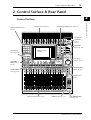 15
15
-
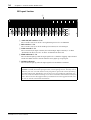 16
16
-
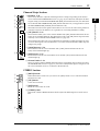 17
17
-
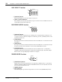 18
18
-
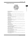 19
19
-
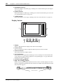 20
20
-
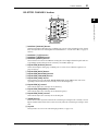 21
21
-
 22
22
-
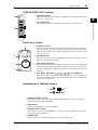 23
23
-
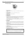 24
24
-
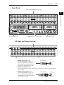 25
25
-
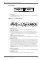 26
26
-
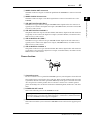 27
27
-
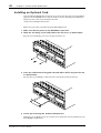 28
28
-
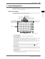 29
29
-
 30
30
-
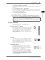 31
31
-
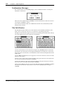 32
32
-
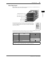 33
33
-
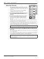 34
34
-
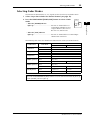 35
35
-
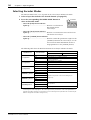 36
36
-
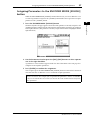 37
37
-
 38
38
-
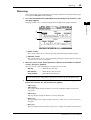 39
39
-
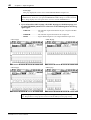 40
40
-
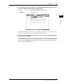 41
41
-
 42
42
-
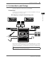 43
43
-
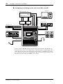 44
44
-
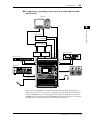 45
45
-
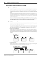 46
46
-
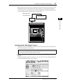 47
47
-
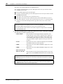 48
48
-
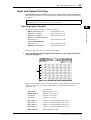 49
49
-
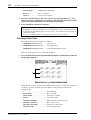 50
50
-
 51
51
-
 52
52
-
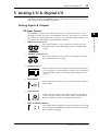 53
53
-
 54
54
-
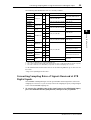 55
55
-
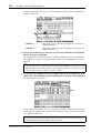 56
56
-
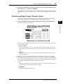 57
57
-
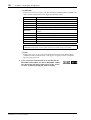 58
58
-
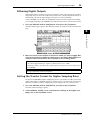 59
59
-
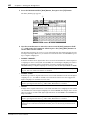 60
60
-
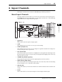 61
61
-
 62
62
-
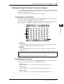 63
63
-
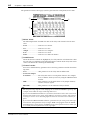 64
64
-
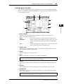 65
65
-
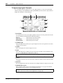 66
66
-
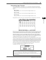 67
67
-
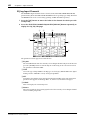 68
68
-
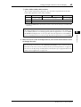 69
69
-
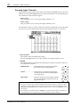 70
70
-
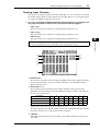 71
71
-
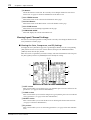 72
72
-
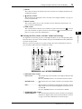 73
73
-
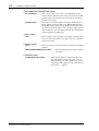 74
74
-
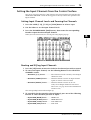 75
75
-
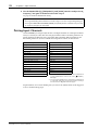 76
76
-
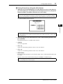 77
77
-
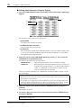 78
78
-
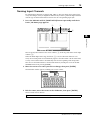 79
79
-
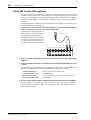 80
80
-
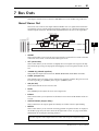 81
81
-
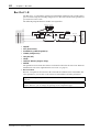 82
82
-
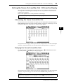 83
83
-
 84
84
-
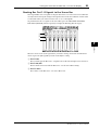 85
85
-
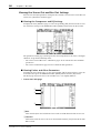 86
86
-
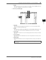 87
87
-
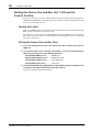 88
88
-
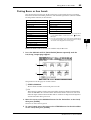 89
89
-
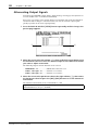 90
90
-
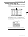 91
91
-
 92
92
-
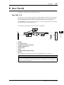 93
93
-
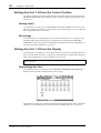 94
94
-
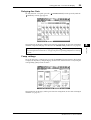 95
95
-
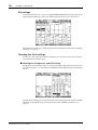 96
96
-
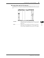 97
97
-
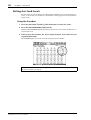 98
98
-
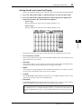 99
99
-
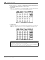 100
100
-
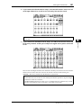 101
101
-
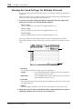 102
102
-
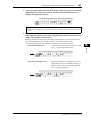 103
103
-
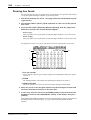 104
104
-
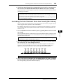 105
105
-
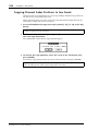 106
106
-
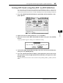 107
107
-
 108
108
-
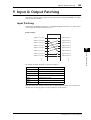 109
109
-
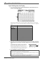 110
110
-
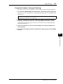 111
111
-
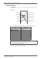 112
112
-
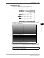 113
113
-
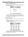 114
114
-
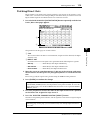 115
115
-
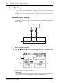 116
116
-
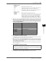 117
117
-
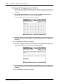 118
118
-
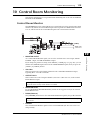 119
119
-
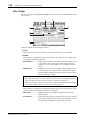 120
120
-
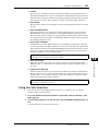 121
121
-
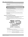 122
122
-
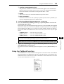 123
123
-
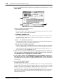 124
124
-
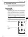 125
125
-
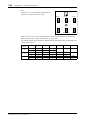 126
126
-
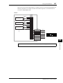 127
127
-
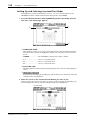 128
128
-
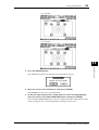 129
129
-
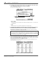 130
130
-
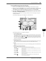 131
131
-
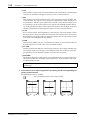 132
132
-
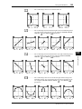 133
133
-
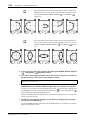 134
134
-
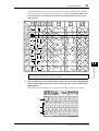 135
135
-
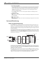 136
136
-
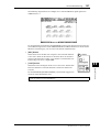 137
137
-
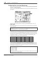 138
138
-
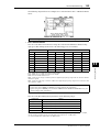 139
139
-
 140
140
-
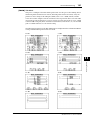 141
141
-
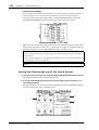 142
142
-
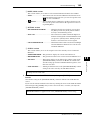 143
143
-
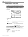 144
144
-
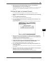 145
145
-
 146
146
-
 147
147
-
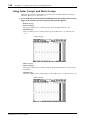 148
148
-
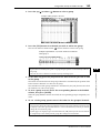 149
149
-
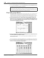 150
150
-
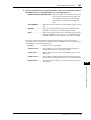 151
151
-
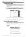 152
152
-
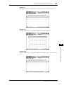 153
153
-
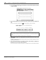 154
154
-
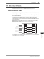 155
155
-
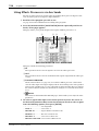 156
156
-
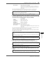 157
157
-
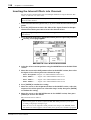 158
158
-
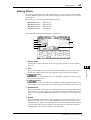 159
159
-
 160
160
-
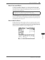 161
161
-
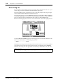 162
162
-
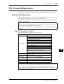 163
163
-
 164
164
-
 165
165
-
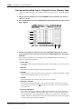 166
166
-
 167
167
-
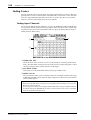 168
168
-
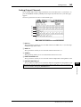 169
169
-
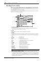 170
170
-
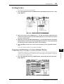 171
171
-
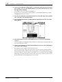 172
172
-
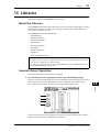 173
173
-
 174
174
-
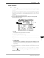 175
175
-
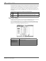 176
176
-
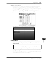 177
177
-
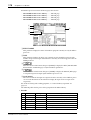 178
178
-
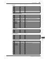 179
179
-
 180
180
-
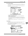 181
181
-
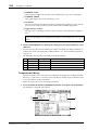 182
182
-
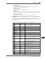 183
183
-
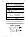 184
184
-
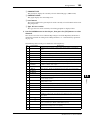 185
185
-
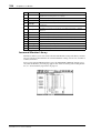 186
186
-
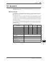 187
187
-
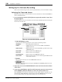 188
188
-
 189
189
-
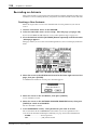 190
190
-
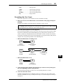 191
191
-
 192
192
-
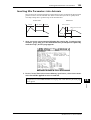 193
193
-
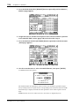 194
194
-
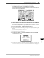 195
195
-
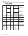 196
196
-
 197
197
-
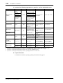 198
198
-
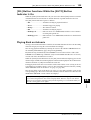 199
199
-
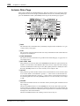 200
200
-
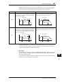 201
201
-
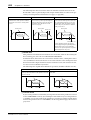 202
202
-
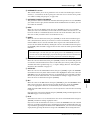 203
203
-
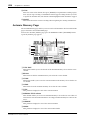 204
204
-
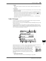 205
205
-
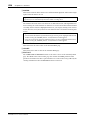 206
206
-
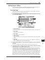 207
207
-
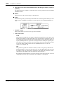 208
208
-
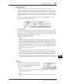 209
209
-
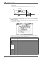 210
210
-
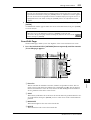 211
211
-
 212
212
-
 213
213
-
 214
214
-
 215
215
-
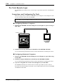 216
216
-
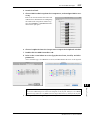 217
217
-
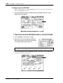 218
218
-
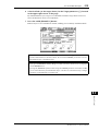 219
219
-
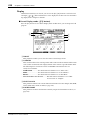 220
220
-
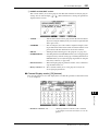 221
221
-
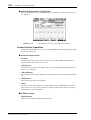 222
222
-
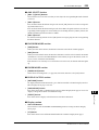 223
223
-
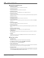 224
224
-
 225
225
-
 226
226
-
 227
227
-
 228
228
-
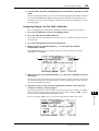 229
229
-
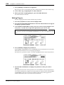 230
230
-
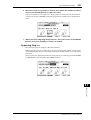 231
231
-
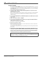 232
232
-
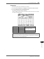 233
233
-
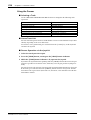 234
234
-
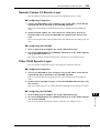 235
235
-
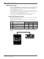 236
236
-
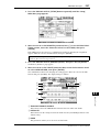 237
237
-
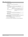 238
238
-
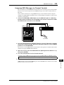 239
239
-
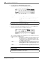 240
240
-
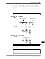 241
241
-
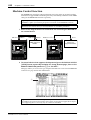 242
242
-
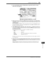 243
243
-
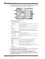 244
244
-
 245
245
-
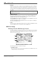 246
246
-
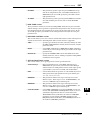 247
247
-
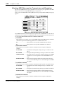 248
248
-
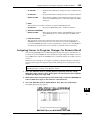 249
249
-
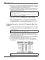 250
250
-
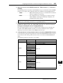 251
251
-
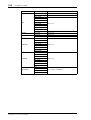 252
252
-
 253
253
-
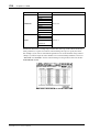 254
254
-
 255
255
-
 256
256
-
 257
257
-
 258
258
-
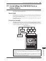 259
259
-
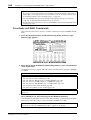 260
260
-
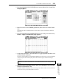 261
261
-
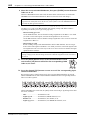 262
262
-
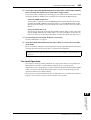 263
263
-
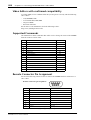 264
264
-
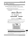 265
265
-
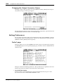 266
266
-
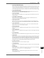 267
267
-
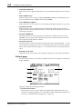 268
268
-
 269
269
-
 270
270
-
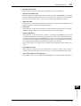 271
271
-
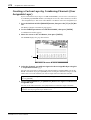 272
272
-
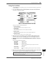 273
273
-
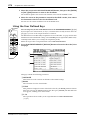 274
274
-
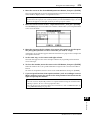 275
275
-
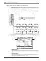 276
276
-
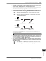 277
277
-
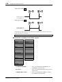 278
278
-
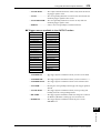 279
279
-
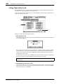 280
280
-
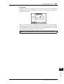 281
281
-
 282
282
-
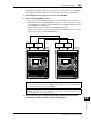 283
283
-
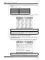 284
284
-
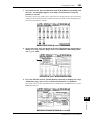 285
285
-
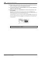 286
286
-
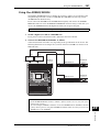 287
287
-
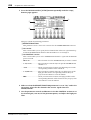 288
288
-
 289
289
-
 290
290
-
 291
291
-
 292
292
-
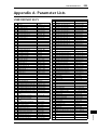 293
293
-
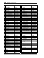 294
294
-
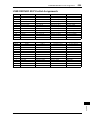 295
295
-
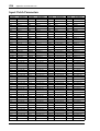 296
296
-
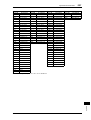 297
297
-
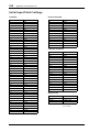 298
298
-
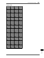 299
299
-
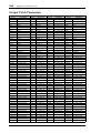 300
300
-
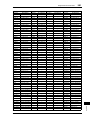 301
301
-
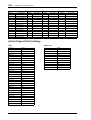 302
302
-
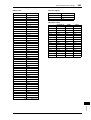 303
303
-
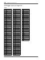 304
304
-
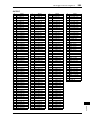 305
305
-
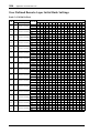 306
306
-
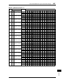 307
307
-
 308
308
-
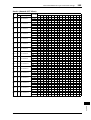 309
309
-
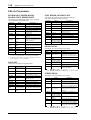 310
310
-
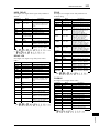 311
311
-
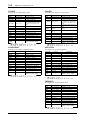 312
312
-
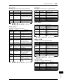 313
313
-
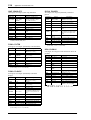 314
314
-
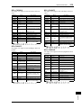 315
315
-
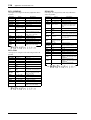 316
316
-
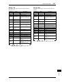 317
317
-
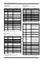 318
318
-
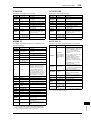 319
319
-
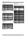 320
320
-
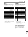 321
321
-
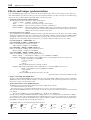 322
322
-
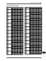 323
323
-
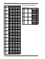 324
324
-
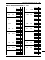 325
325
-
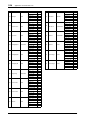 326
326
-
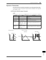 327
327
-
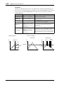 328
328
-
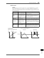 329
329
-
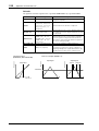 330
330
-
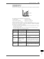 331
331
-
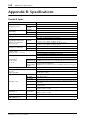 332
332
-
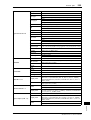 333
333
-
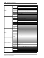 334
334
-
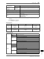 335
335
-
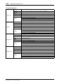 336
336
-
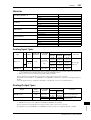 337
337
-
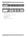 338
338
-
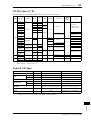 339
339
-
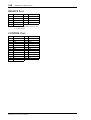 340
340
-
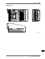 341
341
-
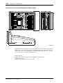 342
342
-
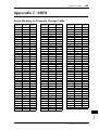 343
343
-
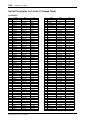 344
344
-
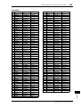 345
345
-
 346
346
-
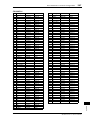 347
347
-
 348
348
-
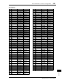 349
349
-
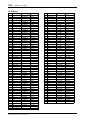 350
350
-
 351
351
-
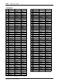 352
352
-
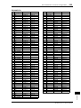 353
353
-
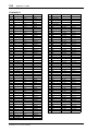 354
354
-
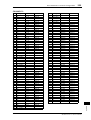 355
355
-
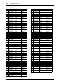 356
356
-
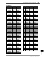 357
357
-
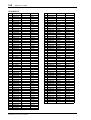 358
358
-
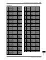 359
359
-
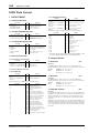 360
360
-
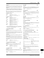 361
361
-
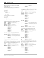 362
362
-
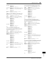 363
363
-
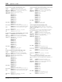 364
364
-
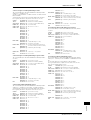 365
365
-
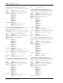 366
366
-
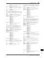 367
367
-
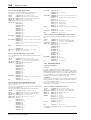 368
368
-
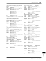 369
369
-
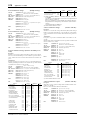 370
370
-
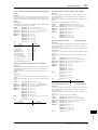 371
371
-
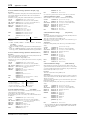 372
372
-
 373
373
-
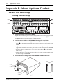 374
374
-
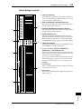 375
375
-
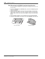 376
376
-
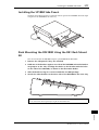 377
377
-
 378
378
-
 379
379
-
 380
380
-
 381
381
-
 382
382
-
 383
383
-
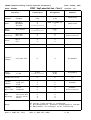 384
384
-
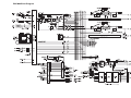 385
385
-
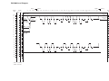 386
386
-
 387
387
-
 388
388


Yamaha DM1000 Manual de usuario
- Categoría
- Equipo de música suplementario
- Tipo
- Manual de usuario
- Este manual también es adecuado para
en otros idiomas
- français: Yamaha DM1000 Manuel utilisateur
- italiano: Yamaha DM1000 Manuale utente
- English: Yamaha DM1000 User manual
- Deutsch: Yamaha DM1000 Benutzerhandbuch
- русский: Yamaha DM1000 Руководство пользователя
- Nederlands: Yamaha DM1000 Handleiding
- português: Yamaha DM1000 Manual do usuário
- dansk: Yamaha DM1000 Brugermanual
- polski: Yamaha DM1000 Instrukcja obsługi
- čeština: Yamaha DM1000 Uživatelský manuál
- svenska: Yamaha DM1000 Användarmanual
- Türkçe: Yamaha DM1000 Kullanım kılavuzu
- suomi: Yamaha DM1000 Ohjekirja
- română: Yamaha DM1000 Manual de utilizare
Artículos relacionados
-
Yamaha DM1000 El manual del propietario
-
-
-
-
Yamaha V96i Manual de usuario
-
-
Yamaha MSR100 Manual de usuario
-
-
-
Otros documentos
-
LD Systems AM8 Manual de usuario
-
Sharp 8M-B120C guía de instalación rápida
-
-
-
Peavey PC 1600x Cover El manual del propietario
-
-
Work-pro MD 82 AX Manual de usuario
-
Ecler DP300 Manual de usuario
-
Sharp CP-LS100 High Performance Portable Speaker Manual de usuario
-
Universal Remote Control TOTAL CONTROL FX-1 El manual del propietario