Yamaha RX-V3800 El manual del propietario
- Categoría
- Receptores AV
- Tipo
- El manual del propietario

YAMAHA ELECTRONICS CORPORATION, USA
6660 ORANGETHORPE AVE., BUENA PARK, CALIF. 90620, U.S.A.
YAMAHA CANADA MUSIC LTD.
135 MILNER AVE., SCARBOROUGH, ONTARIO M1S 3R1, CANADA
YAMAHA ELECTRONIK EUROPA G.m.b.H.
SIEMENSSTR. 22-34, 25462 RELLINGEN BEI HAMBURG, GERMANY
YAMAHA ELECTRONIQUE FRANCE S.A.
RUE AMBROISE CROIZAT BP70 CROISSY-BEAUBOURG 77312 MARNE-LA-VALLEE CEDEX02, FRANCE
YAMAHA ELECTRONICS (UK) LTD.
YAMAHA HOUSE, 200 RICKMANSWORTH ROAD WATFORD, HERTS WD18 7GQ, ENGLAND
YAMAHA SCANDINAVIA A.B.
J A WETTERGRENS GATA 1, BOX 30053, 400 43 VÄSTRA FRÖLUNDA, SWEDEN
YAMAHA MUSIC AUSTRALIA PTY, LTD.
17-33 MARKET ST., SOUTH MELBOURNE, 3205 VIC., AUSTRALIA
©
2007 All rights reserved.
RX-V3800
Printed in Malaysia WK69470
RX-V3800
AV R e c e i ve r
OWNER’S MANUAL
U
RX-V3800_U-cv.fm Page 1 Wednesday, June 6, 2007 11:13 PM

IMPORTANT SAFETY INSTRUCTIONS
Caution-i En
• Explanation of Graphical Symbols
The lightning flash with arrowhead symbol, within an
equilateral triangle, is intended to alert you to the
presence of uninsulated “dangerous voltage” within
the product’s enclosure that may be of sufficient
magnitude to constitute a risk of electric shock to
persons.
The exclamation point within an equilateral triangle
is intended to alert you to the presence of important
operating and maintenance (servicing) instructions in
the literature accompanying the appliance.
1 Read Instructions – All the safety and operating instructions
should be read before the product is operated.
2 Retain Instructions – The safety and operating instructions
should be retained for future reference.
3 Heed Warnings – All warnings on the product and in the
operating instructions should be adhered to.
4 Follow Instructions – All operating and use instructions
should be followed.
5 Cleaning – Unplug this product from the wall outlet before
cleaning. Do not use liquid cleaners or aerosol cleaners.
6 Attachments – Do not use attachments not recommended by
the product manufacturer as they may cause hazards.
7 Water and Moisture – Do not use this product near water –
for example, near a bath tub, wash bowl, kitchen sink, or
laundry tub; in a wet basement; or near a swimming pool;
and the like.
8 Accessories – Do not place this product on an unstable cart,
stand, tripod, bracket, or table. The product may fall,
causing serious injury to a child or adult, and serious
damage to the product. Use only with a cart, stand, tripod,
bracket, or table recommended by the manufacturer, or sold
with the product. Any mounting of the product should
follow the manufacturer’s instructions, and should use a
mounting accessory recommended by the manufacturer.
9 A product and cart combination should be moved with care.
Quick stops, excessive force, and uneven surfaces may
cause the product and cart combination to
overturn.
10 Ventilation – Slots and openings in the cabinet are provided
for ventilation and to ensure reliable operation of the
product and to protect it from overheating, and these
openings must not be blocked or covered. The openings
should never be blocked by placing the product on a bed,
sofa, rug, or other similar surface. This product should not
be placed in a built-in installation such as a bookcase or rack
unless proper ventilation is provided or the manufacturer’s
instructions have been adhered to.
11 Power Sources – This product should be operated only from
the type of power source indicated on the marking label. If
you are not sure of the type of power supply to your home,
consult your product dealer or local power company. For
products intended to operate from battery power, or other
sources, refer to the operating instructions.
12 Grounding or Polarization – This product may be equipped
with a polarized alternating current line plug (a plug having
one blade wider than the other). This plug will fit into the
power outlet only one way. This is a safety feature. If you
are unable to insert the plug fully into the outlet, try
reversing the plug. If the plug should still fail to fit, contact
your electrician to replace your obsolete outlet. Do not
defeat the safety purpose of the polarized plug.
13 Power-Cord Protection – Power-supply cords should be
routed so that they are not likely to be walked on or pinched
by items placed upon or against them, paying particular
attention to cords at plugs, convenience receptacles, and the
point where they exit from the product.
14 Lightning – For added protection for this product during a
lightning storm, or when it is left unattended and unused for
long periods of time, unplug it from the wall outlet and
disconnect the antenna or cable system. This will prevent
damage to the product due to lightning and power-line
surges.
15 Power Lines – An outside antenna system should not be
located in the vicinity of overhead power lines or other
electric light or power circuits, or where it can fall into such
power lines or circuits. When installing an outside antenna
system, extreme care should be taken to keep from touching
such power lines or circuits as contact with them might be
fatal.
16 Overloading – Do not overload wall outlets, extension
cords, or integral convenience receptacles as this can result
in a risk of fire or electric shock.
17 Object and Liquid Entry – Never push objects of any kind
into this product through openings as they may touch
dangerous voltage points or short-out parts that could result
in a fire or electric shock. Never spill liquid of any kind on
the product.
18 Servicing – Do not attempt to service this product yourself
as opening or removing covers may expose you to
dangerous voltage or other hazards. Refer all servicing to
qualified service personnel.
19 Damage Requiring Service – Unplug this product from the
wall outlet and refer servicing to qualified service personnel
under the following conditions:
a) When the power-supply cord or plug is damaged,
b) If liquid has been spilled, or objects have fallen into the
product,
c) If the product has been exposed to rain or water,
Important safety instructions
CAUTION
CAUTION: TO REDUCE THE RISK OF
ELECTRIC SHOCK, DO NOT REMOVE
COVER (OR BACK). NO USER-SERVICEABLE
PARTS INSIDE. REFER SERVICING TO
QUALIFIED SERVICE PERSONNEL.
RISK OF ELECTRIC SHOCK
DO NOT OPEN

Important safety instructions
Caution-ii En
EXAMPLE OF ANTENNA GROUNDING
MAST
GROUND
CLAMP
ANTENNA
LEAD IN
WIRE
ANTENNA
DISCHARGE UNIT
(NEC SECTION 810–20)
GROUNDING CONDUCTORS
(NEC SECTION 810–21)
GROUND CLAMPS
POWER SERVICE GROUNDING
ELECTRODE SYSTEM
(NEC ART 250. PART H)
ELECTRIC
SERVICE
EQUIPMENT
NEC – NATIONAL ELECTRICAL CODE
d) If the product does not operate normally by following
the operating instructions. Adjust only those controls
that are covered by the operating instructions as an
improper adjustment of other controls may result in
damage and will often require extensive work by a
qualified technician to restore the product to its normal
operation,
e) If the product has been dropped or damaged in any
way, and
f) When the product exhibits a distinct change in
performance - this indicates a need for service.
20 Replacement Parts – When replacement parts are required,
be sure the service technician has used replacement parts
specified by the manufacturer or have the same
characteristics as the original part. Unauthorized
substitutions may result in fire, electric shock, or other
hazards.
21 Safety Check – Upon completion of any service or repairs to
this product, ask the service technician to perform safety
checks to determine that the product is in proper operating
condition.
22 Wall or Ceiling Mounting – The unit should be mounted
to a wall or ceiling only as recommended by the
manufacturer.
23 Heat – The product should be situated away from heat
sources such as radiators, heat registers, stoves, or other
products (including amplifiers) that produce heat.
24 Outdoor Antenna Grounding – If an outside antenna or
cable system is connected to the product, be sure the antenna
or cable system is grounded so as to provide some
protection against voltage surges and built-up static charges.
Article 810 of the National Electrical Code, ANSI/NFPA 70,
provides information with regard to proper grounding of the
mast and supporting structure, grounding of the lead-in wire
to an antenna discharge unit, size of grounding conductors,
location of antenna discharge unit, connection to grounding
electrodes, and requirements for the grounding electrode.
Note to CATV system installer:
This reminder is provided to call the CATV system
installer’s attention to Article 820-40 of the NEC that
provides guidelines for proper grounding and, in
particular, specifies that the cable ground shall be
connected to the grounding system of the building, as
close to the point of cable entry as practical.
FCC INFORMATION (for US customers)
1 IMPORTANT NOTICE: DO NOT MODIFY THIS
UNIT!
This product, when installed as indicated in the
instructions contained in this manual, meets FCC
requirements. Modifications not expressly approved by
Yamaha may void your authority, granted by the FCC, to
use the product.
2 IMPORTANT: When connecting this product to
accessories and/or another product use only high quality
shielded cables. Cable/s supplied with this product MUST
be used. Follow all installation instructions. Failure to
follow instructions could void your FCC authorization to
use this product in the USA.
3 NOTE: This product has been tested and found to comply
with the requirements listed in FCC Regulations, Part 15
for Class “B” digital devices. Compliance with these
requirements provides a reasonable level of assurance that
your use of this product in a residential environment will
not result in harmful interference with other electronic
devices.
This equipment generates/uses radio frequencies and, if
not installed and used according to the instructions found
in the users manual, may cause interference harmful to the
operation of other electronic devices.
Compliance with FCC regulations does not guarantee that
interference will not occur in all installations. If this
product is found to be the source of interference, which
can be determined by turning the unit “OFF” and “ON”,
please try to eliminate the problem by using one of the
following measures:
Relocate either this product or the device that is being
affected by the interference.
Utilize power outlets that are on different branch (circuit
breaker or fuse) circuits or install AC line filter/s.
In the case of radio or TV interference, relocate/reorient
the antenna. If the antenna lead-in is 300 ohm ribbon lead,
change the lead-in to coaxial type cable.
If these corrective measures do not produce satisfactory
results, please contact the local retailer authorized to
distribute this type of product. If you can not locate the
appropriate retailer, please contact Yamaha Electronics
Corp., U.S.A. 6660 Orangethorpe Ave, Buena Park, CA
90620.
The above statements apply ONLY to those products
distributed by Yamaha Corporation of America or its
subsidiaries.

CAUTION: READ THIS BEFORE OPERATING YOUR UNIT.
Caution-iii En
1 To assure the finest performance, please read this manual
carefully. Keep it in a safe place for future reference.
2 Install this sound system in a well ventilated, cool, dry, clean
place – away from direct sunlight, heat sources, vibration,
dust, moisture, and/or cold. Allow ventilation space of at least
30 cm on the top, 20 cm on the left and right, and 20 cm on
the back of this unit.
3 Locate this unit away from other electrical appliances, motors,
or transformers to avoid humming sounds.
4 Do not expose this unit to sudden temperature changes from
cold to hot, and do not locate this unit in an environment with
high humidity (i.e. a room with a humidifier) to prevent
condensation inside this unit, which may cause an electrical
shock, fire, damage to this unit, and/or personal injury.
5 Avoid installing this unit where foreign objects may fall onto
this unit and/or this unit may be exposed to liquid dripping or
splashing. On the top of this unit, do not place:
– Other components, as they may cause damage and/or
discoloration on the surface of this unit.
– Burning objects (i.e. candles), as they may cause fire,
damage to this unit, and/or personal injury.
– Containers with liquid in them, as they may fall and liquid
may cause electrical shock to the user and/or damage to
this unit.
6 Do not cover this unit with a newspaper, tablecloth, curtain,
etc. in order not to obstruct heat radiation. If the temperature
inside this unit rises, it may cause fire, damage to this unit,
and/or personal injury.
7 Do not plug in this unit to a wall outlet until all connections
are complete.
8 Do not operate this unit upside-down. It may overheat,
possibly causing damage.
9 Do not use force on switches, knobs and/or cords.
10 When disconnecting the power cable from the wall outlet,
grasp the plug; do not pull the cable.
11 Do not clean this unit with chemical solvents; this might
damage the finish. Use a clean, dry cloth.
12
Only voltage specified on this unit must be used. Using this unit
with a higher voltage than specified is dangerous and may cause
fire, damage to this unit, and/or personal injury. Yamaha will not
be held responsible for any damage resulting from use of this
unit with a voltage other than specified.
13 To prevent damage by lightning, keep the power cord and
outdoor antennas disconnected from a wall outlet or the unit
during a lightning storm.
14 Do not attempt to modify or fix this unit. Contact qualified
Yamaha service personnel when any service is needed. The
cabinet should never be opened for any reasons.
15
When not planning to use this unit for long periods of time (i.e.
vacation), disconnect the AC power plug from the wall outlet.
16 Install this unit near the AC outlet and where the AC power
plug can be reached easily.
17 Be sure to read the “Troubleshooting” section on common
operating errors before concluding that this unit is faulty.
18 Before moving this unit, press
A
MASTER ON/OFF to
release it outward to the OFF position to turn off this unit, the
main room, Zone 2 and Zone 3 and then disconnect the AC
power plug from the AC wall outlet.
19 VOLTAGE SELECTOR (Asia and General models only)
The VOLTAGE SELECTOR on the rear panel of this unit
must be set for your local main voltage BEFORE plugging
into the AC wall outlet. Voltages are as follows:
................................. 110/120/220/230–240 V AC, 50/60 Hz
20 The batteries shall not be exposed to excessive heat such as
sunshine, fire or like.
21 Excessive sound pressure from earphones and headphones can
cause hearing loss.
Responsible Party: Yamaha Electronics Corporation, U.S.A.
Address: 6660 Orangethorpe Avenue
Buena Park, CA 90620
Telephone: 714-522-9105
Fax: 714-670-0108
Type of Equipment: AV Receiver
Model Name: RX-V3800
• This device complies with Part 15 of the FCC Rules.
• Operation is subject to the following conditions:
– This device may not cause harmful interference.
– This device must accept any interference received including
interference that may cause undesired operation.
See the “Troubleshooting” section at the end of this manual if
interference to radio reception is suspected.
Caution: read this before operating your unit.
WARNING
TO REDUCE THE RISK OF FIRE OR ELECTRIC
SHOCK, DO NOT EXPOSE THIS UNIT TO RAIN
OR MOISTURE.
As long as this unit is connected to the AC wall outlet,
it is not disconnected from the AC power source even
if you turn off this unit by
A
MASTER ON/OFF. In
this state, this unit is designed to consume a very small
quantity of power.
FOR CANADIAN CUSTOMERS
To prevent electric shock, match wide blade of plug to
wide slot and fully insert.
This Class B digital apparatus complies with Canadian
ICES-003.
POUR LES CONSOMMATEURS CANADIENS
Pour éviter les chocs électriques, introduire la lame la
plus large de la fiche dans la borne correspondante de
la prise et pousser jusqu’au fond.
Cet appareil numérique de la classe B est conforme à
la norme NMB-003 du Canada.
IMPORTANT
Please record the serial number of this unit in the space
below.
MODEL:
Serial No.:
The serial number is located on the rear of the unit.
Retain this Owner’s Manual in a safe place for future
reference.
COMPLIANCE INFORMATION STATEMENT (DECLARATION OF CONFORMITY PROCEDURE)

1 En
PREPARATIONINTRODUCTION
BASIC
OPERATION
ADVANCED
OPERATION
ADDITIONAL
INFORMATION
APPENDIX
English
Notices...................................................................... 2
Features ................................................................... 3
Supplied accessories .................................................. 4
Getting started ........................................................ 5
Quick start guide .................................................... 6
Connections........................................................... 12
Optimizing the speaker setting
for your listening room (YPAO) ..................... 37
Using the automatic setup (Auto Setup).................. 37
Playback ................................................................ 41
Basic procedure ....................................................... 41
Selecting audio input jacks (AUDIO SELECT)...... 42
Selecting the MULTI CH INPUT component......... 42
Using your headphones............................................ 42
Muting the audio output........................................... 43
Playing video sources in the background
of an audio source................................................ 43
Using the sleep timer ............................................... 43
Operating the amplifier functions of this unit by using
the graphical user interface (GUI) screen............ 44
Sound field programs ........................................... 45
Selecting sound field programs ............................... 45
Sound field program descriptions............................ 45
Using CINEMA DSP 3D mode............................... 50
Enjoying unprocessed input sources........................ 50
Using audio features ............................................. 51
Enjoying pure hi-fi sound ........................................ 51
Adjusting the tonal quality....................................... 51
Adjusting the speaker level...................................... 52
Enjoying multi-channel sources in 2-channel stereo
....... 52
FM/AM tuning ...................................................... 53
Automatic tuning ..................................................... 53
Manual tuning.......................................................... 53
Automatic preset tuning........................................... 54
Manual preset tuning ............................................... 54
Selecting preset stations........................................... 55
Exchanging preset stations ...................................... 55
XM™ Satellite Radio tuning ............................... 56
Connecting the XM™ Mini-Tuner Home Dock...... 56
Activating XM™ Satellite Radio ............................ 57
Basic XM™ Satellite Radio operations................... 57
Setting the XM™ Satellite Radio preset channels
....... 59
Displaying the XM™ Satellite Radio information
...... 60
Using iPod™.......................................................... 62
Controlling iPod™................................................... 62
Using Network/USB features............................... 64
Navigating the network and USB menus................. 64
Using a PC server or Yamaha MCX-2000 .............. 66
Using the Internet Radio.......................................... 67
Using a USB memory device or a USB
portable audio player ........................................... 68
Using shortcut buttons ............................................. 68
Recording .............................................................. 70
Advanced sound configurations...........................71
Selecting decoders ................................................... 71
Graphical user interface (GUI) screen................73
Stereo/Surround (Stereo/Surround menu) ............... 74
Input Select .............................................................. 81
Manual Setup (Volume) .......................................... 84
Manual Setup (Sound) ............................................. 85
Manual Setup (Video) ............................................. 89
Manual Setup (Basic) .............................................. 91
Manual Setup (NET/USB)....................................... 94
Manual Setup (Option) ............................................ 96
Signal Info. (Input signal information).................... 98
Language ................................................................. 99
Saving and recalling the system settings
(System Memory) ............................................100
Saving the current system settings......................... 100
Loading the stored system settings........................ 101
Using examples...................................................... 102
Remote control features......................................105
Controlling this unit, a TV, or other components
...... 105
Setting remote control codes ................................. 107
Programming codes from other remote controls
....... 109
Changing source names in the display window
........ 110
Macro programming features ................................ 111
Clearing configurations ......................................... 114
Using multi-zone configuration..........................117
Connecting the Zone 2 and Zone 3 components
....... 117
Controlling Zone 2 or Zone 3 ................................ 118
Advanced setup....................................................122
Using the advanced setup menu ............................ 122
Troubleshooting...................................................127
Resetting the system............................................137
Glossary................................................................138
Sound field program information......................142
Parametric equalizer information .....................143
Specifications .......................................................144
Index.....................................................................146
z
(at the end of this manual)
Front Panel................................................................i
Remote Control ...................................................... ii
Sound output in each sound field program......... iii
GPL/LGPL...............................................................v
List of remote control codes ..................................ix
Contents
INTRODUCTION
PREPARATION
BASIC OPERATION
ADVANCED OPERATION
ADDITIONAL INFORMATION
APPENDIX
“
A
MASTER ON/OFF” or “
1
DVD” (example) indicates
the name of the parts on the front panel or the remote control.
Refer to the attached sheet or the pages at the end of this
manual for the information about each position of the parts.

Notices
2 En
Note on source code distribution
This product includes software code subject to the GNU General
Public License (GPL) or the GNU Lesser General Public License
(LGPL). The copy, distribution, or change of this software code is
licensed under the terms of the GPL or the LGPL. The source
code is available at the following website:
http://www.global.yamaha.com/download/
The source code is also available on a physical media (such as a
CD-ROM) at actual cost.
Contact: AV products division, YAMAHA CORPORATION,
10-1 Nakazawa-cho, Naka-ku, Hamamatsu 430-8650,
Japan
In principle, the source code is offered for 3 years from the day of
purchase.
We Want You Listening For A Lifetime
Yamaha and the Electronic Industries Association’s
Consumer Electronics Group want you to get the
most out of your equipment by playing it at a safe
level. One that lets the sound come through loud and
clear without annoying blaring or distortion – and,
most importantly, without affecting your sensitive
hearing. Since hearing damage from loud sounds is often
undetectable until it is too late, Yamaha and the Electronic
Industries Association’s Consumer Electronics Group
recommend you to avoid prolonged exposure from excessive
volume levels.
Manufactured under license from Dolby Laboratories.
“Dolby”, “Pro Logic”, and the double-D symbol are trademarks
of Dolby Laboratories.
Manufactured under license under U.S. Patent No’s:
5,451,942;5,956,674;5,974,380;5,978,762;6,226,616;6,487,535
& other U.S. and worldwide patents issued & pending. DTS is a
registered trademark and the DTS logos, Symbol, DTS-HD and
DTS-HD Master Audio are trademark of DTS, Inc. © 1996-2007
DTS, Inc. All Rights Reserved.
“iPod” is a trademark of Apple Inc., registered in the U.S. and
other countries.
MPEG Layer-3 audio coding technology licensed from
Fraunhofer IIS and Thomson.
This receiver supports network connections.
“HDMI”, the “HDMI” logo, and “High-Definition Multimedia
Interface” are trademarks or registered trademarks of HDMI
Licensing LLC.
“SILENT CINEMA” is a trademark of YAMAHA
CORPORATION.
The XM name and related logos are registered trademarks of XM
Satellite Radio Inc.
This product is manufactured under license from Neural Audio
Corporation and THX Ltd. YAMAHA CORPORATION hereby
grants the user a non-exclusive, non-transferable, limited right of
use to this product under U.S.A. and foreign patent, patent
pending and other technology or trademarks owned by Neural
Audio Corporation and THX Ltd. “Neural Surround”, “Neural
Audio”, “Neural” and “NRL” are trademarks and logos owned by
Neural Audio Corporation. THX is a trademark of THX Ltd.,
which may be registered in some jurisdictions. All rights
reserved.
Windows XP, Windows Vista, Windows Media Audio, Windows
Media Connect and Windows Media Player are either registered
trademarks or trademarks of Microsoft corporation in the United
States and/or other countries.
Notices
About this manual
• y indicates a tip for your operation.
• Some operations can be performed by using either the
buttons on the front panel or the ones on the remote
control. In case the button names differ between the front
panel and the remote control, the button name on the
remote control is given in parentheses.
• This manual is printed prior to production. Design and
specifications are subject to change in part as a result of
improvements, etc. In case of differences between the
manual and product, the product has priority.
• This unit is equipped with GUI display menu language
switching capability. In this manual, the illustrations of the
GUI are examples when you set the GUI language to
English.
•
“A
MASTER ON/OFF” or “
1
DVD” (example)
indicates the name of the parts on the front panel or the
remote control. Refer to the attached sheet or the pages at
the end of this manual for the information about each
position of the parts.
• The symbol “☞ ” with page number(s) indicates the
corresponding reference page(s).
iPod
TM

Features
3 En
INTRODUCTION
English
Built-in 7-channel power amplifier
◆ Minimum RMS output power
(20 Hz to 20 kHz, 0.04% THD, 8 Ω)
Front: 140 W + 140 W
Center: 140 W
Surround: 140 W + 140 W
Surround back: 140 W + 140 W
Sound field programs
◆ Proprietary Yamaha technology for the creation of sound
fields
◆ CINEMA DSP 3D mode for creating intensive and accurate
stereoscopic sound field
◆ Compressed Music Enhancer mode to improve the sound
quality of compression artifacts (such as the MP3 format) to
that of a high-quality multi-channel source playback
◆ Virtual CINEMA DSP
◆ SILENT CINEMA
Digital audio decoders
◆ Dolby TrueHD, Dolby Digital Plus decoder
◆ DTS-HD Master Audio, DTS-HD High Resolution Audio
decoder
◆ Dolby Digital/Dolby Digital EX decoder
◆ DTS/DTS-ES Matrix 6.1, Discrete 6.1, DTS 96/24 decoder
◆ Dolby Pro Logic/Dolby Pro Logic II/Dolby Pro Logic IIx
decoder
◆ DTS NEO:6 decoder
◆ Neural-THX Surround decoder
(U.S.A. and Canada models only)
Sophisticated FM/AM tuner
◆ 40-station random and direct preset tuning
◆ Automatic preset tuning
◆ Preset station shifting capability (preset editing)
XM™ Satellite Radio
◆ XM Satellite Radio tuning capability (using XM Mini-Tuner
and Home Dock, sold separately)
◆ Neural-THX Surround decoder to play back the XM HD
content of XM Satellite Radio broadcasts in multi-channels,
resulting in a full surround sound experience
◆ XM Satellite Radio information displaying capability
HDMI™ (High-Definition Multimedia Interface)
◆ HDMI interface for standard, enhanced or
high-definition video as well as multi-channel digital audio
based on HDMI version 1.3a
◆ Automatic audio and video synchronization (lip sync)
information capability
◆ Deep Color video signal (30/36 bits) transmission capability
◆ High refresh rate and high resolution video signals capability
◆ High definition digital audio format signals capability
◆ Analog video to HDMI digital video up-conversion
(composite video ↔ S-video ↔ component video → HDMI
digital video) capability for monitor out
◆ Analog video up-scaling from 480i (NTSC)/576i (PAL) or
480p/576p to 720p, 1080i or 1080p
iPod controlling capability
◆ DOCK terminal to connect a Yamaha iPod universal dock
(such as the YDS-10, sold separately), which supports iPod
(Click and Wheel), iPod nano, and iPod mini
Network features
◆ NETWORK port to connect a PC and Yamaha MCX-2000 or
access the Internet Radio via LAN
◆ DHCP automatic or manual network configuration
USB features
◆ USB port to connect a USB memory device or a USB portable
audio player
Other features
◆ YPAO (Yamaha Parametric Room Acoustic Optimizer) for
automatic speaker setup
◆ 192-kHz/24-bit D/A converter
◆ GUI (graphical user interface) menus that allow you to
optimize this unit to suit your individual audio/video system
◆ GUI display menu language switching capability
(English, Japanese, French, German, Spanish and Russian)
◆ 6 or 8-channel additional input jacks for discrete multi-
channel input
◆ Analog video interlace/progressive conversion from 480i
(NTSC)/576i (PAL) to 480p/576p
◆ S-video signal input/output capability
◆ Component video input/output capability includes
(3 COMPONENT VIDEO INs and 1 MONITOR OUT)
◆ Optical and coaxial digital audio signal jacks
◆ Pure Direct mode for pure hi-fi sound for all sources
◆ Adaptive dynamic range controlling capability
◆ Adaptive DSP effect level controlling capability
◆ Remote control with preset remote control codes, learning,
macro and buttons and display backlight capability
◆ ZONE 2/ZONE 3 custom installation facility
◆ Zone switching capability between the main zone and
ZONE 2/ZONE 3 using ZONE CONTROLS
◆ Zone 2 video output and displaying OSD (on-screen display)
capability
◆ System Memory capability for saving and recalling multiple
system parameter settings
◆ Sleep timer
Features

Features
4 En
Check that you received all of the following parts.
The form of the supplied accessories varies depending on the models.
Supplied accessories
Note
ON
OFF
CLEAR
LEARN
RENAME
MACRO
REC
NET RADIO
USB
PC/MCX
VOLUME
EFFECT
STRAIGHT
A-E/CAT.
SRCH MODE
PURE DIRECT
PRESET/CH
SET MENU
BAND
LEVEL
CLASSICAL LIVE/CLUB ENTERTAIN MOVIE
STEREO
ENHANCER
SUR. DECODE
3D DSP
TV
SOURCE
AMP
SELECT
TUNER
MD/TAPE DVD BD/HD DVD PHONO
DTV/CBL DVR VCR
CD CD-R
MULTI CH IN
V-AUX/DOCK
SLEEP
AUDIO SEL
POWER
STANDBY
XM
NET/USB
2
+
–
ENTER
MENU
TITLE
MUTE
4
3
ENT
+
10
09
5
1
7
6
8
SYSTEM MEMORY
CH
TV VOL
MEMORY
POWER
POWER
–
+
–
+
DISPLAY
AUDIO
TV MUTE
TV INPUT
AV
TV
RETURN
Remote control
Batteries (6)
(AAA, LR03)
AM loop antenna
Optimizer microphoneSpeaker terminal wrench Power cable
(Two for Asia model)
Indoor FM antenna
TUNER
CD
CD-R
MD/TAPE DVD BD/HD DVD
NET/USB
DTV/CBL
VCR
V-AUX/DOCK
DVR
POWER
XM
STANDBY
A-E/CAT.
PRESET/CH
A/B/C/D/E
PRESET
VOLUME
ZONE 3
ZONE 2
ID2
ID1
NUMBER
CAT.
ALL
PRESET
DISPLAY
MUTE
1
2
3
4
5
ENT
6
7
8
9
0
Zone 2/Zone 3
remote control

Getting started
5 En
INTRODUCTION
English
■ Installing batteries in the remote control
1 Press the part and slide the battery
compartment cover off.
2 Insert the four supplied batteries
(AAA, LR03) according to the polarity
markings (+ and –) on the inside of the
battery compartment.
3 Slide the cover back until it snaps into place.
■ Installing batteries in the Zone 2/Zone 3
remote control
1 Take off the battery compartment cover.
2 Insert the two supplied batteries (AAA, LR03)
according to the polarity markings
(+ and –) on the inside of the battery
compartment.
3 Snap the battery compartment cover back
into place.
• Change all of the batteries if you notice the following
conditions:
– the operation range of the remote control decreases.
– the transmit indicator (P) does not flash or its light becomes
dim.
• Do not use old batteries together with new ones.
• Do not use different types of batteries (such as alkaline and
manganese batteries) together. Read the packaging carefully as
these different types of batteries may have the same shape and
color.
• We strongly recommend that you use alkaline batteries.
• If the batteries have leaked, dispose of them immediately. Avoid
touching the leaked material or letting it come into contact with
clothing, etc. Clean the battery compartment thoroughly before
installing new batteries.
• Do not throw away batteries with general house waste; dispose
of them correctly in accordance with your local regulations.
• If the remote control is without batteries for more than 2
minutes, or if exhausted batteries remain in the remote control,
the contents of the memory may be cleared. When the memory
is cleared, insert new batteries, set up the remote control code
and program any acquired functions that may have been
cleared.
■ VOLTAGE SELECTOR
(Asia and General models only)
Rotate the VOLTAGE SELECTOR clockwise or
counterclockwise to the correct position using a straight
slot screwdriver.
Voltages are as follows:
.......................AC 110/120/220/230–240 V, 50/60 Hz
Getting started
1
3
2
1
3
2
Notes
Caution
The VOLTAGE SELECTOR on the rear panel of this
unit must be set for your local voltage BEFORE
plugging the power cable into the AC wall outlet.
Improper setting of the VOLTAGE SELECTOR may
cause damage to this unit and create a potential fire
hazard.
230-
240V
VOLTAGE
SELECTOR
Voltage indication

Quick start guide
6 En
The following steps describe the easiest way to enjoy DVD movie playback in your home theater.
In these steps, you need the following supplied
accessories.
❏ AM loop antenna
❏ Indoor FM antenna
❏ Power cable
The following items are not included in the package of this
unit.
❏ Speakers
❏ Front speaker ..................................... x 2
❏ Center speaker ................................... x 1
❏ Surround speaker .............................. x 4
Select magnetically shielded speakers. The
minimum required speakers are two front speakers.
The priority of the requirement of other speakers is
as follows:
1. Two surround speakers
2. One center speaker
3. One (or two) surround back speaker(s)
❏ Active subwoofer ................................... x 1
Select an active subwoofer equipped with an RCA
input jack.
❏ Speaker cable ......................................... x 7
❏ Subwoofer cable ..................................... x 1
Select a monaural RCA cable.
❏ DVD player .............................................. x 1
Select DVD player equipped with coaxial digital
audio output jack and composite video output
jack.
❏ Video monitor.......................................... x 1
Select a TV monitor, video monitor or projector
equipped with a composite video input jack.
❏ Video cable ............................................. x 2
Select an RCA composite video cables.
❏ Digital coaxial audio cable .................... x 1
Quick start guide
Front right
speaker
Subwoofer
Surround back
right speaker
Surround left
speaker
Front left
speaker
Surround back left
speaker
Surround right
speaker
Center
speaker
Video monitor
DVD player
Enjoy DVD playback!
Step 1: Set up your speakers
☞ P. 7
Step 2: Connect your DVD player
and other components
Step 3: Turn on the power and
start playback
☞ P. 8
☞ P. 10
Preparation: Check the items

Quick start guide
7 En
INTRODUCTION
English
Place your speakers in the room and connect them to this
unit.
1 Place your speakers and subwoofer in the
room.
2 Connect speaker cables to each speaker.
3 Connect each speaker cable to the
corresponding speaker terminal of this unit.
1 Make sure that this unit and the subwoofer are
unplugged from the AC wall outlets.
2 Twist the exposed wires of the speaker cables
together to prevent short circuits.
3 Do not let the bare speaker wires touch each other.
4 Do not let the bare speaker wires touch any metal
part of this unit.
Be sure to connect the left channel (L), right channel
(R), “+” (red) and “–” (black) properly.
Front speakers and center speaker
Surround and surround back speakers
4 Connect the subwoofer cable to the
SUBWOOFER PRE OUT jack of this unit and
the input jack of the subwoofer.
Step 1: Set up your speakers
AC IN
AC OUTLETS
SWITCHED
HOLDER
WRENCH
SPEAKERS
CENTER
BI-AMP
SURROUND BACK/
PRESENCE/ZONE 2/ZONE 3
SP1
FRONT
SURROUND
ZONE 2/ZONE 3
SINGLE
SP2
ANTENNA
FM
GND
AM
75Ω UNBAL.
VIDEO
S VIDEO
MONITOR OUT
VIDEO
REMOTE
PHONO
GND
CD
IN(PLAY)
OUT(REC)
CD-R
HDMI
COMPONENT VIDEO
AUDIO
DOCK
XM
NETWORK
DIGITAL INPUT
MULTI CH INPUT
PRE OUT
TRIGGER OUT
RS-232C
DIGITAL OUTPUT
ZONE OUT
SUB
WOOFER
SUB
WOOFER
CENTER
CENTER
FRONT(6CH)
FRONT
SURROUND
SURROUND
PRESENCE
SUR.BACK/
SINGLE(SB)
ZONE 2
ZONE 3
ZONE
VIDEO
CD
DVD
DVR
COAXIAL
1
2
1
2
CD
+12V 16mA MAX.
BD/
HD DVD
DTV/
CBL
MD/
TAPE
DVD CD-R
OPTICAL
987
65
4
321
SB(8CH)
DVD
TAPE
MD/
(REC)
(PLAY)
IN
OUT
BD/HD DVD
VCR
DVR 1
DTV/CBL
OUT OUT
ININ
BD/HD DVD
DVD
DTV/CBL
MONITOR OUT
Y
P
R
Y
P
R
P
B
P
B
IN
OUT
IN
OUT
DVR
DTV/
CBL
DVD
BD/
HD DVD
OUT
+
++
A B C
R
L
R
R
L
R
L
+ + +
R
L
+ +
R
L
+ +
R
L
L
IN2
IN3
IN4
IN1
SUBWOOFER PRE OUT Speaker terminals
12 3 4
12 3 4
To the front left
speaker
To the front right
speaker
To the center speaker
Loosen Insert Tighten
Speaker terminal wrench
To the surround right
speaker
To the surround left
speaker
To the surround
back left speaker
To the surround back
right speaker
Input jack
AV receiverSubwoofer
Subwoofer cable

Quick start guide
8 En
1 Connect the digital coaxial audio cable to the
digital coaxial audio output jack of your DVD
player and the DVD DIGITAL INPUT COAXIAL
jack of this unit.
2 Connect the video cable to the composite
video output jack of your DVD player and the
DVD VIDEO jack of this unit.
3 Connect the video cable to the VIDEO
MONITOR OUT jack of this unit and the video
input jack of your video monitor.
Step 2: Connect your DVD player
and other components
AC IN
AC OUTLETS
SWITCHED
HOLDER
WRENCH
SPEAKERS
CENTER
BI-AMP
SURROUND BACK/
PRESENCE/ZONE 2/ZONE 3
SP1
FRONT
SURROUND
ZONE 2/ZONE 3
SINGLE
SP2
ANTENNA
FM
GND
AM
75
Ω
UNBAL.
VIDEO
S VIDEO
MONITOR OUT
VIDEO
REMOTE
PHONO
GND
CD
IN(PLAY)
OUT(REC)
CD-R
HDMI
COMPONENT VIDEO
AUDIO
DOCK
XM
NETWORK
DIGITAL INPUT
MULTI CH INPUT
PRE OUT
TRIGGER OUT
RS-232C
DIGITAL OUTPUT
ZONE OUT
SUB
WOOFER
SUB
WOOFER
CENTER
CENTER
FRONT(6CH)
FRONT
SURROUND
SURROUND
PRESENCE
SUR.BACK/
SINGLE(SB)
ZONE 2
ZONE 3
ZONE
VIDEO
CD
DVD
DVR
COAXIAL
1
2
1
2
CD
+12V 16mA MAX.
BD/
HD DVD
DTV/
CBL
MD/
TAPE
DVD CD-R
OPTICAL
987
65
4
321
SB(8CH)
DVD
TAPE
MD/
(REC)
(PLAY)
IN
OUT
BD/HD DVD
VCR
DVR 1
DTV/CBL
OUT OUT
ININ
BD/HD DVD
DVD
DTV/CBL
MONITOR OUT
Y
P
R
Y
P
R
P
B
P
B
IN
OUT
IN
OUT
DVR
DTV/
CBL
DVD
BD/
HD DVD
OUT
+
+
+
A B C
R
L
R
R
L
R
L
+ + +
R
L
+ +
R
L
+ +
R
L
L
IN2
IN3
IN4
IN1
Make sure that this unit and the DVD
player are unplugged from the AC
wall outlets.
VIDEO MONITOR OUTDVD VIDEO
DVD DIGITAL INPUT
COAXIAL
AC IN
Digital coaxial
audio output
jack
Digital coaxial audio
cable
DVD DIGITAL INPUT
COAXIAL jack
DVD player
AV receiver
Composite video
output jack
Video cable
DVD VIDEO jack
DVD player
AV receiver
Video monitor
AV receiver
Video cable
VIDEO MONITOR OUT
jack
Video input
jack

Quick start guide
9 En
INTRODUCTION
English
4 Connect the supplied AM loop antenna and
indoor FM antenna to this unit.
The types of the supplied indoor FM antenna and the FM
antenna terminal of this unit are different depending on the
models.
Connecting the wire of the AM loop antenna
y
The wire of the AM loop antenna does not have any polarity
and you can connect either end of the wire to AM or GND
terminal.
Assembling the supplied AM loop antenna
5 Connect the supplied power cable to AC IN of
this unit and then plug the power cable and
other components into the AC wall outlet.
y
• This unit is equipped with AC OUTLET(S) that provide(s)
power to other components (except Korea model). See
page 32 for details.
• (Asia model only) Select one of the supplied power cables
suitable for the type of AC wall outlet in your location
before plugging this into the AC wall outlet.
Note
Indoor FM antenna
AM loop antenna
Open the lever
Insert
Close the lever
For further connections
• Using other kinds of speaker combinations
☞ P. 13
• Connecting a video monitor via various ways of
connection ☞ P. 23
• Connecting a DVD player via various ways of
connection ☞ P. 25
• Connecting a DVD recorder or a digital video
recorder ☞ P. 26
• Connecting a set-top box ☞ P. 26
• Connecting a CD player, an MD recorder, or a
turntable ☞ P. 27
• Connecting an external amplifier ☞ P. 28
• Connecting a DVD player via multi-channel analog
audio connection ☞ P. 29
• Connecting a Yamaha iPod universal dock ☞ P. 30
• Using the REMOTE IN/OUT jacks ☞ P. 30
• Using the VIDEO AUX jacks on the front panel
☞ P. 30
• Connecting FM/AM antennas ☞ P. 32
• Connecting XM Mini-Tuner Home Dock ☞ P. 56
• Connecting this unit to your network ☞ P. 31
• Connecting a USB device ☞ P. 68
General connection information
• General information on jacks and cable plugs
☞ P. 20
• General information on HDMI ☞ P. 21
• Speaker impedance settings ☞ P. 33

Quick start guide
10 En
1 Turn on the video monitor connected to this
unit.
2 Press
A
MASTER ON/OFF inward to the ON
position on the front panel.
3 Rotate the
C
INPUT selector to set the input
source to “DVD”.
y
• The recommended sound field program is set for each
input source (DVD, etc.). You can also use various sound
field programs and other sound modes for playback. Refer
to the following pages for details:
– see pages 50 and 71 to use various sound field
programs
– see page 50 to turn on or off the sound effect
– see page 51 to use the pure direct mode for high
fidelity sound
• You can also set the input source to “TUNER” to use the
FM/AM tuning feature. For information on the FM/AM
tuning, see pages 53 to 55.
4 Start playback of the desired DVD on your
player.
5 Rotate
R
VOLUME to adjust the volume.
■ After using this unit...
Press
B
MAIN ZONE ON/OFF to set this unit to
the standby mode.
This unit is set to the standby mode and consumes a small
amount of power in order to receive infrared signals from
the remote control. To turn on this unit from the standby
mode, press
B
MAIN ZONE ON/OFF on the front panel
(or
9
POWER on the remote control). See page 33 for
details.
Step 3: Turn on the power and start
playback
Check the type of the connected speakers.
If the speakers are 6-ohm speakers, set “SPEAKER
IMP.” to “6Ω MIN” before using this unit (see
page 122). You can also use 4-ohm speakers as the
front speakers (see page 33).

Quick start guide
11 En
INTRODUCTION
English
What do you want to do with this unit?
Using various input sources
• Basic operations of this unit ☞ P. 41
• Enjoying FM/AM radio programs ☞ P. 53
• Enjoying XM Satellite Radio programs ☞ P. 56
• Using your iPod with this unit ☞ P. 62
• Enjoying the contents stored on your PC ☞ P. 64
• Enjoying Internet radio programs and Podcasts
☞ P. 67
• Using USB devices with this unit ☞ P. 68
Using various sound features
• Using various sound field programs ☞ P. 45
• Using the Pure Direct mode for high fidelity sound
☞ P. 51
• Adjusting the tonal quality of the speakers
☞ P. 51
• Customizing the sound field programs ☞ P. 74
Adjusting the parameters of this unit
• Automatically optimizing the speaker parameters for
your listening room (Auto Setup) ☞ P. 37
• Setting the remote control ☞ P. 105
Additional features
• Displaying the current input source signal
information in the GUI ☞ P. 98
• Saving and recalling the system settings of this unit
(System Memory) ☞ P. 100
• Using headphones ☞ P. 42
• Using this unit in multiple rooms simultaneously
(multi-zone configuration) ☞ P. 117
• Automatically turning off this unit ☞ P. 43
Manually adjusting various parameters
of this unit
• Setting the language of the GUI menu ☞ P. 99
• Assigning the input/output jacks of this unit
☞ P. 82
• Setting the parameters for each input source
☞ P. 81
• Setting the parameters related to the volume level
☞ P. 84
• Adjusting the tonal quality of each channel manually
by using the parametric equalizer ☞ P. 85
• Adjusting the audio and video synchronization
☞ P. 87
• Muting the selected speaker channel ☞ P. 88
• Setting the parameters related to the video signals
☞ P. 89
• Setting the basic speaker configuration ☞ P. 91
• Setting the network parameters ☞ P. 94
• Setting the parameters of the multi-zone feature
☞ P. 96
• Protecting the various settings ☞ P. 98
Adjusting the advanced parameters
• Setting the speaker impedance of the connected
speakers ☞ P. 122
• Setting the language of the GUI menu ☞ P. 126
• Setting the video format of the connected video
monitor ☞ P. 126
• Setting the parameters of this unit to default values
☞ P. 137

CONNECTIONS
12 En
A TRIGGER OUT jack
This is a control expansion terminal for custom
installation. Consult your dealer for details.
A RS-232C terminal
This is a control expansion terminal for factory use only.
Consult your dealer for details.
Connections
Rear panel
AC IN
AC OUTLETS
SWITCHED
HOLDER
WRENCH
SPEAKERS
CENTER
BI-AMP
SURROUND BACK/
PRESENCE/ZONE 2/ZONE 3
SP1
FRONT
SURROUND
ZONE 2/ZONE 3
SINGLE
SP2
ANTENNA
FM
GND
AM
75Ω UNBAL.
VIDEO
S VIDEO
MONITOR OUT
VIDEO
REMOTE
PHONO
GND
CD
IN(PLAY)
OUT(REC)
CD-R
HDMI
COMPONENT VIDEO
AUDIO
DOCK
XM
NETWORK
DIGITAL INPUT
MULTI CH INPUT
PRE OUT
TRIGGER OUT
RS-232C
DIGITAL OUTPUT
ZONE OUT
SUB
WOOFER
SUB
WOOFER
CENTER
CENTER
FRONT(6CH)
FRONT
SURROUND
SURROUND
PRESENCE
SUR.BACK/
SINGLE(SB)
ZONE 2
ZONE 3
ZONE
VIDEO
CD
D
VD
D
VR
COAXIAL
1
2
1
2
CD
+12V 16mA MAX.
BD/
HD DVD
DTV/
CBL
MD/
TAP E
DVD CD-R
OPTICAL
987
65
4
321
SB(8CH)
DVD
TAP E
MD/
(REC)
(PLAY)
IN
OUT
BD/HD DVD
VCR
DVR
DTV/CBL
OUT OUT
ININ
BD/HD DVD
DVD
DTV/CBL
MONITOR OUT
Y
P
R
Y
P
R
P
B
P
B
IN
OUT
IN
OUT
DVR
DTV/
CBL
DVD
BD/
HD DVD
OUT
+
++
A B C
R
L
R
R
L
R
L
+++
R
L
++
R
L
++
R
L
L
IN2
IN3
IN4
IN1
1
89 0 A B
23 4 567
Name Page
1 HDMI connectors
21
2 COMPONENT VIDEO jacks
23 – 26
3 Audio component jacks
27
REMOTE IN/OUT jacks
30
4 Video component jacks
23 – 26
5 ANTENNA terminals
32
6 VOLTAGE SELECTOR
(Asia and General models only)
32
7 AC IN
32
AC OUTLET(S)
32
8 DOCK terminal
30
XM jack (U.S.A. and Canada models only)
56
9 NETWORK port
31
0 DIGITAL INPUT/OUTPUT jacks
24
B MULTI CH INPUT jacks
29
PRE OUT jacks
28
ZONE OUT jacks
117
Speaker terminals
15
WRENCH HOLDER
18

13 En
Connections
PREPARATION
English
The speaker layout below shows the speaker setting we recommend. You can use it to enjoy the CINEMA DSP and
multi-channel audio sources.
■ 7.1-channel speaker layout
7.1-channel speaker layout is highly recommended for playback the sound of high definition audio formats (Dolby
TrueHD, DTS-HD Master Audio, etc.) as well as the conventional audio sources with sound field programs. See page 15
for connection information.
y
We recommend that you also add the presence speakers for the effect sounds of the CINEMA DSP sound field program. See page 17 for
details.
Front left and right speakers
The front speakers are used for the main source sound plus effect sounds. Place these speakers at an equal distance from the
ideal listening position. The distance of each speaker from each side of the video monitor should be the same.
Center speaker
The center speaker is for the center channel sounds (dialog, vocals, etc.). If for some reason it is not practical to use a
center speaker, you can do without it. Best results, however, are obtained with the full system.
Surround left and right speakers
The surround speakers are used for effect and surround sounds.
Surround back left and right speakers
The surround back speakers supplement the surround speakers and provide more realistic front-to-back transitions.
Subwoofer
The use of a subwoofer with a built-in amplifier, such as the Yamaha Active Servo Processing Subwoofer System, is
effective not only for reinforcing bass frequencies from any or all channels, but also for reproducing the high fidelity
sound of the LFE (low-frequency effect) channel included in Dolby Digital and DTS sources. The position of the
subwoofer is not so critical, because low bass sounds are not highly directional. But it is better to place the subwoofer
near the front speakers. Turn it slightly toward the center of the room to reduce wall reflections.
Placing speakers
SW
FR
FL
SBR
SBL
SL
SR
C
60˚
30˚
SB
SBL
FL
FR
C
SL
SR
SR
80˚
SL
1.8 m (6 ft)
Speaker indications
FL/FR: Front left/right
C: Center
SL/SR: Surround left/right
SBL/SBR: Surround back left/right
SW: Subwoofer
30 cm (12 in) or more

14 En
Connections
■ 6.1-channel speaker layout
See page 15 for connection information.
y
We recommend that you also add the presence speakers for the
effect sounds of the CINEMA DSP sound field program. See
page 17 for details.
Front left and right speakers
Center speaker
Surround left and right speakers
Subwoofer
The functions and settings of each speaker are the same as
those for the 7.1-channel speaker layout (see page 13).
Surround back speaker
Connect a single surround speakers to the SURROUND
BACK SINGLE speaker terminal and place the single
surround back speaker behind the listening position. The
surround back left and right channel signals are mixed
down and output at the single surround back speaker when
you set “Surround Back” to “Small x1” or “Large x1” (see
page 92).
■ 5.1-channel speaker layout
See page 15 for connection information.
y
We recommend that you also add the presence speakers for the
effect sounds of the CINEMA DSP sound field program. See
page 17 for details.
Front left and right speakers
Center speaker
Subwoofer
The functions and settings of each speaker are the same as
those for the 7.1-channel speaker layout (see page 13).
Surround left and right speakers
Connect the surround speakers to the SURROUND
speaker terminals even if you place the surround speakers
behind the listening position. For the smooth and
unbroken sound field behind the listening position, place
the surround left and right speakers farther back compared
with the placement in the 7.1-channel speaker layout. The
surround back channel signals are directed to the surround
left and right speakers when “Surround Back” is set to
“None” (see page 92).
SW
FR
FL
SB
SL
SR
C
1.8 m (6 ft)
60˚
30˚
SB
FL
FR
C
SL
SR
SR
80˚
SL
Speaker indications
FL/FR: Front left/right
C: Center
SL/SR: Surround left/right
SB: Surround back left/right
SW: Subwoofer
SW
FR
FL
SL
SR
C
60˚
30˚
FL
FR
C
SL
SR
SR
80˚
SL
1.8 m (6 ft)
Speaker indications
FL/FR: Front left/right
C: Center
SL/SR: Surround left/right
SW: Subwoofer
For other speaker combinations
You can enjoy multi-channel sources with sound field programs by using a speaker combination other than the 7.1/
6.1/5.1-channel speaker combinations.
Use the automatic setup feature (see page 37) or set the “Speaker Set” parameters in “Manual Setup” (see page 91) to
output the surround sounds at the connected speakers.

15 En
Connections
PREPARATION
English
Be sure to connect the left channel (L), right channel (R), “+” (red) and “–” (black) properly. If the connections are faulty,
this unit cannot reproduce the input sources accurately.
• A speaker cord is actually a pair of insulated cables running side by side. Cables are colored or shaped differently, perhaps with a
stripe, groove or ridge. Connect the striped (grooved, etc.) cable to the “+” (red) terminals of this unit and your speaker. Connect the
plain cable to the “–” (black) terminals.
• You can use the SP1 terminals to connect the Zone 2 or Zone 3 speakers as well as the presence speakers (see page 118).
■ For the 7.1-channel speaker setting
Connecting speakers
Caution
• Before connecting the speakers, make sure that this unit is turned off (see page 33).
• Do not let the bare speaker wires touch each other or do not let them touch any metal part of this unit. This could
damage this unit and/or speakers.
• Use magnetically shielded speakers. If this type of speaker still creates interference with the monitor, place the
speakers away from the monitor.
• If you are to use 6-ohm speakers, be sure to set “SPEAKER IMP.” to “6ΩMIN” before using this unit (see
page 33). You can also use 4-ohm speakers as the front speakers (see page 122).
Notes
SPEAKERS
CENTER
BI-AMP
SURROUND BACK/
FRONT
SURROUND
ZONE 2/ZONE 3
SINGLE
SP2
SUB
WOOFER
+
R
L
+ + +
R
L
+ +
R
L
+ +
R
L
Front speakers
Surround speakers
Subwoofer
Left
Center speaker
Surround back speakers
Right
Left
Left
Right
Right
Zone 2 or Zone 3
speakers
(see page 117)

16 En
Connections
■ For the 6.1-channel speaker setting
■ For the 5.1-channel speaker setting
Surround back speakers
SPEAKERS
CENTER
BI-AMP
SURROUND BACK/
FRONT
SURROUND
ZONE 2/ZONE 3
SINGLE
SP2
SUB
WOOFER
+
R
L
+ +
L
+ +
R
L
+ +
R
L
Front speakers
Surround speakers
Subwoofer
Left
Center speaker
Left
Left
Right
Right
Zone 2 or Zone 3
speakers
(see page 117)
SPEAKERS
CENTER
BI-AMP
SURROUND BACK/
FRONT
SURROUND
ZONE 2/ZONE 3
SINGLE
SP2
SUB
WOOFER
+
R
L
+ + +
R
L
+ +
R
L
+ +
R
L
Front speakers
Surround speakers
Subwoofer
Center speaker
Left
Left
Right
Right
Zone 2 or Zone 3
speakers
(see page 117)
Front speakers for the
bi-amplification
connections
(see page 19)

17 En
Connections
PREPARATION
English
The presence speakers supplement the sound from the front speakers with extra ambient effects produced by the sound
field programs (see page 45). Presence left and right speakers function more effectively when the CINEMA DSP 3D
mode is active (see page 50). You can adjust the vertical position of dialogues with using the presence speakers (see
page 75). To use the presence speakers, connect the speakers to SP1 speaker terminals and then set “Presence” to “Yes”
(see page 92).
• If “Presence” is set to “None”, this unit cannot activate the CINEMA DSP 3D mode.
• You can connect both surround back and presence speakers to this unit, but they do not output sound simultaneously. This unit
automatically switches the presence speakers and surround back speakers depending on the input sources and the selected sound field
programs. You can set to prioritize either set of speakers using the “PR/SB Priority” parameter in “Basic” (see page 93).
■ Connecting presence left and right speakers
Using presence speakers
Notes
FR
PRPL
C
FL
1.8 m
(6 ft)
0.5 to 1 m (1 to 3 ft) 0.5 to 1 m (1 to 3 ft)
1.8 m
(6 ft)
Speaker indications
FL: Front left
FR: Front right
C: Center
PL: Presence left
PR: Presence right
SPEAKERS
PRESENCE/ZONE 2/ZONE 3
SP1
+ +
R
L
Presence speakers
Right Left

18 En
Connections
■ Connecting the speaker cable
1 Remove approximately 10 mm (0.4 in) of
insulation from the end of each speaker
cable and then twist the exposed wires of the
cable together to prevent short circuits.
2 Loosen the knob using the supplied speaker
terminal wrench.
3 Insert one bare wire into the hole on the side
of each terminal.
4 Tighten the knob to secure the wire using the
supplied speaker terminal wrench.
5 Hook the speaker terminal wrench onto the
WRENCH HOLDER on the rear panel of this
unit when not in use.
■ Connecting to the SP2 speaker
terminals
Connect Zone 2 or Zone 3 speakers to these terminals (see
page 117).
1 Open the tab.
2 Insert one bare wire into the hole on the
terminal.
3 Close the tab to secure the wire.
10 mm (0.4 in)
Speaker terminal wrench
Red: positive (+)
Black: negative (–)
Red: positive (+)
Black: negative (–)

19 En
Connections
PREPARATION
English
■ Connecting the banana plug
(except U.K., Europe, Asia and Korea
models)
1 Tighten the knob using the supplied speaker
terminal wrench.
2 Insert the banana plug connector into the
end of the corresponding terminal.
y
You can also use the banana plug with the SP2 speaker terminals.
Open the tab and then insert one banana plug into the hole on the
terminal. Do not close the tab after connecting the banana plug.
■ Using bi-amplification connections
This unit allows you to make bi-amplification connections
to one speaker system. Check if your speakers support bi-
amplification.
To make the bi-amplification connections, use the FRONT
and SURROUND BACK/BI-AMP terminals as shown
below. To activate the bi-amplification connections, set
“BI-AMP” to “ON” in “ADVANCED SETUP” (see
page 126).
When you make the conventional connection, make sure that the
shorting bars are put into the terminals of the speakers
appropriately. Refer to the instruction manuals of the speakers for
details.
Red: positive (+)
Black: negative (–)
Speaker terminal wrench
Banana plug
Caution
Remove the shorting bars or bridges of your speakers
to separate the LPF (low pass filter) and HPF (high
pass filter) crossovers.
Note
BI-AMP
SURROUND BACK/
FRONT
SINGLE
++
+
+
R
L
SURROUND
+ +
R
R
L
L
This unit
LeftRight
Front speakers

20 En
Connections
■ Audio jacks
This unit has three types of audio jacks. Connection
depends on the availability of audio jacks on your other
components.
AUDIO jacks
For conventional analog audio signals transmitted via left
and right analog audio cables. Connect red plugs to the
right jacks and white plugs to the left jacks.
DIGITAL COAXIAL jacks
For digital audio signals transmitted via coaxial digital
audio cables.
DIGITAL OPTICAL jacks
For digital audio signals transmitted via optical digital
audio cables.
You can use the digital jacks to input PCM, Dolby Digital and
DTS bitstreams. When you connect components to both the
COAXIAL and OPTICAL jacks, priority is given to the signals
input at the COAXIAL jack. All digital input jacks are
compatible with 96-kHz sampling digital signals.
■ Video jacks
This unit has three types of video jacks. Connect the video
input jacks of this unit to the video output jacks of the
input source components to switch the audio and video
sources simultaneously. Connection depends on the
availability of input jacks on your video monitor.
VIDEO jacks
For conventional composite video signals transmitted via
composite video cables.
S VIDEO jacks
For S-video signals, separated into the luminance (Y) and
chrominance (C) video signals transmitted on separate
wires of S-video cables.
COMPONENT VIDEO jacks
For component video signals, separated into the
luminance (Y) and chrominance (P
B, PR) video signals
transmitted on separate wires of component video cables.
y
This unit is equipped with the video conversion function. See
pages 22 and 89 for details.
Information on jacks and cable plugs
Note
COAXIAL
DIGITAL
AUDIO
OPTICAL
DIGITAL
R
L
C
O
R
L
Left and right
analog audio
cable plugs
Optical
digital
audio cable
plug
Coaxial
digital audio
cable plug
Audio jacks and cable plugs
(Red)(White) (Orange)
VIDEO S VIDEO
COMPONENT VIDEO
Y
R
P
B
P
PB
Y
P
R
S
V
Composite
video cable
plug
S-video
cable plug
Component
video cable
plugs
Video jacks and cable plugs
(Yellow) (Green) (Blue) (Red)

21 En
Connections
PREPARATION
English
This unit has four HDMI input jacks and one HDMI
output jack for digital audio and video signal input/output.
Connect the HDMI IN1, HDMI IN2, HDMI IN3, or
HDMI IN4 jack of this unit to the HDMI output jack of
other HDMI components (such as a DVD player). Connect
the HDMI OUT jack of this unit to the HDMI input jack
of other HDMI components (such as a TV and a
projector).
The video or audio signals input at the HDMI IN jacks of
the selected input source are output at the HDMI OUT
jack of this unit.
y
• You can check the potential problem about the HDMI
connection (see page 98).
• See page 145 for the information on the input signal capability
of this unit for the HDMI connection.
■ HDMI jack and cable plug
y
• We recommend that you use a commercially available HDMI
cable shorter than 5 meters (16 feet) with the HDMI logo
printed on it.
• Use a conversion cable (HDMI jack
↔ DVI-D jack) to connect
this unit to other DVI components.
• Do not disconnect or connect the cable or turn off the power of
the HDMI components connected to the HDMI OUT jack of
this unit while data is being transferred. Doing so may disrupt
playback or cause noise.
• The HDMI OUT jack outputs the audio signals input at the
HDMI input jacks only even if “Support Audio” is set to
“Other” (see page 98).
• If you turn off the power of the video monitor connected to the
HDMI OUT jack via a DVI connection, this unit may fail to
establish the connection to the component.
• The analog video signals input at the composite video, S-video
and component video jacks can be digitally up-converted to be
output at the HDMI OUT jack. Set “Conversion” to “On” in
“Manual Setup” (see page 89) to activate this feature.
■ Default input assignment of HDMI input
jacks
Information on HDMI™
Notes
HDMI
HDMI cable plug
HDMI input jack Assigned input source
IN1 BD/HD DVD
IN2 DVD
IN3 DTV/CBL
IN4 DVR

22 En
Connections
■ Audio signal flow
• 2-channel as well as multi-channel PCM, Dolby Digital and
DTS signals input at the HDMI input jacks can be output at the
HDMI OUT jack only when “Support Audio” is set to “Other”
(see page 98).
• The following types of audio signals can be only input at HDMI
input jacks:
–DSD
–Dolby TrueHD
– Dolby Digital Plus
– DTS-HD Master Audio
– DTS-HD High Resolution Audio
■ Video signal flow
y
You can deinterlace and convert the resolution of the video
signals by using “Video” parameters. See page 89 for details.
• When the analog video signals are input at the COMPONENT
VIDEO, S VIDEO and VIDEO jacks, the priority order of the
input signals is as follows:
1. COMPONENT VIDEO
2. S VIDEO
3. VIDEO
• Digital video signals input at the HDMI input jacks cannot be
output from analog video output jacks.
• The analog component video signals (with 480i (NTSC)/576i
(PAL) of resolution only) are converted to the S-video or
composite video signals and output at the VIDEO or S VIDEO
MONITOR OUT jacks.
• The analog component video signals with 1080p of resolution
are only output at the COMPONENT VIDEO MONITOR OUT
jacks.
• The GUI signal is not output at the DVR OUT and
VCR OUT jacks and is not recorded.
Audio and video signal flow
Notes
DIGITAL AUDIO
(OPTICAL)
DIGITAL AUDIO
(COAXIAL)
HDMI
AUDIO
OutputInput
Analog output
Digital output
Notes
S VIDEO
VIDEO
COMPONENT
VIDEO
HDMI
Through
OutputInput
Video conversion ON (see page 89)

23 En
Connections
PREPARATION
English
Connect your TV (or projector) to the HDMI OUT jack,
the COMPONENT VIDEO MONITOR OUT jacks, the S
VIDEO MONITOR OUT jack or the VIDEO MONITOR
OUT jack of this unit.
y
You can select to play back HDMI audio signals on this unit or on
another HDMI component connected to the HDMI OUT jack on
the rear panel of this unit. Use the “Support Audio” parameter in
“Option” to select the component to play back HDMI audio
signals (see page 98).
• Some video monitors connected to this unit via a DVI
connection fail to recognize the HDMI audio/video signals
being input if they are in the standby mode. In this case, the
HDMI indicator flashes irregularly.
• Set “Conversion” in “Video” to “On” (see page 89) to display
the short message displays.
• The GUI screen appears with the wall paper or gray background
depending on the input video signal format and the setting of
the parameters in “Wall Paper” (see page 91).
• If the connected video monitor is compatible with the automatic
audio and video synchronization feature (automatic lip sync
feature), this unit adjusts the audio and video timing
automatically (see page 87). Connect the video monitor to the
HDMI OUT jack of this unit to use the feature.
Connecting a TV monitor or projector
Make sure that this unit and other
components are unplugged from the
AC wall outlets.
Notes
VIDEO
S VIDEO
MONITOR OUT
VIDEO
HDMI
COMPONENT VIDEO
MONITOR OUT
Y
P
R
P
B
OUT
PR PB
V
S
Y
TV
(or projector)
Video in
Component video in
S-video in
HDMI in
indicates recommended connections
indicates alternative connections

24 En
Connections
• When “Conversion” is set to “Off” (see page 89), be sure to
make the same type of video connections as those made for
your TV (see page 23). For example, if you connected your TV
to the VIDEO MONITOR OUT jack of this unit, connect your
other components to the VIDEO jacks.
• When “Conversion” is set to “On” (see page 89), the converted
video signals are output only at the MONITOR OUT jacks.
When recording a source, you must make the same type of
video connections between each component.
• To make a digital connection to a component other than the
default component assigned to each DIGITAL INPUT or
DIGITAL OUTPUT jack, select the corresponding setting for
“Option”, “Optical Output”, or “Coaxial Input” in “I/O
Assignment” (see page 82).
• If you connect your DVD player to both the DIGITAL INPUT
(OPTICAL) and the DIGITAL INPUT (COAXIAL) jacks,
priority is given to the signals input at the DIGITAL INPUT
(COAXIAL) jack.
■ Connecting a Blu-ray Disc or HD DVD player
Connect your Blu-ray Disc or HD DVD player to the HDMI IN1 jack of this unit to perform the features of the Blu-ray
Disc or HD DVD completely.
Connecting other components
Notes
Make sure that this unit and other
components are unplugged from the
AC wall outlets.
VIDEO
S VIDEO
VIDEO
HDMI
COMPONENT VIDEO
DIGITAL INPUT
BD/
HD DVD
OPTICAL
5
BD/HD DVD
BD/HD DVD
Y
P
R
P
B
BD/
HD DVD
A
R
L
IN1
L R
O
V
S
PRPBY
Blu-ray Disc or
HD DVD player
HDMI out
Component out
S-video out Video out
Optical out
Audio out
indicates recommended connections
indicates alternative connections

25 En
Connections
PREPARATION
English
■ Connecting a DVD player
VIDEO
S VIDEO
VIDEO
HDMI
COMPONENT VIDEO
DIGITAL INPUT
DVD
COAXIAL
DVD
OPTICAL
6
2
DVD
DVD
Y
P
R
P
B
DVD
B
R
L
IN2
L R
C
O
V
S
PRPBY
DVD player
HDMI out
Coaxial out
Component out
S-video out Video out
Optical out
Audio out
indicates recommended connections
indicates alternative connections

26 En
Connections
■ Connecting a set-top box
■ Connecting a DVD recorder, PVR or VCR
* When you connect another VCR to this unit, connect it to the VCR terminals (S VIDEO IN, VIDEO IN, AUDIO IN, S VIDEO OUT,
VIDEO OUT and AUDIO OUT jacks) same as DVR terminals except the DIGITAL INPUT (COAXIAL) jack.
Note
VIDEO
S VIDEO
VIDEO
HDMI
COMPONENT VIDEO
DIGITAL INPUT
DTV/
CBL
OPTICAL
7
DTV/CBL
DTV/CBL
Y
P
R
P
B
DTV/
CBL
C
R
L
IN3
O
V
L R
S
PRPBY
Satellite receiver,
cable TV receiver or HDTV
decoder
HDMI out
Component out
Video out
Audio out
S-video out
Optical out
VIDEO
S VIDEO
VIDEO
HDMI
DIGITAL INPUT
DVR
3
VCR
DVR
OUT OUT
ININ
DVR
R
L
IN4
DVR
OUT
IN
R
L
R
L
V
V
S
S
C
DVD recorder, PVR or VCR
Coaxial out
S-video out
Video out
Audio in
Video in
S-video in
Audio out
HDMI out
*

27 En
Connections
PREPARATION
English
■ Connecting audio components
• Connect your turntable to the GND terminal of this unit to reduce noise in the signal. However, you may hear less noise without the
connection to the GND terminal for some turntables.
• The PHONO jacks are only compatible with a turntable with an MM or a high-output MC cartridge. To connect a turntable with a low-
output MC cartridge to the PHONO jacks, use an in-line boosting transformer or an MC-head amplifier.
• When you connect both the DIGITAL INPUT (OPTICAL) jack and the DIGITAL INPUT (COAXIAL) jack to an audio component,
the priority is given to the DIGITAL INPUT (COAXIAL) jack.
Notes
PHONO
GND
CD
IN(PLAY)
OUT(REC)
CD-R
AUD IO
DIGITAL INPUT
DIGITAL OUTPUT
CD
COAXIAL
CD
MD/
TAP E
CD-R
OPTICAL
98
4
1
TAP E
MD/
(REC)
(PLAY)
IN
OUT
R
L
R
L
L R L RL RL R
L
R
L
R
C
OO
O
CD recorder
Turntable CD player MD recorder or
tape deck
Audio in
Optical in
Audio out
Optical out
Audio in
Audio out
Optical in
Ground
Audio out
Coaxial out
Audio out
indicates recommended connections
indicates alternative connections

28 En
Connections
■ Connecting an external amplifier
This unit has more than enough power for any home use. However, if you want to add more power to the speaker output
or if you want to use another amplifier, connect an external amplifier to the PRE OUT jacks.
• When you make connections to the PRE OUT jacks, do not make connections to the SPEAKERS terminals.
• Each PRE OUT jack outputs the same channel signals as the corresponding SPEAKERS terminals.
• Adjust the volume level of the subwoofer with the control on the subwoofer (see page 52).
• Some signals may not be output at the SUBWOOFER PRE OUT jack depending on the settings for “Speaker Set” (see page 91) and
“Bass Out” (see page 92).
• You can use the automatic setup feature even if you use an external amplifier (see page 37).
1 CENTER PRE OUT jack
Center channel output jack.
2 FRONT PRE OUT jacks
Front channel output jacks.
3 SURROUND PRE OUT jacks
Surround channel output jacks.
4 SURROUND BACK/PRESENCE PRE OUT
jacks
Surround back or presence channel output jacks. When
you only connect one external amplifier for the surround
back channel, connect it to the SINGLE (SB) jack.
y
• Set the “Surround Back” to “Large x2”, “Large x1”, “Small x2”
or “Small x1” and “Presence” to “None” (see page 92) to output
the surround back channel signals at SURROUND BACK/
PRESENCE PRE OUT jacks.
• Set the “Presence” to “Yes” and “Surround Back” to “None”
(see page 92) to output the presence channel signals at
SURROUND BACK/PRESENCE PRE OUT jacks.
• When “BI-AMP” is set to “ON” (see page 19), this unit output
the front channel audio signals at the SUR.BACK/PRESENCE
PRE OUT jacks.
5 SUBWOOFER PRE OUT jack
Connect a subwoofer with a built-in amplifier.
Notes
PRE OUT
SUB
WOOFER
CENTER
FRONT
SURROUND
PRESENCE
SUR.BACK/
SINGLE(SB)
5
432
1
R
L

29 En
Connections
PREPARATION
English
■ Connecting a multi-format player or an external decoder
This unit is equipped with 6 additional input jacks (left and right FRONT, CENTER, left and right SURROUND and
SUBWOOFER) for discrete multi-channel input from a multi-format player, external decoder, sound processor or
pre-amplifier.
If you set “Input Channels” to “8ch” in “MULTI CH” (see page 83), you can use the input jacks assigned as “Front
Input” in “Multi CH Assign” (see page 83) together with the MULTI CH INPUT jacks to input 8-channel signals.
Connect the output jacks on your multi-format player or external decoder to the MULTI CH INPUT jacks. Be sure to
match the left and right outputs to the left and right input jacks for the front and surround channels.
• When you select the component connected to the MULTI CH INPUT jacks as the input source (see page 42), this unit automatically
turns off the digital sound field processor, and you cannot select sound field programs.
• This unit does not redirect signals input at the MULTI CH INPUT jacks to accommodate for missing speakers. We recommend that
you connect at least a 5.1-channel speaker system before using this feature.
• When the component connected to the MULTI CH INPUT jacks of this unit is selected as the input source, only the signals input at
MULTI CH INPUT FRONT jacks are output from the connected headphones.
For 6-channel input For 8-channel input
* The analog audio input jacks assigned as “Front Input” in
“Multi CH Assign” (see page 83).
Notes
MULTI CH INPUT
SUB
WOOFER
CENTER
FRONT(6CH)
SURROUND
SB(8CH)
R
L
LR
LR
Subwoofer
out
Multi-format player/
External decoder
Center out
Surround
out
Front out
Note
MULTI CH INPUT
SUB
WOOFER
SUB
CENTER
FRONT(6CH)
SURROUND
SB(8CH)
TAPE
MD/
(C)
()
R
L
R
L
LR
LRLR
Multi-format player/
External decoder
Front out
Subwoofer
out
Center out
Surround back out
Surround out
*

30 En
Connections
■ Connecting a Yamaha iPod universal
dock
This unit is equipped with the DOCK terminal on the rear
panel that allows you to connect a Yamaha iPod universal
dock (such as the YDS-10, sold separately) where you can
station your iPod and control playback of your iPod using
the supplied remote control. Connect a Yamaha iPod
universal dock (such as the YDS-10, sold separately) to
the DOCK terminal on the rear panel of this unit using its
dedicated cable.
■ Using REMOTE IN/OUT jacks
When the components are the Yamaha products and have
the capability of the transmission of the remote control
signals, connect the REMOTE IN and REMOTE OUT
jacks to the remote control input and output jacks with the
monaural analog mini cable as follows. See page 117 for
more details of this feature.
* You can connect another set of infrared signal receiver and
Yamaha component to the REMOTE IN 2 and OUT 2 jacks
same as the REMOTE IN 1 and OUT 1 jacks.
Use the VIDEO AUX jacks on the front panel to connect a
game console or a video camera to this unit.
The audio signals input at the DOCK terminal on the rear panel
take priority over the ones input at the VIDEO AUX jacks.
DOCK
Yamaha iPod universal dock
(such as the YDS-10,
sold separately)
REMOTE
1
2
IN
OUT
IN
OUT
Yamaha component
(CD or DVD player,
etc.)
*
Remote
control out
Infrared signal
receiver or Yamaha
component
Using the VIDEO AUX jacks on the
front panel
Caution
Be sure to turn down the volume of this unit and other
components before making connections.
Note
MASTER
PURE DIRECT
VOLUME
MAIN ZONE
INPUT
ON
OFF
SLEEP
ZONE ON/OFF
ZONE CONTROLS
MIC
OPTIMIZER
EFFECT
STRAIGHT
CONTROL
SELECT
AUDIO
TONE
REC OUT/
ZONE2
PROGRAM
ZONE 3
R
L
OPTICAL
USB
ZONE 2
AUDIO
VIDEO AUX
SILENT CINEMA
S VIDEO
VIDEO
PHONES
DISPLAY
MODE
TUNING
PRESET/TUNING/CH
SEARCH MODE
EDIT
FM/AM
PRESET/
TUNING
MAN'L/AUTO FM
MEMORY
CATEGORY
A/B/C/D/E
MULTI ZONE
YPAO
R
L
OPTICAL
AUDIO
S VIDEO
VIDEO
O
V
S
L
R
Game console or
video camera
Optical output
Video output
S-Video output
Audio output

31 En
Connections
PREPARATION
English
To connect this unit to your network, plug one end of a network cable (CAT-5 or higher straight cable) into the
NETWORK port of this unit, and plug the other end into one of the LAN ports on your router that supports the DHCP
(Dynamic Host Configuration Protocol) server function. The following diagram shows a connection example where this
unit is connected to one of the LAN ports on a 4-port router. To enjoy music files saved on your PC and Yamaha MCX-
2000 or access the Internet Radio, each device must be connected properly in the network.
• You must use an STP cable (commercially available) to connect a network hub or router and this unit.
• If the DHCP server function on your router is disabled, you need to configure the network settings manually (see page 94).
• Yamaha MCX-2000, MCX-A10 and MCX-C15 may not be for sale in same locations.
Connecting the network
Notes
NETWORK
LAN
WAN
Router
PC
Modem
Yamaha MCX-2000
Internet
Yamaha MCX-C15
Yamaha MCX-A10
(with optional
speakers)
Network cable

32 En
Connections
Both FM and AM indoor antennas are supplied with this
unit. Connect each antenna correctly to the designated
terminals. In general, these antennas should provide
sufficient signal strength.
• (Asia and General models only) Be sure to set the tuner
frequency step according to the frequency spacing in your area
(see page 126).
• The AM loop antenna should be placed away from this unit.
• The AM loop antenna should always be connected, even if an
outdoor AM antenna is connected to this unit.
• A properly installed outdoor antenna provides clearer reception
than an indoor one. If you experience poor reception quality,
install an outdoor antenna. Consult the nearest authorized
Yamaha dealer or service center about outdoor antennas.
■ Connecting the AC power cable
Plug the supplied AC power cable into the AC inlet after
all other connections are complete, then plug the AC
power cable into an AC wall outlet.
(Asia model only) Select one of the supplied power cables
suitable for the type of AC wall outlet in your location before
plugging this unit into the AC wall outlet.
■ AC OUTLET(S) (SWITCHED)
U.K. and Australia models..................................... 1 outlet
Korea model............................................................... None
Other models......................................................... 2 outlets
Use these outlet(s) to supply power to any connected
components. Connect the power cable of your other
components to these outlet(s). Power to these outlet(s) is
supplied when this unit is turned on. However, power to
these outlet(s) is cut off when this unit is turned off. For
information on the maximum power or the total power
consumption of the components that can be connected to
these outlet(s), see “Specifications” on page 144.
Connecting the FM and AM
antennas
Notes
ANTENNA
FM
GND
AM
Indoor FM
antenna
(supplied)
Ground (GND terminal)
For maximum safety and minimum interference, connect the
antenna GND terminal to a good earth ground. A good earth
ground is a metal stake driven into moist earth.
AM loop
antenna
(supplied)
Outdoor AM antenna
Use a 5 to 10 m (16 to 32 ft)
vinyl-covered wire extended
outdoors from a window.
Connecting the power cable
Note
Memory back-up
The memory back-up circuit prevents the stored data
from being lost even if this unit is in the standby mode.
However, the stored data will be lost in case the power
cable is disconnected from the AC wall outlet or if the
power supply is cut off for more than one week.
AC IN
AC OUTLETS
To the AC wall outlet

33 En
Connections
PREPARATION
English
Before using this unit, set the speaker impedance of the
connected speakers and the language of the menu items
and messages, that appears in the GUI (graphical user
interface) screen of this unit.
1 Make sure this unit is turned off.
2 Press and hold
P
STRAIGHT on the front
panel and then press
A
MASTER ON/OFF
inward to the ON position to turn on this unit.
This unit turns on, and the advanced setup menu (see
page 122) appears in the front panel display.
3 Rotate the
O
PROGRAM selector to select
“SPEAKER IMP.”.
4 Press
P
STRAIGHT repeatedly to select
“6ΩMIN”.
5 Rotate the
O
PROGRAM selector to select
“GUI LANGUAGE”.
6 Press
P
STRAIGHT repeatedly to select the
desired language setting for the GUI screen
in the video monitor.
Choices: ENGLISH (English), JAPANESE
(Japanese), FRENCH (French), GERMAN
(German), SPANISH (Spanish), RUSSIAN
(Russian)
• This setting does not affect to the messages that appear in the
front panel display.
• You can also select the GUI language by using GUI screen. See
page 99 for details.
7 Press
A
MASTER ON/OFF to release it
outward to the OFF position to save the new
setting and turn off this unit.
The setting you made is reflected next time you turn
on this unit.
■ Turning on this unit
Press
A
MASTER ON/OFF on the front panel
inward to the ON position to turn on this unit.
When you turn on this unit by pressing
A
MASTER ON/
OFF, the main zone is turned on.
y
When you turn on this unit, there will be a delay for a few
seconds before this unit can reproduce sound.
■ Turning off this unit
Press
A
MASTER ON/OFF on the front panel
again to release it outward to the OFF position to
turn off this unit.
•
B
MAIN ZONE ON/OFF on the front panel as well as
9
POWER and
8
STANDBY on the remote control are
operational only when
A
MASTER ON/OFF is pressed
inward to the ON position.
• Basically, we recommend that you use the standby mode to turn
off this unit.
■ Turning on the main zone from the
standby mode
Press
B
MAIN ZONE ON/OFF
(or
8
STANDBY
)
to set the main zone to the standby mode.
In the standby mode, this unit consumes a small amount of
power in order to receive infrared signals from the remote
control.
■ Set the main zone to the standby mode
Press
B
MAIN ZONE ON/OFF (or
9
POWER) to
turn on the main zone.
y
• When you turn on this unit, there will be a delay for a few
seconds before this unit can reproduce sound.
• These buttons are operational only when
A
MASTER ON/
OFF is pressed inward to the ON position.
Setting the speaker impedance
and GUI language
Caution
If you are to use 6-ohm speakers, set “SPEAKER IMP.”
to “6ΩMIN” as follows BEFORE using this unit. You
can also use 4-ohm speakers as the front speakers.
Notes
EFFECT
STRAIGHT
MASTER
While holding
down
Turning this unit on and off
Notes
If there are some problems...
• First, turn off and then turn on this unit again.
• If problems persist, initialize the parameters of this
unit. See page 137 for details.

34 En
Connections
The remote control transmits a directional infrared ray.
Be sure to aim the remote control directly at the remote
control sensor on this unit during operation.
2LIGHT
Lights up the remote control buttons and the display
window (B).
Display window (B)
Shows the name of the selected input source that you can
control.
Infrared window (Q)
Outputs infrared control signals. Aim this window at the
component you want to operate.
Transmit indicator (P)
Flashes while the remote control is sending infrared
signals.
Operation mode selector (D)
The function of some buttons depends on the operation
mode selector position.
AMP
Operates the amplifier function of this unit.
SOURCE
Operates the component selected with an input
selector button (see page 106).
TV
Operates the TV assigned to either DTV/CBL or
PHONO (see page 105).
• Do not spill water or other liquids on the remote control.
• Do not drop the remote control.
• Do not leave or store the remote control in the following types
of conditions:
– places of high humidity, such as near a bath
– places of high temperatures, such as near a heater or stove
– places of extremely low temperatures
– dusty places
When you want to use the controls behind the front panel
door, open the door by gently pressing on the lower part of
the panel. Keep the door closed when not using these
controls.
Using the remote control
30 30
Approximately 6 m (20 ft)
Remote control sensor
Notes
Opening and closing the front
panel door
To open, press gently on the lower part of the panel.

35 En
Connections
PREPARATION
English
1 RECOUT indicator
Lights up when this unit is in the recording input source
selecting mode (see page 70).
2 HDMI indicator
Lights up when the signal of the selected input source is
input at one of the HDMI input jacks (see page 21).
3 DOCK indicator
Lights up when you station your iPod in a Yamaha iPod
universal dock (such as the YDS-10, sold separately)
connected to the DOCK terminal of this unit
(see page 30).
4 Battery charge indicator
Lights up when this unit charges the battery of the
stationed iPod in the standby mode of this unit (see
page 62).
5 Input source indicators
The corresponding cursor lights up to show the currently
selected input source.
The XM indicator is only applicable to the U.S.A. and Canada
models.
6 MUTE indicator and VOLUME level indicator
• Indicates the current volume level.
• The MUTE indicator flashes while the MUTE function
is on (see page 43).
7 Multi-information display
Shows the name of the current sound field program and
other information when adjusting or changing settings.
8 96/24 indicator
Lights up when a DTS 96/24 signal is input to this unit.
9 Input channel and speaker indicators
Input channel indicators
• Indicate the channel components of the current
digital input signal.
• Light up or flash according to the settings of the
speakers when this unit is in the auto setup
procedure (see page 37) or the speaker level setting
procedure in the “Speaker Level” (see page 94).
Presence speaker indicators
Light up according to setting for “Presence” (see
page 92) in “Speaker Set” when this unit is in the auto
setup procedure (see page 37) or the speaker level
setting procedure in the “Speaker Level” (see
page 94).
y
You can make settings for the presence and surround back
speakers automatically by running “Auto Setup” (see
page 37) or manually by adjusting settings for “Presence”
(see page 92) and “Surround Back” (see page 92) in
“Speaker Set”.
Front panel display
MUTE
VOLUME
dB
LL C R
SL SB SR
MP3
WMA
DSD
neural
PCM
96/24
TUNED
STEREO
AUTO
MEMORY
ZONE2
ZONE3
SLEEP
CD-R
CD
PHONO
MULTI CH
TUNER
XM
MD/TAPE
BD/HD DVD
DVD
NET/USB
DOCK
DVR
DTV/CBL
VCR
V-AUX
MASTER AUDIO
MATRIX
DISCRETE
SILENT
CINEMA
YPAO ENHANCER
VIRTUAL
HiFi
DSP
HD
96
24
q
DIGITAL PLUS
q
TRUE HD
q
EX
q
PL x
LFE
SBRSBL
3
RECOUT
TUNED
STEREO
AUTO
MEMORY
ZONE2
ZONE3
SLEEP
B
A
0
9
8
7
32
1 465
See page 36 for details.
Note
Presence speaker indicators
Input channel indicators
LL C R
SL SB SR
LFE
SBRSBL

36 En
Connections
0 Tuner indicators
Lights up when this unit is in the FM, AM or XM Satellite
Radio tuning mode.
TUNED indicator
Lights up when this unit is tuned into a station
(see page 53).
STEREO indicator
Lights up when this unit is receiving a strong signal
for an FM stereo broadcast while the AUTO indicator
is lit (see page 53).
AUTO indicator
Lights up when this unit is in the automatic tuning
mode (see page 53).
MEMORY indicator
Flashes to show that a station can be stored
(see page 55).
y
MEMORY indicator also flashes while this unit is in the
shortcut memory preset mode of NET/USB (see page 68).
A ZONE2/ZONE3 indicators
Lights up when Zone 2 or Zone 3 is turned on
(see page 117).
B SLEEP indicator
Lights up while the sleep timer is on (see page 43).
C neural indicator
(U.S.A. and Canada models only)
Lights up when the Neural-THX Surround decoder is
activated (see page 71).
D YPAO indicator
Lights up when you run “Auto Setup” and when the
speaker settings set in “Auto Setup” are used without any
modifications (see page 37).
E Input signal indicators
The respective indicator lights up when this unit is
reproducing DSD (Direct Stream Digital), PCM (Pulse
Code Modulation), WMA (Windows Media Audio), or
MP3 (MPEG-1 Audio Layer-3) audio signals.
F DSP indicators
The respective indicator lights up when any of the sound
field programs are selected.
CINEMA DSP indicator
Lights up when you select a CINEMA DSP sound
field program (see page 45).
HiFi DSP indicator
Lights up when you select a HiFi DSP sound field
program (see page 51).
VIRTUAL indicator
Lights up when Virtual CINEMA DSP is active (see
page 50).
3D indicator
Lights up when the CINEMA DSP 3D mode is active
(see page 50).
G Sound field indicators
Light up to indicate the active sound fields (see page 45).
H ENHANCER indicator
Lights up when the Compressed Music Enhancer mode is
turned on (see page 49).
I Headphones indicator
Lights up when headphones are connected (see page 42).
J SILENT CINEMA indicator
Lights up when headphones are connected and a sound
field program is selected (see page 50).
K Decoder indicators
The respective indicator lights up when any of the
decoders of this unit function.
MP3
WMA
DSD
neural
PCM
MASTER AUDIO
MATRIX
DISCRETE
SILENT
CINEMA
YPAO ENHANCER
HD
96
24
q
DIGITAL PLUS
q
TRUE HD
q
EX
q
PL x
VIRTUAL
HiFi
DSP
3
D
C
E
F
G
H
I
J
K

OPTIMIZING THE SPEAKER SETTING FOR YOUR LISTENING ROOM (YPAO)
37 En
PREPARATION
English
This unit employs the YPAO (Yamaha Parametric Room Acoustic Optimizer) technology which lets you avoid
troublesome listening-based speaker setup and achieves highly accurate sound adjustments automatically. The supplied
optimizer microphone collects and this unit analyzes the sound your speakers produce in your actual listening
environment.
• Be advised that it is normal for loud test tones to be output
during the automatic setup procedure.
• To achieve the best results, make sure the room is as quiet as
possible while the automatic setup procedure is in progress. If
there is too much ambient noise, the results may not be
satisfactory.
y
• If an error occurs during the automatic setup procedure and an
error or warning message appears in the GUI screen or in the
front panel display, see the “Auto Setup” section in
“Troubleshooting” on pages 135 and 136 for a complete list of
error and warning messages and proper remedies.
• The initial setting for each parameter is indicated in bold.
• Before performing operations, set the operation mode selector
on the remote control to
D
AMP.
■ Basic procedure of the automatic setup
1 Make sure of the following check points
before starting the automatic setup
operations.
❏ Speakers are connected appropriately.
❏ Headphones are disconnected from this unit.
❏ This unit and the video monitor are turned on.
❏ The connected subwoofer is turned on and the
volume level is set to about half way (or slightly
less).
❏ The crossover frequency controls of the
connected subwoofer is set to the maximum.
❏ If you use the external amplifiers (see page 28),
the amplifiers are turned on and the settings are
appropriate.
❏ The room is sufficiently quiet.
2 Connect the supplied optimizer microphone
to the OPTIMIZER MIC jack on the front
panel.
“MIC ON” and “View OSD MENU” appears in the
front panel display.
The following menu screen appears on the video
monitor.
y
Following message appears in the front panel display after a
while. You can only perform the automatic setup with the
GUI menu.
Optimizing the speaker setting for your listening room (YPAO)
Using the automatic setup
(Auto Setup)
Notes
VOLUME
MIN
MAX
MIN MAX
CROSSOVER
HIGH CUT
Controls of a subwoofer (example)
SLEEP
ZONE ON/OFF
ZONE CONTROLS
MIC
OPTIMIZER
EFFECT
STRAIGHT
CONTROL
SELECT
AUDIO
TONE
REC OUT/
ZONE2
PROGRAM
ZONE 3
R
L
OPTICAL
USB
ZONE 2
AUDI O
VIDEO AUX
SILENT CINEMA
S VIDEO
VIDEO
PHONES
DISPLAY
MODE
TUNING
PRESET/TUNING/CH
SEARCH MODE
EDIT
FM/AM
PRESET/
TUNING
MAN'L/AUTO FM
MEMORY
CATEGORY
A/B/C/D/E
MULTI ZONE
YPAO
Omni-directional
microphone
MIC ON
VIEW OSD MENU
Information
Setup Menu
Start Start: ENTER
GUI
RX-V3800

38 En
Optimizing the speaker setting for your listening room (YPAO)
3 Place the optimizer microphone at your
normal listening position on a flat level
surface with the omni-directional
microphone heading upward.
y
It is recommended that you use a tripod (etc.) to affix the
optimizer microphone at the same height as your ears would
be when you are seated in your listening position. You can
use the attached screw of a tripod (etc.) to fix the optimizer
microphone to the tripod (etc.).
4 Press
4
ENTER to start the setup
procedure.
This unit starts the automatic setup procedure
immediately. Loud test tones are output from each
speaker during the automatic setup procedure. During
the setup procedure, “Measuring...” appears in the
GUI screen.
• During the automatic setup procedure, do not perform any
operation on this unit.
• We recommend that you get out of the room while this unit
is in the automatic setup procedure. Keep quiet when you
leave the room. The necessary time for the automatic setup
procedure may differ depending on the environment of the
listening room and connected speakers (from 30 seconds
to 3 minutes).
y
To stop the automatic setup procedure and set this unit to the
pause mode, press one of the cursor buttons (4k / n / l /
h) or 4ENTER. In the pause mode, press 4k to retry the
procedure, and 4
l to cancel the Auto Setup procedure.
5 Once all items are set successfully, following
display appears in the GUI screen.
•Press 4n and select “Setup” to set the measured
values.
•Press 4k and select “Retry” to retry the automatic
setup procedure. This unit starts the automatic
setup procedure immediately again.
•Press 4h and select “Detail” to view information
about measurement results and warning messages.
In the information display, press 4k / n
repeatedly to toggle between the parameters. For
more details about warning messages, see the
“Auto Setup” section in “Troubleshooting” on
page 135.
•Press 4l and select “Exit” to exit from the Auto
Setup procedure. If you select “Exit”, “Don’t
Setup?” appears on the screen. To set the measured
values and exit, select “Setup”. To cancel the
settings and exit, select “Cancel”.
y
If you are not satisfied with the results or want to manually
adjust each parameter, set the parameters in “Basic” (see
page 91).
• If you change speakers, speaker positions, or the layout of
your listening environment, run “Auto Setup” again to
recalibrate your system.
• The distances displayed in the “Distance” results may be
longer than the actual distance depending on the
characteristics of your subwoofer or external amplifiers if
you connect them.
• In the “Equalizing” results, different values may be set for
the same band to provide finer adjustments.
Before proceeding next operation
Once you perform the next operation, this unit starts
the automatic setup procedure immediately. For the
accurate measurements, once you perform the next
operation, we recommend that you get out of the room
or move to the position where you do not interrupt the
accurate measurements (for example, along the wall
with no speakers installed nearby).
Notes
Optimizer microphone
Notes
✓
✓
✓
Equalizing
Level
Result
Retry
Exit Detail
Setup
Measurement Over
Successfully

39 En
Optimizing the speaker setting for your listening room (YPAO)
PREPARATION
English
6 Press
G
SET MENU to exit from the GUI
screen.
• After you have completed the automatic setup procedure, be
sure to disconnect the optimizer microphone.
• The optimizer microphone is sensitive to heat. Keep it away
from direct sunlight and do not place it on top of this unit.
■ Customizing the measurements
You can select the parametric equalizer type, and activate
or deactivate each check items.
1 Connect the supplied optimizer microphone
to this unit and place the microphone
appropriately.
Refer to the steps 1 to 3 of “Basic procedure” on page
41.
2 Press
4
k to select “Setup Menu” and then
4
h.
“Setup Menu” is selected as the currently selected
menu item.
3 Press
4
k / n repeatedly to select “Wiring”,
“Distance”, “Size”, “Equalizing”, or “Level”,
and then press
4
h to set the selected
parameter.
4 Press
4
k / n repeatedly to select the desired
parameter and then
4
ENTER to confirm the
selection.
5 Repeat steps 3 and 4 until you set all the
desired parameters.
This unit performs the following checks:
Wiring (Speaker wiring)
Checks which speakers are connected and the
polarity of each speaker.
Distance (Speaker distance)
Checks the distance of each speaker from the
listening position and adjusts the timing of each
channel.
Size (Speaker size)
Checks the frequency response of each speaker and
sets the appropriate low-frequency crossover for each
channel.
Choices: Check, Skip
• Select “Check” to automatically check and adjust
the item.
• Select “Skip” to skip the item and perform no
adjustments.
Equalizing (Parametric equalizer level)
Parametric equalizer adjusts the level of the specified
frequency bands. This unit automatically selects the
crucial frequency bands for the listening room and
adjusts the level of the selected frequency bands to
create a cohesive sound field in the room. You can
select the type of the parametric equalizer adjustment
from the following choices.
Choices: Check:Natural, Check:Flat, Check:Front,
Skip
• Select “Check:Natural” to average out the
frequency response of all speakers with higher
frequencies being less emphasized. Recommended
if the “Check:Flat” setting sounds a little harsh.
• Select “Check:Flat” to average the frequency
response of all speakers. Recommended if all of
your speakers are of similar quality.
• Select “Check:Front” to adjust the frequency
response of each speaker in accordance with the
sound of your front speakers. Recommended if
your front speakers are of much higher quality than
your other speakers.
• Select “Skip” to skip the selected item and perform
no adjustments.
Level (Volume level)
Checks and adjusts the volume level of each speaker.
Choices: Check, Skip
• Select “Check” to automatically check and adjust
this item.
• Select “Skip” to skip this item and perform no
adjustments.
y
A check mark appears at the left of the parameter you set
other then “Skip”.
If warning message appears...
When this unit detects potential problems during
the automatic setup procedure, warning messages
appears in the result display. See the “Auto Setup”
section in “Troubleshooting” on page 135 for a
complete list of warning messages and proper
remedies.
Notes
✓
✓
✓
Equalizing
Level
Result
Retry
Exit Detail
Setup
Measurement Over
W1:Out of Phase
W3:Level Error
Warning messages

40 En
Optimizing the speaker setting for your listening room (YPAO)
6 Once you have selected the desired settings
of each parameter, press
4
l to return to the
previous menu level and then press
4
n to
select “Start”.
7 After the setting of the measurement, start
the automatic setup procedure.
Refer to steps 4 to 6 of “Basic procedure of the
automatic setup” on page 37 for details.
■ Reviewing the result of the automatic
setup
Use this feature to review the result of the automatic setup.
1 Set the operation mode selector to
D
AMP
and then press
G
SET MENU to turn on the
GUI screen.
2 Press 4k / n repeatedly and then 4h to
select “Auto Setup”.
3 Press 4k to select “Information”.
4 Press 4h and then 4n repeatedly to select
the desired check items.
Wiring (Speaker wiring)
Displays the polarity of each connected speaker.
• “NRM” appears when the polarity of the connected
speaker is normal.
• “REV” appears when the polarity of the connected
speaker is reversed.
“–––” appears when no speaker is connected to the
corresponding speaker channel.
Distance (Speaker distance)
Displays the speaker distance from the listening
position. Press 4l / h to switch the unit to display
the value of the each speaker distance.
“–––” appears when no speaker is connected to the
corresponding speaker channel.
Size (Speaker size)
Displays the size of the connected speakers. The bass
cross over frequency (“Cross”) appears at the bottom
of the menu area.
• “LRG” appears when the connected speaker has
the ability to reproduce the low-frequency signals
effectively.
• “SML” appears when the connected speaker does
not have the ability to reproduce the low-frequency
signals effectively.
“–––” appears when no speaker is connected to the
corresponding speaker channel.
Equalizing (Speaker equalizing)
Displays the result of the adjustment of the frequency
responses of each connected speaker.
“–––” appears when no speaker is connected to the
corresponding speaker channel.
Level (speaker level)
Displays the speaker output level of the connected
speakers.
“–––” appears when no speaker is connected to the
corresponding speaker channel.
System Memory feature
You can save multiple result of the automatic setup by using
the System Memory feature. See page 100 for details.
Input Select
Manual Setup
Auto Setup
System Memory
Signal Info.
Information
Setup Menu
Start
Information
Setup Menu
Start
Wiring
Distance
Size
Wiring
Distance
Size
Left Right
Front NRM NRM
Center NRM
Sur. NRM NRM
S.Back NRM NRM
PRNS NRM NRM
SubWfr NRM
Reload:ENTER
Note
Note
Note
Note
Note

PLAYBACK
41 En
BASIC
OPERATION
English
1 Turn on the video monitor connected to this
unit.
y
• You can control this unit by using the graphical user
interface (GUI) screen. See page 44 for details.
• You can turn on or off the short message displays on the
video monitor. See page 90 for details.
2 Rotate the
C
INPUT selector (or set the
operation mode selector to
D
AMP and then
press one of the input selector buttons (1))
to select the desired input source.
The name of the currently selected input source
appears in the front panel display and in the short
message display for a few seconds.
3 Start playback on the selected source
component or select a broadcast station.
• Refer to the instruction manuals for the source
component.
• See page 53 for details about FM/AM tuning
instructions.
• See page 56 for details about XM Satellite Radio
tuning instruction.
• See page 62 for details about the iPod operation
with this unit.
• See page 64 for details about playback of Internet
Radio programs and the music contents in the PC
or USB memory devices.
4
Rotate
R
VOLUME
(or press
C
VOLUME +/–
)
to adjust the volume to the desired output level.
Control range: Mute, –80.0 dB (minimum) to
+16.5 dB (maximum)
y
See page 52 to adjust the level of each speaker.
5 Rotate the
O
PROGRAM selector on the
front panel (or press one of the sound field
program selector buttons (O) repeatedly) to
select the desired sound field program.
The name of the selected sound field program appears
in the front panel display and in the short message
display. See page 45 for details about sound field
programs.
Sound field programs cannot be selected when the
component connected to the MULTI CH INPUT jacks is
selected as the input source (see page 42).
y
• Choose a sound field program based on your listening
preference, not merely on the name of the program.
• When you select an input source, this unit automatically
selects the last sound field program used with the
corresponding input source.
Playback
Caution
Extreme caution should be exercised when you play
back CDs encoded in DTS. If you play back a CD
encoded in DTS on a DTS-incompatible CD player,
you will only hear some unwanted noise that may
damage your speakers. Check whether your CD player
supports CDs encoded in DTS. Also, check the sound
output level of your CD player before you play back a
CD encoded in DTS.
y
To play DTS-encoded CDs when using a digital audio
connection, set “Decoder Mode” in “Input Select” to “DTS”
before playback (see page 82).
Before performing the following operations, set the operation
mode selector on the remote control to
D
AMP.
Basic procedure
CD-R
CD
PHONO
MULTI CH
TUNER
XM
MD/TAPE
BD/HD DVD
DVD
DVR
DTV/CBL
VCR
V-AUX
NET/USB
DVD
Currently selected input source
Available input sources
Note
Movie
Sci-Fi
Currently selected sound field program
Currently selected sound field program category

42 En
Playback
This unit comes with a variety of input jacks. Use this
feature (audio input jack select) to switch the input jack
assigned to an input source when more than one jacks are
assigned to an input source.
y
• We recommend setting the audio input jack select to “AUTO”
in most cases.
• You can adjust the default the audio input jack select of this unit
by using “Audio Select” in “Option” (see page 98).
• You can also set the audio input jack select setting in “Audio
Select” in “Input Select” (see page 82).
1 Rotate the
C
INPUT selector (or press one
of the input selector buttons (1)) to select
the desired input source.
2 Press
D
AUDIO SELECT (or
0
AUDIO
SEL) repeatedly to select the desired Audio
input jack select setting.
This feature is not available when no digital input jack
(OPTICAL, COAXIAL and HDMI) are assigned. Use “I/O
Assignment” in “Input Select” to reassign the respective input
jack (see page 82).
Use this feature to select the component connected to the
MULTI CH INPUT jacks (see page 29) as the input
source.
Rotate the
C
INPUT selector on the front panel
to select MULTI CH (or press
1
MULTI CH IN).
y
Use “MULTI CH” menu in “Input Select” to set the parameters
for MULTI CH (see page 83).
Sound field programs and the Compressed Music Enhancer mode
cannot be selected when the component connected to the MULTI
CH INPUT jacks is selected as the input source (see page 45).
Connect a pair of headphones with a stereo
analog audio cable plug to the PHONES jack on
the front panel.
y
When you select a sound field program, SILENT CINEMA mode
activates automatically (see page 50).
• When you connect headphones, no signals are output at the
speaker terminals.
• When the component connected to the MULTI CH INPUT
jacks of this unit is selected as the input source, only the signals
input at the MULTI CH INPUT FRONT jacks are output from
the connected headphones.
• All digital multi-channel audio signals (except DSD signals) are
mixed down to the left and right headphone channels.
Selecting audio input jacks
(AUDIO SELECT)
AUTO
Automatically selects input signals in the
following order:
(1) HDMI
(2) Digital signals
(3) Analog signals
HDMI
Selects only HDMI signals. When HDMI
signals are not input, no sound is output.
COAX/OPT
Automatically selects input signals in the
following order:
(1) Digital signals input at the COAXIAL jack.
(2) Digital signals input at the OPTICAL jack.
When no signals are input, no sound is output.
ANALOG
Selects only analog signals. If no analog
signals are input, no sound is output.
Note
CD-R
CD
PHONO
MULTI CH
TUNER
XM
MD/TAPE
BD/HD DVD
DVD
DVR
DTV/CBL
VCR
V-AUX
NET/USB
A.SEL: AUTO
Currently selected Audio
input jack select setting
Available input sources
Selecting the MULTI CH INPUT
component
Note
Using your headphones
Notes
MASTER
PURE DIRECT
VOLUME
MAIN ZONE
INPUT
ON
OFF
SLEEP
ZONE ON/OFF
ZONE CONTROLS
MIC
OPTIMIZER
EFFECT
STRAIGHT
CONTROL
SELECT
AUDIO
TONE
REC OUT/
ZONE2
PROGRAM
ZONE 3
R
L
OPTICAL
USB
ZONE 2
AUDIO
VIDEO AUX
SILENT CINEMA
S VIDEO
VIDEO
PHONES
DISPLAY
MODE
TUNING
PRESET/TUNING/CH
SEARCH MODE
EDIT
FM/AM
PRESET/
TUNING
MAN'L/AUTO FM
MEMORY
CATEGORY
A/B/C/D/E
MULTI ZONE
YPAO

43 En
Playback
BASIC
OPERATION
English
Press
E
MUTE on the remote control to mute the
audio output. Press
E
MUTE again to resume
the audio output.
y
• You can also rotate
R
VOLUME on the front panel or press
C
VOLUME +/– on the remote control to resume the audio
output.
• You can adjust the muting level by using the “Muting Type”
parameter in “Volume” (see page 84).
• The MUTE indicator flashes in the front panel display when the
audio output is muted and disappears from the front panel
display when the audio output is resumed.
You can combine a video image from a video source with
sound from an audio source. For example, you can enjoy
listening to classical music while viewing beautiful
scenery from the video source on the video monitor.
Press the input selector buttons (1) to select a
video source and then an audio source.
y
Set the “BGV” parameter in the “MULTI CH” menu to the
desired setting to select the default background video input source
of the MULTI CH INPUT sources (see page 83).
Use this feature to automatically set the main zone to the
standby mode after a certain amount of time. The sleep
timer is useful when you are going to sleep while this unit
is playing or recording a source. The sleep timer also
automatically turns off any external components
connected to the AC OUTLET(S) (see page 32).
1 Rotate the
C
INPUT selector (or press one
of the input selector buttons (1)) to select
the desired input source.
2 Start playback on the selected source
component or select a broadcast station.
Refer to the operating instructions for the source
component.
See page 53 for details about tuning instructions.
3 Press
M
SLEEP (or
A
SLEEP) repeatedly to
set the amount of time.
Each time you press
M
SLEEP (or
A
SLEEP), the
front panel display changes as shown below.
The SLEEP indicator flashes while you are switching
the amount of time for the sleep timer. Once the sleep
timer is set, the SLEEP indicator lights up in the front
panel display, and the display returns to the selected
sound field program.
■ Canceling the sleep timer
Press
M
SLEEP (or
A
SLEEP) repeatedly until
“SLEEP OFF” appears in the front panel display.
The SLEEP indicator turns off, and “SLEEP OFF”
disappears from the front panel display after a few
seconds.
y
The sleep timer setting can also be canceled by pressing
B
MAIN
ZONE ON/OFF (or
8
STANDBY) to set the main zone to the
standby mode.
Muting the audio output
Playing video sources in the
background of an audio source
Using the sleep timer
SLEEP 120min. SLEEP 90min.
SLEEP 60min.SLEEP 30min.SLEEP OFF
SLEEP
SLEEP 120min.
Flashes
SLEEP
STRAIGHT
Lights up
SLEEP OFF
Disappears

44 En
Playback
This unit features a sophisticated graphical user interface (GUI) screen that helps you to control the amplifier function of
this unit. With the GUI screen, you can view the information of the signals being input and the status of this unit. You can
also set up this unit using the GUI screen (see page 73).
■ Items in GUI screen
y
• Set the operation mode selector to
D
AMP when you operate this unit by using GUI screen.
• See page 73 for details about the contents in the menu area.
• This unit reserves the previously selected GUI screen.
■ Basic controls in the GUI screen
Operating the amplifier functions of this unit by using the graphical user
interface (GUI) screen
DVD
Manual Setu
p
-40.0dB
qPLIIx Movie Sci-Fi
Currently selected decoder
Currently selected
sound field program
Menu area
Currently selected
input source
Currently selected
menu item
Current menu directory
Volume level
(see page 41)
Stereo/Surround
Input Select
Manual Setup
Auto Setup
System Memory
Sound
Video
Basic
NET/USB
Option
button feature
4 Cursor k / n
Press to select the item in the current menu
level.
4 Cursor h
Press to select the currently selected menu
item and move to the next menu level.
4 Cursor l
Press to return to the previous menu level.
4 ENTER
Press to select the currently selected menu
item and move to the next menu level.
G SET MENU
Press to display or turn off the GUI screen.

SOUND FIELD PROGRAMS
45 En
BASIC
OPERATION
English
This unit is equipped with a variety of precise digital decoders that allow you to enjoy multi-channel playback from
almost any stereo or multi-channel sound source. This unit is also equipped with a Yamaha digital sound field processing
(DSP) chip containing several sound field programs which you can use to enhance your playback experience.
y
• The Yamaha CINEMA DSP sound field program are compatible with all Dolby Digital, DTS, Dolby Surround, Dolby TrueHD, and
DTS-HD Master Audio sources.
• The Yamaha HiFi DSP sound field programs recreate real-world acoustic environments made from precise measurements taken in
actual concert halls, music venues, movie theaters, etc. Thus, you may notice variations in the strength of the reflections coming from
the front, back, left and right.
Rotate the
O
PROGRAM selector (or set the
operation mode selector to
D
AMP and then
press one of the sound field selector buttons (O)
repeatedly).
The name of the selected sound field program appears in
the front panel display and in the short message display.
• When you select an input source, this unit automatically selects
the last sound field program used with the corresponding input
source.
• Sound field programs cannot be selected when the component
connected to the MULTI CH INPUT jacks is selected as the
input source (see page 42) or when this unit is in the Pure Direct
mode (see page 51).
• When you play back DTS 96/24 sources with any sound field
program, this unit applies the selected program without
activating the DTS 96/24 decoder.
• Sampling frequencies higher than 48 kHz are sampled down to
48 kHz or lower and then sound field programs are applied.
y
You can select the desired sound field programs and setting the
parameters by using GUI screen. See page 74 for details.
y
Select a sound field program based on your listening preference, not merely on the name of the program, etc.
Sound field programs
Selecting sound field programs
Notes
Sound field program descriptions
Sound field indicators
Sci-Fi
MOVIE
8
MOVIE
This program clearly reproduces the finely elaborated sound design of the latest science fiction and special effects-featuring movies. You can
enjoy a variety of cinematographically created virtual spaces reproduced with clear separation between dialog, sound effects and background
music.
Available sound field parameters (see page 76)
Program description
Remote control
button
Name of the
program
Created sound
fields
CINEMA DSP
or
HiFi DSP
Category of the
program
Decoder Type Init. Delay Sur. Init. Delay SB. Init. Delay Dialogue Lift
DSP Level Room Size Sur. Room Size SB. Room Size
Presence sound field
Listening position
Surround left
sound field
Surround right
sound field
Surround back sound field

46 En
Sound field programs
■ For audio music sources
y
For audio music sources, we also recommend using the Pure Direct mode (see page 51), the “STRAIGHT” mode (see page 50) or
surround decode mode (see page 71).
CLASSICAL Hall in Munich
This sound field simulates a concert hall with approximately 2500 seats in Munich, using stylish wood for the interior finishing as normal
standards for European concert halls. Fine, beautiful reverberations spread richly, creating a calming atmosphere. The listener’s virtual seat is
at the center left of the arena.
DSP Level
Init. Delay
Room Size
Liveness
Dialogue Lift
CLASSICAL Hall in Vienna
This is an approximately 1700-seated, middle-sized concert hall with a shoebox shape that is traditional in Vienna. Pillars and ornate carvings
create extremely complex reflections from all around the audience, producing a very full, rich sound.
DSP Level
Init. Delay
Room Size
Liveness
Dialogue Lift
7
ENTERTAIN
5
CLASSICAL
HiFi DSP
7
ENTERTAIN
5
CLASSICAL
HiFi DSP
CLASSICAL
Hall in Amsterdam
The large, shoe box shaped hall seats about 2200 around the circle stage. Reflections are rich and pleasing while the sound travels freely.
DSP Level
Init. Delay
Room Size
Liveness
Dialogue Lift
CLASSICAL
Church in Freiburg
Located in the south of Germany, this grand, stone-built church has a pointed tower at 120 meters in height. Its long and narrow shape and the
high ceiling enable the elongated reverberation time and limited initial reflection time. Thus, the rich reverberation rather than the sound itself
reproduces the atmosphere of the church.
DSP Level
Init. Delay
Liveness
Rev. Time
Rev. Delay
Rev. Level
Dialogue Lift
CLASSICAL Chamber
This program creates a relatively wide space with a high ceiling like an audience hall in a palace. It offers pleasant reverberations that are
suitable for courtly music and chamber music.
DSP Level
Init. Delay
Liveness
Rev. Time
Rev. Delay
Rev. Level
Dialogue Lift
LIVE/CLUB Village Vanguard
The Jazz club is on 7th Avenue, New York. This small club with the low ceiling makes the powerful reflections converge toward the stage
located in the corner.
DSP Level
Init. Delay
Room Size
Liveness
Dialogue Lift
LIVE/CLUB Warehouse Loft
The warehouse resembles some lofts in Soho. Sound reflects off the concrete walls clearly with a lot of energy.
DSP Level
Init. Delay
Room Size
Liveness
Rev. Time
Rev. Delay
Rev. Level
Dialogue Lift
7
ENTERTAIN
5
CLASSICAL
HiFi DSP
7
ENTERTAIN
5
CLASSICAL
HiFi DSP
5
CLASSICAL
HiFi DSP
6
LIVE/CLUB
HiFi DSP
6
LIVE/CLUB
HiFi DSP

47 En
Sound field programs
BASIC
OPERATION
English
■ For various sources
The available sound field parameters and the created sound fields differ depending on the input sources and the settings of this unit.
LIVE/CLUB Cellar Club
This program simulates a live house with a low ceiling and homey atmosphere. A realistic, live sound field features powerful sound as if the
listener is in a row in front of a small stage.
DSP Level
Init. Delay
Room Size
Liveness
Dialogue Lift
LIVE/CLUB The Roxy Theatre
This is the sound field of a rock music live house in Los Angeles, with approximately 460 seats. The listener’s virtual seat is at the center left
of the hall.
DSP Level
Init. Delay
Room Size
Liveness
Rev. Time
Rev. Delay
Rev. Level
Dialogue Lift
LIVE/CLUB The Bottom Line
This is the sound field at stage front in The Bottom Line, a famous New York jazz club. The floor can seat 300 people to the left and right in
a sound field offering real and vibrant sound.
DSP Level
Init. Delay
Room Size
Liveness
Dialogue Lift
Note
ENTERTAINMENT Sports
This program allows the listeners to enjoy stereo sport broadcasts and studio variety programs with enriched live feeling. In sports broadcasts,
the voices of the commentator and sportscaster are positioned clearly on the center while the atmosphere of the stadium expands in an
optimum space to offer the listeners with a feeling of presence in the stadium.
DSP Level
Init. Delay
Room Size
Sur. Init. Delay
Sur. Room Size
SB. Init. Delay
SB. Room Size
Dialogue Lift
ENTERTAINMENT Action Game
This sound field is suitable for action games such as car racing and FPS games. It uses the reflection data that limits the effects range per
channel in order to offer a powerful playing environment with a being-there feeling by enhancing various effects tones while maintaining a
clear sense of directions.
DSP Level
Init. Delay
Room Size
Sur. Init. Delay
Sur. Room Size
SB. Init. Delay
SB. Room Size
Dialogue Lift
ENTERTAINMENT Roleplaying Game
This sound field is suitable for role-playing and adventure games. It combines the sound field effects for movies and the sound field design
used with “Action Game” to represent the depth and 3D feeling of the field during play, while offering movie-like surround effects in the
movie scenes in the game.
DSP Level
Init. Delay
Room Size
Sur. Init. Delay
Sur. Room Size
SB. Init. Delay
SB. Room Size
Dialogue Lift
6
LIVE/CLUB
HiFi DSP
6
LIVE/CLUB
HiFi DSP
6
LIVE/CLUB
HiFi DSP
7
ENTERTAIN
7
ENTERTAIN
7
ENTERTAIN

48 En
Sound field programs
■ For visual sources of music
The available sound field parameters and the created sound fields differ depending on the input sources and the settings of this unit.
■ For movie sources
y
You can select the desired decoder used with following sound field program (except “Mono Movie”). See page 71 for details.
The available sound field parameters and the created sound fields differ depending on the input sources and the settings of this unit.
Note
ENTERTAINMENT Music Video
This sound field offers an image of a concert hall for live performance of pop, rock and jazz music. The listener can indulge oneself in a hot
live space thanks to the presence sound field that emphasizes the vividness of vocals and solo play and the beat of rhythm instruments, and to
the surround sound field that reproduces the space of a big live hall.
DSP Level
Init. Delay
Room Size
Sur. Init. Delay
Sur. Room Size
SB. Init. Delay
SB. Room Size
Dialogue Lift
ENTERTAINMENT Recital/Opera
This program controls the amount of reverberations at an optimum level and emphasizes the depth and clarity of human voices. “Opera”
offers the reverberations of an orchestra box in front of the listener at the same time as providing the acoustic positioning and feeling of
presence on the stage. The surround sound field is relatively moderate, but the data for concert hall effects are used to represent the inherent
beauty of music. The listener will not be fatigued even after long hours of opera entertainment.
DSP Level
Init. Delay
Room Size
Sur. Init. Delay
Sur. Room Size
SB. Init. Delay
SB. Room Size
Dialogue Lift
Note
6
LIVE/CLUB
7
ENTERTAIN
HiFi DSP
7
ENTERTAIN
MOVIE Standard
This program create a sound field emphasizing the surrounding feeling without disturbing the original acoustic positioning of multi-channel
audio such as Dolby Digital and DTS. It has been designed with the concept of “an ideal movie theater”, in which the audience is surrounded
by beautiful reverberations from the left, right and rear.
Decoder Type
DSP Level
Sur. Init. Delay
Sur. Room Size
Sur. Liveness
SB. Init. Delay
SB Room Size
SB Liveness
Dialogue Lift
MOVIE Spectacle
This program represents the spectacular feeling of large-scale movie productions. It reproduces a broad theater sound field matching the
cinemascope and wider-screen movies with an excellent dynamic range from very small to extremely large sound.
Decoder Type
DSP Level
Init. Delay
Room Size
Sur. Init. Delay
Sur. Room Size
SB. Init. Delay
SB. Room Size
Dialogue Lift
8
MOVIE
8
MOVIE
MOVIE Sci-Fi
This program clearly reproduces the finely elaborated sound design of the latest science fiction and special effects-featuring movies. You can
enjoy a variety of cinematographically created virtual spaces reproduced with clear separation between dialog, sound effects and background
music.
Decoder Type
DSP Level
Init. Delay
Room Size
Sur. Init. Delay
Sur. Room Size
SB. Init. Delay
SB. Room Size
Dialogue Lift
8
MOVIE

49 En
Sound field programs
BASIC
OPERATION
English
■ Stereo playback
■ The Compressed Music Enhancer
MOVIE Adventure
This program is ideal for precisely reproducing the sound design of action and adventure movies. The sound field restrains reverberations but
puts emphasis on reproducing a powerful space expanded widely to the left and right. The reproduced depth is also restrained relatively to
ensure the separation between audio channels and the clarity of the sound.
Decoder Type
DSP Level
Init. Delay
Room Size
Sur. Init. Delay
Sur. Room Size
SB. Init. Delay
SB. Room Size
Dialogue Lift
8
MOVIE
MOVIE Drama
This sound field features stable reverberations that match a wide range of movie genres from serious dramas to musicals and comedies. The
reverberations are modest but offer an optimum 3D feeling, reproducing effects tones and background music softly but cubically around clear
words and center positioning in a way that does not fatigue the listener even after long hours of viewing.
Decoder Type
DSP Level
Init. Delay
Room Size
Sur. Init. Delay
Sur. Room Size
SB. Init. Delay
SB. Room Size
Dialogue Lift
8
MOVIE
MOVIE Mono Movie
This program is provided for reproducing monaural video sources such as a classic movie in an atmosphere of a good old movie theater. The
program produces the optimum expansion and reverberation to the original audio to create a comfortable space with a certain sound depth.
DSP Level
Init. Delay
Room Size
Liveness
Rev. Time
Rev. Level
Rev. Delay
Dialogue Lift
STEREO 2ch STEREO
Use this program to mix down multi-channel sources to 2 channels. See page 52 for details.
Direct
8
MOVIE
9
STEREO
STEREO 7ch STEREO
Use this program to output sound from all speakers. When you play back multi-channel sources, this unit downmixes the source to 2
channels, and then output the sound from all speakers. This program creates a larger sound field and is ideal for background music at parties,
etc.
Center Level
Surround L Level
Surround R Level
Sur. Back Level
Presence L Level
Presence R Level
MUSIC ENHANCER Straight Enhancer
Use this program to improve the sound enhancer nearest to the original depth and width of the 2-channel or multi-channel compression
artifacts.
Level
9
STEREO
HiFi DSP
0
ENHANCER
MUSIC ENHANCER 7ch Enhancer
Use this program to play back compression artifacts in 7-channel stereo.
Level
0
ENHANCER

50 En
Sound field programs
■ Using sound field programs without
surround speakers
(Virtual CINEMA DSP)
Virtual CINEMA DSP allows you to enjoy the CINEMA
DSP or HiFi DSP sound field programs without surround
speakers. It creates virtual speakers to reproduce the
natural sound field.
When you set “Surround” to
“None” (see page 92), Virtual
CINEMA DSP activates automatically whenever you
select a CINEMA DSP or HiFi DSP sound field program
(see page 45).
Virtual CINEMA DSP will not activate even when “Surround” is
set to “None” (see page 92) in the following cases:
– when the component connected to the MULTI CH INPUT
jacks is selected as the input source (see page 42).
– when headphones are connected to the PHONES jack.
– when this unit is in the “7ch stereo” mode.
■ Enjoying multi-channel sources and
sound field programs with headphones
(SILENT CINEMA)
SILENT CINEMA allows you to enjoy multi-channel
music or movie sound through ordinary headphones.
SILENT CINEMA activates automatically whenever you
connect headphones to the PHONES jack while listening
to CINEMA DSP or HiFi DSP sound field programs (see
page 45). When activated, the SILENT CINEMA
indicator lights up in the front panel display.
• SILENT CINEMA does not activate when the component
connected to the MULTI CH INPUT jacks is selected as the
input source (see page 42).
• SILENT CINEMA is not effective when the Pure Direct (see
page 51) or “2ch Stereo” mode (see page 52) is selected, or
when this unit is in the “STRAIGHT” mode.
CINEMA DSP 3D mode creates the intensive and
accurate stereoscopic sound field in the listening room.
You can activate and deactivate the CINEMA DSP 3D
mode.
Press
K
3D DSP repeatedly to turn on and off
the CINEMA DSP 3D mode.
• “3D:ON” appears in the front panel display and the 3D
indicator (see page 36) lights up while this unit is in the
CINEMA DSP 3D mode. CINEMA DSP 3D mode
creates the intensive and stereoscopic sound field in the
listening room.
• “3D:OFF” appears in the front panel display and the
3D indicator disappears when the CINEMA DSP 3D
mode is turned off. Conventional CINEMA DSP mode
creates the large and expanding sound field in the
listening room.
• “3D:––” appears when the CINEMA DSP 3D mode is not
available.
• If you set “Presence” to “None”, this unit cannot activate the
CINEMA DSP 3D mode.
• This unit activates the CINEMA DSP 3D mode only when you
select one of the CINEMA DSP or HiFi DSP sound field
programs.
• When your headphones are connected to this unit, this unit
cannot activate the CINEMA DSP 3D mode.
When this unit is in the “STRAIGHT” mode, 2-channel
stereo sources are output from only the front left and right
speakers. Multi-channel sources are decoded straight into
the appropriate channels without any additional effect
processing.
y
You can also select the “STRAIGHT” mode by using GUI screen.
See page 74 for details.
Press
P
STRAIGHT (or
I
STRAIGHT) to select
“STRAIGHT”.
y
The names of the audio signal format of the input source and the
active decoder appear in the front panel display.
■ Deactivating the “STRAIGHT” mode
Press
P
STRAIGHT (or
I
STRAIGHT) so that
“STRAIGHT” disappears from the front panel
display.
The sound effect is turned back on.
y
You can also select desired sound field program by rotating the
O
PROGRAM selector (or press one of the desired sound field
program buttons (O)) repeatedly.
Note
Notes
Before performing the following operation, set the operation
mode selector on the remote control to
D
AMP.
Using CINEMA DSP 3D mode
Notes
Enjoying unprocessed input
sources
STRAIGHT

USING AUDIO FEATURES
51 En
BASIC
OPERATION
English
Use the Pure Direct mode to enjoy the pure fidelity sound
of the selected source. When the Pure Direct mode is
activated, this unit plays back the selected source with the
least circuitry.
Press
N
PURE DIRECT (or
F
PURE DIRECT)
to turn on or off the Pure Direct mode.
The
F
PURE DIRECT button on the front panel lights up
and the front panel display automatically turns off while
this unit is in the Pure Direct mode.
• When this unit is in the Pure Direct mode, this unit does not
output any video signals at the MONITOR OUT jacks and the
HDMI OUT jack.
• When you set Audio input jack selects to “AUTO”, “HDMI”, or
“COAX/OPT” (see page 42) and play back the bitstreams or
multi-channel PCM sources, this unit activates the
corresponding decoder.
• The following operations are not possible when this unit is in
the Pure Direct mode:
– switching the sound field program
– displaying the GUI screen
– operating video functions (video conversion, etc.)
• The Pure Direct mode is automatically canceled whenever this
unit is turned off.
y
The front panel display turns on momentarily when an operation
is performed.
Use this feature to adjust the balance of bass and treble for
the front L/R and center speaker channels and the
subwoofer channel.
1 Press
E
TONE CONTROL on the front
panel repeatedly to select the high-frequency
response (TREBLE) or the low-frequency
response (BASS).
2 Rotate the
O
PROGRAM selector to adjust
the high-frequency response (TREBLE) or
the low-frequency response (BASS).
Control range: –6.0 dB to +6.0 dB
• If you increase or decrease the high-frequency or the
low-frequency sound to an extreme level, the tonal quality of
the surround speakers may not match that of the front L/R and
center speakers and the subwoofer.
• TONE CONTROL is not effective when PURE DIRECT is
selected, or when MULTI CH is selected as the input source.
y
Use “Tone Control” parameter in “Sound” menu to adjust the
balance of bass and treble output to your speakers or headphones
by using GUI screen. See page 86 for details.
Using audio features
Before performing the following operation, set the operation
mode selector on the remote control to
D
AMP.
Enjoying pure hi-fi sound
Notes
Adjusting the tonal quality
Notes

52 En
Using audio features
You can adjust the output level of each speaker while
listening to a music source. This is also possible when
playing sources input at the MULTI CH INPUT jacks.
This operation will override the level adjustments made in “Auto
Setup” (see page 37) and “Speaker Level” (see page 94).
1
Press
3
LEVEL
on the front panel repeatedly
to select the speaker you want to adjust.
y
• Once you press
3
LEVEL on the remote control, you can
also select the speaker by pressing 4k / n.
• Instead of “SB R” and “SB L”, “SB” is displayed if
“Surround Back” is set to either “Small x1” or “Large x1”
(see page 92).
2 Press 4l / h to adjust the speaker output
level.
• Press 4h to increase the value.
• Press 4l to decrease the value.
Control range: –10.0 dB to +10.0 dB
You can mix down multi-channel sources to 2 channels
and enjoy playback in 2-channel stereo.
Press
O
STEREO on the remote control
repeatedly to select “2ch Stereo”.
y
• You can use a subwoofer with this program when “Bass Out” is
set to “SWFR” or “Both” (see page 92).
• You can also select the “2ch Stereo” mode by rotating the
O
PROGRAM selector on the front panel.
• You can also select the “2ch Stereo” mode and adjust the
parameter by using GUI screen. See page 74 for details.
• See page 79 for details about the parameters of the “2ch Stereo”
mode.
Before performing the following operation, set the operation
mode selector on the remote control to
D
AMP.
Adjusting the speaker level
Note
Display Adjusted speaker
FRONT L
Front left speaker
CENTER
Center speaker
FRONT R
Front right speaker
SUR. R
Surround right speaker
SB R
Surround back right speaker
SB L
Surround back left speaker
SUR. L
Surround left speaker
SWFR
Subwoofer
PRNS L
Presence left speaker
PRNS R
Presence right speaker
Enjoying multi-channel sources in
2-channel stereo

FM/AM TUNING
53 En
BASIC
OPERATION
English
There are 2 tuning methods: automatic and manual. Automatic tuning is effective when station signals are strong and
there is no interference. If the signal from the station you want to select is weak, tune into it manually. You can also use
the automatic and manual preset tuning features to store up to 40 stations (A1 to E8: 8 preset station numbers in each of
the 5 preset station groups). Furthermore, you can recall any preset stations and exchange the assignment of two preset
stations with each other.
Orient the connected FM and AM antennas for the best reception.
Automatic tuning is effective when station signals are
strong and there is no interference.
1 Rotate the
C
INPUT selector on the front
panel to select “TUNER” as the input source.
2 Press
J
FM/AM to select the reception band.
“FM” or “AM” appears in the front panel display.
3 Press
L
TUNING MODE so that the AUTO
indicator lights up in the front panel display.
If a colon (:) appears in the front panel display, tuning
is not possible. Press
I
PRESET/TUNING to turn
the colon (:) off.
4 Press
H
PRESET/TUNING/CH l / h once
to begin automatic tuning.
When this unit is tuned into a station, the TUNED
indicator lights up and the frequency of the received
station is shown in the front panel display.
• Press
H
h to tune into a higher frequency.
• Press
H
l to tune into a lower frequency.
If the signal received from the station you want to select is
weak, tune into it manually.
Manually tuning into an FM station automatically switches the
tuner to monaural reception to increase the signal quality.
1 Rotate the
C
INPUT selector on the front
panel to select “TUNER” as the input source.
2 Press
J
FM/AM to select the reception band.
“FM” or “AM” appears in the front panel display.
3 Press
L
TUNING MODE so that the AUTO
indicator disappears from the front panel
display.
If a colon (:) appears in the front panel display, tuning
is not possible. Press
I
PRESET/TUNING to turn
the colon (:) off.
4 Press
H
PRESET/TUNING/CH l / h to
tune into the desired station manually.
Hold down the button to continue searching.
FM/AM tuning
Note
Automatic tuning
AUTO
A FM 88.9 MHz
Lights upNo colon (:)
Manual tuning
Note
A FM 88.9 MHz
No colon (:)

54 En
FM/AM tuning
You can use the automatic preset tuning feature to store up
to 40 FM stations with strong signals (A1 to E8: 8 preset
station numbers in each of the 5 preset station groups) in
order. You can then recall any preset station easily by
selecting the preset station number.
1 Rotate the
C
INPUT selector on the front
panel to select “TUNER” as the input source.
2 Press
J
FM/AM to select “FM” as the
reception band.
“FM” appears in the front panel display.
3 Press and hold
K
MEMORY for more than 3
seconds.
The preset station number as well as the AUTO and
MEMORY indicators flashes. After approximately 10
seconds, automatic presetting starts from the current
frequency and proceeds toward higher frequencies.
When automatic preset tuning is completed, the front
panel display shows the frequency of the last preset
station.
y
• You can specify the preset number from which this unit
stores FM stations. Press
G
A/B/C/D/E and then
H
PRESET/TUNING/CH l / h repeatedly after you
perform step 3 to select the preset station number under
which the first station will be stored.
• You can begin tuning toward lower frequencies to store FM
stations automatically. Press
I
PRESET/TUNING
so that
the colon (:) disappears from the front panel display and
then press
H
PRESET/TUNING/CH
l
after pressing and
holding
K
MEMORY
for more than 3 seconds.
• Any stored station data existing under a preset station
number is cleared when you store a new station under the
same preset station number.
• If the number of received stations does not reach 40 (E8),
automatic preset tuning automatically stops after
searching for all the available stations.
• Only FM stations with sufficient signal strength are stored
automatically by automatic preset tuning. If the station
you want to store is weak in signal strength, tune into it
manually and store it as described in “Manual preset
tuning”.
• (Europe model only) Only Radio Data System
broadcasting station are stored automatically by automatic
preset tuning.
You can also store up to 40 stations (A1 to E8: 8 preset
station numbers in each of the 5 preset station groups)
manually.
1 Tune into a station automatically or manually.
See page 53 for tuning instructions.
2 Press
K
MEMORY.
The MEMORY indicator flashes in the front panel
display for approximately 10 seconds.
3 Press
G
A/B/C/D/E repeatedly to select a
preset station group (A to E) while the
MEMORY indicator is flashing.
The selected preset station group letter appears.
Check that the colon (:) appears in the front panel
display.
4 Press
H
PRESET/TUNING/CH l / h to
select a preset station number (1 to 8) while
the MEMORY indicator is flashing.
•Press
H
h to select a higher preset station number.
•Press
H
l to select a lower preset station number.
Automatic preset tuning
Notes
AUTO
MEMORY
A1:FM 88.9 MHz
Flashes Flashes
Manual preset tuning
MEMORY
Flashes
MEMORY
A :FM 88.9 MHz
Preset station group
FlashesColon (:)
MEMORY
A1:FM 88.9 MHz
Preset station number
Flashes

55 En
FM/AM tuning
BASIC
OPERATION
English
5 Press
K
MEMORY while the MEMORY
indicator is flashing.
The station band and frequency appear in the front
panel display with the preset station group and
number you have selected. The MEMORY indicator
disappears from the front panel display.
• Any stored station data existing under a preset station
number is cleared when you store a new station under the
same preset station number.
• The reception mode (stereo or monaural) is stored along
with the station frequency.
You can tune into any desired station simply by selecting
the preset station group and number under which it was
stored.
1 Press
G
A/B/C/D/E (or
4
A-E/CAT. l / h) to
select the desired preset station group (A to
E).
The preset station group letter appears in the front
panel display and changes each time you press the
button.
2 Press
H
PRESET/TUNING/CH l / h (or
4
PRESET/CH k / n) to select the desired
preset station number (1 to 8).
The preset station group and number appear in the
front panel display along with the station band and
frequency.
You can exchange the assignments of two preset stations
with each other. The example below describes the
procedure to exchange preset station “E1” with “A5”.
1 Select preset station “E1” using
G
A/B/C/D/E
and
H
PRESET/TUNING/CH l / h on the
front panel.
See “Selecting preset stations” on left column.
2 Press and hold
I
EDIT for more than 3
seconds.
“E1” and the MEMORY indicator flash in the front
panel display.
3 Select preset station “A5” using
G
A/B/C/D/
E and
H
PRESET/TUNING/CH l / h.
“A5” and the MEMORY indicator flash in the front
panel display.
See “Selecting preset stations” on left column.
4 Press
I
EDIT again.
“EDIT E1–A5” appears in the front panel display and
the assignments of the two preset stations are
exchanged.
Notes
Selecting preset stations
Set the operation mode selector to
D
SOURCE and then
press
1
TUNER to select “TUNER” as the input source.
A1:FM 88.9 MHz
The displayed station has been stored as A1.
A1:FM 88.9 MHz
Exchanging preset stations
MEMORY
E1:FM 88.9 MHz
FlashesFlashes
MEMORY
A5:FM 88.9 MHz
Flashes
Flashes
EDIT E1-A5

XM™ SATELLITE RADIO TUNING
56 En
XM Satellite Radio offers an extraordinary variety of commercial-free music, plus the best in sports, news, talk and
entertainment. XM is broadcast in superior digital audio from coast to coast. From rock to reggae, from classical to hip
hop, XM has something for every music fan. XM’s dedication to playing the richest selection of music is matched by its
passion for live sporting events, talk radio, up-to-the-minute news, stand-up comedy, children’s programming, and much
more.
The XM Satellite Radio service is only available in the 48 contiguous United States (not available in Alaska and Hawaii) and Canada.
■ Enjoying XM HD Surround content
This unit is equipped with the Neural-THX Surround decoder that plays back the XM HD surround sound content of the
XM Satellite Radio broadcasts in multi-channels, resulting in a full surround sound experience (see page 72).
Connect XM Mini-Tuner and Home Dock (each sold
separately) to the XM jack on the rear panel of this unit.
For information on your XM Mini-Tuner and Home Dock,
see the operating instructions provided with XM Mini-
Tuner Dock.
y
• To ensure optimal reception of the XM Satellite Radio signals,
the antenna of Home Dock must be placed at or near a south-
facing window with no obstacles in the path to the sky. You can
mount it indoors or outdoors.
• Use the “Antenna Level” parameter of “XM” in “Input Select”
(see page 81) to display the XM Satellite Radio reception level
on the video monitor. For the best reception, adjust the
orientation of the antenna of connected Home Dock so that a
value of 60% or more is displayed.
If “CHECK ANTENNA” appears in the front panel display,
Home Dock may not be connected to the XM jack on the rear
panel of this unit properly.
XM™ Satellite Radio tuning
XM Satellite Radio online information
For U.S. customers: http://www.xmradio.com/
For Canadian customers: http://www.xmradio.ca/
Note
XM READY
legal disclaimer
Hardware and required monthly subscription sold separately. Other fees and taxes, including a one-time activation fee may apply.
Subscription fee is consumer only. All fees and programming subject to change. Channels with frequent explicit language are
indicated with an XL. Channel blocking is available for XM radio receivers by calling 1-800-XMRADIO (US residents) and 1-877-
GET-XMSR (Canadian residents). For a full listing of the XM commercial-free channels and advertising-supported channels, visit
lineup.xmradio.com (US residents) or www.xmradio.ca (Canadian residents). Subscriptions subject to Customer Agreement
available at xmradio.com (US residents) and xmradio.ca (Canadian residents). Service only available in the 48 contiguous United
States and Canada. ©2007 XM Satellite Radio Inc. All rights reserved. All other trademarks are the property of their respective
owners.
Connecting the XM™ Mini-Tuner Home Dock
XM
XM Mini-Tuner and
XM Home Dock (sold separately)
Note

57 En
XM™ Satellite Radio tuning
BASIC
OPERATION
English
■ Checking your XM Radio ID
Once you have installed the XM Mini-Tuner Home Dock,
inserted the XM Mini-Tuner, connected the Home Dock to
your XM Ready home audio system, and installed the
antenna, you are ready to subscribe and begin receiving
XM programming. There are three places to find your
eight character XM Radio ID: on the XM Mini-Tuner, on
the XM Mini-Tuner package, and on XM Channel 0 (see
page 58). Record the Radio ID in the following eight
squares for reference.
The XM Radio ID does not use the letters “I”, “O”, “S” or “F”.
■ Subscription of your XM Satellite Radio
service
For U.S. customers
URL: http://www.xmradio.com/
Phone: 1-800-XM-RADIO (1-800-967-2346)
For Canadian customers
URL: http://www.xmradio.ca/
Phone (XM’s Listener Care):
1-877-GET-XMSR (1-877-438-9677)
You will need a major credit card. XM will send a signal from the
satellites to activate the full channel lineup. Activation normally
takes 10 to 15 minutes, but during peak busy periods you may
need to keep your XM Ready home audio system on for up to an
hour. When you can access the full channel lineup on your XM
Ready home audio system you are done.
1 Rotate the
C
INPUT selector (or press
1
XM) to select “XM” as the input source.
The cursor on the left of the XM indicator lights up in
the front panel display and the XM Satellite Radio
information (such as channel number, channel name,
category, artist name, or song title) for the currently
selected channel appears in the front panel display.
y
When you select “XM” as the input source, this unit
automatically recalls the previously selected channel.
The XM Satellite Radio signals cannot be output at the
AUDIO OUT (REC) jacks.
2 Search for a channel by using one of the XM
Satellite Radio search modes.
• To select a channel from the all channel list, see
“All Channel Search mode” on page 58.
• To select a channel by category, see “Category
Search mode” on page 58.
• To select a channel from the preset channels, see
“Preset Search mode” on page 58.
• To select the desired channel directly by entering
the channel number, see “Direct Number Access
mode” on page 58.
y
• You can use the Neural-THX Surround decoder to enjoy
the XM HD surround sound content of the XM Satellite
Radio broadcasts in multi-channels (see page 72).
• You can set the XM Satellite Radio preset channels (see
page 59).
• You can display the XM Satellite Radio information in the
front panel display or in the OSD (see page 60).
Activating
XM™ Satellite Radio
Note
Note
Basic
XM™ Satellite Radio
operations
Before performing the following operations, set the operation
mode selector on the remote control to
D
SOURCE.
Note
CD-R
CD
PHONO
MULTI CH
TUNER
XM
MD/TAPE
BD/HD DVD
DVD
NET/USB
DVR
DTV/CBL
VCR
V-AUX
[001] Preview
Lights up

58 En
XM™ Satellite Radio tuning
■ All Channel Search mode
1 Press
I
SEARCH MODE (or
G
SRCH
MODE) repeatedly to select “ALL CH
SEARCH”.
2 Press
G
CATEGORY (or
4
A-E/CAT. l / h)
repeatedly to change the channel category.
3 Press
H
PRESET/TUNING/CH l / h (or
4
PRESET/CH k / n) repeatedly to search
for a channel within all channels.
y
You can search for a channel quickly by pressing and
holding
H
PRESET/TUNING/CH l / h (or
4
PRESET/CH k / n).
■ Category Search mode
1 Press
I
SEARCH MODE (or
G
SRCH
MODE) repeatedly to select “CAT SEARCH”.
2 Press
G
CATEGORY (or
4
A-E/CAT. l / h)
repeatedly to change the channel category.
3 Press
H
PRESET/TUNING/CH l / h (or
4
PRESET/CH k / n) repeatedly to search
for a channel within the selected channel
category.
y
You can search for a channel quickly by pressing and
holding
H
PRESET/TUNING/CH l / h (or
4
PRESET/CH k / n).
■ Preset Search mode
Prior to selecting a preset channel in the Preset Search
mode, you must preset XM Satellite Radio channels. For
details, see “Setting the XM™ Satellite Radio preset
channels” on page 59.
y
The initial factory setting of all preset channels (A1 to E8) is
“[001] Preview”.
1 Press
I
SEARCH MODE (or
G
SRCH
MODE) repeatedly to select “PRESET
SEARCH”.
2 Press
G
CATEGORY (or
4
A-E/CAT. l / h)
repeatedly to change the preset channel
group (A to E).
3 Press
H
PRESET/TUNING/CH l / h (or
4
PRESET/CH k / n) repeatedly to change
the preset channel number (1 to 8).
y
You can also select the preset channel number directly by
pressing the numeric buttons (1 to 8) on the remote control.
■ Direct Number Access mode
1 Press
G
SRCH MODE on the remote control
repeatedly to select “ALL CH SEARCH” or
“CAT SEARCH”.
Before performing the following operations, set the operation
mode selector on the remote control to
D
SOURCE and then
press 1XM.
ALL CH SEARCH
CAT SEARCH
PRESET SEARCH
ALL CH SEARCH
CAT SEARCH
or

59 En
XM™ Satellite Radio tuning
BASIC
OPERATION
English
2 Press the numeric buttons (6) on the remote
control to enter the desired three-digit
channel number.
For example, to enter the number 123, press the
numeric buttons as shown below.
The display changes as follows.
y
• To enter a one-digit or two-digit channel number, press the
numeric buttons (
6
) on the remote control and then press
K
ENT to confirm the input number.
• If no button is pressed within a few seconds after you enter a
one-digit or two-digit number, this unit automatically confirms
the entered channel number.
• Pressing a button other than the numeric buttons (
6
) or
K
ENT
cancels the Direct Number Access mode procedure.
• If you enter the number 0, this unit displays your XM Radio ID
(see page 57).
You can use this feature to store up to 40 XM Satellite
Radio channels (A1 to E8: 8 preset channel numbers in
each of the 5 preset channel groups). You can then recall
any preset channel easily by selecting the preset channel
group and number as described in “Preset Search mode”
on page 58.
1 Search for a channel you want to set as a
preset channel by using one of the XM
Satellite Radio search modes.
2 Press
K
MEMORY (or
5
MEMORY).
The MEMORY indicator flashes in the front panel
display for approximately 5 seconds.
You must proceed to and carry out steps 3 through 5 while
the MEMORY indicator is flashing in the front panel
display.
3 Press
G
CATEGORY (or
4
A-E/CAT. l / h)
repeatedly to select a preset channel group
(A to E) while the MEMORY indicator is
flashing.
The preset channel group letter appears in the front
panel display.
1
2
3
<XM> --1
<XM> -12
<XM>123
Before performing the following operations, set the operation
mode selector on the remote control to
D
SOURCE and then
press 1XM.
Setting the XM™ Satellite Radio
preset channels
Note
[043] XMU
Currently selected channel number
MEMORY
Flashes
MEMORY
C [043] XMU
Currently selected preset channel group Flashes

60 En
XM™ Satellite Radio tuning
4 Press
H
PRESET/TUNING/CH l / h (or
4
PRESET/CH k / n) repeatedly to select a
preset channel number (1 to 8) while the
MEMORY indicator is flashing.
The preset channel number appears in the front panel
display.
5 Press
K
MEMORY (or
5
MEMORY) to set
the selected XM Satellite Radio channel as a
preset channel while the MEMORY indicator
is flashing.
A colon (:) appears next to the preset channel number
for confirmation, and the MEMORY indicator turns
off in the front panel display.
Once you set a new preset channel, the one previously
stored in the same preset channel group and number is
cleared.
You can display the XM Satellite Radio information (such
as channel number, channel name, category, artist name,
or song title) for the currently selected channel in the front
panel display or on the video monitor.
If a status message or an error message appears in the front panel
display or on the video monitor, see the “XM Satellite Radio
(U.S.A. and Canada models only)” section in “Troubleshooting”
on page 127 for appropriate remedies.
■ Displaying the XM Satellite Radio
information in the front panel display
Press
L
DISPLAY (or
J
DISPLAY) repeatedly to
toggle between the following XM Satellite Radio
information display modes.
When the channel number / name is displayed:
When the channel category is displayed:
When the artist name / song title is displayed:
y
• You can set the front panel display mode by using the “Scroll”
parameter in “Front Panel Disp.” (see page 96).
• If the XM Satellite Radio information contains a character that
cannot be recognized by this unit, the character will be
displayed with a space.
Note
Before performing the following operations, set the operation
mode selector on the remote control to
D
SOURCE and then
press 1XM.
Displaying the XM™ Satellite
Radio information
Note
MEMORY
C5 [043] XMU
Currently selected preset channel number
Flashes
C5: [043] XMU
Colon (:)
Channel number / name
Channel category
Artist name / Song title
[043] XMU
<CAT>Rock
<CAT>Rock
< C A T > R o c k X
<CAT>Rock
< C A T > R o c k X
<CAT>Rock
< C A T > R o c k X
<CAT>Rock
< C A T > R o c k X
Coldplay / Spe

61 En
XM™ Satellite Radio tuning
BASIC
OPERATION
English
■ Displaying the XM Satellite Radio
information on the video monitor
Press
L
DISPLAY or (
J
DISPLAY).
The following information screen is displayed on the
video monitor.
y
• To turn off the displayed information screen, press
L
DISPLAY (or
J
DISPLAY).
• You can set the time for which the XM Satellite Radio
information is displayed on the video monitor by using the “On
Screen” parameter in “Manual Setup” (see page 90).
• To hold the XM Satellite Radio information screen, press
4
ENTER on the remote control while it is being displayed on
the video monitor.
• The XM Satellite Radio information screen on hold is released
if you press
4
ENTER on the remote control again or if you
change the XM Satellite Radio channel.
• This unit can save up to two XM Satellite Radio information
screens for future reference. To view the previous two XM
Satellite Radio information screens, press
3
TITLE on the
remote control repeatedly while the current XM Satellite Radio
information screen is being hold.
XM Information
All CH Search
CH NUMBER 043
CH NAME XMU
CATEGORY Rock
NAME Coldplay
TITLE Speed of sound
Hold : ENTER

USING IPOD™
62 En
Once you have stationed your iPod in a Yamaha iPod universal dock (such as the YDS-10, sold separately) connected to
the DOCK terminal of this unit (see page 30), you can enjoy playback of your iPod using the supplied remote control.
You can also use the Compressed Music Enhancer mode of this unit to enhance the sound quality of the compression
artifacts (such as the MP3 format) stored on your iPod (see page 49).
• Only iPod (Click and Wheel), iPod nano, and iPod mini are supported.
• Some features may not be compatible depending on the model or the software version of your iPod.
y
• For a complete list of status messages that appear in the front panel display and on the video monitor, see the “iPod” section in
“Troubleshooting” on page 135.
• Once your iPod is stationed in a Yamaha iPod universal dock (such as the YDS-10, sold separately) connected to the DOCK terminal
of this unit, this unit begins signal transmission with your iPod.
• Once the connection between your iPod and this unit is complete, “iPod connected” appears in the front panel display and the DOCK
indicator lights up in the front panel display.
• Your iPod battery is automatically charged when your iPod is stationed in a Yamaha iPod universal dock (such as the YDS-10, sold
separately) connected to the DOCK terminal of this unit as long as this unit is turned on. You can also select whether this unit charges
the battery of the stationed iPod or not when this unit is in the standby mode by selecting the “Standby Charge” parameter in “iPod”
(see page 96).
• While the stationed iPod is being charged in the standby mode of this unit, the battery charge indicator (see page 35) appears in the
front panel display. Once the charge is complete (or after 4 hours from the start of the charge), the indicator disappears.
You can control your iPod when “V-AUX” is selected as
the input source. The operations of your iPod can be done
with the aid of the GUI screen of this unit (menu browse
mode) or without it (simple remote mode).
■ Remote control operation
■ Controlling iPod in the simple remote
mode
You can perform the basic operations of your iPod (play,
stop, skip, etc.) using the supplied remote control without
the aid of the GUI screen of this unit.
y
• You can view the photos or video clips stored on your iPod.
• Operations can be also done with the controls on your iPod.
■ Controlling iPod in the menu browse
mode
You can perform the advanced operations of your iPod
using the supplied remote control with the aid of the GUI
screen of this unit. The name of the song being played
appears in the front panel display according to the “Scroll”
parameter in “Front Panel Disp.” (see page 96). You can
also browse the songs stored on your iPod in the GUI
screen. Further, you can change or adjust settings for your
iPod to suit your personal preferences.
• Operations cannot be done with the controls on your iPod.
• The Yamaha logo appears in the display window of your iPod.
• There are some characters that cannot be displayed in the front
panel display or in the GUI screen of this unit. Those characters
are replaced with underscores “_”.
• You cannot browse the photos or video clips stored on your
iPod in the GUI screen. Use the simple remote mode to enjoy
watching the photos or video clips stored on your iPod.
• You can set the time for which the GUI screen of iPod is
displayed on the video monitor by using the “On Screen”
parameter in “Manual Setup” (see page 90).
Using iPod™
Notes
Controlling iPod™
Before performing the following operations, set the operation
mode selector on the remote control to
D
SOURCE and then
press 1V-AUX/DOCK.
Button Function
4 ENTER Subsequent menu
k Menu up
n Menu down
l Previous menu
h Subsequent menu
7 ll Search backward (Press and hold)
hh
Search forward
(Press and hold)
a Skip forward
b Skip backward
s Stop
e Pause (Menu browse mode)
Play/Pause (Simple remote mode)
p Play (Menu browse mode)
Play/Pause (Simple remote mode)
G MENU Previous menu
J DISPLAY Display
Notes

63 En
Using iPod™
BASIC
OPERATION
English
1 Press
J
DISPLAY on the remote control.
The following display appears in the video monitor.
2 Press
4
k / n / l / h to navigate the iPod
menu and then press
4
ENTER to begin
playback of the selected song.
Choices: Playlists (playlists), Artists (artists),
Albums (albums), Songs (songs),
Genres (genres), Composers (composers),
Settings (settings)
• Playlists > Songs
• Artists > Albums > Songs
• Albums > Songs
• Songs
• Genres > Artists > Albums > Songs
• Composers > Albums > Songs
• Settings > Shuffle, Repeat
Shuffle (Shuffle)
Use this feature to set this unit to play songs or albums in
random order.
Choices: Off, Songs, Albums
• Select “Off” to deactivate this feature.
• Select “Songs” to set this unit to play songs in random
order.
• Select “Albums” to set this unit to play albums in
random order.
• When “Shuffle” is set to a setting other than “Off”, “ ”
appears in the top right corner while songs or albums are being
shuffled.
• Press 4ENTER repeatedly to toggle between the settings of
“Shuffle”.
Repeat (Repeat)
Use this feature to set this unit to repeat one song or a
sequence of songs.
Choices: Off, One, All
• Select “Off ” to deactivate this feature.
• Select “One” to set this unit to repeat one song.
• Select “All” to set this unit to repeat a sequence of
songs.
• When “Repeat” is set to a setting other than “Off ”, “ ” or
“ ” appears in the top right corner while one song or a
sequence of songs are being repeated.
• Press 4ENTER repeatedly to toggle between the settings of
“Repeat”.
■ The functions of the play information
display
1 Track number/total tracks
2 Name of the album
3 Name of the song
4 Elapsed time
5 (playback), (pausing), (search forward) or
(search backward)
6 Shuffle and repeat icons
7 Name of the artist
8 Progress bar
9 Remaining time
Before performing the following operations, set the operation
mode selector on the remote control to
D
SOURCE and then
press 1V-AUX/DOCK.
Notes
Top
Playlists
Artists
Albums
Songs
Genres
Composers
Settings
Notes
0:51 -7:44
Play Information
Road to India
Made-to-order
Frankie Zipper
1/9
1
2
3
4
5
6
7
8
9

USING NETWORK/USB FEATURES
64 En
This unit is equipped with network and USB features that allow you to enjoy WAV (PCM format only), MP3 and WMA
files saved on your PC, Yamaha MCX-2000, USB memory device and USB portable audio player or access the Internet
Radio.
• Yamaha MCX-2000 may not be for sale in some locations.
• For further details about networking, refer to the operation manuals supplied with your network devices. Also refer to technical
reference books, if needed.
• Some WAV, MP3 and WMA files may not be playable or may be noisy when played.
y
• For a complete list of the remote control functions used to control the network and USB features, refer to the “Remote control
operation” on page 65.
• For a complete list of status messages that appear in the front panel display and on the video monitor, see the “Network and USB”
section in “Troubleshooting” on page 132.
The following diagram shows the construction of the network and USB menu.
* Only the available PC servers and MCX-2000 are displayed.
Using Network/USB features
Notes
Navigating the network and USB menus
Note
NET/USB
PC/MusicCAST
(MCX-2000)
Artists
Albums
Songs
Genres
Popular Stations
New Stations
USB
Recall Play
Server* Playlists
Internet Radio
Files/Directories
Help
Locations
Podcasts
Bookmarks
Genres
Selects a song by playlist stored on the server. Refer to the documents of
the server for details about the playlist file format, the process of creating
the playlist file, etc.
Makes this unit recall play from MCX-2000 or another client. For details,
refer to the instruction manual of MCX-2000.
Selects a song by genre. In addition, you can select an album within the
genre (MCX-2000 only).
Selects a song by album.
Selects a song by artist. In addition, you can select an album within the
artist (MCX-2000 only).
Selects an Internet Radio station that has been added to the “Bookmarks” list (see page 67).
Selects an Internet Radio station or a Podcast service by location.
Broadcasts voice-assisted guidelines on various topics of the related Internet service.
Selects a file by navigating directories.
Selects an Internet Radio station or a Podcast service by genre.
Selects an Internet Radio station from the ones that have recently started the service.
Selects an Internet Radio station from the list of popular stations.
Selects a Podcast service by location or genre.
Selects a song directly.

65 En
Using Network/USB features
BASIC
OPERATION
English
The following procedure shows the basic steps to navigate
the network and USB menus. See pages 66 to 68 for
details about each sub input source.
“Please wait” may appear whenever it takes time for
communication. This is not a system malfunction. Wait for a
while.
1 Press
1
NET/USB on the remote control to
select “NET/USB” as the input source.
The cursor on the left of the NET/USB indicator
lights up in the front panel display, and the contents
previously played for the corresponding sub input
source of NET/USB is automatically played.
2 Press
J
DISPLAY to display the top NET/
USB menu.
The following display appears on the video monitor.
If any other screen appears on the video monitor,
press
G
MENU on the remote control repeatedly
until the top NET/USB menu appears.
3 Press
4
k / n to select the desired sub input
source and then press
4
h or
4
ENTER.
y
You can also select the desired sub input source by pressing
7
NET RADIO,
7
USB or
7
PC/MCX when “NET/
USB” is selected as the input source. This unit automatically
starts playback of the last selected music file, Internet Radio
station, or Podcast when you press
7
NET RADIO,
7
USB or
7
PC/MCX.
4 Press 4k / n / l / h to select the desired
song or Internet Radio station.
•Press 4k / n to select the desired menu.
•Press 4h to enter the selected menu.
•Press 4l to return to the previous menu level.
y
• “>” in the right corner of each menu line indicates that
there is a submenu available in the next menu level.
• You can also press 4ENTER or
G
MENU to enter the
selected menu or to return to the previous menu level.
5 Press
4
ENTER to play the selected song or
to listen to the selected station.
y
• See page 63 for details about the functions of the play
information display.
• Some items do not appear in the play information display
depending on the selected sub input source.
• You can set the time for which the GUI screen of the
network/USB is displayed on the video monitor by using
the “On Screen” parameter in “Manual Setup” (see
page 90).
■ Remote control operation
*1 Press and hold to store your favorite Internet Radio stations
with bookmarks (see page 67).
*2 Press to assign or recall the preset items (see page 68).
Note
Before performing the following operations, set the operation
mode selector on the remote control to
D
SOURCE.
CD-R
CD
PHONO
MULTI CH
TUNER
XM
MD/TAPE
BD/HD DVD
DVD
NET/USB
DVR
DTV/CBL
VCR
V-AUX
Lights up
Top
PC/MusicCAST
Internet Radio
USB
Before performing the following operations, set the operation
mode selector on the remote control to
D
SOURCE and then
press 1NET/USB.
Button Function
3 TITLE
Bookmark
*1
4 k Up
n Down
l Previous menu
h Subsequent menu
5 MEMORY Memory
6 1 – 8
Numeric buttons (1-8)
*2
7 NET RADIO Select “NET RADIO”
USB Select “USB”
b Skip backward (“PC/MCX” and “USB” only)
a Skip forward (“PC/MCX” and “USB” only)
PC/MCX Select “PC/MCX”
s Stop
p Play
G MENU Previous menu
J DISPLAY Display

66 En
Using Network/USB features
Use this feature to enjoy music files saved on your PC or
Yamaha MCX-2000. MCX-2000 is a music server that
enhances the concept of Yamaha exclusive MusicCAST, a
digital music delivery method over a personal network.
1 Install Windows Media Player 11 on your PC,
or register this unit on your Yamaha MCX-
2000.
• Refer to “Installing Windows Media Player 11 on
your PC” and “Registering this unit on the Yamaha
MCX-2000” on page 67.
• This procedure is needed only the first time.
• (PC only) You may need to make some setting of
Windows Media Player 11 to start the contents
sharing. Refer to the attached documents of
Windows Media Player 11.
2 Turn on your PC or MCX-2000.
The PC server or MCX-2000 is added to the server
list on the submenu of PC/MusicCAST.
3 Select a desired server or MusicCAST to
begin playback.
• Yamaha MCX-2000 may not be for sale in some locations.
• You can connect this unit to up to 4 PC servers and 1
MCX-2000, and each server must be connected to the same
subnet as this unit.
• Some WAV, MP3 and WMA files on your PC may not be
playable or may be noisy when played.
• (MCX-2000 only) Files marked with an asterisk (*) have not
been converted to MP3 format. You cannot play back such files
immediately unless you set the “Receive PCM Stream” setting
of this unit to “ON” on MCX-2000. For details, refer to the
instruction manual of MCX-2000.
y
• While a song is being played, the time elapsed is displayed at
the bottom of the playback information screen.
• You can use 7b / a to skip backward/forward and
7h / s to start/stop playback independently from the menu
on the video monitor.
• You can set the settings for repeat and shuffle mode by using the
“Play Style” parameters in “NET/USB” (see page 95).
• You can set the front panel display mode by using the “Scroll”
parameter in “Front Panel Disp.” (see page 96).
■ Installing Windows Media Player 11 on
your PC
With Windows Media Player 11, you can play back the
audio files on your PC. For details refer to the documents
of Windows Media Player 11.
y
You can also play back the audio files on your PC with Windows
Media Connect 2.0 installed.
1 Install Windows Media Player 11 on your PC.
You can download the installer of Windows Media
Player 11 from the Microsoft website, or use the
upgrade function of the installed Microsoft Windows
Media Player.
2 Turn on your PC and then share a folder on
the PC.
The Shared folder is added to the server list on the
submenu of PC/MusicCAST.
• If the operating system (OS) of your PC is Windows Vista,
Windows Media Player 11 is pre-installed (except some
products).
• Some security software installed on your PC (anti-virus
software, firewall software, etc.) may block the access of this
unit to your PC. In such cases, configure the security software
appropriately.
• If you are using a PC with Windows XP Professional, and the
PC is logging on to a domain, you may not be able to connect
the PC server. In such cases, log on to the local machine instead
of the domain.
Using a PC server or Yamaha
MCX-2000
Notes
Notes

67 En
Using Network/USB features
BASIC
OPERATION
English
■ Registering this unit on the Yamaha
MCX-2000
You must register this unit on your Yamaha MCX-2000 so
that this unit can be recognized by your Yamaha MCX-
2000. For details, refer to the operation manual supplied
with your Yamaha MCX-2000.
1 Turn off this unit.
2 Set your YAMAHA MCX-2000 to the “Auto
Config” mode.
3 Turn on this unit.
• MCX-2000 is added to the server list on the
submenu of PC/MCX.
• The client ID of this unit appears in the OSD of
your Yamaha MCX-2000 (shown as CL-XXXXX),
and this completes the automatic configuration
procedure.
• The latter part of the client ID of this unit is same as the last 5
digits of the MAC address of this unit. For details about MAC
address, see page 95.
• To clear the registered client ID of this unit, use the “Manual
Config” mode of your Yamaha MCX-2000 (refer to the
instruction manual of MCX-2000) and then set “INITIALIZE”
in the advanced setup menu of this unit to “NETWORK” (see
page 122).
• The client control functions of MusicCAST over this unit other
than “View Play Info”, “Receive PCM Stream” and “Edit Client
title” are not available. Avoid using these functions as it will
stop the playback on this unit.
Use this feature to listen to Internet Radio stations. This
unit uses the vTuner Internet Radio station database
service particularly customized for this unit, providing
over 2000 radio station database. Further, you can store
your favorite stations with bookmarks.
• This service may be discontinued without notice.
• Some Internet Radio stations may not be played even if they are
selected in the NET RADIO menu.
• To listen to the Internet Radio, connect this unit to your network
(see page 31).
• A narrowband Internet connection (i.e. 56K modem, ISDN) will
not provide satisfactory results, and a broadband connection is
strongly recommended (i.e. a cable modem, an xDSL modem,
etc.). For detailed information, consult with your ISP.
y
• You can use
7
h / s to start/stop playback independently
from the menu on the video monitor.
• “Podcast” is a type of the Internet Radio service, and there are a
number of Podcast services available on the Internet. The
Podcast is not a continuous service. That is, this unit stops
playback when an episode of the Podcast ends.
• Some security devices (such as firewall) may block the access
of this unit to Internet Radio stations. In such cases, configure
the security settings appropriately.
■ Storing your favorite Internet Radio
stations with bookmarks
Use this feature to select your favorite Internet Radio
stations quickly.
Press and hold
3
TITLE on the remote control
while the selected Internet Radio station service
is being broadcast.
The stored Internet Radio station is added to the
“Bookmarks” list (see page 64).
y
• To remove the stored station from the list, select the item in the
first level of the “Bookmarks” list and then press and hold
3
TITLE on the remote control.
• You can also register your favorite Internet Radio stations to this
unit by accessing the following website with the web browser
on your PC. To use this feature, you need the MAC address of
this unit as the ID number and your e-mail address to create
your personal account. Use “Information” in the “NET/USB”
menu to display the MAC address of this unit (see page 95). For
details, refer to the help information on the website.
URL: http://yradio.vtuner.com/
Notes
Using the Internet Radio
Notes

68 En
Using Network/USB features
Use this feature to enjoy WAV (PCM format only), MP3
and WMA files saved on your USB memory device or
USB portable audio player connected to the USB port on
the front panel of this unit.
• This unit supports USB mass storage class devices (except USB
Hard Disc Drivers) using FAT 16 or FAT 32.
• Only the first partition is displayed in the GUI menu. You
cannot select files in other partitions.
• Up to 8 levels of directory hierarchy and 500 music files per
directory are recognized.
• Some devices may not work properly even if they meet the
requirements.
• Some WAV, MP3 and WMA files may not be playable or may
be noisy when played.
• When you connect your USB memory device or USB portable
audio player, there may be an about 10 seconds delay.
y
• While a song is being played, the time elapsed is displayed at
the bottom of the playback information screen.
• You can use
7
b / a to skip backward/forward and
7
h / s to start/stop playback independently from the menu
in the OSD.
• You can set the settings for repeat and shuffle mode by using the
“Play Style” parameters in “NET/USB” (see page 95).
• You can set the front panel display mode by using the “Scroll”
parameter in “Front Panel Disp.” (see page 96).
■ Connecting a USB memory device or a
USB potable audio player
Connect a USB jack of a USB memory device or
USB portable audio player to the USB port on the
front panel of this unit.
Use this feature to access the desired music sources (WAV,
MP3 and WMA files on the connected PC, MCX-2000 or
USB storage devices and Internet Radio stations) directly.
You can preset 8 items in each sub input sources.
■ Assigning the items to the numeric
button (1-8)
1 Press
1
NET/USB to select “NET/USB” as
the input source.
2 Select a desired music source you want to
assign to the numeric button (1-8) (6), and
then play back the source.
See page 65 for details.
3 Press
5
MEMORY.
This unit in the memory preset mode. The MEMORY
indicator flashes and following message appears in
the video monitor and front panel display.
y
When you do not complete each of the following steps within 10
seconds, the memory preset mode is automatically canceled. In
this case, start over from step 3.
Using a USB memory device or a
USB portable audio player
Notes
SLEEP
S
USB
USB memory device or USB
portable audio player
Using shortcut buttons
Before performing the following operations, set the operation
mode selector on the remote control to
D
SOURCE.
MEMORY
CD-R
CD
PHONO
MULTI CH
TUNER
XM
MD/TAPE
BD/HD DVD
DVD
NET/USB
DVR
DTV/CBL
VCR
V-AUX
-: PC/MCX
FlashesPreset number

69 En
Using Network/USB features
BASIC
OPERATION
English
4 Press desired numeric buttons (1-8) (6).
The number of the selected numeric button appears in
the video monitor or front panel display.
5 Press
4
ENTER or
5
MEMORY to confirm
the preset.
■ Select an item by using numeric buttons
(1-8) (6)
1 Press
1
NET/USB to select “NET/USB” as
the input source.
2 Select the desired sub input source.
3 Press one of the numeric button (1-8) (6)
which the desired item is assigned to select
the item as the input source.
The selected preset number appears in the front panel
display, and this unit starts the playback of the source
assigned to the selected numeric button.
• “Empty Memory!” appears in the front panel display and
the short message display when you press the numeric
button (1-8) (6) to which no items are assigned.
• This unit does not recall the correct item assigned to the
selected numeric button (1-8) (6) in the following cases:
– the connected USB device is incorrect.
– the PC or MCX-2000 which stores the selected item is
turned off or disconnected from the network.
– the selected Internet Radio station is temporary
unavailable or out of service.
– the directory of the selected item has been changed.
y
This unit stores the relative position of the preset items in a
directory or playlist, and does not recall the correct item by
using numeric buttons (1-8) (6) if you add or delete music
files to or from the same directory or playlist as the preset
items. In such cases, preset the desired item to the numeric
buttons (1-8) (6) again.
We recommend the following methods:
PC server/MCX-2000
Create eight playlists which contain the desired items, and
then preset the top item of each playlist to the numeric
buttons (1-8) (6). When you change the items which are
preset to the numeric buttons (1-8) (6), replace the
registered items in the playlist with the desired items
without deleting the playlist.
USB memory devices
Create eight directories which contain the desired items in a
directory beside the directory which contains all music files,
and then preset the top item of each directory to the numeric
buttons (1-8) (6). When you change the items which are
preset to the numeric buttons (1-8) (6), replace the items in
the directory to the desired items without deleting the
directory.
Before performing the following operations, set the operation
mode selector on the remote control to
D
SOURCE.
Notes
MEMORY
CD-R
CD
PHONO
MULTI CH
TUNER
XM
MD/TAPE
BD/HD DVD
DVD
NET/USB
DVR
DTV/CBL
VCR
V-AUX
1: PC/MCX
FlashesSelected preset number
CD-R
CD
PHONO
MULTI CH
TUNER
XM
MD/TAPE
BD/HD DVD
DVD
NET/USB
DVR
DTV/CBL
VCR
V-AUX
1: PC/MCX
Selected preset number

RECORDING
70 En
Recording adjustments and other operations are performed from the recording components. Refer to the operating
instructions for those components.
• When this unit is set to the standby mode, you cannot record between other components connected to this unit.
• TONE CONTROL (see page 51) and the volume settings, the speaker level (see page 94) and the sound field programs (see page 45)
do not affect recorded material.
• The source connected to the MULTI CH INPUT jacks of this unit cannot be recorded.
• The XM Satellite Radio signals (U.S.A. and Canada models only) cannot be output at the audio OUT (REC) jacks.
• Digital signals input at the DIGITAL INPUT jacks are not output at the analog audio OUT (REC) jacks for recording. Likewise,
analog signals input at the AUDIO IN jacks are not output at the DIGITAL OUTPUT jack. Therefore, if your source component is
connected to provide only digital or analog signals, you can only record digital or analog signals.
• A given input source is not output on the same OUT (REC) channel.
• S-video and composite video signals pass independently through the video circuits of this unit. Therefore, when recording or dubbing
video signals input from a video source component that provides only an S-video or a composite video signal, you can record only an
S-video or a composite video signal on your VCR.
• The analog audio and video signals input at the DOCK terminal can be output at the analog audio OUT (REC) jacks and DVR or VCR
OUT jacks for recording.
• Check the copyright laws in your country to record from CDs, radio, etc. Recording of copyrighted material may infringe copyright
laws.
y
Do a test recording before you start an actual recording.
1 Turn on all the connected components.
2 Press
F
REC OUT/ZONE2 until the
RECOUT indicator lights up in the front panel
display.
This unit in the recording source selecting mode.
3 Rotate the
O
PROGRAM to select the source
component you want to record from.
Carry out the operation while the RECOUT indicator
is lit.
y
Select “SOURCE” to record the currently selected input
source.
4 Start playback on the selected source
component or select a broadcast station.
5 Start recording on the recording component.
Recording
Caution
The DTS signal is a digital bitstream. Attempting to digitally record the DTS bitstream will result in noise being
recorded. Therefore, if you want to use this unit to record sources encoded in DTS, the following considerations and
adjustments need to be made. To play DTS-encoded DVDs and CDs (when using a digital audio connection) on your
DTS-compatible player, follow its operating instructions to make a setting so that the analog signal will be output
from the player.
Notes
If you play back a video source that uses scrambled or encoded signals to prevent it from being dubbed, the picture
itself may be disturbed due to those signals.
RECOUT

ADVANCED SOUND CONFIGURATIONS
71 En
ADVANCED
OPERATION
English
■ Selecting decoders for 2-channel
sources (surround decode mode)
Use this feature to play back sources with selected
decoders. You can play back 2-channel sources on multi-
channels.
Set the operation mode selector to
D
AMP and
then press
L
SUR. DECODE repeatedly on the
remote control to select the surround decode
mode.
You can select desired surround decoder modes depending
on the type of source you are playing and your personal
preference.
y
You can select the desired decoder and adjust the decoder
parameter settings by using GUI screen. See page 74 for details.
■ Decoder descriptions
Advanced sound configurations
Selecting decoders
SUR. DECODE
Surround Decoder
PRO LOGIC
Dolby Pro Logic processing for any sources.
EXTD Surround
SUR. DECODE
Surround Decoder
PLIIx Movie
PLII Movie
Dolby Pro Logic IIx (or Dolby Pro Logic II) processing for movie sources. The Pro Logic IIx decoder is not available when “Surround
Back” is set to “None” (see page 92).
EXTD Surround
SUR. DECODE
Surround Decoder
PLIIx Music
PLII Music
Dolby Pro Logic IIx (or Dolby Pro Logic II) processing for music sources. The Pro Logic IIx decoder is not available when “Surround
Back” is set to “None” (see page 92).
Panorama Dimension Center Width
EXTD Surround
SUR. DECODE
Surround Decoder
PLIIx Game
PLII Game
Dolby Pro Logic IIx (or Dolby Pro Logic II) processing for game sources. The Pro Logic IIx decoder is not available when “Surround
Back” is set to “None” (see page 92).
EXTD Surround
Center Width EXTD SurroundDimension
PLIIMusic
PLIIxMusic
SUR. DECODE
Surround Decode
Panorama
+10
SUR.DECODE
Dolby Pro Logic IIx (or Dolby Pro Logic II) processing for music sources. The Pro Logic IIx decoder is not
available when “Surround Back” is set to “None” (see page 92).
Available decoder parameters (see page 80)
Program description
Remote control
button
Name of the
decoder
(Decoder Type)
Category and name
of the program
+10
SUR.DECODE
+10
SUR.DECODE
+10
SUR.DECODE
+10
SUR.DECODE

72 En
Advanced sound configurations
y
When you select the surround decode mode for the multi-channel digital sources, this unit automatically selects the corresponding
decoder for each source.
■ Selecting decoders used with sound
field programs
Use this feature to select the desired decoder used with
MOVIE sound field programs (except “Mono Movie”).
Use the “Decoder Type” parameter in “Stereo/Surround”
to set the desired decoder (see page 76).
y
See page 48 for details about MOVIE sound field program.
Available decoders (Decoder Type)
SUR. DECODE
Surround Decoder
Neo:6 Cinema
DTS processing for movie sources.
EXTD Surround
+10
SUR.DECODE
SUR. DECODE
Surround Decoder
Neo:6 Music
DTS processing for music sources.
Center Image EXTD Surround
SUR. DECODE
Surround Decoder
Neural THX
(U.S.A. and Canada models
only)
Neural-THX Surround processing for any sources. The Neural-THX Surround decoder is especially suitable for the XM HD
Surround program of XM Satellite Radio.
EXTD Surround
+10
SUR.DECODE
+10
SUR.DECODE
Decoder Functions
PLIIx Movie
PLII Movie
Dolby Pro Logic IIx (or Dolby Pro
Logic II) processing for movie sources.
The Pro Logic IIx decoder is not available
when “Surround Back” is set to “None”
(see page 92).
Neo:6 Cinema
DTS processing for movie sources

GRAPHICAL USER INTERFACE (GUI) SCREEN
73 En
ADVANCED
OPERATION
English
This unit features a sophisticated graphical user interface (GUI) screen that helps you to control the amplifier function of
this unit. With the GUI screen, you can view the information of the signals being input and the status of this unit.
■ Stereo/Surround (Stereo/Surround menu)
Use this feature to select the sound field programs and customize the program parameter settings (see page 74).
■ Input Select (Input select menu)
Use this feature to select the input source and customize the parameters of each input source (see page 81).
■ Manual Setup (Manual setup menu)
Use this feature to manually adjust speaker and system parameters.
Volume (Volume menu)
See page 84 for details.
Sound (Sound menu)
See page 85 for details.
Video (Video menu)
See page 89 for details.
Basic (Basic menu)
See page 91 for details.
NET/USB (Network and USB menu)
See page 94 for details.
Option (Option menu)
See page 96 for details.
■ Auto Setup (Automatic setup menu)
Use this feature to run the automatic setup and specify which speaker parameters to be adjusted (see page 37).
■ System Memory (System memory menu)
Use this feature to store and recall various settings of this unit (see page 100).
■ Signal Info. (Signal information)
Use this feature to check audio signal information (see page 98).
■ Language (GUI language menu)
Use this feature to select the language of your choice that appears in the GUI screen of this unit (see page 99).
y
• You can also select the GUI language using “GUI Language” parameter in “Advanced setup” in the front panel display (see page 126).
• See page 44 for details about the operations in GUI screen.
Graphical user interface (GUI) screen
Stereo/Surround
Input Select
Manual Setup
Auto Setup
System Memory
Sound
Video
Basic
NET/USB
Option

74 En
Graphical user interface (GUI) screen
Use this feature to select the sound field programs (see
page 45), the surround decode mode or the “STRAIGHT”
mode (see page 50), and adjust the parameters of each
program.
■ Selecting sound field programs and
setting the parameters by using GUI
screen
1 Set the operation mode selector to
D
AMP
and then press
G
SET MENU.
2 Press
4
k / n / l / h repeatedly to select
“Stereo/Surround” and then press
4
h.
3 Press
4
k / n repeatedly to select the desired
category of the programs and then press
4
h.
4 Press
4
k / n repeatedly to select the desired
programs.
5 Press
4
h on the remote control and then
4
k / n to select the desired parameter.
y
You can select “Initialize” to set all the parameters of the
selected sound field program to the default values. See
page 80 for details.
6 Press
4
h and then press
4
l / h to adjust
the selected parameter.
7 Press
4
ENTER or
4
k / n to confirm the
setting of the selected parameter.
■ Basic configuration of sound field
programs
Each sound field program has some parameters defining
the characteristics of the program. To customize the
selected sound field program, adjust “DSP Level” and/or
“Dialogue Lift” first, and then try other parameters.
Adjusting the effect sound level of the sound
field programs (DSP Level)
Sound field programs add effect sounds (DSP effect
sounds) to the original source sound to create sound field
in the listening room. Use the “DSP Level” parameter to
adjust the level of the effect sounds.
Adjust “DSP Level” as follows:
Increase the value of “DSP Level” when
• the effect sound of the selected sound field
program is too weak.
• you cannot recognize any difference between the
sound field programs.
Decrease the value of “DSP Level” when
• the sound is vague.
• you feel that the additional sound effect is
excessive.
Control range: –6 dB to +3 dB
Stereo/Surround
(Stereo/Surround menu)
The DSP effect
sound level is low.
The DSP effect sound
level is high.

75 En
Graphical user interface (GUI) screen
ADVANCED
OPERATION
English
Adjusting the vertical dialogue position
(Dialogue Lift)
Use this feature to adjust the vertical position of the
dialogues in movies. The ideal position of the dialogues is
at the center of the video monitor screen.
If the dialogues are heard at the lower position of the video
monitor screen, increase the value of “Dialogue Lift”.
Choices: 0, 1, 2, 3, 4, 5
“0” (initial setting) is the lowest position, and “5” is the
highest position.
• “Dialogue Lift” is available only when “Presence” is set to
“Yes” (see page 92).
• You cannot move the dialogue position down from the initial
dialogue position.
Notes
The ideal
dialogue
position
Move up to the ideal dialogue position.

76 En
Graphical user interface (GUI) screen
■ Sound field parameter descriptions
You can adjust the values of certain digital sound field parameters so that the sound fields are recreated accurately in your
listening room. Not all of the following parameters are found in every program.
Sound field parameter Features
Decoder Type
Decoder type. Selects the decoder used with the SUR. DECODE or MOVIE programs. See pages 71
and 72 for details.
Init. Delay
Sur. Init. Delay
SB. Init. Delay
Initial delay. Presence, surround, and surround back sound field initial delay. Changes the apparent size
of the sound field by adjusting the delay between the direct sound and the first reflection heard by the
listener. The smaller the value, the smaller the sound field seems to the listener.
y
When you adjust the initial delay parameters, we also recommend that you adjust the corresponding
room size parameters likewise. This adjustment is especially effective for the CINEMA DSP programs.
Control range: 1 to 99 ms (Init. Delay)
1 to 49 ms (Sur. Init. Delay and SB Init. Delay)
Room Size
Sur. Room Size
SB. Room Size
Room size. Presence, surround, and surround back room size. Adjusts the apparent size of the sound
field. The larger the value, the larger the surround sound field becomes. As the sound is repeatedly
reflected around a room, the larger the hall is, the longer the time between the original reflected sound
and the subsequent reflections. By controlling the time between the reflected sounds, you can change
the apparent size of the virtual venue. Changing this parameter from one to two doubles the apparent
length of the room.
y
When you adjust the room size parameters, we also recommend that you adjust the corresponding
initial delay parameters likewise. This adjustment is especially effective for the CINEMA DSP
programs.
Control range: 0.1 to 2.0
Source sound
Early
reflections
Time
Time
Time
Delay
Delay
Delay
Sound source
Reflection face
Level
Small value = 1 ms Large value = 99 ms
Level
Level
Level
Level
Level
Time Time Time
Source sound
Early
reflections
Small value = 0.1
Large value = 2.0
Sound source

77 En
Graphical user interface (GUI) screen
ADVANCED
OPERATION
English
Liveness
Sur. Liveness
SB. Liveness
Liveness. Surround and surround back liveness. Adjusts the reflectivity of the virtual walls in the hall
by changing the rate at which the early reflections decay. The early reflections of a sound source decay
much faster in a room with acoustically absorbent wall surfaces than in one which has highly reflective
surfaces. A room with acoustically absorbent surfaces is referred to as “dead”, while a room with
highly reflective surfaces is referred to as “live”. This parameter lets you adjust the early reflection
decay rate and thus the “liveness” of the room.
Control range: 0 to 10
Rev. Time
Reverberation time. Adjusts the amount of time taken for the dense, subsequent reverberation sound to
decay by 60 dB at 1 kHz. This changes the apparent size of the acoustic environment over an extremely
wide range. Set a longer reverberation time to get more sustaining reverberation sound, and set a
shorter time to get articulate sound.
Control range: 1.0 to 5.0 s
Sound field parameter Features
Source sound
Level
Level
Level
Dead
Live
Time
Time Time
Small reflected
sound
Large reflected
sound
Small value = 0 Large value = 10
Reverberation
ReverberationSource sound
Rev. Time
Rev. Time Rev. Time
Sound source
Short
reverberation
Long
reverberation
Small value = 1.0 s Large value = 5.0 s
Early reflections
60 dB 60 dB 60 dB

78 En
Graphical user interface (GUI) screen
Rev. Delay
Reverberation delay. Adjusts the time difference between the beginning of the direct sound and the
beginning of the reverberation sound. The larger the value, the later the reverberation sound begins. A
later reverberation sound makes you feel as if you are in a larger acoustic environment.
Control range: 0 to 250 ms
Rev. Level
Reverberation level. Adjusts the volume of the reverberation sound. The larger the value, the stronger
the reverberation becomes.
Control range: 0 to 100%
Sound field parameter Features
(dB)
Level
Source sound
Reverberation
Rev. TimeRev. Delay
Time
60 dB
Source sound
Level
Rev. Level
Time

79 En
Graphical user interface (GUI) screen
ADVANCED
OPERATION
English
■ Stereo program parameter descriptions
■ Compressed Music Enhancer mode parameter descriptions
Sound field parameter Features
Direct
(“2ch Stereo” only)
2-channel stereo direct. Bypasses the decoders and DSP processors of this unit for pure hi-fi stereo
sound when playing 2-channel analog sources.
Choices: Auto, Off
y
• Select “Auto” to bypass the decoders, DSP processors and the tone control circuitry only when
“BASS” and “TREBLE” are set to 0 dB (see page 51).
• Select “Off” not to bypass the decoders, DSP processors and the tone control circuitry when “BASS”
and “TREBLE” are set to 0 dB.
• When multi-channel signals are input, they are downmixed to 2 channels and output from the front
left and right speakers.
• The low-frequency signals of the front left and right channels are redirected to the subwoofer in the
following cases:
– “Bass Out” is set to “Both” (see page 92).
– “Front” is set to “Small” (see page 92) and “Bass Out” is set to “SWFR” (see page 92).
Center Level
Surround L Level
Surround R Level
Sur. Back Level
Presence L Level
Presence R Level
(“7ch Stereo” only)
7-channel stereo center, surround left, surround right, surround back, presence left and presence right
levels. Adjusts the volume level of each channel in the 7-channel stereo mode. The available
parameters differ depending on the speaker settings.
Control range: 0 to 100%
The Compressed Music
Enhancer mode
Features
Level
(“Straight Enhancer” and
“7ch Enhancer” only)
Straight enhancer or 7-channel enhancer effect level. Select “High” or “Low” to adjust the effect for the
high-frequency.
Choices: High, Low

80 En
Graphical user interface (GUI) screen
■ Decoder parameter descriptions
■ Initialize (Program parameters initialization)
Use this feature to initialize the parameter of the selected sound field program.
Choices: No, Yes
• Select “Yes” and then press 4ENTER to set the program parameters to the factory default settings.
• Select “No” (or press 4l) to cancel the program parameter initialization.
y
Use “DSP PARAM” of “INITIALIZE” in “ADVANCED SETUP” to initialize the parameters of all sound field programs (see
page 126).
Decoder parameter Features
Panorama
(“PLIIx Music” and “PLII
Music” only)
Pro Logic IIx Music and Pro Logic II Music panorama. Sends stereo signals to the surround speakers as
well as the front speakers for a wraparound effect.
Choices: Off, On
Center Width
(“PLIIx Music” and “PLII
Music” only)
Pro Logic IIx Music and Pro Logic II Music center width. Moves the center channel output completely
towards the center speaker or towards the front left and right speakers. A larger value moves the center
channel output towards the front left and right speakers.
Control range: 0 (center channel sound is output only from the center speaker) to
7 (center channel sound is output only from the front left and right speakers)
Initial setting: 3
Dimension
(“PLIIx Music” and “PLII
Music” only)
Pro Logic IIx Music and Pro Logic II Music dimension. Adjusts the sound field either towards the front
or towards the rear.
Control range: –3 (towards the rear) to +3 (towards the front)
Initial setting: STD (standard)
Center Image
(“Neo:6 Music” only)
DTS Neo:6 Music center image. Adjusts the front left and right channel output relative to the center
channel to make the center channel more or less dominant as necessary.
Control range: 0.0 (center channel sound is output only from the front left and right speakers) to
1.0 (center channel sound output only from the center speaker)
Initial setting: 0.3
EXTD Surround
(U.S.A. and Canada models
only)
Extended surround mode. Selects the extended surround mode used for the multi-channel sources when
the decoder is selected. See page 88 for details.
Choices: AUTO, PLIIx Movie, PLIIx Music, EX/ES, EX, Neural-THX, OFF
y
You can select “Neural-THX” in “EXTD Surround”. When you select “Neural-THX” in “EXTD
Surround”, this unit plays back Dolby Digital or DTS signals in 6.1/7.1 channels using the Neural-THX
Surround decoder.
SB. Room Size
Dialogue Lift
Initialize No
Yes

81 En
Graphical user interface (GUI) screen
ADVANCED
OPERATION
English
Use this feature to reassign digital input/outputs, select the
input signal, rename the inputs, or adjust the level of the
signal input at each input source.
• Some parameters described above may not be available for all
input sources and some parameters are only available for
specific input sources.
• When iPod is stationed in a Yamaha iPod universal dock (such
as YDS-10, sold separately) connected to the DOCK terminal
of this unit, “DOCK” appears in the “Input Select” menu
instead of “V-AUX”. In such cases, the parameters marked with
asterisk (*) in the above table do not appear in the input source
parameter menu.
• When you select “NET/USB” as the input source, selected sub
input source (PC/MCX, NET RADIO or USB) appears in the
Input Select menu. You can set “Volume Trim” for each sub
input source separately.
1 Set the operation mode selector to
D
AMP
and then press
G
SET MENU.
The top display appears.
2 Press 4k / n to select “Input Select” and
then press
4
h.
3 Select the desired input source (CD, DVD,
etc.) and then press
4
h or
4
ENTER to
access and adjust.
■ Antenna Level (Antenna level)
(U.S.A. and Canada models only)
Use this feature to check the current reception level of the
XM Satellite Radio signals (see page 56). For the best
reception, adjust the orientation of the antenna of
connected Home Dock so that a value of 60% or more is
displayed here.
Display status: None, 0 to 100%
• “None” is displayed if the Home Dock is not connected to this unit.
In this case, check the antenna connections (see page 56).
• The “Antenna Level” parameter cannot be adjusted by using the
remote control. Instead, you need to adjust the orientation of the
antenna of Home Dock connected to the XM jack of this unit
for a better percentage of the reception level.
Input Select
Input source Parameter
XM
(U.S.A. and Canada models
only)
Antenna Level
Volume Trim
Rename
TUNER Volume Trim
Rename
MULTI CH Volume Trim
Rename
Multi CH Assign
BGV
PHONO
CD
CD-R
MD/TAPE
BD/HD DVD
DVD
DTV/CBL
DVR
VCR
I/O Assignment
Audio Select
Decoder Mode
Volume Trim
Rename
V-AUX or DOCK I/O Assignment*
Audio Select*
Decoder Mode*
Volume Trim
Rename
PC/MCX, NET RADIO or
USB
Volume Trim
Notes
Notes
Stereo/Surround
Input Select
Manual Setup
Auto Setup
System Memory
Sound
Video
Basic
NET/USB
Option
Stereo/Surround
Input Select
Manual Setup
Auto Setup
MD/TAPE
BD/HD DVD
DVD
DTV/CBL
DVR
Antenna Level
Volume Trim
Rename
Antenna Level
96%

82 En
Graphical user interface (GUI) screen
■ I/O Assignment
(Input/output assignment)
Use this feature to assign the input/output jacks according
to the component to be used if the initial settings of this
unit do not correspond to your needs. Change the
following parameters to reassign the respective jacks and
effectively connect more components.
Once the input/output jacks are reassigned, you can select
the corresponding component by using the
C
INPUT
selector (or the input selector buttons (1)).
Example 1: Assigning the CD DIGITAL INPUT
COAXIAL jack to the DVD input.
1 Select “Input Select” in the GUI screen and
then select “DVD”.
2 Select “I/O Assignment” and then “Coaxial
Input”.
3 Select “
1
CD”.
Example 2: Clearing a jack assignment.
1 Select “Input Select” and then select the
desired input source (“DVD”, etc.).
2 Select “I/O Assignment” and then select the
desired jack assignment (“Coaxial Input”,
“Optical Input”, “Optical Output”,
“Component Video”, or “HDMI”).
3 Select “None” and then press
4
ENTER to
clear the assignment.
• “None” appears in the GUI when any input source is not
assigned to the input/output jack.
• You cannot select a specific item more than once for the same
type of jack.
• When you connect a component to both the COAXIAL and
OPTICAL jacks, priority is given to signals input at the
COAXIAL jack.
■ Audio Select (Audio input jack select)
Use this feature to select the type of the input jack you
want to use.
y
• You can also select the audio input jack by pressing
D
AUDIO
SELECT on the front panel (or
0
AUDIO SEL on the remote
control). See page 42 for details.
• You can set the default audio input jack select of this unit by
using “Audio Select” in “Option” (see page 98).
This feature is not available when no digital input jack
(OPTICAL, COAXIAL and HDMI) are assigned. In addition,
“HDMI” is not available as an Audio input jack select setting
when the HDMI input jacks are not used. Use “I/O Assignment”
in “Input Select” to reassign the respective input jack.
■ Decoder Mode (Decoder mode)
Use this feature to switch the decoder mode. You can
designate the reassigned digital input jacks (see page 82)
for DTS signals.
■ Volume Trim (Volume trimming)
Use this feature to adjust the level of the signal input at
each input source. This is useful if you want to balance the
level of each input source to avoid sudden changes in
volume when switching between input sources.
Control range: –6.0 dB to +6.0 dB
Initial setting: 0.0 dB
y
This parameter also affects the signals output at ZONE OUT
jacks.
You can only adjust the volume for the current input source using
this setting.
Notes
I/O Assignment
Audio Select
Decoder Mode
Optical Output
Component Video
HDMI
Choice Functions
Auto
Automatically selects input signals in the
following order:
(1) HDMI
(2) Digital signals
(3) Analog signals
HDMI
Selects only HDMI signals. When HDMI
signals are not input, no sound is output.
Coax/Opt
Automatically selects input signals in the
following order:
(1) Digital signals input at the COAXIAL jack.
(2) Digital signals input at the OPTICAL jack.
When no signals are input, no sound is output.
Analog
Selects only analog signals. If no analog signals
are input, no sound is output.
Note
Choice Functions
Auto
Automatically detects digital audio signal input
types and selects the appropriate decoder.
DTS
Activates the DTS decoder when digital audio
signals are input.
Note

83 En
Graphical user interface (GUI) screen
ADVANCED
OPERATION
English
■ Rename (Rename)
Use this feature to change the name of the inputs in the
GUI screen or the front panel display menu. (DVD is used
as the source component in the following example.)
1 Press
4
l / h to place the _ (underscore)
under the space or character you want to
edit.
2 Press
4
ENTER repeatedly to select a
character type (CAPITAL/SMALL/FIGURE/
MARK).
3 Press
4
k / n to select the character you
want to use and
4
l / h to move to the next
one.
• You can use up to 9 characters for each input.
• Press 4n to change the character in the following
order, or press 4k to go in the reverse order:
CAPITAL A to Z, space
SMALL a to z, space
FIGURE 0 to 9, space
MARK !, #, %, &, etc.
• Press
4
ENTER to switch between character
types.
• Repeat steps 1 to 3 to rename each input.
Even if you select “Français”, “Deutsch”, “Español” or
“Русский” in “Language” (see page 99), you cannot use
accent symbols or cyrillic alphabets for the name of each
input.
4 Press 4l / h repeatedly to select “OK” and
press 4ENTER when complete.
y
You can also change the name of the input source that appears in
the display window (B) on the remote control. Refer to
“Changing source names in the display window” on page 110.
You can only change the name of the current input source (except
for multi channel input sources) using this setting.
■ Multi CH Assign
(Multi channel assignment)
Use this feature to set the direction of the signals input
into the center, subwoofer and surround channels when a
source component is connected to the MULTI CH INPUT
jacks.
Input Channels (Input channels)
Use this setting to select the number of channels input
from an external decoder (see page 29).
If “Zone2 Amplifier” (page 97) is set to “INT:[SP1]”,
“INT:[SP2]” or “INT:Both”, no sound is output from the surround
back speakers even if you select “8ch”. In this case, select “6ch”
and set the output setting of the external component to 6 channels.
Front Input
(Front left and right channels input jacks)
If you selected “8ch” in “Input Channels”, you can select
analog jacks at which front left and right channel signals
from an external decoder will be input.
Choices: CD, CD-R, MD/TAPE, BD/HD DVD, DVD,
DTV/CBL, DVR, VCR, V-AUX
■ BGV (Back ground video)
Use this feature to select the video source played in the
background of the sources input at the MULTI CH INPUT
jacks.
Note
Note
Decoder Mode
Volume Trim
Rename
CAPITAL
DVD
OK RESET
Choice Description
6ch
Select “6ch” the connected component outputs
discrete 6-channel audio signals.
8ch
Select “8ch” the connected component outputs
discrete 8-channel audio signals. Also set “Front
Input” (see below) to the analog audio jacks at
which the front left and right channel signals
output from the connected component are input.
Note
Choice Functions
Last
Automatically selects the last selected video
source as the background video source.
BD/HD DVD,
DTV/CBL,
DVD, DVR,
VCR, V-AUX
Selects the corresponding input source as the
background video source.
Off
Does not play the video source in the
background.

84 En
Graphical user interface (GUI) screen
Use this menu to manually adjust the various volume
settings.
1 Set the operation mode selector to
D
AMP
and then press
G
SET MENU on the remote
control.
2 Press
4
k / n on the remote control to select
“Manual Setup” and then press
4
h.
3 Press
4
k / n / l / h on the remote control to
select “Volume” and then press
4
h.
4 Select the desired parameters and then press
4
h to access and adjust.
Adaptive DRC (Adaptive dynamic range control)
Use this feature to adjust the dynamic range in
conjunction with the volume level. This feature is useful
when you are listening at lower volumes or at night. When
“Adaptive DRC” is set to “Auto”, this unit controls the
dynamic range as follows:
– If the VOLUME setting is low:
the dynamic range is narrow
– If the VOLUME setting is high:
the dynamic range is wide
y
• You can also adjust the dynamic range of the bitstream signal
sources by using “Dynamic Range” in “Sound” (see page 85).
• This function is also useful for listening with your headphones.
The adaptive dynamic range control feature does not function
when this unit is in the Pure Direct mode (see page 51).
Adaptive DSP Lvl (Adaptive DSP effect level)
Use this feature to make fine adjustments of the DSP
effect level (see page 74) automatically in conjunction
with the volume level.
Even if you set “Adaptive DSP Lvl” to “Auto”, this unit does not
change but fine-tunes the specified value of “DSP Level” (see
page 74).
Max Volume (Maximum volume)
Use this feature to set the maximum volume level in the main
zone. This feature is useful to avoid the unexpected loud
sound by mistake. For example, the original volume range is
–80.0 dB to +16.5 dB. However, when “Max Volume” is set
to –5.0 dB, the volume range becomes –80.0 dB to –5.0 dB.
Control range: –30.0 dB to +15.0 dB, +16.5 dB
Control step: 5.0 dB
Initial Volume (Initial volume)
Use this feature to set the volume level of the main zone
when the power of this unit is turned on.
Choices: Off, Mute, –80.0 dB to +16.5 dB
Control step: 0.5 dB
• When this unit is in the auto setup procedure, the volume level
is automatically set to 0 dB regardless of the current “Max
Volume” setting.
• The “Max Volume” setting takes priority over the initial volume
setting. For example, if “Initial Volume” is set to –20.0 dB and
“Max Volume” is set to –30.0 dB, the volume level is
automatically set to –30.0 dB when you turn on the power of
this unit next time.
Muting Type (Muting type)
Use this feature to adjust how much the mute function
reduces the output volume (see page 43).
Manual Setup (Volume)
Choice Functions
Auto
Adjusts the dynamic range automatically.
Off
Does not adjust the dynamic range
automatically.
Volume
Sound
Video
Adaptive DRC
Adaptive DSP Lvl
Max Volume
Initial Volume
Muting Type
Input level
Output level
Output level
Input level
AUTO
OFF
AUTO
OFF
VOLUME: low VOLUME: high
Note
Choice Functions
Auto
Adjusts the DSP effect level in conjunction with
the volume level.
Off
Does not adjust the DSP effect level
automatically.
Note
Notes
Choice Functions
Full
Mutes all the audio output.
–20dB
Reduces the current volume by 20 dB.

85 En
Graphical user interface (GUI) screen
ADVANCED
OPERATION
English
Use this menu to adjust the sound parameters.
1 Set the operation mode selector to
D
AMP
and then press
G
SET MENU on the remote
control.
2 Press
4
k / n on the remote control to select
“Manual Setup” and then press
4
h.
3 Press
4
k / n / l / h on the remote control to
select “Sound” and then press
4
h.
4 Select the desired parameters and then press
4
h to access and adjust.
■ LFE Level (Low-frequency effect level)
Use this feature to adjust the output level of the LFE (low-
frequency effect) channel according to the capacity of
your subwoofer or headphones. The LFE channel carries
low-frequency special effects which are only added to
certain scenes. This setting is effective only when this unit
decodes bitstream signals.
Control range: –20.0 to 0.0 dB
Control step: 1.0 dB
Speakers (Speaker low-frequency effect level)
Select to adjust the speaker LFE level.
Headphones
(Headphone low-frequency effect level)
Select to adjust the headphone LFE level.
Depending on the settings of “Bass Out” (see page 92), some
signals may not be output at the SUBWOOFER PRE OUT jack.
■ Dynamic Range (Dynamic range)
Use this feature to select the amount of dynamic range
compression to be applied to your speakers or
headphones. This setting is effective only when the unit is
decoding bitstream signals.
Speakers (Speaker dynamic range)
Adjusts the dynamic range compression for the speakers.
Headphones (Headphone dynamic range)
Adjusts the dynamic range compression for the
headphones.
■ Parametric EQ (Parametric equalizer)
Use this feature to adjust the parametric equalizer of each
speaker.
1 Press
4
k / n / l / h to select Test Tone or
the speaker you want to adjust.
Manual Setup (Sound)
Note
Choice Functions
MAX
Preserves the greatest amount of dynamic range.
STD
Adjusts the dynamic range to medium. When
this unit is decoding Dolby TrueHD signals, the
dynamic range control is always active
regardless of the instruction of the input source
signals.
MIN/AUTO
• MIN: Adjusts the dynamic range to narrow
when this unit is decoding bitstream signals
(except Dolby TrueHD).
• AUTO: Adjusts the dynamic range according
to the instruction of the input source signals
when this unit is decoding Dolby TrueHD
signals.
Choice Adjusted speaker
Front L
Front left speaker
Front R
Front right speaker
Center
Center speaker
Surround L
Surround left speaker
Surround R
Surround right speaker
Surround Back L
Surround back left speaker
Surround Back R
Surround back right speaker
Presence L
Presence left speaker
Presence R
Presence right speaker
Subwoofer
Subwoofer
LFE Level
Dynamic Range
Parametric EQ
Tone Control
Lipsync
Test Tone
Front L
Front R
Center

86 En
Graphical user interface (GUI) screen
Test Tone
Use this feature to select whether to turn on or off the
test tone output while you are adjusting the tonal
quality of each speaker.
2 Press
4
h to access the settings window.
3 Press
4
k / n / l / h to select “PARAM” and
then press
4
ENTER to select a parameter
from “Band” (band), “Freq.” (frequency) or
“Q” (Q factor).
y
You can adjust “Gain” (gain) with any parameter.
4 Press
4
n to select “EDIT” and press
4
ENTER to access the edit window.
For more information on the parametric equalizer and
each parameter, see page 142.
The parameter selected in “PARAM” is highlighted.
• Press
4
l / h to adjust the parameter.
• Press
4
k / n to adjust the “Gain”.
• Press
4
ENTER to exit the edit window.
y
• When you select “Band” in step 3, you can use this menu
as a graphic equalizer.
• The “Band #1” and “Band #2” can adjust the frequencies
below of 198.4 Hz.
• When you select “Subwoofer” in step 1 and “Band” in
step 3, you can adjust “Band #1” and “Band #2” only.
5 Repeat steps 3 and 4 until you are satisfied
with the results.
y
If you want to reset all “Parametric EQ” parameter settings
for the selected speaker, select “RESET” and press
4
ENTER.
6 Select “EXIT” and press
4
ENTER to exit the
settings window.
■ Tone Control (Tone control)
Use this feature to adjust the balance of bass and treble
output to your speakers or headphones.
Tone Control is not effective when:
– PURE DIRECT (see page 51) is selected.
– MULTI CH INPUT is selected as the input source.
Control (Tone control)
y
“Speaker” and “Headphone” adjustments are stored
independently. The adjustments for “Speaker” affects the front
left/right, center, presence left/right speaker channels and
Subwoofer channel.
Bass (Bass control)
Use this feature to adjust low-frequencies output to your
speakers or headphones.
Choices: 125Hz, 350Hz, 500Hz
Control range: – 6.0 dB to +6.0 dB
Initial setting: 0.0 dB
Choice Functions
On
Outputs the test tone.
Off
Does not output the test tone.
Test Tone
Front L
Front R
Center
PARAM RESET
EDIT EXIT
Band / Gain
Test Tone
Front L
Front R
Center
Band #1
Gain 0.0dB
Freq. 62.5Hz
Q 1.000
Note
Choice Functions
Speaker
adjust the bass/treble balance of your speakers.
Headphone
adjust the bass/treble balance of your
headphones.
+6
0
-6
Control
Bass
Treble
Auto Bypass
Speaker
Freq : 350Hz
Gain : 0.0dB

87 En
Graphical user interface (GUI) screen
ADVANCED
OPERATION
English
Treble (Treble control)
Use this feature to adjust high-frequencies output to your
speakers or headphones.
Choices: 2.5kHz, 3.5kHz, 8.0kHz
Control range: – 6.0 dB to +6.0 dB
Initial setting: 0.0 dB
Auto Bypass (Auto bypass)
Use this feature to select whether the audio output
bypasses the tone control circuitry when “Treble” and
“Bass” are set to 0 dB (see page 51).
■ Lipsync
(Audio and video synchronization)
Use this feature to adjust the audio and video
synchronization.
HDMI Auto (HDMI automatic lip sync mode)
If the connected video monitor is connected to the HDMI
OUT jack of this unit and compatible with the automatic
audio and video synchronization function (automatic lip
sync), this unit adjusts the audio and video
synchronization automatically. Use this feature to activate
or deactivate the automatic lip sync.
Auto (Automatic audio delay adjustment)
Use this feature to make fine adjustments of the audio and
video synchronization when you set “HDMI Auto” to
“ON”.
Control range: 0 to 240 ms
Control step: 1 ms
y
“offset” indicates the difference between the value of the audio
delay that this unit sets automatically and the value of the audio
delay that you set in “Auto”. This unit stores the value of “offset”
and applies the value to other automatic lip sync compatible video
monitors.
Manual (Manual audio delay adjustment)
Use this feature to adjust the delay of the sound output
manually to synchronize audio with video images when
you set “HDMI Auto” to “Off”.
Control range: 0 to 240 ms
Control step: 1 ms
Choice Functions
Auto
Automatically bypasses the tone control
circuitry to provide the purest signal possible
when “TREBLE” and “BASS” are set to 0 dB.
Off
Does not bypass the tone control circuitry.
Choice Descriptions
Off
Select this setting if the connected video
monitor is compatible with the automatic lip
sync. Use “Auto” to make fine adjustments of
the audio and video synchronization.
On
Select this setting if the video monitor is not
compatible with the automatic lip sync or you
do not want to use the automatic lip sync. Use
“Manual” to adjustment the audio and video
synchronization.
+6
0
-6
Control
Bass
Treble
Auto Bypass
Speaker
Freq : 3.5kHz
Gain : 0.0dB

88 En
Graphical user interface (GUI) screen
■ EXTD Surround (Extended surround)
Use this feature to enjoy 6.1/7.1-channel playback for
multi-channel sources using the Dolby Pro Logic IIx,
Dolby Digital EX, or DTS-ES decoders by using the
connected surround back speakers.
y
Use this feature to activate the desired decoder manually when
this unit cannot detect the signal flag encoded to the input sources
correctly.
• The available decoders vary depending on the setting of the
speakers and the input sources.
• 6.1/7.1-channel playback is not possible in the following cases:
– when “Surround” (see page 92) or “Surround Back” (see
page 92) is set to “None”.
– when the component connected to the MULTI CH INPUT
jacks is being played.
– when the source being played does not contain surround left
and right channel signals.
– when a Dolby Digital KARAOKE source is being played.
– when this unit is in the stereo playback, Compressed Music
Enhancer (see page 79) or Pure Direct (see page 51) mode.
– when “BI-AMP” is set to “On” (see page 126).
• When this unit is turned off, this setting will be reset to “Auto”.
• (U.S.A. and Canada models only) “EXTD Surround” does not
function when this unit is in the surround decode mode (see
page 72). You can select the desired extended surround mode
for each decoder by setting “EXTD” (see page 80).
■ Channel Mute (Channel mute)
Use this feature to mute specific speaker channels.
Mode (Mode)
Use this feature to activate or deactivate the “Channel
Mute” setting for each speaker.
Each speaker settings
Select whether this unit mutes each speaker channel when
you set “Mode” to “Enable”.
Choice Functions
Auto
Activates the optimum decoder to play back
signals in 6.1/7.1 channels when this unit
recognizes a signal flag being input.
PLIIx Movie
Plays back multi-channel sources in 7.1
channels using the Pro Logic IIx movie decoder.
PLIIx Music
Plays back multi-channel sources in 6.1/7.1
channels using the Pro Logic IIx music decoder.
EX/ES
Plays back multi-channel sources in 6.1/7.1
channels using the Dolby Digital EX or DTS-ES
decoder.
EX
Plays back multi-channel sources in 6.1/7.1
channels using the Dolby Digital EX decoder.
Off
Does not use any decoders to create 6.1/7.1
channels.
Notes
Choice Functions
Disable
Deactivates the “Channel Mute” function.
Enable
Activates the “Channel Mute” function.
Channel Mute Speaker channel
Front L
Front left
Front R
Front right
Center
Center
Surround L
Surround left
Surround R
Surround right
Surround Back L
Surround back left
Surround Back R
Surround back right
Presence L
Presence left
Presence R
Presence right
Subwoofer
Subwoofer
Choice Functions
Mute On
Mutes the selected speaker channel.
Mute Off
Does not mute the selected speaker channel.

89 En
Graphical user interface (GUI) screen
ADVANCED
OPERATION
English
Use this menu to adjust the video parameters.
1 Set the operation mode selector to
D
AMP
and then press
G
SET MENU on the remote
control.
2 Press
4
k / n / l / h on the remote control to
select “Manual Setup” and then press
4
h.
3 Press
4
k / n / l / h on the remote control to
select “Video” and then press
4
h.
4 Select the desired parameters and then press
4
h to access and adjust.
Use the “Video” in “Initialize” to set the parameters in “Manual
Setup (Video)” (except “Short Message” and “On Screen”) to the
factory presets (see page 126).
■ Conversion (Video conversion)
Use this feature to activate or deactivate the video scaling
as well as the HDMI up-conversion of the analog video
signals input at the composite VIDEO, S VIDEO, and
COMPONENT VIDEO jacks.
• This unit does not convert 480 line video signals and 576 line
video signals interchangeably.
• The analog component video signals with 480i (NTSC)/576i
(PAL) of resolution are converted into the S-video or composite
video signals and output at the S VIDEO MONITOR OUT and
VIDEO MONITOR OUT jacks.
• The converted video signals are only output at the MONITOR
OUT jacks. When recording a video source, you must make the
same type of video connections between each component.
• When composite video or S-video signals from a VCR are
converted into component video signals, the picture quality may
suffer depending on your VCR.
• Even when “Conversion” is set to “On”, HDMI digital signals
are not converted to analog video signals.
• If “Conversion” is set to “Off”, the “Component I/P”, “HDMI
Resolution”, “HDMI Aspect”, and “Short Message” features
are deactivated.
• Set “Conversion” to “On” to display the short message.
• Unconventional signals input at the composite video or S-video
jacks cannot be converted or may be output abnormally. In such
cases, set “Conversion” to “Off”.
• When non-standard video signals (such as video signals from a
video game console) are input, this unit does not display short
messages on the video monitor even if “Conversion” is set to
“On”.
• When the analog component video signals with 480p of
resolution are input at the COMPONENT VIDEO jacks and the
video monitor is connected to the VIDEO MONITOR OUT or
S VIDEO MONITOR OUT jack of this unit, the GUI screen is
not displayed on the video monitor.
• This unit does not up-scale the analog component video signals
with 720p or 1080i of resolution.
■ Component I/P (Component interlace/
progressive conversion)
Use this feature to activate or deactivate the analog
interlace/progressive conversion of the analog video
signals input at the composite video, S-video and
component video jacks so that the analog video signals
deinterlaced from 480i (NTSC)/576i (PAL) to 480p/576p
are output at the COMPONENT MONITOR OUT jacks.
• This menu item is not available and hence not visible in the GUI
screen if “Conversion” is set to “Off”.
• If your video monitor does not support analog video signals
with 480p/576p of resolution, the GUI screen may not be
displayed on your video monitor when “Component I/P” is set
to “On”. In such a case, set “VIDEO” of “INITIALIZE” in
“ADVANCED SETUP” parameter to “Off” (see page 126).
Manual Setup (Video)
Note
Choice Functions
On
Converts composite, S-video, and component
video signals interchangeably and up-converts
composite, S-video, and component video
signals to HDMI video signals.
Off
Does not convert any signals.
Notes
Choice Functions
On
Activates the analog interlace/progressive up-
conversion of the analog video signals.
Off
Deactivates the analog interlace/progressive up-
conversion of the analog video signals.
Notes

90 En
Graphical user interface (GUI) screen
■ HDMI Resolution
(HDMI video signal resolution)
Use this feature to activate or deactivate the HDMI up-
scaling of the analog video signals input at the composite
video, S-video and component video jacks so that the up-
scaled analog video signals are output at the HDMI OUT
jack.
This unit up-scales the analog video signals as follows:
• 480i (NTSC)/576i (PAL) → 480p/576p, 1080i,
720p, or 1080p
• 480p/576p → 1080i, 720p, or 1080p
• This menu item is not available and hence not visible in the GUI
menu if “Conversion” is set to “Off” (see page 89).
• This unit does not up-scale the digital video signals input at the
HDMI input jacks.
■ HDMI Aspect (HDMI aspect ratio)
Use this feature to select the adjustment of aspect ratio for
analog video signals output at the HDMI OUT jack.
• When “HDMI Resolution” is set to “Through”, you cannot
make any adjustments to “HDMI Aspect”.
• If the aspect ratio of the input video source is other than 4:3, this
unit automatically ignores the setting of “HDMI Aspect”.
• When “HDMI Aspect” is set to “Smart Zoom”, the video
images of the edge of the video monitor are rather stretched.
• When the video signals are input at HDMI IN jacks or the
signals are input with 720p, 1080i or 1080p of resolution, the
setting of “HDMI Aspect” does not affect the video signals
output at the HDMI OUT jack.
■ Short Message (Short message display)
Use this feature to activate or deactivate the short message
display function.
The short message display does not appear in the following cases:
– when the component video signals with 720p, 1080i or 1080p
resolutions are input
– when HDMI video signals are input
■ On Screen (On-screen display time)
Use this feature to set the time for which the XM Satellite
Radio information, iPod or NET/USB menu is displayed
on the video monitor after you perform a certain
operation.
■ Position (GUI screen position)
Use this feature to adjust the vertical and horizontal
position of the GUI screen.
Control range: –5 (downward/left) to +5 (upward/right)
Choice Functions
Through
Does not up-scale any analog video signals.
480p (or
576p), 1080i,
720p, 1080p
Up-scales analog video signals to 480p or 576p,
1080i, 720p, or 1080p of resolution.
Notes
Choice Functions
Through
Does not make any adjustments to the aspect
ratio for the HDMI video signal sources.
16:9 Normal
Displays video images with the aspect ratio of
4:3 on your video monitor with the aspect ratio
of 16:9. Black stripes appear on the right and
left sides as a result.
Smart Zoom
Fits video images with the aspect ratio of 4:3 to
your video monitor with the aspect ratio of 16:9.
Notes
Choice Functions
On
Activates the short message display function.
The contents of the front panel display appear at
the bottom of the screen each time you operate
this unit.
Off
Deactivates the short message display function.
Note
Choice Functions
Always
Displays the OSD unceasingly during an
operation.
10sec
Turns off the OSD 10 seconds after you perform
a certain operation.
30sec
Turns off the OSD 30 seconds after you perform
a certain operation.
Button Moving direction of the GUI display
4 k
Up
4 n
Down
4 h
Right
4 l
Left
:0
+
:0 //
Short Message
On Screen
Position
Wall Paper

91 En
Graphical user interface (GUI) screen
ADVANCED
OPERATION
English
■ Wall Paper (Wall paper)
Use this feature to display the wall paper or gray
background in your video monitor when there is no video
signal being input.
When “Conversion” is set to “Off”, no background is displayed
even if “Wall Paper” is set to “Yes”.
Use this menu to manually adjust any speaker setting.
1 Set the operation mode selector to
D
AMP
and then press
G
SET MENU on the remote
control.
2 Press
4
k / n to select “Manual Setup” and
then press
4
h.
3 Press
4
k / n / l / h to select “Basic” and
then press
4
h.
4 Select the desired parameters and then press
4
h to access and adjust.
y
• Most of the parameters described in the basic menu are set
automatically when you run “Auto Setup”. You can use the
basic menu to make further adjustments, but we recommend
running “Auto Setup” first.
• You can reset these parameters by performing the “Auto Setup”
procedure (see page 37).
• If your subwoofer can adjust the output volume and the
crossover frequency, set the volume to about half way (or
slightly less) and set the crossover frequency to the maximum.
■ Test Tone (Test tone)
Turns the test tone output on or off for “Speaker Set”,
“Speaker Distance”, and “Speaker Level” settings.
y
If you use a handheld sound pressure level meter, hold at arm’s
length and point upwards so that the meter is in the listening
position. With the meter set to the 70 dB scale and to C SLOW,
calibrate each speaker to 75 dB.
• Loud test tones will be output when “On” is selected. In this
case, make sure no children are present in the listening room.
• This function is automatically turned off if you exit “Basic”.
■ Speaker Set (Speaker settings)
Use to manually adjust any speaker setting.
y
If you are not satisfied with the bass sounds from your speakers,
you can change these settings according to your preference.
Choice Functions
None
Does not display any background in your video
monitor.
Yes
Display a background image (the photograph of
a piano) in your monitor when there is no video
signal being input.
Gray
Display a gray background in your monitor
when there is no video signal being input.
Note
Manual Setup (Basic)
Choice Functions
Off
This unit does not output the test tone for the
“Speaker Set”, “Speaker Level”, and “Speaker
Distance” settings.
On
This unit outputs the test tone for the “Speaker
Set”, “Speaker Level”, and “Speaker Distance”
settings.
Notes

92 En
Graphical user interface (GUI) screen
Front (Front speakers)
• When “Bass Out” is set to “Front”, the LFE signals found in
bitstream sources, the low-frequency signals of the front left
and right channels, and the low-frequency signals of other
speakers set to “Small” are all directed to the front left and right
speakers regardless of the “Front” setting.
• When “Bass Out” is set to “Front”, you can select only “Large”
in “Front”. If the value of “Front” is set to other than “Large” in
advance, this unit change the value to “Large” automatically.
Center (Center speaker)
Surround (Surround left/right speakers)
y
See page 15 for the connection information of the surround
speakers.
Surround Back
(Surround back left/right speakers)
y
See page 15 for the connection information of the surround
speakers.
Presence (Presence speakers)
Use this feature if you want to use the presence speakers
connected to this unit.
• If you set “Presence” to “No”, you cannot activate the CINEMA
DSP 3D mode (see page 50).
• “Dialogue Lift” is available only when “Presence” is set to
“Yes” (see page 75).
Bass Out (Bass out)
Use this feature to select the speakers that output the LFE
(low-frequency effect) and the low-frequency signals.
LFE signals output
Measure for the speaker size
The woofer section of a speaker is
– 16 cm (6.5 in) or larger: large
– smaller than 16 cm (6.5 in): small
Choice Descriptions
Large
Select this setting when the front speakers are
large.
Small
Select this setting when the front speakers are
small.
Notes
Choice Descriptions
Large
Select this setting when the center speaker is
large.
Small
Select this setting when the center speaker is
small.
None
Select this setting when you do not use the
center speaker. The center channel signals are
directed to the front left and right speakers.
Choice Descriptions
Large
Select this setting when the surround speakers
are large.
Small
Select this setting when the surround speakers
are small.
None
Select this setting when you do not use the
surround speakers. This unit is set to the Virtual
CINEMA DSP mode (see page 50), and
“Surround Back” is automatically set to “None”.
Choice Descriptions
Large x1
Select this setting when the single surround back
speaker is large.
Large x2
Select this setting when the surround back left
and right speakers are Large.
Small x1
Select this setting when the single surround back
speaker is small.
Small x2
Select this setting when the surround back left
and right speakers are small.
None
Select this setting when you do not use the
surround back speakers. The surround back
channel signals are directed to the surround left
and right speakers.
Choice Descriptions
Yes
Select “Yes” when you use the presence
speakers.
None
Select “None” when you do not use the presence
speakers.
Notes
Choice
Subwoofer and speakers
Subwoofer
Front
speakers
Other
speakers
Both
Output Output No output
SWFR
Output No output No output
Front
No output Output No output

93 En
Graphical user interface (GUI) screen
ADVANCED
OPERATION
English
Low-frequency signals output
*1 Output(s) the low-frequency signals of the front channels and
other speakers set to “Small” or “None”.
*2 Always output the low-frequency signals of the front
channels.
*3 Output the low-frequency signals if the speakers are set to
“Large”.
*4 Outputs the low-frequency signals of the speakers set to
“Small” or “None”.
Bass Cross Over (Bass cross over)
Use this feature to select the crossover frequency of all the
speakers set to “Small” or to “None” in “Speaker Set” (see
pages 91 and 92). All frequencies below the selected
frequency will be sent to the subwoofer or to the speakers
set to “Large” in “Speaker Set” (see pages 91 and 92).
Choices: 40Hz, 60Hz, 80Hz, 90Hz, 100Hz, 110Hz,
120Hz, 160Hz, 200Hz
y
If your subwoofer can adjust the output volume and the crossover
frequency, set the volume to about half way (or slightly less) and
set the crossover frequency to the maximum.
SWFR Phase (Subwoofer phase)
Use this feature to switch the phase of your subwoofer if
bass sounds are lacking or unclear.
PR/SB Priority
(Presence/surround back speaker priority)
Use this feature to prioritize either the presence or the
surround back speakers when playing back 2-channel
audio sources using the sound field programs.
When the CINEMA DSP 3D mode is active (see page 50), this
unit always prioritize the presence speakers.
■ Speaker Distance (Speaker distance)
Use this feature to manually adjust the distance of each
speaker and the delay applied to the respective channel.
Ideally, each speaker should be the same distance from the
main listening position. However, this is not possible in most
home situations. Thus, a certain amount of delay must be
applied to the sound from each speaker so that all sounds will
arrive at the listening position at the same time.
Speaker distances
Control range: 0.30 to 24.00 m (1.0 to 80.0 ft)
Initial setting:
Front L/Front R/Subwoofer/Presence L/Presence R/
Subwoofer: 3.00 m (10.0 ft)
CENTER: 2.60 m (8.5 ft)
Surround L/Surround R/Surround Back L/
Surround Back R: 2.40 m (8.0 ft)
Control step: 0.1 m (0.5 ft)
y
If your subwoofer can adjust the output volume and the crossover
frequency, set the volume to about half way (or slightly less) and
set the crossover frequency to the maximum.
• The available speaker channels differ depending on the setting
of the speakers.
• If you are only using one surround back speaker, connect it to
the SURROUND BACK SINGLE jack, and adjust the distance
in “Surround Back L”.
Choice
Subwoofer and speakers
Subwoofer
Front
speakers
Other
speakers
Both
*1 *2 *3
SWFR
*4 *3 *3
Front
No output *1 *3
Choice Functions
Normal
(normal)
Does not change the phase of your subwoofer.
Reverse
(reverse)
Sets the phase of your subwoofer to reverse.
Choice Functions
Presence
Uses the presence speakers.
Surround
Back
Uses the surround back speakers.
Note
Speaker Distance Adjusted speaker
Front L
Front left speaker
Front R
Front right speaker
Center
Center speaker
Surround L
Surround left speaker
Surround R
Surround right speaker
Surround Back L
Surround back left speaker
Surround Back R
Surround back right speaker
Presence L
Presence left speaker
Presence R
Presence right speaker
Subwoofer
Subwoofer
Notes
Test Tone
Speaker Set
Speaker Distance
Speaker Level
Subwoofer
Unit
Front L
Front R
Center

94 En
Graphical user interface (GUI) screen
Unit (Unit)
Selects the unit for displaying the values of “Speaker
Distance” parameter.
Initial setting:Feet (U.S.A. and Canada models)
Meter (Other models)
■ Speaker Level (Speaker level)
Use this feature to manually balance the speaker levels
between the front left or surround left speakers and each
speaker selected in “Speaker Set” (see page 91).
Control range: –10.0 dB to +10.0 dB
Initial setting:
Front L/Front R/Presence L/Presence R/Subwoofer:
0.0 dB
CENTER/Surround L/Surround R/Surround Back L/
Surround Back R: –1.0 dB
Control step: 0.5 dB
y
If your subwoofer can adjust the output volume and the crossover
frequency, set the volume to about half way (or slightly less) and
set the crossover frequency to the maximum.
• The available speaker channels differ depending on the setting
of the speakers.
• If you are only using one surround back speaker, connect it to
the SURROUND BACK SINGLE jack, and adjust the balance
in “Surround Back L”.
Use this menu to adjust the network and USB system
parameters.
■ Network (Network settings)
Use this feature to view the network parameters (IP
address, etc.) or to change them manually.
DHCP (DHCP setting)
Use this feature to select whether this unit can obtain the
network parameters (IP address, subnet mask, default
gateway, primary DNS server and secondary DNS server)
from the DHCP server of the connected network.
IP Address (IP address)
Use this parameter to specify an IP address assigned to
this unit. This value must not duplicate the one used for
other devices in the target network.
Subnet Mask (Subnet mask)
Use this parameter to specify the subnet mask value
assigned to this unit.
y
For most of the cases, the subnet mask value can be set as
“255.255.255.0”.
Default Gateway (Default gateway)
Use this parameter to specify the IP address of the default
gateway.
DNS Server (P) (Primary DNS server)
DNS Server (S) (Secondary DNS server)
Use this parameter to specify the IP address of the primary
and secondary DNS (Domain Name System) servers.
If you have only one DNS address, enter the DNS address in
“DNS Server (P)”. If you have two or more DNS addresses, enter
one of them in “DNS Server (P)” and another in
“DNS Server (S)”.
Setup (Setup)
Select “Setup” to confirm the settings of the “Network”
parameters.
Choice Functions
Meter (m)
Adjusts speaker distances in meters.
Feet (ft)
Adjusts speaker distances in feet.
Speaker Level Adjusted speaker
Front L
Front left speaker
Front R
Front right speaker
Center
Center speaker
Surround L
Surround left speaker
Surround R
Surround right speaker
Surround Back L
Surround back left speaker
Surround Back R
Surround back right speaker
Presence L
Presence left speaker
Presence R
Presence right speaker
Subwoofer
Subwoofer
Notes
Manual Setup (NET/USB)
Choice Descriptions
On
Select this setting when this unit can obtain the
network parameters from the DHCP server of
the connected network.
Off
Select this setting when you set the network
parameters manually.
Note

95 En
Graphical user interface (GUI) screen
ADVANCED
OPERATION
English
Procedure of the network configuration
1 From the top GUI screen, press
4
k / n on
the remote control repeatedly and then 4h
to select “Network”.
2 Press
4
k / n repeatedly and then 4h to
select “DHCP”.
3 Press 4k / n to select “On” or “Off” and
then 4ENTER to confirm.
• If you select “On”, you do not have to set other network
parameters. Refer to step 5 and finish the configuration.
• If you select “Off”, you need to set other network
parameters. Refer to steps 4 through 6 to set the
parameters.
When “DHCP” is set to “On”, you cannot select and adjust
any other network settings. To specify the other parameters,
you need to first set “DHCP” to “Off”.
4
Press
4k
/
n to select the desired parameter
and then 4h.
5 Press 4l / h repeatedly to select the digit
to change and then press 4k / n repeatedly
to change the number.
6 Press 4ENTER to confirm the setting of the
parameter.
7 Repeat steps 4 through 6 to configure each
network parameter.
8 Press 4n repeatedly to select “Setup” and
then 4ENTER to finish configuration.
In case you have changed your network configuration, you may
need to reconfigure the network settings again.
y
You can reset the network settings of this unit to the initial factory
settings by using “NETWORK” of “INITIALIZE” in the
advanced setup menu (see page 126).
■ Play Style (Playback styles)
Use this feature to adjust the playback style according to
your preference. You can shuffle songs in a random order
or repeat one specific song or a sequence of songs.
Repeat (Repeat)
Use this feature to set this unit to repeat one song or a
sequence of songs.
If “Repeat” is set to “Single”, the setting will be reset to “Off”
when this unit is turned off.
Shuffle (Shuffle)
Use this feature to set this unit to play songs or albums in a
random order.
■ Information (Network information)
Use this feature to display the network system
information.
The above display is an example.
MAC Address
(MAC (Media Access Control) address)
This information displays the MAC address that is
assigned to this unit.
Status (Network status)
This information displays the current link status of the
network.
Display status: 10BASE-T, 100BASE-TX, Full Duplex,
Half Duplex, No Link
“No Link” appears when network connection is not made.
System (System ID)
This information displays the system ID that is assigned to
this unit.
Note
Note
Choice Functions
Off
Deactivates the repeat function.
Single
Repeats one song. “ ” appears in the top
right corner of the playback status screen.
All
Repeats a sequence of songs. “ ” appears in
the top right corner of the playback status
screen.
Note
Choice Functions
Off
Deactivates the shuffle function.
On
Play songs or albums in a random order. “ ”
appears in the top right corner of the playback
status screen.
Note
Note
Network
Play Style
Information
MAC Address
00:00:00:00:00:00
Status
100 BASE-TX
Full Duplex
System
ABCDE123

96 En
Graphical user interface (GUI) screen
This menu adjusts the optional system settings.
1 Set the operation mode selector to
D
AMP
and then press
G
SET MENU on the remote
control.
2 Press
4
k / n to select “Manual Setup” and
then press
4
h.
3 Press
4
k / n / l / h to select “Option” and
then press
4
h.
4 Select the desired parameters and then press
4
h to access and adjust.
■ Front Panel Disp.
(Front panel display setting)
Dimmer (Dimmer)
Use this feature to adjust the brightness of the front panel
display.
Control range: – 4 to 0
Scroll (Front panel display message scroll)
Use this feature to set whether to display the information
(such as song title or channel name) in the front panel
display in a continuous manner or by the first 14
alphanumeric characters after scrolling all characters once
when “XM”, “DOCK” or “NET/USB” is selected as the
input source.
■ iPod (iPod settings)
Standby Charge
(iPod charge on the standby mode)
Use this feature to select whether this unit charges the
battery of the stationed iPod or not when this unit is in the
standby mode (see page 62).
■ Zone OSD (On-screen display)
Use this feature to display the operational status of Zone 2
as well as Zone 3 on the Zone 2 video monitor connected
to the ZONE VIDEO jacks on the rear panel of this unit.
The Zone 2 and Zone 3 information to be displayed is
listed as follows:
• The input source
• The volume level
• The audio mute status
• The tonal quality status
• The XM Satellite Radio information when XM is
selected as the input source of Zone 2 and/or Zone 3
Manual Setup (Option)
Video
Basic
Option
Front Panel Disp.
iPod
Zone OSD
Zone2 Set
Zone3 Set
0
Dimmer
Scroll
Choice Functions
Continue
Continuous mode.
Select this to display the operation status in the
front panel display in a continuous manner.
Once
Scroll-once mode.
Select this to display the operation status in the
front panel display by the first 14 alphanumeric
characters after scrolling all characters once.
Choice Functions
Auto
Charges the battery of the stationed iPod when
this unit is turned on and in the standby mode.
Off
Charges the battery of the stationed iPod only
when this unit is turned on.
Choice Functions
Off
Does not display any operational status of Zone
2 and Zone 3.
Zone2
Displays the operational status of Zone 2 only.
Zone2&Zone3
Displays the operational status of Zone 2 and
Zone 3.

97 En
Graphical user interface (GUI) screen
ADVANCED
OPERATION
English
• You can connect up to two video monitors to the ZONE VIDEO
jacks of this unit as the Zone 2 video monitors. If you connect
two video monitors to the ZONE VIDEO jacks, these video
monitors displays the same video images of the input source of
Zone 2.
• When you set “Zone OSD” to “Zone2&Zone3”, the operational
status of Zone 3 appears on the Zone 2 video monitor(s) even if
Zone 2 is turned off.
■ Zone2 Set/Zone3 Set
(Zone 2/Zone 3 setting)
Zone2 Amplifier/Zone3 Amplifier
(Zone 2/Zone 3 amplifier)
Use to select how the Zone 2 or Zone 3 speakers are
amplified.
• When “BI-AMP” is set to “ON” in “ADVANCED SETUP” (see
page 126), you can only set “Zone2 Amplifier” or “Zone3
Amplifier” to “EXT”.
• When you set “Zone2 Amplifier” or “Zone3 Amplifier” to
“INT:[SP1]” and the corresponding zone is turned on, no sound
is output from the surround back speakers.
• When you set “Zone2 Amplifier” or “Zone3 Amplifier” to
“INT:[SP2]” in “ZONE 2” or “ZONE 3” and the corresponding
zone is turned on, no sound is output from the surround
speakers.
• When you set “Zone2 Amplifier” or “Zone3 Amplifier” to
“INT:Both”, you can only set “AMP” to “EXT” in the other
zone setting.
• When you set “Zone2 Amplifier” or “Zone3 Amplifier” to
“INT:Both” and the corresponding zone is turned on, no sound
is output from both the surround and surround back speakers.
Zone2 Volume/Zone3 Volume
(Zone 2/Zone 3 volume)
Use this feature to select whether this unit controls the
volume level of the audio signals output at the ZONE
OUT (ZONE2 or ZONE3) jacks when you set “Zone2
Amplifier” or “Zone3 Amplifier” to “EXT”.
Zone2 Max Vol./Zone3 Max Vol.
(Zone 2/Zone 3 Maximum volume)
Use this feature to set the maximum volume level in the
Zone 2 or Zone 3.
Control range: –30.0 dB to +15.0 dB, +16.5 dB
Control step: 5.0 dB
The “Zone2 Max Vol.” or “Zone3 Max Vol.” setting takes priority
over the “Zone2 Initial Vol.” or “Zone3 Initial Vol.” setting. For
example, “Zone2 Initial Vol.” is set to –20.0 dB and then “Zone2
Max Vol.” is set to –30.0 dB, the volume level is automatically set
to –30.0 dB when you turn on the power of this unit next time.
Zone2 Initial Vol./Zone3 Initial Vol.
(Zone 2/Zone 3 Initial volume)
Use this feature to set the volume level of Zone 2 or Zone
3 when the power of this unit is turned on.
Choices: Off, Mute, –80.0 dB to +16.5 dB
Control step: 0.5 dB
The “Zone2 Max Vol.” or “Zone3 Max Vol.” setting takes priority
over the “Zone2 Initial Vol.” or “Zone3 Initial Vol.” setting.
Notes
Choice Descriptions
EXT
Select this setting when the speakers in Zone 2
or Zone 3 are connected to the external amplifier
and the external amplifier is connected to the
ZONE OUT (ZONE 2 or ZONE 3) jacks of this
unit. “Using external amplifiers” on page 117
for details.
INT:[SP1]
Select this setting when the speakers in Zone 2
or Zone 3 is connected to the SP1 speaker
terminals of this unit directly. See “Using the
internal amplifiers of this unit” on page 118 for
details.
INT:[SP2]
Select this setting when the speakers in Zone 2
or Zone 3 is connected to the SP2 speaker
terminals of this unit directly. See “Using the
internal amplifiers of this unit” on page 118 for
details.
INT:Both
Select this setting when the speakers in Zone 2
or Zone 3 are connected to both the SP1 and SP2
speaker terminals (for example, the speakers are
connected via the bi-amplifier connection, or
there are four speakers in a room) or if you want
to play back the same source in Zone 2 and Zone
3 simultaneously. See “Using the internal
amplifiers of this unit” on page 118 for details.
Notes
Choice Descriptions
Fixed
Select this setting when you want to control the
volume level of the selected zone on the external
amplifier. This unit fixes the ZONE OUT
(ZONE 2 or ZONE 3) volume level to a standard
line level.
Variable
Select this setting when you want to control the
volume level of the selected zone on this unit.
You can adjust the ZONE OUT (ZONE 2 or
ZONE 3) volume level simultaneously with
C
VOLUME +/– on the remote control.
Note
Note

98 En
Graphical user interface (GUI) screen
■ Audio Select
(Default audio input jack select)
Use this feature to designate the default audio input jack
select setting (see page 81) for the input sources connected
to the DIGITAL INPUT jacks when you turn on the power
of this unit.
■ Decoder Mode (Default decoder mode)
Use this feature to designate the default decoder mode
(see page 82) for the input sources when you turn on the
power of this unit.
■ EXTD Surround
(Default Extended surround setting)
Use this feature to designate the extended decoder mode
(see page 88) for the input sources connected to the
DIGITAL INPUT jacks when you turn on the power of
this unit.
■ Memory Guard (Memory guard)
Use this feature to prevent accidental changes to sound
field program parameter values and other system settings.
y
When you select the protected parameter, “ ” appears at the
bottom left of the GUI screen. You can adjust the parameters
when you select the parameter and “ ” does not appear at the
bottom left of the GUI screen even if “Memory Guard” is set to
“On”.
■ HDMI Set (HDMI settings)
Use this feature to adjust the HDMI support audio.
Support Audio (Support audio)
Use this feature to select whether to play back HDMI
audio signals on this unit or on another HDMI component
connected to the HDMI OUT jack on the rear panel of this
unit.
• This unit transmits audio and video signals input at the HDMI
input jacks to HDMI OUT jack only when this unit is turned on
even if “Support Audio” is set to “Other”.
• Available audio/video signals depend on the specification of the
connected video monitor. Refer to the instruction manual of
each connected component.
You can display the format, sampling frequency, channel,
bit rate and flag data of the current input signal.
You can display the format, sampling frequency, channel,
bit rate and flag data of the current input signal.
1 Set the operation mode selector to
D
AMP
and then press
G
SET MENU on the remote
control.
2 Press
4
k / n repeatedly to select “Signal
Info.”.
The audio information of the current input source
appears in the GUI screen.
3 Press
4
l / h repeatedly to select “Audio
Info.” or “Video Info.”.
y
The information is also appears in the front panel display.
Press 4l / h repeatedly to change the displayed
information.
Choice Functions
Auto
Automatically detects the type of audio input
signals and selects the appropriate audio input
jack select setting.
Last
Automatically selects the last audio input jack
select setting used for the connected input
source.
Choice Functions
Auto
Automatically detects the type of input signals
and select the appropriate decoder mode setting.
Last
Automatically selects the last decoder mode
setting used for the connected input source.
Choice Functions
Auto Automatically detects the input digital audio
signals and activates the appropriate decoder.
Last Automatically selects the last decoder mode
selected “EXTD Surround” in “Sound”.
Choice Functions
Off
Turns off the “Memory Guard” feature.
On
Protects the following parameters
– sound field program parameters
– all GUI menu parameters
– all speaker levels
Choice Functions
RX-V3800
Plays back HDMI audio signals on this unit. The
HDMI audio signals input at the HDMI input
jacks of this unit are not output to the HDMI
component connected to the HDMI OUT jack
on the rear panel of this unit.
Other
Plays back HDMI audio signals on another
HDMI component connected to the HDMI OUT
jack.
Notes
Signal Info.
(Input signal information)

99 En
Graphical user interface (GUI) screen
ADVANCED
OPERATION
English
■ Audio Info. (Audio information)
• “–––” appears when this unit cannot display the corresponding
information.
• Some high definition audio bitstream contents may not include
the discrete surround back left and right channel signals but are
encoded at the bitrate of 192 kHz.
• Even if you make settings to output bitstreams directly, some
players convert the Dolby TrueHD or Dolby Digital Plus
bitstreams to the Dolby Digital bitstreams, while converting the
DTS-HD Master Audio or DTS-HD High Resolution Audio
bitstreams to the DTS bitstreams.
■ Video Info. (Video information)
Use this feature to select the language of the menu items
and messages that appears in the GUI (graphical user
interface) screen of this unit.
Choices: English (English), (Japanese),
Français (French), Deutsch (German),
Español (Spanish), Русский (Russian)
y
You can also select the GUI language using the “GUI
LANGUAGE” parameter in “ADVANCED SETUP” in the front
panel display (see page 126).
1 Set the operation mode selector to
D
AMP
and then press
G
SET MENU on the remote
control.
The top display appears.
2 Press
4
n repeatedly to select “Language”
and then press
4
h.
3 Press
4
k / n repeatedly to select the
language of your choice.
4 Press
4
ENTER to confirm your selection.
Format
Signal format. When this unit cannot detect a
digital signal, it automatically switches to
analog input.
Sampling
The number of samples per second taken from
a continuous signal to make a discrete signal.
Channel
The number of source channels in the input
signal (front/surround/LFE). For example, a
multi-channel soundtrack with 3 front
channels, 2 surround channels and LFE, is
displayed as “3/2/0.1”.
Bitrate
The number of bits passing a given point per
second.
Dialogue
The dialogue normalization level preset to the
current input bitstream signal (see page 138).
Flag1/Flag2
Flag data encoded in the bitstream, or PCM
signals that cue this unit to automatically
switch decoders (“Surround EX”, etc.).
Notes
HDMI Signal
Type of the source video signals and
the video signals output at the HDMI
OUT jack of this unit.
HDMI Resolution
Resolution of the input signal (analog
or HDMI) and the output signal
(HDMI).
Analog Resolution
Resolution of the source video signals
and the analog video signals output at
the COMPONENT MONITOR OUT
jacks of this unit.
HDMI Error
(HDMI Message)
Error message for HDMI sources or
connected HDMI devices. See
page 131 for details.
Language
Français
English
System Memory
Signal Info.
Language

SAVING AND RECALLING THE SYSTEM SETTINGS (SYSTEM MEMORY)
100 En
Use this feature to save up to six of your favorite settings
that can be easily recalled when needed. You can save the
following system setting parameters:
* The settings of “Dynamic Range”, “LFE Level”, “Tone
Control”, and the tonal quality control for headphones are not
saved.
■ Saving by the
N
SYSTEM MEMORY
buttons
You can save the system settings stored in “Memory1” to
“Memory4” by pressing the corresponding
N
SYSTEM
MEMORY buttons.
Press and hold one of the
N
SYSTEM MEMORY
buttons on the remote control for 4 seconds.
“MEMORY 1 SAVE Done” (example) appears in the front
panel display, and then this unit saves the current system
setting to the corresponding memory number.
If system settings are already saved in the selected memory
number, this unit overwrites the old system settings.
■ Saving by the SET MENU operation
You can save the system settings stored in “Memory1” to
Memory6” by using the “System Memory” menu in “SET
MENU”.
1 Press
G
SET MENU on the remote control.
The top menu appears in the GUI.
2 Press 4k / n repeatedly to select “System
Memory” and then press 4h.
The “System Memory” menu appears in the GUI.
3 Press 4k / n to select “Save” and then press
4h.
The following menu appears in the GUI.
Saving and recalling the system settings (System Memory)
Saved parameters Page
“Stereo/Surround” parameters
74
“Volume” parameters
(except “Initial Volume”)
84
“Sound” parameters* (except “EXTD
Surround” and “Channel Mute”)
85
“Video” parameters (except “Short Message”)
89
“Basic” parameters
91
“Front Panel Disp.” parameters
96
“Support Audio”
98
Currently selected sound field program (or the
Pure Direct mode)
45, 51
Tonal quality control settings*
51
Saving the current system settings
Before performing the following operations, set the operation
mode selector on the remote control to
D
AMP.
Note
4
3
2
1
SYSTEM MEMORY
Stereo/Surround
Input Select
Manual Setup
Auto Setup
System Memory
Sound
Video
Basic
NET/USB
Option
Load
Save
Current
Memory1
Memory2
Memory3
Memory4
Current
Memory1
Memory2
Sci-Fi
SpeakerCH 4/3/0.1
LFE Level 0dB
D-Range MAX
PEQ YPAO Natural
Current system parameters

101 En
Saving and recalling the system settings (System Memory)
ADVANCED
OPERATION
English
4 Press 4k / n repeatedly to select the desired
memory number (“Memory1” to “Memory6”)
and then press 4h.
“Save: ENTER” appears in the GUI.
y
• If system settings are already stored in the selected
memory number, the stored system parameter settings
appear in the menu screen.
• If system settings are already saved in the selected
memory number, this unit overwrites to old system
settings.
• If you save the system settings to “Memory1” to
“Memory4”, you can load the stored settings by pressing
the corresponding
N
SYSTEM MEMORY buttons (see
page 101).
5 Press
4
ENTER to save the current system
settings to the selected memory number.
y
You can cancel the saving by pressing 4l.
6 Press
G
SET MENU again to exit from GUI
screen.
■ Loading by the
N
SYSTEM MEMORY
buttons
You can recall the system settings stored in “Memory1” to
“Memory4” by pressing the corresponding
N
SYSTEM
MEMORY buttons.
1 Press one of the
N
SYSTEM MEMORY
buttons on the remote control to select the
desired memory number.
“MEMORY 1 LOAD” (example) appears in the front
panel display.
y
“EMPTY” appears in the front panel display if no system
settings are stored in the selected memory number.
2 Press the selected
N
SYSTEM MEMORY
button once more to confirm the selection.
This unit loads the settings stored in the selected
memory number.
Current
Memory1
Memory2
Memory3
Memory Empty
Save: ENTER
Current
Memory1
Memory2
Memory3
Recital/Opera
SpeakerCH 5/4/0.1
LFE Level 0dB
D-Range MAX
PEQ Reset
Stored system parameters in the selected
memory number
Loading the stored system settings
• Before performing the following operations, set the
operation mode selector on the remote control to
D
AMP.
• This unit overwrites the stored settings to the current
settings of this unit. If you do not want to erase the current
settings, save the current settings to any System Memory
number in advance.
4
3
2
1
SYSTEM MEMORY

102 En
Saving and recalling the system settings (System Memory)
■ Loading by the SET MENU operation
1 Press
G
SET MENU on the remote control.
The top menu appears in the GUI.
2 Press
4
k / n repeatedly to select “System
Memory” and then press
4
h.
The “System Memory” menu appears in the GUI.
3 Press
4
k / n to select “Load” and then
press 4h.
The following menu appears in the GUI.
4 Press
4
k / n repeatedly to select the desired
memory number where the system settings
are stored and then press
4
h.
Once “Load: ENTER” appears in the GUI, press
4ENTER to confirm the loading.
y
You can cancel the loading by pressing 4l.
5 Press
G
SET MENU to exit from GUI screen.
■ Example 1: Comparing the results of the
automatic setup and manual setup
This unit is equipped with three types of parametric
equalizer settings (see page 40), and you can also make
your customized configuration of the sound settings of this
unit by using the “Manual Setup” parameters (see
page 85). To compare the results of the automatic setup or
your manual configuration, use the NSYSTEM
MEMORY buttons.
Saving each setting
Carry out the following procedure when all the parameters are set
to default values.
1 Press and hold
N
SYSTEM MEMORY 1 for
four seconds.
This unit stores the current settings of this unit to
“Memory1”.
2 Perform the automatic setup.
Set “Equalizing” to “Check:Natural”. See page 40 for
details.
3 Press and hold
N
SYSTEM MEMORY 2 for
4 seconds.
This unit stores the results of the automatic setup
performed in step 2 to “Memory2”.
4 Perform the automatic setup again.
This time, set “Equalizing” to “Check:Front”.
5 Press and hold
N
SYSTEM MEMORY 3 for
4 seconds.
This unit stores the results of the automatic setup
performed in step 4 to “Memory3”.
Current
Memory1
Memory2
Sci-Fi
SpeakerCH 3/2/0.1
LFE Level 0dB
D-Range MAX
PEQ YPAO Natural
Memory1
Memory2
Memory3
Memory4
Memory5
Pure Direct
SpeakerCH 5/4/0.1
LFE Level 0dB
D-Range MAX
PEQ YPAO Flat
Using examples
Note
4
5
7
6
8
CLASSICAL LIVE/CLUB
ENTERTAIN
MOVIE
SYSTEM MEMORY
3
2
1
SYSTEM MEMORY 1
The current settings of this unit
SYSTEM MEMORY 2
The results of the automatic setup
(Equalizing: Check:Natural)
SYSTEM MEMORY 3
The results of the automatic setup
(Equalizing: Check:Front)

103 En
Saving and recalling the system settings (System Memory)
ADVANCED
OPERATION
English
■ Example 2: Switching the settings for
different room environments
The tonal characteristics of the listening room may vary
depending on the situations of the room (for example,
whether the curtains are open or closed), and the settings
of this unit should be arranged for each situation of the
room. You can switch between the settings of this unit
easily by using NSYSTEM MEMORY buttons.
Saving each setting
1 Close the curtains of the listening room and
then perform the automatic setup.
See page 37 for details of the automatic setup.
2 Press and hold
N
SYSTEM MEMORY 1 for
4 seconds.
This unit stores the settings for the current room
situation (i.e. the curtains are closed) to “Memory1”.
3 Open the curtains of the listening room and
the perform the automatic setup.
4 Press and hold
N
SYSTEM MEMORY 2 for
4 seconds.
This unit stores the current room situation (i.e. the
curtains are open) to “Memory2”.
■ Example 3: Saving the sound
configurations for specific sources
The desired sound configurations are different for each
input source. For example, if you use the sound field
program “Village Vanguard” for a music source of a live
jazz performance, the parameter settings may differ when
the input source is a vinyl record or an SACD. You can
store the sound settings for each input source.
Saving each setting
y
See page 76 for the sound field program parameter settings.
1 Start playback of the desired live jazz
performance recorded on the SACD.
2 Set the sound field program to “Village
Vanguard” and then adjust the parameters
for the current playback sources.
3 Press and hold
N
SYSTEM MEMORY 1 for
4 seconds.
This unit stores the current sound field program
settings to “Memory1”.
4 Change the input source to “PHONO” and
then start playback of the desired live jazz
performance recorded on the vinyl record.
5 Adjust the sound field program parameters
for the current playback source.
6 Press and hold
N
SYSTEM MEMORY 2 for
4 seconds.
This unit stores the current sound field program
settings to “Memory2”.
4
5
7
6
8
CLASSICAL LIVE/CLUB
ENTERTAIN
MOVIE
SYSTEM MEMORY
3
2
1
SYSTEM MEMORY 1
The settings when the curtains of the
listening room are closed
SYSTEM MEMORY 2
The settings when the curtains of
the listening room are open
4
5
7
6
8
CLASSICAL LIVE/CLUB
ENTERTAIN
MOVIE
SYSTEM MEMORY
3
2
1
SYSTEM MEMORY 1
The “Village Vanguard” program configured
for the SACD sources
SYSTEM MEMORY 2
The “Village Vanguard” program configured for
the vinyl record sources

104 En
Saving and recalling the system settings (System Memory)
■ Example 4: Switching multiple audio and
video synchronization settings
If you use two different kinds of video monitors or
projectors, and these components are not compatible with
the automatic audio and video synchronization feature,
you should set “Manual” in “Lipsync” for each
component. You can switch between the different
“Manual” in “Lipsync” settings by using the NSYSTEM
MEMORY buttons.
Saving each setting
In the following example, the LCD video monitor and one input
component (for example, VCR) are connected to the S VIDEO
input jack and S VIDEO MONITOR OUT jack, and the video
projector and the other input component (for example, DVD
player) are connected to one of the HDMI IN jacks and HDMI
OUT jack.
1 Start playback of the desired video source on
the connected LCD video monitor and then
adjust “Manual” in “Lipsync” appropriately
(see page 87).
2 Press and hold
N
SYSTEM MEMORY 1 for
4 seconds.
This unit stores the audio and video synchronization
settings for the LCD video monitor to “Memory1”.
3 Change the input source to the component
connected to one of the HDMI IN jacks and
then start playback.
4 Adjust “Manual” in “Lipsync” appropriately.
5 Press and hold
N
SYSTEM MEMORY 2 for
4 seconds.
This unit stores the audio and video synchronization
settings for the video projector to “Memory2”.
Note
4
5
7
6
8
CLASSICAL LIVE/CLUB
ENTERTAIN
MOVIE
SYSTEM MEMORY
3
2
1
SYSTEM MEMORY 1
The settings for the LCD video monitor
connected to the S VIDEO MONITOR OUT jack
SYSTEM MEMORY 2
The settings for the video projector connected
to the HDMI OUT jack

REMOTE CONTROL FEATURES
105 En
ADVANCED
OPERATION
English
In addition to controlling this unit, the remote control can also operate other audiovisual components made by Yamaha
and other manufacturers. To control your TV or other components, you must set up the appropriate remote control code
for each input source (see page 107).
■ Controlling this unit
Set the operation mode selector to
D
AMP to control this
unit.
*1 These buttons always control this unit regardless of the
operation mode selector position.
*2 These buttons control this unit only when the component
operation mode selector is set to DAMP.
■ Controlling a TV
Set the operation mode selector to
D
TV to control your
TV. To control your TV, you must set the appropriate
remote control code for DTV or PHONO (see page 107).
When you set the remote control codes for both DTV and
PHONO, priority is given to the one set for DTV.
*1 These buttons always control your TV regardless of the
operation mode selector position.
*2 These buttons control your TV only when the operation mode
selector is set to DTV. For details, see the “TV” column on
page 106.
Remote control features
Controlling this unit, a TV, or other components
Notes
ON
OFF
CLEAR
LEARN
RENAME
MACRO
REC
NET RADIO
USB
PC/MCX
VOLUME
EFFECT
STRAIGHT
A-E/CAT.
SRCH MODE
PURE DIRECT
PRESET/CH
SET MENU
BAND
LEVEL
CLASSICAL LIVE/CLUB ENTERTAIN MOVIE
STEREO
ENHANCER
SUR. DECODE
3D DSP
TV
SOURCE
AMP
SELECT
TUNER
MD/TAPE DVD BD/HD DVD PHONO
DTV/CBL DVR VCR
CD CD-R
MULTI CH IN
V-AUX/DOCK
SLEEP
AUDIO SEL
POWER
STANDBY
XM
NET/USB
2
+
–
ENTER
MENU
TITLE
MUTE
4
3
ENT
+
10
09
5
1
7
6
8
SYSTEM MEMORY
CH
TV VOL
MEMORY
POWER
POWER
–
+
–
+
DISPLAY
AUDI O
TV MUTE
TV INPUT
AV
TV
RETURN
Set to AMP
*1
*1
*1
*2
Notes
Remote control Digital TV/Cable TV
TV POWER Turns on or off the power.
TV VOL +/–
Increases or decreases the volume
level.
TV MUTE Mutes the audio output.
TV INPUT Changes the input source.
ON
OFF
CLEAR
LEARN
RENAME
MACRO
REC
NET RADIO
USB
PC/MCX
VOLUME
EFFECT
STRAIGHT
A-E/CAT.
SRCH MODE
PURE DIRECT
PRESET/CH
SET MENU
BAND
LEVEL
CLASSICAL LIVE/CLUB ENTERTAIN MOVIE
STEREO
ENHANCER
SUR. DECODE
3D DSP
TV
SOURCE
AMP
SELECT
TUNER
MD/TAPE DVD BD/HD DVD PHONO
DTV/CBL DVR VCR
CD CD-R
MULTI CH IN
V-AUX/DOCK
SLEEP
AUDIO SEL
POWER
STANDBY
XM
NET/USB
2
+
–
ENTER
MENU
TITLE
MUTE
4
3
ENT
+
10
09
5
1
7
6
8
SYSTEM MEMORY
CH
TV VOL
MEMORY
POWER
POWER
–
+
–
+
DISPLAY
AUDI O
TV MUTE
TV INPUT
AV
TV
RETURN
Set to TV
*2
*1
*1
*2
*2

106 En
Remote control features
■ Controlling other components
Set the operation mode selector to DSOURCE to control
other components selected with the input selector buttons
(1). You must set the appropriate remote control code for
each input source in advance (see page 107). The
following table shows the function of each control button
used to control other components assigned to each input
selector button (1). Be advised that some buttons may
not correctly operate the selected component.
y
The remote control has 14 modes (input areas) to control
components so that the remote control can operate up to 14
different components.
*1 This button is operational only when the original remote control supplied with the component has a POWER button.
*2 These buttons operate your video recorder (DVD recorder etc.) only when you set the appropriate remote control code for DVR (see
page 107).
*3 These buttons always control your TV regardless of the operation mode selector position.
VOLUME
STRAIGHT
A-E/CAT.
SRCH MODE
PURE DIRECT
PRESET/CH
SET MENU
BAND
LEVEL
TV
SOURCE
AMP
SELECT
TUNER
MD/TAPE DVD BD/HD DVD PHONO
DTV/CBL DVR VCR
CD CD-R
MULTI CH IN
V-AUX/DOCK
SLEEP
AUDIO SEL
POWER
STANDBY
XM
NET/USB
+
–
ENTER
MENU
TITLE
MUTE
CH
TV VOL
POWER
POWER
–
+
–
+
AUDIO
TV MUTE
TV INPUT
AV
TV
ON
OFF
CLEAR
LEARN
RENAME
MACRO
REC
NET RADIO
USB
PC/MCX
EFFECT
STRAIGHT
A-E/CAT.
SRCH MODE
PURE DIRECT
PRESET/CH
SET MENU
BAND
LEVEL
CLASSICAL LIVE/CLUB ENTERTAIN MOVIE
STEREO
ENHANCER
SUR. DECODE
3D DSP
2
ENTER
MENU
TITLE
MUTE
4
3
ENT
+
10
09
5
1
7
6
8
SYSTEM MEMORY
MEMORY
DISPLAY
AUDIO
TV MUTE
TV INPUT
RETURN
[
1
]
[
3
]
[8]
[9]
[10]
[
11
]
[
4
]
[
5
]
[
6
]
[7]
[2]
Set to SOURCE
Blu-ray Disc/
HD DVD
player/
recorder
DVD player/
DVD
recorder
VCR
Cable TV/
Satellite
tuner
TV LD player CD player
MD recorder/
CD recorder
Tape deck Tuner
[1] AV P OW E R
Power
*1
Power
*1
Power
*1
Power
*1
DVR power
*2
Power
*1
Power
*1
Power
*1
Power
*1
Power
*1
[2] CH + TV
channel up
*3
TV
channel up
*3
Channel up Channel up Channel up
TV
channel up
*3
TV
channel up
*3
TV
channel up
*3
TV
channel up
*3
TV
channel up
*3
CH –
TV channel
down
*3
TV channel
down
*3
Channel
down
Channel down Channel down
TV channel
down
*3
TV channel
down
*3
TV channel
down
*3
TV channel
down
*3
TV channel
down
*3
[3] TITLE Title Title Title Title Title Band
[4] ENTER Menu enter Menu enter Menu select Menu select
PRESET/CH k Menu up Menu up Menu up Menu up
Preset up
(1 to 8)
PRESET/CH n Menu down Menu down Menu down Menu down
Preset down
(1 to 8)
A-E/CAT. l Menu left Menu left Menu left Menu left
Preset down
(A to E)
A-E/CAT. h Menu right Menu right Menu right Menu right
Direction
A/B
Preset up
(A to E)
[5] RETURN,
MEMORY
Return Return Return Return Return
[6] 1-9, 0, +10
Numeric buttons
Numeric
buttons
Numeric
buttons
Numeric
buttons
Numeric
buttons
Numeric
buttons
Numeric
buttons
Numeric
buttons
[7] ll
Search
backward
Search
backward
Search
backward
DVR search
backward
*2
DVR search
backward
*2
Search
backward
Search
backward
Search
backward
Search
backward
hh Search forward
Search
forward
Search
forward
DVR search
forward
*2
DVR search
forward
*2
Search
forward
Search
forward
Search
forward
Search
forward
b Skip backward
Skip
backward
Chapter/Skip
backward
Skip
backward
Skip
backward
Direction
back
a Skip forward Skip forward
Chapter/Skip
forward
Skip forward Skip forward
Direction
forward
REC Rec (recorder)
Disc skip (player)
Rec (recorder)
Rec
DVR rec
*2
DVR rec
*2
Disc skip Rec Rec
s Stop Stop Stop
DVR stop
*2
DVR stop
*2
Stop Stop Stop Stop
e Pause Pause Pause
DVR pause
*2
DVR pause
*2
Pause Pause Pause Pause
p Play Play Play
DVR play
*2
DVR play
*2
Play Play Play Play
[8] MENU Menu Menu Menu Menu
[9] AUDIO Audio Audio Audio
[10] DISPLAY Display Display Display Display Display Display Display
[11] ENT Enter Enter/recall Enter
Notes

107 En
Remote control features
ADVANCED
OPERATION
English
■ Selecting a component to be controlled
You can select a component to be controlled
independently of the input source selected with the input
selector buttons.
Press
B
SELECT k / n repeatedly to select the
desired component.
The name of the component to be controlled appears in the
display window (B) on the remote control.
■ Controlling optional components
(Option mode)
“OPTN” is an optional component control area that can be
programmed with remote control functions independently
from any input source. This area is useful for
programming commands that are to be used only as a part
of a macro function or for components that do not have a
valid remote control code.
To select the option mode, press
B
SELECT n
repeatedly until “OPTN” appears in the display
window (B) on the remote control.
You cannot set a remote control code for the optional area. See
page 109 to program buttons operated within this component
control area.
You can control other components by setting the
appropriate remote control codes. Codes can be set up for
each input area. For a complete list of available remote
control codes, refer to “List of remote control codes” at
the end of this manual.
The following table shows the default component
(Library: component category) and the remote control
code for each input area.
Remote control code default settings
You may not be able to operate your Yamaha component even if a
Yamaha remote control code is preset as listed above. In this case,
try setting another Yamaha remote control code.
Note
Setting remote control codes
Input area
Library
(component
category)
Manufacturer
Default
code
XM TUNER Yamaha 2604
NET/USB TUNER Yamaha 2607
TUNER TUNER Yamaha 2602
CD CD Yamaha 2300
CD-R CD-R Yamaha 2400
MULTI CH
IN
DVD Yamaha 2100
MD/TAPE MD Yamaha 2500
DVD DVD Yamaha 2100
BD/HD DVD DVD Yamaha 2100
PHONO TV — —
DTV/CBL TV — —
DVR DVR Yamaha 2807
VCR VCR — —
V-AUX/
DOCK
TUNER Yamaha 2606
Note

108 En
Remote control features
1 Set the operation mode selector to
D
SOURCE and then press an input selector
button (
1
) to select the input area you want
to set up.
2 Press and hold
M
LEARN for about 3
seconds using a ballpoint pen or similar
object.
The library name (ex. L;DVD) and the name of the
selected input area (ex. DVD) appear alternately in
the display window (B) on the remote control.
y
• You can set a remote control code of a different type of
component to an input area. Press
4
l / h repeatedly to
change the library (component category).
Library choices: L;DVD, L;DVR, L;LD, L;CD, L;CDR,
L;MD, L;TAP (tape), L;TUN (tuner),
L;AMP, L;TV, L;CAB (cable),
L;SAT (satellite), L;VCR
• If you want to setup for another input area, press the input
selector button, or press
B
SELECT k / n repeatedly to
select the input area.
• Be sure to press and hold
M
LEARN for at least 3
seconds, otherwise the learning process will start.
• If you do not complete each of the following steps within
30 seconds, the setting mode will be automatically
canceled. In this case, start over from step 2.
3 Press
4
ENTER.
The four-digit code set for the selected component
appears in the display window (B).
“0000” appears in the display window (B) if no code has
been set.
4 Press the numeric buttons (6) to enter the
four-digit remote control code for the
component you want to use.
For a complete list of available remote control codes,
refer to “List of remote control codes” at the end of
this manual.
5 Press
4
ENTER to set the number.
“OK” appears in the display window (B) on the
remote control if setting was successful.
“NG” appears in the display window (B) on the
remote control if the setting was unsuccessful. In this
case, start over from step 3.
y
If you continuously want to set up another code for another
component, press the input selector button, or
BSELECT k / n repeatedly to select the component, then
repeat steps 2 through 5.
6 Press
M
LEARN again to exit from the setup
mode.
7 Press
4
p or AV POWER to confirm
whether you can control your component
using the remote control.
y
If operation is not possible and the manufacturer of your
component has more than one code, try each of them until you
find the correct one.
• “ERROR” appears in the display window (B) on the remote
control if you press a button not indicated in the respective step,
or when you press more than one button simultaneously.
• The supplied remote control does NOT contain ALL possible
codes for commercially available audio and video components
(including Yamaha components). If operation is not possible
with any of the remote control codes, program the new remote
control function using the learn feature (see “Programming
codes from other remote controls” on page 109) or use the
remote control supplied with the component.
• Functions programmed using the learn feature take priority over
remote control code functions.
Notes
Note
Notes

109 En
Remote control features
ADVANCED
OPERATION
English
You can program remote control codes from other remote
controls. Use the learn feature if you want to program
functions not included in the basic operations covered by
the remote control codes, or an appropriate remote control
code is not available. You can program the function of
other remote control to the buttons in the highlighted areas
in the following illustration. The buttons can be
programmed independently for each input area.
The remote control transmits infrared rays. If the other remote
control also uses infrared rays, this remote control can learn most
of its functions. However, you may not be able to program some
special signals or extremely long transmissions. Refer to the
operating instructions for the other remote control.
1 Set the operation mode selector to
D
SOURCE and then press an input selector
button (
1
) to select an input area.
Make sure that the operation mode selector is set to
D
SOURCE.
When you set the operation mode selector to
D
AMP and
program a remote control codes from other remote controls, the
programmed key cannot operate the amplifier function of this
unit.
2 Place this remote control about 5 to 10 cm
(2 to 4 in) apart from the other remote control
on a flat surface so that their infrared
transmitters are aimed at each other.
3 Press
M
LEARN using a ballpoint pen or
similar object.
“LEARN” and the name of the selected input area
(ex. “DVD”) appear alternately in the display window
(B) on the remote control.
• Do not press and hold
M
LEARN. If you hold it down for
more than 3 seconds, the remote enters the remote control
code setting mode.
• If you do not complete each of the following steps within
30 seconds, the learning mode will be automatically
canceled. In this case, start over from step 3.
4 Press the button for which you want to
program the new function.
“LEARN” appears in the display window (B) on the
remote control.
Programming codes from other
remote controls
Note
Note
VOLUME
SRCH MODE
PURE DIRECT
PRESET/CH
SET MENU
BAN
D
LEVEL
TV
SOURCE
AMP
SELECT
TUNER
MD/TAPE DVD BD/HD DVD PHONO
DTV/CBL DVR VCR
CD CD-R
MULTI CH IN
V-AUX/DOCK
SLEEP
AUDIO SEL
POWER
STANDBY
XM
NET/USB
+
–
MENU
TITLE
MUTE
CH
TV VOL
POWER
POWER
–
+
–
+
TV MUTE
TV INPUT
AV
TV
ON
OFF
CLEAR
LEARN
RENAME
MACRO
REC
NET RADIO
USB
PC/MCX
EFFECT
STRAIGHT
A-E/CAT.
SRCH MODE
PURE DIRECT
PRESET/CH
SET MENU
BA
N
D
LEVEL
CLASSICAL LIVE/CLUB ENTERTAIN MOVIE
STEREO
ENHANCER
SUR. DECODE
3D DSP
2
ENTER
MENU
TITLE
MUTE
4
3
ENT
+
10
09
5
1
7
6
8
SYSTEM MEMORY
MEMORY
DISPLAY
AUDIO
TV MUTE
TV INPUT
RETURN
Set to
SOURCE
TUNER
MD/TAPE DVD BD/HD DVD PHONO
DTV/CBL DVR VCR
CD CD-R
MULTI CH IN
V-AUX/DOCK
XM
NET/USB
TV
SOURCE
AMP
Notes
SELECT
TUNER
MD/TAPE DVD BD/HD DVD PHONO
DTV/CBL DVR VCR
CD CD-R
MULTI CH IN
V-AUX/DOCK
SLEEP
AUDIO SEL
POWER
STANDBY
XM
NET/USB
POWER
POWER
AV
TV
5 to 10 cm (2 to 4 in)
Other remote control
LEARN

110 En
Remote control features
5 Press and hold the button you want to
program on the other remote control until
“OK” appears in the display window (B) on
the remote control.
“NG” appears in the display window (B) on the
remote control if learning was unsuccessful. In this
case, start over from step 4.
y
• If you want to program another function, repeat steps 4
and 5.
• If you continuously want to program another function for
another component, press
B
SELECT k / n to select the
component, and then repeat steps 4 and 5.
6 Press
M
LEARN again to exit the learning
mode.
• “ERROR” appears in the display window (B) on the remote
control if you press a button not indicated in the respective step,
or when you press more than one button simultaneously.
• This remote control can learn approximately 200 functions.
However, depending on the signals learned, “FULL” may
appear in the display before you program 200 functions. In this
case, clear unnecessary programmed functions to make room
for further learning.
• Learning may not be possible in the following cases:
– when the batteries in the remote control for this unit or other
components are weak.
– when the distance between the two remote controls is too
great or too small.
– when the remote control infrared windows are not facing each
other at the appropriate angle.
– when the remote control is exposed to direct sunlight.
– when the function to be programmed is continuous or
uncommon.
You can change the name of the input source that appears
in the display window (B) on the remote control if you
want to use a different name from the factory preset. This
feature is useful when you have set an input area to control
a different component.
1 Set the operation mode selector to
D
AMP or
D
SOURCE and then press an input selector
button (
1
) to select the input area you want
to rename.
The name of the selected input area appears in the
display window (B).
2 Press
M
RENAME using a ballpoint pen or
similar object.
If you do not complete each of the following steps within 30
seconds, the renaming mode will be automatically canceled.
In this case, start over from step 2.
Notes
SELECT
TUNER
MD/TAPE DVD BD/HD DVD PHONO
DTV/CBL DVR VCR
CD CD-R
MULTI CH IN
V-AUX/DOCK
SLEEP
AUDIO SEL
POWER
STANDBY
XM
NET/USB
POWER
POWER
AV
TV
Other remote control
LEARN
Changing source names in the
display window
Note
TUNER
MD/TAPE DVD BD/HD DVD PHONO
DTV/CBL DVR VCR
CD CD-R
MULTI CH IN
V-AUX/DOCK
XM
NET/USB
TV
SOURCE
AMP
TV
SOURCE
AMP
or
RENAME

111 En
Remote control features
ADVANCED
OPERATION
English
3 Press
4
k / n to select and enter a character.
Pressing
4
n changes the character as follows:
A to Z, 1 to 9, 0, + (plus), – (hyphen), ; (semicolon),
/ (slash), and space. Pressing
4
k changes the
characters in reverse order.
4 Press
4
h to move the cursor to the next
position.
y
Press
4
l to move the cursor to the previous position.
5 Press
4
ENTER to set the new name.
“OK” appears in the display window (B) on the
remote control if renaming was successful. “NG”
appears in the display window (B) on the remote
control if renaming was unsuccessful. In this case,
start over from step 3.
y
If you continuously want to rename another input area, press
the input selector button, or press
B
SELECT k / n
repeatedly to select the component, then repeat steps 3
through 5.
6 Press
M
RENAME again to exit the renaming
mode.
“ERROR” appears in the display window (B) on the remote
control if you press a button not indicated in the respective step,
or when you press more than one button simultaneously.
The macro programming feature makes it possible to
perform a series of operations with the press of a single
button. For example, when you want to play a CD,
normally you would turn on the components, select the
CD input, and press the play button to start playback. The
macro programming feature lets you perform all of these
operations simply by pressing the CD macro button. The
buttons listed as macro buttons below are factory set with
macro programs. You can also program your own macros
(see page 113).
■ MACRO operations
1 Set the
M
MACRO ON/OFF selector to ON.
2 Press the desired macro button.
3 Set the
M
MACRO ON/OFF selector to OFF
when you finish to using the macro
programming operation.
• While the remote control is running a macro program, it does
not accept any other operation until it has completed running
the program (the transmission indicator stops flashing).
• Continue to aim the remote control at the component the macro
is operating until the macro operation is complete.
Note
A-E/CAT.
PRESET/CH
ENTER
RENAME
Macro programming features
Notes
TUNER
MD/TAPE DVD BD/HD DVD PHONO
DTV/CBL DVR VCR
CD CD-R
MULTI CH IN
V-AUX/DOCK
SLEEP
AUDIO SEL
POWER
STANDBY
XM
NET/USB
POWER
POWER
AV
TV
ON
OFF
CLEAR
LEARN
RENAME
MACRO
REC
NET RADIO
USB
PC/MCX
SO
C
SU CO
3S
ENT
+
10
09
MACRO
MACRO ON/OFF
Macro buttons
ON
OFF
CLEAR
LEARN
MACRO
ON
OFF
CLEAR
LEARN
MACRO

112 En
Remote control features
■ Default macro functions
*1 You can turn on some components (including Yamaha components) connected to this unit by connecting them to the AC
OUTLET(S) on the rear panel of this unit. Power control may not be synchronized with this unit depending on the component. For
details, refer to the operating instructions for the connected component.
*2 When the remote control code for your TV is set up for either DTV/CBL or PHONO (see page 107), you can turn on the power of
your TV without selecting an input source. The remote control code set up for DTV takes priority over the one for PHONO.
*3 When TUNER is selected as the input source, this unit plays the last station received before the unit was set in the standby mode.
*4 Playback can be started for any Yamaha remote control-compatible MD recorder, CD player, CD recorder, DVD player, Blu-ray
Disc player, HD DVD player or DVD recorder. When using macros to operate other components, you will need to program the play
button on the input area of that component (see page 109) or set a remote control code (see page 107) in advance.
Pressing macro
button
To automatically transmit these signals in order
First Second Third
—
—
—
—
—
(*1)
—
(CD area) (*4)
(CD-R area) (*4)
—
(MD/TAPE area) (*4)
(DVD area) (*4)
(BD/HD DVD area) (*4)
—
—
(DVR area) (*4)
(VCR area) (*4)
—
STANDBY STANDBY
POWER
POWER
(*1)
TV
POWER
(*2)
XM
POWER
XM
NET/USB
POWER
NET/USB
TUNER
POWER
TUNER
(*3)
CD CD
CD-R CD-R
MULTI CH IN MULTI CH IN
MD/TAP
E
MD/TAP
E
DVD DVD
BD/HD DV
D
BD/HD DV
D
PHONO PHONO
DTV/CBL DTV/CBL
DVR DVR
VCR VCR
V-AUX/DOCK V-AUX/DOCK

113 En
Remote control features
ADVANCED
OPERATION
English
■ Programming macro operations
You can program your own macro and use the macro
programming feature to transmit several remote control
commands in sequence at the press of a button. Be sure to
set up remote control codes or perform learning operations
before programming the macro.
• The default macro is not cleared when a new macro is
programmed for a button. The default macro can be used again
when the programmed macro is cleared.
• It is not possible to add a new signal (macro step) to the default
macro. Programming a macro changes all macro contents.
• We do not recommend programming continuous operations
such as volume control in a macro.
1 Set the operation mode selector to
D
AMP or
D
SOURCE and then press
M
MACRO using
a ballpoint pen or similar object.
“MCR ?” appears in the display window (B) on the
remote control.
If you do not complete each of the following steps within 30
seconds, the macro programming mode will be
automatically canceled. In this case, start over from step 1.
2 Press the macro button you want to use to
operate the macro.
The macro button name (ex. “M;DVD”) and the
selected component name (ex. “DVD”) appear
alternately in the display window (B) on the remote
control.
“AGAIN” appears in the display window (B) if you press a
button other than a macro button.
3 Press the buttons for the functions you want
to include in the macro operation in
sequence.
You can set up to 10 steps (10 functions). After you
have set 10 steps, “FULL” appears and the remote
control automatically exits the macro mode.
Example
Set the input source to DVD
→ Activate the DVD
player
→ Set the sleep timer
Step 1 (“MCR 1”): Press DVD.
Step 2 (“MCR 2”): Press AV POWER.
Step 3 (“MCR 3”): Press SLEEP.
To change the selected input area, press
B
SELECT k / n.
Pressing the input selector buttons will program a macro step,
whereas
B
SELECT k / n only changes the selected input
area.
4 Press
M
MACRO again using a ballpoint pen
or similar object when the operation
sequence you want to program is complete.
“ERROR” appears in the display window (B) if you press more
than one button simultaneously.
Notes
Note
Note
MACRO
TV
SOURCE
AMP
TV
SOURCE
AMP
or
Note
Note
TUNER
MD/TAPE DVD BD/HD DVD PHONO
DTV/CBL DVR VCR
CD CD-R
MULTI CH IN
V-AUX/DOCK
SLEEP
AUDIO SEL
POWER
STANDBY
XM
NET/USB
POWER
POWER
AV
TV
1
2
3
Indicates the
number of macro
steps entered
Flashes alternately so you can set the
next step

114 En
Remote control features
You can clear all changes made in each function set, such
as learned functions, macros, renamed input area names
and setup remote control ID.
■ Clearing function sets
1 Set the operation mode selector to
D
AMP or
D
SOURCE and then press
M
CLEAR by
using a ballpoint pen or similar object.
“CLEAR” appears in the display window (B).
If you do not complete each of the following steps within 30
seconds, the clearing mode will be automatically canceled.
In this case, start over from step 1.
2 Press
4
k / n to select the clear mode.
L;CD (etc.) (L; Name of an input area) Clears all learned
functions in the respective input area. The name
of a component is shown after a semicolon (;).
Press an input selector button to select the input
area.
L;AMP Clears all learned functions for controlling the
amplifier functions of this unit.
L;ALL Clears all learned functions.
M;ALL Clears all programmed macros.
RNAME Clears all renamed source names.
FCTRY Clears all remote functions and returns the
remote to the factory settings.
3 Press and hold
M
CLEAR again for about 3
seconds.
“WAIT” appears in the display window (B). If
clearing was successful, “C;OK” appears in the
display window (B) on the remote control.
y
Once you have cleared a learned function for a button, the button
reverts to the factory setting (or to the manufacturer setting, if you
have set remote control codes).
• “L;ALL” and “FCTRY” may take about 30 seconds to
complete.
• “C;NG” appears in the display window (B) if clearing was
unsuccessful. In this case start over from step 2.
• “ERROR” appears in the display window (B) if you press a
button not indicated in the respective step, or if you press more
than one button simultaneously.
4 Press MCLEAR again to exit.
Clearing configurations
Note
CLEAR
TV
SOURCE
AMP
TV
SOURCE
AMP
or
A-E/CAT.
PRESET/CH
ENTER
Notes
CLEAR

115 En
Remote control features
ADVANCED
OPERATION
English
■ Clearing a learned function
You can clear the function learned for a certain button in
each control area.
1 Set the operation mode selector to
D
AMP or
D
SOURCE and then press an input selector
button (
1
) to select the input area containing
the function you want to clear.
The selected component name appears in the display
window (B).
2 Press
M
LEARN using a ballpoint pen or
similar object.
“LEARN” and the selected component name (ex.
“DVD”) appear alternately in the display
window (B).
• Do not press and hold
M
LEARN. If you hold it down for
more than 3 seconds, the remote control enters the remote
control code setting mode.
• If you do not complete each of the following steps within
30 seconds, the learning mode will be automatically
canceled. In this case, start over from step 2.
3 Press and hold
M
CLEAR using a ballpoint
pen or similar object and then press the
button you want to clear for about 3 seconds.
“C;OK” appears in the display window (B) if
clearing was successful. Once “C;OK” appears in the
display window (B) on the remote control, release
the ballpoint pen or similar object used to press
M
CLEAR to exit the clearing mode. The remote
control returns to the learning mode.
y
• If you continuously want to clear another function, repeat
step 3.
• If you continuously want to clear another function for
another component, press
B
SELECT k / n to select the
input area, and then repeat step 3.
• Once you clear a learned function, the button reverts to the
factory setting (or to the manufacturer setting if you have
set remote control codes).
4 Press
M
LEARN again to exit.
• “C;NG” appears in the display window (B) on the remote
control if clearing was unsuccessful. In this case, start over from
step 2.
• “ERROR” appears in the display window (B) if you press
more than one button simultaneously.
Notes
TUNER
MD/TAPE DVD BD/HD DVD PHONO
DTV/CBL DVR VCR
CD CD-R
MULTI CH IN
V-AUX/DOCK
XM
NET/USB
TV
SOURCE
AMP
TV
SOURCE
AMP
or
LEARN
Notes
CLEAR
LEARN
RENAME

116 En
Remote control features
■ Clearing a macro function
You can clear the function programmed for a certain
macro button.
1 Set the operation mode selector to
D
AMP or
D
SOURCE and then press
M
MACRO using
a ballpoint pen or similar object.
“MCR ?” appears in the display window (B) on the
remote control.
If you do not complete each of the following steps within 30
seconds, the macro programming mode will be
automatically canceled. In this case, start over from step 1.
2 Press and hold
M
CLEAR using a ballpoint
pen or similar object, then press the macro
button you want to clear for about 3 seconds.
“C;OK” appears in the display window (B) on the
remote control if clearing was successful.
y
• If you continuously want to clear another function, repeat
step 2.
• Once you clear a programmed function, the button reverts
to the factory setting (or to the manufacturer setting if you
have set remote control codes).
3 Press
M
MACRO again to exit the macro
programming mode.
• “C;NG” appears in the display window (B) on the remote
control if clearing was unsuccessful. In this case, start over from
step 2.
• “ERROR” appears in the display window (B) on the remote
control if you press more than one button simultaneously.
Note
MACRO
TV
SOURCE
AMP
TV
SOURCE
AMP
or
ON
OFF
CLEAR
LEARN
RENAME
MACRO
MD/TAPE DVD BD/HD DVD PHONO
DTV/CBL DVR VCR
V-AUX/DOCK
Notes

USING MULTI-ZONE CONFIGURATION
117 En
ADVANCED
OPERATION
English
This unit allows you to configure a multi-zone audio/video system. The multi-zone configuration feature enables you to
set this unit to reproduce separate input sources in the main zone, second zone (Zone 2) and third zone (Zone 3). You can
control this unit from the second or third zone using the supplied remote control.
You need the following additional equipment to use the multi-room functions of this unit:
• An infrared signal receiver in Zone 2 and/or Zone 3.
• An infrared emitter in the main room. This emitter transmits the infrared signals from the remote control in Zone 2
and/or Zone 3 to the main room (to a CD player or DVD player, for example).
• An amplifier and speakers for Zone 2 and/or Zone 3.
• A video monitor for the second room
y
• You do not need an extra amplifier and speakers for Zone 2 and/or Zone 3 if you want to use the internal amplifiers of this unit.
• Since there are many possible ways to connect and use this unit in a multi-zone configuration, we recommend that you consult with
your nearest authorized Yamaha dealer or service center for the Zone 2 and Zone 3 connections that best meet your requirements.
■ Using external amplifiers
To use an external amplifier in Zone 2 or Zone 3, connect the external amplifier to ZONE OUT terminals and select
“EXT” in “Zone2 Amplifier” or “Zone3 Amplifier” (see page 97).
• To avoid unexpected noise, DO NOT use the Zone 2/Zone 3 feature with CDs encoded in DTS.
• Adjust the Zone 2/Zone 3 volume by using the amplifier in the second/third room when “Zone2 Volume” or “Zone3 Volume” are set to
“Fixed” (see page 97).
Using multi-zone configuration
Connect the source component to the analog audio input jacks of this unit to play back the source in Zone 2 or Zone 3.
This unit does not output the audio signals input at the DIGITAL INPUT and HDMI jacks to the ZONE OUT jacks.
Connecting the Zone 2 and Zone 3 components
Notes
OUTOUT
IN
REMOTE
IN
REMOTE
OUT
IN
REMOTE
REMOTE
This unit
Yamaha component
Yamaha component
Infrared signal
receiver
MAIN
ZONE 2
ZONE 3
Infrared signal
emitter
DVD player etc.
Amplifier
Remote control
Analog audio signals only
Amplifier
Remote control
Infrared signal
receiver
Second zone
(Zone 2)
Third zone
(Zone 3)
Main zone
This unit
From the ZONE OUT (ZONE 2) jacks
From the ZONE OUT (ZONE 3) jacks
To the REMOTE IN jack
To the REMOTE IN jackFrom the REMOTE OUT jack
From the ZONE OUT (ZONE VIDEO) jack
Infrared signal
receiver

118 En
Using multi-zone configuration
■ Using the internal amplifiers of this unit
If you want to use one internal amplifier (SP1 or SP2) of this unit
Connect the Zone 2 or Zone 3 speakers directly to the SP1 or SP2 speaker terminals and select either “INT:[SP1]” or
“INT:[SP2]” for “Zone2 Amplifier” or “Zone3 Amplifier” (see page 97).
If you want to use two internal amplifiers (SP1 and SP2) of this unit
Connect the Zone 2 and Zone 3 speakers directly to the SP1 and SP2 speaker terminals and select “Both” for “Zone2
Amplifier” or “Zone3 Amplifier” (see page 97).
You can select the zone you want to control by using the
control buttons on the front panel or on the remote control.
■ Selecting Zone 2 or Zone 3
Front panel operations
1 Press
Q
ZONE 2 ON/OFF or
Q
ZONE 3
ON/OFF on the front panel to individually
turn on or off Zone 2 or Zone 3.
2 Press
Q
ZONE CONTROLS on the front
panel repeatedly to select the zone you want
to control.
Each time you press
Q
ZONE CONTROLS, the
front panel display changes as shown below, and the
indicator for the currently selected zone flashes for
approximately 10 seconds. However, no indicator
flashes when the main zone is selected.
ZONE2
Controls the Zone 2 amplifier or tuner functions.
ZONE3
Controls the Zone 3 amplifier or tuner functions.
y
• You must complete this step within 10 seconds while the
selected zone flashes in the front panel display. Otherwise,
the currently selected zone mode is automatically
canceled. In this case, press
Q
ZONE CONTROLS
again.
• The initial setting is ZONE2 when both Zone 2 and Zone 3
are turned on.
Important safety notice
The SP1 or SP2 speaker terminals of this Receiver should not be connected to a Passive Loudspeaker Selector Box or
more than one loudspeaker per channel.
Connection to a Passive Loudspeaker Selector Box or multiple speakers per channel could create an abnormally low
impedance load resulting in amplifier damage. See this owner’s manual for correct usage.
Compliance with minimum speaker impedance information for all channels must be maintained at all times. This
information is found on the back panel of your Receiver.
R
L
+
–
SP2
SINGLE
R
L
+
–
+
–
+
+
–
–
BI-AMP
SURROUND BACK/
PRESENCE/ZONE 2/ZONE 3
R
L
SP1
Third zone
(Zone 3)
This unit
Second zone
(Zone 2)
Controlling Zone 2 or Zone 3
ZONE2
ZONE3
No indicator flashes when the main zone is
selected.

119 En
Using multi-zone configuration
ADVANCED
OPERATION
English
3 Refer to “Selecting the input source of Zone
2 or Zone 3”, “Adjusting the volume level of
Zone 2 or Zone 3”, “Adjusting the balance of
the speaker level in Zone 2 or Zone 3” or
“Adjusting the tonal quality of Zone 2 or
Zone 3” on page 120 to perform further
operations.
Remote control operations
1 Set the operation mode selector to
D
AMP
and then press
B
SELECT k repeatedly to
select the zone you want to control.
“ZONE 2” or “ZONE 3” is displayed in the display
window (B) on the remote control.
2 Refer to “Selecting the input source of Zone
2 or Zone 3”, “Adjusting the volume level of
Zone 2 or Zone 3”, “Adjusting the balance of
the speaker level in Zone 2 or Zone 3” or
“Adjusting the tonal quality of Zone 2 or
Zone 3” on page 120 to perform further
operations.
3 Press
B
SELECT k / n to exit from the
Zone 2/Zone 3 mode.
■ Turning on or off Zone 2 and/or Zone 3
using the remote control
9
POWER and
8
STANDBY on the remote control
work differently depending on the selected zone that
appears in the display window (B) on the remote control.
• When the main zone, Zone 2 or Zone 3 mode is
selected (see page 119), you can turn on the main zone,
Zone 2 or Zone 3 or set them to the standby mode
individually.
• When the all mode is selected, pressing
9
POWER
turns on the main zone, Zone 2 and Zone 3
simultaneously and pressing
8
STANDBY sets them
to the standby mode simultaneously.
• When the remote control is in the main zone mode, “MAIN”
appears for a few seconds when
9
POWER or
8
STANDBY
is pressed.
• “ALL” appears in the display window (B) on the remote
control only when
B
SELECT n is pressed.
■ Selecting the input source of Zone 2 or
Zone 3
Rotate the
C
INPUT selector on the front panel
(or set the operation mode selector to
D
AMP
and then press one of the input selector buttons
(
1
)) to select the input source of the selected
zone.
If the remote control is used to select the input source, “2;
name of the selected input area” or “3; name of the
selected input area” is displayed in the display window
(B) on the remote control when Zone 2 or Zone 3 is
selected respectively.
• The selected input sources are shared across all zones.
• If you set the recording source other than “SOURCE” (see
page 70), the input source of Zone 2 is fixed to the source you
set as the recording source.
• This unit does not display the iPod or network/USB menu on
the video monitor connected to one of the ZONE VIDEO jacks.
y
• You must complete this step within 10 seconds while the
selected zone flashes in the front panel display. Otherwise, the
currently selected zone mode is automatically canceled. In this
case, press
Q
ZONE CONTROLS on the front panel again.
• When a video monitor is connected to one of the ZONE VIDEO
jacks, you can display the control information of Zone 2 or
Zone 3 and XM Satellite Radio information on the video
monitor screen. Set “Zone OSD” to “Zone2&Zone3” or
“Zone2” (see page 96).
SELECT
TV
SOURCE
AMP
or
Control mode Display window (B)
POWER
and
STANDBY
Main zone
mode
Name of the selected
input area
Turns on the main
zone only or sets it to
the standby mode.
Zone 2 mode
“ZONE 2” or “2;name
of the selected input
area”
Turns on Zone 2 or
sets it to the standby
mode.
Zone 3 mode
“ZONE 3” or “3;name
of the selected input
area”
Turns on Zone 3 or
sets it to the standby
mode.
All mode
“ALL”
9
POWER: turns on
the main zone, Zone
2 and Zone 3.
8
STANDBY: sets
the main zone, Zone
2 and Zone 3 to the
standby mode.
Notes
Notes

120 En
Using multi-zone configuration
■ Adjusting the volume level of Zone 2 or
Zone 3
Rotate RVOLUME on the front panel (or press
CVOLUME +/–) to adjust the volume level of the
selected zone.
y
Press
E
MUTE on the remote control to mute the sound output to
the selected zone.
When you use the external amplifiers in Zone 2 or Zone 3,
C
VOLUME +/– can be used only when “Zone2 Volume” or
“Zone3 Volume” is set to “Variable” in “Zone2 Set” or “Zone3
Set” (see page 97).
■ Adjusting the balance of the speaker
level in Zone 2 or Zone 3
Press
E
TONE CONTROL repeatedly to select
“BALANCE” and then rotate OPROGRAM to
adjust the balance of the front left and right
speaker level of the selected zone.
■ Adjusting the tonal quality of Zone 2 or
Zone 3
Set the operation mode selector to
D
AMP and
then press CH +/– on the remote control to
adjust the high-frequency response (TREBLE) or
TV VOL +/– to adjust the low-frequency
response (BASS) respectively.
y
You can also adjust the tonal quality of Zone 2 or Zone 3 by using
E
TONE CONTROL on the front panel. For details, see
“Adjusting the tonal quality” on page 51.
Check that “ZONE 2” or “ZONE 3” is displayed in the display
window (B) of the remote control before you adjust the tonal
quality of the corresponding zone (see page 119).
■ Using Zone 2/Zone 3 remote control
You can control Zone 2 or Zone 3 features by using the
supplied Zone 2/Zone 3 remote control. First, set the ID1/
ID2 switch and ZONE 2/ZONE 3 switch appropriately.
Controlling the amplifier function
1 XM
Selects XM as the input source of the controlling zone.
2 Input selector buttons
Selects the desired input source for the controlling zone.
8 ID1/ID2 switch
Switches the remote control ID between ID1 and ID2 (see
page 124).
0 POWER
Turns on Zone 2 or Zone 3.
This button is operational only when
A
MASTER ON/OFF on
the front panel is pressed inward to the ON position.
A STANDBY
Sets Zone 2 or Zone 3 to the standby mode.
This button is operational only when
A
MASTER ON/OFF on
the front panel is pressed inward to the ON position.
Operate the following operations after activating the Zone 2
or Zone 3 operation mode.
Note
Note
–
+
TV VOL
+
–
CH
TV
SOURCE
AMP
TREBLE
BASS
Note
Note
TUNER
CD
CD-R
MD/TAPE DVD
BD/HD DVD
NET/USB
DTV/CBL
VCR
V-AUX/DOCK
DVR
POWER
XM
STANDBY
A-E/CAT.
PRESET/CH
A/B/C/D/E
PRESET
VOLUME
ZONE 3
ZONE 2
ID2
ID1
NUMBER
CAT.
ALL
PRESET
DISPLAY
MUTE
1
2
3
4
5
ENT
6
7
8
9
0
8
9
G
D
E
F
C
B
A
0
2
3
4
6
7
5
1

121 En
Using multi-zone configuration
ADVANCED
OPERATION
English
B VOLUME +/–
Increases or decreases the volume level of Zone 2 or Zone 3.
C MUTE
Mutes the sound of Zone 2 or Zone 3. Press again to
restore the audio output to the previous volume level.
G ZONE 2/ZONE 3 switch
Switches between the operation mode of Zone 2 and that
of Zone 3.
Controlling the tuner function (see page 53)
3 PRESET k / n
Selects one of the 8 preset station numbers (1 to 8) when
the colon (:) is displayed in the front panel display (see
page 55).
4 A/B/C/D/E
Selects one of the preset station groups (A to E) (see
page 55).
Controlling the XM Satellite Radio tuning
function (see page 56)
2 Numeric buttons
(All Channel Search or Category Search mode)
Use 1 to 9 and 0 to enter a channel number directly.
(Preset Search mode)
Use 1 to 8 to enter a preset channel number directly.
y
While holding down 9NUMBER (see page 121), press the
numeric buttons to enter the desired channel numbers directly
when this unit is in the All Channel Search or Category Search
mode.
5 A-E/CAT. l / h
(All Channel Search mode)
Changes the channel category.
(Category Search mode)
Changes the channel category.
(Preset Search mode)
Changes the preset channel group (A to E).
6 PRESET/CH k / n
(All Channel Search mode)
Searches for a channel within all channels. Press and hold
for quick search.
(Category Search mode)
Searches for a channel within the selected category. Press
and hold for quick search.
(Preset Search mode)
Changes the preset channel number (1 to 8).
7 ALL
Selects the All Channel Search mode as the search mode
(see page 58).
9 NUMBER
Press and hold before you press the numeric buttons to
switch the function to entering the three-digit channel
number in the All channel Search mode or Category
Search mode (see page 58).
D DISPLAY
Displays the XM Satellite Radio information such as
channel number, channel name, category, artist name, or
song title displayed in the front panel display or on the
video monitor (see page 60).
E CAT.
Selects the Category Search mode as the search mode (see
page 58).
F PRESET
Selects the Preset Search mode as the search mode (see
page 58).
Select “TUNER” as the input source of the controlling zone
to use the following functions
Select “XM” as the input source of the controlling zone to use
the following functions.

ADVANCED SETUP
122 En
This unit has additional menus that are displayed in the front panel display. The advanced setup menu offers additional
operations to adjust and customize the way this unit operates. Change the initial settings (indicated in bold under each
parameter) to reflect the needs of your listening environment.
• The settings you make are reflected next time you press
A
MASTER ON/OFF inward to the ON position to turn on this unit (see
page 33).
•Only
A
MASTER ON/OFF,
P
STRAIGHT and the
O
PROGRAM selector are effective while you are using the advanced setup
menu.
• All the other operations cannot be made while you are using the advanced setup menu.
• The advanced setup menu is only available in the front panel display.
1 Press
A
MASTER ON/OFF on the front
panel to release it outward to the OFF
position to turn off this unit.
2 Press and hold PSTRAIGHT on the front
panel and then press
A
MASTER ON/OFF
inward to the ON position to turn on this unit.
This unit turns on, and the advanced setup menu
appears in the front panel display.
3 Rotate the
O
PROGRAM selector on the
front panel to select the parameter you want
to adjust.
The name of the selected parameter appears in the
front panel display.
4 Press
P
STRAIGHT on the front panel
repeatedly to change the selected parameter
setting.
5 Press
A
MASTER ON/OFF on the front
panel to release it outward to the OFF
position to save the new setting and turn off
this unit.
y
The settings you made are reflected next time you turn on
this unit.
■ Speaker impedance SPEAKER IMP.
Use this feature to set the speaker impedance of this unit
so that it matches that of your speakers.
Choices: 8ΩMIN, 6ΩMIN
• Select “8ΩMIN” to set the speaker impedance to 8 Ω .
• Select “6ΩMIN” to set the speaker impedance to 6 Ω .
■ Remote sensor REMOTE SENSOR
Use this feature to activate or deactivate the signal-
receiving capability of the remote control sensor on the
front panel of this unit.
Choices: ON, OFF
• Select “ON” if you want to activate the signal-
receiving capability of the remote control sensor.
• Select “OFF” if you want to deactivate the signal-
receiving capability of the remote control sensor.
We recommend setting the parameter to “ON” in most cases.
Advanced setup
Notes
Using the advanced setup menu
SPEAKER
IMP.
Speaker Impedance level
8ΩMIN
Front
The impedance of each
speaker must be 8 Ω or
higher.
Center
The impedance of each
speaker must be 8 Ω or
higher.
Surround
Surround back
6ΩMIN
Front
The impedance of each
speaker must be 4 Ω or
higher.
Center
The impedance of each
speaker must be 6 Ω or
higher.
Surround
Surround back
Note

123 En
Advanced setup
ADVANCED
OPERATION
English
■ Wake on RS-232C access
RS-232C STANDBY
Use this feature to set this unit to transmit data via the RS-
232C interface when this unit is in the standby mode.
Choices: YES, NO
Initial setting:
[U.S.A. and Canada models]: YES
[Other models]: NO
• Select “YES” to set this unit to transmit data via the
RS-232C interface.
• Select “NO” to set this unit not to transmit data via the
RS-232C interface.
■ Remote control AMP ID
RC AMP ID
Use this feature to set the AMP ID of this unit for remote
control recognition.
Choices: ID1, ID2
• Select “ID1” when the remote control AMP ID library
code is set to “2001”.
• Select “ID2” when the remote control AMP ID library
code is set to “2002”.
Setting remote control AMP ID code
1 Set the operation mode selector to
C
AMP or
C
SOURCE.
2 Press and hold
M
LEARN for about 3
seconds using a ballpoint pen or similar
object and then press
4
l / h repeatedly
until “L;AMP” appears in the display window
(B) on the remote control.
• Be sure to press and hold
M
LEARN for at least 3
seconds, otherwise the learning process will start.
• If you do not complete each of the following steps within
30 seconds, the setting mode will be automatically
canceled. In this case, start over from step 2.
3 Press
4
ENTER.
The four-digit code set for the selected input area
appears in the display window (B) on the remote
control.
4 Press the numeric buttons (
6
) to enter the
four-digit remote control AMP ID code for the
input area you want to use.
*1 The remote control setting.
*2 The setting of this unit.
5 Press
4
ENTER to set the number.
“OK” appears in the display window (B) if the
setting was successful.
“NG” appears in the display window (B) if the
setting was unsuccessful. In this case, start over from
step 2.
6 Press
M
LEARN again to exit from the setup
mode.
Notes
LEARN
A-E/CAT.
PRESET/CH
ENTER
Remote
control AMP
ID code
*1
Function
RC AMP ID
*2
2001
(initial setting)
Operates this unit using the
default code.
ID1
(initial setting)
2002
Operates this unit using an
alternative code.
ID2
A-E/CAT.
PRESET/CH
ENTER
LEARN

124 En
Advanced setup
■ Remote control TUNER ID
RC TUNER ID
Use this feature to set the TUNER ID of this unit for
remote control recognition.
Choices: ID1, ID2
• Select “ID1” when the remote control TUNER ID
library code is set to “2602”.
• Select “ID2” when the remote control TUNER ID
library code is set to “2603”.
Setting remote control TUNER ID
1 Set the operation mode selector to
D
AMP or
D
SOURCE and then press
1
TUNER on
the remote control to select the tuner to
change the remote control ID.
2 Press and hold
M
LEARN for about 3
seconds using a ballpoint pen or similar
object until “L;TUN” and “TUNER”
alternately appear in the display window (B).
• Be sure to press and hold
M
LEARN for at least 3
seconds, otherwise the learning process will start.
• If you do not complete each of the following steps within
30 seconds, the setting mode will be automatically
canceled. In this case, start over from step 2.
3 Press
4
ENTER.
The four-digit code set for the selected input area
appears in the display window (B) on the remote
control.
4 Press the numeric buttons (
6
) to enter the
four-digit remote control code for the input
area you want to use.
*1 The remote control setting.
*2 The setting of this unit.
5 Press
4
ENTER to set the number.
“OK” appears in the display window (B) if the
setting was successful.
“NG” appears in the display window (B) if the
setting was unsuccessful. In this case, start over from
step 2.
6 Press
M
LEARN again to exit from the setup
mode.
Notes
LEARN
3 seconds
Remote
control
TUNER ID
code
*1
Function
RC TUNER
ID
*2
2602
(initial setting)
Operates this unit using the
default code.
ID1
(initial setting)
2603
Operates this unit using an
alternative code.
ID2
LEARN

125 En
Advanced setup
ADVANCED
OPERATION
English
■ Remote control XM ID RC XM ID
(U.S.A. and Canada models only)
Use this feature to set the XM ID of this unit for remote
control recognition.
Choices: ID1, ID2
• Select “ID1” when the remote control XM ID library
code is set to “2604”.
• Select “ID2” when the remote control XM ID library
code is set to “2605”.
Setting remote control XM ID
1 Set the operation mode selector to
D
AMP or
D
SOURCE and then press
1
XM on the
remote control to select the XM to change the
remote control ID.
2 Press and hold
M
LEARN for about 3
seconds using a ballpoint pen or similar
object until “L;TUN” and “XM” alternately
appear in the display window (B) on the
remote control.
• Be sure to press and hold
M
LEARN for at least 3
seconds, otherwise the learning process will start.
• If you do not complete each of the following steps within
30 seconds, the setting mode will be automatically
canceled. In this case, start over from step 2.
3 Press
4
ENTER.
The four-digit code set for the selected input area
appears in the display window (B) on the remote
control.
4 Press the numeric buttons (
6
) to enter the
four-digit remote control code for the input
area you want to use.
*1 The remote control setting.
*2 The setting of this unit.
5 Press
4
ENTER to set the number.
“OK” appears in the display window (B) if the
setting was successful.
“NG” appears in the display window (B) if the
setting was unsuccessful. In this case, start over from
step 2.
6 Press
M
LEARN again to exit from the setup
mode.
Notes
LEARN
3 seconds
Remote
control XM
ID code
*1
Function
RC XM ID
*2
2604
(initial setting)
Operates this unit using the
default code.
ID1
(initial setting)
2605
Operates this unit using an
alternative code.
ID2
See page 122 for the operation of the advanced setup.
LEARN

126 En
Advanced setup
■ Tuner frequency step TUNER FRQ STEP
(Asia and General models only)
Use this feature to set the tuner frequency step according
to the frequency spacing in your area.
Choices: AM10/FM100, AM9/FM50
• Select “AM10/FM100” for North, Central and South
America.
• Select “AM9/FM50” for all other areas.
■ Bi-amplifier setting BI-AMP
Use this feature to activate or deactivate the bi-amplifier
function.
Choices: ON, OFF
• Select “ON” if you want to activate the bi-amplifier
function.
• Select “OFF” if you want to deactivate the bi-amplifier
function.
When “BI-AMP” is set to “ON”, the SURROUND BACK
terminals cannot be used to connect surround back speakers in
that the SURROUND BACK terminals are already used for the
bi-amplifier connection (see page 19).
■ Parameter initialization INITIALIZE
Use this feature to reset the parameters of this unit to the
initial factory settings. You can select the category of
parameters to be initialized.
Choices:DSP PARAM, VIDEO, NETWORK, ALL,
CANCEL
• Select “DSP PARAM” to initialize all the parameters
of the sound field parameters (see page 74).
• Select “VIDEO” except “Short Message” and “On
Screen” (see page 90).
• Select “NETWORK” to initialize the network and USB
parameters (see page 94).
• Select “ALL” to initialize all the parameters of this
unit.
• Select “CANCEL” to cancel the initialization
procedure.
• Use “Initialize” in the sound field program menu to initialize
the parameters of the desired program (see page 80).
• When the network settings are reset, “DHCP” in “NET/USB” is
automatically set to “On” (see page 94) and the registered client
ID of this unit on your Yamaha MCX-2000 is cleared (see
page 67).
■ TV format TV FORMAT
Use this feature to set the color encoding format of your
television.
Choices: NTSC, PAL
Initial setting:
[U.S.A., Canada, General and Korea models]: NTSC
[Other models]: PAL
This parameter setting only affects the video monitor connected
to the MONITOR OUT jacks and does not affect the Zone 2
video monitor connected to the ZONE 2 VIDEO jacks.
■ HDMI monitor check
MONITOR CHECK
Use this feature to activate or deactivate the monitor check
function of this unit. When “MONITOR CHECK” is set to
“YES”, this unit receives the information of the available
video signal resolutions from the video monitor connected
via HDMI and you can only select the resolutions
supported by the video monitor in “HDMI Resolution”
(see page 90). When “MONITOR CHECK” is set to
“SKIP”, you can select any resolution in “HDMI
Resolution”.
Choices: YES, SKIP
■ GUI language GUI LANGUAGE
Use this feature to select the language of your choice that
appears in the GUI (graphical user interface) menu of this
unit.
Choices:ENGLISH (English), JAPANESE (Japanese),
FRENCH (French), GERMAN (German),
SPANISH (Spanish), RUSSIAN (Russian)
Note
Notes
Note

TROUBLESHOOTING
127 En
ADDITIONAL
INFORMATION
English
Refer to the table below when this unit does not function properly. If the problem you are experiencing is not listed below
or if the instruction below does not help, turn off this unit, disconnect the power cable, and contact the nearest authorized
Yamaha dealer or service center.
■ General
Troubleshooting
Problem Cause Remedy
See
page
This unit fails to turn
on or enters the
standby mode soon
after the power is
turned on.
The power cable is not connected or the
plug is not completely inserted.
Connect the power cable firmly.
—
The speaker impedance setting is
incorrect.
Set the speaker impedance to match your speakers.
33
The protection circuitry has been
activated.
Make sure that all speaker wire connections on this
unit and on all speakers are secure and that the wire
for each connection does not touch anything other
than its respective connection.
15
This unit has been exposed to a strong
external electric shock (such as lightning
or strong static electricity).
Set this unit to the standby mode, disconnect the
power cable, plug it back in after 30 seconds and then
use it normally.
—
No sound. Incorrect input or output cable
connections.
Connect the cables properly. If the problem persists,
the cables may be defective.
23-30
Audio input jack select is set to “HDMI”,
“COAX/OPT” or “ANALOG”.
Set the audio input jack select to “AUTO”.
42
Audio input jack select is set to
“ANALOG” while the input source
component outputs digital audio signals.
Set the audio input jack select to “AUTO” or
“COAX/OPT”.
42
No appropriate input source has been
selected.
Select an appropriate input source with the
C
INPUT
selector on the front panel (or the input selector
buttons (1) on the remote control).
41, 42
Speaker connections are not secure. Secure the connections.
15
The volume is turned down. Turn up the volume.
—
The sound is muted.
Press
E
MUTE or
C
VOLUME +/– on the remote
control to resume audio output and then adjust the
volume.
43
Signals this unit cannot reproduce are
being input from a source component,
such as a CD-ROM.
Play a source whose signals can be reproduced by this
unit.
—
The HDMI components connected to this
unit do not support the HDCP copy
protection standards.
Connect HDMI components that support the HDCP
copy protection standards.
21
“Support Audio” is set to “Other” and
“HDMI” audio signals are not being
played back on this unit.
Set “Support Audio” to “RX-V3800” in “Option”.
98
No picture. The output and input for the picture are
connected to different types of video
jacks.
Set “Conversion” to “On” or connect your source
components in the same way as you connect your
video monitor to this unit.
89
This unit outputs the video signals are not
supported on the video monitor connected
to the HDMI OUT jack.
Set the “INITIALIZE” to “VIDEO” to reset the video
parameters.
126
Set “MONITOR CHECK” to “YES”.
126
Pure Direct mode is active. Turn off the Pure Direct mode.
51
Non-standard video signals are input.

128 En
Troubleshooting
Short message
displays do not
appear in the video
monitor.
“Short Message” is set to “Off”. Set “Short Message” to “On”.
90
“Conversion” is set to “Off”. Set “Conversion” to “On”.
89
The signals input at the HDMI input jacks
are being output at the HDMI OUT jack.
HDTV video signals are being input.
The sound suddenly
goes off.
The protection circuitry has been activated
because of a short circuit, etc.
Check that the speaker impedance setting is correct.
33, 122
Check that the speaker wires are not touching each
other and then turn this unit back on.
—
The sleep timer has turned off this unit. Turn on this unit, and play the source again.
—
The sound is muted.
Press
E
MUTE or
C
VOLUME +/– on the remote
control to resume audio output.
43
Sound is heard from
the speaker on one
side only.
Incorrect cable connections. Connect the cables properly. If the problem persists,
the cables may be defective.
15
Incorrect settings in “Speaker Level”. Adjust the “Speaker Level” settings.
94
Only the center
speaker outputs
substantial sound.
When playing a monaural source with a
CINEMA DSP program, the source signal
is directed to the center channel, and the
front and surround speakers output effect
sounds.
No sound is heard
from the center
speaker.
“Center” in “Speaker Set” is set to “None”.
Set “Center” to “Small” or “Large”.
92
One of the HiFi DSP programs (except for
“7ch Stereo”) has been selected and
analog 2-channel source is being input
Try another sound field program if you want to output
sound from the center speaker.
45
No sound is heard
from the presence
speakers.
The sound field programs are turned off.
Press
P
STRAIGHT to turn them on.
50
You are using a source or program
combination that does not output sound
from all channels.
Try another sound field program.
41
No sound is heard
from the surround
speakers.
“Surround” in “Speaker Set” is set to “None”.
Set “Surround” to “Small” or “Large”.
92
This unit is in the “STRAIGHT” mode
and a monaural source is being played
back.
Press
P
STRAIGHT on the front panel so that
“STRAIGHT” disappears from the front panel
display.
50
No sound is heard
from the subwoofer.
“Bass Out” in “Speaker Set” is set to
“Front” when a Dolby Digital or DTS
signal is being played.
Set “Bass Out” to “SWFR” or “Both”.
92
“Bass Out” in “Speaker Set” is set to
“SWFR” or “Front” when a 2-channel
source is being played.
Set “Bass Out” to “Both”.
92
The source does not contain low-
frequency signals.
No sound is heard
from the surround
back speakers.
“Surround” in “Speaker Set” is set to
“None” and “Surround Back” is
automatically set to “None”.
Set “Surround” and “Surround Back” to a setting
other than “None”.
92
“Surround Back” in “Speaker Set” is set to
“None”.
Set “Surround Back” to a setting other than “None”.
92
CINEMA DSP 3D mode is active. Set the CINEMA DSP 3D mode to “OFF”. 50
Problem Cause Remedy
See
page

129 En
Troubleshooting
ADDITIONAL
INFORMATION
English
The audio input
sources cannot be
played in the desired
digital audio signal
format. (Desired input
source indicator or
decoder indicator in
the front panel
display does not light
up.)
The connected component is not set to
output Dolby Digital or DTS digital
signals.
Make an appropriate setting following the operating
instructions for your component.
—
Audio input jack select is set to
“ANALOG”.
Set the audio input jack select to “AUTO”.
42
A humming sound is
heard.
Incorrect cable connections. Connect the audio cables firmly. If the problem
persists, the cables may be defective.
—
No connection from the turntable to the
GND terminal.
Connect the grounding cable of the turntable to the
GND terminal of this unit.
27
The volume level is
low while a record is
being played.
The record is being played on a turntable
with an MC cartridge.
Connect the turntable to this unit through an MC-
head amplifier.
27
The volume level
cannot be increased,
or the sound is
distorted.
The component connected to the AUDIO
OUT (REC) jacks of this unit is turned
off.
Turn on the power of the component.
—
The sound effect
cannot be recorded.
It is not possible to record the sound effect
with a recording component.
A source cannot be
recorded by a digital
recording component
connected to the
DIGITAL OUTPUT
jack.
The source component is not connected to
the DIGITAL INPUT jacks of this unit.
Connect the source component to the DIGITAL
INPUT jacks.
24, 27
Some components cannot record Dolby
Digital or DTS sources.
A source cannot be
recorded by an analog
component connected
to the AUDIO OUT
(REC) jacks.
The source component is not connected to
the analog AUDIO IN jacks of this unit.
Connect the source component to the analog AUDIO
IN jacks.
27
The sound field
parameters and some
other settings of this
unit cannot be
changed.
“Memory Guard” in “Option” is set to
“On”.
Set “Memory Guard” to “Off”.
98
This unit does not
operate properly.
The internal microcomputer has been
frozen by an external electric shock (such
as lightning or excessive static electricity)
or by a power supply with low voltage.
Disconnect the power cable from the AC wall outlet
and then plug it in again after about 30 seconds.
—
“CHECK SP WIRES”
appears in the front
panel display.
Speaker cables are short-circuited. Make sure all speaker cables are connected correctly.
15
There is noise
interference from
digital or radio
frequency equipment.
This unit is too close to the digital or high-
frequency equipment.
Move this unit further away from such equipment.
—
The picture is
disturbed.
The video source uses scrambled or
encoded signals to prevent dubbing.
This unit suddenly
enters the standby
mode.
The internal temperature becomes too
high and the overheat protection circuitry
has been activated.
Wait about 1 hour for this unit to cool down and then
turn it back on.
—
Problem Cause Remedy
See
page

130 En
Troubleshooting
■ Tuner
■ XM Satellite Radio (U.S.A. and Canada models only)
If an operation takes longer than usual or an error occurs, one of the following messages may appear in the front panel
display. In this case, read the cause and follow the corresponding remedies.
Problem Cause Remedy
See
page
FM
FM stereo reception is
noisy.
The characteristics of FM stereo
broadcasts may cause this problem
when the transmitter is too far away or
the antenna input is poor.
Check the antenna connections.
32
Try using a high-quality directional FM
antenna.
—
Use the manual tuning method.
53
There is distortion, and
clear reception cannot
be obtained even with a
good FM antenna.
There is multi-path interference. Adjust the antenna position to eliminate
multi-path interference.
—
The desired station
cannot be tuned into
with the automatic
tuning method.
The signal is too weak. Use a high-quality directional FM antenna.
—
Use the manual tuning method.
53
Previously preset
stations can no longer
be tuned into.
This unit has been disconnected for a
long period.
Preset the stations again.
54
AM
The desired station
cannot be tuned into
with the automatic
tuning method.
The signal is weak or the antenna
connections are loose.
Tighten the AM loop antenna connections
and orient it for the best reception.
—
Use the manual tuning method.
53
There are continuous
crackling and hissing
noises.
Supplied AM loop antenna is not
connected.
Connect the AM loop antenna correctly even
if you use an outdoor antenna.
32
Noises can result from lightning,
fluorescent lamps, motors, thermostats
and other electrical equipment.
Use an outdoor antenna and a ground wire.
This will help somewhat, but it is difficult to
eliminate all noise.
—
There are buzzing and
whining noises.
A TV set is being used nearby. Move this unit away from the TV set.
—
Status message Cause Remedy
See
page
CHECK ANTENNA
XM Mini-Tuner and Home Dock are not
connected to the XM jack of this unit or
do not work properly.
Check XM Mini-Tuner and Home Dock connections
and orient for the best reception level.
56
UPDATING
The XM user encryption code is being
updated.
Wait until the encryption code is updated.
—
NO SIGNAL
The signal is too weak. Adjust the orientation of the antenna of Home Dock
for the best reception level.
56
LOADING
It takes longer than 4 seconds for audio or
text data to be decoded.
Wait until the decoding process has finished.
—
OFF AIR
The XM Satellite Radio channel you
selected is not currently broadcasting any
signals.
Check the channel number again or select another
XM Satellite Radio channel.
—
<XM> - - -
The Channel Station ID (SID) is no longer
available.
- - - / - - -
No artist name or song title is available.
<CAT> - - -
No channels are available for the selected
category.
Select another channel category by pressing
G
CATEGORY on the front panel (or
4
A-E/CAT.
l / h on the remote control) repeatedly.
58

131 En
Troubleshooting
ADDITIONAL
INFORMATION
English
■ Remote control
■ HDMI
Problem Cause Remedy
See
page
The remote control
does not work or
function properly.
Wrong distance or angle. The remote control will function within a maximum
range of 6 m (20 ft) and no more than 30 degrees off-
axis from the front panel.
34
Direct sunlight or lighting (from an
inverter type of fluorescent lamp, etc.) is
striking the remote control sensor of this
unit.
Reposition this unit.
—
The batteries are weak. Replace all batteries.
5
The batteries do not last long and get
quickly exhausted.
Using alkaline batteries is strongly recommended.
—
The operation mode selector is set
incorrectly.
Set the operation mode selector correctly.
When operating this unit, set it to the
D
AMP
position. When operating the component selected by
the input selector button, set it to the
D
SOURCE
position. When operating the TV set in the DTV or
PHONO area, set it to the
D
TV position.
—
The remote control code was not correctly
set.
Set the remote control code correctly using
“List of remote control codes” at the end of this
manual.
107
Try setting another code of the same manufacturer
using “List of remote control codes” at the end of this
manual.
107
The library code of the remote control and
the remote control ID of this unit do not
match.
Match the remote control ID of this unit with the
corresponding remote control library code.
107
The remote control
does not work or
function properly.
Even if the remote control code is
correctly set, there are some models that
do not respond to the remote control.
Program the necessary functions independently into
the programmable buttons using the Learn feature.
109
The remote control
does not learn new
functions.
The batteries of this remote control and/or
the other remote control are too weak.
Replace the batteries.
5
The distance between the two remote
controls is too much or too little.
Place the remote controls at the proper distance.
109
The signal coding or modulation of the
other remote control is not compatible
with this remote control.
Learning is not possible.
—
Memory capacity is full. Delete other unnecessary functions to make room for
the new functions.
114
Error message Cause Remedy
See
page
Device Over
The number of the connected HDMI
components is over the limit.
Reduce the number of the connected HDMI
components.
—
HDCP Error
HDCP authentication failed.
Check that the connected HDMI components support
the HDCP copy protection standards.
—

132 En
Troubleshooting
■ Network and USB
HDMI Message Cause Remedy
See
page
Out of Resolution The connected monitor is not compatible
with the resolution of the input video
signal or input video signal is the analog
component video signal with 1080p of
resolution.
Set the resolution of the video output signal of the
input source component appropriately.
—
Problem Cause Remedy
See
page
The PC server/MCX-2000/
Internet Radio does not
function properly.
The IP address is not set properly. Set the DHCP server function of the router to ON.
Alternately, perform manual configuration
according to the current operating environment.
94
The network cable is not connected. Connect it properly.
31
The music in the PC
server cannot be played
back.
The PC does not have Windows Media
Player 11 or Windows Media Connect
2.0 installed in it.
Install Windows Media Player 11 or Windows
Media Connect 2.0 in the PC.
—
The music is recorded in a format that
cannot be played on this unit. This unit
cannot play music formats other than
WMA, MP3 and WAV (PCM format).
Also note that it cannot play certain
music files even if these are recorded in
the WMA, MP3 or WAV format.
Play music recorded in a format that this unit is
compatible with.
—
The music is copyright-protected. This unit cannot play copyright-protected music.
—
Windows Media Player 11
or Windows Media
Connect 2.0 cannot be
connected.
The Windows XP PC is logging on to a
domain.
Log on to the local machine instead of the
domain.
—
The MusicCAST server
cannot be connected.
You are attempting to connect to
MCX-1000. The MusicCAST server that
can be connected by this unit is
MCX-2000.
Use MCX-2000 or the PC server.
—
Auto Configuration is not executed. Execute “Auto Configure”.
66
“Disconnected” is
displayed even when a
USB device is present.
This unit recognized the USB device as
an illegal device.
Turn this unit off then on again.
68
The Internet Radio cannot
be played.
The firewall of the network device is
activated. The Internet Radio can be
played only when it passes through the
port designated by each radio station.
The port number is variable depending
on radio station.
Check the firewall setting of the network device.
—
Connection to the Internet is
disconnected.
Check the configuration of the network device,
and then contact the network connection provider.
—
The music files and
directories in the USB
device cannot be viewed.
The music files and directories are placed
in locations other than the FAT area.
Place music files and directories in the FAT area.
—
You are attempting to browse directory
hierarchies of over 8 levels or a directory
with more than 500 files.
Modify the data structure on your USB device.
—

133 En
Troubleshooting
ADDITIONAL
INFORMATION
English
The USB device cannot
be recognized.
The connected USB device is other than
a USB mass storage class USB memory
device or USB portable audio player.
This unit can recognize only a USB mass storage
class USB memory device or USB portable audio
player. Also note that it cannot recognize certain
USB devices even when they are devices as
described above.
68
Some devices may become easier to recognize
when they are inserted before turning this unit on.
68
This unit does not recall
the correct item by using
numeric buttons (1-8).
The connected USB device is incorrect. Connect the USB device that stores the preset
item.
68
The directory that stores the selected item
is changed.
Preset the desired item to the numeric button (1-8)
again.
68
This unit does not recall
the selected item by using
numeric buttons (1-8).
The USB device is not connected
correctly.
Connect the correct USB device properly.
68
The PC or MCX-2000 that stores the
selected item is turned off.
Turn on the PC or MCX-2000.
66
The selected Internet Radio station is
temporary unavailable or out of service.
Try again when the selected Internet Radio is
providing the service.
67
Preset other Internet Radio stations.
68
Problem Cause Remedy
See
page
Status message Cause Remedy
See
page
Please wait
This unit is in the middle of recognizing
the connection with your network.
This is not a system malfunction. Wait for a
while.
—
This unit is in the middle of recognizing
the connection with your USB memory
device or USB portable audio player.
This is not a system malfunction. Wait for a
while.
—
Please wait
(Starting Server)
This unit is in the middle of waking up
MCX-2000 that has been set to the
standby mode.
Wait for approximately 20 seconds.
—
Connect error
There is a problem with the signal path
from your network to this unit.
Check the connection between this unit and the
LAN port on your router or hub.
31
Make sure your router is properly connected and
turned on. Also, make sure your modem is
properly connected and turned on when you are
attempting to listen to Internet Radio.
31
Disconnected
Your USB memory device or USB
portable audio player has been
disconnected from the USB port of this
unit.
Check the connection between this unit and your
USB memory device or USB portable audio
player.
—
The PC server or MCX-2000 previously
connected to this unit no longer exists.
Connect this unit to the available PC server or
MCX-2000.
66
There is a problem with the signal path
from your USB memory device or USB
portable audio player to this unit.
Turn off this unit and reconnect your USB
memory device or USB portable audio player to
the USB port of this unit.
33
Try resetting your USB memory device or USB
portable audio player.
—

134 En
Troubleshooting
Access error
This unit cannot access your USB
memory device or USB portable audio
player.
Try another USB memory device or USB portable
audio player.
—
There is a problem with the signal path
from your USB memory device or USB
portable audio player to this unit.
Turn off this unit and reconnect your USB
memory device or USB portable audio player to
the USB port of this unit.
33
Try resetting your USB memory device or USB
portable audio player.
—
Unable to play This unit cannot play back the songs
currently stored on your PC.
Make sure Windows Media Connect 2.0 is
installed on your PC.
—
Check that the songs currently stored on your PC
are playable (MP3, WMA, and WAV).
—
Store some other playable music files (MP3,
WMA, and WAV) on your PC.
—
The network may be overloaded with
heavy traffic, and playback is interrupted.
Try preparing a network exclusively for use with
this unit to separate it from general network
traffic.
—
List updated The list of the contents stored on your PC
server or MCX-2000 has been updated.
Bookmark ON
The desired Internet Radio station has
been added to the “Bookmarks” list.
Bookmark OFF
The stored Internet Radio station has
been removed from the “Bookmarks”
list.
Empty Memory!
No items are assigned to the selected
numeric button.
Assign the desired item to the numeric button.
68
Not found!
This unit cannot find the assigned item
for the selected numeric button.
Connect the USB device that stores the preset
item.
68
Turn on the PC or MCX-2000.
66
Try again when the selected Internet Radio is
providing the service.
67
Preset the desired item to the numeric button (1-8)
again.
68
Status message Cause Remedy
See
page

135 En
Troubleshooting
ADDITIONAL
INFORMATION
English
■ iPod
In case of a transmission error without a status message appearing in the front panel and on the video monitor, check the connection to
your iPod (see page 30).
■ Auto Setup
Before Auto Setup
Note
Status message Cause Remedy
See
page
Loading... This unit is in the middle of recognizing
the connection with your iPod.
This unit is in the middle of acquiring
song lists from your iPod.
Connect error There is a problem with the signal path
from your iPod to this unit.
Turn off this unit and reconnect the Yamaha iPod
universal dock to the DOCK terminal of this unit.
30
Try resetting your iPod.
—
Unknown iPod The iPod being used is not supported by
this unit.
Only iPod (Click and Wheel), iPod nano, and iPod
mini are supported.
—
iPod connected Your iPod is properly stationed in a
Yamaha iPod universal dock (such as the
YDS-10, sold separately) connected to the
DOCK terminal of this unit, and the
connection between your iPod and this
unit is complete.
Disconnected Your iPod was removed from a Yamaha
iPod universal dock (such as YDS-10 sold
separately) connected to the DOCK
terminal of this unit.
Station your iPod back in a Yamaha iPod universal
dock (such as YDS-10 sold separately) connected to
the DOCK terminal of this unit.
30
Unable to play This unit cannot play back the songs
currently stored on your iPod.
Check that the songs currently stored on your iPod
are playable.
—
Store some other playable music files on your iPod.
—
Error message Cause Remedy
See
page
Connect MIC! Optimizer microphone is not connected. Connect the supplied optimizer microphone
to the OPTIMIZER MIC jack on the front
panel.
37
Unplug Phones! Headphones are connected. Unplug the headphones.
—
No Setup Menu! All setup menu are set to “Skip”. Set the desired menu item to “Check”. 39
Memory Guard! “Memory Guard” is set to “On”. Set “Memory Guard” to “Off”. 98

136 En
Troubleshooting
During Auto Setup
After Auto Setup
• If the “ERROR” or “WARNING” screens appears, check the cause of the problem, then run “Auto Setup” again.
• If warning “W2” or “W3” appears, the adjustment are made, however the adjustments may not be optimal.
• Depending on the speakers, warning “W1” may appears even if the speakers connections are correct.
• If error “E10” occurs repeatedly, please contact a qualified Yamaha service center.
Error message Cause Remedy
See
page
E01:No Front SP Front L/R channel signals are not detected. Check the front L/R speaker connections. 15
E02:No Sur. SP A surround channel signal is not detected. Check the surround speaker connections. 15
E03:No PRNS SP A presence channel signal is not detected. Check the presence speaker connections. 15
E04:SBR→SBL Only right surround back channel signal is
detected.
Connect the surround back speaker to the
SURROUND BACK SINGLE terminal if
you only have one surround back speaker.
15
E05:Noisy Background noise is too loud. Try running “Auto Setup” in a quiet
environment.
—
Turn off noisy electric equipment like air
conditioners or move them away from the
optimizer microphone.
—
E06:Check Sur. Surround back speakers are connected,
though surround L/R speakers are not.
Connect surround speakers when you use
surround back speakers.
15
E07:No MIC The optimizer microphone was unplugged
during the “Auto Setup” procedure.
Connect the supplied optimizer microphone
to the OPTIMIZER MIC jack on the front
panel.
37
E08:No Signal The optimizer microphone does not detect
test tones.
Check the microphone setting. 37
Check the speaker connections and
placement.
15
E09:User Cancel The “Auto Setup” procedure was cancelled
due to user activity.
Run “Auto Setup” again. 37
E10:Internal Err. An internal error occurred. Run “Auto Setup” again. 37
Warning message Cause Remedy
See
page
W1:Out of Phase Speaker polarity is not correct. This
message may appear depending on the
speakers even when the speakers are
connected correctly.
Check the speaker connections for proper
polarity (+ or –).
15
W2:Over Distance The distance between the speaker and the
listening position is over 24 m (80 ft).
Bring the speaker closer to the listening
position.
—
W3:Level Error The difference of volume level among
speakers is excessive.
Readjust the speaker installation so that all
speakers are set in locations with similar
conditions.
—
Check the speaker connections. 15
Use speakers of similar quality.
—
Adjust the output volume of the subwoofer. 37
W4:SP Mismatch The result of the wiring check of “Auto
Setup” is different from “Speaker Set” in
“Manual Setup”.
Use “Speaker Set” in “Manual Setup” to
adjust the speaker settings manually.
91
Notes

RESETTING THE SYSTEM
137 En
ADDITIONAL
INFORMATION
English
Use this feature to reset all the parameters of this unit to the initial factory settings.
• This procedure completely resets all the parameters of this unit including the “SET MENU” parameters. However, the advanced setup
menu parameters will not be initialized.
• The initial factory settings are activated next time you turn on this unit.
y
To cancel the initialization procedure at any time without making any changes, press
A
MASTER ON/OFF on the front panel to release
it outward to the OFF position.
1 Press
A
MASTER ON/OFF on the front
panel to release it outward to the OFF
position to turn off this unit.
2 Press and hold
P
STRAIGHT and then
press
A
MASTER ON/OFF inward to the ON
position to turn on this unit.
This unit turns on, and “ADVANCED SETUP”
appears in the front panel display.
3 Rotate the
O
PROGRAM selector to select
“INITIALIZE”.
4 Press
P
STRAIGHT repeatedly to select
“ALL”.
y
• Select “CANCEL” to cancel the initialization procedure
without making any changes.
• You can initialize the video parameters or sound field
program parameters separately. See page 126 for details.
5 Press
A
MASTER ON/OFF to release it
outward to the OFF position to confirm your
selection and turn off this unit.
Resetting the system
Notes
EFFECT
STRAIGHT
MASTER
While holding
down
INITIALIZE
CANCEL
INITIALIZE
ALL

GLOSSARY
138 En
■ Audio and video synchronization
(lip sync)
Lip sync, an abbreviation for lip synchronization, is a
technical term that involves both a problem and a
capability of maintaining audio and video signals
synchronized during post-production and transmission.
Whereas the audio and video latency requires complex
end-user adjustments, HDMI version 1.3 incorporates an
automatic audio and video syncing capability that allows
devices to perform this synchronization automatically and
accurately without user interaction.
■ Bi-amplification connection
A bi-amplification connection uses two amplifiers for a
speaker. One amplifier is connected to the woofer section
of a loudspeaker while the other is connected to the
combined mid and tweeter section. With this arrangement
each amplifier operates over a restricted frequency range.
This restricted range presents each amplifier with a much
simpler job and each amplifier is less likely to influence
the sound in some way. The internal crossover of the
speaker consists of a LPF (low pass filter) and a HPF (high
pass filter). As its name implies, the LPF passes
frequencies below a cutoff and rejects frequencies above
the cutoff frequency. Likewise, the HPF passes
frequencies above its cutoff.
■ Component video signal
With the component video signal system, the video signal
is separated into the Y signal for the luminance and the PB
and P
R signals for the chrominance. Color can be
reproduced more faithfully with this system because each
of these signals is independent. The component signal is
also called the “color difference signal” because the
luminance signal is subtracted from the color signal. A
monitor with component input jacks is required in order to
output component signals.
■ Composite video signal
With the composite video signal system, the video signal
is composed of three basic elements of a video picture:
color, brightness and synchronization data. A composite
video jack on a video component transmits these three
elements combined.
■ Deep Color
Deep Color refers to the use of various color depths in
displays, up from the 24-bit depths in previous versions of
the HDMI specification. This extra bit depth allows
HDTVs and other displays go from millions of colors to
billions of colors and eliminate on-screen color banding
for smooth tonal transitions and subtle gradations between
colors. The increased contrast ratio can represent many
times more shades of gray between black and white. Also
Deep Color increases the number of available colors
within the boundaries defined by the RGB or YCbCr color
space.
■ Dialogue normalization
Dialogue Normalization is a feature of Dolby Digital or
DTS, which is used to keep the programs at the same
average listening level so that the user does not have to
change the volume control between Dolby Digital or DTS
programs.
■ Dolby Digital
Dolby Digital is a digital surround sound system that gives
you completely independent multi-channel audio. With 3
front channels (front L/R and center), and 2 surround
stereo channels, Dolby Digital provides 5 full-range audio
channels. With an additional channel especially for bass
effects, called LFE (Low Frequency Effect), the system
has a total of 5.1-channels (LFE is counted as 0.1
channel). By using 2-channel stereo for the surround
speakers, more accurate moving sound effects and
surround sound environment are possible than with Dolby
Surround. The wide dynamic range from maximum to
minimum volume reproduced by the 5 full-range channels
and the precise sound orientation generated using digital
sound processing provide listeners with unprecedented
excitement and realism. With this unit, any sound
environment from monaural up to a 5.1-channel
configuration can be freely selected for your enjoyment.
■ Dolby Digital EX
Dolby Digital EX creates 6 full-bandwidth output
channels from 5.1-channel sources. This is done using a
matrix decoder that derives 3 surround channels from the
2 in the original recording. For the best results, Dolby
Digital EX should be used with movie sound tracks
recorded with Dolby Digital Surround EX. With this
additional channel, you can experience more dynamic and
realistic moving sound especially with scenes with “fly-
over” and “fly-around” effects.
Glossary

139 En
Glossary
ADDITIONAL
INFORMATION
English
■ Dolby Digital Plus
Dolby Digital Plus is an advanced audio technology
developed for high-definition programming and media
including HD broadcasts, HD DVD, and Blu-ray Disc.
Selected as a mandatory audio standard for HD DVD and
as an optional audio standard for Blu-ray Disc, this
technology delivers multichannel sound with discrete
channel output. Supporting bitrates up to 6.0 Mbps, Dolby
Digital Plus can carry up to 7.1 discreet audio channels
simultaneously. Supported by HDMI version 1.3 and
designed for the optical disc players and AV receivers/
amplifiers of the future, Dolby Digital Plus also remains
fully compatible with the existing multichannel audio
systems that incorporate Dolby Digital.
■ Dolby Pro Logic II
Dolby Pro Logic II is an improved technique used to
decode vast numbers of existing Dolby Surround sources.
This new technology enables a discrete 5-channel
playback with 2 front left and right channels, 1 center
channel, and 2 surround left and right channels instead of
only 1 surround channel for conventional Pro Logic
technology. There are three modes available: “Music
mode” for music sources, “Movie mode” for movie
sources and “Game mode” for game sources.
■ Dolby Pro Logic IIx
Dolby Pro Logic IIx is a new technology enabling discrete
multi-channel playback from 2-channel or multi-channel
sources. There are three modes available: “Music mode”
for music sources, “Movie mode” for movie sources (for
2-channel sources only) and “Game mode” for game
sources.
■ Dolby Surround
Dolby Surround uses a 4-channel analog recording system
to reproduce realistic and dynamic sound effects: 2 front
left and right channels (stereo), a center channel for dialog
(monaural), and a surround channel for special sound
effects (monaural). The surround channel reproduces
sound within a narrow frequency range. Dolby Surround is
widely used with nearly all video tapes and laser discs,
and in many TV and cable broadcasts as well. The Dolby
Pro Logic decoder built into this unit employs a digital
signal processing system that automatically stabilizes the
volume on each channel to enhance moving sound effects
and directionality.
■ Dolby TrueHD
Dolby TrueHD is an advanced lossless audio technology
developed for high-definition disc-based media including
HD DVD and Blu-ray Disc. Selected as a mandatory
audio standard for HD DVD and as an optional audio
standard for Blu-ray Disc, this technology delivers sound
that is bit-for-bit identical to the studio master, offering a
high-definition home theater experience. Supporting
bitrates up to 18.0 Mbps, Dolby TrueHD can carry up to 8
discrete channels of 24-bit/96 kHz audio simultaneously.
Supported by HDMI version 1.3 and designed for the
optical disc players and AV receivers/amplifiers of the
future, Dolby TrueHD also remains fully compatible with
the existing multichannel audio systems and retains the
metadata capability of Dolby Digital, allowing dialog
normalization and dynamic range control.
■ DSD
Direct Stream Digital (DSD) technology stores audio
signals on digital storage media, such as Super Audio
CDs. Using DSD, signals are stored as single bit values at
a high-frequency sampling rate of 2.8224 MHz, while
noise shaping and oversampling are used to reduce
distortion, a common occurrence with very high
quantization of audio signals. Due to the high sampling
rate, better audio quality can be achieved than that offered
by the PCM format used for normal audio CDs.
■ DTS 96/24
DTS 96/24 offers an unprecedented level of audio quality
for multi-channel sound on DVD video, and is fully
backward-compatible with all DTS decoders. “96” refers
to a 96 kHz sampling rate compared to the typical 48 kHz
sampling rate. “24” refers to 24-bit word length.
DTS 96/24 offers sound quality transparent to the original
96/24 master, and 96/24 5.1-channel sound with full-
quality full-motion video for music programs and motion
picture soundtracks on DVD video.
■ DTS Digital Surround
DTS digital surround was developed to replace the analog
soundtracks of movies with a 6.1-channel digital sound
track, and is now rapidly gaining popularity in movie
theaters around the world. DTS, Inc. has developed a
home theater system so that you can enjoy the depth of
sound and natural spatial representation of DTS digital
surround in your home. This system produces practically
distortion-free 6-channel sound (technically, front left and
right, center, surround left and right, and LFE 0.1
(subwoofer) channels for a total of 5.1 channels). This unit
incorporates a DTS-ES decoder that enables 6.1-channel
reproduction by adding the surround back channel to the
existing 5.1-channel format.

140 En
Glossary
■ DTS Express
DTS Express is an advanced audio technology for the
optional feature on Blu-ray Disc or HD DVD, which
offers high-quality, low bit rate audio optimized for
network streaming, and Internet applications. DTS
Express is used for the Secondary Audio feature of Blu-
ray Disc or the Sub Audio feature of HD DVD. These
features deliver audio commentaries (for example, the
additional commentaries made by the director of a film)
on demand by the users via the Internet, etc. DTS Express
signals are mixed down with the main audio stream on the
player component, and the component sends the mixed
audio stream to the AV receivers/amplifiers via digital
coaxial, digital optical, or analog connections.
■ DTS-HD Master Audio
DTS-HD Master Audio is an advanced lossless audio
technology developed for high-definition disc-based
media including HD DVD and Blu-ray Disc. Selected as a
mandatory audio standard for both HD DVD and Blu-ray
Disc, this technology delivers sound that is bit-for-bit
identical to the studio master, offering a high-definition
home theater experience. Supporting bitrates up to 18.0
Mbps for HD DVD and up to 24.5 Mbps for Blu-ray Disc,
DTS-HD Master Audio can carry up to 7.1 discrete
channels of 24-bit/96 kHz audio simultaneously.
Supported by HDMI version 1.3 and designed for the
optical disc players and AV receivers/amplifiers of the
future, DTS-HD Master Audio also remains fully
compatible with the existing multichannel audio systems
that incorporate DTS Digital Surround.
■ DTS-HD High Resolution Audio
DTS-HD High Resolution Audio is an high resolution
audio technology developed for high-definition disc-based
media including HD DVD and Blu-ray Disc. Selected as
an optional audio standard for both HD DVD and Blu-ray
Disc, this technology delivers sound that is virtually
indistinguishable from the original, offering a high-
definition home theater experience. Supporting bitrates up
to 3.0 Mbps for HD DVD and 6.0 Mbps for Blu-ray Disc,
DTS-HD High Resolution Audio can carry up to 7.1
discrete channels of 24-bit/96 kHz audio simultaneously.
Supported by HDMI version 1.3 and designed for the
optical disc players and AV receivers/amplifiers of the
future, DTS-HD High Resolution Audio also remains
fully compatible with the existing multichannel audio
systems that incorporate DTS Digital Surround.
■ HDMI
HDMI (High-Definition Multimedia Interface) is the first
industry-supported, uncompressed, all-digital audio/video
interface. Providing an interface between any source (such
as a set-top box or AV receiver) and an audio/video
monitor (such as a digital television), HDMI supports
standard, enhanced or high-definition video as well as
multi-channel digital audio using a single cable. HDMI
transmits all ATSC HDTV standards and supports 8-
channel digital audio, with bandwidth to spare to
accommodate future enhancements and requirements.
When used in combination with HDCP (High-bandwidth
Digital Content Protection), HDMI provides a secure
audio/video interface that meets the security requirements
of content providers and system operators. For further
information on HDMI, visit the HDMI website at
“http://www.hdmi.org/”.
■ LFE 0.1 channel
This channel reproduces low-frequency signals. The
frequency range of this channel is from 20 Hz to 120 Hz.
This channel is counted as 0.1 because it only enforces a
low-frequency range compared to the full-range
reproduced by the other 5/6 channels in Dolby Digital or
DTS 5.1/6.1-channel systems.
■ MP3
One of the audio compression methods used by MPEG. It
employs the irreversible compression method, which
achieves a high compression rate by thinning out the data
of hardly audible part to the human ears. It is said to be
capable of compressing the data quantity by about 1/11
(128 kbps) while maintaining a similar audio quality to
music CD.
■ Neo:6
Neo:6 decodes the conventional 2-channel sources for 6-
channel playback by the specific decoder. It enables
playback with the full-range channels with higher
separation just like digital discrete signal playback. There
are two modes available: “Music mode” for music sources
and “Cinema mode” for movie sources.

141 En
Glossary
ADDITIONAL
INFORMATION
English
■ Neural-THX Surround
“Neural-THX
®
” Surround is taking surround sound to the
next level. This revolutionary new technology delivers the
rich envelopment and discrete image detail of surround
sound in a format that is fully compatible with stereo.
Neural-THX Surround reduces the bandwidth needed for
broadcasters to deliver true, multi-channel surround
presentations, and enables 7.1-channel support for gaming
and movies. By unmasking the audio details, typically lost
by other playback systems, audiences will experience the
deep ambience and subtle details of movies, music and
games. And with this technology being used by sound
designers during content creation, as well as embedded
into playback devices, Neural-THX Surround promises a
listening experience that is true to the original mix.
Neural-THX Surround has been chosen as the official
surround sound broadcast format for XM Satellite Radio’s
“XM HD Surround”, as well as other leading FM/HD
radio stations worldwide. For additional information,
please visit http://www.neuralsurround.com/.
■ PCM (Linear PCM)
Linear PCM is a signal format under which an analog
audio signal is digitized, recorded and transmitted without
using any compression. This is used as a method of
recording CDs and DVD audio. The PCM system uses a
technique for sampling the size of the analog signal per
very small unit of time. Standing for “Pulse Code
Modulation”, the analog signal is encoded as pulses and
then modulated for recording.
■ Sampling frequency and number of
quantized bits
When digitizing an analog audio signal, the number of
times the signal is sampled per second is called the
sampling frequency, while the degree of fineness when
converting the sound level into a numeric value is called
the number of quantized bits. The range of rates that can
be played back is determined based on the sampling rate,
while the dynamic range representing the sound level
difference is determined by the number of quantized bits.
In principle, the higher the sampling frequency, the wider
the range of frequencies that can be played back, and the
higher the number of quantized bits, the more finely the
sound level can be reproduced.
■ S-video signal
With the S-video signal system, the video signal normally
transmitted using a pin cable is separated and transmitted
as the Y signal for the luminance and the C signal for the
chrominance through the S-video cable. Using the
S VIDEO jack eliminates video signal transmission loss
and allows recording and playback of even more beautiful
images.
■ WAV
Windows standard audio file format, which defines the
method of recording the digital data obtained by
converting audio signals. It does not specify the
compression (coding) method so a desired compression
method can be used with it. By default, it is compatible
with the PCM method (no compression) and some
compression methods including the ADPCM method.
■ WMA
An audio compression method developed by Microsoft
Corporation. It employs the irreversible compression
method, which achieves a high compression rate by
thinning out the data of hardly audible part to the human
ears. It is said to be capable of compressing the data
quantity by about 1/22 (64 kbps) while maintaining a
similar audio quality to music CD.

SOUND FIELD PROGRAM INFORMATION
142 En
■ Elements of a sound field
What really creates the rich, full tones of a live instrument
are the multiple reflections from the walls of the room. In
addition to making the sound live, these reflections enable
us to tell where the player is situated as well as the size
and shape of the room in which we are sitting.
There are two distinct types of sound reflections that
combine to make up the sound field in addition to the
direct sound coming straight to our ears from the player’s
instrument.
Early reflections
Reflected sounds reach our ears extremely rapidly (50 ms
to 100 ms after the direct sound), after reflecting from one
surface only (for example, from a wall or the ceiling).
Early reflections actually add clarity to the direct sound.
Reverberations
These are caused by reflections from more than one
surface (for example, from the walls, and the ceiling) so
numerous that they merge together to form a continuous
sonic afterglow. They are non-directional and lessen the
clarity of the direct sound.
Direct sound, early reflections and subsequent
reverberations taken together help us to determine the
subjective size and shape of the room, and it is this
information that the digital sound field processor
reproduces in order to create sound fields.
If you could create the appropriate early reflections and
subsequent reverberations in your listening room, you
would be able to create your own listening environment.
The acoustics in your room could be changed to those of a
concert hall, a dance floor, or a room with virtually any
size at all. This ability to create sound fields at will is
exactly what Yamaha has done with the digital sound field
processor.
■ CINEMA DSP
Since the Dolby Surround and DTS systems were
originally designed for use in movie theaters, their effect
is best felt in a theater having many speakers designed for
acoustic effects. Since home conditions, such as room
size, wall material, number of speakers, and so on, can
differ so widely, it is inevitable that there are differences in
the sound heard. Based on a wealth of actually measured
data, Yamaha CINEMA DSP provides the audiovisual
experience of a movie theater in the listening room of your
own home by using the Yamaha original sound field
technology combined with various digital audio systems.
■ CINEMA DSP 3D
The actually measured sound field data contain the
information of the height of the sound images. CINEMA
DSP 3D feature achieves the reproduction of the accurate
height of the sound images so that it creates the accurate
and intensive stereoscopic sound fields in a listening
room.
■ SILENT CINEMA
Yamaha has developed a natural, realistic sound effect
DSP algorithm for headphones. Parameters for
headphones have been set for each sound field so that
accurate representations of all the sound field programs
can be enjoyed on headphones.
■ Virtual CINEMA DSP
Yamaha has developed a Virtual CINEMA DSP algorithm
that allows you to enjoy DSP sound field surround effects
even without any surround speakers by using virtual
surround speakers. It is even possible to enjoy Virtual
CINEMA DSP using a minimal two-speaker system that
does not include a center speaker.
■ Compressed Music Enhancer
The Compressed Music Enhancer feature of this unit
enhances your listening experience by regenerating the
missing harmonics in a compression artifact. As a result,
flattened complexity due to the loss of high-frequency
fidelity as well as lack of bass due to the loss of low-
frequency bass is compensated, providing improved
performance of the overall sound system.
■ Sound output from each speaker
Sound output from each speaker depends on the type of
audio signals being input. Refer to the diagrams in the
table below to understand the speaker layout for each
sound field program. For details about the sound output
from each speaker in sound field programs, refer to
“Sound output in each sound field program” in
“APPENDIX” at the end of this manual.
Be advised that there may be no or not enough sound output from
speakers depending on the type of input source being played
back. Furthermore, there may be some channels that can only be
used partially when they are adjusted to specific aspects of
movies, such as special sound effects, etc.
y
Except for “2ch Stereo”, “7ch Stereo”, and “STRAIGHT”, you
can select a decoder to output sound from the surround back
speakers (see page 45).
Sound field program information
Note

PARAMETRIC EQUALIZER INFORMATION
143 En
ADDITIONAL
INFORMATION
English
This unit employs Yamaha Parametric Room Acoustic
Optimizer (YPAO) technology, together with the
Parametric EQ settings (see page 85), to optimize the
frequency characteristics of its parametric equalizer to
match your listening environment. YPAO uses a
combination of the following three parameters
(Frequency, Gain and Q factor) to provide highly precise
adjustment of the frequency characteristics.
■ Frequency
This parameter is adjustable in one-third octave
increments between 32 Hz and 16 kHz.
■ Gain
This parameter is adjustable in increments of 0.5 dB
between –20 and +6 dB.
■ Q factor
The width of the specified frequency band is referred to as
the Q factor. This parameter is adjustable between the
values 0.5 and 10.
YPAO adjusts frequency characteristics to suit your
listening requirements using a combination of the above
three parameters (Frequency, Gain and Q factor) for each
equalizer band in this unit’s parametric equalizer. This unit
has 7 equalizer bands for each channel.
The use of multiple equalizer bands enables more precise
adjustments of frequency characteristics (as in Figure 2).
This is not possible using only a single equalizer band (as
in Figure 1).
Figure 1
Figure 2
Parametric equalizer information
Gain
Frequency
Original frequency
characteristic
Band 1
Frequency
characteristic after
correction
Gain
Frequency
Band 1
Band 2
Frequency
characteristic after
correction
Original frequency
characteristic

SPECIFICATIONS
144 En
AUDIO SECTION
• Minimum RMS Output Power for Front, Center, Surround,
Surround back
20 Hz to 20 kHz, 0.04% THD, 8 Ω .................................... 140 W
• Dynamic Power (IHF)
Front L/R 8/6/4/2 Ω ...................................... 170/205/265/345 W
• Maximum Useful Output Power (JEITA)
[Asia, General, China and Korea models]
1 kHz, 10% THD, 8 Ω ....................................................... 185 W
• Maximum Output Power [U.K. and Europe models]
1 kHz, 0.7% THD, 4 Ω ...................................................... 200 W
• Dynamic Headroom
8 Ω ..................................................................................... 0.84 dB
• IEC Output Power [U.K. and Europe models]
Front L/R 1 kHz, 0.04% THD, 8 Ω .................................... 145 W
• Damping Factor (IHF)
Front L/R 20 Hz to 20 kHz, 8 Ω ................................ 150 or more
• Input Sensitivity/Input Impedance
PHONO .................................................................. 3.5 mV/47 kΩ
CD, etc. ................................................................. 200 mV/47 kΩ
MULTI CH INPUT ............................................... 200 mV/47 kΩ
• Maximum Input Voltage
PHONO (1 kHz, 0.1% THD) ................................ 60 mV or more
CD, etc. (1 kHz, 0.5% THD) ................................... 2.4 V or more
• Rated Output Voltage/Output Impedance
OUT (REC) ........................................................... 200 mV/900 Ω
PRE OUT ................................................................. 1.0 V/1.2 kΩ
SUBWOOFER ......................................................... 2.0 V/1.2 kΩ
ZONE 2/ZONE 3 OUT ............................................ 1.0 V/1.4 kΩ
• Headphone Jack Rated Output/Impedance
CD, etc. (1 kHz, 40 mV, 8 Ω) ................................ 150 mV/100 Ω
• Frequency Response
CD to Front L/R, Pure Direct ........... 10 Hz to 100 kHz, +0/–3 dB
• RIAA Equalization Deviation
PHONO (20 Hz to 20 kHz) .......................................... 0 ± 0.5 dB
• Total Harmonic Distortion
PHONO to OUT (REC)
(20 Hz to 20 kHz, 1 V) .......................................... 0.02% or less
CD, etc. to Front L/R
(20 Hz to 20 kHz, 70 W, 8 Ω) ............................... 0.04% or less
• Signal to Noise Ratio (IHF-A Network)
PHONO (5 mV) to Front L/R
[Australia, U.K. and Europe models] ..................... 81 dB or more
[Other models] ....................................................... 86 dB or more
CD, etc. (250 mV) to Front L/R ........................... 100 dB or more
• Residual Noise (IHF-A Network)
Front L/R ................................................................ 150 µV or less
• Channel Separation (1 kHz/10 kHz)
PHONO (shortened) to Front L/R ............... 60 dB/55 dB or more
CD, etc. (5.1 kΩ shortened) to Front L/R ... 60 dB/45 dB or more
• Tone Control (Front L/R, Center, Subwoofer)
BASS Boost/Cut ....................................................... ±6 dB/50 Hz
BASS Turnover Frequency ................................................ 350 Hz
TREBLE Boost/Cut ................................................ ±6 dB/20 kHz
TREBLE Turnover Frequency .......................................... 3.5 kHz
• Zone 2/Zone 3 Tone Control
BASS Boost/Cut ................................................... ±10 dB/100 Hz
BASS Turnover Frequency ................................................ 450 Hz
TREBLE Boost/Cut .............................................. ±10 dB/10 kHz
TREBLE Turnover Frequency .......................................... 2.0 kHz
• Filter Characteristics (fc=40/60/80/90/100/110/120/160/200 Hz)
H.P.F. (Front, Center, Surround, Surround Back, Presence: Small)
.................................................................................. 12 dB/oct.
L.P.F. (Subwoofer) ........................................................ 24 dB/oct.
VIDEO SECTION
• Video Format [MONITOR OUT] (Wall Paper)
[U.S.A., Canada, General and Korea models] ............ NTSC/PAL
[U.K., Europe, Australia, Asia and China models]
.................................................................................. PAL/NTSC
• Video Format (Video Conversion)
......................................................................................... NTSC/PAL
• Signal Level
Composite ................................................................. 1 Vp-p/75 Ω
S-video ............................ 1 Vp-p/75 Ω (Y), 0.286 Vp-p/75 Ω (C)
Component ................... 1 Vp-p/75 Ω (Y), 0.7 Vp-p/75 Ω (PB/PR)
• Maximum Input Level (Video Conversion Off)
............................................................................... 1.5 Vp-p or more
• Signal to Noise Ratio (Video Conversion Off)
.................................................................................... 60 dB or more
• Frequency Response [MONITOR OUT]
Component (Video Conversion Off)
............................................................. 5 Hz to 100 MHz, ±3 dB
• Video Format [ZONE OUT] (Gray Back)
[U.S.A., Canada, General and Korea models] ..................... NTSC
[U.K., Europe, Australia, Asia and China models] ................ PAL
FM SECTION
• Tuning Range
[U.S.A. and Canada models] .......................... 87.5 to 107.9 MHz
[Asia and General models] ....... 87.5/87.50 to 108.0/108.00 MHz
[Other models] ............................................ 87.50 to 108.00 MHz
• 50 dB Quieting Sensitivity (IHF)
Mono/Stereo ........................................ 2.0/25 µV (17.3/39.2 dBf)
• Usable Sensitivity (IHF) ...................................... 1.0 µV (11.2 dBf)
• Selectivity (400 kHz) .............................................................. 70 dB
• Signal to Noise Ratio (IHF)
Mono/Stereo ............................................................. 76 dB/70 dB
• Harmonic Distortion (1 kHz)
Mono/Stereo ................................................................... 0.2/0.3%
• Stereo Separation (1 kHz)
Stereo .................................................................................... 42 dB
• Frequency Response
Stereo ............................................. 20 Hz to 15 kHz, +0.5, –2 dB
• Antenna Input (unbalanced) ..................................................... 75 Ω
Specifications

145 En
Specifications
ADDITIONAL
INFORMATION
English
AM SECTION
• Tuning Range
[U.S.A. and Canada models] .............................. 530 to 1710 kHz
[Asia and General models] ................. 530/531 to 1710/1611 kHz
[Other models] .................................................... 531 to 1611 kHz
• Usable Sensitivity ............................................................. 300 µV/m
GENERAL
• Power Supply
[U.S.A. and Canada models] ............................. AC 120 V, 60 Hz
[General and Asia models]
....................................... AC 110/120/220/230–240 V, 50/60 Hz
[China model] .................................................... AC 220 V, 50 Hz
[Korea model] .................................................... AC 220 V, 60 Hz
[Australia model] ............................................... AC 240 V, 50 Hz
[U.K. and Europe models] ................................. AC 230 V, 50 Hz
• Power Consumption
[U.S.A. and Canada models] ................................. 500 W/630 VA
[Other models] .................................................................... 500 W
• Standby Power Consumption
[U.S.A. and Canada models] .................................... 0.1 W or less
[General model] (AC 240 V, 50 Hz) ....................... 0.33 W or less
[Other models] .......................................................... 0.1 W or less
• Maximum Power Consumption [General model only]
6ch, 10% THD .................................................................. 1100 W
• AC Outlets
[U.S.A. and Canada models] .... 2 (Total 100 W/0.8 A maximum)
[Asia, General and China models] ........ 2 (Total 50 W maximum)
[Australia model] ......................................... 1 (100 W maximum)
[U.K. model] ...................................... 1 (100 W/0.4 A maximum)
[Europe model] ......................... 2 (Total 100 W/0.4 A maximum)
• Dimensions (W x H x D) ............................. 435 x 171 x 438.5 mm
(17-1/8 x 6-3/4 x 17-1/4 in)
• Weight .............................................................. 17.4 kg (38 lbs 6 oz)
* Specifications are subject to change without notice.
■ HDMI signal compatibility
Audio signals
y
• If the input source component can decode the bitstream audio
signals of audio commentaries, you can play back the audio
sources with the audio commentaries mixed down by using the
following connections:
– multi-channel analog audio input (see page 29)
– DIGITAL INPUT OPTICAL (or COAXIAL)
• Refer to the supplied instruction manuals of the input source
component, and set the component appropriately.
• When CPPM copy-protected DVD audio is played back, video
and audio signals may not be output depending on the type of
the DVD player.
• This unit is not compatible with HDCP-incompatible HDMI or
DVI components.
• To decode audio bitstream signals on this unit, set the input
source component appropriately so that the component outputs
the bitstream audio signals directly (does not decode the
bitstream signals on the component). Refer to the supplied
instruction manuals for details.
• This unit is not compatible with the audio commentary features
(for example, the special audio contents downloaded via
Internet) of Blu-ray Disc or HD DVD. This unit does not play
back the audio commentaries of the Blu-ray Disc or HD DVD
contents.
Video signals
This unit is compatible with the video signals of the
following resolutions:
Video signal format
– 480i/576i
– 480p/576p
– 720p
– 1080i
– 1080p
Refresh rate
– 59.94(60)/50 Hz
y
This unit also accepts 30 or 36-bit Deep Color video signals.
Audio signal
types
Audio signal
formats
Compatible
media
2ch Linear
PCM
2ch, 32-192 kHz,
16/20/24 bit
CD, DVD-Video,
DVD-Audio, etc.
Multi-ch
Linear PCM
8ch, 32-192 kHz,
16/20/24 bit
DVD-Audio, etc.
DSD 2/5.1ch,
2.8224 MHz,1 bit
SACD, etc.
Bitstream Dolby Digital,
DTS
DVD-Video, etc.
Bitstream (High
definition audio)
Dolby TrueHD,
Dolby Digital Plus,
DTS-HD Master
Audio, DTS-HD
High Resolution
Audio
Blu-ray Disc,
HD DVD, etc.
Notes
The HDMI interface of this unit is based on the
following standards:
• HDMI Version 1.3a (High-Definition Multimedia
Interface Specification Version 1.3a) licensed by
HDMI Licensing, LLC.
• HDCP (High-bandwidth Digital Content Protection
System) licensed by Digital Content Protection,
LLC.

146 En
■ Numerics
2ch Stereo Direct,
Sound field parameter ...................... 79
2ch STEREO, Sound field programs
...... 49
2-channel stereo direct,
Sound field parameter ...................... 79
3D indicator ......................................... 36
7ch Enhancer Level,
Sound field parameter ...................... 79
7ch Enhancer, Sound field program .... 49
7ch Stereo Center Level,
Sound field parameter ...................... 79
7ch Stereo Presence L Level,
Sound field parameter ...................... 79
7ch Stereo Presence R Level,
Sound field parameter ...................... 79
7ch Stereo Sur. Back Level,
Sound field parameter ...................... 79
7ch Stereo Surround L Level,
Sound field parameter ...................... 79
7ch Stereo Surround R Level,
Sound field parameter ...................... 79
7ch STEREO, Sound field programs
...... 49
7-channel Compressed Music Enhancer
effect level, Sound field parameter
..... 79
7-channel stereo center speaker level,
Sound field parameter ...................... 79
7-channel stereo presence left speaker
level, Sound field parameter ............ 79
7-channel stereo presence right speaker
level, Sound field parameter ............ 79
7-channel stereo surround back speaker
level, Sound field parameter ............ 79
7-channel stereo surround left speaker
level, Sound field parameter ............ 79
7-channel stereo surround right speaker
level, Sound field parameter ............ 79
96/24 indicator ..................................... 35
■ A
AC OUTLET(S) .................................. 32
Action Game, Sound field programs
...... 47
Adaptive DRC, Volume ....................... 84
Adaptive DSP effect level, Volume ..... 84
Adaptive DSP Lvl, Volume ................. 84
Adaptive dynamic range control,
Volume ............................................ 84
Advanced setup .................................. 122
Advanced sound configurations ........... 71
Adventure, Sound field programs ........ 49
Albums, network menu ........................ 64
ALL CH SEARCH .............................. 58
All Channel Search mode, XM tuning
.... 58
AM antenna connection ....................... 32
AM tuning ............................................ 53
AMP, Operation mode selector ........... 34
Antenna Level, Input select ................. 81
Antenna level, Input select ................... 81
Artists, network menu .......................... 64
Audio and video synchronization,
Sound ...............................................87
Audio cable plugs .................................20
Audio components connection .............27
Audio Info., Input signal information
.....99
Audio information, Input signal
information .......................................99
Audio input jack select, Input menu ....82
Audio input jacks selection ..................42
AUDIO jacks ........................................20
Audio jacks ..........................................20
AUDIO SELECT .................................42
Audio Select, Input menu .....................82
Audio Select, Option ............................98
Audio signal flow .................................22
Auto Bypass, Tone control ...................87
Auto bypass, Tone control ...................87
AUTO indicator ...................................36
Auto Setup ............................................37
Auto,
Audio and video synchronization ....87
Automatic audio delay adjustment .......87
Automatic preset tuning,
FM/AM tuning .................................54
Automatic tuning, FM/AM tuning .......53
■ B
Back ground video, Input select ...........83
Basic, Manual Setup ............................91
Basic, Manual setup .............................91
Bass control, Tone control ...................86
Bass Cross Over, Speaker settings .......93
Bass cross over, Speaker settings .........93
Bass Out, Speaker settings ...................92
Bass out, Speaker settings ....................92
Bass, Tone control ................................86
Battery charge indicator .......................35
BGV, Input select .................................83
BI-AMP, Advanced setup ..................126
Bi-AMP, Advanced setup ..................126
Blu-ray Disc player connection ............24
Bookmarks, network menu ..................64
■ C
Cable plugs ...........................................20
CAT SEARCH, XM tuning .................58
CD player connection ...........................27
Cellar Club, Sound field programs ......47
CENTER PRE OUT jack connection
.....28
Center speaker, Speaker settings ..........92
Center, Speaker settings .......................92
Chamber, Sound field programs ..........46
Channel Mute, Sound ...........................88
Channel mute, Sound ...........................88
Church in Freiburg,
Sound field programs .......................46
CINEMA DSP indicator ......................36
CLASSICAL, Sound field programs
......46
Component I/P, Video ..........................89
Component interlace/progressive
conversion, Video ............................89
COMPONENT VIDEO jacks ..............20
Compressed Music Enhancer ...............49
Connection, AM antenna ......................32
Connection, audio components ............27
Connection, Blu-ray Disc player ..........24
Connection, CD player .........................27
Connection, CENTER PRE OUT jack
....28
Connection, DVD player ......................25
Connection, DVD recorder ...................26
Connection, external decoder ...............29
Connection, FM antenna ......................32
Connection, FRONT PRE OUT jack
......28
Connection, iPod ..................................30
Connection, Multi-format player ..........29
Connection, network ............................31
Connection, Power cable ......................32
Connection,
PRESENCE PRE OUT jack .............28
Connection, projector ...........................23
Connection, PVR ..................................26
Connection, set-top box ........................26
Connection,
SUBWOOFER PRE OUT jack ........28
Connection, SURROUND BACK
PRE OUT jack ..................................28
Connection,
SURROUND PRE OUT jack ...........28
Connection, turntable ...........................27
Connection, TV monitor .......................23
Connection, VCR .................................26
Control, Tone control ...........................86
Conversion, Video ................................89
■ D
Decoder descriptions ............................71
Decoder indicators ................................36
Decoder Mode, Input menu ..................82
Decoder mode, Input menu ..................82
Decoder Mode, Option .........................98
Decoder parameter descriptions ...........80
Decoder Type, Sound field parameter
.....76
Decoder Type, Sound field parameter
.....76
Default audio input jack select, Option
......98
Default decoder mode, Option .............98
Default extended surround setting,
Option ...............................................98
Default Gateway, Network settings ......94
Default gateway, Network settings ......94
DHCP setting, Network settings ..........94
DHCP, Network settings ......................94
Dialogue Lift, Sound field parameter
......75
Dialogue lift, Sound field parameter
.......75
DIGITAL COAXIAL jacks ..................20
DIGITAL OPTICAL jacks ...................20
Dimmer, Front panel display setting
.......96
Dimmer, Front panel display setting
.......96
Direct number access mode,
XM tuning ........................................58
Index

Index
147 En
ADDITIONAL
INFORMATION
English
Distance, Auto setup parameter ..... 39, 40
DNS Server (P), Network settings ....... 94
DNS Server (S), Network settings ....... 94
DOCK indicator ................................... 35
Drama, Sound field programs .............. 49
DSP effect level,
Sound field parameter ...................... 74
DSP indicators ..................................... 36
DSP Level, Sound field parameter ......74
DTS Neo:6 Music center image,
Decoder parameter ........................... 80
DVD player connection ....................... 25
DVD recorder connection .................... 26
Dynamic Range, Sound ....................... 85
Dynamic range, Sound ......................... 85
■ E
Each speaker settings, Channel mute
...... 88
ENHANCER indicator ........................ 36
ENTERTAINMENT,
Sound field programs ....................... 47
Equalizing, Auto setup parameter
..... 39, 40
EXTD Surround, Decoder parameter
..... 80
EXTD Surround, Option ...................... 98
EXTD Surround, Sound ....................... 88
Extended surround mode,
Decoder parameter ........................... 80
Extended surround, Sound ................... 88
External amplifier connection .............. 28
External decoder connection ................ 29
■ F
Files/Directories, USB menu ............... 64
FM antenna connection ........................ 32
FM tuning ............................................ 53
Front Input,
Multi channel assignment ................ 83
Front left and right channels input jacks,
Multi channel assignment ................ 83
Front Panel Disp., Option .................... 96
Front panel display message scroll,
Front panel display setting ............... 96
Front panel display setting, Option ...... 96
Front panel door ................................... 34
FRONT PRE OUT connection ............ 28
Front, Speaker settings, Front speakers,
Speaker settings ............................... 92
■ G
Genres, network menu ......................... 64
Graphic user interface (GUI) screen .... 73
GUI LANGUAGE, Advanced setup
..... 126
GUI language, Advanced setup ......... 126
GUI screen position, Video ................. 90
■ H
Hall in Amsterdam,
Sound field programs ....................... 46
Hall in Munich, Sound field programs
....... 46
Hall in Vienna, Sound field programs
.... 46
HDMI ................................................... 21
HDMI aspect ratio, Video .................... 90
HDMI Aspect, Video ........................... 90
HDMI Auto, Audio and video
synchronization ................................87
HDMI automatic lip sync mode ...........87
HDMI indicator ....................................35
HDMI monitor check,
Advanced setup ..............................126
HDMI Resolution, Video .....................90
HDMI Set, Option ................................98
HDMI settings, Option .........................98
HDMI video signal resolution, Video
.....90
Headphone dynamic range ...................85
Headphone low-frequency effect level
.......85
Headphones ..........................................42
Headphones indicator ...........................36
Headphones, dynamic range ................85
Headphones,
Low frequency effect level ..............85
Help, network menu .............................64
HiFi DSP indicator ...............................36
■ I
I/O Assignment, Input menu ................82
Information, NET/USB ........................95
Infrared window ...................................34
Init. Delay, Sound field parameter .......76
Initial delay, Sound field parameter .....76
Initial Volume, Volume .......................84
Initial volume, Volume ........................84
INITIALIZE, Advanced setup ...........126
Initialize, Sound field parameter. .........80
Input channel and speaker indicators
......35
Input channel indicators .......................35
Input Channels,
Multi channel assignment ................83
Input channels,
Multi channel assignment ................83
Input Select, GUI menu ........................81
Input select, GUI menu ........................81
Input signal indicators ..........................36
Input signal information, GUI menu
.......98
Input source indicators .........................35
Input/output assignment, Input menu
......82
Internet radio ........................................67
Internet Radio, network menu ..............64
IP Address, Network settings ...............94
IP address, Network settings ................94
iPod Charge on the standby mode,
iPod settings .....................................96
iPod connection ....................................30
iPod settings, Option ............................96
iPod use ................................................62
iPod, Option .........................................96
■ J
Jacks .....................................................20
■ L
LAN connection ...................................31
Language, GUI menu ...........................99
Language, GUI menu ...........................99
Level, Auto setup parameter ..........39, 40
LFE Level, Sound ................................85
Lipsync, Sound .....................................87
LIVE/CLUB, Sound field programs ....46
Liveness, Sound field parameter ......... 77
Liveness, Sound field parameter ......... 77
Locations, network menu .................... 64
Low-frequency effect level, Sound ..... 85
■ M
MAC Address, Network information
..... 95
MAC address, Network information ... 95
Macro programming, remote control
...... 111
Manual audio delay adjustment ........... 87
Manual preset tuning, FM/AM tuning
.... 54
Manual tuning, FM/AM tuning ........... 53
Manual,
Audio and video synchronization .... 87
MASTER ON/OFF .............................. 33
Max Volume, Volume ......................... 84
Maximum volume, Volume ................. 84
Memory Guard, Option ....................... 98
Memory guard, Option ........................ 98
MEMORY indicator ............................ 36
Mode, Channel mute ........................... 88
Mode, Channel mute ........................... 88
MONITOR CHECK,
Advanced setup ............................. 126
Mono Movie, Sound field programs
...... 49
MOVIE, Sound field programs ........... 48
Multi CH Assign, Input menu ............. 83
MULTI CH INPUT
component selection ........................ 42
MULTI CH INPUT jacks .................... 29
Multi channel assignment, Input menu
...... 83
Multi -format player connection .......... 29
Multi-channel source playback
in 2-channel stereo .......................... 52
Multi-channel sources playback
with headphones .............................. 50
Multi-information display ................... 35
MULTI-ZONE configuration,
Zone2, Zone3 ................................ 117
MUSIC ENHANCER,
Sound field category ........................ 49
Music Video, Sound field programs
....... 48
MUTE .................................................. 43
MUTE indicator ................................... 35
Muting ................................................. 43
Muting Type, Volume ......................... 84
Muting type, Volume ........................... 84
■ N
Neo:6 Cinema, Decoder type .............. 72
Neo:6 Music Center Image,
Decoder parameter .......................... 80
Neo:6 Music, Decoder type ................. 72
NET/USB, Manual setup ..................... 94
NET/USB, Manual setup ..................... 94
Network connection ............................. 31
Network feature ................................... 64
Network information, NET/USB ......... 95
Network menu ..................................... 64
Network settings, NET/USB ............... 94
Network status, Network information
.... 95
Network, NET/USB ............................ 94
neural indicator .................................... 36
Neural THX, Decoder type .................. 72

Index
148 En
New Stations, network menu ............... 64
■ O
On Screen, Video ................................. 90
On-screen display time, Video ............. 90
On-screen display, Option ................... 96
Operation mode selector ...................... 34
OPTIMIZER MIC jack ........................ 37
Optimizer microphone ......................... 37
Option, Manual setup ........................... 96
Option, Manual setup ........................... 96
Other components controlling
by Remote control ......................... 106
Other components controlling,
Remote control .............................. 106
■ P
Parameter initialization,
Advanced setup ............................. 126
Parametric EQ, Sound .......................... 85
Parametric equalizer information ....... 143
Parametric equalizer level,
Auto setup parameter ................. 39, 40
Parametric equalizer, Sound ................ 85
PC server .............................................. 66
PC/MusicCAST, network feature ........ 64
PHONES jack ...................................... 42
Play Style, NET/USB .......................... 95
Playback basic procedure ..................... 41
Playback styles, NET/USB .................. 95
Playlists, network menu ....................... 64
PLII Game, Decoder type .................... 71
PLII Movie, Decoder type ............. 71, 72
PLII Music, Decoder type .................... 71
PLIIx Game, Decoder type .................. 71
PLIIx Movie, Decoder type ........... 71, 72
PLIIx Music and PLII Music Center
Width, Decoder parameter ............... 80
PLIIx Music and PLII Music Dimension,
Decoder parameter ........................... 80
PLIIx Music, Decoder type .................. 71
Podcasts, network menu ...................... 64
Popular Stations, network menu .......... 64
Position, Video ..................................... 90
Power cable connection ....................... 32
PR/SB Priority, Speaker settings ......... 93
Presence and surround back speaker
indicators ......................................... 35
PRESENCE PRE OUT
jack connection ................................ 28
Presence speakers, Speaker settings .... 92
Presence, Speaker settings ................... 92
Presence/surround back speaker priority,
Speaker settings ............................... 93
Preset channel setting, XM tuning ....... 59
Preset Search mode, XM tuning .......... 58
Preset stations exchange,
FM/AM tuning ................................. 55
Preset stations selection ....................... 55
Primary DNS server, Network settings
...... 94
Pro Logic IIx Music and Pro Logic II Music
center width, Decoder parameter
....... 80
Pro Logic IIx Music and Pro Logic II Music
Dimension, Decoder parameter
.......... 80
PRO LOGIC, Decoder type .................71
Projector connection ............................23
PURE DIRECT ....................................51
Pure hi-fi sound ....................................51
PVR connection ...................................26
■ R
RC AMP ID, Advanced setup ............123
RC TUNER ID, Advanced setup .......124
RC XM ID, Advanced setup ..............125
Recall Play, network menu ..................64
Recital/Opera, Sound field programs
......48
RECOUT indicator ..............................35
Remote control AMP ID,
Advanced setup ..............................123
Remote control code default settings
....107
Remote control codes settings ............107
Remote control TUNER ID,
Advanced setup ..............................124
Remote control XM ID,
Advanced setup ..............................125
REMOTE IN jack ................................30
REMOTE OUT jack ............................30
REMOTE SENSOR, Advanced setup
..122
Remote sensor, Advanced setup ........122
Rename, Input menu ............................83
Rename, Input menu ............................83
Repeat ...................................................63
Repeat iPod playback ...........................63
Repeat, Playback styles ........................95
Repeat, Playback styles ........................95
Resetting the system ...........................137
Rev. Delay, Sound field parameter ......78
Rev. Level, Sound field parameter .......78
Rev. Time, Sound field parameter .......77
Reverberation delay, Sound field
parameter .........................................78
Reverberation level,
Sound field parameter ......................78
Reverberation time,
Sound field parameter ......................77
Roleplaying Game,
Sound field programs .......................47
Room Size, Sound field parameter ......76
Room size, Sound field parameter .......76
RS-232C STANDBY,
Advanced setup ..............................123
■ S
S VIDEO jacks .....................................20
SB. Init. Delay,
Sound field parameter ......................76
SB. Liveness, Sound field parameter
......77
SB. Room Size,
Sound field parameter ......................76
Sci-Fi, Sound field programs ...............48
Scroll, Front panel display setting ........96
Secondary DNS server,
Network settings ..............................94
Selection, Audio input jacks ................42
Selection, MULTI CH INPUT
component ........................................42
Server, network menu ..........................64
Set-top box connection .........................26
Setup, Network settings ........................94
Setup, Network settings ........................94
Short message display, Video ..............90
Short Message, Video ...........................90
Shortcut buttons,
Network/USB feature .......................68
Shuffle ..................................................63
Shuffle iPod playback ..........................63
Shuffle, Playback styles .......................95
Shuffle, Playback styles .......................95
Signal Info., GUI menu ........................98
SILENT CINEMA ...............................50
SILENT CINEMA indicator ................36
Size, Auto setup parameter .............39, 40
SLEEP indicator ...................................36
Sleep timer ............................................43
Songs, network menu ...........................64
Sound field indicators ...........................36
Sound field parameter descriptions ......76
Sound field programs ...........................45
Sound field programs
with headphones ...............................50
Sound field programs
without surround speakers ................50
Sound, Manual Setup ...........................85
Sound, Manual setup ............................85
SOURCE, Operation mode selector
........34
Speaker distance,
Auto setup parameter .................39, 40
Speaker Distance, Basic .......................93
Speaker distance, Basic ........................93
Speaker dynamic range ........................85
SPEAKER IMP., Advanced setup .....122
Speaker impedance setting ...................33
Speaker impedance, Advanced setup
....122
Speaker level adjusting .........................52
Speaker Level, Basic ............................94
Speaker level, Basic .............................94
Speaker low-frequency effect level ......85
Speaker Set, Basic ................................91
Speaker settings, Basic .........................91
Speaker size,
Auto setup parameter .................39, 40
Speaker wiring,
Auto setup parameter .................39, 40
Speakers Dynamic range ......................85
Speakers, Low-frequency effect level
........85
Specifications .....................................144
Spectacle, Sound field programs ..........48
Sports, Sound field programs ...............47
Standard, Sound field programs ...........48
Standby Charge, iPod settings ..............96
Standby mode, Zone2, Zone3 .............119
Status, Network information ................95
STEREO indicator ................................36
Stereo program parameter descriptions
......79
STEREO, Sound field programs ..........49
Stereo/Surround menu, GUI menu .......74
Stereo/Surround, GUI menu .................74
STRAIGHT ..........................................50
Straight Compressed Music Enhancer effect
level, Sound field parameter
...............79
Straight Enhancer Level,
Sound field parameter ......................79

Index
149 En
ADDITIONAL
INFORMATION
English
Straight Enhancer,
Sound field program ........................ 49
STRAIGHT mode ................................ 50
Subnet Mask, Network settings ........... 94
Subnet mask, Network settings ............ 94
Subwoofer phase, Speaker settings ...... 93
SUBWOOFER PRE OUT
jack connection ................................ 28
Supplied accessories .............................. 4
Support Audio, HDMI settings ............ 98
Support audio, HDMI settings ............. 98
SUR. DECODE, Decoder category ..... 71
Sur. Init. Delay,
Sound field parameter ...................... 76
Sur. Liveness, Sound field parameter
..... 77
Sur. Room Size,
Sound field parameter ...................... 76
Surround back initial delay,
Sound field parameter ...................... 76
Surround back left/right speakers,
Speaker settings ............................... 92
Surround back liveness,
Sound field parameter ...................... 77
SURROUND BACK PRE OUT
jack connection ................................ 28
Surround back room size,
Sound field parameter ...................... 76
Surround Back, Speaker settings ......... 92
Surround initial delay,
Sound field parameter ...................... 76
Surround left/right speakers,
Speaker settings ............................... 92
Surround liveness,
Sound field parameter ...................... 77
SURROUND PRE OUT
jack connection ................................ 28
Surround room size,
Sound field parameter ...................... 76
Surround, Speaker settings .................. 92
SWFR Phase, Speaker settings ............ 93
System ID, Network information ......... 95
System Memory ................................. 100
System memory ................................. 100
System, Network information .............. 95
■ T
Test Tone, Basic .................................. 91
Test tone, Basic .................................... 91
Test Tone, Parametric EQ .................... 86
Test tone, Parametric EQ ..................... 86
The Bottom Line,
Sound field programs ....................... 47
The Roxy Theatre,
Sound field programs ....................... 47
Tonal quality adjusting ........................ 51
Tone Control, Sound ............................ 86
Tone control, Sound ............................. 86
Tone control, Tone control .................. 86
TRANSMIT indicator .......................... 34
Treble control, Tone control ................ 87
Treble, Tone control ............................ 87
Troubleshooting ................................. 127
TUNED indicator ................................. 36
Tuner frequency step,
Advanced setup ..............................126
TUNER FRQ STEP, Advanced setup
......126
Tuner indicators ...................................36
Turning off ...........................................33
Turning on ............................................33
Turntable connection ............................27
TV controlling by Remote control .....105
TV controlling, Remote control .........105
TV FORMAT, Advanced setup .........126
TV format, Advanced setup ...............126
TV monitor connection ........................23
TV, Operation mode selector ...............34
■ U
Unit, Speaker distance ..........................94
Unit, Speaker distance ..........................94
Unprocessed input sources ...................50
USB feature ..........................................64
USB memory device ............................68
USB menu ............................................64
USB portable audio player ...................68
USB, USB menu ..................................64
■ V
VCR connection ...................................26
VIDEO AUX jacks ..............................30
Video conversion, Video ......................89
Video Info., Input signal information
......99
Video information, Input signal
information .......................................99
VIDEO jacks ........................................20
Video jacks ...........................................20
Video Manual setup .............................89
Video signal flow .................................22
Video sources in the background .........43
Video, Manual setup ............................89
Village Vanguard,
Sound field programs .......................46
Virtual CINEMA DSP .........................50
VIRTUAL indicator .............................36
VOLTAGE SELECTOR ........................5
VOLUME level indicator .....................35
Volume level,
Auto setup parameter .................39, 40
Volume Manual setup ..........................84
Volume Trim, Input menu ....................82
Volume trimming, Input menu .............82
Volume, Manual setup .........................84
■ W
Wake on RS-232C access,
Advanced setup ..............................123
Wall Paper, Video ................................91
Wall paper, Video ................................91
Warehouse Loft,
Sound field programs .......................46
Wiring, Auto setup parameter ........39, 40
■ X
XM Mini-Tuner Home Dock ...............56
XM satellite radio activation ................57
XM Satellite Radio display ..................60
XM satellite radio tuning .....................56
■ Y
Yamaha MCX-2000 ............................ 66
YPAO indicator ................................... 36
■ Z
Zone 2 amplifier, Zone 2 setting ......... 97
Zone 2 initial volume,
Zone 2 setting .................................. 97
Zone 2 maximum volume,
Zone 2 setting .................................. 97
Zone 2 setting, Option ......................... 97
Zone 2 volume, Zone 2 setting ............ 97
Zone 3 amplifier, Zone 3 setting ......... 97
Zone 3 Initial volume, Zone 3 setting
..... 97
Zone 3 maximum volume,
Zone 3 setting .................................. 97
Zone 3 setting, Option ......................... 97
Zone 3 volume, Zone 3 setting ............ 97
Zone OSD, Option ............................... 96
Zone2 Amplifier, Zone 2 setting ......... 97
Zone2 Initial Vol., Zone 2 setting ....... 97
Zone2 Max Vol., Zone 2 setting .......... 97
Zone2 Set, Option ................................ 97
Zone2 Volume, Zone 2 setting ............ 97
ZONE2/ZONE3 indicators .................. 36
Zone3 Amplifier, Zone 3 setting ......... 97
Zone3 Initial Vol., Zone 3 setting ....... 97
Zone3 Max Vol., Zone 3 setting .......... 97
Zone3 Set, Option ................................ 97
Zone3 Volume, Zone 3 setting ............ 97
“
A
MASTER ON/OFF” or
“
1
DVD” (example) indicates the
name of the parts on the front panel
or the remote control. Refer to the
attached sheet or the pages at the
end of this manual for the
information about each position of
the parts.

i
■ Front panel
ON/OFF
MASTER
PURE DIRECT
VOLU ME
MAIN ZONE
INPUT
ON
OFF
SLEEP
ZONE ON/OFF
ZONE CONTROLS
MIC
OPTIMIZER
EFFECT
STRAIGHT
CONTROL
SELECT
AUDIO
TONE
REC OUT/
ZONE2
PROGRAM
ZONE 3
R
L
OPTICAL
USB
ZONE 2
AUDIO
VIDEO AUX
SILENT CINEMA
S VIDEO
VIDEO
PHONES
DISPLAY
MODE
TUNING
PRESET/TUNING/CH
SEARCH MODE
EDIT
FM/AM
PRESET/
TUNING
MAN'L/AUTO FM
MEMORY
CATEGORY
A/B/C/D/E
MULTI ZONE
YPAO
BNAC
R
DEFG H IJ MKL
QPO

ii
APPENDIX
■ Remote control
ON
OFF
CLEAR
LEARN
RENAME
MACRO
REC
NET RADIO
USB
PC/MCX
VOLUME
EFFECT
STRAIGHT
A-E/CAT.
SRCH MODE
PURE DIRECT
PRESET/CH
SET MENU
BAND
LEVEL
CLASSICAL LIVE/CLUB ENTERTAIN MOVIE
STEREO
ENHANCER
SUR. DECODE
3D DSP
TV
SOURCE
AMP
SELECT
TUNER
MD/TAPE DVD BD/HD DVD PHONO
DTV/CBL DVR VCR
CD CD-R
MULTI CH IN
V-AUX/DOCK
SLEEP
AUDIO SEL
POWER
STANDBY
XM
NET/USB
2
+
–
ENTER
MENU
TITLE
MUTE
4
3
ENT
+
10
09
5
1
7
6
8
SYSTEM MEMORY
CH
TV VOL
MEMORY
POWER
POWER
–
+
–
+
DISPLAY
AUDIO
TV MUTE
TV INPUT
AV
TV
RETURN
4
3
2
0
9
5
1
7
6
8
CLASSICALLIVE/CLUB
ENTERTAIN
MOVIE
SYSTEM MEMORY
ENHANCERSTEREO
8
QP
9
0
A
B
C
D
E
G
H
I
F
J
K
L
M
1
2
3
4
5
6
7
O
N

iii
Sound output in each sound field program
Front left speaker Surround left speaker Surround back right speaker
Center speaker Surround right speaker Presence left speaker
Front right speaker Surround back left speaker Presence right speaker
Speaker from which sound is being output
Speaker from which no sound is being output
L
SL
SBR
C SR PL
R
SBL
PR
Speaker settings
7-channel 5-channel
1
2
3
4
L
PL
C
R
PR
SL
SBRSBL
SR
L
C
R
SL SR
L
PL
C
R
PR
SL
SBRSBL
SR
L
C
R
SL SR
L
PL
C
R
PR
SL
SBRSBL
SR
L
C
R
SL SR
L
PL
C
R
PR
SL
SBRSBL
SR
L
C
R
SL SR
Speaker settings
7-channel 5-channel
5
6
7
8
L
PL
C
R
PR
SL
SBRSBL
SR
L
C
R
SL SR
L
PL
C
R
PR
SL
SBRSBL
SR
L
C
R
SL SR
L
PL
C
R
PR
SL
SBRSBL
SR
L
C
R
SL SR
L
PL
C
R
PR
SL
SBRSBL
SR
L
C
R
SL SR

iv
APPENDIX
*1
/ / / : OFF
*2
/ / / : ON or discrete 6.1/7.1-channel audio signals are input.
EX
PL x
neural
EX
PL x
neural
Program 3D
PR/SB
Priority
Input audio source
2-channel
(monaural)
2-channel
(stereo)
5.1-channel*
1
6.1/7.1-
channel*
2
CLASSICAL
Hall in Munich
Hall in Vienna
Hall in Amsterdam
Church in Freiburg
Chamber
LIVE/CLUB
Village Vanguard
Warehouse Loft
Cellar Club
The Roxy Theatre
The Bottom Line
ON Presence/
Surround
Back
1122
OFF Presence
1124
Surround
Back
1124
ENTERTAINMENT
Sports
Music Video
Recital/Opera
Action Game
Roleplaying Game
MOVIE
STANDARD
Spectacle
Sci-Fi
Adventure
Drama
ON Presence/
Surround
Back
2222
OFF Presence
3224
Surround
Back
7424
MOVIE
Mono Movie
ON Presence/
Surround
Back
2222
OFF Presence
3224
Surround
Back
3224
STEREO
2ch Stereo
–– Presence/
Surround
Back
5555
STEREO
7ch Stereo
MUSIC ENHANCER
7ch Enhancer
–– Presence/
Surround
Back
4444
SUR.DECODE
Surround Decoder
(Pro Logic)
(PLII Movie)
(PLII Game)
–– Presence/
Surround
Back
6774
SUR.DECODE
Surround Decoder
(PLII Music)
–– Presence/
Surround
Back
8774
SUR.DECODE
Surround Decoder
(PLIIx Movie)
(PLIIx Game)
(Neo:6 Cinema)
(Neural THX)
–– Presence/
Surround
Back
6474
SUR.DECODE
Surround Decoder
(PLIIx Music)
(Neo:6 Music)
–– Presence/
Surround
Back
8474
STRAIGHT
Pure Direct
MUSIC ENHANCER
Straight Enhancer
–– Presence/
Surround
Back
5574

v
GPL/LGPL
■ GNU GENERAL PUBLIC LICENSE
Version 2, June 1991
Copyright (C) 1989, 1991 Free Software Foundation, Inc. 59 Temple Place, Suite 330,
Boston, MA 02111-1307 USA Everyone is permitted to copy and distribute verbatim
copies of this license document, but changing it is not allowed.
Preamble
The licenses for most software are designed to take away your freedom to share and
change it. By contrast, the GNU General Public License is intended to guarantee your
freedom to share and change free software–to make sure the software is free for all its
users. This General Public License applies to most of the Free Software Foundation’s
software and to any other program whose authors commit to using it. (Some other Free
Software Foundation software is covered by the GNU Library General Public License
instead.) You can apply it to your programs, too.
When we speak of free software, we are referring to freedom, not price. Our General
Public Licenses are designed to make sure that you have the freedom to distribute
copies of free software (and charge for this service if you wish), that you receive source
code or can get it if you want it, that you can change the software or use pieces of it in
new free programs; and that you know you can do these things.
To protect your rights, we need to make restrictions that forbid anyone to deny you
these rights or to ask you to surrender the rights. These restrictions translate to certain
responsibilities for you if you distribute copies of the software, or if you modify it.
For example, if you distribute copies of such a program, whether gratis or for a fee, you
must give the recipients all the rights that you have. You must make sure that they, too,
receive or can get the source code. And you must show them these terms so they know
their rights.
We protect your rights with two steps: (1) copyright the software, and (2) offer you this
license which gives you legal permission to copy, distribute and/or modify the software.
Also, for each author’s protection and ours, we want to make certain that everyone
understands that there is no warranty for this free software. If the software is modified
by someone else and passed on, we want its recipients to know that what they have is
not the original, so that any problems introduced by others will not reflect on the
original authors’ reputations.
Finally, any free program is threatened constantly by software patents. We wish to avoid
the danger that redistributors of a free program will individually obtain patent licenses,
in effect making the program proprietary. To prevent this, we have made it clear that any
patent must be licensed for everyone’s free use or not licensed at all.
The precise terms and conditions for copying, distribution and modification follow.
TERMS AND CONDITIONS FOR COPYING, DISTRIBUTION AND
MODIFICATION
0. This License applies to any program or other work which contains a notice placed
by the copyright holder saying it may be distributed under the terms of this
General Public License. The “Program”, below, refers to any such program or
work, and a “work based on the Program” means either the Program or any
derivative work under copyright law: that is to say, a work containing the Program
or a portion of it, either verbatim or with modifications and/or translated into
another language. (Hereinafter, translation is included without limitation in the
term “modification”.) Each licensee is addressed as “you”.
Activities other than copying, distribution and modification are not covered by this
License; they are outside its scope. The act of running the Program is not restricted, and
the output from the Program is covered only if its contents constitute a work based on
the Program (independent of having been made by running the Program). Whether that
is true depends on what the Program does.
1. You may copy and distribute verbatim copies of the Program’s source code as you
receive it, in any medium, provided that you conspicuously and appropriately
publish on each copy an appropriate copyright notice and disclaimer of warranty;
keep intact all the notices that refer to this License and to the absence of any
warranty; and give any other recipients of the Program a copy of this License
along with the Program.
You may charge a fee for the physical act of transferring a copy, and you may at your
option offer warranty protection in exchange for a fee.
2. You may modify your copy or copies of the Program or any portion of it, thus
forming a work based on the Program, and copy and distribute such modifications
or work under the terms of Section 1 above, provided that you also meet all of
these conditions:
a) You must cause the modified files to carry prominent notices stating that you
changed the files and the date of any change.
b) You must cause any work that you distribute or publish, that in whole or in
part contains or is derived from the Program or any part thereof, to be
licensed as a whole at no charge to all third parties under the terms of this
License.
c) If the modified program normally reads commands interactively when run,
you must cause it, when started running for such interactive use in the most
ordinary way, to print or display an announcement including an appropriate
copyright notice and a notice that there is no warranty (or else, saying that
you provide a warranty) and that users may redistribute the program under
these conditions, and telling the user how to view a copy of this License.
(Exception: if the Program itself is interactive but does not normally print
such an announcement, your work based on the Program is not required to
print an announcement.)
These requirements apply to the modified work as a whole. If identifiable sections
of that work are not derived from the Program, and can be reasonably considered
independent and separate works in themselves, then this License, and its terms, do
not apply to those sections when you distribute them as separate works. But when
you distribute the same sections as part of a whole which is a work based on the
Program, the distribution of the whole must be on the terms of this License,
whose permissions for other licensees extend to the entire whole, and thus to each
and every part regardless of who wrote it.
Thus, it is not the intent of this section to claim rights or contest your rights to work
written entirely by you; rather, the intent is to exercise the right to control the
distribution of derivative or collective works based on the Program.
In addition, mere aggregation of another work not based on the Program with the
Program (or with a work based on the Program) on a volume of a storage or distribution
medium does not bring the other work under the scope of this License.
3. You may copy and distribute the Program (or a work based on it, under Section 2)
in object code or executable form under the terms of Sections 1 and 2 above
provided that you also do one of the following:
a) Accompany it with the complete corresponding machine-readable source
code, which must be distributed under the terms of Sections 1 and 2 above on
a medium customarily used for software interchange; or,
b) Accompany it with a written offer, valid for at least three years, to give any
third party, for a charge no more than your cost of physically performing
source distribution, a complete machine-readable copy of the corresponding
source code, to be distributed under the terms of Sections 1 and 2 above on a
medium customarily used for software interchange; or,
c) Accompany it with the information you received as to the offer to distribute
corresponding source code. (This alternative is allowed only for
noncommercial distribution and only if you received the program in object
code or executable form with such an offer, in accord with Subsection b
above.)
The source code for a work means the preferred form of the work for making
modifications to it. For an executable work, complete source code means all the source
code for all modules it contains, plus any associated interface definition files, plus the
scripts used to control compilation and installation of the executable. However, as a
special exception, the source code distributed need not include anything that is normally
distributed (in either source or binary form) with the major components (compiler,
kernel, and so on) of the operating system on which the executable runs, unless that
component itself accompanies the executable.
If distribution of executable or object code is made by offering access to copy from a
designated place, then offering equivalent access to copy the source code from the same
place counts as distribution of the source code, even though third parties are not
compelled to copy the source along with the object code.
4. You may not copy, modify, sublicense, or distribute the Program except as
expressly provided under this License. Any attempt otherwise to copy, modify,
sublicense or distribute the Program is void, and will automatically terminate
your rights under this License. However, parties who have received copies, or
rights, from you under this License will not have their licenses terminated so long
as such parties remain in full compliance.
5. You are not required to accept this License, since you have not signed it.
However, nothing else grants you permission to modify or distribute the Program
or its derivative works. These actions are prohibited by law if you do not accept
this License. Therefore, by modifying or distributing the Program (or any work
based on the Program), you indicate your acceptance of this License to do so, and
all its terms and conditions for copying, distributing or modifying the Program or
works based on it.
6. Each time you redistribute the Program (or any work based on the Program), the
recipient automatically receives a license from the original licensor to copy,
distribute or modify the Program subject to these terms and conditions. You may
not impose any further restrictions on the recipients’ exercise of the rights granted
herein. You are not responsible for enforcing compliance by third parties to this
License.
7. If, as a consequence of a court judgment or allegation of patent infringement or
for any other reason (not limited to patent issues), conditions are imposed on you
(whether by court order, agreement or otherwise) that contradict the conditions of
this License, they do not excuse you from the conditions of this License. If you
cannot distribute so as to satisfy simultaneously your obligations under this
License and any other pertinent obligations, then as a consequence you may not
distribute the Program at all. For example, if a patent license would not permit
royalty-free redistribution of the Program by all those who receive copies directly
or indirectly through you, then the only way you could satisfy both it and this
License would be to refrain entirely from distribution of the Program.
If any portion of this section is held invalid or unenforceable under any particular
circumstance, the balance of the section is intended to apply and the section as a whole
is intended to apply in other circumstances.

vi
APPENDIX
It is not the purpose of this section to induce you to infringe any patents or other
property right claims or to contest validity of any such claims; this section has the sole
purpose of protecting the integrity of the free software distribution system, which is
implemented by public license practices. Many people have made generous
contributions to the wide range of software distributed through that system in reliance
on consistent application of that system; it is up to the author/donor to decide if he or
she is willing to distribute software through any other system and a licensee cannot
impose that choice.
This section is intended to make thoroughly clear what is believed to be a consequence
of the rest of this License.
8. If the distribution and/or use of the Program is restricted in certain countries
either by patents or by copyrighted interfaces, the original copyright holder who
places the Program under this License may add an explicit geographical
distribution limitation excluding those countries, so that distribution is permitted
only in or among countries not thus excluded. In such case, this License
incorporates the limitation as if written in the body of this License.
9. The Free Software Foundation may publish revised and/or new versions of the
General Public License from time to time. Such new versions will be similar in
spirit to the present version, but may differ in detail to address new problems or
concerns.
Each version is given a distinguishing version number. If the Program specifies a
version number of this License which applies to it and “any later version”, you have the
option of following the terms and conditions either of that version or of any later
version published by the Free Software Foundation. If the Program does not specify a
version number of this License, you may choose any version ever published by the Free
Software Foundation.
10. If you wish to incorporate parts of the Program into other free programs whose
distribution conditions are different, write to the author to ask for permission. For
software which is copyrighted by the Free Software Foundation, write to the Free
Software Foundation; we sometimes make exceptions for this. Our decision will
be guided by the two goals of preserving the free status of all derivatives of our
free software and of promoting the sharing and reuse of software generally.
NO WARRANTY
11. BECAUSE THE PROGRAM IS LICENSED FREE OF CHARGE, THERE IS
NO WARRANTY FOR THE PROGRAM, TO THE EXTENT PERMITTED BY
APPLICABLE LAW. EXCEPT WHEN OTHERWISE STATED IN WRITING
THE COPYRIGHT HOLDERS AND/OR OTHER PARTIES PROVIDE THE
PROGRAM “AS IS” WITHOUT WARRANTY OF ANY KIND, EITHER
EXPRESSED OR IMPLIED, INCLUDING, BUT NOT LIMITED TO, THE
IMPLIED WARRANTIES OF MERCHANTABILITY AND FITNESS FOR A
PARTICULAR PURPOSE. THE ENTIRE RISK AS TO THE QUALITY AND
PERFORMANCE OF THE PROGRAM IS WITH YOU. SHOULD THE
PROGRAM PROVE DEFECTIVE, YOU ASSUME THE COST OF ALL
NECESSARY SERVICING, REPAIR OR CORRECTION.
12. IN NO EVENT UNLESS REQUIRED BY APPLICABLE LAW OR AGREED
TO IN WRITING WILL ANY COPYRIGHT HOLDER, OR ANY OTHER
PARTY WHO MAY MODIFY AND/OR REDISTRIBUTE THE PROGRAM AS
PERMITTED ABOVE, BE LIABLE TO YOU FOR DAMAGES, INCLUDING
ANY GENERAL, SPECIAL, INCIDENTAL OR CONSEQUENTIAL
DAMAGES ARISING OUT OF THE USE OR INABILITY TO USE THE
PROGRAM (INCLUDING BUT NOT LIMITED TO LOSS OF DATA OR
DATA BEING RENDERED INACCURATE OR LOSSES SUSTAINED BY
YOU OR THIRD PARTIES OR A FAILURE OF THE PROGRAM TO
OPERATE WITH ANY OTHER PROGRAMS), EVEN IF SUCH HOLDER OR
OTHER PARTY HAS BEEN ADVISED OF THE POSSIBILITY OF SUCH
DAMAGES.
END OF TERMS AND CONDITIONS
How to Apply These Terms to Your New Programs
If you develop a new program, and you want it to be of the greatest possible use to the
public, the best way to achieve this is to make it free software which everyone can
redistribute and change under these terms.
To do so, attach the following notices to the program. It is safest to attach them to the
start of each source file to most effectively convey the exclusion of warranty; and each
file should have at least the “copyright” line and a pointer to where the full notice is
found.
<one line to give the program’s name and a brief idea of what it does.>
Copyright (C) <year> <name of author>
This program is free software; you can redistribute it and/or modify it under the
terms of the GNU General Public License as published by the Free Software
Foundation; either version 2 of the License, or (at your option) any later version.
This program is distributed in the hope that it will be useful, but WITHOUT ANY
WARRANTY; without even the implied warranty of MERCHANTABILITY or
FITNESS FOR A PARTICULAR PURPOSE. See the GNU General Public
License for more details.
You should have received a copy of the GNU General Public License along with
this program; if not, write to the Free Software Foundation, Inc., 59 Temple Place,
Suite 330, Boston, MA 02111-1307 USA.
Also add information on how to contact you by electronic and paper mail.
If the program is interactive, make it output a short notice like this when it starts in an
interactive mode:
Gnomovision version 69, Copyright (C) year name of author Gnomovision comes with
ABSOLUTELY NO WARRANTY; for details type ‘show w’. This is free software, and
you are welcome to redistribute it under certain conditions; type ‘show c’ for details.
The hypothetical commands ‘show w’ and ‘show c’ should show the appropriate parts
of the General Public License. Of course, the commands you use may be called
something other than ‘show w’ and ‘show c’; they could even be mouse-clicks or menu
items–whatever suits your program.
You should also get your employer (if you work as a programmer) or your school, if
any, to sign a “copyright disclaimer” for the program, if necessary. Here is a sample;
alter the names:
Yoyodyne, Inc., hereby disclaims all copyright interest in the program
‘Gnomovision’ (which makes passes at compilers) written by James Hacker.
<signature of Ty Coon>, 1 April 1989
Ty Coon, President of Vice
This General Public License does not permit incorporating your program into
proprietary programs. If your program is a subroutine library, you may consider it more
useful to permit linking proprietary applications with the library. If this is what you
want to do, use the GNU Library General Public License instead of this License.
■ GNU LESSER GENERAL PUBLIC LICENSE
Version 2.1, February 1999
Copyright (C) 1991, 1999 Free Software Foundation, Inc.
59 Temple Place, Suite 330, Boston, MA 02111-1307 USA
Everyone is permitted to copy and distribute verbatim copies of this license document,
but changing it is not allowed.
[This is the first released version of the Lesser GPL. It also counts as the successor of
the GNU Library Public License, version 2, hence the version number 2.1.]
Preamble
The licenses for most software are designed to take away your freedom to share and change
it. By contrast, the GNU General Public Licenses are intended to guarantee your freedom to
share and change free software–to make sure the software is free for all its users.
This license, the Lesser General Public License, applies to some specially designated
software packages–typically libraries–of the Free Software Foundation and other
authors who decide to use it. You can use it too, but we suggest you first think carefully
about whether this license or the ordinary General Public License is the better strategy
to use in any particular case, based on the explanations below.
When we speak of free software, we are referring to freedom of use, not price. Our General
Public Licenses are designed to make sure that you have the freedom to distribute copies of
free software (and charge for this service if you wish); that you receive source code or can
get it if you want it; that you can change the software and use pieces of it in new free
programs; and that you are informed that you can do these things.
To protect your rights, we need to make restrictions that forbid distributors to deny you
these rights or to ask you to surrender these rights. These restrictions translate to certain
responsibilities for you if you distribute copies of the library or if you modify it.
For example, if you distribute copies of the library, whether gratis or for a fee, you must
give the recipients all the rights that we gave you. You must make sure that they, too,
receive or can get the source code. If you link other code with the library, you must
provide complete object files to the recipients, so that they can relink them with the
library after making changes to the library and recompiling it. And you must show them
these terms so they know their rights.
We protect your rights with a two-step method: (1) we copyright the library, and (2) we
offer you this license, which gives you legal permission to copy, distribute and/or
modify the library.
To protect each distributor, we want to make it very clear that there is no warranty for
the free library. Also, if the library is modified by someone else and passed on, the
recipients should know that what they have is not the original version, so that the
original author’s reputation will not be affected by problems that might be introduced
by others.
Finally, software patents pose a constant threat to the existence of any free program. We
wish to make sure that a company cannot effectively restrict the users of a free program
by obtaining a restrictive license from a patent holder. Therefore, we insist that any
patent license obtained for a version of the library must be consistent with the full
freedom of use specified in this license.
Most GNU software, including some libraries, is covered by the ordinary GNU General
Public License. This license, the GNU Lesser General Public License, applies to certain
designated libraries, and is quite different from the ordinary General Public License. We
use this license for certain libraries in order to permit linking those libraries into non-
free programs.
When a program is linked with a library, whether statically or using a shared library, the
combination of the two is legally speaking a combined work, a derivative of the original
library. The ordinary General Public License therefore permits such linking only if the
entire combination fits its criteria of freedom. The Lesser General Public License
permits more lax criteria for linking other code with the library.
We call this license the “Lesser” General Public License because it does Less to protect the
user’s freedom than the ordinary General Public License. It also provides other free
software developers Less of an advantage over competing non-free programs. These
disadvantages are the reason we use the ordinary General Public License for many libraries.

vii
However, the Lesser license provides advantages in certain special circumstances.
For example, on rare occasions, there may be a special need to encourage the widest
possible use of a certain library, so that it becomes a de-facto standard. To achieve this,
non-free programs must be allowed to use the library. A more frequent case is that a free
library does the same job as widely used non-free libraries. In this case, there is little to
gain by limiting the free library to free software only, so we use the Lesser General
Public License.
In other cases, permission to use a particular library in non-free programs enables a
greater number of people to use a large body of free software. For example, permission
to use the GNU C Library in non-free programs enables many more people to use the
whole GNU operating system, as well as its variant, the GNU/Linux operating system.
Although the Lesser General Public License is Less protective of the users’ freedom, it
does ensure that the user of a program that is linked with the Library has the freedom
and the wherewithal to run that program using a modified version of the Library.
The precise terms and conditions for copying, distribution and modification follow. Pay
close attention to the difference between a “work based on the library” and a “work that
uses the library”. The former contains code derived from the library, whereas the latter
must be combined with the library in order to run.
TERMS AND CONDITIONS FOR COPYING, DISTRIBUTION AND
MODIFICATION
0. This License Agreement applies to any software library or other program which
contains a notice placed by the copyright holder or other authorized party saying
it may be distributed under the terms of this Lesser General Public License (also
called “this License”). Each licensee is addressed as “you”.
A “library” means a collection of software functions and/or data prepared so as to be
conveniently linked with application programs (which use some of those functions and
data) to form executables.
The “Library”, below, refers to any such software library or work which has been
distributed under these terms. A “work based on the Library” means either the Library
or any derivative work under copyright law: that is to say, a work containing the Library
or a portion of it, either verbatim or with modifications and/or translated
straightforwardly into another language. (Hereinafter, translation is included without
limitation in the term “modification”.)
“Source code” for a work means the preferred form of the work for making
modifications to it. For a library, complete source code means all the source code for all
modules it contains, plus any associated interface definition files, plus the scripts used
to control compilation and installation of the library.
Activities other than copying, distribution and modification are not covered by this
License; they are outside its scope. The act of running a program using the Library is
not restricted, and output from such a program is covered only if its contents constitute
a work based on the Library (independent of the use of the Library in a tool for writing
it). Whether that is true depends on what the Library does and what the program that
uses the Library does.
1. You may copy and distribute verbatim copies of the Library’s complete source
code as you receive it, in any medium, provided that you conspicuously and
appropriately publish on each copy an appropriate copyright notice and
disclaimer of warranty; keep intact all the notices that refer to this License and to
the absence of any warranty; and distribute a copy of this License along with the
Library.
You may charge a fee for the physical act of transferring a copy, and you may at your
option offer warranty protection in exchange for a fee.
2. You may modify your copy or copies of the Library or any portion of it, thus
forming a work based on the Library, and copy and distribute such modifications
or work under the terms of Section 1 above, provided that you also meet all of
these conditions:
a) The modified work must itself be a software library.
b) You must cause the files modified to carry prominent notices stating that you
changed the files and the date of any change.
c) You must cause the whole of the work to be licensed at no charge to all third
parties under the terms of this License.
d) If a facility in the modified Library refers to a function or a table of data to be
supplied by an application program that uses the facility, other than as an
argument passed when the facility is invoked, then you must make a good
faith effort to ensure that, in the event an application does not supply such
function or table, the facility still operates, and performs whatever part of its
purpose remains meaningful.
(For example, a function in a library to compute square roots has a purpose that is
entirely well-defined independent of the application. Therefore, Subsection 2d requires
that any application-supplied function or table used by this function must be optional: if
the application does not supply it, the square root function must still compute square
roots.)
These requirements apply to the modified work as a whole. If identifiable sections of
that work are not derived from the Library, and can be reasonably considered
independent and separate works in themselves, then this License, and its terms, do not
apply to those sections when you distribute them as separate works. But when you
distribute the same sections as part of a whole which is a work based on the Library, the
distribution of the whole must be on the terms of this License, whose permissions for
other licensees extend to the entire whole, and thus to each and every part regardless of
who wrote it.
Thus, it is not the intent of this section to claim rights or contest your rights to work
written entirely by you; rather, the intent is to exercise the right to control the
distribution of derivative or collective works based on the Library.
In addition, mere aggregation of another work not based on the Library with the Library
(or with a work based on the Library) on a volume of a storage or distribution medium
does not bring the other work under the scope of this License.
3. You may opt to apply the terms of the ordinary GNU General Public License
instead of this License to a given copy of the Library. To do this, you must alter all
the notices that refer to this License, so that they refer to the ordinary GNU
General Public License, version 2, instead of to this License. (If a newer version
than version 2 of the ordinary GNU General Public License has appeared, then
you can specify that version instead if you wish.) Do not make any other change
in these notices.
Once this change is made in a given copy, it is irreversible for that copy, so the ordinary
GNU General Public License applies to all subsequent copies and derivative works
made from that copy.
This option is useful when you wish to copy part of the code of the Library into a
program that is not a library.
4. You may copy and distribute the Library (or a portion or derivative of it, under
Section 2) in object code or executable form under the terms of Sections 1 and 2
above provided that you accompany it with the complete corresponding machine-
readable source code, which must be distributed under the terms of Sections 1 and
2 above on a medium customarily used for software interchange.
If distribution of object code is made by offering access to copy from a designated
place, then offering equivalent access to copy the source code from the same place
satisfies the requirement to distribute the source code, even though third parties are not
compelled to copy the source along with the object code.
5. A program that contains no derivative of any portion of the Library, but is
designed to work with the Library by being compiled or linked with it, is called a
“work that uses the Library”. Such a work, in isolation, is not a derivative work of
the Library, and therefore falls outside the scope of this License.
However, linking a “work that uses the Library” with the Library creates an executable
that is a derivative of the Library (because it contains portions of the Library), rather
than a “work that uses the library”. The executable is therefore covered by this License.
Section 6 states terms for distribution of such executables.
When a “work that uses the Library” uses material from a header file that is part of the
Library, the object code for the work may be a derivative work of the Library even
though the source code is not. Whether this is true is especially significant if the work
can be linked without the Library, or if the work is itself a library. The threshold for this
to be true is not precisely defined by law.
If such an object file uses only numerical parameters, data structure layouts and
accessors, and small macros and small inline functions (ten lines or less in length), then
the use of the object file is unrestricted, regardless of whether it is legally a derivative
work. (Executables containing this object code plus portions of the Library will still fall
under Section 6.)
Otherwise, if the work is a derivative of the Library, you may distribute the object code
for the work under the terms of Section 6. Any executables containing that work also
fall under Section 6, whether or not they are linked directly with the Library itself.
6. As an exception to the Sections above, you may also combine or link a “work that
uses the Library” with the Library to produce a work containing portions of the
Library, and distribute that work under terms of your choice, provided that the
terms permit modification of the work for the customer’s own use and reverse
engineering for debugging such modifications.
You must give prominent notice with each copy of the work that the Library is used in it
and that the Library and its use are covered by this License. You must supply a copy of
this License. If the work during execution displays copyright notices, you must include
the copyright notice for the Library among them, as well as a reference directing the
user to the copy of this License. Also, you must do one of these things:
a) Accompany the work with the complete corresponding machine-readable
source code for the Library including whatever changes were used in the
work (which must be distributed under Sections 1 and 2 above); and, if the
work is an executable linked with the Library, with the complete machine-
readable “work that uses the Library”, as object code and/or source code, so
that the user can modify the Library and then relink to produce a modified
executable containing the modified Library. (It is understood that the user
who changes the contents of definitions files in the Library will not
necessarily be able to recompile the application to use the modified
definitions.)
b) Use a suitable shared library mechanism for linking with the Library. A
suitable mechanism is one that (1) uses at run time a copy of the library
already present on the user’s computer system, rather than copying library
functions into the executable, and (2) will operate properly with a modified
version of the library, if the user installs one, as long as the modified version
is interface-compatible with the version that the work was made with.
c) Accompany the work with a written offer, valid for at least three years, to give
the same user the materials specified in Subsection 6a, above, for a charge no
more than the cost of performing this distribution.

viii
APPENDIX
d) If distribution of the work is made by offering access to copy from a
designated place, offer equivalent access to copy the above specified
materials from the same place.
e) Verify that the user has already received a copy of these materials or that you
have already sent this user a copy.
For an executable, the required form of the “work that uses the Library” must include
any data and utility programs needed for reproducing the executable from it. However,
as a special exception, the materials to be distributed need not include anything that is
normally distributed (in either source or binary form) with the major components
(compiler, kernel, and so on) of the operating system on which the executable runs,
unless that component itself accompanies the executable.
It may happen that this requirement contradicts the license restrictions of other
proprietary libraries that do not normally accompany the operating system. Such a
contradiction means you cannot use both them and the Library together in an executable
that you distribute.
7. You may place library facilities that are a work based on the Library side-by-side
in a single library together with other library facilities not covered by this License,
and distribute such a combined library, provided that the separate distribution of
the work based on the Library and of the other library facilities is otherwise
permitted, and provided that you do these two things:
a) Accompany the combined library with a copy of the same work based on the
Library, uncombined with any other library facilities. This must be distributed
under the terms of the Sections above.
b) Give prominent notice with the combined library of the fact that part of it is a
work based on the Library, and explaining where to find the accompanying
uncombined form of the same work.
8. You may not copy, modify, sublicense, link with, or distribute the Library except
as expressly provided under this License. Any attempt otherwise to copy, modify,
sublicense, link with, or distribute the Library is void, and will automatically
terminate your rights under this License. However, parties who have received
copies, or rights, from you under this License will not have their licenses
terminated so long as such parties remain in full compliance.
9. You are not required to accept this License, since you have not signed it.
However, nothing else grants you permission to modify or distribute the Library
or its derivative works. These actions are prohibited by law if you do not accept
this License. Therefore, by modifying or distributing the Library (or any work
based on the Library), you indicate your acceptance of this License to do so, and
all its terms and conditions for copying, distributing or modifying the Library or
works based on it.
10. Each time you redistribute the Library (or any work based on the Library), the
recipient automatically receives a license from the original licensor to copy,
distribute, link with or modify the Library subject to these terms and conditions.
You may not impose any further restrictions on the recipients’ exercise of the
rights granted herein. You are not responsible for enforcing compliance by third
parties with this License.
11. If, as a consequence of a court judgment or allegation of patent infringement or
for any other reason (not limited to patent issues), conditions are imposed on you
(whether by court order, agreement or otherwise) that contradict the conditions of
this License, they do not excuse you from the conditions of this License. If you
cannot distribute so as to satisfy simultaneously your obligations under this
License and any other pertinent obligations, then as a consequence you may not
distribute the Library at all. For example, if a patent license would not permit
royalty-free redistribution of the Library by all those who receive copies directly
or indirectly through you, then the only way you could satisfy both it and this
License would be to refrain entirely from distribution of the Library.
If any portion of this section is held invalid or unenforceable under any particular
circumstance, the balance of the section is intended to apply, and the section as a whole
is intended to apply in other circumstances.
It is not the purpose of this section to induce you to infringe any patents or other
property right claims or to contest validity of any such claims; this section has the sole
purpose of protecting the integrity of the free software distribution system which is
implemented by public license practices. Many people have made generous
contributions to the wide range of software distributed through that system in reliance
on consistent application of that system; it is up to the author/donor to decide if he or
she is willing to distribute software through any other system and a licensee cannot
impose that choice.
This section is intended to make thoroughly clear what is believed to be a consequence
of the rest of this License.
12. If the distribution and/or use of the Library is restricted in certain countries either
by patents or by copyrighted interfaces, the original copyright holder who places
the Library under this License may add an explicit geographical distribution
limitation excluding those countries, so that distribution is permitted only in or
among countries not thus excluded. In such case, this License incorporates the
limitation as if written in the body of this License.
13. The Free Software Foundation may publish revised and/or new versions of the
Lesser General Public License from time to time. Such new versions will be
similar in spirit to the present version, but may differ in detail to address new
problems or concerns.
Each version is given a distinguishing version number. If the Library specifies a version
number of this License which applies to it and “any later version”, you have the option
of following the terms and conditions either of that version or of any later version
published by the Free Software Foundation. If the Library does not specify a license
version number, you may choose any version ever published by the Free Software
Foundation.
14. If you wish to incorporate parts of the Library into other free programs whose
distribution conditions are incompatible with these, write to the author to ask for
permission. For software which is copyrighted by the Free Software Foundation,
write to the Free Software Foundation; we sometimes make exceptions for this.
Our decision will be guided by the two goals of preserving the free status of all
derivatives of our free software and of promoting the sharing and reuse of
software generally.
NO WARRANTY
15. BECAUSE THE LIBRARY IS LICENSED FREE OF CHARGE, THERE IS NO
WARRANTY FOR THE LIBRARY, TO THE EXTENT PERMITTED BY
APPLICABLE LAW. EXCEPT WHEN OTHERWISE STATED IN WRITING
THE COPYRIGHT HOLDERS AND/OR OTHER PARTIES PROVIDE THE
LIBRARY “AS IS” WITHOUT WARRANTY OF ANY KIND, EITHER
EXPRESSED OR IMPLIED, INCLUDING, BUT NOT LIMITED TO, THE
IMPLIED WARRANTIES OF MERCHANTABILITY AND FITNESS FOR A
PARTICULAR PURPOSE. THE ENTIRE RISK AS TO THE QUALITY AND
PERFORMANCE OF THE LIBRARY IS WITH YOU. SHOULD THE
LIBRARY PROVE DEFECTIVE, YOU ASSUME THE COST OF ALL
NECESSARY SERVICING, REPAIR OR CORRECTION.
16. IN NO EVENT UNLESS REQUIRED BY APPLICABLE LAW OR AGREED
TO IN WRITING WILL ANY COPYRIGHT HOLDER, OR ANY OTHER
PARTY WHO MAY MODIFY AND/OR REDISTRIBUTE THE LIBRARY AS
PERMITTED ABOVE, BE LIABLE TO YOU FOR DAMAGES, INCLUDING
ANY GENERAL, SPECIAL, INCIDENTAL OR CONSEQUENTIAL
DAMAGES ARISING OUT OF THE USE OR INABILITY TO USE THE
LIBRARY (INCLUDING BUT NOT LIMITED TO LOSS OF DATA OR DATA
BEING RENDERED INACCURATE OR LOSSES SUSTAINED BY YOU OR
THIRD PARTIES OR A FAILURE OF THE LIBRARY TO OPERATE WITH
ANY OTHER SOFTWARE), EVEN IF SUCH HOLDER OR OTHER PARTY
HAS BEEN ADVISED OF THE POSSIBILITY OF SUCH DAMAGES.
END OF TERMS AND CONDITIONS
How to Apply These Terms to Your New Libraries
If you develop a new library, and you want it to be of the greatest possible use to the
public, we recommend making it free software that everyone can redistribute and
change. You can do so by permitting redistribution under these terms (or, alternatively,
under the terms of the ordinary General Public License).
To apply these terms, attach the following notices to the library. It is safest to attach
them to the start of each source file to most effectively convey the exclusion of
warranty; and each file should have at least the “copyright” line and a pointer to where
the full notice is found.
<one line to give the library’s name and a brief idea of what it does.>
Copyright (C) <year> <name of author>
This library is free software; you can redistribute it and/or modify it under the
terms of the GNU Lesser General Public License as published by the Free
Software Foundation; either version 2.1 of the License, or (at your option) any
later version.
This library is distributed in the hope that it will be useful, but WITHOUT ANY
WARRANTY; without even the implied warranty of MERCHANTABILITY or
FITNESS FOR A PARTICULAR PURPOSE. See the GNU Lesser General
Public License for more details.
You should have received a copy of the GNU Lesser General Public License
along with this library; if not, write to the Free Software Foundation, Inc., 59
Temple Place, Suite 330, Boston, MA 02111-1307 USA
Also add information on how to contact you by electronic and paper mail.
You should also get your employer (if you work as a programmer) or your school, if
any, to sign a “copyright disclaimer” for the library, if necessary. Here is a sample; alter
the names:
Yoyodyne, Inc., hereby disclaims all copyright interest in the library ‘Frob’ (a
library for tweaking knobs) written by James Random Hacker.
<signature of Ty Coon>, 1 April 1990
Ty Coon, President of Vice
That’s all there is to it!

ix
List of remote control codes
CABLE
ABC 0030, 0035
AMERICAST 0926
BELL SOUTH 0926
BIRMINGHAM CABLE
COMMUNICATIONS
0303
BRITISH TELECOM 0030
CABLE & WIRELESS
1095
DAERYUNG 0035, 0504, 0904,
1904
DIRECTOR 0503
FILMNET 0470
GENERAL INSTRUMENT
0030, 0303, 0503,
0837,
GOLDSTAR 0171
HAMLIN 0036, 0300
JERROLD 0030, 0303, 0503,
0837
LG 0171
MNET 0470
MEMOREX 0027
MOTOROLA 0303, 0503, 0837,
1133
NTL 1095
NOOS 0844
ONO 1095
PVP STEREO VISUAL MATRIX
0030
PACE 0264, 1087, 1095
PANASONIC 0027, 0035, 0134
PARAGON 0027
PHILIPS 0332, 0344
PIONEER 0171, 0560, 0904,
1904
PULSAR 0027
QUASAR 0027
REGAL 0300, 0306
RUNCO 0027
SAGEM 0844
SAMSUNG 0027, 0171
SCIENTIFIC ATLANTA
0035, 0504, 0904,
1904
SONY 1033
STARCOM 0030
SUPERCABLE 0303
TS 0030
TELE+1 0470
TELEWEST 1095
TORX 0030
TOSHIBA 0027
TRANS PX 0303
UNITED CABLE 0030
ZENITH 0027, 0552, 0926
CD PLAYER
AIWA 0184
ARCAM 0184
AUDIO RESEARCH 0184
AUDIO TON 0184
AUDIOLAB 0184
AUDIOMECA 0184
CAIRN 0184
CALIFORNIA AUDIO LABS
0056
CARVER 0184, 0206
CYRUS 0184
DKK 0027
DMX ELECTRONICS
0184
DENON 0900
DYNAMIC BASS 0206
EMERSON 0332
FISHER 0206
GENEXXA 0059, 0332
GOODMANS 0332
GRUNDIG 0184
HARMAN/KARDON
0184, 0200
HITACHI 0059
JVC 0099
KENWOOD 0055, 0064
KRELL 0184
LXI 0332
LINN 0184
MCS 0056
MAGNAVOX 0184, 0332
MARANTZ 0056, 0184
MATSUI 0184
MEMOREX 0332
MERIDIAN 0184
MICROMEGA 0184
MIRO 0027
MISSION 0184
MYRYAD 0184
NAD 0027
NSM 0184
NAIM 0184
OPTIMUS 0027, 0059, 0064,
0206, 0332
PANASONIC 0056
PHILIPS 0184
PIONEER 0059, 0332
POLK AUDIO 0184
PROTON 0184
QED 0184
QUAD 0184
QUASAR 0056
RCA 0059, 0206, 0332
REALISTIC 0206
REVOX 0184
ROTEL 0184
SAE 0184
SANSUI 0184, 0332
SANYO 0206
SCOTT 0332
SEARS 0332
SHARP 0064
SIMAUDIO 0184
SONIC FRONTIERS 0184
SONY 0027
SYMPHONIC 0332
TAG MCLAREN 0184
TANDY 0059
TECHNICS 0056
THORENS 0184
THULE 0184
UNIVERSUM 0184
VICTOR 0099
WARDS 0184
Yamaha 2300, 2301
CD RECORDER
KENWOOD 0653
MARANTZ 0653
PHILIPS 0653
Yamaha 2400
DVD PLAYER
ACOUSTIC SOLUTIONS
0757
ALBA 0744
AMSTRAD 0740
APEX DIGITAL 0699, 0744,
0782, 0821, 0823,
0857, 1127
BLAUPINKT 0744
BLUE PARADE 0598
BUSH 0740
CENTREX 0699
CLATRONIC 0815
CYBERHOME 0741
DVD2000 0548
DAEWOO 0811, 0797
DANSAI 0797
DECCA 0797
DENON 0517
DIAMOND 0795
DIGITREX 0699
EMERSON 0618
ENTERPRISE 0618
FISHER 0697
GE 0549, 0744
GO VIDEO 0742
GOLDSTAR 0768
GRADIENTE 0678
GREENHILL 0744
GRUNDIG 0566
HITACHI 0600, 0691
HITEKER 0699
JVC 0585, 0650
KLH 0744
KENWOOD 0517, 0561
KOSS 0678
LG 0768
LIMIT 0795
MAGNAVOX 0530, 0702
MARANTZ 0566
MEMOREX 0858
MICO 0750
MICROSOFT 0549
MINTEK 0744
MITSUBISHI 0548
MUSTEK 0757
NESA 0744
ONKYO 0530
ORITRON 0678
PALSONIC 0699
PANASONIC 0517, 0659, 1389
PHILIPS 0530, 0566, 0673,
0881
PIONEER 0552, 0598, 0658,
0659
POLK AUDIO 0566
PROSCAN 0549
QWESTAR 0678
RCA 0549, 0598, 0744
ROTEL 0650
SM ELECTRONIC 0757
SAMSUNG 0600
SANYO 0697
SHARP 0657
SHERWOOD 0797
SHINSONIC 0560
SLIM ART 0811
SONY 0560, 0891
SYLVANIA 0702
TATUNG 0797
TEAC 0598, 0744
TECHNICS 0517
THETA DIGITAL 0598
THOMSON 0549
TOSHIBA 0530
URBAN CONCEPTS 0530
XBOX 0549
Yamaha 0517, 0566, 0572,
2100
ZENITH 0530, 0618, 0768
ZEUS 0811
HD DVD PLAYER
TOSHIBA 2103
DVD RECORDER
PANASONIC 2800, 2801, 2802
PHILIPS 2808
SHARP 2812, 2813
SONY 2809, 2810, 2811
Yamaha 2807
Blu-lay Disc player
PANASONIC 2800, 2801, 2802
SAMSUNG 2816
LD PLAYER
CARVER 0091
DENON 0086
MARANTZ 0091
MITSUBISHI 0086
NAD 0086
NAGSMI 0086
OPTIMUS 0086
PHILIPS 0091
PIONEER 0086
SALORA 0091
SONY 0228
TELEFUNKEN 0086
Yamaha 2200
MD RECORDER
KENWOOD 0708
ONKYO 0895
SHARP 0888
SONY 0517
Yamaha 2500, 2501, 2502
RECEIVER (TUNER)
ADC 0558
AIWA 0185, 1116, 1415,
1432, 1668
ALCO 1417
ANAM 1636
APEX DIGITAL 1284
AUDIOLAB 1216
AUDIOTRONIC 1216

x
APPENDIX
AUDIOVOX 1417
BOSE 1256
CAMBRIDGE SOUNDWORKS
1397
CAPETRONIC 0558
CARVER 1116, 1216
CENTREX 1284
DENON 1387
FERGUSON 0558
FINE ARTS 1216
GRUNDIG 1216
HARMAN/KARDON
0137, 1331
INTEGRA 0162, 1325
JBL 0137, 1333
JVC 0101, 0558, 1401,
1522
KLH 1417, 1439
KENWOOD 1054, 1340
MCS 0066
MAGNAVOX 0558, 1116, 1216,
1296,
MARANTZ 0066, 1116, 1216,
1316
MICROMEGA 1216
MUSICMAGIC 1116
MYRYAD 1216
NAD 0347
NORCENT 1416
ONKYO 0162, 0869, 1325
OPTIMUS 0558, 1050
PANASONIC 0066, 1315, 1545,
1790
PHILIPS 1116, 1216, 1293,
1295, 1296, 1310,
1316
PIONEER 0041, 0558, 1050,
1411
POLK AUDIO 1316
PROSCAN 1281
QUASAR 0066
RCA 0558, 1050, 1281,
1417, 1636,
SABA 0558
SANSUI 1116
SCHNEIDER 0558
SONY 0185, 1085, 1185,
1685, 1785
STEREOPHONICS 1050
SUNFIRE 1340
TEAC 1417
TECHNICS 0066, 1335, 1336,
1545
TELEFUNKEN 0558
THOMSON 1281
THORENS 1216
UHER 0558
VENTURER 1417
VICTOR 0101
WARDS 0041, 0185
Yamaha 0203, 1203, 1358,
2601
(TUNER ID1) 2602
(TUNER ID2) 2603
(XM ID1) 2604
(XM ID2) 2605
(iPod) 2606
SATELLITE TUNER
@SAT 1327
ABSAT 0150
ALBA 0482
ALPHASTAR 0799
AMSTRAD 0874
ASTON 0169, 1156
ASTRO 0200
ATSAT 1327
AVALON 0423
BLAUPUNKT 0200
BRITISH SKY BROADCASTING
0874, 1202
CANAL DIGITAL 0880
CANAL SATELLITE 0880
CANAL+ 0880
CHAPARRAL 0243
CITYCOM 1203
CONNEXIONS 0423
CROSSDIGITAL 1136
CYRUS 0227
D-BOX 0750, 1154
DMT 1102
DNT 0227, 0423
DAERYUNG 0423
DAEWOO 1323
DIGENIUS 0326
DIRECTV 0274, 0419, 0593,
0666, 0751, 0776,
0846, 1103, 1136,
1169, 1776, 1883
DISH NETWORK SYSTEM
0802, 1032
DISHPRO 0802, 1032
DISTRATEL 0111
DREAM MULTIMEDIA
1264
ECHOSTAR 0194, 0423, 0637,
0802, 0880, 0898,
1032, 1113
ENGEL 1044
EXPRESSVU 0802
FTE 0890
FINLUX 0482
FRACARRO 0898
FUBA 0423
GE 0593
GOI 0802
GALAXIS 0890, 1138
GENERAL INSTRUMENT
0896
GOLD BOX 0880
GRUNDIG 0200, 0874
HTS 0802
HIRSCHMANN 0200, 0423
HITACHI 0482, 0846
HUGHES NETWORK SYSTEM
0776, 1169, 1776
HUMAX 0890, 1203
INVIDEO 0898
JVC 0802
KATHREIN 0150, 0200, 0227,
0276, 0685, 1248
KREISELMEYER 0200
LABGEAR 1323
LOGIX 1044
LORENZEN 0326
MAGNAVOX 0749, 0751
MANHATTAN 0482, 1044,
1110
MARANTZ 0227
MEDIASAT 0880
MEMOREX 0751
METRONIC 0111
MITSUBISHI 0776
MOTOROLA 0896
MYRYAD 0227
NEXT LEVEL 0896
NOKIA 0482, 0750, 0778,
1154, 1250, 1750
OCTALTV 1032
ORBITECH 1127
PACE 0482, 0874, 1202,
1350
PANASONIC 0274, 0728, 0874,
1347
PANDA 0482
PAYSAT 0751
PHILIPS 0160, 0227, 0482,
0749, 0751, 0776,
0880, 1103, 1169,
1776
PIONEER 0880
PROMAX 0482
PROSCAN 0419, 0593
RCA 0170, 0419, 0593,
0882
RFT 0227
RADIOSHACK 0896
RADIOLA 0227
RADIX 0423
SKY 0874, 0883, 1202
SM ELECTRONIC 1227
SABRE 0482
SAGEM 0847, 1141, 1280
SAMSUNG 1044, 1136, 1303,
1319
SAT CONTROL 1327
SATSTATION 1110
SCHWAIGER 1138
SEEMANN 0423
SIEMENS 0200
SONY 0666, 0874, 1666
STAR CHOICE 0896
STRONG 1327
TPS 0847, 1280
TANTEC 0482
TECHNISAT 1126, 1127
TELESTAR 1127
THOMSON 0482, 0880, 1073,
1318
TOPFIELD 1233
TOSHIBA 0776, 0817, 1776
ULTIMATETV 0419, 0666
UNIDEN 0749, 0751
UNIVERSUM 0200
VENTANA 0227
WISI 0200, 0423, 0482
XSAT 0150
ZEHNDER 1102
ZENITH 0883, 1883
TAPE DECK
AIWA 0056
CARVER 0056
GRUNDIG 0056
HARMAN/KARDON
0056
MAGNAVOX 0056
MARANTZ 0056
MYRYAD 0056
OPTIMUS 0054
PHILIPS 0056
PIONEER 0054
POLK AUDIO 0056
RCA 0054
REVOX 0056
SANSUI 0056
SONY 0270
THORENS 0056
WARDS 0054
Yamaha 2700,2701
TV
AGB 0543
AOC 0036, 0057, 0087,
0119, 0120, 0135,
0205, 0207, 0478
ASA 0131
AWA 0036
ACURA 0036
ADDISON 0119, 0135, 0680
ADMIRAL 0120, 0190, 0490
ADVENT 0788
AIKO 0119
AKAI 0036, 0057, 0235,
0388, 0543, 0729,
0839
AKURA 0291
ALBA 0036, 0064, 0398,
0695
AMERICA ACTION 0207
AMPRO 0778
AMSTRAD 0036, 0064, 0198,
0398, 0439, 0460,
0543
ANAM 0036, 0207, 0277
ANAM NATIONAL 0277, 0677
ANITECH 0036
APEX DIGITAL 0775, 0792,
0794
AUDIOSONIC 0064, 0136
BANG & OLUFSEN 0592
BASIC 0036
BAUR 0064, 0388, 0539
BAYSONIC 0207
BEAUMARK 0205
BEKO 0397, 0513, 0741,
0742
BELL & HOWELL 0181
BEON 0064
BLAUPUNKT 0222
BLUE SKY 0695, 1064
BONDSTEC 0274
BRADFORD 0207
BRANDT 0136, 0362
BROKSONIC 0263, 0490
BUSH 0036, 0064, 0398,
0401, 0695, 1064
CCE 0064
CGE 0274
CTC 0274
CXC 0207
CANDLE 0057
CARNIVALE 0057
CARVER 0081, 0197
CASCADE 0036
CATHAY 0064
CELEBRITY 0027
CELERA 0792
CENTURION 0064
CHANGHONG 0792
CHING TAI 0036, 0119
CHUN YUN 0027, 0036, 0119,
0207
CHUNG HSIN 0080, 0135, 0207
CIMLINE 0036
CINERAL 0119, 0478
CITIZEN 0057, 0087, 0119
CLARION 0207
CLARIVOX 0064
CLATRONIC 0274, 0397
CONDOR 0347, 0397
CONRAC 0835

xi
CONTEC 0036, 0207
CRAIG 0207
CROSLEY 0081
CROWN 0036, 0064, 0207,
0397, 0445
CURTIS MATHES 0057, 0074,
0081, 0087, 0120,
0172, 0181, 0193,
0478, 0729, 1174,
1374
DAEWOO 0036, 0057, 0064,
0119, 0135, 0181,
0197, 0205, 0207,
0401, 0478, 0650,
0661, 1688
DANSAI 0064
DAYTON 0036
DE GRAAF 0235, 0575
DECCA 0064, 0543
DENON 0172
DIGATRON 0064
DIXI 0036, 0064
DUMONT 0044
DWIN 0747, 0801
ECE 0064
ELBE 0286
ELECTROBAND 0027
ELIN 0064, 0575
ELITE 0347
ELTA 0036
EMERSON 0181, 0205, 0207,
0263, 0388, 0490,
0650
ENVISION 0057,0840
EPSON 0860
ERRES 0064
ETHER 0036, 0057
ETRON 0036
EUROPHON 0543
FERGUSON 0064, 0100, 0136,
0265, 0314, 0362,
0587
FIDELITY 0388
FINLANDIA 0235, 0373
FINLUX 0064, 0131, 0132,
0373, 0543
FIRSTAR 0036, 0263
FIRSTLINE 0036, 0274, 0695
FISHER 0131, 0181, 0235,
0397
FLINT 0482
FORMENTI 0064, 0347
FORTRESS 0120
FRONTECH 0190, 0274, 0291
FUJITSU 0710, 0836
FUNAI 0207, 0198, 0291
FUTURETECH 0207
GE 0057, 0074, 0078,
0119, 0205, 0207,
0478, 0587, 1174,
1374, 1481
GEC 0064, 0543
GATEWAY 1782, 1783
GELOSO 0036
GENEXXA 0190
GIBRALTER 0044, 0057
GOLDSTAR 0057, 0064, 0136,
0181, 0205, 0404
GOODMANS 0064, 0398, 0401,
0661
GOREMJE 0397
GRADIENTE 0080, 0197
GRAETZ 0190, 0388
GRANADA 0064, 0235, 0366,
0543
GRANDIN 0637
GRUNDIG 0064, 0222, 0514,
0583, 0614
GRUNPY 0207
HCM 0036, 0439
HALLMARK 0205
HANKOOK 0057, 0205, 0207
HANSEATIC 0064, 0347, 0388,
0455, 0583
HANTAREX 0543
HARMAN/KARDON 0081
HARVARD 0207
HAVERMY 0120
HELLO KITTY 0478
HINARI 0036, 0064
HISAWA 0482
HITACHI 0036, 0057, 0119,
0132, 0136, 0172,
0190, 0205, 0252,
0383, 0508, 0575,
0605, 1172, 1283
HUA TUN 0036
HUANYU 0401
HYPSON 0064, 0291
ICE 0291, 0398
ITS 0398
ITT 0190, 0388, 0575
IMPERIAL 0274, 0397, 0445
INDIANA 0064
INFINITY 0081
INGELEN 0190
INNO HIT 0543
INNOVA 0064
INTEQ 0044
INTERFUNK 0064, 0190, 0274,
0388, 0539
INTERVISION 0064, 0291,
0404
JBL 0081
JCB 0027
JVC 0080, 0398, 0490,
0680, 0710
JEAN 0036, 0078, 0119,
0183, 0263
JENSEN 0788
KEC 0207
KTV 0057, 0207
KAISUI 0036
KAPSCH 0190
KARCHER 0637
KATHREIN 0583
KENDO 0064
KENWOOD 0057
KNEISSEL 0286, 0462
KOLIN 0080, 0135, 0207
KORPEL 0064
KOYODA 0036
L&S ELECTRONIC 0835
LG 0057, 0064, 0087,
0135, 0205, 0741
LXI 0074, 0081, 0181,
0183, 0205
LEYCO 0064, 0291
LIESENK & TTER 0064
LOEWE 0539
LUXOR 0383, 0388
M ELECTRONIC 0036, 0064,
0131, 0132, 0136,
0190, 0314, 0373,
0401, 0507
MGA 0057, 0177, 0205
MTC 0057, 0087, 0539
MAGNADYNE 0274, 0543
MAGNAFON 0543
MAGNAVOX 0057, 0081, 1281,
1481
MANESTH 0291, 0347
MARANTZ 0057, 0064, 0081,
0583
MARK 0064
MATSUI 0036, 0064, 0235,
0398, 0514, 0543
MATSUSHITA 0277, 0677
MEDIATOR 0064
MEDION 0695, 0835, 1064
MEGATRON 0172, 0205
MEMOREX 0036, 0177, 0181,
0205, 0277, 0490,
1064
METZ 0474
MICROMAXX 0835
MICROSTAR 0835
MIDLAND 0044, 0074, 0078
MINERVA 0514
MINOKA 0439
MITSUBISHI 0057, 0120, 0135,
0177, 0181, 0205,
0207, 0263, 0277,
0539, 0863, 1277
MIVAR 0318,0319, 0543,
0636
MOTOROLA 0120
MULTITECH 0036, 0207
MYRYAD 0583
NAD 0183, 0205, 0388,
0893
NEC 0036, 0057, 0078,
0181, 0183, 0197,
0205, 0482, 0524,
1731
NEI 0064
NTC 0119
NECKERMANN 0064, 0583
NETSAT 0064
NEWAVE 0036, 0119, 0120,
0205
NIKKAI 0064, 0291
NIKKO 0057, 0119, 0205
NOKIA 0388, 0500, 0507,
0575, 0658
NORCENT 0775, 0851
NORDMENDE 0136, 0314,
0587
OCEANIC 0190, 0388
ONWA 0207, 0460
OPTIMUS 0181, 0193, 0277,
0677
OPTONICA 0120
ORION 0064, 0263, 0347,
0490, 0543
OSAKI 0291, 0439
OTTO VERSAND 0064, 0347,
0539, 0583
PALLADIUM 0397, 0445
PANAMA 0291
PANASONIC 0064, 0078, 0081,
0190, 0277, 0677,
1437
PATHE CINEMA 0265, 0347
PAUSA 0036
PENNEY 0057, 0074, 0078,
0087, 0183, 0205,
1374
PERDIO 0347
PHILCO 0057, 0064, 0081,
0172, 0205, 0207,
0274, 0490, 1688
PHILIPS 0027, 0057, 0064,
0078, 0081, 0119,
0135, 0205, 0401,
0583, 0717, 1481
PHONOLA 0064
PILOT 0057
PIONEER 0136, 0190, 0193,
0314, 0706, 0787,
0893
PORTLAND 0119
PRANDONI-PRINCE
0543
PRIMA 0788
PRISM 0078
PROFEX 0036, 0388
PROSCAN 0074
PROTECH 0036, 0064, 0274,
0291, 0445, 0695
PROTON 0036, 0057, 0205
PULSAR 0044
QUASAR 0078, 0277, 0677
QUELLE 0064, 0131, 0388,
0539
R-LINE 0064
RCA 0027, 0057, 0074,
0117, 0119, 0205,
0706, 1074, 1174,
1274, 1374, 1474,
1481, 1574
RFT 0455
RADIOSHACK 0057, 0074,
0181, 0205, 0207
RADIOLA 0064
RADIOMARELLI 0543
REALISTIC 0057, 0181, 0205,
0207
REDIFFUSION 0388
REOC 0741
REVOX 0064
REX 0190, 0286, 0291
ROADSTAR 0036, 0291, 0445
RUNCO 0044, 0057, 0524,
0630
SBR 0064
SEG 0291, 0695
SEI 0543
SKY 0064
SSS 0207
SABA 0136, 0190, 0314,
0362
SACCS 0265
SAGEM 0637
SAISHO 0036, 0291, 0543
SALORA 0190, 0380, 0388,
0575
SAMBERS 0543
SAMPO 0036, 0057, 0119,
0120, 0181, 0198,
0205, 0677, 1782
SAMSUNG 0036, 0057, 0064,
0087, 0117, 0119,
0181, 0205, 0291,
0397, 0583, 0614,
0645, 0729, 0793,
0839, 0841
SANSEI 0478
SANSUI 0490
SANYO 0131, 0181, 0207,
0235, 0366, 0826
SCHAUB LORENZ 0388
SCHNEIDER 0064, 0274, 0398,
0695
SCOTCH 0205
SCOTT 0205, 0207, 0263

xii
APPENDIX
SEARS 0074, 0081, 0181,
0183, 0198, 0205
SELECO 0190, 0286
SEMIVOX 0207
SEMP 0183
SHARP 0057, 0120, 0677
SHEN YING 0036, 0119
SHENG CHIA 0036, 0120, 0263
SIAREM 0543
SIEMENS 0064, 0222
SINUDYNE 0543
SKANTIC 0383
SKYGIANT 0207
SKYWORTH 0064
SOLAVOX 0190
SONITRON 0235
SONOKO 0036, 0064
SONOLOR 0190, 0235
SONTEC 0064
SONY 0027, 0677, 0861,
1127, 1532, 1678
SOUNDESIGN 0205, 0207
SOUNDWAVE 0064, 0445
SOWA 0078, 0087, 0119,
0183, 0205
SQUAREVIEW 0198
STANDARD 0036
STARLITE 0207
STERN 0190, 0286
SUPREME 0027
SYLVANIA 0057, 0081, 0198
SYMPHONIC 0198, 0207
SYNCO 0027, 0087, 0119,
0120, 0205, 0478
SYSLINE 0064
T + A 0474
TCM 0835
TMK 0205
TNCI 0044
TVS 0490
TACICO 0036, 0119, 0205
TAI YI 0036
TANDY 0120, 0190
TASHIKO 0119, 0677
TATUNG 0036, 0064, 0078,
0081, 0087, 0181,
0183, 0543
TEAC 0036, 0064, 0291,
0439, 0445, 0482,
0695, 1064
TEC 0274
TECHNEMA 0347
TECHNICS 0078, 0277, 0677
TECHWOOD 0078
TECO 0036, 0078, 0119,
0120, 0205, 0291,
0680
TEKNIKA 0081, 0087, 0119,
0177, 0207
TELEFUNKEN 0136, 0289,
0362, 0652, 0729
TELEMEISTER 0347
TELETECH 0036
TENSAI 0347
TERA 0057
THOMSON 0136, 0314, 0587,
0652, 1474
THORN 0064, 0131, 0388,
0539
TOSHIBA 0087, 0181, 0183,
0535, 0645, 0677,
0859, 1283, 1383,
1683, 1731
TRIUMPH 0543
TUNTEX 0036, 0057, 0119
UHER 0347
UNIVERSUM 0064, 0131, 0132,
0291, 0373, 0397,
0519
VECTOR RESEARCH
0057
VESTEL 0064
VICTOR 0080, 0277, 0677,
0680
VIDEOSAT 0274
VIDIKRON 0081
VIDTECH 0205
VIEWSONIC 1782
VISION 0347
VOXSON 0190
WALTHAM 0383
WARDS 0057, 0081, 0205,
0893
WATSON 0064, 0347
WAYCON 0183
WHITE WESTINGHOUSE
0064, 0347, 0490,
0650
Yamaha 0057, 0172, 0677,
0796, 0860,
2900 (projector),
2901 (projector),
2903,
2904 (projector)
YAPSHE 0277
YOKO 0064, 0291
ZENITH 0044, 0119, 0205,
0490
VCR
ASA 0064, 0108
ADMIRAL 0075
ADVENTURA 0027
AIKO 0305
AIWA 0027, 0064, 0334,
0375, 0379
AKAI 0068, 0342
AKIBA 0099
ALBA 0099, 0305, 0342,
0379
AMERICA ACTION 0305
AMERICAN HIGH 0062
AMSTRAD 0027
ANAM 0064, 0253, 0267,
0305, 0507
ANAM NATIONAL 0253, 1589
ANITECH 0099
ASHA 0267
ASUKA 0064
AUDIOVOX 0064, 0305
BAIRD 0027, 0068, 0131
BASIC LINE 0099, 0305
BEAUMARK 0267
BELL & HOWELL 0131
BLAUPUNKT 0253
BRANDT 0347
BRANDT ELECTRONIC
0068
BROKSONIC 0211, 0375, 1506
BUSH 0099, 0305, 0379
CCE 0099, 0305
CGE 0027
CALIX 0064
CANON 0062
CARVER 0108
CIMLINE 0099
CINERAL 0305
CITIZEN 0064, 0305, 1305
COLT 0099
COMBITECH 0379
CRAIG 0064, 0074, 0099,
0267
CROWN 0099, 0305
CURTIS MATHES 0062, 0068,
0087, 1062
CYBERNEX 0267
CYRUS 0108
DAEWOO 0072, 0131, 0305,
0669, 1305
DANSAI 0099
DE GRAAF 0069
DECCA 0027, 0108
DENON 0069
DUAL 0068
DUMONT 0027, 0108, 0131
DYNATECH 0027
ESC 0267, 0305
ELCATECH 0099
ELECTROHOME 0064
ELECTROPHONIC 0064
EMEREX 0059
EMERSON 0027, 0062, 0064,
0070, 0072, 0211,
0267, 0305, 1305,
1506
FERGUSON 0068, 0347
FIDELITY 0027
FINLANDIA 0108, 0131
FINLUX 0027, 0069, 0108,
0131
FIRSTLINE 0064, 0070, 0072,
0099
FISHER 0074, 0131
FUJI 0060, 0062
FUJITSU 0027, 0072
FUNAI 0027
GE 0062, 0087, 0267,
0834, 1062, 1087
GEC 0108
GARRARD 0027
GENERAL 0072
GO VIDEO 0459
GOLDHAND 0099
GOLDSTAR 0064, 0252, 0507,
1264
GOODMANS 0027, 0064, 0099,
0305
GRADIENTE 0027
GRAETZ 0068, 0131, 0267
GRANADA 0108, 0131
GRANDIN 0027, 0064, 0099
GRUNDIG 0099, 0108, 0253,
0374
HCM 0099
HI-Q 0074
HANSEATIC 0064
HARLEY DAVIDSON
0027
HARMAN/KARDON 0108
HARWOOD 0099
HINARI 0099, 0267, 0379
HITACHI 0027, 0064, 0068,
0069, 0267
HUGHES NETWORK SYSTEMS
0069
HYPSON 0099
ITT 0068, 0131, 0267
ITV 0064, 0305
IMPERIAL 0027
INTERFUNK 0108
JVC 0068, 0072, 0094
JENSEN 0068
KEC 0064, 0305
KLH 0099
KAISUI 0099
KENWOOD 0068, 0094
KODAK 0062, 0064
KOLIN 0068, 0070
KORPEL 0099
LG 0064, 0069, 0072,
0507
LXI 0064
LENCO 0305
LEYCO 0099
LLOYD’S 0027
LOEWE 0064, 0108, 1589
LOGIK 0099, 0267
LUXOR 0070, 0075, 0131
M ELECTRONIC 0027
MEI 0062
MGA 0070, 0267
MGN TECHNOLOGY
0267
MTC 0027, 0267
MAGNASONIC 1305
MAGNAVOX 0027, 0062, 0066,
0108, 1808
MAGNIN 0267
MANESTH 0072, 0099
MARANTZ 0062, 0108
MARTA 0064
MATSUI 0375, 0379
MATSUSHITA 0062
MEDION 0375
MEMOREX 0027, 0062, 0064,
0066, 0074, 0075,
0131, 0267, 0334,
0375, 1264
MEMPHIS 0099
METZ 0064, 0374, 1589
MINOLTA 0069
MITSUBISHI 0068, 0070, 0094,
0108, 0834
MOTOROLA 0062, 0075
MULTITECH 0027, 0099
MURPHY 0027
MYRYAD 0108
NAD 0131
NEC 0062, 0064, 0068,
0075, 0094, 0131
NATIONAL 0253
NECKERMANN 0108
NESCO 0099
NEWAVE 0064
NIKKO 0064
NOBLEX 0267
NOKIA 0068, 0131, 0267
NORDMENDE 0068, 0347
OCEANIC 0027, 0068
OKANO 0342, 0375
OLYMPUS 0062, 0253
OPTIMUS 0064, 0075, 0131,
0459
ORION 0211, 0375, 0379,
1506
OSAKI 0027, 0064, 0099
OTTO VERSAND 0108
PALLADIUM 0064, 0068, 0099
PANASONIC 0062, 0252, 0253,
0643, 1062, 1589
PATHE MARCONI 0068
PENNEY 0062, 0064, 0069,
0267, 1062, 1264
PENTAX 0069
PERDIO 0027
PHILCO 0062
PHILIPS 0062, 0108, 0645,
1108, 1208
PHONOLA 0108

xiii
PILOT 0064
PIONEER 0069, 0094, 0108
POLK AUDIO 0108
PROFITRONIC 0267
PROLINE 0027
PROSCAN 0087, 1087
PROTEC 0099
PULSAR 0066
PYE 0108
QUASAR 0062, 1062
QUELLE 0108
RCA 0062, 0069, 0087,
0267, 0834, 1062,
1087
RADIOSHACK 0027
RADIOLA 0108
RADIX 0064
RANDEX 0064
REALISTIC 0027, 0062, 0064,
0074, 0075, 0131
REOC 0375
REPLAYTV 0641, 0643
REX 0068
ROADSTAR 0064, 0099, 0267,
0305
RUNCO 0066
SBR 0108
SEG 0267
SEI 0108
STS 0069
SABA 0068, 0347
SALORA 0070
SAMPO 0064, 0075
SAMSUNG 0072, 0267, 0459
SANKY 0066, 0075
SANSUI 0027, 0068, 0094,
1506
SANYO 0074, 0131, 0267
SAVILLE 0379
SCHAUB LORENZ 0027, 0068,
0131
SCHNEIDER 0027, 0099, 0108
SCOTT 0070, 0072, 0211
SEARS 0027, 0062, 0064,
0069, 0074, 0131,
1264
SELECO 0068
SEMP 0072
SHARP 0075, 0834
SHINTOM 0099, 0131
SIEMENS 0064, 0108, 0131
SILVA 0064
SINGER 0072, 0099
SINUDYNE 0108
SONIC BLUE 0641, 0643
SONTEC 0064
SONY 0027, 0059, 0060,
0062, 0663, 1259
SUNKAI 0375
SUNSTAR 0027
SUNTRONIC 0027
SYLVANIA 0027, 0062, 0108,
0070, 1808
SYMPHONIC 0027
TMK 0267
TANDY 0027, 0131
TASHIKO 0027, 0064
TATUNG 0027, 0068, 0072,
0094, 0108
TEAC 0027, 0068, 0305,
0334, 0669
TECHNICS 0062, 0253
TECO 0062, 0064, 0068,
0075
TEKNIKA 0027, 0062, 0064
TELEAVIA 0068
TELEFUNKEN 0068, 0347
TENOSAL 0099
TENSAI 0027
THOMAS 0027
THOMSON 0068, 0087, 0094,
0347
THORN 0068, 0131
TIVO 0645, 0663
TOSHIBA 0068, 0070, 0072,
0094, 0108, 0872
TOTEVISION 0064, 0267
UHER 0267
UNITECH 0267
UNIVERSUM 0027, 0064, 0108,
0267
VECTOR 0072
VICTOR 0068, 0094
VIDEO CONCEPTS 0072
VIDEOMAGIC 0064
VIDEOSONIC 0267
VILLAIN 0027
WARDS 0027, 0062, 0069,
0074, 0075, 0087,
0099, 0108, 0267
WHITE WESTINGHOUSE
0099
XR-1000 0027, 0062, 0099
Yamaha 0068
YAMISHI 0099
YOKAN 0099
YOKO 0267
ZENITH 0027, 0060, 0066,
1506

YAMAHA ELECTRONICS CORPORATION, USA
6660 ORANGETHORPE AVE., BUENA PARK, CALIF. 90620, U.S.A.
YAMAHA CANADA MUSIC LTD.
135 MILNER AVE., SCARBOROUGH, ONTARIO M1S 3R1, CANADA
YAMAHA ELECTRONIK EUROPA G.m.b.H.
SIEMENSSTR. 22-34, 25462 RELLINGEN BEI HAMBURG, GERMANY
YAMAHA ELECTRONIQUE FRANCE S.A.
RUE AMBROISE CROIZAT BP70 CROISSY-BEAUBOURG 77312 MARNE-LA-VALLEE CEDEX02, FRANCE
YAMAHA ELECTRONICS (UK) LTD.
YAMAHA HOUSE, 200 RICKMANSWORTH ROAD WATFORD, HERTS WD18 7GQ, ENGLAND
YAMAHA SCANDINAVIA A.B.
J A WETTERGRENS GATA 1, BOX 30053, 400 43 VÄSTRA FRÖLUNDA, SWEDEN
YAMAHA MUSIC AUSTRALIA PTY, LTD.
17-33 MARKET ST., SOUTH MELBOURNE, 3205 VIC., AUSTRALIA
©
2007 All rights reserved.
RX-V3800
Printed in Malaysia WK69470
RX-V3800
AV R e c e i ve r
OWNER’S MANUAL
U
RX-V3800_U-cv.fm Page 1 Wednesday, June 6, 2007 11:13 PM

The circled numbers and alphabets correspond to those in the Owner’s Manual.
Les nombres et lettres dans un cercle correspondent à ceux du mode d’emploi.
■ Front panel/Face avant
RX-V3800
UC
ON/OFF
MASTER
PURE DIRECT
VOLUME
MAIN ZONE
INPUT
ON
OFF
SLEEP
ZONE ON/OFF
ZONE CONTROLS
MIC
OPTIMIZER
EFFECT
STRAIGHT
CONTROL
SELECT
AUDIO
TONE
REC OUT/
ZONE2
PROGRAM
ZONE 3
R
L
OPTICAL
USB
ZONE 2
AUDIO
VIDEO AUX
SILENT CINEMA
S VIDEO
VIDEO
PHONES
DISPLAY
MODE
TUNING
PRESET/TUNING/CH
SEARCH MODE
EDIT
FM/AM
PRESET/
TUNING
MAN'L/AUTO FM
MEMORY
CATEGORY
A/B/C/D/E
MULTI ZONE
YPAO
B NACD
OP R
EFG H IJKL M
Q
00_sheet_RX-V3800_UC.book Page 1 Wednesday, May 16, 2007 8:01 PM

■ Remote control/Boîtier de télécommande
ON
OFF
CLEAR
LEARN
RENAME
MACRO
REC
NET RADIO
USB
PC/MCX
VOLUME
EFFECT
STRAIGHT
A-E/CAT.
SRCH MODE
PURE DIRECT
PRESET/CH
SET MENU
BA
ND
LEVEL
CLASSICAL LIVE/CLUB ENTERTAIN MOVIE
STEREO
ENHANCER
SUR. DECODE
3D DSP
TV
SOURCE
AMP
SELECT
TUNER
MD/TAPE DVD BD/HD DVD PHONO
DTV/CBL DVR VCR
CD CD-R
MULTI CH IN
V-AUX/DOCK
SLEEP
AUDIO SEL
POWER
STANDBY
XM
NET/USB
2
+
–
ENTER
MENU
TITLE
MUTE
4
3
ENT
+
10
09
5
1
7
6
8
SYSTEM MEMORY
CH
TV VOL
MEMORY
POWER
POWER
–
+
–
+
DISPLAY
AUDIO
TV MUTE
TV INPUT
AV
TV
RETURN
4
3
2
0
9
5
1
7
6
8
CLASSICAL LIVE/CLUB
ENTERTAIN
MOVIE
SYSTEM MEMORY
ENHANCERSTEREO
8
QP
9
0
A
B
C
D
E
G
H
I
F
J
K
L
M
1
2
3
4
5
6
7
O
N
WK69550
Printed in Malaysia
00_sheet_RX-V3800_UC.book Page i Wednesday, May 16, 2007 8:01 PM
-
 1
1
-
 2
2
-
 3
3
-
 4
4
-
 5
5
-
 6
6
-
 7
7
-
 8
8
-
 9
9
-
 10
10
-
 11
11
-
 12
12
-
 13
13
-
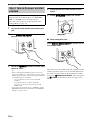 14
14
-
 15
15
-
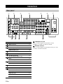 16
16
-
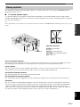 17
17
-
 18
18
-
 19
19
-
 20
20
-
 21
21
-
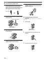 22
22
-
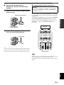 23
23
-
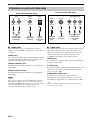 24
24
-
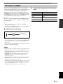 25
25
-
 26
26
-
 27
27
-
 28
28
-
 29
29
-
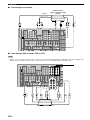 30
30
-
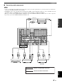 31
31
-
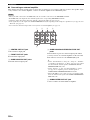 32
32
-
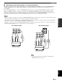 33
33
-
 34
34
-
 35
35
-
 36
36
-
 37
37
-
 38
38
-
 39
39
-
 40
40
-
 41
41
-
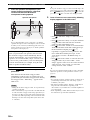 42
42
-
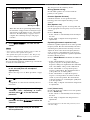 43
43
-
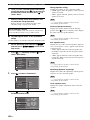 44
44
-
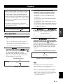 45
45
-
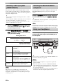 46
46
-
 47
47
-
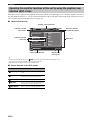 48
48
-
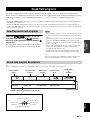 49
49
-
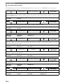 50
50
-
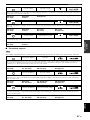 51
51
-
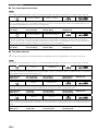 52
52
-
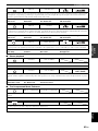 53
53
-
 54
54
-
 55
55
-
 56
56
-
 57
57
-
 58
58
-
 59
59
-
 60
60
-
 61
61
-
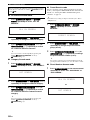 62
62
-
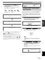 63
63
-
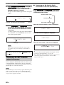 64
64
-
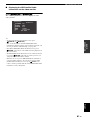 65
65
-
 66
66
-
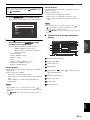 67
67
-
 68
68
-
 69
69
-
 70
70
-
 71
71
-
 72
72
-
 73
73
-
 74
74
-
 75
75
-
 76
76
-
 77
77
-
 78
78
-
 79
79
-
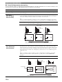 80
80
-
 81
81
-
 82
82
-
 83
83
-
 84
84
-
 85
85
-
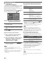 86
86
-
 87
87
-
 88
88
-
 89
89
-
 90
90
-
 91
91
-
 92
92
-
 93
93
-
 94
94
-
 95
95
-
 96
96
-
 97
97
-
 98
98
-
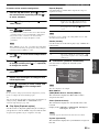 99
99
-
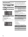 100
100
-
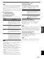 101
101
-
 102
102
-
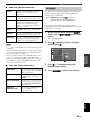 103
103
-
 104
104
-
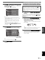 105
105
-
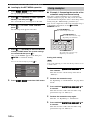 106
106
-
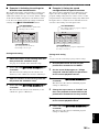 107
107
-
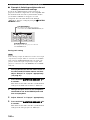 108
108
-
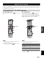 109
109
-
 110
110
-
 111
111
-
 112
112
-
 113
113
-
 114
114
-
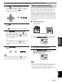 115
115
-
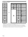 116
116
-
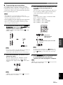 117
117
-
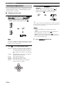 118
118
-
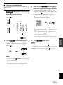 119
119
-
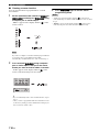 120
120
-
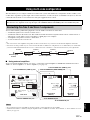 121
121
-
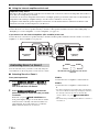 122
122
-
 123
123
-
 124
124
-
 125
125
-
 126
126
-
 127
127
-
 128
128
-
 129
129
-
 130
130
-
 131
131
-
 132
132
-
 133
133
-
 134
134
-
 135
135
-
 136
136
-
 137
137
-
 138
138
-
 139
139
-
 140
140
-
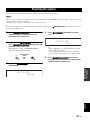 141
141
-
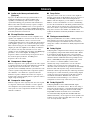 142
142
-
 143
143
-
 144
144
-
 145
145
-
 146
146
-
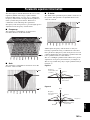 147
147
-
 148
148
-
 149
149
-
 150
150
-
 151
151
-
 152
152
-
 153
153
-
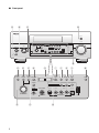 154
154
-
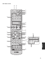 155
155
-
 156
156
-
 157
157
-
 158
158
-
 159
159
-
 160
160
-
 161
161
-
 162
162
-
 163
163
-
 164
164
-
 165
165
-
 166
166
-
 167
167
-
 168
168
-
 169
169


Yamaha RX-V3800 El manual del propietario
- Categoría
- Receptores AV
- Tipo
- El manual del propietario
en otros idiomas
- français: Yamaha RX-V3800 Le manuel du propriétaire
- italiano: Yamaha RX-V3800 Manuale del proprietario
- English: Yamaha RX-V3800 Owner's manual
- Deutsch: Yamaha RX-V3800 Bedienungsanleitung
- русский: Yamaha RX-V3800 Инструкция по применению
- Nederlands: Yamaha RX-V3800 de handleiding
- português: Yamaha RX-V3800 Manual do proprietário
- dansk: Yamaha RX-V3800 Brugervejledning
- polski: Yamaha RX-V3800 Instrukcja obsługi
- čeština: Yamaha RX-V3800 Návod k obsluze
- svenska: Yamaha RX-V3800 Bruksanvisning
- Türkçe: Yamaha RX-V3800 El kitabı
- suomi: Yamaha RX-V3800 Omistajan opas
- română: Yamaha RX-V3800 Manualul proprietarului
Artículos relacionados
-
Yamaha RV2600 DTS Manual de usuario
-
Yamaha RX-V3900 El manual del propietario
-
-
-
-
Yamaha DSP-Z7 El manual del propietario
-
Yamaha V150 El manual del propietario
-
-
Yamaha DSP-Z11 El manual del propietario
-
Otros documentos
-
Sherwood R-807 Operating Instructions Manual
-
NAD 310 El manual del propietario
-
Hama 00040074 El manual del propietario
-
TEAC AG-H600NT El manual del propietario
-
Sony RM-TP503 Manual de usuario
-
Marantz DH9300 Guía del usuario
-
Rotel RAP-1580 El manual del propietario
-
NuTone NM100WH Manual de usuario
-
Clarion DVC920 Manual de usuario
-