Zycoo IV03 SIP Safety Video Intercom Quick Guía de instalación
- Categoría
- Sistemas de intercomunicador de puerta
- Tipo
- Guía de instalación
Este manual también es adecuado para

Quick Installation Guide
IA03/IV03
ZYCOO SIP Safety Intercom

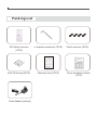
Packing List
SIP Safety Intercom
(1PCS)
L-shaped screwdriver (1PCS) Plastic anchors (4PCS)
KA4*25 Screws (4PCS)
Warranty Card (1PCS) Quick Installation Guide
(1PCS)
Power Adaptor (optional)

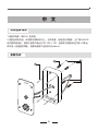
系统登录导向
1.连接好电源(或PoE)及网线。
2.设备启动完成后,长按拨号按键5秒以上,松开按键,设备进行IP播报,出厂默认DHCP,
若未获取到地址,则默认登录IP地址为192.168.1.101。直接在浏览器地址栏输入IP地址,
即可进入设备登录界面,设备缺省用户名密码均为admin。
1
5
4
4
2
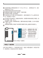
安装方式
中 文
01

在安装的墙面上根据设备安装孔尺寸(99mm/38.3mm),使用电钻钻4个孔,膨胀
管规格为M6*25mm。
使用塑料锤将膨胀管打进所钻的孔里面。
使用配备的L型螺丝刀将设备上盖拆开,并保存好螺钉。
将网线穿过护线圈(腔体或底板)。
将设备背板上的4个螺钉孔位对准膨胀螺钉孔,使用所配备的KA4*25mm螺钉进行固
定,将网线插入RJ45接口。
如不使用PoE给设备供电,使用直流电源供电,则需要将供电电源线穿过护线圈,接入
到J2连接器(蓝色)端子上。
如需要接入传感器、报警器等类设备,需要将连接线通过护线圈后,接入到J2连接器
(蓝色)端子上。
使用配备的L型螺丝刀和刚拆下来的梅花防盗螺钉将设备上盖固定在设备腔体上。
1
2
3
4
5
6
7
8
6
12V-
12V+
NC
COM
NO
IN-
IN+
直流电源12V输入负极
直流电源12V输入正极
干接点信号常闭输出
干接点信号公共端输入
干接点信号常开输出
数字电平输入负极
数字电平输入正极
恢复出厂设置按钮
长按PCB板上按键5秒以上,听到语音提示后松开,设备进入恢复设置状态,系统指示灯熄
灭。恢复成功后,系统运行指示灯进入闪烁状态。
恢复出厂设置导向
02

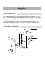
Network Settings
1.The default IP assignment of the SIP safety intercom is DHCP, to change DHCP to
static IP before installation, please first power it on using power adaptor or PoE enabled
network cable, wait for 30s then press and hold the call button to listen to its IP address,
if no DHCP server or DHCP fails, default IP 192.168.1.101 will be used.
2.Insert the IP address in the browser address bar to open the web interface, use
default login credentials admin/admin to sign in. Go to Settings -> Network Settings
page to setup static IP.
1
5
4
4
2
Mechanical Installation
English
03

Use an 8 mm drill to drill 4 mounting holes on the wall with 99 (H) x 38.3 (W)
spacing, each hole should be able to fit M6*25mm anchor.
Push the 4 anchors into each of the mounting holes with a rubber hammer.
Unscrew and remove the front panel from the SIP safety intercom using the L-
shaped screwdriver.
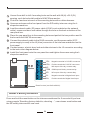
Lead the network cable, DC power cable (if PoE is not enabled on the network
cable), sensor and door lock cables through the hole on the back or bottom of the
rear panel box.
Place the rear panel box to the mounting holes and perfect the box position and fix
the box with the KA4*25 mm screws.
Connect the network cable to the RJ45 connector, and the power cable (if DC
power supply is used) to the J2 (blue) connector of the intercom mainboard on the
front panel.
Connect sensor, electric door lock and other devices to the J2 connector according
to the instruction diagram below.
Install the front panel onto the rear panel box and tighten the screws using the L-
shaped screwdriver.
1
3
6
12V-
12V+
NC
COM
NO
IN-
IN+
Negative terminal of 12V DC connector.
Positive terminal of 12V DC connector.
NO output of the dry contact relay.
COM input of the dry contact relay.
NC output of the dry contact relay.
Negative terminal of digital level input.
Positive terminal of digital level input.
Reset button (on the backside).
Press and hold the reset button on the intercom mainboard for 5 seconds till you hear
voice prompts “Resetting factory defaults, rebooting…”, now release reset button and
the SIP safety intercom will now reset.
Reset Factory Defaults
2
4
5
8
6
04

05
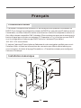
Paramètres réseau
1. Par défaut l'interphone de sécurité SIP est configure pour prendre une adresse en
DHCP. Pour changer la configuration réseau de DHCP en une adresse IP statique avant
l’installation, veuillez d'abord le mettre sous tension à l'aide d'un adaptateur secteur ou
d'un câble réseau compatible PoE. Attendez 30 secondes puis appuyez et maintenez le
bouton d'appel pour écouter son adresse IP. Cependant, s’il n’y a aucun serveur DHCP
ou si la recuperation d’adresse par DHCP échoue, l'adresse IP par défaut
192.168.1.101 sera utilisée.
2. Insérez l'adresse IP dans la barre d'adresse de votre navigateur préféré pour ouvrir
l'interface Web, utilisez les informations de connexion par défaut admin/admin pour
vous connecter. Accédez à la page Paramètres -> Paramètres réseau pour configurer
l'adresse IP statique.
1
5
4
4
2
Installation mécanique
Français

06
Utilisez un foret de 8 mm pour percer 4 trous de montage sur le mur avec un
espacement de 99 (H) x 38,3 (W), chaque trou doit pouvoir s'adapter à une cheville
M6*25 mm.
Inserez les 4 chevilles dans chacun des trous de montage avec un marteau en
caoutchouc.
Dévissez et retirez le panneau avant de l'interphone de sécurité SIP à l'aide du
tournevis en L.
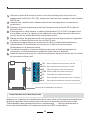
Faites passer le câble réseau, le câble d'alimentation CC (si PoE n'est pas activé
sur le câble réseau), le capteur et les câbles de verrouillage de porte à travers le
trou à l'arrière ou en bas du boîtier du panneau arrière.
Placez le boîtier du panneau arrière sur les trous de montage et ajustez la position
du boîtier et fixez le boîtier avec les vis KA4*25 mm.
Connectez le câble réseau au connecteur RJ45 et le câble d'alimentation (si
l'alimentation CC est utilisée) au connecteur J2 (bleu) de la carte mère
d'interphone sur le panneau avant.
Connectez le capteur, la serrure électrique de porte et d'autres appareils au
connecteur J2 conformément au schéma d'instructions ci-dessous.
Installez le panneau avant sur le boîtier du panneau arrière et serrez les vis à l'aide
du tournevis en forme de L.
1
3
6
12V-
12V+
NC
COM
NO
IN-
IN+
Borne négative du connecteur 12V DC.
Borne positive du connecteur 12V DC.
PAS de sortie du relais à contact sec.
Entrée COM du relais à contact sec.
Sortie NC du relais à contact sec.
Borne négative d'entrée de niveau numérique.
Borne positive d'entrée de niveau numérique.
Bouton de réinitialisation (à l'arrière)
Appuyez sur le bouton de réinitialisation de la carte mère de l'interphone et maintenez-
le enfoncé pendant 5 secondes jusqu'à ce que vous entendiez les invites vocales
"Réinitialisation des paramètres d'usine, redémarrage ...", relâchez maintenant le
bouton de réinitialisation et l'interphone de sécurité SIP se réinitialise.
Interfaces et instructions
2
4
5
8
6

07
Impostazioni di rete
1.L'assegnazione IP predefinita dell’interfono SIP di sicurezza è in DHCP, per cambiare
da DHCP in IP statico prima dell'installazione, accenderlo utilizzando la scheda di
alimentazione o il cavo di rete abilitato PoE, attendere 30s quindi premere e tenere
premuto il pulsante di chiamata per ascoltare il suo indirizzo IP, se non esiste server
DHCP o se il server DHCP fallisce, verrà utilizzato l'IP predefinito 192.168.1.101.
2.Inserire l'indirizzo IP nella barra degli indirizzi del browser per aprire l'interfaccia
Web, utilizzare le credenziali di accesso predefinite admin/admin per accedere. Vai a
Impostazioni -> Impostazioni di rete, per configurare l'IP statico.
1
5
4
4
2
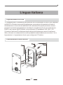
Installazione meccanica
Lingua italiana

08
Utilizzare un trapano da 8 mm per praticare 4 fori di montaggio sulla parete con
spaziatura di 99 (H) x 38,3 (W), ogni foro deve essere in grado di accettare un
tassello da M6-25 mm.
Spingere i 4 tasselli in ciascuno dei fori di montaggio con un martello di gomma.
Svitare e rimuovere il pannello anteriore dall’interfono SIP di sicurezza utilizzando
la brucola a forma di L.
Inserire il cavo di rete, il cavo di alimentazione DC (se PoE non è abilitato sul cavo
di rete), i cavi di blocco del sensore e della porta attraverso il foro sul retro o sul
fondo della scatola del pannello posteriore.
Posizionare la scatola del pannello posteriore in corrispondenza dei fori di
montaggio, perfezionare la posizione della scatola e fissare la scatola con le viti
KA4-25 mm.
Collegare il cavo di rete al connettore RJ45 e il cavo di alimentazione (se viene
utilizzata l'alimentazione DC) al connettore J2 (blu) della scheda madre
dell’interfono sul pannello anteriore.
Collegare il sensore, la serratura elettrica della porta e altri dispositivi al
connettore J2 in base allo schema di collegamento riportato di seguito.
Installare il pannello anteriore sulla scatola del pannello posteriore e stringere le
viti utilizzando la brucola a forma di L.
1
3
6
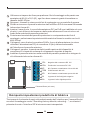
12V-
12V+
NC
COM
NO
IN-
IN+
Negativo del connettore DC 12V
Positivo del connettore DC 12V
NC Contatto normalmente chiuso del relè
COM Centrale del relè
NO Contatto normalmente aperto del relè
Ingresso di livello digitale negativo
Ingresso livello digitale positivo
Pulsante Reset (sul retro)
Tieni premuto il pulsante di reset sulla scheda madre dell’interfono per 5 secondi finché
non senti il messaggio vocale " Resetting factory defaults, rebooting…", ora rilascia il
pulsante di reset e l’interfono SIP di sicurezza verrà reimpostato.
Reimposta impostazioni predefinite di fabbrica
2
4
5
8
6

09
1.По умолчанию IP адрес для SIP домофона выдаётся DHCP сервером, чтобы
сменить способ назначения IP адреса с DHCP сервера на статический IP, перед
установкой включите устройство, используя адаптер питания или PoE, ожидайте
30с и удерживайте кнопку вызова для прослушивания IP адреса устройства. Если
DHCP сервер отсутствует или неисправен, IP адрес по умолчанию - 192.168.1.101.
2.Введите IP устройства в адресную строку браузера для перехода в веб-
интерфейс, используйте логин и пароль по умолчанию - admin/admin для входа.
Откройте Settings(Настройки) -> Network Settings(Сетевые Настройки) для
установки статического IP адреса.
1
5
4
4
2
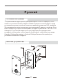
Монтаж устройства
Сетевые настройки
Русский

Используя сверло диаметром 8 мм, просверлите 4 монтажных отверстия на
стене с шагом 99 (В) x 38,3 (Ш), каждое отверстие должно соответствовать
анкеру M6*25 мм.
Вставьте 4 анкера в каждое из монтажных отверстий с помощью резинового
молотка.
Отвинтите и снимите переднюю панель с SIP домофона с помощью Г-
образной отвертки.
Проведите сетевой кабель, а также кабель питания постоянного тока (если не
используется PoE), вместе с кабелями для датчика и дверного замка через
отверстие в задней или нижней части коробки задней панели.
Установите коробку задней панели к монтажным отверстиям, отрегулируйте
положение и зафиксируйте коробку с помощью винтов KA4*25 мм.
Подсоедините сетевой кабель к разъему RJ45, а кабель питания (Если
используется источник питания постоянного тока) - к разъему J2 (синего
цвета) материнской платы SIP домофона на передней панели.
Подсоедините датчик, электрический дверной замок и другие необходимые
устройства к разъему J2 в соответствии с приведенной ниже схемой.
Установите переднюю панель на заднюю панель коробки и затяните винты с
помощью Г-образной отвертки.
1
3
6
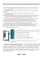
Нажмите и удерживайте кнопку для сброса настроек на материнской плате SIP
домофона в течение 5 секунд, затем вы услышите голосовую подсказку “Resetting
factory defaults, rebooting…(Сброс до заводских настроек, перезагрузка…)”, после
чего вы можете отпустить кнопку для сброса настроек, и SIP домофон вернётся к
заводским настройка.
Сброс до заводских настроек
2
4
5
8
10
12V-
12V+
NC
COM
NO
IN-
IN+
Кнопка для сброса конфигурации (на обратной стороне).
6
Отрицательная клемма разъема для постоянного тока на 12В.
Положительная клемма разъема для постоянного тока на 12В.
NO выход для сухого контакта реле
COM вход для сухого контакта реле
NC выход для сухого контакта реле
Отрицательная клемма для цифрового входа
Положительная клемма для цифрового входа

11
1.La asignación de IP por defecto del intercomunicador de seguridad SIP es DHCP,
para cambiar DHCP a IP estática antes de la instalación, por favor enciéndalo primero
usando el adaptador de corriente o el cable de red habilitado para PoE, espere 30
segundos y luego mantenga presionado el botón de llamada para escuchar su dirección
IP, si no hay ningún servidor DHCP o DHCP falla, se usará la IP por defecto
192.168.1.101.
2.Inserte la dirección IP en la barra de direcciones del navegador para abrir la interfaz
web, utilice las credenciales de inicio de sesión por defecto admin/admin para iniciar
sesión. Vaya Settings -> Network Settings para configurar la IP estática.
1
5
4
4
2
Instalación mecánica
Configuración de la red
Español

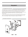
Utilice una broca de 8 mm para perforar 4 agujeros de montaje en la pared con un
espacio de 99 mm(alto) x 38,3 mm (ancho), cada agujero debe ser capaz de
encajar el anclaje M6*25mm.
Empuje los 4 anclajes en cada uno de los agujeros de montaje con un martillo de
goma.
Desenrosque y retire el panel frontal del intercomunicador de seguridad SIP con el
destornillador en forma de L.
Pase el cable de red, el cable de alimentación de corriente continua (si no está
habilitada la función PoE en el cable de red), los cables del sensor y de la
cerradura de la puerta por el orificio de la parte trasera o inferior de la caja del
panel trasero.
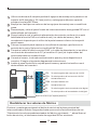
Coloque la caja del panel trasero en los orificios de montaje y perfeccione la
posición de la caja y fíjela con los tornillos KA4*25 mm.
Conecte el cable de red al conector RJ45, y el cable de alimentación (si se utiliza
una fuente de alimentación de CC) al conector J2 (azul) de la placa base del
intercomunicador en el panel frontal.
Conecte el sensor, la cerradura eléctrica de la puerta y otros dispositivos al
conector J2 según el siguiente diagrama de instrucciones.
Instale el panel frontal en la caja del panel trasero y apriete los tornillos con el
destornillador en forma de L.
1
3
6
Presione y mantenga presionado el botón de reinicio en la placa principal del
intercomunicador durante 5 segundos hasta que escuche las indicaciones de voz
"Reiniciando los valores predeterminados de fábrica, reiniciando...", ahora libere el
botón de reinicio y el intercomunicador de seguridad SIP se reiniciará.
Restablecer los valores de fábrica
2
4
5
8
12
12V-
12V+
NC
COM
NO
IN-
IN+
Terminal negativo del conector de 12V DC.
Terminal positivo del conector de 12V DC.
Salida NA del relé.
Entrada COM del relé.
Salida NC del relé.
Terminal negativo de la entrada de nivel digital.
Terminal positivo de la entrada de nivel digital.
Botón de reinicio (en la parte posterior)
6


Company: Zycoo Co., Ltd.
Address:16F, D5, Tianfu Software Park, Chengdu, China
Telephone:+86 (28)85337096 ext 813 / 815
Website:www.zycoo.com
制造厂商:成都智科通信技术股份有限公司
总部地址:四川省成都市高新区天府软件园 D5 栋 16 层
咨询电话:028-85337096
公司网址:www.zycoo.com.cn
-
 1
1
-
 2
2
-
 3
3
-
 4
4
-
 5
5
-
 6
6
-
 7
7
-
 8
8
-
 9
9
-
 10
10
-
 11
11
-
 12
12
-
 13
13
-
 14
14
-
 15
15
-
 16
16


Zycoo IV03 SIP Safety Video Intercom Quick Guía de instalación
- Categoría
- Sistemas de intercomunicador de puerta
- Tipo
- Guía de instalación
- Este manual también es adecuado para
en otros idiomas
Artículos relacionados
-
 Zycoo SH30 Network Horn Speaker Quick Guía de instalación
-
 Zycoo SC10 Network Ceiling Speaker Quick Guía de instalación
-
 Zycoo SL30 Network Column Speaker Quick Guía de instalación
-
 Zycoo M100 Dispatch Microphone Console Quick Guía de instalación
-
 Zycoo SW15 Network Cabinet Speaker Quick Guía de instalación
-
 Zycoo SC15 Network Ceiling Speaker Quick Guía de instalación


