La página se está cargando...

Quick Installation Guide
SC15


Packing List
Network Ceiling Speaker (1PCS)
Warranty Card (1PCS)
Quick Installation Guide (1PCS)
Power Adaptor (optional)
Mounting Bracket (optional)
01

安装方式一
1、在天花板上开一个直径在210±5mm的安装圆孔;
2、连接网线及需要的干接点信号线;
3、取下铁网放好;
4、小心将设备推入已开好的安装孔,旋转夹扣螺钉以调整夹片的位置,使夹扣能够勾住天花板;
5、拧紧四个螺钉,将四个夹扣扣紧,使夹扣能够牢固加紧天花板,最后盖上铁网。
φ210mm
天花
铁网
1、如需要安装支架 ,需要先将两扇支架安装到塑料圆形圈上;
安装方式二
中 文
02

系统登录导向
1.连接好电源(或PoE)及网线。
2.设备启动完成后,按下恢复出厂设置按键5秒后,松开按键,设备进行IP播报。出厂默认DHCP,若未获取到IP地址,则
默认登录IP地址为192.168.1.101。直接在浏览器地址栏输入IP地址,即可进入设备登录界面,设备的缺省用户名及密码,
均为admin。
2、在天花板上开一个直径在220±5mm的圆孔;
3、连接网线及需要的干接点信号线;
4、取下铁网放好;
5、小心将设备推入已开好的安装孔,将组装好的支架套件装进后桶,紧贴天花板;
6、旋转夹扣螺钉以调整夹片的位置,使夹扣能够勾住支架套件;
7、拧紧四个螺钉,将四个夹扣扣紧,使夹扣能够牢固加紧支架套件,最后盖上铁网。
支架
铁网
φ220mm
支架
天花
03

恢复出厂设置导向
长按恢复出厂设置按键10秒以上,听到语音提示后松开,设备进入恢复设置状态,系统指示灯熄灭。恢复成功后,系统运
行指示灯进入闪烁状态。
04
恢复出厂设置按键
以太网接口
系统运行指示灯
RST
SYS
ETH0
NO
NC
COM
BTN
MIC+
VOL-
DC24V-
MIC-
VOL+
DC24V+
RST
SYS
ETH0
NO
NC
COM
BTN
MIC+
VOL-
DC24V-
MIC-
VOL+
DC24V+
直流电源24V输入+
直流电源24V输入-
按键呼叫
喇叭音量输出调节+
喇叭音量输出调节-
麦克风音频输入-
麦克风音频输入+
干接点信号常开输出
干接点信号公共端输入
干接点信号常闭输出

English
Installation Method 1
1.Cut a hole in the ceiling with 210±5 mm diameter.
2. Connect network cable and power supply (if PoE is not enabled on the network cable), and other cabling if required.
3. Detach the metal mesh (adsorbed by magnets).
4.Adjust the clips and place the back end of the ceiling speaker into the mounting hole, adjust the clips again for being
able to clamp the ceiling.
5.Tighten the screws in order to tighten the clamping of the clips with the ceiling, and then cover the metal mesh.
φ210mm
Ceiling
Metal Mesh
1.To install the ceiling speaker with mounting brackets, please first fix the two plates to the plastic ring.
Installation Method 2
05

Web Login
1.Connect network cable and power supply (if PoE is not enabled on the network cable).
2.Wait for 30 seconds then press and hold the RST button for 5 seconds and release, it will announce the IP address
obtained from the DHCP server. If there’s no DHCP server or DHCP fails, it will use default IP 192.168.1.101. In the
browser address bar input the IP address you hear to open its web management interface. Default username and
password admin/admin.
2. Cut a hole in the ceiling with 210±5 mm diameter.
3.Connect network cable and power supply (if PoE is not enabled on the network cable), and other cabling if required.
4.Detach the metal mesh (adsorbed by magnets).
5.Place the mounting bracket on top of ceiling, push the speaker back end into the ceiling through the mounting
bracket ring and ensure the mounting bracket is tightly attached to the ceiling.
6.Adjust the clips for being able to clamp with the mounting bracket.
7.Tighten the screws of the 4 clips in order to tighten the clamping of the clips with the mounting bracket and the
ceiling, and then cover the metal mesh.
Bracket
Metal Mesh
φ220mm
Bracket
Ceiling
06

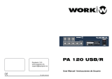
Interfaces and Instructions
To reset factory defaults, press and hold the RST button for 10 seconds (5 seconds for IP address announcements)
and release, now you should hear voice prompts “Resetting factory defaults, rebooting…”, it means the speaker will
now reset.
Reset button
Ethernet interface
System LED indicator
07
RST
SYS
ETH0
NO
NC
COM
BTN
MIC+
VOL-
DC24V-
MIC-
VOL+
DC24V+
RST
SYS
ETH0
NO
NC
COM
BTN
MIC+
VOL-
DC24V-
MIC-
VOL+
DC24V+
Positive terminal of 24V DC input
Negative terminal of 24V DC input
Press To Talk Button
Volume Control+
Volume Control-
Audio In-
Audio In+
NO output of dry contact relay
COM input of dry contact relay
NC output of dry contact relay

Méthode d'installation 1
1. Découpez un trou dans le plafond de 210 ± 5 mm de diamètre.
2. Connectez le câble réseau et l'alimentation (si PoE n'est pas activé sur le câble réseau), et tout autre câblage si
nécessaire.
3. Détachez le treillis métallique (adsorbé par des aimants).
4.Ajustez les clips et placez l'extrémité arrière du haut-parleur de plafond dans le trou de montage, ajustez à nouveau
les clips pour pouvoir fixer le plafond.
5. Serrez les vis afin de resserrer le serrage des clips avec le plafond, puis couvrez le treillis métallique.
φ210mm
Plafond
Maille en métal
1.Pour installer le haut-parleur de plafond avec des supports de montage, veuillez d'abord fixer les deux
plaques sur l'anneau en plastique.
Méthode d'installation 2
Français
08

Connexion Web
1.Connectez le câble réseau et l'alimentation (si PoE n'est pas activé sur le câble réseau).
2.Attendez 30 secondes, puis appuyez et maintenez le bouton RST pendant 5 secondes et relâchez, il annoncera
l'adresse IP obtenue du serveur DHCP. S'il n'y a pas de serveur DHCP ou si la configuration par DHCP échoue, il
utilisera l'IP par défaut 192.168.1.101. Dans la barre d'adresse du navigateur, saisissez l'adresse IP que vous
entendez pour ouvrir son interface de gestion Web. Nom d'utilisateur et mot de passe par défaut admin / admin.
2. Découpez un trou dans le plafond de 210 ± 5 mm de diamètre.
3.Connectez le câble réseau et l'alimentation (si PoE n'est pas activé sur le câble réseau), et tout autre câblage si
nécessaire.
4. détachez le treillis métallique (adsorbé par des aimants).
5.Placez le support de montage sur le dessus du plafond, poussez l'extrémité arrière du haut-parleur dans le plafond à
travers l'anneau du support de montage et assurez-vous que le support de montage est fermement fixé au plafond.
6.Ajustez les clips pour pouvoir serrer avec le support de montage.
7. Serrez les vis des 4 clips afin de resserrer le serrage des clips avec le support de montage et le plafond, puis
couvrez le treillis métallique.
Support
Maille en métal
φ220mm
Support
Plafond
09

Interfaces et instructions
Pour réinitialiser les paramètres d'usine, appuyez sur le bouton RST et maintenez-le enfoncé pendant 10 secondes (5
secondes pour les annonces d'adresse IP) et relâchez, vous devriez maintenant entendre les invites vocales
"Réinitialisation des paramètres d'usine, redémarrage ...", cela signifie que le haut-parleur va maintenant se
réinitialiser.
10
RST
SYS
ETH0
NO
NC
COM
BTN
MIC+
VOL-
DC24V-
MIC-
VOL+
DC24V+
RST
SYS
ETH0
NO
NC
COM
BTN
MIC+
VOL-
DC24V-
MIC-
VOL+
DC24V+
Indicateur LED système
Borne négative d'entrée 24 v cc
Pas de sortie de relais à contact sec
Entrée COM du relais à contact sec
Sortie NC du relais à contact sec
Entrée audio +
Entrée audio –
Volume –
Volume+
Appuyez pour parler
Interface ethernet
Bouton de réinitialisation
Borne positive d'entrée 24 v cc

Lingua italiana
Metodo di installazione 1
1.Tagliare un foro nel soffitto con un diametro di 210x5 mm.
2. Collegare il cavo di rete e l'alimentazione (se PoE non è abilitato sul cavo di rete) e altri cablaggi, se necessario.
3. Staccare la rete metallica (fissata da magneti).
4.Regolare le clip e posizionare l'estremità posteriore dell'altoparlante nel foro di montaggio, regolare nuovamente le
clip per essere in grado di bloccare l’altoparlante al controsoffitto.
5.Stringere le viti per fissare le clip al controsoffitto, e quindi coprire con la rete metallica.
φ210mm
Soffitto
Maglia metallica
1.Per installare l'altoparlante del controsoffitto con staffe di montaggio, si prega di fissare prima le due piastre per
l'anello di plastica.
Metodo di installazione 2
11

Web Login
1.Collegare il Cavo di rete e alimentatore (se PoE non è abilitato sul cavo di rete).
2.Attendere 30 secondi poi premere e tenere premuto il pulsante RST per 5 secondi e rilasciare, verrà annunciato
l'indirizzo IP ottenuto dal server DHCP. Se il server DHCP è assente o se il server DHCP fallisce, verrà utilizzato l'IP
predefinito 192.168.1.101. Nella barra degli indirizzi del browser immettere l'indirizzo IP che si sente, per aprire la
relativa interfaccia di gestione web. Nome utente e password predefiniti admin/admin.
2. Fare un foro nel controsoffitto con un diametro di 210 x 5 mm.
3.Collegare il cavo di rete e l'alimentazione (se PoE non è abilitato sul cavo di rete) e altri cablaggi, se necessario.
4.Staccare la rete metallica (fissata da magneti).
5.Posizionare la staffa di montaggio sulla parte superiore del soffitto, inserire l’altoparlante nel controsoffitto
attraverso l'anello della staffa di montaggio e assicurarsi che la staffa di montaggio sia strettamente attaccata al
controsoffitto.
6.Regolare le clip per fissare la staffa di montaggio.
7.Stringere le viti delle 4 clip per fissare la staffa di montaggio al controsoffitto, quindi coprire con la maglia metallica.
Staffa
Maglia metallica
φ220mm
Staffa
Soffitto
12

Interfacce e Istruzioni
Per ripristinare le impostazioni predefinite di fabbrica, premere e tenere premuto il pulsante RST per 10 secondi (5
secondi per gli annunci di indirizzi IP) e rilasciare, ora si dovrebbero sentire le istruzioni vocali " Resetting factory
defaults, rebooting...", significa che l'altoparlante verrà ora reimpostato.
13
RST
SYS
ETH0
NO
NC
COM
BTN
MIC+
VOL-
DC24V-
MIC-
VOL+
DC24V+
RST
SYS
ETH0
NO
NC
COM
BTN
MIC+
VOL-
DC24V-
MIC-
VOL+
DC24V+
Indicatore LED di sistema
Alim.24V-
Contatto Relè Normalmente Aperto
Contatto Relè Comune
Contatto Relè Normalmente Chiuso
Audio in+
Audio in-
Volume control-
Volume control+
Pulsante press to talk
Interfaccia Ethernet
Pulsante Ripristina
Alim.24V+

Метод установки 1
1.Вырежьте в потолке отверстие диаметром 210±5 мм.
2. Подключите сетевой кабель и источник питания (если не используется PoE), а также другие кабели по
необходимости.
3. Отсоедините металлическую сетку (адсорбированную магнитами).
4.Отрегулируйте зажимы и поместите задний конец потолочного динамика в монтажное отверстие,
отрегулируйте зажимы, чтобы закрепить устройство на потолке.
5.Затяните винты для закрепления зажима с потолком, а затем накройте металлической сеткой.
φ210mm
Потолок
Металлическая сетка
1.Для установки потолочного громкоговорителя при помощи монтажных кронштейнов сначала
закрепите две пластины на пластиковом кольце.
Метод установки 2
14
Русский

Вход в веб-интерфейс
1.Подключите сетевой кабель и источник питания (Если не используется PoE).
2. Ожидайте 30с, затем нажмите и удерживайте кнопку RST в течение 5 секунд, после чего отпустите. Вы
услышите IP адрес устройства, полученный от DHCP сервера. Если DHCP сервер не используется, или
работает неисправно, IP адрес по умолчанию - 192.168.1.101. Для открытия веб-интерфейса введите IP адрес
устройства в адресную строку браузера. Для входа используйте логин/пароль по умолчанию - admin/admin.
2. Вырежьте в потолке отверстие диаметром 210±5 мм.
3.Подключите сетевой кабель и источник питания (если не используется PoE), а также другие кабели по
необходимости.
4.Отсоедините металлическую сетку (адсорбированную магнитами)
5.Поместите монтажный кронштейн на верхнюю часть потолка, вставьте задний конец громкоговорителя в
потолок через кольцо монтажного кронштейна и убедитесь, что монтажный кронштейн плотно прикреплен к
потолку.
6.Отрегулируйте зажимы так, чтобы их можно было зажать с помощью монтажного кронштейна.
7.Затяните винты 4 зажимов для того, чтобы закрепить монтажный кронштейн на потолке, а затем накройте
металлической сеткой.
Кронштейн
Металлическая сетка
φ220mm
Кронштейн
Потолок
15

Интерфейсы и инструкции
Для сброса до заводских настроек нажмите и удерживайте кнопку RST в течение 10 секунд (5 секунд для
голосового оповещения IP адреса), затем отпустите, после чего вы услышите голосовое уведомление
“Resetting factory defaults, rebooting…(Сброс до заводских настроек, перезагрузка)”, после чего
громкоговоритель произведет сброс настроек.
16
RST
SYS
ETH0
NO
NC
COM
BTN
MIC+
VOL-
DC24V-
MIC-
VOL+
DC24V+
RST
SYS
ETH0
NO
NC
COM
BTN
MIC+
VOL-
DC24V-
MIC-
VOL+
DC24V+
Системный LED индикатор
Отрицательная клемма для входного
сигнала постоянного тока 24 В
NO выход для сухого контакта реле
COM вход для сухого контакта реле
аудиовход +
аудио вход-
регулятор громкости-
регулятор громкости +
нажмите, чтобы поговорить
Ethernet интерфейс
Кнопка сброса до заводских настроек
Положительная клемма для входного
сигнала постоянного тока 24 В
NC выход для сухого контакта реле

Español
Método de instalación 1
1.Corte un agujero en el techo con un diámetro de 210 ± 5 mm.
2.Conecte el cable de red y la fuente de alimentación (si PoE no está habilitado en el cable de red), y otro cableado si
es necesario.
3.Desprenda la malla metálica (pegada por imanes).
4.Ajuste los clips y coloque el extremo posterior del altavoz de techo en el orificio de montaje, vuelva a ajustar los
clips para poder sujetar el techo.
5.Apriete los tornillos para apretar la sujeción de los clips con el techo, y luego cubra la malla metálica.
φ210mm
Techo
Malla metálica
1.Para instalar el altavoz de techo con soportes de montaje, por favor, primero fije las dos placas al anillo de plástico.
Método de instalación 2
17

Inicio de sesión en la web
1.Conecte el cable de red y la fuente de alimentación (si PoE no está habilitado en el cable de red).
2.Espere 30 segundos, luego mantenga presionado el botón RST durante 5 segundos y suéltelo, anunciará la
dirección IP obtenida del servidor DHCP. Si no hay un servidor DHCP o si el DHCP falla, utilizará la IP 192.168.1.101
por defecto. En la barra de direcciones del navegador introduzca la dirección IP que oye para abrir su interfaz de
gestión web. Nombre de usuario y contraseña por defecto admin/admin.
2.Haga un agujero en el techo con un diámetro de 210 ± 5 mm.
3.Conecte el cable de red y la fuente de alimentación (si PoE no está habilitado en el cable de red), y otro cableado si
es necesario.
4.Desprenda la malla metálica (pegada por imanes).
5.Coloque el soporte de montaje en la parte superior del techo, empuje el extremo posterior del altavoz hacia el techo
a través del anillo del soporte de montaje y asegúrese de que el soporte de montaje esté bien sujeto al techo.
6.Ajuste los clips para poder sujetar el soporte de montaje.
7.Apriete los tornillos de los 4 clips para poder apretar la sujeción de los clips con el soporte de montaje y el techo, y
luego cubra la malla metálica.
Soporte
Malla metálica
φ220mm
Soporte
Techo
18

Instrucciones e interfaces
Para restablecer los valores de fábrica, mantenga pulsado el botón RST durante 10 segundos (5 segundos para los
anuncios de direcciones IP) y suéltelo, ahora debería oír las indicaciones de voz "Restablecimiento de los valores de
fábrica, reinicio...", significa que el altavoz se restablecerá ahora.
19
RST
SYS
ETH0
NO
NC
COM
BTN
MIC+
VOL-
DC24V-
MIC-
VOL+
DC24V+
RST
SYS
ETH0
NO
NC
COM
BTN
MIC+
VOL-
DC24V-
MIC-
VOL+
DC24V+
Sistema indicador LED
Terminal negativo de la entrada de 24V DC
NA salida del relé
COM entrada del relé
Salida NC del relé
Entrada audio +
Entrada audio -
Control volumen -
Control volumen+
Botón presionar para hablar
Interfaz Ethernet
Botón de reinicio
Terminal positivo de entrada de 24V DC


制造厂商:成都智科通信技术股份有限公司
总部地址:成都高新区世纪城南路599号5栋16层1602号
咨询电话:028-85337096
公司网址:www.zycoo.com.cn
Company: Zycoo Co., Ltd.
Address:No. 1602, 16th Floor, Building No. 599, Century City
South Road, High-tech Zone, Chengdu, Sichuan Province, China
Telephone:+86 (28)85337096 ext 813 / 815
Website:www.zycoo.com
/