SUNNY Health Fitness SF-RW5910 Manual de usuario
- Categoría
- Fitness, gimnasia
- Tipo
- Manual de usuario
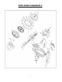
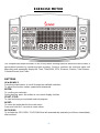
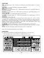
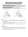
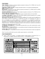
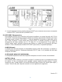
El SUNNY Health Fitness SF-RW5910 es una máquina de remo hidráulica que ofrece un entrenamiento de cuerpo completo. Su diseño ergonómico y su asiento acolchado proporcionan una experiencia de remo suave y cómoda. Con 8 niveles de resistencia ajustables, el SF-RW5910 es ideal para usuarios de todos los niveles de condición física. Su monitor LCD muestra el tiempo, la distancia, las calorías quemadas y las pulsaciones por minuto. También tiene una función de escaneo que muestra todos los datos en una secuencia continua.
El SUNNY Health Fitness SF-RW5910 es una máquina de remo hidráulica que ofrece un entrenamiento de cuerpo completo. Su diseño ergonómico y su asiento acolchado proporcionan una experiencia de remo suave y cómoda. Con 8 niveles de resistencia ajustables, el SF-RW5910 es ideal para usuarios de todos los niveles de condición física. Su monitor LCD muestra el tiempo, la distancia, las calorías quemadas y las pulsaciones por minuto. También tiene una función de escaneo que muestra todos los datos en una secuencia continua.


-
 1
1
-
 2
2
-
 3
3
-
 4
4
-
 5
5
-
 6
6
-
 7
7
-
 8
8
-
 9
9
-
 10
10
-
 11
11
-
 12
12
-
 13
13
-
 14
14
-
 15
15
-
 16
16
-
 17
17
-
 18
18
-
 19
19
-
 20
20
-
 21
21
-
 22
22
-
 23
23
-
 24
24
-
 25
25
-
 26
26
-
 27
27
-
 28
28
-
 29
29
-
 30
30
-
 31
31
-
 32
32
-
 33
33
-
 34
34
-
 35
35
-
 36
36


SUNNY Health Fitness SF-RW5910 Manual de usuario
- Categoría
- Fitness, gimnasia
- Tipo
- Manual de usuario
El SUNNY Health Fitness SF-RW5910 es una máquina de remo hidráulica que ofrece un entrenamiento de cuerpo completo. Su diseño ergonómico y su asiento acolchado proporcionan una experiencia de remo suave y cómoda. Con 8 niveles de resistencia ajustables, el SF-RW5910 es ideal para usuarios de todos los niveles de condición física. Su monitor LCD muestra el tiempo, la distancia, las calorías quemadas y las pulsaciones por minuto. También tiene una función de escaneo que muestra todos los datos en una secuencia continua.
en otros idiomas
Artículos relacionados


Otros documentos
-
Tunturi Fit R60w Manual de usuario
-
Sunny SF-B020026 Manual de usuario
-
-
-
Sunny SF-RW5713 Manual de usuario
-
 Sunny Health & Fitness SF-B1423 Manual de usuario
-
-
-
-
