Gorilla MH-1242-D El manual del propietario
- Tipo
- El manual del propietario

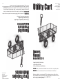
Owners
Manual
Model MH1242-D
• Important Safety Instructions
• Assembly Instructions
• Parts and Hardware Identification
Utility Cart
For product inquiries:
Tricam
7677 Equitable Drive
Eden Prairie, MN 55344
800-867-6763
www.tricam.com
CAUTION: Read, understand and follow ALL instructions before using this product.
WARNING: Not for recreational use. Persons should never ride in the Cart.
Questions, problems, or missing parts? Before returning to your retailer, visit us
online at www.tricam.com and complete the replacement parts submission form or
call our customer service department at 1-800-867-6763,
9 a.m. - 4 p.m., CST, Monday-Friday.
1/14
Manual del
Propietario
Modelo MH1242-D
• Instrucciones Importantes de Seguridad
• Instrucciones de Ensamblaje
• Información de Piezas y Herrajes
Para Trabajos
Moderados
Preguntas sobre el producto:
Tricam
7677 Equitable Drive
Eden Prairie, MN 55344
800-867-6763
www.tricam.com
PRECAUCIÓN: Leer, entender y seguir TODAS las instrucciones antes de usar este producto.
ADVERTENCIA: No usar para fines recreativos. Las personas nunca deben montarse en el carrito.
¿Preguntas, problemas o piezas faltantes? Antes de devolverlo al minorista, visí-
tanos en Internet en www.tricam.com y completa nuestro formulario de piezas de
repuesto o llama a nuestro departamento de servicio al cliente al 1-800-867-6763, de
9 a.m. a 4 p.m., Hora Estándar del Centro, de Lunes a Viernes.
1/14

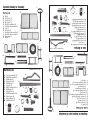
Parts List
Hardware List
Drawings are not to scale
Exploded Drawing for Assembly
Lista de Herrajes
Las imágenes no están a escala
A.
G.
B.
D.
C.
E.
A. Fence Assembly Pins (8)
B. M8x170 Carriage Bolt (1)
C. M8 Washers (6)
D. M8 Lock Nuts (6)
E. M10 Washer (1)
F. Cotter Pin (5)
G. M6x17 Shoulder Bolts (2)
H. M6 Washers (2)
I. M6 Lock Nuts (2)
J. M8x20 Carriage Bolts (4)
K. Wheel Spacer (4)
L. Wheel Washers (4)
M. M8x60 Hex Bolt (1)
F.
H.
K.
L.
J.
I.
M.
A. Bed (1)
B. Side Panels (2)
C. Front Panel (1)
D. Back Panel (1)
E. 10in (25.4cm) Wheels (4)
F. Front Axle Sub-Assembly (1)
G. Yoke (1)
H. Front Strut (1)
I. Front Axle Connection Bar (1)
J. Rear Axle Sub-Assembly (1)
K. Rear Struts (2)
L. Handle (1)
K.
C.
D.
E.
F.
G.
H.
I.
J.
A.
G.
B.
D.
C.
E.
F.
H.
K.
L.
J.
I.
M.
Lista de Piezas
Diagrama de Despiece para el Ensamblaje
A. Cama (1)
B. Paneles Laterales (2)
C. Panel Frontal (1)
D. Panel Posterior (1)
E. Ruedas de 10 plg (25,4 cm) (4)
F. Subensamblaje del Eje Delantero (1)
G. Horquilla (1)
H. Amortiguador Delantero (1)
I. Barra de Conexión del
Eje Delantero (1)
J. Subensamblaje del Eje Trasero (1)
K. Amortiguadores Traseros (2)
L. Mango (1)
A. Pasadores de Ensamblaje del
Protector (8)
B. Perno de Carro M8x170 (1)
C. Arandelas M8 (11)
D. Contratuercas M8 (11)
E. Arandela M10 (1)
F. Pasador de Chaveta (5)
G. Pernos de Hombro M6x17 (2)
H. Arandelas M6 (2)
I. Contratuercas M6 (2)
J. Pernos de Carro M8x20 (4)
K. Espaciadores de Ruedas (4)
L. Arandelas de Ruedas (4)
M. Perno Hexagonal M8x60 (1)
A.
L.
K.
C.
D.
E.
F.
G.
H.
I.
J.
A.
L.
B.
B.

1.
RREEAADD AALLLL IINNSSTTRRUUCCTTIIOONNSS CCAARREEFFUULLLLYY BBEEFFOORREE UUSSEE..
If you do not understand these
instructions, need clarification or further explanation, please call our toll free
answer line for assistance at
11--880000--886677--66776633
Monday through Friday 9:00 a.m. - 4:00 p.m., CST.
2. Do not exceed the overall maximum load capacity of 800 lbs (362 kg). The weight
rating is based on an evenly distributed load.
3. Do not load items on the top edges of the panels. Remove panels before loading
oversized items.
4. Do not allow children to use this cart without supervision. This cart is not a toy.
5. Do not use this cart to transport passengers.
6. This cart is not intended for highway use.
7. Do not exceed 5 mph.
8. If any parts become damaged, broken or misplaced, do not use the cart until
replacement parts have been obtained.
9. Do not use the cart on surfaces or for transporting objects that can cause damage
to the pneumatic tires or tubes.
DDoo nnoott iinnffllaattee tthhee ttiirreess ttoo mmoorree tthhaann 3300 PPSSII ((22..0077 BBAARR))..
10. It is recommended that the cart be inspected for damage before each use.
11.
KKEEEEPP TTHHEESSEE IINNSSTTRRUUCCTTIIOONNSS FFOORR FFUURRTTHHEERR RREEFFEERREENNCCEE..
Your cart requires assembly. Account for all parts before beginning assembly. If any
parts are missing, damaged, or if you have any questions or need additional instructions,
DO NOT RETURN THIS PRODUCT TO THE RETAILER, visit us at www.tricam.com to
complete the replacement parts submission form or call our customer service
department at 1-800-867-6763.
Tools required for assembly: pliers, adjustable wrenches and/or metric socket set.
For ease of assembly, refer to the parts list during assembly.
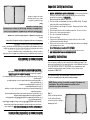
Important Safety Instructions
Assembly Instructions
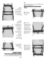
Step 1
Turn the cart bed upside down.
Use the cardboard from the
carton to keep from scratching or
damaging the finish.
NOTE: During each step of assembly, assemble all hardware and
hand tighten. Once all the hardware is installed for that
particular step, tighten all hardware.
1.
LLEEEE CCOONN CCUUIIDDAADDOO TTOODDAASS LLAASS IINNSSTTRRUUCCCCIIOONNEESS AANNTTEESS DDEE UUSSAARR
. Si no entiendes estas
instrucciones, o necesitan ser aclaradas o explicadas en detalle, por favor, llama a nuestra
línea de asistencia gratuita al1-800-867-6763, de Lunes a Viernes, de 9:00 a.m. a 4:00 p.m., (Hora
Estándar del Centro de EE. UU.)
2. No sobrepases el límite máximo de carga total de 800 lb (362 kg). La capacidad de peso
nominal está basada en una carga distribuida de manera uniforme.
3. No cargues artículos en los bordes superiores de los paneles. Quita los paneles antes de
cargar artículos grandes.
4. No permitas que los niños usen este carrito sin supervisión. Este carrito no es un juguete.
5. No lo uses para transportar pasajeros.
6. Este carrito no está diseñado para usar en autopistas.
7. No sobrepases las 5 mph.
8. Si alguna de las piezas se daña, rompe o pierde, no uses el carrito hasta obtener la
pieza de repuesto.
9. No usar el carrito sobre superficies o para transportar objetos que puedan causar daños a los
neumáticos o las cámaras.
NNoo iinnfflleess llooss nneeuummááttiiccooss aa mmááss ddee 3300 PPSSII ((22,,0077 BBAARR))..
10. Se recomienda revisar el carrito antes de cada uso para detectar cualquier daño.
11.
GGUUAARRDDAA EESSTTAASS IINNSSTTRRUUCCCCIIOONNEESS PPAARRAA CCOONNSSUULLTTAASS FFUUTTUURRAASS ..
El carrito necesita ensamblarse. Antes de empezar el ensamblaje, revisa si están todas
las piezas y herrajes. Si falta alguna pieza o si tienes preguntas o necesitas
instrucciones adicionales, NO DEVUELVAS ESTE PRODUCTO AL MINORISTA, visítanos
en Internet en www.tricam.com para llenar el formulario de piezas de repuesto o llama a
nuestro departamento del servicio del cliente al 1-800-867-6763.
Herramientas necesarias para el ensamblaje: alicate, llaves ajustables y/o juego de dados
métricos
Para facilitar el ensamblaje, consulta la lista de las partes al ensamblar.
Instrucciones de Seguridad Importantes
Instrucciones de Ensamblaje
Paso 1
Voltea la cama del carrito boca
abajo. Usa la caja de cartón para
evitar rayar o dañar el acabado.
NOTA: Durante cada paso del ensamblaje, ensambla todos los herra-
jes y ajústalos con la mano. Una vez que los herrajes estén instalados
para cada paso en particular, ajústalos todos.

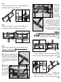
Step 3
Attach the connection bar onto the front axle sub-assembly using M6x17 shoulder
bolts (2), M6 washers (2), M6 lock nuts (2) M10 washer (1) and cotter pin (1).
Step 2
Attach the front strut and yoke to the front axle sub-assembly using M8x170 carriage
bolt (1), M8 washer (1) and M8 lock nut (1). Tighten securely.
Paso 3
Fija la barra de conexión al subensamblaje del eje delantero con (2) pernos de hombro
M6x17, (2) arandelas M6, (2) contratuercas M6, (1) arandela M10 y (1) pasador de
chaveta.
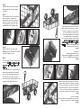
Step 4
Attach the front axle assembly and front strut to the bed using M8x20 carriage bolts
(2), M8 washers (2) and M8 lock nuts (2).
NNOOTTEE:: tthhee hhaarrddwwaarree ttoo aattttaacchh tthhee ffrroonntt
ssttrruutt ttoo tthhee bbeedd iiss pprree--aasssseemmbblleedd ttoo tthhee ssttrruutt..
AA..
Place the front axle assembly and front strut onto
the bed. Attach the front strut to the bed first. Place
the M8x25 carriage bolt (pre-assembled to the strut)
into the pre-punched hole on the bed and slide it into
place. Lift up slightly on the strut and tighten bolt
securely.
BB..
Next secure the
front axle assembly to
the bed using M8x20
carriage bolts (2), M8
washers (2) and M8
lock nuts (2). Tighten
bolts securely.
Paso 4
Fija el ensamblaje del eje delantero y el amortiguador delantero a la cama con (2)
pernos de carro M8x20, (2) arandelas M8 y (2) contratuercas M8.
NNOOTTAA:: eell hheerrrraajjee
ppaarraa ssuujjeettaarr eell aammoorrttiigguuaaddoorr ddeellaanntteerroo aa llaa ccaammaa eessttáá pprreeeennssaammbbllaaddoo ccoonn
eell aammoorrttiigguuaaddoorr..
AA..
Coloca en la cama el ensamblaje del eje
delantero y el amortiguador delantero. Primero fija el
amortiguador delantero a la cama. Coloca el perno
de carro M8x25 (preensamblado con el
amortiguador) en el orificio preperforado en la cama
y deslízalo en su lugar. Levanta ligeramente el
amortiguador y aprieta el perno firmemente.
BB..
Luego, asegura el
ensamblaje del eje
delantero a la cama
con (2) pernos de
carro M8x20, (2)
arandelas M8 y (2)
contratuercas M8.
Aprieta todos los
pernos firmemente.
4A
4B
4A
4B
Paso 2
Fija el amortiguador delantero y la horquilla en el subensamblaje del eje delantero
con un (1) perno de carro M8x170, una (1) arandela M8 y una (1) contratuerca M8.
Ajústalos firmemente.
M10 washer
Arandela M10

Step 5
Attach the rear axle assembly and rear struts onto the bed using M8x20 carriage bolts
(2), M8 washers (2) and M8 lock nuts (2).
NNOOTTEE:: tthhee hhaarrddwwaarree ttoo aattttaacchh tthhee rreeaarr ssttrruuttss ttoo tthhee bbeedd iiss pprree--aasssseemmbblleedd
ttoo eeaacchh ssttrruutt..
AA..
Slide the rear struts
onto each end of the rear
axle assembly.
BB..
Place the rear axle
assembly and rear struts onto
the bed. Attach the rear struts
to the bed first. Place the
M8x25 carriage bolts (pre-
assembled to the strut) into the
pre-punched holes on the bed
and slide them into place. Lift
up slightly on each strut and
tighten bolts securely.
CC..
Next secure the rear axle
assembly to the bed using
M8x20 carriage bolts (2), M8
washers (2) and M8 lock nuts
(2).Tighten bolts securely.
5C
5A
5B
Paso 5
Fija el ensamblaje del eje trasero y los amortiguadores traseros a la cama con
(2) pernos de carro M8x20, (2) arandelas M8 y (2) contratuercas M8.
NNOOTTAA:: eell hheerrrraajjee ppaarraa ssuujjeettaarr llooss aammoorrttiigguuaaddoorreess ttrraasseerrooss aa llaa ccaammaa vviieennee
pprreeeennssaammbbllaaddoo eenn ccaaddaa aammoorrttiigguuaaddoorr..
AA..
Desliza los
amortiguadores traseros
sobre cada extremo del
ensamblaje del eje trasero.
BB..
Coloca el ensamblaje
del eje trasero y los
amortiguadores traseros
sobre la cama.
Primero fija los
amortiguadores traseros a
la cama. Coloca los pernos
de carro M8x25
(preensamblados con el
amortiguador) en los
orificios preperforados en
la cama y deslízalos en su
lugar. Levanta ligeramente
cada amortiguador y
aprieta los pernos
firmemente.
CC..
Luego, asegura el
ensamblaje del eje trasero
a la cama con (2) pernos de
carro M8x20, (2) arandelas
M8 y (2) contratuercas M8.
Ajusta los pernos
firmemente.
L
R
L
R
5C
5A
5B
L
R
L
R

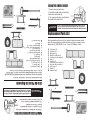
Step 6
Attach the wheels by first placing the
wheel spacers (4) onto the front and
rear axles.
Step 7
Place the wheels onto each axle (valve
stems facing out). Next place the
wheel washers and insert a cotter pin
into the hole at each end of the axles,
then bend back the ends of the cotter
pins with pliers to keep them in place.
Step 8
Attach the handle to the yoke using
M8x60 hex bolt (1), M8 washer (1) and M8
lock nut (1). Tighten securely.
Step 9
The lock handles are pre-assembled onto
the panels.
N
OTE: Do not tighten the lock
nuts on the lock handles until the end of
this step.
Attach the front, back, and side panels (2)
onto the bed using the fence assembly
pins. Latch the front and back panels to
the side panels using the lock handles.
Once all panels are locked together in the
upright position, tighten all lock nuts.
Paso 8
Fija el mango a la horquilla con un (1)
perno de carro M8x60, (1) arandela M8 y
(1) contratuerca M8. Ajústalos
firmemente.
Paso 9
Los mangos de cierre están
preensamblados a los paneles.
N
OTA: No
ajustes las contratuercas de los mangos
de cierre hasta el final de este paso.
Fija los paneles delanteros, traseros y los
(2) laterales a la cama, utilizando los
pasadores de ensamblaje del protector.
Une los paneles frontal y trasero a los
paneles laterales mediante los mangos
de cierre. Una vez que los paneles estén
unidos en posición vertical, ajusta todas
las contratuercas.
Paso 6
Monta las ruedas en el carrito no sin antes
colocar los (4) espaciadores de ruedas en los ejes
delantero y trasero.
Paso 7
Coloca las ruedas en cada eje (los vástagos de
las válvulas hacia afuera). Luego, coloca las
arandelas de las ruedas e inserta un pasador de
chaveta en el orificio de cada extremo de los ejes
y dobla hacia atrás las puntas de los pasadores
de chaveta con alicates para fijarlos en su lugar.

Replacement Parts List
For replacement parts, please visit us online at www.tricam.com to com-
plete the replacement parts submission form or call our customer service
department at 1-800-867-6763, 9 a.m. - 4 p.m., CST, Monday - Friday.
CAUTION
M.
Lista de Piezas de Repuesto
Antes de devolverlo al minorista, visítanos por Internet en
www.tricam.com para completar nuestro formulariode piezas de repuesto
o llama a nuestro departamento de servicio al cliente al 1-800-867-6763,
de 9 a.m. a 4 p.m., Hora Estándar del Centro, de Lunes a Viernes.
B. Paneles Laterales (2)
C. Panel Frontal (1)
D. Panel Posterior (1)
E. Ruedas de 10 plg (25,4 cm) (4)
F. Subensamblaje del Eje
Delantero (1)
G. Horquilla (1)
H. Amortiguador Delantero (1)
I. Barra de Conexión del
Eje Delantero (1)
J. Subensamblaje del Eje Trasero (1)
K. Amortiguadores Traseros (2)
L. Mango (1)
M. Kit de Herrajes (1)
B. Side Panels (2)
C. Front Panel (1)
D. Back Panel (1)
E. 10in (25.4cm) Wheels (4)
F. Front Axle Sub-Assembly (1)
G. Yoke (1)
H. Front Strut (1)
I. Front Axle Connection Bar (1)
J. Rear Axle Sub-Assembly (1)
K. Rear Struts (2)
L. Handle (1)
M. Hardware Kit (1)
C.
D.
E.
F.
L.
B.
M.
K.
C.
D.
E.
F.
G.
H.
I.
J.
L.
B.
K.
G.
H.
I.
J.
DO NOT EXCEED MAXIMUM OVERALL LOAD CAPACITY 800 lbs
(362 kg). PERSON SHOULD NEVER RIDE IN THE UTILITY CART.
WEIGHT RATING IS BASED ON AN EVENLY DISTRIBUTED LOAD.
USING THE SWIVEL HANDLE
1. Remove clips and cotter pins.
2. Rotate the handle and insert cotter pin.
Secure by attaching the clip.
3. The second cotter pin is used to attach
the handle to the trailer hitch.
PRECAUCIÓN
NO SOBREPASAR EL LÍMITE MÁXIMO DE CARGA TOTAL DE
800 LB (362 KG).LAS PERSONAS NUNCA DEBEN MONTAR EL
CARRITO. LA CAPACIDAD DE PESO NOMINAL ESTÁ BASADA
EN UNA CARGA DISTRIBUIDA DE MANERA UNIFORME.
PARA UTILIZAR LA MANIJA GIRATORIA
1. Retire los sujetadores y los pasadores de chaveta.
2. Gire la manija e inserte los pasadores de
chaveta. Fíjela con el sujetador.
3. El segundo pasador de chaveta se usa
para fijar la manija al enganche de remolque.
-
 1
1
-
 2
2
-
 3
3
-
 4
4
-
 5
5
-
 6
6
-
 7
7


Gorilla MH-1242-D El manual del propietario
- Tipo
- El manual del propietario
En otros idiomas
- English: Gorilla MH-1242-D Owner's manual
Documentos relacionados
Otros documentos
-
 Ground Work GW1242 El manual del propietario
-
 TriCam MH2121D Guía de instalación
-
none SC100D2 Guía de instalación
-
Gorilla Carts GORMP-12 El manual del propietario
-
-
 Farm&Ranch FR100F El manual del propietario
-
-
-
 Farm & Ranch FR110-2 Instrucciones de operación
-


