Farm & Ranch FR110-2 Instrucciones de operación
- Tipo
- Instrucciones de operación

Manual del propietario
Modelo FR110-2
Tricam
7677 Equitable Drive
Eden Prairie, MN 55344
www.tricam.com
12/09
• Instrucciones importantes de seguridad
• Instrucciones de ensamblaje
• Identificación de las piezas y aditamentos
PRECAUCIÓN:
Lea, comprenda y siga TODAS las instrucciones antes de utilizar este producto.
Patentes de los EE.UU. y Patentes
Extranjeras Pendientes
Tricam
7677 Equitable Drive
Eden Prairie, MN 55344
www.tricam.com
12/09
• Important Safety Instructions
• Assembly Instructions
• Parts and Hardware Identification
CAUTION:
Read, understand and follow ALL instructions before using this product.
UTILITY CART
Owners Manual
Model FR110-2
Questions, problems, missing parts? Before returning to your retailer, call our customer service
department at 1-800-867-6763, 9 a.m. - 4 p.m., CST, Monday-Friday.
U.S. and Foreign Patents Pending
¿Preguntas, problemas, piezas faltantes? Antes de volver a la tienda, llame a nuestro
Departamento de Servicio al Cliente al 1-800-867-6763, de lunes a viernes de 9 a.m. a 4 p.m.,
hora central estándar.
CARRITO PARA
USO GENERAL
FR110-2-Assy Manual 12/8/09 4:44 PM Page 1

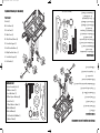
A. Bed (1)
B. Side Panels (2)
C. Front Panel (1)
D. Back Panel (1)
E. 10in (25.4cm) Wheels (4)
F. Rear Axle Support (1)
G. Left Rear Axle Brace (1)
H. Right Rear Axle Brace (1)
I. Front Axle Support (1)
J. Pull Handle (1)
Exploded Drawing for Assembly
Parts List
A. Fence Assembly Pins (8)
B. Washers 8mm (11)
C. Lock Nuts 8mm (11)
D. Wheel Spacer Bushings (4)
E. Cotter Pins (5)
F. Wheel Washers 16mm (4)
G. Bolts 8x20mm (6)
H. Bolts 8x40mm (4)
I. Pull Handle Bolt 8x60mm (1)
J. Washer 10mm (1)
Hardware List
A.
B.
D.
C.
E.
F.
G.
B.
H.
I.
J.
Images are not to scale
B.
D.
C.
E.
F.
G.
H.
I.
A.
A. Base (1)
B. Paneles laterales (2)
C. Panel frontal (1)
D. Panel posterior (1)
E. Ruedas de 25,40 cm (4)
F. Soporte del eje posterior(1)
G. Abrazadera izquierda del eje posterior (1)
H. Abrazadera derecha del
eje posterior (1)
I. Soporte del eje frontal (1)
J. Manija de tiro (1)
Dibujo del despiece para el ensamblaje
Lista de piezas
A.
B.
D.
C.
E.
F.
G.
B.
H.
I.
J.
A. Pasadores de ensamblaje
de la cerca(8)
B. Arandelas de 8 mm (11)
C. Contratuercas de 8 mm (11)
D. Conectores del espaciador
para las ruedas (4)
E. Pasadores de chaveta (5)
F. Arandelas de 16 mm para
las ruedas (4)
G. Pernos de 8 x 20 mm (6)
H. Pernos de 8 x 40 mm (4)
I. Perno de la manija de
tiro de 8 x 60 mm (1)
J. Arandelas de 10 mm (1)
Aditamentos
Images are not to scale
J.
B.
D.
C.
E.
F.
G.
H.
I.
A.
J.
FR110-2-Assy Manual 12/8/09 4:44 PM Page 3

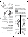
Step 4
A. Attach the front axle support to the bed of the cart using
(2) 8x40mm bolts, (2) 8mm lock nuts, and (2) 8mm washers.
B. Secure the center front axle brace to the bed of the cart
using (2) 8x20mm bolts, (2) 8mm lock nuts, and
(2) 8mmwashers.
Step 2
Assemble the rear support assembly to the back of the
bed using (2) 8x40mm bolts, (2) 8mm lock nuts, and (2)
8mm washers.
Hand tighten. Next
attach the left and
right rear axle braces
using (4) 8x20mm
bolts, (4) 8mm lock
nuts, and (4) 8mm
washers. Tighten all
nuts securely.
1. READ ALL INSTRUCTIONS CAREFULLY BEFORE USE. If you do not understand these instructions, need
clarification or further explanation, please call our toll free answer line for assistance at 1-800-867-6763
Monday through Friday 8:00 a.m. until 5:00 p.m. CST.
2. Do not load cart with more than 400 lbs / 181 kg.
3. Do not allow children to use the cart unsupervised. This cart is not a toy.
4. This product is not to be used for transporting passengers.
5. This product is not to be used for highway use.
6. Always distribute payload evenly over surface of the bed.
7. Do not load any items on top of the panels. Lower panel when objects are to be loaded onto the cart.
8. If any parts become damaged, broken or misplaced, do not use the cart until replacement parts can be obtained.
9. Do not operate or use on objects that can cause damage to the pneumatic tires or tubes. Over-inflation of a tire can
result in serious injury. Do not exceed the maximum tire PSI. Do not inflate tires more than 30 PSI / 2.07 BAR.
10. SAVE THESE INSTRUCTONS
Your Utility Cart requires assembly. Account for all parts and hardware before beginning assembly. If any parts are missing
or damaged, or if you have any questions or need additional instructions, call the manufacturer at 1-800-867-6763.
Tools required for assembly: Medium size slot screwdriver, 6, 8, and 12mm open end wrench and /or two medium
adjustable wrenches.
Step 1
Turn the cart bed upside down. Use the cardboard
from the carton to keep from scratching or damaging
the finish.
Step 5
Install the wheels in the following order:
1. Place the wheel spacer bushings onto the axles.
2. Place the wheels onto the axles with the valve stem
facing out.
3. Use the 16mm washers and the
cotter pins to secure the
wheels.
Important Safety Instructions
Assembly Instructions
Paso 4
A. Fije el soporte del eje frontal a la base del carrito con (2)
pernos de 8 x 40 mm (2) contratuercas de 8 mm y (2)
arandelas de 8 mm.
B. Fije abrazadera central del eje frontal a la base del
carrito con (2) pernos de 8 x 20 mm (2) contratuercas de 8
mm y (2) arandelas de 8 mm.
Paso 2
Fije el ensamble del soporte posterior a la parte
posterior de la base con (2) pernos de 8 x 40 mm
(2) contratuercas de 8 mm y (2) arandelas de 8
mm. Apriete a mano.
A continuación fije las
abrazaderas izquierda y
derecha del eje posterior
con (4) pernos de 8 x 20
mm, (4) contratuercas de 8
mm y (4) arandelas de 8
mm. Apriete firmemente
todas las tuercas.
1. LEA CON ATENCIÓN TODAS LAS INSTRUCCIONES ANTES DE USAR. Si no comprende estas
instrucciones, necesita una aclaración o más explicaciones, llame a nuestra línea gratuita al 1-800-867-6763, de
lunes a viernes de 9 a.m. a 4 p.m., hora central estándar, para obtener ayuda.
2. No cargue el carrito con más de 181,44 kg. (400 lb).
3. No permita que los niños utilicen el carrito sin supervisión. Este carrito no es un juguete.
4. No se debe utilizar este producto para transportar pasajeros.
5. No se debe utilizar este producto en autopistas.
6. Siempre distribuya la carga uniformemente sobre la superficie de la base.
7. No cargue ningún artículo sobre los paneles. Baje el panel cuando deba cargar objetos en el carrito.
8. Si alguna pieza se daña, rompe o pierde, no utilice el carrito hasta obtener las piezas de repuesto.
9. No lo opere ni utilice sobre objetos que puedan dañar las ruedas neumáticas o los tubos. Inflar un neumático en exceso
podría resultar en lesiones graves. No exceda el PSI máximo de los neumáticos. No infle los neumáticos a más
de 30 PSI (2,07 BAR).
10. GUARDE ESTAS INSTRUCCIONES
Su carrito para uso general requiere de ensamblaje. Antes de comenzar el ensamblaje, ubique todas las piezas y
aditamentos. Si falta alguna pieza o éstas están dañadas, o si tiene alguna duda o necesita instrucciones adicionales,
llame al fabricante al 1-800-867-6763.
Herramientas necesarias para el ensamblaje:
Destornillador estándar, llave española de 6, 8
y 12 mm y/o dos llaves ajustables medianas.
Paso 1
Coloque la base del carrito boca abajo.
Utilice el cartón de la caja para evitar rayar o
dañar el acabado.
Paso 5
Instale las ruedas en el siguiente orden:
1. Coloque los conectores del espaciador para las
ruedas en los ejes.
2. Coloque las ruedas en los ejes con el
vástago de la válvula apuntando
hacia fuera.
3. Utilice las arandelas de 16 mm y
los pasadores de
chaveta para
asegurar las ruedas.
Instrucciones importantes de seguridad
Instrucciones de ensamblaje
Step 3
The front support assembly is mostly pre-assembled
at the factory. Please make sure all bolts and nuts
assembled at the factory are tight.
Assemble the front axle support by sliding the arms
onto the support rod and secure by using a 10mm
washer and cotter pin.
Paso 3
El ensamble del soporte frontal viene en gran
parte preensamblado de fábrica. Asegúrese de
que todos los pernos y tuercas ensamblados de
fábrica estén apretados. Montar el soporte del eje
delantero, deslizando los brazos en la varilla de
soporte y seguro mediante una arandela de 10mm
y la chaveta.
FR110-2-Assy Manual 12/8/09 4:44 PM Page 5

DO NOT EXCEED MAXIMUM OVERALL LOAD CAPACITY 400 LBS.
PERSON SHOULD NEVER RIDE IN THE UTILITY CART.
WEIGHT RATING IS BASED ON AN EVENLY DISTRIBUTED LOAD.
CAUTION
NO EXCEDA LA CAPACIDAD TOTAL MÁXIMA DE 181,44 KG.
NUNCA SE DEBE TRANSPORTAR PERSONAS EN EL CARRITO PARA USO GENERAL.
EL ÍNDICE DE PESO ESTÁ CALCULADO EN BASE A UNA CARGA DISTRIBUIDA
UNIFORMEMENTE.
PRECAUCIÓN
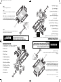
Step 7
Attach the front, back, left and right fences using the fence
assembly pins.
NOTE: Latch the fences in the upright position using the
lock handles. Tighten the nuts on the lock handles to
allow for smooth operation while not being overly tight.
Step 6
Turn the cart upright onto its wheels.
Step 8
Attach the pull handle to the front axel support using the 8x60mm pull
handle bolt, 8mm lock nut and 8mm washer.
Paso 7
Coloque los paneles de cerca frontal, posterior, izquierdo y
derecho utilizando los pasadores de ensamblaje de la cerca.
NOTA: Asegure los paneles de cerca en su posición
vertical utilizando las manijas de bloqueo. Apriete las
tuercas en las manijas de bloqueo para permitir una
operación suave sin que queden demasiado apretadas.
Paso 6
Gire el carrito a la posición vertical, sobre sus ruedas.
Paso 8
Fije la manija a la horquilla con el perno M8 x 60 mm, una contratuerca
M8 y una arandela M8.
B. Side Panels
C. Front Panel
D. Back Panel
E. 10in (25.4cm) Wheels
F. Rear Axle Support
G. Left Rear Axle Brace
H. Right Rear Axle Brace
I. Front Axle Support
J. Pull Handle
K. Hardware Kit
Replacement Parts List
B.
D.
C.
E.
F.
G.
B.
H.
I.
J.
For replacement parts, call our customer service department
at 1-800-867-6763, 9 a.m. - 4 p.m., CST, Monday-Friday.
K.
B. Paneles laterales (2)
C. Panel frontal (1)
D. Panel posterior (1)
E. Ruedas de 25,40 cm (4)
F. Soporte del eje posterior(1)
G. Abrazadera izquierda del eje
posterior (1)
H. Abrazadera derecha del
eje posterior (1)
I. Soporte del eje frontal (1)
J. Manija de tiro (1)
K. Kit de aditamentos
Lista De Piezas Dd Repuesto
B.
D.
C.
E.
F.
G.
B.
H.
I.
J.
Para obtener piezas de repuesto, llame a nuestro Departamento de Servicio al Cliente al 1-800-867-6763, de
lunes a viernes de 9 a.m. a 4 p.m., hora central estándar.
K.
FR110-2-Assy Manual 12/8/09 4:44 PM Page 7
Transcripción de documentos
Tricam 7677 Equitable Drive Eden Prairie, MN 55344 www.tricam.com 12/09 Questions, problems, missing parts? Before returning to your retailer, call our customer service department at 1-800-867-6763, 9 a.m. - 4 p.m., CST, Monday-Friday. CAUTION: Read, understand and follow ALL instructions before using this product. • Important Safety Instructions • Assembly Instructions • Parts and Hardware Identification CARRITO PARA USO GENERAL Model FR110-2 Owners Manual U.S. and Foreign Patents Pending Manual del propietario Modelo FR110-2 • Instrucciones importantes de seguridad • Instrucciones de ensamblaje • Identificación de las piezas y aditamentos Patentes de los EE.UU. y Patentes Extranjeras Pendientes PRECAUCIÓN: Lea, comprenda y siga TODAS las instrucciones antes de utilizar este producto. UTILITY CART ¿Preguntas, problemas, piezas faltantes? Antes de volver a la tienda, llame a nuestro Departamento de Servicio al Cliente al 1-800-867-6763, de lunes a viernes de 9 a.m. a 4 p.m., hora central estándar. Tricam 7677 Equitable Drive Eden Prairie, MN 55344 www.tricam.com 12/09 FR110-2-Assy Manual 12/8/09 4:44 PM Page 1 Dibujo del despiece para el ensamblaje D. Lista de piezas A. Base (1) B. B. A. B. Paneles laterales (2) C. Panel frontal (1) D. Panel posterior (1) C. B. C. E. Ruedas de 25,40 cm (4) F. Soporte del eje posterior(1) G. Abrazadera izquierda del eje posterior (1) Images are not to scale D. E. H. H. Abrazadera derecha del eje posterior (1) F. G. I. Soporte del eje frontal (1) I. J. Aditamentos F. E. G. H. J. D. I. C. B. A. 4:44 PM J. Manija de tiro (1) I. J. H. G. F. G. F. H. C. A. Images are not to scale 12/8/09 A. Pasadores de ensamblaje de la cerca(8) B. Arandelas de 8 mm (11) C. Contratuercas de 8 mm (11) D. Conectores del espaciador para las ruedas (4) E. Pasadores de chaveta (5) F. Arandelas de 16 mm para las ruedas (4) G. Pernos de 8 x 20 mm (6) H. Pernos de 8 x 40 mm (4) I. Perno de la manija de tiro de 8 x 60 mm (1) J. Arandelas de 10 mm (1) J. Washer 10mm (1) I. Pull Handle Bolt 8x60mm (1) A. H. Bolts 8x40mm (4) G. Bolts 8x20mm (6) F. Wheel Washers 16mm (4) E. Cotter Pins (5) D. Wheel Spacer Bushings (4) C. Lock Nuts 8mm (11) E. B. Washers 8mm (11) A. Fence Assembly Pins (8) Hardware List J. I. J. Pull Handle (1) I. Front Axle Support (1) E. H. Right Rear Axle Brace (1) G. Left Rear Axle Brace (1) F. Rear Axle Support (1) E. 10in (25.4cm) Wheels (4) B. D. Back Panel (1) C. Front Panel (1) B. Side Panels (2) B. A. Bed (1) Parts List D. Exploded Drawing for Assembly FR110-2-Assy Manual Page 3 Step 3 Step 5 The front support assembly is mostly pre-assembled at the factory. Please make sure all bolts and nuts assembled at the factory are tight. Assemble the front axle support by sliding the arms onto the support rod and secure by using a 10mm washer and cotter pin. Install the wheels in the following order: 1. Place the wheel spacer bushings onto the axles. 2. Place the wheels onto the axles with the valve stem facing out. 3. Use the 16mm washers and the cotter pins to secure the wheels. Instrucciones importantes de seguridad 1. LEA CON ATENCIÓN TODAS LAS INSTRUCCIONES ANTES DE USAR. Si no comprende estas instrucciones, necesita una aclaración o más explicaciones, llame a nuestra línea gratuita al 1-800-867-6763, de lunes a viernes de 9 a.m. a 4 p.m., hora central estándar, para obtener ayuda. 2. No cargue el carrito con más de 181,44 kg. (400 lb). 3. No permita que los niños utilicen el carrito sin supervisión. Este carrito no es un juguete. 4. No se debe utilizar este producto para transportar pasajeros. 5. No se debe utilizar este producto en autopistas. 6. Siempre distribuya la carga uniformemente sobre la superficie de la base. 7. No cargue ningún artículo sobre los paneles. Baje el panel cuando deba cargar objetos en el carrito. 8. Si alguna pieza se daña, rompe o pierde, no utilice el carrito hasta obtener las piezas de repuesto. 9. No lo opere ni utilice sobre objetos que puedan dañar las ruedas neumáticas o los tubos. Inflar un neumático en exceso podría resultar en lesiones graves. No exceda el PSI máximo de los neumáticos. No infle los neumáticos a más de 30 PSI (2,07 BAR). 10. GUARDE ESTAS INSTRUCCIONES Instrucciones de ensamblaje Hand tighten. Next attach the left and right rear axle braces using (4) 8x20mm bolts, (4) 8mm lock nuts, and (4) 8mm washers. Tighten all nuts securely. Assemble the rear support assembly to the back of the bed using (2) 8x40mm bolts, (2) 8mm lock nuts, and (2) 8mm washers. Step 1 Step 4 Turn the cart bed upside down. Use the cardboard from the carton to keep from scratching or damaging the finish. A. Attach the front axle support to the bed of the cart using (2) 8x40mm bolts, (2) 8mm lock nuts, and (2) 8mm washers. B. Secure the center front axle brace to the bed of the cart using (2) 8x20mm bolts, (2) 8mm lock nuts, and (2) 8mmwashers. Step 2 Tools required for assembly: Medium size slot screwdriver, 6, 8, and 12mm open end wrench and /or two medium adjustable wrenches. Your Utility Cart requires assembly. Account for all parts and hardware before beginning assembly. If any parts are missing or damaged, or if you have any questions or need additional instructions, call the manufacturer at 1-800-867-6763. Assembly Instructions 1. READ ALL INSTRUCTIONS CAREFULLY BEFORE USE. If you do not understand these instructions, need clarification or further explanation, please call our toll free answer line for assistance at 1-800-867-6763 Monday through Friday 8:00 a.m. until 5:00 p.m. CST. 2. Do not load cart with more than 400 lbs / 181 kg. 3. Do not allow children to use the cart unsupervised. This cart is not a toy. 4. This product is not to be used for transporting passengers. 5. This product is not to be used for highway use. 6. Always distribute payload evenly over surface of the bed. 7. Do not load any items on top of the panels. Lower panel when objects are to be loaded onto the cart. 8. If any parts become damaged, broken or misplaced, do not use the cart until replacement parts can be obtained. 9. Do not operate or use on objects that can cause damage to the pneumatic tires or tubes. Over-inflation of a tire can result in serious injury. Do not exceed the maximum tire PSI. Do not inflate tires more than 30 PSI / 2.07 BAR. 10. SAVE THESE INSTRUCTONS Su carrito para uso general requiere de ensamblaje. Antes de comenzar el ensamblaje, ubique todas las piezas y aditamentos. Si falta alguna pieza o éstas están dañadas, o si tiene alguna duda o necesita instrucciones adicionales, llame al fabricante al 1-800-867-6763. Herramientas necesarias para el ensamblaje: Destornillador estándar, llave española de 6, 8 y 12 mm y/o dos llaves ajustables medianas. Paso 1 Coloque la base del carrito boca abajo. Utilice el cartón de la caja para evitar rayar o dañar el acabado. Paso 4 A. Fije el soporte del eje frontal a la base del carrito con (2) pernos de 8 x 40 mm (2) contratuercas de 8 mm y (2) arandelas de 8 mm. B. Fije abrazadera central del eje frontal a la base del carrito con (2) pernos de 8 x 20 mm (2) contratuercas de 8 mm y (2) arandelas de 8 mm. Paso 2 Fije el ensamble del soporte posterior a la parte posterior de la base con (2) pernos de 8 x 40 mm (2) contratuercas de 8 mm y (2) arandelas de 8 mm. Apriete a mano. A continuación fije las abrazaderas izquierda y derecha del eje posterior con (4) pernos de 8 x 20 mm, (4) contratuercas de 8 mm y (4) arandelas de 8 mm. Apriete firmemente todas las tuercas. Paso 5 Paso 3 El ensamble del soporte frontal viene en gran parte preensamblado de fábrica. Asegúrese de que todos los pernos y tuercas ensamblados de fábrica estén apretados. Montar el soporte del eje delantero, deslizando los brazos en la varilla de soporte y seguro mediante una arandela de 10mm y la chaveta. Instale las ruedas en el siguiente orden: 1. Coloque los conectores del espaciador para las ruedas en los ejes. 2. Coloque las ruedas en los ejes con el vástago de la válvula apuntando hacia fuera. 3. Utilice las arandelas de 16 mm y los pasadores de chaveta para asegurar las ruedas. Important Safety Instructions FR110-2-Assy Manual 12/8/09 4:44 PM Page 5 Paso 6 Gire el carrito a la posición vertical, sobre sus ruedas. J. Paso 7 Coloque los paneles de cerca frontal, posterior, izquierdo y derecho utilizando los pasadores de ensamblaje de la cerca. G. E. H. F. NOTA: Asegure los paneles de cerca en su posición vertical utilizando las manijas de bloqueo. Apriete las tuercas en las manijas de bloqueo para permitir una operación suave sin que queden demasiado apretadas. K. Hardware Kit I. J. Pull Handle I. Front Axle Support H. Right Rear Axle Brace G. Left Rear Axle Brace F. Rear Axle Support B. E. 10in (25.4cm) Wheels C. Paso 8 Fije la manija a la horquilla con el perno M8 x 60 mm, una contratuerca M8 y una arandela M8. NO EXCEDA LA CAPACIDAD TOTAL MÁXIMA DE 181,44 KG. NUNCA SE DEBE TRANSPORTAR PERSONAS EN EL CARRITO PARA USO GENERAL. EL ÍNDICE DE PESO ESTÁ CALCULADO EN BASE A UNA CARGA DISTRIBUIDA UNIFORMEMENTE. K. PRECAUCIÓN D. Back Panel B. C. Front Panel B. Side Panels D. For replacement parts, call our customer service department at 1-800-867-6763, 9 a.m. - 4 p.m., CST, Monday-Friday. Replacement Parts List Lista De Piezas Dd Repuesto Para obtener piezas de repuesto, llame a nuestro Departamento de Servicio al Cliente al 1-800-867-6763, de lunes a viernes de 9 a.m. a 4 p.m., hora central estándar. CAUTION DO NOT EXCEED MAXIMUM OVERALL LOAD CAPACITY 400 LBS. PERSON SHOULD NEVER RIDE IN THE UTILITY CART. WEIGHT RATING IS BASED ON AN EVENLY DISTRIBUTED LOAD. K. B. Paneles laterales (2) D. Attach the pull handle to the front axel support using the 8x60mm pull handle bolt, 8mm lock nut and 8mm washer. C. Panel frontal (1) B. D. Panel posterior (1) Step 8 C. E. Ruedas de 25,40 cm (4) F. Soporte del eje posterior(1) G. Abrazadera izquierda del eje posterior (1) B. H. E. NOTE: Latch the fences in the upright position using the lock handles. Tighten the nuts on the lock handles to allow for smooth operation while not being overly tight. F. H. Abrazadera derecha del eje posterior (1) G. Attach the front, back, left and right fences using the fence assembly pins. I. I. Soporte del eje frontal (1) Step 7 J. J. Manija de tiro (1) Turn the cart upright onto its wheels. Step 6 K. Kit de aditamentos FR110-2-Assy Manual 12/8/09 4:44 PM Page 7-
 1
1
-
 2
2
-
 3
3
-
 4
4


Farm & Ranch FR110-2 Instrucciones de operación
- Tipo
- Instrucciones de operación
en otros idiomas
Artículos relacionados
Otros documentos
-
Gorilla MH-1242-D El manual del propietario
-
none SC100D2 Guía de instalación
-
Gorilla Carts GORMP-12 El manual del propietario
-
 TriCam MH2121D Guía de instalación
-
-
-
-
-
