La página se está cargando...

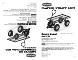
Owner’s Manual
1SHIP+3614
3/14
•Important Safety Instructions
•Assembly Instructions
•Parts and Hardware Identification
CAUTION: Read, understand and follow ALL instructions before using this product.
Questions, problems, missing parts? Before returning to your retailer, visit us online at
www.tricam.com or call our customer service department at 1-800-867-6763, 9a.m. - 4p.m., CST,
Monday - Friday.
CARRO BASCULANTE
MULTIUSO
Manual del Propietario
1SHIPS+3614
Para preguntas acerca del producto:
Tricam
7677 Equitable Drive
Eden Prairie, MN.° 55344
1-800-867-6763
www.tricam.com 3/14
•Instrucciones Importantes de Seguridad
•Instrucciones de Ensamblaje
•Identificación de Piezas y Herrajes
PRECAUCIÓN: Antes de utilizar este producto, lea, comprenda y siga TODAS las instrucciones.
¿Preguntas, problemas, piezas faltantes? Antes de volver al minorista, visita nuestro sitio en Internet www.tri-
cam.com y llena el formulario de solicitud de piezas de repuesto o llama a nuestro departamento de servicio
al cliente al 1-800-867-6763,de Lunes a Viernes entre las 9 a.m. y 4 p.m., Hora Estándar del Centro
For product inquiries:
Tricam
7677 Equitable Drive
Eden Prairie, MN 55344
1-800-867-6763
www.tricam.com
U.S. Patent #s: 6,851,756, 7,390,065, 7,818,865,
7,887,141, 7,210,697, 7,441,792
Canada Patent #s: 2,503,869, 2,590,949
China Patent #: 中国发明专利ZL 200680000909.0
Other U.S. and Foreign Patents Pending
Patentes de los EE.UU.: 6,851,756, 7,390,065,
7,818,865, 7,887,141, 7,210,697, 7,441,792
Patentes de Canadá: 2,503,869, 2,590,949
Patente de China: 中国发明专利ZL 200680000909.0
Otras Patentes de EE.UU. o Extranjeras Pendientes
MULTI-USE DUMP CART
NTEMP-14manual

A.
B.
H.
D.
E.
F.
G.
C.
I.
J.
K.
L.
M.
J.
Exploded Drawing for Assembly
A.Bed Frame (1)
B. Poly Liner / Cover (1)
C. Front Panel (1)
D.Left Panel (1)
E. Right Panel (1)
F. Back Panel (1)
G.Front Axle Assembly (1)
H.Rear Axle Assembly (1)
I. Front Struts (2)
J. Rear Struts (2)
K. Tires (4)
L. Handle (1)
M. Coupling (1)
Parts List
A. M8X60 Hex Head Bolt (1)
B. M8X20 Carriage Head Bolt (10)
C. M8X20 Hex Head Bolt (2)
D. M8 Flat Washer (13)
E. M8 Lock Nut (13)
F. M12 Wheel Spacer (4)
G. M12 Flat Washer (4)
H. M12 Lock Nut (4)
I. Assembly Pins (3)
Hardware List Drawings are not to scale
A.
B.
D.
C. E.
F.
G.
H.
A.
B.
H.
D.
E.
F.
G.
Plano Esquemático de Ensamblaje
A. Armazón de la Plataforma (1)
B. Cubierta / Revestimiento
de Polietileno (1)
C. Panel Delantero (1)
D. Panel Izquierdo (1)
E. Panel Derecho (1)
F. Panel Trasero (1)
G. Conjunto del Eje Delantero (1)
H. Conjunto del Eje Posterior (1)
I. Puntales Delanteros (4)
J. Puntales Posteriores (4)
K. Neumáticos (4)
L. Mango (1)
M. Acoplamiento (1)
Lista de Piezas:
A. Tornillo de Cabeza Hexagonal
M8x60 (1)
B. Tornillo de Carruaje Hexagonal
M8X20 (10)
C. Tornillo de Cabeza Hexagonal
M8x20 (2)
D. Arandela Plana M8 (13)
E. Tuerca de Fijación M8 (13)
F. Separador para Ruedas M12 (4)
G. Arandela Plana M12 (4)
H. Tuerca de Fijación M12 (4}
Î. Pasadores de Ensamblaje
del Protector (3)
Lista de Herrajes Los planos no son a escala
A.
B.
D.
C. E.
F.
G.
H.
C.
I.
J.
K.
L.
M.
J.
I.
I.

1. READ ALL INSTRUCTIONS BEFORE USE. If you do not understand these instructions, need clarification or further
explanation, please call our customer service department for assistance at 1-800-867-6763.
2. Do not load the cart with more than 1,200 lb (544 kg). Do not use the dumping feature of the cart with a load of more
than 500 lb (226 kg). The weight rating is based on an evenly distributed load.
3. Do not allow children to use the cart without supervision. This cart is not a toy.
4. Do not use this cart for transporting passengers.
5. This cart is not intended for highway use.
6. Do not exceed 5 mph.
7. Distribute the load evenly over the surface of the cover / work surface.
8. Do not load items on the top edges of the cover / work surface.
9. If any parts become damaged, broken or misplaced, do not use the cart until replacement parts have been obtained.
10. Do not use the cart on surfaces or for transporting objects that can cause damage to the pneumatic tires or tubes.
Do not inflate the tires to more than 30 PSI / 2.07 BAR.
11. It is recommended that the cart be inspected for damage before each use.
12. KEEP THESE INSTRUCTIONS FOR FURTHER REFERENCE.
Questions, problems, missing parts? Before returning to your retailer, visit us online at www.tricam.com or call our
customer service department at 1-800-867-6763, 9a.m. - 4p.m., CST, Monday - Friday.
Your cart requires assembly. Account for all parts and hardware before beginning assembly. If any parts are missing or
damaged, or if you have any questions or need additional instructions, call the manufacturer at 1-800-867-6763.
Tools required for assembly: standard screwdriver and
metric socket set (or two adjustable wrenches).
Important Safety Instructions
Assembly Instructions
Step 1
Turn the cart bed frame assembly upside down. Use the
cardboard from the carton to keep from scratching or
damaging the finish. The front frame is pre-assembled to the
cart bed frame.
1. LEA TODAS LAS INSTRUCCIONES ANTES DE USAR. Si no comprende estas instrucciones, necesita disipar
alguna duda o necesita una explicación más exhaustiva, solicite asistencia llamando a nuestro departamento
de servicio al cliente al 1-800-867-6763.
2. No cargue el carro con más de 1,200 libras (544 kg). No use el accesorio de descarga del carro con una carga
de más de 500 libras (226 kg). El peso que soporta tiene en cuenta la carga distribuida en forma uniforme.
3. No permita que los niños usen el carro sin supervisión. Este carro no es un juguete.
4. No utilice este carro para transportar personas.
5. Este carro no está diseñado para su uso en vías públicas.
6. No exceda las 5 mph.
7. Distribuya la carga en forma uniforme sobre la cubierta o superficie de trabajo. No lo cargue con más de 100
libras (45 kg).
8. No cargue ningún elemento sobre los bordes de la cubierta o superficie de trabajo.
9. Si alguna de las partes se daña, se rompe o está mal colocada, no use el carro hasta reemplazar dichas partes.
10. No use el carro en superficies o para transportar objetos que puedan dañar los neumáticos o las cámaras.
No infle los neumáticos a más de 30 PSI / 2.07 BAR.
11. Se recomienda verificar el carro después de cada uso.
12. CONSERVE ESTAS INSTRUCCIONES PARA CONSULTARLAS EN EL FUTURO.
¿Preguntas, problemas, piezas faltantes? Antes de volver al minorista, visita nuestro sitio en Internet
www.tricam.com y llena el formulario de solicitud de piezas de repuesto o llama a nuestro departamento de
servicio al cliente al 1-800-867-6763,de Lunes a Viernes entre las 9 a.m. y 4 p.m., Hora Estándar del Centro
El carro necesita ensamblaje. Antes de comenzar el ensamblaje verifique todas las piezas y los herrajes. Si faltan piezas o
están dañadas, o si tiene preguntas o necesita instrucciones adicionales, llame al fabricante al 1-800-867-6763.
Herramientas necesarias para el ensamblaje:
destornillador estándar y juego de cubos (o dos llaves inglesas).
Instrucciones Importantes de Seguridad
Instrucciones de Ensamblaje
Paso 2
Desbloquee la estructura frontal jalando la
manija hacia fuera y coloque el ensamble del
eje posterior bajo la estructura para levantarla
y facilitar el acceso.
Fije el ensamble del eje frontal a la estructura
de la plataforma con (4) pernos cabeza de
hongo M8x20, (4) arandelas planas M8 y (4)
contratuercas M8. Los pernos se deben
insertar primero a través de la estructura y
luego a través del ensamble del eje frontal.
Paso 1
Coloque el conjunto del armazón de la plataforma del carro
boca abajo. Utilice el cartón de la caja para evitar arañazos o
daños al acabado.
El armazón delantero viene previamente ensamblado al
armazón de la plataforma del carro.
Step 2
Unlock the front frame by pulling the
handle out and place the rear axle
assembly under the frame to prop it up for
easier access.
Attach the front axle assembly to the bed
frame using M8x20 carriage bolts (4), M8
flat washers (4) and M8 lock nuts (4). The
bolts should go through the frame first
and then the front axle assembly.

Step 5
Attach the rear axle assembly to the bed
frame using M8x20 carriage bolts (2), M8
flat washers (2) and M8 lock nuts (2).
Hand tighten.
Step 3
Attach the front struts (2) to the bed frame
using M8x20 carriage bolts (2), M8 flat
washers (2) and M8 lock nuts (2). Slide
the M8x20 carriage bolts through the bed
frame first and then through the struts.
Step 6
Slide the rear struts onto the rear
axle assembly and attach the
angled part of the strut to the bed
frame using M8x20 carriage bolts
(2), M8 flat washers (2) and M8
lock nuts (2). Tighten all
hardware securely.
Paso 5
Fije el ensamble del eje posterior a la
estructura de la plataforma con (2)
pernos cabeza de hongo M8x20, (2)
arandelas planas M8 y (2)
contratuercas M8. Apriete a mano.
Paso 3
Fije los (2) puntales frontales a la
estructura de la plataforma con (2)
pernos cabeza de hongo M8x20, (2)
arandelas planas M8 y (2)
contratuercas M8. Deslice los pernos
cabeza de hongo M8x20 a través de la
estructura de la plataforma y luego a
través de los puntales.
Paso 6
Deslice los puntales posteriores hasta el
ensamble del eje posterior y fije la sección
en ángulo del puntal a la estructura de la
plataforma con (2) pernos cabeza de
hongo M8x20, (2) arandelas planas M8 y
(2) contratuercas M8. Ajuste firmemente
todos los aditamentos.
Step 4
Next attach the front struts (2) to the
underside of the front axle assembly using
M8x20 hex head bolts (2), M8 flat washers
(2) and M8 lock nuts (2). Tighten all
hardware securely with socket set.
Paso 4
Luego, fije los (2) puntales frontales a
la parte inferior del ensamble del eje
frontal con (2) pernos cabeza de
hongo M8x20, (2) arandelas planas
M8 y (2) contratuercas M8. Ajuste
firmemente todos los aditamentos con
el juego de dados.
Step 5
Step 5
Step 6
Step 6
Paso 5
Paso 5
Paso 6
Paso 6

Step 8
Place the wheels onto each axle (valve
stems facing out) using the M12 flat
washers (4) and M12 lock nuts (4).
Tighten all nuts securely.
Turn the cart upright onto all 4 wheels.
Step 7
Attach the wheels to the cart by
first placing the wheel spacers (4)
onto the front and rear axles.
Step 9
Attach the mesh panels to
the side of the bed frame.
Each panel has a letter
stamped on it (L, R, F, B) that
corresponds to the same
letters stamped on the
bed frame itself.
Paso 8
Luego, coloque las ruedas en cada eje
(el obús hacia afuera) y por último las
arandelas planas M12 (4) y las tuercas
de fijación (4).
Apriete todas las tuercas firmemente.
Paso 7
Para fijar las ruedas al carro,
primero coloque los
espaciadores para ruedas (4) en
los ejes delantero y posterior.
Paso 9
Fije los paneles de malla en
la parte lateral del armazón
de la plataforma.
Cada panel tiene una letra
estampada (L, R, F, B) que
corresponde a las mismas
letras estampadas en el
armazón de la plataforma.

Step 10
Insert the plastic tray by lining up the openings on the
rim of the tray with the tabs on the top edges of the
side panels. Lock the tray in place by sliding cotter
pins through the tabs.
The plastic tray can also be used as a cover / work
surface. Lock the tray in place by sliding the cotter
pins through the tabs.
Step 11
Attach the handle to the yoke using M8x60
bolt (1), M8 flat washer (1) and M8 lock
nut (1). Tighten securely.
Paso 10
Inserte la bandeja plástica alineando las aberturas
del borde de la bandeja con las lengüetas de los
bordes superiores de los paneles laterales. Bloquee
la bandeja en su lugar deslizando los pasadores de
chaveta a través de las lengüetas.
La bandeja plástica también puede usarse como una
cubierta/superficie de trabajo. Bloquee la bandeja
en su lugar deslizando los pasadores de chaveta a
través de las lengüetas.
Paso 11
Una el mango a la horquilla con un tornillo
M8x60 (1), una arandela plana M8 (1) y
una tuerca de fijación M8 (1). Apriete
firmemente.
DO NOT EXCEED
MAXIMUM EVENLY
DISTRIBUTED OVERALL
PLASTIC TRAY LOAD
CAPACITY: 80 LBS
CAUTION
NO EXCEDA LA
CAPACIDAD MÁXIMA
DE LA CARGA TOTAL
(DISTRIBUIDA
UNIFORMEMENTE) DE
LA BANDEJA: 36.2 KG
PRECAUCIÓN
Using the swivel handle
1. Remove clips and cotter pins.
2. Rotate the handle and insert
cotter pin. Secure by
attaching the clip.
3. The second cotter pin is used
to attach the handle to the
trailer hitch, as shown.
Para utilizar la
manija giratoria
1. Retire los sujetadores y los
pasadores de chaveta.
2. Gire la manija e inserte los
pasadores de chaveta. Fíjela
con el sujetador.
3. El segundo pasador de chaveta
se usa para fijar la manija al
enganche de remolque.

DO NOT EXCEED THE OVERALL MAXIMUM LOAD CAPACITY OF 1,200 lb
OR THE MAXIMUM DUMPING LOAD CAPACITY OF 500 lb.
THE WEIGHT RATING IS BASED ON AN EVENLY DISTRIBUTED LOAD.
CAUTION
Using the Dumping
Feature
To operate the dumping
feature, pull the dumping
release handle outward to
release the bed from the
locking mechanism. Lift up
the release handle to rotate
cart upward into the
dumping position.
Returning the Bed to
the Lowered Position
Rotate the bed back down to
the lowered position. Make
sure the dumping release
handle is locked into place
when the cart is in the
lowered position.
THIS PRODUCT MAY CONTAIN A CHEMICAL KNOWN TO THE STATE OF
CALIFORNIA TO CAUSE CANCER, OR BIRTH DEFECTS OR OTHER
REPRODUCTIVE HARM.
WARNING
NO EXCEDA LA CAPACIDAD MÁXIMA DE CARGA TOTAL DE 544 kg O LA
CARGA MÁXIMA DE DESCARGA DE 226 kg.EL PESO QUE SOPORTA SE
CALCULA CON LA CARGA DISTRIBUIDA EN FORMA UNIFORME.
PRECAUCIÓN
Cómo Usar el
Accesorio de Descarga
Para operar el accesorio de
descarga, tire del mango de
liberación de la descarga
para liberar la plataforma del
mecanismo de bloqueo.
Levante el mango de
liberación para rotar el carro
hacia arriba hasta la posición
de descarga.
Cómo Volver la
Plataforma a la
Posición Más Baja
Gire la plataforma hacia abajo
hasta la posición más baja.
Asegúrese de que el mango
de liberación de la descarga
esté trabado en su lugar
cuando el carro se encuentre
en la posición más baja.
ESTE PRODUCTO PUEDE CONTENER UN COMPONENTE QUIMICO CONOCIDO EN
EL ESADO DE CALIFORNIA COMO CAUSANTE DE CÁNCER, DEFECTOS DE
NAMICIENTO Y OTROS DAÑOS AL SISTEMA REPRODUCTOR.
ADVERTENCIA
LISTA DE PIEZAS DE REPUESTO
Para obtener piezas de repuesto, visitar nuestro sitio en Internet www.tricam.com y llenar el formulario de solicitud de
piezas de repuesto o llamar a nuestro departamento de servicio al
cliente al 1-800-867-6763, de 9 a.m. a 4 p.m., Hora Estándar
del Centro, de Lunes a Viernes.
C. Front Panel (1)
D.Left Panel (1)
E. Right Panel (1)
F. Back Panel (1)
G.Front Axle Assembly (1)
H.Rear Axle Assembly (1)
I. Front Struts (2)
J. Rear Struts (2)
K. Tires (4)
L. Handle (1)
M. Coupling (1)
N. Hardware Kit (1)
C.
H.
G.
C. Panel Delantero (1)
D. Panel Izquierdo (1)
E. Panel Derecho (1)
F. Panel Trasero (1)
G. Conjunto del Eje Delantero (1)
H. Conjunto del Eje Posterior (1)
I. Puntales Delanteros (4)
J. Puntales Posteriores (4)
K. Neumáticos (4)
L. Mango (1)
M. Acoplamiento (1)
N. Kit de aditamentos (1)
I.
J.
K.
L.
M.
J.
N.
REPLACEMENT PARTS LIST
For replacement parts, please visit us online at www.tricam.com to
complete the replacement parts submission form
or call our customer service department at
1-800-867-6763, 9 a.m. - 4 p.m., CST, Monday - Friday.
D.
E.
F.
C.
H.
G.
I.
J.
K.
L.
M.
J.
N.
D.
E.
F.
/