
RJL ACCD
ES
Spain
Safety, Operation & Maintenance Manual
Manual de seguridad, funcionamiento y mantenimiento
Jacobsen HR800 Rotary Mower
Cortacésped rotativo Jacobsen HR800
Kubota® V3307-CR-E5B, With Reversing Fan, 4WD
with ROPS And Cab
Kubota® V3307-CR-E5B, con ventilador de inversión, 4WD
con protección antivuelco y cabina
Series from / Serie desde: AAD000344
Series from / Serie desde: AAE000347
Series from / Serie desde: AAF000301
Series from / Serie desde: AAG000314
Product code / Código de producto: 070543-4613110 / 4624110 / 4613210 / 4623210
4372606-D-ES
ADVERTENCIA
ADVERTENCIA: Si se usa de forma incorrecta esta máquina puede causar graves lesiones. Cualquier persona
que use y mantenga esta máquina deberá estar entrenado en su uso correcto, instruido sobre sus peligros y
deberá leer el manual completamente antes de tratar de instalar, operar, ajustar o revisar la máquina.
WARNING
WARNING: If incorrectly used this machine can cause severe injury. Those who use and maintain this
machine must be trained in its proper use, warned of its dangers and must read the entire manual
before attempting to set up, operate, adjust or service the machine.

1 CONTENTS
SECTION .............................................................................................. PAGESECTION............................................................................................... PAGE
INTRODUCTION
IMPORTANT ................................................................................................... 1
PRODUCT IDENTIFICATION .......................................................................... 2
GUIDELINES FOR THE DISPOSAL OF SCRAP PRODUCTS ....................... 4
DURING SERVICE LIFE ................................................................................. 4
END OF SERVICE LIFE................................................................................... 4
SAFETY
HOW TO OPERATE SAFELY .......................................................................... 7
SAFE OPERATION .......................................................................................... 7
PREPARATION ............................................................................................... 7
OPERATION..................................................................................................... 8
ROPS ........................................................................................................... 9
SAFE HANDLING OF FUELS .......................................................................... 9
MAINTENANCE AND STORAGE .................................................................... 9
LOADING ONTO A TRAILER ......................................................................... 10
IMPORTANT SAFETY NOTES ....................................................................... 11
DECALS
SAFETY DECALS ........................................................................................... 14
INSTRUCTION DECALS................................................................................. 16
CONTROLS
OPERATOR WORKSTATION......................................................................... 18
CONTROL PANEL ......................................................................................... 19
STARTER KEY SWITCH................................................................................. 20
THROTTLE CONTROL ROTARY .................................................................. 20
PARK BRAKE.................................................................................................. 20
HAZARD WARNING SWITCH (OPTIONAL) .................................................. 20
CUTTER SWITCH (PTO) ............................................................................... 21
4WD IN REVERSE SWITCH .......................................................................... 21
LIGHT SWITCH (OPTIONAL) ........................................................................ 21
ROTATING BEACON (OPTIONAL) ............................................................... 21
CRUISE CONTROL SWITCH ......................................................................... 22
TRANSPORT LOCK SWITCH......................................................................... 22
DPF SWITCH ................................................................................................. 22
AUXILARY HYDRAULIC SERVICES KIT ....................................................... 22
VISUAL DISPLAY............................................................................................ 23
STARTUP SCREEN........................................................................................ 23
WARNING / SERVICE SCREEN .................................................................... 23
HOME SCREEN .............................................................................................. 24
ENGINE START ............................................................................................. 24
THE ENGINE WILL NOT START.................................................................... 24
MAIN MENU ................................................................................................... 25
CLOCK & DATE ADJUST ............................................................................... 25
SERVICE MENU ............................................................................................. 25
FAULT LOG..................................................................................................... 25
TIME UNTIL SERVICE ................................................................................... 26
VEHICLE DIAGNOSTICS ............................................................................... 26
I/O DIAGNOSTICS .......................................................................................... 27
SETTINGS ...................................................................................................... 27
MEASUREMENT UNITS ................................................................................ 27
VEHICLE MODES .......................................................................................... 34
CRUISE CONTROL......................................................................................... 34
PIN .......................................................................................................... 35
ADAPTICUT™................................................................................................. 35
VEHICLE SPEED ........................................................................................... 36
DISPLAY INCLINES........................................................................................ 36
AUTO IDLE ..................................................................................................... 36
CROSS CUT ................................................................................................... 37
INCLINOMETER ............................................................................................. 37
SET DEFAULT PARAMETERS....................................................................... 37
CHANGE PIN ................................................................................................. 38
BRIGHTNESS ................................................................................................. 38
LANGUAGE MENU ........................................................................................ 38
WARNING SCREENS ..................................................................................... 39
SLOPE ANGLE DISPLAY ............................................................................... 39
WARNING SLOPE ANGLE – INHIBIT CUT ................................................... 40
WARNING SLOPE ANGLE – STOP CUT ...................................................... 40
WARNING OIL PRESSURE FAULT .............................................................. 40
WARNING ENGINE OVERHEAT ................................................................... 41
WARNING ENGINE FAULT ........................................................................... 41
WARNING BATTERY FAULT ........................................................................ 41
WARNING LOW HYDRAULIC OIL ................................................................. 42
WARNING CHARGE FILTER BLOCKED ...................................................... 42
WARNING SERVICE REQUIRED .................................................................. 42
EMISSION FAULT – DELTA-P SENSOR ....................................................... 42
EMISSION FAULT – EGR NOX CONTROL ................................................... 43
EMISSION FAULT – MAF SENSOR .............................................................. 43
EMISSION FAULT – DPF SENSOR ............................................................... 43
CLEAN DPF ASH ............................................................................................ 43
ECU COMMUNICATION FAULT.................................................................... 44
MCU / DISPLAY COMMUNICATION FAULT................................................. 44
LIFT/LOWER SWITCH’S ................................................................................ 45
INDICATOR LAMPS........................................................................................ 45
WEIGHT TRANSFER ..................................................................................... 45
TRACTION PEDAL.......................................................................................... 46
DRIVING ......................................................................................................... 46
MOWING ......................................................................................................... 46
STEERING TILT CONTROL ........................................................................... 47
HORN .......................................................................................................... 47
POWER OUTLET............................................................................................ 47
PARK BRAKE RELEASE VALVE ................................................................... 48
FREE WHEEL ................................................................................................ 48
LIGHTING KIT (OPTIONAL) .......................................................................... 49
SEAT RIGHT HAND ARM REST & POD ....................................................... 49
CABIN CONTROLS......................................................................................... 50
OPERATION
DAILY INSPECTION ...................................................................................... 51
OPERATOR PRESENCE AND SAFETY INTERLOCK SYSTEM .................. 52
PROCEDURE FOR OPERATION................................................................... 53
FITTING CUTTER DECKS TO THE MACHINE ............................................. 54
OPERATION OF THE MACHINE ................................................................... 57
HOW TO START THE ENGINE ..................................................................... 57
HOW TO DRIVE.............................................................................................. 57
HOW TO MOW ............................................................................................... 58
TO STOP THE ENGINE.................................................................................. 58
TO REMOVE A BLOCKAGE FROM CUTTING UNITS .................................. 58
TRANSPORTING ON A TRAILER ................................................................. 59
SLINGING AND JACKING THE MACHINE .................................................... 59
MOWING ON SLOPES .................................................................................. 60
HOW TO CALCULATE A SLOPE ................................................................... 61
ADJUSTMENTS
GENERAL PRECAUTIONS ............................................................................ 64
ENGINE FAN BELT ........................................................................................ 64
WEIGHT TRANSFER ADJUSTMENT ............................................................ 65
STEERING SHAFT ADJUSTMENT ............................................................... 65
AXLE STOP ADJUSTMENT ........................................................................... 65
HEIGHT OF CUT ADJUSTMENT (FRONT DECK) ........................................ 66
HEIGHT OF CUT ADJUSTMENT (WING CUTTER DECKS .......................... 67
GENERAL INSTRUCTIONS FOR GRAMMER SEATS .................................. 68
AIR SUSPENSION SEAT (GRAMMER MSG95 -721) ................................... 69
MAINTENANCE
MAINTENANCE AND LUBRICATION CHARTS............................................. 72
MACHINE SERVICE INTERVAL CHART ...................................................... 72
FLUID REQUIREMENTS ............................................................................... 72
ENGINE SERVICE INTERVAL CHART .......................................................... 74
GENERAL PRECAUTIONS ............................................................................ 75
ENGINE ......................................................................................................... 76
ENGINE LUBRICATION.................................................................................. 77
ENGINE COOLANT ....................................................................................... 78
HYDRAULIC SYSTEM .................................................................................... 80
HYDRAULIC FILTER ...................................................................................... 81
HYDRAULIC TEST PORTS ............................................................................ 82
FUEL .......................................................................................................... 83
FUEL SYSTEM ............................................................................................... 84
AIR CLEANER ................................................................................................ 85
BATTERY ........................................................................................................ 86
CHARGE THE BATTERY ............................................................................... 87
ENGINE EXHAUST ........................................................................................ 87
DIESEL PARTICULATE FILTER .................................................................... 88
HYDRAULIC HOSES ..................................................................................... 89
WHEEL ALIGNMENT PROCEDURE ............................................................ 90
STEERING ROD AND STEERING LINK CHECK.......................................... 91
TYRES .......................................................................................................... 92
WHEEL MOUNTING PROCEDURE .............................................................. 92
BLADE CHANGE .......................................................................................... 93
INSPECTING BLADES ................................................................................. 94
SHARPENING BLADES ................................................................................ 94
FOLDING ROPS ........................................................................................... 95
CARE AND CLEANING.................................................................................. 96
MOWER STORAGE....................................................................................... 97
LUBRICATION OF CUTTING UNIT ............................................................... 98
PROBLEM SOLVING
ENGINE PROBLEM DIAGNOSTICS ............................................................. 100
QUALITY OF CUT PROBLEM SOLVING ...................................................... 102
ELECTRICAL
FUSE AND RELAY/COMPONENT IDENTIFICATION................................... 110
SPECIFICATION
ENGINE SPECIFICATION ............................................................................ 113
DIMENSIONS & WEIGHTS ........................................................................... 114
MACHINE SPECIFICATION .......................................................................... 116
VIBRATION ................................................................................................... 117
NOISE ......................................................................................................... 118
SLOPES ........................................................................................................ 118
CUTTING PERFORMANCE........................................................................... 118
CUTTER DECK SPECIFICATION ................................................................. 119
RECOMMENDED LUBRICANTS .................................................................. 119
ACCESSORIES ............................................................................................. 120
THIRD PARTY ACCESSORIES .................................................................... 120
AFTERSALES
GUARANTEE ................................................................................................ 121
WARRANTY .................................................................................................. 121
SERVICE ....................................................................................................... 121

en-1
INTRODUCTION 2
2.1 IMPORTANT __________________________________________________________
The HR800 with Diesel engine is a self propelled rotary mower. With hydraulic systems to power the traction
drive, the cutting unit lift and lower, the cutting unit drives and the steering.
IMPORTANT: Do the maintenance indicated in this manual to make sure that the quality of cut is kept at a high
level.
This Manual is part of the machine and must stay with the machine always. The suppliers of new, or used,
machines need to keep this documentation and supply the owners with a copy.
You must use the machine to cut the grass only and not for any other purpose. The Compliance with these con-
ditions of The operation, service and repair specified by the manufacturer, are understood to be part of the cor-
rect use.
ALL operators MUST read through this manual and understand the Safety Instructions, controls, lubrication and
maintenance procedures.
Make sure that you obey all safety and road traffic regulations.
You must not make any changes to the machine that are not approved by the manufacturer. This type of change
can release the manufacturer from the liability for any damage or injury.
Discard of worn parts in alignment with all local environment protection regulations. Use the local systems avail-
able in the country where the machine is used, for these recycled materials. When the machine is at its end of
life, there are guidelines in this manual for the removal of the machine from use.
Use only Jacobsen Genuine spare parts to meet the machine type approval regulations specified by the Euro-
pean Union.
2006/42/EC
These instructions are the Original instructions confirmed by Ransomes Jacobsen Limited
CALIFORNIA PROPOSITION 65
WARNING
The engine exhaust from this product contains
chemicals known to the State of California to cause
cancer, birth defects and other reproductive harm.
!
©2023 Ransomes Jacobsen Limited. All Rights Reserved.
Ransomes Jacobsen Limited reserves the right to make design changes without obligation to make these changes on units
previously sold and the information contained within this manual is subject to change without notice.

en-2
2 INTRODUCTION
2.2 PRODUCT IDENTIFICATION ___________________________________________
A Maximum front axle load in Kg (for all machines being driven
on the highway)
B Weight-Mass in Kg
C Maximum rear axle load in Kg (for all machines being driven
on the highway)
D Power Rating in Kw
E Date code
F Machine type (Name)
G Product code
H Product name
J Serial number
Location of Serial number plate
The serial number plate (A) is found on the front of the
chassis, between the front deck stops next to the
environmental noise decal (B).
Chassis Stamp
The Serial number and date code (C) are shown on the
chassis between the serial plate and engine data decals (D).
Engine Identification
Serial number plate
Location of Engine Serial number plate
The engine serial number is found on the top of the valve cover toward
the front of the mower. Label shows the engine group and serial
number.
The engine serial number is also found on the engine block.
Kg Kw
Kg Kg
Ransomes Jacobsen Ltd.
West Road
Ransomes Europark
Ipswich IP3 9TT
England
ABCD E
FG
HJ
.5
$
&'
%
A
B
C
D
MADE IN JAPAN
V3307
Serial No.:
Code No.:
XXXXXXX
XXXXX-XXXXX
MADE IN JAPAN
V3307
Serial No.:
Code No.:
XXXXXXX
XXXXX-XXXXX

en-3
INTRODUCTION 2
CD
E
Kg
A
F
Ransomes Jacobsen ltd.
West Road
Ransomes Europark
Ipswich IP3 9TT
England
B
ROPS Serial number plate
A Reference Mass
B Date Code
C Standard Used
D Part Number
E For Product
F Serial Number
ROPS Serial number plate Location
The ROPS serial number plate (C) is found at the base of the front of the
ROPS main beam.
Cabin Serial number plate
Cabin Serial number plate Location
The cab serial number plate (C) is located on the front face of the control
panel facing forwards.
FG
H
Kg
B
J
West Road
Ransomes Europark
Ipswich IP3 9TT
England
E
C
DIETEG
GERÄTEBAU GMBH & CO. KG
MODEL N0. 50 048 0000
SERIAL NO. 50 048 / #########
APPROVED FOR THE MP SERIES
OECD APPROVAL No. 4 / N950/14/16923
DIETEG GERÄTEBAU GMBH & C0.KG
FUHRENKAMP 1
D-29664 WALSRODE
C
DIETEG
GERÄTEBAU GMBH & CO. KG
D-29664 WALSRODE
MODEL N0. 50 048 0000
SERIAL NO. 50 048 / #########
APPROVED FOR THE MP SERIES
OECD APPROVAL No. 4 / N950/14/16923
DIETEG GERÄTEBAU GMBH & C0.KG
FUHRENKAMP 1

en-4
2 INTRODUCTION
2.3 GUIDELINES FOR THE DISPOSAL OF SCRAP PRODUCTS ____________________
2.3.1 DURING SERVICE LIFE _______________________________________________
All the used fluids and parts must be controlled as hazardous materials material. Recommended procedures must be
followed for their safe removal.
If a fluid leak occurs, contain the spill to make sure that the leak does not flow into the ground or drainage system.
Follow the regulations in force to make sure that leaks are controlled.
The maintenance procedures in this manual make sure that the damage that the machine can cause in the local
environment is controlled.
When the machine completes its full service life, the following actions must be taken.
2.3.2 END OF SERVICE LIFE _______________________________________________
These guidelines must be used with applicable Health, Safety and Environmental laws. Always use the approved local
waste disposal and agencies for recycled materials.
• Park the machine in an applicable area to use all of the necessary lifting equipment.
• Use correct tools and Personal Protective Equipment (PPE) and take instruction from the technical
manuals applicable to the machine.
• Remove and store correctly
1. Batteries
2. Fuel
3. Engine coolant
4. Oils
• Read the Technical Manual before you begin to disassemble the machine. Plan the disassembly, give
attention to parts that are in a state of mechanical pressure or contain stored energy e.g springs.
• Items that continue to have a service life must be separated and returned to the local dealer.
• Items that are worn must be separated into the material groups and removed according to the agencies
for the recycled materials that are available. Common examples.
• Steel
• Non ferrous metals
• Aluminium
• Brass
• Copper
• Plastic materials
• Identified
• Can be recycled
• Can not be recycled
• Not identified
• Rubber
• Electrical and Electronic Components
• Some parts are not easily separated e.g Hydraulic hose. These materials must be added to the
“General discarded materials” area.
• Do not burn discarded materials.
Change the machinery records to show that the machine is not in operation and is discarded. Supply this serial number
to The Jacobsen Warranty Department to close their records.

en-5
INTRODUCTION 2
2.4 PARTS MANUAL ______________________________________________________
To meet the standard ISO14001, Ransomes Jacobsen Limited does not send a paper parts manual with every
product.
To refer to the parts list for this mower you have four options:
1. Website – www.ransomesjacobsen.com. Select the “ONLINE PARTS LOOK-UP” tab. These pages will
show the parts list and the line drawings you need to help with the identification of spare parts.
2. Website – www.ransomesjacobsen.com. Select the “MANUALS” tab. You have the option to view or
“Download” a PDF version of the parts manual.
3. Complete the form included in the technical manual pack supplied with the machine for one of the two
options below
a. A disc that contains an electronic copy of the Parts Book.
b. A paper copy of the parts manual.
2.5 KEY NUMBERS _______________________________________________________
Record the key numbers
Starter Switch Key:- - - - - - - - - - - - - - - - - - - - - - - - - - - - - - - - - - - - - - - - - - - -
Diesel tank Filler Cap:- - - - - - - - - - - - - - - - - - - - - - - - - - - - - - - - - - - - - - - - - -
Record the machine and the engine numbers.
The machine serial number is found on the registration plate and the engine serial number is on the rocker cover.
Machine Serial Number:- - - - - - - - - - - - - - - - - - - - - - - - - - - - - - - - - - - - - - - -
Engine Serial Number:- - - - - - - - - - - - - - - - - - - - - - - - - - - - - - - - - - - - - - - - - -
2.6 SERVICE SUPPORT MATERIAL ___________________________________________
Part No. Description
4372607 Parts manual
4372608 Kubota Engine Parts manual

en-6
2 INTRODUCTION
NOTES

en-7
SAFETY 3
3.1 HOW TO OPERATE SAFELY _____________________________________________
3.1.1 SAFE OPERATION ___________________________________________________
a Read the Operator’s Manual and other training material. If the operator or technician can not read this
manual, the owner is responsible to describe this material to the operators and technicians. Manuals in
additional languages may be available on the Jacobsen or Ransomes Jacobsen website.
a Read all of the instructions for this mower carefully. Know the controls and the correct operation of the
equipment.
b Children or persons who do not understand these instructions must not use the mower. The local
regulations can limit the age of the operator.
c Never use a mower near persons, including children or animals.
d Remember that the operator or owner is responsible for accidents or hazards that occur to other persons or
their property.
e Never carry passengers.
f Never allow persons to operate or service the mower or its attachments without correct instructions.
g Do not operate equipment while tired, sick or after you use alcohol or drugs.
3.1.2 PREPARATION ______________________________________________________
a When you operate the mower, wear correct clothing, slip resistant work shoes or boots, work gloves, hard
hat, safety glasses and hearing protection. Long hair, loose clothing or jewelry can be caught in moving
parts.
b Do not operate the equipment with the Interlock System disconnected or the system does not operate
correctly. Do not disconnect or prevent the operation of any switch.
c Never operate equipment that is not in correct order or without decals, guards, shields, deflectors or other
protective devices fastened. When you mow with a side discharge deck, DO NOT operate the cutting unit
without the discharge chute installed.
d Inspect the mower before you operate the mower. Check the tyre pressure, engine oil level, the radiator
coolant level and the air cleaner indicator. Fuel is flammable. Use caution when you add the fuel to the
mower.
e Operate the mower in daylight or in good artificial light. Use caution when you operate the mower during
bad weather. Never operate the mower with lightning in the area.
f Inspect the area to select the accessories and attachments that are needed to correctly and safely do the
job. Only use parts, accessories and attachments approved by Manufacture.
g Be careful of holes in the terrain and other hazards that are not visible.
h Inspect the area where the equipment is operated. Remove all objects you can find before you operate. Be
careful of obstructions above the ground (low tree limbs, electrical wires) and also underground obstacles
(sprinklers, pipes, tree roots). Enter a new area carefully. Look for possible hazards.
i Inspect the cutting system before you start the mower. Make sure the blades are free to rotate. When you
rotate one blade, other blades can rotate.
WARNING
EQUIPMENT OPERATED INCORRECTLY OR WITHOUT TRAINING CAN BE DANGEROUS.
Know the location and correct operation of controls. Operators without experience must receive instruction from
another person that knows the correct operation of the equipment before you operate the mower.
Only use parts, accessories and attachments approved by Jacobsen.
!

en-8
3 SAFETY
3.1.3 OPERATION ________________________________________________________
a Never operate the engine without enough ventilation or in an enclosed area. The carbon monoxide in the
exhaust fumes can increase to dangerous levels.
b Never carry passengers. Keep other persons or animals away from the mower.
c Disengage all drives and engage the parking brake before you start the engine. Only start the engine with
the operator in the seat. Never start the engine with persons near the mower.
d Keep your legs, arms and body inside the operator compartment while the mower is in operation. Keep
your hands and feet away from the cutting units.
e Do not use on the slopes greater than the safe slope limit for the equipment.
f To guard against over turning or loss of control:
– Operate the mower up and down on the face of slopes (vertically), but not across the face (horizontally).
– Do not start or stop suddenly on slopes.
– Decrease the speed when you operate on slopes or when you must turn. Use caution when you change
direction. Turf condition can change the mower stability.
– Use caution when you operate the mower near drop-offs, ditches or embankments.
– Be careful of holes in the terrain and other hazards that are not visible.
g When you drive in the reverse direction, look behind you and down to make sure the path is clear. Do not
operate the cutting units when you drive in the reverse direction.
h Use caution when you go near corners, trees or other objects that can prevent a clear view.
i Equipment must meet the current regulations to be driven on the public roads.
j Before you move across or operate on the paths or roads, turn off the PTO switch, lift the mowers and
travel at decreased speed. Look for traffic.
k Stop the blades when the mower is on any surface that is not grass.
l Do not release the cut grass in the direction of persons or allow persons near the mower while in operation.
m Do not operate the mower with damaged guards or without safety devices in position.
n Do not change the engine governor setting or over-speed the engine. Never change or tamper with
adjusters that are closed with a seal for the engine speed control.
o Before you leave the operator compartment, for any reason:
– Disengage all the drives and lower attachments to the ground.
– Engage the parking brake.
– Stop the engine and remove the key.
p When you hit an object or mower starts to cause the vibration that is not normal, inspect the mower for
damage and make repairs.
q Decrease the throttle setting before you stop the engine.
r Do not use this equipment for uses that the mower was not made for.

en-9
SAFETY 3
3.1.4 ROPS______________________________________________________________
a The ROPS is a safety device. Keep the ROPS in the vertical and locked position. Always use the seat belt
when you operate the mower. Make sure the seat belt can be released quickly in an emergency.
b The ROPS should only be folded if absolutely necessary for storage or when working on flat ground under
low obstructions. Do not operate the mower with the ROPS in the folded position on slopes, near sharp
edges or near water. There is no roll over protections with the ROPS in the folded position
c Do not operate the mower with the ROPS in the folded position on slopes, near sharp edges or near water.
There is no roll over protections with the ROPS in the folded position.
d Check for clearance before you drive below objects. Do not contact tree branches, electrical wires or other
objects with the ROPS.
e Do not use the seat belt with the ROPS in the folded position.
f Inspect the ROPS for damage. Keep the ROPS hardware fastened.
g Do not weld, drill, change or bend the ROPS. Replace a damaged ROPS. Do not try to correct a damaged
ROPS.
h Do not remove the ROPS from the mower.
i Jacobsen must approve any changes to the ROPS.
3.1.5 SAFE HANDLING OF FUELS___________________________________________
a The fuel and the fuel vapors are flammable. Use caution when you add the fuel to the mower. The fuel
vapors can cause an explosion.
b Never use the containers that are not approved to keep or transfer fuel.
c Never keep the mower or fuel containers near an open flame or any device that can cause the ignition of
fuel or fuel vapors.
d Never fill the fuel containers inside a vehicle or on a truck or trailer with a plastic liner. Always put the fuel
container on the ground away from your vehicle before you fill the container.
e Refuel the mower before you start the engine. When the engine is in operation or while the engine is hot,
never remove the fuel cap or add fuel to the mower.
f Refuel outdoors only and do not smoke when you add fuel. Extinguish all types of ignition.
g The fuel nozzle must touch the rim of the fuel tank when you add fuel to the mower. Do not use a device to
lock the fuel nozzle in the open position.
h Do not over fill the fuel tank. Leave at least 1 inch (25 mm) below the filler neck.
i Always tighten the fuel tank cap and container cap after you add fuel.
j If the fuel spills on your clothing, change your clothing immediately.
3.1.6 MAINTENANCE AND STORAGE ________________________________________
a Before you clean, adjust or repair this equipment, push PTO switch to the OFF position, lower the cutting
unit to the ground, engage the parking brake, stop the engine and remove the key.
b Make sure the mower is parked on a solid and level surface.
c Never work on a mower that is lifted only by the jack. Always use the jack stands.
d Never allow persons to service the mower or its attachments without correct instructions.
e When the mower is parked, put into storage or left without an operator, lower the cutting device unless a
positive mechanical lock is used.
When you put the mower on a trailer or put the mower in storage, close the fuel valve. Do not keep fuel near
flames or drain the fuel inside a building.

en-10
3 SAFETY
f Disconnect the battery before you service the mower. Always disconnect the negative battery cable before
the positive battery cable. Always connect the positive battery cable before the negative battery cable.
g Charge the battery in an area with good airflow. The battery can release hydrogen gas that is explosive. To
prevent an explosion, keep any device that can cause sparks or flames away from the battery.
h Disconnect the battery charger from the power supply before you connect or disconnect the battery charger
to the battery. Wear protective clothing and use insulated tools when you service the battery.
i Be careful and wear gloves when you check or service the cutting unit blades. Replace any damaged
blades, do not try to correct a damaged blade.
j Keep your hands and feet away from parts that move. Do not adjust the mower with the engine in
operation, unless the adjustment needs the engine in operation.
k Carefully release the pressure from components with stored energy.
l To prevent injury from the hot, high pressure oil, never use your hands to check for oil leaks. Use the paper
or cardboard to find leaks.
m The hydraulic fluid pressure can have enough force to enter your skin. If hydraulic fluid has entered your
skin, a doctor must remove the hydraulic fluid surgically within a few hours or gangrene can occur.
n When you service the hydraulic system, make sure the hydraulic fittings, tubes and hoses are tightened to
the correct torque. Make sure the hydraulic system is in good condition before you start the engine.
o Keep the mower and the engine clean.
p Allow the engine to become cool before storage and always remove the ignition key.
q Keep all nuts, bolts and screws tight to make sure the equipment is in safe condition.
r Replace worn or damaged parts for safety. Replace damaged or worn decals. Only use parts, accessories
and attachments approved by Jacobsen.
s To decrease the fire hazard, remove materials that burn from the engine, muffler, battery tray and fuel tank
area.
t Disconnect the battery and controller connectors before you weld on this mower.
3.1.7 When you Put the mower on a trailer____________________________________
a Be careful when you load or unload the mower on a trailer. Trailer must be wider than the mower and can
carry the weight of the mower.
b Use a full-width ramp to load or unload the mower on a trailer.
c Use straps, chains, cables or ropes to fasten the mower to the trailer. Both front and rear straps must be
sent down and toward sides of trailer.
Make sure that all latches are correctly fastened.

en-11
SAFETY 3
3.1.8 Important Safety Notes _______________________________________________
This safety alert symbol is used to alert you to possible hazards.
DANGER:
Indicates a dangerous condition that WILL cause death or injury unless it is prevented.
WARNING:
Indicates a dangerous condition that CAN cause death or injury unless it is prevented.
CAUTION:
Indicates a dangerous condition that can cause injury and property damage unless it is prevented. Also, the label
can indicate work procedures that are not safe.
IMPORTANT:
Only drive the machine at road speed when you are on a highway. You must not select road speed on grass
areas or rough roads and gravel tracks.
Some illustrations in this manual can show shields, guards or plates removed for clearness. This equipment must
not be operated without these devices correctly fastened in position.
By following all instructions in this manual, you increase the life of your machine and keep its maximum
performance. Adjustments and maintenance must always be done by an approved technician.
If additional information or service is needed. Contact your Authorized Jacobsen Dealer, who knows the latest
methods to service this equipment and can give that service.
WARNING
The Interlock System on this mower prevents the starting of the mower unless a.) The parking brake is
Engaged. b.) The mow switch is in the OFF position, c.) The traction pedal is in the Neutral position. d) The
operator is in the seat. The system stops the engine when the operator leaves the seat a.) without the parking
brake engaged or b.) the mow switch is not in the OFF position. NEVER operate the mower unless the
Interlock System is working.
WARNING
1. Before leaving the operator’s position for any reason:
a. Return traction pedal to the Neutral position.
b. Disengage all drives.
c. Lower all implements to the ground.
d. Engage parking brake.
e. Stop the engine and remove the ignition key.
2. Keep your hands, feet, and clothing away from moving parts. Wait for all movement to stop before you
clean, adjust, or service the machine.
3. Keep the area of operation clear of all persons and animals.
4. Never carry any passengers.
5. Never operate the equipment without a correctly fastened grass deflector in position.

en-12
3 SAFETY
WARNING
California Proposition 65
Engine Exhaust, Some Of Its Constituents, And Some Vehicle Components Contain Or Release Chemicals
Known To The State Of California To Cause Cancer And Birth Defects Or Other Reproductive Harm.
WARNING
To Prevent Injury From The Hot Oil At High Pressure, Do Not Use Your Hands To Check For Oil Leaks. Make
Sure That You Use Paper Or Cardboard.
Release Of Hydraulic Fluid At High Pressure Has Enough Force To Enter Through The Skin. If The Fluid Enters
Through The Skin, The Fluid Must Be Surgically Removed Within Hours By A Specialist Doctor Or Gangrene
May Result.
WARNING
When The Machine Is Driven Off-Road, A Seat Belt Must Be Worn Only When A Rops Frame Is In Position.
This Warning Is Because A Seat Belt Must Be Worn With A Rops To Follow The Machinery Directive,
2006/42/EC Sections 3.2.2, Seating & 3.4.3, Rollover. (ANSI B71.4-2012 section 20.7)
Ransomes Jacobsen Limited Recommends That The Owner/User Of The Machine Completes A Local Risk
Assessment Of The Machine To Find Any Conditions That Do Not Follow This Rule. E.g. When You Drive The
Machine Next To Water Or On The Highway.
WARNING
Explosive Gases Are Released By Batteries. The Battery Contains Corrosive Acid And Supply An Electrical
Current That Is High Enough To Cause Burn Injuries To The Body.
WARNING
You Must Not Use This Machine To Tow Other Vehicles.
WARNING
Ear Protection Must Be Worn When You Operate Machines With
An Operator Ear Noise Level Of More Than 85 db(A) Leq.

en-13
SAFETY 3
WARNING
Vibration Exposure Limits
Exposure limits are calculated as a combination of the vibration level (magnitude) of the tool and the
Daily Exposure Time (Trigger Time). E.g. A product with 5m/s² vibration can be used up to 2 hours/day to
reach the EAV and up to 8 hours/day to reach the ELV.
Exposure Action Value (EAV) - Daily vibration exposure A(8) = 2.5m/s²
Where daily vibration exposure A(8) is below 2.5m/s² the risk is relatively low and no action need be
taken
Exposure Limit Value (ELV) - Daily Vibration Exposure A(8) = 5.0m/s²
If several tools are use the exposure values must be combined:
Total exposure is then the combined value of the activities
WARNING
Never Mow If There Is A Risk Of Lightning Or You Hear Thunder. If You Are In The Middle Of Mowing,
Stop In A Safe Place, Turn Off The Engine And Go Inside a Building.
CAUTION
When You Do Any Welding On The Machine, The Battery, Controller And Display Must Be Disconnected
Before You Start. You Must Not Open The Controller. If The Controller Is Opened, This Can Cancel All Of The
Warranties And Can Cause The Failure Of The Machine.
CAUTION
Personal Protective Equipment (PPE), For Example Safety Glasses, Leather Work Shoes Or Boots, A Hard
Hat, Leather Work Gloves And Ear Protection Must Be Used After The Owner/User Completes A Local Risk
Assessment Of The Mower, To Prevent Injury.
Training In All Manual Operations Must Be Given By An Approved Person Before The Machine Is Used The
First Time.

en-14
4 DECALS
4.1 SAFETY DECALS _____________________________________________________
AAB C D
EF G H
J
N
K L M M

en-15
DECALS 4
A. 009034920 Caution, Stay Away From Hot Surfaces.
B. 009034880 Caution, Fan Blade, Do Not Open Or Remove The Safety Shields While The Engine Is
In Operation.
C. 009034900 Caution, Drive Belt, Do Not Remove The Safety Shields While The Engine Is In
Operation.
D. 4324674 Caution, Low Sulfur Diesel Fuel.
E. 4118415 Caution, Engine Coolant Under Pressure.
F. 009034890 Caution, Keep A Safe Distance From The Machine.
G. 009034960 Caution, Rotating Blades
H. 009114380 Caution, Fasten Seat Belt
J 4153197 Caution, Stop The Engine And Remove The Starter Key Before You Pressure Wash
The machine.
K. 4170640 Caution, Stop Engine & Remove the Starter Key, Lock Deck in its Vertical Position
Before Carrying Out Maintenance Under Deck
L. 4164860 Caution, Hydraulic Oil
M. 4165644 Caution, No Step
N 4321506 Decal, Seal Plate 19°
4252558 Decal, Seal Plate 15°
4334846 Decal, Seal Plate 17°
a. Read The Operator Manual.
b. Crush Hazard.
c. Keep A Safe Distance From The Machine.
d. Prevent Contact With Hydraulic-Oil Release Under Pressure. Read Operator Manual
For Service Procedures.
e. Danger Of Explosion If The Battery Terminals Are Short Circuited.
f. Maximum Permitted Slope. (See Accessories Section For Correct Limit With Different
Accessories).
g. When The Machine Is Being Used Off Road, Whether Cutting Grass Or Not, The Seat
Belt Must Only Be Worn When A ROPS Frame Is In Place And Deployed.

en-16
4 DECALS
4.2 INSTRUCTION DECALS _____________________________________________
B
E
C
F
A
TOTAL EQUIVIS ZS 46
4286422
G
API
CLASSIFICATION
CJ-4
D
K
K
X
X
1-2-3 S
S
1.0 IN
1.5 IN
2.0 IN
2.5 IN
3.0 IN
3.0 IN
3.5 IN
4.0 IN
4.5 IN
5.0 IN
5.0 IN
5.5 IN
6.0 IN
25 MM A
A
10
28 MM B
B
11
50 MM C
C
12
63 MM D
D
13
76 MM E
E
14
76 MM E 2 0
88 MM F
F
21
101 MM G
G
22
114 MM H
H
23
127 MM J
J
24
127 MM J 3
1
2
3
0
140 MM K
K31
152 MM L
L
32
4339906
K
K
X
X
1-2-3 S
S
1.0 IN
1.5 IN
2.0 IN
2.5 IN
3.0 IN
3.0 IN
3.5 IN
4.0 IN
4.5 IN
5.0 IN
5.0 IN
5.5 IN
6.0 IN
25 MM A
A
10
28 MM B
B
11
50 MM C
C
12
63 MM D
D
13
76 MM E
E
14
76 MM E 2 0
88 MM F
F
21
101 MM G
G
22
114 MM H
H
23
127 MM J
J24
127 MM J 3
1
2
3
0
140 MM K
K31
152 MM L
L
32
4339908

en-17
DECALS 4
Description
A. 009034770 Guaranteed Sound Power Level
B. 4286422 Hydraulic Fluid
C. 009039870 Jack & Hook Point
D. 4164580 Lubrication Point
E. 4316686 Engine Oil Classification
F. 4339908 Height Of Cut - Wing deck
G. 4339906 Height Of Cut - Front deck

en-18
5 CONTROLS
5.1 OPERATOR WORKSTATION______________________________________________
5.3
5.8
5.4
7.5
1234.51234.5
12V
10A
5.2
7.6
1234.51234.5
1234.5
12V
10A
5.6
1234.51234.5
12V12V
12V
10A
5.2
5.6
5.8
5.3
5.11
7.5
7.6
Workstation ROPS
Workstation Cabin

en-19
CONTROLS 5
5.2 CONTROL PANEL ______________________________________________________
6
A: Starter Key Switch
B: Throttle Control
C: Park Brake Switch
D: Transport Lock Switch
E: Cutter Switch (PTO)
F: 4WD Reverse Assist
G: Cruise Control Switch
H: Blank
J: DPF Switch
K: Slew Control Switch (Optional)
L: Road Light Switch (Optional)
M: Lamp Hazard Warning Switch (Optional)
N: Beacon Switch (Optional)
P: Right Hand Cutting Unit Lift / Lower Control
Q: Centre Cutting Unit Lift / Lower Control
R: Left Hand Cutting Unit Lift / Lower Control
S: Cutters (PTO) LED Indicator
T: Right Hand Cutting Unit LED Indicator
W: Centre Cutting Unit LED Indicator
X: Left Hand Cutting Unit LED Indicator
Y: Traction Boost / Weight Transfer Switch
Z: Visual Display
W
X
R
Y
P
T
S
Q
A
E
M
B
K
C
Z
5 .6
5.5
L
12V
10A
F
D
G
J
H
12V12V
E
N
B
FD
C
Z
K
6.6
6.5
12V
10A
L
J
M
G
A
H
H
H
Cabin PanelROPS Panel
2.5 Hours
2.5 Hours

en-20
5 CONTROLS
5.2.A STARTER KEY SWITCH________________________________________________
The Starter Key (A) must be turned clockwise to the 'start' position to start the engine.
After starting, the key must be released and allowed to return automatically to the 'on'
position for normal running.
NOTE:The glow plugs will auto pre-heat depending on the coolant temperature before
cranking begins.
5.2.B THROTTLE CONTROL ROTARY _________________________________________
Rotate the Throttle Control to the right to increase the engine speed and towards the left to
decrease the engine speed.
NOTE: Operate the machine with the engine at full speed.
5.2.C PARK BRAKE ________________________________________________________
When the engine is running the Park Brake is applied by sliding
back the orange button (1) on the rocker and depressing the switch
(2) on the control panel. When the engine is switched off the Park
Brake is automatically applied.
To release the parking brake depress the opposite end of the rocker
switch.
DO NOT apply the brake when the machine is moving.
5.2.D HAZARD WARNING SWITCH (OPTIONAL) ________________________________
Switches the hazard warning indicators on and off.
The red lens flashes when switched on.
1
2

en-21
CONTROLS 5
5.2.E CUTTER SWITCH (PTO)________________________________________________
Switches the Cutters On and Off when machine is in Mow mode
(See Section 6.10).
Push top of the PTO rocker switch to start the cutters.
Push bottom of the PTO rocker switch to stop the cutters.
5.2.F 4WD IN REVERSE SWITCH _____________________________________________
Engages 4 wheel drive whilst the vehicle is reversing. The switch
must be held to engage.
5.2.G LIGHT SWITCH (OPTIONAL)____________________________________________
Switches the road lights on and off.
Position 1. OFF*
Position 2. Side / Marker Lights
Position 3. Main Beam.
NOTE: Position 3 requires ignition to be on.
*Also there are daylight running lamps installed that automatically come on
when the ignition is switched on.
5.2.H ROTATING BEACON (OPTIONAL) _______________________________________
Operates the vehicles rotating beacon when a cab is not fitted.
1
23

en-22
5 CONTROLS
5.2.I CRUISE CONTROL SWITCH _____________________________________________
Cruise Control function will only operate whilst in cutting mode.
When selected it will automatically hold the desired vehicle speed
until further input by the operator is made.
To engage cruise control:
Automatic mode should be selected to enable cruise control.
Press the rocker switch to engage the cruise function.To disengage cruise control press the rocker switch to dis-
engage the cruise function. The cruise control icon shall be displayed when active.
5.2.J TRANSPORT LOCK SWITCH____________________________________________
Engages the Wing Cutting Units lift arm locks for transport, pre-
venting unintentional lowering of the cutting units whilst driving.
Press the forward part of the rocker switch to engage. Press the
rear part of the switch to disengage.
The wing unit lock icon is displayed on the visual display screen
when engaged.
5.2.K DPF SWITCH ________________________________________________________
With the switch in the center position (default) it allows automatic
Active Regen. Operation of the mower is not changed during Ac-
tive Regen. See 8.15
When the Regen Request light flashes, press and release the
front part of the switch to start the Parked Regen cycle.
To prevent damage to the turf during Parked Regen, park the mower on concrete or gravel. The engine must be
warm (above 65° C / 149° F), the traction pedal in NEUTRAL position, PTO switch in OFF position and the parking
brake engaged and the throttle in idle position for the Parked Regen cycle to start.
Do not stop the engine, disengage the parking brake or drive the mower until the Regen cycle is completed and
the Regen Request light turns off. See 8.15
5.2.L AUXILARY HYDRAULIC SERVICES KIT SWITCH (OPTIONAL) ________________
Used to slew the rotary brush or snow blade to the right or to the
left.
Push the front of the rocker switch to slew to the right.
Push the rear of the rocker switch to slew to the left.

en-23
CONTROLS 5
5.3 VISUAL DISPLAY _______________________________________________________
The visual display is activated when the ignition is turned on.
5.3.1 STARTUP SCREEN____________________________________________________
When the Ignition Key is turned to the start position, this screen is shown.
The Hour Meter will show total hours of engine operation.
5.3.2 WARNING / SERVICE SCREEN __________________________________________
After the Start-up Screen the Warning Screen is
shown, the screen is visible for four seconds. If the
machine is within 5 hours of the next service, a
warning is shown. An operator input is needed to
continue to the Home Screen. If there is no input
needed, the main screen will become visible. If a fault
condition has occurred during the previous start, a
pop up screen will become visible over the top of the
warning screen. The operator must confirm the fault
before they can move to the Home Screen.
1. Park Brake Engaged
2. DPF Inhibit
3. DPF Regeneration Request
4. DPF Regeneration Ongoing
5. TST™ Active (Optional
6. TST™ Not Active (Optional)
7 Cutter Indicator (Flashes if not in off position on start up)
8. Water In Fuel Warning
9. Transport Lock
10. Foot Pedal Warning (Flashes if not in neutral position on start up)
11. Seat Warning (Flashes if not occupied or disconnected on start up)
12. Fuel Indicator (Below bar graph)
13. Engine Temperature Indicator (Below bar graph)
14. Check Engine
15. Traction Boost / Weight Transfer
16. Engine Able To Start (Green)
17. Engine Unable To Start (Red)
18. Fan
19. Backlap
20. Mode (Selection Pop Up)
21. Automatic Mode
22. Manual Mode
23. Creep Mode
24. Cruise Control
2.5 Hours
WARNING
If incorrectly used this machine can cause
severe injury. Those who use and maintain
this machine should be trained in its proper
use, warned of its dangers and should
read the entire operators manual before
attempting to set up, operate,
adjust or service
the machine.
1234 123.4 Hours
P
TM
MODE
1
5
TST
™
4
8
3
2
6
TST
™
16
15
17
10
11
12
13
14
7
9
18
19
H
2
O
20
MODE
21
22
23
A
M
24

en-24
5 CONTROLS
5.3.3 HOME SCREEN_______________________________________________________
This screen shows the Cutter Switch in the OFF position, the TST™ is in
operation and the Park Brake is applied.
Note: The TST™ (Tilt Sensor Technology) is an optional active safety de-
vice to warn you when the machine is being used in unsuitable conditions.
If TST™ is not installed the TST™ icon will be crossed through.
Jacobsen recommends that the owner/user of the machine completes a
site specific risk assessment of the area to be mown prior to operation of
the machine
5.3.4 ENGINE START_______________________________________________________
When the Ignition Key is turned to the start position, this screen is shown.
If the Park Brake is applied, the Cutting Unit Switch is in the OFF position,
the Foot Pedal is in the Neutral position, and the operator is in the seat, the
engine will start.
This screen shows the fuel bar graph on the left side. The colour changes
from green to red as the fuel level decreases. The engine temperature
gauge is on the right side. The colour changes from green to red as the
temperature increases.
5.3.5 THE ENGINE WILL NOT START _________________________________________
When the Ignition Key is turned to the start position this screen is shown. If
any of the icons flash:
• The Park Brake is not applied.
• The Cutter Switch is not in the OFF position.
• The Foot Pedal is not in the neutral position.
• The operator is not in the seat.
• The vehicle angle is greater than 45º.
Note: The engine will not start until all the items in the list are correct. The
red LEDs either side of the display will flash and the key icon in the centre
will appear red.
GENERAL NOTES FOR WARNING SCREENS
The number in the bottom right of the screen indicates the total
number of faults recorded. Press the button below the to confirm the fault.
WARNING
The slope monitoring system “TST™” (Tilt Sensor Technology) is a slope angle warning system only.
It does not increase the safe working slope beyond that of the declared safe slope.
1234 123.4 Hours
P
TM
MODE
!
1234 123.4 Hours
P
MODE
P1234 123.4 Hours
MODE

en-25
CONTROLS 5
5.3.6 MAIN MENU__________________________________________________________
The Main Menu is accessed by pressing button 4.
The arrow is moved up and down using Button 2 and 3, Button 4 then
enters the selected page, Button 1 returns to the Home Screen. There will
be four options within this menu:
• Clock
• Service Menu
• Settings
• Language.
5.3.7 CLOCK & DATE ADJUST _______________________________________________
Button 3 is used to traverse the time and date digits, and Button 2 is used
to increment. As well as adjusting the Time and Date, this page can be
used to change the Date Time format between EU and US.
Once amended Button 1 is used to save and exit back to the
Main Menu.
5.3.8 SERVICE MENU ______________________________________________________
The arrow can be moved up and down using Buttons 2 and 3, Button 4
then enters the selected page, Button 1 returns to the Main Menu. There
are five options within this menu:
• Fault Log
• Time Until Service
• Vehicle Diagnostics
• I/O Diagnostics
5.4 FAULT LOG ___________________________________________________________
The first page within the Fault Log makes it possible to see any Fault Popup
Warnings that have occurred and been cleared, that are however still ac-
tive. Button 2 & 3 can be used to scroll through if there is more than one,
Button 1 exits to the Service Menu.
Main Menu
Clock
Service Menu
Settings
Language
Clock Adjust
12 : 34 : 65
07 /07 / 2020
Date Time Format: EU (dd/mm/yyyy)
Service Menu
Fault Log
Time Until Service
Vehicle Diagnostics
I/O Diagnostics
1/2
101010

en-26
5 CONTROLS
Button 4 takes the screen to the second Fault Log page which displays a
list of the last 100 faults along with the Time, Date and Engine Hours that
the fault occurred.The number in the top right hand corner shows the total
number of faults recorded, and Button 1 can be used to exit to the Service
Menu.
Note: The fault displayed is an example and the actual popup seen by the
operator may be different
.
5.4.1 TIME UNTIL SERVICE__________________________________________________
This screen gives the number of engine hours until the next service
inspection is required.
To reset the service interval press & hold Button 2, 3 & 4 until the figure
changes. Note: this should only be done once the required service has
been completed.
5.4.2 VEHICLE DIAGNOSTICS _______________________________________________
These screens give access to vari-
ous machine parameters. Buttons
2 & 3 can be used to scroll between
the pages, Button 1 returns to the
Service Menu.
1 00:44:27 04/01/21 0000.0
2 00:40:32 04/01/21 0000.0
3 00:31:12 04/01/21 0000.0
Time Date Hours
DPF
SENSOR
Fault Log = 3
Time Until Service
50
Hours
Software Versions
Controller Software Version:
00000000.00.00
HMI Software Version:
00000000.00.00
Engine Speed Engine Throttle Postion
Pedal B PositionPedal A Position
0 0.0V 0%
0.0V 0%0.0V 0%
R.P.M.
Volt - % Volt - %
Volt - %
Cutter Hours Fuel Level
Battery VoltageEngine Coolant Temperature
00
12.0
-40
R.P.M.
°C Volt
%
Engine Total Fuel Used Engine Fuel Rate
Engine TorqueDPF Soot
0 0.0
-125
0
Litre
% %
I/h
{}
Engine Air Inlet T Intake Man T
Driver Engine TorqueOil Presssure
-40 -40
-125
0.0
°C
°C %
°C

en-27
CONTROLS 5
5.4.3 I/O DIAGNOSTICS_____________________________________________________
These screens give access to various controller input and output Pin func-
tions and their state to be used for diagnostic trouble shooting. Buttons 2
& 3 can be used to scroll between the pages, Button 1 returns to the Ser-
vice Menu. (See Following Pages for I/0 screens).
5.5 SETTINGS_____________________________________________________________
Within the settings Menu you will find the three options:
• Measurement Units
• Pin
• Brightness
5.5.1 MEASUREMENT UNITS ________________________________________________
Buttons 2 & 3 move the arrow up and down the list, Button 4 selects pa-
rameter to be altered, then Button 2 & 3 scroll between the unit types.
When amended as necessary Button 1 then saves the setting.
Settings Menu
Measurement Units
PIN
Brightness
Measurement Units
Speed Km/h
Pressure kPa
Volume Litre
Temperature °C
Fuel Rate L/h

en-28
5 CONTROLS
General
Ref # Module Pin Number Function
1 Main Controller J4-07 Engine Ignition Key Input
2 Main Controller J4-08 Park Brake Switch Input
3 Main Controller J4-05 Hydraulic Oil Level Switch Input
4 Main Controller J2-06 Engine Run Interlock Output
5 Main Controller J5-07 Reverse Beeper Output
6 Main Controller J4-01 Seat Switch Input
7 Main Controller J6-10 Hydraulic Oil Filter Switch Input
8 Main Controller J6-12 Traction Pedal Neutral Switch Input
9 Main Controller J6-01 Engine Start Interlock Output
10 Main Controller J1-06 Cooling Fan Direction Output
11 - - -
12 Main Controller J3-10 Throttle Input
13 HMI c1p10 Fuel Level Sensor Input
14 Main Controller J2-10 Park Brake Solenoid Output
15 Main Controller J2-12 Cooling Fan Speed Output

en-29
CONTROLS 5
Cutting Units
Ref # Module Pin Number Function
1 Main Controller J3-05 Left Hand Joystick Input
2 Main Controller J4-03 Left Hand Position Sensor Input
3 Main Controller J6-02 Left Hand Float Solenoid Output
4 Main Controller J2-05 Left Hand Lower Solenoid Output
5 Main Controller J2-11 Left Hand Raise Solenoid Output
6 Main Controller J3-04 Centre/Front Joystick Input
7 Main Controller J4-04 Centre/Front Position Sensor Input
8 - - -
9 Main Controller J2-09 Centre/Front Lower Solenoid Output
10 Main Controller J2-03 Centre/Front Raise Solenoid Output
11 Main Controller J3-03 Right Hand Joystick Input
12 Main Controller J4-02 Right Hand Position Sensor Input
13 Main Controller J6-03 Right Hand Float Solenoid Output
14 Main Controller J2-01 Right Hand Lower Solenoid Output
15 Main Controller J2-02 Right Hand Raise Solenoid Output
16 Main Controller J5-05 Raise Enable Solenoid Output

en-30
5 CONTROLS
Cutters
Ref # Module Pin Number Function Note
1 Main Controller J4-09 Cutter Switch (PTO) Input
2 Main Controller J5-02 Left Hand Cut Solenoid Output
3 Main Controller J5-04 Centre Cut Solenoid Output
4 Main Controller J5-08 Right Hand Cut Solenoid Output
5 Main Controller J5-01 Centre Unit Position LED Output
6 Main Controller J5-10 Transport Lock Switch Input
7 Main Controller J5-03 Left Hand Transport Lock Solenoid Output
8 Main Controller J5-06 Right Hand Transport Lock Solenoid Output
9 - - -
10 - - -
11 Main Controller J3-06 Traction Boost Switch Input
12 Main Controller J6-04 Traction Boost Solenoid Output
13 Main Controller J4-06 Backlap Switch Input
14 Main Controller J6-05 Backlap Solenoid Output
15 - - -

en-31
CONTROLS 5
Traction
Ref # Module Pin Number Function Note
1 Main Controller J5-11 Cutting Circuit Pressure Switch
Input
2 Main Controller J3-12 Traction Pedal Signal A Input
3 Main Controller J2-07 EDC Coil Forwards Output
4 Main Controller J4-11 High Speed Switch Input HR800 Only
5 Main Controller J2-04 High Speed Solenoid Output HR800 Only
6 Main Controller J4-10 Cruise Control Switch Input
7 Main Controller J3-01 Traction Pedal Signal B Input
8 Main Controller J2-08 EDC Coil Reverse Output
9 - - -
10 - - -
11 Main Controller J3-08 Left Hand Wheel Speed Sensor
Input
12 Main Controller J3-07 Right Hand Wheel Speed
Sensor Input
13 Main Controller J5-12 Service Brake Switch Input
14 Main Controller J2-04 Service Brake LED Output Reserved
15 - - -

en-32
5 CONTROLS
Main Controller Miscellaneous Pins
Ref # Module Pin Number Function Note
1 Main Controller J1-01 Battery Positive
2 Main Controller J6-06 Starter Power
3 Main Controller J6-09 Battery Negative
4 Main Controller J1-09 CAN High
5 HMI c1p03 CAN High
6 Main Controller J1-02 Battery Positive
7 Main Controller J6-07 Battery Positive
8 Main Controller J1-11 5V Sensor Output
9 Main Controller J1-08 CAN Low
10 HMI c1p04 CAN Low
11 Main Controller J1-05 Battery Positive
12 Main Controller J1-10 Battery Negative
13 Main Controller J1-03 Ignition Signal
14 HMI c1p02 Battery Positive
15 HMI c1p12 Alarm Buzzer Output

en-33
CONTROLS 5
Miscellaneous Pins Continued
Ref # Module Pin Number Function Note
1 Main Controller J6-08 DPF Regen Start Switch Input
2 Main Controller J1-03 Ignition Signal
3 - - -
4 Main Controller J1-07 Not Used
5 Main Controller J3-11 Not Used
6 Main Controller J5-09 DPF Regen Inhibit Switch Input
7 Main Controller J3-09 Signal Ground
8 - - -
9 Main Controller J1-12 Not Used
10 Main Controller J4-12 Not Used
11 - - -
12 - - -
13 Main Controller J1-04 Not Used
14 Main Controller J3-02 Not Used
15 Main Controller J6-11 Not Used

en-34
5 CONTROLS
5.5.2 VEHICLE MODES _____________________________________________________
The machines transmission operates in one of three selectable modes. In each mode the maximum vehicle
speed and maximum engine throttle settings are predefined in the settings menu. (Section 6.5.6)
Maximum defined Transport speed is available when Cutters are switched off. When Cutters are switched on only
the predefined Mowing speed is achievable.
•Manual Mode (M) – In this mode the operator remains manually in control of the vehicles forward / reverse
speeds and the engine throttle by operating the foot pedal (6.11) and the throttle control rotary switch (6.2.B).
The cutters can be started whilst in this mode.
•Automatic Mode (A) – In this mode the vehicle has additional automated control functions which can control
and maintain vehicle speeds and throttle settings without further input from the operator. The Maximum defined
speeds cannot be exceeded in this mode but the vehicle may reduce transmission speeds for optimal grass
cutting performance. The following drive features are available in Automatic mode:
• Cruise
• AdaptiCut
• Auto Idle
•Creep ( ) -The vehicle transmission speed is limited to Creep & the cutters cannot be started.
The mode selection is possible via Button 3 on the display from the Home screen.
Note it is possible to disable the ability to select Manual mode and therefore encourage the user to use Auto mode.
This can be achieved via the display as follows:
1. Press Button 4 once to enter the Main Menu
2. Use Button 3 to scroll to Settings followed by Button 4 to enter the
Settings Menu
3. Use Button 3 to scroll to PIN followed by Button 4 to enter the Enter
PIN page
4. Enter the Owner PIN (default 1001) to enter the PIN Menu page
5. Use Button 3 to scroll to Drive Modes followed by Button 4 to enter
the Drive Modes settings screen
6. Use Button 2 & 3 to select either Enabled or Disabled as necessary,
followed by Button 4 to set
7. Button 1 is then used to exit to the Main Menu or Home Screen
5.5.3 CRUISE CONTROL ____________________________________________________
When Cruise is active the machine will maintain the forward transmission
speed that it was traveling at when Cruise was engaged. Note that Cruise is
only possible when the machine is set to Automatic (A) transmission mode
and Mow speed (the Cutter Switch is on).
To engage Cruise:
• Select Automatic mode using Button 3 on the display
• Turn the Cutter Switch (PTO) to on and lower units as necessary
• Use the Forward/Reverse pedal to select the desired forward speed
• Press and release the Cruise Control switch
When the Cruise Control icon appears on the screen, remove foot from the
Forward/Reverse pedal
Once cruise is engaged the forward speed can be increased or decreased us-
ing the + or – buttons on the display.
To disengage Cruise, Use one of the two methods below:
A
TM
1234 123.4 Hours
P

en-35
CONTROLS 5
• Put foot back onto the Forward/Reverse pedal and push the pedal forwards. Note in this scenario the machine
will continue to drive forwards.
• Press and release the Cruise Control switch. Note in this scenario the machine will come to a stop.
Cruise will also disengage if the Forward/Reverse pedal is moved backwards to brake.
DISABLING CRUISE
Cruise can be disabled via the display as follows:
1. Press Button 4 once to enter the Main Menu
2. Use Button 3 to scroll to Settings followed by Button 4 to enter the
Settings Menu
3. Use Button 3 to scroll to PIN followed by Button 4 to enter the Enter
PIN page
4. Enter the Owner PIN (default 1001) to enter the PIN Menu page
5. Use Button 3 to scroll to Cruise Control followed by Button 4 to enter
the Cruise Control settings screen
6. Use Button 2 & 3 to select either Enabled or Disabled as necessary,
followed by Button 4 to set
7. Button 1 is then used to exit to the Main Menu or Home Screen
5.5.4 PIN _________________________________________________________________
This screen gives access to the following parameters and machine functions that can be altered:
• Cruise Control
• Cross Cut
• Vehicle Speed
• Fan Drive
• Change PIN
• Inclinometer
• Set Default Parameters
• Drive Modes
The default owner’s Pin is 1001, however Jacobsen recommend this is changed
5.5.5 ADAPTICUT™ ________________________________________________________
AdaptiCutTM is a load sensing system that maintains optimum cutting performance by adjusting ground speed
depending on the machine cutting system loading. It will automatically activate when the vehicle transmission is
set to Automatic (A), the speed is set to Mow (Cutter Switch is on), Cruise is active, and the cutting system
detects increased load. When active the AdaptiCutTM icon will be displayed on the screen and the green Cutting
Unit Position lamps on the armrest pod will turn red.
Enter Pin
_ _ _ _
1 0 0 1
Enter Pin
E
nt
e
r
Pi
n
PIN Menu
Cruise Control
Cross Cut
Vehicle Speed
Fan Drive
Change PIN

en-36
5 CONTROLS
5.5.6 VEHICLE SPEED______________________________________________________
The vehicle forward and reverse transmission speeds are factory set to the
defaults stated in this manual however can be adjusted via the display as
follows:
1. Press Button 4 once to enter the Main Menu
2. Use Button 3 to scroll to Settings followed by Button 4 to enter the
Settings Menu
3. Use Button 3 to scroll to PIN followed by Button 4 to enter the Enter
PIN page
4. Enter the Owner PIN (default 1001) to enter the PIN Menu page
5. Use Button 3 to scroll to Vehicle Speed followed by Button 4 to
enter the Vehicle Speed settings screen
6. Use Button 2 & 3 to select the speed to be adjusted followed by But-
ton 4 to select
7. Use Button 2 & 3 to increase or decrease as desired, followed by
Button 4 to save
8. Adjust the other speeds as necessary or use Button 1 to exit-the default, minimum and maximum allowa-
ble speeds are shown in the table below:
Note all speeds can be incremented by 1 km/h.
5.5.7 DISPLAY INCLINES ___________________________________________________
Only Visible if TST™ is installed and
enabled showing machine angle. Left/
Right, Forward Backwards. Rotating
graphics to illustrate direction. With a
central value underneath each picture
to show magnitude of angle.
To access this screen go to Main
Menu, Service Menu, Display Inclines
then Button 4.
5.5.8 AUTO IDLE __________________________________________________________
The throttle drops to idle when the Forward/Reverse pedal returns to neutral and the vehicle speed is set to
Transport (Cutter Switch is off).
Default
(km/h)
Min
(km/h)
Max
(km/h)
Transport Forwards 25 1 25
Reverse 13 1 13
Mow Forwards 16 1 16
Reverse 13 1 13
Creep Forwards 10 1 10
Reverse 8 1 8
Vehicle Speed
FWD 25 km/h
REV 13 Mm/h
FWD 16 km/h
REV 13 Km/h
FWD 10 Km/h
REV 8 Km/h
Transport
Mow
Creep
0º0º
Display Inclines
45º
45º
Display Inclines

en-37
CONTROLS 5
5.5.9 CROSS CUT _________________________________________________________
Cross Cut function raises the cutting unit to a partially raised position,
allowing the operator to avoid obstructions without having to fully lift the
cutter deck. The Cutter PTO will disengage within 3 seconds of reaching
Cross Cut position. If lowered again within 2 minutes the Cutter PTO will re-
engage automatically. After 2 minutes of continued use in Cross Cut the
PTO will have to be manually reactivated using the PTO switch.
To activate Cross Cut, with the cutting unit in lowered position move the Lift
/Lower switch momentarily to the rear in a quick motion. To deactivate, move
the switch lever fully forward. refer to (section 6.7)
Using the PIN Menu Buttons 2 and 3 to arrow up and down, Button 4 to
select Cross Cut, this gives you the option to Enable or Disable
• Disabled - The unit will only lift while the lift joystick is held
• Enabled - The unit will lift to a predetermined height with a short single activation of the lift joystick.
5.5.10 INCLINOMETER _____________________________________________________
Using the PIN Menu Buttons 2 and 3 to arrow up and down, and
Button 4 to select Inclinometer and this gives you the option to Enable or
Disable TST™.
Note: If TST™ is installed, but disabled via the screen, the machine angle
when greater than 14° will be displayed, however no alarms or physical
interventions will occur.
5.5.11 SET DEFAULT PARAMETERS __________________________________________
The machine will have factory set
defaults. You can reset to factory
settings by Using the PIN Menu
Buttons 2 and 3 to arrow up and
down, and Button 4 to select Set
Default Parameters. Press arrow to
confirm.
Cross Cut
Disabled
Enabled
Inclinometer
Disabled
Enabled
Set Default Parameters
Press To Confirm Set
To Default Parameter Values
Set Default Parameters
Press To Confirm Set
To Default Parameter Values
Are You Sure?
Yes No

en-38
5 CONTROLS
5.5.12 CHANGE PIN________________________________________________________
Using the PIN Menu Buttons 2 and 3 to arrow down to the bottom of the
list, and Button 4 to select Change Pin, this gives you the option to change
from the default Owner’s PIN Number.
5.5.13 BRIGHTNESS _______________________________________________________
Using the PIN Menu Buttons 2 and 3 to arrow down to the bottom of the
list, and Button 4 to select Brightness, this gives you the option to change
from day to night mode.
The top line is used to alter the brightness in daytime mode. The middle line
is used to alter the brightness in night time mode. Bottom line is used to set
the threshold at which the screen automatically changes from daytime to
night time mode and vice-versa.
Note: The small white triangle below the 3 lines indicates current light level.
5.5.14 LANGUAGE MENU ___________________________________________________
When you access the language selection page, the check-mark appears
next to the selected language.
When the check-mark is moved up and down, the language does not
change until Button 4 is used to select and store the language. At that point
the title bar changes to the new selected language.
The options will always be in the correct language.
English, Deutsch, Francais, Dansk, Svensk, Nederlands and Español.
Change Pin - Owner
New PIN: * * * *
Confirm: 1 _ _ _
Brightness
100%
50%
814
Language
English
Deutsch
Francais
Dansk
Svensk
Nederlands
Español

en-39
CONTROLS 5
5.6 WARNING SCREENS____________________________________________________
When a fault, warning or hazard presents itself, the following screens are displayed.
5.6.1 SLOPE ANGLE DISPLAY _______________________________________________
During work, if the machine is driven on a slope of 16° the machine angle
will be displayed in the centre of the screen, until the machine has been
driven onto an area of less than 16°.
Note: Whilst in Transport Mode, the TST icon on screen will appear Red
with Cross, indicating TST is disabled.
CAUTION
While in Transport Mode the following audible alarms are disabled for TST™ functions:
Maximum Slope Angle Exceeded, Inhibit Cut and Stop Cut
16
TM
1234 123.4 Hours
P
!

en-40
5 CONTROLS
5.6.2 WARNING SLOPE ANGLE – INHIBIT CUT _________________________________
If the slope angle continues to increase the screen will display this
warning which indicates that the cutters will be prevented from
starting if not already running, or re-started if running then stopped.
An audible warning will be sounded 4 times at 4 second intervals.
This will continue until the machine has been driven to an area with a
shallower slope angle. The warning screen and the audible alarm will
self-clear as the vehicle angle decreases (i.e. the operator does not
need to press Button 4 to clear it). The angle at which this warning
occurs varies with machine configuration as follows:
• with ROPS – 19°
• with Cab –19°
5.5.3 WARNING SLOPE ANGLE – STOP CUT ___________________________________
If the slope angle continues to increase the screen will display this
warning which indicates that the cutters have been switched off and
disabled. An audible warning will sound continuously for 4 seconds at
4 second intervals, and the red LEDs will flash continuously for 4 sec-
onds at 4 second intervals. This will continue until the machine has
been driven to an area with a shallower slope angle. The warning
screen and the audible alarm will self-clear as the vehicle angle de-
creases (i.e. the operator does not need to press Button 4 to clear it).
The angle at which this warning occurs varies with machine configu-
ration as follows.
The angle at which this warning occurs varies with machine
configuration as follows:
• with ROPS –21°
• with Cab – 21°
5.6.4 WARNING OIL PRESSURE FAULT _______________________________________
When this screen is shown, the engine oil pressure has decreased below
the normal level. If this happens during operation, or does not go off when
the engine is run at more than 1000 rpm. Stop the engine and check the oil
level. Top up if necessary.
If the fault persists, do not use the machine at all and contact your local
Jacobsen dealer.
22 1/1
25 1/1
1/1

en-41
CONTROLS 5
5.6.5 WARNING ENGINE OVERHEAT__________________________________________
When this screen is shown, the engine
temperature has risen above the normal
levels.
If not actioned the engine power will be de-
rated until fault is resolved.
Park the machine in a safe area disengage
cutting units, set engine to idle to allow
engine temperature to decrease prior to
switching off the engine.
Clean the radiator and screens of all
grass and debris.
5.5.6 WARNING ENGINE FAULT ______________________________________________
When this screen is shown, there is an engine fault. Stop the engine as
soon as possible and contact your local Jacobsen Dealer.
When this fault occurs the machine’s engine may automatically reduce the
power available.
5.6.7 WARNING BATTERY FAULT ____________________________________________
When this screen is shown, the battery is not charging or there is a
charge circuit fault.
1/1
TM
1234 123.4 Hours
P
1/1
1/1

en-42
5 CONTROLS
5.6.8 WARNING LOW HYDRAULIC OIL ________________________________________
When this screen is shown, the system has detected Low Hydraulic oil lev-
el in the tank. Stop the machine immediately and check for any hydraulic
oil leaks that need repair prior to topping up the hydraulic oil reservoir tank.
5.6.9 WARNING CHARGE FILTER BLOCKED ___________________________________
When this screen is shown, the hydraulic-charge filter is blocked and
needs replacing.
Replace the filter element at the earliest opportunity.
5.6.10 WARNING SERVICE REQUIRED ________________________________________
When this screen is shown, the machine needs a service. Refer to
section 6.4.1 to reset counter.
5.6.11 EMISSION FAULT – DELTA-P SENSOR OR ABNORMAL DELTA-P __________
When this screen is shown, the engine controller (ECU) is reporting an
abnormal DPF Differential Pressure or a fault with the sensor itself. The
output from the engine may be reduced. Stop the engine as soon as
possible and contact your local Jacobsen Dealer.
1/1
1/1
1/1
1/1
P

en-43
CONTROLS 5
5.6.12 EMISSION FAULT – EGR NOX CONTROL _______________________________
When this screen is shown, the engine controller (ECU) is reporting a fault
with EGR system or sensor.The output from the engine will be reduced.
Stop the engine as soon as possible and contact your local Jacobsen
Dealer.
5.6.13 EMISSION FAULT – MAF SENSOR ___________________________________
When this screen is shown, the engine controller (ECU) is reporting a fault
with the MAF (Mass Air Flow) sensor. The output from the engine will be
reduced. Stop the engine as soon as possible and contact your local Jacob-
sen Dealer.
5.6.14 EMISSION FAULT – DPF SENSOR ____________________________________
When this screen is shown, the engine controller (ECU) is reporting a fault
with the DPF (Diesel Particulate Filter). Stop the engine as soon as possi-
ble and contact your local Jacobsen Dealer.
5.6.15 CLEAN DPF ASH __________________________________________________
When this screen is shown, the engine controller (ECU) is reporting that
the level of ash in the DPF (Diesel Particulate Filter) is in excess of 95%
and therefore the DPF needs to be serviced. Contact your local Jacobsen
Dealer for information on the procedure for servicing the DPF.
1/1
EGR
NOx
1/1
MAF
SENSOR
1/1
DPF
SENSOR
1/1
>95%

en-44
5 CONTROLS
5.6.16 ECU COMMUNICATION FAULT ______________________________________
When this screen is shown, there is a communication fault with the engine
controller (ECU). Stop the engine as soon as possible and contact your lo-
cal Jacobsen Dealer.
5.6.17 MCU / DISPLAY COMMUNICATION FAULT ___________________________
When this screen is shown, there is a communication fault with the ma-
chine controller (MCU) and/or display. Stop the engine as soon as possible
and contact your local Jacobsen Dealer.
If a warning appears on the screen that is not listed in this manual, please refer to your authorised Jacobsen
support agent/dealer.
1/2
101010
1/2
101010

en-45
CONTROLS 5
5.7 LIFT/LOWER SWITCH’S _________________________________________________
P. Right Hand Wing Cutter Deck
Q. Front Cutter Deck
R. Left Hand Wing Cutter Deck
To lower the cutting unit move the switch lever forward.
To raise the cutting unit move the switch lever rearwards
NOTE:
If the cutter switch is engaged when the unit is lowered the green
lamp will illuminate when the unit is below 400mm from the ground.
The yellow PTO lamp will illuminate when the cutter switch in ON.
When the blades are moving the icon on the display change to
green.
If the lever is pulled momentarily rearwards the unit will raise to the cross cut position and continue to rotate for 3
seconds. Lowering the unit within 3 seconds will let the blade continue rotating without stopping.
If the lever is held and the unit lifts above the cross cut position the unit will continue to lift and the blade will stop
rotating at 400mm. The lift will stop when the lever is released.
5.8 INDICATOR LAMPS _____________________________________________________
S. Yellow lamp: Illuminates when the PTO is engaged
T. Green lamp: Illuminates when the Right hand cutter deck is
in cutting position.
W. Green lamp: Illuminates when the center cutter deck is in
cutting position.
X. Green lamp: Illuminates when the Left hand cutter deck is in
cutting position.
NOTE:
The green lamps T, W and X will turn red when a deck begins to
stall.
5.9 WEIGHT TRANSFER BUTTON ____________________________________________
The button will transfer weight by the hydraulic system between
the drive wheels and the cutter deck.
To adjust the amount of weight transfer manually on the lift valve.
R
Q
P
XWTS

en-46
5 CONTROLS
5.10 TRACTION PEDAL_____________________________________________________
DRIVING
To enable full forward transport speed, The vehicle needs to be set to either Automatic or Manual mode from the
Main menu (Section.6.5.2) and the Cutter PTO switch off. (Section.5.2.E)
1. Release Brake - Make sure the Park Brake is released before you
try to go forward or in reverse.
2. Forward - Carefully push the top (A) of the Forward / Reverse
Foot Pedal until desired forward ground speed is achieved.
3. Reverse - Carefully push the bottom (B) of the Forward / Reverse
Foot Pedal until desired reverse ground speed is achieved.
4. To Stop - Carefully return the Forward / Reverse Foot Pedal to the
neutral position ensuring your foot remains in contact with the
pedal at all times.
5. To hold - Whilst the vehicle has stopped on a slope it may be nec-
essary to apply an amount of forward or reverse traction to hold
the vehicle stationary on a slope.
NOTES:
• Use complete foot to operate both forward and reverse.
• Unless in an emergency, do not move the pedal suddenly, always operate slowly and carefully. Do not move
the pedal with force from forward to reverse or reverse to forward.
• The angle of the Foot Pedal can be altered to obtain the most comfortable angle for long periods of operation.
This can be achieved by repositioning screws (C) as required.
MOWING
1. Ensure vehicle is set to either Automatic or Manual mode from Home screen. (Section 5.5.2)
2. Lower the desired cutting units with the Lift/Lower Controls. (Section 5.7)
NOTE: The cutting units cannot be lowered if the Transports locks are applied. (Section 5.2.J).
3. Engage the cutters by pushing on the upper half of the Cutter Switch (PTO). (Section 5.2.E)
4. Release the Park Brake and begin driving forward.
NOTE: Always set the throttle to full engine speed for mowing especially when the grass is heavy. When the
engine is labouring, reduce forward speed by easing back on the Forward / Reverse Foot Pedal. A
performance indicator lamp on the control pod will illuminate Red as the cutter unit starts to labour.
If Adapticut™ mode is selected, then the machines forward speed will automatically decrease as the cutting
load increase. Section 5.5.5).
CAUTION
The foot should always be kept firmly on the pedal to maintain full control
of the drive pedal, both whilst accelerating and decelerating the vehicle.
A
B
C
!

en-47
CONTROLS 5
5.11 STEERING TILT CONTROL ______________________________________________
When the operators seat is in the correct position to operate the Traction
Pedal comfortably, push the small Foot Pedal (A) at the base of the steer-
ing column, and tilt the column backward or forward to the correct posi-
tion. Release the small Foot Pedal to lock the steering column
in position.
5.12 HORN _______________________________________________________________
For machines without the lighting kit.
The horn button is situated on the control panel. If the lighting kit is fitted
the horn is located on the end of the indicator stalk.
5.13 POWER OUTLET ______________________________________________________
The auxiliary power outlet is located on the side of the control panel. It is
for use with mobile phone chargers and accessories.
Automotive 12 Volt, 10 Amp power outlet.
A
12V
10A

en-48
5 CONTROLS
5.14 PARK BRAKE RELEASE VALVE _________________________________________
The Park Brake Release Valve is situated under the footplate, on the left
hand chassis rail. It is used to release the parking brake when the engine
is not running
To release the Parking Brake,
• Unscrew Lock wheel (B) by rotating counter-clockwise.
• Rotate Hand wheel (A) clockwise until resistance is felt.
• Using the Hand pump (C), create sufficient pressure to release the
brakes (50 to 60 strokes should give 90 seconds of brake release).
• When complete rotate Hand wheel (A) counter-clockwise 3 turns and
lock using Lock wheel (B).
5.15 FREE WHEEL_________________________________________________________
To push the machine, disengage the Park Brake,
• Turn screw (A) located on the left hand side of the transmission pump
1 turn counter-clockwise. Set the steering wheel so that the rear
wheels are pointing straight ahead.
• After pushing the machine, return the Park Brake valve to its normal
operating position (see section 6.14) and turn screw (A) on the pump
clockwise until fully closed.
WARNING
THE FREE WHEEL FACILITY IS FOR RECOVERY PURPOSES ONLY.
DO NOT TOW THE MACHINE FOR MORE THAN A FEW METRES, OR ALLOW THE MACHINE TO FREE
WHEEL DOWN SLOPES EVEN WHEN UNLOADING DOWN RAMPS.
A
C
B
A
!

en-49
CONTROLS 5
5.16 LIGHTING KIT (OPTIONAL)______________________________________________
Lighting Control Stalk
A No function.
B Pull towards operator to flash headlights.
C Move stalk down to indicate left turn.
D Move stalk up to indicate right turn.
E Horn
NOTE: Daylight Running Lamps will operate when
ignition is in the run position
When the lighting kit is fitted a brake light function
is available. If brake lights are used rear view mir-
rors must be fitted.
5.17 SEAT RIGHT HAND ARM REST & POD ____________________________________
The right hand arm rest of the seat has an extension mounted to it which carries the control pod.
To obtain a comfortable operating position:
a) Release hand wheel (A).
b) Using both hands grip the arm rest and lift or lower the
arm rest. It will move in a circular motion (X) either mov-
ing up and forward or down and rearwards.
c) When the desired position is obtained lock by tightening
the hand wheel (A).
The pod can be pivoted in the horizontal plane (Y), inde-
pendently of the arm as follows:
a) Loosening the three screws (B) holding the pod to the
arm rest extension.
b) Swivel pod to desired position.
c) Tighten the three screws (B).
The whole arm rest extension can be pivoted in the horizontal plane (Z) as follows:
a) Remove the arm rest cushion by removing the four screws (D).
b) Loosen the three locknut’s (E) fitted to studs (C).
c) Swivel the arm rest extension to the desired position.
d) Tighten the three locknut’s (E)
e) Refit the arm rest cushion with the four screws (D)
A
B
C
D
E
X
Y
Z

en-50
5 CONTROLS
5.18 CABIN CONTROLS ____________________________________________________
ABCH
G
F
E
D
3
2
1
0
A
/C
O
F
F
F
O
F
15
25
7.5
20
10
15
7.5
15
15
5
10
15
7.5
J
K
L
N
8
7
6
5
4
3
2
1
8
7
3
2
1
6
5
4
M
A Left Turn Signal Lamp
B Working Lights Switch (Optional)
C Beacon Switch
D Front Screen De-Mist Switch
E Rear Screen Wiper Switch (Optional)
F Front Screen Wash Switch
G Front Screen Wiper Switch
H Right Turn Signal Lamp
J Fan Control
K Air Conditioning Control
L Temperature Control
M Fuse Holder
N Fuse Holder
FUSE HOLDER
Fuse Rating Protected Circuits
M8 15A Wiper Front
M7 25A Front Screen Heating
M6 7.5A Radio (15)
M5 20A Working Lights / Locater Lighting Left
M4 10A Wiper Rear / Marker Lights
M3 15A Air Condition (Fan Condenser)
M2 7.5A Air Condition
M1 15A Air Condition (Fan)
N8 15A Low Beam
N7 5A Parking Lights (15)
N6 - -
N5 - -
N4 - -
N3 10A Radio (30) / Interior Light
N2 15A Beacon
N1 7.5A Air Condition (Enable Signal Compressor)

en-51
OPERATION 6
6.1 DAILY INSPECTION ____________________________________________________
1. Do a visual inspection of the vehicle and look for indication of wear, loose hardware. Check for any
components that are not included on the machine or damaged. Check for fuel and oil leaks to make
sure that all connections are tight. Make sure that all hoses and tubes are in good condition.
2. Check the fuel supply, radiator coolant level, engine crankcase oil level and air cleaner is clean. All
fluids must be at the full mark with the engine cold.
3. Make sure all cutter decks are adjusted to the same height of cut.
4. Check all tyres for the correct pressure.
5. Test the operator presence and safety interlock system.
CAUTION
The Inspection Must Be Done Each day When The Engine Is Turned Off And All Fluids Are Cold. Lower
The Cutter Equipment To The Ground, Engage the Parking Brake, Stop the Engine And Remove the
Ignition Key.

en-52
6 OPERATION
6.2 OPERATOR PRESENCE AND SAFETY INTERLOCK SYSTEM _________________
1. The Operator Presence And Safety Interlock System will not allow the engine to start unless the
operator is sitting in the seat, the parking brake is engaged and the cutter switch is disengaged. The
system stops the engine if the operator leaves the seat with the cutters engaged.
2. Do each of the tests as shown below, to make sure that the Operator Presence And Safety Interlock
Systems operates correctly. If any of the tests fail, stop the test and have the system inspected and
repaired.
• The engine will start in test 1;
• The engine does start during tests 2 to 4.
• The engine continues to run during test 5.
3. Refer to the chart below for each test and follow the check () sign across the chart. Turn off the engine
between each test.
Test 1: Shows the normal start procedure. The operator must be in the driver seat and the cutter switch
disengaged and the park brake switch on. The engine must start correctly.
Test 2: The engine must not start if the cutter switch is engaged.
Test 3: The engine must not start if the park brake is off.
Test 4: The engine will not start if the operator is not in the seat.
Test 5: Start the engine with the normal procedure, then turn mower engagement device on and move your
weight from the seat.
WARNING
Do Not Operate The Equipment With The Operator Presence And Safety Interlock System Disengaged
Or When The Equipment Has Defects. Do Not Disconnect Or Bypass Any Switch.
Test Operator in the
seat
Parking Brake
Engaged
Cutter Switch Engine Starts
Yes No Yes No On Off Yes No
1
2
3
4
5
Remove your weight from the seat. The cutting units must not rotate after three (3) seconds

en-53
OPERATION 6
6.3 PROCEDURE FOR OPERATION__________________________________________
1. You must not start the engine without the operator in the seat on the tractor.
2. Do not operate the tractor and attachments with loose or damaged components. All components must
be included on the tractor. To get the best results, grass must be cut in dry conditions.
3. First cut in a test area so that you completely understand the operation of the tractor and controls.
4. Inspect the area and find the safest procedure for the vehicle. Check the height of the grass, the type of
terrain and the condition of the surface. Each area condition needs the applicable adjustments and
precautions.
5. You must not direct the cut material toward persons near the machine. When the vehicle is in operation,
do not allow persons to stand near to the machine. The owner/operator is responsible for injuries
caused to persons near the machine and any damage to their property.
6. Be careful when you cut surfaces that are near to gravel areas (roadway, parking areas, cart paths).
Stones released from the equipment can cause injuries to persons and damage the equipment.
7. When you move across the roads or paths, disengage the cutter motors and lift the equipment. Check
for the traffic when you drive on the roads.
8. If you hit an obstruction or if the machine causes vibration that is not normal, stop and inspect the
equipment for damage immediately. Repair damaged equipment before operation is continued.
9. Never start the engine without the operator in the seat.
10. If components are not included on the vehicle or equipment is loose and damaged, do not operate the
tractor and attachments.
CAUTION
To Prevent Injury, Always Wear The Safety Glasses, Leather Work Shoes Or Boots, A Hard Hat And Ear
Protection.
CAUTION
Remove All Dangerous Material From The Area Before You Cut The Grass. Enter A New Area Carefully
And Always Operate At Speeds That Allow You To Control The Mower Safely.
CAUTION
Before You Clean, Adjust Or Repair This Equipment, Always Disengage All Drives And Lower All
Equipment To The Ground. Engage The Parking Brake, Stop The Engine And Remove The Key From The
Ignition Switch To Prevent Injuries.
WARNING
DO NOT USE ON the SLOPES GREATER THAN 20° with ROPS.
DO NOT USE ON the SLOPES GREATER THAN 17° with Cab

en-54
6 OPERATION
6.4 TO FIT THE CUTTER DECKS TO THE MACHINE ____________________________
Front Deck Mounting
1. Make sure the hydraulic hoses are plugged. Start the
engine and lower the lift arms (A), stop the engine and
remove the ignition key.
2 Position cutter deck and align the lift arms (A) with
mounting brackets.
3 Fit the pin to the front position (B) of the arm and bracket.
4. Fasten with R clips.
5. Start the engine and lift the deck into the cross cut position,
stop the engine and remove the ignition key.
6. Fit the rear pins and R clips in the holes (C) for the height
of cut needed.
7. Start the engine and lower the deck to the ground.
Wing Deck Caster Wheel Initial Setting.
1. Make sure the hydraulic hoses are plugged. Start the
engine and lower the lift arms (A), stop the engine and
remove the ignition key.
2. Set the 2 outer caster wheels (B) to the lowest height of cut
(use decals on the decks).
NOTE
For height of cut adjustments see section 7.2 and 7.3
BCA
C
C
B
B
B
B
A
A
C

en-55
OPERATION 6
Wing Deck Mounting
1. Make sure the hydraulic hoses are plugged.
Start the engine and lower the lift arms (A), stop
the engine and remove the ignition key.
2. Move the deck into position and align the ball
joints over bolts in bridge (B). Fasten with M16
Nuts.
3. Set the 2 outer caster wheels to the lowest
height of cut (use decals on the decks).
1. Start the engine and slowly raise the lift arms,
use caution as the restraining chain and stops
have not yet been set. stop the engine and
remove the ignition key
2. Fit the Anti-Mohawk bracket (item 10) and
Adjustable plate (item 4) to the chassis frame
using the bolts, washers and spacer (items 7,8
and 9) in the order show.
3. Fit Anti Mohawk chain, with the shackle end
(item 3) to the Anti Mohawk Adjustable Plate
(item 4). Use the hole marked X as a datum,
make sure the plate is in the orientation shown.
4. Attach the free end link of the Anti Mohawk chain
(item 3) to the Anti Mohawk lower bracket on the
wing deck using Bolt (item 1), Washer (item 5),
Spacer (item 2) and Nut (item 6).
NOTE
The Anti Mohawk Chain should be taut when the wing deck is in the raised position.
A
B
1
6
5
2
3
4
X
9
8
7

en-56
6 OPERATION
5. To adjust tautness of Anti Mohawk Chain move shackle to
one of the other holes in Anti Mohawk adjustable Plate
(item 4.) The chain should run in a straight line, as shown.
6. If the Anti Mohawk Chain (item 3) is not running in a
straight line perpendicular to the ground plane, adjust the
lift arm position by turning the pre-tension bolt.
7. Repeat the procedure for other wing deck.
Hydraulic Hoses
1. Assemble the hydraulic hoses to the deck motors. Tighten
the hoses finger tight, then use a spanner to tighten a
further 1/2 to 3/4 of a flat (approximately).
A

en-57
OPERATION 6
6.5 OPERATION OF THE MACHINE __________________________________________
1. Check the machine, look for worn, damaged or loose parts. Check the machine for fuel and oil leaks.
Make sure that all connections are tight. Make sure that all hoses and tubes are in good condition.
2. Check the fuel level, radiator coolant level, crankcase oil level and air cleaner is clean. All fluids must
be at the full mark with the engine cold.
3. Make sure all cutter decks are adjusted to the same height of cut.
4. Check all tyres for the correct pressure.
5. Test the Operator Presence And Safety Interlock System.
6.6 HOW TO START THE ENGINE ___________________________________________
How to start a cold engine.
1. Make sure that the Traction pedal is in the NEUTRAL position and the mow switch is turned off. The
throttle must be in the center position.
2. Turn the ignition switch to start position, engine cranks when countdown complete. If engine does not
start after 3 - 5 seconds return key to off position.
3. When the engine starts, release the key immediately. The key must return to the RUN position and
move the throttle to the low idle position.
6.7 HOW TO DRIVE ______________________________________________________
• Set the throttle to maximum engine speed.
• Release the parking brake before you move in a forward or reverse direction.
• Forward - Carefully press the top of the Traction pedal to engage forward drive.
• Reverse - Carefully press the bottom of the Traction pedal to engage reverse drive.
• To stop - Carefully return the Traction pedal to the Neutral position.
NOTE
Adjust the seat to make sure all controls are within reach and will operate through the full range of movement.
1. Set the seat for the operators weight, height and reach.
2. Set the seat so that you can see the cutter decks and the area around them.
3. Set the seat position for distance from the traction pedal. Check you can reach all the controls easily.
4. Check the angle of your foot on the traction pedal (see section 5.3).
NOTE
• If the engine does not start after two tries, wait 20 seconds and try again.
• You must not run the starter motor for longer than 30 seconds or the motor can fail.
NOTE

en-58
6 OPERATION
6.8 HOW TO MOW ________________________________________________________
1. To mow the machine should be set to either manual or automatic mode.
2. Release any transport locks and lower the cutting units with the joysticks.
3. To engage the cutter decks, press the upper half of the cutting unit switch, found on the control panel.
4. Release the parking brake and drive in a forward direction.
5. Set a speed compatible with the surface and gradient you are cutting. When you operate at speed,
danger is increased and the quality of cut will be compromised.
6.9 TO STOP THE ENGINE _________________________________________________
1. Disengage the drive to the cutting units with the cutting unit switch.
2. Return the Traction pedal to the Neutral position.
3. Set the parking brake.
4. Move the throttle control lever to the SLOW position.
5. Turn the ignition key to the OFF position.
6.10 TO REMOVE A BLOCKAGE FROM CUTTING UNITS ________________________
1. Stop and lift the cutter decks before you move the machine to level ground.
2. Turn off the engine and remove the ignition key.
3. If the front cutter deck has become blocked, you will need to tilt front cutter deck refer to section 8.19
4. Wear the personal protective equipment that is applicable for this work, for example eye protection,
gloves and correct footwear. Use Bat (4184540), to remove the blockage.
5. Check the blades for damage and replace if necessary.
6. Put the deck into the position for operation.
7. Start the engine and run the cutter decks to check for correct operation.
• Use complete foot to operate both forward and reverse.
• Always operate the traction pedal carefully. Do not move the pedal from forward to reverse quickly.
NOTE
Always set the throttle to the maximum engine speed. If you find wet or thick grass difficult to cut,
decrease the forward speed to increase hydraulic pressure to the cutting motors.
WARNING
Always use the Bat (4184540) and heavy duty leather gloves to clean under cutter deck to reduce the risk
of injury and infection from foreign objects.

en-59
OPERATION 6
6.11 TRANSPORTING ON A TRAILER _________________________________________
The machine is fitted with tie-down loops front and rear. Always tie down the machine securely to the trailer.
Always follow any recommendations for maximum trailer weights given in your towing vehicles handbook.
Do Not exceed the maximum gross weight shown on the trailer plate.
Always read the trailer manufactures and towing vehicle manufactures handbooks before towing.
6.12 SLINGING AND JACKING THE MACHINE __________________________________
Slinging
When slinging the machine a set of four damage free wheel clamps must be used, similar
to the one shown, in conjunction with a certified lifting frame.
Jacking points
There are four jack points indicated on the machine, two on the rear axle and two on the
front axle. This decal indicates the correct lift point.
IMPORTANT
Use the chart in the specification section 12.2 to calculate the total weight of your machine
configuration.

en-60
6 OPERATION
6.13 MOWING ON SLOPES__________________________________________________
The mower is designed for good traction and stability in normal conditions for operation. On wet grass slopes
use caution, as wet grass decreases traction and steering control.
1. Always mow with the engine at full throttle,
control forward speed with the traction foot
pedal to maintain correct cutting.
2. Use the weight transfer control as required to
improve the weight distribution between decks
and mower.
3. If the mower slides or the tyres begin to mark
the turf, you can angle the mower into a less
steep slope until traction is regained or tyre
marking stops.
4. If the mower continues to slide or mark the turf,
the slope is too steep for safe operation. Do not
make another attempt to climb, and back down
slowly.
5. When descending a steep slope, always lower
implements to the ground to reduce the risk of
mower overturning.
Correct tyre pressure is essential for maximum
traction.
See Specification
WARNING
To decrease the possible cause of overturning.
The safest method for operation on slopes and
terraces is.
1. To travel up and down the face of the slope
(vertically) but not across the face
(horizontally).
2. Do not make a turn that is not necessary.
3.Travel at decreased speeds and look for
hazards.
For best stability, always cut with all three units.
A° Maximum
A° Maximum
A = Maximum Allowed Slope
0°
0%
2-3/4°
5%
5-3/4°
10%
8-1/2°
15%
11-1/4°
20%
14°
25%
16-3/4°
30%
19-1/4°
35%
21-3/4°
40%
24-1/4°
45%
26-1/2°
50%
28-3/4°
55%
31°
60%
33°
65%
35°
70%
36-3/4°
75%
38-3/4°
80%
40-1/4°
85%
42°
90%
43-1/2°
95%
45°
100%
Degrees
Grade
Degrees are shown to the nearest 1/4°.
General slope of roadway embankment - 45°
Steepest grass area - 31°
Slope of average roof - 19-1/4°
2nd class highway maximum grade 4-1/2°
Toll road or freeway - 1-3/4°

en-61
OPERATION 6
HOW TO CALCULATE A SLOPE
Tools:
Spirit level 1 metre long.
Tape measure.
With the spirit level (A) positioned horizontally measure the distance (C) with tape measure (B). Using the chart
determine the angle of the ground.
WARNING
When The Machine Is Being Used, Whether
Cutting Grass Or Not, On Slopes, The Rops
Frame Must Be Deployed And The Seat Belt
Used.
This Rationale Is Based On The Fact That A
Seat Belt Must Be Worn With A Rops To
Comply With The Machinery Directive 2006/
42/EC Sections 3.2.2, Seating & 3.4.3,
Rollover
Ransomes Jacobsen Limited Recommends
That A Local Risk Assessment Is Completed
By The Owner/user Of The Machine To
Determine The Risks Associated With
Working On Slopes.
A
#######
D
C

en-62
6 OPERATION
SLOPE CALCULATION CHART
Use Either of these columns but not both The result of what you are measuring
Height ‘C’ in inches
measured with a 1 yard
horizontal edge ‘A’
Height ‘C’ in millime-
ters measured with a 1
metre horizontal edge
‘A’
Slope Angle ‘D’
measured in
Degrees
Slope Angle ‘D’
measured in
Grade%
3 4.8 8.3
100 5.7 10.0
150 8.5 15.0
6 9.5 16.7
200 11.3 20.0
7.5 11.8 20.8
225 12.7 22.5
9 250 14.0 25.0
275 15.4 27.5
10 15.5 27.8
300 16.7 30.0
11 17.0 30.6
325 18.0 32.5
12 18.4 33.3
350 19.3 35.0
13 19.9 36.1
375 20.6 37.5
14 21.3 38.9
400 21.8 40.0
15 22.6 41.7
425 23.0 42.5
16 24.0 44.4
475 25.4 47.5
18 500 26.6 50.0
20 29.1 55.6
600 31.0 60.0
25 34.8 69.4
800 38.7 80.0
30 39.8 83.3
900 42.0 90.0
36 1000 45.0 100.0

en-63
OPERATION 6
NOTES:

en-64
7 ADJUSTMENTS
1
7.1 GENERAL PRECAUTIONS ______________________________________________
A trained technician must always do the adjustments and maintenance.
Inspect the equipment according to the maintenance schedule and keep complete records.
a Keep the equipment clean.
b Keep all the moving parts correctly adjusted and lubricated.
c Replace worn or damaged parts before you operate the mower.
d Keep all fluids at the correct level.
e Keep the guards in position and all hardware tight.
f Keep the tyres inflated to the correct pressure.
g Do not wear jewelry or loose fitting clothing, when you make adjustments or carry out maintenance.
Refer to the illustrations in the Parts Manual for the removal and assembly of parts.
When you discard hazardous materials (batteries, lubricants, fuel, anti-freeze), follow your local, state or federal-
recommended procedures.
7.2 ENGINE FAN BELT ____________________________________________________
Check And Adjust The Fan Belt
The fan belt tension is adjusted to prevent the stress on the alternator
bearings and to prevent movement on the alternator pulley. Use the
procedure shown below to check the belt tension at the center of the belt
between crank shaft and alternator pulleys.
1. Loosen the alternator bolt (A) and the pivot bolt below the alternator.
2. Move the alternator to tighten or loosen the belt. A deflection of 7 to
9 mm is needed at the center (B) with a load 10Kgf (98N/22lbs) for a
new belt. A deflection of 8 - 10mm is needed for a used belt.
3. Tighten the bolts.
WARNING
When you clean, adjust or repair this equipment, Lower all the cutting units to the ground. Engage the parking
brake switch, stop the engine and remove the key.
Make sure the mower is parked on a solid and level surface. Never work on the mower, if the mower is only
held by the jack. Always use jack stands.

en-65
ADJUSTMENTS 7
7.3 WEIGHT TRANSFER ADJUSTMENT_____________________________________
The weight transfer bias can be adjusted on the lift valve. The valve is
accessible by removing the access panel in the operator platform. The valve
is situated on the right hand side.
To adjust:
1. Loosen the locknut A whilst holding the threaded shaft still with the
Allen Key B.
2. Using an Allen key B rotate the threaded shaft clockwise in direction D
to increase weight onto the drive wheels when the traction control
button is operated on the control pod. This improves slope climbing
performance. To reduce weight on the drive wheels when the traction control button is operated on the
control pod, rotate the threaded shaft counter clockwise in direction C. This increases the ground weight of
the cutting unit and will reduce the possibility of cutting unit “bounce” when working at high speed on
undulating ground. It is recommended that the Allen key is turned a 1/4 turn at a time and the weight
transfer tested.
3. Tighten locknut A. whilst holding the threaded shaft still with the Allen Key B.
7.4 STEERING SHAFT ADJUSTMENT ______________________________________
The rear motor mounts (A and B) must be parallel
to each other and the machine.
The steering ram shaft must be equal (C and D) on
both sides of the steering ram.
1. Apply Loctite 243 to nut (E) and steering
link (F).
2. Assemble rod end to steering link on both
side of axle.
3. Check motor mounts are parallel and ram
shaft is equal on both sides.
4. Torque the nuts (E) to 100Nm (74 lbf-ft).
7.5 AXLE STOP ADJUSTMENT ____________________________________________
The rear wheels axle stops are set as follows.
1. Loosen the nut (A) and adjust bolt (B) to give a dimension of
12mm.
2. Tighten nut (A) to 210Nm (155 lbf-ft)
3. Repeat for opposite side of axle.
4. Check that full steering lock is obtainable.
CD
A
B
A
B
DC
E
F
EF
2.5 to 3mm
A
B

en-66
7 ADJUSTMENTS
7.6 HEIGHT OF CUT ADJUSTMENT ________________________________________
The cutting height is determined by the position of the blades in relation to the caster wheels. Changes to this
height are made at all points and can be made in any order. Make adjustment selections for each deck from the
height of cut chart for that deck included in this section.
NOTES
– Cutting height must be set the same for all three cutter decks.
– The actual height may vary slightly from the chart value because of tyre pressure or turf condition.
7.6.1 HEIGHT OF CUT ADJUSTMENT (FRONT DECK) ___________________________
1. Raise the deck to mid position.
2. Remove the quick pin (A) from the top of the caster wheel pivot spindle
3. Remove the caster wheel from caster support (B).
4. Select either Position 1 or Position 2 for wheel mounting bracket (C).
To change, remove (4) mounting bolts (D), move to the alternate
location and bolt in place.
5. Place the selected size and number of spacers (E) below the caster
support. Both A-size (6.5 mm) HR600 only and B-size (12.5 mm)
HR600 and HR700 spacers are provided. Place the remaining
spacers above the caster support.
6. Replace the quick pin.
7. Place pin (F) into the proper hole of bracket for the selected height
of cut and fit quick pin.
A
B
D
C
E
E
F
G
K
K
X
X
1-2-3 S
S
1.0 IN
1.5 IN
2.0 IN
2.5 IN
3.0 IN
3.0 IN
3.5 IN
4.0 IN
4.5 IN
5.0 IN
5.0 IN
5.5 IN
6.0 IN
25 MM A
A
10
28 MM B
B
11
50 MM C
C
12
63 MM D
D
13
76 MM E
E
14
76 MM E 2 0
88 MM F
F
21
101 MM G
G
22
114 MM H
H
23
127 MM J
J
24
127 MM J 3
1
2
3
0
140 MM K
K31
152 MM L
L
32
4339906

en-67
ADJUSTMENTS 7
7.6.2 HEIGHT OF CUT ADJUSTMENT (WING CUTTER DECKS) ___________________
1. Raise the deck to mid position.
2. Engage transport lock
2. Remove the quick pin (A) from the top of the caster wheel pivot
spindle
3. Remove the caster wheel from caster support (B).
4. Select either Position 1 or Position 2 for wheel mounting bracket
(C). To change, remove (4) mounting bolts (D), move to the
alternate location and bolt in place.
5. Place the selected size and number of spacers (E) below the caster
support. Both A-size (6.5 mm) HR600 only and B-size (12.5 mm)
HR600 and HR700 spacers are provided. Place the remaining
spacers above the caster support.
6. Replace the quick pin.
7. Place pin (F) into the proper hole of bracket for the selected height
of cut and fit quick pin (G).
8. To change level of deck - remove R clip (K) from pin (J) and move
bracket (G) to required hole position on bracket (H). Refit pin (J)
and secure with R clip (K)
Note. The holes (L) in bracket (G) are to take up any slack in the chains.
A
B
D
C
E
E
FG
K
K
X
X
1-2-3 S
S
1.0 IN
1.5 IN
2.0 IN
2.5 IN
3.0 IN
3.0 IN
3.5 IN
4.0 IN
4.5 IN
5.0 IN
5.0 IN
5.5 IN
6.0 IN
25 MM A
A
10
28 MM B
B
11
50 MM C
C
12
63 MM D
D
13
76 MM E
E
14
76 MM E 2 0
88 MM F
F
21
101 MM G
G
22
114 MM H
H
23
127 MM J
J24
127 MM J 3
1
2
3
0
140 MM K
K31
152 MM L
L
32
4339908

en-68
7 ADJUSTMENTS
7.7 GENERAL INSTRUCTIONS FOR GRAMMER SEATS________________________
To identify seat type, slide seat forward on its runners to reveal seat label.
All The seat adjustments are to be done while the vehicle is stopped.
• After removal of the backrest cover, hold the backrest frame in position with a support before the backrest
adjuster is operated. If you do not lock the frame in position safely, the backrest frame can move forward
suddenly and can cause injury.
• Use approved GRAMMER parts.
• Only GRAMMAR approved changes are to be made to the seat. During the removal and installation of the
GRAMMER driver seat, follow the instructions supplied by the vehicle manufacturer.
• When you lift the driver seat, do not hold the covers. The covers are not a load bearing component and injury
can occur.
• Before you remove the driver seat, disconnect all plug-in connectors between the seat and the vehicle supply
network. When you replace the plug-in connectors, make sure the connectors are tight so that dust and water
does not enter.
• Fasten seat belts before operation.
• Replace the seat belt after an accident.
• After an accident with a vehicle that has seat belts installed, have the seat and seat mounting checked by
the safety personnel.
• Check the seat fasteners to make sure that the seat is installed correctly.
• If the seat does not operate correctly, have the seat repaired in a GRAMMER workshop. Check the seat for
damage to the seat suspension and bellows or for an incorrect curve in the lumbar support.
• If you do not correct problems that occur in the seat, the seat can damage your health and increase the risk of
an accident.
• Before the vehicle is used, check the load sensor, installed in the seat, for correct operation. If the driver
leaves the seat, this sensor stops the vehicle.
• If a problem is found, you must not drive the vehicle. – INCREASED RISK OF ACCIDENT –
• Do not put the loads on to seats that have a load sensor. A load on the seat can cause the vehicle to move
and cause an accident. – INCREASED RISK OF ACCIDENT –
• If you drive the vehicle and remove the weight from the seat, the vehicle will stop.
• Do not load the bellows while there is a load on the driver seat. – RISK OF INJURY FROM BELLOWS –
• Make sure that dirt and liquids can not get inside the drivers seat.
• The driver seat is not waterproof.
• Any changes or adjustment to a GRAMMER driver seat must be done in authorised workshops by approved
personnel. The changes must follow the operation instructions and must be in compliance with all national
regulations.
• Incorrect installation and assembly hold the risk of personal injury or property damage. Your warranty will also
be invalidated.

en-69
ADJUSTMENTS 7
7.8 AIR SUSPENSION SEAT (GRAMMER MSG95 -721) ________________________
7.8.1 WEIGHT ADJUSTMENT _______________________________________________
The seat should be adjusted for the driver's weight with the driver sitting on
the seat. The adjustment is made by pulling out or pushing in the actuator
lever (1) until the green marking is visible in the weight-and-height indicator
(2).
• To prevent damage to yourself, the setting for the driver's weight
must be checked and adjusted as necessary before the vehicle is
driven.
7.8.2 HEIGHT ADJUSTMENT _______________________________________________
The seat height can be altered by fully pulling out or pressing in the actuator
lever (1).
• The green marking in the weight-and-height indicator (2) should
be visible.
• In order to avoid damage, do not operate compressor for more
than 1 minute.
7.8.3 ARMRESTS ADJUSTMENT (OPTION)____________________________________
The inclination of the armrests can be modified by turning the adjustment
knob (arrow).
7.8.4 ARMREST (OPTION) _________________________________________________
The armrests can be folded up if required and the height individually
adjusted.
To adjust the armrests for height, seperate the round cap (see arrow) from
the cover, loosen the hexagon nut (size 13mm) and adjust the armrest to the
desired position and tighten the nut again.

en-70
7 ADJUSTMENTS
7.8.5 BACKREST ADJUSTMENT (OPTION) ____________________________________
The backrest extension can be individually adjusted for height by pulling it
upwards over the various increments up to the end stop.
To remove the backrest extension, pull it over the end stop.
7.8.6 LUMBER SUPPORT (OPTION)__________________________________________
By turning the adjustment knob (arrow) to the left or right, both the height
and curvature of the backrest cushion can be individually adjusted.
This increases both the seating comfort and the performance of the driver.
7.8.7 BACKREST ADJUSTMENT (OPTION) ____________________________________
backrest is adjusted using the locking lever (arrow).
• The locking lever must latch into the desired position. It should not
be possible to move the backrest into another position when it is
locked.
7.8.8 FORE / AFT ISOLATOR (OPTION) _______________________________________
Under certain driving conditions (for example with a trailer attached), it is
useful to activate the fore/aft isolator. This means that shock impacts in the
driving direction can be better absorbed by the driver seat.
Position 1 = fore/aft isolator off
Position 2 = fore/aft isolator on

en-71
ADJUSTMENTS 7
7.8.9 MULTIFUNCTION ARMREST (OPTION) __________________________________
After releasing the hand wheel (arrow), the operator can adjust the armrest
vertical and longitudinal direction; the armrest inclination can be adjusted as
well.
The vertical and longitudinal adjustment are effected at the same time in
perceptible steps.
• After adjustment has been terminated, tighten the hand-wheel
safely
7.8.10 MAINTENANCE ___________________________________________________
Dirt can impair the function of the seat, so make sure you keep your seat
clean.
Upholstery can be quickly and simply removed from the seat frame for easy
cleaning, or replacement.
Caution: take care with the backrest frame - it may jerk forward and
cause injury!
During cleaning the upholstery should not be soaked through.
Use a standard commercially available upholstery or plastics cleaning agent. Test first for compatibility on a
small, concealed area

en-72
8 MAINTENANCE AND LUBRICATION
8.1 MAINTENANCE AND LUBRICATION CHARTS ______________________________
MACHINE SERVICE INTERVAL CHART
Interval Item Section
First 50 hours Change the Hydraulic Filter Elements 8.7
Each day
10 hours
Check Safety Interlock System
Check the Hydraulic Fluid Level
Check Tyre Pressure
Check Engine Bay for Dirt
6.2
8.6
8.17
8.22
Each week
Every 50 hours
Check for Loose Components
Check Cutter Blades
Check for Hydraulic Leaks
8.12
8.20
3.1.8
End of season
Every 1000
hours
Check Battery Condition
Change the Hydraulic Oil and Filters
8.12
8.6
Lubricate these fittings every week
A = All Lift Arm Pivots.
B = All Cutter Deck Caster Wheel Pivots.
FLUID REQUIREMENTS
Quantity Type
Engine Oil (with filter) 11.2 litres 2.46 Imp gals 2.96 US gals 10-30W (see specification below)
Hydraulic Oil (with filter) 75.7 litres 16.7Imp gals 20 US gals Total Equivis ZS46 (ISO VG 46)
Radiator Coolant 7.6 litres 1.67 Imp gals 2.0 US gals 50% Anti-Freeze
Fuel 109.8 litres 24 Imp gals 29 US gals #2-D (ASTM D975) Diesel
Engine oil:Must be to A.P.I. Classification CJ-4 grade.
TEMPERATURE VISCOSITY
Above 25°C (77°F) SAE30 or SAE10W-30 or 15W-40
0°C to 25°C (32°F to 77°F) SAE10W-30 or 15W-40
Below 0°C (32°F) SAE10W-30
TYRE PRESSURE
Product Front Wheel Rear Wheel
Tyre Size Tyre Type Tyre Pressure Tyre Size Tyre Type Tyre Pressure
HR800 ROPS
HR800 CAB
26.5 x 14.00 -
12
Grassmaster
6pr
1.10 bar
(16 psi) 20.00 x 10.00 - 8 Grassmaster
8pr
2.07 bar
(30 psi)
26.5 x 14.00 -
12 Armour 6pr 1.24 bar
(18 psi) 20.00 x 10.00 - 8 Grassmaster
8pr
2.21 bar
(32 psi)
Caster
Wheels 11 x 4 - 5 Smooth 1.38 - 1.72 Bar (20-
25 PSI)

en-73
MAINTENANCE AND LUBRICATION 8
B
B
A
A
B
B
B
A
B
B
AB
B
B

en-74
8 MAINTENANCE AND LUBRICATION
ENGINE SERVICE INTERVAL CHART
Interval Item Section
Daily
10 hours
Check Engine Oil Level.
Check Fuel Level.
Check Coolant Level.
Check Fan Belt Tension.
Every 50 hours Check Fuel Pipes and Clamps.
Drain Water Separator (A). 8.10
Every 100 hours
Check the Air Cleaner Service Indicator.
Clean Fuel Filter.
Check Fan Belt Tension
Drain Water Separator (A). 8.10
Every 250 hours
Check Radiator Hoses and Clamps.
Check Air Cleaner |Element.
Adjust Fan Belt Tension.
Check Air Intake Hose.
Every 400 hours Change Engine Oil.
Change Engine Oil. Filter Cartridge.
Every 500 hours
Replace Fuel Filter Cartridge (B).
Clean Water Separator (A).
Remove the Sediment in Fuel Tank.
Clean Water Jacket and Radiator internally
Replace the Fan Belt.
8.10
8.10
*3
*3
*3
*3
*3
Every 1000 hours Check the Valve Clearances. *3
Every 1500 hours
Check Fuel Injector Tip.
Check EGR Cooler.
Change Oil Separator Element.
*3
*3
*3
@
@
@
Every 3000 hours
Check Turbocharger.
Clean DPF.
Check EGR System.
*3
*3
*3
@
@
@
Every Year
Check DPF Related Piping.
Check EGR Piping.
Check Air Intake Hoses.
Check Exhaust Manifold for Cracks or Gas Leak,
looseness or Damage.
*3
*3
*3
-
-

en-75
MAINTENANCE AND LUBRICATION 8
8.2
Interval Item Section
Every 2 Years
Replace Oil Separator Related Rubber Piping.
Replace DPF Related Rubber Piping.
Replace Intake Air Line and Suction Air Pressure
takeout Rubber Piping.
Replace Boost Sensor Pressure Rubber Piping.
Replace EGR Cooler Rubber Piping.
Replace Water Rubber Piping.
Replace Lubricant Rubber Piping.
Change Radiator Coolant.
Replace Radiator Hoses and Clamp Bands.
Replace Fuel Pipes and Clamp Bands.
Replace Intake Air Line.
Replace Fan Belt (or Every 500 Hours)
*3
*3
*3
*3
*3
*3
*3
-
*3
*3
*3
*3
The jobs indicated by must be done after the first 50 hours of operation.
*3 Consult your local Kubota Dealer for this Service.
The items listed above (@ marked) are registered as emission related critical parts by Kubota in
the U.S.EPA non road emission regulation. As the engine owner you are responsible for the
performance of the required maintenance on the engine according to the above instruction.
Please see Warranty Statement for detail.
The items listed above other than @ marked items are not necessary to keep the emission-
related warranty valid.
Failure to perform the maintenance will cause problems that will significantly degrade the engine
performance.
IMPORTANT
Refer to Engine Manufacturers Manual for the Complete Engine Maintenance Procedures
8.5
8.2
8.2
8.8
8.3
8.2
B
A

en-76
8 MAINTENANCE AND LUBRICATION
GENERAL PRECAUTIONS
A qualified technician must always do adjustments and maintenance. If the correct adjustments can not be made,
contact your Jacobsen Dealer.
Inspect the equipment according to the maintenance schedule and keep complete records.
a Keep the equipment clean.
b Keep all moving parts correctly adjusted and lubricated.
c Replace worn or damaged parts before you operate the mower.
d Keep all fluids at the correct level.
e Keep the shields in position and all hardware tight.
f Keep the tyres correctly inflated.
When you make the adjustments or repairs, do not wear jewelry or loose fitting clothing.
Refer to the illustrations in the Parts Manual for the removal and assembly of parts.
When you discard hazardous materials (batteries, lubricants, fuel, anti-freeze), follow your local, state or federal-
recommended procedures.
8.3 ENGINE _____________________________________________________________
IMPORTANT - The mower includes a separate Engine Manual prepared by the engine manufacturer. Read the
Engine Manual and know the operation and maintenance of the engine. When you follow the engine
manufacturer instructions, you will make sure of the maximum service life of the engine. The replacement engine
manuals are available from the engine manufacturer.
The operation and maintenance during the first 50 hours of a new engine can make a difference to the
performance and life of the engine.
During the first 50 hours of operation, Jacobsen recommends the following.
• Allow the engine to reach a temperature of at least 60° C (140° F) before operation at full load.
• Check the engine oil level two times each day. Higher than normal oil use can occur during the first 50
hours.
• Change the engine oil and oil filter after the first 50 hours of operation.
• Check the fan belt.
• Refer to the Engine manual for specified maintenance intervals.
If the injection pump, injectors or the fuel system need service, contact your Jacobsen Dealer.
WARNING
Before you clean, adjust or repair this equipment, push PTO switch to the OFF position, lower front
and wing cutter Decks to the ground, turn on the parking brake switch, stop the engine and remove
the key.
Make sure the mower is parked on a solid and level surface. Never work on a mower that is lifted only
by the jack. Always use the jack stands.
NOTICE
Only use the tool attached to the key ring to open the engine hood catches.
NOTICE
The mower operates and cuts correctly at the preset governor setting. Do not change the engine
governor setting or over speed the engine.
!

en-77
MAINTENANCE AND LUBRICATION 8
8.4 ENGINE LUBRICATION_________________________________________________
Check Engine Oil Level
Check the engine oil level before you start or at least five minutes after you
stop the engine.
(a) Park the machine on level ground, remove the dipstick (A), clean with
a cloth and replace in position.
(b) Remove the dipstick (A) again and check the oil level. The oil must
be between the two level indicators (B) on the dipstick.
Change Engine Oil
(a) Start the engine to increase the temperature, then turn off the engine.
Remove oil drain plug (C) from the bottom of the crankcase and
clean with a cloth.
(b) Drain engine oil into a container.
(c) Replace the drain plug (C) and fill the engine with the correct quantity
and grade of oil through the filler (E).
Change Engine Oil Filter
(a) Remove the oil filter cartridge (D).
(b) Let the engine oil flow into a container.
(c) Clean area on the crankcase.
(d) Apply a thin layer of oil to cartridge gasket before you install the filter.
(e) Only use your hand to tighten the filter cartridge (D).
(f) Check for oil leaks around the cartridge gasket after the engine is
started.
CAUTION
The Engine Oil Can Damage Your Skin. Use Gloves. If Engine Oil Touches Your Skin, Clean The Area
Immediately.
CAUTION
Discard Engine Oil As Shown In Local Regulations
!
!
A
B
C
D
E

en-78
8 MAINTENANCE AND LUBRICATION
8.5 ENGINE COOLANT ______________________________________________________
Check coolant level each day. The radiator must be full and the recovery bottle must be at the cold mark.
Drain and fill the cooling system each year. Empty and clean the recovery bottle.
Mix clean water with anti-freeze for the coldest ambient temperature. Read and follow the instructions on the anti-
freeze container and the Engine manual.
Keep the radiator, engine oil cooler and hydraulic oil cooler air passages clean. Do not use compressed air to
clean the fins. Only use low pressure water to clean radiator.
Check and tighten the engine fan belt (see maintenance chart) and replace the belt (see maintenance chart).
Replace the clamps and hoses (see maintenance chart).
Have your Jacobsen Dealer check the cooling system if you need to add coolant more than one time a month or
you add more than a litre of coolant at a time.
WARNING
To prevent injury from the hot-engine coolant or steam, never remove the radiator cap with the engine
in operation. Stop the engine and wait until the radiator is cool. When radiator is cool, use caution to
remove the radiator cap.
CAUTION
Do not put cold coolant mixture into a hot radiator. Do not operate the engine without a correct
coolant mixture. Install the radiator cap correctly.
CAUTION
Stop Engine & Remove the Starter Key Before Pressure Washing. Do not use a pressure washer near
the instrument panel or Engine radiator to prevent damage.
!
!
!

en-79
MAINTENANCE AND LUBRICATION 8
Check The Engine Coolant Level
(a) The level of coolant in a cold expansion tank must be between
the indicators.
(b) If you need to fill the tank, remove the plastic cap and fill with
the correct anti-freeze mixture (see section 8.1).
(c) Replace the plastic cap.
How To Change Coolant
(a) To drain coolant, remove the bottom hose (A) from the radiator.
Drain the engine coolant into a container.
(b) Replace the bottom hose (A) on to the radiator. Make sure all
the hose clips (B) are tight.
(c) Fill the cooling system with the correct anti-freeze mixture, see section 8.1. Fill system through the
radiator cap.
(d) The level of coolant in a cold expansion tank must be between the indicators.
(e) Run the engine for approximately 5 minutes or until the thermostat opens.
(f) Check the level of coolant in expansion tank. Fill the tank if more coolant is needed.
CAUTION
The Anti-freeze Can Damage Your Skin. Use Gloves When You Use Anti-freeze. If Anti-freeze Touches
Your Skin, Clean The Area Immediately.
CAUTION
!
!
A
B

en-80
8 MAINTENANCE AND LUBRICATION
A
8.6 HYDRAULIC SYSTEM
Drain and replace the hydraulic oil if one of the following occur.
• Component failure
• Water or foam is in the hydraulic fluid
• The hydraulic fluid has a rancid odor (indication of high heat)
• When required by maintenance schedule.
Always replace the hydraulic filter when you replace the hydraulic fluid.
Change The Hydraulic Oil
a Clean the area around the oil cap to prevent dirt to enter the hydraulic
system.
b Remove the hose (F) from the bottom of the tank.
c After the oil has drained, reinstall the hose and fill the tank with hydraulic
fluid through filler (A).
d Start the engine and remove the air from the hydraulic system. Operate
all mower functions for 5 minutes to remove the air and to balance the hydraulic fluid level.
e When all air is removed from the hydraulic-fluid, check the level, add hydraulic fluid to the tank to the
recommended level.
IMPORTANT
If you open the closed hydraulic transmission circuit, you need to fill the circuit with oil before the circuit is used
again. When you fill the hydraulic tank, use only clean oil. The hydraulic oil must go through a 25micron filter
before the oil enters the tank.
Discard Anti-freeze As Shown In Local Safety Regulations.
CAUTION
The Hydraulic Oil Can Damage Your Skin. Use Gloves When You Use Hydraulic Oil. If Hydraulic Oil
Touches Your Skin, Clean The Area Immediately.
CAUTION
Discard Used Hydraulic Oil As Shown In Local Safety Regulations.
!
!
F

en-81
MAINTENANCE AND LUBRICATION 8
8.7 HYDRAULIC FILTER ___________________________________________________
The hydraulic system is protected by two 10 micron filters. Flow through the filter is monitored while you operate
the mower. When the difference in hydraulic pressure across the filter is greater than 16 to 20 psi (1.1 to 1.4
BAR), the hydraulic oil filter warning light on the combination gauge will illuminate. To make sure continued
protection of the hydraulic system, replace filter as soon as possible after light illuminates.
When you replace the filter, -
a Fill the new filter with hydraulic fluid and lubricate the filter O-ring with
hydraulic fluid before you assemble the new filter. Tighten the filter with
your hand.
b Operate the engine at idle speed for five minutes to remove the air from
the hydraulic system. The oil-level light can illuminate and the horn can
activate during the five minutes.
c Stop the engine and check the level of hydraulic fluid in the tank. Add the hydraulic fluid to the Full mark on
the dipstick.
NOTICE
During cold weather, the oil filter warning light can illuminate until the hydraulic fluid becomes warm.
Wait until the oil becomes warm and the warning light turn off before you operate the mower.
CAUTION
The Hydraulic Oil Can Damage Your Skin. Use Gloves When You Use Hydraulic Oil. If Hydraulic Oil
Touches Your Skin, Clean The Area Immediately.
CAUTION
Discard Used Hydraulic Oil As Shown In Local Safety Regulations.
!
!

en-82
8 MAINTENANCE AND LUBRICATION
1
3
2
8.8 HYDRAULIC TEST PORTS ______________________________________________
If you have any problems with the hydraulic system, check the hydraulic pressures with the service ports that are
supplied.
All tests must be done with the hydraulic oil at the normal temperature of the engine, unless specified at a different
temperature.
TEST PORTS:
1. Charge pressure: 20 Bar ± 2 Bar (290
psi + - 29 psi)
2. Forward traction pressure, engine
running, no drive (Wheel restraints
installed). Should balance charge
pressure constant 250 Bar (3629 psi),
Peak 280 Bar (4061 psi).
3. Reverse traction pressure (plugged
port). Engine running, no drive (Wheel
restraints installed), should balance
charge pressure, maximum 210 Bar
(3045 psi), peak 250 Bar (3629 psi).
NOTE: Only approved personnel must service the hydraulic system.

en-83
MAINTENANCE AND LUBRICATION 8
8.9 FUEL________________________________________________________________
Diesel fuel is flammable. Use caution when you add the fuel to the mower. Only use an approved container.
The spout on the container must fit inside the fuel filler neck. Never use the containers that are not approved to
keep or transfer fuel.
Fill the fuel tank to less than 25 mm (1 inch) below the filler neck.
Use clean Ultra low sulfur Diesel fuel to the recommended specification. The use of Diesel fuel additives is not
recommended. If fuel additives are used, the fuel additives must be approved for use in the engine type used in
your machine. Refer to the engine manual for additional information.
Check fuel hoses and clamps at service interval (see chart). Replace the fuel hoses and clamps at first indication
of wear or damage.
Keep the fuel according to your local, state or federal regulations. Below are some items you should be aware of.
WARNING
Refuel the mower before you start the engine. When the engine is in operation or while the engine is hot,
never remove the fuel cap or add fuel to the mower.
Refuel outdoors only and do not smoke when you add fuel.
If the fuel spills, do not try to start the engine, but move the mower away from the area. Until fuel vapors are
removed, do not allow the sparks, open flame or other types of ignition.
Never keep fuel containers near an open flame or any device that can cause the ignition of fuel or fuel vapors.
Always tighten the fuel tank cap and container cap after you add fuel.
What you need to do Reasons to do it
Inspect your Diesel fuel tank, pipes and
fittings. If there is Brass, Copper, Lead or
Zinc in contact with the fuel, plan to change
the parts.
Low emission Diesel engines use higher pressure injection
equipment. The presence of Copper, Lead and Zinc in Diesel
fuel can accelerate wear in fuel pumps and injectors. Diesel
fuel can absorb these metals when in prolonged contact.
Check your fuel supplier is supplying ultra
low sulfur Diesel. It has to meet ASTM
D975 S15 or EN590:2009 or equivalent fuel
with a sulfur content of less than 15 ppm
(parts per million)
Low emission Diesel engines, use Particle Filters (DPF). The
use of high sulfur fuel will block the DPF and damage the
engine. Any engine damage caused by high sulfur fuel is not
covered by warranty.
Ask your fuel supplier if there are records
showing the amount of water mixed in with
the Diesel fuel supplied.
Water in the fuel is harmful to the high-pressure injection
equipment. Kubota recommends that water content must not
be more than 0.05%
Ensure that Bio content to your Diesel fuel
does not exceed 5% as described in ASTM
D6751 or EN 14214
Higher Bio Diesel content has been proven to absorb more
moisture from the atmosphere. The moisture and Bio content
can result in the development of molds and bacteria. These
accelerate the blocking of fuel filters.
Ask your fuel supplier to verify that fuel
being delivered meets the lubricity level
required set in ASTM D6079
Low emission Diesel engines use higher pressure injection
equipment. The tolerances in the injection equipment require
the fuel to provide lubrication.
Ask your fuel supplier to verify that fuel
being delivered has less than 1milligram of
solid contaminant per litre of fuel.
Any particles in the fuel can damage parts within the fuel
injection system, reducing performance. The vehicle fuel sys-
tem will provide protection, but the cleaner the fuel into the
vehicle, the lower the chance of a particle by passing the fil-
tration system.
!

en-84
8 MAINTENANCE AND LUBRICATION
8.10 FUEL SYSTEM ________________________________________________________
Use Diesel to B.S. EN590 or ASTM D975 (Ultra Low Sulfur)
Water Separator
If the water is not removed from the fuel, damage to the fuel-injection system
can occur. When the fuel filter light on the filter light module is illuminated or at
service interval, drain the water from the water separator.
a. Stop the engine. Open the air vent at the top of water separator.
b. Open the drain valve at the bottom of the water separator and drain the
water. Water will drain before the fuel. When fuel drains from the valve,
close the valve.
c. Close the vent at the top of the water separator.
Fuel Filter
Replace the fuel filter
a. Stop the engine.
b. Open the air valve at the top of the filter to release system pressure.
c. Remove fuel filter cartridge. Clean any fuel that spills.
d. Assemble new filter cartridge to the filter base. Tighten the cartridge with
your hand.
e. Bleed air from the fuel system.
How To Bleed The Air From The Fuel System
After water is drained from the fuel system, fuel filter cartridge is replaced or
the fuel hoses are replaced, bleed the air from the fuel system.
a. Open the air vent at the top of the water separator.
b. Press and release the hand pump until air bubbles at separator air vent
stop and fuel starts to spill. Close the vent. Clean any fuel that spills.
c. Open the air vent on the fuel filter. Turn the ignition switch to the RUN
position, but do not start the engine. Operate the fuel pump until air bubbles at filter vent stop and fuel starts to
spill. Close the air vent. Clean any fuel that spills.
d. Start the engine. The engine will remove any air remaining in the fuel hoses
CAUTION
The Diesel Fuel Can Damage Your Skin. Use Gloves When You Use Diesel Fuel. If Diesel Fuel
Touches Your Skin, Clean The Area Immediately.
CAUTION
Discard Diesel Fuel As Shown In Local Safety Regulations
!
!
1 Water Separator
2 Hand Pump
3 Drain Valve
4 Fuel Filter
5 Air Vent
6 Fuel Pump
5
52
4
6
3
1

en-85
MAINTENANCE AND LUBRICATION 8
8.11 AIR CLEANER ________________________________________________________
Check the service indicator (1) each day. If the red band become
visible in the window (2), replace the filter elements.
Do not remove the elements to inspect or clean. Removal of the
filter that is not necessary increases the risk of dust and other
particles to enter the engine.
When service is needed, first clean the outside of the filter housing
(4), then remove the primary (5) and secondary (6) filter elements
carefully.
Clean the inside of the filter housing. Make sure dust and other
particles do not get into the engine inlet hose.
Inspect the new elements. Do not use a damaged element and
never use an incorrect element.
Assemble the secondary (6) and primary (5) filter elements. Make sure the elements seat correctly. Press the
button (3) to set the service indicator.
Assemble the cap (7) to the filter housing (4). Make sure the cap seals around the filter housing. The dust valve
(8) on the cap must be at the bottom of the filter. Fasten the cap with the two clips.
Check the air filter hoses for wear or damage. Make sure the hose clamps are tight and hold the hoses in
position.
4
6
5
7
8
2
3
1

en-86
8 MAINTENANCE AND LUBRICATION
8.12 BATTERY ____________________________________________________________
Before you service the battery, make sure the ignition switch is in the OFF position and the key is removed.
Tighten the battery cables on the battery terminals, To prevent corrosion, apply a layer of silicone dielectric
grease to battery terminals and ends of cables. Keep the vent caps
and battery terminal covers in position.
Before you do any welding operation on the mower, always
disconnect the battery cables from the battery and the connectors
from the controllers.
Confirm the battery polarity before you connect or you disconnect the
battery cables.
When you install the battery, always connect the positive (RED) battery cable before the negative (BLACK)
battery cable.
When you remove the battery, always disconnect the negative (BLACK) battery cable before the positive (RED)
battery cable.
Jump-Starting the Mower
a Before you try to jump-start the mower, check the condition of the drained battery.
b Connect the positive (+) battery terminal of the charged battery to positive battery terminal of the drained
battery.
c Connect the negative (–) battery terminal of the charged battery to frame of vehicle with the drained
battery.
CAUTION
When you service the battery, always use the tools with insulation, wear protective glasses and
protective clothing.
Discard used batteries as shown in your local regulations.
WARNING
The battery contains corrosive acid. Prevent contact with the battery acid.
Always wash your hands after you service a battery.
WARNING
The battery posts, battery terminals and related accessories contain lead and lead compounds,
chemicals know to the State of California to cause cancer and other reproductive harm.
WARNING
The battery can release hydrogen gas that is explosive. To decrease the risk of an explosion, prevent
sparks near the battery. Always connect the negative jumper cable to the frame of the mower with the
drained battery.
!
!
!
!

en-87
MAINTENANCE AND LUBRICATION 8
d When the cables are connected, start the engine on the vehicle with the good battery, then start the mower.
8.13 CHARGE THE BATTERY________________________________________________
Read the battery charger manual for specified instructions on the operation of the charger.
When possible, remove the battery from the mower before you charge the battery. If the battery is not sealed,
check and make sure the level of the electrolyte is above the plates in all of the cells.
Make sure the battery charger is turned OFF, then connect the battery charger to the battery terminals as
specified in the battery charger manual.
Always turn OFF the battery charger before you disconnect the battery charger from the battery terminals.
8.14 ENGINE EXHAUST ____________________________________________________
If you sense a change in the color or sound of the exhaust, stop the engine immediately. Identify the problem and
have the system repaired.
Torque all exhaust manifold hardware equally. Tighten or replace the exhaust clamps.
WARNING
Charge the battery in an area with good airflow. The battery can release hydrogen gas that is
explosive. To prevent an explosion, keep any device that can cause sparks or flames away from the
battery.
When the battery charger is turned on, to prevent injury, stay away from the battery. A battery that is
damaged can cause an explosion.
WARNING
The exhaust fumes contain carbon monoxide. The carbon monoxide in the exhaust fumes can
increase to dangerous levels. To protect you from carbon monoxide poisoning, inspect the complete
exhaust system every month and replace damaged components immediately.
NEVER operate the engine without enough ventilation.
The temperature of the exhaust components can be greater than 300° F (149° C). To prevent the burns,
do not touch a hot exhaust system.
!
!

en-88
8 MAINTENANCE AND LUBRICATION
8.15 DIESEL PARTICULATE FILTER __________________________________________
During the operation of the mower, the level of particle material will increase in the Diesel Particulate Filter (DPF)
system. The periodic Regen of the DPF system is needed to remove particle material. During an Active or Parked
Regen, the engine will use more fuel. The DPF system operates in one of four states
Passive Regen State - The engine operates in the Passive Regen state during normal engine operation. The
exhaust temperature can be more than 572° F (300° C).
Inhibit Regen State - When the front of the Regen Inhibit switch is momentarily pressed, the engine can not
enter the Active or Parked Regen states. Inhibit Regen does not prevent the Passive Regen. If the fuel tank is
near empty, press the Regen Inhibit switch to the INHIBIT until the fuel tank is filled.
Active Regen State - When the level of particle material reach a certain point, the engine will enter Active Regen
state. Operation of the mower is not changed. The exhaust temperature can be more than 1150° F (625° C)
during Active Regen. The high exhaust temperatures during Active Regen will illuminate the High Exhaust
Temperature light.
Parked Regen State - When a Parked Regen is needed, the Regen Request on the display will be illuminated.
Park the mower on concrete or gravel to prevent damage to the turf. Engage the parking brake, but do not stop
the engine. Press and release the front part of the Inhibit Regen switch to start the Parked Regen. During the
Parked Regen, the Regen Request display will illuminate. The high exhaust temperatures during Parked Regen
will illuminate the High-Exhaust Temperature light. Do not disengage the parking brake, stop the engine or move
the mower during the Parked Regen.
A Regen cycle that is not completed will move the engine through six different levels of control.
Level 0 - Normal operation of mower with Passive Regen. When particles reach the Active Regen level, the
engine controller will change to Level 1. When the engine controller is at Level 0, the Active and Parked Regen is
disabled.
Level 1 - Engine will enter Active Regen state unless Inhibit Regen switch is in the INHIBIT position. Normal
Active Regen is completed in approximately 20 minutes. If the particle material level does not decrease to the
Passive Regen level in 30 minutes (1800 seconds), the engine controller will change to Level 2. When the engine
controller is at Level 1, the Parked Regen is disabled
Level 2 - Regen Request display will illuminate. Engine will enter Active Regen state unless the Inhibit Regen
switch has been pressed. When the mower is parked and the parking brake is engaged, the Parked Regen state
is available. If the engine is operated at Level 2 without a Regen for approximately 1 to 1-1/2 hours, the engine
controller will change to Level 3.
Level 3 - Regen Request will illuminate. The engine power output is decreased and Active Regen is disabled.
When the mower is parked and the parking brake is engaged, the Parked Regen state is available. If the engine
is operated at Level 3 without a Regen for approximately 1 to 1-1/2 hours, the engine controller will change to
Level 4.
Level 4 - High Exhaust Temperature display will illuminate. The engine power output is decreased significantly.
Active and Parked Regen is disabled. The Kubota Diagmaster tool is needed to start a Regen. If the engine is
operated at level 4 without a Regen for approximately 1 to 1-1/2 hours, the engine controller will change to Level
5.
WARNING
During active or parked regeneration, the temperature of the exhaust components can be more than 1150° F
(625° C). To prevent burns, do not touch a hot exhaust system and do not stand or reach into exhaust gas
area from exhaust pipe outlet. To prevent fires, make sure the engine area is kept clean and the grass
clippings are not near exhaust components. During parked regeneration turn rear wheels fully to the right.
Make sure the exhaust gas from the exhaust pipe is not blocked and there is enough space between the
exhaust pipe and objects. Park the mower on concrete or gravel during parked regeneration. During Active or
parked regeneration exhaust gas from the exhaust pipe can cause turf damage or fire.
!

en-89
MAINTENANCE AND LUBRICATION 8
Level 5 - High Exhaust Temperature display will flash quickly. The engine power output is decreased significantly.
An authorized Kubota Engine Service Center must clean the DPF before the mower is used.
8.16 HYDRAULIC HOSES ___________________________________________________
Always lower the cutting units to the ground, disengage all drives, engage parking brake, stop the engine and
remove the key before you inspect or disconnect hydraulic lines or hoses.
Check visible hoses and tubes each day. Look for wet hoses or oil marks. Replace worn or damaged hoses and
tubes before you operate the mower.
The replacement tube or hoses must follow the same path as the original hose. Do not move the clamps,
brackets and cable-ties to a new location.
Completely inspect all tubes, hoses and connections in accordance with the maintenance chart.
IMPORTANT: If the hydraulic fluid becomes dirty, damage to the hydraulic system can occur. Before you
disconnect any hydraulic component, clean the area around the fittings and the ends of the hoses to stop the
entry of dirt into the system.
Before you disconnect any hydraulic component, tag or mark the location of each hose then clean the area
around the fittings.
To stop the entry of dirt into the system when you disconnect the component, be prepared to assemble plugs or
caps to the ends of hoses and open ports. Clean any hydraulic fluid that spills.
Make sure “O” rings are clean and hose fittings are correctly installed before you tighten.
Prevent the hose twist. The twisted hoses can cause the hose connections to loosen as the hose moves while
you operate the mower and can cause oil leaks.
The hydraulic hoses that are twisted or have sharp bends can decrease the oil flow and cause damage to the
hoses. The decreased oil flow can cause system problems and increase the temperature of the hydraulic flui
WARNING
To prevent injury from the hot, high pressure oil, never use your hands to check for oil leaks. Use the
paper or cardboard to find leaks.
The hydraulic fluid pressure can have enough force to enter your skin. If hydraulic fluid has entered
your skin, a doctor must remove the hydraulic fluid surgically within a few hours or gangrene can
occur.
!

en-90
8 MAINTENANCE AND LUBRICATION
8.17 WHEEL ALIGNMENT PROCEDURE _______________________________________
1. Park machine on a flat and level surface, turn the steering wheel so that the steering ram shafts are equal
on both sides of the ram (Dimensions ‘C’ and ‘D’ below).
2. Fully lower the cutting units/decks to the ground, engage the parking brake, reduce engine speed to idle
and stop engine then remove key from the ignition switch.
3. Loosen the four-wheel nuts on both rear wheels.
4. Lift the rear of the machine at the rear axle, and support it close as possible to the wheel motors with the
appropriately rated axle stands.
5. Remove both rear wheels.
6. Using two wheel nuts (With flat sides towards plate) fasten each alignment tool (Part Number 4390586)
plate to each rear wheel hub (See below)

en-91
MAINTENANCE AND LUBRICATION 8
7. Take a measurement between the front of the left-hand and right-hand alignment tool plates and compare
this with the measurement between the rear of the alignment tool plates.
8. The measurements should be equal between the front and the rear of the alignment tool plates, i.e. there is
a 0 mm toe-in.
9. If the measurements are not equal, hold steering link ‘F’ with a ?? mm spanner and using a ?? mm
spanner undo nut ‘E’.
10. Keeping distances ‘C’ and ‘D’ equal, adjust steering link ‘F’ on both sides of the machine so that the motor
mounts ‘A’ and ‘B’ (Including both alignment tool plates) are parallel to the machine’s chassis and each
other.
11. Re-check that the tow-in is 0mm, as per step 7 above.
12. Apply Loctite 243 to nuts ‘E’ tighten and torque to 100 Nm (74 lb-ft), repeat on the opposite side of machine.
8.18 STEERING ROD AND STEERING LINK CHECK _____________________________
1. With the steering in a straight position and the Alignment Tools still fitted (after the Wheel Alignment
procedure) inspect the “free movement” of the steering linkage can be checked to see if it is within specifi-
cation.
2. With the Alignment Tools secured with the wheel nuts, pull and push the alignment tool, making sure not to
apply too much force so as not to extend or retract the Hydraulic Steering Cylinder.
3. Using Fig 1 check the “free movement” does not exceed a combined movement of 3 mm for A & C or B &
D.
4. If excessive movement is noted, carefully inspect where the movement is originating from; either the Rod
Ends or the Steering Link.
5. Replace only components that are noted to experience “free movement” greater than 3mm.
6. Replace the rear wheels and wheel nuts.
7. Remove the axle stands and lower the machine to the floor.
8. Tighten the wheel nuts and torque to 75 Nm (55 ft-lbf).
NOTICE
Alignment tool in illustration may vary to tool provided under part number 4390586.
FRONT
REAR
AB
CD

en-92
8 MAINTENANCE AND LUBRICATION
8.19 TYRES ______________________________________________________________
Keep the tyres correctly inflated to increase tyre life. Inspect the tread wear.
Check the tyre pressure each day, while the tyres are cool. Use an accurate low-pressure tyre gauge.
Keep tyres inflated at the correct pressure (see section 8.1)
8.20 WHEEL MOUNTING PROCEDURE ________________________________________
Remove dirt, grease and oil from the stud threads. Do not lubricate threads.
Put the wheel on the hub. Inspect the wheel to make sure of full contact between
surface of wheel and hub.
Tighten all hardware with your fingers, then torque hardware in the order shown.
When possible, tighten nuts in the top position.
Check and torque hardware each day until torque is kept at 85-95 ft.lb. (115-
128Nm).
CAUTION
DO NOT try to put a tyre on a rim unless you have the correct training, tools and experience. Incorrect
mounting can cause an explosion which can cause injury.
WARNING
Make sure the mower is parked on a solid and level surface. Never work on a mower that is supported
only by the jack. Always use jack stands.
If only the front or rear of the mower is lifted, put the chocks in front of and behind the wheels that are
not lifted.
!
!
1
2
3
4
1
2
3
4
5

en-93
MAINTENANCE AND LUBRICATION 8
8.21 BLADE CHANGE ______________________________________________________
Front Cutter Deck
1. Raise the deck to the cross cut position. This will allow
the setting pin D to lift clear of the arm and be easier to
remove.
2. Remove the pins at position D on both sides of the
machine which lock the deck in its working position.
3. Lift the cutter deck to its full height.
4. Rotate cutter deck to the Inclined position.
5.Insert one of the height of cut pins at position (E) to
lock deck in its vertical position.
All Cutter Decks
6. Remove blade bolt (A).
7. Remove blade (B) from deck.
8. Fit new blade.
9. Replace blade bolt A to hydraulic motor spindle.
10. Tighten blade bolt with torque wrench (C) set to 95N-m
(70 ft.-lb.) torque.
Front Cutter Deck
11. Remove the pin which holds the cutter deck in the
vertical position and return deck to its working position.
12. Refit the locking pins to position (D).
WARNING
Blades Are Extremely Sharp And Can Cause
Severe Cuts. For Your Protection, Hold Blades
With Thick Leather Work Gloves Only.
!
D
E

en-94
8 MAINTENANCE AND LUBRICATION
8.22 INSPECTING BLADES__________________________________________________
Inspected the blade in accordance with the maintenance chart or when the cutting
unit is removed from the mower, carefully inspect the blades to make sure the
blades are in good condition. Replace any blade that has bends, grooves or
cracks.
A bent blade can have a small crack that can increase and cause a piece of the blade to break. The bent blades
can cause vibration and other stress on the mower.
The dust or sand particles can wear a dangerous groove in the blade between the air vanes and the flat part of
the blade. The groove can quickly increase in size and allow a piece of the blade to break.
8.23 SHARPENING BLADES_________________________________________________
Put a wooden block between the blade and cutting unit housing to
prevent the blade to rotate.
When you prepare or sharpen the blade, do not follow the original grind pattern. Grind new cutting edges at an
angle. If the maximum of one half inch (13 mm) blade loss has occurred, do not sharpen more, replace the blade.
To stop blade balance problems, make sure an equal amount of material is removed from both ends of the
blades. A blade that is not balanced will cause vibration and can damage the mower. Use a blade balancer to
check the blade after you sharpen.
Torque center blade bolt to 75 to 90 ft.Lb. (100 to 120 Nm).
CAUTION
Be careful when you check blades to prevent pinching hands and fingers
between ends of the blades.
WARNING
Never try to correct or repair a damaged blade. Always replaced a damaged
blade.
The bends, grooves or cracks can cause a piece of the blade to become loose
and be discharged from the mower. The broken blade pieces can cause injury
to persons or property damage.
WARNING
The cutting unit blades can have sharp edges. To prevent injury,
use caution when you service or hold the blade.
When you remove more than one half inch of material, the blade tip
can break and be discharged from the mower. The broken blade
pieces can cause injury to persons or property damage.
A
B
C
D
!
!
1/2 inch
(13 mm)
!

en-95
MAINTENANCE AND LUBRICATION 8
8.24 FOLDING ROPS_______________________________________________________
A folding Roll Over Protective Structure (ROPS) is included with this mower. Inspect the ROPS weekly for loose
hardware or damage.
Inspect the seat, seat belt, ROPS mounting hardware and ROPS frame for damage in accordance with
maintenance chart. Replace all damaged parts immediately.
All replacement parts for the ROPS must be as specified in
the Parts Manual.
Check and torque all ROPS hardware in accordance
with maintenance chart.
Do not operate the mower with the ROPS in the
folded position.
There is no roll over protection with the ROPS in
the folded position.
Folding the ROPS.
a Remove the R clip and ROPS pin from both sides
of the ROPS.
b Fold the ROPS toward the mower hood.
c Assemble the ROPS pin and R clip to lock the
ROPS in the folded position. Never wear the seat
belt with the ROPS in the folded position.
CAUTION
Keep the ROPS hardware correctly fastened. Do not do any welding operations, Do not drill, change or
bend the ROPS. Replace damaged ROPS. Do not try to correct a damaged ROPS.
DANGER
In off road or transport mode, the seat belt must always be worn. The ROPS frame must be in the
position for operation. This instruction is given to meet:
The machinery directive, 2006/42/EC sections 3.2.2, seating & 3.4.3, rollover.
Ransomes Jacobsen Limited. recommend that the owner operator of the machine complete a local risk
assessment on the machine to find any conditions that do not follow this rule.
WARNING
To prevent injury when you fold the ROPS, use caution to prevent your fingers being crushed between
moving and rigid parts of the ROPS.
Always wear the set belt with the ROPS frame in the vertical and locked position.
Never wear the seat belt with the ROPS in the folded position.
!
!
!

en-96
8 MAINTENANCE AND LUBRICATION
8.25 CARE AND CLEANING _________________________________________________
Clean the mower and cutting units after each use. To prevent damage to the engine, do not wash the mower with
the engine in operation. When possible, clean the mower with compressed air.
Use clean water to wash your equipment.
Do not spray water at the instrument panel, ignition switch, controller or other electrical components or at bearing
housings and seals.
Clean all plastic or rubber parts with a weak soap solution or use commercially available rubber cleaners.
To keep the original high polish of the plastic parts, wax with a good grade of one-step cleaner wax.
Repair damaged metal surfaces and use Jacobsen touch-up paint. Apply wax to the equipment for maximum
paint protection.
NOTICE
To prevent damage to the ROPS or the mower hood, do not operate the mower without the ROPS
frame locked in the vertical or folded position.
NOTICE
Do not wash any part of the mower that is hot. Use cold water and automotive cleaners.
CAUTION
It is important not to use high pressure water or air to clean radiator fins. Do not pressure wash
engine.
NOTICE
To use salt water or drain water is known to cause rust and corrosion of metal parts and can cause
damage or failure. This damage is not included by the factory warranty.
CAUTION
To prevent fire, clean grass clippings and dirt from the cutting units, drives, engine and exhaust
components.
WARNING
Never use your hands to clean cutting units. Use a brush to remove grass clippings from the blades.
The blades are sharp and can cause injuries.
!
!
!

en-97
MAINTENANCE AND LUBRICATION 8
8.26 MOWER STORAGE ____________________________________________________
General
• Clean the mower and lubricate. Repair and paint damaged or open metal.
• Inspect the mower, tighten all hardware, replace worn or damaged components.
• Drain and fill the radiator.
• Clean the tyres
• When the vehicle is not being used for an extended period, the tyre pressures must be increased. Inflate to
the maximum rating on the tyre wall to make sure that flat spots do not occur. Decreased the tyre pressure
before the vehicle is put into operation.
• Keep the mower and all accessories clean, dry and protected from the elements. Never keep the mower
near an open flame or spark which can cause ignition of the fuel or fuel vapors.
• When a label is damaged or removed from the machine, make sure that the label is replaced. See the
Decals section of this manual or the Parts Manual.
Battery
• Remove, clean and keep the battery in the upright position on a surface that is not metal in a cool dry
location. To prevent increased battery discharge, do not keep the battery on a metal surface.
• Check and charge the battery every 60 to 90 days.
• Keep the battery in a cool dry location. To decrease the self discharge rate, the temperature must not be
more than 80° F (27° C) or less than 20° F (-7° C).
Engine
• While the engine is warm, remove the drain plug, drain the oil from the crankcase and change the oil filter.
Install the drain plug torque the drain plugs to 22 ft. Lb. (30 Nm) and fill the engine with oil
• Clean the outside surface of the engine. Paint bare metal or apply a thin layer of rust preventative oil.
Cutting Units
• Completely clean the cutting units. Repair and paint any damaged or bare metal surfaces.
• Lubricate all grease fittings and friction points.
• Apply a thin layer of rust preventative oil to the sharpened edges of the blades.
After Storage
• Check and install the battery. If necessary, charge the battery.
• Check or service the fuel filter and air cleaner
• Check the radiator coolant level.
• Check the level of engine oil and hydraulic fluid.
• Fill the fuel tank with fuel. Bleed the fuel system.
• Make sure the tyres are correctly inflated.
• Remove all oil from the blades. Adjust the cutting height.
• Start the engine at 1/2 throttle. Allow the engine to become warm and lubricated.
•
CAUTION
The cutting unit blades can have sharp edges. To prevent injury, use caution when you service or hold
the blade.
WARNING
Never operate the engine without enough ventilation or in an enclosed area. The carbon monoxide in
the exhaust fumes can increase to dangerous levels.
!

en-98
8 MAINTENANCE AND LUBRICATION
8.25 LUBRICATION OF CUTTING UNIT ________________________________________
Wing Pivot Arm (A)
Front Pivot Arm (B)
Caster Wheel Mounting Pivot (C)
C
A
A
B
C

en-99
MAINTENANCE AND LUBRICATION 8
NOTES

en-100
9 PROBLEM SOLVING
9.1 ENGINE PROBLEM DIAGNOSTICS _____________________________________
The Engine is difficult to start
Cause Action
The fuel is thick and does not flow.
Check the fuel tank and fuel filter.
Remove any contamination from the fuel system.
Clean the fuel filter with kerosene.
Air or water mixed in fuel
The fuel system is a pressure type. Air in the system will cause a problem. Bleed
the Fuel System.
To get correct fuel injection pressure, check carefully for loose fuel line
couplings and loose cap nut.
Loosen the joint bolt stop, fuel filter and air vent screws of fuel injection pump to
remove all the air in the fuel system.
The Engine oil becomes thick in cold weather and
engine cranks slowly. Change the grade of oil according to the average temperature.)
The Battery is discharged and the engine will not crank
Charge the battery.
In The winter, always remove the battery from the machine. Keep the battery
charged and store in a dry, safe environment.
Loss of Power
Cause Action
No fuel. Check the fuel system.
Moving parts at more than operating temperature.
Check lubricating oil system.
Make sure that the lubricating oil filter flow is not decreased.
A dirty filter element can cause loss of lubrication. Change the filter element.
The air cleaner is dirty Clean the filter element every 100 hours of operation.
Injection pump wear Use the correct grade of fuel. Low grade fuel will cause the fuel pump to wear.
Only use the specified Diesel fuel.
The Engine stops
Cause Action
There is no Fuel
Check the fuel tank and fill with fuel.
Check the fuel system for air leaks.
Bad Nozzle If necessary, replace the nozzle.
Moving parts at more than operating temperature. Not
enough lubrication.
Check amount of engine oil with oil level gauge.
Check lubricating oil system.
The oil filter cartridge must be replaced at every second oil change.
Dirty Smoke or carbon increase on the Exhaust
Cause Action
Wrong fuel Only use Diesel fuel specified in specification section.
Bad Nozzle If necessary, replace the nozzle.

en-101
PROBLEM SOLVING 9
Engine must be stopped immediately
Cause Action
The colour of The exhaust turns dark. Check the fuel system and the fuel injection nozzle.
The bearings are at more than operating temperature. Check the lubricating system.
The oil-temperature light is illuminated.
Check the lubricating system
Check the function of the relief valve in the lubricating system.
Check the pressure switch.
Check the fuel filter base gasket.
Engine Temperature above Safe Maximum.
Cause Action
Engine oil low. Check oil level. Fill to specified level.
The fan belt is broken or has defects. Change the belt or adjust the belt tension.
Coolant low. Fill to the specified level.
The Anti-freeze solution is too strong. Add clean water only or change to coolant of the correct ratio.
The radiator screen or radiator fins are dirty. Clean screen or fin carefully.
The radiator or coolant lines are dirty Clean or replace the radiator and parts.
The fan, radiator or radiator cap has defects. Replace the parts.
The Thermostat has defects. Check the thermostat and replace if necessary.
The Temperature gauge or sensor has defects. Check the temperature with thermometer and replace if necessary.
Engine is operated at more than maximum load. Decrease the load.
Head gasket has defects or water leakage. Replace the parts.
Incorrect fuel used Use specified fuel.

en-102
10 QUALITY OF CUT
Do a “test-cut” to measure the performance of the
mower before you begin the repairs.
An area must be available for “test cuts.” Use this
area to give a base line with which to measure the
mower performance.
When the work is completed, repeat the “test-cut” to
check the mower performance.
The following items must be checked to make sure of
an accurate “test cut.”
1. Mowing (Ground) Speed
2. Blade Sharpness
3. Height-of-Cut (HOC)
4. Roller and Roller Bearing Condition
5. Blade Speed
6. Forward pitch of decks
10.1 QUALITY OF CUT PROBLEM SOLVING __________________________________

en-103
QUALITY OF CUT 10
NOTE: The Arrow indicates direction of travel.
“Step cutting” occurs when the grass is cut higher
on one side. The cause is mechanical wear or
incorrect setting of the roller or deck caster.
Possible Cause Correction
The HOC (height-of-cut) settings are different on the side of one
cutting unit or the cutting cutter decks are set at different
heights.
Check HOC adjustment of cutting units. (Refer to Parts and
Maintenance Manual.)
Worn roller bearings or deck caster wheels. Check and replace the roller bearings, deck caster wheels.
Cutting unit movement is decreased. Check and remove the cutting unit movement limit.
Changes in turf density Change the direction of cut.
The Machine ride height is not equal from side to side. Check and adjust the tyre pressure. (Refer to Parts and
Maintenance Manual.)
Cutting unit height is not equal from side to side. Check and adjust the mower weight distribution.
TN0221
10.2 THE STEP CUT ________________________________________________________

en-104
10 QUALITY OF CUT
NOTE: The Arrow indicates direction of travel.
“Scalping” is a condition in which some areas are
cut shorter than the set height of cut. This results in
very short grass or brown areas. The cause is a low
height-of-cut (HOC) setting, rough surface.
Possible Cause Correction
The HOC (height-of-cut) settings are low for the
conditions.
Check and adjust the HOC settings.
The mower can not follow the ground in this direc-
tion.
Change the direction of cut.
You try to cut deep grass in one try. Increase the HOC.
Cutting at more than the recommended speed. Decrease the cutting speed.
TN0222
10.3 SCALPING ___________________________________________________________

en-105
QUALITY OF CUT 10
NOTE: The Arrow indicates direction of travel.
“Stragglers” are separated blades of not cut or incor-
rectly cut grass.
Possible Cause Correction
The cutting blade is blunt Sharpen or replace the blade.
Cutting at more than the recommended speed. Decrease the cutting speed.
You try to cut deep grass in one try. Increase the number of cuttings
Mowing in the same direction. Change the direction of cut on each cut.
TN0223
10.4 STRAGGLERS_________________________________________________________

en-106
10 QUALITY OF CUT
NOTE: The Arrow indicates direction of travel.
A streak is a strip of longer grass in the cutting area.
The cause is a damaged blade or you turn quickly
when you mow.
Possible Cause Correction
Damaged blade. Replace the blade.
When you turn suddenly, the cutting units do not cut
all the area.
Make the turns slow and allow the cutting units to cut
the complete area. Change the cut pattern on side
hills.
The tire mats down grass before the cut. Check and adjust the tyre pressure. (Refer to Mainte-
nance Section.)
Wet grass is compressed before the cut. Mow when grass is dry.
Wet grass is compressed before the cut. Mow when grass is dry.
TN0224
10.5 STREAKS ____________________________________________________________

en-107
QUALITY OF CUT 10
10.6 WINDROWING _________________________________________________________
Probable Cause Remedy
Grass is too tall. Mow more often.
Mowing while grass is wet. Mow when grass is dry.
Grass built up on roller. Clean rollers and scrapers.
Grass collecting on mower or cutt ing unit
frame. Clear cutting unit(s) discharge deflector.
NOTE: The Arrow indicates direction of travel.
“Windrowing” is a increase of cut grass in the corner
of the cutting units or between the cutting units, that
leaves lines in the direction of travel.

en-108
10 QUALITY OF CUT
NOTE: The Arrow indicates direction of travel.
“Mismatched cutting units.” This problem is identi-
fied by the pattern shown, that of different height of
cut or the cut has a step appearance. When the cut-
ting units are set at different heights or the motors
turn at different speed, you will see this pattern.
Possible Cause Correction
The HOC is not set equally on all the units. Check and adjust the HOC on all cutting units to
same height. (Refer to Maintenance Section.)
Difference in rotary cutting unit speeds. Check operation of the cutting motors, repair or re-
place as required.
The difference in the mower ride height from side to
side.
Check and adjust the tire pressure. (Refer to Mainte-
nance Section.)
Check and adjust the mower weight distribution.
TN1278
10.7 MISMATCHED CUTTER DECKS __________________________________________

en-109
QUALITY OF CUT 10
NOTES

en-110
11 FUSES, RELAYS AND CONTROLLER
1
3
4
123 45 6
123 45 6
123 45 6
5.1
5.2
R1
R2
R3
R4
R5
2
123 45 6
11.1 FUSE AND RELAY/COMPONENT IDENTIFICATION _________________________

en-111
FUSES, RELAYS AND CONTROLLER 11
FUSES
RELAYS
FUSE HOLDER 1
Fuse Rating Protected Circuits
1
2
3 7.5A EM Positive to Fuel Pump
4 10A Key Switch to Beacon And Horn
5 7.5A Key Switch to Proximity Switches and Pressure Switches
6 10A Key Switch to Accessory Sockets
FUSE HOLDER 2
Fuse Rating Protected Circuits
1 20A Key Switch to Machine Control Unit
2 10A Key Switch to Air Seat
3 5A Key Switch to Mow Switch
4 5A Key Switch to Visual Display
5 5A Key Switch to Alternator
6 5A Key Switch to Transport Lock Solenoids
FUSE HOLDER 3
Fuse Rating Protected Circuits
1 5A Battery Positive Distribution Box to DSG Tracker
2 10A Battery Positive Distribution Box to Hazard Switch
3 5A Key Switch to Indicators
4 15A Key Switch to Front Head Lights
5 7.5A Key Switch to Side, Rear, Brake And Reverse Lights
6
FUSE HOLDER 4
Fuse Rating Protected Circuits
1 20A Battery Positive Distribution Box to Machine Control Unit Positive Splice A
2 20A Battery Positive Distribution Box to Machine Control Unit Positive Splice B
3 25A Battery Positive Distribution Box to Engine Master Relay
4 5A Splice to Start Circuit Signal
5 20A I/P from M Positive Splice to O/P to Engine Control Unit
6 7.5A I/P from M Positive Splice to EGR, MAF And SVC Connectors
MAXI FUSE 5
Fuse Rating Protected Circuits
1 40A Battery Positive Distribution Box to Glow Plug Relay
2 40A Battery Positive Distribution Box to Cab Connector
Relay Rating Circuits
R1 40A Ignition Relay
R2 Micro Start Relay
R3 70A Glow Plug Relay
R4 Micro Engine Master Relay
R5 40A Indicator Relay

en-112
11 FUSES, RELAYS AND CONTROLLER
NOTES

en-113
SPECIFICATIONS 12
12.1 ENGINE SPECIFICATION ______________________________________________
Model: V3307-CR-T-E4B/5B-TXN-1
Type: Vertical, water-cooled, 4-cycle diesel engine
Number of Cylinders 4
Bore and Stroke 94mm x 120mm (3.70 in. x 4.72 in.)
Total Displacement 3.331 liters (148.53 cu.in.)
Combustion Type Direct Injection
SAE Net Intermittent kW / rpm
H.P. (SAEJ1349) (HP / rpm)
55.4 kW @ 2600 rpm
(74.3 HP @ 2700 rpm)
Maximum Torque / Rotating Speed 265 N-m / min (1500 rpm)
196 ft-lb / min (1500 rpm)
Maximum Bare Speed: 2820 rpm (No load)
Idle Speed: 775 to 825 rpm
Firing order 1-3-4-2
Direction of Rotation Counter-clockwise (viewed from flywheel side)
Compression Ratio 20:1
Fuel: Diesel to BS EN590 or ASTM D975 (Ultra Low Sulfur)
Lubrication (API Class) Above CJ4
Dimensions
(length x width x height)
900mm x 592mm x 753mm
(35.4 in. x 23.3 in. x 29.6 in.)
Dry Weight
(BB Spec.) 305kg (672 lbs)
Starter Cell starter
Starter motor 12V, 3.0kW
Generator 12V, 1080w

en-114
12 SPECIFICATIONS
12.2 DIMENSIONS & WEIGHTS _____________________________________________
A Width Of Cut With 167.6 cm (66 inch) Wing Cutter Decks 488 cm 192 in.
B Overall Width With 167.6 cm (66 inch) Wing Cutter Decks 500 cm 196.7 in.
C Maximum Width Transport With Wing Decks in Transport Position 197 cm 77.7 in.
D Maximum Height With ROPS Frame Up And Wing Decks Down 221 cm 86.9 in.
D Maximum Height With Cab And Wing Decks Down 223 cm 87.9 in.
EMaximum Height With ROPS Frame Down And 167.6 cm (66 inch) Wing
Cutter Decks Up In Transport Position 243 cm 95.8 in.
H Total Length Working: 389 cm 153.1 in.
J Total Length For Storage (Front Deck in Service Position) 373 cm 146.7 in.
K Wheel Base 171 cm 67.4 in.
L Wheel Track Front 152 cm 59.8 in.
M Wheel Track Rear 116 cm 45.7 in.
Ground Clearance 18.7 cm 7.375 in.
Turning Circle, Curb to Curb (outside tire to outside tire) in Transport Left
Turn 560 220.5 in.
Turning Circle, Curb to Curb (outside tire to outside tire) in Transport
Right Turn 549 216
Uncut Turning Circle With 167.6 cm (66 inch) Wing Cutter Decks 0 cm 0 in.
Weight Of HR800 Machine With ROPS, No Decks And Fuel Tank Empty 1686 kg 3716 lb.
Weight Of HR800 Machine With Cab, Air Conditioning, No Decks And
Fuel Tank Empty 1885 kg 4155 lb.
Maximum Front Axle Loading TBD kg TBD lb.
Maximum Rear Axle Loading TBD kg TBD lb.
Weight Of Front Deck 163 kg 360 lb.
Weight Of Wing Deck 167.6 cm (66 inch) 165 363 lb.
Weight Of Light and Mirror Kit LMAC556 22 kg 48.5 lb.
Weight Of Beacon Kit LMAC531 3.5 kg 7.7 lb.
Weight Of Number Plate (When Light Kit Not Fitted) 2.5 kg 5.5 lb.
Weight Of 109.8 Liters (29 US Gallons) Of Diesel Fuel 94 Kg. 207 lb.

en-115
SPECIFICATIONS 12
A
B
HR800 with ROPS
Right deck not shown
HR800 with Cab
Right deck not shown
E
D
L
M
C
K
H
M
J
E
D
L
M
C

en-116
12 SPECIFICATIONS
12.3 MACHINE SPECIFICATION ____________________________________________
Frame construction: Heavy duty steel chassis with formed steel frame rails.
Cutter Deck Drive: HR800, Nine individual hydraulic motors with self lubricating integral bearings.
Transmission: Hydrostatic closed loop parallel cross series SureTrac system. Variable displacement piston
pump. Front high torque two speed piston wheel motors. Full time auto 4WD forward, on demand 4 WD in
reverse.
Speeds:
Cutting: 0 - 17.7 km/h (0 - 11 mph) Forward
0 - 9.6 km/h (0 - 6 mph) Reverse
High Speed 0 - 32.2 km/h (0 - 20 mph) Forward
Transport: 0 - 16.1 km/h (0 - 10 mph) Reverse
Low Speed 0 - 25 km/h (0 - 15.5 mph) Forward
Transport: 0 - 6.4 km/h (0 - 6 mph) Reverse
Creep: 0 - 8 km/h (0 - 5 mph) Forward
0 - 5 km/h (0 - 3.1 mph) Reverse
Steering: Q-AMP® variable rate hydrostatic powered equal displacement cylinder to rear wheels.
Ground pressure: Depends on the tire pressures and the accessories installed.
Brakes: Hydrostatic braking with wet disc parking brakes on the front wheels.
Battery: BBMS 678 80-capacity 20 Amp Hours 540A
Cab Climate Control:
Technical data
Air conditioning system
Heating Performance 6.0 kW
Cooling performance 4.5 kW
Refrigerant R 134A
Recommended refrigerant level 800 g
Operating voltage 12 V
Power consumption, clutch max.49W
Refrigerant Oil 135 cc
Refrigerant Oil - in the compressor 50 cc

en-117
SPECIFICATIONS 12
12.4 VIBRATION __________________________________________________________
The machine was tested for hand and arm vibration levels. The operator was in the normal position to drive the
vehicle, with two hands on the steering mechanism. The engine was in operation and the cutting device was in
rotation. No drive was engaged.
The Machinery Safety Directive 2006/42/EC
By compliance to:
The Lawnmower Standard BS EN ISO5395-3:2013
Referenced to Hand/Arm: BS EN ISO20643:2008
Information Supplied for Physical Agents Directive 2002/44/EC
By reference to:
Hand/Arm Standards: BS EN ISO 5349-1 (2001)
BS EN ISO 5349-2 (2002)
Whole-body vibration measurement was carried out with the machine traveling in a straight line at a speed close
to 6 km/h on a flat horizontal level surface. The height of cut was set at the lowest position and the cutting means
engaged.
Each reading shall be obtained from a signal time suitable
The Machinery Safety Directive 2006/42/EC
By compliance to:
Whole Body EN1032:2003
Information Supplied for Physical Agents Directive 2002/44/EC
By reference to:
Whole Body Standards BS EN ISO 2631-1 (1997)
HR800
Hand / Arm Acceleration
Level
70543 with ROPS HR800
Hand / Arm Acceleration
Level
70543 with Cab
Maximum Accelerations m/s² Maximum Accelerations m/s²
0.552 ± 1.4 0.343 ± 1.4
HR800
Whole Body Acceleration
Level
70543 with ROPS HR800
Whole Body Acceleration
Level
70543 with Cab
Maximum.Acceleration m/s² Maximum Acceleration m/s²
0.247 ± 0.1 0.257 ± 0.1

en-118
12 SPECIFICATIONS
12.5 NOISE _____________________________________________________________
When the machine was tested for sound pressure (Operator Ear).
The Machinery Safety Directive 2006/42/EC
And
Exposure Of Workers To The Risks Arising From Physical Agents (Noise) Directive 2003/10/EC
By compliance to:
The Lawnmower Standard BS EN ISO 5395:2013
And
Sound Pressure Standard EN ISO 3746: 2010
ROPS machine: Measured Sound Pressure 85 dB(A) ± 0.71 LWA
Cab machine: Measured Sound Pressure 86 dB(A) ± 0.71 LWA (Worst case - Windows Open, Decks On)
When the machine was tested for sound power (Noise in the Environment).
The Machinery Safety Directive 2006/42/EC
And
Noise Emission In The Environment By Equipment For Use Outdoors
Directive 2000/14/EC
By compliance to:
Sound Power Standard EN ISO 3744:2010
ROPS machine: Measured Sound Power 103 dB(A) ± 0.71 LWA
Cab machine: Measured Sound Power 104 dB(A) ± 0.71 LWA
12.6 SLOPES____________________________________________________________
DO NOT USE ON SLOPES GREATER THAN 19° when ROPS is fitted and 17° when cab is fitted. The slope was
calculated using static stability measurements according to the requirements of BS EN ISO 5395:2013
12.7 CUTTING PERFORMANCE ____________________________________________
4.87m (16ft) width of cut:
5.36 hectares/hr. At 12 kph.
13.23 acres / at 7.5mph
(10% allowance is included for normal overlaps and turning at the end of each cut).

en-119
SPECIFICATIONS 12
12.8 CUTTER DECK SPECIFICATION ________________________________________
12.9 RECOMMENDED LUBRICANTS _________________________________________
Grease:
For rear axle: K NATE (RJL No. 4213860), or equivalent to MIL-G-23549C, MIL-G-2345C, DIN 51 825, DIN 51
818
All other applications: Shell Darina R2 lithium based grease or equivalent.
Product HR800 Front Deck
Deck Width 183 cm (72 inch) Deck (Front)
Construction Bull nose profile, steel construction. Solid bumper rails, bolted assembly of all impact and
wearing parts.
Blade Length 635 mm (25 inch)
Number of Blades 3
Blade Tip Speed 4942 m/minute (16214 feet/minute)
Height of Cut 25 mm - 152 mm (1 inch - 6 inch) 12.7 mm (1/2 in) increments. Tools-less adjustment.
Height of Cut Adjust-
ment Front Two castor wheels, with spacers. tires 11 X 4.00 - 5 smooth, pneumatic, taper roller bearings.
Height of Cut Adjust-
ment Rear Front deck pin and slot. Wing deck chain and Pin
“Anti Scalp” Roll Three anti scalp rollers on the front of deck and three anti scalp rollers on the rear.
Transmission By Hydraulic motor to each cutter blade.
Product HR800 Wing Deck
Deck Width 167 cm (66 inch) Deck (Wing)
Construction Bull nose profile, steel construction. Solid bumper rails, bolted assembly of all impact and
wearing parts.
Blade Length 584.2 mm (23 inch)
Number of Blades 3
Blade Tip Speed 4955 m/minute (16257 feet/minute)
Height of Cut 25 mm - 152 mm (1 inch - 6 inch) 12.7 mm (1/2 in) increments. Tools-less adjustment.
Height of Cut Adjust-
ment Front Two castor wheels,. tires 11 X 4.00 - 5 smooth, pneumatic, taper roller bearings.
Height of Cut Adjust-
ment Rear
Two castor wheels, with spacers. tires 11 X 4.00 - 5 smooth, pneumatic, taper roller bearings.
Wing deck chain and Pin
“Anti Scalp” Roll One anti scalp rollers 3 in. on the front of deck and one anti scalp roller 5 x 2-3/4 in. on the rear.
Transmission By Hydraulic motor to each cutter blade.

en-120
12 SPECIFICATIONS
12.10 ACCESSORIES ______________________________________________________
Lights and mirror Kit
Kit number LMAC556
Road Light Kit
Kit Number LMAC641
Beacon Kit
Kit number LMAC531A
Armaturf Tire Kit
Kit number WL065
Bat (for clearing blockages) 4184540
Rotary Blade Balancer 425450
HR800 Mulching Kit
Kit Number 4382306
12.11 THIRD PARTY ACCESSORIES__________________________________________
The following attachments have been designed and approved for use by the respective manufacturer on the HR
series mowers and are approved by Jacobsen for U.S. sales and distribution. Communications, including
ordering, pricing and terms should be made directly with the listed suppliers. Jacobsen makes no warranty or
commitment with regard to the functionality, reliability, or safety of these third-party products. Jacobsen does
support warranty for the equipment when the approved accessories are mounted.
Certifications of accessories for global regional use is subject to local regulations.
Rotary Brush
Sweeper
Front Blades
Snow Blower
M-B Companies Inc.
1200 Park Street, Box 148
Chilton, WI 53014, USA
Phone: (888) 558-5801
Fax: (920) 898-4588

en-121
GUARANTEE 13
13.1 GUARANTEE _________________________________________________________
WARRANTY
Warranty is subject to specific terms and conditions, e.g. wearing parts, unapproved modifications, etc. are not
included. For a full set of warranty conditions, contact your local dealer or distributor.
SERVICE
A network of authorised Sales and Service dealers has been established and these details are available from
your supplier.
When service attention, or spares, are required for the machine, within or after the warranty period your supplier
or any authorised dealer should be contacted. Always quote the registered serial number of the machine.
If any damage is apparent when delivery is made, report the details at once to the supplier of the machine.
NOTICE
The use of components not provided by the manufacturer under this warranty or maintenance or
repair that is improperly or incorrectly performed may void this warranty.

1 ÍNDICE
SECCIÓN ......................................................................................... PÁGINA SECCIÓN .......................................................................................... PÁGINA
INTRODUCCIÓN
IMPORTANTE ................................................................................................. 1
IDENTIFICACIÓN DEL PRODUCTO .............................................................. 2
MEDIDAS PARA LA ELIMINACIÓN DE PRODUCTOS DE DESECHO ......... 4
DURANTE LA VIDA ÚTIL ................................................................................ 4
DESPUÉS DE LA VIDA ÚTIL .......................................................................... 4
MANUAL DE PIEZAS ...................................................................................... 5
NÚMEROS DE REFERENCIA ........................................................................ 5
MATERIAL DE ASISTENCIA AL SERVICIO.................................................... 5
SEGURIDAD
CÓMO TRABAJAR DE MODO SEGURO........................................................ 7
FUNCIONAMIENTO SEGURO ....................................................................... 7
PREPARACIÓN ............................................................................................... 7
FUNCIONAMIENTO ........................................................................................ 8
ROPS (PROTECCIÓN ANTIVUELCO) ........................................................... 9
MANIPULACIÓN SEGURA DE COMBUSTIBLES .......................................... 9
MANTENIMIENTO Y ALMACENAMIENTO .................................................... 9
PARA TRANSPORTAR EL CORTACÉSPED EN UN REMOLQUE .............. 10
AVISOS IMPORTANTES SOBRE SEGURIDAD ........................................... 11
ETIQUETAS
ETIQUETAS DE SEGURIDAD ....................................................................... 14
ETIQUETAS DE INSTRUCCIONES ............................................................... 16
CONTROLES
ESTACIÓN DE TRABAJO DEL OPERARIO .................................................. 18
PANEL DE CONTROL ................................................................................... 19
INTERRUPTOR DE ENCENDIDO DEL MOTOR DE ARRANQUE ............... 20
CONTROL DEL ACELERADOR ROTATIVO ................................................. 20
FRENO DE ESTACIONAMIENTO ................................................................. 20
INTERRUPTOR DE ADVERTENCIA DE PELIGRO (OPCIONAL) ................ 20
INTERRUPTOR DE CORTE (PTO) ............................................................... 21
INTERRUPTOR DE 4WD EN MARCHA ATRÁS ........................................... 21
INTERRUPTOR DE LUCES (OPCIONAL) ..................................................... 21
BALIZA ROTATIVA (OPCIONAL) .................................................................. 21
INTERRUPTOR DE CONTROL DE CRUCERO ............................................ 22
INTERRUPTOR DE BLOQUEO DE TRANSPORTE ..................................... 22
INTERRUPTOR DEL FPD .............................................................................. 22
INTERRUPTOR DEL KIT DE SERVICIO HIDRÁULICO
AUXILIAR (OPCIONAL) ................................................................................. 22
PANTALLA DE VISUALIZACIÓN ................................................................... 23
REGISTRO DE FALLOS ................................................................................ 25
AJUSTES ........................................................................................................ 27
PANTALLAS DE ADVERTENCIA .................................................................. 39
INTERRUPTORES DE ELEVACIÓN Y BAJADA ........................................... 45
LUCES INDICADORAS .................................................................................. 45
BOTÓN DE TRANSFERENCIA DE PESO ..................................................... 45
PEDAL DE TRACCIÓN .................................................................................. 46
CONTROL DE INCLINACIÓN DE LA DIRECCIÓN ....................................... 47
CLAXON ......................................................................................................... 47
TOMACORRIENTE ........................................................................................ 47
VÁLVULA DE LIBERACIÓN DEL FRENO DE ESTACIONAMIENTO ........... 48
RUEDA LIBRE ................................................................................................ 48
JUEGO DE LUCES (OPCIONAL) .................................................................. 49
REPOSABRAZOS DERECHO Y MANDO DEL ASIENTO ............................ 49
CONTROLES DE LA CABINA ........................................................................ 50
FUNCIONAMIENTO
INSPECCIÓN DIARIA .................................................................................... 51
SISTEMA DE CONTROL DE PRESENCIA DEL OPERARIO E
INTERBLOQUEO DE SEGURIDAD ............................................................... 52
PROCEDIMIENTO ......................................................................................... 53
INSTALAR LAS PLATAFORMAS DE CORTE EN LA MÁQUINA .................. 54
FUNCIONAMIENTO DE LA MÁQUINA .......................................................... 57
CÓMO ENCENDER EL MOTOR .................................................................... 57
CÓMO CONDUCIR ........................................................................................ 57
CÓMO CORTAR EL CÉSPED ....................................................................... 58
CÓMO APAGAR EL MOTOR ......................................................................... 58
PARA ELIMINAR UN ATASCO DE LAS UNIDADES DE CORTE ................. 58
TRANSPORTE EN UN REMOLQUE ............................................................. 59
ENGANCHE Y ELEVACIÓN DE LA MÁQUINA ............................................. 59
CORTE DE CÉSPED EN PENDIENTE .......................................................... 60
AJUSTES
PRECAUCIONES GENERALES .................................................................... 64
CORREA DEL VENTILADOR DEL MOTOR .................................................. 64
AJUSTE DE TRANSFERENCIA DE PESO .................................................... 65
AJUSTE DEL ÁRBOL DE LA DIRECCIÓN .................................................... 65
AJUSTE DEL TOPE DE EJES ....................................................................... 65
AJUSTE DE LA ALTURA DE CORTE ............................................................ 66
AJUSTE DE LA ALTURA DE CORTE (PLATAFORMA FRONTAL) .............. 66
AJUSTE DE LA ALTURA DE CORTE (PLATAFORMAS
DE CORTE LATERALES) .............................................................................. 67
INSTRUCCIONES GENERALES PARA LOS ASIENTOS GRAMMER ......... 68
ASIENTO NEUMÁTICO (GRAMMER MSG95 -721)....................................... 69
AJUSTE DEL PESO ....................................................................................... 69
AJUSTE DE ALTURA ..................................................................................... 69
AJUSTE DE LOS REPOSABRAZOS (OPCIONAL) ....................................... 69
REPOSABRAZOS (OPCIONAL) .................................................................... 69
AJUSTE DEL RESPALDO (OPCIONAL) ....................................................... 70
SOPORTE LUMBAR (OPCIONAL) ................................................................ 70
AJUSTE DEL RESPALDO (OPCIONAL) ....................................................... 70
AISLANTE LONGITUDINAL (OPCIONAL) ..................................................... 70
REPOSABRAZOS MULTIFUNCIÓN (OPCIONAL) ........................................ 71
MANTENIMIENTO .......................................................................................... 71
MANTENIMIENTO
TABLAS DE MANTENIMIENTO Y LUBRICACIÓN ........................................ 72
PRECAUCIONES GENERALES..................................................................... 76
MOTOR .......................................................................................................... 76
LUBRICACIÓN DEL MOTOR ......................................................................... 77
REFRIGERANTE DEL MOTOR ..................................................................... 78
SISTEMA HIDRÁULICO ................................................................................. 80
FILTRO HIDRÁULICO .................................................................................... 81
PUERTOS HIDRÁULICOS DE PRUEBA ....................................................... 82
COMBUSTIBLE .............................................................................................. 83
SISTEMA DE COMBUSTIBLE ....................................................................... 84
DEPURADOR DE AIRE ................................................................................. 85
BATERÍA ........................................................................................................ 86
CARGAR LA BATERÍA ................................................................................... 87
GASES DE ESCAPE DEL MOTOR ................................................................ 87
FILTRO DE PARTÍCULAS PARA DIÉSEL ..................................................... 88
MANGUERAS HIDRÁULICAS ........................................................................ 89
PROCEDIMIENTO DE ALINEACIÓN DE LAS RUEDAS ............................... 90
COMPROBACIÓN DEL ARIETE DE LA DIRECCIÓN Y DEL
CONECTOR DE LA DIRECCIÓN .................................................................. 91
NEUMÁTICOS ................................................................................................ 92
MONTAJE DE LAS RUEDAS ......................................................................... 92
CAMBIO DE CUCHILLAS .............................................................................. 93
INSPECCIÓN DE LAS CUCHILLAS .............................................................. 94
AFILADO DE LAS CUCHILLAS ..................................................................... 94
ROPS PLEGABLE .......................................................................................... 95
CUIDADOS Y LIMPIEZA ................................................................................ 96
ALMACENAMIENTO DEL CORTACÉSPED ................................................. 97
LUBRICACIÓN DE LA UNIDAD DE CORTE ................................................. 98
RESOLUCIÓN DE PROBLEMAS
DIAGNÓSTICO DE PROBLEMAS DEL MOTOR........................................... 100
CALIDAD DE CORTE
RESOLUCIÓN DE PROBLEMAS RELACIONADOS CON LA
CALIDAD DE CORTE ................................................................................... 102
CORTE ESCALADO ..................................................................................... 103
PELADO ........................................................................................................ 104
PENACHOS .................................................................................................. 105
VETAS ........................................................................................................... 106
FORMACIÓN DE HILERAS .......................................................................... 107
PLATAFORMAS DE CORTE DESIGUALES ................................................ 108
FUSIBLES, RELÉS Y CONTROLADOR
IDENTIFICACIÓN DE COMPONENTES, FUSIBLES Y RELÉS ................... 110
ESPECIFICACIONES
ESPECIFICACIONES DEL MOTOR.............................................................. 113
DIMENSIONES Y PESOS.............................................................................. 114
ESPECIFICACIONES DE LA MÁQUINA ...................................................... 116
VIBRACIÓN ................................................................................................... 117
RUIDO ........................................................................................................... 118
PENDIENTES ................................................................................................ 118
RENDIMIENTO DE CORTE .......................................................................... 118
ESPECIFICACIONES DE LA PLATAFORMA DE CORTE ............................ 119
LUBRICANTES RECOMENDADOS ............................................................. 119
ACCESORIOS ............................................................................................... 120
ACCESORIOS DE OTROS FABRICANTES ................................................. 120
GARANTÍA
GARANTÍA .................................................................................................... 121

es-1
INTRODUCCIÓN 2
2.1 IMPORTANTE ________________________________________________________
El HR800 con motor diésel es un cortacésped rotativo autopropulsado. Utiliza sistemas hidráulicos para la
unidad de tracción, la subida y bajada de la unidad de corte, la transmisión de la unidad de corte y la dirección.
IMPORTANTE: Para que el aparato conserve su calidad de corte, realice el mantenimiento explicado en este
manual.
Este manual forma parte de la máquina y debe conservarse en él siempre. Es importante que los proveedores
de máquinas originales y de segunda mano conserven este documento y entreguen una copia a los propietarios.
Esta máquina debe utilizarse únicamente para cortar césped. El respeto a las instrucciones de uso,
mantenimiento y reparación establecidas por el fabricante se considera imprescindible para un uso correcto.
TODOS los operadores DEBEN leer íntegramente el manual y entender las instrucciones de seguridad, los
controles y los procedimientos de lubricación y mantenimiento.
Respete siempre las normas de tráfico y de seguridad.
No haga cambios en la máquina no autorizados por el fabricante. Este tipo de cambios podría eximir al
fabricante de su responsabilidad en caso de daños materiales o personales.
Deseche las piezas gastadas siguiendo las leyes locales de protección medioambiental. Cuando la máquina
llegue al final de su vida útil, siga los sistemas de eliminación de su país para estos materiales reciclados.
También en este manual encontrará instrucciones sobre cómo desechar la máquina cuando llegue el momento.
Para asegurarse de cumplir con la normativa europea en materia de tipos de máquina, utilice exclusivamente
piezas de repuesto auténticas de Jacobsen.
2006/42/CE
Estas son las instrucciones originales verificadas por Ransomes Jacobsen Limited.
PROPOSICIÓN 65 DE CALIFORNIA
ADVERTENCIA
Los escapes de los motores de este producto contienen
sustancias químicas conocidas por el Estado de
California por causar cáncer, defectos de nacimiento y
otros daños reproductivos.
!
©2023 Ransomes Jacobsen Limited. Todos los derechos reservados.
Ransomes Jacobsen Limited se reserva el derecho a realizar cambios de diseño sin obligación de realizar dichos cambios
en unidades previamente vendidas y la información incluida en este manual puede cambiar sin aviso previo.

es-2
2 INTRODUCCIÓN
2.2 IDENTIFICACIÓN DEL PRODUCTO _____________________________________
A Carga máxima en el eje delantero en kg (para todas las
máquinas conducidas en vías rápidas)
B Peso bruto en kg
C Carga máxima en el eje trasero en kg (para todas las
máquinas conducidas en vías rápidas)
D Potencia en kW
E Código de fecha
F Tipo de máquina (nombre)
G Código de producto
H Nombre de producto
J Número de serie
Emplazamiento de la placa del número de serie
La placa del número de serie (A) está situada en el frontal
del chasis, entre los topes de la plataforma frontal junto a la
etiqueta de ruido medioambiental (B).
Grabado en el chasis
El número de serie y el código de fecha (C) están situados
en el chasis, entre la placa del número de serie y las
etiquetas de información del motor (D).
Identificación del motor
Placa del número de serie
Emplazamiento de la placa del número de serie del motor
El número de serie del motor se encuentra sobre la tapa de válvulas,
hacia el frontal del cortacésped. La etiqueta indica el grupo y el
número de serie del motor.
También encontrará este número de serie en el bloque del motor.
Kg Kw
Kg Kg
Ransomes Jacobsen Ltd.
West Road
Ransomes Europark
Ipswich IP3 9TT
England
ABCD E
FG
HJ
.5
$
&'
%
A
B
C
D
MADE IN JAPAN
V3307
Serial No.:
Code No.:
XXXXXXX
XXXXX-XXXXX
MADE IN JAPAN
V3307
Serial No.:
Code No.:
XXXXXXX
XXXXX-XXXXX

es-3
INTRODUCCIÓN 2
CD
E
Kg
A
F
Ransomes Jacobsen ltd.
West Road
Ransomes Europark
Ipswich IP3 9TT
England
B
Placa del número de serie del ROPS
A Masa de referencia
B Código de fecha
C Estándar utilizado
D Número de referencia
E Producto
F Número de serie
Ubicación de la placa del número de serie del ROPS
La placa del número de serie ROPS (C) se encuentra en la base del frontal de
la viga maestra del ROPS.
Placa del número de serie de la cabina
Ubicación de la placa del número de serie de la cabina
La placa del número de serie de la cabina (C) se encuentra en la cara frontal
del panel de control, orientada hacia adelante.
FG
H
Kg
B
J
West Road
Ransomes Europark
Ipswich IP3 9TT
England
E
C
DIETEG
GERÄTEBAU GMBH & CO. KG
MODEL N0. 50 048 0000
SERIAL NO. 50 048 / #########
APPROVED FOR THE MP SERIES
OECD APPROVAL No. 4 / N950/14/16923
DIETEG GERÄTEBAU GMBH & C0.KG
FUHRENKAMP 1
D-29664 WALSRODE
C
DIETEG
GERÄTEBAU GMBH & CO. KG
D-29664 WALSRODE
MODEL N0. 50 048 0000
SERIAL NO. 50 048 / #########
APPROVED FOR THE MP SERIES
OECD APPROVAL No. 4 / N950/14/16923
DIETEG GERÄTEBAU GMBH & C0.KG
FUHRENKAMP 1

es-4
2 INTRODUCCIÓN
2.3 MEDIDAS PARA LA ELIMINACIÓN DE PRODUCTOS DE DESECHO____________
2.3.1 DURANTE LA VIDA ÚTIL ______________________________________________
Todas las piezas gastadas y líquidos usados deben tratarse como sustancias peligrosas. Para desecharlos de forma
segura, es preciso respetar los procedimientos recomendados.
Si se producen fugas de líquidos, contenga el derrame para evitar que el líquido se vierta en el suelo o en el sistema
de drenaje. Respete la legislación vigente para controlar las fugas de forma segura.
Los procedimientos de mantenimiento explicados en este manual permiten mitigar los daños producidos por la
máquina en el entorno local.
Cuando la máquina llegue al final de su vida útil, siga los pasos que se explican a continuación:
2.3.2 DESPUÉS DE LA VIDA ÚTIL ___________________________________________
Siga estas pautas junto con la legislación sobre sanidad, seguridad y medioambiente. Lleve siempre los materiales
reciclados a vertederos y centros de reciclaje locales autorizados.
• Estacione la máquina en una zona que le permita utilizar el equipo de elevación necesario.
• Utilice las herramientas adecuadas y el Equipo de Protección Personal y cumpla las instrucciones de
los manuales técnicos correspondientes del cortacésped.
• Extraiga y almacene adecuadamente lo siguiente:
1. Baterías
2. Combustible
3. Refrigerante del motor
4. Aceites
• Lea el manual técnico antes de empezar a desmontar la máquina. Planifique el desmontaje y preste
atención a las piezas que soportan presión mecánica o contienen energía almacenada, como los
resortes.
• Los componentes que no hayan llegado al final de su vida útil deben separarse y devolverse al
distribuidor local.
• Los componentes gastados deben clasificarse en grupos de materiales y eliminarse en centros de
reciclaje locales. Ejemplos comunes:
• Acero
• Metales no ferrosos
• Aluminio
• Latón
• Cobre
• Materiales plásticos
• Identificados
• Puede reciclarse
• No puede reciclarse
• No identificados
• Goma
• Componentes eléctricos y electrónicos
• Algunas piezas no se separan con facilidad, como, por ejemplo, la manguera hidráulica. Estas piezas
deben clasificarse como «residuos generales».
• No queme los materiales descartados.
En los registros de la máquina haga constar que está fuera de servicio y descartada. Proporcione este número de
serie al departamento de garantías de Jacobsen para que cierren sus registros.

es-5
INTRODUCCIÓN 2
2.4 MANUAL DE PIEZAS___________________________________________________
De conformidad con la norma ISO14001, Ransomes Jacobsen Limited no entrega un manual de repuestos en
papel con sus productos.
Para consultar la lista de piezas de este cortacésped tiene cuatro opciones:
1. Sitio web: www.ransomesjacobsen.com. Seleccione el enlace «Búsqueda de partes en línea».
Accederá a un catálogo con la lista de piezas y los planos técnicos que necesita para identificar las
piezas de repuesto.
2. Sitio web: www.ransomesjacobsen.com. Seleccione la pestaña «Manuales». Tiene la posibilidad de
consultar o descargar una versión en PDF del manual de las piezas de repuesto.
3. Si desea recibir alguna de las opciones de abajo, cumplimente el formulario incluido en el pack del
manual técnico suministrado con la máquina.
a. Un disco con una copia electrónica del libro de piezas.
b. Una copia en papel del manual de piezas.
2.5 NÚMEROS DE REFERENCIA ____________________________________________
Anote los números de referencia
Llave del interruptor del motor de arranque:-- - - - - - - - - - - - - - - - - - - - - - - - - -
Tapón de llenado del depósito diésel:- - - - - - - - - - - - - - - - - - - - - - - - - - - - - - -
Anote la referencia de la máquina y del motor.
El número de serie de la máquina se encuentra en la placa de datos y el número de serie del motor, en la tapa de
balancines.
Número de serie de la máquina:- - - - - - - - - - - - - - - - - - - - - - - - - - - - - - - - - - -
Número de serie del motor:- - - - - - - - - - - - - - - - - - - - - - - - - - - - - - - - - - - - - -
2.6 MATERIAL DE ASISTENCIA AL SERVICIO _________________________________
N.º de pieza Descripción
4372607 Manual de piezas
4372608 Manual de piezas del motor Kubota

es-6
2 INTRODUCCIÓN
NOTAS

es-7
SEGURIDAD 3
3.1 CÓMO TRABAJAR DE MODO SEGURO ___________________________________
3.1.1 FUNCIONAMIENTO SEGURO __________________________________________
a Lea el manual del operador y cualquier otro apoyo didáctico. Si el operador o el técnico no puede leer este
manual, el propietario será responsable de explicarle la información contenida en este manual. En la
página web de Jacobsen o Ransomes Jacobsen encontrará manuales en otros idiomas.
a Lea atentamente todas las instrucciones de este cortacésped. Familiarícese con los controles y el uso
seguro del equipo.
b No deben utilizar el cortacésped ni niños ni personas que no entiendan las instrucciones. Los reglamentos
locales pueden restringir la edad del operador.
c Nunca utilice el cortacésped cerca de animales o personas (mucho menos niños).
d Recuerde que el operador o propietario es el responsable de los accidentes o peligros sufridos por las
personas o su propiedad.
e No llevar nunca pasajeros.
f No permita nunca que nadie utilice ni repare el cortacésped o sus accesorios sin conocer las instrucciones.
g No conduzca la máquina si está cansado, enfermo con bajo la influencia de drogas o alcohol.
3.1.2 PREPARACIÓN______________________________________________________
a Para conducir el cortacésped, lleve siempre ropa adecuada, zapatos o botas de trabajo antideslizantes,
guantes de trabajo, casco, gafas de seguridad y protección en los oídos. El cabello largo, la ropa suelta o
las joyas pueden enredarse en las piezas en movimiento.
b No use el equipo con el sistema de interbloqueo desconectado o el sistema no funcionará correctamente.
No desconecte ni entorpezca el funcionamiento de ningún interruptor.
c Nunca manipule equipo que no funcione en perfecto estado o sin etiquetas, protectores, deflectores o
cualquier otro dispositivo de protección bien instalado. Si trabaja con una plataforma de descarga lateral,
NO accione la unidad de corte sin instalar primero la tolva de descarga.
d Inspeccione el cortacésped antes de utilizarlo. Compruebe la presión de los neumáticos, el nivel de aceite
del motor, el nivel de refrigerante del radiador y el depurador de aire. El combustible es inflamable. Tenga
cuidado cuando añada combustible al cortacésped.
e Maneje el cortacésped a la luz del día o con buena iluminación artificial. Tenga cuidado al utilizar el
cortacésped con mal tiempo. Absténgase de hacerlo en caso de tormenta con relámpagos.
f Inspeccione el terreno para determinar qué accesorios y herramientas son necesarios para realizar el
trabajo de modo apropiado y seguro. Utilice solo piezas, accesorios y herramientas aprobados por el
fabricante.
g Tenga cuidado con los baches y otros accidentes poco visibles del terreno.
h Inspeccione el área donde va a utilizar el equipo. Retire todos los objetos que encuentre antes de
comenzar. Esté atento a las obstrucciones por encima de la cabeza (ramas de árboles bajas, cables
eléctricos) y también a los obstáculos subterráneos (regadores, tubos, raíces de árboles). Entre en una
nueva zona con precaución. Busque posibles peligros.
ADVERTENCIA
UN APARATO MANIPULADO INCORRECTAMENTE O SIN FORMACIÓN PUEDE SER PELIGROSO.
Familiarícese con el emplazamiento y el funcionamiento correcto de los controles. Los operadores sin
experiencia deben recibir instrucciones de otra persona que conozcan bien el funcionamiento del cortacésped
antes de manejarlo.
Utilice solo piezas, accesorios y herramientas aprobados por Jacobsen.
!

es-8
3 SEGURIDAD
i Inspeccione el sistema de corte antes de arrancar el cortacésped. Asegúrese de que las cuchillas pueden
girar libremente. La rotación de una cuchilla puede hacer que lo hagan las demás.
3.1.3 FUNCIONAMIENTO __________________________________________________
a Nunca encienda el motor si no hay una ventilación adecuada o si está en un sitio cerrado. El monóxido de
carbono de los gases de escape puede alcanzar niveles peligrosos.
b No llevar nunca pasajeros. Aleje a las personas y animales del cortacésped.
c Desactive todas las transmisiones y eche el freno de estacionamiento antes de encender el motor. No
arranque el motor hasta estar sentado en el asiento. Nunca arranque el motor si hay personas cerca del
cortacésped.
d Mientras el cortacésped esté en movimiento, mantenga las piernas, brazos y el cuerpo dentro de la cabina.
Aleje las manos y los pies de las unidades de corte.
e No utilice esta máquina en pendientes que excedan el límite de seguridad.
f Para evitar vuelcos y pérdidas de control:
– Maniobre el cortacésped por las pendientes en sentido vertical, nunca horizontalmente.
– No arranque ni pare repentinamente en pendientes.
– Aminore la velocidad cuando trabaje en pendientes o haga giros rápidos. Tenga cuidado al cambiar de
dirección. El estado del césped puede alterar la estabilidad del cortacésped.
– Tenga cuidado al trabajar cerca de descensos, zanjas o terraplenes.
– Tenga cuidado con los baches y otros accidentes poco visibles del terreno.
g Cuando se desplace marcha atrás, mire hacia atrás y abajo para comprobar que el camino está
despejado. No accione las unidades de corte al avanzar marcha atrás.
h Tenga cuidado al acercarse a esquinas, árboles y demás elementos que puedan obstruirle la visión.
i Para poder circular por carreteras públicas, los vehículos deben cumplir con las normas vigentes.
j Antes de cruzar o trabajar por caminos o carreteras, desactive el interruptor PTO, levante las unidades y
circule a menor velocidad. Esté atento al tráfico.
k Detenga las cuchillas cuando el cortacésped atraviese superficies que no sean de hierba.
l No proyecte la hierba cortada hacia las personas ni permita que nadie se acerque al cortacésped.
m No utilice el cortacésped con protecciones en mal estado o sin los dispositivos de seguridad instalados.
n No cambie los ajustes del regulador del motor ni lo haga funcionar a velocidad excesiva. Nunca cambie ni
manipule los ajustadores que están cerrados con un sello para el control de velocidad del motor.
o Antes de abandonar por cualquier motivo la cabina del operador:
– Desactive todas las transmisiones y baje los accesorios al suelo.
– Ponga el freno de estacionamiento.
– Apague el motor y extraiga la llave.
p Si golpea un objeto o el cortacésped vibra de forma anómala, inspecciónelo para ver si tiene daños y
repárelos.
q Reduzca el valor del acelerador antes de detener el motor.
r No utilice la máquina para otros fines a los previstos.

es-9
SEGURIDAD 3
3.1.4 ROPS (PROTECCIÓN ANTIVUELCO) ____________________________________
a El ROPS es un dispositivo de seguridad. Manténgalo en posición vertical y bloqueado. Abróchese el
cinturón de seguridad siempre que conduzca el cortacésped. Asegúrese de poder desabrocharlo
rápidamente en caso de emergencia.
b El ROPS solo debería plegarse cuando sea absolutamente necesario, bien para almacenarlo o para
trabajar en suelo llano y bajo obstrucciones bajas. No conduzca el cortacésped con el ROPS plegado en
pendientes ni cerca de aristas afiladas ni del agua. No existe protección antivuelco con la estructura ROPS
plegada.
c No conduzca el cortacésped con el ROPS plegado en pendientes ni cerca de aristas afiladas ni del agua.
No existe protección antivuelco con la estructura ROPS plegada.
d Compruebe las distancias siempre que vaya a pasar por debajo de objetos. Evite que el ROPS choque
con ramas, cables eléctricos y otros objetos.
e Nunca se abroche el cinturón de seguridad con el ROPS plegado.
f Inspeccione el ROPS en busca de daños. Mantenga los tornillos del ROPS bien apretados.
g No suelde, taladre, altere ni doble el ROPS. Cambie el ROPS cuando esté dañado. No intente reparar un
ROPS dañado.
h No desmonte el ROPS del cortacésped.
i Jacobsen debe aprobar cualquier cambio realizado al ROPS.
3.1.5 MANIPULACIÓN SEGURA DE COMBUSTIBLES ___________________________
a El combustible y los vapores de combustible son inflamables. Tenga cuidado cuando añada combustible al
cortacésped. Los vapores de combustible pueden causar explosiones.
b Nunca utilice contenedores que no sean aptos para almacenar o transferir combustible.
c Nunca almacene el cortacésped ni depósitos de combustible cerca de una llama viva, ni ningún dispositivo
que pueda prender el combustible o los gases de combustible.
d No llene los contenedores de combustible dentro de un vehículo o en un remolque con un revestimiento de
plástico. Antes de llenar el contenedor, deposítelo siempre en el suelo, lejos del vehículo.
e Añada combustible antes de arrancar. Nunca quite el tapón de combustible ni añada combustible al
cortacésped cuando el motor esté en marcha o caliente.
f Reabastezca de combustible al aire libre únicamente y no fume mientras lo hace. Extinga cualquier
elemento combustible.
g Cuando añada combustible al cortacésped, la boquilla de combustible debe tocar el borde del contenedor.
No utilice ningún elemento para mantener abierta la boquilla del surtidor.
h No llene en exceso el depósito de combustible. Dejar un espacio de por lo menos 25 mm por debajo del
cuello de llenado.
i Cuando haya añadido el combustible, apriete el tapón del depósito y del contenedor.
j Si se derrama combustible en la ropa, cámbiese inmediatamente.
3.1.6 MANTENIMIENTO Y ALMACENAMIENTO ________________________________
a Antes de limpiar, ajustar o reparar este equipo, desactive el interruptor PTO, baje la unidad de corte y
hasta el suelo, ponga el freno de estacionamiento, pare el motor y quite la llave de encendido.
b Asegúrese de que el cortacésped esté aparcado sobre una base sólida y llana.
c Nunca trabaje en un cortacésped que sólo esté levantado por un gato. Utilice siempre soportes para gatos.
d No permita nunca que nadie repare el cortacésped o sus accesorios sin conocer las instrucciones.
e Si piensa estacionar el cortacésped, almacenarlo o salir de él, baje el dispositivo de corte o utilice un
bloqueo mecánico.

es-10
3 SEGURIDAD
Cierre la válvula de combustible siempre que vaya a transportarlo en un remolque o almacenarlo. Aleje el
combustible de las llamas y vacíe el combustible en el interior de un edificio.
f Desconecte la batería antes de reparar el cortacésped. Desconecte siempre el cable de batería negativo
antes que el cable positivo. Y viceversa: conecte siempre el cable de batería positivo antes que el
negativo.
g Cargue la batería en una zona bien ventilada. La batería puede liberar gas hidrógeno explosivo. Para
evitar explosiones, mantenga alejada la batería de las llamas.
h Desconecte el cargador de la batería del suministro eléctrico antes de conectar o desconectar el cargador
a la batería. Para hacer la puesta a punto de la batería, lleve ropa de protección y utilice herramientas
aisladas.
i Cuando inspeccione o ponga a punto las cuchillas de la unidad de corte, tenga precaución y lleve guantes.
Cambie las cuchillas dañadas, no intente repararlas.
j Aleje las manos y los pies de las piezas en movimiento. No ajuste el cortacésped con el motor en marcha,
salvo que sea necesario.
k Libere con cuidado la presión de los componentes con energía almacenada.
l Para no hacerse daño con el aceite caliente a alta presión, no utilice nunca las manos al comprobar fugas
de aceite. Utilice mejor papel o cartón.
m El líquido hidráulico puede tener la presión suficiente para penetrar en la piel. Si le ocurre esto, acuda a un
médico para que le extraiga quirúrgicamente el líquido hidráulico en pocas horas. De lo contrario podría
gangrenarse.
n Cuando ponga a punto el sistema hidráulico, asegúrese de que los sistemas de fijación, los tubos y las
mangueras hidráulicas estén apretadas en su par correcto. Compruebe que el sistema hidráulico esté en
buen estado antes de arrancar el motor.
o Mantenga limpios el cortacésped y el motor.
p Deje que se enfríe antes de almacenar la máquina y retire siempre la llave de encendido.
q Mantenga apretadas todas las tuercas, los pernos y los tornillos para estar seguro de que la máquina está
en perfectas condiciones para trabajar.
r Por motivos de seguridad, reemplace las piezas desgastadas o dañadas. Cambie las etiquetas gastadas o
dañadas. Utilice solo piezas, accesorios y herramientas aprobados por Jacobsen.
s Para evitar riesgos de incendio, retire cualquier material combustible del motor, del silenciador, de la
bandeja de la batería y de la zona del depósito de combustible.
t Desconecte los conectores del controlador y la batería antes de realizar cualquier trabajo de soldadura en
este cortacésped.
3.1.7 PARA TRANSPORTAR EL CORTACÉSPED EN UN REMOLQUE ______________
a Tenga cuidado al cargar o descargar el cortacésped en el remolque. El remolque debe ser más ancho que
el cortacésped y ser capaz de transportar su peso.
b Utilice una rampa de gran anchura para cargar o descargar el cortacésped en un remolque.
c Enganche el cortacésped al remolque con ayuda de correas, cables o cadenas. Las correas de la parte
delantera y trasera deben pasarse por abajo y los laterales del remolque.
d Asegúrese de que todos los pestillos estén bien echados.

es-11
SEGURIDAD 3
3.1.8 AVISOS IMPORTANTES SOBRE SEGURIDAD ____________________________
Este símbolo de seguridad sirve para alertarle de posibles peligros.
PELIGRO:
Indica una situación de peligro que, de no evitarse, PROVOCARÍA la muerte o lesiones personales.
ADVERTENCIA:
Indica una situación de peligro que, de no evitarse, PODRÍA provocar la muerte o lesiones personales.
PRECAUCIÓN:
Indica una situación de peligro que, de no evitarse, podría provocar daños personales o materiales. Esta etiqueta
también señala procedimientos de trabajo poco seguros.
IMPORTANTE:
Conduzca a la velocidad de crucero solo cuando se encuentre en vías públicas. No seleccione esta velocidad
para zonas de hierba, carreteras sin asfaltar ni caminos de tierra.
Es posible que en algunas ilustraciones de este manual aparezca el aparato sin sus dispositivos de seguridad y
protección para que se vea con más claridad. Pero recuerde que no debe utilizar el equipo sin estos dispositivos
instalados.
Si sigue todas las instrucciones de este manual, conseguirá prolongar la vida de su máquina y mantener su
máxima eficacia. Los ajustes y las tareas de mantenimiento deben ser realizados siempre por técnicos
cualificados.
Si necesita mantenimiento o más información, póngase en contacto con su distribuidor Jacobsen. Nadie mejor
que él conoce los métodos de mantenimiento más recientes para la máquina y podrá prestarle el servicio
necesario.
ADVERTENCIA
El sistema de interbloqueo de este cortacésped impide que se ponga en marcha sin que a) el freno de
estacionamiento esté echado, b) el interruptor del cortacésped esté en posición OFF, c) el pedal de tracción
esté en punto muerto, d) el operario esté sentado en el asiento. El sistema detendrá el motor si el operario
abandona su asiento a) sin poner el freno de estacionamiento o b) sin haber situado el interruptor del
cortacésped en posición OFF. NUNCA utilice el cortacésped sin tener activado el sistema de interbloqueo.
ADVERTENCIA
1. Antes de abandonar por cualquier motivo la posición del operador:
a. Ponga el pedal de tracción en punto neutro.
b. Desactive todas las transmisiones.
c. Baje al suelo todos los accesorios.
d. Ponga el freno de estacionamiento.
e. Apague el motor y quite la llave de encendido.
2. Mantenga las manos, los pies y la ropa lejos de las piezas en movimiento. Espere a que no haya
ninguna pieza en movimiento antes de limpiar, ajustar o reparar la máquina.
3. Mantenga a las personas y animales alejados de la zona de trabajo.
4. No transporte nunca pasajeros.
5. Nunca utilice la máquina sin utilizar un deflector de hierba bien instalado.

es-12
3 SEGURIDAD
ADVERTENCIA
Proposición 65 California
Los gases de escape (junto con algunas de sus sustancias) y ciertos componentes de los vehículos contienen o
emiten sustancias químicas que son conocidas por el Estado de California como causantes de cáncer, defectos
de nacimiento u otros daños reproductivos.
ADVERTENCIA
Para evitar heridas producidas por el aceite caliente a alta presión, no utilice nunca las manos al comprobar
fugas de aceite, utilice papel o cartón.
La liberación de fluido hidráulico a alta presión tiene fuerza suficiente para penetrar en la piel. Si le entra fluido
en la piel, un especialista deberá extraérselo quirúrgicamente en pocas horas o podría gangrenarse.
ADVERTENCIA
Cuando conduzca en carreteras no asfaltadas, debe llevar el cinturón siempre que utilice un marco ROPS.
El motivo es que es obligatorio llevar un cinturón de seguridad con un sistema de protección antivuelco
(ROPS) conforme a la Directiva de maquinaria 2006/42/CE, Secciones 3.2.2, Asientos y 3.4.3, Vuelco. (ANSI
B71.4-2012 sección 20.7)
Ransomes Jacobsen Limited recomienda al propietario o usuario de la máquina realizar una evaluación local
de riesgos a fin de encontrar situaciones que incumplan esta norma. p. ej.: al conducir la máquina junto a
corrientes de agua o en carreteras públicas.
ADVERTENCIA
Las baterías liberan gases explosivos, contienen ácido corrosivo y emiten una corriente eléctrica lo
suficientemente potente como para causar quemaduras.
ADVERTENCIA
No utilice esta máquina para remolcar vehículos.
ADVERTENCIA
Deben llevarse protecciones auditivas siempre que se utilicen máquinas con un nivel sonoro para operario
superior a 85 db(A) Leq.

es-13
SEGURIDAD 3
ADVERTENCIA
Límites de exposición a las vibraciones
Los límites de exposición son una combinación del nivel de vibración (magnitud) de la herramienta y el
tiempo de exposición diaria (tiempo de activación). Por ejemplo, un producto con una vibración de 5m/s²
puede utilizarse hasta 2 horas al día para alcanzar el valor de acción de exposición y hasta 8 horas al día
para alcanzar el valor límite de exposición.
Valor de acción de exposición (VAE): exposición diaria a las vibraciones A(8) = 2,5m/s²
Cuando el valor de acción de exposición a las vibraciones diarias A(8) es inferior a 2,5m/s², el riesgo es
relativamente bajo y no es necesario tomar ninguna medida.
Valor límite de exposición (VLE): exposición diaria a las vibraciones A(8) = 5,0m/s²
Si se utilizan varias herramientas, los valores de exposición pueden combinarse:
La exposición total es entonces el valor combinado de todas las actividades
ADVERTENCIA
Nunca corte el césped si existe riesgo de relámpagos u oye truenos. Si la tormenta le sorprende
cortando el césped, párese en un lugar seguro, apague el motor y entre en un edificio.
PRECAUCIÓN
Cuando realice soldaduras en la máquina, deberá desconectar la batería, el controlador y la pantalla antes de
encender. No abra el controlador: si lo hace, invalidaría las garantías y podría ocasionar averías en la
máquina.
PRECAUCIÓN
Deben utilizarse equipos de protección de personal (PPE) como, por ejemplo, gafas protectoras, zapatos o
botas de trabajo de cuero, casco, guantes de trabajo de cuero y protectores de oídos después de que el
propietario/usuario realice una evaluación local de riesgos de la máquina de corte de césped para evitar
lesiones.
Antes de utilizar la máquina por primera vez una persona autorizada debe instruir sobre todas las operaciones
manuales.

es-14
4 ETIQUETAS
4.1 ETIQUETAS DE SEGURIDAD ____________________________________________
A
AB C D
EF G H
J
N
K L
M
M

es-15
ETIQUETAS 4
A. 009034920 Precaución: manténgase alejado de las superficies calientes.
B. 009034880 Precaución: hélice. No abra ni quite protectores de seguridad con el motor
funcionando.
C. 009034900 Precaución: correa de tracción, no quite los protectores de seguridad con el motor
funcionando.
D. 4324674 Precaución: combustible diésel bajo en azufre.
E. 4118415 Precaución: refrigerante del motor a presión.
F. 009034890 Precaución: manténgase a una distancia segura de la máquina.
G. 009034960 Precaución: cuchillas girando.
H. 009114380 Precaución: abrocharse el cinturón de seguridad.
J. 4153197 Precaución: pare el motor y saque la llave de encendido antes de lavar la máquina a
presión.
K. 4170640 Precaución: parar el moto, quitar la llave de encendido y bloquear la plataforma en
posición vertical antes de realizar tareas de mantenimiento debajo de la plataforma.
L. 4164860 Precaución: aceite hidráulico
M. 4165644 Precaución: no pisar
N. 4321506 Placa del asiento en forma de etiqueta 19°
4252558 Placa del asiento en forma de etiqueta 15°
4334846 Placa del asiento en forma de etiqueta 17°
a. Lea el manual del operario.
b. Peligro de aplastamiento.
c. Manténgase a una distancia segura de la máquina.
d. Evite el contacto con el aceite hidráulico a presión. Lea el manual del operario para
conocer los procedimientos de servicio.
e. Puede producirse una explosión si se cortocircuitan los bornes de la batería.
f. Pendiente máxima de trabajo admisible. (Consulte la sección «Accesorios» para
conocer el límite correcto con varios accesorios).
Cuando se utilice la máquina fuera de carretera, bien sea cortando césped o no,
debería llevarse el cinturón de seguridad del asiento sólo cuando la protección
antivuelco (ROPS) esté en su lugar y montada.

es-16
4 ETIQUETAS
4.2 ETIQUETAS DE INSTRUCCIONES _____________________________________
B
E
C
F
A
105dB
LWA
TOTAL EQUIVIS ZS 46
4286422
G
API
CLASSIFICATION
CJ-4
D
K
K
X
X
1-2-3 S
S
1.0 IN
1.5 IN
2.0 IN
2.5 IN
3.0 IN
3.0 IN
3.5 IN
4.0 IN
4.5 IN
5.0 IN
5.0 IN
5.5 IN
6.0 IN
25 MM A
A
10
28 MM B
B
11
50 MM C
C
12
63 MM D
D
13
76 MM E
E
14
76 MM E 2 0
88 MM F
F
21
101 MM G
G
22
114 MM H
H
23
127 MM J
J
24
127 MM J 3
1
2
3
0
140 MM K
K31
152 MM L
L
32
4339906
K
K
X
X
1-2-3 S
S
1.0 IN
1.5 IN
2.0 IN
2.5 IN
3.0 IN
3.0 IN
3.5 IN
4.0 IN
4.5 IN
5.0 IN
5.0 IN
5.5 IN
6.0 IN
25 MM A
A
10
28 MM B
B
11
50 MM C
C
12
63 MM D
D
13
76 MM E
E
14
76 MM E 2 0
88 MM F
F
21
101 MM G
G
22
114 MM H
H
23
127 MM J
J24
127 MM J 3
1
2
3
0
140 MM K
K31
152 MM L
L
32
4339908

es-17
ETIQUETAS 4
Descripción
A. 009034770 Nivel de potencia sonora garantizado
B. 4286422 Líquido hidráulico
C. 009039870 Puntos para gato y ganchos
D. 4164580 Punto de lubricación
E. 4316686 Clasificación del aceite del motor
F. 4339908 Altura de corte: plataforma de corte lateral
G. 4339906 Altura de corte: plataforma frontal

es-18
5 CONTROLES
5.1 ESTACIÓN DE TRABAJO DEL OPERARIO __________________________________
5.3
5.8
5.4
7.5
1234.51234.5
12V
10A
5.2
7.6
1234.5
1234.5
1234.5
12V
10A
5.6
1234.51234.5
12V12V
12V
10A
5.2
5.6
5.8
5.3
5.4
7.5
7.6
Estación de trabajo con ROPS
Estación de trabajo con cabina

es-19
CONTROLES 5
5.2 PANEL DE CONTROL ___________________________________________________
6
A: Interruptor de encendido del motor de arranque
B: Control del acelerador
C: Interruptor del freno de estacionamiento
D: Interruptor de bloqueo de transporte
E: Interruptor de corte (PTO)
F: Asistencia para marcha atrás 4WD
G: Interruptor de control de crucero
H: Vacío
J: Interruptor del FPD
K: Interruptor de control de montones (opcional)
L: Interruptor de luces de carretera (opcional)
M: Interruptor de advertencia de peligro (opcional)
N: Interruptor de baliza (opcional)
P: Control de subida/bajada de la unidad de corte
lateral derecha
Q: Control de subida/bajada de la unidad de corte
central
R: Control de subida/bajada de la unidad de corte
lateral izquierda
S: Indicador LED de las unidades de corte (PTO)
T: Indicador LED de la unidad de corte lateral
derecha
W: Indicador LED de la unidad de corte central
X: Indicador LED de la unidad de corte lateral
izquierda
Y: Interruptor de activación de tracción/transferencia
de peso
Z: Pantalla de visualización
W
X
R
Y
P
T
S
Q
A
E
M
B
K
C
Z
5 .6
5.5
L
12V
10A
F
D
G
J
H
12V12V
E
N
B
FD
C
Z
K
6.6
6.5
12V
10A
L
J
M
G
A
H
H
H
Panel con cabinaPanel con ROPS
2.5 Hours
2.5 Hours

es-20
5 CONTROLES
5.2.A INTERRUPTOR DE ENCENDIDO DEL MOTOR DE ARRANQUE _______________
El interruptor de encendido (A) debe girarse a la derecha hasta la posición «START»
(puesta en marcha) para encender el motor. Una vez en marcha, se debe soltar la llave y
dejar que vuelva automáticamente a la posición ON para su funcionamiento normal.
NOTA:Las bujías incandescentes se precalentarán automáticamente dependiendo de la
temperatura del refrigerante antes comenzar el arranque del motor.
5.2.B CONTROL DEL ACELERADOR ROTATIVO ________________________________
Gire el control del acelerador a la derecha para aumentar la velocidad del motor y a la
izquierda para reducirla.
NOTA: Utilice la máquina con el motor a máxima velocidad.
5.2.C FRENO DE ESTACIONAMIENTO ________________________________________
Cuando el motor está en funcionamiento el freno de
estacionamiento se activa tirando hacia atrás el botón naranja (1)
del interruptor de balancín y pulsando el interruptor (2) en el panel
de control. Cuando el motor está apagado, el freno de
estacionamiento se activa automáticamente.
Para soltar el freno de estacionamiento, pulse el extremo opuesto
del interruptor de balancín.
NO ponga el freno cuando la máquina esté en movimiento.
5.2.D INTERRUPTOR DE ADVERTENCIA DE PELIGRO (OPCIONAL)________________
Enciende y apaga los indicadores de advertencia de peligro.
La LED roja parpadea cuando está encendido.
1
2

es-21
CONTROLES 5
5.2.E INTERRUPTOR DE CORTE (PTO)________________________________________
Activa y desactiva las unidades de corte cuando la máquina está
en modo de corte (consulte la sección 6.10).
Pulse la parte superior del interruptor basculante (PTO) para
poner en marcha las unidades de corte.
Pulse la parte inferior del interruptor basculante (PTO) para
detener las unidades de corte.
5.2.F INTERRUPTOR DE 4WD EN MARCHA ATRÁS______________________________
Activa la tracción a las 4 ruedas mientras el vehículo se
desplaza marcha atrás. El interruptor debe mantenerse pulsado
para activarse.
5.2.G INTERRUPTOR DE LUCES (OPCIONAL) __________________________________
Enciende y apaga las luces de carretera.
Posición 1. OFF* (apagado)
Posición 2. Luces laterales/de posición
Posición 3. Luces largas.
NOTA: La posición 3 requiere que el encendido esté conectado.
* También hay instaladas luces de circulación diurna que se encienden
automáticamente al conectar el encendido.
5.2.H BALIZA ROTATIVA (OPCIONAL) _________________________________________
Controla la baliza giratoria del vehículo cuando la cabina no está
instalada.
1
23

es-22
5 CONTROLES
5.2.I INTERRUPTOR DE CONTROL DE CRUCERO_______________________________
La función de control de crucero solo funciona en modo de corte.
Cuando se selecciona, mantiene automáticamente la velocidad
del vehículo deseada hasta que el operador realice otra acción.
Para activar el control de crucero:
Para activar el control de crucero es necesario que esté seleccionado el modo automático.
Pulse el interruptor basculante para activar la función de crucero. Para desactivar el control de crucero, pulse el
interruptor basculante. El icono de control de crucero se mostrará cuando esté activo.
5.2.J INTERRUPTOR DE BLOQUEO DE TRANSPORTE___________________________
Acople los bloqueos de los brazos de elevación de las unidades
de corte lateral para el transporte, evitando la bajada accidental
de las unidades de corte durante la conducción.
Pulse la parte delantera del interruptor basculante para
acoplarlos. Pulse la parte trasera del interruptor para desbloquear
la unidad.
Cuando la unidad lateral está bloqueada, se muestra en la pantalla el icono de bloqueo.
5.2.K INTERRUPTOR DEL FPD_______________________________________________
Para permitir que la regeneración se active automáticamente,
sitúe el interruptor en la posición central (predeterminada). El
funcionamiento del cortacésped no cambia con la regeneración
activa. Véase la sección 8.15.
Cuando parpadee la luz de solicitud de regeneración, pulse y
libere la parte frontal del interruptor para iniciar el ciclo de
regeneración en aparcamiento.
Para no dañar la hierba durante la regeneración en aparcamiento, aparque el cortacésped sobre un suelo de
hormigón o tierra. Para que el ciclo de regeneración en aparcamiento comience, el motor debe estar caliente (por
encima de 65° C / 149° F), el pedal de tracción en punto muerto, el interruptor PTO en posición Off, el freno de
estacionamiento, echado y el acelerador en reposo.
No detenga el motor, quite el freno de estacionamiento ni conduzca el cortacésped hasta que el ciclo de
regeneración se haya completado y se apague la luz de solicitud de regeneración. Véase la sección 8.15.
5.2.L INTERRUPTOR DEL KIT DE SERVICIO HIDRÁULICO AUXILIAR (OPCIONAL)____
Se utiliza para girar el cepillo giratorio o la cuchilla de nieve a la
derecha o a la izquierda.
Para girar a la derecha, presione el frontal del interruptor de
balancín.
Para girar a la izquierda, presione la parte trasera del interruptor
de balancín.

es-23
CONTROLES 5
5.3 PANTALLA DE VISUALIZACIÓN___________________________________________
La pantalla se activa al dar el contacto.
5.3.1 PANTALLA DE ARRANQUE _____________________________________________
Esta pantalla aparece cuando se gira la llave de encendido hasta la posición de
arranque.
El contador horario muestra las horas totales de funcionamiento del motor.
5.3.2 PANTALLA DE ADVERTENCIA/REVISIÓN _________________________________
Justo después de la pantalla de inicio aparece la
pantalla de advertencias, que se verá durante cuatro
segundos. Cuando queden menos de 5 horas para el
siguiente servicio, aparecerá una advertencia. En
algunos casos, el operario debe realizar una acción
para pasar a la pantalla principal. En otros casos la
pantalla principal aparece directamente. Si se ha
producido un fallo durante el arranque anterior,
aparece un mensaje en la parte superior de la
pantalla de advertencia. El operario debe confirmar el
error para pasar a la pantalla principal.
1. Freno de estacionamiento puesto
2. Inhibición del DPF
3. Solicitud de regeneración del filtro de partículas diésel (DPF)
4. Regeneración del FPD en marcha
5. TST™ activo (opcional)
6. TST™ inactivo (opcional)
7 Indicador de unidad de corte (parpadea si no está en posición apagada al arrancar)
8. Advertencia de agua en combustible
9. Bloqueo de transporte
10. Advertencia de pedal (parpadea si no está en posición neutra al arrancar)
11. Advertencia de asiento (parpadea si está desocupado o desconectado al arrancar)
12. Indicador de combustible (bajo la gráfica)
13. Indicador de temperatura de combustible (bajo la gráfica)
14. Control del motor
15. Activación de tracción/transferencia de peso
16. El motor puede arrancar (verde)
17. El motor no puede arrancar (rojo)
18. Ventilador
19. Esmerilado
20. Modo (menú desplegable de selección)
21. Modo automático
22. Modo manual
23. Modo Tortuga
24. Control de crucero
2.5 Hours
WARNING
If incorrectly used this machine can cause
severe injury. Those who use and maintain
this machine should be trained in its proper
use, warned of its dangers and should
read the entire operators manual before
attempting to set up, operate,
adjust or service
the machine.
1234 123.4 Hours
P
TM
MODE
1
5
TST
™
4
8
3
2
6
TST
™
16
15
17
10
11
12
13
14
7
9
18
19
H
2
O
20 MODE
21
22
23
A
M
24

es-24
5 CONTROLES
5.3.3 PANTALLA PRINCIPAL_________________________________________________
Esta pantalla muestra el interruptor de corte en la posición OFF, el TST™
está en funcionamiento y el freno de estacionamiento está aplicado.
Nota: La tecnología TST™ (Tilt Sensor Technology) es un mecanismo de
protección activo opcional que le advierte cuando se usa la máquina en
situaciones peligrosas.
Si la tecnología TST™ no está instalada, el icono de TST™ estará
tachado.
Jacobsen recomienda al propietario u operario realizar una evaluación
específica de riesgos de la zona que se va a cortar antes de utilizar la
máquina.
5.3.4 ARRANQUE DEL MOTOR ______________________________________________
Esta pantalla aparece cuando se gira la llave de encendido hasta la
posición de arranque. Si está puesto el freno de estacionamiento, el
interruptor de la unidad de corte estará desactivado (posición OFF) y el
pedal en posición de punto muerto, y cuando el operario se siente en el
asiento, el motor se pondrá en marcha.
Esta pantalla muestra un gráfico de barras del combustible (lado
izquierdo). El color pasará de verde a rojo a medida que disminuya el nivel
de combustible. A la derecha se encuentra el medidor de temperatura del
motor. El color pasará de verde a rojo a medida que aumente la
temperatura.
5.3.5 EL MOTOR NO ARRANCA ______________________________________________
Esta pantalla aparece cuando se gira la llave de encendido hasta la
posición de arranque. Si parpadea alguno de los iconos:
• El freno de estacionamiento no está activado.
• El interruptor de corte no está en la posición OFF.
• El pedal no está en posición de punto muerto.
• El operario no está sentado.
• El ángulo del vehículo es superior a 45°.
Nota: El motor no arrancará hasta que todos los elementos de la lista
estén en las condiciones necesarias. Los diodos LED rojos a ambos lados
de la pantalla parpadearán y el icono de la llave en el centro aparecerá en
rojo.
NOTAS GENERALES SOBRE LAS PANTALLAS DE ADVERTENCIA
El número situado en la esquina inferior derecha de la pantalla indica el número total
de averías registradas. Pulse el botón situado debajo de para confirmar el fallo.
ADVERTENCIA
El sistema de vigilancia de pendiente «TST™» (Tilt Sensor Technology) únicamente advierte del ángulo de la
pendiente.
No ofrece ningún tipo de protección ni reduce la pendiente.
1234 123.4 Hours
P
TM
MODE
!
1234 123.4 Hours
P
MODE
P1234 123.4 Hours
MODE

es-25
CONTROLES 5
5.3.6 MENÚ PRINCIPAL_____________________________________________________
Al menú principal se accede pulsando el boton 4.
La flecha se desplaza hacia arriba y hacia abajo utilizando los botones 2
y 3, el botón 4 entra en la página seleccionada, el botón 1 vuelve a la
pantalla principal. Hay cuatro opciones dentro de este menú:
• Clock (reloj)
• Service Menu (Mmenú de revisión)
• Settings (ajustes)
• Language (idioma)
5.3.7 AJUSTE DE LA HORA Y LA FECHA ______________________________________
El botón 3 se utiliza para reducir el número de los dígitos de la hora y la
fecha, y el botón 2 se utiliza para incrementarlo. Además de ajustar la
hora y la fecha, esta página puede utilizarse para cambiar el formato de la
fecha y la hora entre la UE y Estados Unidos.
Una vez modificado, el botón 1 se utiliza para guardar los cambios y
volver al menú principal.
5.3.8 MENÚ DE REVISIÓN___________________________________________________
La flecha puede desplazarse hacia arriba y hacia abajo utilizando los
botones 2 y 3, el botón 4 permite acceder a la página seleccionada; el
botón 1 vuelve al menú principal. Hay cinco opciones dentro de este
menú:
• Fault Log (registro de fallos)
• Time Until Service (tiempo para la próxima revisión)
• Vehicle Diagnostics (diagnóstico del vehículo)
• I/O Diagnostics (diagnóstico de E/S)
5.4 REGISTRO DE FALLOS__________________________________________________
La primera página del registro de fallos permite ver las advertencias
emergentes de fallos que se han producido y se han borrado, y que sin
embargo siguen activas. Los botones 2 y 3 se pueden utilizar para
desplazarse si hay más de uno, el botón 1 lleva al menú de revisión.
Main Menu
Clock
Service Menu
Settings
Language
Clock Adjust
12 : 34 : 65
07 /07 / 2020
Date Time Format: EU (dd/mm/yyyy)
Service Menu
Fault Log
Time Until Service
Vehicle Diagnostics
I/O Diagnostics
1/2
101010

es-26
5 CONTROLES
El botón 4 lleva a la pantalla a la segunda página del registro de fallos, que
muestra una lista de las últimas 100 fallos junto con la hora, la fecha y las
horas de funcionamiento del motor en el que se produjo el fallo. El número
de la esquina superior derecha muestra el número total de fallos
registrados, y el botón 1 puede utilizarse para ir al menú de servicio.
Nota: El fallo que se muestra es un ejemplo y puede diferir de la que
realmente ve el operario
.
5.4.1 TIEMPO PARA LA PRÓXIMA REVISIÓN ___________________________________
Esta pantalla da el número de horas del motor hasta que se requiera la
próxima revisión.
Para restablecer el intervalo de revisión, mantenga pulsados los botones
2, 3 y 4 hasta que la cifra cambie. Nota: esto solo debe hacerse una vez
que se haya completado el servicio requerido.
5.4.2 DIAGNÓSTICO DEL VEHÍCULO _________________________________________
Estas pantallas dan acceso a
varios parámetros de la máquina.
Los botones 2 y 3 se pueden
utilizar para desplazarse entre las
páginas, el botón 1 lleva al menú
de revisión.
1 00:44:27 04/01/21 0000.0
2 00:40:32 04/01/21 0000.0
3 00:31:12 04/01/21 0000.0
Time Date Hours
DPF
SENSOR
Fault Log = 3
Time Until Service
50
Hours
Software Versions
Controller Software Version:
00000000.00.00
HMI Software Version:
00000000.00.00
Engine Speed Engine Throttle Postion
Pedal B PositionPedal A Position
0 0.0V 0%
0.0V 0%0.0V 0%
R.P.M.
Volt - % Volt - %
Volt - %
Cutter Hours Fuel Level
Battery VoltageEngine Coolant Temperature
00
12.0
-40
R.P.M.
°C Volt
%
Engine Total Fuel Used Engine Fuel Rate
Engine TorqueDPF Soot
0 0.0
-125
0
Litre
% %
I/h
{}
Engine Air Inlet T Intake Man T
Driver Engine TorqueOil Presssure
-40 -40
-125
0.0
°C
°C %
°C

es-27
CONTROLES 5
5.4.3 DIAGNÓSTICO DE E/S _________________________________________________
Estas pantallas dan acceso a varias funciones de las clavijas de entrada y
salida del controlador y a su estado para utilizarse en la resolución de
problemas de diagnóstico. Los botones 2 y 3 se pueden utilizar para
desplazarse entre las páginas, el botón 1 lleva al menú de revisión.
(Consulte las página siguientes para ver la pantallas de entrada y salida).
5.5 AJUSTES _____________________________________________________________
Dentro del menú de ajustes encontrará las tres opciones siguientes:
• Measurement Units (unidades de medida)
• PIN (número de PIN)
• Brightness (brillo)
5.5.1 UNIDADES DE MEDIDA ________________________________________________
Los botones 2 y 3 mueven la flecha hacia arriba y hacia abajo en la lista,
el botón 4 selecciona el parámetro que se desea modificar y los botones
2 y 3 se desplazan entre los tipos de unidades. Una vez modificado el
ajuste, el botón 1 permite guardar el cambio.
Settings Menu
Measurement Units
PIN
Brightness
Measurement Units
Speed Km/h
Pressure kPa
Volume Litre
Temperature °C
Fuel Rate L/h

es-28
5 CONTROLES
General
Ref. Módulo Número de
clavija (pin)
Función
1 Controlador principal J4-07 Entrada de la llave de encendido del motor
2 Controlador principal J4-08 Entrada del interruptor del freno de
estacionamiento
3 Controlador principal J4-05 Entrada del interruptor de nivel de aceite
hidráulico
4 Controlador principal J2-06 Salida del interbloqueo de funcionamiento del
motor
5 Controlador principal J5-07 Salida de la advertencia sonora de marcha
atrás
6 Controlador principal J4-01 Entrada del interruptor del asiento
7 Controlador principal J6-10 Entrada del interruptor del filtro de aceite
hidráulico
8 Controlador principal J6-12 Entrada del interruptor de punto muerto del
pedal de tracción
9 Controlador principal J6-01 Salida del interbloqueo de arranque del motor
10 Controlador principal J1-06 Salida de la dirección del ventilador de
refrigeración
11 - - -
12 Controlador principal J3-10 Entrada del acelerador
13 HMI c1p10 Entrada del sensor de nivel de combustible
14 Controlador principal J2-10 Salida del solenoide del freno de
estacionamiento
15 Controlador principal J2-12 Salida de velocidad del ventilador de
refrigeración

es-29
CONTROLES 5
Unidades de corte
Ref. Módulo Número de
clavija (pin)
Función
1 Controlador principal J3-05 Entrada de la palanca izquierda
2 Controlador principal J4-03 Entrada del sensor de posición izquierdo
3 Controlador principal J6-02 Salida del solenoide del flotador izquierdo
4 Controlador principal J2-05 Salida del solenoide de bajada izquierdo
5 Controlador principal J2-11 Salida del solenoide de subida izquierdo
6 Controlador principal J3-04 Entrada de la palanca central/delantera
7 Controlador principal J4-04 Entrada del sensor de posición central/
delantero
8- - -
9 Controlador principal J2-09 Salida del solenoide de bajada central/
izquierdo
10 Controlador principal J2-03 Salida del solenoide de subida central/
izquierdo
11 Controlador principal J3-03 Entrada de la palanca derecha
12 Controlador principal J4-02 Entrada del sensor de posición derecho
13 Controlador principal J6-03 Salida del solenoide del flotador derecho
14 Controlador principal J2-01 Salida del solenoide de bajada derecho
15 Controlador principal J2-02 Salida del solenoide de subida derecho
16 Controlador principal J5-05 Salida del solenoide de activación de subida

es-30
5 CONTROLES
Unidades de corte
Ref. Módulo Número de
clavija (pin)
Función Nota
1 Controlador
principal
J4-09 Entrada del interruptor de corte (PTO)
2 Controlador
principal
J5-02 Salida del solenoide de corte izquierdo
3 Controlador
principal
J5-04 Salida del solenoide de corte central
4 Controlador
principal
J5-08 Salida del solenoide de corte derecho
5 Controlador
principal
J5-01 Salida LED de posición de la unidad central
6 Controlador
principal
J5-10 Entrada del interruptor de bloqueo de transporte
7 Controlador
principal
J5-03 Salida del solenoide de bloqueo de transporte
izquierdo
8 Controlador
principal
J5-06 Salida del solenoide de bloqueo de transporte
derecho
9- - -
10 - - -
11 Controlador
principal
J3-06 Entrada del interruptor de activación de tracción
12 Controlador
principal
J6-04 Salida del solenoide de activación de tracción
13 Controlador
principal
J4-06 Entrada del interruptor de esmerilado
14 Controlador
principal
J6-05 Salida del solenoide de esmerilado
15 - - -

es-31
CONTROLES 5
Tracción
Ref. Módulo Número de
clavija (pin)
Función Nota
1 Controlador principal J5-11 Entrada del presostato del circuito de
corte
2 Controlador principal J3-12 Entrada de la señal del pedal de
tracción A
3 Controlador principal J2-07 Salida de movimiento hacia adelante de
la bobina de EDC
4 Controlador principal J4-11 Entrada del interruptor de alta velocidad Solo HR800
5 Controlador principal J2-04 Salida del solenoide de alta velocidad Solo HR800
6 Controlador principal J4-10 Entrada del interruptor de control de
crucero
7 Controlador principal J3-01 Entrada de la señal del pedal de
tracción B
8 Controlador principal J2-08 Salida de marcha atrás de la bobina de
EDC
9- - -
10 - - -
11 Controlador principal J3-08 Entrada del sensor de velocidad de la
rueda izquierda
12 Controlador principal J3-07 Entrada del sensor de velocidad de la
rueda de mano derecha
13 Controlador principal J5-12 Entrada del interruptor del freno de
servicio
14 Controlador principal J2-04 Salida LED del freno de servicio Reservado
15 - - -

es-32
5 CONTROLES
Clavijas varias del controlador principal
Ref. Módulo Número de
clavija (pin)
Función Nota
1 Controlador principal J1-01 Positivo de la batería
2 Controlador principal J6-06 Alimentación del starter
3 Controlador principal J6-09 Negativo de la batería
4 Controlador principal J1-09 CAN alta
5 HMI c1p03 CAN alta
6 Controlador principal J1-02 Positivo de la batería
7 Controlador principal J6-07 Positivo de la batería
8 Controlador principal J1-11 Salida del sensor 5 V
9 Controlador principal J1-08 CAN baja
10 HMI c1p04 CAN baja
11 Controlador principal J1-05 Positivo de la batería
12 Controlador principal J1-10 Negativo de la batería
13 Controlador principal J1-03 Señal de encendido
14 HMI c1p02 Positivo de la batería
15 HMI c1p12 Salida del zumbador de alarma

es-33
CONTROLES 5
Clavijas varias (Continuación)
Ref. Módulo Número de
clavija (pin)
Función Nota
1 Controlador principal J6-08 Entrada del interruptor de inicio de la
regeneración del DPF
2 Controlador principal J1-03 Señal de encendido
3- - -
4 Controlador principal J1-07 No usado
5 Controlador principal J3-11 No usado
6 Controlador principal J5-09 Entrada del interruptor inhibidor de
regeneración del DPF
7 Controlador principal J3-09 Conexión a tierra para señalización
8- - -
9 Controlador principal J1-12 No usado
10 Controlador principal J4-12 No usado
11 - - -
12 - - -
13 Controlador principal J1-04 No usado
14 Controlador principal J3-02 No usado
15 Controlador principal J6-11 No usado

es-34
5 CONTROLES
5.5.2 MODOS DEL VEHÍCULO _______________________________________________
La transmisión de la máquina opera en uno de tres modos seleccionables. En cada modo, la velocidad máxima
del vehículo y la configuración máxima del acelerador del motor están predefinidas en el menú de
configuración. (Sección 6.5.6).
La velocidad de transporte máxima definida está disponible cuando los cortadores están apagados. Cuando se
encienden los cortadores, solo se puede alcanzar la velocidad de corte predefinida.
•Modo manual (M) - En este modo, el operador mantiene manualmente el control de las velocidades de
avance / marcha atrás del vehículo y el acelerador del motor accionando el pedal (6.11) y el interruptor
giratorio del control del acelerador (6.2.B). Los cortadores pueden iniciarse mientras están en este modo.
•Modo automático (A) - En este modo, el vehículo tiene funciones de control automatizado adicionales que
pueden controlar y mantener la velocidad del vehículo y los ajustes del acelerador sin más intervención del
operador. Las velocidades máximas definidas no se pueden exceder en este modo, pero el vehículo puede
reducir las velocidades de transmisión para un rendimiento óptimo de corte de césped. Las siguientes
funciones de la unidad están disponibles en el modo automático:
• Crucero
• AdaptiCut
• Ralentí automático
•Movimiento lento () -
La velocidad de transmisión del vehículo está limitada a movimiento lento y los
cortadores no pueden iniciarse.
La selección de modo es posible mediante el botón 3 de la pantalla en la pantalla de inicio.
Nota: es posible desactivar la opción de selección de modo manual y hacer que el usuario utilice el modo
automático. Esto puede conseguirse en la pantalla del siguiente modo:
1. Pulse una vez el botón 4 para entrar en el menú principal.
2. Utilice el botón 3 para desplazarse a Settings (ajustes) y pulse el
botón 4 para entrar en el menú Settings (menú de ajustes).
3. Utilice el botón 3 para desplazarse a PIN y pulse el botón 4 para
entrar en la página Enter PIN (introducir PIN).
4. Introduzca el PIN del propietario (por defecto 1001) para entrar en la
página PIN Menu.
5. Utilice el botón 3 para desplazarse a Drive Modes (modos de
conducción) y pulse el botón 4 para entrar en la página de ajustes
Drive Modes (modos de conducción).
6. Use los botones 2 y 3 para seleccionar Enabled (activado) o Disabled
(desactivado) según sea necesario, seguido del botón 4 para
configurar
7. el botón 1 y luego para salir al menú principal o la pantalla de inicio.
5.5.3 CONTROL DE CRUCERO_______________________________________________
Cuando el control de crucero está activo, la máquina mantendrá la velocidad
de transmisión de avance a la que viajaba cuando se activó el control de
crucero. Tenga en cuenta que el control de crucero solo es posible cuando la
máquina está configurada en el modo de transmisión automática (A) y la
velocidad de corte (el interruptor de corte está encendido).
Para activar el control de crucero:
• Seleccione el modo automático con el botón 3 en la pantalla.
• Encienda el interruptor del cortador (PTO) y baje las unidades lo
necesario.
• Utilice el pedal de avance/marcha atrás para seleccionar la velocidad de
avance deseada.
• Pulse y suelte el interruptor de control de crucero.
Cuando aparezca el icono de control de crucero en la pantalla, quite el pie del
pedal de avance/marcha atrás.
Cuando el crucero está activado, la velocidad de avance se puede aumentar
o disminuir usando los botones + o - en la pantalla.
A
TM
1234 123.4 Hours
P

es-35
CONTROLES 5
Para desactivar el control de crucero, utilice uno de los dos métodos siguientes:
• Vuelva a colocar el pie en el pedal de avance/marcha atrás y empuje el pedal hacia adelante. Tenga en
cuenta que en este escenario la máquina seguirá avanzando.
• Pulse y suelte el interruptor de control de crucero. Tenga en cuenta que en este escenario la máquina se
detendrá.
El control de crucero también se desactivará si el pedal de avance/marcha atrás se mueve hacia atrás
para frenar.
DESACTIVACIÓN DEL CONTROL DE CRUCERO
El control de crucero se puede desactivar a través de la pantalla de la
siguiente manera:
1. Pulse una vez el botón 4 para entrar en el menú principal.
2. Utilice el botón 3 para desplazarse a Settings (ajustes) y pulse el
botón 4 para entrar en el menú Settings (menú de ajustes).
3. Utilice el botón 3 para desplazarse a PIN y pulse el botón 4 para
entrar en la página Enter PIN (introducir PIN).
4. Introduzca el PIN del propietario (por defecto 1001) para entrar en la
página PIN Menu.
5. Utilice el botón 3 para desplazarse a Cruise Control (control de
crucero) y pulse el botón 4 para entrar en la página de ajustes Cruise
Control (control de crucero).
6. Use los botones 2 y 3 para seleccionar Enabled (activado) o Disabled (desactivado) según sea
necesario, seguido del botón 4 para configurar
7. el botón 1 y luego se usa para salir al menú principal o la pantalla de inicio.
5.5.4 PIN _________________________________________________________________
Esta pantalla da acceso a los siguientes parámetros y funciones de la máquina que se pueden modificar:
• Control de crucero
• Corte cruzado
• Velocidad del vehículo
• Accionamiento del ventilador
• Cambiar PIN
• Inclinómetro
• Establecer parámetros predeterminados
• Modos de propulsión
El pin del propietario por defecto es 1001; sin embargo, Jacobsen recomienda cambiarlo.
5.5.5 ADAPTICUT™ ________________________________________________________
AdaptiCutTM es un sistema de detección de carga que mantiene un rendimiento de corte óptimo ajustando la
velocidad de avance según la carga del sistema de corte de la máquina. Se activa automáticamente cuando la
transmisión del vehículo se ajusta a Automática (A), la velocidad se ajusta a Corte (el interruptor de corte está
encendido), el control de crucero está activo y el sistema de corte detecta un aumento de carga. Cuando está
activo, el icono AdaptiCutTM se mostrará en la pantalla y las luces verdes de posición de la unidad de corte en el
soporte del reposabrazos se volverán rojas.
Enter Pin
_ _ _ _
1 0 0 1
Enter Pin
E
nt
e
r
Pi
n
PIN Menu
Cruise Control
Cross Cut
Vehicle Speed
Fan Drive
Change PIN

es-36
5 CONTROLES
5.5.6 VELOCIDAD DEL VEHÍCULO____________________________________________
Las velocidades de transmisión de avance y marcha atrás del vehículo
están configuradas de fábrica a los valores predeterminados establecidos
en este manual, sin embargo, se pueden ajustar a través de la pantalla de
la siguiente manera:
1. Pulse una vez el botón 4 para entrar en el menú principal.
2. Utilice el botón 3 para desplazarse a Settings (ajustes) y pulse el
botón 4 para entrar en el Settings Menu (menú de ajustes).
3. Utilice el botón 3 para desplazarse a PIN y pulse el botón 4 para
entrar en la página Enter PIN (introducir PIN).
4. Introduzca el PIN del propietario (por defecto 1001) para entrar en
la página PIN Menu.
5. Utilice el botón 3 para desplazarse a Vehicle Speed (velocidad del
vehículo) y pulse el botón 4 para entrar en la página de ajustes
Vehicle Speed (velocidad del vehículo).
6. Use los botones 2 y 3 para seleccionar la velocidad que va a ajustar seguido del botón 4 para configurar.
7. Use los botones 2 y 3 para aumentar o disminuir como desee, seguido del botón 4 para guardar.
8. Ajuste las otras velocidades según sea necesario o use el botón 1 para salir. Las velocidades permitidas
predeterminadas mínimas y máximas se muestran en la siguiente tabla:
Tenga en cuenta que todas las velocidades se pueden incrementar en 1 km/h.
5.5.7 PANTALLA DE INCLINACIONES _________________________________________
Solo es visible si la tecnología TST™
está instalada y habilitada mostrando
el ángulo de la máquina. Izquierda/
derecha, adelante/atrás. Gráficos
giratorios que ilustran la dirección.
Con un valor central debajo de cada
imagen que muestra la magnitud del
ángulo.
Para acceder a esta pantalla, siga la
ruta «Main Menu» > «Service Menu»
> «Display Inclines» y pulse el
botón 4.
5.5.8 RALENTÍ AUTOMÁTICO________________________________________________
El acelerador baja a ralentí cuando el pedal de avance / marcha atrás regresa a punto muerto y la velocidad del
vehículo se establece en Transporte (el interruptor de corte está apagado).
Predeterminada
(km/h)
Mín.
(km/h)
Máx.
(km/h)
Transporte Hacia delante 25 1 25
Marcha atrás 13 1 13
Corte Hacia delante 16 1 16
Marcha atrás 13 1 13
Velocidad
ultralenta
Hacia delante 10 1 10
Marcha atrás 8 1 8
Vehicle Speed
FWD 25 km/h
REV 13 Mm/h
FWD 16 km/h
REV 13 Km/h
FWD 10 Km/h
REV 8 Km/h
Transport
Mow
Creep
0º0º
Display Inclines
45º
45º
Display Inclines

es-37
CONTROLES 5
5.5.9 CORTE CRUZADO ____________________________________________________
La función de corte cruzado eleva la unidad de corte a una posición
parcialmente elevada, lo que permite al operario evitar obstáculos sin tener
que levantar completamente la plataforma de corte. El interruptor de corte
(PTO) se desactiva a los 3 segundos de alcanzar la posición de corte
transversal. Si se vuelve a bajar antes de 2 minutos, el interruptor de corte
(PTO) se volverá a activar automáticamente. Después de 2 minutos de uso
continuado en corte transversal, la PTO tendrá que reactivarse
manualmente utilizando el interruptor de PTO.
Para activar el corte cruzado, con la unidad de corte en la posición bajada,
mueva el interruptor de subida/bajada momentáneamente hacia atrás con
un movimiento rápido. Para desactivarlo, mueva la palanca del interruptor
completamente hacia adelante (consulte la sección 6.7).
Usando el menú PIN, los botones 2 y 3 para mover la flecha hacia arriba y hacia abajo, y el botón 4 para
seleccionar la opción Cross Cut (corte cruzado), podrá habilitar o deshabilitar el corte cruzado.
• Disabled (deshabilitado): La unidad solo se elevará mientras se mantenga presionada la palanca de
elevación.
• Enabled (habilitado): La unidad se elevará hasta una altura predeterminada con una sola activación corta de
la palanca de elevación.
5.5.10 INCLINÓMETRO _____________________________________________________
Usando el menú PIN, los botones 2 y 3 para mover la flecha hacia arriba y
hacia abajo, y el botón 4 para seleccionar la opción «Inclinometer», podrá
habilitar o deshabilitar la tecnología TST™.
Nota: Si la tecnología TST™ está instalada, pero deshabilitada a través de
la pantalla, se mostrará el ángulo de la máquina cuando sea mayor de 14°;
sin embargo, no se emitirán alarmas ni se producirán intervenciones
físicas.
5.5.11 ESTABLECER PARÁMETROS PREDETERMINADOS _______________________
La máquina tendrá los ajustes
predeterminados de fábrica. Puede
restablecer los ajustes de fábrica
utilizando los botones 2 y 3 del menú
PIN para mover la flecha hacia arriba
y hacia abajo, y el botón 4 para
seleccionar la opción Set Default
Parameters (establecer parámetros
predeterminados). Pulse la flecha
para confirmar la acción.
Cross Cut
Disabled
Enabled
Inclinometer
Disabled
Enabled
Set Default Parameters
Press To Confirm Set
To Default Parameter Values
Set Default Parameters
Press To Confirm Set
To Default Parameter Values
Are You Sure?
Yes No

es-38
5 CONTROLES
5.5.12 CAMBIAR PIN _______________________________________________________
Utilice los botones 2 y 3 del menú de PIN para bajar la flecha hasta el final
de la lista, y el botón 4 para seleccionar la opción «Change Pin»; esta le
permite cambiar el número de PIN predeterminado del propietario.
5.5.13 BRILLO ____________________________________________________________
Utilice los botones 2 y 3 del menú de PIN para bajar la flecha hasta el final
de la lista, y el botón 4 para seleccionar la opción Brightness (brillo); esta
le permite cambiar del modo diurno al nocturno.
La línea superior se utiliza para modificar el brillo en el modo diurno. La
línea central se utiliza para modificar el brillo en el modo nocturno. La línea
inferior se utiliza para fijar el umbral en el que la pantalla cambia
automáticamente del modo diurno al nocturno y viceversa.
Nota: El triángulo pequeño blanco debajo de las 3 líneas indica el nivel
actual de la iluminación.
5.5.14 MENÚ DE IDIOMAS __________________________________________________
Al acceder a la página de selección de idioma, la marca de comprobación
aparece junto al idioma seleccionado.
El idioma no cambia con solo subir y bajar la marca de comprobación: es
necesario pulsar el botón 4 para seleccionarlo y guardarlo. En ese punto
la barra de título cambia al nuevo idioma seleccionado.
Las opciones se mostrarán siempre en el idioma correcto:
English, Deutsch, Francais, Dansk, Svensk, Nederlands y Español.
Change Pin - Owner
New PIN: * * * *
Confirm: 1 _ _ _
Brightness
100%
50%
814
Language
English
Deutsch
Francais
Dansk
Svensk
Nederlands
Español

es-39
CONTROLES 5
5.6 PANTALLAS DE ADVERTENCIA___________________________________________
Cuando se presenta un fallo, advertencia o peligro, aparecen las siguientes pantallas.
5.6.1 VISUALIZACIÓN DEL ÁNGULO DE INCLINACIÓN __________________________
Durante el trabajo, si la máquina se conduce sobre una pendiente de 16°,
el ángulo de la máquina se mostrará en el centro de la pantalla hasta que
la máquina se conduzca sobre un área de menos de 16°.
Nota: Mientras esté en el modo de transporte, aparecerá el icono de TST
de la pantalla rojo con una cruz, lo que indica que el TST está desactivado.
PRECAUCIÓN
Mientras está en el modo de transporte, las siguientes alarmas acústicas estarán deshabilitadas para las fun-
ciones de TST™: se ha superado el ángulo de inclinación máxima, corte inhibido y corte detenido.
16
TM
1234 123.4 Hours
P
!

es-40
5 CONTROLES
5.6.2 ADVERTENCIA DE ÁNGULO DE PENDIENTE: CORTE INHIBIDO ______________
Si el ángulo de inclinación sigue aumentando, la pantalla mostrará
esta advertencia que indica que se impedirá el arranque de las
unidades de corte si no están en marcha, o que se detendrán si
estaban en marcha. Sonará una alarma acústica 4 veces a intervalos
de 4 segundos.
Continuará así hasta que la máquina sea llevada a una zona con una
pendiente de una inclinación inferior. La pantalla de advertencia y la
alarma acústica desaparecerán automáticamente a medida que
disminuye el ángulo del vehículo (es decir, el operario no necesita
pulsar el botón 4 para eliminarlas). El ángulo en el que se muestra
esta advertencia varía según la configuración de la máquina, como se
indica a continuación:
• con ROPS: 19°
• con cabina: 19°
5.5.3 ADVERTENCIA DE ÁNGULO DE PENDIENTE: CORTE DETENIDO _____________
Si el ángulo de inclinación sigue aumentando, la pantalla mostrará
esta advertencia que indica que las unidades de corte se han
desconectado y deshabilitado. Una alarma acústica sonará
continuamente durante 4 segundos a intervalos de 4 segundos, y los
LED parpadearán en rojo continuamente durante 4 segundos a
intervalos de 4 segundos. Continuará así hasta que la máquina sea
llevada a una zona con una pendiente de una inclinación inferior. La
pantalla de advertencia y la alarma acústica desaparecerán
automáticamente a medida que disminuye el ángulo del vehículo (es
decir, el operario no necesita pulsar el botón 4 para eliminarlas). El
ángulo en el que se muestra esta advertencia varía según la
configuración de la máquina, como se indica a continuación.
El ángulo en el que se muestra esta advertencia varía según la configuración de la máquina, como se
indica a continuación:
• con ROPS: 21°
• con cabina: 21°
5.6.4 ADVERTENCIA: FALLO DE PRESIÓN ____________________________________
Esta pantalla aparece cuando la presión del aceite del motor ha disminuido
por debajo del nivel normal. Si esto ocurre con el vehículo en marcha o no
desaparece al revolucionar el motor a más de 1000 rpm, apague el motor
y compruebe el nivel de aceite. Reponga el aceite si es necesario.
Si el fallo persiste, no utilice la máquina bajo ninguna circunstancia y
póngase en contacto con su
distribuidor local de Jacobsen.
22 1/1
25 1/1
1/1

es-41
CONTROLES 5
5.6.5 ADVERTENCIA: SOBRECALENTAMIENTO DEL MOTOR _____________________
Esta pantalla aparece cuando la
temperatura del motor ha aumentado por
encima del nivel normal.
Si no se actúa, la potencia del motor se
reducirá hasta que se resuelva el fallo.
Aparque la máquina en una zona segura y
libere las unidades de corte; ponga el
motor al ralentí para que se enfríe antes de
apagarlo del todo.
Limpie la hierba y los residuos del
radiador y los filtros.
5.5.6 ADVERTENCIA: AVERÍA DEL MOTOR ____________________________________
Esta pantalla aparece cuando se produce un fallo del motor. Detenga el
motor lo antes posible y contacte con su distribuidor local de Jacobsen.
Cuando se produce este fallo, el motor de la máquina puede reducir
automáticamente la potencia disponible.
5.6.7 ADVERTENCIA: FALLO DE LA BATERÍA __________________________________
Esta pantalla aparece cuando la batería no carga o existe un fallo en el
circuito de carga.
1/1
TM
1234 123.4 Hours
P
1/1
1/1

es-42
5 CONTROLES
5.6.8 ADVERTENCIA BAJO NIVEL DE ACEITE HIDRÁULICO ______________________
Cuando se muestra esta pantalla, significa que el sistema ha detectado un
nivel bajo de aceite hidráulico en el depósito. Detenga la máquina
inmediatamente y compruebe si hay fugas de aceite hidráulico que deban
repararse antes de rellenar el depósito de aceite hidráulico.
5.6.9 ADVERTENCIA: FILTRO DE CARGA ONSTRUIDO __________________________
Esta pantalla aparece cuando el filtro de carga hidráulico está obstruido y
debe sustituirse.
Cambie el filtro lo antes posible.
5.6.10 ADVERTENCIA: SERVICIO REQUERIDO _________________________________
Esta pantalla aparece cuando la máquina necesita una puesta a punto.
Consulte la sección 6.4.1 para restablecer el contador.
5.6.11 FALLO DE EMISIÓN: SENSOR DELTA P O DELTA P ANORMAL ___________
Cuando se muestra esta pantalla, el controlador del motor (ECU) está
informando que existe una presión diferencial del DPF anormal o un fallo
en el propio sensor. Es posible que la potencia del motor se reduzca.
Detenga el motor lo antes posible y contacte con su distribuidor local de
Jacobsen.
1/1
1/1
1/1
1/1
P

es-43
CONTROLES 5
5.6.12 FALLO DE EMISIÓN: CONTROL DE NOX DEL EGR _______________________
Cuando se muestra esta pantalla, el controlador del motor (ECU) está
informando que existe un fallo en el sistema o en el sensor de EGR. El
rendimiento del motor se reducirá. Detenga el motor lo antes posible y
contacte con su distribuidor local de Jacobsen.
5.6.13 FALLO DE EMISIÓN: SENSOR DE MAF _______________________________
Cuando se muestra esta pantalla, el controlador del motor (ECU) está
informando que existe un fallo en el sensor DE MAF (caudal másico de
aire). Es posible que la potencia del motor se vea reducida. Detenga el
motor lo antes posible y contacte con su distribuidor local de Jacobsen.
5.6.14 FALLO DE EMISIÓN: SENSOR DEL DPF ______________________________
Cuando se muestra esta pantalla, el controlador del motor (ECU) está
informando que existe un fallo en el DPF (filtro de partículas diésel).
Detenga el motor lo antes posible y contacte con su distribuidor local de
Jacobsen.
5.6.15 LIMPIEZA DE CENIZAS DEL FILTRO DE PARTÍCULAS DIÉSEL (DPF) ______
Cuando se muestra esta pantalla, el controlador del motor (ECU) está
informando de que el nivel de cenizas en el DPF (filtro de partículas diésel)
es superior al 95 % y, por tanto, se debe revisar el DPF. Póngase en
contacto con su distribuidor local de Jacobsen para obtener información
sobre el procedimiento de mantenimiento del DPF.
1/1
EGR
NOx
1/1
MAF
SENSOR
1/1
DPF
SENSOR
1/1
>95%

es-44
5 CONTROLES
5.6.16 FALLO DE COMUNICACIÓN DE LA ECU ______________________________
Esta pantalla aparece cuando se produce un fallo de comunicación con el
controlador del motor (ECU). Detenga el motor lo antes posible y contacte
con su distribuidor local de Jacobsen.
5.6.17 FALLO DE COMUNICACIÓN DE LA MCU/PANTALLA___________________
Esta pantalla aparece cuando se produce un fallo de comunicación con el
controlador de la máquina (MCU) y/o la pantalla. Detenga el motor lo antes
posible y contacte con su distribuidor local de Jacobsen.
Si aparece una advertencia en la pantalla que no aparece en este manual, consulte a su agente/distribuidor
autorizado de Jacobsen.
1/2
101010
1/2
101010

es-45
CONTROLES 5
5.7 INTERRUPTORES DE ELEVACIÓN Y BAJADA_______________________________
P. Plataforma de corte lateral derecha
Q. Plataforma de corte delantera
R. Plataforma de corte lateral izquierda
Para bajar la unidad de corte, mueva la palanca del interruptor
hacia delante.
Para subir la unidad de corte, mueva la palanca del interruptor
hacia atrás.
NOTA:
Si se acciona el botón del cortador cuando se baja la unidad se
iluminará la luz verde cuando la unidad esté a menos de 400 mm
del suelo.
La luz amarilla del PTO se iluminará cuando el interruptor de corte
esté activado. Mientras las cuchillas se mueven, el icono de la pantalla cambia a verde.
Si se tira hacia atrás momentáneamente de la palanca la unidad subirá hasta la posición de corte cruzado y
seguirá girando durante 3 segundos. Bajar la unidad antes de 3 segundos hará que la cuchilla siga girando sin
parar.
Si se mantiene sujetada la palanca y la unidad sube por encima de la posición de corte cruzado, la unidad seguirá
subiendo y la cuchilla dejará de girar a 400 mm. La subida se interrumpirá cuando se suelte la palanca.
5.8 LUCES INDICADORAS __________________________________________________
S. Luz amarilla: Se enciende al accionar el PTO.
T. Luz verde: Se enciende cuando la plataforma de corte
derecha está en posición de corte.
W. Luz verde: Se enciende cuando la plataforma de corte
central está en posición de corte.
X. Luz verde: Se enciende cuando la plataforma de corte
izquierda está en posición de corte.
NOTA:
Las luces verdes T, W y X se volverán rojas cuando una
plataforma comience a pararse.
5.9 BOTÓN DE TRANSFERENCIA DE PESO____________________________________
El botón transfiere el peso hidráulicamente entre las ruedas de
tracción y la plataforma de corte.
Es posible ajustar la cantidad de transferencia de peso
manualmente en la válvula de subida.
R
Q
P
XWTS

es-46
5 CONTROLES
5.10 PEDAL DE TRACCIÓN _________________________________________________
CONDUCCIÓN
Para habilitar la velocidad máxima de transporte hacia adelante, el vehículo debe configurarse en modo
Automático o Manual desde el menú principal (Sección 6.5.2) y apagar la PTO del cortador. (Sección 5.2.E)
1. Suelte el freno: compruebe que el freno de estacionamiento está
suelto antes de tratar de conducir o ir marcha atrás.
2. Hacia delante: pise suavemente la parte superior (A) del pedal de
dirección hacia delante/marcha atrás para alcanzar la velocidad
hacia delante deseada.
3. Marcha atrás: pise suavemente la parte inferior (B) del pedal de
dirección hacia delante/marcha atrás para alcanzar la velocidad
marcha atrás deseada.
4. Parada: vuelva a colocar con cuidado el pedal de dirección hacia
adelante/marcha atrás en la posición de punto muerto
asegurándose de que su pie permanezca en contacto con el pedal
en todo momento.
5. Mantenimiento: mientras el vehículo está parado en una
pendiente, es posible que sea necesario aplicar cierta tracción
hacia adelante o marcha atrás para mantener el vehículo inmóvil en la pendiente.
NOTAS:
• Use el pie completo para operar tanto la marcha hacia adelante como la marcha atrás.
• Salvo en caso de emergencia, no mueva el pedal bruscamente: hágalo siempre con lentitud y suavidad. No
mueva el pedal con fuerza desde adelante hacia atrás y viceversa.
• El ángulo del pedal puede modificarse para obtener el ángulo más cómodo para largos períodos de uso. Esto
puede lograrse reposicionando los tornillos (C) según sea necesario.
CORTE DE CÉSPED
1. Asegúrese de que el vehículo está ajustado en modo Automático o Manual en la pantalla de inicio.
(Sección 5.5.2).
2. Baje las unidades de corte con los controles de subida/bajada. (Sección 5.7)
NOTA: Las unidades de corte no pueden bajarse si se accionan los seguros de transporte. (Sección 5.2.J)
3. Active las unidades de corte empujando la mitad superior del interruptor de corte (PTO). (Sección 5.2.E)
4. Suelte el freno de estacionamiento y comience a conducir hacia adelante.
NOTA: Ajuste siempre el acelerador al máximo para cortar, incluso cuando la hierba esté pesada. Cuando
el motor esté trabajando, reduzca la velocidad hacia adelante aflojando ligeramente el pedal de dirección
hacia adelante/marcha atrás. Cuando la unidad de corte comience a funcionar se iluminará una luz
indicadora de rendimiento.
Si se selecciona el modo Adapticut™, la velocidad hacia delante de la máquina se reduce automáticamente
a medida que aumenta la carga de corte. (Sección 5.5.5).
PRECAUCIÓN
El pie debe mantenerse siempre con firmeza en el pedal para mantener el
control total del pedal de tracción, tanto al aumentar como al reducir la
velocidad del vehículo.
A
B
C
!

es-47
CONTROLES 5
5.11 CONTROL DE INCLINACIÓN DE LA DIRECCIÓN ____________________________
Cuando el asiento del operario esté en la posición correcta para utilizar
el pedal de tracción con comodidad, pise el pedal pequeño (A) en la base
de la columna de la dirección e incline la columna hacia atrás o hacia
adelante para alcanzar la posición correcta. Suelte el pedal pequeño
para bloquear la columna de la dirección
en su posición.
5.12 CLAXON _____________________________________________________________
Para máquinas sin juego de luces.
El botón del claxon se encuentra en el panel de control. Si está instalado
el kit de iluminación, el claxon está situado en el extremo del indicador.
5.13 TOMACORRIENTE_____________________________________________________
El tomacorriente auxiliar está en el lateral del panel de control. Se utiliza
para cargar teléfonos móviles o accesorios similares.
Tomacorriente de automóvil de 12 V y 10 A
A
12V
10A

es-48
5 CONTROLES
5.14 VÁLVULA DE LIBERACIÓN DEL FRENO DE ESTACIONAMIENTO______________
La válvula de liberación del freno de estacionamiento está situada bajo
la placa de pedales, en el riel izquierdo del chasis. Se usa para soltar el
freno de estacionamiento cuando el motor no está en funcionamiento.
Para soltar el freno de estacionamiento:
• Desenrosque la rueda de bloqueo (B) girándola hacia la izquierda.
• Gire la rueda de mano (A) hacia la derecha hasta que sienta
resistencia.
• Con ayuda de la bomba de mano (C), genere suficiente presión para
liberar los frenos (entre 50 y 60 pasadas deberían liberar el freno
durante 90 segundos).
• Cuando haya terminado, gire la rueda manual (A) hacia la izquierda
3 vueltas y bloquéela con la rueda de bloqueo (B).
5.15 RUEDA LIBRE ________________________________________________________
Para empujar la máquina, quite el freno de estacionamiento.
• Gire el tornillo (A) situado a la izquierda de la bomba de transmisión
1 vuelta hacia la izquierda. Ajuste el volante para que las ruedas
traseras estén directamente hacia adelante.
• Después de empujar la máquina, devuelva la válvula del freno de
estacionamiento a su posición normal de funcionamiento (consulte la
sección 6.14) y gire el tornillo (A) de la bomba hacia la derecha hasta
que esté completamente cerrada.
ADVERTENCIA
LA RUEDA LIBRE SOLO DEBE UTILIZARSE PARA TRABAJOS DE RECUPERACIÓN.
REMOLQUE LA MÁQUINA ÚNICAMENTE UNOS CUANTOS METROS Y NO DEJE QUE SE DESPLACE
CON RUEDA LIBRE EN PENDIENTES, NI SIQUIERA AL BAJARLA POR RAMPAS.
A
C
B
A
!

es-49
CONTROLES 5
5.16 JUEGO DE LUCES (OPCIONAL) _________________________________________
Palanca de luces
A Ninguna función asignada.
B Acercar al operario para hacer parpadear las
luces.
D Bajar el control para indicar giro a la izquierda.
C Subir el control para indicar giro a la derecha.
E Claxon
NOTA: Las luces de circulación diurna funcionan
cuando la llave de encendido está en posición RUN
(funcionamiento).
Cuando se instala el juego de luces hay disponible
una función de luz de freno. Si se usan las luces
de freno deben instalarse espejos retrovisores.
5.17 REPOSABRAZOS DERECHO Y MANDO DEL ASIENTO ______________________
El reposabrazos derecho del asiento tiene una extensión montada a él que lleva el mando de control.
Para obtener una posición de trabajo confortable:
a) Suelte la rueda de mano (A).
b) Sujete el reposabrazos con las dos manos y súbalo o
bájelo. Se moverá en dirección circular (X) subiéndolo
hacia arriba y hacia adelante o bajándolo hacia abajo y
hacia detrás.
c) Cuando obtenga la posición deseada, fíjelo apretando la
rueda de mano (A).
El panel de control puede pivotarse en plano horizontal (Y)
independientemente del reposabrazos realizando lo siguiente:
a) Afloje los tres tornillos (B) que sujetan el panel de
control a la extensión del reposabrazos.
b) Gire el panel de control hasta la posición deseada.
c) Apriete los tres tornillos (B).
La extensión del reposabrazos puede pivotarse en plano horizontal (Z) de la siguiente forma:
a) Quite la colchoneta del reposabrazos soltando los cuatro tornillos (D).
b) Afloje las tres contratuercas (E) montadas en los pasadores (C).
c) Gire la extensión del reposabrazos hasta la posición deseada.
d) Apriete las tres contratuercas (E)
e) Vuelva a colocar la colchoneta del reposabrazos con los cuatro tornillos (D).
A
B
C
D
E
X
Y
Z

es-50
5 CONTROLES
5.18 CONTROLES DE LA CABINA ____________________________________________
ABCH
G
F
E
D
3
2
1
0
A
/C
O
F
F
F
O
F
15
25
7.5
20
10
15
7.5
15
15
5
10
15
7.5
J
K
L
N
8
7
6
5
4
3
2
1
8
7
3
2
1
6
5
4
M
A Intermitente izquierdo
B Interruptor de luces de trabajo (opcional)
C Interruptor de baliza
D Interruptor antiempañamiento de parabrisas delantero
E Interruptor de la escobilla limpiaparabrisas trasera (opcional)
F Interruptor del líquido del limpiaparabrisas delantero
G Interruptor de la escobilla limpiaparabrisas delantera
H Intermitente derecho
J Control del ventilador
K Control del aire acondicionado
L Control de temperatura
M Soporte fusible
N Soporte fusible
SOPORTE FUSIBLE
Fusible Régimen Circuitos protegidos
M8 15 A Escobilla delantera
M7 25 A Calor parabrisas delantero
M6 7,5 A Radio (15)
M5 20 A Luces de trabajo / Luz localizadora izquierda
M4 10 A Escobilla trasera/luces de posición
M3 15 A Aire acondicionado (condensador de ventilador)
M2 7,5 A Aire acondicionado
M1 15 A Aire acondicionado (ventilador)
N8 15 A Luz de cruce
N7 5 A Luces de estacionamiento (15)
N6 --
N5 --
N4 --
N3 10 A Radio (30) / Luz interior
N2 15 A Baliza
N1 7,5 A Aire acondicionado (habilitar compresor de señal)

es-51
FUNCIONAMIENTO 6
6.1 INSPECCIÓN DIARIA___________________________________________________
1. Inspeccione visualmente el vehículo y compruebe que no haya componentes desgastados ni sueltos.
Compruebe que no falten componentes ni que estén dañados. Busque fugas de combustible y de
aceite para asegurarse de que las conexiones sean correctas. Verifique que los tubos y mangueras
estén en buen estado.
2. Compruebe el suministro de combustible, el nivel de aceite en el cárter y el filtro del aire. Todos los
líquidos deben estar al nivel de la marca de llenado máximo cuando el motor esté frío.
3. Asegúrese de que las plataformas de corte estén ajustadas a la misma altura de corte.
4. Compruebe que los neumáticos tengan la presión correcta.
5. Pruebe el sistema de presencia del operario y dispositivo de bloqueo de seguridad.
PRECAUCIÓN
La inspección diaria debe realizarse sólo cuando el motor está apagado y todos los líquidos fríos.
Baje el equipo de corte hasta el suelo, eche el freno de estacionamiento, apague el motor y saque la
llave de encendido.

es-52
6 FUNCIONAMIENTO
6.2 SISTEMA DE CONTROL DE PRESENCIA DEL OPERARIO E INTERBLOQUEO DE
SEGURIDAD __________________________________________________________
1. Este sistema impide poner en marcha el motor a menos que el conductor esté sentado en el asiento, el
freno de estacionamiento esté activado y el interruptor de corte esté sin pulsar. El sistema detiene el
motor si el operario abandona el asiento con las cuchillas activadas.
2. Realice todas las pruebas que siguen para cerciorarse de que el sistema de control de presencia del
operario y el dispositivo de bloqueo de seguridad funcionan correctamente. En caso de no superarse
alguna prueba, detenga la prueba y haga que inspeccionen o reparen el sistema:
• El motor arranca durante la prueba 1.
• El motor arranca durante las pruebas 2 a 4.
• El motor sigue funcionando durante la prueba 5.
3. Consulte el cuadro siguiente para cada una de las pruebas y siga las marcas () de comprobación del
cuadro. Apague el motor entre una prueba y otra.
Prueba 1: Explica el procedimiento de arranque normal. El conductor debe estar sentado, el interruptor de la
cortadora sin pulsar y el freno de estacionamiento activado. El motor debe arrancar correctamente.
Prueba 2: El motor no debe arrancar si el interruptor de la cortadora está pulsado.
Prueba 3: El motor no debe arrancar si el freno de estacionamiento no está puesto.
Prueba 4:El motor no debe arrancar si el operario no está sentado en el asiento.
Prueba 5: Arranque el motor con el procedimiento normal, encienda el dispositivo de activación del
cortacésped y levántese del asiento.
ADVERTENCIA
No utilice nunca el equipo si el control de presencia del operario y el dispositivo de bloqueo de
seguridad están desconectados o si el equipo presenta defectos. No desconecte ni derive ningún
interruptor.
Prueba Operario sentado Freno de estacionamiento
puesto
Interruptor de
corte
El motor arranca
Sí No Sí No ON OFF Sí No
1
2
3
4
5
Levántese del asiento. Las unidades de corte deben dejar de girar en tres (3) segundos.

es-53
FUNCIONAMIENTO 6
6.3 PROCEDIMIENTO _____________________________________________________
1. No arranque el motor hasta que el conductor esté sentado en el tractor.
2. No maneje el tractor ni accesorios que tengan componentes sueltos o averiados. No debe faltar ningún
componente en el tractor. Para conseguir resultados óptimos, corte la hierba cuando esté seca.
3. Primero, corte en una zona de prueba para familiarizarse con el funcionamiento del tractor y de los
controles.
4. Inspeccione la zona y encuentre el procedimiento más seguro para el vehículo. Compruebe la altura
del césped, el tipo de terreno y el estado de la superficie. Cada zona requiere, en función de su estado,
unos ajustes y precauciones específicos.
5. No dirija el material de corte hacia personas que se encuentren cerca de la máquina. No permita que
nadie se acerque al vehículo cuando esté en funcionamiento. El propietario/operario es responsable de
las lesiones producidas a las personas cercanas y de los daños a su propiedad.
6. Tenga cuidado al cortar superficies próximas a caminos de tierra (caminos, aparcamientos, senderos
para carros). Las piedras proyectadas por el vehículo pueden ocasionar lesiones personales y daños al
propio vehículo.
7. Cuando cruce carreteras o caminos, desactive los motores de las cortadoras y levante el equipo.
Tenga precaución con el tráfico cuando circule por carretera.
8. Si golpea un obstáculo o si la máquina empieza a vibrar de forma anómala, deténgala inmediatamente
e inspeccione el vehículo en busca de daños. No reanude el trabajo hasta reparar los desperfectos.
9. Nunca encienda el motor hasta estar sentado en el asiento.
10. Si faltan componentes del vehículo o hay materiales sueltos o dañados, no utilice el tractor ni los
accesorios.
PRECAUCIÓN
Lleve siempre gafas protectoras, zapatos o botas de trabajo de cuero, un casco y protectores de oídos
para no lesionarse.
PRECAUCIÓN
Antes de cortar la hierba, retire cualquier material peligroso de la zona. Entre en una nueva área con
precaución y trabaje siempre a velocidades que le permitan tener un control completo del cortacésped.
PRECAUCIÓN
Antes de proceder a limpiar, ajustar o reparar el equipo, saque todas las marchas y baje el equipo hasta
el suelo. Para evitar lesiones, eche el freno de estacionamiento, apague el motor y quite la lleve del
contacto.
ADVERTENCIA
NO USAR SOBRE CUESTAS CON UNA PENDIENTE SUPERIOR A 20º con ROPS.
NO USAR SOBRE CUESTAS CON UNA PENDIENTE SUPERIOR A 17º con cabina

es-54
6 FUNCIONAMIENTO
6.4 INSTALAR LAS PLATAFORMAS DE CORTE EN LA MÁQUINA_________________
Montaje de la plataforma frontal
1. Asegúrese de que las mangueras hidráulicas estén
conectadas. Arranque el motor y baje los brazos
elevadores (A). Apague el motor y saque la llave del
contacto.
2. Coloque la plataforma de corte y alinee los brazos
elevadores (A) con los soportes de montaje.
3. Inserte el pasador por el frontal (B) del brazo y el soporte.
4. Sujete con pinzas R.
5. Encienda el motor y levante la plataforma en la posición
de corte cruzado. Apague el motor y saque la llave del
contacto.
6. Inserte los pasadores traseros y las pinzas R en los
orificios (C) correspondientes a la altura de corte deseada.
7. Encienda el motor y baje la plataforma al suelo.
Ajuste inicial de las ruedas direccionales de la plataforma
lateral
1. Asegúrese de que las mangueras hidráulicas estén
conectadas. Arranque el motor y baje los brazos
elevadores (A). Apague el motor y saque la llave del
contacto.
2. Sitúe las dos ruedas direccionales externas (B) a la menor
altura de corte posible (guíese por las etiquetas de las
plataformas).
IMPORTANTE
Para regular la altura de corte, vea los apartados 7.2 y 7.3
BCA
C
C
B
B
B
B
A
A
C

es-55
FUNCIONAMIENTO 6
Montaje de la superficie lateral
1. Asegúrese de que las mangueras hidráulicas
estén conectadas. Arranque el motor y baje los
brazos elevadores (A). Apague el motor y
saque la llave del contacto.
2. Mueva la plataforma a su posición y alinee las
juntas esféricas sobre los pernos del puente
(B). Fije con tuercas M16.
3. Sitúe las dos ruedas direccionales externas a
la menor altura de corte posible (guíese por las
etiquetas de las plataformas).
1. Arranque el motor y levante lentamente los
brazos de elevación, tenga cuidado ya que la
cadena de sujeción y los topes aún no se han
ajustado. pare el motor y retire la llave de
contacto.
2. Coloque la abrazadera Anti-Mohawk (elemento
10) y la placa ajustable (elemento 4) en el
bastidor del chasis utilizando los pernos,
arandelas y espaciador (elementos 7,8 y 9) en el
orden indicado.
3. Inserte el extremo de enganche (elemento 3) de
la cadena Anti-Mohawk en la placa ajustable
Anti-Mohawk (4). Utilice como referencia el
orificio marcado con una X, asegurándose de
orientar la placa como se muestra.
4. Conecte el que la extremo de conexión de la
cadena Anti-Mohawk (elemento 3) ) a la platina inferior Anti-Mohawk de la plataforma lateral utilizando
el tornillo (1), la arandela (5), el espaciador (2) ) y la tuerca (6).
IMPORTANTE
La cadena Anti-Mohawk debería estar tensa cuando la plataforma lateral se encuentre en posición
elevada.
A
B
1
6
5
2
3
4
X
9
8
7

es-56
6 FUNCIONAMIENTO
5. Para ajustar la tensión de la cadena Anti-Mohawk, mueva
el enganche a uno de los otros orificios de la placa
ajustable Anti-Mohawk (elemento 4). La cadena debe
moverse en línea recta, como se muestra.
6. Si la cadena Anti Mohawk (elemento 3) no se desplaza en
línea recta perpendicular al plano del suelo, ajuste la
posición del brazo de elevación girando el perno de
pretensión.
7. Repita este mismo procedimiento en la otra plataforma
lateral.
Mangueras hidráulicas
1. Monte las mangueras hidráulicas en los motores de la
plataforma. Enrosque la manguera apretándola con la
mano y después, con ayuda de una llave de tuercas,
apriétela un poco más, entre 1/2 y 3/4 de vuelta
(aproximadamente).
A

es-57
FUNCIONAMIENTO 6
6.5 FUNCIONAMIENTO DE LA MÁQUINA _____________________________________
1. Revise la máquina en busca de piezas dañadas, desgastadas o sueltas. Busque posibles fugas de
combustible o de aceite. Asegúrese de que todas las conexiones están prietas. Verifique que los tubos
y mangueras estén en buen estado.
2. Compruebe el nivel de combustible, el nivel de refrigerante del radiador, el nivel de aceite en el cárter y
verifique que el depurador de aire esté limpio. Todos los líquidos deben estar al nivel de la marca de
llenado máximo cuando el motor esté frío.
3. Asegúrese de que las plataformas de corte estén ajustadas a la misma altura de corte.
4. Compruebe que los neumáticos tengan la presión correcta.
5. Pruebe el sistema de presencia del operario e interbloqueo de seguridad.
6.6 CÓMO ENCENDER EL MOTOR __________________________________________
Cómo arrancar un motor en frío.
1. Asegúrese que el pedal de tracción está en posición neutra y el interruptor de corte desactivado. El
acelerador debe estar en posición central.
2. Gire el interruptor de encendido hasta la posición de encendido. El motor se enciende al finalizar la
cuenta atrás. Si el motor no se enciende pasados 3 - 5 segundos, gire la llave a la posición de
apagado.
3. Suelte la llave inmediatamente cuando se encienda el motor; La llave debe volver a la posición de
funcionamiento ("Run") y al régimen de ralentí.
6.7 CÓMO CONDUCIR ____________________________________________________
• Con el acelerador, sitúe la velocidad del motor al máximo.
• Suelte el freno de estacionamiento antes de circular marcha adelante o atrás.
• Hacia delante: para situarse en marcha adelante, presione con cuidado la parte superior del pedal de
tracción.
• Marcha atrás: para situarse en marcha atrás, presione con cuidado la parte inferior del pedal de
tracción.
• Parada: ponga suavemente el pedal de tracción en la posición de punto muerto.
IMPORTANTE
Ajuste el asiento de manera que todos los controles estén al alcance y abarque toda la gama de movimientos.
1. El asiento debe adaptarse al peso, la altura y el alcance del operario.
2. Ajústelo de manera que pueda ver las plataformas de corte y el área que las rodea.
3. Ajuste la posición del asiento teniendo en cuenta la distancia al pedal de tracción. Compruebe que
llega fácilmente a todos los controles.
4. Compruebe el ángulo de su pie en el pedal de tracción (véase la sección 5.3).
IMPORTANTE
• Si el motor no arranca después de dos intentos, espere 20 segundos e inténtelo de nuevo.
• No accione el motor de arranque más de 30 segundos o podría averiar el motor.
IMPORTANTE
• Use el pie completo para operar tanto la marcha hacia adelante como la marcha atrás.
• Tenga cuidado siempre que accione el pedal de tracción. Mueva el pedal de la marcha adelante a la
marcha atrás lentamente.

es-58
6 FUNCIONAMIENTO
6.8 CÓMO CORTAR EL CÉSPED ____________________________________________
1. Para cortar el césped, sitúe la máquina en modo manual o automático.
2. Suelte los bloqueos de transporte y baje las unidades de corte con los mandos de control.
3. Para activar las plataformas de corte, pulse la mitad superior del interruptor de la unidad de corte, que
se encuentra en el panel de control.
4. Suelte el freno de estacionamiento y conduzca hacia delante.
5. Circule a una velocidad adecuada a la superficie y la pendiente del terreno que va a podar. Recuerde
que un exceso de velocidad es peligroso y compromete la calidad de corte.
6.9 CÓMO APAGAR EL MOTOR_____________________________________________
1. Desactive las unidades de corte con el interruptor de la unidad de corte.
2. Ponga el pedal de tracción en punto neutro.
3. Ponga el freno de estacionamiento
4. Mueva la palanca del control del acelerador a la posición SLOW (lento).
5. Sitúe la llave de encendido en la posición OFF.
6.10 PARA ELIMINAR UN ATASCO DE LAS UNIDADES DE CORTE_________________
1. Detenga y levante las plataformas de corte y lleve la máquina a un suelo llano.
2. Apague el motor y saque la llave de encendido.
3. Si la que está atascada es la plataforma de corte delantera, necesitará inclinarla. Consulte el apartado
8.19
4. Lleve equipo de protección personal adecuado para esta tarea, como gafas protectoras, guantes o
calzado. Utilice el producto Bat (4184540) para eliminar el atasco.
5. Compruebe que no haya daños en las cuchillas y sustitúyalas si es necesario.
6. Sitúe la plataforma en posición de uso.
7. Encienda el motor y haga funcionar las plataformas de corte para comprobar que funcionan
correctamente.
IMPORTANTE
Sitúe siempre el acelerador a la velocidad máxima del motor. Si se encuentra con hierba gruesa o
húmeda difícil de cortar, aminore la velocidad en marcha adelante para aumentar la presión hidráulica
de los motores de corte.
ADVERTENCIA
Para no lesionarse o infectarse con sustancias extrañas, utilice el producto Bat (4184540) y guantes de
cuero de buena calidad siempre que limpie bajo la plataforma.

es-59
FUNCIONAMIENTO 6
6.11 TRANSPORTE EN UN REMOLQUE _______________________________________
La máquina va equipada con puntos de enganche delante y detrás. Asegure siempre bien la máquina al
remolque.
Siga siempre las recomendaciones relativas a pesos máximos en el remolque que aparecen en el manual del
vehículo de transporte.
No supere nunca el peso bruto máximo mostrado en la placa del remolque.
Lea siempre los manuales del fabricante del remolque y del fabricante del vehículo antes de remolcar.
6.12 ENGANCHE Y ELEVACIÓN DE LA MÁQUINA_______________________________
Enganche
Cuando vaya a izarse la máquina deben utilizarse cuatro abrazaderas para rueda libre,
similares a la mostrada, junto con un bastidor de elevación certificado.
Puntos de tracción
La máquina tiene cuatro puntos de elevación indicados, dos en el eje trasero y dos en el
eje delantero. Esta etiqueta indica el punto de elevación correcto.
IMPORTANTE
Utilice el cuadro que aparece en la sección 12.2 de especificaciones para calcular el peso total de la
máquina.

es-60
6 FUNCIONAMIENTO
6.13 CORTE DE CÉSPED EN PENDIENTE _____________________________________
El cortacésped ha sido diseñado para ofrecer buena tracción y estabilidad en condiciones de uso normales.
Tenga precaución si circula por pendientes de hierba mojada, ya que la hierba mojada reduce la tracción y el
control de la dirección.
1. Corte siempre el césped con el motor a
velocidad máxima y controle la velocidad hacia
delante utilizando el pedal de tracción para
mantener un corte regular.
2. Utilice el control de transferencia de peso lo
necesario para mejorar la distribución de peso
entre las plataformas y el cortacésped.
3. Si el cortacésped tiende a resbalar o los
neumáticos «marcan» el césped, coloque el
cortacésped en una pendiente menos
empinada hasta que se vuelva a recuperar la
tracción o los neumáticos dejen de marcar el
césped.
4. Si el cortacésped continúa resbalando o
marcando el césped, la pendiente es
demasiado empinada y no se puede maniobrar
la máquina con seguridad. No vuelva a intentar
subir y baje despacio.
5. Cuando descienda una pendiente empinada,
baje siempre el grupo de herramientas de corte
al suelo para que el riesgo de que vuelque el
cortacésped sea menor.
Para conseguir la máxima tracción es imprescindible que la presión de los neumáticos sea la correcta.
Consulte las especificaciones
ADVERTENCIA
Cómo evitar riesgos de vuelco. El método más
seguro de trabajar en pendientes y desniveles
es:
1. Suba y baje por la ladera de la pendiente
en sentido vertical, nunca en horizontal.
2. Evitar los giros innecesarios.
3. Circular a velocidades bajas y estar
atento a los peligros.
Para una mejor estabilidad, cortar siempre con
las tres unidades.
A° Maximum
A° Maximum
A = Pendiente máxima permitida
0°
0%
2-3/4°
5%
5-3/4°
10%
8-1/2°
15%
11-1/4°
20%
14°
25%
16-3/4°
30%
19-1/4°
35%
21-3/4°
40%
24-1/4°
45%
26-1/2°
50%
28-3/4°
55%
31°
60%
33°
65%
35°
70%
36-3/4°
75%
38-3/4°
80%
40-1/4°
85%
42°
90%
43-1/2°
95%
45°
100%
Degrees
Grade
Los grados se muestran al 1/4° más cercano.
Pendiente general de arcén de carretera - 45°
Zona con más pendiente - 31°
Pendiente de tejado medio - 19-1/4°
Grado máximo de autovía 4-1/2°
Autopista de peaje - 1-3/4°

es-61
FUNCIONAMIENTO 6
CÓMO CALCULAR UNA PENDIENTE
Herramientas:
Nivelador de 1 metro
Cinta métrica.
Con el nivelador (A) colocado horizontalmente, mida la distancia (C) con cinta métrica (B). Determine el ángulo
del terreno utilizando el cuadro.
ADVERTENCIA
Cuando se utilice la máquina en pendientes,
bien sea cortando césped o no, debe
montarse la protección antivuelco (ROPS) y
debe utilizarse el cinturón de seguridad.
Esto debe hacerse basándose en que debe
llevarse un cinturón de seguridad con un
sistema de protección antivuelco (ROPS)
para cumplir con la Directiva de maquinaria
2006/42/EC, secciones 3.2.2, Asientos y 3.4.3,
Vuelco.
Ransomes Jacobsen Limited aconseja que el
propietario/usuario de la máquina realice una
evaluación de riesgos para determinar los
riesgos asociados con el trabajo en
pendientes.
A
#######
D
C

es-62
6 FUNCIONAMIENTO
CUADRO PARA CÁLCULO DE PENDIENTE
Utilice solo una de estas columnas Resultado de la medición
Altura C en pulgadas
medida con un tope
horizontal 'A' de 1
yarda.
Altura C en milímetros
medida con un tope
horizontal 'A' de 1
metro.
Angulo de
pendiente ‘D ’
medido en grados
Ángulo de
pendiente D
medido en
% de inclinación
34,88,3
100 5,7 10,0
150 8,5 15,0
69,516,7
200 11,3 20,0
7,5 11,8 20,8
225 12,7 22,5
9 250 14,0 25,0
275 15,4 27,5
10 15,5 27,8
300 16,7 30,0
11 17,0 30,6
325 18,0 32,5
12 18,4 33,3
350 19,3 35,0
13 19,9 36,1
375 20,6 37,5
14 21,3 38,9
400 21,8 40,0
15 22,6 41,7
425 23,0 42,5
16 24,0 44,4
475 25,4 47,5
18 500 26,6 50,0
20 29,1 55,6
600 31,0 60,0
25 34,8 69,4
800 38,7 80,0
30 39,8 83,3
900 42,0 90,0
36 1000 45,0 100,0

es-63
FUNCIONAMIENTO 6
NOTAS:

es-64
7 AJUSTES
1
7.1 PRECAUCIONES GENERALES __________________________________________
Las tareas de ajuste y mantenimiento deben ser realizadas siempre por técnicos cualificados.
Inspeccione el aparato siguiendo el calendario de mantenimiento y lleve un registro completo.
a Mantenga el aparato limpio.
b Mantenga todas las piezas móviles debidamente ajustadas y lubricadas.
c Cambie las piezas gastadas o dañadas antes de operar el cortacésped.
d Mantenga todos los líquidos a los niveles correspondientes
e Mantenga las protecciones en su lugar con los tornillos bien apretados.
f Mantenga los neumáticos inflados a la presión correcta.
g No llevar joyas ni ropa suelta al hacer ajustes o reparaciones.
Consulte las ilustraciones del manual de piezas para informarse bien sobre la extracción y el montaje de piezas.
Para desechar las sustancias peligrosas (baterías, lubricantes, combustibles o anticongelantes), siga los
procedimientos locales, estatales o federales recomendados.
7.2 CORREA DEL VENTILADOR DEL MOTOR _________________________________
Comprobar y ajustar la correa del ventilador
La tensión de la correa del ventilador se ajusta para no sobrecargar los
cojinetes del alternador y para impedir el movimiento de la polea del
alternador. Siga este procedimiento para revisar la tensión de la correa en el
punto medio de la carrera, entre el cigüeñal y las poleas del alternador.
1. Afloje el perno del alternador (A) y el perno de pivote debajo del
alternador.
2. Mueva el alternador para tensar o aflojar la correa. Las correas
nuevas requieren una desviación de 7 a 9 mm en el centro (B) con
una carga de 10 Kgf (98 N / 22 lbs). Las correas usadas necesitan
una desviación de 8 a 10 mm.
3. Apriete los pernos.
ADVERTENCIA
Para limpiar, ajustar o reparar este equipo, baje todas las unidades de corte al suelo. Ponga el freno de
estacionamiento, pare el motor y quite siempre la llave de encendido.
Asegúrese de que el cortacésped esté aparcado sobre una base sólida y llana. Nunca trabaje en el
cortacésped si está levantado con un gato. Utilice siempre soportes para gatos.

es-65
AJUSTES 7
7.3 AJUSTE DE TRANSFERENCIA DE PESO ________________________________
La transferencia de peso puede ajustarse con la válvula de elevación. Para
acceder a la válvula hay que desmontar el panel de acceso en la plataforma
del operario. La válvula se encuentra a mano derecha.
Para el ajuste:
1. Afloje la tuerca de fijación A y mantenga sujeto el eje ranurado con la
llave Allen B.
2. Gire con la llave Allen B el eje ranurado a la derecha en dirección D
para aumentar el peso en las ruedas motrices cuando el botón de
control de tracción se active desde el panel de control. Esto mejora el
rendimiento al subir pendientes. Para reducir el peso en las ruedas motrices cuando el botón de control de
tracción se active desde el panel de control, gire el eje ranurado hacia la izquierda en dirección C. Esto
aumenta el peso al suelo de la unidad de corte y reduce el riesgo de que ésta bote al trabajar a alta
velocidad en terreno irregular. Es aconsejable girar la llave Allen 1/4 de giro cada vez y probar la
transferencia de peso.
3. Apriete la tuerca de fijación A y mantenga sujeto el eje ranurado con la llave Allen B.
7.4 AJUSTE DEL ÁRBOL DE LA DIRECCIÓN ________________________________
Las bancadas traseras del motor (A y B) deben ser
paralelas entre sí y con la máquina.
El eje del ariete de la dirección debe ser igual (C y
D) en ambos lados del ariete.
1. Aplique Loctite 243 en la tuerca (E) y en
el conector de la dirección (F).
2. Inserte la cabeza de biela en el conector
de la dirección, a ambos lados del eje.
3. Compruebe que las bancadas del motor
son paralelas y que el eje del ariete es
igual en ambos lados.
4. Apriete las tuercas (E) a 100 Nm (74 lbf-ft).
7.5 AJUSTE DEL TOPE DE EJES __________________________________________
Los topes de los ejes de las ruedas traseras se ajustan de la siguiente
manera:
1. Afloje la tuerca (A) y ajuste el perno (B) para obtener una
dimensión de 12mm.
2. Apriete la tuerca (A) a 210 Nm (155 lbf-ft)
3. Repita en el lado contrario del eje.
4. Compruebe que se bloquea toda la dirección.
CD
A
B
AB
DC
E
F
EF
2.5 to 3mm
A
B

es-66
7 AJUSTES
7.6 AJUSTE DE LA ALTURA DE CORTE_____________________________________
La altura de corte se determina por la posición de las cuchillas en relación con las ruedas direccionales. Los
cambios a esta altura se realizan en todos los puntos y en cualquier orden. Ajuste las plataformas según el cuadro
de altura de corte incluido en esta sección para esa plataforma.
NOTAS
– La altura de corte debe ser la misma para las tres plataformas de corte.
– La altura real puede variar ligeramente con respecto al cuadro debido a la presión de los neumáticos o al estado
del césped.
7.6.1 AJUSTE DE LA ALTURA DE CORTE (PLATAFORMA FRONTAL) ______________
1. Levante la plataforma hasta la posición central.
2. Quite el pasador (A) de la parte superior del husillo de giro de la
rueda direccional.
3. Quite el soporte de la rueda direccional (B).
4. Seleccione la Posición 1 o 2 para la abrazadera de montaje de la
rueda (C). Para cambiar, quite los (4) pernos de montaje (D),
seleccione la posición y vuelva poner los pernos.
5. Coloque los espaciadores (E) seleccionados debajo del soporte de
la rueda direccional. Se proporcionan los espaciadores tamaño A
(6,5 mm) solo en HR600 y B (12,5 mm) en HR600 y HR700. Coloque
los espaciadores restantes encima del soporte de la rueda
direccional.
6. Vuelva a colocar el pasador.
7. Coloque el pasador (F) en el orificio correcto de la abrazadera para
obtener la altura de corte seleccionada e inserte el pasador.
A
B
D
C
E
E
F
G
K
K
X
X
1-2-3 S
S
1.0 IN
1.5 IN
2.0 IN
2.5 IN
3.0 IN
3.0 IN
3.5 IN
4.0 IN
4.5 IN
5.0 IN
5.0 IN
5.5 IN
6.0 IN
25 MM A
A
10
28 MM B
B
11
50 MM C
C
12
63 MM D
D
13
76 MM E
E
14
76 MM E 2 0
88 MM F
F
21
101 MM G
G
22
114 MM H
H
23
127 MM J
J
24
127 MM J 3
1
2
3
0
140 MM K
K31
152 MM L
L
32
4339906

es-67
AJUSTES 7
7.6.2 AJUSTE DE LA ALTURA DE CORTE (PLATAFORMAS DE CORTE LATERALES)
1. Levante la plataforma hasta la posición central.
2. Active el bloqueo de transporte.
2. Quite el pasador (A) de la parte superior del husillo de giro de la
rueda direccional.
3. Quite el soporte de la rueda direccional (B).
4. Seleccione la Posición 1 o 2 para la abrazadera de montaje de la
rueda (C). Para cambiar, quite los (4) pernos de montaje (D),
seleccione la posición y vuelva poner los pernos.
5. Coloque los espaciadores (E) seleccionados debajo del soporte
de la rueda direccional. Se proporcionan los espaciadores tamaño
A (6,5 mm) solo en HR600 y B (12,5 mm) en HR600 y HR700.
Coloque los espaciadores restantes encima del soporte de la rueda
direccional.
6. Vuelva a colocar el pasador.
7. Coloque el pasador (F) en el orificio correcto de la abrazadera para
obtener la altura de corte seleccionada e inserte el pasador (G).
8. Para cambiar la altura de la plataforma, quite la pinza R (K) del
pasador (J) y mueva la abrazadera (G) a la posición del orificio
correspondiente en la abrazadera (H). Vuelva a introducir el
pasador (J) y fíjelo con la pinza R (K).
Nota: Los orificios (L) de la abrazadera (G) sirven para tensar las cadenas.
A
B
D
C
E
E
FG
K
K
X
X
1-2-3 S
S
1.0 IN
1.5 IN
2.0 IN
2.5 IN
3.0 IN
3.0 IN
3.5 IN
4.0 IN
4.5 IN
5.0 IN
5.0 IN
5.5 IN
6.0 IN
25 MM A
A
10
28 MM B
B
11
50 MM C
C
12
63 MM D
D
13
76 MM E
E
14
76 MM E 2 0
88 MM F
F
21
101 MM G
G
22
114 MM H
H
23
127 MM J
J24
127 MM J 3
1
2
3
0
140 MM K
K31
152 MM L
L
32
4339908

es-68
7 AJUSTES
7.7 INSTRUCCIONES GENERALES PARA LOS ASIENTOS GRAMMER ___________
Para identificar el tipo de asiento, empuje el asiento hacia adelante sobre sus guías para acceder a la
etiqueta.
Todos los ajustes del asiento deben realizarse con el vehículo parado.
• Quite la funda del respaldo, sujete en su sitio el chasis de este y, solo entonces, accione el ajustador del
respaldo. Si no sujeta el chasis del respaldo, podría moverse bruscamente hacia delante y lesionarle.
• Utilice piezas GRAMMER aprobadas.
• Recuerde que no debe hacer en el asiento cambios no aprobados por GRAMMER. Durante el desmontaje e
instalación del asiento de conductor GRAMMER, deben seguirse las instrucciones del fabricante del
vehículo.
• No tire de las fundas para levantar el asiento del conductor. Las fundas no pueden tirar de cargas y podría
lesionarse.
• Antes de quitar el asiento del conductor, desconecte los conectores entre este y la red eléctrica del vehículo.
Cuando vuelva a conectar los conectores, asegúrese de apretarlos bien para evitar que entre polvo y agua.
• Abróchese el cinturón antes de conducir.
• Los cinturones de seguridad deben cambiarse después de un accidente.
• Si tiene un accidente con un vehículo que lleva asientos de seguridad, es necesario que técnicos
especializados inspeccionen el asiento y su instalación.
• Compruebe los tornillos del asiento para asegurarse de que está correctamente instalado.
• Si no funciona correctamente, llévelo a un taller de GRAMMER para que lo reparen. Compruebe el asiento
en busca de daños en la suspensión y en los muelles, y mire que la curva del soporte lumbar sea correcta.
• Si no corrige los problemas, el asiento podría dañar su salud e incrementar el riesgo de accidentes.
• Antes de utilizar el vehículo, compruebe que el sensor de carga, instalado en el asiento, funciona
correctamente. La función de este sensor es detener el vehículo si el conductor se levanta del asiento.
• No conduzca el vehículo si encuentra un problema. – MAYOR RIESGO DE ACCIDENTE –
• No ponga cargas en los asientos con sensor de carga. Las cargas en el asiento pueden hacer que el
vehículo empiece a moverse y provocar un accidente. – MAYOR RIESGO DE ACCIDENTE –
• Si levanta su peso del asiento mientras conduce el vehículo, el vehículo se detendrá.
• No cargue los muelles cuando hay carga en el asiento del conductor. – RIESGO DE LESIONARSE CON
LOS MUELLES –
• Asegúrese de que no entre suciedad ni líquido en el asiento del conductor.
• El asiento del conductor no es impermeable.
• Cualquier cambio o ajuste en el asiento de conductor GRAMMER debe realizarse en talleres autorizados por
personal capacitado. Los cambios se harán siguiendo las instrucciones de funcionamiento y conforme a la
normativa nacional.
• La instalación y el montaje incorrectos podrían provocar lesiones personales y daños a la propiedad. También
anulan la garantía.

es-69
AJUSTES 7
7.8 ASIENTO NEUMÁTICO (GRAMMER MSG95 -721) ________________________
7.8.1 AJUSTE DEL PESO __________________________________________________
El asiento está ajustado para el peso del conductor con el conductor
sentado en el asiento. El ajuste se realiza apretando o tirando de la palanca
del actuador (1) hasta que se ve la marca verde en el indicador de peso y
altura (2).
• Para evitar dañarse, el ajuste del peso del conductor debe
comprobarse y ajustarse como se requiera antes de conducir el
vehículo.
7.8.2 AJUSTE DE ALTURA_________________________________________________
La altura del asiento puede cambiarse apretando o tirando de la palanca del
actuador (1).
• Debe poder verse la marca verde en el indicador de peso y altura
(2).
• Para evitar daños, no utilice el compresor durante más de
1 minuto.
7.8.3 AJUSTE DE LOS REPOSABRAZOS (OPCIONAL)__________________________
La inclinación del reposabrazos puede modificarse girando el pomo de
ajuste (flecha).
7.8.4 REPOSABRAZOS (OPCIONAL) ________________________________________
El reposabrazos puede plegarse hacia arriba si es necesario y se puede
ajustar su altura.
Para ajustar la altura del reposabrazos, separe el sombrerete circular (ver la
flecha) de la cubierta, afloje la tuerca hexagonal (13 mm), ajuste el
reposabrazos en la posición deseada y apriete la tuerca de nuevo.

es-70
7 AJUSTES
7.8.5 AJUSTE DEL RESPALDO (OPCIONAL) __________________________________
La extensión del respaldo puede ajustarse individualmente en cuanto a
altura tirando hacia arriba o empujando hacia abajo por los distintos
incrementos hasta el tope.
Para quitar la extensión del respaldo, tire hacia arriba sobre el tope.
7.8.6 SOPORTE LUMBAR (OPCIONAL) _______________________________________
La altura y la curvatura de la colchoneta del respaldo pueden ajustarse
girando el pomo de ajuste (flecha) a la izquierda o a la derecha.
Esto aumenta la comodidad del asiento y el rendimiento del conductor.
7.8.7 AJUSTE DEL RESPALDO (OPCIONAL) __________________________________
El respaldo se ajusta mediante la palanca de fijación (flecha).
• La palanca de fijación debe engancharse en la posición deseada.
No debería ser posible mover el reposabrazos a otra posición
cuando la palanca esté bloqueada.
7.8.8 AISLANTE LONGITUDINAL (OPCIONAL) _________________________________
En determinadas condiciones de conducción (por ejemplo con un remolque
acoplado), es útil activar el aislante longitudinal. Esto significa que los
impactos en la dirección de desplazamiento pueden ser mejor absorbidos
por el asiento del conductor.
Posición 1 = aislante longitudinal desactivado
Posición 2 = aislante longitudinal activado

es-71
AJUSTES 7
7.8.9 REPOSABRAZOS MULTIFUNCIÓN (OPCIONAL)___________________________
Después de soltar la rueda de mano (flecha), el operario puede ajustar la
dirección vertical y longitudinal del reposabrazos, así como la inclinación
del mismo.
El ajuste vertical y longitudinal se realiza al mismo tiempo en pasos
perceptibles.
• Después de finalizar el ajuste, apriete de nuevo la rueda de mano.
7.8.10 MANTENIMIENTO _________________________________________________
La suciedad puede reducir la funcionalidad del asiento, así que asegúrese
de mantenerlo limpio.
La tapicería puede quitarse rápidamente del marco del asiento para su
limpieza o sustitución.
Precaución: Tenga cuidado con el respaldo, podría inclinarse hacia
delante y producirle heridas.
Durante la limpieza, la tapicería no deberá mojarse demasiado.
Utilice un limpiador para tapicerías o plásticos comercial. Pruebe primero la compatibilidad en una zona pequeña
y oculta.

es-72
8 MANTENIMIENTO Y LUBRICACIÓN
8.1 TABLAS DE MANTENIMIENTO Y LUBRICACIÓN ____________________________
CUADRO DE FRECUENCIA DE REVISIONES DE LA MÁQUINA
Frecuencia Elemento Sección
Primeras 50
horas
Cambiar los elementos del filtro hidráulico 8.7
Cada día
10 horas
Comprobar el sistema de interbloqueo de seguridad
Comprobar el nivel de líquido hidráulico
Comprobar la presión de los neumáticos
Comprobar que no haya suciedad en el compartimento del motor
6.2
8.6
8.17
8.22
Cada semana
Cada 50 horas
Comprobar que no haya componentes sueltos
Comprobar la hoja de las cortadoras
Comprobar que no haya fugas hidráulicas
8.12
8.20
3.1.8
Final de
temporada
Cada 1000 horas
Comprobar el estado de la batería
Cambiar los filtros y el aceite hidráulico 8.12
8.6
Lubricar estos accesorios una vez por semana
A = Todos los pivotes del brazo de elevación.
B = Todos los pivotes de las ruedas direccionales de las plataformas de corte.
REQUISITOS DE LOS LÍQUIDOS
Cantidad Tipo
Aceite de motor (con filtro) 11,2 litros 2.46 Imp gals 2.96 US
gals
10-30 W (véanse las
especificaciones más adelante)
Aceite hidráulico (con filtro) 75,7 litros 16.7Imp gals 20 US gals Total Equivis ZS46 (ISO VG 46)
Refrigerante del radiador 7,6 litros 1.67 Imp gals 2.0 US gals Anticongelante 50%
Combustible 109,8 litros 24 Imp gals 29 US gals N.º 2-D (ASTM D975) Diesel
Aceite de motor:Debe ser de clasificación A.P.I. Clasificación grado CJ-4.
TEMPERATURA VISCOSIDAD
Superior a 25°C (77°F) SAE30 o SAE10W-30 o 15 W-40
De 0°C a 25°C (de 32°F a 77°F) SAE10W-30 o 15W-40
Menos de 0°C (32°F) SAE10W-30
PRESIÓN DE NEUMÁTICO
Producto
Rueda delantera Rueda trasera
Tamaño de
neumático
Tipo de
neumático
Presión de
neumático
Tamaño de
neumático
Tipo de
neumático
Presión de
neumático
HR800 ROPS
HR800
CABINA
26,5 × 14,00 -
12
Grassmaster
6pr
1,10 bar
(16 psi) 20,00 × 10,00 - 8 Grassmaster
8pr
2,07 bar
(30 psi)
26,5 × 14,00 -
12 Armour 6pr 1,24 bar
(18 psi) 20,00 × 10,00 - 8 Grassmaster
8pr
2,21 bar
(32 psi)
Ruedas con
pivote 11 × 4 - 5 Suave 1.38 - 1.72 Bar (20-
25 PSI)

es-73
MANTENIMIENTO Y LUBRICACIÓN 8
B
B
A
A
B
B
B
A
B
B
AB
B
B

es-74
8 MANTENIMIENTO Y LUBRICACIÓN
Cuadro de intervalos de servicio del motor
Frecuencia Elemento Sec-
ción
Diariamente
10 horas
Comprobar el nivel de aceite del motor
Comprobar el nivel de combustible
Comprobar el nivel de refrigerante
Comprobar la tensión de la correa del ventilador.
Cada 50 horas
Comprobar las tuberías de combustible y las
abrazaderas
Vaciar separador de agua (A) 8.10
Cada 100 horas
Comprobar el indicador del filtro de aire
Limpiar el filtro del combustible
Comprobar la tensión de la correa del ventilador
Vaciar separador de agua (A) 8.10
Cada 250 horas
Comprobar las tuberías del radiador y las abrazaderas
Comprobar el elemento del filtro de aire
Ajustar la tensión de la correa del ventilador
Comprobar la tubería de entrada de aire
Cada 400 horas Cambiar el aceite del motor
Cambiar el aceite del motor Cartucho del filtro.
Cada 500 horas
l Cambiar el cartucho del filtro del combustible (B)
Limpiar separador de agua (A)
Quitar los sedimentos del depósito de combustible
Limpiar la cámara de agua y el radiador por dentro
Cambiar la correa del ventilador
8.10
8.10
*3
*3
*3
*3
*3
Cada 1000 horas Comprobar las distancias entre las válvulas *3
Cada 1500 horas
Comprobar la punta de inyección de combustible
Comprobar el refrigerador de EGR
Cambiar el elemento del separador de aceite
*3
*3
*3
@
@
@
Cada 3000 horas
Comprobar el estado del turbocompresor
Cambiar el filtro de partículas diésel
Comprobar el sistema de EGR
*3
*3
*3
@
@
@
Anualmente
Comprobar los conductos del filtro de partículas diésel
Comprobar los conductos de EGR
Comprobar las mangueras de entrada de aire
Comprobar el manguito de escape (grietas, fugas de gas,
apriete y deterioro)
*3
*3
*3
-
-

es-75
MANTENIMIENTO Y LUBRICACIÓN 8
Frecuencia Elemento Sec-
ción
Cada 2 años
Cambiar los conductos de goma del separador de aceite
Cambiar los conductos de goma del filtro de partículas
diésel
Cambiar la tubería de entrada de aire y la tubería de goma
de salida de presión de aire
Cambiar los conductos de goma del sensor de presión
Cambiar los conductos de goma del refrigerador de EGR
Cambiar los conductos de goma del agua
Cambiar los conductos de goma del lubricante
Cambiar el refrigerante del radiador
Cambiar las tuberías del radiador y las bandas de las
abrazaderas
Cambiar las tuberías de combustible y las bandas de las
abrazaderas
Cambiar la tubería de entrada de aire
Cambiar la correa del ventilador (o cada 500 horas)
*3
*3
*3
*3
*3
*3
*3
-
*3
*3
*3
*3
Los trabajos indicados por deben realizarse después de las primeras 50 horas de
funcionamiento.
*3 Consulte esta revisión con su distribuidor Kubota local.
Los artículos antes citados (marcados con @) están registrados como piezas críticas relativas a
emisiones por Kubota en el reglamento sobre emisiones fuera de carretera U.S.EPA. Como propietario
del motor, usted es responsable de la realización del mantenimiento necesario en el motor según las
instrucciones anteriores.
Consulte la Garantía para más detalles.
Los artículos citados que no estén señalados con el @ no son imprescindibles para la
conservación de la garantía de emisiones.
Si no se realiza el mantenimiento, se ocasionarán problemas y el deterioro del motor.
IMPORTANTE
Consultar el manual del fabricante del motor para ver los procedimientos completos de
mantenimiento del motor
8.5
8.2
8.2
8.8
8.3
8.2
B
A

es-76
8 MANTENIMIENTO Y LUBRICACIÓN
8.2 PRECAUCIONES GENERALES __________________________________________
Las tareas de ajuste y mantenimiento deben ser realizadas siempre por técnicos cualificados. Si no puede
realizar los ajustes deseados, póngase en contacto con su distribuidor Jacobsen.
Inspeccione el aparato siguiendo el calendario de mantenimiento y lleve un registro completo.
a Mantenga el aparato limpio.
b Mantenga todas las piezas móviles debidamente ajustadas y lubricadas.
c Cambie las piezas gastadas o dañadas antes de operar el cortacésped.
d Mantenga todos los líquidos a los niveles correspondientes
e Mantenga las protecciones en su lugar con todos los tornillos bien apretados.
f Mantenga los neumáticos debidamente inflados.
Para hacer ajustes o reparaciones, no lleve joyas ni ropa suelta.
Consulte las ilustraciones del manual de piezas para informarse bien sobre la extracción y el montaje de piezas.
Para desechar las sustancias peligrosas (baterías, lubricantes, combustibles o anticongelantes), siga los
procedimientos locales, estatales o federales recomendados.
8.3 MOTOR _____________________________________________________________
IMPORTANTE: El cortacésped incluye un manual independiente del motor elaborado por el fabricante del motor.
Lea el manual del motor y familiarícese con su uso y mantenimiento. Respete las instrucciones del fabricante
para prolongar al máximo la vida útil del motor. Si lo necesita, puede solicitar al fabricante manuales de repuesto
del motor.
El uso y el mantenimiento del motor durante las primeras 50 horas son claves para el rendimiento y la vida útil.
Durante las 50 primeras horas de uso, Jacobsen recomienda lo siguiente.
• Deje que el motor alcance una temperatura de, como mínimo, 60 °C (140 °F) antes de operarlo a la
máxima carga.
• Compruebe el nivel de aceite del motor dos veces al día. Durante las 50 primeras horas es posible que
consuma más aceite de lo normal.
• Cambie el aceite del motor y el filtro de aceite después de las primeras 50 horas.
• Compruebe la correa del ventilador.
• Consulte el manual del motor sobre intervalos específicos de mantenimiento.
Si fuera necesario poner en servicio la bomba de inyección, los inyectores o el sistema de combustible, póngase
en contacto con un distribuidor Jacobsen.
ADVERTENCIA
Antes de limpiar, ajustar o reparar este equipo, desactive el interruptor PTO, baje las plataformas de
corte delanteras y laterales hasta el suelo, ponga el freno de estacionamiento, pare el motor y quite la
llave de contacto.
Asegúrese de que el cortacésped esté aparcado sobre una base sólida y llana. Nunca trabaje en un
cortacésped que sólo esté levantado por un gato. Utilice siempre soportes para gatos.
IMPORTANTE
Para abrir los pestillos del capó del motor, utilice solo la herramienta enganchada al llavero.
IMPORTANTE
El cortacésped funciona y corta perfectamente con la configuración predeterminada del regulador. No
cambie los ajustes del regulador del motor ni lo haga funcionar a velocidad excesiva.
!

es-77
MANTENIMIENTO Y LUBRICACIÓN 8
8.4 LUBRICACIÓN DEL MOTOR_____________________________________________
Comprobación del nivel de aceite del motor
Compruebe el nivel de aceite del motor antes de arrancar o al menos cinco
minutos después de apagar el motor.
(a) Aparque la máquina en terreno llano, saque la varilla de medición
(A), límpiela con un trapo y vuelva a colocarla en su sitio.
(b) Vuelva a sacar la varilla de medición (A) y compruebe el nivel de
aceite. El aceite debe estar entre las dos marcas de nivel (B) de la
varilla.
Cambio del aceite del motor
(a) Arranque el motor para aumentar la temperatura y, a continuación,
apague el motor. Saque el tapón de vaciado (C) de la parte inferior del cárter y límpielo con una bayeta.
(b) Drene el aceite del motor en un contenedor.
(c) Vuelva a colocar el tapón de vaciado (C) y añada la cantidad y grado
correctos de aceite a través del tubo de llenado (E).
Cambiar el filtro de aceite del motor
(a) Desmonte el cartucho del filtro de aceite (D).
(b) Deje que el aceite fluya en el contenedor.
(c) Limpie la zona del cárter del motor.
(d) Ponga una fina capa de aceite en la junta del cartucho antes de
instalar el filtro.
(e) Utilice solo la mano para apretar el cartucho del filtro (D).
(f) Compruebe que no haya fugas de aceite alrededor de la junta del
cartucho una vez encendido el motor.
PRECAUCIÓN
El aceite del motor es perjudicial para la piel. Use guantes. Si el aceite entra en contacto con la piel,
lávese inmediatamente.
PRECAUCIÓN
Deseche el aceite de motor como establece la normativa local
!
!
A
B
C
D
E

es-78
8 MANTENIMIENTO Y LUBRICACIÓN
8.5 REFRIGERANTE DEL MOTOR ___________________________________________
Compruebe el nivel del refrigerante diariamente. El radiador debería estar lleno y la botella de recuperación,
llegar hasta la marca de frío.
Vacíe y llene el sistema refrigerante una vez al año. Vacíe y limpie la botella de recuperación.
Mezcle agua limpia con anticongelante para las temperaturas ambientales más frías. Lea y siga las instrucciones
indicadas en el contenedor del anticongelante y en el manual del motor.
Mantenga limpias las entradas de aire del radiador, el refrigerante de aceite del motor y el refrigerante de aceite
hidráulico. No utilice aire comprimido para limpiar las aletas. Utilice solo agua a baja presión para limpiar el
radiador.
Compruebe y apriete la correa del ventilador del motor (véase la tabla de mantenimiento) y cambie la correa
(véase la tabla de mantenimiento). Remplace las mordazas y las mangueras (véase la tabla de mantenimiento).
Si debe añadir refrigerante más de una vez al mes o más de un litro cada vez, será necesario que un distribuidor
de Jacobsen revise el sistema de refrigeración.
ADVERTENCIA
Para evitar heridas producidas por refrigerante caliente o vapor, no quite nunca el tapón del radiador
con el motor en marcha. Apague el motor y espere a que se enfríe el radiador. Una vez frío, quite el
tapón con cuidado.
PRECAUCIÓN
No vierta la mezcla de refrigerante fría en un radiador caliente. No encienda el motor sin una mezcla
correcta de refrigerante. Instale correctamente el tapón del radiador.
PRECAUCIÓN
Pare el motor y saque la llave de encendido antes de lavar a presión. Para evitar daños, no utilice
limpiadores a presión cerca del panel de instrumentos ni del radiador del motor.
!
!
!

es-79
MANTENIMIENTO Y LUBRICACIÓN 8
Comprobar el nivel de refrigerante del motor
(a) El nivel de refrigerante en el depósito de recuperación frío
debe estar entre las marcas.
(b) Si hay que llenar el depósito, quite el tapón de plástico y
rellene con la mezcla correcta de anticongelante (ver sección
8.1.).
(c) Vuelva a poner el tapón de plástico.
Cómo cambiar el refrigerante
(a) Para vaciar el refrigerante, desconecte la manguera inferior (A)
del radiador. Drene el refrigerante del motor en un contenedor.
(b) Vuelva a conectar la manguera inferior (A) al radiador.
Asegúrese de que todos los pasadores (B) estén apretados.
(c) Llene el sistema de refrigeración con la mezcla correcta de
anticongelante, ver sección 8.1. Vierta el líquido a través del
tapón del radiador.
(d) El nivel de refrigerante en el depósito de recuperación frío debe estar entre las marcas.
(e) Encienda el motor durante unos 5 minutos o hasta que se abra el termostato.
(f) Compruebe el nivel de refrigerante en el depósito de recuperación. Llene el depósito si necesita más
refrigerante.
PRECAUCIÓN
El anticongelante es perjudicial para la piel. Use guantes cuando trabaje con anticongelante. Si el
anticongelante entra en contacto con la piel, lávese inmediatamente.
PRECAUCIÓN
Deseche el anticongelante como establece la normativa local
!
!
A
B

es-80
8 MANTENIMIENTO Y LUBRICACIÓN
A
8.6 SISTEMA HIDRÁULICO _________________________________________________
Vacíe y cambie el líquido hidráulico si se produce lo siguiente:
• Avería de componentes
• Hay agua o espuma en el líquido hidráulico
• El líquido hidráulico despide un olor rancio (indica un exceso de calor)
• Cuando lo indique el calendario de mantenimiento.
Siempre que cambie el líquido hidráulico sustituya también el filtro hidráulico.
Cambiar el aceite hidráulico
a Limpie la zona alrededor del tapón del aceite para evitar que entren
impurezas en el sistema hidráulico.
b Desconecte la manguera (F) de la parte inferior del depósito.
c Después de vaciar el aceite, vuelva a conectar la manguera y llene el
depósito con líquido hidráulico a través del orificio de llenado (A).
d Arranque el motor y extraiga el aire del sistema hidráulico. Active todas
las funciones del cortacésped durante unos 5 minutos para purgar el
aire y equilibrar el nivel de líquido hidráulico.
e Cuando haya salido todo el aire del fluido hidráulico, compruebe el nivel
de fluido hidráulico y llene el depósito hasta el nivel recomendado.
IMPORTANTE
Si abre el circuito cerrado de transmisión hidráulica, necesitará llenarlo de aceite antes de volver a utilizarlo. El
aceite con el que llene el depósito hidráulico debe estar limpio. Deberá filtrarlo con un filtro de 25 micrones antes
de entrar en el depósito.
PRECAUCIÓN
El aceite hidráulico es perjudicial para la piel. Use guantes cuando trabaje con aceite hidráulico. Si el
aceite hidráulico entra en contacto con la piel, lávese inmediatamente.
PRECAUCIÓN
Deseche el aceite hidráulico usado como establece la normativa local.
!
!
F

es-81
MANTENIMIENTO Y LUBRICACIÓN 8
8.7 FILTRO HIDRÁULICO __________________________________________________
El sistema hidráulico está protegido por dos filtros de 10 micrones. El flujo que atraviesa el filtro es controlado
mientras conduce el cortacésped. Cuando la diferencia de presión hidráulica del filtro es superior a 1,1 -1,4 bar,
se enciende la luz de advertencia del filtro de aceite hidráulico en el panel indicador. Para proteger la integridad
del sistema hidráulico, cambie el filtro lo antes posible cuando se enciende la luz.
Para cambiar el filtro:
a Llene el nuevo filtro con aceite hidráulico y lubrique la junta tórica con
líquido hidráulico antes de montar el nuevo filtro. Apriete el filtro con la
mano.
b Arranque el motor al ralentí durante cinco minutos para expulsar el aire
del sistema hidráulico. Es posible que se encienda la luz de nivel de
aceite y se active el claxon durante cinco minutos.
c Apague el motor y compruebe el nivel de líquido hidráulico del depósito.
Vierta líquido hidráulico hasta la marca de lleno de la varilla.
IMPORTANTE
En tiempo frío, es posible que la luz de advertencia del filtro de aceite se encienda hasta que se
caliente el líquido hidráulico. Espere a que se caliente el aceite y se apague la luz de advertencia antes
de utilizar el cortacésped.
PRECAUCIÓN
El aceite hidráulico es perjudicial para la piel. Use guantes cuando trabaje con aceite hidráulico. Si el
aceite hidráulico entra en contacto con la piel, lávese inmediatamente.
PRECAUCIÓN
Deseche el aceite hidráulico usado como establece la normativa local.
!
!

es-82
8 MANTENIMIENTO Y LUBRICACIÓN
1
3
2
8.8 PUERTOS HIDRÁULICOS DE PRUEBA____________________________________
Si tiene problemas con el sistema hidráulico, compruebe las presiones hidráulicas con ayuda de los puertos de
servicio suministrados.
Todas las pruebas con aceite hidráulico deben realizarse a la temperatura normal del motor, salvo que se
especifique otra temperatura.
PUERTOS DE PRUEBA:
1. Presión de carga: 20 bar ± 2 bar (290 psi
+- 29 psi)
2. Presión de tracción hacia delante, con el
motor encendido y sin ninguna marcha
metida (cuñas de ruedas instaladas). La
presión de carga debería mantenerse
constante a 250 bar (3629 psi), máx. 280
bar (4061 psi).
3. Presión de tracción en marcha atrás
(puerto enchufado). Con el motor
encendido y sin ninguna marcha metida
(cuñas de ruedas instaladas), la presión
de carga debería equilibrarse en 210 bar
(3045 psi), máximo 250 bar (3629 psi).
NOTA: El mantenimiento del sistema hidráulico lo realizará personal autorizado únicamente.

es-83
MANTENIMIENTO Y LUBRICACIÓN 8
8.9 COMBUSTIBLE _______________________________________________________
El combustible diésel es inflamable. Tenga cuidado cuando añada combustible al cortacésped. Utilice
solo contenedores aprobados. La espita del contenedor debe caber en el cuello del tubo de llenado de
combustible. Nunca utilice contenedores que no sean aptos para almacenar o transferir combustible.
Llene el depósito del combustible hasta no más de 25 mm del fondo del cuello del tubo de llenado.
Utilice combustible diésel Ultra limpio bajo en azufre según las especificaciones recomendadas. No se
recomienda utilizar aditivos para combustible diésel. Si lo hace, los aditivos deben estar aprobados para su uso
en el tipo de motor de la máquina. Consulte el manual del motor para obtener más información.
Revise las mordazas y las mangueras de combustible en la frecuencia indicada en el calendario de
mantenimiento (véase la tabla). Sustituya las mangueras de combustible y las abrazaderas al menor signo de
daño o desgaste.
Conserve el combustible según las normativas locales, regionales o nacionales. A continuación se citan algunas
recomendaciones importantes:
ADVERTENCIA
Añada combustible antes de arrancar. Nunca quite el tapón de combustible ni añada combustible al
cortacésped cuando el motor esté en marcha o caliente.
Reabastezca de combustible al aire libre únicamente y no fume mientras lo hace.
Nunca intente arrancar el motor donde haya gasolina derramada: aleje el cortacésped de la zona. Evite las
chispas, las llamas y demás elementos combustibles hasta que desaparezcan los gases del combustible.
Nunca almacene depósitos de combustible cerca de una llama viva, ni ningún dispositivo que pueda prender
el combustible o los gases de combustible.
Cuando haya añadido el combustible, apriete el tapón del depósito y del contenedor.
Qué hacer Motivos
Inspeccione el depósito, las tuberías y las fijaciones del
sistema de combustible diésel. Si encuentra que hay
piezas de latón, cobre, plomo o zinc en contacto con el
combustible, cámbielas.
Los motores diésel de bajas emisiones utilizan sistemas de inyección a mayor
presión. La presencia de cobre, plomo y zinc en el combustible diésel puede
acelerar el desgaste de las bombas e inyectores de combustible. También existe el
riesgo de que el combustible diésel absorba estos metales con el contacto
prolongado.
Compruebe que su proveedor de combustible le esté
vendiendo diésel de muy bajo contenido en azufre. Debe
cumplir con la norma ASTM D975 S15 o EN590:2009 o
bien ser un combustible equivalente con un contenido de
azufre inferior a 15 ppm (partes por millón).
Los motores diésel de bajas emisiones utilizan filtros de partículas. Los
combustibles ricos en azufre obstruyen el filtro de partículas y dañan el motor.
Recuerde que la garantía no cubre los daños del motor ocasionados por
combustibles ricos en azufre.
Pregunte a su proveedor de combustible si dispone de
documentación donde figure la cantidad de agua mezclada
en el combustible diésel.
La presencia de agua en el combustible daña el sistema de inyección de alta
presión. Kubota recomienda que el contenido de agua no supere el 0,05%
Asegúrese de que el contenido de biodiésel de su
combustible no supere el 5%, tal y como establecen las
normas ASTM D6751 o EN 14214
Se ha demostrado que un mayor contenido de biodiésel absorbe más humedad de
la atmósfera. La combinación de humedad y biodiésel favorece la aparición de
moho y bacterias, responsables en gran medida de la obstrucción del filtro de
combustible.
Pida a su proveedor de combustible que compruebe si el
combustible que vende cumple con los niveles de lubrici-
dad establecidos en la norma ASTM D6079
Los motores diésel de bajas emisiones utilizan sistemas de inyección a mayor pre-
sión. Las tolerancias del sistema de inyección requieren que el combustible ofrezca
lubricación.
Pida a su proveedor de combustible que compruebe si el
combustible que vende contiene menos de 1 miligramo de
contaminantes sólidos por litro de combustible.
La presencia de partículas en el combustible puede dañar las piezas del sistema
de inyección, perjudicando el rendimiento. Aunque el sistema de combustible del
vehículo protege contra ellas, cuanto más limpio esté el combustible, menos proba-
bilidad habrá de que las partículas entren en el sistema de filtración.
!

es-84
8 MANTENIMIENTO Y LUBRICACIÓN
8.10 SISTEMA DE COMBUSTIBLE ____________________________________________
Utilice gasóleo conforme con la norma BS EN 590 o ASTM D975 (muy bajo
contenido en azufre).
Separador de agua
Asegúrese de retirar el agua del combustible; de lo contrario podría averiarse
el sistema de inyección de combustible. Cuando se encienda la luz del filtro de
combustible del módulo luminoso o en el momento de la revisión, vacíe el
agua del separador de agua.
a. Apague el motor. Abra la salida de aire situada encima del separador de
agua.
b. Abra la válvula de desagüe situada en la base del separador y drene el
agua. El agua se vaciará antes que el combustible. Cuando el
combustible haya salido por la válvula, ciérrela.
c. Cierre la salida situada encima del separador de agua.
Filtro de combustible
Cambiar el filtro de combustible
a. Apague el motor.
b. Abra la válvula de aire situada en la parte superior del filtro para liberar
la presión del sistema.
c. Extraiga el cartucho del filtro de combustible. Si se derrama
combustible, límpielo.
d. Monte el nuevo cartucho en la base del filtro. Apriete el cartucho con la
mano.
e. Purgue el aire del sistema de combustible.
Cómo purgar aire del sistema de combustible
Cuando haya drenado el agua del sistema de combustible, colocado el
cartucho del filtro y puesto los tubos de combustible, purgue el aire del
sistema.
a. Abra la salida de aire situada encima del separador de agua.
b. Presione y suelte el surtidor hasta que dejen de formarse burbujas en las salidas de aire y el combustible
empiece a rebosar. Cierre la salida de aire. Si se derrama combustible, límpielo.
c. Abra la salida de aire del filtro de combustible. Sitúe la llave de contacto en la posición RUN, pero sin arrancar
el motor. Accione el surtidor de combustible hasta que dejen de formarse burbujas en la salida del filtro y el
combustible empiece a rebosar. Cierre la salida de aire. Si se derrama combustible, límpielo.
d. Encienda el motor. El motor expulsará el aire que quede en los tubos de combustible.
PRECAUCIÓN
El combustible diésel es perjudicial para la piel. Use guantes cuando trabaje con combustible diésel.
Si el combustible diésel entra en contacto con la piel, lávese inmediatamente.
PRECAUCIÓN
Deseche el combustible diésel como establece la normativa local
!
!
1 Separador de agua
2 Bomba de mano
3 Válvula de desagüe
4 Filtro de combustible
5 Orificio de ventilación
6 Bomba de combustible
5
25
4
6
3
1

es-85
MANTENIMIENTO Y LUBRICACIÓN 8
8.11 DEPURADOR DE AIRE _________________________________________________
Compruebe el indicador de mantenimiento (1) diariamente. Si en la
ventana (2) se vuelve visible la banda roja, cambie los elementos
de filtro.
No saque el filtro para revisarlo o limpiarlo. Si extrae el filtro
innecesariamente se expone a que entre polvo y otras partículas en
el motor.
Cuando necesite cambiarlo, limpie la parte exterior del alojamiento
del filtro (4); después, saque el elemento del filtro primario (5) y
secundario (6) con cuidado.
Limpie la parte interior del alojamiento del filtro. Asegúrese de que
el polvo y otras partículas no entren en la manguera de entrada.
Revise el nuevo filtro. No utilice un filtro dañado y nunca uno que no
sea adecuado.
Monte los elementos secundarios (6) y primarios (5) del filtro. Asegúrese de asentar los elementos
correctamente. Presione el botón (3) para activar el indicador de servicio.
Ponga el tapón (7) al alojamiento del filtro (4). Compruebe que el tapón cierra bien alrededor del alojamiento del
filtro. La válvula antipolvo (8) del tapón debe situarse en la parte inferior del filtro. Fije el tapón con dos pinzas.
Compruebe que los tubos del filtro de aire no están dañados ni desgastados. Compruebe que las abrazaderas
están apretadas y sujetan los tubos en su sitio.

es-86
8 MANTENIMIENTO Y LUBRICACIÓN
8.12 BATERÍA_____________________________________________________________
Antes de realizar el mantenimiento de la batería, asegúrese de que el contacto esté en la posición OFF y la llave,
quitada.
Apriete los cables a los bornes de la batería y aplique una ligera capa de grasa dieléctrica de silicona en los
bornes y en los extremos de los cables para prevenir la corrosión.
Mantenga en su sitio los tapones respiraderos y las cubiertas de los
bornes.
Desconecte siempre los cables de la batería y los conectores de los
controladores antes de realizar trabajos de soldadura en el
cortacésped.
Verifique la polaridad de la batería antes de conectar o desconectar
los cables.
Cuando instale la batería, monte siempre el cable positivo (ROJO) en primer lugar y el cable negativo (NEGRO)
en último lugar.
Cuando extraiga la batería, desconecte siempre el cable negativo (NEGRO) en primer lugar y el cable positivo
(ROJO) en último lugar.
Arrancar con puente
a Antes de intentar arrancar con puente el motor, compruebe el estado de la batería descargada.
b Conecte el borne positivo (+) de la batería cargada al borne positivo de la batería descargada.
c Conecte el borne negativo (–) de la batería cargada al bastidor del vehículo con la batería descargada.
d Una vez conectados los cables, encienda el motor del vehículo con la batería en buen estado y
seguidamente ponga en marcha el cortacésped.
PRECAUCIÓN
Para poner a punto la batería, utilice herramientas aislantes y lleve gafas y ropa de protección.
Deseche las baterías usadas como establece la normativa local.
ADVERTENCIA
Las baterías contienen ácidos corrosivos. Proteja el contacto del ácido de la batería.
Lávese siempre las manos después de manipular una batería.
ADVERTENCIA
Las baterías, bornes y accesorios contienen plomo y compuestos de plomo, agentes químicos que
según el estado de California provocan cáncer y daños reproductivos.
ADVERTENCIA
La batería puede liberar gas hidrógeno explosivo. Para reducir el riesgo de explosión, evite que haya
chispas cerca de la batería. Conecte siempre el cable del puente negativo al bastidor del cortacésped
con la batería descargada.
!
!
!
!

es-87
MANTENIMIENTO Y LUBRICACIÓN 8
8.13 CARGAR LA BATERÍA _________________________________________________
En el manual del cargador de la batería encontrará instrucciones específicas sobre cómo utilizarlo.
Siempre que pueda, saque la batería del cortacésped antes de cargarla. Si no está sellada, compruebe que el
nivel de electrolitos cubre las placas en todas las celdas.
Asegúrese de que el cargador está desconectado, seguidamente conéctelo a los terminales de la batería
siguiendo las instrucciones del manual del cargador.
Apague siempre el cargador antes de desconectarlo de los bornes de la batería.
8.14 GASES DE ESCAPE DEL MOTOR ________________________________________
Si advierte un cambio de color y de sonido del escape, pare el motor inmediatamente. Averigüe cuál es el
problema y mande el equipo a reparar.
Apriete los tornillos del colector del escape regularmente. Apriete o sustituya las abrazaderas del escape.
ADVERTENCIA
Cargue la batería en una zona bien ventilada. La batería puede liberar gas hidrógeno explosivo. Para
evitar explosiones, mantenga alejada la batería de las llamas.
Para evitar lesiones, aléjese de la batería cuando se active el cargador. Una batería en mal estado
puede explotar.
ADVERTENCIA
Los gases de escape contienen monóxido de carbono. El monóxido de carbono de los gases de
escape puede alcanzar niveles peligrosos. Para protegerse del monóxido de carbono, inspeccione
todo el sistema de escape cada mes y sustituya los componentes dañados inmediatamente.
NUNCA accione el motor sin la adecuada ventilación.
Los componentes del sistema de escape pueden alcanzar temperaturas superiores a 149 °C (300 °F).
Para evitar quemaduras, no toque el sistema de escape cuando está caliente.
!
!

es-88
8 MANTENIMIENTO Y LUBRICACIÓN
8.15 FILTRO DE PARTÍCULAS PARA DIÉSEL ___________________________________
Durante el funcionamiento del cortacésped, el contenido de partículas aumentará en el sistema DPF. Para
eliminar las partículas, se necesita la regeneración periódica del sistema DPF Durante la Regeneración Activa o
en aparcamiento, el motor consume más combustible. El sistema DPF funciona en uno de cuatro estados
Estado de regeneración pasiva: el motor se encuentra en este estado durante el funcionamiento normal. El
sistema de escape puede alcanzar temperaturas superiores a 300 °C (572 °F).
Estado de regeneración inhibida: si presiona momentáneamente la parte delantera del interruptor de
inhibición de regeneración, el motor no podrá entrar en los estados de Regeneración Activa o en Aparcamiento.
La regeneración inhibida no impide la pasiva. Si el depósito de combustible está casi vacío, presione el
interruptor de inhibición de regeneración a la posición INHIBIT hasta que se llene el depósito de combustible.
Estado de regeneración activa: el motor entra en este estado cuando el nivel de partículas alcanza cierto nivel.
El funcionamiento del cortacésped no cambia. El sistema de escape puede alcanzar temperaturas superiores a
625 °C (1150 °F) durante la regeneración activa. La luz de temperatura de escape alta se ilumina si las
temperaturas de escape aumentan considerablemente durante la regeneración activa.
Estado de regeneración en aparcamiento: la luz de solicitud de regeneración se enciende cuando se necesita
una regeneración en aparcamiento. Para no dañar la hierba, aparque el cortacésped sobre un suelo de
hormigón o tierra. Ponga el freno de estacionamiento, pero no apague el motor. Presione y libere la parte
delantera del interruptor de regeneración inhibida para iniciar la regeneración en aparcamiento. Durante la
regeneración en aparcamiento, se enciende la luz de solicitud de regeneración. La luz de temperatura de escape
alta se ilumina si las temperaturas de escape aumentan considerablemente durante la regeneración en
aparcamiento. No quite el freno de estacionamiento, apague el motor ni mueva el cortacésped durante la
regeneración con el vehículo detenido.
Si el ciclo de regeneración no se completa, el motor pasará por seis niveles de control.
Nivel 0: funcionamiento normal del cortacésped con regeneración pasiva. Cuando partículas alcancen el nivel
de regeneración activa, el controlador del motor cambiará a Nivel 1. Cuando el controlador del motor están en el
Nivel 0, significa que la regeneración activa y en aparcamiento están desactivadas.
Nivel 1: el motor entrará en estado de regeneración activa a menos que el interruptor de regeneración inhibida
se sitúe en posición INHIBIT. La regeneración activa normal se completa en unos 20 minutos. Si el nivel de
partículas no desciende hasta el nivel de regeneración pasiva en 30 minutos (1800 segundos), el controlador del
motor cambiará al Nivel 2. Cuando el controlador del motor están en el Nivel 1, significa que la regeneración
activa y en aparcamiento están desactivadas.
Nivel 2: la luz de solicitud de regeneración se enciende. El motor entrará en estado de regeneración activa a
menos que se pulse el interruptor de regeneración inhibida. El estado de regeneración en aparcamiento está
disponible cuando el cortacésped está aparcado y el freno de estacionamiento está puesto. Si el motor se
acciona al Nivel 2 sin una regeneración durante 1-1,5 horas, el controlador del motor cambiará a Nivel 3.
Nivel 3: la solicitud de regeneración se enciende. La potencia del motor se reduce y la regeneración activa se
desactiva. El estado de regeneración en aparcamiento está disponible cuando el cortacésped está aparcado y el
freno de estacionamiento está puesto. Si el motor se acciona al Nivel 3 sin una regeneración durante 1-
1,5 horas, el controlador del motor cambiará a Nivel 4.
Nivel 4: la luz de temperatura de escape alta se enciende. La potencia del motor desciende considerablemente.
La regeneración activa y en aparcamiento se desactivan. Para iniciar una regeneración, se necesita la
herramienta Kubota Diagmaster. Si el motor se acciona al nivel 4 sin una regeneración durante 1 a 1 hora y
media, el controlador del motor cambiará a Nivel 5.
Nivel 5: la luz de temperatura de escape alta parpadea rápidamente. La potencia del motor desciende
considerablemente. Un Centro de Servicio de Motores Kubota autorizado deberá limpiar el DPF antes de volver
a utilizar el cortacésped.
ADVERTENCIA
Durante la regeneración activa o en aparcamiento, la temperatura de los componentes del sistema de escape
puede superar los 625 °C (1150 °F). Para evitar quemaduras, no toque el sistema de escape cuando está
caliente ni se acerque ni toque la zona del gas desde la salida del tubo de escape. Para evitar incendios,
mantenga limpia la zona del motor y evite que haya restos de hierba cerca de los componentes de escape.
Durante la regeneración en aparcamiento, gire las ruedas traseras totalmente a la derecha.
Asegúrese de que no bloquear la salida del tubo de escape y de que haya suficiente espacio entre el tubo de
escape y los objetos. Durante la regeneración en aparcamiento, aparque el cortacésped sobre suelo de
hormigón o tierra. Durante la regeneración activa o en aparcamiento, el gas que sale del tubo de escape
puede causar daños al césped o incendios.
!

es-89
MANTENIMIENTO Y LUBRICACIÓN 8
8.16 MANGUERAS HIDRÁULICAS____________________________________________
Baje siempre al suelo las unidades de corte, desactive todas las transmisiones, ponga el freno de
estacionamiento, pare el motor y retire la llave de contacto antes de inspeccionar o desconectar las tuberías y
mangueras hidráulicas.
Compruebe el estado de los tubos y las mangueras diariamente. Busque mangueras mojadas o manchas de
aceite. Sustituya las mangueras y tubos desgastados o dañados antes de poner en funcionamiento el
cortacésped.
El tubo o las mangueras nuevas deben colocarse en el mismo sitio que las retiradas. No coloque las fijaciones,
abrazaderas o uniones en un sitio distinto al original.
Inspeccione a fondo todos los tubos, mangueras y conexiones siguiendo la tabla de mantenimiento.
IMPORTANTE: Un líquido hidráulico sucio puede estropear el sistema hidráulico. Antes de desconectar
cualquier componente hidráulico, limpie la zona alrededor de los accesorios y de los extremos de las mangueras
para evitar la entrada de suciedad en el sistema.
Antes de desconectar cualquier componente hidráulico, etiquete o marque la ubicación de cada manguera y, a
continuación, limpie la zona alrededor de los accesorios.
Para evitar que la suciedad entre en el sistema, esté preparado cuando desconecte el componente, para montar
los insertos o tapones en los extremos de las mangueras y en los puertos abiertos. Limpie el líquido hidráulico
derramado.
Asegúrese de que las juntas tóricas estén limpias y de que los accesorios de las mangueras estén
correctamente instalados antes de apretarlos.
Evite retorcer la manguera. Las mangueras retorcidas pueden hacer que las conexiones se aflojen con el
movimiento de la manguera mientras conduce el cortacésped y causar fugas de aceite.
Las mangueras hidráulicas retorcidas o puntiagudas obstaculizan el flujo de aceite y acaban estropeándose. El
menor flujo de aceite puede ocasionar problemas al sistema y calentar el líquido hidráulico.
ADVERTENCIA
Para no hacerse daño con el aceite caliente a alta presión, no utilice nunca las manos al comprobar
fugas de aceite. Utilice mejor papel o cartón.
El líquido hidráulico puede tener la presión suficiente para penetrar en la piel. Si le ocurre esto, acuda
a un médico para que le extraiga quirúrgicamente el líquido hidráulico en pocas horas. De lo contrario
podría gangrenarse.
!

es-90
8 MANTENIMIENTO Y LUBRICACIÓN
8.17 PROCEDIMIENTO DE ALINEACIÓN DE LAS RUEDAS ________________________
1. Aparque la máquina en una superficie llana y nivelada, gire el volante hasta que la ejes del ariete de la
dirección estén a la misma distancia del ariete (Dimensiones «C» y «D» debajo).
2. Baje las unidades/plataformas de corte al suelo, active el freno de estacionamiento, reduzca la velocidad
del motor hasta ralentí, apague el motor y quite la llave del interruptor de encendido.
3. Afloje las cuatro tuercas de las ruedas traseras.
4. Levante la parte trasera de la máquina en ele eje trasero y apóyela lo más cerca posible a los motores de
ruedas con soportes apropiados.
5. Quite las dos ruedas traseras.
6. Por medio de dos tuercas de ruedas (con los lados planos mirando hacia la placa) apriete las placas de
los alineadores (número de pieza 4390586) a los cubos de las ruedas traseras (véase más abajo).
IMPORTANTE
El alineador de la ilustración puede variar con respecto al proporcionado con el número de pieza
4390586.

es-91
MANTENIMIENTO Y LUBRICACIÓN 8
7. Tome medidas entre la parte delantera de las placas de los alineadores izquierdo y derecho y compárelas
con las medidas en la parte delantera de las placas de los alineadores.
8. Las medidas deben ser iguales entre la parte delantera y trasera de las placas de los alineadores, p.ej.
hay una convergencia de 0 mm.
9. Si las medidas no son iguales, sujete el conector de la dirección ‘F’ con una llave de ?? mm y afloje la
tuerca ‘E’ con una llave de ?? mm.
10. Mantenga las distancias ‘C’ y ‘D’ iguales y ajuste el conector de la dirección ‘F’ en ambos lados de la
máquina para que las bancadas del motor ‘A’ y ‘B’ (incluyendo ambas placas de los alineadores) queden
paralelas al chasis de la máquina y entre ellas.
11. Vuelva a comprobar que la convergencia sea 0mm según el paso 7.
12. Ponga Loctite 243 en las tuercas ‘E’, apriételas a 100 Nm (74 lb-ft) y repita este paso en el lado opuesto de la
máquina.
8.18 COMPROBACIÓN DEL ARIETE DE LA DIRECCIÓN Y DEL CONECTOR DE LA
DIRECCIÓN __________________________________________________________
1. Con la dirección en posición recta y los alineadores colocados (al finalizar el procedimiento de alineación
de las ruedas), revise el movimiento del conector de la dirección para que esté dentro las
especificaciones.
2. Con los alineadores fijados con las tuercas de rueda, mueva los alineadores asegurándose de no hacer
excesiva fuerza para no afectar al cilindro de la dirección hidráulica.
3. Fíjese en la Fig. 1 y compruebe que el movimiento no supere un movimiento combinado de 3 mm para A
& C o B & D.
4. Si nota demasiado movimiento, revise cuidadosamente dónde se origina el movimiento, que puede ser en
las cabezas de biela o el conector de la dirección.
5. Sustituya los componentes que se muevan más de 3 mm.
6. Vuelva a colocar las ruedas traseras y las tuercas de rueda.
7. Quite los soportes del eje y baje la máquina al suelo.
8. Apriete las tuercas de la rueda a 75 N·m (55 ft lbf).
PARTE
DELANTERA
PARTE TRASERA
AB
CD

es-92
8 MANTENIMIENTO Y LUBRICACIÓN
8.19 NEUMÁTICOS ________________________________________________________
Para prolongar la vida útil de los neumáticos, manténgalos bien inflados. Inspeccione el desgaste de la
rodadura.
Compruebe todos los días la presión de los neumáticos cuando estén fríos. Use un medidor de presión baja de
neumáticos exacto.
Mantenga los neumáticos inflados a la presión correcta (consulte la sección 8.1)
8.20 MONTAJE DE LAS RUEDAS_____________________________________________
Limpie la suciedad, la grasa y el aceite de la rosca de los pernos sin cabeza. No
lubrique las roscas.
Coloque la rueda en el cubo. Inspeccione la rueda para asegurarse de que su
superficie entra en contacto con el cubo.
Apriete todos los tornillos con los dedos y gírelos en el orden mostrado. Cuando sea
posible, apriete las tuercas en la posición superior.
Compruebe y apriete los herrajes todos los días: el apriete debe mantenerse en 85-
95 ft.lb. (115-128 N·m).
PRECAUCIÓN
NO intente montar un neumático en una llanta a menos que cuente con la debida formación,
herramientas y experiencia. Un montaje deficiente puede ocasionar una explosión y lesiones.
ADVERTENCIA
Asegúrese de que el cortacésped esté aparcado sobre una base sólida y llana. Nunca trabaje en un
cortacésped que solo esté apoyado sobre un gato. Utilice siempre soportes para gatos.
Si solo está elevada la parte delantera o trasera del cortacésped, coloque bloques delante y detrás de
las ruedas que estén apoyadas en el suelo.
!
!
1
2
3
4
1
2
3
4
5

es-93
MANTENIMIENTO Y LUBRICACIÓN 8
8.21 CAMBIO DE CUCHILLAS _______________________________________________
Plataforma de corte delantera
1. Levante la plataforma hasta la posición de corte
cruzado. Esto permitirá que el pasador de ajuste D se
levante del brazo y sea más fácil de quitar.
2. Quite los pasadores de la posición D en ambos lados
de la máquina que bloquean la plataforma en su
posición de trabajo.
3. Levante la plataforma de corte al máximo.
4. Gire la plataforma de corte a la posición inclinada.
5. Meta uno de los pasadores de altura de corte en la
posición (E) para bloquear la plataforma en su posición
vertical.
Todas las plataformas de corte
6. Saque el perno de la cuchilla (A).
7. Saque la cuchilla (B) de la plataforma.
8. Instale la cuchilla nueva.
9. Vuelva a colocar el perno de la cuchilla A al husillo del
motor hidráulico.
10. Apriete el perno de la cuchilla con una llave
dinamométrica (C) con un par de 95 N·m (70 ft lb).
Plataforma de corte delantera
11. Saque el pasador que sujeta la plataforma de corte en
posición vertical y vuelva a colocar la plataforma en su
posición de trabajo.
12. Vuelva a colocar los pasadores de bloqueo (D).
ADVERTENCIA
Las cuchillas están extremadamente afiladas y
puede provocar graves cortes. Para su
protección, sujete las cuchillas con guantes de
cuero grueso.
!
D
E

es-94
8 MANTENIMIENTO Y LUBRICACIÓN
8.22 INSPECCIÓN DE LAS CUCHILLAS _______________________________________
Cuando se indique en la tabla de mantenimiento o cuando extraiga la unidad de
corte del cortacésped, inspeccione atentamente las cuchillas para comprobar que
están en buen estado. Cambie cualquier cuchilla que esté doblada, estriada o
agrietada.
Una cuchilla doblada puede tener una pequeña grieta que se abra cada vez más hasta romper una pieza de la
cuchilla. Las cuchillas dobladas causan vibraciones y otras tensiones sobre el cortacésped.
Las partículas de polvo y arena pueden abrir una ranura peligrosa en la cuchilla, entre las aspas y la parte plana
de esta. La ranura puede crecer rápidamente hasta fracturar una pieza de la cuchilla.
8.23 AFILADO DE LAS CUCHILLAS___________________________________________
Coloque un bloque de madera entre la cuchilla y el alojamiento de la
unidad de corte para evitar que la cuchilla gire.
Para preparar o afilar la cuchilla, no siga el patrón de afilado original. Afile nuevos bordes de corte en ángulo.
Cuando haya afilado el máximo de material (media pulgada o 13 mm), no siga afilando y cambie la cuchilla.
Para evitar problemas de equilibrio de las cuchillas, procure quitar la misma cantidad de material en los dos
extremos. Una cuchilla mal equilibrada hará vibrar el cortacésped, pudiendo incluso dañarlo. Utilice un
compensador de cuchillas para comprobarlas después del afilado.
Apriete el tornillo central de la cuchilla entre 100 N·m y 120 N·m (75-90 ft lb). (100-120 N·m).
PRECAUCIÓN
Cuando inspeccione las cuchillas, tenga cuidado de no pillarse las manos en
sus extremos.
ADVERTENCIA
Nunca intente reparar o corregir una cuchilla dañada. Cámbiela siempre.
Las dobleces, las estrías y las grietas pueden hacer que se suelte alguna
pieza de la cuchilla y se caiga del cortacésped. La pieza rota de la cuchilla
puede provocar daños personales o materiales.
ADVERTENCIA
Los bordes de las cuchillas pueden estar muy afilados. Para evitar
lesiones, tenga cuidado al sujetar o hacer la puesta a punto de las
cuchillas.
Al quitar más de media pulgada de material, la punta de la cuchilla
puede partirse y caer del cortacésped. La pieza rota de la cuchilla
puede provocar daños personales o materiales.
A
B
C
D
!
!
1/2 inch
(13 mm)
!

es-95
MANTENIMIENTO Y LUBRICACIÓN 8
8.24 ROPS PLEGABLE _____________________________________________________
Con este cortacésped se incluye una estructura de protección antivuelco (ROPS). Inspeccione el ROPS una vez
a la semana en busca de daños o herrajes sueltos.
Inspeccione el asiento, el cinturón de seguridad, los herrajes de montaje del ROPS y el bastidor del ROPS y
compruebe que no presentan daños, de acuerdo con la tabla de
mantenimiento. Cambie inmediatamente cualquier pieza dañada.
Las piezas de recambio del ROPS deben ser las especificadas en
el Catálogo de Piezas.
Compruebe y apriete todos los herrajes del ROPS según
la tabla de mantenimiento.
No utilice el cortacésped con el ROPS plegado.
No existe protección antivuelco con la estructura ROPS
plegada.
Plegado del ROPS.
a Extraiga la pinza R y el pasador de los dos lados
del ROPS.
b Pliegue el ROPS hacia el capó del cortacésped.
c Monte el pasador y la pinza R para bloquear el ROPS en la posición de plegado. Nunca se abroche el
cinturón de seguridad con el ROPS plegado.
PRECAUCIÓN
Mantenga los tornillos del ROPS bien apretados. No suelde, taladre, altere ni doble el ROPS. Cambie el
ROPS cuando esté dañado. No intente reparar un ROPS dañado.
PELIGRO
En modo de transporte o fuera de carretera, abróchese siempre el cinturón de seguridad. El bastidor del
ROPS debe estar en posición de funcionamiento. Esta instrucción tiene como objeto cumplir con:
la directiva de maquinaria 2006/42/CE, secciones 3.2.2, asientos y 3.4.3, vuelco.
Ransomes Jacobsen Limited recomienda al propietario o usuario de la máquina realizar una evaluación
local de riesgos a fin de encontrar situaciones que incumplan esta norma.
ADVERTENCIA
Para no hacerse daño al plegar el ROPS, tenga cuidado de no aplastarse los dedos entre las piezas
móviles y rígidas del ROPS.
Abróchese siempre el cinturón de seguridad con el ROPS en posición vertical y bloqueada.
Nunca se abroche el cinturón de seguridad con el ROPS plegado.
IMPORTANTE
Para evitar dañar el ROPS y el capó, no conduzca el cortacésped sin antes bloquear el bastidor del
ROPS en posición vertical o plegada.
!
!
!

es-96
8 MANTENIMIENTO Y LUBRICACIÓN
8.25 CUIDADOS Y LIMPIEZA ________________________________________________
Limpie el cortacésped y las unidades de corte después de cada uso. Para no dañar el motor, no lave el
cortacésped con el motor en marcha. Siempre que sea posible, limpie el cortacésped con aire comprimido.
Utilice agua limpia para lavar el aparato.
No rocíe agua al panel de instrumentos, el interruptor de encendido, el controlador o cualquier otro componente
eléctrico, ni tampoco sobre los alojamientos de los cojinetes y juntas.
Limpie todas las piezas de plástico o goma con una solución jabonosa suave o con los limpiadores para goma
disponibles en el mercado.
Para mantener el lustre original de las piezas de plástico, encere con cera One-Step.
Repare las superficies metálicas dañadas y utilice pintura para retoques Jacobsen. Aplique una capa de cera al
equipo para proteger la pintura.
IMPORTANTE
No lave ninguna parte del vehículo que esté caliente. Use agua fría y limpiadores para automóviles.
PRECAUCIÓN
Es importante no aplicar agua ni aire a alta presión para limpiar las aletas del radiador. No lave el
motor con agua a presión.
IMPORTANTE
Se ha demostrado que el agua marina y las aguas residuales oxidan y corroen las piezas metálicas y
causan daños y averías. Estos daños no están cubiertos por la garantía del fabricante.
PRECAUCIÓN
Para evitar incendios, elimine los restos de hierba y suciedad de las unidades de corte, las
transmisiones, el motor y el sistema de escape.
ADVERTENCIA
Nunca use las manos para limpiar las unidades de corte. Utilice un cepillo para retirar los restos de
hierba de las cuchillas. Las cuchillas están muy afiladas y podría hacerse daño.
!
!
!

es-97
MANTENIMIENTO Y LUBRICACIÓN 8
8.26 ALMACENAMIENTO DEL CORTACÉSPED _________________________________
General
• Limpie el cortacésped y lubríquelo. Repare y pinte el metal dañado o expuesto.
• Revise el cortacésped, apriete todos los tornillos y cambie los componentes que estén desgastados o
dañados.
• Vacíe y llene el radiador.
• Limpie los neumáticos
• Si no va a utilizar el vehículo durante mucho tiempo, aumente la presión de los neumáticos. Infle hasta el
nivel máximo de la pared de la llanta para asegurarse de que no queden puntos planos. Reduzca la
presión de los neumáticos antes de conducir el vehículo.
• Mantenga el cortacésped y todos sus accesorios limpios, secos y protegidos de la intemperie. Nunca
almacene el cortacésped cerca de una llama viva o chispa que pueda prender el combustible o los gases
de combustible.
• Reponga las etiquetas dañadas o perdidas de la máquina. Consulte la sección Etiquetas de este manual o
del manual de las piezas.
Batería
• Extraiga, limpie y guarde la batería en posición recta, sobre una superficie no metálica y en lugar seco.
Para que la batería no se descargue antes de tiempo, no la coloque sobre superficies metálicas.
• Revise y recargue la batería cada 60-90 días.
• Guarde la batería en un lugar seco y fresco. Para reducir la velocidad de autodescarga, la temperatura no
debe superar los 27 °C (80 °F) ni descender por debajo de –7 °C. (20 °F)
Motor
• Con el motor caliente, retire el tapón de vaciado, vacíe el aceite del cárter y cambie el filtro de aceite.
Instale el tapón de vaciado, apriételo a 30 N·m (22 ft lb) y llene el motor de aceite
• Limpie la superficie externa del motor. Pinte el metal expuesto o aplique una fina capa de aceite
anticorrosión.
Unidades de corte
• Limpie a fondo las unidades de corte. Repare y pinte las superficies metálicas dañadas o expuestas.
• Lubrique todos los accesorios y puntos de fricción.
• Aplique una fina capa de aceite anticorrosión en los bordes afilados de las cuchillas.
Tras el almacenamiento
• Compruebe e instale la batería. Cárguela si es necesario.
• Revise o cambie el filtro de combustible y el limpiador de aire
• Compruebe el nivel del refrigerante del radiador.
• Compruebe el nivel de aceite del motor y del líquido hidráulico.
• Llene el depósito de combustible. Purgue el sistema de combustible.
• Compruebe que los neumáticos están bien inflados.
• Elimine todo el aceite de las cuchillas. Ajuste la altura de corte.
• Arranque el motor y póngalo a media aceleración. Deje que se caliente el motor y lubríquelo.
PRECAUCIÓN
Los bordes de las cuchillas pueden estar muy afilados. Para evitar lesiones, tenga cuidado al sujetar o
hacer la puesta a punto de las cuchillas.
ADVERTENCIA
Nunca encienda el motor si no hay una ventilación adecuada o si está en un sitio cerrado. El
monóxido de carbono de los gases de escape puede alcanzar niveles peligrosos.
!

es-98
8 MANTENIMIENTO Y LUBRICACIÓN
8.25 LUBRICACIÓN DE LA UNIDAD DE CORTE _________________________________
Brazo del pivote lateral (A)
Brazo del pivote frontal (B)
Pivote de montaje de la rueda direccional (C)
C
A
A
B
C

es-99
MANTENIMIENTO Y LUBRICACIÓN 8
NOTAS

es-100
9 RESOLUCIÓN DE PROBLEMAS
9.1 DIAGNÓSTICO DE PROBLEMAS DEL MOTOR ____________________________
El motor arranca con dificultad
Causa Acción
El combustible es espeso y no fluye.
Compruebe el depósito y el filtro de combustible.
Limpie cualquier sustancia extraña del sistema de combustible.
Limpie el filtro de combustible con queroseno.
El combustible se ha mezclado con aire o agua
El sistema de combustible es de tipo presión. La presencia de aire en el sistema
es perjudicial. Purgue el sistema de combustible.
Para obtener la presión de inyección de combustible correcta, compruebe
atentamente los acoplamientos de las tuberías de combustible y la tuerca del
tapón para descartar que estén sueltos.
Afloje los tornillos conjuntos del tope, el filtro de combustible y la salida de aire
de la bomba de inyección de combustible para vaciar todo el aire del sistema
de combustible.
El aceite del motor se espesa con las bajas
temperaturas y el motor arranca muy despacio. Utilice aceite de otra graduación, más acorde con la temperatura media.
La batería está descargada y el motor no arranca
Cargue la batería.
En invierto desinstale siempre la batería de la máquina. Mantenga la batería
cargada y guárdela en un lugar seco y seguro.
Pérdida de potencia
Causa Acción
Falta combustible. Compruebe el sistema de combustible.
Las piezas móviles superan la temperatura de
funcionamiento.
Compruebe el sistema de aceite lubricante.
Asegúrese de que el flujo del filtro de aceite lubricante no haya disminuido.
Un filtro sucio puede mermar la lubricación. Cambie el filtro.
El filtro de aire está sucio Limpie el filtro cada 100 horas de uso.
Bomba de inyección desgastada
Utilice combustible de graduación correcta. Un combustible de baja graduación
desgasta la bomba de combustible. Utilice solo el combustible diésel
especificado.
El motor se para.
Causa Acción
Falta combustible
Compruebe el depósito de combustible y llénelo.
Compruebe que el sistema de combustible no tenga pérdidas de aire.
Boquilla defectuosa Cambie la boquilla si es necesario.
Las piezas móviles superan la temperatura de
funcionamiento. La lubricación es insuficiente.
Compruebe la cantidad de aceite del motor con el indicador de nivel.
Compruebe el sistema de aceite lubricante.
El cartucho del filtro de aceite debe sustituirse cada dos cambios de aceite.

es-101
RESOLUCIÓN DE PROBLEMAS 9
Se acumula el humo sucio o el carbón en el sistema de escape
Causa Acción
Combustible inadecuado Utilice solo el combustible diésel especificado en el apartado sobre
especificaciones.
Boquilla defectuosa Cambie la boquilla si es necesario.
El motor debe pararse inmediatamente.
Causa Acción
Los gases de escape se han vuelto negros. Compruebe el sistema de combustible y la boquilla de inyección de combustible.
Los cojinetes superan la temperatura de
funcionamiento. Compruebe el sistema lubricante.
La luz de la temperatura de aceite se enciende.
Compruebe el sistema lubricante
Compruebe el funcionamiento de la válvula de liberación del sistema lubricante.
Compruebe el interruptor de presión.
Compruebe la junta base del filtro de combustible.
La temperatura del motor supera el límite máximo de seguridad.
Causa Acción
Nivel bajo de aceite del motor. Comprobar el nivel de aceite. Llenar hasta el nivel especificado.
La correa del ventilador está rota o defectuosa. Cambie la correa o ajuste la tensión.
Nivel bajo de refrigerante. Llenar hasta el nivel especificado.
El anticongelante es demasiado fuerte. Rebájelo con agua limpia o utilice un refrigerante de la proporción adecuada.
Hay suciedad en la pantalla o las aletas del radiador. Limpie a fondo la pantalla o las aletas.
Las tuberías del radiador o del refrigerante están
sucias. Limpie o cambie el radiador y las piezas.
El ventilador, el radiador o el tapón del radiador está
defectuoso. Cambie estas piezas.
Termostato defectuoso. Compruebe el termostato y cámbielo si es necesario.
Indicador o sensor de temperatura defectuoso. Compruebe la temperatura con el termómetro y cámbielo si es necesario.
El motor se acciona a una carga superior a la máxima. Reduzca la carga.
La junta del cabezal está defectuosa o pierde agua. Cambie estas piezas.
El combustible utilizado no es correcto Use el combustible especificado.

es-102
10 CALIDAD DE CORTE
Antes de proceder con las reparaciones, realice un
corte de prueba para comprobar el rendimiento del
cortacésped.
Reserve una zona para realizar pruebas de corte. Uti-
lice esta zona como guía para medir el rendimiento
del cortacésped.
Cuando termine el trabajo, repita la prueba de corte
para comprobar el rendimiento del cortacésped.
Para que la prueba de corte sea eficaz, deben com-
probarse los siguientes elementos:
1. Velocidad de corte (suelo)
2. Afilado de la cuchilla
3. Altura de corte (HOC)
4. Estado del rodillo y del cojinete del rodillo.
5. Velocidad de la cuchilla
6. Paso hacia delante de las plataformas
10.1 RESOLUCIÓN DE PROBLEMAS RELACIONADOS CON LA CALIDAD DE CORTE

es-103
CALIDAD DE CORTE 10
NOTA: La flecha indica la dirección del
desplazamiento.
El corte escalado ocurre cuando la hierba se corta
más alta de un lado que del otro. Se debe a un
desgaste mecánico o a un desajuste incorrecto del
rodillo o de la rueda direccional.
Posible causa Solución
Las alturas de corte de los lados de una unidad de corte no
coinciden o bien las plataformas de corte están ajustadas a
distinta altura.
Comprobar el ajuste de altura de corte de las unidades de
corte. (Consulte el Manual de piezas y mantenimiento.)
Cojinetes del rodillo o ruedas direccionales de la plataforma de
corte desgastados.
Compruebe y cambie los cojinetes del rodillo y las ruedas
direccionales de la plataforma.
El movimiento de la unidad de corte está restringido. Compruebe si hay algo que obstruye el movimiento de la
unidad de corte y elimínelo.
Diferencias en la densidad del césped Cambie la dirección del corte.
La altura de conducción de la máquina difiere de un lado al otro. Compruebe y ajuste la presión de los neumáticos (Consulte
el Manual de piezas y mantenimiento.)
Alturas desiguales en los lados de la unidad de corte. Compruebe y ajuste la distribución del peso en el
cortacésped.
TN0221
10.2 CORTE ESCALADO ____________________________________________________

es-104
10 CALIDAD DE CORTE
NOTA: La flecha indica la dirección del
desplazamiento.
El efecto de «pelado» ocurre cuando algunas zonas
se cortan a mayor profundidad que la altura de corte
establecida. El resultado es un césped con hierba
demasiado corta o incluso claros. Puede deberse a
dos causas: una altura de corte demasiado baja o el
mal estado del terreno.
Posible causa Solución
Los ajustes de la altura de corte (HOC) son dema-
siado bajos para la situación.
Compruebe y ajuste los ajustes de altura de corte.
El cortacésped no puede seguir el suelo en esta di-
rección.
Cambie la dirección del corte.
Intente cortar la hierba a gran profundidad en un
solo intento.
Aumente la altura de corte.
Trabaja a una velocidad de corte superior a la
recomendada.
Reduzca la velocidad de corte.
TN0222
10.3 PELADO _____________________________________________________________

es-105
CALIDAD DE CORTE 10
NOTA: La flecha indica la dirección del
desplazamiento.
Los penachos son fragmentos de hierba aisladas
que no se han cortado o se han cortado mal.
Posible causa Solución
La cuchilla está desafilada Afilar o sustituir la cuchilla.
Trabaja a una velocidad de corte superior a la
recomendada.
Reduzca la velocidad de corte.
Intente cortar la hierba a gran profundidad en un
solo intento.
Aumente la cantidad de cortes
Corte en la misma dirección. Cambie la dirección de corte en cada pasada.
TN0223
10.4 PENACHOS ___________________________________________________________

es-106
10 CALIDAD DE CORTE
NOTA: La flecha indica la dirección del
desplazamiento.
Una veta es una franja de hierba que ha quedado
más larga que el resto. Puede deberse a desperfec-
tos en la cuchilla o a giros bruscos al cortar.
Posible causa Solución
Cuchilla dañada. Sustituir la cuchilla.
Ha realizado giros bruscos y las unidades de corte
no han cubierto no toda la zona.
Gire despacio para que las unidades de corte lle-
guen a toda la zona. Cambie el patrón de corte en
pendientes.
Los neumáticos apelmazan la hierba antes del cor-
te.
Compruebe y ajuste la presión de los neumáticos
(Consulte la sección «Mantenimiento».)
La hierba que deseo cortar está mojada y aplasta-
da.
Corte cuando la hierba está seca.
La hierba que deseo cortar está mojada y aplasta-
da.
Corte cuando la hierba está seca.
TN0224
10.5 VETAS_______________________________________________________________

es-107
CALIDAD DE CORTE 10
10.6 FORMACIÓN DE HILERAS_______________________________________________
NOTA: La flecha indica la dirección del
desplazamiento.
Las unidades de corte desiguales crean un
patrón de corte con distintas alturas, el cual
ocasiona un aspecto de corte escalonado,
normalmente debido a un ajuste desigual de la
altura de corte (HOC) de una unidad de corte a
la otra.
Causa probable Solución
La altura de corte de una unidad es distinta de la otra. Compruebe y ajuste la altura de corte de las
unidades de corte a la misma altura. Véase la
sección 6.6
Diferencia en las velocidades de motor de las
unidades de corte.
Compruebe el funcionamiento de los motores de
las unidades de corte. Reparar o sustituir según
sea necesario.
Diferencia en la altura de circulación del cortacésped
de un lado respecto al otro.
Compruebe y ajuste la presión de inflado de los
neumáticos.
Comprobar y ajustar para conseguir una
distribución regular del peso en el cortacésped.
TN1278

es-108
10 CALIDAD DE CORTE
NOTA: La flecha indica la dirección del
desplazamiento.
«Unidades de corte desiguales». Este problema se
pone de manifiesto por el patrón dejado en el cés-
ped: hierba cortada a distinta altura o con aspecto
desigual. Si regula las unidades de corte a distinta
altura o los motores giran a distinta velocidad, ob-
tendrá este patrón.
Posible causa Solución
La altura de corte no es igual en todas las unidades. Compruebe y establezca la misma altura de corte
en todas las unidades. (Consulte la sección «Manteni-
miento».)
Diferencia en las velocidades de las unidades de
corte rotativas.
Compruebe el funcionamiento de los motores de
corte. Repárelos o sustitúyalos si es necesario.
Diferencia en la altura de circulación del cortacés-
ped de un lado respecto al otro.
Compruebe y ajuste la presión de los neumáticos.
(Consulte la sección «Mantenimiento».)
Compruebe y ajuste la distribución del peso en el
cortacésped.
TN1278
10.7 PLATAFORMAS DE CORTE DESIGUALES _________________________________

es-109
CALIDAD DE CORTE 10
NOTAS

es-110
11 FUSIBLES, RELÉS Y CONTROLADOR
1
3
4
123 45 6
123 45 6
123 45 6
5.1
5.2
R1
R2
R3
R4
R5
2
123 45 6
11.1 IDENTIFICACIÓN DE COMPONENTES, FUSIBLES Y RELÉS _________________

es-111
FUSIBLES, RELÉS Y CONTROLADOR 11
FUSIBLES
RELÉS
SOPORTE DEL FUSIBLE 1
Fusible Régimen Circuitos protegidos
1
2
3 7,5 A E.M. positivo a la bomba de combustible
4 10 A Interruptor de encendido de la baliza y el claxon
5 7,5 A Interruptor de encendido de los botones de proximidad y de presión
6 10 A Interruptor de encendido de los enchufes de accesorios
SOPORTE DEL FUSIBLE 2
Fusible Régimen Circuitos protegidos
1 20 A Interruptor de encendido de la unidad de control de la máquina
2 10A Interruptor de encendido del asiento neumático
3 5 A Interruptor de encendido del botón de corte de césped
4 5 A Interruptor de encendido a la pantalla
5 5 A Interruptor de encendido del alternador
6 5 A Interruptor de encendido de las solenoides de bloqueo para transporte
SOPORTE DEL FUSIBLE 3
Fusible Régimen Circuitos protegidos
1 5 A Caja de distribución positiva de la batería al DSG Tracker
2 10 A Caja de distribución positiva de la batería al interruptor de avería
3 5 A Interruptor de encendido de los indicadores
4 15 A Interruptor de encendido de los faros delanteros
5 7,5 A Interruptor de encendido de las luces laterales, traseras, de freno y de
marcha atrás
6
SOPORTE DEL FUSIBLE 4
Fusible Régimen Circuitos protegidos
1 20 A Caja de distribución positiva de la batería a la unidad de control de la
máquina, pinza A positiva
2 20 A Caja de distribución positiva de la batería a la unidad de control de la
máquina, pinza B positiva
3 25 A Caja de distribución positiva de la batería al relé maestro del motor
4 5 A Pinza para iniciar la señal del circuito
5 20 A I/P de pinza positiva M a O/P a unidad de control del motor
6 7,5 A I/P de pinza positiva M a conectores EGR, MAF y SVC
FUSIBLE MAXI 5
Fusible Régimen Circuitos protegidos
1 40 A Caja de distribución positiva de la batería al relé de la bujía
2 40 A Caja de distribución positiva de la batería al conector de cabina
Relé Régimen Circuitos
R1 40 A Relé de encendido
R2 Micro Relé de puesta en marcha
R3 70 A Relé de la bujía
R4 Micro Relé maestro del motor
R5 40 A Relé indicador

es-112
11 FUSIBLES, RELÉS Y CONTROLADOR
NOTAS

es-113
ESPECIFICACIONES 12
12.1 ESPECIFICACIONES DEL MOTOR_______________________________________
Modelo V3307-CR-T-E4B/5B-TXN-1
Tipo Vertical, refrigerado por agua, motor diésel de 4 tiempos
Número de cilindros 4
Diámetro y carrera 94mm × 120mm (3,70 in × 4,72 in)
Cilindrada total 3,331 litros (148,53 in³)
Tipo de combustión Inyección directa
SAE neto intermitente kW/rpm
H.P. (SAEJ1349) (HP/rpm)
55,4 kW a 2600 rpm
(74,3 HP a 2700 rpm)
Par/velocidad de giro máximo 265 N·m/min (1500 rpm)
196 ft lb/min (1500 rpm)
Velocidad máxima 2820 rpm (sin carga)
Ralentí De 775 a 825 rpm
Orden de encendido 1-3-4-2
Dirección de rotación Hacia la izquierda (visto desde el lado del volante)
Índice de compresión 20:1
Combustible Diésel conforme con BS EN590 o ASTM D975 (muy bajo
contenido en azufre)
Lubricación (Clase API) Superior a CJ4
Dimensiones
(largo x ancho x alto)
900mm × 592mm × 753mm
(35,4 in × 23,3 in × 29,6 in)
Peso seco
(Espec.BB) 305 kg (672 lb)
Motor de arranque Estárter de células de combustible
Motor de arranque 12V, 3,0kW
Generador 12 V, 1080 W

es-114
12 ESPECIFICACIONES
12.2 DIMENSIONES Y PESOS ______________________________________________
A Anchura de corte con plataformas de corte lateral de 167,6 cm (66 in) 488 cm 192 in
B Anchura total con plataformas de corte lateral de 167,6 cm (66 in) 500 cm 196,7 in
CAnchura máxima de transporte con las plataformas de corte lateral en
posición de transporte 197 cm 77,7 in
DAltura máxima con bastidor de ROPS subido y plataformas de corte
lateral bajadas 221 cm 86,9 in
D Altura máxima con cabina y plataformas de corte lateral bajadas 223 cm 87,9 in
EAltura máxima con bastidor ROPS bajado y plataformas de corte lateral
de 167,6 cm (66 in) en posición de transporte 243 cm 95,8 in
H Anchura total de trabajo 389 cm 153,1 in
JLongitud total para almacenamiento (plataforma frontal en posición de
servicio) 373 cm 146,7 in
K Distancia entre ejes 171 cm 67,4 in
L Seguimiento rueda - Delante 152 cm 59,8 in
M Seguimiento rueda - Detrás 116 cm 45,7 in
Distancia al suelo 18,7 cm 7,375 in
Radio de giro, de bordillo a bordillo (neumático exterior a neumático
exterior) en transporte (giro izquierdo) 560 220,5 in
Radio de giro, de bordillo a bordillo (neumático exterior a neumático
exterior) en transporte (giro derecho) 549 216
Círculo de giro sin corte con plataformas de corte lateral de 167,6 cm
(66 in) 0 cm 0 in
Peso de la máquina HR800 con ROPS, sin plataformas y con el depósito
de combustible vacío 1686 kg 3716 lb
Peso de la máquina HR800 con cabina, aire acondicionado, sin
plataformas y con el depósito de combustible vacío. 1885 kg 4155 lb
Carga máxima en el eje delantero Por determinar
(kg)
Por determinar
(lb)
Carga máxima en el eje trasero Por determinar
(kg)
Por determinar
(lb)
Peso de la plataforma delantera 163 kg 360 lb
Peso de la plataforma de corte lateral de 167,6 cm (66 in) 165 363 lb
Peso del juego de luces y espejos LMAC556 22 kg 48,5 lb
Peso del juego de baliza LMAC531 3,5 kg 7,7 lb
Peso de la placa de datos (con el kit de luces no instalado) 2,5 kg 5,5 lb
Peso de 109,8 l de gasóleo (29 gal) 94 kg 207 lb

es-115
ESPECIFICACIONES 12
A
B
HR800 con protección antivuelco
Plataforma derecha no mostrada
HR800 con cabina
Plataforma derecha no mostrada
E
D
L
M
C
K
H
M
J
E
D
L
M
C

es-116
12 ESPECIFICACIONES
12.3 ESPECIFICACIONES DE LA MÁQUINA __________________________________
Construcción del bastidor: Chasis resistente de acero fresado con rieles de acero para el bastidor.
Transmisión de la plataforma de corte: HR800, nueve motores hidráulicos con cojinetes integrales
autolubricados.
Transmisión: Sistema hidrostático paralelo cruzado en bucle cerrado SureTrac.
Bomba de émbolo de desplazamiento variable. Motores de pistón de
dos velocidades y alto par en ruedas frontales. Tracción a las 4 ruedas
automática y continua hacia adelante, seleccionable en marcha atrás.
Velocidades:
Corte: 0-17,7 km/h (0-11 m/h) hacia delante
0-9,6 km/h (0-6 m/h) marcha atrás
Alta velocidad: 0-32,2 km/h (0-20 m/h) hacia adelante
Transporte: 0-16,1 km/h (0-10 m/h) marcha atrás
Baja velocidad 0-25 km/h (0-15,5 m/h) hacia adelante
Transporte: 0-6,4 km/h (0-6 m/h) marcha atrás
Velocidad ultralenta: 0-8 km/h (0-5 m/h) hacia adelante
0 - 5 km/h (0 - 3,1 mph) marcha atrás
Dirección: Cilindros Q-AMP® de desplazamiento equivalente con potencia
hidrostática de velocidad variable en las ruedas traseras.
Presión al suelo: Depende de las presiones de los neumáticos y de los accesorios
instalados.
Frenos: Frenada hidrostática con frenos de estacionamiento de disco húmedo
en las ruedas delanteras.
Batería: BBMS 678 80, capacidad 20 A/h 540 A
Control del clima de cabina:
Datos técnicos
Sistema de aire acondicionado
Rendimiento calorífico 6,0 kW
Rendimiento refrigerante 4,5 kW
Refrigerante R 134A
Nivel de refrigerante recomendado 800 g
Tensión de funcionamiento 12 V
Consumo energético, embrague máx.49 W
Aceite refrigerante 135 cc
Aceite refrigerante: en el compresor 50 cc

es-117
ESPECIFICACIONES 12
12.4 VIBRACIÓN _________________________________________________________
La máquina ha sido probada en cuanto a niveles de vibración en manos/brazos. El operador estaba sentado en
la posición de conducción normal, con ambas manos sobre el mecanismo de dirección. El motor estaba en
marcha y la unidad de corte girando. No había ninguna marcha metida.
Directiva de seguridad de maquinaria 2006/42/CE
Según:
La norma sobre cortacésped BS EN ISO5395-3:2013
Referentes a manos/brazos: BS EN ISO20643:2008
Información suministrada para la Directiva sobre agentes físicos 2002/44/CE
Según:
Estándares sobre manos/brazos: BS EN ISO 5349-1 (2001)
BS EN ISO 5349-2 (2002)
Las vibraciones en el cuerpo entero se midieron con la máquina circulando en línea recta a una velocidad
cercana a los 6 km/h sobre una superficie llana y horizontal. La altura de corte se estableció en la posición más
baja y se activó el modo de corte.
Cada lectura se obtendrá de un tiempo de señal adecuado
Directiva de seguridad de maquinaria 2006/42/CE
Según:
Cuerpo entero EN1032:2003
Información suministrada para la Directiva sobre agentes físicos 2002/44/CE
Según:
Estándares sobre cuerpo entero BS EN ISO 2631-1 (1997)
HR800
Nivel de aceleración
en mano/brazo
70543 con ROPS HR800
Nivel de aceleración
en mano/brazo
70543 con cabina
Aceleraciones máximas m/s² Aceleraciones máximas m/s²
0,552 ± 1,4 0,343 ± 1,4
HR800
Nivel de aceleración
en todo el cuerpo
70543 con ROPS HR800
Nivel de aceleración
en todo el cuerpo
70543 con cabina
Aceleración máx. m/s² Aceleración máxima m/s²
0,247 ± 0,1 0,257 ± 0,1

es-118
12 ESPECIFICACIONES
12.5 RUIDO _____________________________________________________________
La máquina ha sido probada en cuanto a niveles de presión acústica (oído del operario).
Directiva de seguridad de maquinaria 2006/42/CE
Y:
Directiva 2003/10/CE en materia de exposición de los trabajadores a riesgos derivados de agentes físicos
(ruidos)
Según:
La norma sobre cortacésped BS EN ISO 5395:2013
Y:
Norma EN ISO 3746: 2010
Máquina con ROPS: Presión acústica medida 85 dB(A) ± 0,71 LWA
Máquina con cabina: Presión acústica medida 86 dB(A) ± 0,71 LWA (peor situación: ventanas abiertas,
plataformas activadas)
La máquina ha sido probada en cuanto a niveles de potencia acústica (ruido medioambiental).
Directiva de seguridad de maquinaria 2006/42/CE
Y:
Emisión de ruidos al medioambiente por máquinas de uso en exteriores
Directiva 2000/14/CE
Según:
Norma EN ISO 3744:2010 sobre potencia acústica
Máquina con ROPS: Potencia acústica medida 103 dB(A) ± 0,71 LWA
Máquina con cabina: Potencia acústica medida 104 dB(A) ± 0,71 LWA
12.6 PENDIENTES________________________________________________________
NO UTILIZAR EN PENDIENTES MAYORES DE 19° con el ROPS (protección antivuelco) instalado ni de 17°
con la cabina instalada. La pendiente se ha calculado usando medidas de estabilidad estática conforme a la
normativa BS EN ISO 5395:2013
12.7 RENDIMIENTO DE CORTE_____________________________________________
4,87 m de anchura de corte:
5,36 ha/h. A 12 km/h.
13,23 acres/a 7,5 m/h
(Se incluye un 10% de margen para superposición normal y para giros al final de cada corte).

es-119
ESPECIFICACIONES 12
12.8 ESPECIFICACIONES DE LA PLATAFORMA DE CORTE _____________________
12.9 LUBRICANTES RECOMENDADOS ______________________________________
Grasa:
Para el eje trasero: K NATE (RJL n.º 4213860) o equivalente a MIL-G-23549C, MIL-G-2345C, DIN 51 825, DIN
51 818.
Resto de aplicaciones: Lubricante de litio Shell Darina R2 o equivalente.
Producto Plataforma frontal HR800
Anchura de la
plataforma Plataforma de 183 cm (frontal) (72")
Construcción Perfil redondeado, fabricado de acero. Parachoques sólido, bloque atornillado con todas las
piezas de desgaste y de impacto.
Longitud de la cuchilla 635 mm (25")
Número de cuchillas 3
Velocidad de la punta
de la cuchilla 4942 m/min (16214 pies/min)
Altura de corte 25-152 mm (1-6") en incrementos de 12,7 mm (1/2"). Ajuste sin herramientas.
Ajuste de la altura de
corte - Delante
Dos ruedas pivotantes con separadores; neumáticos 11 x 4.00 - 5 cojinetes de rodillos cónicos
suaves, neumáticos.
Ajuste de la altura de
corte - Detrás Plataforma frontal, pasador y ranura. Plataforma de corte lateral, cadena y pasador.
Rodillo antidesbroce Tres rodillos antidesbroce en el frontal de la plataforma y tres en la parte trasera.
Transmisión Motor hidráulico en cada cuchilla de corte.
Producto Plataforma de corte lateral HR800
Anchura de la
plataforma Plataforma (lateral) de 167 cm (66")
Construcción Perfil redondeado, fabricado de acero. Parachoques sólido, bloque atornillado con todas las
piezas de desgaste y de impacto.
Longitud de la cuchilla 584,2 mm (23")
Número de cuchillas 3
Velocidad de la punta
de la cuchilla 4955 m/min (16257 pies/min)
Altura de corte 25-152 mm (1-6") en incrementos de 12,7 mm (1/2"). Ajuste sin herramientas.
Ajuste de la altura de
corte - Delante
Dos ruedas giratorias; neumáticos 11 x 4.00 - 5 cojinetes de rodillos cónicos suaves,
neumáticos.
Ajuste de la altura de
corte - Detrás
Dos ruedas pivotantes con separadores; neumáticos 11 x 4.00 - 5 cojinetes de rodillos cónicos
suaves, neumáticos. Plataforma de corte lateral, cadena y pasador.
Rodillo antidesbroce Un rodillo antidesbroce de 3in en el frontal de la plataforma y uno de 5 x 2-3/4 in en la parte
trasera.
Transmisión Motor hidráulico en cada cuchilla de corte.

es-120
12 ESPECIFICACIONES
12.10 ACCESORIOS _______________________________________________________
Juego de luces y espejo
Referencia de kit LMAC556
Juego de luces de carretera
Referencia de kit LMAC641
Juego de baliza
Referencia de kit LMAC531A
Referencia de neumáticos Armaturf
Referencia de kit WL065
Arpón Bat (para eliminar atascos) 4184540
Equilibrador de cuchilla giratoria 425450
Juego para acolchado HR800
Referencia de kit 4382306
12.11 ACCESORIOS DE OTROS FABRICANTES________________________________
Los siguientes accesorios han sido diseñados y aprobados para su uso por el respectivo fabricante en los
cortacéspedes de la serie HR y están aprobados por Jacobsen para su venta y distribución en Estados Unidos.
Las comunicaciones, incluidos los pedidos, los precios y las condiciones, deben realizarse directamente con los
proveedores de la lista. Jacobsen no ofrece ninguna garantía ni compromiso con respecto a la funcionalidad,
fiabilidad o seguridad de estos productos de otros fabricantes. Jacobsen sí que da garantía al equipo cuando se
montan los accesorios homologados. Las certificaciones de los accesorios para uso local está sujeto a su
normativa.
Cepillo giratorio
Barredora
Cuchillas frontales
Limpiador de nieve
M-B Companies Inc.
1200 Park Street, Box 148
Chilton, WI 53014, EE. UU.
Teléfono: (888) 558-5801
Fax: (920) 898-4588

es-121
GARANTÍA 13
13.1 GARANTÍA ___________________________________________________________
GARANTÍA
La garantía está sujeta a condiciones específicas; por ejemplo, no cubre ni las piezas de recambio ni las
modificaciones no autorizadas. Para conocer todas las condiciones de garantía, póngase en contacto con su
distribuidor local.
REVISIONES
Se ha establecido una red de representantes oficiales de venta y servicio, cuyos detalles pueden obtenerse de
su suministrador.
Deberá ponerse en contacto con su suministrador o con cualesquiera representantes oficiales cuando se
precise efectuar un servicio a la máquina o se requieran piezas de repuesto, ya sea dentro del plazo de la
garantía o tras su finalización. Debe citar siempre el número de serie registrado de la máquina.
Si en el momento de la entrega observa algún daño, deberá informar inmediatamente del mismo al
suministrador de la máquina.
IMPORTANTE
El uso de componentes no suministrados por el fabricante bajo esta garantía o un mantenimiento
o reparación inadecuados o incorrectos podrán anular esta garantía.

Europa y resto del mundo, excepto América del norte y América del sur
Ransomes Jacobsen Limited
West Road, Ransomes Europark, Ipswich, IP3 9TT, Inglaterra
Número de registro de empresa inglesa 1070731
www.ransomesjacobsen.com
América del norte y América del sur
Jacobsen
1451 Marvin Griffin Road, Augusta,
Georgia 30906 - 3852, EE.UU.
www.Jacobsen.com
-
 1
1
-
 2
2
-
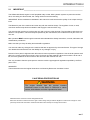 3
3
-
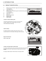 4
4
-
 5
5
-
 6
6
-
 7
7
-
 8
8
-
 9
9
-
 10
10
-
 11
11
-
 12
12
-
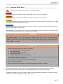 13
13
-
 14
14
-
 15
15
-
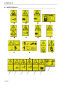 16
16
-
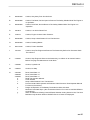 17
17
-
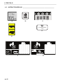 18
18
-
 19
19
-
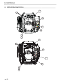 20
20
-
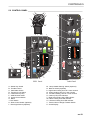 21
21
-
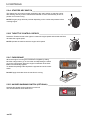 22
22
-
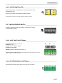 23
23
-
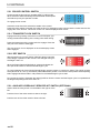 24
24
-
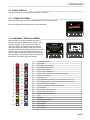 25
25
-
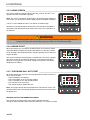 26
26
-
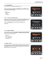 27
27
-
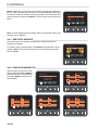 28
28
-
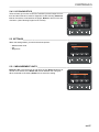 29
29
-
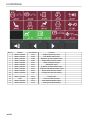 30
30
-
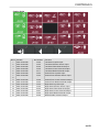 31
31
-
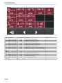 32
32
-
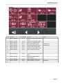 33
33
-
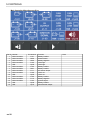 34
34
-
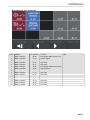 35
35
-
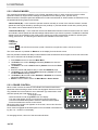 36
36
-
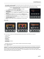 37
37
-
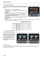 38
38
-
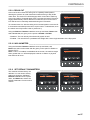 39
39
-
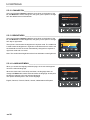 40
40
-
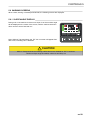 41
41
-
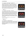 42
42
-
 43
43
-
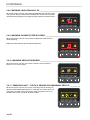 44
44
-
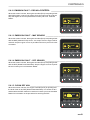 45
45
-
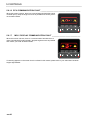 46
46
-
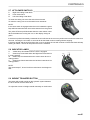 47
47
-
 48
48
-
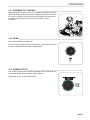 49
49
-
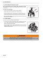 50
50
-
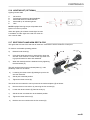 51
51
-
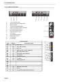 52
52
-
 53
53
-
 54
54
-
 55
55
-
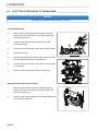 56
56
-
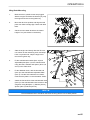 57
57
-
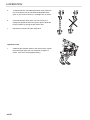 58
58
-
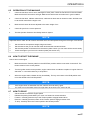 59
59
-
 60
60
-
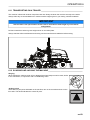 61
61
-
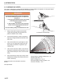 62
62
-
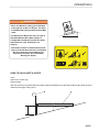 63
63
-
 64
64
-
 65
65
-
 66
66
-
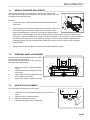 67
67
-
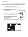 68
68
-
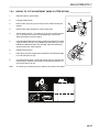 69
69
-
 70
70
-
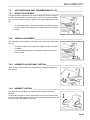 71
71
-
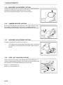 72
72
-
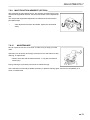 73
73
-
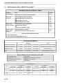 74
74
-
 75
75
-
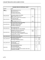 76
76
-
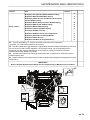 77
77
-
 78
78
-
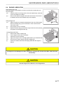 79
79
-
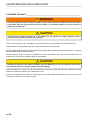 80
80
-
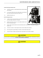 81
81
-
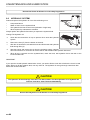 82
82
-
 83
83
-
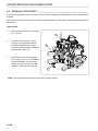 84
84
-
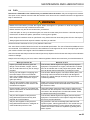 85
85
-
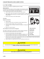 86
86
-
 87
87
-
 88
88
-
 89
89
-
 90
90
-
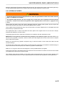 91
91
-
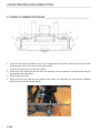 92
92
-
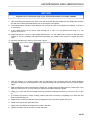 93
93
-
 94
94
-
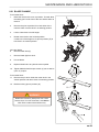 95
95
-
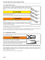 96
96
-
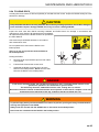 97
97
-
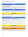 98
98
-
 99
99
-
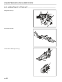 100
100
-
 101
101
-
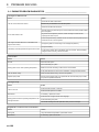 102
102
-
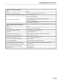 103
103
-
 104
104
-
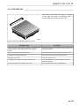 105
105
-
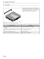 106
106
-
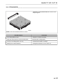 107
107
-
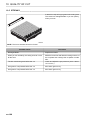 108
108
-
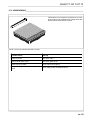 109
109
-
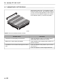 110
110
-
 111
111
-
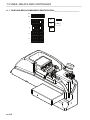 112
112
-
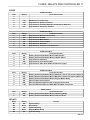 113
113
-
 114
114
-
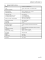 115
115
-
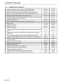 116
116
-
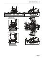 117
117
-
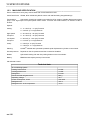 118
118
-
 119
119
-
 120
120
-
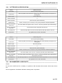 121
121
-
 122
122
-
 123
123
-
 124
124
-
 125
125
-
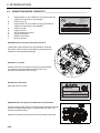 126
126
-
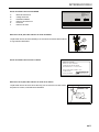 127
127
-
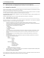 128
128
-
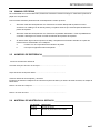 129
129
-
 130
130
-
 131
131
-
 132
132
-
 133
133
-
 134
134
-
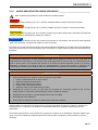 135
135
-
 136
136
-
 137
137
-
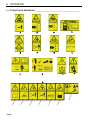 138
138
-
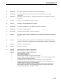 139
139
-
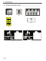 140
140
-
 141
141
-
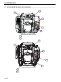 142
142
-
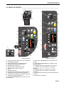 143
143
-
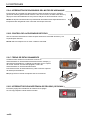 144
144
-
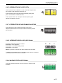 145
145
-
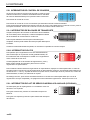 146
146
-
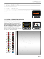 147
147
-
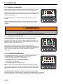 148
148
-
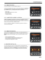 149
149
-
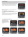 150
150
-
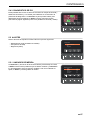 151
151
-
 152
152
-
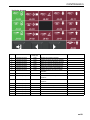 153
153
-
 154
154
-
 155
155
-
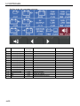 156
156
-
 157
157
-
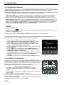 158
158
-
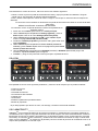 159
159
-
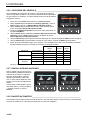 160
160
-
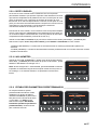 161
161
-
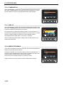 162
162
-
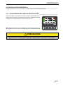 163
163
-
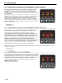 164
164
-
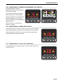 165
165
-
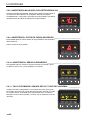 166
166
-
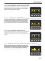 167
167
-
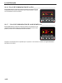 168
168
-
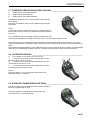 169
169
-
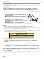 170
170
-
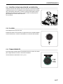 171
171
-
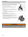 172
172
-
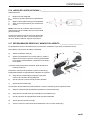 173
173
-
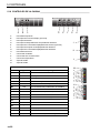 174
174
-
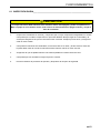 175
175
-
 176
176
-
 177
177
-
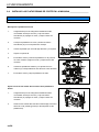 178
178
-
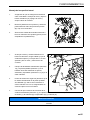 179
179
-
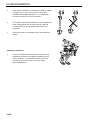 180
180
-
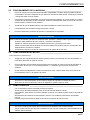 181
181
-
 182
182
-
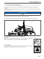 183
183
-
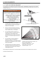 184
184
-
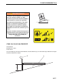 185
185
-
 186
186
-
 187
187
-
 188
188
-
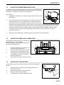 189
189
-
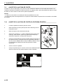 190
190
-
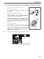 191
191
-
 192
192
-
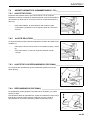 193
193
-
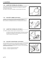 194
194
-
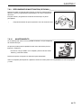 195
195
-
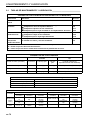 196
196
-
 197
197
-
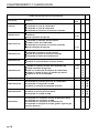 198
198
-
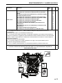 199
199
-
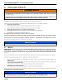 200
200
-
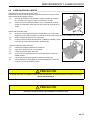 201
201
-
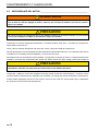 202
202
-
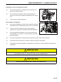 203
203
-
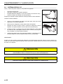 204
204
-
 205
205
-
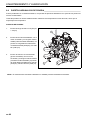 206
206
-
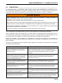 207
207
-
 208
208
-
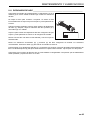 209
209
-
 210
210
-
 211
211
-
 212
212
-
 213
213
-
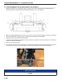 214
214
-
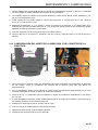 215
215
-
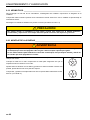 216
216
-
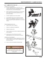 217
217
-
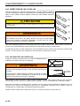 218
218
-
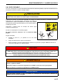 219
219
-
 220
220
-
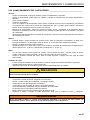 221
221
-
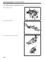 222
222
-
 223
223
-
 224
224
-
 225
225
-
 226
226
-
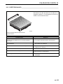 227
227
-
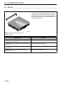 228
228
-
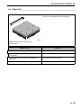 229
229
-
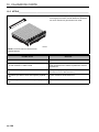 230
230
-
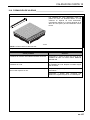 231
231
-
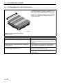 232
232
-
 233
233
-
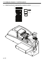 234
234
-
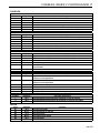 235
235
-
 236
236
-
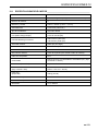 237
237
-
 238
238
-
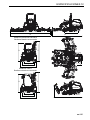 239
239
-
 240
240
-
 241
241
-
 242
242
-
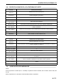 243
243
-
 244
244
-
 245
245
-
 246
246


Jacobsen 070543-4613110 Maintenance Manual
- Categoría
- Cortadoras de césped
- Tipo
- Maintenance Manual
en otros idiomas
- English: Jacobsen 070543-4613110
Artículos relacionados


Otros documentos
-
Ransomes 70524, 70525 El manual del propietario
-
-
-
Husqvarna P 535HX Manual de usuario
-
Husqvarna 967953702 Instrucciones de operación
-
Alamo FX21 Manual de usuario
-
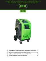 JBM 54290 Guía del usuario
-
 Egholm TH2500B Manual de usuario

