Jacobsen 068021-E410E Maintenance Manual
- Categoría
- Cortadoras de césped
- Tipo
- Maintenance Manual

ADVERTENCIA
ES
Spain
A SIGNATURE CUT, TRUSTED FOR OVER 100 YEARS
ADVERTENCIA: Si se usa de forma incorrecta, esta máquina puede causar graves lesiones. Cualquier persona que
use y mantenga esta máquina deberá estar entrenada en su uso correcto, instruida sobre sus peligros y deberá leer el
manual completamente antes de tratar de instalar, operar, ajustar o revisar la máquina.
WARNING
WARNING: If incorrectly used this machine can cause severe injury. Those who use and maintain this machine must
be trained in its proper use, warned of its dangers and must read the entire manual before attempting to set up,
operate, adjust or service the machine.
SAFETY, OPERATION & MAINTENANCE MANUAL
MANUAL DE SEGURIDAD, FUNCIONAMIENTO Y MANTENIMIENTO
10014954-A-ES
RJL AECD
068021 - E410E - AR331, 3WD
Series / Serie DDB
CAT® - C1.1 Diesel

© 2023 Textron Specialized Vehicles
This manual may not be reproduced in whole or in part without the express permission of Ransomes Jacobsen Ltd.
CALIFORNIA PROPOSITION 65
WARNING
The engine exhaust from this product contains
chemicals known to the State of California to cause
cancer, birth defects and other reproductive harm.
!

CONTENTS
SECTION 1 - FOREWORD
IMPORTANT ............................................................................. 1
PRODUCTION IDENTIFICATION ............................................. 2
GUIDELINES FOR DISPOSING SCRAP PRODUCTS............. 4
DURING SERVICE LIFE ........................................................... 4
END OF SERVICE LIFE............................................................ 4
PARTS MANUAL...................................................................... 5
KEY NUMBERS ....................................................................... 5
SECTION 2 - SAFETY
HOW TO OPERATE SAFELY .................................................. 7
SAFE OPERATION ................................................................... 7
PREPARATION......................................................................... 7
OPERATION ............................................................................. 8
ROPS ........................................................................................ 9
SAFE HANDLING OF FUELS ................................................... 9
MAINTENANCE AND STORAGE ............................................. 9
WHEN YOU PUT THE MOWER ON TO TRAILER................. 10
IMPORTANT SAFETY NOTES ............................................... 11
SECTION 3 - SPECIFICATIONS
ENGINE SPECIFICATION ...................................................... 14
DIMENSIONS & WEIGHTS..................................................... 15
TYRE PRESSURES................................................................ 15
MACHINE SPECIFICATION ................................................... 17
VIBRATION ............................................................................. 18
NOISE ..................................................................................... 19
SLOPES .................................................................................. 19
CUTTING UNIT SPECIFICATION.......................................... 20
CUTTING PERFORMANCE.................................................... 21
RECOMMENDED LUBRICANTS............................................ 21
ACCESSORIES....................................................................... 21
SECTION 4 - DECALS
SAFETY LABELS .................................................................... 22
INSTRUCTION LABELS ......................................................... 24
SECTION 5 - CONTROLS
OPERATION WORKSTATION................................................ 26
CONTROL PANEL .................................................................. 27
KEY SWITCH .......................................................................... 28
LIGHT SWITCH (OPTIONAL) ................................................. 28
PARKING BRAKE SWITCH .................................................... 28
MOW SWITCH ........................................................................ 28
SIDE SHIFT SWITCH.............................................................. 29
LIFT LOWER JOYSTICK......................................................... 29
VISUAL DISPLAY UNIT...........................................................29
STARTUP SCREEN ................................................................ 29
ENGINE START ...................................................................... 30
THE ENGINE WILL NOT START ............................................ 30
ENGINE START ...................................................................... 31
THE ENGINE WILL NOT START ............................................ 31
MAIN MENU ............................................................................ 31
MAIN NAVIGATION................................................................. 32
LANGUAGE ............................................................................. 32
CLOCK..................................................................................... 33
DISPLAY SETTINGS............................................................... 33
VEHICLE SETTINGS...............................................................34
MEASUREMENT SETTINGS MENU ...................................... 34
ENTER PIN.............................................................................. 35
ONE TOUCH ........................................................................... 36
CHANGE PIN........................................................................... 36
SET DEFAULT PARAMETERS............................................... 37
RESET SERVICE HOURS ...................................................... 38
SERVICE MENU ..................................................................... 38
FAULT LOG ............................................................................. 39
TIME UNTIL SERVICE ............................................................ 40
VEHICLE STATUS .................................................................. 41
INPUT/OUTPUT DIAGNOSTICS (I/O DIAGNOSTICS)...........42
CONNECTOR J1 ..................................................................... 42
CONNECTOR J2 ..................................................................... 43
CONNECTOR J3 ..................................................................... 43
CONNECTOR J4 ..................................................................... 43
CONNECTOR J5 ..................................................................... 44
CONNECTOR J6 ..................................................................... 44
WARNINGS ............................................................................. 45
WARNING - OIL PRESSURE FAULT .....................................45
WARNING CLEAR RADIATOR SCREENS.............................45
WARNING - CAN TIMEOUT....................................................46
WARNING - BATTERY FAULT ............................................... 46
WARNING - CONTROLLER I/O FAULT.................................. 46
THROTTLE LEVER ................................................................. 47
ARMREST ADJUSTER ...........................................................47
TRACTION PEDAL.................................................................. 47
MOW SPEED LEVER.............................................................. 48
STEERING TILT CONTROL....................................................48
POWER OUTLET .................................................................... 48
TOW VALVE ............................................................................ 49
PARKING BRAKE RELEASE VALVE ..................................... 49
FUEL GUAGE..........................................................................50
SECTION 6 - OPERATION
DAILY INSPECTION............................................................... 52
OPERATOR PRES & SAFETY INTERLOCK SYSTEM .......... 53

B
CONTENTS
OPERATING PROCEDURE ....................................................54
TO FIT THE CUTTING UNITS TO THE MACHINE ................55
OPERATION OF THE MACHINE.............................................58
HOW TO START THE ENGINE................................................58
HOW TO DRIVE.......................................................................59
HOW TO MOW ........................................................................59
TO STOP THE ENGINE...........................................................59
TRANSPORTING.....................................................................60
TRANSPORTING ON A TRAILER OR FLATBED ...................60
MOWING ON SLOPES ............................................................61
SECTION 7 - MAINTENANCE
MAINTENANCE & LUBRICATION CHARTS.......................... 62
MAINTENANCE & LUBRICATION CHART .............................63
ENGINE LUBRICATION...........................................................64
GENERAL PRECAUTIONS .....................................................65
ENGINE....................................................................................65
CHECK ENGINE OIL LEVEL ...................................................66
ENGINE COOLANT .................................................................67
CHECK THE ENGINE COOLANT LEVEL ...............................67
ENGINE: FAN BELT ................................................................68
HYDRAULIC FILTER ...............................................................69
HYDRAULIC SYSTEM.............................................................69
HYDRAULIC HOSES ..............................................................70
FUEL .......................................................................................71
REPLACING FUEL FILTERS...................................................72
PRIMING FUEL SYSTEM ........................................................72
AIR CLEANER .........................................................................75
ENGINE EXHAUST................................................................. 75
CUTTING UNIT 674381 LUBRICATION..................................76
LUBRICATION .........................................................................76
INSPECT BLADES...................................................................77
BLADE SHARPENING.............................................................77
BATTERY.................................................................................78
CHARGING THE BATTERY ....................................................79
TYRES .....................................................................................80
WHEEL MOUNTING PROCEDURE ........................................80
ROPS .......................................................................................81
CARE AND CLEANING............................................................82
MOWER STORAGE.................................................................83
SECTION 8 - ADJUSTMENTS
GENERAL PRECAUTIONS .....................................................84
TRACTION CONTROL.............................................................84
WEIGHT TRANSFER ADJUSTMENT......................................85
NEUTRAL SWITCH ADJUSTMENT ........................................86
ARMREST HEIGHT ADJUSTMENT ........................................86
TRACTION PEDAL STOPS .....................................................87
CUTTING UNIT LIMIT SWITCH .............................................. 87
CUTTING BLADE CHANGE.................................................... 89
SEAT (MILSCO V-2853).......................................................... 90
SEAT (MICHIGAN V-5300....................................................... 90
TORQUE SPECIFICATION .................................................... 91
SECTION 9 - PROBLEM SOLVING
PROBLEM SOLVING GENERAL ............................................ 92
SECTION 10 - QUALITY OF CUT
QUALITY OF CUT PROBLEM SOLVING................................ 94
STEP CUTTING....................................................................... 94
SCALPING............................................................................... 95
STRAGGLERS ........................................................................ 96
STREAKS ............................................................................... 97
WINDROWING ........................................................................ 98
CLUMPING.............................................................................. 99
INSUFFICIENT MULCHING.................................................. 100
TORN CROWNS ................................................................... 101
LAYING UNCUT GRASS....................................................... 102
SECTION 11 - SCHEMATICS
FUSES..................................................................................... 95
RELAYS................................................................................... 95
SECTION 12 - TORQUES
TORQUES ............................................................................ 106
SECTION 13 - GUARANTEE
GUARANTEE......................................................................... 107

B
en 1
FOREWORD 1
1.1 IMPORTANT _________________________________________________________
The AR331 with Diesel engine is a self propelled Rotary mower with hydraulic systems to power the traction drive,
the cutting unit lift and lower, the cutting unit drives and the steering.
IMPORTANT: Do the maintenance indicated in this manual to make sure that the quality of cut is kept at a
high level.
This SAFETY AND OPERATORS MANUAL is part of the machine and must stay with the machine always. Sup-
pliers of both original and used machines need to keep the documentation that comes with the machine.
You must use the machine to cut the grass only and not for any other purpose. Compliance with the conditions of
operation, service and repair specified by the manufacturer, are understood to be part of the correct use.
ALL operators MUST read through this manual and understand the Safety Instructions, controls, lubrication and
maintenance procedures.
Make sure that you obey all safety and road traffic regulations.
You must not make any changes to the machine that the manufacturer does not approve. This type of change can
release the manufacturer from the liability for any damage or injury.
Discard worn parts, taking note of the environmental result, use the systems available in the country where the
machine is used. When the machine is at its end of life, there are guidelines in this manual for the removal of the
machine from use.
Use only Ransomes Jacobsen Limited Genuine spare parts to make sure that European conformity is controlled.
2006/42/EC
These instructions are the original instructions confirmed by Ransomes Jacobsen Limited.

en 2
1 FOREWORD
1.2 PRODUCTION IDENTIFICATION _________________________________________
A. Maximum front axle load in Kg (for machines being driven on
the highway)
B. Unladen weight, (No cutting implements or fuel (mass) in Kg
C. Maximum rear axle load in Kg (for machines being driven on
the highway)
D. Power in Kw
E. Date code
F. Machine type (Designation)
G. Product code
H. Product name
I. Serial number
Location of Serial Number Plate
The serial number plate (A) is found on the right hand of the chassis towards the
rear of the front right hand wheel.
Chassis Stamp
The Serial number and date code (B) are marked on the right hand of
the chassis towards the rear of the front right hand wheel.
Engine Identification
Serial Plate
Location of Serial Number Plate
The engine serial number is found on the top of the valve
cover toward the front of the mower. The label shows the
engine group and serial number.
The engine serial number is also found on the engine block.
D
Kg Kw
Kg Kg
West Road
Ransomes Europark
Ipswich IP3 9TT
England
ABCE
FG
HJ
B
ARRANGEMENT NUMBERSERIAL NUMBER
ASSEMBLED IN (ALWAYS GIVE ALL NUMBERS) 2468
MODEL
®®
A
ARRANGEMENT NUMBER
SERIAL NUMBER
ASSEMBLED IN XXXXXXXXXXXXXXXXXXXXX 2468
MODEL
®®

B
en 3
FOREWORD 1
ROPS Serial Plate
A. Weight of ROPS
B. Date Code
C. Standard Used
D. Part Number
E. Used on Product
F. Serial Number
ROPS Serial Plate Location
The ROPS serial plate (C) is located at the base of the front of the
ROPS main beam.
CD
E
Kg
A
F
West Road
Ransomes Europark
Ipswich IP3 9TT
England
B

en 4
1 FOREWORD
1.3 GUIDELINES FOR THE DISPOSAL OF SCRAP PRODUCTS __________________
1.3.1 DURING SERVICE LIFE ______________________________________________
Used oil, oil filters and engine coolant are hazardous materials. Recommended procedures must be followed for
their safe removal.
If a fluid leaks, contain the spill to make sure that the leak does not flow into the ground or drainage system. Fol-
low the local laws to make sure that leaks are controlled safely.
The maintenance procedures in this manual make sure that the damage that the machine can cause in the local
environment is controlled safely.
When the machine completes its full service life, the following actions must be taken.
1.3.2 END OF SERVICE LIFE _______________________________________________
These guidelines must be used with applicable Health, Safety and Environmental laws. Always use the approved
local waste disposal and agencies for recycled materials.
• Park the machine in a location to use all of the necessary lifting equipment.
• Use correct tools and Personal Protective Equipment (PPE) and take instruction from the technical manuals
applicable to the machine.
• Remove and store correctly
• Batteries
• Fuel
• Engine coolant
• Oils
• Disassemble the structure of the machine and refer to the technical manuals where applicable. Give attention
to parts that have mechanical pressure or tension applied to the part in the machine,including springs.
• Items that continue to have a service life must be separated and returned to the local store.
• items that are worn must be separated into the material groups and removed according to the agencies for
recycled materials that are available. Common types are as follows:
• Steel
• Non ferrous metals
• Aluminium
• Brass
• Copper
• Plastic materials
• Identified
• Can be recycled
• Can not be recycled
• Not identified
• Rubber
• Electrical and Electronic Components
• If an item is not easily separated into different material groups, the material must be added to the “General
discarded materials” area.
• Do not burn discarded materials.
Change the machinery records to show that the machine is not in service and is discarded. Supply this serial
number to Ransomes Jacobsen Limited Warranty Department to close their records.

B
en 5
FOREWORD 1
1.4 PARTS MANUAL______________________________________________________
In compliance with the ISO14001 standard, Ransomes Jacobsen Limited does not send a paper parts manual
with every product.
To refer to a parts list for this mower you have two options:
1. Website – www.jacobsen.com. Select the “MANUALS” tab at the top, select a brand, product category and
product. You now have access to a PDF version of the parts manual.
Complete the form included in the technical manual pack supplied with the machine if you require a paper copy of
the parts manual.
1.5 KEY NUMBERS_______________________________________________________
Record the key numbers shown below:
Starter Switch:_ _ _ _ _ _ _ _ _ _ _ _ _ _ _ _ _ _ _ _ _ _ _ _ _ _ _ _ _ _ _ _ _ _ _ _ _ _ _ _
Diesel tank:_ _ _ _ _ _ _ _ _ _ _ _ _ _ _ _ _ _ _ _ _ _ _ _ _ _ _ _ _ _ _ _ _ _ _ _ _ _ _ _ _
Record the machine and engine numbers shown below:
The machine serial number is found on the registration plate and the engine serial number can be found on the
rocker cover.
Machine Number: _ _ _ _ _ _ _ _ _ _ _ _ _ _ _ _ _ _ _ _ _ _ _ _ _ _ _ _ _ _ _ _ _ _ _ _ _ _ _
Engine Number: _ _ _ _ _ _ _ _ _ _ _ _ _ _ _ _ _ _ _ _ _ _ _ _ _ _ _ _ _ _ _ _ _ _ _ _ _ _ _ _

en 6
1 FOREWORD
NOTES

en 7
SAFETY 2
2.1 HOW TO OPERATE SAFELY ____________________________________________
2.2 SAFE OPERATION ____________________________________________________
a. Read the Operator’s Manual and other training material. If the operator or technician can not read this
manual, the owner is responsible to describe this material to the operators and technicians. Manuals and
additional languages may be available on the Jacobsen website.
b. Read all of the instructions for this mower carefully. Know the controls and the correct operation of the
equipment.
c. Children or persons who do not understand these instructions must not use the mower. The local regula-
tions can limit the age of the operator.
d. Never use a mower near persons, including children or animals.
— Parts could be ejected from the machine at high speed in certain circumstances. The hazard area,
particularly in front of and behind the machine, must be cleared of any persons, animals or objects before
starting.
— Any use of the machine without verification of the hazard area can lead to serious or fatal accidents.
e. Any use of the machine without verification of the hazard area can lead to serious or fatal accidents.
f. Remember that the operator or owner is responsible for accidents or hazards that occur to other persons
or their property.
g. Never carry passengers.
h. Never allow persons to operate or service the mower or its attachments without correct instructions.
i. Do not operate equipment while tired, sick or whilst under the influence of alcohol or drugs.
2.3 PREPARATION _______________________________________________________
a. When you operate the mower, wear correct clothing, slip resistant work shoes or boots, work gloves,
hard hat, safety glasses and hearing protection. Long hair, loose clothing or jewelry can be caught in
moving parts.
b. Do not operate the equipment with the Interlock System disconnected or the system does not operate
correctly. Do not disconnect or prevent the operation of any switch.
c. Never operate equipment that is not in correct order or without decals, guards, shields, deflectors or
other protective devices fastened. When you mow with a side discharge deck, DO NOT operate the cut-
ting unit without the discharge chute installed.
d. Inspect the mower before you operate the mower. Check the tyre pressure, engine oil level, the radiator
coolant level and the air cleaner indicator. Fuel is flammable. Use caution when you add the fuel to the
mower.
e. Operate the mower in daylight or in good artificial light. Use caution when you operate the mower during
bad weather. Never operate the mower with lightning in the area.
f. Inspect the area to select the accessories and attachments that are needed to correctly and safely do the
job. Only use parts, accessories and attachments approved by Jacobsen.
g. Be careful of holes in the terrain and other hazards that are not visible.
WARNING
EQUIPMENT OPERATED INCORRECTLY OR WITHOUT TRAINING CAN BE DANGEROUS.
Know the location and correct operation of controls. Operators without experience must receive instruction
from another person that knows the correct operation of the equipment before you operate the mower.
Only use parts, accessories and attachments approved by Ransomes Jacobsen Limited.
!

en 8
2 SAFETY
h. Inspect the area where the equipment is operated. Remove all objects you can find before you operate.
Be careful of obstructions above the ground (low tree limbs, electrical wires) and also underground
obstacles (sprinklers, pipes, tree roots). Enter a new area carefully. Look for possible hazards.
i. Inspect the cutting system before you start the mower. Make sure the blades are free to rotate. When you
rotate one blade, other blades can rotate.
2.4 OPERATION _________________________________________________________
a. Never operate the engine without enough ventilation or in an enclosed area. The carbon monoxide in the
exhaust fumes can increase to dangerous levels.
b. Never carry passengers. Keep other persons or animals away from the mower.
c. Disengage all drives and engage the park brake before you start the engine. Only start the engine with
the operator in the seat. Never start the engine with persons near the mower.
d. Keep your legs, arms and body inside the operator compartment while the mower is in operation. Keep
your hands and feet away from the cutting units.
e. Do not use on the slopes greater than the safe slope limit for the equipment.
f. To guard against over turning or loss of control:
• Operate the mower up and down on the face of slopes (vertically), but not across the face (horizontally).
• Do not start or stop suddenly on slopes.
• Decrease the speed when you operate on slopes or when you must turn. Use caution when you change
direction. Turf condition can change the mower stability.
• Use caution when you operate the mower near drop-offs, ditches or embankments.
• Be careful of holes in the terrain and other hazards that are not visible.
g. When you drive in the reverse direction, look behind you and down to make sure the path is clear. Do not
operate the cutting units when you drive in the reverse direction.
h. Use caution when you go near corners, trees or other objects that can prevent a clear view.
i. Equipment must meet the current regulations to be driven on the public roads.
j. Before you move across or operate on the paths or roads, turn off the PTO switch, lift the mowers and
travel at decreased speed. Look for traffic.
k. Stop the blades when the mower is on any surface that is not grass.
l. Do not release the cut grass in the direction of persons or allow persons near the mower while in
operation.
m. Do not operate the mower with damaged guards or without safety devices in position.
n. Do not change the engine governor setting or over-speed the engine. Never change or tamper with
adjusters that are closed with a seal for the engine speed control.
o. Before you leave the operator compartment, for any reason:
• Disengage all the drives and lower attachments to the ground.
• Engage the park brake.
• Stop the engine and remove the key.
p. When you hit an object or mower starts to cause the vibration that is not normal, inspect the mower for
damage and make repairs.
q. Decrease the throttle setting before you stop the engine.
r. Do not use this equipment for uses that the mower was not made for.
s. The machine and its cutting units are designed for use on maintained turf surfaces. Use of the machine
with its cutting units engaged on hard and rough surfaces could rapidly decrease design life of compo-
nents and potentially cause acute damage to the units making them unsafe for operation.

en 9
SAFETY 2
2.5 ROPS_______________________________________________________________
a. The ROPS is a safety device. Keep the ROPS in the vertical and locked position. Always use the seat
belt when you operate the mower. Make sure the seat belt can be released quickly in an emergency.
b. Only operate the mower with the ROPS in the folded position on flat and level surfaces when necessary.
Do not operate the mower with the ROPS in the folded position on slopes, near sharp edges or near
water. On a ROPS machine there is no roll over protection with the ROPS in the folded position.
c. Check for clearance before you drive below objects. Do not contact tree branches, electrical wires or
other objects with the ROPS.
d. Do not use the seat belt with the ROPS in the folded position.
e. Inspect the ROPS for damage. Keep hardware fastened.
f. Do not weld, drill, change or bend the structure. Replace a damaged ROPS. Do not try to correct a
damaged ROPS frame.
g. Do not remove the ROPS from the mower other than for maintenance access. Ensure to refit before use.
h. Ransomes Jacobsen must approve any changes to the ROPS.
2.6 SAFE HANDLING OF FUELS____________________________________________
a. The fuel and the fuel vapors are flammable. Use caution when you add the fuel to the mower. The fuel
vapors can cause an explosion.
b. Never use the containers that are not approved to keep or transfer fuel.
c. Never keep the mower or fuel containers near an open flame or any device that can cause the ignition of
fuel or fuel vapors.
d. Never fill the fuel containers inside a vehicle or on a truck or trailer with a plastic liner. Always put the fuel
container on the ground away from your vehicle before you fill the container.
e. Refuel the mower before you start the engine. When the engine is in operation or while the engine is hot,
never remove the fuel cap or add fuel to the mower.
f. Refuel outdoors only and do not smoke when you add fuel. Extinguish all types of ignition.
g. The fuel nozzle must touch the rim of the fuel tank when you add fuel to the mower. Do not use a device
to lock the fuel nozzle in the open position.
h. Do not over fill the fuel tank. Leave at least 1 inch (25 mm) below the filler neck.
i. Always tighten the fuel tank cap and container cap after you add fuel.
j. If the fuel spills on your clothing, change your clothing immediately.
2.7 MAINTENANCE AND STORAGE _________________________________________
a. Before you clean, adjust or repair this equipment, push PTO switch to the OFF position, lower the cutting
unit to the ground, engage the park brake, stop the engine and remove the key.
b. Make sure the mower is parked on a solid and level surface.
c. Never work on a mower that is lifted only by a Jack. Always use Axle stands.
d. Never allow persons to service the mower or its attachments without correct instructions.
e. When the mower is parked, put into storage or left without an operator, lower the cutting device unless a
positive mechanical lock is used.
- Do not keep fuel near flames or drain the fuel inside a building.
f. Disconnect the battery before you service the mower. Always disconnect the negative battery cable
before the positive battery cable. Always connect the positive battery cable before the negative battery
cable.

en 10
2 SAFETY
g. Charge the battery in an area with good airflow. The battery can release hydrogen gas that is explosive.
To prevent an explosion, keep any device that can cause sparks or flames away from the battery.
h. Disconnect the battery charger from the power supply before you connect or disconnect the battery
charger to the battery. Wear protective clothing and use insulated tools when you service the battery.
i. Be careful and wear gloves when you check or service the cutting unit blades. Replace any damaged
blades, do not try to correct a damaged blade.
j. Keep your hands and feet away from parts that move. Do not adjust the mower with the engine in opera-
tion, unless the adjustment needs the engine in operation.
k. Take care working on cutting units and moving parts with stored energy.
l. To prevent injury from the hot, high pressure oil, never use your hands to check for oil leaks. Use paper
or cardboard to find leaks.
m. The hydraulic fluid pressure can have enough force to enter your skin. If hydraulic fluid has entered your
skin, seek medical attention immediately.
n. When you service the hydraulic system, make sure the hydraulic fittings, tubes and hoses are tightened
to the correct torque (where applicable). Make sure the hydraulic system is in good condition before you
start the engine.
o. Keep the mower and the engine clean.
p. Allow the engine to become cool before storage and always remove the ignition key.
q. Keep all nuts, bolts and screws tight to make sure the equipment is in safe condition.
r. DO NOT operate the machine if you have worn or damaged parts for safety. Replace damaged or worn
decals. Only use parts, accessories and attachments approved by Ransomes Jacobsen.
s. To decrease the fire hazard, remove materials that burn from the engine, muffler, battery tray and fuel
tank area.
t. Disconnect the battery and controller connectors before you weld on this mower.
2.8 WHEN YOU PUT THE MOWER ON TO TRAILER____________________________
a. Be careful when you load or unload the mower on a trailer. The trailer must be wider than the mower and
can carry the weight of the mower.
b. Use a full-width ramp to load or unload the mower on a trailer.
c. Use appropriate securing methods to fasten the mower to the trailer. Both front and rear straps must be
sent down and towards the sides of trailer.
d. Make sure that all latches are correctly fastened.

en 11
SAFETY 2
2.9 IMPORTANT SAFETY NOTES ___________________________________________
DANGER:
Indicates a dangerous condition that WILL cause death or injury unless it is prevented.
WARNING:
Indicates a dangerous condition that CAN cause death or injury unless it is prevented.
CAUTION:
Indicates a dangerous condition that can cause injury and property damage unless it is prevented. Also, the label
can indicate work procedures that are not safe.
IMPORTANT:
Some illustrations in this manual can show shields, guards or plates removed for clarity. This equipment must not
be operated without these devices correctly fastened and in position.
By following all instructions in this manual, you increase the life of your machine and keep its maximum perfor-
mance. Adjustments and maintenance must always be done by an approved technician.
If a service is needed contact your authorized Ransomes Jacobsen Dealer or after sales for additional information
or help.
WARNING
The Interlock System on this mower prevents the starting of the mower unless a.) The Park Brake is Engaged.
b.) The mow switch is in the OFF position, c.) The traction pedal is in the Neutral position. d) The operator is in
the seat. The system stops the engine when the operator leaves the seat a.) without the Park Brake engaged
and b.) the mow switch is not in the OFF position. NEVER operate the mower unless the Interlock System
is working.
WARNING
1. Before leaving the operator’s position for any reason:
a. Return traction pedal to the Neutral position.
b. Disengage all drives.
c. Lower all cutting units to the ground.
d. Engage Park Brake.
e. Stop the engine and remove the ignition key.
2. Keep your hands, feet, and clothing away from moving parts. Wait for all movement to stop before you
clean, adjust, or service the machine.
3. Keep the area of operation clear of all persons and animals.
4. Never carry any passengers.
Never operate the equipment without guards and deflectors in position.
This safety alert symbol is used to alert you to possible hazards.
!
!

en 12
2 SAFETY
WARNING
California Proposition 65
Engine exhaust, some of its constituents, and some vehicle components contain or release chemicals known to
the state of California to cause cancer and birth defects or other reproductive harm.
WARNING
To prevent injury from the hot oil at high pressure, DO NOT use your hands to check for oil leaks.
Make sure that you use paper or cardboard.
Release of hydraulic fluid at high pressure has enough force to enter through the skin. If the fluid enters
through the skin, you must seek medical attention immediately.
WARNING
When the machine is driven off-road, a seat belt must be worn only when a ROPS frame is in position.
This warning is because a seat belt must be worn with a ROPS to follow the Machinery Directive,
2006/42/EC Sections 3.2.2, Seating & 3.4.3, Rollover. (ANSI B71.4-2012 section 20.7)
Ransomes Jacobsen Limited recommends that the owner/user of the machine completes a site specific risk
assessment of the machine to find any conditions that do not follow this rule.
e.g. when you drive the machine next to water.
WARNING
Explosive gases are released by batteries. The battery contains corrosive acid and supplies an electrical
current that is high enough to cause injuries to the body.
WARNING
You must not use this machine to tow other vehicles.
WARNING
Ear protection must be worn when you operate machines with
an operator ear noise level of more than 85dB(A) Leq
!
!
!
!
!
!

en 13
SAFETY 2
WARNING
Vibration Exposure Limits
Exposure limits are calculated as a combination of the vibration level (magnitude) of the tool and the Daily
Exposure Time (Trigger Time). e.g. A product with 5m/s² vibration can be used up to 2 hours/day
to reach the EAV and up to 8 hours/day to reach the ELV.
Exposure Action Value (EAV) - Daily vibration exposure A(8) = 2.5m/s²
Where daily vibration exposure A(8) is below 2.5m/s² the risk is relatively low and no
action need be taken.
Exposure Limit Value (ELV) - Daily Vibration Exposure A(8) = 5.0m/s²
If several tools are use the exposure values must be combined:
Total exposure is then the combined value of the activities.
WARNING
Never mow if there is a risk of lightning or you hear thunder. If you are in the middle of mowing, stop in a safe
place, turn off the engine and go inside a building.
CAUTION
When you do any welding on the machine, the battery, controller and display must be disconnected before
you start. You must not open the controller. If the controller is opened, this can void all of the warranties and
can cause the failure of the machine
CAUTION
Personal Protective Equipment (PPE), for example safety glasses, safety footwear, work gloves
and ear protection must be used after the owner/user completes a site specific risk assessment of the
mower to prevent injury.
!
!
!
!

en 14
3 SPECIFICATIONS
3.1 ENGINE SPECIFICATION_______________________________________________
Note: Specifications are subject to change without notice.
CAT® - C1.1
Number of cylinders 3
Cylinder arrangment Vertical inline
Cycle 4 stroke
Induction system Naturally aspirated
Combustion system Indirect injection
Bore & Stroke 77 mm (3.03 in) - 81 mm (3.19 in)
Displacement 1,131 Litres (69.0 in³)
Compression ratio 22.1:1
Gross Intermittent Power 18.4kW (24.7hp) @ 2800rpm
Maximum Speed: 2950 ± 50 RPM (No load)
Idle Speed: 2175 ± 25 RPM
Firing Order 1-2-3
Governing at rated rpm 8% ± 2
Rotation Clockwise (viewed from front)
Basic thread form Metric
Cooling system Liquid, 50/50 anti freeze
Injection Pressure 13.73 MPa (140kgf/cm²)
Injection Timing (Before T.D.C.) 21° 20°
Compression Ratio 23:1
Fuel: No. 2-D Diesel fuel (ASTM D975)
Lubrication (API Classification) Above CF grade
Oil Sump Capacity: Maximum: 4.4 Litres / 7.7 pints - Minimum: 3.4 Litres / 6 pints
Dimensions (length x width x height) 491mm (19.33 in) x 400mm (15.75 in) x 576mm (22.67 in)
Dry Weight 87, 0 kg (191.0 lb)
Starting System Cell starter (with glow plug)
Standard Starting Motor cold start limit -20°C - (-4°F)

en 15
SPECIFICATIONS 3
3.2 DIMENSIONS & WEIGHTS______________________________________________
Note: Specifications are subject to change without notice
3.3 TYRE PRESSURES ___________________________________________________
A Width Of Cut 183 cm 72 In.
B Overall Width 195 cm 76.8 In.
C Maximum Width Transport With Floating Head At 25 mm Height Of Cut 195 cm 76.8 In
D Maximum Height With ROPS Frame Up 206.5 cm 81.3 In.
E Total Length 309.8 cm 122 In
F Wheel Base 154 cm 60.6 In.
G Wheel Track Front 122 cm 48 In.
HGround Clearance (Centre Unit Mounting Frame And Deck Set At
Maximum Height Of Cut) 35 mm 1.4 In.
Turning Circle (Cutting Units Centralised) 199 cm 78.3 In.
Weight Of Machine (Transport) 1078 kg. 657 lb.
Maximum Front Axle Loading 776 kg. 1710.8 lb.
Maximum Rear Axle Loading 259 kg. 571 lb.
27” Cutting Deck (Not Including Hydraulic Motor) 72 kg 158.7 lb
Weight Of 28.7 Litres (7.58 US Gallons) (6.3 Imp Gallons) Of Diesel Fuel 20.4 kg. 45.0 lb.
Tyre Pressure
Product Front Wheel Rear Wheel
Tyre Size Tyre Type Tyre Pressure Tyre Size Tyre Type Tyre Pressure
3WD,
Treaded
Tire Option
20 x 12.00 - 10 Grassmaster 4pr
Minimum
0.7 bar (10 psi)
Maximum
1.37 bar (20 psi)
20 x 10.00 - 10 Grassmaster 4pr
Minimum
0.7 bar (10 psi)
Maximum
1.37 bar (20 psi)
3WD,
Smooth
Tire Option
20x 12.00 - 10 Smooth 4pr
Minimum
0.7 bar (10 psi)
Maximum
1.37 bar (20 psi)
20 x 10.00 - 10 Smooth 4pr
Minimum
0.7 bar (10 psi)
Maximum
1.37 bar (20 psi)

en 16
3 SPECIFICATIONS
A
B/C
D
E
F
3WD Option Cutting Units Lowered Front View.
3WD Option Cutting Units Raised Position Right Side View.
H
G

en 17
SPECIFICATIONS 3
3.4 MACHINE SPECIFICATION _____________________________________________
Frame construction: Heavy duty steel chassis with box section frame rails.
Cutter Deck Drive: AR331, Fixed displacement hydraulic motors directly coupled to cutting unit.
Transmission: 3WD Transmission: Hydrostatic closed loop parallel cross series system. Variable
displacement piston pump. Front high torque fixed displacement piston wheel motors.
Full time auto 3WD forward and reverse.
Speeds:
Cutting: 0 - 9.5 km/h (0 - 5.9 mph) Forward.
Transport: 0 - 14 km/h (0 - 8.7 mph) Forward.
0 - 6 km/h (0 - 3.7 mph) Reverse.
Steering: Hydrostatic powered steering.
Ground pressure: Dependant upon the tyre pressures and the accessories installed.
Brakes: Hydrostatic braking with wet disc parking brakes on the front wheels.
Battery: Yuasa battery P/N 4322478 - ybx306312v45ah440A (en).
Mower Lift/Lower: Hydraulic Double Acting Cylinders.
Hydraulic Tank Capacity: 28.4 Litres (6.2 Imp Gallons / 7.5 U.S Gallons).

en 18
3 SPECIFICATIONS
3.5 VIBRATION __________________________________________________________
The machine was tested for hand and arm vibration levels. The operator was in the normal position to drive the
vehicle, with two hands on the steering mechanism. The engine was in operation and the cutting device was in
rotation. No drive was engaged.
The Machinery Safety Directive 2006/42/EC
By compliance to:
The Lawnmower Standard BS EN ISO5395-3:2013
Referenced to Hand/Arm: BS EN ISO20643:2008
Information Supplied for Physical Agents Directive 2002/44/EC
By reference to:
Hand/Arm Standards: BS EN ISO 5349-1 (2001)
BS EN ISO 5349-2 (2002)
Whole-body vibration measurement was carried out with the machine traveling in a straight line at a speed close
to 6 km/h on a flat horizontal level surface. The height of cut was set at the lowest position and the cutting means
engaged.
The Machinery Safety Directive 2006/42/EC
By compliance to:
Whole Body EN1032:2003
Information Supplied for Physical Agents Directive 2002/44/EC
By reference to:
Whole Body Standards BS EN ISO 2631-1 (1997)
Hand / Arm
Acceleration
Level
AR331
Maximum of RH and LH Accelerations m/s²
0.672 ± 0.40
Whole Body
Acceleration
Level
AR331
Maximum Weighted Acceleration m/s²
0.686 ± 1.57

en 19
SPECIFICATIONS 3
3.6 NOISE______________________________________________________________
When the machine was tested for sound pressure (Operator Ear).
The Machinery Safety Directive 2006/42/EC
And
Exposure Of Workers To The Risks Arising From Physical Agents (Noise) Directive 2003/10/EC
By compliance to:
The Lawnmower Standard BS EN ISO 5395:2013
And
Sound Pressure Standard EN ISO 3746: 2010
Measured Sound Pressure 90.6 dB(A) ± 1.05
When the machine was tested for sound power (Noise in the Environment).
The Machinery Safety Directive 2006/42/EC
And
Noise Emission In The Environment By Equipment For Use Outdoors
Directive 2000/14/EC
By compliance to:
Sound Power Standard EN ISO 3744:2010
Measured Sound Power 104.3 dB(A) ± 1.056
3.7 SLOPES ____________________________________________________________
DO NOT USE ON SLOPES GREATER THAN 16°. The 16° slope was calculated using static stability
measurements according to the requirements of BS EN ISO 5395-2013

en 20
3 SPECIFICATIONS
3.8 CUTTING UNIT SPECIFICATION__________________________________________
Note: Specifications are subject to change without notice.
Product 674381 (Consists of 674376/77/78)
Deck Width 811.4 mm deck length 1012.5 mm (Includes rear discharge and lowest HOC)
Construction Heavy duty welded pressed steel
Blade Length 670 mm (26.38 Inches)
Number of Blades 3
Blade Tip Speed 5001 m/minute
(16408 feet/minute)
Overall Width Of Cut 183 cm (72 in)
Height of Cut 19 mm (0.75 Inches) to 88 mm (3.5 Inches) in 0.25 (1/4 Inch) Increments
Hydraulic Motor Speed 2355 rpm
Cutting Width 686 mm (27 Inches)
Transmission Fixed displacement hydraulic motors directly coupled to cutting unit.

en 21
SPECIFICATIONS 3
3.9 CUTTING PERFORMANCE _____________________________________________
1.0 hectares/hr.at 9.5 km/hr. (2.6 acres/hr at 5.9 mph)
10% allowance is included for normal overlaps and turning at the end of each cut.
3.10 RECOMMENDED LUBRICANTS ________________________________________
Grease:
Shell Darina R2 lithium grease or equivalent.
3.11 ACCESSORIES ______________________________________________________
Mower Options.
674381 - 27 Inch (686 mm) Truedeck (Consists of 674376/77/78).
Blade Options.
4398987AN - 27" Shredder blades.
4139103 - 27" (686 mm) High Lift Blades.
4138725 - 27" (686 mm) Low Lift Blades.
4163101 - 27" (686 mm) Combi Blades.
Accessories.
674595 - Quick Release Pin Kit.
672858 - Weight Transfer Kit.
4392007 - Mow Mode.
4400013 - LED Work Light Kit.
068127 - Adjustable Canopy / Sunshade Kit.
669644 - Ball Guard.
4399787 - Inclinometer.
LMAC629 - Foot Rest.
4395906 - Mulch Baffles.

en 22
4 DECALS
4.1 SAFETY LABELS_____________________________________________________
4153197
L
4181865
16°+
009114170
A B C D
E F G H
J K

B
en 23
DECALS 4
A. 009034920 Caution, Stay Away From Hot Surfaces.
B. 009034880 Caution, Fan Blade, Do Not Open Or Remove The Safety Shields While The Engine Is
In Operation.
C. 009034900 Caution, Drive Belt, Do Not Remove The Safety Shields While The Engine Is In
Operation.
D. 009114340 Caution, Diesel Fuel.
E. 009114100 Caution, Battery.
F. 009114170 Slope Angle.
G. 009034960 Caution, Rotating Blades.
H. 009114380 Caution, Fasten Seat Belt.
J 4153197 Caution, Stop The Engine And Remove The Starter Key Before You Pressure Wash The
machine.
K. 4164860 Caution, Hydraulic Oil.
L. 4181865 Decal, Warning.

en 24
4 DECALS
4.2 INSTRUCTION LABELS ________________________________________________
0.7 bar
10 psi
673581
L
4324674
43974864397486
J-T 3008682
4374506
H J K
D E F G
A B C
TOTAL EQUIVIS ZS 46
4286422

B
en 25
DECALS 4
10028270
19 mm 0.75 in 1
25 mm 1.00 in 2
32 mm 1.25 in 3
38 mm 1.50 in 4
44 mm 1.75 in 5
51 mm 2.00 in 6
57 mm 2.25 in 7
64 mm 2.50 in 8
70 mm 2.75 in 9
76 mm 3.00 in 10
83 mm 3.25 in 11
89 mm 3.50 in 12
HK
6
3
1
2
4
5
9
10
11
12
8
7
Description
A 009034770 Guaranteed Sound Power Level. K 4374506 Keyswitch and Light.
B 4178900 Diesel Fuel. L 3008682 Tow Valve.
C 4397486 Traction. M 4392886 Control Panel.
D 673581 Tyre Pressure. N 838363 Throttle Lever
E 4164861 Forward / Reverse Traction Pedal. P 10028280 27” Front HOC Decal
F 4286422 Hydraulic Fluid. Q 10028270 27” Rear HOC Decal R\H
G 4397046 Jacking Point.
H 4164580 Lubrication Point.
4392886
M P
N
Q
10028280
19 mm 0.75 in 1
HK
25 mm 1.00 in 2
32 mm 1.25 in 3
38 mm 1.50 in 4
44 mm 1.75 in 5
51 mm 2.00 in 6
57 mm 2.25 in 7
64 mm 2.50 in 8
70 mm 2.75 in 9
76 mm 3.00 in 10
83 mm 3.25 in 11
89 mm 3.50 in 12
10
39
85
41
12 6
11 2
7

en 26
5 CONTROLS
5.1 OPERATION WORKSTATION ___________________________________________
5.3 - Control Panel
5.4 - Throttle Control
5.5 - Armrest Adjuster
5.6 - Traction Pedal
5.7 - Mow Speed Lever
5.8 - Steering Tilt Lever
5.9 - Tow Valve
5.10 - Brake Valve (Under Floorboard)
5.6
5.5
5.4
5.2
5.3
5.7
5.10
5.9

B
en 27
CONTROLS 5
5.2 CONTROL PANEL ____________________________________________________
A. Key Switch
B. Light Switch (Optional)
C. Parking Brake Switch
D. Mow Switch
E. Side Shift Switch
F. Visual Display
G. Lift/Lower Joystick
0.0 Hours
0.0 Hours
E
A
D
F
G
C
B
4374506
4392886

en 28
5 CONTROLS
5.3 CONTROL PANEL ____________________________________________________
5.3.A KEY SWITCH
Turn the starter key to the “Start Position” to crank the engine. Let go of the
key when the engine is running and the key will return to the “Run Position”.
Note: The glow plugs operate automatically. The engine will not run from
cold until the glow plugs reach their operating temperature.
Turn the starter key to the “Off Position” to turn the engine off.
5.3.B LIGHT SWITCH (OPTIONAL) __________________________________________
Turns the work lights “On” and “Off”.
Push the top of the switch to turn the lights ON.
Push the bottom of the switch to turn the lights OFF.
5.3.C PARKING BRAKE SWITCH ___________________________________________
Move the orange button to the rear (Towards the Operator) and press the
switch to engage the parking brake.
When the engine is stopped, the parking brake engages.
To release the parking brake, press the opposite end of the switch.
DO NOT apply the brake while the machine is being driven.
5.3.D MOW SWITCH______________________________________________________
The mow switch engages the cutter rotation.
To cut grass, push the front of the “Mow Switch” (Red Lens End) and move
the joystick forward to lower the cutting means. When engaged the Red lens
will illuminate.
To stop drive to the cutting means, push the bottom of the rocker switch
(Opposite end to the Red Lens).
Note: When the cutting means is raised above 400mm from the ground or
when the operator leaves the seat, blade rotation is stopped.
4374506

B
en 29
CONTROLS 5
0.0 Hours
0.0 Hours
5.3.E SIDE SHIFT SWITCH ________________________________________________
The side shift switch shifts the all cutting units to either the left or right.
Push the lever to the left to shift the front cutting units to the left.
Push the lever to the right to shift the front cutting units to the right.
Note: The cutting units MUST be raised into the “Cross Cut” position before
using this function.
5.3.F LIFT LOWER JOYSTICK _____________________________________________
The lift/lower joystick controls the cutting units lift and lower. The lift/lower
joystick operates in One-Touch or manual mode. Push the lift/lower joystick to
lower the cutting units or pull the lift/lower joystick to lift the cutting units.
The One-Touch or manual mode is set on the display.
Manual Mode – When One-Touch is disabled, the cutting units will lift or lower
only while the lift / lower joystick is either pulled or pushed.
One-Touch Mode – With One-Touch mode enabled and the Mow Switch on,
push and release the lift / lower joystick to lower the cutting units to the ground
and start the cutting unit reels.
5.3.G VISUAL DISPLAY UNIT ________________________________________________
The visual display is activated when the key switch is turned to the ‘Run’ position
5.4 STARTUP SCREEN____________________________________________________
When the key switch is turned to the ‘Run’ position, this screen is
shown.
The hour meter will show total hours of engine operation.

en 30
5 CONTROLS
5.4.1
ENGINE START
________________________________________________________
After the initial start-up screen, the warning screen is displayed for
three seconds. If there is no input required, the main screen will
become visible.
If a fault condition has occurred during the previous start, a pop up
screen will become visible over the top of the warning screen. The
operator must confirm the fault before they can move to the first
screen.
5.4.2
THE ENGINE WILL NOT START
____________________________________________
This screen shows the position of the interlock switches,
The engine temperature gauge is on the right side of the display. The
colour changes from green to red as the temperature increases.
IICONS
1. Parking Brake Engaged
2. TST Active
3. TST Not Active
4. Cutter Indicator (Flashes if not in off position on start up)
5. Foot Pedal Warning (Flashes if not in neutral position on start up)
6. Seat Warning (Flashes if not occupied or disconnected on start up)
7. Cutting Unit Position Indicator
8. Engine Temperature Indicator (Below bar graph)
9. Glow Plug
10. Time
11. Engine Able To Start
12. Engine Unable To Start
13. Back
14. Home
15. Red Select
16. Green Select
17. Menu Option Indicator
TST
™
1
2
3
10
11
12
13
14
4
5
8
7
6
TST
™
9
15
16
17
WARNING
If incorrectly used this maching can cause
severe injury. Those who use and maintain
this machine should be trained in its proper
use, warned of its dangers and should read
the entire operators manual before attempting
to set-up, operate, adjust or service the
machine.
!
12 : 34 : 56
0.0 Hours

B
en 31
CONTROLS 5
5.4.3
ENGINE START
________________________________________________________
When the key switch is turned to the start’ position and the interlocks
are set, this screen is shown.
To start the engine, the parking brake must be applied, the mow
switch must be in the off position and the foot pedal must be in the
neutral position. When the glow plug timer ends, the engine will start.
The two LED lamps will flash green if the all of the above conditions
have been met.
5.4.4
THE ENGINE WILL NOT START
____________________________________________
When the ignition key is turned to the start position and the interlocks
are not set, this screen is shown.
• The parking brake is not applied.
• Mow switch is not in the OFF position.
• The foot pedal is not in the neutral position.
The engine will not start until all the items in the list are correct.
The two LED lamps will flash red until the above conditions have
been corrected.
5.4.5
MAIN MENU
__________________________________________________________
When the first screen is shown on the display, press the left
or right arrow keys to access the main menu.

en 32
5 CONTROLS
5.4.6
MAIN NAVIGATION
______________________________________________________
When the first screen is shown on the display, press the left
or right arrow keys to access the main menu.
Use the up and down arrow keys to move the
selection arrow up and down the list.
Press the select button to select the menu option indicated by the
green arrow.
Press the back button to return to the previous screen.
Press the home button to return to the previous screen.
The main menu has backlap, language, clock, vehicle settings
(requires pin) and service.
5.4.7
LANGUAGE
__________________________________________________________
Turn the key switch to the “Run” position.
Press the left or right arrow key to display the main menu.
Use the up or down arrow keys until the green arrow
is next to Language. Press the select button to select Language.
The is moved with the up or down arrow keys
until the green arrow is next to the preferred language.
The button accepts the option that has the beside it.
Press the select button to set.
Press the button to return to previous menu.
Language
English
Deutsch
Francais
Dansk
Svensk
Netherlands
Espanol
Back Button Home Button Navigation Buttons Select Button

B
en 33
CONTROLS 5
5.4.8
CLOCK
______________________________________________________________
Turn the key switch to the “Run” position.
Press the left or right arrow key to display the main menu.
Use the up or down arrow keys until the green arrow
is next to clock. Press the select button to select clock.
The is moved with the up or down arrow keys
to select, date, time or date format.
The button accepts the option that has the beside it.
Use the up or down arrow keys to increase or decrease
the value.
Use the left or right arrow keys to move between fields.
Press the select button, to set.
Press the button to return to previous menu.
5.4.9
DISPLAY SETTINGS
___________________________________________________
Turn the key switch to the “Run” position.
Press the left or right arrow key to display the main menu.
Use the up or down arrow keys until the green arrow
is next to display settings. Press the select button to select display
settings.
Use the up or down arrow keys to toggle the
brightness.
Press the select button, to set.
Press the button, to return to previous menu.
Main Menu
Backlap
Language
Clock
Vehicle Settings
Service
Clock Settings
Set Date/Time
2:03:04 AM 01/01/2000
Set Date Format
US EU
Clock Settings
Set Date/Time
2:03:04 AM 01/01/2000
Set Date Format
US EU
80
Lorem ipsum

en 34
5 CONTROLS
5.4.10 VEHICLE SETTINGS ________________________________________________
Turn the key switch to the “Run” position.
Use the up or down arrow keys until the green arrow
is next to vehicle status. Press the select button to select vehicle
status.
The vehicle settings menu has the measurement units and pin
options available.
5.4.11 MEASUREMENT SETTINGS MENU ____________________________________
Turn the key switch to the “Run” position.
Use the up or down arrow keys until the green arrow
is next to measurement units.
Press the select button to select vehicle status.
Press the button to return to previous menu.
Use the arrow keys to change the unit of measure, only the
temperature setting can be changed to either Celsius or Fahrenheit.
Press the select button to accept the new values.
Press the button to return to previous menu.

B
en 35
CONTROLS 5
5.4.12 ENTER PIN _________________________________________________________
Turn the key switch to the “Run” position, navigate to the vehicle
settings menu.
Use the up and down arrow keys until the green
arrow is next to pin.
Use the arrow keys to highlight the correct number. Press the select
button to enter the number and to advance to the next position.
Repeat until all four numbers of the pin have been entered.
Highlight the “C” and press the select button to clear the
previous number.
The initial pin number is 1001.
If the correct pin number has been entered the pin menu will be
displayed.
Press the button to return to vehicle settings menu.
NOTE: Managers are advised to change the pin number to stop the
machine parameters being changed.

en 36
5 CONTROLS
5.4.13 ONE TOUCH ______________________________________________________
Turn the key switch to the run position, navigate to the pin menu.
Use the up or down arrow keys until the green arrow
is next to one touch. Press the select button to select one
touch.
Use the up and down arrow keys until the green arrow
is next to Enable or Disable. Press the select button to
accept.
Disable - The cutting units lift or lower only while the lift/lower joystick
is pulled or pushed.
Enable - The lift/lower joystick is pressed and released to lift or lower
the cutting units.
Press the back button to return to previous menu.
5.4.14 CHANGE PIN ______________________________________________________
Turn the key switch to the “Run” position, navigate to the pin menu.
Use the up and down arrow keys until the green arrow
is next to the Change Pin.
Use the arrow keys to highlight the new correct number.
Press the select button to enter the number and to advance to the
next position. Repeat until all four numbers of the pin have been
entered.
Press the select button to accept.
Press the button to return to Pin Menu.

B
en 37
CONTROLS 5
5.4.15 SET DEFAULT PARAMETERS ________________________________________
Turn the key switch to the “Run” position, navigate to the pin menu.
Use the up and down arrow keys until the green arrow
is next to set default parameters. Press the select button to
select set default parameters.
Press and hold the select button for five seconds to reset the
mower to default parameters.
Press the back button to return to previous menu

en 38
5 CONTROLS
5.4.16 RESET SERVICE HOURS ____________________________________________
Turn the key switch to the “Run” position, navigate to the pin menu.
Use the up or down arrow keys until the green arrow
is next to reset service hours. Press the select button to
select reset service hours.
Press and hold the select button for five seconds to reset current
service hours.
Press the back button to return to previous menu.
5.4.17 SERVICE MENU ____________________________________________________
Turn the key switch to the “Run” position.
Press the left or right arrow key to display the main menu.
Use the up or down arrow keys until the green arrow
is next to Language. Press the select button to select service.
The service menu has the fault log, time until service, vehicle status
and I/O diagnostics (input/output diagnostics).
Press the back button to return to the previous screen.
Fault Log
Time Until Service
Vehicle Status
I/O Diagnostics
Service Menu

B
en 39
CONTROLS 5
5.4.18
FAULT LOG
________________________________________________________
Turn the key switch to the “Run” position, navigate to the service
menu.
Use the up or down arrow keys until the green arrow
is next to fault log. Press the select button to select fault log.
The last 50 faults that the controller finds are recorded. When 50
faults are recorded, the fault that next occurs will write over the oldest
fault.
The engine, records the engine shut downs because of overheating
or loss of oil pressure.
The service, records missed service.
Press the button to select, press the up and down
arrow keys to move the green arrow the faults will move with the last
error to the top of the screen.
Select the fault log to be accessed to accept then to show
the details.
These details show the date and time of the fault.
Press the button to return to previous menu.
Fault Log
Time Until Service
Vehicle Status
I/O Diagnostics
Service Menu
12 : 34 : 56
0.0 Hours
Inclo Error
Date 02:04:2014
Time 14:55:46

en 40
5 CONTROLS
Time Until Service
23.4 Hours
Engine Hours:7
Cutter Hours: 0
5.4.19 TIME UNTIL SERVICE _______________________________________________
Turn the key switch to the “Run” position, navigate to the service
menu.
Use the up or down arrow keys until the green arrow
is next to fault log. Press the select button to select time
until service.
Press the button to return to previous menu.
Fault Log
Time Until Service
Vehicle Status
I/O Diagnostics
Service Menu

B
en 41
CONTROLS 5
Pg 2 of 2
5.4.20 VEHICLE STATUS _________________________________________________
Turn the key switch to the “Run” position., navigate to the service
menu.
Use the up or down arrow keys until the green arrow
is next to Vehicle Status. Press the select button to select
vehicle status.
The first screen of the vehicle status shows the battery voltage and
the engine coolant temperature.
Press the button to return to previous menu.
The second screen of the vehicle status shows the software revision
of the MCU controller and display.
Press the button to return to previous menu.
Fault Log
Time Until Service
Vehicle Status
I/O Diagnostics
Service Menu
Pg 1 of 2

en 42
5 CONTROLS
5.4.21 INPUT/OUTPUT DIAGNOSTICS (I/O DIAGNOSTICS) ______________________
Turn the key switch to the “Run” position, navigate to the service
menu.
Use the up or down arrow keys until the green arrow
is next to I/O Diagnostics. Press the select button to select I/O
Diagnostics.
Use the up or down arrow keys until the red arrow is
next to the connector. Press the select button to select the
required connector.
5.4.22 CONNECTOR J1 ___________________________________________________
Turn the key switch to the “Run” position, navigate to the service menu.
Information shown for illustration purposes only.
Press the button to return to I/O Diagnostic Menu.
Service Menu
Fault Log
Time Until Service
Vehicle Status
I/O Diagnostics
I/O Diagnostics
J1
J2
J3
J4
J5
J6
1
6
7
12
DEUTSCH PN
DT13-12PA
Connector J1
J1-1 Battery Voltage 12.7 V
J1-2 Key Switch IGN
J1-3
J1-4 Battery
J1-5
J1-6 Start With Interlocks
J1-7 CAN Shield
J1-8 CAN Low
J1-9 CAN High
J1-10 Main Ground
J1-11 5V Sensor Output
J1-12
O
12.7 V

B
en 43
CONTROLS 5
5.4.23 CONNECTOR J2 ___________________________________________________
Turn the key switch to the “Run” position, navigate to the
service menu.
Information shown for illustration purposes only.
Press the button to return to I/O Diagnostic Menu.
5.4.24 CONNECTOR J3 ___________________________________________________
Turn the key switch to the “Run” position, navigate to the service
menu.
Information shown for illustration purposes only.
Press the button to return to I/O Diagnostic Menu.
5.4.25 CONNECTOR J4 ___________________________________________________
Turn the key switch to the “Run” position, navigate to the service menu.
Information shown for illustration purposes only.
Press the button to return to I/O Diagnostic Menu.
Connector J2
J2-1 Lower Sol
J2-2 Not Used
J2-3 Lift Sol
J2-4 Fan Relay
J2-5 Park Brake Sol
J2-6 Fuel Hold
J2-7 Not Used
J2-8 Not Used
J2-9 Not Used
J2-10 Not Used
J2-11 Float Sol
J2-12 Weight Transfer Sol
ON
ON
ON
O
ON
O
O
Connector J3
J3-1 Not Used
J3-2 Engine Temp
J3-3 Not Used
J3-4 Not Used
J3-5 Not Used
J3-6 Not Used
J3-7 Program Select
J3-8 Not Used
J3-9 GND
J3-10 Not Used
J3-11 Not Used
J3-12 Not Used
O
ON
Connector J4
J4-1 Seat Switch
J4-2 Crosscut Switch
J4-3 Not Used
J4-4 Not Used
J4-5 Not Used
J4-6 Not Used
J4-7 Start Signal Input
J4-8 Not Used
J4-9 Mow Switch
J4-10 Neutral Switch
J4-11 Sideshift Left
J4-12 Sideshift Righ
O
ON
ON
O
O
O
ON

en 44
5 CONTROLS
5.4.26 CONNECTOR J5 ___________________________________________________
Turn the key switch to the “Run” position, navigate to the Service
Menu.
Information shown for illustration purposes only.
Press the button to return to I/O Diagnostic Menu.
5.4.27 CONNECTOR J6 ___________________________________________________
Turn the key switch to the “Run” position, navigate to the
Service Menu.
Information shown for illustration purposes only.
Press the button to return to I/O Diagnostic Menu.
Connector J5
J5-1 Not Used
J5-2 Mow Sol
J5-3 Not Used
J5-4 Not Used
J5-5 Not Used
J5-6 Not Used
J5-7 Not Used
J5-8 Glow Plug
J5-9 Not Used
J5-10 Joystick Lower
J5-11 Joystick Lift
J5-12 Not Used
O
O
O
ON
Connector J6
J6-1 Fuel Pull
J6-2 Sideshift Sol
J6-3 Backlap Sol
J6-4 Not Used
J6-5 Not Used
J6-6 Fused B+ Input
J6-7 Fused B+ Input
J6-8 Not Used
J6-9 GND
J6-10 Not Used
J6-11 Engine Oil Pressure
J6-12 Not Used
ON
O
O
O

B
en 45
CONTROLS 5
5.4.28 WARNINGS _______________________________________________________
5.4.29 WARNING - OIL PRESSURE FAULT ____________________________________
When this screen is shown, the engine oil pressure has decreased
below the normal level. If this happens during operation, Stop the
engine and check the oil level. Top up if necessary. If the problem
persists consult your service dealer.
Press the select button to confirm the fault.
5.4.30 WARNING CLEAR RADIATOR SCREENS_______________________________
When this screen is shown, the engine temperature has risen above
normal levels.
Park the machine in a safe area disengage the cutting units, set
engine to idle to allow engine temperature to decrease prior to
switching off the engine.
Turn engine off, clean the radiator and screens of all grass and
debris.
Press the select button to confirm the fault.
NOTICE
The number in the top right of the screen indicates the total number of current faults recorded.
If more than one fault, it will cycle all current faults.
!
Engine Overheat
9
1
!
OIL PRESSURE
FAULT
9
1

en 46
5 CONTROLS
5.4.31 WARNING - CAN TIMEOUT __________________________________________
This screen is shown if there is a communications fault between the
display and the controller.
Stop the machine as soon as possible and contact your service
dealer. Check the armrest and controller harness connections.
Press the button below the to confirm the fault.
5.4.32 WARNING - BATTERY FAULT _________________________________________
When this screen is shown, the battery is below 12V for 30 seconds.
Press the button below the to confirm the fault.
5.4.33 WARNING - CONTROLLER I/O FAULT _________________________________
When this screen is shown, there is a Controller I/O fault.
Press the button below the to confirm the fault.
!
CAN Timeout
9
1
9
1
!
?? Solenoid Fault
(J?-??)
9
1

B
en 47
CONTROLS 5
5.5 THROTTLE LEVER____________________________________________________
The throttle lever controls the engine speed. Always operate the
mower at full throttle during normal operation.
Push the throttle lever toward the front of the mower to increase
engine speed.
Pull the throttle lever toward the rear of the mower to decrease engine
speed.
5.6 ARMREST ADJUSTER_________________________________________________
The armrest adjuster is found on the right side under the armrest.
Lift up on the adjuster lever and slide the armrest in the forward or
rearward direction. Release the adjuster lever to set the adjustment.
5.7 TRACTION PEDAL ____________________________________________________
The traction pedal is found on the right side of the footplate.
Carefully press the top (A) of the foot pedal to reach the
forward speed that you need.
To stop - Carefully return the foot pedal to the Neutral
position.
To move in the reverse direction press the bottom (B) of the
foot pedal.
There are adjustable stops for the forward transport speed
(C) and for the reverse speed (D). When the mow speed
lever is in the Mow Position, the pedal will contact the mow
speed stop (E).
CAUTION
To prevent injury or property damage, do not adjust the
armrest position while the mower is in motion.
NOTICE
Allow the machine to come to a stop before you engage reverse drive.
When the parking brake is applied, DO NOT press the traction pedal.
!
Throttle
Lever
Slow
Fast
Throttle
Lever
A
C
DE
B
A

en 48
5 CONTROLS
A
B
5.8 MOW SPEED LEVER __________________________________________________
The mow speed lever is used to limit the forward speed while mowing.
When you mow, rotate the mow speed stop lever to mow position (A) so the
traction pedal contacts the stop when the traction pedal is pressed. The mow
speed stop can be adjusted to set specific mow speeds.
To travel at full speed, rotate the mow speed lever to transport position (B).
5.9 STEERING TILT CONTROL _____________________________________________
Put the operators seat in a position that lets you have free use of all the controls.
Hold the steering wheel and press the small foot pedal (A) at the base of the
steering column.
Tilt the column to a position in which you have a full range of movement and
control. Release the small foot pedal to lock the steering column in position.
5.10 POWER OUTLET ____________________________________________________
The auxiliary power outlet is located behind the seat on the left hand
ROPS mount.
Used for mobile devices and accessories rated at 12 Volts up to 10 Amps only.
CAUTION
To prevent injury or property damage, do not adjust the
armrest position while the mower is in motion.
!
A
12V12V
12V
12V
10A
10A

B
en 49
CONTROLS 5
5.11 TOW VALVE ________________________________________________________
The valve (B) is located underneath the transmission pump (A) between
the engine and two section gear pump.
1. To push the machine, disengage the parking brake, see section
6.10.
2. Turn the screw (C) found on the left side of the transmission pump,
three complete turns to the left. Set the steering wheel so that the
rear wheels toward the front.
3. After pushing the machine, return the parking brake valve, see
section 6.10 to its normal position and screw (C) on the pump to its
position for operation.
5.12 PARKING BRAKE RELEASE VALVE ____________________________________
The parking brake release valve is situated under the foot plate, on the left hand side of chassis plate. The park-
ing brake release Valve is used to release the parking brake when the
engine is not in operation.
The parking brake is released with the hand wheel (A) turned completely to
the right (clockwise), after you release lock wheel (B). Use the hand pump
(C) to create enough pressure to release the brakes (50 to 60 strokes will
give 90 seconds of brake release). When complete, rotate the hand wheel
(A) to the left (counter clockwise) completely and lock with wheel (B).
This method of brake release is to recover the vehicle a short distance only
and should be carried out on level ground.
C
A
B
AB
C

en 50
5 CONTROLS
5.13 FUEL GUAGE _______________________________________________________
The fuel gauge is located behind the left hand ROPS Mount.
Always check daily to ensure that there is sufficient fuel prior to cutting.

B
en 51
CONTROLS 5
NOTES

en 52
6 OPERATION
6.1 DAILY INSPECTION_________________________________________________________
1. Do a visual inspection of the vehicle and look for indication of wear, loose hardware. Check for any
components that are not included on the machine or damaged. Check for fuel and oil leaks to make sure
that all connections are tight. Make sure that all hoses and tubes are in good condition.
2. Check the fuel supply, radiator coolant level, crankcase oil level and air cleaner is clean. All fluids must
be at the full mark while the engine is cold.
3. Make sure all cutting units are adjusted to the same height of cut.
4. Check all tyres for the correct pressure.
5. Test the Operator Presence And Safety Interlock System.
CAUTION
The daily inspection should be performed only when the engine is off and all fluids are cold. Lower
implements to the ground, engage Park Brake, stop engine and remove Ignition Key.
!

B
en 53
OPERATION 6
6.2 OPERATOR PRESENCE AND SAFETY INTERLOCK SYSTEM_________________
1. The Operator Presence And Safety Interlock System will not allow the engine to start unless the
operator is sitting in the seat, the parking brake is engaged and the cutter switch is disengaged. The
system stops the engine if the operator leaves the seat with the cutters engaged
2. Do each of the tests as shown below, to make sure that the Operator Presence And Safety Interlock
System operates. If any of the tests fail, stop the test and have the system inspected and repaired.
a. The engine does not start during test 1
b. The engine does start during tests 2, 3 and 4
c. The engine continues to run during tests 5 and 6
Refer to the chart below for each test and follow the check marks across the chart. Turn off the engine between
each test.
TEST 1: The test shows the normal engine start procedure. The operator is in the seat, parking brake switch is in
the ON position, the traction pedal is in the NEUTRAL position and the mow switch is in the OFF position. The
engine will start.
TEST 2: The engine must not start if the mow switch is in the ON position.
TEST 3: The engine must not start if the parking brake switch is in the OFF position.
TEST 4: The engine must not start if the traction pedal is out of the NEUTRAL position.
TEST 5: Start the engine with the normal procedure. Turn on the mow switch and lift your weight off the seat. The
engine must stop. The cutting unit reels must not rotate after seven (7) seconds.
TEST 6: Start the engine with the normal procedure. Turn off the parking brake switch and lift your weight off the
seat. The engine must stop. The cutting unit reels must not rotate after seven (7) seconds.
.
WARNING
Do not operate the equipment with the operator presence and safety interlock system disengaged or while the
equipment has defects. Do not disconnect any switch.
Test Operator Seated Mow Switch OFF Parking Brake
Switch ON
Traction Pedal in
Neutral
Engine Starts
Yes No Yes No Yes No Yes No Yes No
1
2
3
4
5
6
Start the engine with the normal procedure, move position of the switch and lift your weight off the seat.
The engine must stop within 3 seconds and the cutting unit reels must not rotate after 7 seconds.
!

en 54
6 OPERATION
6.3 OPERATING PROCEDURE _____________________________________________
1. You must not start the engine without the operator in the seat on the tractor.
2. Do not operate the mower and attachments with loose or damaged components.
3. First cut in a test area so that you completely understand the operation of the mower and controls.
4. Inspect the area and find the safest procedure for the vehicle. Check the height of the grass, the type of
terrain and the condition of the surface. Each area condition needs the applicable adjustments
and precautions.
5. You must not direct the cut material toward persons near the machine. When the vehicle is in operation,
do not allow persons to stand near to the machine. The owner/operator maybe responsible for injuries
caused to persons near the machine and any damage to their property.
6. Be careful when you cut surfaces that are near to gravel areas, roadway, parking areas, cart paths.
Stones released from the equipment can cause injuries to persons and damage the equipment.
7. When you move across the roads or paths, disengage the cutting motors and lift the equipment. Check
for the traffic when you drive on the roads.
8. If you hit an obstruction or if the machine has a vibration that is not normal, stop and inspect the
equipment for damage immediately. Repair damaged equipment before operation is continued.
WARNING
Do not operate the equipment with the operator presence and safety interlock system disengaged or while the
equipment has defects. Do not disconnect any switch.
CAUTION
To prevent injury, always wear the safety glasses, protective footwear,
a hard hat and ear protection.
CAUTION
Remove all dangerous material from the area before you cut the grass.
Enter a new area carefully and always operate at speeds that allow you to control the mower safely.
CAUTION
Before you clean, adjust, or repair this equipment, always disengage all drives, lower implements to
the ground, engage parking brake, stop engine and remove key from ignition switch to prevent injuries.
WARNING
DO NOT USE ON SLOPES GREATER THAN 16°.
!
!
!
!
!

B
en 55
OPERATION 6
6.4 TO FIT THE CUTTING UNITS TO THE MACHINE_____________________________
Cutting Unit Mounting
1. Position the pivot shaft (A) so that the end of the shaft
is flush to the rear of the welded clamp bracket. Secure
the pivot shaft by locating the clamp (D) over the pivot
shaft (Ensure that the gap between the clamp and lift
arm is the same at the top and bottom) and secure in
place with four bolts and washers (B and C) and
tighten to 45 Nm (33.2 ft lb).
2. Apply a small amount of Shell Darina R2 grease to the
front and rear surfaces of spacer (E) then slide onto
pivot shaft (A).
3. Slide the centre yoke (F) onto the pivot shaft (A).
NOTICE
For height of cut adjustments see section 7.2 and 7.3
CAUTION
Blades are extremely sharp and can cause severe cuts.
For your protection, hold blade with thick leather work glove only.
!
AA
B
C
D
EA
FA

en 56
6 OPERATION
4. Slide the M8 lockwasher (H) and M8 washer (G)
onto the M8 bolt (I), Apply a small amount of Shell
Darina R2 grease to the rear surfaces of collar (J).
5. Install collar (J) onto pivot shaft, align holes so that
the M8 bolt (I) can locate and be tightened. Torque
bolt (I) to 45 Nm (33.2 ft lb).
6. Slide the anti-vibration washer (K) onto M6 bolt (L),
Install pin (M) into the hole marked (N) through the
lift cylinder mounting hole and secure in place with
the M6 bolt (L) torque to 9 Nm (6.6 ft lb).
7. Repeat instructions 1 to 6 for the left and centre
yoke assemblies.
8. Lift and support the cutting unit to access the
carriage bolts from below the deck shell, remove
all six M10 Nyloc nuts (O), M10 washers (P) and
M10 carriage bolts, do not discard.
9. Position the cutting unit below the lift arm, then
start the engine and lower lift arm to the deck. Stop
engine and remove key from the ignition switch.
10. Release the cutting unit motor from the vehicle. Do
not suspend the hydraulic motor by its hoses.
G
H
J
K
L
M
N
I
O, P

B
en 57
OPERATION 6
11. Before installing the hydraulic motor ensure that both
spacer rings are fitted. Position the hydraulic motor
over the motor mounting holes, Insert an M10
carriage bolt into each motor mount hole from
beneath the deck ensuring that the carriage bolt seats
correctly. Place a washer (P) and nut (O) onto each
bolt and then tighten to 51 Nm (38 lb-ft).
12. Repeat this instruction for the left and rear (centre)
cutting unit.
Note: Hydraulic hoses removed for clarity.
13. For the rear (centre) cutting unit, align the bolt holes
for the centre yoke (F) and yoke brackets (Q) position
number 1 on both sides of the cutting unit.
For the front (left and right) cutting units, align the
shoulder bolt holes for the centre yoke (F) and yoke
brackets (Q) position number 2 on both sides of the
cutting unit.
14. Place one M20 washer (R) onto M20 Bolt (S), slide
the M20 bolt (S) through both the centre yoke (F) and
yoke bracket (Q). Install M20 washer (T) and secure
in place with Nyloc nut (U) torque to 27 Nm (20 ft lb).
15. Repeat process for opposite side.
16. Repeat instructions 13 to 14 for the left and centre
cutting unit.
Note: Decal and hoses are removed for clarity.
17. Start the engine and lift the cutting units into the
transport position, Stop engine and remove key from
ignition switch.
18. Install the blade adapter (V) onto the motor shaft,
ensure that the parallel key is installed.
19. Fit the cutting blade (W) onto the blade adapter (V),
secure in place with blade spacer (X) and blade bolt
(Y), tighten the bolt with your fingers first. Place a
block of wood between the cutting blade (W) and
cutter deck shell, then carefully torque the blade bolt
(Y) to 95 Nm (70 lb ft).
V
WX
Y
Q
F
R
S
TU
Q
F
1
2
O, P

en 58
6 OPERATION
6.5 OPERATION OF THE MACHINE _________________________________________
1. Check the machine, look for worn, damaged or loose parts. Check the machine for fuel and oil leaks. Make
sure that all connections are tight. Make sure that all hoses and tubes are in good condition.
2. Check the fuel level, radiator coolant level, crankcase oil level and air cleaner is clean. When the engine is
cold, all additional fluids must be at the full level mark.
3. Make sure all cutting units are adjusted to the same height of cut.
4. Check all tyres for the correct pressure.
5. Test the Operator Presence And Safety Interlock System.
6.6 HOW TO START THE ENGINE __________________________________________
The following procedure is for starting cold engines.
1. Ensure the FWD/REV pedal is in the neutral position, the mow and parking brake switches are off, the
throttle setting is in a mid position and the operator is in the seat.
2. The glow plugs are auto timed depending on the coolant temperature for operating the starter motor (This
should only take a few seconds).
3. Turn the ignition switch to the “Run” position and wait until the yellow (Glow plug indicator) LED turns off,
then turn ignition switch to the “Crank” position until the engine starts.
4. When the engine starts, release the key immediately and it will return to the “Run” position.
5. If the engine does not start, return key to the “Off” position and repeat the above procedure.
NOTICE
Adjust the seat to make sure all controls are within reach and will operate through the full range
of movement.
1. Set the seat for the operators weight, height and reach.
2. Set the seat so that you can see the cutting units and the area around them.
3. Set the seat position for distance from the traction pedal. Check you can reach all the
controls easily.
NOTICE
1. If the engine fails to start after two attempts, wait 20 seconds and try again.
2. The starter motor must not be run continuously for longer than 30 seconds or it may fail.
3. If the red LED’s on the display flash whilst starting, one of the safety interlock switches has not been
set correctly.

B
en 59
OPERATION 6
6.7 HOW TO DRIVE ______________________________________________________
1. Move the throttle control lever to the “Fast” position.
2. Release the brake. Make sure the parking brake is completely released before you move in a forward or
reverse direction.
3. Forward - Carefully press the top of the “Forward / Reverse” foot pedal to reach the ground speed that
you need.
4. Reverse - Carefully press the bottom of the “Forward / Reverse” foot pedal to reach the ground speed
that you need.
5. To stop - carefully return the “Forward / Reverse” foot pedal to the neutral position then decrease
throttle.
6. To stop the vehicle on a slope it may be necessary to apply traction in the opposite direction to which the
machine is trying to roll.
6.8 HOW TO MOW _______________________________________________________
1. Set the mow / transport speed selector to the mow position, this will set the maximum cutting speed.
2. Lower the cutting units.
3. To engage the cutting mechanism, press the lower half of cutting unit switch, found on the control panel.
4. Release the parking brake and drive in a forward direction.
To remove or install grass catchers:
Set the mow switch in the “Off” (down) position, lower the cutting units to the ground, put the parking brake switch
in the “On” position and stop the engine. Release latch and slide grass catcher off or back onto the lift yoke.
6.9 TO STOP THE ENGINE ________________________________________________
1. Disengage the drive to the cutting units with the cutting unit switch.
2. Return the forward / reverse foot pedal to the Neutral position.
3. Set the parking brake.
4. Move the throttle control lever to the SLOW position.
5. Turn the ignition key to the OFF position.
NOTICE
1. Use complete foot to operate both forward and reverse.
2. Always operate the traction pedal carefully. Do not move the pedal from forward to reverse quickly.
NOTICE
Always set the throttle to maximum engine rpm. To mow when the grass is heavy and the engine
can not give enough power, decrease the forward speed.

en 60
6 OPERATION
6.10 TRANSPORTING ______________________________________________________
1. Start the engine and set the throttle lever to full speed position.
2. Release the parking brake and after ensuring that the pedal control lever is in the transport position,
press the upper part of the foot pedal. The machine will move in a forward direction.
3. Continue to push down on the foot pedal until the desired speed of the machine is reached.The foot
should always be kept firmly on the pedal to maintain full control of the drive pedal.
6.11 TRANSPORTING ON A TRAILER OR FLATBED ____________________________
Once the vehicle is loaded onto the trailer or flatbed truck, lower the
units down onto the trailer. If the cutting units cannot be lowered onto
the trailer, a secondary restraint should be placed around the cutting
units when transporting on a trailer or flatbed.
Use straps over the front and rear wheels (A).
Make sure that all tie down straps are tight.
Check the fuel and hydraulic tank caps are tight. Make sure that no
part of the mower can fall during transport.
Check that the hood is securely latched down using the mechanism
provided.
Always follow the given maximum transport load weight for the
vehicle used.
Do NOT carry more than the maximum weight shown on the transport vehicle plate.
Slinging
When slinging the mower, damage free clamps must be used, see the illustration, with an approved lift frame.
Information is available at www.tipnlift.co.uk.
Jacking
The machine jack points indicated by the decal shown.Two for each axle on four
wheel vehicles. Other axle types are different, check the Safety and Operations
Manual for the safe jack points.
WARNING
Care should be taken when jacking or slinging machines. Only trained
personal should carry out this procedure.
!
AA
A

B
en 61
OPERATION 6
6.12 MOWING ON SLOPES __________________________________________________
The mower is assembled for good traction and stability
in normal conditions. For operation on wet grass and
gradients use caution, vehicle control.will be decreased
in these conditions
1. Always mow with the engine at full throttle, control
forward speed with the traction foot pedal.
2. Use the weight transfer control to improve the
weight distribution between decks and mower.
3. If traction is lost turn the mower on to a lower
gradient.
4. If the mower continues to move or mark the turf,
the slope is more than the normal limit.
Do not try to move toward the top, move
backward slowly.
5. When you move across a slope, to keep the
vehicle stable lower equipment to the ground.
Correct tyre pressure is necessary for maximum traction.
See Specification (Section 3).
WARNING
The vehicle can turn over in some conditions.
The method for the correct operation on the
gradients and terraces is:
1. To travel up and down the face of the slope
(vertically) but not across the face
(horizontally).
2. Do not make a turn that is not necessary.
3.Travel at decreased speeds and look for
hazards.
For best stability, always cut with all three units.
!
0°
0%
2-3/4°
5%
5-3/4°
10%
8-1/2°
15%
11-1/4°
20%
14°
25%
16-3/4°
30%
19-1/4°
35%
21-3/4°
40%
24-1/4°
45%
26-1/2°
50%
28-3/4°
55%
31°
60%
33°
65%
35°
70%
36-3/4°
75%
38-3/4°
80%
40-1/4°
85%
42°
90%
43-1/2°
95%
45°
100%
Degrees
Grade
Degrees are shown to the nearest 1/4”.
General slope of roadway embankment - 45°
Steepest grass area - 31°
Slope of average roof - 19-1/4°
2nd class highway maximum grade 4-1/2°
Toll road or freeway - 1-3/4°
A = Maximum Allowed Slope
A = Maximum Allowed Slope
A° Maximum
A° Maximum

en 62
7 MAINTENANCE
7.1 MAINTENANCE AND LUBRICATION CHARTS _________________________________
MAINTENANCE AND LUBRICATION CHART
Interval Item Section
First 50 hours Change Engine Oil & Filter
Check Fan Belt Tension
Change Hydraulic Oil Filter
7.4.1
7.6
7.7
Daily
10 hours
Check Engine Oil Level
Check Safety Interlock System
Check Engine Coolant Level
Check Hydraulic Fluid Level
Check Tyre Pressure
Check Air Filter Service Indicator*
Check for Hydraulic Leaks
Check Oil Cooler Screen
Check Oil Cooler Fins
Check Bedknife & Reel Blades
Walk-Around Inspection
7.4.1
6.2
7.5.2
7.8
3.3
7.10
7.10.4
6.1
Weekly Every 50 hours Check for Loose Components
Check Fan Belt Tension
Check Engine Bay For Debris
Check Battery Condition
Drain & Clean Fuel Tank
7.10.11
7.6
7.10.11
7.10.6
Every 100 hours Change Engine Oil Filter
Check Fuel Filter For Water Contamination
7.4.1
7.9.2
Every 200 hours Change Engine Oil
Change Inline Fuel Filter
7.4.1
7.9.2
Every 250 hours Change Hydraulic Oil & Filters
Alternator and Fan Belts - Inspect / Adjust 7.6
Every 500 hours Change Air Filter Element*
Change Oil and Filter Element
Check Safety Interlock System
Hoses and Clamps - Inspect / Replace
Radiator - Clean
6.2
7.8.1
7.5
End of season
Every 1000 hours
Check Parking Brake Operation
Check Brake pads
Drain & Clean Fuel Tank
Drain & Replace Engine Coolant 7.5
Lubricate all Grease fittings weekly
A = Lift Arm Pivot, B = Cutting Unit Pivot, C = Cutting Unit Bearing Housing, D = Steering Ram Ball Joint.
*Check more often in dirty conditions
IMPORTANT
Refer to Engine Manufacturers Manual for Additional Engine Maintenance Procedures

B
en 63
MAINTENANCE 7
Engine Oil: Must meet A.P.I. CK-4
TEMPERATURE VISCOSITY
-18°C to 40°C (-0.4°F to 104°F) SAE10W-30
Lubrication Points (Grease Every 50 Hours)
A. Tie Rod Ball Joints (1). D. Yoke Pivot Assembly (3).
B. Steering Cylinder Ball Joints (1). E. Rear Roller (6).
C. Lift Arm Pivot (3).
Service Interval Chart
Interval Item Section
First 25 hours • Roller bearings 7.10.2
First 50 hours
• Yoke pivots
• Rear roll bearings
• Rear roller adjusters
7.10.3
Every 40 hours • Levers, pivot points any friction points 7.10.3

en 64
7 MAINTENANCE
7.2 ENGINE LUBRICATION ________________________________________________
3.3 / 7.9.12*
A
B
E
7.7
7.9.4
Rear wheel position moved for clarity.
*
DD
EE
C
C
C
D
7.5
7.9 7.9.10
7.4
7.4
7.9
7.9
7.5
7.9.3
7.5
7.6

B
en 65
MAINTENANCE 7
7.3 GENERAL PRECAUTIONS______________________________________________
A qualified technician must do any adjustment and all maintenance. If the correct adjustments can not be made,
contact your Jacobsen Dealer.
Inspect the equipment according to the maintenance schedule and keep complete records for warranty purposes.
1. Keep the equipment clean.
2. Keep all moving parts correctly adjusted and lubricated.
3. Replace worn or damaged parts before you operate the mower.
4. Keep all fluids at the correct level.
5. Keep the shields in position and all hardware tight.
6. Keep the tyres inflated to the recommended pressure.
When you do any maintenance, do not wear jewelry or loose fitting clothing.
Refer to the illustrations in the Parts Manual for the removal and assembly of parts.
When you discard hazardous materials (batteries, lubricants, fuel, anti-freeze), follow your local,
recommended procedures.
.
7.4 ENGINE _____________________________________________________________
IMPORTANT - An engine service manual is available through a Jacobsen dealer and is either included with the
mower or is available on our website. Read this engine manual to understand the operation and maintenance of
the engine. When you follow the engine manufacturer instructions, you will make sure of the maximum service life
of the engine. The replacement engine manuals are available from the engine manufacturer.
During the first 50 hours of operation, Jacobsen recommends the following:
1 Allow the engine to reach a temperature of at least 60° C (140° F) before operation at full load.
2 Check engine oil at startup check on daily basis. Higher than normal oil use can occur during the first 50 hours.
3 Change the engine oil and oil filter after the first 50 hours of operation.
4 Check the alternator belt.
5 Refer to the Engine manual for specified maintenance intervals.If the injection pump, injectors or the fuel
system need service, contact your Jacobsen Dealer.
WARNING
Before you clean, adjust or repair this equipment, ensure the cutter switch is in the OFF position. Lower all
the cutting units to the ground, apply the parking brake, stop the engine and remove the key.
Make sure the mower is parked on a solid and level surface. Never work on the mower that is only held by
a jack. Always use the jack stands.
NOTICE
Only use the tool attached to the key ring to open the engine hood catches.
NOTICE
The mower operates and cuts correctly at the preset governor setting.
Do not change the engine governor setting or run at more than the maximum permitted engine speed.
!

en 66
7 MAINTENANCE
7.4.1 CHECK ENGINE OIL LEVEL ___________________________________________
Check the engine oil level before you start or at least five minutes after you stop the engine.
1. Park the machine on level ground, remove the
dipstick (A), clean with a cloth and replace in position.
2. Remove the dipstick (A) again and check the oil level.
The oil must be between the two level indicators (B)
on the dipstick.
Change Engine Oil
1. Start the engine to increase the temperature, then
turn off the engine. Remove the oil drain plug (C) from
the bottom of the crankcase and clean with a cloth.
2. Drain the engine oil into a container.
3. Replace the drain plug (C) and fill the engine with the
correct quantity and grade of oil through the filler (E).
Change Engine Oil Filter
1. Remove the oil filter cartridge (D).
2. Let the engine oil flow into a container.
3. Clean area on the crankcase.
4. Apply a thin layer of oil to cartridge gasket before you
install the filter.
5. Only use your hand to tighten the filter cartridge (D).
6. Check for oil leaks around the cartridge gasket after the engine is started.
CAUTION
Engine oil can damage your skin. Use the applicable safety equipment.
If engine oil touches the skin, clean the area immediately.
Discard used engine oil in accordance with local regulations.
A
B
E
A
D
C
!

B
en 67
MAINTENANCE 7
7.5 ENGINE COOLANT___________________________________________________
Check coolant level each day. The radiator must be full and the recovery bottle must be at the cold mark.
Drain and fill the cooling system each year. Empty and clean the recovery bottle.
Mix clean water with coolant for the coldest ambient temperature. Read and follow the instructions on the coolant
container and the engine manual.
Keep the radiator, engine oil cooler and hydraulic oil cooler air passages clean, use compressed air to blow out
dust. Avoid using water to clean radiator.
Check and tighten the engine fan belt at the specified intervals listed in the maintenance chart. Replace the belt,
Clamps and hoses at the specified intervals listed in the maintenance chart.
Have your Jacobsen Dealer check the cooling system if you need to add coolant more than one time a month or
you add more than a liter of coolant at a time.
7.5.2 CHECK THE ENGINE COOLANT LEVEL_________________________________
1. The level of coolant in a cold expansion tank must be
between the MIN and MAX indicators.
2. If you need to fill the tank, remove the expansion tank cap and fill with the correct anti-freeze mixture.
3. Replace the plastic cap.
WARNING
To prevent injury from the hot-engine coolant or steam, never remove the expansion tank cap with the engine
in operation. Stop the engine and wait until the radiator is cool. When radiator is cool, use caution to
remove the expansion tank cap.
CAUTION
Contact with coolant can damage your skin. Use gloves when working with coolant.
If you come in contact with coolant, wash it off immediately.
WARNING
To prevent injury from the hot-engine coolant or
steam, never remove the expansion tank cap with
the engine in operation. Stop the engine and wait
until the radiator is cool. When radiator is cool,
use caution to remove the expansion tank cap.
!
!
!

en 68
7 MAINTENANCE
Check The Engine Coolant Level Continued:
How To Change Coolant
1. To drain coolant, remove the bottom hose (A)
from the radiator. Drain the engine coolant
into a container.
2. Replace the bottom hose (A) on to the
radiator. Make sure all the hose clamps
are tight.
3. Fill the cooling system with the correct anti-
freeze mixture).
Fill system through the expansion tank.
4. The level of coolant in a cold expansion tank
must be between the MIN and MAX
indicators.
5. Run the engine for approximately 5 minutes
or until the thermostat opens.
6. Check the level of coolant in expansion tank.
Fill the tank if more coolant is needed.
7.6 ENGINE: FAN BELT ___________________________________________________
Check & Adjust Fan Belt
The fan belt is adjusted so that it has sufficient tension to avoid undue stress on alternator bearings but does not
slip on the alternator pulley. Use the following procedure to check the belt tension at the mid-point of the belt
between crank shaft and alternator pulleys.
1. Loosen alternator bolt (A) and pivot bolt (B) on the
underside of the alternator.
2. Move the alternator to tighten or loosen the belt so that
a deflection of 7 to 9 mm is achieved at the mid-span
with a load 10Kgf (98N/22lbs).
3. Re-tighten bolts.
CAUTION
The anti-freeze can damage your skin. Use gloves when you use anti-freeze. If anti-freeze touches your skin,
clean the area immediately.
Discard anti-freeze in accordance with local regulations.
!
A
A
B
7 - 9mm
0.28 - 0.35in

B
en 69
MAINTENANCE 7
7.7 HYDRAULIC FILTER___________________________________________________
The hydraulic system is protected by one 10 micron filter. A 25 psi (1.7 BAR)
visual indicator (A) is on the side of the filter head to indicate when service is
needed.
When you replace the filter:
1. Fill the new filter with hydraulic fluid and lubricate the filter O-ring with
hydraulic fluid before you assemble the new filter. Tighten the filter with your
hand before tightening the filter to 25Nm, do not exceed 25Nm (18.5lbf-ft).
2. Operate the engine at the idle speed for five minutes to remove the air from
the hydraulic system. The hydraulic filter warning light may illuminate for up
to thirty minutes in cold conditions.
3. Stop the engine and check the level of hydraulic fluid in the tank. Add the
hydraulic fluid to the full mark on the dipstick.
7.8 HYDRAULIC SYSTEM _________________________________________________
Drain and replace the hydraulic oil if one of the following occurs:
.
1. Component failure.
2. Water or foam is in the hydraulic fluid.
3. The hydraulic fluid has a rancid odor (indication of high heat).
4. When required by maintenance schedule,
Always replace the hydraulic filter when you replace the hydraulic fluid.
Change The Hydraulic Oil.
1. Clean the area around the oil cap to prevent contaminates from entering the
hydraulic system.
2. Disconnect the hose (B) from the gear pump. Allow the oil to drain
into a container.
3. After the oil has drained, reinstall the hose and fill the tank with
hydraulic fluid through filler (A).
4. Start the engine and remove the air from the hydraulic system. Operate all
mower functions for 5 minutes to remove the air and to balance the hydraulic fluid level.
5. When all air is removed from the hydraulic-fluid, check the level, add the hydraulic fluid to the full
mark on the dipstick.
NOTICE
If you open the closed hydraulic transmission circuit, it is important that the hydraulic oil is
flushed through a 25micron filter and topped up with clean filtered oil before the circuit is
used again.
CAUTION
Hydraulic oil can damage your skin. Use the applicable safety equipment. If engine oil touches the skin,
clean the area immediately.
Discard used hydraulic oil in accordance with local regulations.
A
B
!

en 70
7 MAINTENANCE
7.8.1 HYDRAULIC HOSES ________________________________________________
Always lower the cutting units to the ground, disengage all drives, engage parking brake, stop the engine and
remove the key before you inspect or disconnect hydraulic lines or hoses.
Check visible hoses and tubes each day. Look for wet hoses or oil marks. Replace worn or damaged hoses and
tubes before you operate the mower.
The replacement tube or hoses must follow the same path as the original hose. Do not move the clamps, brackets
and cable-ties to a new location.
Completely inspect all tubes, hoses and connections in accordance with the maintenance chart
.
Before you disconnect any hydraulic component, clean the area around the fittings and the ends of the hoses to
stop the entry of contaminates into the system.
Before you disconnect any hydraulic component, tag or mark the location of each hose then clean the area
around the fittings.
To stop the entry of contaminates into the system when you disconnect the component, be prepared to assemble
plugs or caps to the ends of hoses and open ports. Clean any hydraulic fluid that spills.
Make sure “O” rings are clean and hose fittings are correctly installed before you tighten.
Prevent the hose from twisting. Twisted hoses can cause the hose connections to loosen as the hose moves
while you operate the mower and can cause oil leaks.
The hydraulic hoses that are twisted or have sharp bends can decrease the oil flow and cause damage to the
hoses. The decreased oil flow can cause system problems and increase the temperature of the hydraulic fluid.
WARNING
To prevent injury from hot high pressure oil, never use your hands to check for oil leaks. Use the paper
or cardboard to find leaks.
The hydraulic fluid pressure can have enough force to enter your skin. If hydraulic fluid has entered your skin,
a doctor must remove the hydraulic fluid surgically within a few hours or gangrene can occur.
NOTICE
If the hydraulic fluid becomes contaminated, damage to the hydraulic system can occur.
WARNING
Only trained personnel must service the hydraulic system.
CAUTION
Hydraulic oil can damage your skin. Use gloves when you use hydraulic oil. If hydraulic oil touches your skin,
clean the area immediately.
Discard used hydraulic oil in accordance with local regulations.
!
!
!

B
en 71
MAINTENANCE 7
7.9 FUEL _______________________________________________________________
Fill the fuel tank to less than 25 mm (1 inch) below the filler neck.
Use clean low sulfur Diesel fuel to the recommended specification. The use of Diesel fuel additives is not recom-
mended. If fuel additives are used, the fuel additives must be approved for use in the engine type used in your
machine. Refer to the engine manual for additional information.
Check fuel hoses and clamps at service interval (see chart). Replace the fuel hoses and clamps at first indication
of wear or damage.
Keep the fuel according to your local, state or federal regulations. Below are some items you should be aware of.
WARNING
Refuel the mower before you start the engine. When the engine is in operation or while the engine is hot, never
remove the fuel cap or add fuel to the mower.
Refuel outdoors only and do not smoke when you add fuel.
If the fuel spills, do not try to start the engine, but move the mower away from the area. Until fuel vapors are
removed, do not allow the sparks, open flame or other types of ignition.
Never keep fuel containers near an open flame or any device that can cause the ignition of fuel or fuel vapors.
Always tighten the fuel tank cap and container cap after you add fuel.
CAUTION
Diesel fuel is flammable. Use caution when you add the fuel to the mower.
Only use an approved container. The spout on the container must fit inside the fuel filler neck. Never use the
containers that are not approved to keep or transfer fuel.
What you need to do Reasons to do it
Inspect your Diesel fuel tank, pipes and
fittings. If there is Brass, Copper, Lead or
Zinc in contact with the fuel, plan to change
the parts.
Low emission Diesel engines use higher pressure injection
equipment. The presence of Copper, Lead and Zinc in Diesel
fuel can accelerate wear in fuel pumps and injectors. Diesel
fuel can absorb these metals when in prolonged contact.
Check your fuel supplier is supplying ultra
low sulfur Diesel. It has to meet ASTM
D975 S15 or EN590:2009 or equivalent fuel
with a sulfur content of less than 15 ppm
(parts per million)
Low emission Diesel engines, use Particle Filters (DPF). The
use of high sulfur fuel will block the DPF and damage the
engine. Any engine damage caused by high sulfur fuel is not
covered by warranty.
Ask your fuel supplier if there are records
showing the amount of water mixed in with
the Diesel fuel supplied.
Water in the fuel is harmful to the high-pressure injection
equipment. Cat® recommends that water content must not
be more than 0.05%.
Ensure that Bio content to your Diesel fuel
does not exceed 5% as described in ASTM
D6751 or EN 14214.
Higher Bio Diesel content has been proven to absorb more
moisture from the atmosphere. The moisture and Bio content
can result in the development of molds and bacteria. These
accelerate the blocking of fuel filters.
Ask your fuel supplier to verify that fuel
being delivered meets the lubricity level
required set in ASTM D6079.
Low emission Diesel engines use higher pressure injection
equipment. The tolerances in the injection equipment require
the fuel to provide lubrication.
Ask your fuel supplier to verify that fuel
being delivered has less than 1 milligram of
solid contaminant per litre of fuel.
Any particles in the fuel can damage parts within the fuel
injection system, reducing performance. The vehicle fuel
system will provide protection, but the cleaner the fuel into the
vehicle, the lower the chance of a particle by passing the
filtration system.
!
!

en 72
7 MAINTENANCE
7.9.1 REPLACING FUEL FILTERS __________________________________________
1. Stop the engine.
2. Open the air valve (A) at the top of the filter (B) to release
system pressure.
3. Remove fuel filter cartridge (B). Clean any fuel that spills.
4. Assemble new filter cartridge to the filter base. Tighten the cartridge
with your hand.
5. Loosen hose clamps (C). Loosen filter clamp (E) and
replace pre-filter (D).
6. Bleed air from the fuel system - Close Air Valve (A).
7.9.2 PRIMING FUEL SYSTEM______________________________________________
The fuel system must be bled and primed when:
• Starting the engine for the first time.
• The fuel tank becomes completely empty.
• The engine has not been used for an extended period of time.
• The fuel filter and/or fuel lines have been loosened, removed or replaced.
Use the following procedure to prime the fuel system:
If air enters the fuel system, the air must be purged from the fuel system before the engine can be started. Air can
enter the fuel system when the following events occur:
• The fuel tank is empty or the fuel system has been partially drained.
• The low-pressure fuel lines are disconnected.
• A leak exists in the low-pressure fuel system.
• The fuel filter is replaced.
WARNING
Fuel and its vapors are extremely flammable and explosive.
Fire or explosion can cause severe burns or death.
NOTICE
Care must be taken to ensure that fluids are contained during performance of inspection, maintenance,
testing, adjusting and repair of the product.
Be prepared to collect the with suitable containers before opening any compartment or disassembling
any component containing fluids.
CAUTION
Contact with diesel fuel can damage your skin. Use gloves when working with diesel fuel.
If you come in contact with diesel fuel, wash it off immediately.
Dispose of used diesel fuel in accordance with local regulations.
!
!
A
B
C
C
D
E

B
en 73
MAINTENANCE 7
Secondary Fuel Filter
Fuel filter that is installed on the engine.
Element
(1) Fuel valve
(2) Vent screw
In-line Priming Pump
1. Ensure that the fuel valve for the fuel filter that has
an element is in the ON position (1).
2. Loosen vent screw (2).
3. Operate in-line priming pump (3). When fuel free
from air flows from the vent screw tighten the
vent screw.
4. Loosen connection (4) at the fuel injection
pump.
Note: Fuel return line (5) may need to be removed
to prime the fuel system.
5. Operate the in-line priming pump. When fuel is
free from all air flows from the connections tighten
the connecting bolt.
6. The engine should now be able to start. Operate
‘the starting motor to start the engine.
Note: Do not operate the starting motor for more than 15
seconds. If the engine does not start after 15 seconds,
stop and wait for 30 seconds before trying again.
Secondary Fuel Filter

en 74
7 MAINTENANCE
Replacing Secondary Fuel Filter
1. Clean the outside of the fuel filter assembly.
2. Loosen locking ring (2).
3. Remove the casting for the filter (3) and the
element. Ensure that any fluid is drained into
a suitable container.
4. Assemble the following items: seal (5), filter
element (6) and casing (3).
Note: Do not fill the fuel filter with fuel. This fuel will
not be filtered and the fuel could be contaminated.
Contaminated fuel can damage the fuel system.
5. install the assembled items to the filter base (4).
6. Install the locking ring (2) to the filter base. Rotate
the locking ring in order to lock the assembly.
The fuel system will need to be primed after the new
filter is installed.
NOTICE
Care must be taken to ensure that fluids are
contained during performance of inspection,
maintenance, testing, adjusting and repair of the
product.
Be prepared to collect the fluid with suitable
containers before opening any compartment or
disassembling any component containing fluids.
Dispose of all fluids according to local regulations
and mandates.

B
en 75
MAINTENANCE 7
7.10 AIR CLEANER ______________________________________________________
Service Air Filter
.
1. Remove end cap of air filter cartridge.
2. Remove loose contaminates from element with compressed
air working from the clean to contaminated side, using the max 6
bar, with nozzle 5cm from element.
3. Reinstall filter element (press firmly against rear shoulder).
4. Replace end cap and fasten with clips.
5. Change air filter (A) Raise engine cover.
1. Remove end cap of air filter cartridge.
2. Remove accumulated dust or dirt.
3. Remove filter element (A) (pull straight out firmly)
4. Install new filter element (press firmly against rear shoulder).
5. Replace end cap and fasten with clips.
7.10.1 ENGINE EXHAUST _______________________________________________________
If the exhaust note or color changes, stop the engine immediately. Identify the problem and have the
system repaired.
Torque all exhaust manifold hardware equally. Tighten or replace the exhaust clamps.
CAUTION
Never start and run the engine with the air cleaner assembly or the air filter removed.
NOTICE
Do not use pressurized air or solvents to clean the filter. Pressurized air can damage the filter and solvents
will dissolve the filter. See the Maintenance Schedule for service requirements.
WARNING
The exhaust fumes contain carbon monoxide. The Carbon Monoxide in exhaust fumes can increase to
dangerous levels if the exhaust is damaged or you operate in closed spaces. Inspect the complete-exhaust
system every month and replace damaged components immediately.
NEVER operate the engine without enough ventilation.
The temperature of the exhaust components can be more than 300° F (149° C). To prevent the burns,
do not touch a hot exhaust system.
!
!

en 76
7 MAINTENANCE
7.10.2 CUTTING UNIT 674381 LUBRICATION _________________________________
Always clean the grease fitting before and after lubricating.
• Lubricate the following with Shell Darina R2 grease
or equivalent.
• Rear roller (A) weekly of every 25 hours.
7.10.3 LUBRICATION _____________________________________________________
Always clean the grease fitting before and after lubricating.
Lubricate the following on all with Shell Darina R2 grease:
• Mower pivot (A).
• Front and centre lift arms (B).
Periodically apply a small amount of lithium based grease to the seat runners.
For smooth operation of all levers, pivot points and other friction points that are not shown on the lubrication chart
apply several drops of SAE 30 oil every 40 hours of operation or as needed.
NOTICE
Apply grease with a manual grease gun, do not use a compressed air gun.
Fill slowly until grease begins to seep out.
A
AA
B
B
B
A
A
A

B
en 77
MAINTENANCE 7
7.10.4 INSPECT BLADES__________________________________________________
As indicated in the Maintenance chart or the cutting unit is removed from the mower. Inspect the condition of the
blades. Replace any blade that has bends, grooves or cracks.
A bent blade can have a small crack that can increase and cause a piece of the blade to break. The bent blades
can cause vibration and other stress on the mower.
The dust or sand particles can wear a dangerous groove in the blade between the air vanes and the flat part of the
blade. The groove can quickly increase in size and allow a piece of the blade to break.
7.10.5 BLADE SHARPENING ______________________________________________
When you prepare or sharpen the blade, do not follow the original pattern of the blade. Grind new cutting edges at
an angle. If the 13-mm (1/2 Inch) blade loss has occurred, do not sharpen, replace the blade. To stop any blade
balance problems, grind an equal amount of material from both ends of the blades.
A blade that is not balanced will cause vibration and can damage the mower. Use a blade balancer (4254850,
obtainable from your local Jacobsen dealer, distributor) to check the blade after you sharpen.
Torque center blade bolt to 95Nm ft.Lb. (70 ft.Lb).
CAUTION
Be careful when you check the blades to prevent injury to hands and fingers.
WARNING
Never try to correct or repair a damaged blade. Always replaced a damaged blade.
The bends, grooves or cracks can cause a piece of the blade to become loose and be discharged from the
mower. The broken blade pieces can cause injury to persons or property damage
WARNING
The cutting unit blades can have sharp edges. To prevent injury, use caution when you service or hold the
blade. When you remove more than 1/2 inch 13 mm from the blade, the tip can break and be discharged from
the mower. The broken blade pieces can cause injury to persons or property damage.
NOTICE
• Do not overheat or weaken blades when sharpening.
• Do not straighten bent blades.
• If any part of the blade is worn thin, replace with a new blade.
• Replace cracked or bent blades.
• For greatest safety always use genuine replacement blades.
!
!
!

en 78
7 MAINTENANCE
7.10.6 BATTERY _________________________________________________________
Before you service the battery, make sure the ignition switch is in the OFF position and the key is removed.
Keep the battery terminal hardware tight, to prevent corrosion, apply a layer of silicone dielectric grease to battery
terminals and ends of cables. Keep the vent caps and battery terminal covers in position.
Before welding any part on the Mower, disconnect the battery cables.
Battery Access
1. Loosen and remove the black socket head screw (A).
2. Lift the battery cover and set it to the side.
3. Confirm the battery polarity before you connect or you disconnect the
battery cables.
When you remove the battery, always disconnect the negative (BLACK)
battery cable before the positive (RED) battery cable.
When you install the battery, always connect the positive (RED)
battery cable before the negative (BLACK) battery cable.
Flat Battery Start
1. Before you try to start the mower, check the condition of the drained battery.
2. Connect the positive (+) battery terminal of the charged battery to positive battery terminal of the
drained battery.
3. Connect the negative (–) battery terminal of the charged battery to frame of vehicle with the drained battery.
4. Start the engine on the vehicle with the good battery, then start the mower.
5. Disconnect and remove the cables from the charged battery first.
CAUTION
When you service the battery, always use insulated tools. Wear applicable eye protection and clothing.
Discard used batteries in accordance with local regulations.
WARNING
The battery contains corrosive acid. Prevent any contact with the battery acid.
Always Wash the Hands after you service a Battery.
WARNING
The battery posts, terminals and related parts contain lead and lead compounds.
The State of California understands Lead to be a cause of cancer and reproductive harm.
!
!
!
A

B
en 79
MAINTENANCE 7
7.10.7 CHARGING THE BATTERY_____________________________________________
Read the battery charger manual for specified instructions on the operation of
the battery charger.
Remove the battery from the mower before you charge the battery. Check the
level of the electrolyte is above the plates in all of the cells, unless the battery is
a closed unit.
Make sure the battery charger is turned OFF, then connect the battery charger
to the battery terminals as shown in the battery charger manual.
Always turn OFF the battery charger before you disconnect the battery charger
from the battery terminals.
WARNING
The battery can release hydrogen gas that is explosive. Work in an area with good ventilation and shield
from any type of ignition.
Always connect the negative jumper cable to the frame of the mower with the drained battery.
!

en 80
7 MAINTENANCE
7.10.8 TYRES ___________________________________________________________
Check the tyre pressure as indicated in the Maintenance and Lubrication Charts, while the tyres are cool. Use an
accurate low-pressure tyre gauge.
Keep the tyres inflated at the correct pressure and do a check each day for wear (see section 3)
7.10.9 WHEEL MOUNTING PROCEDURE_____________________________________
Remove any comntaminates, grease or oil from the stud threads. Do not lubricate threads.
Put the wheel on the hub. Inspect the wheel to make sure of full contact between surface of wheel and hub.
Tighten all hardware with your fingers, then torque hardware in the order shown. Tighten each of the nuts in the
top position (1).
Check and torque hardware as indicated in the Maintenance and Lubrication
Charts. Torque wheel nuts as follows:
Front wheels 112 ±10 Nm (83 ± 7 lbf-ft).
Rear wheels 75 ±10 Nm (55 ± 7 lbf-ft)
.
CAUTION
Do NOT try to put a tyre on the rim unless you have the training, tools and experience. Incorrect mounting
can cause injury.
WARNING
Make sure the mower is parked on a solid and level surface. Never work on a mower that is supported only
by the jack. Always use jack stands.
If only the front or rear of the mower is lifted, put the chocks in front of and behind the
wheels that are not lifted.
!
!
1
2
3
4
5
1
2
3
4
5

B
en 81
MAINTENANCE 7
7.10.10 ROPS ___________________________________________________________
A Roll Over Protective Structure (ROPS) is included with this mower. Inspect the ROPS as indicated in the
Maintenance chart for loose hardware or damage.
Inspect the seat, seat belt, ROPS mounting hardware and ROPS frame for damage. Replace all damaged parts
immediately. All the replacement parts for the ROPS must be approved Ransomes Jacobsen Limited parts as
shown in the Parts Manual.
Check and torque all ROPS hardware as indicated in the Parts Manual.
CAUTION
Keep the ROPS hardware correctly fastened. Do not do any welding operations.
Do not drill, change or bend the ROPS. Replace damaged ROPS. Do not try to correct a damaged ROPS.
DANGER
The seat belt must always be worn. The ROPS frame must be in the position for operation.
This instruction is given to meet:
The Machinery Directive, 2006/42/EC sections 3.2.2, seating & 3.4.3, rollover. (ANSI B71.4-2012 section 20.7)
Ransomes Jacobsen recommends that the owner operator of the machine complete a local risk assessment
on the machine to find any conditions that do not follow this rule.
!
!

en 82
7 MAINTENANCE
7.10.11 CARE AND CLEANING _____________________________________________
Clean the mower and cutter decks after each use. To prevent damage to the engine, do not wash the mower with
the engine in operation
.
Use clean water to wash your equipment.
Do not spray water at the instrument panel, ignition switch, controller or other electrical components or at bearing
housings and seals.
Clean all plastic or rubber parts with a weak soap solution or use commercially available rubber cleaners.
To keep the original high polish of the plastic parts, wax with a good grade of one-step cleaner wax.
Repair damaged metal surfaces and use Jacobsen touch-up paint. Apply wax to the equipment for maximum
paint protection.
.
CAUTION
To prevent fire, clean the grass clippings and debris from the cutting units, drives,
engine and exhaust components.
NOTICE
Do not wash any part of the mower that is hot. Do not use the high-pressure spray or steam. Use only cold
water and automotive cleaners. When you use compressed air, use the correct eye protection.
CAUTION
It is important not to use high pressure water to clean radiator fins. Do not pressure wash engine.
NOTICE
The use of salt water or grey water is known to cause rust and corrosion of metal parts and can cause
damage or failure. This damage is not covered by the factory warranty.
WARNING
Never use your hands to clean the cutting units. Use a brush to remove the grass clippings from the blades.
The blades are sharp and can cause injuries.
!
!
!

B
en 83
MAINTENANCE 7
7.10.12 MOWER STORAGE ________________________________________________
General
1. Clean the mower and lubricate. Repair and paint damaged or open metal.
2. Inspect the mower, tighten all hardware, replace worn or damaged components.
3. Drain and fill the radiator as indicated in the Maintenance and Lubrication Charts.
4. Drain fuel tank.
5. Clean the tyres.
6. When the vehicle is not being used for an extended period, the tyre pressures must be increased. Inflate to the
maximum rating on the tyre wall to make sure that flat spots do not occur. Decrease the tyre pressure before
the vehicle is put into operation.
7. Keep the mower and all accessories clean, dry and protected from the elements. Never keep the mower near
an open flame or spark which can cause ignition of the fuel or fuel vapors.
8. When a label is damaged or removed from the machine, make sure that the label is replaced. See the Decals
section 4 of this manual or the Parts Manual.
Battery
1. Remove, clean and keep the battery in the upright position on a surface that is not metal in a cool dry location.
To prevent increased battery discharge, do not keep the battery on a metal surface.
2. Check and charge the battery every 60 to 90 days.
3. Keep the battery in a cool dry location. To decrease the self discharge rate, the temperature must not be more
than 80° F (27° C) or less than 20° F (-7° C).
Engine
1. While the engine is warm, remove the drain plug, drain the oil from the crankcase and change the oil
filter. Install the drain plug and fill the engine with oil.
2. Clean the outside surface of the engine. Paint bare metal or apply a thin layer of rust preventative oil.
Cutting Units
1. Completely clean the cutting units. Repair and paint any damaged or bare metal surfaces.
2. Lubricate all grease fittings and friction points.
3. Apply a thin layer of rust preventative oil to the sharpened edges of the blades
.
After Storage
1. Check and install the battery. If necessary, charge the battery.
2. Check or service the fuel filter and air cleaner.
3. Check the radiator coolant level.
4. Check the level of engine oil and hydraulic fluid.
5. Fill the fuel tank with fuel. Bleed the fuel system.
6. Make sure the tyres are correctly inflated.
7. Remove all oil from the blades. Adjust the cutting height.
8. Start the engine at 1/2 throttle. Allow the engine to become warm and lubricated.
.
CAUTION
The cutting unit blades can have sharp edges.
To prevent injury, use caution when you service or hold the blade.
WARNING
Never operate the engine without enough ventilation or in an enclosed area.
The carbon monoxide in the exhaust fumes can increase to dangerous levels.
!
!

en 84
8 ADJUSTMENTS
8.1 GENERAL PRECAUTIONS ______________________________________________
A trained technician must always do the adjustments and maintenance.
Inspect the equipment according to the maintenance schedule and keep complete records.
1. Keep the equipment clean.
2. Keep all the moving parts correctly adjusted and lubricated.
3. Replace worn or damaged parts before you operate the mower.
4. Keep all fluids at the correct level.
5. Keep the guards in position and all hardware tight.
6. Keep the tyres inflated to the correct pressure.
7. Do not wear jewelry or loose fitting clothing, when you make adjustments or carry out maintenance.
Refer to the illustrations in the Parts Manual for the removal and assembly of parts.
When you discard hazardous materials (batteries, lubricants, fuel, anti-freeze), follow your local, state or federal-
recommended procedures.
8.2 TRACTION CONTROL _________________________________________________
The LPV transmission pump has a maintenance free drive limiter. If the machine does start to move slowly at idle
speed, do this maintenance.
1. Lift and safely support the vehicle with all wheels off the ground.
2. Remove the ball-joint A from pump lever B to allow the pump to
become neutral.
3. Start the engine, manually move the pump control lever and
release to make sure the wheels stop rotating.
4. Where it has been identified that the transmission pump is not
returning to neutral, adjust the mechanical neutral (F) within the
pump (This should only be adjusted by a trained
technician).
5. Operate the foot pedal to make sure the cable is free.
6. Attach the ball joint A to pump lever B.
7. Move the foot pedal through forward and reverse to make sure
there is no movement at the idle speed with the drive in the Neutral position.
WARNING
When you clean, adjust or repair this equipment, lower all the cutting units to the ground.
Engage the parking brake switch, stop the engine and remove the key.
Make sure the mower is parked on a solid and level surface. Never work on the mower,
if the mower is only supported by the jack. Always use jack stands.
!
BC
AD
E
F

en 85
ADJUSTMENTS 8
8.3 WEIGHT TRANSFER ADJUSTMENT _____________________________________
The weight transfer bias can be adjusted on the lift valve.
The valve is accessible from the front of the machine and is
situated under the right hand side of the footplate when
facing the machine (left hand side when viewed from the
operating position).
To adjust.
1. Loosen the locknut A. Hold the threaded shaft with
the Allen Key B.
2. Use the Allen key B rotate the shaft in the direction D
to increase the weight on the drive wheels. To
decrease the weight transfer to the drive wheels,
rotate the shaft in direction C. When the traction
control button is operated on the control pod, the
weight distribution you set will engage.
Use the Weight Transfer to adjust for the cutting unit
movement on rough ground and for traction on
slopes. To set the Weight Transfer, use 1/4-turn at a
time then test the weight transfer.
3. Hold the threaded shaft with the Allen Key B. Tighten the Locknut A.

en 86
8 ADJUSTMENTS
8.4 NEUTRAL SWITCH ADJUSTMENT _______________________________________
The mower has a proximity switch (D) located on the traction pump,
which signals the controller when the traction pedal is in the Neutral
position. The proximity switch has a red LED to signal when the
switch contacts are closed. To adjust the neutral switch:
1. Turn the ignition switch to the “Run” position to provide power
to the neutral switch (D). Do not start the engine.
2. Adjust the neutral switch (D) as required to get an 1/8 to 3/16
in. (0.3 to 0.5 cm) air gap between the switch and the lift arm.
3. Loosen the traction cable hardware (A) and the damper hardware (B). Adjust the bracket (C) until bracket
is centred under the sensing portion of the switch (E). The switch contacts will close and the red LED will
turn on. Tighten hardware (A and B).
8.5 ARMREST HEIGHT ADJUSTMENT ______________________________________
The armrest has three available height settings and can tilt
for the operator.
1.Stop the engine and remove the key.
1. Remove the hardware cover (A).
2. Remove the armrest hardware (B) from the bracket on
the right side of the seat.
3. Lift or lower the armrest as needed until another set of
holes in the armrest bracket align with the seat
bracket. Install the armrest hardware (B).
4. To adjust the armrest angle, loosen screws (D) and lift
or lower the front of the armrest.
5. After you adjust the armrest, check the armrest wire harness connector (C) for a tight connection to the mower
harness.
6. Install the hardware cover (A).
ABC
D
BC
AD
E

en 87
ADJUSTMENTS 8
8.6 TRACTION PEDAL STOPS _____________________________________________
The traction pedal has three pedal stops to limit the speed of
the mower.
The forward transport speed stop (A) is used to set the
maximum transport speed. Make sure the mow speed lever
(C) is in the transport position. Loosen nut (B) and adjust the
stop to set the desired speed. Tighten the nut.
The forward mow speed stop (D) is used to set the maximum
mow speed. Rotate the mow speed lever (C) to the mow
position. Loosen nut (E) and adjust the stop to set the
desired speed. Tighten the nut.
The reverse speed stop (F) is used to set the maximum
reverse transport speed. Loosen nut (G) and adjust the stop
to set the desired speed (See section 12.3 for specifications).
8.7 CUTTING UNIT LIMIT SWITCH __________________________________________
The mower has a proximity switch (A), which signals the
cutting circuit to turn off the blades. The switch is installed on
the mower frame behind the centre lift arm. If the blades
continue to rotate when lifted or do not rotate when lowered,
inspect the switch. Adjust or replace the switch as required.
The proximity switch has a red LED to signal when the switch
contacts are closed.
To adjust switch:
1. Park the mower on a flat and level surface.
2. Lower the cutting units.
3. Remove the cutting unit from the centre lift arm.
4. Raise the remaining cutting units into the cross cut position.
5. Remove the access panel from within the operators platform.
6. Turn the ignition switch to the RUN position to activate the electrical system. Do not run the
reels or start the engine.
7. Adjust the lift arm switch (A) as required to get an 0.3 to 0.5 cm (1/8 to 3/16 in.) air gap between
the switch and the lift arm (B) until the switch contacts close and the red LED turns on. Fasten the switch in
this position.
8. Start engine and lower the cutting units to the ground.
9. Install centre cutting unit.
10. Test vehicle and make sure that the reels turn off when lifted above 400 mm.
A
C
DGFE
B
A
B

en 88
8 ADJUSTMENTS
8.8 CUTTING HEIGHT ADJUSTMENT (OPTION - QUICK RELEASE PIN)____________
Rear height of change adjustment.
1. 1. Start the engine and raise all three cutting decks into the
transport position, turn off engine and remove ignition key.
2. Support the rear roller by holding the height of cut handle and
remove the ‘R’ clip then remove the pin from the height of cut
bracket by pulling it away from the deck (Do not discard)
3. Select the new height of cut, then align the front roller arm with
the relevant hole.
4. Re-insert the pin through both the height of cut bracket and the
front roller arm and fit the ‘R’ pin to secure.
Front height of change adjustment.
1. Support the front caster arm and remove the ‘R’ clip then
remove the pin from the height of cut bracket by pulling it away
from the deck (Do not discard)
2. Select the new height of cut, then align the front caster arm with
the relevant hole.
3. Re-insert the pin through both the height of cut bracket and the
front caster arm and fit the ‘R’ pin to secure.
4. Repeat steps 1-3 on the other front height of cut bracket
NOTICE
In thick/wet conditions.
1. Remove rear roller scraper and install an M6-1.00 x 35 bolts into each scraper mounting hole at
either end.
2. Increase the rake angle by adjusting the rear height of cut to the next hole position above the front
setting, for example if the front is set at 50 mm (2 in) the rear should be adjusted to 57 mm (2 1/4 in).
10028270
19 mm 0.75 in 1
25 mm 1.00 in 2
32 mm 1.25 in 3
38 mm 1.50 in 4
44 mm 1.75 in 5
51 mm 2.00 in 6
57 mm 2.25 in 7
64 mm 2.50 in 8
70 mm 2.75 in 9
76 mm 3.00 in 10
83 mm 3.25 in 11
89 mm 3.50 in 12
HK
6
3
1
2
4
5
9
10
11
12
8
7
Left & Right hand height of cut decal.
10028280
19 mm 0.75 in 1
HK
25 mm 1.00 in 2
32 mm 1.25 in 3
38 mm 1.50 in 4
44 mm 1.75 in 5
51 mm 2.00 in 6
57 mm 2.25 in 7
64 mm 2.50 in 8
70 mm 2.75 in 9
76 mm 3.00 in 10
83 mm 3.25 in 11
89 mm 3.50 in 12
10
39
85
41
12 6
11 2
7
Front height of cut decal.

en 89
ADJUSTMENTS 8
8.9 CUTTING BLADE CHANGE _____________________________________________
BLADE CHANGE
1. Start the engine and raise all three cutting decks into the
transport position, then lock the lift arms. Turn off engine and
remove ignition key.
2. Place a block of wood between the cutting blade and deck shell
then carefully remove blade bolt (A) and blade spacer (B).
3. Remove cutting blade from the blade adapter.
4. Fit the cutting blade onto the blade adapter, secure in place with
blade spacer and blade bolt tighten the nut with your fingers first.
Place a block of wood between the cutting blade (W) and cutter
deck shell, then carefully torque the blade bolt to 95 Nm
(70 lb ft).
CAUTION
Blades are extremely sharp and can cause severe cuts.
For your protection, hold blade with thick leather work glove only.
!
A
B
C

en 90
8 ADJUSTMENTS
8.10 SEAT (MILSCO V-2853) STANDARD _____________________________________
Adjust the seat to the best location based on leg reach.
A. FORE AND AFT ADJUSTMENT.
To Adjust.
The adjusting lever is on the left hand side of the seat below the seat cushion
(B). By moving the lever upwards, the seat can slide backwards and forwards.
When in the desired position release the lever to lock the seat into one of the
pre-set positions.
8.11 SEAT (MICHIGAN V-5300) PREMIUM ____________________________________
Adjust the seat to the best location based on leg reach.
A. ADJUSTMENT FOR OPERATOR WEIGHT
To Adjust.
Whilst standing in front of the machine, rotate knob (A) clockwise or
anticlockwise to move the red indicator to the approximate operator weight.
B. FORE AND AFT ADJUSTMENT.
To Adjust.
The adjusting lever is on the left hand side of the seat below the seat cushion (B). By moving the lever upwards,
the seat can slide backwards and forwards. When in the desired position release the lever to lock the seat into
one of the pre-set positions.
C. BACKREST ADJUSTMENT.
To Adjust.
Rotate the adjuster (C) clockwise or anticlockwise until a comfortable position is achieved.
D. ARM REST ADJUSTMENT.
To Adjust.
Raise the arm rest to the vertical position and rotate the adjustable stop to achieve a comfortable position.
WARNING
The Operator Weight must be set to the actual weight of the Operator. Safety
Systems will be compromised if this is not done.
NOTICE
Adjust the seat to make sure all controls are within reach and will operate through the
full range of movement.
1. The seat has a microswitch fitted to sense that the operator is in the seat, therefore it is important to set
the seat to match the operators weight.
2. Set the seat position for distance from the traction pedal, check that you can reach all the controls.
3. Set the seat so that you can see the cutting units and area around them.
!
A
A
B
C
D

en 91
ADJUSTMENTS 8
8.12 TORQUE SPECIFICATION ____________________________________________
Ransomes Jacobsen uses Grade 5 (Inch) and Grade 8.8 (Metric) Plated bolts, unless a note is given. Always
check the marks on the head of the bolts for the bolt grade. For tightening plated bolts, use the value given for
lubricated.
NOTICE
The torque values included in these charts are approximate and are for reference only. Use these torque
values at your risk. Ransomes Jacobsen is not responsible for any loss, claim or damage caused by these
charts. Always use caution with torque values.
AMERICAN NATIONAL STANDARD FASTENERS
SIZE UNITS
GRADE 5 GRADE 8
SIZE UNITS
GRADE 5 GRADE 8
Lubricated Dry Lubri-
cated
Dry Lubri-
cated
Dry Lubri-
cated
Dry
#6-32 in-lb (Nm) – 20 (2.3) – – 7/16-14 ft-lb (Nm) 37 (50.1) 50 (67.8) 53 (71.8) 70 (94.9)
#8-32 in-lb (Nm) – 24 (2.7) – 30 (3.4) 7/16-20 ft-lb (Nm) 42 (56.9) 55 (74.6) 59 (80.0) 78 (105)
#10-24 in-lb (Nm) – 35 (4.0) – 45 (5.1) 1/2-13 ft-lb (Nm) 57 (77.2) 75 (101) 80 (108) 107 (145)
#10-32 in-lb (Nm) – 40 (4.5) – 50 (5.7) 1/2-20 ft-lb (Nm) 64 (86.7) 85 (115) 90 (122) 120 (162)
#12-24 in-lb (Nm) – 50 (5.7) – 65 (7.3) 9/16-12 ft-lb (Nm) 82 (111) 109 (148) 115 (156) 154 (209)
1/4-20 in-lb (Nm) 75 (8.4) 100 (11.3) 107 (12.1) 143 (16.1) 9/16-18 ft-lb (Nm) 92 (124) 122 (165) 129 (174) 172 (233)
1/4-28 in-lb (Nm) 85 (9.6) 115 (13.0) 120 (13.5) 163 (18.4) 5/8-11 ft-lb (Nm) 113 (153) 151 (204) 159 (215) 211 (286)
5/16-18 in-lb (Nm) 157 (17.7) 210 (23.7) 220 (24.8) 305 (34.4) 5/8-18 ft-lb (Nm) 128 (173) 170 (230) 180 (244) 240 (325)
5/16-24 in-lb (Nm) 173 (19.5) 230 (26.0) 245 (27.6) 325 (36.7) 3/4-10 ft-lb (Nm) 200 (271) 266 (360) 282 (382) 376 (509)
3/8-16 ft-lb (Nm) 23 (31.1) 31 (42.0) 32 (43.3) 44 (59.6) 3/4-16 ft-lb (Nm) 223 (302) 298 404 315 (427) 420 (569)
3/8-24 ft-lb (Nm) 26 (35.2) 35 (47.4) 37 (50.1) 50 (67.8) 7/8-14 ft-lb (Nm) 355 (481) 473 (641) 500 (678) 668 (905)
METRIC FASTENERS
SIZE UNITS Non Critical
Fasteners into
Aluminum
Lubricated Dry Lubricated Dry Lubricated Dry Lubricated Dry
M4 Nm (in-lb) – – – – – – 3.83 (34) 5.11 (45) 2.0 (18)
M5 Nm (in-lb) 1.80 (16) 2.40 (21) 4.63 (41) 6.18 (54) 6.63 (59) 8.84 (78) 7.75 (68) 10.3 (910 4.0 (35)
M6 Nm (in-lb) 3.05 (27) 4.07 (36) 7.87 (69) 10.5 (93) 11.3 (102) 15.0 (133) 13.2 (117) 17.6 (156) 6.8 (60)
M8 Nm (in-lb) 7.41 (65) 9.98 (88) 19.1 (69) 25.5 (226) 27.3 (241) 36.5 (323) 32.0 (283) 42.6 (377) 17.0 (150)
M10 Nm (ft-lb) 14.7 (11) 19.6 (14) 37.8 (29) 50.5 (37) 54.1 (40) 72.2 (53) 63.3 (46) 84.4 (62) 33.9 (25)
M12 Nm (ft-lb) 25.6 (19) 34.1 (25) 66.0 (48) 88.0 (65) 94.5 (70) 125 (92) 110 (81) 147 (108) 61.0 (45)
M14 Nm (ft-lb) 40.8 (30) 54.3 (40) 105 (77) 140 (103) 150 (110) 200 (147) 175 (129) 234 (172) 94.9 (70)
4.6 8.8 10.9 12.9

en 92
9 PROBLEM SOLVING
9.1 PROBLEM SOLVING GENERAL _________________________________________ l
Symptoms Possible Causes Action
Engine will not
start
Glow plug has not timed out Reset ignition switch and allow glow plug to time out before
cranking engine.
Battery low on charge or
defective.
Inspect condition of battery and battery connections.
Fuel tank empty or fuel
contaminated.
Fill tank with fresh fuel. Change filter. Bleed air from lines.
Blown fuse. Replace Fuse.
Defective starter relay. Test and replace relay if necessary.
Brake switch is not on. Ensure brake switch is on.
Mow switch set to cut. Set mow switch to off.
Transport pedal not in neutral. Remove foot from pedal, cheek pedal returns to the neutral
position.
Engine hard to start
or runs poorly.
Fuel tank empty or fuel
contaminated.
Fill tank with fresh fuel. Change filter. Bleed air from lines.
Air Cleaner blocked or dirty. Check air cleaner, replace as necessary.
Injectors, fuel pump. Consult engine manual.
Other Engine Problem. Consult engine troubleshooting guide.
Engine Stops
Fuel tank empty. Fill with fresh fuel and bleed lines.
Interlocks not set before leaving
operators seat.
Ensure Parking Brake is on & Mow switch is in the off position.
Engine
Overheating
Coolant level low. Inspect and add 50/50 coolent solution if required
Radiator air intake restricted. Clean wire mesh guard at radiator.
Waterpump / alternator belt or
fan belt loose or broken.
Inspect waterpump / alternator belt and fan belt..
Tighten if necessary.
Battery not holding
charge. Battery
light on
Loose or corroded battery
terminals.
Inspect terminals, clean and tighten as required.
Low electrolyte level in battery. Refill battery with distilled water.
Alternator belt loose or broken. Inspect waterpump/alternator belt. Tighten if necessary.
Alternator defective. See engine manual.
Decks cut unevenly
Poor quality of cut.
Cutting blades are worn. Replace blades.
Engine speed too low. Check engine speed, run engine at full throttle.
Cutter motors worn. Check case drain leakage & flow check cutting circuit.
Ground speed to high. Set work speed stop.

en 93
PROBLEM SOLVING 9
NOTES

en 94
10 QUALITY OF CUT
10.1 QUALITY OF CUT PROBLEM SOLVING __________________________________
If required perform a “test-cut” to assess the performance of the mower before you begin the repairs.
When the work is completed, repeat the “test-cut” to check the mower performance.
The following items must be checked and set correctly to make sure of an effective assessment.
1. Blade Sharpness
2. Blade Speed
3. Mowing (Ground) Speed
4. Height-of-Cut (HOC)
5. Rake Angle
6. Caster/Roller and Roller Bearing Condition
7. Tyre pressures
8. General wear and tear of the machine
10.2 STEP CUTTING______________________________________________________
NOTE: Arrow indicates direction of travel.
“Step cutting” occurs when the grass is cut higher
on one side. The cause is mechanical wear or
incorrect setting of the roller or deck caster.
Possible Cause Correction
The HOC (height-of-cut) settings are different on the
side of one cutting implement.
Check HOC adjustment of cutting implement
Worn roller bearings or deck caster wheels. Check and replace the roller bearings, deck
caster wheels.
Changes in turf density Change the direction of cut.
The machine ride height is uneven side to side. Check and adjust the tyre pressure.
(See section 4)
General wear and tear of the machine. Check machine for any damaged or worn parts.
TN0221

en 95
QUALITY OF CUT 10
10.3 SCALPING _________________________________________________________
NOTE: Arrow indicates direction of travel.
“Scalping” is a condition in which some areas are cut
shorter than the set height of cut. This results in very
short grass or brown areas. The cause is a low
height-of-cut (HOC) setting, rough surface.
Possible Cause Correction
The HOC (height-of-cut) settings are low for the
conditions.
Check and adjust the HOC settings.
(See section 9.9)
The mower cannot follow the ground in this direction. Change the direction of cut.
The height of grass is being reduced too much in
one pass. Mow more often or raise the height of cut.
Damaged anti-scalp skid/roller Replace or repair
Rotary Deck caster stance too wide Move deck caster towards the centre of the deck
TN0222

en 96
10 QUALITY OF CUT
10.4 STRAGGLERS ______________________________________________________
NOTE: Arrow indicates direction of travel.
“Stragglers” are separated blades of incorrectly cut
grass.
Possible Cause Correction
The cutting blades are blunt. Replace or sharpen blades.
Cutting Speed to fast for grass conditions. Decrease the cutting speed.
Too much grass is being removed in one pass. Mow more often or raise the height of cut.
Grass lain flat in direction of cut. Change the direction of cut on each cut.
TN0223

en 97
QUALITY OF CUT 10
10.5 STREAKS __________________________________________________________
NOTE: Arrow indicates direction of travel.
A streak is a strip of longer grass in the cutting area.
The cause is a damaged blade.
Possible Cause Correction
Damaged or worn blades. Replace the blades.
Blades fitted incorrectly. Install blades correctly.
Low lift blades do not lift the grass sufficiently to
be cut.
Try high lift blades.
Front castor wheels flattened grass before it is cut. On rotary deck, move the castor wheels to the outer
edges of the deck and remove anti scalp rollers.
Wet grass is flattened before the cut. Mow when ground conditions have improved.
TN0224

en 98
10 QUALITY OF CUT
10.6 WINDROWING ______________________________________________________
NOTE: Arrow indicates direction of travel.
“Windrowing” is an increase of cut grass arranged in
rows in the discharge area of the rotary cutting imple-
ment, this appears as cut grass in the direction of
travel.
Possible Cause Remedy
The Height of grass is being reduced by too much in
one pass.Mow more often or raise the height of cut.
Try high lift blades.
Incorrect blade choice. Use original Ransomes blades: Low Lift, High Lift or
Eliminator blades.
Damaged baffles. Check for damage, repair/replace.
Mowing while grass is very wet. Mow when grass conditions improve.
TN0225

en 99
QUALITY OF CUT 10
10.7 CLUMPING _________________________________________________________
“Clumping.” This problem is identified by the
appearance of clumps of grass in the discharge
area.
Possible Cause Correction
Front edge of deck bulldozing grass between front
castor wheels and anti-scalp rollers.
Move the castor wheels to the outer edges of the
deck and remove anti scalp rollers.
Extreme volume of grass is not discharged quickly
enough from the deck. Consider using a cut and clear kit
(152cm rotary deck only).
Damaged baffles. Check for damage, repair/replace.
Mowing while grass is very wet. Mow when grass conditions improve.
Grass discharge build up on machine dropping off. Remove grass from machine regularly.
TN1281

en 100
10 QUALITY OF CUT
10.8 INSUFFICIENT MULCHING ____________________________________________
“Insufficient Mulching.” This problem is identified by
long lengths of cut grass not sufficiently chopped.
Possible Cause Correction
Incorrect blades fitted. Ensure standard low lift blades are fitted
Try Shredder blades.
Cut and clear kit fitted. Fit standard baffles and blades.
Long lengths of grass are not sufficiently chopped. Consider dropping the rear height of cut pins 1 hole
to flatten the deck.
Cutting at more than the recommended speed. Decrease the cutting speed.
Too much grass is being removed in one pass. Mow more often or raise the height of cut.
Level of mulching insufficient. Install mulching kit.
Mulched
Non Mulched
TN1280

en 101
QUALITY OF CUT 10
10.9 TORN CROWNS _____________________________________________________
“Torn Crowns” This problem is identified when
clumps of grass (Crowns) are torn up rather than cut.
Possible Cause Correction
Too much material. Cut more frequently, increase HOC.
Worn blade edge. Sharpen or Replace damaged blades.
Cutting too fast for conditions. Decrease the cutting speed.
TN1234

en 102
10 QUALITY OF CUT
10.10 LAYING UNCUT GRASS _____________________________________________
NOTE: Arrow indicates direction of travel.
“Laying uncut grass.” This problem is identified by
areas of grass that have been left uncut and laid flat.
Possible Cause Correction
Mowing (ground) speed is too fast. Cut more frequently, increase HOC.
HOC set close to the actual grass height. Reduce HOC.
Too much material to clear rear of unit, brought
round the unit pushing over the grass.
Reduce mowing (ground) speed.
Excessive cut grass wrapped on the front of the cut-
ting blades resulting in blunt blades beating the
grass down.
Cut when grass conditions improve. Remove exces-
sive grass build up. Sharpen or replace damaged
blades.
Grass always cut in same direction. Cut grass in opposite direction.
TN1234

en 103
QUALITY OF CUT 10
NOTES

en 104
11 SCHEMATICS
11.1 FUSE AND RELAY/COMPONENT IDENTIFICATION _________________________
R1
F10
R3
15 20
F7
F4
R4
10
F1
R5
20 10
F8
F6
30 F5
R2
30 F3
40 F2 30 F9
5

en 105
SCHEMATICS 11
FUSES
RELAYS
Component Rating Type Description
F1 10 Amp Mini Accessory Socket, 4WD Relay (R5).
F2 40 Amp Mini Glow Plug Relay (R2), Glow Plugs.
F3 30 Amp Mini Run Relay (R1).
F4 15 Amp Mini Console Interlock, Work Light.
F5 30 Amp Mini Fan Power.
F6 20 Amp Mini Marlin Controller Power Feed (Pin 6 &7), Ignition Run.
F7 20 Amp Mini Marlin Controller Power Feed (Pin 1 &4), Run Relay.
F8 10 Amp Mini
Cross Cut Switch, Console Interlock, Forward
Proximity Switch, Seat Switch, Seat Switch (Air Ride
Seat, Fan Relay (R4).
F9 30 Amp Mini Starter Relay (R3), Starter Motor.
F10 5 Amp Mini Run Relay (R1), Marlin Controller.
Component Rating Type Description
R1 SPDT N/C=20 Amp
+ N/O 35 Amp
Micro 280 Run Relay (Part Number 4333409), also known as K1.
R2 Standard Glow Plug Relay (Part Number 4193880), also known
as K2.
R3 SPDT N/C=20 Amp
+ N/O 35 Amp
Micro 280 Starter Relay (Part Number 4333409), also known as K3.
R4 SPDT N/C=20 Amp
+ N/O 35 Amp
Micro 280 Fan Relay/ Fan Control (Part Number 4333409), also
known as K4.
R5 SPDT N/C=20 Amp
+ N/O 35 Amp
Micro 280 4WD Relay (Part Number 4333409), also known as K5.

en 106
12 TORQUES
12.1 TORQUES__________________________________________________________
FINE PITCH METRIC THREADS COARSE PITCH METRIC THREADS
Dia
(mm)
Grade
4.6
Grade
4.8
Grade
8.8
Grade
10.9
Grade
12.9
Dia
(mm)
Grade
4.6
Grade
4.8
Grade
8.8
Grade
10.9
Grade
12.9
(Nm) (Nm) (Nm) (Nm) (Nm) (Nm) (Nm) (Nm) (Nm) (Nm)
6 0 0 0 0 0 6 5 6 12 17 21
8 12 16 32 45 54 8 11 15 30 42 51
10 24 31 63 88 106 10 22 30 59 84 100
12 42 57 113 159 191 12 39 52 104 146 175
14 67 90 179 252 302 14 62 82 165 232 278
16 103 137 274 385 462 16 96 129 257 362 434
20 209 279 557 783 940 20 188 251 502 706 847
22 281 375 750 1055 1266 22 256 341 683 960 1152
24 354 472 944 1327 1593 24 325 434 868 1220 1464
27 514 686 1371 1928 2314 27 476 635 1269 1785 2142
30 715 954 1908 2683 3219 30 646 862 1723 2424 2908
33 964 1286 2572 3616 4340 33 822 1097 2193 3084 3701
36 1196 1594 3189 4484 5381 36 1129 1506 3012 4235 5082
UNF THREADS UNC THREADS
Dia
(in)
Grade
A
Grade
S
Grade
T
Grade
V
Grade
X
Dia
(in)
Grade
A
Grade
S
Grade
T
Grade
V
Grade
X
(lbf. ft) (lbf. ft) (lbf. ft) (lbf. ft) (lbf. ft) (lbf. ft) (lbf. ft) (lbf. ft) (lbf. ft) (lbf. ft)
1/4 3.8 10.4 11.3 14.3 17.3 1/4 3.4 9.2 9.9 12.6 15.2
5/16 7.7 20.8 22.5 28.5 34.5 5/16 7 18.9 20.4 25.8 31.3
3/8 13.9 37.7 40.7 51.6 62.5 3/8 12.3 33.5 36.1 45.8 55.5
7/16 21.9 59.5 64.2 81.4 98.6 7/16 19.7 53.5 57.8 73.2 88.7
1/2 33.7 91.5 98.7 125 152 1/2 30.1 81.6 88 112 135
9/16 48.2 131 141 179 217 9/16 43.3 117 127 161 195
5/8 67.4 183 197 250 303 5/8 59.8 162 175 222 269
3/4 118 319 344 437 529 3/4 106 288 310 394 477
7/8 188 509 550 697 645 7/8 171 464 500 635 769
1 279 757 817 1036 1255 1 256 695 749 950 1152
1 1/8 405 1099 1186 1504 1823 1 1/8 363 984 1062 1347 1632
1 1/4 563 1529 1650 2093 2535 1 1/4 511 1387 1497 1899 2300
1 3/8 759 2061 2224 2821 3418 1 3/8 670 1820 1963 2490 3017

en 107
GUARANTEE 13
13.1 GUARANTEE _______________________________________________________
WARRANTY
Warranty is subject to specific terms and conditions, e.g. wearing parts, unapproved modifications, etc. are not
included. For a full set of warranty conditions, contact your local dealer or distributor.
SERVICE
A network of authorised Sales and Service dealers has been established and these details are available from your
supplier.
When service attention, or spares, are required for the machine, within or after the warranty period your supplier
or any authorised dealer should be contacted. Always quote the registered serial number of the machine. If any
damage is apparent when delivery is made, report the details at once to the supplier of the machine.
NOTICE
The use of components not provided by the manufacturer under this warranty or maintenance or repair that
is improperly or incorrectly performed may void this warranty.

© 2023 Textron Specialized Vehicles
Este manual no puede ser reproducido total o parcialmente sin la autorización expresa de Ransomes Jacobsen Ltd.
PROPOSICIÓN 65 DE CALIFORNIA
ADVERTENCIA
Los escapes de los motores de este producto contienen
sustancias químicas conocidas por el Estado de
California por causar cáncer, defectos de nacimiento y
otros daños reproductivos.
!

ÍNDICE
PRÓLOGO
IMPORTANTE ........................................................................... 1
IDENTIFICACIÓN DEL PRODUCTO ........................................ 2
MEDIDAS PARA LA ELIMINACIÓN DE PRODUCTOS
DE DESECHO........................................................................... 4
DURANTE LA VIDA ÚTIL 4
DESPUÉS DE LA VIDA ÚTIL................................................... 4
MANUAL DE PIEZAS................................................................ 5
NÚMEROS DE REFERENCIA .................................................. 5
SEGURIDAD
CÓMO TRABAJAR DE MODO SEGURO................................. 7
FUNCIONAMIENTO SEGURO ................................................. 7
PREPARACIÓN......................................................................... 7
FUNCIONAMIENTO.................................................................. 8
ROPS (PROTECCIÓN ANTIVUELCO) Y CABINA.................... 9
MANIPULACIÓN SEGURA DE COMBUSTIBLES .................... 9
MANTENIMIENTO Y ALMACENAMIENTO............................... 9
PARA TRANSPORTAR EL CORTACÉSPED EN
UN REMOLQUE...................................................................... 10
AVISOS IMPORTANTES SOBRE SEGURIDAD..................... 11
ESPECIFICACIONES
ESPECIFICACIÓN DEL MOTOR ............................................ 14
DIMENSIONES Y PESOS....................................................... 15
PRESION DE NEUMATICOS..................................................15
ESPECIFICACIÓN DE LA MÁQUINA ..................................... 17
VIBRACIÓN............................................................................. 18
RUIDO ..................................................................................... 19
PENDIENTES.......................................................................... 19
ESPECIFICACIONES DE LA UNIDAD DE CORTE................ 20
RENDIMIENTO DEL CORTE .................................................. 21
LUBRICANTES RECOMENDADOS ....................................... 21
ACCESORIOS......................................................................... 21
ETIQUETAS
ETIQUETAS DE SEGURIDAD ................................................ 22
ETIQUETAS DE INSTRUCCIONES........................................ 24
CONTROLES
ESTACIÓN DE TRABAJO DEL OPERARIO........................... 26
PANEL DE CONTROL ............................................................ 27
LLAVE DE ENCENDIDO......................................................... 22
INTERRUPTOR DE LUCES (OPCIONAL).............................. 28
INTERRUPTOR DEL FRENO DE ESTACIONAMIENTO ...... 28
INTERRUPTOR DE CORTE ................................................... 28
INTERRUPTOR DE DESPLAZAMIENTO LATERAL ............. 29
PALANCA DE SUBIDA/BAJADA ............................................ 29
PANTALLA DE VISUALIZACIÓN ........................................... 29
PANTALLA DE ENCENDIDO ................................................. 29
PANTALLA DE ADVERTENCIA DE REVISIÓN......................30
PRIMERA PANTALLA .............................................................30
ARRANQUE DEL MOTOR .....................................................31
EL MOTOR NO ARRANCA .....................................................31
MENÚ PRINCIPAL .................................................................31
NAVEGACIÓN PRINCIPAL ....................................................32
IDIOMA ....................................................................................32
RELOJ .....................................................................................33
AJUSTES DE PANTALLA ......................................................33
MENÚ DE AJUSTES DEL VEHÍCULO ...................................34
MENÚ AJUSTES DE MEDICIÓN ...........................................34
INTRODUCIR PIN ...................................................................35
UN TOQUE ..............................................................................36
CAMBIAR PIN .........................................................................36
RESTAURAR PARÁMETROS POR DEFECTO .....................37
RESTABLECER HORAS DE REVISIÓN ...............................38
MENÚ DE REVISIÓN ..............................................................38
REGISTRO DE AVERÍAS .......................................................39
TIEMPO PARA LA PRÓXIMA REVISIÓN ..............................40
ESTADO DEL VEHÍCULO ......................................................41
DIAGNÓSTICO DE ENTRADA/SALIDA
(DIAGNÓSTICO DE E/S) ........................................................42
CONECTOR J1........................................................................42
CONECTOR J2 .......................................................................43
CONECTOR J3 .......................................................................43
CONECTOR J4 .......................................................................43
CONECTOR J5 .......................................................................44
CONECTOR J6 .......................................................................44
ADVERTENCIAS .....................................................................45
ADVERTENCIA: ALERTA DE ÁNGULO DE PENDIENTE .....45
ADVERTENCIA: FALLO DE PRESIÓN DEL ACEITE ............45
ADVERTENCIAS: LIMPIAR LOS FILTROS
DEL RADIADOR .....................................................................45
ADVERTENCIA: AGOTADO TIEMPO DE
COMUNICACIÓN ...................................................................46
ADVERTENCIA: FALLO DE LA BATERÍA .............................46
ADVERTENCIA: FALLO DE E/S DEL CONTROLADOR. .......46
PALANCA DEL ACELERADOR ..............................................47
AJUSTADOR DEL REPOSABRAZOS ....................................47
PEDAL DE TRACCIÓN ...........................................................47
PALANCA DE VELOCIDAD DE CORTE.................................48
PALANCA DE DIRECCIÓN DE INCLINACIÓN.......................48
TOMACORRIENTE ................................................................48
VÁLVULA DE REMOLQUE .....................................................49
VÁLVULA DE LIBERACIÓN DEL FRENO
DE ESTACIONAMIENTO .......................................................49
INDIICADOR DE COMBUSTIBLE ...........................................50

B
ÍNDICE
FUNCIONAMIENTO
INSPECCIÓN DIARIA.............................................................. 52
SISTEMA DE CONTROL DE PRESENCIA DEL
OPERARIO E INTERBLOQUEO DE SEGURIDAD ................53
PROCEDIMIENTO DE OPERACIÓN...................................... 54
CÓMO INSTALAR LAS UNIDADES DE CORTE EN
LA MÁQUINA...........................................................................55
FUNCIONAMIENTO DE LA MÁQUINA ...................................58
CÓMO ENCENDER EL MOTOR ............................................58
CÓMO CONDUCIR .................................................................59
CÓMO CORTAR EL CÉSPED................................................. 59
CÓMO APAGAR EL MOTOR .................................................. 59
TRANSPORTE EN UN REMOLQUE O PLATAFORMA.......... 60
CORTE DE CÉSPED EN PENDIENTE................................... 61
MANTENIMIENTO
TABLAS DE MANTENIMIENTO Y LUBRICACIÓN .................62
CUADRO DE MANTENIMIENTO Y LUBRICACIÓN ...............62
LUBRICACIÓN DEL MOTOR ..................................................64
PRECAUCIONES GENERALES............................................. 65
MOTOR ................................................................................... 65
COMPROBACIÓN DEL NIVEL DE ACEITE DEL MOTOR...... 66
REFRIGERANTE DEL MOTOR ..............................................67
COMPROBACIÓN DEL NIVEL DE REFRIGERANTE
DEL MOTOR .......................................................................... 67
MOTOR: CORREA DEL VENTILADOR ..................................68
FILTRO HIDRÁULICO............................................................ 69
SISTEMA HIDRÁULICO ..........................................................69
MANGUERAS HIDRÁULICAS ............................................... 70
COMBUSTIBLE ...................................................................... 71
CAMBIAR LOS FILTROS DE COMBUSTIBLE ......................72
CEBADO DEL SISTEMA DE COMBUSTIBLE ........................ 72
FILTRO DE AIRE .....................................................................75
GASES DE ESCAPE DEL MOTOR........................................ 75
LUBRICACIÓN DE LA UNIDAD DE CORTE 674381.............. 76
LUBRICACIÓN ........................................................................ 76
INSPECCIÓN DE LAS CUCHILLAS .......................................77
AFILADO DE LAS CUCHILLAS ..............................................77
BATERÍA.................................................................................. 78
CARGA DE LA BATERÍA......................................................... 79
NEUMÁTICOS......................................................................... 80
MONTAJE DE LAS RUEDAS .................................................. 80
ROPS (PROTECCIÓN ANTIVUELCO) ................................... 81
CUIDADOS Y LIMPIEZA ......................................................... 82
ALMACENAMIENTO DEL CORTACÉSPED ...........................83
AJUSTES
PRECAUCIONES GENERALES .............................................84
CONTROL DE TRACCIÓN......................................................84
AJUSTE DE TRANSFERENCIA DE PESO .............................85
AJUSTE DEL INTERRUPTOR DE PUNTO MUERTO.............86
AJUSTE DE ALTURA DEL REPOSABRAZOS ........................86
TOPES DEL PEDAL DE TRACCIÓN.......................................87
INTERRUPTOR DE LÍMITE DE LA UNIDAD DE CORTE .......87
AJUSTE DEL INTERRUPTOR:................................................87
AJUSTE DE ALTURA DE CORTE (OPCIÓN - PASADOR) ... 88
EN CONDICIONES HÚMEDAS.............................................. 88
CAMBIO DE CUCHILLAS DE CORTE ....................................89
ASIENTO (MILSCO V-2853) ESTÁNDAR ...............................90
ASIENTO (MICHIGAN V-5300) PREMIUM..............................90
ESPECIFICACIONES DE PAR DE APRIETE .........................91
RESOLUCIÓN DE PROBLEMAS
RESOLUCIÓN DE PROBLEMAS - GENERAL........................92
CALIDAD DE CORTE
RESOLUCIÓN DE PROBLEMAS RELACIONADOS
CON LA CALIDAD DE CORTE................................................94
CORTE ESCALADO................................................................94
PELADO...................................................................................95
PENACHOS.............................................................................96
VETAS......................................................................................97
FORMACIÓN DE HILERAS.....................................................98
AMONTONAMIENTO ..............................................................99
COMPACTACIÓN INSUFICIENTE ........................................100
CORONAS TORCIDAS .........................................................101
HIERBA SIN CORTAR ...........................................................102
ESQUEMAS
FUSIBLES............................................................................. 105
RELÉS .................................................................................. 105
PARES DE APRIETE
PARES DE APRIETE .............................................................106
GARANTÍA
GARANTÍA.............................................................................107

B
es 1
PRÓLOGO 1
1.1 IMPORTANTE ________________________________________________________
El AR331 con motor diésel es un cortacésped de cilindros autopropulsado que utiliza sistemas hidráulicos para la
unidad de tracción, la subida y bajada de la unidad de corte, la transmisión de la unidad de corte y la dirección.
IMPORTANTE: Para que el aparato conserve su calidad de corte, realice el mantenimiento explicado en este
manual.
Este MANUAL DE SEGURIDAD Y USO forma parte de la máquina y debe conservarse en él siempre. Es
importante que los proveedores de máquinas originales y de segunda mano conserven la documentación
incluida.
Esta máquina debe utilizarse únicamente para cortar césped. El respeto a las instrucciones de uso,
mantenimiento y reparación establecidas por el fabricante se considera imprescindible para un uso correcto.
TODOS los operadores DEBEN leer íntegramente el manual y entender las instrucciones de seguridad, los
controles y los procedimientos de lubricación y mantenimiento.
Respete siempre las normas de tráfico y de seguridad.
No haga cambios en la máquina no autorizados por el fabricante. Este tipo de cambios podría eximir al fabricante
de su responsabilidad en caso de daños materiales o personales.
Cuando deseche piezas gastadas, infórmese de las consecuencias medioambientales y use los sistemas del
país donde utilice el cortacésped. También en este manual encontrará instrucciones sobre cómo desechar la
máquina cuando llegue el momento.
Para asegurarse de cumplir con la normativa europea, utilice exclusivamente piezas de repuesto auténticas de
Ransomes Jacobsen Limited.
2006/42/CE
Estas son las instrucciones originales verificadas por Ransomes Jacobsen Limited.

es 2
1 PRÓLOGO
1.2 IDENTIFICACIÓN DEL PRODUCTO ______________________________________
A. Carga máxima en el eje delantero en kg (para máquinas
conducidas en carretera)
B. Peso en vacío, (sin unidades de corte ni combustible (masa)
en kg
C. Carga máxima en el eje trasero en kg (para máquinas
conducidas en carretera)
D. Potencia en kW
E. Código de fecha
F. Tipo de máquina (designación)
G. Código de producto
H. Nombre de producto
I. Número de serie
Ubicación de la placa del número de serie
La placa del número de serie (A) se encuentra en el lado derecho del chasis
mirando hacia la parte trasera de la rueda de mano delantera derecha.
Grabado en el chasis
El número de serie y el código de fecha (B) se encuentran marcados en
el lado derecho del chasis mirando hacia la rueda de mano delantera
derecha.
Identificación del motor
Placa de datos
Ubicación de la placa del número
de serie
El número de serie del motor se encuentra sobre la tapa de
válvulas, hacia el frontal del cortacésped. La etiqueta indica
el grupo y el número de serie del motor.
También encontrará este número de serie en el bloque del
motor.
D
Kg Kw
Kg Kg
West Road
Ransomes Europark
Ipswich IP3 9TT
England
ABCE
FG
HJ
B
ARRANGEMENT NUMBERSERIAL NUMBER
ASSEMBLED IN (ALWAYS GIVE ALL NUMBERS) 2468
MODEL
®®
A
ARRANGEMENT NUMBER
SERIAL NUMBER
ASSEMBLED IN XXXXXXXXXXXXXXXXXXXXX 2468
MODEL
®®

B
es 3
PRÓLOGO 1
Placa de datos del sistema de protección antivuelco (ROPS)
A. Peso del ROPS
B. Código de fecha
C. Estándar utilizado
D. N.º pieza
E. Utilizado en el producto
F. Número de serie
Ubicación de la placa de datos del sistema de protección
antivuelco
La placa de serie ROPS (C) se encuentra en la base de la parte
frontal de la viga maestra del ROPS.
CD
E
Kg
A
F
West Road
Ransomes Europark
Ipswich IP3 9TT
England
B

es 4
1 PRÓLOGO
1.3 MEDIDAS PARA LA ELIMINACIÓN DE PRODUCTOS DE DESECHO____________
1.3.1 DURANTE LA VIDA ÚTIL _____________________________________________
El aceite, los filtros de aceite y el anticongelante del motor usados son sustancias peligrosas. Para desecharlos
de forma segura, es preciso respetar los procedimientos recomendados.
Si se producen fugas de líquidos, contenga el derrame para evitar que el líquido se vierta en el suelo o en el
sistema de drenaje. Respete la legislación local para controlar las fugas de forma segura.
Los procedimientos de mantenimiento explicados en este manual permiten controlar con seguridad los daños
producidos por la máquina en el entorno local.
Cuando la máquina llegue al final de su vida útil, siga los pasos que se explican a continuación:
1.3.2 DESPUÉS DE LA VIDA ÚTIL___________________________________________
Siga estas pautas junto con la legislación sobre sanidad, seguridad y medioambiente. Lleve siempre los
materiales reciclados a vertederos y centros de reciclaje locales autorizados.
• Estacione la máquina en un lugar que le permita utilizar el equipo de elevación necesario.
• Utilice las herramientas adecuadas y el Equipo de Protección Personal y cumpla las instrucciones de los
manuales técnicos correspondientes del cortacésped.
• Extraiga y almacene adecuadamente lo siguiente:
• Baterías
• Combustible
• Refrigerante del motor
•Aceites
• Desmonte la estructura de la máquina, remitiéndose a los manuales técnicos cuando sea necesario. Preste
atención a las piezas que soportan tensión o presión mecánica, incluyendo los resortes.
• Los componentes que no hayan llegado al final de su vida útil deben separarse y devolverse a la tienda.
• Los componentes gastados deben clasificarse en grupos de materiales y eliminarse en centros de reciclaje
locales. Los tipos más comunes son:
•Acero
• Metales no ferrosos
•Aluminio
• Latón
•Cobre
• Materiales plásticos
• Identificados
• Puede reciclarse
• No puede reciclarse
• No identificados
•Goma
• Componentes eléctricos y electrónicos
• Cuando no resulte fácil separar un componente en distintos grupos de materiales, se añadirá a la zona de
«Materiales generales descartados».
• No queme los materiales descartados.
En los registros de la máquina haga constar que está fuera de servicio y descartada. Proporcione este número de
serie al departamento de garantías de Ransomes Jacobsen Limited para que cierren sus registros.

B
es 5
PRÓLOGO 1
1.4 MANUAL DE PIEZAS __________________________________________________
De conformidad con la norma ISO14001, Ransomes Jacobsen Limited no entrega un manual de repuestos en
papel con sus productos.
Para consultar una lista de piezas de este cortacésped tiene dos opciones:
1. Página web: www.jacobsen.com. Seleccione la pestaña “MANUALS” en la parte superior, seleccione una
marca, una categoría de producto u un producto. Podrá acceder a la versión en PDF del manual de las
piezas de repuesto.
Si desea recibir una copia impresa del manual de piezas. cumplimente el formulario incluido en el pack del
manual técnico suministrado con la máquina.
1.5 NÚMEROS DE REFERENCIA ___________________________________________
Anote los números de referencia siguientes:
Interruptor del motor de arranque:_ _ _ _ _ _ _ _ _ _ _ _ _ _ _ _ _ _ _ _ _ _ _ _ _ _ _ _ _ _ _ _ _ _ _ _ _ _ _ _
Depósito de combustible diésel:_ _ _ _ _ _ _ _ _ _ _ _ _ _ _ _ _ _ _ _ _ _ _ _ _ _ _ _ _ _ _ _ _ _ _ _ _ _ _ _ _
Anote los siguientes números de la máquina y del motor:
El número de serie de la máquina se encuentra en la placa de datos y el número de serie del motor, en la tapa de
balancines.
Número de la máquina: _ _ _ _ _ _ _ _ _ _ _ _ _ _ _ _ _ _ _ _ _ _ _ _ _ _ _ _ _ _ _ _ _ _ _ _ _ _ _
Número del motor: _ _ _ _ _ _ _ _ _ _ _ _ _ _ _ _ _ _ _ _ _ _ _ _ _ _ _ _ _ _ _ _ _ _ _ _ _ _ _ _

es 6
1 PRÓLOGO
NOTAS

es 7
SEGURIDAD 2
2.1 CÓMO TRABAJAR DE MODO SEGURO __________________________________
2.2 FUNCIONAMIENTO SEGURO ___________________________________________
a. Lea el manual del operador y cualquier otro apoyo didáctico. Si el operador o el técnico no puede leer
este manual, el propietario será responsable de explicarle la información contenida en este manual. En
la página web de Ransomes Jacobsen encontrará manuales en otros idiomas.
b. Lea atentamente todas las instrucciones de este cortacésped. Familiarícese con los controles y el uso
seguro del equipo.
c. No deben utilizar el cortacésped ni niños ni personas que no entiendan las instrucciones. Los
reglamentos locales pueden restringir la edad del operador.
d. Nunca utilice el cortacésped cerca de animales o personas (mucho menos niños).
- En determinadas circunstancias, las piezas podrían salir despedidas de la máquina a gran velocidad.
La zona de peligro, especialmente delante y detrás de la máquina, debe estar alejada de personas,
animales u objetos antes de la puesta en marcha.
- Cualquier uso de la máquina sin verificar la zona de peligro puede provocar accidentes graves o
mortales.
e. - Cualquier uso de la máquina sin verificar la zona de peligro puede provocar accidentes graves o
mortales.
f. Recuerde que el operador o propietario es el responsable de los accidentes o peligros sufridos por las
personas o su propiedad.
g. No llevar nunca pasajeros.
h. No permita nunca que nadie utilice ni repare el cortacésped o sus accesorios sin conocer las
instrucciones.
i. No conduzca la máquina si está cansado, enfermo o bajo la influencia de drogas o alcohol.
2.3 PREPARACIÓN_______________________________________________________
a. Para conducir el cortacésped, lleve siempre ropa adecuada, zapatos o botas de trabajo antideslizantes,
guantes de trabajo, casco, gafas de seguridad y protección en los oídos. El cabello largo, la ropa suelta
o las joyas pueden enredarse en las piezas en movimiento.
b. No use el equipo con el sistema de interbloqueo desconectado o el sistema no funcionará
correctamente. No desconecte ni entorpezca el funcionamiento de ningún interruptor.
c. Nunca manipule equipo que no funcione en perfecto estado o sin etiquetas, protectores, deflectores o
cualquier otro dispositivo de protección bien instalado. Si trabaja con una plataforma de descarga lateral,
NO accione la unidad de corte sin instalar primero la tolva de descarga.
d. Inspeccione el cortacésped antes de utilizarlo. Compruebe la presión de los neumáticos, el nivel de
aceite del motor, el nivel de refrigerante del radiador y el depurador de aire. El combustible es
inflamable. Tenga cuidado cuando añada combustible al cortacésped.
e. Maneje el cortacésped a la luz del día o con buena iluminación artificial. Tenga cuidado al utilizar el
cortacésped con mal tiempo. Absténgase de hacerlo en caso de tormenta con relámpagos.
f. Inspeccione el terreno para determinar qué accesorios y herramientas son necesarios para realizar el trabajo
de modo apropiado y seguro. Utilice solo piezas, accesorios y herramientas aprobados por Jacobsen.
g. Tenga cuidado con los baches y otros accidentes poco visibles del terreno.
ADVERTENCIA
UN APARATO MANIPULADO INCORRECTAMENTE O SIN FORMACIÓN PUEDE SER PELIGROSO.
Familiarícese con el emplazamiento y el funcionamiento correcto de los controles. Los operadores sin
experiencia deben recibir instrucciones de otra persona que conozcan bien el funcionamiento del cortacésped
antes de manejarlo.
Utilice solo piezas, accesorios y herramientas aprobados por Ransomes Jacobsen Limited.
!

es 8
2 SEGURIDAD
h. Inspeccione el área donde va a utilizar el equipo. Retire todos los objetos que encuentre antes de
comenzar. Esté atento a las obstrucciones por encima de la cabeza (ramas de árboles bajas, cables
eléctricos) y también a los obstáculos subterráneos (regadores, tubos, raíces de árboles). Entre en una
nueva zona con precaución. Busque posibles peligros.
i. Inspeccione el sistema de corte antes de arrancar el cortacésped. Asegúrese de que las cuchillas
pueden girar libremente. La rotación de una cuchilla puede hacer que lo hagan las demás.
2.4 FUNCIONAMIENTO ___________________________________________________
a. Nunca encienda el motor si no hay una ventilación adecuada o si está en un sitio cerrado. El monóxido
de carbono de los gases de escape puede alcanzar niveles peligrosos.
b. No llevar nunca pasajeros. Aleje a las personas y animales del cortacésped.
c. Desactive todas las transmisiones y eche el freno de estacionamiento antes de encender el motor. No
arranque el motor hasta estar sentado en el asiento. Nunca arranque el motor si hay personas cerca del
cortacésped.
d. Mientras el cortacésped esté en movimiento, mantenga las piernas, brazos y el cuerpo dentro de la
cabina. Aleje las manos y los pies de las unidades de corte.
e. No utilice esta máquina en pendientes que excedan el límite de seguridad.
f. Para evitar vuelcos y pérdidas de control:
• Maniobre el cortacésped por las pendientes en sentido vertical, nunca horizontalmente.
• No arranque ni pare repentinamente en pendientes.
• Aminore la velocidad cuando trabaje en pendientes o haga giros rápidos. Tenga cuidado al cambiar de
dirección. El estado del césped puede alterar la estabilidad del cortacésped.
• Tenga cuidado al trabajar cerca de descensos, zanjas o terraplenes.
• Tenga cuidado con los baches y otros accidentes poco visibles del terreno.
g. Cuando se desplace marcha atrás, mire hacia atrás y abajo para comprobar que el camino está
despejado. No accione las unidades de corte al avanzar marcha atrás.
h. Tenga cuidado al acercarse a esquinas, árboles y demás elementos que puedan obstruirle la visión.
i. Para poder circular por carreteras públicas, los vehículos deben cumplir con las normas vigentes.
j. Antes de cruzar o trabajar por caminos o carreteras, desactive el interruptor PTO, levante las unidades y
circule a menor velocidad. Esté atento al tráfico.
k. Detenga las cuchillas cuando el cortacésped atraviese superficies que no sean de hierba.
l. No proyecte la hierba cortada hacia las personas ni permita que nadie se acerque al cortacésped.
m. No utilice el cortacésped con protecciones en mal estado o sin los dispositivos de seguridad instalados.
n. No cambie los ajustes del regulador del motor ni lo haga funcionar a velocidad excesiva. Nunca cambie
ni manipule los ajustadores que están cerrados con un sello para el control de velocidad del motor.
o. Antes de abandonar por cualquier motivo la cabina del operador:
• Desactive todas las transmisiones y baje los accesorios al suelo.
• Ponga el freno de estacionamiento.
• Apague el motor y extraiga la llave.
p. Si golpea un objeto o el cortacésped vibra de forma anómala, inspecciónelo para ver si tiene daños y
repárelos.
q. Reduzca el valor del acelerador antes de detener el motor.
r. No utilice la máquina para otros fines a los previstos.
s. La máquina y sus unidades de corte están diseñadas para su uso en superficies de césped mantenidas.
El uso de la máquina con sus unidades de corte activadas en superficies duras y rugosas podría
disminuir rápidamente la vida útil de los componentes y causar graves daños a las unidades que harán
que sean inseguras para su uso.

es 9
SEGURIDAD 2
2.5 ROPS (PROTECCIÓN ANTIVUELCO) Y CABINA____________________________
a. El ROPS/cabina es un dispositivo de seguridad. Manténgalo en posición vertical y bloqueado.
Abróchese el cinturón de seguridad siempre que conduzca el cortacésped. Asegúrese de poder
desabrocharlo rápidamente en caso de emergencia.
b. Conduzca solo el cortacésped con el ROPS plegado en superficies llanas y niveladas si fuera necesario.
No conduzca el cortacésped con el ROPS plegado en pendientes ni cerca de aristas afiladas ni del
agua. En una máquina con ROPS, no existe protección antivuelco con la estructura ROPS plegada.
c. Compruebe las distancias siempre que vaya a pasar por debajo de objetos. Evite que el ROPS/cabina
choque con ramas, cables eléctricos y otros objetos.
d. Nunca se abroche el cinturón de seguridad con el ROPS plegado.
e. Inspeccione el ROPS/cabina en busca de daños. Mantenga los tornillos bien apretados.
f. No suelde, taladre, altere ni doble la estructura. Cambie el ROPS/cabina cuando esté dañado. No
intente reparar una estructura ROPS/cabina dañada.
g. No retire la estructura ROPS/cabina del cortacésped si no es para llevar a cabo su mantenimiento.
Asegúrese de volver a colocarla antes de utilizarla.
h. Ransomes Jacobsen debe aprobar cualquier cambio realizado al ROPS.
2.6 MANIPULACIÓN SEGURA DE COMBUSTIBLES ____________________________
a. El combustible y los vapores de combustible son inflamables. Tenga cuidado cuando añada combustible
al cortacésped. Los vapores de combustible pueden causar explosiones.
b. Nunca utilice contenedores que no sean aptos para almacenar o transferir combustible.
c. Nunca almacene el cortacésped ni depósitos de combustible cerca de una llama viva, ni ningún
dispositivo que pueda prender el combustible o los gases de combustible.
d. No llene los contenedores de combustible dentro de un vehículo o en un remolque con un revestimiento
de plástico. Antes de llenar el contenedor, deposítelo siempre en el suelo, lejos del vehículo.
e. Añada combustible antes de arrancar. Nunca quite el tapón de combustible ni añada combustible al
cortacésped cuando el motor esté en marcha o caliente.
f. Reabastezca de combustible al aire libre únicamente y no fume mientras lo hace. Extinga cualquier
elemento combustible.
g. Cuando añada combustible al cortacésped, la boquilla de combustible debe tocar el borde del
contenedor. No utilice ningún elemento para mantener abierta la boquilla del surtidor.
h. No llene en exceso el depósito de combustible. Dejar un espacio de por lo menos 25 mm por debajo del
cuello de llenado.
i. Cuando haya añadido el combustible, apriete el tapón del depósito y del contenedor.
j. Si se derrama combustible en la ropa, cámbiese inmediatamente.
2.7 MANTENIMIENTO Y ALMACENAMIENTO _________________________________
a. Antes de limpiar, ajustar o reparar este equipo, desactive el interruptor PTO, baje la unidad de corte y
hasta el suelo, ponga el freno de estacionamiento, pare el motor y quite la llave de encendido.
b. Asegúrese de que el cortacésped esté aparcado sobre una base sólida y llana.
c. Nunca trabaje en un cortacésped que solo esté levantado por un gato. Utilice siempre soportes de eje.
d. No permita nunca que nadie repare el cortacésped o sus accesorios sin conocer las instrucciones.
e. Si piensa estacionar el cortacésped, almacenarlo o salir de él, baje el dispositivo de corte o utilice un
bloqueo mecánico.
- Aleje el combustible de las llamas y vacíe el combustible en el interior de un edificio.

es 10
2 SEGURIDAD
f. Desconecte la batería antes de reparar el cortacésped. Desconecte siempre el cable de batería negativo
antes que el cable positivo. Y viceversa: conecte siempre el cable de batería positivo antes que el
negativo.
g. Cargue la batería en una zona bien ventilada. La batería puede liberar gas hidrógeno explosivo. Para
evitar explosiones, mantenga alejada la batería de las llamas.
h. Desconecte el cargador de la batería del suministro eléctrico antes de conectar o desconectar el
cargador a la batería. Para hacer la puesta a punto de la batería, lleve ropa de protección y utilice
herramientas aisladas.
i. Cuando inspeccione o ponga a punto las cuchillas de la unidad de corte, tenga precaución y lleve
guantes. Cambie las cuchillas dañadas, no intente repararlas.
j. Aleje las manos y los pies de las piezas en movimiento. No ajuste el cortacésped con el motor en
marcha, salvo que sea necesario.
k. Tenga cuidado al trabajar con unidades de corte y piezas móviles con energía almacenada.
l. Para no hacerse daño con el aceite caliente a alta presión, no utilice nunca las manos al comprobar
fugas de aceite. Utilice papel o cartón para encontrar fugas.
m. El líquido hidráulico puede tener la presión suficiente para penetrar en la piel. Si el líquido hidráulico
penetra su piel, busque atención médica de inmediato.
n. Cuando ponga a punto el sistema hidráulico, asegúrese de que los sistemas de fijación, los tubos y las
mangueras hidráulicas estén apretadas en su par correcto (si procede). Compruebe que el sistema
hidráulico esté en buen estado antes de arrancar el motor.
o. Mantenga limpios el cortacésped y el motor.
p. Deje que se enfríe antes de almacenar la máquina y retire siempre la llave de encendido.
q. Mantenga apretadas todas las tuercas, los pernos y los tornillos para estar seguro de que la máquina
está en perfectas condiciones para trabajar.
r. NO haga funcionar la máquina si tiene piezas desgastadas o dañadas por seguridad. Cambie las
etiquetas gastadas o dañadas. Utilice solo piezas, accesorios y herramientas aprobados por Ransomes
Jacobsen.
s. Para evitar riesgos de incendio, retire cualquier material combustible del motor, del silenciador, de la
bandeja de la batería y de la zona del depósito de combustible.
t. Desconecte los conectores del controlador y la batería antes de realizar cualquier trabajo de soldadura
en este cortacésped.
2.8 PARA TRANSPORTAR EL CORTACÉSPED EN UN REMOLQUE _______________
a. Tenga cuidado al cargar o descargar el cortacésped en el remolque. El remolque debe ser más ancho
que el cortacésped y ser capaz de transportar su peso.
b. Utilice una rampa de gran anchura para cargar o descargar el cortacésped en un remolque.
c. Utilice métodos de fijación adecuados para sujetar el cortacésped al remolque. Las correas de la parte
delantera y trasera deben pasarse por abajo y los laterales del remolque.
d. Asegúrese de que todos los pestillos estén bien echados.

es 11
SEGURIDAD 2
2.9 AVISOS IMPORTANTES SOBRE SEGURIDAD _____________________________
PELIGRO:
Indica una situación de peligro que, de no evitarse, PROVOCARÍA la muerte o lesiones personales.
ADVERTENCIA:
Indica una situación de peligro que, de no evitarse, PODRÍA provocar la muerte o lesiones personales.
PRECAUCIÓN:
Indica una situación de peligro que, de no evitarse, podría provocar daños personales o materiales. Esta etiqueta
también señala procedimientos de trabajo poco seguros.
IMPORTANTE:
Es posible que en algunas ilustraciones de este manual aparezca el aparato sin sus dispositivos de seguridad y
protección para que se vea con más claridad. Pero recuerde que no debe utilizar el equipo sin estos dispositivos
instalados.
Si sigue todas las instrucciones de este manual, conseguirá prolongar la vida de su máquina y mantener su
máxima eficacia. Los ajustes y las tareas de mantenimiento deben ser realizados siempre por técnicos
cualificados.
Si necesita servicio técnico, póngase en contacto con su distribuidor autorizado de Ransomes Jacobsen o con el
servicio posventa para obtener más información o ayuda.
ADVERTENCIA
El sistema de interbloqueo de este cortacésped impide que se ponga en marcha sin que a) el freno de
estacionamiento esté puesto, b) el interruptor del cortacésped esté en posición OFF, c) el pedal de tracción
esté en punto muerto, d) el operario esté sentado en el asiento. El sistema detendrá el motor si el operario
abandona su asiento a) sin poner el freno de estacionamiento y b) sin haber situado el interruptor del
cortacésped en posición OFF. NUNCA utilice el cortacésped sin que el sistema de interbloqueo
está funcionando.
ADVERTENCIA
1. Antes de abandonar por cualquier motivo la posición del operador:
a. Ponga el pedal de tracción en punto neutro.
b. Desactive todas las transmisiones.
c. Baje todas las unidades de corte al suelo.
d. Ponga el freno de estacionamiento.
e. Apague el motor y quite la llave de encendido.
2. Mantenga las manos, los pies y la ropa lejos de las piezas en movimiento. Espere a que no haya
ninguna pieza en movimiento antes de limpiar, ajustar o reparar la máquina.
3. Mantenga a las personas y animales alejados de la zona de trabajo.
4. No transporte nunca pasajeros.
Nunca utilice la máquina sin las protecciones y deflectores bien colocados.
Este símbolo de seguridad sirve para alertarle de posibles peligros.
!
!

es 12
2 SEGURIDAD
ADVERTENCIA
Proposición 65 California
Los gases de escape del motor, junto con algunas de sus sustancias, y ciertos componentes de los vehículos
contienen o emiten sustancias químicas que son conocidas por el Estado de California como causantes de
cáncer, defectos de nacimiento u otros daños reproductivos.
ADVERTENCIA
Para evitar heridas producidas por el aceite caliente a alta presión, NO utilice nunca las manos al comprobar
fugas de aceite. Utilice papel o cartón.
La liberación de fluido hidráulico a alta presión tiene fuerza suficiente para penetrar en la piel. Si el líquido
penetra en su piel, busque atención médica de inmediato.
ADVERTENCIA
Cuando conduzca en carreteras no asfaltadas, debe llevar el cinturón siempre que utilice un marco ROPS.
El motivo es que es obligatorio llevar un cinturón de seguridad con un sistema de protección antivuelco
(ROPS) conforme a la Directiva de maquinaria 2006/42/CE, secciones 3.2.2 «Asientos» y 3.4.3 «Vuelco».
(ANSI B71.4-2012 sección 20.7)
Ransomes Jacobsen Limited recomienda al propietario o usuario de la máquina realizar una evaluación
específica de riesgos a fin de encontrar situaciones que incumplan esta norma.
Por ejemplo, al conducir la máquina junto a corrientes de agua o en carreteras públicas.
ADVERTENCIA
Las baterías liberan gases explosivos. La batería contiene ácido corrosivo y emite una corriente eléctrica lo
suficientemente potente como para causar lesiones corporales.
ADVERTENCIA
No utilice esta máquina para remolcar vehículos.
ADVERTENCIA
Deben llevarse protecciones auditivas siempre que se utilicen máquinas con un nivel sonoro para operario
superior a 85dB(A) Leq.
!
!
!
!
!
!

es 13
SEGURIDAD 2
ADVERTENCIA
Límites de exposición a las vibraciones
Los límites de exposición son una combinación del nivel de vibración (magnitud) de la herramienta y el tiempo
de exposición diaria (tiempo de activación). Por ejemplo, un producto con una vibración de 5 m/s² puede
utilizarse hasta 2 horas al día
para alcanzar el valor de acción de exposición y hasta 8 horas al día para alcanzar el valor límite de exposición.
Valor de acción de exposición (VAE): exposición diaria a las vibraciones A(8) = 2,5m/s²
Cuando el valor de acción de exposición a las vibraciones diarias A(8) es inferior a 2,5 m/s², el riesgo es
relativamente bajo y no es necesario tomar ninguna medida.
Valor límite de exposición (VLE): exposición diaria a las vibraciones A(8) = 5,0m/s²
Si se utilizan varias herramientas, los valores de exposición pueden combinarse:
La exposición total es entonces el valor combinado de todas las actividades
ADVERTENCIA
Nunca corte el césped si existe riesgo de relámpagos u oye truenos. Si la tormenta le sorprende cortando el
césped, párese en un lugar seguro, apague el motor y entre en un edificio.
PRECAUCIÓN
Cuando realice soldaduras en la máquina, deberá desconectar la batería, el controlador y la pantalla antes de
empezar. No abra el controlador: si lo hace, invalidaría las garantías y podría ocasionar averías en la
máquina.
PRECAUCIÓN
Deben utilizarse equipos de protección individual (EPI) como, por ejemplo, gafas protectoras, calzado de
seguridad, guantes de trabajo y protectores de oídos después de que el propietario/usuario realice una
evaluación específica de riesgos del cortacésped para evitar lesiones.
!
!
!
!

es 14
3 ESPECIFICACIONES
3.1 ESPECIFICACIÓN DEL MOTOR _________________________________________
Nota: Las especificaciones pueden cambiar sin previo aviso.
CAT® - C1.1
Número de cilindros 3
Disposición de los cilindros Vertical en línea
Ciclo 4 tiempos
Sistema de inducción Naturalmente aspirada
Sistema de combustión Inyección indirecta
Diámetro y carrera 77 mm (3.03 in) - 81 mm (3.19 in)
Cilindrada 1,131 litros (69.0 in³)
Índice de compresión 22,1:1
Potencia bruta intermitente 18,4 kW (24,7 CV) a 2800 rpm
Velocidad máxima 2950 ± 50 rpm (sin carga)
Ralentí: 2175 ± 25 rpm
Orden de encendido 1-2-3
Regulación a régimen nominal 8% ± 2
Rotación En sentido de las agujas del reloj (visto de frente)
Forma básica de rosca Métrico
Sistema de enfriamiento Líquido, 50/50 anticongelante
Presión de inyección 13,73 MPa (140kgf/cm²)
Sincronización de inyección (antes de
T.D.C.)
21° 20°
Índice de compresión 23:1
Combustible Diesel Nº 2 (ASTM D975)
Lubricación (Clasificación API) Por encima de la clase CF
Capacidad del cárter de aceite Máximo: 4,4 litros / 7,7 pintas - Mínimo: 3,4 litros / 6 pintas
Dimensiones (largo x ancho x alto) 491 mm (19.33 pulg.) x 400 mm (15.75 pulg.) x 576 mm (22.67 pulg.)
Peso seco 87,0 kg (191.0 lb)
Sistema de encendido Estárter de células de combustible (con bujía)
Motor de arranque estándar con límite
de arranque en frío
-20°C - (-4°F)

es 15
ESPECIFICACIONES 3
3.2 DIMENSIONES Y PESOS _______________________________________________
Nota: Las especificaciones pueden cambiar sin previo aviso.
3.3 PRESION DE NEUMATICOS ____________________________________________
A Anchura de corte 183 cm 72 pulg.
B Anchura total 195 cm 76,8 pulg.
CAnchura máxima de transporte con cabezal flotante a una altura de corte
de 25 mm 195 cm 76,8 pulg.
D Altura máxima con bastidor del ROPS (protección antivuelco) subido 206,5 cm 81,3 pulg.
E Longitud total 309,8 cm 122 pulg.
F Distancia entre ejes 154 cm 60,6 pulg.
G Seguimiento rueda - Delante 122 cm 48 pulg.
HDistancia al suelo (bastidor de montaje de la unidad central y plataforma
ajustados a altura de corte máxima) 35 mm 1,4 pulg.
Radio de giro (unidades de corte centralizadas) 199 cm 78,3 pulg.
Peso de la máquina (transporte) 1078 kg 657 lb
Carga máxima en el eje delantero 776 kg 1710,8 lb
Carga máxima en el eje trasero 259 kg 571 lb
Plataforma de corte de 27” (sin incluir motor hidráulico) 72 kg 158,7 lb
Peso de 28,7 litros de combustible diésel 20,4 kg 45,0 lb
Presión de neumático
Producto
Rueda delantera Rueda trasera
Tamaño de
neumático
Tipo de
neumático
Presión de
neumático
Tamaño de
neumático
Tipo de
neumático
Presión de
neumático
Tracción a
las tres
ruedas,
neumáticos
recauchu-
tados
opcionales
20 × 12,00 - 10 Grassmaster 4pr
Mínimo:
0,7 bar (10 psi)
Máximo:
1,37 bar (20 psi)
20 × 10,00 - 10 Grassmaster 4pr
Mínimo:
0,7 bar (10 psi)
Máximo:
1,37 bar (20 psi)
Tracción a
las tres
ruedas,
neumáticos
Smooth
opcionales
20x 12.00 - 10 Smooth 4pr
Mínimo:
0,7 bar (10 psi)
Máximo:
1,37 bar (20 psi)
20 × 10,00 - 10 Smooth 4pr
Mínimo:
0,7 bar (10 psi)
Máximo:
1,37 bar (20 psi)

es 16
3 ESPECIFICACIONES
A
B/C
D
E
F
2SFLyQ:'FRQXQLGDGHVGHFRUWHEDMDGDV9LVWDIURQWDO
2SFLyQ:'FRQXQLGDGHVGHFRUWHOHYDQWDGDV9LVWDODWHUDOGHUHFKD
H
G

es 17
ESPECIFICACIONES 3
3.4 ESPECIFICACIÓN DE LA MÁQUINA______________________________________
Construcción del bastidor: Chasis de acero sólido con rieles para el bastidor de sección rectangular.
Transmisión de la
plataforma de corte: AR331, motores hidráulicos de desplazamiento fijo acoplados directamente a la
unidad de corte.
Transmisión: Transmisión con tracción a las tres ruedas (3WD): Sistema hidrostático paralelo
cruzado en bucle cerrado. Bomba de émbolo de desplazamiento variable. Motores de
pistón de desplazamiento fijo y alto par en ruedas frontales.
Tracción a las tres ruedas automática y continua hacia adelante y hacia atrás.
Velocidades:
Corte: 0-9,5 km/h (0-5,9 m/h) hacia adelante
Transporte: 0-14 km/h (0-8,7 m/h) hacia adelante
0-6 km/h (0-3,7 m/h) marcha atrás
Dirección: Dirección asistida hidrostática
Presión al suelo: Depende de las presiones de los neumáticos y de los accesorios equipados.
Frenos: Frenada hidrostática con frenos de estacionamiento de disco húmedo en las ruedas
delanteras.
Batería: Batería Yuasa N/P 4322478 - ybx306312v45ah440A (en).
Subida/bajada del
cortacésped: Cilindros hidráulicos de acción doble
Capacidad del
depósito hidráulico: 28,4 litros (6.2 Imp Gallons / 7.5 U.S Gallons).

es 18
3 ESPECIFICACIONES
3.5 VIBRACIÓN__________________________________________________________
La máquina ha sido probada en cuanto a niveles de vibración en manos/brazos. El operador estaba sentado en
la posición de conducción normal, con ambas manos sobre el mecanismo de dirección. El motor estaba en
marcha y la unidad de corte girando. No había ninguna marcha metida.
Directiva de seguridad de maquinaria 2006/42/CE
Según:
La norma sobre cortacésped BS EN ISO5395-3:2013
Referentes a manos/brazos: BS EN ISO20643:2008
Información suministrada para la Directiva sobre agentes físicos 2002/44/CE
Según:
Estándares sobre manos/brazos: BS EN ISO 5349-1 (2001)
BS EN ISO 5349-2 (2002)
Las vibraciones en el cuerpo entero se midieron con la máquina circulando en línea recta a una velocidad
cercana a los 6 km/h sobre una superficie llana y horizontal. La altura de corte se estableció en la posición más
baja y se activó el modo de corte.
Directiva de seguridad de maquinaria 2006/42/CE
Según:
Cuerpo entero EN1032:2003
Información suministrada para la Directiva sobre agentes físicos 2002/44/CE
Según:
Estándares sobre cuerpo entero BS EN ISO 2631-1 (1997)
Nivel de
aceleración en
mano/brazo
AR331
Aceleraciones máximas de pie izquierdo o derecho m/s²
0,672 ± 0,40
Nivel de aceleración en
todo el cuerpo
AR331
Aceleraciones ponderadas máximas m/s²
0,686 ± 1,57

es 19
ESPECIFICACIONES 3
3.6 RUIDO ______________________________________________________________
La máquina ha sido probada en cuanto a niveles de presión acústica (oído del operario).
Directiva de seguridad de maquinaria 2006/42/CE
Y:
Directiva 2003/10/CE en materia de exposición de los trabajadores a riesgos derivados de agentes físicos
(ruidos)
Según:
La norma sobre cortacésped BS EN ISO 5395:2013
Y:
Norma EN ISO 3746: 2010
Presión acústica medida 90,6 dB(A) ± 1,05
La máquina ha sido probada en cuanto a niveles de potencia acústica (ruido medioambiental).
Directiva de seguridad de maquinaria 2006/42/CE
Y:
Emisión de ruidos al medioambiente por máquinas de uso en exteriores
Directiva 2000/14/CE
Según:
Norma EN ISO 3744:2010 sobre potencia acústica
Intensidad acústica medida 104,3 dB(A) ± 1,056
3.7 PENDIENTES ________________________________________________________
NO USAR EN PENDIENTES CON INCLINACIÓN SUPERIOR A 16°. La cuesta de 16º se ha calculado usando
medidas de estabilidad estática conforme a la normativa BS EN ISO 5395-2013

es 20
3 ESPECIFICACIONES
3.8 ESPECIFICACIONES DE LA UNIDAD DE CORTE __________________________
Nota: Las especificaciones pueden cambiar sin previo aviso.
Producto 674381 (se compone de 674376/77/78)
Anchura de la plataforma 811,4 mm Profundidad de la plataforma 1012,5 mm (incluye descarga trasera y
altura de corte más baja)
Construcción Acero fresado sólido
Longitud de la cuchilla 670 mm (26.38 pulg.)
Número de cuchillas 3
Velocidad de la punta de la
cuchilla
5001 m/minuto
16408 pies/minuto
Anchura de corte total 183 cm (72 pulg.)
Altura de corte 19 mm (0.75 pulg.) a 88 mm (3.5 pulg.) en incrementos de 0.25 (1/4 pulg.)
Velocidad del motor
hidráulico 2.355 rpm
Anchura de corte 686 mm (27 pulg.)
Transmisión Motores hidráulicos de desplazamiento fijo acoplados directamente a la unidad
de corte.

es 21
ESPECIFICACIONES 3
3.9 RENDIMIENTO DEL CORTE ____________________________________________
1,0 ha/h a 9,5 km/h (2,6 acres/h a 5,9 m/h)
Se incluye un 10 % de margen para superposición normal y para giros al final de cada corte.
3.10 LUBRICANTES RECOMENDADOS______________________________________
Grasa:
Lubricante de litio Shell Darina R2 o equivalente.
3.11 ACCESORIOS _______________________________________________________
Opciones del cortacésped
674381 - 27 pulg. (686 mm) Truedeck (se compone de 674376/77/78).
Opciones de cuchillas
4398987AN - Cuchillas trituradoras de 27" (686 mm).
4139103 - Cuchillas de elevación alta de 27" (686 mm).
4138725 - Cuchillas de elevación baja de 27" (686 mm).
4163101 - Cuchillas combi de 27" (686 mm).
Accesorios
674595 - Kit de pasador de liberación rápida.
672858 - Kit de transferencia de peso.
4392007 - Modo de corte.
4400013 - Kit de luces de trabajo LED.
068127 - Kit de tejadillo/toldo ajustable.
669644 - Protección de bola.
4399787 - Inclinómetro.
LMAC629 - Reposapiés.
4395906 - Deflectores de compactado.

es 22
4 ETIQUETAS
4.1 ETIQUETAS DE SEGURIDAD ___________________________________________
4153197
ABC D
EFGH
JK
L
4181865
14°+
009114550

es 23
ETIQUETAS 4
A. 009034920 Precaución: manténgase alejado de las superficies calientes.
B. 009034880 Precaución: hélice. No abra ni quite protectores de seguridad con el motor funcionando.
C. 009034900 Precaución: correa de tracción, no quite los protectores de seguridad con el motor
funcionando.
D. 009114340 Precaución: combustible diésel.
E. 009114100 Precaución, Batería
F. 009114550 Ángulo de pendiente
G. 009034960 Precaución: cuchillas girando.
H. 009114380 Precaución: abrocharse el cinturón de seguridad.
J. 4153197 Precaución: pare el motor y saque la llave de encendido antes de lavar la máquina a
presión.
L. 4164860 Precaución: aceite hidráulico.
L. 4181865 Adhesivo, advertencia

es 24
4 ETIQUETAS
4.2 ETIQUETAS DE INSTRUCCIONES _______________________________________
0.7 bar
10 psi
673581
L
4324674
43974864397486
J-T 3008682
4374506
H J K
D E F G
A B C
TOTAL EQUIVIS ZS 46
4286422

es 25
ETIQUETAS 4
Descripción
A. 009034770Nivel de potencia sonora garantizado. K. 4374506 Llave de encendido y luces.
B. 4178900Combustible diésel. L. 3008682 Válvula de remolque.
C. 4397486Tracción. M. 4392886 Panel de control.
D. 673581Presión de los neumáticos. M. 4392886 Panel de control.
E. 4164861Pedal de tracción FWD/REV N. 838363 Palanca del acelerador.
(marcha adelante/marcha atrás). P. 674418 Etiqueta de altura de corte delantera de 27”.
F 4286422Líquido hidráulico. Q. 10028280 Etiqueta de altura de corte
G. 4397046Punto de colocación del gato. trasera de 27” (lado derecho).
H. 4164580Punto de lubricación.
4391886
N
M P
Q
10028280
19 mm 0.75 in 1
HK
25 mm 1.00 in 2
32 mm 1.25 in 3
38 mm 1.50 in 4
44 mm 1.75 in 5
51 mm 2.00 in 6
57 mm 2.25 in 7
64 mm 2.50 in 8
70 mm 2.75 in 9
76 mm 3.00 in 10
83 mm 3.25 in 11
89 mm 3.50 in 12
10
39
85
41
12 6
11 2
7
10028270
19 mm 0.75 in 1
25 mm 1.00 in 2
32 mm 1.25 in 3
38 mm 1.50 in 4
44 mm 1.75 in 5
51 mm 2.00 in 6
57 mm 2.25 in 7
64 mm 2.50 in 8
70 mm 2.75 in 9
76 mm 3.00 in 10
83 mm 3.25 in 11
89 mm 3.50 in 12
HK
6
3
1
2
4
5
9
10
11
12
8
7

5 CONTROLES
es 26
5.1 ESTACIÓN DE TRABAJO DEL OPERARIO _______________________________
5.3 - Panel de control
5.4 - Control del acelerador
5.5 - Ajustador del reposabrazos
5.6 - Pedal de tracción
5.7 - Palanca de velocidad de corte
5.8 - Palanca de inclinación de la dirección
5.9 - Válvula de remolque
5.10 - Válvula de frenos (bajo el suelo)
5.6
5.5
5.4
5.2
5.3
5.7
5.10
5.9

CONTROLES 5
es 27
5.2 PANEL DE INSTRUMENTOS ___________________________________________
A. Llave de encendido
B. Interruptor de luces (opcional)
C. Interruptor del freno de estacionamiento
D. Interruptor de corte
E. Interruptor de desplazamiento lateral
F. Pantalla de visualización
G. Palanca de subida/bajada
0.0 Hours
0.0 Hours
E
A
D
F
G
C
B
4374506
4392886

5 CONTROLES
es 28
5.2.A CONTACTO ________________________________________________________
Gire la llave del motor de arranque a la posición de arranque para encender
el motor. Suelte la llave cuando el motor esté en marcha; esta volverá a la
posición RUN (arranque).
NOTA: Las bujías funcionan automáticamente. El motor no funcionará
en frío hasta que las bujías alcancen su temperatura de
funcionamiento.
Gire la llave del motor de arranque a la posición OFF para apagar el motor.
5.2.B INTERRUPTOR DE LUCES (OPCIONAL) _________________________________
Enciende y apaga las luces de trabajo.
Para encenderlas, presione la parte superior del interruptor.
Para apagarlas, presione la parte inferior del interruptor.
5.2.C INTERRUPTOR DEL FRENO DE ESTACIONAMIENTO _______________________
Para activar el freno de estacionamiento, mueva el botón naranja hacia atrás
(hacia el operario) y presione el interruptor.
El freno de estacionamiento se activa al apagar el motor.
Para soltar el freno de estacionamiento, pulse el extremo opuesto del
interruptor.
NO ponga el freno cuando la máquina esté en movimiento.
5.2.D INTERRUPTOR DE CORTE _____________________________________________
El interruptor de corte activa el giro de la cortadora.
Para cortar la hierba, pulse la parte delantera del interruptor de corte (extremo
de lente roja) y mueva la palanca hacia delante para bajar las unidades de
corte. Al activarlo, la lente roja se iluminará.
Para detener el accionamiento de las unidades de corte, pulse la parte inferior
del interruptor de balancín (extremo opuesto al de la lente roja).
Nota: La cuchilla dejará de girar cuando el medio de corte se levante más de 400 mm del suelo o cuando
el operario abandone el asiento.
4374506

CONTROLES 5
es 29
5.2.E INTERRUPTOR DE DESPLAZAMIENTO LATERAL _________________________
El interruptor de desplazamiento lateral mueve todas las unidades de corte a
la izquierda o la derecha.
Empuje la palanca a la izquierda para llevar las unidades de corte delanteras a
la izquierda.
Empuje la palanca a la derecha para llevar las unidades de corte delanteras a
la derecha.
NOTA: Las unidades de corte DEBEN elevarse hasta la posición de
“Cross Cut” (corte en cruz) para poder usar esta función.
5.2.F PALANCA DE SUBIDA/BAJADA ________________________________________
La palanca de subida/bajada permite bajar y subir las unidades de corte. La
palanca de subida/bajada funciona en modo Un toque o manual. Para bajar
las unidades de corte, empuje la palanca de subida/bajada; para elevarlas, tire
de ella.
El modo Un toque y el modo manual se seleccionan en la pantalla.
Modo manual: cuando el modo Un toque está desactivado, las unidades de
corte solo suben o bajan empujando o tirando de la palanca de subida/bajada.
Modo Un toque: cuando Un toque está activado y el interruptor de corte
también, empuje y suelte la palanca de subida/bajada para bajar las unidades
de corte al suelo e iniciar los molinetes.
5.2.G PANTALLA DE VISUALIZACIÓN_________________________________________
La pantalla de visualización se activa cuando el contacto se sitúa en la posición ‘Run’.
5.2.H.1 PANTALLA DE INICIO ________________________________________________________
Esta pantalla aparece cuando se gira el contacto hasta la posición
‘Run’.
El contador horario muestra las horas totales de funcionamiento del
motor.
0.0 Hours
0.0 Hours

5 CONTROLES
es 30
5.2.H.2 PANTALLA DE ADVERTENCIA/SERVICIO ________________________________________
Tras la pantalla de inicio, aparece la pantalla de advertencia durante
tres segundos. En otros casos la pantalla principal aparece
directamente.
Si se ha producido una avería durante el arranque anterior, aparece
un mensaje en la parte superior de la pantalla de advertencia. El
operario debe confirmar el error para pasar a la primera pantalla.
5.2.H.3 PRIMERA PANTALLA ________________________________________________________
Esta pantalla muestra la posición de los interruptores de interbloqueo, el TST si está en marcha y la temperatura
del refrigerante.
A la derecha de la pantalla se encuentra el medidor de temperatura
del motor. El color pasará de verde a rojo a medida que aumente la
temperatura.
ICONOS
1. Freno de estacionamiento puesto
2. TST activo
3. TST no activo
4. Indicador de cortadora (parpadea si no está en posición apagada al arrancar)
5. Advertencia de pedal (parpadea si no está en posición neutra al arrancar)
6. Advertencia de asiento (parpadea si está desocupado o desconectado al arrancar)
7. Indicador de posición de la unidad de corte
8. Indicador de temperatura de combustible (bajo la gráfica)
9. Bujía incandescente
10. Hora
11. El motor puede arrancar
12. El motor no puede arrancar
13. Atrás
14. Inicio
15. Selección rojo
16. Selección verde
17. Indicador de opción de menú
TST
™
1
2
3
10
11
12
13
14
4
5
8
7
6
TST
™
9
15
16
17
WARNING
If incorrectly used this maching can cause
severe injury. Those who use and maintain
this machine should be trained in its proper
use, warned of its dangers and should read
the entire operators manual before attempting
to set-up, operate, adjust or service the
machine.
!
12 : 34 : 56
0.0 Hours

CONTROLES 5
es 31
5.2.H.4 ARRANQUE DEL MOTOR ______________________________________________
Esta pantalla aparece cuando se gira el contacto hasta la posición
‘Arranque’ y se seleccionan los interbloqueos.
Para arrancar el motor, el freno de estacionamiento debe estar
activado, el interruptor de corte, desactivado y el pedal, en posición
neutra. El motor arrancará cuando finalice el temporizador de la
bujía.
Cuando se den todas estas condiciones, las dos luces LED
empezarán a parpadear en verde.
5.2.H.5 EL MOTOR NO ARRANCA ____________________________________________
Esta pantalla aparece cuando se gira la llave de contacto hasta la
posición ‘Arranque’ y no están seleccionados los interbloqueos.
• El freno de estacionamiento no está activado.
• El interruptor de corte no está desactivado.
• El pedal no está en posición neutra.
El motor no arrancará hasta que todos los elementos de la lista
estén en las condiciones necesarias.
Las dos luces LED parpadearán en rojo hasta que se corrijan estas
situaciones, como se explica en el punto 5.2.H.4. anterior.
5.2.H.6 MENÚ PRINCIPAL ____________________________________________________
Cuando aparezca la primera pantalla, pulse las teclas de flecha
izquierda o derecha para acceder al menú principal.

5 CONTROLES
es 32
5.2.H.7 NAVEGACIÓN PRINCIPAL _____________________________________________
Cuando aparezca la primera pantalla, pulse las teclas de flecha
izquierda o derecha para acceder al menú principal.
Pulse las teclas de flecha arriba o abajo para subir y
bajar la flecha de selección por la lista.
Pulse el botón seleccionar para elegir la opción de menú indicada
por la flecha verde.
Pulse el botón atrás para volver a la pantalla anterior.
Pulse el botón de inicio para volver a la pantalla anterior.
Las opciones del menú principal son: esmerilado, idioma, reloj, ajustes del vehículo (se necesita pin) y revisión.
5.2.H.8 IDIOMA__________________________________________________________
Gire el contacto hasta la posición “Run”.
Presione la tecla flecha izquierda o derecha para mostrar el
menú principal.
Pulse las teclas arriba o abajo hasta que la flecha
verde se sitúe junto a idioma. Pulse el botón de selección para
elegir Idioma.
La se mueve con las teclas de flecha arriba o abajo
hasta situarla junto al idioma deseado.
El botón sirve para aceptar la opción que aparece con el símbolo
Pulse el botón de selección para hacer la selección.
Pulse el botón para volver al menú anterior.
Botón de retroceso Botón de inicio Botones de navegación Botón de selección
Language
English
Deutsch
Francais
Dansk
Svensk
Netherlands
Espanol

CONTROLES 5
es 33
5.2.H.9 RELOJ __________________________________________________________
Gire el contacto hasta la posición “Run”.
Presione la tecla de flecha izquierda o derecha para mostrar el
menú principal.
Pulse las teclas arriba o abajo hasta que la flecha
verde se sitúe junto a Reloj. Pulse el botón de selección para
elegir Reloj.
La se desplaza con las flechas arriba o abajo para
seleccionar la fecha, la hora o el formato de la fecha.
El botón sirve para aceptar la opción que aparece con el símbolo
.
Use las teclas de flecha arriba XXX o abajo XXX para aumentar o
reducir el valor.
Use las teclas izquierda o derecha para moverse entre los
campos.
Pulse el botón de selección para hacer la selección.
Pulse el botón para volver al menú anterior.
5.2.H.10 AJUSTES DE PANTALLA______________________________________________
Gire el contacto hasta la posición “Run”.
Presione la tecla de flecha izquierda o derecha para mostrar el
menú principal.
Pulse las teclas arriba o abajo hasta que la flecha
verde se sitúe junto a Ajustes de pantalla. Pulse el botón de
selección para elegir los ajustes de pantalla.
Use las teclas de flecha arriba o abajo para cambiar el
brillo.
Pulse el botón de selección para hacer la selección.
Pulse el botón para volver al menú anterior.
Main Menu
Backlap
Language
Clock
Vehicle Settings
Service
Clock Settings
Set Date/Time
2:03:04 AM 01/01/2000
Set Date Format
US EU
Clock Settings
Set Date/Time
2:03:04 AM 01/01/2000
Set Date Format
US EU
80
Lorem ipsum

5 CONTROLES
es 34
5.2.H.11 AJUSTES DEL VEHÍCULO _____________________________________________
Gire el contacto hasta la posición “Run”.
Pulse las teclas arriba o abajo hasta que la flecha
verde se sitúe junto a Estado del vehículo. Pulse el botón de
selección para elegir el estado del vehículo.
En el menú ajustes del vehículo están las unidades de medición y las
opciones de pin.
5.2.H.12 MENÚ AJUSTES DE MEDICIÓN _____________________________________
Gire el contacto hasta la posición “Run”.
Pulse las teclas arriba o abajo hasta que la flecha
verde se sitúe junto a Unidades de medición.
Pulse el botón de selección para elegir el estado del vehículo.
Pulse el botón para volver al menú anterior.
Pulse las teclas de flecha para cambiar la unidad de medida. La
temperatura puede cambiarse entre Celsius y Fahrenheit.
Pulse el botón de selección para aceptar los nuevos valores.
Pulse el botón para volver al menú anterior.

CONTROLES 5
es 35
5.2.H.13 INTRODUCIR PIN _________________________________________________
Gire el contacto a la posición “Run” y navegue hasta el menú ajustes
del vehículo.
Pulse las teclas arriba y abajo hasta que la flecha
verde se sitúe junto al pin.
Utilice las teclas de flecha para resaltar el número deseado. Pulse el
botón de selección para introducir el número y pasar a la
siguiente posición. Repita hasta haber introducido los cuatro
números del pin.
Marque la “C” y pulse el botón de selección para eliminar el
número anterior.
El número pin inicial es 1001.
Si ha introducido el número pin correcto, se mostrará el menú pin.
Pulse el botón para volver al menú de ajustes del vehículo.
NOTA: Para evitar que se modifiquen los parámetros de la
máquina, se recomienda a los administradores cambiar el
número PIN.

5 CONTROLES
es 36
5.2.H.14 UN TOQUE ________________________________________________________
Gire el contacto a la posición Run y navegue hasta el menú pin.
Pulse las teclas arriba o abajo hasta que la flecha
verde se sitúe junto a ‘Un toque’. Pulse el botón de selección
para elegir ‘Un toque’.
Pulse las teclas arriba y abajo hasta que la flecha
verde se sitúe junto a Activar o Desactivar. Pulse el botón de
selección para aceptar.
Desactivar: las unidades de corte solo suben o bajan empujando o
tirando de la palanca de subida/bajada.
Activar: la palanca de subida/bajada se presiona y se libera para
bajar o subir las unidades de corte.
Pulse el botón atrás para volver al menú anterior.
5.2.H.15 CAMBIAR PIN _______________________________________________________
Gire el contacto a la posición “Run” y navegue hasta el menú pin.
Pulse las teclas arriba y abajo hasta que la flecha
verde se sitúe junto a Cambiar PIN.
Utilice las teclas de flecha para resaltar el nuevo número.
Pulse el botón de selección para introducir el número y pasar a la
siguiente posición. Repita hasta haber introducido los cuatro
números del pin.
Pulse el botón de selección para aceptar.
Pulse el botón para volver al menú Pin.

CONTROLES 5
es 37
5.2.H.16 RESTAURAR LOS PARÁMETROS PREDETERMINADOS___________________
Gire el contacto a la posición “Run” y navegue hasta el menú pin.
Pulse las teclas arriba y abajo hasta que la flecha
verde se sitúe junto a Establecer parámetros predeterminados.
Pulse el botón de selección para elegir Restaurar los parámetros
predeterminados.
Mantenga pulsado el botón de selección durante cinco segundos
para restaurar los parámetros por defecto del cortacésped.
Pulse el botón atrás para volver al menú anterior.

5 CONTROLES
es 38
5.2.H.17 RESTABLECER HORAS DE REVISIÓN __________________________________
Gire el contacto a la posición “Run” y navegue hasta el menú pin.
Pulse las teclas arriba o abajo hasta que la flecha verde
se sitúe junto a Restablecer horas de revisión. Pulse el botón
de selección para elegir Restablecer horas de servicio.
Mantenga pulsado el botón de selección durante cinco segundos
para restablecer las horas de revisión actual.
Pulse el botón atrás para volver al menú anterior.
5.2.H.18 MENÚ REVISIÓN ____________________________________________________
Gire el contacto hasta la posición “Run”.
Presione la tecla de flecha izquierda o derecha para mostrar el
menú principal.
Pulse las teclas arriba o abajo hasta que la flecha
verde se sitúe junto a Idioma. Pulse el botón de selección
para elegir Revisión.
Las opciones del menú revisión son: registro de averías, tiempo que
falta para la revisión, estado del vehículo y diagnóstico de E/S
(entrada/salida).
Pulse el botón atrás para volver a la pantalla anterior.
Fault Log
Time Until Service
Vehicle Status
I/O Diagnostics
Service Menu

CONTROLES 5
es 39
5.2.H.19 REGISTRO DE AVERÍAS _____________________________________________
Gire el contacto a la posición “Run” y navegue hasta el menú
revisión.
Pulse las teclas arriba o abajo hasta que la flecha
verde se sitúe junto a Registro de fallos. Pulse el botón de
selección para elegir Registro de averías.
Se graban las 50 últimas averías halladas por el controlador. Cuando
se llega a la avería n.º 50, la siguiente avería sobrescribirá a la más
antigua.
El inclinómetro registra pendientes superiores a 22°.
El motor registra apagados del motor debidos a recalentamiento o a
pérdidas de presión de aceite.
La revisión registra las revisiones omitidas.
Pulse el botón para seleccionar, las teclas de flecha arriba y
abajo para desplazar la flecha verde por los errores, el último
se situará el primero de la lista.
Seleccione el registro de averías al que desea acceder con y
acepte con para ver los detalles.
En ellos puede consultar la fecha y la hora en que tuvo lugar la
avería.
Pulse el botón para volver al menú anterior.
Fault Log
Time Until Service
Vehicle Status
I/O Diagnostics
Service Menu
12 : 34 : 56
0.0 Hours
Inclo Error
Date 02:04:2014
Time 14:55:46

5 CONTROLES
es 40
5.2.H.20 TIEMPO PARA LA PRÓXIMA REVISIÓN _________________________________
Gire el contacto a la posición “Run” y navegue hasta el menú
revisión.
Pulse las teclas arriba o abajo hasta que la flecha
verde se sitúe junto a Registro de fallos. Pulse el botón de
selección para elegir Hora para la próxima revisión.
Pulse el botón para volver al menú anterior.
Fault Log
Time Until Service
Vehicle Status
I/O Diagnostics
Service Menu
Time Until Service
23.4 Hours
Engine Hours:7
Cutter Hours: 0

CONTROLES 5
es 41
5.2.H.21 ESTADO DEL VEHÍCULO _____________________________________________
Gire el contacto a la posición “Run” y navegue hasta el menú
revisión.
Pulse las teclas arriba o abajo hasta que la flecha verde
se sitúe junto a Estado del vehículo. Pulse el botón de selección
para elegir el estado del vehículo.
La primera pantalla del estado del vehículo muestra la tensión de la
batería y la temperatura del refrigerante del motor.
Pulse el botón para volver al menú anterior.
La segunda pantalla de estado del vehículo muestra la revisión del
software del controlador MCU y la pantalla.
Pulse el botón para volver al menú anterior.
Fault Log
Time Until Service
Vehicle Status
I/O Diagnostics
Service Menu
Pg 1 of 2
Pg 2 of 2

5 CONTROLES
es 42
5.2.H.22 DIAGNÓSTICO DE ENTRADA/SALIDA (DIAGNÓSTICO DE E/S) ______________
Gire el contacto a la posición “Run” y navegue hasta el menú
revisión.
Pulse las teclas arriba o abajo hasta que la flecha
verde se sitúe junto a Diagnóstico de E/S. Pulse el botón de selección
para elegir Diagnóstico de E/S.
Pulse las teclas arriba o abajo hasta que la flecha roja
se sitúe junto al conector. Pulse el botón de selección para elegir
el conector necesario.
5.2.H.23 CONECTOR J1 ____________________________________________________
Gire el contacto a la posición “Run” y navegue hasta el menú
revisión.
La información se muestra solo a título ilustrativo.
Pulse el botón para volver al menú Diagnóstico de E/S.
Service Menu
Fault Log
Time Until Service
Vehicle Status
I/O Diagnostics
I/O Diagnostics
J1
J2
J3
J4
J5
J6
1
6
7
12
DEUTSCH PN
DT13-12PA
Connector J1
J1-1 Battery Voltage 12.7 V
J1-2 Key Switch IGN
J1-3
J1-4 Battery
J1-5
J1-6 Start With Interlocks
J1-7 CAN Shield
J1-8 CAN Low
J1-9 CAN High
J1-10 Main Ground
J1-11 5V Sensor Output
J1-12
O
12.7 V

CONTROLES 5
es 43
5.2.H.24 CONECTOR J2 ____________________________________________________
Gire el contacto a la posición “Run” y navegue hasta el menú
revisión.
La información se muestra solo a título ilustrativo.
Pulse el botón para volver al menú Diagnóstico de E/S.
5.2.H.25 CONECTOR J3 ____________________________________________________
Gire el contacto a la posición “Run” y navegue hasta el menú
revisión.
La información se muestra solo a título ilustrativo.
Pulse el botón para volver al menú Diagnóstico de E/S.
5.2.H.26 CONECTOR J4 ____________________________________________________
Gire el contacto a la posición “Run” y navegue hasta el menú
revisión.
La información se muestra solo a título ilustrativo.
Pulse el botón para volver al menú Diagnóstico de E/S.
Connector J2
J2-1 Lower Sol
J2-2 Not Used
J2-3 Lift Sol
J2-4 Fan Relay
J2-5 Park Brake Sol
J2-6 Fuel Hold
J2-7 Not Used
J2-8 Not Used
J2-9 Not Used
J2-10 Not Used
J2-11 Float Sol
J2-12 Weight Transfer Sol
ON
ON
ON
O
ON
O
O
Connector J3
J3-1 Not Used
J3-2 Engine Temp
J3-3 Not Used
J3-4 Not Used
J3-5 Not Used
J3-6 Not Used
J3-7 Program Select
J3-8 Not Used
J3-9 GND
J3-10 Not Used
J3-11 Not Used
J3-12 Not Used
O
ON
Connector J4
J4-1 Seat Switch
J4-2 Crosscut Switch
J4-3 Not Used
J4-4 Not Used
J4-5 Not Used
J4-6 Not Used
J4-7 Start Signal Input
J4-8 Not Used
J4-9 Mow Switch
J4-10 Neutral Switch
J4-11 Sideshift Left
J4-12 Sideshift Righ
O
ON
ON
O
O
O
ON

5 CONTROLES
es 44
5.2.H.27 CONECTOR J5 ____________________________________________________
Gire el contacto a la posición “Run” y navegue hasta el menú
revisión.
La información se muestra solo a título ilustrativo.
Pulse el botón para volver al menú Diagnóstico de E/S.
5.2.H.28 CONECTOR J6 ____________________________________________________
Gire el contacto a la posición “Run” y navegue hasta el menú
revisión.
La información se muestra solo a título ilustrativo.
Pulse el botón para volver al menú Diagnóstico de E/S.
Connector J5
J5-1 Not Used
J5-2 Mow Sol
J5-3 Not Used
J5-4 Not Used
J5-5 Not Used
J5-6 Not Used
J5-7 Not Used
J5-8 Glow Plug
J5-9 Not Used
J5-10 Joystick Lower
J5-11 Joystick Lift
J5-12 Not Used
O
O
O
ON
Connector J6
J6-1 Fuel Pull
J6-2 Sideshift Sol
J6-3 Backlap Sol
J6-4 Not Used
J6-5 Not Used
J6-6 Fused B+ Input
J6-7 Fused B+ Input
J6-8 Not Used
J6-9 GND
J6-10 Not Used
J6-11 Engine Oil Pressure
J6-12 Not Used
ON
O
O
O

CONTROLES 5
es 45
5.2.H.29 ADVERTENCIAS_____________________________________________________
5.2.H.30 ADVERTENCIA: FALLO DE PRESIÓN DEL ACEITE _______________________
Esta pantalla aparece cuando la presión del aceite del motor ha
disminuido por debajo del nivel normal. Si esto ocurre mientras
trabaja, apague el motor y compruebe el nivel de aceite. Reponga el
aceite si es necesario. Si el problema persiste, acuda a su taller de
reparaciones.
Pulse el botón de selección para confirmar el fallo.
5.2.H.31 ADVERTENCIA: LIMPIAR REJILLAS DEL RADIADOR ______________________
Esta pantalla aparece cuando la temperatura del motor ha
aumentado por encima del nivel normal.
Aparque la máquina en una zona segura y libere las unidades de
corte; ponga el motor al ralentí para que se enfríe antes de apagarlo
del todo.
Apague el motor, y limpie el radiador y las rejillas de hierba y
residuos.
Pulse el botón de selección para confirmar el fallo.
IMPORTANTE
El número situado en la esquina superior derecha indica el total de averías registradas.
Si hay varias, mostrará todas las actuales.
!
OIL PRESSURE
FAULT
9
1
!
Engine Overheat
9
1

5 CONTROLES
es 46
5.2.H.32 ADVERTENCIA: AGOTADO TIEMPO DE COMUNICACIÓN __________________
Esta pantalla aparece cuando se produce un fallo de comunicación
entre la pantalla y el controlador.
Detenga la máquina lo antes posible y contacte con su taller de
reparación. Compruebe las conexiones del reposabrazos y el arnés
del controlador.
Pulse el botón situado debajo de para confirmar el fallo.
5.2.H.33 ADVERTENCIA: FALLO DE LA BATERÍA _________________________________
Cuando aparece esta pantalla, la batería está por debajo de 12V
durante 30 segundos.
Pulse el botón situado debajo de para confirmar el fallo.
5.2.H.34 ADVERTENCIA: FALLO DE E/S DEL CONTROLADOR______________________
Esta pantalla aparece cuando se produce un fallo de E/S del
controlador.
Pulse el botón situado debajo de para confirmar el fallo.
!
CAN Timeout
9
1
9
1
!
?? Solenoid Fault
(J?-??)
9
1

CONTROLES 5
es 47
5.3 PALANCA DEL ACELERADOR _________________________________________
La palanca del acelerador controla la velocidad del motor. Utilice
siempre el cortacésped a máxima velocidad durante el funcionamiento
normal.
Empuje la palanca del acelerador hacia la parte delantera del
cortacésped para aumentar la velocidad del motor.
Tire de la palanca del acelerador hacia la parte trasera del
cortacésped para reducir la velocidad del motor.
5.4 AJUSTADOR DEL REPOSABRAZOS _____________________________________
El ajustador del reposabrazos se encuentra a la derecha bajo el
reposabrazos.
Levante la palanca del ajustador y deslice el reposabrazos hacia
adelante o hacia atrás. Cuando haya encontrado la posición
deseada, suelte la palanca del ajustador para fijarla.
5.5 PEDAL DE TRACCIÓN ______________________________________________
El pedal de tracción se encuentra a la derecha de la placa
de pedales.
Pise suavemente la parte superior (A) del pedal para
alcanzar la velocidad marcha adelante deseada.
Parada: ponga suavemente el pedal en la posición de punto
muerto.
Para desplazarse marcha atrás, pulse el saliente inferior (B)
del pedal.
Hay topes ajustables para la velocidad de transporte hacia
delante (C) y marcha atrás (D). Cuando la palanca de
velocidad de corte esté en la posición de corte, el pedal
entrará en contacto con el tope de velocidad de corte (E).
PRECAUCIÓN
Para evitar lesiones o daños materiales, no ajuste la posición
del reposabrazos mientras el cortacésped esté en
movimiento.
IMPORTANTE
Haga que la máquina se detenga antes de activar la marcha atrás.
NO presione el pedal de tracción con el freno de estacionamiento activado.
!
Palanca del
acelerador
Lento
Rápido
Palanca del
acelerador
A
C
DE
B
A

5 CONTROLES
es 48
5.6 PALANCA DE VELOCIDAD DE CORTE ___________________________________
La palanca de velocidad de corte se utiliza para limitar la velocidad hacia
adelante mientras se corta el césped.
Mientras corte el césped, gire la palanca de tope de velocidad de corte a la
posición (A) para que el pedal de tracción entre en contacto con el tope al pisar
el pedal de tracción. El tope de velocidad de corte se puede ajustar a
velocidades específicas de corte.
Para desplazarse a máxima velocidad, gire la palanca de velocidad de corte a
la posición de transporte (B).
5.7 CONTROL DE INCLINACIÓN DE LA DIRECCIÓN ___________________________
Sitúe el asiento del conductor en una posición que facilite el uso de todos los
controles.
Sujetando el volante, pise el pequeño pedal (A) situado en la base de la
columna de dirección.
Incline la columna a una posición que le permita tener libertad de
movimientos y control. Suelte el pedal pequeño para bloquear la columna de
la dirección en su posición.
5.8 TOMACORRIENTE ____________________________________________________
La tomacorriente auxiliar se encuentra detrás del asiento, a la izquierda del
soporte del ROPS.
Se utiliza para dispositivos móviles y accesorios con una potencia nominal de
12 v hasta 10 A únicamente.
PRECAUCIÓN
Para evitar lesiones o daños materiales, no ajuste la posición de
control de inclinación de la dirección del reposabrazos mientras el
cortacésped esté en movimiento.
!
A
A
B
12V
12V
12V
12V
10A
10A

CONTROLES 5
es 49
5.9 VÁLVULA DE REMOLQUE ____________________________________________
La válvula (B) se encuentra debajo de la bomba de transmisión (A) entre
el motor y la bomba de engranajes de dos secciones.
1. Para empujar la máquina, quite el freno de estacionamiento,
véase la sección 5.10.
2. Gire el tornillo (C) situado en la parte izquierda de la bomba de
transmisión tres vueltas hacia la izquierda. Ajuste el volante para
que las ruedas traseras se orienten hacia adelante.
3. Después de empujar la máquina, vuelva a poner la válvula del
freno de estacionamiento (véase la sección 5.10) en su posición normal y el tornillo (C) de la bomba a
su posición de funcionamiento.
5.10 VÁLVULA DE LIBERACIÓN DEL FRENO DE ESTACIONAMIENTO_____________
La válvula de liberación del freno de estacionamiento está situada bajo la placa de pedales, en la placa del
chasis de la izquierda. La función de esta válvula es desactivar el freno de
estacionamiento con el motor apagado.
El freno de estacionamiento se libera con la rueda de mano (A). Gírela
completamente a la derecha (sentido horario) después de liberar la rueda
de bloqueo (B). Con ayuda de la bomba de mano (C), genere suficiente
presión para liberar los frenos (entre 50 y 60 pasadas liberarán el freno
durante 90 segundos). Cuando haya terminado, gire la rueda de mano (A)
totalmente a la izquierda y bloquéela con la rueda de bloqueo (B).
Este método de liberación de frenos sirve para recuperar el vehículo en
una distancia corta y debe realizarse en una superficie llana.
C
A
B
AB
C

5 CONTROLES
es 50
5.11 INDICADOR DE COMBUSTIBLE _________________________________________
El indicador de combustible se encuentra detrás de la parte izquierda del
soporte del ROPS.
Verifique siempre diariamente que haya suficiente combustible antes de cortar.

CONTROLES 5
es 51
NOTAS

es 52
6 FUNCIONAMIENTO
6.1 INSPECCIÓN DIARIA____________________________________________________
1. Inspeccione visualmente el vehículo y compruebe que no haya componentes desgastados ni sueltos.
Compruebe que no falten componentes ni que estén dañados. Busque fugas de combustible y de
aceite para asegurarse de que las conexiones sean correctas. Verifique que los tubos y mangueras
estén en buen estado.
2. Compruebe el suministro de combustible, el nivel de aceite en el cárter y el depurador de aire. Todos
los líquidos deben estar al nivel de la marca de llenado máximo cuando el motor esté frío.
3. Asegúrese de que las unidades de corte estén ajustadas a la misma altura de corte.
4. Compruebe que los neumáticos tengan la presión correcta.
5. Pruebe el sistema de presencia del operario e interbloqueo de seguridad.
PRECAUCIÓN
Las inspecciones diarias deben realizarse sólo cuando el motor está apagado y todos los fluidos están fríos.
Baje al suelo las unidades de corte, ponga el freno de estacionamiento, pare el motor y retire la llave de
encendido.
!

B
es 53
FUNCIONAMIENTO 6
6.2 SISTEMA DE CONTROL DE PRESENCIA DEL OPERARIO E INTERBLOQUEO DE
SEGURIDAD ______________________________________________________________
1. Este sistema impide poner en marcha el motor a menos que el conductor esté sentado en el asiento, el
freno de estacionamiento esté activado y el interruptor de corte esté sin pulsar. El sistema detiene el
motor si el operario abandona el asiento con las cuchillas activadas.
2. Realice todas las pruebas que siguen para cerciorarse de que el sistema de control de presencia del
operario e interbloqueo de seguridad funciona correctamente. En caso de no superarse alguna prueba,
detenga la prueba y haga que inspeccionen o reparen el sistema:
a. El motor no arranca durante la prueba 1.
b. El motor sí arranca durante las pruebas 2, 3 y 4.
c. El motor sigue funcionando durante las pruebas 5 y 6.
Remítase a la tabla siguiente por lo que respecta a cada prueba y observe las marcas a su través. Apague el
motor entre una prueba y otra.
PRUEBA 1: La prueba muestra el procedimiento normal de arranque del motor. El operario está sentado, con el
freno de estacionamiento echado (ON), el pedal de tracción en punto muerto y el interruptor de corte en la
posición OFF. El motor arranca.
PRUEBA 2: El motor no debe arrancar si el interruptor de corte está en la posición ON.
PRUEBA 3: El motor no debe arrancar si el freno de estacionamiento no está puesto.
PRUEBA 4: El motor no debe arrancar si el pedal de tracción no está en punto muerto.
PRUEBA 5: Arranque el motor normalmente. Ponga el interruptor de corte en la posición ON y levántese del
asiento. El motor debe detenerse. Los molinetes de las unidades de corte deben dejar de girar en siete (7)
segundos.
PRUEBA 6: Arranque el motor normalmente. Quite el freno de estacionamiento y levántese del asiento. El motor
debe detenerse. Los molinetes de las unidades de corte deben dejar de girar en siete (7) segundos..
ADVERTENCIA
No utilice el equipo si el control de presencia del operario e interbloqueo de seguridad están desconectados
o si el equipo presenta defectos. No desconecte ningún interruptor.
Prueba Operador
sentado
Interruptor de
corte en OFF
Interruptor del
freno de
estacionamiento
conectado
Pedal de tracción
en punto neutro
El motor arranca
Sí No Sí No Sí No Sí No Sí No
1
2
3
4
5
6
Arranque el motor como de costumbre, mueva la posición del interruptor y levántese del asiento sin
abandonarlo completamente.
El motor debe detenerse en 3 segundos y los molinetes de la unidad de corte dejar de girar pasados 7
segundos.
!

es 54
6 FUNCIONAMIENTO
6.3 PROCEDIMIENTO DE OPERACIÓN ________________________________________
1. No arranque el motor hasta que el conductor esté sentado en el tractor.
2. No maneje el cortacésped ni accesorios que tengan componentes sueltos o averiados.
3. Primero corte en una zona de prueba para familiarizarse con el funcionamiento del cortacésped y de los
controles.
4. Inspeccione la zona y encuentre el procedimiento más seguro para el vehículo. Compruebe la altura del
césped, el tipo de terreno y el estado de la superficie. Cada zona requiere, en función de su estado,
unos ajustes
y precauciones.
5. No dirija el material de corte hacia personas que se encuentren cerca de la máquina. No permita que
nadie se acerque al vehículo cuando esté en funcionamiento. El propietario/operario puede ser
responsable de las lesiones producidas a las personas cercanas y de los daños a su propiedad.
6. Tenga cuidado al cortar superficies próximas a caminos de tierra (caminos, aparcamientos, senderos
para carros). Las piedras proyectadas por el vehículo pueden ocasionar lesiones personales y daños al
propio vehículo.
7. Cuando cruce carreteras o caminos, desactive los motores de corte y levante el equipo. Tenga
precaución con el tráfico cuando circule por carretera.
8. Si golpea un obstáculo o si la máquina empieza a vibrar de forma anómala, deténgala inmediatamente
e inspeccione el equipo en busca de daños. No reanude el trabajo hasta reparar los desperfectos.
ADVERTENCIA
No utilice el equipo si el control de presencia del operario e interbloqueo de seguridad están desconectados
o si el equipo presenta defectos. No desconecte ningún interruptor.
PRECAUCIÓN
Lleve siempre gafas protectoras, calzado de seguridad, un casco y protectores de oídos para no lesionarse.
PRECAUCIÓN
Antes de cortar la hierba, retire cualquier material peligroso de la zona.
Entre en una nueva área con precaución y trabaje siempre a velocidades que le permitan tener un control
completo del cortacésped.
PRECAUCIÓN
Para evitar lesiones, antes de limpiar, ajustar o reparar el equipo, desactive siempre todas las
transmisiones, baje las unidades de corte al suelo, ponga el freno de estacionamiento, pare el motor y retire
la llave de contacto.
ADVERTENCIA
NO USAR EN PENDIENTES CON INCLINACIÓN SUPERIOR A 16°.
!
!
!
!
!

B
es 55
FUNCIONAMIENTO 6
6.4 CÓMO INSTALAR LAS UNIDADES DE CORTE EN LA MÁQUINA ________________
Montaje de la unidad de corte
1. Coloque el eje de pivote (A) de tal modo que el
extremo del eje esté alineado con la parte trasera de la
abrazadera de fijación soldada. Fije el eje de pivote
colocando la abrazadera (D) sobre el eje de pivote
(asegúrese de que la separación entre la abrazadera y
el brazo de elevación es la misma en la parte superior
y en la parte inferior) y sujételo con cuatro pernos y
arandelas (B y C) y apriete a 45 Nm (33.2 ft lb).
2. Aplique un poco de grasa Shell Darina R2 en las
superficies delantera y trasera del espaciador (E) e
introdúzcala en el eje de pivote (A).
3. Introduzca la horquilla delantera (F) en el eje de
pivote (A).
IMPORTANTE
Para regular la altura de corte, vea los apartados 7.2 y 7.3.
PRECAUCIÓN
Las cuchillas están extremadamente afiladas y puede provocar graves cortes.
Para su protección, sujete la cuchilla con un guante de cuero grueso.
!
AA
B
C
D
EA
FA

es 56
6 FUNCIONAMIENTO
4. Introduzca la arandela fijación M8 (H) y la arandela
M8 (G) en el perno M8 (I). Ponga un poco de grasa
Shell Darina R2 en las superficies traseras del
collarín (J).
5. Instale el collarín (J) en el eje de pivote, alinee los
orificios para que el perno M8 (I) pueda quedar
fijado. Apriete el perno (I) a 45 Nm (33.2 ft lb).
6. Introduzca la arandela anti-vibración (K) en el
perno M6 (L). Instale el pasador (M) en el orificio
marcado (N) a través del orificio de montaje del
cilindro de elevación y fíjelo con el perno M6 (L)
con un par de apriete de 9 Nm (6.6 ft lb).
7. Repita las instrucciones 1 a 6 para los montajes de
las horquillas izquierda y central.
8. Levante y sujete la unidad de corte para tener
acceso a los pernos de transporte de debajo de la
cubierta de la plataforma, quite las seis tuercas de
Nyloc M10 (O), las arandelas M10 (P) y los pernos
de transporte M10. No los deseche.
9. Coloque la unidad de corte debajo del brazo de
elevación, encienda el motor y baje el brazo de
elevación a la plataforma. Pare el motor y quite la
llave de encendido.
10. Saque el motor de la unidad de corte del vehículo.
No deje colgado el motor de la unidad de corte de
sus manguitos.
G
H
J
K
L
M
N
I
O, P

B
es 57
FUNCIONAMIENTO 6
11. Antes de instalar el motor hidráulico, asegúrese de
los dos aros espaciadores están colocados. Coloque
el motor hidráulico sobre los orificios de montaje del
motor. Meta un perno de transporte M10 en cada
orificio de montaje del motor desde debajo de la
plataforma asegurándose de que el perno de
transporte se asienta correctamente. Coloque una
arandela (P) y una tuerca (O) en cada perno y
apriete a 51 Nm (38 lb-ft).
12. Repita esta instrucción en la unidad de corte
izquierda y trasera (central).
Nota: Manguitos hidráulicos quitados para dar más claridad.
13. Para la unidad de corte trasera (central), alinee los
orificios del perno de la horquilla central (F) y las
abrazaderas de la horquilla (Q) posición número 1 en
ambos lados de la unidad de corte.
Para las unidades de corte delanteras (izquierda y la
derecha), alinee los orificios del perno de apoyo de
la horquilla central (F) y las abrazaderas de la
horquilla (Q) posición número 2 en ambos lados de
la unidad de corte.
14. Coloque una arandela M20 (R) en el perno M20 (S),
introduzca el perno M20 (S) por la horquilla central
(F) y la abrazadera de la horquilla (Q). Instale la
arandela M20 (T) y fíjela con la tuerca de Nyloc (U)
con un par de apriete de 27 Nm (20 ft lb).
15. Repita el proceso para el lado opuesto.
16. Repita las instrucciones 13 y 14 para la unidad de
corte izquierda y central.
Nota: Etiqueta y manguitos quitados para dar más
claridad.
17. Encienda el motor y levante las unidades de corte
hasta su posición de transporte. Pare el motor saque
la llave de encendido.
18. Instale el adaptador de la cuchilla (V) en el eje del motor, y asegúrese de instalar la llave paralela.
19. Coloque la cuchilla de corte (W) en el adaptador de
la cuchilla (V), móntela en su posición con el
espaciador de la cuchilla (X) y el perno de la cuchilla
(Y) y apriete el perno con la mano primero. Coloque
un taco de madera entre la cuchilla de corte (W) y la
cubierta de la plataforma de corte, y a continuación
apriete con cuidado el perno de la cuchilla (Y) a 95
Nm (70 lb ft).
V
WX
Y
Q
F
R
S
TU
Q
F
1
2
O, P

es 58
6 FUNCIONAMIENTO
6.5 FUNCIONAMIENTO DE LA MÁQUINA ______________________________________
1. Revise la máquina en busca de piezas dañadas, desgastadas o sueltas. Busque posibles fugas de
combustible o de aceite. Asegúrese de que todas las conexiones están prietas. Verifique que los tubos y
mangueras estén en buen estado.
2. Compruebe el nivel de combustible, el nivel de refrigerante del radiador, el nivel de aceite en el cárter y
verifique que el depurador de aire esté limpio. Todos los líquidos deben estar al nivel de la marca de lleno
cuando el motor esté frío.
3. Asegúrese de que las unidades de corte estén ajustadas a la misma altura de corte.
4. Compruebe que los neumáticos tengan la presión correcta.
5. Pruebe el sistema de presencia del operario e interbloqueo de seguridad.
6.6 CÓMO ENCENDER EL MOTOR____________________________________________
El siguiente procedimiento se refiere al arranque de motores fríos
1. Asegúrese de que el pedal de dirección DELANTERA/TRASERA esté en punto muerto, el interruptor de
corte y el del freno de estacionamiento apagados, el ajuste del acelerador en posición media y el operador
esté en el asiento.
2. Las bujías incandescentes se temporizan automáticamente dependiendo de la temperatura del refrigerante
para activar el motor de arranque (esto solo debería tardar unos segundos).
3. Ponga el interruptor de encendido en la posición de funcionamiento («Run») y espere a que el indicador
LED amarillo (indicador de bujía incandescente) se apague. A continuación ponga el interruptor de
encendido en la posición de arranque («Crank»).
4. Cuando se encienda el motor, suelte la llave inmediatamente hasta que vuelva a la posición de
funcionamiento («Run»).
5. Si el motor no se pone en marcha, vuelva a colocar la llave en la posición OFF e inténtelo de nuevo.
IMPORTANTE
Ajuste el asiento de manera que todos los controles estén al alcance y abarque toda la gama de movimientos.
1. El asiento debe adaptarse al peso, la altura y el alcance del operario.
2. Ajústelo de manera que pueda ver las unidades de corte y el área que las rodea.
3. Ajuste la posición del asiento teniendo en cuenta la distancia al pedal de tracción. Compruebe que llega
fácilmente a todos los controles.
IMPORTANTE
1. Si el motor no arranca después de dos intentos, espere 20 segundos e inténtelo de nuevo.
2. El motor de arranque nunca se debe operar continuamente durante más de 30 segundos ya que se puede
averiar.
3. Si los LED rojos en el monitor parpadean mientras se arranca, significa que uno de los interruptores de
bloqueo de seguridad no se ha ajustado correctamente.

B
es 59
FUNCIONAMIENTO 6
6.7 CÓMO CONDUCIR _____________________________________________________
1. Mueva la palanca del control del acelerador a la posición FAST (rápido).
2. Suelte el freno. Asegúrese de que el freno de estacionamiento esté totalmente quitado antes de circular
marcha adelante o atrás.
3. Marcha hacia delante: pise suavemente la placa superior del pedal de marcha hacia delante / marcha
atrás para alcanzar la velocidad deseada.
4. Marcha atrás: pise suavemente la placa superior del pedal de marcha hacia delante / marcha atrás para
alcanzar la velocidad deseada.
5. Parada: pise suavemente el pedal de marcha hacia delante / marcha atrás en la posición de punto
muerto; luego, reduzca el valor del acelerador.
6. Para detener el vehículo en una pendiente puede ser necesario aplicar tracción en la dirección opuesta
a la que la máquina está tratando de rodar.
6.8 CÓMO CORTAR EL CÉSPED _____________________________________________
1. Ponga el selector de velocidad de corte/transporte en la posición de corte; esto establecerá la velocidad
de corte máxima.
2. Baje las unidades de corte.
3. Para activar el mecanismo de corte, pulse la mitad inferior del interruptor de la unidad de corte, que se
encuentra en el panel de control.
4. Suelte el freno de estacionamiento y conduzca hacia delante.
Cómo quitar o instalar los recogedores de hierba:
Ponga el interruptor de corte en la posición OFF (bajada), baje las unidades de corte hasta el suelo, ponga el
interruptor del freno de estacionamiento en la posición ON y pare el motor. Suelte el enganche y deslice el
recogedor de hierba para sacarlo o volver a introducirlo en la horquilla de elevación.
6.9 CÓMO APAGAR EL MOTOR ____________________________________________
1. Desactive las unidades de corte con el interruptor de la unidad de corte.
2. Sitúe el pedal FWD/REV en punto muerto.
3. Ponga el freno de estacionamiento
4. Mueva la palanca del control del acelerador a la posición SLOW (lento).
5. Sitúe la llave de encendido en la posición OFF.
IMPORTANTE
1. Use el pie completo para operar tanto la marcha hacia adelante como la marcha atrás.
2. Tenga cuidado siempre que accione el pedal de tracción. Mueva el pedal de la marcha adelante a la
marcha atrás lentamente.
IMPORTANTE
Sitúe siempre el acelerador a las revoluciones máximas del motor. Para cortar el césped cuando es denso y el
motor no puede dar suficiente potencia, disminuya la velocidad hacia adelante.

es 60
6 FUNCIONAMIENTO
6.10 TRANSPORTE ______________________________________________________
1. Arranque el motor y sitúe la palanca del acelerador en la posición de máxima velocidad.
2. Quite el freno de estacionamiento y, tras asegurarse de que la palanca de control del pedal está en la
posición de transporte, pise la parte superior del pedal. La máquina se desplazará hacia adelante.
3. Siga pisando el pedal hasta alcanzar la velocidad deseada. Mantenga el pie en todo momento bien
apoyado en el pedal para mantener el control del mismo.
6.11 TRANSPORTE EN UN REMOLQUE O PLATAFORMA _________________________
Una vez que se cargue el vehículo en el remolque o camión con
plataforma plana, baje las unidades sobre el remolque. Si no pueden
bajarse las unidades de corte al remolque, deberá colocarse una
retención secundaria alrededor de las unidades de corte cuando se
transporten en un remolque o plataforma plana.
Utilice correas sobre las ruedas delanteras y traseras (A).
Asegúrese de que todas las correas de enganche están apretadas.
Compruebe que los tapones del depósito de combustible y el tanque
hidráulico están apretados. Asegúrese de que ninguna pieza del
cortacésped caiga durante el transporte.
Compruebe que la capota esté bien sujeta utilizando el mecanismo
proporcionado.
Respete siempre el peso máximo de carga de transporte para el
vehículo utilizado.
NO cargue más peso que el máximo indicado en la placa del vehículo de transporte.
Enganche
Para enganchar el cortacésped, se utilizarán abrazaderas libres (véase la
ilustración) con un bastidor de elevación aprobado. Más información en
www.tipnlift.co.uk.
Elevación con gato
Los puntos de colocación del gato en la máquina se indican en la placa mostrada.
En vehículos de cuatro ruedas son dos en cada eje del vehículo. Con otros tipos
de eje, difiere. Consulte el manual de seguridad y del operario para encontrar los
puntos de gato más seguros.
ADVERTENCIA
Se debe tener cuidado al usar máquinas de elevación con gato o
eslingas. Solo el personal capacitado deberá llevar a cabo este
procedimiento.
!
AA
A

B
es 61
FUNCIONAMIENTO 6
6.12 CORTE DE CÉSPED EN PENDIENTE ______________________________________
El cortacésped está montado para ofrecer buena
tracción y estabilidad en condiciones de uso normales.
Tenga cuidado al trabajar en césped húmedo y
pendientes, el control del vehículo disminuirá en estas
condiciones.
1. Corte siempre el césped con el motor a velocidad
máxima y controle la velocidad hacia delante con
el pedal de tracción.
2. Utilice el control de transferencia de peso para
mejorar la distribución de peso entre las
plataformas y el cortacésped.
3. Si se pierde la tracción, encienda el cortacésped a
un pendiente inferior.
4. Si el cortacésped continúa resbalando o marcando
el césped, la pendiente es más empinada que el
límite normal.
No intente desplazarse hacia arriba, desplácese
hacia atrás lentamente.
5. Cuando se desplace por una pendiente, baje el
equipo al suelo para mantener la estabilidad del
vehículo.
Para conseguir la máxima tracción es necesario que la
presión de los neumáticos sea la correcta. Ver
Especificaciones (sección 3).
ADVERTENCIA
El vehículo puede volcarse en determinadas
condiciones.
El método de uso correcto en pendientes y
terrazas es:
1. Suba y baje por la ladera de la pendiente en
sentido vertical, nunca en horizontal.
2. Evitar los giros innecesarios.
3. Circular a velocidades bajas y estar atento a
los peligros.
Para una mejor estabilidad, cortar siempre con las
tres unidades.
!
0°
0%
2-3/4°
5%
5-3/4°
10%
8-1/2°
15%
11-1/4°
20%
14°
25%
16-3/4°
30%
19-1/4°
35%
21-3/4°
40%
24-1/4°
45%
26-1/2°
50%
28-3/4°
55%
31°
60%
33°
65%
35°
70%
36-3/4°
75%
38-3/4°
80%
40-1/4°
85%
42°
90%
43-1/2°
95%
45°
100%
Degrees
Grade
Los grados se muestran al 1/4" más cercano.
Pendiente general de arcén de carretera - 45°
Zona con más pendiente - 31°
Pendiente de tejado medio - 19-1/4°
Grado máximo de autovía 4-1/2°
Autopista de peaje - 1-3/4°
A = Pendiente máxima permitida
A = Pendiente máxima permitida
A° Maximum
A° Maximum

es 62
7 MANTENIMIENTO
7.1 TABLAS DE MANTENIMIENTO Y LUBRICACIÓN ______________________________
CUADRO DE MANTENIMIENTO Y LUBRICACIÓN
Frecuencia Elemento Sección
Primeras 50 horas Cambiar el filtro de aceite del motor
Comprobar la tensión de la correa del ventilador
Cambiar filtro del aceite hidráulico
7.4.1
7,6
7,7
Diariamente
10 horas
Comprobar nivel de aceite del motor
Comprobar sistema de interbloqueo de seguridad
Comprobar el nivel de refrigerante del motor
Comprobar el nivel de líquido hidráulico
Comprobar la presión de los neumáticos
Comprobar el indicador de mantenimiento del filtro de
aire*
Comprobar que no haya fugas hidráulicas
Comprobar pantalla del refrigerante de aceite
Comprobar las aletas del refrigerante de aceite
Comprobar la cuchilla fija y las cuchillas del molinete
Revise visualmente el vehículo
7.4.1
6,2
7.5.2
7,8
3,3
7,10
7.10.4
6,1
Semanalmente, Cada 50
horas
Comprobar que no haya componentes sueltos
Comprobar la tensión de la correa del ventilador
Comprobar que no haya suciedad en compartimiento del
motor
Comprobar el estado de la batería
Vaciar y limpiar el depósito de combustible
7.10.11
7,6
7.10.11
7.10.6
Cada 100 horas Cambiar filtro de aceite del motor
Comprobar que no haya contaminación de agua en el
filtro de combustible
7.4.1
7.9.2
Cada 200 horas Cambiar aceite del motor
Cambiar filtro de combustible en línea
7.4.1
7.9.2
Cada 250 horas Cambiar el aceite hidráulico y los filtros
Revisar / ajustar las correas del alternador y el ventilador 7,6
Cada 500 horas Cambiar elemento del filtro de aire*
Cambiar el aceite y el elemento del filtro
Comprobar sistema de interbloqueo de seguridad
Revisar y sustituir los manguitos y las abrazaderas
Limpiar el radiador
6,2
7.8.1
7,5
Final de temporada
Cada 1000 horas
Comprobar el funcionamiento del freno de
estacionamiento
Comprobar las zapatas de freno
Vaciar y limpiar el depósito de combustible
Vaciar y cambiar el refrigerante del motor. 7,5
Lubricar todos los accesorios de engrase semanalmente
A = Pivote del brazo de elevación, B =Pivote de la unidad de corte, C = Alojamiento de los cojinetes de la
unidad de corte, D = Junta de rótula del ariete de la dirección.
* Comprobar más a menudo en ambientes sucios
IMPORTANTE
Consultar el Manual del fabricante del motor para conocer procedimientos adicionales de mantenimiento del
motor

B
es 63
MANTENIMIENTO 7
Aceite del motor: Debe cumplir con la norma A.P.I. CI-4.
TEMPERATURA VISCOSIDAD
De -18°C a 40°C (de -0,4°F a 104°F) SAE10W-30
Puntos de lubricación (engrase cada 50 horas)
A. Juntas esféricas de la barra de acoplamiento (1). D. Conjunto de horquilla de giro (3).
B. Juntas esféricas del cilindro de la dirección (1). E. Rodillo trasero (6).
C. Pivote del brazo de elevación (3).
Tabla de intervalos de mantenimiento
Frecuencia Elemento Sección
Primeras 25 horas • Cojinetes del rodillo 7.10.2
Primeras 50 horas
• Horquillas de giro
• Cojinetes de rodillo trasero
• Ajustadores de rodillo trasero
7.10.3
Cada 40 horas • Palancas, puntos de articulación, cualquier punto de
fricción 7.10.3

es 64
7 MANTENIMIENTO
7.2 LUBRICACIÓN DEL MOTOR ____________________________________________
3.3 / 7.9.12*
A
B
E
7.7
7.9.4
La posición de la rueda trasera no aparece para mayor claridad.
*
DD
EE
C
C
C
D
7.5
7.9 7.9.10
7.4
7.4
7.9
7.9
7.5
7.9.3
7.5
7.6

B
es 65
MANTENIMIENTO 7
7.3 PRECAUCIONES GENERALES__________________________________________
Las tareas de ajuste y mantenimiento deben ser realizadas siempre por técnicos cualificados. Si no puede
realizar los ajustes deseados, póngase en contacto con su distribuidor Jacobsen.
Inspeccione el aparato siguiendo el calendario de mantenimiento y lleve un registro completo para fines de
garantía.
1. Mantenga el aparato limpio.
2. Mantenga todas las piezas móviles debidamente ajustadas y lubricadas.
3. Cambie las piezas gastadas o dañadas antes de operar el cortacésped.
4. Mantenga todos los líquidos a los niveles correspondientes
5. Mantenga las protecciones en su lugar con todos los tornillos bien apretados.
6. Mantenga los neumáticos inflados a la presión recomendada.
Si realiza alguna tarea de mantenimiento, no lleve joyas ni ropa suelta.
Consulte las ilustraciones del manual de piezas para informarse bien sobre la extracción y el montaje de
piezas.
Para desechar las sustancias peligrosas (baterías, lubricantes, combustibles o anticongelantes), siga los
procedimientos locales recomendados.
.
7.4 MOTOR _____________________________________________________________
IMPORTANTE: Un manual de servicio del motor está disponible a través de un distribuidor Jacobsen y se incluye
con el cortacésped o está disponible en nuestra página web. Lea el manual del motor y familiarícese con su uso
y mantenimiento. Respete las instrucciones del fabricante para prolongar al máximo la vida útil del motor. Si lo
necesita, puede solicitar al fabricante manuales de repuesto del motor.
Durante las 50 primeras horas de uso, Jacobsen recomienda lo siguiente:
1 Deje que el motor alcance una temperatura de, como mínimo, 60 °C (140 °F) antes de operarlo a la máxima
carga.
2 Compruebe el aceite del motor al encender la máquina y compruebe a diario. Durante las 50 primeras horas
es posible que consuma más aceite de lo normal.
3 Cambie el aceite del motor y el filtro de aceite después de las primeras 50 horas.
4 Compruebe la correa del alternador.
5 Consulte el manual del motor para ver los intervalos de mantenimiento especificados. Si se necesita realizar
el mantenimiento a la bomba de inyección, los inyectores o el
sistema de combustible, póngase en contacto con su distribuidor de Jacobsen.
ADVERTENCIA
Antes de limpiar, ajustar o reparar este equipo, asegúrese de que el interruptor de corte esté en la posición OFF.
Baje todas las unidades de corte al suelo, ponga el freno de estacionamiento, apague el motor y quite la llave.
Asegúrese de que el cortacésped esté aparcado sobre una base sólida y llana. Nunca trabaje en un
cortacésped que solo esté apoyado sobre
un gato. Utilice siempre soportes para gatos.
IMPORTANTE
Para abrir los pestillos del capó del motor, utilice solo la herramienta enganchada al llavero.
IMPORTANTE
El cortacésped funciona y corta perfectamente con la configuración predeterminada del regulador.
No cambie los ajustes del regulador del motor ni haga funcionar el motor a un régimen superior al máximo permitido.
!

es 66
7 MANTENIMIENTO
7.4.1 COMPROBACIÓN DEL NIVEL DE ACEITE DEL MOTOR ____________________
Compruebe el nivel de aceite del motor antes de arrancar o al menos cinco minutos después de apagar el motor.
1. Aparque la máquina en terreno llano, saque la varilla
de medición (A), límpiela con un trapo y vuelva a
colocarla en su sitio.
2. Vuelva a sacar la varilla de medición (A) y compruebe
el nivel de aceite. El aceite debe estar entre las dos
marcas de nivel (B) de la varilla.
Cambio del aceite del motor
1. Arranque el motor para aumentar la temperatura y, a
continuación, apague el motor. Saque el tapón de
vaciado de aceite (C) de la parte inferior del cárter y
límpielo con una bayeta.
2. Drene el aceite del motor en un contenedor.
3. Vuelva a colocar el tapón de vaciado (C) y añada la
cantidad y grado correctos de aceite a través del tubo
de llenado (E).
Cambiar el filtro de aceite del motor
1. Desmonte el cartucho del filtro de aceite (D).
2. Deje que el aceite fluya en el contenedor.
3. Limpie la zona del cárter del motor.
4. Ponga una fina capa de aceite en la junta del cartucho antes de instalar el filtro.
5. Utilice solo la mano para apretar el cartucho del filtro (D).
6. Compruebe que no haya fugas de aceite alrededor de la junta del cartucho una vez encendido el motor.
PRECAUCIÓN
El aceite del motor es perjudicial para la piel. Utilice las protecciones necesarias.
Si el aceite del motor entra en contacto con la piel, lávese inmediatamente.
Deseche el aceite de motor usado según los reglamentos locales.
A
B
E
A
D
C
!

B
es 67
MANTENIMIENTO 7
7.5 REFRIGERANTE DEL MOTOR __________________________________________
Compruebe el nivel del refrigerante diariamente. El radiador debería estar lleno y la botella de recuperación,
llegar hasta la marca de frío.
Vacíe y llene el sistema refrigerante una vez al año. Vacíe y limpie la botella de recuperación.
Mezcle agua limpia con refrigerante para las temperaturas ambientales más frías. Lea y siga las instrucciones
indicadas en el contenedor del refrigerante y en el manual del motor.
Mantenga limpias las entradas de aire del radiador, el refrigerante de aceite del motor y el refrigerante de aceite
hidráulico, utilice aire comprimido para eliminar el polvo. Evite utilizar agua para limpiar el radiador.
Compruebe y apriete la correa del ventilador del motor a los intervalos específicos indicados en la tabla de
mantenimiento. Cambie la correa, las abrazaderas y las mangueras a los intervalos específicos indicados en la
tabla de mantenimiento.
Si debe añadir refrigerante más de una vez al mes o más de un litro cada vez, será necesario que un distribuidor
de Jacobsen revise el sistema de refrigeración.
7.5.2 COMPROBACIÓN DEL NIVEL DE REFRIGERANTE DEL MOTOR ____________
1. El nivel de refrigerante en el depósito de expansión
frío debe estar entre las marcas MIX y MAX.
2. Si hay que llenar el depósito, quite el tapón del depósito de expansión y rellene con la mezcla correcta de
anticongelante.
3. Vuelva a poner el tapón de plástico.
ADVERTENCIA
Para evitar heridas producidas por el refrigerante o el vapor calientes, no quite nunca el tapón del depósito de
expansión con el motor en marcha. Apague el motor y espere a que se enfríe el radiador. Una vez frío,
quite el tapón con cuidado.
PRECAUCIÓN
El contacto con refrigerante puede dañar su piel. Use guantes cuando trabaje con refrigerante.
Si toca el refrigerante, lávese inmediatamente..
ADVERTENCIA
Para evitar heridas producidas por el refrigerante
o el vapor calientes, no quite nunca el tapón del
depósito de expansión con el motor en marcha.
Apague el motor y espere a que se enfríe el
radiador. Una vez frío, quite el tapón con cuidado.
!
!
!

es 68
7 MANTENIMIENTO
Comprobar el nivel de refrigerante del motor
(continuación):
Cómo cambiar el refrigerante
1. Para vaciar el refrigerante, desconecte la manguera
inferior (A) del radiador. Vacíe el refrigerante del
motor en un recipiente.
2. Vuelva a conectar la manguera inferior (A) al
radiador. Asegúrese de que todas las abrazaderas
de mangueras estén apretadas.
3. Llene el sistema de refrigeración con la mezcla de
anticongelante correcta.
Llene el sistema por el depósito de expansión.
4. El nivel de refrigerante en el depósito de expansión
frío debe estar entre las marcas MIN y MAX.
5. Haga funcionar el motor durante aproximadamente 5 minutos
o hasta que el termostato se abra.
6. Compruebe el nivel de refrigerante en el depósito de expansión.
Llene el depósito si necesita más refrigerante.
7.6 MOTOR: CORREA DEL VENTILADOR ____________________________________
Comprobar y ajustar la correa del ventilador
La correa del ventilador se ajusta con la tensión suficiente para evitar una presión indebida en los cojinetes del
alternador, pero que no se escurra en la polea del alternador. Siga el siguiente procedimiento para revisar la
tensión de la correa en el punto medio de la carrera, entre
el cigüeñal y las poleas del alternador.
1. Afloje el perno del alternador (A) y el perno de pivote
(B) en la parte inferior del alternador.
2. Mueva el alternador para apretar o aflojar la correa
hasta llegar a una holgura de 7 mm a 9 mm en la media
carrera con una carga de 10 kg.
3. Apriete de nuevo los pernos.
PRECAUCIÓN
El anticongelante es perjudicial para la piel. Use guantes cuando trabaje con anticongelante.
Si el anticongelante entra en contacto con la piel, lávese inmediatamente.
Deseche el anticongelante usado según los reglamentos locales.
!
A
A
B
7 - 9mm
0.28 - 0.35in

B
es 69
MANTENIMIENTO 7
7.7 FILTRO HIDRÁULICO__________________________________________________
El sistema hidráulico está protegido por un filtro de 10 micrones. Hay un
indicador visual (A) de 1,7 bar (25 psi) en el lateral del cabezal del filtro que
indica cuándo se requiere una revisión.
Para cambiar el filtro:
1. Llene el nuevo filtro con aceite hidráulico y lubrique la junta tórica con
líquido hidráulico antes de montar el nuevo filtro. Apriete el filtro a mano
antes de apretarlo a 25 Nm, y no supere 25 Nm.
2. Arranque el motor al ralentí durante cinco minutos para expulsar el aire del
sistema hidráulico. Si la temperatura es fría, es posible que la luz de
advertencia del filtro hidráulico se ilumine durante treinta minutos.
3. Apague el motor y compruebe el nivel de líquido hidráulico del depósito.
Añada líquido hidráulico hasta la marca de lleno de la varilla.
7.8 SISTEMA HIDRÁULICO ________________________________________________
Vacíe y cambie el líquido hidráulico si se produce lo siguiente:
.
1. Avería de componentes.
2. Hay agua o espuma en el líquido hidráulico.
3. El líquido hidráulico despide un olor rancio (indica un exceso de calor).
4. Cuando lo indique el calendario de mantenimiento,
Siempre que cambie el líquido hidráulico sustituya también el filtro
hidráulico.
Cambiar el aceite hidráulico
1. Limpie la zona alrededor del tapón del aceite para evitar que entren
contaminantes en el sistema hidráulico.
2. Desconecte la manguera (B) de la bomba de engranajes. Deje que salga el
aceite en un recipiente.
3. Después de vaciar el aceite, vuelva a conectar la manguera y llene el
depósito con líquido hidráulico a través del orificio de llenado (A).
4. Arranque el motor y extraiga el aire del sistema hidráulico. Active todas las funciones del cortacésped durante
unos 5 minutos para purgar el aire y equilibrar el nivel de líquido hidráulico.
5. Cuando haya salido todo el aire del fluido hidráulico, compruebe el nivel de fluido hidráulico y repóngalo
hasta la marca de lleno de la varilla.
IMPORTANTE
Si abre el circuito cerrado de transmisión hidráulica, es importante que el aceite hidráulico
se lave a través de un filtro de 25 micrones y se rellene con aceite filtrado limpio antes de
volver a utilizar el circuito.
PRECAUCIÓN
El aceite hidráulico es perjudicial para la piel. Utilice las protecciones necesarias.
Si el aceite entra en contacto con piel, lávese inmediatamente.
Deseche el aceite hidráulico usado según los reglamentos locales.
A
B
!

es 70
7 MANTENIMIENTO
7.8.1 MANGUERAS HIDRÁULICAS _________________________________________
Baje siempre al suelo las unidades de corte, desactive todas las transmisiones, ponga el freno de
estacionamiento, pare el motor y retire la llave de contacto antes de inspeccionar o desconectar las tuberías y
mangueras hidráulicas.
Compruebe el estado de los tubos y las mangueras diariamente. Busque mangueras mojadas o manchas de
aceite. Sustituya las mangueras y tubos desgastados o dañados antes de poner en funcionamiento el
cortacésped.
El tubo o las mangueras nuevas deben colocarse en el mismo sitio que las retiradas. No coloque las fijaciones,
abrazaderas o uniones en un sitio distinto al original.
Inspeccione a fondo todos los tubos, mangueras y conexiones siguiendo la tabla de mantenimiento.
.
Antes de desconectar cualquier componente hidráulico, limpie la zona alrededor de los accesorios y de los
extremos de las mangueras para evitar la entrada de contaminantes en el sistema.
Antes de desconectar cualquier componente hidráulico, etiquete o marque la ubicación de cada manguera y, a
continuación, limpie la zona alrededor de los accesorios.
Para evitar que los contaminantes entren en el sistema, esté preparado cuando desconecte el componente, para
montar los insertos o tapones en los extremos de las mangueras y en los puertos abiertos. Limpie el líquido
hidráulico derramado.
Asegúrese de que las juntas tóricas estén limpias y de que los accesorios de las mangueras estén correctamente
instalados antes de apretarlos.
Evite retorcer la manguera. Las mangueras retorcidas pueden hacer que las conexiones se aflojen con el
movimiento de la manguera mientras conduce el cortacésped y causar fugas de aceite.
Las mangueras hidráulicas retorcidas o puntiagudas obstaculizan el flujo de aceite y acaban estropeándose. El
menor flujo de aceite puede ocasionar problemas al sistema y calentar el líquido hidráulico.
ADVERTENCIA
Para evitar lesiones graves con el aceite caliente a alta presión, no utilice nunca las manos al comprobar
fugas de aceite. Utilice papel o cartón para encontrar fugas.
El líquido hidráulico puede tener la presión suficiente para penetrar en la piel. Si le ocurre esto, acuda a un
médico para que le extraiga quirúrgicamente el líquido hidráulico en pocas horas. De lo contrario podría
gangrenarse.
IMPORTANTE
Un líquido hidráulico contaminado puede estropear el sistema hidráulico.
ADVERTENCIA
El mantenimiento del sistema hidráulico lo realizará personal autorizado únicamente.
PRECAUCIÓN
El aceite hidráulico es perjudicial para la piel. Use guantes cuando trabaje con aceite hidráulico. Si el aceite
hidráulico entra en contacto con la piel, lávese inmediatamente.
Deseche el aceite hidráulico usado según los reglamentos locales.
!
!
!

B
es 71
MANTENIMIENTO 7
7.9 COMBUSTIBLE ______________________________________________________
Llene el depósito del combustible hasta no más de 25 mm del fondo del cuello del tubo de llenado.
Utilice combustible diésel limpio bajo en azufre según las especificaciones recomendadas. No se recomienda
utilizar aditivos para combustible diésel. Si lo hace, los aditivos deben estar aprobados para su uso en el tipo de
motor de la máquina. Consulte el manual del motor para obtener más información.
Revise las mordazas y las mangueras de combustible en la frecuencia indicada en el calendario de
mantenimiento (véase la tabla). Sustituya las mangueras de combustible y las abrazaderas al menor signo de
daño o desgaste.
Conserve el combustible según las normativas locales, regionales o nacionales. A continuación, se citan algunas
recomendaciones importantes:
ADVERTENCIA
Añada combustible antes de arrancar. Nunca quite el tapón de combustible ni añada combustible al cortacésped
cuando el motor esté en marcha o caliente.
Reabastezca de combustible al aire libre únicamente y no fume mientras lo hace.
Nunca intente arrancar el motor donde haya gasolina derramada: aleje el cortacésped de la zona. Evite las
chispas, las llamas y demás elementos combustibles hasta que desaparezcan los gases del combustible.
Nunca almacene depósitos de combustible cerca de una llama viva, ni ningún dispositivo que pueda prender el
combustible o los gases de combustible.
Cuando haya añadido el combustible, apriete el tapón del depósito y del contenedor.
PRECAUCIÓN
El combustible diésel es inflamable. Tenga cuidado cuando añada combustible al cortacésped.
Utilice solo contenedores aprobados. La espita del contenedor debe caber en el cuello del tubo de llenado de
combustible. Nunca utilice contenedores que no sean aptos para almacenar o transferir combustible.
Qué hacer Motivos
Inspeccione el depósito, las tuberías y las fijaciones del
sistema de combustible diésel. Si encuentra que hay
piezas de latón, cobre, plomo o zinc en contacto con el
combustible, cámbielas.
Los motores diésel de bajas emisiones utilizan sistemas de inyección a mayor
presión. La presencia de cobre, plomo y zinc en el combustible diésel puede
acelerar el desgaste de las bombas e inyectores de combustible. También existe el
riesgo de que el combustible diésel absorba estos metales con el contacto
prolongado.
Compruebe que su proveedor de combustible le esté
vendiendo diésel de muy bajo contenido en azufre. Debe
cumplir con la norma ASTM D975 S15 o EN590:2009 o
bien ser un combustible equivalente con un contenido de
azufre inferior a 15 ppm (partes por millón).
Los motores diésel de bajas emisiones utilizan filtros de partículas. Los
combustibles ricos en azufre obstruyen el filtro de partículas y dañan el motor.
Recuerde que la garantía no cubre los daños del motor ocasionados por
combustibles ricos en azufre.
Pregunte a su proveedor de combustible si dispone de
documentación donde figure la cantidad de agua mezclada
en el combustible diésel.
La presencia de agua en el combustible daña el sistema de inyección de alta
presión. Cat® recomienda que el contenido de agua no supere el 0,05%.
Asegúrese de que el contenido de biodiésel de su
combustible no supere el 5%, tal y como establecen las
normas ASTM D6751 o EN 14214.
Se ha demostrado que un mayor contenido de biodiésel absorbe más humedad de
la atmósfera. La combinación de humedad y biodiésel favorece la aparición de
moho y bacterias, responsables en gran medida de la obstrucción del filtro de
combustible.
Pida a su proveedor de combustible que compruebe si el
combustible que vende cumple con los niveles de lubrici-
dad establecidos en la norma ASTM D6079.
Los motores diésel de bajas emisiones utilizan sistemas de inyección a mayor pre-
sión. Las tolerancias del sistema de inyección requieren que el combustible ofrezca
lubricación.
Pida a su proveedor de combustible que compruebe si el
combustible que vende contiene menos de 1 miligramo de
contaminantes sólidos por litro de combustible.
La presencia de partículas en el combustible puede dañar las piezas del sistema
de inyección, perjudicando el rendimiento. Aunque el sistema de combustible del
vehículo protege contra ellas, cuanto más limpio esté el combustible, menos
probabilidad habrá de que las partículas entren en el sistema de filtración.
!
!

es 72
7 MANTENIMIENTO
7.9.1 CAMBIAR LOS FILTROS DE COMBUSTIBLE ____________________________
1. Apague el motor.
2. Abra la válvula de aire (A) situada en la parte superior del filtro (B)
para liberar la presión del sistema.
3. Extraiga el cartucho del filtro de combustible (B). Si se derrama
combustible, límpielo.
4. Monte el nuevo cartucho en la base del filtro. Apriete el cartucho
con la mano.
5. Afloje las abrazaderas de mangueras (C). Afloje la abrazadera del
filtro (E) y cambie el prefiltro (D).
6. Purgue el aire del sistema de combustible. Cierre la válvula de
aire (A).
7.9.2 CEBADO DEL SISTEMA DE COMBUSTIBLE _____________________________
El sistema de combustible debe purgarse y cebarse en las siguientes circunstancias:
• Al encender el motor por primera vez.
• Cuando el depósito de combustible se vacía completamente.
• Cuando el motor no se ha usado durante bastante tiempo.
• Cuando el filtro de combustible y/o los conductos de combustible se han aflojado, quitado o cambiado.
Utilice el siguiente procedimiento para cebar el sistema de combustible:
Si entra aire en el sistema de combustible, debe purgarse el aire del sistema de combustible antes de arrancar el
motor. Puede entrar aire en el sistema de combustible cuando se producen las siguientes situaciones:
• El depósito de combustible está vacío o el sistema de combustible se ha vaciado parcialmente.
• Los conductos de combustible de baja presión están desconectados.
• Existe una fuga en el sistema de combustible de baja presión.
• Se ha cambiado el filtro de combustible.
ADVERTENCIA
El combustible y sus vapores son extremadamente inflamables y explosivos.
Un incendio o una explosión puede provocar heridas o la muerte.
IMPORTANTE
Se debe tener cuidado para garantizar la contención de fluidos durante la realización de tareas de
inspección, mantenimiento, prueba, ajuste y reparación del producto.
Esté preparado para recoger el fluido con recipientes adecuados antes de abrir cualquier compartimento
o desmontar cualquier componente que contenga fluidos.
PRECAUCIÓN
El contacto con combustible diésel puede dañar su piel. Use guantes cuando trabaje con combustible diésel.
Si toca el combustible diésel, lávese inmediatamente.
Deshágase del combustible diésel usado según los reglamentos locales.
!
!
A
B
C
C
D
E

B
es 73
MANTENIMIENTO 7
Filtro de combustible secundario
Filtro de combustible instalado en el motor.
Elemento
(1 ) Válvula de combustible
(2) Tornillo de ventilación
Bomba de cebado en línea
1. Asegúrese de que la válvula de combustible para
el filtro de combustible que tiene un elemento está en
la posición ON (1).
2. Afloje el tornillo de ventilación (2).
3. Accione la bomba de cebado en línea (3). Cuando
el combustible libre de aire fluya por el tornillo de
ventilación apriete el tornillo de purga.
4. Afloje la conexión (4) de la bomba de inyección de
combustible.
Nota: Puede ser necesario retirar la tubería de
retorno de combustible (5) para cebar el sistema de
combustible.
5. Accione la bomba de cebado en línea. Cuando el
combustible esté libre de todo flujo de aire de las
conexiones, apriete el perno de conexión.
6. El motor debería poder arrancar. Accione
el motor de arranque para arrancar el motor.
Nota: No accione el motor de arranque durante más de
15 segundos. Si el motor no se enciende en 15
segundos, espere 30 segundos y vuelva a intentarlo.
Filtro de combustible secundario

es 74
7 MANTENIMIENTO
Sustitución del filtro de combustible secundario
1. Limpie la parte exterior del conjunto del filtro de
combustible.
2. Afloje el aro de fijación (2).
3. Retire la pieza fundida para el filtro (3) y
el elemento. Asegúrese de vaciar el líquido en
un recipiente adecuado.
4. Monte los siguientes elementos: junta (5),
elemento del filtro (6) y carcasa (3).
Nota: No llene el filtro de combustible con
combustible. Este combustible no se filtrará y el
combustible podría contaminarse. El combustible
contaminado puede dañar el sistema de combustible.
5. Instale los elementos montados en la base del filtro
(4).
6. Instale el aro de fijación (2) en la base del filtro.
Gire el aro de fijación para bloquear el conjunto.
Es necesario cebar el sistema de combustible
después de instalar el nuevo filtro.
IMPORTANTE
Se debe tener cuidado para garantizar la
contención de fluidos durante la realización de
tareas de inspección, mantenimiento, prueba,
ajuste y reparación del producto.
Esté preparado para recoger el fluido con
recipientes adecuados antes de abrir cualquier
compartimento o desmontar cualquier
componente que contenga fluidos.
Elimine todos los fluidos de acuerdo con las
normativas y mandatos locales.

B
es 75
MANTENIMIENTO 7
7.10 DEPURADOR DE AIRE _______________________________________________
Revisión del aire del motor
.
1. Saque la tapa del cartucho del filtro de aire.
2. Saque la basura suelta del elemento con aire comprimido
trabajando desde el lado limpio al sucio, con aire comprimido a 6
bar máximo, con la boquilla a 5 cm del elemento.
3. Vuelva a colocar el elemento de filtro (apriete firmemente contra la
montura trasera).
4. Vuelva a colocar la tapa del extremo y apriete con los pasadores.
5. Cambie el filtro de aire (A) y suba la tapa del motor.
1. Saque la tapa del cartucho del filtro de aire.
2. Limpie el polvo o basura acumulado.
3. Quite el elemento del filtro (A) (sáquelo con fuerza).
4. Coloque el elemento de filtro nuevo (apriete firmemente contra la montura trasera).
5. Vuelva a colocar la tapa del extremo y apriete con los pasadores.
7.10.1 GASES DE ESCAPE DEL MOTOR _________________________________________
Si el color o el sonido del sistema de escape cambia, apague el motor de inmediato. Averigüe cuál es el problema
y mande el equipo a reparar.
Apriete los tornillos del colector del escape regularmente. Apriete o sustituya las abrazaderas del escape.
PRECAUCIÓN
Nunca arranque y haga funcionar el motor con el conjunto de depurador de aire o el filtro de aire retirado.
IMPORTANTE
No utilice aire a presión o disolventes para limpiar el filtro. El aire a presión puede dañar el filtro y los
disolventes disolverán el filtro. Consulte el calendario de mantenimiento para ver los requisitos de revisión.
ADVERTENCIA
Los gases de escape contienen monóxido de carbono. El monóxido de carbono de los gases de escape
puede alcanzar niveles peligrosos si el sistema de escape está dañado o trabaja en espacios cerrados.
Inspeccione todo el sistema de escape cada mes y sustituya los componentes dañados inmediatamente.
NUNCA accione el motor sin la adecuada ventilación.
Los componentes del sistema de escape pueden alcanzar temperaturas superiores a 149 °C. Para evitar
quemaduras, no toque el sistema de escape cuando está caliente.
!
!

es 76
7 MANTENIMIENTO
7.10.2 LUBRICACIÓN DE LA UNIDAD DE CORTE 674381 _______________________
Limpie siempre el accesorio engrasador antes y después de lubricar.
• Lubricar lo siguiente con grasa Shell Darina R2
o equivalente.
• Rodillo trasero (A) semanalmente o cada 25 horas.
7.10.3 LUBRICACIÓN_____________________________________________________
Limpie siempre el accesorio engrasador antes y después de lubricar.
Lubrique lo siguiente con grasa Shell Darina R2:
• Pivote del cortacésped (A).
• Brazo de elevación delantero y central (B).
Aplique periódicamente una pequeña cantidad de grasa de litio en las guías del asiento.
Para garantizar un funcionamiento suave de todas las palancas, puntos de pivote y otros puntos de fricción que
no se muestran en la tabla de lubricación, aplique varias gotas de aceite SAE 30 cada 40 horas o según sea
necesario.
IMPORTANTE
Aplique grasa con una pistola de engrase manual, no utilice una pistola de aire comprimido.
Rellene lentamente hasta que la grasa comience a escurrirse.
A
AA
B
B
B
A
A
A

B
es 77
MANTENIMIENTO 7
7.10.4 INSPECCIÓN DE LAS CUCHILLAS ____________________________________
Cuando se indique en la tabla de mantenimiento o si desmonta la unidad de corte del cortacésped. Inspeccione
el estado de lascuchillas. Cambie cualquier cuchilla que esté doblada, estriada o agrietada.
Una cuchilla doblada puede tener una pequeña grieta que se abra cada vez más hasta romper una pieza de la
cuchilla. Las cuchillas dobladas causan vibraciones y otras tensiones sobre el cortacésped.
Las partículas de polvo y arena pueden abrir una ranura peligrosa en la cuchilla, entre las aspas y la parte plana
de esta. La ranura puede crecer rápidamente hasta fracturar una pieza de la cuchilla.
7.10.5 AFILADO DE LAS CUCHILLAS _______________________________________
Para preparar o afilar la cuchilla, no siga el patrón de afilado original. Afile nuevos bordes de corte en ángulo.
Cuando haya afilado media pulgada o 13 mm, no siga afilando y cambie la cuchilla. Para evitar problemas de
equilibrio de las cuchillas, procure quitar la misma cantidad de material en los dos extremos.
Una cuchilla mal equilibrada hará vibrar el cortacésped, pudiendo incluso dañarlo. Utilice un compensador de
cuchillas (4254850, puede obtenerlo en su distribuidor Jacobsen) para comprobarlas después del afilado.
Apriete el tornillo central de la cuchilla a 95 Nm ft.Lb. (70 ft.Lb).
PRECAUCIÓN
Cuando inspeccione las cuchillas, tenga cuidado de no lesionarse las manos y los dedos.
ADVERTENCIA
Nunca intente reparar o corregir una cuchilla dañada. Cámbiela siempre.
Las dobleces, las estrías y las grietas pueden hacer que se suelte alguna pieza de la cuchilla y se caiga del
cortacésped. Las piezas rotas de la cuchilla pueden provocar daños personales o materiales.
ADVERTENCIA
Los bordes de las cuchillas pueden estar muy afilados. Para evitar lesiones, tenga cuidado al sujetar o hacer
la puesta a punto de las cuchillas. Al quitar más de media pulgada o 13 mm de la cuchilla, la punta puede
partirse y caer del cortacésped. La pieza rota de la cuchilla puede provocar daños personales o materiales.
IMPORTANTE
• No sobrecaliente o debilite las cuchillas al afilarlas.
• No enderece las cuchillas torcidas.
• Si alguna parte de la cuchilla está desgastada, ponga una cuchilla nueva.
• Cambie las cuchillas agrietadas o torcidas.
• Para más seguridad, utilice siempre cuchillas de recambio originales.
!
!
!

es 78
7 MANTENIMIENTO
7.10.6 BATERÍA _________________________________________________________
Antes de realizar el mantenimiento de la batería, asegúrese de que el contacto esté en la posición OFF y la llave,
quitada.
Mantenga apretados los tornillos de los bornes de la batería y aplique una ligera capa de grasa dieléctrica de
silicona en los bornes y en los extremos de los cables para evitar la corrosión. Mantenga en su sitio los tapones
respiraderos y las cubiertas de los bornes.
Antes de soldar cualquier pieza en el cortacésped, desconecte los cables de la batería.
Acceso a la batería
1. Afloje y retire el tornillo de hexágono interior negro (A).
2. Levante la cubierta de la batería y póngala al lado.
3. Verifique la polaridad de la batería antes de conectar o desconectar
los cables.
Al retirar la batería, desconecte siempre el cable negativo (NEGRO)
antes que el cable positivo (ROJO).
Al instalar la batería, conecte siempre el cable positivo (ROJO)
antes que el cable negativo (NEGRO).
Arranque con batería gastada
1. Antes de intentar arrancar el cortacésped, compruebe el estado de la batería descargada.
2. Conecte el borne positivo (+) de la batería cargada al borne positivo de la batería descargada.
3. Conecte el borne negativo (–) de la batería cargada al bastidor del vehículo con la batería descargada.
4. Encienda el motor del vehículo con la batería en buen estado y seguidamente ponga en marcha el
cortacésped.
5. Desconecte y quite los cables de la batería cargada en primer lugar.
PRECAUCIÓN
Para poner a punto la batería, utilice siempre herramientas aislantes. y lleve gafas y ropa de protección.
Deseche las baterías usadas según los reglamentos locales.
ADVERTENCIA
Las baterías contienen ácidos corrosivos. Evite el contacto con el ácido de la batería.
Lávese siempre las manos después de manipular una batería.
ADVERTENCIA
Los bornes, terminales y piezas relacionados con la batería contienen plomo y compuestos con plomo.
Según el estado de California, el plomo puede provocar cáncer y daños reproductivos.
!
!
!
A

B
es 79
MANTENIMIENTO 7
7.10.7 CARGA DE LA BATERÍA_____________________________________________
En el manual del cargador de la batería encontrará instrucciones específicas
sobre cómo utilizarlo.
Extraiga la batería del cortacésped antes de cargarla. Compruebe que el nivel
de electrolito cubre las placas en todas las células (a menos que la batería esté
cerrada).
Asegúrese de que el cargador está desconectado, seguidamente conéctelo a
los terminales de la batería siguiendo las instrucciones del manual del
cargador.
Apague siempre el cargador antes de desconectarlo de los bornes de la batería.
ADVERTENCIA
La batería puede liberar gas hidrógeno explosivo. Trabaje en un lugar ventilado y alejado
de cualquier fuente de ignición.
Conecte siempre el cable del puente negativo al bastidor del cortacésped con la batería descargada.
!

es 80
7 MANTENIMIENTO
7.10.8 NEUMÁTICOS _____________________________________________________
Compruebe la presión de los neumáticos como se indica en las tablas de mantenimiento y lubricación con los
neumáticos fríos. Use un medidor de presión baja de neumáticos exacto.
Mantenga los neumáticos inflados a la presión correcta y compruebe cada día que no están desgastados
(consulte la sección 3).
7.10.9 MONTAJE DE LAS RUEDAS _________________________________________
Limpie la suciedad, la grasa y el aceite de la rosca de los pernos sin cabeza. No lubrique las roscas.
Coloque la rueda en el cubo. Inspeccione la rueda para asegurarse de que su superficie entra en contacto con el
cubo.
Apriete todos los tornillos con los dedos y gírelos en el orden mostrado. Apriete
cada tuerca en la posición superior (1).
Compruebe y apriete los tornillos como se indica en las tablas de
mantenimiento y lubricación. Apriete las tuercas de la rueda de la siguiente
manera:
Ruedas delanteras 112 ±10 Nm (83 ± 7 lbf-ft).
Ruedas traseras 75 ±10 Nm (55 ± 7 lbf-ft).
.
PRECAUCIÓN
NO intente montar un neumático en una llanta a menos que cuente con la debida formación, herramientas y
experiencia. Podría lesionarse.
ADVERTENCIA
Asegúrese de que el cortacésped esté aparcado sobre una base sólida y llana. Nunca trabaje en un
cortacésped que solo esté apoyado sobre un gato. Utilice siempre soportes para gatos.
Si solo está elevada la parte delantera o trasera del cortacésped, coloque bloques delante y detrás de las
ruedas que estén apoyadas en el suelo.
!
!
1
2
3
4
5
1
2
3
4
5

B
es 81
MANTENIMIENTO 7
7.10.10 ROPS (PROTECCIÓN ANTIVUELCO) _________________________________
Con este cortacésped se incluye una estructura de protección antivuelco (ROPS). Compruebe que el ROPS no
presente desperfectos o tornillos sueltos, como se indica en la tabla de mantenimiento.
Inspeccione el asiento, el cinturón de seguridad, los tornillos de montaje del ROPS y el bastidor del ROPS en
busca de desperfectos. Cambie inmediatamente cualquier pieza dañada. Todas las piezas
de repuesto del ROPS deben ser piezas aprobadas por Ransomes Jacobsen Limited,
como se muestra en el manual de piezas.
Compruebe y apriete los tornillos del ROPS como se indica en el manual de piezas.
PRECAUCIÓN
Mantenga los tornillos del ROPS bien apretados. No realice trabajos de soldadura.
No suelde, taladre, altere ni doble el ROPS. Cambie el ROPS cuando esté dañado. No intente reparar un
ROPS dañado.
PELIGRO
Siempre debe llevarse puesto el cinturón de seguridad. El bastidor del ROPS debe estar en posición de
funcionamiento.
Esta instrucción tiene como objeto cumplir con la directiva de maquinaria 2006/42/CE, secciones 3.2.2
«Asientos» y 3.4.3 «Vuelco». (ANSI B71.4-2012 sección 20.7)
Jacobsen recomienda al propietario o usuario de la máquina realizar una evaluación local de riesgos a fin de
encontrar situaciones que incumplan esta norma.
!
!

es 82
7 MANTENIMIENTO
7.10.11 CUIDADOS Y LIMPIEZA ____________________________________________
Limpie el cortacésped y las plataformas de corte después de cada uso. Para no dañar el motor, no lave el
cortacésped con el motor en marcha.
.
Utilice agua limpia para lavar el equipo.
No rocíe agua al panel de instrumentos, el interruptor de encendido, el controlador o cualquier otro componente
eléctrico, ni tampoco sobre los alojamientos de los cojinetes y juntas.
Limpie todas las piezas de plástico o goma con una solución jabonosa suave o con los limpiadores para goma
disponibles en el mercado.
Para mantener el lustre original de las piezas de plástico, encere con cera One-Step.
Repare las superficies metálicas dañadas y utilice pintura para retoques Jacobsen. Aplique una capa de cera al
equipo para proteger la pintura.
.
PRECAUCIÓN
Para evitar incendios, elimine los restos de hierba y suciedad de las unidades de corte, las transmisiones,
el motor y el sistema de escape.
IMPORTANTE
No lave ninguna parte del vehículo que esté caliente. No utilice rociadores de alta presión. Use solo agua
fría y limpiadores para automóviles. Cuando utilice aire comprimido, póngase protecciones oculares.
PRECAUCIÓN
Es importante no aplicar agua a alta presión para limpiar las aletas del radiador. No lave el motor con agua a
presión.
IMPORTANTE
Se ha demostrado que el agua marina y las aguas sucias oxidan y corroen las piezas metálicas y causan
daños y averías. Estos daños no están cubiertos por la garantía del fabricante.
ADVERTENCIA
No use NUNCA las manos para limpiar las unidades de corte. Utilice un cepillo para retirar los restos de
hierba de las cuchillas.
Las cuchillas están muy afiladas y podría hacerse daño.
!
!
!

B
es 83
MANTENIMIENTO 7
7.10.12 ALMACENAMIENTO DEL CORTACÉSPED _____________________________
General
1. Limpie el cortacésped y lubríquelo. Repare y pinte el metal dañado o expuesto.
2. Revise el cortacésped, apriete todos los tornillos y cambie los componentes que estén desgastados o
dañados.
3. Vacíe y llene el radiador como se indica en las tablas de mantenimiento y lubricación.
4. Vacíe el depósito de combustible.
5. Limpie los neumáticos.
6. Si no va a utilizar el vehículo durante mucho tiempo, aumente la presión de los neumáticos. Infle hasta el nivel
máximo de la pared de la llanta para asegurarse de que no queden puntos planos. Reduzca la presión de los
neumáticos antesde conducir el vehículo.
7. Mantenga el cortacésped y todos sus accesorios limpios, secos y protegidos de la intemperie. Nunca
almacene el vehículo cerca de una llama viva o chispa que pueda prender el combustible o los gases de
combustible.
8. Reponga las etiquetas dañadas o perdidas de la máquina. Consulte la sección Etiquetas
de este manual o del manual de las piezas.
Batería
1. Extraiga, limpie y guarde la batería en posición recta, sobre una superficie no metálica y en lugar seco. Para
que la batería no se descargue antes de tiempo, no la coloque sobre superficies metálicas.
2. Revise y recargue la batería cada 60-90 días.
3. Guarde la batería en un lugar seco y fresco. Para reducir la velocidad de autodescarga, la temperatura no
debe superar los 27 °C (80 °F) ni descender por debajo de –7 °C. (20 °F)
Motor
1. Con el motor caliente, retire el tapón de vaciado, vacíe el aceite del cárter y cambie el
filtro del aceite. Instale el tapón de vaciado y llene el motor de aceite.
2. Limpie la superficie externa del motor. Pinte el metal expuesto o aplique una fina capa de aceite anticorrosión.
Unidades de corte
1. Limpie a fondo las unidades de corte. Repare y pinte las superficies metálicas dañadas o expuestas.
2. Lubrique todos los accesorios y puntos de fricción.
3. Aplique una fina capa de aceite anticorrosión en los bordes afilados de las cuchillas.
Tras el almacenamiento
1. Compruebe e instale la batería. Cárguela si es necesario.
2. Revise o cambie el filtro de combustible y el depurador de aire.
3. Compruebe el nivel del refrigerante del radiador.
4. Compruebe el nivel de aceite del motor y del líquido hidráulico.
5. Llene el depósito de combustible. Purgue el sistema de combustible.
6. Compruebe que los neumáticos están bien inflados.
7. Elimine todo el aceite de las cuchillas. Ajuste la altura de corte.
8. Arranque el motor y póngalo a media aceleración. Deje que se caliente el motor y lubríquelo.
.
PRECAUCIÓN
Los bordes de las cuchillas pueden estar muy afilados.
Para evitar lesiones, tenga cuidado al sujetar o hacer la puesta a punto de las cuchillas.
ADVERTENCIA
Nunca encienda el motor si no hay una ventilación adecuada o si está en un sitio cerrado.
El monóxido de carbono de los gases de escape puede alcanzar niveles peligrosos.
!
!

es 84
8 AJUSTES
8.1 PRECAUCIONES GENERALES ______________________________________________
Las tareas de ajuste y mantenimiento deben ser realizadas siempre por técnicos cualificados.
Inspeccione el aparato siguiendo el calendario de mantenimiento y lleve un registro completo.
1. Mantenga el aparato limpio.
2. Mantenga todas las piezas móviles debidamente ajustadas y lubricadas.
3. Cambie las piezas gastadas o dañadas antes de operar el cortacésped.
4. Mantenga todos los líquidos a los niveles correspondientes
5. Mantenga las protecciones en su lugar con los tornillos bien apretados.
6. Mantenga los neumáticos inflados a la presión correcta.
7. No llevar joyas ni ropa suelta al hacer ajustes o reparaciones.
Consulte las ilustraciones del manual de piezas para informarse bien sobre la extracción y el montaje de piezas.
Para desechar las sustancias peligrosas (baterías, lubricantes, combustibles o anticongelantes), siga los
procedimientos locales, estatales o federales recomendados.
8.2 CONTROL DE TRACCIÓN __________________________________________
La bomba de transmisión LPV tiene un limitador de transmisión de mantenimiento libre. Si la máquina empieza a
moverse lentamente al ralentí, realice este mantenimiento.
1. Levante y apoye el vehículo de forma segura con todas las ruedas separadas del suelo.
2. Saque la junta esférica A de la palanca de la bomba B para
poder neutralizar la bomba.
3. Arranque el motor, mueva manualmente la palanca de control
de la bomba y suéltela para asegurarse de que las ruedas
dejan de girar.
4. Cuando se haya identificado que la bomba de transmisión no
vuelve al punto muerto, ajuste el punto muerto mecánico (F) en
la bomba (esto sólo debe ajustarlo un técnico formado).
5. Active el pedal para asegurarse de que el cable esté suelto.
6. Acoplar la junta esférica A a la palanca de la bomba B.
7. Mueva el pedal hacia delante y atrás para asegurarse de que no
se produce movimiento al ralentí con la marcha en punto muerto.
ADVERTENCIA
Para limpiar, ajustar o reparar este equipo, baje todas las unidades de corte al suelo.
Ponga el freno de estacionamiento, pare el motor y quite siempre la llave de encendido.
Asegúrese de que el cortacésped esté aparcado sobre una base sólida y llana. Nunca trabaje en el
cortacésped si solo está apoyado por el gato. Utilice siempre soportes para gatos.
!
BC
AD
E
F

es 85
AJUSTES 8
8.3 AJUSTE DE TRANSFERENCIA DE PESO _________________________________
La transferencia de peso puede ajustarse con la válvula de
elevación. Puede accederse a la válvula desde la parte
delantera de la máquina y está situada bajo el lado
derecho de la placa de pedales mirando hacia la máquina
(al lado izquierdo mirando desde la posición del operario).
Para el ajuste:
1. Afloje la tuerca de fijación A y mantenga sujeto el eje
ranurado con la llave Allen B.
2. Con la llave Allen B, gire el eje en la dirección D para
aumentar el peso en las ruedas motrices. Para
reducir la transferencia de peso a las ruedas
motrices, gire el eje en dirección C. Cuando pulse el
botón de control de tracción en el mando de control,
la distribución del peso que haya establecido se
activa.
En terrenos irregulares y en pendientes, utilice la
transferencia de peso para ajustar el movimiento de
la unidad de corte. Para ajustar la transferencia de
peso, dé 1/4 de giro cada vez y luego pruebe la
transferencia de peso.
3. Afloje el eje ranurado con la llave Allen B. Apriete la tuerca de fijación A.

es 86
8 AJUSTES
8.4 AJUSTE DEL INTERRUPTOR DE PUNTO MUERTO _________________________
El cortacésped tiene un interruptor de proximidad (D) situado en la
bomba de tracción, que señala al controlador cuándo el pedal de
tracción está en punto muerto. El interruptor de proximidad tiene una
luz LED roja que indica cuándo están cerrados los contactos del
interruptor. Para ajustar el interruptor de punto muerto:
1. Gire el interruptor de encendido a la posición RUN
(funcionamiento) para suministrar energía al interruptor de
punto muerto (D). No arranque el motor.
2. Ajuste el interruptor de punto muerto (D) según se requiera
para obtener una separación de entre 0,3 mm y 0,5 cm entre el interruptor y el brazo de elevación.
3. Afloje los tornillos del cable de tracción (A) y los tornillos del amortiguador (B). Ajuste el soporte (C) hasta
que esté centrado bajo la parte sensorial del interruptor (E). Los contactos del interruptor se cerrarán y la
luz LED roja se encenderá. Apriete los tornillos (A y B).
8.5 AJUSTE DE ALTURA DEL REPOSABRAZOS ______________________________
El reposabrazos tiene tres ajustes de altura disponibles y
se puede inclinar para el operario.
1. Apague el motor y extraiga la llave.
1. Quite la cubierta de los tornillos (A).
2. Quite los tornillos del reposabrazos (B) y sepárelo de la
pletina en el lado derecho del asiento.
3. Suba o baje el reposabrazos lo necesario hasta que se
alinee otro grupo de orificios con la pletina del asiento.
Instale los tornillos del reposabrazos (B).
4. Para ajustar el ángulo del reposabrazos, afloje los
tornillos (D) y suba o baje la parte delantera del
reposabrazos.
5. Después de ajustar el reposabrazos, compruebe que el conector del cableado del reposabrazos (C) esté bien
conectado al cableado del cortacésped.
6. Instale la cubierta de los tornillos (A).
ABC
D
BC
AD
E

es 87
AJUSTES 8
8.6 TOPES DEL PEDAL DE TRACCIÓN ______________________________________
El pedal de tracción tiene tres topes para limitar la velocidad
del cortacésped.
El tope de velocidad de transporte hacia adelante (A)
establece la velocidad máxima de transporte. Asegúrese de
que la palanca de velocidad de corte (C) esté en la posición
de transporte. Afloje la tuerca (B) y ajuste el tope para
establecer la velocidad deseada. Apriete la tuerca.
El tope de velocidad de corte hacia adelante (A) establece la
velocidad máxima de corte. Gire la palanca de velocidad de
corte (C) a la posición de corte. Afloje la tuerca (E) y ajuste el
tope para establecer la velocidad deseada. Apriete la tuerca.
El tope de velocidad hacia atrás (F) establece la velocidad
máxima de transporte marcha atrás. Afloje la tuerca (G) y ajuste el tope para establecer la velocidad deseada
(consulte la sección 12.3 para ver las especificaciones).
8.7 INTERRUPTOR DE LÍMITE DE LA UNIDAD DE CORTE ______________________
El cortacésped tiene un interruptor de proximidad (A) que
avisa
al circuito de corte para desconectar las cuchillas. El
interruptor está instalado en el bastidor del cortacésped detrás
del brazo de elevación central. Si las cuchillas siguen girando
cuando se levantan o no giran cuando se bajan, compruebe el
interruptor. Ajuste o sustituya el interruptor si es necesario. El
interruptor de proximidad tiene una luz LED roja que indica
cuándo están cerrados los contactos del interruptor.
Ajuste del interruptor:
1. Aparque el cortacésped en una superficie llana y nivelada.
2. Baje las unidades de corte.
3. Extraiga la unidad de corte del brazo de elevación central.
4. Levante las unidades de corte restantes en la posición de corte transversal.
5. Quite el panel de acceso del puesto de mando.
6. Sitúe la llave de contacto en la posición RUN (funcionamiento) para activar el sistema eléctrico. No accione
los molinetes ni arranque el motor.
7. Ajuste el interruptor del brazo de elevación (A) según proceda para obtener una separación de entre 0,3 cm y
0,5 cm entre el interruptor y el brazo de elevación (B) hasta que los contactos del interruptor se cierren y la luz
LED roja se encienda. Fije el interruptor en esta posición.
8. Arranque el motor y baje las unidades de corte al suelo.
9. Instale la unidad de corte central.
10. Pruebe el vehículo y asegúrese de que los molinetes se paran al elevarlos por encima de 400 mm.
A
C
DGFE
B
A
B

es 88
8 AJUSTES
8.8 AJUSTE DE ALTURA DE CORTE (OPCIÓN - PASADOR DE LIBERACIÓN RÁPIDA)
Ajuste del cambio de altura trasera
1. 1. Encienda el motor y levante las tres plataformas de corte
hasta la posición de transporte, apague el motor y saque la llave
de encendido.
2. Sujete el rodillo trasero por el asa de altura de corte y retire el
clip "R". A continuación, retire el pasador del soporte de altura
de corte tirando de él hacia fuera de la plataforma (no lo des-
eche).
3. Seleccione la altura de corte nueva y alinee el brazo del rodillo
delantero con el orificio correspondiente.
4. Vuelva a insertar el pasador a través del soporte de altura de
corte y el brazo del rodillo delantero y coloque el pasador "R"
para fijarlo.
Ajuste del cambio de altura delantero
1. Sujete el brazo de la rueda delantera y retire el clip "R". A conti-
nuación, retire el pasador del soporte de altura de corte tirando
de él hacia fuera de la plataforma (no lo deseche).
2. Seleccione la altura de corte nueva y alinee el brazo de la rueda
giratoria delantera con el orificio correspondiente.
3. Vuelva a insertar el pasador a través del soporte de altura de
corte y el brazo del rodillo delantero y coloque el pasador "R"
para fijarlo.
4. Repita los pasos 1-3 en la otra abrazadera de altura de corte
delantera.
IMPORTANTE
En condiciones húmedas
1. Quite el raspador del rodillo trasero y coloque pernos M6-1.00 x 35 en todos los orificios de montaje
del raspador en los dos extremos.
2. Aumente el ángulo del rastrillo ajustando la altura de corte trasera a la posición del siguiente orificio
encima del ajuste delantero, por ejemplo si el delantero está ajustado a 50 mm (2 in), el trasero
debe ajustarse a 57 mm (2 1/4 in).
10028270
19 mm 0.75 in 1
25 mm 1.00 in 2
32 mm 1.25 in 3
38 mm 1.50 in 4
44 mm 1.75 in 5
51 mm 2.00 in 6
57 mm 2.25 in 7
64 mm 2.50 in 8
70 mm 2.75 in 9
76 mm 3.00 in 10
83 mm 3.25 in 11
89 mm 3.50 in 12
HK
6
3
1
2
4
5
9
10
11
12
8
7
Etiqueta de altura de corte del lado izquierdo y derecho. Etiqueta de altura de corte delantera.
10028280
19 mm 0.75 in 1
HK
25 mm 1.00 in 2
32 mm 1.25 in 3
38 mm 1.50 in 4
44 mm 1.75 in 5
51 mm 2.00 in 6
57 mm 2.25 in 7
64 mm 2.50 in 8
70 mm 2.75 in 9
76 mm 3.00 in 10
83 mm 3.25 in 11
89 mm 3.50 in 12
10
39
85
41
12 6
11 2
7

es 89
AJUSTES 8
8.9 CAMBIO DE CUCHILLAS DE CORTE _____________________________________
CAMBIO DE CUCHILLAS
1. Encienda el motor y levante las tres plataformas de corte hasta
la posición de transporte, y a continuación bloquee los brazos
de elevación. Apague el motor y saque la llave de encendido.
2. Coloque un taco de madera entre la cuchilla de corte y la
cubierta de la plataforma y saque con cuidado el perno de la
cuchilla (A) y el espaciador de la cuchilla (B).
3. Saque la cuchilla de corte del adaptador de la cuchilla.
4. Coloque la cuchilla de corte en el adaptador de la cuchilla,
móntela en su posición con el espaciador de la cuchilla y el
perno de la cuchilla y apriete la tuerca con la mano primero.
Coloque un taco de madera entre la cuchilla de corte (W) y la
cubierta de la plataforma de corte, y a continuación apriete con
cuidado el perno de la cuchilla a 95 Nm (70 lb ft).
PRECAUCIÓN
Las cuchillas están extremadamente afiladas y puede provocar graves cortes.
Para su protección, sujete la cuchilla con un guante de cuero grueso.
!
A
B
C

es 90
8 AJUSTES
8.10 ASIENTO (MILSCO V-2853) ESTÁNDAR _________________________________
Ajuste el asiento en la mejor posición en función del largo de las piernas.
A. AJUSTE HACIA DELANTE Y HACIA ATRAS
Para el ajuste:
La palanca de ajuste se encuentra a la izquierda del asiento debajo del cojín
del asiento (B). Moviendo la palanca hacia arriba, se puede deslizar el
asiento hacia delante y hacia detrás. Cuando llegue a la posición correcta,
suelte la palanca para bloquear el asiento en una de las posiciones
preajustadas.
8.11 ASIENTO (MICHIGAN V-5300) PREMIUM _________________________________
Ajuste el asiento en la mejor posición en función del largo de las piernas.
A. AJUSTE AL PESO DEL OPERARIO
Para el ajuste:
Mientras está de pie frente a la máquina, gire el botón (A) en sentido horario o
antihorario para mover el indicador rojo al peso aproximado del operario.
B. AJUSTE HACIA DELANTE Y HACIA ATRAS
Para el ajuste:
La palanca de ajuste se encuentra a la izquierda del asiento debajo del cojín del asiento (B). Moviendo la palanca
hacia arriba, se puede deslizar el asiento hacia delante y hacia detrás. Cuando llegue a la posición correcta,
suelte la palanca para bloquear el asiento en una de las posiciones preajustadas.
C. AJUSTE DEL RESPALDO
Para el ajuste:
Gire el ajustador (C) en sentido horario o antihorario hasta lograr una posición cómoda.
D. AJUSTE DEL REPOSABRAZOS
Para el ajuste:
Levante el reposabrazos hasta la posición vertical y gire el tope ajustable para lograr una posición cómoda.
ADVERTENCIA
El peso del operario se adaptará al peso real del conductor. En caso de no
hacerse así, los sistemas de seguridad podrían fallar.
IMPORTANTE
Ajuste el asiento de manera que todos los controles estén al alcance y abarque
toda la gama de movimientos.
1. El asiento tiene un microinterruptor instalado para detectar cuando el operador está en el asiento, por lo
tanto es importante ajustar el asiento a la altura del operador.
2. Ajuste la posición del asiento teniendo en cuenta la distancia al pedal de tracción y verifique que
alcanza todos los controles.
3. Ajuste el asiento de manera que pueda ver las unidades de corte y el área que las rodea.
!
A
A
B
C
D

es 91
AJUSTES 8
8.12 ESPECIFICACIONES DE PAR DE APRIETE ______________________________
Ransomes Jacobsen utiliza pernos metalizados de grado 5 (pulgadas) y de grado 8.8 (métrico), salvo que se
indique lo contrario. Mire siempre las marcas de la cabeza de los pernos para conocer su grado. Para apretar
pernos metalizados, utilice el valor dado para los lubricados.
IMPORTANTE
Los valores de par de apriete de estas tablas son aproximados y solo sirven como referencia. La utilización de
estos valores es responsabilidad del usuario. Ransomes Jacobsen no se hace responsable de ninguna
pérdida, reclamación o daño surgido por estas tablas. Tenga precaución siempre con los valores de apriete.
FIJADORES CON ESTÁNDAR NACIONAL AMERICANO
TAMAÑ
O
UNIDADE
S
GRADO 5 GRADO 8
TAMAÑ
O
UNIDADE
S
GRADO 5 GRADO 8
Lubricado Seco Lubri-
cado
Seco Lubricado Seco Lubricado Seco
#6-32 in lb (N·m) – 20 (2,3) – – 7/16-14 ft lb (N·m) 37 (50,1) 50 (67,8) 53 (71,8) 70 (94,9)
#8-32 in lb (N·m) – 24 (2,7) – 30 (3,4) 7/16-20 ft lb (N·m) 42 (56,9) 55 (74,6) 59 (80,0) 78 (105)
#10-24 in lb (N·m) – 35 (4,0) – 45 (5,1) 1/2-13 ft lb (N·m) 57 (77,2) 75 (101) 80 (108) 107 (145)
#10-32 in lb (N·m) – 40 (4,5) – 50 (5,7) 1/2-20 ft lb (N·m) 64 (86,7) 85 (115) 90 (122) 120 (162)
#12-24 in lb (N·m) – 50 (5,7) – 65 (7,3) 9/16-12 ft lb (N·m) 82 (111) 109 (148) 115 (156) 154 (209)
1/4-20 in lb (N·m) 75 (8,4) 100 (11,3) 107 (12,1) 143 (16,1) 9/16-18 ft lb (N·m) 92 (124) 122 (165) 129 (174) 172 (233)
1/4-28 in lb (N·m) 85 (9,6) 115 (13,0) 120 (13,5) 163 (18,4) 5/8-11 ft lb (N·m) 113 (153) 151 (204) 159 (215) 211 (286)
5/16-18 in lb (N·m) 157 (17,7) 210 (23,7) 220 (24,8) 305 (34,4) 5/8-18 ft lb (N·m) 128 (173) 170 (230) 180 (244) 240 (325)
5/16-24 in lb (N·m) 173 (19,5) 230 (26,0) 245 (27,6) 325 (36,7) 3/4-10 ft lb (N·m) 200 (271) 266 (360) 282 (382) 376 (509)
3/8-16 ft lb (N·m) 23 (31,1) 31 (42,0) 32 (43,3) 44 (59,6) 3/4-16 ft lb (N·m) 223 (302) 298 404 315 (427) 420 (569)
3/8-24 ft lb (N·m) 26 (35,2) 35 (47,4) 37 (50,1) 50 (67,8) 7/8-14 ft lb (N·m) 355 (481) 473 (641) 500 (678) 668 (905)
FIJADORES MÉTRICOS
TAMAÑ
O
UNIDADE
S
Fijadores no
críticos con el
aluminio
Lubricado Seco Lubricado Seco Lubricado Seco Lubricado Seco
M4 N·m (in lb) – – – – – – 3,83 (34) 5,11 (45) 2,0 (18)
M5 N·m (in lb) 1,80 (16) 2,40 (21) 4,63 (41) 6,18 (54) 6,63 (59) 8,84 (78) 7,75 (68) 10,3 (910) 4,0 (35)
M6 N·m (in lb) 3,05 (27) 4,07 (36) 7,87 (69) 10,5 (93) 11,3 (102) 15,0 (133) 13,2 (117) 17,6 (156) 6,8 (60)
M8 N·m (in lb) 7,41 (65) 9,98 (88) 19,1 (69) 25,5 (226) 27,3 (241) 36,5 (323) 32,0 (283) 42,6 (377) 17,0 (150)
M10 N·m (ft lb) 14,7 (11) 19,6 (14) 37,8 (29) 50,5 (37) 54,1 (40) 72,2 (53) 63,3 (46) 84,4 (62) 33,9 (25)
M12 N·m (ft lb) 25,6 (19) 34,1 (25) 66,0 (48) 88,0 (65) 94,5 (70) 125 (92) 110 (81) 147 (108) 61,0 (45)
M14 N·m (ft lb) 40,8 (30) 54,3 (40) 105 (77) 140 (103) 150 (110) 200 (147) 175 (129) 234 (172) 94,9 (70)
4,6
8,8
10,9
12,9

es 92
9 RESOLUCIÓN DE PROBLEMAS
9.1 RESOLUCIÓN DE PROBLEMAS - GENERAL ______________________________
Síntomas Posibles causas Acción
El motor no arranca.
La bujía incandescente no se ha
desconectado.
Restablecer el contacto y dejar que se apague la bujía incandescente antes
de arrancar el motor.
Batería con poca carga o defectuosa. Revise el estado de la batería y de sus conexiones.
Depósito de combustible vacío o
combustible contaminado.
Llene el depósito con combustible nuevo. Cambie el filtro. Purgue los tubos.
Fusible fundido. Cambie el fusible.
Relé del motor de arranque
defectuoso.
Pruébelo y cámbielo si es necesario.
Interruptor de freno no encendido. Asegúrese de que el interruptor de freno esté encendido.
Interruptor de corte ajustado para
cortar.
Desconecte el interruptor de corte.
Pedal de transporte no en punto
muerto.
Quite el pie del pedal, compruebe que el pedal vuelva a punto muerto.
Al motor le cuesta
arrancar o funciona
mal.
Depósito de combustible vacío o
combustible contaminado.
Llene el depósito con combustible nuevo. Cambie el filtro. Purgue los tubos.
Limpiador de aire bloqueado o sucio. Compruebe el filtro de aire y cámbielo si es necesario.
Inyectores, bomba de combustible. Consulte el manual del motor.
Otro problema del motor Consulte la guía de resolución de problemas del motor.
El motor se para
Depósito de combustible vacío. Llene el depósito con combustible nuevo. Purgue los conductos.
Interbloqueos no ajustados antes de
abandonar el asiento del operario.
Asegúrese de que el freno de estacionamiento esté puesto y de que el
interruptor de corte esté desactivado.
Sobrecalentamiento del
motor
Hay poco refrigerante. Revise y añada una solución anticongelante al 50% si es necesario.
Entrada de aire del radiador
restringida.
Limpie la protección de malla metálica del radiador.
Bomba de agua/correa del alternador o
del ventilador suelta o rota.
Revise la bomba de agua/correa del alternador o del ventilador.
Apriete si es necesario.
Batería sin carga. Se
ilumina la luz de la
batería
Terminales de la batería sueltos o
corroídos.
Revise los terminales, límpielos y apriételos lo necesario.
Nivel bajo del electrolito de la batería. Llene la batería con agua destilada.
Correa del alternador suelta o rota. Revise la bomba de agua/correa del alternador. Apriete si es necesario.
Alternador defectuoso. Consulte el manual del motor.
Las plataformas cortan
de forma irregular. Mala
calidad de corte.
Cuchillas de corte desgastadas. Cambie las cuchillas.
Velocidad del motor demasiado baja. Compruebe la velocidad del motor, póngalo en marcha a máxima velocidad.
Motores de corte desgastados. Compruebe las posibles fugas en el bastidor y el flujo en el circuito de corte.
Velocidad demasiado alta. Ponga la velocidad de trabajo a cero.

es 93
RESOLUCIÓN DE PROBLEMAS 9
NOTAS

es 94
10 CALIDAD DE CORTE
10.1 RESOLUCIÓN DE PROBLEMAS RELACIONADOS CON LA CALIDAD DE CORTE
Antes de proceder con las reparaciones y si lo desea, realice un corte de prueba para comprobar el rendimiento
del cortacésped.
Cuando termine el trabajo, repita la prueba de corte para comprobar el rendimiento del cortacésped.
Para realizar una prueba efectiva, deben comprobarse los siguientes elementos:
1. Afilado de la cuchilla
2. Velocidad de la cuchilla
3. Velocidad de corte (suelo)
4. Altura de corte (HOC)
5. Ángulo del rastrillo
6. Estado del rodillo/rueda direccional y del cojinete del rodillo.
7. Presiones de los neumáticos
8. Desgaste general de la máquina
10.2 CORTE ESCALADO __________________________________________________
NOTA: La flecha indica la dirección del
desplazamiento.
El corte escalado ocurre cuando la hierba se corta
más alta de un lado que del otro. Se debe a un
desgaste mecánico o a un desajuste incorrecto del
rodillo o de la rueda direccional.
Posible causa Solución
Los ajustes de altura de corte son distintos en el lado
de una unidad de corte.
Compruebe el ajuste de altura de corte de la unidad
de corte.
Cojinetes del rodillo o ruedas direccionales de la
plataforma de corte desgastados.
Compruebe y cambie los cojinetes del rodillo y las
ruedas direccionales de la plataforma.
Diferencias en la densidad del césped Cambie la dirección del corte.
La altura de conducción de la máquina es irregular de
un lado respecto al otro.
Compruebe y ajuste la presión de los neumáticos
(Consulte la sección 3.3).
Desgaste general de la máquina. Compruebe la máquina en busca de piezas
dañadas o gastadas.
TN0221

es 95
CALIDAD DE CORTE 10
10.3 PELADO ___________________________________________________________
NOTA: La flecha indica la dirección del
desplazamiento.
El efecto de «pelado» ocurre cuando algunas zonas
se cortan a mayor profundidad que la altura de corte
establecida. El resultado es un césped con hierba
demasiado corta o incluso claros. Puede deberse a
dos causas: una altura de corte demasiado baja o el
mal estado del terreno.
Posible causa Solución
Los ajustes de la altura de corte (HOC) son
demasiado bajos para la situación.
Compruebe y ajuste los ajustes de altura de corte.
(Consulte la sección 8.13).
El cortacésped no puede seguir el suelo en esta
dirección.
Cambie la dirección del corte.
La altura de la hierba se reduce demasiado en una
pasada.
Corte más a menudo o aumente la altura de corte.
Placa/rodillo antirraspado dañado Sustituya o repare
Posición de la rueda giratoria de la plataforma
demasiado ancha
Desplace la rueda giratoria hacia el centro de la
plataforma
TN0222

es 96
10 CALIDAD DE CORTE
10.4 PENACHOS_________________________________________________________
NOTA: La flecha indica la dirección del
desplazamiento.
Los penachos son fragmentos de hierba aisladas
que se han cortado mal.
Posible causa Solución
Las cuchillas de corte están desafiladas. Cambie o afile las cuchillas.
Velocidad de corte demasiado rápida para el estado
del césped. Reduzca la velocidad de corte.
Demasiada hierba quitada en una pasada. Corte más a menudo o aumente la altura de corte.
La hierba queda plana en la dirección de corte. Cambie la dirección de corte en cada pasada.
TN0223

es 97
CALIDAD DE CORTE 10
10.5 VETAS _____________________________________________________________
NOTA: La flecha indica la dirección del
desplazamiento.
Una veta es una franja de hierba que ha quedado
más larga que el resto. La causa es una cuchilla
dañada.
Posible causa Solución
Cuchillas dañadas o desgastadas. Cambie las cuchillas.
Cuchillas montadas incorrectamente. Monte la cuchillas correctamente.
Las cuchillas de corte bajo no levantan la hierba lo
suficiente como para cortarla. Pruebe cuchillas de elevación alta.
Las ruedas direccionales delanteras de la
plataforma aplastan la hierba antes de cortarla.
En la plataforma giratoria, mueva las ruedas
direccionales hacia los bordes exteriores de la
plataforma y retire los rodillos antidesbroce.
La hierba está aplastada antes de cortar. Corte cuando el estado del terreno haya mejorado.
TN0224

es 98
10 CALIDAD DE CORTE
10.6 FORMACIÓN DE HILERAS ____________________________________________
NOTA: La flecha indica la dirección del
desplazamiento.
Las hileras son depósitos de los restos del corte en
el extremo de las unidades de corte giratoria. Este
efecto crea una línea en la dirección.
Posible causa Solución
La altura de la hierba se reduce demasiado en una
pasada.Corte más a menudo o aumente la altura de corte.
Pruebe cuchillas de elevación alta.
Elección incorrecta de cuchilla. Utilice cuchillas originales Ransomes Jacobsen:
Elevación baja, elevación alta o Eliminator.
Deflectores dañados. Compruebe que no haya daños y repare/sustituya.
Se corta mientras la hierba está muy mojada. Corte cuando mejoren las condiciones de la hierba.
TN0225

es 99
CALIDAD DE CORTE 10
10.7 AMONTONAMIENTO _________________________________________________
“Amontonamiento.” Este problema se observa con la
aparición de montones de hierba en la zona de
descarga.
Posible causa Solución
El borde delantero de la plataforma arrasa la hierba
entre las ruedas pivotantes delanteras y los rodillos
antidesbroce.
Mueva las ruedas direccionales hacia los bordes
exteriores de la plataforma y retire los rodillos
antidesbroce.
El volumen extremo de hierba no se descarga lo
suficientemente rápido desde la plataforma. Considere el uso de un kit de corte y desbroce.
(oólo plataforma giratoria de 152 cm).
Deflectores dañados. Compruebe que no haya daños y repare/sustituya.
Se corta mientras la hierba está muy mojada. Corte cuando mejoren las condiciones de la hierba.
Acumulación de descarga de hierba en la salida de
la máquina. Retire la hierba de la máquina con regularidad.
TN1281

es 100
10 CALIDAD DE CORTE
10.8 COMPACTACIÓN INSUFICIENTE _______________________________________
“Compactación insuficiente.” Este problema aparece
con líneas de hierba cortada no suficientemente
pequeña.
Posible causa Solución
Cuchillas instaladas incorrectas. Asegúrese de que están instaladas las cuchillas
estándar de elevación baja.
Pruebe las cuchillas trituradoras.
Kit de corte y limpieza instalado. Instale deflectores y cuchillas estándar.
La hierba larga no se corta lo suficiente. Considere la posibilidad de bajar los pasadores
traseros de altura de corte 1 orificio para aplanar la
plataforma.
Trabaja a una velocidad de corte superior a la
recomendada.
Reduzca la velocidad de corte.
Demasiada hierba quitada en una pasada. Corte más a menudo o aumente la altura de corte.
Nivel de acolchado insuficiente. Instale un juego para acolchado.
Compactado
No compactado
TN1280

es 101
CALIDAD DE CORTE 10
10.9 CORONAS TORCIDAS________________________________________________
“Coronas torcidas”. Este problema aparece con
acumulaciones de hierba (coronas) rasgadas en
lugar de cortadas.
Posible causa Solución
Demasiado material. Corte con más frecuencia, aumente la altura de
corte.
Borde de la cuchilla desgastado. Afile o sustituya las cuchillas dañadas.
Corte demasiado rápido para las condiciones. Reduzca la velocidad de corte.
TN1234

es 102
10 CALIDAD DE CORTE
10.10 HIERBA SIN CORTAR _______________________________________________
NOTA: La flecha indica la dirección del
desplazamiento.
“Hierba sin cortar.” Este problema aparece con
áreas de hierba que han sido dejadas sin cortar y
están aplanadas.
Posible causa Solución
Velocidad de corte demasiado rápida. Corte con más frecuencia, aumente la altura de
corte.
Altura de corte ajustada cerca de la altura real de la
hierba.. Reduzca la altura de corte.
Demasiado material para limpiar en la parte trasera
de la unidad que aplana la hierba.
Reduzca la velocidad de corte.
Demasiada hierba cortada en la parte frontal de las
cuchillas de corte que hace que las cuchillas
desafiladas golpeen la hierba hacia abajo.
Corte cuando mejoren las condiciones de la hierba.
Elimine la acumulación excesiva de hierba. Afile o
sustituya las cuchillas dañadas.
La hierba siempre se corta en la misma dirección. Corte la hierba en la dirección opuesta.
TN1234

es 103
CALIDAD DE CORTE 10
NOTAS

es 104
11 ESQUEMAS
11.1 IDENTIFICACIÓN DE COMPONENTES, FUSIBLES Y RELÉS _________________
R1
F10
R3
15 20
F7
F4
R4
10
F1
R5
20 10
F8
F6
30 F5
R2
30 F3
40 F2 30 F9
5

es 105
ESQUEMAS 11
FUSIBLES
RELÉS
Compo-
nente Régimen Tipo Descripción
F1 10 A Mini Puerto de accesorios, relé de 4WD (R5).
F2 40 A Mini Relé de bujía (R2), bujías.
F3 30 A Mini Relé de arranque (R1).
F4 15 A Mini Interbloqueo de consola, luz de trabajo.
F5 30 A Mini Potencia del ventilador.
F6 20 A Mini Alimentación de corriente del controlador Marlin (Pin 6
y 7), Arranque ignición.
F7 20 A Mini Alimentación de corriente del controlador Marlin (Pin 1
y 4), Relé de arranque.
F8 10 A Mini
Interruptor de corte en cruz, interbloqueo de consola,
hacia delante
Interruptor de proximidad, Interruptor de asiento, Inte-
rruptor de asiento (asiento neumático, relé de ventila-
dor (R4).
F9 30 A Mini Relé del starter (R3), motor del starter.
F10 5 A Mini Relé de arranque (R1), controlador Marlin.
Compo-
nente
Régimen Tipo Descripción
R1 SPDT NC= 20 A
+ NA 35 A
Micro 280 Relé de arranque (número de referencia 4333409), tam-
bién conocido como K1.
R2
De serie Relé de bujía (número de referencia 4193880), también
conocido
como K2.
R3 SPDT NC= 20 A
+ NA 35 A
Micro 280 Relé de starter (número de referencia 4333409), tam-
bién conocido como K3.
R4 SPDT NC= 20 A
+ NA 35 A
Micro 280 Relé de ventilador/control de ventilador (número de
referencia 4333409), también conocido como K4.
R5 SPDT NC= 20 A
+ NA 35 A
Micro 280 Relé de 4WD (número de referencia 4333409), también
conocido como K5.

es 106
12 PARES DE APRIETE
12.1 PARES DE APRIETE _________________________________________________
ROSCAS MÉTRICAS DE PASO FINO ROSCAS MÉTRICAS DE PASO GRUESO
Dia
(mm)
Grado
4.6
Grado
4.8
Grado
8.8
Grado
10.9
Grado
12.9
Dia
(mm)
Grado
4.6
Grado
4.8
Grado
8.8
Grado
10.9
Grado
12.9
(Nm) (Nm) (Nm) (Nm) (Nm) (Nm) (Nm) (Nm) (Nm) (Nm)
600000 656121721
8 1216324554 8 1115304251
10 24 31 63 88 106 10 22 30 59 84 100
12 42 57 113 159 191 12 39 52 104 146 175
14 67 90 179 252 302 14 62 82 165 232 278
16 103 137 274 385 462 16 96 129 257 362 434
20 209 279 557 783 940 20 188 251 502 706 847
22 281 375 750 1055 1266 22 256 341 683 960 1152
24 354 472 944 1327 1593 24 325 434 868 1220 1464
27 514 686 1371 1928 2314 27 476 635 1269 1785 2142
30 715 954 1908 2683 3219 30 646 862 1723 2424 2908
33 964 1286 2572 3616 4340 33 822 1097 2193 3084 3701
36 1196 1594 3189 4484 5381 36 1129 1506 3012 4235 5082
ROSCAS UNF ROSCAS UNC
Dia
(in)
Grado
A
Grado
S
Grado
T
Grado
V
Grado
X
Dia
(in)
Grado
A
Grado
S
Grado
T
Grado
V
Grado
X
(lbf. ft) (lbf. ft) (lbf. ft) (lbf. ft) (lbf. ft) (lbf. ft) (lbf. ft) (lbf. ft) (lbf. ft) (lbf. ft)
1/4 3.8 10.4 11.3 14.3 17.3 1/4 3.4 9.2 9.9 12.6 15.2
5/16 7.7 20.8 22.5 28.5 34.5 5/16 7 18.9 20.4 25.8 31.3
3/8 13.9 37.7 40.7 51.6 62.5 3/8 12.3 33.5 36.1 45.8 55.5
7/16 21.9 59.5 64.2 81.4 98.6 7/16 19.7 53.5 57.8 73.2 88.7
1/2 33.7 91.5 98.7 125 152 1/2 30.1 81.6 88 112 135
9/16 48.2 131 141 179 217 9/16 43.3 117 127 161 195
5/8 67.4 183 197 250 303 5/8 59.8 162 175 222 269
3/4 118 319 344 437 529 3/4 106 288 310 394 477
7/8 188 509 550 697 645 7/8 171 464 500 635 769
1 279 757 817 1036 1255 1 256 695 749 950 1152
1 1/8 405 1099 1186 1504 1823 1 1/8 363 984 1062 1347 1632
1 1/4 563 1529 1650 2093 2535 1 1/4 511 1387 1497 1899 2300
1 3/8 759 2061 2224 2821 3418 1 3/8 670 1820 1963 2490 3017

es 107
GARANTÍA 13
13.1 GARANTÍA _________________________________________________________
GARANTÍA
La garantía está sujeta a condiciones específicas; por ejemplo, no cubre ni las piezas de recambio ni las
modificaciones no autorizadas. Para conocer todas las condiciones de garantía, póngase en contacto con su
distribuidor local.
REVISIONES
Se ha establecido una red de representantes oficiales de venta y servicio, cuyos detalles pueden obtenerse de su
suministrador.
Deberá ponerse en contacto con su suministrador o con cualesquiera representantes oficiales cuando se precise
efectuar un servicio a la máquina o se requieran piezas de repuesto, ya sea dentro del plazo de la garantía o tras
su finalización. Debe citar siempre el número de serie registrado de la máquina. Si en el momento de la entrega
observa algún daño, deberá informar inmediatamente del mismo al suministrador de la máquina.
IMPORTANTE
El uso de componentes no suministrados por el fabricante bajo esta garantía o un mantenimiento
o reparación inadecuados o incorrectos podrán anular esta garantía.

es 108
13 GARANTÍA

Reino Unido
Ransomes Jacobsen Limited
West Road, Ransomes Europark, Ipswich, IP3 9TT, Inglaterra
Número de registro de empresa inglesa 1070731
T: +44 1473 270000 W: www.ransomes.com
Europa
Ransomes Jacobsen France
3 Chemin des Silos
ZI du Chapitre
31100 Toulouse, Francia
T: +33 (0)5 34 47 86 40
América del norte y América del sur
Jacobsen
1451 Marvin Griffin Road, Augusta,
Georgia 30906 - 3852, EE.UU.
W: www.jacobsen.com
1451 Marvin Griffin Road Augusta, Georgia 30906 - 3852, EE.UU.
Cert No. FS609275 Cert No. EMS609276 Cert No. OHS609277
OHSAS
18001
Occupational
Health & Safety
Management
ISO
14001
Environmental
Management
ISO
9001
Quality
Management
A SIGNATURE CUT, TRUSTED FOR OVER 100 YEARS
-
 1
1
-
 2
2
-
 3
3
-
 4
4
-
 5
5
-
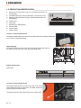 6
6
-
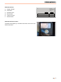 7
7
-
 8
8
-
 9
9
-
 10
10
-
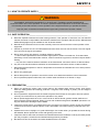 11
11
-
 12
12
-
 13
13
-
 14
14
-
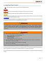 15
15
-
 16
16
-
 17
17
-
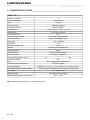 18
18
-
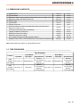 19
19
-
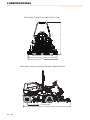 20
20
-
 21
21
-
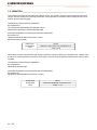 22
22
-
 23
23
-
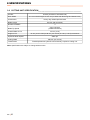 24
24
-
 25
25
-
 26
26
-
 27
27
-
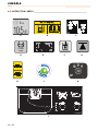 28
28
-
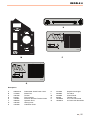 29
29
-
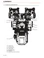 30
30
-
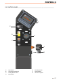 31
31
-
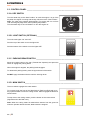 32
32
-
 33
33
-
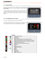 34
34
-
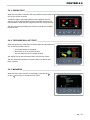 35
35
-
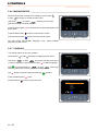 36
36
-
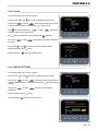 37
37
-
 38
38
-
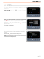 39
39
-
 40
40
-
 41
41
-
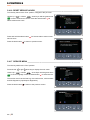 42
42
-
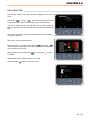 43
43
-
 44
44
-
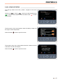 45
45
-
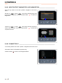 46
46
-
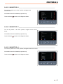 47
47
-
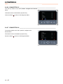 48
48
-
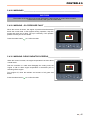 49
49
-
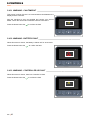 50
50
-
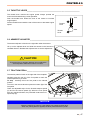 51
51
-
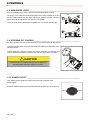 52
52
-
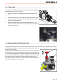 53
53
-
 54
54
-
 55
55
-
 56
56
-
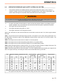 57
57
-
 58
58
-
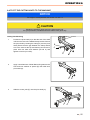 59
59
-
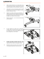 60
60
-
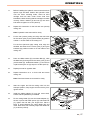 61
61
-
 62
62
-
 63
63
-
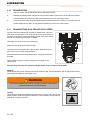 64
64
-
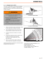 65
65
-
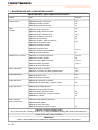 66
66
-
 67
67
-
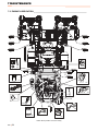 68
68
-
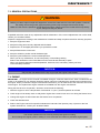 69
69
-
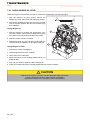 70
70
-
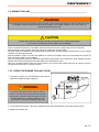 71
71
-
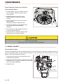 72
72
-
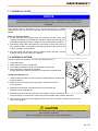 73
73
-
 74
74
-
 75
75
-
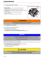 76
76
-
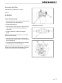 77
77
-
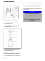 78
78
-
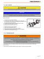 79
79
-
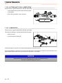 80
80
-
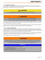 81
81
-
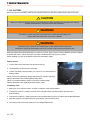 82
82
-
 83
83
-
 84
84
-
 85
85
-
 86
86
-
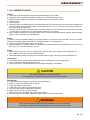 87
87
-
 88
88
-
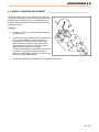 89
89
-
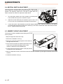 90
90
-
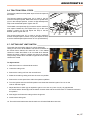 91
91
-
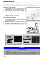 92
92
-
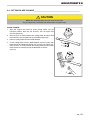 93
93
-
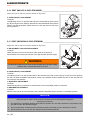 94
94
-
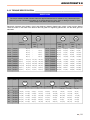 95
95
-
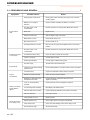 96
96
-
 97
97
-
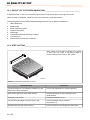 98
98
-
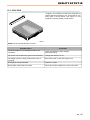 99
99
-
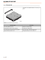 100
100
-
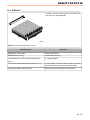 101
101
-
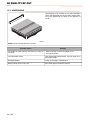 102
102
-
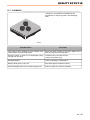 103
103
-
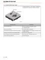 104
104
-
 105
105
-
 106
106
-
 107
107
-
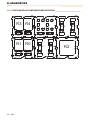 108
108
-
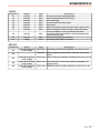 109
109
-
 110
110
-
 111
111
-
 112
112
-
 113
113
-
 114
114
-
 115
115
-
 116
116
-
 117
117
-
 118
118
-
 119
119
-
 120
120
-
 121
121
-
 122
122
-
 123
123
-
 124
124
-
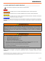 125
125
-
 126
126
-
 127
127
-
 128
128
-
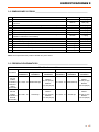 129
129
-
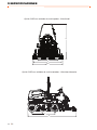 130
130
-
 131
131
-
 132
132
-
 133
133
-
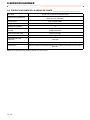 134
134
-
 135
135
-
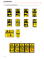 136
136
-
 137
137
-
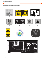 138
138
-
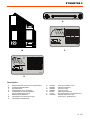 139
139
-
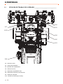 140
140
-
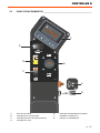 141
141
-
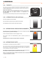 142
142
-
 143
143
-
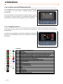 144
144
-
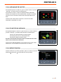 145
145
-
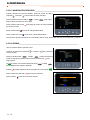 146
146
-
 147
147
-
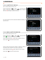 148
148
-
 149
149
-
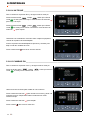 150
150
-
 151
151
-
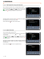 152
152
-
 153
153
-
 154
154
-
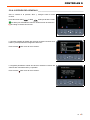 155
155
-
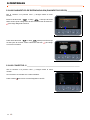 156
156
-
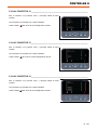 157
157
-
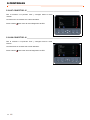 158
158
-
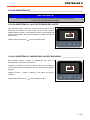 159
159
-
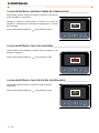 160
160
-
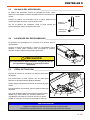 161
161
-
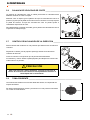 162
162
-
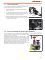 163
163
-
 164
164
-
 165
165
-
 166
166
-
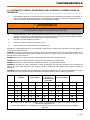 167
167
-
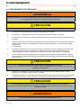 168
168
-
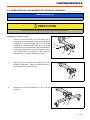 169
169
-
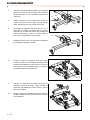 170
170
-
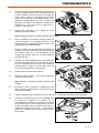 171
171
-
 172
172
-
 173
173
-
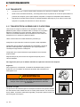 174
174
-
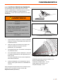 175
175
-
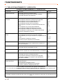 176
176
-
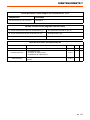 177
177
-
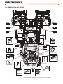 178
178
-
 179
179
-
 180
180
-
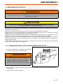 181
181
-
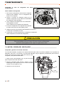 182
182
-
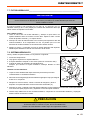 183
183
-
 184
184
-
 185
185
-
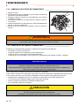 186
186
-
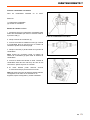 187
187
-
 188
188
-
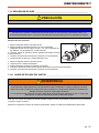 189
189
-
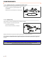 190
190
-
 191
191
-
 192
192
-
 193
193
-
 194
194
-
 195
195
-
 196
196
-
 197
197
-
 198
198
-
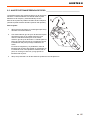 199
199
-
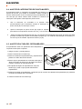 200
200
-
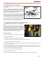 201
201
-
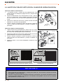 202
202
-
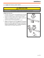 203
203
-
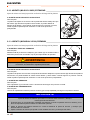 204
204
-
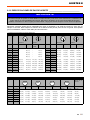 205
205
-
 206
206
-
 207
207
-
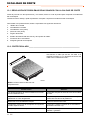 208
208
-
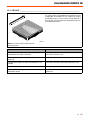 209
209
-
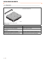 210
210
-
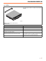 211
211
-
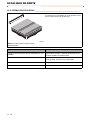 212
212
-
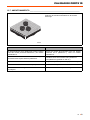 213
213
-
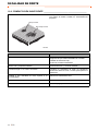 214
214
-
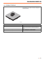 215
215
-
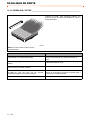 216
216
-
 217
217
-
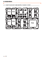 218
218
-
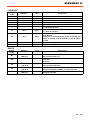 219
219
-
 220
220
-
 221
221
-
 222
222
-
 223
223


Jacobsen 068021-E410E Maintenance Manual
- Categoría
- Cortadoras de césped
- Tipo
- Maintenance Manual
En otros idiomas
- English: Jacobsen 068021-E410E
Documentos relacionados


Otros documentos
-
Ransomes 70524, 70525 El manual del propietario
-
-
-
-
RHINO Twister Series Manual de usuario
-
Bush Hog Disc Hay Mower El manual del propietario
-
-
Alamo FX21 Manual de usuario
-
-
 JBM 54290 Guía del usuario
